Yaesu Musen VX-150 Scanning Receiver User Manual VX150
Yaesu Musen Co., Ltd. Scanning Receiver VX150
users manual

VX-150 OPERATING MANUAL 1
The VX-150 is an ultra compact FM hand-held providing up to five watts of RF power and
a wealth of new features for the 2m amateur band. The VX-150 accepts the same battery
packs, and has rubber gasket seals around all external controls and connectors keep out
dust and rain or spray, assuring years of reliable operation even in harsh environments.
Sixteen multi-function keys provide the ultimate in programmability of 199 freely tunable
memories and two VFOs. All memories store repeater shifts or separate tx/rx frequencies,
CTCSS (Continuous Tone Controlled Squelch System) tone frequencies and tone encode/
decode selections with one instant-recall call channel memory and two special purpose
memories for limited subband tuning/scanning. Busy channel band or selective memory
scanning is provided along with priority channel monitoring; 1 MHz up/down stepping;
ARS (automatic repeater shift) when tuned to repeater subbands, plus a top panel rotary
dial for memory and frequency selection. The keypad serves as a DTMF encoder during
transmission, and up to 9 DTMF memories can store 16 digits each for quick playback of
commonly used numbers.
The liquid crystal display shows seven frequency digits, memory selection, CTCSS tone
frequency while setting*, page-received status when paged by a CTCSS tone, and includes
a bargraph S/PO meter. Yaesu’s power saver system can be set by the operator for optimum
sampling/standby ratio, or can be turned off for packet operation. And our new APO (Au-
tomatic Power Off) system shuts off the transceiver to avoid dead batteries if you doze off
or are called away unexpectedly.
Operation under difficult conditions is simplified by a lamp button illuminating the display
and backlit translucent keypad, diatonically assigned function-dependent keypad beeps.
Please read this manual carefully to gain a clear understanding of the features of the VX-
150.
*: Paging features require optional FVP-25.
Introduction
VX-150 OPERATING MANUAL2
Controls & Connectors
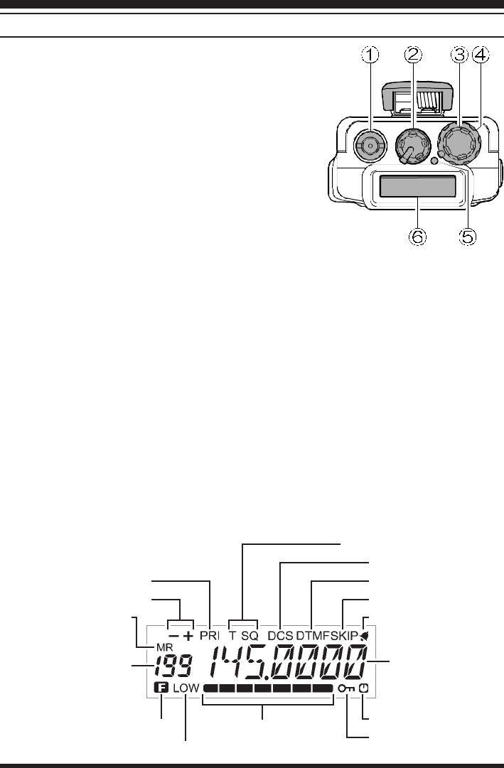
TOP PANEL
•ANTENNA Jack
This SMC jack accepts the supplied YHA-?? rub-
ber flex antenna, or any other antenna designed to
provide 50-ohm impedance on the 2m band.
‚ VOL/OFF Control
This control adjusts the volume of the receiver. Turn
this control to the fully counterclockwise position
(into the click stop) to turn the transceiver OFF.
ƒDIAL Rotary Selector
This 20-position detented rotary switch tunes the
operating (or CTCSS tone) frequency or selects the memory channels, according to
which function is selected by the keys on the front panel. This knob duplicates some of
the functions of the up and down arrow keys for operating convenience.
„SQL Control
This control sets the threshold level at which received signals (or noise) open the noise
squelch. Set this control from counterclockwise just to the point where noise is si-
lenced (and the BUSY/TX indicator on the front panel is off) when the channel is
clear.
…BUSY/TX Indicator Lamp
This LED indicator glows green when the noise squelch is open during reception, and
red when transmitting.
†LCD (Liquid Crystal Display)
The display shows the selected operating conditions as indicated in the following dia-
gram:
S- and TX Power Meter Auto Power OFF Active
LOCK Feature Active
LOW Power
Alt Key Active
Memory Number
or
VFO Selection
Tone Encoder/Squelch Enabled
Digital Coded Squelch
DTMF Memory Mode
Memory Skip
BELL
Priority Channel Scanning
Repeater Shift
Memory Mode
Frequency
VX-150 OPERATING MANUAL 3
Controls & Connectors
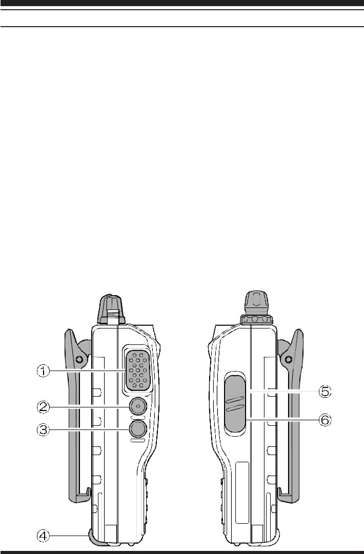
SIDE PANELS
•PTT Button
Press and hold this (Push-to-Talk) button to transmit. The BUSY/TX indicator glows
red while transmitting.
‚ Monitor (Burst) Button
In the USA version, this button opens the squelch momentarily without disturbing the
setting of the SQL control. In the European version, this button activates the 1750 Hz
Burst tone generator.
ƒLAMP Button
Press this button to illuminate the display and keypad when necessary.
…MIC/EAR Jack
This four-conductor miniature jack provides connection points for microphone audio,
earphone audio, PTT, and ground.
†EXT DC
This coaxial DC jack allows connection to an external DC power source (6.0-16V
DC).
The center pin of this jack is the Positive (+) line.
VX-150 OPERATING MANUAL4
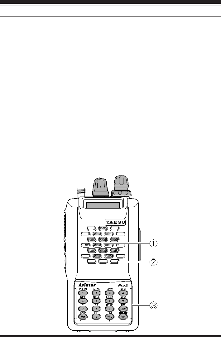
FRONT PANELS
•Speaker
The internal speaker is located directly below the display.
‚ Mic
The internal microphone is located at the bottom right-hand corner of the speaker.
ƒKeypad
These sixteen keys select the various operating features of the transceiver during re-
ception, and generate DTMF (Dual Tone Multi Frequency) tone pairs during transmis-
sion. One or two beeps will sound whenever one of the keys is pressed (if the beeper is
active). The labels on the faces of the keys indicate their primary functions, while the
labels above fifteen of the keys indicate alternate functions, which are activated by
pressing the [F/W] key first, and then another key within five seconds. When referring
to alternate key functions in this manual, we show the alternate key label followed by
the primary label in parentheses ( ). Primary key functions are referred to by the labels
on the keyfaces.
Remember to press the [F/W] key first (momentarily, unless otherwise indicated) when
you want to use an alternate key function. All key functions are described in the “Op-
eration” section, and summarized on the “VX-150 Operator’s Quick Reference Card.”
Controls & Connectors

VX-150 OPERATING MANUAL 5
ACCESSORIES SUPPLIED WITH THE VX-150
FNB-V57 7.2 V, 1100 mAh Ni-Cd Battery Pack
FC-72A/B/C/F/U Battery Chareger
Belt Clip
Hand Strap
Antenna
Operating Manual
Warranty Card
AVAILABLE OPTIONS FOR YOUR VX-150
FNB-V57 7.2 V, 1100 mAh Ni-Cd Battery Pack
FNB-62 7.2 V, 700 mAh Ni-Cd Battery Pack
FBA-25 Compact Dry Cell Battery Case for 6 AA-size cells
NC-72A 117 VAC Compact Wall Charger for FNB-14
NC-72B 220-234 VAC Compact Wall Charger for FNB-14
NC-72C 117 VAC Compact Wall Charger for FNB
NC-72U 220-234 VAC Compact Wall Charger for FNB
NC-73 Desktop Quick Charger
MH-34B4B External Hand Speaker/Microphone
MH-37A4B Earpiece/Microphone
VC-25 VOX Headset
E-DC-5B DC Cable w/Noise Filter
E-DC-6 DC Cable; plug and wire only
CSC-73 Soft Case
CN-3 BNC-to-SMA Adapter
CT-44 Microphone Adapter
YHA-?? Rubber flex antenna
Availability of accessories may vary: some accessories are supplied as standard per local
regulations and requirements, others may be unavailable in some regions. Check with your
Yaesu dealer for additions to the above list.
Accessories & Options
VX-150 OPERATING MANUAL6
ANTENNA INSTALLATION
The supplied antenna provides good results over the entire frequency range of the trans-
ceiver. However, for enhanced base station medium-wave and shortwave reception, you
may wish to connect an external (outside) antenna.
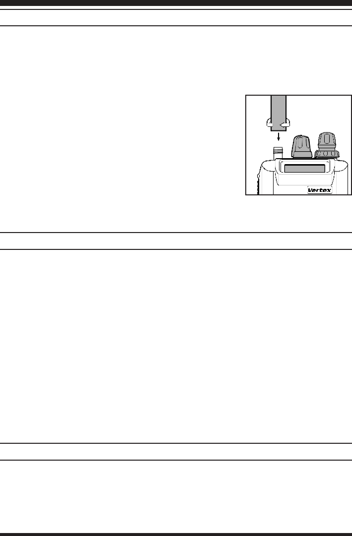
To install the supplied antenna
Hold the bottom end of the antenna, then screw it onto the
mating connector on the transceiver until it is snug. Do not
over-tighten by use of extreme force.
Notes:
¦Never transmit without having an antenna connected.
¦When installing the supplied antenna, never hold the
upper part of the antenna while screwing it onto the
mating connector on the transceiver.
¦If using an external antenna for transmission, ensure that the SWR presented to the
transceiver is 1.5:1 or lower.
BATTERY PACKS AND CASES
The following rechargeable Ni-Cd battery packs are recommended for use with the VX-
150:
FNB-V57 7.2V 1100 mAh
FNB-62 7.2V 700 mAh
The following battery cases are also available for operating the VX-150 with non-recharge-
able dry cell batteries (not supplied):
FBA-25 Battery Cases for 6 ‘AA’ (UM-3) batteries
The Ni-Cd packs above may be recharged either while attached to the transceiver or sepa-
rately, using the battery chargers described on the following pages. Each Ni-Cd pack should
be fully charged before it is used with the transceiver for the first time. Note that most of
these packs require different wall chargers: NC-72A/B/C/U for FNB-V57. Make certain
that you use the correct charger for each pack. The NC-73 Desktop Quick charger may be
used with all of these Ni-Cd packs.
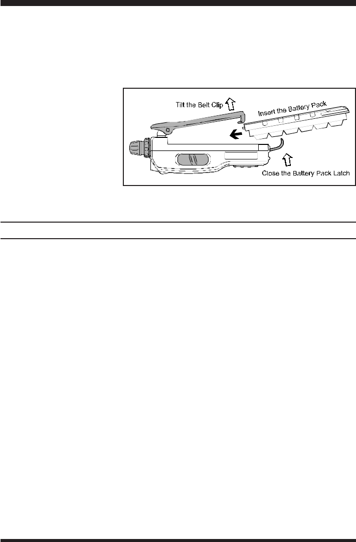
BATTERY PACK INSTALLATION AND REMOVAL
To install the battery, hold the transceiver with your left hand, so your palm is over the
speaker and your thumb is on the top of the belt clip. Insert the battery pack into the battery
compartment on the back of the radio while tilting the Belt Clip outward, then close the
Battery Pack Latch until it locks in place with a “Click.”
Installation & Accessories
VX-150 OPERATING MANUAL 7
To remove the battery, turn the radio off and remove any protective cases. Open the Bat-
tery Pack latch on the bottom of the radio, then slide the battery downward and out from
the radio while unfolding the Belt Clip.
Do not attempt to open any of the rechargeable Ni-Cd packs, as they could explode if
accidentally short-circuited.
If the battery has never been
used, or its charge is de-
pleted, it may be charged by
connecting the NC-72A/B/
C/F/U Battery Charger, as
shown in the illustration, to
the EXT DC jack. If only 12
~ 16 Volt DC power is avail-
able, the optional E-DC-5B or E-DC-6 DC Adapter (with its cigarette lighter plug) may
also be used for charging the battery, as shown in the illustration.
INSTALLATION OF FBA-25 (Option) ALKALINE BATTERY CASE
The optional FBA-25 Battery Case allows receive monitoring using six “AA” size Alka-
line batteries. Alkaline batteries can also be used for transmission in an emergency, but
power output will only be 300 mW, and battery life will be shortened dramatically.
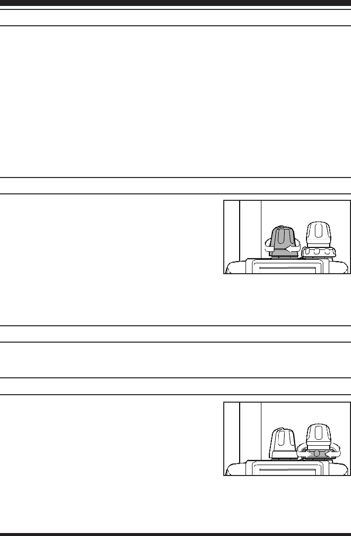
To Install Alkaline Batteries into the FBA-25
rSlide the batteries into the FBA-25 as shown in the illustration, with the Negative [–]
side of the batteries touching the spring connections inside the FBA-25.
rUnlock the bottom plate by pushing the latch in the “Open” direction.
rInstall the FBA-25 as shown in the illustration, with the [+] side facing the bottom of
the transceiver.
rRe-lock the bottom plate by carefully pressing the latch cover back into its normal
operating position.
The FBA-25 does not provide connections for charging, since Alkaline cells cannot be re-
charged. Therefore, the NC-72A/B/C/F/U, E-DC-5B, or E-DC-6 may safely be con-
nected to the EXT DC jack when the FBA-25 is installed.
Notes:
mThe FBA-25 is designed for use only with AA-type Alkaline cells.
mIf you do not use the VX-150 for a long time, remove the Alkaline batteries from the
FBA-25, as battery leakage could cause damage to the FBA-25 and/or the trans-
ceiver.
Installation & Accessories
VX-150 OPERATING MANUAL8
PRELIMINARY OPERATING INFORMATION
Before operating the transceiver for the first time, charge the battery pack completely (if
using Ni-Cd batteries) as described on pages 6 and 7. If using the FBA-25 battery case,
install the batteries as described on page 7.
Connect the YHA-?? rubber flex antenna to the antenna jack on the top of the transceiver.
Never operate the transceiver without an antenna connected.
Before proceeding, please read the Controls and Connectors chapter if you have not al-
ready, to familiarize yourself with the controls. Note especially item ?? on page ??, which
describes the terminology used in this chapter when referring to the keys.
Except for certain special cases mentioned later, the keypad functions as a DTMF (Dual
Tone Multi Frequency) tone generator during transmission.
SWITCHING POWER ON AND OFF
•Be sure the battery pack is installed.
‚Connect the antenna to the top panel ANTENNA
jack.
ƒSwitch on the transceiver by rotating the VOL con-
trol clockwise out of the click-stop (a momentary
beep will sound).
If you don’t hear the two “Beep” tones when the radio comes on, the Beeper may have
been disabled via the Menu system. See page ??, which tells you how to reactivate the
Beeper.
ADJUSTING THE VOLUME LEVEL
Rotate the VOL control (immediately to the right of the Antenna) to set the desired audio
level. Clockwise rotation increases the volume level.
SQUELCH SETUP
Set the SQL control fully counterclockwise, rotate the
VOL control out of the click-stop and adjust for a com-
fortable volume on the noise or received signal. The
BUSY/TX indicator LED should glow green. If a sig-
nal is present, rotate the DIAL selector on the top panel
to a channel where only noise is heard.
Adjust the SQL control just to the point where the noise is silenced and the LED is extin-
guished. If the SQL control is set further clockwise, sensitivity to weak signals will be
reduced. Now, whenever a signal reaches the receiver that is strong enough to open the
squelch, the indicator will glow green.
Operation

VX-150 OPERATING MANUAL 9
Note that while receiving, one or more bargraph segments may appear along the bottom of
the display, indicating signal strength on the receiving frequency. This indication is not
affected by the squelch setting, so even squelched signals may have some indication. If you
notice more than one or two bargraph segments appearing while the squelch is still closed,
try reducing the squelch control setting (if you want to hear weak signals).
The Monitor switch on the USA versions (just above the PTT switch) allows you to check
for channel activity beneath the squelch level and to adjust the volume without having to
adjust the squelch: just press the Monitor switch and the squelch will open.
FREQUENCY NAVIGATION
Press the [VFO(PRI)] button, if necessary, to select the VFO mode. The VX-150 has two
vfos, labelled “A” and “B” either of which can be used for all of the procedures described
in this manual. You can change vfos with the [VFO(PRI)] button at any time.
You have several ways to tune the VX-150: in selectable channel steps or 1 MHz steps
with the [s] / [t] keys or DIAL knob, and direct keypad frequency entry.
Use the DIAL knob to tune the displayed VFO frequency at the current channel step rate.
You can also press the [s] / [t] keys momentarily to do this, but if you press an [s] or
[t] key for more than 1/2-second scanning will start. This is described later, so for now,
just press an [s] / [t] key again to stop (if you have to).
To change the MHz range of the VFO, you can press the [F/W] key followed by an [s] or
[t] key (or turn the DIAL knob). Note the beeps when using the [s] / [t] keys: when
moving up, and when moving down. When done press [F/W] again, or just wait five sec-
onds.
You can also enter a frequency directly just by keying in the 1 MHz and the kHz digits. If
you are using 5 or 10 kHz steps enter five digits. Otherwise just four digits will do. Partial
entries can be cancelled with the [VFO(PRI)] key.
Examples:
To enter 146.5200 MHz, press à à à à
To enter 146.5000 MHz, press à à à
Operation

VX-150 OPERATING MANUAL10
TRANSMITTING
When you wish to transmit, wait until the channel is clear (BUSY/TX lamp off), and squeeze
the PTT switch. During transmission the BUSY/TX lamp glows red, and relative transmit-
ter power output is indicated graphically along the bottom of the display. Release the PTT
switch to receive.
If using a version B (in Europe), press the T-CALL switch (above the PTT switch) to
transmit a 1750 Hz tone to access repeaters that require it.
CHANGING THE CHANNEL STEPS
Tuning steps are factory preset to 20 kHz. To change a frequency step, follow the proce-
dure below:
•Press the [F/W] key, then immediately press the [0(SET)] key to enter the Set mode.
‚Rotate the DIAL to select Menu Item #7 (“STEPSTEP
STEPSTEP
STEP”).
ƒPress the [F/W] key to enable modification of the current setting.
„Now rotate the DIAL knob to select 5, 10, 12.5, 15, 20, 25 or 50 kHz steps.
…Press the PTT key to save the new setting and exit to normal operation.
Operation

VX-150 OPERATING MANUAL 11
KEYPAD/LCD ILLUMINATION
Your VX-150 includes a reddish illumination lamp which aids in nighttime operation. The
red illumination yields clear viewing of the display in a dark environment, with minimal
degradation of your night vision. Three options for activating the lamp are provided:
KEYKEY
KEYKEY
KEY Mode: Pressing any key causes the lamp to provide illumination for 5 seconds,
after which the lamp will automatically shut off.
5SEC5SEC
5SEC5SEC
5SEC Mode: Pressing the LAMP switch momentarily causes the lamp to provide illu-
mination for 5 seconds, after which the lamp will automatically shut off.
TOGGLETOGGLE
TOGGLETOGGLE
TOGGLE Mode:Pressing the LAMP switch momentarily “Toggles” the lamp on and off.
The lamp will stay illuminated until you press the LAMP switch once
more.
Here is the procedure for setting up the Lamp mode:
•You first need to enter the “Set” (menu) mode. Press the [F/W] key, then immediately
press the [0(SET)] key (just below the [F/W] key) to activate the Set mode.
‚Now rotate the DIAL to select Menu Item #21 (“LMP MODELMP MODE
LMP MODELMP MODE
LMP MODE”).
ƒPress the [F/W] key to enable modification of the current setting.
„Next, rotate the DIAL to select one of the three modes described above.
…When you have made your choice, press the PTT key to save the new setting for Menu
Item #21. The transceiver will now return to normal operation.
The 5SEC mode provides the greatest battery conservation, as it allows activation of the
lamp only when you press the LAMP switch.
If you press and hold in the LAMP key for one second, the lamp will remain illuminated
until you press the LAMP switch once more (no time limit).
Operation
VX-150 OPERATING MANUAL12
REPEATER OPERATION
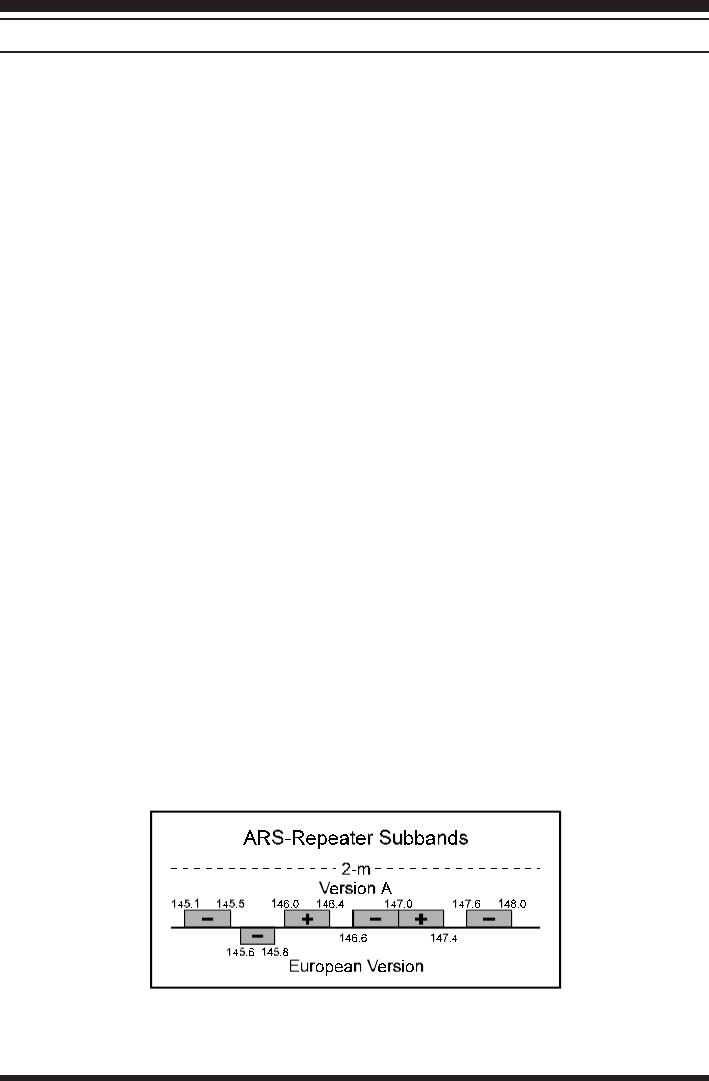
The ARS (Automatic Repeater Shift) feature in the VX-150 provides repeater shift of the
transmit frequency whenever you are tuned to a standard repeater subband (see diagram
below). When enabled, a small “–” or “+” displayed above the upper left-hand corner of
the display that repeater shift is active, and closing the push-to-talk switch changes the
display to the (shifted) transmit frequency.
Automatic Repeater Shift (ARS)
The VX-150 provides a convenient Automatic Repeater Shift feature, which causes the
appropriate repeater shift to be automatically applied whenever you tune into the desig-
nated repeater sub-bands in your country. These sub-bands are shown below.
If the ARS feature does not appear to be working, you may have accidentally disabled it.
To re-enable ARS:
•Press the [F/W] key, then immediately press the [0(SET)] key to enter the Set mode.
‚Rotate the DIAL to select Menu Item #2 (“ARSARS
ARSARS
ARS”).
ƒPress the [F/W] key to enable modification of the current setting.
„Now rotate the DIAL to select “ON” (to enable Automatic Repeater Shift).
…Press the PTT key to save the new setting and exit to normal operation.
Manual Repeater Shift Activation
If the ARS feature has been disabled, or if you need to set a repeater shift other than that
established by the ARS, you may set the direction of the repeater shift manually.
To do this, press the [F/W] key, then press the [4(RPT)] key. This provides a “Shortcut” to
Menu #3 (“RPTRPT
RPTRPT
RPT”). Rotate the DIAL, and you will see that the “–” or “+” icon appears at the
upper of the LCD (when no icon is present, “Simplex” operation - transmit and receive on
the same frequency - has been selected, and the LCD will indicate “SIMPSIMP
SIMPSIMP
SIMP” in this case).
When the desired shift direction has been selected, press the PTT key momentarily to save
your new setting and exit.
Advanced Operation

VX-150 OPERATING MANUAL 13
Changing the Default Repeater Shifts
If you travel to a different country, you may need to change the default repeater shift so as
to ensure compatibility with local operating requirements.
To do this, follow the procedure below:
•Press the [F/W] key, then immediately press the [0(SET)] key to enter the Set mode.
‚Rotate the DIAL to select Menu Item #3 (“RPTRPT
RPTRPT
RPT”).
ƒPress the [F/W] key to enable modification of the current setting.
„Now rotate the DIAL knob to select the new repeater shift magnitude.
…Press the PTT key momentarily to save the new setting and exit.
Checking the Repeater Uplink (Input) Frequency
It often is helpful to be able to check the uplink (input) frequency of a repeater, to see if the
calling station is within direct (“Simplex”) range.
To do this, just press the [REV(HM)] key momentarily. If Menu Item #20 (“REVREV
REVREV
REV/HMHM
HMHM
HM”) has
been set to “HMHM
HMHM
HM” you may press the [F/W] key, and then [REV(HM)] key. To return to the
normal uplink/downlink frequency relationship, repeat this step.
Advanced Operation

VX-150 OPERATING MANUAL14
CTCSS OPERATION
Many repeater systems require that a very-low-frequency audio tone be superimposed on
your FM carrier in order to activate the repeater. This helps prevent false activation of the
repeater by radar or spurious signals from other transmitters. This tone system, called
“CTCSS” (Continuous Tone Coded Squelch System), is included in your VX-150, and is
very easy to activate.
CTCSS setup involves two actions: setting the Tone Frequency and then setting of the
Tone Mode. These actions are set up by using the [1(SQ TYP)] and [2(CODE)] keys, or
Menu Items #25 and #26.
•Press the [F/W] key, then immediately press the [1(SQ TYP)] key. This provides a
“Short-cut” to Menu #25 (“SQL TYPSQL TYP
SQL TYPSQL TYP
SQL TYP”).
‚Rotate the DIAL so that “TT
TT
T” appears on the display; this activates the CTCSS Encoder,
which allows repeater access.
ƒYou may notice an additional “DCSDCS
DCSDCS
DCS” icon appearing while you rotate the DIAL in this
step. We’ll discuss the Digital Code Squelch system shortly.
„Rotation of the DIAL in step ‚ above will occasionally cause “SQSQ
SQSQ
SQ” to appear adjacent
to the “TT
TT
T” icon. When “TONE SQLTONE SQL
TONE SQLTONE SQL
TONE SQL” appears, this means that the Tone SQuelch system
is active, which mutes your VX-150’s receiver until it receives a call from another
radio sending out a matching CTCSS tone. This can help keep your radio quiet until a
specific call is received, which may be helpful while operating in congested areas.
…When you have made your selection of the CTCSS tone mode, press the PTT.
†Press the [F/W] key, then immediately press the [2(CODE)] key. This provides a “Short-
cut” to Menu #26 (“TN SETTN SET
TN SETTN SET
TN SET”).
‡This Menu selection allows setting of the CTCSS tone frequency to be used.
ˆRotate the DIAL until the display indicates the Tone Frequency you need to be using
(ask the repeater owner/operator if you don’t know the tone frequency).
‰Press the [F/W] key to save the new settings and exit to normal operation.
CTCSS TONE F
REQ UEN CY (Hz)
67.0 69.3 71.9 74.4 77.0 79.7 82.5 85.4
88.5 91.5 94.8 97.4 100.0 103.5 107.2 110.9
114.8 118.8 123.0 127.3 131.8 136.5 141.3 146.2
151.4 156.7 162.2 167.9 173.8 179.9 186.2 192.8
203.5 210.7 218.1 225.7 233.6 241.8 250.3 -
Advanced Operation

VX-150 OPERATING MANUAL 15
DCS OPERATION
Another form of tone access control is Digital Code Squelch, or DCS. It is a newer, more
advanced tone system which generally provides more immunity from false paging than
does CTCSS. The DCS Encoder/Decoder is built into your VX-150, and operation is very
similar to that just described for CTCSS. Your repeater system may be configured for
DCS; if not, it is frequently quite useful in Simplex operation if your friend(s) use trans-
ceivers equipped with this advanced feature.
Just as in CTCSS operation, DCS requires that you set the Tone Mode to DCS and that
you select a tone code.
•Press the [F/W] key, then immediately press the [1(SQ TYP)] key. This provides a
“Short-cut” to Menu #25 (“SQL TYPSQL TYP
SQL TYPSQL TYP
SQL TYP”).
‚Rotate the DIAL until “DCSDCS
DCSDCS
DCS” appears on the display; this activates the DCS Encoder/
Decoder.
ƒWhen you have made your selection of the DCS mode, press the PTT.
„Press the [F/W] key, then immediately press the [2(CODE)] key. This provides a “Short-
cut” to Menu #26 (“TN SETTN SET
TN SETTN SET
TN SET”).
…Rotate the DIAL to select the desired DCS Code (a three-digit number). Ask the re-
peater owner/operator if you don’t know DCS Code; if you are working simplex, just
set up the DCS Code to be the same as that used by your friend(s).
†When you have made your selection, press the [F/W] key to save the new settings and
exit to normal operation.
Remember that the DCS is an Encode/Decode system, so your receiver will remain muted
until a matching DCS code is received on an incoming transmission. Switch the DCS off
when you’re just tuning around the band!
Advanced Operation
DCS CODE
023 025 026 031 032 036 043 047 051 053 054 065 071 072 073 074 114 115 116
122 125 131 132 134 143 145 152 155 156 162 165 172 174 205 212 223 225 226
243 244 245 246 251 252 255 261 263 265 266 271 274 306 311 315 325 331 332
343 346 351 356 364 365 371 411 412 413 423 431 432 445 446 452 454 455 462
464 465 466 503 506 516 523 526 532 546 565 606 612 624 627 631 632 654 662
664 703 712 723 731 732 734 743 754

VX-150 OPERATING MANUAL16
TONE SEARCH SCANNING
In operating situations where you don’t know the CTCSS or DCS tone being used by
another station or stations, you can command the radio to listen to the incoming signal and
scan in search of the tone being used. Two things must be remembered in this regard:
mYou must be sure that your repeater uses the same tone type (CTCSS vs. DCS).
mSome repeaters do not pass the CTCSS tone; you may have to listen to the station(s)
transmitting on the repeater uplink (input) frequency in order to allow Tone Search
Scanning to work.
To scan for the tone in use:
•Set the radio up for either CTCSS or DCS Decoder operation (see the previous discus-
sion). In the case of CTCSS, “T SQT SQ
T SQT SQ
T SQ” will appear on the display; in the case of DCS,
“DCSDCS
DCSDCS
DCS” will appear on the display.
‚Press the [F/W] key, then immediately press the [2(CODE)] key to select the “TNTN
TNTN
TN
SETSET
SETSET
SET” Menu item (when TONE SQL is selected) or “DCS SETDCS SET
DCS SETDCS SET
DCS SET” (during DCS opera-
tion).
ƒPress and hold in the [s] or [t] key to start scanning for the incoming CTCSS or DCS
tone/code.
„When the radio detects the correct tone or code, it will halt on that tone/code, and audio
will be allowed to pass. Press the [F/W] key to lock in that tone/code, and exit to
normal operation.
If the Tone Scan feature does not detect a tone or code, it will continue to scan indefi-
nitely. When this happens, it may be that the other station is not sending any tone. You
can press the PTT switch to halt the scan at any time.
You also can press the MONI key during Tone Scanning to listen to the (muted) signal
from the other station. When you release the MONI key, Tone Scanning will resume
after about a second.
Tone Scanning works either in the VFO or Memory modes.
Advanced Operation

VX-150 OPERATING MANUAL 17
CTCSS/DCS BELL OPERATION
During CTCSS Decode or DCS operation, you may set the VX-150 up such that a ringing
“Bell” sound alerts you to the fact that a call is coming in. Here is the procedure for activat-
ing the Bell will ring in accordance with this programming.
•Set the transceiver up for CTCSS Decode (“TONE SQL” or DCS operation, as de-
scribed previously.
‚Adjust the operating frequency to the desired channel.
ƒPress the [F/W] key, then press the [0(SET)] key to activate the Set mode.
„Rotate the DIAL to select Menu Item #18 (“BELLBELL
BELLBELL
BELL”).
…Press the [F/W] key to enable adjustment of the Bell ringer.
†Rotate the DIAL to set the desired number of rings of the Bell. The available choices
are 1, 3, 5, or 8 rings, REPEAT (continuous ringing), or OFF.
‡Press the PTT key momentarily to save the new setting and exit to normal operation.
When a station calls you whose transceiver is sending a CTCSS tone or DCS code which
matches that set into your Decoder, the Bell will ring in accordance to this programming.
TONE CALLING (1750 Hz)
If the repeaters in your country require a 1750-Hz burst tone for access (typically in Eu-
rope), you can set the MONI key to serve as a “TONE CALL” switch instead. To change the
configuration of this switch, we again use the Menu to help us.
•Press the [F/W] key, then press the [0(SET)] key to enter the Set mode.
‚Rotate the DIAL to select Menu Item #19 (“MONMON
MONMON
MON/TCLTCL
TCLTCL
TCL”).
ƒPress the [F/W] key to enable adjustment of this Menu item.
„Rotate the DIAL to select “T.CALLT.CALL
T.CALLT.CALL
T.CALL” on the display.
…Press the PTT key to save the new setting and exit.
†To access a repeater, press and hold in the MONI key for the amount of time specified
by the repeater owner/operator. The transmitter will automatically be activated, and a
1750-Hz audio tone will be superimposed on the carrier. Once access to the repeater
has been gained, you may release the MONI key, and use the PTT key for activating the
transmitter.
Advanced Operation

VX-150 OPERATING MANUAL18
CHANGING THE TRANSMITTER POWER LEVEL
You can select between a total of three transmitter power levels on your VX-150. The
exact power output will vary somewhat, depending on the voltage supplied to the trans-
ceiver. With the standard FNB-V57 Battery Pack, the power output levels available are:
HIGHHIGH
HIGHHIGH
HIGH: ?? W MIDMID
MIDMID
MID: ?? W LOWLOW
LOWLOW
LOW: ?? W
To change the power level:
•Press the [F/W] key, then immediately press the [3(LOW)] key.
‚Now rotate the DIAL knob to select “LOWLOW
LOWLOW
LOW”, “MIDMID
MIDMID
MID” or “HIGHHIGH
HIGHHIGH
HIGH”.
ƒPress the PTT key to save the new setting and exit to normal operation.
TRANSMITTER TIME-OUT TIMER (TOT)
The TOT feature provides a safety switch which limits transmission to a pre-programmed
value. This will promote battery conservation by not allowing you to make excessively-
long transmissions, and in the event of a stuck PTT switch (perhaps if the radio or a Speaker/
Mic is wedged between car seats) it can prevent interference to other users as well as
battery depletion. As configured at the factory the TOT feature is set to OFF, and here is
the procedure for activating it:
•Press the [F/W] key, then press the [0(SET)] key to enter the Set mode.
‚Rotate the DIAL to select Menu Item #22 (“TOTTOT
TOTTOT
TOT”).
ƒPress the [F/W] key to enable adjustment of this Menu item.
„Rotate the DIAL to set the Time-Out Timer to the desired “Maximum TX” time (1
minute, 2.5 minutes, 5 minutes, or 10 minutes).
…Once you’ve made the selection you wish to use, press the PTT key to save the new
setting and exit to normal operation.
Since brief transmissions are the mark of a good operator, try setting up your radio’s
TOT feature for a maximum transmission time of 1 minute. This will significantly im-
prove battery life, too!
Advanced Operation

VX-150 OPERATING MANUAL 19
RECEIVE BATTERY SAVER SETUP
An important feature of the VX-150 is its Receive Battery Saver, which “puts the radio to
sleep” for a time interval, periodically “waking it up” to check for activity. If somebody is
talking on the channel, the VX-150 will remain in the “active” mode, then resume its
“sleep” cycles. This feature significantly reduces quiescent battery drain, and you may
change the amount of “sleep” time between activity checks using the Menu System:
•Press the [F/W] key, then press the [0(SET)] key to enter the Set mode.
‚Rotate the DIAL to select Menu Item #9 (“RX SAVERX SAVE
RX SAVERX SAVE
RX SAVE”).
ƒPress the [F/W] key to enable adjustment of this Menu item.
„Rotate the DIAL to select the desired “Sleep” duration. The selections available are
200 ms, 300 ms, 500 ms, 1 second, and 2 seconds, or OFF. The default value is 200 ms.
…When you have made your selection, press the PTT key to save the new setting and exit
to normal operation.
When you are operating on Packet, switch the Receive Battery Saver OFF, as the sleep
cycle may “Collide” with the beginning of an incoming Packet transmission, causing
your TNC not to receive the full data burst.
When the battery saving function is working, the beginning of the companion voice
breaks off and it is sometimes possible to hear it.
TX BATTERY SAVER
The VX-150 also includes a useful Transmit Battery Saver, which will automatically lower
the power output level when the last signal received was very strong. For example, when
you are in the immediate vicinity of a repeater station, there generally is no reason to use
the full 5? Watts of power output in order to achieve full-quieting access to the repeater.
With the Transmit Battery Saver, the automatic selection of Low Power operation con-
serves battery drain significantly.
To activate the Transmit Battery Saver:
•Press the [F/W] key, then press the [0(SET)] key to enter the Set mode.
‚Rotate the DIAL to select Menu Item #10 (“TX SAVETX SAVE
TX SAVETX SAVE
TX SAVE”).
ƒPress the [F/W] key to enable adjustment of this Menu item.
„Rotate the DIAL so as to select ON (thus activating the Transmit Battery Saver).
…When you have completed your selection, press the PTT key to save the new setting
and exit to normal operation.
Advanced Operation

VX-150 OPERATING MANUAL20
DISABLING THE BUSY/TX LED
Further battery conservation may be accomplished by disabling the BUSY/TX LED. Use
the following procedure:
•Press the [F/W] key, then press the [0(SET)] key to enter the Set mode.
‚Rotate the DIAL to select Menu Item #12 (“BSY LEDBSY LED
BSY LEDBSY LED
BSY LED”).
ƒPress the [F/W] key to enable adjustment of this Menu item.
„Rotate the DIAL to set this Menu item to OFF (thus disabling the BUSY/TX LED).
…Press the PTT key to save the new setting and exit to normal operation.
BUSY CHANNEL LOCK-OUT (BCLO)
The BCLO feature prevents the radio’s transmitter from being activated if a signal strong
enough to break through the “Noise” squelch is present. On a frequency where stations
using different CTCSS or DCS codes may be active, BCLO prevents you from disrupting
their communications accidentally (because your radio may be muted by its own Tone
Decoder). The default setting for the BCLO is OFF, and here is how to change that setting:
•Press the [F/W] key, then press the [0(SET)] key to enter the Set mode.
‚Rotate the DIAL to select Menu Item #23 (“BCLOBCLO
BCLOBCLO
BCLO”).
ƒPress the [F/W] key to enable adjustment of this Menu item.
„Rotate the DIAL to set the BCLO feature to the “ON” position.
…Press the PTT key to save the new setting and resume normal operation.
AUTOMATIC POWER-OFF (APO) FEATURE
The APO feature helps conserve battery life by automatically turning the radio off after a
user-defined period of time within which there has been no dial or key activity. The avail-
able selections for the time before power-off are 0.5/1/3/5/8 hours, as well as APO Off.
The default condition for the APO is OFF , and here is the procedure for activating it:
•Press the [F/W] key, then press the [0(SET)] key to enter the Set mode.
‚Rotate the DIAL to select Menu Item #11 (“APOAPO
APOAPO
APO”).
ƒRotate the DIAL to select the desired time period after which the radio will automati-
cally shut down.
„Once you have made your selection, press the PTT key to save the new setting and exit
to normal operation.
CHECKING THE BATTERY VOLTAGE
The VX-150’s measure the current battery voltage.
•Press the [F/W] key, then press the [0(SET)]] key to enter the Set mode.
‚Rotate the DIAL to select Menu Item #37 (“BATTBATT
BATTBATT
BATT”).
ƒPress the [F/W] key to check the battery condition.
„To return to normal operation, press the [F/W] key, then press the PTT.
Advanced Operation

VX-150 OPERATING MANUAL 21
KEYBOARD LOCKING
In order to prevent accidental frequency change or inadvertent transmission, various as-
pects of the VX-150’s keys and switches may be locked out. The possible lockout combi-
nations are:
KEYKEY
KEYKEY
KEY: Just the front panel keys are locked out
DIALDIAL
DIALDIAL
DIAL: Just the top panel DIAL is locked out
KEYKEY
KEYKEY
KEY + DIALDIAL
DIALDIAL
DIAL: Both the DIAL and Keys are locked out
PTTPTT
PTTPTT
PTT: The PTT switch is locked (TX not possible)
KEYKEY
KEYKEY
KEY + PTTPTT
PTTPTT
PTT: Both the keys and PTT switch are locked out
DIALDIAL
DIALDIAL
DIAL + PTTPTT
PTTPTT
PTT: Both the DIAL and PTT switch are locked out
ALLALL
ALLALL
ALL: All of the above are locked out
To lock out some or all of the keys:
•Press the [F/W] key, then press the [0(SET)] key to enter the Set mode.
‚Rotate the DIAL to select Menu Item #32 (“LK MODELK MODE
LK MODELK MODE
LK MODE”).
ƒPress the [F/W] key to enable setting of the Lock mode (which defines which keys/
functions are to be locked out).
„Rotate the DIAL to choose between one of the locking schemes as outlined above.
…Once you have made your selection, press the PTT key momentarily to save the new
setting and resume normal operation.
†To activate the locking feature, press the [F/W] key, then press the [6(LOCK)] key.
The “??” icon will lower on the LCD. To cancel keyboard locking, again press [F/W]
key, followed by [6(LOCK)] key.
DISABLING THE KEYPAD BEEPER
If the keypad’s Beeper creates an inconvenience (particularly when operating in a quiet
room), it may easily be disabled.
•Press the [F/W] key, then press the [0(SET)] key to enter the Set mode.
‚Rotate the DIAL to select Menu Item #16 (“KEY BPKEY BP
KEY BPKEY BP
KEY BP”).
ƒPress the [F/W] key to enable adjustment of this Menu item.
„Rotate the DIAL to change the setting from ON to OFF.
…When you have made your selection, press the PTT key to save the new setting and exit
to normal operation.
†If you wish to re-enable the Beeper, just repeat the above procedure, rotating the DIAL
to select ON in step ‚ above.
Advanced Operation

VX-150 OPERATING MANUAL22
DTMF OPERATION
The VX-150’s 16-button keypad allows easy DTMF dialing for Autopatch or repeater
control purposes. Besides numerical digits [0] through [9], the keypad includes the [ÛÛ
ÛÛ
Û]
and [#] digits, plus the [A], [B], [C], and [D] tones often used for repeater control.
Manual DTMF Tone Generation
You can generate DTMF tones during transmission manually.
•Press the PTT switch to begin transmission.
‚While transmitting, press the desired numbers on the keypad.
ƒWhen you have sent all the digits desired, release the PTT key.
DTMF Autodialer
Nine DTMF Autodial memories are provided, allowing you to store telephone numbers
for autopatch use. You can also store short autopatch access code streams so as to avoid
having to send them manually.
Here is the DTMF Autodial storage procedure:
•Press the [F/W] key, then press the [0(SET)] key to enter the Set mode.
‚Rotate the DIAL to select Menu Item #28 (“DTMFDTMF
DTMFDTMF
DTMF”).
ƒPress the [F/W] key to enable adjustment of this Menu item.
„Rotate the DIAL to select the DTMF Memory register into which you wish to store this
DTMF string.
…Press the [F/W] key, then press the [F/W] key to begin DTMF Memory entry into the
selected register.
†Rotate the DIAL to select the first digit of the desired label. When you have made your
selection, press the [s] key momentarily to move to the next digit.
‡Repeat the previous step to program the remaining letters , numbers of the desired
label. A total of 16 digits may be used in the creation of a label.
ˆPress the PTT switch to save the setting. To store other numbers, repeat this process,
using a different DTMF memory register.
To send the telephone number:
•Press [F/W], then the [9(DTMF)] key to activate the DTMF Autodialer function.
‚Press the PTT switch to begin transmission.
ƒPress the numerical key ([1] through [9]) corresponding to the DTMF memory string
you wish to send. Once the string begins, you may release the PTT key, as the transmit-
ter will be held “on the air” until the DTMF string is completed.
Advanced Operation

VX-150 OPERATING MANUAL 23
DTMF CODE SQUELCH (REQUIRES OPTIONAL FVP-25)
The code squelch system use 3-digit numeric codes (000000
000000
000 ~ 999999
999999
999), transmitted as DTMF
(dual, audible) tone pairs.
There are twelve code memories numbered [1] ~ [9], [A] and [D], which store 3-digit
DTMF paging codes (these are independent and unrelated to the channel memories and the
VFOs).
The code squelch mode is very simple: both you and the other station communicate using
the same 3-digit DTMF sequence, sent automatically at the start of every transmission.
Your receiver normally remains silent to all signals that are not prefixed by your selected
3-digit code. When you receive the matching tone sequence, your squelch opens and stays
open until a few seconds after the end of their transmission.
In the code squelch mode, you must first store and then manually select the one Code
Memory holding the 3-digit DTMF code required to open your squelch (as described on
the following pages). Also, in the code squelch mode, Code Memories [1] ~ [9] always
function the same.
Codes of up to nine other stations can be stored in these memories. These are stations you
expect to frequently contact, and whose page calls you also want to receive. Members of a
common group or club usually share a common 3-digit paging code so that they can be
paged simultaneously.
Remember, with Code Squelch operation (but not with DTMF Paging), you can only re-
ceive a call on the currently selected Code Memory, and the display does not change when
a call is received. So for code squelch, as mentioned before, the Code Memory distinction
does not apply (although you must still store the 3-digit Code Memories).
Storing Code Memories
The first thing to do before using Code Squelch is to store 3-digit code in Code Memory:
•Press the [F/W] key, then press the [0(SET)] key to enter the Set mode.
‚Rotate the DIAL to select Menu Item #40 (“PG CODEPG CODE
PG CODEPG CODE
PG CODE”).
ƒPress the [F/W] key to enable adjustment of this Menu item.
„Rotate the DIAL to select the Code Memories register into which you wish to store this
code string.
…Press the [F/W] key, then press the [F/W] key to begin Code Memories entry into the
selected register.
†Rotate the DIAL to select Key in the DTMF digits you wish to store into this register.
‡Press the PTT switch to save the setting. To store other numbers, repeat this process,
using a different DTMF memory register.
Advanced Operation

VX-150 OPERATING MANUAL24
You can use the same procedure to store the Memory Codes of other individuals or groups
in Code Memories [1] ~ [9].
Although up to nine Code Memories can be stored, you might only need a few of them to
call your friends or a specific group. Likewise, you’ll probably only want your radio to
respond to pages directed to you (or maybe your group or club’s code). The following
explains how to temporarily inhibit unused Code Memories.
Page Code Inhibit
During the Code Memory storage procedure above, when storing Code Memories [1] ~
[9], you have an opportunity to decide whether your transceiver should respond to incom-
ing paging calls on a particular Memory Code.
To activate Code setting:
•Press the [F/W] key, then press the [0(SET)] key, to enter the Set mode.
‚Rotate the DIAL to select Menu #40 (“PG CODEPG CODE
PG CODEPG CODE
PG CODE”).
ƒPress the [F/W] key, then rotate the DIAL to select the Code Memories register into
which you wish to this code string.
„Press the [F/W] key, rotate the DIAL to set the function ON.
…When you have made your selection, press the PTT key to save the new setting and exit
to Set mode.
DTMF Code Squelch Operation
As described earlier, with DTMF code squelch activated (CODE displayed), your squelch
will not open until you receive the proper 3-digit DTMF code according to the selected
code memory. Likewise, each time you press the PTT, the same 3-digit code is automati-
cally sent to open the other station’s DTMF coded squelch.
With the Code Squelch activated in this manner, you will hear three DTMF code digits
transmitted when you press your PTT switch. These are the digits stored in the Code
Memory currently selected, and they will open the squelch of the other station.
Therefore, at the start of each transmission, you must wait a second or two after pressing
the PTT switch for the DTMF code to be sent (you will hear it in your speaker).
When you finish your conversation, if you need to reactivate DTMF Code Paging, press
CODE (PAGE) until PAGE is again displayed.
Advanced Operation

VX-150 OPERATING MANUAL 25
PAGING TX DELAY
When calling other stations using Code Squelch, particularly through repeaters, you may
find that some stations are unable to receive your calls. This can be caused by their receiver
squelch not opening fast enough (after receiving your transmitted carrier) to allow all of
the DTMF digits to be received and decoded. To correct this problem, you can set a longer
delay (750 ms) between the time your transmitter is keyed and the time the first DTMF
digit is sent.
•Press the [F/W] key, then press the [0(SET)] key to enter the Set mode.
‚Rotate the DIAL to select Menu Item #35 (“DT DLYDT DLY
DT DLYDT DLY
DT DLY”).
ƒPress the [F/W] key to enable adjustment of this Menu item.
„Rotate the DIAL to change the setting from 450 to 750.
…When you have made your selection, press the PTT key to save the new setting and exit
to normal operation.
PAGING “ANSWER BACK”
When you press the PTT to respond to a page call, the caller’s ID code, followed by a
DTMF “ÛÛ
ÛÛ
Û” and your personal ID code, are transmitted.
This informs the calling station that their page was received. If you prefer, you can have the
VX-150 respond to page calls automatically (transpond).
As mentioned before, the answer-back mode acknowledges a received page by “paging
back” the calling station (just as if you manually selected their 3-digit code and pressed the
PTT).
To activate Paging Answer back:
•Press the [F/W] key, then press the [0(SET)] key, to enter the Set mode.
‚Rotate the DIAL to select Menu #41 (“PG ASBKPG ASBK
PG ASBKPG ASBK
PG ASBK”).
ƒPress the [F/W] key to enable adjustment of this Menu item.
„Rotate the DIAL to set the function ON.
…When you have made your selection, press the PTT key to save the new setting and exit
to normal operation.
Advanced Operation

VX-150 OPERATING MANUAL26
ANI OPERATION (AUTOMATIC NUMBER IDENTIFICATION)
Because it isn’t decided, it sends later.
Advanced Operation
VX-150 OPERATING MANUAL 27
ARTS (AUTOMATIC RANGE TRANSPONDER SYSTEM)
The ARTS feature uses DCS signaling to inform both parties when you and another ARTS-
equipped station are within communications range. This may be particularly useful during
Search-and Rescue situations, where is important to stay in contact with other members of
your group.
Both stations must set up their DCS codes to the same code number, then activate their
ARTS feature using the command appropriate for their radio. Alert ringers may be acti-
vated, if desired.
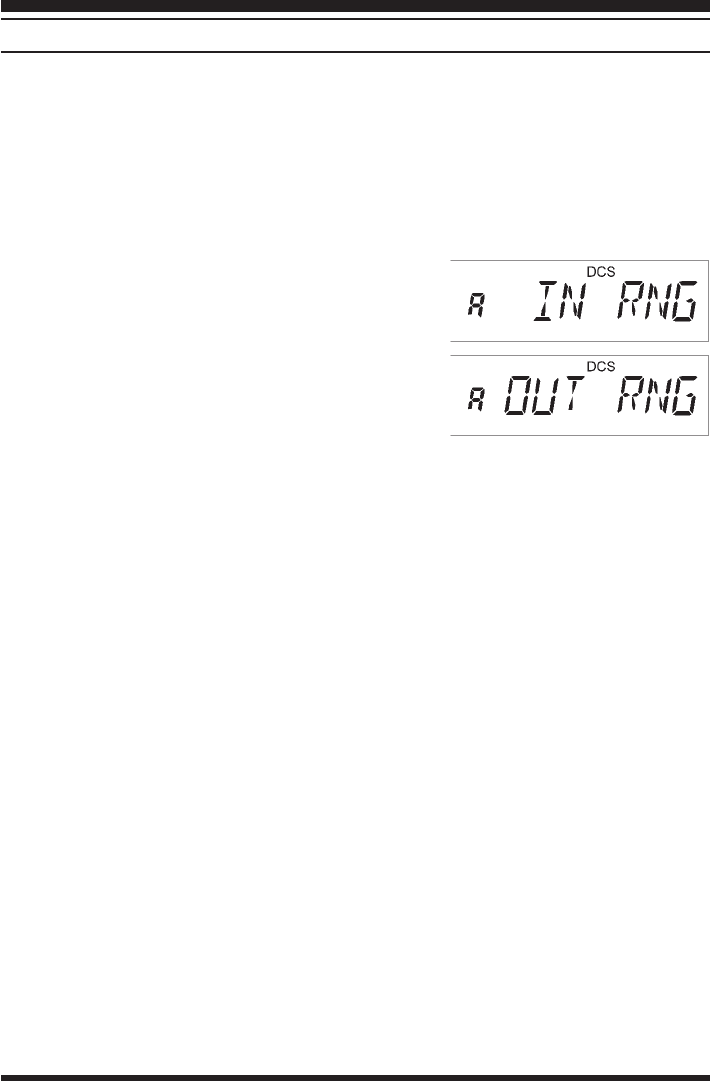
Whenever you push the PTT, or every 25 (or 15) sec-
onds after ARTS is activated, your radio will transmit
a signal which includes a (subaudible) DCS signal for
about 1 second. If the other radio is in range, the beeper
will sound (if enabled) and the display will show “ININ
ININ
IN
RNGRNG
RNGRNG
RNG” as opposed to the out of range display “OUTOUT
OUTOUT
OUT
RNGRNG
RNGRNG
RNG” in which ARTS operation begins.
Whether you talk or not, the polling every 15 or 25 seconds will continue until you de-
activate ARTS. Every 10 minutes, moreover, you can have your radio transmit your callsign
via CW, so as to comply with identification requirements. When ARTS is de-activated,
DCS will also be deactivated (if you were not using it previously in non-ARTS operation).
If you move out of range for more than one minute (four pollings), your radio will sense
that no signal has been received, three beeps will sound, and the display will revert to
“OUT RNGOUT RNG
OUT RNGOUT RNG
OUT RNG.” If you move back into range, your radio will again beep, and the display will
change back to the “IN RNGIN RNG
IN RNGIN RNG
IN RNG” indication.
You must terminate ARTS in order to resume normal operation. This is a safety feature
designed to prevent accidental loss of contact due to channel change, etc.
Here is how to activate ARTS:
Basic ARTS Setup and Operation
•Set your radio and the other radio(s) to the same DCS code number, per the discussion
on page ??.
‚Press [F/W], then press the [7(P1)] key to activate the ARTS operation.
ƒPress the [F/W] key. You will observe the “OUT RNGOUT RNG
OUT RNGOUT RNG
OUT RNG” display on the LCD. ARTS
operation has now commenced.
„Every 15 seconds, your radio will transmit a “polling” call to the other station. When that
station responds with its own ARTS polling signal, the display will change to “IN RNGIN RNG
IN RNGIN RNG
IN RNG” to
confirm that the other station “polling” code was received in response to yours.
…Press the [F/W] key again to exit ARTS operation and resume normal functioning of
the transceiver.
Advanced Operation

VX-150 OPERATING MANUAL28
ARTS Polling Time Options
The ARTS feature may be programmed to poll every 15 seconds (default value) or 25
seconds. The default value provides maximum battery conservation, because the polling
signal is sent out less frequently. To change the polling interval:
•Press the [F/W] key, then press the [0(SET)] key, to enter the Set mode.
‚Rotate the DIAL to select Menu #15 (“AR ITVLAR ITVL
AR ITVLAR ITVL
AR ITVL”).
ƒPress the [F/W] key to enable changing of this Menu item.
„Rotate the DIAL to select the desired polling interval (15 or 25 seconds).
…When you have made your selection, press the PTT key to save the new setting and exit
to normal operation.
ARTS Alert Beep Options
The ARTS feature allows two kinds of alert beeps (with the additional option of turning
them off), so as to alert you to the current status of ARTS operation. Depending on your
location and the potential annoyance associated with frequent beeps, you may choose the
Beep mode which best suits your needs. The choices are:
IN RANGE: The beeps are issued only when the radio first confirms that you are within
range, but does not re-confirm with beeps thereafter.
ALWAYS: Every time a polling transmission is received from the other station, the alert
beeps will be heard.
ARB OFF: No alert beeps will be heard; you must look at the display to confirm current
ARTS status.
To set the ARTS Beep mode, use the following procedure:
•Press the [F/W] key, then press the [0(SET)] key, to enter the Set mode.
‚Rotate the DIAL to select Menu #14 (“ARTS BPARTS BP
ARTS BPARTS BP
ARTS BP”).
ƒPress the [F/W] key to enable changing of this Menu item.
„Rotate the DIAL to select the desired ARTS Beep mode (see above).
…When you have made your selection, press the PTT key to save the new setting and exit
to normal operation.
Advanced Operation

VX-150 OPERATING MANUAL 29
CW Identifier Setup
The ARTS feature includes a CW identifier, as discussed previously. Every ten minutes
during ARTS operation, the radio can be instructed to send “DE (your callsign) K” if this
feature is enabled. The callsign field may contain up to 16 characters.
Here’s how to program the CW Identifier:
•Press the [F/W] key, then press the [0(SET)] key, to enter the Set mode.
‚Rotate the DIAL to select Menu #29 (“CW IDCW ID
CW IDCW ID
CW ID”).
ƒPress the [F/W] key to enable changing of this Menu item.
„Press the [F/W] key, then press the [F/W] key, to begin entry of the letters and numbers
in your callsign.
…Rotate the DIAL to select the first letter or number in your callsign. When the correct
character has been selected, press the [s] key to move on to the next character.
†Repeat step 5 as many times as necessary to complete your callsign, pressing [F/W]
between each entry. Note that the “slant bar” (– • • – •) is among the available charac-
ters, should you be a “portable” station.
‡When you have entered your entire callsign, press the [F/W] key.
ˆWhen you have entered your entire callsign, press the PTT key. to save the settings and
exit to normal operation.
Note that the “DE” (– • • •) preceding your callsign is already programmed; you only
need to program your callsign, and the “DE” will be appended at the time of transmis-
sion.
To activate CW identifier:
•Press the [F/W] key, then press the [0(SET)] key, to enter the Set mode.
‚Rotate the DIAL to select Menu #29 (“CW IDCW ID
CW IDCW ID
CW ID”).
ƒPress the [F/W] key to enable changing of this Menu item.
„Rotate the DIAL to set the CW ID function ON.
…When you have made your selection, press the PTT key to save the new setting and exit
to normal operation.
Advanced Operation

VX-150 OPERATING MANUAL30
The VX-150 provides a wide variety of memory system resources. These include:
m199 “Standard” memory channels, numbered “11
11
1” through “199199
199199
199.”
mA Home channel per band, allowing storage and quick recall of one prime frequency
on each band.
mTen sets of band-edge memories also known as “Programming Memory Scan” chan-
nels, labeled “L1L1
L1L1
L1/U1U1
U1U1
U1” through “L5L5
L5L5
L5/U5U5
U5U5
U5”
MEMORY STORAGE
•Select the desired frequency, while operating in the VFO mode. Be sure to set up any
desired CTCSS or DCS tones, as well as any desired repeater offset. The power level
may also be set at this time, if you wish to store it.
‚Press and hold the [F/W] key for one second.
ƒWithin five seconds of releasing the [F/W] key, rotate the DIAL to select the desired
memory channel.
„Press the [F/W] key once more to store the frequency into memory.
…You still will be operating in the “VFO” mode, so you may now enter other frequen-
cies, and store them into additional memory locations, by repeating the above process.
STORING INDEPENDENT TRANSMIT FREQUENCIES (“ODD SPLITS”)
All memories can store an independent transmit frequency, for operation on repeaters with
non-standard shift. To do this:
•Store the receive frequency using the method already described under MEMORY STOR-
AGE (it doesn’t matter if a repeater offset is active).
‚Turn to the desired transmit frequency, then press and hold the [F/W] key for one second.
ƒWith in five seconds of releasing the [F/W] key, rotate the DIAL to select the same
memory channel number as used in step • above.
„Press and hold the PTT switch then press the [F/W] key once more momentarily (this
does not key the transmitter).
Whenever you recall a memory which contains independently-stored transmit and re-
ceive frequencies, the “[+][–]” indication will appear in the display.
MEMORY RECALL
•While operating in the VFO mode, press the [MR(SKIP)] key. The “MRMR
MRMR
MR” indicator
will show that you are now in the Memory Recall mode.
‚Rotate the DIAL to select the desired channel.
ƒTo return to the VFO mode, press the [VFO(PRI)] key.
An easy way to recall memories is to key in the memory channel number, then press
[MR(SKIP)].
For example, to recall memory channel #16, press [1]-[6]-[MR(SKIP)].
Memory Mode

VX-150 OPERATING MANUAL 31
HOME CHANNEL MEMORY
A special one-touch “HOME” channel is available to allow quick recall of a favorite oper-
ating frequency. Memory storage is simple to accomplish:
•Set Menu Item #20 (“REVREV
REVREV
REV/HMHM
HMHM
HM”) to “HOMEHOME
HOMEHOME
HOME” if it is not already set to that option (see
page ??).
‚Select the desired frequency, while operating in the VFO mode. Be sure to set up any
desired CTCSS or DCS tones, as well as any desired repeater offset. The power level
may also be set at this time, if you like.
ƒPress and hold the [F/W] key for 1/2 second.
„While the memory channel number is blinking, just press the [REV(HM)] key. The
frequency and other data (if any) will now be stored in the special HOME channel
register.
…To recall the HOME channel, press the [REV(HM)] key momentarily while operating
in the VFO or MR mode.
LABELING MEMORIES
You may wish to append an alpha-numeric “Tag” (label) to a memory or memories, to aid
in recollection of the channel’s use (such as a club name, etc.). This is easily accomplished
using the Set mode.
•Recall the memory channel on which you wish to append a label.
‚Press the [F/W] key, then press the [0(SET)] key, to enter the Menu mode.
ƒRotate the DIAL to select Menu #1 (“NAMENAME
NAMENAME
NAME”).
„Press the [F/W] key to enable changing of this Menu item.
…Press the [F/W] key, then press the [F/W] key, to begin entry of the Label.
†Rotate the DIAL to select the first digit of the desired label. When you have made your
selection, press the[s] key momentarily to move to the next character.
‡Repeat the previous step to program the remaining letters , numbers, or symbols of the
desired label. A total of seven characters may be used in the creation of a label.
ˆWhen you have completed the creation of the label, press the [F/W] key, then press the
PTT to save the label and exit.
To activate alphanumeric Tag:
•Press the [F/W] key, then press the [0(SET)] key, to enter the Set mode.
‚Rotate the DIAL to select Menu #1 (“NAMENAME
NAMENAME
NAME”).
ƒPress the [F/W] key to enable changing of this Menu item.
„Rotate the DIAL to set the “ALPHAALPHA
ALPHAALPHA
ALPHA”.
…When you have made your selection, press the PTT key to save the new setting and exit
to normal operation.
Memory Mode

VX-150 OPERATING MANUAL32
MEMORY OFFSET TUNING
Once you have recalled a particular memory channel, you may easily tune off that channel,
as though you were in the “VFO” mode.
•With the VX-150 in the “MRMR
MRMR
MR” (Memory Recall) mode, select the desired memory
channel.
‚Now press the [MR(SKIP)] key momentarily. The “MRMR
MRMR
MR” indicator will be blinking.
ƒRotate the DIAL, as desired, to tune to a new frequency. The synthesizer steps selected
for VFO operation on the current band will be the steps used during Memory Tuning.
„If you wish to return to the original memory frequency, press the [MR(SKIP)] key
momentarily. The “MRMR
MRMR
MR” indication.
…If you wish to store a new frequency set during Memory Tuning, just press and hold in
the [F/W] key for 1/2 second, per normal memory storage procedure. The micropro-
cessor will automatically set itself to the next-available clear memory location, and you
then press [F/W] again to lock in the new frequency.
If you want to replace the original memory contents with those of the new frequency, be
sure to rotate the DIAL to the original memory channel number!
Any required CTCSS/DCS changes, or repeater offset modifications, must be done be-
fore storing the data into the new (or original) memory channel location.
MASKING MEMORIES
There may be situations where you want to “Mask” memories so they are not visible during
memory selection or scanning. For example, several memories used only in a city you visit
infrequently may be stored, then “Masked” until you visit that city, at which time you can
“Unmask” them for normal use.
•Press the [MR(SKIP)] key, if needed, to enter the MR mode.
‚Press and hold in the [F/W] key for one second, then rotate the DIAL to select the
memory channel to be “Masked” from view.
ƒPress the [MR(SKIP)] key. The display will revert to memory channel #1. If you rotate
the DIAL to the location you just “Masked,” you will observe that it is now invisible.
„To Unmask the hidden memory, repeat the above procedure: press and hold in the [F/
W] key for one second, rotate the DIAL to select the masked memory’s number, then
press [MR(SKIP)] to restore the memory channel’s data.
Memory Mode

VX-150 OPERATING MANUAL 33
Memory Only Mode
This allows operation only on stored memories, which are displayed by name (if any) at the
right, and the memory channel number to the left. No frequency is displayed, and only
“CH.nnCH.nn
CH.nnCH.nn
CH.nn” appear if you haven’t assigned name to a memory.
Repeater shift and tone setting indicators are displayed, although they cannot be changed.
•Turn the radio off.
‚Press and hold the [PTT] and [LAMP] key while turning the radio on.
ƒRotate the DIAL to select “MEM.ONLYMEM.ONLY
MEM.ONLYMEM.ONLY
MEM.ONLY”.
„Press the [F/W] key momentarily to initialize the radio.
…Repeat the previous step, it returns to normal operation.
Memory Mode

VX-150 OPERATING MANUAL34
The VX-150 allows you to scan just the memory channels, the operating band, or a portion
of that band. It will halt on signals encountered, so you can talk to the station(s) on that
frequency, if you like.
Scanning operation is basically the same in each of the above modes. Before you begin,
take a moment to select the way in which you would like the scanner to resume scanning
after it halts on a signal.
Setting the Scan Resume Technique
Three options for the Scan-Resume mode are available:
5 SEC5 SEC
5 SEC5 SEC
5 SEC: In this mode, the scanner will halt on a signal it encounters, and will hold there for
5 seconds. If you do not take action to disable the scanner within that time period,
the scanner will resume even if the stations are still active.
BUSYBUSY
BUSYBUSY
BUSY: In this mode, the scanner will halt on a signal it encounters. Two seconds after the
carrier has dropped because the other station(s) ceased transmission, the scanner
will resume. In the case of constant-carrier signals like Weather Station broad-
casts, the scanner will likely remain on this frequency indefinitely.
HOLDHOLD
HOLDHOLD
HOLD: In this mode, the scanner will halt on a signal it encounters. It will not restart
automatically; you must manually re-initiate scanning if you wish to resume.
To set the Scan-Resume mode
•Press the [F/W] key, then press the [0(SET)] key, to enter the Set mode.
‚Rotate the DIAL to select Menu #7 (“RESUMERESUME
RESUMERESUME
RESUME”).
ƒPress the [F/W] key to enable changing of this Menu item.
„Rotate the DIAL to select the desired scan-resume mode.
…When you have made your selection, press the PTT key to save the new setting and exit
to normal operation.
The default condition for this Menu Item is “5 SEC”.
Scanning

VX-150 OPERATING MANUAL 35
VFO SCANNING
This mode allows you to scan the entire current operating band.
•Select the VFO mode by pressing the [VFO(PRI)] key, if necessary.
‚Press and hold in the [s] or [t] key for one second to start scanning.
ƒIf and when the scanner encounters a signal strong enough to open the squelch, the
scanner will halt temporarily; the decimal point of the frequency display will blink
during this “Pause” condition.
„The scanner will then resume according to the Scan Resume selected in the previous
section.
…To cancel scanning, press the PTT, [MR(SKIP)], or [VFO(PRI)] key.
When you press the [ss
ss
s] key to start scanning, the VX-150 will be changing frequency
in the upward direction. If you want to change direction of the scan while it is under-
way, rotate the DIAL one click in the opposite direction (in this case, one click counter-
clockwise). You’ll see the scanner turn around and change frequency downward!
MEMORY SCANNING
Memory scanning is similarly easy to initiate:
•Set the radio to the Memory mode by pressing the [MR(SKIP)] key, if necessary.
‚Press and hold in the [s] / [t] key for one second to initiate scanning.
ƒAs with VFO scanning, the scanner will halt on any signal encountered that is strong
enough to open the squelch; it will then resume scanning according to the Scan-Re-
sume mode set previously.
„To cancel scanning, press the PTT, [MR(SKIP)], or [VFO(PRI)] key.
H
OW
TO
S
KIP
(O
MIT
)
A
C
HANNEL
D
URING
M
EMORY
S
CAN
O
PERATION
When you have some very active channels stored in memories, you may wish to skip them
when scanning, but still have them available for manual selection.
Such channels may be “Skipped” during scanning, if you like:
•Set the radio to the Memory Mode by pressing the [MR(SKIP)] key, if necessary.
‚Rotate the DIAL to select the Memory Channel to be skipped during scanning.
ƒPress the [F/W] key momentarily (not for 1/2 second), then press the [MR(SKIP)] key
(momentarily). A small “SKIP” will appear to the LCD. indicating it is to be ignored
during scanning.
To re-institute the channel into the scanning loop, repeat the above three steps (the “Skipped”
channel will, of course, still be accessible via manual channel selection methods using the
DIAL in the MR mode).
Scanning

VX-150 OPERATING MANUAL36
PROGRAMMABLE (BAND LIMIT) MEMORY SCAN (PMS)
This feature allows you to set sub-band limits for either scanning or manual VFO opera-
tion. For example, you might wish to set up a limit (in North America) of 144.300 MHz to
148.000 MHz so as to prevent encroachment into the SSB/CW “Weak Signal” portion of
the band below 144.300 MHz. Here’s how to do this:
•Set the radio to the VFO mode by pressing the [VFO(PRI)] key, if necessary.
‚Using the techniques learned earlier, store (per the above example) 144.300 MHz into
Memory Channel #L1L1
L1L1
L1 (the “LL
LL
L” designates the Lower sub-band limit).
ƒLikewise, store 148.000 MHz into Memory Channel #U1U1
U1U1
U1 (the “UU
UU
U” designates the Up-
per sub-band limit).
„Switch to the Memory mode by pressing the [MR(SKIP)] key once, then rotate the
DIAL to select Memory Channel # L1L1
L1L1
L1.
…Press the [MR(SKIP)] key; the “MRMR
MRMR
MR” label will be blinking in the left-hand frequency
of the display.
†You may now rotate the DIAL, or begin scanning by pressing the [s] or [t] key for
one second. The transceiver will behave as though it is in the standard VFO mode, but
operation will be restricted to the range between Memory Channels L1L1
L1L1
L1 and U1U1
U1U1
U1.
If you wish to scan, do not press the [MR(SKIP)] key, as it is disabled during PMS
operation. Press and hold in the [VFO(PRI)] key instead.
‡Five pairs of Band Limit memories, labeled L1L1
L1L1
L1/U1U1
U1U1
U1 through L5L5
L5L5
L5/U5U5
U5U5
U5 are available.
PRIORITY CHANNEL SCANNING (DUAL WATCH)
The VX-150 scanning features include a two-channel scanning capability which allows
you to operate on a VFO or Memory channel, while periodically checking a user-select-
able Priority Channel for activity. If a station is received on the Priority Channel which is
strong enough to open the Squelch, the scanner will pause on that station in accordance
with the Scan-Resume mode set via Menu #7 (see page ??).
Here is the procedure for activating Priority Channel Dual Watch operation:
•Recall the memory channel you wish to be the “Priority” Channel.
‚Set the radio to the VFO mode by pressing the [VFO(PRI)] key.
ƒPress the [F/W] key momentarily (not for 1/2 second), then press the [VFO(PRI)] key
(momentarily). A small “PRI” will appear to the LCD.
Here is the procedure for activating Two-VFO Dual Watch operation:
•Press the [VFO(PRI)] key to switch to the VFO mode, if needed.
‚Press the [F/W] key, then press and hold in the [VFO(PRI)] key.
The VX-150 will now periodically change from the VFO-A frequency to the VFO-B
frequency, checking for activity on VFO-B for 0.2 second.
Scanning

VX-150 OPERATING MANUAL 37
AUTOMATIC LAMP ILLUMINATION ON SCAN STOP
The VX-150 will automatically illuminate the LCD Lamp whenever the scanner stops on a
signal; this allows you to see the frequency of the incoming signal better at night. Note that
this will, of course, increase the battery consumption, so be sure to switch it off during the
day (the default condition for this feature is “ON”.
The procedure for disabling the Scan Lamp is:
•Press the [F/W] key, then press the [0(SET)] key, to enter the Set mode.
‚Rotate the DIAL to select Menu #8 (“SCN LMPSCN LMP
SCN LMPSCN LMP
SCN LMP”).
ƒPress the [F/W] key to enable changing of this Menu item.
„Rotate the DIAL to set this Menu item to OFF.
…When you have made your selection, press the PTT key to save the new setting and exit
to normal operation.
BAND EDGE BEEPER
The VX-150 will automatically “beep” when a band edge is encountered during scanning
(either in standard VFO scanning or during PMS operation). You may disable this feature,
if it is annoying, without disabling the keypad beeper (the default condition for this feature
is “ON”.
The procedure for disabling the Band-Edge Beeper is:
•Press the [F/W] key, then press the [0(SET)] key, to enter the Set mode.
‚Rotate the DIAL to select Menu #17 (“EDGE BPEDGE BP
EDGE BPEDGE BP
EDGE BP”).
ƒPress the [F/W] key to enable changing of this Menu item.
„Rotate the DIAL to set this Menu item to OFF.
…When you have made your selection, press the PTT key to save the new setting and exit
to normal operation.
PROGRAMMING THE KEY FUNCTIONS
Default VX-150 set mode have been assigned (at the factory) to the [7(P1)] and [8(P2)]
keys. These may be changed by the user, if you wish to define another set mode for a keys.
To change the assignment of a key’s set mode:
•Press the [F/W] key, then press the [0(SET)] key, to enter the Set mode.
‚Rotate the DIAL knob to the menu to be assigned a function.
ƒPress and hold in the [F/W] key for 1.5 second.
„Press the [7(P1)] or [8(P2)] key to the new setting and exit to set mode.
Scanning

VX-150 OPERATING MANUAL38
The Smart Search feature allows you to load frequencies automatically according to where
activity is encountered by your radio. When Smart Search is engaged, the transceiver will
search above and below your current frequency, storing active frequencies as it goes (with-
out stopping on them even momentarily); these frequencies are stored into a special Smart
Search memory bank, consisting of 31 memories (15 above the current frequency, 15 be-
low the current frequency, plus the current frequency itself).
Two basic operating modes for Smart Search are available:
SINGLESINGLE
SINGLESINGLE
SINGLE: In this mode, the transceiver will sweep the current band once in each direc-
tion starting on the current frequency. All channels where activity is present
will be loaded into the Smart Search memories; whether or not all 31 memo-
ries are filled, the search will stop after one sweep in each direction.
CONTINUECONTINUE
CONTINUECONTINUE
CONTINUE: In this mode, the transceiver will make one pass in each direction as with
One-Shot searching; if all 31 channels are not filled after the first sweep,
however, the radio will continue sweeping until they are all filled.
Setting the Smart Search Mode
•Press the [F/W] key, then press the [0(SET)] key, to enter the Set mode.
‚Rotate the DIAL to select Menu #31 (“SMT MODSMT MOD
SMT MODSMT MOD
SMT MOD”).
ƒPress the [F/W] key to enable changing of this Menu item.
„Rotate the DIAL to select the desired Smart Search mode (see above).
…When you have made your selection, press the PTT key to save the new setting and exit
to normal operation.
Storing Smart Search Memories
•Set the radio to the VFO mode.
‚Press the [F/W] key, then press the [8(P2)] key.
ƒPress the [s] or [t] key to begin the Smart Search scanning.
„As active channels are detected, you will observe the number of “loaded” channels
increasing in the regular memory channel window.
…Depending on the mode you set for Smart Search operation (SINGLE or CONTINUE),
the Smart Search scan will eventually terminate, and the LCD will revert to Smart
Search Memory Channel 0.
†To recall Smart Search memories, rotate the DIAL to choose from among the Smart
Search memories.
‡To return to normal operation, Press the [VFO(PRI)] key.
Smart Search is a great tool when visiting a city for the first time. You don’t need to
spend hours looking up repeater frequencies from a reference guidebook... just ask
your VX-150 where the action is!
Smart Search Operation

VX-150 OPERATING MANUAL 39
The VX-150 may be used for Packet operation, using the optional CT-44 microphone
adapter (available from your Yaesu dealer) for easy interconnection to commonly-avail-
able connectors wired to your TNC. You may also build your own cable using a four-
conductor miniature phone plug, per the diagram below.
The audio level from the receiver to the TNC may be adjusted by using the VOL knob, as
with voice operation. The input level to the VX-150 from the TNC should be adjusted at
the TNC side; the optimum input voltage is approximately 5 mV at 2 k-ohm.
Be sure to turn the transceiver and TNC off before connecting the cables, so as to prevent
voltage spikes from possibly damaging your transceiver.
When operating a packet, you make battery saving “OFF”.
Interface of Packet TNCs

VX-150 OPERATING MANUAL40
MICROPROCESSOR RESETTING
•Turn the radio off.
‚Press and hold the [PTT] and [LAMP] key while turning the radio on.
ƒRotate the DIAL to select “ALL.RSTALL.RST
ALL.RSTALL.RST
ALL.RST”.
„Press the [F/W] key momentarily to initialize the radio.
SET MODE RESETTING
•Turn the radio off.
‚Press and hold the [PTT] and [LAMP] key while turning the radio on.
ƒRotate the DIAL to select “SET.RSTSET.RST
SET.RSTSET.RST
SET.RST”.
„Press the [F/W] key momentarily to initialize the Set mode.
Reset

VX-150 OPERATING MANUAL 41
The VX-150 includes a convenient “Clone” feature, which allows the memory and con-
figuration data from one transceiver to be transferred to another VX-150. This can be
particularly useful when configuring a number of transceivers for a public service opera-
tion. Here is the procedure for Cloning one radio’s data to another:
•Turn both radios off.
‚Connect the optional CT-27 cloning cable between the MIC/EAR jacks of the two
radios.
ƒPress and hold the [PTT] and [LAMP] key while turning the radio on.
„Rotate the DIAL to select “CLONECLONE
CLONECLONE
CLONE”.
…Press the [F/W] key, to enter the CLONE mode. “CLONECLONE
CLONECLONE
CLONE” will appear on the displays
of both radios when the Clone mode is successfully activated in this step.
†On the Destination radio, press the [MONI] key (“SAVINGSAVING
SAVINGSAVING
SAVING” will appear on the LCD).
‡Press the [PTT] key on the Source radio; “SENDINGSENDING
SENDINGSENDING
SENDING” will appear on the Source radio,
and the data is transferred.
ˆIf there is a problem during the cloning process, “C-ERRORC-ERROR
C-ERRORC-ERROR
C-ERROR” will be displayed. Check
your cable connections and battery voltage, and try again.
‰If the data transfer is successful, the Destination radio will return to normal operation;
Turn both radios off and disconnect the CT-27. You can then turn the radios back on,
and begin normal operation.
Cloning

VX-150 OPERATING MANUAL42
Default
–
ON
SIMP
0.6MHz
OFF
?
5SEC
ON
200ms
OFF
OFF
ON
–
INRANGE
25 SEC
ON
OFF
OFF
•¦
REV
KEY
OFF
OFF
ON
OFF
100 Hz
023
–
–
–
SINGLE
KEY
WIDE
50 ms
The VX-150 Set (Menu) mode is easy to activate and set. Use the following procedure:
•Press the [F/W] key, then press the [0(SET)] key, to activate the Set mode.
‚Turn the DIAL to select the Menu item number to be adjusted.
ƒPress the [F/W] key momentarily, then rotate the DIAL to adjust or select the parameter
to be changed on the Menu item selected in above step.
„After completing your selection and adjustment, press the PTT switch momentarily to
exit the Set mode and exit to normal operation.
Set Mode Summary
Menu Item
NAME
ARS
RPT
SHIFT
V-SPLIT
STEP
RESUME
SCN LMP
RX SAVE
TX SAVE
APO
BSY LED
ARTS
ARTS BP
AR ITVL
KEY BP
EDGE BP
BEEL
MON/TCL
REV/HM
LMP MOD
TOT
BCLO
CLK SFT
SQL TYP
TN SET
DCS SET
DTMF
CW ID
S SRCH
SMT MOD
LK MODE
NAR/WID
DTMF SP
Function
Store Alpha-Numeric “Tags”
Enable/disable the Automatic Repeater Shift
Set the Repeater Shift Direction
Set the magnitude of the Repeater Shift
Enable/disable “VFO Split” Operation
Setting of the synthesizer steps
Select the Scan Resume mode
Enable/disable the Scan lamp
Select the Rx-mode Battery Saver interval
Enable/disable the Transmit Battery Saver
Set the Automatic Power-Off time
Enable/disable the BUSY LED
Activate the ARTS operation
Select the Beep option during ARTS operation
Select the Polling Interval during ARTS opera-
tion
Enable/disable the Keypad beeper
Enable/disable the Band-edge beeper
Select the CTCSS Bell ringer repetitions
Select the MON key function
Select the function of [REV(HC)] key
Select the LCD/Keypad Lamp mode
Set the TOT time
Enable/disable the Busy Channel Lock-out fea-
ture
Shifting of the CPU clock frequency
Select the Tone Encoder and/or Decoder mode
Setting of the CTCSS Tone Frequency
Setting of the DCS code
Programming the DTMF Autodialer
Programming and activate the CW Ider
Activate the Smart Search
Select the Smart Search Sweep mode
Select the Control Locking lockout combination
Select the Operating mode
Select the DTMF Autodialer sending speed
Available Values
–
ON/OFF
-RPT/SIMP/+RPT
0 - 99.9MHz
ON/OFF
5/10/12.5/15/20/25/50 kHz
5SEC/BUSY/HOLD
ON/OFF
OFF/200ms/300ms/500ms/1s/2s
ON/OFF
OFF/30min/1h/3h/5h/8h
ON/OFF
–
OFF/INRANGE/ALWAYS
15 SEC/25 SEC
ON/OFF
ON/OFF
OFF/1/3/5/8/REPEAT
MON/T-CALL
REV/HOME
KEY/5SEC/TOGGLE
OFF/1min/2.5min/5min/10min
ON/OFF
ON/OFF
OFF/TONE/TONESQL/DCS
39 Standard CTCSS tones
104 standard DCS codes
–
–
–
SINGLE/CONTINUE
KEY/DIAL/KEY+DIAL/PTT/
KEY+PTT/DIAL+PTT/ALL
NARROW/WIDE
50 ms/100 ms
Set Mode
Item #
1
2
3
4
5
6
7
8
9
10
11
12
13
14
15
16
17
18
19
20
21
22
23
24
25
26
27
28
29
30
31
32
33
34

VX-150 OPERATING MANUAL 43
Item #
35
36
37
38
39
40
41
42
Menu Item
DT DIY
ANI
BATT
SKIP
PAG MOD
PG CODE
PG ASBK
SCRMBLE
Function
Select the DTMF Autodialer delay time
Program and activate the ANI Identifier
Indication of the Supply Voltage
Enable/Disable skipping of a memory during
scanning
Storing Code Memories
Enable/disable The Pager Answer Back
Enable/disable The Scrambler
Available Values
450 ms/750 ms
–
–
ON/OFF
–
ON/OFF
ON/OFF
Default
450 ms
–
–
OFF
–
OFF
OFF
Set Mode Details
Set Item 1 [NAME]
Function: Store Alpha-Numeric “Tags” for the Memory channels.
See page ?? for details.
Set Item 2 [ARS]
Function: Enable/disable the Automatic Repeater Shift function.
Available Values: ON/OFF
Default: ON
Set Item 3 [RPT]
Function: Set the Repeater Shift Direction
Available Values: -RPT/SIMP/+RPT
Default: SIMP
Set Item 4 [SHIFT]
Function: Set the magnitude of the Repeater Shift.
Available Values: 0.00 ~ 99.9 MHz
Default: Depends on the transceiver version, as well as the setting of Menu #2 (ARS).
Set Item 5 [V-SPLIT]
Function: Enable/disable “VFO Split” Operation
Available Values: ON/OFF
Default: OFF
Set Item 6 [STEP]
Function: Setting of the synthesizer steps.
Available Values: 5/10/12.5/15/20/25/50 kHz
Default: Depends on the transceiver version.
•¦Depends on the transceiver version
Set Mode

VX-150 OPERATING MANUAL44
Set Item 7 [RESUME]
Function: Select the Scan Resume mode.
Available Values: 5 SEC/BUSY/HOLD
Default: 5 SEC
Set Item 8 [SCN LMP]
Function: Enable/disable the Scan lamp while paused.
Available Values: ON/OFF
Default: ON
Set Item 9 [RX SAVE]
Function: Select the Receive-mode Battery Saver interval (“Sleep” ratio).
Available Values: OFF/200ms(1:1)/300ms(1:1.5)/500ms(1:2.5)/1s(1:5)/2s(1:10)
Default: 200ms(1:1)
Set Item 10 [TX SAVE]
Function: Enable/disable The Transmit Battery Saver.
Available Values: ON/OFF
Default: OFF
Set Item 11 [APO]
Function: Set the Automatic Power-Off time.
Available Values: OFF/30 min/1 hour/3 hour/5 hour/8 hour
Default: OFF
Set Item 12 [BSY LED]
Function: Enable/disable the BUSY LED while the Squelch is open.
Available Values: ON/OFF
Default: ON
Set Item 13 [ARTS]
Function: Activate the ARTS.
See page ?? for details.
Set Item 14 [ARTS BP]
Function: Select the Beep option during ARTS operation.
Available Values: OFF/INRANGE/ALWAYS
Default: INRANGE
Set Item 15 [AR ITVL]
Function: Select the Polling Interval during ARTS operation.
Available Values: 15 SEC/25 SEC
Default: 25 SEC
Set Mode

VX-150 OPERATING MANUAL 45
Set Item 16 [KEY BP]
Function: Enable/disable the Keypad beeper.
Available Values: ON/OFF
Default: ON
Set Item 17 [EDGE BP]
Function: Enable/disable the Band-edge beeper while scanning.
Available Values: ON/OFF
Default: OFF
Set Item 18 [BELL]
Function: Select the CTCSS Bell ringer repetitions.
Available Values: OFF/1/3/5/8/REPEAT
Default: OFF
Set Item 19 [MON/TCL]
Function: Select the MONI key (just below the PTT switch) function.
Available Values: MONI/T-CALL
Default: Depends on the transceiver version.
MONI: Pressing the [MONI] key causes the noise/tone Squelch to be over-ridden, al-
lowing you to listen for weak (or non-encoded) signals.
T.CALL: Pressing the [MONI] key activates a 1750-Hz burst tone, used for repeater ac-
cess in many countries.
Set Item 20 [REV/HM]
Function: Select the function of the [REV(HM)] key.
Available Values: REV/HOME
Default: REV
Set Item 21 [LMP MOD]
Function: Select the LCD/Keypad Lamp mode.
Available Values: KEY/5SEC/TOGGLE
Default: KEY
Set Item 22 [TOT]
Function: Set the TOT time.
Available Values: OFF/1 min/2.5 min/5 min/10 min
Default: OFF
Set Mode

VX-150 OPERATING MANUAL46
Set Item 23 [BCLO]
Function: Enable/disable the Busy Channel Lock-Out feature.
Available Values: ON/OFF
Default: OFF
Set Item 24 [CLK SFT]
Function: Shifting of CPU clock frequency.
Available Values: ON/OFF
Default: OFF
This function is only used to move a spurious response “birdie” should it fall on a desired
frequency.
Set Item 25 [SQL TYP]
Function: Select the Tone Encoder and/or Decoder mode.
Available Values: OFF/T/TSQ/DCS
Default: OFF
T: CTCSS Encoder
TSQ: CTCSS Encoder/Decoder
DCS: Digital Coded Squelch Encoder/Decoder
Set Item 26 [TN SET]
Function: Setting of the CTCSS Tone Frequency
Available Values: 39 standard CTCSS tones
Default: 100 Hz
In this mode, press the [F/W] key, then press the [PTT] key, to save the new setting and
exit to normal operation.
Set Item 27 [DCS SET]
Function: Setting of the DCS code.
Available Values: 104 standard DCS codes.
Default: 023
In this mode, press the [F/W] key, then press the [PTT] key, to save the new setting and
exit to normal operation.
Set Item 28 [DTMF]
Function: Programming the DTMF Autodialer.
See page ?? for details.
Set Mode

VX-150 OPERATING MANUAL 47
Set Item 29 [CW ID]
Function: Program and activate the CW Identifier (used during ARTS operation).
See page ?? for details.
Set Item 30 [S SRCH]
Function: Activate the Smart Search.
See page ?? for details.
Set Item 31 [SMT MOD]
Function: Select the Smart Search Sweep mode.
Available Values: SINGLE/CONT
Default: SINGLE
SINGLE:The transceiver sweeps the current band once in each direction starting on the
current frequency. All channels where activity is present (up to 15 in each direc-
tion) are loaded into the Smart Search memories. Whether or not all 31 memo-
ries are filled, the search stops after one sweep in each direction.
CONT: The transceiver makes a sweep in each direction as with the “SINGLE” mode,
but if all 31 channels are not filled after the first sweep, the radio continues
sweeping until they are all filled.
Set Item 32 [LK MODE]
Function: Select the Control Locking lockout combination.
Available Values: KEY/DIAL/ KEY+DIAL/PTT/KEY+PTT/DIAL+PTT/ALL
Default: KEY
Set Item 33 [NAR/WID]
Function: Select the Operating mode.
Available Values: NARROW/WIDE
Default: WIDE
Set Item 34 [DTMF SP]
Function: Select the DTMF Autodialer sending speed.
Available Values: 50 ms/100 ms
Default: 50 ms (High speed)
Set Item 35 [DT DLY]
Function: Select the DTMF Autodialer delay time.
Available Values: 450 ms/750 ms
Default: 450 ms
Set Mode

VX-150 OPERATING MANUAL48
Set Item 36 [ANI]
Function: Program and activate the ANI Identifier
See page ?? for details.
Set Item 37 [BATT]
Function: Indication of the Supply Voltage.
In this mode, press the [F/W] key, then press the [PTT] key, to exit to normal operation.
Set Item 38 [SKIP]
Function: Enable/disable skipping of a memory during scanning.
Available Values: ON/OFF
Default: OFF (Scanner stops when the channel is busy)
Set Item 39 [PAG MOD] (requires optional FVP-25)
Function:
See page ?? for details.
Set Item 40 [PG CODE] (requires optional FVP-25)
Function: Storing Code Memories
See page ?? for details.
Set Item 41 [PG ASBK] (requires optional FVP-25)
Function: Enable/disable The Pager Answer Back
Available Values: ON/OFF
Default: OFF
Set Item 42 [SCRMBLE] (requires optional FVP-25)
Function: Enable/disable The Scrambler
Available Values: ON/OFF
Default: OFF
Set Mode