Yaesu Musen VX-4204-0H VHF Mobile Transceiver User Manual users manual 1
Yaesu Musen Co., Ltd. VHF Mobile Transceiver users manual 1
UserManual.wiki
>
Yaesu Musen
>
VX-4204-0H User Manual
>
users manual 1
Contents
1.
users manual 1
2.
users manual 2
users manual 1
Navigation menu
Upload a User Manual
Namespaces
Wiki Guide
HTML
PDF
Info
Views
User Manual
Discussion / Help
Navigation
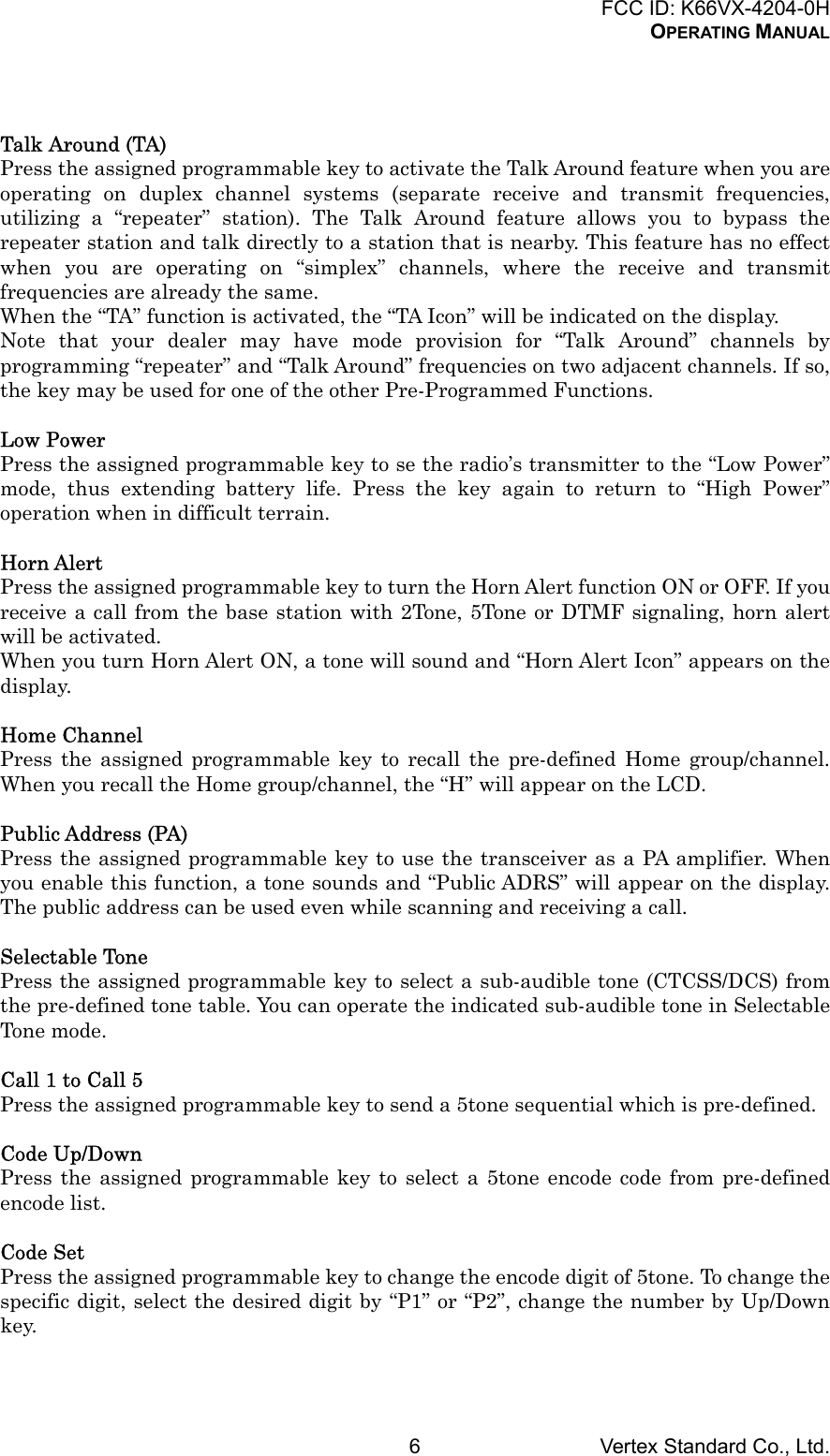
![FCC ID: K66VX-4204-0HOPERATING MANUALVertex Standard Co., Ltd.2Network Administrator regarding precise details of the configuration of this equipmentfor use in your applicationFor North American Users Regarding 406 MHz Guard BandThe U.S. Coast Guard and National Oceanographic and Atmospheric Administrationhave requested the cooperation of the U.S. Federal Communications Commission inpreserving the integrity of the protected frequency range 406.0 to 406.1 MHz, which isreserved for use by distress beacons. Do not attempt to program this apparatus, underany circumstances, for operation in the frequency range 406.0 - 406.1 MHz if theapparatus is to be used in or near North America.Controls & ConnectorsFront PanelImportant! - All buttons located on the Front Panel are Programmable Function (PF)Buttons, configured according to your network requirements and programmed by yourVERTEX STANDARD dealer. The instructions below a typically-configured radio.1. [ xxx ] ButtonPress the [ xxx ] button more than 2 seconds to turn the radio on. Press it againmore than 2 seconds to turn the radio off.2. VOL KnobTurn this control clockwise to increase the volume.3. BUSY/TX IndicatorIndicate transceiver Transmit/Receive StatusSteady Red: Transmitting in progressSteady Green: Busy ChannelBlinking Green: Tone Squelch in defeated condition4. LCD (Liquid Crystal Display)The display includes 3-character numeric section showing various statuses, and12-character alphanumeric section showing Group and Channel name tag andidentity information, and error messages etc.5. [θ]/[π] Buttons (Programmable Function Buttons)Pressing either button changes the current channel (and displayed channel numberor name). Holding a button for more than 1/2 second causes the function to repeat.6. Microphone JackConnect the microphone plug to this jack.7. [A] Button (Programmable Function Button)This button can be set up for special applications, such as High/Low power selection,Monitor, Talk-Around, etc, as determined by your network requirements andprogrammed by your VERTEX STANDARD dealer.8. [P1] - [P4] Buttons (Programmable Function Buttons)These buttons can be set up for special applications, such as High/Low powerselection, Monitor, Talk-Around, etc, as determined by your network requirementsand programmed by your VERTEX STANDARD dealer.](https://usermanual.wiki/Yaesu-Musen/VX-4204-0H.users-manual-1/User-Guide-328531-Page-2.png)
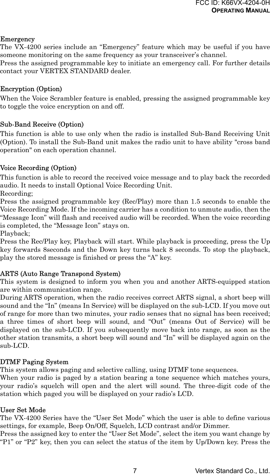
![FCC ID: K66VX-4204-0HOPERATING MANUALVertex Standard Co., Ltd.3Rear Panel1. Antenna SocketThe 50-Ohm coaxial feedline to the antenna must be connected here, using a type-M (PL-259) plug.2. 13.6V DC Cable Pigtail with ConnectorThe supplied DC power cable must be connected to this 2-pin connector. Use onlythe supplied fused cable, extended if necessary, for power connection.3. External Speaker JackAn external loudspeaker may be connected to this 2-contact, 3.5-mm mini-phonejack.Caution: Do not connect either wire of this line to ground, and be certain that thespeaker has adequate capability to handle the audio output (12 W) from the radio.4. D-Sub 15-Pin Accessory ConnectorExternal TX audio line input, PTT (Push To Talk), Squelch, and external RX audioline output signals may be obtained from this connector for use with accessoriessuch as data transmission/reception modems, and external Channel control inputetc.Basic Operation of the TransceiverImportant! - Before turning on the radio the first time, confirm that the powerconnections have been made correctly and that a proper antenna is connected to theantenna jack.Switching Power ON/OFF Press the PWR button to turn the radio on. The display will become illuminated. Press the [θ]/[π] button to choose the desired operating channel. A channel name willappear on the display. If you want to select an operating channel from a differentgroup, press the pre-defined Group Up/Down button to select the group you wantbefore selecting the operating channel.Setting the Volume Turn the VOL knob clockwise to increase the volume, and counterclockwise todecrease it.Transmitting To transmit, monitor the channel and make sure it is clear.THIS IS AN FCC REQUIRMENT! Press the PF button which is programmed to the Monitor feature to listen forchannel activity. When receiving a call, transmit only after the incoming call ends. The radio cannotreceive a call and transmit simultaneously. Press the PTT switch. If the channel is clear, the BUSY/TX indicator will glow red. The radio is nowtransmitting. While holding in the PTT switch, speak across the face of themicrophone in a clear and normal voice. For best transmission, hold the microphoneabout 1-1/2 to 2 inches away from your mouth. Release the PTT switch to receive. If the Busy Channel Lockout feature has been programmed on a channel, the radiowill not transmit when a carrier is present. Instead, the radio will generate shortbeep three times and indicate * ERROR * on the display. Release the PTT switch](https://usermanual.wiki/Yaesu-Musen/VX-4204-0H.users-manual-1/User-Guide-328531-Page-3.png)
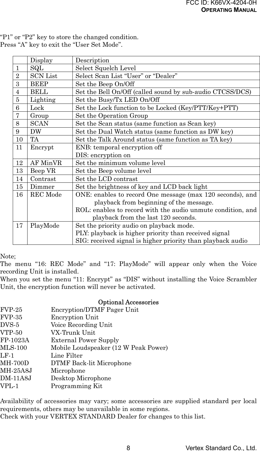
![FCC ID: K66VX-4204-0HOPERATING MANUALVertex Standard Co., Ltd.5EXT. ACC2Direct CH#1Direct CH#2Direct CH#3Direct CH#4REC/PLAY *AF ATT* needs optional unitDescription of Operating FunctionsMonitorPress the assigned programmable key to cancel CTCSS- and DCS-controlled squelch;the BUSY/TX indicator will blink green. Press and hold this button for 1.5 seconds tohear background noise (unmute the audio); the BUSY/TX indicator will glow green.Channel Up/DownPress the assigned programmable key (generally the [θ]/[π] button) to select a differentchannel within the current group.Channel ScanThe Scanning feature is used to monitor multiple signals programmed into thetransceiver. While scanning, the transceiver will check each channel for the presence ofa signal, and will stop on a channel if a signal is present.To activate scanning:• Press the assigned programmable key to activate scanning.• The scanner will search the channels of each channel, looking for active ones; it willpause each time it finds a channel on which someone is speaking.• Press the assigned programmable key again to disable scanning. Operation willrevert to the programmed revert channel.Note: Your dealer may have programmed your radio to stay on one of the followingchannels if you press the PTT switch during scanning pause:- Current channel (“Talk Back”)- “Last Busy” channel- “Priority” channel- “Home” channel- “Scan Start” channelDual WatchThe Dual Watch feature is similar to the SCAN feature, except that only two channelsare monitored:- The current operating channel; and- The Priority channel.To activate Dual Watch:• Press the assigned programmable key.• The scanner will search the two channels; it will pause each time it finds a channelon which someone is speaking.To stop Dual Watch:• Press the assigned programmable key.• Operation will revert to the “Dual Watch Start” channel.](https://usermanual.wiki/Yaesu-Musen/VX-4204-0H.users-manual-1/User-Guide-328531-Page-5.png)