Yaesu Musen VXA-700 Airband Transceiver User Manual Operating Manual
Yaesu Musen Co., Ltd. Airband Transceiver Operating Manual
UserManual.wiki
>
Yaesu Musen
>
VXA 700 User Manual
Operating Manual
Navigation menu
Upload a User Manual
Namespaces
Wiki Guide
HTML
PDF
Info
Views
User Manual
Discussion / Help
Navigation
![FCC ID: K66VXA-700Operating ManualVertex Standard Co., Ltd.3Controls & Connectors (Top Panel)Controls & Connectors (Top Panel)Controls & Connectors (Top Panel)Controls & Connectors (Top Panel)1. Antenna JackThis SMA jack accepts the supplied flexible antenna, or another antenna designedto provide 50 Ohm impedance on the Aircraft Communication Band.2. MIC/SP JackYou may connect the supplied CT-XX Headset Cable, optional MH-57A4BSpeaker/Microphone, or optional CMP460A Waterproof Speaker/Microphone to thisjack.Never connect any Speaker/Microphone that is not recommended by themanufacturer. Because these jack connections are unique, using aSpeaker/Microphone that is not specified by Vertex Standard may damage theVXA-700.3. VOLUME KnobThis control adjusts the audio volume level. Clockwise rotation increases thevolume level.4. DIAL Selector KnobThis 20-position detended rotary switch tunes the operating frequency or selectsthe memory channels.Controls & Connectors (Controls & Connectors (Controls & Connectors (Controls & Connectors (FrontFrontFrontFront Panel) Panel) Panel) Panel)1. LCD (Liquid Crystal Display)The display shows the selected operating conditions.2. PWR SwitchPress and hold this switch for 3 seconds to toggle the transceiver’s power on and off.3. KeypadSeveral keys have triple functions.The primary functions are labeled on the key top (activated by simply pressing thekey momentarily).The secondary functions are labeled in yellow above the top edge of the key(activated by pressing the [F] key first, then the indicated key).](https://usermanual.wiki/Yaesu-Musen/VXA-700/User-Guide-260189-Page-3.png)
![FCC ID: K66VXA-700Operating ManualVertex Standard Co., Ltd.4The third functions are labeled in black above the top edge of the key (activated bypress and holding the indicated key for 2 seconds).KeyKeyKeyKey Primary FunctionPrimary FunctionPrimary FunctionPrimary FunctionPress KeyPress KeyPress KeyPress KeySecondary FunctionSecondary FunctionSecondary FunctionSecondary FunctionPress [F] +Press [F] +Press [F] +Press [F] +Third FunctionThird FunctionThird FunctionThird FunctionPress and hold for 3 sec.Press and hold for 3 sec.Press and hold for 3 sec.Press and hold for 3 sec.[SEL(SET)] Select the tuningmethods among theVFO (VariableFrequency Oscillator),MR (Memory Recall),BMR (Pre-ProgrammedMemories), and WX(Weather ChannelMemories).Enter the “Set” (Menu)mode.None[USER(LOCK)]*1 Activates the AutomaticNoise Limiter duringAM reception.Locks the Keypad. Switches the frequencydisplay between the“Large Character” and“Small Character”mode.[F] Activates the“Secondary” key mode.None None[121.5(HM)] Selects the EmergencyChannel (121.5 MHz).Switches operation tothe “home” (favoritefrequency) channel.None[MW(SPL.W)] None Split-Memory “Write”Command.Memory “Write”Command.[1(VOR)TN] Frequency entry digit“1.”Activates DVOR mode. Recall Menu Item “SQLType” (for activating theCTCSS or DCSoperation).[2(TO)CD] Frequency entry digit“2.”Selects “TO” VORmode.Recall Menu Item“TONE Set” (forselecting the CTCSStone frequency).[3(FRM)DT] Frequency entry digit“3.”Selects “FROM” VORmode.Activates the DTMFAutodialer function.[4(CDI)RV] Frequency entry digit“4.”Activates CourseDeviation Indicatormode.Reverse the transmitand receive frequencieswhile working througha repeater.[5(AP)] Frequency entry digit“5.”None Recall Menu Item“APO” (for setting of theAutomatic Power-Offtime).[6(TAG)RP] Frequency entry digit“6.”Select the display type(Frequency or Alpha-numeric Tag) duringMemory operation.Recall Menu Item “RPTShift” (for selecting thedirection of the uplinkfrequency shift (“Simp,”“-RPT,” or “+RPT”)during repeateroperation).[7(SPL)ST] Frequency entry digit“7.”Activates Split (Duplex)mode.Recall Menu Item“Step” (for setting of thesynthesizer steps).[8(BP)] Frequency entry digit“8.”None Recall Menu Item“Beep” (for setting ofthe keypad beeper).[9(SK)] Frequency entry digit None Set the Memory Skip](https://usermanual.wiki/Yaesu-Musen/VXA-700/User-Guide-260189-Page-4.png)
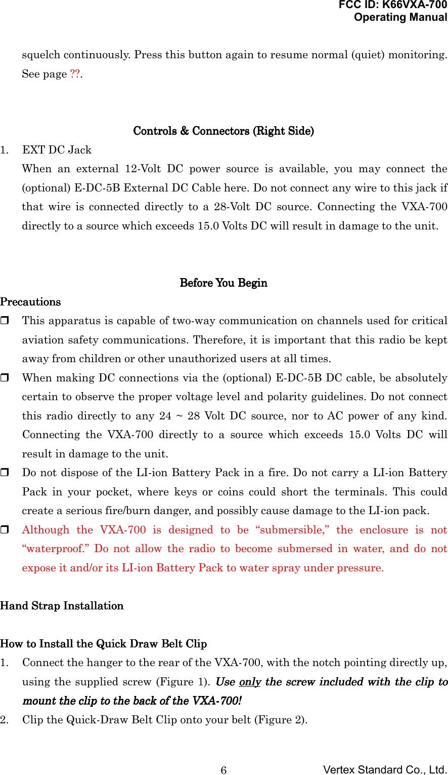
![FCC ID: K66VXA-700Operating ManualVertex Standard Co., Ltd.5“9.” (Omit) feature to thecurrent memorychannel.[0(SQ)] Frequency entry digit“0.”None Recall Menu Item“SQL” (for setting thesquelch threshold levelfor the AM and FM-Narrow mode).[BAND(MODE)] Select the operationband among the AIRband, Amateur band,and FM BC band on theVFO.Select the operatingmode among the AM,FM, and Wide FM.None[SCAN(DW)MT] Activates the Scanner. Activates Dual Watch. Activates the “MemoryTune” mode while in theMemory Recall mode.*1: The Primary and Third function of the USER key may be customized by user via the Menumode. See page ??.4. BUSY/TX Indicator LampThis lamp glows green when a signal is being received and red when transmitting.You may customize the color setup via the Menu mode.5. LoudspeakerThe internal speaker is located in this position.6. MicrophoneSpeak across this opening in a normal voice level while pressing the PTT switch, totransmit.7. Battery Pack LatchOpen this latch for battery removal.Controls & Connectors (Controls & Connectors (Controls & Connectors (Controls & Connectors (Left SideLeft SideLeft SideLeft Side))))1. PTT (Push To Talk) SwitchPress this button to transmit when you are operating in the COM band or 2-mamateur band. Release this button to return to the “Receive” mode. See page ??.2. MONITOR SwitchThis button may be pressed to “Open” the squelch manually, allowing you to listenfor very weak signals. Press and hold this button for 2 seconds to “Open” the](https://usermanual.wiki/Yaesu-Musen/VXA-700/User-Guide-260189-Page-5.png)

![FCC ID: K66VXA-700Operating ManualVertex Standard Co., Ltd.8the FNB-80LI, follow the appropriate instructions provided with thecharger/battery. Contact your Dealer if you have any doubts about theappropriateness of the particular charger or battery pack you intend to use.Installation of FBA-23 Alkaline Battery Case (Option)Installation of FBA-23 Alkaline Battery Case (Option)Installation of FBA-23 Alkaline Battery Case (Option)Installation of FBA-23 Alkaline Battery Case (Option)The optional FBA-23 Battery Case allows receive monitoring using two “AA” sizeAlkaline batteries. Alkaline batteries can also be used for transmission in an emergency,but power output will only be ??? mW, and battery life will be shortened dramatically.To Install Alkaline Batteries into the FBA-231. Slide the batteries into the FBA-23 as shown in the illustration, with the Negative[–] side of the batteries touching the spring connections inside the FBA-23.2. Open the Battery Pack Latch on the bottom of the radio.3. Install the FBA-23 as shown in the illustration, with the [+] side facing the bottomof the transceiver.4. Close the Battery Pack Latch on the bottom of the radio.The FBA-23 does not provide connections for charging, since Alkaline cells cannot bere-charged. Therefore, the NC-72B/C, E-DC-5B, or E-DC-6 may safely be connected tothe EXT DC jack when the FBA-23 is installed.Notes:• The FBA-23 is designed for use only with AA-type Alkaline cells.• If you do not use the VXA-700 for a long time, remove the Alkaline batteries fromthe FBA-23, as battery leakage could cause damage to the FBA-23 and/or thetransceiver.Battery Life InformationBattery Life InformationBattery Life InformationBattery Life InformationWhen the battery charge is almost depleted, a “Low Voltage” indicator will appear onthe display. When this icon appears, it is recommended that you charge the batterysoon.Battery Life (Approx.)Operating BandFNB-80LI FBA-23Low Voltage IndicatorAIR Band (1) ?? hours ?? hours144 MHz Band (1) ?? hours ?? hoursFNB-80LI:FNB-80LI:FNB-80LI:FNB-80LI:: Fully battery power: Enough battery power: Lower battery power: Poor battery power: Nearing depletion: Prepare to charge the batteryFBA-23:FBA-23:FBA-23:FBA-23:: Enough battery power: Prepare to replace the battery](https://usermanual.wiki/Yaesu-Musen/VXA-700/User-Guide-260189-Page-8.png)
![FCC ID: K66VXA-700Operating ManualVertex Standard Co., Ltd.9FM BC Band (2) ?? hours(1) TX 6 sec., RX 6 sec. and Squelched 48 sec.(2) Continuous signal receptionThe current battery voltage can be displayed manually on the LCD, by following theinstructions on page ??.Battery capacity may be reduced during extremely cold weather operation. Keeping theradio inside your parka may help preserve the full charge capacity.AC Operation Using NC-72B/C (Receiving only)AC Operation Using NC-72B/C (Receiving only)AC Operation Using NC-72B/C (Receiving only)AC Operation Using NC-72B/C (Receiving only)The VXA-700 may be operated from your house current by use of the supplied NC-72B/C Battery Charger. The NC-72B/C should only be used for reception, because it isnot capable of supplying sufficient current to support transmission.To use the NC-72B/C, turn the transceiver off, then plug the miniature connector of theBattery Charger into the EXT DC jack on the side of the radio. Now plug the BatteryCharger into the wall outlet. You may now turn on the transceiver.Basic Basic Basic Basic OperationOperationOperationOperationPreliminary StepsPreliminary StepsPreliminary StepsPreliminary Steps Install a charged battery pack onto the transceiver, as described previously. Screw the supplied antenna onto the Antenna jack. Never operate this transceiverwithout an antenna connected. If you have an optional Speaker/Microphone or headset, we recommend that it notbe connected until you are familiar with the basic operation of the VXA-700.Operation Quick StartOperation Quick StartOperation Quick StartOperation Quick Start To turn the radio on, press and hold in the PWR Switch for 3 seconds. The opening message will appear on the display, then frequency display willappear. Press the [BAND(MODE)] key repetitively, switch the operating band among ARIband, 2-m Amateur band, and FM BC band each time you press the[BAND(MODE)] key. Directly entering frequencies from the keypad is the easiest method if you know the](https://usermanual.wiki/Yaesu-Musen/VXA-700/User-Guide-260189-Page-9.png)
![FCC ID: K66VXA-700Operating ManualVertex Standard Co., Ltd.10frequency on which you wish to operate. Just enter the five digits of the frequencyto move to that frequency.For example, to set 134.35 MHz,press [1] ´ [3] ´ [4] ´ [3] ´ [5].To set 118.275 MHz, you do not need to press the final “5” in the frequency:[1] ´ [1] ´ [8] ´ [2] ´ [7].NoteNoteNoteNote: When the entering frequencies is out of the operating band, this feature isignored (i.e.: VXA-700 does not entry the 2-m Ammeter band frequency into the AIRband. You may also turn the top panel’s DIAL selector knob to choose the desiredoperating frequency. The channel frequency will appear on the LCD. To change frequency in 1 MHz steps, press the [F] key momentarily, then rotate theDIAL selector knob to select the MHz digit desired. Press [F] key once more toresume normal channel step. Rotate the VOLUME knob to set the volume level. If no signal is present, press andhold the MONITOR button for 2 seconds; background noise will now be heard, andyou may use this noise to set the VOLUME knob for the desired audio level. Pressthe MONITOR button momentarily to silence the noise and resume normal (quiet)monitoring. To turn the radio off, press and hold in the PWR Switch for 3 seconds.Squelch AdjustmentSquelch AdjustmentSquelch AdjustmentSquelch Adjustment Press and hold the [0(SQ)] key for 3 second. This instantly recalls Menu Item“”SQL: on the AM or Narrow FM mode” or “WSQL: on the WFM mode.” Press the [SEL(SET)] key to enable adjustment of this Menu Item. Rotate the DIAL selector knob to set the squelch threshold (0 - 8) so that thereceiver is just silenced. A higher number indicates that a higher signal level isrequired in order to open the squelch. When you have made your setting, press the [SEL(SET)] key to save the newsetting, then press the PTT key repetitively until the radio exit to normaloperation.Accessing the 121.5 MHz Emergency FrequencyAccessing the 121.5 MHz Emergency FrequencyAccessing the 121.5 MHz Emergency FrequencyAccessing the 121.5 MHz Emergency FrequencyThe VXA-700 can quickly access the 121.500 MHz Emergency Frequency. This functioncan be activated even when the keypad lock function is in use. To access the Emergency Frequency, press the [121.5(HM)] key momentarily.](https://usermanual.wiki/Yaesu-Musen/VXA-700/User-Guide-260189-Page-10.png)
![FCC ID: K66VXA-700Operating ManualVertex Standard Co., Ltd.11 To exit the Emergency Frequency, press the [SEL(SET)] key momentarily.Tuning MethodsTuning MethodsTuning MethodsTuning MethodsThroughout this manual, you will see references to several different frequency settingmethods. Each will be particularly useful in a particular operating situation, and theyare described below: VFO (Variable Frequency Oscillator)The VFO is a “tuning dial” system which allows you to tune through the AIR band,2-m Amateur band, and FM BC band using the DIAL selector, the Keypad, or thescanner. To select these bands, press the [BAND(MODE)] key momentarily. MR (Memory Recall) The MR (Memory Recall) mode of the VXA-700 provides the user with the ability tostore and recall as many as 50 channels in the radio’s main memory bank. Thesememory channels may also be labeled by you with an alpha/numeric name of up to8 characters in length, to aid in quick identification of the channel. See page ?? fordetails on creating alpha/numeric labels. BOOK (Pre-Programmed) MemoriesThe Book memories are pre-programmed, either at the factory or by your Dealer(depending on your country’s requirements), typically including the major AIRband station frequencies used in your area. The Book memories can be changed bythe user. See page ?? for details. WX (Weather Channel) Memories (USA version only)Ten Weather Channels are pre-programmed at the factory. The VXA-700 willautomatically scan this special bank when it is selected by the user.TransmissionTransmissionTransmissionTransmission To transmit, press and hold the PTT switch. Speak into the microphone area of thefront panel grille in a normal voice level. To return to the receive mode, release the PTT switch.Reception of Weather Channel BroadcastsReception of Weather Channel BroadcastsReception of Weather Channel BroadcastsReception of Weather Channel Broadcasts (USA version only)(USA version only)(USA version only)(USA version only)The VXA-700 can receive VHF Weather Channel broadcasts, which may assist yourflight planning. The VXA-700 includes a ten-channel auto-search feature, whichsimplifies access to Weather Channels when you are in an unfamiliar location. To receive Weather Channels, press the [SEL(SET)] key (repeatedly, if necessary) toselect the Weather Channel mode. In the Weather Channel mode, “WX” will appear](https://usermanual.wiki/Yaesu-Musen/VXA-700/User-Guide-260189-Page-11.png)
![FCC ID: K66VXA-700Operating ManualVertex Standard Co., Ltd.12upper left corner of the display. The VXA-700 will now scan quickly though the ten standard Weather Channels,and will stop on the first active station found. If there are two or more weather channels audible in your area, you may select thealternate channel(s) by pressing the PTT switch. Pressing the PTT switch re-initiates the scanning process. If there are no Weather Channels in your area, the scanner will not stop. Press theMONITOR button to stop the scanner. You can also select Weather Channels manually by rotating the DIAL selector knob. To exit the Weather Channel mode, press the [SEL(SET)] key momentarily toreturn to the VFO mode.Note: The Weather Channel mode memorizes the last Weather Channel you have used,and will retain this information until the radio is turned off.Monitor KeyMonitor KeyMonitor KeyMonitor KeyWhen listening to a very weak signal from an aircraft or ground station, you mayobserve the signal disappearing periodically as the incoming signal strength becomestoo weak to override the squelch threshold setting.To disable the squelch temporarily, press and hold the MONITOR key for 2 seconds onthe left side of the radio, just below the PTT button. The squelch will remain open andyou should have a better chance of hearing weak signals.To return to normal operation, press the MONITOR key momentarily.ANL (Automatic Noise Limiter) FeatureANL (Automatic Noise Limiter) FeatureANL (Automatic Noise Limiter) FeatureANL (Automatic Noise Limiter) FeatureFor reduction of impulse noise, such as that produced by an engine’s ignition system,the ANL feature may prove helpful. To activate the ANL feature, press the [USER(LOCK)] key momentarily. The “ANL”icon will appear on the display, and you should observe a reduction in the ignitionnoise. To turn the ANL feature off, press the [USER(LOCK)] key again; the “ANL” iconwill disappear from the display.](https://usermanual.wiki/Yaesu-Musen/VXA-700/User-Guide-260189-Page-12.png)
![FCC ID: K66VXA-700Operating ManualVertex Standard Co., Ltd.13LOCK FunctionLOCK FunctionLOCK FunctionLOCK FunctionThe lock function prevents accidental changes to the frequency setting and the keypadcontrols. To activate the lock feature, press [F] ´ [USER(LOCK)]. In the LOCK mode, the “KEY LOCK” icon will appear on the display. To turn the lock feature off, press [F] ´ [USER(LOCK)] again. You can still access the 121.500 MHz Emergency Frequency when the LOCKfunction is on.Simply press the [121.5(HM)] key momentarily (this key never locks). Pressing thiskey also unlocks the radio.Beep On/OffBeep On/OffBeep On/OffBeep On/OffThe VXA-700’s key/button beeper provides convenient audible feedback whenever abutton is pressed. Each key and button has a different beep pitch, and each function hasa unique beep combination.When you are scanning, the beeper will be heard each time the scanner halts on a busychannel. This may be distracting in some environments; if you want to turn the beeperoff (or back on again): Press and hold the [8(BP)] key for 3 seconds. This instantly recalls Menu Item“Beeper.” Press the [SEL(SET)] key to enable adjustment of this Menu Item. Rotate the DIAL selector knob to select the desired selection.On: Sounds a keypad beeper corresponding to a musical note.DTMF: Sounds a keypad beeper corresponding to a DTMF tone.Off: Keypad beeper is “off” When you have made your selection, press the [SEL(SET)] key to save the newsetting, then press the PTT key repetitively until the radio exit to normaloperation.Receive Battery Saver SetupReceive Battery Saver SetupReceive Battery Saver SetupReceive Battery Saver SetupAn important feature of the VXA-700 is its Receive Battery Saver, which “puts the radioto sleep” for a time interval, periodically “waking it up” to check for activity. If somebodyis talking on the channel, the VXA-700 will remain in the “active” mode, then resume its“sleep” cycles. This feature significantly reduces quiescent battery drain, and you maychange the amount of “sleep” time between activity checks using the Menu System:](https://usermanual.wiki/Yaesu-Musen/VXA-700/User-Guide-260189-Page-13.png)
![FCC ID: K66VXA-700Operating ManualVertex Standard Co., Ltd.14 Press the [F] key, then press the [SEL(SET)] key to activate the Menu (“SET”)mode. Rotate the DIAL selector knob to select Menu Item “3. Receive,” then press the[SEL(SET)] key. Rotate the DIAL selector knob to select Sub Menu Item “5. RX Save,” then press the[SEL(SET)] key. Press the [SEL(SET)] key again to enable adjustment of this Menu Item. Rotate the DIAL selector knob to select the desired “duty cycle” (receive:sleep). Theselections available are 1:1, 1:2, 1:3, 1:4, 1:5, and ABS* or oFF. The default value is1:1. When you have made your selection, press the [SEL(SET)] key to save the newsetting, then press the PTT key repetitively until the radio exit to normaloperation.*ABS: Automatic Battery Saver, based on activity on the receiver.The setting of 1:5 will promote the greatest conservation of battery capacity, but thereceiver’s response time to incoming calls will be slowed somewhat.Note: This feature does not operate during Scan or Dual Watch.Memory OperationMemory OperationMemory OperationMemory OperationThe VXA-700 provides 102 user-programmable Main memories, labeled “MR001”through “MR100”, “MRLch,” and “MRUch,” and up to 90 pre-programmed memories,designated “Book” Memories, labeled “BMR001” through “BMR090.”The Main memories and “Book” Memories can be assigned alpha-numeric names of upto eight characters.Memory System OperationMemory System OperationMemory System OperationMemory System OperationThe VXA-700’s Main Memory system allows the user to store, label, and recall channelfrequencies which you may want to use frequently. You may store VFO frequencies,“Book” Memory frequencies, and/or Weather Channel frequencies (USA version only)into the Main Memory system.](https://usermanual.wiki/Yaesu-Musen/VXA-700/User-Guide-260189-Page-14.png)
![FCC ID: K66VXA-700Operating ManualVertex Standard Co., Ltd.15Memory Storage Select the desired frequency in the VFO mode, or recall the “Book” Memory channelor Weather channel to be stored in the Main Memory. Press and hold the [MW(SPL.W)] key for 3 seconds. The display will indicate “MR”and a channel number will blink on the LCD. Within five seconds of pressing the [MW(SPL.W)] key, rotate the DIAL selectorknob to select the desired memory channel number for storage.In order to prevent writing over memory channels, a “open door” icon will appear atthe right of the channel number to indicate a vacant memory channel. Now press and hold the [MW(SPL.W)] key for 3 seconds; you will now see theblinked “A” character on the LCD. To attach an alpha/numeric name (label) to thememory, proceed to the next step; otherwise press and hold the [MW(SPL.W)] keyfor 3 seconds to save the entry and exit. To label a memory with an alpha/numeric name, the next step is to use the DIALselector knob to select any of the 125 available characters (including letters,numbers, and special symbols). When the desired first character appears, press the[SEL(SET)] key momentarily to move on to the next character. Select succeeding characters in the same manner, pressing the [SEL(SET)] keymomentarily after each selection. After entering the entire name (eight characters maximum), press the[MW(SPL.W)] key for 3 seconds to save all data for the channel and exit.Note: If you have stored a Weather Channel or “Book” Memory Channel, utilize thealphanumeric memory, and other labels may not be stored.Recalling the Memories Press the [SEL(SET)] key, repeatedly if necessary, until “MR” (Memory Recall)appears on the display. In the MR mode, you will see the previously selectedchannel number appearing at the bottom of the “MR” icon on the LCD. Rotate the DIAL selector knob to select the desired memory channel. You may change the title structure of the Memory display type between “FrequencyIndication” and “Frequency Indication plus Alpha-numeric Label” by press [F] ´[6(TAG)RP] key. To exit the Memory mode, press the DIAL selector knob momentarily to return tothe VFO mode.Note: In either the Memory mode or the “Book” Memory mode, you can change memory](https://usermanual.wiki/Yaesu-Musen/VXA-700/User-Guide-260189-Page-15.png)
![FCC ID: K66VXA-700Operating ManualVertex Standard Co., Ltd.16channels in 10 channel steps: press the [F] key momentarily, then rotate the DIALselector knob. The “F” icon will show at the right edge of the display when the 10channel step tuning mode is active. Press the [F] key once more to resume normalchannel selection in 1 channel steps.Scanning OperationScanning OperationScanning OperationScanning OperationBasic ScanBasic ScanBasic ScanBasic ScanThe VXA-700 allows you to scan automatically in the VFO*1, Main Memory, “Book”Memory, or Weather Channel*2 modes. It pauses on signals encountered, so you can talkto the station(s) on that frequency, if you like.*1: In the VFO mode, the automatic scanner is only available in the current operatingband (AIR band, 2-m Amateur band, or FM BC band). Furthermore, on the AIRband, the automatic scanner is only available in the COM band (118.000 - 136.975MHz); when the scanner reaches the uppermost frequency in the COM band, it willrevert to the bottom end of the COM band and repeat the scanning process untilyou cancel the scanning process.*2: USA version only.If you wish to scan in the NAV band (108.000 - 117.975 MHz), you can do so manually, asdescribed below.Scanning operation is basically the same in each of the above modes. Press the [SCAN(DW)MT] key momentarily to start the automatic scanner upward(toward a higher frequency or a higher channel number). When the scanner encounters a signal, scanning pauses and the radio remains onthat channel until one second after the signal disappears, after which scanning willresume. While the scanner remains paused on a frequency, the decimal point of thefrequency display blinks. The display will be illuminated unless the Scan LampFeature is turned off. To change the scan direction, turn the DIAL selector knob one click in the oppositedirection. To stop the automatic scanner, press the PTT switch or the [SCAN(DW)MT] keymomentarily.](https://usermanual.wiki/Yaesu-Musen/VXA-700/User-Guide-260189-Page-16.png)
![FCC ID: K66VXA-700Operating ManualVertex Standard Co., Ltd.17The VXA-700’s automatic scanner is not operational in the NAV band (108.000 - 117.975MHz), because the NAV stations (ILS, etc.) transmit constantly (thereby causing thescanner to stop repeatedly). However, you can scan manually in the NAV band, per thefollowing procedure: Press and hold the [SCAN(DW)MT] key to start the manual scanner. Scanning willcontinue as long as the key is depressed. Release the [SCAN(DW)MT] key to stop the manual scanner immediately.Note: When scanning upward in frequency, when the frequency reaches the COM Band(118.000 - 136.975 MHz) via manual scanning, The VXA-700 will switch to theautomatic scanner mode.Channel-Skip ScanningChannel-Skip ScanningChannel-Skip ScanningChannel-Skip ScanningContinuous-carrier stations like ATIS (Automatic Terminal Information Service) orWeather Broadcast stations inhibit scanner operation. Since these stations are alwaysactive, the scanner will be halted repeatedly on their channels. Such channels can be setto be “Skipped” during Memory scanning (MR, Book or WX modes), if you like, so as notto interfere with automatic channel scanning: Recall the Memory Channel to be skipped during scanning. Press and hold the [9(SK)] key for 3 seconds. The “W” icon will appear at the right ofthe frequency display, indicating that the channel is to be ignored during scanning. You can also designate a channel to be skipped while scanning. When the receiver ishalted on a channel that you wish to skip, press and hold the [SCAN(DW)MT] keyfor 2 seconds (the icon will appear next to the channel to be skipped). Later, to re-enable the memory channel for scanning, repeat the first two steps. The“W” icon will disappear by the channel you have just re-enabled.Note: A memory set to be “Skipped” is still accessible for manual memory selection usingthe DIAL selector knob.Dual Watch OperationDual Watch OperationDual Watch OperationDual Watch OperationThe Dual Watch feature automatically checks for activity on a “Priority” channel* whileyou are operating on another channel. During Dual Watch operation, the currentchannel and the Priority channel will each be polled for a 500 ms interval, as the VXA-700 looks for activity on each channel. To start Dual Watch, press [F] ´ [SCAN(DW)MT]. The “DW” icon will appear on the display. While receiving on the “current” channel (not the Priority channel), you may push](https://usermanual.wiki/Yaesu-Musen/VXA-700/User-Guide-260189-Page-17.png)
![FCC ID: K66VXA-700Operating ManualVertex Standard Co., Ltd.18the PTT switch at any time to transmit on that channel. When a signal is received on the Priority channel, operation immediately shifts tothe Priority channel, the “DW” icon will blink, and the display will becomeilluminated. While receiving on the priority channel, if you momentarily press the PTT switch,Dual Watch will be disabled. You may then transmit on the Priority Channel. To stop Dual Watch, press [F] ´ [SCAN(DW)MT]. If you wish, you may use both the Dual Watch and Scan features simultaneously. Todo this, start the Dual Watch first, then start the Scanner.*The “Priority” channel is defined as the last-used Memory Channel (when using theVFO and “Book” memory modes) or Memory Channel “1” (when using the Main Memorymode).Priority Dual Watch OperationPriority Dual Watch OperationPriority Dual Watch OperationPriority Dual Watch OperationSimilar to Dual Watch operation (described on previous page), Priority Dual Watch is anenhanced version which includes the following additional features: The receiving time interval (ratio) between the current channel and the Prioritychannel may be customized via the Menu Item “PRI Time.” See page ?? for details. Irrespective of which channel is currently being received, when the PTT button ispushed transmission will always occur on the Priority channel.Before initiating Priority Dual Watch, Menu Item “DW/PRI” must be set to the “PRI”mode (instead of “DW”). See page ?? for details. To start Priority Dual Watch, press [F] ´ [SCAN(DW)MT]. The “DW” icon willappear on the display. While receiving on the “current” (non-Priority) channel, pressing the PTT buttononce causes the radio to switch to the Priority channel and cancels Dual Watch.Press the PTT button again to transmit on the Priority channel.When a signal is received on the Priority channel, reception immediately shifts tothe Priority channel, the “DW” icon will blink, and the display will becomeilluminated unless the Scan Lamp Feature is turned off. While receiving on the priority channel, if you momentarily press the PTT switch,Priority Dual Watch will be disabled. You may then transmit on the PriorityChannel. To stop Priority Dual Watch, press [F] ´ [SCAN(DW)MT].](https://usermanual.wiki/Yaesu-Musen/VXA-700/User-Guide-260189-Page-18.png)
![FCC ID: K66VXA-700Operating ManualVertex Standard Co., Ltd.19Spectrum Scope MonitorSpectrum Scope MonitorSpectrum Scope MonitorSpectrum Scope MonitorAdvanced Operation (Air Band)Advanced Operation (Air Band)Advanced Operation (Air Band)Advanced Operation (Air Band)VOR NavigationVOR NavigationVOR NavigationVOR NavigationTo Select the VOR Mode When entering the NAV band (108.000 - 117.975 MHz), the VXA-700 selects theVOR mode automatically. The “Course Indicator” will appear on the display, andthe “TTTTOOOO” or “FFFFRRRROOOOMMMM” indicator will appear at the right of the “Course Indicator” onthe display.NoteNoteNoteNote: The “Course Indicator” indicates “---°” when either your aircraft is too faraway from the VOR station or the frequency is not correctly set to that of the VORstation. Conversely, the “Course Indicator” will indicate “Loc” when a localizersignal is being received. The “TTTTOOOO” or “FFFFRRRROOOOMMMM” flag indicators indicate whether the VOR navigationinformation is based on a course leading to the VOR station or leading away fromthe VOR station. To change the flag from “TTTTOOOO” to “FFFFRRRROOOOMMMM” or vice versa, press the [F] ´[3(FROM)DT] or [2(TO)CD] key, respectively. The small “Course Indicator” and “TTTTOOOO”/“FFFFRRRROOOOMMMM” flag indicators may be toggled tothe larger character. To do this, press and hold in the [ ()] key for 2 seconds to toggleto the larger display area. Press the [ ()] key momentarily again to return to thesmaller displays.Flying to a VOR StationThe VXA-700 can indicate the deviation from the direct course to a VOR station. Select a VOR station on your aeronautical chart and turn the DIAL selector knob(or enter the frequency directly with the keypad) to the frequency of the VORstation. To indicate the deviation between your current flight path and the desired course,press [F] ´ [4(CDI)RV] to change to the CDI (Course Deviation Indicator) mode.The “Course Deviation Arrow” will appear on the display when your aircraft is offthe direct course to the VOR station.](https://usermanual.wiki/Yaesu-Musen/VXA-700/User-Guide-260189-Page-19.png)
![FCC ID: K66VXA-700Operating ManualVertex Standard Co., Ltd.20 When your aircraft is off course to the right, the Course Deviation Arrow displaywill show bars to the left side of the diamond (“|||”). When your aircraft is offcourse to the left, the Course Deviation Arrow display will show bars to the rightside of the diamond (“|||”). Correct your course until no bars appear on eitherside of the CDI “diamond” (only (“”) will be visible when the heading is correct). To return to the DVOR mode, press [F] ´ [1(VOR)TN].Entering a Desired CourseThe VXA-700 can also be configured to indicate the deviation from the desired course,not only the deviation from the path to the VOR station. Set the frequency to the desired VOR station. To change the “ TTTTOOOO” or “FFFFRRRROOOOMMMM” to “TTTTOOOO,” if it is not in that mode already. Press [F] ´ [4(CDI)RV] key to change to the CDI mode. Set the desired course to the VOR station using the DIAL selector knob or keypad(three digits input; e.g. 47°, press [0] ´ [4] ´ [7]).Note 1Note 1Note 1Note 1: The (“|||”) or (“|||”) indication will appear on the display when youraircraft is off the desired course.Note 2Note 2Note 2Note 2: When your heading is correct, the ABCS function may be more useful thanthe course input option. The Course Deviation Arrow points to the right when your aircraft is off course tothe left, and it points to the left when your aircraft is off course to the right.Note 1Note 1Note 1Note 1: To get back on course, fly right more than the number of degrees indicatedby the Course Deviation Arrow.Note 2Note 2Note 2Note 2: If the overflow indicator “W” appears on the right side, select a heading plus10 degrees to the desired course; if the overflow indicator “W” appears on the leftside, select a heading minus 10 degrees.ABCS ModeIn the CDI mode, the Auto Bearing Center System (ABCS) adds or subtracts thenumber of degrees indicated by the CDI from the Omni Bearing Selector (OBS).Position Cross-checkingPosition Cross-checkingPosition Cross-checkingPosition Cross-checking Select two VOR stations on your aeronautical chart. Set the frequency of one of the VOR stations in the VOR mode. The course indicatorwill show the course deviation from the VOR radial. Note the radial you currentlyare on.](https://usermanual.wiki/Yaesu-Musen/VXA-700/User-Guide-260189-Page-20.png)
![FCC ID: K66VXA-700Operating ManualVertex Standard Co., Ltd.21 Now set the frequency of the other VOR station in the VOR mode. Note the radialfrom the station you are on. Extend the radials from each VOR station on the chart. Your aircraft is located atthe point where the lines intersect.Split OperationThe split operation feature allows you to transmit a call to a Flight Service Stationusing the COM band frequencies, while receiving a VOR station (in the NAV band).VOR stations equipped with this capability typically are shown, on navigation charts,with the voice calling frequency in parenthesis above the navigation frequency.Programming a Transmit Frequency Press the DIAL selector knob, repeatedly if necessary, to select the VFO mode. Set a NAV band (108.000 - 117.975 MHz) frequency using the DIAL selector knob orkeypad. Press [F] & [MW (SPL.W)]. The icon will blink, and the transmit frequency willappear on the display. Now set your radio transmit frequency, where the Flight Service Station will belistening for calls, using the DIAL selector knob or keypad. Press and hold in the [MW (SPL.W)] key for 2 seconds to save the transmitfrequency and return to the NAV band frequency.Note: You have now stored the separate transmit frequency, but you have not yetactivated the split-frequency function; go on to the next section.Operating in the Split Moder It is assumed that you have already set the desired VOR station frequencies (inthe NAV band) per the above instructions.r Press [F] & [7 (SPL)] to turn on the split function. The SPL icon will appear onthe display.r Press and hold in the PTT switch to transmit on the split transmit frequency.r Release the PTT switch to return to the receive mode.r To disable the split function, press [F] & [7 (SPL)] again.Note: A split frequency can be programmed into each memory channel independently.Set a transmit frequency before programming the memory channel, if desired. The splitfunction on/off setting can also be programmed into a memory channel.](https://usermanual.wiki/Yaesu-Musen/VXA-700/User-Guide-260189-Page-21.png)
![FCC ID: K66VXA-700Operating ManualVertex Standard Co., Ltd.22Advanced Operation (Amateur Band)Advanced Operation (Amateur Band)Advanced Operation (Amateur Band)Advanced Operation (Amateur Band)Repeater OperationRepeater OperationRepeater OperationRepeater OperationRepeater stations, usually located on mountaintops or other high locations, provide adramatic extension of the communication range for low-powered hand-held or mobiletransceivers. The VXA-700 includes a number of features which make repeateroperation simple and enjoyable.Repeater ShiftsYour VXA-700 has been configured, at the factory, the repeater shift set to 600 kHz onthe 2-m amateur band.Depending on the part of the band in which you are operating, the repeater shift may beeither downward (–) or upward (+), and one of these icons will appear at the bottom ofthe LCD when repeater shifts have been enabled.Automatic Repeater Shift (ARS)The VXA-700 provides a convenient Automatic Repeater Shift feature, which causes theappropriate repeater shift to be automatically applied whenever you tune into thedesignated repeater sub-bands in your country. These sub-bands are shown below.If the ARS feature does not appear to be working, you may have accidentally disabled it.To re-enable ARS: Press the [F] key, then press the [SEL(SET)] key to activate the Menu (“SET”)mode. Rotate the DIAL selector knob to select Menu Item “4. Transmit,” then press the[SEL(SET)] key. Rotate the DIAL selector knob to select Sub Menu Item “3. ARS,” then press the[SEL(SET)] key. Press the [SEL(SET)] key again to enable adjustment of this Menu Item. Rotate the DIAL selector knob to select “ON” (to enable Automatic Repeater Shift). When you have made your selection, press the [SEL(SET)] key to save the newsetting, then press the PTT key repetitively until the radio exit to normaloperation.Manual Repeater Shift ActivationIf the ARS feature has been disabled, or if you need to set a repeater shift direction](https://usermanual.wiki/Yaesu-Musen/VXA-700/User-Guide-260189-Page-22.png)
![FCC ID: K66VXA-700Operating ManualVertex Standard Co., Ltd.23other than that established by the ARS, you may set the direction of the repeater shiftmanually.To do this: Press the [F] key, then press the [SEL(SET)] key to activate the Menu (“SET”)mode. Rotate the DIAL selector knob to select Menu Item “4. Transmit,” then press the[SEL(SET)] key. Rotate the DIAL selector knob to select Sub Menu Item “1. RPT Shift,” then pressthe [SEL(SET)] key. Press the [SEL(SET)] key again to enable adjustment of this Menu Item. Rotate the DIAL selector knob to select the desired shift among “-RPT,” “+RPT,” and“Simplex.” When you have made your selection, press the [SEL(SET)] key to save the newsetting, then press the PTT key repetitively until the radio exit to normaloperation.Changing the Default Repeater ShiftsIf you travel to a different region, you may need to change the default repeater shift soas to ensure compatibility with local operating requirements.To do this, follow the procedure below: Press the [F] key, then press the [SEL(SET)] key to activate the Menu (“SET”)mode. Rotate the DIAL selector knob to select Menu Item “4. Transmit,” then press the[SEL(SET)] key. Rotate the DIAL selector knob to select Sub Menu Item “2. Shift Width,” then pressthe [SEL(SET)] key. Press the [SEL(SET)] key again to enable adjustment of this Menu Item. Rotate the DIAL selector knob to select the new repeater shift magnitude. When you have made your selection, press the [SEL(SET)] key to save the newsetting, then press the PTT key repetitively until the radio exit to normaloperation.NoteNoteNoteNote: If you just have one “odd” split that you need to program, don’t change the“default” repeated shifts using this Menu Item! Enter the transmit and receivefrequencies separately, as shown on page ??.](https://usermanual.wiki/Yaesu-Musen/VXA-700/User-Guide-260189-Page-23.png)
![FCC ID: K66VXA-700Operating ManualVertex Standard Co., Ltd.24Checking the Repeater Uplink (Input) FrequencyIt often is helpful to be able to check the uplink (input) frequency of a repeater, to see ifthe calling station is within direct (“Simplex”) range.To do this, just press the [HM/RV(EMG)] key. You’ll notice that the display has shifted tothe repeater uplink frequency. Press the [HM/RV(EMG)] key again to cause operation torevert to normal monitoring of the repeater downlink (output) frequency.RF SaysRF SaysRF SaysRF Says: The configuration of this key may be set either to “RV” (for checking the inputfrequency of a repeater, or “HM” (for instant switching to the “Home” channel for theband you are operating on). To change the configuration of this key, use Menu Item“Misc. Setup #2 [HOM/REV]. See page ??.CTCSS OperationCTCSS OperationCTCSS OperationCTCSS OperationMany repeater systems require that a very-low-frequency audio tone be superimposedon your FM carrier in order to activate the repeater. This helps prevent false activationof the repeater by radar or spurious signals from other transmitters. This tone system,called “CTCSS” (Continuous Tone Coded Squelch System), is included in your VXA-700,and is very easy to activate.The CTCSS setup involves two actions: setting the Tone Frequency and then setting ofthe Tone Mode. These actions are set up by using the [1(VOR)TN] and [2(TO)CD] keys,or Menu Items (SQL Type) and (TONE Set). Press and hold the [1(VOR)TN] key for 3 seconds. This instantly recalls Menu Item(SQL Type). Press the [SEL(SET)] key again to enable adjustment of this Menu Item. Rotate the DIAL selector knob so that “T” appears at the bottom right corner on thedisplay; this activates the CTCSS Encoder, which allows repeater access.NoteNoteNoteNote: You may notice an additional “DCS” icon appearing while you rotate theDIAL selector knob in this step. We’ll discuss the Digital Code Squelch systemshortly. Rotate the DIAL selector knob in above step will occasionally appear “TSQ.” When“TSQ” appears, this means that the Tone SQuelch system is active, which mutesyour VXA-700’s receiver until it receives a call from another radio sending out amatching CTCSS tone. This can help keep your radio quiet until a specific call isreceived, which may be helpful while operating in congested areas. When you have made your selection of the CTCSS tone mode, press the [SEL(SET)]](https://usermanual.wiki/Yaesu-Musen/VXA-700/User-Guide-260189-Page-24.png)
![FCC ID: K66VXA-700Operating ManualVertex Standard Co., Ltd.25key momentarily, then rotate the DIAL selector knob one click clockwise to selectMenu Item (TONE Set). This Menu selection allows setting of the CTCSS tonefrequency to be used. Press the [SEL(SET)] key to enable the adjustment of the CTCSS frequency. Rotate the DIAL selector knob until the display indicates the Tone Frequency youneed to be using (ask the repeater owner/operator if you don’t know the tonefrequency). When you have made your selection, press the [SEL(SET)] key to save the newsetting, then press the PTT key repetitively until the radio exit to normaloperation.NoteNoteNoteNote: Your repeater may or may not re-transmit a CTCSS tone - some systems just useCTCSS to control access to the repeater, but don’t pass it along when transmitting. Ifthe S-Meter deflects, but the VXA-700 is not passing audio, repeat steps “1” through “3”above, but rotate the DIAL selector knob so that “SQL” disappears - this will allow youto hear all traffic on the channel being received.DCS OperationDCS OperationDCS OperationDCS OperationAnother form of tone access control is Digital Code Squelch, or DCS. It is a newer, moreadvanced tone system which generally provides more immunity from false paging thandoes CTCSS. The DCS Encoder/Decoder is built into your VXA-700, and operation isvery similar to that just described for CTCSS. Your repeater system may be configuredfor DCS; if not, it is frequently quite useful in Simplex operation if your friend(s) usetransceivers equipped with this advanced feature.NoteNoteNoteNote: Just as in CTCSS operation, DCS requires that you set the Tone Mode to DCS andthat you select a tone code. Press and hold the [1(VOR)TN] key for 3 seconds. This instantly recalls Menu Item(SQL Type). Press the [SEL(SET)] key again to enable adjustment of this Menu Item. Rotate the DIAL selector knob until “DCS” appears on the display; this activatesthe DCS Encoder/Decoder. Press the [SEL(SET)] key momentarily, then rotate the DIAL selector knob twoclick clockwise to select Menu Item (DCS Set). Press the [SEL(SET)] key again to enable adjustment of this Menu Item. Rotate the DIAL selector knob until the desired DCS Code (a three-digit number).Ask the repeater owner/operator if you don’t know DCS Code; if you are workingsimplex, just set up the DCS Code to be the same as that used by your friend(s).](https://usermanual.wiki/Yaesu-Musen/VXA-700/User-Guide-260189-Page-25.png)
![FCC ID: K66VXA-700Operating ManualVertex Standard Co., Ltd.26 When you have made your selection, press the [SEL(SET)] key to save the newsetting, then press the PTT key repetitively until the radio exit to normaloperation.RRRR....FFFF.... Says Says Says Says: Remember that the DCS is an Encode/Decode system, so your receiver willremain muted until a matching DCS code is received on an incoming transmission.Switch the DCS off when you’re just tuning around the band!MiscellaneousMiscellaneousMiscellaneousMiscellaneous Setting Setting Setting SettingChanging the Channel StepChanging the Channel StepChanging the Channel StepChanging the Channel StepThe VXA-700’s synthesizer provides the option of utilizing channel steps of5/10/12.5/20/25/50/100 kHz per step, any number of which may be important to youroperating requirements. The VXA-700 is set up at the factory with different defaultsteps on each operating band which probably are satisfactory for most operation.However, if you need to change the channel step increments, the procedure to do so isvery easy. Press and hold the [7(SPL)ST] key for 3 seconds. This instantly recalls Menu Item(Step). Press the [SEL(SET)] key again to enable adjustment of this Menu Item. Rotate the DIAL selector knob select the new channel step size. When you have made your selection, press the [SEL(SET)] key to save the newsetting, then press the PTT key repetitively until the radio exit to normaloperation.Changing the Operating ModeChanging the Operating ModeChanging the Operating ModeChanging the Operating ModeThe VXA-700 provides for automatic mode changing when the radio is tuned to differentoperating frequencies. However, on the 2-m amateur band, should an unusual operatingsituation arise in which you need to change between the available operating modes(FM-Narrow and AM), by pressing the [F] ´ [BAND(MODE] repeatedly.NoteNoteNoteNote: The Air band is fixed “AM” mode. Meanwhile, the FM BC band is fixed “Wide FM”mode.Automatic Power-Off (APO) FeatureAutomatic Power-Off (APO) FeatureAutomatic Power-Off (APO) FeatureAutomatic Power-Off (APO) FeatureThe APO feature helps conserve battery life by automatically turning the radio off aftera user-defined period of time within which there has been no dial or key activity. Theavailable selections for the time before power-off are 0.5/1/8 hours, as well as APO Off.](https://usermanual.wiki/Yaesu-Musen/VXA-700/User-Guide-260189-Page-26.png)
![FCC ID: K66VXA-700Operating ManualVertex Standard Co., Ltd.27The default condition for the APO is OFF, and here is the procedure for activating it: Press the [F] key, then press the [SEL(SET)] key to activate the Menu (“SET”)mode. Rotate the DIAL selector knob to select Menu Item “6. Misc Setup,” then press the[SEL(SET)] key. Rotate the DIAL selector knob to select Sub Menu Item “1. APO,” then press the[SEL(SET)] key. Press the [SEL(SET)] key again to enable adjustment of this Menu Item. Rotate the DIAL selector knob to select the desired time period after which theradio will automatically shut down. When you have made your selection, press the [SEL(SET)] key to save the newsetting, then press the PTT key repetitively until the radio exit to normaloperation.When the APO is activated, the “TIMER” icon will appear at the center bottom on theLCD. If there is no action by you within the time interval programmed, themicroprocessor will shut down the radio automatically.Just press and hold in the PWR switch for 3 seconds to turn the transceiver back onafter an APO shutdown, as usual.Transmitter Transmitter Transmitter Transmitter Time-Out Timer (TOT)Time-Out Timer (TOT)Time-Out Timer (TOT)Time-Out Timer (TOT)The TOT feature provides a safety switch which limits transmission to a pre-programmed value. This will promote battery conservation by not allowing you to makeexcessively-long transmissions, and in the event of a stuck PTT switch (perhaps if theradio or a Speaker/Mic is wedged between pailot’s seats) it can prevent interference toother users as well as battery depletion. As configured at the factory the TOT feature isset to OFF, and here is the procedure for activating it: Press the [F] key, then press the [SEL(SET)] key to activate the Menu (“SET”)mode. Rotate the DIAL selector knob to select Menu Item “4. Transmit,” then press the[SEL(SET)] key. Rotate the DIAL selector knob to select Sub Menu Item “6. T.O.T,” then press the[SEL(SET)] key. Press the [SEL(SET)] key again to enable adjustment of this Menu Item. Rotate the DIAL selector knob to set the Time-Out Timer to the desired “Maximum](https://usermanual.wiki/Yaesu-Musen/VXA-700/User-Guide-260189-Page-27.png)
![FCC ID: K66VXA-700Operating ManualVertex Standard Co., Ltd.28TX” time (1 minute, 3 minutes or 5 minutes). When you have made your selection, press the [SEL(SET)] key to save the newsetting, then press the PTT key repetitively until the radio exit to normaloperation.NoteNoteNoteNote: Since brief transmissions are the mark of a good operator, try setting up yourradio’s TOT feature for a maximum transmission time of 1 minute. This willsignificantly improve battery life, too!Programming the Programming the Programming the Programming the KKKKey ey ey ey AAAAssignmentssignmentssignmentssignmentDefault VXA-700’s [USER(LOCK)] key function have been assigned to ANL feature(press key) and Large font feature (press and hold key) at the factory. These may bechanged by the user, if you wish to utilize another function.To program the function assigned to a key: Press the [F] key, then press the [SEL(SET)] key to activate the Menu (“SET”)mode. Rotate the DIAL selector knob to select Menu Item “5. Key Set,” then press the[SEL(SET)] key. Rotate the DIAL selector knob to select Sub Menu Item “4. USER 1” (for press keyfunction) or “5 USER 2” (for press and hold key function), then press the[SEL(SET)] key. Press the [SEL(SET)] key again to enable adjustment of this Menu Item. Rotate the DIAL selector knob to select the function you wish to assign to thebutton you selected in the previous step. The available choices are:ANL: Activate the Automatic Noise Limiter in the AM mode.TX Power: Selects the FM transmit power output level on the 2-m Amateur band.ARTS: Activates the ARTS feature on the 2-m Amateur band.XFER: Reverses the transmit and receive frequencies during split-frequencyoperation.SPEC Start: Activates the Spectrum Scope Monitor feature.Large Font: Switches the frequency display between the “Large Character” and“Small Character” mode.None When you have made your selection, press the [SEL(SET)] key to save the newsetting, then press the PTT key repetitively until the radio exit to normaloperation.](https://usermanual.wiki/Yaesu-Musen/VXA-700/User-Guide-260189-Page-28.png)
![FCC ID: K66VXA-700Operating ManualVertex Standard Co., Ltd.29Display CustomizationDisplay CustomizationDisplay CustomizationDisplay CustomizationDisplay ContrastThe LCD’s contrast may be adjusted using the Menu. Press the [F] key, then press the [SEL(SET)] key to activate the Menu (“SET”)mode. Rotate the DIAL selector knob to select Menu Item “1. Display,” then press the[SEL(SET)] key. Rotate the DIAL selector knob to select Sub Menu Item “4. Contrast,” then pressthe [SEL(SET)] key. Press the [SEL(SET)] key again to enable adjustment of this Menu Item. Rotate the DIAL selector knob to adjust the contrast. As you make the adjustment,you will be able to see the effects of your changes. When you have made your selection, press the [SEL(SET)] key to save the newsetting, then press the PTT key repetitively until the radio exit to normaloperation.Display DimmerThe LCD illumination may be adjusted using the Menu, as well. Press the [F] key, then press the [SEL(SET)] key to activate the Menu (“SET”)mode. Rotate the DIAL selector knob to select Menu Item “1. Display,” then press the[SEL(SET)] key. Rotate the DIAL selector knob to select Sub Menu Item “5. Dimmer,” then press the[SEL(SET)] key. Press the [SEL(SET)] key again to enable adjustment of this Menu Item. Rotate the DIAL selector knob to adjust the display illumination for a comfortablebrightness level. As you make the adjustment, you will be able to see the effects ofyour changes. When you have made your selection, press the [SEL(SET)] key to save the newsetting, then press the PTT key repetitively until the radio exit to normaloperation.TX/BUSY Indicator CustomizationDefault VXA-700’s TX/BUSY illuminate color have been assigned at the factory. Thesemay be changed by the user, if you wish to utilize another custom-designed color hue.](https://usermanual.wiki/Yaesu-Musen/VXA-700/User-Guide-260189-Page-29.png)
![FCC ID: K66VXA-700Operating ManualVertex Standard Co., Ltd.30The Red, Green, and Blue elements of each color’s composition may be adjustedindividually. Press the [F] key, then press the [SEL(SET)] key to activate the Menu (“SET”)mode. Rotate the DIAL selector knob to select Menu Item “1. Display,” then press the[SEL(SET)] key. Rotate the DIAL selector knob to select Sub Menu Item “5. Dimmer,” then press the[SEL(SET)] key. Press the [SEL(SET)] key again to enable adjustment of this Menu Item. Rotate the DIAL selector knob to adjust the display illumination for a comfortablebrightness level. As you make the adjustment, you will be able to see the effects ofyour changes. When you have made your selection, press the [SEL(SET)] key to save the newsetting, then press the PTT key repetitively until the radio exit to normaloperation.Field Programming ModeField Programming ModeField Programming ModeField Programming ModeThe VXA-700’s “Book” Memories also allow the user to store, label, and recall channelfrequencies which you may want to use frequently while the VXA-700 is in the FieldProgramming mode. Press and hold the PTT switch and [MW(SPL.W)] key while turning the radio on, toactivate the Field Programming Mode. “FD” appears at the upper left corner on thedisplay. Select the desired frequency to be stored in the Book Memory. Press and hold the [MW(SPL.W)] key for 3 seconds. The display will indicate a“Book” memory channel number will blink on the LCD. Within five seconds of pressing the [MW(SPL.W)] key, rotate the DIAL selectorknob to select the desired memory channel number for storage.In order to prevent writing over memory channels, a “open door” icon will appear atthe right of the channel number to indicate a vacant memory channel. Now press and hold the [MW(SPL.W)] key for 3 seconds; you will now see theblinked “A” character on the LCD. To attach an alpha/numeric name (label) to thememory, proceed to the next step; otherwise press and hold the [MW(SPL.W)] key](https://usermanual.wiki/Yaesu-Musen/VXA-700/User-Guide-260189-Page-30.png)
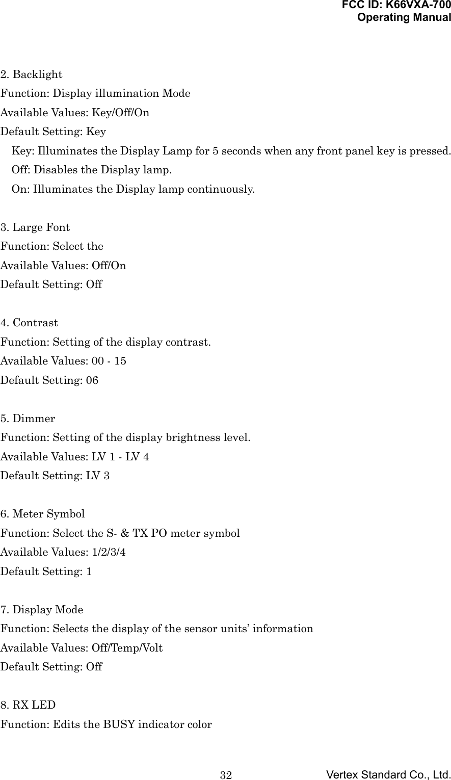
![FCC ID: K66VXA-700Operating ManualVertex Standard Co., Ltd.31for 3 seconds to save the entry and exit. To label a memory with an alpha/numeric name, the next step is to use the DIALselector knob to select any of the 125 available characters (including letters,numbers, and special symbols). When the desired first character appears, press the[SEL(SET)] key momentarily to move on to the next character. Select succeeding characters in the same manner, pressing the [SEL(SET)] keymomentarily after each selection. After entering the entire name (eight characters maximum), press the[MW(SPL.W)] key for 3 seconds to save all data for the channel. Turn the radio off, then turn the radio back on again to begin normal operation.Menu (Menu (Menu (Menu (““““SSSSetetetet””””)))) Mode Mode Mode ModeThe Menu system allows certain aspects of your radio’s configuration to be customizedfor your personal operating convenience. We do not recommend that any of the defaultsettings be changed, however, until you are thoroughly familiar with the operation ofthe VXA-700. Press the [F] key, then press the [SEL(SET)] key to activate the Menu (“SET”)mode. Rotate the DIAL selector knob to select the “Main” Menu, then press the[SEL(SET)] key. Rotate the DIAL selector knob to select the “Sub” Menu item you wish to viewand/or modify, then press the [SEL(SET)] key. Once you have selected the desired Menu Item, press the [SEL(SET)] key once toview the current setting for the item. Rotate the DIAL selector knob to change the setting of the item (ON to OFF, etc.). Press the [SEL(SET)] key again to save your new setting. Press the PTT key repetitively until the radio exit to normal operation.MENU ListingMENU ListingMENU ListingMENU ListingA listing of the Menu items available via the SET mode may be found below.1. Display1. Scan LampFunction: Scan Lamp On/Off (while paused)Available Values: On/OffDefault Setting: On](https://usermanual.wiki/Yaesu-Musen/VXA-700/User-Guide-260189-Page-31.png)

![FCC ID: K66VXA-700Operating ManualVertex Standard Co., Ltd.362. ARSFunction:Available Values:Default Setting:3. ARTSFunction:Available Values:Default Setting:4. ARTS [tv]Function:Available Values:Default Setting:5. T.O.TFunction:Available Values:Default Setting:6. TX PowerFunction:Available Values:Default Setting:5. Key Set1. Lock ModeFunction:Available Values:Default Setting:2. [MON]Function:Available Values:Default Setting:](https://usermanual.wiki/Yaesu-Musen/VXA-700/User-Guide-260189-Page-36.png)
![FCC ID: K66VXA-700Operating ManualVertex Standard Co., Ltd.373. [121.5]Function:Available Values:Default Setting:4. USER 1Function:Available Values:Default Setting:5. USER 2Function:Available Values:Default Setting:6. Misc Setup1. APOFunction:Available Values:Default Setting:2. WX AlertFunction:Available Values:Default Setting:3. TEMP UnitFunction:Available Values:Default Setting:4. TEMP CheckFunction:Available Values:Default Setting:](https://usermanual.wiki/Yaesu-Musen/VXA-700/User-Guide-260189-Page-37.png)