Yale 1510 Surface Vertical Rod Exit Device Installation Instructions 1510seriesinstallation
User Manual: Yale 1510 Surface Vertical Rod Exit Device Installation Instructions Installation Instructions
Open the PDF directly: View PDF ![]() .
.
Page Count: 8
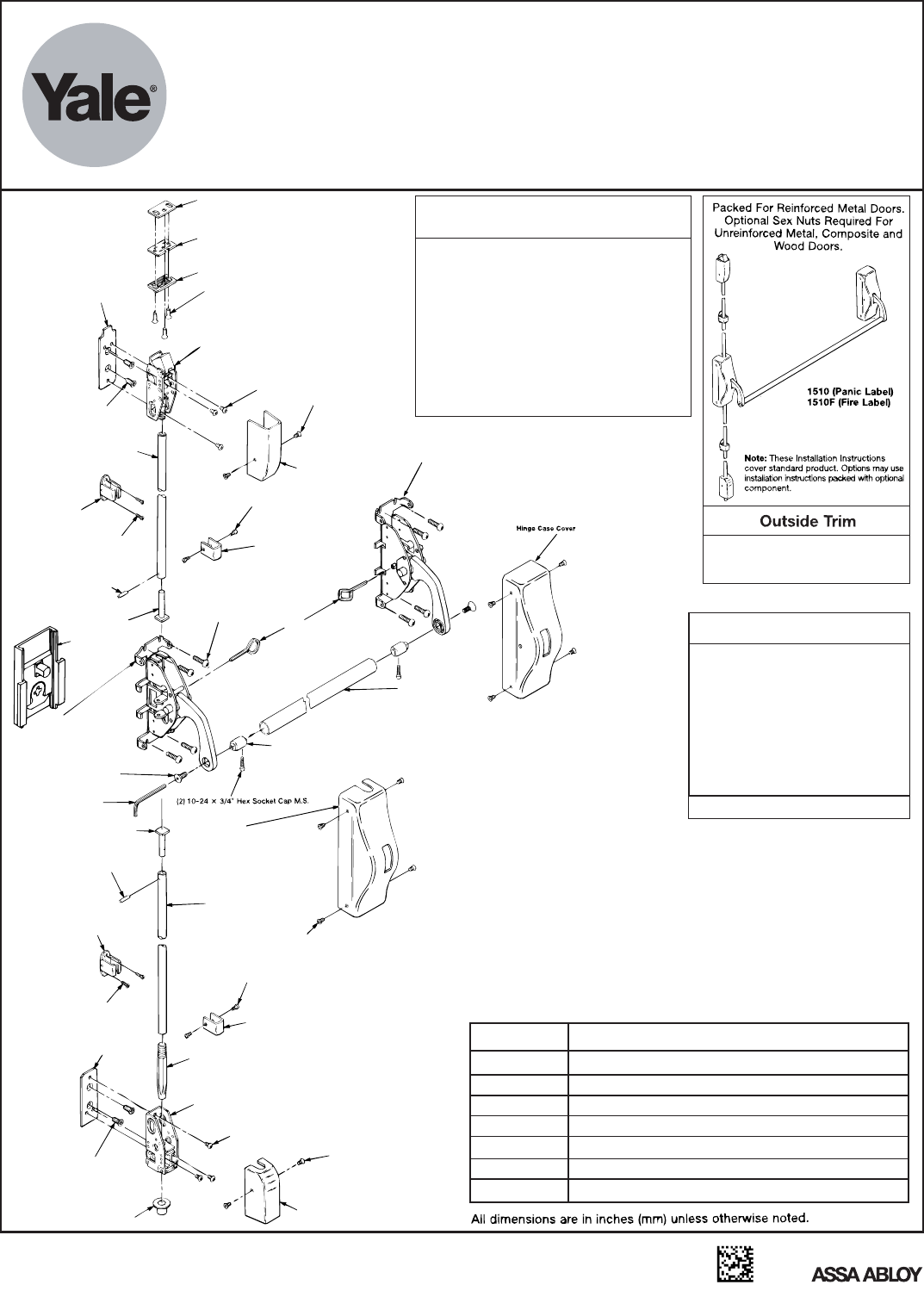
1510(F) Surface Vertical Rod Exit Devices
Installation Instructions
Attention Installer
Any retrofit or other field modification to a fire
rated opening can potentially impact the fire
rating of the opening, and Yale Locks & Hardware
makes no representations or warranties
concerning what such impact may be in any
specific situation. When retrofitting any portion of
an existing fire rated opening, or specifying and
installing a new fire-rated opening, please consult
with a code specialist or local code official
(Authority Having Jurisdiction) to ensure
compliance with all applicable codes and ratings.
PPHMS PHILLIPS PAN HEAD MACHINE SCREW
PPH”AB”SMS
PFHUMS
PFHMS
PRH”AB”SMS
PFH”AB”SMS
PHILLIPS PAN HEAD TYPE “AB” SHEET METAL SCREW
PHILLIPS FLAT HEAD MACHINE SCREW
PHILLIPS FLAT HEAD TYPE “AB” SHEET METAL SCREW
PHILLIPS ROUND HEAD TYPE “AB” SHEET METAL SCREW
PHILLIPS FLAT HEAD UNDER CUT MACHINE SCREW
FASTENER DESCRIPTION
ABBREVIATION
PTH”AB”SMS PHILLIPS TRUSS HEAD TYPE “AB” SHEET METAL SCREW
Shim (2 Supplied)
Strike Plate
791 Strike
(3) 10-24 x 3/4" PFHMS
or
(3) 10 x 1" PFHWS
Top Latch
Top Mounting Plate
(3) 10-24 x 1/4" PRHMS
(2) 8-32 x 1/4" PFHMS
(2) 1/4-20 x 3/4"
PFHMS
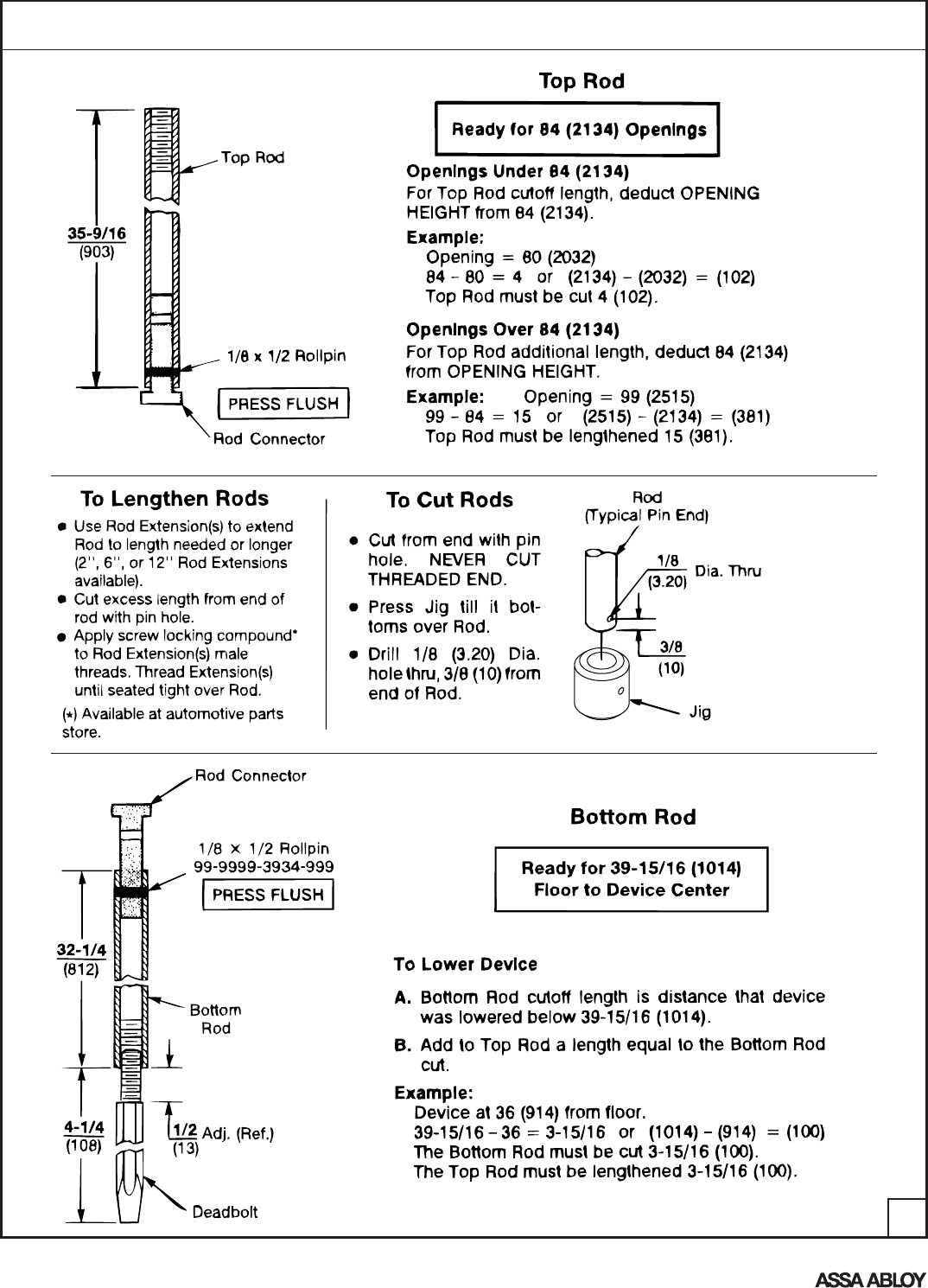
Top Rod
Latch Cover
Hinge Case Assembly
Rod Guide
(2) 8x1/2" PRH'AB"SMS Guide Cover
(2) 6x3/8" PTH"AB"SMS
Roll Pin
Rod Connector
(8) 10-24 x 3/4"
PRHMS
Lifter
Assembly
Rod Case
Assembly
Dogging Key
Crossbar
(2) Bar Inserts
(2) 516-18 x 3/4"
Hex Socket FHMS
3/16" Hex Key
Rod Connector
Roll Pin
Rod Guide
Bottom Rod
Rod Case
Cover
(8) 8-32 x 3/8 PFHMS (T23)
(2) 6x3/8" PTH"AB"SMS
Guide Cover
Deadbolt
(2) 8x1/2" PRH"AB"SMS
Bottom Bolt Case
Bottom Mounting Plate
(2) 1/4-20 x 3/8"
PFHMS
790 Strike
(3) 10-24 x 1/4" PRHMS
(2) 8-32 x 1/4" PFHMS
Latch Cover
Dogging
Feature to hold bolts retracted and
crossbar depressed, for push-pull door
operation.
To Dog Device
Set Rod Case Retractor and Hinge
Case Retractor, as follows:
1. Hold crossbar depressed.
2. Insert dogging key.
3. Turn key 1/4 turn clockwise.
(Not a feature of fire labeled devices.)
Lifter for 620F or 630F Series Trim
supplied when outside trim is packed
with the device.
An ASSA ABLOY Group brand
80-9415-0010-000 (04-13)
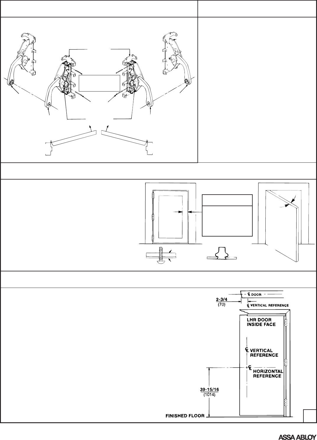
To Change Hands
Check Before Starting
Unreinforced Doors or Frames
Doors and Frames with walls having a structural
thickness (metal skin plus reinforcement or solid
hardwood) to engage less than (3) full screw threads
are considered unreinforced.
Unreinforced Doors: Use SNB (sex nuts and bolts).
Unreinforced Frames: Use Blind Rivet Nuts.
Recommended fasteners for unreinforced openings
are not necessarily supplied by Yale Locks and
Hardware.
Reinforcement
Door Skin Blind Rivet Nut
Door Must Swing Freely
Min. Door Stile
4-1/2" (114mm)
Maintenance
1. Periodically remove covers and coat mechanisms
with a silicone base lubricant. This is particularly
required in corrosive environments for proper product
function.
2. Check mounting fasteners periodically. Retighten if
found loose. Apply screw locking compound (available
at automotive part stores) or change part fasteners if
screws continue to back out.
3. Periodic checks (and adjustments) of strikes are
required to compensate for changes in the opening
(e.g. door sagging).
1. Mark Door
Door and frame must
meet structural and
dimensional specifications
on exit device template(s)
for door and frame
preparation.
Single Door or Pair without Mullion
Locate and Mark Horizontal and Vertical
Reference Centerlines as shown.
LHR door shown. Preparation is typical for both
door hands.
Caution: If device is mounted higher or lower
than shown, rod length must change. Lengthen
or cut top and bottom rods as shown on Step 5.
2
Arm
Hinge
Case
Assembly
RHR Device Complete device required to change hands.
Arms are swapped between latch and hinge
cases. Only essential components shown or
highlighted, for clarity.
(2) Cotter Pin
Note Position!
Caution:
Place Cotter Pins
in correct holes.
Hinge
Case
Assembly
LHR Device
RHR Door LHR Door
Arm Arm
Arm
Rod Case
Assembly
(2) Pivot Pin
An ASSA ABLOY Group brand
80-9415-0010-000 (04-13)
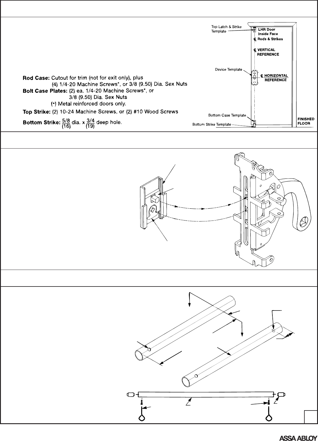
3
3. Prepare Device For Trim
4. Prepare Crossbar
If outside trim is not used, go to step 4.
Drawing shows only essential parts, for
clarity.
The Lifter Assembly is nested in the Device
Case.
The boss of the lifter moving plate
penetrates the round hole above the case
slider center.
The Device Case seats over the door face,
with the Lifter Assembly projecting thru the
door cutout surface and into the door cavity.
Lifter Cam
(Trim Tailpiece penetrates Cam slot.)
Lifter Track
(Ears nest in the Case,
between the two center tabs.)
Lifter Moving Plate
(Boss activates Case Slider
when lifted by Lifter Cam.)
Crossbar length (L) = Door Opening Width - 6-1/4" (159mm)
A. Cut bar to required length (Detail "A").
B. Locate and drill hole (Detail "B").
C. Assemble crossbar (Detail "C"). Hole on
This End
DETAIL A
Cut Line
(Cut Square)
Scribed Line
DETAIL B
Dimension "L"
5/16
(8) Dia. Thru
(This Wall)
1
(25)
DETAIL C
5/32" Hex Key
(Dogging Key)
Crossbar (2) Hex Socket
Cap Screws
(2) Bar Inserts
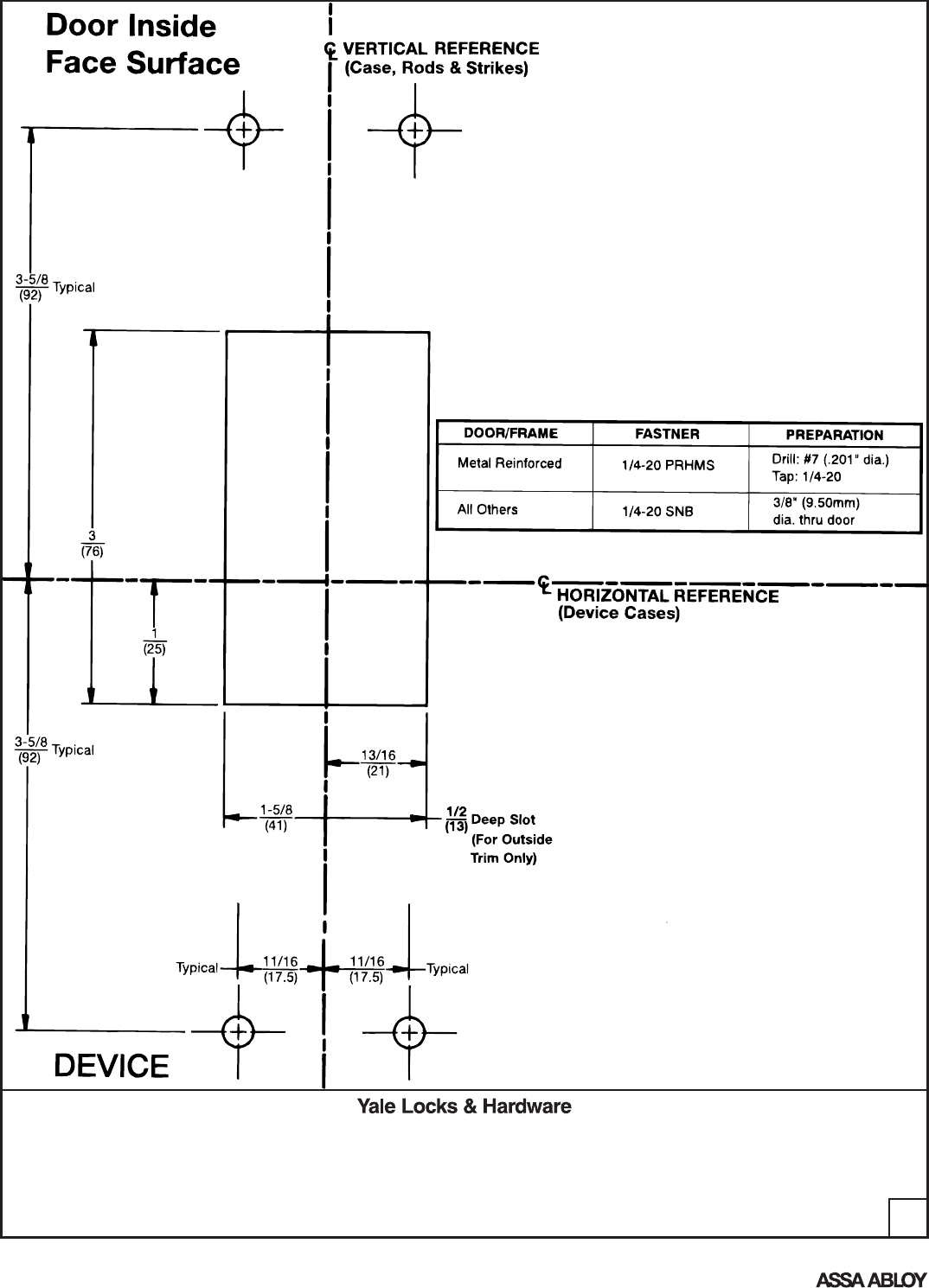
2. Prepare Door, Frame & Sill
A. Locate "Device Template" aligning VERTICAL REFERENCE and HORIZONTAL
REFERENCE lines on door and template. Tape template to door face.
B. Extend centerline of Rods and Strikes from "Device Template" to door top and
bottom, on door face.
C. Locate "Top Latch & Strike," "Bottom Case," and "Bottom Strike" template,
aligning on centerline of Rods and Strikes on door. Tape templates in place.
D. Locate and tape Trim Template to door. (See instructions packed with Trim)
E. Spot and prepare holes:
An ASSA ABLOY Group brand
80-9415-0010-000 (04-13)
An ASSA ABLOY Group brand
80-9415-0010-000 (04-13)
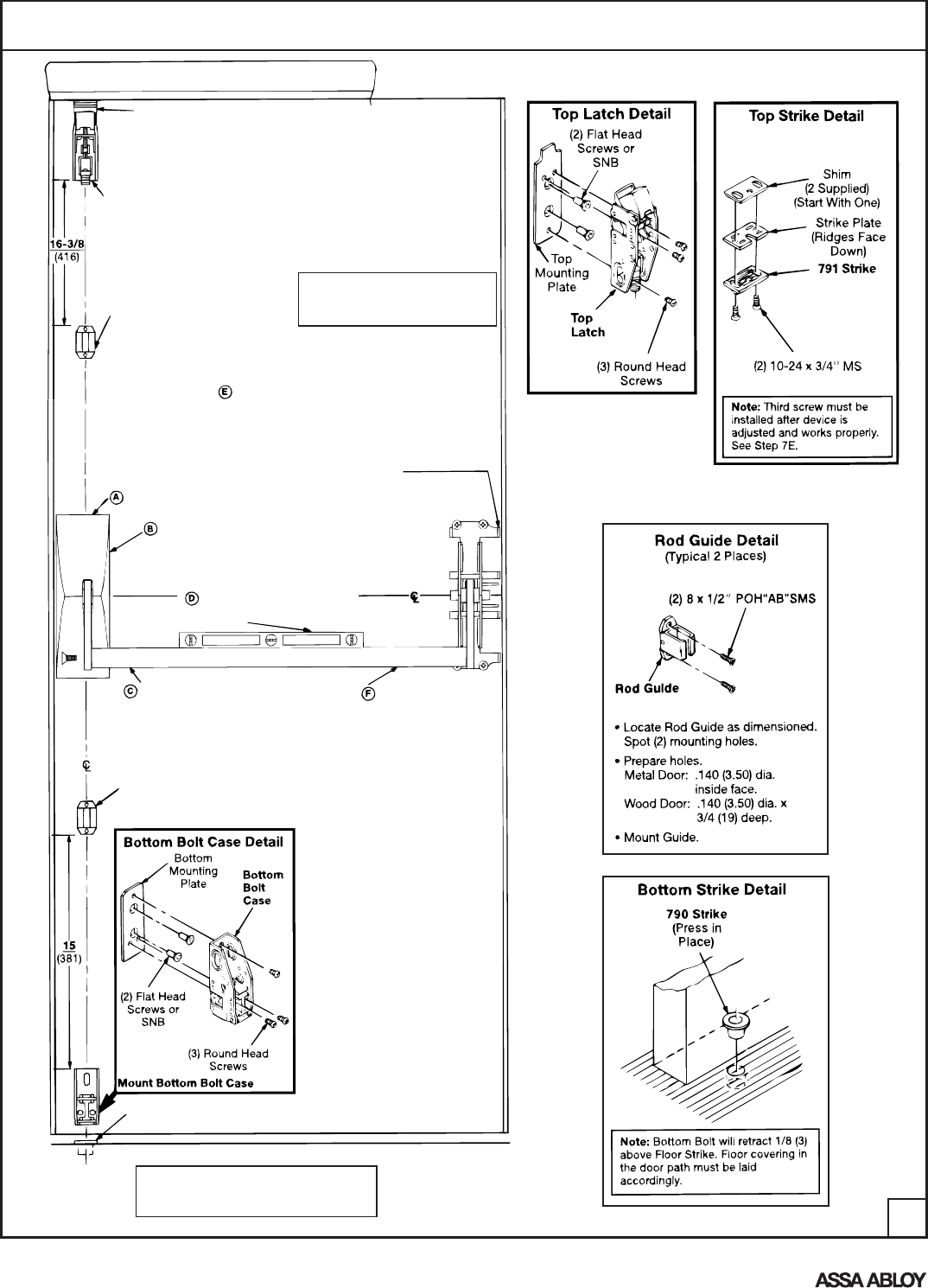
5. Mount Components
4
Mount 791 Top Strike
(See Top Strike Detail, at right)
Mount Top Latch
(See Detail, at right)
Mount Rod Guide
(See Rod Guide Detail, below)
Note that fire openings with thresholds
require optional 794 Strikes, anchored
to floor under thresholds.
Mount 790 Floor Strike
(See Detail, at right)
Rod Guide
(See Rod Guide Detail, at right)
Device, Rods & Strikes
Note: Additional Rod Guides(s)
recommended for openings
8'0" (2.45m) and higher.
Mount Device (Follow letter sequence)
Mount Trim
(Follow instructions supplied with trim)
Mount Center Case
Chassis: 4 Round Head Screws
Cover: 4 Flat Head Screws
Mount Hinge Case
Use Chassis as template.
Prepare (4) holes for 1/4-20
screws, or 3/8" (9.5) Sex Nuts.
Chassis: 4 Round Head Screws
Cover: 4 Flat Head Screws
Reinstall Crossbar
Install Crossbar to Set Hinge Case
Crossbar into Arm grooves,
bolted with Flat Head Cap
Screws (3/16 Hex Key).
Assembly has to be level
to set Hinge Case in position.
An ASSA ABLOY Group brand
80-9415-0010-000 (04-13)
6. Prepare Rods
5
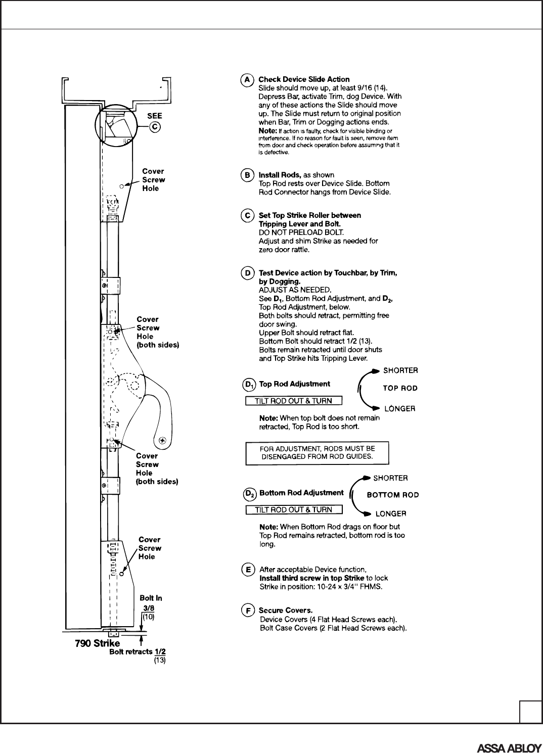
7. Complete Installation
6
An ASSA ABLOY Group brand
80-9415-0010-000 (04-13)
An ASSA ABLOY Group brand
80-9415-0010-000 (04-13)
7
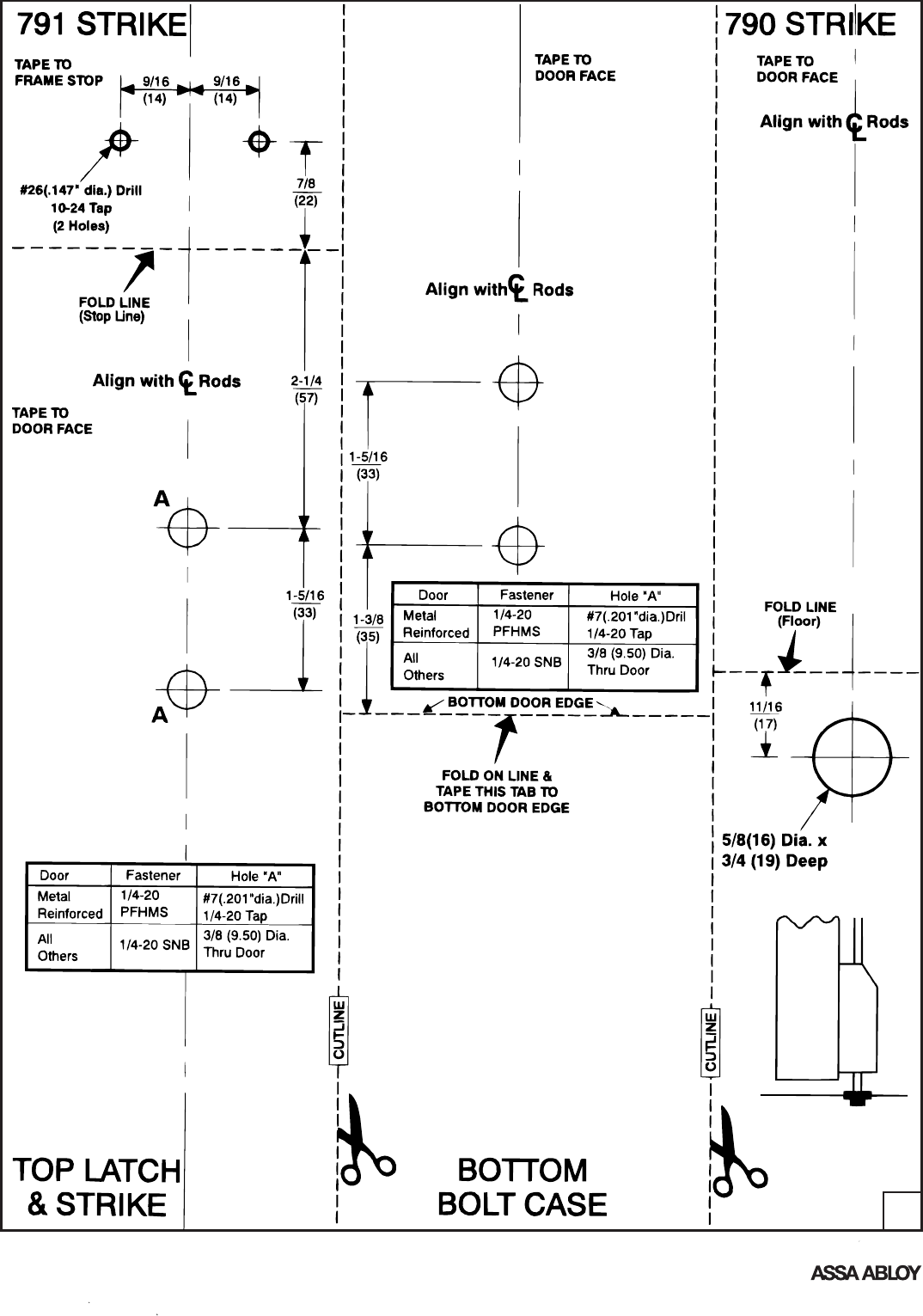
CAUTION:
Office copiers, printers and facsimile
machines may change the size of a
drawing and make the template
inaccurate to use as a door marker.
An ASSA ABLOY Group brand
80-9415-0010-000 (04-13)
8
Yale® is a registered trademark of Yale Security Inc., an ASSA ABLOY Group company. Other products' brand names may be trademarks or registered trademarks of their respective
owners and are mentioned for reference purposes only. These materials are protected under U.S. copyright laws. All contents current at time of publication.
Yale Security Inc. reserves the right to change availability of any item in this catalog, its design, construction, and/or its materials.
Copyright © 1995, 2013, Yale Security Inc., an ASSA ABLOY Group company.
All rights reserved. Reproduction in whole or in part without the express written permission of Yale Security Inc. is prohibited.
Product Support Tel 800.438.1951 • www.yalelocks.com
Yale Locks & Hardware is a division of Yale Security Inc., an ASSA ABLOY Group company.
Notes:
1. Rectangular slot for Trim Lifter is not required for exit only
openings.
2. Mark centerline of rods on door face.
3. Unreinforced frames require that 10-24 blind rivet nuts (by others)
be used to bolt strike. Frames are considered not reinforced when
strike mounting screws cannot engage (3) full threads.
4. Dimensions are given in inches (mm).
5. CAUTION: Office copiers, printers and facsimile machines may
change the size of a drawing and make the template inaccurate to
use as a door marker.
