Yamaha Motor X0P00 X0P Meter User Manual X0P00
Yamaha Motor Co., Ltd. X0P Meter X0P00
Users Manual

Drive Unit
Display Unit
Battery Pack
Battery Charger
ORIGINAL INSTRUCTIONS
q READ THIS MANUAL CAREFULLY!
It contains important safety information.
(3$&.0DQXDOB(8B(QJLQGG

(3$&.0DQXDOB(8B(QJLQGG

TABLE OF CONTENTS
INTRODUCTION ..................................................................1
LOCATION OF THE WARNING AND SPECIFICATION
LABELS ...............................................................................4
DESCRIPTION .....................................................................6
E-BIKE SYSTEMS ...............................................................7
SAFETY INFORMATION ...................................................10
INSTRUMENT AND CONTROL FUNCTIONS ..................13
BATTERY PACK AND CHARGING PROCEDURE ..........33
CHECKING THE RESIDUAL BATTERY CAPACITY .......41
PRE-OPERATION CHECK ................................................43
CLEANING AND STORAGE .............................................44
TRANSPORT .....................................................................46
CONSUMER INFORMATION ............................................47
TROUBLESHOOTING .......................................................48
SPECIFICATIONS .............................................................54
(3$&.0DQXDOB(8B(QJLQGG
1
INTRODUCTION
These original instructions have been prepared for your Drive Unit, display unit, battery pack and
battery charger.
FAILURE TO FOLLOW THE WARNINGS CONTAINED IN THIS MANUAL CAN RESULT IN SERI-
OUS INJURY OR DEATH.
Particularly important information is distinguished in this manual by the following notations:
This is the safety alert symbol. It is used to alert you to potential
personal injury hazards. Obey all safety messages that follow this
symbol to avoid possible injury or death.
A WARNING indicates a hazardous situation which, if not avoided,
could result in death or serious injury.
A NOTICE indicates special precautions that must be taken to avoid
damage to the vehicle or other property.
TIP A TIP provides key information to make procedures easier or clearer.
Indicates prohibited items that you must not do for safety reasons.
* Product and specifications are subject to change without notice.
WARNING
NOTICE
(3$&.0DQXDOB(8B(QJLQGG

2
INTRODUCTION
The Bluetooth® word mark and logos are registered trademarks owned by the Bluetooth SIG, Inc.
and any use of such marks by YAMAHA MOTOR CO., LTD. is under license.
(3$&.0DQXDOB(8B(QJLQGG

3
INTRODUCTION
Please check your local riding laws and regulations before operating this e-Bike Systems bicycle.
Drive Unit, Display Unit,
Battery Pack, Battery Charger
ORIGINAL INSTRUCTIONS
©2016 by Yamaha Motor Co., Ltd.
1st edition, September 2016
All rights reserved.
Any reprinting or unauthorized use
without the written permission of
Yamaha Motor Co., Ltd.
is expressly prohibited.
Printed in Japan
(3$&.0DQXDOB(8B(QJLQGG
4
LOCATION OF THE WARNING AND
SPECIFICATION LABELS
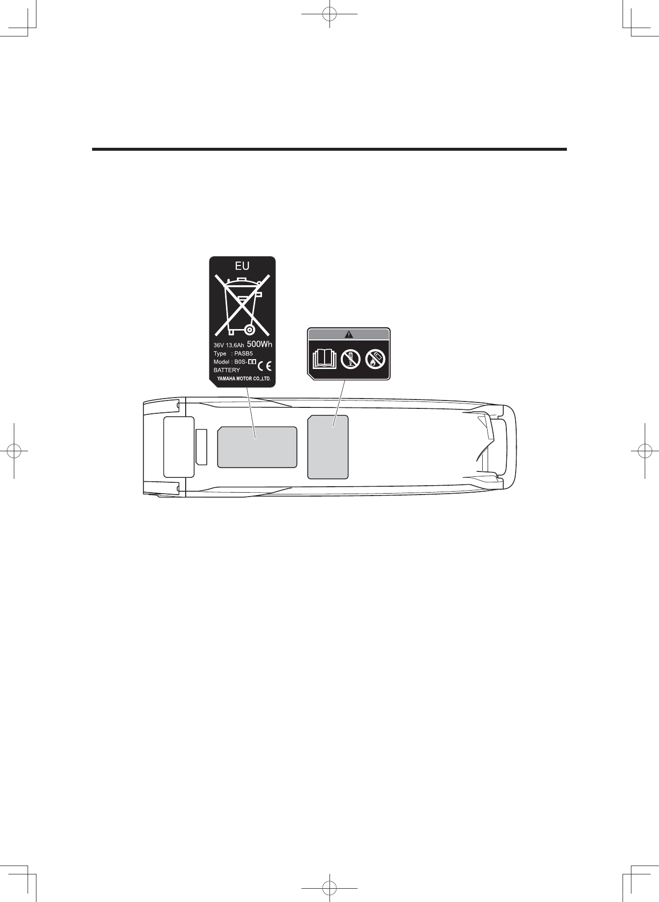
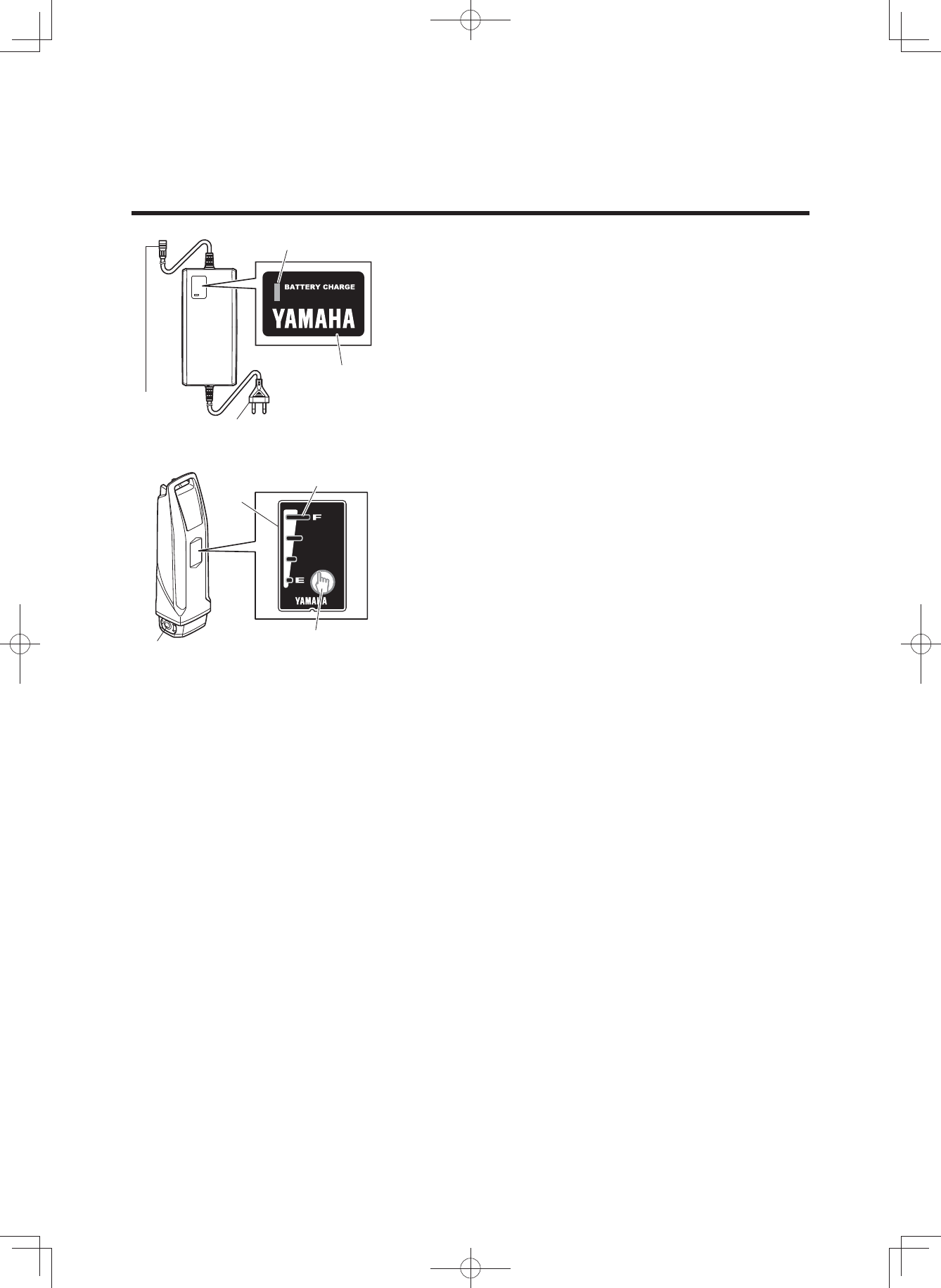
Read and understand all of the labels on your battery pack and battery charger. These labels con-
tain important information for safe and proper operation. Never remove any labels from your bat-
tery pack and battery charger:
Battery pack
(3$&.0DQXDOB(8B(QJLQGG
5
LOCATION OF THE WARNING AND
SPECIFICATION LABELS
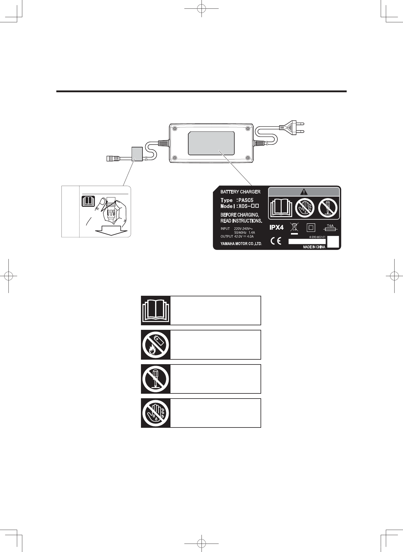
How to disconnect the plug.
1.GRASP
2.PULL
Familiarize yourself with the following pictograms and read the explanatory text, then make sure to
check the pictograms that apply to your model.
Read the Owner’s manual
Do not dispose of in a fire
Do not disassemble
Do not use with wet hands
Battery charger
(3$&.0DQXDOB(8B(QJLQGG
6
DESCRIPTION
a
b
c
a
b
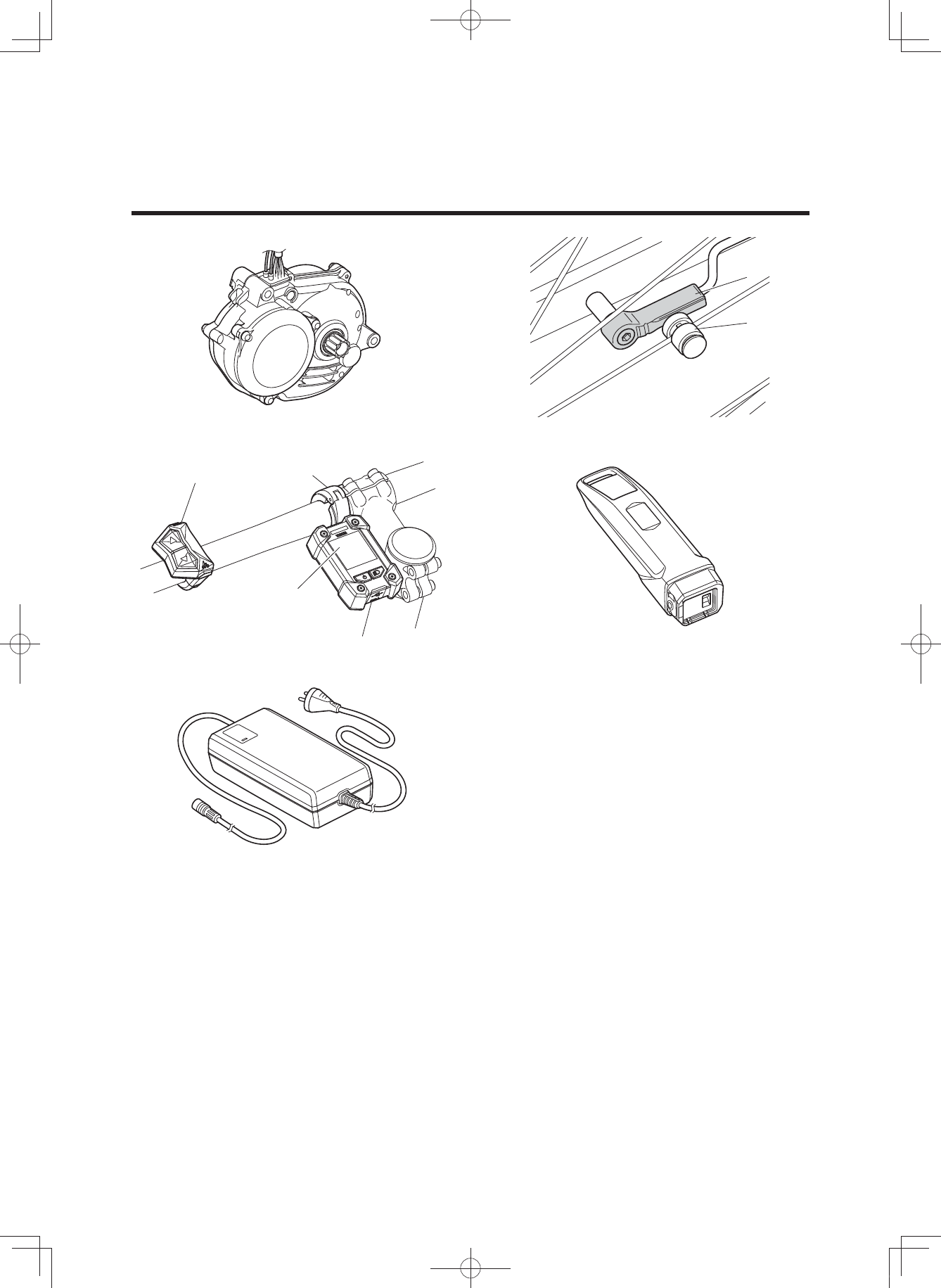
1. Drive Unit
2. Speed sensor set
a) Magnet sensor spoke type
b) Pick up
3. Display unit
a) Display
b) Clamp
c) Switch
4. Battery pack (400 Wh/500 Wh)
5. Battery charger
12
43
5
(3$&.0DQXDOB(8B(QJLQGG

7
E-BIKE SYSTEMS
The e-Bike Systems are designed to give you the optimal amount of
power assist.
It assists you within a standard range based on factors such as your pedaling strength, bicycle
speed, and current gear.
The e-Bike Systems do not assist in the following situations:
• When the display unit’s power is off.
• When you are moving 25 km/h or faster.
• When you are not pedaling and the pushing assist switch is released.
• When there is no residual battery capacity.
• When the automatic power off function* is operating.
* Power turns off automatically when you do not use the e-Bike Systems for 5 minutes.
• When the assist mode is set to Off mode.
(3$&.0DQXDOB(8B(QJLQGG
8
E-BIKE SYSTEMS
* This illustration is for reference purposes only.
Actual performance may vary depending on road conditions, wind, and other factors.
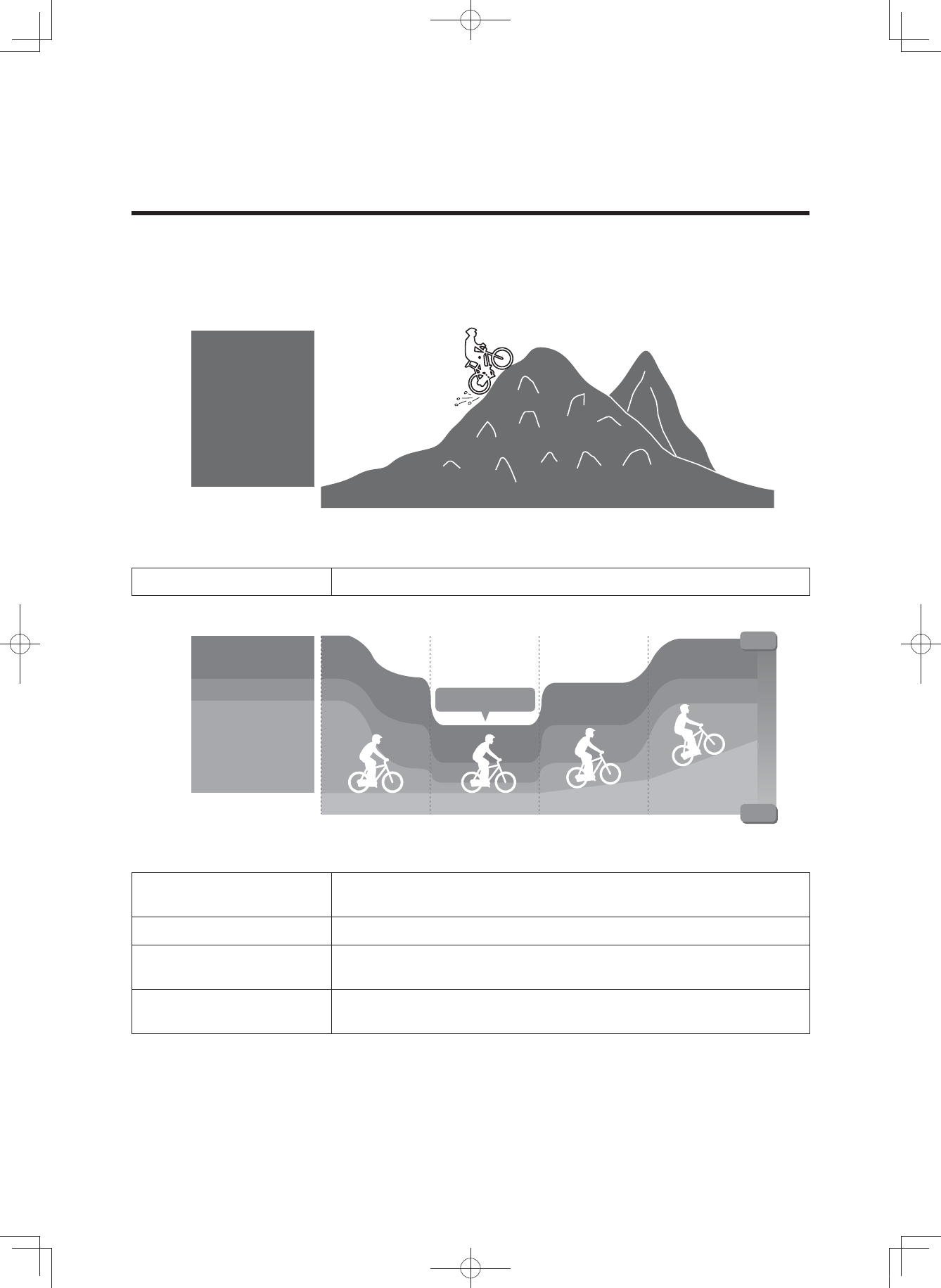
Extra Power mode Use when climbing rough terrain.
* This illustration is for reference purposes only.
Actual performance may vary depending on road conditions, wind, and other factors.
High-Performance mode Use when you want to ride more comfortably, such as when
climbing a steep hill.
Standard mode Use when riding on flat roads or climbing gentle hills.
Eco mode
+Eco mode Use when you want to ride as far as possible.
Off mode Use when you want to ride without power assist. You can still use
the other display unit functions.
Multiple power assist modes are available.
Choose from Extra Power mode, High-Performance mode, Standard mode, Eco mode, +Eco mode
and Off mode to suit your riding conditions.
See “Displaying and switching the assist mode” for information on switching between assist modes.
Extra Power
mode
Power-saving
High
Low
Starting off Level road Inclined road
Assist power
Steep incline
Eco mode
+Eco mode
High-Performance
mode
Standard mode
(3$&.0DQXDOB(8B(QJLQGG

9
E-BIKE SYSTEMS
Conditions that could decrease remaining assist distance
The remaining assist distance will decrease when riding in the following conditions:
• Frequent starts and stops
• Numerous steep inclines
• Poor road surface conditions
• When carrying heavy loads
• When riding together with children
• Riding into a strong head wind
• Low air temperature
• Worn-out battery pack
• When using the headlight (applies only to models equipped with lights powered by the battery
pack)
• Remaining assist distance will also decrease if the bicycle is not maintained properly.
Examples of inadequate maintenance that could decrease remaining assist distance:
• Low tire pressure
• Chain not turning smoothly
• Brake engaged constantly
(3$&.0DQXDOB(8B(QJLQGG

10
SAFETY INFORMATION
Never use this battery charger to charge other electrical appliances.
Do not use any other charger or charging method to recharge the special batter-
ies. Using any other charger could result in fire, explosion, or damage the batter-
ies.
This battery charger can be used by children aged from 8 years and above and
persons with reduced physical, sensory or mental capabilities or lack of experi-
ence and knowledge if they have been given supervision or instruction concern-
ing use of the battery charger in a safe way and understand the hazards in-
volved. Children shall not play with the battery charger. Cleaning and user
maintenance shall not be made by children without supervision.
Although the battery charger is waterproof, never allow it to become immersed
in water or other fluids. In addition, never use the battery charger if the terminals
are wet.
Never handle the power plug, charge plug or touch the charger contacts with wet
hands. This could result in electric shock.
Do not touch charger contacts with metallic objects. Do not allow foreign materi-
al to cause short circuit of the contacts. This could result in electric shock, fire,
or damage the battery charger.
Periodically remove dust from the power plug. Dampness or other issues could
reduce the effectiveness of the insulation, resulting in fire.
Never disassemble or modify the battery charger. This could result in fire or elec-
tric shock.
Do not use with a power strip or extension cord. Using a power strip or similar
methods may exceed rated current and can result in fire.
Do not use with the cable tied or rolled up, and do not store with the cable
wrapped around the charger main body. Cable damage can result in fire or elec-
tric shock.
Firmly insert the power plug and the charging plug into the socket. Failure to in-
sert the power plug and the charging plug completely can result in fire caused
by electric shock or overheating.
Do not use the battery charger near flammable material or gas. This could result
in fire or explosion.
Never cover the battery charger or place other objects on top of it while charg-
ing. This could result in internal overheating leading to fire.
Do not drop the battery charger or expose it to strong impacts. Otherwise, it
could cause a fire or electric shock.
Store the battery and battery charger out of reach of children.
Do not touch the battery pack or battery charger while it is charging. As the bat-
tery pack or battery charger reaches 40–70 °C during charging, touching it could
result in low-temperature burns.
(3$&.0DQXDOB(8B(QJLQGG

11
SAFETY INFORMATION
Do not use if the battery pack case is damaged, cracked, or if you smell any unu-
sual odors. Leaking battery fluid can cause serious injury.
Do not short the contacts of the battery pack. Doing so could cause the battery
pack to become hot or catch fire, resulting in serious injury or property damage.
Do not disassemble or modify the battery pack. Doing so could cause the battery
pack to become hot or catch fire, resulting in serious injury or property damage.
If the power cable is damaged, stop using the battery charger and have it in-
spected at an authorized dealer.
Do not turn the pedals or move the bicycle while the battery charger is connect-
ed. Doing so could cause the power cable to become tangled in the pedals, re-
sulting in damage to the battery charger, power cable, and/or plug.
Handle the power cable with care. Connecting the battery charger from indoors
while the bicycle is outdoors could result in the power cable becoming pinched
and damaged in a doorway or window.
Do not run over the power cable or plug with the wheels of the bicycle. Doing so
could result in damage to the power cable or plug.
Do not drop the battery pack or subject it to impact. Doing so could cause the
battery pack to become hot or catch fire, resulting in serious injury or property
damage.
Do not dispose of the battery pack in a fire or expose it to a heat source. Doing
so could cause fire, or explosion, resulting in serious injury or property damage.
Do not modify or disassemble the e-Bike Systems. Do not install anything other
than genuine parts and accessories. Doing so could result in product damage,
malfunction, or increase your risk of injury.
When stopped, be sure to apply the front and rear brakes and keep both feet on
the ground. Placing one’s foot on the pedal when stopped may unintentionally
engage the power assist function, which could result in loss of control and seri-
ous injury.
Do not ride the bicycle if there is any irregularity with the battery pack or e-Bike
Systems. Doing so could lead to loss of control and serious injury.
Be sure to check the residual battery capacity before riding at night. The head-
light powered by the battery pack will turn off soon after the residual battery ca-
pacity has decreased to where power assisted riding is no longer possible. Rid-
ing without an operating headlight can increase your risk of injury.
Do not start off by running with one foot on a pedal and one foot on the ground
and then mounting the bicycle after it has reached a certain speed. Doing so
could result in loss of control or serious injury. Be sure to start riding only after
you are seated properly on the bicycle seat.
Do not press the pushing assist switch if the rear tire is off the ground. Other-
wise, the tire will turn at high speed in the air and you could be injured.
(3$&.0DQXDOB(8B(QJLQGG

12
SAFETY INFORMATION
Do not use the wireless function with Bluetooth low energy technology in areas
such as hospitals or medical institutions where use of electronic equipment or
wireless equipment is prohibited. Otherwise, this could affect the medical equip-
ment, etc. and cause an accident.
When using the wireless function with Bluetooth low energy technology, keep
the display at a safe distance from heart pacemakers in use. Otherwise, the radio
waves could affect the heart pacemaker function.
Do not use the wireless function with Bluetooth low energy technology near au-
tomatic control equipment such as automatic doors, fire alarms, etc. Otherwise,
the radio waves could affect the equipment and cause an accident through pos-
sible malfunction or unintentional operation.
(3$&.0DQXDOB(8B(QJLQGG
13
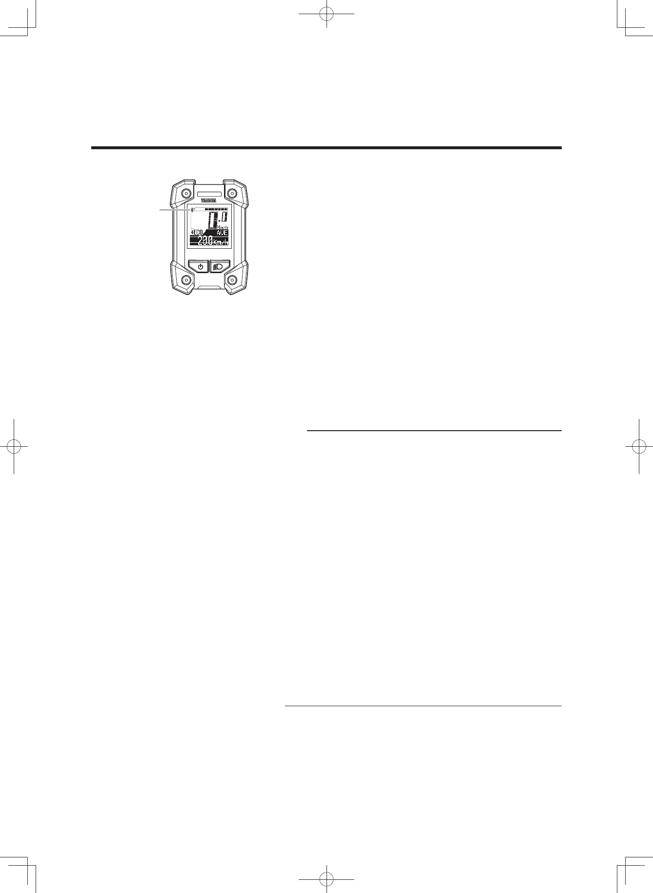
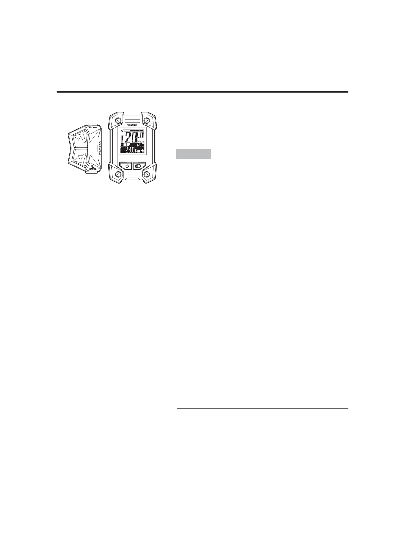
INSTRUMENT AND CONTROL FUNCTIONS
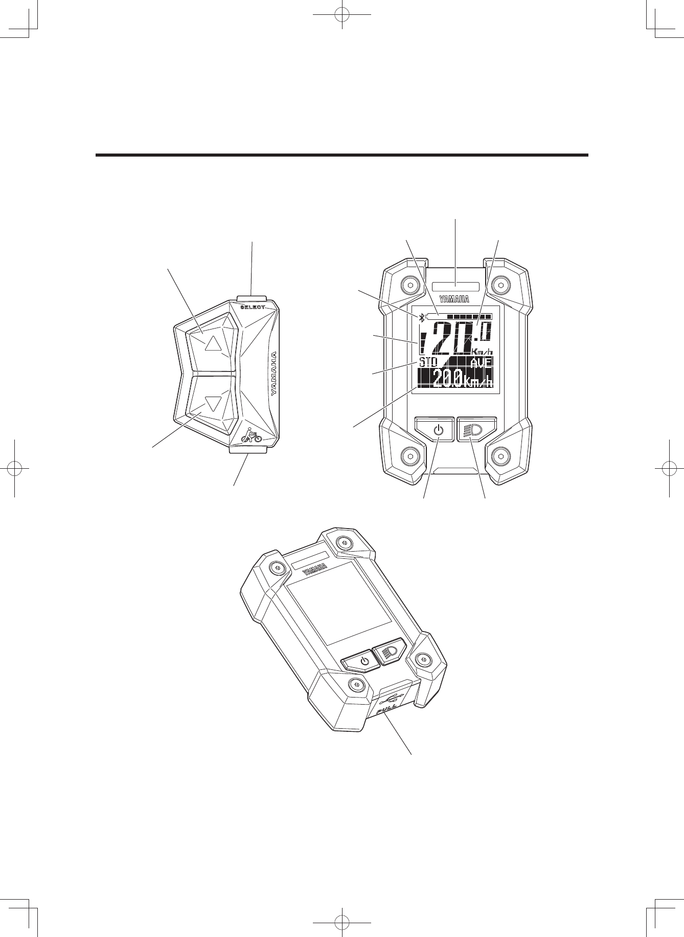
Display unit
Function select switch
USB receptacle
Assist mode lamp
Pushing assist switch
Assist mode switch (up)
Battery capacity
indicator
Bluetooth
indicator
Assist power
meter
Assist mode
indicator
Function
display
Speedometer
Power switch Light switch
Assist mode switch
(down)
(3$&.0DQXDOB(8B(QJLQGG
14
Display unit
The display unit offers the following operations and infor-
mation displays.
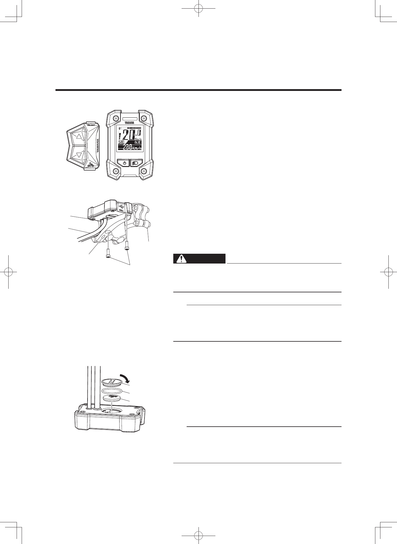
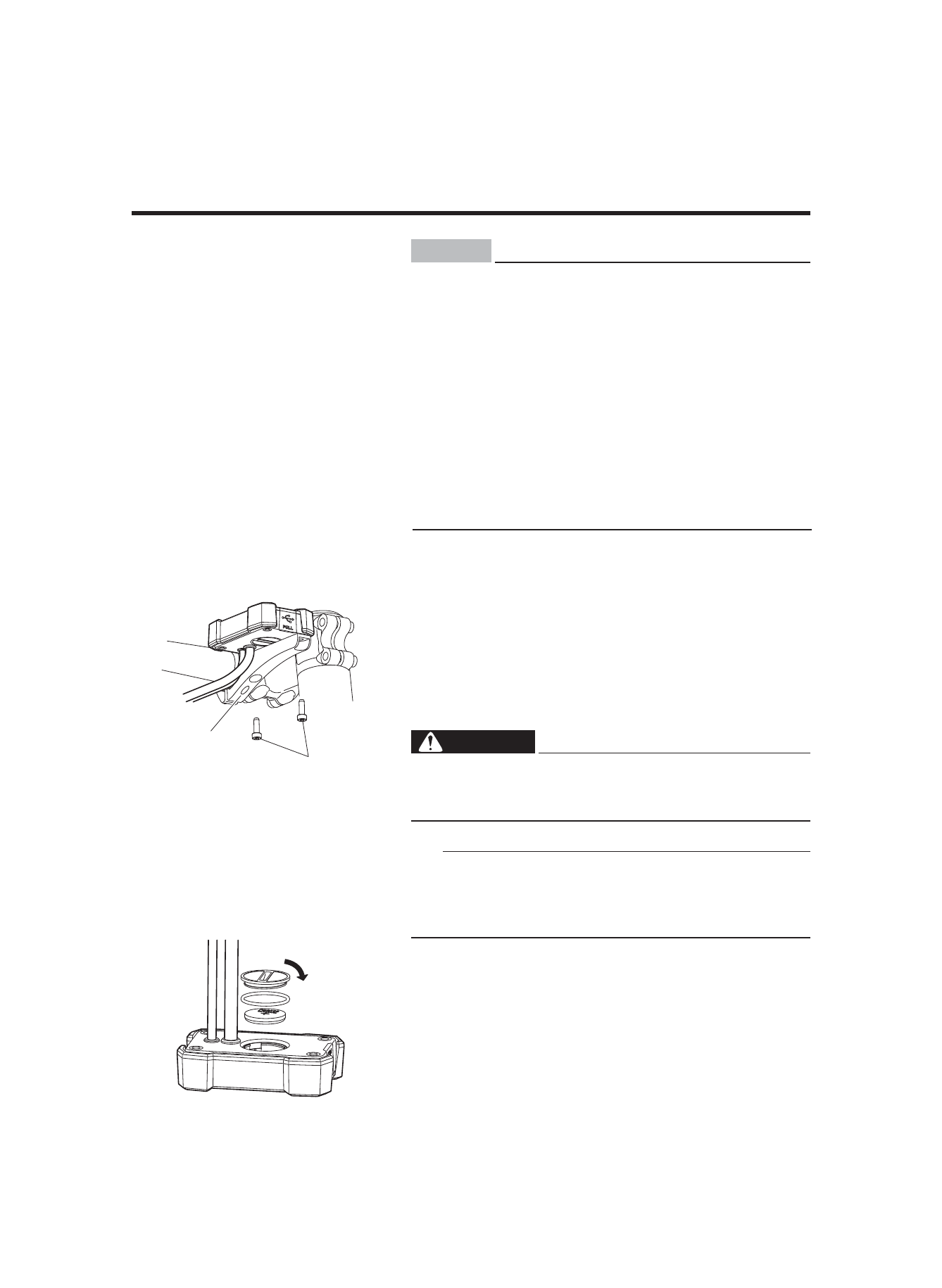
2 Installing the battery
The display needs to be removed and installed for chang-
ing the battery.
• Remove the two bolts on back side of the clamp, and
then remove the display.
• When installing the display, tighten the two display
bolts from the back side of the clamp.
WARNING
Tighten the display bolts to 1.5–2.5 N·m. During rid-
ing, vibration could cause the bolts to come loose
with the risk that the display may fall off.
TIP
• The clamp and display might be installed on the right
side of the stem.
• For models without this clamp, the above note does not
apply.
2 Battery
Check if the rated battery (CR2032) is installed in the rear
of the display.
If a battery is not installed, or if there is not sufficient bat-
tery power remaining, install a new battery.
To adjust the time and set the units for distance and
speed, see “Stopwatch and settings”.
TIP
• Make sure that the waterproof seal is installed correct-
ly.
• Use a new type CR2032 button cell battery (sold sepa-
rately).
INSTRUMENT AND CONTROL FUNCTIONS
Clamp
Display bolt
Close
Cover
Waterproof seal
Battery
(3$&.0DQXDOB(8B(QJLQGG
15
INSTRUMENT AND CONTROL FUNCTIONS
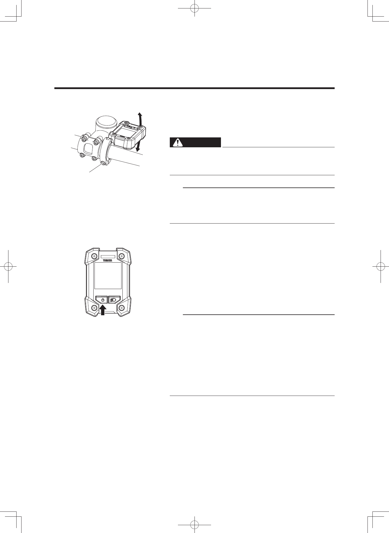
2 Adjusting the display angle
Adjust the display angle by loosening the clamp bolt. The
angle depends on each rider.
After adjustment, tighten the clamp bolt.
WARNING
Tighten the clamp bolt to 3.0–4.5 N·m. During riding,
vibration could cause the clamp bolt to come loose
with the risk that the clamp may fall off.
TIP
• The clamp and display might be installed on the right
side of the stem.
• For models without this clamp, the above note does not
apply.
2 Power “On/Off”
Each time you press the power switch, the power switches
between “On” and “Off”.
When you turn on the power, the animation will be dis-
played.
After that, the battery capacity indicator, speedometer, as-
sist power meter, Bluetooth indicator, the function display,
and “STD” of assist mode indicator are displayed.
TIP
• When you turn on the power, the assist mode is auto-
matically set to Standard mode.
• Keep your feet off the pedals when turning on the dis-
play unit. Also, do not start riding immediately after
turning on the display unit. Doing so could weaken the
assist power. (Weak assist power in either of these
cases is not a malfunction.) If you did either of the
above by accident, remove your feet from the pedals,
turn on the power again, and wait a moment (approxi-
mately two seconds) before starting to ride.
Clamp bolt
(3$&.0DQXDOB(8B(QJLQGG
16
INSTRUMENT AND CONTROL FUNCTIONS
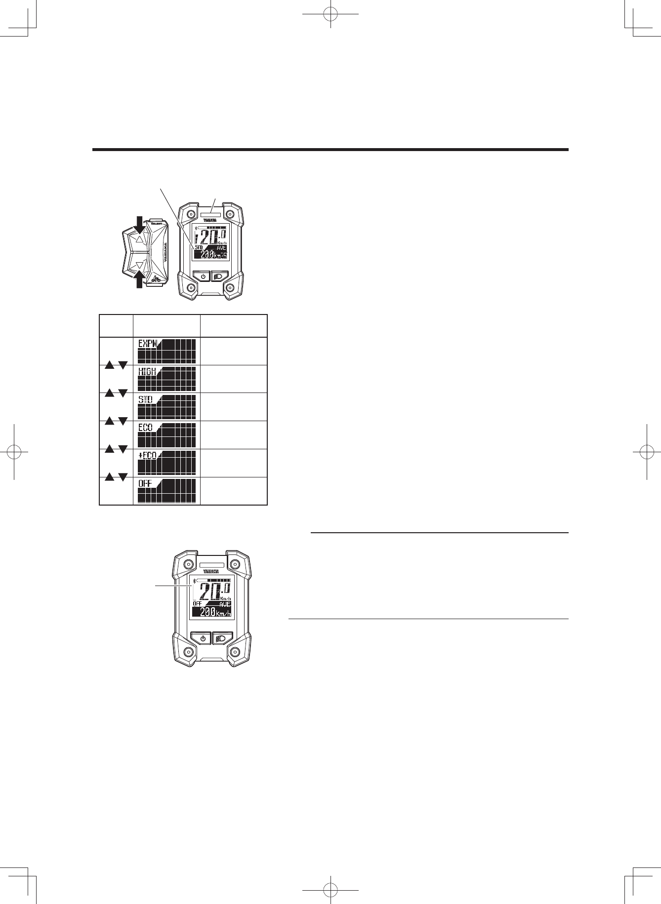
2 Displaying and switching the assist mode
You can select the assist mode by using the assist mode
switches (up & down).
The selected assist mode is displayed by the assist mode
indicator and assist mode lamp color.
• When you press the assist mode switch (up), the mode
changes from “OFF” to “+ECO” to “ECO” to “STD” to
“HIGH”, or from “HIGH” to “EXPW”.
• When you press the assist mode switch (down), the
mode changes from “EXPW” to “HIGH”, or from “HIGH”
to “STD”, or “STD” to “ECO”, or “ECO” to “+ECO” or
“+ECO” to “OFF”.
TIP
• Further pressing of the assist mode switch will not cy-
cle the assist mode selections.
• In the Off mode, the assist power meter are not dis-
played.
• You can keep the assist mode lamp unlit.
For more information, see “Stopwatch and settings”.
EXPW Yellow
Assist
mode Assist mode
indicator Assist mode
lamp
HIGH Blue
STD Blue
ECO Green
+ECO Green
OFF Hide
Off mode
Assist mode indicator
Assist mode lamp
Assist power
meter
(3$&.0DQXDOB(8B(QJLQGG
17
INSTRUMENT AND CONTROL FUNCTIONS
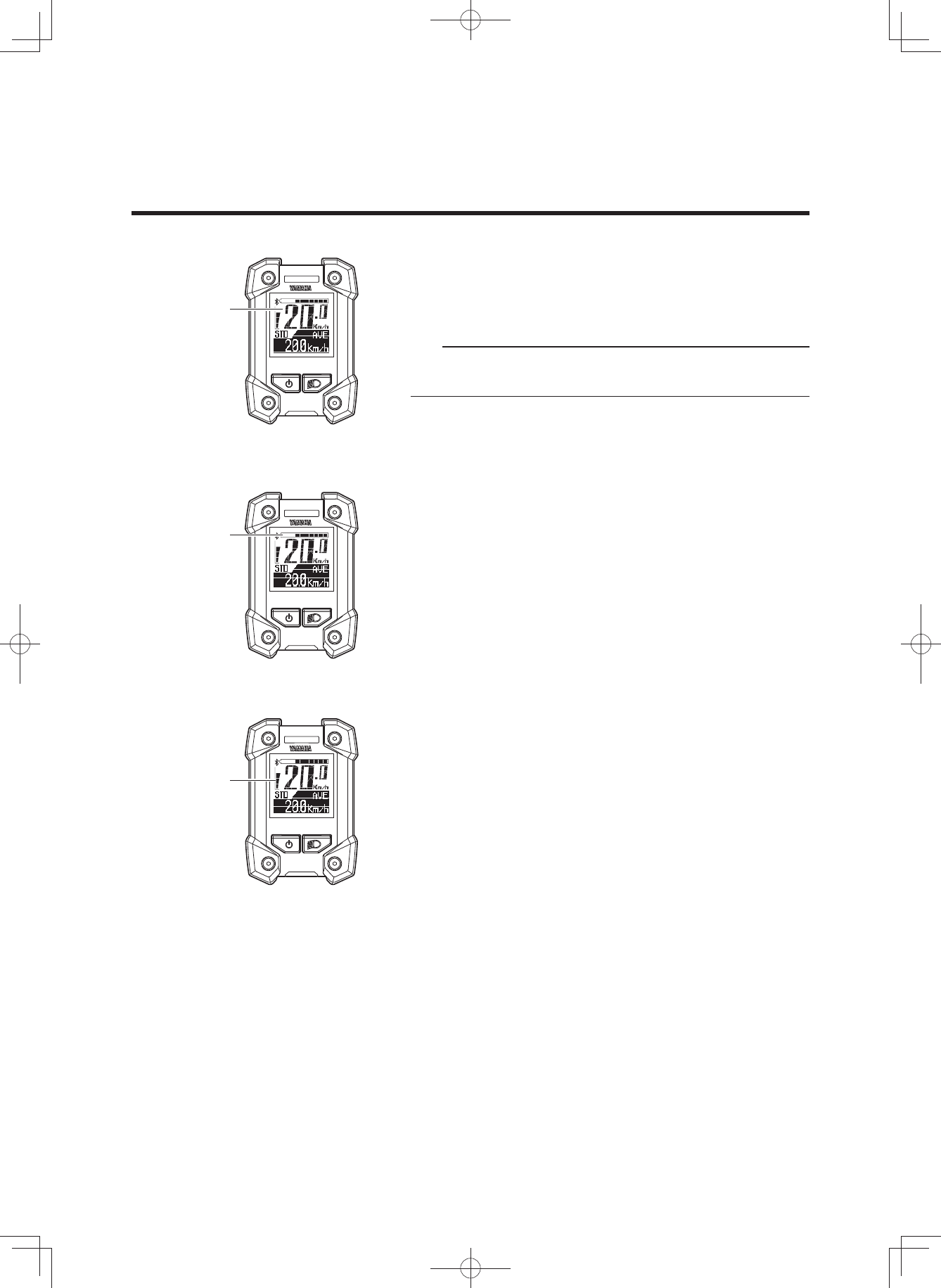
2 Speedometer
The speedometer displays your bicycle speed (in kilome-
ter per hour or mile per hour). To select the km/mile, see
“Stopwatch and settings”.
TIP
If your bicycle speed is less than 2.0 km/h or 1.2 MPH, the
speedometer displays “0.0 km/h or 0.0 MPH”.
2 Battery capacity indicator
The battery capacity indicator displays an estimate of how
much capacity is left in the battery on an 11-segment
scale.
2 Assist power meter
The assist power meter displays an estimate of the assist
power during riding on a 5-segment scale.
When the e-Bike Systems are not in operation, none of
the segments of the assist power meter are displayed.
When the e-Bike Systems are operating, as the assist
power increases, the segments of the assist power meter
are added one by one.
Battery capacity
indicator
Assist power
meter
Speedometer
(3$&.0DQXDOB(8B(QJLQGG
18
INSTRUMENT AND CONTROL FUNCTIONS
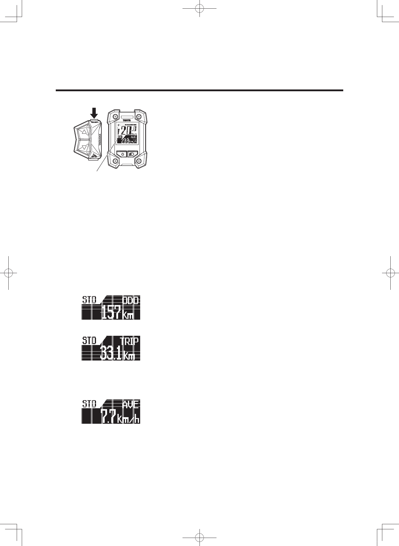
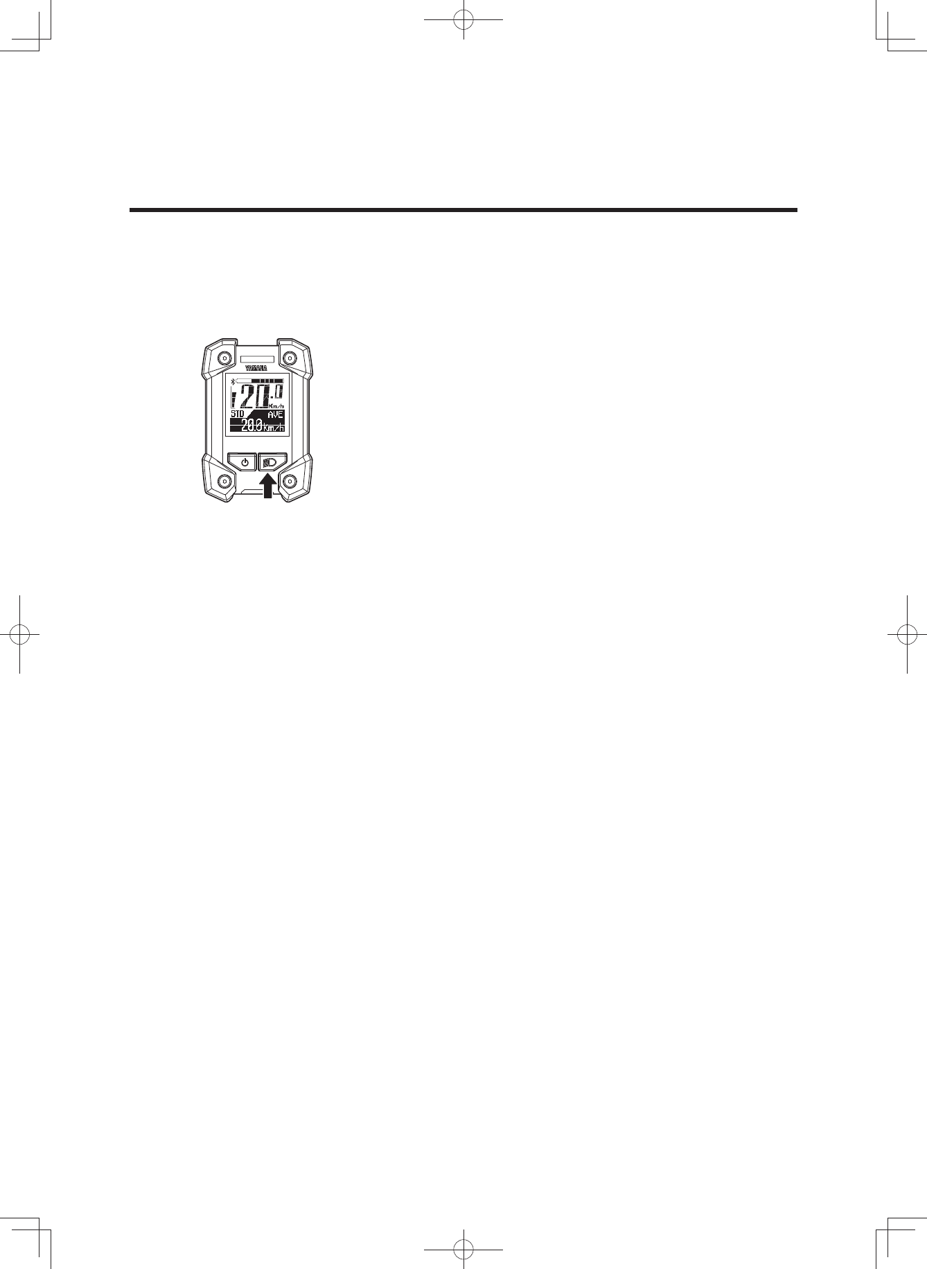
2 Function display
The function display can display the following functions.
• Odometer
• Trip meter
• Average bicycle speed
• Maximum bicycle speed
• Remaining assist distance
• Battery capacity (%)
• Cadence
• Clock
Push the function select switch, the display changes as fol-
lows:
Odometer Trip meter Average bicycle speed Max-
imum bicycle speed Remaining assist distance Bat-
tery capacity (%) Cadence Clock Odometer
You can select the items to be displayed.
For more information, see “Stopwatch and settings”.
You can reset the data for trip meter, average bicycle
speed, and maximum bicycle speed.
For more information, see “Stopwatch and settings”.
7 Odometer
This displays the total distance (in kilometers or miles) rid-
den while the power was on.
The odometer cannot be reset.
7 Trip meter
This displays the total riding distance (in kilometers or
miles) since it was last reset.
When you turn off the power, the data up to that point will
remain in the display.
For the procedure of resetting the trip meter to measure a
new distance travelled, see “Stopwatch and settings”.
7 Average bicycle speed
This displays the average bicycle speed (in kilometers per
hour or miles per hour) since it was last reset.
When you turn off the power, the data up to that point will
remain in the display.
For the procedure of resetting the average bicycle speed,
see “Stopwatch and settings”.
Function display
(3$&.0DQXDOB(8B(QJLQGG
19
INSTRUMENT AND CONTROL FUNCTIONS
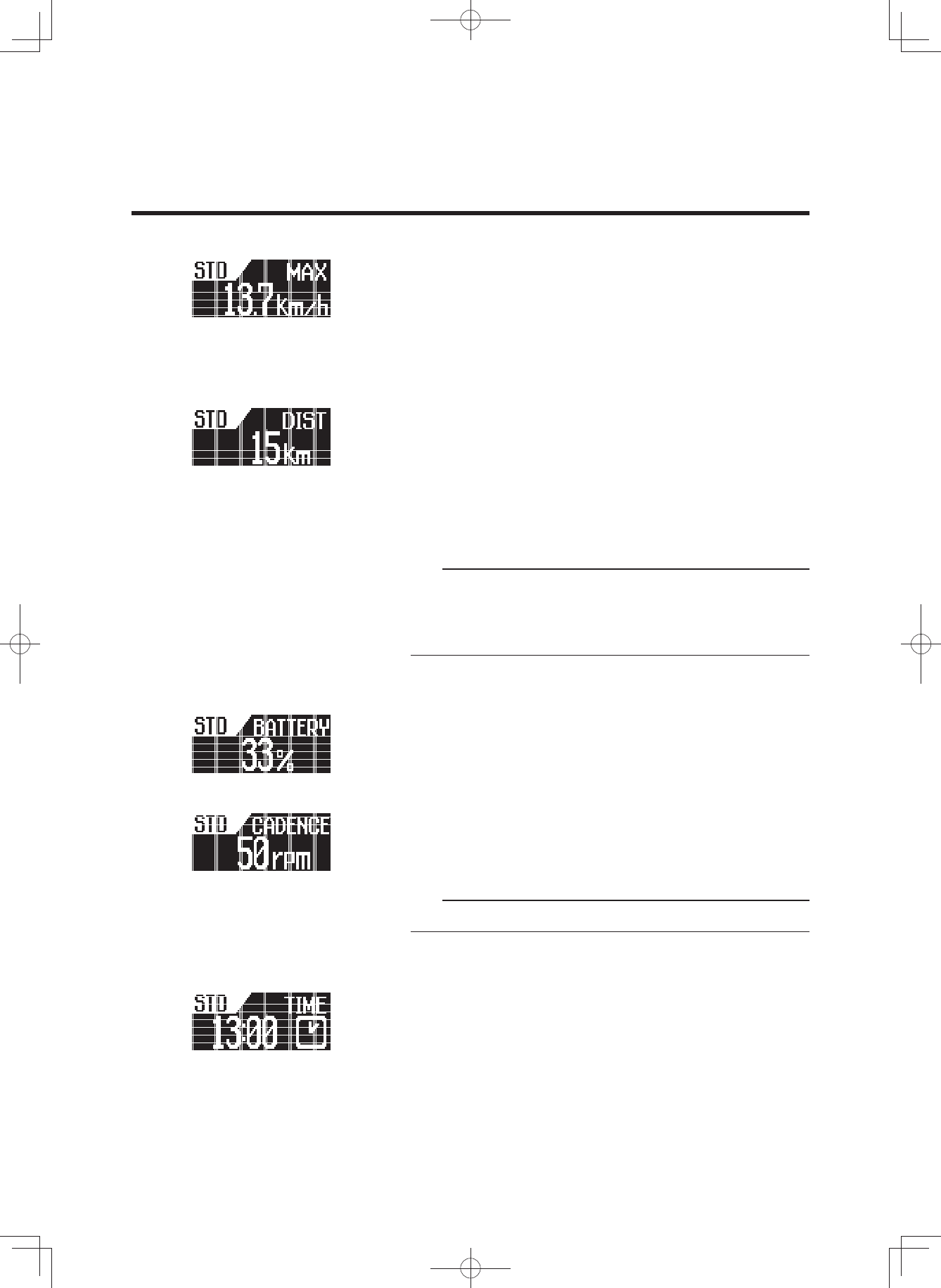
7 Maximum bicycle speed
This displays the maximum bicycle speed (in kilometers
per hour or miles per hour) since it was last reset.
When you turn off the power, the data up to that point will
remain in the display.
For the procedure of resetting the maximum bicycle
speed, see “Stopwatch and settings”.
7 Remaining assist distance
This displays an estimate of the distance (in kilometers or
miles) that can be ridden with assist on the residual bat-
tery capacity of the battery installed. If you switch the as-
sist mode when the remaining assist distance is displayed,
the estimate of the distance that can be ridden with assist
changes.
The remaining assist distance estimate cannot be reset.
TIP
• The remaining assist distance changes depending on
the riding situation (hills, headwind, etc.) and as the
battery runs down.
• If in “Off mode”, “- - - -” is displayed.
7 Battery capacity (%)
This displays the power remaining in the battery.
The residual battery capacity display cannot be reset.
7 Cadence
This displays your pedaling speed in revolutions per min-
ute.
The pedaling cadence display cannot be reset.
TIP
If you pedal in backward, “0” is displayed.
7 Clock
Displays the current time in 24 hour format. To adjust the
time, see “Stopwatch and settings”.
(3$&.0DQXDOB(8B(QJLQGG
20
INSTRUMENT AND CONTROL FUNCTIONS
2 Headlight “On/Off” (Applies only to models
equipped with a headlight powered by the
battery pack. The taillight, which is powered
by the battery pack, is switched on/off with
the headlight.)
Each time you press the light switch, the headlight switch-
es between “On” and “Off”.
(3$&.0DQXDOB(8B(QJLQGG
21
INSTRUMENT AND CONTROL FUNCTIONS
[S---] [▲][S]
[▲][▼]
[▲][▼]
[▲][▼]
[▲][▼]
[▲][▼]
[▲][▼]
[▲][▼]
[▲][▼]
[S]
[S]
[S]
[S]
[S]
[S]
[S]
[S]
[▼]
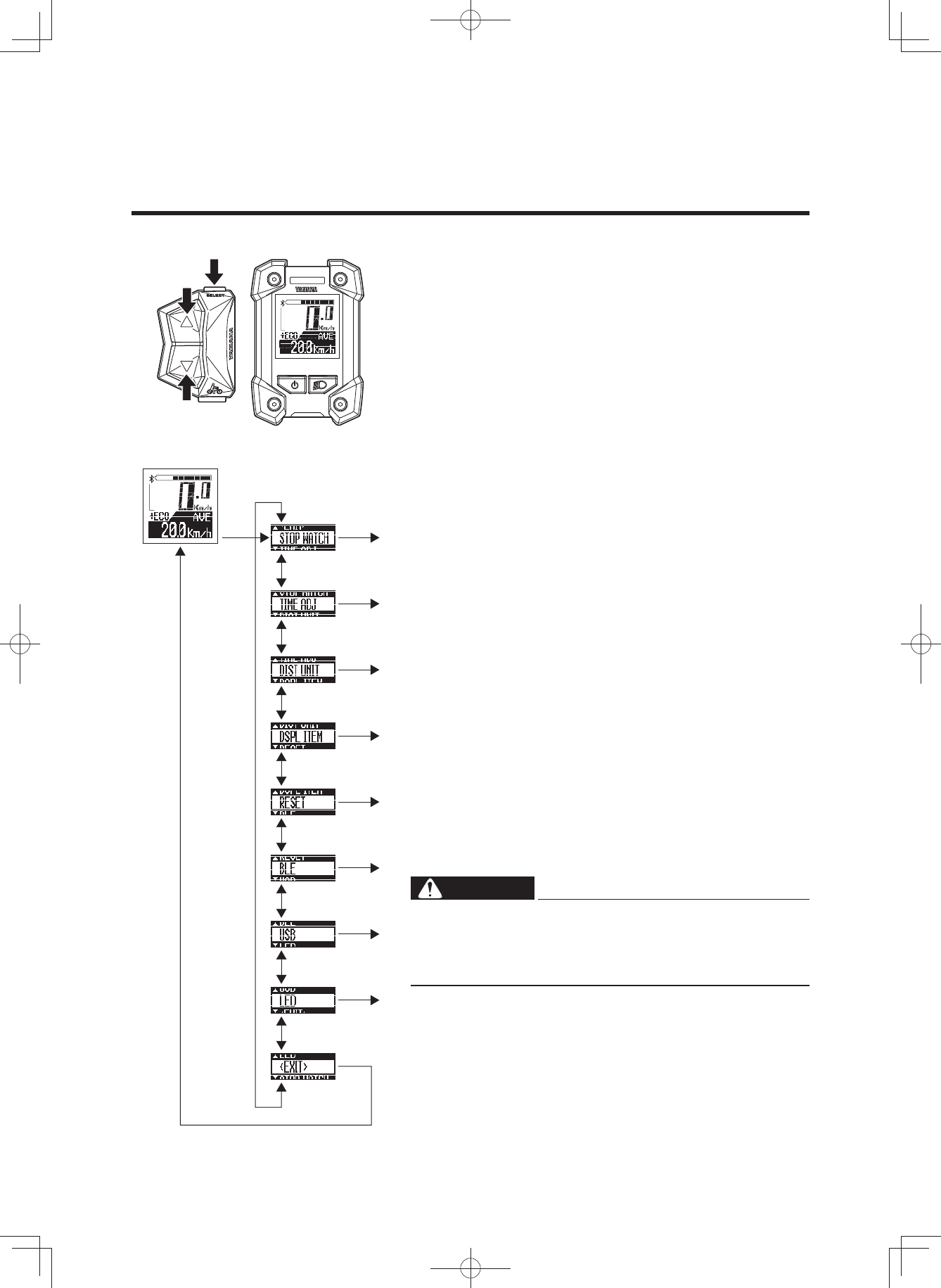
2 Stopwatch and settings
The display enables the following.
• STOPWATCH
Stopwatch function
• TIME ADJ (TIME ADJUST)
Clock setting
• DIST UNIT (DISTANCE UNIT)
km/mile setting
• DSPL ITEM (DISPLAY ITEM)
Sets the items to be displayed in the function display
during normal riding.
• RESET
Resets the values of the trip meter, average bicycle
speed, and maximum bicycle speed.
• BLE (Bluetooth low energy technology)
Switches the profiles and turns off the wireless func-
tion.
• USB
Switches the USB receptacle between a power supply
port and a wired communication port.
• LED
Changes between lighting the assist mode lamp and
keeping the assist mode lamp unlit.
1. Press the function select switch for 2 seconds or long-
er.
2. Select an item by using the assist mode switches (up &
down).
Press the function select switch at the displayed item
that you want to select, and the selected item will then
be displayed.
Selecting “EXIT” returns to the main riding display.
WARNING
For all setting procedures, be sure to stop the bicycle
and perform the required settings in a safe location.
Otherwise, lack of attention to surrounding traffic
could cause an accident.
[S---] ···· Press the function select switch for 2 seconds or
longer
[S] ······· Press the function select switch
[▲] ······ Press the assist mode switch (up)
[▼] ······ Press the assist mode switch (down)
Main riding display
(3$&.0DQXDOB(8B(QJLQGG
22
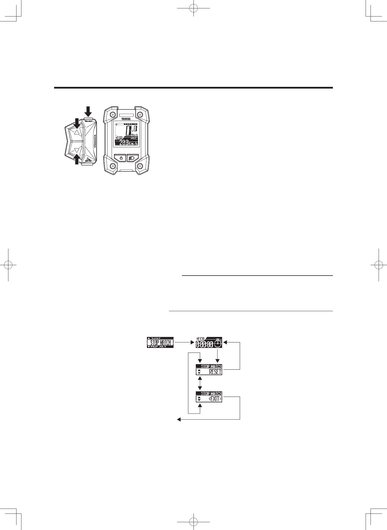
INSTRUMENT AND CONTROL FUNCTIONS
7 STOPWATCH
The stopwatch counts time in seconds up to a maximum
of 9 hours 59 minutes 59 seconds.
If this maximum is reached, it will automatically start over
from 0 (zero) and continue counting.
• TIME MEASUREMENT
Use the function select switch to start and stop time
measurement.
Press the function select switch for 2 seconds or longer
to “RESET” the measured time.
• RESET
When the function select switch is pressed, the meas-
ured time will be reset and the measuring display will
be shown.
Use the assist mode switches (up & down) to go to the
“EXIT” display.
• EXIT
When the function select switch is pressed, the display
will return to the main riding display.
Use the assist mode switches (up & down) to go to the
“RESET” display.
TIP
• It is possible to return to the main riding display without
interrupting time measurement.
• When the power is turned off, the measured time will
be reset.
[S---]
[S]
[S]
[S]
[▲]
[▼]
[▲][▼]
Repetition of measurement start/stop by [S]
To main riding
display
Reset of the measurement value
(3$&.0DQXDOB(8B(QJLQGG
23
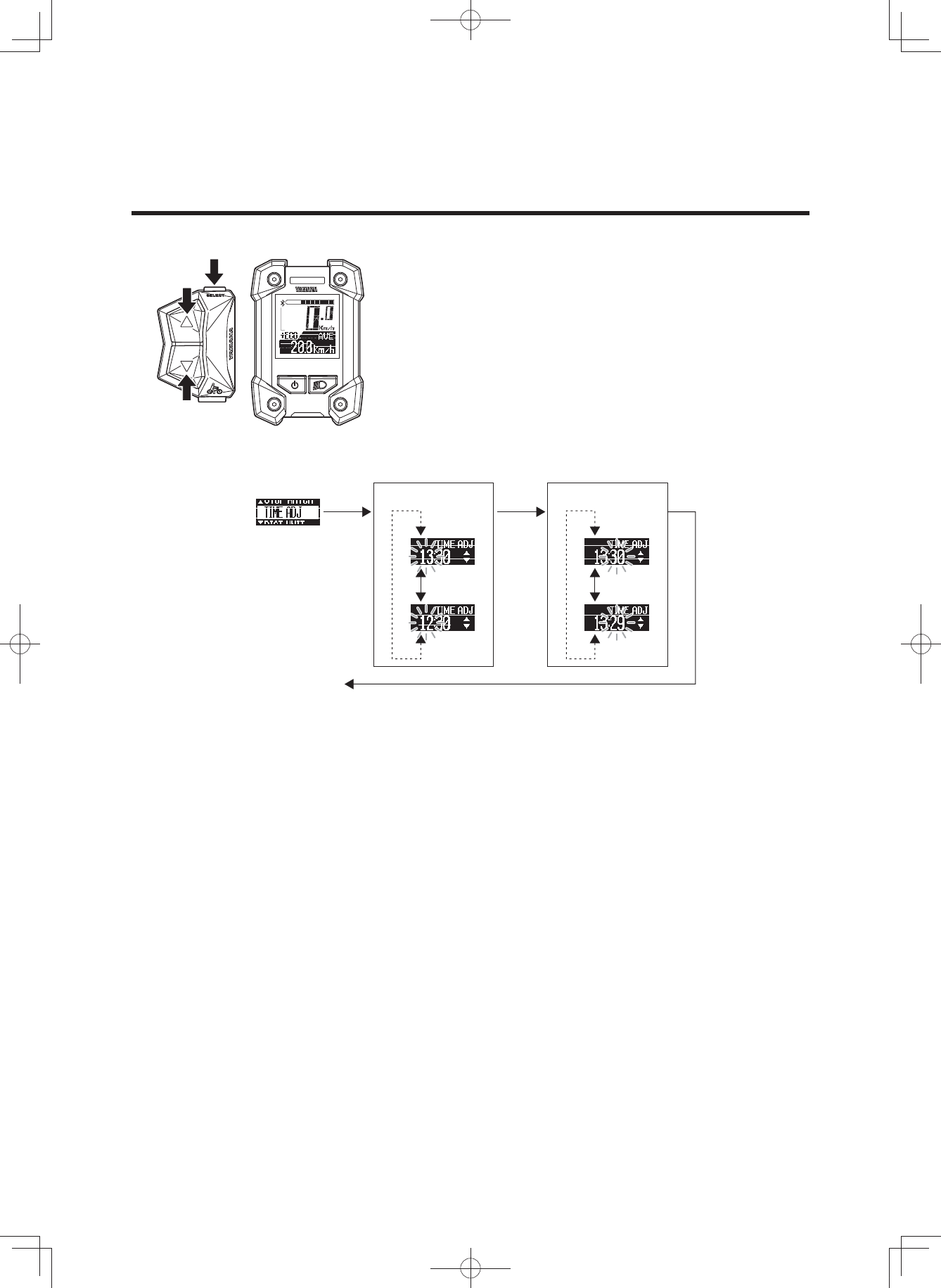
INSTRUMENT AND CONTROL FUNCTIONS
7 TIME ADJ (TIME ADJUST)
You can adjust the time of the clock.
1. Check that the “Hour” is flashing and adjust the hour by
using the assist mode switches (up & down).
2. Press the function select switch to adjust the minutes.
3. Check that the “Minute” is flashing and adjust the min-
utes by using the assist mode switches (up & down).
4. Press the function select switch to return to the main
riding display.
[S]
[▼]
[▲]
[S] [S]
[▼]
[▲]
[▲][▼][
▲][▼]
To main riding
display
“Hour” adjustment “Minute” adjustment
(3$&.0DQXDOB(8B(QJLQGG
24
INSTRUMENT AND CONTROL FUNCTIONS
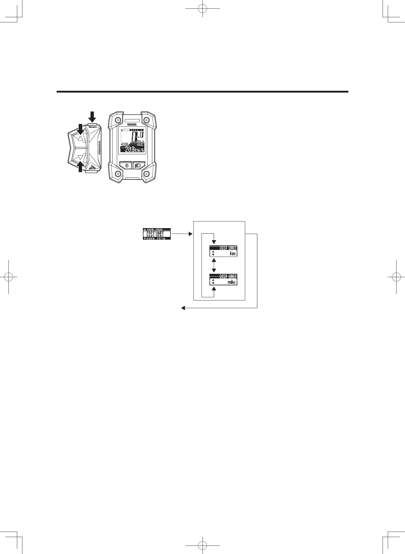
7 DIST UNIT (DISTANCE UNIT)
You can select the display units for distance and speed.
When “km” is selected, the travelled distance will be indi-
cated in kilometers and the speed in km/h.
When “mile” is selected, the travelled distance will be indi-
cated in miles and the speed in mph.
1. Select “km” or “mile” by using the assist mode switches
(up & down).
2. Press the function select switch when the desired unit
is indicated in the display. This setting will then be kept
and the display will return to the main riding display.
[S]
[▼]
[▲]
[S]
[▲][▼]
To main riding
display
Selection of
“km” or “mile”
(3$&.0DQXDOB(8B(QJLQGG
25
INSTRUMENT AND CONTROL FUNCTIONS
Function display
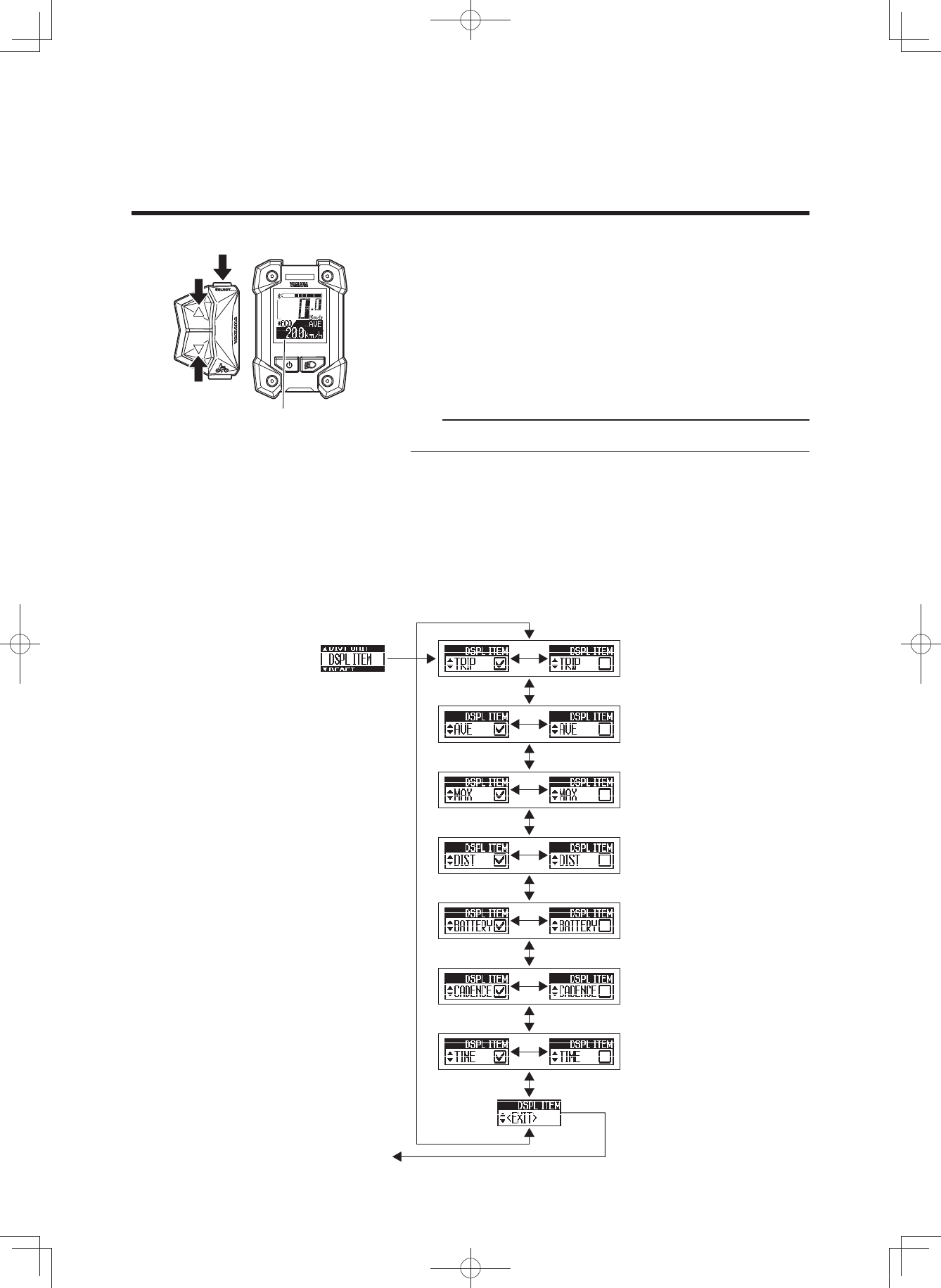
7 DSPL ITEM (DISPLAY ITEM)
You can select to show or hide different items in the func-
tion display during normal riding.
The items which you can select to show or hide are: TRIP
(trip meter), AVE (average bicycle speed), MAX (maxi-
mum bicycle speed), DIST (remaining assist distance),
BATTERY (battery capacity (%)), CADENCE (cadence),
and TIME (clock).
TIP
You cannot hide the odometer indication.
1. Select an item by using the assist mode switches (up &
down).
2. Use the function select switch to show or hide the se-
lected item. (When an item is shown, a check mark will
be shown in the check box.)
3. When you press the function select switch in the “EXIT”
display, the setting will be kept and the display will re-
turn to the main riding display.
[S]
[S]
[▲]
[S]
[S]
[S]
[S]
[S]
[S]
[S]
[▼]
[▲][▼]
[▲][▼]
[▲][▼]
[▲][▼]
[▲][▼]
[▲][▼]
[▲][▼]
To main riding
display
(3$&.0DQXDOB(8B(QJLQGG
26
INSTRUMENT AND CONTROL FUNCTIONS
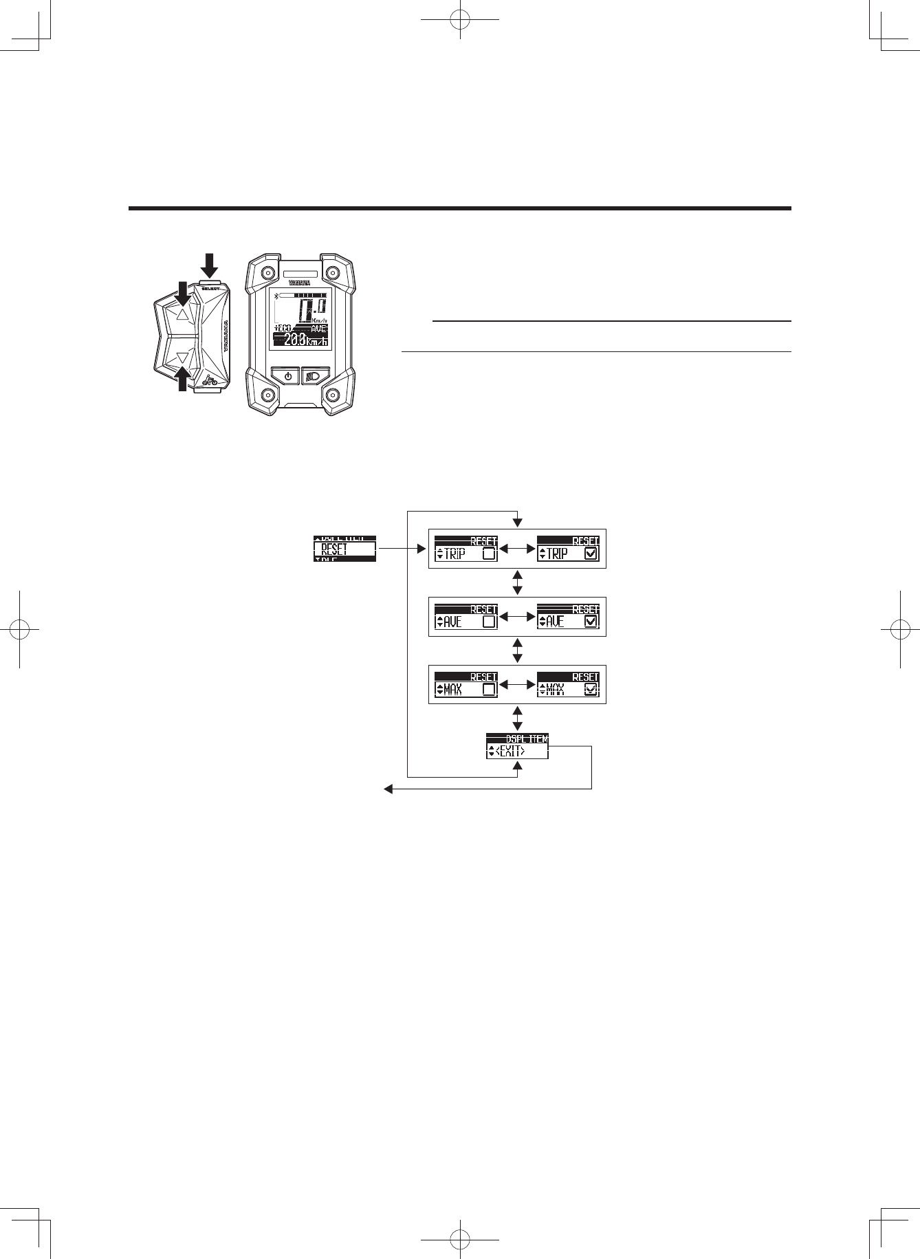
7 RESET
You can reset the TRIP (trip meter), AVE (average bicycle
speed), and MAX (maximum bicycle speed) values.
TIP
You cannot reset the odometer.
1. Select an item by using the assist mode switches (up &
down) and use the function select switch to place a
check mark in the check box for the item that you want
to reset.
2. When you press the function select switch in the “EXIT”
display, the items with check marks will be reset and
the display will return to the main riding display.
[S]
[S]
[▲]
[S]
[S]
[S]
[▼]
[▲][▼]
[▲][▼]
[▲][▼]
Items with check marks will be
reset and the display will return to
the main riding display
(3$&.0DQXDOB(8B(QJLQGG
27
INSTRUMENT AND CONTROL FUNCTIONS
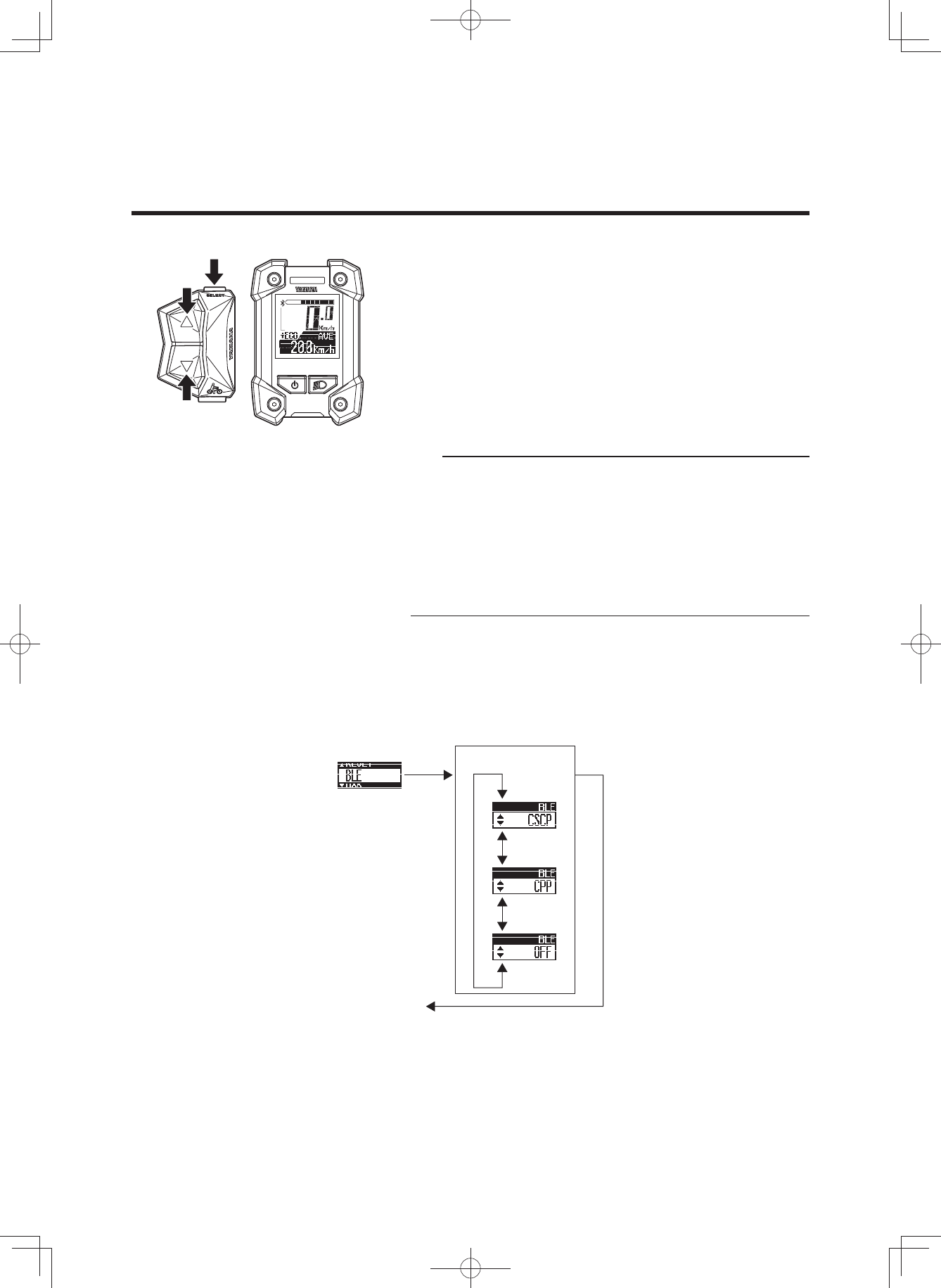
7 BLE (Bluetooth low energy technology)
You can set the profile to use the wireless function with
Bluetooth low energy technology, or you can select not to
use the wireless function.
When “CSCP” is selected, the Cycling Speed and Ca-
dence Profile will be available.
When “CPP” is selected, the Cycling Power Profile will be
available.
When “OFF” is selected, the wireless function will be inac-
tive.
TIP
• Set the profile according to the wireless communication
equipment that communicates via Bluetooth low energy
technology.
• For the output power level of each profile, see “SPECI-
FICATIONS”.
• Even if the power is turned off, the setting will be kept.
When the power is turned on the next time, the last
used setting will be selected.
1. Select “CSCP”, “CPP”, or “OFF” by using the assist
mode switches (up & down).
2. When you press the function select switch at the de-
sired item display, the setting will be kept and the main
riding display will be shown.
[S]
[▼]
[▲]
[S]
[▲][▼]
[▲][▼]
To main riding
display
Selection of “CSCP”,
“CPP”, or “OFF”
(3$&.0DQXDOB(8B(QJLQGG
28
INSTRUMENT AND CONTROL FUNCTIONS
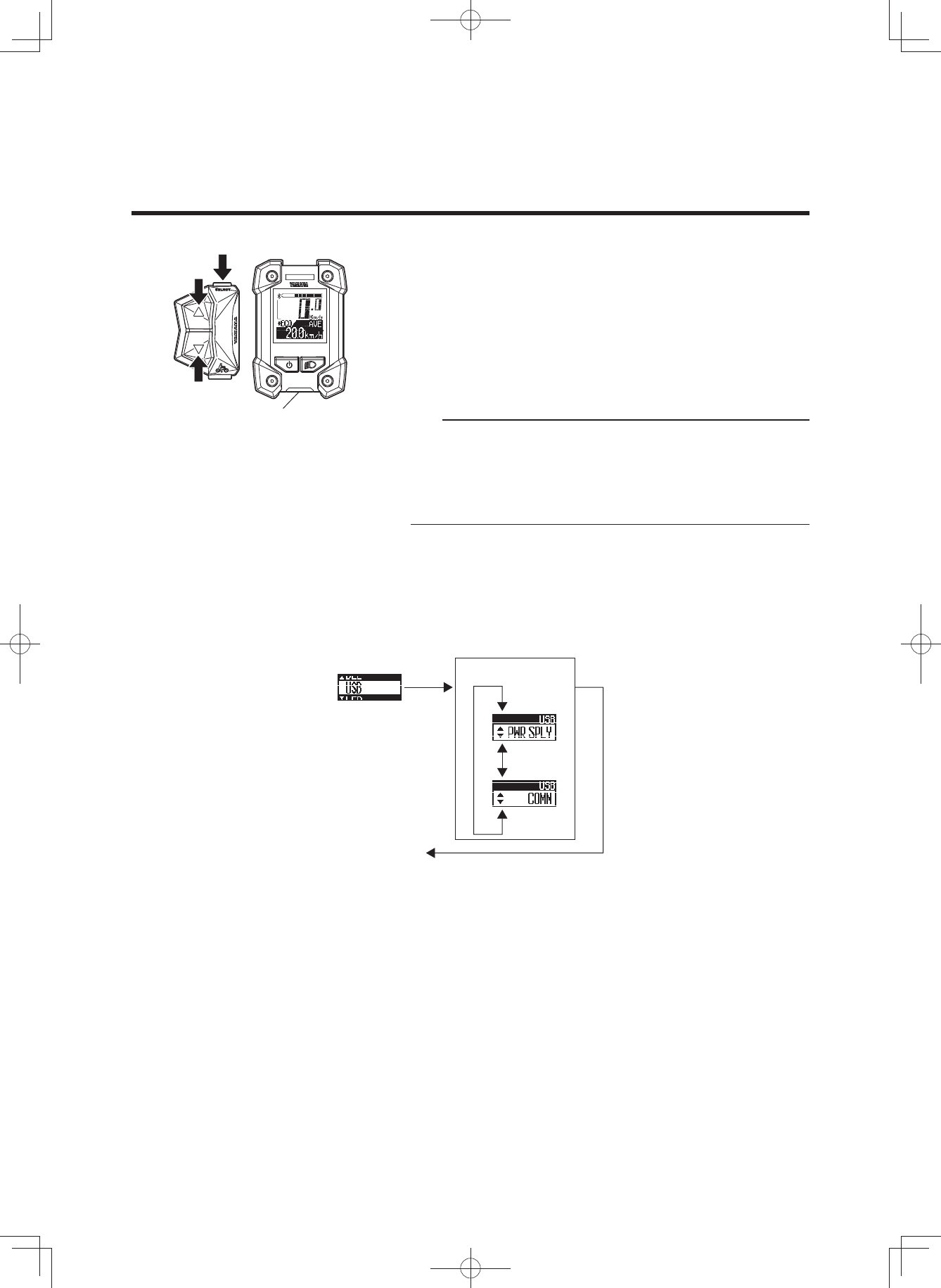
7 USB
You can select the USB receptacle as a power supply re-
ceptacle or as a receptacle for communication over a
wired connection.
When “PWR SPLY” is selected, it can be used as a power
supply receptacle.
When “COMM” is selected, it can be used as a receptacle
for wired communication.
TIP
• Normally you should not select “COMM” because this
is a service mode used for wired communication by
dealers.
• When the power is turned off, the mode automatically
changes to “PWR SPLY”.
1. Select “PWR SPLY” or “COMM” by using the assist
mode switches (up & down).
2. When you press the function select switch at the de-
sired item display, the setting will be kept and the main
riding display will be shown.
USB receptacle
[S]
[▲]
[S]
[▼]
[▲][▼]
To main riding
display
Selection of
“PWR SPLY” or “COMM”
(3$&.0DQXDOB(8B(QJLQGG
29
[S]
[▲]
[S]
[▼]
[▲][▼]
INSTRUMENT AND CONTROL FUNCTIONS
Assist mode lamp
To main riding
display
Selection of
“ON” or “OFF”
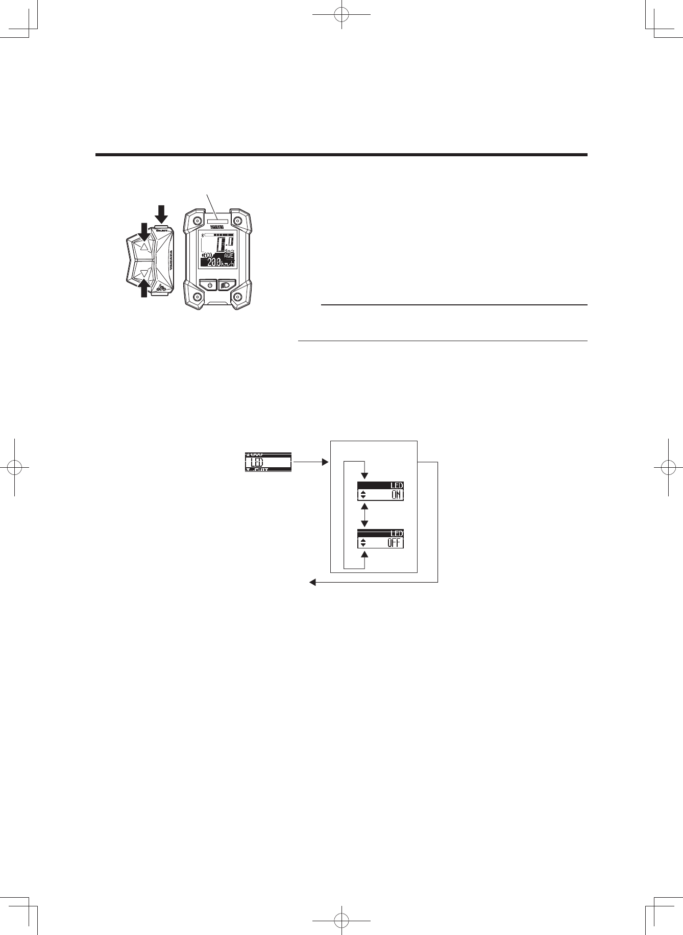
7 LED
You can select to light up the assist mode lamp according
to the assist mode or keep the assist mode lamp unlit all
the time.
When “ON” is selected, the assist mode lamp will light up
according to the assist mode.
When “OFF” is selected, the assist mode lamp will remain
unlit all the time.
TIP
Even if the assist mode lamp is set to “OFF”, it will light up
in red if an error occurs.
1. Select “ON” or “OFF” by using the assist mode switch-
es (up & down).
2. When you press the function select switch at the de-
sired item display, the setting will be kept and the main
riding display will be shown.
(3$&.0DQXDOB(8B(QJLQGG
30
INSTRUMENT AND CONTROL FUNCTIONS
2 Pushing assist
When you are on or off the bicycle and start moving it, you
can use pushing assist without pedaling the bicycle.
To use pushing assist, press and hold the pushing assist
switch.
Pushing assist will stop in the following situations:
• When you release the pushing assist switch.
• If you press another switch at the same time.
• When you start to pedal.
• If your bicycle speed exceeds 6 km/h.
• If you select Off mode.
• If the wheels are not turning (when braking or coming
into contact with an obstacle, etc.).
TIP
The maximum speed will vary depending on the selected
gear. The maximum speed will become slower in a lower
gear.
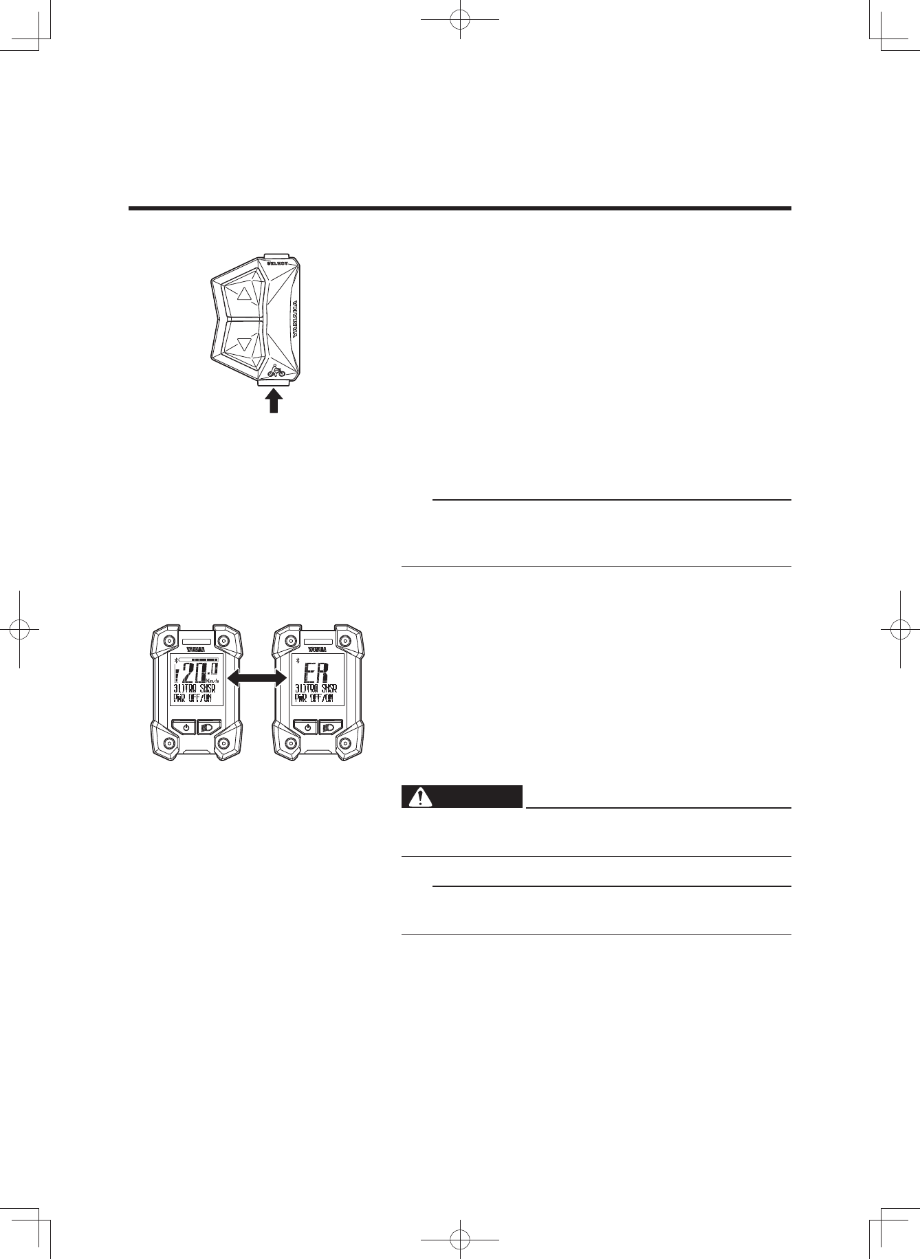
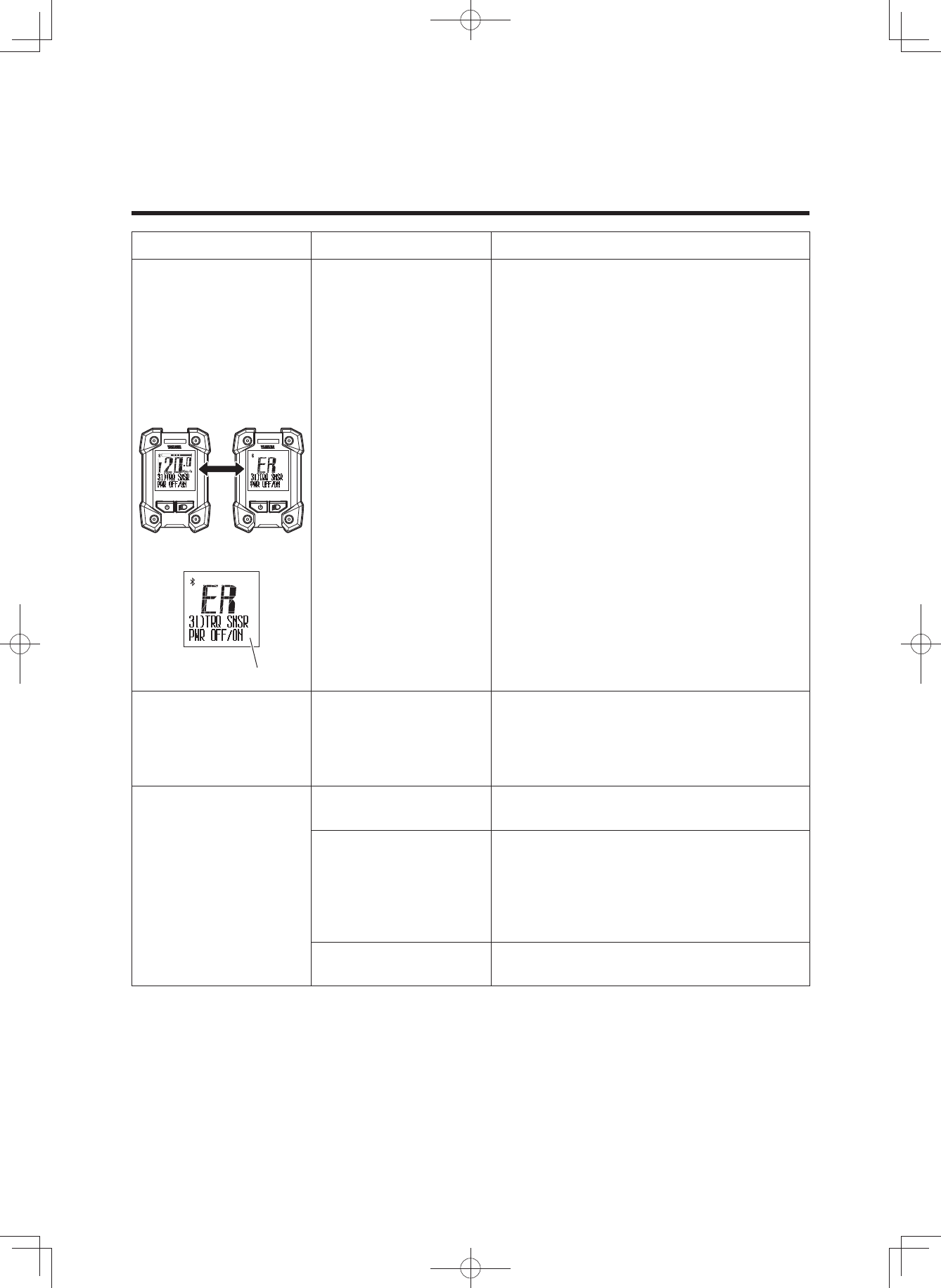
2 Diagnosis mode
The e-Bike Systems are equipped with a diagnosis mode.
If a malfunction or fault occurs in the e-Bike Systems, the
assist mode lamp will light up in red, and the main riding
display and “ER” will be shown alternately, while an error
description will inform you of the type of error in the func-
tion display. See “TROUBLESHOOTING” regarding symp-
toms and remedies for abnormal displays and abnormal
flashing.
WARNING
If the problem cannot be solved, have your bicycle in-
spected by a dealer as soon as possible.
TIP
Even if the assist mode lamp is set to “OFF”, it will light up
in red if a malfunction or fault occurs.
Displays alternately
(3$&.0DQXDOB(8B(QJLQGG
31
INSTRUMENT AND CONTROL FUNCTIONS
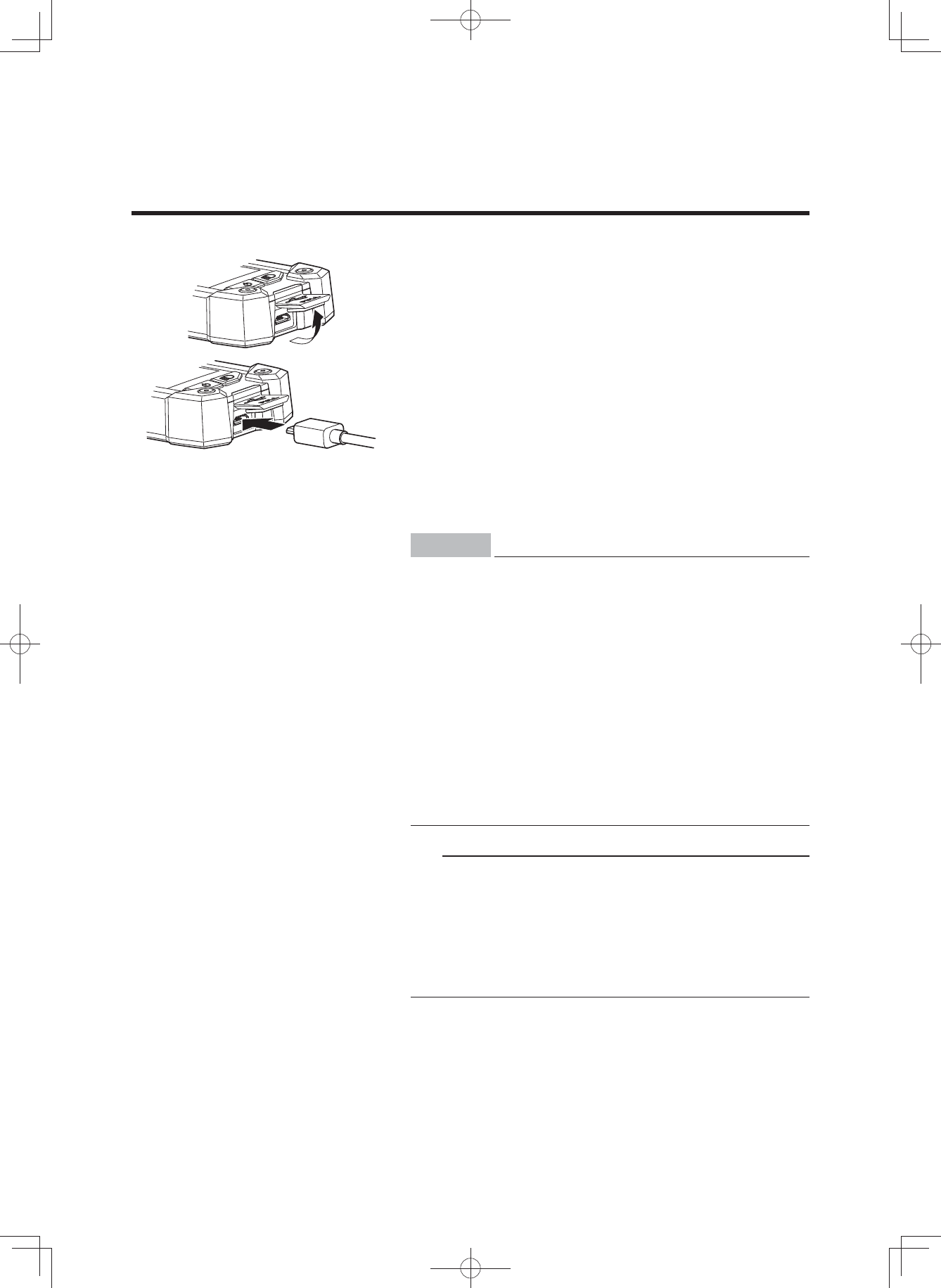
2 Power supply to external devices
Power can be supplied to most external devices (e.g. vari-
ous smart phones etc.) by connecting a commercial USB
2.0 OTG cable.
[To supply power]
1. Open the USB receptacle cap of the display.
2. Connect the USB cable to the switch and external de-
vice.
3. Turn on the power of the vehicle.
[To stop the power supply]
1. Turn off the power of the vehicle.
2. Disconnect the USB cable and put on the cap of the
USB receptacle.
NOTICE
• Do not apply unreasonable force on the USB plug
or pull the USB cable.
• Check that the USB plug is facing the right way and
not totally out-of-position with the USB receptacle
or slanted, and make sure it is fully inserted all the
way in.
• Do not connect the USB receptacle and the USB
plug in a wet state.
• Use a USB 2.0 OTG cable that conforms to the
standards.
• Do not insert foreign objects into the USB recepta-
cle unit.
Otherwise the display unit and external device may
malfunction.
TIP
• Power is supplied automatically when an external de-
vice is connected with the USB cable.
• No power is supplied if the remaining capacity of the
battery pack is low.
• The power supply of the vehicle will go off and power
supplied by the USB connection will also stop if the ve-
hicle is not operated for 5 minutes.
(3$&.0DQXDOB(8B(QJLQGG
32
INSTRUMENT AND CONTROL FUNCTIONS
2 Communication with Bluetooth low energy
technology
The wireless equipment corresponding to the CSCP or
CPP profiles can provide the communication via Bluetooth
low energy technology.
1. Set the profiles of the display unit by referring to “Stop-
watch and settings”.
Also confirm that they are in accordance with the con-
nection settings of your wireless communication equip-
ment.
2. Check that the Bluetooth indicator is displayed.
3. Select “Yamaha ####*” from the user menu of your
wireless communication equipment.
For more information, see the instruction manual of the
wireless communication equipment.
* “####” of “Yamaha ####” is a combination of irregular al-
phanumeric characters.
TIP
• Keep the distance between the display and wireless
communication equipment within 1 m. The maximum
communication distance of this equipment is 1 m.
If the wireless communication equipment is kept in a
bag, etc., the actual communication distance might be
shorter.
• Do not use the equipment in places with magnetic
fields, static electricity, or electromagnetic interference.
If the equipment is used near transmitters, broadcast-
ing stations or the following type of equipment, wireless
communication may not be possible.
• Microwave ovens
• Digital cordless phones
• Wireless communication devices
• Near other wireless equipment using the 2.4 GHz
band.
• Do not cover the display with objects such as aluminum
sheets that block the radio waves. Otherwise, wireless
communication may not be possible.
• For the output power level of each profile, see the
“SPECIFICATIONS”.
Bluetooth
indicator
(3$&.0DQXDOB(8B(QJLQGG
33
BATTERY PACK AND CHARGING PROCEDURE
The battery pack equipped for the Yamaha e-Bike Sys-
tems is a lithium-ion battery. The lithium-ion battery is
lightweight and offers superior capacity. However, it does
have the following characteristics.
• Its performance decreases in extremely hot or cold en-
vironments.
• It naturally loses its charge.
The battery pack for the Yamaha e-Bike Systems also has
an embedded computer which notifies you of estimated
residual battery capacity and suspected faults via the bat-
tery capacity indicator lamp.
By pressing the battery capacity indicator button, you can
display the residual battery capacity for approximately 5
seconds.
See “CHECKING THE RESIDUAL BATTERY CAPACITY”
for the estimate of the residual battery capacity. See
“TROUBLESHOOTING” for information on fault flashing.
Charging
plug Power plug
Battery charger lamp
Charger display
Charging connector Battery capacity
indicator button
Battery
capacity
indicator
Battery capacity
indicator lamp
(3$&.0DQXDOB(8B(QJLQGG

34
BATTERY PACK AND CHARGING PROCEDURE
Appropriate charging environments
For safe and efficient charging, use the battery charger in
a location that is:
• Flat and stable (when on the bicycle)
• Free of rain or moisture
• Out of direct sunlight
• Well-ventilated and dry
• Not accessible to children or pets
• Temperature between 15–25 °C
Inappropriate charging environments and
solutions.
The hot and cold environments described below can
cause charging to enter standby or suspension without
fully charging the battery.
• Summertime charging standby/suspension
If charging in a location receiving direct summer sun-
light or immediately after riding, the battery charger
might enter charging standby (all four battery capacity
indicator lamps flash slowly). See “Reading the charg-
ing status”. This is to automatically stop charging in or-
der to protect the battery from exceeding the specified
temperature while charging. You can avoid charging
suspension by starting to charge with the battery cold
or at a room temperature of 15–25 °C. If charging sus-
pension occurs, move the battery charger to a cool lo-
cation to reduce the charging standby time.
• Wintertime charging standby/suspension
Charging standby will occur if the temperature is 0 °C
lower. If charging is started and the temperature drops
below this level due to late-night cooling or other fac-
tors, charging is suspended and standby mode is en-
tered to protect the battery. In such cases, restart
charging at an indoor location with a temperature of
15–25 °C.
• Noise on televisions/radios/computers
Charging next to televisions, radios, or similar appli-
ances might cause static, flickering images, and other
interference. If this occurs, recharge in a location fur-
ther away from the television or radio (such as in an-
other room).
(3$&.0DQXDOB(8B(QJLQGG
35
BATTERY PACK AND CHARGING PROCEDURE
WARNING
If a charging fault occurs during charging, remove the
power plug of the battery charger from the socket and
wait for the battery pack/battery charger to cool.
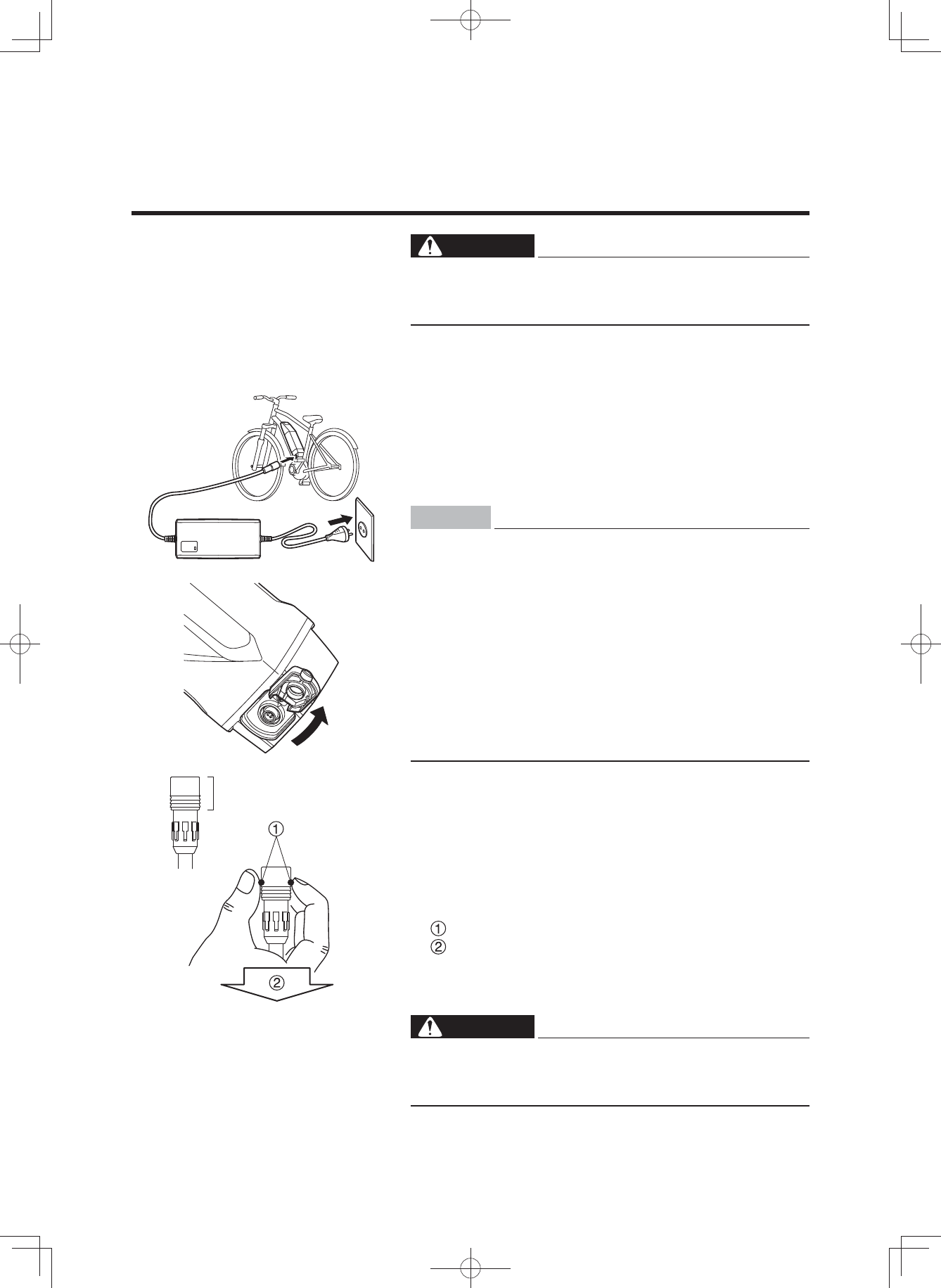
[CHARGING THE BATTERY PACK MOUNTED ON THE
BICYCLE]
1. Connect the power plug of the battery charger to a
household power outlet.
2. Remove the cap of charging inlet from the charging
connector on the battery pack, and connect it to the
charging plug on the battery charger.
NOTICE
• Do not connect the charging plug of the battery
charger with the charging connector of the battery
in a wet state.
• Be sure to connect the charging plug only after the
charging connector on the battery pack is com-
pletely dry.
Otherwise the battery charger and battery may mal-
function.
• Do not apply excessive force to the charging plug
or pull on the cord with the charging plug connect-
ed to the battery.
Otherwise, the plug or connector may be damaged.
3. See “Reading the charging status”, and check that the
battery charger is charging the battery pack.
4. The battery capacity indicator lamps will light up one by
one until all four are on. Then, when charging is com-
plete, all of the lamps will go off.
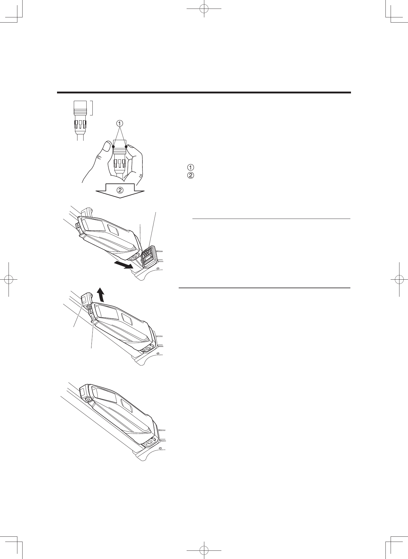
5. Confirm that charging is complete, and then disconnect
the charging plug from the battery pack.
How to disconnect the plug (see the left figure)
Grasp the lock-release ring.
Pull it out straight.
6. Place the cap of charging inlet on the battery pack’s
charging connector.
WARNING
Never handle the power plug, charging plug or touch
the charger contacts with wet hands. This could result
in electric shock.
Lock-release ring
(3$&.0DQXDOB(8B(QJLQGG
36
BATTERY PACK AND CHARGING PROCEDURE
TIP
• Charging will start automatically.
• If the display unit is turned on while the battery pack is
charging, all normal displays will be shown, including
the battery capacity indicator, but the assist system will
not function.
• When the battery pack is connected to the battery
charger, battery charger lamp will flash at approximate-
ly 0.2 second intervals to indicate that charging is pre-
paring to charge the battery pack. Leave it as it is and
charging will start normally.
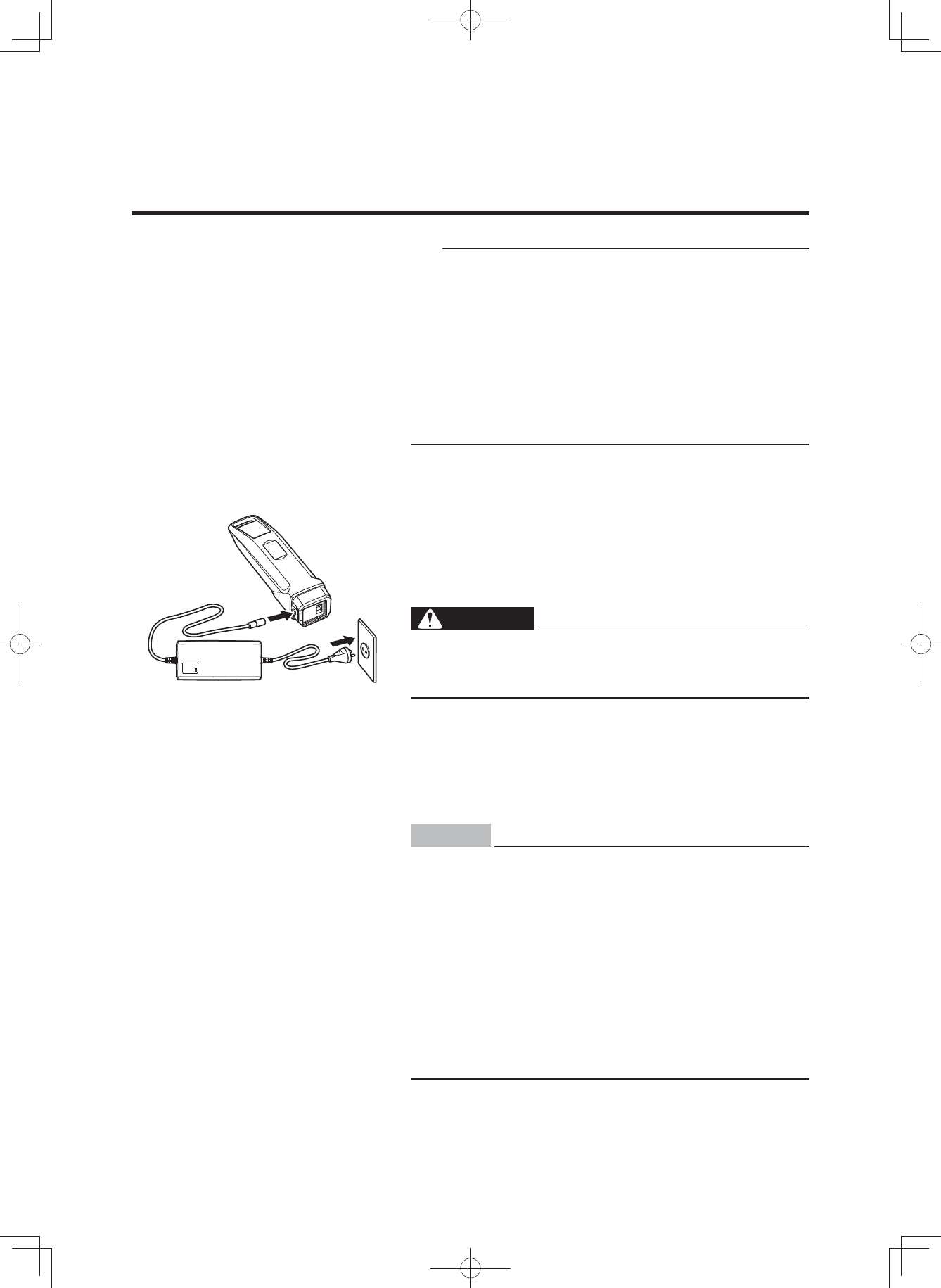
[CHARGING THE BATTERY PACK REMOVED FROM
THE BICYCLE]
1. Turn the display unit off.
2. Insert the key into the battery lock, and turn it to re-
lease the battery lock.
3. Remove the battery pack.
WARNING
Use both hands when removing the battery pack, be-
ing careful not to drop it. Dropping the battery pack
on your foot could result in injury.
4. Connect the power plug of the battery charger to a
household power outlet.
5. Remove the cap from the charging connector on the
battery pack, and connect it to the charging plug on the
battery charger.
NOTICE
• Do not connect the charging plug of the battery
charger with the charging connector of the battery
in a wet state.
• Be sure to connect the charging plug only after the
charging connector on the battery pack is com-
pletely dry.
Otherwise the battery charger and battery may mal-
function.
• Do not apply excessive force to the charging plug
or pull on the cord with the charging plug connect-
ed to the battery.
Otherwise, the plug or connector may be damaged.
(3$&.0DQXDOB(8B(QJLQGG
37
BATTERY PACK AND CHARGING PROCEDURE
6. See “Reading the charging status”, and check that the
battery charger is charging the battery pack.
7. The battery capacity display lamps will light up one by
one until all four are on. Then, when charging is com-
plete, all of the lamps will go off.
8. Confirm that charging is complete, and then discon-
nect the charging plug from the battery pack.
How to disconnect the plug (see the left figure)
Grasp the lock-release ring.
Pull it out straight.
9. Place the cap on the battery pack’s charging connec-
tor.
10.
Mount the battery pack on the bicycle.
TIP
Mounting method of the battery pack
• Insert the battery in the direction of the arrow so that
the battery bottom is aligned to the top of the case.
• Insert the upper part of the battery in the direction of
the arrow so that the battery handle is aligned to the
top of the key lock.
• Press the upper part of the battery toward the frame
until it clicks into place to secure it.
Lock-release ring
Top of the case
Battery bottom
Key lock
Battery handle
(3$&.0DQXDOB(8B(QJLQGG

38
BATTERY PACK AND CHARGING PROCEDURE
11.
Make sure that it is securely attached by pulling the
battery after installation.
NOTICE
Make sure there is no foreign matter on the battery
pack contacts before inserting the battery pack.
(3$&.0DQXDOB(8B(QJLQGG
39
BATTERY PACK AND CHARGING PROCEDURE
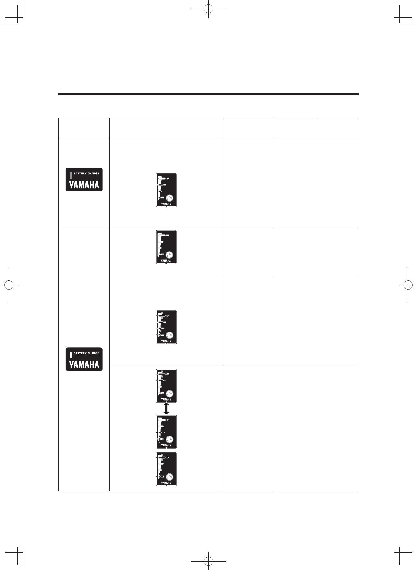
Reading the charging status
Battery
charger lamp Battery capacity indicator lamps Current
status Details
On
Lit power lamps indicate the
amount of charging completed. A
flashing power lamp indicates
current progress.
Charging During charging, the
battery capacity indicator
lamps light up one by one.
(Example: Battery is approximately
50–75 % charged.)
Off
Charging
completed
When charging is
complete, the charging
lamp on the battery
charger and the battery
capacity indicator lamp on
the battery pack go off.Off
Four lamps flash simultaneously. Battery is in
standby mode.
* The battery
internal
temperature
is too high
or too low.
Charging will
automatically restart when
a temperature is reached
that allows charging. (See
“Appropriate charging
environments”.)
When possible, always
perform charging at the
optimal temperature of
15–25 °C.
Battery is in
fault mode.
There is a fault in the
charging system. See
“TROUBLESHOOTING”.
(3$&.0DQXDOB(8B(QJLQGG
40
BATTERY PACK AND CHARGING PROCEDURE
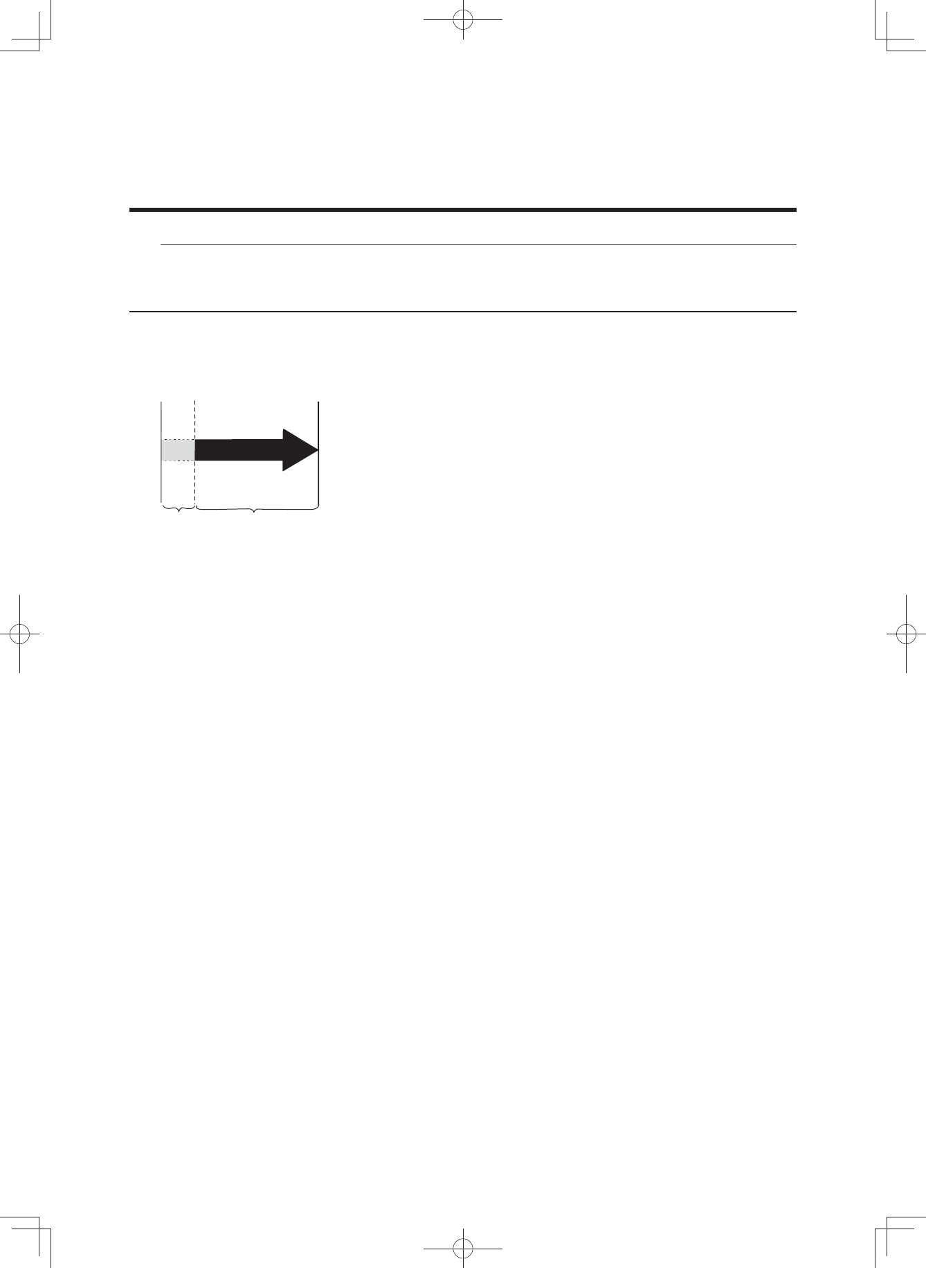
Charging time guidelines
Although charging time varies depending on residual bat-
tery capacity and external temperature, if the battery has
been exhausted, it generally takes approximately 4 hours
(500 Wh)/3.5 hours (400 Wh) until one battery capacity in-
dicator lamp flashes.
If the battery pack enters standby mode while charging,
charging time will increase by an equal amount.
* If charging after a long period of disuse, the charging
time will be lengthened depending on the battery status.
However, note that if the battery capacity indicator lamps
do not flash in fault pattern (See “Reading the charging
status”), there is no malfunction.
TIP
For example, even if normal charging is started, if the battery temperature or the surrounding tem-
perature is too high or too low, the charging may be extended or charging may be stopped without
the battery being charged sufficiently in order to protect the battery.
Charging
start Charging
finish
Charging
standby Charging time*
(Not including standby time)
(3$&.0DQXDOB(8B(QJLQGG
41
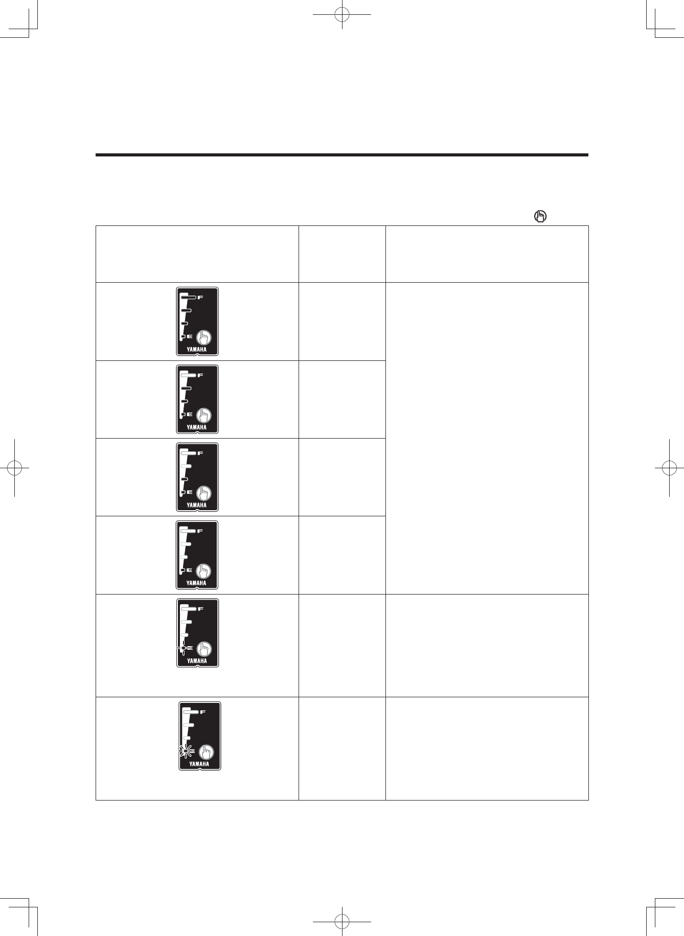
You can check the estimate of how much capacity is left in the battery and to what extent it is
charged. The check can be performed using either the display unit’s residual battery capacity indi-
cator or the battery’s residual battery capacity indicator lamps.
TIP
• Even if the battery’s capacity reaches 0 (zero), you can still ride the bicycle as a regular bicycle.
• If you are using an old battery pack, the residual battery capacity indicator may suddenly display
very little power when you start moving. This is not a malfunction. Once riding stabilizes and the
load is reduced, the proper value is displayed.
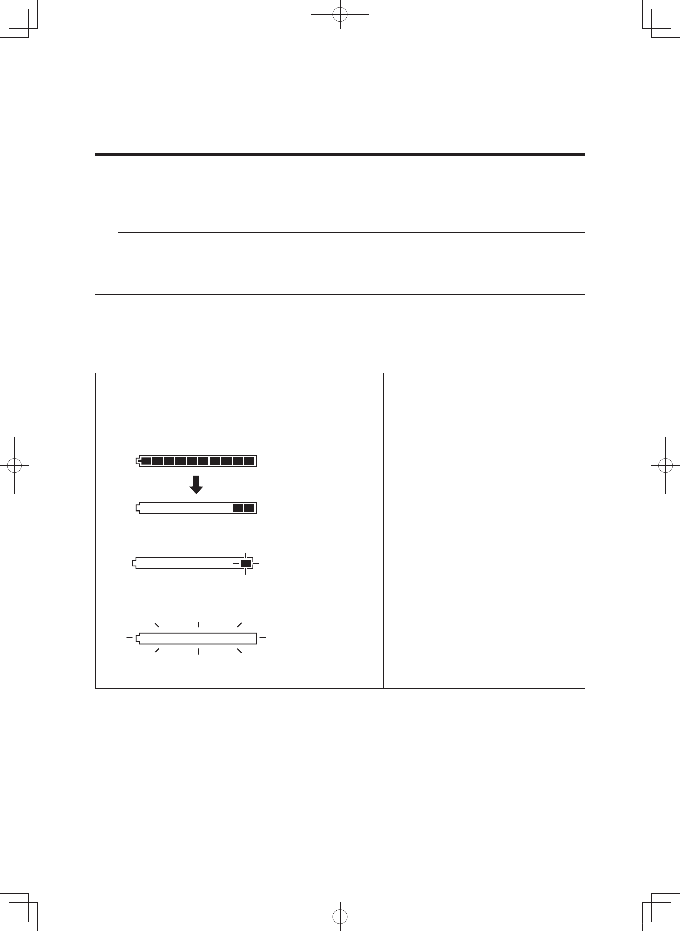
Residual battery capacity indicator display and estimate of residual bat-
tery capacity for display unit
The residual battery capacity can be displayed as a numerical value on the LCD display.
Display of the residual battery
capacity for the display unit
Display of the
residual
battery
capacity
Applicable situation
100–11 %
When you turn on the power of the
LCD multi-function drive controller and
ride continually after the battery is fully
charged, the segments for the residual
battery capacity indicator go out one
by one each time the residual battery
capacity is reduced by 10 %.
Slow flashing
<every 0.5 seconds>
10–1 % There is very little residual battery
capacity left. Please charge the
battery soon.
Fast flashing
<every 0.2 seconds>
0 %
There is no more residual battery
capacity. Turn off the power for the
LCD multi-function drive controller and
charge the battery pack soon.
* Assist is stopped, but you can still
ride the bicycle as a regular bicycle.
CHECKING THE RESIDUAL BATTERY CAPACITY
(3$&.0DQXDOB(8B(QJLQGG
42
Display of the battery capacity indicator lamps and the estimate of the
residual battery capacity
When checking the residual battery capacity, push the battery capacity indicator button “ ”.
Display of the battery capacity
indicator lamps
Estimate of
the residual
battery
capacity
Applicable situation
100–76 %
From full charge (100 %), the battery
capacity indicator lamps turn off, one
by one.
75–51 %
50–26 %
25–11 %
10–1 % There is very little battery capacity left.
The bottom of lamp slow flashing
<0.5 second interval>
0 % The battery capacity has reached 0
(zero). Please charge the battery
pack.
The bottom of lamp fast flashing
<0.2 second interval>
CHECKING THE RESIDUAL BATTERY CAPACITY
(3$&.0DQXDOB(8B(QJLQGG
43
WARNING
Be sure to perform the inspection before riding the bicycle.
If there is anything you do not understand or find difficult, please consult a bicycle dealer.
NOTICE
• If you confirm there is a fault, have your bicycle inspected at a dealer as soon as possi-
ble.
• The power assist mechanism consists of precision parts. Do not disassemble it.
Along with performing the regular inspection before riding the bicycle, also perform the fol-
lowing inspections.
No. Inspection item Inspection contents
1 Residual battery capacity Is enough capacity left in the battery?
2 Installation status of the battery pack Is it properly installed?
3 Operation of the e-Bike Systems Do the e-Bike Systems operate when you
begin moving?
PRE-OPERATION CHECK
(3$&.0DQXDOB(8B(QJLQGG
44
NOTICE
Do not use high-pressure washers or steam jet clean-
ers since they can cause water seepage, resulting in
property damage or malfunction of the Drive Unit or
display unit or battery pack. Should water get inside
one of these units, have an authorized dealer inspect
your bicycle.
Caring for the battery pack
Use a moist, tightly-wrung towel to wipe off dirt on the bat-
tery case. Do not pour water directly on the battery pack,
such as with a hose.
NOTICE
Do not clean the contacts by polishing them with a file
or using a wire, etc. Doing so could result in a fault.
Storage
Store the system in a place that is:
• Flat and stable
• Well ventilated and free from moisture
• Sheltered from the elements and from direct sunlight
CLEANING AND STORAGE
(3$&.0DQXDOB(8B(QJLQGG

45
Long storage period (1 month or longer)
and using it again after a long storage
period
• When storing the bicycle for a long period (1 month or
longer), remove the battery pack and store it using the
following procedure.
• Decrease the residual battery capacity to where one or
two lamps are lit, and store it indoors in a cool (10 to 20
°C), dry place.
• Check the residual battery capacity once a month, and
if only one lamp is flashing, charge the battery pack for
about 10 minutes. Do not let the residual battery ca-
pacity become too low.
TIP
• If you leave the battery pack at “full charge” or “empty”,
it will deteriorate quicker.
• Due to self-discharge, the battery slowly loses its
charge during storage.
• The battery’s capacity decreases over time but proper
storage will maximize its service life.
• When using it again after a long storage period, be
sure to charge the battery pack before using it. Also, if
you are using it again after storing it for 6 months or
longer, have your bicycle inspected and maintained at
a dealer.
CLEANING AND STORAGE
(3$&.0DQXDOB(8B(QJLQGG

46
The batteries are subject to the Dangerous Goods Legislation requirements. When being transport-
ed by third parties (e.g. via air transport or forwarding agency), special requirements on packaging
and labels must be observed. To prepare the item for shipping, consult a hazardous materials ex-
pert. The customer can transport the batteries by road without further requirements. Do not trans-
port damaged batteries.
Tape or mask off open contacts and pack up the battery pack in such a manner that it cannot move
around in the packaging. Be sure to observe all local and national regulations. In case of questions
concerning transport of the batteries, please refer to an authorized bicycle dealer.
TRANSPORT
(3$&.0DQXDOB(8B(QJLQGG
47
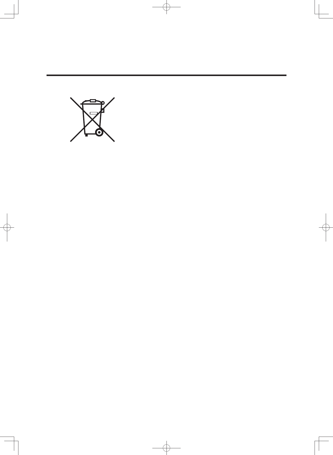
Disposal
The Drive Unit, battery pack, battery charger, display unit,
speed sensor set, accessories and packaging should be
sorted for environmental-friendly recycling.
Do not dispose of the bicycle or its components as house-
hold waste.
For EU countries:
According to the European Guideline 2012/19/EU, electri-
cal devices/tools that are no longer usable, and according
to the European Guideline 2006/66/EC, defective or used
battery packs/batteries, must be collected separately and
disposed of in an environmentally correct manner.
Please return battery packs that are no longer usable to
an authorized bicycle dealer.
CONSUMER INFORMATION
(3$&.0DQXDOB(8B(QJLQGG

48
TROUBLESHOOTING
E-Bike Systems
Symptom Check Action
Pedaling is difficult.
Is the display unit’s
power on? Press the power switch on the display
unit to turn the power on.
Is the battery pack
installed? Install a charged battery pack.
Is the battery pack
charged? Charge the battery pack.
Has the bicycle
remained stationary for
5 minutes or longer? Turn the power on again.
Are you riding on a long
inclined road or carrying
a heavy load during
summertime?
This is not a malfunction. It is a
safeguard engaged when the
temperature of the battery pack or the
Drive Unit is too high. Power assist will
be restored once the temperature of the
battery pack or the Drive Unit has
decreased. Also, you can make this less
likely to occur by shifting to a lower gear
than you would usually use (for example,
by shifting from second to first gear).
Is the air temperature
low (roughly 10 °C or
below)?
During the wintertime, store the battery
pack indoors before use.
Are you charging the
battery pack while it is
mounted on the
bicycle?
Stop charging the battery pack.
The Drive Unit turns
on and off while
riding.
Is the battery pack
correctly installed?
Check to make sure the battery pack is
locked in place.
If this problem still occurs with the
battery pack firmly locked in place, there
may be a loose connection the battery
pack terminals or wires. Have an
authorized dealer inspect your bicycle.
Strange rumbling or
crunching noises
come from the Drive
Unit.
There could be a problem inside the
Drive Unit.
Smoke or unusual
odor comes from the
Drive Unit.
There could be a problem inside the
Drive Unit.
(3$&.0DQXDOB(8B(QJLQGG
49
TROUBLESHOOTING
Symptom Check Action
The assist mode lamp
lights up in red, the
main riding display
and “ER” are
displayed alternately,
and an error
description is
indicated in the
function display.
Displays alternately
Error displays
The problem occurs in the e-Bike
Systems. Turn off the power and then
turn it on again.
If the problem cannot be solved, have
your bicycle inspected by a dealer as
soon as possible.
The display unit shuts
down immediately
(approx. 4 seconds
later) after switching
the power on.
Are the bicycle’s battery
pack connection
terminals dirty?
Remove the battery pack, clean the
bicycle’s terminals with a dry cloth or
cotton swab, and then install the battery
pack again.
Traveling range has
decreased.
Are you fully charging
the battery pack? Charge the battery pack until full (F).
Are you using the
system under low-
temperature
conditions?
Normal traveling range will be restored
when the ambient temperature rises.
Additionally, storing the battery pack
indoors (in a warm location) before use
will improve traveling range under cold
conditions.
Is the battery pack worn
out? Replace the battery pack.
(3$&.0DQXDOB(8B(QJLQGG
50
TROUBLESHOOTING
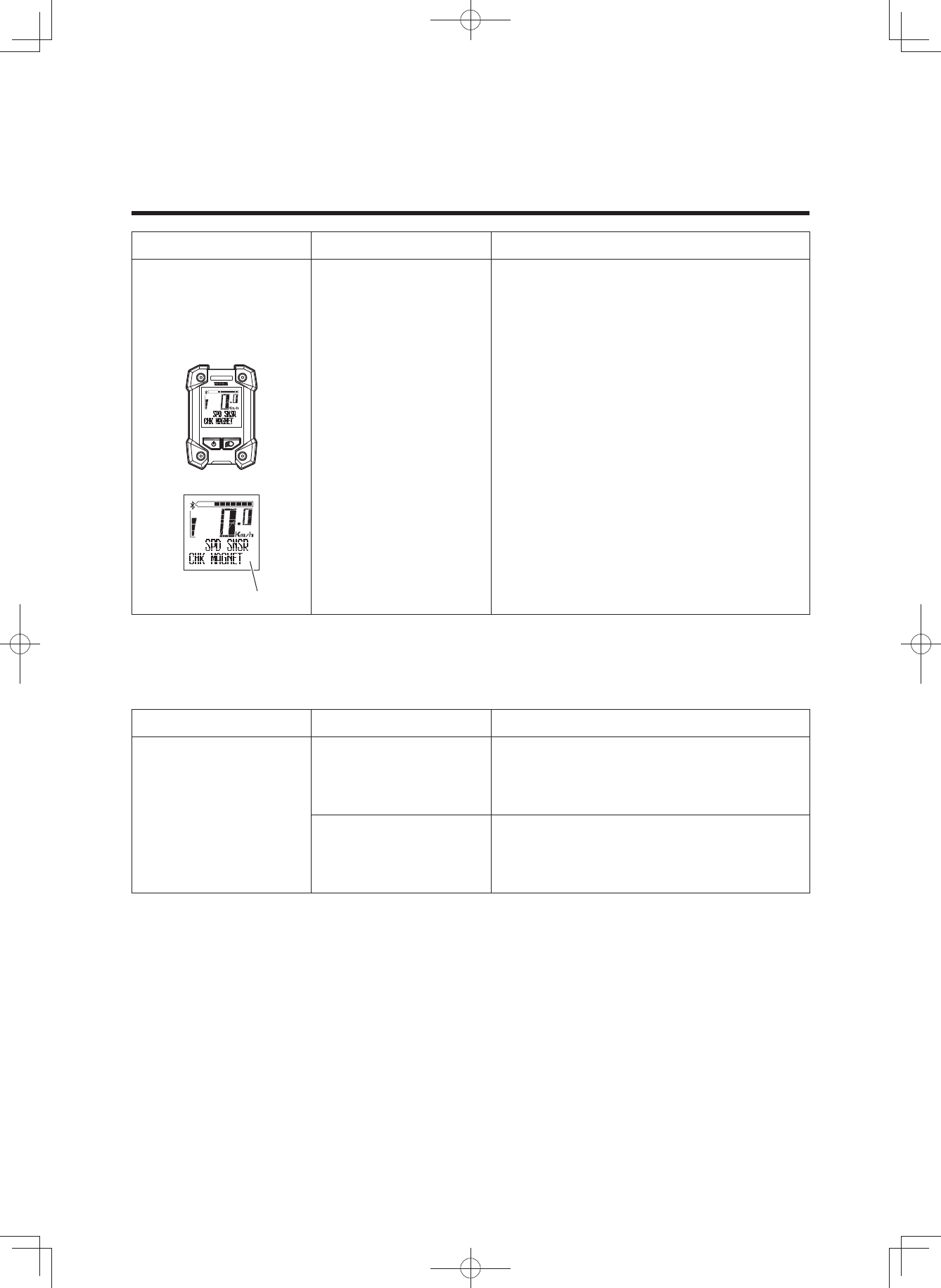
Symptom Check Action
An assist mode lamp
lights up in red and
an error description is
indicated in the
function display.
Error displays
The speed sensor cannot detect a
correct signal.
Turn off the power to the display unit and
then turn it on again, select the assist
mode and then ride for short distance.
Also, make sure the magnet is mounted
correctly on the spokes of the wheels.
Pushing assist function
Symptom Check Action
The pushing assist
function turns off.
Is the tire locked for a
few seconds?
Release your finger from the pushing
assist switch for a moment, and after
making sure that the tires turn, push the
switch again.
Did you pedal while the
pushing assist function
was running?
Take your feet off the pedals, and remove
your finger from the pushing assist
switch for a moment, and then press it
again.
(3$&.0DQXDOB(8B(QJLQGG

51
TROUBLESHOOTING
Power supply of external devices via USB connection
Symptom Check Action
Power is not supplied.
Is the display unit’s
power on? Press the power switch on the display
unit to turn the power on.
Is the USB version
correct? Use an external device that complies
with USB 2.0.
Is the USB cable type
correct? Use an OTG cable. And connect the host
side to the switch.
Is the USB cable firmly
connected? Re-connect the USB cable.
Is the USB receptacle
or USB plug terminal
dirty or wet?
Disconnect the USB cable from the
display unit and external device. Remove
the dirt and water on the USB receptacle
and USB plug terminal and re-connect
the cable.
Is USB set to “COMM”?
Set the USB settings to “PWR SPLY” by
referring to “Stopwatch and settings” or
turn off the power and then turn it on
again.
Wireless communication with Bluetooth low energy technology
Symptom Check Action
Wireless
communication
cannot be used.
Are both the wireless
communication settings
of the display unit and
your wireless
communication
equipment turned off? Set the communication profiles by
referring to “Stopwatch and settings”,
and then set the correct communication
profiles of the wireless equipment or
application software.
Are the communication
profiles of the wireless
equipment or
application software
that communicates
wirelessly with the
communication profiles
of the display correct?
The display values of
the external wireless
communication
equipment are wrong.
Did you change the
settings of the
communication
profiles?
Reset pairing for a moment, set the
communication profiles of the display,
and then establish pairing again.
For resetting of pairing and the
procedure of establishing pairing, refer
to the instruction manual supplied with
the wireless communication equipment.
(3$&.0DQXDOB(8B(QJLQGG
52
TROUBLESHOOTING
Battery pack and charger
Symptom Check Action
Cannot charge
Is the power plug firmly
connected? Is the
charging plug firmly
inserted in the battery
pack?
Reconnect and try charging again.
If the battery pack still does not charge,
the battery charger might be
malfunctioning.
Are the residual battery
capacity lamps lit?
Review charging method and try
charging again.
If the battery pack still does not charge,
the battery charger might be
malfunctioning.
Are the battery charger
or battery pack contact
terminals dirty or wet?
Remove the battery pack from the battery
charger and the charger plug from the
socket. Use a dry cloth or cotton swab to
clean the charger and battery contact
terminals, and then reconnect.
There is a contact fault
in the contact terminals.
Remove the battery pack from the
bicycle, connect the charging plug into
the battery pack.
(If lamps still flash alternately, there
might be a fault in the battery pack)
When remount the battery pack on the
bicycle and press the power switch of
display unit, if lamps still flash
alternately, there might be a fault in the
Drive Unit.
There is a contact fault
in the contact terminals.
Remove the battery pack from the battery
charger, mount the battery on the bicycle
and press the power switch of display
unit. When the charging plug
reconnected into the battery pack, if
lamps still flash simultaneously, there
might be a fault in the battery charger.
Isn’t the charging
connector on the
battery pack wet?
Clean the charging connector and
charging plug, and dry them. After that,
connect the charging plug to the
charging connector.
(3$&.0DQXDOB(8B(QJLQGG
53
TROUBLESHOOTING
Symptom Check Action
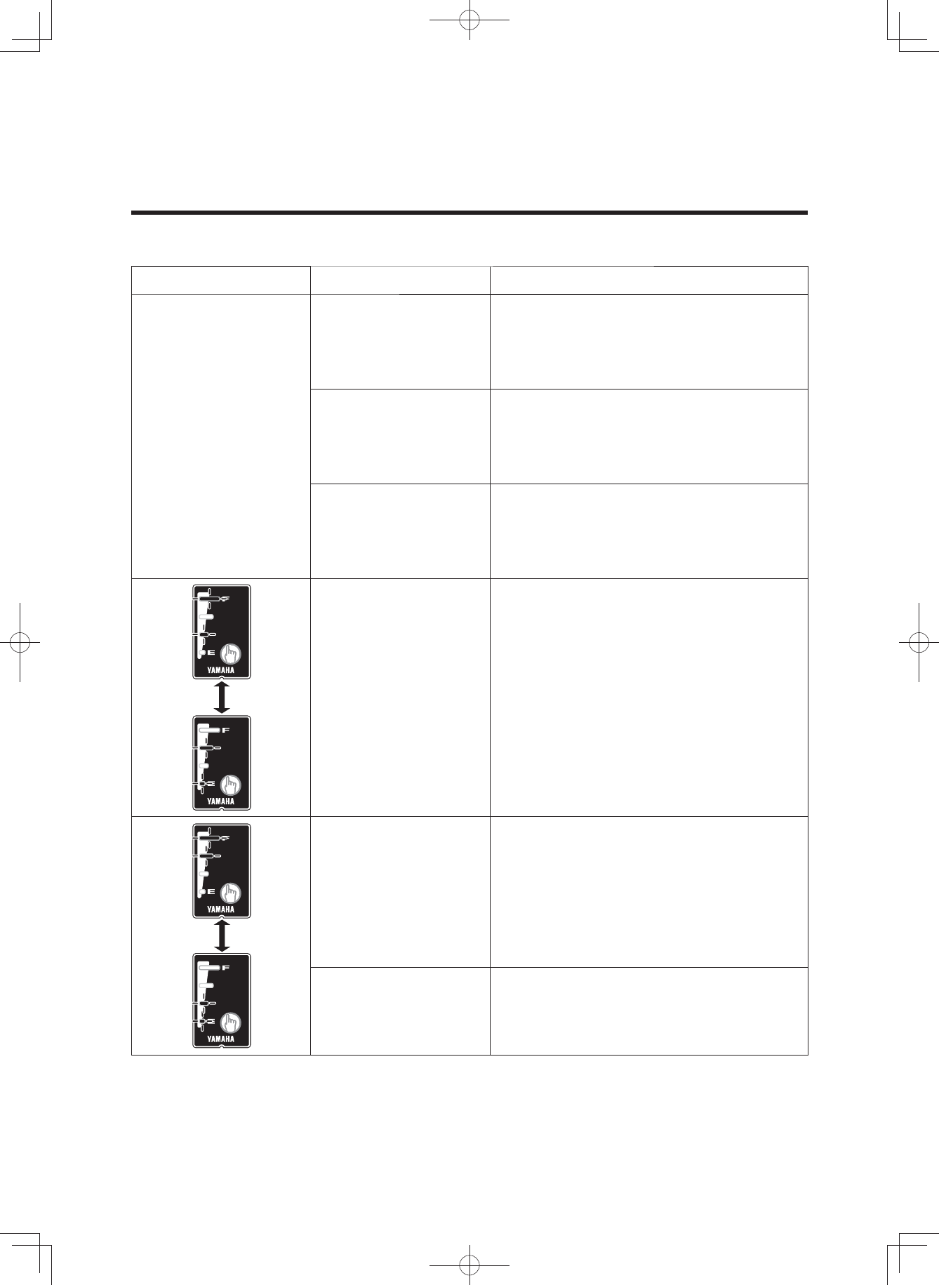
Both side lamps are
flashing
simultaneously. The battery pack protection feature has
been activated and the system cannot be
used. Replace the battery pack at an
authorized dealer as soon as possible.
The battery charger
emits abnormal
noises, foul odors or
smoke.
Unplug the charger plug and immediately
cease operation.
The battery charger
becomes hot.
It is normal for the
battery charger to
become somewhat
warm during charging.
If the battery charger is too hot to be
touched by hand, unplug the charger
plug, wait for it to cool, and consult an
authorized dealer.
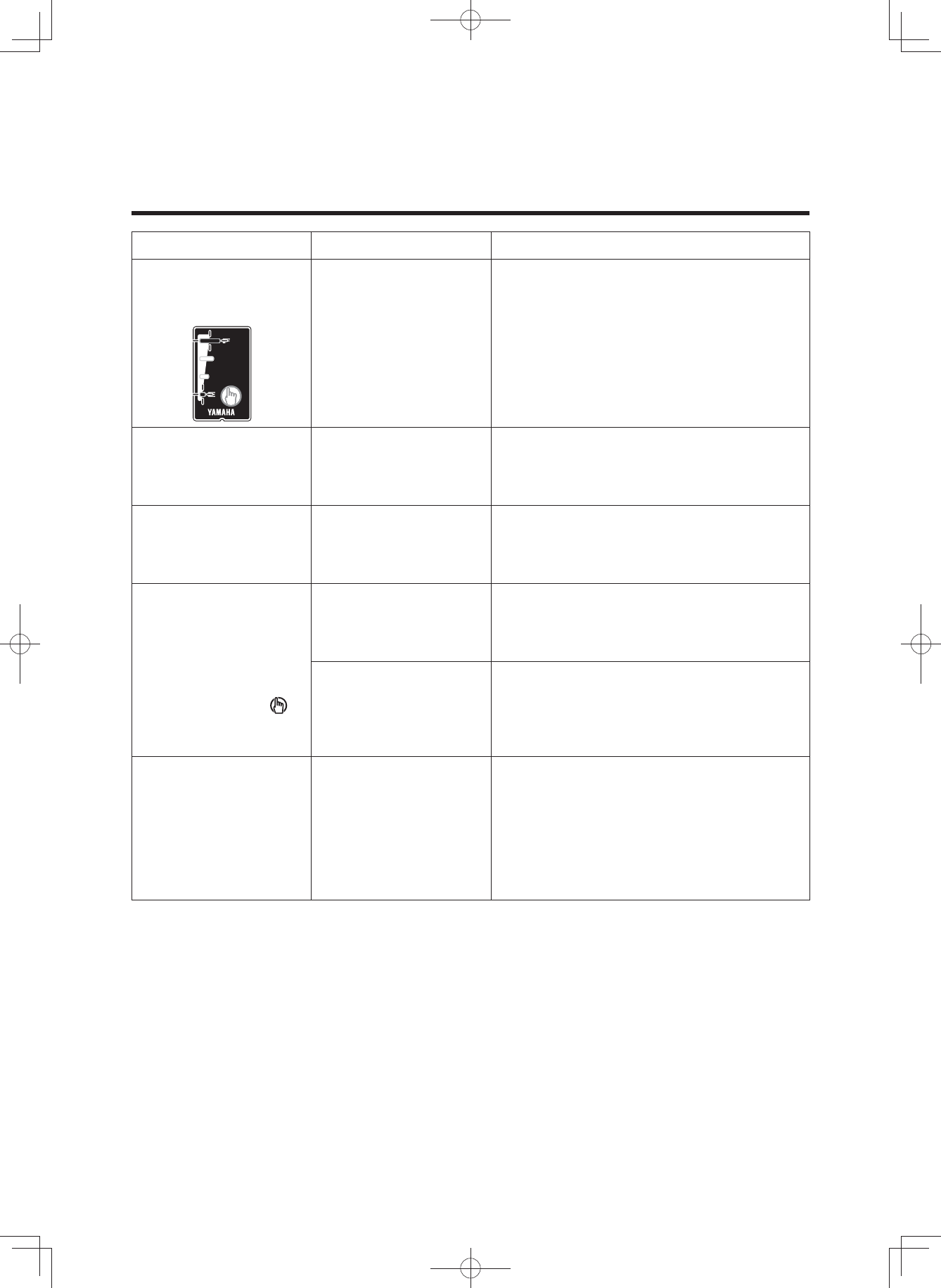
After charging, all of
the battery capacity
indicator lamps do
not light up when the
battery capacity
indicator button “ ”
is pressed.
Has the charger plug
been unplugged or the
battery pack removed
during charging?
Charge the battery pack again.
Did you start charging
with the battery pack at
a high temperature,
such as immediately
after use?
Move to a location where the battery
temperature can reach the range where
charging is possible (15–25 °C), and then
start charging again.
After disconnecting
the charging plug on
the battery charger
from the battery pack,
the battery capacity
indicator lamps
continue to light.
Isn’t the charging
connector on the
battery pack wet?
Clean the charging connector and
charging plug, and dry them.
(3$&.0DQXDOB(8B(QJLQGG

54
SPECIFICATIONS
Range of assist speed 0 to less than 25 km/h
Electric motor Type Brushless DC type
Rated output 250 W
Assist power control method Control method depends on
pedaling torque and bicycle speed
Battery
400 Wh/500 Wh
Type PASB2/PASB5
(Lithium-ion battery)
Voltage 36 V
Capacity 11 Ah/13.6 Ah
Number of battery cells 40
Charger
Type PASC5
Input voltage AC 220–240 V/50–60 Hz
Maximum output voltage DC 42 V
Maximum output current DC 4.0 A
Maximum consumed power 310 VA/180 W
(Charged at AC 240 V)
Applicable type battery PASB2/PASB5
Display unit
(Power supply portion)
USB receptacle type USB2.0 Micro-B (OTG type)
Output current Max. 1000 mA
Rated voltage 5 V
(3$&.0DQXDOB(8B(QJLQGG

55
SPECIFICATIONS
Display unit
(Wireless communication
portion)
Communication system Bluetooth version 4.0
(Bluetooth low energy technology)
Output power Power class 3
Communication range Line-of-sight distance approx.
1 m (3 ft) without interference
Frequency band 2.4 GHz band
(2.400 GHz–2.4835 GHz)
Modulation method *)6.
Supported profiles CSCP*1
CPP*2
*1 CSCP (Cycling Speed and Cadence Profile)
Corresponds to the wheel revolution data and crank revolution data.
*2 CPP (Cycling Power Profile)
Corresponds to the wheel revolution data, crank revolution data, instantaneous power, and accumu-
lated energy.
• Communication is not necessarily guaranteed with all wireless communication devices that have
the same profiles as this system.
Even when a device complies with the specification for Bluetooth low energy technology, there
may be cases where the characteristics, specifications, or communicative environment of the
device with this technology make it impossible to connect, or may result in different control
methods, display or operation.
•YAMAHA MOTOR CO., LTD. can not be held liable in any way for damages or other loss result-
ing from information leaks during the communication via Bluetooth low energy technology.
(3$&.0DQXDOB(8B(QJLQGG

(3$&.0DQXDOB(8B(QJLQGG
13
Display unit
The display unit offers the following operations and infor-
mation displays.
INSTRUMENT AND CONTROL FUNCTIONS
(3$&.0DQXDOB(8B(QJLQGG
NOTICE
7KLVGHYLFHFRPSOLHVZLWK3DUWRIWKH)&&5XOHV
DQG,QGXVWU\&DQDGDOLFHQFHH[HPSW566
VWDQGDUG2SHUDWLRQLVVXEMHFWWRWKHIROORZLQJWZR
FRQGLWLRQV7KLVGHYLFHPD\QRWFDXVHKDUPIXO
LQWHUIHUHQFHDQG7KLVGHYLFHPXVWDFFHSWDQ\
LQWHUIHUHQFHUHFHLYHGLQFOXGLQJLQWHUIHUHQFHWKDW
PD\FDXVHXQGHVLUHGRSHUDWLRQ
/HPDQXHOGXWLOLVDWLRQGHVDSSDUHLOVUDGLRH[HPSWV
GHOLFHQFHGRLWFRQWHQLUOpQRQFpTXLVXLWRX
OpTXLYDOHQWjXQHQGURLWELHQHQYXHHWRXVXUOHV
DSSDUHLOV
/HSUpVHQWDSSDUHLOHVWFRQIRUPHDX[&15G,QGXVWULH
&DQDGDDSSOLFDEOHVDX[DSSDUHLOVUDGLRH[HPSWVGH
OLFHQFH/H[SORLWDWLRQHVWDXWRULVpHDX[GHX[
FRQGLWLRQVVXLYDQWHVODSSDUHLOQHGRLWSDV
SURGXLUHGHEURXLOODJHHWOXWLOLVDWHXUGHODSSDUHLO
GRLWDFFHSWHUWRXWEURXLOODJHUDGLRpOHFWULTXHVXEL
PrPHVLOHEURXLOODJHHVWVXVFHSWLEOHGHQ
FRPSURPHWWUHOHIRQFWLRQQHPHQW
FCC ID : 2ADBKX0P00
IC 740A-X0P00
CAN ICES-3 (B) / NMB-3 (B)
Brand name : YAMAHA
Model no. : X0P00
Manufacturer name : YAMAHA MOTOR CO., LTD.
MADE IN CHINA

14
INSTRUMENT AND CONTROL FUNCTIONS
(3$&.0DQXDOB(8B(QJLQGG
NOTICE
Federal Communication Commission Interfere-nce
Statement
7KLVHTXLSPHQWKDVEHHQWHVWHGDQGIRXQGWRFRPSO\
ZLWKWKHOLPLWVIRUD&ODVV%GLJLWDOGHYLFHSXUVXDQWWR
3DUWRIWKH)&&5XOHV7KHVHOLPLWVDUHGHVLJQHGWR
SURYLGHUHDVRQDEOHSURWHFWLRQDJDLQVWKDUPIXO
LQWHUIHUHQFHLQDUHVLGHQWLDOLQVWDOODWLRQ
7KLVHTXLSPHQWJHQHUDWHVXVHVDQGFDQUDGLDWHUDGLR
IUHTXHQF\HQHUJ\DQGLIQRWLQVWDOOHGDQGXVHGLQ
DFFRUGDQFHZLWKWKHLQVWUXFWLRQVPD\FDXVHKDUPIXO
LQWHUIHUHQFHWRUDGLRFRPPXQLFDWLRQV+RZHYHUWKHUHLV
QRJXDUDQWHHWKDWLQWHUIHUHQFHZLOOQRWRFFXULQD
SDUWLFXODULQVWDOODWLRQ,IWKLVHTXLSPHQWGRHVFDXVH
KDUPIXOLQWHUIHUHQFHWRUDGLRRUWHOHYLVLRQUHFHSWLRQ
ZKLFKFDQEHGHWHUPLQHGE\WXUQLQJWKHHTXLSPHQWRII
DQGRQWKHXVHULVHQFRXUDJHGWRWU\WRFRUUHFWWKH
LQWHUIHUHQFHE\RQHRIWKHIROORZLQJPHDVXUHV
5HRULHQWRUUHORFDWHWKHUHFHLYLQJDQWHQQD
,QFUHDVHWKHVHSDUDWLRQEHWZHHQWKHHTXLSPHQWDQG
UHFHLYHU
&RQQHFWWKHHTXLSPHQWLQWRDQRXWOHWRQDFLUFXLW
GLIIHUHQWIURPWKDWWRZKLFKWKHUHFHLYHULVFRQQHFWHG
&RQVXOWWKHGHDOHURUDQH[SHULHQFHGUDGLR79
WHFKQLFLDQIRUKHOS
FCC Caution: To assure continued compliance, DQ\
FKDQJHVRUPRGLILFDWLRQVQRWH[SUHVVO\DSSURYHGE\WKH
SDUW\UHVSRQVLEOHIRUFRPSOLDQFHFRXOGYRLGWKHXVHUV
DXWKRULW\WRRSHUDWHWKLVHTXLSPHQW([DPSOHXVHRQO\
VKLHOGHGLQWHUIDFHFDEOHVZKHQFRQQHFWLQJWRFRPSXWHU
RUSHULSKHUDOGHYLFHV
FCC Radiation Exposure Statement
7KLVHTXLSPHQWFRPSOLHVZLWK)&&5)UDGLDWLRQH[SRVXUH
OLPLWVVHWIRUWKIRUDQXQFRQWUROOHGHQYLURQPHQW
7KLVWUDQVPLWWHUPXVWQRWEHFRORFDWHGRURSHUDWLQJLQ
FRQMXQFWLRQZLWKDQ\RWKHUDQWHQQDRUWUDQVPLWWHU
7KLVGHYLFHFRPSOLHVZLWK3DUWRIWKH)&&5XOHV
2SHUDWLRQLVVXEMHFWWRWKHIROORZLQJWZRFRQGLWLRQV
7KLVGHYLFHPD\QRWFDXVHKDUPIXOLQWHUIHUHQFHDQG
7KLVGHYLFHPXVWDFFHSWDQ\LQWHUIHUHQFHUHFHLYHG
LQFOXGLQJLQWHUIHUHQFHWKDWPD\FDXVHXQGHVLUHG
RSHUDWLRQ
15
ۑInstalling the battery
The display need be removed and installed for changing
the battery.
• Remove the two bolts on back side of the clamp, and
then remove the display.
• When installing the display, tighten the two display
bolts from the back side of the clamp.
WARNING
Tighten the display bolts to 1.5–2.5 N·m. During rid-
ing, vibration could cause the bolts to come loose
with the risk that the display may fall off.
TIP
• The clamp and display might be installed on the right
side of the stem.
• For models without this clamp, the above note does not
apply.
ۑBattery
Check if the rated battery (CR2032) is installed in the rear
of the display.
If a battery is not installed, or if there is not sufficient bat-
tery power remaining, install a new battery.
To adjust the time and set the units for distance and
speed, see “Stop watch and settings”.
INSTRUMENT AND CONTROL FUNCTIONS
Clamp
Display bolt
(3$&.0DQXDOB(8B(QJLQGG
NOTICE
IC Radiation Exposure Statement:
KLVHTXLSPHQWFRPSOLHVZLWK,&566UDGLDWLRQ
H[SRVXUHOLPLWVVHWIRUWKIRUDQXQFRQWUROOHG
HQYLURQPHQW
'pFODUDWLRQG¶H[SRVLWLRQjODUDGLDWLRQ
&HWpTXLSHPHQWUHVSHFWHOHVOLPLWHVG¶H[SRVLWLRQDX[
UD\RQQHPHQWV,&566GpILQLHVSRXUXQ
HQYLURQQHPHQWQRQFRQWU{Op