Yamaha TF5 TF3 TF1 TF RACK V3.1 Reference Manual TF5/TF3/TF1/TF En Rm F0
User Manual: Yamaha TF5/TF3/TF1/TF-RACK Reference Manual
Open the PDF directly: View PDF ![]() .
.
Page Count: 104 [warning: Documents this large are best viewed by clicking the View PDF Link!]

EN
DIGITAL MIXING CONSOLE
V3.1 Reference Manual

Table of contents
Reference Manual
TF Series
-
2
-
Table of contents
Overview ................................................................................... 4
Using this document................................................................................................ 4
The display .............................................................................................................. 4
Universal operations ................................................................. 8
Library screen .......................................................................................................... 8
Keyboard screen .................................................................................................... 10
Menu .................................................................................................................... 10
Button and slider operations .................................................................................. 10
Toolbar.................................................................................... 11
SCENE screen ........................................................................................................ 11
METER screen ........................................................................................................ 13
RECORDER screen (INPUT/OUTPUT/TITLE LIST screen) .......................................... 14
MONITOR screen .................................................................................................. 18
SETUP screen (V3.0 and later)................................................................................ 21
LOGIN screen (V3.0 and later)............................................................................... 38
OVERVIEW screen.................................................................... 42
CH STRIP section ................................................................................................... 42
FADER section........................................................................................................ 44
Configuration screens............................................................. 47
INPUT screen......................................................................................................... 47
EQ screen .............................................................................................................. 49
GATE screen .......................................................................................................... 53
COMP screen ........................................................................................................ 55
FX screen (FX1/2, InsFX1–6) .................................................................................. 57
SEND TO AUX screen ............................................................................................ 62
ASSIGN screen....................................................................................................... 63
CH VIEW screen..................................................................................................... 64
CH NAME screen ................................................................................................... 71
GEQ screen............................................................................................................ 72
OUTPUT screen ..................................................................................................... 74
SEND FROM screen ............................................................................................... 75
DCA ASSIGN screen............................................................................................... 76
DELAY screen (V2.5 and later)................................................................................ 78
Maintenance screen................................................................. 79
Initialize All Memory screen .................................................................................... 79
Initialize Current Memory screen ............................................................................ 80
Initialize NY64-D screen (V3.0 and later) ................................................................ 80
Input Port Trim screen............................................................................................ 81
Output Port Trim screen......................................................................................... 81
Fader Calibration screen (TF5/TF3/TF1) .................................................................. 82
Channel Color Calibration screen (TF5/TF3/TF1) .................................................... 83
Reference................................................................................. 84
List of parameters saved in Scenes and Presets........................................................ 84
Access limitation parameter list............................................................................... 90
Quick Config Input and input channel relationships ............................................... 92
Warnings and error messages ................................................................................. 94
Index........................................................................................ 96
Product dimensions................................................................. 98

Table of contents
Reference Manual
TF Series
-
3
-
Procedures
Recalling a Preset............................................................................................................. 9
Editing a Preset................................................................................................................ 9
Displaying configuration screens ................................................................................... 11
Saving the current settings as a new Scene.................................................................... 12
Recalling a Scene........................................................................................................... 12
Editing a Scene.............................................................................................................. 12
Setting the input ........................................................................................................... 15
Setting the output......................................................................................................... 16
Recording...................................................................................................................... 17
Playing back files stored on a USB storage device .......................................................... 18
Checking the input signals ............................................................................................ 19
Setting the oscillator...................................................................................................... 20
Using Recall safe function .............................................................................................. 25
Configuring settings in the PREFERENCE screen............................................................. 29
Assigning a feature to a [USER DEFINED KEY] ................................................................ 32
Assigning a feature to a [USER DEFINED KNOB] ............................................................ 33
Assigning a feature to the footswitch............................................................................. 33
Configuring the custom fader bank ............................................................................... 34
Recalling the CUSTOM FADER BANK (TF5/TF3/TF1) ...................................................... 34
Applying access permissions.......................................................................................... 40
Resetting user settings................................................................................................... 40
Loading user settings to other TF series consoles ........................................................... 40
OVERVIEW screen operations......................................................................................... 44
Copying settings from one channel and applying them to another channel .................. 45
Setting stereo link and the input source......................................................................... 48
Adjusting EQ in manual mode....................................................................................... 51
Adjusting EQ in 1-knob EQ mode.................................................................................. 51
Setting HPF ................................................................................................................... 52
Setting LPF .................................................................................................................... 52
Setting the gate............................................................................................................. 54
Setting the compressor.................................................................................................. 56
Setting an effect ............................................................................................................ 58
Setting an insert effect................................................................................................... 58
Adjusting the SEND TO AUX level.................................................................................. 63
Using GEQ .................................................................................................................... 73
Using faders to adjust GEQ (TF5/TF3/TF1) ..................................................................... 73
Adjusting the SEND FROM level .................................................................................... 75
Adjusting the send level from AUX channels, STEREO channels,
and SUB channel to a MATRIX channel (V2.5 and later)..................................... 75
Assigning channels to a DCA group............................................................................... 77
Using the maintenance screen....................................................................................... 79
Calibrating the faders .................................................................................................... 82
If a fader must be calibrated again................................................................................. 82
Adjusting channel colors................................................................................................ 83
Overview
Reference Manual
TF Series
-
4
-
Overview
Using this document
You can search for keywords and view reference pages while using this document.
Searching for keywords
You can use the search function of your PDF viewing software to search for the desired text
within the document.
When using Adobe Reader, enter the desired text in the search bar and press your computer's
<Enter> key to begin the search.
Moving backward and forward in your viewing history
When viewing this document using Adobe Reader, you can easily move backward and
forward in your viewing history. This is particularly useful when you click a link to jump to
another page, and then want to return to the original page.
Using the index
An index of the keywords and topics in this document can be found on page 96. You can use
the index to easily jump to the desired explanation or topic.
The display
Here we will introduce the different screens displayed on the TF Series console display.
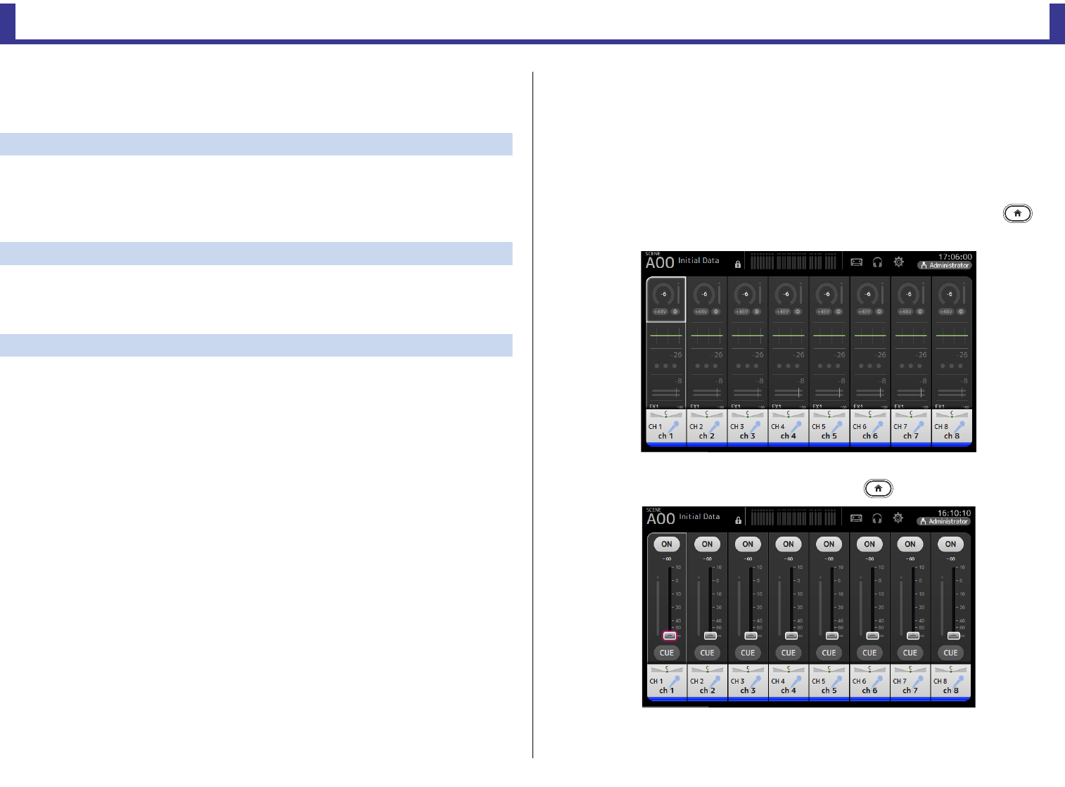
OVERVIEW screen
This screen is displayed when you first turn on the console.
From here you can move to other screens depending on the operations that you want to
perform.
You can return to the OVERVIEW screen at any time by pressing the Home key ( ).
For the TF5/TF3/TF1, the CH STRIP section is displayed.
For the TF-RACK, the FADER section is displayed. You can switch between the CH STRIP
section and FADER section by pressing the Home key ( ).
For more information about the OVERVIEW screen, see page 42.
Overview
Reference Manual
TF Series
-
5
-
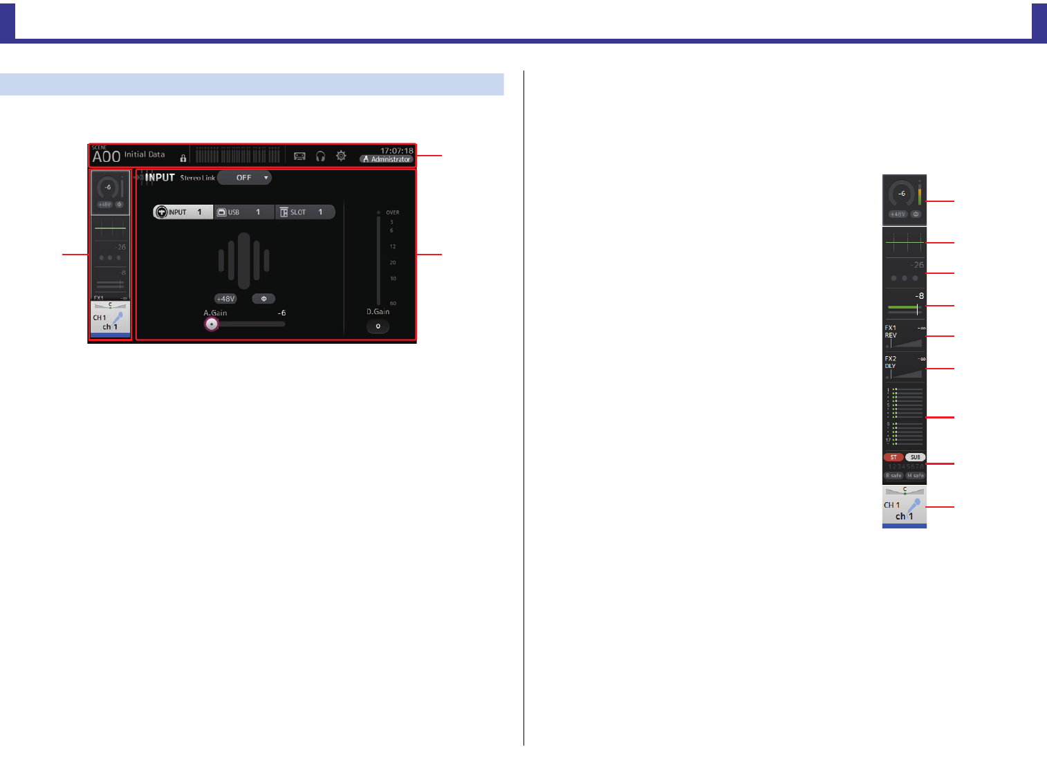
Configuration screens
You can touch an area of the OVERVIEW screen to display the configuration screen for the
corresponding area.
1Toolbar (page 11)
Displays buttons for frequently used features. When you touch a button, the
corresponding configuration screen in the main area of the display.
2Navigation area
Allows you to select which screen is displayed in the main area of the display.
3Main area (page 47)
Displays the screen that you select using the toolbar or navigation area.
INavigation area
Displays the features of the currently selected channel.
You can drag the screen up and down to display other features.
CH1–CH32
1Displays the INPUT screen. (page 47)
2Displays the EQ screen. (page 49)
3Displays the GATE screen. (page 53)
4Displays the COMP screen. (page 55)
5Displays the FX1 screen. (page 57)
6Displays the FX2 screen. (page 57)
7Displays the SEND TO AUX screen. (page 62)
8Displays the ASSIGN screen. (page 63)
9Displays the CH VIEW screen. (page 64)
ձ
ճ
ղ
ձ
ղ
ճ
մ
յ
ն
շ
ո
չ
Overview
Reference Manual
TF Series
-
6
-
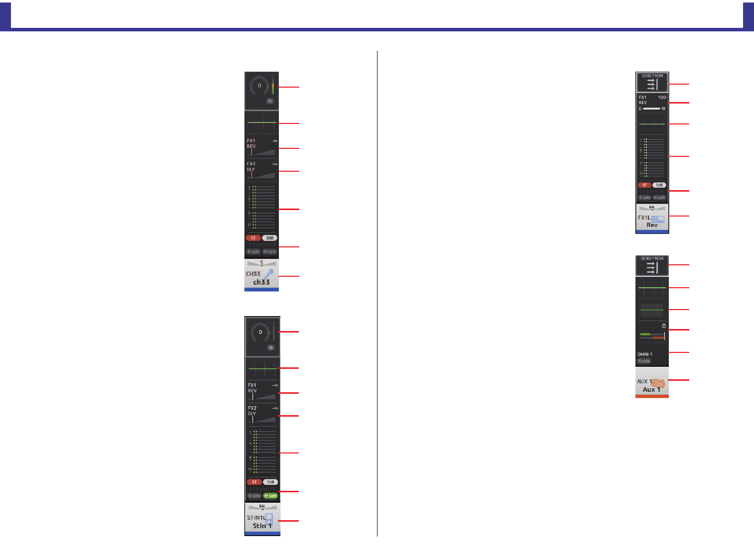
CH33–CH40
1Displays the INPUT screen. (page 47)
2Displays the EQ screen. (page 49)
3Displays the FX1 screen. (page 57)
4Displays the FX2 screen. (page 57)
5Displays the SEND TO AUX screen. (page 62)
6Displays the ASSIGN screen. (page 63)
7Displays the CH VIEW screen. (page 64)
STIN1/2
1Displays the INPUT screen. (page 47)
2Displays the EQ screen. (page 49)
3Displays the FX1 screen. (page 57)
4Displays the FX2 screen. (page 57)
5Displays the SEND TO AUX screen. (page 62)
6Displays the ASSIGN screen. (page 63)
7Displays the CH VIEW screen. (page 64)
FX RTN 1/2
1Displays the SEND FROM screen. (page 75)
2Displays the FX1 screen. (page 57)
3Displays the EQ screen. (page 49)
4Displays the SEND TO AUX screen. (page 62)
5Displays the ASSIGN screen. (page 63)
6Displays the CH VIEW screen. (page 64)
AUX1–AUX8
1Displays the SEND FROM screen. (page 75)
2Displays the EQ screen. (page 49)
3Displays the GEQ screen. (page 72)
4Displays the COMP screen. (page 55)
5Displays the OUTPUT screen. (page 74)
6Displays the CH VIEW screen. (page 64)
մ
ն
շ
ձ
ղ
ճ
յ
մ
ն
շ
ձ
ղ
ճ
յ
յ
ղ
ձ
ճ
մ
ն
ձ
ղ
ճ
մ
յ
ն
Overview
Reference Manual
TF Series
-
7
-
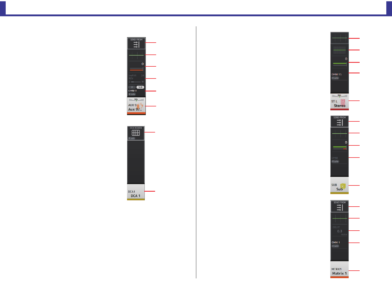
AUX9/10–AUX19/20
1Displays the SEND FROM screen. (page 75)
2Displays the EQ screen. (page 49)
3Displays the COMP screen. (page 55)
4Displays the INSFX screen. (page 57)
5Displays the OUTPUT screen. (page 74)
6Displays the CH VIEW screen. (page 64)
DCA1–DCA8
1Displays the DCA ASSIGN screen. (page 76)
2Displays the CH VIEW screen. (page 64)
STEREO
1Displays the EQ screen. (page 49)
2Displays the GEQ screen. (page 72)
3Displays the COMP screen. (page 55)
4Displays the OUTPUT screen. (page 74)
5Displays the CH VIEW screen. (page 64)
SUB
1Displays the SEND FROM screen. (page 75)
2Displays the EQ screen. (page 49)
3Displays the COMP screen. (page 55)
4Displays the OUTPUT screen. (page 74)
5Displays the CH VIEW screen. (page 64)
MATRIX1–MATRIX4
1Displays the SEND FROM screen. (page 75)
2Displays the EQ screen. (page 49)
3Displays the DELAY screen. (page 78)
4Displays the OUTPUT screen. (page 74)
5Displays the CH VIEW screen. (page 64)
մ
ն
ձ
ղ
ճ
յ
ձ
ղ
մ
ձ
ղ
ճ
յ
մ
ձ
ղ
ճ
յ
մ
ձ
ղ
ճ
յ
Universal operations
Reference Manual
TF Series
-
8
-
Universal operations
In this section we will introduce the screens that are displayed when you press the Library key
( ) and the Menu key ( ), which are found in the Display section of the console's top
panel.
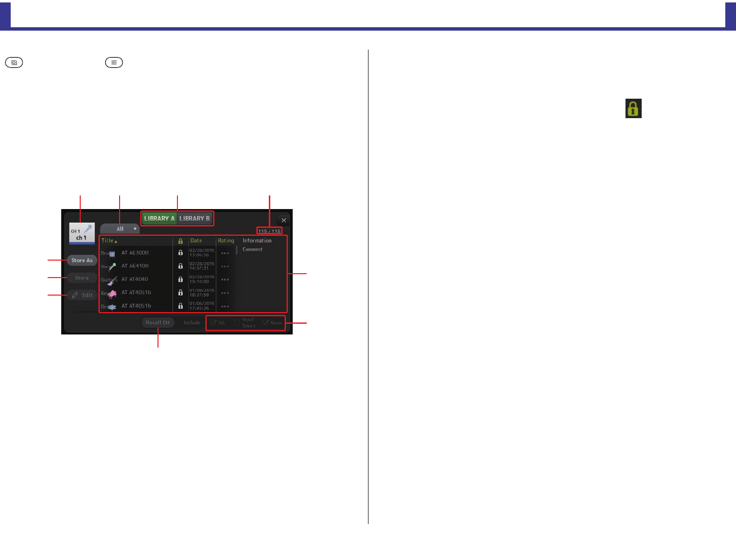
Library screen
Allows you to recall saved Presets.
A Preset is a collection of settings that are customized for a certain type of input, microphone,
instrument, etc. By recalling a Preset, you can set up a channel quickly and easily according
to the type of input, and then fine-tune the settings to your specific needs. You can even save
your own Presets.
1Channel name
Displays the name of the channel.
2Category selection button
Allows you to select a category.
Presets that match the selected category are displayed in the Library list.
3Library selection button
Allows you to switch between the available Libraries. The Presets that are stored in the
selected Library are displayed in the list.
LIBRARY A: Displays the Presets stored in LIBRARY A.
LIBRARY B: Displays the Presets stored in LIBRARY B.
4List
You can click a header in the list to sort the items by that header. (List items cannot be
sorted by "Information".)
To select a Preset, simply touch it. The selected Preset is highlighted, and can then be
saved, recalled, or edited.
A lock icon is displayed or cleared each time you touch the column. When the icon
is displayed, the Preset is write-protected.
The date on which the Preset was last saved is displayed in the Date column.
5Recall on/off checkboxes
Allow you to determine which parameters will be recalled (checkbox on) and not be
recalled (checkbox off).
Input channels
HA: Analog/digital gain setting, phantom power on/off, phase setting
Input Select: Input source settings
Name: Channel name, icon, and color
AUX 1–8, STEREO channels
GEQ: GEQ settings
Name: Channel name, icon, and color
FX RTN, AUX9/10–AUX19/20 channels
FX: Effect settings
Name: Channel name, icon, and color
SUB, MATRIX1–4 channels
Name: Channel name, icon, and color
6Recall CH button
Recalls a Preset to the selected channel.
7Edit button
Touch this button to display the keyboard so you can edit the title and comment.
(Keyboard screenpage 10)
8Store button
Saves the settings for the current channel as a Preset. The settings will overwrite the
Preset selected in the Library list.
9Store As button
Saves the settings for the current channel as a new Preset.
Touch this button to display the keyboard so you can enter the Preset name. (Keyboard
screenpage 10)
0Preset number (V1.1 and later)
Displays the Preset number. The first number indicates the number of Presets in the
selected category (2), and the second number indicates the total number of Presets.
ձղ ճ պ
մ
յ
ն
շ
ո
չ
Universal operations
Reference Manual
TF Series
-
9
-
Displaying the Library screen from a configuration screen
When you display the Library screen from a configuration screen, one of the following buttons
is added to the Library screen, depending on the configuration screen you were using.
Recall EQ button
Displayed when you enter the Library from the EQ screen, and recalls EQ settings only.
Recall Gate button
Displayed when you enter the Library from the GATE screen, and recalls GATE settings only.
Recall COMP button
Displayed when you enter the Library from the COMP screen, and recalls COMP settings only.
Recall FX button
Displayed when you enter the Library from the FX screen, and recalls FX settings only.
Recall GEQ button
Displayed when you enter the Library from the GEQ screen, and recalls GEQ settings only.
Library screen menu
Press the Menu key ( ) from the Library screen to display the following items.
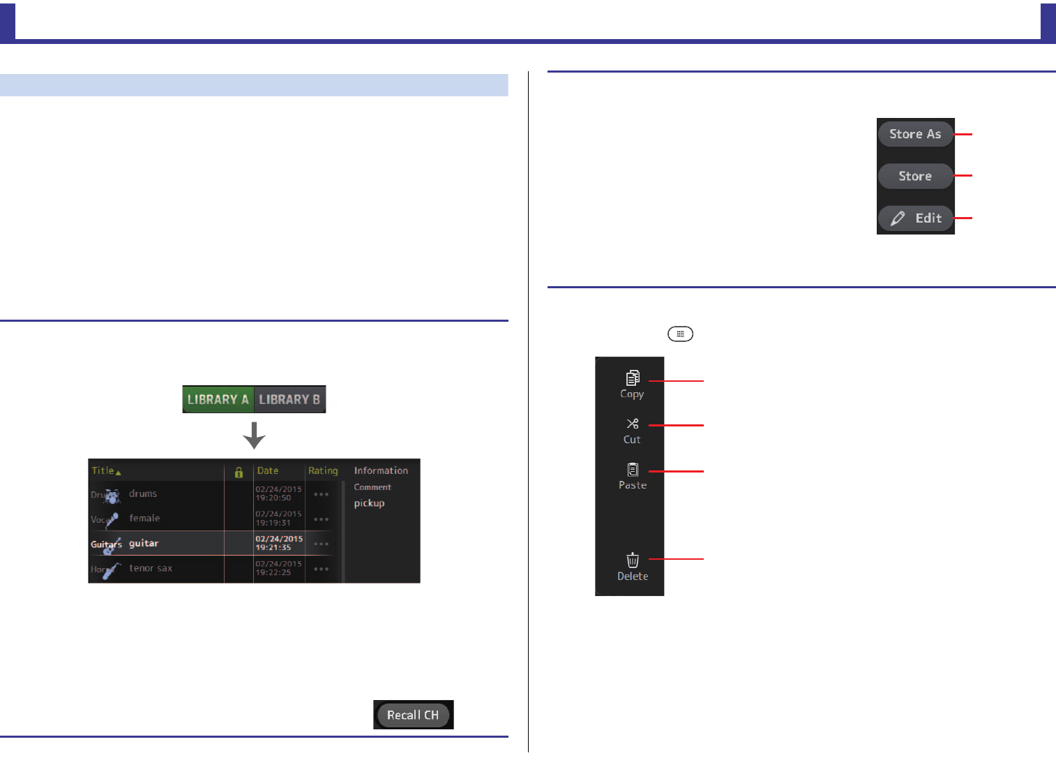
Recalling a Preset
1.
Touch a Library selection button to select the Library that contains the desired Preset.
A list of Presets is displayed.
You can click a header in the list to sort the items by that header. (List items cannot be sorted by
"Information".)
2. Touch the desired Preset.
The selected Preset is highlighted.
3. Select the items that will be recalled.
Turn the checkboxes on for items that you want to recall.
4. Touch the Recall CH button.
The Preset is recalled to the selected channel.
Preset list
Editing a Preset
1. Recall the desired Preset.
2. Touch the Edit button.
Display the keyboard so you can edit the title and comment.
(Keyboard screenpage 10)
Edit the desired items.
3. touch the Store or Store As button.
Store button: Saves the settings for the current channel as
a Preset. The settings will overwrite the Preset selected in
the Library list.
Store As button: Saves the settings for the current channel
as a new Preset.
1Copy
Copies the selected Preset.
2Cut
Cuts the selected Preset.
3Paste
Pastes the copied or cut Preset to the Library.
4Delete
Deletes the selected Preset.
Store As
button
Store button
Edit button
ձ
ղ
ճ
մ
Universal operations
Reference Manual
TF Series
-
10
-
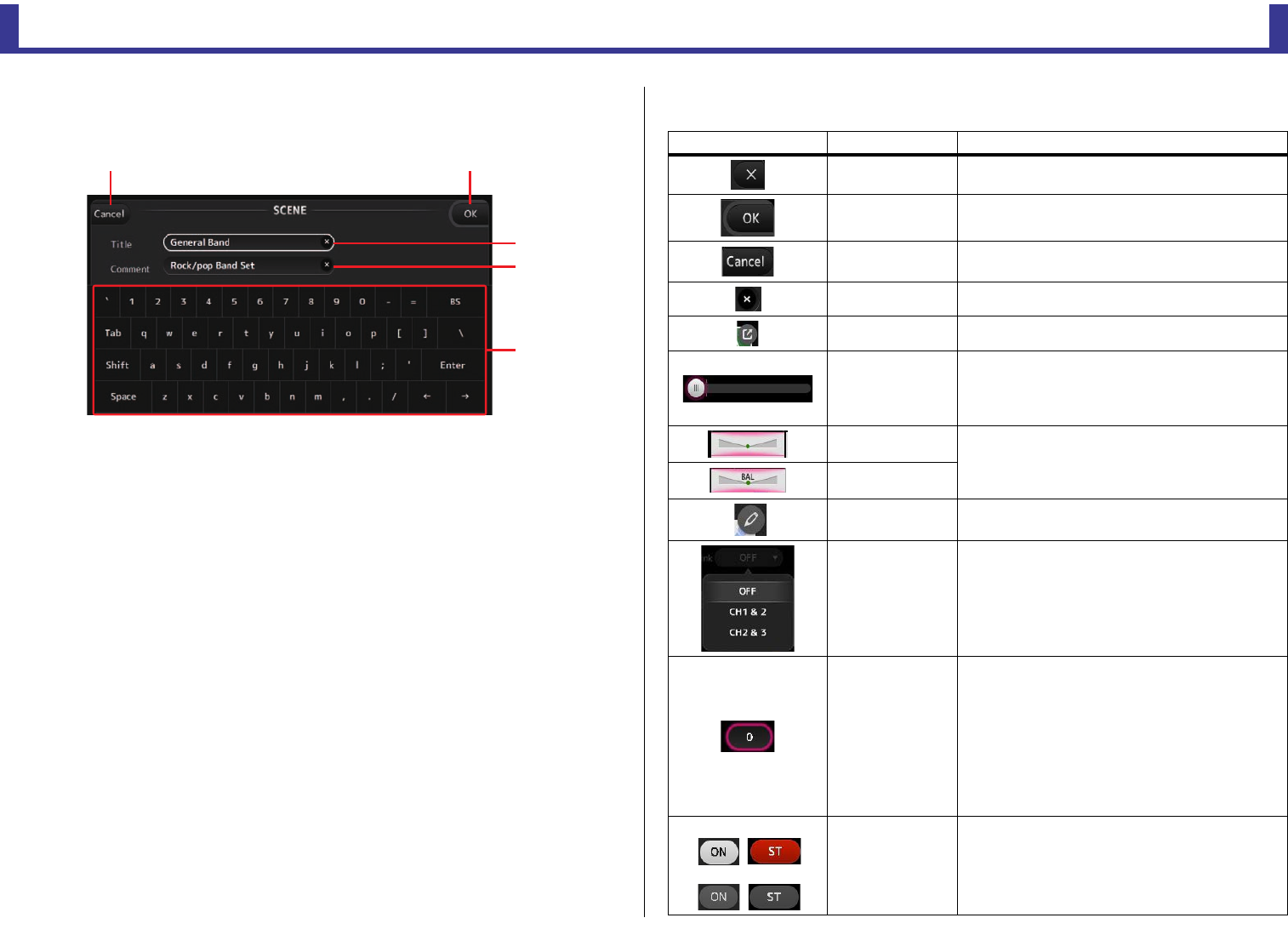
Keyboard screen
Allows you to edit titles and comments.
1Cancel button
Discards any changes you made and returns to the previous screen.
2OK button
Saves the changes you made.
3Title field
Enter the name of the Scene here.
4Comment field
Enter comments about the Scene here.
5Keyboard
Touch to enter the desired text.
Menu
Displays a menu of options available in the current screen. The content of the menu varies
depending on which screen is being displayed. For information about each menu, refer to the
description for the corresponding page.
Button and slider operations
䐟䐠
䐡
䐢
䐣
Item Term Description
Close button [X] Touch to close the current screen.
OK button Applies the current settings.
Cancel button Cancels the operation and returns to the previous
screen.
Clear button Clears the information you entered.
Jump icon Displays the relevant screen.
Slider
Flashes in pink when you touch it to indicate it can be
operated.
You can then drag the slider on the display or turn the
[TOUCH AND TURN] knob to adjust the setting.
Pan slider Flashes in pink when you touch it to indicate it can be
operated by the [TOUCH AND TURN] knob.
Balance slider
Edit icon Displays the screen where you can edit information,
such as the keyboard screen.
Menu Touch a button with "M" displayed on it to display the
menu.
Text box
When you touch a text box that can accept values, it
flashes in pink to indicate that its content can be
changed.
Touch the box again to display the screen that allows
you to enter values.
You can also change the value by turning the
[TOUCH AND TURN] knob.
When you touch a text box that can accept text, the
keyboard screen is displayed.
When on (example):
When off (example): On and off Switches between on and off when you touch the
item.
Toolbar
Reference Manual
TF Series
-
11
-
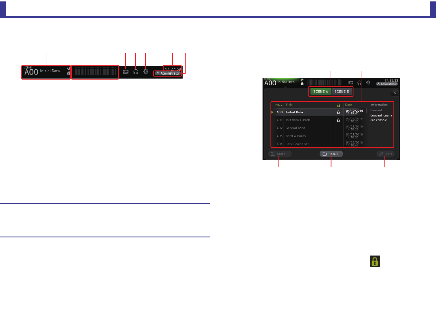
Toolbar
Provides access to frequently used features and system settings.
The toolbar is displayed regardless of the screen content.
1Displays the SCENE screen.
2Displays the METER screen. (page 13)
3Displays the RECORDER screen. (page 14)
4Displays the MONITOR screen. (page 18)
5Displays the SETUP screen. (page 21) (V3.0 and later)
6Displays the current time. (page 36)
7Displays the LOGIN screen. (page 38) (V3.0 and later)
The name of the user that is currently logged in is displayed with the icon.
Additionally, the following items may be displayed to indicate the corresponding
status.
ACCESS: The console is accessing the USB storage device that is connected to its
USB connector.
CUE: The cue is turned on.
OSCILLATOR: The oscillator is turned on.
Quick Config: Quick Config is being used. (V2.0 and later)
SCENE screen
Allows you to manage previously saved mixer setups, or "Scenes".
When you recall a Scene, you can exempt certain settings from being replaced by the settings
contained in the Scene; this is called "recall safe".
1Scene list selection button
Allows you to switch between the available Scene lists.
SCENE A: Displays Scene list A.
SCENE B: Displays Scene list B.
2Scene list
Displays the Scenes saved in the selected Scene list.
You can click a header in the list to sort the items by that header. (List items cannot be
sorted by "Information".)
To select a Scene, simply touch it. The selected Scene is highlighted, and can then be
saved, recalled, or edited.
A green triangle is displayed next to the Scene that is currently recalled.
A lock icon is displayed or cleared each time you touch the column. When the icon
is displayed, the Scene is write-protected.
The date on which the Scene was last saved is displayed in the Date column.
Displaying configuration screens
When you touch an icon, the corresponding configuration screen is displayed.
To return to the previous screen, touch the icon again, or touch the close button ([X]) in the
upper right of the screen.
ձղճմյնշ
䐟䐠
䐡䐢 䐣
Toolbar
Reference Manual
TF Series
-
12
-
3Store button
Saves the current mixer setup and assigns it to the Scene number selected in the Scene
list.
Touch this button to display the keyboard so you can edit the title and comment.
(Keyboard screenpage 10)
4Recall button
Recalls the Scene that is selected in the Scene list.
5Edit button
Touch this button to display the keyboard so you can edit the title and comment.
(Keyboard screenpage 10)
Saving the current settings as a new Scene
1. Touch the Scene area of the Toolbar.
2. Touch a Scene list selection button to select the Scene list.
The Scene list is displayed.
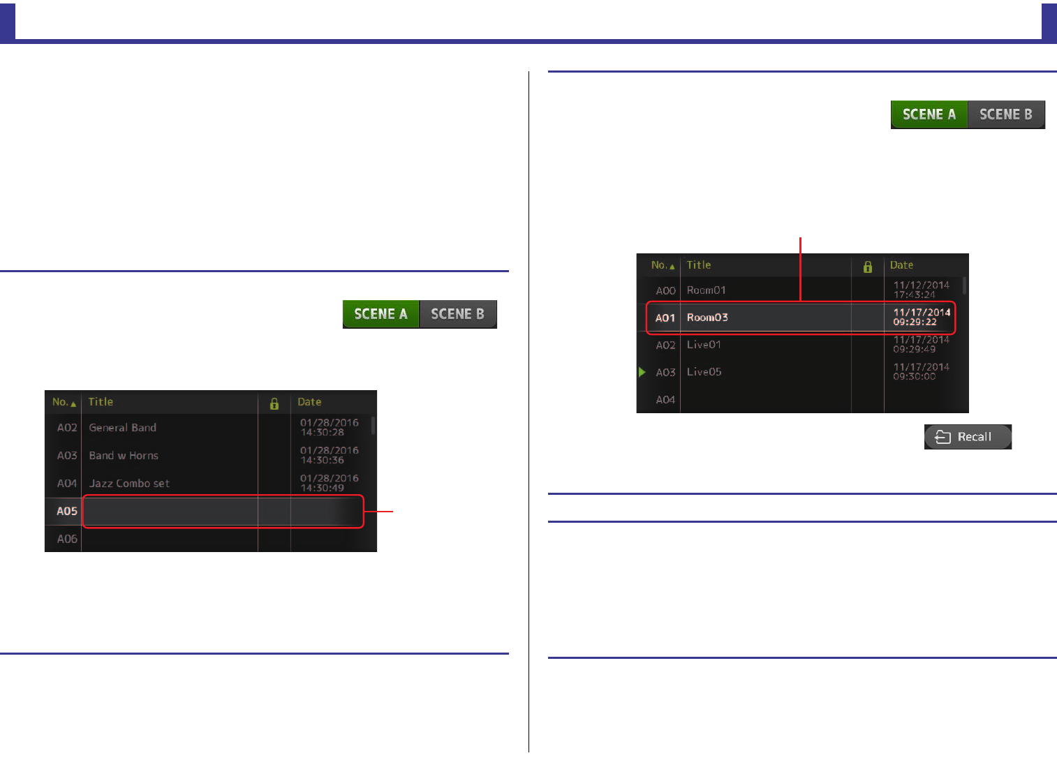
3. Touch a blank Scene.
4. Touch the Store button.
Display the keyboard so you can edit the title and comment (Keyboard screenpage 10).
Enter the new Scene name and a comment.
5. Touch the OK button.
The settings will be saved as a new Scene.
Blank Scene
Recalling a Scene
1. Touch a Scene list selection button to select the
Scene list that contains the desired Scene.
The Scene list is displayed.
2. Touch the desired Scene.
The selected Scene is highlighted.
You can click a header in the list to sort the items by that header. (List items cannot be sorted by
"Information".)
3. Touch the Recall button.
The mixer settings saved in the Scene are recalled.
The name of the recalled Scene is displayed in the upper left
of the screen.
Editing a Scene
1. Select the Scene that you want to edit.
2. Touch the Edit button.
Display the keyboard so you can edit the title and comment (Keyboard screenpage 10).
Edit the desired items.
3. Touch the OK button.
The settings will overwrite the Scene selected in the Scene list.
Selected Scene
Toolbar
Reference Manual
TF Series
-
13
-
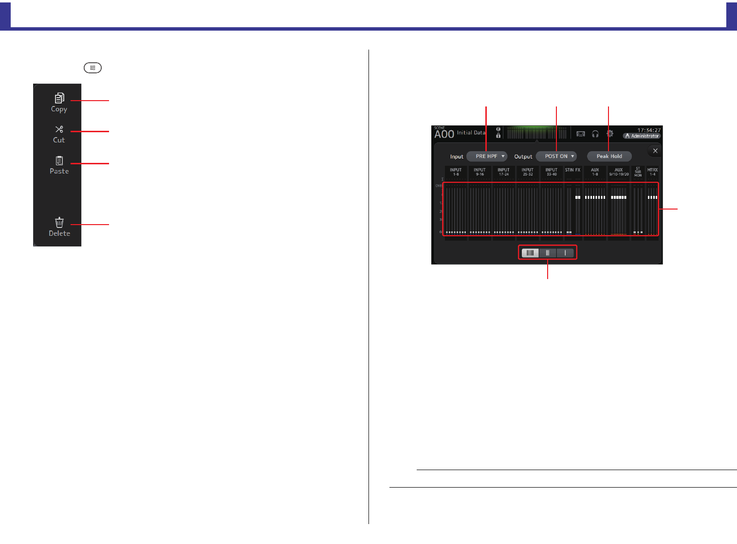
SCENE screen menu
Press the Menu key ( ) from the Scene screen to display the following items.
METER screen
Displays the input and output level of all the channels, and allows you to select the metering
point (i.e., the point at which the level is detected).
1Input metering point selection menu
Select the input level metering point from the menu.
PRE HPF: After the head amp; before the HPF
PRE FADER: Before the fader
POST ON: After the [ON] key
2Output metering point selection menu
Select the output level metering point from the menu.
PRE EQ: Before the EQ
PRE FADER: Before the fader
POST ON: After the [ON] key
3Peak Hold button
Turn this button on to hold the peak level for each level meter. Turn this button off to
remove the peak level that was being held. The Peak Hold on/off setting affects both
input and output channels.
1Copy
Copies the selected Scene.
2Cut
Cuts the selected Scene.
3Paste
Pastes the copied or cut Scene to the Scene list.
4Delete
Deletes the selected Scene.
ձ
ղ
ճ
մ
NOTE
You can assign the Peak Hold button to a [USER DEFINED KEY]. (page 29)
ձղճ
մ
յ
Toolbar
Reference Manual
TF Series
-
14
-
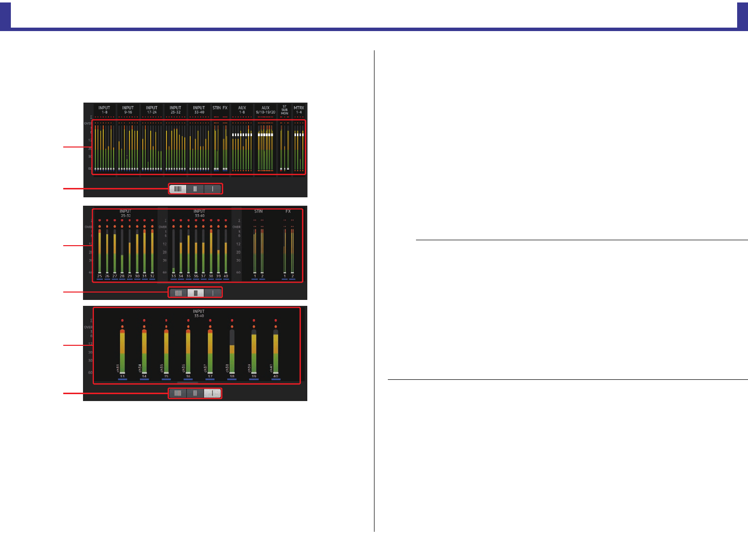
4Meters
Display the input and output levels of the channels.
5Meter display selection button
Allows you to select how many meters are displayed. Three display modes are available.
RECORDER screen (INPUT/OUTPUT/TITLE LIST
screen)
You can connect a USB storage device to the console's iPad connector and use the console
to record audio to the device, play back audio files stored on the device, and manage audio
files stored on the device.
When a USB storage device is connected to the iPad connector, your TF series console can
record its internal signals to the device as an audio file and play back files that are stored on
the device.
You can also connect an iOS device to the console and use your iPad or iPhone as an audio
input source for the mixer.
Recorded files are formatted as 48 kHz, 24-bit stereo WAV files.
Playback is supported for WAV and MP3 (MPEG-1 Audio Layer-3) files.
These features allow you to record signals from the STEREO and AUX buses to the USB
storage device, and use audio files that are saved on your iPad or USB storage device as the
source for the console's ST IN 1 channel.
մ
յ
մ
յ
մ
յ
NOTE
• Simultaneous recording and playback is not supported.
• While recording, the signal being recorded cannot be used as an INPUT channel.
• Compatible USB storage devices must be formatted in FAT32. If necessary, connect the device to the
USB connector (on the right side of the top panel) and use the contextual menu in the SAVE/LOAD
screen to format the device.
• Use only USB storage devices with a sector size of 512 bytes. (Certain large-capacity hard disk drives
may not be compatible with the console.)
• USB storage devices with an allocation unit size under 4096 bytes are not supported. (This may apply
to small-capacity USB memory devices.)
• For recording, we recommend using a high-speed device, such as a hard disk drive (HDD) or solid-state
drive (SSD). USB memory devices and iOS devices can be used for playback only.
• For playback, MP3 files must be encoded at 44.1 kHz or 48 kHz, with a bit rate of 128 kbps–320 kbps.
Files encoded using variable bit rate (VBR) can be played back, but file length and elapsed playback
time may not be displayed properly.
Toolbar
Reference Manual
TF Series
-
15
-
INPUT/OUTPUT screen
Allows you to configure inputs and outputs for playback and recording.
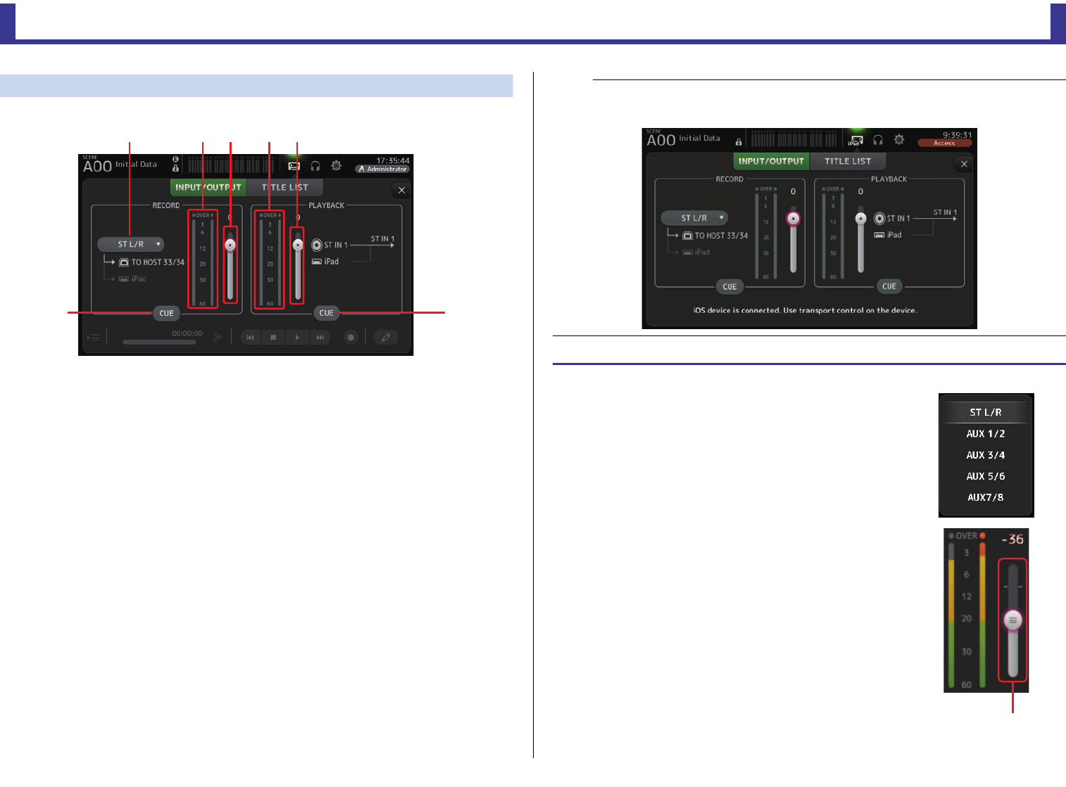
1RECORD source selection menu
Allows you to select the source that will be recorded.
The source selected here is also output to CH33 and CH34 of the USB TO HOST
connector.
2RECORD level meter
Displays the recording level.
3RECORD level slider
Adjusts the recording level.
4RECORD CUE button
Turns the recording source cue on and off.
5PLAYBACK level meter
Displays the playback level.
6PLAYBACK level slider
Adjusts the playback level.
7PLAYBACK CUE button
Turns the playback source cue on and off.
մշ
ձղճյն
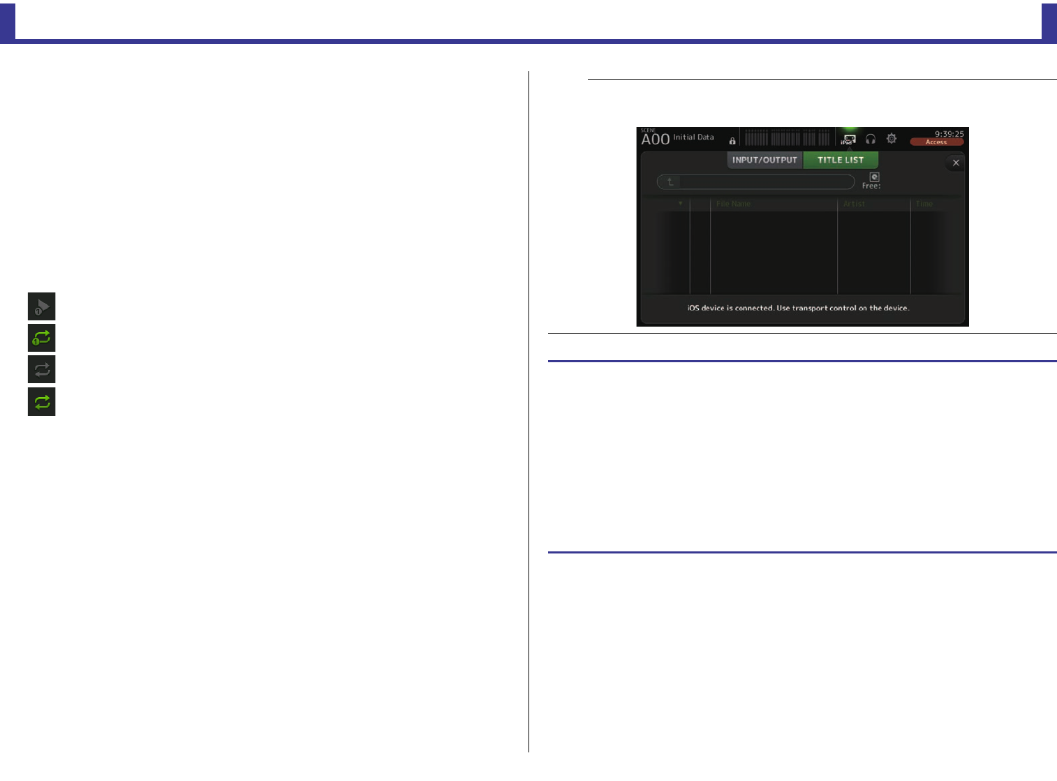
NOTE
When an iPad or other iOS device is connected, "iOS device is connected. Use transport control on the
device." is displayed, and the playback button is not displayed. Use the corresponding app on the iOS
device to control playback.
Setting the input
1. Touch the RECORD source selection menu and select
the source you want to record.
2. Drag the RECORD level slider and adjust the recording
level.
RECORD level slider
Toolbar
Reference Manual
TF Series
-
16
-
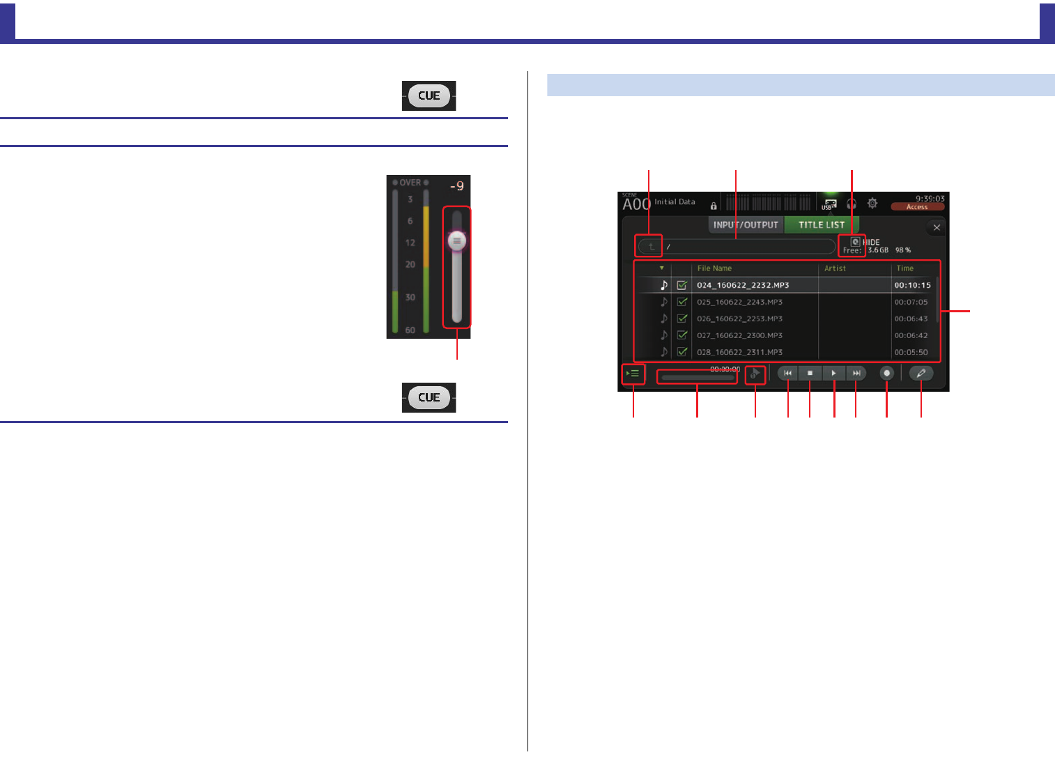
TITLE LIST screen
When a USB storage device is connected to the console via the iPad connector, you can use
this screen to play back audio files saved on the device and record the signal from the 2MIX
source to the device.
1Parent directory button
Displays the directory that is one level above the current directory.
2Current directory
Displays the path of the current directory on the USB storage device.
3USB storage device information
Displays the volume name of the USB storage device.
The amount of available space (i.e., available capacity and available percentage of total
capacity) on the USB storage device is also displayed.
4File list
Displays a list of the files in the current directory.
You can click a header in the list to sort the items by that header.
Touch a file name to select the file for playback or editing.
Touch the music note icon to start and pause playback.
Files whose checkboxes are turned on will be played back-to-back during continuous playback.
The name of each file in the directory is displayed in the File Name column.
Artist information is displayed in the Artist column (MP3 files only) and the length of the
file is displayed in the Time column.
3. If you want to monitor the record source, touch the
RECORD CUE button to turn the cue on.
Setting the output
1. Drag the PLAYBACK level slider and adjust the playback
level.
2. Touch the PLAYBACK CUE button to turn the cue on.
PLAYBACK level slider
ձղ ճ
մ
յնշոչպջռս
Toolbar
Reference Manual
TF Series
-
17
-
5Follow playback button
When this button is turned on during continuous playback, the file that is currently
playing is highlighted in the file list.
6File information
When playing back an MP3 file, the file's bit rate and the current playback location are
displayed here.
When playing back a WAV file, the file's sample rate and the current playback location
are displayed here.
When recording, the WAV file's sample rate and the elapsed recording time are
displayed here.
7Playback mode selector button
You can select the desired playback mode.
Touch the button to toggle through the available modes.
: SINGLE playback; the file is played and then playback stops.
: SINGLE REPEAT; the file plays repeatedly until you stop playback.
: ALL; all files with checkboxes turned on in the file list are played back one after
another, and then playback stops.
: ALL REPEAT; all files with checkboxes turned on in the file list are played back one
after another, and then playback repeats until you stop playback.
8Previous button
Moves the playback location to the beginning of the current file or to the beginning of
the previous file.
9Stop button
Stops playback and recording.
0Play/pause button
Starts and pauses playback.
ANext button
Moves the playback location to the beginning of the next file.
BRecord button
Sets the console to record-ready mode.
CFile name edit button
Allows you to edit the file's name.
NOTE
When an iPad or other iOS device is connected, "iOS device is connected. Use transport control on the
device." is displayed, and the playback button is not displayed. Use the corresponding app on the iOS
device to control playback.
Recording
1. Connect a compatible USB storage device to the iPad connector.
2. Touch the record button.
The record button begins flashing to indicate that the console is in record-ready mode.
3. When you're ready to start recording, touch the play/pause button.
The record button remains lit during recording.
You can touch the play/pause button to pause and resume recording.
4. When you're ready to stop recording, touch the stop button.
The recorded file is named automatically based on the console's date and time setting.
5. If necessary, touch the file name edit button and change the file name.
Toolbar
Reference Manual
TF Series
-
18
-
RECORDER screen menu
Press the Menu key ( ) from the RECORDER screen to display the following items.
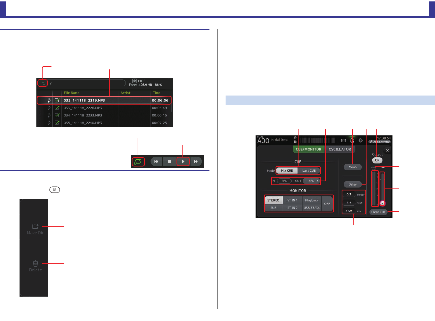
MONITOR screen
Allows you to manage cue and monitor signals and to control oscillators.
The CUE/MONITOR screen is used to control the signals that are monitored using
headphones and near-field monitors. Here you can select the sources that will be
continuously monitored, and select individual channels for monitoring using the CUE feature.
The OSCILLATOR screen is used to configure the oscillator and turn it on and off. The console
has a built-in oscillator that can output a sine wave or pink noise to the desired bus, allowing
you to check external devices or test the characteristics of a venue.
CUE/MONITOR screen
Allows you to monitor certain inputs using headphones or speakers. You can select which
sources will be monitored, change the monitor signal to mono, or add a delay.
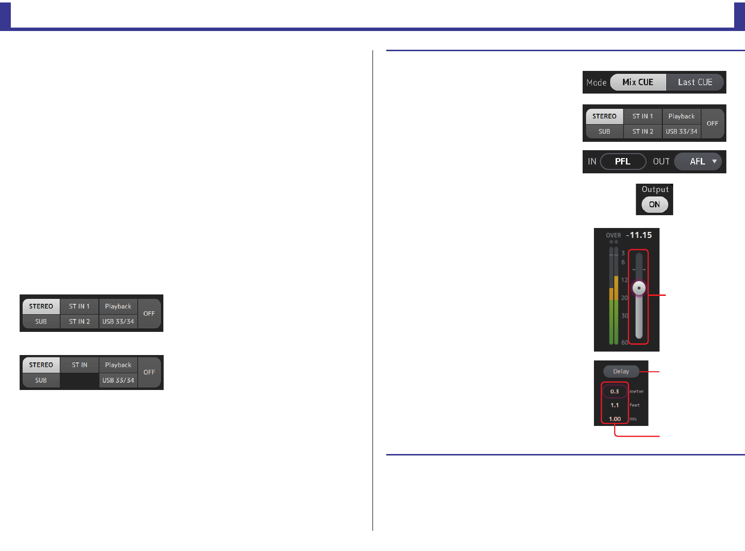
1CUE mode button
Used to select the CUE mode.
Mix CUE: Enables cue for multiple channels.
Last CUE: Enables cue for the last channel selected.
2CUE point selection buttons
Selects the point in the signal path that will be monitored.
PFL: Before the fader
AFL: After the fader (inputs are PFL only)
3Mono button
Allows you to change the monitor signal to mono.
Playing back files stored on a USB storage device
1. Touch the file that you want to play in the file list.
To play a file stored in a different directory, touch the parent directory button and navigate to the
desired directory.
2. Touch the playback mode selector button and
select the desired mode.
3. Touch the play button.
Playback begins.
1Make Dir
Makes a new directory in the current directory.
2Delete
Deletes the selected file.
Selected fileParent directory button
Play button
Playback mode selector button
ձ
ղ
ձղճմյ
ն
շ
ո
չպ
Toolbar
Reference Manual
TF Series
-
19
-
4Delay button
Delays the monitor signal.
5Monitor output button
Turns the monitor output on and off.
The signal is output from the [PHONES] jack regardless of this setting.
6Monitor level meter
Displays the monitor level.
7Monitor level slider
Adjusts the monitor output level.
The signal is output from the [PHONES] jack regardless of this setting.
8Clear CUE button
Cancels all cue selections.
9Delay setting
Determines the delay time by specifying distance (meters or feet) or time (milliseconds).
Touch a text box to display the keyboard and enter a value. (page 10)
0Monitor selection buttons
Allow you to select the sources that will be monitored.
TF5/TF3/TF1
TF-RACK
Checking the input signals
1. Touch a CUE mode button to select
the desired cue mode.
2. Select the desired monitor sources by
touching the corresponding monitor
selection buttons.
3. Select the desired cue point by
touching the corresponding CUE
point selection button.
4. Touch the monitor output button to
turn the monitor output on and off.
5. Drag the monitor level slider to adjust
the monitor level.
6. Select the desired delay time.
Touch one of the delay setting text boxes to
display the keyboard. You can set the delay
time by specifying distance (meters and feet)
or time (milliseconds).
7. Touch the delay button.
The delay is turned on.
Monitor level
slider
Delay button
Delay setting
Tex t b oxe s
Toolbar
Reference Manual
TF Series
-
20
-
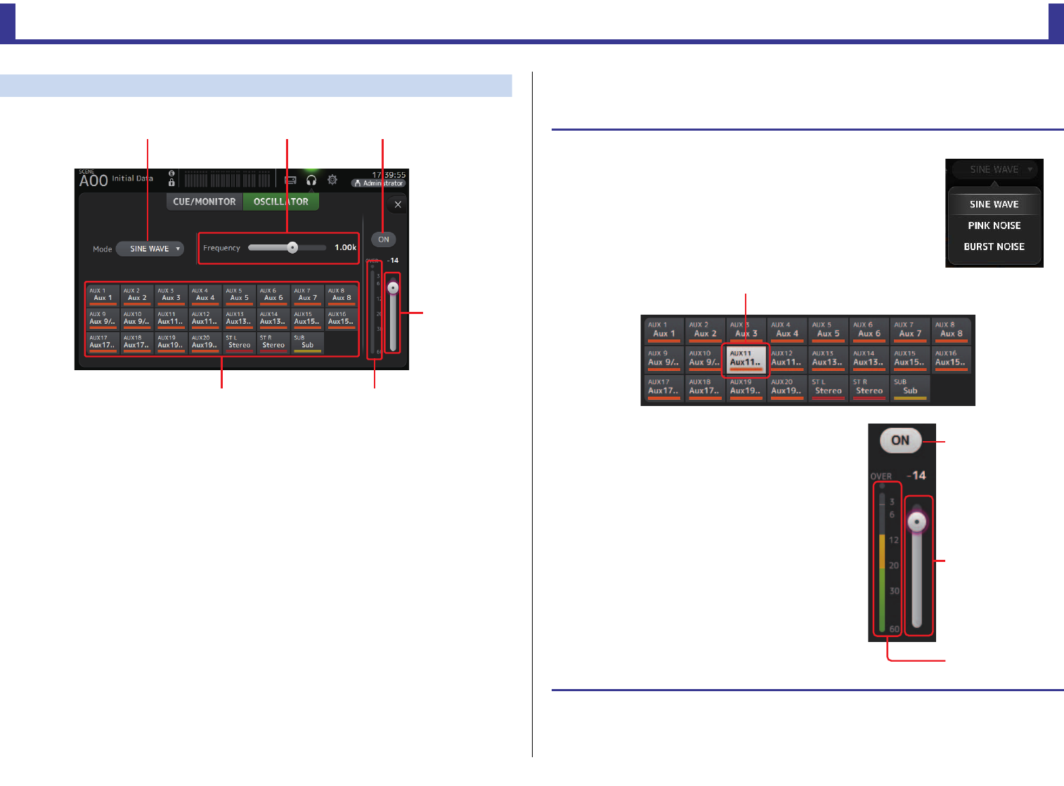
OSCILLATOR screen
Allows you to configure the oscillator.
1Oscillator mode button
Allows you to select the oscillator mode.
SINE WAVE: A sine wave will be output continuously.
PINK NOISE: Pink noise will be output continuously.
BURST NOISE: Pink noise will be output intermittently.
2Parameter sliders
Allows you to adjust parameters for the oscillator.
When the oscillator mode is set to SINE WAVE, this setting determines the frequency of
the sine wave.
When the oscillator mode is set to BURST NOISE, this setting determines the Width
(duration of the noise) and Interval (length of silence between noise bursts).
When the oscillator mode is set to PINK NOISE, nothing is displayed here.
3Oscillator output button
Turns the oscillator output on and off. When the oscillator is turned on, the oscillator
signal is sent to the input channels that are selected by the oscillator assignment
buttons.
4Oscillator output level slider
Adjusts the oscillator output level.
5Oscillator output meter
Displays the oscillator output level.
6Oscillator assignment buttons
Determine which channels the oscillator is sent to. You can select multiple channels.
ձղճ
մ
յն
Setting the oscillator
1. Touch the oscillator mode button and select the desired
mode.
2. Use the oscillator assignment buttons to determine
which channels the oscillator signal will be sent to.
3. Touch the oscillator output button to turn on
the oscillator output.
4. While referring to the oscillator output level
meter, drag the oscillator level slider to adjust
the oscillator output level.
When the oscillator mode is set to SINE WAVE, you can
also adjust the frequency of the oscillator.
When the oscillator mode is set to BURST NOISE, you
can also adjust Width (duration of each noise burst) and
the Interval (duration of each silence between noise
bursts).
Channel is selected
Oscillator
output button
Oscillator
level slider
Oscillator
output meter
Toolbar
Reference Manual
TF Series
-
21
-
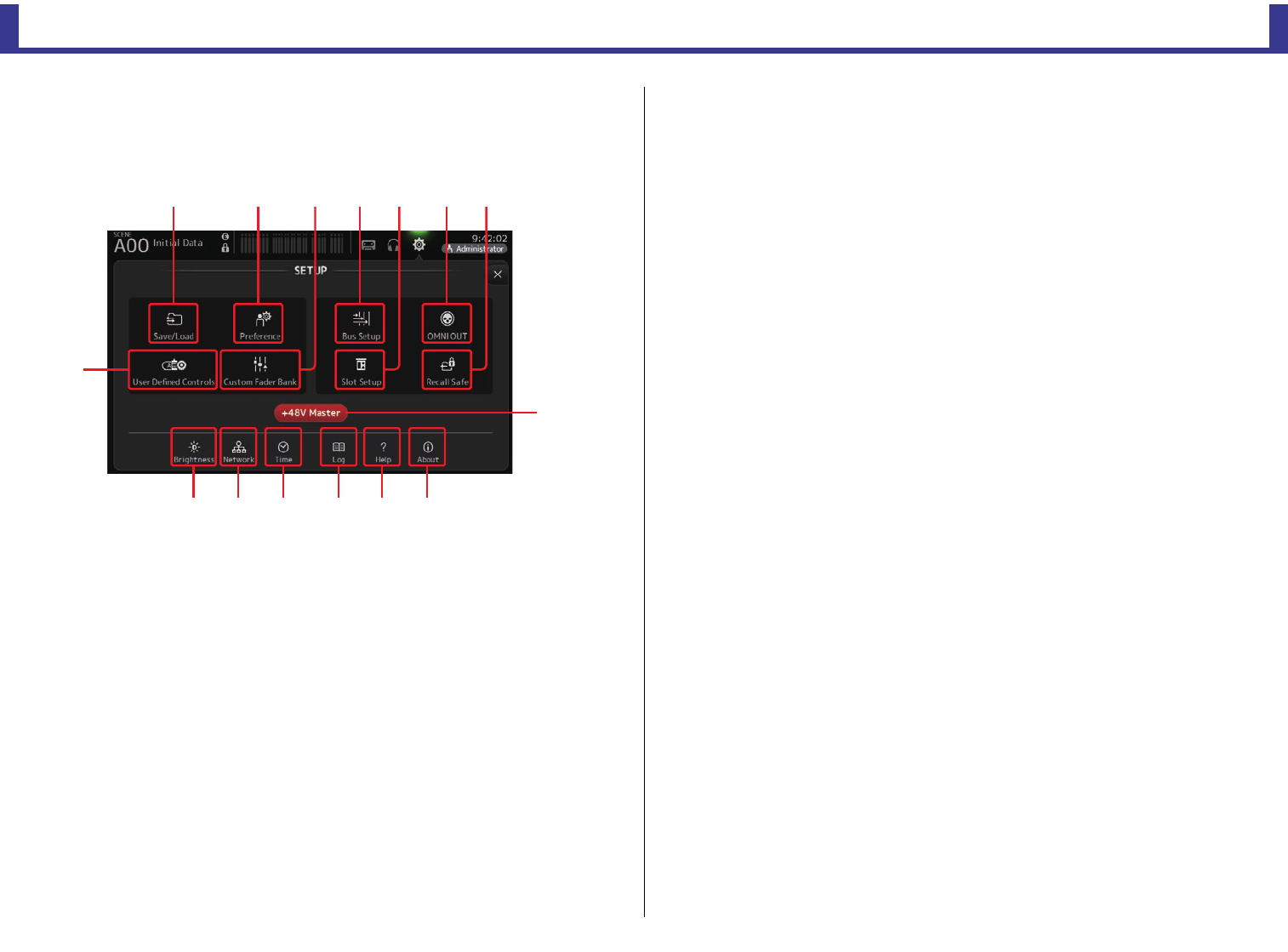
SETUP screen (V3.0 and later)
Allows you to configure general mixer settings, as well as settings for OMNI OUT, Recall Safe,
[USER DEFINED KEYS], [USER DEFINED KNOBS], custom fader banks, and other
preferences.
1Bus Setup icon (page 22)
Displays the BUS SETUP screen.
2OMNI OUT icon (page 22)
Displays the OMNI OUT screen.
3Slot Setup icon (page 23) (V2.0 and later)
Displays the SLOT SETUP screen.
4Recall Safe icon (page 25)
Displays the RECALL SAFE screen.
5Save/Load icon (page 26)
Displays the SAVE/LOAD screen.
6Preference icon (page 28)
Displays the PREFERENCE screen.
7User Defined Control icon (page 29)
Displays the USER DEFINED CONTROLS screen.
8Custom Fader Bank icon (page 34)
Displays the CUSTOM FADER BANK screen.
9+48V Master button
Master button that turns the console's phantom power feature on and off. When this
button is turned off, phantom power will not be supplied to any channels, even if their
+48V buttons are turned on. (page 47)
0Brightness icon (page 35)
Displays the BRIGHTNESS screen.
ANetwork icon (page 35)
Displays the NETWORK screen.
BTime icon (page 36)
Displays the TIME screen.
CLog icon (page 37)
Displays the LOG screen.
DHelp icon (page 37)
Displays the HELP screen.
EAbout icon (page 38)
Displays the ABOUT screen.
յն ձղ
չ
ոճ մ
շ
պտվսռջ
Toolbar
Reference Manual
TF Series
-
22
-
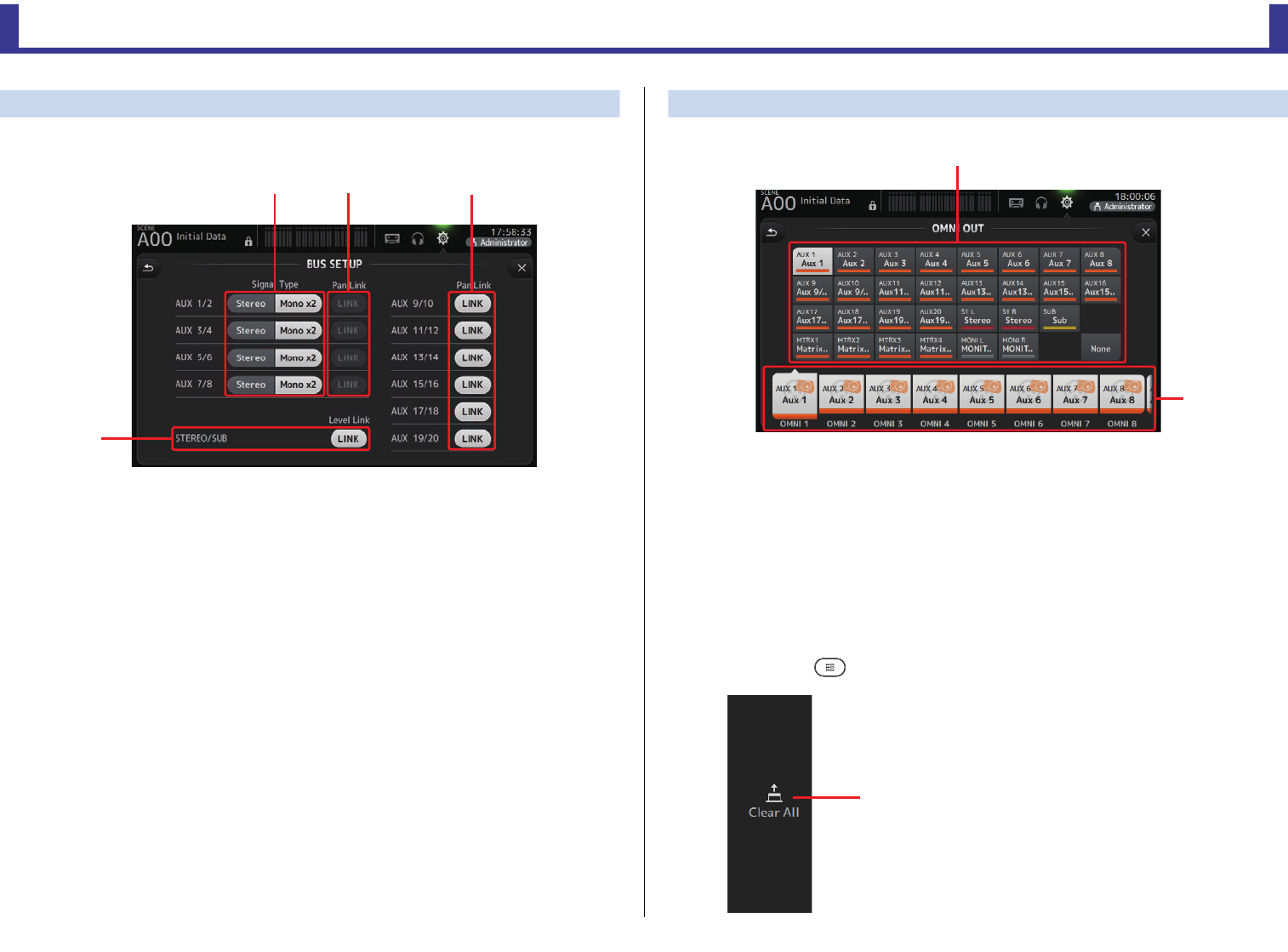
BUS SETUP screen
Allows you to configure bus settings. You can change basic settings such as stereo/mono, Pan
Link, etc. These settings are included when saving a Scene.
1AUX1/2–AUX7/8 signal type buttons
Determines how each pair of buses is processed. You can set each pair to be either
Stereo (an odd and even numbered bus are paired and main parameters are shared
between the two) or MONO x2 (two independent mono channels).
2AUX1/2–AUX7/8 Pan Link buttons
Turns pan link on and off for AUX1/2–AUX7/8.
These buttons are only displayed if the Signal Type of the corresponding bus is set to
Stereo. When these buttons are turned on, the pan setting of signals sent from input
channels to the corresponding two buses will link with the Stereo bus pan setting.
3AUX9/10–AUX19/20 Pan Link buttons
Turns pan link on and off for AUX9/10–AUX19/20.
4STEREO/SUB Level Link button (V1.1 and later)
When turned on, the levels of the STEREO channel and the SUB channel are linked.
For V3.0 and later, when turned on, the gain for both channels can be adjusted together
but the difference in gain between the two channels is maintained.
Additionally, for TF5/TF3/TF1, you can adjust the difference in gain between the two
channels by adjusting the faders while pressing the [SEL] key on the panel.
OMNI OUT screen
Allows you to configure the output channels that are sent to the OMNI OUT jacks.
1OMNI OUT1–16 buttons
Allows you to select which OMNI OUT jack will be configured.
The name of the channel currently assigned to each OMNI OUT jack is also displayed in
the buttons.
2Output channel buttons
Determines which output channel or monitor output will be assigned to the OMNI OUT
jack you selected for 1. If you select None, nothing will be output to the corresponding
OMNI OUT jack.
OMNI OUT screen menu
Press the Menu key ( ) from the OMNI OUT screen to display the following items.
ձղ ճ
մ
1Clear All
Clears all assignments for each OMNI OUT jack (all
will be set to None).
ղ
ձ
ձ
Toolbar
Reference Manual
TF Series
-
23
-
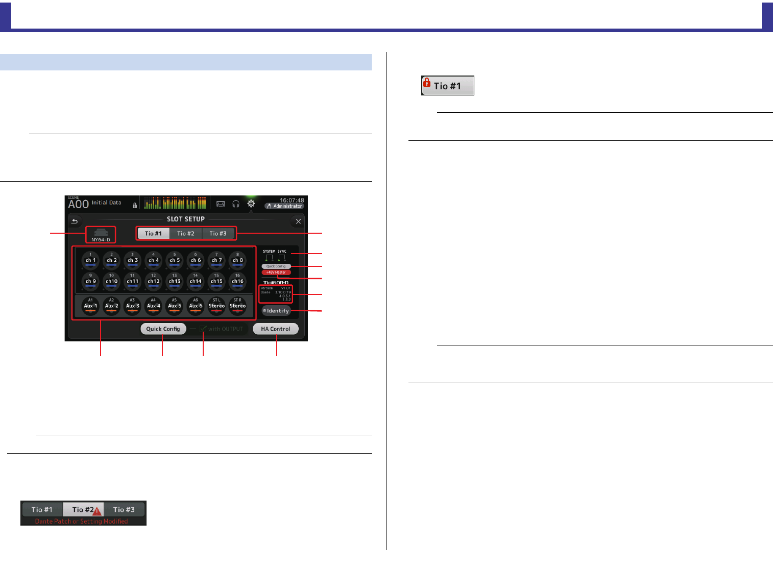
SLOT SETUP screen (V2.0 and later)
Displays settings and information related to the Tio1608-D I/O Rack that is connected to the
console via the NY64-D that is installed in the expansion slot.
The information that is displayed varies depending on the connection status of the Tio1608-D
and the Quick Config settings.
1UNIT ID button
Allows you to select the unit ID of the Tio1608-D whose information is displayed.
If the Tio1608-D is operating in Dante AES67 mode, "AES67" is displayed above and to
the right of the unit ID.
2SYSTEM and SYNC indicators
Display the same information as the [SYSTEM] and [SYNC] indicators on the Tio1608-D.
If an error occurs, details are displayed on the UNIT ID button.
If Dante Device Lock has been enabled for the corresponding Tio1608-D, a lock icon is
displayed on the UNIT ID button. (V3.1 and later)
3Quick Config status indicator
Indicates the status of the Tio1608-D's [QUICK CONFIG] switch.
Displayed in gray when turned off, and white when turned on.
Displayed in orange if the Dante settings set by Dante Controller differ from the Quick
Config settings.
4+48V Master status indicator
Indicates the status of the Tio1608-D's +48V Master switch.
Displayed in gray when turned off, and red when turned on.
5Version information
Displays the version of the Tio1608-D firmware, as well as the Dante firmware contained
in the Tio1608-D.
6Identify button
Helps you identify the connected Tio1608-D. While this button is being touched, the
LED on the corresponding Tio1608-D flashes.
7Quick Config button
Turns the console's Quick Config feature on and off.
Displayed in gray when turned off, and white when turned on.
Displayed in orange if the Dante settings set by Dante Controller differ from the Quick
Config settings.
For information about Tio1608-D channel support when using Quick Config, see "Quick
Config Input and input channel relationships" (page 92).
NOTE
Quick Config automatically configures essential settings, making it easy to connect a Tio1608-D. It can
automatically configure Dante Network settings and audio signal patching for connections between the
console and up to three Tio1608-D units.
For information about Tio1608-D settings, refer to the documentation for the Tio1608-D.
NOTE
Dante Controller (v3.10.0.19 and later) is required in order for the Tio1608-D to operate in AES67 mode.
ջ
ճ
ն
ղ
ձ
մ
յ
պշ ո չ
NOTE
Dante Device Lock is a feature that prevents unintended operation. Dante Controller (v3.10.0.19 and
later) is required to use Dante Device Lock.
NOTE
If the audio signals of the Tio1608-D that corresponds to the UNIT ID button are patched, the Identify
button and various information about the Tio1608-D (error details, status, and version) are displayed,
regardless of the Quick Config button status.
Toolbar
Reference Manual
TF Series
-
24
-
8with OUTPUT checkbox
Determines whether the Tio1608-D OUTPUT ports are connected to the console when
the console is turned on and Quick Config is enabled.
When the checkbox is turned on and if Quick Config is enabled, the Tio1608-D and the
console are patched automatically.
This checkbox can be turned on and off when the Quick Config button is turned off.
9HA Control button
Determines whether the head amp of the Tio1608-D is controlled by the console.
Displayed in gray when turned off, and white when turned on.
When turned off, analog gain and +48V phantom power is disabled for input channels
set to SLOT, and the current setting is displayed.
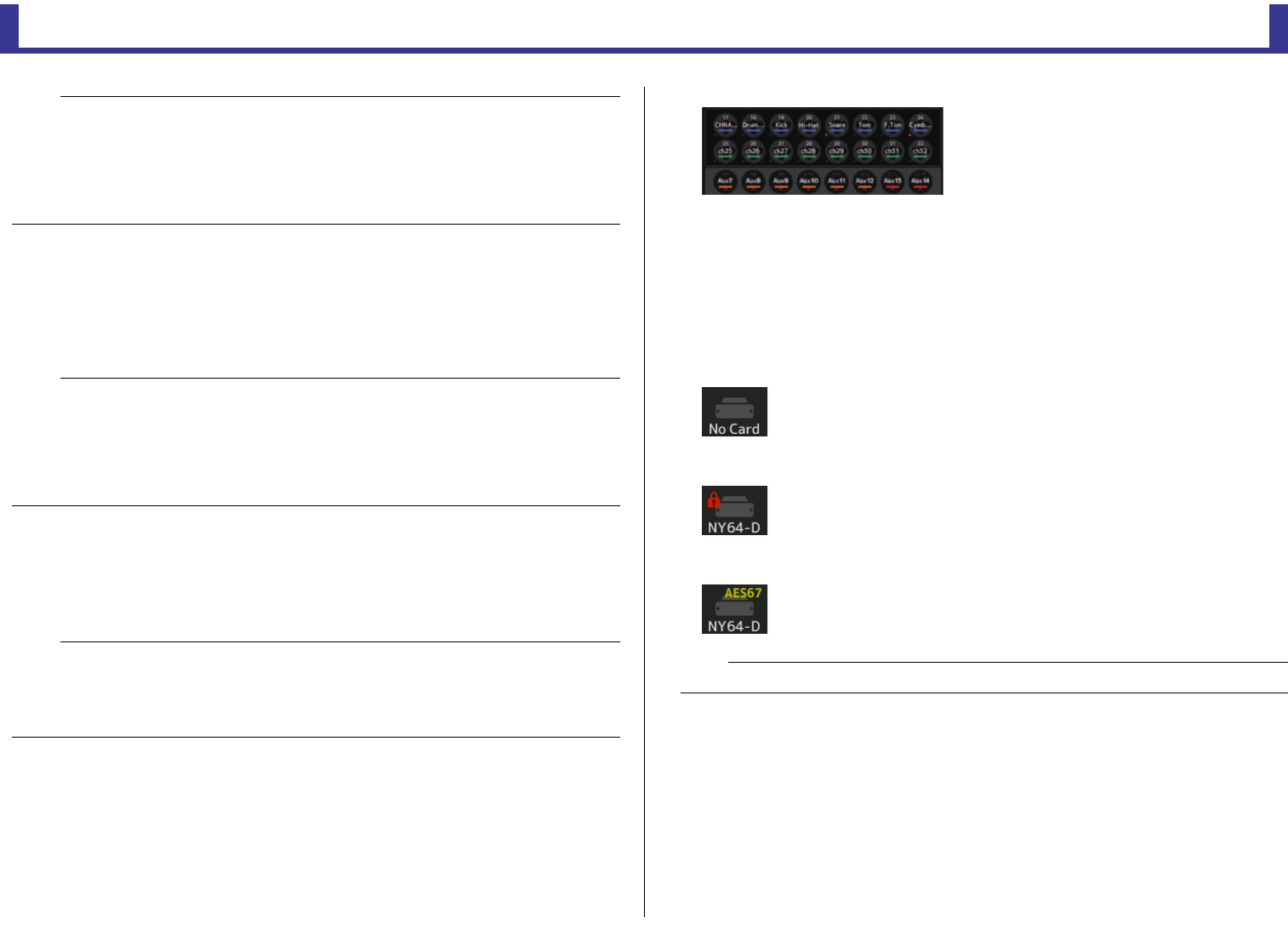
0Channel display area
The following information is displayed when the console's Quick Config button is turned
on and a Tio1608-D with the [QUICK CONFIG] switch turned on is connected.
•CH Name
• CH Color
• +48V setting for each channel (the indicator below and to the left of the channel icon
lights in red when turned on)
ASLOT display area (V3.1 and later)
Displays the status of the expansion slot.
If no NY card is installed, "No Card" is displayed.
If an NY64-D is installed and Dante Device Lock has been enabled, a lock icon is
displayed.
If the NY64-D is operating in Dante AES67 mode, "AES67" is displayed above and to the
right of the SLOT display area.
NOTE
• You can use Dante Controller to change Dante patches even when the Quick Config feature is
enabled. However, Quick Config patching will be applied when you restart the console.
If you want to use Dante Controller to change these settings, disable the Quick Config feature.
• If devices that are configured by Quick Config are also locked by Dante Device Lock, a message is
displayed and the Quick Config may not be implemented. (V3.1 and later)
• Up to 24 I/O racks (Tio1608-D, R series, etc.) can be connected to the same Dante network. If more
racks are connected, a message is displayed and the HA control may not operate properly.
NOTE
• When Quick Config is enabled, only one TF series console on the network can use the Tio1608-D
OUTPUT ports. If one or more other Tio1608-D units on the network have OUTPUT ports used by
another TF series console, the with OUTPUT checkbox turns off automatically and a popup screen
is displayed.
• When the with OUPUT checkbox is turned off and you are using Dante Controller for patching, refer
to "Quick Config Input and input channel relationships" (page 92) for information about output port
assignments for channels.
NOTE
• When there are multiple host devices on the same network that can control the head amp, repeated
operations could result, therefore we recommend having only one host device control the head amp.
• Even when Quick Config is turned off, you can use Dante Controller to patch into the corresponding
SLOT input channel (refer to "Quick Config Input and input channel relationships" (page 92)) and
control the head amp for up to 8 I/O racks.
NOTE
Dante Controller (v3.10.0.19 and later) is required in order for the NY64-D to operating in AES67 mode.
Toolbar
Reference Manual
TF Series
-
25
-
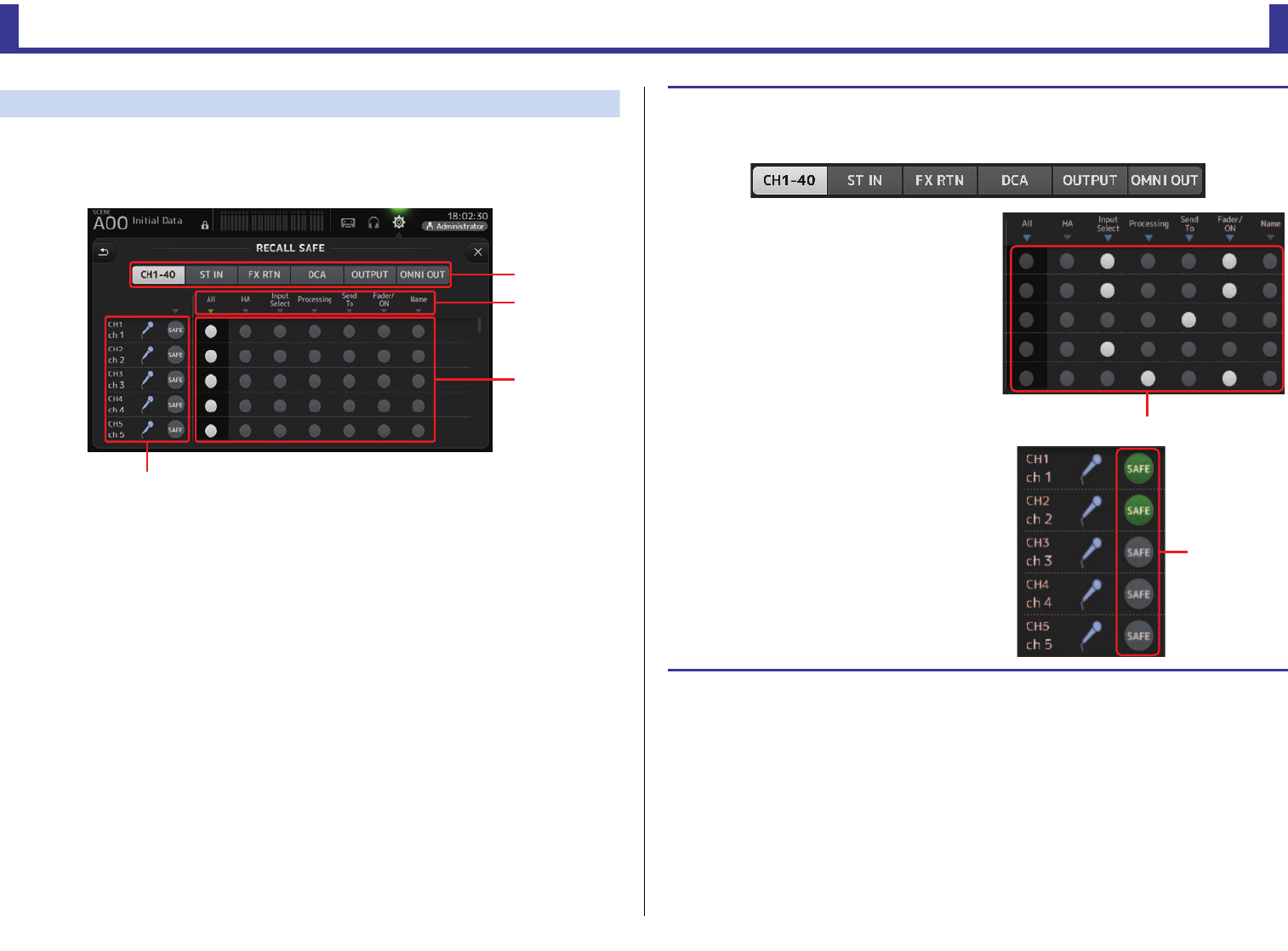
RECALL SAFE screen
Allows you to configure which items are recalled and which items are not (i.e., recall safe)
when recalling Scenes and Presets.
"Recall safe" allows you to select certain parameters, channels, DCA groups, etc. whose
settings will not be replaced when recalling a Preset or Scene.
1Channel selection buttons
Allows you to select which types of channels will be configured.
When you select a channel type, the different parameters that can be configured as
recall safe are displayed.
2Parameter names
Touch the
M
button to turn SAFE parameters on and off for all channels of the same type.
The
M
button turns green when all SAFE parameters are turned on. If turned off for a parameter
on all channels, it is displayed in gray. Finally, if recall safe is turned on for a parameter
but not for all channels, the M button under the parameter name is displayed in blue.
3Recall safe on/off buttons
Turns recall safe on and off for the corresponding parameter. When turned on, the
corresponding parameter is recall safe, i.e., its setting will not be changed when a Preset
or Scene is recalled.
For OMNI OUT assignments, recall safe can be turned on and off for OMNI OUT PATCH
only.
4Channel information
Displays the channel ID, name, and icon.
Touch the SAFE button to turn safe recall on and off for the corresponding channel.
When turned on, parameters whose recall safe on/off buttons are in the "on" position
will not be recalled.
ղ
ձ
ճ
մ
Using Recall safe function
1. Touch a channel selection button to select the channels or DCA groups that you
want to configure for recall safe.
2. Touch the recall safe on/off buttons
according to the items you want to make
recall safe.
3. Touch the SAFE buttons for each channel
to enable or disable the settings you
made above.
4. Touch the [X] button to close the screen,
and proceed to recall the desired Preset
or Scene.
Recall safe on/off buttons
SAFE buttons
Toolbar
Reference Manual
TF Series
-
26
-
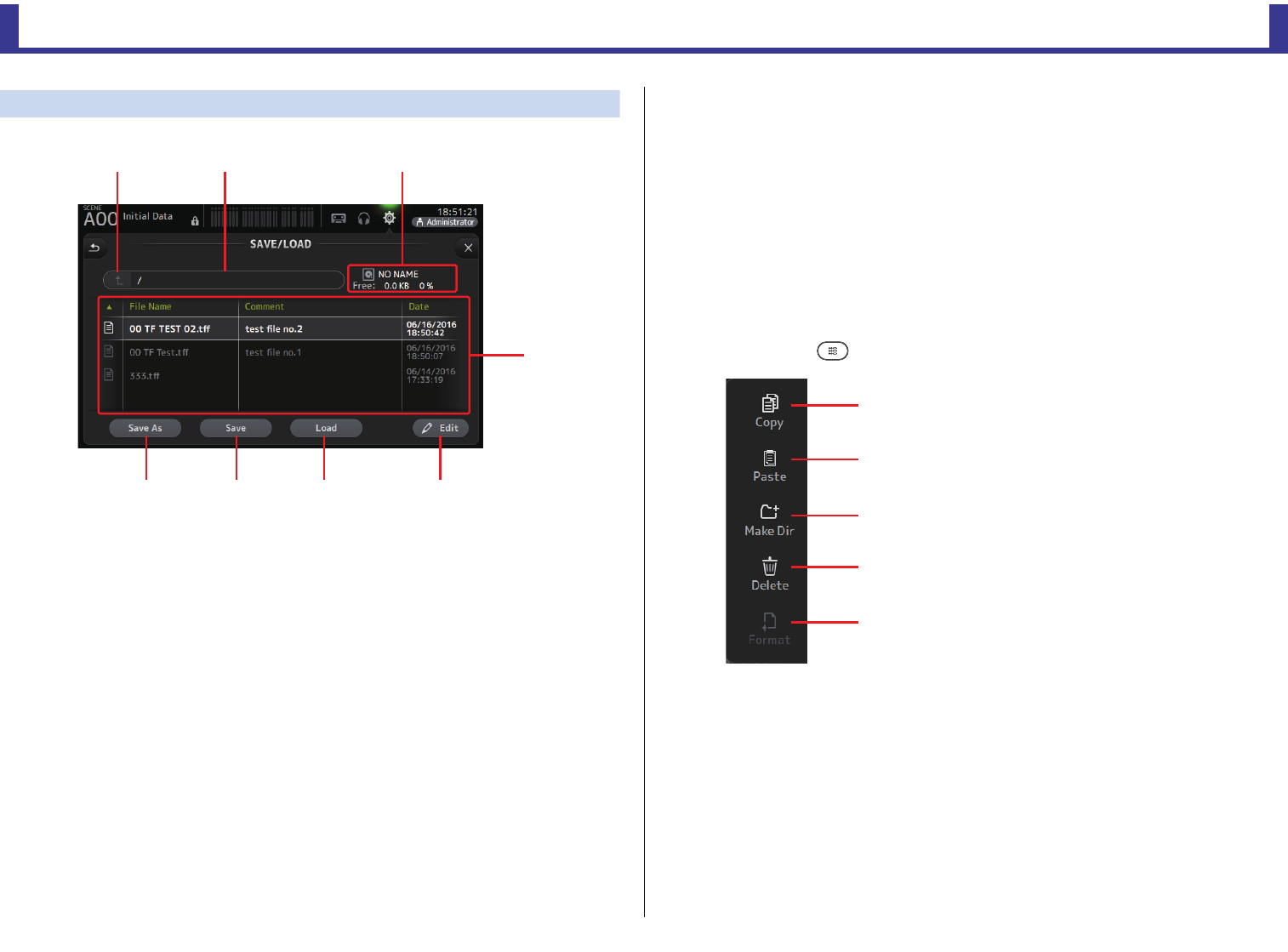
SAVE/LOAD screen
Displays a list of saved directories and files.
1Parent directory button
Displays the directory that is one level above the current directory.
This button is grayed out if the current directory is the top directory.
2Current directory
Displays the name of the current directory.
3Volume name
Displays the volume name of the USB storage device and the amount of available space.
4File list
Displays a list of the directories and files stored on the USB storage device. When an item
in the file list is selected, it is highlighted to indicate it will be the subject of any
subsequent operations.
You can touch a header in the list to sort the items by that header. Touch the same
header again to switch between ascending and descending order.
File Name: Displays directory and file names. An icon is displayed for each item so that
you can distinguish between the two.
Comment: Displays any comments you have entered for TF Series console files. To edit
a file's comment, select the file and then touch the Edit button to display the
keyboard (page 10).
Date: Displays each item's modified date.
5Edit button
Allows you to edit the selected file's file name and comment.
6Load button
Loads the file selected in the file list.
The LOAD SELECT screen is displayed when you press the Load button. (V2.0 and later)
7Save button
Saves the current settings by overwriting them over the file selected in the file list.
8Save As button
Saves the current settings by saving them as a new file.
SAVE/LOAD screen menu
Touch the Menu key ( ) from the SAVE/LOAD screen to display the following items.
ձղ ճ
մ
յնշո
1Copy
Copies the selected file.
2Paste
Pastes the file into the current directory.
3Make Dir
Creates a new directory.
4Delete
Deletes the selected file.
5Format
Formats the USB storage device that is connected
to the console.
ձ
ղ
ճ
մ
յ
Toolbar
Reference Manual
TF Series
-
27
-
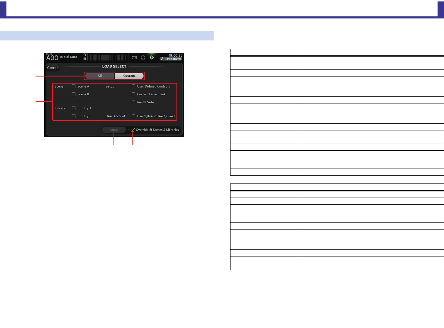
LOAD SELECT screen (V2.0 and later)
Allows you to select which data is loaded when you load a TF Series setup file.
1All/Custom selection button
Allows you to select the type of data that will be loaded. When All is selected, all data
will be loaded.
When Custom is selected, the checkboxes on this screen can be used to select the data
that will be loaded.
2Data selection checkboxes
Turn on the checkboxes according to the type of data that you want to load.
The User Account checkbox is displayed for both All and Custom, but you can change
the checkbox setting only when you are logged in as the Administrator.
3Load button
Touch this button to load the data.
4Override Protected Scenes & Libraries checkbox
When this checkbox is turned on, protected Scenes and Libraries will also be overwritten
by loaded data. If you want to prevent protected Scenes and Libraries from being
overwritten, turn off this checkbox.
Data that can be saved and loaded
The following data can be saved and loaded on the SAVE/LOAD screen.
ձ
ղ
ճմ
Data that is saved/loaded Description
Scene Memory All Scenes and the current Scene
Channel Library All channel Presets
+48V Master
Mute Safe
Mute Master
Cue Except channel cue settings
Oscillator Except oscillator on
Monitor
Meter
Recall Safe
User Defined Keys
User Defined Knobs
Foot Switch
Custom Fader Bank
Preference Except the following settings: Help Language, Show Help at Startup, Touch
Area Optimization, [Home] Key
Slot Setup Quick Config, HA Control
User Account Only when logged in as Administrator
Data that is not saved/loaded Description
Cue Channel cue settings
Oscillator Oscillator on
Brightness
Preference Help Language, Show Help at Startup, Touch Area Optimization settings,
[Home] Key
Date Time
Network
Console Lock
Input Port Trim
Output Port Trim
Fader Calibration
Channel Color Calibration
Toolbar
Reference Manual
TF Series
-
28
-
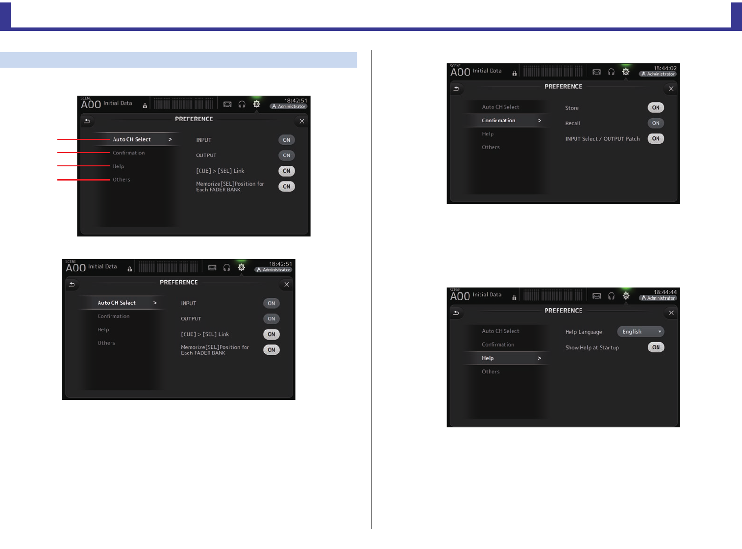
PREFERENCE screen
Allows you to configure general operating settings regarding confirmation message display,
[SEL] key behavior, etc.
1Auto CH Select section
INPUT/OUTPUT: When turned on, a channel of the corresponding type will be selected
automatically when you operate that channel's fader.
You can turn this feature on and off independently for input channels
and output channels.
[CUE] > [SEL] LINK: When turned on, a channel will be selected when you turn its CUE
on.
Memorize [SEL] Position for Each FADER BANK: Determines whether channel
positions are remembered in fader
banks.
2Confirmation section
Store/Recall: When turned on, a confirmation message is displayed when you store and
recall features.
INPUT Select/OUTPUT Patch: When turned on, a confirmation message is displayed
when you change the input selection or OMNI OUT
patching.
3Help section
Help Language: Determines the language used when displaying the HELP screen.
Show Help at Startup: Determines whether the HELP screen is displayed automatically
after the console starts up.
ձ
ղ
ճ
մ
Toolbar
Reference Manual
TF Series
-
29
-
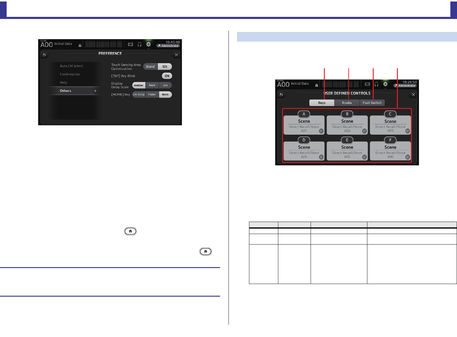
4Others section
Touch Sensing Area Optimization: Allows you to optimize the touchscreen's
sensitivity.
Stand: Optimized for operating the touchscreen
when you are positioned above it, such as
when standing.
Sit: Optimized for operating the touchscreen
when you are positioned below it, such as
when sitting.
[TAP] Key Blink (V2.0 and later): Allows you to turn the flashing [TAP] key on or off.
The [TAP] key can be used to tap the tempo even
when the flashing is turned off.
Display Delay Scale (V2.5 and later): You can select the desired units (meters, feet,
milliseconds) that are displayed in the MATRIX
channel DELAY box.
[HOME] Key (V3.0 and later): Allows you to choose what is displayed when you press
the Home key ( ) to display the OVERVIEW screen.
You can choose CH Strip, Fader, or Both. When Both is
selected, you can switch between the CH STRIP section
and FADER section by pressing the Home key ( ).
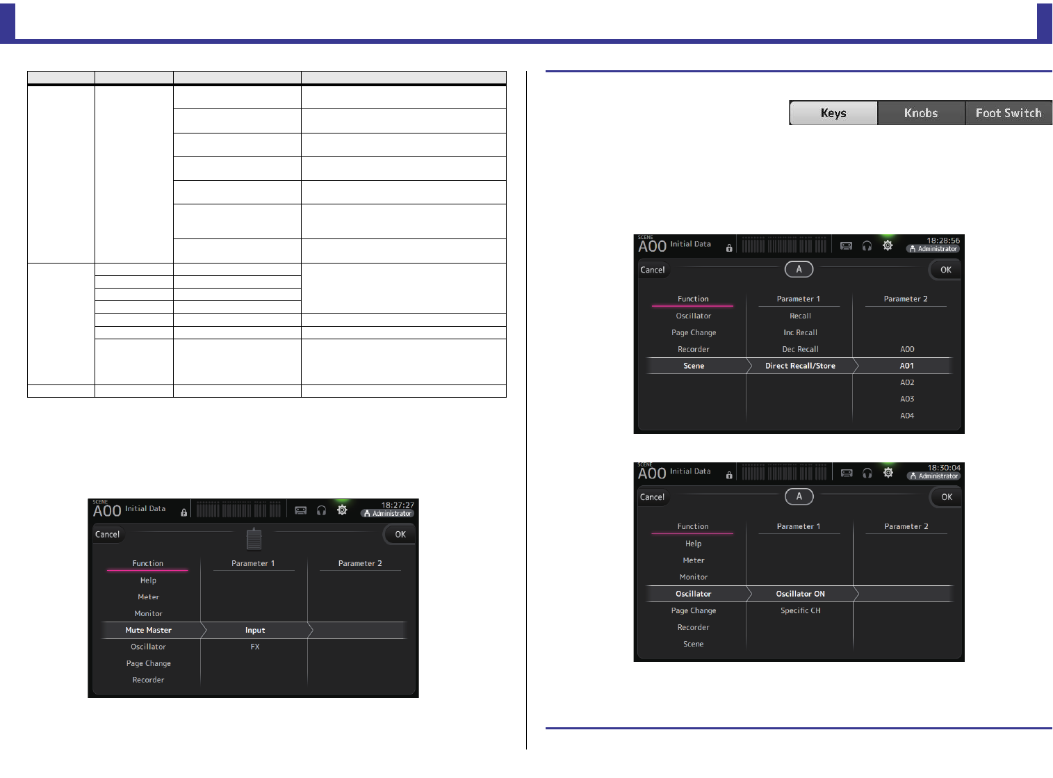
USER DEFINED CONTROLS screen
This screen allows you to assign features to the [USER DEFINED KEYS], [USER DEFINED
KNOBS], and to the footswitch.
1Keys button
Allows you to assign features to the [USER DEFINED KEYS] on the top panel.
2Key setup buttons (A–F)
Touch the desired button to display the screen that allows you to assign features to the
corresponding key.
Features that can be assigned to [USER DEFINED KEYS]
Configuring settings in the PREFERENCE screen
1. Use the buttons on the PREFERENCE screen to configure the settings as desired.
2. When finished, touch the close button ([X]).
FUNCTION PARAMETER1 PARAMETER2 Description
No Assign No feature is assigned
Brightness Bank Change Switches the brightness setting bank. This
feature is supported from V1.1.
CH ON Specific CH
CH 1–40,
ST IN 1, ST IN 2,
FX 1, FX 2,
DCA 1–8,
AUX 1–8,
AUX 9/10–19/20,
STEREO, SUB
MATRIX1–4 (V2.5 and later)
Turns the channel assigned to PARAMETER 2
on and off.
ձճյղ
Toolbar
Reference Manual
TF Series
-
30
-
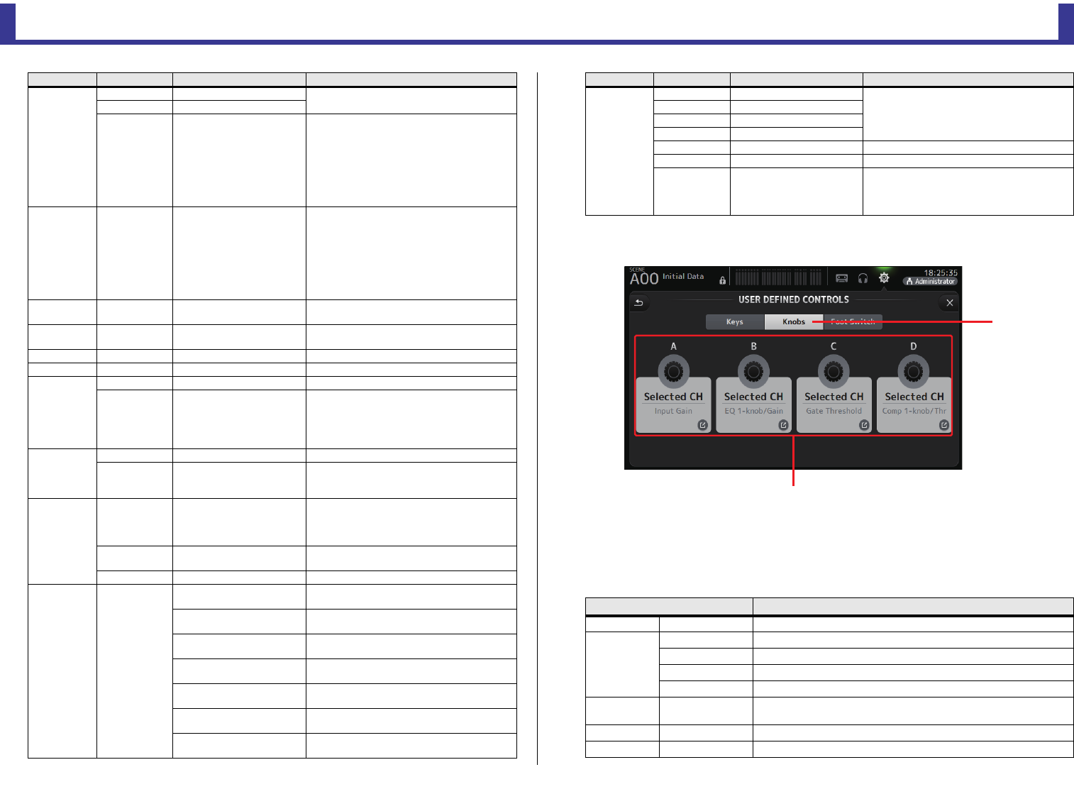
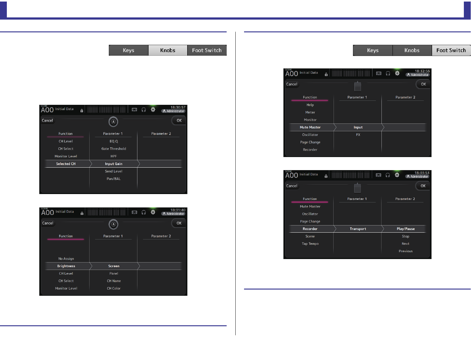
3Knobs button
Allows you to assign features to the [USER DEFINED KNOBS].
4Knob setup buttons
Touch the desired button to display the screen that allows you to assign features to the
corresponding [USER DEFINED KNOBS].
Features that can be assigned to [USER DEFINIED KNOBS]
CH Select
Inc Select channels in order of the direction
selected for PARAMETER 1.
Dec
Specific CH
CH 1–40,
ST IN 1L–ST IN 2R
FX1L–FX2R,
AUX 1–8,
AUX 9–20,
STEREO L, STEREO R,
SUB
MATRIX1–4 (V2.5 and later)
Selects the channel assigned to PARAMETER 2.
CUE Specific CH
CH 1–40,
ST IN 1, ST IN 2,
FX 1, FX 2,
DCA 1–8,
AUX 1–8,
AUX 9/10–19/20,
STEREO, SUB
MATRIX1–4 (V2.5 and later)
Turns the cue on and off for the channel
assigned to PARAMETER 2.
Effect Bypass FX 1, FX 2,
INS FX 1–6 Bypasses the effect assigned to PARAMETER 2.
EQ Band Select HPF, LPF, Low, Low-Mid,
High-Mid, High
Selects the band assigned to PARAMETER 2.
(V3.0 and later)
Help Displays help information.
Meter Peak Hold ON Turns the peak hold on and off.
Monitor
Output Turns the monitor out on and off.
Source Select
STEREO, SUB,
STIN 1, STIN 2,
STIN (TF-RACK),
USB 33/34,
Playback
Selects the monitor source assigned to
PARAMETER 2.
Oscillator
Oscillator On Turns the oscillator on and off.
Specific CH
AUX 1–20,
STEREO L, STEREO R,
SUB
Turns the oscillator sent to the channel
assigned to PARAMETER 2 on and off.
Page Change
Bookmark
Press and hold for more than 2 seconds to
bookmark the current screen. Press and hold
for less than two seconds to display the
bookmarked screen.
Bookmark with
“SEL”
The selected channel is saved with the
bookmark. Same as above.
Close Popup Closes the popup screen.
Recorder Transport
Play/Pause Same as the Play/Pause button on the
RECORDER screen.
Stop Same as the Stop button on the RECORDER
screen.
Next Same as the Next button on the RECORDER
screen.
Previous Same as the Previous button on the
RECORDER screen.
Rec Same as the Rec button on the RECORDER
screen.
Auto Rec Recording stops and the file is saved, and then
recording resumes immediately as a new file.
Rec & Start Recording starts immediately without entering
record-ready mode.
FUNCTION PARAMETER1 PARAMETER2 Description
SCENE
Inc
Same as the INC, DEC, STORE, and RECALL
keys.
Dec
Store
Recall
Inc Recall Recalls the next numbered Scene.
Dec Recall Recalls the previous numbered Scene.
Direct Recall/
Store
A00–99,
B00–99
Recalls the Scene number assigned to
PARAMETER 2. Press and hold for more than
two seconds to assign the current settings to
that Scene number.
Features Description
No Assign No feature is assigned
Brightness
CH Name Adjusts the brightness of the CH NAME. (TF5/TF3/TF1 only)
CH Color Adjusts the brightness of the CH COLOR indicator. (TF5/TF3/TF1 only)
Screen Adjusts the brightness of the touchscreen.
Panel Adjusts the brightness of the panel LEDs.
CH Level Specific CH Adjusts the level of the channel assigned to PARAMETER 2. (V3.0 and
later)
CH Select Inc/Dec Selects the channel. (V3.0 and later)
Monitor Level Adjusts monitor level.
FUNCTION PARAMETER1 PARAMETER2 Description
ճ
մ
Knob setup buttons
Toolbar
Reference Manual
TF Series
-
31
-
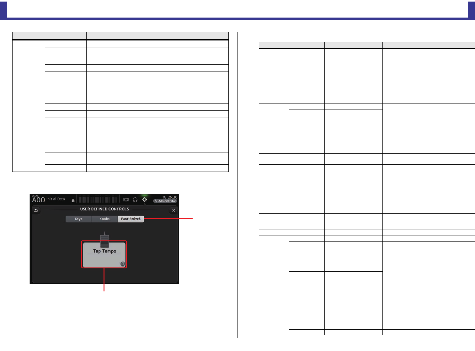
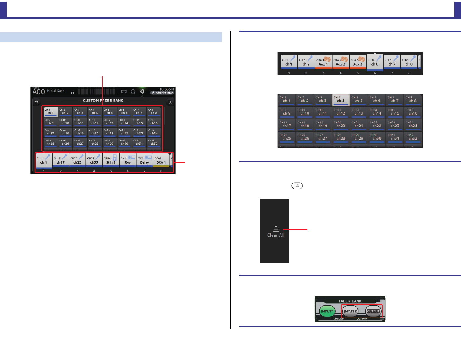
5Foot Switch button
Allows you to assign features to the footswitch.
6Foot Switch setup button
Displays the features that can be assigned to the footswitch.
Features that can be assigned to the footswitch
Selected CH
CH Level Adjusts the level of the selected channel. (V3.0 and later)
Comp 1-knob/Thr
Adjusts 1-knob or threshold for the selected channel's COMP.
When 1-knob COMP is turned on, adjusts 1-knob; when 1-knob COMP
is turned off, adjusts threshold.
Digital Gain Adjusts the DIGITAL GAIN of the selected channel. (V3.0 and later)
EQ 1-knob/Gain
Adjusts 1-knob or gain for the selected channel's EQ.
When 1-knob EQ is turned on, adjusts 1-knob; when 1-knob EQ is
turned off, adjusts gain.
EQ Band Select Selects the band for the selected channel. (V3.0 and later)
EQ Frequency Adjusts EQ frequency for the selected channel.
EQ Q Adjusts EQ Q for the selected channel.
Gate Threshold Adjusts gate threshold for the selected channel.
HPF Adjusts HPF for the selected channel.
Turn the knob to adjust the frequency.
Input Gain
Adjusts analog gain or digital gain for the selected channel.
When the channel's input is an analog source, adjusts analog gain.
When the channel's input is a digital source (i.e., USB, iPad, or STIN),
adjusts digital gain.
Send Level Adjusts the send level to the bus selected for PARAMETER2 (FX, AUX,
SUB) for the selected channel. (V3.0 and later)
Pan/BAL Adjusts pan or balance for the selected channel.
Features Description
յ
ն
Foot Switch setup button
FUNCTION PARAMETER1 PARAMETER2 Description
No Assign No feature is assigned
Brightness Bank Change Switches the brightness setting bank. This
feature is supported from V1.1.
CH ON Specific CH
CH 1–40,
ST IN 1, ST IN 2,
FX 1, FX 2,
DCA 1–8,
AUX 1–8,
AUX 9/10–19/20,
STEREO, SUB
MATRIX1–4 (V2.5 and later)
Turns the channel assigned to PARAMETER 2
on and off.
CH Select
Inc Select channels in order of the direction
selected for PARAMETER 1.
Dec
Specific CH
CH 1–40,
ST IN 1L–ST IN 2R,
FX1L–FX2R,
AUX 1–8,
AUX 9–20,
STEREO L, STEREO R,
SUB
MATRIX1–4 (V2.5 and later)
Selects the channel assigned to
PARAMETER 2.
Clear Cue Clears all cue selections.
Same as the CLEAR CUE key on the top panel.
CUE Specific CH
CH 1–40,
ST IN 1, ST IN 2,
FX 1, FX 2,
DCA 1–8,
AUX 1–8,
AUX 9/10–19/20,
STEREO, SUB
MATRIX1–4 (V2.5 and later)
Turns the cue on and off for the channel
assigned to PARAMETER 2.
Effect Bypass FX 1, FX 2,
INS FX 1–6 Bypasses the effect assigned to PARAMETER 2.
EQ Band Select
HPF, LPF, Low, Low-Mid,
High-Mid, High
Selects the band assigned to PARAMETER 2.
(V3.0 and later)
Help Displays help information.
Meter Peak Hold ON Turns the peak hold on and off.
Monitor
Output Turns the monitor out on and off.
Source Select
STEREO, SUB,
ST IN 1, ST IN 2,
STIN (TF-RACK),
USB 33/34,
Playback
Selects the monitor source assigned to
PARAMETER 2.
Mute Master Input Same as the corresponding MUTE key on the
top panel.
FX
Oscillator
Oscillator On Turns the oscillator on and off.
Specific CH
AUX 1–20,
STEREO L, STEREO R,
SUB
Turns the oscillator sent to the channel
assigned to PARAMETER 2 on and off.
Page Change
Bookmark
Press and hold for more than 2 seconds to
bookmark the current screen. Press and hold
for less than two seconds to display the
bookmarked screen.
Bookmark with
“SEL”
The selected channel is saved with the
bookmark. Same as above.
Close Popup Closes the popup screen.
Toolbar
Reference Manual
TF Series
-
32
-
Feature assignment screen
When you select a Function, the items available for Parameter 1 are displayed. Likewise,
when you select an item for Parameter 1, the items available for Parameter 2 are
displayed. Some Functions may not have items available for Parameter 1; some
Parameter 1 items may not have items available for Parameter 2.
Recorder Transport
Play/Pause Same as the Play/Pause button on the
RECORDER screen.
Stop Same as the Stop button on the RECORDER
screen.
Next Same as the Next button on the RECORDER
screen.
Previous Same as the Previous button on the
RECORDER screen.
Rec Same as the Rec button on the RECORDER
screen.
Auto Rec
Recording stops and the file is saved, and
then recording resumes immediately as a new
file.
Rec & Start Recording starts immediately without
entering record-ready mode.
SCENE
Inc
Same as the INC, DEC, STORE, and RECALL
keys.
Dec
Store
Recall
Inc Recall Recalls the next numbered Scene.
Dec Recall Recalls the previous numbered Scene.
Direct Recall/
Store
A00–99,
B00–99
Recalls the Scene number assigned to
PARAMETER 2. Press and hold for more than
two seconds to assign the current settings to
that Scene number.
TAP TEMPO Same as the TAP key on the top panel.
FUNCTION PARAMETER1 PARAMETER2 Description Assigning a feature to a [USER DEFINED KEY]
1. Touch the Keys button.
The screen where you can select the
desired [USER DEFINED KEY] is displayed.
Buttons A–F correspond to [USER
DEFINED KEYS] A–F.
2. Touch the Key button that corresponds to the [USER DEFINED KEY] that you want
to configure.
The configuration screen is displayed.
3. Scroll through the Function list and select the desired feature.
4. Scroll through the Parameter 1 list and select the desired item.
If items are available in the Parameter 2 list, select the desired item.
5. Touch the OK button.
Toolbar
Reference Manual
TF Series
-
33
-
Assigning a feature to a [USER DEFINED KNOB]
1. Touch the Knobs button.
The screen where you can select the
desired [USER DEFINED KNOB] is
displayed.
Buttons A–D correspond to [USER DEFINED KNOBS] A–D.
2. Touch the Knob button that corresponds to the [USER DEFINED KNOB] that you
want to configure.
The configuration screen is displayed.
3. Scroll through the Function list and select the desired feature.
4. Scroll through the Parameter 1 list and select the desired item.
If items are available in the Parameter 2 list, select the desired item.
5. Touch the OK button.
Assigning a feature to the footswitch
1. Touch the Foot Switch button.
2. Touch the Foot Switch setup button.
The configuration screen is displayed.
3. Scroll through the Function list and select the desired feature.
4. Scroll through the Parameter 1 list and select the desired item.
If items are available in the Parameter 2 list, select the desired item.
5. Touch the OK button.
Toolbar
Reference Manual
TF Series
-
34
-
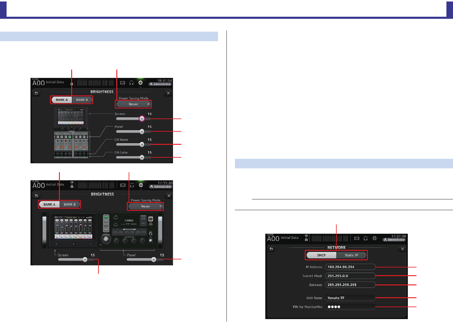
CUSTOM FADER BANK screen
The custom fader bank allows you to choose different channels, regardless of type (input
channels, AUX buses, MATRIX (V2.5 and later), DCA groups, etc.), and group them into a
bank of faders.
1Fader buttons
Allow you to select which fader will be configured.
2Channel buttons
Determines which channel will be assigned to the fader you selected for 1.
If you select None, nothing will be assigning to the corresponding fader.
ղ
ձ
Configuring the custom fader bank
1. Touch a fader button to select the fader that you want to configure.
2. Touch the desired the channel button according to which channel you want to
assign to the fader you selected in step 1.
3. Repeats steps 1–2 and configure other faders as desired.
CUSTOM FADER BANK screen menu
Touch the Menu key ( ) from the CUSTOM FADER BANK screen to display the following
items.
1Clear All
Clears all assignments for each fader bank (all will
be set to None).
Recalling the CUSTOM FADER BANK (TF5/TF3/TF1)
1. Press the [INPUT2] and [OUTPUT] keys on the top panel at the same time.
ձ
Toolbar
Reference Manual
TF Series
-
35
-
BRIGHTNESS screen
Allows you to adjust the brightness of the touchscreen, as well as the LEDs, name display,
and channel colors on the top panel. You can save brightness settings into BANK A and BANK
B, allowing you to recall the desired brightness settings to suit your work conditions.
1Bank selection buttons
Allow you to switch between BANK A and BANK B.
BANK A: Selects BANK A brightness settings.
BANK B: Selects BANK B brightness settings.
For V1.1 and later, you can switch between the banks using [USER DEFINED KEYS] or a
footswitch.
2Power Saving Mode button
Allows you to set the amount of time that passes before console switches to power
saving mode.
You can choose 30 seconds, 2 minutes, 5 minutes, 10 minutes, 15 minutes, or never.
3Screen brightness slider
Adjusts the brightness of the touchscreen.
4Panel brightness slider
Adjusts the brightness of the LEDs on the top panel.
1–10: In low lighting conditions, an auxiliary light lights, which makes the key top easier
to read.
11–20: In bright lighting conditions, an auxiliary light does not light, which helps
emphasize contrast.
5CH Name brightness slider (TF5/TF3/TF1)
Adjusts the brightness of the channel names displayed on the top panel.
6CH Color brightness slider (TF5/TF3/TF1)
Adjusts the brightness of the channel colors on the top panel.
NETWORK screen
Allows you to configure the console's network address, which is needed when you connect a
computer to the NETWORK connector.
Configure these settings according to the connected computer or network.
ղձ
ճ
մ
յ
ն
TF5/TF3/TF1
ղձ
մ
ճ
TF-RACK
NOTE
When connecting the console to a LAN, refer to the TF Editor Installation Guide.
ձ
ղ
ճ
մ
յ
ն
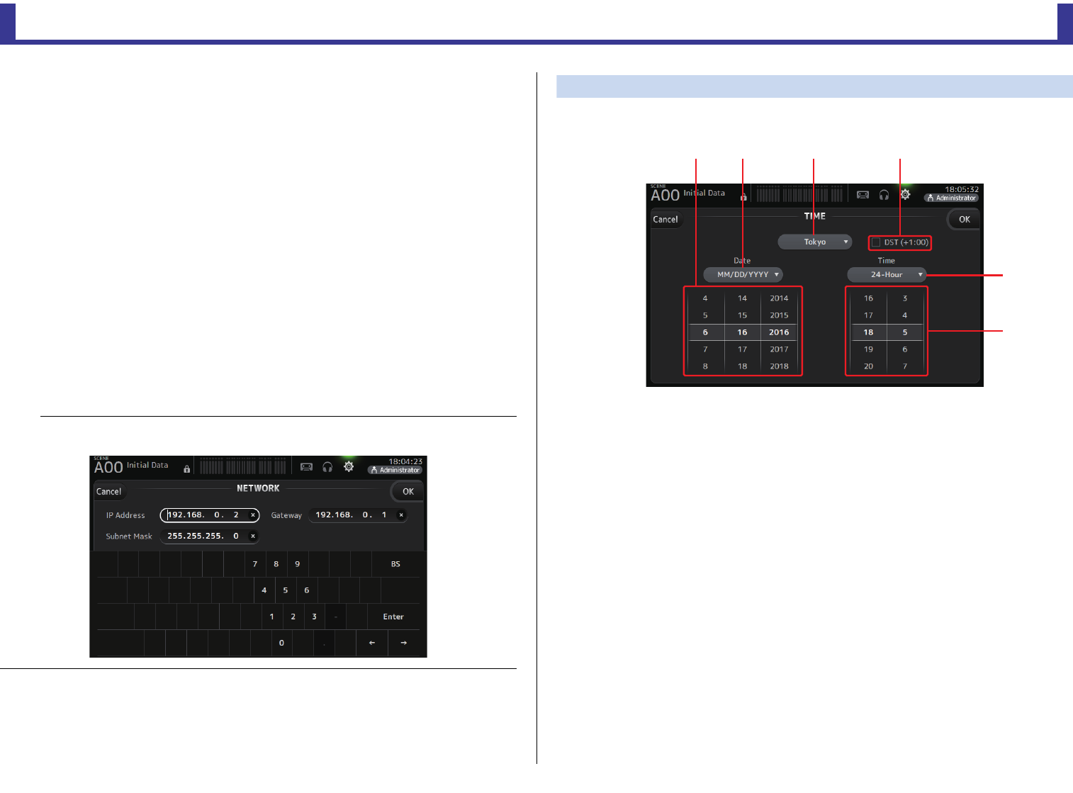
Toolbar
Reference Manual
TF Series
-
36
-
1IP address provisioning method button
Select the setting that matches how the console will configure its IP address.
DHCP: The console receives its IP address automatically.
Static IP: The console's IP address is set manually.
2IP Address
Determines the unique address that identifies the console on the network.
3Subnet Mask
Defines how many bits are used for network addresses on the connected network.
4Gateway
The address of the network device (gateway) that facilitates communication between
different devices on the network.
5Unit Name
Allows you to specify a name that can be used to identify the console on the network.
6PIN for MonitorMix (V1.1 and later)
This is a 4-digit password that is required when accessing the console using the
MonitorMix app.
MonitorMix is an application that allows performers to adjust the levels of the monitor
mix directly from the stage.
TIME screen
Allows you to set the console's internal clock and change the date and time format. The date
and time set here are used as a timestamp when saving Scenes.
1Date setting
Determines the console's date setting.
2Date format setting
Allows you to select the date format.
The following formats are available.
MM/DD/YYYY
DD/MM/YYYY
YYYY/MM/DD
3Region
Allows you to change the region.
4DST (+1:00)
Enables daylight saving time.
When turned on, the current time advances by one hour.
5Time format setting
Allows you to select the time format.
24-Hour
12-Hour (uses AM and PM)
6Time setting
Determines the console's time setting.
NOTE
When the DHCP button is selected, items 2–4 are not needed.
2–4 are only needed when you select the Static IP button. Configure these parameters as needed.
ձղ ճ մ
յ
ն
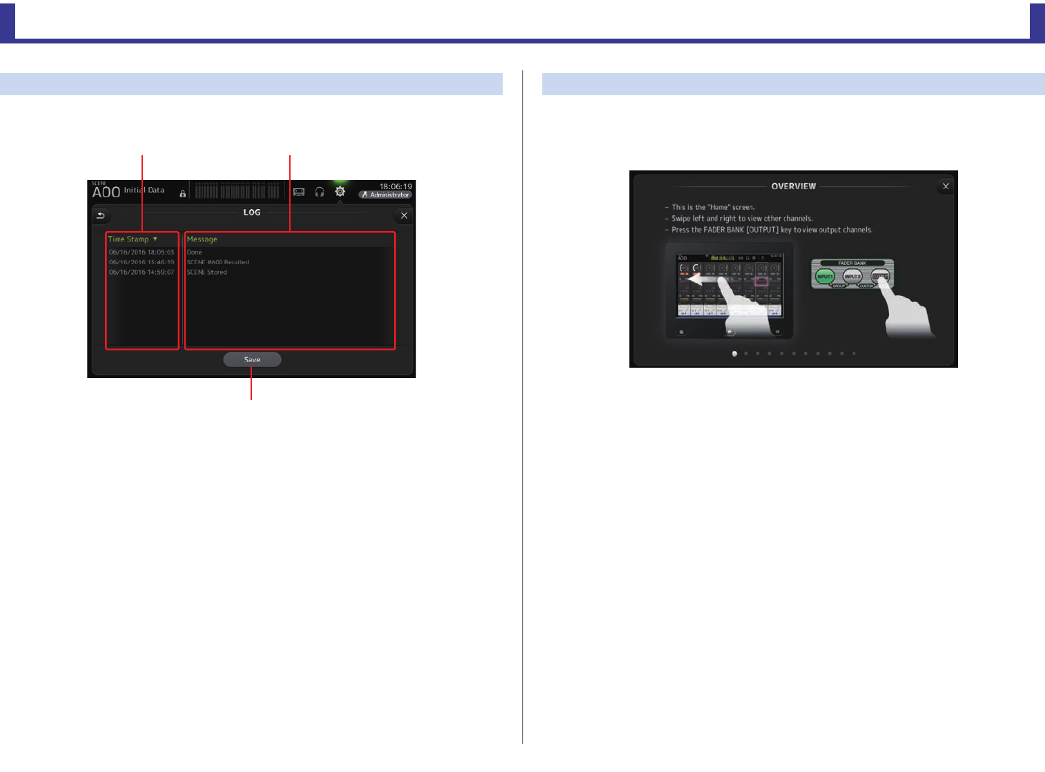
Toolbar
Reference Manual
TF Series
-
37
-
LOG screen
When messages are displayed while using the console, they are logged by date and time and
can be viewed later on this screen.
1Time Stamp field
Displays the date and time of each message.
You can touch the header to sort messages by date and time.
2Message field
Displays messages.
You can touch the header to sort messages alphabetically by message.
3Save button
Allows you to save the log to a USB storage device.
This button is not available when no USB storage device is connected.
HELP screen
Displays information about console operations. If "Show Help at Startup" is turned on in the
PREFERENCE screen, the HELP screen is displayed automatically after the console starts
up.
You can swipe left and right to view different pages.
ձղ
ճ
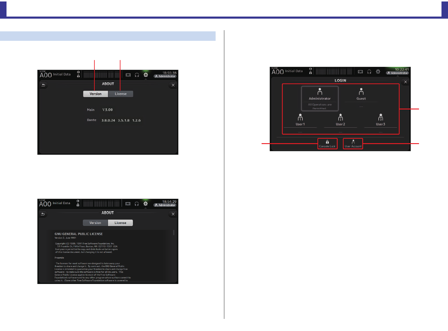
Toolbar
Reference Manual
TF Series
-
38
-
ABOUT screen
Displays system software version information and license information.
1Version button
Displays the console's system software version number.
(V2.0 and later) Displays the Dante version of the connected NY64-D, if installed.
2License button
Displays system software license information.
LOGIN screen (V3.0 and later)
Allows you to assign permissions for accessing the TF series console.
By limiting which parameters can be operated by different users, you can prevent improper
operation and specify what guest engineers can and cannot do when operating the console.
1User icons
Display the icon, name, and comments for each user.
When you touch an item, the console prompts you to enter the password for the
corresponding user.
If there is no password assigned to a user, you can log in by simply touching the user's icon.
Administrator
Can use all features. Only one administrator can be configured for the console.
The administrator is the only user that can set the access permissions of other users.
If another user has locked the console, the administrator can release the console lock.
The only setting that must be set for the administrator is the password.
Guest
Can use features according to the access permissions set by the administrator. Only one
guest can be configured for the console.
Access permissions and comments can be assigned to the guest.
User
Can use features according to the access permissions set by the administrator. Three
users can be configured for the console.
A user name, password, access permissions, and comments can be assigned to each user.
ձղ
ճ
ձ
ղ
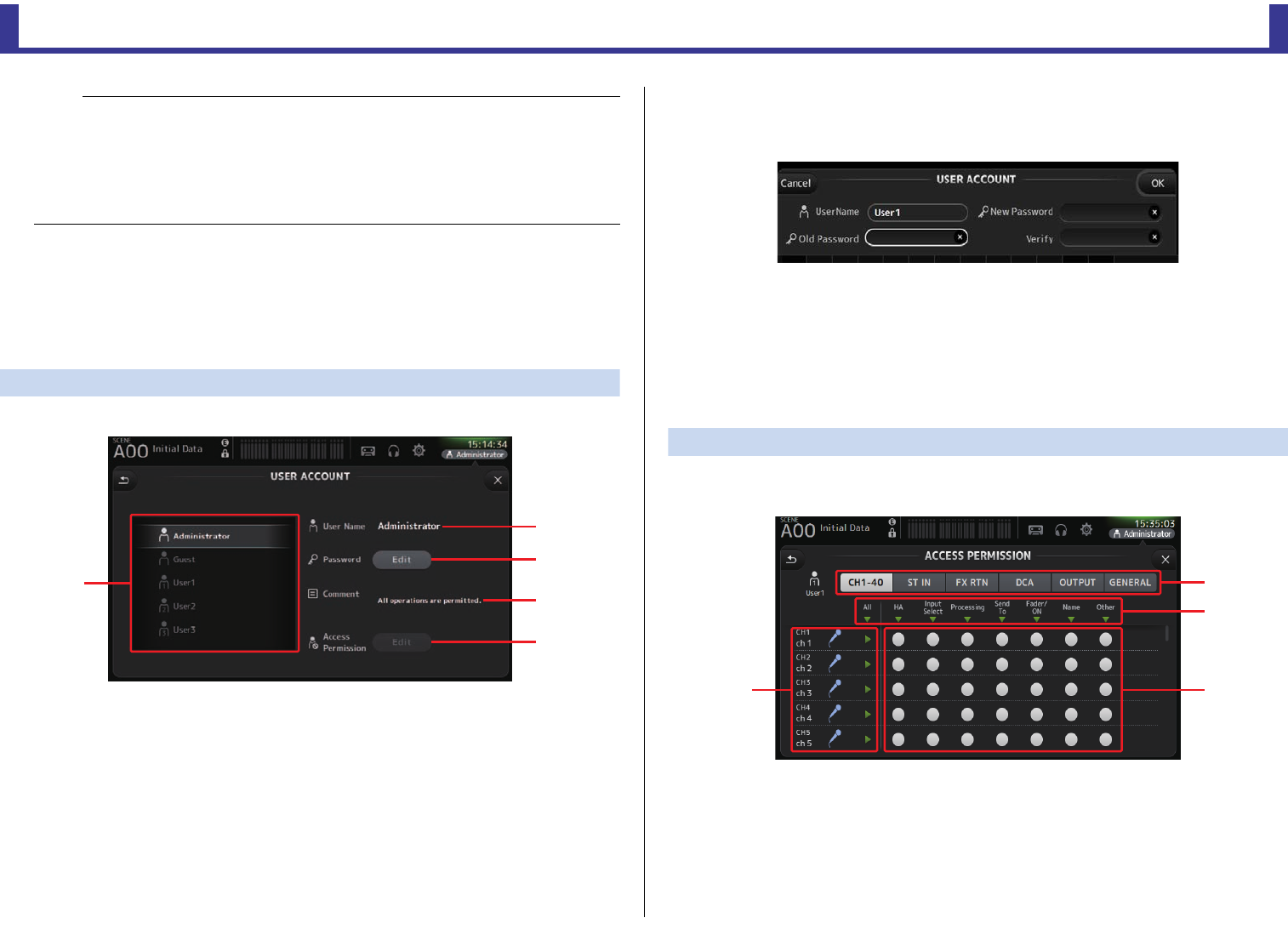
Toolbar
Reference Manual
TF Series
-
39
-
2Console lock icon
Prompts you to enter the password for the current user.
If the correct password is entered, the CONSOLE LOCK screen is displayed. (page 41)
3User account icon
Displays the USER ACCOUNT screen.
USER ACCOUNT screen (V3.0 or later)
Allows the administrator to set the access permissions for the other users.
1User selection area
Allows you to select which user's settings you will configure.
Information about the selected user is displayed on the right side of the screen.
2User Name text box
Displays the keyboard screen so that you can edit the user name.
You cannot edit the user name of the administrator and guest accounts.
3Password Edit button
Displays the keyboard screen so that you can edit the password.
When setting a password for the first time, enter the desired password in the New
Password text box, and then enter the password again in the Verify text box. When
changing a password, enter the current password in the Old Password text box, and
then set the new password.
4Comment text box
Displays the keyboard screen so that you can enter a comment.
5Access Permission Edit button
Displays the ACCESS PERMISSION screen.
When logged in as the administrator, you can set the access permissions of the selected
user for each parameter.
ACCESS PERMISSION screen (V3.0 and later)
Allows you to select which parameters can be used and not used by each user.
This screen is only displayed when logged in as the administrator.
1Selection buttons
Allows you to select a channel to assign access permission to.
According to which button you have selected, the different parameters that can be
assigned access permissions are displayed.
You can set access permissions for operations that are not associated with channels, such
as the SETUP screen or the SCENE screen, by touching the GENERAL button.
NOTE
• There is no password saved for the administrator in the factory default settings. (All users have
full access.)
In order to set permissions for other users, you must first set a password for the administrator.
• If a user with a password assigned is logged in to the console when the console is turned off, the
console will prompt the user to enter that password when the console is turned on the next time.
If another user wants to log in, press the cancel button when prompted to enter the password, and
then select the desired user in the LOGIN screen.
յ
ղ
ճ
մ
ձ
ճ
ձ
ղ
մ
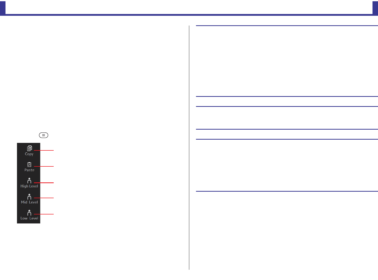
Toolbar
Reference Manual
TF Series
-
40
-
2Parameter names
Touch the
button to allow/restrict access to the parameters for all channels of the same type.
The button turns green when access is allowed for all channels. If access is allowed
for only some channels, it is displayed in blue, and if access is restricted for all channels,
it is displayed in gray.
3Access permission on/off buttons
Allow (on) and restrict (off) access to the corresponding parameters.
The selected user can only use the parameters that are allowed here.
For details about each parameter, refer to the parameter list. (page 84)
4Channel information
Displays the channel ID, name, and icon.
Touch the
button to allow/restrict access to the parameters for the corresponding channel.
The button turns green when access is allowed for all parameters. If access is allowed
for only some parameters, it is displayed in blue, and if access is restricted for all
parameters, it is displayed in gray.
ACCESS PERMISSION screen menu
Press the Menu key ( ) from the ACCESS PERMISSION screen to display the following options.
1Copy
Copies the ACCESS PERMISSION settings of the
selected user to the clipboard.
2Paste
Pastes the ACCESS PERMISSION settings in the
clipboard to the selected user.
3High Level
4Mid Level
5Low Level
Applies ACCESS PERMISSION settings to the
selected user based on their proficiency.
High Level: For advanced users. Only network and
clock settings are restricted. All other
parameters are allowed.
Mid Level: For moderately proficient users.
System settings are restricted. All other
parameters, such as channel
operations, are allowed.
Low Level: For beginners. Most parameters are
restricted. Channel on/off and fader
level adjustments are allowed.
ձ
ղ
ճ
մ
յ
Applying access permissions
1. From the LOGIN screen, log in as the administrator.
2. From the LOGIN screen, touch the User Account icon to display the USER ACCOUNT
screen.
3. Select the desired user, then set the user name, password, and comments.
4. Touch the Access Permission Edit button to display the ACCESS PERMISSION screen.
5. Restrict (turn off) the parameters that you do not want the user to access.
6. To confirm whether the access permissions were set as desired, return to the LOGIN
screen and log in as the user you set access permissions for.
7. Operate a parameter that you restricted. "Permission Denied!" is displayed if the
parameter is restricted.
Resetting user settings
If the console is reset, all user passwords are deleted and all restrictions are released.
(page 79)
Loading user settings to other TF series consoles
1. From the SAVE/LOAD screen, save the console's internal settings.
2. Log in as the administrator using the console to which you want load the user
settings.
3. From the SAVE/LOAD screen, select the settings file you saved in step 1 and touch
the Load button.
4. From the LOAD SELECT screen, select user accounts on the CUSTOM tab and touch
the Load button.
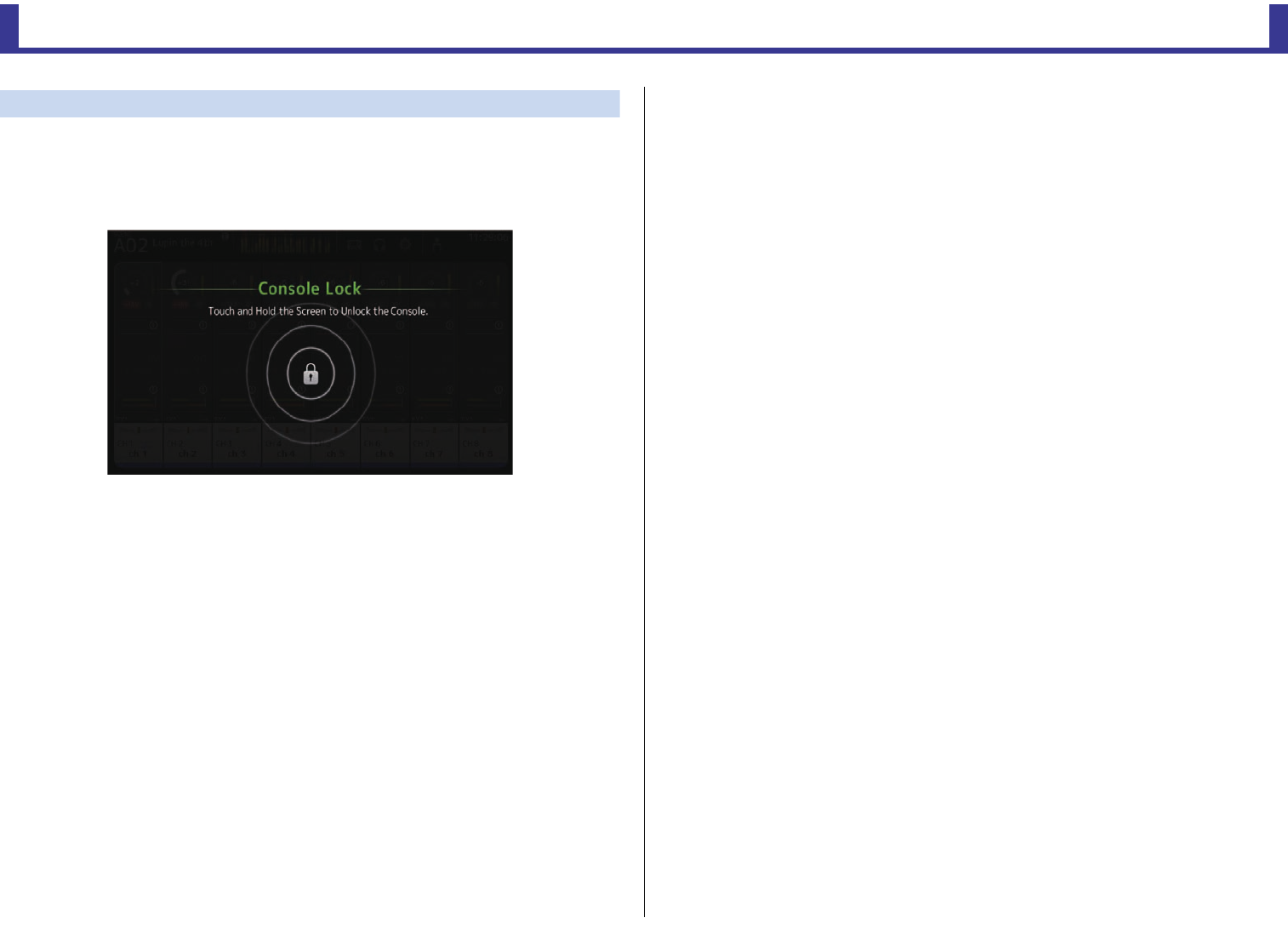
Toolbar
Reference Manual
TF Series
-
41
-
CONSOLE LOCK screen
You can lock the console to prevent it from being operated accidentally.
While the CONSOLE LOCK screen is displayed, controls are disabled and the console cannot
be operated.
To unlock the console, touch and hold the CONSOLE LOCK screen. If you are prompted to
enter a password, enter the password of the current user or the administrator.
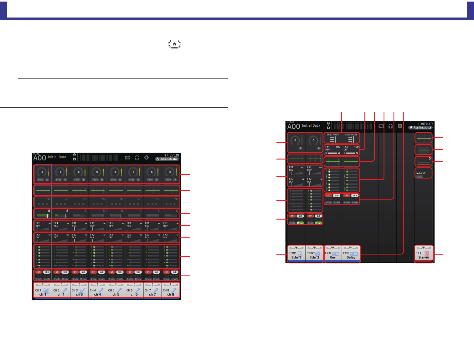
OVERVIEW screen
Reference Manual
TF Series
-
42
-
OVERVIEW screen
Displays information about the channel strips.
You can display the OVERVIEW screen by pressing the Home key ( ).
For the TF5/TF3/TF1, the CH STRIP section is displayed as the home screen; for the
TF-RACK, the FADER section is displayed. Additionally, for the TF-RACK, you can switch
between the CH STRIP section and FADER section by pressing the Home key.
CH STRIP section
Input channels
1Displays the INPUT screen. (page 47)
2Displays the EQ screen. (page 49)
3Displays the GATE screen. (page 53)
4Displays the COMP screen. (page 55)
5Displays the FX1 screen. (page 57)
6Displays the FX2 screen. (page 57)
7Displays the SEND TO AUX screen. (page 62)
8Displays the ASSIGN screen. (page 63)
9Displays the CH VIEW screen. (page 64)
Stereo channels
1Displays the INPUT screen. (page 47)
2Displays the EQ screen. (page 49)
3Displays the FX1/FX2 screen. (page 57)
4Displays the SEND TO AUX screen. (page 62)
5Displays the ASSIGN screen. (page 63)
6Displays the CH VIEW screen. (page 64)
7Displays the GEQ screen. (page 72)
8Displays the COMP screen. (page 55)
NOTE
For the TF5/TF3/TF1, the FADER section is displayed on the OVERVIEW screen when
SETUPPREFERENCEOther[HOME] key is set to "Both". In this case, you can switch between the
CH STRIP section and FADER section by pressing the Home key while the OVERVIEW screen is
displayed.
ձ
ղ
ճ
մ
յ
ն
շ
ո
չ
ձ
ղ
ճ
մ
յ
ն
պղմյ
ղ
շ
ո
չ
ն
ն
ճ
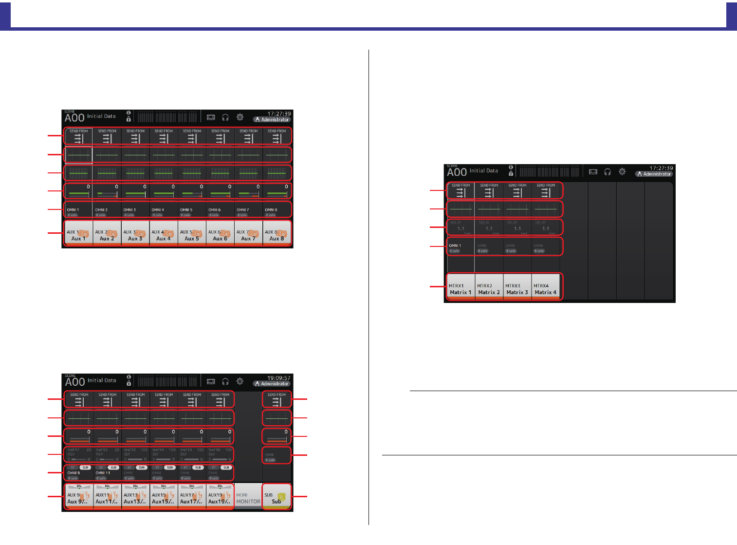
OVERVIEW screen
Reference Manual
TF Series
-
43
-
9Displays the OUTPUT screen. (page 74)
0Displays the SEND FROM screen (page 75) (V3.0 and later)
AUX1–AUX8 channels
1Displays the SEND FROM screen. (page 75)
2Displays the EQ screen. (page 49)
3Displays the GEQ screen. (page 72)
4Displays the COMP screen. (page 55)
5Displays the OUTPUT screen. (page 74)
6Displays the CH VIEW screen. (page 64)
AUX9/10–19/20 channels, SUB channel
1Displays the SEND FROM screen. (page 75)
2Displays the EQ screen. (page 49)
3Displays the GEQ screen. (page 72)
4Displays the COMP screen. (page 55)
5Displays the OUTPUT screen. (page 74)
6Displays the CH VIEW screen. (page 64)
MATRIX1–4 channels (V2.5 and later)
1Displays the SEND FROM screen. (page 75)
2Displays the EQ screen. (page 49)
3Displays the DELAY screen. (page 78)
4Displays the OUTPUT screen. (page 74)
5Displays the CH VIEW screen. (page 64)
ձ
ղ
ճ
մ
յ
ն
ձ
ղ
ճ
մ
ձ
ղ
ճ
յ
ն
յ
ն
NOTE
• MATRIX channels 1–4 are in the OUTPUT FADER BANK. To use the faders on the top panel to control
these channels, press the [OUTPUT] key in the FADER BANK section, and then display the OUTPUT
BANK in the channel strip.
• For TF1, MATRIX channels 1–4 are not controlled by the faders, and are displayed only. Scroll the
displayed area to the right. To control these channels using the faders, register them to the CUSTOM
FADER BANK.
ձ
ղ
ճ
մ
յ
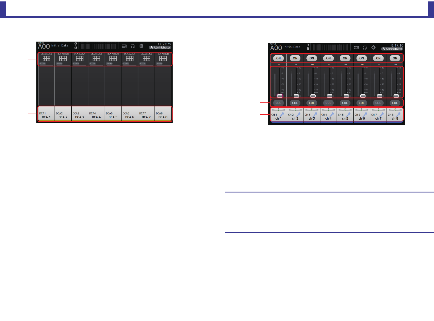
OVERVIEW screen
Reference Manual
TF Series
-
44
-
Group channels
1Displays the DCA ASSIGN screen. (page 76)
2Displays the CH VIEW screen. (page 64)
FADER section
1ON button
Turns the channel on and off.
2Fader
Adjusts the channel’s fader level.
3CUE button
Turns the cue on and off for the assigned channel.
4Displays the CH VIEW screen. (page 64)
ձ
ղ
OVERVIEW screen operations
When you touch an item on the screen, a pink box is displayed around the item to highlight it.
When an item is highlighted, you can adjust it using the [TOUCH AND TURN] knob.
If you touch a highlighted item, its configuration screen is displayed.
You can drag or swipe up, down, left, and right to display other areas of the screen.
ձ
ղ
ճ
մ
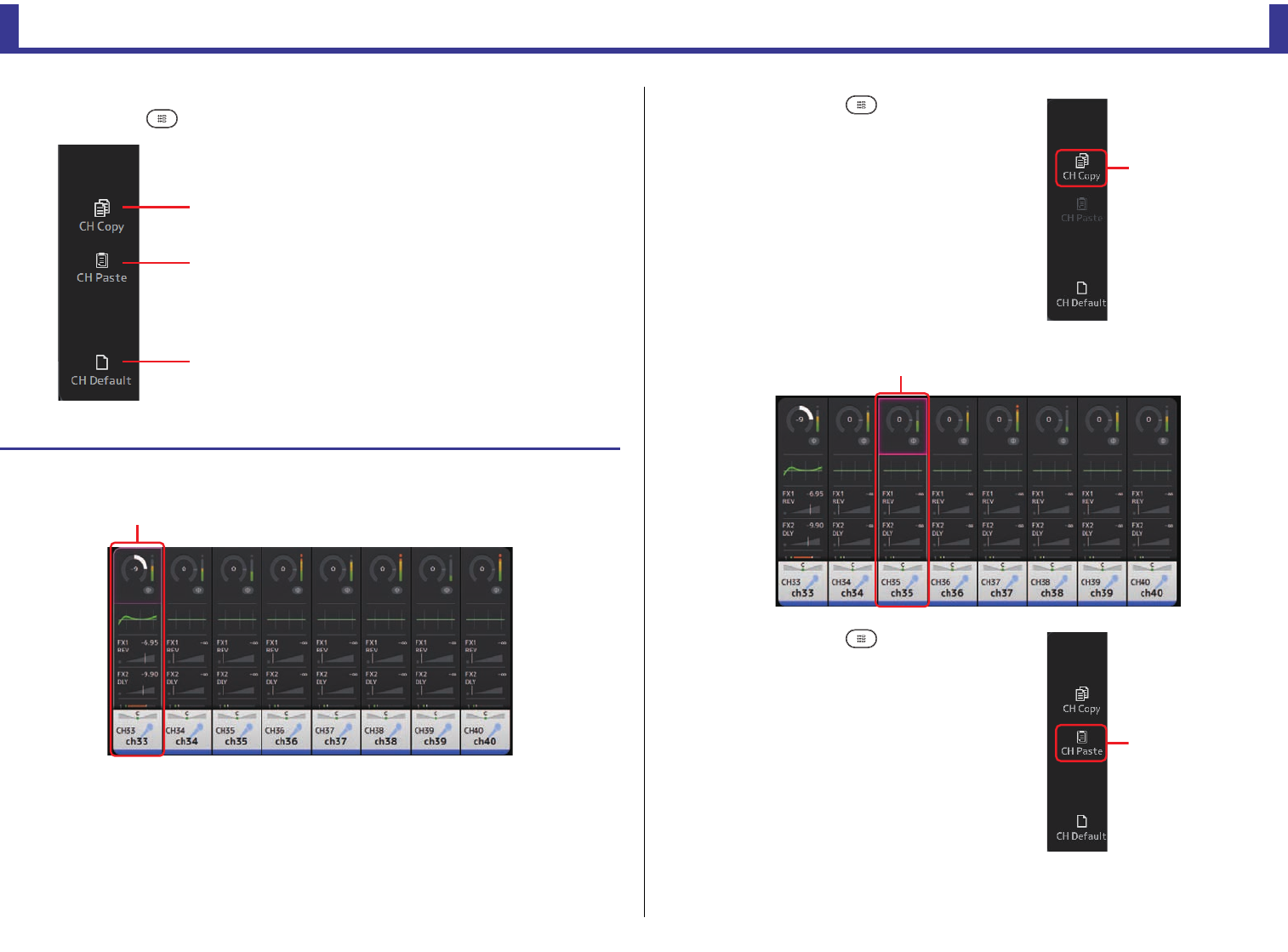
OVERVIEW screen
Reference Manual
TF Series
-
45
-
OVERVIEW screen menu
Press the Menu key ( ) from the OVERVIEW screen to display the following items.
1CH Copy
Copies the settings of the current channel.
2CH Paste
Pastes settings from another channel and applies
them to the current channel.
3CH Default
Resets the settings of the current channel to their
default values.
Copying settings from one channel and applying them to another channel
1. Select the channel whose settings you want to copy.
ձ
ղ
ճ
Copy settings from this channel
2. Press the Menu key ( ).
Displays the menu.
3. Touch the CH Copy icon.
The settings are copied and the menu closes.
4. Select the channel that you want to apply the settings to.
5. Press the Menu key ( ).
Displays the menu.
6. Touch the CH Paste icon.
CH Copy icon
Settings will be applied to this channel
CH Paste icon
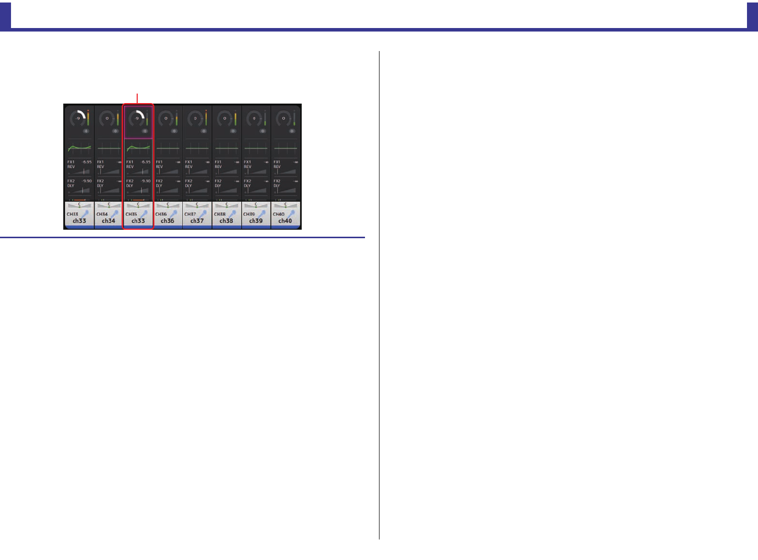
OVERVIEW screen
Reference Manual
TF Series
-
46
-
The settings from the first channel you selected are applied to the second channel you selected, and
then the menu closes.
Paste completed
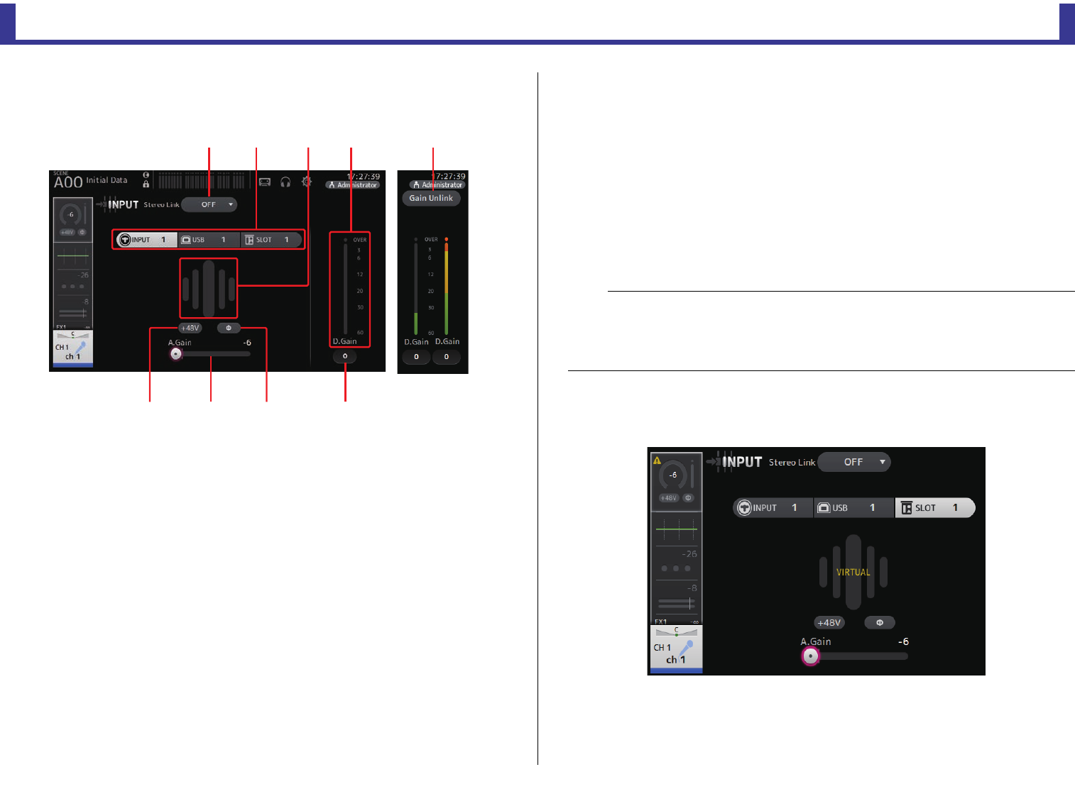
Configuration screens
Reference Manual
TF Series
-
47
-
Configuration screens
INPUT screen
Allows you to change the stereo link setting, select an input source, turn phantom power on
and off, turn phasing on and off, and adjust input gain.
1Stereo link selection button
Allows you to select whether two adjacent mono input channels are linked as a stereo
pair, or behave as two separate mono channels. Touch to display the popup menu.
OFF: Stereo link is disabled.
CH1&2: Stereo link is enabled. When stereo link is enabled, the odd numbered channel
is the left side of the stereo pair, and the even numbered one is the right. The
channel numbers displayed in the popup menu depend on the channel whose
settings you are editing.
CH2&3: Stereo link is enabled. When stereo link is enabled, the even numbered channel
is the left side of the stereo pair, and the odd numbered one is the right. The
channel numbers displayed in the popup menu depend on the channel whose
settings you are editing.
2Input selection buttons
Allows you to select the channel's input source. The available sources depend on the
channel whose settings you are editing.
INPUT: The device connected to the INPUT jack will be used as the input source.
USB: The computer connected to the USB TO HOST connector will be used as the input
source.
SLOT (V2.0 and later): Allows you to select an input from the NY64-D installed in the
expansion slot. Use this button when selecting an input from a
Tio1608-D or stage box connected to the NY64-D and the
Dante network. See page 92 for information about SLOT port
numbers and channels.
Playback:
Displayed for ST IN1. Allows you to select a USB storage device that is connected
to the USB connector on the top panel as an input.
Even if you select SLOT as the input source, if a source is not actually available (such as
when there is no NY64-D installed, no Tio1608-D or stage box connected, no Dante
patching, etc.), this "virtual HA" state is displayed in the HA box area of this screen, the
OVERVIEW screen, and the CH VIEW screen.
3GainFinder
Displays the input's gain adjusted level. When adjusting the input gain, adjust it so that
the center of the GainFinder lights up. When the input source is set to INPUT, the
GainFinder displays the digital input's gain.
ձղ ճմ
յնշո
չ
NOTE
When USB is selected, the gain slider (
7
) adjusts digital gain, and the +48V button (
8
) is not displayed.
When SLOT is selected, analog gain adjustment and the +48V button cannot be used if the HA Control
button on the SLOT SETUP screen is not turned on. Additionally, for inputs from a device whose head
amp cannot be controlled, the gain slider (7) becomes a digital gain adjustment, and the +48V button
(8) is not displayed.
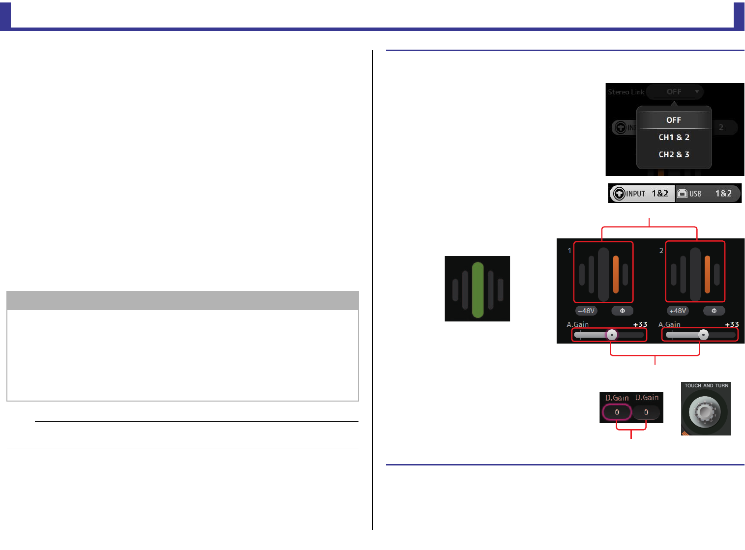
Configuration screens
Reference Manual
TF Series
-
48
-
4Level meter
Displays the gain adjusted level.
5Digital gain text box
Allows you to adjust the digital gain. It is set to 0 dB by default. You can touch the text
box to highlight it, then use the [TOUCH AND TURN] knob to adjust the setting. You
can also touch the text box again to adjust the setting using the keyboard screen.
6Φ (phase) button
Allows you to reverse the phase.
When turned on, the input signal's phase is reversed.
7Gain slider
When the INPUT button is selected, the slider adjusts the analog gain of the head amp.
The PAD (-24 dB) will be switched on or off when the analog gain is adjusted between
+17 dB and +18 dB.
When the USB button is selected, the slider adjusts digital gain.
8+48V button
Turns phantom power (+48 V) to the head amp on and off.
On: Phantom power is turned on.
Off: Phantom power is turned off.
When the USB button is selected, the +48V button is not displayed.
9Gain Unlink button (V1.1 and later)
Displayed for stereo channels and for channels that have stereo link turned on.
While you are touching the button, gain for the left and right channels can temporarily
be adjusted individually. When you release the button, the gain for both channels can
be adjusted together but the difference in gain between the two channels is maintained.
NOTICE
Information about phantom power
When phantom power is not needed, set the +48V button to the off position.
Observe the following when using phantom power to prevent damage to the console or connected
devices, and signal noise.
• Do not set the +48V button to the on position when the device connected to the input jack does
not require phantom power.
• Do not connect or disconnect cables when the +48V button is set to the on position.
• Before turning phantom power on or off for a channel, first set the channel's volume to the
minimum level.
NOTE
When using phantom power, noise may be generated if there is a difference in the impedance between
the hot and cold of the device connected to an input jack.
Setting stereo link and the input source
1. Display the INPUT screen. (page 5)
2. Touch the stereo link selection button that
corresponds to the desired setting.
3. Touch the input selection button that
corresponds to the desired setting.
4. Use the gain slider to adjust the
head amp gain.
Adjust the gain slider so that the center of
the GainFinder lights up.
5. Touch the digital gain text box to highlight
it, then use the [TOUCH AND TURN] knob to
adjust the setting.
Gain finder level display
Gain slider
Digital gain
text boxes
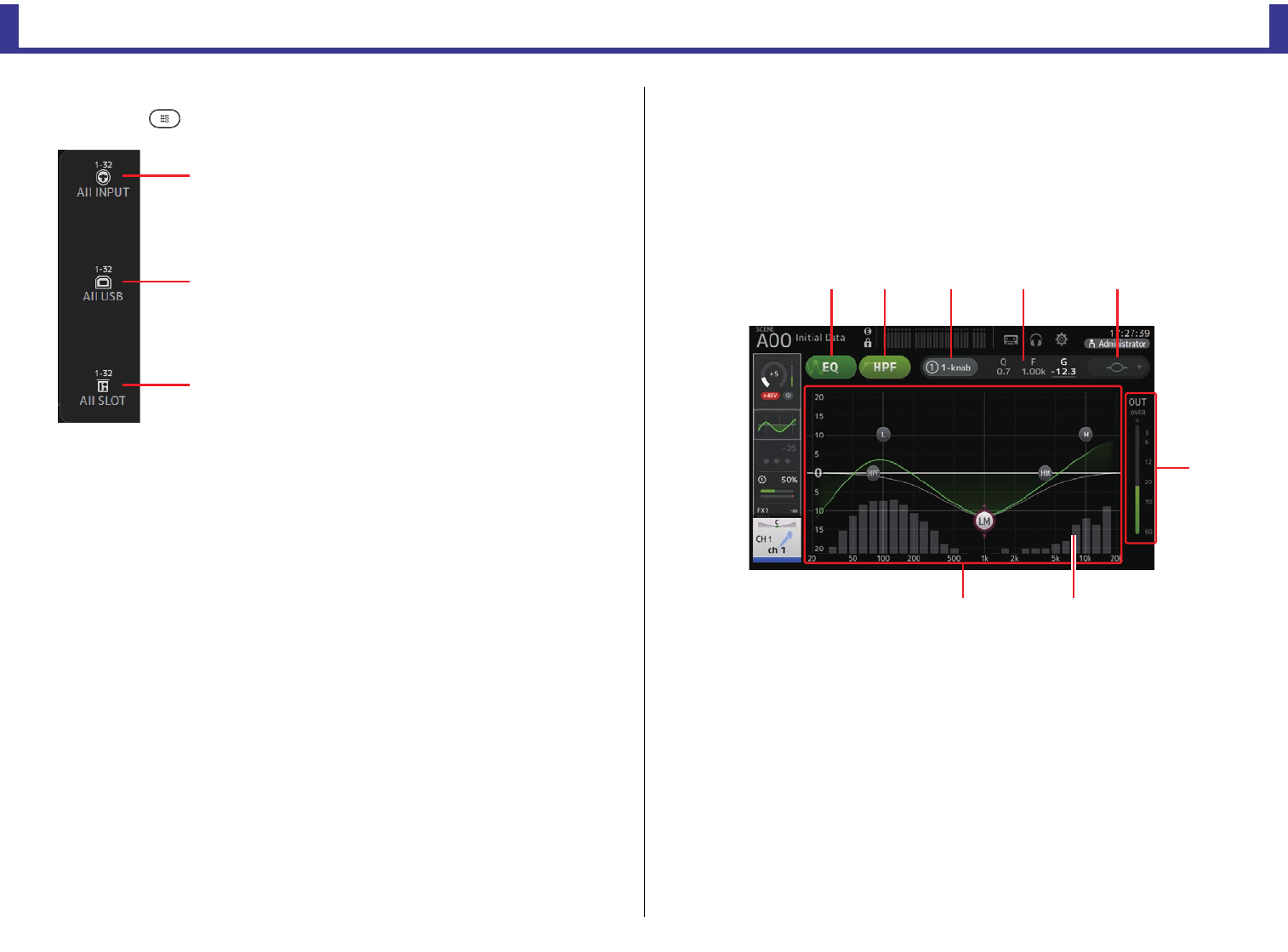
Configuration screens
Reference Manual
TF Series
-
49
-
INPUT screen menu (V1.1 and later)
Touch the Menu key ( ) from the INPUT screen to display the following items.
EQ screen
Controls the EQ for each channel. 4-band parametric EQ is available for CH 1–32, AUX 1–20,
STEREO and MATRIX1-4; 2-band parametric EQ is available for CH 33–40, ST IN 1, ST IN
2, FX1, FX2, and SUB. You can adjust settings using 1-knob mode, which allows you to use
the [TOUCH AND TURN] knob to easily adjust settings, or manual mode, which allows you to
adjust each parameter individually.
4-band parametric EQ
1EQ button
Turns the EQ on and off.
2HPF button
Turns the HPF (high-pass filter) on and off.
Displayed for CH 1–40.
31-knob button
Switches between 1-knob EQ mode and manual mode.
When using 1-knob EQ mode, the 1-knob level slider is displayed.
41-knob level slider
Adjusts the intensity of 1-knob EQ.
When using manual mode, information about the selected band's Q, F, and G is
displayed here.
1All INPUT
Allows you to assign the INPUT jacks as the input
source for all input channels.
2All USB
Allows you to assign the USB TO HOST connector
as the input source for all input channels.
3All SLOT (V2.0 and later)
Switches all inputs to input sources of Dante
network devices that are connected to the NY64-
D installed in the expansion slot.
The input source for the following channels will be
changed.
TF5:
CH 1–32 (when CH 1–32 are selected)
CH 33–40 (when CH 33–40 are selected)
TF3:
CH 1–24 (when CH 1–24 are selected)
CH 25–32 (when CH 25–32 are selected)
CH 33–40 (when CH 33–40 are selected)
TF1/TF-RACK:
CH 1–16 (when CH 1–16 are selected)
CH 17–32 (when CH 17–32 are selected)
ձ
ղ
ճ
ձղ ճ մ յ
ն
շո
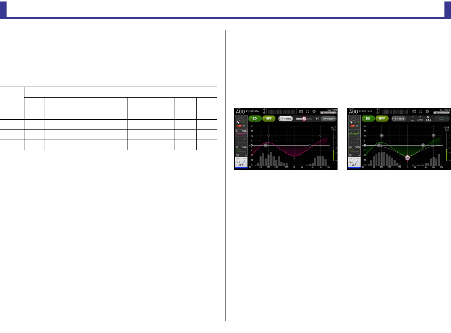
Configuration screens
Reference Manual
TF Series
-
50
-
5EQ mode type selection button
When using 1-knob EQ mode, allows you to select the 1-knob EQ mode type. Select
[Vocal] for vocal channels, otherwise select [Intensity].
When set to [Intensity], you can adjust the EQ to a setting between flat and double the
intensity of the EQ settings you made using manual mode.
For output channels, [Loudness] is available. This setting allows you to boost low and
high tones.
The available types depend on the channel whose settings you are editing.
In manual mode, this button switches the filter type. Low-band and high-band filter are
available.
For CH 1-40, the available low-band filters are low-shelving type and bell type.
For other channels (i.e., for channels that do not have an HPF), the available low-band
filters are HPF, low-shelving type, and bell type.
The available high-band filters are LPF, high-shelving type, and bell type.
6EQ output level meter
Displays the post-EQ level.
7EQ graph
Displays the parameter settings of the EQ and filter. As you adjust the settings of each
band, the results are reflected in the graph.
When using 1-knob EQ mode, you can touch the level slider and then adjust the slider
using the slider itself or the [TOUCH AND TURN] knob.
When using manual mode, you can drag the handles displayed in the graph to adjust
the corresponding settings.
When HPF is turned on, you can drag the HPF handle to adjust the cutoff frequency. You
can also adjust HPF independently when using the Intensity type for 1-knob EQ mode.
<1-knob EQ mode> <Manual mode>
How does 1-knob EQ mode work?
1-knob EQ mode allows you to adjust several parameters at once with just the turn of a knob.
It makes EQ adjustment quick and easy.
The console contains Presets that are configured for a variety of instruments. You can use 1-
knob EQ mode to adjust the EQ settings that are saved in Presets without disturbing the
overall balance of your mix.
You can even configure EQ settings using manual mode, then switch to 1-knob EQ mode and
use the Intensity type to adjust the amount of EQ applied to the channel. In this case you can
use the [TOUCH AND TURN ] knob to adjust from 0% (no EQ applied) to 50% (the EQ
settings you made using manual mode) and 100% (double the intensity of the EQ settings you
made using manual mode). This makes it very easy to fine-tune your EQ settings with just one
knob.
If 1-knob EQ mode type is set to Vocal or Loudness, you can adjust the EQ between 0% (no
EQ applied) and 100% (maximum EQ applied).
Type
Channel
CH1-32
HPF +
4-band
CH33-40
HPF +
2-band
ST IN
2-band
FX
2-band
STEREO
4-band
AUX1-8
4-band
AUX9/10–
AUX19/20
4-band
MATRIX
1-4
4-band
SUB
2-band
+ LPF
Intensity ○○○○○○ ○ ○×
Vocal ○××××× × ××
Loudness × × × × ○○ ○ ○ ×
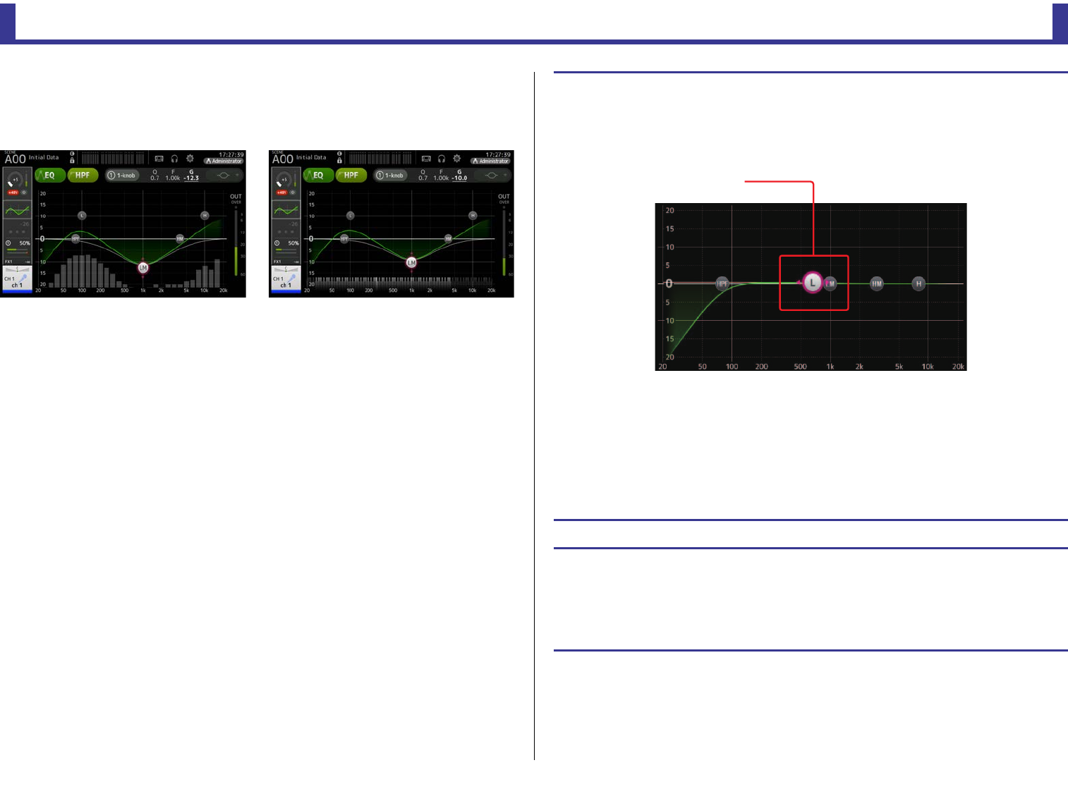
Configuration screens
Reference Manual
TF Series
-
51
-
8RTA/Keyboard display
You can touch the bottom of the graph where no parameters are displayed to display
RTA or a keyboard. RTA is a graph that displays the frequencies of the input signal after
the EQ is applied. The keyboard display is helpful for understanding the relationship
between frequencies and musical pitches.
Adjusting EQ in manual mode
1. Display the EQ screen. (page 5)
2. Touch the EQ button and turn on the EQ.
3. Touch the 1-knob button and turn 1-knob mode off.
4. Use the handles in the EQ graph to adjust the EQ as desired.
When you touch an EQ parameter to select it, you can then adjust it using the [TOUCH AND TURN]
knob. You can press the [SHIFT] key to switch to a different parameter. Each time you press the
[SHIFT] key, you can switch between gain (G) and frequency (F). You can also switch between G and
F by touching the corresponding area to the right of the 1-knob button.
To adjust Q, pinch in or out on the touchscreen, or touch the Q area to the right of the 1-knob button
and then use the [TOUCH AND TURN] knob to adjust the setting.
5. Turn HPF on as desired.
When using a vocal mic, you can reduce low-frequency noise (rumble noise, etc.) by turning on HPF.
Adjusting EQ in 1-knob EQ mode
1. Display the EQ screen. (page 5)
2. Turn on the EQ and select 1-knob mode.
3. Select the desired 1-knob mode type.
4. Use the [TOUCH AND TURN] knob to adjust the EQ.
Drag to adjust
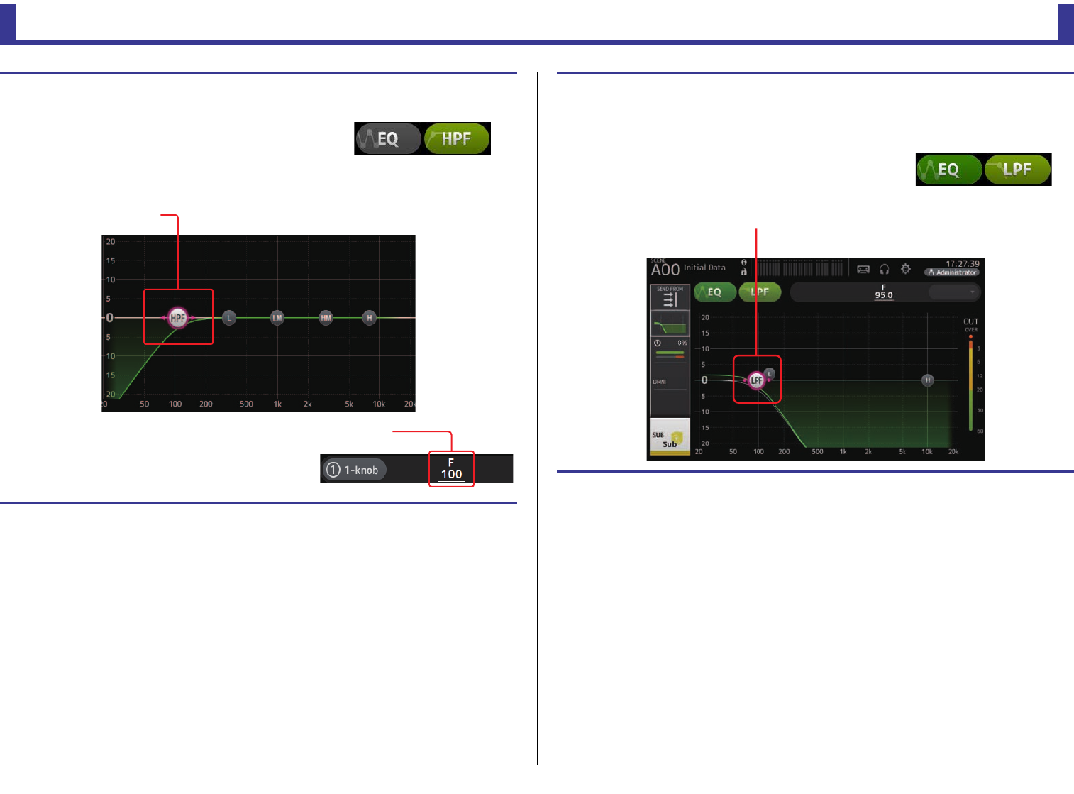
Configuration screens
Reference Manual
TF Series
-
52
-
Setting HPF
1. Display the EQ screen. (page 5)
2. Touch the HPF button and turn on the HPF.
3. Touch the HPF handle.
4. Use the [TOUCH AND TURN] knob to adjust the HPF.
You can also drag the HPF handle in the EQ graph.
The value that corresponds to your adjustments is
displayed in the upper right of the screen.
Drag to adjust
Adjusted value
Setting LPF
The SUB channel can use the LPF to cut high frequencies independent of the EQ, ideal for
adjusting the signal sent to a sub-woofer.
1. Display the SUB channel's EQ screen. (page 5)
2. Touch the EQ button and turn on the EQ.
3. Use the LPF handle in the EQ graph to adjust the LPF as desired.
Drag to adjust
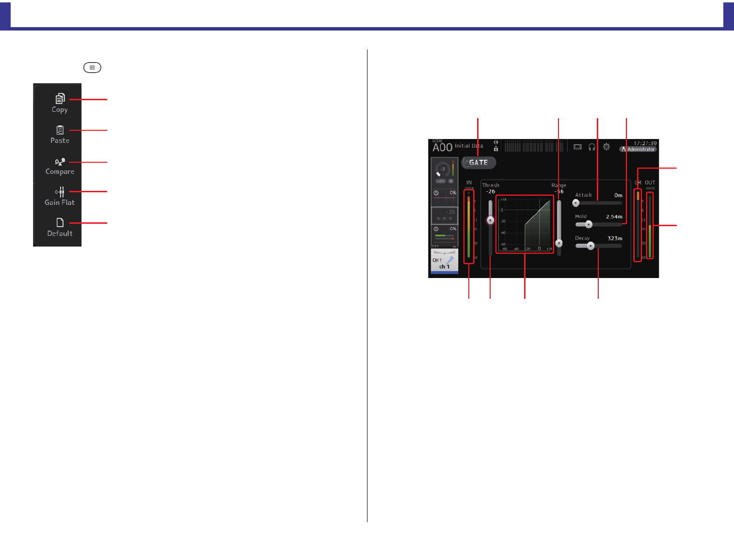
Configuration screens
Reference Manual
TF Series
-
53
-
EQ screen menu
Press the Menu key ( ) from the EQ screen to display the following options.
GATE screen
Allows you to configure the noise gate for each channel. When the input signal level is lower
than a specified amount (threshold), the output signal is reduced by a specified amount
(range). GATE is available for CH 1–32.
1GATE button
Turns the gate on and off.
2Gate input level meter
Displays the gate input level.
3Threshold slider
Determines the level at which the gate is applied.
4Gate graph
Displays a visual representation of the gate level.
5Range slider
Determines the amount by which the signal will be lowered when the gate is applied.
6Attack slider
When the input signal exceeds the threshold, this setting determines how quickly the
gate opens.
1Copy
Copies the EQ parameters of the selected channel
to the clipboard.
2Paste
Pastes the EQ parameters in the clipboard to the
selected channel.
3Compare
Allows you to compare the EQ parameters of the
selected channel with the EQ parameters in the
clipboard by switching between the two.
4Gain Flat
Sets the EQ gain for all bands to 0.
5Default
Resets EQ settings to their default values.
ձ
ղ
ճ
մ
յ
ձյնշ
չ
պ
ոմճղ
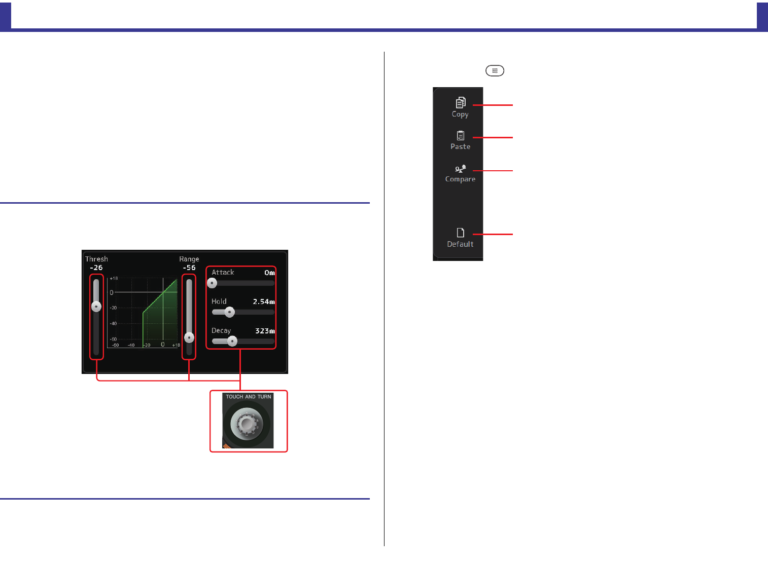
Configuration screens
Reference Manual
TF Series
-
54
-
7Hold slider
When the input signal drops below the threshold, this setting determines how much
time passes before the gate closes.
8Decay slider
After the hold time passes, this setting determines how quickly the gate closes. The value
here is expressed as the time required for the level to change by 6 dB.
9GR (gain reduction) meter
Displays the amount by which the signal's gain is reduced.
0OUT (gate output) meter
Displays the gate output level.
GATE screen menu
Press the Menu key ( ) from the GATE screen to display the following options.
Setting the gate
1. Display the GATE screen. (page 5)
2. Turn on the gate and then touch the slider that you want to adjust.
3. Use the [TOUCH AND TURN] knob to adjust the setting.
Refer to the gate graph and each meter while making adjustments.
You can also drag the slider on the touchscreen to adjust the setting.
1Copy
Copies the GATE parameters of the selected
channel to the clipboard.
2Paste
Pastes the GATE parameters in the clipboard to the
selected channel.
3Compare
Allows you to compare the GATE parameters of the
selected channel with the GATE parameters in the
clipboard by switching between the two.
4Default
Resets the GATE settings for the current channel to
their default values.
ձ
ղ
ճ
մ
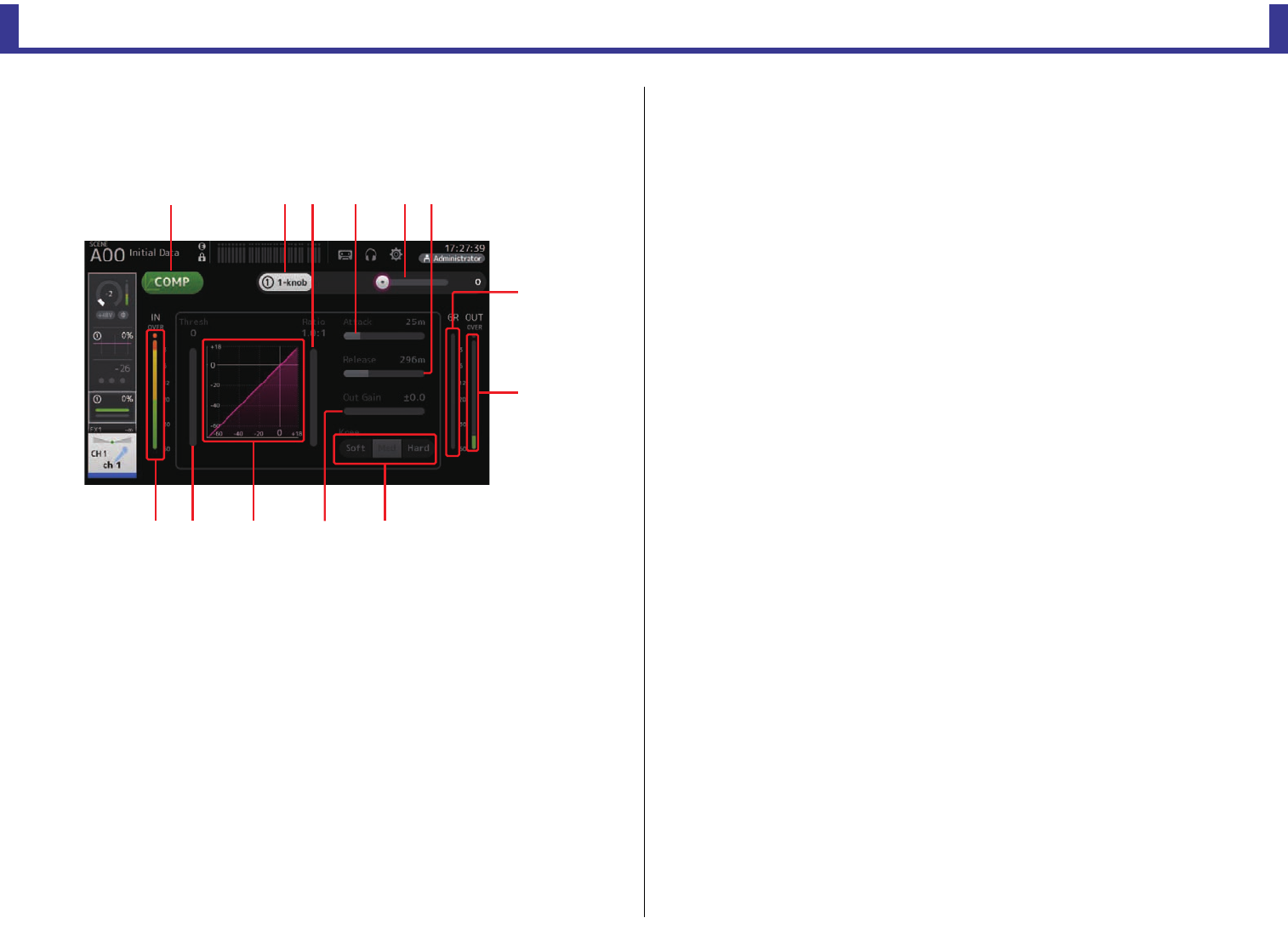
Configuration screens
Reference Manual
TF Series
-
55
-
COMP screen
Allows you to configure the compressor for each channel. You can adjust settings using 1-
knob mode, which allows you to use the [TOUCH AND TURN] knob to easily adjust settings,
or manual mode, which allows you to adjust each parameter individually.
1COMP button
Turns the compressor on and off.
21-knob button
Switches between 1-knob mode and manual mode.
31-knob level slider (1-knob mode only)
Adjusts the amount of 1-knob COMP applied.
Not displayed during manual mode.
4Compressor input level slider
Displays the compressor output level.
5Threshold slider
Determines the level at which compression is applied.
6Compressor graph
Displays a visual representation of the current settings.
7Ratio slider
Determines the amount of compression that is applied.
8Attack slider
When the input signal exceeds the threshold, this setting determines how quickly the
maximum amount of compression is applied.
9Release slider
When the input signal drops below the threshold, this setting determines how much
time passes before compression is no longer applied. The value here is expressed as the
time required for the level to change by 6 dB.
0Out Gain slider
Adjusts the output level.
AKnee button
Determines how gradual or sudden the curve is at the threshold. A soft knee means that
compression is applied gradually as the signal exceeds the threshold; a hard knee means
a more sudden transition.
BGR (gain reduction) meter
Displays the amount by which the signal's gain is reduced.
COUT (compressor output) meter
Displays the compressor output level.
How does 1-knob COMP mode work?
1-knob COMP mode allows you to adjust the amount of compression applied to the signal with
just the turn of a knob.
By turning the [TOUCH AND TURN] knob to the right (or sliding the 1-knob level slider to the
right), more compression is applied. In situations where raising the fader or gain could cause
clipping at louder points in the signal, compression can deliver a more consistent sound.
1-knob COMP takes some of the worry out of compression by allowing you to adjust the
balance between threshold, ratio, and out gain easily.
ձղշոչ
ռ
ս
ջպն
ճ
յմ
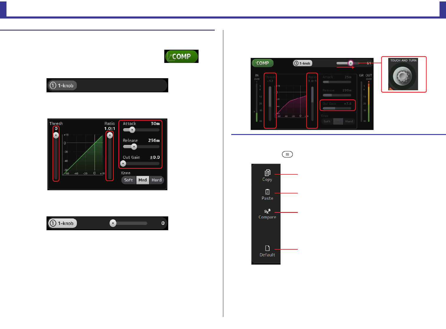
Configuration screens
Reference Manual
TF Series
-
56
-
COMP screen menu
Press the Menu key ( ) from the COMP screen to display the following options.
Setting the compressor
1. Display the COMP screen. (page 5)
2. If the compressor is turned off, touch the COMP button
to turn compression on.
3. Touch the 1-knob button and turn 1-knob COMP mode off.
4. Adjust the desired slider.
Drag the sliders to adjust each parameter.
When you touch an item, you can also use the [TOUCH AND TURN] knob to adjust the setting.
Adjusting the compressor in 1-knob COMP mode
1. Turn 1-knob COMP mode on.
2. Turn the [TOUCH AND TURN] knob.
Attack, Release, and Knee settings are fixed at their current settings, and the Threshold, Ratio, and
Out Gain settings are adjusted automatically.
1Copy
Copies the COMP parameters of the selected
channel to the clipboard.
2Paste
Pastes the COMP parameters in the clipboard to
the selected channel.
3Compare
Allows you to compare the COMP parameters of
the selected channel with the COMP parameters
in the clipboard by switching between the two.
4Default
Resets the COMP settings for the current channel
to their default values.
ձ
ղ
ճ
մ
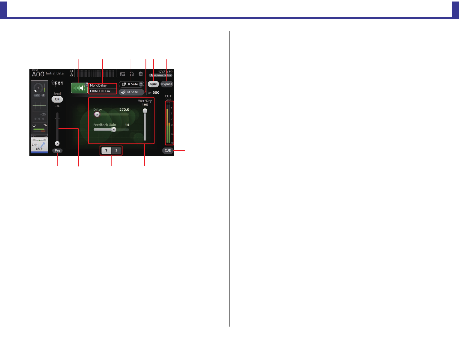
Configuration screens
Reference Manual
TF Series
-
57
-
FX screen (FX1/2, InsFX1–6)
Allows you to select an effect and edit its parameters.
1Send button
Displayed for CH 1–40, ST IN 1 and ST IN 2.
Determines whether a signal is sent (on) or not sent (off) to the FX return channel.
2EFFECT TYPE button
Displays the EFFECT TYPE screen (page 58), where you can select an effect type.
3Effect type and name
Displays the type and name of the current effect.
4R Safe (recall safe) indicator
Displays the recall safe status of the effects module.
Displays the RECALL SAFE screen. (page 25)
5M safe (mute safe) button
Turns mute safe on and off for the effects module.
6FX send level slider
Displayed for CH 1–40, ST IN 1 and ST IN 2.
Allows you to adjust the amount of signal that is sent to the effects module.
7Pre button
Displayed for CH 1–40, ST IN 1 and ST IN 2.
Allows you to select whether the pre-fader or post-fader signal is processed by the effect
module.
On: Before the fader
Off: After the fader
8Parameter selection buttons
Touch to display other parameters available for the current effect.
9Parameter sliders
Allow you to adjust the parameters available for the current effect.
0Sync button
Displayed for effects that have a tempo setting, such as delays. When this button is
turned on, the effect's tempo setting can be controlled with the [TAP] button found in
the SENDS ON FADER section of the top panel.
ABypass button
Allows you to bypass the effects module.
BEffects output level meter
Displays the effects output level.
CCUE button
Turns cue on and off for the effects module.
ձղ ճ մ ջպյ
ռ
ս
չոնշ
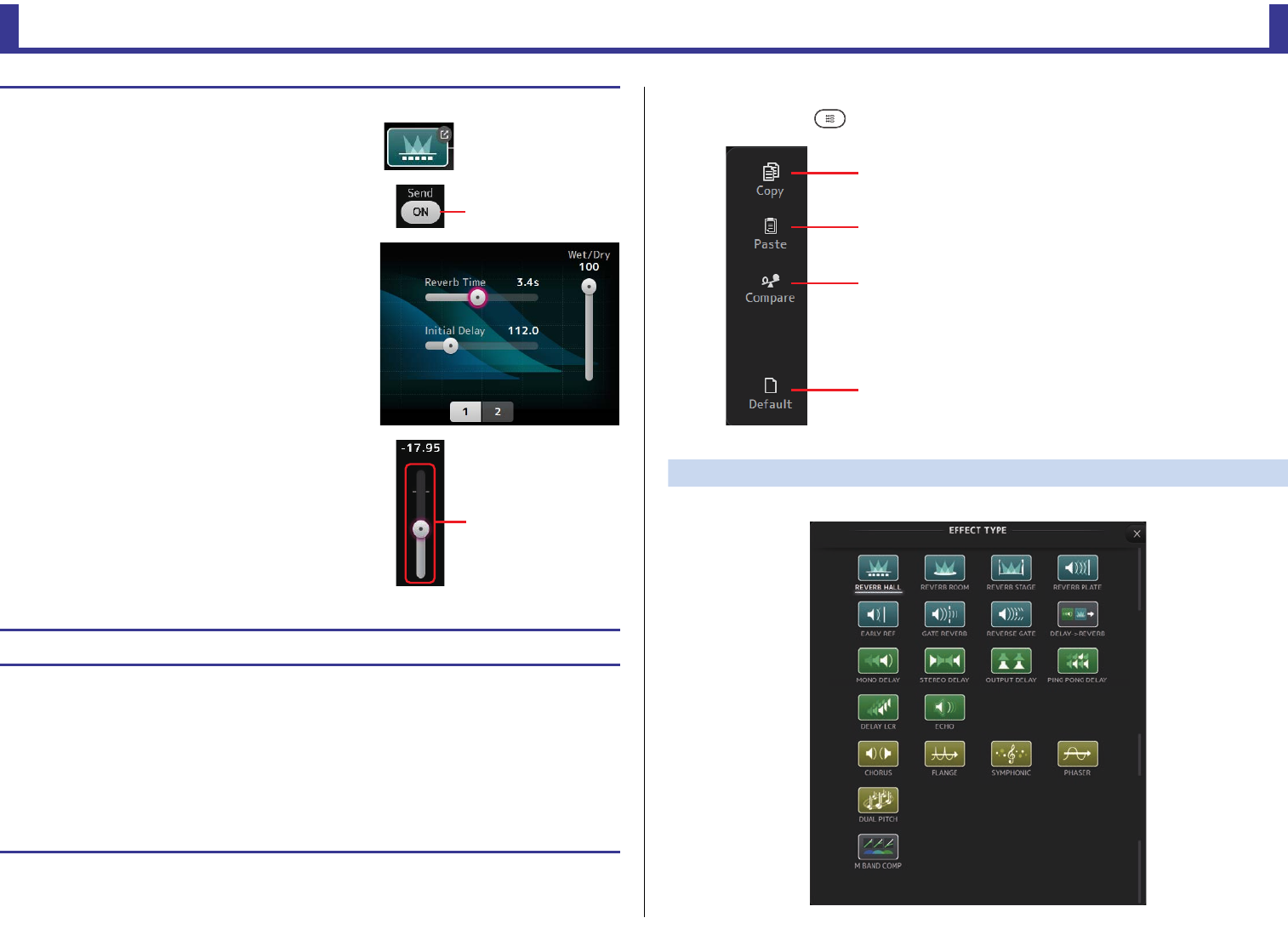
Configuration screens
Reference Manual
TF Series
-
58
-
FX screen menu
Press the Menu key ( ) from the FX screen to display the following options.
EFFECT TYPE screen
Allows you to select the effect type. Touch the desired button to make a selection.
Setting an effect
1. Touch the effects type button.
When the EFFECTS TYPE screen is displayed, select the
desired effect type.
2. Touch the Send button.
3. Adjust the parameter sliders as desired.
You can adjust the characteristics of the effect, the wet/dry
balance, etc.
4. Adjust the effects send level slider.
This allows you to adjust how much of the channel's signal
is sent to the effects module.
5. Adjust the FX RTN1/2 levels.
FX RTN1/2 channels are in the INPUT FADER BANK. (Stereo Channelspage 42)
Setting an insert effect
You can configure insert effects for AUX9/10–AUX19/20.
1. Touch the effects type button.
When the EFFECTS TYPE screen is displayed, select the desired effect type.
2. Touch the bypass button.
Bypass is turned on by default; turn the bypass off.
3. Adjust the parameter sliders as desired.
Adjust the characteristics of the effect.
Send button
FX send level slider
1Copy
Copies the effect parameters of the selected effect
to the clipboard.
2Paste
Pastes the effect parameters in the clipboard to the
selected effect.
3Compare
Allows you to compare the effect parameters of
the selected effect with the effect parameters in
the clipboard by switching between the two.
4Default
Resets the selected effect's settings to their default
values.
ձ
ղ
ճ
մ
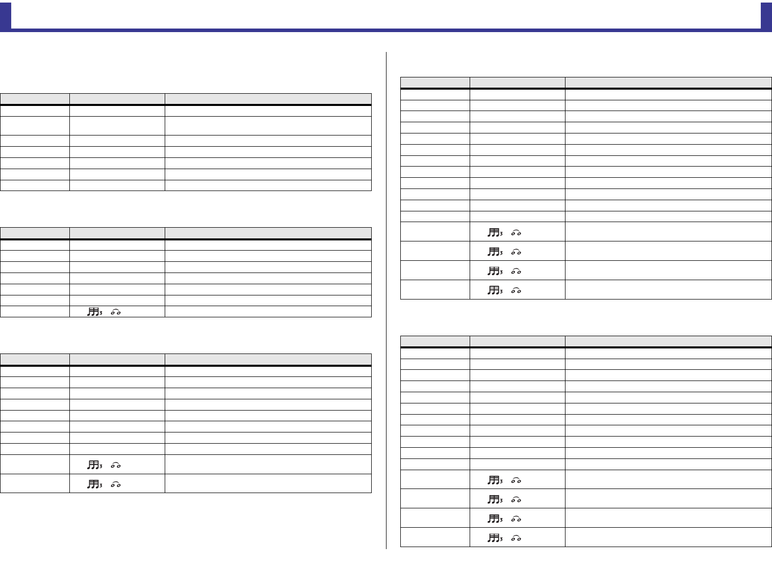
Configuration screens
Reference Manual
TF Series
-
59
-
Effect parameters
REVERB HALL, REVERB ROOM, REVERB STAGE, REVERB PLATE
One-input, two-output hall, room, stage, and plate reverbs.
MONO DELAY
One-input, two-output basic repeating-type delay.
STEREO DELAY
Two-input, two-output basic stereo delay.
DELAY LCR
One-input, two-output 3-tap delay.
ECHO
Two-input, two-output stereo delay with a crossed feedback loop.
Parameter Range Description
Reverb Time 0.3s–20.0s Determines the length of the reverberation.
Initial Delay 1.0ms–500.0ms Determines the amount of time that passes before the initial
reverberation is heard.
High Ratio 0.1–1.0 Ratio of high frequency reverberations to the Reverb Time.
Diffusion 0–10 Left and right spread of the reverberation.
Density 0% – 100% Density of the reverberation.
HPF Thru, 21.2Hz–8.00kHz High-pass filter cutoff frequency.
LPF 50.0Hz–16.0kHz, Thru Low-pass filter cutoff frequency.
Parameter Range Description
Delay 1.0ms–2700.0ms Delay time.
Feedback Gain -99 – +99 Amount of feedback.
High Ratio 0.1–1.0 Amount of high-frequency feedback.
HPF Thru, 21.2Hz–8.00kHz High-pass filter cutoff frequency.
LPF 50.0Hz–16.0kHz, Thru Low-pass filter cutoff frequency.
Sync Off, On Delay time tempo sync.
Note ----, ~ Value used to calculate the delay time based on the tempo.
Parameter Range Description
Delay L 1.0ms–1350.0ms Left channel delay time.
Delay R 1.0ms–1350.0ms Right channel delay time.
Feedback Gain L -99 – +99 Left channel feedback gain.
Feedback Gain R -99 – +99 Right channel feedback gain.
High Ratio 0.1–1.0 Amount of high-frequency feedback.
HPF Thru, 21.2Hz–8.00kHz High-pass filter cutoff frequency.
LPF 50.0Hz–16.0kHz, Thru Low-pass filter cutoff frequency.
Sync Off, On Delay time tempo sync.
Note L ----, ~ Value used to calculate the left channel delay time based on the
tempo.
Note R ----, ~ Value used to calculate the right channel delay time based on
the tempo.
Parameter Range Description
Delay L 1.0ms–2700.0ms Left channel delay time.
Delay C 1.0ms–2700.0ms Center channel delay time.
Delay R 1.0ms–2700.0ms Right channel delay time.
Delay FB 1.0ms–2700.0ms Feedback delay time.
Feedback Gain -99 – +99 Amount of feedback.
High Ratio 0.1–1.0 Amount of high-frequency feedback.
HPF Thru, 21.2Hz–8.00kHz High-pass filter cutoff frequency.
LPF 50.0Hz–16.0kHz, Thru Low-pass filter cutoff frequency.
Level L -100 – +100 Left channel level.
Level C -100 – +100 Center channel level.
Level R -100 – +100 Right channel level.
Sync Off, On Delay time tempo sync.
Note L ----, ~ Value used to calculate the left channel delay time based on the
tempo.
Note C ----, ~ Value used to calculate the center channel delay time based on
the tempo.
Note R ----, ~ Value used to calculate the right channel delay time based on
the tempo.
Note FB ----, ~ Value used to calculate the delay feedback time based on the
tempo.
Parameter Range Description
Delay L 1.0ms–1350.0ms Left channel delay time.
Delay R 1.0ms–1350.0ms Right channel delay time.
Delay FB L 1.0ms–1350.0ms Left channel feedback delay time.
Delay FB R 1.0ms–1350.0ms Right channel feedback delay time.
Feedback Gain L -99 – +99 Left channel feedback gain.
Feedback Gain R -99 – +99 Right channel feedback gain.
XFeedback Gain -99 – +99 Left-to-right, right-to-left feedback gain.
High Ratio 0.1–1.0 Amount of high-frequency feedback.
HPF Thru, 21.2Hz–8.00kHz High-pass filter cutoff frequency.
LPF 50.0Hz–16.0kHz, Thru Low-pass filter cutoff frequency.
Sync Off, On Delay time tempo sync.
Note L ----, ~ Value used to calculate the left channel delay time based on the
tempo.
Note R ----, ~ Value used to calculate the right channel delay time based on
the tempo.
Note FBL ----, ~ Value used to calculate the left channel feedback delay time
based on the tempo.
Note FBR ----, ~ Value used to calculate the right channel feedback delay time
based on the tempo.
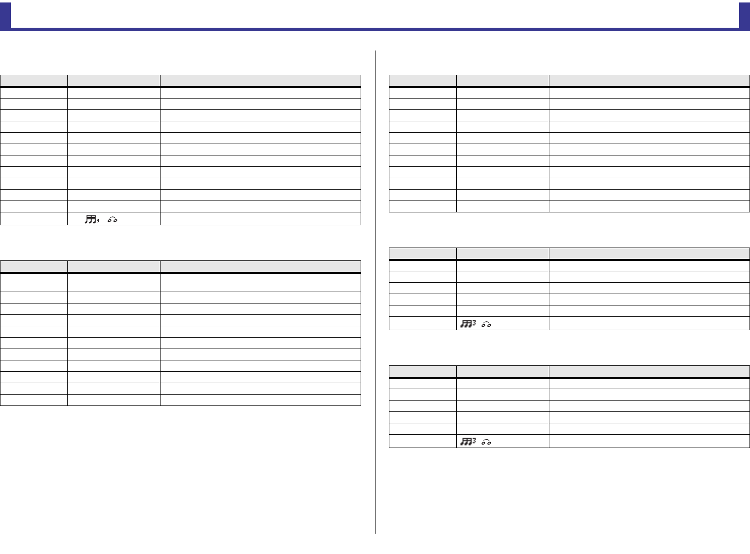
Configuration screens
Reference Manual
TF Series
-
60
-
DELAY-REVERB (V1.1 and later)
One-input, two-output effect that has a delay and reverb connected in series.
EARLY REF (V1.1 and later)
One-input, two-output early reflection effect.
GATE REVERB, REVERSE GATE (V1.1 and later)
One-input, two-output early reflection with gate, and an early reflection with reverse gate.
CHORUS (V1.1 and later)
Two-input, two-output chorus effect.
FLANGE (V1.1 and later)
Two-input, two-output flanger effect.
Parameter Range Description
Delay 1.0ms - 2700.0ms Delay time.
Feedback Gain -99% - 99% Amount of feedback.
DLY BAL 0% - 100% Delay mix balance.
Reverb Time 0.3s - 20.0s Determines the length of the reverberation.
High Ratio 0.1 - 1.0 Ratio of high frequency reverberations to the Reverb Time.
Diffusion 0 - 10 Left and right spread of the reverberation.
Density 0% - 100% Density of the reverberation.
HPF Thru, 21.2Hz - 8.00kHz High-pass filter cutoff frequency.
LPF 50.0Hz - 16.0kHz, Thru Low-pass filter cutoff frequency.
REV BAL 0% - 100% Reverb mix balance.
Sync Off, On Parameter tempo sync.
Note ----, ~ Value used to calculate the delay time based on the tempo.
Parameter Range Description
Type S-Hall, L-Hall, Random,
Reverse, Plate, Spring Early reflection type.
Room Size 0.1 - 20.0 Room size; determines interval between early reflections.
Liveness 0 - 10 Decay of the early reflections (0: dead, 10: live).
Initial Delay 1.0ms - 500.0ms Delay before the early reflection.
Diffusion 0 - 10 Width of the reflections in the stereo field.
Density 0% - 100% Density of the reflections.
ER Number 1 - 19 Number of reflections.
Feedback Gain -99% - 99% Amount of feedback.
High Ratio 0.1 - 1.0 Amount of high-frequency feedback.
HPF Thru, 21.2Hz - 8.00kHz High-pass filter cutoff frequency.
LPF 50.0Hz - 16.0kHz, Thru Low-pass filter cutoff frequency.
Parameter Range Description
Type Type-A, Type-B Early reflection type.
Room Size 0.1 - 20.0 Room size; determines interval between early reflections.
Liveness 0 - 10 Decay of the early reflections.
Initial Delay 1.0ms - 500.0ms Delay before the early reflection.
Diffusion 0 - 10 Width of the reflections in the stereo field.
Density 0% - 100% Density of the reflections.
ER Number 1 - 19 Number of reflections.
Feedback Gain -99% - 99% Amount of feedback.
High Ratio 0.1 - 1.0 Amount of high-frequency feedback.
HPF Thru, 21.2Hz - 8.00kHz High-pass filter cutoff frequency.
LPF 50.0Hz - 16.0kHz, Thru Low-pass filter cutoff frequency.
Parameter Range Description
Frequency 0.05Hz - 10.00Hz Modulation speed
AM Depth 0% - 100% Depth of amplitude modulation.
PM Depth 0% - 100% Depth of pitch modulation.
MOD. Delay 1.0ms - 500.0ms Delay time of modulation.
Sync Off, On Parameter tempo sync.
Note - Value used to calculate the frequency based on the tempo.
Parameter Range Description
Frequency 0.05Hz - 10.00Hz Modulation speed
Depth 0% - 100% Depth of modulation.
MOD. Delay 1.0ms - 500.0ms Delay time of modulation.
Feedback Gain -99% - 99% Amount of feedback.
Sync Off, On Parameter tempo sync.
Note - Value used to calculate the frequency based on the tempo.
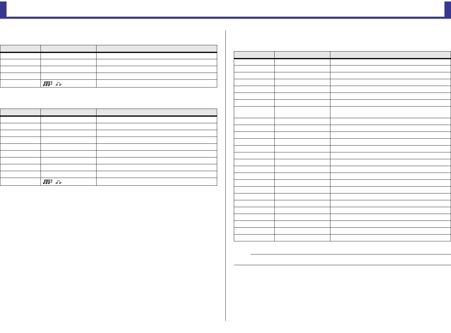
Configuration screens
Reference Manual
TF Series
-
61
-
SYMPHONIC (V1.1 and later)
Two-input, two-output symphonic effect.
PHASER (V1.1 and later)
Two-input, two-output 16-stage phase-shift effect.
M BAND COMP (V1.1 and later)
Two-input, two-output three-band compressor. Each band has solo and gain reduction
metering.
Parameter Range Description
Frequency 0.05Hz - 10.00Hz Modulation speed
Depth 0% - 100% Depth of modulation.
MOD. Delay 1.0ms - 500.0ms Delay time of modulation.
Sync Off, On Parameter tempo sync.
Note - Value used to calculate the frequency based on the tempo.
Parameter Range Description
Frequency 0.05Hz - 10.00Hz Modulation speed
Depth 0% - 100% Depth of modulation.
Feedback Gain -99% - 99% Amount of feedback.
Offset 0 - 100 Offset of the phase shifted frequency.
Phase 0° - 355° Left/right balance of modulation.
Stage 2 - 16 Number of phase shift stages.
HPF Thru, 21.2Hz - 8.00kHz High-pass filter cutoff frequency.
LPF 50.0Hz - 16.0kHz, Thru Low-pass filter cutoff frequency.
Sync Off, On Parameter tempo sync.
Note - Value used to calculate the frequency based on the tempo.
Parameter Range Description
Low Gain -12.0dB - +12.0dB Low-band gain.
Mid Gain -12.0dB - +12.0dB Mid-band gain.
High Gain -12.0dB - +12.0dB High-band gain.
Total Gain -72dB - +12dB Overall gain.
L-M XOver 21.2Hz - 8.00kHz Low-to-mid crossover frequency.
M-H XOver 21.2Hz - 8.00kHz Mid-to-high crossover frequency.
Knee 0 - 5 Compressor knee (all bands).
Low/Mid/High Link Off, On When turned on, the difference in the threshold for low, mid,
and high is maintained. (V3.0 and later)
Low Thr -54dB - 0dB Low threshold.
Low Ratio 1:1 - ∞:1 Low ratio.
Low Attack 0ms - 120ms Low attack time.
Low Release 3.34ms - 42.7s Low release time.
Low Bypass Off, On Compression bypass feature for low.
Low Solo Off, On Solo feature for low.
Mid Thr -54dB - 0dB Mid threshold.
Mid Ratio 1:1 - ∞:1 Mid ratio.
Mid Attack 0ms - 120ms Mid attack time.
Mid Release 3.34ms - 42.7s Mid release time.
Mid Bypass Off, On Compression bypass feature for mid.
Mid Solo Off, On Solo feature for mid.
High Thr -54dB - 0dB High threshold.
High Ratio 1:1 - ∞:1 High Ratio
High Attack 0ms - 120ms High attack time.
High Release 3.34ms - 42.7s High release time.
High Bypass Off, On Compression bypass feature for high.
High Solo Off, On Solo feature for high.
NOTE
The Make Up parameter is omitted for V3.0 and later.
Configuration screens
Reference Manual
TF Series
-
62
-
PING PONG DELAY (V2.0 and later)
One-input, two-output ping pong delay. The delayed sound alternates between left and right
at equal intervals.
DUAL PITCH (V2.0 and later)
Two-input, two-output pitch-shift effect.
OUTPUT DELAY (V2.5 and later)
Two-input, two-output single delay. When used for INS FX 1–6, this delay is good for delay
compensation.
SEND TO AUX screen
Allows you to configure the amount of signal that is sent from each channel to the AUX buses.
You can swipe left and right to view other buses.
1Send button
Determines whether a signal is sent (on) or not sent (off) to the corresponding AUX bus.
2Send level slider
Determines the amount of signal sent to the corresponding AUX bus.
Parameter Range Description
Delay 1.0ms - 1350.0ms Delay time.
Feedback Gain -99% - 99% Amount of feedback.
High Ratio 0.1 - 1.0 Amount of high-frequency feedback.
HPF Thru, 21.2Hz - 8.00kHz High-pass filter cutoff frequency.
LPF 50.0Hz - 16.0kHz, Thru Low-pass filter cutoff frequency.
Sync Off, On Parameter tempo sync.
Note ----, - Value used to calculate the delay time based on the tempo.
Parameter Range Description
Pitch 1 -24 - 24 Pitch of Ch1 (semitone increments).
Fine 1 -50 - 50 Pitch of Ch1 (1 cent increments).
Level 1 -100 - 100 Volume of Ch1.
Pan 1 L63 - R63 Pan of Ch1.
Delay 1 1.0ms - 1000.0ms Delay time of Ch1.
Feedback Gain 1 -99 - 99 Feedback level of Ch1.
Pitch 2 -24 - 24 Pitch of Ch2 (semitone increments).
Fine 2 -50 - 50 Pitch of Ch2 (1 cent increments).
Level 2 -100 - 100 Volume of Ch2.
Pan 2 L63 - R63 Pan of Ch2.
Delay 2 1.0ms - 1000.0ms Delay time of Ch2.
Feedback Gain 2 -99 - 99 Feedback level of Ch2.
Mode 1 - 10 Width of pitch shift.
Sync Off, On Parameter tempo sync.
Note 1 ----, - Value used to calculate Delay 1 based on the tempo.
Note 2 ----, - Value used to calculate Delay 2 based on the tempo.
Parameter Range Description
LR LINK On, Off Links the left and right delays.
Delay
0.3 – 343.6 meter
1.1 – 1127.3 feet
1.00 – 1000.00ms
You can specify the delay time in meters, feet, or milliseconds.
ձ
ղ
ճ
մ
Configuration screens
Reference Manual
TF Series
-
63
-
3Pre button
Allows you to select whether the pre-fader or post-fader signal is sent to the
corresponding AUX bus.
On: Before the fader
Off: After the fader
4Send pan slider
Displayed for stereo AUX buses. Allows you to adjust the pan of the signal sent to the
corresponding AUX bus.
ASSIGN screen
Allows you configure recall safe and mute safe settings, DCA group assignments, signals sent to
the SUB bus, etc.
1Recall Safe button
Turns Recall Safe on and off for the corresponding channel.
You can display the RECALL SAFE screen by touching the jump button in the right corner
of the Recall Safe button. (page 25)
2Mute Safe button
You can temporarily exclude certain channels from a mute group.
If you mute a mute group, any channels in that group that have mute safe enabled will
not be muted.
3ST button
Turns the channel's assignment to the stereo channel on and off.
4SUB button
Determines whether the channel's signal is sent (on) or not sent (off) to the SUB bus.
5SUB level slider
Determines the amount of signal sent from the selected channel to the SUB bus.
6DCA buttons
Turns the channel's assignment to each DCA group (1–8) on and off.
You can assign a channel to multiple DCA groups if desired.
Adjusting the SEND TO AUX level
1. Adjust the level sliders as desired.
Each level slider determines the amount of signal sent from
the selected channel to the corresponding AUX bus.
2. Turn the Pre button on or off depending on your
needs.
Send the pre-fader signal when using the AUX bus for on-stage floor monitors—this allows you to
create a mix that is separate from the main mix.
Send the post-fader signal when using external effects processors or when you want to maintain the
same mix balance as the main mix.
3. Turn the send button on or off.
When turned on, the signal is sent to the corresponding AUX
bus.
4. Touch the send pan slider and then adjust it using the [TOUCH AND TURN] knob.
When sending the signal to a stereo AUX bus, you can adjust the pan of the signal that is sent.
ձղ ճ
մ
յ
ն
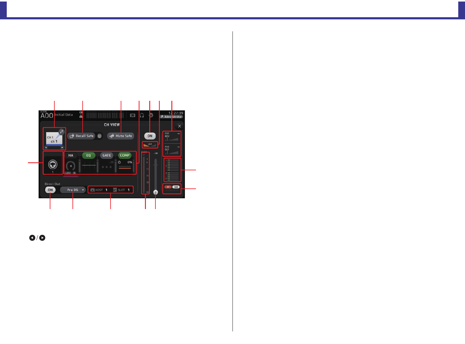
Configuration screens
Reference Manual
TF Series
-
64
-
CH VIEW screen
Provides an overview of all the settings for a channel.
You can change settings using this screen, in addition to the corresponding feature's
configuration screen.
Items displayed on this screen vary depending on the type of channel selected.
CH1–CH32
1Channel name
Touch to display the CH NAME screen.
Touch to display information for a different channel.
2Recall Safe button
Turns recall safe on and off for the corresponding channel.
You can display the RECALL SAFE screen (page 25) by touching the jump button in
the right corner of the Recall Safe button.
3Input source indicator
Displays the input channel's input source. You can select the input source on the INPUT
screen.
4Mute Safe button
Touch to temporarily exclude the selected channel from the input mute group.
If you mute the input mute group, any channels in that group that have mute safe
enabled will not be muted.
5Boxes
Touch to display the configuration screen for the corresponding feature.
You can touch the EQ, GATE, and COMP buttons displayed here to turn the
corresponding feature on and off.
HA box: Displays the INPUT screen. (page 47)
EQ box: Displays the EQ screen. (page 49)
GATE box: Displays the GATE screen. (page 53)
COMP box: Displays the COMP screen. (page 55)
6Channel on/off button
Turns the selected channel on and off.
7Channel pan slider
Adjusts the pan for the selected channel.
8FX1/FX2 boxes
Displays the effect type.
When selected, you can use the [TOUCH AND TURN] knob to adjust the effects send
level. You can also display the corresponding effect's configuration screen by touching
again.
Each box displays the amount of signal from the selected channel that is sent to the
corresponding effects module.
Send level, the selected channel's fader level, and the actual send level grouped with the
DCA is displayed in the triangular bar.
The information displayed here indicates whether the signal sent to the effects module
is the pre-fader or post-fader signal. Pre-fader signal is displayed in green; post-fader
signal is displayed in gray.
9SEND TO AUX box
Touch when selected to display the SEND TO AUX screen.
Displays the amount of signal from the selected channel that is sent to each AUX bus.
Send level, the selected channel's fader level, and the actual send level grouped with the
DCA is displayed in the horizontal bar.
The information displayed here indicates whether the signal sent to the AUX bus is the
pre-fader or post-fader signal. Pre-fader signal is displayed in green; post-fader signal is
displayed in gray.
0ASSIGN box
Displays the ASSIGN screen. (page 63)
AChannel output level slider
Adjusts the fader level for the selected channel.
BChannel output level meter
Displays the channel's output signal level.
չ
պ
ջռսվտ
ճ
ձղ մյնշո
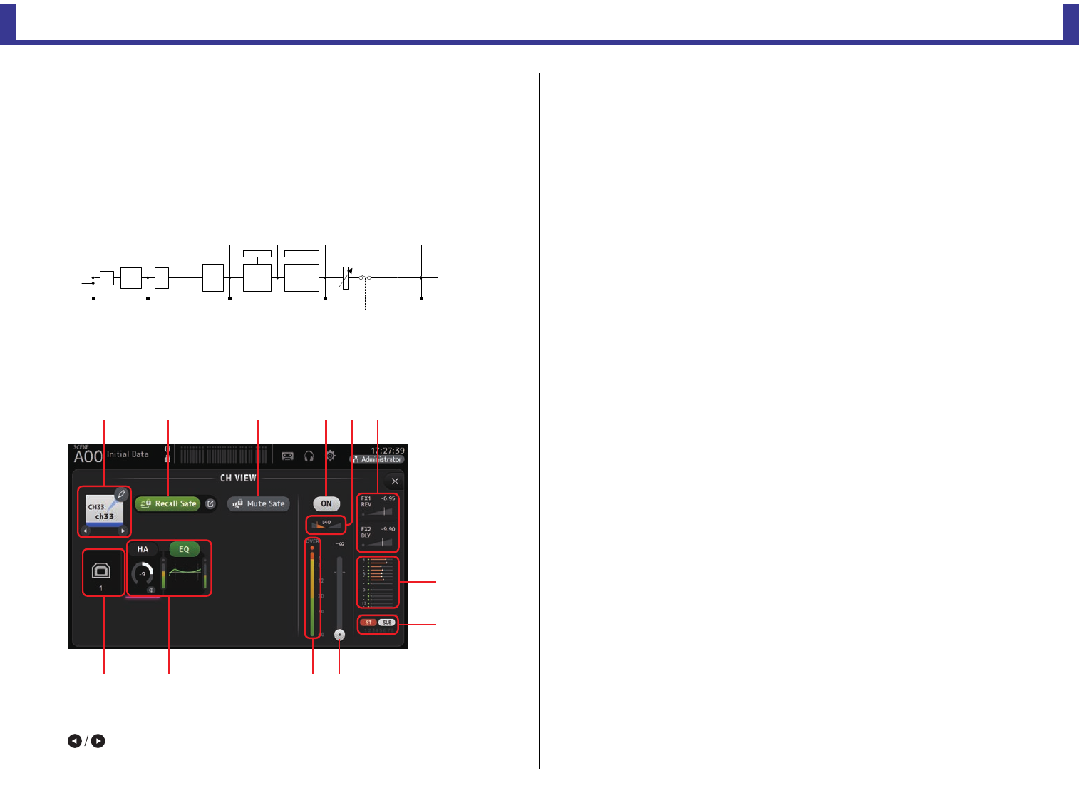
Configuration screens
Reference Manual
TF Series
-
65
-
CDirect out port indicator
Indicates the channel's direct out port.
For information about channels and output ports, see "Quick Config Input and input
channel relationships" (page 92).
DDirect out point button
Allows you to set the point of the direct out signal.
Pre DG: Before the digital gain
Pre HPF: Before the high-pass filter
Pre Fader: Before the fader
Post Fader: After the fader
EDirect out on/off button
Turns the direct out on and off.
CH33–CH40
1Channel name
Touch to display the CH NAME screen.
Touch to display information for a different channel.
2Recall Safe button
Turns recall safe on and off for the corresponding channel.
You can display the RECALL SAFE screen (page 25) by touching the jump button in
the right corner of the Recall Safe button.
3Input source indicator
Displays the input channel's input source. You can select the input source on the INPUT
screen.
4Mute Safe button
Touch to temporarily exclude the selected channel from the input mute group.
If you mute the input mute group, any channels in that group that have mute safe
enabled will not be muted.
5Boxes
Touch to display the configuration screen for the corresponding feature.
You can touch the EQ button displayed here to turn EQ on and off.
HA box: Displays the INPUT screen. (page 47)
EQ box: Displays the EQ screen. (page 49)
6Channel on/off button
Turns the selected channel on and off.
7Channel pan slider
Adjusts the pan for the selected channel.
8FX1/FX2 boxes
Displays the effect type.
When selected, you can use the [TOUCH AND TURN] knob to adjust the effects send
level. You can also display the corresponding effect's configuration screen by touching
again.
Each box displays the amount of signal from the selected channel that is sent to the
corresponding effects module.
Send level, the selected channel's fader level, and the actual send level grouped with the
DCA is displayed in the triangular bar.
The information displayed here indicates whether the signal sent to the effects module
is the pre-fader or post-fader signal. Pre-fader signal is displayed in green; post-fader
signal is displayed in gray.
9SEND TO AUX box
Touch when selected to display the SEND TO AUX screen.
Displays the amount of signal from the selected channel that is sent to each AUX bus.
Send level, the selected channel's fader level, and the actual send level grouped with the
DCA is displayed in the horizontal bar.
',*,7$/
*$,1
䃅
+3) %$1'
(4 *$7( &203
*50(7(5 *50(7(5
3UH+3) 3UH)$'(5
21
3RVW)$'(53RVW(43UH'*
)$'(5'&$
ձղ մ նշո
չ
պ
ջռյճ
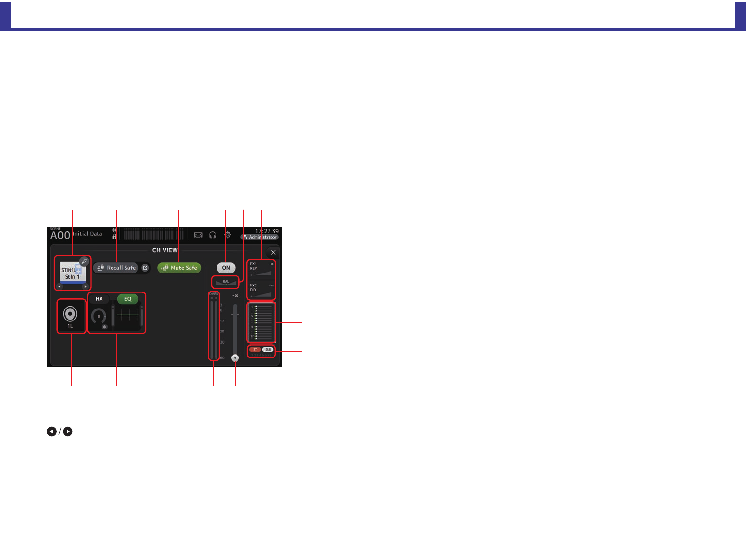
Configuration screens
Reference Manual
TF Series
-
66
-
The information displayed here indicates whether the signal sent to the AUX bus is the
pre-fader or post-fader signal. Pre-fader signal is displayed in green; post-fader signal is
displayed in gray.
0ASSIGN box
Displays the ASSIGN screen. (page 63)
AChannel output level slider
Adjusts the fader level for the selected channel.
BChannel output level meter
Displays the channel's output signal level.
ST IN 1L-ST IN 2R
1Channel name
Touch to display the CH NAME screen.
Touch to display information for a different channel.
2Recall Safe button
Turns recall safe on and off for the corresponding channel.
You can display the RECALL SAFE screen (page 25) by touching the jump button in
the right corner of the Recall Safe button.
3Input source indicator
Displays the input channel's input source. You can select the input source on the INPUT
screen.
4Mute Safe button
Touch to temporarily exclude the selected channel from the input mute group.
If you mute the input mute group, any channels in that group that have mute safe
enabled will not be muted.
5Boxes
Touch to display the configuration screen for the corresponding feature.
You can touch the EQ button displayed here to turn EQ on and off.
HA box: Displays the INPUT screen. (page 47)
EQ box: Displays the EQ screen. (page 49)
6Channel on/off button
Turns the selected channel on and off.
7Channel pan slider
Adjusts the pan for the selected channel.
8FX1/FX2 boxes
Displays the effect type.
When selected, you can use the [TOUCH AND TURN] knob to adjust the effects send
level. You can also display the corresponding effect's configuration screen by touching
again.
Each box displays the amount of signal from the selected channel that is sent to the
corresponding effects module.
Send level, the selected channel's fader level, and the actual send level grouped with the
DCA is displayed in the triangular bar.
The information displayed here indicates whether the signal sent to the effects module
is the pre-fader or post-fader signal. Pre-fader signal is displayed in green; post-fader
signal is displayed in gray.
9SEND TO AUX box
Touch when selected to display the SEND TO AUX screen.
Displays the amount of signal from the selected channel that is sent to each AUX bus.
Send level, the selected channel's fader level, and the actual send level grouped with the
DCA is displayed in the horizontal bar.
The information displayed here indicates whether the signal sent to the AUX bus is the
pre-fader or post-fader signal. Pre-fader signal is displayed in green; post-fader signal is
displayed in gray.
0ASSIGN box
Displays the ASSIGN screen. (page 63)
AChannel output level slider
Adjusts the fader level for the selected channel.
ձղ մ նշո
չ
պ
ջռյճ
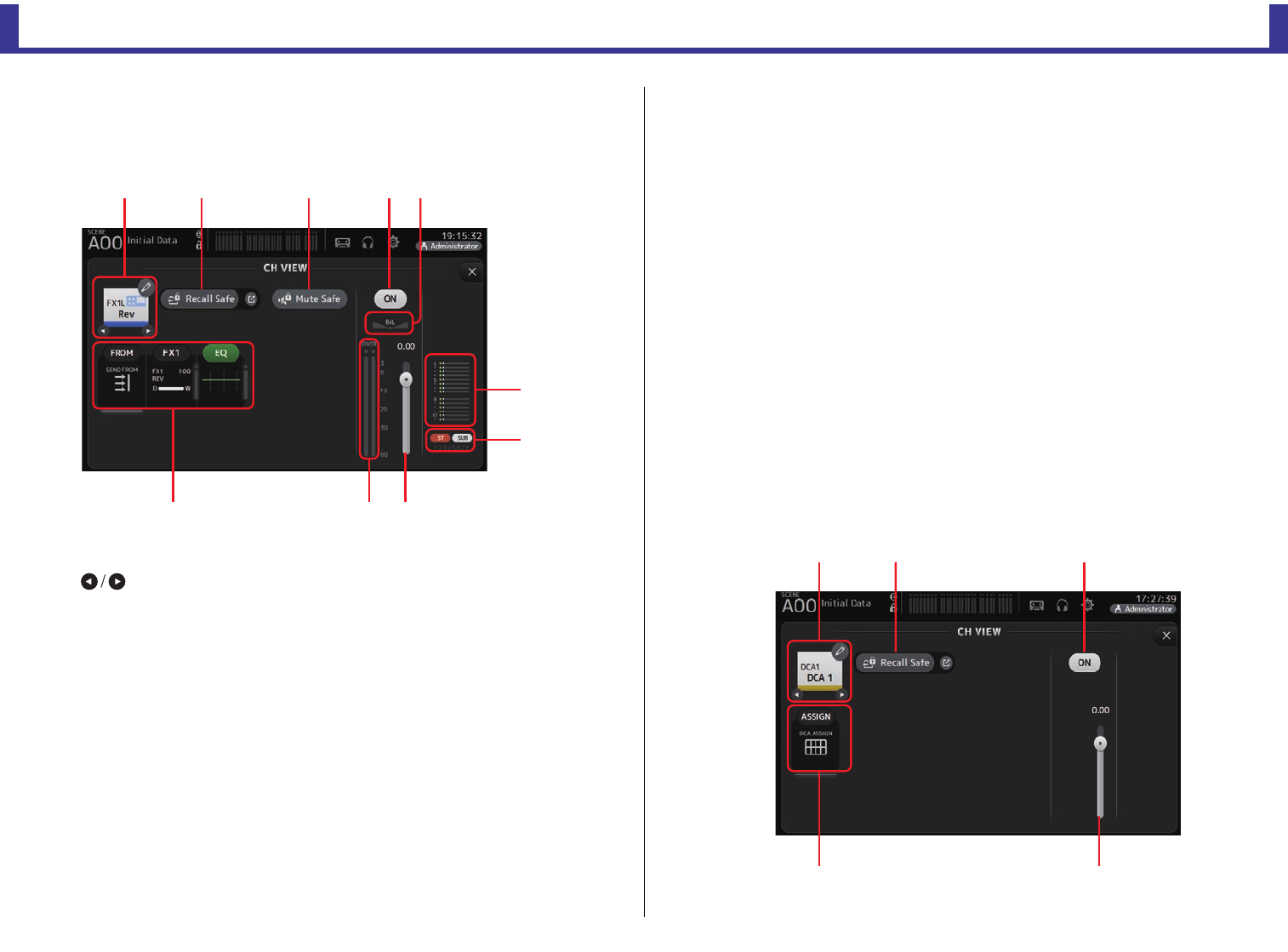
Configuration screens
Reference Manual
TF Series
-
67
-
BChannel output level meter
Displays the channel's output signal level.
FX1L–FX2R
1Channel name
Touch to display the CH NAME screen.
Touch to display information for a different channel.
2Recall Safe button
Turns recall safe on and off for the corresponding channel.
You can display the RECALL SAFE screen (page 25) by touching the jump button in
the right corner of the Recall Safe button.
3Mute Safe button
Touch to temporarily exclude the selected channel from the effects mute group.
If you mute the effects mute group, any channels in that group that have mute safe
enabled will not be muted.
4Boxes
Touch to display the configuration screen for the corresponding feature.
You can touch the EQ button displayed here to turn EQ on and off.
FROM box: Displays the SEND FROM screen. (page 75) (V3.0 and later)
FX1 (FX2) box: Displays the FX screen. (page 57)
EQ box: Displays the EQ screen. (page 49)
5Channel on/off button
Turns the selected channel on and off.
6Channel pan slider
Adjusts the pan for the selected channel.
7SEND TO AUX box
Touch when selected to display the SEND TO AUX screen.
Displays the amount of signal from the selected channel that is sent to each AUX bus.
Send level, the selected channel's fader level, and the actual send level grouped with the
DCA is displayed in the horizontal bar.
The information displayed here indicates whether the signal sent to the AUX bus is the
pre-fader or post-fader signal. Pre-fader signal is displayed in green; post-fader signal is
displayed in gray.
8ASSIGN box
Displays the ASSIGN screen. (page 63)
9Channel output level slider
Adjusts the fader level for the selected channel.
0Channel output level meter
Displays the channel's output signal level.
DCA 1–DCA 8
ձղ ճ յն
շ
ո
չպմ
ձ
յ
ղճ
մ
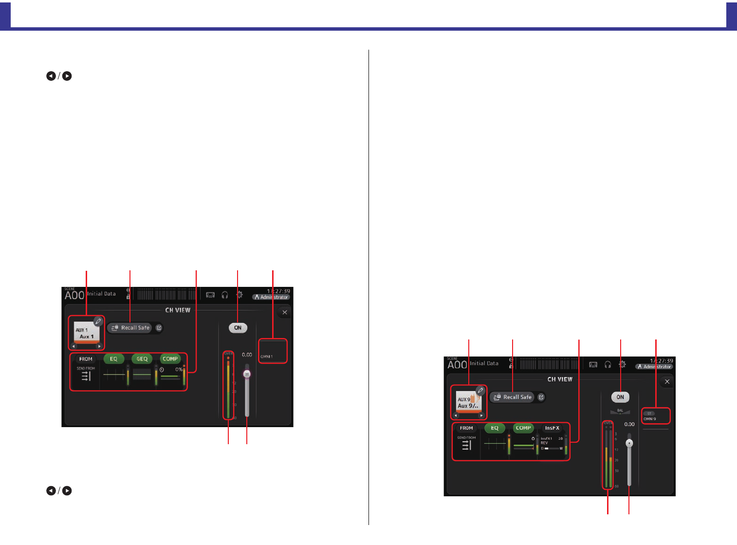
Configuration screens
Reference Manual
TF Series
-
68
-
1Channel name
Touch to display the CH NAME screen.
Touch to display information for a different channel.
2Recall Safe button
Turns recall safe on and off for the corresponding channel.
You can display the RECALL SAFE screen (page 25) by touching the jump button in
the right corner of the Recall Safe button.
3Channel on/off button
Turns the selected channel on and off.
4Channel output level slider
Adjusts the fader level for the selected channel.
5ASSIGN box (V1.1 and later)
When this area is selected, touch this area to display the DCA ASSIGN screen.
(page 76)
AUX1–AUX8
1Channel name
Touch to display the CH NAME screen.
Touch to display information for a different channel.
2Recall Safe button
Turns recall safe on and off for the corresponding channel.
You can display the RECALL SAFE screen (page 25) by touching the jump button in
the right corner of the Recall Safe button.
3Boxes
Touch to display the configuration screen for the corresponding feature.
You can touch the EQ, GEQ, and COMP buttons displayed here to turn the
corresponding feature on and off.
FROM box: Displays the SEND FROM screen. (page 75)
EQ box: Displays the EQ screen. (page 49)
GEQ box: Displays the GEQ screen. (page 72)
COMP box: Displays the COMP screen. (page 55)
4Channel on/off button
Turns the selected channel on and off.
5OUTPUT box
Displays the OUTPUT screen. (page 74)
6Channel output level slider
Adjusts the fader level for the selected channel.
7Channel output level meter
Displays the channel's output signal level.
AUX 9–AUX 20
ձղ մյ
նշ
ճ
ձղ մյ
նշ
ճ
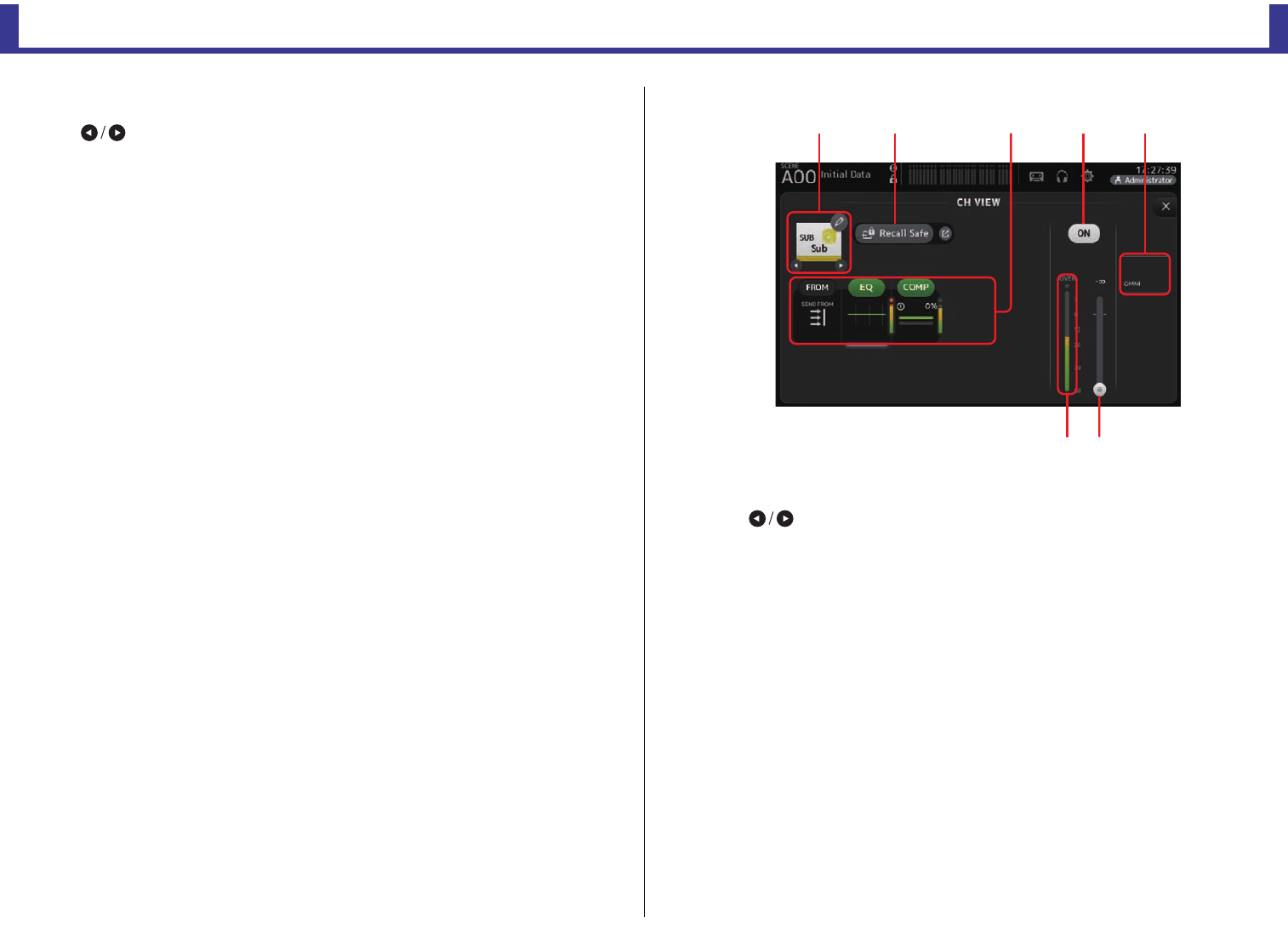
Configuration screens
Reference Manual
TF Series
-
69
-
1Channel name
Touch to display the CH NAME screen.
Touch to display information for a different channel.
2Recall Safe button
Turns recall safe on and off for the corresponding channel.
You can display the RECALL SAFE screen (page 25) by touching the jump button in
the right corner of the Recall Safe button.
3Boxes
Touch to display the configuration screen for the corresponding feature.
You can touch the EQ and COMP buttons displayed here to turn the corresponding
feature on and off.
FROM box: Displays the SEND FROM screen. (page 75)
EQ box: Displays the EQ screen. (page 49)
COMP box: Displays the COMP screen. (page 55)
InsFX box: Displays the FX screen. (page 57)
4Channel on/off button
Turns the selected channel on and off.
5OUTPUT box
Displays the OUTPUT screen. (page 74)
6Channel output level slider
Adjusts the fader level for the selected channel.
7Channel output level meter
Displays the channel's output signal level.
SUB
1Channel name
Touch to display the CH NAME screen.
Touch to display information for a different channel.
2Recall Safe button
Turns recall safe on and off for the corresponding channel.
You can display the RECALL SAFE screen (page 25) by touching the jump button in
the right corner of the Recall Safe button.
3Boxes
Touch to display the configuration screen for the corresponding feature.
You can touch the EQ and COMP buttons displayed here to turn the corresponding
feature on and off.
FROM box: Displays the SEND FROM screen. (page 75)
EQ box: Displays the EQ screen. (page 49)
COMP box: Displays the COMP screen. (page 55)
4Channel on/off button
Turns the selected channel on and off.
5OUTPUT box
Displays the OUTPUT screen. (page 74)
6Channel output level slider
Adjusts the fader level for the selected channel.
ձղ մյճ
նշ
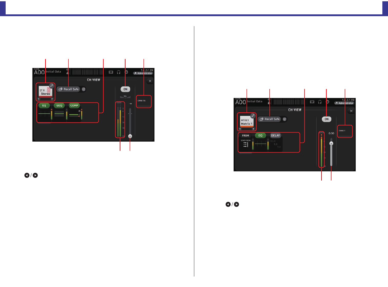
Configuration screens
Reference Manual
TF Series
-
70
-
7Channel output level meter
Displays the channel's output signal level.
ST L, ST R
1Channel name
Touch to display the CH NAME screen.
Touch to display information for a different channel.
2Recall Safe button
Turns recall safe on and off for the corresponding channel.
You can display the RECALL SAFE screen (page 25) by touching the jump button in
the right corner of the Recall Safe button.
3Boxes
Touch to display the configuration screen for the corresponding feature.
You can touch the EQ, GEQ, and COMP buttons displayed here to turn the
corresponding feature on and off.
EQ box: Displays the EQ screen. (page 49)
GEQ box: Displays the GEQ screen. (page 72)
COMP box: Displays the COMP screen. (page 55)
4Channel on/off button
Turns the selected channel on and off.
5OUTPUT box
Displays the OUTPUT screen. (page 74)
6Channel output level slider
Adjusts the fader level for the selected channel.
7Channel output level meter
Displays the channel's output signal level.
MATRIX1– MATRIX4 (V2.5 and later)
1Channel name
Touch to display the CH NAME screen.
Touch to display information for a different channel.
2Recall Safe button
Turns recall safe on and off for the corresponding channel.
You can display the RECALL SAFE screen (page 25) by touching the jump button in
the right corner of the Recall Safe button.
ձղ մյ
նշ
ճ
ձղ մյճ
նշ
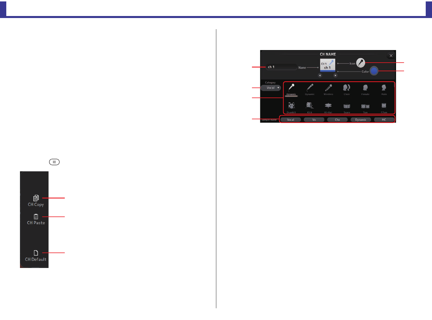
Configuration screens
Reference Manual
TF Series
-
71
-
3Boxes
Touch to display the configuration screen for the corresponding feature.
You can touch the EQ, and COMP buttons displayed here to turn the corresponding
feature on and off.
FROM box: Displays the SEND FROM screen. (page 75)
EQ box: Displays the EQ screen. (page 49)
DELAY box: Displays the DELAY screen. (page 78)
4Channel on/off button
Turns the selected channel on and off.
5OUTPUT box
Displays the OUTPUT screen. (page 74)
6Channel output level slider
Adjusts the fader level for the selected channel.
7Channel output level meter
Displays the channel's output signal level.
CH VIEW screen menu
Press the Menu key ( ) from the CH VIEW screen to display the following options.
CH NAME screen
Allows you to set the channel name, icon, and channel color.
1Name text box
Enter the channel name here.
Touch the text box to enter the name using the KEYBOARD screen. (page 10)
2Icon button
Touch to display a list of available channel icons.
3Category button
Allows you to select a different category of channel icons.
The available categories vary depending on the type of channel.
4Channel icon list
Touch to apply the channel icon.
You can drag this area up and down to display all of the available icons.
5Sample Name button
Displays a list of commonly used channel names based on the selected channel icon.
Touch on a sample name to use it as the channel name.
1CH Copy
Copies the settings of the current channel.
2CH Paste
Pastes settings from another channel and applies
them to the current channel.
3CH Default
Resets the settings of the current channel to their
default values.
ձ
ղ
ճ
ն
ղ
ձ
ճ
մ
յ
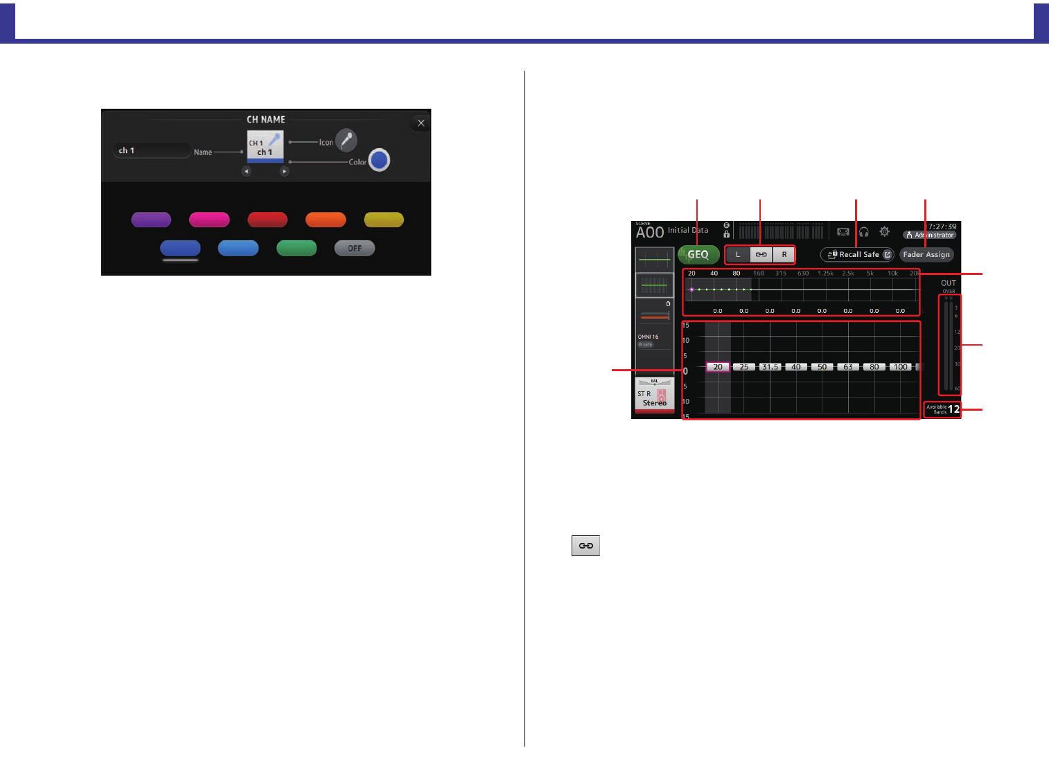
Configuration screens
Reference Manual
TF Series
-
72
-
6Color button
Touch to display a list of available channel colors.
Touch the desired color to use that color as the channel color.
GEQ screen
You can use the internal graphic equalizer (GEQ) to process AUX 1–8 and STEREO channel
signals.
The GEQ is a mono, 12-band EQ. Each band is 1/3 octave wide, with an adjustable gain range
of ±15 dB.
31 bands are available; you can adjust gain for up to 12 bands.
1GEQ button
Turns the GEQ on and off.
2GEQ channel selection buttons
These buttons are displayed only when configuring the GEQ for stereo AUX buses or the
STEREO channels.
They are not displayed for mono AUX buses.
: Turns the GEQ left/right channel link on and off.
L/R: Allows you select the left and right GEQ channels.
3Recall Safe button
Displays the RECALL SAFE screen. (page 25)
4Fader Assign button (V2.0 and later)
This feature is available for TF5/TF3/TF1.
When this button is turned on, you can use the faders to adjust each band of the GEQ.
5EQ graph, RTA display, band selection
Displays the EQ settings with RTA (real-time analysis).
Swipe left or right or touch an area to display the gain sliders for other bands.
ձղ ճ մ
ն
շ
յ
ո
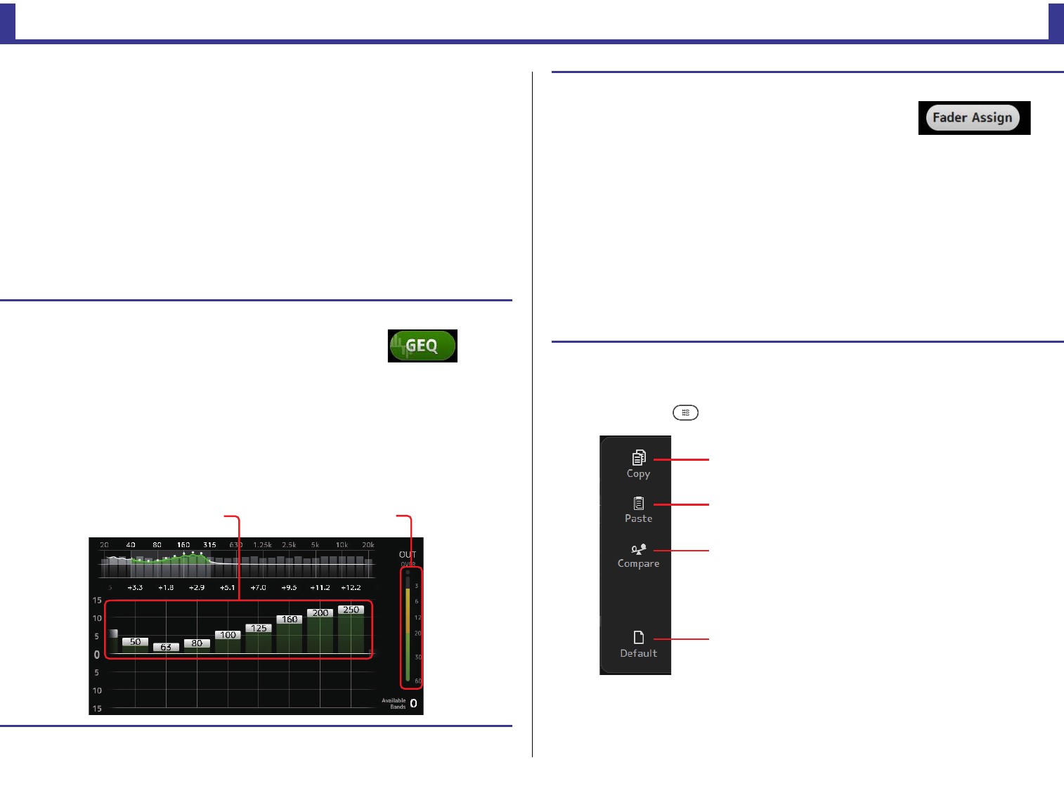
Configuration screens
Reference Manual
TF Series
-
73
-
When the Fader Assign button is turned on, you can use this area to change which
bands can be adjusted by the faders. (TF3 and TF1 only.)
6Gain slider
Adjusts the gain for the corresponding band.
Swipe left or right to display the gain sliders for other bands.
When the Fader Assign button is turned on, you can use this area to change which
bands can be adjusted by the faders. (TF3 and TF1 only.)
7Output level meter
Displays the GEQ output level.
8Available bands display
Displays the number of additional bands that you can adjust.
GEQ screen menu
Press the Menu key ( ) from the GEQ screen to display the following options.
Using GEQ
1. Touch the GEQ button to turn GEQ on.
2. Swipe left or right on the gain sliders to display the
desired bands.
3. Drag sliders up and down to adjust the gain of the corresponding bands.
You can confirm the overall output using the output level meter.
Once you have adjusted gain for 12 bands, the gain sliders for the remaining bands are displayed in
gray. If you want adjust gain for other bands, you must first set the gain to 0 for one of the bands you
have already adjusted.
Touch the gain slider quickly two times to reset it to its default value (0 dB).
Gain slider Output level meter
Using faders to adjust GEQ (TF5/TF3/TF1)
1. Touch the Fader Assign button to turn it on.
The current gain setting for each band is applied to the faders
in the channel strip section of the console.
You can confirm the frequency and gain for each band in the channel display.
2. For TF3 and TF1, swipe left or right on the gain sliders in the GEQ screen to select
other bands.
You can swipe the EQ graph, RTA display, or band selection area left or right to select other bands.
For TF5, all bands are applied to the faders.
3. Use the console's faders to adjust the gain.
If you turn on a channel's [ON] key, you can reset the gain of frequencies assigned to that channel to
0 dB.
4. When you are finished making adjustments, touch the Fader Assign button to turn
it off.
Fader Assign also turns off when you switch another screen or enter SENDS ON FADER mode.
1Copy
Copies the GEQ parameters of the selected
channel to the clipboard.
2Paste
Pastes the GEQ parameters in the clipboard to the
selected channel.
3Compare
Allows you to compare the GEQ parameters of the
selected channel with the GEQ parameters in the
clipboard by switching between the two.
4Default
Resets the GEQ settings for the current channel to
their default values.
ձ
ղ
ճ
մ
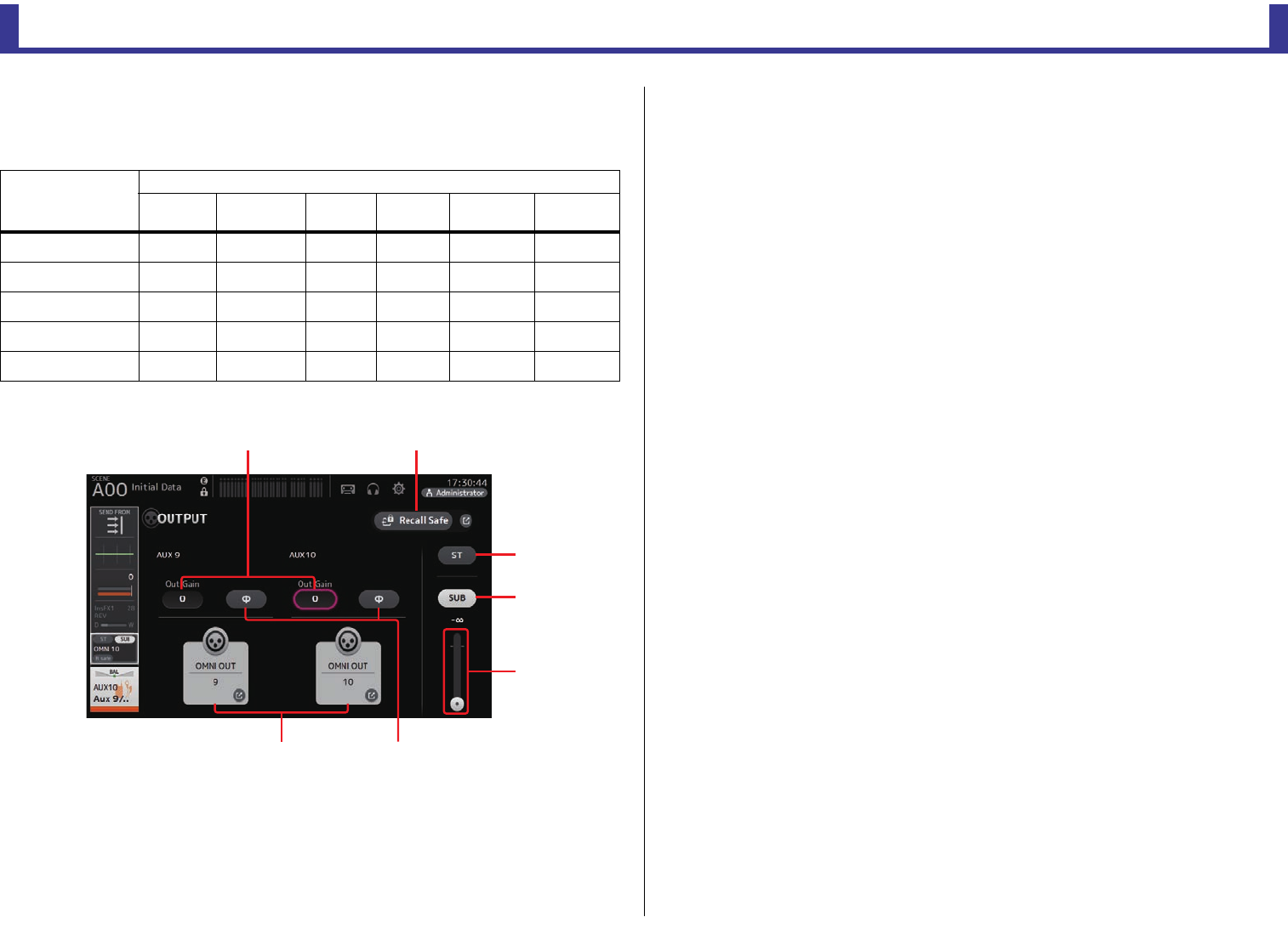
Configuration screens
Reference Manual
TF Series
-
74
-
OUTPUT screen
Allows you to configure how output channels will be output. The buttons displayed vary
depending on the type of output channel selected.
○: Displayed
– : Not displayed
1ST button
Determines whether the stereo channel is output or not.
2SUB button (V3.0 and later)
Determines whether the channel's signal is sent (on) or not sent (off) to the SUB bus.
3SUB slider (V3.0 and later)
Determines the amount of signal sent from the selected channel to the SUB bus.
4Out Gain text box
Allows you to adjust the output gain.
When selected, you can use the [TOUCH AND TURN] knob to adjust the setting. Touch
again to display the keyboard and enter a value.
5Φ (phase) button
Allows you to reverse the phase.
When turned on, the output signal's phase is reversed.
6OMNI OUT button
Displays the number of the OMNI OUT to which the channel is directed.
Up to two numbers can be displayed. For three or more numbers, "+" is displayed.
Displays the OMNI OUT screen. (page 22)
For information about channels and output ports, see "Quick Config Input and input
channel relationships" (page 92).
7Recall Safe button (V1.1 and later)
Turns recall safe on and off for the corresponding channel.
You can display the RECALL SAFE screen by touching the jump button in the right corner
of the Recall Safe button.
Output channel
Buttons
ST button SUB button
SUB slider
Out Gain
Buttons Φ button OMNI OUT
Indicator
OMNI OUT
Buttons
AUX 1–8 – – ○○ ○ ○
AUX9/10–AUX19/20 ○○○○○ ○
SUB – – ○○ ○ ○
STEREO – – ○○ ○ ○
MATRIX1–4 – – ○○ ○ ○
ձ
ղ
ճ
շ
մ
նյ
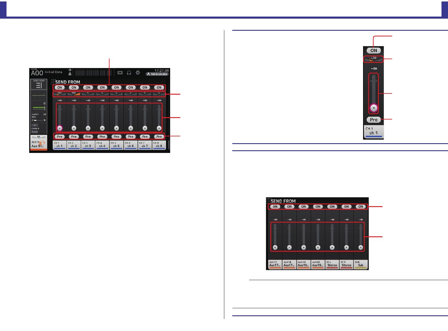
Configuration screens
Reference Manual
TF Series
-
75
-
SEND FROM screen
Allows you to send signals from the each channels.
1ON button
Determines whether a signal is sent (on) or not sent (off) from the corresponding each
channel.
2Send pan slider
Adjusts the pan of the input channel signal that is sent.
For AUX 1–8, this slider is only displayed if the signal type is set to stereo.
Not displayed for MATRIX 1–4 or FX1L–FX2R.
3Send level slider
Determines the amount of signal sent from the corresponding each channel.
4Pre button
Allows you to select whether the pre-fader or post-fader signal is sent from the
corresponding input channel.
On: Before the fader
Off: After the fader
Not displayed for MATRIX 1–4.
ձ
ճ
ղ
մ
Adjusting the SEND FROM level
1. Touch the ON button for the input channels
that you want to send.
2. Touch the send pan slider, and then use the
[TOUCH AND TURN] knob to adjust the pan
of the input channel signal that is sent.
3. Drag the send level sliders to adjust the
amount of input channel signal that is sent.
Adjusting the send level from AUX channels, STEREO channels, and SUB
channel to a MATRIX channel (V2.5 and later)
1. Touch the ON button for the AUX channel, STEREO channel, or SUB channel that
you want to send. (It is turned on by default.)
2. Drag the send level sliders to adjust the amount of AUX channel, STEREO channel,
and SUB channel signal that is sent.
Send level slider
Send pan slider
ON button
Pre button
ON button
Send level slider
NOTE
• You can send the post-on signal of an AUX channel, STEREO channel, or SUB channel to a MATRIX
channel.
• Left and right channel SEND levels can be adjusted independently for stereo channels such as AUX 9/
10 and STEREO.
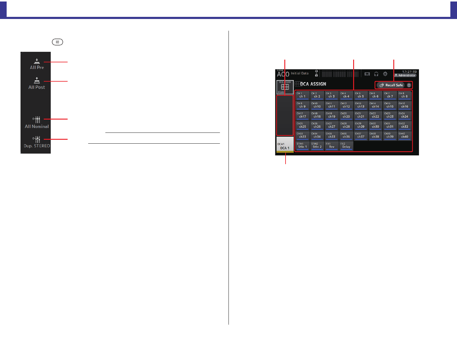
Configuration screens
Reference Manual
TF Series
-
76
-
SEND FROM screen menu
Press the Menu key ( ) from the SEND FROM screen to display the following options.
DCA ASSIGN screen
Allows you to group channels together by assigning them to DCA groups.
1Channel display area
Displays the channels that are assigned to the current DCA group.
2DCA ASSIGN buttons
Allow you to select which channels are assigned to the current DCA group.
Selected channels are highlighted.
3CH VIEW button
Displays the CH VIEW screen. (page 64)
4Recall Safe button (V1.1 and later)
Turns recall safe on and off for the corresponding channel.
You can display the RECALL SAFE screen by touching the jump button in the right corner
of the Recall Safe button.
1All Pre
Turns on all Pre buttons.
2All Post
Turns off all Pre buttons.
3All Nominal (V2.0 and later)
Sets all SEND levels to nominal (0 dB).
4Dup. STEREO (V2.0 and later)
Duplicate STEREO. Copies each channel's fader
level and applies it to the SEND level.
ձ
ղ
ճ
մ
NOTE
This menu is not available for MATRIX channels 1–4.
ձ մղ
ճ
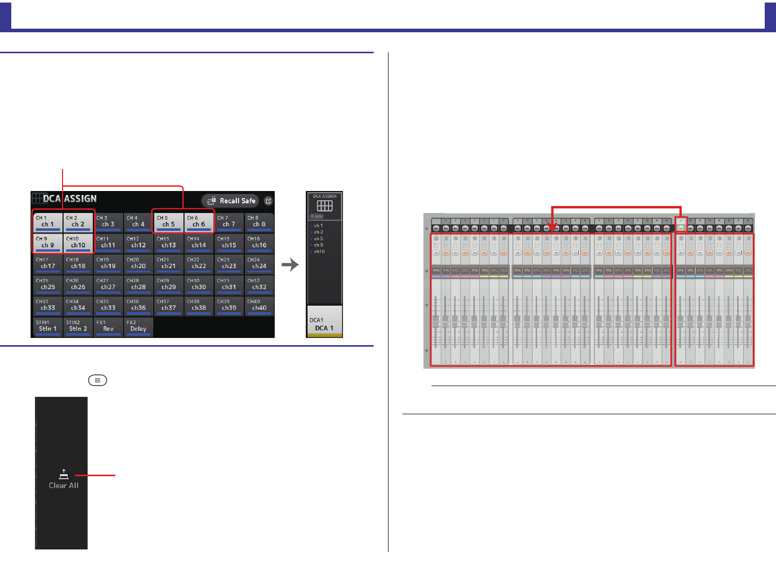
Configuration screens
Reference Manual
TF Series
-
77
-
DCA ASSIGN screen menu
Press the Menu key ( ) from the DCA ASSIGN screen to display the following options.
DCA roll out
You can assign DCA groups 1–8 to the last 8 channel strips on the right side of the console's
top panel.
(TF5: channel strips 25–32; TF3: 17–24; TF1: 9–16)
You can then assign the channels of a DCA group to the channel strips on the left side of the
console's top panel by pressing the corresponding DCA group's [SEL] key.
(TF5: channel strips 1–24; TF3: 1–16; TF1: 1–8)
The number of channels in the group that will be assigned to the channels strips depends on
the model number. For the TF5 console, the 24 lowest numbered channels in the group are
assigned; the lowest 16 for the TF 3, and the lowest 8 for the TF1.
This feature allows you to manipulate the channels strips for both the DCA group master and
the group's "member" channels at the same time.
Assigning channels to a DCA group
1. Press the [INPUT1] and [INPUT2] buttons on the top panel simultaneously to display
the GROUP channels.
2. Press a [SEL] button on the top panel that corresponds to the DCA group that you
want to configure.
3. Touch the DCA buttons that correspond to the channels you want to assign to the
group. (You can select multiple channels.)
The selected channels are displayed in the channel display area.
1Clear All
Removes all channels from the group.
Channel is selected
ձ
NOTE
For TF-RACK, this item is displayed only in the OVERVIEW screen. The channels assigned to the faders
are the same as for the TF1.
Member channels of selected DCA group
assigned to these channel strips
DCA groups 1–8
assigned to these
channel strips
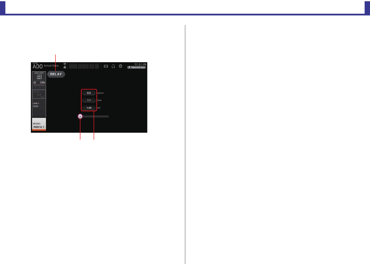
Configuration screens
Reference Manual
TF Series
-
78
-
DELAY screen (V2.5 and later)
Allows you to configure the delay applied to the signal output from the MATRIX channels.
This works well for delay compensation for speakers that are placed far away.
1DELAY button
Turns the DELAY on and off.
2DELAY slider
Allows you to adjust the delay time.
You can specify the delay time in meters, feet, or milliseconds.
3DELAY setting
Determines the delay time by specifying distance (meters or feet) or time (milliseconds).
Touch a text box to display the keyboard and enter a value.
ձ
ղճ
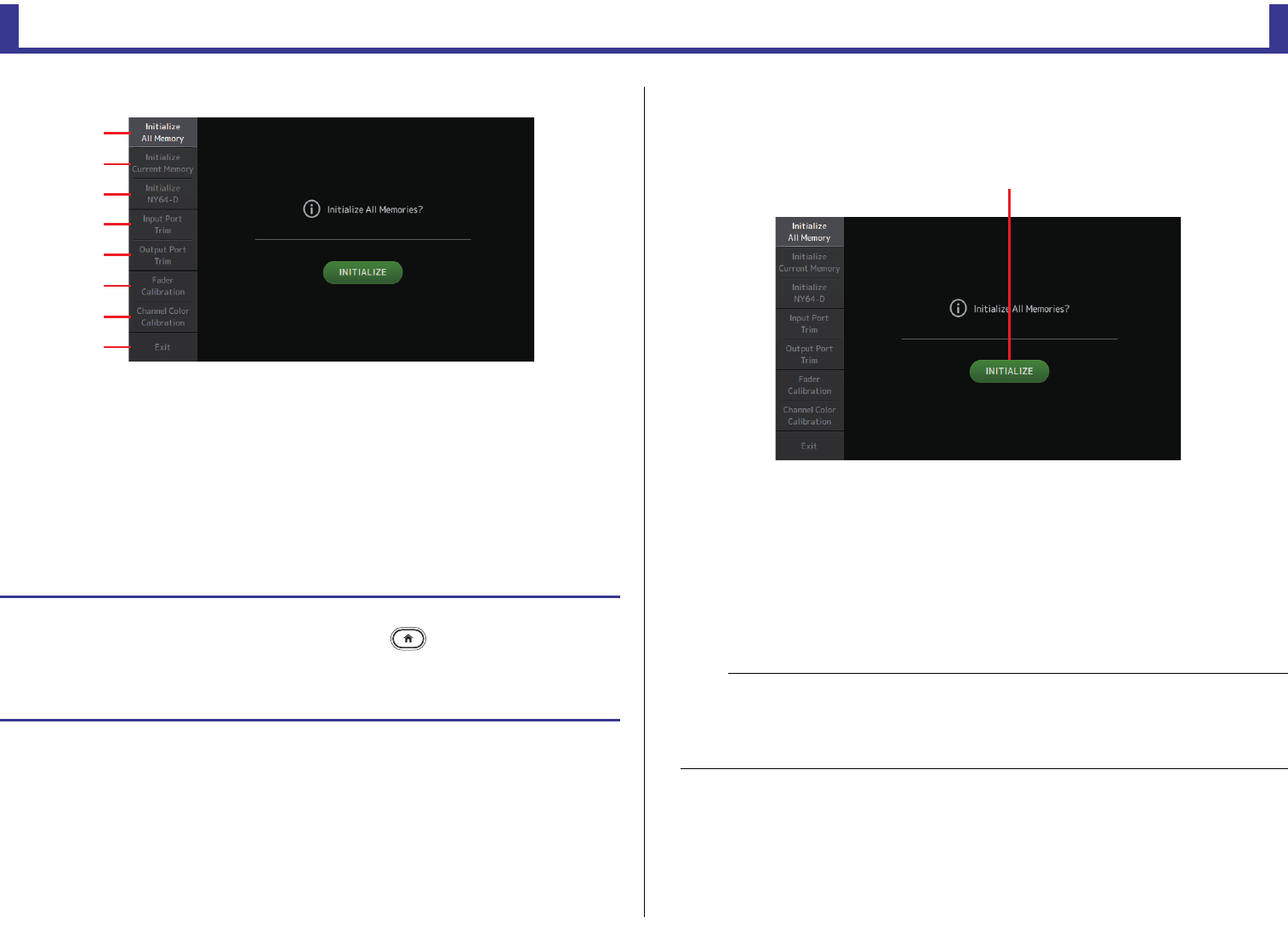
Maintenance screen
Reference Manual
TF Series
-
79
-
Maintenance screen
Allows you to access maintenance features.
1Displays the Initialize All Memory screen.
2Displays the Initialize Current Memory screen. (page 80)
3Displays the Initialize NY64-D screen. (page 80) (V3.0 and later)
4Displays the Input Port Trim screen. (page 81)
5Displays the Output Port Trim screen. (page 81)
6Displays the Fader Calibration screen. (page 82) (TF5/TF3/TF1)
7Displays the Channel Color Calibration screen. (page 83) (TF5/TF3/TF1)
8Closes the maintenance screen.
Initialize All Memory screen
Resets the console's memory, including Scene memory and Libraries, to the factory default
settings.
1INITIALIZE button
Initializes the internal memory.
The following data is initialized: all Scene data, all Preset data, mixing data, and setup
data.
Touch to display the confirmation message. Touch the OK button to perform the
operation.
Do not touch any buttons until the initialization is complete.
When initialization is complete, you can continue to use other maintenance features
without exiting.
Using the maintenance screen
1. Turn on the console while pressing the Home key ( ).
The maintenance screen is displayed.
Touch the button that corresponds to the desired maintenance feature.
Touch the Exit button to exit the maintenance mode.
ձ
ղ
ճ
մ
յ
ն
շ
ո
NOTE
• When initializing the internal memory, all data stored in the memory will be lost. Use caution when
performing this operation.
• The internal clock, network settings, and brightness settings are not initialized by this operation.
• If an NY64-D is installed, we recommend you turn the TF series console off and on again so the
console will be set up correctly with the connected Dante devices.
ձ
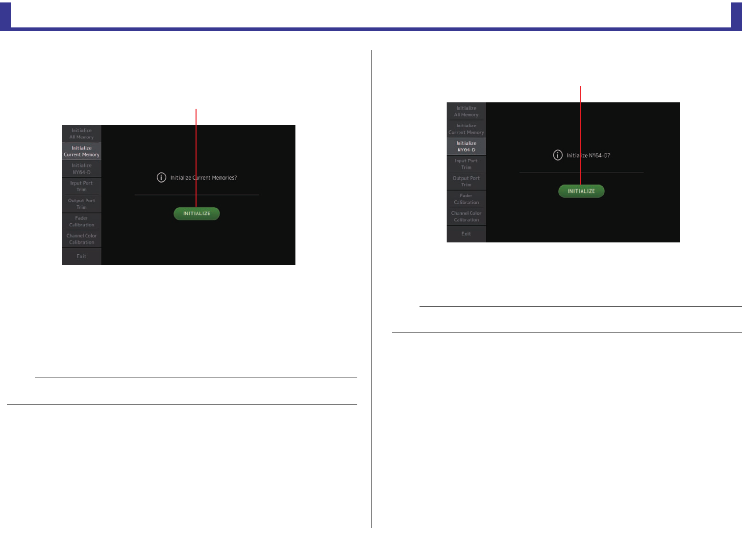
Maintenance screen
Reference Manual
TF Series
-
80
-
Initialize Current Memory screen
Resets the console's current memory to the factory default settings. Scene memory and
Libraries are not reset.
1INITIALIZE button
Initializes the current memory.
The following data is initialized: mixing data and setup data.
Touch to display the confirmation message. Touch the OK button to perform the
operation.
Do not touch any buttons until the initialization is complete.
When initialization is complete, you can continue to use other maintenance features
without exiting.
Initialize NY64-D screen (V3.0 and later)
1INITIALIZE button
Resets the settings of the NY64-D installed in the expansion slot. After initializing, in
order to reconfigure the connected Dante device, we recommend first turning the TF
series console off and then on again.
NOTE
When initializing the current memory, all data in the current memory will be lost. Use caution when
performing this operation.
ձ
NOTE
A NY64-D card will be initialized even if Dante Device Lock has been enabled for it. In this case, Dante
Device Lock will be disabled after the card is initialized.
ձ
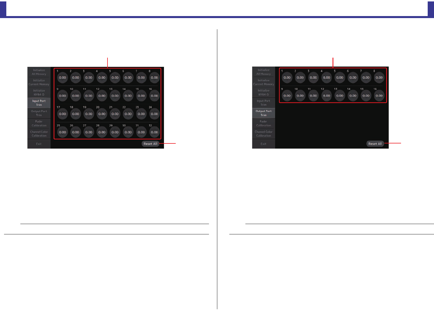
Maintenance screen
Reference Manual
TF Series
-
81
-
Input Port Trim screen
Allows you to adjust the gain of each INPUT jack in 0.01 dB increments.
1INPUT jack selection buttons
Select the INPUT jack that you want to configure here.
Select the button that corresponds to the INPUT jack you want to configure, and then
use the [TOUCH AND TURN] knob to adjust the value.
After making adjustments, start up the console as usual.
2Reset All button
Resets all values to 0.00 dB. The factory default setting is also 0.00 dB.
Touch to display the confirmation message. Touch the OK button to perform the
operation.
Output Port Trim screen
Allows you to adjust the gain of each OMNI OUT jack in 0.01 dB increments.
1OMNI OUT jack selection buttons
Select the OMNI OUT jack that you want to configure here.
Select the button that corresponds to the OMNI OUT jack you want to configure, and
then use the [TOUCH AND TURN] knob to adjust the value.
After making adjustments, start up the console as usual.
2Reset All button
Resets all values to 0.00 dB. The factory default setting is also 0.00 dB.
Touch to display the confirmation message. Touch the OK button to perform the
operation.
NOTE
When the reset is complete, you can continue to use other maintenance features without exiting.
ձ
ղ
NOTE
When the reset is complete, you can continue to use other maintenance features without exiting.
ձ
ղ
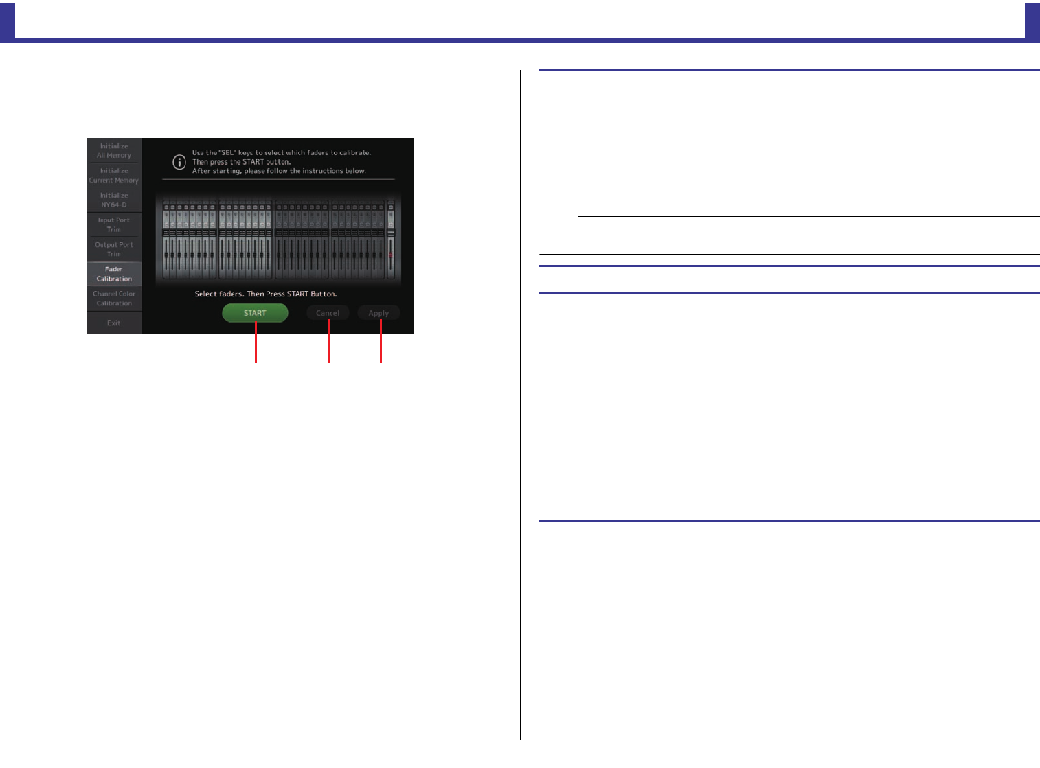
Maintenance screen
Reference Manual
TF Series
-
82
-
Fader Calibration screen (TF5/TF3/TF1)
In some usage environments, discrepancies may occur in the motion of the motor faders. You
can use this screen to correct these discrepancies
1START button
Starts the calibration.
Touch to display the confirmation message. Touch the OK button to perform the
operation.
2Cancel button
Stops the calibration.
3Apply button
Applies the settings and exits.
ձղճ
Calibrating the faders
1. Press the [SEL] key on the top panel that corresponds to the fader you want to
calibrate.
2. Touch the START button on the FADER CALIBRATION MODE screen.
3. Touch the OK button when the confirmation message is displayed.
4. When calibration has finished, touch the APPLY button.
5. Touch the Exit button in the maintenance menu and start up the console as usual.
If a fader must be calibrated again
If a fader must be calibrated again, the [ON] or [CUE] key of the corresponding fader will flash.
Use the following procedure to recalibrate.
1. When the message "Found faders requiring adjustment. Please calibrate faders again."
is displayed, touch the Close button to close the popup.
2. Touch the Apply button displayed on the screen.
The [SEL] key of the fader that was flashing begins to flash.
3. Slide the corresponding fader to the highest and lowest positions several times.
Make sure the fader's slide action is smooth and not getting stuck.
4. Perform the procedure described in "Calibrating the faders" beginning at step 2.
If you perform this procedure multiple times and the popup message is still displayed, contact
your Yamaha dealer.
NOTE
• This feature automatically calibrates the specified fader (channel strip or master section fader).
• When calibration is complete, you can continue to use other maintenance features without exiting.
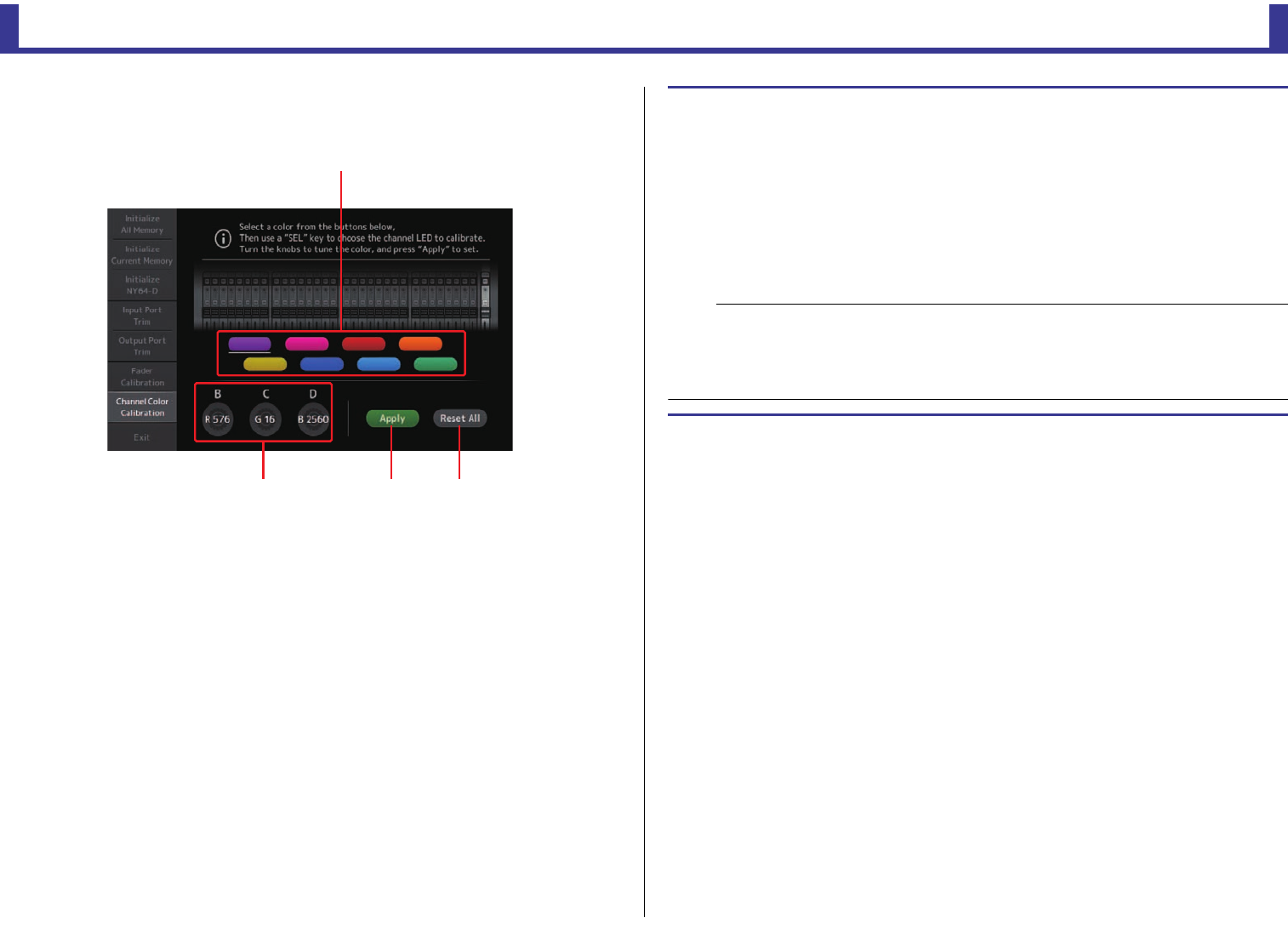
Maintenance screen
Reference Manual
TF Series
-
83
-
Channel Color Calibration screen (TF5/TF3/TF1)
You can adjust the colors of the LEDs as desired. LED colors are adjusted one at a time.
1Color buttons
Allow you to select a color.
2RGB knobs
Allow you to adjust the color.
3Apply button
Applies the settings and exits.
4Reset All button
Starts the calibration.
Touch to display the confirmation message. Touch the OK button to perform the
operation.
ղճմ
ձ
Adjusting channel colors
1. Press the [SEL] key on the top panel that corresponds to the channel color you want
to adjust.
2. Touch a color button to choose a color.
3. While comparing the [SEL] you selected with the other indicators on the top panel,
use the [TOUCH AND TURN] knob or the [USER DEFINED KNOBS] B, C, and D to
adjust the color.
4. When finished, touch the Apply button to apply the settings.
5. Touch the Exit button in the maintenance menu and start up the console as usual.
NOTE
• For TF3 and TF1, channels not supported by the console are not displayed.
• Only one channel color can be adjusted at a time.
• The Apply button is only displayed after you begin adjusting the channel's color.
• To reset all channel color's to their factory default values, touch the Reset All button.
• When the reset is complete, you can continue to use other maintenance features without exiting.
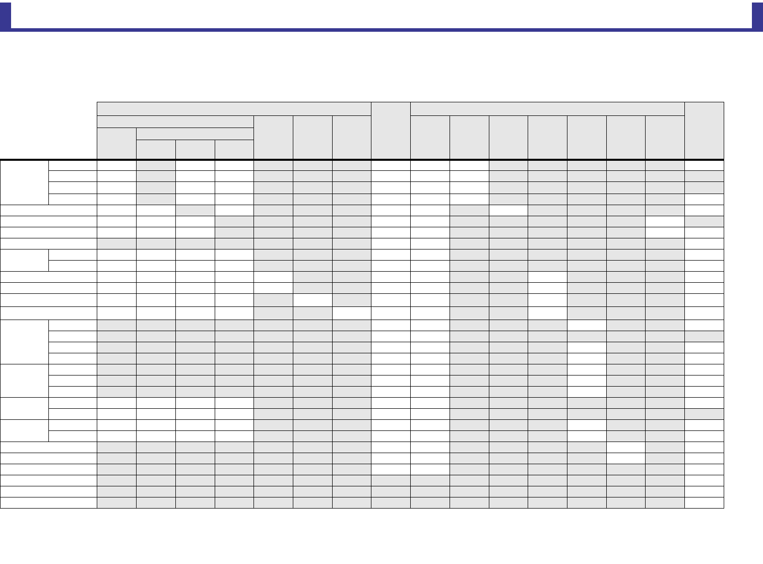
Reference
Reference Manual
TF Series
-
84
-
Reference
List of parameters saved in Scenes and Presets
CH 1–40
*1 CH 1–32 only
*2 Only parameters are linked. (Gain reduction control is not linked.)
*3 Libraries created for CH 1–32 cannot recall to CH 33–40. Similarly, libraries created for CH 33–40 cannot recall to CH 1–32.
Channel Library Recall*3
Scene
Can use Scene Recall Safe
Stereo
Link
Recall CH
Recall EQ Recall
Gate
Recall
Comp All HA Input
Select
Processing
Send To Fader/On Name
(All)
(Exclude)
HA Input
Select Name
HA
Gain O OO OOO O
+48V O OO OOO
ΦOOO OOO
Digital Gain O OO OOO O
Input Select O O OOO O O
Channel Name OOO OO O
Category, Color, Icon O O O OO OO
Stereo Link OO O
Direct Out*1 ON OOOO OO O
Point OOOO OO O
HPF OOOOO OO O O
PEQ OOOOO OO O O
GATE*1 OOOO OOO OO*2
COMP*1 OOOO OOO OO*2
TO AUX
Level OO O O
Pan OO
ON OO O O
Pre OO O O
TO FX
Level OO O O
ON OO O O
Pre OO O O
TO ST Assign OOOO OO O
Pan OOOO OO
TO SUB Level OOOO OO O O
ON OOOO OO O O
ON OO O O
Fader OO O O
DCA Assign OO O
Mute Safe O
Recall Safe O
CUE O
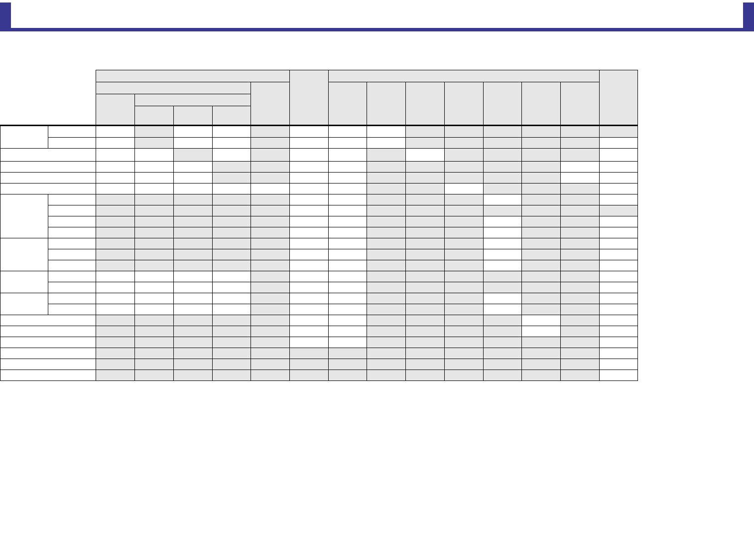
Reference
Reference Manual
TF Series
-
85
-
ST IN 1, ST IN 2
*1 Input Select can only recall Libraries for the same channel.
Channel Library Recall
Scene
Can use Scene Recall Safe
Stereo
Link
Recall CH
Recall EQ All HA Input
Select
Processing
Send To Fader/On Name
(All)
(Exclude)
HA Input
Select Name
HA
ΦOOO OOO
Digital Gain O OO OOO O
Input Select O*1 O*1 O*1 OO O O
Channel Name OOO OO OO
Category, Color, Icon O O O OO OO
PEQ OOOOOOO O O
TO AUX
Level OO O O
Pan OO
ON OO O O
Pre OO O O
TO FX
Level OO O O
ON OO O O
Pre OO O O
TO ST Assign OOOO OO O
Balance OOOO OO O
TO SUB Level OOOO OO O O
ON OOOO OO O O
ON OO O O
Fader OO O O
DCA Assign OO O
Mute Safe O
Recall Safe O
CUE O
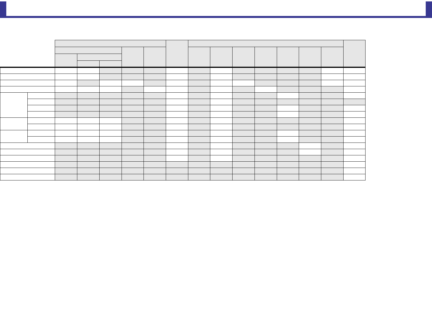
Reference
Reference Manual
TF Series
-
86
-
FX 1, FX 2
*1 For With Send, TO FX signals from CH 1–40, ST IN 1, and ST IN 2 can be recall safe.
Channel Library Recall
Scene
Can use Scene Recall Safe
Stereo
Link
Recall CH
Recall FX Recall EQ With
Send*1 All FX
Processing
Send To Fader/On Name
(All) (Exclude)
FX Name
Channel Name O O O O OO
Category, Color, Icon O O O O OO
FX O OO OOO O-
PEQ OOO OO O O O
TO AUX
Level O O O O
Pan O O
ON O O O O
Pre O O O O
TO ST Assign OOO O O O
Balance OOO O O O
TO SUB Level OOO O O O O
ON OOO O O O O
ON O O O O
Fader O O O O
DCA Assign O O O
Mute Safe O
Recall Safe O
CUE O
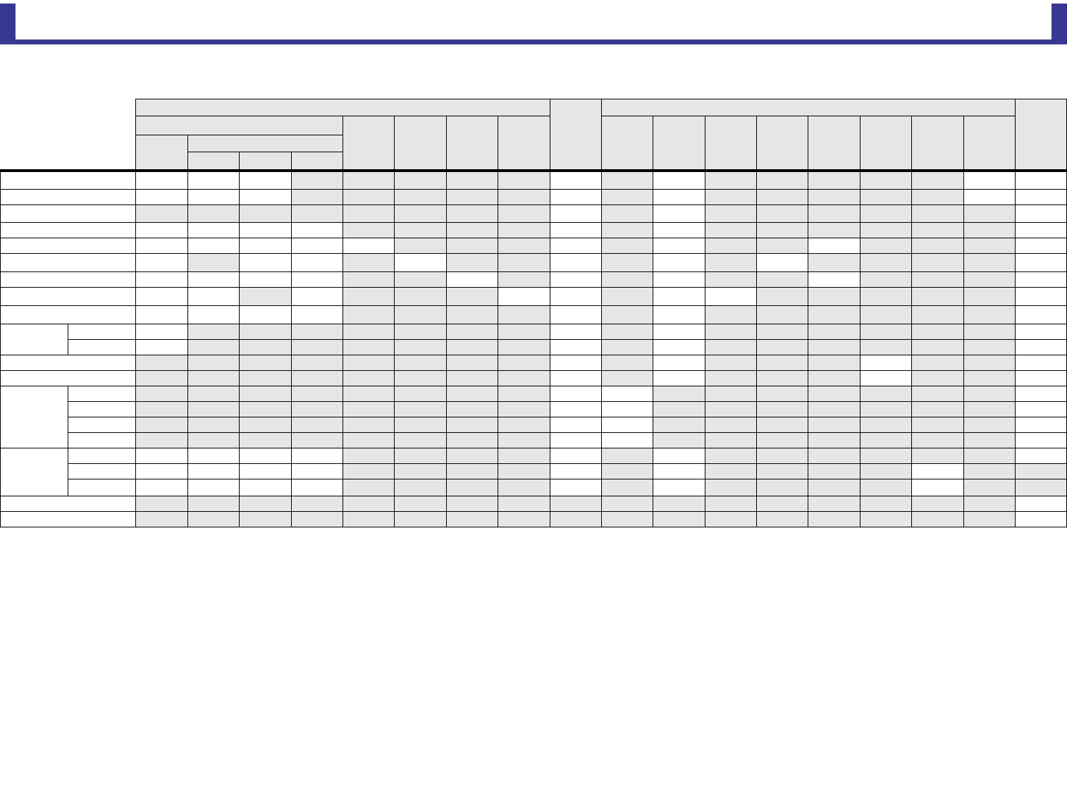
Reference
Reference Manual
TF Series
-
87
-
AUX
*1 AUX 1–8 only
*2 AUX 9/10–19/20 only
*3 Only when L/R LINK for GEQ is turned on
*4 Libraries created for AUX 1–8 cannot recall to AUX 9/10–19/20. Similarly, libraries created for AUX 9/10–19/20 cannot recall to AUX 1–8.
Channel Library Recall
Scene
Can use Scene Recall Safe
Stereo
Link
Recall CH*4
Recall EQ Recall
GEQ*1
Recall
COMP*1
Recall
FX*2
With
Send All FX*2 GEQ*1
Processing
Fader/
On Gain/ΦName
(All) (Exclude)
GEQ*1 FX*2 Name
Channel Name OOO O O O O*2
Category, Color, Icon O O O O O OO
Signal Type*1 O O O
Pan Link O O O O O O O
PEQ OOOOO O O O O
GEQ*1 OOO O O O O O*3
COMP O O O O O O O O O
Ins FX*2 OO OOO OO O
TO ST Assign*2 OOOO O O O
TO SUB*2 Level O O O O
ON O O O O
ON O O O O
Fader O O O O
Send From
Level OO O
Pan OO O
ON OO O
Pre OO O
OUTPUT
Balance OOOO O O O
Out Gain OOOO O O O
ΦOOOO O O O
Recall Safe O
CUE O
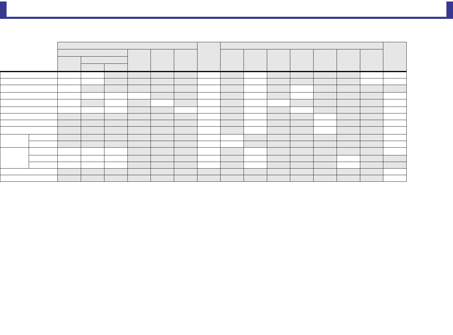
Reference
Reference Manual
TF Series
-
88
-
STEREO, SUB
*1 STEREO only
*2 SUB only
*3 Only when L/R LINK for GEQ is turned on
*4 Libraries created for STEREO cannot recall CH/EQ to SUB. Similarly, libraries created for SUB cannot recall CH/EQ to STEREO.
Channel Library Recall
Scene
Can use Scene Recall Safe
Stereo
Link*1
Recall CH
Recall EQ Recall
GEQ*1
Recall
COMP
With
Send*2 All GEQ*1
Processing
Fader/On Gain/ΦName
(All) (Exclude)
GEQ*1 Name
Channel Name O O O O OO
Category, Color, Icon O O O O OO
LPF*2 O O O O
PEQ OOOO O O O O
GEQ*1 OOOOOO O*3
COMP O O O OO O O O
ON O O O O
Fader O O O O
STEREO/SUB Level Link*2 OO*2 O*2 -
Send From*2 Level OO O
ON OO O
OUTPUT
Balance*1 OOO O O O
Out GainOOO O O O
ΦOOO O O O
Recall Safe O
CUE O
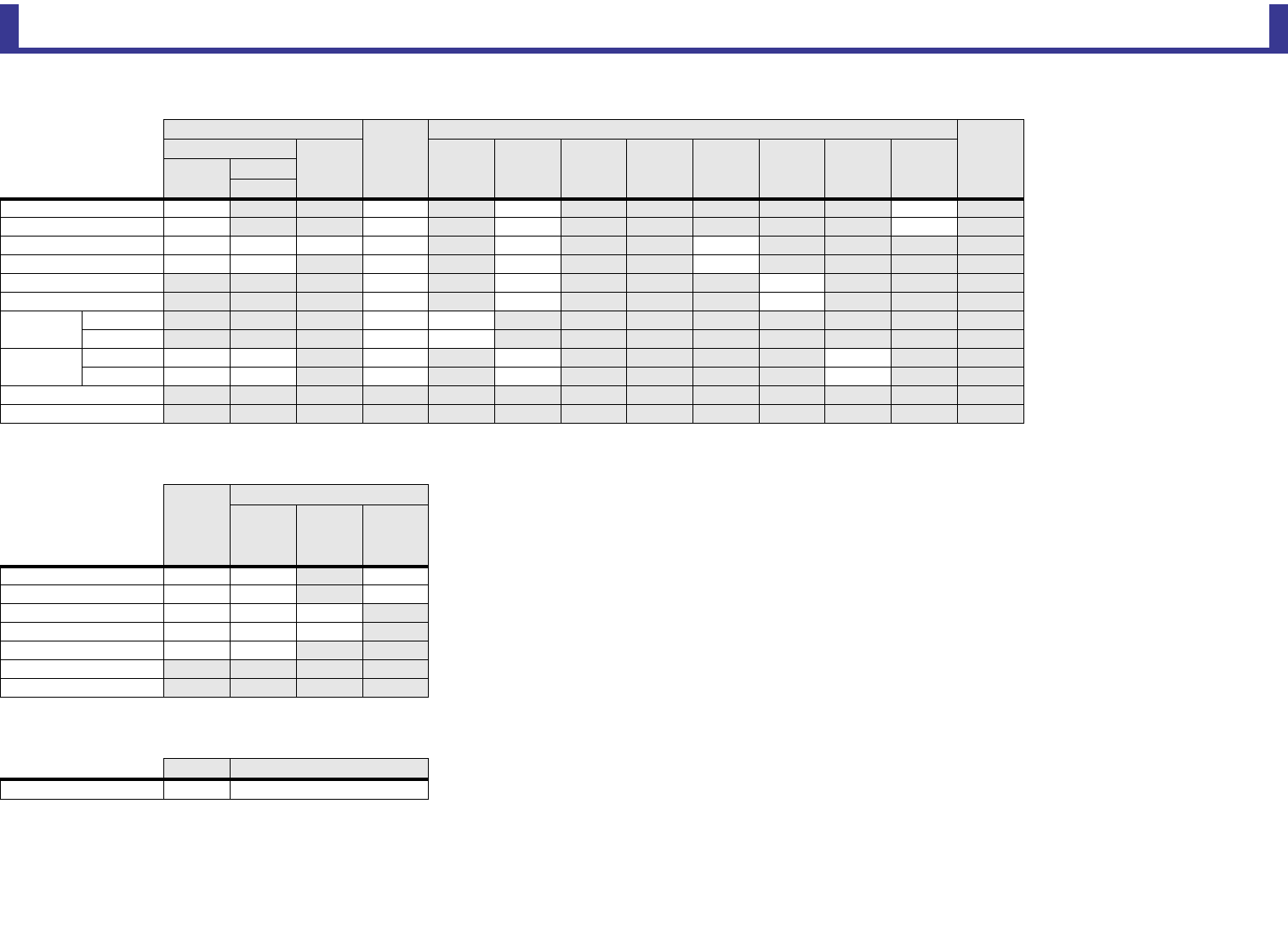
Reference
Reference Manual
TF Series
-
89
-
MATRIX (V2.5 and later)
DCA
OMNI OUT
Channel Library Recall
Scene
Can use Scene Recall Safe
Stereo
Link
Recall CH
Recall EQ With
Send All FX GEQ
Processing
Fader/On Gain/ΦName
(All) (Exclude)
Name
Channel Name O O O O
Category, Color, Icon O O O O
PEQ OOOO O O
DELAY O O O O O
ON O O O
Fader O O O
Send From Level OO
ON OO
OUTPUT Out Gain O O O O O
ΦOO O O O
Recall Safe
CUE
Scene
Can use Scene Recall Safe
All Fader/On Name
Channel Name O O O
Category, Color, Icon O O O
ON OOO
Fader OOO
DCA Assign O O
Recall Safe
CUE
Scene Can use Scene Recall Safe
OMNI OUT Patch O O (All OMNI OUT)
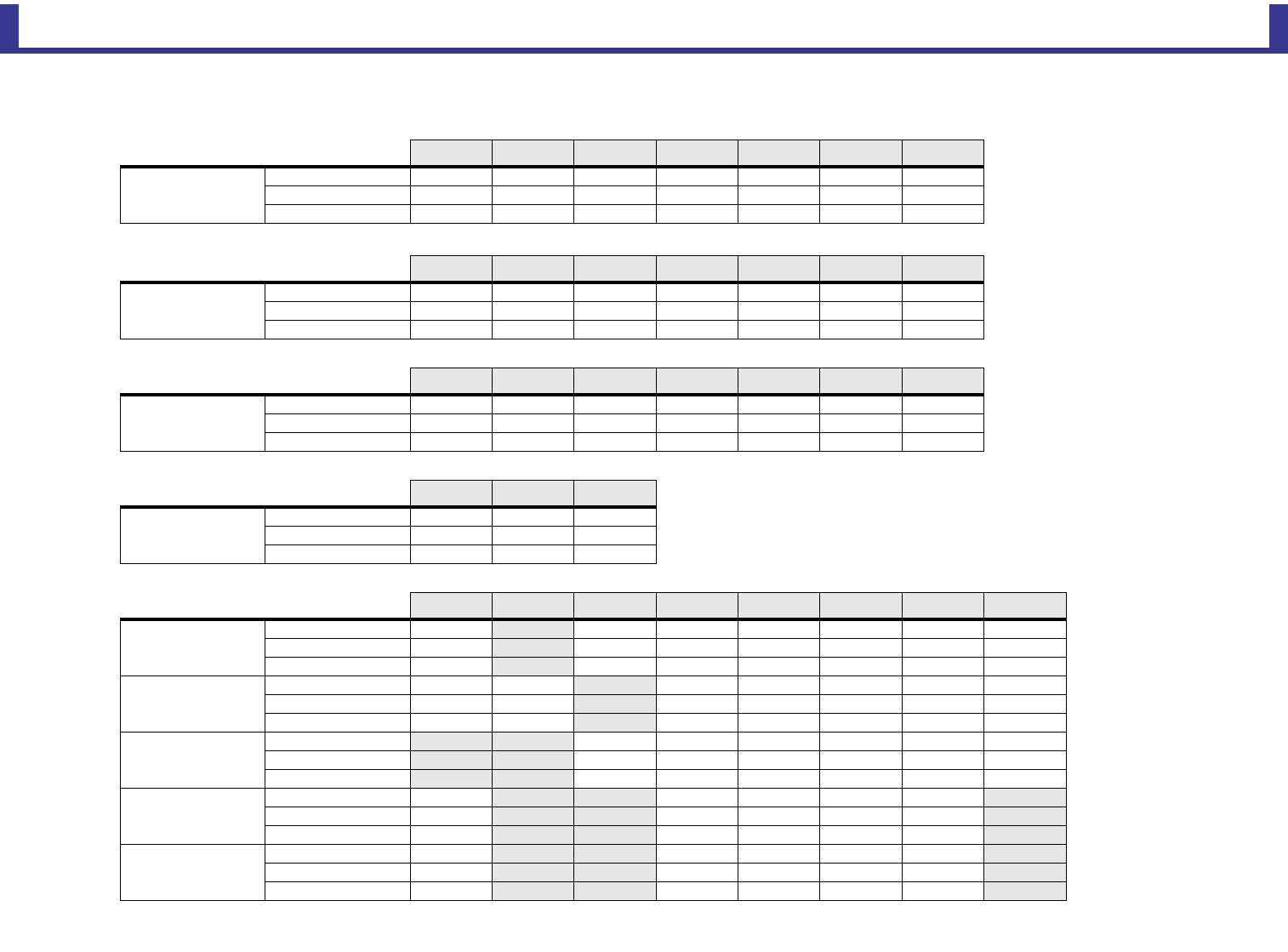
Reference
Reference Manual
TF Series
-
90
-
Access limitation parameter list
CH1-40 HA Input Select Processing Send To Fader/ON Name Other
CH1-40
High Level OOOOOOO
Mid Level OOOOOXO
Low Level XXXXOXX
ST IN HA Input Select Processing Send To Fader/ON Name Other
ST IN 1-2
High Level OOOOOOO
Mid Level O X O O O X O
Low Level XXXXOXX
FX RTN With Send FX Processing Send To Fader/ON Name Other
FX RTN 1-2
High Level OOOOOOO
Mid Level OOOOOX X
Low Level XXXXOXX
DCA Fader/ON Name DCA Assign
DCA 1-8
High Level OOO
Mid Level O X X
Low Level O X X
OUTPUT With Send FX GEQ Processing Fader/ON Gain/ΦName Other
AUX1–8
High Level O – OOOOOO
Mid Level O –OOOXXO
Low Level X –XXOXXX
AUX9/10–19/20
High Level O O – OOOOO
Mid Level O O –OOXXO
Low Level X X –XOXXX
STEREO
High Level –– OOOOOO
Mid Level ––XXOXXX
Low Level ––XXOXXX
SUB
High Level O –– OOOO –
Mid Level O ––XOXX–
Low Level X ––XOXX–
MATRIX1–4
High Level O –– OOOO –
Mid Level X ––XXXX–
Low Level X ––XXXX–
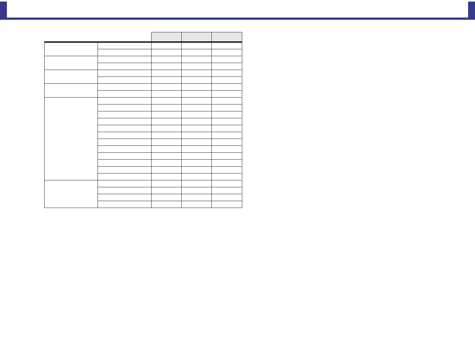
Reference
Reference Manual
TF Series
-
91
-
GENERAL High Level Mid Level Low Level
Scene A Store OOX
Recall OOO
Scene B Store OOX
Recall OOO
Library A Store OOX
Recall OOX
Library B Store OOX
Recall OOX
Setup
+48V Master OXX
Bus Setup OOX
Brightness OOO
Custom Fader Bank OOX
File Load OXX
Network XXX
OMNI OUT Patch OXX
Preference OOO
Recall Safe OXX
Slot Setup OXX
Time XXX
User Defined Control OXX
Other
Monitor Delay OXX
Mute Safe OXX
Oscillator OOX
Stereo Link OOX
Reference
Reference Manual
TF Series
-
92
-
Quick Config Input and input channel relationships
Tio1608-D: TF INPUT SLOT: TF INPUT CHANNEL TF OUTPUT CHANNEL: SLOT Tio1608-D: TF OUTPUT
Tio1608-D UNIT ID 1: INPUT1 SLOT IN 1 CH1 Input Select CH1 Direct Out SLOT OUT 1 No connection
Tio1608-D UNIT ID 1: INPUT2 SLOT IN 2 CH2 Input Select CH2 Direct Out SLOT OUT 2 No connection
Tio1608-D UNIT ID 1: INPUT3 SLOT IN 3 CH3 Input Select CH3 Direct Out SLOT OUT 3 No connection
Tio1608-D UNIT ID 1: INPUT4 SLOT IN 4 CH4 Input Select CH4 Direct Out SLOT OUT 4 No connection
Tio1608-D UNIT ID 1: INPUT5 SLOT IN 5 CH5 Input Select CH5 Direct Out SLOT OUT 5 No connection
Tio1608-D UNIT ID 1: INPUT6 SLOT IN 6 CH6 Input Select CH6 Direct Out SLOT OUT 6 No connection
Tio1608-D UNIT ID 1: INPUT7 SLOT IN 7 CH7 Input Select CH7 Direct Out SLOT OUT 7 No connection
Tio1608-D UNIT ID 1: INPUT8 SLOT IN 8 CH8 Input Select CH8 Direct Out SLOT OUT 8 No connection
Tio1608-D UNIT ID 1: INPUT9 SLOT IN 9 CH9 Input Select CH9 Direct Out SLOT OUT 9 No connection
Tio1608-D UNIT ID 1: INPUT10 SLOT IN 10 CH10 Input Select CH10 Direct Out SLOT OUT 10 No connection
Tio1608-D UNIT ID 1: INPUT11 SLOT IN 11 CH11 Input Select CH11 Direct Out SLOT OUT 11 No connection
Tio1608-D UNIT ID 1: INPUT12 SLOT IN 12 CH12 Input Select CH12 Direct Out SLOT OUT 12 No connection
Tio1608-D UNIT ID 1: INPUT13 SLOT IN 13 CH13 Input Select CH13 Direct Out SLOT OUT 13 No connection
Tio1608-D UNIT ID 1: INPUT14 SLOT IN 14 CH14 Input Select CH14 Direct Out SLOT OUT 14 No connection
Tio1608-D UNIT ID 1: INPUT15 SLOT IN 15 CH15 Input Select CH15 Direct Out SLOT OUT 15 No connection
Tio1608-D UNIT ID 1: INPUT16 SLOT IN 16 CH16 Input Select CH16 Direct Out SLOT OUT 16 No connection
Tio1608-D UNIT ID 2: INPUT1 SLOT IN 17 CH17 Input Select CH17 Direct Out SLOT OUT 17 No connection
Tio1608-D UNIT ID 2: INPUT2 SLOT IN 18 CH18 Input Select CH18 Direct Out SLOT OUT 18 No connection
Tio1608-D UNIT ID 2: INPUT3 SLOT IN 19 CH19 Input Select CH19 Direct Out SLOT OUT 19 No connection
Tio1608-D UNIT ID 2: INPUT4 SLOT IN 20 CH20 Input Select CH20 Direct Out SLOT OUT 20 No connection
Tio1608-D UNIT ID 2: INPUT5 SLOT IN 21 CH21 Input Select CH21 Direct Out SLOT OUT 21 No connection
Tio1608-D UNIT ID 2: INPUT6 SLOT IN 22 CH22 Input Select CH22 Direct Out SLOT OUT 22 No connection
Tio1608-D UNIT ID 2: INPUT7 SLOT IN 23 CH23 Input Select CH23 Direct Out SLOT OUT 23 No connection
Tio1608-D UNIT ID 2: INPUT8 SLOT IN 24 CH24 Input Select CH24 Direct Out SLOT OUT 24 No connection
Tio1608-D UNIT ID 2: INPUT9 SLOT IN 25 CH25 Input Select CH25 Direct Out SLOT OUT 25 No connection
Tio1608-D UNIT ID 2: INPUT10 SLOT IN 26 CH26 Input Select CH26 Direct Out SLOT OUT 26 No connection
Tio1608-D UNIT ID 2: INPUT11 SLOT IN 27 CH27 Input Select CH27 Direct Out SLOT OUT 27 No connection
Tio1608-D UNIT ID 2: INPUT12 SLOT IN 28 CH28 Input Select CH28 Direct Out SLOT OUT 28 No connection
Tio1608-D UNIT ID 2: INPUT13 SLOT IN 29 CH29 Input Select CH29 Direct Out SLOT OUT 29 No connection
Tio1608-D UNIT ID 2: INPUT14 SLOT IN 30 CH30 Input Select CH30 Direct Out SLOT OUT 30 No connection
Tio1608-D UNIT ID 2: INPUT15 SLOT IN 31 CH31 Input Select CH31 Direct Out SLOT OUT 31 No connection
Tio1608-D UNIT ID 2: INPUT16 SLOT IN 32 CH32 Input Select CH32 Direct Out SLOT OUT 32 No connection
Tio1608-D UNIT ID 3: INPUT1*1 SLOT IN 33 CH33 Input Select*1 AUX1 Output SLOT OUT 33 Tio1608-D UNIT ID 1: OUTPUT1
Tio1608-D UNIT ID 3: INPUT2*1 SLOT IN 34 CH34 Input Select*1 AUX2 Output SLOT OUT 34 Tio1608-D UNIT ID 1: OUTPUT2
Tio1608-D UNIT ID 3: INPUT3*1 SLOT IN 35 CH35 Input Select*1 AUX3 Output SLOT OUT 35 Tio1608-D UNIT ID 1: OUTPUT3
Tio1608-D UNIT ID 3: INPUT4*1 SLOT IN 36 CH36 Input Select*1 AUX4 Output SLOT OUT 36 Tio1608-D UNIT ID 1: OUTPUT4
Tio1608-D UNIT ID 3: INPUT5*1 SLOT IN 37 CH37 Input Select*1 AUX5 Output SLOT OUT 37 Tio1608-D UNIT ID 1: OUTPUT5
Tio1608-D UNIT ID 3: INPUT6*1 SLOT IN 38 CH38 Input Select*1 AUX6 Output SLOT OUT 38 Tio1608-D UNIT ID 1: OUTPUT6
Tio1608-D UNIT ID 3: INPUT7*1 SLOT IN 39 CH39 Input Select*1 AUX7 Output SLOT OUT 39 Tio1608-D UNIT ID 2: OUTPUT1
Tio1608-D UNIT ID 3: INPUT8*1 SLOT IN 40 CH40 Input Select*1 AUX8 Output SLOT OUT 40 Tio1608-D UNIT ID 2: OUTPUT2
*1 No connection for TF1, TF-RACK.
Reference
Reference Manual
TF Series
-
93
-
* When quick config is turned off, this table also applies for mixer SLOT channels.
No connection SLOT IN 41 No connection AUX9 Output SLOT OUT 41 Tio1608-D UNIT ID 2: OUTPUT3
No connection SLOT IN 42 No connection AUX10 Output SLOT OUT 42 Tio1608-D UNIT ID 2: OUTPUT4
No connection SLOT IN 43 No connection AUX11 Output SLOT OUT 43 Tio1608-D UNIT ID 2: OUTPUT5
No connection SLOT IN 44 No connection AUX12 Output SLOT OUT 44 Tio1608-D UNIT ID 2: OUTPUT6
No connection SLOT IN 45 No connection AUX13 Output SLOT OUT 45 Tio1608-D UNIT ID 3: OUTPUT1
No connection SLOT IN 46 No connection AUX14 Output SLOT OUT 46 Tio1608-D UNIT ID 3: OUTPUT2
No connection SLOT IN 47 No connection AUX15 Output SLOT OUT 47 Tio1608-D UNIT ID 3: OUTPUT3
No connection SLOT IN 48 No connection AUX16 Output SLOT OUT 48 Tio1608-D UNIT ID 3: OUTPUT4
No connection SLOT IN 49 No connection AUX17 Output SLOT OUT 49 Tio1608-D UNIT ID 3: OUTPUT5
No connection SLOT IN 50 No connection AUX18 Output SLOT OUT 50 Tio1608-D UNIT ID 3: OUTPUT6
No connection SLOT IN 51 No connection AUX19 Output SLOT OUT 51 Tio1608-D UNIT ID 3: OUTPUT7
No connection SLOT IN 52 No connection AUX20 Output SLOT OUT 52 Tio1608-D UNIT ID 3: OUTPUT8
No connection SLOT IN 53 No connection MATRIX1 OUT (V2.5 and later) SLOT OUT 53 No connection
No connection SLOT IN 54 No connection MATRIX2 OUT (V2.5 and later) SLOT OUT 54 No connection
No connection SLOT IN 55 No connection MATRIX3 OUT (V2.5 and later) SLOT OUT 55 No connection
No connection SLOT IN 56 No connection MATRIX4 OUT (V2.5 and later) SLOT OUT 56 No connection
No connection SLOT IN 57 No connection STEREO L Output SLOT OUT 57 Tio1608-D UNIT ID 1: OUTPUT7,
Tio1608-D UNIT ID 2: OUTPUT7
No connection SLOT IN 58 No connection
No connection SLOT IN 59 No connection STEREO R Output SLOT OUT 58 Tio1608-D UNIT ID 1: OUTPUT8
Tio1608-D UNIT ID 2: OUTPUT8
No connection SLOT IN 60 No connection
No connection SLOT IN 61 No connection SUB Output SLOT OUT 59 No connection
No connection SLOT IN 62 No connection No connection SLOT OUT 60 No connection
No connection SLOT IN 63 ST IN 2L Input Select MONITOR L Output SLOT OUT 61 No connection
No connection SLOT IN 64 ST IN 2R Input Select MONITOR R Output SLOT OUT 62 No connection
No connection SLOT OUT 63 No connection
No connection SLOT OUT 64 No connection
Tio1608-D: TF INPUT SLOT: TF INPUT CHANNEL TF OUTPUT CHANNEL: SLOT Tio1608-D: TF OUTPUT
Reference
Reference Manual
TF Series
-
94
-
Warnings and error messages
Message Description
Item Already Exists. Replace it? Displayed when you are about to store (overwrite) a Library.
File Already Exists, Replace it?
When using Save As, the name of the file you tried to save was the
same name as an existing file.
Displayed when you are about to save (overwrite) data.
Exceed Maximum Number!
Library A:XXXX items, Library B:XXXX
items
The Library exceeds the maximum number of items and cannot be
loaded.
File System is Not Ready. This
Operation can Overwrite Existing Files
or Directories.
You tried to start recording immediately after connecting a USB storage
device (i.e., while a list was being generated). You tried to change the
name of a file or directory.
Over Current Error! This USB Device is
Not Supported. Please Disconnect.
The USB device was disconnected because overcurrent was detected in
the USB connection.
Tio OUTPUT is in Use by Another TF.
"with OUTPUT" in Quick Config is
Turned off.
The OUTPUT of the Tio1608-D is already in use by a console using
Quick Config, therefore the "with OUTPUT" in Quick Config was turned
off for this console.
Operation Failed!
An error occurred during the operation. (This is a general error.)
Less severe than "Unknown".
(Between "Unknown" and "Ignore".)
Invalid Name! Name violates naming convention.
Operation Ignored.
The feature assigned to the knob was not operated. The operation had
no effect.
This message refers to Tips operations for User Defined Knobs.
This message is displayed when the feature assigned to a User Defined
Knob cannot be operated.
SCENE #XX is Empty! No data is stored in the Scene you tried to recall, or the data is
damaged.
SCENE #XX is Read Only! You tried to overwrite a Scene that is write-protected.
Cannot Store! Could not save the data in the Scene memory or in the Library.
Cannot Recall! Could not recall the data from the Scene memory or from the Library.
Operation Failed. Library X Memory
Full.
You tried to add data when the memory was full.
A or B will be entered into X.
Wrong Word Clock! (Slot) The sample rate setting of the NY64-D is incorrect, therefore it cannot
sync with the console.
Turn Off 1-knob Mode to Adjust. 1-knob mode is enabled; turn 1-knob mode off.
Nothing to Paste! You tried to paste data when the copy buffer was empty.
Cannot Bookmark This Screen. You tried to bookmark a screen that cannot be bookmarked.
Page Does not Exist.
Cannot Close This Popup.
Not Bookmarked. The item is not bookmarked.
File Busy! Operation Denied. The operation could not be performed because the USB memory was
being accessed.
Unsupported File Format! You tried to read an unsupported file format from the USB memory.
Storage Not Found! The USB memory could not be recognized.
Couldn't Write File. The file could not be saved to the USB memory.
File Protected! Could not overwrite the file on the USB memory because the file is
write-protected.
Already Exists!
The name of the directory you tried to create matches the name of an
existing directory.
This message may also be displayed when editing a file or directory
name.
Couldn't Access File. Could not access the file on the USB memory for some reason.
File Error! An internal file access error occurred.
Format Error! An error occurred during formatting.
USB Storage Unmounted! Recorder
Stopped.
Recording stopped because the USB memory was removed during
recording.
USB Storage Full! Recorder Stopped. Recording stopped because the USB memory became full during
recording.
Maximum Number of Audio Files
Exceeded! The number of files supported by the USB recorder was exceeded.
USB Storage Busy: Recorder Stopped! Recording or playback stopped because time is required for a USB
storage device process.
Illegal Storage Format! Format USB
Device with the Other USB Port.
A USB memory device with an allocation unit size under 4096 bytes
was connected. If you record in this situation, the format may become
damaged.
Low Battery! The backup battery's voltage is low.
Illegal IP Address! The IP address setting or gateway setting is incorrect.
USB Sample Rate Mismatch on USB.
Console:44100Hz
The same rates of the console and the computer that is connected to
the USB TO HOST connector are different. (Console: 44.1 kHz, PC; 48
kHz)
Set the sample rate of the computer to 44.1 kHz.
USB Sample Rate Mismatch on USB.
Console:48000Hz
The same rates of the console and the computer that is connected to
the USB TO HOST connector are different. (Console: 48kHz, PC;
44.1kHz)
Set the sample rate of the computer to 48kHz.
Two or More Devices Have Same Unit
ID!
Two or more devices connected to the NY64-D via the Dante network
have the same UNIT ID.
Dante Module Error! An error occurred with the Dante module of the NY64-D or Tio1608-D.
Illegal Dante Module MAC Address! The MAC address of the NY64-D is damaged and communication is not
possible.
Dante Module Memory Error! An memory error occurred with the Dante module of the Tio1608-D.
Dante Audio Resource Overflow An excessive amount of audio data was sent over the Dante network
connected to the NY64-D.
Message Description
Reference
Reference Manual
TF Series
-
95
-
Under Synchronization
Settings are bring performed for a Tio1608-D on the Dante network
connected to the NY64-D.
When the Tio1608-D is in Resume mode, this message may be
displayed continuously on the SLOT SETUP screen. This is not a
malfunction.
Wrong Word Clock! (Dante Device)
The sample rate setting of a device on the Dante network connected to
the NY64-D is incorrect, therefore the device cannot sync to the NY64-
D.
Linked at 10/100Mbps. Check Cables
or Switches.
A switch or cable that does not support Gigabit Ethernet is connected
to the Dante network connected to the NY64-D.
Error on the Dante Primary Port When using a redundancy network, an error has occurred on the
PRIMARY network and the SECONDARY network is being used.
Error on the Dante Secondary Port When using a redundancy network, an error has occurred on the
SECONDARY network.
Dante Patch or Setting Modified A setting that is different from the values determined by Quick Config
has been set, perhaps by Dante Controller.
Dante Setting Mismatch
The UNIT ID switch on the Tio1608-D panel does not match the actual
unit ID. This is displayed when you change the Tio1608-D's UNIT ID
while the Tio1608-D is locked using Dante Device Lock, or when you
change the switch after turning the unit on.
Restart Tio to Complete Quick Config The Tio1608-D Device Config or other settings do not equal Quick
Config values. Restart the Tio1608-D.
No Option Card Installed
There is no NY64-D card installed in the expansion slot.
This message is displayed when the Quick Config button is ON and
there is no NY64-D card installed.
TF Controls First 24 Dante Devices
Found
The maximum number of I/O Racks (Tio1608-D, R series, etc.) on the
Dante network connected to the NY64-D has been exceeded.
TF Controls HAs of Maximum of
8 Dante Devices
The maximum number of Dante devices with HA on the Dante network
connected to the NY64-D has been exceeded.
Unknown Option Card Installed! An unsupported card has been found in the console's expansion slot.
Overcurrent Detected (Slot) Overcurrent was detected in the card installed in the expansion slot.
Slot Communication Error! A communication error occurred in the card installed in the expansion
slot.
Dante Module Restarted! The Dante module of the NY64-D was restarted.
Dante Setting Error! Please Restart the
Console.
An error occurred in the Dante module of the NY64-D that requires you
to restart the console.
If this message is displayed, restart the console.
Dante I/O Device Disconnected A Dante device was disconnected from the NY64-D.
Two or More HA Controllers may
Cause Conflict
More than one device on the Dante network can control the same
device's HA, therefore operational conflicts may occur.
This message is displayed every time the HA Control on the SLOT
SETUP screen is turned on, but it does not indicate a malfunction.
Message Description
Dante devices are locked. Use Dante
Controller to unlock devices.
This is displayed when you touch the Quick Config button while the
Tio1608-D or NY64-D are locked using Dante Device Lock. In this case,
patching is not performed automatically by Quick Config, but it does
not indicate a malfunction. Dante Controller (v3.10.0.19 and later) is
required to unlock the devices.
Permission Denied! The user does not have permission to perform the operation, therefore
the operation was ignored.
Operation ignored, you are not
logged-in. The user is not logged in, therefore the operation cannot be performed.
Incorrect password entered. The password that was entered is incorrect.
Message Description

Index
Reference Manual
TF Series
-
96
-
Index
Numerics
1-knob COMP.................................. 55
1-knob EQ ....................................... 50
Intensity ....................................... 50
Loudness ..................................... 50
Vocal............................................ 50
A
ACCESS PERMISSION screen ...... 39
ASSIGN screen ............................... 63
Audio file.......................................... 14
Auto CH Select................................ 28
AUX1–AUX8 channels .................... 43
AUX9/10–19/20 channels................ 43
AUX9/10–AUX19/20.......................... 7
C
CH STRIP section ........................... 42
CH VIEW screen ............................. 64
Channel Color Calibration screen ... 83
COMP screen.................................. 55
Configuration screens ................. 5, 47
CUE................................................. 18
CUSTOM FADER BANK screen
menu .............................................. 34
D
Daylight saving time
(summer time)................................ 36
DCA ASSIGN screen ...................... 76
DCA group....................................... 76
DELAY screen................................. 78
Digital gain....................................... 48
Direct out ......................................... 65
Displaying configuration screens..... 11
E
EQ screen ....................................... 49
EQ screen menu ............................. 53
F
Fader Calibration screen................. 82
FADER section ............................... 44
File information ............................... 17
Footswitch....................................... 31
FX screen (FX1/2, InsFX1–6) ......... 57
G
GainFinder ...................................... 47
GATE screen .................................. 53
Gateway.......................................... 36
GEQ screen .................................... 72
Group channels............................... 44
I
Initialize (internal memory).............. 79
Initialize (NY64-D)........................... 80
Initialize All Memory screen ............ 79
Initialize Current Memory screen .... 80
Input channels................................. 42
Input Port Trim screen .................... 81
INPUT screen ................................. 47
Internal clock................................... 36
IP address....................................... 36
K
Keyboard screen............................. 10
L
Level meter ..................................... 13
Library ............................................... 8
Library screen ................................... 8
License information......................... 38
LOGIN screen ................................. 38
M
Maintenance screen........................ 79
MATRIX1–MATRIX4 channels ....... 43
Menu ............................................... 10
METER screen................................ 13
Metering point ................................. 13
Monitor ............................................ 18
MONITOR screen ........................... 18
MP3................................................. 14
O
OMNI OUT....................................... 22
OMNI OUT screen menu................. 22
Oscillator.......................................... 20
Output Port Trim screen .................. 81
OUTPUT screen .............................. 74
OVERVIEW screen ......................... 42
OVERVIEW screen operations........ 44
P
Peak Hold ........................................ 13
Phantom power ............................... 48
Phase .............................................. 48
PHONES jack .................................. 19
Playback .......................................... 14
Playback mode ................................ 17
Preset ................................................ 8
R
Recall on/off checkboxes................... 8
RECORDER screen (INPUT/
OUTPUT/TITLE LIST screen) ........ 14
RECORDER screen menu .............. 18
Recording ........................................ 14
RTA display ..................................... 72
S
SAVE/LOAD screen menu .............. 26
Scene .............................................. 11
SCENE screen ................................ 11
SCENE screen menu ...................... 13
SEND FROM screen ....................... 75
Send pan ......................................... 75
SEND TO AUX screen .................... 62
SETUP screen................................. 21
Stereo channels............................... 42
Stereo link........................................ 47
SUB channels.................................. 43
Subnet mask.................................... 36
T
Time stamp...................................... 37
Toolbar ............................................ 11
U
USER ACCOUNT screen................ 39
USER DEFINED KEYS................... 29
USER DEFINED KNOBS................ 29
V
Version information ......................... 38
W
Warnings and error messages ........ 94
WAV ................................................ 14

Index
Reference Manual
TF Series
-
97
-
IOperations and
settings
A
Access
Applying access permissions ...... 40
B
Button and slider operations............ 10
C
Checking the input signals .............. 19
Copying and pasting channel
settings........................................... 45
CUSTOM FADER BANK
Recalling...................................... 34
Custom fader bank
Configuring .................................. 34
D
DCA groups
Assigning channels...................... 77
E
Editing a Preset ................................. 9
Editing a Scene ............................... 12
EQ
1-knob EQ mode ......................... 51
GEQ............................................. 73
HPF ............................................. 52
LPF .............................................. 52
Manual mode............................... 51
F
Feature assignments
Assigning to footswitch ................ 33
Assigning to [USER DEFINED
KEYS] .......................................... 32
Assigning to [USER DEFINED
KNOBS] ....................................... 33
P
Playback
Files on USB storage device ....... 18
R
Recall safe
Using recall safe.......................... 25
Recalling a Preset............................. 9
Recalling a Scene ........................... 12
Recording
Recording.................................... 17
S
Setting
Adjust the send level ................... 75
Channel colors ............................ 83
Compressor................................. 56
Effects ......................................... 58
Fader calibration ......................... 82
Gate ............................................ 54
Input ............................................ 15
Insert effects................................ 58
Oscillator ..................................... 20
Output ......................................... 16
PREFERENCE screen................ 29
SEND FROM level ...................... 75
SEND TO AUX level ................... 63
Stereo link, input source.............. 48
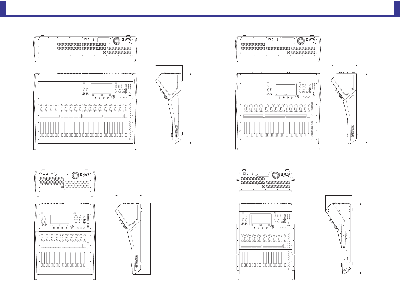
Product dimensions
Reference Manual
TF Series
-
98
-
Product dimensions
224
599
480
225
599
510
716
225
599
866
225
599
TF5 TF3
TF1 TF1 rack mount (14U)
Unit: mm
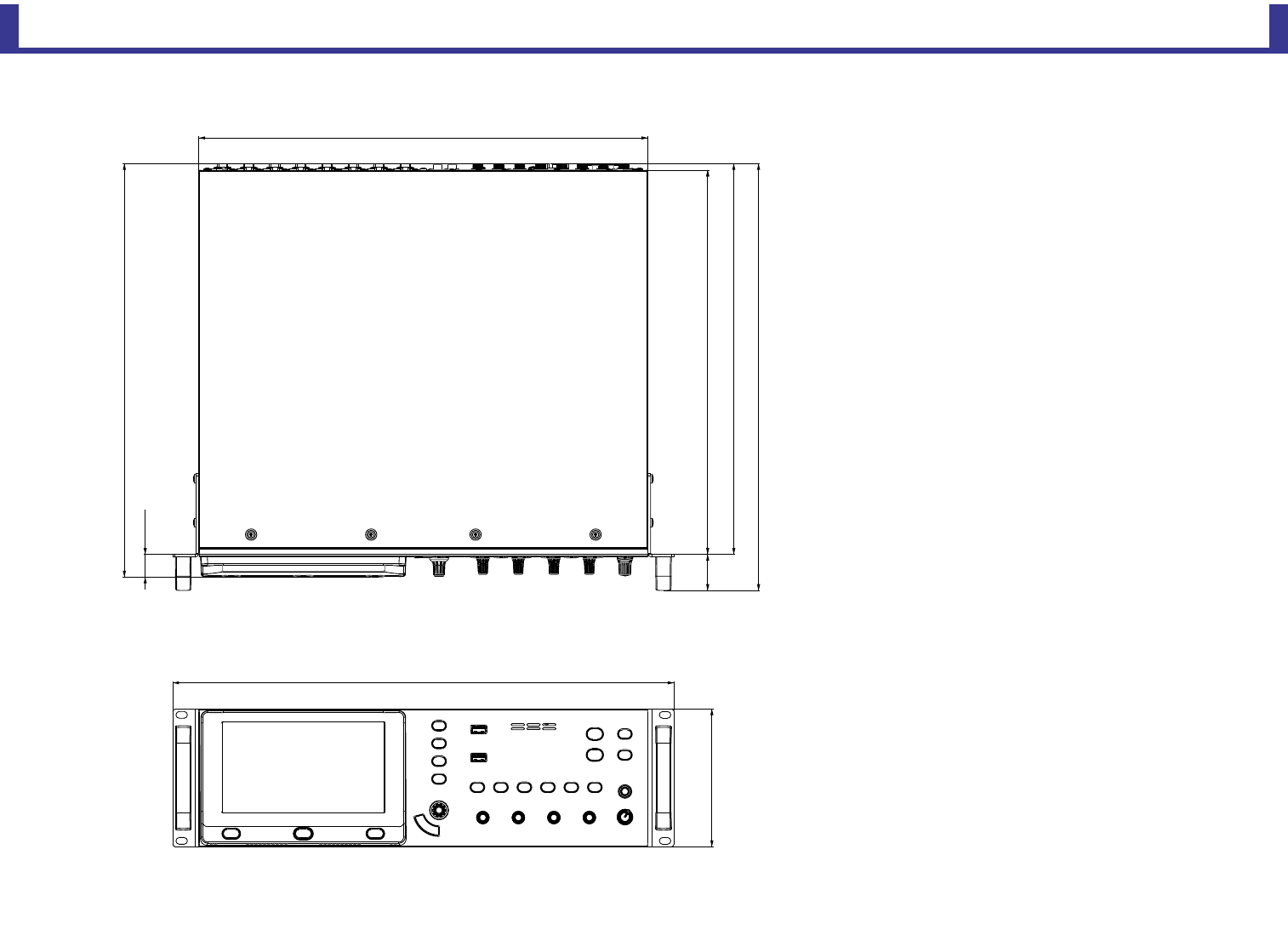
Product dimensions
Reference Manual
TF Series
-
99
-
132
480
374
409
430
368
35
22
396
TF-RACK
Unit: mm
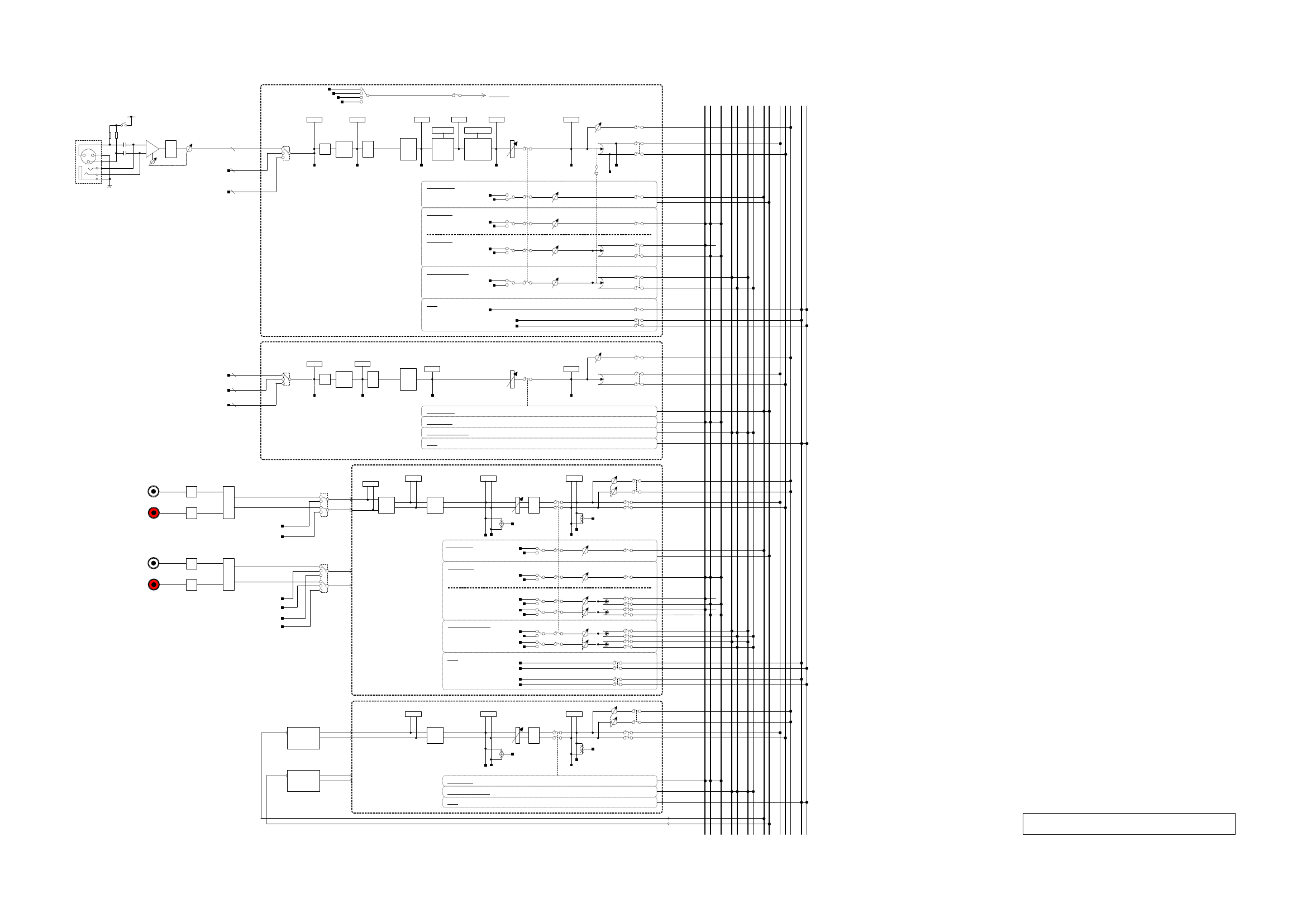
$'
0(7(5
3UH'*
*$,175,0
',*,7$/
*$,1
䃅
0(7(5
3UH+3)
+3) %$1'
(4
0(7(5
(4287
*$7( &203
*50(7(5 *50(7(5
0(7(5
*$7(287
0(7(5
&203287
3UH+3) 3UH)$'(5
21
0(7(5
3RVW)$'(5
3RVW)$'(5
3$1 67
,1387
6(/(&7
3UH)$'(5
3RVW)$'(5
);
21 6(1'
72););
3UH)$'(5
3RVW)$'(5
$8;
21
72$8;
3UH)$'(5
3RVW)$'(5
$8;
21 6(1'
72$8;
$8;67(5(2
3$1
68%
68%/(9(/
3UH)$'(5
&8(
3UH'*
3UH+3)
3UH)$'(5
3RVW)$'(5
',5(&7287
);
6/27,1
3RVW(4
&+
3UH'*
);
3$1/,1.
3UH)$'(5
3RVW)$'(5
$8;
21 6(1'
72$8;
3$1
67,1
',*,7$/
*$,1
%$1'
(4
0(7(5
3UH(4
3UH)$'(5/
)$'(5'&$
21
0(7(5
(4287
%$/
3UH)$'(55
3UH)$'(5/5
3RVW)$'(55
3RVW)$'(5/
3RVW)$'(5/5
67
$8;0212
$8;
21 6(1'
72$8;
3UH)$'(5/5
3RVW)$'(5/5
$8;67(5(2
&8(
3UH)$'(5/
3RVW)$'(5/
3UH)$'(55
3RVW)$'(55
$8;
3$16(1'21
3UH)$'(5/
3RVW)$'(5/
3UH)$'(55
3RVW)$'(55
$8;
3$16(1'21
72$8;
);571
%$1'
(4
0(7(5
3UH(4
3UH)$'(5/
)$'(5'&$
21
0(7(5
(4287
%$/
3UH)$'(55
3UH)$'(5/5
3RVW)$'(55
3RVW)$'(5/
3RVW)$'(5/5
67
6DPHDV67,1
72$8;
6DPHDV67,1
72$8;
)$'(5'&$
6(1'
'&$&8(䠅
3RVW3$1/
3RVW3$15
$8;
$8;
$8;
$8;
$8;
$8;
$8;
$8;
21
86%287
0(7(5
3UH'* 0(7(5
3267)$'(5
0(7(5
3267)$'(5
&8(
&8(
3UH)$'(5/
3UH)$'(55
3RVW)$'(5/
3RVW)$'(55
'&$&8(䠅
6DPHDV67,1
&8(
72););
);
21 6(1'
3UH)$'(5/5
3RVW)$'(5/5
67/
675
68%
);
);
$8;
$8;
$8;
$8;
$8;
$8;
$8;
&8(/
&8(5
$8;0212
&20%2-$&.
9
3RVW3$1/
3RVW3$15
86%,1
68%
68%/(9(/
68%
68%/(9(/
0(7(5
3UH'*
',*,7$/
*$,1
䃅
0(7(5
3UH+3)
%$1'
(4
0(7(5
(4287
3UH+3)
)$'(5'&$
21
0(7(5
3RVW)$'(5
3RVW)$'(5
3$1 67
,1387
6(/(&7
68%
68%/(9(/
35()$'(53UH'*
6DPHDV&+
72););
6DPHDV&+
72$8;
6DPHDV&+72$8;
6DPHDV&+&8(
&+7)7)
86%,1
,13877)
,13877) +3)
6/27,1
,13877)
,13877)
,13877)
>,1387@7)
>,1387@7)
>,1387@7)
$'
G%9
%$
%$
$'
3/$<%$&.5
%$
%$
>67,1@
G%9
>67,1@
3/$<%$&./
,13876(/(&7
67,1/
67,15
86%,1
86%,1
,13876(/(&7
67,1/
67,15
6/27,1
6/27,1
7)0L[HU%ORFN'LDJUDP
Block diagram
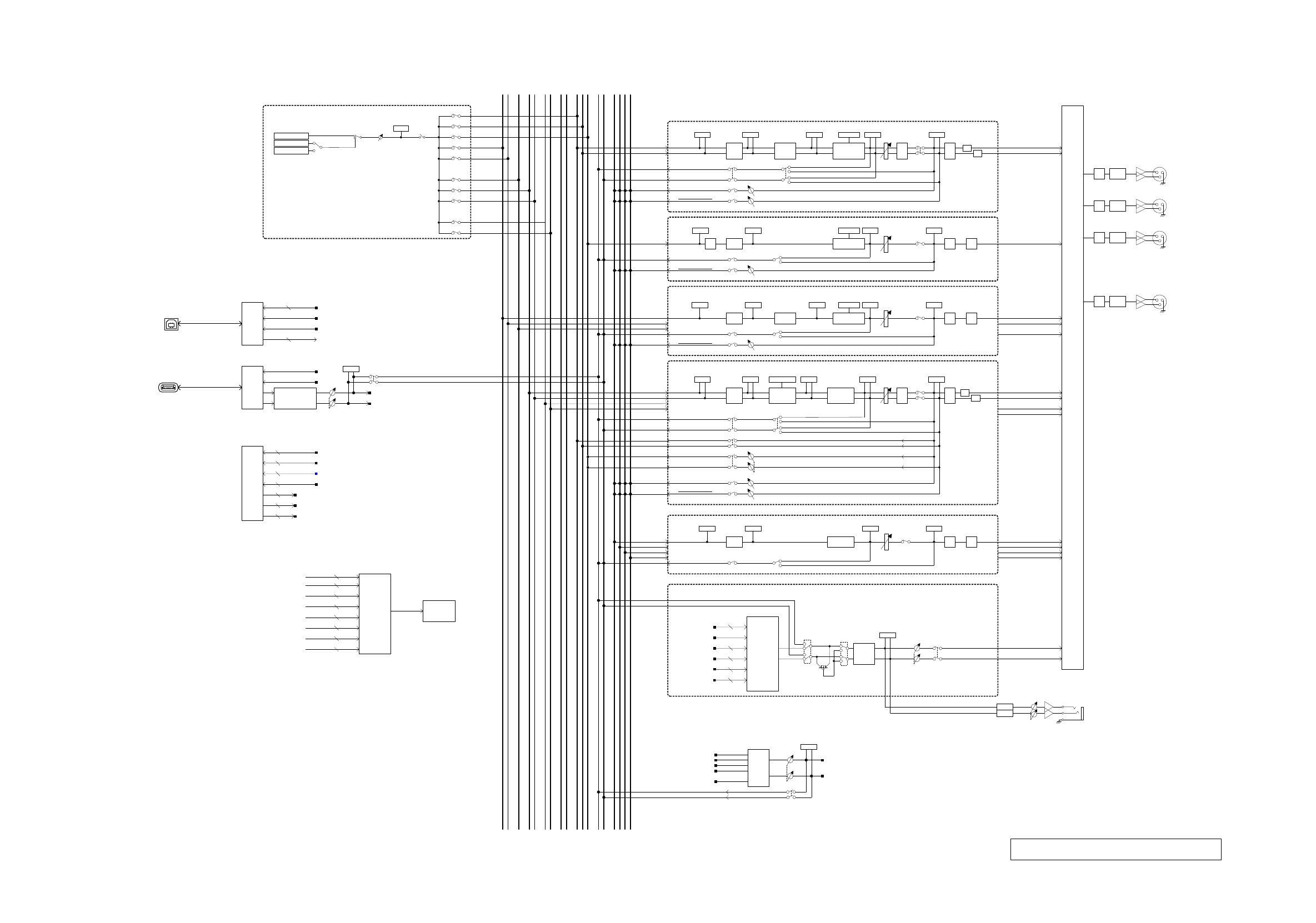
>3+21(6@
021,725/(9(/
/(9(/ 21
3LQN1RLVH
%XUVW1RLVH
0(7(5
26&
26&,//$725
6LQH:DYH
67/
675
68%
$8;
$8;
$8;
86%
+267
,)
5(&/
5(&5
3/$<%$&./
3/$<%$&.5
>L3DG@
86%,)
>86%72+267@
',5(&7287
5(&/
5(&5
3+21(6/(9(/
021,725
6(/(&7
67(5(2287
68%287
67,1
67,1
3/$<%$&.
86%,1
&8(/2*,& 0(7(5
3/$<%$&./HYHO
'$
'$
86%,1
$8;
$8;
$8;
$8;
201,2873$7&+
&+3UH)$'(5
67,13UH)$'(5
);5713UH)$'(5
$8;3UH)$'(5
$8;3UH)$'(5
6768%3UH)$'(5
,1387
6(/(&725
57$
&8(
'(/$<
0212
0(7(5
21
6DPSOH5DWH
&RQYHUWRU
67/
675
68%
);
);
$8;
$8;
$8;
$8;
$8;
$8;
$8;
&8(/
&8(5
021,725&8(
5(&
6(/(&7
5(&/
5(&5
&8(
5(&/(9(/
0(7(5
67/3UH)$'(5
6753UH)$'(5
$8;3UH)$'(5
$8;3UH)$'(5
$8;3UH)$'(5
67(5(22875
67(5(2287/
68%287
$8;287
$8;287
$8;287
$8;287
$8;287
$8;287
$8;287
021,725287/
021,7252875
6/27
',5(&7287DV6/27287
$8;287DV6/27287
67(5(2287/568%287021,725287
DV6/27287
6/27,1DV&+,1387V
6/27,1DV67,1,1387V
0$75,;287DV6/27287
0$75,;
0$75,;
0$75,;
0$75,;
0$75,;287
0$75,;287
0$75,;287
0$75,;287
0$75,;
6/27,1DV&+,1387V7)7)
&+3UH)$'(57)7)
7)0L[HU%ORFN'LDJUDP
>201,287@
G%X
>201,287@
G%X
>201,287@
G%X
>201,287@
G%X
'$
'$
'$
'$
75,0
75,0
75,0
75,0
%$1'
(4
0(7(5
3UH(4
&203
*50(7(5 )$'(5
21
0(7(5
(4287
%$/
$8;
0(7(5
35()$'(5
0(7(5
3267)$'(5
*$,1
0(7(5
,16(57
())(&7
&203287
䃅
䃅
67(5(2
%$1'
(4
0(7(5
3UH(4
)$'(5 21
0(7(5
(4287
0(7(5
&203287
%$/
&8(
&203
*50(7(5
)OH[*(4
0(7(5
3267)$'(5
0(7(5
*(4287
*$,1 䃅
䃅
68%
/3) %$1'
(4
0(7(5
35(/3)
)$'(5
21
0(7(5
&203287
&8(
&203
*50(7(5 0(7(5
3267)$'(5
0(7(5
(4287
3UH)$'(5
3RVW)$'(5
䃅
*$,1
$8;
%$1'
(4
0(7(5
3UH(4
)$'(5
21
0(7(5
(4287
0(7(5
&203287
&203
*50(7(5 0(7(5
3267)$'(5
0(7(5
*(4287
䃅
*$,1)OH[*(4
&8( 3UH)$'(5/
3UH)$'(55
3RVW)$'(55
3UH)$'(5/
3UH)$'(55 3RVW)$'(5/
720$75,;
0$75,;
0$75,;
720$75,;
6(1'
6(1'
&8( 3UH)$'(5
3RVW)$'(5
720$75,;
0$75,; 6(1'
67
68%
0$75,;
720$75,;
6(1'
0$75,;
)$'(5
21
&8(
0(7(5
3267)$'(5
'(/$<
%$1'
(4
0(7(5
(4287
䃅
*$,1
0(7(5
35()$'(5
3UH)$'(5
3RVW)$'(5
0(7(5
3UH(4
0$75,;
0$75,;
6(1'
6(1'
6(1'
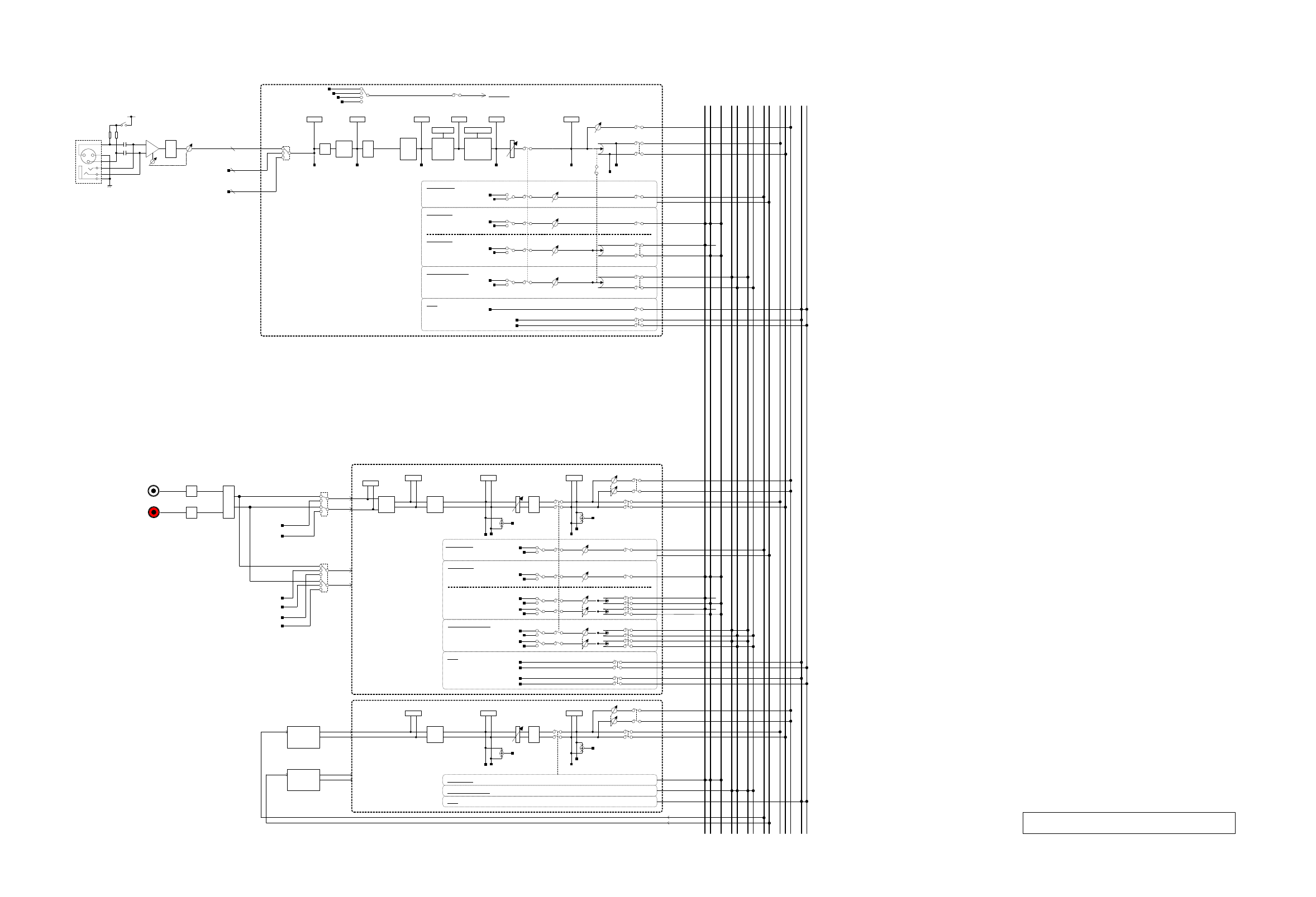
$'
0(7(5
3UH'*
7)5$&.0L[HU%ORFN'LDJUDP
*$,175,0
',*,7$/
*$,1
䃅
0(7(5
3UH+3)
+3) %$1'
(4
0(7(5
(4287
*$7( &203
*50(7(5 *50(7(5
0(7(5
*$7(287
0(7(5
&203287
3UH+3) 3UH)$'(5
21
0(7(5
3RVW)$'(5
3RVW)$'(5
3$1 67
,1387
6(/(&7
3UH)$'(5
3RVW)$'(5
);
21 6(1'
72););
3UH)$'(5
3RVW)$'(5
$8;
21
72$8;
3UH)$'(5
3RVW)$'(5
$8;
21 6(1'
72$8;
$8;67(5(2
3$1
68%
68%/(9(/
3UH)$'(5
&8(
3UH'*
3UH+3)
3UH)$'(5
3RVW)$'(5
',5(&7287
);
$'
G%9
%$
%$
3/$<%$&.5
6/27,1
>67,1@
3RVW(4
3/$<%$&./
,13876(/(&7
&+
3UH'*
);
3$1/,1.
3UH)$'(5
3RVW)$'(5
$8;
21 6(1'
72$8;
3$1
67,1
',*,7$/
*$,1
%$1'
(4
0(7(5
3UH(4
3UH)$'(5/
)$'(5'&$
21
0(7(5
(4287
%$/
3UH)$'(55
3UH)$'(5/5
3RVW)$'(55
3RVW)$'(5/
3RVW)$'(5/5
67
$8;0212
$8;
21 6(1'
72$8;
3UH)$'(5/5
3RVW)$'(5/5
$8;67(5(2
&8(
3UH)$'(5/
3RVW)$'(5/
3UH)$'(55
3RVW)$'(55
$8;
3$16(1'21
3UH)$'(5/
3RVW)$'(5/
3UH)$'(55
3RVW)$'(55
$8;
3$16(1'21
72$8;
);571
%$1'
(4
0(7(5
3UH(4
3UH)$'(5/
)$'(5'&$
21
0(7(5
(4287
%$/
3UH)$'(55
3UH)$'(5/5
3RVW)$'(55
3RVW)$'(5/
3RVW)$'(5/5
67
6DPHDV67,1
72$8;
6DPHDV67,1
72$8;
)$'(5'&$
6(1'
'&$&8(䠅
3RVW3$1/
3RVW3$15
$8;
$8;
$8;
$8;
$8;
$8;
$8;
$8;
21
86%287
0(7(5
3UH'* 0(7(5
3267)$'(5
0(7(5
3267)$'(5
&8(
&8(
3UH)$'(5/
3UH)$'(55
3RVW)$'(5/
3RVW)$'(55
'&$&8(䠅
6DPHDV67,1
&8(
72););
);
21 6(1'
3UH)$'(5/5
3RVW)$'(5/5
67/
675
68%
);
);
$8;
$8;
$8;
$8;
$8;
$8;
$8;
&8(/
&8(5
86%,1
86%,1
,13876(/(&7
$8;0212
&20%2-$&.
9
3RVW3$1/
3RVW3$15
86%,1
6/27,1
6/27,1
68%
68%/(9(/
68%
68%/(9(/
>,1387@
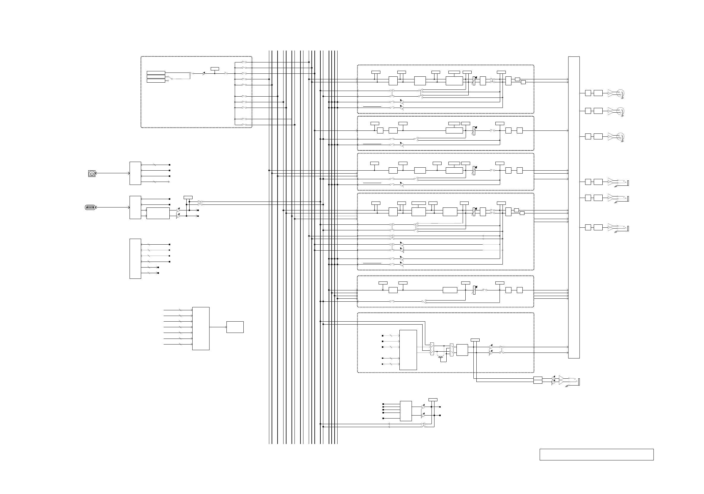
7)5$&.0L[HU%ORFN'LDJUDP
>201,287@
>3+21(6@
021,725/(9(/
/(9(/ 21
3LQN1RLVH
%XUVW1RLVH
0(7(5
26&
26&,//$725
6LQH:DYH
67/
675
68%
$8;
$8;
$8;
86%
+267
,)
5(&/
5(&5
3/$<%$&./
3/$<%$&.5
>L3DG@
86%,)
>86%72+267@
',5(&7287
5(&/
5(&5
G%X
3+21(6/(9(/
021,725
6(/(&7
67(5(2287
68%287
67,1
3/$<%$&.
86%,1
&8(/2*,& 0(7(5
3/$<%$&./HYHO
'$
'$
86%,1
$8;
$8;
$8;
$8;
>201,287@
G%X
>201,287@
G%X
'$
'$
'$
201,2873$7&+
&+3UH)$'(5
67,13UH)$'(5
);5713UH)$'(5
$8;3UH)$'(5
$8;3UH)$'(5
6768%3UH)$'(5
,1387
6(/(&725
57$
&8(
'(/$<
0212
75,0
75,0
75,0
0(7(5
21
6DPSOH5DWH
&RQYHUWRU
%$1'
(4
0(7(5
3UH(4
&203
*50(7(5 )$'(5
21
0(7(5
(4287
%$/
$8;
0(7(5
35()$'(5
0(7(5
3267)$'(5
*$,1
0(7(5
,16(57
())(&7
&203287
䃅
䃅
67/
675
68%
);
);
$8;
$8;
$8;
$8;
$8;
$8;
$8;
&8(/
&8(5
67(5(2
%$1'
(4
0(7(5
3UH(4
)$'(5 21
0(7(5
(4287
0(7(5
&203287
%$/
&8(
&203
*50(7(5
)OH[*(4
0(7(5
3267)$'(5
0(7(5
*(4287
*$,1 䃅
䃅
68%
/3) %$1'
(4
0(7(5
35(/3)
)$'(5
21
0(7(5
&203287
&8(
&203
*50(7(5 0(7(5
3267)$'(5
0(7(5
(4287
3UH)$'(5
3RVW)$'(5
䃅
*$,1
$8;
%$1'
(4
0(7(5
3UH(4
)$'(5
21
0(7(5
(4287
0(7(5
&203287
&203
*50(7(5 0(7(5
3267)$'(5
0(7(5
*(4287
䃅
*$,1)OH[*(4
&8(
3RVW)$'(55
3UH)$'(5/
3UH)$'(55 3RVW)$'(5/
021,725&8(
5(&
6(/(&7
5(&/
5(&5
&8(
5(&/(9(/
0(7(5
67/3UH)$'(5
6753UH)$'(5
$8;3UH)$'(5
$8;3UH)$'(5
$8;3UH)$'(5
67(5(22875
67(5(2287/
68%287
$8;287
$8;287
$8;287
$8;287
$8;287
$8;287
$8;287
021,725287/
021,7252875
6/27
',5(&7287DV6/27287
$8;287DV6/27287
67(5(2287/568%287021,725287
DV6/27287
6/27,1DV&+,1387V
6/27,1DV67,1,1387V
'$75,0
>201,287@
720$75,;
0$75,;
720$75,;
6(1'
&8( 3UH)$'(5
3RVW)$'(5
720$75,;
0$75,; 6(1'
67
0$75,;287DV6/27287
0$75,;
0$75,;
0$75,;
0$75,;
0$75,;287
0$75,;287
0$75,;287
0$75,;287
720$75,;
0$75,;
0$75,;
)$'(5
21
&8(
0(7(5
3267)$'(5
'(/$<
%$1'
(4
0(7(5
(4287
䃅
*$,1
3UH)$'(5
0(7(5
35()$'(5
0(7(5
3UH(4
3RVW)$'(5
0$75,;
6(1'
0$75,;
6(1'
0$75,;
6(1'
68%
0$75,;
6(1'
6(1'
'$75,0
>201,287@
'$75,0
>201,287@

Published 01/2017 CR-F0
© 2015 Yamaha Corporation
Manual Development Group
Yamaha Downloads
http://download.yamaha.com/
Yamaha Pro Audio global website
http://www.yamahaproaudio.com/
Published 01/2017 CR-F0
© 2015 Yamaha Corporation
Manual Development Group
Yamaha Downloads
http://download.yamaha.com/
Yamaha Pro Audio global website
http://www.yamahaproaudio.com/
