Yard King 50565X89 User Manual LAWN TRACTOR Manuals And Guides L0403134
YARD KING Lawn, Tractor Manual L0403134 YARD KING Lawn, Tractor Owner's Manual, YARD KING Lawn, Tractor installation guides
User Manual: Yard King 50565X89 50565X89 YARD KING LAWN TRACTOR - Manuals and Guides View the owners manual for your YARD KING LAWN TRACTOR #50565X89. Home:Lawn & Garden Parts:Yard King Parts:Yard King LAWN TRACTOR Manual
Open the PDF directly: View PDF ![]() .
.
Page Count: 60
f
PFRFORMANCE
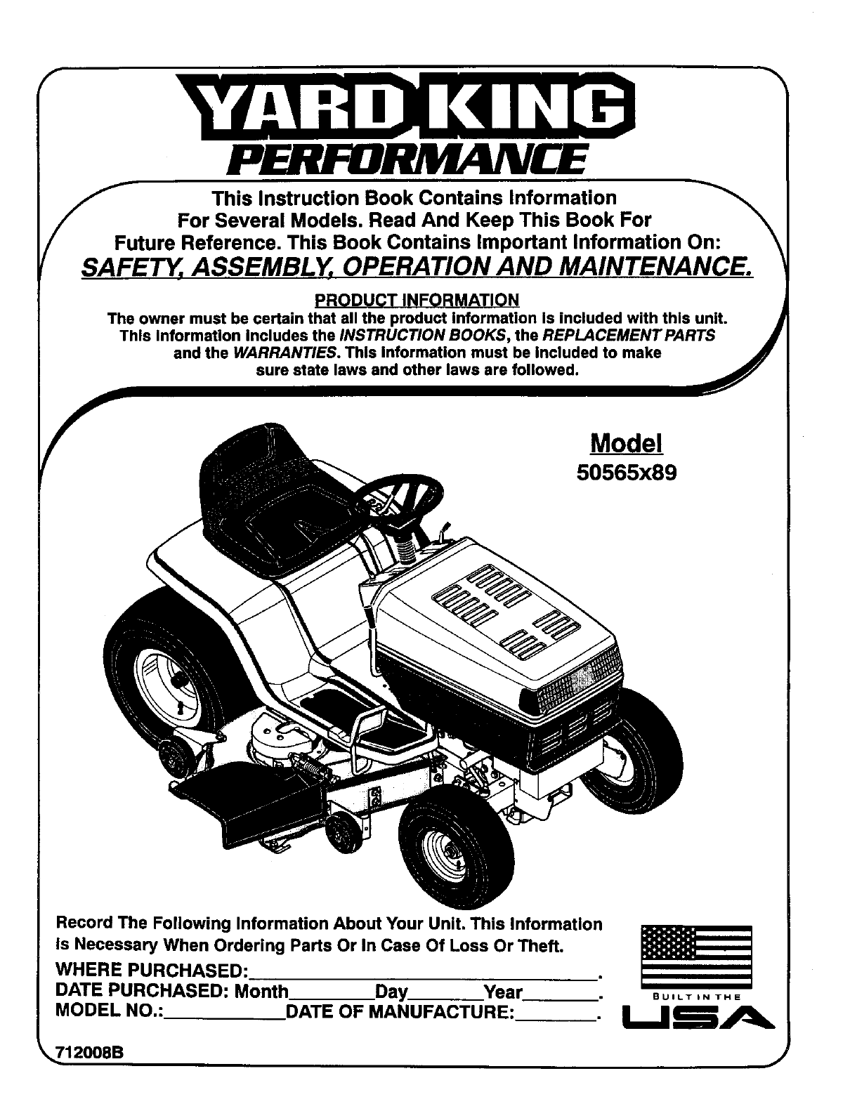
_SA_E This Instruction Book Contains Information
For Several Models. Read And Keep This Book For
ture Reference, This Book Contains Important Information On:
TY;ASSEMBLY, OPERATION AND MAINTENANCE.
PRODUCT INFORMATION
The owner must be certain that all the product information is included with this unit.
This Information includes the INSTRUCTION BOOKS, the REPLACEMENT PARTS J
and the WARRANTIES. This Information must be included to make
sure state laws and other laws are followed. JJ
Model
50565x89
Record The Following Information About Your Unit. This Information
is Necessary When Ordering Parts Or In Case Of Loss Or Theft.
WHERE PURCHASED:
DATE PURCHASED: Month Day Year
MODEL NO.: DATE OF MANUFACTURE: BUILT iN THE
_,_12008B j
TABLE OF CONTENTS
WARRANTY ......................................... 2
RESPONSIBILITY OF THE OWNER .................... 3
SAFETY RULES ..................................... 3
BEFORE YOU MOW .................................. 9
ASSEMBLY ............................................. 9
CHECK THE TIRES ...................................... 9
CHECK THE LEVEL OF THE MOWER HOUSING ........... 9
HOW TO CHECK THE MUFFLER ......................... 18
HOW TO REMOVE AND INSTALL THE BLADE ............. 19
HOW TO SHARPEN THE BLADE ......................... 19
HOW TO ADJUST THE BLADE ROTATION CONTROL ...... 20
HOW TO CHECK AND ADJUST THE DRIVE BRAKE ........ 21
HOW TO CHECK AND ADJUST THE MOTION DRIVE BELT .. 21
HOW TO ADJUST THE SPEED CONTROL PEDAL .......... 22
22
MAINTENANCE FREE BA'R'ERY .......................... 9MAINTENANCE FREE BATI'IERY ..........................
HOW TO PREPARE THE ENGINE ......................... 10
IMPORTANTI BEFORE YOU START MOWING ............. 10
OPERATION ......................................... 11
LOCATION OF CONTROLS ............................... 11
AI-rACHMENTS ......................................... 12
HOW TO USE THE THROTTLE CONTROL ................. 12
HOW TO USE THE BLADE ROTATION CONTROL .......... 12
HOW TO USE THE SPEED CONTROL PEDAL .............. 13
HOW TO DISCONNECT THE TRANSMISSION .............. 13
HOW TO SET THE PARKING BRAKE ...................... 14
HOW TO CHANGE THE CUl"FING HEIGHT ................. 14
HOW TO STOP THE UNIT ................................ 14
HOW TO TRANSPORT THE UNIT ......................... 14
HOW TO OPERATE WITH THE MOWER HOUSING ......... 15
HOW TO OPERATE THE UNIT ON HILLS .................. 15
BEFORE STARTING THE ENGINE ........................ 16
HOW TO START THE ENGINE ............................ 16
OPERATING TIPS ....................................... 17
MOWING AND BAGGING TIPS ........................... 17
MAINTENANCE ...................................... lS
MAINTENANCE CHART .................................. 18
HOW TO CHARGE THE BA'I'rERY ........................ 22
WHERE TO LUBRICATE ................................. 23
HOW TO OPERATE
THE QUICK RELEASE OIL DRAIN VALVE .............. 23
HOW TO CHECK THE FUEL FILTER ...................... 23
CHECK THE TIRES ...................................... 23
HOW TO REMOVE THE MOWER HOUSING ................ 24
HOW TO INSTALL THE MOWER HOUSING ................ 24
HOW TO ADJUST THE GAUGE WHEELS .................. 25
HOW TO LEVEL THE MOWER HOUSING .................. 26
HOW TO REPLACE THE MOTION DRIVE BELT ............ 27
HOW TO REPLACE THE MOWER DRIVE BELTS ........... 28
HOW TO REPLACE THE FUSES .......................... 29
HOW TO REPLACE THE LIGHT BULB ..................... 29
HOW TO CLEAN THE MOWER HOUSING .................. 29
STORAGE (OVER 30 DAYS) .............................. 29
TROUBLE SHOOTING CHART ........................ 30
SLOPE GUIDE ....................................... 31
REPAIR PARTS ..................................... 32
LAWN TRACTOR ACCESSORIES ..................... 59
HOW TO ORDER REPAIR PARTS ...................... 60
W \' •
YARDKING PERFORMANCE Two Year Limited Warranty
Yardking Performance warrants to the original purchaser that this unit shall be free from defects in material and workmanship
under normal use and service for a period of Two (2) Years from the date of purchase; however, this wan:anty does not cover
engines, accessories (such as snow blowers, snow blades, grass baggers and plows), transmissions, batteries and Normal
Wear Parts (except as noted below) or transaxles as the companies that manufacture these items furnish their own warranties
and provideservice through their authorized field service facilities. Foradditional information, see the warranties covering these
particular parts, Ifyou are uncertain whether your unitcontainsoris equipped withone ormore of these parts, consult your dealer
priorto purchase. Subject to the terms and conditions noted in this Limited Warranty, we shall, at our option, repair or replace
at no cost to the original purchaser any part covered by this Limited Warranty during the applicable warranty period.
In the event the battery proves defective within ninety (90) days from the date of purchase, we will replace it without charge If
the battery proves defective after (90) days but within one hundredtwenty (120) days from the date of purchase, we wilt replace
it for a charge of one hall (1/2) of the retail price of the battery in effect at the time of return.
Normal Wear Parts are defined as belts, blades, blade adapters, pneumatic tires, headlights and seat covers. These parts are
warranted to be free from defects in material and workmanship as delivered withthe product. Any claim for repair or replacement
of Normal Wear Parts must be made within thirty (30) days of the date of purchase. No claims involving damage caused from
material use, abuse or misuse will be honored.
This Yardklng Performance Two (2) Year Limited Warranty is your exclusive remedy; however, this warranty is void or does
not apply to any unit that has been tampered with, altered, misused, abused or used for rental or other commercial and/or
professional (non-homeowner) uses. Your warranty does not cover minor mechanical adjustments which are not due to any
defect in material or workmanship. For assistance in making such adjustments, consult your Instruction Book.
To make a claim under this Yardklng Performance Two (2) Year Limited Warranty, return the unit (or ifauthorized inadvance,
the defective part) along with your proof of purchase to an Authorized Service Center near you. To locate the nearest Authorized
Service Center, call the Central Parts Distributorfor your area shown inthe list provided with your unit or check the Yellow Page
listings in your local telephone directory. If you return the entire unit, we will repair the unit, If we authorize the return of the
defective part only,we will either replace orrepair the part. Inthe case of a defect in atransmission or differential (as distinguished
from a transaxle), the entire transmission or differential must be returned since they do not include user serviceabte parts.
This Yardking Performance Two (2) Year Limited Warranty gives you specific legal rights, and you may also have other rights
which vary from state to state. This Limited Warranty is given in lieu of all other expressed and Implied warranties
including the implied warranty of merchantability and warranty of fitness for a particular purpose. Ifyou need additional
information on this written warranty or assistance in obtaining service, write or caU:Yardking Performance, Outdoor Power
IL Equipment, Customer Service Department, P.O. Box 268, Brentwood, Tennessee 37027. (1-800-289-8995) i
712008 2
OWNER'S INFORMATION
This instruction book isfor several different models. The instructions
are writtenfor a personwith some mechanical ability.Like most ser-
vice books,not allthe steps are described. Steps on howto loosen or
tighten fasteners are steps anyone can follow withsome mechanical
ability.Read and followthese instructions before you use the unit.
Knowyour product: Ifyou understandthe unitand howthe unit oper-
ates,youwillgetthebestperformance.Asyou readthis manual,com-
pare the illustrationstothe unit.Learnthe location and the function of
thecontrols.Tohelp prevent an accident, followtheoperating instruc-
tionsandthesafetyrules. Keepthis manualfor future reference.
IMPORTANT: Many units are not assembled and are sold in car-
tons. Itisthe responsibility of the owner to make sure the assembly
instructionsin this manual are exactly followed. Other unitsare pur-
chased in an assembled condition. On assembled units, it is the re-
sponsibility of the owner to make sure the unit is correctly
assembled. The owner must carefully check the unit according to
the instructions in this manual before it is first used.
RESPONSIBILITY OF THE OWNER
The responsibility of the owner is to follow the instructions below.
1. Carefuny read and follow the rules for safe operation.
2. Follow all the assembly instructions.
3. Inspect the unit.
4. Make sure that the operator of the unit knows how to correctly
use all standard and accessory equipment.
5. Operate the unit only with guards, shields, and other safety
items in place and working correctly.
6, Correctly adjust the unit.
7. Service the unit only with authorized or approved replacement
parts.
8. Complete all maintenance on the unit.
Environmental Awareness
• Do not fill the engine's fuel tank completely full.
• Drain fuel for off-season storage.
• Use only unleaded gasoline.
• Service the air cleaner regularly.
• Change oil regularly. Use 30W oil in summer.
• Change oil regularly. Use 10W-30 oil in summer.
•Tune-upthe engine regularly.
• Keep equipment in efficient operating condition.
•Dispose of used engine oil properly.
SAFETY RULES
Safe Operation Practices for Ride-on Mowers
_ARNING: This cultlng machine Is capable of amp_atlng hands and feet and throwing objects. Failure to obee_,e the
following safety Instructions could result in serious Injury or death.
I. General operation
t. Read, understandandfollowallinstructionsinthelnstruction Book,onthemachine,theengineandwith anyattachments before starting.
2. Only allow responsible adults, who are familiar with the instructions, to operate the machine.
3. Clear the area of objects such as rocks, toys, wire, etc., which could be picked up and thrown by the blade.
4. Be sure the area is clear of other people before mowing. Stop the machine if anyone enters the area.
5. Never carry passengers.
6. Turn off power to the blades or any attachments before backing up. Do not mow in reverse unless absolutely necessary. Always look
down and behind before and while backing.
7. Be awareofthe mowerdischargedirection and do not pointitat anyone. Do notoperatethe mowerwithouteither the entiregrass bagger
or the mower guard in place.
8. Slow down before turning.
9. Never leave a machine unattended with the engine running. Always turn off the blade(s), set the parking brake, stop the engine and
remove the key before dismounting.
10. Turn off power to attachment(s) when transporting or not in use. Turn off the blade(s) when not mowing.
11. Stop the engine before removing the grass bagger or unclogging the chute.
12. Mow only in daylight or good artificial light.
13. Do not operate the machine while under the influence of alcohol or drugs or when very tired.
14. Watch for traffic when operating near or crossing roadways.
15. Use extra caution when loading or unloading the machine into a trailer or truck.
16. Turn off all attachment clutches before attempting to start the engine.
17. Alwayswearg_ggIes,safetyg_asses_raneyeshie_dwheny_u_peratetheunitt_pr_tecty_ureyesfr_mf_reign_bjectsthatcanbe
thrown from the unit. Always wear eye protection when you make an adjustment or repair to the machine.
18. Use care when pulling loads or using heavy equipment.
a. Use only approved drawbar hitch points.
b. Limit loads to those you can safely control.
c. Do not turn sharply. Use care when backing.
d. Use counterweights or wheel weights when suggested in the Instruction Book.
19. Do not operate this machine if you are taking drugs or other medication which can cause drowsiness or affect your abildy to operate
this machine.
712008
OWNER'S INFORMATION
20, Do not use this machine if you are mentally or physically unable to operate this machine safely.
II. Slope operation
Slopes and rough terrain are major factors related to loss-of-control and tip-over accidents, which can result In severe injury
or death. ALL slopes require extra caution. If you cannot back up the slope or if you feel uneasy on the slope, do not mow it. See
the "Slope Guide" In the back of this book to check for safe operation.
DO
1. Mow up and down slopes, not across.
2, Remove obstacles such as rocks, limbs, etc...
3. Watch for holes, ruts or bumps. Uneven terrain could overturn the machine. Tallgrass can hide obstacles.
4. Use slow speed on slopes. Do not make sudden speed changes.
5. Follow the manufacturer's recommendations for wheel weights or counterweights to improve stability.
6. Use extra care with grass baggers or other attachments, they can change the stability of the machine,
7. Keep all movement on the slopes slow and gradual. Do not make sudden changes in speed or direction.
8. Avoid starting or stopping on aslope. If tires lose traction, turn off the blades and proceed slowly straight down the slope.
DO NOT
1. Do not turn on slopes unless absolutely necessary, then only turn slowly and gradually downhill, ifpossible.
2. Do not mow drop-offs, ditches or embankments. A wheel over the edge or an edge caving in could cause a sudden overturn and an
injury or death.
3. Do not mow on wet grass. Reduced traction could cause sliding,
4. Do not try to stabilize the machine by putting your foot on the ground.
5. Do not use a grass bagger or other rear mounted accessories on Steep slopes (greater than 10 degrees).
III. Children
Tragic accidents can occur if the operator Is not alert to the presence of children. Children are often attracted to the machine and
the mowing activity. NEVER assume that children will remain where you last saw them.
1. Keep children out of the mowing area and in the watchful care of another responsible adult.
2. Be alert and turn the engine off ifchildren enter the area.
3. Before and when backing, look behind and down for small children.
4. Never carry c_'lildrenor any passengers, even with the blades off. They may fall off and be seriously injured or interfere with the safe
operation of the machine,
5. Never allow children to operate the machine. Instruct children in the potential dangers of the machine.
6. Use extra care when approaching blind corners, shrubs, trees or other objects that may obscure vision.
IV. Service
t, Use extra care when handling gasoline and other fuels. Fuels are flammable and the vapors are explosive.
a, Use only an approved container.
b. Never remove the gas cap or add fuel with the engine running, Allow the engine to cool for several minutes before refueling, bo
not smoke.
c. Never refuel the machine indoors.
d. Never store the machine with fuel in the tank or fuel container inside where there is an open flame, such as a water heater.
2. Never start or run the engine inside a closed area.
3. Keep all nuts and bolts, especially the blade attachment nutstight. Frequently check the blade(s) for wear or damage such as cracks
and nicks. A blade that is bent or damaged must be immediately replaced with an original equipment blade from an authorized service
dealer. For safety, replace the blade every two years. Keep the equipment in good condition.
4. Never tamper with the safety devices. Check their proper operation regularly,
5. To reduce fire hazards, keep the machine free of grass, leaves or other debds build-up. Clean up oil or fuel spills. Allow the machine
to cool before storing.
6. Stop and inspect the equipment if you strike an object. Repair, if necessary, before restarting.
7. Never make adjustments or repairs with the engine running. The carburetor can be adjusted with the engine running. Do not change
the engine governor settings or over-speed the engine.
8. Grass bagger components are subiect to wear, damage and detedoration, which could expose moving parts or allow objects to be
thrown. For storage, always make sure the grass bag is empty. Frequently check components and replace with manufacturer's recom-
mended parts when necessaTy.
9. Mower blade(s)are sharp end can cut. Wrap the blade(s)or wear gloves and use extra caution when servicing them orthe blade housing
area.
10. Check the brake operation frequently. Adjust and service as required.
11. Wait for all movement to stop before servicing any part of the unit.
Look for this symbol to Indicate Important safety
precautions. This symbol Indicates: "Attentlonl
Become Alertl Your Safety Is At Risk."
712008 4
Eachpersonthatoperatespower
equipmentmustlearntousecorrectand
safe mowing procedures. To help you
learn, carefully read the following
pages. Most of the time the operator was
not correctly shown or did not read the
instructions on the unit or in the Instruction
Book before using the unit. Also, some
operators do not have enough experience.
The result is unsafe use, endangering the
operator, bystanders and the equipment.
Another result can be a poor appearance
of the area mowed.
Read this book. Read the instructions on
the unit. Operate the mower according to
the Safe Mowing Guide. Follow all safety
rules, cautions or warnings in this book
and on the unit. Make sure anyone that
uses the unit reads the instructions and is
told how to safely operate the mower.
The mower will give you good service and
durability, if operated in normal conditions.
tf the mower is not correctly serviced or is
used where the terrain is rough or
unsuitable, product performance and
safety will be decreased.
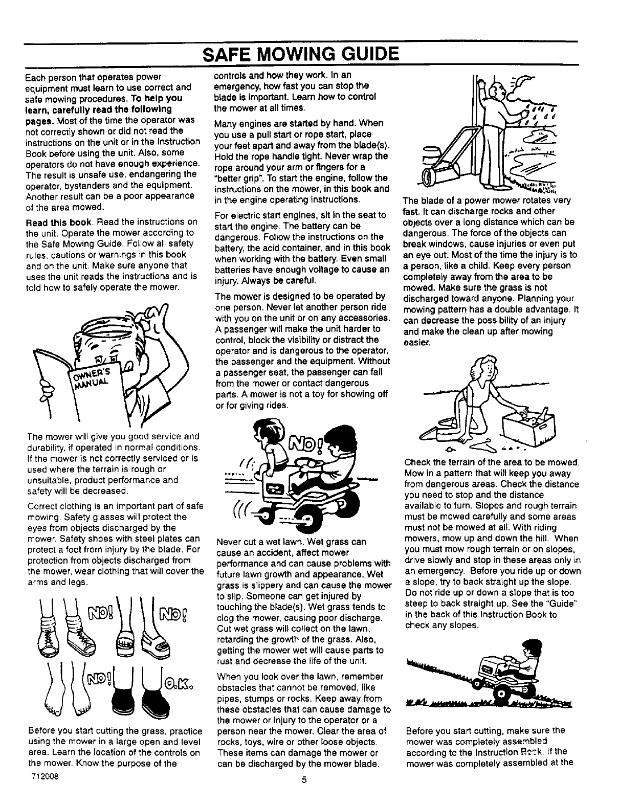
Correct clothing is an important part of safe
mowing. Safety glasses will protect the
eyes from objects discharged by the
mower. Safety shoes with steel plates can
protect a foot from injury by the blade. For
protection from objects discharged from
the mower, wear clothing that will cover the
arms and legs.
Before you start cutting the grass, practice
using the mower in a large open and level
area. Learn the location of the controls on
the mower. Know the purpose of the
712008
SAFE MOWING GUIDE
controls and how they work. In an
emergency, how fast you can stop the
blade is important. Learn how to control
the mower at all times.
Many engines are started by hand. When
you use apull start or rope start, place
your feet apart and away from the blade(s).
Hold the rope handle tight. Never wrap the
rope around your arm or fingers for •
"better grip". To start the engine, follow the
instructions on the mower, in this book and
in the engine operating instructions.
For electric start engines, sit in the seat to
start the engine. The battery can be
dangerous. Follow the instructions on the
battery, the acid container, and in this book
when working with the battery. Even small
batteries have enough voltage to cause an
injury.Always be careful.
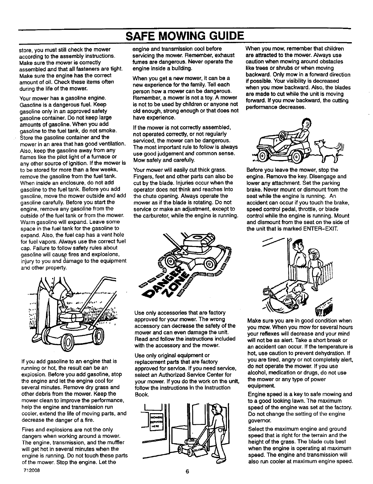
The mower is designed to be operated by
one person. Never let another person ride
with you on the unit or on any accessories.
Apassenger will make the unit harder to
control, blockthe visibility or distract the
operator and is dangerous to the operator,
the passenger and the equipment. Without
apassenger seat, the passenger can fail
from the mower or contact dangerous
parts. Amower is not a toy for showing off
or for giving rides,
Never cut a wet lawn. Wet grass can
cause an accident, affect mower
performance and can cause problems with
future lawn growth and appearance. Wet
grass is slippery and can cause the mower
to slip. Someone can get injured by
touching the blade(s). Wet grass tends to
clog the mower, causing poor discharge.
Cut wet grass will collect on the lawn,
retarding the growth of the grass. Also,
getting the mower wet will cause parts to
rust and decrease the life of the unit.
When you look over the lawn, remember
obstacles that cannot be removed, like
pipes, stumps or rocks. Keep away from
these obstacles that can cause damage to
the mower or injury to the operator or a
person near the mower, Clear the area of
rocks, toys, wire or other loose objects.
These items can damage the mower or
can be discharged by the mower blade.
The blade of a power mower rotates very
fast. It can discharge rocks and other
objects over a long distance which can be
dangerous. The force of the objects can
break windows, cause injuries or even put
an eye out. Most of the time the injury is to
a person, like a child. Keep every person
completely away from the area to be
mowed. Make sure the grass is not
discharged toward anyone. Planning your
mowing pattern has a double advantage. It
can decrease the possibility of an injury
and make the clean up after mowing
easier.
Check the terrain of the area to be mowed.
Mow in a pattern that wilt keep you away
from dangerous areas. Check the distance
you need to stop and the distance
available to turn. Slopes and rough terrain
must be mowed carefully and some areas
must not be mowed at all. With riding
mowers, mow up and down the hill. When
you must mow rough terrain or on slopes,
drive slowly and stop in these areas only in
an emergency. Before you ride up or down
a slope, try to back straight up the slope.
Do notride up or down a slope that is too
steep to back straight up. See the "Guide"
in the back of this Instruction Book to
check any slopes.
Before you start cutting, make sure the
mower was completely assembled
according to the instruction P..':':.k.If the
mower was completely assembled at the
store, you must still check the mower
according to the assembly instructions.
Make sure the mower is correctly
assembled and that all fasteners are tight.
Make sure the engine has the correct
amount of oil. Check these items often
during the life of the mower.
Your mower has a gasoline engine.
Gasoline is a dangerous fuel. Keep
gasoline only in an approved safety
gasoline container. Do not keep large
amounts of gasoline. When you add
gasoline to the fuel tank, do not smoke.
Store the gasoline container and the
mower in an area that has good ventilation.
Also, keep the gasoline away from any
flames tike the pilot light of a furnace or
any other source of ignition. If the mower is
to be stored for more than a few weeks,
remove the gasoline from the fuel tank.
When inside an enclosure, do not add
gasoline to the fuel tank. Before you add
gasoline, move the mower outside and add
gasoline carefully. Before you start the
engine, remove any gasoline from the
outside of the fuel tank or from the mower.
Warm gasoline will expand. Leave some
space in the fuel tank for the gasoline to
expand. Also, the fuel cap has a vent hole
for fuel vapors. Always use the correct fuel
cap. Failure to follow safety rules about
gasoline will caus_efires and explosions,
injury to you anda&mage to the equipment
and other property.
If you add gasoline to an engine that is
running or hot, the result can be an
explosion. Before you add gasoline, stop
the engine and let the engine cool for
several minutes. Remove dry grass and
other debris from the mower. Keep the
mower clean to improve the performance,
help the engine and transmission run
cooler, extend the life of moving pads, and
decrease the danger of a fire.
Fires and explosions are not the only
dangers when working around a mower.
The engine, transmission, and the muffler
will get hot in several minutes when the
engine is running. Do not touch these parts
of the mower. Stop the engine. Let the
712008
SAFE MOWING GUIDE
engine and transmission cool before
servicing the mower. Remember, exhaust
fumes are dangerous. Never operate the
engine inside a building.
When youget anewmower,it can be a
new experienceforthe family.Telleach
personhowa mowercan be dangerous.
Remember, a moweris notatoy.A mower
is notto be usedby childrenoranyone not
old enough,strongenoughorthat doesnot
have experience.
If the mower is not correctly assembled,
not operated correctly, or not regularly
serviced, the mower can be dangerous.
The most important rule to follow is always
use good judgement and common sense.
Mow safely and carefully.
Your mower will easily cut thick grass.
Fingers, feet and other parts can also be
cut by the blade. Injuries occur when the
operator does not think and reaches into
the chute opening. Always operate the
mower as ifthe blade is rotating. Do not
service or make an adjustment, except to
the carburetor, while the engine is running.
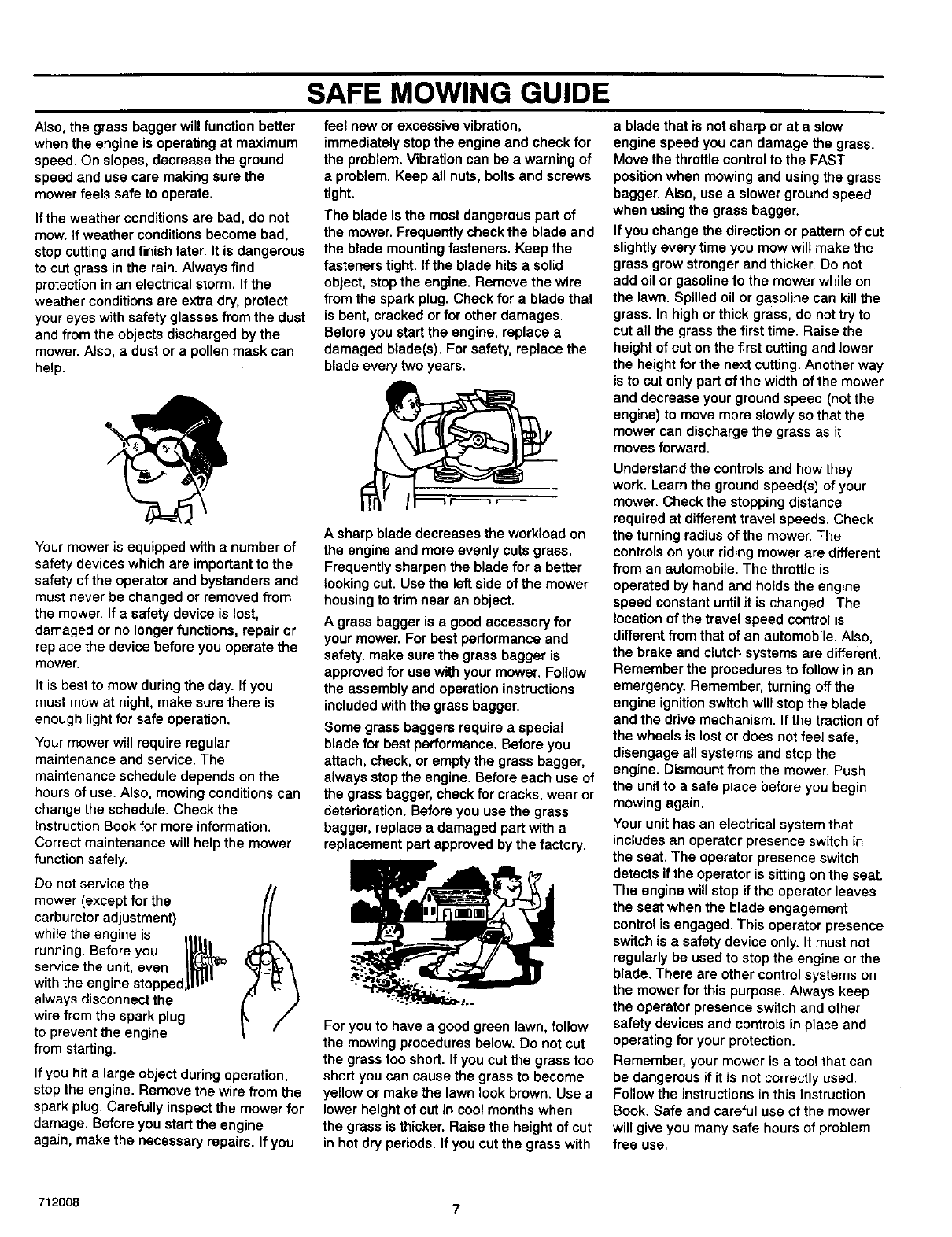
When you mow, remember that children
are attracted to the mower. Always use
caution when mowing around obstacles
like trees or shrubs or when moving
backward. Only mow in a forward direction
if possible. Your visibility is decreased
when you mow backward. Also, the blades
are made to cut while the unit is moving
forward. If you mow backward, the cutting
performance decreases.
Before you leave the mower, stop the
engine. Remove the key. Disengage and
lower any attachment. Set the parking
brake. Never mount or dismount from the
seat while the engine is running. An
accident can occur ifyou touch the brake,
speed control pedal, throttle, or blade
control while the engine is running. Mount
and dismount from the seat on the side of
the unit that is marked ENTER-EXIT.
Use onlyaccessoriesthatare factory
approvedfor yourmower.The wrong
accessory can decreasethe safetyof the
mowerand can even damagethe unit.
Read andfollowthe instructions included
withthe accessoryandthe mower.
Use only originalequipmentor
replacementpartsthat are factory
approvedforservice.If youneed service,
selectan Authorized ServiceCenterfor
your mower.If youdothe workonthe unit,
followthe instructionsInthe Instruction
Book.
Make sure you are in good condition when
you mow. When you mow for several hours
your reflexes will decrease and your mind
will not be as alert. Take a short break or
an accident can occur. If the temperature is
hot, use caution to prevent dehydration. If
you are tired, angry or not completely alert,
do not operate the mower. If you use
alcohol, medication or drugs, do not use
the mower or any type of power
equipment.
Engine speed is akey to safe mowing and
to agood looking lawn. The maximum
speed of the engine was set at the factory.
Do not change the setting of the engine
governor.
Select the maximum engine and ground
speed that is right for the terrain and the
height of the grass. The blade cuts best
when the engine is operating at maximum
speed. The engine and transmission will
also run cooler at maximum engine speed.
6
SAFE MOWING GUIDE
Also, the grass bagger will function better
when the engine is operating at maximum
speed. On slopes, decrease the ground
speed and use care making sure the
mower feels safe to operate.
If the weather conditions are bad, do not
mow. If weather conditions become bad,
stop cutting and finish later. It is dangerous
to cut grass in the rain. Always find
protection in an electrical storm. If the
weather conditions are extra dry, protect
your eyes with safety glasses from the dust
and from the objects discharged by the
mower. Also, a dust or a pollen mask can
help.
Your mower is equipped with a number of
safety devices which are important to the
safety of the operator and bystanders and
must never be changed or removed from
the mower. If a safety device is lost,
damaged or no longer functions, repair or
replace the device before you operate the
mower.
It is best to mow during the day. If you
must mow at night, make sure there is
enough light for safe operation.
Your mower will require regular
maintenance and service. The
maintenance schedule depends on the
hours of use. Also, mowing conditions can
change the schedule. Check the
Instruction Book for more information.
Correct maintenance will help the mower
function safely.
Do not service the
mower (except for the
carburetor adjustment)
while the engine is m,.
running. Before you I_
service the unit, even t_]_
with the engine stopped,W I''
always disconnect the
wire from the spark plug
to prevent the engine
from starting.
If you hit a large object during operation,
stop the engine. Remove the wire from the
spark plug. Carefully inspect the mower for
damage. Before you start the engine
again, make the necessary repairs. If you
feel new or excessive vibration,
immediately stop the engine and check for
the problem. Vibration can be a warning of
aproblem. Keep all nuts, bolts and screws
tight.
The blade is the most dangerous part of
the mower. Frequently check the blade and
the blade mounting fasteners. Keep the
fasteners tight. If the blade hits a solid
object, stop the engine. Remove the wire
from the spark plug. Check for a blade that
is bent, cracked or for other damages.
Before you start the engine, replace a
damaged blade(s). For safety, replace the
blade every two years.
A sharp blade decreases the workload on
the engine and more evenly cuts grass.
Frequently sharpen the blade for a better
looking cut. Use the left side of the mower
housing to trim near an object.
A grass bagger is a good accessory for
your mower. For best performance and
safety, make sure the grass bagger is
approved for use with your mower. Follow
the assembly and operation instructions
included with the grass bagger.
Some grass baggers require a special
blade for best performance. Before you
attach, check, or empty the grass bagger,
always stop the engine. Before each use of
the grass bagger, check for cracks, wear or
deterioration. Before you use the grass
bagger, replace a damaged part with a
replacement part approved by the factory.
For you to have a good green lawn, follow
the mowing procedures below. Do not cut
the grass too short. If you cut the grass too
short you can cause the grass to become
yellow or make the lawn look brown. Use a
lower height of cut in cool months when
the grass is thicker. Raise the height of cut
in hot dry periods. Ifyou cut the grass with
a blade that is not sharp or at a slow
engine speed you can damage the grass.
Move the throttle control to the FAST
position when mowing and using the grass
bagger. Also, use a slower ground speed
when using the grass bagger.
If yau change the direction or pattern of cut
slightly every time you mow will make the
grass grow stronger and thicker. Do not
add oil or gasoline to the mower while on
the lawn. Spilled oil or gasoline can kill the
grass. In high or thick grass, do not try to
cut all the grass the first time. Raise the
height of cut on the first cutting and lower
the height for the next cutting. Another way
is to cut only part of the width of the mower
and decrease your ground speed (not the
engine) to move more slowly so that the
mower can discharge the grass as it
moves forward.
Understand the controls and how they
work. Learn the ground speed(s) of your
mower. Check the stopping distance
required at different travel speeds. Check
the turning radius of the mower. The
controls on your riding mower are different
from an automobile. The throttle is
operated by hand and holds the engine
speed constant until it is changed. The
location of the travel speed control is
different from that of an automobile. Also,
the brake and clutch systems are different.
Remember the procedures to follow in an
emergency. Remember, turning off the
engine ignition switch will stop the blade
and the ddve mechanism. If the traction of
the wheels is lost or does not feel safe,
disengage all systems and stop the
engine. Dismount from the mower. Push
the unit to a safe place before you begin
mowing again,
Your unit has an electrical system that
includes an operator presence switch in
the seat. The operator presence switch
detects if the operator is sitting on the seat.
The engine will stop ifthe operator leaves
the seat when the blade engagement
control is engaged. This operator presence
switch is a safety device only. It must not
regularly be used to stop the engine or the
blade. There are other control systems on
the mower for this purpose. Always keep
the operator presence switch and other
safety devices and controls in place and
operating for your protection.
Remember, your mower is a tool that can
be dangerous if it is not correctly used.
Follow the instructions in this Instruction
Book. Safe and careful use of the mower
will give you many safe hours of problem
free use,
712008 7
STEPS TO FOLLOW
BEFORE MOWING
• Be sure to dress correctly. Wear hard shoes, not sandals or tennis shoes.
•Examine the blade. A blade that is bent, cracked, or damaged must be replaced with a factory replacement blade.
•Fill the fuel tank outside. Clean off spilled fuel.
•Read and follow the Owner's Manual, the instTuctions with the engine, and the instructions with any attachments. Owner's Manual
instructions are for your safety and the safety of others.
• Exhaust fumes are dangerous. Start the engine outside.
•Make sure all safety devices are in place and working correctly.
•Operation ofthe mower is only for a person that has experience.
•Wet grass can be dangerous. Let the grass dry.
•Instruct children and others to keep away from the work area.
•Never cut the grass without good light.
•Pick up loose objects. Remove them from the mowing area.
WHILE MOWING
•Watch for fixed objects and avoid them. They can damage the mower or cause injury.
•Ahot engine, muffler, and transmission will cause a burn. Do not touch.
•Inclines and slopes must be carefully mowed. See the "Guide" in the back of this book to check a slope.
•Lack of daylight or good artificial light is cause to stop mowing.
•Examine the mower, the blade, and other parts for damage after hitting a foreign object or if the unit vibrates excessively.
•Do not make adjustments or repairs without stopping the engine. Disconnect the spark plug wire.
•On or near r_ads, watch out for traffic. Direct discharge away from roads.
•When mowing, avoid areas where traction is unsure. Look back before changing direction of travel.
•In heavy grass, raise the cutting height. Cut slower. Stop the engine to remove clogged grass from the mower.
•Never remove any safety related parts.
•Do not pour gasoline into a engine that is hot or running.
AFTER MOWING
•AJwayslet the mower cool before storing in an enclosed area.
•Foreign material on the mower is dangerous. Clean off grass, leaves, grease and oil before storing.
•Tighten all loose nuts, bolts and screws before you use the unit.
•Empty and clean any grass catcher or other accessory.
•Remove the key °r disc°nnect the spark plug wire to prevent unauth°rized use"
•Make sure the mower is not kept near a source of ignition. Gas fumes can cause an explosion.
•Only original parts or factory approved substitutes can be used to service the mower.
•When storing the mower for an extended period, remove the fuel from the fuel tank.
•Instruct children to leave the mower alone. It is not a toy.
•Never keep gasoline near a source of ignition. Always use an approved container. Keep gasoline away from children.
•Lubricate according to the Instruction Book. See "Lubrication".
IMPORTANT--Read the Instruction Book. Keep this book for future use and reference.
,_ WARNING: Look for this symbol to point out important
safety precautions. It means: "Attention! Become Alert!
Your Safety Is Involved."
712008 8
BEFORE YOU MOW
ASSEMBLY
This instruction book isfor several models. Some parts oraccesso-
ries are not included on all models. Read and follow the assembly
and adjustment instructions for your mower. Do not discard any
parts or material until the unit is assembled.
A WARNING: Before doing any assembly or mainte-
nance to the mower, remove the wire from the spark
plug.
NOTE: In this Instruction book, left and right describe the loca-
tion of a part with the operator on the seat.
CHECK THE TIRES
Check the air pressure inthe tires. "13reswith too much air pressure
will cause the unit to ride rough. Also, the wrong air pressure will
keep the mower housing from cutting level. The correct air pressure
(PSI) is 14 PSI (1 BAR). The tires were over inflated for shipment.
CHECK THE LEVEL OF THE MOWER HOUSING
Make sure the level of cut is still correct. After you mow a short
distance, look at the area that was cut. Ifthe mower housing does
not cut level, see the instructions on "How To Level The Mower
Housing" in the Maintenance section of this instruction book.
MAINTENANCE FREE BA'I-rERY
IMPORTANT: Before you attach the battery cables to the
battery, check the battery date. The battery date tells If the
battery must be charged.
t. Check the top of the battery for the location of the battery date
(Figure t).
2. If the battery is put into service before the battery date, the
battery cables can be attached without charging the battery.
See "How To Install The Battery Cables".
3. If the battery is put into service after the battery date, the
battery must be charged. See "How To Charge The
Maintenance Free Battery".
HOWTO CHARGETHEMAINTENANCEFREEBATrERY
A
1.
2.
3.
4.
WARNING: When you charge the battery, do not
smoke. Keep the battery away from any sparks. The
fumes from the battery acid can cause an explosion.
Remove the battery and battery tray.
Remove the protective caps from the battery terminals.
Use a 12 volt battery charger to charge the battery. Charge at
a rate of 6 amperes for one hour. if you do not have abattery
charger, have an authorized service center charge the battery.
Install the battery and battery tray. Make sure the positive (+)
terminal is on the left side.
712008 9
BEFORE YOU MOW
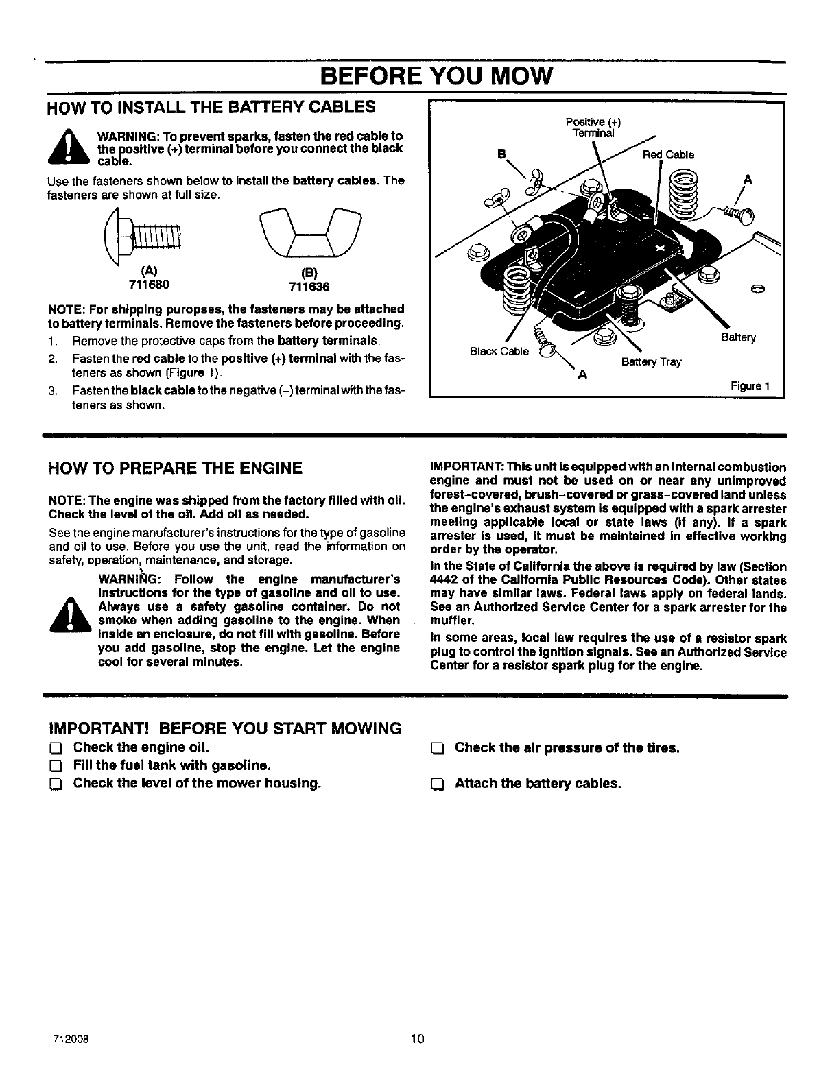
HOW TO INSTALL THE BATTERY CABLES
_WARNING: To prevent sparks, fasten the red cable to
the positive (+) terminal before you connect the black
cable.
Use the fasteners shown below to install the battery cables. The
fasteners are shown at full size.
(A) (B)
711680 711636
NOTE: For shipping puropses, the fasteners may be attached
to battery terminals. Remove the fasteners before proceeding.
1. Remove the protective caps from the battery terminals,
2. Fasten the red cable to the positive (+) terminal with the fas-
teners as shown (Figure t).
3, Fasten the black cable to the negative (-) terminal with thefas-
teners as shown.
B
Black Cable
Positive(+)
Terminal
ABattery Tray
A
/
Battery
Figure I
I
HOW TO PREPARE THE ENGINE
NOTE: The engine was shipped from the factory filled with oil
Check the level of the oil Add oll as needed.
See the engine manufacturer's instructions for the type of gasoline
and oil to use. Before you use the unit, read the information on
safety, operation, maintenance, and storage.
WARNI_IG: Follow the engine manufacturer's
instructions for the type of gasoline and oll to use.
_lk lways use a safety gasoline container. Do notsmoke when adding gasoline to the engine. When
inside an enclosure, do not fill with gasoline. Before
you add gasoline, stop the engine. Let the engine
cool for several minutes.
IMPORTANT: This unit is equipped with an Internal combustion
engine and must not be used on or near any unimproved
forest-covered, brush-covered or grass-covered land unless
the engine's exhaust system Is equipped with a spark arrester
meeting applicable local or state laws (If any). If a spark
arrester is used, It must be maintained in effective working
order by the operator.
In the State of California the above Is required by law (Section
4442 of the California Public Resources Code). Other states
may have similar laws. Federal laws apply on federal lands.
See an Authorized Service Center for a spark arrester for the
muffler.
tn some areas, local law requires the use of a resistor spark
plug to control the Ignition signals. See an Authorized Service
Center for a resistor spark plug for the engine.
IMPORTANT! BEFORE YOU START MOWING
CJ Check the engine oil.
[] Fill the fuel tank with gasoline.
[] Check the level of the mower housing.
[] Check the air pressure of the tires.
[] Attach the battery cables.
712008 10
OPERATION
Throttle Control
Lever Blade Rotation
Control
Brake Pedal
Speed
Control
Pedal
Lever
Figure 2
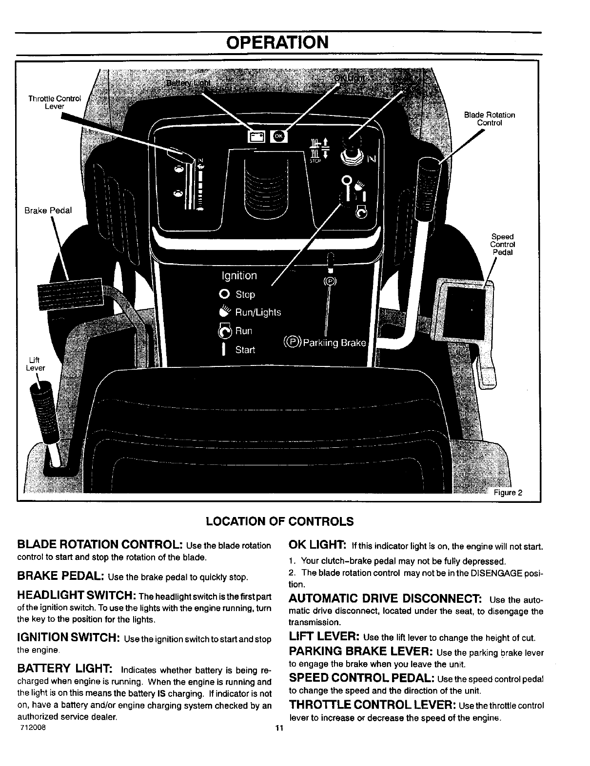
LOCATION OF CONTROLS
BLADE ROTATION CONTROL: usethebladerotation
control to start and stop the rotation of the blade.
BRAKE PEDAL: use the brake pedal to quickly stop.
HLAD LIGHT SWITCH: The headlight switch is the firstpart
of the ignitionswitch. To use the lightswith the engine running, turn
the key to the position for the lights.
IGNITION SWITCH: Usetheignitionswitchtostartandstop
the engine.
BATTERY LIGHT: Indicates whether battery is being re-
charged when engine is running. When the engine is running and
the light is on this means the battery IS charging. If indicator is not
on, have a battery and/or engine charging system checked by an
authorized service dealer.
712008 11
OK LIGHT: If this indicator light is on, the engine will not start.
1. Your clutch-brake pedal may not be fully depressed.
2. The blade rotation control may not be inthe DISENGAGE posi-
tion.
AUTOMATIC DRIVE DISCONNECT: usetheauto-
maticdrive disconnect, located under the seat, to disengage the
transmission.
LIFT LEVER: use the lift lever to change the height of cut.
PARKING BRAKE LEVER: usethe parkingI?rakelever
to engage the brake when you leave the unit.
SPEED CONTROL PEDAL: usethespeedcontrolpedal
to change the speed and the direction of the unit.
TH ROTTLE CONTROL LEVER: usethethrottlecontrol
lever to increase or decrease the speed of the engine.
OPERATION
ATrACHMENTS HOWTO USETHE BLADE ROTATIONCONTROL
This unit can use many different attachments. See the attachment
page in this book. This unit can pull attachments like a lawn
sweeper, a lawn aerator, or a hopper spreader. This unit can not use
attachments that engage the ground like a plow, a disk harrow, or
a cultivator.
HOW TO USE THE THRO'I-rLE CONTROL
Use the throttle control to increase or decrease the speed of the
engine
CAUTION: Always operate the engine with the throttle control
in the FAST position. If the engine runs for several minutes at
slower than the FAST position, the engine and transmission
will overheat and can be damaged.
1. The FAST position is marked with a detent. For normal opera-
tion and when using a grass bagger, move the throttle control
to the FAST position. For maximum charging of the battery and
for a cooler running engine and transmission, operate the en-
gine in the FAST position.
2 For transport and to tow pull behind attachments, control the
ground speed with the speed control pedal.
3. The engine governor is set at the factory for maximum perform-
ance. Do not adjust the governor to increase the speed of the
engine.
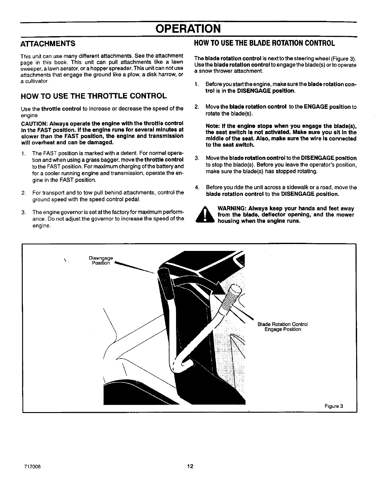
The blade rotation control is next to the steering wheel (Figure 3).
Use the blade rotation control to engage the blade(s) orto operate
a snow thrower attachment.
1. Before you start the engine, make sure the blade rotation con-
trol is inthe DISENGAGE position.
2. Move the blade rotation control to the ENGAGE position to
rotate the blade(s).
Note: If the engine stops when you engage the blade(s),
the seat switch Is not activated. Make sure you sit In the
middle of the seat. Also, make sure the wire Is connected
to the seat switch.
3. Move the blade rotation control to the DISENGAGE position
to stop the blade(s). Before you leave the operator's position,
make sure the blade(s) has stopped rotating.
4. Before you ride the unit across a sidewalk or a road, move the
blade rotation control to the DISENGAGE position.
_WARNING: Always keep your hands and feet away
from the blade, deflector opening, and the mower
housing when the engine runs.
Disengage
Position _
Blade Rotation Control
Engage Position
\
Figure 3
712008 12
OPERATION
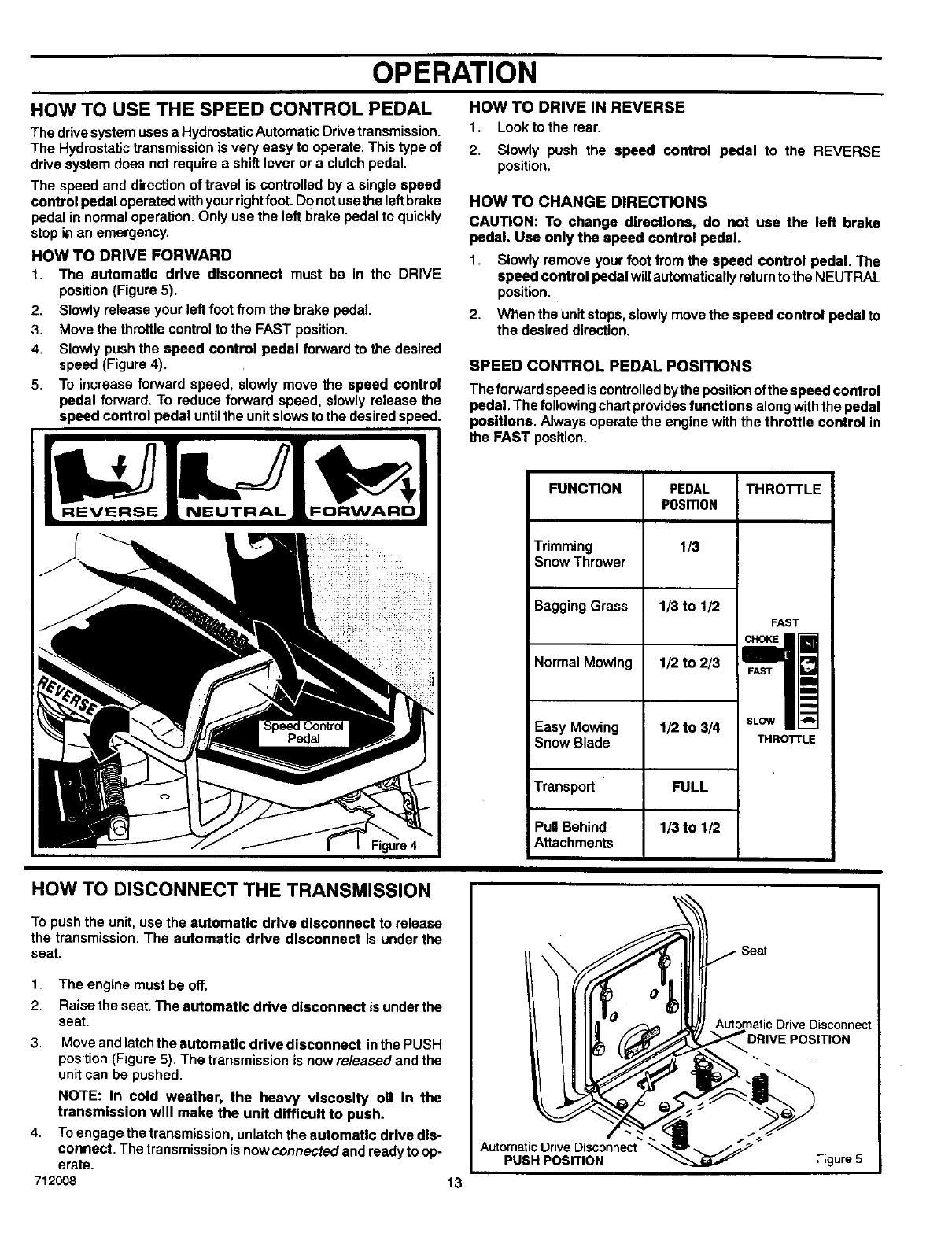
HOW TO USE THE SPEED CONTROL PEDAL
The drive system uses a Hydrostatic Automatic Drive transmission.
The Hydrostatic transmission is very easy to operate. This type of
drive system does not require a shift lever or a clutch pedal.
The speed and direction of travel is controlled by a single speed
control pedal operated with your dght foot. Do not usethe left brake
pedal in normal operation. Only use the left brake pedal to quickly
stop i_ an emergency.
HOW TO DRIVE FORWARD
1. The automatic drive disconnect must be in the DRIVE
position (Figure 5),
2. Slowly release your left foot from the brake pedal.
3. Move the throttle control to the FAST position.
4. Slowly push the speed control pedal forward to the desired
speed (Figure 4).
5. To increase forward speed, slowly move the speed control
pedal forward. To reduce forward speed, slowly release the
speed control pedal untilthe unit slows to the desired speed.
HOW TO DRIVE IN REVERSE
1. Look to the rear.
2. Slowly push the speed control pedal to the REVERSE
position.
HOW TO CHANGE DIRECTIONS
CAUTION: To change directions, do not use the left brake
pedal. Use only the speed control pedal.
1. Slowly remove your foot from the speed control pedal. The
speed control pedal willautomatically returnto the NEUTRAL
position.
2. When the Unit stops, slowly move the speed control pedal to
the desired direction.
SPEED CONTROL PEDAL POSITIONS
The forward speed is controlled bythe position of the speed control
pedal. The following chart provides functions along withthe pedal
positions. Always operate the engine with the throttle control in
the FAST position.
FUNCTION THROTTLE
Trimming
Snow Thrower
Bagging Grass
Normal Mowing
Easy Mowing
Snow Blade
Transport
Pull Behind
Attachments
PEDAL
P0Sm0N
1/3
1/3 to 1/2
1/2 to 2/3
1/2 to 3/4
FULL
1/3 to 1/2
FAST
CHOKE
FAST m
m
m
m
SLOW
THROI"rLE
HOW TO DISCONNECT THE TRANSMISSION
To push the unit, use the automatic drive disconnect to release
the transmission, The automatic drive disconnect is under the
seat.
1. The engine must be off.
2. Raise the seat. The automatic drive disconnect is under the
seat.
3,
4.
712008
Move and latch the automatic drive disconnect inthe PUSH
position (Figure 5). The transmission is now released and the
unit can be pushed.
NOTE: In cold weather, the heavy viscosity oll In the
transmission will make the unit difficult to push.
To engage the transmission, unlatch the automatic drive dis-
connect. The transmission is now connected and ready to op-
erate.
13
/
Automatic Drive Disconnec
AutomaticDrive Disconnect
PUSH POSITION .igure 5
OPERATION
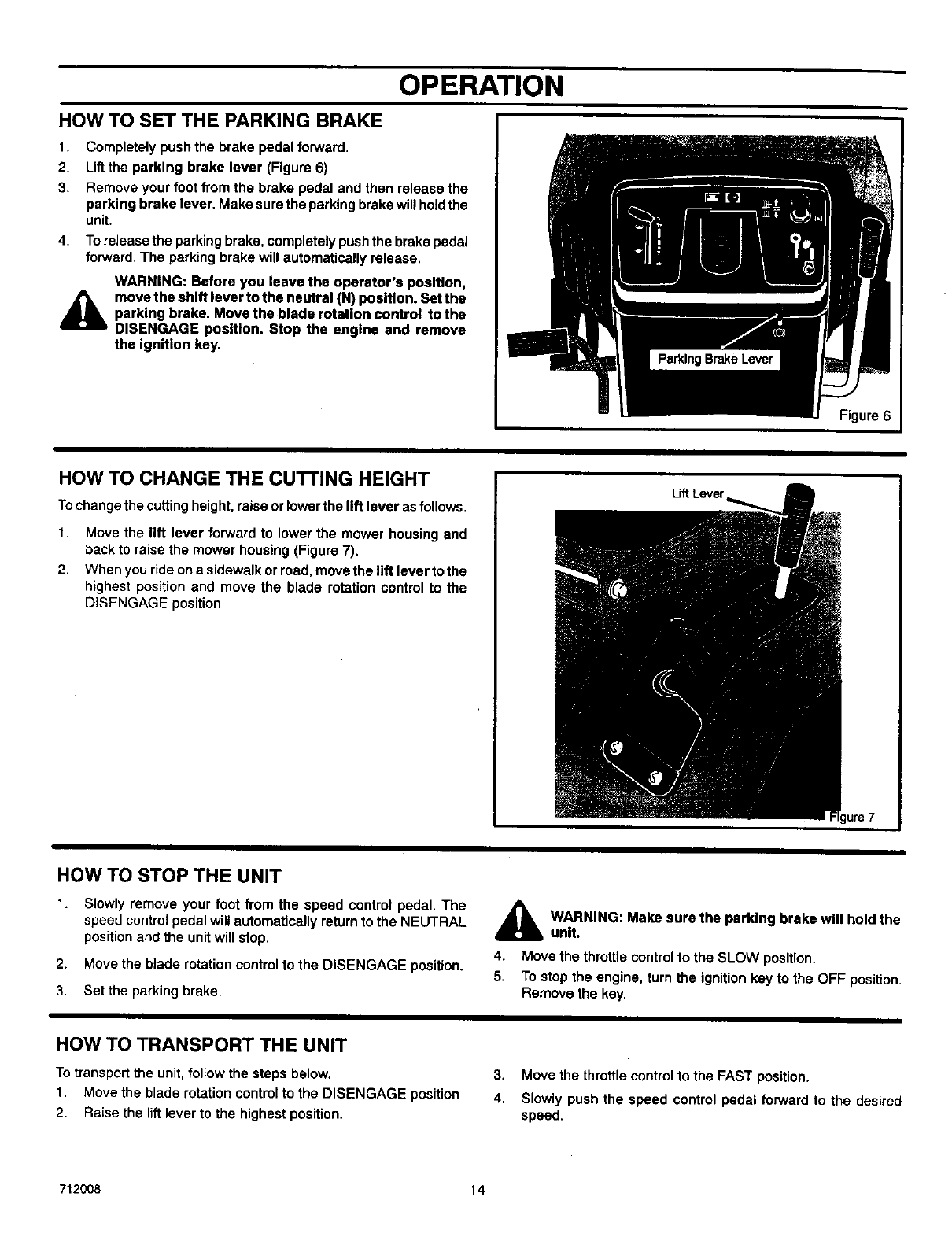
HOW TO SET THE PARKING BRAKE
1. Completely push the brake pedal forward,
2. lift the parking brake lever (Figure 6).
3. Remove your foot from the brake pedal and then release the
parking brake lever. Make sure the parking brake will holdthe
unit.
4. To release the parking brake, completely push the brake pedal
forward. The parking brake will automatically release.
AWARNING: Before you leave the operator's position,
move the shift lever to the neutral (N) position. Set the
parking brake. Move the blade rotation control to the
DISENGAGE position. Stop the engine and remove
the ignition key.
Figure 6
HOW TO CHANGE THE CUTTING HEIGHT
Tochange the cutting height, raise or lower the lift lever as follows.
1. Move the lift lever forward to lower the mower housing and
back to raise the mower housing (Figure 7).
2. When you ride on a sidewalk or road, move the lift lever to the
highest position and move the blade rotation control to the
DISENGAGE position.
Uft Lever
HOW TO STOP THE UNIT
1. Slowly remove your foot from the speed control pedal. The
speed control pedal wilt automatically return to the NEUTRAL
position and the unit will stop.
2. Move the blade rotation control to the DISENGAGE position.
3. Set the parking brake.
_lb ARNING: Make sure the parking brake will holdthe
unit.
4. Move the throttle control to the SLOW position.
5. To stop the engine, turn the ignition key to the OFF position.
Remove the key.
HOW TO TRANSPORT THE UNIT
To transport the unit, follow the steps below.
1. Move the blade rotation control to the DISENGAGE position
2. Raise the lift lever to the highest position.
3. Move the throttle control to the FAST position.
4. Slowly push the speed control pedal forward to the desired
speed.
712008 14
OPERATION
HOWTO OPERATEWITHTHE MOWER HOUSING
A
1.
2,
3,
WARNING: The deflector is a safety device. Do not re-
move the deflector. The deflector forces the dis-
charged material toward t he ground. Always keep the
deflector In the down position. If the deflector Is dam-
aged, replace the deflector with an original equipment
part from an authorized service center.
Start the engine.
Release the parking brake.
Move the lift lever to a height of cut position. In high or thick
grass, cutthe grass in the highest positionfirst and then lower
the mower housing to a lower position.
CAUTION: Do not operate with the mower housing In the
LEVEL ADJUSTMENT position. If you operate In the
LEVEL ADJUSTMENT position, the mower housing and
blades can be damaged.
4. Move the throttle control to the SLOW position.
5. Move the blade rotation control to the ENGAGE position.
6. Move the throttle control to the FAST position.
7. Slowly push the speed control pedal to the desired speed.
NOTE: When you mow In heavy grass or mow with a grass
bagger, use a slow forward speed.
8. Make sure the level of cut set at the factory is still correct. After
you mow a short distance, look at the area that was cut. If the
mower housing does notcut level, see the instructions on "How
To Level The Mower Housing" in the Maintenance section.
_ARNING: For better control of the unit, always
select asafe speed.
HOW TO OPERATE THE UNIT ON HILLS
,_ WARNING: Do not ride up or down slopes that are too
steep to back straight up. Never ride the unit across
a slope. See the "Slope Guide" In the back of this
book for information on how to check elopes.
HOW TO OPERATE ON A HILL
1. Controtthe speed onlywith the speed controlpedal. Do not use
the brake pedal on a hill.
2. To help prevent an accident, slowly move the speed control
pedal. Avoid sudden turns or changes in speed.
3. To reduce forward speed when going down a hill, slowly release
the speed control pedal until the unit slows to the desired
speed.
HOW TO STOP ON A HILL
1. Avoid stopping ona hill.Ifyou must quickly stop in an emergen-
cy, remove your right foot from the speed control pedal and
quickly depress the left brake oedal.
2,
3,
Set the parking brake.
Before you dismount from the seat, move the throttle controlto
SLOW position, move the blade rotation control to the DISEN-
GAGED position, turn offthe engine and set the parking brake.
HOW TO START OPERATION ON A HILL
1. Start the engine
2. Move the blade rotation control to the ENGAGED position.
3. Move the throttle control to the FAST position.
4. Depress the brake pedal and release the parking brake. As you
release the parking brake, push the speed control pedal to the
desired speed.
4_ WARNING: Slowly push the speed control pedal as
you release the parking brake. The parking brake
must be disengaged before the speed control pedal
Is able to engage the transmission.
712008 15
OPERATION
BEFORE STARTING THE ENGINE
CHECK THE OIL
NOTE: The engine was shipped from the factory filled with o11.
Check the level of the oil Add oll as needed. See the engine
manufacturer's Instructions for the type of gasoline and oll to
use.
1. Make sure the unit is level.
NOTE: Do not check the level of the oll while the engine
runs.
2. Check the oil. Follow the procedure in the engine manufactur-
er's instructions.
3. If necessary, add oil untilthe oil reaches the FULL mark onthe
dipstick.The quantity of oil needed from ADD to FULL is shown
on the dipstick. Do not add too much oil.
CAUTION: A mixture of alcohol (ethanol or methanol) and
gasoline (called gasohol), will attract moisture and cause acid
deposits during storage. While the unit Is In storage, the acids
in the fuel can damage the fuel system.
To prevent engine problems with the fuel system, empty the fuel
system before storage of 30 days or longer as follows.
1. Drain the fuel tank.
2. Start the engine. Let the engine run untilthe fuel lines and the
carburetor are empty.
3. Afterstorage,makesureyou use freshfuel. See the storage
instructionsforadditionalinformation.
4. Neveruseenginecleanerorcarburetorcleanerinthefuel tank
orpermanentdamagecan occur.
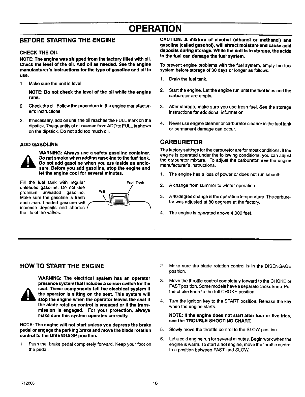
ADD GASOLINE
AWARNING: Always use a safety gasoline container.
Do not smoke when adding gasoline to the fuel tank.
Do not add gasoline when you are Inside an enclo-
sure. Before you add gasoline, stop the engine and
let the engine cool for several minutes.
Fill the fuel tank with regular FuelTank
unleaded gasoline. Do not use (F /
premium unleaded gasoline.
Make sure the gasoline is fresh
and clean, Leaded gasoline wilt
increase deposits and shorten
the life of the va_,es.
CARBURETOR
The factory settings for the carburetor are for most conditions. Ifthe
engine is operated under the following conditions, you can adjust
the carburetor mixture. To adjust the carburetor, see the engine
manufacturer's instructions.
1. The engine has a loss of power or does not run smooth.
2. A change from summer to winter operation.
3. A40 degree change inthe operation temperature. The carbure-
tor was adjusted at 80 degrees at the factory.
4. The engine is operated above 4,000 feet.
HOW TO START THE ENGINE
A
WARNING: The electrical system has an operator
presence system that includes a sensor switch for the
seat, These components tell the electrical system If
the operator is sitting on the seat. This system will
stop the engine when the operator leaves the seat If
the blade rotation control Is engaged or if the trans-
mission Is engaged. For your protection, always
make sure this system operates correctly,
2.
3.
4.
NOTE: The engine will not start unless you depress the brake
pedal or engage the parking brake and move the blade rotation 5.
control to the DISENGAGE position. 6,
1. Push the brake pedal completely forward. Keep your foot on
the pedal.
Make sure the blade rotation control is in the DISENGAGE
position.
Move the throttle control completely forward to the CHOKE or
FAST position. Some models have a separate choke knob. Pull
the choke knob to the full CHOKE position.
Turn the ignition kay to the START position. Release the key
when the engine starts.
NOTE: If the engine does not start after four or five tries,
see the TROUBLE SHOOTING CHART,
Slowly move the throttle control to the SLOW position.
Let a cold engine run for several minutes. Begin work when the
engine is warm. To start a hot engine, move the throttle control
to a position between FAST and SLOW.
712008 16
OPERATION
OPERATING TIPS
1.
2.
3.
4.
Check the blade rotation controlfor correct adjustment. Forthe
blade(s) to disengage correctly, the adjustment must be cor-
rect.
Beforeyouusethe unit,checkthe oil inthe engineandaddoil
if necessary,
If the engine will not start, flint make sure the wire is attached
to the spark plug.
Make sure allthe belts are inside all the belt guides. See the in-
structions on how to remove and install the motion drive and
mower drive belts.
5.
6.
7.
8.
Before you make an inspection, adjustment (except forthe car-
buretor) or repair, make sure the wire fTomthe spark plug isdis-
connected,
For longer life of the battery onelectric start models, charge the
battery every three months.
Use the speed control pedal to change the ground speed, not
the throttle control.
Belt noise can occur when the blade is engaged. This noise is
normal and does not affect the operation of the unit.
MOWING AND BAGGING TIPS
1. For alawn to look better, check the cutting level of the mower
housing. See =How To Level The Mower Housing" in the Main-
tenance section.
2. For the mower housing to cut level, make sure the tires have
the correct amount of air pressure.
3. Every time you use the unit,check the blade, ifthe blade isbent
or damaged, immediately replace the blade. Also, make sure
the nut for the blade is tight.
4. Keep the blade(s) sharpened. Worn blades willcause the ends
of the grass to turn brown.
5. Do not cut orbag grass that iswet. Wet grass will not discharge
correctly. Let the grass dry before cutting.
6. Use the left side of the mower housing to trim near an object.
7. Discharge the cut grass onto the mowed area. The result is a
more even discharge of cut grass.
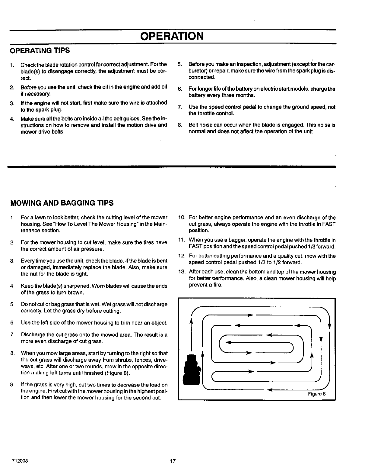
8.
9.
When you mow large areas, start by turning to the right so that
the cut grass will discharge away from shrubs, fences, drive-
ways, etc. After one or two rounds, mow inthe opposite direc-
tion making left turns until finished (Figure 8).
If the grass is very high, cut two times to decrease the load on
the engine. First cutwiththe mower housing inthe highest posi-
tion and then lower the mower housing for the second cut.
10.
11.
12.
13.
For better engine performance and an even discharge of the
cut grass, always operate the engine with the throttle in FAST
position.
When you use a bagger, operate the engine with the throttle in
FAST positionand the speed control pedal pushed 1/3 forward.
For better cutting performance and a quality cut, mow with the
speed control pedal pushed 1/3 to 1/2 forward.
After each use, clean the bottom and top of the mower housing
for better performance. Also, aclean mower housing will help
prevent a fire.
712008 17
MAINTENANCE
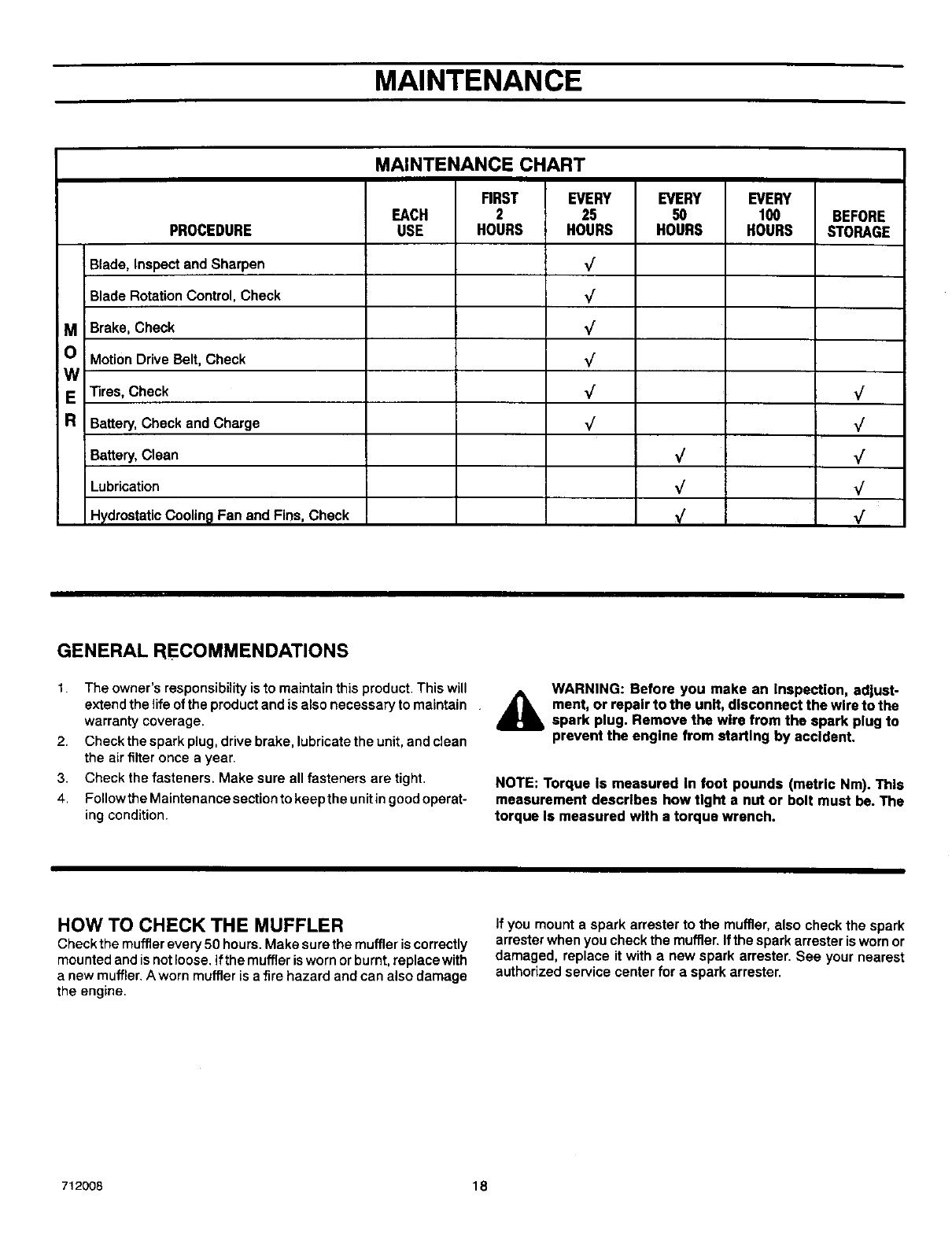
MAINTENANCE CHART
RRST EVERY EVERY EVERY
EACH 2 25 50 100 BEFORE
PROCEDURE USE HOURS HOURS HOURS HOURS STORAGE
Blade, Inspect and Sharpen _/
Blade Rotation Control, Check _/
MBrake, Check _/
O Motion Drive Belt, Check _/
W
ETires, Check _/ _/
RBattery, Check and Charge _/ _/
Battery, Clean V
Lubrication ,,/ _/
Hydrostatic Cooling Fan and Fins, Check _/ V"
GENERAL RECOMMENDATIONS
t. The owner's responsibility is to maintain this product. This will AWARNING: Before you make an inspection, adjust-
extend the life of the product and is also necessary to maintain AL ment, or repair to the unit, disconnect the wire to the
warranty coverage. _spark plug. Remove the wire from the spark plug to
2. Check the spark plug, drive brake, lubricate the unit, and clean prevent the engine from starting by accident.
the air filter once a year.
3. Check the fasteners, Make sure all fasteners are tight. NOTE: Torque Is measured In foot pounds (metric Nm). This
4. FollowtheMaintenancesectiontokeeptheunitin goodoperat- measurement describes how tight a nut or bolt must be. The
ing condition, torque Is measured with a torque wrench.
HOW TO CHECK THE MUFFLER
Check the muffler every 50 hours. Make sure the muffler is correctly
mounted and is not loose, ifthe muffler is worn or burnt, replace with
a new muffler. A worn muffler is a fire hazard and can also damage
the engine.
If you mount a spark arrester to the muffler, also check the spark
arrester when you check the muffler, Ifthe spark arrester is worn or
damaged, replace it with a new spark arrester, See your nearest
authorized service center for a spark arrester,
712008 18

MAINTENANCE
INSPECT BLADE
WARNING: Before you inspect or remove the blade,
disconnect the wire to the spark plug. If the blade hits
_IL an object, stop the engine. Check the unit for dam-
age. The blade has sharp edges. When you hold the
blade, use gloves or cloth material to protect your
hands.
If you keep the blade sharp and inspect the blade for damage, the
blade willcut better and be more safe to operate. Frequently check
the blade for excessive wear, cracks, or other damage. Frequently
check the nut that holds the blade. Keep the nut tight. If the blade
hits an object, stop the engine. Disconnectthewire tothe spark plug.
See if the blade is bent or damaged. Check the blade adapter for
damage. Before you operate the unit, replace damaged parts with
original equipment parts. See the authorized service center in your
area. Every three years, have an authorized service person inspect
the blade or replace the old blade with an original equipment part.
HOW TO REMOVE AND INSTALL THE BLADE
1. Remove the mower housing. See the instructions on "How To
Remove The Mower Housing"
2. Use a piece of wood to keep the blade from rotating.
3. Remove the nut that holds the blade (Figure 9).
Hi-Uft
Edge Up
Mandrel
Blade
Blade Adapter
Belleville Washer
_/asher
Nut Figure 9
4.
5.
6.
7.
8.
A
Check the blade and the blade adapter according to the in-
structions for "Inspect Blade". Replace a badly worn or dam-
aged blade with an original equipment blade. See an
authorized service center in your area.
Clean the top and bottom of the mower housing. Remove all the
grass and debris.
Mount the blade and blade adapter on the mandrel
(Figure 9).
Mount the blade so that the hi-lift edges are up. Ifthe blade
is upside down, the blade will not cut correctly and can cause
an accident.
Fasten the blade withthe originalwashers and nut. Make sure
the outside rim of the Bellevllle washer is against the blade
(Figure 10).
WARNING: Always keep the nut tight that holds the
blade. A loose nut or blade can cause an accident.
712008
9. "lighten the nut that holds the blade to a torque of 35 foot
pounds (47,5 N-m).
10. Install the mower housing. See "How To Install The Mower
Housing".
BladeA
Blade
W her
rNut
Be,,eviUeWasher _J
(Outsiderim must be
againsttheblade.) IFigure 10
HOW TO SHARPEN THE BLADE
WARNING: Vibration can be caused If the blade is
d_lb not correctly balanced or Ifthe blade is damaged. A
blade that is damaged with cracks can break and
cause an accident.
Keep a sharp edge on the blade. A blade that is not sharp will cause
the tips of the grass to become brown.
1. Sharpen the blade two times a year or every 25 hours.
2. Remove the blade according to the instructions in "How To Re-
move And Install The Blade".
3. Clean the blade with a brush, soap and water. Check the ;
blade, Look for cracks, nicks, or other damage. Replace a
badlyworn ordamaged bladewith an originalequipment blade.
See an authorized service center in your area.
4. Sharpen the blade with a file (Figure 11). Make sure you keep
the original bevel angle.
5. Make sure the blade is balanced. Use a screwdriver and hold
the blade parallel to the ground (Fig ure 11). Ablade that is bal-
anced wilt stay parallel to the ground. If the blade is not bal-
anced, the heavy end will rotate toward the ground. Sharpen
the heavy end untilthe blade is balanced.
6. Anew blade will cutbetter than a badly worn blade. Every three
years, have an authorized service person inspect the blade or
replace the old blade with an original equipment blade.
7. Assemble the blade according to the instructions"How To Re-
move And Install The Blade".
19
Screwdriv__
I Blade is balanced
when paraielto theground.
Ground Figure11
MAINTENANCE
HOW TO ADJUST THE BLADE ROTATION CONTROL 6. Attachthewiretothesparkplug. Uowforashortdistanceand
_k ARNING: To prevent an injury, the blade rotation
control must operate correctly.
In normal usage, the blade rotation control will not require an
adjustment. However, ifthe cutting performance decreases or the
quality of cut is poor, make the following changes.
1. When you mow, make sure the throttle control in in the FAST
position.
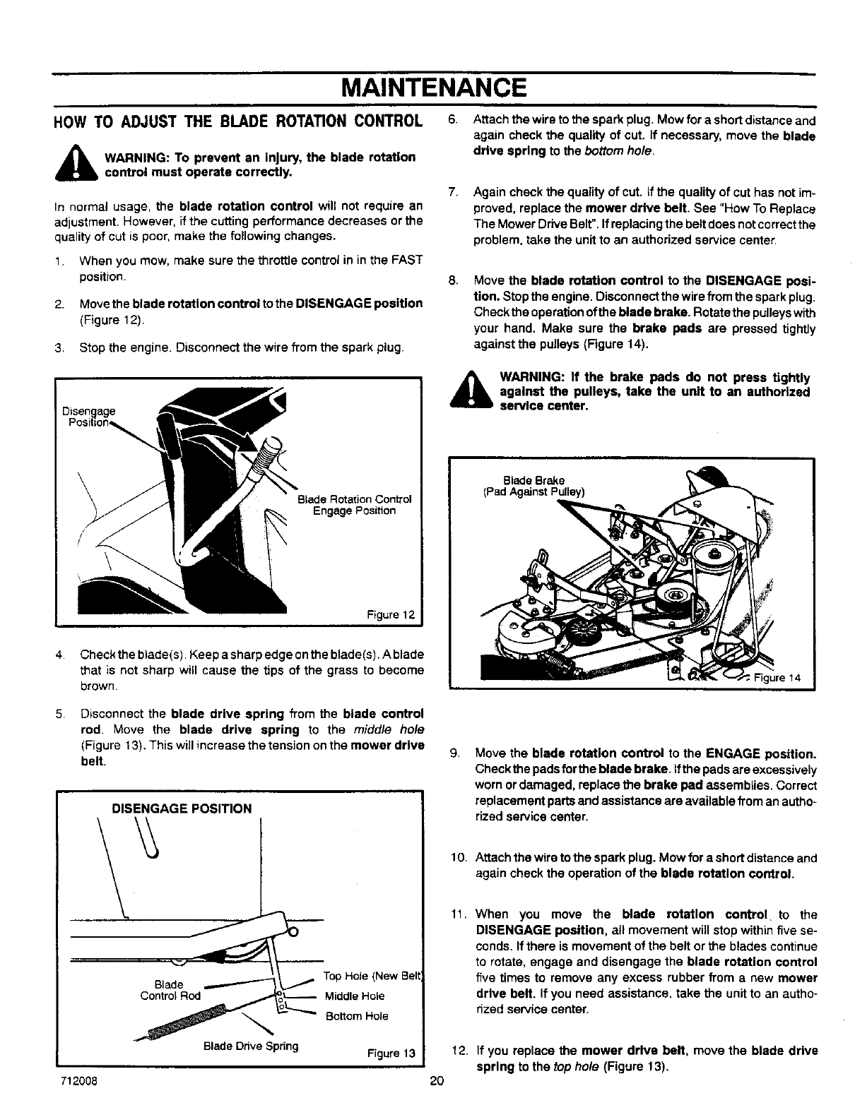
2. Move the blade rotation control to the DISENGAGE position
(Figure 12).
3. Stop the engine. Disconnect the wire from the spark plug.
again check the quality of cut. If necessary, move the blade
drive spring to the bottom ho/e.
7. Again check the quality of cut. If the quality of cut has not im-
proved, replace the mower drive belt. See "How To Replace
The Mower Drive Belt".If replacing the belt does not correctthe
problem, take the unit to an authorized service center.
8, Move the blade rotation control to the DISENGAGE posi-
tion. Stop the engine, Disconnect the wire from the spark plug.
Check the operation ofthe blade brake. Rotate the pulleys with
your hand, Make sure the brake pads are pressed tightly
against the pulleys (Figure 14).
4
Blade Rotation Control
Engage Position
\
Figure 12
Check the blade(s). Keep asharp edge on the blade(s). A blade
that is not sharp will cause the tips of the grass to become
brown.
,_ WARNING: If the brake pads do not press tightly
against the pulleys, take the unit to an authorized
service center.
Blade Brake
(Pad Against Pulley)
//
Figure 14
5.
712008
Disconnect the blade drive spring from the blade control
rod. Move the blade drive spring to the midd/e ho/e
(Figure 13). This will increase the tension onthe mower drive
belt.
DISENGAGE POSITION
Top Hole (New Belt
Blade
Control Rod MiddleHole
Blade DriveSpring Figure13
20
9. Move the blade rotation control to the ENGAGE position.
Check the pads for the blade brake. Ifthe pads are excessively
worn or damaged, replace the brake pad assembBes. Correct
replacement parts and assistance are available from an autho-
rized service center.
10. Attach the wire to the spark plug. Mow for a short distance and
again check the operation of the blade rotation control.
11. When you move the blade rotation control to the
DISENGAGE position, all movement will stop within five se-
conds. If there is movement of the belt or the blades continue
to rotate, engage and disengage the blade rotation control
five times to remove any excess rubber from anew mower
drive belt. If you need assistance, take the unit to an autho-
nzed service center.
12. if you replace the mower drive belt, move the blade drive
spring to the top hole (Figure 13).
MAINTENANCE
HOW TO CHECK AND ADJUST THE DRIVE BRAKE
Completely push the brake pedal forward. Set the parking brake.
Move the automatic drive disconnect to the PUSH position, Push
the unit. If the rear wheels rotate, adjust or replace the brake pads.
Adjust the drive brake as foUows.
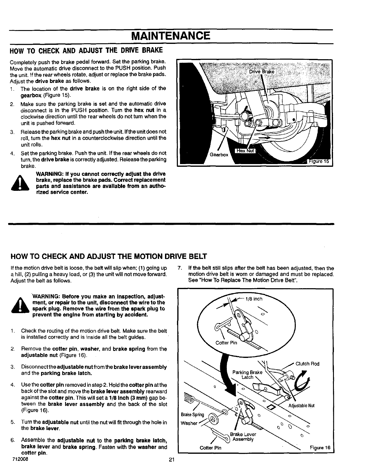
1. The location of the drive brake is on the right side of the
gearbox (Figure 15).
2. Make sure the parking brake is set and the automatic drive
disconnect is in the PUSH position. Turn the hex nut in a
clockwise direction until the rear wheels do not turn when the
unit is pushed forward.
3_
4.
Release the parking brake and push the unit. Ifthe unit does not
roll, turn the hex nut in a counterclockwise direction until the
unit rolls.
Set the parking brake. Push the unit. If the rear wheels do not
turn, the drive brake is correctly adjusted. Release the parking
brake.
AWARNING: If you cannot correctly adjust the drive
brake, replace the brake pads. Correct replacement
parts and assistance are available from an autho-
rized service center.
HOW TO CHECK AND ADJUST THE MOTION DRIVE BELT
If the motion drive belt is loose, the belt will slip when; (1) going up 7. If the belt still slips after the belt has been adjusted, then the
a hill, (2) pulling a heavy load, or (3) the unit will not move forward, motion drive belt is worn or damaged and must be replaced.
Adjust the belt as follows. See "How To Replace The Motion Drive Belt".
AWARNING: Before you make an Inepectlon, adjust-
ment, or repair to the unit, disconnect the wire to the
spark plug. Remove the wire from the spark plug to
prevent the engine from starting by accident.
1.
2.
3.
4.
5.
Check the routing of the motion drive belt. Make sure the belt
is installed correctly and is inside all the belt guides.
Remove the cotter pin, washer, and brake spring from the
adjustable nut (Figure 16).
Disconnect the adjustable nut from the brake lever assembly
and the parking brake latch.
Use the cotter pin removed instep 2. Hold the cotter pin at the
back of the slot and move the brake lever assembly rearward
against the cotter pin. This will set a 1/8 Inch (3 ram) gap be-
tween the brake lever assembly and the back of the slot
(Figure 16).
Turn the adjustable nut untilthe nut willfit through the hole in
the brake lever,
6. Assemble the adjustable nut to the parking brake latch,
brake lever and brake spring. Fasten with the washer and
cotter pin.
712008 21
MAINTENANCE
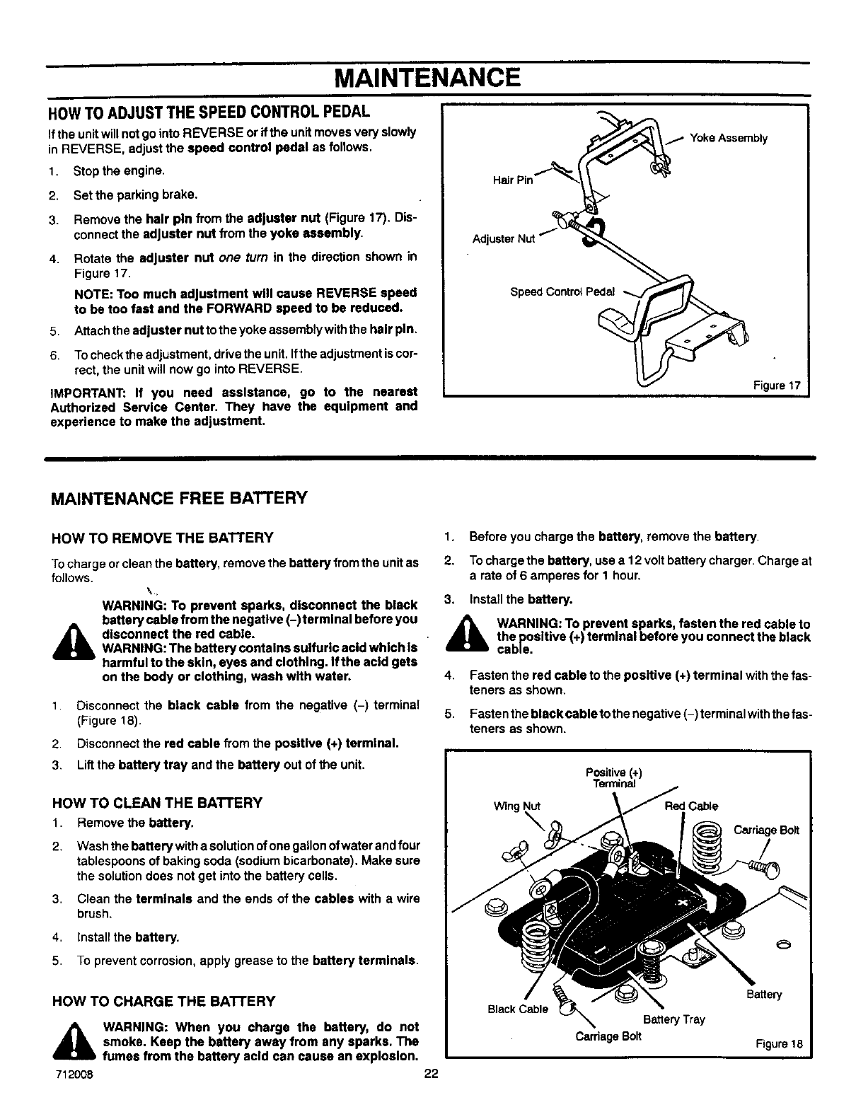
HOWTO ADJUST THE SPEED CONTROL PEDAL
Ifthe unit will not go into REVERSE or ifthe unit moves very slowly
in REVERSE, adjust the speed control pedal as follows.
1. Stop the engine.
2. Setthe parking brake.
3. Remove the hair pin from the adjuster nut (Figure 17). Dis-
connect the adjuster nut from the yoke assembly.
4. Rotate the adjuster nut one turn in the direction shown in
Figure 17.
NOTE: Too much adjustment will cause REVERSE speed
to be too fast and the FORWARD speed to be reduced.
5. Attach the adjuster nut to the yoke assembly with the hair pin.
6. To check the adjustment, drive the unit. Ifthe adjustment is cor-
rect, the unit will now go into REVERSE.
IMPORTANT: If you need assistance, go to the nearest
Authorized Service Center. They have the equipment and
experience to make the adjustment.
Adj
Speed Control Pedal
7Yoke Assembly
Figure 17
MAINTENANCE FREE BATTERY
HOW TO REMOVE THE BATTERY
Tocharge or clean the battery, remove the battery from the unit as
follows. \,
WARNING: To prevent sparks, disconnect the black
battery cable from the usgstlve (-)farmlnal before you
A disconnect the red cable.
WARNING: The battery contains sulfuric add which Is
harmful to the skin, eyes and clothing. Ifthe acid gets
on the body or clothing, wash with water.
1. Disconnect the black cable from the negative (-) terminal
(Figure 18).
2. Disconnect the red cable from the positive (+) terminal.
3. Lift the battery tray and the battery out of the unit.
1. Before you charge the battery, remove the battery.
2. To charge the battery, use a 12 volt battery charger. Charge at
a rate of 6 amperes for 1 hour.
3. Install the battery.
A WARNING: To prevent sparks, fasten the red cable to
the positive (+) terminal before you connect the black
cable.
4.
5.
Fasten the red cable to the positive (+) terminal with the fas-
teners as shown.
Fasten the black cable to the negative (-) terminal withthe fas-
teners as shown.
HOW TO CLEAN THE BATTERY
1 Remove the battery.
2. Wash the battery with a solution of one gallon ofwater and four
tablespoons of baking soda (sodium bicarbonate). Make sure
the solution does not get into the battery cells.
3, Clean the terminals and the ends of the cables with a wire
brush.
4, Install the battery.
5, To prevent corrosion, apply grease to the battery terminals.
HOW TO CHARGE THE BATTERY
A
712008
WARNING: When you charge the battery, do not
smoke. Keep the battery away from any sparks. The
fumes from the battery acid can cause an explosion.
22
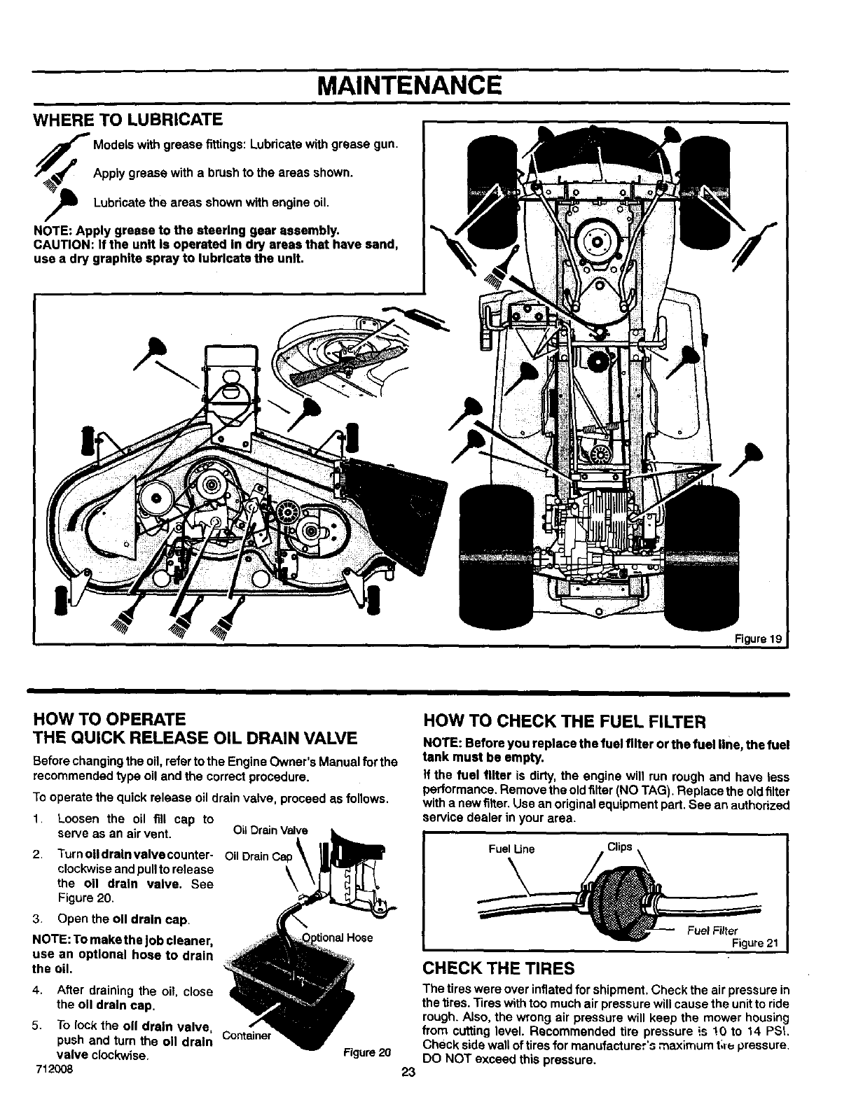
MAINTENANCE
WHERE TO LUBRICATE
"j Models with grease fittings: Lubricate with grease gun.
/Apply grease with a brush to the areas shown.
,_ Lubricate the areas shown with engine oil.
NOTE: Apply grease to the steering gear assembly.
CAUTION: If the unit Is operated In dry areas that have sand,
use a dry graphite spray to lubricate the unit,
Figure 19
HOW TO OPERATE
THE QUICK RELEASE OIL DRAIN VALVE
Before changing the oil, refer to the Engine Owner's Manual for the
recommended type oil and the correct procedure.
To operate the quick release oil drain valve, proceed as follows.
1. Loosen the oil fill cap to
serve as an air vent. OLIDrain Valve
2. Turnoil drain valve counter- Oil DrainCa
clockwise and pull to release \
the on drain valve. See \
Figure 20.
3. Openthe oll drain cap.
NOTE: To make the Jobcleaner,
use an optional hose to drain
the oil.
Hose
4. After draining the oit, close
the oll drain cap.
5. To lock the oll drain valve,
push and turn the oll drain Container
valve clockwise.
712008
Figure20
23
HOW TO CHECK THE FUEL FILTER
NOTE: Before you replace the fuel filter or the fuel line, the fuel
tank must be empty.
If the fuel filter is dirty, the engine will run rough and have less
performance. Remove the oldfilter (NO TAG). Replace the oldfilter
with a new filter. Use an original equipment part. See an authorized
service dealer in your area.
Fuel Line Clips _ I
Figure 21
CHECK THE TIRES
The tires were over inflated for shipment. Check the air pressure in
the tires. Tires with too much air pressure will cause the unit to ride
rough. Also, the wrong air pressure will keep the mower housing
from cutting level. Recommended tire pressure is !0 to 14 PSI.
Check side wall of tires for manufacture;'s maximum t;r_ pressure.
DO NOT exceed this pressure.
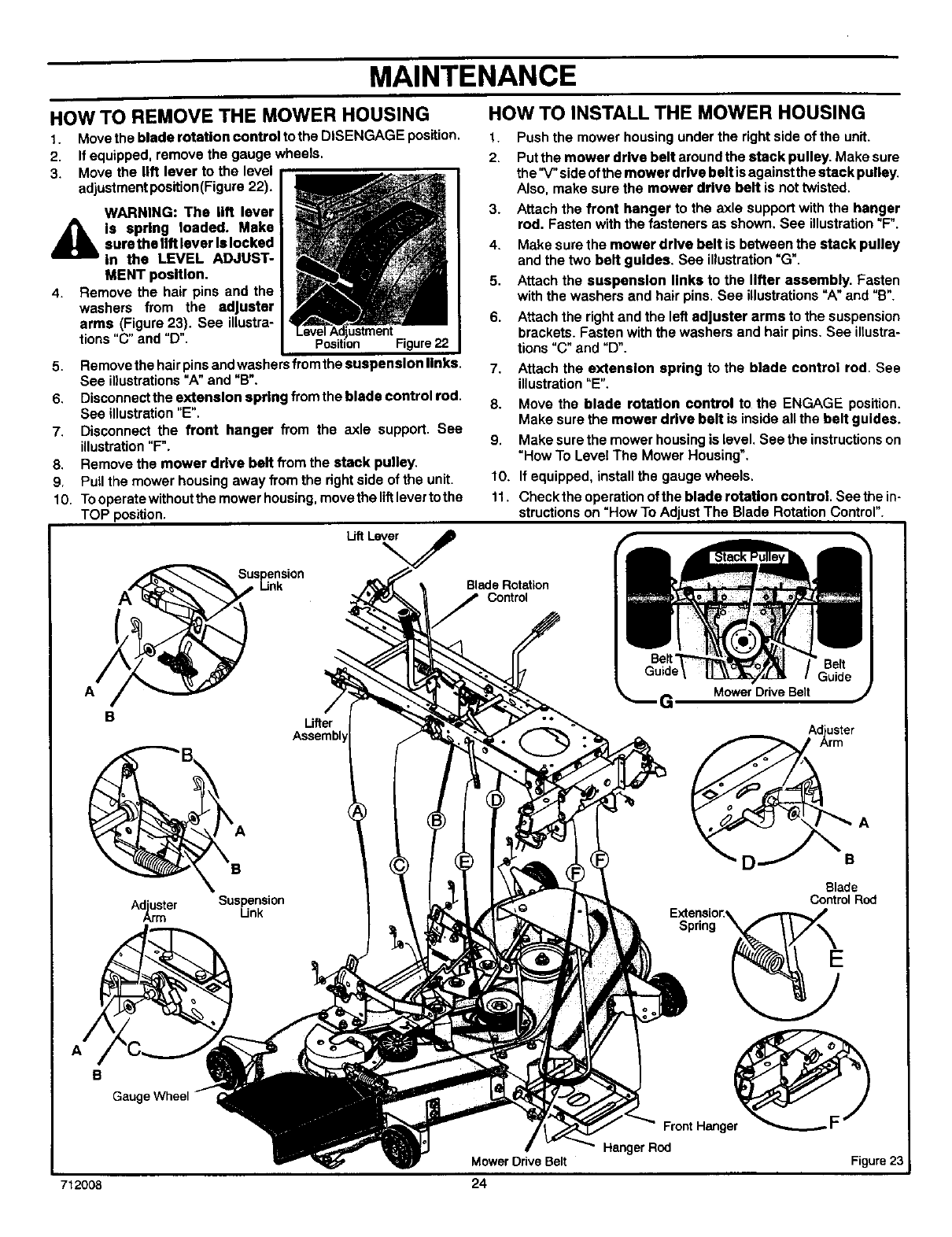
MAINTENANCE
HOW TO INSTALL THE MOWER HOUSING
HOW TO REMOVE THE MOWER HOUSING
t. Move the blade rotation control to the DISENGAGE position.
2. Ifequipped, remove the gauge wheels.
3. Move the Iltt lever to the level
adjustment position(Figure 22).
WARNING: The lift lever
,_IL Is spring loaded. Make
sure the lift lever Is locked
in the LEVEL ADJUST-
MENT position.
4. Remove the hair pins and the
washers from the adjuster
arms (Figure 23). See illustra-
tions "C" and "D".
5. Remove the hair pins and washers from the suspension links.
See illustrations "A"and "B'.
6. Disconnect the extension spring from the blade control rod.
See illustration "E".
7. Disconnect the front hanger from the axle support. See
illustration "F".
8. Remove the mower drive belt from the stack pulley.
9. Pull the mower housing away from the right side of the unit.
10. To operate without the mower housing, move the liftlever to the
TOP position.
LiftLl_'_
A
BLifter
Ad_Smter SuspensionLink
1. Push the mower housing under the right side of the unit.
2. Put the mower drive belt around the stack pulley. Make sure
the'V' side of the mower drive belt is against the stack pulley.
Also, make sure the mower drive belt is not twisted.
3. Attach the front hanger to the axle support with the hanger
rod. Fasten with the fasteners as shown. See illustration "F".
4. Make sure the mower drive belt is between the stack pulley
and the two belt guides. See illustration "G".
5. Attach the suspension links to the lifter assembly. Fasten
with the washers and hair pins. See illustrations "A" and "B'.
6. Attach the right and the left adjuster arms to the suspension
brackets. Fasten with the washers and hair pins. See inustra-
tions "C" and "D".
7. Attach the extension spring to the blade control rod. See
illustration "E".
8. Move the blade rotation control to the ENGAGE position.
Make sure the mower drive belt is inside all the belt guides.
9. Make sure the mower housing is level. See the instructions on
"How To Level The Mower Housing".
10. If equipped, install the gauge wheels.
11. Check the operation of the blade rotation control. See the in-
structions on "How To Adjust The Blade Rotation Control".
Blade Rotation
Control
Mower Drive Belt
G
Adiuster
Arm
Blade
Control Rod
Extensio_.
Spring
B
Gaugq
FrontHanger
HangerRod
F
Mower Drive Belt Figure 23
712008 24
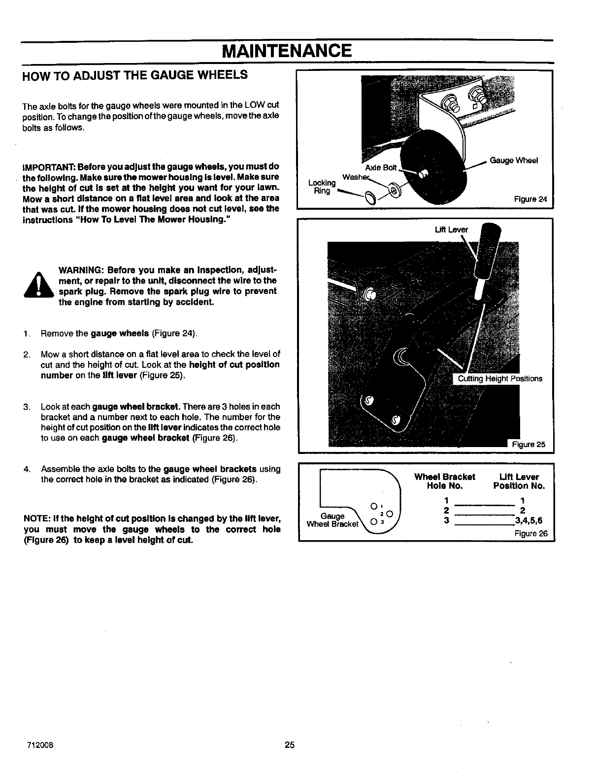
MAINTENANCE
HOW TO ADJUST THE GAUGE WHEELS
The axle boltsfor the gauge wheels were mounted in the LOW cut
position.To change the positionof the gauge wheels, move the axle
bolts as follows.
IMPORTANT: Before you adjust the gauge wheels, you must do
• the following. Make sure the mower housing ts level. Make sure
the height of cut Is set at the height you want for your lawn.
Mow a short distance on a fiat level area and look st the area
that was cut. If the mower housing does not cut level, see the
instructions "How To Level The Mower Housing."
AWARNING: Before you make an Inspection, adjust-
ment, or repair to the unit, disconnect the wire to the
spark plug. Remove the spark plug wire to prevent
the engine from starting by accident.
t. Remove the gauge wheels (Figure 24).
2. Mow a short distance on a fiat level area to check the level of
cut and the height of cut. Look at the height of cut position
number on the lift lever (Figure 25),
3. Look at each gauge wheel bracket. There are 3 holes in each
bracket and a number next to each hole. The number for the
height of cut position onthe lift lever indicates the correct hole
to use on each gauge wheel bracket (Figure 26).
Wheel
Figure24
UftLever
Cutting Height Positions
4. Assemble the axle bolts to the gauge wheel brackets using
the correct hole in the bracket as indicated (Figure 26).
NOTE: If the height of cut position Is changed by the lift lever,
you must move the gauge wheels to the correct hole
(Figure 26) to keep a level height of cut.
Wheel Bracket Lift Lever
Hole No. Position No,
1 1
2 2
3 3,4,5,6
Figure26
712008 25
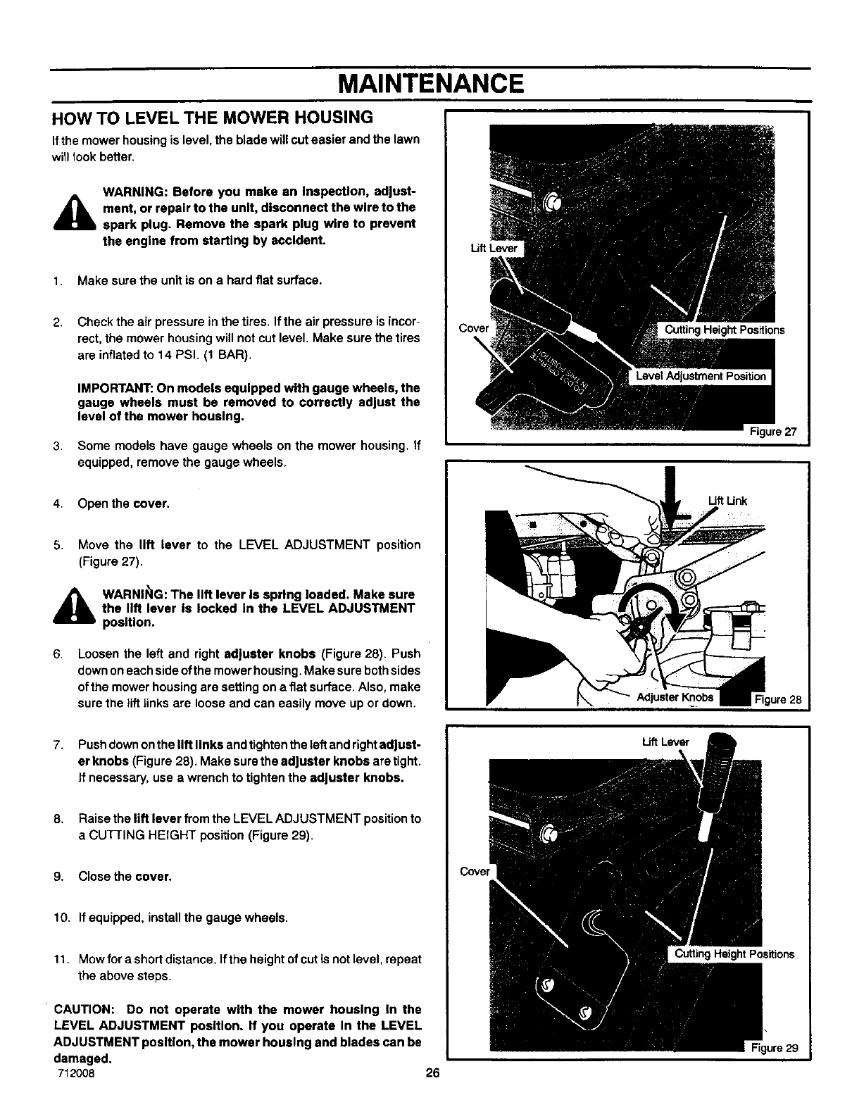
MAINTENANCE
HOW TO LEVEL THE MOWER HOUSING
Ifthe mower housing is level, the blade will cut easier and the lawn
will look better.
AWARNING: Before you make an Inspection, adjust-
ment, or repair to the unit, disconnect the wire to the
spark plug. Remove the spark plug wire to prevent
the engine from starting by aocldent.
1. Make sure the unit is on a hard fiat surface.
2,
3,
Check the air pressure in the tires. If the air pressure is incor-
rect, the mower housing will not cut level. Make sure the tires
are inflated to 14 PSI. (t BAR).
IMPORTANT: On models equipped with gauge wheels, the
gauge wheels must be removed to correctly adjust the
level of the mower housing.
Some models have gauge wheels on the mower housing. If
equipped, remove the gauge wheels.
4. Open the cover.
5. Move the lift lever to the LEVEL ADJUSTMENT position
(Figure 27).
A WARNII_IG: The lift lever Is spring loaded. Make sure
the lift lever Is locked In the LEVEL ADJUSTMENT
position.
6, Loosen the left and right adjuster knobs (Figure 28). Push
down on each side of the mower housing. Make sure both sides
of the mower housing are setting on a flat surface. Also, make
sure the lift links are loose and can easily move up or down.
Lift Lever
Cutting Height Positions
Figure 27
Uft Unk
7. Push down on the lift links and tighten the left and right adjust-
er knobs (Figure 28). Make sure the adjuster knobs are tight.
If necessary, use awrench to tighten the adjuster knobs.
8, Raise the lift lever from the LEVEL ADJUSTMENT position to
a CUI_IING HEIGHT position (Figure 29).
9. Close the cover.
10. If equipped, install the gauge wheels.
11. Mow for a short distance. If the height of cut is not level, repeat
the above steps.
CAUTION: Do not operate with the mower housing In the
LEVEL ADJUSTMENT position. If you operate In the LEVEL
ADJUSTMENT position, the mower housing and blades can be
damaged.
712008
Covel
26
Lift Lever
Cutting Height Positions
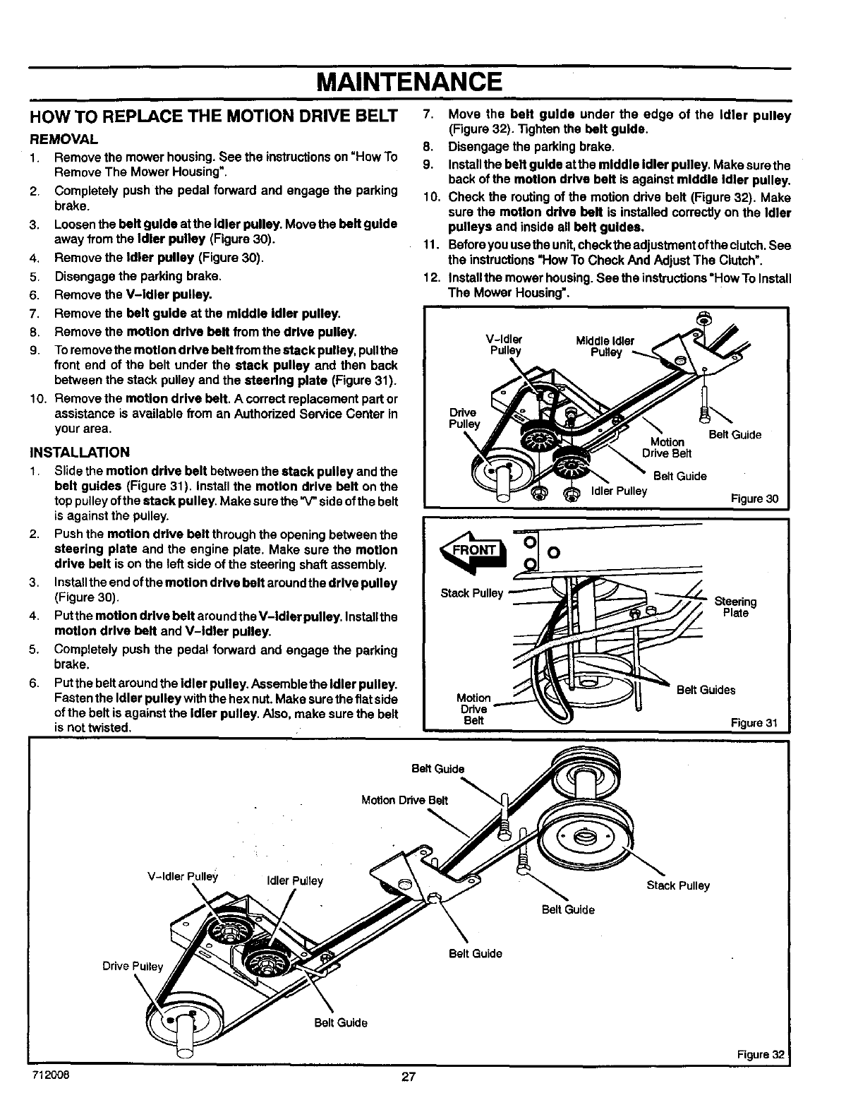
MAINTENANCE
HOW TO REPLACE THE MOTION DRIVE BELT 7,
REMOVAL 8.
1. Remove the mower housing. See the instructions on "How To 9.
Remove The Mower Housing".
2. Completely push the pedal forward and engage the parking 10.
brake.
3. Loosen the belt guide at the Idler pulley. Move the belt guide
away from the Idler pulley (Figure 30).
4. Remove the Idler pulley (Figure 30).
5. Disengage the parking brake.
6. Remove the V-idler pulley.
7. Remove the belt guide at the middle idler pulley.
8. Remove the motion drive belt from the drive pulley.
9. To remove the motion drive belt fromthe stack pulley, pullthe
front end of the belt under the stack pulley and then back
between the stack pulley and the steering plate (Figure 31).
10. Remove the motion drive belt. A correct replacement part or
assistance is available from an Authorized Service Center in
your area.
INSTALLATION
1. Slide the motion drive belt between the stack pulley and the
belt guides (Figure 31). install the motion drive belt on the
top pulley ofthe stack pulley. Make sure the "V"side of the belt
is against the pulley.
2. Push the motion drive belt through the opening between the
steering plate and the engine plate. Make sure the motion
drive belt is on the left side of the steering shaft assembly.
3. Install the end ofthe motion drive belt around the drive pulley
(Figure 30).
4. Putthe moUon drive belt around the V-Idler pulley. Installthe
motion drive belt and V-Idler pulley.
5. Completely push the pedal forward and engage the parking
brake.
6, Put the belt around the Idler pulley. Assemble the Idler pulley.
Fasten the Idler pulley with the hex nut. Make sure the fiatside
of the belt is against the Idler pulley. Also, make sure the belt
is not twisted.
11.
12.
Move the belt guide under the edge of the Idler pulley
(Figure32). Tightenthe belt guide.
Disengagethe parkingbrake.
Installthe beltguide atthe middle Idler pulley. Makesurethe
back ofthe moUon drive belt is againstmiddle Idler pulley.
Checkthe muting of the motionddva belt (Figure32). Make
surethe motion drive belt is installedcorrectlyonthe Idler
pulleys andinsideall belt guides.
Beforeyouusethe unit,checkthe adjustmentoftheclutch.See
the instructions"HowTo CheckAndAdjust The Clutch'.
Installthe mowerhousing.Seethe instructions"HowToInstall
The Mower Housing'.
V-Idler Middle Idler
Pulley
Ddve
Pulley
%Belt Guide
Motion
Drive Belt
Belt Guide
Idler Pulley Figure 30
O
StackPulley Steering
Plate
Motion
Drive
Belt
BeltGuides
Figure31
BeltGuide
MotionDriveBelt
V-ldlerPulley
\IdlerPulley
Belt Guide
Stack Pulley
Drive Pulley
Belt Guide
Belt Guide
Figure32
712008 27
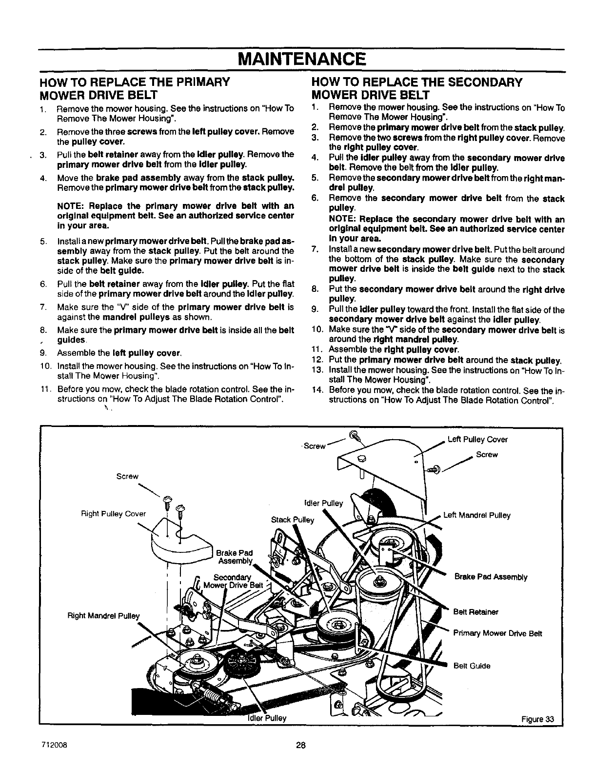
MAINTENANCE
2•
•3•
4•
HOW TO REPLACE THE PRIMARY
MOWER DRIVE BELT
1, Remove the mower housing. See the instructions on "How To
Remove The Mower Housing'.
Remove the three screws from the left pulley cover, Remove
the pulley cover.
Puff the belt retainer away from the Idler pulley. Remove the
primary mower drive belt from the Idler pulley•
Move the brake pad assembly away from the stack pulley,
Remove the primary mower drive belt from the stack pulley.
NOTE: Replace the primary mower drive belt with an
original equipment belt, See an authorized service center
in your area.
5, Install a new primary mower drive belt. Pullthe brake pad as-
sembly away from the stack pulley, Put the belt around the
stack pulley. Make sure the primary mower drive belt is in-
side of the belt guide.
6. Pull the belt retainer away from the Idler pulley. Put the fiat
side of the primary mower drive belt around the Idler pulley,
7 Make sure the "V" side of the primary mower drive belt is
against the mandrel pulleys as shown.
8. Make sure the primary mower drive belt is inside all the belt
guides•
9Assemble the left pulley cover,
10. Installthe mower housing. See the instructions on "How To In-
stall The Mower Housing".
11• Before you mow, check the blade rotation control• See the in-
structions on "How To Adjust The Blade Rotation Control",
\,
HOW TO REPLACE THE SECONDARY
MOWER DRIVE BELT
1. Remove the mower housing. See the instructions on "How To
Remove The Mower Housing'.
2. Remove the primary mower drive belt from the stack pulley.
3. Remove the two screws from the right pulley cover• Remove
the right pulley cover.
4. Pull the idler pulley away from the secondary mower drive
belt. Remove the belt from the Idler pulley•
5, Remove the secondary mower drive belt from the right man-
drel pulley•
6. Remove the secondary mower drive belt from the stack
pulley.
NOTE: Replace the secondary mower drive belt with an
original equipment belt. See an authorized service center
In your area.
7. Install a new secondary mower drive belt, Putthe belt around
the bottom of the stack pulley, Make sure the secondary
mower drive belt is inside the belt guide next to the stack
pulley,
8, Put the secondary mower drive belt around the right drive
pulley,
9. Pull the Idler pulley toward the front. Install the fiat side of the
secondary mower drive belt against the idler pulley,
10. Make sure the "V" side ofthe secondary mower drive belt is
around the right mandrel pulley•
11. Assemble the right pulley cover.
12, Put the primary mower drive belt around the stack pulley,
13, Install the mower housing. See the instructions on "How To In-
stall The Mower Housing"•
14, Before you mow, check the blade rotation control, See the in-
structions on "How To Adjust The Blade Rotation Control".
Screw
Right Pulley
Co Brake Pad
Right Mandrel Pulley
1_ ,Cover
•Screw
g j Screw
Pulley
Brake Pad Assembly
Belt Retainer
Pdmery Mower Drive Belt
Belt Guide
Figure 33
712008 28
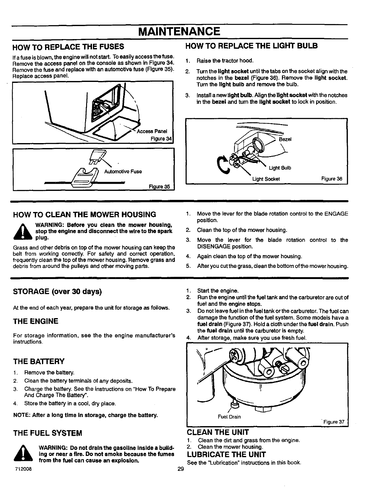
MAINTENANCE
HOW TO REPLACE THE FUSES HOW TO REPLACE THE LIGHT BULB
If a fuse is blown, the engine will not start. To easily access the fuse.
Remove the access panel on the console as shown in Figure 34. 1.
Remove the fuse and replace with an automotive fuse (Figure 35). 2.
Replace access panel.
ve Fuse
Figure34
Figure35
3.
Raise the tractor hood.
Turn the light socket untilthe tabs onthe socket align with the
notches in the bezel (Figure 36). Remove the light socket.
Turn the light bulb and remove the bulb.
Install a new light bulb. Align the light socket with the notches
in the bezel and turn the light socket to lock in position.
Bezel
Ught Bulb
Ught Socket Figure 36
HOW TO CLEAN THE MOWER HOUSING
_lb WARNING: Before you clean the mower housing,
stop the engine and disconnect the wire to the spark
plug.
Grass and other debris on top of the mower housing can keep the
belt from working correctly. For safety and correct operation,
frequently clean the top of the mower housing. Remove grass and
debris from around the pulleys and other moving pads,
1. Move the lever for the blade rotation control to the ENGAGE
position.
2. Clean the top of the mower housing.
3. Move the lever for the blade rotation control to the
DISENGAGE position.
4. Again clean the top of the mower housing.
5. After you cut the grass, clean the bottom ofthe mower housing.
STORAGE (over 30 days)
At the end of each year, prepare the unit for storage as follows.
THE ENGINE
For storage information, see the the engine manufacturer's
instructions.
THE BATTERY
1. Remove the battery.
2. Clean the battery terminals of any deposits.
3. Charge the battery. See the instructions on "How To Prepare
And Charge The Battery".
4. Store the battery in a cool, dry place.
NOTE: After a long time In storage, charge the battery.
THE FUEL SYSTEM
712008
WARNING: Do not draintbe gasoline Insidea build-
ing or near a fire. Do not smoke because the fumes
from the fuel can cause an explosion.
29
1. Start the engine.
2. Run the engine untilthe fuel tank and the carburetor are out of
fue! and the engine stops.
3. Do not leave fuelin the fueltank orthe carburetor. The fuel can
damage the function of the fuel system. Some models have a
fuel drain (Figure 37). Hold a cloth under the fuel drain. Push
the fuel drain until the carburetor is empty.
4. After storage, make sure you use f_esh fuel.
Fuel Drain
CLEAN THE UNIT
1. Clean the dirt and grass from the engine.
2. Clean the mower housing.
LUBRICATE THE UNIT
See the "Lubrication" instructions in this book.
Figure37
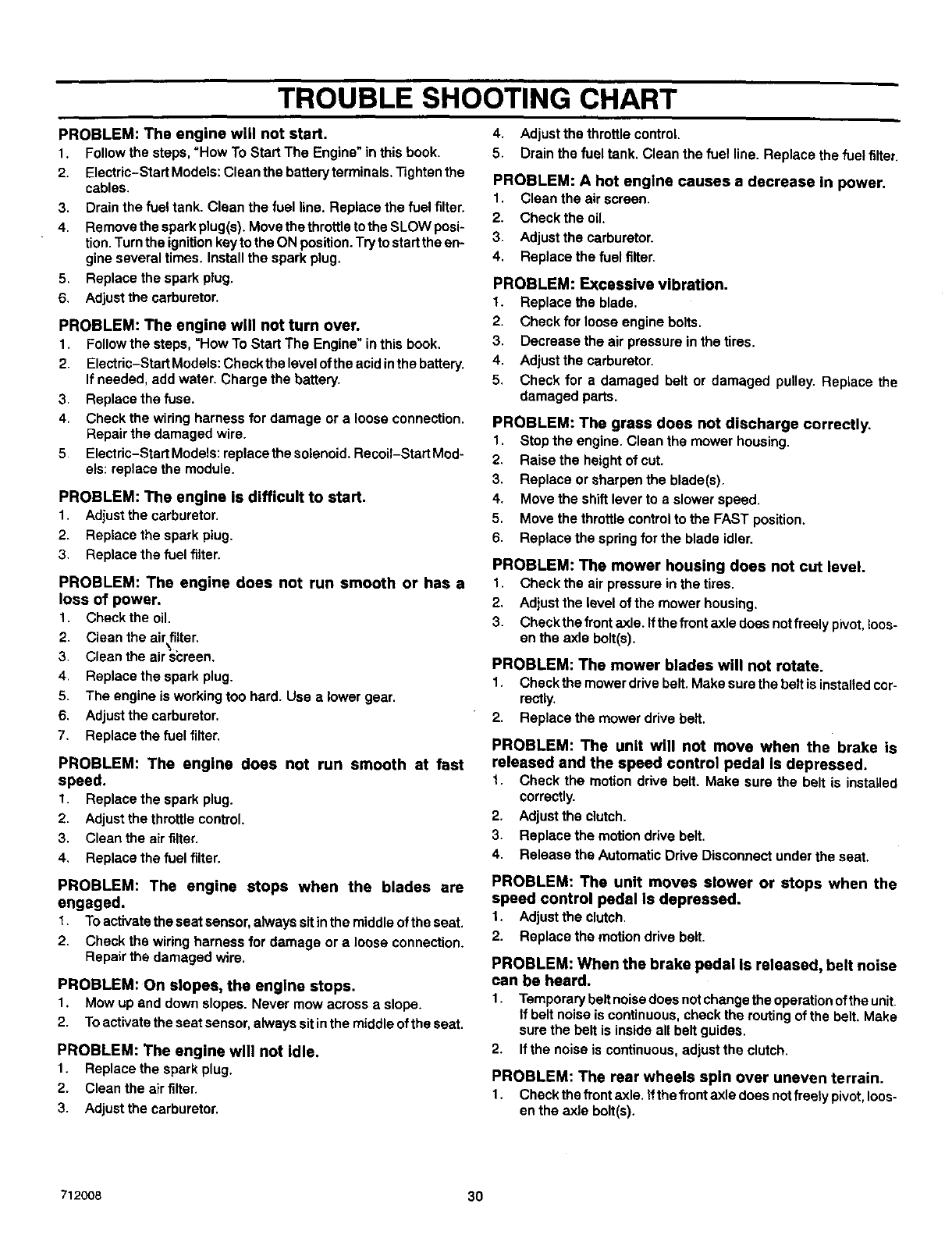
TROUBLE SHOOTING CHART
PROBLEM: The engine will not start.
1. Follow the steps, "How To Start The Engine" in this book.
2. Electric-Start Models: Clean the battery terminals. Tighten the
cables.
3. Drain the fuel tank. Clean the fuel line. Replace the fuel filter.
4. Remove the spark plug(s). Move the throttle to the SLOW posi*
tion. Turn the ignition key to the ON position. Try tostart the en-
gine several times. Install the spark plug.
5. Replace the spark plug.
6. Adjust the carburetor.
PROBLEM: The engine will not turn over.
1. Follow the steps, "How To Start The Engine" in this book.
2. Electric-Start Models: Check the level ofthe acid inthe battery.
If needed, add water. Charge the battery.
3. Replace the fuse.
4. Check the wiring harness for damage or a loose connection.
Repair the damaged wire.
5. Electric-Start Models: replacethe solenoid. Recoil-Start Mod-
els: replace the module.
PROBLEM: The engine is difficult to start.
1. Adjust the carburetor.
2. Replace the spark plug.
3. Replacethe fuelfitter.
PROBLEM: The engine does not run smooth or has a
loss of power,
1. Check the oil.
2. Clean the air filter.
3. Clean the air si:reen.
4. Replace the spark plug.
5. The engine is working too hard. Use alower gear.
6. Adjust the carburetor.
7. Replace the fuel filter.
PROBLEM: The engine does not run smooth at fast
speed.
1. Replacethe sparkplug.
2, Adjustthe throttlecontrol.
3. Cleanthe air filter,
4, Replacethe fuel filter.
PROBLEM: The engine stops when the blades are
engaged.
t. Toactivatetheseatsensor,alwayssit inthe middleoftheseat.
2. Checkthe wiringharnessfordamage or a looseconnection.
Repairthe damagedwire.
PROBLEM: On slopes, the engine stops.
1. Mow up and down slopes. Never mow across a slope.
2. To activate the seat sensor, always sit inthe middle of the seat.
PROBLEM: The engine will not idle.
1. Replace the spark plug.
2. Clean the air filter.
3. Adjust the carburetor.
4. Adjust the throttle control.
5. Drain the fuel tank. Clean the fuel line. Replace the fuel filter.
PROBLEM: A hot engine causes a decrease in power.
1. Clean the air screen.
2. Check the oil.
3. Adjust the carburetor.
4. Replace the fuel filter.
PROBLEM: Excessive vibration.
1. Replace the blade.
2. Check for loose engine bolts.
3. Decrease the air pressure in the tires.
4. Adjust the carburetor.
5. Check for a damaged belt or damaged pulley. Replace the
damaged parts.
PROBLEM: The grass does not discharge correctly.
1. Stop the engine. Clean the mower housing.
2. Raise the height of cut.
3. Replace or sharpen the blade(s).
4. Move the shift lever to a slower speed.
5. Move the throttle control to the FAST position.
6. Replace the spring for the blade idler.
PROBLEM: The mower housing does not cut level.
1. Check the air pressure in the tires.
2. Adjust the level of the mower housing.
3. Check the front axle. Ifthe front axle does not freely pivot, loos-
en the axle bolt(s).
PROBLEM: The mower blades will not rotate.
1. Check the mower drive belt. Make sure the belt is installed cor-
rectly.
2. Replace the mower drive belt.
PROBLEM: The unit will not move when the brake is
released and the speed control pedal is depressed.
t. Check the motion ddve belt. Make sure the belt is installed
correctly.
2. Adjust the clutch.
3. Replace the motion drive belt.
4. Release the Automatic Drive Disconnect under the seat.
PROBLEM: The unit moves slower or stops when the
speed control pedal Is depressed.
1. Adjustthe clutch.
2. Replacethe motion drivebelt.
PROBLEM: When the brake pedal Is released, belt noise
can be heard.
1. Temporary belt noisedoes not change the operation ofthe unit.
If belt noise is continuous, check the routing of the belt. Make
sure the belt is inside all belt guides.
2. If the noise is continuous, adjust the clutch.
PROBLEM: The rear wheels spin over uneven terrain.
1. Check the front axle. if the front axle does not freely pivot, loos-
en the axle bolt(s).
712008 30
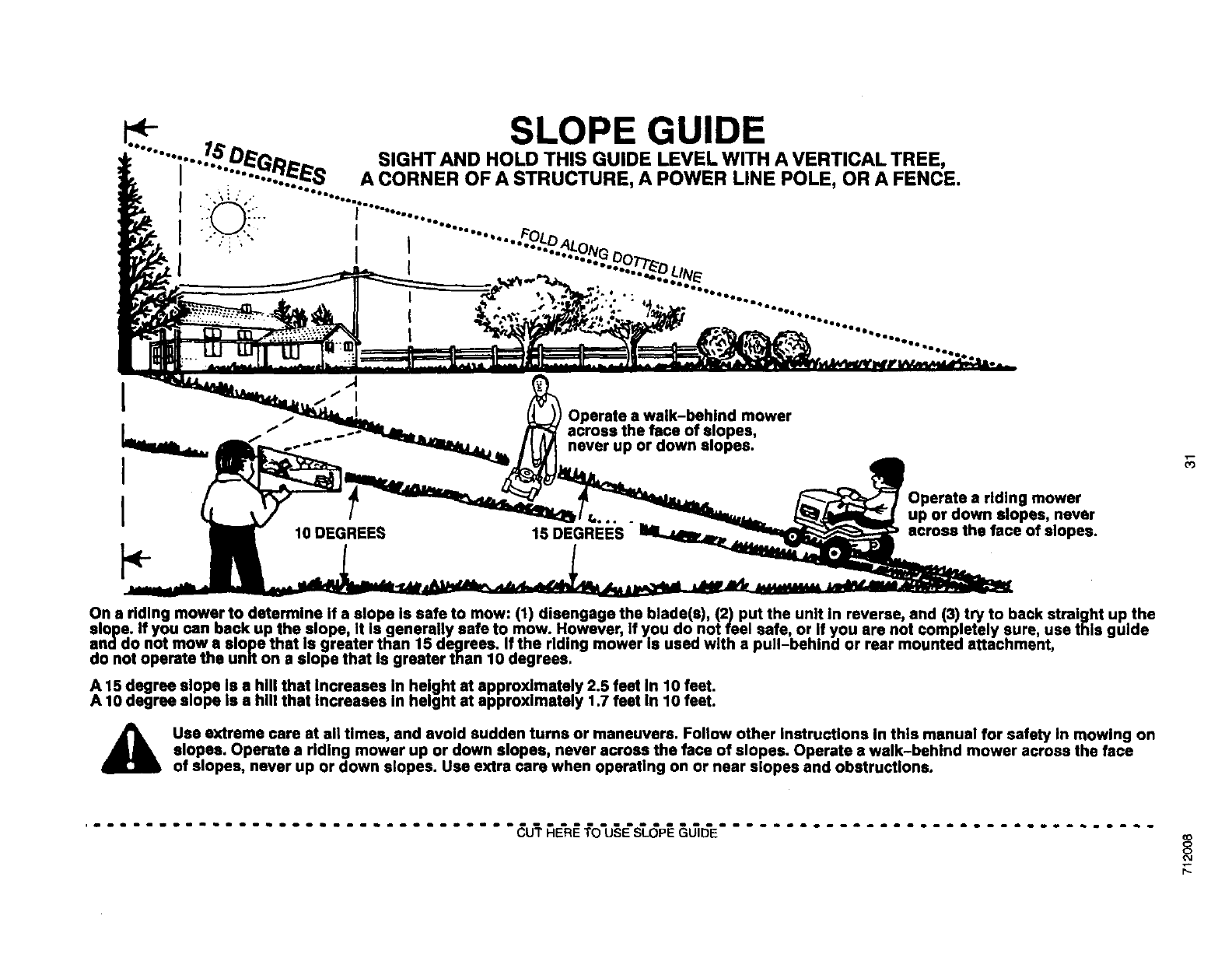
_SLOPE GUIDE
.... •..-..7_.D_(_,... SIGHT AND HOLD THIS GUIDE LEVEL WITH A VERTICAL TREE,
I •...... :._-8 A CORNER OF A STRUCTURE, A POWER LINE POLE, OR A FENCE.
I".......T--........
•:.."--_.•":. I ............ FOL,,-
; " .i' I ....._.._LoNr.,._
I i ..... "_UUTT/_h
' ...... .................................
I
I
I
p- IODEGREES
IOperate a walk-behind mower
across the face of elopes,
never up or down elopes.
Operate a riding mower
up or down elopes, never
across the face of slopes.
On a riding mower to determine if a slope is safe to mow: (1) disengage the blade(s), (2) put the unit in reverse and (3) try to back straight up the
slope. If you ran back up the slope, It Is generally safe to mow. However, If you do not feel safe, or If you are not completely sure, use this guide
anddo not mow • mop.e that is greater than 15 degrees. If the riding mower Is used with a pull-behind or rear mounted attachment,
do not operate the unr[ on a elope that Is greater than 10 degrees.
A 15 degree slope Is a hill that Increases In height at approximately 2.5 feet In 10 feet.
A 10 degree slope Is a hill that Increases in height at approximately 1.7 feet In 10 feet.
Use extreme care at all tlmee, and avoid sudden turns or maneuvers. Follow other instructions In this manual for safety In mowing on
slopes. Operate a riding mower up or down slopee, never across the face of slopes. Operate a walk-behind mower across the face
of elopes, never up or down slopes. Use extra care when operating on or near slopes and obstructions.
................................. _ _E'R¢"fo'u§E'ST__p_&_'E ................................. to
8
O4
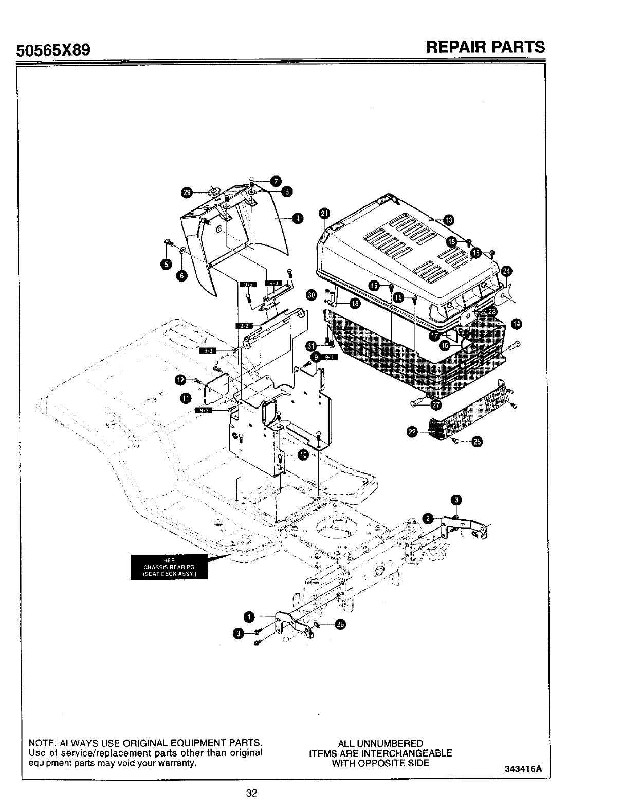
50565X89 REPAIR PARTS
..~,
NOTE: ALWAYS USE ORIGINAL EQUIPMENT PARTS.
Use of service/replacement parts other than original
equipment parts may void your warranty.
ALL UNNUMBERED
ITEMS ARE INTERCHANGEABLE
WITH OPPOSITE SIDE 343416A
32
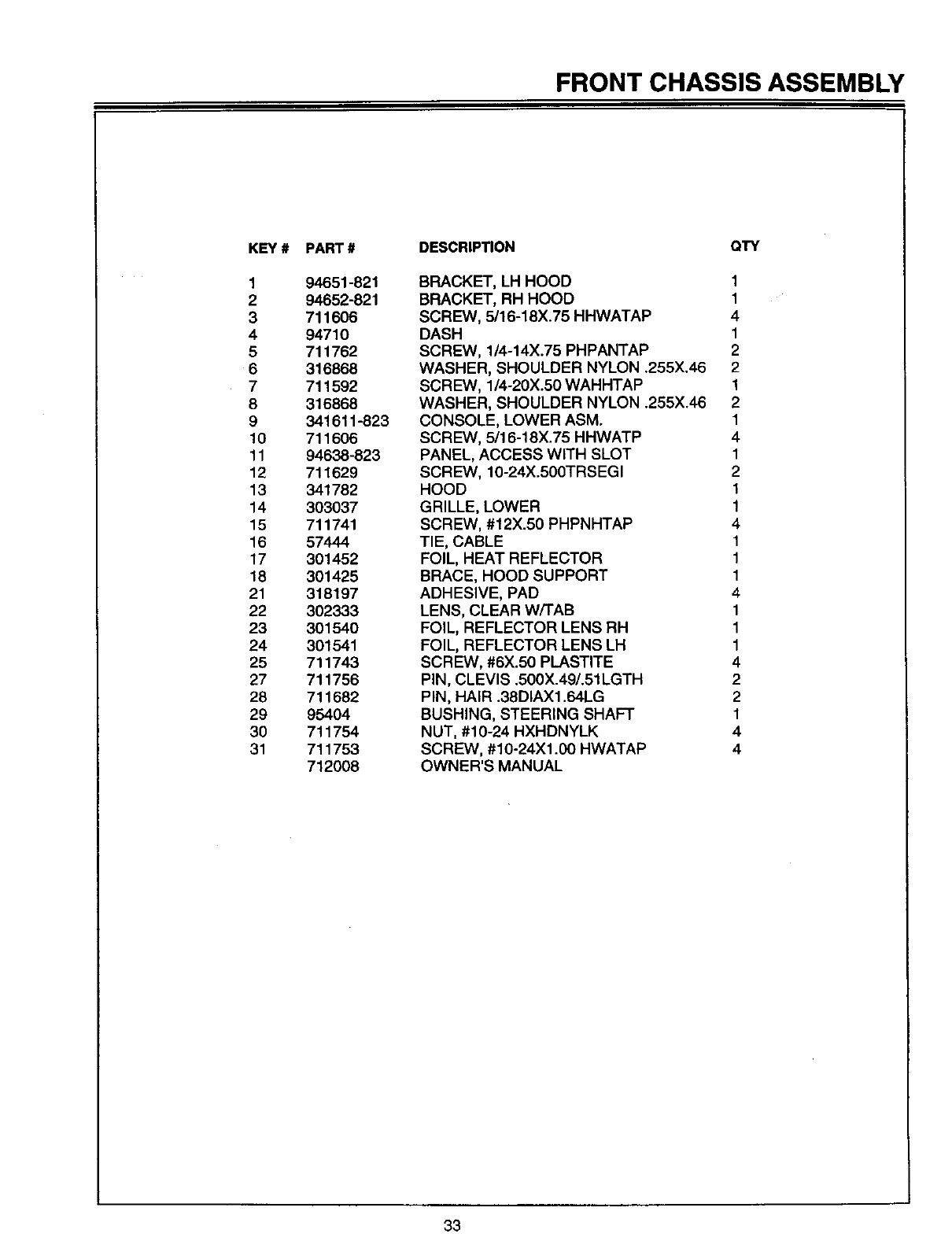
FRONT CHASSIS ASSEMBLY
KEY #
1
2
3
4
5
6
7
8
9
10
11
12
13
14
15
16
17
18
21
22
23
24
25
27
28
29
30
31
PART#
94651-821
94652-821
711606
94710
711762
316868
711592
316868
341611-823
711606
94638-823
711629
341782
303037
711741
57444
301452
301425
318197
302333
301540
301541
711743
711756
711682
95404
711754
711753
712008
DESCRIPTION QTY
BRACKET, LH HOOD 1
BRACKET, RH HOOD 1
SCREW, 5116-18X.75 HHWATAP 4
DASH 1
SCREW, 1/4-14X.75 PHPANTAP 2
WASHER, SHOULDER NYLON .255X.46 2
SCREW, 1/4-20X.50 WAHHTAP 1
WASHER, SHOULDER NYLON .255X.46 2
CONSOLE, LOWER ASM. 1
SCREW, 5/16-18X.75 HHWATP 4
PANEL, ACCESS WITH SLOT 1
SCREW, 10-24X.500TRSEGI 2
HOOD 1
GRILLE, LOWER 1
SCREW, #12X.50 PHPNHTAP 4
TIE, CABLE 1
FOIL, HEAT REFLECTOR 1
BRACE, HOOD SUPPORT 1
ADHESIVE, PAD 4
LENS, CLEAR W/TAB 1
FOIL, REFLECTOR LENS RH 1
FOIL, REFLECTOR LENS LH 1
SCREW, #6X.50 PLASTITE 4
PiN, CLEVIS .500X.49/.51LGTH 2
PIN, HAIR .38DIAX1.64LG 2
BUSHING, STEERING SHAFT 1
NUT, #10-24 HXHDNYLK 4
SCREW, #10-24Xl .00 HWATAP 4
OWNER'S MANUAL
33
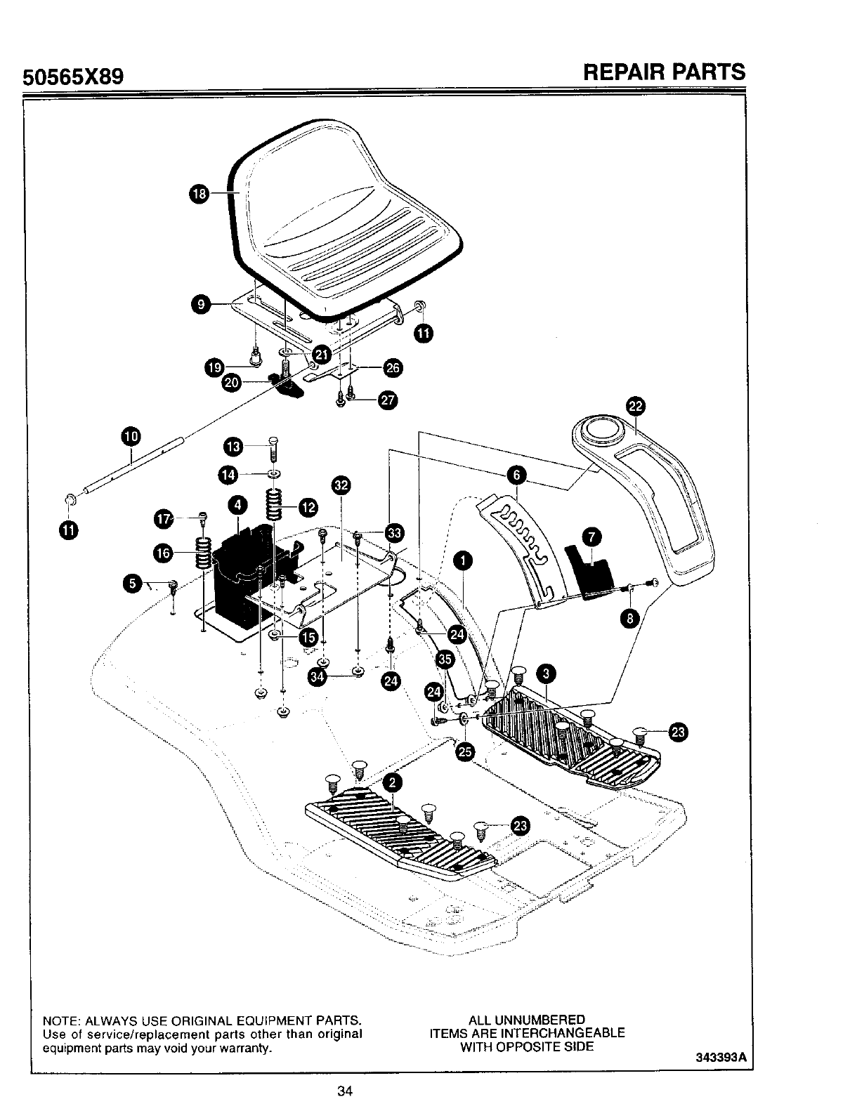
50565X89 REPAIR PARTS
J
I
O
%
®
%
NOTE: ALWAYS USE ORIGINAL EQUIPMENT PARTS.
Use of service/replacement parts other than original
equipment parts may void your warranty.
ALLUNNUMBERED
ITEMS AREINTERCHANGEABLE
WITH OPPOSITESIDE 343393_
34
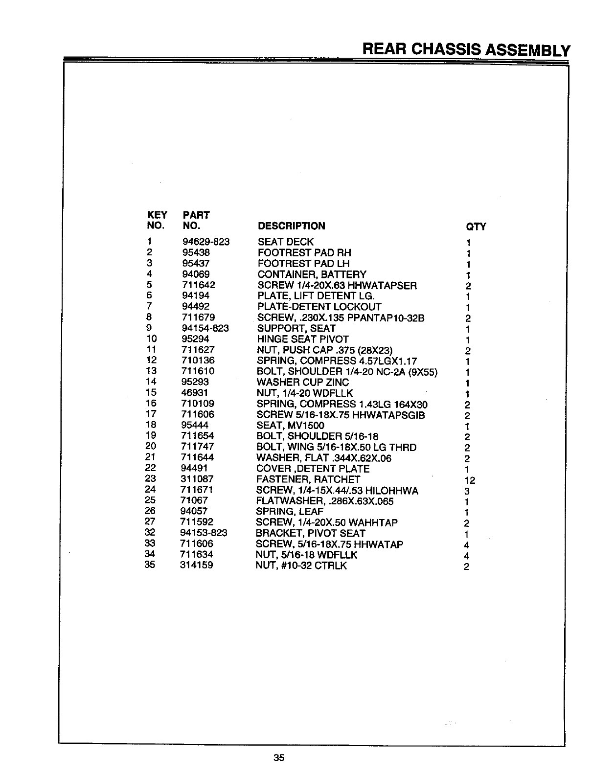
REAR CHASSIS ASSEMBLY
KEY
NO,
1
2
3
4
5
6
7
8
9
10
11
12
13
14
15
16
17
18
19
20
21
22
23
24
25
26
27
32
33
34
35
PART
NO.
94629-823
95438
95437
94069
711642
94194
94492
711679
94154-823
95294
711627
710136
711610
95293
46931
710109
711606
95444
711654
711747
711644
94491
311087
711671
71067
94057
711592
94153-823
711606
711634
314159
DESCRIPTION
SEAT DECK
FOOTREST PAD RH
FOOTREST PAD LH
CONTAINER, BATTERY
SCREW 1/4-20X.63 HHWATAPSER
PLATE, LIFT DETENT LG.
PLATE-DETENT LOCKOUT
SCREW, .230X.135 PPANTAP10-32B
SUPPORT, SEAT
HINGE SEAT PIVOT
NUT, PUSH CAP .375 (28X23)
SPRING, COMPRESS 4.57LGXl.17
BOLT, SHOULDER 1/4-20 NC-2A (9X55)
WASHER CUP ZINC
NUT, 1/4-20 WDFLLK
SPRING, COMPRESS 1.43LG 164X30
SCREW 5116-18X.75 HHWATAPSGIB
SEAT, MV1500
BOLT, SHOULDER 5/16-18
BOLT, WING 5/16-18X.50 LG THRD
WASHER, FLAT .344X.62X.06
COVER ,DETENT PLATE
FASTENER, RATCHET
SCREW, 1/4-15X.44/.53 HILOHHWA
FLATWASHER, .286X.63X.065
SPRING, LEAF
SCREW, 1/4-20X.50 WAHHTAP
BRACKET, PIVOT SEAT
SCREW, 5116-18X.75 HHWATAP
NUT, 5/16-18 WDFLLK
NUT, #10-32 CTRLK
QTY
1
1
1
1
2
1
1
2
1
1
2
1
1
1
1
2
2
1
2
2
2
1
12
3
1
1
2
1
4
4
2
35
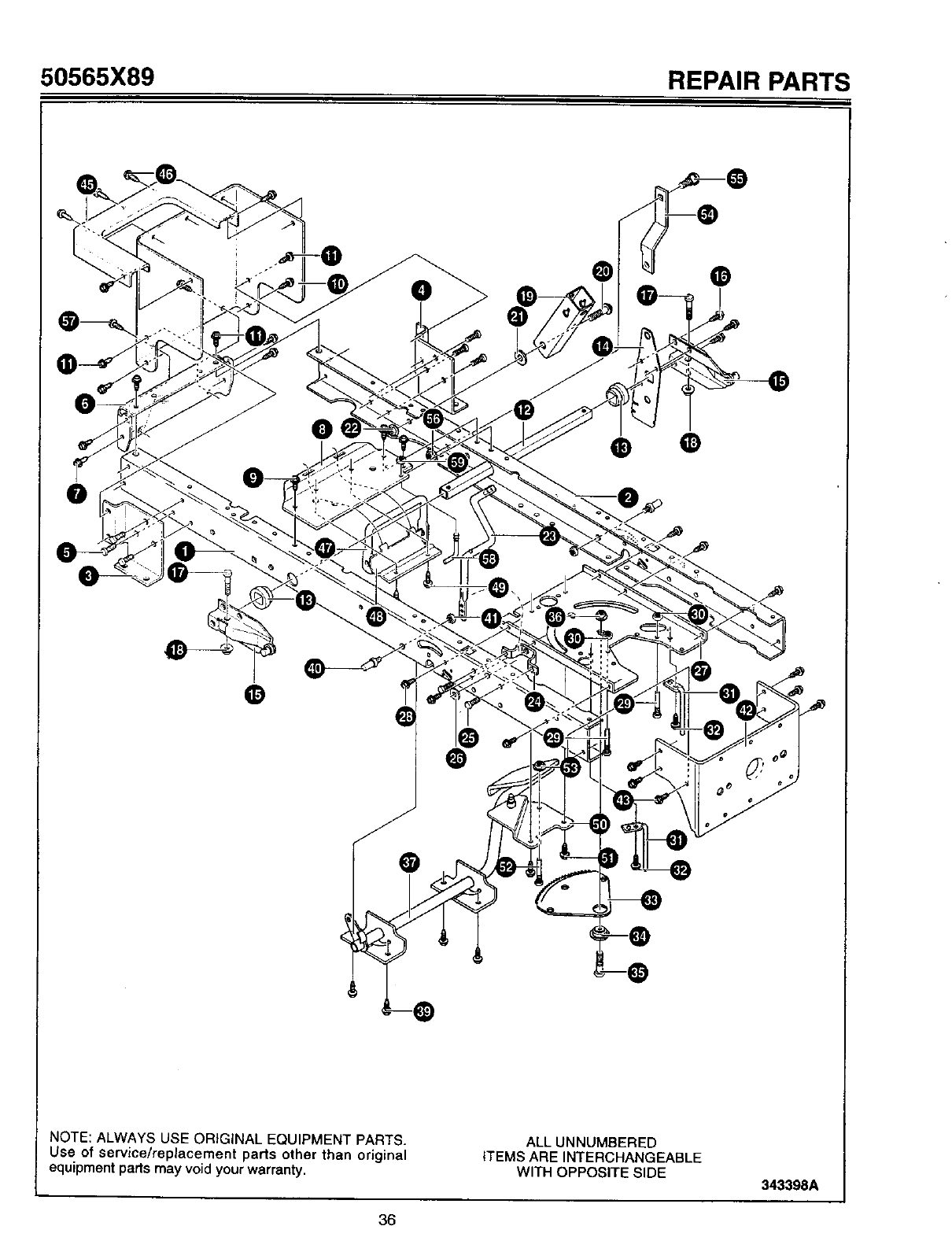
50565X89 REPAIR PARTS
NOTE: ALWAYS USE ORIGINAL EQUIPMENT PARTS.
Use of service/replacement parts other than original
equipment parts may void your warranty.
ALL UNNUMBERED
ITEMS ARE INTERCHANGEABLE
WITH OPPOSITE SIDE 343398A
36
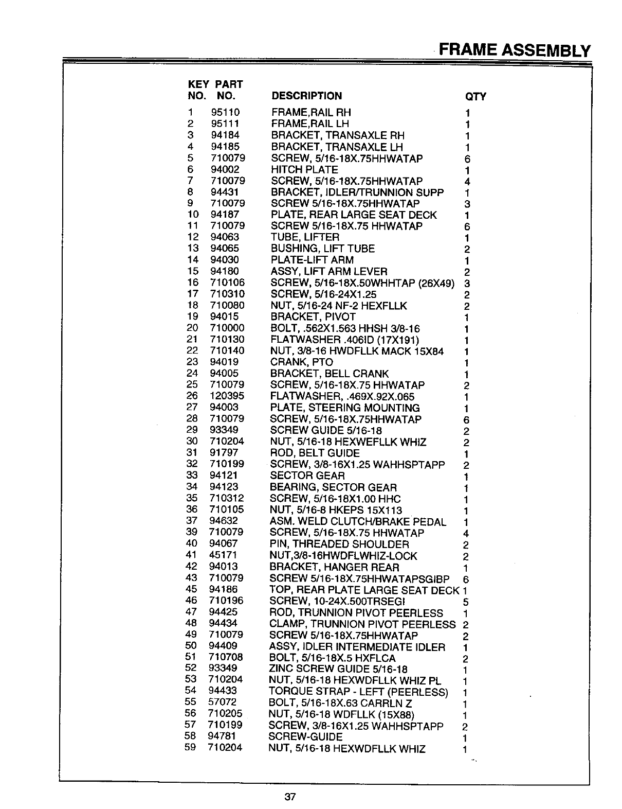
FRAME ASSEMBLY
KEY PART
NO, NO.
1 95110
295111
3 94184
4 94185
5 71O079
6 94002
7710079
8 94431
9 710079
10 94187
11 710079
12 94063
13 94065
14 94030
15 94180
16 710106
17 710310
18 710080
19 94015
20 710000
21 710130
22 710140
23 94019
24 94005
25 710079
26 120395
27 94003
28 710079
29 93349
30 710204
31 91797
32 710199
33 94121
34 94123
35 710312
36 710105
37 94632
39 710079
40 94067
41 45171
42 94013
43 710079
45 94186
46 710196
47 94425
48 94434
49 710079
50 94409
51 710708
52 93349
53 710204
54 94433
55 57072
56 710205
57 710199
58 94781
59 710204
DESCRIPTION QTY
FRAME,RAIL RH 1
FRAME,RAIL LH 1
BRACKET, TRANSAXLE RH 1
BRACKET, TRANSAXLE LH 1
SCREW, 5/16-18X.75HHWATAP 6
HITCH PLATE 1
SCREW, 5/16-18X.75HHWATAP 4
BRACKET, IDLER/TRUNNION SUPP 1
SCREW 5/16-18X.75HHWATAP 3
PLATE, REAR LARGE SEAT DECK 1
SCREW 5/16-18X.75 HHWATAP 6
TUBE, LIFTER 1
BUSHING, LIFT TUBE 2
PLATE-LIFT ARM 1
ASSY, LIFT ARM LEVER 2
SCREW, 5/16-18X.50WHHTAP (26X49) 3
SCREW, 5/16-24X1.25 2
NUT, 5/16-24 NF-2 HEXFLLK 2
BRACKET, PIVOT 1
BOLT, .562Xl .563 HHSH 3/8-16 1
FLATWASHER .4061D (17X191) 1
NUT, 3/8-16 HWDFLLK MACK 15X84 1
CRANK, PTO 1
BRACKET, BELL CRANK 1
SCREW, 5/16-18X.75 HHWATAP 2
FLATWASHER, .469X.92X.065 1
PLATE, STEERING MOUNTING 1
SCREW, 5/16-18X.75HHWATAP 6
SCREW GUIDE 5/16-18 2
NUT, 5/16-18 H EXWEFLLK WHIZ 2
ROD, BELT GUIDE 1
SCREW, 3/8-16Xl .25 WAHHSPTAPP 2
SECTOR GEAR 1
BEARING, SECTOR GEAR 1
SCREW, 5/16-18Xl .OOHHC 1
NUT, 5/16-8 HKEPS 15X113 1
ASM. WELD CLUTCH/BRAKE PEDAL 1
SCREW, 5/16-18X.75 HHWATAP 4
PIN, THREADED SHOULDER 2
NUT,3/8-16HWDFLWHIZ-LOCK 2
BRACKET, HANGER REAR 1
SCREW 5/16-18X.75HHWATAPSGIBP 6
TOP, REAR PLATE LARGE SEAT DECK 1
SCREW, 10-24X.500TRSEGI 5
ROD, TRUNNION PIVOT PEERLESS 1
CLAMP, TRUNNION PIVOT PEERLESS 2
SCREW 5/16-18X.75HHWATAP 2
ASSY, IDLER INTERMEDIATE IDLER 1
BOLT, 5/16-18X.5 HXFLCA 2
ZINC SCREW GUIDE 5/16-18 1
NUT, 5/16-18 HEXWDFLLK WHIZ PL 1
TORQUE STRAP - LEFT (PEERLESS) 1
BOLT, 5/16-18X.63 CARRLN Z 1
NUT, 5/16-18 WDFLLK (15X88) 1
SCREW, 3/8-16Xl .25 WAHHSPTAPP 2
SCREW-GUIDE 1
NUT, 5/16-18 HEXWDFLLK WHIZ 1
37
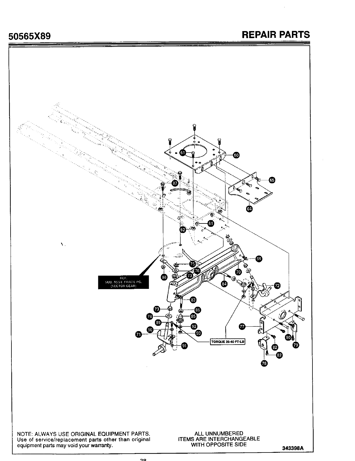
50565X89 REPAIR PARTS
®
TORQUE 2540 FT"LBI O
NOTE: ALWAYS USE ORIGINAL EQUIPMENT PARTS. ALL UNNUMBERED
Use of service/replacement parts other than original ITEMS ARE INTERCHANGEABLE
equipment parts may void your warranty. WITH OPPOSITE SIDE 343398A
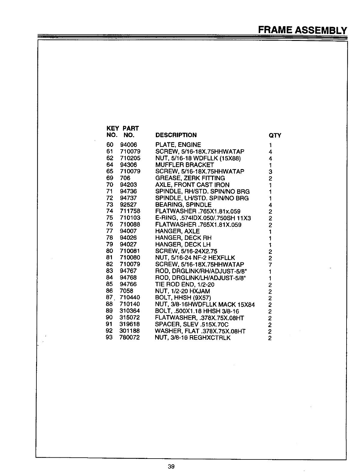
FRAME ASSEMBLY
KEY PART
NO. NO.
60 94006
61 710079
62 710205
64 94306
65 710079
69 706
70 94203
71 94736
72 94737
73 92527
74 711758
75 710103
76 710088
77 94007
78 94026
79 94027
80 710081
81 710080
82 710079
83 94767
84 94768
85 94766
86 7058
87 710440
88 710140
89 310364
90 315072
91 319618
92 301188
93 780072
DESCRIPTION
PLATE, ENGINE
SCREW, 5/16-18X.75HHWATAP
NUT, 5/16-18 WDFLLK (15X88)
MUFFLER BRACKET
SCREW, 5/16-18X.75HHWATAP
GREASE, ZERK FITTING
AXLE, FRONT CAST IRON
SPINDLE, RH/STD. SPIN/NO BRG
SPINDLE, LH/STD. SPIN/NO BRG
BEARING, SPINDLE
FLATWASHER .765X1.81 x.059
E-RING, .5741DX.050/.750SH 11X3
FLATWASHER .765X1.81X.059
HANGER, AXLE
HANGER, DECK RH
HANGER, DECK LH
SCREW, 5/16-24X2.75
NUT, 5/16-24 NF-2 HEXFLLK
SCREW, 5/16-18X.75HHWATAP
ROD, DRGLINK/RH/ADJUST-5/8"
ROD, DRG LINKJLH/ADJUST-5/8"
TIE ROD END, 1/2-20
NUT, 1/2-20 HXJAM
BOLT, HHSH (9X57)
NUT, 3/8-16HWDFLLK MACK 15X84
BOLT, .500X1.18 HHSH 3/8-16
FLATWASHER, .378X.75X.08HT
SPACER, SLEV .515X.70C
WASHER, FLAT .378X.75X.08HT
NUT, 3/8-16 REGHXCTRLK
QTY
1
4
4
1
3
2
1
1
1
4
2
2
2
1
1
1
2
2
7
1
1
2
2
2
2
2
2
2
2
2
39
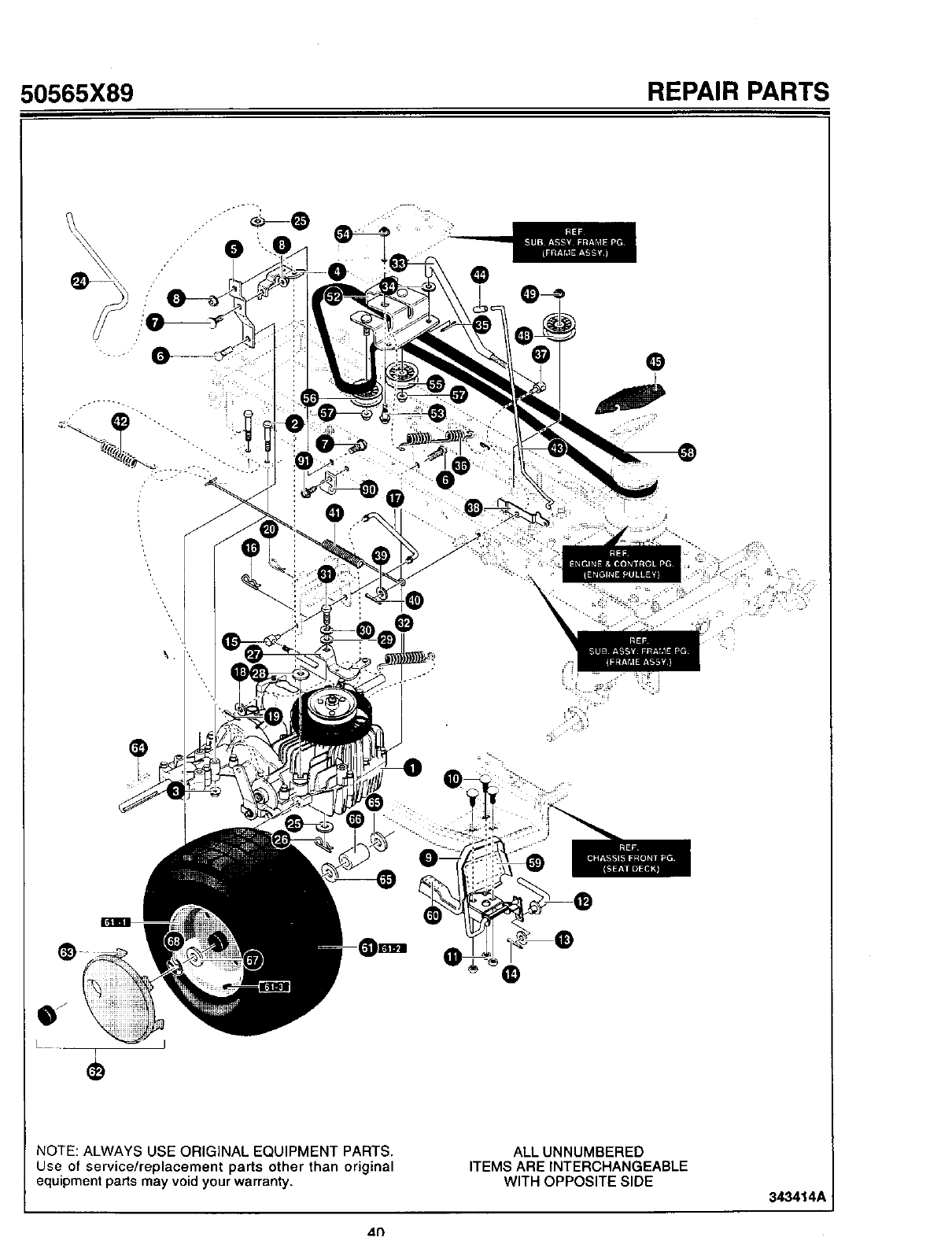
50565X89 REPAIR PARTS
\,
+t -=;_+ • • • • • ?:
°°
NOTE: ALWAYS USE ORIGINAL EQUIPMENT PARTS.
Use of service/replacement parts other than original
equipment parts may void your warranty.
ALL UNNUMBERED
ITEMS ARE INTERCHANGEABLE
WITH OPPOSITE SIDE 3434141
41")
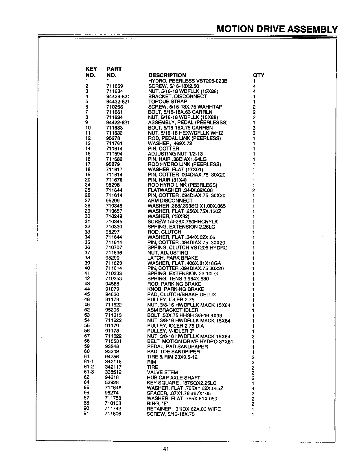
MOTION DRIVE ASSEMBLY
KEY
NO.
1
2
3
4
5
6
7
8
9
lO
11
12
13
14
15
16
17
18
19
2o
24
25
26
27
28
29
3o
31
32
33
34
35
36
37
38
39
4o
41
42
43
44
45
48
49
52
53
54
55
56
57
58
59
60
61
61-1
61-2
61-3
62
64
65
66
67
68
90
91
PART
NO.
711669
711634
94429-821
94432-821
710268
711661
711634
94422-821
711688
711633
95278
711761
711614
711594
711682
95279
711617
711614
711676
95298
711644
711614
95299
710346
710657
710249
710345
710330
95297
711644
711614
710707
711596
95290
711623
711614
710333
710353
94566
91079
94630
91179
711622
95305
711613
711622
91179
91178
711622
710531
93248
93249
94756
342118
342117
338612
94618
52928
711646
95274
711758
710103
711742
711606
DESCRIPTION
HYDRO, PEERLESS VST205-O23B
SCREW, 5/16-18X2.50
NUT, 5/16-18 WDFLLK (15X88)
BRACKET, DISCONNECT
TORQUE STRAP
SCREW, 5/16-18X.75 WAHHTAP
BOLT, 5/16-18X.63 CARRLN
NUT, 5/16-18 WDFLLK (15X88)
ASSEMBLY, PEDAL (PEERLESSS)
BOLT, 5/16-18X.75 CARRSN
NUT, 5/16-18 HEXWDFLLK WHIZ
ROD, PEDAL LINK (PEERLESS)
WASHER, .469X.72
PIN, COTFER
ADJUSTING NUT I/2-13
PIN, HAIR .38DIAX1,64LG
ROD HYDRO LINK (PEERLESS)
WASHER, FLAT (17X91)
PIN, COTTER .094DIAX.75 30X20
PIN, HAIR (31)(4)
ROD HYRO LINK (PEERLESS)
FLATWASHER .344X.62X.06
PIN, COFFER .094DIAX.75 30X20
ARM DISCONNECT
WASHER .388/.393SQ.X1.00X.065
WASHER, FLAT .256X.75X.130Z
WASHER, (18X32)
SCREW 1/4-28X.750HHCNYLK
SPRING, EXTENSION 2.26LG
ROD, CLUTCH
WASHER, FLAT .344X.62X.06
PIN, COTTER .094DIAX.75 30)(20
SPRING, CLUTCH VST205 HYDRO
NUT, ADJUSTING
LATCH, PARK BRAKE
WASHER, FLAT .406X.81X16GA
PIN, COFFER .094DIAX.75 30X20
SPRING, EXTENSION 23,10LG
SPRING, TENS 3,984X.530
ROD, PARKING BRAKE
KNOB, PARKING BRAKE
PAD, CLUTCH/BRAKE DELUX
PULLEY, IDLER 2.75
NUT, 3/8-16 HWDFLLK MACK 15X84
ASM BRACKET IDLER
BOLT .50X.75 HHSH 3/6-16 9X39
NUT, 3/8-16 HWDFLLK MACK 15X84
PULLEY, IDLER 2.75 DIA
PULLEY, V-IDLER 3"
NUT, 3/8-16 HWDFLLK MACK 15X84
BELT, MOTION DRIVE HYDRO 37X61
PEDAL, PAD SANDPAPER
PAD, TOE SANDPIPER
TIRE & RIM 23X9.5-12
RIM
TIRE
VALVE STEM
HUB CAP AXLE SHAFT
KEY SQUARE. 187SQX2.25LG
WASHER, FLAT .765Xl .62X.065Z
SPACER, .87Xl.78 #87X105
WASHER, FLAT .765X.81X.059
RING, "E"
RETAINER, .311DX.62X.03 WIRE
SCREW, 5/16-18X.75
QTY
1
4
4
1
1
2
2
2
1
3
3
1
1
1
1
1
1
1
1
1
1
2
1
1
1
1
I
1
1
1
1
I
1
1
1
1
1
1
1
1
1
1
1
1
1
1
1
1
1
2
1
1
1
2
2
2
2
2
1
4
2
2
2
1
1
41
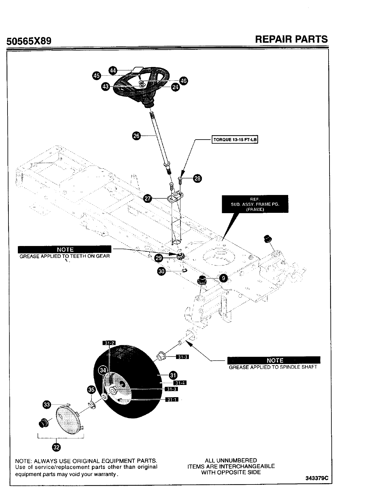
50565X89 REPAIR PARTS
TORQUE1_15FT-LB]
GREASE APPLIED TO TEETH ON GEAR
![I]ll
GREASE APPLIED TO SPINDLE SHAFT
I J
e
NOTE: ALWAYS USE ORIGINAL EQUIPMENT PARTS•
Use of service/replacement parts other than original
equipment parts may void your warranty.
ALL UNNUMBERED
ITEMS ARE INTERCHANGEABLE
WITH OPPOSITE SIDE 343379(
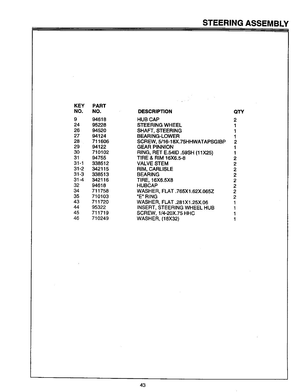
STEERING ASSEMBLY
KEY
NO.
9
24
26
27
28
29
30
31
31-1
31-2
31-3
31-4
32
34
35
43
44
45
46
PART
NO.
94618
95228
94520
94124
711606
94122
710102
94755
338512
342115
338513
342116
94618
711758
710103
711720
95322
711719
710249
DESCRIPTION QTY
HUB CAP 2
STEERING WHEEL 1
SHAFT, STEERING 1
BEARING-LOWER 1
SCREW, 5/16-18X.75HHWATAPSGIBP 2
GEAR PINNION 1
RING, RET E.541D .59SH (11X25) 1
TIRE & RIM 16X6.5-8 2
VALVE STEM 2
RIM, CARLISLE 2
BEARING 2
TIRE, 16X6.5X8 2
HUBCAP 2
WASHER, FLAT .765X1.62X.065Z 2
"E" RING 2
WASHER, FLAT .281X1.25X.06 1
INSERT, STEERING WHEEL HUB 1
SCREW, 1/4-20X.75 HHC 1
WASHER, (18X32) 1
43
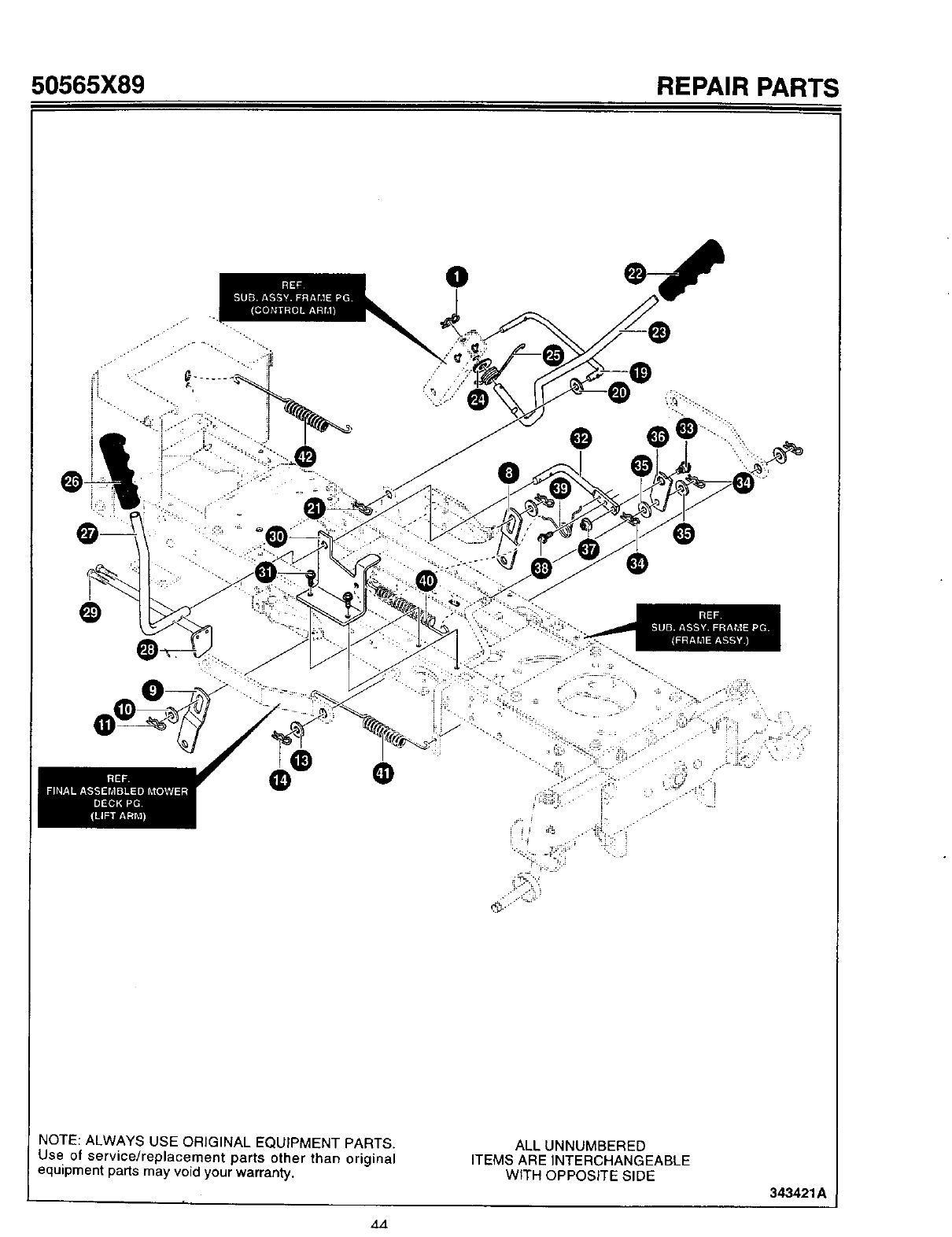
50565X89 REPAIR PARTS
III
NOTE: ALWAYS USE ORIGINAL EQUIPMENT PARTS•
Use of service/replacement parts other than original
equipment parts may void your warranty.
ALLUNNUMBERED
ITEMS AREINTERCHANGEABLE
WITH OPPOSITESIDE
343421A
,t.t
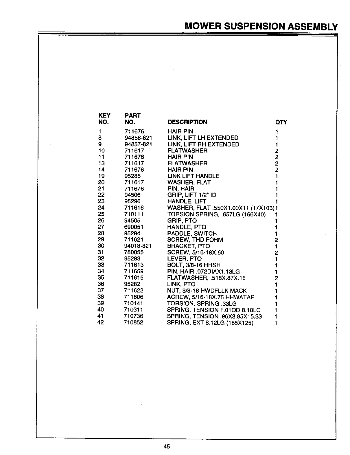
MOWER SUSPENSION ASSEMBLY
KEY
NO.
1
8
9
10
11
13
14
19
20
21
22
23
24
25
26
27
28
29
30
31
32
33
34
35
36
37
38
39
40
41
42
PART
NO.
711676
94858-821
94857-821
711617
711676
711617
711676
95285
711617
711676
94506
95296
711616
710111
94505
690051
95284
711621
94018-821
780O55
95283
711613
711659
711615
95282
711622
711606
710141
710311
710736
710852
DESCRIPTION QTY
HAIR PIN
LINK, LIFT LH EXTENDED
LINK, LIFT RH EXTENDED
FLATWASHER
HAIR PIN
FLATWASHER
HAIR PIN
LINK LIFT HANDLE
WASHER, FLAT
PIN, HAIR
GRIP, LIFT 1/2" ID
HANDLE, LIFT
1
1
1
2
2
2
2
1
1
1
1
1
WASHER, FLAT .550X1.00X11 (17X103) 1
TORSION SPRING, .657LG (166X40) 1
GRIP, PTO 1
HANDLE, PTO 1
PADDLE, SWITCH 1
SCREW, THD FORM 2
BRACKET, PTO 1
SCREW, 5/16-18X.50 2
LEVER, PTO 1
BOLT, 3/8-16 HHSH 1
PIN, HAIR .072DIAX1.13LG 1
FLATWASH ER, .518X.87X. 16 2
LINK, PTO 1
NUT, 3/8-16 HWDFLLK MACK 1
ACREW, 5/16-18X.75 HHWATAP 1
TORSION, SPRING .33LG 1
SPRING, TENSION 1.01OD 8.18LG 1
SPRING, TENSION .96X3.85X15.33 1
SPRING, EXT 8.12LG (165X125) 1
45
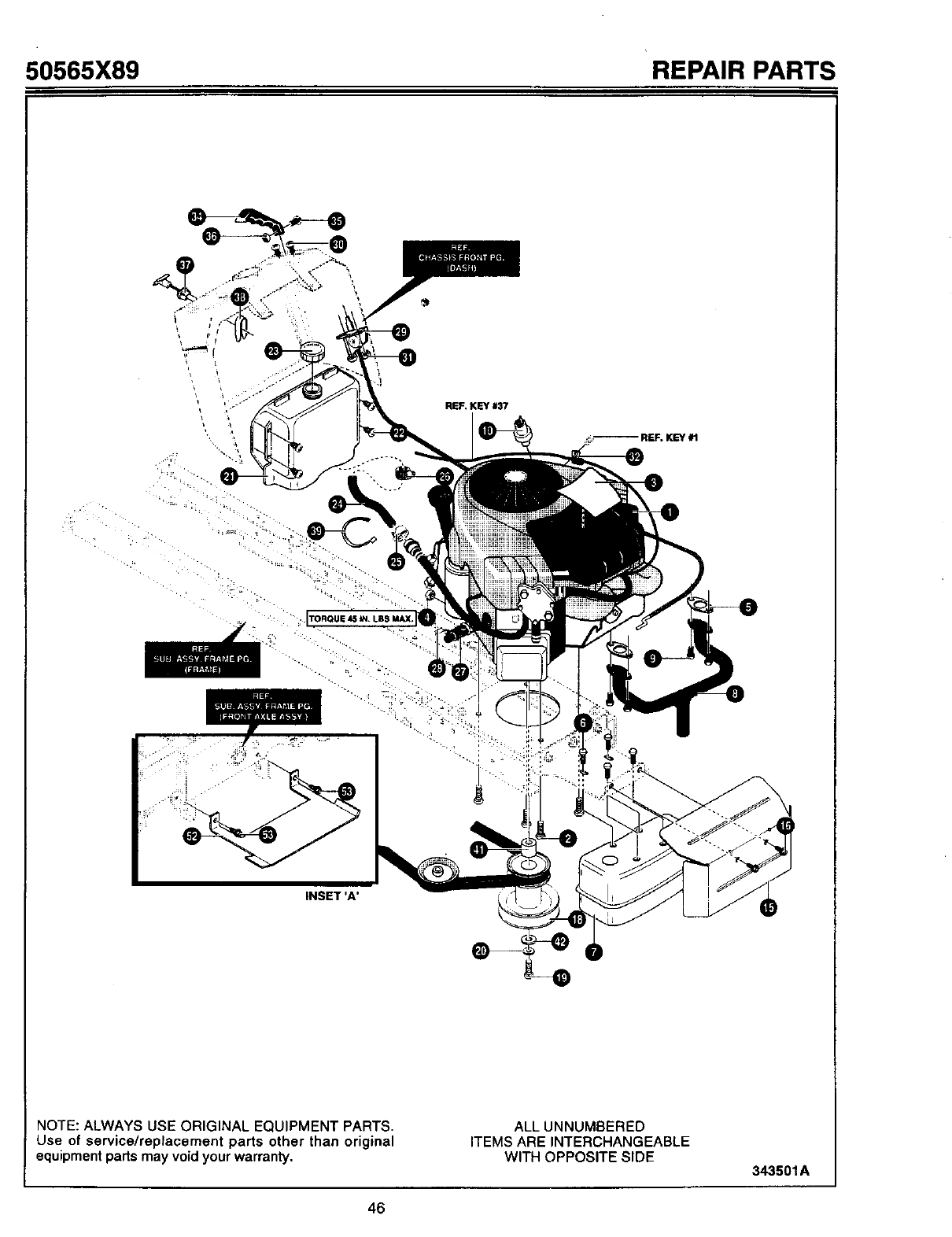
50565X89 REPAIR PARTS
REF. KEY #37
• . ..-...
INSET 'A'
NOTE: ALWAYS USE ORIGINAL EQUIPMENT PARTS.
Use of service/replacement parts other than original
equipment parts may void your warranty.
ALLUNNUMSERED
ITEMS AREINTERCHANGEABLE
WITH OPPOSITESIDE 343501A
46
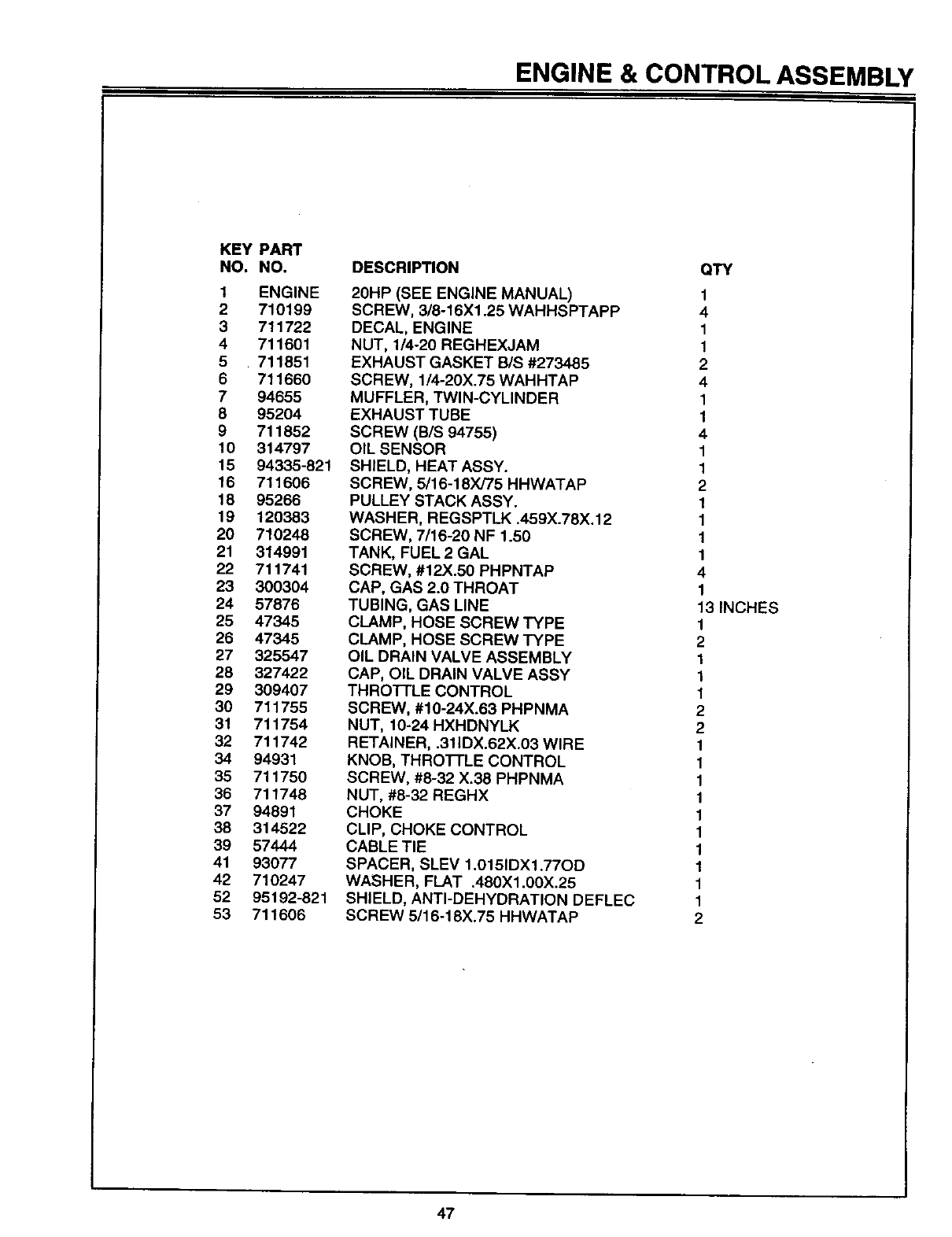
ENGINE & CONTROL ASSEMBLY
KEY PART
NO. NO.
1 ENGINE
2710199
3 711722
4711601
5 711851
6 711660
7 94655
8 95204
9711852
10 314797
15 94335-821
16 711606
18 95266
19 120383
20 710248
21 314991
22 711741
23 300304
24 57876
25 47345
26 47345
27 325547
28 327422
29 309407
30 711755
31 711754
32 711742
34 94931
35 711750
36 711748
37 94891
38 314522
39 57444
41 93077
42 710247
52 95192-821
53 711606
DESCRIPTION
20HP (SEE ENGINE MANUAL)
SCREW, 3/8-16X1.25 WAHHSPTAPP
DECAL, ENGINE
NUT, 1/4-20 REGHEXJAM
EXHAUST GASKET B/S #273485
SCREW, 1/4-20X.75 WAHHTAP
MUFFLER, TWIN-CYLINDER
EXHAUST TUBE
SCREW (B/S 94755)
OIL SENSOR
SHIELD, HEAT ASSY.
SCREW, 5/16-18)(/75 HHWATAP
PULLEY STACK ASSY.
WASHER, REGSPTLK .459X.78X.12
SCREW, 7/16-20 NF 1.50
TANK, FUEL 2 GAL
SCREW, #12X.50 PHPNTAP
CAP, GAS 2.0 THROAT
TUBING, GAS LINE
CLAMP, HOSE SCREW TYPE
CLAMP, HOSE SCREW TYPE
OIL DRAIN VALVE ASSEMBLY
CAP, OIL DRAIN VALVE ASSY
THRO'I-rLE CONTROL
SCREW, #10-24X.63 PHPNMA
NUT, 10-24 HXHDNYLK
RETAINER, .311DX.62X.03 WIRE
KNOB, THROTTLE CONTROL
SCREW, #8-32 X.38 PHPNMA
NUT, #8-32 REGHX
CHOKE
CLIP, CHOKE CONTROL
CABLE TIE
SPACER, SLEV 1.0151DXl .77OD
WASHER, FLAT .480X1.00X.25
SHIELD, ANTI-DEHYDRATION DEFLEC
SCREW 5/16-18X.75 HHWATAP
QTY
1
4
1
1
2
4
1
1
4
1
1
2
1
1
1
1
4
1
13 INCHES
1
2
1
1
1
2
2
1
1
1
1
1
1
1
1
1
1
2
47
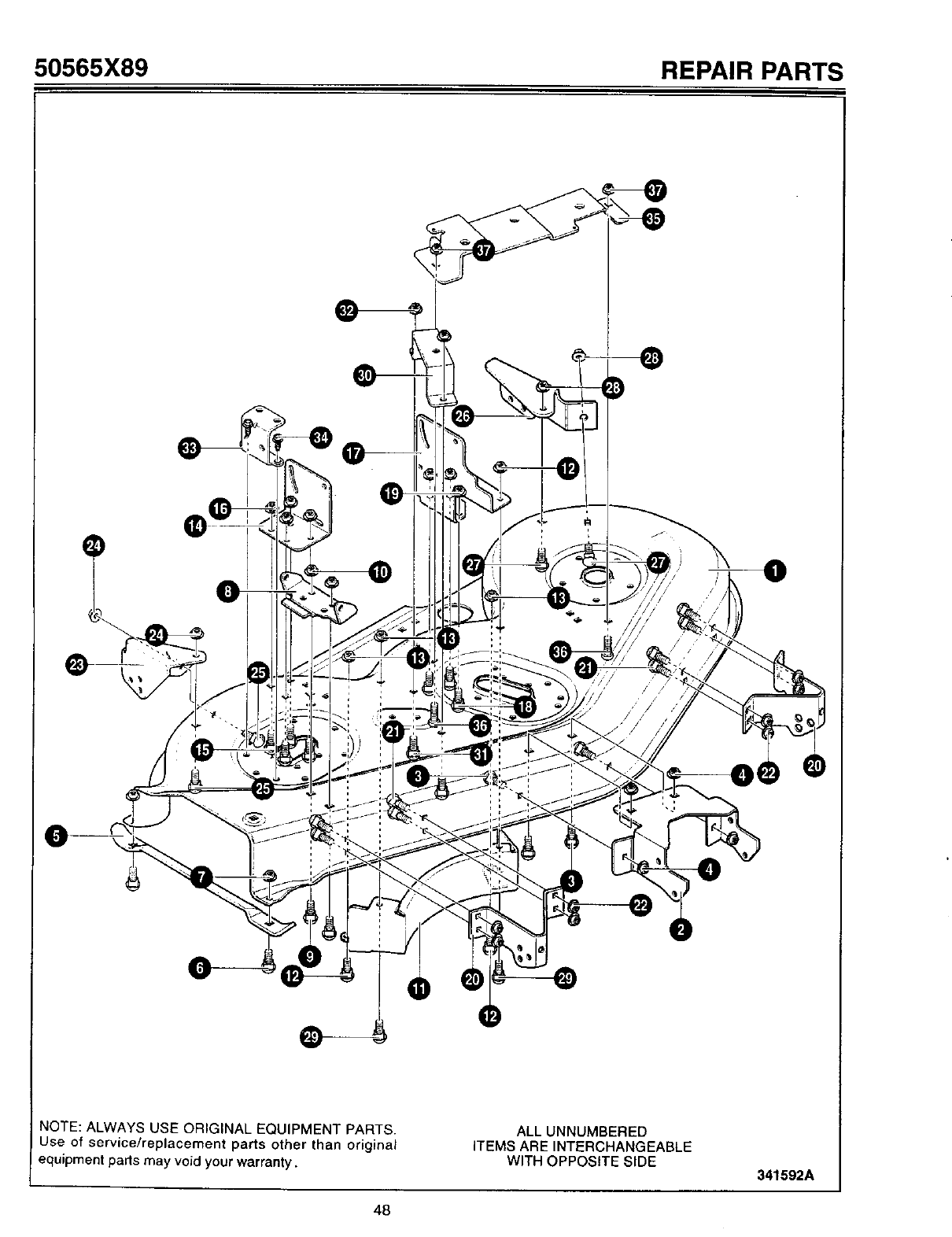
50565X89 REPAIR PARTS
O
NOTE: ALWAYS USE ORIGINAL EQUIPMENT PARTS.
Use of service/replacement parts other than original
equipment parts may void your warranty.
ALL UNNUMBERED
iTEMS ARE INTERCHANGEABLE
WITH OPPOSITE SIDE 341592A
48

PRE-PAINTED DECK ASSEMBLY
KEY
NO.
1
2
3
4
5
6
7
8
9
10
11
12
13
14
15
16
17
18
19
20
21
22
23
24
26
26
27
28
29
3O
31
32
33
34
35
36
37
PART
NO.
94663
94693
57072
710204
95176
57072
710205
92104
57072
710205
94825
57072
710204
94694
57072
710204
94695
57072
710204
95180
57072
710204
94716
710204
57072
94717
57072
710204
710079
94601
57072
710204
92140
710079
94699
57072
710204
DESCRIPTION
BLADE HOUSING 50"
BRACKET, FRONT DECK
BOLT, 5/16-18X.63 CARR.
NUT, 5/16-18 HEXWDFLLK WHIZ
BRACKET, CHUTE SUPPORT
BOLT, 5/16-18X.63 CARR.
NUT 5/16-18 WDFLLK (15X88)
HINGE, CHUTE BRACKET
BOLT 5/16-18X.63 CARR.
NUT, 5/16-18 WDFLLK (15X88)
BAFFLE, CENTER 50"
BOLT, 5/16-18X.63 CARR.
NUT, 5/16-18 HEXWDFLLK WHIZ
BRACKET, LIFTER RH
BOLT, 5/16-18X.63 CARR.
NUT 5/16-18 HEXWDFLLK WHIZ
BRACKET, LIFTER LH
BOLT, 5/16-18X.63 CARR.
NUT, 5/16-18 HEXWDFLLK WHIZ
BRACKET, GAGE WHEEL FRONT
BOLT, 5/16-18X.63 CARR.
NUT, 5/16-18 HEXWDFLLK WHIZ
BRACKET, GAGE WHEEL RH
NUT, 5/16-18 HEXWDFLLK WHIZ
BOLT, 5/16-18X,63 CARR.
BRACKET, GAGE WHEEL LR
BOLT, 5/16-18X.63 CARR.
NUT, 5/16-18 HEXWDFLLK WHIZ
SCREW, 5/16-18X.75HHWATAP
BRACKET, BELL CRANK
BOLT, 5/16-18X.63 CARR.
NUT, 5/16-18 HEXWDFLLK WHIZ
BRACKET, PULLEY COVER
SCREW, 5/16-18X.75 HHWATAP
BRACKET, BRAKE MT
BOLT, 5/16-18X.63 CARR.
NUT, 5/16-18 HEXWDFLLK WHIZ
QTY
1
1
4
4
1
2
2
1
2
2
1
4
4
1
4
4
1
4
4
1
8
8
1
2
2
1
2
2
2
1
2
2
1
2
1
2
2
49
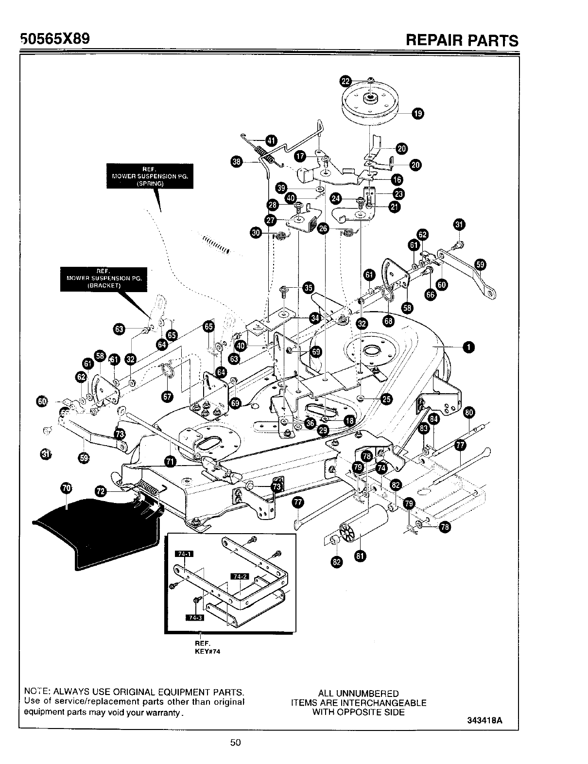
50565X89 REPAIR PARTS
REF.
KEY#74
NQ_"E: ALWAYS USE ORIGINAL EQUIPMENT PARTS.
Use of service/replacement parts other than original
equipment parts may void your warranty.
ALL UNNUMBERED
ITEMS ARE INTERCHANGEABLE
WITH OPPOSITE SIDE 343418A
5O

DECKASSEMBLY
KEY
NO.
1
16
17
18
19
2O
21
22
23
24
25
26
27
28
29
3O
31
32
34
35
36
38
39
4O
41
58
59
6O
61
62
63
64
65
66
67
68
69
70
71
72
73
74
74-1
74-2
74-3
,77
78
79
8O
81
82
83
84
PART
NO.
341592-821
94702-821
711613
711622
95272
94809
711609
711622
94697-921
711613
711622
710227
94698-821
711613
711622
710227
711612
711622
94808-821
711613
711622
94703
711759
711614
710331
94128-821
94055-821
711600
94137
711628
711595
711616
711676
711611
710112
710113
711622
92100
95281
710220
711627
690056-821
94058
95057
711079
95295
71 "1617
711676
95302
92137
91925
711616
711635
DESCRIPTION
ASM, BLADE HOUSING 50"
ARM, IDLER CLUTCHING 50"
BOLT, .50X.75 HHSH 3/8-16 9X39
NUT, 3/8-16 HWDFLLK MACK 15X84
IDLER PULLEY 5"
SPRING, BELT GUIDE
SCREW 3/8-16X2.00
NUT 3/8-16 HWDFLLK MACK 15X84
ASM. BRAKE ARM & PAD LH
BOLT, .50X.75HHSH 3/8-16
NUT, 3/8-16 HWDFLLK MACK
TORSION SPRING .55LG (166X41)
ASM. BRAKE ARM & PAD CENTER
BOLT, .50X.75HHSH 3/8-16
NUT, 3/8-16 HWDFLLK MACK
TORSION SPRING .55LG (166X41)
BOLT, SHOULDER 3/8-16 (9X52)
NUT, 3/8-16 HWDFLLK MACK
BELLCRANK 50"
BOLT, .50X.75HHSH 3/8-16
NUT, 3/8-16HWDFLLK MACK
LINK, 50"
WASHER, FLAT .406X.812X.O6HT
PIN, COTFER .094DIAX.75 30)(20
SPRING, TENSION 4.57LG
PLATE SUSPENSION
SUSPENSION BRACKET REAR
WlNGNUT 5/16-18
PAD, FRICTION
WASHER (17X45)
PIN, HANGER
WASHER, FLAT .550X1.00X11
PIN, HAIR
BOLT, SHOULDER .375 (9X51)
SPRING, TORSION .68LG RH 166X42
SPRING, TORSION .68LG LH 166X43
NUT 3/8-16 HWDFLLK MACK 15X84
DEFLECTOR, DECK CHUTE
ROD DEFLECTOR
SPRING, TORSION
NUT, PUSH CAP .375 (28X32)
ASM., BRACKET & STIFFENER
BRACKET, FRT SUSPENSION
STIFFENER, FRT HANGER
SCREW, 5/16-18X.75 HHWATAP
ROD HANGER
WASHER, FLAT 17X91
•PIN, ,HAIR (31X4)
ROD, ROLLER
ROLLER, 6" NOSE DECK
SPACER, SLEEVE
WASHER, FLAT .550Xl.OOX11
HAIR PIN 30X49
QTY
1
1
1
1
1
2
1
1
1
1
1
1
1
1
1
1
2
2
1
1
1
1
1
2
1
2
2
2
2
2
2
2
2
2
2
2
2
1
1
1
2
1
1
1
4
1
1
1
2
1
2
1
1
51
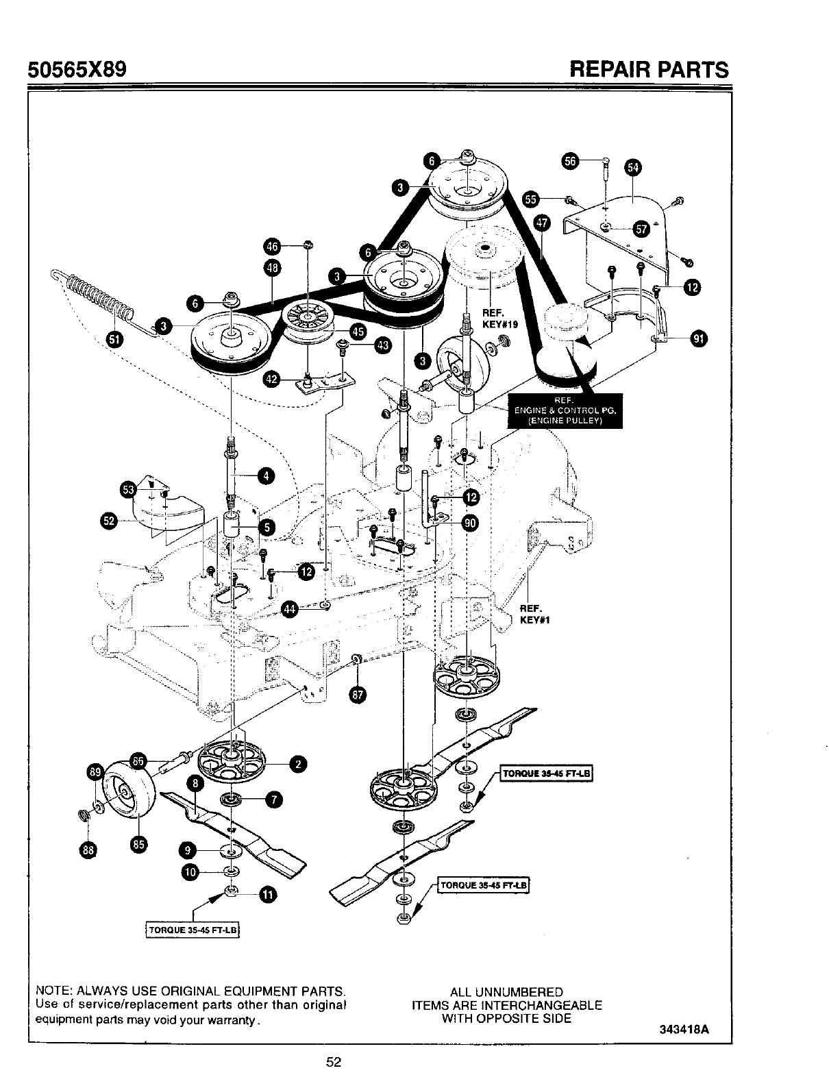
50565X89 REPAIR PARTS
L
ITORQUE 35-45 F'r-LBI
Y
NOTE: ALWAYS USE ORIGINAL EQUIPMENT PARTS.
Use of service/replacement parts other than original
equipment parts may void your warranty.
ALL UNNUMBERED
ITEMS ARE INTERCHANGEABLE
WITH OPPOSITE SIDE 343418A
52
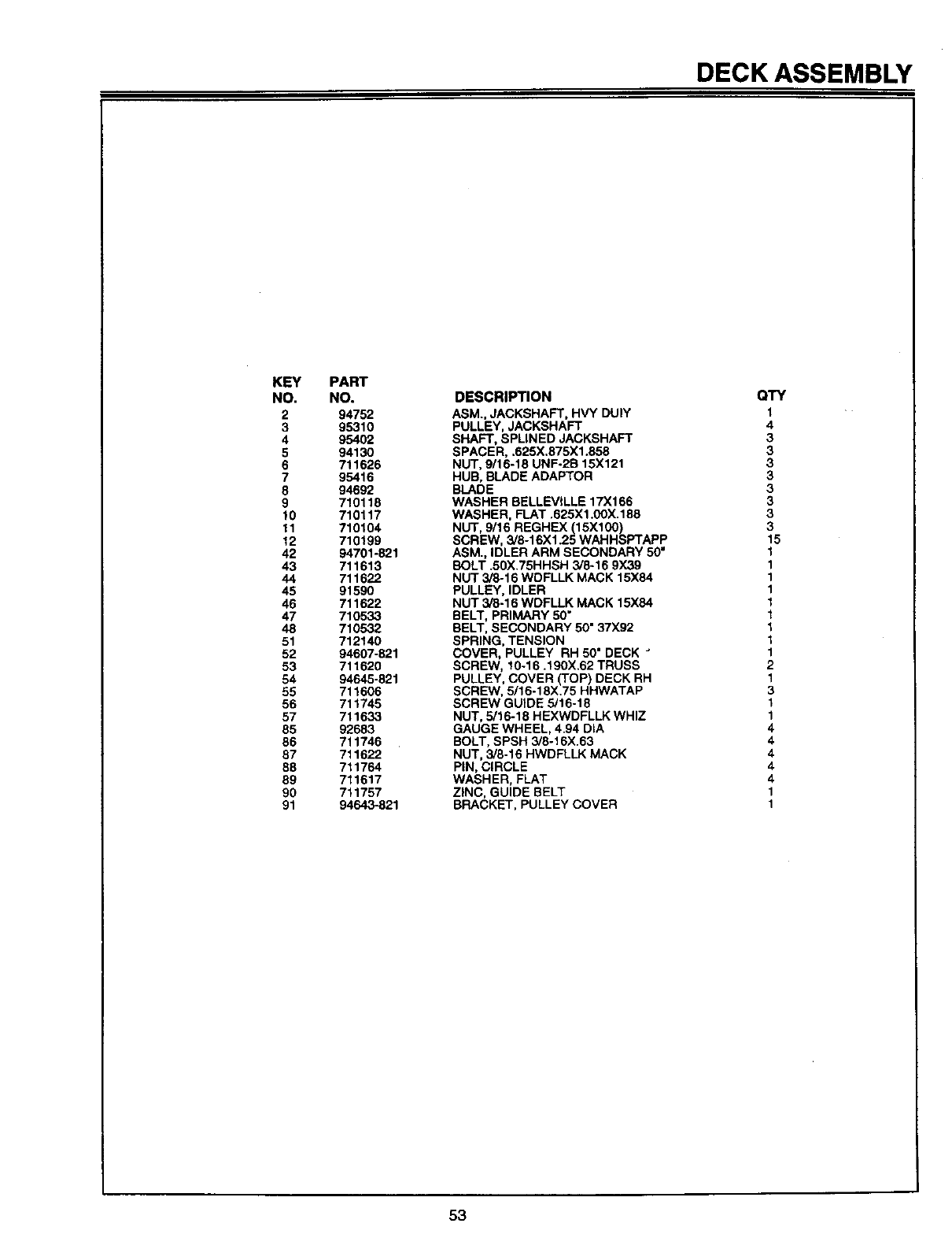
DECK ASSEMBLY
KEY
NO.
2
3
4
5
6
7
8
9
lo
11
12
42
43
44
45
46
47
48
51
52
53
54
55
56
57
85
86
87
88
89
90
91
PART
NO.
94752
95310
95402
94150
711626
95416
94692
710118
710117
710104
710199
94701-821
711613
711822
91590
711622
710533
710532
712140
94607-821
711620
94645-821
711606
711745
711633
92683
711746
711622
711764
711617
711757
94643-821
DESCRIPTION
ASM., JACKSHAFT, HVY DUlY
PULLEY, JACKSHAFT
SHAFT, SPLINED JACKSHAFT
SPACER, ,625X.875X1.858
NUT, 9/16-18 UNF-2R 15X121
HUB, BLADE ADAPTOR
BLADE
WASHER BELLEVILLE 17X166
WASHER, FLAT .625X1.00X.188
NUT, 9/16 REGHEX(15X100)
SCREW, 3/8-16X1.25 WAHHSPTAPP
ASM., IDLER ARM SECONDARY 50 =
BOLT .50X.75HHSH 3/6-16 9X39
NUT 3/8-16 WDFLLK MACK 15X84
PULLEY, IDLER
NUT 3/8-16 WDFLLK MACK 15X84
BELT, PRIMARY 50"
BELT, SECONDARY 50" 37X92
SPRING, TENSION
COVER, PULLEY RH 50" DECK
SCREW, 10-16.190X.62 TRUSS
PULLEY, COVER (TOP) DECK RH
SCREW, 5/16-18X.75 HHWATAP
SCREW GUIDE 5/16-18
NUT, 5/16-18 HEXWDFLLK WHIZ
GAUGE WHEEL, 4.94 DiA
BOLT, SPSH 3/8-16X.63
NUT, 3/8-18 HWDFLLK MACK
PIN, CIRCLE
WASHER, FLAT
ZINC, GUIDE BELT
BRACKET, PULLEY COVER
QTY
1
4
3
3
3
3
3
3
3
3
15
1
1
1
1
1
1
1
1
1
2
1
3
1
1
4
4
4
4
4
1
1
53
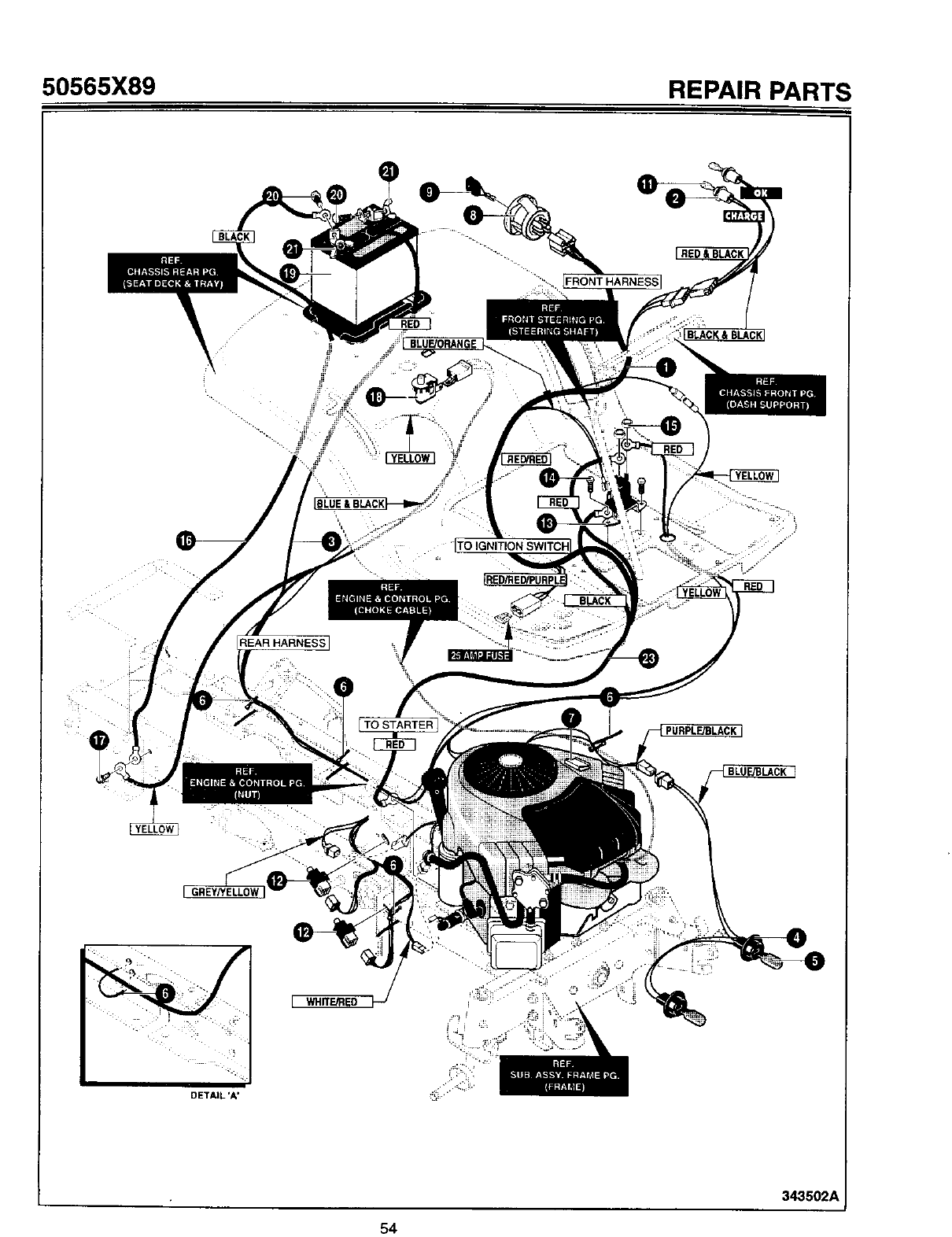
50565X89 REPAIR PARTS
REAR HARNESS 1
• . .9
BLUE/ORANGE
=i=
=
BLUE & BLACK
TO STARTER
RED &BLACK
PURPLE_LACK ]
BLUE/BLACK ]
[GREYHELL0W
DETAIL *A'
[WHffE_IEO
343502A
54
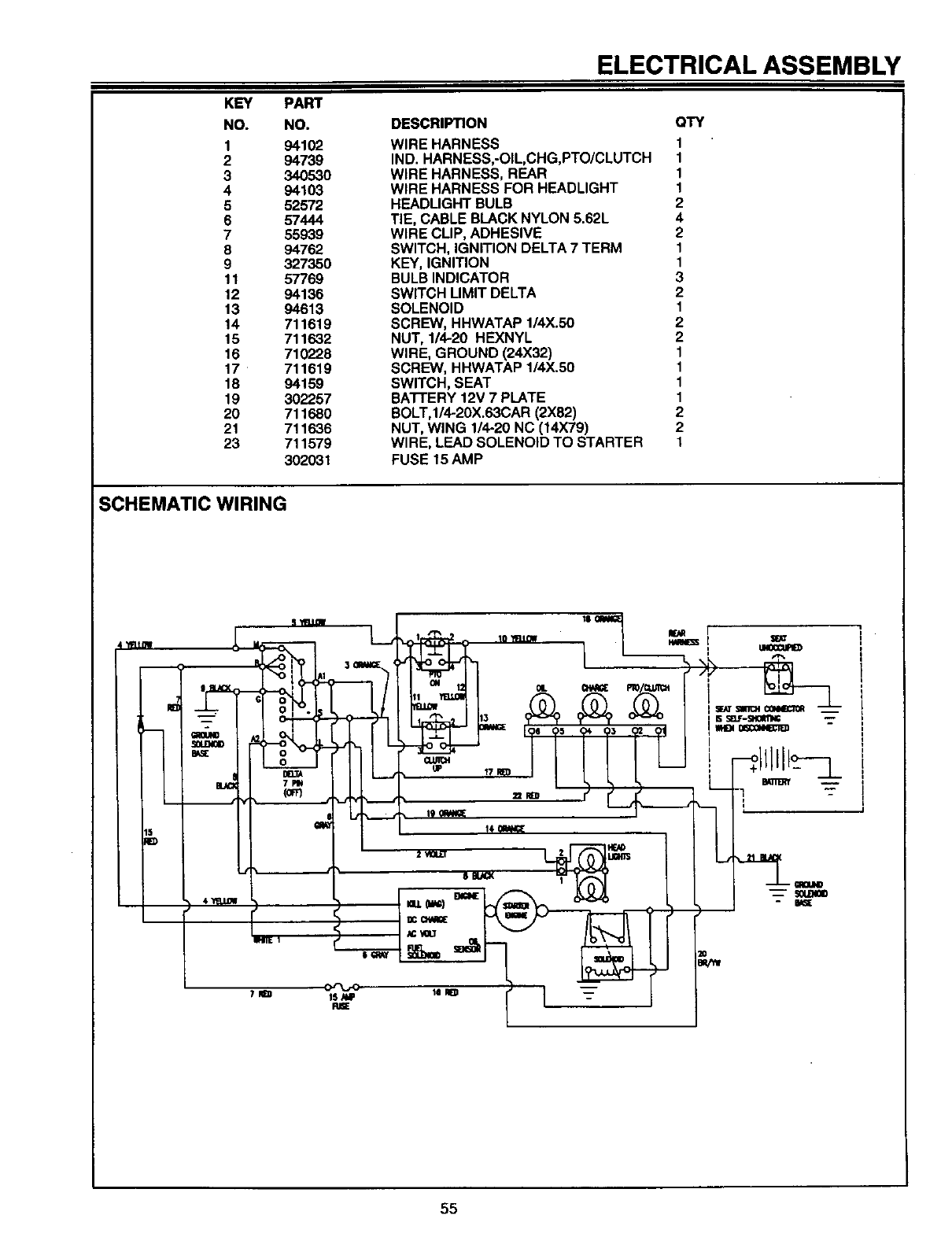
ELECTRICAL ASSEMBLY
KEY
NO.
1
2
3
4
5
6
7
8
9
11
12
13
14
15
16
17
18
19
20
21
23
PART
NO.
941O2
94739
34O530
941O3
52572
57444
55939
94762
327350
57769
94136
94613
711619
711632
710228
711619
94159
302257
711680
711636
711579
302031
DESCRIPTION QTY
WIRE HARNESS 1
IND. HARNESS,-OIL,CHG,PTO/CLUTCH 1
WIRE HARNESS, REAR 1
WIRE HARNESS FOR HEADLIGHT 1
HEADLIGHT BULB 2
TIE, CABLE BLACK NYLON 5.62L 4
WIRE CLIP, ADHESIVE 2
SWITCH, IGNITION DELTA 7 TERM 1
KEY, IGNITION 1
BULB INDICATOR 3
SWITCH LIMIT DELTA 2
SOLENOID 1
SCREW, HHWATAP 1/4X.50 2
NUT, 1/4-20 HEXNYL 2
WIRE, GROUND (24X32) 1
SCREW, HHWATAP 1/4X.50 1
SWITCH, SEAT 1
BATI'ERY 12V 7 PLATE 1
BOLT,1/4-20X.63CAR (2X82) 2
NUT, WING 1/4-20 NC (14X79) 2
WIRE, LEAD SOLENOID TO STARTER 1
FUSE 15 AMP
SCHEMATIC WIRING
iw,u_
'_o =L =,,,=m !,.,,=__
oO --Ll ..,- -
": J/o°_---_11L__ ,,,_/ / / / ! LmI _iml__o---_
/I , L_ ,,0,._ --I- 7 I'
55
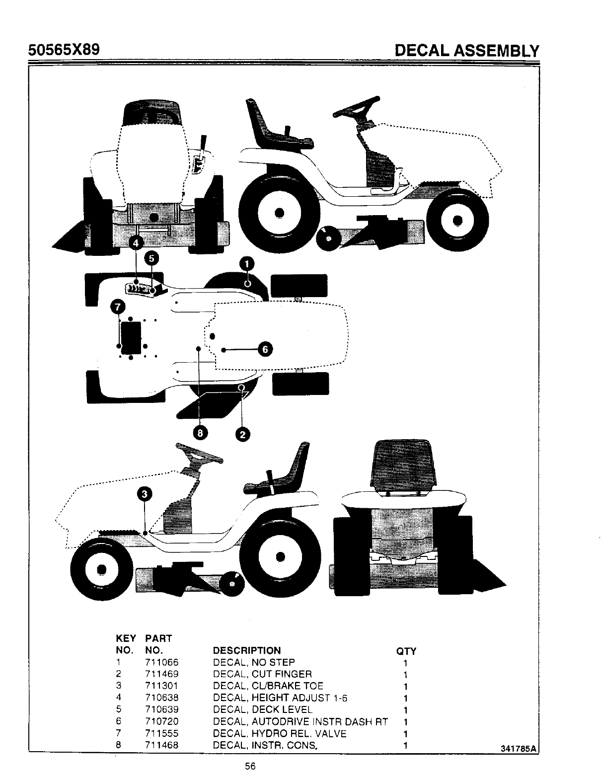
50565X89 DECAL ASSEMBLY
/
KEY PART
NO. NO.
1 711066
2 711469
3 711301
4 710638
5 710639
6 710720
7 711555
8 711468
DESCRIPTION QTY
DECAL, NO STEP 1
DECAL, CUT FINGER 1
DECAL, CUBRAKETOE 1
DECAL, HEIGHT ADJUST1-6 1
DECAL, DECKLEVEL 1
DECAL, AUTODRIVEINSTR DASH RT 1
DECAL. HYDRO REL. VALVE 1
DECAL, INSTR. CON& 1
56
341785_
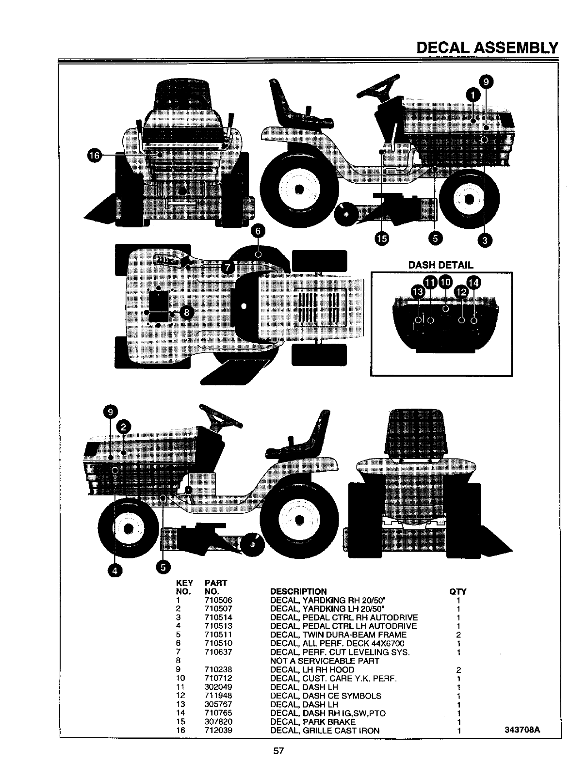
DECALASSEMBLY
DASH DETAIL
KEY
NO.
1
2
3
4
5
6
7
8
9
10
11
12
13
14
15
16
PART
NO.
710506
710507
710514
710513
710511
710510
710637
710238
710712
302049
711948
305767
710765
307820
712039
DESCRIPTION
DECAL, YARDKING RH 20/50"
DECAL, YARDKING LH 20150"
DECAL, PEDAL CTRL RH AUTODRIVE
DECAL, PEDAL CTRL LH AUTODRIVE
DECAL, TWIN DURA-BEAM FRAME
DECAL, ALL PERF. DECK 44X6700
DECAL, PERF. CUT LEVELING SYS.
NOT A SERVICEABLE PART
DECAL, LH RH HOOD
DECAL, CUST. CARE Y.K. PERF.
DECAL, DASH LH
DECAL, DASH CE SYMBOLS
DECAL, DASH LH
DECAL, DASH RH IG,SW,PTO
DECAL, PARK BRAKE
DECAL, GRILLE CAST IRON
QTY
1
1
1
1
2
1
1
2
1
1
1
1
1
1
1343708A
57

NOTES
712008 58
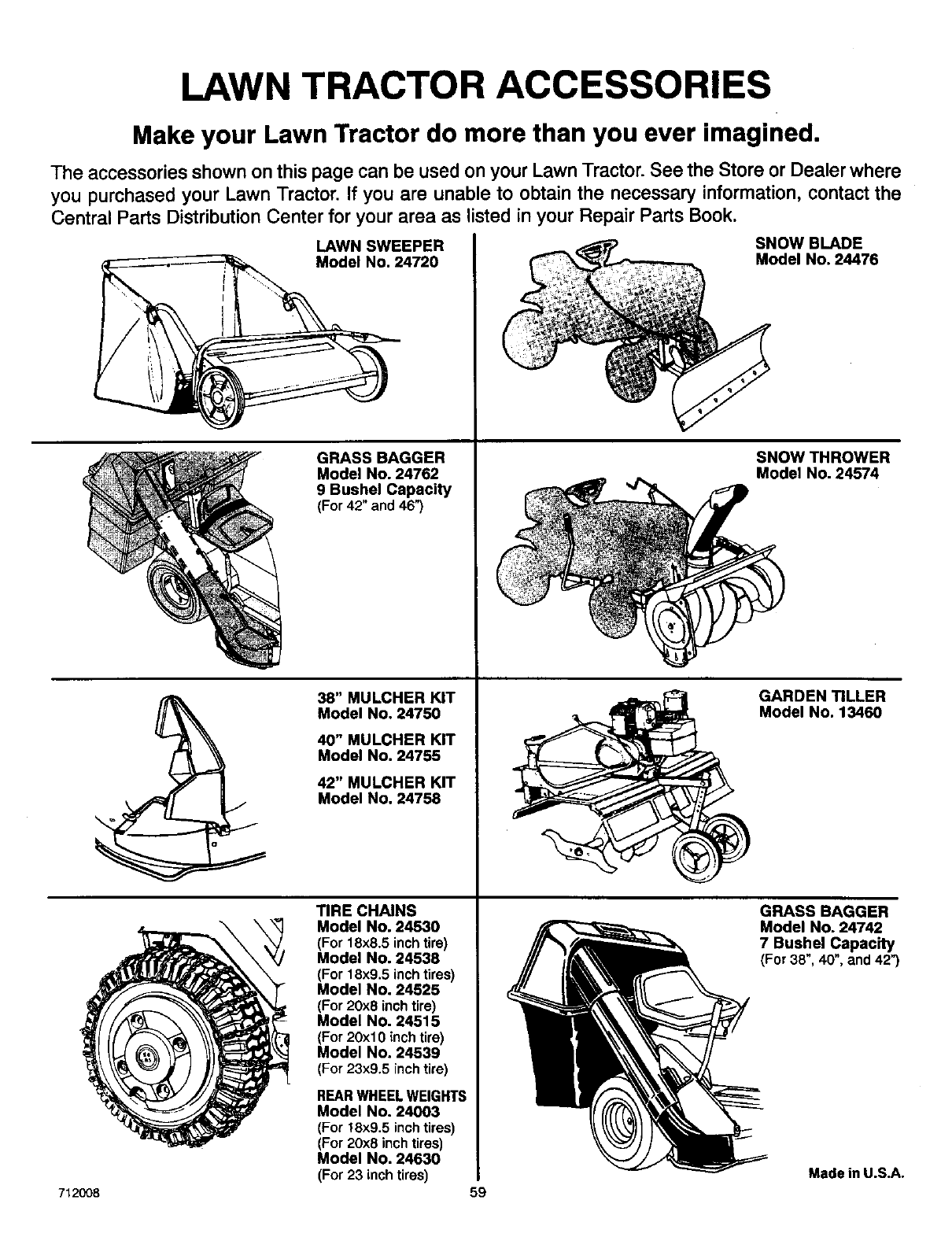
LAWN TRACTOR ACCESSORIES
Make your Lawn Tractor do more than you ever imagined.
The accessories shown on this page can be used on your Lawn Tractor. See the Store or Dealer where
you purchased your Lawn Tractor. If you are unable to obtain the necessary information, contact the
Central Parts Distribution Center for your area as listed in your Repair Parts Book.
LAWN SWEEPER
Model No. 24720
GRASS BAGGER
Model No. 24762
9 Bushel Capacity
(For 42" and 46")
38" MULCHER KIT
Model No. 24750
40" MULCHER KIT
Model No. 24755
42" MULCHER KIT
Model No. 24758
TIRE CHAINS
Model No. 24530
(For 18x8.5 inchtire)
Model No. 24538
(For 18x9.5 inchtires)
Model No. 24525
(For 20x8 inchtire)
Model No. 24515
(For 20xl 0 inch tire)
Model No. 24539
(For 23x9.5 inch tire)
REAR WHEEL WEIGHTS
Model No. 24003
(For !8x9.5 inch tires)
(For 20x8 inch tires)
Model No. 24630
(For 23 inch tires) 59
SNOW BLADE
Model No. 24476
SNOW THROWER
Model No. 24574
GARDEN TILLER
Model No. 13460
GRASS BAGGER
Model No. 24742
7 Bushel Capacity
(For 38", 40",and42")
Made in U.S.A.
712008

HOW TO QRGIERREPAIR
Onlyuse a factoryrepairpart. Repair pads, exceptforthe engineor the transmission,are availablefromthe storewherethe unitwas
purchased,a serviceshoprecommendedbythe store,oran aulhorizedserviceshopfound intheyellowpagesofthetelephonedirectory.
If youcannotget a repairpartor serviceas describedabove,callorwriteto the CentralParts Distributorshownbelow.When youorder,
includethe following information:(1) CompleteModelNumber (seenameplate),(2) Date of Manufacture,(3) CompletePart Number, (4)
Description,(5) Quantity.
Repairpartsfortheengineorthe transmissionare availablefrom the manufacturer'sauthorizedservicecenterfound intheyellowpages
of thetelephonedirectory.See the individualengineortransmissionwarranties.
LAWNMOWERCENTRALPARTSDISTRIBUTORS
BEBCO,INC.
22212nd.Ave.South
Birmingham,AL 35233
(205)251-4600
1-800-828-8094
Alabama,Florida,Georgia,PuertoRico
BILLIOU'S, INC.
1343SouthMainSt.
Porterville,CA+93257
(209)784-4102
1-800-245-5468
FAX 1-800-226-7337
Arizona,California,Hawaii,Nevada
BROWN & WISER, INC.
9991S.W.AveryStreet
P.O.Box1109
Tualatin,OR. 97062
(503)692-0330
1-800-882-4782 \
Alaska,Idaho(countiesAda,Adams,
Banewah,Boise,Bonner,Boundry,Canyon,
Clearwater,Elmore,Gem,Idaho,Kooten,
Latah,Lewis,NezPerce,Owyee,Payette,
Ravaili,Shoshone,Valley,Washington),
Montana(countiesFlathead,Lake,Uncoln,
Mineral,Missoulo,Ravalli,Sanders),Oregon,
Washington
CANADA POWER TECHNOLOGY
161WatlineAvenue
Mississauga,Ont.L4Z-1P2
(905)890-6900
1-800-861-9559(OntarioOnly)
Canada
CHILTONAIR COOLED ENGINE
3194th.Ave.South
P.O.Box150806
Nashville,TN. 37215
(615)254-1634 1-800-621-6934
Arkansas(countiesClay,Craighead,
Crittendan,Cross,Greene,Jackson,
Lawrence,Lee,Mississippi,Monroe,Phillips,
Poinsett,Randolph,St. Francis,Woodruff),
Mississippi{countiesDesota,Panda,
Quitman,Tate,Tunica),Missouri {counties
Dunkin,NewMadrid,Pemiscot),Tennessee,
Virginia(countiesBland,Buchanan,
Dickanson,Lee,Russell,Scott,Smyth,
Tazewell,Washington,Wise)
7_2008
ENGINESSOUTHWEST
1255No Heama
Shreveport,L/_ 71107-7108
(318)222-3871
1-800-388-6995
Arkansas(exceptthesecounties:Clay,
Craighead,Crittendan,Cross,Greene,
Hempstead,Howard,Jackson,Lafayette,
Lawrence,Lee,LittleRiver,Miller,Mississippi,
Monroe,Nevada,Phillips,Pike,Poinsett,
Randolph,Sevier,St.Francis,Woodruff)
Louisiana,Mississippi(exceptthese
counties:Deseta,Panela,QuitmanTate,
Tunica,)
FRANK EDWARDSCO.
3653South500West
SaltLakeCity,UT 84101
(801)281-4660
1-800-366-4563
Colorado,Idaho(countiesBannockBearlake,
Bingham,Blaine,Booneville,Butte,Comas,
Caribou,Cassia,Custer,Franklin,Fremont,
Goodin9, Jefferson,Jerome,Lamhi,Lincoln,
Madison,Minidoka,Oneida,Power,Teton,
TwinFalls)Montana(allcountiesexcept
Flathead,Lake,Uncoln,Mineral,Missoulo,
Ravaili,andSanders),Utah,Wyoming
GARDNER,INC.
1150ChesapeakeAve.
Columbus,OH. 43212
(614)488-7951
1-800-848-8946
Indiana,Kentucky,Michigan(exceptupper
Peninsula),Ohio,WesternPennsylvania
withzipcodesuptoandincluding16999,
WestVirginia
GULF COAST ENGINE, INC.
4202RussellDr.
P.O.Box9724
CorpusChristi,TX.78408
(512)888-6999
1-800-825-6999
Arkansas(countiesHempstead,Howard,
Lafayette,LittleRiver,Miller,Nevada,Pike,
Sevier)NewMexico,Oklahoma,Texas,
Mexico
OSCAR WILSON ENGINE & PARTS
826 LoneStarDr.
O'Fallon,MO. 63366
(314)978-1313
1-8Q0-873-6722
Illinois(S. ofHwy.80),Iowa,Kansas,
Missouri(allcountiesexceptDunkin,
NewMadrid,Pemiscot)Nebraska
R.B.I. CORPORATION
P.O.Box9318
Richmond,VA. 23227
(804)550-2210
1-800-888-7149
Connecticut,Delaware,Districtof
Columbia,Maine,Maryland,Massachusetts,
New Hampshire,NewJersey,New York,N.
& S. Carolina,Pennsylvaniazips17000& up,
RhodeIsland,Vermont,Virginia(allcounties
exceptBland,Buchanan,Dickenson,Lee,
Russell,Scott,Smyth,Tazewell,Washington,
Wise)
WISCONSIN MAGNETO
(2 LOCATIONS)
4727N.TeutoniaAve.
P.O.Box9218
Milwaukee,wi. 53209
(414)445-2800
1-800-733-7388
Illinois(N.of Hwy.80),Michigan(upper
Peninsula),Wisconsin
800 McKinleySt.
Anoka,MN. 55303
(612)323-7477
1-800-248-4016
Minnesota,North& SouthDakota
