Yazaki Kako FCU-RC01 Wireless Intersection Module User Manual
Yazaki Kako Corporation Wireless Intersection Module
User Manual
Logistics Solution
Option Unit for
CREFORM AGC Drive Unit
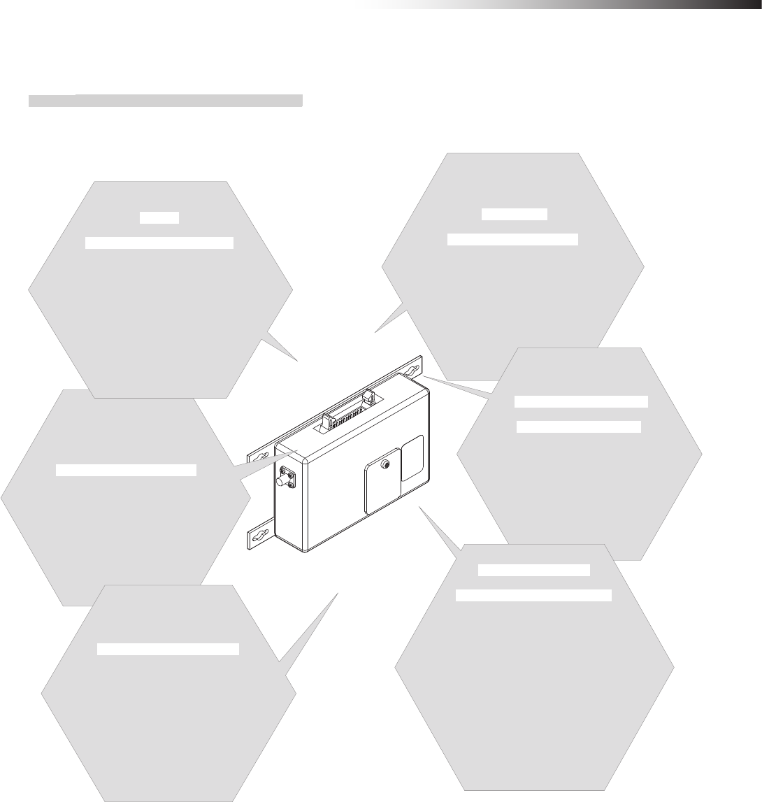
Wireless Intersection Module
FCU-RC01

Contents
- 2 -
Contents
1. About this instruction manual 4
Ü 1-1. Requirements for handling the manual 4
Ü 1-2. About symbols used in this manual 4
2. About safety 5
3. Overview of product 6
Ü 3-1. Software versions 6
Ü 3-2. About the wireless module 7
3-2-1. Features of the wireless module 7
3-2-2. Overview of the wireless module 8
4. Accessories 8
Ü 4-1. Checklist 8
5. Specifications 9
Ü 5-1. Specication table 9
6. Part names and functions 10
Ü 6-1. Part names 10
Ü 6-2. Functions 10
6-2-1. Switches 10
6-2-2. Display 10
6-2-3. Antenna connection section 10
6-2-4. CN1 power connector 10
6-2-5. CN2 input/output connector 11
6-2-6. CN3 connector for parameter settings 11
Ü 6-3. Details of switches 12
6-3-1. DIP switch (SW1) 12
6-3-2. Rotary switches (RSW1 to 4) 13
Ü 6-4. Details of CN2 input/output 14
6-4-1. Input/output signals in the address sensor mode 15
6-4-2. Input/output signals in the RFID mode 16
6-4-3. Input/output signals in the ground station mode 17
6-4-4. Input/output signals in the external control mode 18
Ü 6-5. Details of display 19
7. About related components 22
Ü 7-1. Wireless intersection module box FCP-RCB01-24 22
7-1-1. CN1 22
7-1-2. CN2 22
7-1-3. CN3 23
7-1-4. CN4 23
Ü 7-2. Wireless intersection module box FCP-RCB01-12 24
7-2-1. CN1 24
7-2-2. CN2 25
7-2-3. CN3 25
7-2-4. CN4 25
Ü 7-3. Pencil type antenna FCP-RCA01 26
Ü 7-4. Flanged antenna with bracket FCP-RCA02 26
Ü 7-5. Address sensor with bracket FCP-RCS01 27
7-5-1. Specications 27
Ü 7-6. RFID antenna with bracket FCP-RCS02 27
7-6-1. Specications 27
Ü 7-7. Address sensor with bracket for small Drive Unit FCP-RCS03 28
7-7-1. Specications 28
Ü 7-8. RFID antenna with bracket for small Drive Unit FCP-RCS04 28
7-8-1. Specications 28
Ü 7-9. Cable for 24 V Drive Unit FCP-RCC01-24 29
Ü 7-10. Cable for 12V Drive Unit FCP-RCC01-12 30
Ü 7-11. Cable for course 30 FCP-RCC02 31
Ü 7-12. Cable for small Drive Unit FCP-RCC03 32
Ü 7-13. Cable for address sensor FCP-RCC04 32
Ü 7-14. Cable for RFID antenna FCP-RCC05 33
Ü 7-15. Wireless intersection module setting cable FCP-RCC08 33
Ü 7-16. Address magnetic plate FCP-SMG01-* 34
7-16-1. Specications 34
Ü 7-17. ID tag FCP-TAG01 35
7-17-1. Specications 35
Ü 7-18. Wireless intersection module mounting bracket FCU-RCK06 36
Ü 7-19. Wireless intersection module mounting bracket FCU-RCK07 36
Ü 7-20. AC adapter FCP-RCP01 36
8. Installation and connections 37
Ü 8-1. About installation place 37
Ü 8-2. About installation 39
8-2-1. Wireless Intersection Module 39
Ü 8-3. Connections and settings 41
8-3-1. Intersection is instructed by the address sensor when the 24 V forward type
Drive Unit is used. 41
8-3-2. Intersection is instructed by the RFID antenna when the 24 V forward type
Drive Unit is used. 42
8-3-3. Intersection is instructed by the course 30 unit when the 24 V forward type
Drive Unit is used. 43
8-3-4. Intersection is not instructed by the course 30 unit, but it is instructed by the
address sensor when the 24 V forward type Drive Unit is used. 44
8-3-5. Intersection is not instructed by the course 30 unit, but it is instructed by the
RFID antenna when the 24 V forward type Drive Unit is used. 45
8-3-6. Intersection is instructed by the course 30 unit when the 24 V forward/backward
type Drive Unit is used. 46
8-3-7. Intersection is not instructed by the course 30 unit, but it is instructed by the
address sensor when the 24 V forward/backward type Drive Unit is used. 47
8-3-8. Intersection is not instructed by the course 30 unit, but it is instructed by the
RFID antenna when the 24 V forward/backward type Drive Unit is used. 48
8-3-9. Intersection is instructed by the address sensor when the 12V forward type
Drive Unit is used. 49
8-3-10. Intersection is instructed by the RFID antenna when the 12V forward type
Drive Unit is used. 50
8-3-11. Intersection is instructed by the course 30 unit when the 12V forward type
Drive Unit is used. 51
8-3-12. Intersection is not instructed by the course 30 unit, but it is instructed by the
address sensor when the 12V forward type Drive Unit is used. 52
8-3-13. Intersection is not instructed by the course 30 unit, but it is instructed by the
RFID antenna when the 12V forward type Drive Unit is used. 53
8-3-14. Intersection is instructed by the course 30 unit when the 12V forward/back-
ward type Drive Unit is used. 54
8-3-15. Intersection is not instructed by the course 30 unit, but it is instructed by the
address sensor when the 12V forward/backward type Drive Unit is used. 55
8-3-16. Intersection is not instructed by the course 30 unit, but it is instructed by the
RFID antenna when the 12V forward/backward type Drive Unit is used. 56
8-3-17. Intersection is instructed by the address sensor when the small Drive Unit is
used. 57
8-3-18. Intersection is instructed by the RFID antenna when the small Drive Unit is
used. 58
8-3-19. Intersection control is performed using the ground station. 59
9. Intersection 60
Ü 9-1. For address sensor 60
9-1-1. Layout of address magnetic plate 60
9-1-2. Installation of address sensor 60
9-1-3. Detection direction of address sensor 61
9-1-4. About installation of address magnetic plate 61
9-1-5. Forward type 62
9-1-6. Forward/backward type 63
9-1-7. Timing chart 64
Ü 9-2. For RFID antenna 65
9-2-1. Layout of ID tag 65
9-2-2. Installation of RFID antenna 65
9-2-3. Forward type 66
9-2-4. Forward/backward type 67
9-2-5. Timing chart 68
Ü 9-3. For course 30 unit 69
9-3-1. Forward type 69
9-3-2. Forward/backward type 70

Contents
- 3 -
9-3-3. Timing chart 72
Ü 9-4. For ground station 72
10. Wireless intersection module parameter settings 73
Ü 10-1. FCU-RC01 setup software FCU-RC01_Set 73
10-1-1. Operating conditions for FCU-RC01 setup software 73
10-1-2. Basic screen, and part names and functions 74
10-1-3. Connection and disconnection procedures 78
Ü 10-2. ID setting 79
10-2-1. Setting example 79
Ü 10-3. One shot pulse width setting 79
10-3-1. Setting example 79
Ü 10-4. Stop-Start delay setting 80
10-4-1. Setting example 80
Ü 10-5. Frequency CH setting 81
10-5-1. Setting example 81
Ü 10-6. Travel priority setting 82
10-6-1. Setting example 82
10-6-2. Address sensor mode 83
10-6-3. Timing chart 83
10-6-4. RFID mode 84
10-6-5. Timing chart 85
Ü 10-7. Ground station setting 85
10-7-1. Setting example 1 85
10-7-2. Setting example 2 86
10-7-3. Setting example 3 87
10-7-4. Setting example 4 88
10-7-5. Caution 89
Ü 10-8. Trigger setting 90
10-8-1. Setting example 90
10-8-2. Timing chart 91
Ü 10-9. Intersection operation setting 92
10-9-1. Setting example 92
Ü 10-10. Initialization 93
10-10-1. Procedures 93
Ü 10-11. Load or Save settings 94
10-11-1. Settings saving procedures 94
10-11-2. Settings loading procedures 95
11. External control mode 96
Ü 11-1. Settings 96
11-1-1. Wiring 96
11-1-1-1. Power supply 96
11-1-1-2. Input/output 97
11-1-2. Wiring example 98
11-1-3. Flow of control 99
11-1-3-1. AGV (1) passes through the intersection and AGV (2) waits. 99
11-1-3-2. AGV (3) waits while AGV (1) is passing and AGV (2) is waiting. 100
11-1-3-3. AGV (2) waits with the intersection top priority input turned ON while AGV (1)
is passing and AGV (3) is waiting. 101
11-1-3-4. AGV (1) passes through the intersection, AGV (2) waits, and SW1-4 of each
wireless intersection module is turned ON. 102
11-1-3-5. AGV (1) passes through the intersection, AGV (2) waits, and SW1-5 of each
wireless intersection module is turned ON. 102
12. Caution 103
13. Contents of warranty 103
Ü 13-1. Warranty period 103
Ü 13-2. Warranty coverage 103
14. Others 104
Ü 14-1. Precautions 104
Ü 14-2. Contacts 104
ê 1. About this instruction manual
- 4 -
1. About this instruction manual
This instruction manual is prepared to control and use the wireless intersection module, that is an optional unit for the
Drive Unit, in a correct and safe manner and fully utilize its functions. This manual primarily describes the methods of
handling the wireless intersection module. For details about the Drive Unit main body, refer to the instruction manual
supplied with the Drive Unit.
1-1. Requirements for handling the manual
The instruction manual is a “part of the product” necessary to use the product. To operate the product in a safe and
correct manner, thoroughly read this instruction manual to fully understand its contents and strictly observe its guid-
ance when operating the product. In addition, after reading the instruction manual, carefully store it in a safe place for
the period of appropriate time for future reference. Update the manual as newly revised documents are delivered and
dispose of the previous versions.
1-2. About symbols used in this manual
To help users’ understanding, this manual uses two kinds of symbols in the main body of the document to describe
important points and supplemental contents.
Indicates contents where one must pay attention in the main body of the document.
Indicates useful information and provides operating tips.
To warn the users and prevent hazards, the following indications are provided to indicate possible hazards leading to
personal injury or damage to the equipment.
WARNING : This denotes immediate hazards which will result in death or severe personal injury, if not avoided.
In addition, to prevent hazards, the following graphic warning symbols are used for safety-related items.
Prohibited action symbols
The actions are prohibited when the product is being operated. The action may be overlapped with the graphic
symbols to show the prohibition of more specic contents.
Example: Fire is prohibited. Example: Touching is prohibited.
Alert symbols
The symbols show the conditions under which special attention is required such as ignition hazard or high tem-
perature when the product is being operated. The action may be overlapped with the graphic symbol to alert the
user to more specic contents.
Example: General alert Example: Corrosion alert
Action instruction symbols
The symbols are added when action is required in accordance with the instructions when the product is being
operated. The symbol illustrating the contents may be combined
to further show the contents of the instruction.
Example:
General instruction or action request
Example: Grounding instruction
ê 2. About safety
- 5 -
2. About safety
Strictly observe the following safety precautions to prevent operating problems or malfunction of this product.
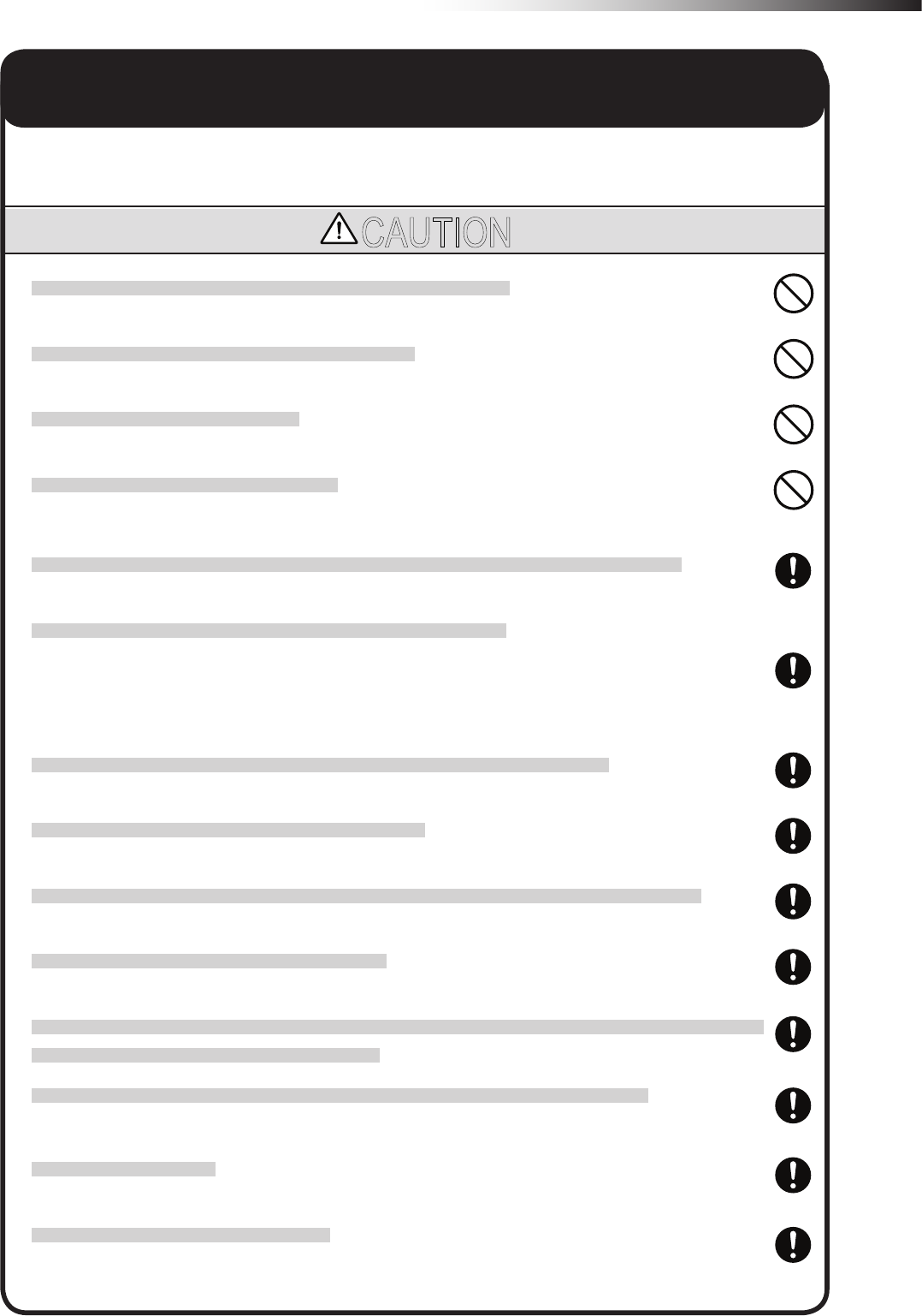
CAUTION
Do not install the antenna in a place surrounded by metallic members.
Install the antenna 200 mm or more away from the oor.
Do not apply any shock to the antenna.
Do not pull or bend the cable or cord forcibly.
Install the antennas at the highest possible positions where the antennas can be seen together.
Install the antenna so that it is not parallel to cables or metallic plates.
Install the antenna away from any cable, metallic plates, concrete, plasterboard, lumber, and wall surfac-
es as much as possible (300 mm or more).
Install the antennas of the different wireless units 2 m or more away from each other.
When installing the antenna, adjust the antenna direction.
Set the ID of the wireless intersection module so that it is not duplicated. Do not use duplicate IDs.
Set the ID to 900 to 999 in the ground station mode.
An incorrect approach may occur depending on the communication status. Widen the range of the obstacle
sensor as much as possible inside the intersection.
Use the wireless intersection modules with the same software version in the same system.
The wireless intersection modules with different software versions cannot be used.
Do not modify this product.
This product is intended for indoor use only.
Be sure to handle the product under the conditions dened in the specications.
ê 3. Overview of product
- 6 -
3. Overview of product
This product is a wireless module that communicates in the 2.4 GHz band.
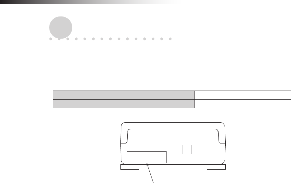
3-1. Software versions
This instruction manual supports the following software versions or later.
FCU-RC01 main unit software version App_v1.10.22
FCU-RC01 setup software version Ver. 0.1.9
Software version label affixing position
ê 4. Accessories
- 7 -
Multiple
operation modes
The address sensor mode, RFID mode,
ground station mode, and external con-
trol mode are available as operation
modes.
Radio frequency
channel change
You can select a radio frequency
from 15 channels. An optimal fre-
quency band without interference
can be easily selected.
Wireless com-
munication distance
The wireless communication
distance may vary depending on the
installation location (environment). The
following distance is used as a guide.
• Indoor placement with good visibility, About
15 m (Environment in which the antennas
can be seen together and are installed
at high positions, and there are no
obstacles around the antennas.)
Note: Field research is need-
ed.
Antenna selection
You can select a pencil type antenna
or anged antenna depending on the
application.
Easy installation
The wireless intersection module
can be installed on a Creform pipe using
the wireless intersection module box
or wireless intersection module
mounting bracket.
Easy
intersection control
The wireless units communicate
with each other to determine wheth-
er passing through the intersection is
possible or not. Therefore, the AGV
does not need to perform the
intersection control.
3-2. About the wireless module
3-2-1. Features of the wireless module
ê 4. Accessories
- 8 -
3-2-2. Overview of the wireless module
• The wireless module units communicate with each other to perform the intersection control.
• Instructions regarding the entrance and exit of the intersection are sent to the wireless intersection modules by the
address sensor, RFID antenna, course 30 unit, and external unit that sends various output signals. In addition, the
wireless intersection modules installed on the AGVs communicate with each other to determine whether passing
through the intersection is possible or not.
Basically, the order of passing through the intersection is set in the order of arrivals.
• If the communication status is unstable due to a long distance of wireless communication or due to effects of
obstacles caused by the layout, install the wireless intersection module on the ground and use it in the ground
station mode. The radio wave then easily reaches and avoids the effects caused by obstructions.
One ground station can control four intersections.
• You can select the intersection control by connecting signals from the wireless intersection modules installed on
the AGVs with each other or the intersection control by sending inquiries to the ground station for each intersection
address.
For the intersection control by setting the wireless intersection modules to communicate with each other, up
to eight wireless intersection modules can be used for one intersection. (Total number of units that are pass-
ing through the intersection and units that are waiting at the same time. For example, one unit is passing
and seven units are waiting at the same time.) In addition, when the intersection control is performed using
the ground station, one ground station can control up to four intersections.
4. Accessories
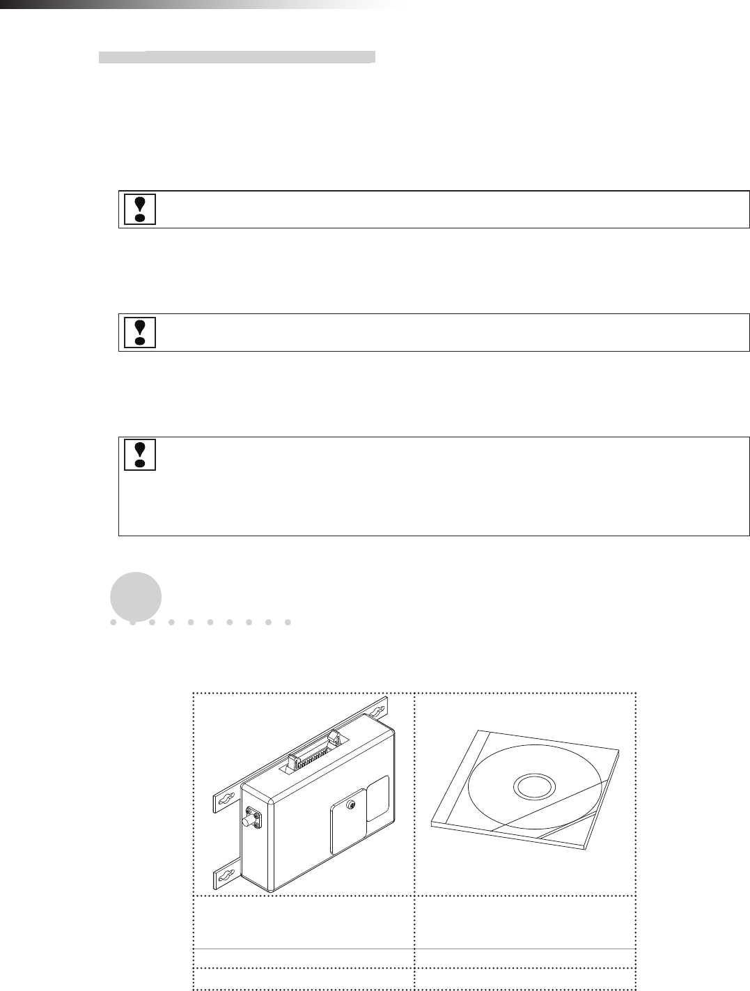
4-1. Checklist
Use the checklist to check the contents of the product package you have received.
Wireless Intersection Module
FCU-RC01
This instruction manual and
parameter setup software
“FCU-RC01_Set”
1 unit 1 pc. (CD-ROM)
□ □
Note: When multiple units are ordered, one CD-ROM is supplied with one set.
ê 5. Specications
- 9 -
5. Specications
5-1. Specication table
Product name Wireless Intersection Module
Model number FCU-RC01
Rated power supply voltage 24 V DC±10%
Power consumption 6 W or less
Body size 80 × 171 × 32 mm (excluding protrusions)
Weight 235 g
Environment
specications
Operating temperature -10 to 50ºC (No dew condensation or freezing allowed.)
Operating humidity 0 to 90% RH (No dew condensation allowed.)
Radio frequency band 2.4 GHz, 2405 to 2475 MHz
Input circuit Applied voltage 24 V DC
Rated current 10 mA
Output circuit Rated current 50 mA
Intersection control
using modules Number of control units Up to eight units for one intersection.
One unit is passing and seven units are waiting.
Intersection control
using ground station
One ground station
Number of intersections Up to four intersections
One ground station
Number of control units
For one intersection, one unit is passing through one
intersection and seven units are waiting.
For two intersections, one unit is passing through one
intersection and seven units are waiting.
For three intersections, one unit is passing through one
intersection and four units are waiting.
For four intersections, one unit is passing through one
intersection and three units are waiting.
ê 6. Part names and functions
- 10 -
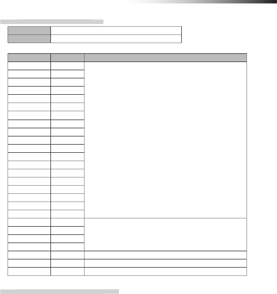
6. Part names and functions
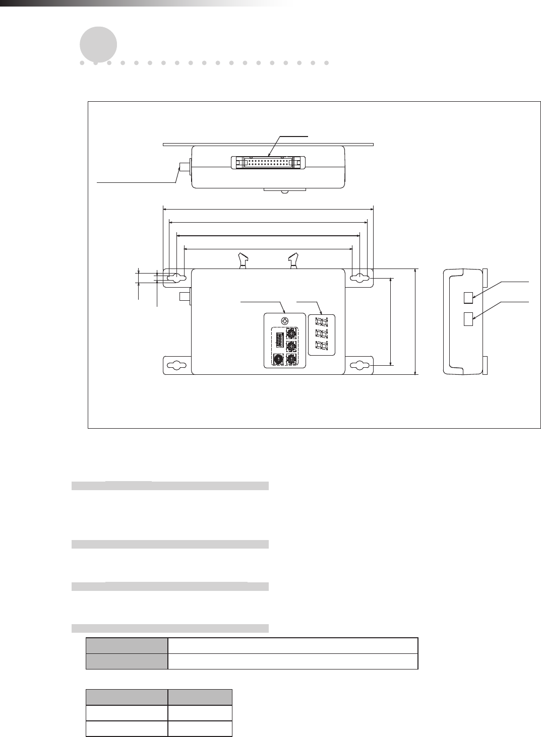
6-1. Part names
64
80
FCU-RC01
0
1
F
2
E
3
D
4
C
5
B
6
A
7
9
8
0
1
9
2
8
3
7
4
6
5
0
1
9
2
8
3
7
4
6
5
ON
1
2345678
0
1
9
2
8
3
7
4
6
5
171
161
149
137
CN2
Antenna connection
section
CN1
CN3Switch Display
7
3.5
Unit: mm
6-2. Functions
6-2-1. Switches
When you loosen the screw that secures the switch cover and slide it, you can operate the DIP switches and the
rotary switches for setting the wireless intersection module.
6-2-2. Display
A 3-digit and 7-segment display indicates the status of the wireless intersection module.
6-2-3. Antenna connection section
Connect the antenna.
6-2-4. CN1 power connector
Connector S2B-XH-A connector for printed circuit board (JST)
Fitting connector XHP-2 connector for printed circuit board (JST)
Pin number Contents
1 +24 V
2 GND
ê 6. Part names and functions
- 11 -
6-2-5. CN2 input/output connector
Connector MIL connector 26-core, male
Fitting connector MIL connector 26-core, female
Pin number Contents Remarks
1 OUT1
The input/output is switched using the operation mode setting of the DIP
switch (SW1).
2 OUT2
3 OUT3
4 OUT4
5 OUT5
6 OUT6
7 IN1
8 IN2
9 IN3
10 IN4
11 IN5
12 IN6
13 IN7
14 IN8
15 IN9
16 IN10
17 IN11
18 IN12
19 IN13
20 +24 V
Do not use these pins for supplying the power to an external device.
21 +24 V
22 GND
23 GND
24 TxD Dedicated for the RFID mode.
25 RxD Dedicated for the RFID mode.
26 SGND Dedicated for the RFID mode.
6-2-6. CN3 connector for parameter settings
This connector is used for the parameter settings of the wireless intersection module.
ê 6. Part names and functions
- 12 -
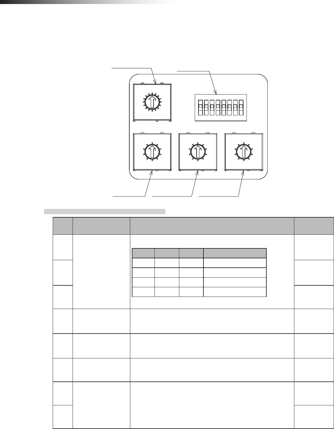
6-3. Details of switches
When the settings of the switches (DIP switch and rotary switches) are changed, the settings take effect by turning OFF
the power and turning it ON again. Be sure to turn OFF the power, and then turn it ON again after changing the settings.
RSW1RSW2
RSW3
0
1
9
2
8
3
7
4
6
5
ON
1 2 3 45678
0
1
9
2
8
3
7
4
6
5
0
1
F
2
E
3
D
4
C
5
B
6
A
7
9
8
0
1
9
2
8
3
7
4
6
5
RSW4 SW1
6-3-1. DIP switch (SW1)
No. Contents Details Setting at
shipment
1
Operation mode
settings
No. 3 No. 2 No. 1 Operation mode
OFF OFF OFF Address sensor
OFF OFF ON RFID
OFF ON OFF Ground station
OFF ON ON External control
OFF
2 OFF
3 OFF
4 Start signal
In the external control mode
OFF: Level output
ON: One shot output
OFF
5 Stop signal
In the external control mode
OFF: Level output
ON: One shot output
OFF
6 PC setting ID and frequency CH settings using the FCU-RC01 setup
software are enabled. OFF
7
For maintenance Setting is disabled.
OFF
8 OFF
ê 6. Part names and functions
- 13 -
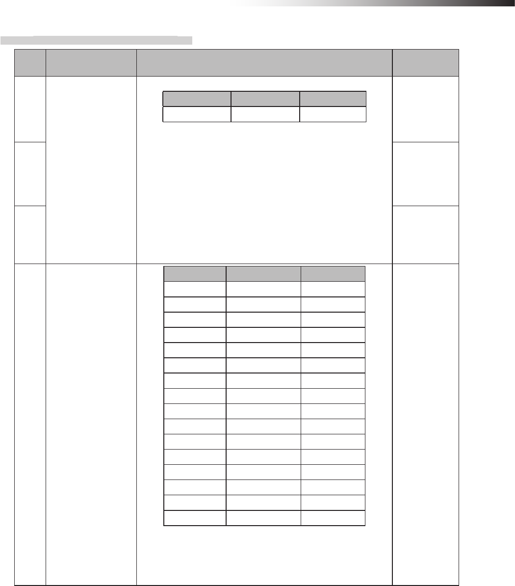
6-3-2. Rotary switches (RSW1 to 4)
No. Contents Details Setting at
shipment
1
ID setting
No. 3 No. 2 No. 1
Hundreds digit Tens digit Ones digit
• Set the ID of the wireless intersection module.
• The setting range of the wireless intersection module to be
installed on the AGV is 001 to 899.
• The setting range is 900 to 999 in the ground station mode.
• It is necessary to assign each wireless intersection module
a unique ID that is not duplicated.
• When the settings of RSW1 to 3 are 0, the ID setting using
the FCU-RC01 setup software is enabled.
1
2 0
3 0
4Radio frequency
setting
No. 4 Frequency Channel
0―PC setting
1 2405 MHz 1
2 2410 MHz 2
3 2415 MHz 3
4 2420 MHz 4
5 2425 MHz 5
6 2430 MHz 6
7 2435 MHz 7
8 2440 MHz 8
9 2445 MHz 9
A 2450 MHz 10
B 2455 MHz 11
C 2460 MHz 12
D 2465 MHz 13
E 2470 MHz 14
F 2475 MHz 15
• When the setting of RSW4 is 0, the frequency CH setting
using the FCU-RC01 setup software is enabled.
F

ê 6. Part names and functions
- 14 -
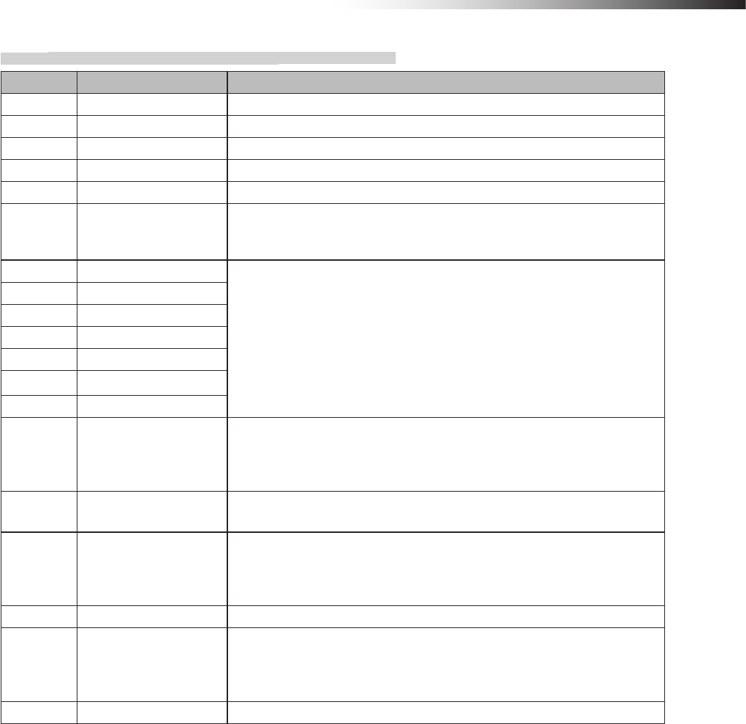
6-4. Details of CN2 input/output
The input/output of CN2 is switched using the operation mode setting of the DIP switch (SW1).
Signal Address sensor mode RFID mode Ground station mode External control mode
OUT1 Start Start Battery voltage drop Start
OUT2 Stop Stop AGV error Stop
OUT3 - - - -
OUT4 - - Normal (wireless unit) Normal (wireless unit)
OUT5 Passing Passing Passing Passing
OUT6 Pause Pause AGV arrival -
IN1 Intersection address (1) - Start permission 1 Intersection address (1)
IN2 Intersection address (2) - Start permission 2 Intersection address (2)
IN3 Intersection address (4) - Start permission 3 Intersection address (4)
IN4 Intersection address (8) - Start permission 4 Intersection address (8)
IN5 Intersection address (16) - Start permission 5 Intersection address (16)
IN6 Intersection address (32) - Start permission 6 Intersection address (32)
IN7 Intersection address (64) - Start permission 7 Intersection address (64)
IN8 AGV error AGV error - AGV error
IN9 Read timing - - Intersection inquiry
IN10 AGV arrival AGV arrival - AGV arrival
IN11 - - - Intersection top priority
IN12 Battery voltage drop Battery voltage drop - Battery voltage drop
IN13 Reset Reset Reset Reset
ê 6. Part names and functions
- 15 -
6-4-1. Input/output signals in the address sensor mode
Contents Signal Description
OUT1 Start This signal is output to start the AGV that is waiting at the intersection.
OUT2 Stop This signal is output to stop the AGV at the intersection.
OUT3 - -
OUT4 - -
OUT5 Passing This signal is output while the AGV is passing through the intersection.
OUT6 Pause
Inputting the pause signal to the AGV performs the intersection control with
the travel priority.
For details, see “10-6 Travel priority setting”.
IN1 Intersection address (1)
Instructs the intersection address.
IN2 Intersection address (2)
IN3 Intersection address (4)
IN4 Intersection address (8)
IN5 Intersection address (16)
IN6 Intersection address (32)
IN7 Intersection address (64)
IN8 AGV error
This signal is used by connecting the error output from the AGV.
When the input of the wireless intersection module that is passing through the
intersection turns ON during communication with the ground station, OUT2 of
the ground station turns ON.
IN9 Read timing This signal is output in one shot 10 ms after the output to instruct the intersec-
tion address has been sent from the address sensor.
IN10 AGV arrival
This signal is used by connecting the arrival output from the AGV.
When the input of the wireless intersection module that is passing through the
intersection turns ON during communication with the ground station, OUT6 of
the ground station turns ON.
IN11 - -
IN12 Battery voltage drop
This signal is used by connecting the battery voltage drop output from the
AGV. When the input of the wireless intersection module that is passing
through the intersection turns ON during communication with the ground sta-
tion, OUT1 of the ground station turns ON.
IN13 Reset This signal resets the intersection information.
ê 6. Part names and functions
- 16 -
6-4-2. Input/output signals in the RFID mode
Contents Signal Description
OUT1 Start This signal is output to start the AGV that is waiting at the intersection.
OUT2 Stop This signal is output to stop the AGV at the intersection.
OUT3 - -
OUT4 - -
OUT5 Passing This signal is output while the AGV is passing through the intersection.
OUT6 Pause
Inputting the pause signal to the AGV performs the intersection control with
the travel priority.
For details, see “10-6 Travel priority setting”.
IN1 - -
IN2 - -
IN3 - -
IN4 - -
IN5 - -
IN6 - -
IN7 - -
IN8 AGV error
This signal is used by connecting the error output from the AGV.
When the input of the wireless intersection module that is passing through the
intersection turns ON during communication with the ground station, OUT2 of
the ground station turns ON.
IN9 - -
IN10 AGV arrival
This signal is used by connecting the arrival output from the AGV.
When the input of the wireless intersection module that is passing through the
intersection turns ON during communication with the ground station, OUT6 of
the ground station turns ON.
IN11 - -
IN12 Battery voltage drop
This signal is used by connecting the battery voltage drop output from the
AGV. When the input of the wireless intersection module that is passing
through the intersection turns ON during communication with the ground sta-
tion, OUT1 of the ground station turns ON.
IN13 Reset This signal resets the intersection information.
ê 6. Part names and functions
- 17 -
6-4-3. Input/output signals in the ground station mode
Contents Signal Description
OUT1 Battery voltage drop
This signal is output when IN12 of the wireless intersection module installed
on the AGV that is passing through the intersection turns ON during commu-
nication with the wireless intersection module in the ground station mode.
The battery voltage drop output of the AGV needs to be connected to IN12.
OUT2 AGV error
This signal is output when IN8 of the wireless intersection module installed on
the AGV that is passing through the intersection turns ON during communica-
tion with the wireless intersection module in the ground station mode.
The error output of the AGV needs to be connected to IN8.
OUT3 - -
OUT4 Normal The output turns OFF if an error occurs in the wireless unit.
OUT5 Passing
This signal is output when the wireless intersection module installed on the
AGV that is passing through the intersection during communication with the
wireless intersection module in the ground station mode.
OUT6 AGV arrival
This signal is output when IN10 of the wireless intersection module installed
on the AGV that is passing through the intersection turns ON during commu-
nication with the wireless intersection module in the ground station mode.
The arrival output of the AGV needs to be connected to IN10.
IN1 Start permission 1
These signals become inputs to permit the approach to the intersection when
the intersection control is performed using the ground station.
To use these signals, set ON in “Trigger” and set a desired input IN1 to 7 in
“Trigger IN No.” using the parameter settings of the FCU-RC01 setup soft-
ware. For details, see “10-8 Trigger setting”.
IN2 Start permission 2
IN3 Start permission 3
IN4 Start permission 4
IN5 Start permission 5
IN6 Start permission 6
IN7 Start permission 7
IN8 - -
IN9 - -
IN10 - -
IN11 - -
IN12 - -
IN13 Reset This signal resets the intersection information.

ê 6. Part names and functions
- 18 -
6-4-4. Input/output signals in the external control mode
Contents Signal Description
OUT1 Start This signal is output to start the AGV that is waiting at the intersection.
OUT2 Stop This signal is output to stop the AGV at the intersection.
OUT3 - -
OUT4 Normal The output turns OFF if an error occurs in the wireless unit.
OUT5 Passing This signal is output while the AGV is passing through the intersection.
OUT6 - -
IN1 Intersection address (1)
Instructs the intersection address.
1 to 127 can be selected for the intersection address using decimal numbers.
IN2 Intersection address (2)
IN3 Intersection address (4)
IN4 Intersection address (8)
IN5 Intersection address (16)
IN6 Intersection address (32)
IN7 Intersection address (64)
IN8 AGV error
This signal is used by connecting the error output from the AGV.
When the input of the wireless intersection module that is passing through the
intersection turns ON during communication with the ground station, OUT2 of
the ground station turns ON.
IN9 Intersection inquiry
Turning ON this signal after specifying the intersection address starts the
intersection control. After that, turning OFF the signal completes passing
through the intersection.
Note: Do not turn ON this signal, intersection address input, or intersection
top priority input at the same time. Be sure to turn ON this signal 100 ms or
longer after turning ON the intersection address input and intersection top
priority input.
IN10 AGV arrival
This signal is used by connecting the arrival output from the AGV.
When the input of the wireless intersection module that is passing through the
intersection turns ON during communication with the ground station, OUT6 of
the ground station turns ON.
IN11 Intersection top priority
There is a waiting AGV with the intersection top priority input turned OFF
at the intersection, and then an AGV with the intersection top priority input
turned ON becomes waiting. In this case, when passing through the inter-
section is enabled, the AGV with the intersection top priority input turned ON
passes through the intersection prior to the AGV that is waiting beforehand.
It is necessary to turn ON this signal before the intersection inquiry input.
IN12 Battery voltage drop
This signal is used by connecting the battery voltage drop output from the
AGV. When the input of the wireless intersection module that is passing
through the intersection turns ON during communication with the ground sta-
tion, OUT1 of the ground station turns ON.
IN13 Reset This signal resets the intersection information.
ê 6. Part names and functions
- 19 -
6-5. Details of display
A 3-digit and 7-segment display indicates the status of the wireless intersection module.
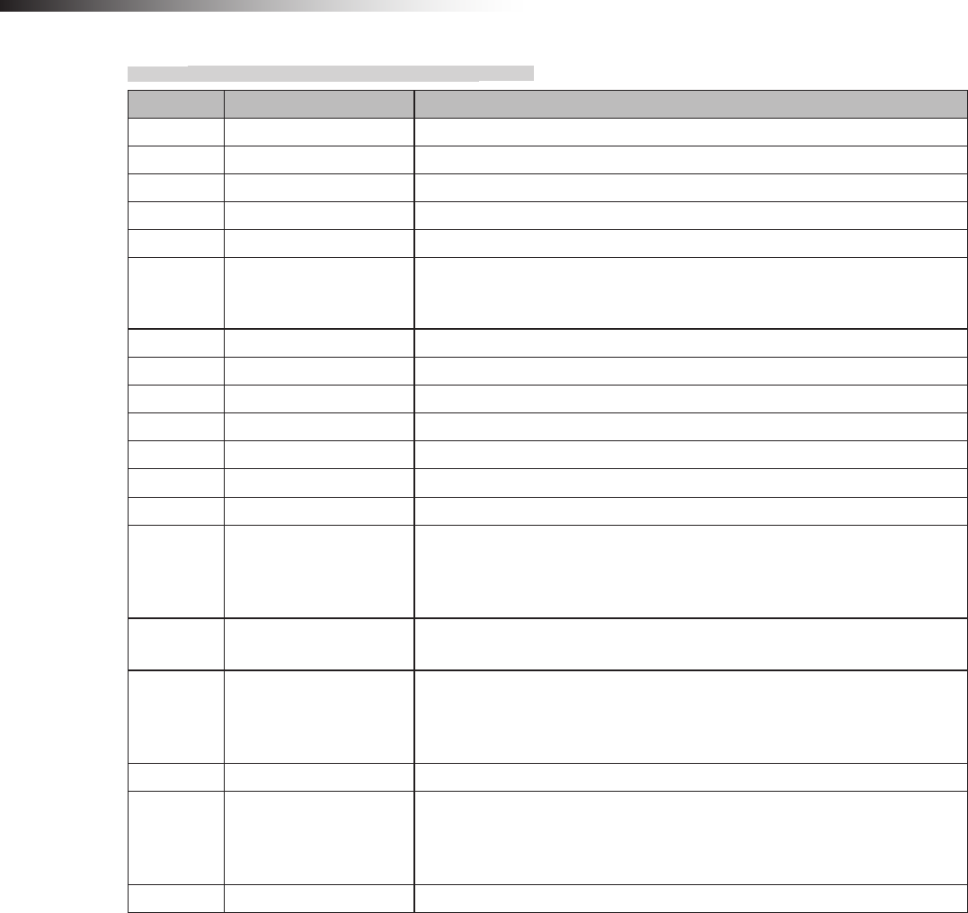
1) Display at power ON
Order Contents Display Example
1 Operation mode display
“--x” is displayed for 1 second.
x: Operation mode number
0: Address sensor mode
1: RFID mode
2: Ground station mode
3: External control mode
Operation mode: External control mode
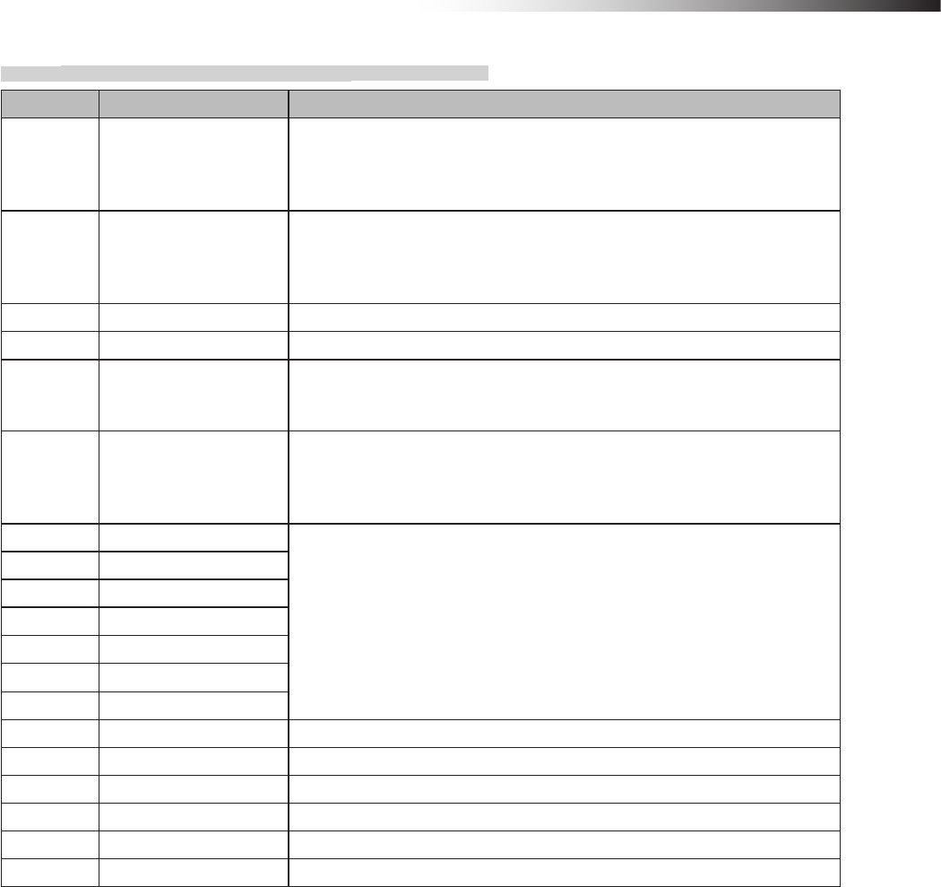
2 ID display “xxx” is displayed for 1 second.
xxx: ID set value
ID: 1
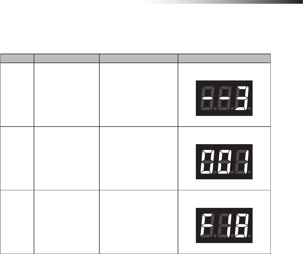
3 Frequency channel display
“Fxx” is displayed for 1 second.
xx: Frequency channel set value
Note: “F00” is displayed when the
PC setting is enabled.
Frequency channel: 18
ê 6. Part names and functions
- 20 -
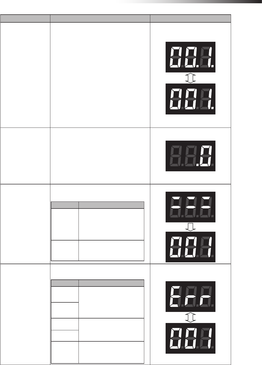
2) Normal display
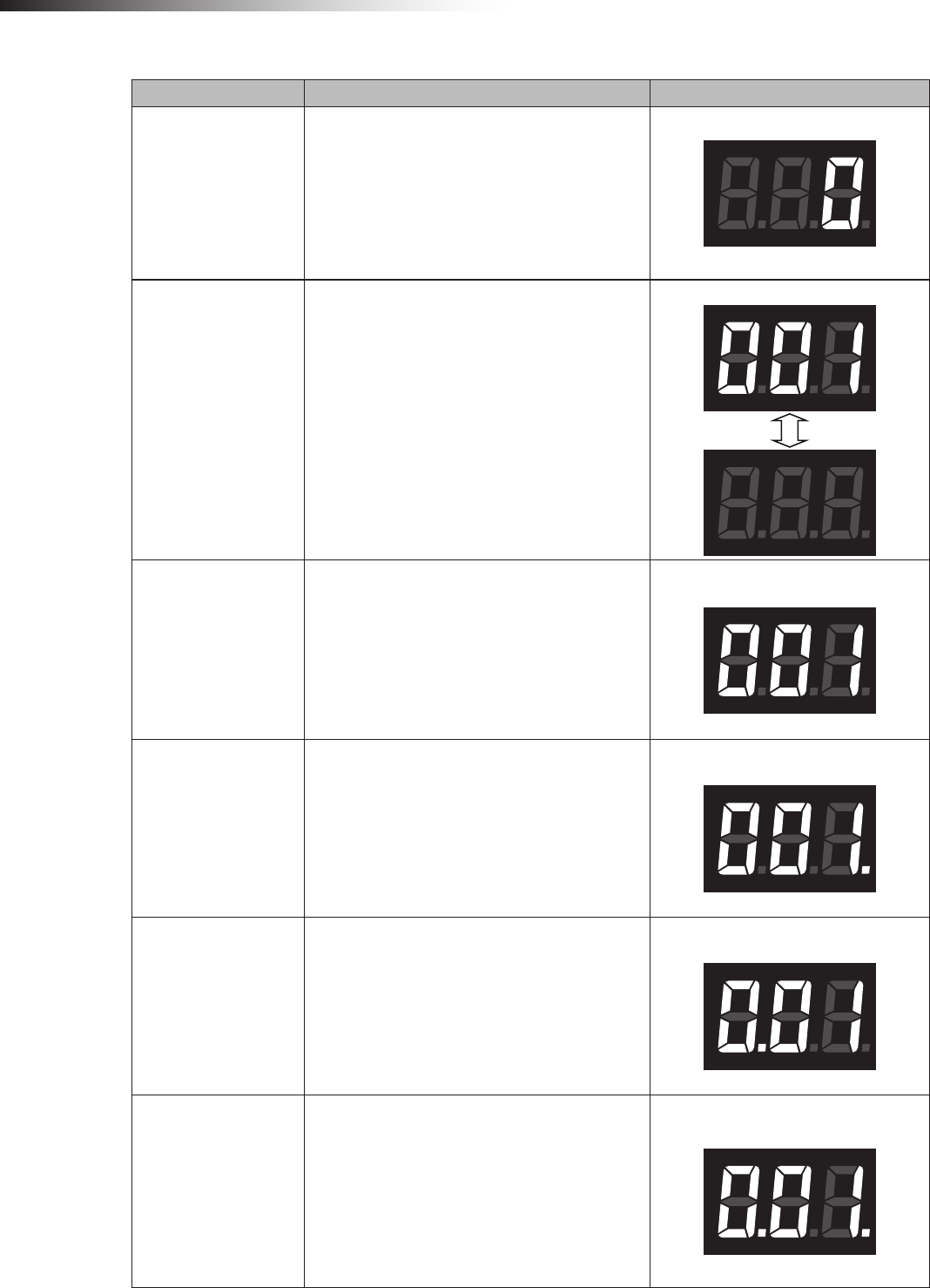
Contents Display Example
Standby
“ 0”
Note: Displayed in the standby status.
Intersection detection
“xxx” ↔ “ ”
Displayed for 0.5 second alternately.
xxx: Intersection address
Note: Displayed after the address magnetic plate
or ID tag has been recognized in the address
sensor mode or RFID mode.
Detection of intersection address 1
Waiting for intersection
detection
“xxx”
xxx: Intersection address
Note: Displayed while waiting after the intersec-
tion has been recognized.
Intersection address 1
Passing through the
intersection
“xxx.”
xxx: Intersection address
Note: Displayed when the intersection is recog-
nized and the AGV is passing through the inter-
section.
Intersection address 1
Waiting with the inter-
section top priority
“x.xx”
xxx: Intersection address
Note: Displayed when the intersection is recog-
nized and the AGV is waiting with the intersection
top priority input turned ON.
Intersection address 1
Passing with the inter-
section top priority
“x.xx.”
xxx: Intersection address
Note: Displayed when the intersection is rec-
ognized and the AGV is passing through the
intersection with the intersection top priority input
turned ON.
Intersection address 1
ê 6. Part names and functions
- 21 -
Contents Display Example
Intersection waiting
countup
“xx.x.” ↔ “xxx.”
The dot at the 2nd digit blinks.
xxx: Intersection address
Note: When the count for the communication
check from the wireless intersection module that
is passing through the intersection is incremented
in the waiting status, the status changes from
waiting to passing, and then it is displayed.
Note: When the count for the communication
check is incremented if there is no wireless
intersection module that is passing through the
intersection, the status changes to passing, and
then it is displayed.
Note: Displayed only when the intersection
control is performed by the wireless intersection
modules.
Intersection address 1
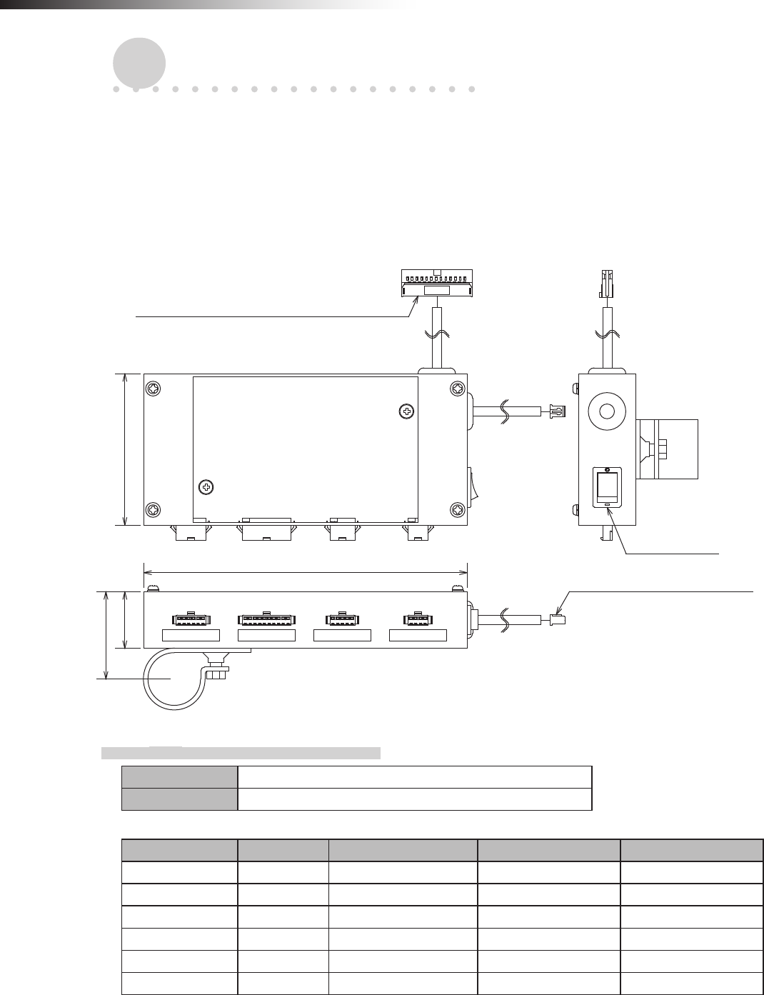
Ground station commu-
nication countup when
exiting intersection
“ .0”
Note: When the wireless intersection module that
was passing through the intersection exits the
intersection, this exit is transmitted to the ground
station. This display appears when the count for
the communication check is incremented.
Note: Displayed only when the intersection con-
trol is performed using the ground station.
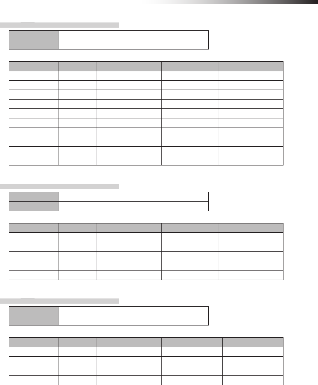
Warning
“:::” Displayed for 1 second. → “xxx”
xxx: Warning code
Warning code Contents
001
The operation mode setting of the
wireless intersection module was not
registered to the parameters of the
ground station.
Register the parameters or change the
operation mode.
100 An internal reset occurred. Turn OFF
the power, and then turn it ON again.
Warning code: 001
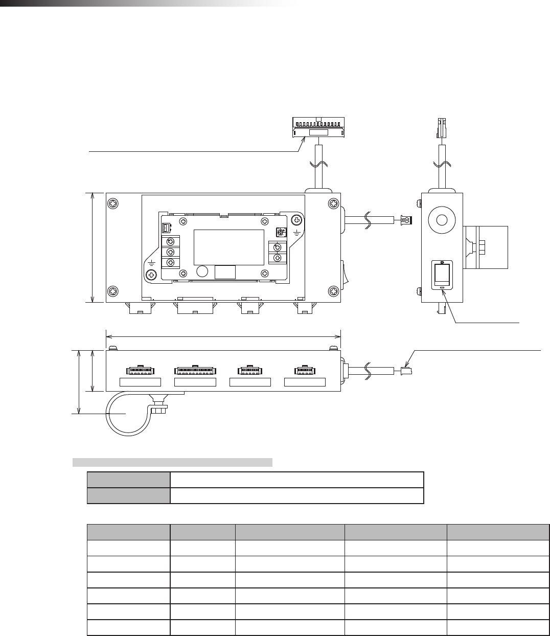
System error
“Err” and “xxx” are displayed alternately.
xxx: Error code
Error code Contents
001 The operation mode setting of the wire-
less intersection module might be out of
the setting range. Turn OFF all settings
of SW1, and then perform the settings
again.
002
100 Replace the wireless intersection
module.
101
102 The communication with the ground
station was not established.
Error code: 001
ê 7. About related components
- 22 -
7. About related components
7-1. Wireless intersection module box FCP-RCB01-24
This box distributes the CN2 input/output cable wiring of the wireless intersection module FCU-RC01 in accordance
with the application.
A bracket to install the wireless intersection module on a ø28-Creform pipe is supplied with the box.
A power switch is provided. When using this box, turn the power switch ON.
Note that this product is dedicated for 24 V.
CN2 connector for wireless intersection module
80
30
(47)
CN1 connector for wireless
intersection module
Power switch
CN1 CN2 CN3 CN4
171
Unit: mm
7-1-1. CN1
Connector SMP-06V-NC cable to cable connection connector (JST)
Fitting connector SMR-06V-N cable to cable connection connector (JST)
Pin number Contents Address sensor mode RFID mode External control mode
1 +Vin - - -
2 OUT1 Start Start Start
3 OUT6 Pause Pause -
4 OUT2 Stop Stop Stop
5 IN10 AGV arrival AGV arrival AGV arrival
6 -Vin - - -
ê 7. About related components
- 23 -
7-1-2. CN2
Connector SMP-10V-NC cable to cable connection connector (JST)
Fitting connector SMR-10V-N cable to cable connection connector (JST)
Pin number Contents Address sensor mode RFID mode External control mode
1 IN9 Read timing - Intersection inquiry
2 IN1 Intersection address (1) - Intersection address (1)
3 IN2 Intersection address (2) - Intersection address (2)
4 IN3 Intersection address (4) - Intersection address (4)
5 IN4 Intersection address (8) - Intersection address (8)
6 IN5 Intersection address (16) - Intersection address (16)
7 IN6 Intersection address (32) - Intersection address (32)
8 IN7 Intersection address (64) - Intersection address (64)
9 +Vout - - -
10 -Vout - - -
7-1-3. CN3
Connector SMP-05V-NC cable to cable connection connector (JST)
Fitting connector SMR-05V-N cable to cable connection connector (JST)
Pin number Contents Address sensor mode RFID mode External control mode
1 TxD - TxD -
2 RxD - RxD -
3 SGND - SGND -
8 +Vout - - -
9 -Vout - - -
7-1-4. CN4
Connector SMP-04V-NC cable to cable connection connector (JST)
Fitting connector SMR-04V-N cable to cable connection connector (JST)
Pin number Contents Address sensor mode RFID mode External control mode
1 IN8 AGV error AGV error AGV error
2 IN12 Battery voltage drop Battery voltage drop Battery voltage drop
3 IN13 Reset Reset Reset
4 -Vout - - -
ê 7. About related components
- 24 -
7-2. Wireless intersection module box FCP-RCB01-12
The functions are the same as the FCP-RCB01-24.
A power switch is provided. When using this box, turn the power switch ON.
Note that this product is dedicated for 12V.
2
1
CN2 connector for wireless intersection module
8030
(47)
171
Power switch
CN1 connector for wireless
intersection module
CN1 CN2 CN3 CN4
Unit: mm
7-2-1. CN1
Connector SMP-06V-NC cable to cable connection connector (JST)
Fitting connector SMR-06V-N cable to cable connection connector (JST)
Pin number Contents Address sensor mode RFID mode External control mode
1 +Vin - - -
2 OUT1 Start Start Start
3 OUT6 Pause Pause -
4 OUT2 Stop Stop Stop
5 IN10 AGV arrival AGV arrival AGV arrival
6 -Vin - - -

ê 7. About related components
- 25 -
7-2-2. CN2
Connector SMP-10V-NC cable to cable connection connector (JST)
Fitting connector SMR-10V-N cable to cable connection connector (JST)
Pin number Contents Address sensor mode RFID mode External control mode
1 IN9 Read timing - Intersection inquiry
2 IN1 Intersection address (1) - Intersection address (1)
3 IN2 Intersection address (2) - Intersection address (2)
4 IN3 Intersection address (4) - Intersection address (4)
5 IN4 Intersection address (8) - Intersection address (8)
6 IN5 Intersection address (16) - Intersection address (16)
7 IN6 Intersection address (32) - Intersection address (32)
8 IN7 Intersection address (64) - Intersection address (64)
9 +Vout - - -
10 -Vout - - -
7-2-3. CN3
Connector SMP-05V-NC cable to cable connection connector (JST)
Fitting connector SMR-05V-N cable to cable connection connector (JST)
Pin number Contents Address sensor mode RFID mode External control mode
1 TxD - TxD -
2 RxD - RxD -
3 SGND - SGND -
8 +Vout - - -
9 -Vout - - -
7-2-4. CN4
Connector SMP-04V-NC cable to cable connection connector (JST)
Fitting connector SMR-04V-N cable to cable connection connector (JST)
Pin number Contents Address sensor mode RFID mode External control mode
1 IN8 AGV error AGV error AGV error
2 IN12 Battery voltage drop Battery voltage drop Battery voltage drop
3 IN13 Reset Reset Reset
4 -Vout - - -
ê 7. About related components
- 26 -
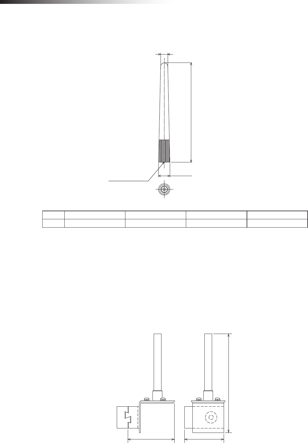
7-3. Pencil type antenna FCP-RCA01
This antenna is connected to the antenna connection section of the wireless intersection module FCU-RC01.
Unit: mm
89±3
6.4
10.2
SMA male pin
Antenna List
No. Manufacturer Part No. Antenna Type Peak Gain
1 Arrow 7 ARN-AP03 Pencil type antenna 2.14dBi for 2.4 GHz
Note: The antenna connector is Reverse SMA type.
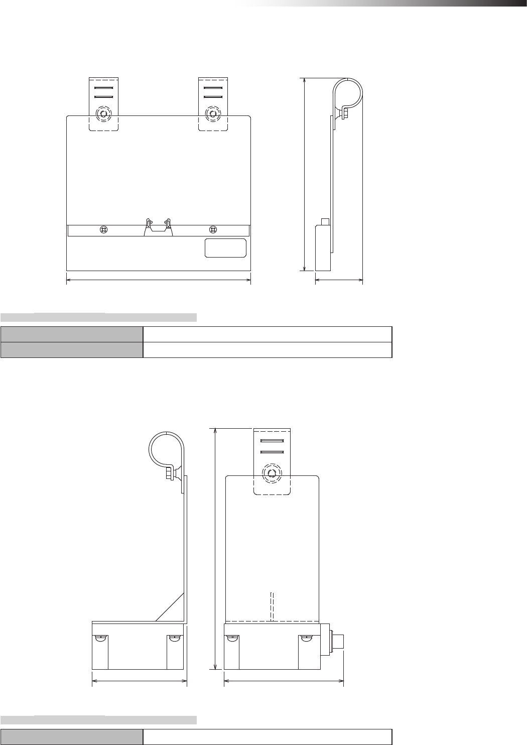
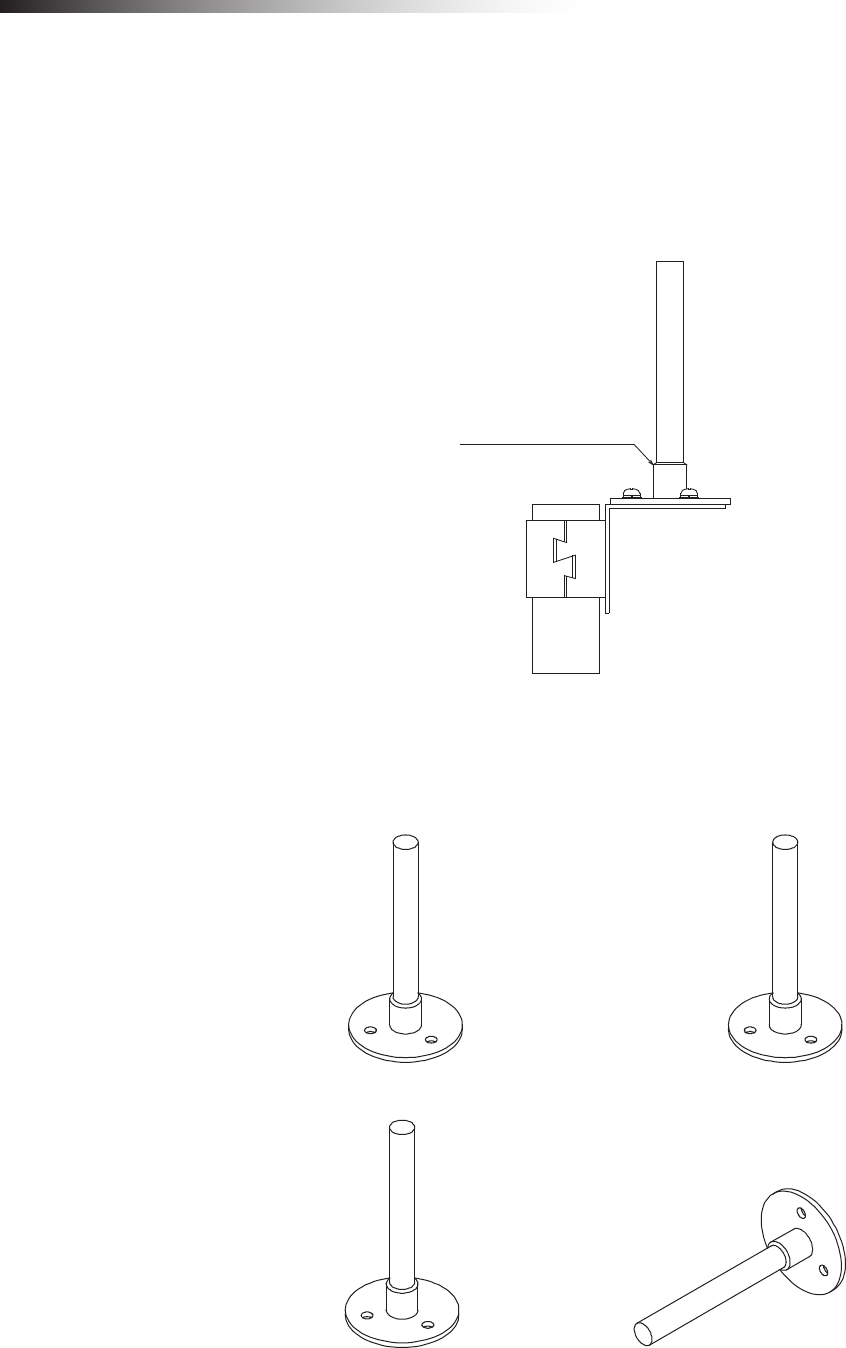
7-4. Flanged antenna with bracket FCP-RCA02
This antenna is used when it is installed at a position away from the wireless intersection module.
• The cable length is approximately 1 m.
• The radio wave is attenuated (lost) by the cable.
• The communicable distance is shortened approximately 15% when compared to the pencil type antenna.
• When two wireless units that communicate with each other use the anged antennas, the communication distance
is shortened by approximately 30% due to double effects.
• For cable bending, the bending radius is 50 mm or more. If the cable is bent excessively, the insulator inside the
cable is deformed and the cable loss increases, causing the communicable distance to be shortened.
69 (58)
146
Unit: mm
ê 7. About related components
- 27 -
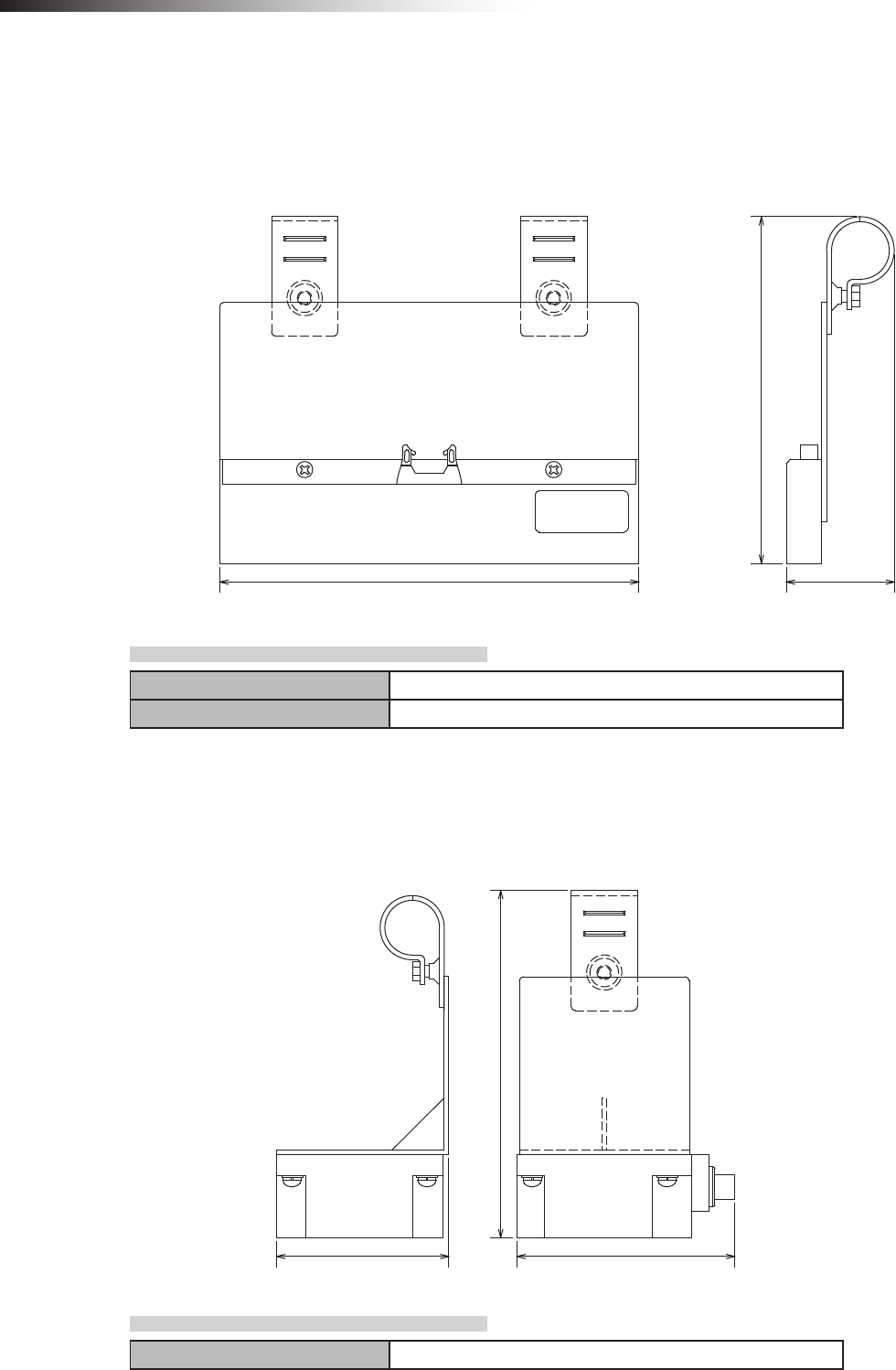
7-5. Address sensor with bracket FCP-RCS01
This sensor reads the address magnetic plate to instruct the intersection entrance or intersection exit.
202 (52)
(212)
Unit: mm
7-5-1. Specications
Operating temperature range -10 to 60ºC (No dew condensation or freezing allowed.)
Operating humidity range 35 to 95% RH (No dew condensation allowed.)
7-6. RFID antenna with bracket FCP-RCS02
This sensor reads the ID tag to instruct the intersection entrance or intersection exit.
83 105
(212)
Unit: mm
7-6-1. Specications
Operating temperature range 0 to 70ºC (No dew condensation or freezing allowed.)
ê 7. About related components
- 28 -
7-7. Address sensor with bracket for small Drive Unit FCP-RCS03
This sensor reads the address magnetic plate to instruct the intersection entrance or intersection exit.
This sensor is used for the small Drive Unit.
202
(168)
(52)
Unit: mm
7-7-1. Specications
Operating temperature range -10 to 60ºC (No dew condensation or freezing allowed.)
Operating humidity range 35 to 95% RH (No dew condensation allowed.)
7-8. RFID antenna with bracket for small Drive Unit FCP-RCS04
This sensor reads the ID tag to instruct the intersection entrance or intersection exit.
This sensor is used for the small Drive Unit.
83 105
(168)
Unit: mm
7-8-1. Specications
Operating temperature range 0 to 70ºC (No dew condensation or freezing allowed.)
ê 7. About related components
- 29 -
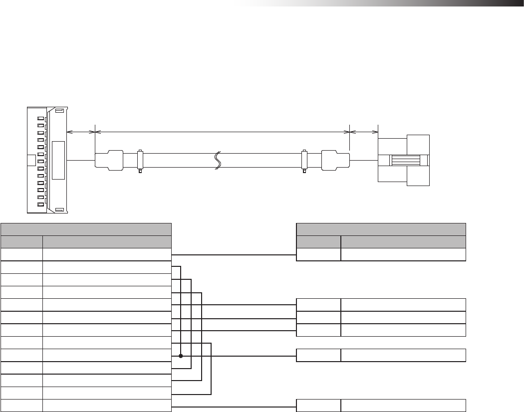
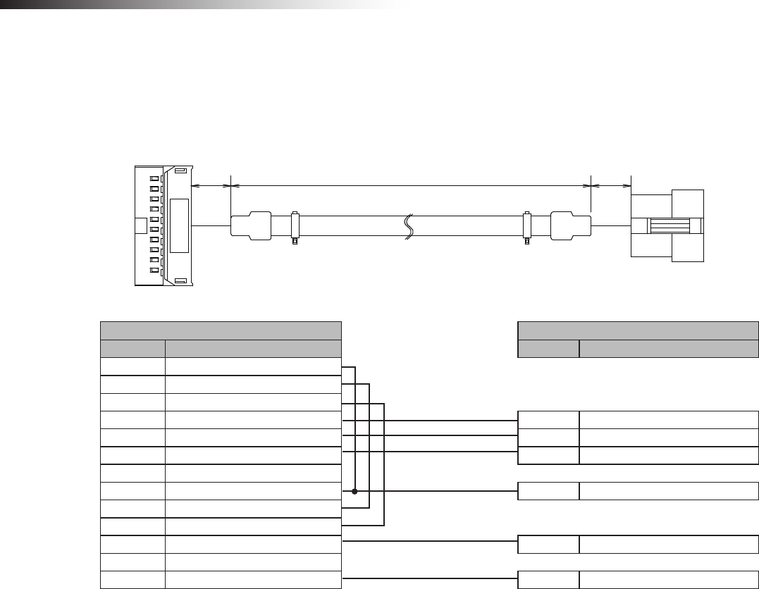
7-9. Cable for 24 V Drive Unit FCP-RCC01-24
This cable connects the CNG connector of the 24 V forward Drive Unit and the CN1 connector of the wireless intersec-
tion module box.
(1500)
(30)
(30)
Unit: mm
Drive Unit CNG connector CN1 connector of wireless intersection module box
Pin number Contents Pin number Contents
1 +24 V 1 +Vin
5 Command stop input
6
Right travel/medium speed change-over input
7
Speed change-over/medium speed change-over input
8 Start signal input 2 Start input
10 Pause input 3 Pause output
11 Stop input 4 Stop output
12 Input change-over input
13 S sensor output 5 AGV arrival input
14
Right travel/medium speed change-over output
15
Speed change-over/medium speed change-over output
21 0 V
22 0 V 6 -Vin
ê 7. About related components
- 30 -
7-10. Cable for 12V Drive Unit FCP-RCC01-12
This cable connects the CNG connector of the 12V forward Drive Unit and the CN1 connector of the wireless intersec-
tion module box.
Unit: mm
(1500) (30)(30)
Drive Unit CNG connector CN1 connector of wireless intersection module box
Pin number Contents Pin number Contents
1 Command stop input
2
Right travel/medium speed change-over input
3
Speed change-over/medium speed change-over input
4 Start signal input 2 Start output
6 Pause input 3 Pause output
7 Stop input 4 Stop output
8 Input change-over input
9 S sensor output 5 AGV arrival input
10
Right travel/medium speed change-over output
11
Speed change-over/medium speed change-over output
17 +12 V 1 +Vin
19 0 V
20 0 V 6 -Vin
ê 7. About related components
- 31 -
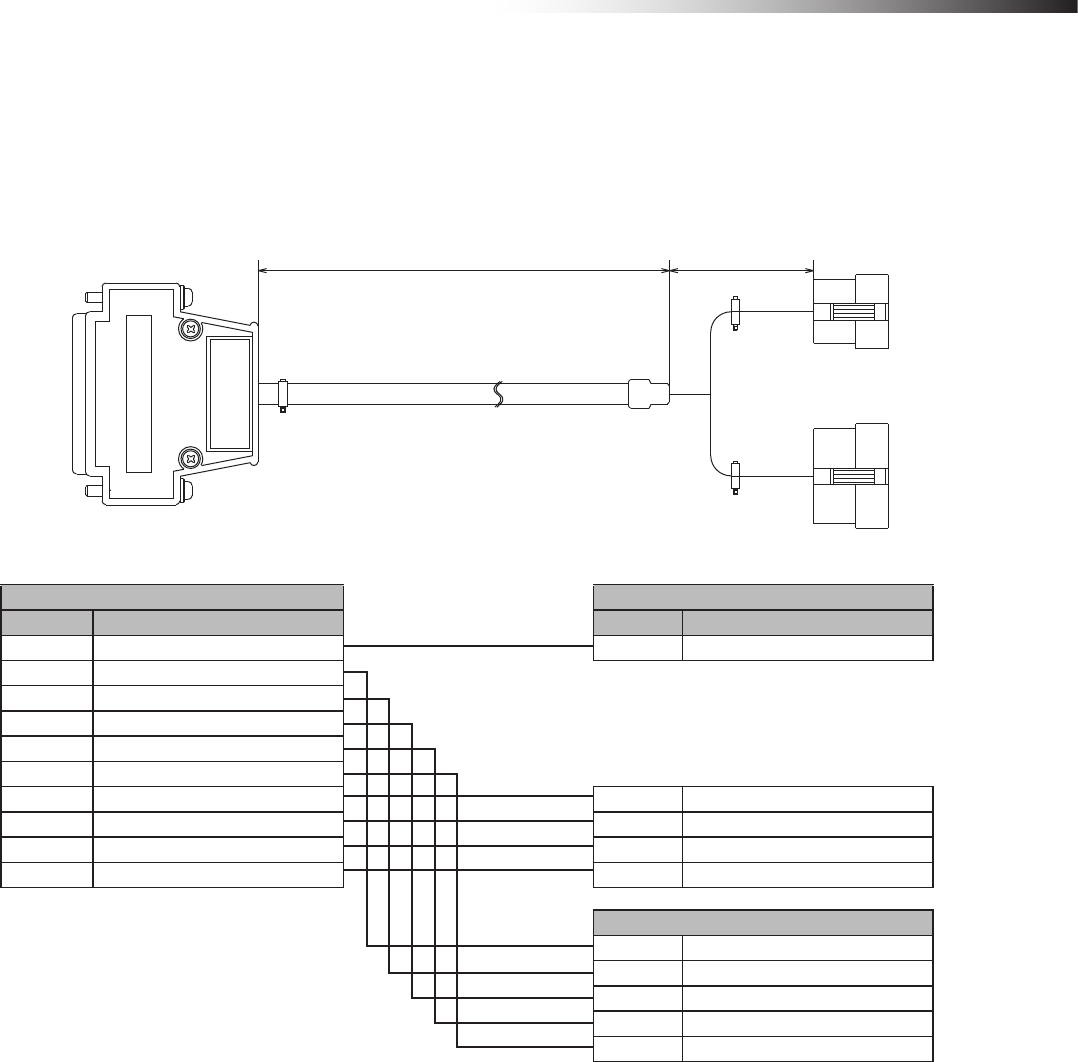
7-11. Cable for course 30 FCP-RCC02
This cable connects the CND or CNG connector of the forward or forward/backward course 30 unit and the CN1 and
CN2 connectors of the wireless intersection module box.
(40)
(1500)
Unit: mm
External option connector of course 30 unit CN1 connector of wireless intersection module box
Pin number Contents Pin number Contents
1 Station arrival output 5 AGV arrival input
6 External operation command 1 output
7 External operation command 2 output
8 External operation command 3 output
9 External operation command 4 output
10 External operation command 5 output
16 External start input 2 Start output
17 External stop input 4 Stop output
18 + 1 +Vin
22 0 V 6 -Vin
CN2 connector of wireless intersection module box
1 Intersection inquiry input
2 Intersection address (1) input
3 Intersection address (2) input
4 Intersection address (4) input
5 Intersection address (8) input
ê 7. About related components
- 32 -
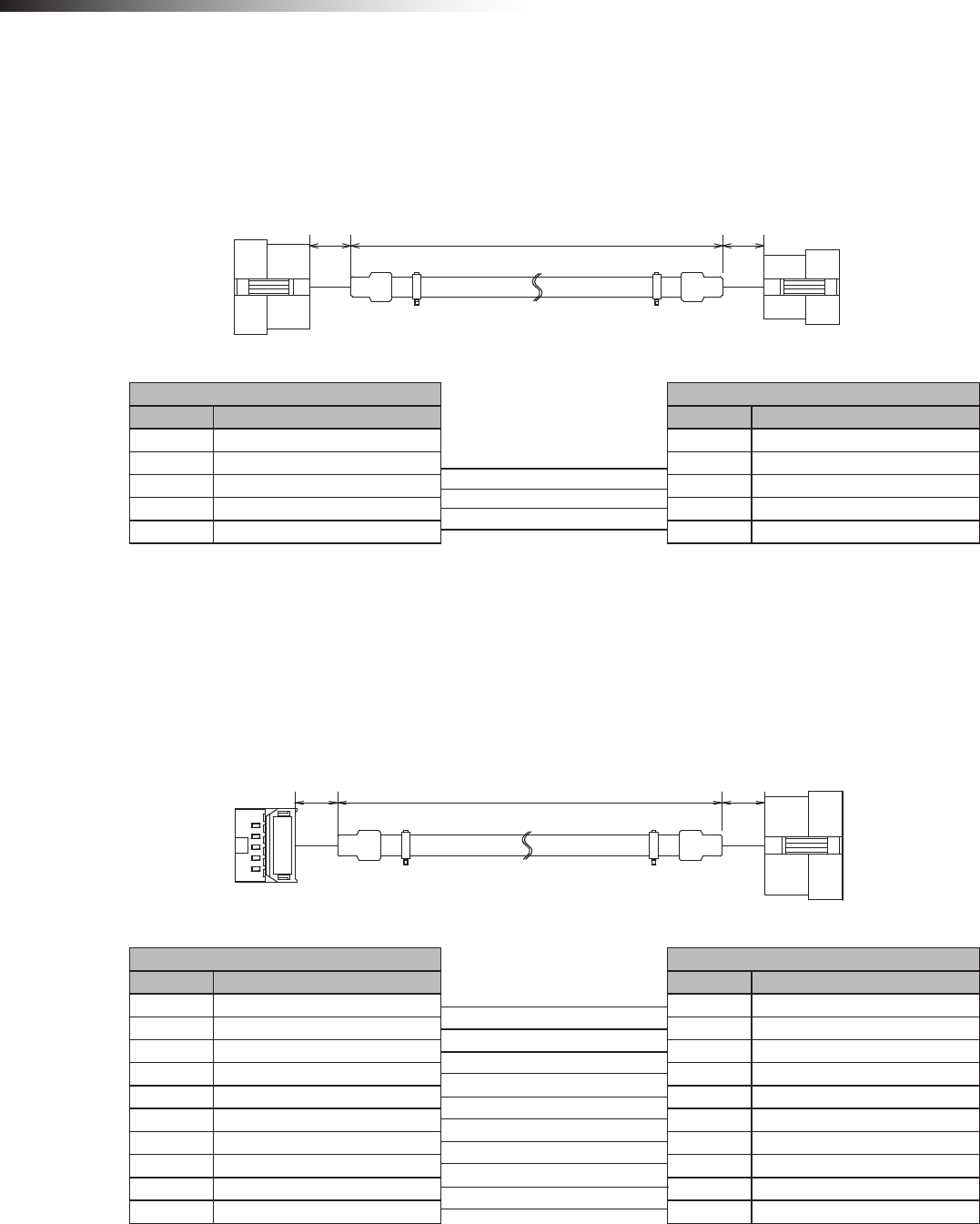
7-12. Cable for small Drive Unit FCP-RCC03
This cable connects the external control cable FCSA-HA14P9 that is an optional component of the small Drive Unit and
the CN1 connector of the wireless intersection module box.
(1500) (30)
(30)
Unit: mm
External control cable for small Drive Unit CN1 connector of wireless intersection module box
Pin number Contents Pin number Contents
1 External stop input 4 Stop output
2 External start input 2 Start output
3 Arrival output 5 AGV arrival input
5 +12 V 1 +Vin
6 0 V 6 -Vin
7-13. Cable for address sensor FCP-RCC04
The cable connects the address sensor with bracket FCP-RCS01 or address sensor with bracket for small Drive Unit
FCP-RCS03 and the CN2 connector of the wireless intersection module box.
(5000) (30)
(30)
Unit: mm
Address sensor CN2 connector of wireless intersection module box
Pin number Contents Pin number Contents
1 Read-out timing output 1 Read-out timing input
2 Data No. 0 output 2 Intersection address (1) input
3 Data No. 1 output 3 Intersection address (2) input
4 Data No. 2 output 4 Intersection address (4) input
5 Data No. 3 output 5 Intersection address (8) input
6 Data No. 4 output 6 Intersection address (16) input
7 Data No. 5 output 7 Intersection address (32) input
8―8 Intersection address (64) input
9 +Vin 9 +Vout
10 -Vin 10 -Vout
ê 7. About related components
- 33 -
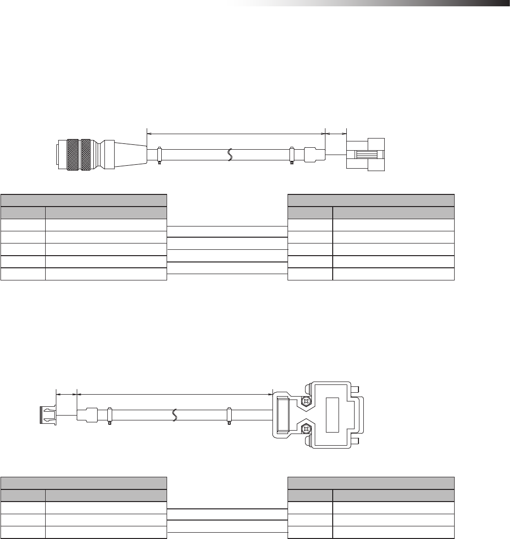
7-14. Cable for RFID antenna FCP-RCC05
This cable connects the RFID antenna with bracket FCP-RCS02 or RFID antenna with bracket for small Drive Unit
FCP-RCS04 and the CN3 connector of the wireless intersection module box.
(30)
(5000)
Unit: mm
RFID antenna CN3 connector of wireless intersection module box
Pin number Contents Pin number Contents
2 TxD 1 TxD
3 RxD 2 RxD
6 -Vin 4 +Vout
7 +Vin 5 -Vout
8 COM 3 SGND
7-15. Wireless intersection module setting cable FCP-RCC08
This cable is needed to set the parameters to the wireless intersection module.
(2000)
(30)
Unit: mm
CN3 connector of wireless intersection module box RS232C port of personal computer
Pin number Contents Pin number Contents
1 TxD 2 RxD
2 RxD 3 TxD
3 SGND 5 SGND
ê 7. About related components
- 34 -
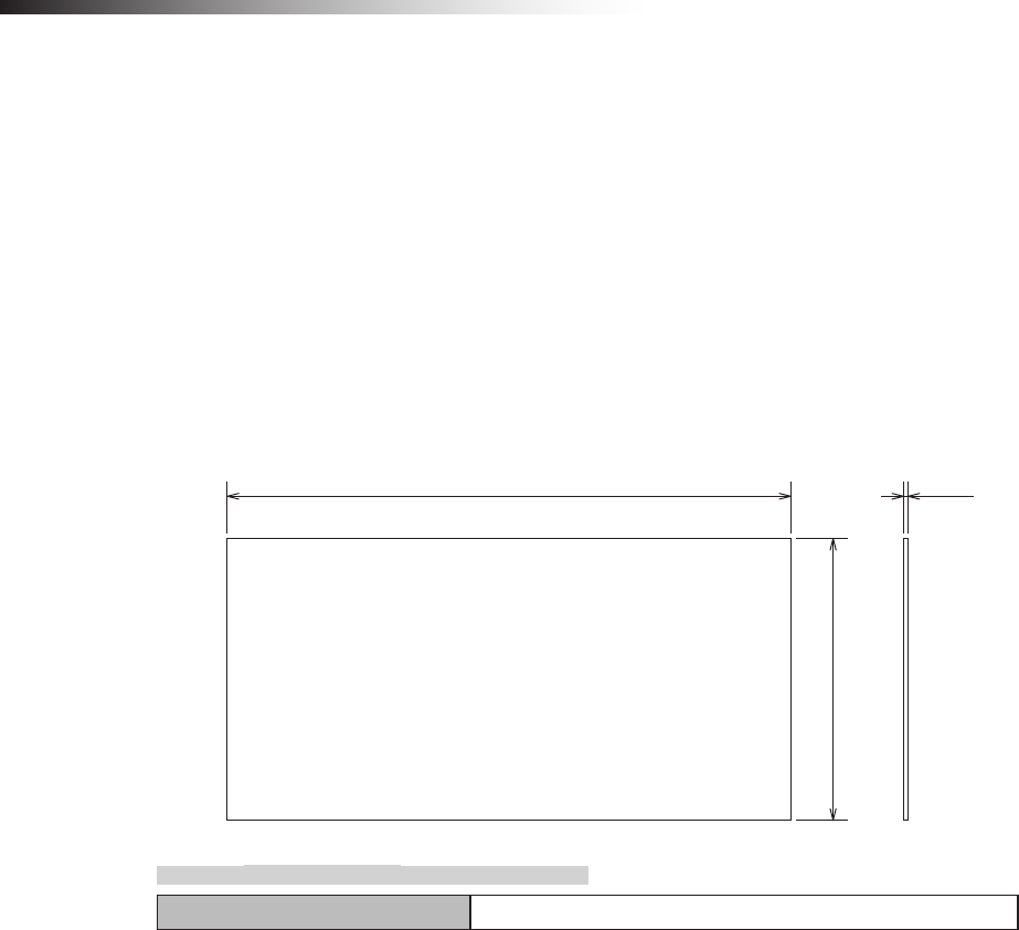
7-16. Address magnetic plate FCP-SMG01-*
The magnetic plate has the address information to be read out by the address sensor with bracket FCP-RCS01 or the
address sensor with bracket for small Drive Unit FCP-RCS03.
When the address magnetic plate with an arbitrary intersection address (address information) is installed at the inter-
section entrance and it is read out, the intersection address is instructed to the wireless intersection module.
When intersection address (address information) “0” is read out at the intersection exit, the intersection exit is instruct-
ed. Usable address information values range from 0 to 62. * portion of the part number is the address information.
Please specify the address information when ordering the address magnetic plate.
(Example) For address information 5: FCP-SMG01-05
1.6
200
100
Unit: mm
7-16-1. Specications
Operating temperature range -10 to 60ºC
ê 7. About related components
- 35 -
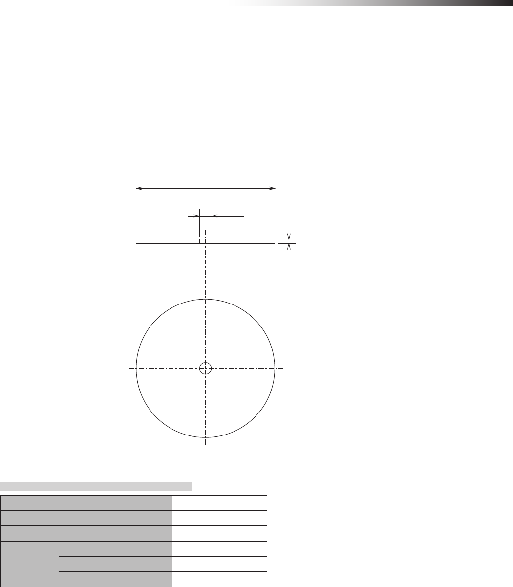
7-17. ID tag FCP-TAG01
This ID tag has the address information to be read out by the RFID antenna with bracket FCP-RCS02 or
RFID antenna with bracket for small Drive Unit FCP-RCS04.
When the ID tag with an arbitrary intersection address (address information) is installed at the intersection entrance
and it is read out, the intersection address is instructed to the wireless intersection module. When intersection address
(address information) “000” is read out at the intersection exit, the intersection exit is instructed. Usable address infor-
mation values range from 000 to 127.
Please specify the address information when ordering the ID tag as the address information is written at shipment.
50
4.3
1.6
Unit: mm
7-17-1. Specications
Operating temperature -25 to 70ºC
Storage humidity -25 to 85ºC
Storage structure IP67
Service life
Number of read-out times Unlimited
Number of write times 10 billion times
Data retention 10 years
ê 7. About related components
- 36 -
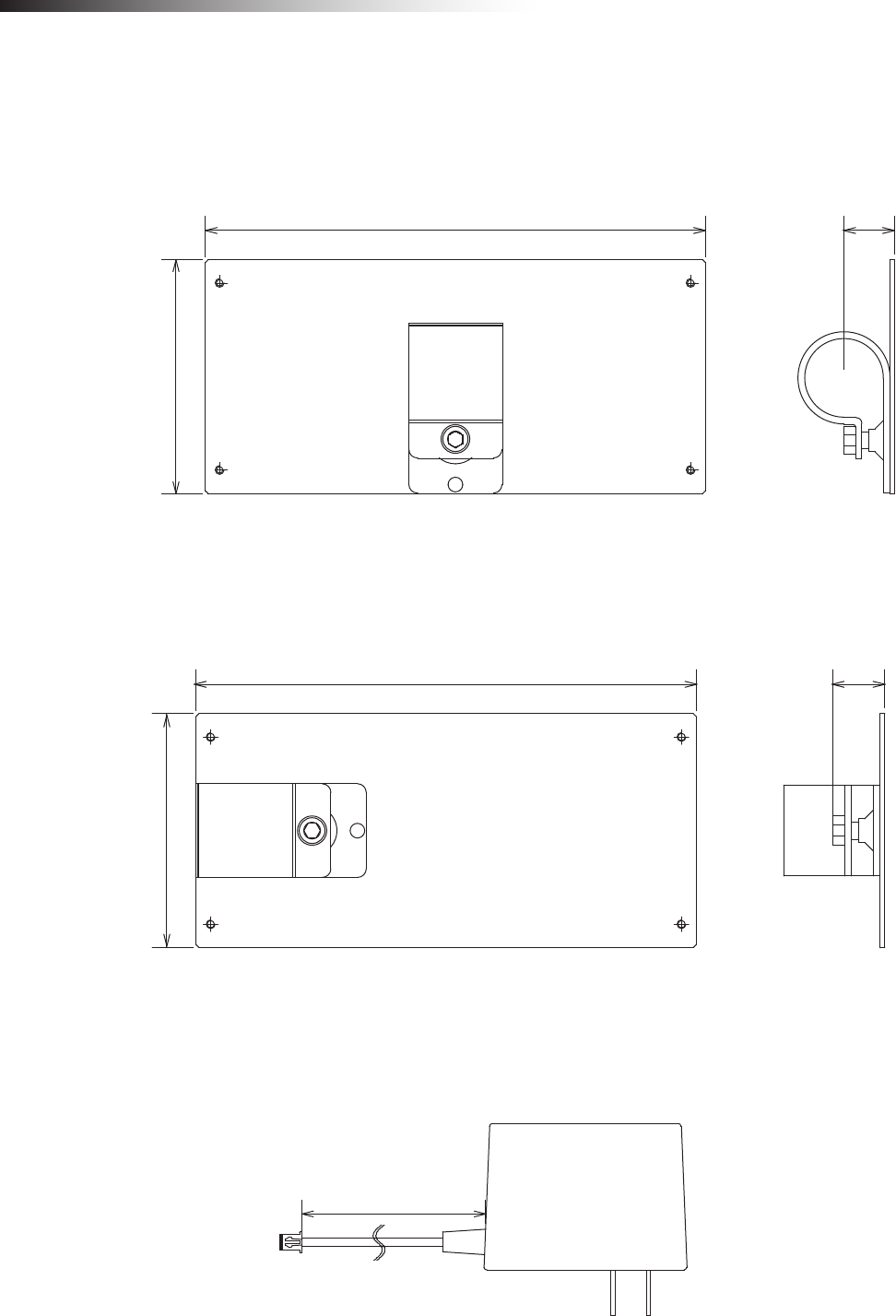
7-18. Wireless intersection module mounting bracket FCU-RCK06
This mounting bracket is used when the single wireless intersection module is used in the ground station mode, etc.
A bracket to install the wireless intersection module on a ø28-Creform pipe is attached.
171 (18)
80
Unit: mm
7-19. Wireless intersection module mounting bracket FCU-RCK07
This mounting bracket is used when the single wireless intersection module is used in the ground station mode, etc.
A bracket to install the wireless intersection module on a ø28-Creform pipe is attached.
171 (18)
80
Unit: mm
7-20. AC adapter FCP-RCP01
This AC adapter is used to supply the power when the wireless intersection module is used in the ground station mode.
(1500)
Unit: mm
ê 8. Installation and connections
- 37 -
8. Installation and connections
8-1. About installation place
Strictly observe the following installation conditions when performing the installation.
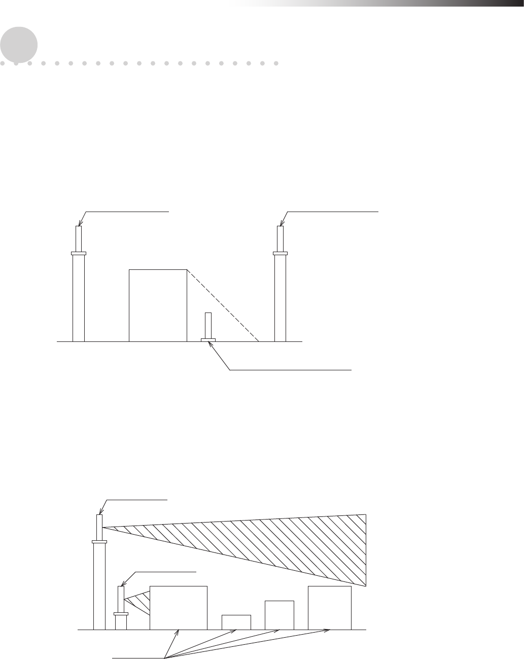
1) Install the antennas at the highest possible positions where the antennas can be seen together.
Since the radio wave with a high frequency is used, the straightness of the radio wave is strong and it is difcult to
reach hidden places. Therefore, install the antennas at positions where the antennas can be simultaneously seen
as much as possible.
Transmitting antenna Antenna where the radio
wave can reach.
Antenna where the radio wave
is difficult to reach.
Obstacle, etc.
Figure. Shadow of radio wave
2) Install the antenna 200 mm or more away from the oor.
Since the antenna is installed in an open space where its installation height is high, it becomes difcult for obstacles
to affect the antenna and the radio wave transmits easily.
If the antenna position is extremely low, the radio wave transmitted from the antenna becomes weak.
High antenna
Low antenna
Obstacle, etc.
Figure. Height of antenna
ê 8. Installation and connections
- 38 -
3) Install the antenna so that it is not parallel to cables or metallic plates.
In addition, install the antenna away from any cable, metallic plates, concrete, plasterboard, lumber, and wall
surfaces as much as possible (300 mm or more).
When there are obstacles around the antenna, the radio wave becomes obstructed and is not transmitted optimally.
In particular, metallic objects affect the antenna greatly as it reects the radio wave. When installing the anged
antenna on a Creform pipe, install it so that the Creform pipe does not affect the antenna as shown in the gure.
Pipe must not protrude
from here.
Figure. Installation on pipe
4) When installing the antenna, adjust the antenna direction.
Install the antennas so that they face in the same direction as shown in the gure.
When the direction differs 90 degrees, the communication distance becomes short extremely.
Figure. Correct direction
Figure. Incorrect direction
5) Install the antenna at a position where an object does not hit it.
The antenna is not designed so that it can be hit by an object. If any impact is applied to the antenna, it may be
damaged. Even though the antenna may appear normal, wire breakage may occur inside the antenna, causing the
communication to fail.
ê 8. Installation and connections
- 39 -
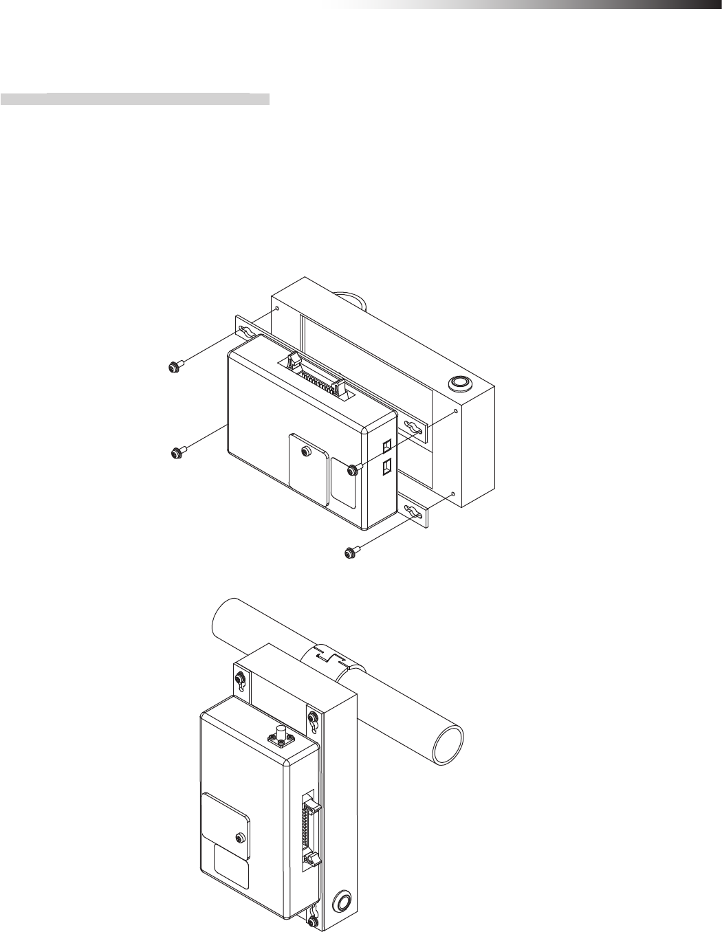
8-2. About installation
8-2-1. Wireless Intersection Module
Secure the wireless intersection module FCU-RC01 to the wireless intersection module box FCP-RCB01-24 or
FCP-RCB01-12 with the screws supplied with the wireless intersection module box, connect the MIL 26-core
connector to the CN2 connector of the wireless intersection module and the XHP-2 connector to the CN1 connector.
After that, the wireless intersection module can be installed on a Creform pipe using the at saddle of the wireless
intersection module.
Since the status is indicated on the display of the wireless intersection module, install the wireless intersection
module at a position where the display can be recognized.
Figure. Installation of wireless intersection module in wireless intersection module box
Figure. Installation on Creform pipe
ê 8. Installation and connections
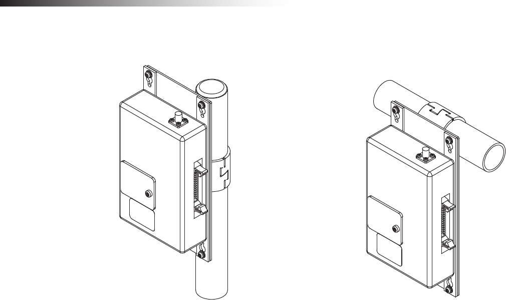
- 40 -
When the wireless intersection module is used as a ground station, install it on a Creform pipe using the wireless
intersection module mounting bracket FCP-RCK06 or FCP-RCK07.
Figure. Installation on Creform pipe
ê 8. Installation and connections
- 41 -
8-3. Connections and settings
Select components to be connected in accordance with the system conguration.
The total number of usable intersection addresses is determined depending on the conguration.
In addition, it is necessary to change the wireless intersection module settings so that they match the conguration.
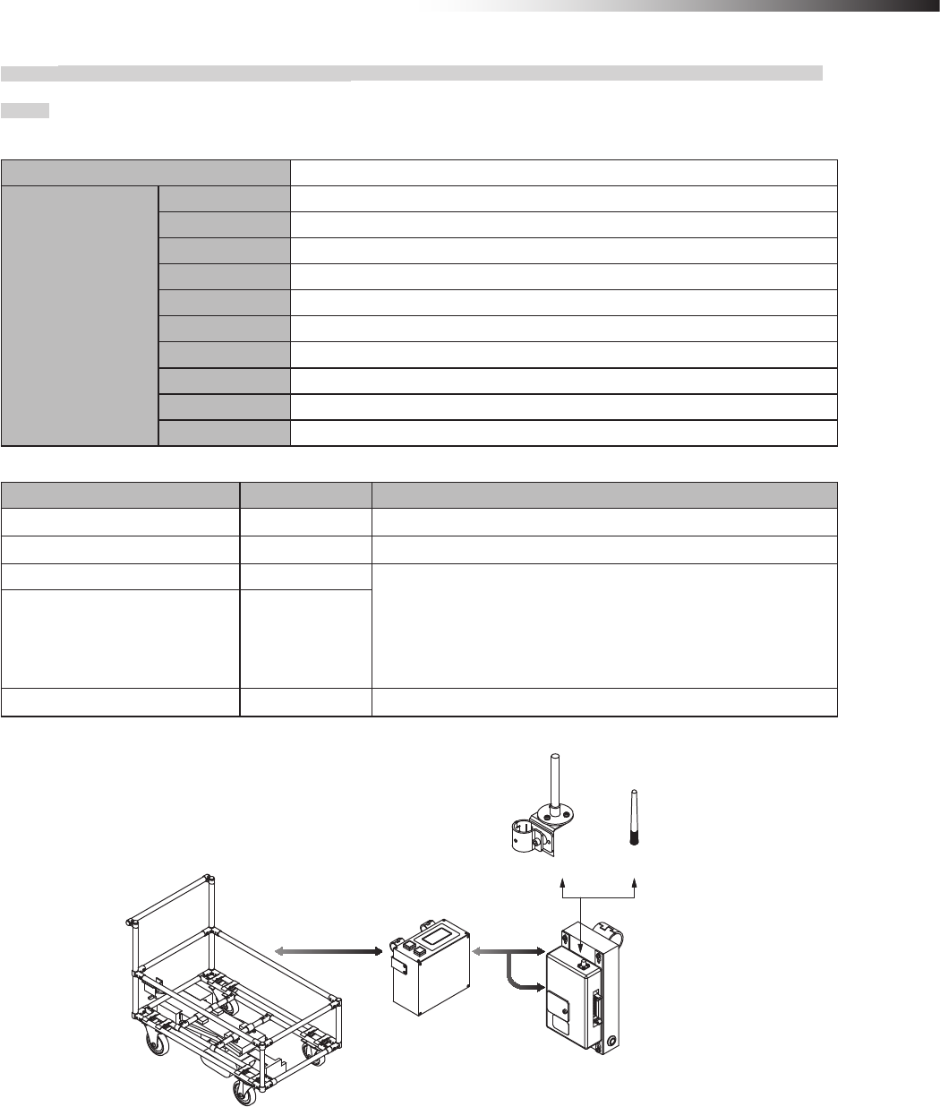
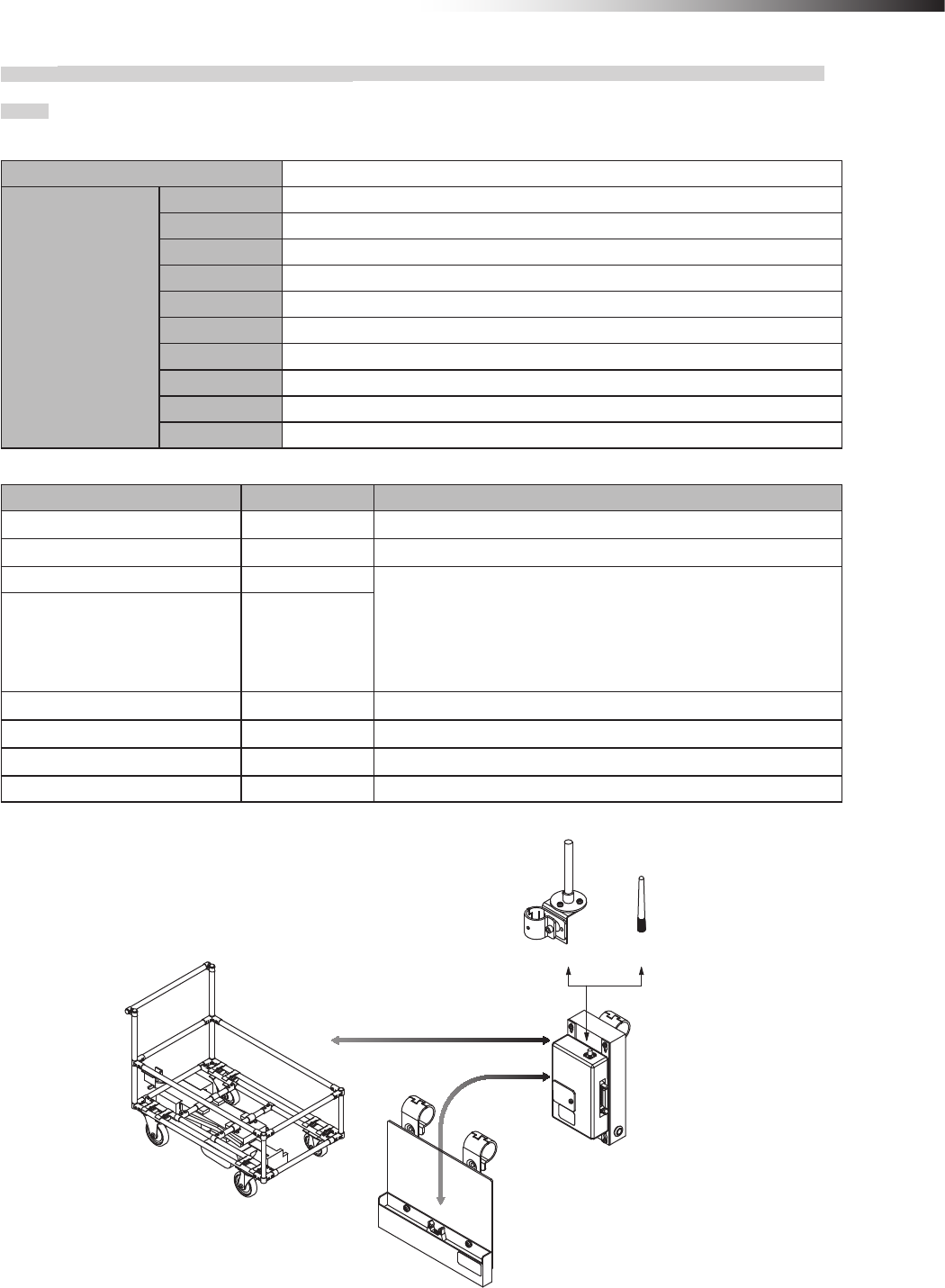
8-3-1. Intersection is instructed by the address sensor when the 24 V forward type Drive Unit is used.
Settings
Usable intersection address 1 to 62
Switch settings of
wireless intersection
module
SW1-1 OFF
SW1-2 OFF
SW1-3 OFF
SW1-4 OFF
SW1-5 OFF
SW1-6 OFF
SW1-7 OFF
SW1-8 OFF
RSW1 to 3 Create a unique setting for each wireless intersection module that is not duplicated.
RSW4 Select a usable frequency band.
Conguration
Product name Model number Remarks
Wireless Intersection Module FCU-RC01
Wireless intersection module box FCP-RCB01-24
Pencil type antenna FCP-RCA01 • Select either antenna depending on the application.
• The anged antenna attenuates the radio wave due to the cable.
The communicable distance is shortened approximately 15% when
compared to the pencil type antenna.
When two wireless units that communicate with each other use the
anged antennas, the communication distance is shortened by approx-
imately 30% due to double effects.
Flanged antenna with bracket FCP-RCA02
Address sensor with bracket FCP-RCS01
Cable for 24 V Drive Unit FCP-RCC01-24
Cable for address sensor FCP-RCC04
Address magnetic plate FCP-SMG01-* An address magnetic plate corresponding to the intersection is needed.
Connection diagram
FCP-RCA02 FCP-RCA01
FCP-RCB01-24
FCU-RC01
FCP-RCS01
FCP-RCC01-24
FCP-RCC04
CN1
CN2
CN G
120/121 type forward Drive Unit
ê 8. Installation and connections
- 42 -
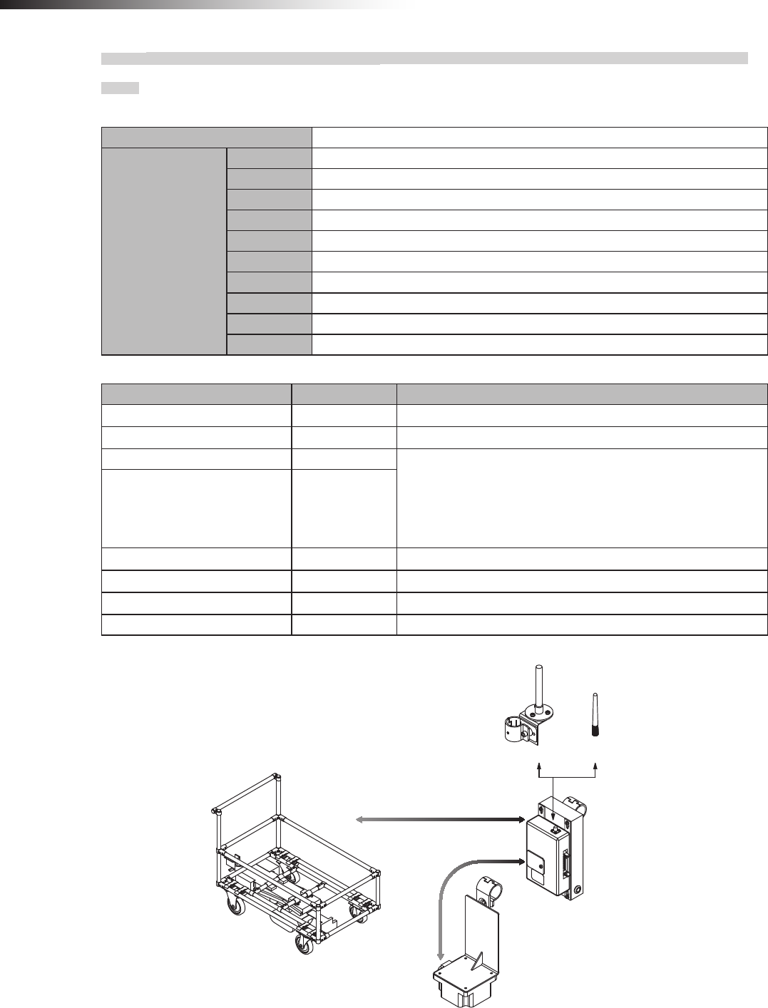
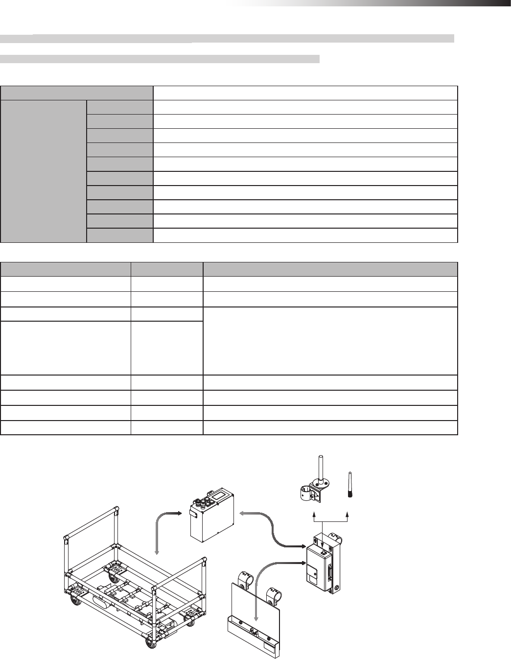
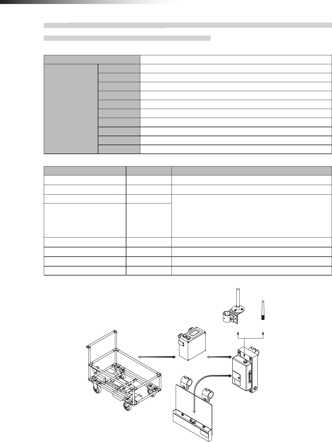
8-3-2. Intersection is instructed by the RFID antenna when the 24 V forward type Drive Unit is
used.
Settings
Usable intersection address 1 to 127
Switch settings of
wireless intersection
module
SW1-1 ON
SW1-2 OFF
SW1-3 OFF
SW1-4 OFF
SW1-5 OFF
SW1-6 OFF
SW1-7 OFF
SW1-8 OFF
RSW1 to 3 Create a unique setting for each wireless intersection module that is not duplicated.
RSW4 Select a usable frequency band.
Conguration
Product name Model number Remarks
Wireless Intersection Module FCU-RC01
Wireless intersection module box FCP-RCB01-24
Pencil type antenna FCP-RCA01 • Select either antenna depending on the application.
• The anged antenna attenuates the radio wave due to the cable.
The communicable distance is shortened approximately 15% when
compared to the pencil type antenna. When two wireless units that com-
municate with each other use the anged antennas, the communication
distance is shortened by approximately 30% due to double effects.
Flanged antenna with bracket FCP-RCA02
RFID antenna with bracket FCP-RCS02
Cable for 24 V Drive Unit FCP-RCC01-24
Cable for RFID antenna FCP-RCC05
ID tag FCP-TAG01 An ID tag corresponding to the intersection is needed.
Connection diagram
FCP-RCA02 FCP-RCA01
CN G FCP-RCC01-24 CN1
FCP-RCC05 CN3
FCU-RC01
FCP-RCB01-24
FCP-RCS02
120/121 type forward Drive Unit
ê 8. Installation and connections
- 43 -
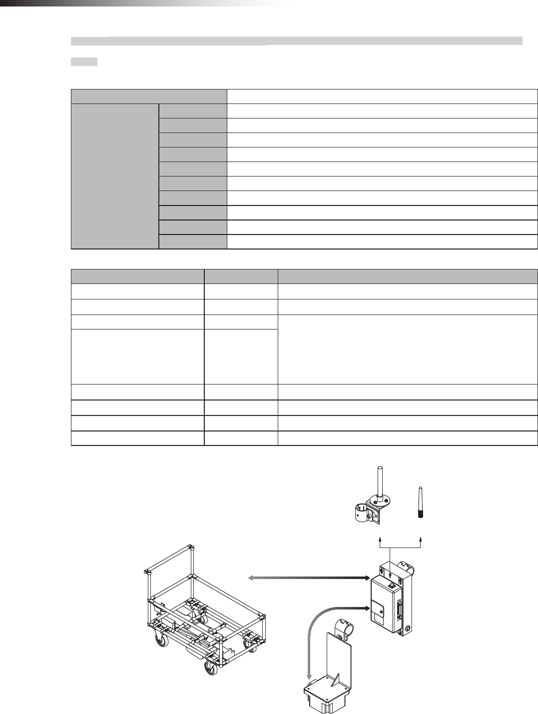
8-3-3. Intersection is instructed by the course 30 unit when the 24 V forward type Drive Unit is
used.
Settings
Usable intersection address 1 to 15
Switch settings of
wireless intersection
module
SW1-1 ON
SW1-2 ON
SW1-3 OFF
SW1-4 ON
SW1-5 OFF
SW1-6 OFF
SW1-7 OFF
SW1-8 OFF
RSW1 to 3 Create a unique setting for each wireless intersection module that is not duplicated.
RSW4 Select a usable frequency band.
Conguration
Product name Model number Remarks
Wireless Intersection Module FCU-RC01
Wireless intersection module box FCP-RCB01-24
Pencil type antenna FCP-RCA01 • Select either antenna depending on the application.
• The anged antenna attenuates the radio wave due to the cable.
The communicable distance is shortened approximately 15% when
compared to the pencil type antenna. When two wireless units that com-
municate with each other use the anged antennas, the communication
distance is shortened by approximately 30% due to double effects.
Flanged antenna with bracket FCP-RCA02
Cable for course 30 FCP-RCC02
Connection diagram
FCP-RCA02 FCP-RCA01
FCP-RCB01-24
FCU-RC01
CN1
CN2
120/121 type forward Drive Unit
CND
FCU-CFO35*
FCP-RCC02
ê 8. Installation and connections
- 44 -
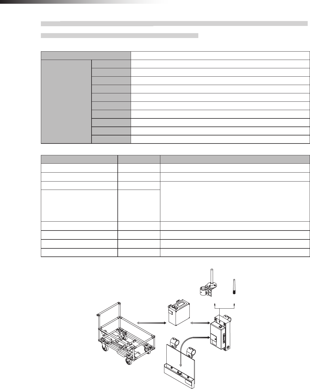
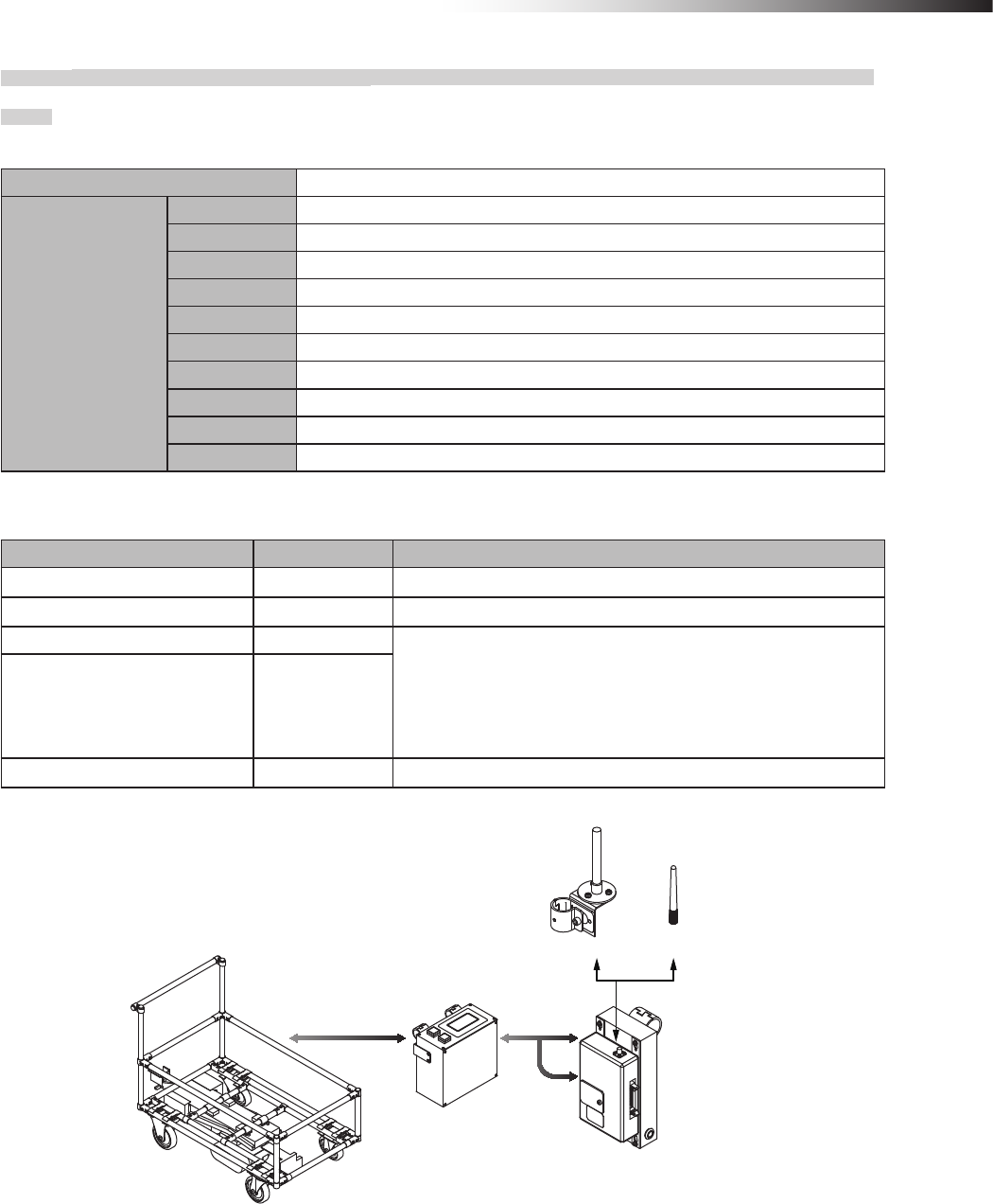
8-3-4. Intersection is not instructed by the course 30 unit, but it is instructed by the address
sensor when the 24 V forward type Drive Unit is used.
Settings
Usable intersection address 1 to 62
Switch settings of
wireless intersection
module
SW1-1 to 1-8 OFF
SW1-2 OFF
SW1-3 OFF
SW1-4 OFF
SW1-5 OFF
SW1-6 OFF
SW1-7 OFF
SW1-8 OFF
RSW1 to 3 Create a unique setting for each wireless intersection module that is not duplicated.
RSW4 Select a usable frequency band.
Conguration
Product name Model number Remarks
Wireless Intersection Module FCU-RC01
Wireless intersection module box FCP-RCB01-24
Pencil type antenna FCP-RCA01 • Select either antenna depending on the application.
• The anged antenna attenuates the radio wave due to the cable.
The communicable distance is shortened approximately 15% when
compared to the pencil type antenna. When two wireless units that com-
municate with each other use the anged antennas, the communication
distance is shortened by approximately 30% due to double effects.
Flanged antenna with bracket FCP-RCA02
Address sensor with bracket FCP-RCS01
Cable for course 30 FCP-RCC02
Cable for address sensor FCP-RCC04
Address magnetic plate FCP-SMG01-* An address magnetic plate corresponding to the intersection is needed.
Connection diagram
FCP-RCA02 FCP-RCA01
FCP-RCB01-24
FCU-RC01
CND
120/121 type forward Drive Unit
CN1
FCU-CFO35*
FCP-RCC04
FCP-RCS01
CN2
FCP-RCC02

ê 8. Installation and connections
- 45 -
8-3-5. Intersection is not instructed by the course 30 unit, but it is instructed by the RFID
antenna when the 24 V forward type Drive Unit is used.
Settings
Usable intersection address 1 to 127
Switch settings of
wireless intersection
module
SW1-1 ON
SW1-2 OFF
SW1-3 OFF
SW1-4 OFF
SW1-5 OFF
SW1-6 OFF
SW1-7 OFF
SW1-8 OFF
RSW1 to 3 Create a unique setting for each wireless intersection module that is not duplicated.
RSW4 Select a usable frequency band.
Conguration
Product name Model number Remarks
Wireless Intersection Module FCU-RC01
Wireless intersection module box FCP-RCB01-24
Pencil type antenna FCP-RCA01 • Select either antenna depending on the application.
• The anged antenna attenuates the radio wave due to the cable.
The communicable distance is shortened approximately 15% when
compared to the pencil type antenna. When two wireless units that com-
municate with each other use the anged antennas, the communication
distance is shortened by approximately 30% due to double effects.
Flanged antenna with bracket FCP-RCA02
RFID antenna with bracket FCP-RCS02
Cable for course 30 FCP-RCC02
Cable for RFID antenna FCP-RCC05
ID tag FCP-TAG01 An ID tag corresponding to the intersection is needed.
Connection diagram
FCP-RCA02 FCP-RCA01
CND CN1
FCU-CFO35*
FCU-RC01
FCP-RCB01-24
120/121 type forward Drive Unit
FCP-RCC05 CN3
FCP-RCS02
FCP-RCC02
ê 8. Installation and connections
- 46 -
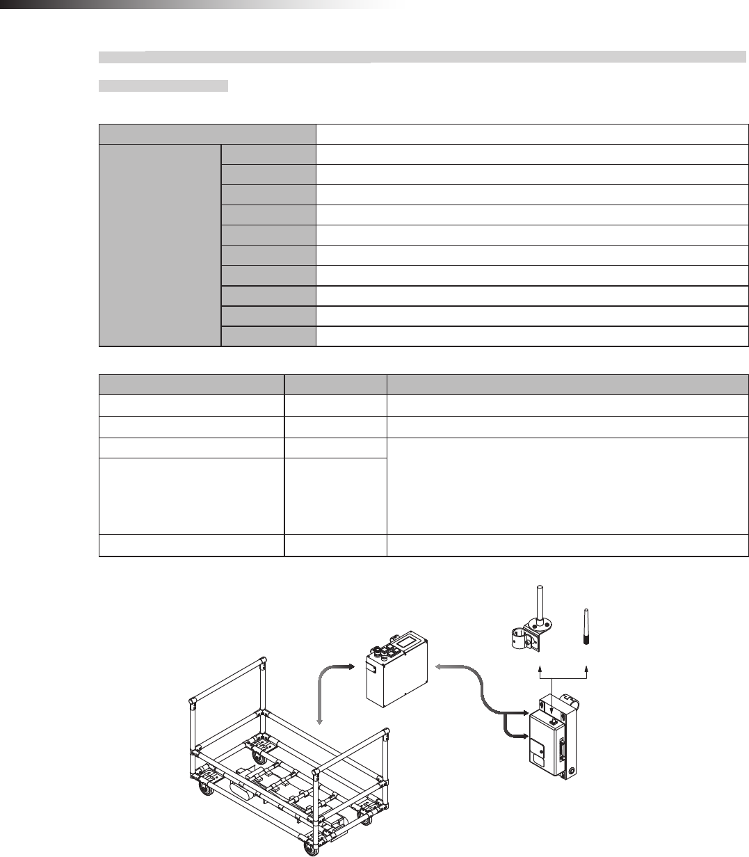
8-3-6. Intersection is instructed by the course 30 unit when the 24 V forward/backward type
Drive Unit is used.
Settings
Usable intersection address 1 to 15
Switch settings of
wireless intersection
module
SW1-1 ON
SW1-2 ON
SW1-3 OFF
SW1-4 ON
SW1-5 OFF
SW1-6 OFF
SW1-7 OFF
SW1-8 OFF
RSW1 to 3 Create a unique setting for each wireless intersection module that is not duplicated.
RSW4 Select a usable frequency band.
Conguration
Product name Model number Remarks
Wireless Intersection Module FCU-RC01
Wireless intersection module box FCP-RCB01-24
Pencil type antenna FCP-RCA01 • Select either antenna depending on the application.
• The anged antenna attenuates the radio wave due to the cable.
The communicable distance is shortened approximately 15% when
compared to the pencil type antenna. When two wireless units that com-
municate with each other use the anged antennas, the communication
distance is shortened by approximately 30% due to double effects.
Flanged antenna with bracket FCP-RCA02
Cable for course 30 FCP-RCC02
Connection diagram
FCP-RCA02 FCP-RCA01
FCP-RCB01-24
FCU-RC01
FCP-RCC02
CN1
CN2
CNG
120/121 type forward/backward Drive Unit
CND1
CND1
FCU-CFB35*
ê 8. Installation and connections
- 47 -
8-3-7. Intersection is not instructed by the course 30 unit, but it is instructed by the address
sensor when the 24 V forward/backward type Drive Unit is used.
Settings
Usable intersection address 1 to 62
Switch settings of
wireless intersection
module
SW1-1 OFF
SW1-2 OFF
SW1-3 OFF
SW1-4 OFF
SW1-5 OFF
SW1-6 OFF
SW1-7 OFF
SW1-8 OFF
RSW1 to 3 Create a unique setting for each wireless intersection module that is not duplicated.
RSW4 Select a usable frequency band.
Conguration
Product name Model number Remarks
Wireless Intersection Module FCU-RC01
Wireless intersection module box FCP-RCB01-24
Pencil type antenna FCP-RCA01 • Select either antenna depending on the application.
• The anged antenna attenuates the radio wave due to the cable.
The communicable distance is shortened approximately 15% when
compared to the pencil type antenna. When two wireless units that com-
municate with each other use the anged antennas, the communication
distance is shortened by approximately 30% due to double effects.
Flanged antenna with bracket FCP-RCA02
Address sensor with bracket FCP-RCS01
Cable for course 30 FCP-RCC02
Cable for address sensor FCP-RCC04
Address magnetic plate FCP-SMG01-* An address magnetic plate corresponding to the intersection is needed.
Connection diagram
FCP-RCC02 FCP-RCA02
FCP-RCB01-24
FCU-RC01
FCP-RCS01
FCP-RCA01
FCP-RCC04
CN1
CN2
CNG
120/121 type forward/backward Drive Unit
CND1
CND1
FCU-CFB35*

ê 8. Installation and connections
- 48 -
8-3-8. Intersection is not instructed by the course 30 unit, but it is instructed by the RFID
antenna when the 24 V forward/backward type Drive Unit is used.
Settings
Usable intersection address 1 to 127
Switch settings of
wireless intersection
module
SW1-1 ON
SW1-2 OFF
SW1-3 OFF
SW1-4 OFF
SW1-5 OFF
SW1-6 OFF
SW1-7 OFF
SW1-8 OFF
RSW1 to 3 Create a unique setting for each wireless intersection module that is not duplicated.
RSW4 Select a usable frequency band.
Conguration
Product name Model number Remarks
Wireless Intersection Module FCU-RC01
Wireless intersection module box FCP-RCB01-24
Pencil type antenna FCP-RCA01 • Select either antenna depending on the application.
• The anged antenna attenuates the radio wave due to the cable.
The communicable distance is shortened approximately 15% when
compared to the pencil type antenna. When two wireless units that com-
municate with each other use the anged antennas, the communication
distance is shortened by approximately 30% due to double effects.
Flanged antenna with bracket FCP-RCA02
RFID antenna with bracket FCP-RCS02
Cable for course 30 FCP-RCC02
Cable for RFID antenna FCP-RCC05
ID tag FCP-TAG01 An ID tag corresponding to the intersection is needed.
Connection diagram
FCP-RCA02 FCP-RCA01
FCP-RCC05 CN3
FCU-RC01
FCP-RCB01-24
FCP-RCS02
120/121 type backward Drive Unit
CNG FCP-RCC02
CN1
CND1
CND1
FCU-CFB35*
ê 8. Installation and connections
- 49 -
8-3-9. Intersection is instructed by the address sensor when the 12V forward type Drive Unit is
used.
Settings
Usable intersection address 1 to 62
Switch settings of
wireless intersection
module
SW1-1 OFF
SW1-2 OFF
SW1-3 OFF
SW1-4 OFF
SW1-5 OFF
SW1-6 OFF
SW1-7 OFF
SW1-8 OFF
RSW1 to 3 Create a unique setting for each wireless intersection module that is not duplicated.
RSW4 Select a usable frequency band.
Conguration
Product name Model number Remarks
Wireless Intersection Module FCU-RC01
Wireless intersection module box FCP-RCB01-12
Pencil type antenna FCP-RCA01 • Select either antenna depending on the application.
• The anged antenna attenuates the radio wave due to the cable.
The communicable distance is shortened approximately 15% when
compared to the pencil type antenna. When two wireless units that com-
municate with each other use the anged antennas, the communication
distance is shortened by approximately 30% due to double effects.
Flanged antenna with bracket FCP-RCA02
Address sensor with bracket FCP-RCS01
Cable for 12V Drive Unit FCP-RCC01-12
Cable for address sensor FCP-RCC04
Address magnetic plate FCP-SMG01-* An address magnetic plate corresponding to the intersection is needed.
Connection diagram
FCP-RCA02 FCP-RCA01
CN G FCP-RCC01-12 CN1
FCP-RCC04 CN2
FCU-RC01
FCP-RCB01-12
FCP-RCS01
91 type forward Drive Unit
ê 8. Installation and connections
- 50 -
8-3-10. Intersection is instructed by the RFID antenna when the 12V forward type Drive Unit is
used.
Settings
Usable intersection address 1 to 127
Switch settings of
wireless intersection
module
SW1-1 ON
SW1-2 OFF
SW1-3 OFF
SW1-4 OFF
SW1-5 OFF
SW1-6 OFF
SW1-7 OFF
SW1-8 OFF
RSW1 to 3 Create a unique setting for each wireless intersection module that is not duplicated.
RSW4 Select a usable frequency band.
Conguration
Product name Model number Remarks
Wireless Intersection Module FCU-RC01
Wireless intersection module box FCP-RCB01-12
Pencil type antenna FCP-RCA01 • Select either antenna depending on the application.
• The anged antenna attenuates the radio wave due to the cable.
The communicable distance is shortened approximately 15% when
compared to the pencil type antenna. When two wireless units that com-
municate with each other use the anged antennas, the communication
distance is shortened by approximately 30% due to double effects.
Flanged antenna with bracket FCP-RCA02
RFID antenna with bracket FCP-RCS02
Cable for 12V Drive Unit FCP-RCC01-12
Cable for RFID antenna FCP-RCC05
ID tag FCP-TAG01 An ID tag corresponding to the intersection is needed.
Connection diagram
FCP-RCA02 FCP-RCA01
CN G FCP-RCC01-12 CN1
FCP-RCC05 CN3
FCU-RC01
FCP-RCB01-12
FCP-RCS02
91 type forward Drive Unit
ê 8. Installation and connections
- 51 -
8-3-11. Intersection is instructed by the course 30 unit when the 12V forward type Drive Unit is
used.
Settings
Usable intersection address 1 to 15
Switch settings of
wireless intersection
module
SW1-1 ON
SW1-2 ON
SW1-3 OFF
SW1-4 ON
SW1-5 OFF
SW1-6 OFF
SW1-7 OFF
SW1-8 OFF
RSW1 to 3 Create a unique setting for each wireless intersection module that is not duplicated.
RSW4 Select a usable frequency band.
Conguration
Product name Model number Remarks
Wireless Intersection Module FCU-RC01
Wireless intersection module box FCP-RCB01-12
Pencil type antenna FCP-RCA01 • Select either antenna depending on the application.
• The anged antenna attenuates the radio wave due to the cable.
The communicable distance is shortened approximately 15% when
compared to the pencil type antenna. When two wireless units that com-
municate with each other use the anged antennas, the communication
distance is shortened by approximately 30% due to double effects.
Flanged antenna with bracket FCP-RCA02
Cable for course 30 FCP-RCC02
Connection diagram
FCP-RCA02 FCP-RCA01
FCU-RC01
FCP-RCB01-12
91 type forward Drive Unit
FCU-CFO33*
CND
CN2
CN1
FCP-RCC02
ê 8. Installation and connections
- 52 -
8-3-12. Intersection is not instructed by the course 30 unit, but it is instructed by the address
sensor when the 12V forward type Drive Unit is used.
Settings
Usable intersection address 1 to 62
Switch settings of
wireless intersection
module
SW1-1 OFF
SW1-2 OFF
SW1-3 OFF
SW1-4 OFF
SW1-5 OFF
SW1-6 OFF
SW1-7 OFF
SW1-8 OFF
RSW1 to 3 Create a unique setting for each wireless intersection module that is not duplicated.
RSW4 Select a usable frequency band.
Conguration
Product name Model number Remarks
Wireless Intersection Module FCU-RC01
Wireless intersection module box FCP-RCB01-12
Pencil type antenna FCP-RCA01 • Select either antenna depending on the application.
• The flanged antenna attenuates the radio wave due to the cable.
The communicable distance is shortened approximately 15% when
compared to the pencil type antenna. When two wireless units that com-
municate with each other use the anged antennas, the communication
distance is shortened by approximately 30% due to double effects.
Flanged antenna with bracket FCP-RCA02
Address sensor with bracket FCP-RCS01
Cable for course 30 FCP-RCC02
Cable for address sensor FCP-RCC04
Address magnetic plate FCP-SMG01-* An address magnetic plate corresponding to the intersection is needed.
Connection diagram
FCP-RCA02 FCP-RCA01
FCU-RC01
FCP-RCB01-12
91 type forward Drive Unit
FCU-CFO33*
CND CN1
FCP-RCC04
FCP-RCS01
CN2
FCP-RCC02
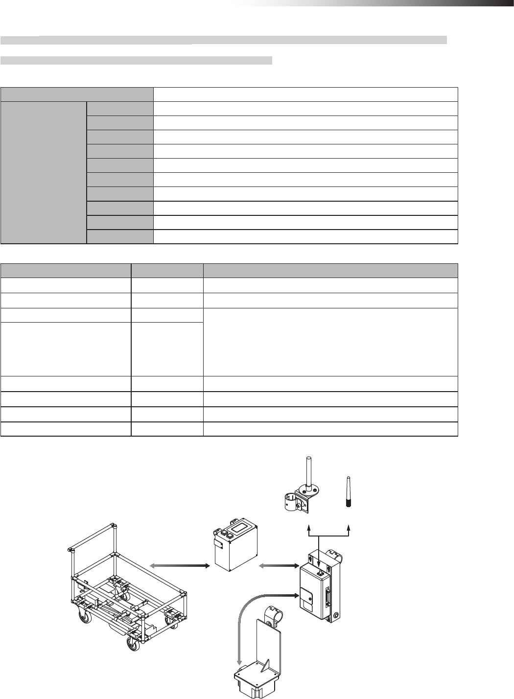
ê 8. Installation and connections
- 53 -
8-3-13. Intersection is not instructed by the course 30 unit, but it is instructed by the RFID
antenna when the 12V forward type Drive Unit is used.
Settings
Usable intersection address 1 to 127
Switch settings of
wireless intersection
module
SW1-1 ON
SW1-2 OFF
SW1-3 OFF
SW1-4 OFF
SW1-5 OFF
SW1-6 OFF
SW1-7 OFF
SW1-8 OFF
RSW1 to 3 Create a unique setting for each wireless intersection module that is not duplicated.
RSW4 Select a usable frequency band.
Conguration
Product name Model number Remarks
Wireless Intersection Module FCU-RC01
Wireless intersection module box FCP-RCB01-12
Pencil type antenna FCP-RCA01 • Select either antenna depending on the application.
• The anged antenna attenuates the radio wave due to the cable.
The communicable distance is shortened approximately 15% when
compared to the pencil type antenna. When two wireless units that com-
municate with each other use the anged antennas, the communication
distance is shortened by approximately 30% due to double effects.
Flanged antenna with bracket FCP-RCA02
RFID antenna with bracket FCP-RCS02
Cable for course 30 FCP-RCC02
Cable for RFID antenna FCP-RCC05
ID tag FCP-TAG01 An ID tag corresponding to the intersection is needed.
Connection diagram
FCP-RCA01
FCP-RCA02
CND CN1
FCU-CFO33*
FCU-RC01
FCP-RCB01-12
91 type forward Drive Unit
FCP-RCC05 CN3
FCP-RCS02
FCP-RCC02
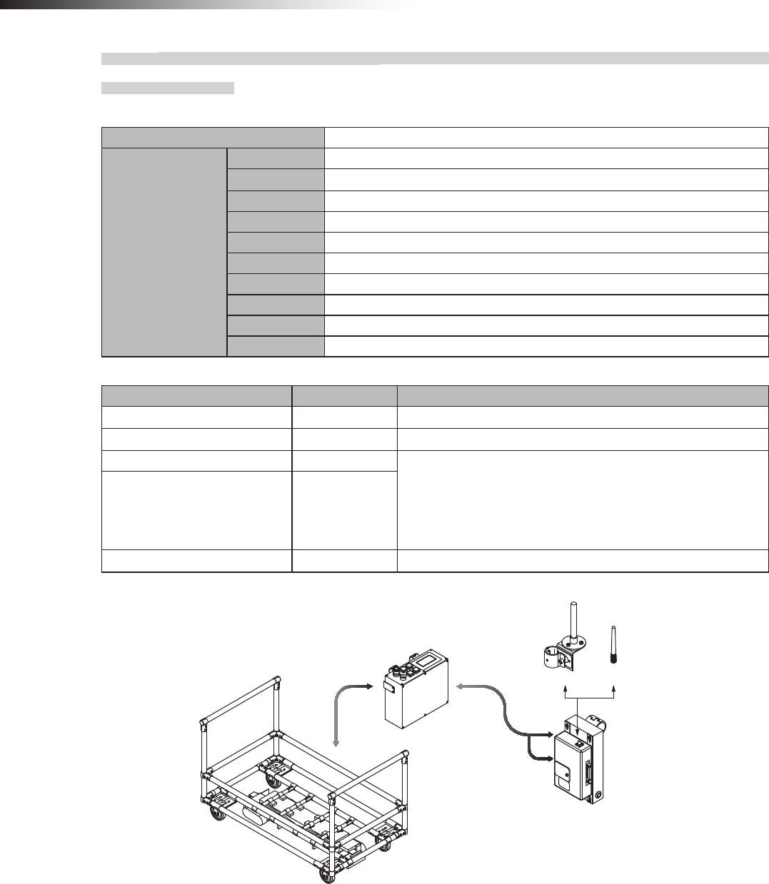
ê 8. Installation and connections
- 54 -
8-3-14. Intersection is instructed by the course 30 unit when the 12V forward/backward type
Drive Unit is used.
Settings
Usable intersection address 1 to 15
Switch settings of
wireless intersection
module
SW1-1 ON
SW1-2 ON
SW1-3 OFF
SW1-4 ON
SW1-5 OFF
SW1-6 OFF
SW1-7 OFF
SW1-8 OFF
RSW1 to 3 Create a unique setting for each wireless intersection module that is not duplicated.
RSW4 Select a usable frequency band.
Conguration
Product name Model number Remarks
Wireless Intersection Module FCU-RC01
Wireless intersection module box FCP-RCB01-12
Pencil type antenna FCP-RCA01 • Select either antenna depending on the application.
• The anged antenna attenuates the radio wave due to the cable.
The communicable distance is shortened approximately 15% when
compared to the pencil type antenna. When two wireless units that com-
municate with each other use the anged antennas, the communication
distance is shortened by approximately 30% due to double effects.
Flanged antenna with bracket FCP-RCA02
Cable for course 30 FCP-RCC02
Connection diagram
FCP-RCA02 FCP-RCA01
CN2
FCU-RC01
FCP-RCB01-12
CND1
CND1
91 type forward/backward Drive Unit
CNG FCP-RCC02
CN1
FCU-CFB33*
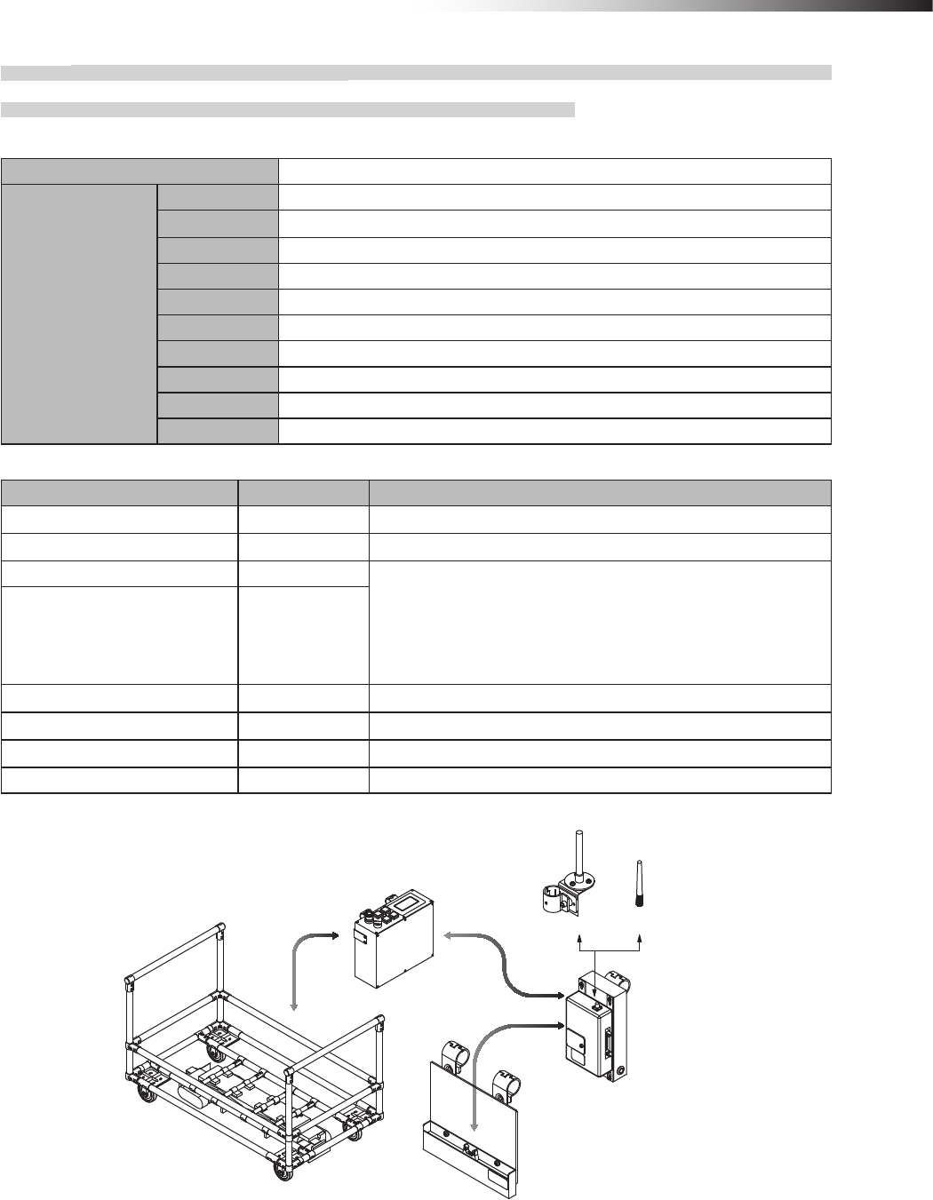
ê 8. Installation and connections
- 55 -
8-3-15. Intersection is not instructed by the course 30 unit, but it is instructed by the address
sensor when the 12V forward/backward type Drive Unit is used.
Settings
Usable intersection address 1 to 62
Switch settings of
wireless intersection
module
SW1-1 OFF
SW1-2 OFF
SW1-3 OFF
SW1-4 OFF
SW1-5 OFF
SW1-6 OFF
SW1-7 OFF
SW1-8 OFF
RSW1 to 3 Create a unique setting for each wireless intersection module that is not duplicated.
RSW4 Select a usable frequency band.
Conguration
Product name Model number Remarks
Wireless Intersection Module FCU-RC01
Wireless intersection module box FCP-RCB01-12
Pencil type antenna FCP-RCA01 • Select either antenna depending on the application.
• The anged antenna attenuates the radio wave due to the cable.
The communicable distance is shortened approximately 15% when
compared to the pencil type antenna. When two wireless units that com-
municate with each other use the anged antennas, the communication
distance is shortened by approximately 30% due to double effects.
Flanged antenna with bracket FCP-RCA02
Address sensor with bracket FCP-RCS01
Cable for course 30 FCP-RCC02
Cable for address sensor FCP-RCC04
Address magnetic plate FCP-SMG01-* An address magnetic plate corresponding to the intersection is needed.
Connection diagram
FCP-RCA02 FCP-RCA01
FCP-RCC04 CN2
FCU-RC01
FCP-RCB01-12
FCP-RCS01
CND1
CND1
91 type forward/backward Drive Unit
CNG FCP-RCC02
CN1
FCU-CFB33*
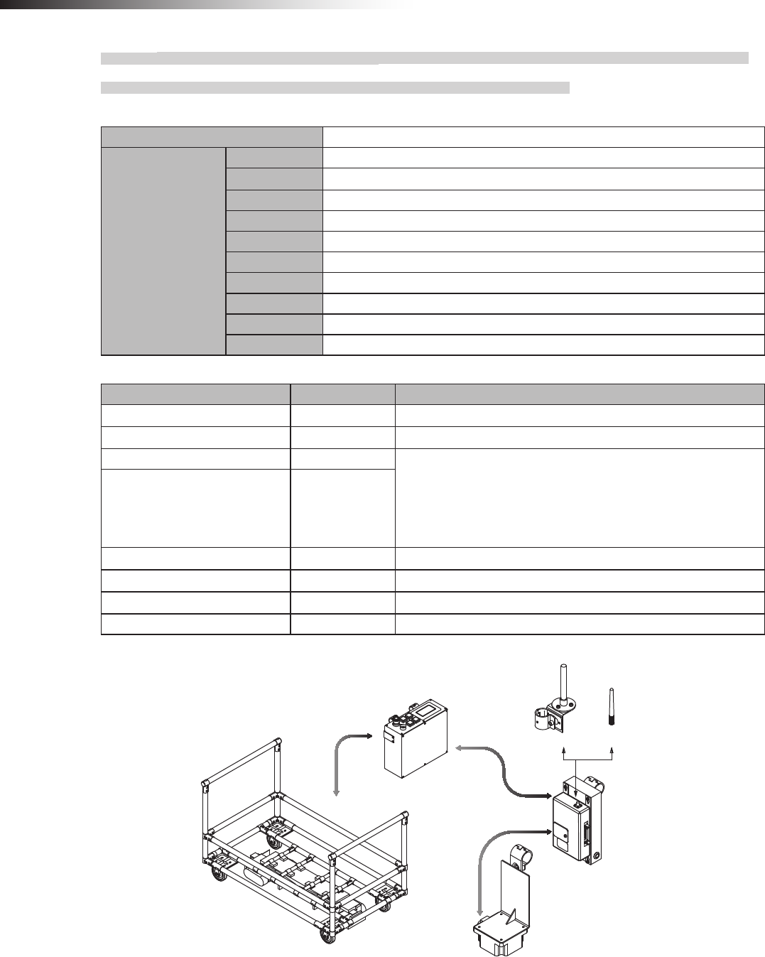
ê 8. Installation and connections
- 56 -
8-3-16. Intersection is not instructed by the course 30 unit, but it is instructed by the RFID
antenna when the 12V forward/backward type Drive Unit is used.
Settings
Usable intersection address 1 to 127
Switch settings of
wireless intersection
module
SW1-1 ON
SW1-2 OFF
SW1-3 OFF
SW1-4 OFF
SW1-5 OFF
SW1-6 OFF
SW1-7 OFF
SW1-8 OFF
RSW1 to 3 Create a unique setting for each wireless intersection module that is not duplicated.
RSW4 Select a usable frequency band.
Conguration
Product name Model number Remarks
Wireless Intersection Module FCU-RC01
Wireless intersection module box FCP-RCB01-12
Pencil type antenna FCP-RCA01 • Select either antenna depending on the application.
• The anged antenna attenuates the radio wave due to the cable.
The communicable distance is shortened approximately 15% when
compared to the pencil type antenna. When two wireless units that com-
municate with each other use the anged antennas, the communication
distance is shortened by approximately 30% due to double effects.
Flanged antenna with bracket FCP-RCA02
RFID antenna with bracket FCP-RCS02
Cable for course 30 FCP-RCC02
Cable for RFID antenna FCP-RCC05
ID tag FCP-TAG01 An ID tag corresponding to the intersection is needed.
Connection diagram
FCP-RCA02 FCP-RCA01
FCP-RCC05 CN3
FCU-RC01
FCP-RCB01-12
FCP-RCS02
91 type forward/backward Drive Unit
CNG FCP-RCC02
CN1
CND1
CND1
FCU-CFB33*
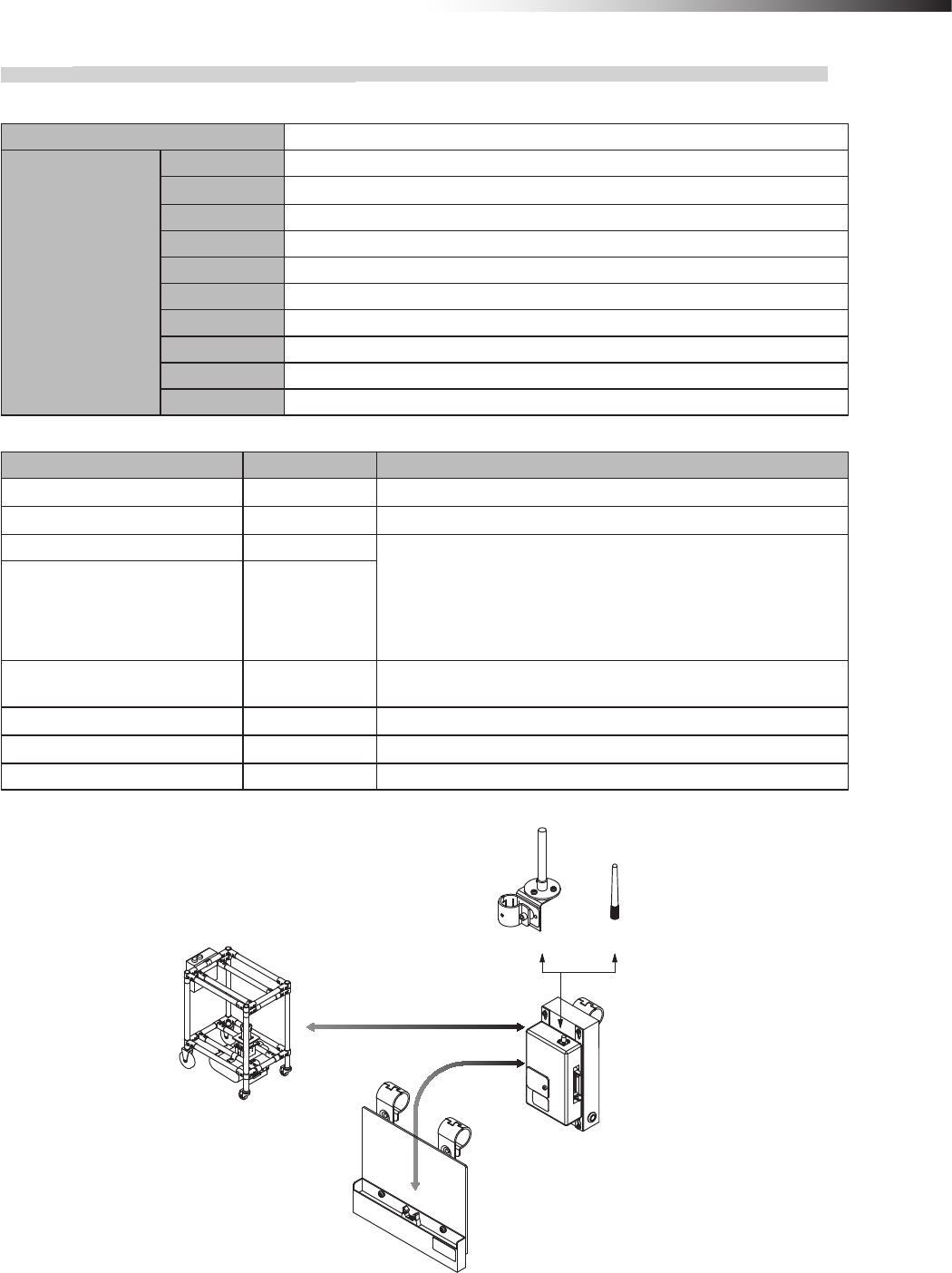
ê 8. Installation and connections
- 57 -
8-3-17. Intersection is instructed by the address sensor when the small Drive Unit is used.
Settings
Usable intersection address 1 to 62
Switch settings of
wireless intersection
module
SW1-1 OFF
SW1-2 OFF
SW1-3 OFF
SW1-4 OFF
SW1-5 OFF
SW1-6 OFF
SW1-7 OFF
SW1-8 OFF
RSW1 to 3 Create a unique setting for each wireless intersection module that is not duplicated.
RSW4 Select a usable frequency band.
Conguration
Product name Model number Remarks
Wireless Intersection Module FCU-RC01
Wireless intersection module box FCP-RCB01-12
Pencil type antenna FCP-RCA01 • Select either antenna depending on the application.
• The anged antenna attenuates the radio wave due to the cable.
The communicable distance is shortened approximately 15% when
compared to the pencil type antenna. When two wireless units that com-
municate with each other use the anged antennas, the communication
distance is shortened by approximately 30% due to double effects.
Flanged antenna with bracket FCP-RCA02
Address sensor with bracket for
small Drive Unit FCP-RCS03
Cable for small Drive Unit FCP-RCC03
Cable for address sensor FCP-RCC04
Address magnetic plate FCP-SMG01-* An address magnetic plate corresponding to the intersection is needed.
Connection diagram
FCP-RCA02 FCP-RCA01
FCP-RCB01-12
FCU-RC01
FCP-RCS03
FCP-RCC03
FCP-RCC04
CN1
CN2
FCSA-HA14P9
Small forward Drive Unit
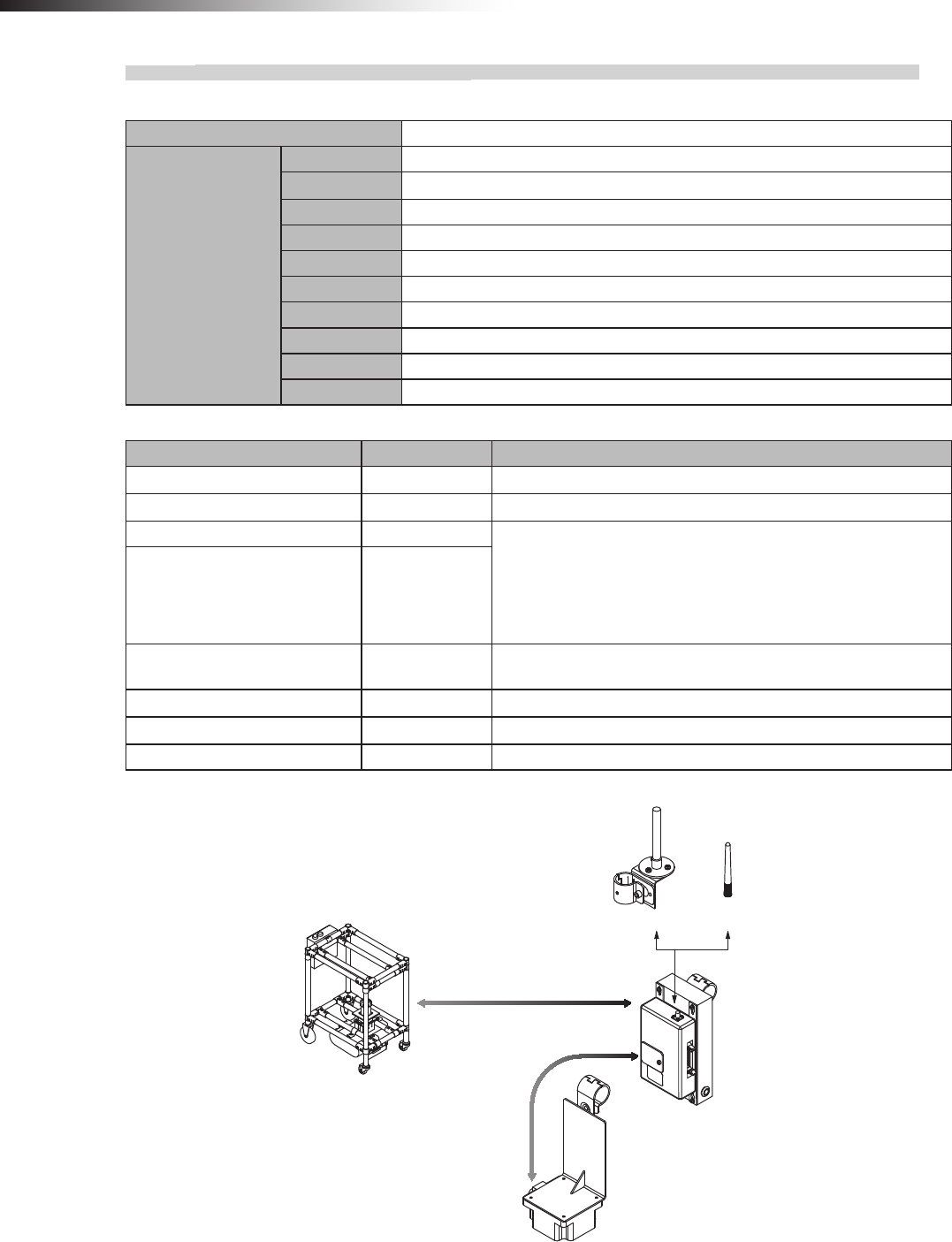
ê 8. Installation and connections
- 58 -
8-3-18. Intersection is instructed by the RFID antenna when the small Drive Unit is used.
Settings
Usable intersection address 1 to 127
Switch settings of
wireless intersection
module
SW1-1 ON
SW1-2 OFF
SW1-3 OFF
SW1-4 OFF
SW1-5 OFF
SW1-6 OFF
SW1-7 OFF
SW1-8 OFF
RSW1 to 3 Create a unique setting for each wireless intersection module that is not duplicated.
RSW4 Select a usable frequency band.
Conguration
Product name Model number Remarks
Wireless Intersection Module FCU-RC01
Wireless intersection module box FCP-RCB01-12
Pencil type antenna FCP-RCA01 • Select either antenna depending on the application.
• The anged antenna attenuates the radio wave due to the cable.
The communicable distance is shortened approximately 15% when
compared to the pencil type antenna. When two wireless units that com-
municate with each other use the anged antennas, the communication
distance is shortened by approximately 30% due to double effects.
Flanged antenna with bracket FCP-RCA02
RFID antenna with bracket for small
Drive Unit FCP-RCS04
Cable for small Drive Unit FCP-RCC03
Cable for RFID antenna FCP-RCC05
ID tag FCP-TAG01 An ID tag corresponding to the intersection is needed.
Connection diagram
FCP-RCA02 FCP-RCA01
FCSA-HA14P9 FCP-RCC03 CN1
FCP-RCC05 CN3
FCU-RC01
FCP-RCB01-12
FCP-RCS04
Small forward Drive Unit
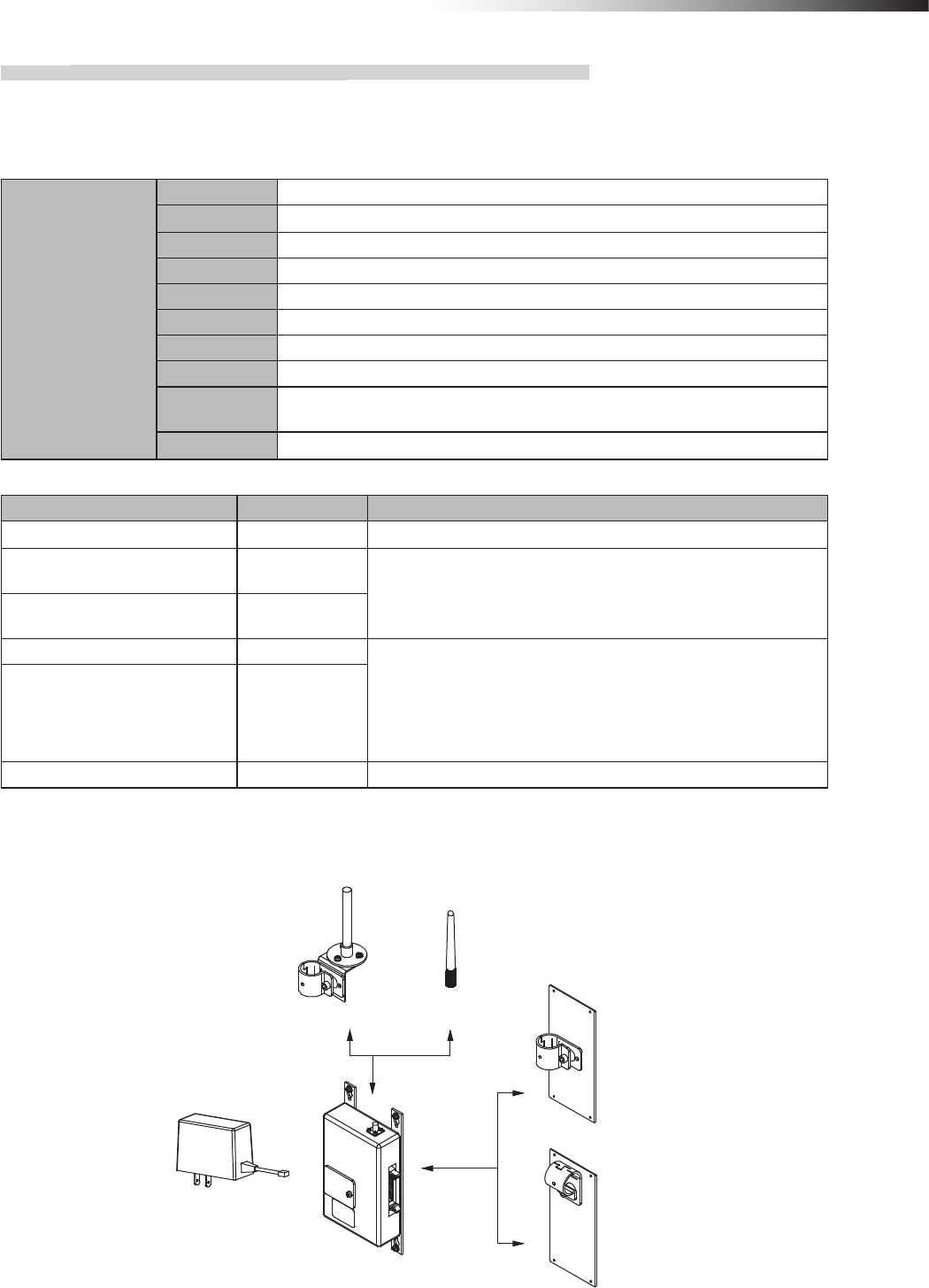
ê 8. Installation and connections
- 59 -
8-3-19. Intersection control is performed using the ground station.
To perform the intersection control using the ground station, the AGVs are built in accordance with the conguration
described previously and the parameters need to be set for each wireless intersection module.
Settings
Switch settings of
wireless intersection
module
SW1-1 OFF
SW1-2 ON
SW1-3 OFF
SW1-4 OFF
SW1-5 OFF
SW1-6 OFF
SW1-7 OFF
SW1-8 OFF
RSW1 to 3 Create a unique setting for each ground station so that it is not duplicated.
Setting range, 900 to 999
RSW4 Select a usable frequency band.
Conguration
Product name Model number Remarks
Wireless Intersection Module FCU-RC01
Wireless intersection module
mounting bracket FCP-RCK06
• Select either antenna depending on the application.
Wireless intersection module
mounting bracket FCP-RCK07
Pencil type antenna FCP-RCA01 • Select either antenna depending on the application.
• The anged antenna attenuates the radio wave due to the cable.
The communicable distance is shortened approximately 15% when
compared to the pencil type antenna. When two wireless units that com-
municate with each other use the anged antennas, the communication
distance is shortened by approximately 30% due to double effects.
Flanged antenna with bracket FCP-RCA02
AC adapter FCP-RCP01 For supplying the power to the wireless intersection module
Connection diagram
Connecting the AC adapter FCP-RCP01 to the CN1 connector of the wireless intersection module supplies the
power.
FCP-RCA02 FCP-RCA01
FCP-RCK06
FCP-RCK07
FCU-RC01
FCP-RCP01
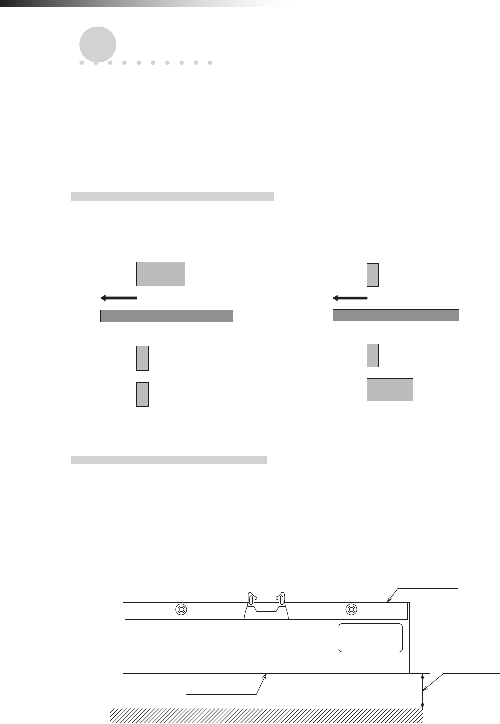
ê 9. Intersection
- 60 -
9. Intersection
The address sensor, RFID antenna, or course 30 unit reads the address magnetic plate or ID tag or the external oper-
ation command of the course 30 unit is output to instruct the intersection entrance or exit to the wireless intersection
module.
When the address sensor and RFID antenna are used, it is always necessary to stop the AGV before the intersection
using the command tape or count tape.
9-1. For address sensor
9-1-1. Layout of address magnetic plate
Afx the address magnetic plate to a position that is different from the command tape and the count tape so that these
are recognized correctly. In addition, afx the magnetic plate to a position where the drive wheels of the Drive Unit or
the casters of the dolly cart do not run over the magnetic plate as much as possible.
Address magnetic plate
Forward direction
Command tape
Count tape
Guide tape
Address magnetic plate
Forward direction
Command tape
Count tape
Figure. Positional relationship of each tape (1) Figure. Positional relationship of each tape (2)
9-1-2. Installation of address sensor
Install the address sensor so that its detection surface is located at a position 25 mm to 30 mm above the ground.
Install the address sensor at a position where it does not interfere with the guide sensor or counter sensor position of
the Drive Unit.
Install the address sensor at a position away from a device (motor, etc.) that generates magnetism.
In addition, when there is a ferromagnetic substance such as iron near the address sensor, this may affect the detection
sensitivity. In this case, provide a space around the address sensor.
Address sensor
Detection surface
25 to 30 mm
Figure. Detection distance
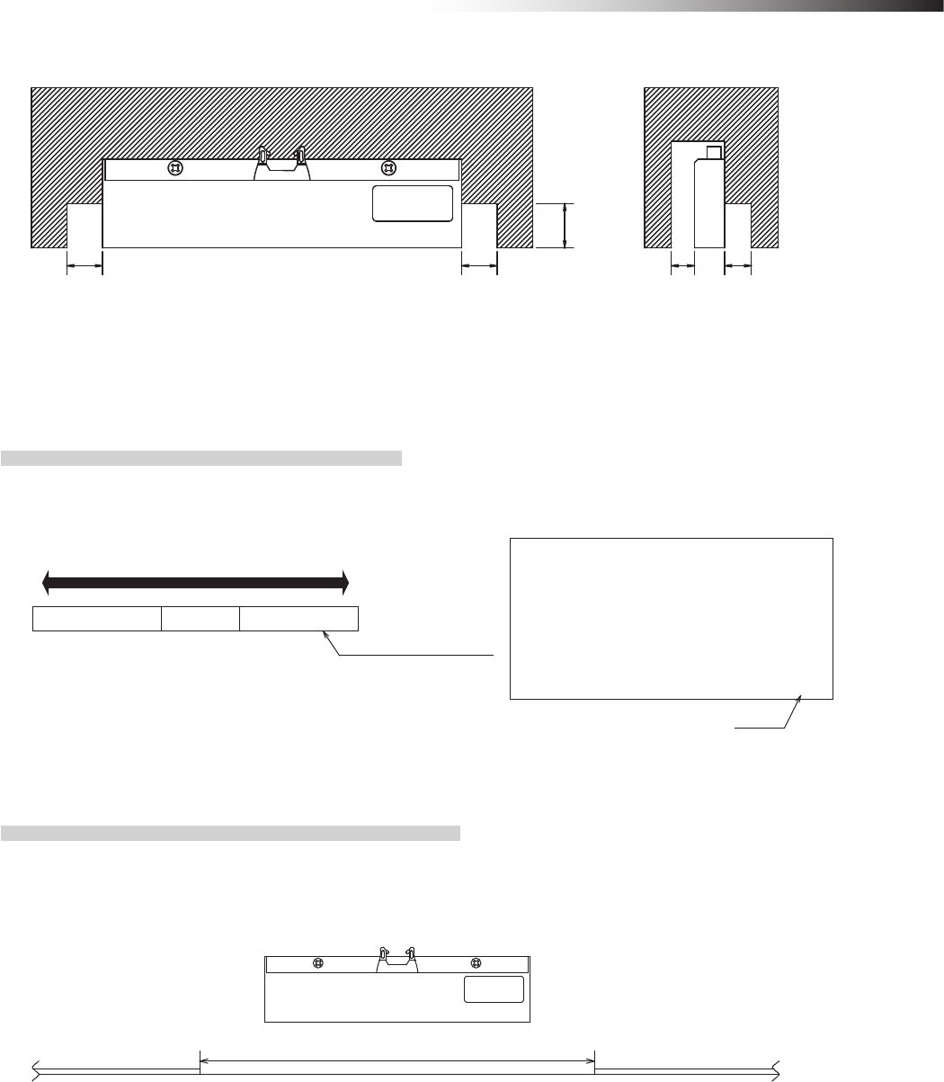
ê 9. Intersection
- 61 -
Magnetic substance Magnetic substance
D1
D2
D1 D3 D3
D1: 40 mm or more
D2: 30 mm or more
D3: 40 mm or more
Figure. Installation position
9-1-3. Detection direction of address sensor
The gure below shows the relationship between the address sensor and address magnetic plate.
Traveling direction
Address magnetic plate
123 A 001
Marking
Label nameplate
surface
Connector
Figure. Detection direction
9-1-4. About installation of address magnetic plate
When installing the address magnetic plates close to each other, be sure to install them 300 mm away from each
other.
Otherwise, the adjacent address magnetic plate may be detected.
Address magnetic plateAddress magnetic plate 300 mm or more
Figure. Clearance between address magnetic plates
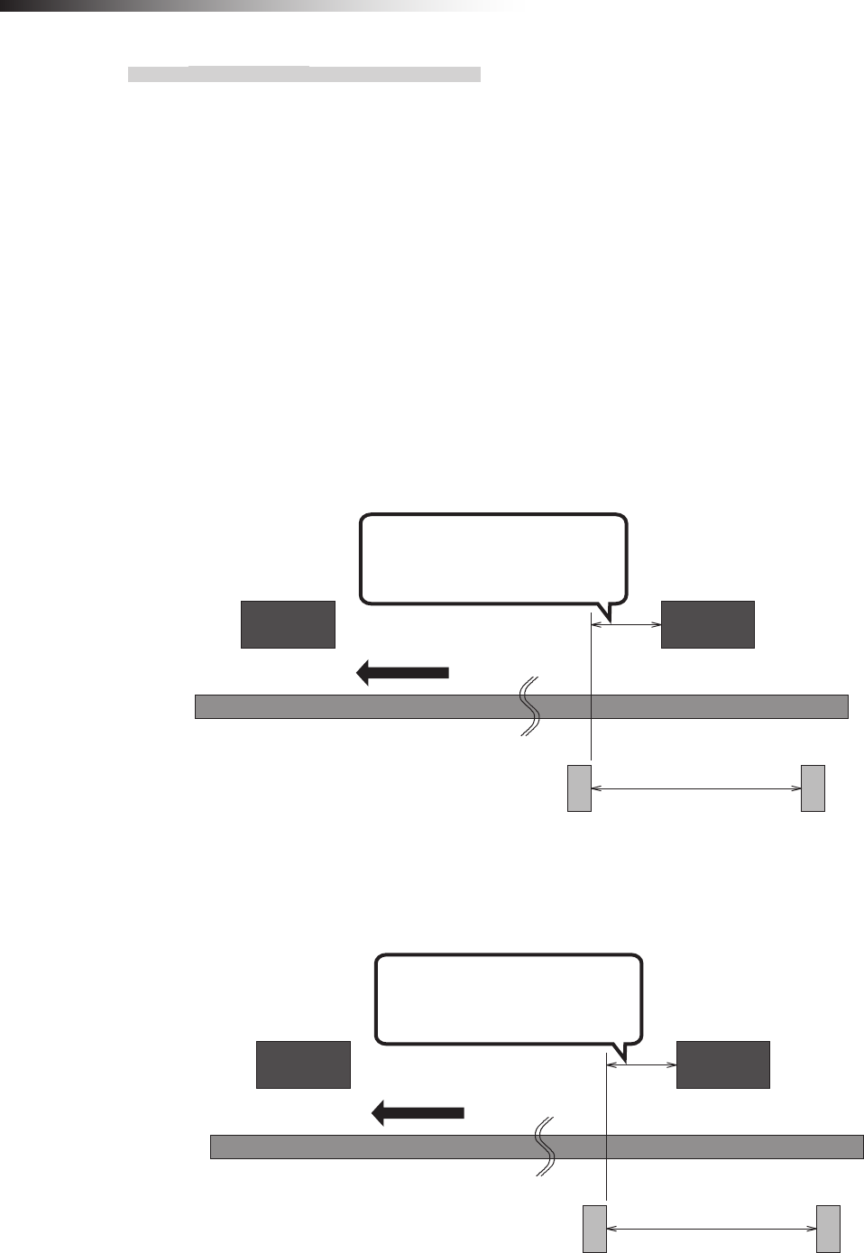
ê 9. Intersection
- 62 -
9-1-5. Forward type
To make the AGV recognize the intersection entrance, afx the address magnetic plate corresponding to the inter-
section address to a position where the address sensor can read it. (This description uses intersection address 1.)
Next, afx the command tape or count tape to a position where the stop command is instructed to the AGV. Make
the AGV read the address magnetic plate, and then recognize the stop command (stop count) after 100 ms. or
longer. Whether the approach to the intersection is permitted or not is determined upon completion of checking
specied by the monitoring time for permission to approach the intersection and radio transmission count for check-
ing the object approaching the intersection.
After that, to make the AGV recognize the intersection exit, afx the address magnet (intersection address 0) that
clears the intersection address.
Install the address sensor so that it reads the address magnetic plate vertically to the traveling direction.
When there is an AGV that is passing through the intersection, the AGV remains stopped by the command tape
or count tape. When the wireless intersection module installed on the AGV that is passing through the intersection
recognizes the intersection exit, it travels again.
800 mm or more
Forward direction
Position where address magnetic
plate (1) is recognized before the
stop command is read.
(Distance to sufficiently
decelerate in speed)
Command tape
(Stop command)
Command tape
(Low speed command)
Intersection entrance
Address magnetic plate (1)
Intersection exit
Address magnetic plate (0)
Figure. Installation of address magnetic plates using command tapes
800 mm or more
Forward direction
Position where address magnetic
plate (1) is recognized before the
stop command is read.
(Distance to sufficiently
decelerate in speed)
Count tape
(Stop)
Count tape
(Low speed)
Intersection entrance
Address magnetic plate (1)
Intersection exit
Address magnetic plate (0)
Figure. Installation of address magnetic plates using count tapes
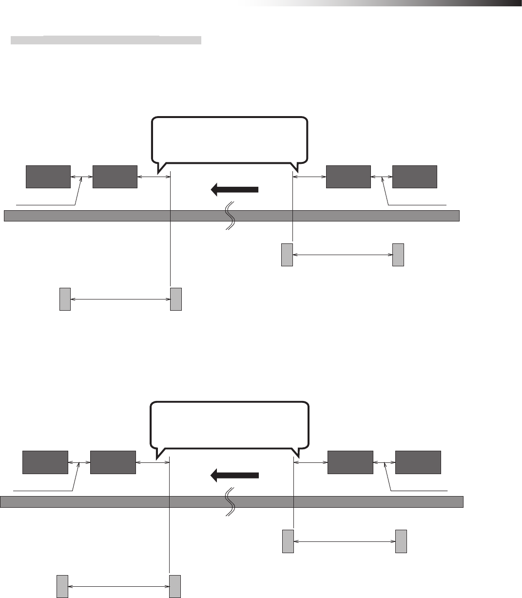
ê 9. Intersection
- 63 -
9-1-6. Forward/backward type
When the address magnetic plate is used for the forward/backward type AGV, it is necessary to read out the
address magnetic plate during forward or backward travel.
The address sensor reads the address magnetic plate in the longitudinal direction.
The address magnetic plate can be read in either direction.
Position where address magnetic
plate (1) is recognized before the
stop command is read.
Forward side
intersection exit
Address magnetic
plate (0)
Backward side
intersection entrance
Address magnetic
plate (1)
Forward side
intersection entrance
Address magnetic
plate (1)
Backward side
intersection exit
Address magnetic
plate (0)
800 mm or more
(Distance to sufficiently
decelerate in speed)
Command tape
(Stop command)
For forward movement
Command tape
(Low speed command)
For forward movement
Command tape
(Low speed command)
For backward movement
Command tape
(Stop command)
For backward movement
800 mm or more
(Distance to sufficiently
decelerate in speed)
Forward direction
300 mm or more 300 mm or more
Figure. Installation of address magnetic plates using command tapes
Position where address magnetic
plate (1) is recognized before the
stop command is read.
Forward side
intersection exit
Address magnetic
plate (0)
Backward side
intersection
entrance
Address magnetic
plate (1)
Forward side
intersection entrance
Address magnetic
plate (1)
Backward side
intersection exit
Address magnetic
plate (0)
800 mm or more
(Distance to sufficiently
decelerate in speed)
Count tape
(Stop)
For forward movement
Count tape
(Low speed)
For forward movement
Count tape
(Low speed)
For backward movement
Count tape
(Stop)
For backward movement
800 mm or more
(Distance to sufficiently
decelerate in speed)
Forward direction
300 mm or more 300 mm or more
Figure. Installation of address magnetic plates using count tapes
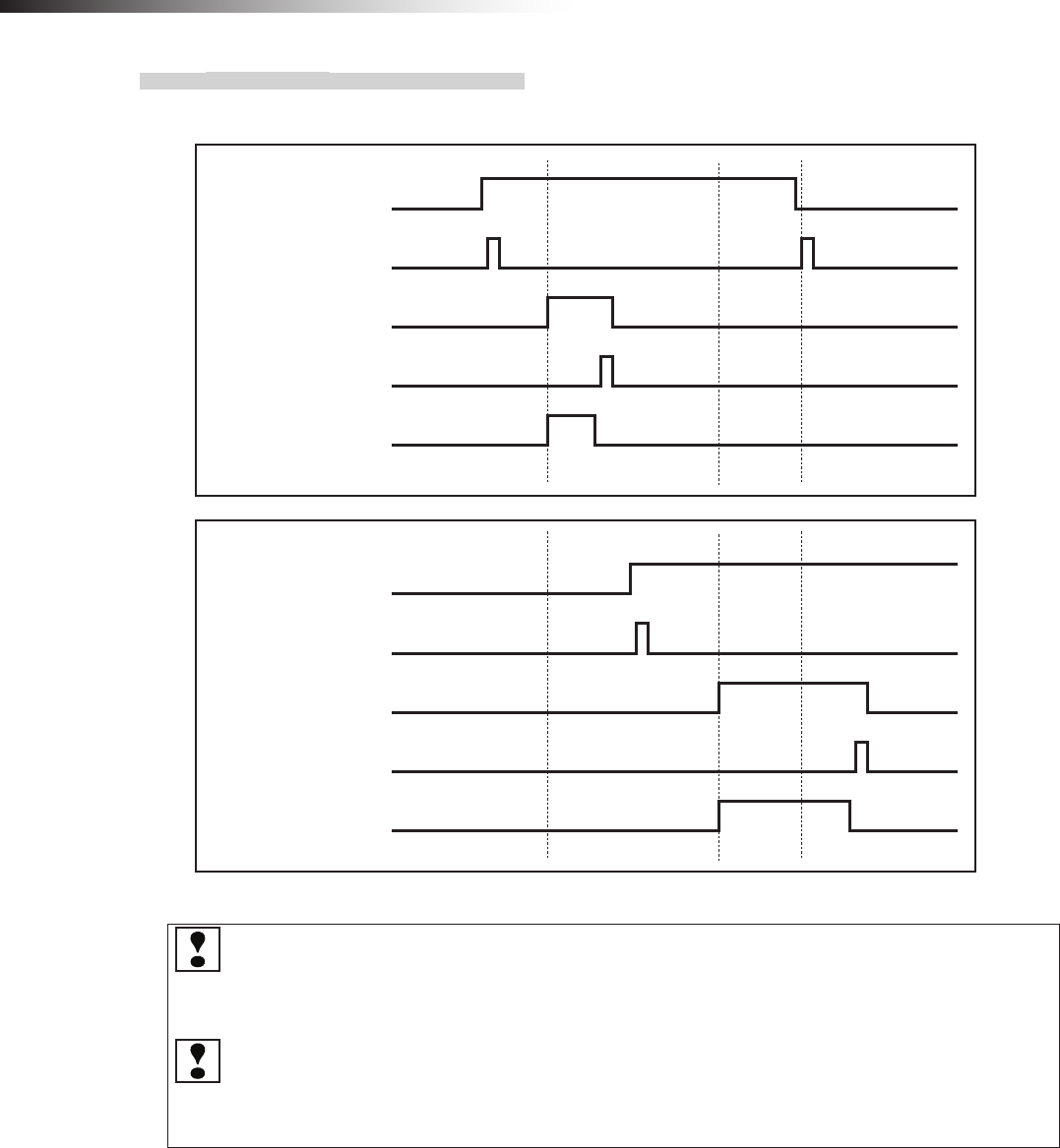
ê 9. Intersection
- 64 -
9-1-7. Timing chart
AGV (1) is passing and AGV (2) is waiting at intersection address (1).
Intersection address (1) input
AGV (1)
Read-out timing input
AGV arrival input
Start output
Stop output
Intersection address (1) input
AGV (2)
Read-out timing input
AGV arrival input
Start output
Stop output
The waiting wireless intersection module cannot check the communication of the wireless intersection
module that is passing through the intersection. The waiting wireless intersection module enters the pass-
ing status upon completion of checking specied by the monitoring time for permission to approach the
intersection and radio transmission count for checking the object approaching the intersection.
For the intersection control using the ground station, when the ground station cannot check the communica-
tion of the wireless intersection module that is passing through the intersection within the AGV communica-
tion error judgment time of the ground station, the waiting wireless intersection module is set to the passing
status.
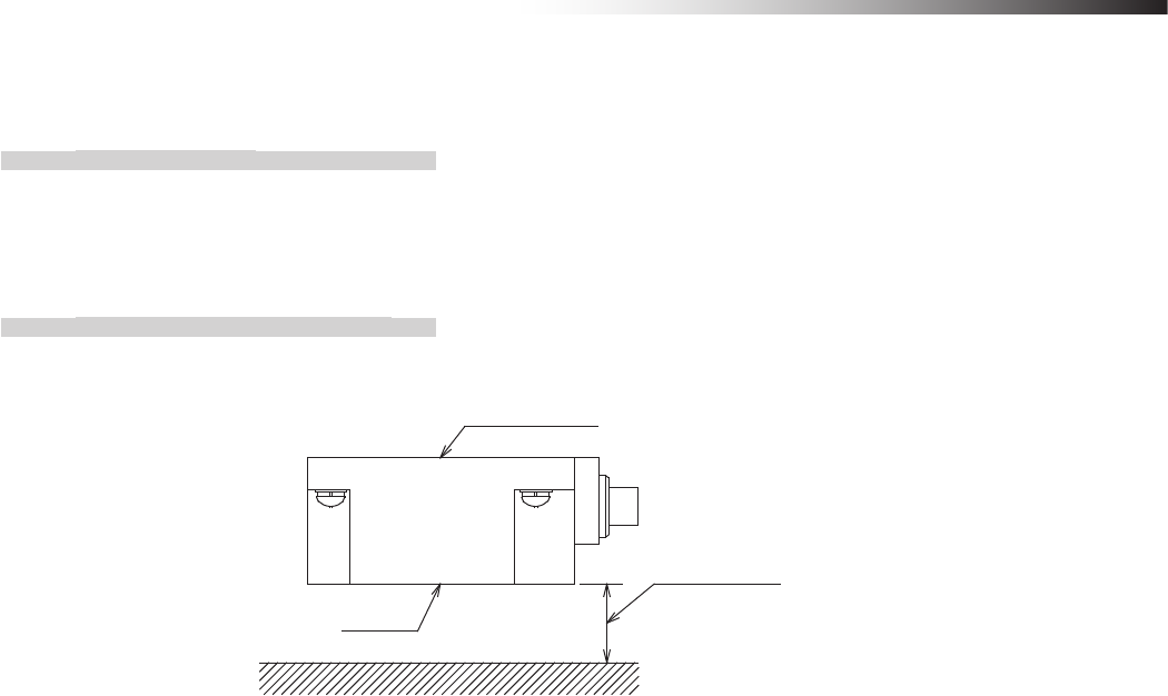
ê 9. Intersection
- 65 -
9-2. For RFID antenna
9-2-1. Layout of ID tag
Afx the ID tag to a position where the drive wheels of the Drive Unit or the casters of the dolly cart do not run over the
ID tag. Do not afx the ID tag to any metallic part. Doing so may affect the read-out.
9-2-2. Installation of RFID antenna
Install the RFID antenna so that its detection surface is located at a position 25 mm to 30 mm above the ground.
RFID antenna
Detection
surface
25 to 30 mm
Figure. Detection distance
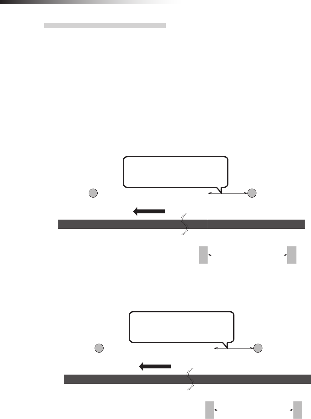
ê 9. Intersection
- 66 -
9-2-3. Forward type
To make the AGV recognize the intersection entrance, afx the ID tag corresponding to the intersection address to a
position where the RFID antenna can read out the intersection address. (This description uses intersection address 1.)
Next, afx the command tape or count tape to a position where the stop command is instructed to the AGV.
Afx the command tape or count tape so that the AGV reads the ID tag, and then recognizes the stop command (stop
count) after 100 ms or longer. Whether the approach to the intersection is permitted or not is determined upon com-
pletion of checking specied by the monitoring time for permission to approach the intersection and radio transmission
count for checking the object approaching the intersection. After that, to make the AGV recognize the intersection exit,
afx the ID tag (intersection address 0) that clears the intersection address.
When there is an AGV that is passing through the intersection, the AGV remains stopped by the command tape or
count tape. When the wireless intersection module installed on the AGV that is passing through the intersection recog-
nizes the intersection exit, it travels again.
Position where ID tag (1) is
recognized before the stop
command is read.
Intersection exit
ID tag (0)
Intersection entrance
ID tag (1)
800 mm or more
(Distance to sufficiently
decelerate in speed)
Command tape
(Stop command)
Command tape
(Low speed command)
Forward direction
Figure. Installation of ID tag using command tapes
Position where ID tag (1) is
recognized before the stop
command is read.
Intersection exit
ID tag (0)
Intersection entrance
ID tag (1)
800 mm or more
(Distance to sufficiently
decelerate in speed)
Count tape
(Stop)
Count tape
(Low speed)
Forward direction
Figure. Installation of ID tag using count tapes
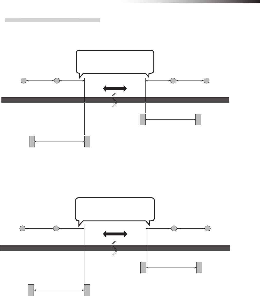
ê 9. Intersection
- 67 -
9-2-4. Forward/backward type
When the ID tag is used for the forward/backward AGV, it is necessary to read the ID tag during forward or backward
travel.
Position where ID tag (1) is
recognized before the stop
command is read.
Forward side
intersection exit
ID tag (0)
Backward side
intersection entrance
ID tag (1)
Forward side
intersection entrance
ID tag (1)
Backward side
intersection exit
ID tag (0)
Traveling direction
800 mm or more
(Distance to sufficiently
decelerate in speed)
Command tape
(Stop command)
For forward movement
Command tape
(Low speed command)
For forward movement
Command tape
(Low speed command)
For backward movement
Command tape
(Stop command)
For backward movement
800 mm or more
(Distance to sufficiently
decelerate in speed)
300 mm or more 300 mm or more
Figure. Installation of ID tag using command tapes
Position where ID tag (1) is
recognized before the stop
command is read.
Forward side
intersection exit
ID tag (0)
Backward side
intersection entrance
ID tag (1)
Forward side
intersection entrance
ID tag (1)
Backward side
intersection exit
ID tag (0)
800 mm or more
(Distance to sufficiently
decelerate in speed)
Count tape
(Stop)
For forward movement
Count tape
(Low speed)
For forward movement
Count tape
(Low speed)
For backward movement
Count tape
(Stop)
For backward movement
800 mm or more
(Distance to sufficiently
decelerate in speed)
300 mm or more 300 mm or more
Traveling direction
Figure. Installation of ID tag using count tapes
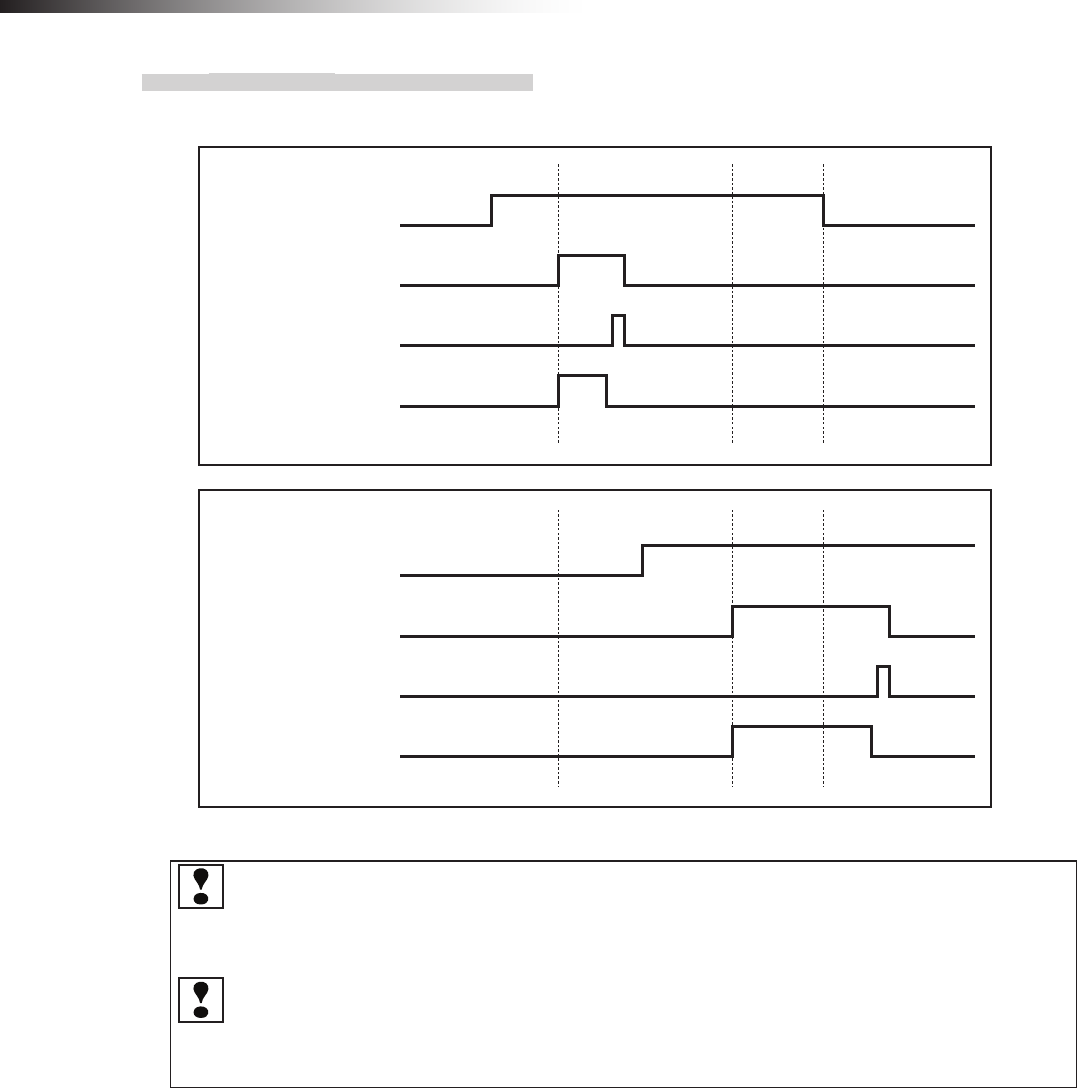
ê 9. Intersection
- 68 -
9-2-5. Timing chart
AGV (1) is passing and AGV (2) is waiting at intersection address (1).
AGV (1)
ID tag recognition by RFID antenna
AGV arrival input
Start output
Stop output
AGV (2)
ID tag recognition by RFID antenna
AGV arrival input
Start output
Stop output
The waiting wireless intersection module cannot check the communication of the wireless intersection
module that is passing through the intersection. The waiting wireless intersection module enters the pass-
ing status upon completion of checking specied by the monitoring time for permission to approach the
intersection and radio transmission count for checking the object approaching the intersection.
For the intersection control using the ground station, when the ground station cannot check the communica-
tion of the wireless intersection module that is passing through the intersection within the AGV communica-
tion error judgment time of the ground station, the waiting wireless intersection module is set to the passing
status.
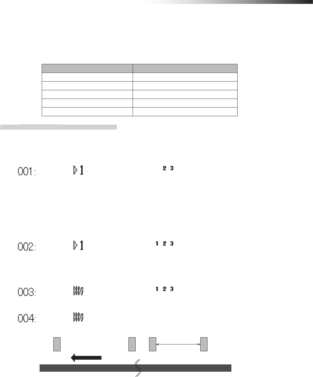
ê 9. Intersection
- 69 -
9-3. For course 30 unit
To make the course 30 unit recognize the intersection entrance or exit, use the external operation command 1 to 5
outputs. When the wireless intersection module is used for the course 30 unit, the software of the course 30 unit needs
to be updated to the latest version.
Outputs on course 30 unit Inputs on wireless intersection module
External operation command 1 output Intersection inquiry input
External operation command 2 output Intersection address (1) input
External operation command 3 output Intersection address (2) input
External operation command 4 output Intersection address (4) input
External operation command 5 output Intersection address (8) input
9-3-1. Forward type
(Example) Example to instruct count data
1) Set the speed to a low speed using the count tape that instructs the intersection entrance and turn ON the
external operation command 2 to 5 output. (This description uses intersection address 3.)
2) Next, turn ON the external operation command 1 output using the count tape.
First, checking is performed in accordance with the monitoring time for permission to approach the intersection
and the radio transmission count for checking the object approaching the intersection. If there is an AGV passing
through the intersection, it will be stopped.
When the wireless intersection module installed on the AGV that is passing through the intersection recognizes the
intersection exit, it travels again.
3) Next, use the count tape to set the speed to a level at which the AGV enters the intersection.
This count tape also turns ON external operation command 1 and external operation command 2 to 5 output. (This
description uses intersection address 3.)
4) Turn OFF external operation command 1 to 5 using the count tape that instructs the intersection exit.
Forward direction
Intersection exit Intersection entrance
23 14
800 mm or more
(Distance to
sufficiently
decelerate in speed)
Figure. Installation of count tapes
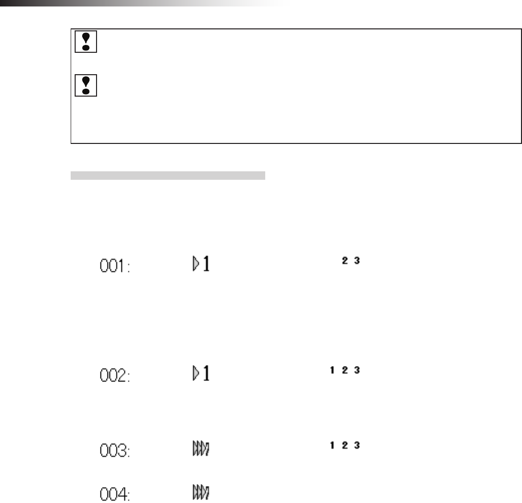
ê 9. Intersection
- 70 -
If the intersection positions are changed using the count change operation of the course 30 unit (2nd and 3rd
counts in the above example), be careful because the wireless intersection module starts the intersection
control and outputs the start command after it determines that the AGV is passing through the intersection.
A time lag occurs until the wireless intersection module recognizes the intersection, checks the wireless
intersection unit that is passing through the intersection, and then it stops. If the AGV speed is fast, the AGV
may stop at a position where it interferes with the AGV that is passing through the intersection. Adjust the
count position where the intersection inquiry input is turned ON by the external operation command from
the course 30 unit to a position without interference where the AGV can stop.
9-3-2. Forward/backward type
(Example) Example to instruct count data
For forward type
1) Set the speed to a low speed using the count tape that instructs the intersection entrance and turn ON the
external operation command 2 to 5 output. (This description uses intersection address 3.)
2) Next, turn ON the external operation command 1 output using the count tape. First, checking is performed in
accordance with the monitoring time for permission to approach the intersection and the radio transmission count
for checking the object approaching the intersection. If there is an AGV passing through the intersection, it will be
stopped. When the wireless intersection module installed on the AGV that is passing through the intersection recog-
nizes the intersection exit, the AGV travels again.
3) Next, use the count tape to set the speed to a level at which the AGV enters the intersection. External oper-
ation command 1 is turned ON and the external operation command 2 to 5 output is turned ON even at this count.
(This description uses intersection address 3.)
4) Turn OFF external operation command 1 to 5 using the count tape that instructs the intersection exit.
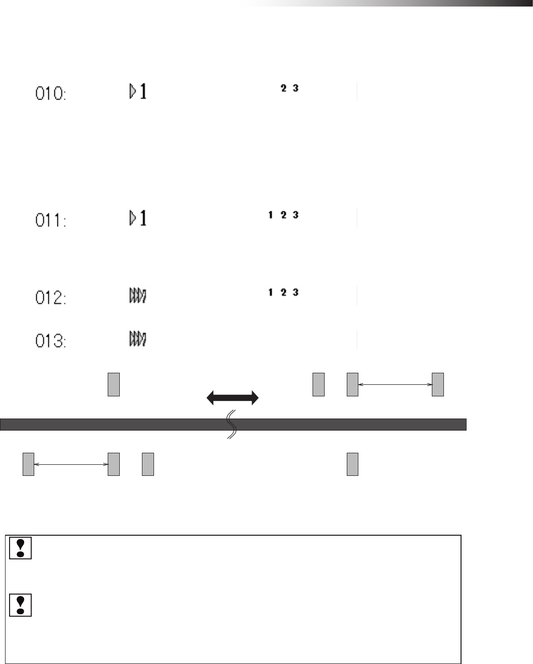
ê 9. Intersection
- 71 -
For backward type
1) Set the speed to a low speed using the count tape that instructs the intersection entrance and turn ON the
external operation command 2 to 5 output. (This description uses intersection address 3.)
2) Next, turn ON the external operation command 1 output using the count tape.
First, checking is performed in accordance with the monitoring time for permission to approach the intersection
and the radio transmission count for checking the object approaching the intersection. If there is an AGV passing
through the intersection, it will be stopped.
When the wireless intersection module installed on the AGV that is passing through the intersection recognizes the
intersection exit, the AGV travels again.
3) Next, use the count tape to set the speed to a level at which the AGV enters the intersection.
This count tape also turns ON external operation command 1 and external operation command 2 to 5 output. (This
description uses intersection address 3.)
4) Turn OFF external operation command 1 to 5 using the count tape that instructs the intersection exit.
Intersection exit Intersection entrance
800 mm or more
(Distance to
sufficiently
decelerate in speed)
800 mm or more
(Distance to
sufficiently
decelerate in speed)
Intersection entrance
23 14
10 11 12 13
Intersection exit
Traveling direction
Figure. Installation of count tapes
If the intersection positions are changed using the count change operation of the course 30 unit (2nd, 3rd,
11th, and 12th counts in the above example), be careful because the wireless intersection module starts the
intersection control and outputs the start command after it determines that the AGV is passing through the
intersection.
A time lag occurs until the wireless intersection module recognizes the intersection, checks the wireless
intersection unit that is passing through the intersection, and then it stops. If the AGV speed is fast, the AGV
may stop at a position where it interferes with the AGV that is passing through the intersection. Adjust the
count position where the intersection inquiry input is turned ON by the external operation command from
the course 30 unit to a position without interference where the AGV can stop.
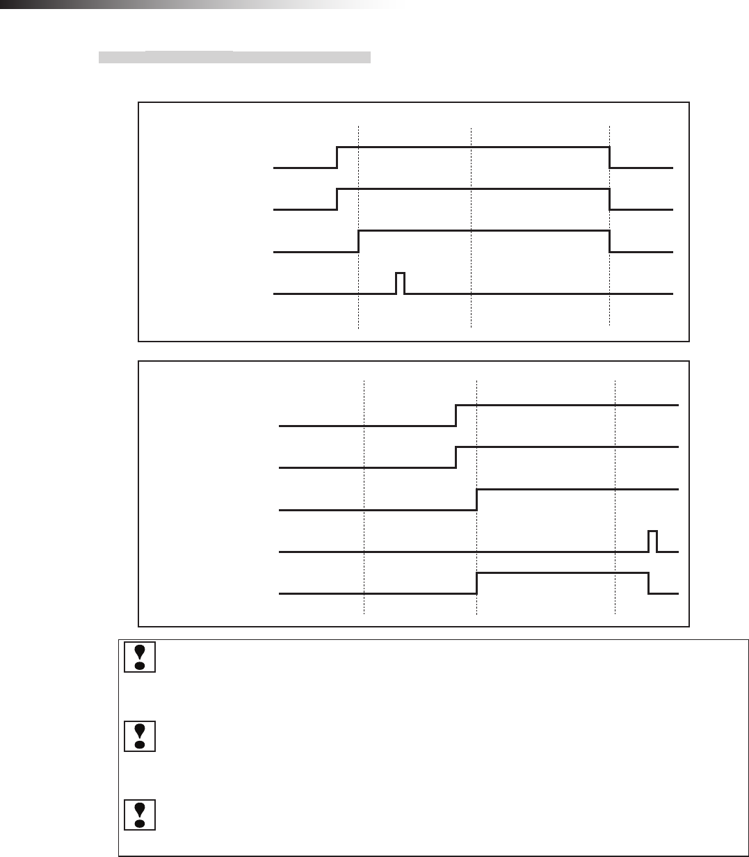
ê 9. Intersection
- 72 -
9-3-3. Timing chart
AGV (3) is passing and AGV (2) is waiting at intersection address (1).
AGV (2)
Intersection address (2) input
Intersection address (1) input
Intersection inquiry input
Start output
Stop output
AGV (1)
Intersection address (2) input
Intersection address (1) input
Intersection inquiry input
Start output
Whether the approach to the intersection is permitted or not is determined upon completion of checking
specied by the monitoring time for permission to approach the intersection and the radio transmission count
for checking the object approaching the intersection. Even when the AGV travels during this period, adjust
the intersection instruction timing from the positional relationship between the AGVs at the intersection.
The waiting wireless intersection module cannot check the communication of the wireless intersection
module that is passing through the intersection. The waiting wireless intersection module enters the pass-
ing status upon completion of checking specied by the monitoring time for permission to approach the
intersection and radio transmission count for checking the object approaching the intersection.
For the intersection control using the ground station, when the ground station cannot check the communica-
tion of the wireless intersection module that is passing through the intersection within the AGV communication
error judgment time of the ground station, the waiting wireless intersection module is set to the passing status.
9-4. For ground station
When the wireless intersection module performs the intersection control in the ground station mode, it is necessary that
the AGV is controlled using the address sensor, RFID antenna, and course 30 unit described previously.
The mutual communication between the wireless units on the AGVs or the communication between the wireless unit
on the AGV and the ground station using the set intersection address can be set for the wireless intersection module
using the parameter settings of the personal computer.
However, note that one ground station can control up to four intersections.
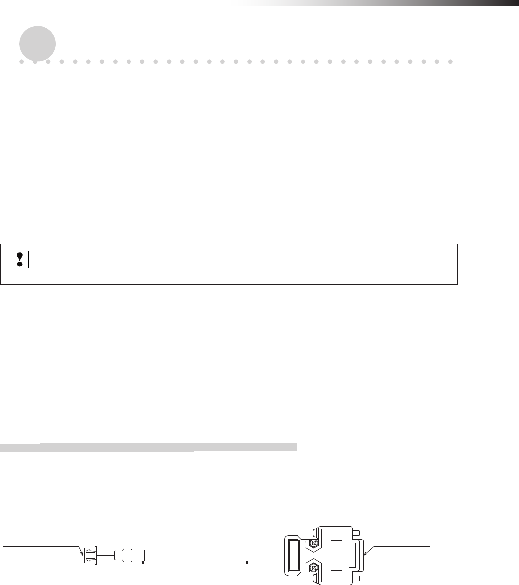
ê 10. Wireless intersection module parameter settings
- 73 -
10. Wireless intersection module parameter settings
The wireless intersection module can perform various settings using the dedicated application.
• ID setting
• One shot pulse width setting
• Frequency CH setting
• Travel priority setting
• Ground station setting
• Trigger setting
• Intersection operation setting
• Initialization
• Save or load settings
After setting the parameters, be sure to turn OFF the power to the module, and then turn it ON again.
Otherwise, the settings do not take effect.
10-1. FCU-RC01 setup software FCU-RC01_Set
This software also provides functions used to set the parameters for the wireless intersection module FCU-RC01. Set
the parameters using the application “FCU-RC01_Set”.
Connect the personal computer and wireless intersection module using the wireless intersection module setting cable
FCP-RCC08. Connect the D-sub 9-pin connector to the serial port of the personal computer and the XHP-3 connector
to the CN3 parameter setting connector of the wireless intersection module.
10-1-1. Operating conditions for FCU-RC01 setup software
• Windows XP/Vista/7
• A serial port is required.
(A USB serial converter can be used. However, some converters may not support the communication.)
For connection of wireless intersection
module FCU-RC01
For connection of
personal computer
Figure. Wireless intersection module setting cable FCP-RCC08
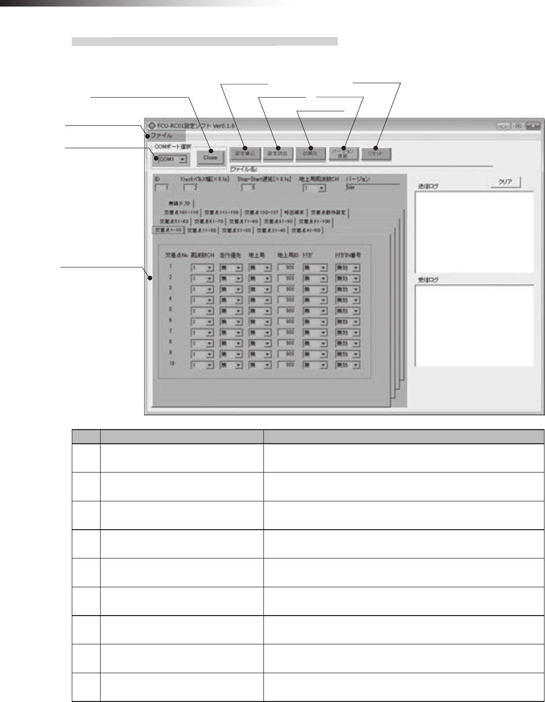
ê 10. Wireless intersection module parameter settings
- 74 -
10-1-2. Basic screen, and part names and functions
Basic screen
(4) Save settings
(5) Load settings
(6) Initialize
(7) Version
(8) Reset
(3) Open or Close COM port
(1) Menu bar
(2) Select COM port
(9)
Wireless intersection module
Parameter settings
No. Name Contents
1 Menu bar Menu commands related to the le saving and loading.
You can save or load the contents of the parameter settings.
2 Select COM port Allows you to select a RS-232C port of the personal computer.
3 Open or Close COM port Opens or closes a RS-232C port of the personal computer.
4 Save settings Saves the settings of the wireless intersection module.
5 Load settings Loads the settings of the wireless intersection module.
6 Initialization Initializes the settings of the wireless intersection module.
7 Version Reads out the software version of the wireless intersection module.
8 Reset Resets the wireless intersection module.
Resets to the status immediately after power ON.
9Wireless Intersection Module
parameter settings Allows you to set various parameters.
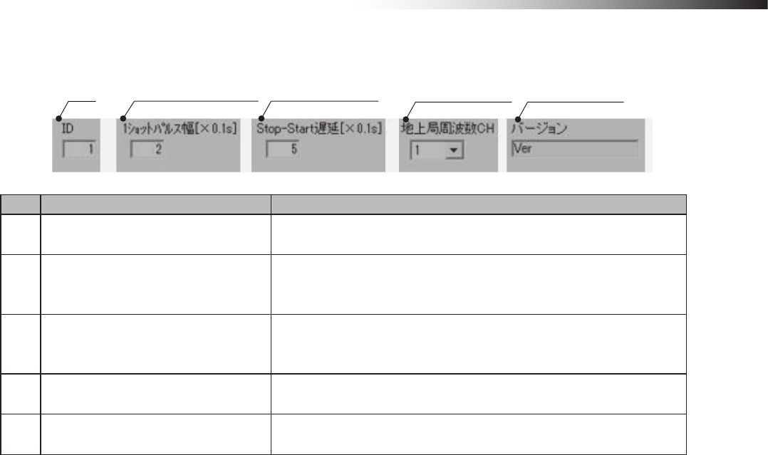
ê 10. Wireless intersection module parameter settings
- 75 -
Wireless intersection module parameter settings
(1) ID (2) One shot pulse width (3) Stop-Start delay
(4) Ground station
frequency CH (5) Version
No. Name Contents
1 ID Allows you to set the ID of the wireless intersection module.
It is necessary to set the rotary switches RSW 1 to 3 to 0.
2 One shot pulse width
Allows you to set the one-shot width of the signal to be output by the start
output in the address sensor mode or RFID mode, or the start output or
stop output in the external control mode.
3 Stop-Start delay
Allows you to set the timing delay time from the stop output OFF to start
output ON sent from the wireless intersection module in the address sen-
sor mode or RFID mode.
4 Ground station frequency CH Allows you to set the ground station frequency CH.
It is necessary to set the rotary switch RSW4 on the ground station to 0.
5 Version Displays the software version of the wireless intersection module.
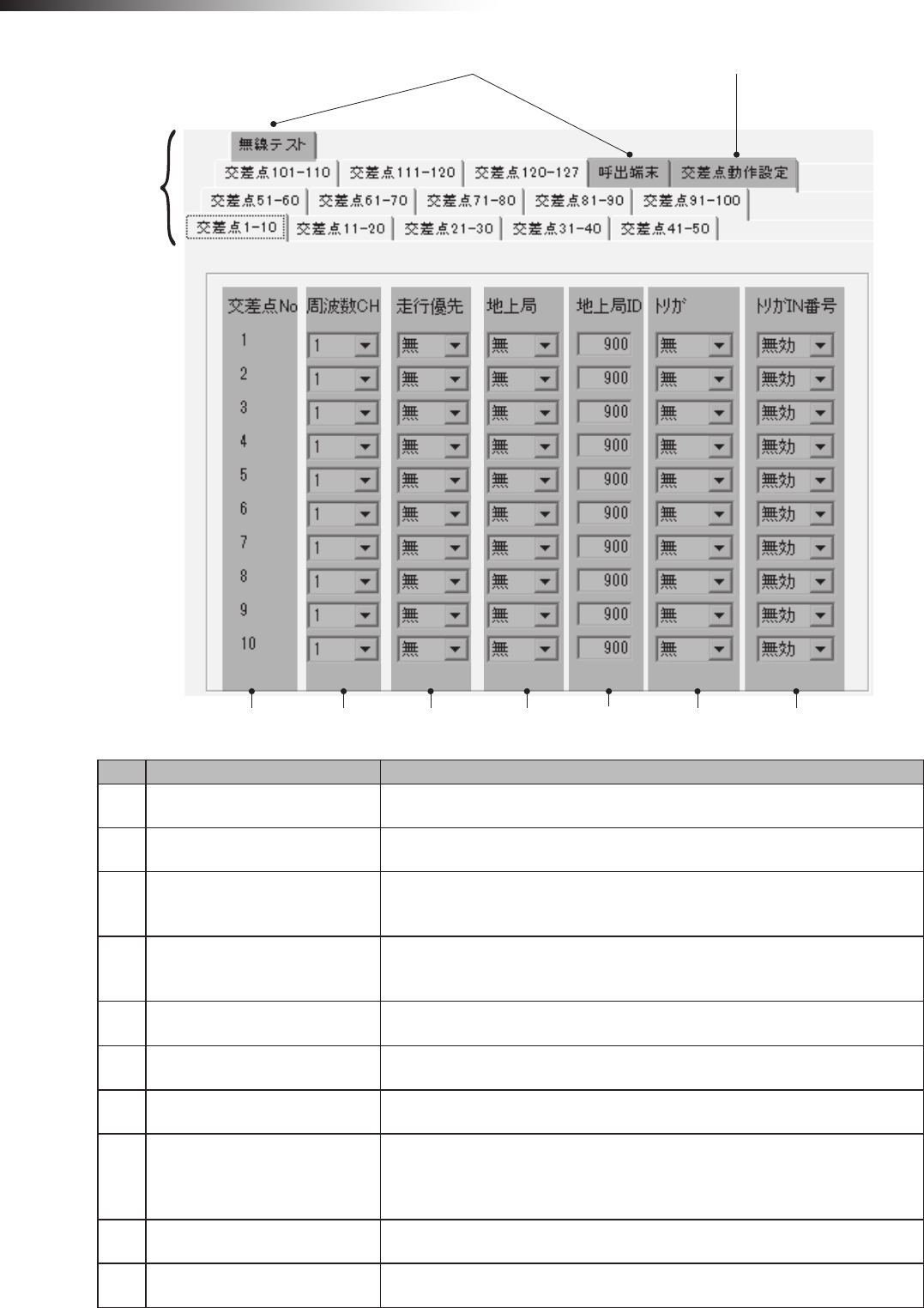
ê 10. Wireless intersection module parameter settings
- 76 -
(9) Tab for maintenance
(2) Intersection
No.
(3) Frequency
CH
(4) Travel priority (5) Ground
station
(6) Ground
station ID
(7) Trigger (8) Trigger IN No.
(10) Tab for intersection operation setting
(1) Tab
No. Name Contents
1Tab Tab for each intersection group.
2 Intersection No. Intersection address (No.) of each intersection.
3 Frequency CH
The communication can be performed from the frequency CH selected for each
intersection.
It is necessary to set the rotary switch RSW4 to 0.
4 Travel priority
The stop output signal is not sent from the wireless intersection module and the
pause output signal is sent. When passing through the intersection is permitted,
the pause output signal is turned OFF.
5 Ground station Allows you to set the intersection control using the ground station enabled or
disabled.
6 Ground station ID Allows you to set the ID of the ground station that performs the intersection
control at each intersection.
7 Trigger This must be set with the trigger IN No. at the same time.
8 Trigger IN No.
This must be set with the trigger at the same time.
The wireless intersection module waits until the start permission input signal
from the ground station turns ON. The module is permitted to pass through the
intersection via the intersection control from the ground station.
9 Tab for maintenance Unusable.
10 Tab for intersection operation
setting Allows you to set the intersection control parameters.
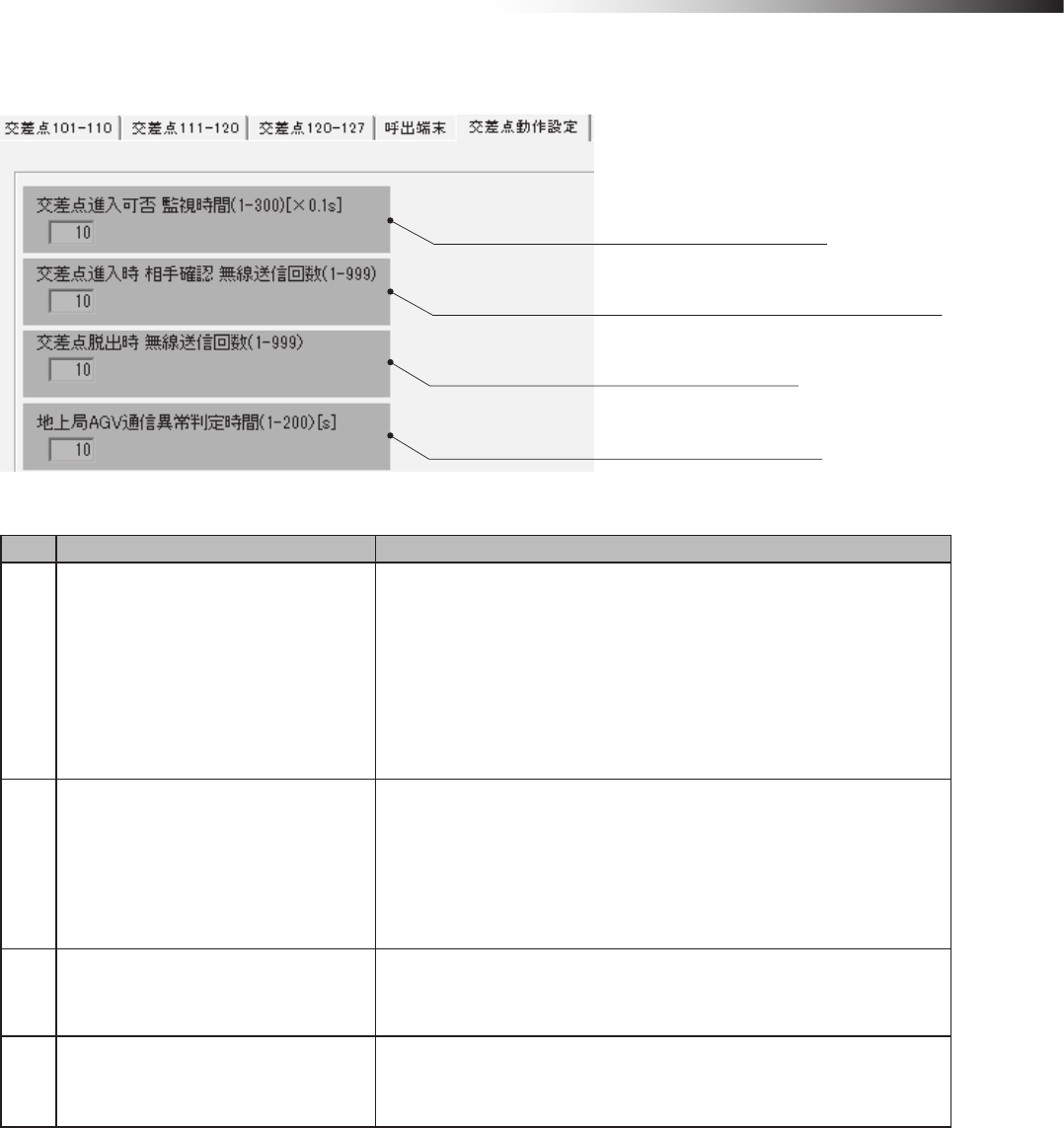
ê 10. Wireless intersection module parameter settings
- 77 -
Tab for intersection operation setting
(1) Monitoring time for permission to approach the intersection
(2) Radio transmission count for checking the object approaching the intersection
(3) Radio transmission count when exiting the intersection
(4) AGV communication error judgment time of ground station
No. Name Contents
1Monitoring time for permission to
approach the intersection
Monitoring time during approach to or waiting at the intersection. When
the intersection is instructed, the inside of the intersection is checked
after the monitoring time has elapsed.
When passing is conrmed during this monitoring time, the status chang-
es to waiting.
In the waiting status, if the radio transmission that indicates “passing”
cannot be received within the monitoring time, the inside of the intersec-
tion is checked. If the inside of the intersection cannot be checked, the
status changes to passing.
2Radio transmission count for checking
the object approaching the intersection
Sets the number of times to check the object approaching the intersec-
tion.
After the signal has been transmitted the set number of times, the AGV
enters the intersection.
If no reply is transmitted from the ground station after the radio has been
transmitted the set number of times,
the ground station displays system error code 102.
3Radio transmission count when exiting
the intersection
Sets the number of times to inform the waiting wireless intersection mod-
ule or the ground station that the AGV has exited the intersection.
4AGV communication error judgment
time of ground station
When the ground station cannot receive the radio transmission that
shows passing beyond the error judgment time,
the approach process that is waiting is started.
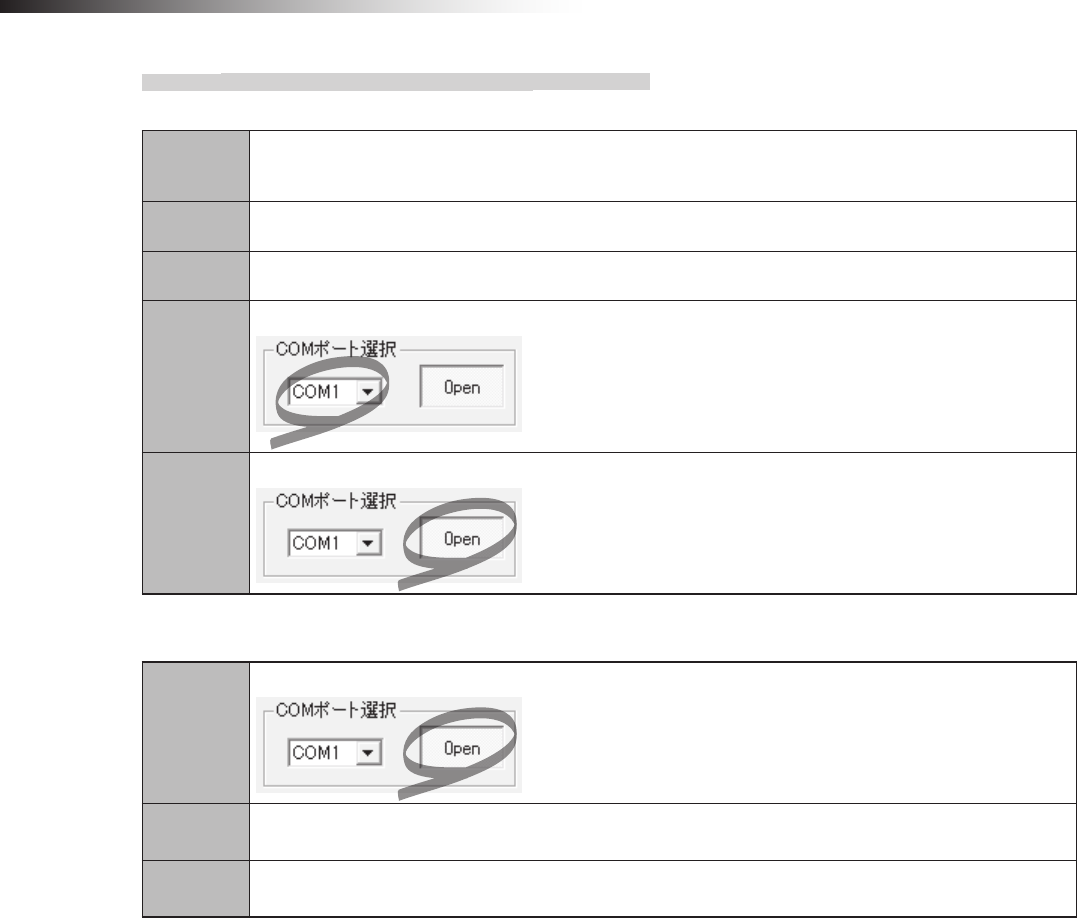
ê 10. Wireless intersection module parameter settings
- 78 -
10-1-3. Connection and disconnection procedures
Connecting the wireless intersection module
Step 1 Connect the CN3 connector of the wireless intersection module and the RS232C port of the personal
computer using the wireless intersection module setting cable FCP-RCC08.
Step 2 Supply the power to the wireless intersection module.
Step 3 Run the FCU-RC01 setup software on the personal computer.
Step 4
Select a COM port in “Select COM port” of the FCU-RC01 setup software.
Step 5
Click “Open” or “Close” in “Select COM port” of the FCU-RC01 setup software.
Disconnecting the wireless intersection module
Step 1
Click “Open” or “Close” in “Select COM port” of the FCU-RC01 setup software.
Step 2 Turn OFF the power supply to the wireless intersection module.
Step 3 Disconnect the wireless intersection module setting cable FCP-RCC08 from the CN3 connector of the
wireless intersection module and the RS232C port of the personal computer.
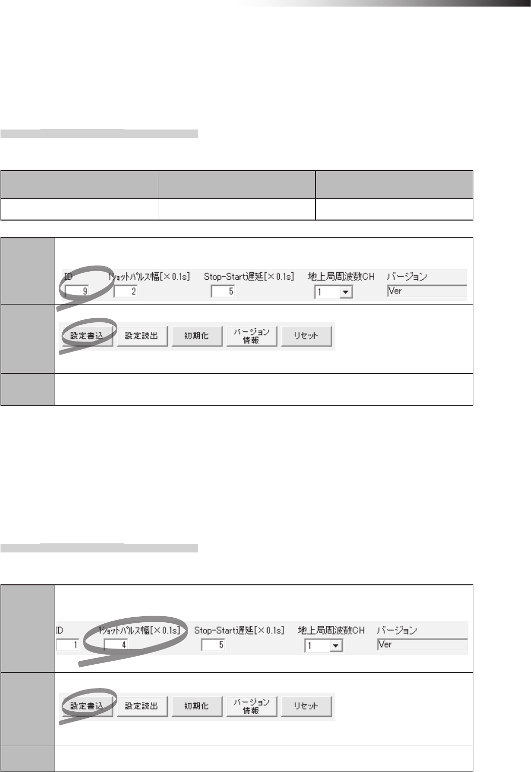
ê 10. Wireless intersection module parameter settings
- 79 -
10-2. ID setting
An ID of the wireless intersection module is normally set using the rotary switches RSW 1 to 3, but it can also be set
using the parameter settings from the personal computer. For setting, enter an ID in the parameter settings of the FCU-
RC01 setup software. To reect the ID setting that has been performed from the personal computer, it is necessary to
set all rotary switches RSW 1 to 3 to 0.
10-2-1. Setting example
(Example) To set the ID of the wireless intersection module installed on AGV1 to 9 using the settings of the
personal computer.
Wireless Intersection Module Rotary switches RSW1 to 3
(ID setting)
Rotary switch RSW4
(Frequency)
AGV1 0 F
Step 1
In the wireless intersection module parameter setting area of the FCU-RC01 setup software,
set 9 in “ID”.
Step 2
Click “Save settings”.
The settings are saved to the wireless intersection module installed on AGV1.
Step 3 Turn OFF the power to the wireless intersection module, and then turn it ON again.
10-3. One shot pulse width setting
You can set the one-shot width of the signal to be output by the start output in the address sensor mode or RFID mode,
or by the start output or stop output in the external control mode.
You can also select whether the start signal is output using the level or one shot in the external control mode in accor-
dance with the setting of the DIP switch SW1-4. In the same manner, you can select whether the stop signal is output
using the level or one shot in accordance with the setting of the DIP switch SW1-5.
10-3-1. Setting example
(Example) To set the one shot output width of the wireless intersection module installed on AGV1 to 400 ms.
using the settings of the personal computer.
Step 1
In the wireless intersection module parameter setting area of the FCU-RC01 setup software,
set 4 in “One shot pulse width”.
Step 2
Click “Save settings”.
The settings are saved to the wireless intersection module installed on AGV1.
Step 3 Turn OFF the power to the wireless intersection module, and then turn it ON again.
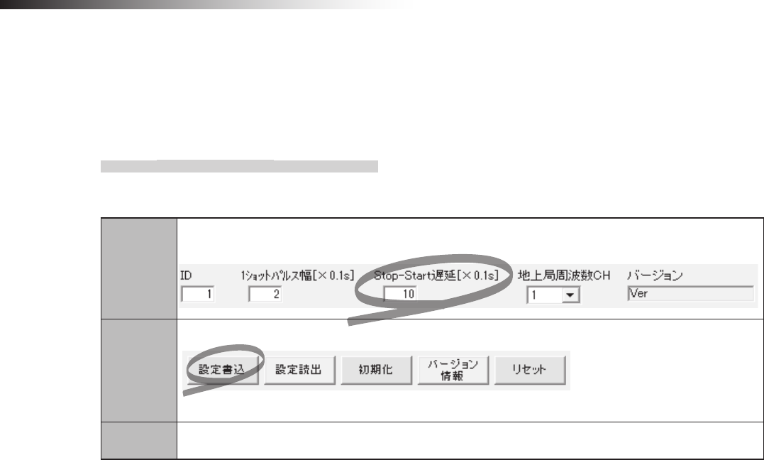
ê 10. Wireless intersection module parameter settings
- 80 -
10-4. Stop-Start delay setting
You can set the delay time of the timing at which the stop output from the wireless intersection module is turned OFF,
and then the start output is turned ON.
The standard setting is 0.5 second. However, you can change the setting in accordance with the system to be used.
10-4-1. Setting example
(Example) To set the Stop-Start delay setting of the wireless intersection module installed on AGV1 to 1 second
using the settings of the personal computer.
Step 1
In the wireless intersection module parameter setting area of the FCU-RC01 setup software,
set 10 in “Stop-Start delay”.
Step 2
Click “Save settings”.
The settings are saved to the wireless intersection module installed on AGV1.
Step 3 Turn OFF the power to the wireless intersection module, and then turn it ON again.
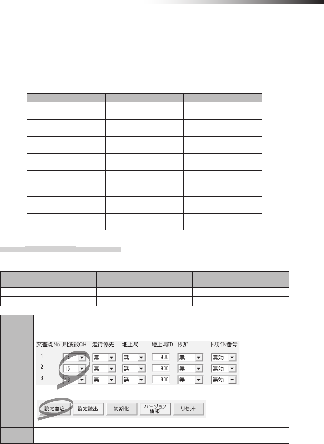
ê 10. Wireless intersection module parameter settings
- 81 -
10-5. Frequency CH setting
The frequency CH for intersection No. of the wireless intersection module is set using the rotary switch RSW4, but the
frequency CH for each intersection No. can be set using the parameter settings from the personal computer.
For setting, enter a frequency CH in the parameter settings of the FCU-RC01 setup software.
To reect the ID setting that has been performed from the personal computer. it is necessary to set the rotary switch
RSW4 to 0.
In addition, the settable frequencies and frequency CHs are as follows.
RSW4 Frequency Frequency CH
1 2405 MHz 1
2 2410 MHz 2
3 2415 MHz 3
4 2420 MHz 4
5 2425 MHz 5
6 2430 MHz 6
7 2435 MHz 7
8 2440 MHz 8
9 2445 MHz 9
A 2450 MHz 10
B 2455 MHz 11
C 2460 MHz 12
D 2465 MHz 13
E 2470 MHz 14
F 2475 MHz 15
10-5-1. Setting example
(Example) To set intersection No. 1 to frequency CH14, intersection No. 2 to frequency CH15, and intersection
No. 3 to frequency CH18.
Wireless Intersection Module Rotary switches RSW1 to 3
(ID setting)
Rotary switch RSW4
(Frequency)
AGV1 1 0
AGV2 2 0
Step 1
To set intersection No. 1 to frequency CH14, intersection No. 2 to frequency CH15, and intersection No.
3 to frequency CH18 in the wireless intersection module parameter setting area of the FCU-RC01 setup
software.
Step 2
Click “Save settings”.
The settings are saved to the wireless intersection modules installed on AGV1 and 2.
Step 3 Turn OFF the power to the wireless intersection module, and then turn it ON again.
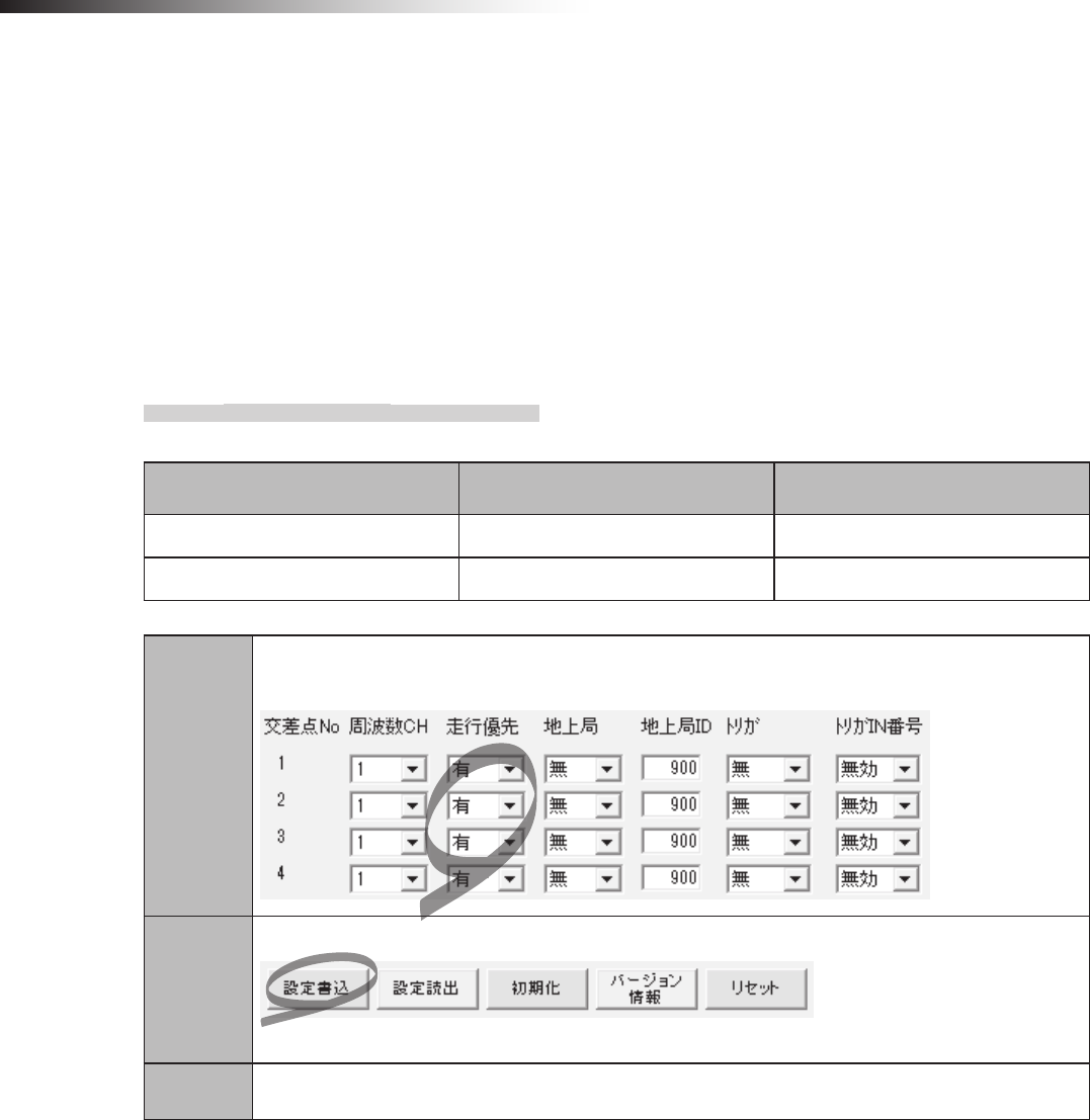
ê 10. Wireless intersection module parameter settings
- 82 -
10-6. Travel priority setting
When the intersection control is performed in the address sensor mode or RFID mode, it is always necessary to pause
the AGV. However, when the AGV has the pause input, the intersection control can be performed without pausing.
When the CNG connector of the 12 or 24 V forward type Drive Unit is directly connected to the wireless intersection
module box, the pause input can be used as this input is available at the connection point.
When the small Drive Unit and course 30 unit are used, the pause input cannot be used as this input is not available at
the connection point.
Note that the contact type of the pause input must be normally open. The pause input cannot be used for the normally
close contact type.
10-6-1. Setting example
(Example) To set intersection Nos. 1 to 4 to the travel priority.
Wireless Intersection Module Rotary switches RSW1 to 3
(ID setting)
Rotary switch RSW4
(Frequency)
AGV1 1 F
AGV2 2 F
Step 1
In the wireless intersection module parameter setting area of the FCU-RC01 setup software,
set as follows. Intersection Nos. 1 to 4, Travel priority ON.
Step 2
Click “Save settings”.
The settings are saved to the wireless intersection modules installed on AGV1 and 2.
Step 3 Turn OFF the power to the wireless intersection module, and then turn it ON again.
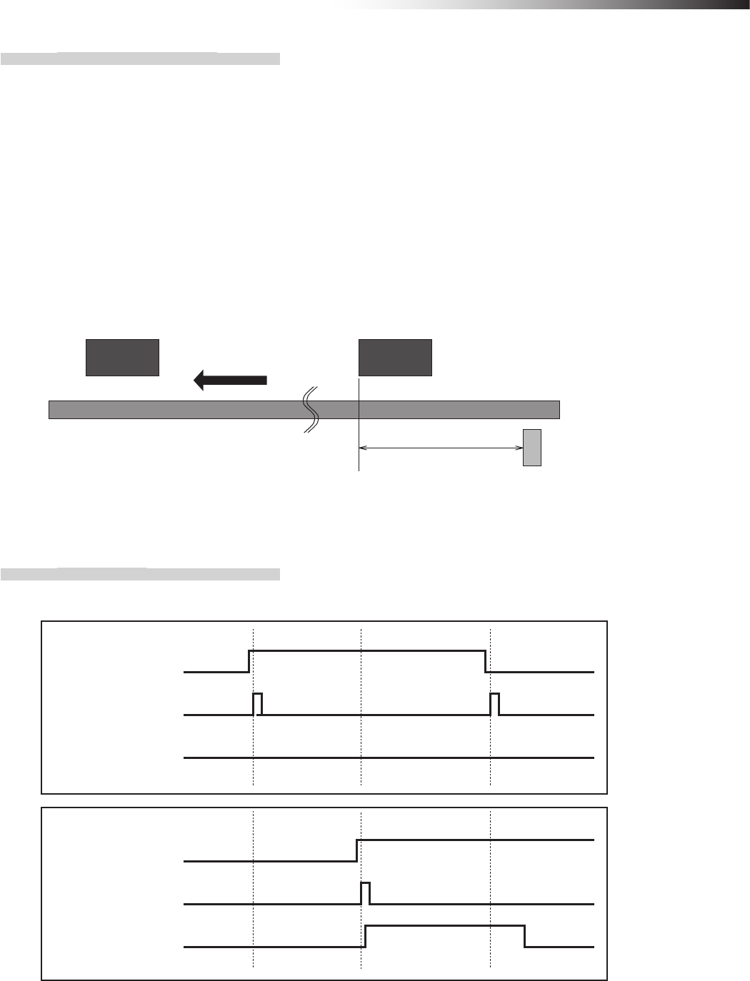
ê 10. Wireless intersection module parameter settings
- 83 -
10-6-2. Address sensor mode
To make the AGV recognize the intersection entrance, afx the address magnetic plate corresponding to the inter-
section address to a position where the address sensor can read it. (This description uses intersection address 1.)
After that, to make the AGV recognize the intersection exit, afx the address magnet (intersection address 0) that
clears the intersection address.
Install the address sensor so that it reads the address magnetic plate vertically to the traveling direction.
First, checking is performed in accordance with the monitoring time for permission to approach the intersection and
the radio transmission count for checking the object approaching the intersection. If there is an AGV that is passing
through the intersection, the AGV pauses at the entrance.
When the wireless intersection module installed on the AGV that is passing through the intersection recognizes the
intersection exit, the pause is turned OFF.
Note that the AGV must read the address magnetic plate at the intersection entrance at a low speed.
Forward direction
Intersection entrance
Address magnetic plate (1)
Intersection exit
Address magnetic plate (0)
800 mm or more
(Distance to sufficiently
decelerate in speed)
Command tape
(Low speed command)
Figure. Installation of address magnetic plate for travel priority
10-6-3. Timing chart
AGV (1) is passing and AGV (2) is waiting at intersection address (1).
Read-out timing input
Intersection address (1) input
Pause output
Read-out timing input
Intersection address (1) input
Pause output
AGV (2)
AGV (1)
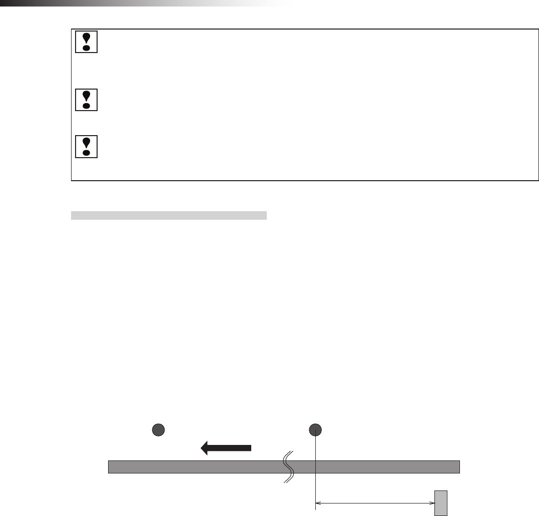
ê 10. Wireless intersection module parameter settings
- 84 -
Whether the approach to the intersection is permitted or not is determined upon completion of checking spec-
ied by the monitoring time for permission to approach the intersection and the radio transmission count for
checking the object approaching the intersection.
Even when the AGV travels during this period, adjust the detection timing of the address magnetic plate or ID
tag from the positional relationship between the AGVs at the intersection.
The waiting wireless intersection module cannot check the communication of the wireless intersection module
that is passing through the intersection. The waiting wireless intersection module enters the passing status
upon completion of checking specied by the monitoring time for permission to approach the intersection and
radio transmission count for checking the object approaching the intersection.
For the intersection control using the ground station, when the ground station cannot check the communication
of the wireless intersection module that is passing through the intersection within the AGV communication error
judgment time of the ground station, the waiting wireless intersection module is set to the passing status. The
waiting wireless intersection module then enters the passing status.
10-6-4. RFID mode
To make the AGV recognize the intersection entrance, afx the ID tag corresponding to the intersection address to
a position where the RFID antenna can read the ID tag. (This description uses intersection address 1.)
After that, to make the AGV recognize the intersection exit, afx the ID tag (intersection address 0) that clears the
intersection address.
First, checking is performed in accordance with the monitoring time for permission to approach the intersection and
the radio transmission count for checking the object approaching the intersection. If there is an AGV that is passing
through the intersection, the AGV pauses at the entrance.
When the wireless intersection module installed on the AGV that is passing through the intersection recognizes the
intersection exit, the pause is turned OFF.
Note that the AGV must read the ID tag at the intersection entrance at a low speed.
800 mm or more
(Distance to sufficiently
decelerate in speed)
Intersection exit
ID tag (0)
Intersection entrance
ID tag (1)
Command tape
(Low speed command)
Forward direction
Figure. Installation of ID tag for travel priority
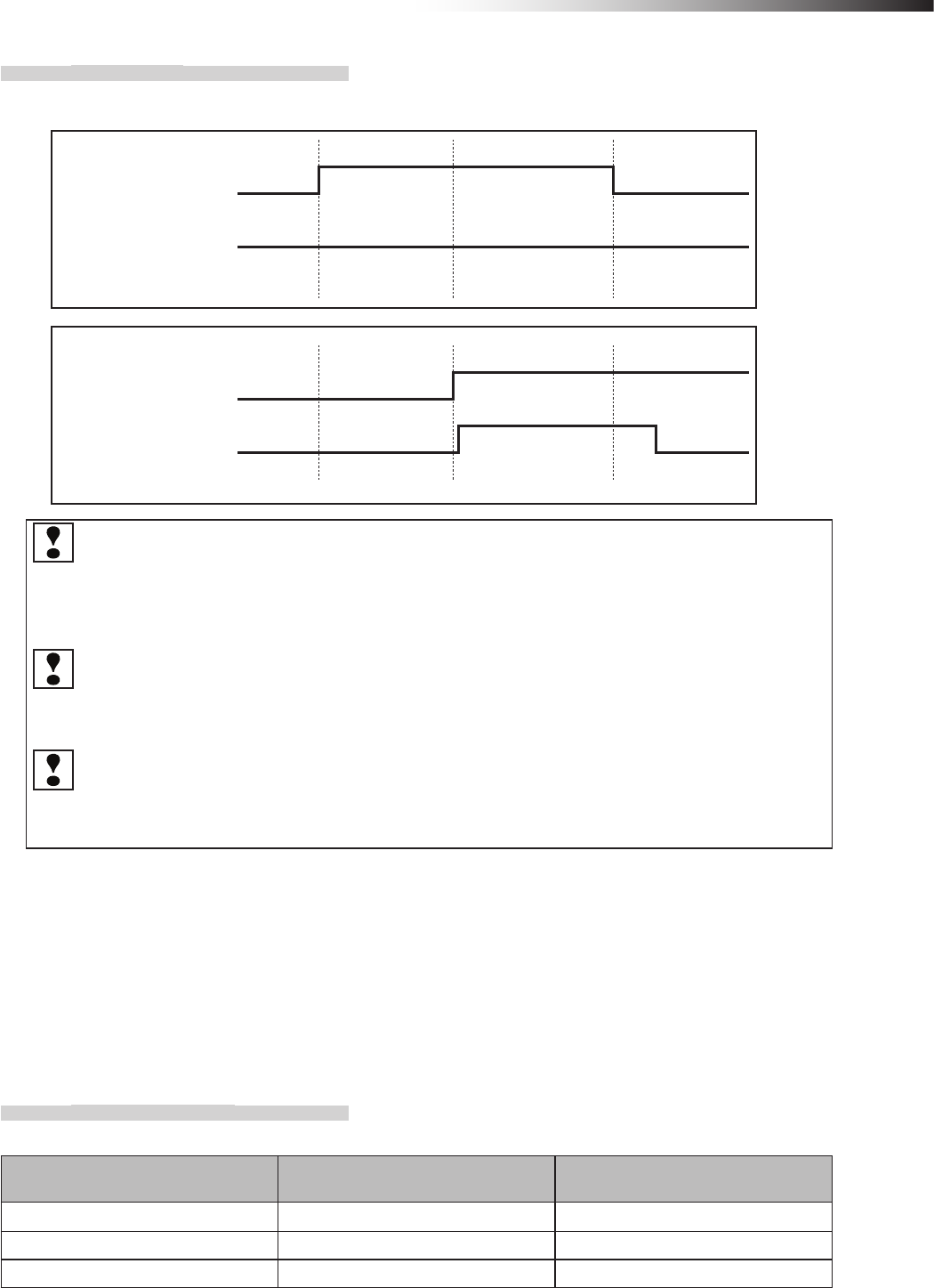
ê 10. Wireless intersection module parameter settings
- 85 -
10-6-5. Timing chart
AGV (1) is passing and AGV (2) is waiting at intersection address (1).
Pause output
ID tag recognition by
RFID antenna
AGV (1)
Pause output
ID tag recognition by
RFID antenna
AGV (2)
Whether the approach to the intersection is permitted or not is determined upon completion of checking
specied by the monitoring time for permission to approach the intersection and the radio transmission
count for checking the object approaching the intersection. Even when the AGV travels during this period,
adjust the detection timing of the address magnetic plate or ID tag from the positional relationship between
the AGVs at the intersection.
The waiting wireless intersection module cannot check the communication of the wireless intersection
module that is passing through the intersection. The waiting wireless intersection module enters the pass-
ing status upon completion of checking specied by the monitoring time for permission to approach the
intersection and radio transmission count for checking the object approaching the intersection.
For the intersection control using the ground station, when the ground station cannot check the communica-
tion of the wireless intersection module that is passing through the intersection within the AGV communica-
tion error judgment time of the ground station, the waiting wireless intersection module is set to the passing
status.
10-7. Ground station setting
For the case of using the wireless intersection module as a ground station, if the communication status is unstable due
to a long distance of wireless communication or due to effects of obstacles caused by the layout, installing a ground
station will help negate these effects allowing radio waves to reach their destinations. Note that one ground station can
control up to four intersections.
10-7-1. Setting example 1
(Example) To perform the intersection control of intersection No. 1 using the ground station (ID900).
Wireless Intersection Module Rotary switches RSW1 to 3
(ID setting)
Rotary switch RSW4
(Frequency)
AGV1 1 F
AGV2 2 F
Ground station 900 F
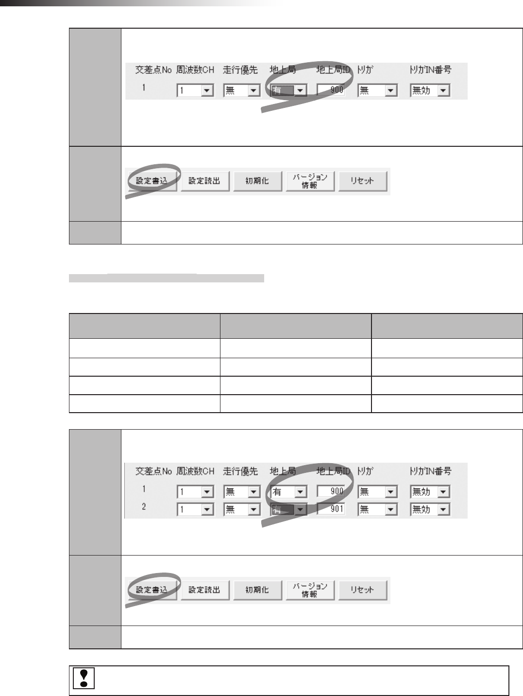
ê 10. Wireless intersection module parameter settings
- 86 -
Step 1
In the wireless intersection module parameter setting area of the FCU-RC01 setup software,
set as follows. Intersection No. 1, Ground station ON, Ground station ID 900.
Note: Since the ID, ground station frequency CH, and frequency CH are set by the rotary switches,
the settings are not needed.
Step 2
Click “Save settings”.
The settings are saved to the wireless intersection modules installed on AGV1 and 2, and ground station.
Step 3 Turn OFF the power to the wireless intersection module, and then turn it ON again.
10-7-2. Setting example 2
(Example) To perform the intersection control of intersection No. 1 using the ground station (ID900) and
intersection No. 2 using the ground station (ID901).
Wireless Intersection Module Rotary switches RSW1 to 3
(ID setting)
Rotary switch RSW4
(Frequency)
AGV1 1 F
AGV2 2 F
Ground station 1 900 F
Ground station 2 901 F
Step 1
In the wireless intersection module parameter setting area of the FCU-RC01 setup software,
set as follows. Intersection Nos. 1 and 2, Ground station ON, Ground station ID 900, 901.
Note: Since the ID, ground station frequency CH, and frequency CH are set by the rotary switches,
the settings are not needed.
Step 2
Click “Save settings”.
The settings are saved to the wireless intersection modules installed on AGV1 and 2, and ground station.
Step 3 Turn OFF the power to the wireless intersection module, and then turn it ON again.
The same intersection No. is not set to ON for the ground stations with different IDs like intersection No. 1
is ON for the ground stations with ID900 and ID901. Otherwise, the communication malfunctions.
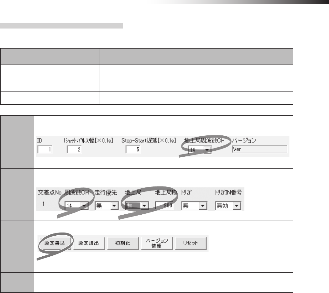
ê 10. Wireless intersection module parameter settings
- 87 -
10-7-3. Setting example 3
(Example) To perform the intersection control of intersection No. 1 using the ground station (ID900). (The
frequency CH is set to 14 using the personal computer setting.)
Wireless Intersection Module Rotary switches RSW1 to 3
(ID setting)
Rotary switch RSW4
(Frequency)
AGV1 1 0
AGV2 2 0
Ground station 900 0
Step 1
In the wireless intersection module parameter setting area of the FCU-RC01 setup software,
set 14 in “Ground station frequency CH”.
Note: Since the ID is set by the rotary switches, the setting is not needed.
Step 2
In the wireless intersection module parameter setting area of the FCU-RC01 setup software,
set as follows. Frequency CH 14, Ground station ON, Ground station ID 900.
Step 3
Click “Save settings”.
The settings are saved to the wireless intersection modules installed on AGV1 and 2, and ground station.
Step 4 Turn OFF the power to the wireless intersection module, and then turn it ON again.
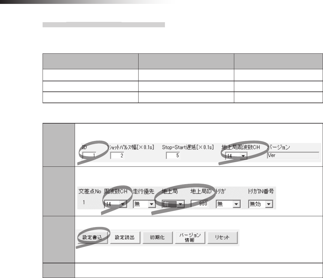
ê 10. Wireless intersection module parameter settings
- 88 -
10-7-4. Setting example 4
(Example) To perform the intersection control of intersection No. 1 using the ground station (ID900).
(For the ID and frequency CH settings, set AGV1 to ID1, AGV2 to ID2, ground station ID to 900,
and frequency CH to 14.)
Wireless Intersection Module Rotary switches RSW1 to 3
(ID setting)
Rotary switch RSW4
(Frequency)
AGV1 0 0
AGV2 0 0
Ground station 0 0
AGV1 setting procedures
Step 1
In the wireless intersection module parameter setting area of the FCU-RC01 setup software,
set 1 in “ID” and 14 in “Ground station frequency CH”.
Step 2
In the wireless intersection module parameter setting area of the FCU-RC01 setup software,
set as follows. Frequency CH 14, Ground station ON, Ground station ID 900 for Intersection No. 1.
Step 3
Click “Save settings”.
The settings are saved to the wireless intersection module installed on AGV1.
Step 4 Turn OFF the power to the wireless intersection module, and then turn it ON again.
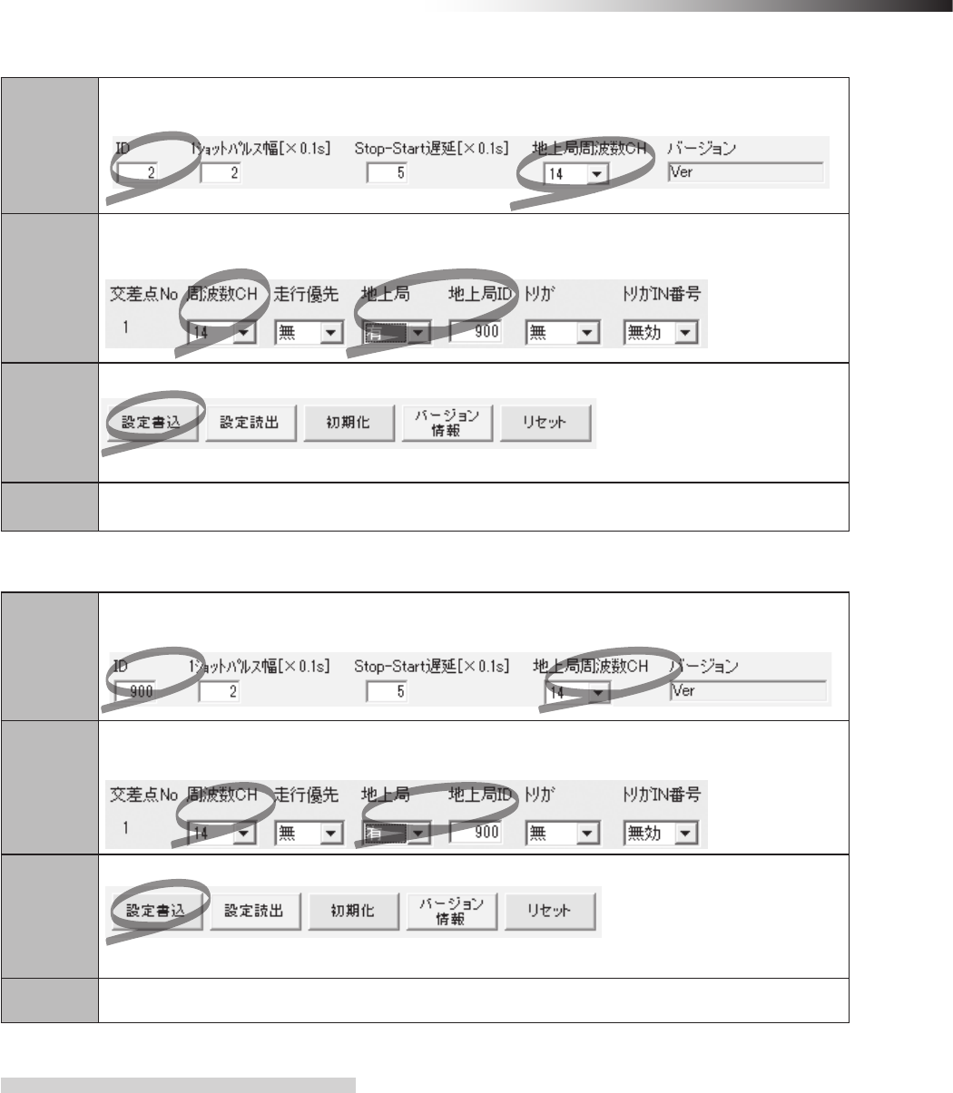
ê 10. Wireless intersection module parameter settings
- 89 -
AGV2 setting procedures
Step 1
In the wireless intersection module parameter setting area of the FCU-RC01 setup software,
set 2 in “ID” and 14 in “Ground station frequency CH”.
Step 2
In the wireless intersection module parameter setting area of the FCU-RC01 setup software,
set as follows. Frequency CH 14, Ground station ON, Ground station ID 900 for Intersection No. 1.
Step 3
Click “Save settings”.
The settings are saved to the wireless intersection module installed on AGV1.
Step 4 Turn OFF the power to the wireless intersection module, and then turn it ON again.
Ground station setting procedures
Step 1
In the wireless intersection module parameter setting area of the FCU-RC01 setup software,
set 900 in “ID” and 14 in “Ground station frequency CH”.
Step 2
In the wireless intersection module parameter setting area of the FCU-RC01 setup software,
Intersection No. 1, set 14 in “Frequency CH”, ON in “Ground station”, and 900 in “Ground station ID”.
Step 3
Click “Save settings”.
The settings are saved to the wireless intersection module installed on AGV1.
Step 4 Turn OFF the power to the wireless intersection module, and then turn it ON again.
10-7-5. Caution
When the wireless intersection module is used in the ground station mode, the wireless intersection module in-
stalled on each AGV communicates with the wireless intersection module set in the ground station mode to perform
the intersection control.
If the wireless intersection module set in the ground station mode cannot communicate with the wireless intersec-
tion module installed on the AGV, the wireless intersection module installed on the AGV displays system error code
102 at the intersection entrance.
Check that the power to the wireless intersection module set in the ground station mode is ON, that the antenna
is connected, that there are no obstacles around the antenna, and then remove the cause of the communication
failure. After turning OFF the power to each wireless intersection module, and then turning it ON again, make the
wireless intersection module recognize the intersection entrance again to recover from the communication failure
status.
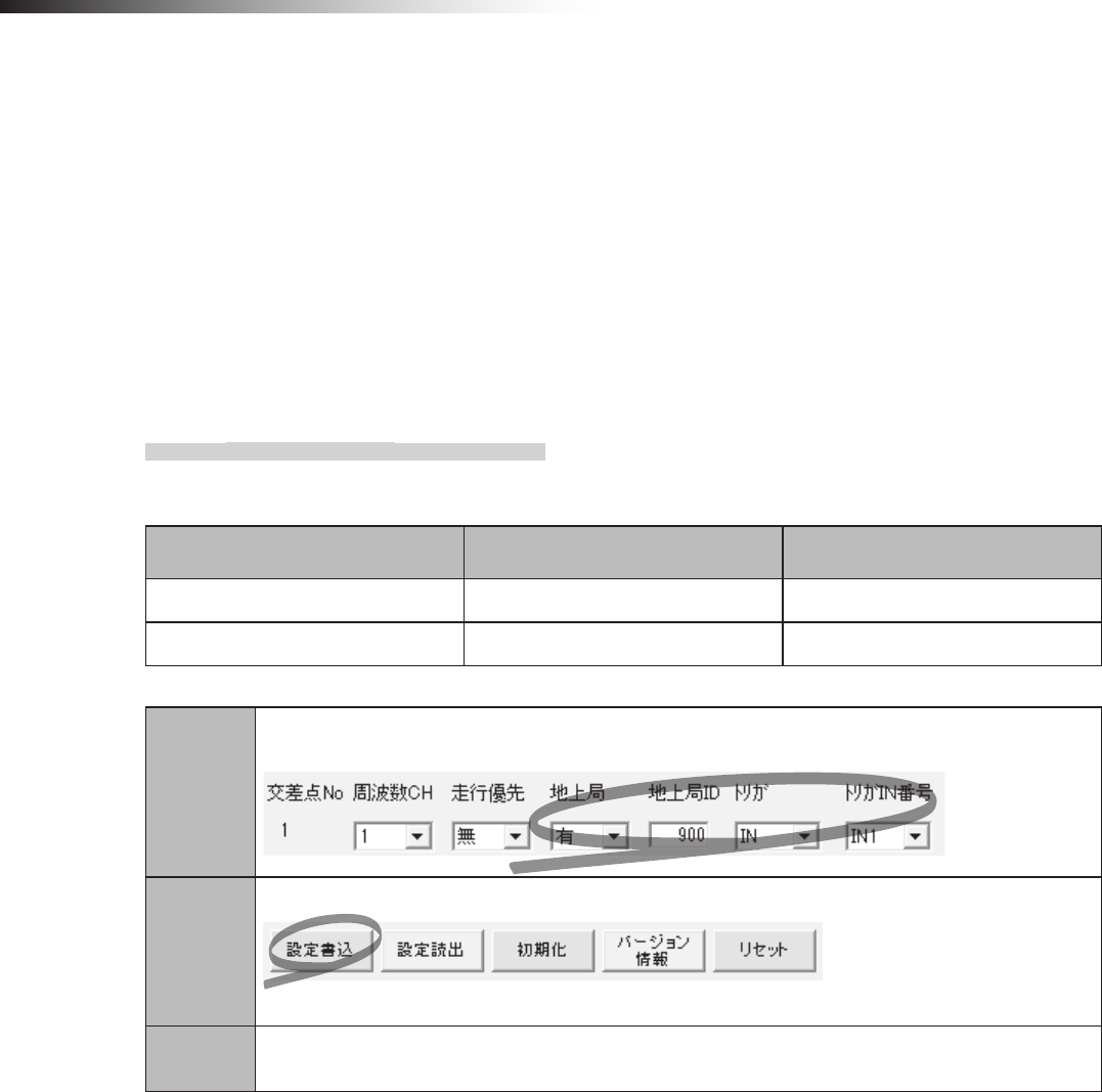
ê 10. Wireless intersection module parameter settings
- 90 -
10-8. Trigger setting
When the wireless intersection module is used in the ground station mode, IN1 to IN7 become the start permission 1
to 7 inputs. These inputs permit the approach to an intersection when the intersection control is performed using the
ground station.
To use these signals, set ON in “Trigger” and set a desired input IN1 to 7 in “Trigger IN No.” using the parameter settings
of the FCU-RC01 setup software.
Multiple trigger IN Nos. IN 1 to 7 can be specied for each ground station ID.
However, duplicate settings like IN1 is set for intersection Nos. 1 and 2 cannot be performed. At this time, it is necessary
to avoid duplicate settings like IN1 is set for intersection No. 1 and IN2 for intersection No. 2.
10-8-1. Setting example
(Example) To perform the intersection control of intersection No. 1 using the ground station (ID900) and set IN1
in “Trigger IN No.” of intersection No. 1.
Wireless Intersection Module Rotary switches RSW1 to 3
(ID setting)
Rotary switch RSW4
(Frequency)
AGV1 1 F
Ground station 900 F
Step 1
In the wireless intersection module parameter setting area of the FCU-RC01 setup software,
set as follows. Intersection No. 1, Ground station ON, Trigger IN, Trigger No. IN1.
Step 2
Click “Save settings”.
The settings are saved to AGV1 and ground station.
Step 3 Turn OFF the power to the wireless intersection module, and then turn it ON again.
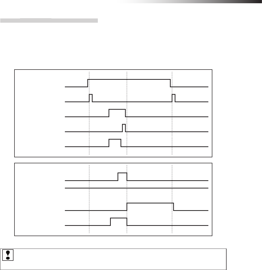
ê 10. Wireless intersection module parameter settings
- 91 -
10-8-2. Timing chart
After AGV (1) (in the address sensor mode) has arrived at intersection No. 1, it approaches to the intersection
by the start permission 1 input.
AGV (1) arrives at intersection No. 1 and waits until the start permission 1 input of ground station (1) turns ON.
For the timing to turn OFF the start permission 1 input, it is checked that the passing output turns ON, and then
the start permission 1 input is turned OFF.
Normal (wireless unit) output
Start permission 1 input
Ground station (1)
AGV arrival output
Passing output
Read-out timing input
Intersection address (1) input
AGV (1)
Start output
AGV arrival input
Stop output
When the start is permitted by the trigger at two or more intersections, the intersection judgment cannot be
performed since only one AGV arrival signal is sent from the ground station. Increase the number of ground
stations in accordance with the application.
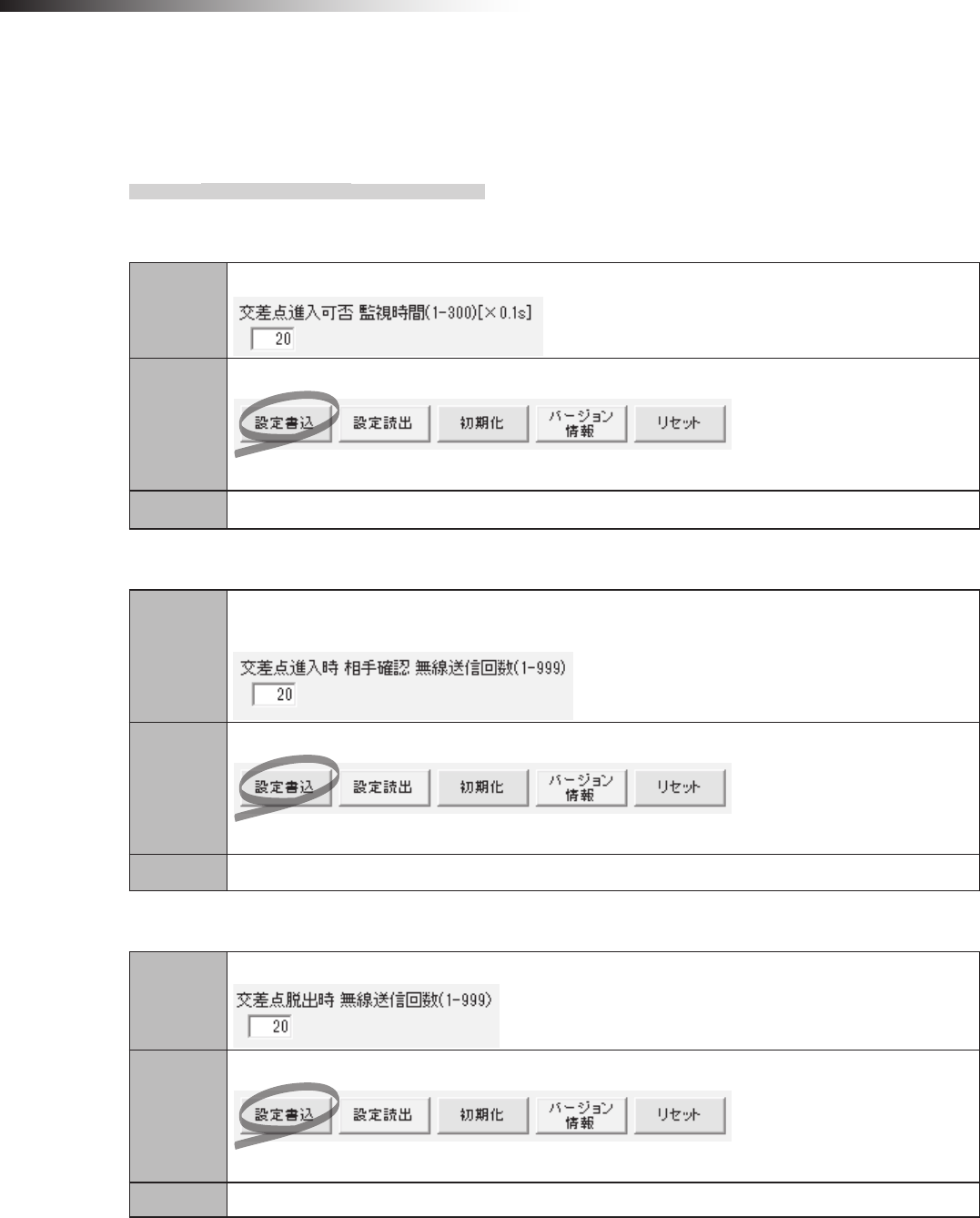
ê 10. Wireless intersection module parameter settings
- 92 -
10-9. Intersection operation setting
This setting becomes parameters to check the intersection status at approach to intersection.
Basically, use the standard values.
10-9-1. Setting example
(Example) Regarding the wireless intersection module installed on the AGV, to set 2 seconds for the monitor-
ing time for permission to approach the intersection using the settings of the personal computer.
Step 1
Set 20 in “monitoring time for permission to approach the intersection” of the FCU-RC01 setup software.
Step 2
Click “Save settings”.
The settings are saved to the wireless intersection module.
Step 3 Turn OFF the power to the wireless intersection module, and then turn it ON again.
(Example)
Regarding the wireless intersection module installed on the AGV, to set 20 for the radio transmission count for
checking the object approaching the intersection.
Step 1
Set 20 in “radio transmission count for checking the object approaching the intersection” of
the FCU-RC01 setup software.
Step 2
Click “Save settings”.
The settings are saved to the wireless intersection module.
Step 3 Turn OFF the power to the wireless intersection module, and then turn it ON again.
(Example) Regarding the wireless intersection module installed on the AGV, to set 20 for the radio
transmission count when exiting the intersection using the settings of the personal computer.
Step 1
Set 20 in “Radio transmission count when exiting the intersection” of the FCU-RC01 setup software.
Step 2
Click “Save settings”.
The settings are saved to the wireless intersection module.
Step 3 Turn OFF the power to the wireless intersection module, and then turn it ON again.
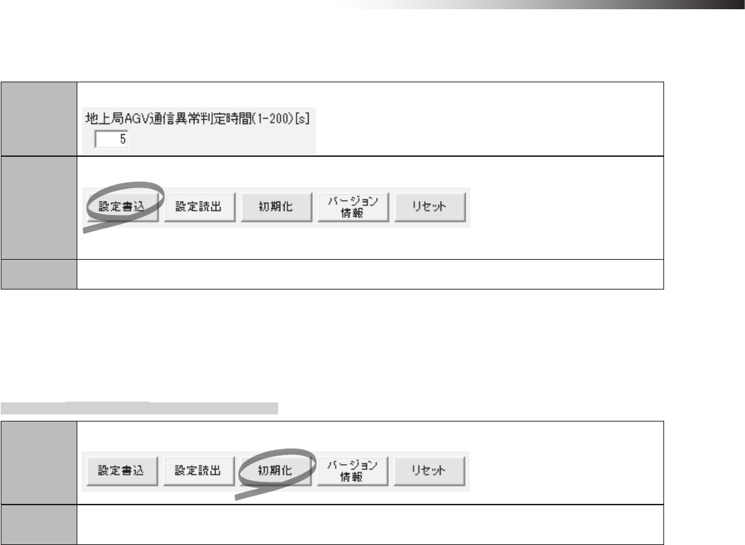
ê 10. Wireless intersection module parameter settings
- 93 -
(Example) Regarding the wireless intersection module installed on the AGV, to set 5 seconds for the ground
station AGV error judgment time using the settings of the personal computer.
Step 1
Set 5 in “Ground station AGV error judgment time” of the FCU-RC01 setup software.
Step 2
Click “Save settings”.
The settings are saved to the wireless intersection module.
Step 3 Turn OFF the power to the wireless intersection module, and then turn it ON again.
10-10. Initialization
The parameter settings of the wireless intersection module are initialized.
10-10-1. Procedures
Step 1
Click “Initialize” on the FCU-RC01 setup software.
Step 2 Turn OFF the power to the wireless intersection module, and then turn it ON again.
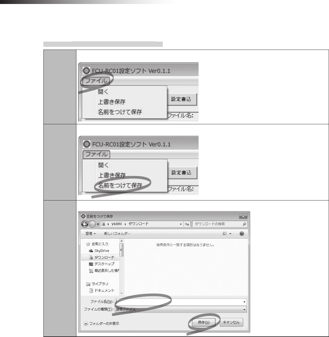
ê 10. Wireless intersection module parameter settings
- 94 -
10-11. Load or Save settings
10-11-1. Settings saving procedures
Step 1
Click “File” on the FCU-RC01 setup software.
Step 2
Click “Save as”.
Step 3
Enter a le name, and then click “Save”.
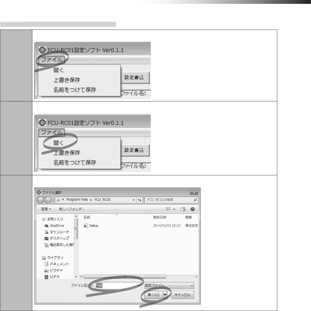
ê 10. Wireless intersection module parameter settings
- 95 -
10-11-2. Settings loading procedures
Step 1
Click “File” on the FCU-RC01 setup software.
Step 2
Click “Open”.
Step 3
Specify a le name, and then click “Open”.
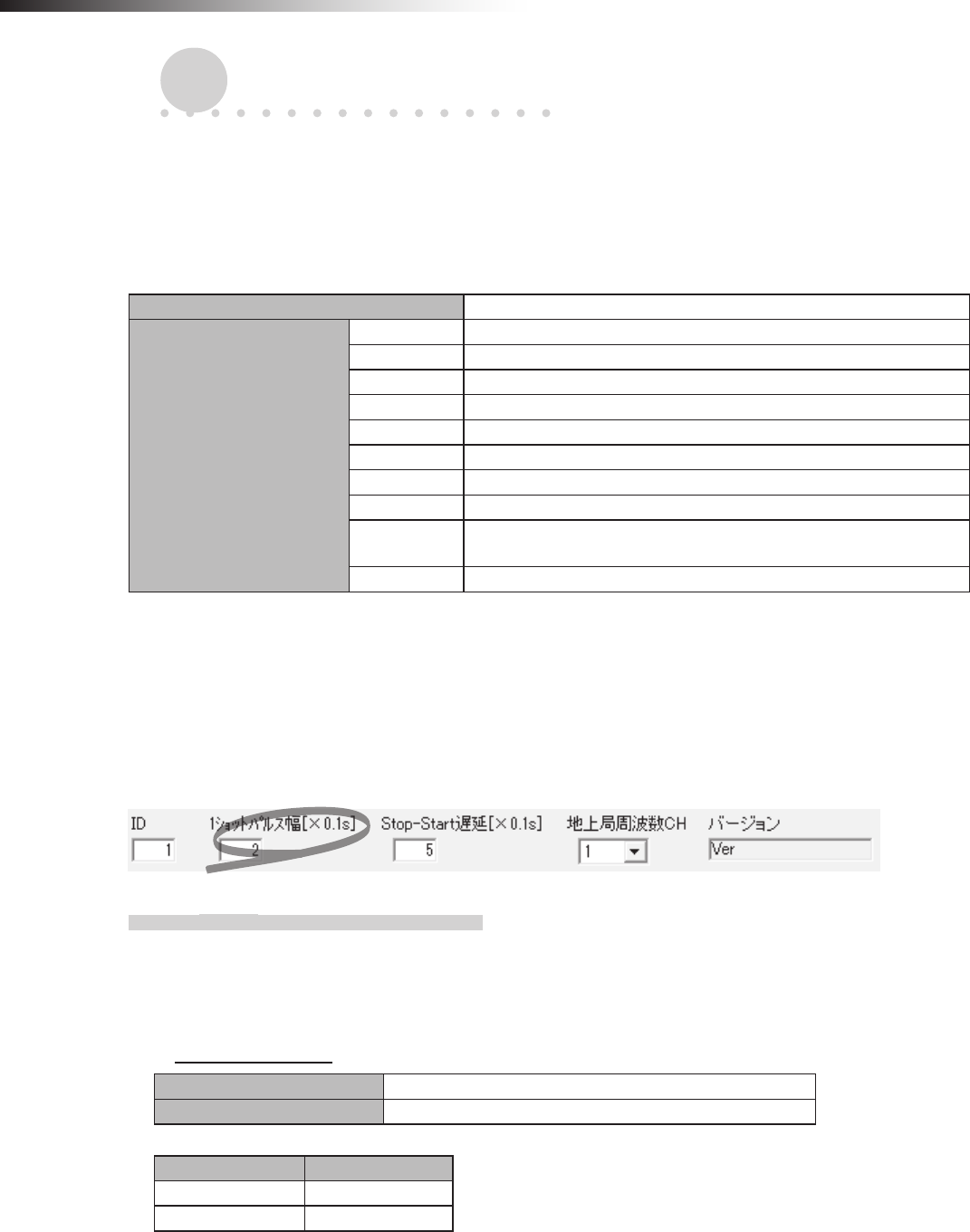
ê 11. External control mode
- 96 -
11. External control mode
The operation mode of the wireless intersection module includes an external control mode that assumes connection of
an external device such as a PLC.
11-1. Settings
It is necessary to perform the following settings on the wireless intersection module.
Usable intersection address 1 to 127
Switch settings of wireless
intersection module
SW1-1 ON
SW1-2 ON
SW1-3 OFF
SW1-4 ON or OFF
SW1-5 ON or OFF
SW1-6 OFF
SW1-7 OFF
SW1-8 OFF
RSW1 to 3 Create a unique setting for each wireless intersection module that is
not duplicated.
RSW4 Select a usable frequency band.
You can also select whether the start signal is output at a level or in one shot in the external control mode using DIP
switch SW1-4.
In the same manner, you can select whether the stop signal is output at a level or in one shot using DIP switch SW1-5.
Select either one in accordance with the programming on the external device.
The width of the one shot output can be set using the FCU-RC01 setup software.
11-1-1. Wiring
11-1-1-1. Power supply
To connect the power supply, connect the XHP-2 connector to the CN1 connector of the wireless intersection
module.
CN1 power connector
Connector S2B-XH-A connector for printed circuit board (JST)
Fitting connector XHP-2 connector for printed circuit board (JST)
Pin number Contents
1 +24 V
2 GND
∗Be sure to supply the power to the wireless intersection module through a protection circuit such as a fuse.
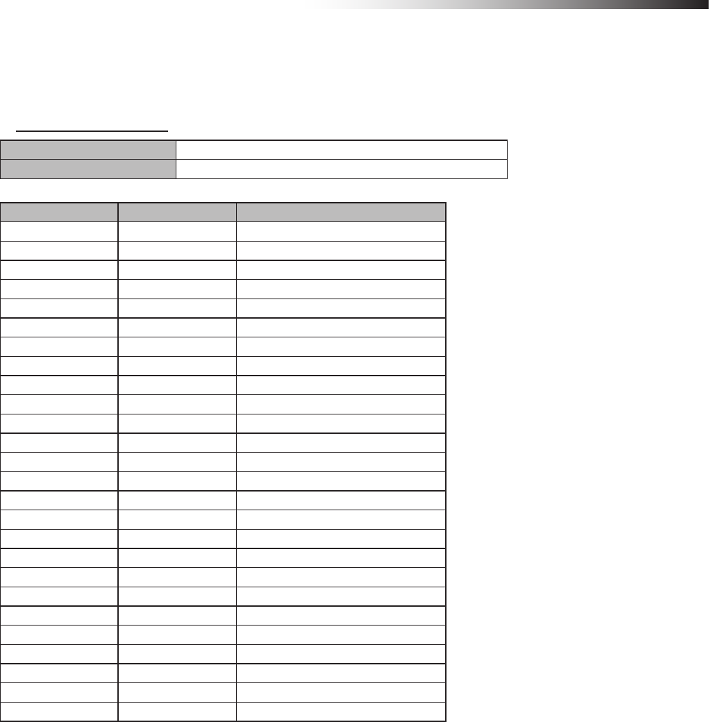
ê 11. External control mode
- 97 -
11-1-1-2. Input/output
To connect the inputs and outputs, connect the MIL 26-core female connector to the CN2 connector of the wireless
intersection module.
CN2 input/output connector
Connector MIL connector 26-core, male
Fitting connector MIL connector 26-core, female
Pin number Contents Signal
1 OUT1 Start
2 OUT2 Stop
3 OUT3 -
4 OUT4 Normal
5 OUT5 Passing
6 OUT6 -
7 IN1 Intersection address (1)
8 IN2 Intersection address (2)
9 IN3 Intersection address (4)
10 IN4 Intersection address (8)
11 IN5 Intersection address (16)
12 IN6 Intersection address (32)
13 IN7 Intersection address (64)
14 IN8 AGV error
15 IN9 Intersection inquiry
16 IN10 AGV arrival
17 IN11 Intersection top priority
18 IN12 Battery voltage drop
19 IN13 Reset
20 +24 V
21 +24 V
22 GND
23 GND
24 TxD
25 RxD
26 SGND
∗+24 V and GND of pin Nos. 20 to 23 are not designed for supplying power.
Do not use these pins for supplying power to other devices.
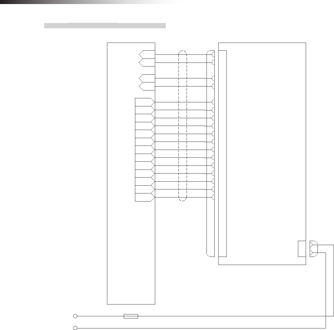
ê 11. External control mode
- 98 -
11-1-2. Wiring example
*A
+24
GND
IN1
IN2
IN3
IN4
OUT1
OUT2
OUT3
OUT4
OUT5
OUT6
OUT7
OUT8
OUT9
OUT10
OUT11
OUT12
OUT13
PLC Wireless intersection module FCU-RC01
CN2
1
2
3
4
5
6
7
8
9
10
11
12
13
14
15
16
17
18
19
20
21
22
23
24
25
26
Start output
Stop output
―
Normal (wireless unit) output
Passing output
―
Intersection address (1) input
Intersection address (2) input
Intersection address (4) input
Intersection address (8) input
Intersection address (16) input
Intersection address (32) input
Intersection address (64) input
AGV error input
Intersection inquiry input
AGV arrival input
Intersection top priority input
Battery voltage drop input
Reset input
+24
+24
GND
GND
TxD
RxD
SGND
1
2
CN1
+24
GND
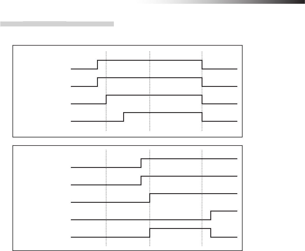
ê 11. External control mode
- 99 -
11-1-3. Flow of control
11-1-3-1. AGV (1) passes through the intersection and AGV (2) waits.
Intersection address (2) input
Intersection address (1) input
AGV (1)
Start output
Intersection inquiry input
Intersection address (2) input
Intersection address (1) input
AGV (2)
Start output
Intersection inquiry input
Stop output
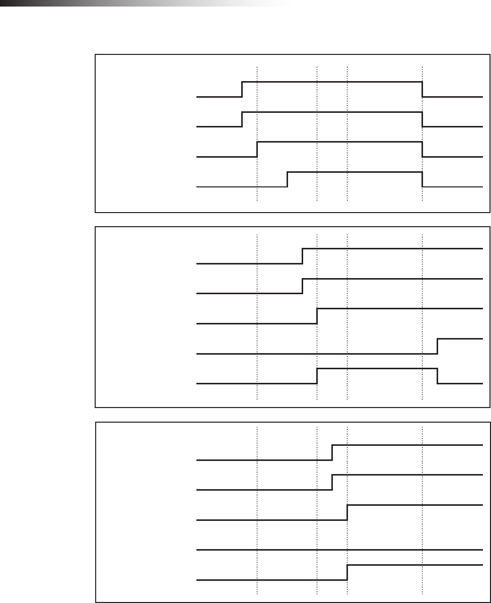
ê 11. External control mode
- 100 -
11-1-3-2. AGV (3) waits while AGV (1) is passing and AGV (2) is waiting.
Intersection address (2) input
Intersection address (1) input
AGV (1)
Start output
Intersection inquiry input
Intersection address (2) input
Intersection address (1) input
AGV (2)
Start output
Intersection inquiry input
Stop output
Intersection address (2) input
Intersection address (1) input
AGV(3)
Start output
Intersection inquiry input
Stop output
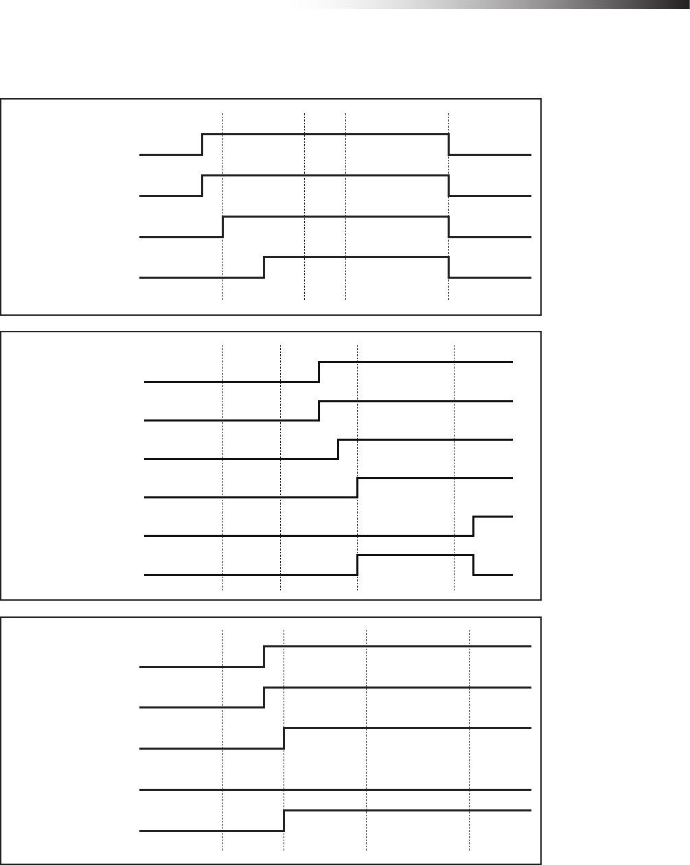
ê 11. External control mode
- 101 -
11-1-3-3. AGV (2) waits with the intersection top priority input turned ON while AGV (1) is passing and
AGV (3) is waiting.
Intersection address (2) input
Intersection address (1) input
AGV (1)
Start output
Intersection inquiry input
Intersection address (2) input
Intersection address (1) input
AGV (2)
Start output
Intersection top priority input
Stop output
Intersection address (2) input
Intersection address (1) input
AGV(3)
Start output
Intersection inquiry input
Stop output
Intersection inquiry input
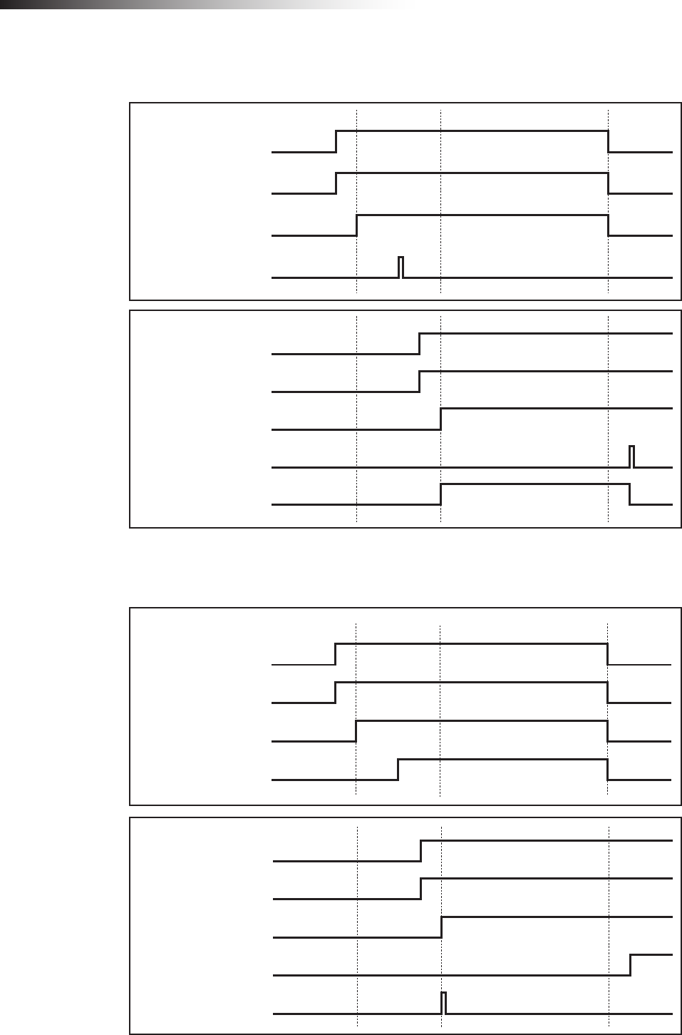
ê 11. External control mode
- 102 -
11-1-3-4. AGV (1) passes through the intersection, AGV (2) waits, and SW1-4 of each wireless inter-
section module is turned ON.
Intersection address (2) input
Intersection address (1) input
AGV (1)
Start output
Intersection inquiry input
Intersection address (2) input
Intersection address (1) input
AGV (2)
Start output
Intersection inquiry input
Stop output
11-1-3-5. AGV (1) passes through the intersection, AGV (2) waits, and SW1-5 of each wireless inter-
section module is turned ON.
Intersection address (2) input
Intersection address (1) input
AGV (1)
Start output
Intersection inquiry input
Intersection address (2) input
Intersection address (1) input
AGV (2)
Start output
Intersection inquiry input
Stop output

ê 15-1. Warranty period
- 103 -
12. Caution
• When the power is turned OFF, and then turned ON again, the intersection information of the wireless intersec-
tion module is initialized.
• The waiting wireless intersection module cannot check the communication of the wireless intersection module
that is passing through the intersection. The waiting wireless intersection module enters the passing status upon
completion of checking specied by the monitoring time for permission to approach the intersection and radio
transmission count for checking the object approaching the intersection.
• The intersection address is not retained when the power is turned OFF before the AGV is stopped by the
command or count after the intersection address has been recognized by the address sensor or RFID antenna.
It is necessary to travel the AGV again before the intersection address is recognized.
• Regardless of AGV traveling or stopping, when the intersection address is recognized by the address sensor or
RFID antenna, the wireless intersection module recognizes that the intersection has been detected. Therefore,
turn OFF the power when moving the AGV manually.
13. Contents of warranty
13-1. Warranty period
The warranty period of this product is one year after delivery to the specied location.
Note that consumables and auxiliary materials such as batteries or lamps are not covered by the warranty.
For repairs outside the warranty period, when repairing the product can maintain normally usable functions, the product
is repaired on a chargeable basis as required. (We may not be able to grant the request due to discontinuance of the
repair part manufacture after the warranty period.)
13-2. Warranty coverage
If any defect due to our faulty design or poor workmanship is found during the warranty period, we shall repair the
defective parts free of charge.
However, the coverage of this warranty does not include the following terms.
1. Defects arising from improper handing such as dropping during transportation or relocation after the
delivery.
2. Defects arising from connection with an option other that those specied by our company.
3. Defects arising from improper repair, adjustment, or modication.
4. Defects arising from operation exceeding the specication range.
5. Defects arising from re, act of God, or natural disasters.
Note that this warranty covers only the single delivery product and does not cover incidental or consequential damages
resulting from operation or malfunction of the delivered product.
The contents shown above are based on the premise that the product is operated in Japan.

ê 16-1. Notes
- 104 -
14. Others
14-1. Precautions
The Drive Unit is a registered trademark of Yazaki Kako Corporation.
When installing a Drive Unit AGV, take safety measures in accordance with your required safety policy or stan-
dards.
It is prohibited to modify or redistribute this manual.
The product specications and other description contents are subject to change without prior notice.
14-2. Contacts
Yazaki Kako Corporation
24-1, Oshika 2-chome, Suruga-ku
Shizuoka-City, Shizuoka-Pref., 422-8519 Japan
URL: http://www.yazaki.co.jp/
U.S.A CREFORM Corporation TEL: +1-864-989-1700
GERMANY CREFORM Technik GmbH TEL: +49(0)561-475-967-0
THAILAND CREFORM yazaki (THAILAND) CO., LTD. TEL: +66(0)2516-4812
FEDERAL COMMUNICATIONS COMMISSION INTERFERENCE
STATEMENT
This equipment has been tested and found to comply with the limits for a Class B digital device, pursuant to part
15 of the FCC Rules. These limits are designed to provide reasonable protection against harmful interference in a
residential installation. This equipment generates, uses and can radiate radio frequency energy and, if not installed
and used in accordance with the instructions, may cause harmful interference to radio communications. However,
there is no guarantee that interference will not occur in a particular installation. If this equipment does cause harmful
interference to radio or television reception, which can be determined by turning the equipment off and on, the user
is encouraged to try to correct the interference by one or more of the following measures:
-Reorient or relocate the receiving antenna.
-Increase the separation between the equipment and receiver.
-Connect the equipment into an outlet on a circuit different from that to which the receiver is connected.
-Consult the dealer or an experienced radio/ TV technician for help.
This device complies with Part 15 of the FCC Rules. Operation is subject to the following two conditions:
(1) this device may not cause harmful interference, and
(2) this device must accept any interference received, including interference that may cause undesired operation.
RF exposure warning
This equipment must be installed and operated in accordance with provided instructions and the antenna(s) used
for this transmitter must be installed to provide a separation distance of at least 20 cm from all persons and must
not be co-located or operating in conjunction with any other antenna or transmitter. End-users and installers must
be provide with antenna installation instructions and transmitter operating conditions for satisfying RF exposure
compliance.
This radio transmitter FCCID: 2ANXXFCU-RC01 has been approved by FCC to operate with the antenna types
listed below with the maximum permissible gain and required antenna impedance for each antenna type indicated.
Antenna types not included in this list, having a gain greater than the maximum gain indicated for that type, are
strictly prohibited for use with this device.
中文說明
經型式認證合格之低功率射頻電機,非經許可,公司、商號或使用者均不得擅自變更頻率、加大功率或變
更原設計之特性及功能。
低功率射頻電機之使用不得影響飛航安全及干擾合法通信;經發現有干擾現象時,應立即停用,並改善至
無干擾時方得繼續使用。前項合法通信,指依電信法規定作業之無線電通信。低功率射頻電機須忍受合法
通信或工業、科學及醫療用電波輻射性電機設備之干擾。
CAUTION:
Any changes or modications not expressly approved by the grantee of this device could void the user’s
authority to operate the equipment.
17121805
DL-139-03