York D2Ce D2Cg Owners Single Package Gas/elec Units & Air Conditioners User Manual
D2Ce-Users-Manual york-d2ce-users-manual-455066
D2CG to the manual af3dbdbc-9289-41b0-b59e-2647dd4b7fc0
2014-08-26
User Manual: York D2Ce-D2Cg-Owners
Open the PDF directly: View PDF ![]() .
.
Page Count: 24

®
SINGLE PACKAGE
GAS / ELECTRIC UNITS AND
SINGLE PACKAGE AIR CONDITIONERS
D2CE / D2CG 300 CONSTANT VOLUME
25 NOMINAL TONS
8.5 EER
SUNLINE 2000 ™
036-21359-001-B-0302
FOR DISTRIBUTION USE ONLY - NOT TO BE USED AT POINT OF RETAIL SALE
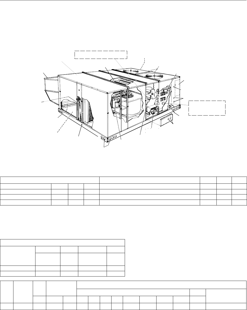
DESCRIPTION
Sunline™ 2000 series convertible package rooftop mod-
els have two independent refrigerant circuits for efficient
part load operation. Although the units are primarily
designed for curb mounting on a roof, they can also be
slab-mounted at ground level or set on steel beams above
a finished roof.
Cooling only, cooling with gas heat and cooling with electric
heat models are available with a wide variety of factory-
mounted options and field-installed accessories to make
them suitable for almost every application.
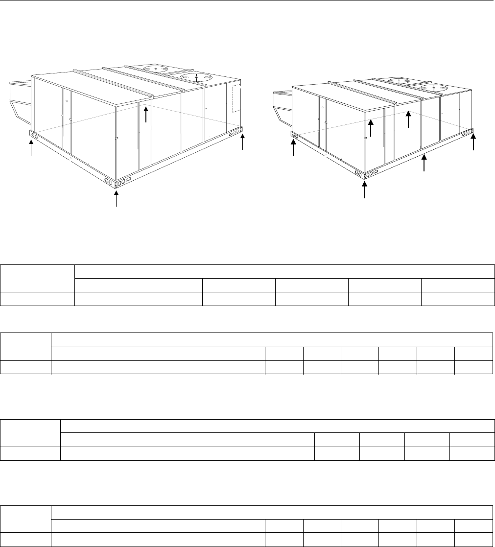
All units are self-contained and assembled on full perimeter
base rails with holes in the four corners for overhead
rigging.
Every unit is completely piped, wired, charged and tested
at the factory to simplify field installation and to provide
years of dependable operation. Powder paint cabinets pro-
vide an exceptionally durable finish with the 750 hour salt
spray process per ASTM-B117 test standard.
All models (including those with an economizer) are suit-
able for either bottom or horizontal duct connections. Mod-
els with power exhaust are suitable for bottom duct
connections only. For bottom duct, you remove the sheet
metal panels from the supply and return air openings
through the base of the unit. For horizontal duct, you
replace the supply and return air panels on the rear of the
unit with a side duct flange accessory.
All models are available with five different outdoor air
damper options:
• Single enthalpy economizer
• Differential (dual) enthalpy economizer
• Single enthalpy economizer with power exhaust
• Differential (dual) enthalpy economizer with
power exhaust
• Motorized outdoor air damper
A fixed outdoor air intake assembly is shipped in the return
air compartment of all units ordered without an economizer
or motorized outdoor air damper option. The assembly
includes a rain hood with a damper that can be set for 10,
15 or 25% outdoor air. With bottom duct connections, the
intake damper assembly should be mounted over the
opening in the return air panel. With horizontal ductwork, it
should be mounted on the return air duct.
Technical Guide

036-21359-001-B-0302
2Unitary Products Group
All supply air blowers are equipped with a belt drive
that can be adjusted to meet the exact requirements of
the job. A high speed drive accessory is available for
applications with a higher CFM and/or static pressure
requirement.
All compressors include internal pressure relief. Every
refrigerant circuit includes an expansion valve, a liquid
line filter-drier, a discharge line high pressure switch
and a suction line with a freezestat and low pressure/
loss of charge switch. The unit control circuit includes
two 75 VA transformers, two 24-volt circuit breakers
and a relay board with two compressor lockout circuits,
a terminal strip for thermostat wiring, plus an additional
set of pin connectors to simplify the interface of addi-
tional field controls.
All 208/230 and 460-volt models are ETL approved. All
208/230 and 575-volt models are CGA approved.
All models include a 1-year limited warranty on the
complete unit. Compressors and electric heater ele-
ments carry an additional 4-year warranty. Aluminized
steel tubular heat exchangers carry an additional 9-
year warranty.
All gas heat models are built with two heating sections
for two equal stages of capacity control. Each section
includes a durable heat exchanger with aluminized
steel tubes, a redundant gas valve, spark ignition,
power venting, an ignition module for 100% shut-off
and all of the safety controls required to meet the latest
ANSI standards.
The gas supply piping can be routed into the heating
compartment through a hole in the base pan of the unit
or through a knockout in the piping panel on the front of
the unit.
All electric heat models are wired for a single power
source and include a bank of nickel chromium ele-
ments mounted at the discharge of the supply air
blower to provide a high velocity and uniform distribu-
tion of air across the heating elements. Every element
is fully protected against excessive current and temper-
ature by fuses and two thermal limit switches.
The power supply wiring can be routed into the control
box through a threaded pipe connection in the base
pan of the unit or through a knockout in the wiring
panel on the front of the unit.
All internal factory wiring is color coded and numbered
for ease in servicing and troubleshooting.
FACTORY-INSTALLED OPTIONS
ECONOMIZERS
Interlocked outdoor and return air dampers are posi-
tioned by a fully modulating, spring return damper actu-
ator capable of introducing up to 100% outdoor air with
nominal 1% leakage type dampers. As the outdoor air
intake dampers open, the return air dampers close.
The changeover from compressor to economizer cool-
ing is determined by one or two solid state enthalpy
controls.
On single enthalpy, an outdoor air sensor determines
when the outdoor air is cool and dry enough to provide
“free” cooling. On differential enthalpy, one sensor
monitors the outdoor air while a second sensor moni-
tors the return air. Whenever the outdoor air is cooler
and drier than the return air, the unit will switch to econ-
omizer operation. For either option, the first compres-
sor stage can provide additional cooling during
economizer operation if the room thermostat calls for
second stage.
The dampers and controls are installed and wired at
the factory. Only the accessory rain hood needs to be
assembled and installed in the field.
These economizer options can be used on all duct con-
figurations.
POWER EXHAUST
Both the single and differential economizer options are
available with power exhaust. Whenever the outdoor
air intake dampers are opened for free cooling, the
exhaust fan will be energized to prevent the condi-
tioned space from being over-pressurized during econ-
omizer operation.
The exhaust fan, motor and controls are installed and
wired at the factory. Only the back-draft damper
assembly needs to be field installed and the accessory
rain hoods need to be assembled and installed in the
field.
The power exhaust option can only be used on bottom
duct configurations.
MOTORIZED OUTDOOR AIR INTAKE DAMPER
Interlocked outdoor and return air dampers are con-
trolled by a 2-position, spring return damper actuator.
The outdoor damper will open to some pre-set position
whenever the supply air blower is operating and will
drive fully closed when the blower shuts down.
The damper and controls are installed and wired at the
factory. Only the accessory rain hood needs to be
assembled in the field.
This damper option can be used on all duct configura-
tions.
036-21359-001-B-0302
Unitary Products Group 3
FIELD-INSTALLED ACCESSORIES
SINGLE INPUT ELECTRONIC ENTHALPY
ECONOMIZERS
Includes a slide-in/plug-in damper assembly with fully
modulating spring-return monitor actuator capable of
introducing up to 100% outdoor air with nominal 1%
leakage type dampers.
The enthalpy system contains one sensor that
monitors the outdoor air and determines when the air is
cool enough and dry enough to provide “free” cooling.
The rainhood is painted to match the basic unit and
must be field-assembled before installing.
Power exhaust is not available as a field installed
option.
DUAL INPUT ELECTRONIC ENTHALPY
ECONOMIZERS
Includes a slide-in / plug-in damper assembly with fully
modulating spring-return monitor actuator capable of
introducing up to 100% outdoor air with nominal 1%
leakage type dampers.
This enthalpy system contains one sensor that moni-
tors the outdoor air and one sensor that monitors the
return air. The logic module compares these two val-
ues and modulates the dampers providing the maxi-
mum efficiency of economizer system.
The rainhood is painted to match the basic unit and
must be field-assembled before installing.
Power exhaust is not available as a field installed
option.
MOTORIZED OUTDOOR AIR INTAKE DAMPER
Includes a slide-in/plug-in damper assembly with a
2-position, spring return motor actuator which opens to
some pre-set position whenever the supply air blower
is operating and will drive fully closed when the blower
unit shuts down.
The rain hood is painted to match the basic unit and
must be field assembled before installing.
Power exhaust is not available as a field installed
option.
ROOF CURBS
Fourteen inch high roof curbs provide a water-tight seal
between the unit and the finished roof. These full
perimeter curbs meet the requirements of the National
Roofing Contractors Association (NRCA) and are
shipped knocked-down for field assembly. They're
designed to fit inside the base rails of the unit and
include both a wood nailing strip and duct hanger sup-
ports.
ANTI-RECYCLE TIMERS
Two solid state timers prevent the compressors from
short-cycling. Once a compressor is de-energized, it
will remain de-energized for approximately five min-
utes.
HIGH ALTITUDE NATURAL GAS
Burner orifices and pilot orifices are provided for proper
furnace operation at altitudes up to 6,000 feet.
PROPANE
Burner orifices, pilot orifices and gas valve parts are
provided to convert a natural gas furnace to propane.
HIGH ALTITUDE PROPANE
Burner orifices and pilot orifices are provided for proper
furnace operation at altitudes up to 6,000 feet. This
accessory supplements the basic propane conversion
kit.
SIDE DUCT FLANGES
One inch flanges replace the supply and return air pan-
els on the rear of the unit to accommodate horizontal
duct connections. These flanges can also be used indi-
vidually for bottom supply/horizontal return or horizon-
tal supply/bottom return. They cannot be used on units
with power exhaust.
BAROMETRIC RELIEF DAMPER
This damper accessory can be used to relieve internal
air pressure on units with an economizer but no power
exhaust. This accessory includes a rain hood, a bird
screen and a fully assembled damper. With bottom
duct connections, the damper should be mounted over
the opening in the return air panel. With horizontal
ductwork, the accessory should be mounted on the
return air duct.
ECONOMIZER / POWER EXHAUST RAIN HOODS
A rain hood accessory must be used on units with an
economizer, a motorized damper, or a combined econ-
omizer with power exhaust option. These accessories
include all the hood panels, the necessary components
and hardware for field assembly.
HIGH SPEED DRIVE
A smaller blower pulley and a shorter belt increase the
speed of the supply air blower for applications with a
higher CFM and/or static pressure requirement.
LOW AMBIENT CONTROLS TO 0°F
An autotransformer and a thermostat maintain stable
system operation by reducing the speed of the con-
denser fan motor at low outdoor temperatures. The kit
036-21359-001-B-0302
4Unitary Products Group
also includes a 1-phase motor to replace the unit's
standard 3-phase condenser fan motor. Standard units
can operate down to 45°F.
COIL GUARD KIT
Provides coil guard and fastners.
Note: All gas units are two-stage heating. First stage is 50% of total.
All models are 80% Steady State Efficiency (S.S.E.).
NOTE: These values have been derived using a model of sound propagation,
measuring the indoor ambient sound levels ten feet from the source. The dBA
values provided are for reference only. Calculation of dBA values cover matters
of system design and application. This constitutes an exception to any specifi-
cation or guarantee requiring a dBA value or sound data in any other form than
sound power level ratings.
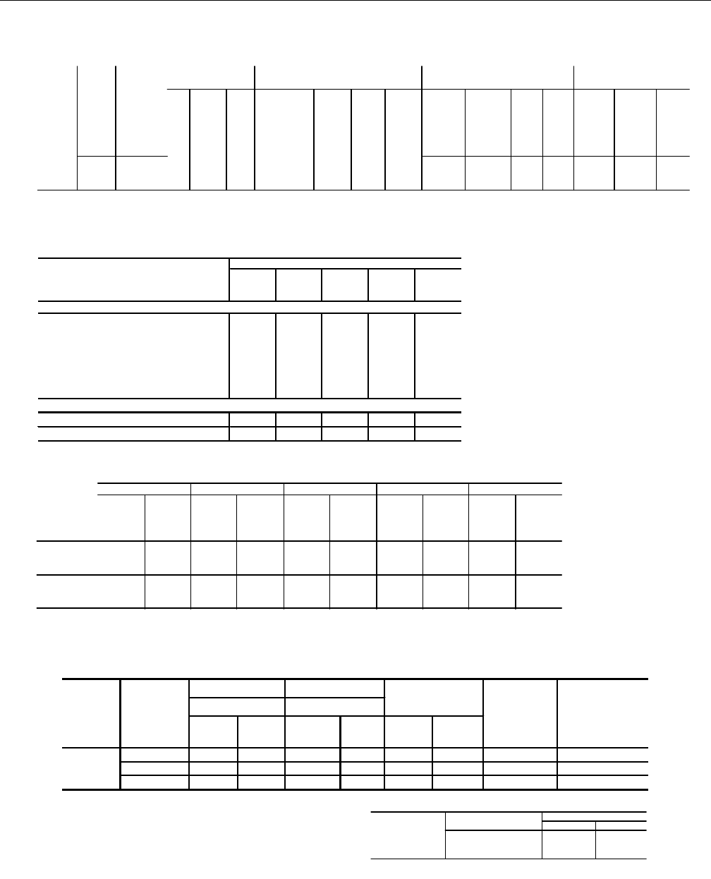
CAPACITY RATINGS - (ARI 360)*
MODEL MBH EER IPLV MODEL MBH EER IPLV
COOLING WITH GAS HEAT COOLING WITH ELECTRIC HEAT
D2CG300N240 290 8.5 8.3 D2CE300E018 290 8.5 8.6
D2CG300N320 290 8.5 8.3 D2CE300E036 290 8.5 8.6
COOLING ONLY D2CE300E054 287 8.5 8.2
D2CE300 290 8.5 8.7 D2CE300E072 284 8.5 8.2
*. Outside the scope of ARI Standard 340/360.
EER=Energy Efficiency Rating at full load-the cooling capacity in Btu’s per hour (Btuh) divided by the power input in watts, expressed in Btuh per
watt (Btuh/watt).
IPLV - Integrated part load value.
NOTE: All cooling is three stage.
LONG LASTING
POW DER PAINT FINISH
FULL PERIM ETER 14 G UAGE BASE
R A IL S W IT H L IF T IN G H O L E S
NPT
T E R M IN A L B L O C K
(For Single P oint P ow er S upply
w ith E le c tric H e a t)
ELECTRIC/ELECTRIC UNITS
ELECTR IC HEATER LO C ATIO N
(O P T IO N A L E L E C T R IC /E L E C T R IC U N IT S )
I
20 G AUG E ALUM INIZED STEEL
TUBULAR HEAT EXCHANGERS
ECONOMIZER HOOD
2" DISPO SABLE
FILTER S
O
UTDOOR AIR OPENING
FO R SLIDE-IN/PLUG-IN
INTERNAL ECONOMIZER (OPTION)
SID E AN D BO TTO M
SUPPLY & RETURN AIR
D U C T O P E N IN G S (S ID E X S ID E )
1" N P TI
CONDENSATE DRAIN BELT-DRIVE
BLOW ER MOTOR
POW ER VENTOR M O TOR
W ITH POST PURGE CYCLE
HOLE FOR BOTTOM
GAS SUPPLY ENTRY
KNO CKOUTS FOR SIDE
GAS SUPPLY ENTRY
BOTTOM POW ER & CONTROL
W IRING ENTRY
KNOCKOUT FOR
S ID E P O W E R W IR IN G E N T R Y S ID E
KNOCKOUT FOR
S ID E C O N T R O L W IR IN G E N T R Y
ELECTRICAL DISCO NNECT
M O U N T IN G L O C A T IO N
(F ie ld in s ta lle d )
LO W VOLTAGE RELAY BOARD
A N D T E R M IA N L S T R IP
COPPER TUBE/ALUM INUM FIN
CONDENSER COILS
HIGH EFFICIENCY SCROLL COM PRESSORS
GAS HEAT RATINGS
MODEL
MBH Input MBH Output
Stage
1&2 Stage 1 Stage
1&2 Stage 1
D2CG300N240 300 150 240 120
D2CG300N320 400 200 320 160
Unit
Size CFM
)
ESP Blower Sound Power (db 10-12 Watts)
Octave Band Centerline Frequency (Hz) SWL db(A)
@10Ft.
*
IWG RPM BHP 63 125 250 500 1,000 2,000 4,000 8,000 db(A)
300 10,000 1.30 1,160 12.5 108 108 98 91 93 86 81 76 98 65
*. At a distance of 10 ft.from the blower.
036-21359-001-B-0302
Unitary Products Group 5
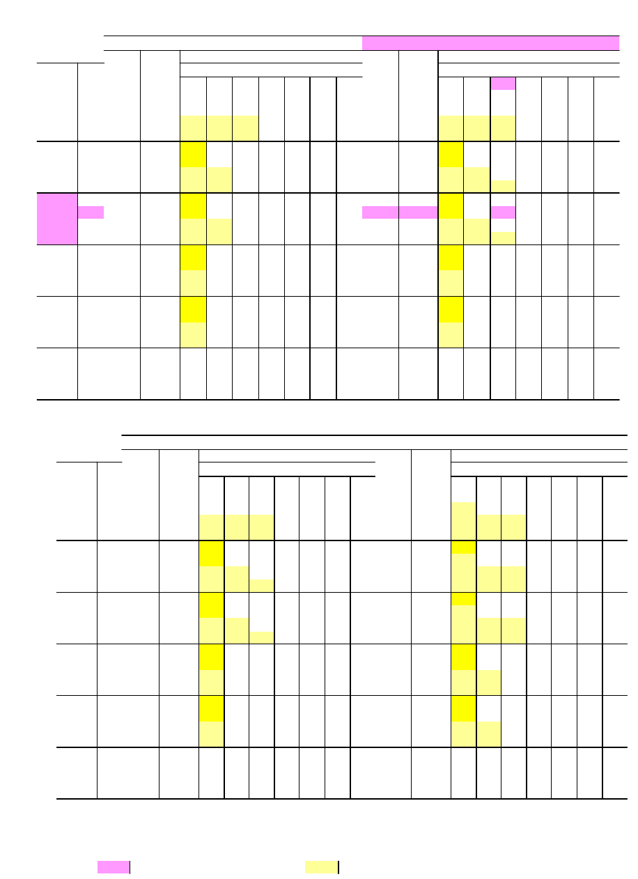
COOL ING CA PACI TIES -
25 TON (DCE / DCG300)
Air On
Evapo ra tor
Coil
Tem pera ture of Air on Con denser Coil
85?F95?F
To tal
Cap.
1
MBH
Power
In put
2
KW
Sen si ble Ca pac ity
1
, MBH To tal
Cap.
1
MBH
Power
In put
2
KW
Sen si ble Ca pac ity
1
, MBH
CFM WB
?F
En ter ing Dry Bulb, ?F En ter ing Dry Bulb, ?F
86 83 80 77 74 71 68 86 83 80 77 74 71 68
12,000
72 371 27.1 277 240 203 167 130 - - 354 28.8 268 231 195 158 122 - -
67 340 26.1 335 299 262 226 189 152 116 325 27.7 324 288 251 214 178 141 105
62 329 25.5 329 329 329 293 256 219 183 315 27.1 315 315 315 278 241 205 168
57 329 25.5 329 329 329 292 256 219 183 314 27.1 314 314 314 278 241 205 168
11,000
72 365 27.0 260 226 193 159 125 - - 348 28.6 257 223 189 155 122 - -
67 336 25.9 317 283 249 216 182 148 114 321 27.5 312 279 245 211 178 144 110
62 324 25.3 324 324 313 279 245 212 178 309 26.9 309 309 307 273 239 206 172
57 324 25.3 324 324 315 281 247 214 180 309 26.9 309 309 309 275 242 208 174
10,000
72 359 26.8 244 213 182 151 120 - - 342 28.5 245 214 184 153 122 - -
67 332 25.7 298 268 237 206 175 144 113 317 27.4 301 270 239 208 177 146 115
62 318 25.2 318 318 296 265 235 204 173 304 26.8 304 304 299 268 237 207 176
57 318 25.1 318 318 301 270 239 208 177 304 26.7 304 304 304 273 242 211 180
9,000
72 354 26.6 229 201 173 145 117 - - 338 28.2 228 200 172 144 116 - -
67 326 25.5 280 252 224 196 168 141 113 312 27.1 279 251 223 195 167 139 111
62 314 25.0 314 306 282 254 226 198 170 300 26.5 300 295 280 253 225 197 169
57 314 25.0 314 308 286 258 230 203 175 300 26.5 300 297 285 257 229 201 173
8,000
72 349 26.4 215 190 165 140 115 - - 334 28.0 211 186 161 136 111 - -
67 321 25.3 262 237 212 187 162 137 112 307 26.9 257 232 207 182 157 132 107
62 310 24.8 310 293 268 243 218 193 168 297 26.3 297 287 262 237 212 187 162
57 310 24.8 310 297 272 247 222 197 172 297 26.3 297 291 266 241 216 191 166
6,000
72 318 25.2 186 167 148 129 110 - - 304 26.8 177 158 138 119 100 - -
67 290 24.0 226 206 187 168 149 130 111 277 25.5 213 194 175 156 137 118 99
62 282 23.7 277 258 240 221 201 192 163 270 25.2 262 243 225 206 187 167 148
57 282 23.7 281 262 243 224 205 186 167 270 25.2 266 247 228 209 190 171 152
Air On
Evapo ra tor
Coil
Tem pera ture of Air on Con denser Coil
105?F 115?F
To tal
Cap.
1
MBH
Power
In put
2
KW
Sen si ble Ca pac ity
1
, MBH To tal
Cap.
1
MBH
Power
In put
2
KW
Sen si ble Ca pac ity
1
, MBH
CFM WB
?F
En ter ing Dry Bulb, ?F En ter ing Dry Bulb, ?F
86 83 80 77 74 71 68 86 83 80 77 74 71 68
12,000
72 337 30.7 264 228 191 155 118 - - 320 32.6 261 224 188 151 114 - -
67 310 29.5 309 283 246 210 173 137 100 294 31.3 294 278 242 205 169 132 95
62 300 28.8 300 300 300 263 226 190 153 285 30.5 285 285 285 248 212 175 138
57 299 28.8 299 299 299 263 226 190 153 285 30.5 285 285 285 248 211 175 138
11,000
72 331 30.5 254 221 187 153 119 - - 315 32.3 252 218 185 151 117 - -
67 306 29.3 302 276 242 208 174 141 107 291 31.0 291 273 239 205 171 138 104
62 295 28.5 295 295 294 260 226 192 159 280 30.3 280 280 280 246 213 179 145
57 294 28.5 294 294 294 261 227 193 160 280 30.3 280 280 280 246 213 179 145
10,000
72 326 30.2 244 213 183 152 121 - - 310 32.1 243 212 181 151 120 - -
67 302 29.0 294 268 237 206 176 145 114 287 30.8 287 267 236 205 174 143 112
62 290 28.3 290 290 287 256 226 195 164 276 30.0 276 276 276 245 214 183 152
57 290 28.2 290 290 290 259 228 197 166 275 29.9 275 275 275 244 214 183 152
9,000
72 322 30.0 228 200 172 144 116 - - 306 31.8 228 200 172 144 116 - -
67 297 28.8 276 251 223 195 167 139 111 283 30.5 274 251 223 195 167 139 111
62 286 28.1 286 284 271 243 215 187 159 272 29.8 272 272 262 234 206 178 150
57 286 28.1 286 285 273 245 217 189 161 272 29.7 272 272 261 234 206 178 150
8,000
72 319 29.8 212 187 162 137 112 - - 303 31.6 213 188 163 138 113 - -
67 293 28.6 259 234 209 184 159 134 109 278 30.3 260 235 210 185 160 135 110
62 283 28.0 283 278 255 230 205 180 155 269 29.6 269 269 248 223 198 173 148
57 283 28.0 283 280 257 232 207 182 157 269 29.6 269 269 248 223 198 173 148
6,000
72 290 28.3 180 161 141 122 103 - - 276 30.0 183 164 145 125 106 - -
67 264 26.9 224 200 181 162 142 123 104 251 28.5 222 203 194 165 146 127 108
62 258 26.6 258 241 223 204 184 165 146 245 28.2 245 239 220 201 182 163 144
57 258 26.6 258 242 224 205 186 167 148 245 28.2 245 240 221 202 182 163 144
1These ca paci ties are gross rat ings. For net ca pac ity, de duct the heat of the sup ply air blower mo tor, MBH = 3.415 x KW. Ref er to the ap pro pri ate Blower
Per form ance Ta ble for the KW of the sup ply air blower mo tor.
2These rat ings in clude the con denser fan mo tors (To tal 2.3 KW) and the com pres sor mo tors but not the sup ply air blower mo tor.
All Sen si ble Ca pac ityNomi nal Rat ing
036-21359-001-B-0302
6Unitary Products Group
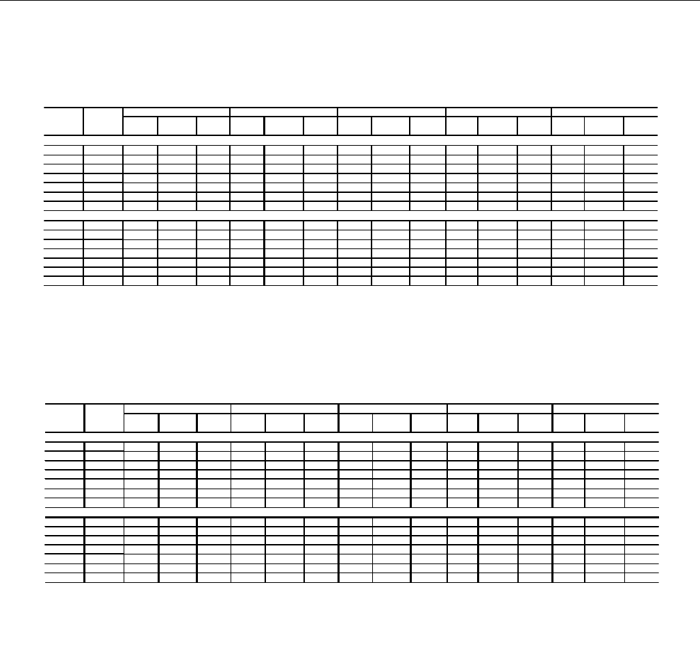
BLOWER PER FORM ANCE - 25 TON (DCE/DCG300)
BLOWER PULLEY
SPEED TURNS ESP OUTPUT INPUT ESP OUTPUT INPUT ESP OUTPUT INPUT ESP OUTPUT INPUT ESP OUTPUT INPUT
(rpm) OPEN: (iwg) (bhp) (kW) (iwg) (bhp) (kW) (iwg) (bhp) (kW) (iwg) (bhp) (kW) (iwg) (bhp) (kW)
975 6.0* 1.4 5.9 4.9 1.0 7.3 6.0 0.5 8.8 7.2 - - - - - -
1005 5.0 1.6 6.2 5.1 1.2 7.7 6.3 0.7 9.2 7.6 0.1 10.9 8.9 - - -
1040 4.0 1.8 6.6 5.4 1.4 8.1 6.7 0.9 9.7 8.0 0.3 11.4 9.4 - - -
1070 3.0 2.0 6.9 5.7 1.6 8.5 7.0 1.1 10.2 8.3 0.6 11.9 9.8 - - -
1100 2.0 2.1 7.3 6.0 1.8 8.9 7.3 1.3 10.6 8.7 0.8 12.4 10.2 0.2 14.3 11.7
1135 1.0 2.4 7.7 6.3 2.0 9.3 7.6 1.6 11.1 9.1 1.0 13.0 10.6 0.4 14.9 12.2
1165 0.0 2.6 8.0 6.6 2.2 9.7 8.0 1.8 11.6 9.5 1.3 13.5 11.0 0.7 15.5 12.7
1140 6.0 2.4 7.7 6.3 2.1 9.4 7.7 1.6 11.2 9.2 1.1 13.1 10.7 0.5 15.0 12.3
1180 5.0 2.7 8.2 6.7 2.3 9.9 8.1 1.9 11.8 9.7 1.4 13.7 11.2 0.8 15.8 12.9
1215 4.0 2.9 8.6 7.0 2.6 10.4 8.5 2.2 12.3 10.1 1.7 14.3 11.7 1.1 16.4 13.5
1255 3.0 3.2 9.1 7.4 2.9 11.0 9.0 2.5 12.9 10.6 2.0 15.0 12.3 1.4 17.2 14.1
1290 2.0 3.4 9.5 7.8 3.1 11.5 9.4 2.7 13.5 11.1 2.2 15.6 12.8 - - -
1330 1.0 3.7 10.0 8.2 3.4 12.0 9.9 3.0 14.1 11.6 2.6 16.4 13.4 - - -
1365 0.0 3.9 10.5 8.6 3.7 12.6 10.3 3.3 14.7 12.1 2.9 17.0 13.9 - - -
NOTES:
Blower performance is based on cooling only unit, with fixed outdoor air, 2" T/A filters and a dry evaporator coil.
Refer to page 7 for additional static resistances.
ESP - External Static Pressure available for the supply and return air duct system. All internal unit resistances have been deducted from the total static pressure of the
blower.
* FACTORY SETTING
7500 CFM 8750 CFM 10000 CFM 11250 CF
M
12500 CF
M
STANDARD DRIVE:
ACCESSORY DRIVE:
DCE300 - BOT TOM DUCT CON NEC TIONS (COOL ING AP PLI CA TIONS)
BLOWER PULLEY
SPEED TURNS ESP OUTPUT INPUT ESP OUTPUT INPUT ESP OUTPUT INPUT ESP OUTPUT INPUT ESP OUTPUT INPUT
(rpm) OPEN: (iwg) (bhp) (kW) (iwg) (bhp) (kW) (iwg) (bhp) (kW) (iwg) (bhp) (kW) (iwg) (bhp) (kW)
975 6.0* 1.2 5.9 4.9 0.5 7.3 6.0 - - - - - - - - -
1005 5.0 1.4 6.2 5.1 0.7 7.7 6.3 - - - - - - - - -
1040 4.0 1.6 6.6 5.4 0.9 8.1 6.7 0.2 9.7 8.0 - - - - - -
1070 3.0 1.8 6.9 5.7 1.1 8.5 7.0 0.4 10.2 8.3 - - - - - -
1100 2.0 2.0 7.3 6.0 1.3 8.9 7.3 0.6 10.6 8.7 - - - - - -
1135 1.0 2.2 7.7 6.3 1.6 9.3 7.6 0.8 11.1 9.1 - - - - - -
1165 0.0 2.4 8.0 6.6 1.8 9.7 8.0 1.0 11.6 9.5 0.2 13.5 11.0 - - -
1140 6.0 2.2 7.7 6.3 1.6 9.4 7.7 0.9 11.2 9.2 - - - - - -
1180 5.0 2.5 8.2 6.7 1.9 9.9 8.1 1.2 11.8 9.7 0.3 13.7 11.2 - - -
1215 4.0 2.7 8.6 7.0 2.1 10.4 8.5 1.4 12.3 10.1 0.6 14.3 11.7 - - -
1255 3.0 3.0 9.1 7.4 2.4 11.0 9.0 1.7 12.9 10.6 0.9 15.0 12.3 - - -
1290 2.0 3.2 9.5 7.8 2.7 11.5 9.4 2.0 13.5 11.1 1.2 15.6 12.8 - - -
1330 1.0 3.5 10.0 8.2 3.0 12.0 9.9 2.3 14.1 11.6 1.5 16.4 13.4 - - -
1365 0.0 3.7 10.5 8.6 3.2 12.6 10.3 2.6 14.7 12.1 1.8 17.0 13.9 - - -
NOTES:
Blower performance is based on cooling only unit, with fixed outdoor air, 2" T/A filters and a dry evaporator coil.
Refer to page 7 for additional static resistances.
ESP - External Static Pressure available for the supply and return air duct system. All internal unit resistances have been deducted from the total static pressure of the
blower.
* FACTORY SETTING
STANDARD DRIVE:
ACCESSORY DRIVE:
7500 CFM 8750 CFM 10000 CFM 11250 CFM 12500 CFM
BLOWER PERFORMANCE - 25 TON (DCE/DCG300)
DCG300 - BOT TOM DUCT CON NEC TIONS (COOL ING AP PLI CA TIONS)
036-21359-001-B-0302
Unitary Products Group 7
PHYSI CAL DATA
BA SIC UNITS
MOD ELS DCE/DCG/DCV
300
EVAPO RA TOR
BLOWER
CEN TRIFU GAL BLOWER (Dia. x Wd. in.) 18 x 15
FAN MO TOR HP 15
EVAPO RA TOR
COIL
ROWS DEEP 4
FINS PER INCH 13.5
FACE AREA (Sq. Ft.) 25.0
CON DENSER
FAN
(Two Per Unit)
PRO PEL LER DIA. (in.) (Each) 30
FAN MO TOR HP (Each) 1
NOM. CFM TO TAL (Each) 7200
CON DENSER
COIL
ROWS DEEP 3
FINS PER INCH 15
FACE AREA (Sq. Ft.) 43.3
COM PRES SOR
(Qty. Per Unit)
12.5 TON, SCROLL, HER METIC,
TAN DEM (2 STAGE, 50% ea.) 2
AIR
FIL TERS
QUAN TITY PER UNIT (16" X 20" X 2") 2
QUAN TITY PER UNIT (16" X 25" X 2") 4
QUAN TITY PER UNIT (14" X 20" X 2") 3
TO TAL FACE AREA (sq. ft.) 21.4
CHARGE
RE FRIG ER ANT
22 (lbs./oz.) SYS TEM NO. 1 20/8
SYS TEM NO. 2 20/0
MODEL SIZE (MBH) 300
Ba sic Unit
DCE (Cool ing only) 2730
DCV (Cool ing only) 2795
DCG (Gas / Elec tric) N240 2930
N320 2970
DCV (Gas / Elec tric) N240 2995
N320 3035
Econo mizer 160
Econo mizer with
Power Ex haust 245
Op tions Mo tor ized Damper 150
Elec tric Heater
(Elec/Elec only)
18 KW 25
36 KW 30
54 KW 35
72 KW 40
Ac ces so -
ries
Roof Curb 185
Ba ro met ric Damper 45
Econo mizer/Mo tor ized Damper
Rain Hood 55
Econo mizer/Power Ex haust Rain
Hood 90
Wood Skid 220
OP ER AT ING WEIGHTS
ELEC TRI CAL DATA
-
Units With Elec tric Heat
NOMI NAL VOLT AGE VOLT AGE KW CAP. MUL TI PLIER
208 208 1.00
240 230 0.92
480 460 0.92
600 575 0.92
1
MINIMUM MAXIMUM
MODEL POWER CIRCUIT OVERCURRENT
D2CE SUPPLY AMPACITY DEVICE (1)
(AMPS) (AMPS)
300A25 208-3-60 E018 13.5 1 37.5 139.5 175
300A25 208-3-60 E036 27.0 2 75.1 142.1 175
300A25 208-3-60 E054 40.6 2 112.6 189.0 200
300A25 208-3-60 E072 54.1 2 150.1 198.4 225
300A25 230-3-60 E018 18.0 1 43.3 139.5 175
300A25 230-3-60 E036 36.0 2 86.6 156.5 175
300A25 230-3-60 E054 54.0 2 129.9 178.2 200
300A25 230-3-60 E072 72.0 2 173.2 221.5 250
300A46 460-3-60 E018 18.0 1 21.7 68.3 80
300A46 460-3-60 E036 36.0 2 43.3 78.3 80
300A46 460-3-60 E054 54.0 2 65.0 89.1 100
300A46 460-3-60 E072 72.0 2 86.6 110.7 125
300A58 575-3-60 E018 18.0 1 17.3 56.1 70
300A58 575-3-60 E036 36.0 2 34.6 62.6 70
300A58 575-3-60 E054 54.0 2 52.0 71.2 80
300A58 575-3-60 E072 72.0 2 69.3 88.5 100
ELECTRIC HEATER OPTION
MODEL kW(1) STAGES AMPS
036-21359-001-B-0302
8Unitary Products Group
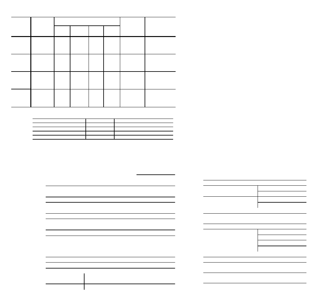
BLOWER MO TOR AND DRIVE DATA
POWER EX HAUST PER FORM ANCE
7500 8750 10000 11250 12500
ESP ESP ESP ESP ESP
(IWG) (IWG) (IWG) (IWG) (IWG)
DEDUCTIONS: (SUBTRACT VALUES BELOW FROM UNIT'S AVAILABLE ESP)
ALLOWANCE FOR WET COIL: 0.10 0.10 0.10 0.10 0.10
ECONOMIZER (RETURN DUCT): 0.06 0.09 0.11 0.14 0.18
18kW ELECTRIC HEAT: 0.31 0.43 0.56 0.71 0.87
36kW ELECTRIC HEAT: 0.38 0.52 0.68 0.87 1.07
54kW ELECTRIC HEAT: 0.62 0.84 1.10 1.39 1.72
72kW ELECTRIC HEAT: 0.68 0.93 1.21 1.54 1.90
ADDITIONS: (ADD VALUES BELOW TO UNIT'S AVAILABLE ESP)
HORIZONTAL (SIDE) SUPPLY DUCT: 0.31 0.26 0.27 0.31 0.41
HORIZONTAL (SIDE) RETURN DUCT: 0.05 0.05 0.05 0.05 0.05
A
IRFLOW (CFM)
DESCRIPTION
MODEL
SIZE DRIVE
BLOWER
RANGE
(RPM)
MO TOR
1
AD JUST ABLE MO TOR PUL LEY FIXED BLOWER PUL LEY BELT
(NOTCHED)
HP FRAME EFF.
(%)
DESIG-
NATION
OUT-
SIDE
DIA.
(IN.)
PITCH
DIA.
(IN.)
BORE
(IN.)
DESIG-
NATION
OUT SIDE
DIA.
(IN.)
PITCH
DIA.
(IN.)
BORE
(IN.)
DESIG-
NATION
PITCH
LENGTH
(IN.)
QTY.
25 TON
Stan-
dard 975/1165
15 254T 91 1LVP58B70
A7.5 6.2-
7.4 1 5/8
1B5V110 11.3 11.1 1-7/16 5VX860 86.0 1
High
Speed
Ac cess
1140/1365 1B5V94 9.7 9.5 1-7/16 5VX840 84.0 1
1All mo tors have a nomi nal speed of 1800 RPM, a 1.15 serv ice fac tor and a solid base. They can op er ate to the limit of their serv ice fac tor be cause they are lo cated in the mov ing air, up stream
of any heat ing de vice.
MO TOR
SPEED
STATIC RE SIS TANCE OF RE TURN DUCT WORK, IWG
0.2 0.3 0.4 0.5 0.6
CFM KW CFM KW CFM KW CFM KW CFM KW
HIGH* 5250 0.83 4500 0.85 4200 0.88 3750 0.93 3000 0.99
ME DIUM 4900 0.77 3900 0.79 3500 0.82 2900 0.85 - -
LOW 4400 0.72 3700 0.74 3000 0.78 - - - -
*Fac tory Set ting
Power Ex haust mo tor is a 3/4 HP, PSC type with sleeve bear ings, a 48 frame and in her ent pro tec tion.
ELEC TRI CAL DATA
-
Cool ing Only Units and Units With Gas Heat
ELECTRICAL DATA - Cooling Only Units & Units With Gas Hea
t
SUPPLY AIR MINIMUM MAXIMUM
POWER BLOWER MOTOR CIRCUIT OVERCURRENT
SUPPLY RLA LRA HP FLA AMPACITY DEVICE (1)
(ea.) (ea.) (ea.) (ea.) (AMPS) (AMPS)
D2CE300 208/230-3-60 41.4 312 1 4.2 15 38.6 139.5 175
& D2CG300 460-3-60 20.0 150 1 2.1 15 19.3 68.3 80
575-3-60 16.4 108 1 2.0 15 15.4 56.1 70
HP RLA
MODEL NO.
COMPRESSORS
(QTY. 2)
COND. FAN
(#1 & #2)
VOLT AGE
LIMI TA TIONS**
POWER SUP PLY VOLT AGE
MIN. MAX.
208/230- 3- 60 187 253
460- 3- 60 414 506
575- 3- 60 518 630
**Rated in ac cor dance with ARI Stan dard 110, utili za tion range “A”.
STATIC RE SIS TANCES*
036-21359-001-B-0302
Unitary Products Group 9
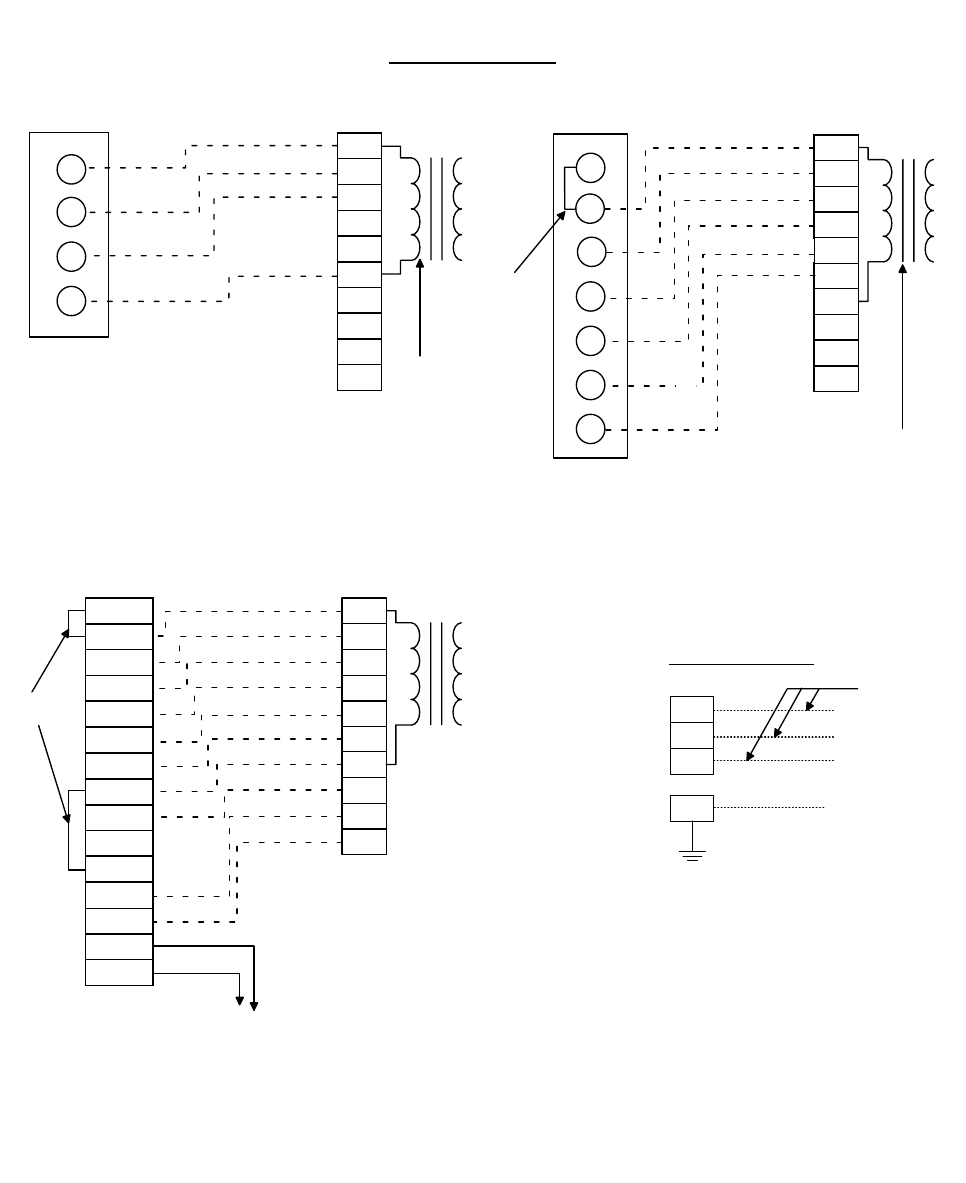
FIELD WIRING - DCE/DCG ELECTRIC/ELECTRIC AND GAS/ELECTRIC UNITS
R
Y1
Y2
W1
G
B
X
A1
A2
G
R
Y1
Y2
R
Y1
Y2
W1
G
B
X
A1
A2
RH
RC
Y1
Y2
W1
W2
G
W2 W2
R
Y1
Y2
W1
G
B
X
A1
A2
W2
T
T
A2
A1
COM
LED 2
LED 1
B
G
W2
W1
Y2
Y1
RH
RC
ADD
JU M P E R
24 VO LT
TRANSFO RM ER
24 VO LT
TRANSFO RM ER
24 VO LT
TRANSFO RM ER
C O O L IN G O N L Y (2 4 V O L T T H E R M O S T A T )
UNIT TERMINAL
BLO CK 1TB
2
THERM OSTAT
1
TER M IN ALS
C O O L IN G / H E A T IN G (2 4 V O L T T H E R M O S T A T )
THERM OSTAT
1
TER M IN ALS
UNIT TERMINAL
BLO CK 1TB
2
1
24 V olt Therm ostat 2TH 04701224.
2
Term inal block 1TB - located on relay board in 24-volt section
of the unit control box.
1
24 V olt Therm ostat 2TH 04701024 or 2TH 04701524
(w ith subbase 2TB 04700224 or 2TB04700324).
2
Term inal block 1TB - located on relay board in 24-volt section
o f th e u n it c o n tro l b o x .
3
Second stage heating is not required on units w ith a single stage
electric heater.
C O O L IN G / H E A T IN G (E L E C T R O N IC T H E R M O S T A T )
THERM OSTAT
1
TER M IN ALS
UNIT TERMINAL
BLO CK 1TB
2
3
3
4
4
1
Electronic program m able Therm ostat 2ET04700224 (includes subbase).
2
Term inal block 1TB - located on relay board in 24-volt section of the unit control box.
3
Second stage heating is not required on units w ith a single stage electric heater.
4
Term inals A 1 and A2 provide a relay output to close the outdoor econom izer dam pers
w hen the therm ostat sw itches to the set-back position.
TO REM OTE SENSO R
2TH 04702224 IF U SE D
L1
L2
L3
O
R e fe r to th e
ELECTRICAL
DATA
ta b le s to s iz e th e
power wiring, the
fuses and the
disconnect
sw itch.
LINE VOLTAGE
TER M IN AL
BLOCK 2TB
IN U N IT
CONTROL BOX
GROUND LUG
Fan sw itch m ust be in "O N " position for m inim um ventilation during heater operation.
CONTROL W IRING
ADD
JUM PER
NOT
USED
POW ER W IRING
036-21359-001-B-0302
10 Unitary Products Group
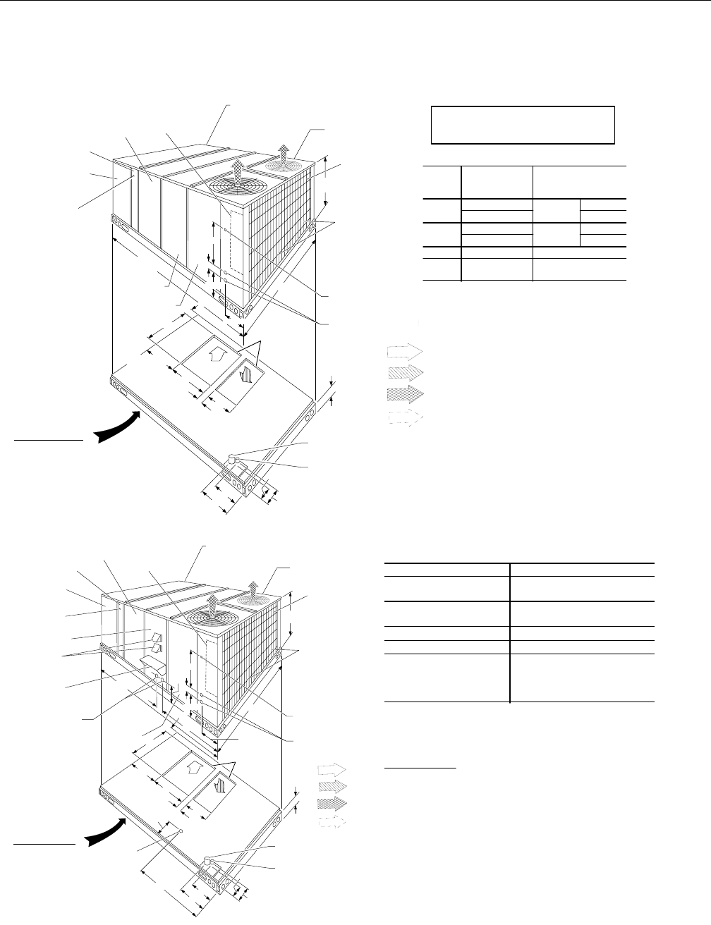
RETURN
AIR
SUPPLY
AIR
BOTTOM SUPPLY
AND RETURN
AIR OPENINGS
(See Note)
(B)
POWER WIRING
ENTRY
(A)
CONTROL WIRING
ENTRY
NOTE:
For curb mounted units, refer to the curb hanger
dimensions of the curb for the proper size of the
supply and return air duct connections.
UNIT BASE WITH RAILS
Shown separately to illustrate
Bottom Duct openings and Power
Connection locations
12-1/2"
9-1/4"
8-1/8"
9-3/4"
3-3/4"
(B)
POWER WIRING
ENTRY
(A)
CONTROL WIRING
ENTRY
92"
CONDENSER
COILS
OPTIONAL COIL
GUARD KIT
COMPRESSOR
ACCESS
(See detail "X")
ECONOMIZER / MOTORIZED DAMPER,
FIXED OUTDOOR INTAKE AIR AND
POWER EXHAUST RAIN HOODS
(See detail "Y")
FIELD-SUPPLIED
DISCONNECT SWITCH
LOCATION
BLOWER
ACCESS
BLOWER MOTOR
ACCESS
BLOWER
COMPARTMENT
ACCESS
(Auxiliary)
DOT PLUG
(For pressure
Drop Reading)
FRONT
VIEW ELECTRIC HEAT
ACCESS
CONTROL BOX
ACCESS
21"
5"
9-3/4"
11-1/2"
2-3/4" 21-1/2"
33"
35"
5-7/8"
RETURN AIR
SUPPLY AIR
OUTDOOR AIR
OUTDOOR AIR
(Economizer)
24-1/4" (15 TON)
36-1/4" (20 TON)
48-5/8" (15TON)
52-5/8" (20TON)
125-1/4" (15 TON)
136-1/4" (20 TON)
HOLE
OPEN ING
SIZE
(DIA.)
USED FOR
A1-1/8" KO Con trol
Wir ing
Front
3/4" NPS (Fem.) Bot tom
B3-5/8" KO Power
Wir ing
Front
3" NPS (Fem.) Bot tom
C 2-3/8" KO Gas Pip ing (Front)1
D 1-11/16" Hole Gas Pip ing (Bot -
tom)1,2
11" pip ing MPT re quired
2 Open ing in the bot tom of the unit can be lo cated by the slice
in the in su la tion.
UTILITIES ENTRY DATA
All dimensions are in inches. They are
subject to change without notice. Certified
dimensions will be provided upon request.
RETURN
AIR
SUPPLY
AIR
BOTTOM SUPPLY
AND RETURN
AIR OPENINGS
(See Note)
(B)
POWER WIRING
ENTRY
(A)
CONTROL WIRING
ENTRY
NOTE:
For curb mounted units, refer to the curb hanger
dimensions of the curb for the proper size of the
supply and return air duct connections.
UNIT BASE WITH RAILS
Shown separately to illustrate
Bottom Duct openings, Power
and Gas Piping Connection
locations
12-1/2"
9-1/4"
8-1/8"
9-3/4"
3-3/4"
(B)
POWER WIRING
ENTRY
(A)
CONTROL WIRING
ENTRY
92"
CONDENSER
COILS
OPTIONAL
COIL GUARD
KIT
COMPRESSOR
ACCESS
(See detail "X")
ECONOMIZER / MOTORIZED DAMPER,
FIXED OUTDOOR INTAKE AIR AND
POWER EXHAUST RAIN HOODS
(See detail "Y")
FIELD-SUPPLIED
DISCONNECT SWITCH
LOCATION
BLOWER
ACCESS
BLOWER MOTOR
ACCESS
BLOWER
COMPARTMENT
ACCESS
(Auxiliary)
DOT PLUG
(For pressure
Drop Reading)
FRONT
VIEW
CONTROL BOX
ACCESS
21"
5"
9-3/4"
11-1/2"
2-3/4" 21-1/2"
33"
35"
5-7/8"
46-5/8"
7-1/8"
6-3/8"
VENT AIR
OUTLET
HOODS
COMBUSTION
AIR INLET
HOOD
GAS HEAT
ACCESS
(C)
GAS SUPPLY
ENTRY
46-5/8"
11-1/8"
(D)
GAS SUPPLY
ENTRY
35-1/4
136-1/4
52-5/8
RETURN AIR
SUPPLY AIR
OUTDOOR AI
R
OUTDOOR AI
R
(Economizer)
Front 36"
Back 24" (Less Econo mizer)
49" (With Econo mizer)
Left Side (Fil ter Ac cess) 24" (Less Econo mizer)
36" (With Econo mizer)
Right Side (Cond. Coil) 36"
Be low Unit1 20"
Above Unit2
72" With 36" Maxi mum
Hori zon tal Over hang
(For Con denser Air
Dis charge)
1U nits (ap pli ca ble in U.S.A. only) may be in stalled on com bus ti ble floors
made from wood or class A, B or C roof cov er ing ma te rial.
2
Units must be in stalled ou doors. Over hang ing struc tures or shrubs should
not ob struct con denser air dis charge out let.
NOTE:
ELEC/ELEC Mod els: Units and duct work are ap proved for zero clear ance to
com bus ti ble ma te ri als when equipped with elec tric heat ers.
GAS/ELEC Mod els: A 1" clear ance must be pro vided be tween any
com bus ti ble ma te rial and the sup ply air duct work for a dis tance of 3 feet
from the unit.
The prod ucts of com bus tion must not be al lowed to ac cu mu late within a
con fined space and re cir cu late.
Lo cate unit so that the vent air out let hood is at least:
?Three (3) feet above any forced air in let lo cated within 10 hori zon tal feet (ex -
clud ing those in te gral to the unit).
?Four (4) feet be low, 4 hori zon tal feet from, or 1 foot above any door or grav ity
air in let into the build ing.
CLEARANCES
036-21359-001-B-0302
Unitary Products Group 11
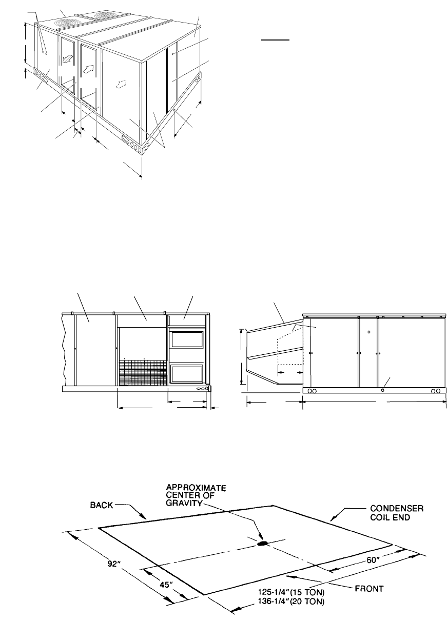
DUCT COVERS - Units are shipped with the bottom
duct openings covered. An accessory flange kit is available for
connecting side ducts.
For bottom duct applications:
1 Remove the side panels from the supply and return air
compartments to gain access to the bottom supply and
return air duct covers.
2 Remove and discard the bottom duct covers. (Duct
openings are closed with sheet metal covers except
when the unit includes a power exhaust option. The
covering consists of a heavy black paper composition.)
3 Replace the side supply and return air compartment
panels.
For side duct applications;
1 Replace the side panels on the supply and return air
compartments with the accessory flange kit panels.
2 Connect ductwork to the duct flanges on the rear of the
unit.
SUPPLY
AIR
RETURN
AIR
OUTDOOR
AIR
5-1/8"
18-5/8"
27-3/4"
29-5/8" (15 TON)
39-5/8" (20 TON)
40-1/2"
OUTDOOR AIR
COMPARTMENT
ACCESS
FILTER
ACCESS
1" NPT FEMALE
COND. DRAIN
CONNECTION
DOT PLUG
(For pressur
e
drop reading)
EVAPORATOR
SECTION
CONDENSER
SECTION
GAUGE LINE
ACCESS
40-3/8"
5-1/2"
COMPRESSOR
ACCESS
SUPPLY AIR
ACCESS
RETURN AIR
ACCESS
REAR
VIEW
SUPPLY
AIR
CO M PARTM ENT
POW ER
EXHAUST
RAIN
HOOD
(o n
Return
Air
C om partm ent)
ECONOMIZER
MOTORIZED
DAM PER
RAIN HOOD
(on O utdoor A ir C om partm ent) ECONOMIZER
/
MOTORIZED
DAM PER
AND
POW ER
EXHAUST
RAIN
HOODS
FIXED
OUTDOOR
AIR
IN T A K E
HOOD
(located on
R e tu rn A ir
C om partm ent) 1" CO N D EN STATE
DRAIN
(M ust be trapped)
REAR VIEW L H V IE W
D E T A IL "Y "
UNIT W ITH RAIN HOODS
36"
66-1/2"
92"
36-1/4"
5"
34-1/4"
16-1/8"
2"
036-21359-001-B-0302
12 Unitary Products Group
DCE
NOTE: These weights are with economizer and 24kW electric heat.
NOTE: These weights are with economizer, high heat and oversized motor.
4 Point Loads 6 Point Loads
DCE
UNIT
4 - POINT LOADS (LBS)
TOTAL A B C D
300 2,890 487 619 646 508
DCE
UNIT
6 - POINT LOADS (LBS)
TOTAL A B C D E F
300 2,890 415 471 528 551 492 433
DCG
UNIT
4-POINTLOADS(LBS)
TOTAL A B C D
300 3,130 615 671 962 882
DCG
UNIT
6 - POINT LOADS (LBS)
TOTAL A B C D E F
300 3,130 418 438 533 658 603 510
A
D
C
B
FRO N T
A
E
D
B
C
F
FRO N T
036-21359-001-B-0302
Unitary Products Group 13
BASE RAIL
3.56"
3.69"
036-21359-001-B-0302
14 Unitary Products Group
036-21359-001-B-0302
Unitary Products Group 15
MECHANICAL SPECIFICATIONS
GENERAL DESCRIPTION
Units shall be factory-assembled, single packaged,
(DCG Electric Cooling/Gas Heat, DCE Electric Cooling/
Optional Electric Heat), designed for outdoor mounted
installation. Units shall have minimum EER ratings of
8.5. They shall have built in field convertible duct con-
nections for down discharge supply/return or horizontal
discharge supply/return, and be available with factory
installed options or field installed accessories.
The units shall be factory wired, piped, charged with R-
22 refrigerant and factory tested prior to shipment. All
unit wiring shall be both numbered and color coded.
Enclosed in each unit shall be a factory test log sheet
consisting of the unit tested pressures, temperatures
and amps, as tested prior to shipment.
All units shall be manufactured in a facility certified to
ISO 9001 standards and the cooling performance shall
be rated in accordance with DOE and ARI test proce-
dures. Units shall be ETL & CGA listed, classified to
ANSIZ21.47 standards, UL 1995/CAN/CSA No. 236-
M90 conditions.
UNIT CABINET
1. Unit cabinet shall be constructed of G90 galva-
nizedsteel,withexteriorsurfacescoatedwitha
non-chalking, powered paint finish, certified at 750
hours salt spray test per ASTM-B117 standards.
2. Indoor blower section shall be insulated with up to
1" thick insulation, coated on the air side. Alumi-
num foil faced insulation shall be used in the fur-
nace compartment and be fastened with ridged
fasteners to prevent insulation from entering the air
stream.
3. Cabinet panels shall be “large” size, easily remov-
able for servicing and maintenance.
4. Full perimeter base rails shall be provided to
assure reliable transit of equipment, overhead rig-
ging and proper sealing on roof curb applications.
5. Disposable 2" filters shall be furnished and be
accessible through a removable access door,
sealed air tight. Units filter track shall be designed
to accommodate either 1" or 2" filters.
6. Fan performance measuring ports shall be pro-
vided on the outside of the cabinet to allow accu-
rate air measurements of evaporator fan
performance without removing panels or creating
air by-pass of the coils.
7. Condensate pan shall be internally sloped and
conform to ASHARE 62-89 self-draining standards.
Condensate connection shall be a minimum of 1"
I.D. female and be a ridged mount connection.
8. Unit shall incorporate a fixed outdoor air damper
with an outdoor air intake opening covered with a
bird screen and a rain hood painted to match the
exterior of the unit.
INDOOR (EVAPORATOR) FAN ASSEMBLY
1. Fan shall be a belt drive assembly and include an
adjustable-pitch motor pulley. Job site selected
(B.H.P.) brake horse power shall not exceed the
motors nameplate horse power rating, plus the ser-
vice factor. Units shall be designed not to operate
above service factor.
2. Fan wheel shall be double-inlet type with forward-
curved blades, dynamically balanced to operate
smoothly throughout the entire range of operation.
Airflow design shall be constant air volume.
3. Bearings shall be sealed and permanently lubri-
cated for longer life and no maintenance.
OUTDOOR (CONDENSER) FAN ASSEMBLY
1. The outdoor fans shall be of the direct-driven pro-
peller type, discharge air vertically, have blades
riveted to corrosion resistant steel spider brackets
and shall be dynamically balanced for smooth
operation.
2. The 2 outdoor fan motors shall be totally enclosed
with permanently lubricated bearings, internally
protected against overload conditions and staged
independently.
REFRIGERANT COMPONENTS
1. Compressors:
A. Shall be fully hermetic type, direct drive, internally
protected with internal high-pressure relief and over
temperature protection. The hermetic motor shall be
suction gas cooled and have a voltage range of + or
- 10% of the unit nameplate voltage.
B. Shall have internal spring isolation and sound muf-
fling to minimize vibration and noise, and be exter-
nally isolated on a dedicated, independent
mounting.
2Coils:
A. Evaporator and condenser coils shall have alumi-
num plate fins mechanically bonded to seamless
internally-enhanced copper tubes with all joints
brazed. Special Phenolic coating shall be available
as a factory option.

036-21359-001-B-0302
16 Unitary Products Group
B. Evaporator and Condenser coils shall be of the
direct expansion, draw-thru, design.
C. Condenser coils shall be protected with factory
installed coil guards
3. Refrigerant Circuit and Refrigerant Safety Compo-
nents shall include:
A. Balance-port thermostatic expansion valve with
independent circuit feed system.
B. Filter drier/strainer to eliminate any moisture or for-
eign matter.
C. Accessible service gage connections on both suc-
tion and discharge lines to charge, evacuate, and
measure refrigerant pressure during any necessary
servicing or troubleshooting, without losing charge.
D. The refrigeration system shall provide at least 15 °F
of sub-cooling at design conditions.
E. All Models shall have two independent circuits..
4. Unit Controls:
A. Unit shall be complete with self contained low-volt-
age control circuit protected by a resetable circuit
breaker on the 24 volt transformer side.
B. Unit shall incorporate a lock-out circuit which pro-
vides reset capability at the space thermostat or
base unit, should any of the following standard
safety devices trip and shut off compressor:
1. Loss-of-charge/Low-pressure switch.
2. High-pressure switch.
3. Freeze-protection thermostat, evaporator coil.
If any of the above safety devices trip, an LED (light-
emitting diode) indicator shall illuminate.
C. Unit shall incorporate “AUTO RESET” compressor
over temperature, over current protection.
D. Unit shall operate with conventional thermostat
designs and have a low voltage terminal strip for
easy hook-up.
GAS HEATING SECTION (DCG MODELS)
1. Shall be designed with induced draft combustion
with post purge logic and energy saving direct
spark ignition, redundant main gas valve. Ventor
wheel shall be constructed of stainless steel for
corrosion resistance.
2. The heat exchanger shall be of the tubular type,
constructed of T1-40 aluminized steel for corrosion
resistance and allowing minimum mixed air enter-
ing temperature of 25 °F.
3. Burners shall be of the in-shot type, constructed of
aluminum coated steel and contain air mixture
adjustments.
4. All gas piping shall enter the unit cabinet at a single
location through either the side or curb, without any
field modifications.
5. An integrated control board shall provide timed
control of evaporator fan functioning and burner
ignition.
6. Heating section shall be provided with the following
minimum protection:
A. Primary and auxiliary high-temperature limit
switches.
B. Induced draft motor speed sensor.
C. Flame roll out switch (manual reset).
D. Flame proving controls.
7 Unit shall have two independent stages of capacity.
ELECTRIC HEATING (DCE MODELS)
1. Nickel chromium electric heating elements shall be
provided as required by the application with 1 or 2
stage control, as required, from 13.5 KW to 72 KW
capacity.
2. The heating section shall have a primary limit con-
trol(s) and automatic reset to prevent the heating
element system from operating at an excessive
temperature.
3. Units with Electric Heating shall be wired for a sin-
gle point power supply with branch circuit fusing
(where required).
UNIT OPERATING CHARACTERISTICS
1. Unit shall be capable of starting and running at 125
°F outdoor temperature, exceeding maximum load
criteria of ARI Standard 210/240.
2. The compressor, with standard controls, shall be
capable of operation down to 25 °F outdoor tem-
perature. Accessory low ambient kit shall be avail-
able for operation to 0 °F.
3. Unit shall be provided with fan time delay to pre-
vent cold air delivery before heat exchanger warms
up. (Gas heat only)
036-21359-001-B-0302
Unitary Products Group 17
ELECTRICAL REQUIREMENTS
All unit power wiring shall enter unit cabinet at a single
factory provided location and be capable of side or bot-
tom entry, to minimize roof penetrations and avoid unit
field modifications. Separate side and bottom openings
shall be provided for the control wiring.
STANDARD LIMITED WARRANTIES
Compressor- 5 Years
Heat Exchanger - 10 Years
Elect. Heat. Elem.- 5 Years
Parts- 1 Year
OPTIONAL OUTDOOR AIR (Shall be made available
by either/or):
1ELECTRONIC ENTHALPY AUTOMATIC ECON-
OMIZER - Outdoor and return air dampers that are
interlocked and positioned by a fully-modulating,
spring-return damper actuator. The maximum leak-
age rate for the outdoor air intake dampers shall
not exceed 2% when dampers are fully closed and
operating against a pressure differential of 0.5
IWG. A unit-mounted potentiometer shall be pro-
vided to adjust the outdoor and return air damper
assembly to take in CFM of outdoor air to meet the
minimum ventilation requirement of the conditioned
space during normal operation. During economizer
operation, a mixed-air temperature control shall
modulate the outdoor and return air damper
assembly to prevent the supply air temperature
from dropping below 55°F. Changeover from com-
pressor to economizer operation shall be provided
by an integral electronic enthalpy control that feeds
input into the basic module. The outdoor intake
opening shall be covered with a rain hood that
matches the exterior of the unit. Water eliminator/
filters shall be provided. Simultaneous economizer/
compressor operation is also possible. Dampers
shall fully close on power loss.
2. DUAL INPUT DIFFERENTIAL ELECTRONIC
ENTHALPY AUTOMATIC ECONOMIZER -Out-
door and return air dampers that are interlocked
and positioned by a fully-modulating, spring-return
damper actuator. The maximum leakage rate for
the outdoor air intake dampers shall not exceed
2% when dampers are fully closed and operating
against a pressure differential of 0.5 IWG. A unit
mounted potentiometer shall be provided to adjust
the outdoor and return air damper assembly to take
in the design CFM of outdoor air to meet the mini-
mum ventilation requirement of the conditioned
space during normal operation. During economizer
operation, a mixed-air temperature control shall
modulate the outdoor and return air damper
assembly to prevent the supply air temperature
from dropping below 55°F. Changeover from com-
pressor to economizer operation shall be provided
by two integral electronic enthalpy controls - one
that senses outdoor air and one that senses indoor
air. Both enthalpy sensors supply input to the logic
module which modulates both sets of dampers for
maximum economizer savings. The outdoor intake
opening shall be covered with a rain hood that
matches the exterior of the unit. Water eliminator/
filters shall be provided. Simultaneous economizer/
compressor operation is also possible. Dampers
shall fully close on power loss.
3MOTORIZED OUTDOOR AIR DAMPERS -Out-
door and return air dampers that are interlocked
and positioned by a 2-position, spring-return
damper actuator. The maximum leakage rate for
the outdoor air intake dampers shall not exceed
2% when dampers are fully closed and operating
against a pressure differential of 0.5 IWG. A unit-
mounted potentiometer shall be provided to adjust
the outdoor and return air damper assembly to take
in the design CFM of outdoor air to meet the venti-
lation requirements of the conditioned space during
normal operation. Whenever the indoor fan motor
is energized, the dampers open up to one of two
pre-selected positions - regardless of the outdoor
air enthalpy. Dampers return to the fully closed
position when the indoor fan motor is de-ener-
gized. Dampers shall fully close on power loss.
OTHER PRE-ENGINEERED ACCESSORIES AVAIL-
ABLE
1. ROOF CURB - 14" high, full perimeter curb with
wood nailer (shipped knocked-down).
2. BAROMETRIC RELIEF DAMPER -Containsarain
hood, air inlet screen, exhaust damper and mount-
ing hardware. Used to relieve internal air pressure
through the unit during economizer operation.
3. PROPANE CONVERSION KIT - Contains new ori-
fices and gas valve parts to convert from natural to
L.P. gas. One per unit required.
4. HIGH ALTITUDE - NATURAL GAS -Containsorifices
required for applications between 2000 and 6000
feet altitude.

036-21359-001-B-0302
18 Unitary Products Group
5. HIGH ALTITUDE - PROPANE GAS - Contains orifices
required for applications between 2000 and 6000
feet altitude. Must be used with propane conver-
sion kit.
6. BURGLAR BARS -Designedtoworkwithabove
roofcurbs, depending on unit model. Fits duct
openings of curb supply and return air openings.
7. SIDE DUCT FLANGE - Supply and return air duct
flanges for side duct applications. Do not use on
units with power exhaust.
8. HIGH SPEED DRIVE - Includes blower pulley and
belt for higher CFM and/or static pressure require-
ments.
9. WOOD SKID - Allows unit to be handled with 90"
forks.
10. ECONOMIZER/MOTORIZED DAMPER RAIN HOOD
(DCE/CG300 only) - Contains all hood panels and
the hardware for assembling.
11. THERMOSTATS - Multiple models available from
A.C.O., M.C.O., Electronic or Electrical Mechanical
versions.
12. ANTI-RECYCLE TIMER - Assures 5-minute off-time
between compressor cycles.
13. LOW AMBIENT KIT - Provides unit cooling opera-
tion down to 0°F.
OTHER FACTORY INSTALLED OPTIONS
1 POWER EXHAUST OPTION - To work in conjunc-
tion with economizers.
2. TECHNICOAT PHENOLIC COATED COND. COIL
3. ELECTRONIC ENTHALPY ECONOMIZER
4. DUAL INPUT ELECTRONIC ENTHALPY ECON-
OMIZER
036-21359-001-B-0302
Unitary Products Group 19

036-21359-001-B-0302
20 Unitary Products Group
036-21359-001-B-0302
Unitary Products Group 21

036-21359-001-B-0302
22 Unitary Products Group
036-21359-001-B-0302
Unitary Products Group 23

Subject to change without notice. Printed in U.S.A. CD: 6-21359 036-21359-001-B-0302
Copyright ©by Unitary Products Group 2002. All rights reserved. Supersedes: 036-21359-001-A-0302
Unitary 5005 Norman
Products York OK
Group Drive 73069
