York Dh 180 Users Manual Y TG, Single Package Gas/Elec Units And Sgl Pkg AC, S
DH 240 to the manual 119c0d37-a1ae-482e-94ce-88b5745bb1dd
2015-02-02
: York Dh-180-Users-Manual york-dh-180-users-manual-455073 york pdf
Open the PDF directly: View PDF ![]() .
.
Page Count: 44
- DESCRIPTION
- TABLE OF CONTENTS
- PRODUCT NOMENCLATURE
- FEATURES
- FACTORY-INSTALLED OPTIONS
- FIELD-INSTALLED ACCESSORIES
- TABLE 1: INDOOR SOUND POWER RATING
- TABLE 2: CAPACITY RATINGS - (ARI 360)
- TABLE 3: gAS HEAT RATINGS
- TABLE 4: dH 180 cooling capacities (15 ton)
- TABLE 4: dH 180 cooling capacities (15 ton) (continued)
- TABLE 5: dH 210 cooling capacities (17.5 ton)
- TABLE 5: dH 210 cooling capacities (17.5 ton) (continued)
- TABLE 6: dH 240 cooling capacities (20 ton)
- TABLE 6: dH 240 cooling capacities (20 ton) (continued)
- TABLE 7: dH 300 cooling capacities (25 ton)
- TABLE 7: dH 300 cooling capacities (25 ton) (continued)
- TABLE 8: ALTITUDE CORRECTION FACTORS
- FIGURE 2 - ALTITUDE/TEMPERATURE CONVERSION FACTOR
- TABLE 9: supply air blower performance (15 ton) - COOLING ONLY 180 mbh - bottom duct connections
- TABLE 10: supply air blower performance (17.5 ton) - COOLING ONLY 210 MBH - bottom duct connections
- TABLE 11: supply air blower performance (20 ton) - COOLING ONLY 240 MBH - bottom duct connections
- TABLE 12: supply air blower performance (15 ton) - gas heat 180 MBH - bottom duct connections
- TABLE 13: supply air blower performance (17.5 ton) - gas heat 210 MBH - bottom duct connections
- TABLE 14: supply air blower performance (20 ton) - gas heat 240 MBH - bottom duct connections
- TABLE 15: supply air blower performance (25 ton) - gas heat 300 MBH - bottom duct connections
- TABLE 16: BLOWER MOTOR AND DRIVE DATA
- TABLE 17: STATIC RESISTANCES
- TABLE 18: POWER EXHAUST PERFORMANCE
- TABLE 19: DH 180, 210 & 240 ELECTRICAL DATA WITHOUT POWERED CONVENIENCE OUTLET
- TABLE 20: DH 300 ELECTRICAL DATA standard motor WITHOUT POWERED CONVENIENCE OUTLET
- TABLE 21: DH 300 ELECTRICAL DATA high static motor WITHOUT POWERED CONVENIENCE OUTLET
- TABLE 22: DH 180, 210 & 240 ELECTRICAL DATA WITH POWERED CONVENIENCE OUTLET
- TABLE 23: DH 300 ELECTRICAL DATA standard motor WITH POWERED CONVENIENCE OUTLET
- TABLE 24: DH 300 ELECTRICAL DATA high static motor WITH POWERED CONVENIENCE OUTLET
- TABLE 25: DH VOLTAGE LIMITATIONS
- TABLE 26: ELECTRIC HEAT CORRECTION FACTORS
- FIGURE 3 - TYPICAL DH FIELD WIRING DIAGRAM
- TABLE 27: Physical Data
- TABLE 28: OPERATING WEIGHTS (LBS.)
- TABLE 29: supply fan vfd weights, in lbs.
- FIGURE 4 - UNIT DIMENSIONS DH180, 210, 240 & 300 (FRONT VIEW)
- TABLE 30: UTILITIES ENTRY DATA
- FIGURE 5 - REAR VIEW DIMENSIONS
- TABLE 31: MINIMUM CLEARANCES
- FIGURE 6 - UNIT DIMENSIONS dh180, 210, 240 & 300 (RAINHOOD)
- FIGURE 7 - UNIT CENTER OF GRAVITY
- FIGURE 8 - Typical Unit applications
- FIGURE 9 - Unit 4 point load
- FIGURE 10 - unit 6 point load
- TABLE 32: DH 180, 210, 240 & 300 4 POINT LOAD WEIGHT DISTRIBUTION
- TABLE 33: DH 180, 210, 240 & 300 6 POINT LOAD WEIGHT DISTRIBUTION
- FIGURE 11 - UNIT ROOF CURB DIMENSIONS
- FIGURE 12 - ROOF CURB DUCT OPENINGS DIMENSIONs
- FIGURE 13 - CUT AWAY OF ROOF CURB
- FIGURE 14 - Typical Rooftop installation
- FIGURE 15 - TYPICAL Simplicity ® control wiring diagram
- GUIDE SPECIFICATIONS
262260-YTG-E-1008
FOR DISTRIBUTION USE ONLY - NOT TO BE USED AT POINT OF RETAIL SALE
SINGLE PACKAGE GAS/ELECTRIC UNITS
AND SINGLE PACKAGE
AIR CONDITIONERS
DH 180, 210, 240 & 300
15, 17.5, 20 & 25 NOMINAL TONS
10.8 EER (15 TONS), 10.2 EER (17.5 TONS), 9.7 EER (20
TONS) AND 9.6 EER (25 TONS)
®
TECHNICAL GUIDE
DESCRIPTION
YORK Sunline Ultra™ units are convertible single package
high efficiency rooftops. All models have independent dual
refrigerant circuits for efficient part load operation. Although
the units are primarily designed for curb mounting on a roof,
they can also be slab-mounted at ground level or set on steel
beams above a finished roof.
All units include:
• Powder Paint finish that meets ASTM-B-117 1000 hour
salt spray standards
• Two-stage cooling provided by dual independent refriger-
ation circuits with expansion valves, filter-driers, high and
low pressure/loss of charge switches and freezestats
• Hermetically sealed scroll compressors with crankcase
heaters
• Two-stage heating provided by dual independent heat
exchangers with aluminized steel tubes, redundant gas
valves, spark ignition with induced draft logic
• Permanently lubricated motors
• Bottom or side air discharge configuration capability
(field convertible)
• Belt drive blower motor with high static drive options
• Constant supply air volume (CV) with optional variable
air volume (VAV)
• Manufactured under the quality standards of ISO9001
• Twenty-four volt control circuit with compressor lock-out
• Zero-25% fixed air damper with hood
• Copper tube/aluminum fin coils
• Hinged filter access and tool free latched doors optional
• Hinged tool free blower, blower motor, filters and electri-
cal panel access optional
• Rigging holes in base rails for lifting
• Single point power connection
• Complete factory package - tested, charged and wired
• CSA agency approvals on all units
WARRANTY
• Factory Limited Parts Warranty
• One-year parts warranty
• A Five-year parts warranty on the compressor and
electric heat elements.
• Ten-year parts warranty on the gas-fired heat
exchangers.

262260-YTG-E-1008
2Johnson Controls Unitary Products
TABLE OF CONTENTS
DESCRIPTION . . . . . . . . . . . . . . . . . . . . . . . . . . . . . 1
PRODUCT NOMENCLATURE . . . . . . . . . . . . . . . . . 3
FEATURES . . . . . . . . . . . . . . . . . . . . . . . . . . . . . . . . 4
FACTORY-INSTALLED OPTIONS . . . . . . . . . . . . . . 5
FIELD-INSTALLED ACCESSORIES . . . . . . . . . . . . 8
GUIDE SPECIFICATIONS . . . . . . . . . . . . . . . . . . . 41
LIST OF FIGURES
Fig. # Pg. #
1 UNIT CUTAWAY . . . . . . . . . . . . . . . . . . . . . . . . . . . . . . . 5
2 ALTITUDE/TEMPERATURE CONVERSION
FACTOR . . . . . . . . . . . . . . . . . . . . . . . . . . . . . . . . . . . . 19
3 TYPICAL DH FIELD WIRING DIAGRAM . . . . . . . . . . . 32
4 UNIT DIMENSIONS DH180, 210, 240 & 300
(FRONT VIEW) . . . . . . . . . . . . . . . . . . . . . . . . . . . . . .34
5 REAR VIEW DIMENSIONS . . . . . . . . . . . . . . . . . . . . . 35
6 UNIT DIMENSIONS DH180, 210, 240 & 300
(RAINHOOD) . . . . . . . . . . . . . . . . . . . . . . . . . . . . . . . . 36
7 UNIT CENTER OF GRAVITY . . . . . . . . . . . . . . . . . . . . 37
8 TYPICAL UNIT APPLICATIONS . . . . . . . . . . . . . . . . . 37
9 UNIT 4 POINT LOAD . . . . . . . . . . . . . . . . . . . . . . . . . . 38
10 UNIT 6 POINT LOAD . . . . . . . . . . . . . . . . . . . . . . . . . . 38
11 UNIT ROOF CURB DIMENSIONS . . . . . . . . . . . . . . . . 39
12 ROOF CURB DUCT OPENINGS DIMENSIONS . . . . . 39
13 CUT AWAY OF ROOF CURB . . . . . . . . . . . . . . . . . . . 39
14 TYPICAL ROOFTOP INSTALLATION . . . . . . . . . . . . . 40
15 TYPICAL SIMPLICITY
® CONTROL WIRING
DIAGRAM . . . . . . . . . . . . . . . . . . . . . . . . . . . . . . . . . . . 40
LIST OF TABLES
Tbl. # Pg. #
1 INDOOR SOUND POWER RATING . . . . . . . . . . . . . . . 9
2 CAPACITY RATINGS - (ARI 360) . . . . . . . . . . . . . . . . . 9
3 GAS HEAT RATINGS . . . . . . . . . . . . . . . . . . . . . . . . . . . 9
4 DH 180 COOLING CAPACITIES (15 TON) . . . . . . . . . 10
5 DH 210 COOLING CAPACITIES (17.5 TON) . . . . . . . . 12
6 DH 240 COOLING CAPACITIES (20 TON) . . . . . . . . . 14
7 DH 300 COOLING CAPACITIES (25 TON) . . . . . . . . . 16
8 ALTITUDE CORRECTION FACTORS . . . . . . . . . . . . . 18
9 SUPPLY AIR BLOWER PERFORMANCE (15 TON) -
COOLING ONLY 180 MBH - BOTTOM DUCT
CONNECTIONS . . . . . . . . . . . . . . . . . . . . . . . . . . . . . . 20
Tbl. # Pg. #
10 SUPPLY AIR BLOWER PERFORMANCE (17.5 TON) -
COOLING ONLY 210 MBH - BOTTOM DUCT
CONNECTIONS . . . . . . . . . . . . . . . . . . . . . . . . . . . . . 21
11 SUPPLY AIR BLOWER PERFORMANCE (20 TON) -
COOLING ONLY 240 MBH - BOTTOM DUCT
CONNECTIONS . . . . . . . . . . . . . . . . . . . . . . . . . . . . . . 22
12 SUPPLY AIR BLOWER PERFORMANCE (15 TON) -
GAS HEAT 180 MBH - BOTTOM DUCT
CONNECTIONS . . . . . . . . . . . . . . . . . . . . . . . . . . . . . 23
13 SUPPLY AIR BLOWER PERFORMANCE (17.5 TON) -
GAS HEAT 210 MBH - BOTTOM DUCT
CONNECTIONS . . . . . . . . . . . . . . . . . . . . . . . . . . . . . 24
14 SUPPLY AIR BLOWER PERFORMANCE (20 TON) -
GAS HEAT 240 MBH - BOTTOM DUCT
CONNECTIONS . . . . . . . . . . . . . . . . . . . . . . . . . . . . . 25
15 SUPPLY AIR BLOWER PERFORMANCE (25 TON) -
GAS HEAT 300 MBH - BOTTOM DUCT
CONNECTIONS . . . . . . . . . . . . . . . . . . . . . . . . . . . . . 26
16 BLOWER MOTOR AND DRIVE DATA . . . . . . . . . . . . 27
17 STATIC RESISTANCES . . . . . . . . . . . . . . . . . . . . . . . 27
18 POWER EXHAUST PERFORMANCE . . . . . . . . . . . . . 27
19 DH 180, 210 & 240 ELECTRICAL DATA WITHOUT
POWERED CONVENIENCE OUTLET . . . . . . . . . . . . 28
20 DH 300 ELECTRICAL DATA STANDARD MOTOR
WITHOUT POWERED CONVENIENCE OUTLET . . . 29
21 DH 300 ELECTRICAL DATA HIGH STATIC MOTOR
WITHOUT POWERED CONVENIENCE OUTLET . . . 29
22 DH 180, 210 & 240 ELECTRICAL DATA WITH
POWERED CONVENIENCE OUTLET . . . . . . . . . . . . 30
23 DH 300 ELECTRICAL DATA STANDARD MOTOR
WITH POWERED CONVENIENCE OUTLET . . . . . . . 31
24 DH 300 ELECTRICAL DATA HIGH STATIC MOTOR
WITH POWERED CONVENIENCE OUTLET . . . . . . . 31
25 DH VOLTAGE LIMITATIONS . . . . . . . . . . . . . . . . . . . . 32
26 ELECTRIC HEAT CORRECTION FACTORS . . . . . . . 32
27 PHYSICAL DATA . . . . . . . . . . . . . . . . . . . . . . . . . . . . . 33
28 OPERATING WEIGHTS (LBS.) . . . . . . . . . . . . . . . . . . 33
29 SUPPLY FAN VFD WEIGHTS, IN LBS. . . . . . . . . . . . . 33
30 UTILITIES ENTRY DATA . . . . . . . . . . . . . . . . . . . . . . . 34
31 MINIMUM CLEARANCES . . . . . . . . . . . . . . . . . . . . . . 36
32 DH 180, 210, 240 & 300 4 POINT LOAD WEIGHT
DISTRIBUTION . . . . . . . . . . . . . . . . . . . . . . . . . . . . . . 38
33 DH 180, 210, 240 & 300 6 POINT LOAD WEIGHT
DISTRIBUTION . . . . . . . . . . . . . . . . . . . . . . . . . . . . . . 38
262260-YTG-E-1008
Johnson Controls Unitary Products 3
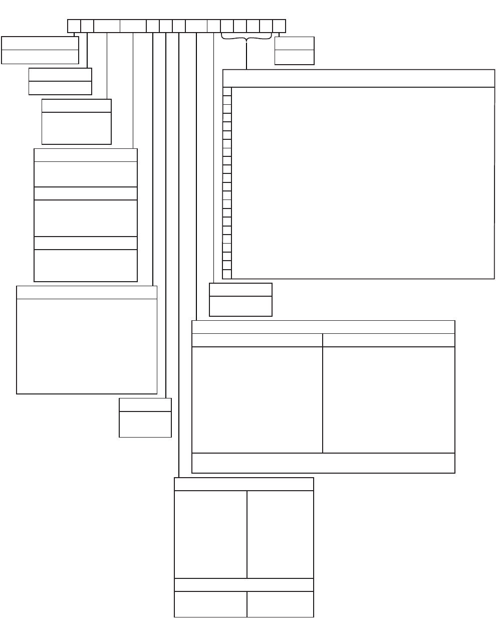
PRODUCT NOMENCLATURE
D H 180 N24 A 2 A AA 1 0 1 2 4 A
D = A/C, Single Pkg., R-22
Product Category
Airflow
1 = First Generation
Product Generation
2 = Second Generation
C00 = Cooling Only. No field installed
electric heat
Heat Type and Nominal Heat Capacity
N24 = 240 MBH Output Aluminized Steel
N32 = 320 MBH Output Aluminized Steel
S24 = 240 MBH Output Stainless Steel
S32 = 320 MBH Output Stainless Steel
E18 = 18 KW
E36 = 36 KW
E54 = 54 KW
E72 = 72 KW
Gas Heat Options
Electric Heat Options
180 = 15 Ton
Nominal Cooling Capacity
210 = 17.5 Ton
240 = 20 Ton
300 = 25 Ton
Product Identifier
H = 10.0-11.0 EER A/C
Voltage
2 = 208/230-3-60
4 = 460-3-60
5 = 575-3-60
Product Style
A = Style A
AA = None
Standard Cabinet
AB = Phase Monitor
AC = Coil Guard
AD = Dirty Filter Switch
AE = Phase Monitor & Coil Guard
AF = Phase Monitor & Dirty Filter Switch
AG = Coil Guard & Dirty Filter Switch
AH = Phase Monitor, Coil Guard & Dirty Filter Switch
RC = Coil Guard & American Flag
TA = Technicoat Condenser Coil
TJ = Technicoat Evaporator Coil
TS = Technicoat Evaporator & Condenser Coils
BA = Hinged Filter Door & Tool Free Access Panels
Additional Options
Hinged Filter Door & Tool Free Access Cabinet
BB = Phase Monitor, Hinged Filter Door & Tool Free
Access Panels
BC = Coil Guard, Hinged Filter Door & Tool Free
Access Panels
BD = Dirty Filter Switch, Hinged Filter Door &
Tool Free Access Panels
BE = Phase Monitor & Coil Guard, Hinged Filter
Door & Tool Free Access Panels
BF = Phase Monitor & Dirty Filter Switch, Hinged
Filter Door & Tool Free Access Panels
BG = Coil Guard & Dirty Filter Switch, Hinged Filter
Door & Tool Free Access Panels
BH = Phase Monitor, Coil Guard & Dirty Filter Switch,
Hinged Filter Door & Tool Free Access Panels
15-25 Ton Sunline Ultra™ Model Number Nomenclature
ZZ = If desired option combination is not listed above, ZZ will be assigned and configuration options will be
located in digits 15-18.
SS Drain Pan
Configuration Options (not required for all units)
These four digits will not be assigned until a quote is requested, or an order placed.
CPC Controller, DFS, APS
Johnson Controller UNT 1126 (N2 protocol), DFS, APS
Honeywell Controller, DFS, APS
Novar Controller, DFS, APS
Simplicity IntelliComfort Controller
Simplicity IntelliComfort Controller w/ModLinc
York Commercial Comfort System (YCCS) Rtu Controller
2" Pleated filters
4" Pleated filters
BAS Ready Economizer (2-10 V.D.C. Actuator without a controller)
Double Wall Construction
Any Combination of Additional Options that Don’t Have an Option Code Pre-assigned
Hot Gas Bypass (Standard on VAV, Optional on CV)
Variable Air Volume, VFD (not available with factory installed BAS options)
Variable Air Volume, VFD with ModLINC (not available with factory installed BAS options)
Variable Air Volume, VFD and Manual Bypass (not available with factory installed BAS options)
Variable Air Volume, VFD and Manual Bypass with ModLINC (not available with factory installed BAS options)
Variable Air Volume, VFD (BAS ready)
Variable Air Volume, VFD and Manual Bypass (BAS ready)
Variable Air Volume, VFD Ready (for customer provided, field installed drive)
Variable Air Volume, VFD Ready with ModLINC (for customer-provided, field-installed drive)
A = No Options Installed
Installation Options
B = Option 1
C = Option 2
D = Options 1 & 2
E = Option 3
F = Option 4
G = Options 1 & 3
H = Options 1 & 4
J = Options 1, 2 & 3
K = Options 1, 2, & 4
L = Options 1,3 & 4
M = Options 1, 2, 3, & 4
1 = Disconnect
2 = Non-Pwr'd Conv. Outlet
3 = Smoke Detector S.A.
4 = Smoke Detector R.A.
5 = Pwr'd Conv. Outlet
Options
N = Options 2 & 3
P = Options 2 & 4
Q = Options 2, 3, & 4
R = Options 3 & 4
S = Option 5
T = Options 1 & 5
U = Options 1, 3, & 5
V = Options 1, 4, & 5
W = Options 1, 3, 4, & 5
X = Options 3 & 5
Y = Options 4 & 5
Z = Options 3, 4 & 5
A = Std. Motor
B = Std. Motor/Economizer
C = Std. Motor/Economizer/Power Exhaust
(Downflow Only)
D = Std. Motor/Motorized Damper
E = Std. Motor/Motorized Damper/Barometric Relief
J = Std. Motor/Economizer/Barometric Relief
N = Hi Static
P = Hi Static/Economizer
Q = Hi Static/Economizer/Power Exhaust
(Downflow Only)
R = Hi Static/Motorized Damper
K = Hi Static/Motorized Damper/Barometric Relief
S = Hi Static/Economizer/Barometric Relief
262260-YTG-E-1008
4Johnson Controls Unitary Products
FEATURES
All models are available with a wide variety of factory-
mounted options such as stainless steel heat exchangers,
phase monitor, dirty filter switch, and coil guard to make them
suitable for almost every application.
All units are self-contained and assembled on full perimeter
base rails with holes in the four corners for overhead rigging.
Every unit is completely piped, wired, charged and tested at
the factory to simplify the field installation and to provide
years of dependable operation.
All models (including those with an economizer) are suitable
for either bottom or horizontal duct connections. Models with
factory installed power exhaust are suitable for bottom
duct connections only. For bottom duct, you remove the
sheet metal panels from the supply and return air openings
through the base of the unit. For horizontal duct, you replace
the supply and return air panels on the rear of the unit with a
side duct flange accessory.
All models are available with these “factory mounted” outdoor
air damper options:
• Single enthalpy economizer with or without power
exhaust
• BAS-ready economizer with or without power exhaust
• Motorized outdoor air damper
• Barometric Relief Damper
A fixed outdoor air intake assembly will be shipped in the
return air compartment of all units ordered without an econo-
mizer or motorized outdoor air damper option. The assembly
includes a rain hood with a damper that can be set for 10, 15
or 25% outdoor air. With bottom duct connections, the intake
damper assembly should be mounted over the opening in the
return air panel. With horizontal ductwork, it should be
mounted on the return air duct.
All supply air blowers are equipped with a belt drive that can
be adjusted to meet the exact requirements of the job. A high
static drive option is available for applications with a higher
CFM and/or static pressure requirement. A variable air volume
(VAV) option using a variable frequency drive is available for
applications requiring a constant supply duct pressure. A dif-
ferential pressure transducer is used to monitor supply duct
static pressure and return a speed reference signal to the VFD
to control the output of the indoor blower motor.
All compressors include scroll compressors and internal pres-
sure relief. Every refrigerant circuit includes an expansion
valve, a liquid line filter-drier, a discharge line high pressure
switch and a suction line with a freezestat and low pressure/
loss of charge switch to protect all system components. A hot
gas bypass option, consisting of an adjustable compressor
discharge bypass valve, is available for low cooling load
applications.
•Simplicity ® Controls - Simplicity ® control boards have
standardized a number of features previously available
only as options or by utilizing additional controls.
•Low Ambient - An integrated low-ambient control
allows all units to operate in the cooling mode down
to 0°F outdoor ambient without additional assis-
tance. Optionally, the control board can be pro-
grammed to lockout the compressors when the
outdoor air temperature is low or when free cooling
is available.
•
•Anti-Short Cycle Protection - To aid compressor
life, an anti-short cycle delay is incorporated into the
standard controls. Compressor reliability is further
ensured by programmable minimum run times. For
testing, the anti short cycle delay can be temporarily
overridden with the push of a button.
•Lead-Lag - An integrated Lead-Lag option allows
equal run time hours on all compressors, thereby
extending the life of all compressors. This option is
selectable on the unit control board.
•Fan Delays - Fan on and fan off delays are fully pro-
grammable. Furthermore, the heating and cooling
fan delay times are independent of one another. All
units are programmed with default values based
upon their configuration of cooling and heat.
•Safety Monitoring - The control board monitors the
high and low-pressure switches, the freezestats, the
gas valve, if applicable, and the temperature limit
switch on gas and electric heat units. The unit con-
trol board will alarm on ignition failures, compressor
lockouts and repeated limit switch trips.
•Nuisance Trip Protection and Strikes - To prevent
nuisance trouble calls, the control board uses a
“three times, you’re out” philosophy. The high and
low-pressure switches and the freezestats must trip
three times within two hours before the unit control
board will lock out the associated compressor.
•On Board Diagnostics - Each alarm will energize a
trouble light on the thermostat, if so equipped, and
flash an alarm code on the control board LED. Each
high and low-pressure switch alarm as well as each
freezestat alarm has its own flash code. The control
board saves the five most recent alarms in memory,
and these alarms can be reviewed at any time.
Alarms and programmed values are retained
through the loss of power.
The Simplicity® control board used in this product will
effectively operate the cooling system down to 0°F
when this product is applied in a comfort cooling
application for people. An economizer is typically
included in this type of application. When applying this
product for process cooling applications (computer
rooms, switchgear, etc.), please reference applications
bulletin AE-011-07 or call the applications department
for Unitary Products @ 1-877-UPG-SERV for
guidance. Additional accessories may be needed for
stable operation at temperatures below 30°F.
262260-YTG-E-1008
Johnson Controls Unitary Products 5
All units have long lasting powder paint cabinets with 1000
hour salt spray test approval under ASTM-B117 procedures.
All models are CSA approved.
• Warranty - All models include a one-year limited parts
warranty on the complete unit. Compressors and electric
heater elements carry a five-year warranty. Gas heat
exchangers carry a 10-year parts warranty.
Gas Heat Operation - All gas heat units are built with
two heating sections for two equal stages of capacity
control. Each section includes a durable heat exchanger
with aluminized steel or optional stainless steel tubes, a
redundant gas valve, spark ignition, power venting, an
ignition module for 100% shut-off and all of the safety
controls required to meet the latest ANSI standards.
The gas supply piping can be routed into the heating
compartment through a hole in the base pan of the unit
or through a knockout in the piping panel on the front of
the unit.
•Electric Heat Operation - All electric heat models (fac-
tory installed only) are wired for a single power source
and include a bank of nickel chromium elements
mounted at the discharge of the supply air blower to pro-
vide a high velocity and uniform distribution of air across
the heating elements. Every element is fully protected
against excessive current and temperature by fuses and
two thermal limit switches.
The power supply wiring can be routed into the control
box through a threaded pipe connection in the base pan
of the unit or through a knockout in the wiring panel on
the front of the unit.
•BAS Controls - York’s Sunline™ series units offer factory
mounted BAS controls such as Simplicity ® Intelli-
Comfort
™, Novar®, Honeywell, Johnson, York Commer-
cial Comfort System (YCCS) and CPC.
FACTORY-INSTALLED OPTIONS
•SINGLE INPUT ELECTRONIC ENTHALPY ECONO-
MIZERS - Includes a slide-in / plug-in damper assembly
with fully modulating spring-return motor actuator capa-
ble of introducing up to 100% outdoor air with nominal
1% leakage type dampers.
The enthalpy system contains one sensor that monitors
the outdoor air and determines when the air is cool
enough and dry enough to provide free cooling.
The rainhood is painted to match the basic unit and must
be field-assembled before installing.
•BAS-READY ECONOMIZER - Includes a slide-in / plug-
in damper assembly with fully modulating spring-return
motor actuator with zero to 95-degree rotation capable of
introducing up to 100% outdoor air with nominal 1% leak-
age type dampers.
Actuator requires 2-10 VDC input from an external
source, such as a field-installed or factory-installed BAS
controller. BAS-ready actuators have an adjustable auxil-
iary end-switch for optional power exhaust control.
For units with optional VAV or Simplicity® Intelli-Com-
fort™ control, a factory-installed, dry bulb sensor deter-
mines if outdoor air temperature is low enough to provide
free-cooling operation. (Field-installed humidity sensors
for either outdoor air or outdoor & return air streams are
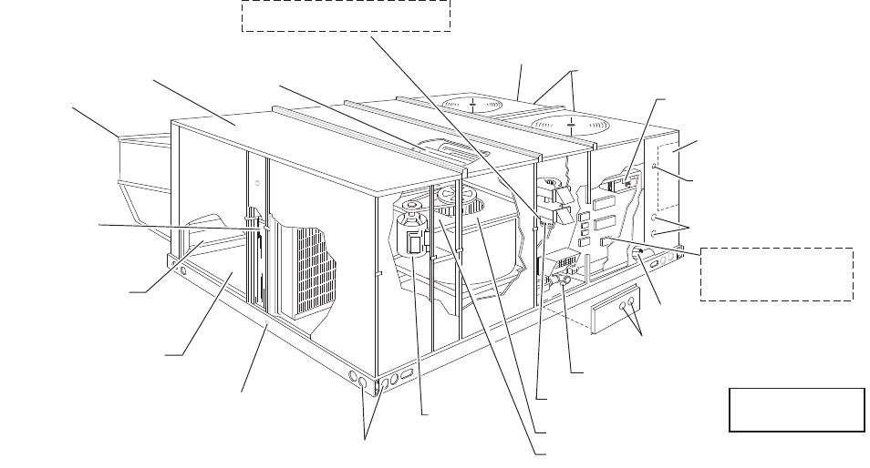
FIGURE 1 - UNIT CUTAWAY
ELECTRICAL DISCONNECT
MOUNTING LOCATION
(Field installed)
KNOCKOUT FOR
SIDE CONTROL WIRING ENTRY
KNOCKOUT FOR
SIDE POWER WIRING ENTRY SIDE
TERMINAL BLOCK
(For Single Point Power Supply
with Electric Heat)
ELECTRIC\ELECTRIC UNITS
BOTTOM POWER & CONTROL
WIRING ENTRY
KNOCKOUTS FOR SIDE
GAS SUPPLY ENTRY
HOLE FOR BOTTOM
GAS SUPPLY ENTRY
POWER VENTOR MOTOR
WITH POST PURGE CYCLE
BELT-DRIVE
BLOWER MOTOR
FULL PERIMETER 14 GAUGE BASE
RAILS WITH LIFTING HOLES
1" NPTI
CONDENSATE DRAIN
SIDE AND BOTTOM
SUPPLY & RETURN AIR
DUCT OPENINGS(SIDE X SIDE)
OUTDOOR AIR OPENING
FOR SLIDE-IN/PLUG-IN
INTERNAL ECONOMIZER(OPTION)
2" DISPOSABLE
FILTERS
ECONOMIZER HOOD
LONG LASTING
POWDER PAINT FINISH
20 GAUGE ALUMINIZED STEEL
TUBULAR HEAT EXCHANGERS COPPER TUBE/ALUMINUM FIN
CONDENSER COILS
LOW VOLTAGE RELAY BOARD
AND TERMINAL STRIP
GAS/ELECTRIC
UNIT SHOWN
ELECTRIC HEATER LOCATION
(OPTIONAL ELECTRIC/ELECTRIC UNITS)
HIGH EFFICIENCY COMPRESSORS
WITH CRANKCASE HEATERS
LOCATION OF VFD (Optional)
LOCATION OF VFD BYPASS (Optional)
262260-YTG-E-1008
6Johnson Controls Unitary Products
available for single enthalpy and differential enthalpy
configurations, respectively).
The rainhood is painted to match the basic unit and must
be field-assembled before installing.
•POWER EXHAUST - Our economizer options are avail-
able with power exhaust. Whenever the outdoor air intake
dampers are opened for free cooling, the exhaust fan will
be energized to prevent the conditioned space from being
over-pressurized during economizer operation. BAS-
ready economizer actuators have an adjustable auxiliary
end-switch to provide a range of damper positions available
to energize power exhaust. For units with optional VAV,
power exhaust is energized by means of a binary output
signal from the unit's VAV control board.
The exhaust fan, motor and controls are installed and
wired at the factory. The rain hood must be assembled
and installed in the field.
The power exhaust option can only be used on bot-
tom duct configurations.
•MOTORIZED OUTDOOR AIR INTAKE DAMPER -
Includes a slide-in / plug-in damper assembly with a 2-
position, spring return motor actuator which opens to a
pre-set position whenever the supply air blower is oper-
ating and will drive fully closed when the blower unit
shuts down.
The rain hood is painted to match the basic unit and
must be field assembled before installing.
•BAROMETRIC RELIEF DAMPER - This damper option
can be used to relieve internal building air pressure on
units with an economizer without power exhaust. This
accessory includes a rain hood, a bird screen and a fully
assembled damper. With bottom duct connections, the
damper should be mounted over the opening in the
return air panel. With horizontal ductwork, the accessory
should be mounted on the return air duct.
•PHENOLIC COATED EVAPORATOR AND CON-
DENSER COILS - Special coating process that utilizes
Technicoat 10-1" processes. Coating is applied by total
immersion of the complete coil for maximum protection.
•ELECTRIC HEATERS wired for single point power sup-
ply. These nickel chromium heater elements are pro-
vided with limit and automatic reset capability to prevent
operation at excessive temperatures.
•VARIABLE AIR VOLUME (VAV) - A factory-installed
variable frequency drive (VFD), mounted in the Blower
Access compartment, is used to control the speed of the
indoor blower motor in order to maintain a constant static
pressure in the supply duct. A pressure transducer and
VAV control board are mounted inside the control box.
The drive comes completely wired and pre-programmed
from the factory.
An optional, factory-installed manual bypass switch
available with factory-installed VFD can be found in the
Blower Motor Access compartment. The switch can be
used to either route power to the VFD for modulating
control of the blower motor, to bypass the drive and oper-
ate the motor at full speed, or to power the drive (and not
the motor) for diagnostic purposes.
Due to space limitations, VAV is not available with any of
the factory-installed BAS options described below, but is
available with ‘BAS-ready’ models. Terminal blocks are
provided in the control box for field wiring of the cus-
tomer-installed BAS.
A ‘VFD-ready’ option provides the provisions for a cus-
tomer-installed drive. The unit comes with a mounting
bracket installed in the Blower Access compartment
which may accommodate other vendor’s drives depend-
ing on their size. In order to utilize the unit’s mounting
bracket, the maximum recommended drive dimensions
are as follows:
For 5-hp motor applications ........................10” H x 6” W x 7” D
For 7.5 thru 15-hp motor applications.........13” H x 8” W x 8” D
If the drive will not fit in the allotted space, then it will
have to be mounted elsewhere; either within the building
on a perpendicular wall which is not subjected to exces-
sive temperature, vibration, humidity, dust, corrosive
gas, explosive gas, etc., or within an appropriate enclo-
sure rated for outside installation to safeguard against
moisture, dust and excessive heat.
A terminal block located in the control box is provided for
field connection of the VFD controls.
•HOT GAS BYPASS - To allow for low cooling load oper-
ation, a direct-acting pressure-modulating bypass control
valve installed on the system #1 discharge line is used to
divert high temperature, high pressure refrigerant around
the TXV in order to maintain a desired minimum evapo-
rator pressure. HGBP is standard on all units with VAV
and optional with CV units.
•FILTER OPTIONS - Standard units are shipped with 2”
throw-away filters installed. 2” pleated and 4” pleated fil-
ters are offered as a factory installed option.
•CONVENIENCE OUTLET - This 110 volt outlet can be
“powered” by the unit with a stepdown transformer or
you may order the unit with a “non-powered” conve-
nience outlet that can be wired in the field.
•DISCONNECT SWITCH - A HACR breaker sized to the
unit max fuse size is provided. Factory installed option
only.
• BAS - Building Automation System Controls (avail-
able on two-system cooling product only).
Simplicity® INTELLI-Comfort™ CONTROL - The York®
Simplicity® INTELLI-Comfort™ control is factory
installed. It includes a supply air sensor, a return air sen-
sor, and an outside air sensor. There are provisions for a
field installed dirty filter indicator switch, an air-proving
262260-YTG-E-1008
Johnson Controls Unitary Products 7
switch, an Outside Air Humidity sensor, a Return Air
Humidity sensor, an Inside IAQ sensor, and an Outside
Air IAQ sensor. Construction mode operation, 365-day
real time clock with 7 day programming plus holiday
scheduling is built-in. Two different modes of demand
ventilation are achieved through the INTELLI-Comfort™
using CO2 sensors. It uses an inside CO2 sensor to per-
form Demand Ventilation. It can also use an Outside CO2
sensor to perform Differential Demand Ventilation. It
uses a Patented Comfort Ventilation algorithm to provide
comfortable ventilation air temperature. The patented
economizer-loading algorithm will protect the equipment
when harsh operating conditions exist. Humidity in the
occupied space or return duct can be monitored and
controlled via humidity sensors and the on-board con-
nection for hot gas re-heat system. It uses the INTELLI-
Start™ algorithm to maximize energy savings by recov-
ering the building from the Unoccupied Setpoints to the
Occupied Setpoints just in time for the Occupied Time
Period to begin. The Simplicity® INTELLI-Comfort™ bal-
ances space temperature, ventilation air temperature,
CO2 and humidity for ultimate comfort.
Simplicity® INTELLI-Comfort™ with ModLINC CON-
TROL - The York® Simplicity® INTELLI-Comfort™ with
ModLINC control is factory installed. It includes all the
features of the INTELLI-Comfort™ control with an addi-
tional control to translate communications from MOD-
BUS to the BACnet MSTP protocol.
Novar® BAS CONTROL - The Novar® building automa-
tion system controller is factory installed. Includes supply
air sensor, return air sensor, dirty filter indicator switch,
and air proving switch.
JOHNSON CONTROLS BAS CONTROL - The John-
son Control YK-UNT-1126 building automation system
controller is factory installed. Includes supply air sen-
sor, return air sensor, dirty filter indicator switch, and air
proving switch.
CPC BAS CONTROL - The Computer Process Controls
Model 810-3060 ARTC Advanced Rooftop building auto-
mation system controller is factory installed. Includes
supply air sensor, return air sensor, dirty filter indicator
switch and air proving switch.
HONEYWELL BAS CONTROL - The Honeywell
W7750C building automation system controller is factory
installed. Includes air supply sensor, return air sensor,
dirty filter indicator switch, and air proving switch.
YORK COMMERCIAL COMFORT SYSTEM (YCCS) -
Provides rooftop system integration for YCCS single
zone, change-over bypass and VAV systems.
•SMOKE DETECTORS - (supply air & return air) The
smoke detectors stop operation of the unit by interrupting
power to the control board if smoke is detected within the
air compartment.
•COIL GUARD - Customers can purchase a coil guard kit
to protect the condenser coil from damage. This is not a
hail guard kit.
•STAINLESS STEEL HEAT EXCHANGER - For applica-
tions in corrosive environments, this option provides a
full stainless steel heat exchanger assembly.
•STAINLESS STEEL DRAIN PAN- An optional rust-proof
stainless steel drain pan is available to provide years of
trouble-free operation in corrosive environments.
•PHASE MONITORS - Designed to prevent unit damage.
The phase monitor will shut the unit down in an out-of-
phase condition.
• HIGH STATIC DRIVE - May include a belt, blower pulley,
motor pulley or a motor change to enhance blower per-
formance.
• DIRTY FILTER SWITCH - This kit includes a differential
pressure switch that energizes the fault light on the unit
thermostat, indicating that there is an abnormally high
pressure drop across the filters. Factory installed option
or field installed accessory.
• HINGED FILTER DOOR/”TOOL FREE” BLOWER AND
ACCESS PANELS (not hinged) - This option allows for
easy access and maintenance.
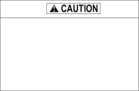
NOTE: Knobs are shipped separately within the unit to pre-
vent shipping damage. These must be field installed
for tool free operation.
Factory installed smoke detectors in the return air,
may be subjected to freezing temperatures during
“off” times due to out side air infiltration. these smoke
detectors have an operational limit of 32°F to 131°F.
smoke detectors installed in areas that could be out
side those limitations will have to be moved to prevent
having false alarms.
262260-YTG-E-1008
8Johnson Controls Unitary Products
•HINGED/"TOOL FREE" BLOWER, BLOWER MOTOR,
FILTER AND ELECTRIC ACCESS PANELS - This
option allows for complete hinged and tool free access to
the unit's blower, blower motor, filters and electrical panel
sections.
FIELD-INSTALLED ACCESSORIES
•SINGLE INPUT ELECTRONIC ENTHALPY ECONO-
MIZERS - Includes a slide-in / plug-in damper assembly
with fully modulating spring-return motor actuator capa-
ble of introducing up to 100% outdoor air with nominal
1% leakage type dampers.
The enthalpy system contains one sensor that monitors
the outdoor air and determines when the air is cool
enough and dry enough to provide free cooling.
The rainhood is painted to match the basic unit and must
be field-assembled before installing.
•MOTORIZED OUTDOOR AIR INTAKE DAMPER -
Includes a slide-in / plug-in damper assembly with a 2-
position, spring return motor actuator which opens to
some pre-set position whenever the supply air blower is
operating and will drive fully closed when the blower unit
shuts down.
The rain hood is painted to match the basic unit and
must be field assembled before installing.
•ROOF CURBS - Fourteen-inch high roof curbs provide a
water-tight seal between the unit and the finished roof.
These full perimeter curbs meet the requirements of the
National Roofing Contractors Association (NRCA) and
are shipped knocked-down for field assembly.
They're designed to fit inside the base rails of the unit
and include both a wood nailing strip and duct hanger
supports.
•HIGH ALTITUDE NATURAL GAS - Burner orifices and
pilot orifices are provided for proper furnace operation at
altitudes up to 6,000 feet.
•PROPANE - Burner orifices, pilot orifices and gas valve
parts are provided to convert a natural gas furnace to
propane.
•HIGH ALTITUDE PROPANE - Burner orifices and pilot
orifices are provided for proper furnace operation at alti-
tudes up to 6,000 feet. This accessory supplements the
basic propane conversion kit.
•SIDE DUCT FLANGES - One-inch flanges replace the
supply and return air panels on the rear of the unit to
accommodate horizontal duct connections. These
flanges can also be used individually for bottom supply/
horizontal return or horizontal supply/bottom return. They
cannot be used on units with power exhaust.
•BAROMETRIC RELIEF DAMPER - This damper acces-
sory can be used to relieve internal building air pressure
on units with an economizer without power exhaust. This
accessory includes a rain hood, a bird screen and a fully
assembled damper. With bottom duct connections, the
damper should be mounted over the opening in the
return air panel. With horizontal ductwork, the accessory
should be mounted on the return air duct.
• HIGH STATIC DRIVE - May include a belt, blower pulley,
motor pulley or a motor change to enhance blower per-
formance.
•ENTHALPY ACCESSORY CONTROL KIT - This kit
contains the required components to convert a single
enthalpy economizer to dual enthalpy.
•BURGLAR BARS - Mount in the supply and return
openings to prevent entry into the duct work.
•FLUE EXHAUST EXTENSION KIT - In locations with
wind or weather conditions which may interfere with
proper exhausting of furnace combustion products, this
kit can be installed to prevent the flue exhaust from
entering nearby fresh air intakes.
•WOOD SKID - Allows unit to be handled with 90” forks.
•CO2 SENSOR - Senses CO2 levels and automatically
overrides the economizer when levels rise above the
present limits.
•COIL GUARD - Customers can purchase a coil guard kit
to protect the condenser coil from damage. This is not a
hail guard kit.
• PHASE MONITORS - Designed to prevent unit damage.
The phase monitor will shut the unit down in an out-of-
phase condition.
262260-YTG-E-1008
Johnson Controls Unitary Products 9
SSE = Steady State Efficiency (80%) - Output divided by Input
TABLE 1: INDOOR SOUND POWER RATING1
1. These values have been accessed using a model of sound propagation from a point source into the hemispheric\free field. The dBA val-
ues provided are to be used for reference only. Calculation of dBA values cover matters of system design and the fan manufacture has no
way of knowing the details of each system. This constitutes and expectation to any specification or guarantee requiring a dBA value or
sound data in any other form than sound power level ratings.
UNIT
SIZE CFM
ESP BLOWER SOUND POWER (db 10-12 Watts)
Octave Band Centerline Frequency (Hz) SWL
dB(A)
dB(A)
@
10Ft.2
2. At a distance of 10 feet from the blower.
IWG RPM BHP 63 125 250 500 1,000 2,000 4,000 8,000
180 6,000 1.00 1,080 4.60 99 99 89 82 84 77 72 67 89 56
210, 240 8,000 1.00 1,120 6.65 102 102 92 85 87 80 75 70 92 59
300 10,000 1.30 1,160 12.5 108 108 98 91 93 86 81 76 98 65
TABLE 2: CAPACITY RATINGS - (ARI 360)1
1. 80/67°F Indoor and 95°F outdoor.
MODEL MBH EER2
2. EER = Energy Efficiency Ratio at full load - the cooling
capacity in Btu’s per hour (Btuh) divided by the power
input in watts, expressed in Btuh per watt (Btuh/watt).
IPLV3
3. IPLV = Integrated part load value.
COOLING ONLY
DH180C00 1784
4. Deduct 2 MBH @ 208V.
10.8 11.3
DH210C00 205 10.2 10.8
DH240C00 223 9.7 10.2
DH300C00 271 9.6 9.6
COOLING WITH GAS HEAT
DH180N/S 178410.8 11.3
DH210N/S 205 10.2 10.8
DH240N/S 223 9.7 10.2
DH300N/S 271 9.6 9.6
COOLING WITH ELECTRIC HEAT
DH180E18 178410.8 11.3
DH180E36 178410.8 11.3
DH180E54 176410.5 11.0
DH180E72 176410.5 11.0
DH210E18 205 10.2 10.8
DH210E36 205 10.2 10.8
DH210E54 203 10.0 10.6
DH210E72 203 10.0 10.6
DH240E18 223 9.6 10.1
DH240E36 223 9.6 10.1
DH240E54 221 9.5 9.7
DH240E72 219 9.5 9.7
DH300E18 271 9.6 9.6
DH300E36 271 9.6 9.6
DH300E54 269 9.5 9.4
DH300E72 269 9.5 9.4
TABLE 3: GAS HEAT RATINGS1
1. All units are two-stage heating. First stage is 50% of total.
MODEL MBH INPUT MBH OUTPUT
DH180N/S24 300 240
DH180N/S32 400 320
DH210N/S24 300 240
DH210N/S32 400 320
DH240N/S24 300 240
DH240N/S32 400 320
DH300N/S24 300 240
DH300N/S32 400 320
For units with VFD and electric or gas heat, the
speed of the indoor blower motor continues to be
controlled by duct static pressure via the VAV con-
trol board.
If there are VAV boxes present in the duct system,
the boxes must be driven to the full-open position
using a customer-supplied power source to assure
adequate airflow across electric heating elements or
gas heat exchanger tubes.
262260-YTG-E-1008
10 Johnson Controls Unitary Products
TABLE 4: DH 180 COOLING CAPACITIES (15 TON)
AIR ON
EVAPORATOR
COIL
TEMPERATURE OF AIR ON CONDENSER COIL
75°F 85°F
TOTAL
CAP.1
MBH
POWER
INPUT2
KW
SENSIBLE CAPACITY, MBH TOTAL
CAP.1
MBH
POWER
INPUT2
KW
SENSIBLE CAPACITY, MBH
ENTERING DRY BULB, °F ENTERING DRY BULB, °F
CFM WB
°F 90 85 80 75 70 65 90 85 80 75 70 65
4500
77 223.0 11.3 100.4 79.0 57.7 - - - 218.1 12.9 99.3 77.9 56.5 - - -
72 211.0 11.2 133.1 111.7 90.3 68.9 - - 203.0 12.6 130.5 109.2 87.8 66.4 - -
67 199.0 11.1 165.8 144.4 123.0 101.6 80.2 - 188.0 12.3 161.8 140.4 119.0 97.6 76.2 -
62 181.3 10.8 181.3 178.6 157.3 135.9 114.5 93.1 173.0 12.1 173.0 169.9 148.5 127.2 105.8 84.4
57 178.5 10.5 178.5 179.1 162.3 140.9 119.6 98.2 170.1 12.1 170.1 170.1 151.1 129.7 108.3 86.9
5250
77 231.5 11.3 107.2 87.6 62.3 - - - 225.0 12.9 112.3 87.0 61.8 - - -
72 219.0 11.2 148.2 122.9 97.7 72.4 - - 209.5 12.6 146.4 121.2 95.9 70.6 - -
67 206.5 11.2 189.2 158.3 133.0 107.7 82.5 - 194.0 12.4 180.5 155.3 130.0 104.7 79.5 -
62 188.1 10.9 188.1 186.8 170.1 144.9 119.6 94.3 178.5 12.2 178.5 177.0 162.3 137.0 111.7 86.5
57 185.3 10.6 185.3 185.5 175.7 150.4 125.1 99.8 175.6 12.2 175.6 175.6 165.0 139.8 114.5 89.2
6000
77 240.0 11.4 114.0 96.2 67.0 - - - 232.0 13.0 125.3 96.2 67.0 - - -
72 227.0 11.3 163.3 134.2 105.0 75.8 - - 216.0 12.7 162.3 133.2 104.0 74.8 - -
67 214.0 11.2 212.6 172.2 143.0 113.8 84.7 - 200.0 12.4 199.3 170.2 141.0 111.8 82.7 -
62 195.0 10.9 195.0 195.0 183.0 153.8 124.7 95.5 184.0 12.2 184.0 184.0 176.0 146.8 117.7 88.5
57 192.0 10.6 192.0 192.0 189.0 159.8 130.7 101.5 181.0 12.2 181.0 181.0 179.0 149.8 120.7 91.5
6750
72 226.4 11.2 178.0 144.8 111.6 78.4 - - 217.6 12.8 176.0 142.7 109.5 76.3 - -
67 213.5 11.2 212.8 185.2 152.0 118.8 85.6 - 201.5 12.5 201.2 181.7 148.5 115.3 82.1 -
62 194.5 10.8 194.5 194.5 188.5 155.3 122.1 88.9 185.4 12.2 185.4 185.4 181.4 148.2 115.0 81.8
57 191.5 10.5 191.5 191.5 190.0 156.8 123.6 90.4 182.4 12.2 182.4 182.4 181.4 148.1 114.9 81.7
7500
72 225.8 11.2 192.8 155.5 118.2 81.0 - - 219.2 12.8 189.6 152.3 115.1 77.8 - -
67 213.0 11.1 213.0 198.3 161.0 123.7 86.5 - 203.0 12.5 203.0 193.3 156.0 118.7 81.5 -
62 194.0 10.8 194.0 194.0 194.0 156.7 119.5 82.2 186.8 12.3 186.8 186.8 186.8 149.5 112.2 75.0
57 191.0 10.5 191.0 191.0 191.0 153.8 116.5 79.3 183.7 12.3 183.7 183.7 183.7 146.5 109.2 71.9
AIR ON
EVAPORATOR
COIL
TEMPERATURE OF AIR ON CONDENSER COIL
95°F 105°F
TOTAL
CAP.1
MBH
POWER
INPUT2
KW
SENSIBLE CAPACITY, MBH TOTAL
CAP.1
MBH
POWER
INPUT2
KW
SENSIBLE CAPACITY, MBH
ENTERING DRY BULB, °F ENTERING DRY BULB, °F
CFM WB
°F 90 85 80 75 70 65 90 85 80 75 70 65
4500
77 213.2 14.5 98.2 76.8 55.4 - - - 198.8 16.1 97.0 75.6 54.2 - - -
72 195.1 14.0 128.0 106.6 85.2 63.8 - - 182.7 15.4 125.1 103.7 82.4 61.0 - -
67 177.0 13.5 157.8 136.4 115.0 93.6 72.2 - 166.5 14.8 153.3 131.9 110.5 89.1 67.7 -
62 164.6 13.4 164.6 161.2 139.8 118.4 97.1 75.7 155.6 14.7 155.6 153.8 135.7 114.3 93.0 71.6
57 161.8 13.7 161.8 161.2 139.8 118.4 97.1 75.7 152.2 15.0 152.2 151.9 134.0 112.6 91.3 69.9
5250
77 218.6 14.5 117.4 86.5 61.2 - - - 203.9 16.2 117.3 84.6 59.4 - - -
72 200.0 14.0 144.7 119.4 94.1 68.8 - - 187.3 15.5 140.7 115.5 90.2 64.9 - -
67 181.5 13.6 171.9 152.3 127.0 101.7 76.5 - 170.8 14.8 164.1 146.3 121.0 95.7 70.5 -
62 168.8 13.5 168.8 167.1 154.4 129.1 103.9 78.6 159.5 14.8 159.5 158.7 148.6 123.3 98.1 72.8
57 165.9 13.7 165.9 165.6 154.4 129.1 103.9 78.6 156.1 15.1 156.1 156.0 146.8 121.5 96.2 70.9
6000
77 224.0 14.6 136.6 96.2 67.0 - - - 209.0 16.3 137.6 93.7 64.5 - - -
72 205.0 14.1 161.3 132.2 103.0 73.8 - - 192.0 15.6 156.3 127.2 98.0 68.8 - -
67 186.0 13.6 186.0 168.2 139.0 109.8 80.7 - 175.0 14.9 175.0 160.7 131.5 102.3 73.2 -
62 173.0 13.5 173.0 173.0 169.0 139.8 110.7 81.5 163.5 14.9 163.5 163.5 161.5 132.3 103.2 74.0
57 170.0 13.8 170.0 170.0 169.0 139.8 110.7 81.5 160.0 15.2 160.0 160.0 159.5 130.3 101.2 72.0
6750
72 208.9 14.3 173.9 140.7 107.4 74.2 - - 195.8 15.7 170.2 137.0 103.8 70.6 - -
67 189.5 13.8 189.5 178.2 145.0 111.8 78.6 - 178.5 15.0 178.5 170.1 139.3 106.0 72.8 -
62 176.3 13.6 176.3 176.3 174.3 141.0 107.8 74.6 166.8 15.0 166.8 166.8 165.8 132.6 99.4 66.1
57 173.2 14.0 173.2 173.2 172.7 139.5 106.3 73.1 163.2 15.3 163.2 163.2 163.0 129.7 96.5 63.3
7500
72 212.7 14.4 186.4 149.2 111.9 74.6 - - 199.7 15.9 184.1 146.8 109.6 72.3 - -
67 193.0 13.9 193.0 188.3 151.0 113.7 76.5 - 182.0 15.2 182.0 179.6 147.0 109.7 72.5 -
62 179.5 13.8 179.5 179.5 179.5 142.3 105.0 67.7 170.0 15.1 170.0 170.0 170.0 132.8 95.5 58.3
57 176.4 14.1 176.4 176.4 176.4 139.1 101.9 64.6 166.4 15.5 166.4 166.4 166.4 129.1 91.9 54.6
262260-YTG-E-1008
Johnson Controls Unitary Products 11
TABLE 4: DH 180 COOLING CAPACITIES (15 TON) (CONTINUED)
AIR ON
EVAPORATOR
COIL
TEMPERATURE OF AIR ON CONDENSER COIL
115°F
TOTAL
CAP.1
MBH
POWER
INPUT2
KW
SENSIBLE CAPACITY, MBH
ENTERING DRY BULB, °F
CFM WB
°F 90 85 80 75 70 65
4500
77 184.5 17.8 95.8 74.4 53.0 - - -
72 170.3 16.9 122.3 100.9 79.5 58.1 - -
67 156.0 16.0 148.8 127.4 106.0 84.6 63.2 -
62 146.5 16.1 146.5 146.5 131.6 110.3 88.9 67.5
57 142.7 16.4 142.7 142.7 128.2 106.8 85.5 64.1
5250
77 189.3 17.9 117.2 82.8 57.5 - - -
72 174.6 17.0 136.8 111.5 86.3 61.0 - -
67 160.0 16.1 156.4 140.3 115.0 89.7 64.5 -
62 150.2 16.2 150.2 150.2 142.8 117.6 92.3 67.0
57 146.3 16.5 146.3 146.3 139.1 113.8 88.6 63.3
6000
77 194.0 18.0 138.6 91.2 62.0 - - -
72 179.0 17.1 151.3 122.2 93.0 63.8 - -
67 164.0 16.2 164.0 153.2 124.0 94.8 65.7 -
62 154.0 16.3 154.0 154.0 154.0 124.8 95.7 66.5
57 150.0 16.6 150.0 150.0 150.0 120.8 91.7 62.5
6750
72 182.8 17.2 166.5 133.3 100.1 66.9 - -
67 167.5 16.3 167.5 162.1 133.5 100.3 67.1 -
62 157.3 16.4 157.3 157.3 157.3 124.1 90.9 57.7
57 153.2 16.7 153.2 153.2 153.2 120.0 86.8 53.6
7500
72 186.6 17.3 181.8 144.5 107.3 70.0 - -
67 171.0 16.4 171.0 171.0 143.0 105.7 68.5 -
62 160.6 16.5 160.6 160.6 160.6 123.3 86.1 48.8
57 156.4 16.8 156.4 156.4 156.4 119.1 81.9 44.6
1. These capacities are gross ratings. For net capacity, deduct the air blower motor, MBH = 3.415 x KW. Refer to the appropriate Blower Perfor-
mance Table for the KW of the supply air blower motor.
2. These ratings include the condenser fan motors (Total 2.3 KW) and the compressor motors but not the supply air blower motor.
Nominal Rating

262260-YTG-E-1008
12 Johnson Controls Unitary Products
TABLE 5: DH 210 COOLING CAPACITIES (17.5 TON)
AIR ON
EVAPORATOR
COIL
TEMPERATURE OF AIR ON CONDENSER COIL
75°F 85°F
TOTAL
CAP.1
MBH
POWER
INPUT2
KW
SENSIBLE CAPACITY, MBH TOTAL
CAP.1
MBH
POWER
INPUT2
KW
SENSIBLE CAPACITY, MBH
ENTERING DRY BULB, °F ENTERING DRY BULB, °F
CFM WB
°F 90 85 80 75 70 65 90 85 80 75 70 65
5250
77 241.5 13.9 119.5 94.6 69.6 - - - 240.2 15.6 119.7 94.8 69.9 - - -
72 232.2 13.2 159.7 134.8 109.8 84.9 - - 226.1 15.1 156.3 131.4 106.4 81.5 - -
67 223.0 12.6 199.9 174.9 150.0 125.1 100.1 - 212.0 14.5 192.9 167.9 143.0 118.1 93.1 -
62 204.4 12.4 204.4 204.4 182.1 157.1 132.2 107.2 193.5 14.3 193.5 193.5 170.5 145.5 120.6 95.6
57 200.4 12.6 200.4 200.4 183.1 158.2 133.2 108.3 191.2 14.3 191.2 191.2 171.8 146.9 121.9 97.0
6125
77 250.1 14.5 136.3 104.8 75.3 - - - 248.8 16.0 140.3 105.8 76.3 - - -
72 240.5 13.8 177.8 148.3 118.9 89.4 - - 234.2 15.4 175.2 145.7 116.2 86.7 - -
67 231.0 13.1 219.4 191.9 162.4 132.9 103.4 - 219.6 14.9 210.0 185.6 156.2 126.7 97.2 -
62 211.7 12.9 211.7 211.7 197.2 167.7 138.2 108.7 200.5 14.7 200.5 200.5 186.1 156.6 127.2 97.7
57 207.6 13.1 207.6 207.6 198.3 168.8 139.3 109.9 198.0 14.7 198.0 198.0 187.6 158.1 128.6 99.1
7000
77 258.7 15.1 153.0 115.0 81.0 - - - 257.4 16.4 160.9 116.7 82.7 - - -
72 248.8 14.4 195.9 161.9 127.9 93.9 - - 242.3 15.8 194.0 160.0 126.0 92.0 - -
67 238.9 13.7 238.9 208.8 174.8 140.8 106.8 - 227.2 15.2 227.2 203.3 169.3 135.3 101.3 -
62 219.0 13.5 219.0 219.0 212.3 178.3 144.3 110.2 207.4 15.0 207.4 207.4 201.8 167.8 133.8 99.7
57 214.7 13.7 214.7 214.7 213.5 179.5 145.5 111.4 204.9 15.0 204.9 204.9 203.4 169.4 135.4 101.3
7875
72 253.0 14.5 214.9 176.1 137.4 98.6 - - 246.9 15.9 212.6 173.9 135.2 96.4 - -
67 243.0 13.8 243.0 227.9 187.8 149.0 110.3 - 231.6 15.3 231.6 219.6 181.6 142.9 104.1 -
62 222.7 13.6 222.7 222.7 219.4 180.6 141.9 103.1 211.4 15.1 211.4 211.4 208.6 169.8 131.1 92.3
57 218.3 13.8 218.3 218.3 217.7 179.0 140.2 101.5 208.8 15.1 208.8 208.8 208.1 169.3 130.6 91.8
8750
72 257.2 14.6 233.8 190.3 146.9 103.4 - - 251.6 16.0 231.2 187.8 144.3 100.8 - -
67 247.0 13.9 247.0 247.0 200.7 157.2 113.8 - 235.9 15.4 235.9 235.9 193.9 150.4 107.0 -
62 226.4 13.7 226.4 226.4 226.4 183.0 139.5 96.0 215.3 15.2 215.3 215.3 215.3 171.9 128.4 84.9
57 222.0 13.9 222.0 222.0 222.0 178.5 135.0 91.6 212.7 15.2 212.7 212.7 212.7 169.3 125.8 82.3
AIR ON
EVAPORATOR
COIL
TEMPERATURE OF AIR ON CONDENSER COIL
95°F 105°F
TOTAL
CAP.1
MBH
POWER
INPUT2
KW
SENSIBLE CAPACITY, MBH TOTAL
CAP.1
MBH
POWER
INPUT2
KW
SENSIBLE CAPACITY, MBH
ENTERING DRY BULB, °F ENTERING DRY BULB, °F
CFM WB
°F 90 85 80 75 70 65 90 85 80 75 70 65
5250
77 238.9 17.4 120.0 95.0 70.1 - - - 228.3 15.0 116.1 91.2 66.2 - - -
72 219.9 16.9 152.9 128.0 103.0 78.1 - - 209.9 14.6 148.0 123.0 98.1 73.1 - -
67 201.0 16.5 185.9 160.9 136.0 111.1 86.1 - 191.5 14.2 179.8 154.8 129.9 105.0 80.0 -
62 182.6 16.3 182.6 182.6 158.8 133.9 108.9 84.0 176.2 14.0 176.2 176.2 152.7 127.8 102.9 77.9
57 182.0 16.1 182.0 182.0 160.5 135.5 110.6 85.6 176.4 13.9 176.4 176.4 153.3 128.3 103.4 78.4
6125
77 247.5 17.6 144.4 106.7 77.2 - - - 235.7 17.2 143.3 102.8 73.3 - - -
72 235.0 17.2 172.5 143.1 124.0 84.1 - - 223.4 19.0 167.5 138.0 108.6 79.1 - -
67 215.5 16.7 200.7 179.4 163.8 120.4 90.9 - 203.8 18.5 191.8 173.3 143.8 114.3 84.8 -
62 195.8 16.5 189.2 189.2 191.3 145.6 116.1 86.6 187.4 18.2 181.8 181.8 169.1 139.6 110.1 80.6
57 195.1 16.3 188.5 188.5 193.3 147.4 117.9 88.4 187.8 18.1 182.1 182.1 169.7 140.2 110.7 81.2
7000
77 256.1 17.7 168.8 118.4 84.4 - - - 243.0 19.5 170.4 114.4 80.4 - - -
72 235.8 17.2 192.1 158.1 124.1 90.1 - - 223.4 19.0 187.1 153.1 119.1 85.0 - -
67 215.5 16.7 215.5 197.8 163.8 129.8 95.8 - 203.8 18.5 203.8 191.7 157.7 123.7 89.7 -
62 195.8 16.5 195.8 195.8 191.3 157.3 123.3 89.2 187.5 18.2 187.5 187.5 185.5 151.4 117.4 83.4
57 195.1 16.3 195.1 195.1 193.3 159.3 125.3 91.2 187.8 18.1 187.8 187.8 186.1 152.0 118.0 84.0
7875
72 240.9 17.3 210.4 171.7 132.9 94.2 - - 228.3 19.1 205.3 166.5 127.8 89.0 - -
67 220.2 16.8 220.2 211.3 175.5 136.7 98.0 - 208.3 18.6 208.3 202.2 169.3 130.5 91.8 -
62 200.0 16.6 200.0 200.0 197.8 159.0 120.3 81.5 191.6 18.3 191.6 191.6 190.6 151.8 113.1 74.3
57 199.3 16.4 199.3 199.3 198.4 159.7 120.9 82.2 191.9 18.2 191.9 191.9 191.0 152.3 113.5 74.8
8750
72 246.0 17.4 228.7 185.2 141.8 98.3 - - 233.2 19.2 223.5 180.0 136.5 93.1 - -
67 224.8 16.9 224.8 224.8 187.1 143.6 100.2 - 212.8 18.7 212.8 212.8 180.9 137.4 93.9 -
62 204.2 16.7 204.2 204.2 204.2 160.8 117.3 73.8 195.7 18.4 195.7 195.7 195.7 152.2 108.7 65.3
57 203.5 16.5 203.5 203.5 203.5 160.0 116.6 73.1 196.0 18.3 196.0 196.0 196.0 152.5 109.1 65.6
262260-YTG-E-1008
Johnson Controls Unitary Products 13
TABLE 5: DH 210 COOLING CAPACITIES (17.5 TON) (CONTINUED)
AIR ON
EVAPORATOR
COIL
TEMPERATURE OF AIR ON CONDENSER COIL
115°F 125°F
TOTAL
CAP.1
MBH
POWER
INPUT2
KW
SENSIBLE CAPACITY, MBH TOTAL
CAP.1
MBH
POWER
INPUT2
KW
SENSIBLE CAPACITY, MBH
ENTERING DRY BULB, °F ENTERING DRY BULB, °F
CFM WB
°F 90 85 80 75 70 65 90 85 80 75 70 65
5250
77 217.8 12.5 112.3 87.3 62.4 - - - 207.3 10.1 108.4 83.5 58.5 - - -
72 199.9 12.2 143.0 118.0 93.1 68.1 - - 189.9 9.9 138.0 113.1 88.1 63.2 - -
67 182.0 12.0 173.7 148.7 123.8 98.9 73.9 - 172.5 9.7 167.6 142.6 117.7 92.8 67.8 -
62 169.7 11.8 169.7 169.7 146.7 121.7 96.8 71.8 163.2 9.5 163.2 163.2 140.6 115.6 90.7 65.7
57 170.9 11.8 170.9 170.9 146.0 121.1 96.1 71.2 165.4 9.6 165.4 165.4 138.8 113.8 88.9 63.9
6125
77 223.9 16.9 142.1 98.9 69.4 - - - 212.0 16.5 141.0 95.0 65.5 - - -
72 205.5 16.5 162.5 133.0 103.5 74.1 - - 194.2 16.2 157.5 128.0 98.5 69.1 - -
67 187.1 16.1 182.9 167.2 137.7 108.2 78.7 - 176.5 15.8 174.0 161.1 131.6 102.1 72.6 -
62 174.4 15.8 174.4 174.4 163.1 133.6 104.2 74.7 167.0 15.6 167.0 167.0 157.2 127.7 98.2 68.7
57 175.7 15.8 175.7 175.7 162.4 132.9 103.4 74.0 169.2 15.7 169.2 169.2 155.2 125.7 96.2 66.7
7000
77 229.9 21.2 172.0 110.4 76.4 - - - 216.8 23.0 173.6 106.4 72.4 - - -
72 211.0 20.7 182.0 148.0 114.0 80.0 - - 198.6 22.5 177.0 143.0 109.0 74.9 - -
67 192.1 20.2 192.1 185.6 151.6 117.6 83.6 - 180.4 22.0 180.4 179.5 145.5 111.5 77.5 -
62 179.1 19.9 179.1 179.1 179.6 145.6 111.6 77.5 170.8 21.6 170.8 170.8 170.8 139.7 105.7 71.7
57 180.4 19.9 180.4 180.4 178.8 144.8 110.8 76.7 173.1 21.7 173.1 173.1 171.6 137.5 103.5 69.5
7875
72 215.7 20.8 200.1 161.4 122.6 83.9 - - 203.1 22.6 195.0 156.3 117.5 78.8 - -
67 196.4 20.3 196.4 193.2 163.1 124.4 85.6 - 184.5 22.1 184.5 184.1 156.9 118.2 79.4 -
62 183.1 20.0 183.1 183.1 183.4 144.6 105.9 67.1 174.7 21.7 174.7 174.7 174.7 137.4 98.7 59.9
57 184.4 20.0 184.4 184.4 183.6 144.9 106.1 67.4 177.0 21.8 177.0 177.0 176.3 137.5 98.8 60.0
8750
72 220.4 20.9 218.2 174.8 131.3 87.8 - - 207.7 22.7 207.7 169.5 126.1 82.6 - -
67 200.7 20.4 200.7 200.7 174.6 131.1 87.7 - 188.7 22.2 188.7 188.7 168.4 124.9 81.4 -
62 187.1 20.1 187.1 187.1 187.1 143.6 100.2 56.7 178.6 21.8 178.6 178.6 178.6 135.1 91.6 48.1
57 188.5 20.1 188.5 188.5 188.5 145.0 101.5 58.1 181.0 21.9 181.0 181.0 181.0 137.5 94.0 50.5
1. These capacities are gross ratings. For net capacity, deduct the air blower motor, MBH = 3.415 x KW. Refer to the appropriate Blower Performance
Table for the KW of the supply air blower motor.
2. These ratings include the condenser fan motors (Total 1 KW) and the compressor motors but not the supply air blower motor.
Nominal Rating
262260-YTG-E-1008
14 Johnson Controls Unitary Products
TABLE 6: DH 240 COOLING CAPACITIES (20 TON)
AIR ON
EVAPORATOR
COIL
TEMPERATURE OF AIR ON CONDENSER COIL
75°F 85°F
TOTAL
CAP.1
MBH
POWER
INPUT2
KW
SENSIBLE CAPACITY, MBH TOTAL
CAP.1
MBH
POWER
INPUT2
KW
SENSIBLE CAPACITY, MBH
ENTERING DRY BULB, °F ENTERING DRY BULB, °F
CFM WB
°F 90 85 80 75 70 65 90 85 80 75 70 65
6000
77 277.0 19.1 159.2 130.7 102.2 - - - 262.0 20.5 153.7 125.2 96.7 - - -
72 263.0 18.6 196.1 167.6 139.1 110.6 - - 249.0 20.1 190.4 161.8 133.3 104.8 - -
67 249.0 18.0 233.0 204.5 176.0 147.5 119.0 - 236.0 19.6 227.0 198.5 170.0 141.5 113.0 -
62 240.6 17.9 240.6 240.6 215.3 186.8 158.3 129.8 228.6 19.4 228.6 228.6 204.2 175.7 147.1 118.6
57 237.8 17.7 237.8 237.8 213.7 185.2 156.7 128.1 226.7 19.1 226.7 226.7 203.3 174.8 146.3 117.8
7000
77 287.0 17.9 189.9 145.8 112.1 - - - 272.0 19.4 187.6 140.0 106.3 - - -
72 272.5 17.4 219.9 186.3 152.6 118.9 - - 258.5 18.9 214.1 180.4 146.7 113.0 - -
67 258.0 16.9 250.0 226.7 193.0 159.3 125.6 - 245.0 18.5 240.5 220.7 187.0 153.3 119.6 -
62 249.3 16.7 249.3 249.3 236.2 202.5 168.8 135.1 237.3 18.3 237.3 237.3 224.6 190.9 157.2 123.5
57 246.4 16.5 246.4 246.4 234.3 200.6 166.9 133.3 235.4 18.1 235.4 235.4 223.7 190.0 156.3 122.6
8000
77 297.0 16.7 220.5 160.9 122.0 - - - 282.0 18.2 221.5 154.9 116.0 - - -
72 282.0 16.2 243.8 204.9 166.0 127.1 - - 268.0 17.8 237.8 198.9 160.0 121.1 - -
67 267.0 15.7 267.0 248.9 210.0 171.1 132.2 - 254.0 17.4 254.0 242.9 204.0 165.1 126.2 -
62 258.0 15.6 258.0 258.0 257.0 218.1 179.2 140.4 246.0 17.2 246.0 246.0 245.0 206.1 167.2 128.4
57 255.0 15.4 255.0 255.0 255.0 216.1 177.2 138.4 244.0 17.0 244.0 244.0 244.0 205.1 166.2 127.4
9000
72 295.2 13.7 275.1 228.1 183.8 139.5 - - 280.7 15.3 265.0 220.8 176.5 132.2 - -
67 279.5 13.3 279.5 270.4 232.5 188.2 143.9 - 266.0 15.0 266.0 260.4 225.0 180.7 136.4 -
62 270.1 13.2 270.1 270.1 269.6 225.3 181.0 136.7 257.6 14.8 257.6 257.6 257.1 212.8 168.6 124.3
57 266.9 13.0 266.9 266.9 266.9 222.7 178.4 134.1 255.5 14.6 255.5 255.5 255.5 211.2 167.0 122.7
10000
72 308.4 11.2 306.4 251.2 201.5 151.9 - - 293.3 12.8 292.3 242.6 192.9 143.3 - -
67 292.0 10.8 292.0 292.0 255.0 205.3 155.6 - 278.0 12.5 278.0 278.0 246.0 196.3 146.6 -
62 282.2 10.7 282.2 282.2 282.2 232.5 182.8 133.1 269.2 12.4 269.2 269.2 269.2 219.6 169.9 120.2
57 278.9 10.6 278.9 278.9 278.9 229.2 179.5 129.8 267.1 12.2 267.1 267.1 267.1 217.4 167.7 118.0
AIR ON
EVAPORATOR
COIL
TEMPERATURE OF AIR ON CONDENSER COIL
95°F 105°F
TOTAL
CAP.1
MBH
POWER
INPUT2
KW
SENSIBLE CAPACITY, MBH TOTAL
CAP.1
MBH
POWER
INPUT2
KW
SENSIBLE CAPACITY, MBH
ENTERING DRY BULB, °F ENTERING DRY BULB, °F
CFM WB
°F 90 85 80 75 70 65 90 85 80 75 70 65
6000
77 247.1 21.9 148.1 119.6 91.1 - - - 232.2 23.3 144.0 115.5 87.0 - - -
72 235.0 21.5 184.6 156.1 127.6 99.0 - - 221.1 22.9 180.0 151.5 123.0 94.5 - -
67 223.0 21.2 221.0 192.5 164.0 135.5 107.0 - 210.0 22.6 209.0 187.5 159.0 130.5 102.0 -
62 216.5 20.9 216.5 216.5 193.0 164.5 136.0 107.5 205.4 22.2 205.4 205.4 183.0 154.5 126.0 97.5
57 215.6 20.6 215.6 215.6 193.0 164.5 136.0 107.5 204.0 21.9 204.0 204.0 182.6 154.1 125.6 97.1
7000
77 257.0 20.8 185.3 134.3 100.6 - - - 241.6 22.3 184.7 132.6 96.0 - - -
72 244.5 20.5 208.2 174.5 140.8 107.1 - - 230.1 21.9 203.1 169.4 135.7 102.0 - -
67 236.0 20.1 231.0 214.7 182.0 147.3 113.6 - 218.5 21.6 218.0 206.2 175.5 141.8 108.1 -
62 225.3 19.8 225.3 225.3 213.0 179.3 145.6 111.9 213.7 21.2 213.7 213.7 202.0 168.3 134.6 100.9
57 224.3 19.6 224.3 224.3 213.0 179.3 145.6 111.9 212.2 21.0 212.2 212.2 201.6 167.9 134.2 100.5
8000
77 267.0 19.7 222.5 148.9 110.0 - - - 251.0 21.3 225.5 149.8 105.0 - - -
72 254.0 19.4 231.8 192.9 154.0 115.1 - - 239.0 20.9 226.3 187.4 148.5 109.6 - -
67 241.0 19.1 241.0 236.9 198.0 159.1 120.2 - 227.0 20.6 227.0 224.9 192.0 153.1 114.2 -
62 234.0 18.8 234.0 234.0 233.0 194.1 155.2 116.4 222.0 20.2 222.0 222.0 221.0 182.1 143.2 104.4
57 233.0 18.6 233.0 233.0 233.0 194.1 155.2 116.4 220.5 20.0 220.5 220.5 220.5 181.6 142.7 103.9
9000
72 266.1 16.9 255.0 213.4 169.2 124.9 - - 251.1 18.4 244.7 208.0 163.7 119.4 - -
67 252.5 16.7 252.5 250.4 217.5 173.2 128.9 - 238.5 18.1 238.5 237.5 211.6 167.3 123.1 -
62 245.2 16.4 245.2 245.2 244.7 200.4 156.1 111.8 233.3 17.8 233.3 233.3 232.8 188.5 144.2 99.9
57 244.1 16.2 244.1 244.1 244.1 199.8 155.6 111.3 231.7 17.6 231.7 231.7 231.7 187.4 143.1 98.8
10000
72 278.2 14.4 278.2 234.0 184.3 134.7 - - 263.2 16.0 263.2 228.5 178.9 129.2 - -
67 264.0 14.2 264.0 264.0 237.0 187.3 137.6 - 250.0 15.7 250.0 250.0 231.3 181.6 131.9 -
62 256.3 14.0 256.3 256.3 256.3 206.7 157.0 107.3 244.5 15.4 244.5 244.5 244.5 194.8 145.1 95.5
57 255.2 13.8 255.2 255.2 255.2 205.6 155.9 106.2 242.8 15.3 242.8 242.8 242.8 193.2 143.5 93.8

262260-YTG-E-1008
Johnson Controls Unitary Products 15
TABLE 6: DH 240 COOLING CAPACITIES (20 TON) (CONTINUED)
AIR ON
EVAPORATOR
COIL
TEMPERATURE OF AIR ON CONDENSER COIL
115°F
TOTAL
CAP.1
MBH
POWER
INPUT2
KW
SENSIBLE CAPACITY, MBH
ENTERING DRY BULB, °F
CFM WB
°F 90 85 80 75 70 65
6000
77 217.3 24.8 139.8 111.3 82.8 - - -
72 207.2 24.3 175.4 146.9 118.4 89.9 - -
67 197.0 23.9 197.0 182.5 154.0 125.5 97.0 -
62 194.2 23.5 194.2 194.2 173.0 144.5 116.0 87.5
57 192.4 23.2 192.4 192.4 172.2 143.7 115.2 86.7
7000
77 226.2 23.8 184.2 131.0 91.4 - - -
72 215.6 23.4 198.1 164.4 130.7 97.0 - -
67 205.0 23.0 205.0 197.8 170.0 136.3 102.6 -
62 202.1 22.5 202.1 202.1 191.0 157.3 123.6 89.9
57 200.2 22.3 200.2 200.2 190.1 156.4 122.7 89.0
8000
77 235.0 22.8 228.5 150.8 100.0 - - -
72 224.0 22.4 220.8 181.9 143.0 104.1 - -
67 213.0 22.0 213.0 213.0 186.0 147.1 108.2 -
62 210.0 21.6 210.0 210.0 209.0 170.1 131.2 92.4
57 208.0 21.4 208.0 208.0 208.0 169.1 130.2 91.4
9000
72 236.1 20.0 234.5 202.5 158.2 113.9 - -
67 224.5 19.6 224.5 224.5 205.8 161.5 117.2 -
62 221.3 19.2 221.3 221.3 220.8 176.6 132.3 88.0
57 219.2 19.1 219.2 219.2 219.2 175.0 130.7 86.4
10000
72 248.2 17.5 248.2 223.0 173.4 123.7 - -
67 236.0 17.2 236.0 236.0 225.5 175.8 126.1 -
62 232.7 16.9 232.7 232.7 232.7 183.0 133.3 83.6
57 230.5 16.7 230.5 230.5 230.5 180.8 131.1 81.4
1. These capacities are gross ratings. For net capacity, deduct the air blower motor, MBH = 3.415 x KW. Refer to the appropriate Blower Perfor-
mance Table for the KW of the supply air blower motor.
2. These ratings include the condenser fan motors (Total 2.3 KW) and the compressor motors but not the supply air blower motor.
Nominal Rating
262260-YTG-E-1008
16 Johnson Controls Unitary Products
TABLE 7: DH 300 COOLING CAPACITIES (25 TON)
AIR ON
EVAPORATOR
COIL
TEMPERATURE OF AIR ON CONDENSER COIL
75°F 85°F
TOTAL
CAP.1
MBH
POWER
INPUT2
KW
SENSIBLE CAPACITY, MBH TOTAL
CAP.1
MBH
POWER
INPUT2
KW
SENSIBLE CAPACITY, MBH
ENTERING DRY BULB, °F ENTERING DRY BULB, °F
CFM WB
°F 90 85 80 75 70 65 90 85 80 75 70 65
7500
77 371.3 19.7 191.8 156.2 120.6 - - - 348.9 21.5 185.5 149.8 114.2 - - -
72 334.4 19.3 233.0 197.4 161.8 126.1 - - 318.7 21.1 226.6 190.9 155.3 119.7 - -
67 297.6 18.8 274.2 238.6 203.0 167.3 131.7 - 288.4 20.8 267.7 232.0 196.4 160.8 125.1 -
62 290.9 18.3 290.9 284.9 246.4 210.8 175.1 139.5 277.6 20.1 277.6 274.6 238.9 203.3 167.7 132.0
57 281.0 18.2 281.0 281.0 261.8 226.1 190.5 154.9 272.4 20.1 272.4 272.4 249.6 214.0 178.3 142.7
8750
77 373.9 19.7 219.7 168.5 126.4 - - - 353.3 21.6 214.0 162.4 120.3 - - -
72 336.8 19.3 253.8 211.7 169.6 127.5 - - 322.7 21.3 247.8 205.7 163.6 121.5 - -
67 299.7 18.9 288.0 254.9 212.8 170.7 128.5 - 292.0 21.0 281.7 249.0 206.9 164.7 122.6 -
62 293.0 18.3 293.0 290.0 258.3 216.2 174.1 132.0 281.1 20.3 281.1 279.6 251.7 209.5 167.4 125.3
57 282.9 18.2 282.9 282.9 274.5 232.4 190.3 148.1 275.8 20.3 275.8 275.8 262.9 220.8 178.7 136.5
10000
77 376.6 19.8 247.6 180.9 132.3 - - - 357.7 21.8 242.4 175.0 126.4 - - -
72 339.1 19.3 274.6 226.0 177.4 128.8 - - 326.7 21.5 269.0 220.4 171.8 123.2 - -
67 301.7 18.9 301.7 271.2 222.6 174.0 125.4 - 295.7 21.1 295.7 265.9 217.3 168.7 120.1 -
62 295.0 18.4 295.0 295.0 270.2 221.6 173.0 124.4 284.6 20.5 284.6 284.6 264.4 215.8 167.2 118.6
57 284.9 18.3 284.9 284.9 287.2 238.6 190.0 141.4 279.3 20.4 279.3 279.3 276.2 227.6 179.0 130.4
11250
72 341.5 20.3 290.9 235.5 180.2 124.8 - - 330.7 22.2 288.3 232.9 177.6 122.2 - -
67 303.7 19.8 303.7 281.3 226.0 170.6 115.3 - 299.3 21.8 299.3 279.9 224.5 169.2 113.8 -
62 297.0 19.3 297.0 297.0 275.0 219.7 164.3 109.0 288.1 21.2 288.1 288.1 273.2 217.8 162.5 107.1
57 286.8 19.2 286.8 286.8 287.9 232.6 177.2 121.9 282.7 21.1 282.7 282.7 281.2 225.8 170.5 115.1
12500
72 343.8 21.3 307.1 245.0 182.9 120.8 - - 334.8 22.9 307.5 245.4 183.3 121.2 - -
67 305.7 20.8 305.7 291.5 229.4 167.3 105.2 - 303.0 22.6 303.0 293.9 231.8 169.7 107.6 -
62 299.1 20.2 299.1 299.1 279.8 217.7 155.6 93.5 291.6 21.8 291.6 291.6 282.0 219.9 157.8 95.7
57 288.7 20.1 288.7 288.7 288.7 226.6 164.5 102.4 286.1 21.8 286.1 286.1 286.1 224.0 161.9 99.8
AIR ON
EVAPORATOR
COIL
TEMPERATURE OF AIR ON CONDENSER COIL
95°F 105°F
TOTAL
CAP.1
MBH
POWER
INPUT2
KW
SENSIBLE CAPACITY, MBH TOTAL
CAP.1
MBH
POWER
INPUT2
KW
SENSIBLE CAPACITY, MBH
ENTERING DRY BULB, °F ENTERING DRY BULB, °F
CFM WB
°F 90 85 80 75 70 65 90 85 80 75 70 65
7500
77 326.6 23.2 179.1 143.5 107.9 - - - 314.3 26.2 163.3 127.7 92.0 - - -
72 302.9 23.0 220.1 184.5 148.8 113.2 - - 288.7 25.8 209.2 173.5 137.9 102.2 - -
67 279.2 22.8 261.1 225.5 189.8 154.2 118.5 - 263.1 25.3 254.1 219.4 183.7 148.1 112.5 -
62 264.2 22.0 264.2 264.2 231.5 195.8 160.2 124.6 253.6 24.5 253.6 253.6 225.7 190.1 154.5 118.8
57 263.7 22.0 263.7 263.7 237.4 201.8 166.1 130.5 251.0 24.6 251.0 251.0 222.7 187.1 151.4 115.8
8750
77 332.8 23.5 208.2 156.3 114.2 - - - 319.5 26.4 197.7 139.8 97.6 - - -
72 308.6 23.3 241.8 199.7 157.5 115.4 - - 293.5 25.9 230.6 188.5 146.3 104.2 - -
67 284.4 23.1 275.4 243.0 200.9 158.8 116.7 - 267.5 25.4 263.0 237.2 195.0 152.9 110.8 -
62 269.2 22.3 269.2 269.2 245.0 202.9 160.8 118.7 257.8 24.7 257.8 257.8 239.6 197.5 155.4 113.3
57 268.7 22.3 268.7 268.7 251.3 209.2 167.1 124.9 255.2 24.8 255.2 255.2 236.4 194.2 152.1 110.0
10000
77 338.9 23.8 237.3 169.1 120.5 - - - 324.6 26.6 232.2 151.9 103.3 - - -
72 314.3 23.6 263.5 214.9 166.3 117.7 - - 298.2 26.1 252.0 203.4 154.8 106.2 - -
67 289.7 23.4 289.7 260.6 212.0 163.4 114.8 - 271.8 25.6 271.8 254.9 206.3 157.7 109.1 -
62 274.2 22.6 274.2 274.2 258.6 210.0 161.4 112.8 261.9 24.9 261.9 261.9 253.5 204.9 156.3 107.7
57 273.7 22.6 273.7 273.7 265.2 216.6 168.0 119.4 259.3 24.9 259.3 259.3 250.0 201.4 152.8 104.2
11250
72 320.0 24.1 285.6 230.3 174.9 119.6 - - 303.0 26.5 271.3 215.9 160.6 105.2 - -
67 294.9 23.9 294.9 278.4 223.1 167.7 112.4 - 276.2 26.0 276.2 266.7 213.9 158.5 103.2 -
62 279.2 23.0 279.2 279.2 271.4 216.0 160.7 105.3 266.1 25.2 266.1 266.1 261.9 206.5 151.2 95.8
57 278.6 23.0 278.6 278.6 274.4 219.0 163.7 108.3 263.4 25.3 263.4 263.4 257.0 201.6 146.3 90.9
12500
72 325.7 24.6 307.8 245.7 183.6 121.5 - - 307.8 26.8 290.5 228.4 166.3 104.2 - -
67 300.2 24.3 300.2 296.2 234.1 172.0 109.9 - 280.5 26.3 280.5 278.5 221.4 159.3 97.2 -
62 284.1 23.5 284.1 284.1 284.1 222.0 159.9 97.8 270.3 25.6 270.3 270.3 270.3 208.2 146.1 84.0
57 283.6 23.5 283.6 283.6 283.6 221.5 159.4 97.3 267.6 25.6 267.6 267.6 263.9 201.8 139.7 77.6

262260-YTG-E-1008
Johnson Controls Unitary Products 17
TABLE 7: DH 300 COOLING CAPACITIES (25 TON) (CONTINUED)
AIR ON
EVAPORATOR
COIL
TEMPERATURE OF AIR ON CONDENSER COIL
115°F
TOTAL
CAP.1
MBH
POWER
INPUT2
KW
SENSIBLE CAPACITY, MBH
ENTERING DRY BULB, °F
CFM WB
°F 90 85 80 75 70 65
7500
77 302.0 29.3 147.5 111.8 76.2 - - -
72 274.5 28.5 198.2 162.6 126.9 91.3 - -
67 247.1 27.7 247.1 213.3 177.7 142.0 106.4 -
62 242.9 27.1 242.9 242.9 220.0 184.3 148.7 113.1
57 238.3 27.2 238.3 238.3 208.0 172.3 136.7 101.1
8750
77 306.2 29.3 187.3 123.2 81.1 - - -
72 278.4 28.5 219.4 177.3 135.1 93.0 - -
67 250.5 27.8 250.5 231.3 189.2 147.0 104.9 -
62 246.3 27.1 246.3 246.3 234.2 192.1 150.0 107.8
57 241.6 27.3 241.6 241.6 221.4 179.3 137.2 95.1
10000
77 310.4 29.4 227.1 134.6 86.0 - - -
72 282.2 28.6 240.5 191.9 143.3 94.7 - -
67 254.0 27.8 254.0 249.2 200.6 152.0 103.4 -
62 249.7 27.2 249.7 249.7 248.4 199.8 151.2 102.6
57 244.9 27.3 244.9 244.9 234.9 186.3 137.7 89.1
11250
72 286.0 28.9 256.9 201.6 146.2 90.9 - -
67 257.4 28.1 257.4 255.1 204.7 149.3 94.0 -
62 253.1 27.4 253.1 253.1 252.4 197.1 141.7 86.4
57 248.2 27.6 248.2 248.2 239.6 184.2 128.9 73.5
12500
72 289.8 29.1 273.3 211.2 149.1 87.0 - -
67 260.9 28.3 260.9 260.9 208.7 146.6 84.5 -
62 256.4 27.7 256.4 256.4 256.4 194.3 132.2 70.1
57 251.5 27.8 251.5 251.5 244.3 182.2 120.1 58.0
1. These capacities are gross ratings. For net capacity, deduct the air blower motor, MBH = 3.415 x KW. Refer to the appropriate Blower Perfor-
mance Table for the KW of the supply air blower motor.
2. These ratings include the condenser fan motors (Total 2.1 KW) and the compressor motors but not the supply air blower motor.
Nominal Rating
262260-YTG-E-1008
18 Johnson Controls Unitary Products
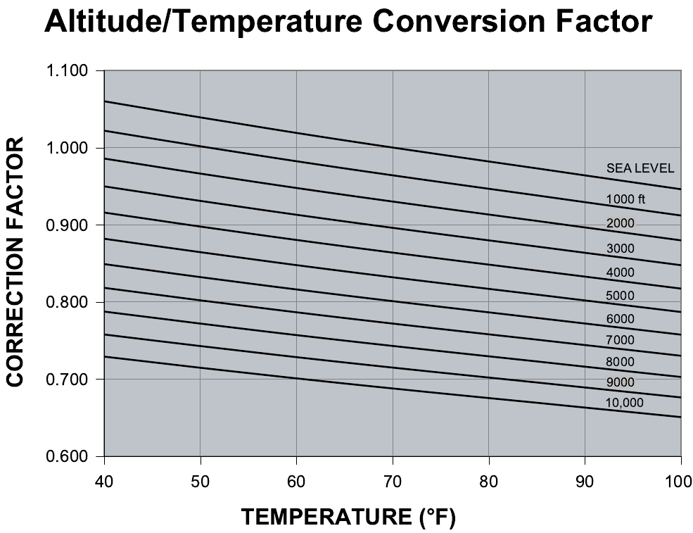
CFM, STATIC PRESSURE, AND POWER - ALTI-
TUDE AND TEMPERATURE CORRECTIONS
The information below should be used to assist in application
of product when being applied at altitudes at or exceeding
1000 feet above sea level.
The air flow rates listed in the standard blower performance
tables are based on standard air at sea level. As the altitude
or temperature increases, the density of air decreases. In
order to use the indoor blower tables for high altitude applica-
tions, certain corrections are necessary.
A centrifugal fan is a "constant volume" device. This means
that, if the rpm remains constant, the CFM delivered is the
same regardless of the density of the air. However, since the
air at high altitude is less dense, less static pressure will be
generated and less power will be required than a similar
application at sea level. Air density correction factors are
shown in Table 8 and Figure 2.
The examples below will assist in determining the airflow per-
formance of the product at altitude.
Example 1: What are the corrected CFM, static pressure,
and BHP at an elevation of 5,000 ft. if the blower performance
data is 6,000 CFM, 1.5 IWC and 4.0 BHP?
Solution: At an elevation of 5,000 ft the indoor blower will still
deliver 6,000 CFM if the rpm is unchanged. However, Table
8 must be used to determine the static pressure and BHP.
Since no temperature data is given, we will assume an air
temperature of 70°F. Table 8 shows the correction factor to be
0.832.
Corrected static pressure = 1.5 x 0.832 = 1.248 IWC
Corrected BHP = 4.0 x 0.832 = 3.328
Example 2: A system, located at 5,000 feet of elevation, is to
deliver 6,000 CFM at a static pressure of 1.5". Use the unit
blower tables to select the blower speed and the BHP
requirement.
Solution: As in the example above, no temperature informa-
tion is given so 70°F is assumed.
The 1.5" static pressure given is at an elevation of 5,000 ft.
The first step is to convert this static pressure to equivalent
sea level conditions.
Sea level static pressure = 1.5 / .832 = 1.80"
Enter the blower table at 6000 sCFM and static pressure of
1.8". The rpm listed will be the same rpm needed at 5,000 ft.
Suppose that the corresponding BHP listed in the table is 3.2.
This value must be corrected for elevation.
BHP at 5,000 ft = 3.2 x .832 = 2.66
TABLE 8: ALTITUDE CORRECTION FACTORS
AIR TEMP ALTITUDE (FEET)
0 1000 2000 3000 4000 5000 6000 7000 8000 9000 10000
40 1.060 1.022 0.986 0.950 0.916 0.882 0.849 0.818 0.788 0.758 0.729
50 1.039 1.002 0.966 0.931 0.898 0.864 0.832 0.802 0.772 0.743 0.715
60 1.019 0.982 0.948 0.913 0.880 0.848 0.816 0.787 0.757 0.729 0.701
70 1.000 0.964 0.930 0.896 0.864 0.832 0.801 0.772 0.743 0.715 0.688
80 0.982 0.947 0.913 0.880 0.848 0.817 0.787 0.758 0.730 0.702 0.676
90 0.964 0.929 0.897 0.864 0.833 0.802 0.772 0.744 0.716 0.689 0.663
100 0.946 0.912 0.880 0.848 0.817 0.787 0.758 0.730 0.703 0.676 0.651
262260-YTG-E-1008
Johnson Controls Unitary Products 19
FIGURE 2 - ALTITUDE/TEMPERATURE CONVERSION FACTOR
262260-YTG-E-1008
20 Johnson Controls Unitary Products
NOTES: 1. Blower performance includes fixed outdoor air, 2” T/A filters, a dry evaporator coil and no electric heat.
2. Refer to Table 11 for additional static resistances.
ESP = External Static Pressure available for the supply and return air duct system. All internal unit resistances have been deducted from the
total static pressure of the blower.
* Do NOT close the pulley below 1 turn open.
** Factory setting.
TABLE 9: SUPPLY AIR BLOWER PERFORMANCE (15 TON) - COOLING ONLY
180 MBH - BOTTOM DUCT CONNECTIONS
BLOWER
SPEED,
(RPM)
MOTOR
PULLEY
(TURNS
OPEN)*
CFM
4500 5250 6000 6750 7200
ESP BHP KW ESP BHP KW ESP BHP KW ESP BHP KW ESP BHP KW
208 VOLT AND STANDARD DRIVE
850 6.0** 0.9 2.4 2.2 0.7 3.0 2.7 0.5 3.2 2.9 - - - - - -
870 5.5 1.0 2.5 2.3 0.8 3.1 2.8 0.6 3.5 3.1 0.2 4.1 3.7 - - -
915 4.5 1.1 2.6 2.4 0.9 3.4 3.0 0.7 3.7 3.3 0.3 4.4 3.9 0.2 4.5 4.0
965 3.5 1.2 2.9 2.6 1.0 3.6 3.2 0.8 4.0 3.6 0.5 4.7 4.2 0.4 4.9 4.4
980 3.0 1.3 3.0 2.7 1.1 3.7 3.3 0.9 4.1 3.7 0.6 4.8. 4.3 0.5 5.1 4.6
1010 2.0 1.4 3.1 2.8 1.2 3.8 3.4 1.0 4.2 3.8 0.7 5.0 4.5 0.6 5.4 4.8
1040 1.0 1.5 3.2 2.9 1.3 3.9 3.5 1.1 4.5 4.0 0.9 5.2 4.7 0.7 5.7 5.1
208 VOLT AND HIGH STATIC DRIVE
965 6.0 1.2 2.9 2.6 1.0 3.6 3.2 0.8 4.0 3.6 0.5 4.7 4.2 0.4 5.0 4.4
980 5.5 1.3 3.0 2.7 1.1 3.7 3.3 0.9 4.1 3.7 0.6 4.8 4.3 0.5 5.1 4.6
1025 4.5 1.5 3.2 2.9 1.3 3.9 3.5 1.1 4.5 4.0 0.8 5.1 4.6 0.7 5.6 5.0
1065 3.5 1.6 3.4 3.0 1.4 4.0 3.6 1.2 4.7 4.2 1.0 5.5 4.9 - - -
1095 3.0 1.7 3.5 3.1 1.5 4.2 3.8 1.3 4.9 4.4 1.2 5.7 5.1 - - -
1130 2.0 1.9 3.7 3.3 1.7 4.5 4.0 1.5 5.1 4.6 - - - - - -
1170 1.0 2.1 3.9 3.5 2.0 4.7 4.2 1.8 5.5 4.9 - - - - - -
230/460/575 VOLT AND STANDARD DRIVE
870 6.0** 1.0 2.4 2.2 0.8 3.1 2.8 0.6 3.5 3.1 0.2 4.1 3.7 - - -
915 5.0 1.1 2.6 2.4 0.9 3.3 3.0 0.7 3.7 3.3 0.3 4.4 3.9 0.2 4.5 4.0
965 4.0 1.2 2.9 2.6 1.0 3.6 3.2 0.8 4.0 3.6 0.5 4.7 4.2 0.4 5.0 4.4
980 3.5 1.3 3.0 2.7 1.1 3.7 3.3 0.9 4.1 3.7 0.6 4.8 4.3 0.5 5.1 4.6
1040 2.0 1.5 3.2 2.9 1.3 3.9 3.5 1.1 4.5 4.0 0.9 5.3 4.7 0.7 5.7 5.1
1065 1.0 1.6 3.3 3.0 1.4 4.0 3.6 1.2 4.7 4.2 1.0 5.5 4.9 - - -
230/460/575 VOLT AND HIGH STATIC DRIVE
980 6.0 1.3 2.9 2.6 1.1 3.7 3.3 0.9 4.1 3.7 0.6 4.8 4.3 0.5 5.1 4.6
1040 4.5 1.5 3.2 2.9 1.3 3.9 3.5 1.1 4.5 4.0 0.9 5.3 4.7 0.7 5.7 5.1
1065 4.0 1.6 3.4 3.0 1.4 4.0 3.6 1.2 4.7 4.2 1.0 5.5 4.9 - - -
1095 3.5 1.7 3.5 3.1 1.5 4.2 3.8 1.3 4.9 4.4 1.2 5.7 5.1 - - -
1130 2.5 1.9 3.7 3.3 1.7 4.5 4.0 1.5 5.1 4.6 - - - - - -
1170 1.5 2.1 3.9 3.5 2.0 4.7 4.2 1.8 5.5 4.9 - - - - - -
1190 1.0 2.2 4.0 3.6 2.1 4.8 4.3 2.0 5.7 5.1 - - - - - -
262260-YTG-E-1008
Johnson Controls Unitary Products 21
NOTES: 1.Blower performance includes fixed outdoor air, 2” T/A filters, a dry evaporator coil and no electric heat.
2.Refer to Table 13 for additional static resistances.
ESP = External Static Pressure available for the supply and return air duct system. All internal unit resistances have been deducted from the total
static pressure of the blower.
* Do NOT close the pulley below 1 turn open.
** Factory setting.
TABLE 10: SUPPLY AIR BLOWER PERFORMANCE (17.5 TON) - COOLING ONLY
210 MBH - BOTTOM DUCT CONNECTIONS
BLOWER
SPEED,
(RPM)
MOTOR
PULLEY
(TURNS
OPEN)*
CFM
6000 7000 8000 9000
ESP BHP KW ESP BHP KW ESP BHP KW ESP BHP KW
208 VOLT AND STANDARD DRIVE
870 6.0** 0.4 2.1 1.8 0.1 2.3 2.0 - - - - - -
900 5.0 0.8 3.2 2.7 0.5 3.5 2.9 0.2 3.8 3.2 - - -
930 4.0 1.1 4.1 3.4 0.9 4.5 3.8 0.6 4.9 4.1 0.1 5.1 4.3
950 3.0 1.3 4.6 3.9 1.1 5.1 4.3 0.8 5.5 4.6 0.4 5.9 5.0
980 2.0 1.6 5.3 4.5 1.4 5.8 4.9 1.2 6.3 5.3 0.7 6.9 5.8
1015 1.0 1.9 5.9 5.0 1.7 6.5 5.5 1.5 7.0 5.9 1.0 7.7 6.5
208 VOLT AND HIGH STATIC DRIVE
950 6.0 1.3 4.6 3.9 1.1 5.1 4.3 0.8 5.5 4.6 0.4 5.9 5.0
980 5.0 1.6 5.3 4.5 1.4 5.8 4.9 1.2 6.3 5.3 0.7 6.9 5.8
1010 4.0 1.8 5.8 4.9 1.7 6.3 5.3 1.5 6.9 5.8 1.0 7.5 6.3
1020 3.5 1.9 6.1 5.1 1.8 6.5 5.5 1.6 7.1 6.0 1.1 7.8 6.6
1035 3.0 2.0 6.2 5.2 1.9 6.8 5.7 1.7 7.4 6.2 1.2 8.1 6.8
1050 2.5 2.1 6.4 5.4 2.0 7.0 5.9 1.8 7.6 6.4 1.3 8.3 7.0
1075 2.0 2.3 6.6 5.5 2.1 7.2 6.0 1.9 7.8 6.6 1.5 8.6 7.2
1100 1.0 2.4 6.7 5.6 2.2 7.3 6.1 2.1 7.9 6.7 - - -
230/460/575 VOLT AND STANDARD DRIVE
870 6.0** 0.4 2.1 1.8 0.1 2.3 2.0 - - - - - -
900 5.0 0.8 3.2 2.7 0.5 3.5 2.9 0.2 3.8 3.2 - - -
930 4.0 1.1 4.1 3.4 0.9 4.5 3.8 0.6 4.9 4.1 0.1 5.1 4.3
950 3.5 1.3 4.6 3.9 1.1 5.1 4.3 0.8 5.5 4.6 0.4 5.9 5.0
980 2.5 1.6 5.3 4.5 1.4 5.8 4.9 1.2 6.3 5.3 0.7 6.9 5.8
1015 1.5 1.9 5.9 5.0 1.7 6.5 5.5 1.5 7.0 5.9 1.0 7.7 6.5
1025 1.0 2.0 6.1 5.1 1.8 6.6 5.6 1.6 7.3 6.1 1.1 7.9 6.7
230/460/575 VOLT AND HIGH STATIC DRIVE
950 6.0 1.3 4.6 3.9 1.1 5.1 4.3 0.8 5.5 4.6 0.4 5.9 5.0
980 5.0 1.6 5.3 4.5 1.4 5.8 4.9 1.2 6.3 5.3 0.7 6.9 5.8
1015 4.0 1.9 5.9 5.0 1.7 6.5 5.5 1.5 7.0 5.9 1.0 7.7 6.5
1035 3.5 2.0 6.2 5.2 1.9 6.8 5.7 1.7 7.4 6.2 1.2 8.1 6.8
1050 3.0 2.1 6.4 5.4 2.0 7.0 5.9 1.8 7.6 6.4 1.3 8.3 7.0
1080 2.0 2.3 6.6 5.5 2.1 7.2 6.0 1.9 7.8 6.6 1.5 8.6 7.2
1100 1.5 2.4 6.7 5.6 2.2 7.3 6.1 2.1 7.9 6.7 - - -
1120 1.0 2.5 6.8 5.7 2.3 7.4 6.2 2.2 8.1 6.8 - - -
262260-YTG-E-1008
22 Johnson Controls Unitary Products
NOTES: 1. Blower performance includes fixed outdoor air, 2” T/A filters, a dry evaporator coil and no electric heat.
2. Refer to Table 11 for additional static resistances.
ESP = External Static Pressure available for the supply and return air duct system. All internal unit resistances have been deducted from the
total static pressure of the blower.
* Do NOT close the pulley below 1 turn open.
** Factory setting.
TABLE 11: SUPPLY AIR BLOWER PERFORMANCE (20 TON) - COOLING ONLY
240 MBH - BOTTOM DUCT CONNECTIONS
BLOWER
SPEED,
(RPM)
MOTOR
PULLEY
(TURNS
OPEN)*
CFM
6000 7000 8000 9000 9400
ESP BHP KW ESP BHP KW ESP BHP KW ESP BHP KW ESP BHP KW
208 VOLT AND STANDARD DRIVE
870 6.0**0.42.11.80.12.32.0---------
900 5.0 0.8 3.2 2.7 0.5 3.5 2.9 0.2 3.8 3.2 - - - - - -
930 4.0 1.1 4.1 3.4 0.9 4.5 3.8 0.6 4.9 4.1 0.1 5.1 4.3 - - -
950 3.0 1.3 4.6 3.9 1.1 5.1 4.3 0.8 5.5 4.6 0.4 5.9 5.0 - - -
980 2.0 1.6 5.3 4.5 1.4 5.8 4.9 1.2 6.3 5.3 0.7 6.9 5.8 0.2 7.3 6.1
1015 1.0 1.9 5.9 5.0 1.7 6.5 5.5 1.5 7.0 5.9 1.0 7.7 6.5 0.6 8.2 6.9
208 VOLT AND HIGH STATIC DRIVE
950 6.0 1.3 4.6 3.9 1.1 5.1 4.3 0.8 5.5 4.6 0.4 5.9 5.0 - - -
980 5.0 1.6 5.3 4.5 1.4 5.8 4.9 1.2 6.3 5.3 0.7 6.9 5.8 0.2 7.3 6.1
1010 4.0 1.8 5.8 4.9 1.7 6.3 5.3 1.5 6.9 5.8 1.0 7.5 6.3 0.5 7.9 6.7
1020 3.5 1.9 6.1 5.1 1.8 6.5 5.5 1.6 7.1 6.0 1.1 7.8 6.6 0.6 8.3 7.0
1035 3.0 2.0 6.2 5.2 1.9 6.8 5.7 1.7 7.4 6.2 1.2 8.1 6.8 0.7 8.6 7.3
1050 2.5 2.1 6.4 5.4 2.0 7.0 5.9 1.8 7.6 6.4 1.3 8.3 7.0 - - -
1075 2.0 2.3 6.6 5.5 2.1 7.2 6.0 1.9 7.8 6.6 1.5 8.6 7.2 - - -
1100 1.0 2.4 6.7 5.6 2.2 7.3 6.1 2.1 7.9 6.7 - - - - - -
230/460/575 VOLT AND STANDARD DRIVE
870 6.0**0.42.11.80.12.32.0---------
900 5.0 0.8 3.2 2.7 0.5 3.5 2.9 0.2 3.8 3.2 - - - - - -
930 4.0 1.1 4.1 3.4 0.9 4.5 3.8 0.6 4.9 4.1 0.1 5.1 4.3 - - -
950 3.5 1.3 4.6 3.9 1.1 5.1 4.3 0.8 5.5 4.6 0.4 5.9 5.0 - - -
980 2.5 1.6 5.3 4.5 1.4 5.8 4.9 1.2 6.3 5.3 0.7 6.9 5.8 0.2 7.3 6.1
1015 1.5 1.9 5.9 5.0 1.7 6.5 5.5 1.5 7.0 5.9 1.0 7.7 6.5 0.6 8.2 6.9
1025 1.0 2.0 6.1 5.1 1.8 6.6 5.6 1.6 7.3 6.1 1.1 7.9 6.7 0.7 8.6 7.3
230/460/575 VOLT AND HIGH STATIC DRIVE
950 6.0 1.3 4.6 3.9 1.1 5.1 4.3 0.8 5.5 4.6 0.4 5.9 5.0 - - -
980 5.0 1.6 5.3 4.5 1.4 5.8 4.9 1.2 6.3 5.3 0.7 6.9 5.8 0.2 7.3 6.1
1015 4.0 1.9 5.9 5.0 1.7 6.5 5.5 1.5 7.0 5.9 1.0 7.7 6.5 0.6 8.2 6.9
1035 3.5 2.0 6.2 5.2 1.9 6.8 5.7 1.7 7.4 6.2 1.2 8.1 6.8 0.7 8.6 7.3
1050 3.0 2.1 6.4 5.4 2.0 7.0 5.9 1.8 7.6 6.4 1.3 8.3 7.0 - - -
1080 2.0 2.3 6.6 5.5 2.1 7.2 6.0 1.9 7.8 6.6 1.5 8.6 7.2 - - -
1100 1.5 2.4 6.7 5.6 2.2 7.3 6.1 2.1 7.9 6.7 - - - - - -
1120 1.0 2.5 6.8 5.7 2.3 7.4 6.2 2.2 8.1 6.8 - - - - - -
262260-YTG-E-1008
Johnson Controls Unitary Products 23
NOTES: 1. Blower performance includes a gas-fired heat exchanger, fixed outdoor air, two-inch T/A filters and a dry evaporator coil.
2. Refer to the additional Static Resistances table.
ESP = External Static Pressure available for the supply and return air duct system. All internal unit resistances have been deducted from the
total static pressure of the blower.
* Do NOT close the pulley below 1 turn open.
** Factory setting.
TABLE 12: SUPPLY AIR BLOWER PERFORMANCE (15 TON) - GAS HEAT
180 MBH - BOTTOM DUCT CONNECTIONS
BLOWER
SPEED,
(RPM)
MOTOR
PULLEY
(TURNS
OPEN)*
CFM
4500 5250 6000 6750 7200
ESP BHP KW ESP BHP KW ESP BHP KW ESP BHP KW ESP BHP KW
208 VOLT AND STANDARD DRIVE
850 6.0** 0.9 2.4 2.1 0.6 2.9 2.6 0.3 3.4 3.0 - - - - - -
870 5.5 1.0 2.5 2.2 0.7 3.0 2.7 0.4 3.5 3.1 - - - - - -
915 4.5 1.1 2.6 2.4 0.8 3.1 2.8 0.5 3.6 3.2 0.2 4.1 3.7 - - -
965 3.5 1.2 2.7 2.5 0.9 3.2 2.9 0.6 3.7 3.3 0.4 4.4 3.0 0.2 5.0 4.5
980 3.0 1.3 2.9 2.6 1.0 3.4 3.0 0.7 3.8 3.4 0.5 4.5 4.0 0.3 5.1 4.6
1010 2.0 1.4 3.0 2.7 1.1 3.6 3.2 0.8 4.0 3.6 0.6 4.7 4.2 0.4 5.4 4.8
1040 1.0 1.6 3.2 2.9 1.3 3.8 3.4 1.0 4.4 3.9 0.8 5.0 4.5 0.6 5.6 5.0
208 VOLT AND HIGH STATIC DRIVE
965 6.0 1.2 2.7 2.5 0.9 3.2 2.9 0.6 3.7 3.3 0.4 4.4 3.9 0.2 5.0 4.5
980 5.5 1.3 2.9 2.6 1.0 3.4 3.0 0.7 3.8 3.4 0.5 4.5 4.0 0.3 5.1 4.6
1025 4.5 1.4 3.1 2.8 1.2 3.6 3.2 0.9 4.1 3.7 0.7 4.8 4.3 0.4 5.5 4.9
1065 3.5 1.6 3.4 3.0 1.4 3.9 3.5 1.1 4.5 4.0 0.9 5.1 4.6 - - -
1125 2.0 1.9 3.6 3.2 1.7 4.4 3.9 1.4 5.0 4.5 1.2 5.8 5.2 - - -
1170 1.0 2.1 3.9 3.5 1.9 4.7 4.2 1.6 5.5 4.9 - - - - - -
230/460/575 VOLT AND STANDARD DRIVE
870 6.0** 1.0 2.5 2.2 0.7 3.0 2.7 0.4 3.5 3.1 - - - - - -
915 5.0 1.1 2.6 2.4 0.8 3.1 2.8 0.5 3.6 3.2 0.2 4.1 3.7 - - -
965 4.0 1.2 2.7 2.5 0.9 3.2 2.9 0.6 3.7 3.3 0.4 4.4 3.9 0.2 5.0 4.5
980 3.5 1.3 2.9 2.6 1.0 3.4 3.0 0.7 3.8 3.4 0.5 4.5 4.0 0.3 5.1 4.6
1015 2.5 1.4 3.0 2.7 1.1 3.6 3.2 0.8 4.0 3.6 0.6 4.7 4.2 0.4 5.4 4.8
1050 1.5 1.5 3.1 2.8 1.2 3.7 3.3 0.9 4.2 3.8 0.7 4.9 4.4 0.5 5.7 5.1
1065 1.0 1.6 3.4 3.0 1.4 3.9 3.5 1.1 4.5 4.0 0.9 5.1 4.6 - - -
230/460/575 VOLT AND HIGH STATIC DRIVE
980 6.0 1.3 2.9 2.6 1.0 3.4 3.0 0.7 3.8 3.4 0.5 4.5 4.0 0.3 5.1 4.6
1045 4.5 1.6 3.2 2.9 1.3 3.8 3.4 1.0 4.4 3.9 0.8 5.0 4.5 0.6 5.6 5.0
1065 4.0 1.7 3.4 3.0 1.4 3.9 3.5 1.1 4.5 4.0 0.9 5.1 4.6 - - -
1125 2.5 1.9 3.6 3.2 1.7 4.4 3.9 1.4 5.0 4.5 1.2 5.8 5.2 - - -
1170 1.5 2.1 3.9 3.5 1.8 4.7 4.2 1.6 5.5 4.9 - - - - - -
1190 1.0 2.2 4.0 3.6 1.9 4.8 4.3 1.7 5.6 5.0 - - - - - -
262260-YTG-E-1008
24 Johnson Controls Unitary Products
NOTES: 1. Blower performance includes a gas-fired heat exchanger, fixed outdoor air, two-inch T/A filters and a dry evaporator coil.
2. Refer to the additional Static Resistances table.
ESP = External Static Pressure available for the supply and return air duct system. All internal unit resistances have been deducted from the
total static pressure of the blower.
* Do NOT close the pulley below 1 turn open.
** Factory setting.
TABLE 13: SUPPLY AIR BLOWER PERFORMANCE (17.5 TON) - GAS HEAT
210 MBH - BOTTOM DUCT CONNECTIONS
BLOWER
SPEED,
(RPM)
MOTOR
PULLEY
(TURNS
OPEN)*
CFM
6000 7000 8000 9000
ESP BHP KW ESP BHP KW ESP BHP KW ESP BHP KW
208 VOLT AND STANDARD DRIVE
870 6.0** 1.33.63.00.74.33.70.25.14.3 - - -
900 5.0 1.43.83.20.94.74.00.45.64.7 - - -
930 4.0 1.64.13.41.15.04.20.65.95.00.16.75.7
950 3.0 1.74.23.61.35.14.30.86.05.10.26.95.8
980 2.0 1.94.53.81.55.44.51.06.35.30.47.26.1
995 1.5 2.14.63.91.65.54.71.16.45.40.57.56.3
1015 1.0 2.24.84.01.74.74.81.26.65.60.77.86.6
208 VOLT AND HIGH STATIC DRIVE
950 6.0 1.74.23.61.35.14.30.86.05.10.26.95.8
980 5.0 1.94.53.81.55.44.51.06.35.30.47.26.1
995 4.5 2.14.53.91.65.54.71.16.45.40.57.56.3
1025 3.5 2.34.94.11.85.84.91.36.75.70.78.06.7
1050 2.5 2.55.14.32.06.15.11.47.16.00.98.47.0
1065 2.0 2.65.34.42.16.35.31.57.36.21.08.67.2
1100 1.0 2.9 5.6 4.7 2.3 6.8 5.7 1.8 7.9 6.6 - - -
230/460/575 VOLT AND STANDARD DRIVE
870 6.0** 1.33.63.00.74.33.70.25.14.3 - - -
900 5.0 1.43.83.20.94.74.00.45.64.7 - - -
930 4.0 1.64.13.41.15.04.20.65.95.00.16.75.7
950 3.5 1.74.23.61.35.14.30.86.05.10.26.95.8
965 2.5 1.94.53.81.55.44.51.06.35.30.47.26.1
995 2.0 2.14.63.91.65.54.71.16.45.40.57.56.3
1015 1.5 2.24.84.01.75.74.81.26.65.60.67.86.6
1025 1.0 2.34.94.11.85.84.91.36.75.70.78.06.7
230/460/575 VOLT AND HIGH STATIC DRIVE
950 6.0 1.74.23.61.35.14.30.86.05.10.26.95.8
980 5.0 1.94.53.81.55.44.51.06.35.30.47.26.1
995 4.5 2.14.63.91.65.54.71.16.45.40.57.56.3
1015 4.0 2.24.84.01.75.74.81.26.65.60.67.86.6
1025 3.5 2.34.94.11.85.84.91.36.75.70.78.06.7
1050 3.0 2.55.14.32.06.15.11.47.16.00.98.47.0
1065 2.5 2.65.34.42.16.35.31.57.36.21.08.67.2
1100 1.5 2.9 5.6 4.7 2.3 6.8 4.7 1.8 7.9 6.6 - - -
1120 1.0 3.1 5.8 4.9 2.5 7.0 5.9 1.9 8.3 6.9 - - -
262260-YTG-E-1008
Johnson Controls Unitary Products 25
NOTES: 1. Blower performance includes a gas-fired heat exchanger, fixed outdoor air, two-inch T/A filters and a dry evaporator coil.
2. Refer to the additional Static Resistances table.
ESP = External Static Pressure available for the supply and return air duct system. All internal unit resistances have been deducted from the
total static pressure of the blower.
* Do NOT close the pulley below 1 turn open.
** Factory setting.
TABLE 14: SUPPLY AIR BLOWER PERFORMANCE (20 TON) - GAS HEAT
240 MBH - BOTTOM DUCT CONNECTIONS
BLOWER
SPEED,
(RPM)
MOTOR
PULLEY
(TURNS
OPEN)*
CFM
6000 7000 8000 9000 9400
ESP BHP KW ESP BHP KW ESP BHP KW ESP BHP KW ESP BHP KW
208 VOLT AND STANDARD DRIVE
870 6.0** 1.3 3.6 3.0 0.7 4.3 3.7 0.2 5.1 4.3 - - - - - -
900 5.0 1.4 3.8 3.2 0.9 4.7 4.0 0.4 5.6 4.7 - - - - - -
930 4.0 1.6 4.1 3.4 1.1 5.0 4.2 0.6 5.9 5.0 0.1 6.7 5.7 - - -
950 3.0 1.7 4.2 3.6 1.3 5.1 4.3 0.8 6.0 5.1 0.2 6.9 5.8 - - -
980 2.0 1.9 4.5 3.8 1.5 5.4 4.5 1.0 6.3 5.3 0.4 7.2 6.1 0.1 8.5 7.1
995 1.5 2.1 4.6 3.9 1.6 5.5 4.7 1.1 6.4 5.4 0.5 7.5 6.3 0.2 8.6 7.3
1015 1.0 2.2 4.8 4.0 1.7 4.7 4.8 1.2 6.6 5.6 0.7 7.8 6.6 - - -
208 VOLT AND HIGH STATIC DRIVE
950 6.0 1.7 4.2 3.6 1.3 5.1 4.3 0.8 6.0 5.1 0.2 6.9 5.8 - - -
980 5.0 1.9 4.5 3.8 1.5 5.4 4.5 1.0 6.3 5.3 0.4 7.2 6.1 0.1 8.5 7.1
995 4.5 2.1 4.5 3.9 1.6 5.5 4.7 1.1 6.4 5.4 0.5 7.5 6.3 0.2 8.6 7.3
1025 3.5 2.3 4.9 4.1 1.8 5.8 4.9 1.3 6.7 5.7 0.7 8.0 6.7 - - -
1050 2.5 2.5 5.1 4.3 2.0 6.1 5.1 1.4 7.1 6.0 0.9 8.4 7.0 - - -
1065 2.0 2.6 5.3 4.4 2.1 6.3 5.3 1.5 7.3 6.2 1.0 8.6 7.2 - - -
1100 1.0 2.9 5.6 4.7 2.3 6.8 5.7 1.8 7.9 6.6 - - - - - -
230/460/575 VOLT AND STANDARD DRIVE
870 6.0** 1.3 3.6 3.0 0.7 4.3 3.7 0.2 5.1 4.3 - - - - - -
900 5.0 1.4 3.8 3.2 0.9 4.7 4.0 0.4 5.6 4.7 - - - - - -
930 4.0 1.6 4.1 3.4 1.1 5.0 4.2 0.6 5.9 5.0 0.1 6.7 5.7 - - -
950 3.5 1.7 4.2 3.6 1.3 5.1 4.3 0.8 6.0 5.1 0.2 6.9 5.8 - - -
965 2.5 1.9 4.5 3.8 1.5 5.4 4.5 1.0 6.3 5.3 0.4 7.2 6.1 0.1 8.5 7.1
995 2.0 2.1 4.6 3.9 1.6 5.5 4.7 1.1 6.4 5.4 0.5 7.5 6.3 0.2 8.6 7.3
1015 1.5 2.2 4.8 4.0 1.7 5.7 4.8 1.2 6.6 5.6 0.6 7.8 6.6 - - -
1025 1.0 2.3 4.9 4.1 1.8 5.8 4.9 1.3 6.7 5.7 0.7 8.0 6.7 - - -
230/460/575 VOLT AND HIGH STATIC DRIVE
950 6.0 1.7 4.2 3.6 1.3 5.1 4.3 0.8 6.0 5.1 0.2 6.9 5.8 - - -
980 5.0 1.9 4.5 3.8 1.5 5.4 4.5 1.0 6.3 5.3 0.4 7.2 6.1 0.1 8.5 7.1
995 4.5 2.1 4.6 3.9 1.6 5.5 4.7 1.1 6.4 5.4 0.5 7.5 6.3 0.2 8.6 7.3
1015 4.0 2.2 4.8 4.0 1.7 5.7 4.8 1.2 6.6 5.6 0.6 7.8 6.6 - - -
1025 3.5 2.3 4.9 4.1 1.8 5.8 4.9 1.3 6.7 5.7 0.7 8.0 6.7 - - -
1050 3.0 2.5 5.1 4.3 2.0 6.1 5.1 1.4 7.1 6.0 0.9 8.4 7.0 - - -
1065 2.5 2.6 5.3 4.4 2.1 6.3 5.3 1.5 7.3 6.2 1.0 8.6 7.2 - - -
1100 1.5 2.9 5.6 4.7 2.3 6.8 4.7 1.8 7.9 6.6 - - - - - -
1120 1.0 3.1 5.8 4.9 2.5 7.0 5.9 1.9 8.3 6.9 - - - - -
262260-YTG-E-1008
26 Johnson Controls Unitary Products
NOTES: 1. Blower performance includes a gas-fired heat exchanger, fixed outdoor air, two-inch T/A filters and a dry evaporator coil.
2. Refer to the additional Static Resistances table.
ESP = External Static Pressure available for the supply and return air duct system. All internal unit resistances have been deducted from the
total static pressure of the blower.
* Do NOT close the pulley below 1 turn open.
** Factory setting.
TABLE 15: SUPPLY AIR BLOWER PERFORMANCE (25 TON) - GAS HEAT
300 MBH - BOTTOM DUCT CONNECTIONS
BLOWER
SPEED,
(RPM)
MOTOR
PULLEY
(TURNS
OPEN)*
CFM
7500 8750 10000 11250 12500
ESP BHP KW ESP BHP KW ESP BHP KW ESP BHP KW ESP BHP KW
208 VOLT AND STANDARD DRIVE
975 6.01.25.94.95.07.36.0---------
1005 5.01.46.25.10.77.76.3---------
1040 4.0 1.6 6.6 5.4 0.9 8.1 6.7 0.2 9.7 8.0 - - - - - -
1070 3.0 1.8 6.9 5.7 1.1 8.5 7.0 0.4 10.2 8.3 - - - - - -
1100 2.0 2.0 7.3 6.0 1.3 8.9 7.3 0.6 10.6 8.7 - - - - - -
1135 1.0 2.2 7.7 6.3 1.6 9.3 7.6 0.8 11.1 9.1 - - - - - -
1165 0.0 2.4 8.0 6.6 1.8 9.7 8.0 1.0 11.6 9.5 0.2 13.5 11.0---
208 VOLT AND HIGH STATIC DRIVE
1140 6.0 2.2 7.7 6.3 1.6 9.4 7.7 0.9 11.2 9.2 - - - - - -
1180 5.0 2.5 8.2 6.7 1.9 9.9 8.1 1.2 11.8 9.7 0.3 13.7 11.2---
1215 4.0 2.7 8.6 7.0 2.1 10.4 8.5 1.4 12.3 10.1 0.6 14.3 11.7---
1255 3.0 3.0 9.1 7.4 2.4 11.0 9.0 1.7 12.9 10.6 0.9 15.0 12.3---
1290 2.0 3.2 9.5 7.8 2.7 11.5 9.4 2.0 13.5 11.1 1.2 15.6 12.8---
1330 1.0 3.5 10.0 8.2 3.0 12.0 9.9 2.3 14.1 11.6 1.5 16.4 13.4---
1365 0.0 3.7 10.5 8.6 3.2 12.6 10.3 2.6 14.7 12.1 1.8 17.0 13.9---
230/460/575 VOLT AND STANDARD DRIVE
975 6.0* 1.4 5.9 4.9 1.0 7.3 6.0 0.5 8.8 7.2 - - - - - -
1005 5.0 1.6 6.2 5.1 1.2 7.7 6.3 0.7 9.2 7.6 0.1 10.9 8.9 - - -
1040 4.0 1.8 6.6 5.4 1.4 8.1 6.7 0.9 9.7 8.0 0.3 11.4 9.4 - - -
1070 3.0 2.0 6.9 5.7 1.6 8.5 7.0 1.1 10.2 8.3 0.6 11.9 9.8---
1100 2.0 2.1 7.3 6.0 1.8 8.9 7.3 1.3 10.6 8.7 0.8 12.4 10.2 0.2 14.3 11.7
1135 1.0 2.4 7.7 6.3 2.0 9.3 7.6 1.6 11.1 9.1 1.0 13.0 10.6 0.4 14.9 12.2
1165 0.0 2.6 8.0 6.6 2.2 9.7 8.0 1.8 11.6 9.5 1.3 13.5 11.0 0.7 15.5 12.7
230/460/575 VOLT AND HIGH STATIC DRIVE
1140 6.0 2.4 7.7 6.3 2.1 9.4 7.7 1.6 11.2 9.2 1.1 13.1 10.7 0.5 15.0 12.3
1180 5.0 2.7 8.2 6.7 2.3 9.9 8.1 1.9 11.8 9.7 1.4 13.7 11.2 0.8 15.8 12.9
1215 4.0 2.9 8.6 7.0 2.6 10.4 8.5 2.2 12.3 10.1 1.7 14.3 11.7 1.1 16.4 13.5
1255 3.0 3.2 9.1 7.4 2.9 11.0 9.0 2.5 12.9 10.6 2.0 15.0 12.3 1.4 17.2 14.1
1290 2.0 3.4 9.5 7.8 3.1 11.5 9.4 2.7 13.5 11.1 2.2 15.6 12.8---
1330 1.0 3.7 10.0 8.2 3.4 12.0 9.9 3.0 14.1 11.6 2.6 16.4 13.4---
1365 0.0 3.9 10.5 8.6 3.7 12.6 10.3 3.3 14.7 12.1 2.9 17.0 13.9---
15 HP Motor is required.
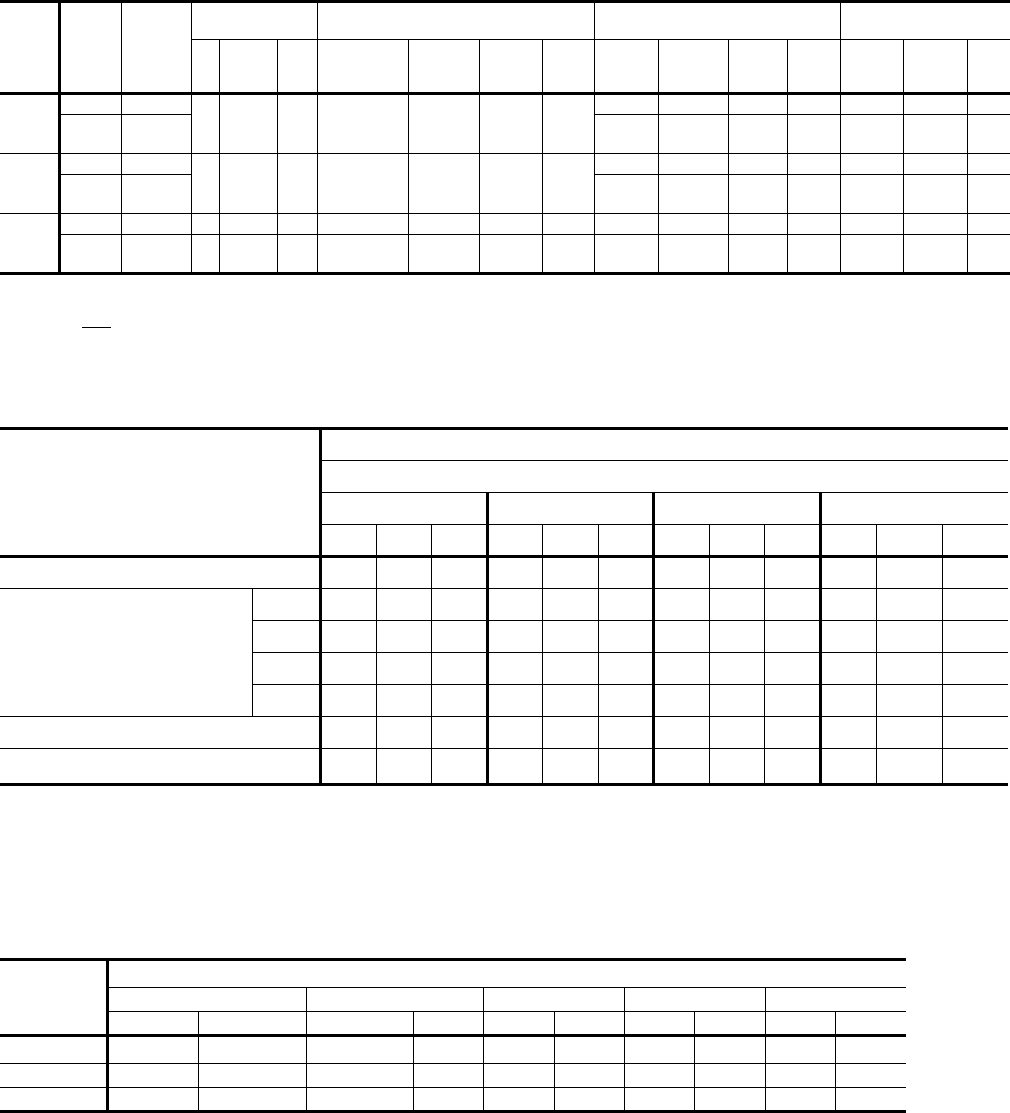
262260-YTG-E-1008
Johnson Controls Unitary Products 27
TABLE 16: BLOWER MOTOR AND DRIVE DATA
MODEL
SIZE DRIVE BLOWER
RANGE
(RPM)
MOTOR1ADJUSTABLE MOTOR PULLEY FIXED BLOWER PULLEY BELT
(NOTCHED)
HP FRAME EFF.
(%) DESIG-
NATION
OUTSIDE
DIA.
(IN.)
PITCH
DIA.
(IN.)
BORE
(IN.) DESIG-
NATION
OUTSIDE
DIA.
(IN.)
PITCH
DIA.
(IN.)
BORE
(IN.) DESIG-
NATION
PITCH
LENGTH
(IN.) QTY.
15 TON
Standard 850/1065
5 184 T 83 1VP56 5.35 4.3-5.321-1/8
BK90 8.75 8.4 1 BX70 82.8 1
High
Static 965/1190 BK80 7.75 7.4 1 BX68 69.8 1
17.5 &
20 TON
Standard 870/1025
7.5 213 T 89 1VP68 6.75 5.5-6.521-3/8
BK120 11.75 11.4 1-3/16 BX83 84.8 1
High
Static 950/1120 BK110 10.75 10.4 1-3/16 BX81 82.8 1
25 TON
Standard 950/1120 10 215 T 89.5 1VP68 6.75 5.5-6.521-3/8 1B5V110 11.3 11.1 1-7/16 BX81 82.8 1
High
Static 1140/1365 15 254 T 91 1VP75X 7.5 6.2-7.4 1-5/8 1B5V94 9.7 9.5 1-7/16 5VX840 84.0 1
1. All motors have a nominal speed of 1800 RPM, a 1.15 service factor and a solid base. They can operate to the limit of their service factor because
they are located in the moving air, upstream of any heating device.
2. Do NOT close this pulley below 1 turn open.
TABLE 17: STATIC RESISTANCES1
DESCRIPTION
RESISTANCE, IWG
CFM
15 TON 17.5 TON 20 TON 25 TON
4500 6000 7200 6000 8000 9000 6000 7000 9400 7500 10000 12500
WET COIL 0.1 0.1 0.1 0.1 0.1 0.1 0.1 0.1 0.1 0.1 0.1 0.1
ELECTRIC HEAT
OPTIONS
(DH models only)
18kW 0.3 0.4 0.4 0.4 0.4 0.5 0.4 0.4 0.5 0.4 0.6 0.6
36kW 0.3 0.4 0.5 0.4 0.5 0.5 0.4 0.5 0.5 0.5 0.5 0.6
54kW 0.4 0.5 0.5 0.5 0.5 0.6 0.5 0.5 0.6 0.5 0.6 0.7
72kW 0.4 0.5 0.5 0.5 0.5 0.6 0.5 0.5 0.6 0.5 0.6 0.7
ECONOMIZER OPTION 0.1 0.1 0.1 0.1 0.1 0.2 0.1 0.1 0.2 0.1 0.2 0.3
HORIZONTAL DUCT CONNECTIONS20.1 0.2 0.3 0.2 0.3 0.5 0.2 0.3 0.5 0.3 0.5 0.6
1. Deduct theses resistance values from the available unit ESP values listed in the respective blower performance table except for
Horizontal Duct Connections.
2. Since the resistance to air flow will be less for horizontal duct connections than for bottom duct connections, add these pressures
to the ESP values on the respective unit’s blower performance table.
TABLE 18: POWER EXHAUST PERFORMANCE
MOTOR
SPEED1
STATIC RESISTANCE OF RETRUN DUCTWORK, IWG
0.2 0.3 0.4 0.5 0.6
CFM kW CFM kW CFM kW CFM kW CFM kW
HIGH25250 0.83 4500 0.85 4200 0.88 3750 0.93 3000 0.99
MEDIUM 4900 0.77 3900 0.79 3500 0.82 2900 0.85 - -
LOW 4400 0.72 3700 0.74 3000 0.78 - - - -
1. Power exhaust motor is a 3/4 HP, PSC type with sleeve bearings, a 48 frame and inherent protection.
2. The factory setting.

262260-YTG-E-1008
28 Johnson Controls Unitary Products
NOTE 1: HACR Type per NEC.
TABLE 19: DH 180, 210 & 240 ELECTRICAL DATA WITHOUT POWERED CONVENIENCE OUTLET
MODEL
(TON-
NAGE) VOLTAGE
COMPRESSORS
OD FAN
MOTORS
FLA EACH
ID
BLOWER
MOTOR
FLA
CONV
OUTLET
AMPS
HEATER OPTION MIN.
CIRCUIT
AMPACITY
(AMPS)
MAX.
FUSE/
BRKR1
SIZE
(AMPS)
RLA
EACH LRA
EACH MODEL KW STAGES AMPS
DH180
(15)
208-3-60 21.8 184 4.5 12.8 0.0
None -- -- -- 70.9 90
E18 13.5 1 37.5 70.9 90
E36 27 2 74.9 109.7 110
E54 40.6 2 112.7 156.9 175
E72 54.1 2 150.2 166.2 200
230-3-60 21.8 184 4.3 12.8 0.0
None -- -- -- 70.5 90
E18 18.0 1 43.3 70.5 90
E36 36.0 2 86.6 124.3 125
E54 54.0 2 129.9 145.9 175
E72 72.0 2 173.2 189.2 225
460-3-60 11.0 90 2.2 6.4 0.0
None -- -- -- 35.6 45
E18 18.0 1 21.7 35.6 45
E36 36.0 2 43.3 62.1 70
E54 54.0 2 65.0 73.0 80
E72 72.0 2 86.6 94.6 110
575-3-60 9.6 73 1.7 5.2 0.0
None -- -- -- 30.2 35
E18 18.0 1 17.3 30.2 35
E36 36.0 2 34.6 49.8 50
E54 54.0 2 52.0 58.5 70
E72 72.0 2 69.3 75.8 90
DH210
(17 1/2)
208-3-60 25.6 190 4.5 20.0 0.0
None -- -- -- 86.6 110
E18 13.5 1 37.5 86.6 110
E36 27 2 74.9 118.7 125
E54 40.6 2 112.7 165.9 175
E72 54.1 2 150.2 175.2 200
230-3-60 25.6 190 4.3 20.0 0.0
None -- -- -- 86.2 110
E18 18.0 1 43.3 86.2 110
E36 36.0 2 86.6 133.3 150
E54 54.0 2 129.9 154.9 175
E72 72.0 2 173.2 198.2 225
460-3-60 12.8 95 2.2 10.0 0.0
None -- -- -- 43.2 50
E18 18.0 1 21.7 43.2 50
E36 36.0 2 43.3 66.6 70
E54 54.0 2 65.0 77.5 90
E72 72.0 2 86.6 99.1 110
575-3-60 10.2 75 1.7 7.5 0.0
None -- -- -- 33.9 40
E18 18.0 1 17.3 33.9 40
E36 36.0 2 34.6 52.7 60
E54 54.0 2 52.0 61.3 70
E72 72.0 2 69.3 78.7 90
DH240
(20)
208-3-60 32.1 237 4.5 20.0 0.0
None -- -- -- 101.2 125
E18 13.5 1 37.5 101.2 125
E36 27 2 74.9 118.7 125
E54 40.6 2 112.7 165.9 175
E72 54.1 2 150.2 175.2 200
230-3-60 32.1 237 4.3 20.0 0.0
None -- -- -- 100.8 125
E18 18.0 1 43.3 100.8 125
E36 36.0 2 86.6 133.3 150
E54 54.0 2 129.9 154.9 175
E72 72.0 2 173.2 198.2 225
460-3-60 14.3 130 2.2 10.0 0.0
None -- -- -- 46.6 60
E18 18.0 1 21.7 46.6 60
E36 36.0 2 43.3 66.6 70
E54 54.0 2 65.0 77.5 90
E72 72.0 2 86.6 99.1 110
575-3-60 12.9 85 1.7 7.5 0.0
None -- -- -- 39.9 50
E18 18.0 1 17.3 39.9 50
E36 36.0 2 34.6 52.7 60
E54 54.0 2 52.0 61.3 70
E72 72.0 2 69.3 78.7 90

262260-YTG-E-1008
Johnson Controls Unitary Products 29
NOTE 1: HACR Type per NEC.
NOTE 1: HACR Type per NEC.
TABLE 20: DH 300 ELECTRICAL DATA STANDARD MOTOR WITHOUT POWERED CONVENIENCE OUTLET
MODEL
(TON-
NAGE) VOLTAGE
COMPRESSORS
OD FAN
MOTORS
FLA EACH
ID
BLOWER
MOTOR
FLA
CONV
OUTLET
AMPS
HEATER OPTION MIN.
CIRCUIT
AMPACITY
(AMPS)
MAX.
FUSE/
BRKR1
SIZE
(AMPS)
RLA
EACH LRA
EACH MODEL KW STAGES AMPS
300
(25)
208 37.1 239 4.5 28.0 0.0
None - - - 120.5 150
E18 13.5 1 37.5 120.5 150
E36 27.0 2 74.9 128.7 150
E54 40.6 2 112.7 175.9 200
E72 54.1 2 150.2 185.2 200
230 37.1 239 4.3 26.0 0.0
None - - - 118.1 150
E18 18.0 1 43.3 118.1 150
E36 36.0 2 86.6 140.8 150
E54 54.0 2 129.9 162.4 175
E72 72.0 2 173.2 205.7 225
460 17.2 125 2.2 13.0 0.0
None - - - 56.1 70
E18 18.0 1 21.7 56.1 70
E36 36.0 2 43.3 70.4 80
E54 54.0 2 65.0 81.2 90
E72 72.0 2 86.6 102.9 110
575 12.4 80 1.7 10.0 0.0
None - - - 41.3 50
E18 18.0 1 17.3 41.3 50
E36 36.0 2 34.6 55.8 60
E54 54.0 2 52.0 64.5 70
E72 72.0 2 69.3 81.8 90
TABLE 21: DH 300 ELECTRICAL DATA HIGH STATIC MOTOR WITHOUT POWERED CONVENIENCE OUTLET
MODEL
(TON-
NAGE) VOLTAGE
COMPRESSORS
OD FAN
MOTORS
FLA EACH
ID
BLOWER
MOTOR
FLA
CONV
OUTLET
AMPS
HEATER OPTION MIN.
CIRCUIT
AMPACITY
(AMPS)
MAX.
FUSE/
BRKR1
SIZE
(AMPS)
RLA
EACH LRA
EACH MODEL KW STAGES AMPS
300
(25)
208 37.1 239 4.5 38.6 0.0
None - - - 131.5 150
E18 13.5 1 37.5 131.5 150
E36 27.0 2 74.9 141.9 150
E54 40.6 2 112.7 189.1 200
E72 54.1 2 150.2 198.4 225
230 37.1 239 4.3 38.6 0.0
None - - - 131.1 150
E18 18.0 1 43.3 131.1 150
E36 36.0 2 86.6 156.5 175
E54 54.0 2 129.9 178.2 200
E72 72.0 2 173.2 221.5 250
460 17.2 125 2.2 19.3 0.0
None - - - 62.9 80
E18 18.0 1 21.7 62.9 80
E36 36.0 2 43.3 78.3 80
E54 54.0 2 65.0 89.1 100
E72 72.0 2 86.6 110.7 125
575 12.4 80 1.7 15.4 0.0
None - - - 47.5 60
E18 18.0 1 17.3 47.5 60
E36 36.0 2 34.6 62.6 70
E54 54.0 2 52.0 71.2 80
E72 72.0 2 69.3 88.5 100

262260-YTG-E-1008
30 Johnson Controls Unitary Products
NOTE 1: HACR Type per NEC.
TABLE 22: DH 180, 210 & 240 ELECTRICAL DATA WITH POWERED CONVENIENCE OUTLET
MODEL
(TON-
NAGE) VOLTAGE
COMPRESSORS
OD FAN
MOTORS
FLA EACH
ID
BLOWER
MOTOR
FLA
CONV
OUTLET
AMPS
HEATER OPTION MIN.
CIRCUIT
AMPACITY
(AMPS)
MAX.
FUSE/
BRKR1
SIZE
(AMPS)
RLA
EACH LRA
EACH MODEL KW STAGES AMPS
DH180
(15)
208-3-60 21.8 184 4.5 12.8 10.0
None -- -- -- 80.9 100
E18 13.5 1 37.5 80.9 100
E36 27 2 74.9 122.2 125
E54 40.6 2 112.7 169.4 175
E72 54.1 2 150.2 178.7 200
230-3-60 21.8 184 4.3 12.8 10.0
None -- -- -- 80.5 100
E18 18.0 1 43.3 82.6 100
E36 36.0 2 86.6 136.8 150
E54 54.0 2 129.9 158.4 175
E72 72.0 2 173.2 201.7 225
460-3-60 11.0 90 2.2 6.4 5.0
None -- -- -- 40.6 50
E18 18.0 1 21.7 41.3 50
E36 36.0 2 43.3 68.4 70
E54 54.0 2 65.0 79.2 90
E72 72.0 2 86.6 100.9 110
575-3-60 9.6 73 1.7 5.2 4.0
None -- -- -- 34.2 40
E18 18.0 1 17.3 34.2 40
E36 36.0 2 34.6 54.8 60
E54 54.0 2 52.0 63.5 70
E72 72.0 2 69.3 80.8 90
DH210
(17 1/2)
208-3-60 25.6 190 4.5 20.0 10.0
None -- -- -- 96.6 110
E18 13.5 1 37.5 96.6 110
E36 27 2 74.9 131.2 150
E54 40.6 2 112.7 178.4 200
E72 54.1 2 150.2 187.7 200
230-3-60 25.6 190 4.3 20.0 10.0
None -- -- -- 96.2 110
E18 18.0 1 43.3 96.2 110
E36 36.0 2 86.6 145.8 150
E54 54.0 2 129.9 167.4 175
E72 72.0 2 173.2 210.7 225
460-3-60 12.8 95 2.2 10.0 5.0
None -- -- -- 48.2 60
E18 18.0 1 21.7 48.2 60
E36 36.0 2 43.3 72.9 80
E54 54.0 2 65.0 83.7 90
E72 72.0 2 86.6 105.4 110
575-3-60 10.2 75 1.7 7.5 4.0
None -- -- -- 37.9 45
E18 18.0 1 17.3 37.9 45
E36 36.0 2 34.6 57.7 60
E54 54.0 2 52.0 66.3 70
E72 72.0 2 69.3 83.7 90
DH240
(20)
208-3-60 32.1 237 4.5 20.0 10.0
None -- -- -- 111.2 125
E18 13.5 1 37.5 111.2 125
E36 27 2 74.9 131.2 150
E54 40.6 2 112.7 178.4 200
E72 54.1 2 150.2 187.7 200
230-3-60 32.1 237 4.3 20.0 10.0
None -- -- -- 110.8 125
E18 18.0 1 43.3 110.8 125
E36 36.0 2 86.6 145.8 150
E54 54.0 2 129.9 167.4 175
E72 72.0 2 173.2 210.7 225
460-3-60 14.3 130 2.2 10.0 5.0
None -- -- -- 51.6 60
E18 18.0 1 21.7 51.6 60
E36 36.0 2 43.3 72.9 80
E54 54.0 2 65.0 83.7 90
E72 72.0 2 86.6 105.4 110
575-3-60 12.9 85 1.7 7.5 4.0
None -- -- -- 43.9 50
E18 18.0 1 17.3 43.9 50
E36 36.0 2 34.6 57.7 60
E54 54.0 2 52.0 66.3 70
E72 72.0 2 69.3 83.7 90
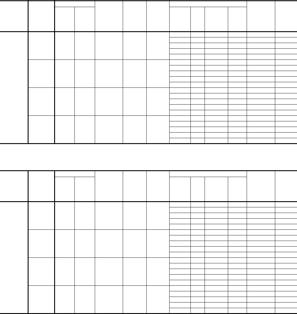
262260-YTG-E-1008
Johnson Controls Unitary Products 31
NOTE 1: HACR Type per NEC.
NOTE 1: HACR Type per NEC.
TABLE 23: DH 300 ELECTRICAL DATA STANDARD MOTOR WITH POWERED CONVENIENCE OUTLET
MODEL
(TON-
NAGE) VOLTAGE
COMPRESSORS
OD FAN
MOTORS
FLA EACH
ID
BLOWER
MOTOR
FLA
CONV
OUTLET
AMPS
HEATER OPTION MIN.
CIRCUIT
AMPACITY
(AMPS)
MAX.
FUSE/
BRKR1
SIZE
(AMPS)
RLA
EACH LRA
EACH MODEL KW STAGES AMPS
300
(25)
208 37.1 239 4.5 28.0 10.0
None - - - 130.5 150
E18 13.5 1 37.5 130.5 150
E36 27.0 2 74.9 141.2 150
E54 40.6 2 112.7 188.4 200
E72 54.1 2 150.2 197.7 200
230 37.1 239 4.3 26.0 10.0
None - - - 128.1 150
E18 18.0 1 43.3 128.1 150
E36 36.0 2 86.6 153.3 175
E54 54.0 2 129.9 174.9 175
E72 72.0 2 173.2 218.2 225
460 17.2 125 2.2 13.0 5.0
None - - - 61.1 70
E18 18.0 1 21.7 61.1 70
E36 36.0 2 43.3 76.6 80
E54 54.0 2 65.0 87.5 90
E72 72.0 2 86.6 109.1 110
575 12.4 80 1.7 10.0 4.0
None - - - 45.3 50
E18 18.0 1 17.3 45.3 50
E36 36.0 2 34.6 60.8 70
E54 54.0 2 52.0 69.5 70
E72 72.0 2 69.3 86.8 90
TABLE 24: DH 300 ELECTRICAL DATA HIGH STATIC MOTOR WITH POWERED CONVENIENCE OUTLET
MODEL
(TON-
NAGE) VOLTAGE
COMPRESSORS
OD FAN
MOTORS
FLA EACH
ID
BLOWER
MOTOR
FLA
CONV
OUTLET
AMPS
HEATER OPTION MIN.
CIRCUIT
AMPACITY
(AMPS)
MAX.
FUSE/
BRKR1
SIZE
(AMPS)
RLA
EACH LRA
EACH MODEL KW STAGES AMPS
300
(25)
208 37.1 239 4.5 38.6 10.0
None - - - 141.5 175
E18 13.5 1 37.5 141.5 175
E36 27.0 2 74.9 154.4 175
E54 40.6 2 112.7 201.6 225
E72 54.1 2 150.2 210.9 225
230 37.1 239 4.3 38.6 10.0
None - - - 141.1 175
E18 18.0 1 43.3 141.1 175
E36 36.0 2 86.6 169.0 175
E54 54.0 2 129.9 190.7 225
E72 72.0 2 173.2 234.0 250
460 17.2 125 2.2 19.3 5.0
None - - - 67.9 80
E18 18.0 1 21.7 67.9 80
E36 36.0 2 43.3 84.5 90
E54 54.0 2 65.0 95.3 110
E72 72.0 2 86.6 117.0 125
575 12.4 80 1.7 15.4 4.0
None - - - 51.5 60
E18 18.0 1 17.3 51.5 60
E36 36.0 2 34.6 67.6 70
E54 54.0 2 52.0 76.2 90
E72 72.0 2 69.3 93.5 100
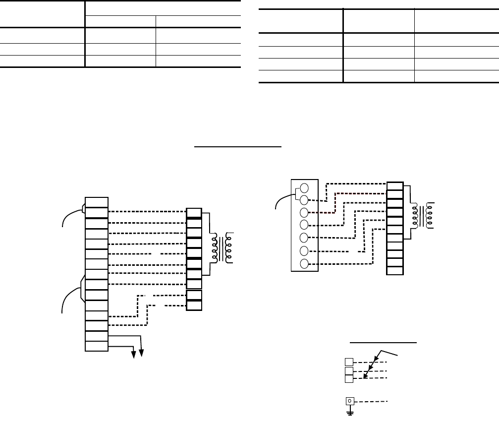
262260-YTG-E-1008
32 Johnson Controls Unitary Products
TABLE 25: DH VOLTAGE LIMITATIONS1
1. Utilization Range “A” in accordance with ARI Standard
110.
POWER SUPPLY VOLTAGE
MIN. MAX.
208/230-3-60 187 253
460-3-60 414 506
575-3-60 518 506
TABLE 26: ELECTRIC HEAT CORRECTION
FACTORS
NOMINAL VOLTAGE VOLTAGE kW CAP. MULTI-
PLIER
208 208 1.00
240 230 0.92
480 460 0.92
600 575 0.92
FIGURE 3 - TYPICAL DH FIELD WIRING DIAGRAM
RH
RC
Y1
Y2
W1
W2
G
R
RH
Y1
Y2
W1
W2
G
B
LED1
LED2
COM
A1
A2
T
T
4
4
3
3
Y1
Y2
W1
W2
G
B
X
A1
A2
L1
L3
L2
RC
R
Y1
Y2
W1
W2
G
B
X
A1
A2
Y3
NOT USED
TO REMOTE SENSOR
2THO4702224 IF USED
1
Electronic programmable thermostat 2ET04700224 (includes subbase).
2
Terminal block 1TB- located on relay board in 24-volt section of the unit control box.
3
Second stage heating is not required on units with a single stage electric heater.
4
Terminals A1 and A2 provide a relay output to close the outdoor economizer dampers
when the thermostat switches to the set-back position.
NOTE: Fans switch must be in "ON" position for minimum ventilation during heater operation.
LINE VOLTAGE
TERMINAL
BLOCK 2TB
IN CONTROL BOX
GROUND LUG
Refer to the
ELECTRICAL DATA
tables to size the
power wiring, the
fuses and the
disconnect switch.
24 VOLT
TRANSFORMER
COOLING / HEATING (24 VOLT THERMOSTAT)
THERMOSTAT
1
TERMINALS
CONTROL WIRING
UNIT TERMINAL
BLOCK 1TB
2
1
24 Volt Thermostat 2TH04701024 or 2TH04701524
(with Subbase 2TB04700324).
2
Terminal strip 1TB - located on relay board in 24-volt section
of the unit control box.
3
Second stage heating is not required on units with a single stage
electric heater.
THERMOSTAT
1
TERMINALS UNIT TERMINAL
BLOCK 1 TB
2
COOLING ONLY (24 VOLT THERMOSTAT)
24 VOLT
TRANSFORMER
POWER WIRING
ADD
JUMPER
ADD
JUMPER
ADD
JUMPER
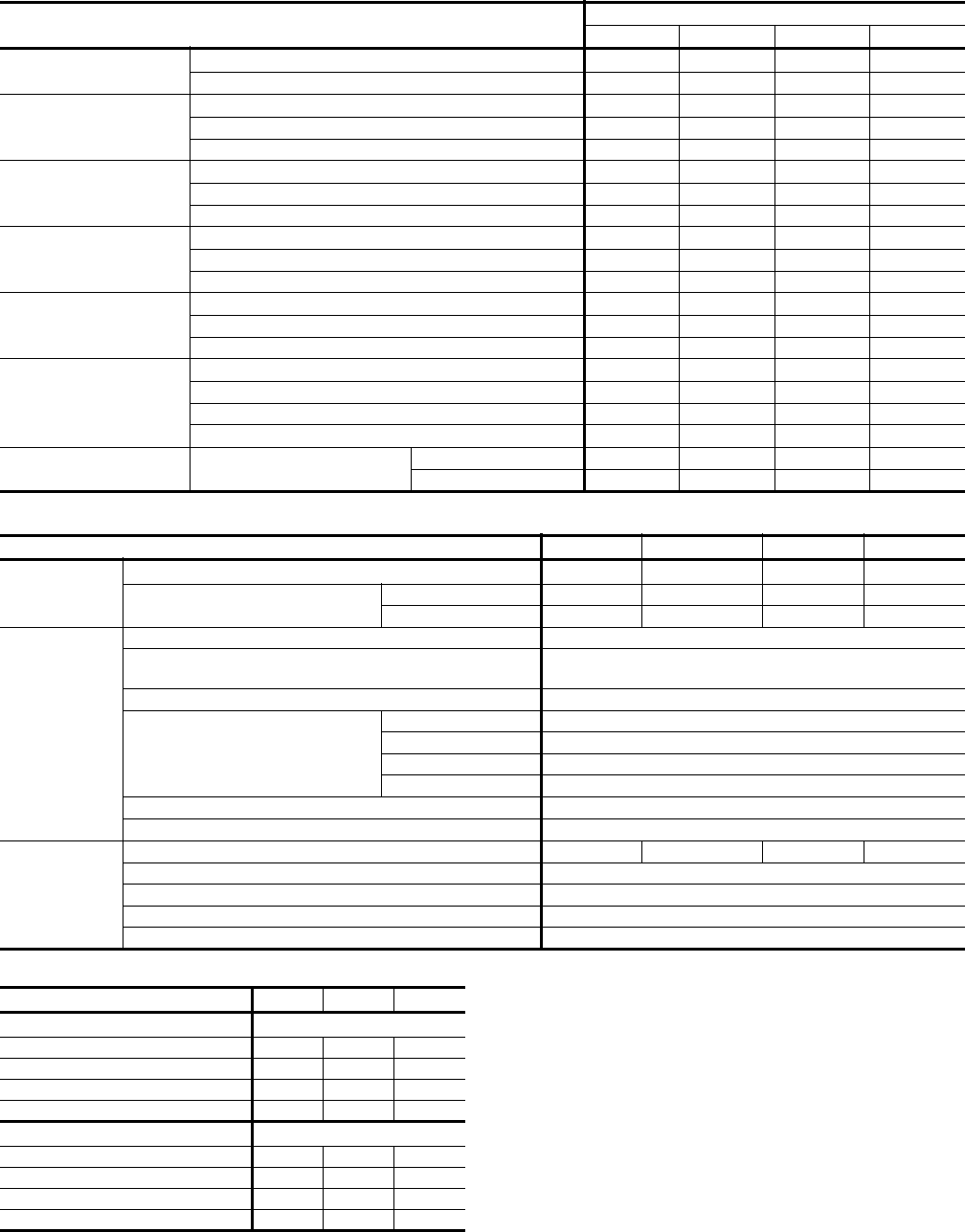
262260-YTG-E-1008
Johnson Controls Unitary Products 33
TABLE 27: PHYSICAL DATA
MODELS DH
180 210 240 300
EVAPORATOR
BLOWER
Centrifugal Blower (Dia. x Wd. in.) 15 x 15 18 x 15 18 x 15 18 x 15
Fan Motor HP Standard/Hi Static 5 7.5 7.5 10/15
EVAPORATOR
COIL
Rows Deep 4444
Fins Per Inch 13.5 13.5 13.5 13.5
Face Area (Sq. Ft. 15.5 20.0 20.0 25.0
CONDENSER
FANS
(Two Per Unit)
Propeller Dia. (in.) (Each) 30 30 30 30
Fan Motor Hp (Each) 1111
Nom. CFM (Each) 5765 7000 7000 7200
CONDENSER
COILS
(Two Per Unit)
Rows Deep (Each) 3332
Fins Per Inch (Each) 13 15 15 20
Face Area (Sq. Ft.) (Total) 36.0 43.3 43.3 43.3
COMPRESSOR
(Qty. Per Unit)
7.5 Ton Scroll 22- -
10 Ton Scroll --2-
12.5 Ton Scroll ---2
AIR
FILTERS
Quantity Per Unit (16” X 20” X 2” or 4“) -444
Quantity Per Unit (16” X 25” X 2” or 4“) -444
Quantity Per Unit (18” X 24” X 2” or 4“) 5---
Total Face Area (sq. ft.) 15.0 20.0 20.0 20.0
CHARGE Refrigerant 22
(lbs./oz.)
System #1 23/10 24/0 24/2 21/1
System #2 21/10 24/8 27/2 21/1
TABLE 28: OPERATING WEIGHTS (LBS.)
MODEL SIZE 15 TON 17.5 TON 20 TON 25 TON
BASIC
UNIT
DH (Cooling Only) 1900 1950 2100 2345
DH
(Gas/Electric)
240Mbh 2100 2150 2300 2545
320Mbh 2140 2190 2340 2585
OPTIONS
Economizer 160
Economizer with
Power Exhaust 245
Motorized Damper 150
Electric Heater
(DH only)
18kW 25
36kW 30
54kW 35
72kW 40
Hot Gas Bypass 10
Supply Fan VFD See Table 29
ACCY.
Roof Curb 175 185 185 185
Barometric Damper 45
Economizer/Motorized Damper Rain Hood 55
Economizer/Power Exhaust Rain Hood 90
Wood Skid 220
TABLE 29: SUPPLY FAN VFD WEIGHTS, IN LBS.
SUPPLY FAN MOTOR 230V 460V 575V
W/O MANUAL BYPASS
5.0 hp 25 25 30
7.5 hp 30 30 30
10.0 hp 30 30 35
15.0 hp 30 30 40
W/MANUAL BYPASS
5.0 hp 30 30 35
7.5 hp 35 35 35
10.0 hp 35 35 40
15.0 hp 40 35 45

262260-YTG-E-1008
34 Johnson Controls Unitary Products
FIGURE 4 - UNIT DIMENSIONS DH180, 210, 240 & 300 (FRONT VIEW)
TABLE 30: UTILITIES ENTRY DATA
HOLE OPENING SIZE
(DIA.) USED FOR
A1-1/8” KO Control Wiring Side
3/4” NPS (Fem.) Bottom
B3-5/8” KO Power Wiring Side
3” NPS (Fem.) Bottom
C2-3/8” KO Gas Piping (Front)1
1. One-inch gas piping NPT required.
D1-11/16” Hole Gas Piping (Bottom)1, 2
2. Opening in the bottom of the unit can be located by the slice in
the insulation.
NOTE: All entry holes should be field sealed to prevent rain
water entry into the building.
RET URN
A I R
SUP P L Y
A I R
BOT T OM S UP P L Y
A ND R ET URN
A IR O P ENINGS
(See N ote)
(B)
P OWER W IRING
ENT RY
(A )
CONT ROL W IRING
ENT RY
NOT E:
For c urb m ounted u nits, r efer to th e c urb h anger
dimensions o f th e c urb fo r th e p roper s ize o f th e
supply a nd r eturn a ir d uct c onnections.
UNIT B A SE W IT H R A IL S
Shown s eparately to i llustrate
Bottom D uct o penings, P ower
and G as P iping C onnection
locations
12-1/2"
9-1/4"
8-1/8"
9-3/4"
3-3/4"
(B)
P OWER W IRING
ENT RY
(A )
CONT ROL W IRING
ENT RY
CONDENSER
COIL S
OP T IONA L C OIL
GUA RD K IT
COMP RESSOR
A CCE SS
(See d etail " X")
ECONOMIZER / M OT ORIZED D A MP ER,
FIXED O UT DOOR IN T A KE A IR A ND
P OWER E XHA UST R A IN H OODS
(See d etail " Y ")
FIELD-SUPPLIED
DISCONNECT SWITCH
LOCATION
BLOWER
COMPARTMENT
ACCESS
(Auxiliary)
DOT P L U G
(For p ressure
Drop R eading)
FRONT
VIEW
CONT ROL B OX
A CCE SS
21"
5"
9-3/4"
11-1/2"
2-3/4" 21-1/2"
33"
35"
5-7/8"
46-5/8"
7-1/8"
6-3/8"
VENT A IR
OUT L ET
HOODS
COMBUST ION
A IR IN L E T
HOOD
GA S H EA T
A CCE SS
(C)
GA S S UP P L Y
ENT RY
46-5/8"
11-1/8"
(D)
GA S S UP P L Y
ENT RY
RET URN A IR
SUP P L Y A I R
OUT DOOR A IR
OUT DOOR A IR
(Economizer)
92"
24-1/4" (15 Ton)
35-1/4" (17.5
thru 25 Ton)
125-1/4" (15 Ton)
136-1/4" (17.5
thru 25 Ton)
48-5/8" (15 Ton)
52-5/8" (17.5 thru 25 Ton)
ELECTRIC
BLOWER ACCESS
(Location Of
Optional VFD)
BLOWER MOTOR ACCESS
(Location Of Optional
VFD Bypass)
All dimensions are in inches. They are
subject to change without notice. Certi-
fied dimensions will be provided upon
request.
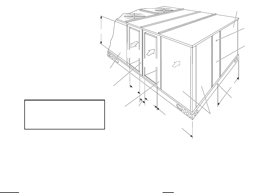
262260-YTG-E-1008
Johnson Controls Unitary Products 35
FIGURE 5 - REAR VIEW DIMENSIONS
NOTE:Units are shipped with the bottom duct openings
covered. An accessory flange kit is available for
connecting side ducts.
For bottom duct applications:
1. Remove the side panels from the supply and return air
compartments to gain access to the bottom supply and
return air duct covers.
2. Remove and discard the bottom duct covers. Duct
openings are closed with sheet metal covers except
when the unit includes a power exhaust option. The
covering consists of a heavy black paper composition.
3. Replace the side supply and return air compartment
panels.
For side duct applications:
1. Replace the side panels on the supply and return air
compartments with the side duct flange accessory kit
panels.
2. Connect ductwork to the flanges on those panels.
SUPPLY
AIR
RETURN
AIR
OUTDOOR
AIR
5-1/8"
18-5/8"
27-3/4"
28-5/8” (15 TON)
39-5/8"
(17.5 thru 25 TON)
40-1/2"
OUTDOOR AIR
COMPARTMENT
ACCESS
FILTER
ACCESS
1" NPT FEMALE
COND. DRAIN
CONNECTION
DOT PLUG
(For pressure
drop reading)
EVAPORATOR
SECTION
40-3/8"
COMPRESSOR
ACCESS
SUPPLY AIR
ACCESS
RETURN AIR
ACCESS
REAR
VIEW
Dimensions listed are for side
duct flange openings; see
Field Accessories for Side
Duct Flange Kit.
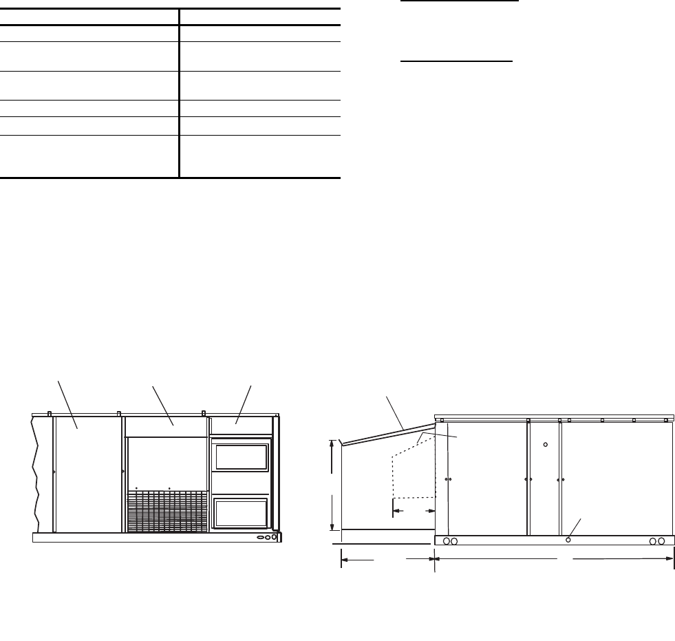
262260-YTG-E-1008
36 Johnson Controls Unitary Products
NOTE: ELEC / ELEC Models: Units and ductwork are
approved for zero clearance to combustible material
when equipped with electric heaters.
GAS / ELEC Models: A 1” clearance must be
provided between any combustible material and the
supply air ductwork for a distance of 3 feet from the
unit.
The products of combustion must not be allowed to
accumulate within a confined space and recirculate.
Locate unit so that the vent air outlet hood is at least:
• Three (3) feet above any force air inlet located
within 10 horizontal feet (excluding those integral to
the unit).
• Four (4) feet below, four horizontal feet from, or one
foot above any door or gravity air inlet into the
building.
• Four (4) feet from electric and gas meters,
regulators and relief equipment.
FIGURE 6 - UNIT DIMENSIONS DH180, 210, 240 & 300 (RAINHOOD)
TABLE 31: MINIMUM CLEARANCES
LOCATION CLEARANCE
Front 36”
Rear 24” (Less Economizer)
49” (With Economizer)
Left Side (Filter Access) 24” (Less Economizer)
36” (With Economizer)3
Right Side (Cond. Coil) 36”
Below Unit1
1. Units may be installed on combustible floors made from wood or
class A, B, or C roof covering material.
0”
Above Unit2
2. Units must be installed outdoors. Overhanging structures or
shrubs should not obstruct condenser air discharge outlet.
3. If economizer is factory installed, the unassembled rain hood
must be removed from its ride along position in front of evapora-
tor coil, or in the outdoor air compartment, prior to final installa-
tion.
72” With 36” Maximum
Horizontal Overhang (For
Condenser Air Discharge)
REAR VIEW
DETAIL “Y”
UNIT WITH RAIN HOODS
LH VIEW
28-3/16” 92”
36-5/8”
5”
16-1/8”
SUPPLY AIR
COMPARTMENT
POWER EXHAUST
RAIN HOOD
(on Return Air Compartment)
ECONOMIZER
MOTORIZED
DAMPER
RAIN HOOD
(on Outdoor Air Compartment) ECONOMIZER / MOTORIZED DAMPER
AND POWER EXHAUST RAIN HOODS
FIXED
OUTDOOR AIR
INTAKE HOOD
(located on
Return Air
Compartment)
1“ CONDENSATE
DRAIN
(Must be trapped)
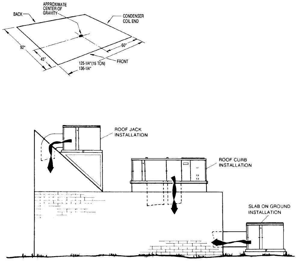
262260-YTG-E-1008
Johnson Controls Unitary Products 37
FIGURE 7 - UNIT CENTER OF GRAVITY
(17.5, 20 & 25 Ton)
FIGURE 8 - TYPICAL UNIT APPLICATIONS
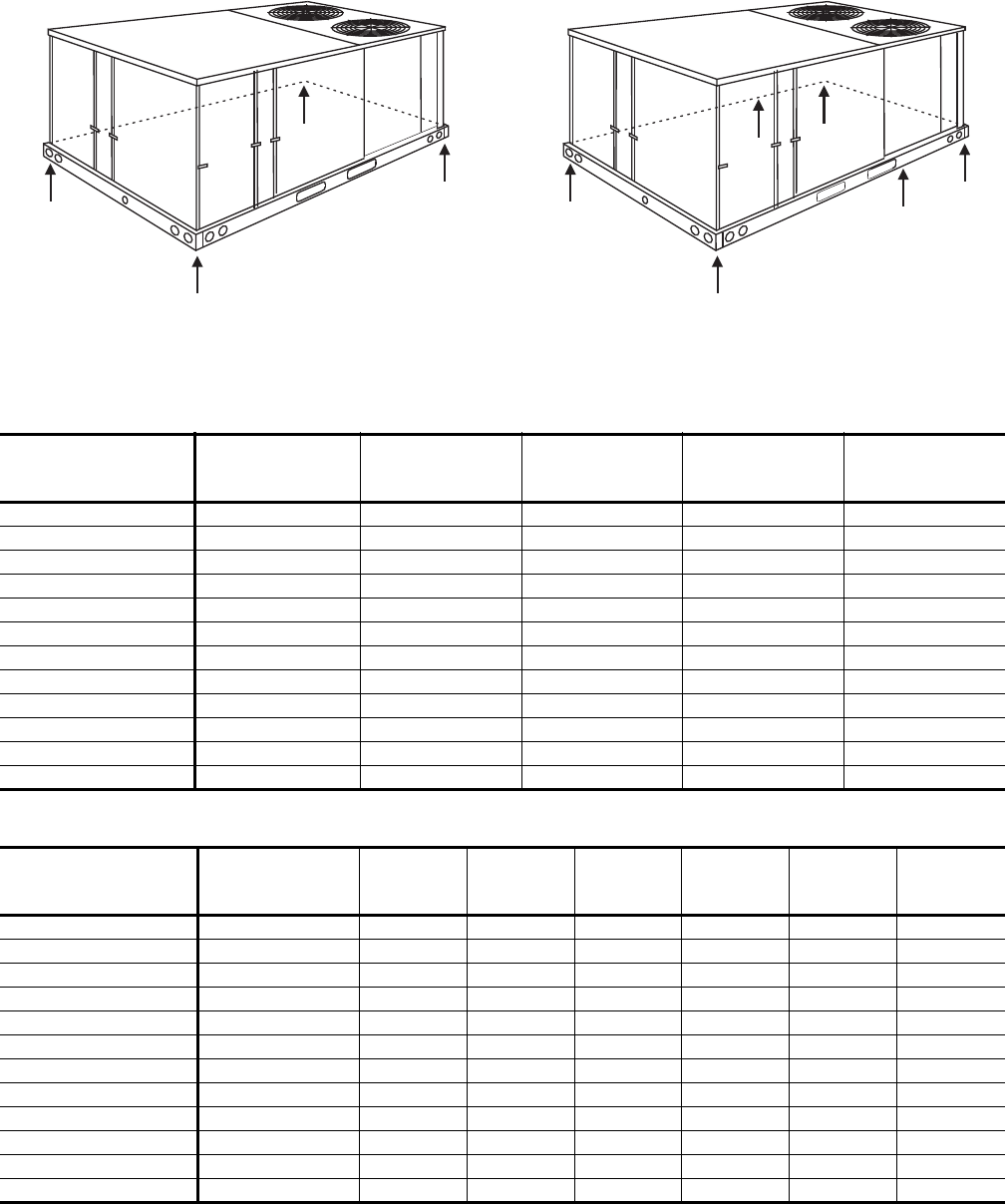
262260-YTG-E-1008
38 Johnson Controls Unitary Products
FIGURE 9 - UNIT 4 POINT LOAD
A
C
D
F R O N T
B
FIGURE 10 - UNIT 6 POINT LOAD
A
E
D
B
F
C
F R O N T
TABLE 32: DH 180, 210, 240 & 300 4 POINT LOAD WEIGHT DISTRIBUTION
UNIT MODEL OPERATING
WEIGHT
(lb) ABCD
DH180C00 1900 445 484 506 465
DH180N24 2100 492 535 559 514
DH180N32 2140 501 545 570 524
DH210C00 1950 457 497 519 477
DH210N24 2150 504 548 572 526
DH210N32 2190 513 558 583 536
DH240C00 2100 492 535 559 514
DH240N24 2300 539 586 612 563
DH240N32 2340 548 596 623 573
DH300C00 2345 461 502 720 662
DH300N24 2545 501 545 781 718
DH300N32 2585 509 553 794 729
TABLE 33: DH 180, 210, 240 & 300 6 POINT LOAD WEIGHT DISTRIBUTION
UNIT MODEL OPERATING
WEIGHT
(lb) ABCDEF
DH180C00 1900 293 306 323 342 327 309
DH180N24 2100 324 338 357 378 362 342
DH180N32 2140 330 344 364 385 369 348
DH210C00 1950 300 314 332 351 336 317
DH210N24 2150 331 346 366 387 370 350
DH210N32 2190 337 352 372 394 377 357
DH240C00 2100 324 338 357 378 362 342
DH240N24 2300 354 370 391 414 396 374
DH240N32 2340 360 377 398 421 403 381
DH300C00 2345 303 321 339 487 460 435
DH300N24 2545 329 348 368 528 499 472
DH300N32 2585 334 353 374 537 507 479
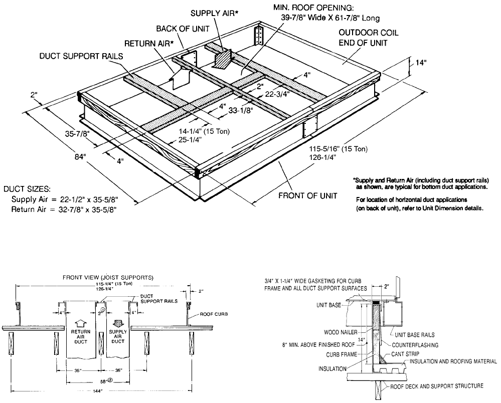
262260-YTG-E-1008
Johnson Controls Unitary Products 39
1. The 2” space between the ducts allows for “jumping” an
existing roof joist.
2. The 58-1/2” overall dimension of the ducts allows
ductwork penetration between roof joists that are
spaced on 72” centers.
NOTE: Ducts can be installed into the curb from the roof. All
electrical and gas line connections can be made
inside the curb.
FIGURE 11 - UNIT ROOF CURB DIMENSIONS
(17.5 thru
25 Ton)
(17.5 thru
25 Ton)
FIGURE 12 - ROOF CURB DUCT OPENINGS
DIMENSIONS
(17.5 & 20 Ton)
FIGURE 13 - CUT AWAY OF ROOF CURB
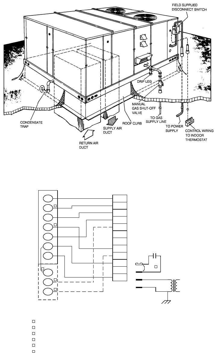
262260-YTG-E-1008
40 Johnson Controls Unitary Products
FIGURE 14 - TYPICAL ROOFTOP INSTALLATION
FIGURE 15 - TYPICAL SIMPLICITY ® CONTROL WIRING DIAGRAM
W1
W2
Y1
G
OCC
P
P1
Y2
X
R
SD
C
C
SD
SD
R
OCC
C
RC
G
Y2
Y1
W2
W1
Jumper
Smoke
Detector
24 VAC
Class 2
X
R
THERMOSTAT
TERMINALS
CONTROL
TERMINAL
BLOCK
TERMINALS ON
A LIMITED
NUMBER OF
THERMOSTATS
3
1
2
4
3
1
2
4
Second stage heating not required on single stage heating units.
Second stage cooling not required on single stage cooling units.
Jumper is required if there is no Smoke Detector circuit.
Jumper is required for any combination of R, RC, or RH.
6
5
5
6
OCC is an output from the thermostat to indicate the Occupied condition.
X is an input to the thermostat to display Error Status conditions.
262260-YTG-E-1008
Johnson Controls Unitary Products 41
GUIDE SPECIFICATIONS
GENERAL
Units shall be manufactured by Unitary Products in an ISO
9001 certified facility.
York's Sunline Ultra™ units are convertible single package
units. All models have dual independent refrigerant circuits
for efficient part load operation and maximum comfort con-
trol. Although the units are primarily designed for curb
mounting on a roof, they can also be slab-mounted at
ground level or set on steel beams above a finished roof.
Cooling only, cooling with gas heat and cooling with electric
heat models are available with a wide variety of factory-
mounted options and field-installed accessories to make
them suitable for almost every application. All units are self-
contained and assembled on full perimeter base rails with
holes in the four corners for overhead rigging. Every unit is
completely piped, wired, charged and tested at the factory
to simplify the field installation and to provide years of
dependable operation. All models (including those with an
economizer) are suitable for either bottom or horizontal duct
connections. Models with power exhaust are suitable for
bottom duct connections only. For bottom duct, remove the
sheet metal panels from the supply and return air openings
through the base of the unit. For horizontal duct, replace the
supply and return air panels on the rear of the unit with a
side duct flange accessory. All supply air blowers are
equipped with a belt drive that can be adjusted to meet the
exact requirements of the job. A high static drive option is
available for applications with a higher CFM and/or static
pressure requirement.
Each unit shall have 2 condenser fan motors. All compres-
sors include crankcase heat and internal pressure relief.
Every refrigerant circuit includes an expansion valve, a liq-
uid line filter-drier, a discharge line high pressure switch and
a suction line with a freezestat and low pressure/loss of
charge switch. The unit control circuit includes a 75 VA
transformer, a 24-volt circuit breaker and a relay board with
two compressor lockout circuits, a terminal strip for thermo-
stat wiring, plus an additional set of pin connectors to sim-
plify the interface of additional field controls. All models are
CSA approved. All models include a 1-year limited warranty
on the complete unit. Compressors and electric heater ele-
ments carry an additional 4-year warranty. Aluminized steel
tubular heat exchangers carry an additional 9-year warranty.
DESCRIPTION
Units shall be factory-assembled, single packaged, DH***N
Electric Cooling/Gas Heat, DH***C/E Electric Cooling/
Optional Electric Heat, designed for outdoor mounted instal-
lation. The 15 ton units shall have minimum EER ratings of
10.8, the 17.5 ton units shall have minimum EER ratings of
10.2, the 20 ton units shall have minimum EER ratings of 9.7
and the 25 ton units shall have minimum EER ratings of 9.6.
They shall have built-in field convertible duct connections
for down discharge supply/return or horizontal discharge
supply/return, and be available with factory installed options
or field installed accessories. The units shall be factory
wired, piped, charged with R-22 refrigerant and factory
tested prior to shipment. All unit wiring shall be both num-
bered and color coded. All units shall be manufactured in a
facility certified to ISO 9001 standards and the cooling per-
formance shall be rated in accordance with DOE and ARI
test procedures. Units shall be CSA listed, classified to
ANSIZ21.47 standards, UL 1995/CAN/CSA No. 236-M90
conditions.
UNIT CABINET
Unit cabinet shall be constructed of galvanized steel, with
exterior surfaces coated with a non-chalking, powdered
paint finish, certified at 1000 hour salt spray test per ASTM-
B117 standards. Indoor blower section shall be insulated
with a minimum 1/2" thick insulation, coated on the airside.
Aluminum foil faced insulation shall be used in the furnace
compartment and be fastened with ridged fasteners to pre-
vent insulation from entering the air stream. Cabinet panels
shall be "large" size, easily removable for servicing and
maintenance. Full perimeter base rails shall be provided to
assure reliable transit of equipment, overhead rigging and
proper sealing on roof curb applications. Disposable 2" fil-
ters shall be furnished and be accessible through a remov-
able access door, sealed airtight. Units filter track shall be
designed to accommodate either 2" or 4" filters. Fan perfor-
mance measuring ports shall be provided on the outside of
the cabinet to allow accurate air measurements of evapora-
tor fan performance without removing panels or creating air
by-pass of the coils. Condensate pan shall be internally
sloped and conform to ASHRAE 62-89 self-draining stan-
dards. Condensate connection shall be a minimum of 1" I.D.
female and be a ridged mount connection. Unit shall incor-
porate a fixed outdoor air damper with an outdoor air intake
opening covered with a bird screen and a rain hood painted
to match the exterior of the unit.
INDOOR (EVAPORATOR) FAN ASSEMBLY
Fan shall be a belt drive assembly and include an adjustable-
pitch motor pulley. Job site selected (B.H.P.) brake horse-
power shall not exceed the motors nameplate horsepower
rating, plus the service factor. Units shall be designed not to
operate above service factor. Fan wheel shall be double-inlet
type with forward-curved blades, dynamically balanced to
operate smoothly throughout the entire range of operation.
Airflow design shall be constant air volume.
A variable air volume (VAV) option using a variable frequency
drive (VFD) is available for applications requiring a constant
supply duct static pressure. Units equipped for VAV shall be
controlled by a duct pressure transducer with a 0 - 5” WC pres-
sure range. The pressure transducer shall provide a 0 - 5 VDC
output signal to a VAV control board which, in turn shall provide
a 2 - 10 VDC speed reference signal to the VFD. The VAV
control board shall operate using factory-installed Supply
Air, Return Air and Outside Air Temperature Sensors. Units
equipped with VFD’s shall have factory-installed manual
bypass as an option.
262260-YTG-E-1008
42 Johnson Controls Unitary Products
OUTDOOR (CONDENSER) FAN ASSEMBLY
The outdoor fans shall be of the direct-driven propeller type,
discharge air vertically, have aluminum blades riveted to cor-
rosion resistant steel spider brackets and shall be dynami-
cally balanced for smooth operation. The 2 outdoor fan
motors shall be totally enclosed with permanently lubricated
bearings, internally protected against overload conditions and
staged independently.
REFRIGERANT COMPONENTS
Compressors:
a. Shall be Scroll compressors internally protected with
internal high-pressure relief and over temperature
protection.
b. Shall have internal spring isolation and sound muf-
fling to minimize vibration and noise, and be exter-
nally isolated on a dedicated, independent mounting.
Coils:
a. Evaporator and condenser coils shall have alumi-
num plate fins mechanically bonded to seamless
internally enhanced copper tubes with all joints
brazed. Special Phenolic coating shall be available
as a factory option.
b. Evaporator and Condenser coils shall be of the
direct expansion, draw-thru, design.
Refrigerant Circuit and Refrigerant Safety Components shall
include:
a. Balance-port thermostatic expansion valve with
independent circuit feed system.
b. Filter drier/strainer to eliminate any moisture or for-
eign matter.
c. Accessible service gage connections on both suc-
tion and discharge lines to charge, evacuate, and
measure refrigerant pressure during any necessary
servicing or troubleshooting, without losing charge.
d. The refrigeration system shall provide at least 15° F
of sub-cooling at design conditions.
e. All models shall have two independent circuits.
f. Hot gas bypass option shall be factory-installed on
compressor #1 discharge line to provide cooling in
low-load applications. HGBP shall be a standard
feature on VAV models and an optional feature on
CV models.
UNIT CONTROLS
a. Unit shall be complete with self-contained low-volt-
age control circuit protected by a resetable circuit
breaker on the 24-volt transformer side.
b. Unit shall incorporate a lockout circuit which pro-
vides reset capability at the space thermostat or
base unit, should any of the following standard
safety devices trip and shut off compressor.
c. Loss-of-charge/Low-pressure switch.
1. High-pressure switch.
2. Freeze-protection thermostat, evaporator coil. If
any of the above safety devices trip, a LED
(light-emitting diode) indicator shall flash a
diagnostic code that indicates which safety
switch has tripped.
d. Unit shall incorporate "AUTO RESET" compressor
over temperature, over current protection.
e. Unit shall operate with conventional thermostat
designs and have a low voltage terminal strip for
easy hook-up.
f. Unit control board shall have on-board diagnostics
and fault code display.
g. Standard controls shall include anti-short cycle and
low voltage protection, and permit cooling operation
down to 0 °F.
h. Control board shall monitor each refrigerant safety
switch independently.
i. Control board shall retain last 5 fault codes in non
volatile memory, which will not be lost in the event of
a power loss.
GAS HEATING SECTION (DH***N MODELS)
Shall be designed with induced draft combustion with post
purge logic and energy saving direct spark ignition, redun-
dant main gas valve. Ventor wheel shall be constructed of
stainless steel for corrosion resistance. The heat exchanger
shall be of the tubular type, constructed of T1-40 aluminized
steel for corrosion resistance and allowing minimum mixed
air entering temperature of 25° F. Burners shall be of the in-
shot type, constructed of aluminum coated steel and contain
air mixture adjustments. All gas piping shall enter the unit
cabinet at a single location through either the side or curb,
without any field modifications. An integrated control board
shall provide timed control of evaporator fan functioning and
burner ignition. Heating section shall be provided with the fol-
lowing minimum protection:
a. Primary and auxiliary high-temperature limit switches.
b. Induced draft motor speed sensor.
c. Flame roll out switch (automatic reset).
d. Flame proving controls. Unit shall have two inde-
pendent stages of capacity.
ELECTRIC HEATING (DH***C/E MODELS)
Nickel chromium electric heating elements shall be provided
as required by the application with 1 or 2 stage control, as
required, from 13.5 KW to 72 KW capacities. The heating
section shall have a primary limit control(s) and automatic
reset to prevent the heating element system from operating
at an excessive temperature. Units with Electric Heating shall
be wired for a single point power supply with branch circuit
fusing (where required).
UNIT OPERATING CHARACTERISTICS
Unit shall be capable of starting and running at 125° F
outdoor temperature, exceeding maximum load criteria of
ARI Standard 340/360. The compressor, with standard
262260-YTG-E-1008
Johnson Controls Unitary Products 43
controls, shall be capable of operation down to 0° F outdoor
temperature. Unit shall be provided with fan time delay to
prevent cold air delivery before heat exchanger warms up
(Gas heat only).
ELECTRICAL REQUIREMENTS
All unit power wiring shall enter unit cabinet at a single factory
provided location and be capable of side or bottom entry, to
minimize roof penetrations and avoid unit field modifications.
Separate side and bottom openings shall be provided for the
control wiring.
STANDARD LIMITED WARRANTIES
• Compressor 5 Years
• Heat Exchanger 10 Years
• Electric Heat Element 5 Years
• Other Parts 1 Year
OPTIONAL OUTDOOR AIR (Shall be made available by
either/or):
•ELECTRONIC ENTHALPY AUTOMATIC ECONO-
MIZER - Outdoor and return air dampers that are inter-
locked and positioned by a fully-modulating, spring-
return damper actuator. The maximum leakage rate for
the outdoor air intake dampers shall not exceed 2%
when dampers are fully closed and operating against a
pressure differential of 0.5 IWG. A unit-mounted potenti-
ometer shall be provided to adjust the outdoor and return
air damper assembly to take in CFM of outdoor air to
meet the minimum ventilation requirement of the condi-
tioned space during normal operation. During econo-
mizer operation, a mixed-air temperature control shall
modulate the outdoor and return air damper assembly to
prevent the supply air temperature from dropping below
55°F. Changeover from compressor to economizer oper-
ation shall be provided by an integral electronic enthalpy
control that feeds input into the basic module. The out-
door intake opening shall be covered with a rain hood
that matches the exterior of the unit. Water eliminator/fil-
ters shall be provided. Simultaneous economizer/com-
pressor operation is also possible. Dampers shall fully
close on power loss.
•BAS-READY ECONOMIZER - Outdoor and return air
dampers that are interlocked and positioned by a fully-
modulating, spring return damper actuator. The maxi-
mum leakage rate for the outdoor air intake dampers
shall not exceed 2% when dampers are fully closed and
operating against a pressure differential of 0.5 IWG.
For units with optional VAV or Simplicity® Intelli-Com-
fort™ control, free-cooling shall be available while the
outdoor dry bulb temperature (OAT) remains below a
programmable set-point of the controller. Field-installed
humidity sensors for either outdoor air or outdoor &
return air streams are available to provide free-cooling
based on single-enthalpy or dual-enthalpy configura-
tions, respectively. If free-cooling is available, a call for
cooling shall modulate the economizer in order to main-
tain a supply air temperature (SAT) programmable set-
point. With the use of a field-installed indoor air quality
sensor, the controller shall provide Demand Ventilation
by modulating the economizer dampers to allow more
outside airflow upon detection of elevated indoor CO2
concentrations above a programmable set-point. With an
additional field-installed outdoor air quality sensor, Differ-
ential Demand Ventilation shall be provided.
The outdoor intake opening shall be covered with a rain
hood that matches the exterior of the unit. Water elimina-
tor/filters shall be provided.
Simultaneous economizer/compressor operation is also
possible. Dampers shall fully close on power loss.
•MOTORIZED OUTDOOR AIR DAMPERS - Outdoor and
return air dampers that are interlocked and positioned by
a 2-position, spring-return damper actuator. The maxi-
mum leakage rate for the outdoor air intake dampers shall
not exceed 2% when dampers are fully closed and operat-
ing against a pressure differential of 0.5 IWG. A unit-
mounted potentiometer shall be provided to adjust the
outdoor and return air damper assembly to take in the
design CFM of outdoor air to meet the ventilation require-
ments of the conditioned space during normal operation.
Whenever the indoor fan motor is energized, the dampers
open up to one of two pre-selected positions - regardless
of the outdoor air enthalpy. Dampers return to the fully
closed position when the indoor fan motor is de-ener-
gized. Dampers shall fully close on power loss.
OTHER PRE-ENGINEERED ACCESSORIES AVAILABLE
•ROOF CURB - 14" high, full perimeter curb with wood
nailer (shipped knocked-down).
•100% BAROMETRIC RELIEF DAMPER - Contains a
rain hood, air inlet screen, exhaust damper and mount-
ing hardware. Used to relieve internal air pressure
through the unit.
•PROPANE CONVERSION KIT - Contains new orifices
and gas valve parts to convert from natural to L.P. gas.
One per unit required.
•HIGH ALTITUDE - NATURAL GAS - Contains orifices
required for applications between 2000 and 6000 feet
altitude.
•HIGH ALTITUDE - PROPANE GAS - Contains orifices
required for applications between 2000 and 6000 feet
altitude. Must be used with propane conversion kit.
•BURGLAR BARS - Designed to work with above roof
curbs, depending on unit model. Fits duct openings of
curb supply and return air openings.
•SIDE DUCT FLANGE - Supply and return air duct
flanges for side duct applications. Do not use on units
with power exhaust.

Subject to change without notice. Printed in U.S.A. 262260-YTG-E-1008
Copyright © 2008 by Johnson Controls, Inc. All rights reserved. Supersedes: 262260-YTG-D-0708
Johnson Controls Unitary Products
5005 York Drive
Norman, OK 73069
•HIGH STATIC DRIVE - May include a belt, blower pulley,
motor pulley or a motor change to enhance blower per-
formance.
•WOOD SKID - Allows unit to be handled with 90" forks.
•ECONOMIZER/MOTORIZED DAMPER RAIN HOOD -
Contains all hood panels and the hardware for assem-
bling.
•ANTI-RECYCLE TIMER - Assures 5-minute off time
between compressor cycles.
•COIL GUARD KIT - Guard for cooling coil.
OTHER FACTORY INSTALLED OPTIONS
•POWER EXHAUST OPTION - To work in conjunction
with economizers.
• STAINLESS STEEL HEAT EXCHANGER
• STAINLESS STEEL DRAIN PAN
• TECHNICOAT PHENOLIC COATED CONDENSER
AND EVAPORATOR COIL
• ELECTRONIC SINGLE ENTHALPY ECONOMIZER
• DIRTY FILTER SWITCH
• PHASE MONITOR
• COIL GUARD
• POWERED GFI CONVENIENCE OUTLET
• NON-POWERED GFI CONVENIENCE OUTLET
• BAS CONTROLS - Simplicity ® Intelli-
Comfort
™, CPC,
JOHNSON, HONEYWELL, NOVAR, YORK COMMER-
CIAL COMFORT SYSTEM (YCCS)
• HINGED FILTER DOOR ACCESS AND TOOL FREE
ACCESS PANELS
• HINGED TOOL FREE BLOWER, BLOWER MOTOR,
FILTER AND ELECTRICAL ACCESS PANELS
• HIGH STATIC DRIVE
•2" THROW AWAY FILTERS
• 4" PLEATED FILTERS
• DISCONNECT SWITCH
• SUPPLY AIR SMOKE DETECTOR
• RETURN AIR SMOKE DETECTOR
