York Maxa Mier Erv Technical Guide
2015-09-09
: York Maxa-Mier-Erv-Technical-Guide york-maxa-mier-erv-technical-guide-811940 york pdf
Open the PDF directly: View PDF ![]() .
.
Page Count: 48
- description
- table of contents
- LIST OF FIGURES
- 1 unitized Energy recovery ventilator 4
- 2 energy recovery wheel 4
- 3 “P” series Pivoting wheel for units w/economizers 10
- 4 uerv dimensional data - 036 through 060 18
- 5 uerv dimensional data - 037 through 150 (3 - 12 1/2 Tons) 18
- 6 uErv dimensional data - 180 through 300 (15 - 25 TONS) 19
- 7 MODEL UNIT VR074 AND VR122 (25 - 40 tON) 20
- list of TABLES
- 8 UERV OUTSIDE AIR CFM SELECTION BY CFM 5
- 9 PERFORMANCE - 3 THROUGH 12 1/2 TON UNITS 7
- 10 PERFORMANCE - 15 THROUGH 25 TON UNITS 8
- 11 PERFORMANCE - PIVOTING WHEEL MODELS 9
- 12 specifications and electrical data - 300 through 550 cfm erv’s 11
- 13 SPECIFICATIONS AND ELECTRICAL DATA - 600 THROUGH 1700 CFM ERV’S 12
- 14 SPECIFICATIONS AND ELECTRICAL DATA - 1500 THROUGH 2800 CFM ERV’S 13
- 15 SPECIFICATIONS AND ELECTRICAL DATA - 2800 THROUGH 3600 CFM ERV’S 14
- 16 SPECIFICATIONS AND ELECTRICAL DATA - 3400 THROUGH 5600 CFM ERV’S 15
- 17 SPECIFICATIONS AND ELECTRICAL DATA - 5500 THROUGH 6200 CFM ERV’S 16
- 18 SPECIFICATIONS AND ELECTRICAL DATA - 6000 THROUGH 13000 CFM UERV’S 17
- 19 Blower PERFORMANCE CHART - VR074 21
- 20 Blower PERFORMANCE CHART - VR122 21
- 21 Filter Sizes - Stand Alone erv Series 23
- 22 Specifications and Electrical Data - 300 through 1100 CFM ERV's 24
- 23 Specifications and Electrical Data - 1200 through 2000 CFM ERV's 25
- 24 Specifications and Electrical Data - 1200 through 2800 CFM ERV's 26
- 25 Specifications and Electrical Data - 2000 through 3600 CFM ERV's 27
- list of TABLES (cont.)
- 26 Specifications and Electrical Data - 3000 through 4600 CFM ERV's 28
- 27 Specifications and Electrical Data - 4600 through 6200 CFM ERV's 29
- 28 Specifications and Electrical Data - 6000 through 13000 CFM ERV's 30
- 29 Airflow Performance - Downflow Configuration for D11 & D20 32
- 30 Airflow Performance - Downflow Configuration for D028 & D036 33
- 31 Airflow Performance - Downflow Configuration for D046 & D062 34
- 32 Airflow Performance - Downflow Configuration for D080 & D120 35
- 33 Airflow Performance - Side by Side Duct Configuration for S011 & S020 37
- 34 Airflow Performance - Side by Side Duct Configuration for S028 & S036 38
- 35 Airflow Performance - Side by Side Duct Configuration for S046 & S062 39
- 36 Airflow Performance - Downflow Configuration for O011 & O020 41
- 37 Airflow Performance - Downflow Configuration for 0028 & O036 42
- 38 Airflow Performance - Downflow Configuration for O46 & O62 43
- LIST OF FIGURES
- UPG Uerv model nomenclature
- applications
- Unitized Energy Recovery Ventilators (UERV) are used with the UPG rooftop packaged units. The internal wheel provides sensible and latent energy exchange between the entering and exhaust air streams of a building. This allows a substantial amount of ...
- The UERV enthalpy wheel contains parallel layers of a polymeric material that are impregnated with silica gel (desiccant). The wheel is located in the entering (intake) air and exhaust air streams of the ventilation equipment. As the wheel rotates th...
- The Air-Conditioning, Heating and Refrigeration Institute (AHRI) issued Standard 1060-2005 to certify air-to-air energy recovery ventilators. This standard deals specifically with the ratings of the Energy Recovery Wheel that is incorporated into the...
- Critical Terms for Standard 1060 are as follows:
- 1. Effectiveness. The measured energy recovery effectiveness not adjusted to account for that portion of the psychrometric change in the leaving supply air (Station 2) that is the result of leakage of entering exhaust air (Station 3) rather than exch...
- 2. Net Effectiveness. The measured recovery effectiveness adjusted to account for that portion of the psychometric change in the leaving supply air (Station 2) that is the result of leakage of the entering exhaust air (Station 3) rather than exchange...
- 3. Exhaust Air Transfer Ratio (EATR). The tracer gas concentration difference between the leaving supply air (Station 2) and entering supply (outdoor) air stream (Station 1) divided by the tracer gas concentration in the entering exhaust (return) air...
- 4. Outdoor Air Correction Factor (OACF). The entering supply (outdoor) airflow (Station 1) divided by the measured (gross) leaving supply airflow (Station 2).
- Energy Recovery Wheel
- The heart of the Energy Recovery Ventilator is the Energy Recovery Wheel (defined by AHRI as a rotary heat exchanger). The wheel has a patented design of parallel layers of wrapped polymeric material that is impregnated with a silica gel (desiccant)....
- The issue of cross leakage in rotary wheel based UERV's used in space conditioning applications is often misunderstood. As a result, many systems are installed with purge sectors and the additional fan capacity required to allow these sectors to func...
- A purge sector minimizes the carry over cross leakage from the exhaust into the supply (outside air) air stream by shunting a portion of the supply air back into the exhaust air stream across the seal separating the exhaust and supply. This is requir...
- In space conditioning applications, where the ventilation is operating to maintain acceptable indoor air quality, there are no contaminants in concentrations large enough to cause concern. Cross leakage in the UERV system results in a small amount of...
- optional accessories - FIELD INSTALLED
- UERV Equipment Support - 8 inch (203 mm) high base for support of the exhaust and intake end of the UERV. Must be ordered separately from the UERV.
- Equipment Support UERV Part No.
- VR006 1ES0401
- VR/P011 1ES0402
- VR/P020 1ES0402
- VR/P028 1ES0402
- Equipment Support UERV Part No.
- VR036 1ES0403
- VR046 1ES0403
- VR062 1ES0404
- VR074
- VR122
- Roof Curb - A 14 or 24 inch (355 or 610 mm) roof curb is required to match supply and exhaust openings of the UERV with the rooftop units. UPG provides a full line of roof curbs to match the specified unit. See specification pages for required curb. ...
- Stand Alone Balancing Damper - Balancing dampers are used with VO and VS models when ERV is connected to the rooftop unit, not to ductwork on the roof.
- optional accessories - FACTORY INSTALLED
- Low Ambient Control Kit - Prevents frost formation on energy wheel heat transfer surfaces by terminating the intake blower operation when discharge air temperature falls below a field selectable temperature setting. Intake blower operation resumes op...
- Pressure Sensor - Measurement device on the UERV to determine airflow across the Wheel.
- Motorized Intake Air Damper - Damper mounts in the outdoor air intake hood. It opens when the UERV is energized and closes when de-energized.
- Stop-Start-Jog - Function that rotates the Enthalpy Wheel (non-pivoting models) on a preset timer to prevent contamination of the wheel during economizer operation.
- ERV Option Codes (ex.: VR028A12H4AL3 would be an R28 series high speed 460 volt UERV with a Low Ambient kit, Motorized Outside Air, and Stop-Start-Jog kit.)
- L1 - Low Ambient Kit (LAK) *
- L2 - LAK & Motorized. Outside Air (MOA) *
- L3 - LAK, MOA, & Stop-Start-Jog (SSJ) *
- L4 - LAK, MOA, SSJ, & Pressure Sensor (PS)
- L5 - LAK and SSJ *
- L6 - LAK, SSJ, and PS
- L7 - LAK and PS
- L8 - LAK, MOA, and PS
- M1 - Motorized Outside Air (MOA) *
- M2 - MOA and Stop-Start-Jog (SSJ) *
- M3 - MOA, SSJ, and Pressure Sensor (PS)
- M4 - MOA and PS
- S1 - Stop-Start-Jog (SSJ) *
- S2 - SSJ and Pressure Sensor (PS)
- P1 - Pressure Sensor (PS)
- NOTE: * denotes only options available for VR074 & VR122.
- How to Select the proper Air Conditioning Unit and Unitary Energy Recovery Ventilator
- 1. Determine the air conditioning load requirements with the required amount of outside air without an UERV.
- 2. Select the proper UERV for the outside air CFM requirements and calculate the tonnage reduction through the UST or UERV software programs.
- 3. Select the air conditioning unit required by reducing the load determined in step 1 by the reduction in step 2. (Example: If the load in Step 1 was 10 tons, and the reduction in Step 2 was 2.5 tons, select a 7.5 ton unit.)
- 4. Select the proper UERV based on the selected unit. SEE Page 3 UERV Nomenclature for Details
- How to Select the proper Air Conditioning Unit and Unitary Energy Recovery Ventilator
- Note 1: Complete UPG ERV model number includes the electrical information. Example ZF 060 needing 500 CFM outside of air at 230 volts/3 phase. Model would be a VR006A06H2AAA1.
- Note 1: Complete UPG ERV model number includes the electrical information. Example: ZJ180 needing 2800 CFM outside of air at 230 volts/3 phase. Model would be a VR028A15H2AAA1.
- Note 2: For VR074 and VR122 units used with an economizer must have the Start-Stop-Jog (SSJ) option.
- Note: 1: A stepdown transformer is provided to stepdown high voltage primary to 115 volt secondary.
- Note: 1. Pivoting electrical data applies to VP models only.
- * Electric data is for (A12) ZH/ZF/ZJ 078-150 and XP 078-150 only.
- ** Electric data is for (A15 and A25) ZH/ZF/ZJ 180-300 and XP 180 and 240 only.
- Note: Pivoting electrical data applies to VP models only.
- FIGURE 4 - uerv dimensional data - 036 through 072 & -03 Through -A6 (3-6 Tons)
- FIGURE 5 - uerv dimensional data - 037 through 150 & A3 THROUGH -12 (3 - 12 1/2 Tons)
- FIGURE 6 - uErv dimensional data - 180 through 300 & -15 THROUGH -25 (15 - 25 TONS)
- - Designed to meet unit specifications - 14’ High Curbs Required - Rooftop unit blower exceeds the capacity of the ERV Exhaust Blowers
- - See blower performance charts for airflow at various external static pressures.
- Notes:
- 1. Drive losses included in the above table
- 2. Performance can vary depending on ambient conditions
- 3. Blower RPMs are for reference only
- Notes:
- 1. Drive losses included in the above table
- 2. Performance can vary depending on ambient conditions
- 3. Blower RPMs are for reference only
- UPG Uerv stand alone model nomenclature
- Performance - erv Series
- Service Clearances - Stand Alone Series ERVs
- D Series Stand Alone ERV'S For Down Discharge Duct Arrangements
- Features and Notes
- 1. Stand alone design allows higher levels of outdoor air to be introduced into the a/c space.
- 2. Static test ports provided to verify intake and exhaust CFM.
- 3. Balancing damper(s) field supplied in duct work when connected to ERV.
- 4. Roof curbs are available for the ERV's.
- 5. See blower performance charts for airflow at various E.S.P.
- 6. Filter rack with 2" pleated filters included.
- Blower RPM for D011
- Notes:
- 1. Drive losses included in the above table
- 2. Performance can vary depending on ambient conditions
- 3. Blower RPMs are for reference only
- Blower RPM for D020
- Notes:
- 1. Drive losses included in the above table
- 2. Performance can vary depending on ambient conditions
- 3. Blower RPMs are for reference only
- Blower RPM for D028
- Notes:
- 1. Drive losses included in the above table
- 2. Performance can vary depending on ambient conditions
- 3. Blower RPMs are for reference only
- Blower RPM for D036
- Notes:
- 1. Drive losses included in the above table
- 2. Performance can vary depending on ambient conditions
- 3. Blower RPMs are for reference only
- Blower RPM for D046
- 1.25
- 1360
- 1425
- 1530
- 1585
- 1650
- Notes:
- 1. Drive losses included in the above table
- 2. Performance can vary depending on ambient conditions
- 3. Blower RPMs are for reference only
- Blower RPM for D062
- Notes:
- 1. Drive losses included in the above table
- 2. Performance can vary depending on ambient conditions
- 3. Blower RPMs are for reference only
- Blower RPM for D080
- Notes:
- 1. Drive losses included in the above table
- 2. Performance can vary depending on ambient conditions
- 3. Blower RPMs are for reference only
- Blower RPM for D120
- Notes:
- 1. Drive losses included in the above table
- 2. Performance can vary depending on ambient conditions
- 3. Blower RPMs are for reference only
- Features and Notes
- S Series Stand Alone ERV'S For Side by Side Duct Arrangements
- Features and Notes
- 1. Stand alone design allows higher levels of outdoor air to be introduced into the conditioned space.
- 2. Static test ports provided to verify intake and exhaust CFM.
- 3. Balancing damper(s) is field provided when connected to ductwork. System may not operate properly without balancing damper.
- 4. Roof curbs are available for the ERV's.
- 5. See blower performance charts for airflow at various E.S.P.
- 6. Filter rack with 2" pleated filters included. Found in return air section.
- Blower RPM for S011
- Notes:
- 1. Drive losses included in the above table
- 2. Performance can vary depending on ambient conditions
- 3. Blower RPMs are for reference only
- Blower RPM for S020
- 0.25
- Notes:
- 1. Drive losses included in the above table
- 2. Performance can vary depending on ambient conditions
- 3. Blower RPMs are for reference only
- Blower RPM for S028
- Notes:
- 1. Drive losses included in the above table
- 2. Performance can vary depending on ambient conditions
- 3. Blower RPMs are for reference only
- Blower RPM for S036
- Notes:
- 1. Drive losses included in the above table
- 2. Performance can vary depending on ambient conditions
- 3. Blower RPMs are for reference only
- Blower RPM for S046
- Notes:
- 1. Drive losses included in the above table
- 2. Performance can vary depending on ambient conditions
- 3. Blower RPMs are for reference only
- Blower RPM for S062
- Notes:
- 1. Drive losses included in the above table
- 2. Performance can vary depending on ambient conditions
- 3. Blower RPMs are for reference only
- Features and Notes
- O Series Stand Alone ERV'S For Over and Under Duct Arrangements
- Features and Notes
- 1. Stand alone design allows higher levels of outdoor air to be introduced into the conditioned space.
- 2. Static test ports provided to verify intake and exhaust CFM.
- 3. Balancing damper(s) is field provided when connected to ductwork. System may not operate properly without balancing damper.
- 4. Roof curbs are available for the ERV's.
- 5. See blower performance charts for airflow at various E.S.P.
- 6. Filter rack with 2" pleated filters included. Found in return air section.
- Blower RPM for O011
- Notes:
- 1. Drive losses included in the above table
- 2. Performance can vary depending on ambient conditions
- 3. Blower RPMs are for reference only
- Blower RPM for O020
- Notes:
- 1. Drive losses included in the above table
- 2. Performance can vary depending on ambient conditions
- 3. Blower RPMs are for reference only
- Blower RPM for O028
- Notes:
- 1. Drive losses included in the above table
- 2. Performance can vary depending on ambient conditions
- 3. Blower RPMs are for reference only
- Blower RPM for O036
- 1200
- Notes:
- 1. Drive losses included in the above table
- 2. Performance can vary depending on ambient conditions
- 3. Blower RPMs are for reference only
- Blower RPM for O046
- Notes:
- 1. Drive losses included in the above table
- 2. Performance can vary depending on ambient conditions
- 3. Blower RPMs are for reference only
- Blower RPM for O062
- Notes:
- 1. Drive losses included in the above table
- 2. Performance can vary depending on ambient conditions
- 3. Blower RPMs are for reference only
- Features and Notes
- guide specifications
- Prepared for the guidance of architects, consulting engineers, and mechanical contractors.
- Furnish and install _____________ mechanical cooling system, complete with a Unitized Energy Recovery Ventilator (UERV).
- The Unitized Energy Recovery Ventilator will contain an energy recovery component rated in accordance with AHRI/ ANSI Standard 1060-2005 with ratings certified by AHRI.
- Cabinet
- UERV shall be designed to attach directly to the a/c (rooftop, upflow, horizontal) unit. It shall be G90 galvanized material with a powdered enamel paint finish electrostatically bonded to the metal. Cabinet panels where conditioned air is handled sh...
- Intake Air Blower (direct drive)
- UERV shall contain a centrifugal blower. All UERV's will be equipped with direct drive PSC blower motors. The motor will be multiple speed and will be individually controlled. Airflow will also be adjustable by means of a damper on the intake air ope...
- Intake Air Blower (belt drive)
- UERV shall contain a centrifugal blower. It shall have ball bearings and adjustable belt drive. Motor mount base shall permit ease of motor changeover and belt tension adjustment. On pivoting wheel models, supply blower will be de- energized during e...
- Exhaust Air Blower (direct drive)
- UERV shall contain a centrifugal blower. All UERV's will be equipped with direct drive PSC blower motors. The motor will be multiple speed and shall be individually controlled. Blowers and motors will be removable through means of a connecting plug f...
- Exhaust Air Blower (belt drive)
- UERV shall contain a centrifugal blower. It shall have ball bearings and adjustable belt drive. Motor mount base shall permit ease of motor changeover and belt tension adjustment. On pivoting wheel models, exhaust blowers shall be sized to provide po...
- Energy Recovery Wheel
- The energy recovery device shall be a rotary heat exchanger per AHRI Standard 1060 description. The device will be an enthalpy wheel coated with a silica gel desiccant by a patented process without the use of binders or adhesives which may plug the d...
- Balancing Dampers
- Balancing dampers will be provided for all VR UERV’s. These dampers will be mounted inside the rooftop air conditioning unit to adjust for the amount of exhaust air on packaged units. On pivoting wheel models, the unit economizer becomes the balanc...
- Barometric Relief Dampers
- Barometric relief dampers will be provided in the exhaust air hood to prevent air infiltration when the UERV is de-energized.
- ERV Support
- All UERV's will be provided with support legs attached to the cabinet to support the intake and exhaust end of the ERV unit. Horizontal ERV's will be provided with support brackets for hanging.
- Filters
- All units shall be provided with mist eliminator type filters in the intake air hood.
- Power Connection
- The UERV shall be provided with a single point power connection for high voltage.
- Optional UERV Equipment Support
- Furnish and install the optional equipment support for the intake and exhaust end of the unit.
- Optional Roof Curb
- Furnish and install the optional roof mounting frame to maintain proper height above the roof.
- Optional Low Ambient Kit
- Furnish and install the optional low ambient kit to prevent frost formation on the energy recovery wheel.
- Optional Motorized Intake Air Damper
- Furnish and install the optional motorized intake air damper.
- Optional Stop-Start-Jog
- On units without economizers furnish and install the optional stop-start-jog controls.
- SEQUENCE OF OPERATION:
- Fixed Models - Normal Operation
- 1. The space thermostat sends a signal to the RTU for cooling, heating or fan only operation.
- 2. The ERV is activated simultaneously with the supply blower of the RTU. The intake blower, the exhaust blower, and the wheel rotation motor of the ERV are activated. These motors will remain energized as long as the supply blower on the RTU is ener...
- 3. If the optional motorized fresh air damper in the outside air intake of the ERV is present, it opens and the ERV is energized.
- 4. If the optional low ambient kit is present, and the temperature leaving the exhaust side of the wheel drops below the field adjusted set point on the temperature sensor of the low ambient kit, the optional motorized fresh air damper will close and...
- Pivoting Models - Normal Operation
- 1. The space thermostat sends a signal to the RTU for cooling, heating or fan only operation.
- 2. The ERV is activated with the supply blower of the RTU. The intake blower, the exhaust blower, and the wheel rotation motor of the ERV are activated. These motors will remain energized as long as the supply blower on the RTU is energized and the R...
- 3. If the optional motorized fresh air damper in the outside air intake of the ERV is present, it opens and the ERV is energized.
- 4. If the optional low ambient kit is present, and the temperature leaving the exhaust side of the wheel drops below the field adjusted set point on the temperature sensor of the low ambient kit, the optional motorized fresh air damper will close and...
- Pivoting Models - Economizer Operation
- 1. The space thermostat sends a signal to the RTU for cooling operation.
- 2. The outdoor air sensor for the RTU senses the outdoor air and determines it is appropriate for economizer operation.
- 3. As the economizer outside air dampers open, the ERV economizer end switch is activated sending a signal to the ERV that the system is in the economizer mode.
- 4. The intake blower, the exhaust blower and the wheel rotation motor all deactivate for up to two minutes. The optional motorized fresh air damper (if present) also closes.
- 5. The ERV enthalpy wheel pivots out of the air stream and the bypass dampers along each side of the intake blower open.
- 6. After a time delay to allow the wheel to pivot out of the airstream and the bypass dampers to open, the optional motorized fresh air damper opens to allow for full economizer operation, and the exhaust blower is reactivated to provide power exhaus...
- Fixed Models - Normal Operation
- UERV troubleshooting guide
- UERV BELOW 600 CFM WITH STATIONARY WHEEL (NO ECONOMIZER)
- UERV will not operate.
- UERV has power, but the enthalpy wheel does not spin.
- 1. Check wheel belt is in place and tight.
- 2. Verify the A130 circuit board switch SW1 Power is in the "on" position.
- 3. Verify the A130 circuit board terminals Wheel "1" and "2" are outputting 110 volts to B28 wheel motor through J/ P150 plug assembly.
- 4. Verify B28 wheel motor C23 capacitor is good. Replace the capacitor if it is bad.
- 5. If the optional Stop, Start, Jog (SSJ) feature is installed, verify that the temperature setpoint on the SSJ does not have the wheel stopped.
- 6. If all of the above are operational, the wheel motor is bad. Replace it with new motor.
- UERV has power, but the exhaust blower does not operate.
- 1. Verify the A130 circuit board switch SW1 Power is in the "on" position.
- 2. Verify the A130 circuit board terminals Exhaust "1” and "3” if in high speed operation, or "1” and "2" if in low speed operation are outputting 110 volts to B26 exhaust blower motor though J/P151 plug assembly.
- 3. Verify B26 wheel motor C25 capacitor is good. Replace the capacitor if it is bad.
- 4. If all of the above are operational, the exhaust motor is bad. Replace it with new motor.
- UERV has power, but the fresh air blower does not operate.
- 1. Verify the A130 circuit board switch SW1 Power is in the "on" position.
- 2. Verify the A130 circuit board terminals Fresh "1” and "3" if in high speed operation, or "1” and "2" if in low speed operation are outputting 110 volts to B27 fresh air blower motor though J/P148 plug assembly.
- 3. On units equipped with the optional low ambient control, verify that the A130 circuit board TB3 terminals marked "low ambient" are closed. The low ambient control will stop the fresh air motor operation and close the optional outside air damper if...
- 4. Verify B27 wheel motor C26 capacitor is good. Replace the capacitor if it is bad.
- 5. If all of the above are operational, the fresh air motor is bad. Replace it with new motor.
- UERV has power, but the optional motorized fresh air damper does not open.
- 1. Verify 24 volts to A130 circuit board terminals TB1 "G" and "C" if in the cooling mode, or "W" and "C" if in the heating mode.
- 2. Verify the A130 circuit board switch SW1 Power is in the "on" position.
- 3. Verify 24 volts to B30 motorized outdoor air motor through J/P160 plug assembly.
- 4. If all of the above are operational, replace the outdoor air damper motor.
- UERV above 600 CFM WITH STATIONARY WHEEL (NO ECONOMIZER)
- UERV will not operate.
- 1. Quick check items.
- a. Verify S51 door switch is closed. The switch must be in the closed position to power the A130 circuit board.
- b. Verify 24 volts to A130 circuit board terminals XFORMER "+" and "-". The terminals must be powered to allow blower contactors to operate.
- c. Verify 24 volts to A130 circuit board terminals TB 37 numbers "1" and "3". Terminal "1" is the hot and "3" is the common side of the power source from activation power source (a/c unit, energy management control, etc.). Typically, "1" would be fro...
- 2. Verify high voltage power to UERV.
- a. Check for correct voltage for UERV to L1 and L2 on 1-phase units.
- UERV has power, but the enthalpy wheel does not spin.
- 1. Check wheel belt is in place and tight.
- 2. Verify the A130 circuit board terminals Exhaust "A" (hot) and "B" (common) are outputting 24 volts to K163 contactor terminal "A" and "B" and that the contacts are closed.
- 3. Verify power to B28 wheel motor.
- 4. Verify B28 wheel motor C23 capacitor is good. Replace the capacitor if it is bad. (Except VR074 to VR122)
- 5. If the optional Stop, Start, Jog (SSJ) feature is installed, verify that the timer on the SSJ does not have the wheel stopped.
- 6. If all of the above are operational, the wheel motor is bad. Replace it with new motor.
- UERV has power, but the exhaust blower does not operate.
- 1. Check that the blower belt is in place and tight on belt drive models. If it is loose, tighten it. If it is broken replace it.
- 2. Verify the A130 circuit board terminals Exhaust "A" (hot) and "B" (common) are outputting 24 volts to K163 contactor terminal "A" and "B", and that the contacts are closed.
- 3. Verify power to B26 exhaust blower motor.
- 4. On direct drive models, verify B26 wheel motor C25 capacitor is good. Replace if necessary.
- 5. If all of the above are operational, the exhaust motor is bad. Replace it with new motor.
- UERV has power, but the fresh air blower does not operate.
- 1. Check that the blower belt is in place and tight on belt drive models. Tighten it if it is loose. Replace it if it is broken.
- 2. Verify the A130 circuit board terminals Fresh "A" (hot) and "B" (common) are outputting 24 volts to K164 contactor terminal "A" and "B", and that the contacts are closed.
- 3. Verify power to B27 fresh air blower motor though J/ P148 plug assembly.
- 4. On direct drive models, verify B27 wheel motor C26 capacitor is good. Replace if necessary.
- 5. On units equipped with the optional low ambient control, verify that the circuit on the A130 circuit board terminal "5" and "6" is closed. The low ambient control will stop the fresh air motor operation and close the optional outside air damper if...
- 6. If all of the above are operational, the fresh air motor is bad. Replace it with new motor.
- UERV has power, but the optional motorized fresh air damper does not open.
- 1. Verify 24 volts to the A130 circuit board terminals XFORMER "+" and "-".
- 2. Verify 24 volts to A130 circuit board terminals TB 37 numbers "1" and "3". Terminal "1" is the hot and "3" is the common side of the power source from activation power source (a/c unit, energy management control, etc.). Typically, "1" would be fro...
- 3. Verify 24 volts to B30 motorized outdoor air motor through J/P160 plug assembly.
- 4. If all of the above are operational, replace the outdoor air damper motor.
- UERV above 600 CFM WITH pivoting WHEEL (used with ECONOMIZER)
- UERV will not operate.
- 1. Quick check items.
- a. Verify S51 door switch is closed. The switch must be in the closed position to power the A130 circuit board.
- b. Verify 24 volts to A130 circuit board terminals XFORMER "+" and "-". The terminals must be powered to allow any blower relays / contactors to operate.
- c. Verify 24 volts to A130 circuit board terminals TB 37 numbers "1" and "3". Terminal "1" is the hot and "3" is the common side of the power source from activation power source (a/c unit, energy management control, etc.). Typically, "1" would be fro...
- 2. Verify high voltage power to UERV.
- a. Check correct voltage for UERV to L1 and, L2 on 1- phase units.
- UERV has power, but the enthalpy wheel does not spin.
- 1. Check wheel belt is in place and tight.
- 2. Verify the A130 circuit board terminals Exhaust 1 "A" (hot) and "B" (common) are outputting 24 volts to K163 contactor terminal "A" and "B" and that the contacts are closed.
- 3. Verify power to B28 wheel motor through J/P150 plug assembly.
- a. If there is no power on the T1 leg of the motor (pivoting models only) verify that the S110 switch located inside the B29 damper motor is in the closed position.
- 4. Verify B28 wheel motor C23 capacitor is good. Replace the capacitor if it is bad.
- 5. If all of the above are operational, the wheel motor is bad. Replace it with new motor.
- UERV has power, but the exhaust blower does not operate.
- 1. Check that the blower belt is in place and tight. If it is loose, tighten it. If it is broken replace it.
- 2. Verify the A130 circuit board terminals Exhaust 1 "A" (hot) and "B" (common) are outputting 24 volts to K163 contactor terminal "A" and "B", and that the contacts are closed.
- 3. Verify power to B26 exhaust blower motor though J/P151 plug assembly.
- 4. On direct drive models, verify B26 wheel motor C25 capacitor is good. Replace if necessary.
- 5. If all of the above are operational, the exhaust motor is bad. Replace it with new motor.
- UERV has power, but the fresh air blower does not operate.
- 1. Energy Recovery Mode of operation.
- a. Check that the blower belt is in place and tight on belt drive models. Tighten it if it is loose. Replace it if it is broken.
- b. Verify the A130 circuit board terminals Fresh "A" (hot) and "B" (common) are outputting 24 volts to K164 contactor terminal "A" and "B", and that the contacts are closed.
- c. Verify power to B27 fresh air blower motor though J/ P148 plug assembly.
- d. On units equipped with the optional low ambient control, verify that the circuit on the A130 circuit board terminal "5" and "6" is made. The low ambient control will stop the fresh air motor operation and close the optional outside air damper if i...
- e. On direct drive models, verify B27 wheel motor C26 capacitor is good. Replace if necessary.
- f. If all of the above are operational, the fresh air motor is bad. Replace it with new motor.
- 2. Economizer Mode of operation.
- a. The fresh air blower is not operational in the economizer mode.
- UERV has power, but the wheel does not rotate out of airstream during economizer operation.
- 1. Check the linkage from the B29 damper motor to the UERV wheel.
- 2. Verify shipping retainers are removed.
- 3. Verify the S122 economizer end switch is closed. The switch is located on the damper and closes when the damper moves from minimum position to the economizer position (field adjustable).
- 4. Verify the B29 damper motor has 24 volts to terminals "B" and "T1" through J/P160 plug assembly
- 5. If all of the above are operational, replace the damper motor.
- UERV has power, but the optional motorized fresh air damper does not open.
- 1. Verify 24 volts to the A130 circuit board terminals XFORMER "+" and "-".
- 2. Verify 24 volts to A130 circuit board terminals TB 37 numbers "1" and "3". Terminal "1" is the "hot" and "3" is the "common" side of the power source from activation power source (a/c unit, energy management control, etc.). Typically, "1" would be...
- 3. Verify 24 volts to B30 motorized outdoor air motor through J/P160 plug assembly.
- 4. If all of the above are operational, replace the outdoor air damper motor.
MAXA-MI$ER
®
TECHNICAL GUIDE
V* Series
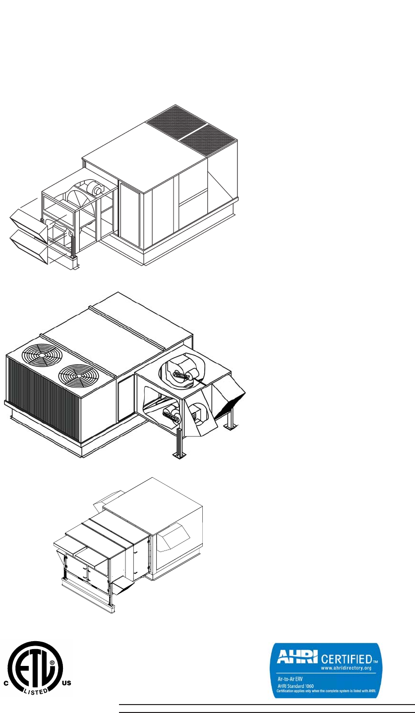
Unitized Energy Recovery
Ventilators
ERV Unit with 3 - 12.5 Ton Packaged Unit
ERV Unit with 15 - 25 Ton Packaged Unit
ERV Unit with 25 -40 Packaged Unit
ETL Certified per UL 1995 and CSA 22.2
903106-UTG-A-0912
FOR DISTRIBUTION USE ONLY - NOT TO BE USED AT POINT OF RETAIL SALE
Energy recovery COMPONENT rated in
accordance with AHRI/ANSI Standard
1060-2005 and certified to AHRI. Actual
performance in packaged equipment
may vary.
DESCRIPTION
• Reduces cooling load at design temperatures up to 4 tons per
1000 cfm of outside air.
• Reduces heating load up to 2.5 Tons Btuh per 1000 CFM of out-
side air.
• Dry energy transfer. Moisture in supply (intake) air stream is
transferred to exhaust air stream in a vapor state, eliminating
condensate plumbing from the UERV.
• Attaches directly to the UPG rooftop units. All mounting equip-
ment is provided.
• Separate fused power supply. (Except VR74 or VR122)
• Filters / mist eliminators are provided on the entering air open-
ings.
• Adjustable support legs are provided. (Except for Stand Alone)
• Two modes of operation (Pivoting Wheel Models only)
• Recovery mode during normal energy recovery operation.
• True economizer mode when outside sensor calls for
economizer operation (3 - 12.5 ton packaged units
equipped with economizers). U. S. Patent 5,548,970.
• Pivoting wheel models used with packaged unit with econo-
mizer. Sequence of operation controlled by economizer control-
ler. (3- 12.5 Ton Only)
• Balancing dampers provided on VR Modules. (Except VR74
and VR122)
• Centrifugal blowers (both intake and exhaust for high static
capability and low sound levels). (Except VR74 and VR122)
• Heavy gauge galvanized steel cabinets corrosion protected with
powder paint process that match UPG units.
• Fully insulated cabinet.
• AHRI certified internal enthalpy wheel is provided.
• Internal enthalpy wheel made of polymeric material with silica
gel impregnated into the material. The enthalpy wheel has a
five year limited warranty.
• Internal enthalpy wheels are easily cleanable. Large wheels (25
inch diameter and above) are split into easily removable pie
segments. Smaller wheels can be removed from the ERV.
• Continuous operation down to 10 ºF (-12 ºC) without defrost at
indoor relative humidity up to 40%. For temperatures below 10
ºF (-12 ºC), Optional Low Ambient Control Kit is required. Kit
includes temperature sensor to control the ERV before frost
build up can occur on recovery wheel.
Note: MAXA-MI$ER® UERV’s are designed for use with
rooftops using 14” high or greater roof curbs.
Note: ZF/ZH/ZJ/XP 037 thru 150 or ZS/ZU/ZW/XA-A3
thru -12, with ERV must use “slab” type econo-
mizers and downflow position.

903106-UTG-A-0912
2 Unitary Products Group
TABLE OF CONTENTS
DESCRIPTION . . . . . . . . . . . . . . . . . . . . . . . . . . . . . . . . 1
TABLE OF CONTENTS . . . . . . . . . . . . . . . . . . . . . . . . . 2
UPG UERV MODEL NOMENCLATURE . . . . . . . . . . . . 3
APPLICATIONS . . . . . . . . . . . . . . . . . . . . . . . . . . . . . . . 4
PRINCIPLE OF OPERATION . . . . . . . . . . . . . . . . . . . . .4
AHRI/ANSI STANDARD 1060-2005 FOR AIR-TO-AIR EN-
ERGY RECOVERY VENTILATION EQUIPMENT . . . . .4
ENERGY RECOVERY WHEEL . . . . . . . . . . . . . . . . . . . .4
CROSS LEAKAGE IN UERV’S (PURGE SECTORS) . . .5
OPTIONAL ACCESSORIES - FIELD INSTALLED . . . . 5
OPTIONAL ACCESSORIES - FACTORY INSTALLED 6
HOW TO SELECT THE PROPER AIR
CONDITIONING UNIT AND UNITARY ENERGY RECOV-
ERY VENTILATOR . . . . . . . . . . . . . . . . . . . . . . . . . . . . .6
UPG UERV STAND ALONE MODEL
NOMENCLATURE . . . . . . . . . . . . . . . . . . . . . . . . . . . . 22
PERFORMANCE - ERV SERIES . . . . . . . . . . . . . . . . . 22
SERVICE CLEARANCES - STAND ALONE SERIES
ERVS . . . . . . . . . . . . . . . . . . . . . . . . . . . . . . . . . . . . . . 23
D SERIES STAND ALONE ERV'S FOR DOWN DIS-
CHARGE DUCT ARRANGEMENTS . . . . . . . . . . . . . . 31
FEATURES AND NOTES . . . . . . . . . . . . . . . . . . . . . . . 31
S SERIES STAND ALONE ERV'S FOR SIDE BY SIDE
DUCT ARRANGEMENTS . . . . . . . . . . . . . . . . . . . . . . 36
FEATURES AND NOTES . . . . . . . . . . . . . . . . . . . . . . . 36
O SERIES STAND ALONE ERV'S FOR OVER AND UN-
DER DUCT ARRANGEMENTS . . . . . . . . . . . . . . . . . . 40
FEATURES AND NOTES . . . . . . . . . . . . . . . . . . . . . . . 40
GUIDE SPECIFICATIONS . . . . . . . . . . . . . . . . . . . . . 44
GENERAL . . . . . . . . . . . . . . . . . . . . . . . . . . . . . . . . . . . 44
APPROVALS . . . . . . . . . . . . . . . . . . . . . . . . . . . . . . . . . 44
OPTIONS . . . . . . . . . . . . . . . . . . . . . . . . . . . . . . . . . . . 45
SEQUENCE OF OPERATION: . . . . . . . . . . . . . . . . . . 45
UERV TROUBLESHOOTING GUIDE . . . . . . . . . . . . . 46
UERV BELOW 600 CFM WITH STATIONARY WHEEL
(NO ECONOMIZER) . . . . . . . . . . . . . . . . . . . . . . . . . . . 46
UERV ABOVE 600 CFM WITH STATIONARY WHEEL
(NO ECONOMIZER) . . . . . . . . . . . . . . . . . . . . . . . . . . . 46
UERV ABOVE 600 CFM WITH PIVOTING WHEEL (USED
WITH ECONOMIZER) . . . . . . . . . . . . . . . . . . . . . . . . . . 47
LIST OF FIGURES
Fig. # Pg. #
1 UNITIZED ENERGY RECOVERY
VENTILATOR . . . . . . . . . . . . . . . . . . . . . . . . . . . . . . . .4
2 ENERGY RECOVERY WHEEL . . . . . . . . . . . . . . . . . .4
3 “P” SERIES PIVOTING WHEEL FOR UNITS W/ECONO-
MIZERS . . . . . . . . . . . . . . . . . . . . . . . . . . . . . . . . . . .10
4 UERV DIMENSIONAL DATA - 036 THROUGH 060 .18
5 UERV DIMENSIONAL DATA - 037 THROUGH 150 (3 -
12 1/2 TONS) . . . . . . . . . . . . . . . . . . . . . . . . . . . . . . .18
6 UERV DIMENSIONAL DATA - 180 THROUGH 300 (15 -
25 TONS) . . . . . . . . . . . . . . . . . . . . . . . . . . . . . . . . . .19
7 MODEL UNIT VR074 AND VR122 (25 - 40 TON). . . 20
LIST OF TABLES
Tbl. # Pg. #
8 UERV OUTSIDE AIR CFM SELECTION BY CFM . . . .5
9 PERFORMANCE - 3 THROUGH 12 1/2 TON UNITS . .7
10 PERFORMANCE - 15 THROUGH 25 TON UNITS . . . .8
11 PERFORMANCE - PIVOTING WHEEL MODELS . . . .9
12 SPECIFICATIONS AND ELECTRICAL DATA - 300
THROUGH 550 CFM ERV’S 11
13 SPECIFICATIONS AND ELECTRICAL DATA - 600
THROUGH 1700 CFM ERV’S . . . . . . . . . . . . . . . . . . . 12
14 SPECIFICATIONS AND ELECTRICAL DATA - 1500
THROUGH 2800 CFM ERV’S . . . . . . . . . . . . . . . . . . . 13
15 SPECIFICATIONS AND ELECTRICAL DATA - 2800
THROUGH 3600 CFM ERV’S . . . . . . . . . . . . . . . . . . . 14
16 SPECIFICATIONS AND ELECTRICAL DATA - 3400
THROUGH 5600 CFM ERV’S . . . . . . . . . . . . . . . . . . . 15
17 SPECIFICATIONS AND ELECTRICAL DATA - 5500
THROUGH 6200 CFM ERV’S . . . . . . . . . . . . . . . . . . . 16
18 SPECIFICATIONS AND ELECTRICAL DATA - 6000
THROUGH 13000 CFM UERV’S . . . . . . . . . . . . . . . . 17
19 BLOWER PERFORMANCE CHART - VR074 . . . . . . 21
20 BLOWER PERFORMANCE CHART - VR122 . . . . . . 21
21 FILTER SIZES - STAND ALONE ERV SERIES . . . . . 23
22 SPECIFICATIONS AND ELECTRICAL DATA - 300
THROUGH 1100 CFM ERV'S . . . . . . . . . . . . . . . . . . . 24
23 SPECIFICATIONS AND ELECTRICAL DATA - 1200
THROUGH 2000 CFM ERV'S . . . . . . . . . . . . . . . . . . . 25
24 SPECIFICATIONS AND ELECTRICAL DATA - 1200
THROUGH 2800 CFM ERV'S . . . . . . . . . . . . . . . . . . . 26
25 SPECIFICATIONS AND ELECTRICAL DATA - 2000
THROUGH 3600 CFM ERV'S . . . . . . . . . . . . . . . . . . . 27
Unitary Products Group 3
903106-UTG-A-0912
LIST OF TABLES (CONT.)
Tbl. # Pg. #
26 SPECIFICATIONS AND ELECTRICAL DATA - 3000
THROUGH 4600 CFM ERV'S . . . . . . . . . . . . . . . . . . . 28
27 SPECIFICATIONS AND ELECTRICAL DATA - 4600
THROUGH 6200 CFM ERV'S . . . . . . . . . . . . . . . . . . . 29
28 SPECIFICATIONS AND ELECTRICAL DATA - 6000
THROUGH 13000 CFM ERV'S . . . . . . . . . . . . . . . . . . 30
29 AIRFLOW PERFORMANCE - DOWNFLOW CONFIGU-
RATION FOR D11 & D20 . . . . . . . . . . . . . . . . . . . . . . 32
30 AIRFLOW PERFORMANCE - DOWNFLOW CONFIGU-
RATION FOR D028 & D036 . . . . . . . . . . . . . . . . . . . . 33
31 AIRFLOW PERFORMANCE - DOWNFLOW CONFIGU-
RATION FOR D046 & D062 . . . . . . . . . . . . . . . . . . . . 34
32 AIRFLOW PERFORMANCE - DOWNFLOW CONFIGU-
RATION FOR D080 & D120 . . . . . . . . . . . . . . . . . . . . 35
33 AIRFLOW PERFORMANCE - SIDE BY SIDE DUCT
CONFIGURATION FOR S011 & S020 . . . . . . . . . . . . 37
34 AIRFLOW PERFORMANCE - SIDE BY SIDE DUCT
CONFIGURATION FOR S028 & S036 . . . . . . . . . . . . 38
35 AIRFLOW PERFORMANCE - SIDE BY SIDE DUCT
CONFIGURATION FOR S046 & S062 . . . . . . . . . . . . 39
36 AIRFLOW PERFORMANCE - DOWNFLOW CONFIGU-
RATION FOR O011 & O020 . . . . . . . . . . . . . . . . . . . . 41
37 AIRFLOW PERFORMANCE - DOWNFLOW CONFIGU-
RATION FOR 0028 & O036 . . . . . . . . . . . . . . . . . . . . 42
38 AIRFLOW PERFORMANCE - DOWNFLOW CONFIGU-
RATION FOR O46 & O62 . . . . . . . . . . . . . . . . . . . . . . 43
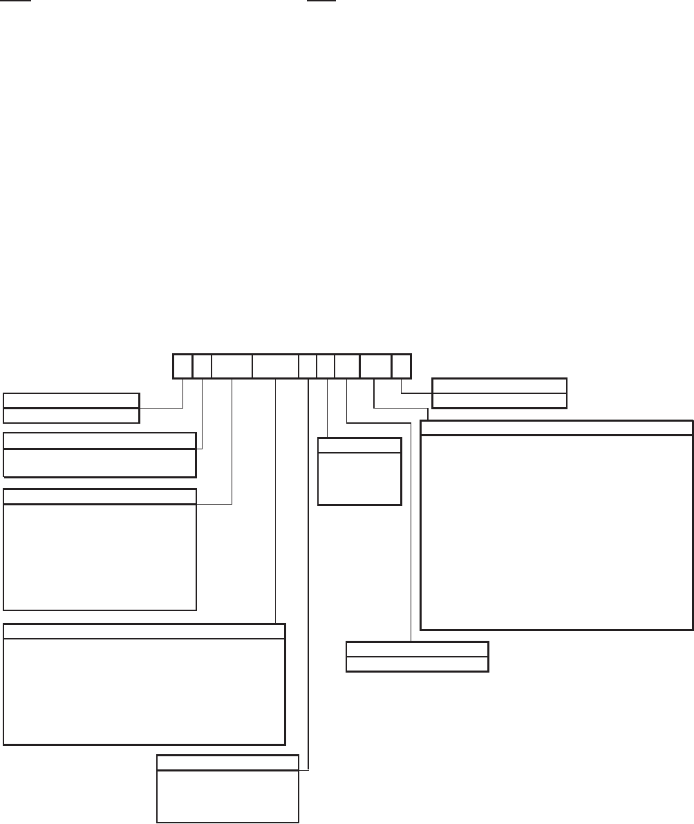
UPG UERV MODEL NOMENCLATURE
028 A12 H
Product Category
V = Ventilator
Wheel Type
R = Rooftop Stationary
CFM*
006 = 300 to 550
011 = 600 to 1000
A06 = ZF/ZR/XP036-072 & ZS/ZK/XA -03 Thru -A6
Additional Options
AA = No Options Installed
Duct Type
2= 208/230v-3ph
UPG UERV Model Nomenclature
H = High Speed**
Product Generation
1 = First Generation
Voltage
4= 460v-3ph
UPG Rooftop Cabinet
VR 4 A L2 1
P = Rooftop Pivoting (036-060 & 078-150 only)
020 = 1100 to 1700
028 = 2200 to 2800** 1500 to 2200**
036 = 2800 to 3600
046 = 3400 to 4600
062 = 5500 to 6200** 4800 to 5600**
074 = 6000 to 8000
122 = 8000 to 13000
Blower Speed
M = Medium Speed**
V = Variable Speed
L = Constant Volume
5= 575v-3ph
9= 208/320v-1ph
A12 = 50” Models ZF/ZH/ZR/XP 102-150, ZJ078-150 &
ZS/ZU/ZK/XA -08 Thru -12, ZW-06 Thru -12
B12 = 42” Models ZF/ZR/XP078-090, ZH037-090, ZJ/ZR037-061
ZS/ZK/XA -06 Thru -07, ZU-A3 Thru-07, ZW/ZK-A3 Thru -A5
A15 = Models ZF180 & ZS-15
A25 = Models ZF210-300, ZJ180-300, XP180-240 & ZS-18 Thru -25,
ZW-15 Thru -25, XA-15, -20
A40 = Models Z42, Z33, Z34 & X42, X33, X34 25-40 Tons
A = No Selection on Rooftop Units
L1 = Low Ambient Kit (LAK)*
L2 = LAK & Motorized Outside Air (MOA)*
L3 = LAK, MOA & Stop-Start-Job (SSJ) (not used on P models)*
L4 = LAK, MOA, SSJ & Pressure Sensor (PS) (not used on P)
L5 = LAK & SSJ (not used on P models)*
L6 = LAK, SSJ & PS (not used on P models)
L7 = LAK & PS
L8 = LAK, MOA and PS
M1 = Motorized Outside Air (MOA)*
M2 = MOA, and Stop Start-Jog (SSJ) (not used on P models)*
M3 = MOA, SSJ and Pressure Sensor (PS) (not used on P models)
M4 = MOA and PS
S1 = Stop-Start-Job (SSJ) (not used on P models)*
S2 = SSJ and Pressure Sensor (PS) (not used on P models)
P1 = Pressure Sensor (PS)
* CFM is ERV wheel rating. This may vary depending on unit cabinet pressure drop.
** These CFM ranges are dependant upon blower motor selection.
903106-UTG-A-0912
4 Unitary Products Group
APPLICATIONS
Unitized Energy Recovery Ventilators (UERV) are used with
the UPG rooftop packaged units. The internal wheel provides
sensible and latent energy exchange between the entering
and exhaust air streams of a building. This allows a substan-
tial amount of the energy, which is normally lost in the
exhaust air stream to be returned into the entering air. Ideal
applications are areas that have cold or hot temperatures, or
areas that have high humidity or very low humidity (recover
exhaust air from buildings that have humidifiers to add
humidity). Application software is available to provide the
energy and dollar savings for all areas of the United States
and Canada.
PRINCIPLE OF OPERATION
The UERV enthalpy wheel contains parallel layers of a poly-
meric material that are impregnated with silica gel (desic-
cant). The wheel is located in the entering (intake) air and
exhaust air streams of the ventilation equipment. As the
wheel rotates through each air stream, the wheel surface
adsorbs sensible and latent energy. In the heating mode, the
wheel rotates to provide a constant transfer of heat from the
exhaust air stream to the colder intake air stream. During the
cooling season, the process is reversed. On units equipped
with an economizer (3 - 12.5 tons), the wheel pivots out of the
air stream to allow economizer to operate normally for "free
cooling" when outdoor temperature and humidity is accept-
able. During economizer operation, the UERV exhaust
blower continues to run, providing power exhaust for the sys-
tem. The intake blower is de-energized during economizer
operation.
AHRI/ANSI STANDARD 1060-2005 FOR AIR-TO-AIR
ENERGY RECOVERY VENTILATION EQUIPMENT
The Air-Conditioning, Heating and Refrigeration Institute
(AHRI) issued Standard 1060-2005 to certify air-to-air energy
recovery ventilators. This standard deals specifically with the
ratings of the Energy Recovery Wheel that is incorporated
into the Energy Recovery Ventilator (ERV). All of the UPG
ERV's have an AHRI certified energy recovery wheel. The
data shown in the specification charts is the AHRI certified
ratings for the wheel. Actual performance in the ERV may
vary.
Critical Terms for Standard 1060 are as follows:
1. Effectiveness. The measured energy recovery effec-
tiveness not adjusted to account for that portion of the
psychrometric change in the leaving supply air (Station
2) that is the result of leakage of entering exhaust air
(Station 3) rather than exchange of heat or moisture
between the air streams.
2. Net Effectiveness. The measured recovery effective-
ness adjusted to account for that portion of the psycho-
metric change in the leaving supply air (Station 2) that is
the result of leakage of the entering exhaust air (Station
3) rather than exchange of heat or moisture between the
air streams.
3. Exhaust Air Transfer Ratio (EATR). The tracer gas
concentration difference between the leaving supply air
(Station 2) and entering supply (outdoor) air stream (Sta-
tion 1) divided by the tracer gas concentration in the
entering exhaust (return) air (Station 3) at the 100%
rated air-flow, expressed as a percentage.
4. Outdoor Air Correction Factor (OACF). The entering
supply (outdoor) airflow (Station 1) divided by the mea-
sured (gross) leaving supply airflow (Station 2).
ENERGY RECOVERY WHEEL
The heart of the Energy Recovery Ventilator is the Energy
Recovery Wheel (defined by AHRI as a rotary heat
exchanger). The wheel has a patented design of parallel lay-
ers of wrapped polymeric material that is impregnated with a
silica gel (desiccant). This unique design makes it the only
truly cleanable wheel on the market today. The small wheels
(30 inch diameter and smaller) are slide out cassettes, and
the larger wheels have pie segments that are removable for
cleaning.
FIGURE 1 - UNITIZED ENERGY RECOVERY
VENTILATOR
FIGURE 2 - ENERGY RECOVERY WHEEL
Unitary Products Group 5
903106-UTG-A-0912
CROSS LEAKAGE IN UERV’S (PURGE SECTORS)
The issue of cross leakage in rotary wheel based UERV's
used in space conditioning applications is often misunder-
stood. As a result, many systems are installed with purge
sectors and the additional fan capacity required to allow
these sectors to function when in fact they are unnecessary.
A better understanding of the rational for the purge sector,
and its history, allows us to dispense with the purge sector, its
added first cost and continuing cost of operation.
A purge sector minimizes the carry over cross leakage from
the exhaust into the supply (outside air) air stream by shunt-
ing a portion of the supply air back into the exhaust air stream
across the seal separating the exhaust and supply. This is
required in industrial applications where the exhaust carries
contaminants. This typically results in air volume being 15%
to 20% higher to get the desired air intake, and the cost asso-
ciated with it.
In space conditioning applications, where the ventilation is
operating to maintain acceptable indoor air quality, there are
no contaminants in concentrations large enough to cause
concern. Cross leakage in the UERV system results in a
small amount of the exhaust air, typically less than 5% in bal-
anced airflow, returning to the space. This is not contami-
nated air, as some would suggest. It is however air that
effectively never left the space. The operation cost of moving
this air is far less than that required for a purge sector. Do not
use the UPG UERV's in applications that have concentrations
of contaminants.
OPTIONAL ACCESSORIES - FIELD
INSTALLED
UERV Equipment Support - 8 inch (203 mm) high base for
support of the exhaust and intake end of the UERV. Must be
ordered separately from the UERV.
Equipment Support
UERV Part No.
VR006 1ES0401
VR/P011 1ES0402
VR/P020 1ES0402
VR/P028 1ES0402
Equipment Support
UERV Part No.
VR036 1ES0403
VR046 1ES0403
VR062 1ES0404
VR074
VR122
Roof Curb - A 14 or 24 inch (355 or 610 mm) roof curb is
required to match supply and exhaust openings of the UERV
with the rooftop units. UPG provides a full line of roof curbs to
match the specified unit. See specification pages for required
curb. Must be ordered separately from UERV.
Stand Alone Balancing Damper - Balancing dampers are
used with VO and VS models when ERV is connected to the
rooftop unit, not to ductwork on the roof.
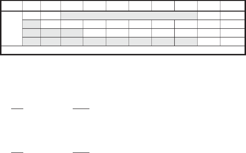
TABLE 1: UERV OUTSIDE AIR CFM SELECTION BY CFM
Unit-Tons 300-550 600-1000 1100-1700 1500-2800 2800-3600 3400-4600 4800-5600 5500-6200 6000-8000 8000-13000
Rooftop
1.5 - 6 1.5 - 6 Stand Alone type ERV’s are available for all tonnage sizes.
7.5 - 12.5 7.5 - 12.5 7.5 - 12.5
15 - 25 15 - 25 15 - 25 15 - 25 15 - 25
25 - 40 30 - 40
Stand Alone ERV’s are available for equipment room applications.
903106-UTG-A-0912
6 Unitary Products Group
OPTIONAL ACCESSORIES - FACTORY
INSTALLED
Low Ambient Control Kit - Prevents frost formation on
energy wheel heat transfer surfaces by terminating the intake
blower operation when discharge air temperature falls below
a field selectable temperature setting. Intake blower opera-
tion resumes operation after temperature rises above the
adjustable temperature differential.
Pressure Sensor - Measurement device on the UERV to
determine airflow across the Wheel.
Motorized Intake Air Damper - Damper mounts in the out-
door air intake hood. It opens when the UERV is energized
and closes when de-energized.
Stop-Start-Jog - Function that rotates the Enthalpy Wheel
(non-pivoting models) on a preset timer to prevent contami-
nation of the wheel during economizer operation.
ERV Option Codes (ex.: VR028A12H4AL3 would be an R28
series high speed 460 volt UERV with a Low Ambient kit,
Motorized Outside Air, and Stop-Start-Jog kit.)
L1 - Low Ambient Kit (LAK) *
L2 - LAK & Motorized. Outside Air (MOA) *
L3 - LAK, MOA, & Stop-Start-Jog (SSJ) *
L4 - LAK, MOA, SSJ, & Pressure Sensor (PS)
L5 - LAK and SSJ *
L6 - LAK, SSJ, and PS
L7 - LAK and PS
L8 - LAK, MOA, and PS
M1 - Motorized Outside Air (MOA) *
M2 - MOA and Stop-Start-Jog (SSJ) *
M3 - MOA, SSJ, and Pressure Sensor (PS)
M4 - MOA and PS
S1 - Stop-Start-Jog (SSJ) *
S2 - SSJ and Pressure Sensor (PS)
P1 - Pressure Sensor (PS)
NOTE: * denotes only options available for VR074 & VR122.
HOW TO SELECT THE PROPER AIR
CONDITIONING UNIT AND UNITARY ENERGY
RECOVERY VENTILATOR
1. Determine the air conditioning load requirements with
the required amount of outside air without an UERV.
2. Select the proper UERV for the outside air CFM require-
ments and calculate the tonnage reduction through the
UST or UERV software programs.
3. Select the air conditioning unit required by reducing the
load determined in step 1 by the reduction in step 2.
(Example: If the load in Step 1 was 10 tons, and the
reduction in Step 2 was 2.5 tons, select a 7.5 ton unit.)
4. Select the proper UERV based on the selected unit. SEE
Page 3 UERV Nomenclature for Details
Unitary Products Group 7
903106-UTG-A-0912
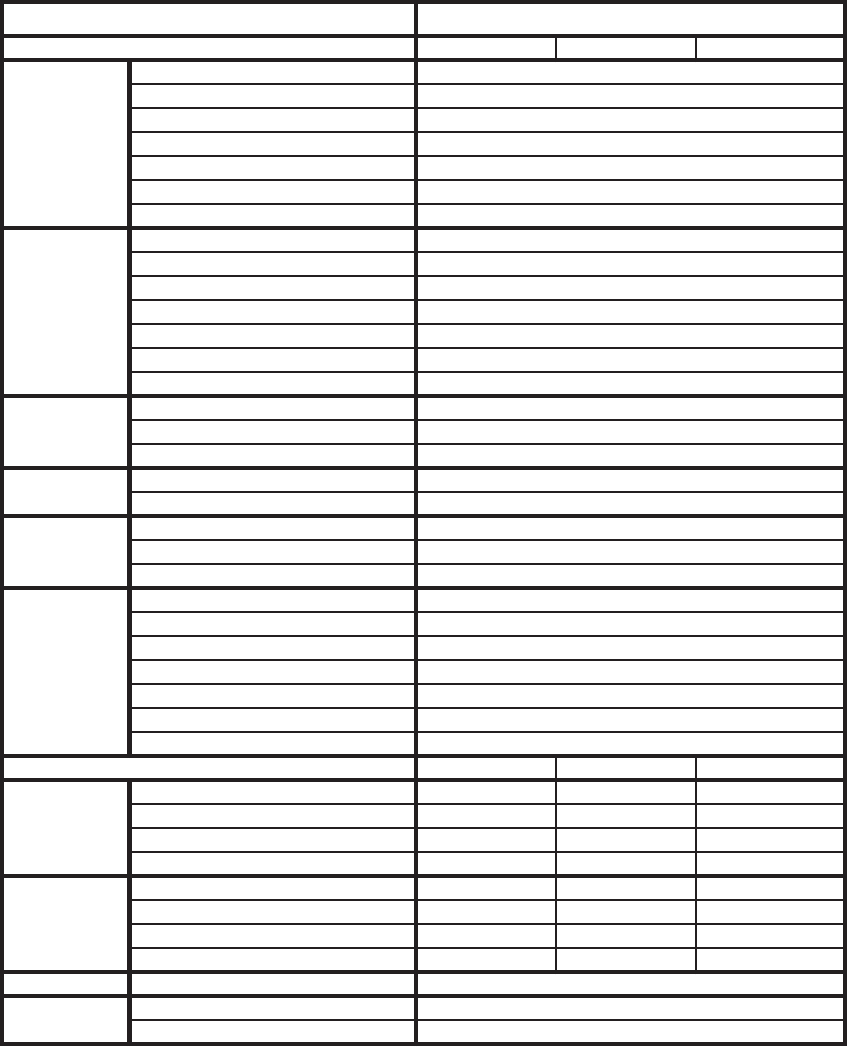
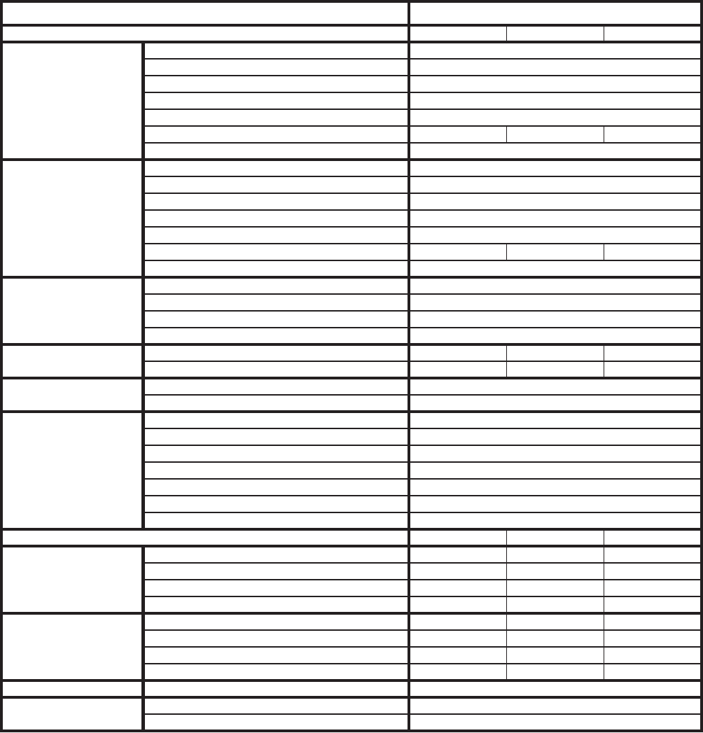
Note 1: Complete UPG ERV model number includes the electrical information. Example ZF 060
needing 500 CFM outside of air at 230 volts/3 phase. Model would be a VR006A06H2AAA1.
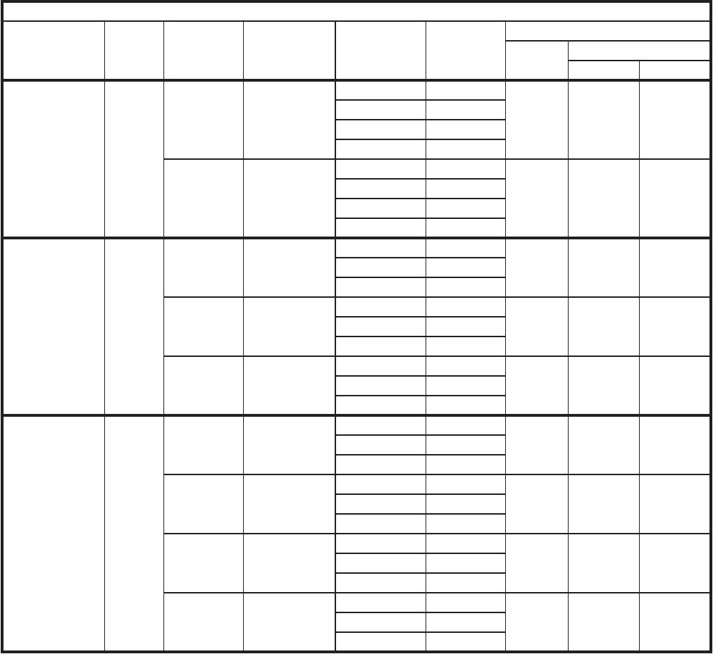
TABLE 2: PERFORMANCE - 3 THROUGH 12 1/2 TON UNITS
“R” Series Stationary Wheel for Units without Economizers
UPG
Packaged Unit
Model No.
Unit Size
(Tons) ERV CFM
Range Matching ERV
Model Voltage &
Phase Voltage
Code
Nominal AHRI Data (Total
CFM Net Effectiveness
Heating Cooling
ZF036-072
ZR036-060
XP036-060
ZS-03-A6
ZK-03-05
XP-03-05
3 - 6
300-550 VR006A06H
110v-1ph 1
500 65% 64%
208/230v-1ph 9
208/240v-3ph 2
460v-3ph 4
600-1000 VR011A06H
208/230v-1ph 9
900 73% 72%
208/230v-3ph 2
460v-3ph 4
575v-3ph 5
(42”)
ZH037-090
ZF078-090
ZJ037-061
ZR037-090
ZU-A3-07
ZS-06-07
ZW-A3-A5
ZK-A3-07
3 - 7.5
300-550 VR006B06H
208/230v-3ph 2
500 65% 64%460v-3ph 4
575v-3ph 5
600-1000 VR011B12H
208/230v-3ph 2
900 73% 72%460v-3ph 4
575v-3ph 5
1100-1700 VR020B12H
208/230v-3ph 2
1600 65% 64%460v-3ph 4
575v-3ph 5
(50”)
ZF102-150
ZH102-150
ZJ078-150
XP102-150
ZR102-150
ZS-08-12
ZU-08-12
ZW-06-12
XA-08-12
ZK-08-12
6.5 - 12.5
600-1000 VR011A12H
208/230v-3ph 2
900 73% 72%460v-3ph 4
575v-3ph 5
1100-1700 VR020A12H
208/230v-3ph 2
1600 65% 64%460v-3ph 4
575v-3ph 5
1500-2200 VR028A12M
208/230v-3ph 2
1950 71% 70%460v-3ph 4
575v-3ph 5
2200-2800 VR028A12H
208/230v-3ph 2
2600 65% 63%460v-3ph 4
575v-3ph 5
903106-UTG-A-0912
8 Unitary Products Group
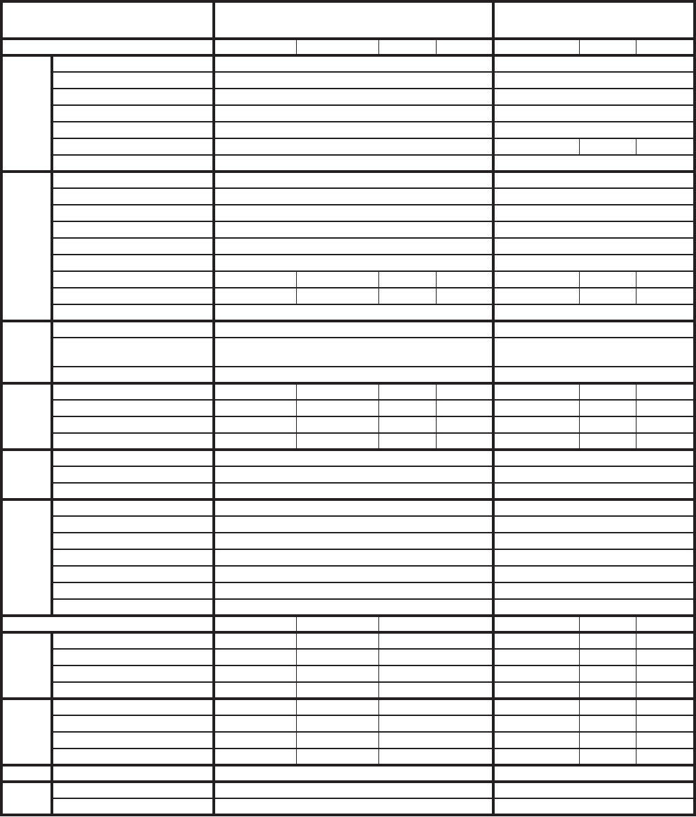
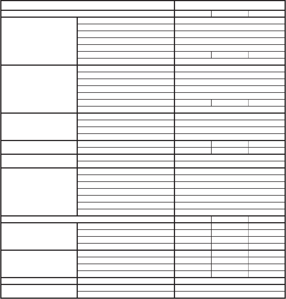
Note 1: Complete UPG ERV model number includes the electrical information. Example: ZJ180 needing 2800 CFM
outside of air at 230 volts/3 phase. Model would be a VR028A15H2AAA1.
Note 2: For VR074 and VR122 units used with an economizer must have the Start-Stop-Jog (SSJ) option.
TABLE 3: PERFORMANCE - 15 THROUGH 25 TON UNITS
Use this table to determine ventilation and size requirements. Table shows UPG packaged units and matching ERV model,
Air Flow Range, and AHRI rated Net Effectiveness at 100% of rated CFM.
“R” Series Stationary Wheel for Units without Economizers
UPG
Packaged Unit
Model No.
Unit
Size
(Tons)
ERV CFM
Range Matching ERV
Model Voltage &
Phase Voltage
Code
Nominal AHRI Data (Total
CFM Net Effectiveness
Heating Cooling
ZF180
ZJ180
ZR180
XP180
ZS-15
ZW-15
ZK-15
XA-15
15
1500-2200 VR028A25H
208/230v-3ph 2
1950 71% 70%460v-3ph 4
575v-3ph 5
2200-2800 VR028A25H
208/230v-3ph 2
2600 65% 63%460v-3ph 4
575v-3ph 5
2800-3600 VR036A15H
208/230v-3ph 2
3100 65% 63%460v-3ph 4
575v-3ph 5
3400-4600 VR046A15H
208/230v-3ph 2
3900 65% 63%460v-3ph 4
575v-3ph 5
4800-5600 VR062A25M
208/230v-3ph 2
4125 71% 70%460v-3ph 4
575v-3ph 5
5500-6200 VR062A25H
208/230v-3ph 2
5500 65% 63%460v-3ph 4
575v-3ph 5
ZJ210-300
ZR240-300
ZF210-300
XP240
ZW-18-25
ZK-20-25
ZF-18-25
XA-20
17.5 - 25
2200-2800 VR028A25H
208/230v-3ph 2
2600 65% 63%460v-3ph 4
575v-3ph 5
2800-3600 VR036A25H
208/230v-3ph 2
3100 65% 63%460v-3ph 4
575v-3ph 5
3400-4600 VR046A25H
208/230v-3ph 2
3900 65% 63%460v-3ph 4
575v-3ph 5
4800-5600 VR062A25M
208/230v-3ph 2
4125 71% 70%460v-3ph 4
575v-3ph 5
5500-6200 VR062A25H
208/230v-3ph 4
5500 65% 63%460v-3ph 5
575v-3ph 2
Z42
Z33
Z34
X42
X33
X34
25-40
6000-8000 VR074A40*
208/230v-3ph 2
6600 65% 63%460v-3ph 4
575v-3ph 5
8000-13000 VR122A40*
208/230v-3ph 2
10800 65% 63%460v-3ph 4
575v-3ph 5
Unitary Products Group 9
903106-UTG-A-0912
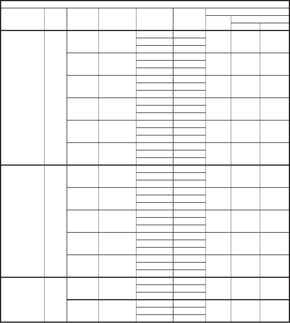
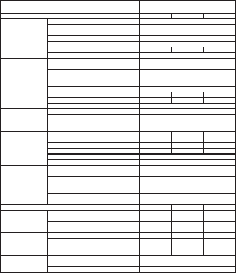
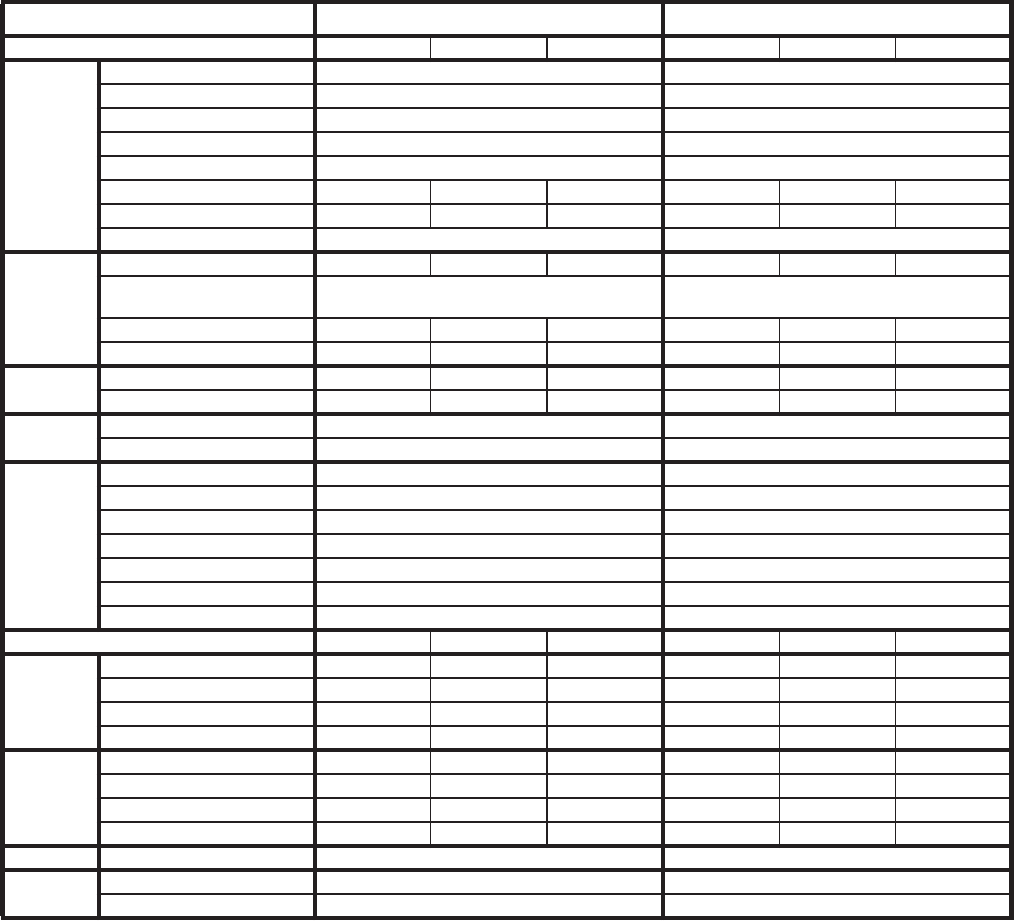
Note 1: Complete UPG ERV model number includes the electrical information. Example ZF 060
needing 800 CFM outside of air at 230 volts/3 phase. Model would be a VP011A06H2AAA1.
2: Models ZF/ZH/ZJ/XP* 037-150 & ZS/ZU/ZW/ZK/XA -A3-12 with ERV must use “slab” type econo-
mizers and downflow position.
TABLE 4: PERFORMANCE - PIVOTING WHEEL MODELS
“P” Series Pivoting Wheel for Units with Economizers
UPG
Packaged Unit
Model No.
Unit
Size
(Tons)
ERV
CFM
Range
Max.
CFM
Power
Exhaust
Matching
ERV
Model
Voltage &
Phase Voltage
Code
Nominal AHRI Data (Total
CFM Net Effectiveness
Heating Cooling
ZF036-072
ZR036-060
XP036-060
ZS-03-A6
ZK-03-05
XA-03-05
3 - 6 600-
1000 1900 VP011A06H
208/230v-1ph 9
900 73% 72%
208/240v-3ph 2
460v-3ph 4
575v-3ph 5
(42”)
ZH037-090
ZF078-090
ZJ037-061
ZR037-090
XP078-090
ZU-A3-07
ZS-06-07
ZW-A3-A5
ZK-A3-07
XA-06-07
3 - 7.5
600-
1000 1900 VP011B12H
208/230v-3ph 2
900 73% 72%460v-3ph 4
575v-3ph 5
1100-
1700 3000 VP020B12H
208/230v-3ph 2
1600 65% 64%
460v-3ph 4
575v-3ph 5
(50”)
ZF102-150
ZH102-150
ZJ078-150
ZR102-150
XP102-150
ZS-08-12
ZU-08-12
ZW-06-12
ZK-08-12
XA-08-12
6.5 -
12.5
600-
1000 1900 VP011A12H
208/230v-3ph 2
900 73% 72%460v-3ph 4
575v-3ph 5
1100-
1700 3000 VP020A12H
208/230v-3ph 2
1600 65% 64%460v-3ph 4
575v-3ph 5
1500-
2200 3450 VP028A12M
208/230v-3ph 2
1950 71% 70%460v-3ph 4
575v-3ph 5
2200-
2800 4200 VP028A12H
208/230v-3ph 2
2600 65% 63%460v-3ph 4
575v-3ph 5
903106-UTG-A-0912
10 Unitary Products Group
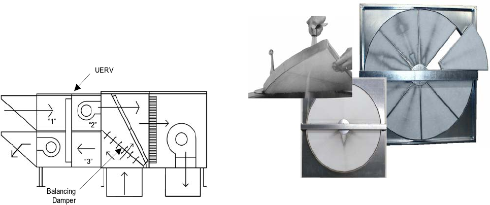
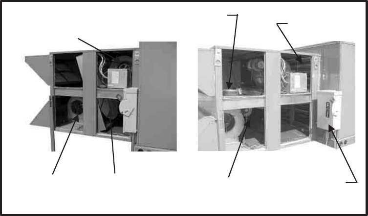
FIGURE 3 - “P” SERIES PIVOTING WHEEL FOR UNITS W/ECONOMIZERS
Enthalpy Wheel
(with removable pie
segments)
Exhaust
Air Blower
(
ener
g
ized
)
Outsid
e
Air Blower
(energized)
Exhaust
Air Blower
Fresh Air Damper
(opens during economizer
operation)
Unit & UERV Disconnect
(provided correct wire size used
for both units and
local code approval)
Enthalpy Wheel
Pivoted out of Intake and
Discharge Air Stream
Unitary Products Group 11
903106-UTG-A-0912
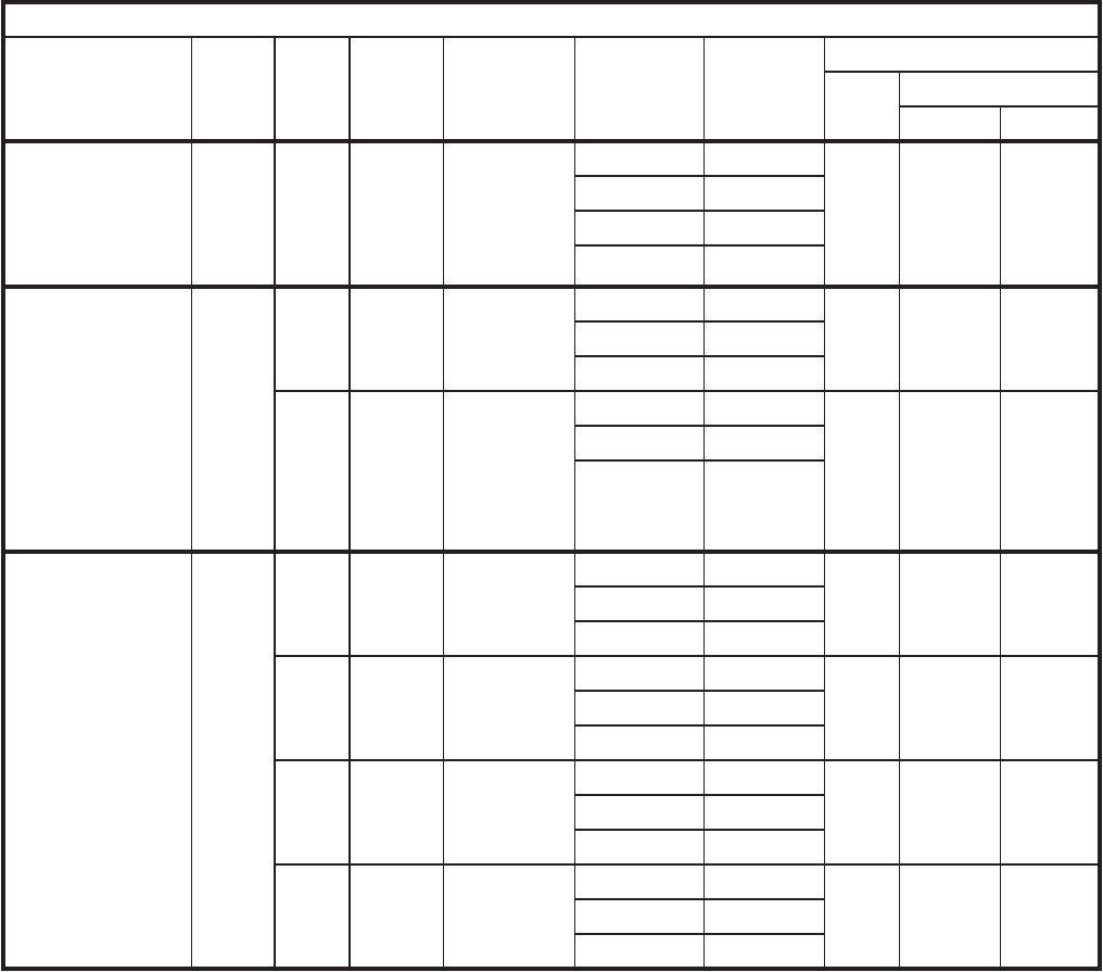
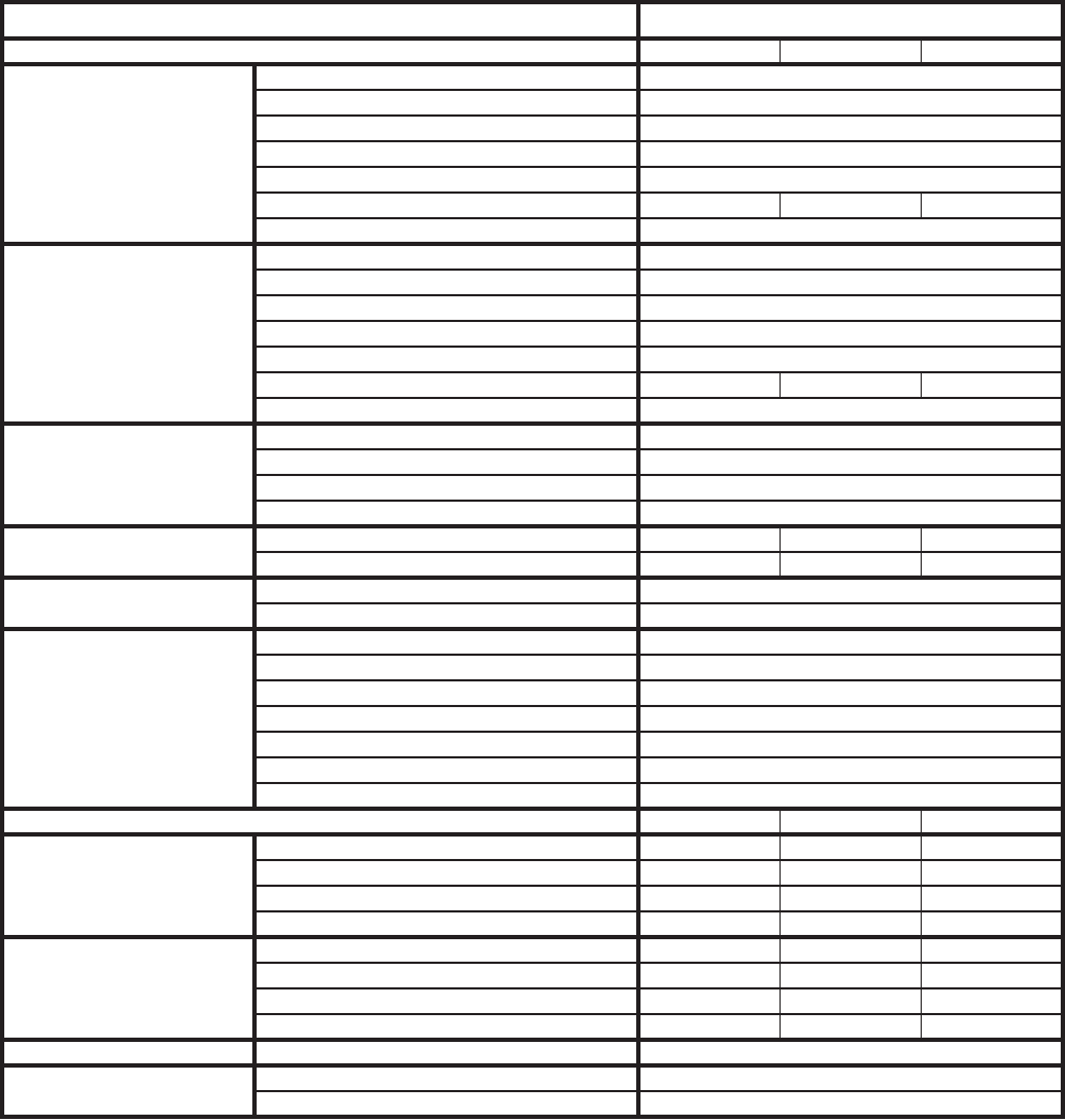
Note: 1: A stepdown transformer is provided to stepdown high
voltage primary to 115 volt secondary.
TABLE 5: SPECIFICATIONS AND ELECTRICAL DATA - 300 THROUGH 550 CFM ERV’S
Model Numbers VR006 - Rooftop Stationary
Line Voltage - 60hz 115v-1ph 208/230v/460-1ph 208/230v/460-3ph
Fresh Air
Blower
Motor - hp / type 0.25 / PSC
Wheel Size (dia x width) - in 5.5 x 6.3
Motor Speed - rpm 1780
Motor Speed(s) 2
Bearing Type Sleeve
Full Load Amps 3.8
Service Factor 1.1
Exhaust Air
Blower
Motor - hp 0.25 / PSC
Wheel Size (dia x width) - in 5.5 x 6.3
Motor Speed - rpm 1780
Motor Speed(s) 2
Bearing Type Sleeve
Full Load Amps-Stationary 3.8
Service Factor 1.1
Wheel
Electrical
Data
Potential Volts 115
Motor Speed (RPM)/Wheel (RPM) 1050/68
Full Load Amps 0.7
Total
Electrical
MCA 8.7
OCPD 10
Wheel
Data
Wheel Depth 2
Wheel Diameter 19.3
Construction / Media Type One Piece / Polymeric
Enthalpy
Wheel AHRI
Rating Data
Nominal Airflow CFM 500 @ .6
EATR - -0.50 H2O 9.90%
EATR - 0.00 H2O 0.20%
EATR - +0.50 H2O 0.00%
OACF - -0.50 H2O 1.02%
OACF - 0.00 H2O 1.33
OACF - +0.50 H2O 1.59%
Thermal Ratings @ 0” Pressure Diff. Sensible Latent Total
Total
Effectiveness
100% Airflow Heating 68% 60% 65%
75% Airflow Heating 73% 65% 70%
100% Airflow Cooling 68% 60% 64%
75% Airflow Cooling 73% 65% 69%
Net
Effectiveness
100% Airflow Heating 68% 60% 65%
75% Airflow Heating 73% 65% 70%
100% Airflow Cooling 68% 60% 64%
75% Airflow Cooling 73% 65% 69%
Curb A/C Unit Curb Height - in 14
Weights Shipping Weight - lbs. 198
Net Weight - lbs. 155
903106-UTG-A-0912
12 Unitary Products Group
TABLE 6: SPECIFICATIONS AND ELECTRICAL DATA - 600 THROUGH 1700 CFM ERV’S
Note: 1. Pivoting electrical data applies to VP models only.
Model Numbers VR011 - Rooftop Stationary
VP011 - Rooftop Pivoting VR020 - Rooftop Stationary
VP020 - Rooftop Pivoting
Line Voltage - 60hz 208/ 230v-1ph 208/ 230v-3ph 460v- 1ph 460v-3ph 208/230v-3ph 460v-3ph 575v-3ph
Fresh Air
Blower
Motor - hp / type .5 / PSC 1.0 / Belt
Wheel Size (dia x width) - in 10 x 6 AT 9 x 9
Motor Speed - rpm 1120 / 960 / 850 1725
Motor Speed(s) 3 Adjustable Sheave
Bearing Type Sleeve Ball
Full Load Amps 3.4 3.8 1.9 1.4
Service Factor 1 1.15
Exhaust
Air
Blower
Motor - hp Stationary .5 / PSC 1.0 / Belt
Motor - hp Pivoting .5 / PSC 1.5 / Belt
Wheel Size (dia x width) - in 10 x 6 AT 9 x 9
Motor Speed - rpm 1120 / 960 / 850 1725
Motor Speed(s) 3 Adjustable Sheave
Bearing Type Sleeve Ball
Full Load Amps-Stationary 3.4 3.4 1.5 1.5 3.8 1.9 1.4
Full Load Amps-Pivoting 3.4 3.4 1.5 1.5 5.6 2.8 2.0
Service Factor 1 1.15
Wheel
Electrical
Data
Potential Volts 208 / 230 208 / 230
Motor Speed (RPM)/Wheel
(RPM) 1050/56 1050/46
Full Load Amps 0.3 0.3
Total
Electrical
MCA - Stationary 8.25 8.25 4.4 4.4 8.85 4.58 3.45
OCPD - Stationary 10 10 6 6 12 6 5
MCA - Pivoting 8.25 8.25 4.4 4.4 11.1 5.7 4.2
OCPD - Pivoting 10 10 6 6 15 8 6
Wheel
Data
Wheel Depth - in 3 3
Diameter - in 25.3 30.346
Construction / Media Type Segmented / Polymeric Segmented / Polymeric
Enthalpy
Wheel
AHRI
Rating
Data
Nominal Airflow CFM 900 @ 1.01600 @ .95
EATR - -1.00 H2O 9.30% 7.80%
EATR - 0.00 H2O 0.70% 0.40%
EATR - +1.00 H2O 0.00% 0.00%
OACF - -1.00 H2O 0.97% 0.97%
OACF - 0.00 H2O 1.19% 1.16%
OACF - +1.00 H2O 1.34% 1.29%
Thermal Ratings @ 0” Pressure Diff. Sensible Latent Total Sensible Latent Total
Total
Effec-
tive-
ness
100% Airflow Heating 76% 68% 73% 68% 61% 65%
75% Airflow Heating 81% 73% 78% 72% 67% 71%
100% Airflow Cooling 76% 68% 72% 68% 61% 64%
75% Airflow Cooling 81% 73% 76% 72% 67% 70%
Net
Effec-
tive-
ness
100% Airflow Heating 76% 68% 73% 68% 61% 65%
75% Airflow Heating 81% 73% 78% 72% 67% 71%
100% Airflow Cooling 76% 68% 72% 68% 61% 64%
75% Airflow Cooling 81% 73% 76% 72% 67% 70%
Curb A/C Unit Curb Height - in 14 14
Weights Shipping Weight - lbs. 318 425
Net Weight - lbs. 245 345
Unitary Products Group 13
903106-UTG-A-0912
TABLE 7: SPECIFICATIONS AND ELECTRICAL DATA - 1500 THROUGH 2800 CFM ERV’S
* Electric data is for (A12) ZH/ZF/ZJ 078-150 and XP 078-150 only.
** Electric data is for (A15 and A25) ZH/ZF/ZJ 180-300 and XP 180 and 240 only.
Note: Pivoting electrical data applies to VP models only.
Model Numbers * VR028 - Rooftop Stationary
* VP028 - Rooftop Pivoting
Line Voltage - 60hz 208/230v-3ph 460v-3ph 575v-3ph
Fresh Air
Blower
Motor - hp / type 1.5 / Belt
Wheel Size (dia x width) - in 10 x 10
Motor Speed - rpm 1725
Motor Speed(s) Adjustable Sheave
Bearing Type Ball
Full Load Amps 5.6 2.8 2
Service Factor 1.15
Exhaust Air
Blower
Motor - hp Stationary 1.5 / Belt
Motor - hp Pivoting 3 / Belt
Wheel Size (dia x width) - in 10 x 10
Motor Speed - rpm 1725
Motor Speed(s) Adjustable Sheave
Bearing Type Ball
Full Load Amps-Stationary 5.6 2.8 2
Full Load Amps-Pivoting 9 4.4 3.6
Service Factor 1.15
Wheel
Electrical
Data
Motor - hp (1 phase) 0.17
Potential Volts 200-208 / 230
Motor Speed (RPM)/Wheel (RPM) 825/58
Full Load Amps 0.6
Total
Electrical
MCA - Stationary 13.2 6.9 5.1
OCPD - Stationary 20 10 7
MCA - Pivoting 17.5 8.9 7.1
OCPD - Pivoting 25 12 10
Wheel
Data
Wheel Depth x Diameter - in 3 x 37.759
Construction / Media Type Segmented Pies / Polymeric
Enthalpy
Wheel AHRI
Rating Data
Nominal Airflow CFM 2600 @ .95
EATR - -1.00 H2O 6.10%
EATR - 0.00 H2O 0.40%
EATR - +1.00 H2O 0.00%
OACF - -1.00 H2O 0.99%
OACF - 0.00 H2O 1.13%
OACF - +1.00 H2O 1.23%
Thermal Ratings @ 0” Pressure Diff. Sensible Latent Total
Total
Effectiveness
100% Airflow Heating 68% 60% 65%
75% Airflow Heating 74% 67% 71%
100% Airflow Cooling 68% 60% 63%
75% Airflow Cooling 74% 67% 70%
Net
Effectiveness
100% Airflow Heating 68% 60% 65%
75% Airflow Heating 74% 67% 71%
100% Airflow Cooling 68% 60% 63%
75% Airflow Cooling 74% 67% 70%
Curb A/C Unit Curb Height - in 14
Weights Shipping Weight - lbs. 470
Net Weight - lbs. 395
903106-UTG-A-0912
14 Unitary Products Group
TABLE 8: SPECIFICATIONS AND ELECTRICAL DATA - 2800 THROUGH 3600 CFM ERV’S
Model Numbers VR036 - Rooftop Stationary
Line Voltage - 60hz 208/230v-3ph 460v-3ph 575v-3ph
Fresh Air
Blower
Motor - hp / type 2 / Belt
Wheel Size (dia x width) - in 12 x 9
Motor Speed - rpm 1725
Motor Speed(s) Adjustable Sheave
Bearing Type Ball
Full Load Amps 7.0 3.5 3.2
Service Factor 1.15
Exhaust Air
Blower
Motor - hp Stationary 3 / Belt
Wheel Size (dia x width) - in 12 x 9
Motor Speed - rpm 1725
Motor Speed(s) Adjustable Sheave
Bearing Type Ball
Full Load Amps-Stationary 7.0 3.5 3.2
Service Factor 1.15
Wheel
Electrical
Data
Motor - hp (1 phase) 0.50
Potential Volts 200-208 / 230
Motor Speed (RPM)/Wheel (RPM) 1725/64
Full Load Amps 1.2
Total
Electrical
MCA - Stationary 16.4 8.6 6.6
OCPD - Stationary 25 12 9
Wheel
Data
Wheel Depth x Diameter - in 3 x 41.825
Construction / Media Type Segmented Pies / Polymeric
Enthalpy
Wheel AHRI
Rating Data
Nominal Airflow CFM 3100 @ .9
EATR - -1.00 H2O 4.90%
EATR - 0.00 H2O 1.30%
EATR - +1.00 H2O 0.30%
OACF - -1.00 H2O 0.99%
OACF - 0.00 H2O 1.07%
OACF - +1.00 H2O 1.12%
Thermal Ratings @ 0” Pressure Diff. Sensible Latent Total
Total
Effectiveness
100% Airflow Heating 68% 60% 65%
75% Airflow Heating 74% 67% 71%
100% Airflow Cooling 68% 60% 63%
75% Airflow Cooling 74% 67% 70%
Net
Effectiveness
100% Airflow Heating 68% 60% 65%
75% Airflow Heating 74% 67% 71%
100% Airflow Cooling 68% 60% 63%
75% Airflow Cooling 74% 67% 70%
Curb A/C Unit Curb Height - in 24 On A15 Or A25
Weights Shipping Weight - lbs. 571
Net Weight - lbs. 475
Unitary Products Group 15
903106-UTG-A-0912
TABLE 9: SPECIFICATIONS AND ELECTRICAL DATA - 3400 THROUGH 5600 CFM ERV’S
Model Numbers VR046 - Rooftop Stationary
Line Voltage - 60hz 208/230v-3ph 460v-3ph 575v-3ph
Fresh Air
Blower
Motor - hp / type 3 / Belt
Wheel Size (dia x width) - in 12 x 12
Motor Speed - rpm 1725
Motor Speed(s) Adjustable Sheave
Bearing Type Ball
Full Load Amps 9.4 4.3 3.4
Service Factor 1.15
Exhaust Air
Blower
Motor - hp Stationary 3 / Belt
Wheel Size (dia x width) - in 12 x 12
Motor Speed - rpm 1725
Motor Speed(s) Adjustable Sheave
Bearing Type Ball
Full Load Amps-Stationary 9 4.4 3.6
Service Factor 1.15
Wheel
Electrical
Data
Motor - hp (1 phase) 0.5
Potential Volts 200-208 / 230
Motor Speed (RPM)/Wheel (RPM) 1075/57
Full Load Amps 1.2
Total
Electrical
MCA - Stationary 22 11 9.1
OCPD - Stationary 30 15 12
Wheel
Data
Wheel Depth x Diameter - in 3 x 46.776
Construction / Media Type Segmented Pies / Polymeric
Enthalpy
Wheel AHRI
Rating Data
Nominal Airflow CFM 3900 @ .95
EATR - -1.00 H2O 4.40%
EATR - 0.00 H2O 1.10%
EATR - +1.00 H2O 0.20%
OACF - -1.00 H2O 0.99%
OACF - 0.00 H2O 1.06%
OACF - +1.00 H2O 1.11%
Thermal Ratings @ 0” Pressure Diff. Sensible Latent Total
Total
Effectiveness
100% Airflow Heating 68% 60% 65%
75% Airflow Heating 73% 67% 71%
100% Airflow Cooling 68% 60% 63%
75% Airflow Cooling 73% 67% 70%
Net
Effectiveness
100% Airflow Heating 68% 60% 65%
75% Airflow Heating 73% 67% 71%
100% Airflow Cooling 68% 60% 63%
75% Airflow Cooling 73% 67% 70%
Curb A/C Unit Curb Height - in 24 On A15 Or A25
Weights Shipping Weight - lbs. 920
Net Weight - lbs. 805
903106-UTG-A-0912
16 Unitary Products Group
TABLE 10: SPECIFICATIONS AND ELECTRICAL DATA - 5500 THROUGH 6200 CFM ERV’S
Model Numbers VR062 - Rooftop Stationary
Line Voltage - 60hz 208/230v-3ph 460v-3ph 575v-3ph
Fresh Air
Blower
Motor - hp / type 5 / Belt
Wheel Size (dia x width) - in 12 x 12
Motor Speed - rpm 1725
Motor Speed(s) Adjustable Sheave
Bearing Type Ball
Full Load Amps 15 7.4 5.8
Service Factor 1.15
Exhaust Air
Blower
Motor - hp Stationary 5 / Belt
Wheel Size (dia x width) - in 12 x 12
Motor Speed - rpm 1725
Motor Speed(s) Adjustable Sheave
Bearing Type Ball
Full Load Amps-Stationary 14.8 7 5.1
Service Factor 1.15
Wheel
Electrical
Data
Motor - hp (1 phase) 0.5
Potential Volts 200-208 / 230
Motor Speed (RPM)/Wheel (RPM) 1075/54
Full Load Amps 1.2
Total
Electrical
MCA - Stationary 34.8 17.5 13.6
OCPD - Stationary 40 25 20
Wheel
Data
Wheel Depth x Diameter - in 3 x 52.026
Construction / Media Type Segmented Pies / Polymeric
Enthalpy
Wheel AHRI
Rating Data
Nominal Airflow CFM 5500 @ .95
EATR - -1.00 H2O 4.00%
EATR - 0.00 H2O 1.00%
EATR - +1.00 H2O 0.20%
OACF - -1.00 H2O 0.99%
OACF - 0.00 H2O 1.06%
OACF - +1.00 H2O 1.10%
Thermal Ratings @ 0” Pressure Diff. Sensible Latent Total
Total
Effectiveness
100% Airflow Heating 68% 60% 65%
75% Airflow Heating 73% 67% 71%
100% Airflow Cooling 68% 60% 63%
75% Airflow Cooling 73% 67% 70%
Net
Effectiveness
100% Airflow Heating 68% 60% 65%
75% Airflow Heating 73% 67% 71%
100% Airflow Cooling 68% 60% 63%
75% Airflow Cooling 73% 67% 70%
Curb A/C Unit Curb Height - in 24 On A15 Or A25
Weights Shipping Weight - lbs. 1250
Net Weight - lbs. 1075
Unitary Products Group 17
903106-UTG-A-0912
TABLE 11: SPECIFICATIONS AND ELECTRICAL DATA - 6000 THROUGH 13000 CFM UERV’S
UERV Series VR074 VR122
Line Voltage - 60hz 208/230v-3ph 460v-3ph 575v-3ph 208/230v-3ph 460v-3ph 575v-3ph
Exhaust Air
Blower
Motor - hp (2) 5 / Belt (2) 7.5 / Belt
Wheel Size (dia x width) - in (2) 12 x 12 (2) 15 x 15
Motor Speed - rpm 1725 1725
Motor Speed(s) Adjustable Sheave Adjustable Sheave
Bearing Type Ball Ball
Full Load Amps 14.8 7 5 22.4 9.7 7.8
OCPD 20 9 7 30 15 10
Service Factor 1.15 1.15
Wheel
Electrical
Data
Motor - hp (3 phase) 0.25 0.25 0.25 0.25 0.25 0.25
Motor Speed (RPM)/Wheel
(RPM) 850/49 850/51
Full Load Amps 2.5 1.2 0.95 2.5 1.2 0.95
OCPD 3 2 2322
Total
Electrical
MCA 34.9 16.6 12.7 52 22.6 19
OCPD 50 20 15 70 30 25
Wheel
Data
Wheel Depth x Diameter - in 3 x 58 3 x 74
Construction / Media Type Segmented Pies / Polymeric Segmented Pies / Polymeric
Enthalpy
Wheel
Airflow Data
Nominal Airflow CFM 6600 @ .9510800 @ .95
EATR - -1.00 H2O 4.60% 3.40%
EATR - 0.00 H2O 1.90% 1.20%
EATR - +1.00 H2O 0.90% 0.40%
OACF - -1.00 H2O 0.99% 0.99%
OACF - 0.00 H2O 1.05% 1.04%
OACF - +1.00 H2O 1.09% 1.07%
Thermal Ratings @ 0” Pressure Diff. Sensible Latent Total Sensible Latent Total
Total
Effective-
ness
100% Airflow Heating 68% 60% 65% 68% 60% 65%
75% Airflow Heating 73% 67% 71% 73% 67% 71%
100% Airflow Cooling 68% 60% 63% 68% 60% 63%
75% Airflow Cooling 73% 67% 70% 73% 67% 70%
Net
Effective-
ness
100% Airflow Heating 68% 60% 65% 68% 60% 65%
75% Airflow Heating 73% 67% 71% 73% 67% 71%
100% Airflow Cooling 68% 60% 63% 68% 60% 63%
75% Airflow Cooling 73% 67% 70% 73% 67% 70%
Curb A/C Unit Curb Height - in 14 14
Weights Shipping Weight - lbs. 2800 3000
Net Weight - lbs. 2600 2800
903106-UTG-A-0912
18 Unitary Products Group
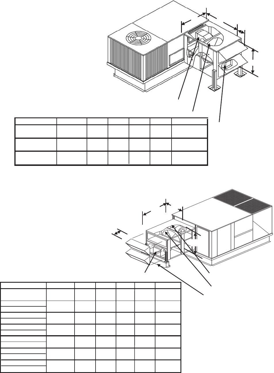
FIGURE 4 - UERV DIMENSIONAL DATA - 036 THROUGH 072 & -03 THROUGH -A6 (3-6 TONS)
14" High Curbs Required -
ERV Model Unit Size A B C D CFM
48.75
(1238)
8
(203)
300-550
036-072
-03 -A6
24.75
(629)
37.9 6
(964)
8
(203)
ZF036-072
ZR036-060
XP036-060
ZS-03-A6
ZK-03-05
XA-03-05
24.63
(624)
600-1000
036-072
-03 -A6
32.13
(816)
33.5
(851)
C
D
A
Exhaust Blower
B
Enthalpy Wheel
Intake Air Blower
VR006A06H
VR011A06H
48.75
(1238)
8
(203) 600-1000
036-072
-03 -A6
32.13
(816)
33.5
(851)
VP011A06H
-1RC0434
Models
FIGURE 5 - UERV DIMENSIONAL DATA - 037 THROUGH 150 & A3 THROUGH -12 (3 - 12 1/2 TONS)
Model Number Unit Size A B C D CFM
20.32
(516)
11
(279)
32.13
(816)
33.5
(851)
44.75
(1137)
60.38
(1533)
600-1000
1100-1700
14" High Curbs Required on "VR011" & "VP011" - 1RC0471
078-102
-06 -08
078-102
-06 -08
090-150
-07 -12
14" High Curbs Required on "VR028" & "VP028" - 1RC0476
37.25
(946)
14" High Curbs Required on "VR020" & "VP020" - 1RC0476
37.5
(953)
090-150
-07 -12
C
D
A
B
Optional Equipment
Support
Exhaust Blower
Outdoor Air
Intake Blower
Enthalpy Wheel
VR011B12H
VP011B12H
VR020B12H
VP020B12H
VR011A12H
VP011A12H
VR020A12H
VP020A12H
43.56
(1106)
42.63
(1083)
1500-2200
42.63
(1083)
64.25
(1631)
18.32
(466)
2200-2800
43.56
(1106)
64 25
(1631)
18.32
(466)
VR028A12M
VP028A12M
VR028A12H
VP028A12H
20.32
(516)
11
(279)
32.13
(816)
33.5
(851)
44.75
(1137)
60.38
(1533)
600-1000
1100-1700
37.25
(946)
37.5
(953)
Models
ZH037, 049, 061, 078, 090, 102, 120, 150
ZF078, 090, 102, 120, 150
ZR037, 049, 061, 078, 090, 102, 120, 150
XP078, 090, 102, 120, 150
ZU-A3, -A4, -A5, -06, -07, -08, -10, -12
ZS-06, -07, -08, -10, -12
ZK-A3, -A4, -A5, -06, -07, -08, -10, -12
XA-06, -07, -08, -10, -12
14" High Curbs Required on "VR06" - 1RC0471
300-550
037-061
-A3 -A5
24.75
(629)
37.9
(9
8
(203)
24.63
(624)
VR006B12H
090-150
-07 -12
090-150
-07 -12
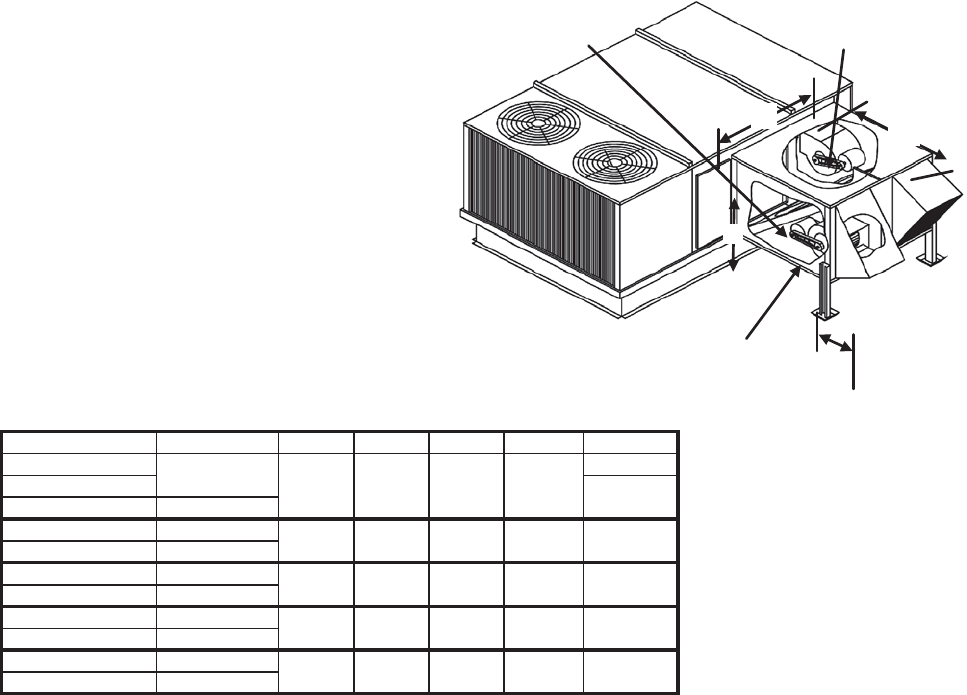
Unitary Products Group 19
903106-UTG-A-0912
FIGURE 6 - UERV DIMENSIONAL DATA - 180 THROUGH 300 & -15 THROUGH -25 (15 - 25 TONS)
Model Number Unit Size A B C D CFM
1500-2200
180-300, -15-25
24" High Curbs Required on "VR036" - 1RC0477 or 1RC0478
14" Roofcurbs Required on "VR028" - 1RC0436 - 437
52.68
(1338)
57.38
(1457)
46.68
(1186)
57.38
(1457)
60.00
(1524)
30.50
(775) 2800-3600
24" High Curbs Required on "VR062" - 1RC0477 or 1RC0478
3400-4600
4800-5600
5500-6200
58.88
(1496)
57.38
(1457)
57.38
(1457)
22.50
(572) 2200-2800
52.13
(1327)
24" High Curbs Required on "VR046" - 1RC0477 or 1RC0478
180, -15 42.63
(1083)
D
A
Exhaust
Blower
Outdoor Air Intake
Blower
Enthalpy
Wheel
B
C
VR028A15M
VR028A15H
VR028A25M
VR036A15H
VR036A25H
VR046A15H
VR046A25H
VR062A15M
VR062A25M
VR062A15H
VR062A25H
58.88
(1496)
43.56
(1106)
60.00
(1524)
60.00
(1524)
60.00
(1524)
30.50
(775)
30.50
(775)
30.50
(775)
NOTE: Refer to Unit Price Pages for exact unit, ERV and curb matchup.
Models
ZF180, 210, 240, 300
ZR180, 240, 300
ZJ180, 210, 240, 300
XP180, 240
ZS-15, -18, -20, -25
ZK-15, -20, -25
ZW-15, -18, -20, -25
XA-15, -20
180, -15
180-300, -15-25
180-300, -15-25
180-300, -15-25
180, -15
180-300, -15-25
180, -15
180-300, -15-25
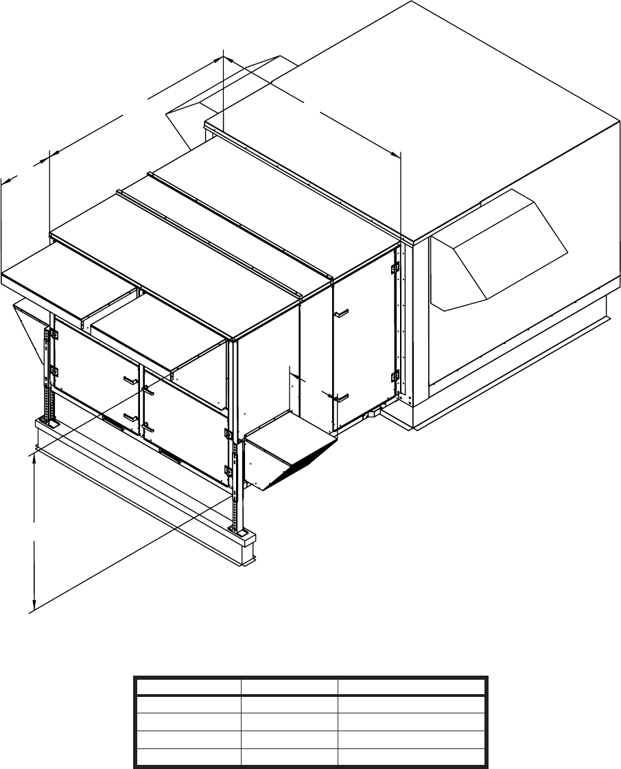
903106-UTG-A-0912
20 Unitary Products Group
- Designed to meet unit specifications
- 14’ High Curbs Required
- Rooftop unit blower exceeds the capacity of the ERV Exhaust Blowers
- See blower performance charts for airflow at various external static pressures.
FIGURE 7 - MODEL UNIT VR074 AND VR122 (25 - 40 TON)
74.75
24.59
61.23
82.13
20.92
Models
Z42, X42
Z33, X33
Z34, X34
Model Number CFM Description
VR074A40L 6000 - 8000 Constant Volume
VR074A40V 6000 - 8000 Variable Air Volume
VR122A40L 8000 - 13000 Constant Volume
VR122A40V 8000 - 13000 Variable Air Volume
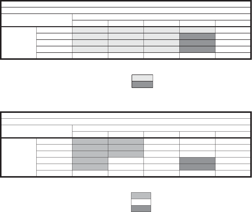
Unitary Products Group 21
903106-UTG-A-0912
Notes:
1. Drive losses included in the above table
2. Performance can vary depending on ambient conditions
3. Blower RPMs are for reference only
Notes:
1. Drive losses included in the above table
2. Performance can vary depending on ambient conditions
3. Blower RPMs are for reference only
TABLE 12: BLOWER PERFORMANCE CHART - VR074
Exhaust
Blower RPM for VR074, (2) 5HP, Barometric Hood
External Static Pressure (in water)
0 0.5 1 1.5 2
CFM
6000 910 1060 1200 1300 1400
6500 955 1095 1225 1360 1430
7000 1000 1130 1260 1380 1475
7500 1040 1170 1290 1400 1500
8000 1080 1200 1315 1425 1530
RPM Range
Low 910-1320 Standard Unit
High 1325-1565 Optional Kit (01-KIT-RH58)
TABLE 13: BLOWER PERFORMANCE CHART - VR122
Exhaust
Blower RPM for VR122, 7.5HP, Barometric Hood
External Static Pressure (in water)
0 0.5 1 1.5 2
CFM
8000 775 900 1030 1125 1200
9000 825 945 1055 1150 1240
10000 875 985 1090 1190 1280
11000 925 1030 1125 1215 1310
12000 970 1070 1165 1250 1355
13000 1015 1110 1200 1280 1360
RPM Range
Low 775-1000 Standard Unit
Med 1000-1200 Optional Kit (01-KIT-RM74)
High 1175-1375 Optional Kit (01-KIT-RH74)
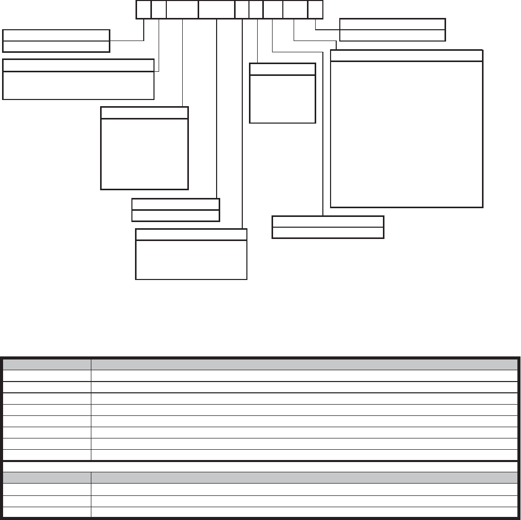
903106-UTG-A-0912
22 Unitary Products Group
UPG UERV STAND ALONE MODEL NOMENCLATURE
PERFORMANCE - ERV SERIES
Use this table to determine ventilation and size requirements. Table shows ERV Air Flow Range. AHRI certified performance
rating provided in specifications and electrical data Effectiveness. "xL", "xM" and "xH" signify low, medium and high speed.
ERV CFM Range ERV Series
300-1100 D011,O011,S011
1200-2000 D020,O020,S020
1200-2800 D028,O028,S028
2000-3600 D036,O036,S036
3000-4600 D046,O046,S046
4600-6200 D062,O062,S062
6000-8000 D080
8000-13000 D120
ERV Series Descriptions
Series Description
D Down Discharge Outdoor Application
O Stand alone outdoor application that attaches to horizontal return air duct in an over and under design.
S Stand alone outdoor application that attaches to horizontal return air duct in an side by side design.
011 N00 H
Product Category
V = Ventilator
Wheel Type
D = Stand Alone, Down Discharge
CFM*
011 = 300 to 1100
N00 = None
Additional Options
AA = No Options Installed
Duct Type
2 = 208/230v - 3ph
UPG UERV Model Nomenclature
H = High Speed**
Product Generation
2 = Second Generation
Voltage
4 = 460v - 3ph
Stand Alone
V D 4 A AA 2
O = Stand Alone, Over and Under
S = Stand Alone, Side by Side
020 = 1200 to 2000
028 = 1200 to 2800
036 = 2000 to 3600
046 = 3000 to 4600
062 = 4600 to 6200
080 = 6000 to 8000
120 = 8000 to 13000
Blower Speed
M = Medium Speed**
V = Variable Speed
L = Constant Volume
5 = 575v - 3ph
9 = 208/320v - 1ph
A = No Selection on Rooftop Units
L1 = Low Ambient Kit (LAK)
L2 = LAK & Motorized Outside Air (MOA)
L3 = LAK, MOA & Stop-Start-Job (SSJ)
L4 = LAK, MOA, SSJ & Pressure Sensor (PS)
L5 = LAK & SSJ
L6 = LAK, SSJ & PS (not used on P models)
L7 = LAK & PS
L8 = LAK, MOA and PS
M1 = Motorized Outside Air (MOA)
M2 = MOA, and Stop Start-Jog (SSJ)
M3 = MOA, SSJ and Pressure Sensor (PS)
M4 = MOA and PS
S1 = Stop-Start-Job (SSJ)
S2 = SSJ and Pressure Sensor (PS)
P1 = Pressure Sensor (PS)
* CFM is ERV wheel rating. This may vary depending on unit cabinet pressure drop.
** These CFM ranges are dependant upon blower motor selection. The choice of H
and M options are only available on the V*028 and V*062 models.
1 = 110v - 1ph
8 = 440v-1ph
Note: SSJ (Start-Stop-Jog) option is required for economizer equipped units.
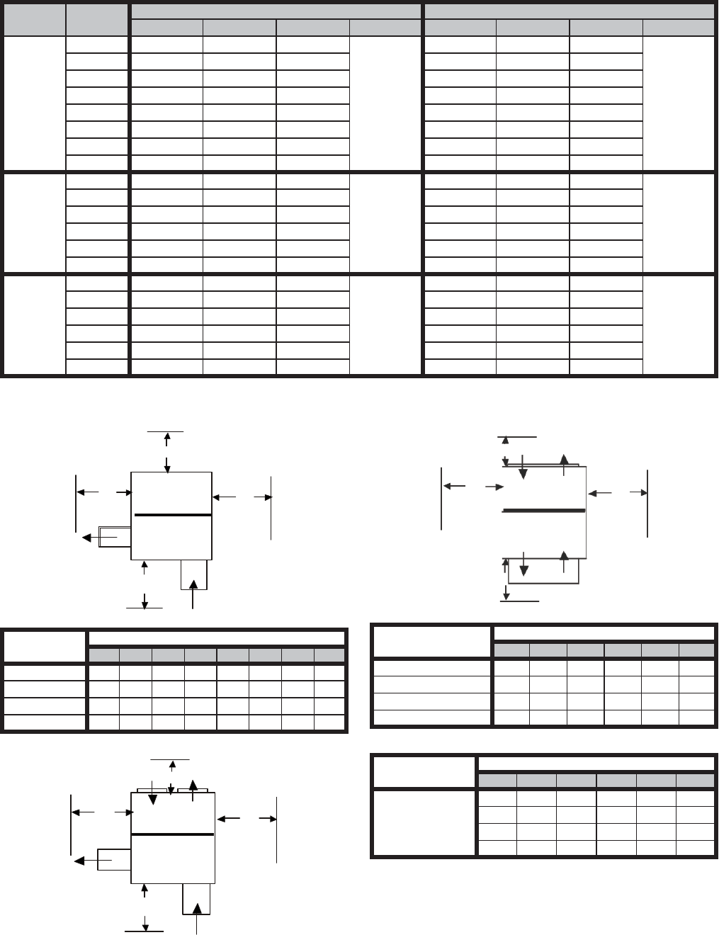
Unitary Products Group 23
903106-UTG-A-0912
TABLE 14: FILTER SIZES - STAND ALONE ERV SERIES
SERVICE CLEARANCES - STAND ALONE SERIES ERVS
Series Size Return Filter Intake Filter
Qty Width Height Type Qty Width Height Type
D
011 1 14 20
2" PLT
1 16.25 10.375
1" ME
020 2 16 20 1 12.5 20
028 2 20 20 1 14.75 32.25
036 3 16 20 1 16.5 32.25
046 2 24 24 1 20 36
062 5 14 20 1/1 20 / 20 36 / 12.5
080 6 18 20 2 32.25 21.5
120 8 20 20 3 32.25 20.25
O
011 1 18 25
2" PLT
1 27.5 10
1" ME
020 2 16 16 1 32.25 18.5
028 2 20 20 1 40.25 21.5
036 2 / 1 16 / 14 20 1 40.25 21.5
046 2 24 24 1 40.25 21.5
062 5 14 20 1 40.25 25.5
S
011 1 14 20
2" PLT
1 16.25 10.375
1" ME
020 2 16 20 1 12.5 20
028 2 20 20 1 14.75 32.25
036 3 16 20 1 16.5 32.25
046 2 24 24 1 20 36
062 5 14 20 1 / 1 20 / 20 36 / 12.5
Dimension
(inches)
"D" Series
11 20 28 36 46 62 80 120
A36 36 36 36 36 36 36 36
B60 60 60 60 60 60 72 84
C48 60 60 60 72 72 72 72
D36 36 48 48 60 60 72 84
A
B
C
D
“D” Series
B
A
D
C
“S” Series
Dimension
(inches)
"O" Series
11 20 28 36 46 62
A12 12 12 12 12 12
B36 36 36 36 36 36
C48 60 60 60 60 60
D36 36 48 48 60 60
Dimension
(inches)
"S" Series
11 20 28 36 46 62
A12 12 12 12 12 12
B60 60 60 60 60 60
C48 60 60 60 72 72
D36 36 48 48 60 60
A
B
C
D
“O” Series
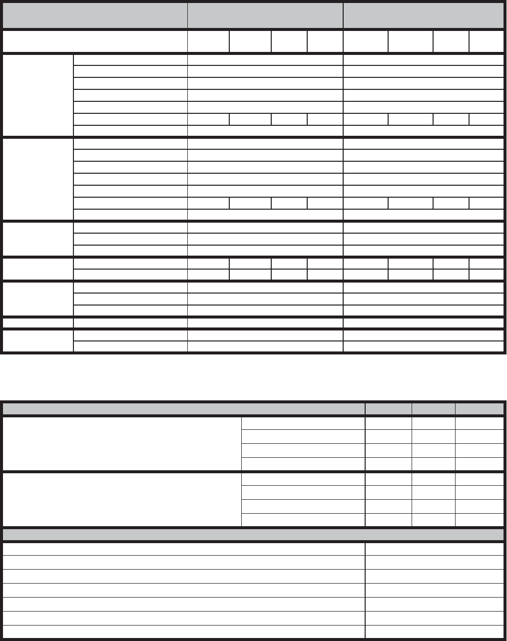
903106-UTG-A-0912
24 Unitary Products Group
TABLE 15: SPECIFICATIONS AND ELECTRICAL DATA - 300 THROUGH 1100 CFM ERV'S
Model Numbers D011 Stand Alone O011 S/A Over & Under
Down Discharge S011 S/A Side by Side
Line Voltage - 60hz 208/230v
1ph 208/230v
3ph 460v
3ph 575v
3ph 208/230v
1ph 208/230v
3ph 460v
1ph 460v
3ph
Fresh Air
Blower
Motor - hp 1.5 / Belt 1.5 / Belt
Wheel Size (dia x width) -in 9 x 4 9 x 4
Motor Speed -rpm 1725 1725
Motor Speed(s) Adjustable Sheave Adjustable Sheave
Bearing Type Ball Ball
Full Load Amps 9.1 5.6 2.8 2.0 9.1 5.6 2.8 2.0
Service Factor 1.15 1.15
Exhaust Air
Blower
Motor - hp Stationary 1.5 / Belt 1.5 / Belt
Wheel Size (dia x width) -in 9 x 4 9 x 4
Motor Speed -rpm 1725 1725
Motor Speed(s) Adjustable Sheave Adjustable Sheave
Bearing Type Ball Ball
Full Load Amps-Stationary 9.1 5.6 2.8 2.0 9.1 5.6 2.8 2.0
Service Factor 1.15 1.15
Wheel Electrical
Data
Potential Volts 208 - 230 208 - 230
Motor Speed -rpm 1050 1050
Full Load Amps 0.3 0.3
Total
Electrical MCA - Stationary 20.8 12.9 6.6 4.8 20.8 12.9 6.6 4.8
OCPD - Stationary 30 15 9 730 159
7
Wheel Data Wheel Depth - in 3 3
Wheel Diameter - in 25.3 25.3
Construction / Media Segmented Pies/Polymeric Segmented Pies/Polymeric
Curb Curb Hgt - in 14 14
Weights Shipping Weight - lbs. (kg) 318 318
Net Weight - lbs. (kg) 245 245
AHRI Certified Ratings
Thermal Ratings @ 0" Pressure Diff. Sensible Latent Total
Total Effectiveness
100% Airflow Heating 76% 68% 73%
75% Airflow Heating 81% 73% 78%
100% Airflow Cooling 76% 68% 72%
75% Airflow Cooling 81% 73% 76%
Net Effectiveness
100% Airflow Heating 76% 68% 73%
75% Airflow Heating 81% 73% 78%
100% Airflow Cooling 76% 68% 72%
75% Airflow Cooling 81% 73% 76%
Enthalpy Wheel AHRI Rating Data
Nominal Airflow CFM 900 @ 1.0
EATR - -1.00 H2O 9.30%
EATR - 0.00 H2O 0.70%
EATR - +1.00 H2O 0.00%
OACF - -1.00 H2O 0.97
OACF - 0.00 H2O 1.19
OACF - +1.00 H2O 1.34
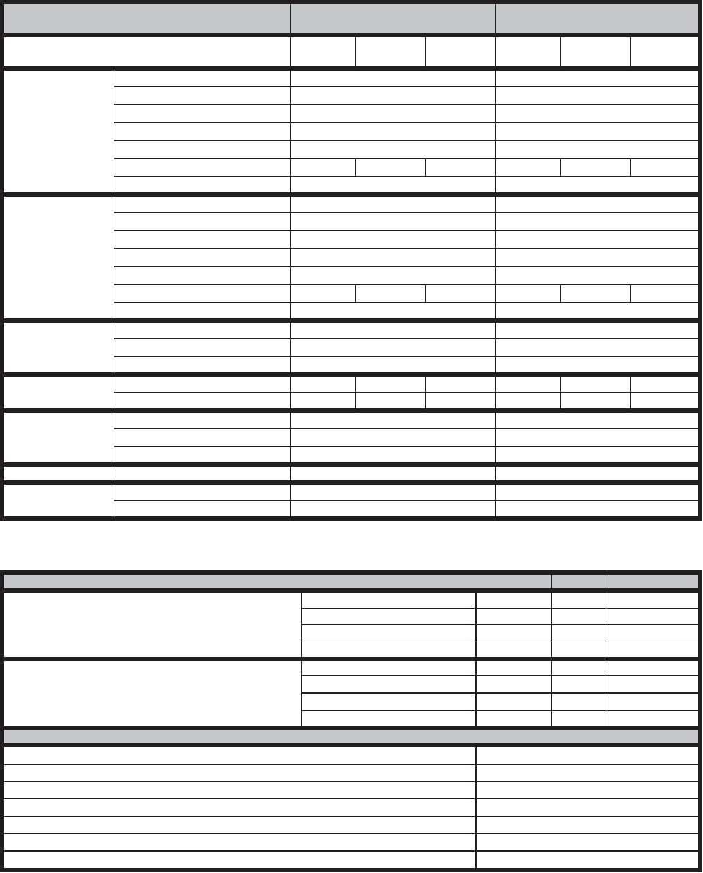
Unitary Products Group 25
903106-UTG-A-0912
TABLE 16: SPECIFICATIONS AND ELECTRICAL DATA - 1200 THROUGH 2000 CFM ERV'S
Model Numbers D020 Stand Alone
Down Discharge O020 S/A Over and Under
S020 S/A Side by Side
Line Voltage - 60hz 208/230v
3ph 460v
3ph 575v
3ph 208/230v
3ph 460v
3ph 575v
3ph
Fresh Air
Blower
Motor - hp 2 / Belt 2 / Belt
Wheel Size (dia x width) -in 9 x 9 9 x 9
Motor Speed -rpm 1725 1725
Motor Speed(s) Adjustable Sheave Adjustable Sheave
Bearing Type Ball Ball
Full Load Amps 6.0 2.6 2.4 6.0 2.6 2.4
Service Factor 1.15 1.15
Exhaust Air Blower
Motor - hp Stationary 2 / Belt 2 / Belt
Wheel Size (dia x width) -in 9 x 9 9 x 9
Motor Speed -rpm 1725 1725
Motor Speed(s) Adjustable Sheave Adjustable Sheave
Bearing Type Ball Ball
Full Load Amps-Stationary 6.0 2.6 2.4 6.0 2.6 2.4
Service Factor 1.15 1.15
Wheel Electrical
Data
Potential Volts 208 - 230 208 - 230
Motor Speed -rpm 1050 1050
Full Load Amps 0.3 0.3
Total
Electrical MCA - Stationary 13.8 6.2 5.7 13.8 6.2 5.7
OCPD - Stationary 20 9 8 20 9 8
Wheel
Data
Wheel Depth - in 3 3
Wheel Diameter - in 30.346 30.346
Construction / Media Segmented Pies/Polymeric Segmented Pies/Polymeric
Curb Curb Hgt - in 14 14
Weights Shipping Weight - lbs. (kg) 425 425
Net Weight - lbs. (kg) 345 345
AHRI Certified Ratings
Thermal Ratings @ 0" Pressure Diff. Sensible Latent Total
Total Effectiveness
100% Airflow Heating 68% 61% 65%
75% Airflow Heating 72% 67% 71%
100% Airflow Cooling 68% 61% 64%
75% Airflow Cooling 72% 67% 70%
Net Effectiveness
100% Airflow Heating 68% 61% 65%
75% Airflow Heating 72% 67% 71%
100% Airflow Cooling 68% 61% 64%
75% Airflow Cooling 72% 67% 70%
Enthalpy Wheel AHRI Rating Data
Nominal Airflow CFM 1600 @ .95
EATR - -1.00 H2O 7.80%
EATR - 0.00 H2O 0.40%
EATR - +1.00 H2O 0.00%
OACF - -1.00 H2O 0.97
OACF - 0.00 H2O 1.16
OACF - +1.00 H2O 1.29
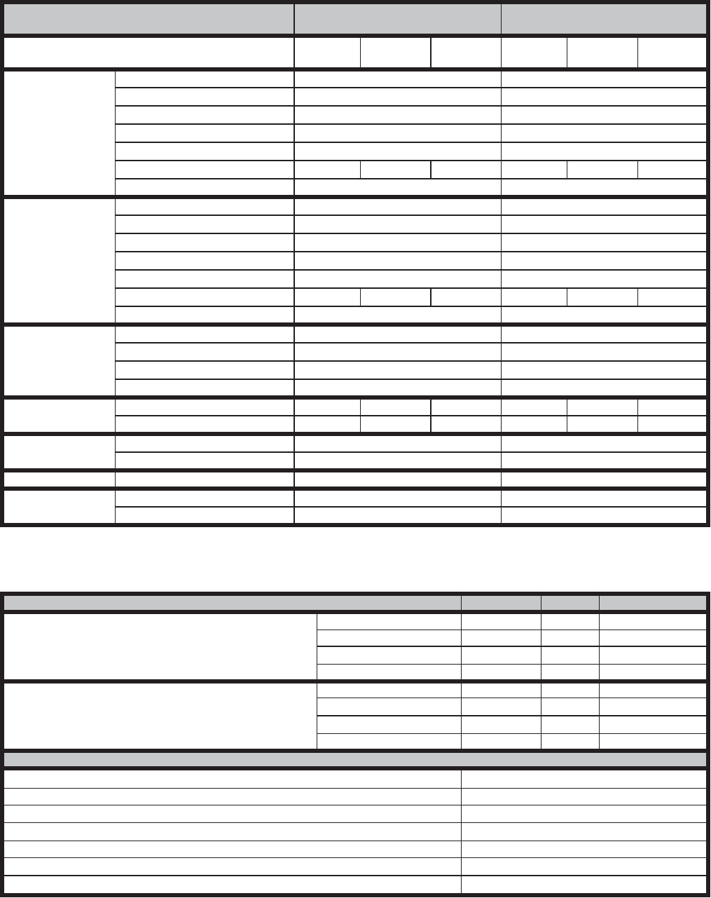
903106-UTG-A-0912
26 Unitary Products Group
TABLE 17: SPECIFICATIONS AND ELECTRICAL DATA - 1200 THROUGH 2800 CFM ERV'S
Model Numbers D028 Stand Alone
Down Discharge O028S/A Over and Under
S028 S/A Side by Side
Line Voltage - 60hz 208/230v
3ph 460v
3ph 575v
3ph 208/230v
3ph 460v
3ph 575v
3ph
Fresh Air
Blower
Motor - hp / type 3 / Belt 3 / Belt
Wheel Size (dia x width) -in 10 x 10 10 x 10
Motor Speed -rpm 1725 1725
Motor Speed(s) Adjustable Sheave Adjustable Sheave
Bearing Type Ball Ball
Full Load Amps 9.4 4.3 3.2 9.4 4.3 3.2
Service Factor 1.15 1.15
Exhaust Air Blower
Motor - hp Stationary 3 / Belt 3 / Belt
Wheel Size (dia x width) -in 10 x 10 10 x 10
Motor Speed -rpm 1725 1725
Motor Speed(s) Adjustable Sheave Adjustable Sheave
Bearing Type Ball Ball
Full Load Amps-Stationary 9.4 4.3 3.2 9.4 4.3 3.2
Service Factor 1.15 1.15
Wheel Electrical
Data
Motor - hp (1 phase) 0.05 0.05
Potential Volts 200 / 208 - 230 200 / 208 - 230
Motor Speed -rpm 825 825
Full Load Amps 0.6 0.6
Total
Electrical MCA - Stationary 21.8 10.3 7.8 21.8 10.3 7.8
OCPD - Stationary 30 12 10 30 12 10
Wheel
Data Wheel Depth x Dia - in 3 x 37.759 3 x 37.759
Construction / Media Type Segmented Pies/Polymeric Segmented Pies/Polymeric
Curb Curb Height - in 14 14
Weights Shipping Weight - lbs. (kg) 470 470
Net Weight - lbs. (kg) 395 395
AHRI Certified Ratings
Thermal Ratings @ 0" Pressure Diff. Sensible Latent Total
Total Effectiveness
100% Airflow Heating 68% 60% 65%
75% Airflow Heating 74% 67% 71%
100% Airflow Cooling 68% 60% 63%
75% Airflow Cooling 74% 67% 70%
Net Effectiveness
100% Airflow Heating 68% 60% 65%
75% Airflow Heating 74% 67% 71%
100% Airflow Cooling 68% 60% 63%
75% Airflow Cooling 74% 67% 70%
Enthalpy Wheel AHRI Rating Data
Nominal Airflow CFM 2600 @ .95
EATR - -1.00 H2O 6.10%
EATR - 0.00 H2O 0.40%
EATR - +1.00 H2O 0.00%
OACF - -1.00 H2O 0.99
OACF - 0.00 H2O 1.13
OACF - +1.00 H2O 1.23
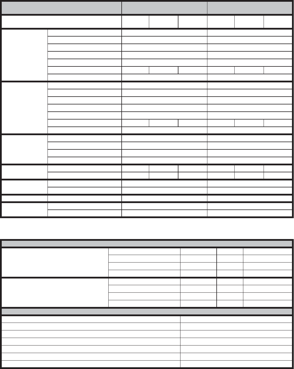
Unitary Products Group 27
903106-UTG-A-0912
TABLE 18: SPECIFICATIONS AND ELECTRICAL DATA - 2000 THROUGH 3600 CFM ERV'S
Model Numbers D036 Stand Alone
Down Discharge O036 S/A Over and Under
S036 S/A Side by Side
Line Voltage - 60hz 208/230v
3ph 460v
3ph 575v
3ph 208/230v
3ph 460v
3ph 575v
3ph
Fresh Air
Blower
Motor - hp / type 3 / Belt 3 / Belt
Wheel Size (dia x width) -in 12 x 9 12 x 9
Motor Speed -rpm 1725 1725
Motor Speed(s) Adjustable Sheave Adjustable Sheave
Bearing Type Ball Ball
Full Load Amps 9.4 4.3 3.2 9.4 4.3 3.2
Service Factor 1.15 1.15
Exhaust Air Blower
Motor - hp Stationary 3 / Belt 3 / Belt
Wheel Size (dia x width) -in 12 x 9 12 x 9
Motor Speed -rpm 1725 1725
Motor Speed(s) Adjustable Sheave Adjustable Sheave
Bearing Type Ball Ball
Full Load Amps-Stationary 9.4 4.3 3.2 9.4 4.3 3.2
Service Factor 1.15 1.15
Wheel Electrical
Data
Motor - hp (1 phase) 0.17 0.17
Potential Volts 200 / 208 - 230 200 / 208 - 230
Motor Speed -rpm 1075 1075
Full Load Amps 1.2 1.2
Total
Electrical
MCA - Stationary 22.4 10.9 8.4 22.4 10.9 8.4
OCPD - Stationary 30 15 10 30 15 10
Wheel
Data
Wheel Depth x Diameter - in 3 x 41.825 3 x 41.825
Construction / Media Type Segmented Pies/Polymeric Segmented Pies/Polymeric
Curb Curb Height - in 14 14
Weights Shipping Weight - lbs. (kg) 571 571
Net Weight - lbs. (kg) 475 475
AHRI Certified Ratings
Thermal Ratings @ 0" Pressure Diff. Sensible Latent Total
Total Effectiveness
100% Airflow Heating 68% 60% 65%
75% Airflow Heating 74% 67% 71%
100% Airflow Cooling 68% 60% 63%
75% Airflow Cooling 74% 67% 70%
Net Effectiveness
100% Airflow Heating 68% 60% 65%
75% Airflow Heating 74% 67% 71%
100% Airflow Cooling 68% 60% 63%
75% Airflow Cooling 74% 67% 70%
Enthalpy Wheel AHRI Rating Data
Nominal Airflow CFM 3100 @ .9
EATR - -1.00 H2O 4.90%
EATR - 0.00 H2O 1.30%
EATR - +1.00 H2O 0.30%
OACF - -1.00 H2O 0.99
OACF - 0.00 H2O 1.07
OACF - +1.00 H2O 1.12
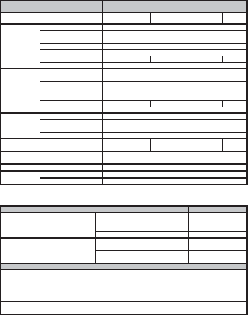
903106-UTG-A-0912
28 Unitary Products Group
TABLE 19: SPECIFICATIONS AND ELECTRICAL DATA - 3000 THROUGH 4600 CFM ERV'S
Model Numbers D046 Stand Alone
Down Discharge O046 S/A Over and Under
S046 S/A Side by Side
Line Voltage - 60hz 208/230v
3ph 460v
3ph 575v
3ph 208/ 230v
3ph 460v
3ph 575v
3ph
Fresh Air
Blower
Motor - hp / type 5 / Belt 5 / Belt
Wheel Size (dia x width) -in 12 x 12 12 x 12
Motor Speed -rpm 1725 1725
Motor Speed(s) Adjustable Sheave Adjustable Sheave
Bearing Type Ball Ball
Full Load Amps 14.8 7.0 5.1 14.8 7.0 5.1
Service Factor 1.15 1.15
Exhaust Air Blower
Motor - hp Stationary 5 / Belt 5 / Belt
Wheel Size (dia x width) -in 12 x 12 12 x 12
Motor Speed -rpm 1725 1725
Motor Speed(s) Adjustable Sheave Adjustable Sheave
Bearing Type Ball Ball
Full Load Amps-Stationary 14.8 7.0 5.1 14.8 7.0 5.1
Service Factor 1.15 1.15
Enthalpy Wheel
Electrical Data
Motor - hp (1 phase) 0.17 0.17
Potential Volts 200 / 208 - 230 200 / 208 - 230
Motor Speed -rpm 1075 1075
Full Load Amps 1.2 1.2
Total
Electrical
MCA - Stationary 34.5 17.0 12.7 34.5 17.0 12.7
OCPD - Stationary 40 25 15 40 25 15
Wheel
Data Wheel Depth x Diameter - in 3 x 46.776 3 x 46.776
Construction / Media Type Segmented Pies/Polymeric Segmented Pies/Polymeric
Curb Curb Height - in 14 14
Weights Shipping Weight - lbs. (kg) 920 920
Net Weight - lbs. (kg) 805 805
AHRI Certified Ratingss
Thermal Ratings @ 0" Pressure Diff. Sensible Latent Total
Total Effectiveness
100% Airflow Heating 68% 60% 65%
75% Airflow Heating 73% 67% 71%
100% Airflow Cooling 68% 60% 63%
75% Airflow Cooling 73% 67% 70%
Net Effectiveness
100% Airflow Heating 68% 60% 65%
75% Airflow Heating 73% 67% 71%
100% Airflow Cooling 68% 60% 63%
75% Airflow Cooling 73% 67% 70%
Enthalpy Wheel AHRI Rating Data
Nominal Airflow CFM 3900 @ .95
EATR - -1.00 H2O 4.40%
EATR - 0.00 H2O 1.10%
EATR - +1.00 H2O 0.20%
OACF - -1.00 H2O 0.99
OACF - 0.00 H2O 1.06
OACF - +1.00 H2O 1.11
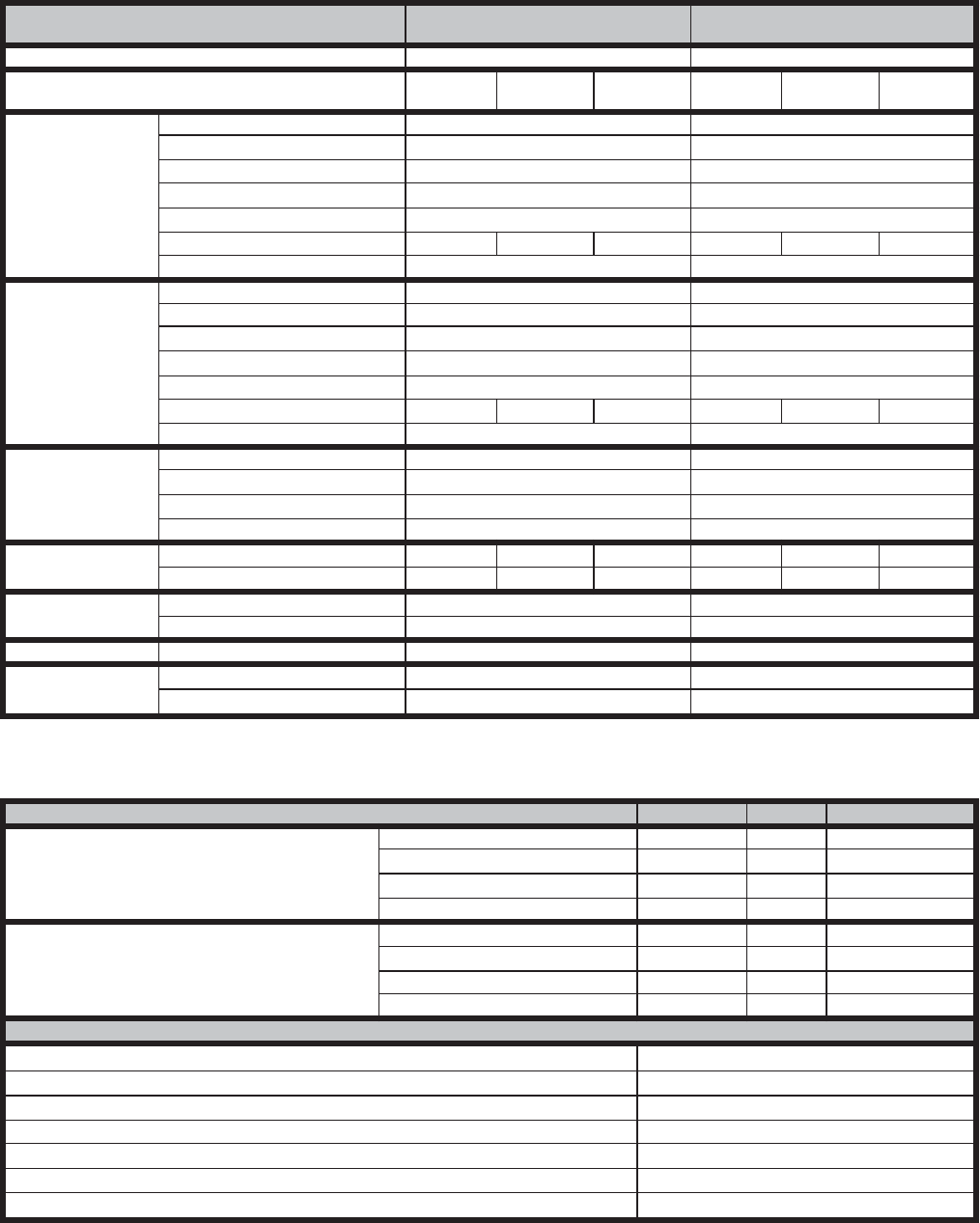
Unitary Products Group 29
903106-UTG-A-0912
TABLE 20: SPECIFICATIONS AND ELECTRICAL DATA - 4600 THROUGH 6200 CFM ERV'S
Model Numbers D062 Stand Alone
Down Discharge O062 S/A Over and Under
S062 S/A Side by Side
CFM Range 4600-6200 CFM 4600-6200 CFM
Line Voltage - 60hz 208/230v
3ph 460v
3ph 575v
3ph 208/230v
3ph 460v
3ph 575v
3ph
Fresh Air
Blower
Motor - hp / type 5 / belt 5 / belt
Wheel Size (dia x width) -in 15 x 15 15 x 15
Motor Speed -rpm 1725 1725
Motor Speed(s) Adjustable Sheave Adjustable Sheave
Bearing Type Ball Ball
Full Load Amps 14.8 7.0 5.1 14.8 7.0 5.1
Service Factor 1.15 1.15
Exhaust Air Blower
Motor - hp Stationary 5 / Belt 5 / Belt
Wheel Size (dia x width) -in 12 x 12 12 x 12
Motor Speed -rpm 1725 1725
Motor Speed(s) Adjustable Sheave Adjustable Sheave
Bearing Type Ball Ball
Full Load Amps-Stationary 14.8 7.0 5.1 14.8 7.0 5.1
Service Factor 1.15 1.15
Enthalpy Wheel
Electrical Data
Motor - hp (1 phase) 0.17 0.17
Potential Volts 200 / 208 - 230 200 / 208 - 230
Motor Speed -rpm 1075 1075
Full Load Amps 1.2 1.2
Total
Electrical
MCA - Stationary 34.5 17.0 12.7 34.5 17.0 12.7
OCPD - Stationary 40 25 15 40 25 15
Wheel
Data
Wheel Depth x Diameter - in 3 x 52.026 3 x 52.026
Construction / Media Type Segmented Pies/Polymeric Segmented Pies/Polymeric
Curb Curb Height - in 14 14
Weights Shipping Weight - lbs. (kg) 1250 1250
Net Weight - lbs. (kg) 1075 1075
AHRI Certified Ratingss
Thermal Ratings @ 0" Pressure Diff. Sensible Latent Total
Total Effectiveness
100% Airflow Heating 68% 60% 65%
75% Airflow Heating 73% 67% 71%
100% Airflow Cooling 68% 60% 63%
75% Airflow Cooling 73% 67% 70%
Net Effectiveness
100% Airflow Heating 68% 60% 65%
75% Airflow Heating 73% 67% 71%
100% Airflow Cooling 68% 60% 63%
75% Airflow Cooling 73% 67% 70%
Enthalpy Wheel AHRI Rating Data
Nominal Airflow CFM 5500 @ .95
EATR - -1.00 H2O 4.00%
EATR - 0.00 H2O 1.00%
EATR - +1.00 H2O 0.20%
OACF - -1.00 H2O 0.99
OACF - 0.00 H2O 1.06
OACF - +1.00 H2O 1.10
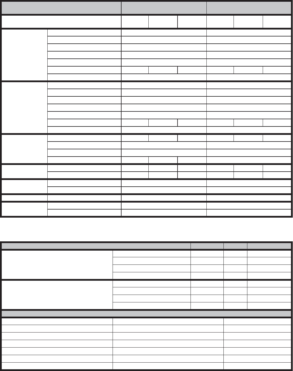
903106-UTG-A-0912
30 Unitary Products Group
TABLE 21: SPECIFICATIONS AND ELECTRICAL DATA - 6000 THROUGH 13000 CFM ERV'S
Model Numbers D080 Stand Alone
Down Discharge D120 Stand Alone
Down Discharge
Line Voltage - 60hz 208/230v
3ph 460v 3ph 575v 3ph 208/230v
3ph 460v 3ph 575v 3ph
Fresh Air
Blower
Motor - hp Stationary 10 / Belt 15 / Belt
Wheel Size (dia x width) -in 15 x 15 22 x 15
Motor Speed -rpm 1725 1725
Motor Speed(s) Adjustable Sheave Adjustable Sheave
Bearing Type Ball Ball
Full Load Amps-Stationary 26.8 13.4 10.3 41.0 18.5 15.4
Service Factor 1.15 1.15
Exhaust Air Blower
Motor - hp / type 7.5 / Belt 10 / Belt
Wheel Size (dia x width) -in 18 x 18 22 x 22
Motor Speed -rpm 1725 1725
Motor Speed(s) Adjustable Sheave Adjustable Sheave
Bearing Type Ball Ball
Full Load Amps 22.4 9.7 7.8 32.6 13.4 10.3
Service Factor 1.15 1.15
Enthalpy Wheel
Electrical Data
Motor - hp (3 phase) 0.25 0.25 0.33 0.25 0.25 0.33
Potential Volts 200 / 208 - 230 200 / 208 - 230
Motor Speed -rpm 1725 1725
Full Load Amps 2.5 1.2 1.4 2.5 1.2 1.4
Total
Electrical MCA - Stationary 63.2 27.7 22.1 86.2 37.7 31.0
OCPD - Stationary 90 40 35 125 50 45
Wheel
Data Wheel Depth x Diameter - in 3 x 58 3 x 74
Construction / Media Type Segmented Pies/Polymeric Segmented Pies/Polymeric
Curb Curb Height - in 14 14
Weights Shipping Weight - lbs. (kg) 2800 3000
Net Weight - lbs. (kg) 2600 2800
AHRI Certified Ratingss
Thermal Ratings @ 0" Pressure Diff. Sensible Latent Total
Total Effectiveness
100% Airflow Heating 68% 60% 65%
75% Airflow Heating 73% 67% 71%
100% Airflow Cooling 68% 60% 63%
75% Airflow Cooling 73% 67% 70%
Net Effectiveness
100% Airflow Heating 68% 60% 65%
75% Airflow Heating 73% 67% 71%
100% Airflow Cooling 68% 60% 63%
75% Airflow Cooling 73% 67% 70%
Enthalpy Wheel AHRI Rating Data
Nominal Airflow CFM 6600 @ .95 10800 @ .95
EATR - -1.00 H2O 4.60% 3.40%
EATR - 0.00 H2O 1.90% 1.20%
EATR - +1.00 H2O 0.90% 0.40%
OACF - -1.00 H2O 0.99 0.99
OACF - 0.00 H2O 1.05 1.04
OACF - +1.00 H2O 1.09 1.07
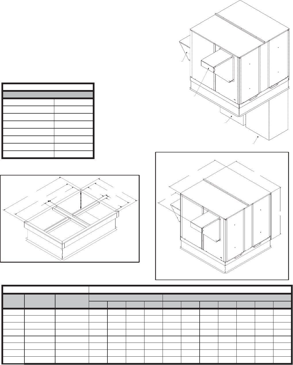
Unitary Products Group 31
903106-UTG-A-0912
D SERIES STAND ALONE ERV'S FOR DOWN DISCHARGE DUCT ARRANGEMENTS
FEATURES AND NOTES
1. Stand alone design allows higher levels of outdoor air to
be introduced into the a/c space.
2. Static test ports provided to verify intake and exhaust
CFM.
3. Balancing damper(s) field supplied in duct work when
connected to ERV.
4. Roof curbs are available for the ERV's.
5. See blower performance charts for airflow at various
E.S.P.
6. Filter rack with 2" pleated filters included.
ERV Roof Curbs
Series Model No
D011 01-2D1-2514
D020 01-2D1-3014
D028 01-2D1-3614
D036 01-2D1-4114
D046 01-2D1-4614
D062 01-2D1-5214
D080 01-201D-5814
D120 01-201D-7414
E
F
G
H
I
J
K
J
EXHAUST AIR HOOD
FRESH AIR HOOD
RETURN AIR DUCT
(FIELD SUPPLIED)
SUPPLY AIR DUCT
(FIELD SUPPLIED)
AB
D
C
ERV Data Dimensional Data
ERV
Series CFM Range Duct Size
(G x J) ERV Roof Curb
A B C D E F G H I J K
D011 300-1100 17.00 x 11.38 44.75 32.13 33.50 14.38 43.00 39.00 17.50 30.25 26.25 11.88 2.50
D020 1200-2000 21.88 x 14.00 54.38 37.25 37.50 17.50 52.75 48.75 22.38 35.50 31.50 14.50 2.50
D028 1200-2800 20.25 x 17.00 52.25 42.63 43.56 25.50 49.50 45.50 20.75 41.00 37.00 17.50 2.00
D036 2000-3600 23.38 x 17.38 60.00 46.69 57.37 25.50 55.75 51.75 23.88 41.81 37.81 17.91 2.00
D046 3000-4600 23.38 x 20.38 60.00 52.69 57.37 28.06 55.75 51.75 23.88 47.81 43.81 20.91 2.00
D062 4600-6200 29.38 x 30.00 72.00 70.88 63.63 37.75 67.75 63.75 29.88 66.00 62.00 30.50 2.00
D080 6000-8000 38.75 x 35.38 101.38 78.38 71.34 21.75 99.75 95.75 38.75 76.75 72.75 35.38 2.00
D120 8000-13000 40.00 x 44.50 120.38 88.38 86.63 28.50 118.50 114.50 44.88 86.50 82.50 40.25 2.00

903106-UTG-A-0912
32 Unitary Products Group
TABLE 22: AIRFLOW PERFORMANCE - DOWNFLOW CONFIGURATION FOR D011 & D020
Blower RPM for D011
Notes:
1. Drive losses included in the above table
2. Performance can vary depending on ambient conditions
3. Blower RPMs are for reference only
Blower RPM for D020
Notes:
1. Drive losses included in the above table
2. Performance can vary depending on ambient conditions
3. Blower RPMs are for reference only
SUPPLY
Mist Eliminator Filter in Intake Hood (1.5HP)
CFM External Static Pressure (in water)
0 0.25 0.5 0.75 1 1.25 1.5
300 N/A N/A 1175 1350 1450 1605 1730
500 N/A 1170 1340 1540 1655 1725 1840
700 1295 1425 1600 1625 1795 1960 2035
900 1540 1660 1720 1790 2030 2110 2195
1100 1785 1915 2025 2185 N/A N/A N/A
EXHAUST
Barometric Hood, 2" Pleated Filters (1.5HP)
CFM External Static Pressure (in water)
0 0.25 0.5 0.75 1 1.25 1.5
300 N/A N/A 1030 1225 N/A N/A N/A
500 N/A 1025 1180 1265 1425 1535 N/A
700 1120 1190 1340 1445 1540 1645 1720
900 1285 1525 1500 1575 1670 1785 1865
1100 1570 1665 1670 1775 1860 1920 N/A
RPM Range
Low 1000-1300 Standard Unit
Medium 1300-1565 Optional Kit
High 1750-2200 Optional Kit
SUPPLY
Mist Eliminator Filter in Intake Hood (2HP)
CFM
External Static Pressure (in water)
0 0.25 0.5 0.75 1 1.25 1.5
1200 1055 1135 1295 1420 1540 1650 1725
1400 1140 1240 1340 1490 1600 1690 1795
1600 1200 1330 1460 1565 1645 1740 1830
1800 1320 1405 1525 1615 1705 1785 1885
2000 1415 1515 1605 1690 1775 1875 1960
EXHAUST
Barometric Hood, 2" Pleated Filters (2HP)
CFM External Static Pressure (in water)
0 0.25 0.5 0.75 1 1.25 1.5
1200 1010 1195 1350 1445 1580 1685 1735
1400 1125 1315 1435 1545 1620 1730 1800
1600 1185 1370 1500 1610 1695 1790 1965
1800 1305 1485 1600 1685 1781 1955 2030
2000 1410 1550 1670 1765 1855 N/A N/A
RPM Range
Low 1000-1300 Standard Unit
Medium 1300-1700 Optional Kit
High 1700-2080 Optional Kit
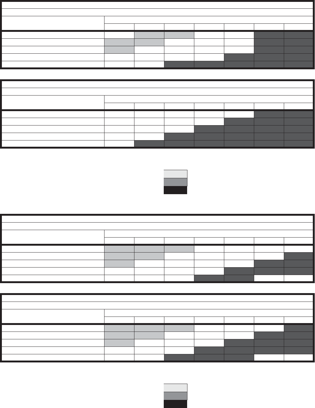
Unitary Products Group 33
903106-UTG-A-0912
TABLE 23: AIRFLOW PERFORMANCE - DOWNFLOW CONFIGURATION FOR D028 & D036
Blower RPM for D028
Notes:
1. Drive losses included in the above table
2. Performance can vary depending on ambient conditions
3. Blower RPMs are for reference only
Blower RPM for D036
Notes:
1. Drive losses included in the above table
2. Performance can vary depending on ambient conditions
3. Blower RPMs are for reference only
SUPPLY
Mist Eliminator Filter in Intake Hood (3HP)
CFM External Static Pressure (in water)
0 0.25 0.5 0.75 1 1.25 1.5
1200 N/A 790 960 1110 1210 1315 1380
1600 750 900 1005 1145 1230 1365 1410
2000 900 1005 1105 1210 1275 1400 1450
2400 1005 1125 1210 1275 1365 1450 1500
2800 1125 1230 1315 1380 1450 1535 1600
EXHAUST
Barometric Hood, 2" Pleated Filters (3HP)
CFM External Static Pressure (in water)
0 0.25 0.5 0.75 1 1.25 1.5
1200 750 885 1015 1145 1260 1350 1485
1600 870 1015 1125 1215 1325 1410 1500
2000 1015 1145 1240 1345 1410 1485 1560
2400 1125 1250 1345 1430 1500 1575 1630
2800 1250 1410 1485 1520 1630 1650 1675
RPM Range
Low 750-975 Standard Unit
Medium 1008-1314 Optional Kit
High 1311-1708 Optional Kit
SUPPLY
Mist Eliminator Filter in Intake Hood (3HP)
CFM External Static Pressure (in water)
0 0.25 0.5 0.75 1 1.25 1.5
2000 725 825 900 1000 1070 1180 1250
2400 800 900 1000 1070 1160 1250 1275
2800 900 1000 1070 1160 1250 1275 1340
3200 1000 1070 1160 1250 1275 1340 1400
3600 1055 1180 1250 1300 1360 N/A N/A
EXHAUST
Barometric Hood, 2" Pleated Filters (3HP)
CFM External Static Pressure (in water)
0 0.25 0.5 0.75 1 1.25 1.5
2000 750 865 950 1030 1100 1200 1265
2400 820 950 1035 1100 1200 1265 1300
2800 925 1035 1150 1200 1265 1315 1350
3200 1035 1160 1215 1265 1325 1350 1390
3600 1100 1215 1300 1350 1390 N/A N/A
RPM Range
Low 725-975 Standard Unit
Medium 1000-1315 Optional Kit
High 1215-1425 Optional Kit
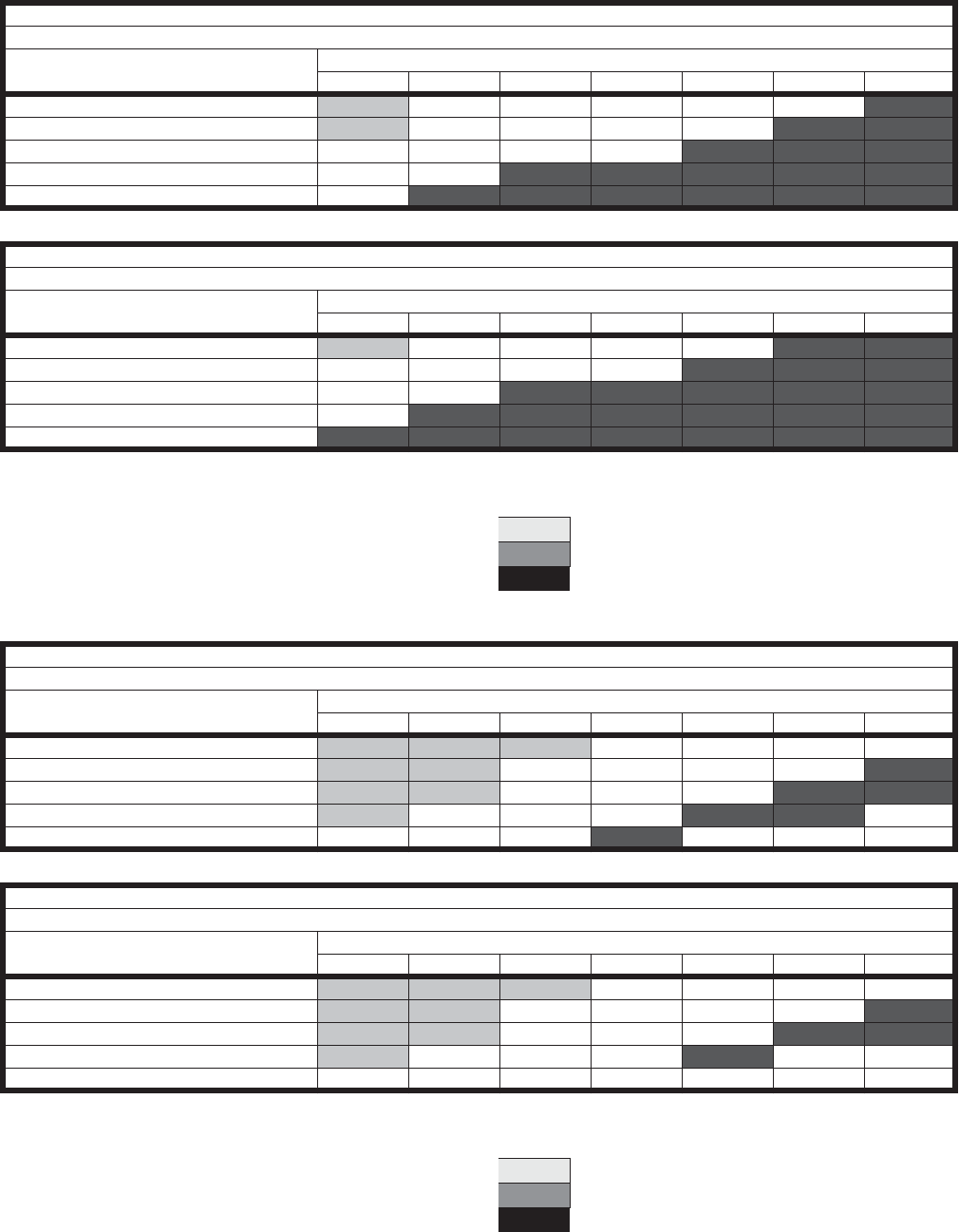
903106-UTG-A-0912
34 Unitary Products Group
TABLE 24: AIRFLOW PERFORMANCE - DOWNFLOW CONFIGURATION FOR D046 & D062
Blower RPM for D046
Notes:
1. Drive losses included in the above table
2. Performance can vary depending on ambient conditions
3. Blower RPMs are for reference only
Blower RPM for D062
Notes:
1. Drive losses included in the above table
2. Performance can vary depending on ambient conditions
3. Blower RPMs are for reference only
SUPPLY
Mist Eliminator Filter in Intake Hood (5HP)
CFM
External Static Pressure (in water)
0 0.25 0.5 0.75 1 1.25 1.5
3000 900 1030 1100 1165 1240 1285 1350
3400 975 1085 1175 1240 1290 1350 1400
3800 1070 1175 1240 1290 1350 1400 1465
4200 1165 1240 1320 1350 1430 1465 1515
4600 1240 1320 1375 1430 1500 1515 1580
EXHAUST
Barometric Hood, 2" Pleated Filters (5HP)
CFM External Static Pressure (in water)
0 0.25 0.5 0.75 1 1.25 1.5
3000 955 1100 1160 1245 1280 1360 1425
3400 1055 1185 1245 1300 1375 1425 1480
3800 1160 1300 1360 1400 1425 1530 1585
4200 1245 1375 1450 1480 1500 1585 1650
4600 1360 1450 1500 1585 1600 1650 1700
RPM Range
Low 780-1020 Standard Unit
Medium 1000-1315 Optional Kit
High 1315-1700 Optional Kit
SUPPLY
Mist Eliminator Filter in Intake Hood (5HP)
CFM External Static Pressure (in water)
0 0.25 0.5 0.75 1 1.25 1.5
4600 815 900 975 1045 1085 1125 1175
5000 880 940 1015 1060 1135 1175 1215
5400 915 975 1045 1125 1150 1195 1250
5800 975 1045 1085 1175 1250 1260 N/A
6200 1000 1075 1165 1200 N/A N/A N/A
EXHAUST
Barometric Hood, 2" Pleated Filters (5HP)
CFM External Static Pressure (in water)
0 0.25 0.5 0.75 1 1.25 1.5
4600 825 915 1000 1025 1100 1140 1170
5000 890 975 1025 1100 1140 1170 1240
5400 925 1000 1085 1140 1170 1240 1280
5800 975 1025 1140 1170 1240 N/A N/A
6200 1025 1120 1170 N/A N/A N/A N/A
RPM Range
Low 820-1000 Standard Unit
Medium 1000-1200 Optional Kit
High 1175-1375 Optional Kit
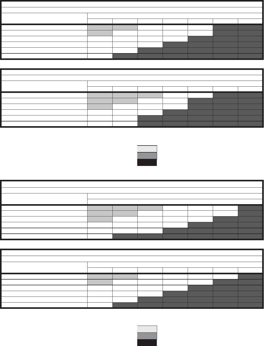
Unitary Products Group 35
903106-UTG-A-0912
TABLE 25: AIRFLOW PERFORMANCE - DOWNFLOW CONFIGURATION FOR D080 & D120
Blower RPM for D080
Notes:
1. Drive losses included in the above table
2. Performance can vary depending on ambient conditions
3. Blower RPMs are for reference only
Blower RPM for D120
Notes:
1. Drive losses included in the above table
2. Performance can vary depending on ambient conditions
3. Blower RPMs are for reference only
SUPPLY
Mist Eliminator Filter in Intake Hood (10HP)
CFM External Static Pressure (in water)
0 0.25 0.5 0.75 1 1.25 1.5
6000 737 794 851 908 961 1012 1061
6400 786 839 893 947 998 1047 1094
6800 836 886 937 987 1036 1083 1129
7200 885 931 979 1027 1074 1119 1163
7600 934 978 1024 1069 1114 1159 1200
8000 983 1025 1068 1111 1154 1196 1237
EXHAUST
Barometric Hood, 2" Pleated Filters (7.5HP)
CFM External Static Pressure (in water)
0 0.25 0.5 0.75 1 1.25 1.5
6000 599 660 716 769 818 866 911
6400 639 695 748 798 846 892 935
6800 679 733 783 831 877 921 963
7200 719 769 817 863 907 949 990
7600 759 808 854 897 940 980 1020
8000 799 845 889 931 972 1011 1049
RPM Range
Low Standard Unit
Medium Optional Kit
High Optional Kit
SUPPLY
Mist Eliminator Filter in Intake Hood (15HP)
CFM External Static Pressure (in water)
0 0.25 0.5 0.75 1 1.25 1.5
8000 427 470 512 552 591 630 667
8800 469 509 547 584 621 656 691
9600 512 548 583 618 651 684 717
10400 555 589 621 653 684 715 746
11200 597 629 659 689 718 747 776
12000 640 670 698 726 754 781 808
EXHAUST
Barometric Hood, 2" Pleated Filters (15HP)
CFM
External Static Pressure (in water)
0 0.25 0.5 0.75 1 1.25 1.5
8000 437 480 521 551 600 639 676
8800 481 520 558 595 631 665 701
9600 525 561 596 630 663 696 728
10400 569 602 634 665 657 727 758
11200 612 643 674 703 732 761 789
12000 656 685 713 741 768 795 822
RPM Range
Low Standard Unit
Medium Optional Kit
High Optional Kit
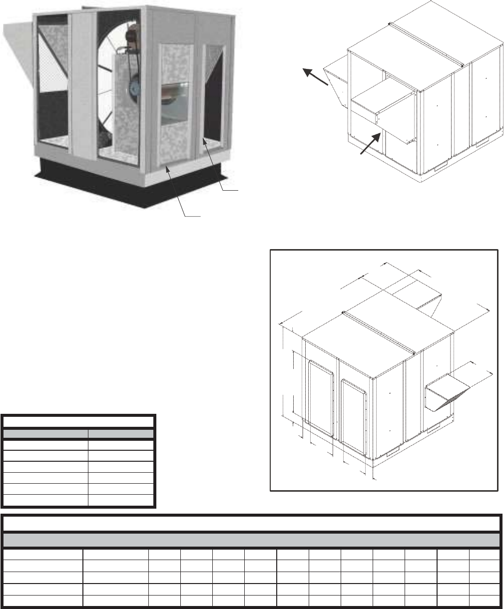
903106-UTG-A-0912
36 Unitary Products Group
S SERIES STAND ALONE ERV'S FOR SIDE BY SIDE DUCT ARRANGEMENTS
FEATURES AND NOTES
1. Stand alone design allows higher levels of outdoor air to
be introduced into the conditioned space.
2. Static test ports provided to verify intake and exhaust
CFM.
3. Balancing damper(s) is field provided when connected to
ductwork. System may not operate properly without bal-
ancing damper.
4. Roof curbs are available for the ERV's.
5. See blower performance charts for airflow at various
E.S.P.
6. Filter rack with 2" pleated filters included. Found in return
air section.
RETURN DUCT FLANGE OPENING
SUPPLY DUCT FLANGE OPENING
ERV Roof Curbs
Series Model No
S011 01-2D1-2514
S020 01-2D1-3014
S028 01-2D1-3614
S036 01-2D1-4114
S046 01-2D1-4614
S062 01-2D1-5214
A
B
C
D
E
F
G
H
D
I
J
K
H
ERV Data Dimensional Data
ERV Series CFM Range A B C D E F G H I J K
S011 300-1100 44.75 32.13 33.50 11.00 27.00 4.00 4.25 2.88 2.50 20.75 14.38
S020 1200-2000 54.38 37.25 37.50 12.00 30.00 5.87 5.13 4.06 1.63 20.75 17.50
S028 1200-2800 52.25 42.63 43.56 14.00 32.00 8.69 5.25 4.25 2.88 20.75 25.50
S036 2000-3600 60.00 46.69 57.37 16.50 39.50 12.00 5.50 4.05 5.88 20.75 25.50
S046 3000-4600 60.00 52.69 57.37 16.50 39.50 12.00 8.69 5.50 5.88 20.75 28.06
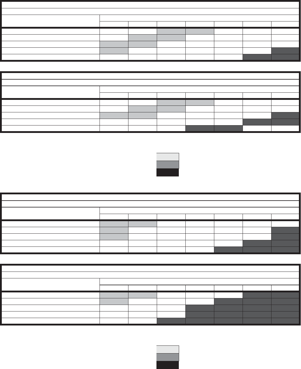
Unitary Products Group 37
903106-UTG-A-0912
TABLE 26: AIRFLOW PERFORMANCE - SIDE BY SIDE DUCT CONFIGURATION FOR S011 & S020
Blower RPM for S011
Notes:
1. Drive losses included in the above table
2. Performance can vary depending on ambient conditions
3. Blower RPMs are for reference only
Blower RPM for S020
Notes:
1. Drive losses included in the above table
2. Performance can vary depending on ambient conditions
3. Blower RPMs are for reference only
SUPPLY
Mist Eliminator Filter in Intake Hood (1.5HP)
CFM External Static Pressure (in water)
0 0.25 0.5 0.75 1 1.25 1.5
300 N/A N/A 1020 1205 1365 1480 1590
500 N/A 1015 1200 1320 1460 1565 1670
700 990 1190 1315 1455 1560 1665 1715
900 1150 1310 1450 1555 1660 1680 1795
1100 1305 1440 1550 1655 1740 1815 1895
EXHAUST
Barometric Hood, 2" Pleated Filters (1.5HP)
CFM External Static Pressure (in water)
0 0.25 0.5 0.75 1 1.25 1.5
300 N/A N/A 1150 1285 1415 1515 1640
500 N/A 1145 1275 1410 1510 1545 1720
700 1140 1270 1405 1505 1590 1715 1815
900 1320 1435 1585 1665 1705 1810 1930
1100 1495 1580 1660 1755 1880 N/A N/A
RPM Range
Low 100-1300 Standard Unit
Medium 1300-1700 Optional Kit
High 1750-2200 Optional Kit
SUPPLY
Mist Eliminator Filter in Intake Hood (2HP)
CFM External Static Pressure (in water)
0 0.25 0.5 0.75 1 1.25 1.5
1200 1065 1285 1375 1415 1495 1580 1685
1400 1140 1330 1410 1440 1555 1660 1760
1600 1290 1400 1480 1545 1670 1745 1835
1800 1395 1470 1540 1665 1735 1800 1880
2000 1460 1530 1650 1725 1795 1870 1960
EXHAUST
Barometric Hood, 2" Pleated Filters (2HP)
CFM External Static Pressure (in water)
00.25 0.5 0.75 1 1.25 1.5
1200 1175 1290 1430 1520 1680 1765 1850
1400 1245 1425 1515 1675 1755 1830 1920
1600 1400 1505 1670 1750 1825 1910 1980
1800 1495 1660 1740 1820 1900 1975 2090
2000 1645 1730 1815 1895 1965 2080 2170
RPM Range
Low 100-1300 Standard Unit
Medium 1300-1750 Optional Kit
High 1750-2200 Optional Kit
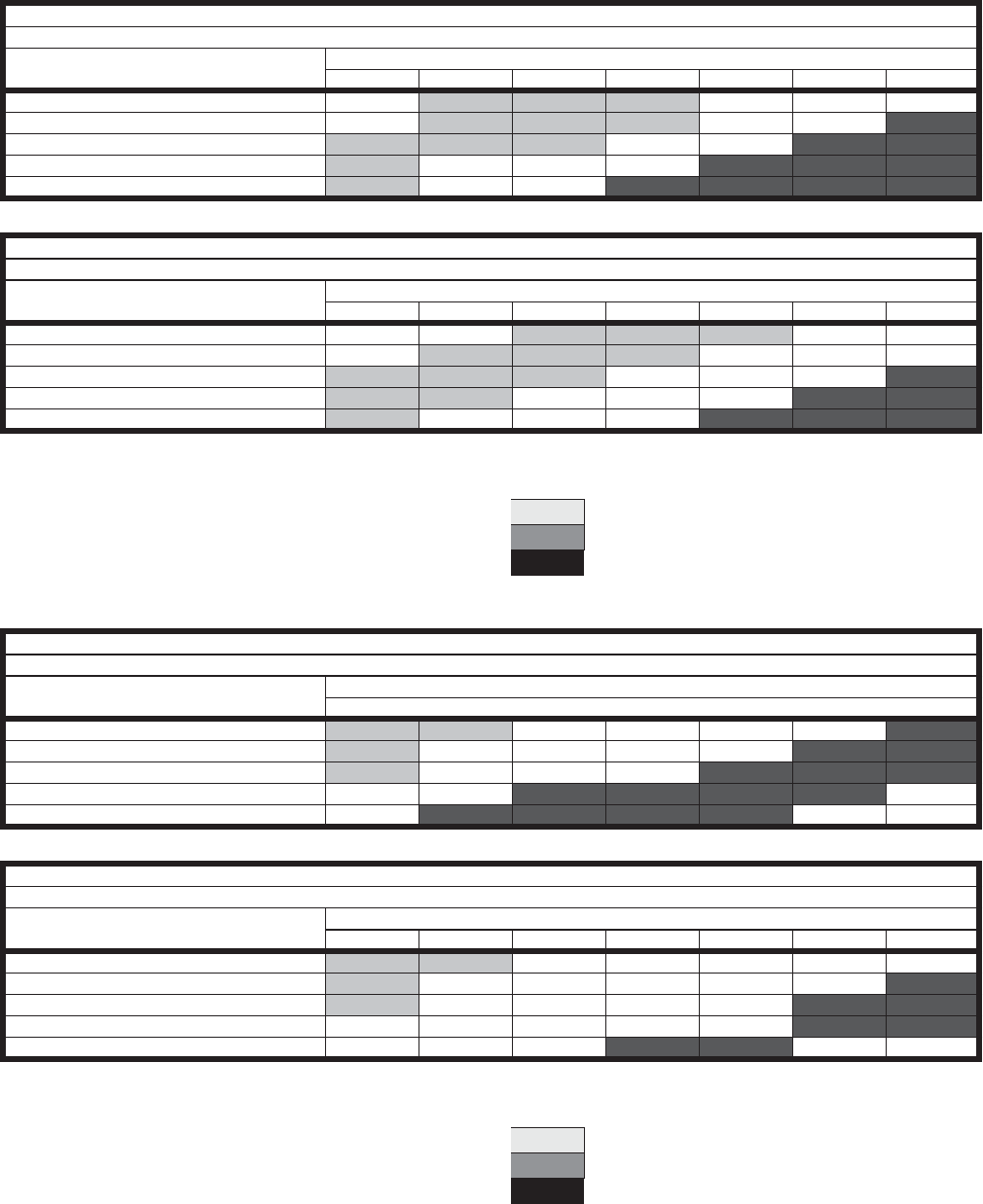
903106-UTG-A-0912
38 Unitary Products Group
TABLE 27: AIRFLOW PERFORMANCE - SIDE BY SIDE DUCT CONFIGURATION FOR S028 & S036
Blower RPM for S028
Notes:
1. Drive losses included in the above table
2. Performance can vary depending on ambient conditions
3. Blower RPMs are for reference only
Blower RPM for S036
Notes:
1. Drive losses included in the above table
2. Performance can vary depending on ambient conditions
3. Blower RPMs are for reference only
SUPPLY
Mist Eliminator Filter in Intake Hood (3HP)
CFM External Static Pressure (in water)
0 0.25 0.5 0.75 1 1.25 1.5
1200 N/A 955 1070 1210 1370 1465 1550
1600 N/A 1065 1205 1305 1460 1540 1595
2000 1060 1200 1290 1445 1530 1585 1680
2400 1190 1335 1440 1490 1575 1670 1755
2800 1300 1460 1550 1645 1705 1750 1800
EXHAUST
Barometric Hood, 2" Pleated Filters (3HP)
CFM External Static Pressure (in water)
0 0.25 0.5 0.75 1 1.25 1.5
1200 N/A N/A 1025 1170 1270 1355 1400
1600 N/A 1020 1155 1240 1330 1390 1490
2000 1015 1150 1235 1325 1380 1475 1590
2400 1140 1285 1365 1420 1510 1595 1640
2800 1280 1345 1455 1540 1575 1670 1745
RPM Range
Low 950-1320 Standard Unit
Medium 1325-1565 Optional Kit
High 1570-1880 Optional Kit
SUPPLY
Mist Eliminator Filter in Intake Hood (3HP)
CFM External Static Pressure (in water)
0 0.25 0.5 0.75 1 1.25 1.5
2000 815 925 1020 1105 1155 1255 1325
2400 920 1060 1130 1215 1250 1355 1385
2800 1010 1140 1240 1285 1370 1425 1470
3200 1125 1235 1340 1385 1455 1465 N/A
3600 1225 1375 1440 1460 1500 N/A N/A
EXHAUST
Barometric Hood, 2" Pleated Filters (3HP)
CFM External Static Pressure (in water)
0 0.25 0.5 0.75 1 1.25 1.5
2000 755 890 970 1060 1125 1215 1280
2400 985 1035 1085 1140 1240 1275 1325
2800 1020 1115 1175 1230 1270 1335 1370
3200 1105 1200 1225 1285 1300 1390 1430
3600 1155 1265 1295 1335 1385 N/A N/A
RPM Range
Low 700-1025 Standard Unit
Medium 1030-1305 Optional Kit
High 1325-1575 Optional Kit
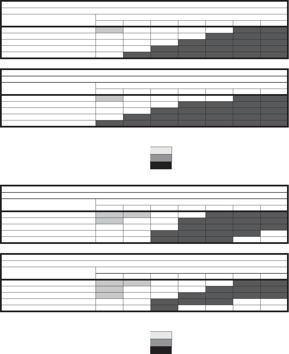
Unitary Products Group 39
903106-UTG-A-0912
TABLE 28: AIRFLOW PERFORMANCE - SIDE BY SIDE DUCT CONFIGURATION FOR S046 & S062
Blower RPM for S046
Notes:
1. Drive losses included in the above table
2. Performance can vary depending on ambient conditions
3. Blower RPMs are for reference only
Blower RPM for S062
Notes:
1. Drive losses included in the above table
2. Performance can vary depending on ambient conditions
3. Blower RPMs are for reference only
SUPPLY
Mist Eliminator Filter in Intake Hood (5HP)
CFM External Static Pressure (in water)
0 0.25 0.5 0.75 1 1.25 1.5
3000 965 1085 1150 1230 1295 1345 1420
3400 1035 1145 1250 1290 1335 1415 1475
3800 1120 1245 1285 1315 1440 1470 1535
4200 1215 1305 1355 1430 1465 1530 1595
4600 1300 1375 1450 1460 1540 1590 1650
EXHAUST
Barometric Hood, 2" Pleated Filters (5HP)
CFM External Static Pressure (in water)
0 0.25 0.5 0.75 1 1.25 1.5
3000 1010 1105 1195 1255 1300 1375 1415
3400 1100 1190 1250 1320 1370 1410 1480
3800 1185 1245 1360 1410 1440 1475 1540
4200 1240 1355 1425 1465 1530 1590 1630
4600 1345 1410 1485 1520 1585 1650 1700
RPM Range
Low 780-1020 Standard Unit
Medium 1000-1315 Optional Kit
High 1315-1700 Optional Kit
SUPPLY
Mist Eliminator Filter in Intake Hood (5HP)
CFM External Static Pressure (in water)
0 0.25 0.5 0.75 1 1.25 1.5
4600 795 900 1030 1075 1160 1220 1255
5000 855 920 1070 1130 1190 1250 1275
5400 880 950 1095 1155 1245 1270 1290
5800 915 1035 1115 1175 1255 1280 N/A
6200 985 1080 1135 1225 1265 N/A N/A
EXHAUST
Barometric Hood, 2" Pleated Filters (5HP)
CFM External Static Pressure (in water)
0 0.25 0.5 0.75 1 1.25 1.5
4600 705 885 985 1045 1100 1155 1215
5000 825 950 1025 1095 1150 1210 1245
5400 875 980 1080 1140 1190 1240 1275
5800 935 995 1130 1180 1230 N/A N/A
6200 985 1095 1165 N/A N/A N/A N/A
RPM Range
Low 700-900 Standard Unit
Medium 900-1100 Optional Kit
High 1100-1300 Optional Kit
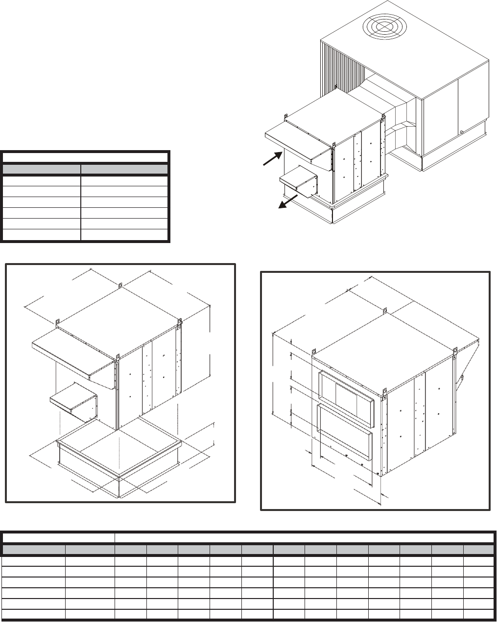
903106-UTG-A-0912
40 Unitary Products Group
O SERIES STAND ALONE ERV'S FOR OVER AND UNDER DUCT ARRANGEMENTS
FEATURES AND NOTES
1. Stand alone design allows higher levels of outdoor air to
be introduced into the conditioned space.
2. Static test ports provided to verify intake and exhaust
CFM.
3. Balancing damper(s) is field provided when connected to
ductwork. System may not operate properly without bal-
ancing damper.
4. Roof curbs are available for the ERV's.
5. See blower performance charts for airflow at various
E.S.P.
6. Filter rack with 2" pleated filters included. Found in return
air section.
ERV Roof Curbs
Series Model No
O011 01-2O1-2514
O020 01-2D1-3014
O028 01-2O1-3614
O036 01-2D1-4114
O046 01-2D1-4614
O062 01-2O1-5214
AB
C
KL
14
ERV with Horizontal Ductwork
(balancing damper(s) field supplied)
A
J
C
F
D
D
G
I
H
E
B
H
ERV Data Dimensional Data
ERV Series CFM Range A B C D E F G H I J K L
O011 300-1100 56.75 32.13 39.50 11.00 27.00 6.50 10.00 2.56 1.00 11.00 55.00 30.25
O020 1200-2000 54.38 37.25 37.50 12.00 30.00 8.00 4.00 3.63 1.50 20.32 52.75 35.50
O028 1200-2800 60.00 42.63 43.56 14.00 32.00 9.56 4.50 5.31 1.50 18.32 49.50 41.00
O036 2000-3600 60.00 46.69 57.37 16.50 39.50 12.13 6.38 3.59 5.88 18.32 55.75 41.81
O046 3000-4600 60.00 52.69 57.37 16.50 39.50 12.13 6.38 6.59 5.88 18.32 55.75 47.81
O062 4600-6200 72.00 70.88 63.63 19.50 39.50 12.13 6.50 15.69 5.88 18.32 67.75 66.00
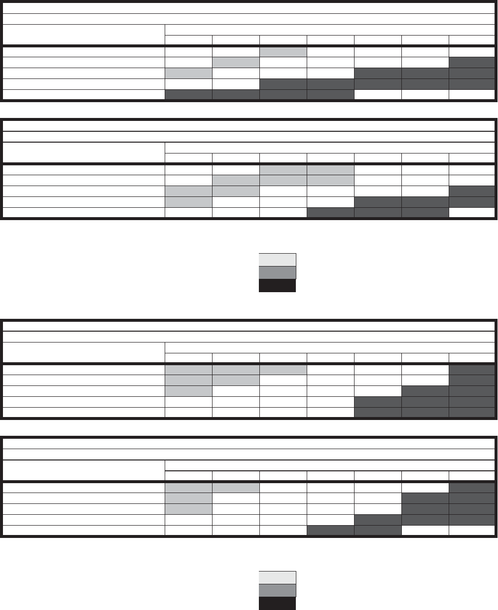
Unitary Products Group 41
903106-UTG-A-0912
TABLE 29: AIRFLOW PERFORMANCE - DOWNFLOW CONFIGURATION FOR O011 & O020
Blower RPM for O011
Notes:
1. Drive losses included in the above table
2. Performance can vary depending on ambient conditions
3. Blower RPMs are for reference only
Blower RPM for O020
Notes:
1. Drive losses included in the above table
2. Performance can vary depending on ambient conditions
3. Blower RPMs are for reference only
SUPPLY
Mist Eliminator Filter in Intake Hood (1.5HP)
CFM External Static Pressure (in water)
0 0.25 0.5 0.75 1 1.25 1.5
300 N/A N/A 1175 1350 1450 1605 1730
500 N/A 1170 1340 1540 1655 1725 1840
700 1295 1425 1600 1625 1795 1960 2035
900 1540 1660 1720 1790 2030 2110 2195
1100 1785 1915 2025 2185 N/A N/A N/A
EXHAUST
Barometric Hood, 2" Pleated Filters (1.5HP)
CFM External Static Pressure (in water)
0 0.25 0.5 0.75 1 1.25 1.5
300 N/A N/A 1030 1225 N/A N/A N/A
500 N/A 1025 1180 1265 1425 1535 N/A
700 1120 1190 1340 1445 1540 1645 1720
900 1285 1525 1500 1575 1670 1785 1865
1100 1570 1665 1670 1775 1860 1920 N/A
RPM Range
Low 1000-1300 Standard Unit
Medium 1300-1700 Optional Kit
High 1750-2200 Optional Kit
SUPPLY
Mist Eliminator Filter in Intake Hood (2HP)
CFM External Static Pressure (in water)
0 0.25 0.5 0.75 1 1.25 1.5
1200 1055 1135 1295 1420 1540 1650 1725
1400 1140 1240 1340 1490 1600 1690 1795
1600 1200 1330 1460 1565 1645 1740 1830
1800 1320 1405 1525 1615 1705 1785 1885
2000 1415 1515 1605 1690 1775 1875 1960
EXHAUST
Barometric Hood, 2" Pleated Filters (2HP)
CFM External Static Pressure (in water)
0 0.25 0.5 0.75 1 1.25 1.5
1200 1010 1195 1350 1445 1580 1685 1735
1400 1125 1315 1435 1545 1620 1730 1800
1600 1185 1370 1500 1610 1695 1790 1965
1800 1305 1485 1600 1685 1781 1955 2030
2000 1410 1550 1670 1765 1855 N/A N/A
RPM Range
Low 1000-1300 Standard Unit
Medium 1300-1700 Optional Kit
High 1700-2080 Optional Kit
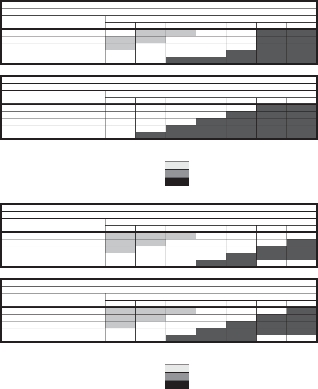
903106-UTG-A-0912
42 Unitary Products Group
TABLE 30: AIRFLOW PERFORMANCE - DOWNFLOW CONFIGURATION FOR O028 & O036
Blower RPM for O028
Notes:
1. Drive losses included in the above table
2. Performance can vary depending on ambient conditions
3. Blower RPMs are for reference only
Blower RPM for O036
Notes:
1. Drive losses included in the above table
2. Performance can vary depending on ambient conditions
3. Blower RPMs are for reference only
SUPPLY
Mist Eliminator Filter in Intake Hood (3HP)
CFM External Static Pressure (in water)
0 0.25 0.5 0.75 1 1.25 1.5
1200 N/A 790 960 1110 1210 1315 1380
1600 750 900 1005 1145 1230 1365 1410
2000 900 1005 1105 1210 1275 1400 1450
2400 1005 1125 1210 1275 1365 1450 1500
2800 1125 1230 1315 1380 1450 1535 1600
EXHAUST
Barometric Hood, 2" Pleated Filters (3HP)
CFM External Static Pressure (in water)
0 0.25 0.5 0.75 1 1.25 1.5
1200 750 885 1015 1145 1260 1350 1485
1600 870 1015 1125 1215 1325 1410 1500
2000 1015 1145 1240 1345 1410 1485 1560
2400 1125 1250 1345 1430 1500 1575 1630
2800 1250 1410 1485 1520 1630 1650 1675
RPM Range
Low 725-975 Standard Unit
Medium 1008-1314 Optional Kit
High 13115-1708 Optional Kit
SUPPLY
Mist Eliminator Filter in Intake Hood (3HP)
CFM External Static Pressure (in water)
0 0.25 0.5 0.75 1 1.25 1.5
2000 725 825 900 1000 1070 1180 1250
2400 800 900 1000 1070 1160 1250 1275
2800 900 1000 1070 1160 1250 1275 1340
3200 1000 1070 1160 1250 1275 1340 1400
3600 1055 1180 1250 1300 1360 N/A N/A
EXHAUST
Barometric Hood, 2" Pleated Filters (3HP)
CFM External Static Pressure (in water)
0 0.25 0.5 0.75 1 1.25 1.5
2000 750 865 950 1030 1100 1200 1265
2400 820 950 1035 1100 1200 1265 1300
2800 925 1035 1150 1200 1265 1315 1350
3200 1035 1160 1215 1265 1325 1350 1390
3600 1100 1215 1300 1350 1390 N/A N/A
RPM Range
Low 725-975 Standard Unit
Medium 1000-1315 Optional Kit
High 1215-1425 Optional Kit
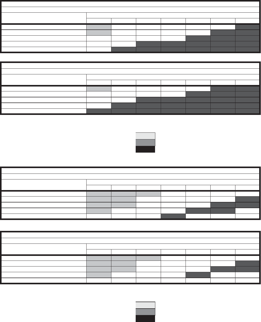
Unitary Products Group 43
903106-UTG-A-0912
TABLE 31: AIRFLOW PERFORMANCE - DOWNFLOW CONFIGURATION FOR O046 & O062
Blower RPM for O046
Notes:
1. Drive losses included in the above table
2. Performance can vary depending on ambient conditions
3. Blower RPMs are for reference only
Blower RPM for O062
Notes:
1. Drive losses included in the above table
2. Performance can vary depending on ambient conditions
3. Blower RPMs are for reference only
SUPPLY
Mist Eliminator Filter in Intake Hood (5HP)
CFM
External Static Pressure (in water)
0 0.25 0.5 0.75 1 1.25 1.5
3000 900 1030 1100 1165 1240 1285 1350
3400 975 1085 1175 1240 1290 1350 1400
3800 1070 1175 1240 1290 1350 1400 1465
4200 1165 1240 1320 1350 1430 1465 1515
4600 1240 1320 1375 1430 1500 1515 1580
EXHAUST
Barometric Hood, 2" Pleated Filters (5HP)
CFM External Static Pressure (in water)
0 0.25 0.5 0.75 1 1.25 1.5
3000 955 1100 1160 1245 1280 1360 1425
3400 1055 1185 1245 1300 1375 1425 1480
3800 1160 1300 1360 1400 1425 1530 1585
4200 1245 1375 1450 1480 1500 1585 1650
4600 1360 1450 1500 1585 1600 1650 1700
RPM Range
Low 780-1020 Standard Unit
Medium 1000-1315 Optional Kit
High 1315-1700 Optional Kit
SUPPLY
Mist Eliminator Filter in Intake Hood (5HP)
CFM External Static Pressure (in water)
0 0.25 0.5 0.75 1 1.25 1.5
4600 815 900 975 1045 1085 1125 1175
5000 880 940 1015 1060 1135 1175 1215
5400 915 975 1045 1125 1150 1195 1250
5800 975 1045 1085 1175 1250 1260 N/A
6200 1000 1075 1165 1200 N/A N/A N/A
EXHAUST
Barometric Hood, 2" Pleated Filters (5HP)
CFM External Static Pressure (in water)
0 0.25 0.5 0.75 1 1.25 1.5
4600 825 915 1000 1025 1100 1140 1170
5000 890 975 1025 1100 1140 1170 1240
5400 925 1000 1085 1140 1170 1240 1280
5800 975 1025 1140 1170 1240 N/A N/A
6200 1025 1120 1170 N/A N/A N/A N/A
RPM Range
Low 820-1000 Standard Unit
Medium 1000-1200 Optional Kit
High 11751375 Optional Kit
903106-UTG-A-0912
44 Unitary Products Group
GUIDE SPECIFICATIONS
Prepared for the guidance of architects, consulting engi-
neers, and mechanical contractors.
GENERAL
Furnish and install _____________ mechanical cooling sys-
tem, complete with a Unitized Energy Recovery Ventilator
(UERV).
APPROVALS
The Unitized Energy Recovery Ventilator will contain an
energy recovery component rated in accordance with AHRI/
ANSI Standard 1060-2005 with ratings certified by AHRI.
Cabinet
UERV shall be designed to attach directly to the a/c (rooftop,
upflow, horizontal) unit. It shall be G90 galvanized material
with a powdered enamel paint finish electrostatically bonded
to the metal. Cabinet panels where conditioned air is handled
shall be fully insulated to prevent sweating and minimize
sound. Openings shall be provided for power connections.
Lifting devices will be provided for rigging. Test ports shall be
provided so airflow can be measured across the energy
recovery wheel.
Intake Air Blower (direct drive)
UERV shall contain a centrifugal blower. All UERV's will be
equipped with direct drive PSC blower motors. The motor will
be multiple speed and will be individually controlled. Airflow
will also be adjustable by means of a damper on the intake air
opening. Blowers and motors will be removable through
means of a connecting plug for ease of servicing.
Intake Air Blower (belt drive)
UERV shall contain a centrifugal blower. It shall have ball
bearings and adjustable belt drive. Motor mount base shall
permit ease of motor changeover and belt tension adjust-
ment. On pivoting wheel models, supply blower will be de-
energized during economizer operation. (Except for VR074
and VR122.)
Exhaust Air Blower (direct drive)
UERV shall contain a centrifugal blower. All UERV's will be
equipped with direct drive PSC blower motors. The motor will
be multiple speed and shall be individually controlled. Blow-
ers and motors will be removable through means of a con-
necting plug for ease of servicing. On pivoting wheel models,
blower shall be sized to provide power exhaust during econo-
mizer operation.
Exhaust Air Blower (belt drive)
UERV shall contain a centrifugal blower. It shall have ball
bearings and adjustable belt drive. Motor mount base shall
permit ease of motor changeover and belt tension adjust-
ment. On pivoting wheel models, exhaust blowers shall be
sized to provide power exhaust during economizer operation.
Where single blowers cannot provide adequate exhaust, two
blowers will be utilized. One blower is energized during
energy recovery mode, and both blowers are energized
during economizer mode.
Energy Recovery Wheel
The energy recovery device shall be a rotary heat exchanger
per AHRI Standard 1060 description. The device will be an
enthalpy wheel coated with a silica gel desiccant by a pat-
ented process without the use of binders or adhesives which
may plug the desiccant aperture. The substrate shall be a
lightweight polymer. Desiccant shall not dissolve or deli-
quesce in the presence of water or high humidity. The wheel
shall be easily cleanable with standard coil cleaning solution.
On UERV's Series 20 and less, the wheel will easily be
removable from the cabinet for cleaning. On UERV's Series
20 and above, the wheel will be provided with removable seg-
ments for cleaning and maintenance. All diameter and perim-
eter seals shall be provided. The energy recovery cassette
shall be Underwriters Laboratories Recognized Component
for electrical and fire safety.
Balancing Dampers
Balancing dampers will be provided for all VR UERV’s. These
dampers will be mounted inside the rooftop air conditioning
unit to adjust for the amount of exhaust air on packaged units.
On pivoting wheel models, the unit economizer becomes the
balancing damper. Upflow and horizontal ERVs' will have the
balancing damper provided in the ERV. Optional on VO and
VS UERV’s when connected to rooftop units. (Except for
VR074 and VR122.)
Barometric Relief Dampers
Barometric relief dampers will be provided in the exhaust air
hood to prevent air infiltration when the UERV is de-ener-
gized.
ERV Support
All UERV's will be provided with support legs attached to the
cabinet to support the intake and exhaust end of the ERV
unit. Horizontal ERV's will be provided with support brackets
for hanging.
Filters
All units shall be provided with mist eliminator type filters in
the intake air hood.
Power Connection
The UERV shall be provided with a single point power con-
nection for high voltage.
Unitary Products Group 45
903106-UTG-A-0912
OPTIONS
Optional UERV Equipment Support
Furnish and install the optional equipment support for the
intake and exhaust end of the unit.
Optional Roof Curb
Furnish and install the optional roof mounting frame to main-
tain proper height above the roof.
Optional Low Ambient Kit
Furnish and install the optional low ambient kit to prevent
frost formation on the energy recovery wheel.
Optional Motorized Intake Air Damper
Furnish and install the optional motorized intake air damper.
Optional Stop-Start-Jog
On units without economizers furnish and install the optional
stop-start-jog controls.
SEQUENCE OF OPERATION:
Fixed Models - Normal Operation
1. The space thermostat sends a signal to the RTU for cool-
ing, heating or fan only operation.
2. The ERV is activated simultaneously with the supply
blower of the RTU. The intake blower, the exhaust
blower, and the wheel rotation motor of the ERV are acti-
vated. These motors will remain energized as long as
the supply blower on the RTU is energized. The RTU is
in standard (non-economizer) mode.
3. If the optional motorized fresh air damper in the outside
air intake of the ERV is present, it opens and the ERV is
energized.
4. If the optional low ambient kit is present, and the tem-
perature leaving the exhaust side of the wheel drops
below the field adjusted set point on the temperature
sensor of the low ambient kit, the optional motorized
fresh air damper will close and the intake blower will de-
energize. The exhaust air blower and wheel rotation
motor will continue to operate. When the temperature
sensor has a sixteen-degree rise, the wheel is defrosted
and the optional motorized damper will open and the
fresh air blower will reactivate.
Pivoting Models - Normal Operation
1. The space thermostat sends a signal to the RTU for cool-
ing, heating or fan only operation.
2. The ERV is activated with the supply blower of the RTU.
The intake blower, the exhaust blower, and the wheel
rotation motor of the ERV are activated. These motors
will remain energized as long as the supply blower on
the RTU is energized and the RTU is in standard (non-
economizer) mode.
3. If the optional motorized fresh air damper in the outside
air intake of the ERV is present, it opens and the ERV is
energized.
4. If the optional low ambient kit is present, and the tem-
perature leaving the exhaust side of the wheel drops
below the field adjusted set point on the temperature
sensor of the low ambient kit, the optional motorized
fresh air damper will close and the intake blower will de-
energize. The exhaust air blower and wheel rotation
motor will continue to operate. When the temperature
sensor has a sixteen-degree rise, the wheel is defrosted
and the optional motorized damper will open and the
fresh air blower will reactivate.
Pivoting Models - Economizer Operation
1. The space thermostat sends a signal to the RTU for cool-
ing operation.
2. The outdoor air sensor for the RTU senses the outdoor
air and determines it is appropriate for economizer oper-
ation.
3. As the economizer outside air dampers open, the ERV
economizer end switch is activated sending a signal to
the ERV that the system is in the economizer mode.
4. The intake blower, the exhaust blower and the wheel
rotation motor all deactivate for up to two minutes. The
optional motorized fresh air damper (if present) also
closes.
5. The ERV enthalpy wheel pivots out of the air stream and
the bypass dampers along each side of the intake blower
open.
6. After a time delay to allow the wheel to pivot out of the
airstream and the bypass dampers to open, the optional
motorized fresh air damper opens to allow for full econo-
mizer operation, and the exhaust blower is reactivated to
provide power exhaust for the system.
903106-UTG-A-0912
46 Unitary Products Group
UERV TROUBLESHOOTING GUIDE
UERV BELOW 600 CFM WITH STATIONARY WHEEL
(NO ECONOMIZER)
UERV will not operate.
1. Quick check items.
a. Verify S51 door switch is closed. The switch must be
in the closed position to power the A130 circuit
board.
b. Verify the A130 circuit board switch SW1 Power is in
the “on” position.
c. Verify 24 volts to A130 circuit board terminals TB1
“G” and “C” if in the cooling mode, or “W” and “C” if
in the heating mode. The terminals must be pow-
ered to allow any blower relays / contactors to oper-
ate.
2. Verify high voltage power to UERV.
a. Verify 110 volts for UERV to L1 and L2 on TB2 on
the A130 board.
b. Verify the F1 fuse is good. Replace any bad fuses.
c. Verify that the T28 step down transformer on 208,
230, and 460 volt units have the voltage correctly
applied to the correct transformer terminals.
UERV has power, but the enthalpy wheel does not spin.
1. Check wheel belt is in place and tight.
2. Verify the A130 circuit board switch SW1 Power is in the
"on" position.
3. Verify the A130 circuit board terminals Wheel "1" and "2"
are outputting 110 volts to B28 wheel motor through J/
P150 plug assembly.
4. Verify B28 wheel motor C23 capacitor is good. Replace
the capacitor if it is bad.
5. If the optional Stop, Start, Jog (SSJ) feature is installed,
verify that the temperature setpoint on the SSJ does not
have the wheel stopped.
6. If all of the above are operational, the wheel motor is
bad. Replace it with new motor.
UERV has power, but the exhaust blower does not
operate.
1. Verify the A130 circuit board switch SW1 Power is in the
"on" position.
2. Verify the A130 circuit board terminals Exhaust "1” and
"3” if in high speed operation, or "1” and "2" if in low
speed operation are outputting 110 volts to B26 exhaust
blower motor though J/P151 plug assembly.
3. Verify B26 wheel motor C25 capacitor is good. Replace
the capacitor if it is bad.
4. If all of the above are operational, the exhaust motor is
bad. Replace it with new motor.
UERV has power, but the fresh air blower does not
operate.
1. Verify the A130 circuit board switch SW1 Power is in the
"on" position.
2. Verify the A130 circuit board terminals Fresh "1” and "3"
if in high speed operation, or "1” and "2" if in low speed
operation are outputting 110 volts to B27 fresh air blower
motor though J/P148 plug assembly.
3. On units equipped with the optional low ambient control,
verify that the A130 circuit board TB3 terminals marked
"low ambient" are closed. The low ambient control will
stop the fresh air motor operation and close the optional
outside air damper if it senses conditions for frost on the
UERV wheel. The "low ambient" terminals can be
jumped together to verify if the low ambient control has
the fresh air blower stopped.
4. Verify B27 wheel motor C26 capacitor is good. Replace
the capacitor if it is bad.
5. If all of the above are operational, the fresh air motor is
bad. Replace it with new motor.
UERV has power, but the optional motorized fresh air
damper does not open.
1. Verify 24 volts to A130 circuit board terminals TB1 "G"
and "C" if in the cooling mode, or "W" and "C" if in the
heating mode.
2. Verify the A130 circuit board switch SW1 Power is in the
"on" position.
3. Verify 24 volts to B30 motorized outdoor air motor
through J/P160 plug assembly.
4. If all of the above are operational, replace the outdoor air
damper motor.
UERV ABOVE 600 CFM WITH STATIONARY WHEEL
(NO ECONOMIZER)
UERV will not operate.
1. Quick check items.
a. Verify S51 door switch is closed. The switch must be
in the closed position to power the A130 circuit
board.
b. Verify 24 volts to A130 circuit board terminals
XFORMER "+" and "-". The terminals must be pow-
ered to allow blower contactors to operate.
c. Verify 24 volts to A130 circuit board terminals TB 37
numbers "1" and "3". Terminal "1" is the hot and "3"
is the common side of the power source from activa-
tion power source (a/c unit, energy management
Unitary Products Group 47
903106-UTG-A-0912
control, etc.). Typically, "1" would be from the blower
contactor on an a/c unit.
2. Verify high voltage power to UERV.
a. Check for correct voltage for UERV to L1 and L2 on
1-phase units.
b. Check for correct voltage for UERV to L1, L2, and
L3 on 3-phase units.
c. Verify the F29 fuses are good. Replace any bad
fuses.
d. Verify that the T27 transformer has the UERV volt-
age correctly applied to the correct transformer ter-
minals.
UERV has power, but the enthalpy wheel does not spin.
1. Check wheel belt is in place and tight.
2. Verify the A130 circuit board terminals Exhaust "A" (hot)
and "B" (common) are outputting 24 volts to K163 con-
tactor terminal "A" and "B" and that the contacts are
closed.
3. Verify power to B28 wheel motor.
4. Verify B28 wheel motor C23 capacitor is good. Replace
the capacitor if it is bad. (Except VR074 to VR122)
5. If the optional Stop, Start, Jog (SSJ) feature is installed,
verify that the timer on the SSJ does not have the wheel
stopped.
6. If all of the above are operational, the wheel motor is
bad. Replace it with new motor.
UERV has power, but the exhaust blower does not
operate.
1. Check that the blower belt is in place and tight on belt
drive models. If it is loose, tighten it. If it is broken replace
it.
2. Verify the A130 circuit board terminals Exhaust "A" (hot)
and "B" (common) are outputting 24 volts to K163 con-
tactor terminal "A" and "B", and that the contacts are
closed.
3. Verify power to B26 exhaust blower motor.
4. On direct drive models, verify B26 wheel motor C25
capacitor is good. Replace if necessary.
5. If all of the above are operational, the exhaust motor is
bad. Replace it with new motor.
UERV has power, but the fresh air blower does not
operate.
1. Check that the blower belt is in place and tight on belt
drive models. Tighten it if it is loose. Replace it if it is bro-
ken.
2. Verify the A130 circuit board terminals Fresh "A" (hot)
and "B" (common) are outputting 24 volts to K164 con-
tactor terminal "A" and "B", and that the contacts are
closed.
3. Verify power to B27 fresh air blower motor though J/
P148 plug assembly.
4. On direct drive models, verify B27 wheel motor C26
capacitor is good. Replace if necessary.
5. On units equipped with the optional low ambient control,
verify that the circuit on the A130 circuit board terminal
"5" and "6" is closed. The low ambient control will stop
the fresh air motor operation and close the optional out-
side air damper if it senses frost on the UERV wheel.
Terminal "5" and "6" can be jumped together to verify if
the low ambient control has the fresh air blower stopped.
6. If all of the above are operational, the fresh air motor is
bad. Replace it with new motor.
UERV has power, but the optional motorized fresh air
damper does not open.
1. Verify 24 volts to the A130 circuit board terminals
XFORMER "+" and "-".
2. Verify 24 volts to A130 circuit board terminals TB 37
numbers "1" and "3". Terminal "1" is the hot and "3" is the
common side of the power source from activation power
source (a/c unit, energy management control, etc.). Typi-
cally, "1" would be from the blower contactor on an a/c
unit.
3. Verify 24 volts to B30 motorized outdoor air motor
through J/P160 plug assembly.
4. If all of the above are operational, replace the outdoor air
damper motor.
UERV ABOVE 600 CFM WITH PIVOTING WHEEL
(USED WITH ECONOMIZER)
UERV will not operate.
1. Quick check items.
a. Verify S51 door switch is closed. The switch must be
in the closed position to power the A130 circuit
board.
b. Verify 24 volts to A130 circuit board terminals
XFORMER "+" and "-". The terminals must be pow-
ered to allow any blower relays / contactors to oper-
ate.
c. Verify 24 volts to A130 circuit board terminals TB 37
numbers "1" and "3". Terminal "1" is the hot and "3"
is the common side of the power source from activa-
tion power source (a/c unit, energy management
control, etc.). Typically, "1" would be from the blower
contactor on an a/c unit.
2. Verify high voltage power to UERV.
a. Check correct voltage for UERV to L1 and, L2 on 1-
phase units.

Subject to change without notice. Printed in U.S.A. 903106-UTG-A-0912
Copyright © January 24, 2013 by Johnson Controls, Inc. All rights reserved. Supersedes: 246681-YTG-C-0611
Johnson Controls Unitary Products
5005 York Drive
Norman, OK 73069
b. Check for correct voltage to L1, L2, and L3 on 3-
phase units.
c. Verify the F29 fuses are good. Replace any bad
fuses.
d. Verify that the T27 transformer has the UERV volt-
age correctly applied to the correct transformer ter-
minals.
UERV has power, but the enthalpy wheel does not spin.
1. Check wheel belt is in place and tight.
2. Verify the A130 circuit board terminals Exhaust 1 "A"
(hot) and "B" (common) are outputting 24 volts to K163
contactor terminal "A" and "B" and that the contacts are
closed.
3. Verify power to B28 wheel motor through J/P150 plug
assembly.
a. If there is no power on the T1 leg of the motor (pivot-
ing models only) verify that the S110 switch located
inside the B29 damper motor is in the closed posi-
tion.
4. Verify B28 wheel motor C23 capacitor is good. Replace
the capacitor if it is bad.
5. If all of the above are operational, the wheel motor is
bad. Replace it with new motor.
UERV has power, but the exhaust blower does not
operate.
1. Check that the blower belt is in place and tight. If it is
loose, tighten it. If it is broken replace it.
2. Verify the A130 circuit board terminals Exhaust 1 "A"
(hot) and "B" (common) are outputting 24 volts to K163
contactor terminal "A" and "B", and that the contacts are
closed.
3. Verify power to B26 exhaust blower motor though J/P151
plug assembly.
4. On direct drive models, verify B26 wheel motor C25
capacitor is good. Replace if necessary.
5. If all of the above are operational, the exhaust motor is
bad. Replace it with new motor.
UERV has power, but the fresh air blower does not
operate.
1. Energy Recovery Mode of operation.
a. Check that the blower belt is in place and tight on
belt drive models. Tighten it if it is loose. Replace it if
it is broken.
b. Verify the A130 circuit board terminals Fresh "A"
(hot) and "B" (common) are outputting 24 volts to
K164 contactor terminal "A" and "B", and that the
contacts are closed.
c. Verify power to B27 fresh air blower motor though J/
P148 plug assembly.
d. On units equipped with the optional low ambient
control, verify that the circuit on the A130 circuit
board terminal "5" and "6" is made. The low ambient
control will stop the fresh air motor operation and
close the optional outside air damper if it senses
frost on the UERV wheel. Terminal "5" and "6" can
be jumped together to verify if the low ambient con-
trol has the fresh air blower stopped.
e. On direct drive models, verify B27 wheel motor C26
capacitor is good. Replace if necessary.
f. If all of the above are operational, the fresh air motor
is bad. Replace it with new motor.
2. Economizer Mode of operation.
a. The fresh air blower is not operational in the econo-
mizer mode.
UERV has power, but the wheel does not rotate out of
airstream during economizer operation.
1. Check the linkage from the B29 damper motor to the
UERV wheel.
2. Verify shipping retainers are removed.
3. Verify the S122 economizer end switch is closed. The
switch is located on the damper and closes when the
damper moves from minimum position to the economizer
position (field adjustable).
4. Verify the B29 damper motor has 24 volts to terminals
"B" and "T1" through J/P160 plug assembly
5. If all of the above are operational, replace the damper
motor.
UERV has power, but the optional motorized fresh air
damper does not open.
1. Verify 24 volts to the A130 circuit board terminals
XFORMER "+" and "-".
2. Verify 24 volts to A130 circuit board terminals TB 37
numbers "1" and "3". Terminal "1" is the "hot" and "3" is
the "common" side of the power source from activation
power source (a/c unit, energy management control,
etc.). Typically, "1" would be from the blower contactor
on an a/c unit.
3. Verify 24 volts to B30 motorized outdoor air motor
through J/P160 plug assembly.
4. If all of the above are operational, replace the outdoor air
damper motor.
