York Millennium Ycas0130 Users Manual 201.19 NM1 (204)
YCAS0130 to the manual b18cdb57-ee24-40f9-96ff-0a7163391231
2015-02-02
: York Millennium-Ycas0130-Users-Manual york-millennium-ycas0130-users-manual-455266 york pdf
Open the PDF directly: View PDF ![]() .
.
Page Count: 204 [warning: Documents this large are best viewed by clicking the View PDF Link!]
- 201.19-NM1
- SECTION 1 - GENERAL CHILLER INFORMATION & SAFETY
- SECTION 2 - PRODUCT DESCRIPTION
- SECTION 3 - HANDLING AND STORAGE
- SECTION 4 - INSTALLATION
- LOCATION REQUIREMENTS
- OUTDOOR INSTALLATIONS
- INDOOR INSTALLATIONS
- LOCATION CLEARANCES
- COMPRESSOR FEET BOLT REMOVAL
- VIBRATION ISOLATORS
- SHIPPING BRACES
- PIPEWORK CONNECTION
- WATER TREATMENT
- PIPEWORK ARRANGEMENT
- CONNECTION TYPES & SIZES
- EVAPORATOR CONNECTIONS
- REFRIGERANT RELIEF VALVE PIPING
- DUCTWORK CONNECTION
- ELECTRICAL CONNECTION
- POWER WIRING
- STANDARD UNITS WITH MULTI POINT POWER SUPPLY WIRING
- 115VAC CONTROL SUPPLY TRANSFORMER
- CONTROL PANEL WIRING
- VOLTS FREE CONTACTS
- SYSTEM INPUTS
- SECTION 5 - COMMISSIONING
- SECTION 6 - OPERATION
- SECTION 7 - TECHNICAL DATA
- FLOW RATE AND PRESSURE DROP CHARTS
- GLYCOL CORRECTION FACTORS
- TEMPERATURE AND FLOWS
- PHYSICAL DATA
- OPERATING LIMITATIONS AND SOUND POWER DATA
- WIRING DIAGRAM
- ELEMENTARY DIAGRAM
- CONNECTION DIAGRAM
- COMPRESSOR TERMINAL BOX
- DIMENSIONS
- TECHNICAL DATA
- WEIGHT DISTRIBUTION AND ISOLATOR MOUNTING POSITIONS
- INSTALLATION INSTRUCTIONS FOR VMC SERIES AWR/AWMR AND CP RESTRAINED MOUNTINGS
- COMPRESSOR COMPONENTS
- SYSTEM STARTUP CHECKLIST
- UNIT CHECKS
- PROGRAMMED VALUES
- INITIAL START-UP
- CHECKING SUBCOOLING AND SUPERHEAT
- CHECKING ECONOMIZER SUPERHEAT
- LEAK CHECKING
- SECTION 8 - MICRO PANEL CONTENTS
- CHILLER CONTROL PANEL PROGRAMMING AND DATA ACCESS KEYS
- DISPLAY AND STATUS INFORMATION KEYS
- ON / OFF ROCKER SWITCH
- PROGRAM & SETUP KEYS
- 1. INTRODUCTION & PHYSICAL DESCRIPTION
- 2. STATUS KEY: GENERAL STATUS MESSAGES & FAULT WARNINGS
- 3. DISPLAY KEYS & OPTION SWITCHES
- 4. PRINT KEYS
- 5. ENTRY KEYS
- 6. SETPOINTS KEYS & CHILLED LIQUID CONTROL
- 7. CLOCK KEYS
- 8. PROGRAM KEY
- SECTION 9 - MAINTENANCE
- SECTION 10 - SPARE PARTS
- SECTION 11 - TROUBLESHOOTING GUIDE
INSTALLATION, OPERATION & MAIN TE NANCE
AIR-COOLED SCREW LIQUID CHILLERS
New Release Form 201.19-NM1 (204)
YCAS AIR-COOLED LIQUID CHILLERS
YCAS0130 THROUGH YCAS0230
STYLE G
YCAS 2 SYSTEM EPROM 031-01798-001 (STANDARD, BRINE & METRIC MODELS COM BINED)
028971-G
60 Hz
035-20319-000
2YORK INTERNATIONAL
FORM 201.19-NM1 (204)
CHANGEABILITY OF THIS DOCUMENT
In complying with YORK’s policy for continuous prod uct improvement, the information contained in this
doc u ment is subject to change without notice. Literature updates that may occur will be printed on the
Revision Sheet and included with the Installation, Operation & Maintenance (IOM) man, which is provided
with new equipment. If not found with the manual, the current Revision Sheet containing any applicable
revisions, and the manual, can be found on the internet at www.york.com. The Renewal Parts (RP) manual
and revision sheet for this equipment can also be found at this internet site.
It is the responsibility of installing/operating/service personnel to determine prior to working on the equip-
ment, that they have all of the applicable literature, that it is current and that the equipment has not been
modifi ed since manufacture.
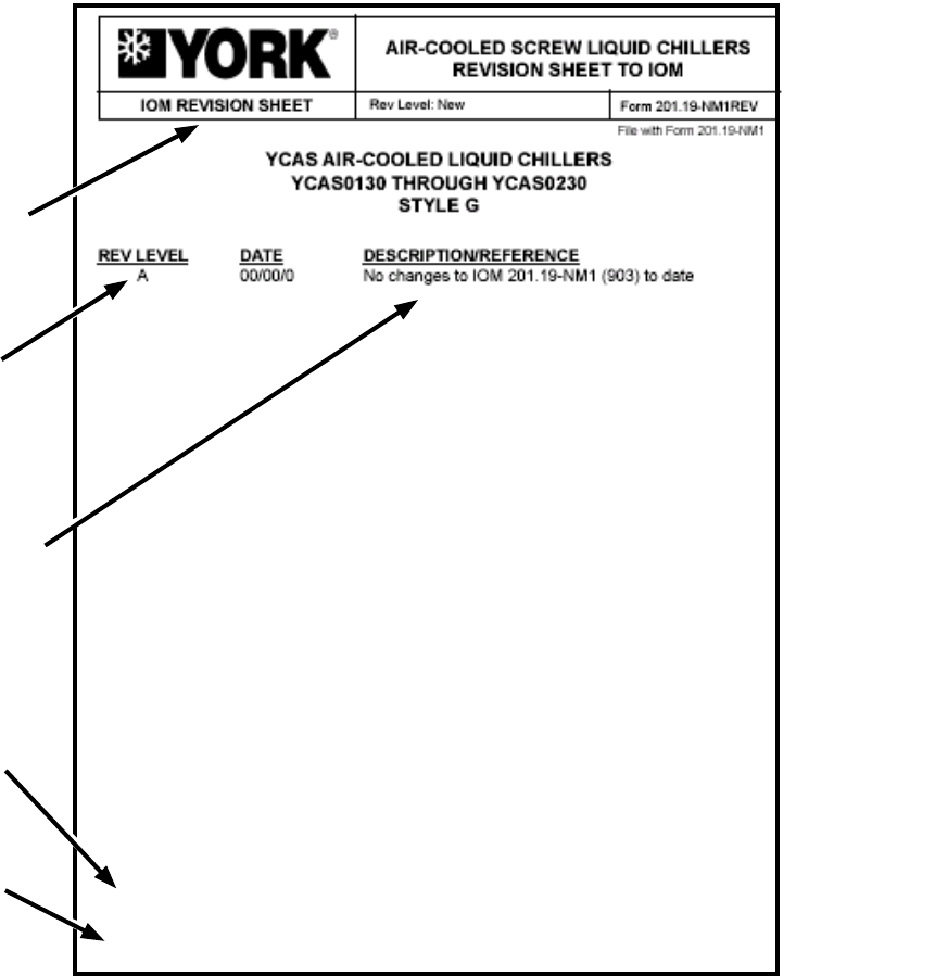
Revision Sheets are available for
the IOM and Renewal Parts
Each update will be assigned a
sequential Rev. Level with the
date it was introduced
The Description/Change will explain
the change. If necessary it will
refer the reader to an additional
supplement or bulletin.
YORK part number for the Revision
Sheet to aid manufacturing and
distribution
Web address for the Revision Sheet
035-XXXXX-XXX
www.york.com

3
YORK INTERNATIONAL
FORM 201.19-NM1 (204)
This equipment is a relatively complicated ap pa ra tus.
Dur ing installation, operation, maintenance or service,
in di vid u als may be exposed to certain com po nents or
conditions in clud ing, but not limited to: re frig er ants,
oils, materials un der pressure, rotating com po nents, and
both high and low voltage. Each of these items has the
po ten tial, if misused or handled im prop er ly, to cause
bodi ly injury or death. It is the obligation and re spon -
si bil i ty of operating/service per son nel to iden ti fy and
rec og nize these inherent hazards, protect them selves,
and pro ceed safely in completing their tasks. Failure
to com ply with any of these requirements could re sult
in se ri ous dam age to the equipment and the prop er ty in
IMPORTANT!
READ BEFORE PROCEEDING!
GENERAL SAFETY GUIDELINES
which it is sit u at ed, as well as severe personal injury or
death to them selves and people at the site.
This document is intended for use by owner-authorized
operating/service personnel. It is expected that this in-
di vid u al possesses independent training that will en able
them to perform their assigned tasks properly and safe ly.
It is essential that, prior to performing any task on this
equipment, this individual shall have read and un der -
stood this document and any referenced materials. This
in di vid u al shall also be familiar with and comply with
all ap pli ca ble governmental standards and regulations
per tain ing to the task in question.
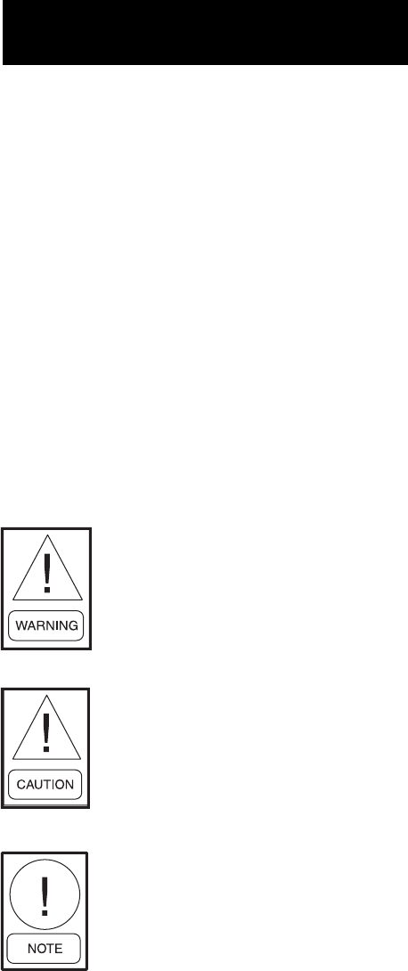
SAFETY SYMBOLS
The following symbols are used in this document to alert the reader to areas of potential hazard:
CAUTION identifi es a hazard which
could lead to damage to the ma chine,
damage to other equip ment and/or
en vi ron men tal pollution. Usually
an in struc tion will be given, together
with a brief ex pla na tion.
NOTE is used to highlight ad di tion al
information which may be helpful to
you.
DANGER indicates an im mi nent ly
hazardous situation which, if not
avoid ed, will re sult in death or se ri ous
injury.
WARNING indicates a potentially
haz ard ous sit u a tion which, if not
avoid ed, could result in death or se-
ri ous in ju ry.
External wiring, unless specifi ed as an optional connection in the man u fac tur er’s prod uct
line, is NOT to be connected inside the micro pan el cab i net. De vic es such as re lays, switch es,
transducers and controls may NOT be installed inside the mi cro pan el. NO external wiring
is al lowed to be run through the micro panel. All wir ing must be in ac cor dance with YORK’s
pub lished spec i fi ca tions and must be per formed ONLY by qual i fi ed YORK personnel. YORK
will not be re spon si ble for dam ag es/problems re sult ing from im prop er con nec tions to the
con trols or ap pli ca tion of im prop er con trol sig nals. Failure to fol low this will void the
man u fac tur er’s warranty and cause serious dam age to property or injury to per sons.
4YORK INTERNATIONAL
FORM 201.19-NM1 (204)
TABLE OF CONTENTS
SECTION 1 - GENERAL CHILLER
INFORMATION & SAFETY
INTRODUCTION ...........................................................9
WARRANTY...................................................................9
SAFETY...........................................................................9
Standards for Safety ...............................................9
RESPONSIBILITY FOR SAFETY...............................10
ABOUT THIS MANUAL..............................................10
MISUSE OF EQUIPMENT...........................................10
Suitability for Application....................................10
Structural Support ................................................10
Mechanical Strength.............................................10
General Access .....................................................10
Pressure Systems..................................................10
Electrical...............................................................10
Rotating Parts ....................................................... 11
Sharp Edges.......................................................... 11
Refrigerants and Oils............................................ 11
High Temperature and Pressure Cleaning ............ 11
Emergency Shutdown...........................................11
SECTION 2 - PRODUCT DESCRIPTION
INTRODUCTION .........................................................12
General Description..............................................12
Compressor...........................................................12
Evaporator ............................................................13
Condenser.............................................................13
Economizer...........................................................14
Oil Separator/System............................................14
Oil Cooling...........................................................14
Capacity Control ..................................................14
Power and Control Panel......................................14
Each power compartment contains: .....................15
The control section contains:................................15
The options sections contain: ...............................15
Microprocessor Controls......................................15
Motor Current Protection .....................................15
Motor Protection Modules (2ACE)......................16
Current Overload..................................................16
Thermal Overload ................................................17
Current Imbalance (Loaded & Unloaded)............17
Loss of Phase........................................................17
Improper Phase Sequence ....................................17
MOTOR STARTING.....................................................22
KEYPAD CONTROLS..................................................22
Display .................................................................22
Program ................................................................23
ACCESSORIES AND OPTIONS .................................23
Multiple Point Power Connection (Standard) ......23
Single-Point Power Connection with Individual
Circuit Protection .................................................23
Single-Point Power Connection with Combined
Circuit Protection ................................................23
Single-Point Power Connection without Circuit
Protection ............................................................23
Control Circuit Terminal Block............................23
Building Automation System (BAS) Interface.....23
Condenser Coil Protection ..................................23
DX EVAPORATOR AND STARTER OPTIONS .........24
UNIT ENCLOSURES OPTIONS .................................24
FAN OPTIONS..............................................................24
SOUND REDUCTION OPTIONS................................24
VIBRATION ISOLATION ...........................................24
UNIT NOMENCLATURE ............................................25
NAMEPLATE ENGINEERING DATA ........................25
PRODUCT IDENTIFICATION NUMBER (PIN) ........26
SECTION 3 - HANDLING AND STORAGE
DELIVERY AND STORAGE .......................................27
INSPECTION ................................................................27
MOVING THE CHILLER ............................................27
Lifting Weights.....................................................27
UNIT RIGGING ............................................................28
SECTION 4 - INSTALLATION
LOCATION REQUIREMENTS....................................29
OUTDOOR INSTALLATIONS ....................................29
INDOOR INSTALLATIONS ........................................29
LOCATION CLEARANCES ........................................29
COMPRESSOR FEET BOLT REMOVAL ...................30
VIBRATION ISOLATORS ..........................................31
Installation............................................................31
SHIPPING BRACES.....................................................31
PIPEWORK CONNECTION ........................................31
General Requirements..........................................31
WATER TREATMENT..................................................32
PIPEWORK ARRANGEMENT....................................33
CONNECTION TYPES & SIZES.................................33
EVAPORATOR CONNECTIONS ................................33
Optional Flanges ..................................................33
REFRIGERANT RELIEF VALVE PIPING ..................33
DUCTWORK CONNECTION .....................................33
General Requirements..........................................33
ELECTRICAL CONNECTION ....................................34
POWER WIRING..........................................................34
STANDARD UNITS WITH MULTI POINT POWER
SUPPLY WIRING .........................................................34
5
YORK INTERNATIONAL
FORM 201.19-NM1 (204)
TABLE OF CONTENTS (CONT’D)
Units with Single-Point Power Supply Wiring ....34
115VAC CONTROL SUPPLY TRANSFORMER ........34
Remote Emergency Stop Device..........................35
CONTROL PANEL WIRING........................................35
VOLTS FREE CONTACTS ..........................................35
Chilled Liquid Pump Starter ................................35
Run Contact..........................................................35
Alarm Contacts.....................................................35
SYSTEM INPUTS.........................................................35
Flow Switch..........................................................35
Remote Run / Stop ...............................................35
Remote Print.........................................................35
Remote Setpoint Offset – Temperature ................35
Remote Setpoint Offset – Current........................35
SECTION 5 - COMMISSIONING
PREPARATION.............................................................42
PREPARATION – POWER OFF ..................................42
Inspection .............................................................42
Refrigerant Charge ...............................................42
Valves ...................................................................42
Compressor Oil ....................................................42
Fans ......................................................................42
Isolation/Protection ..............................................42
Control Panel........................................................42
Power Connections...............................................42
Grounding.............................................................42
Overloads .............................................................42
Supply Voltage .....................................................42
Control Transformer.............................................42
Switch Settings.....................................................43
Crankcase Heaters ................................................43
Water System........................................................43
Flow Switch..........................................................43
Temperature Sensor(s)..........................................43
Control Supply .....................................................43
Programmed Options............................................43
Programmed Settings ...........................................43
Date and Time ......................................................43
Start/Stop Schedule ..............................................43
Setpoint and Remote Offset .................................43
FIRST TIME START-UP...............................................44
Interlocks..............................................................44
System Switches...................................................44
Start-up.................................................................44
Oil Pressure ..........................................................44
Refrigerant Flow ..................................................44
Fan Rotation .........................................................44
Suction Superheat.................................................44
Expansion Valve ..................................................44
Economizer Superheat .........................................44
Subcooling............................................................44
General Operation ................................................44
SECTION 6 - OPERATION
GENERAL DESCRIPTION ..........................................46
START-UP .....................................................................46
NORMAL RUNNING AND CYCLING.......................46
SHUTDOWN.................................................................46
SECTION 7 - TECHNICAL DATA
FLOW RATE AND PRESSURE DROP CHARTS.......48
GLYCOL CORRECTION FACTORS...........................48
TEMPERATURE AND FLOWS...................................49
PHYSICAL DATA.........................................................51
OPERATING LIMITATIONS AND SOUND POWER
DATA .............................................................................53
Electrical Data ......................................................54
Electrical Notes ....................................................62
WIRING DIAGRAM.....................................................64
ELEMENTARY DIAGRAM.........................................66
CONNECTION DIAGRAM (SYSTEM WIRING) ......77
COMPRESSOR TERMINAL BOX ..............................78
DIMENSIONS–YCAS0130-YCAS0180 (ENGLISH) .82
DIMENSIONS–YCAS0130-YCAS0180 (SI)...............84
DIMENSIONS–YCAS0200-YCAS0230 (ENGLISH) .86
DIMENSIONS–YCAS0200-YCAS0230 (SI)...............88
TECHNICAL DATA......................................................90
WEIGHT DISTRIBUTION AND ISOLATOR
MOUNTING POSITIONS ............................................91
INSTALLATION INSTRUCTIONS FOR VMC SERIES
AWR/AWMR AND CP RESTRAINED
MOUNTINGS..............................................................107
COMPRESSOR COMPONENTS............................... 111
UNIT CHECKS (NO POWER)................................... 117
SYSTEM STARTUP CHECKLIST............................. 117
PANEL CHECKS ........................................................118
PROGRAMMED VALUES......................................... 118
INITIAL START-UP.................................................... 119
CHECKING SUBCOOLING AND SUPERHEAT .... 119
CHECKING ECONOMIZER SUPERHEAT .............120
LEAK CHECKING .....................................................120
6YORK INTERNATIONAL
FORM 201.19-NM1 (204)
TABLE OF CONTENTS (CONT’D)
SECTION 8 - MICRO PANEL CONTENTS
CHILLERLER CONTROL PANEL
PROGRAMMING AND DATA ACCESS KEYS .......122
DISPLAY AND STATUS INFORMATION KEYS ....122
ON / OFF ROCKER SWITCH....................................122
PROGRAM & SETUP KEYS .....................................122
1. INTRODUCTION & PHYSICAL DESCRIPTION 123
1.1 General .........................................................123
1.2 Keypad & Display........................................123
1.3 Unit (chiller) ON/OFF Switch......................124
1.4 Microprocessor Board..................................124
1.5 Ancillary Circuit Boards...............................124
1.6 Circuit Breakers ...........................................125
1.8 Transformers.................................................125
1.9 Motor Protection Modules ...........................125
1.10 EMS/BAS Controls....................................128
1.11 Microprocessor Board Layout....................130
1.12 Logic Section Layout .................................131
1.13 Anti-Recycle Timer ....................................132
1.14 Anti-Coincidence Timer .............................132
1.15 Evaporator Pump Control...........................132
1.16 Compressor Heater Control........................132
1.17 Evaporator Heater Control .........................132
1.18 Pumpdown (EEV) Control.........................132
1.19 Alarms ........................................................133
1.20 Run Status (chiller) ....................................133
1.21 Lead / Lag Compressor Selection ..............133
1.22 Economizer Solenoid Control ....................134
2. STATUS KEY: GENERAL STATUS MESSAGES &
FAULT WARNINGS...............................................136
2.1 General .........................................................136
2.2 General Status Messages..............................136
2.3 Unit Warnings...............................................137
2.4 Anticipation Control Status ..........................138
2.5 Unit Fault Status Messages ..........................139
2.6 System Fault (SAFETY) status ...................140
2.7 Printout on Fault Shutdown..........................143
3. DISPLAY KEYS & OPTION SWITCHES.............144
3.1 General .........................................................144
3.2 Chilled Liquid Temps key ............................144
3.3 System # Data Keys .....................................145
3.4 Ambient Temp Key ......................................145
3.5 % Motor Current key....................................146
3.6 Operating Hrs / Start Counter key................146
3.7 Options key & .............................................146
3.8 Funtion Key..................................................148
4. PRINT KEYS...........................................................149
4.1 General .........................................................149
4.2 Oper Data Key..............................................149
4.3 Operating Data – Software Version..............149
4.4 Operating Data – Remote Printout...............151
4.5 History Key ..................................................152
4.6 Fault History Data – Local Display
Messages ......................................................152
4.7 Fault History Data – Remote Printout..........156
5. ENTRY KEYS .........................................................157
5.1 General .........................................................157
5.2 Numerical Keypad........................................157
5.3 Enter Key......................................................157
5.4 Cancel Key ...................................................157
5.5 KEYS ...............................................157
6. SETPOINTS KEYS & CHILLED LIQUID
CONTROL...............................................................158
6.1 General .........................................................158
6.2 Chilled Liquid Temperature Control ............158
6.3 Local Cooling Setpoints Key .......................162
6.4 Remote cooling setpoints Key......................162
7. CLOCK KEYS ........................................................163
7.1 GENERAL ...................................................163
7.2 SET TIME KEY ...........................................163
7.3 set schedule / holiday key.............................164
7.4 Manual Override key....................................165
8. PROGRAM KEY.....................................................166
8.1 General .........................................................166
8.2 Program Key – User Programmable Value ..166
8.3 Programming "Default" Values ....................170
8.4 Electronic Expansion Valve..........................172
8.5 EEV Operation .............................................173
8.6 EEV Programming .......................................175
8.7 EEV Troubleshooting...................................176
8.8 Condenser Fan Control.................................177
8.9 Service Mode: Unit Setup ............................179
8.10 Sensor Calibration Charts...........................185
8.11 Control Inputs/Outputs ...............................186
8.12 ISN Control ...............................................189

7
YORK INTERNATIONAL
FORM 201.19-NM1 (204)
TABLE 1 – Motor Protector Dip Switch Setting ..........18
TABLE 2 – Programmable Values Table
(minimum/maximum) ...............................175
TABLE 3 – Condenser Fan Control and Fan Contactor
Data for DXST Units with 4
Fans/System .............................................178
TABLE 4 – Condenser Fan Control and Fan Contactor
Data For DXST Units With 5
Fans/System.. ...........................................178
TABLE 5 – Service Mode Programmable Values ......179
TABLE 6 – YCAS Style G, Across the Line Start .....180
TABLE 7 – YCAS Style G, Wye Delta Start .............182
TABLE 8 - Digital Outputs..........................................186
TABLE 9 - Analog Inputs ............................................187
TABLE 10 - Digital Inputs ..........................................188
TABLE 11 - Analog Outputs........................................188
TABLE 12 – ISN Received Data .................................189
TABLE 13 – ISN Transmitted Data.............................189
TABLE 14 – ISN Operational and Fault Codes...........192
SECTION 9 - MAINTENANCE
GENERAL REQUIREMENTS ...................................194
CONDENSER COILS.................................................194
Chiller / Compressor Operating Log..................195
Scheduled Maintenance......................................195
ON-BOARD BATTERY BACK-UP ...........................195
OVERALL UNIT INSPECTION ................................195
COMPRESSOR UNIT OPERATION .........................196
GENERAL PERIODIC MAINTENANCE CHECKS 198
STANDARD UNITS ...................................................198
SECTION 10 - SPARE PARTS
Recommended Spares ........................................199
Recommended Compressor Oils........................199
SECTION 11 - TROUBLE SHOOTING
TROUBLESHOOTING GUIDE .................................200
LIMITED WARRANTY YORK AMERICAS
ENGINEERED SYSTEMS .........................................202
WARRANTY ON NEW EQUIPMENT ......................202
WARRANTY ON RECONDITIONED OR
REPLACEMENT MATERIALS.................................202
TEMPERATURE CONVERSION CHART................203
TEMPERATURE CONVERSION CHART
ACTUAL TEMPERATURES......................................203
TEMPERATURE CONVERSION CHART
DIFFERENTIAL TEMPERATURES..........................203
PRESSURE CONVERSION CHARRT - GAUGE
OR DIFFERENTIAL...................................................203
LIST OF TABLES
TABLE OF CONTENTS (CONT’D)
8YORK INTERNATIONAL
FORM 201.19-NM1 (204)
LIST OF FIGURES
FIG. 23 – MODEL YCAS0130 - 0180
DIMENSIONS (ENGLISH) .........................82
FIG. 25 – MODEL YCAS0200 - YCAS0230
DIMENSIONS (ENGLISH) .........................86
FIG. 26 – MODEL YCAS0200 - YCAS0230
DIMENSIONS (SI).......................................88
FIG. 27 – CLEARANCES.............................................90
FIG. 28 – CP-2-XX........................................................92
FIG. 29 – ISOLATOR DETAILS .................................93
FIG. 30 – CP-2-XX........................................................96
FIG. 31 – ISOLATOR DETAILS .................................97
FIG. 32 – CP-2-XX......................................................100
FIG. 33 – ISOLATOR DETAILS ...............................101
FIG. 34 – CP-2-XX......................................................104
FIG. 35 – ISOLATOR DETAILS ...............................105
FIG. 36 – REFRIGERANT FLOW DIAGRAM .........108
FIG. 37 – PROCESS AND INSTRUMENTATION
DIAGRAM..................................................109
FIG. 38 – COMPONENT LOCATIONS..................... 110
FIG. 39 – COMPRESSOR COMPONENTS .............. 111
FIG. 40 – COMPRESSOR COMPONENTS .............. 112
FIG. 41 – COMPRESSOR COMPONENTS .............. 113
FIG. 42 – COMPRESSOR COMPONENTS .............. 114
FIG. 43 – COMPRESSOR COMPONENTS .............. 115
FIG. 44 – COMPRESSOR COMPONENTS .............. 116
FIG. 45 – MOTOR PROTECTION MODULE...........127
FIG. 46 – COMPONENT LAYOUT ...........................130
FIG. 47 – LOGIC SECTION LAYOUT......................131
FIG. 47A – PROCESS AND INSTRUMENTATION
DIAGRAM...............................................135
FIG. 48 – SUCTION PRESSURE CUTOUT .............141
FIG. 49 – ENLARGED PHOTOGRAPH OF DIP
SWITCHES ON MICROPROCESSOR
BOARD.......................................................147
FIG. 50 – ELECTRONIC EXPANSION VALVE .....172
FIG. 51 – CONDENSER FAN LAYOUT FOR
DXST 2 COMPRESSOR UNITS .............177
FIG. 1 – COMPONENT LOCATIONS.........................12
FIG. 2 – SCREW COMPRESSOR................................13
FIG. 3 – UNIT RIGGING..............................................28
FIG. 4 – LIFTING LUGS ..............................................28
FIG. 5 – COMPRESSOR MOUNTING........................30
FIG. 7 – VICTAULIC GROOVE ..................................33
FIG. 8 – FLANGE ATTACHMENTS ...........................33
FIG. 9 – POWER PANEL SECTION............................36
FIG. 10 – OPTION PANEL SECTION .........................37
FIG. 11 – LOGIC SECTION LAYOUT ........................38
FIG. 12 – LOGIC SECTION LAYOUT WITH
CONTROL PANEL LAYOUT......................39
FIG. 13 – CUSTOMER CONNECTIONS ....................40
FIG. 14 – CUSTOMER CONNECTIONS ....................41
FIG. 16 – GLYCOL CORRECTION FACTORS ..........48
FIG. 15 – FLOW RATE AND PRESSURE DROP
CHARTS ........................................................48
FIG. 17 – WIRING DIAGRAM –
ACROSS-THE-LINE START.......................64
FIG. 18 – WIRING DIAGRAM –
ACROSS-THE-LINE START.......................65
FIG. 19 – ELEMENTARY DIAGRAM –
ACROSS-THE-LINE START......................66
FIG. 20 – WIRING DIAGRAM –
WYE-DELTA START ...................................68
FIG. 21 – ELEMENTARY DIAGRAM –
WYE-DELTA START ...................................69
FIG. 22 – ELEMENTARY DIAGRAM –
WYE-DELTA START ...................................70
FIG. 22A – POWER PANEL (SYSTEM #1)
COMPONENT LOCATIONS.....................72
FIG. 22B – CONTROL PANEL COMPONENT
LOCATION................................................73
FIG. 22C – POWER PANEL (SYSTEM #2)
COMPONENT LOCATIONS.....................74

9
YORK INTERNATIONAL
FORM 201.19-NM1 (204)
INTRODUCTION
YORK YCAS chillers are manufactured to the high est
design and construction standards to en sure high
performance, reliability and adaptability to all types of
air conditioning installations.
The unit is intended for cooling water or glycol so lu tions
and is not suitable for purposes other than those spec i fi ed
in this manual.
This manual and the Microprocessor Operating
In struc tions contain all the information required for
correct in stal la tion and commissioning of the unit,
together with operating and maintenance instructions.
The manuals should be read thoroughly before
attempting to operate or service the unit.
All procedures detailed in the manuals, including
in stal la tion, commissioning and maintenance tasks
must only be performed by suitably trained and
qualifi ed per son nel.
The manufacturer will not be liable for any injury or
dam age caused by incorrect installation, com mis sion ing,
op er a tion or maintenance resulting from a failure to
fol low the procedures and instructions detailed in the
manuals.
WARRANTY
York International warrants all equipment and ma te ri als
against defects in workmanship and materials for a
pe ri od of eighteen months from deliveryunless extended
warranty has been agreed upon as part of the contract.
The warranty is limited to parts only replacement and
ship ping of any faulty part, or sub-assembly which has
failed due to poor quality or manufacturing errors. All
claims must be supported by evidence that the failure
has oc curred with in the warranty period, and that the
unit has been op er at ed within the designed parameters
specifi ed.
All warranty claims must specify the unit model, serial
number, order number. These de tails are print ed on the
unit identifi cation plate.
The unit warranty will be void if any modifi cation to the
unit is carried out without prior written approval from
York International.
For warranty purposes, the following conditions must
be satisfi ed:
• The initial start of the unit should be carried out
by trained personnel from an Authorized YORK
Ser vice Cen ter. See Commissioning, page 42.
• Only genuine YORK approved spare parts, oils
and re frig er ants must be used. Recommendations
on spare parts can be found on page 199.
• All the scheduled maintenance operations detailed
in this manual must be performed at the specifi ed
times by suitably trained and qualifi ed personnel.
See Main te nance Section, page 194.
• Failure to satisfy any of these conditions will
au to mat i cal ly void the warranty. See Warranty
Policy, page 202.
SAFETY
Standards for Safety
YCAS chillers are designed and built with in an ISO
9002 accredited design and manufacturing or ga ni za tion.
The chillers comply with the applicable sec tions of the
following Standards and Codes:
• ANSI/ASHRAE Standard 15, Safety Code for
Me chan i cal Refrigeration
• ANSI/NFPA Standard 70, National Electrical Code
(N.E.C.)
• ASME Boiler and Pressure Vessel Code, Section
VIII Division 1
• ARI Standard 550/590-98, Centrifugal and Rotary
Screw Water Chilling Packages
In addition, the chillers conform to Underwriters
Lab o ra to ries (U.L.) for construction of chillers and
provide U.L./cU.L. listing label.
GENERAL CHILLER INFORMATION & SAFETY
1
10 YORK INTERNATIONAL
FORM 201.19-NM1 (204)
RESPONSIBILITY FOR SAFETY
Every care has been taken in the design and man u fac ture
of the unit to ensure compliance with the safety require-
ments listed above. However, the individual op er at ing
or working on any machinery is primarily re spon si ble
for:
• Personal safety, safety of other personnel, and the
ma chin ery.
• Correct utilization of the machinery in accordance
with the procedures detailed in the manuals.
ABOUT THIS MANUAL
The following terms are used in this document to alert
the reader to areas of potential hazard.
A Warning is given in this document
to identify a haz ard which could lead to
per son al injury. Usually an in struc tion
will be given, to geth er with a brief ex pla -
na tion and the possible result of ignoring
the in struc tion.
A Caution identifi es a hazard which could
lead to dam age to the machine, dam age to
other equip ment and/or en vi ron men tal pol-
lution. Usu al ly an in struc tion will be given,
together with a brief explanation and the
pos si ble result of ig nor ing the in struc tion.
A Note is used to highlight additional
in for ma tion which may be helpful to you
but where there are no special safety im pli -
ca tions.
The contents of this manual include sug gest ed best
working practices and pro ce dures. These are issued for
guidance only, and they do not take pre ce dence over
the above stated individual responsibility and/or local
safety regulations.
This manual and any other document supplied with
the unit, are the property of YORK which reserves all
rights. They may not be reproduced, in whole or in part,
with out prior written authorization from an authorized
YORK representative.
MISUSE OF EQUIPMENT
Suitability for Application
The unit is intended for cooling water or glycol so lu tions
and is not suitable for purposes other than those spec i fi ed
in these instructions. Any use of the equip ment oth er than
its intended use, or operation of the equip ment con trary
to the relevant procedures may re sult in injury to the
op er a tor, or damage to the equip ment.
The unit must not be operated outside the design pa-
ram e ters specifi ed in this manual.
Structural Support
Structural support of the unit must be provided as in-
di cat ed in these instructions. Failure to provide proper
support may result in injury to the operator, or damage
to the equipment and/or building.
Mechanical Strength
The unit is not designed to withstand loads or stresses
from adjacent equipment, pipework or structures. Ad-
di tion al components must not be mounted on the unit.
Any such extraneous loads may cause structural fail ure
and may result in injury to the operator, or damage to
the equipment.
General Access
There are a number of areas and features which may
be a hazard and potentially cause injury when working
on the unit unless suitable safety precautions are tak en.
It is important to ensure access to the unit is restricted
to suitably qualifi ed persons who are familiar with the
po ten tial hazards and precautions necessary for safe
op er a tion and maintenance of equipment containing
high temperatures, pressures and voltages.
Pressure Systems
The unit contains refrigerant vapor and liquid under pres-
sure, release of which can be a danger and cause in ju ry.
The user should ensure that care is taken during in stal -
la tion, operation and maintenance to avoid dam age to
the pressure system. No attempt should be made to gain
ac cess to the component parts of the pressure sys tem other
than by suitably trained and qualifi ed per son nel.
Electrical
The unit must be grounded. No in stal la tion or main-
te nance work should be attempted on the electrical
equip ment without fi rst switching OFF, isolating and
lock ing-off the power supply. Work on live equipment
must only be carried out by suitably trained and qualifi ed
General Chiller Information & Safety

11
YORK INTERNATIONAL
FORM 201.19-NM1 (204)
per son nel. No attempt should be made to gain access to
the con trol panel or electrical enclosures during nor mal
op er a tion of the unit.
Rotating Parts
Fan guards must be fi tted at all times and not removed
unless the power supply has been isolated. If ductwork is
to be fi tted, requiring the wire fan guards to be re moved,
alternative safety measures must be taken to protect
against the risk of injury from rotating fans.
Sharp Edges
The fi nning on the air cooled con dens er coils has sharp
metal edges. Reasonable care should be taken when
working in contact with the coils to avoid the risk of
mi nor abra sions and lac er a tions. The use of gloves is
recommended.
Refrigerants and Oils
Refrigerants and oils used in the unit are generally non-
toxic, non-fl ammable and non-corrosive, and pose no
spe cial safety hazards. Use of gloves and safety glass es
are, however, recommended when working on the unit.
The build up of refrigerant vapor, from a leak for ex-
am ple, does pose a risk of asphyxiation in confi ned or
enclosed spac es and attention should be given to good
ven ti la tion.
High Temperature and Pressure Cleaning
High temperature and pressure cleaning methods (e.g.
steam cleaning) should not be used on any part of the
pressure system as this may cause operation of the pres-
sure relief device(s). Detergents and solvents which may
cause corrosion should also be avoided.
EMERGENCY SHUTDOWN
In case of emergency the electrical option panel is fi t ted
with an emergency stop switch CB3 (Circuit Break er
3). Separate Circuit Break ers, CB1 (Sys tem 1) and CB2
(Sys tem 2), can also be used to stop the re spec tive sys-
tem in an emer gen cy. When op er at ed, CB3 re moves the
elec tri cal supply from the con trol sys tem, thus shut ting
down the unit.
1
12 YORK INTERNATIONAL
FORM 201.19-NM1 (204)
INTRODUCTION
YORK YCAS chillers are designed for water or wa-
ter-glycol cooling. All units are designed to be lo cat ed
outside on the roof of a building or at ground level.
The units are completely assembled with all in ter con -
nect ing refrigerant piping and internal wiring, ready for
fi eld installation.
Prior to delivery, the unit is pressure tested, evacuated,
and fully charged with refrigerant and oil in each of the
two independent refrigerant circuits. After assembly,
an operational test is performed with water fl owing
through the evaporator to ensure that each refrigerant
cir cuit operates correctly.
The unit structure is manufactured from heavy gauge,
galvanized steel. All external structural parts are coat ed
with “Desert Sand” baked-on enamel powder paint. This
provides a fi nish which, when subjected to ASTM B117,
500 hour, 5% salt spray conditions, shows breakdown
of less than 1/8" either side of a scribed line (equiv a lent
to ASTM D1654 rating of “6”).
All exposed power wiring is be routed through liquid-
tight, non-metallic conduit.
General Description
The Air Cooled Screw Chiller utilizes many com po nents
which are the same or nearly the same as a stan dard
reciprocating chiller of a similar size. This in cludes
mod u lar frame rails, condenser, fans and evap o ra tor.
The chiller consists of 2 screw compressors in a cor re -
spond ing number of separate refrigerant circuits, a sin gle
shell and tube DX counterfl ow evaporator, econ o miz ers,
an air cooled condenser, and expansion valves.
Compressor
The semi-hermetic rotary twin-screw compressor is
designed for industrial refrigeration applications and
ensures high operational effi ciencies and reliable per-
for mance. Capacity control is achieved through a sin gle
slide valve. The compressor is a positive dis place ment
type characterized by two helically grooved rotors which
are manufactured from forged steel. The 60 Hz motor op-
erates at 3550 RPM to direct drive the male rotor which
in turn drives the female rotor on a light fi lm of oil.
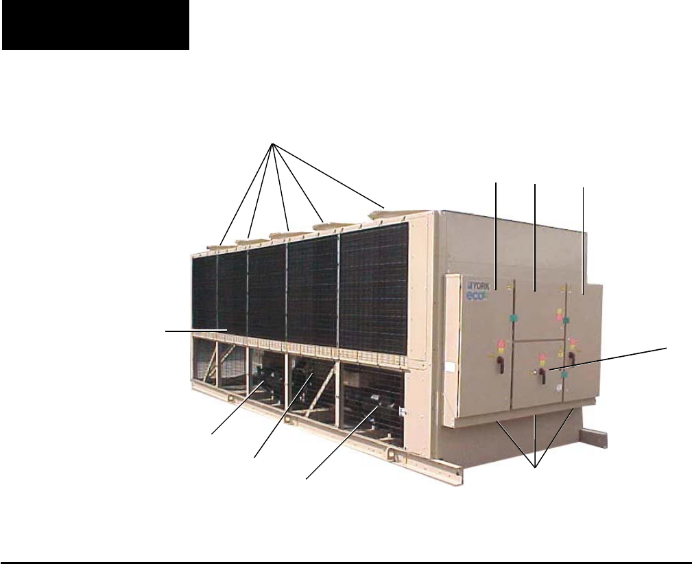
PRODUCT DESCRIPTION
FIG. 1 – COMPONENT LOCATIONS
1 System Fans
2 System 1 Power Panel
3 System 2 Power Panel
4 Control Panel
5 Power Entry
6 System 1 Compressor
7 Evaporator
8 System 2 Compressor
9 System 1 Condenser
10 Option Box
1
028971-G
Product Description
23
10
4
9
8
6
7
5

13
YORK INTERNATIONAL
FORM 201.19-NM1 (204)
Refrigerant gas is drawn into the void created by the
unmeshing of the fi ve lobed male and seven lobed
fe male rotor. Further meshing of the rotors closes
the ro tor threads to the suction port and progressively
com press es the gas in an axial direction to the discharge
port. The gas is compressed in volume and increased
in pressure before exiting at a designed volume at the
dis charge end of the rotor casing. Since the intake and
dis charge cy cles overlap, a resulting smooth fl ow of gas
is maintained.
The rotors are housed in a cast iron compressor hous ing
precision machined to provide optimal clearances for
the rotors. Contact between the male and female rotor
is pri ma ri ly rolling on a contact band on each of the
rotor’s pitch circle. This results in virtually no rotor
wear and in creased reliability, a trademark of the screw
com pres sor.
The compressor incorporates a complete anti-friction
bearing design for reduced power input and increased
reliability. Four separated, cylindrical, roller bearings
handle radial loads. Angular-contact ball bearings
han dle axial loads. Together they maintain accurate rotor
po si tion ing at all pressure ratios, thereby min i miz ing
leak age and maintaining effi ciency. A springless check
valve is installed in the compressor discharge housing
to pre vent compressor rotor backspin due to system
re frig er ant pressure gradients during shut down.
Motor cooling is provided by suction gas from the
evap o ra tor flowing across the motor. Redundant
over load pro tec tion is provided using both thermistor
and cur rent over load protection.
The compressor is lubricated by removing oil from
the refrigerant using an external oil separator. The
pres sur ized oil from the oil separator is then cooled in
the condenser coils and piped back to the compressor for
lubrication. The com pres sor design working pressure is
450 PSIG (31 bar). Each chill er receives a 300 PSIG (21
bar) low side and a 450 PSIG (31 bar) high side factory
test. A 350 watt (115-1-60) cartridge heat er is located
in the com pres sor. The heat er is tem per a ture activated
to prevent re frig er ant condensation.
The following items are also included:
• An acoustically tuned, internal discharge muffl er to
min i mize noise, while maintaining max i mum fl ow
and performance.
• Discharge shutoff valve.
• A rain-tight terminal box.
• A suction gas screen and serviceable, 0.5 - 3.0
micron full fl ow oil fi lter within the compressor
housing.
Evaporator
The system uses a high effi ciency Shell and Tube type
Di rect Ex pan sion Evaporator. Each of the 2 re frig er ant
circuits consists of 4 passes with the chilled liq uid
cir cu lat ing back and forth across the tubes from one
end to the other.
The design working pressure of the standard evaporator
on the shell side is 150 PSIG (10 bar), and 350 PSIG (24
bar) for the tube (refrigerant side). The water baffl es
are fab ri cat ed from galvanized steel to resist corrosion.
Re mov able heads are provided for access to internally
en hanced, seamless, copper tubes. Water vent and drain
con nec tions are included.
The evaporator is equipped with a heater for protection
to -20°F (-29°C) ambient and in su lat ed with 3/4" (19
mm) fl exible closed-cell foam.
The water nozzles are provided with grooves for
me chan i cal couplings and should be insulated by the
con trac tor after pipe installation.
Condenser
The fi n and tube condenser coils are manufactured
from seamless, internally enhanced, high condensing
co ef fi cient, corrosion resistant copper tubes arranged in
FIG. 2 – SCREW COMPRESSOR
00485VIP
2

14 YORK INTERNATIONAL
FORM 201.19-NM1 (204)
stag gered rows and mechanically expanded into cor ro sion
resistant aluminum alloy fi ns with full height fi n col lars.
They have a design working pressure of 450 PSIG
(31 bar). Each coil is rested to 495 PSIG (34 bar).
Multiple fans move air through the coils. They are
dy nam i cal ly and statically balanced, direct drive with
cor ro sion re sis tant glass fi ber reinforced composite
blades mold ed into low noise, full airfoil cross section,
pro vid ing vertical air discharge from extended orifi ces
for ef fi cien cy and low sound. Each fan is located in a
sep a rate com part ment to prevent cross fl ow during fan
cy cling. Guards of heavy gauge, PVC coated galvanized
steel are pro vid ed.
The fan motors are high effi ciency, direct drive, 6-pole,
3-phase, Class- “F,” current overload protected, totally
en closed (TEAO) type with double sealed, per ma nent ly
lubricated ball bearings.
Economizer
Economizer is a refrigerant to refrigerant, compact plate-
type heat exchanger to maximize chiller capacity and
effi ciency by subcooling liquid refrigerant delivered to
the cooler expansion valve. Constructed of corrosion
resistant stainless steel plates formed to induce turbulent
fl ow and enhance heat transfer, then oven brazed and
pressure tested for reliability. Designed and constructed
with ASME and TÜV certifi cation for 31 bar (450 psig).
UL/CSA listed.
Oil Separator/System
The external oil separator, with no moving parts and
de signed for minimum oil carry-over, is mounted in
the dis charge line of the compressor. The high pressure
dis charge gas is forced around a 90 degree bend. Oil is
forced to the outside of the separator through cen trif u gal
action and captured on wire mesh where it drains to the
bottom of the oil separator and fl ows to the condenser
for cooling before returning to the compressor.
The oil (YORK “L” oil – a POE oil used for all re frig -
er ant applications), which fl ows back into the com-
pres sor through a replaceable 0.5 - 3.0 micron oil fi lter,
is at high pressure. This high pres sure “oil injection”
forces the oil into the com pres sor where it is fed to the
bearings for lubrication. After lubricating the bearings,
it is injected through orifi ces on a closed thread near
the suction end of the rotors. The oil is automatically
in ject ed because of the pressure difference between the
discharge pres sure and the reduced pressure at the suc-
tion end of the rotors. This lubricates the rotors as well as
provides an oil seal against leakage around the ro tors to
assure re frig er ant compression (volumetric ef fi cien cy).
The oil also provides cooling by transferring much of
the heat of com pres sion from the gas to the oil keeping
dis charge tem per a tures down and reducing the chance
for oil breakdown. Oil injected into the rotor cage fl ows
into the ro tors at a point about 1.2x suction. This assures
that a required minimum differential of at least 30 PSID
(2.1 bar) exists between discharge and 1.2x suc tion, to
force oil into the rotor case. A minimum of 10 PSID
(0.6 bar) is all that is re quired to assure pro tec tion of
the compressor. Oil pressure safety is mon i tored as the
dif fer ence between suction and the pres sure of the oil
en ter ing the ro tor case.
Maximum working pressure of the oil separator is 450
PSIG (31 bar). Oil level should be above the midpoint
of the “low er” oil sight glass when the compressor is
run ning. Oil level should not be above the top of the
“up per” sight glass.
Oil Cooling
Oil cooling is provided by routing oil from the oil sep a -
ra tor through several of the top rows of the con dens er
coils and back to the compressor.
Capacity Control
The compressors will start at the minimum load po si tion
and provide a capacity control range from 10% - 100%
of the full unit load using a continuous function slide
valve. The microprocessor modulates a voltage signal to
a 3-way pres sure reg u lat ing capacity control valve which
controls com pres sor capacity, in de pen dent of system
pressures, and balances the com pres sor ca pac i ty with
the cool ing load. Loading is ac com plished by varying
pressure through the pressure regulating ca pac i ty control
valve to move the slide valve against the spring pressure
to promote stable smooth loading.
Automatic spring return of the slide valve to the min-
i mum load position will ensure compressor start ing at
min i mum motor load.
Power and Control Panel
All controls and motor starting equipment are factory
wired and function tested. The panel enclosures are
de signed to IP55 and are manufactured from powder
paint ed galvanized steel.
The Power and Control Panel are divided into power
sec tions for each compressor and associated fans, a con-
trol section and an electrical options section. The pow er
and control sections have separate hinged, latched, and
gasket sealed doors equipped with wind struts.
Product Description

15
YORK INTERNATIONAL
FORM 201.19-NM1 (204)
Each power compartment contains:
Compressor and fan starting contactors, fan motor
ex ter nal overloads, control circuit serving compressor
ca pac i ty control, compressor and fan contactor coils and
compressor motor overloads. (Fig #1, page 12)
Current transformers in the 2ACE module provide
compressor motor over load protection and sense each
phase. This protects the compressor motors from
dam age due to: low current input, high input current,
un bal anced current, single phasing, phase reversal, and
com pres sor locked rotor.
The control section contains:
ON/OFF switch, microcomputer keypad and display,
mi cro pro ces sor board, I/O expansion board, relay boards
and power supply board.
The options sections contain:
A control circuit transformer complete with service
switch providing 115/1/60 Hz power to the unit con trol
system.
Electrical options as described in “Accessories and
Options.”
Microprocessor Controls
The microprocessor has the following functions and
displays:
• A liquid crystal 40 character display with text pro-
vid ed on two lines and light emitting diode back-
light ing out door viewing.
• A color coded, 35 button, sealed keypad with sec-
tions for Display, Entry, Setpoints, Clock, Print,
Pro gram and Unit ON/OFF.
The standard controls shall include: brine chilling,
ther mal storage, automatic pump down, run signal
con tacts, demand load limit from external building
automation sys tem input, remote reset liquid temperature
reset in put, unit alarm contacts, chilled liquid pump
control, au to mat ic reset after power failure, automatic
system op ti mi za tion to match operating conditions.
The software is stored in non-volatile memory (EPROM)
to eliminate chiller failure due to AC power failure. The
Programmed Setpoints are stored in lithium battery
backed memory.
Motor Current Protection
The microprocessor motor protection provides high
cur rent protection to assure that the motor is not
damaged due to voltage, excess refrigerant, or other
problems that could cause excessive motor current. This
is ac com plished by sending a current signal pro por tion al
to motor current from the Motor Protector mod ule to the
I/O Expansion board to be multiplexed and sent to the
Microprocessor Board. If the motor cur rent exceeds
the 115% FLA trip point after 3 seconds of op er a tion
on either Wye-Delta or ACL starters, the mi cro will
shut the system down and lock it out after one fault.
A manual reset of the re spec tive system switch is
re quired to clear the fault and restart the system. A
thor ough check of the mo tor, wiring, and refrigerant
system should be done be fore restarting a system that
has fault ed on high motor current.
The micro also provides low motor current protection
when it senses a motor current less than 10% FLA.
The micro will shut the system down whenever low
motor current is sensed and will lock out a system if
three faults occur in 90 minutes. Low motor current
pro tec tion is activated 4 seconds after start on both
Wye-Delta and ACL starters to assure the motor starts,
the sys tem doesn’t run with out refrigerant, the motor
protector is not tripped, and the mechanical high pres sure
cut-out is not tripped. Once the system is locked out
on Low Motor Current, it must be manually reset with
the sys tem switch. See also Motor Protection Module
section below.
The micro senses low motor current whenever a HPCO
or Motor Protector contact opens. This occurs because
the MP and HPCO contacts are in series with the mo tor
contactor. Whenever either of these devices are open,
the contactor de-energizes and the motor shuts down.
Since the micro is sending a run signal to the contactor,
it senses the low motor current below 10% FLA and
shuts the system down.
2

16 YORK INTERNATIONAL
FORM 201.19-NM1 (204)
Motor Protection Modules (2ACE)
The mechanical motor protector is a Texas In stru ments
2ACE Three Phase Protection Module (Fig. 45, page
127), provides thermal and cur rent motor overload pro-
tec tion. This mod ule also pro tects against phase to phase
cur rent im bal ance, over cur rent, under current, and phase
ro ta tion. The mod ules, mount ed in the power pan els,
uti liz es a 7 seg ment display which provides op er at ing
sta tus and fault di ag nos tic in for ma tion. The 7 segment
dis play will dis play ei ther a sta tion ary or a fl ash ing al-
pha nu mer ic value which can be de cod ed by the op er a tor.
A list of the codes follows:
HAXXX Normal motor OFF display. Sequentially
sweeps through the motor protection dip
switch setting.
0 Normal - no fault detected (Running)
Flashing “0” Motor off or un load ed < 5A (Running)
AC current lev el.
1 High cur rent fault.
2 Loaded phase to phase cur rent
imbalance > 17%.
3 Unloaded phase to phase cur rent
imbalance > 25%.
4 Improper in com ing phase ro ta tion.
5 High motor tem per a ture. Trip point =
13kW, re set = 3.25kW.
6 Communication error.
7 Unload imbalance ( > 50%)
8 Phase Loss (> 60%)
E Out of range of RLA cal i bra tion.
Other symbols Defective module or supply volt age.
Working voltage 18 - 30 VAC, 24 VAC nominal.
Low volt age trip = 15 VAC.
Whenever a motor protector trips, the motor pro tec tor
contacts wired in series with the motor contacts opens
and the motor contactor de-energizes causing the mo tor
to stop. The micro senses the low motor current and
shuts the system down. The micro will try two more
starts be fore locking the system out. The system locks
out be cause the motor protector is a man u al re set
de vice. Af ter the fi rst start, the modules’ contacts
will be open pre vent ing the motor contactors from
en er giz ing. Power must be removed and re applied to
re set the mod ule. Use CB3 in the Micro Panel to cycle
power.
Current Overload
The 2ACE module design uses one integral current
trans form er per phase to provide protection against
rap id current over load conditions. The module re sponds
to changes in current and must be cal i brat ed using DIP
switches lo cat ed on the module. Integral trip curves al-
low for in-rush cur rents dur ing Wye-Delta, part wind,
or ACL starts with out nuisance tripping.
To check the factory setting of the 2ACE module cur rent
overload trip value. See Table 1 (pages 18 and 21).
For the location of the dip switches and determining the
ON side of the switches, refer to Fig ure 45, page 127. As
in di cat ed, to place a switch in the ON po si tion re quires
push ing the switch to the left.
A switch must be pushed to the left to
place the switch in the ON position.
The numerical value for the combi-
nation of "ON" switches equals the
overload setting.
It is recommended that a YORK Ser-
vice Tech ni cian or the YORK fac to ry
be con sult ed before chang ing these
settings for any rea son, since dam-
age to the com pres sor could re sult.
Chang es should nev er be made un-
less it is ver i fi ed that the set tings are
in cor rect.
Anytime a dip switch change is made,
pow er must be cycled off and on to the
module to re pro gram the mod ule to the
new value.
Product Description

17
YORK INTERNATIONAL
FORM 201.19-NM1 (204)
Thermal Overload
Three PTC (positive temperature co ef fi cient) ther mistors
in the motor windings provides thermal pro tec tion. The
sensor re sis tance stays rel a tive ly con stant at 1kΩ until
a tem per a ture of 266°F (130°C) is sensed. The sensor
ex pe ri enc es a rapid rise in re sis tance be yond this tem-
per a ture. When ev er the re sis tance of one of the sen sors
reach es 13kΩ, +/− 3kΩ, the 2ACE module trips, which
ul ti mate ly de-energizes the mo tor’s pi lot cir cuit. Re set
is manual after the mo tor cools and the sen sor re sis tance
drops to 3.25kΩ, +/− 0.5kΩ.
Current Imbalance (Loaded & Unloaded)/
Loss of Phase
A 2 second delay at start-up allows for any imbalances
resulting during normal starting conditions. After this
ini tial delay, the 2ACE module compares the “Op er -
at ing Current” to the measured half line current. The
“Op er at ing Current” is given by 0.65 X factory overload
cur rent setting.
An unloaded compressor condition occurs when any
measured half line current is less than the “Operating
Current.” A current imbalance exceeding an unloaded
level of 25% will result in the motor pilot circuit being
de-energized.
A loaded compressor condition occurs when any mea-
sured half line current is great er than or equal to the
“Operating Current.” A cur rent imbalance exceeding a
loaded level of 17% will result in the motor pilot cir cuit
being de-energized.
Imbalance is defi ned as
(High Phase - Low Phase)/High Phase
Improper Phase Sequence
The 2ACE module calculates the phase sequence at
start-up using the three cur rent transformers to de-
ter mine wheth er the three phase sequence on the load
side of the main contactor is miswired. Upon de tec tion
of a miswired motor load, the mod ule will de-energize
the main contactor pi lot circuit within 50 millisecond
re sponse time.
Additional information on the 2ACE MP module may
be found on page 125. 2

18 YORK INTERNATIONAL
FORM 201.19-NM1 (204)
TABLE 1 – MOTOR PROTECTOR DIP SWITCH SETTING
* Indicates one lead/phase through motor protector.
YCAS STYLE G, ACROSS-THE-LINE – 60 HZ
MODEL
VOLT
CHILLER
NO. MO TOR PROTECTOR
NO.
CODE
NAMEPLATE
LEADS
RLA
PER MP
PHASE DISPLAY DIP SWITCH SETTINGS ON MP (“1” INDICATES ON)
HA XXX 128 64 32 16 8 4 2 1
17 246 *2 166 1 0 1 0 0 1 1 0
28 214 2 144 1 0 0 1 0 0 0 0
130 40 130 2 175 1 0 1 0 1 1 1 1
46 107 1 144 1 0 0 1 0 0 0 0
58 86 1 116 0 1 1 1 0 1 0 0
17 267 *4 90 0 1 0 1 1 0 1 0
28 232 *2 157 1 0 0 1 1 1 0 1
140 40 140 2 189 1 0 1 1 1 1 0 1
46 116 1 157 1 0 0 1 1 1 0 1
58 93 1 125 0 1 1 1 1 1 1 0
17 295 *4 99 0 1 1 0 0 0 1 1
0150 28 256 *4 86 0 1 0 1 0 1 1 0
SYS. 1 40 155 2 209 1 1 0 1 0 0 0 1
46 128 2 173 1 0 1 0 1 1 0 1
58 103 1 139 1 0 0 0 1 0 1 1
17 265 *4 89 0 1 0 1 1 0 0 1
0150 28 230 *2 155 1 0 0 1 1 0 1 1
SYS. 2 40 139 2 188 1 0 1 1 1 1 0 0
46 115 1 155 1 0 0 1 1 0 1 1
58 92 1 124 0 1 1 1 1 1 0 0
17 295 *4 99 0 1 1 0 0 0 1 1
28 256 *4 86 0 1 0 1 0 1 1 1
0160 40 155 2 209 1 1 0 1 0 0 0 1
46 128 2 173 1 0 1 0 1 1 0 1
58 103 1 139 1 0 0 0 1 0 1 1
17 321 *4 108 0 1 1 0 1 1 0 0
0170 28 279 *4 94 0 1 0 1 1 1 1 0
SYS. 1 40 169 *2 114 0 1 1 1 0 0 1 0
46 140 2 189 1 0 1 1 1 1 0 1
58 112 1 151 1 0 0 1 0 1 1 1
17 295 *4 99 0 1 1 0 0 0 1 1
0170 28 256 *4 86 0 1 0 1 0 1 1 1
SYS. 2 40 155 2 209 1 1 0 1 0 0 0 1
46 128 2 173 1 0 1 0 1 1 0 1
58 103 1 139 1 0 0 0 1 0 1 1
Product Description
19
YORK INTERNATIONAL
FORM 201.19-NM1 (204)
TABLE 1 – MOTOR PROTECTOR DIP SWITCH SETTING (CONT’D)
* Indicates one lead/phase through motor protector
2
YCAS STYLE G, ACROSS-THE-LINE – 60 HZ
MODEL
VOLT
CHILLER
NO. MO TOR PROTECTOR
NO.
CODE
NAMEPLATE
LEADS
RLA
PER MP
PHASE DISPLAY DIP SWITCH SETTINGS ON MP (“1” INDICATES ON)
HA XXX 128 64 32 16 8 4 2 1
17 321 *4 108 0 1 1 0 1 1 0 0
28 279 *4 94 0 1 0 1 1 1 1 0
180 40 169 *2 114 0 1 1 1 0 0 1 0
46 140 2 189 1 0 1 1 1 1 0 1
58 112 1 151 1 0 0 1 0 1 1 1
17 342 *4 115 0 1 1 1 0 1 0 0
28 298 *4 101 0 1 1 0 0 1 0 1
200 40 181 *2 122 0 1 1 1 1 1 1 0
46 149 2 201 1 1 0 0 1 0 0 1
58 119 1 161 1 0 1 0 0 0 0 1
17 374 *4 126 0 1 1 1 1 1 1 0
210 28 325 *4 110 0 1 1 0 1 1 1 0
SYS. 1 40 197 *2 133 1 0 0 0 0 1 0 1
46 163 *2 110 0 1 1 0 1 1 1 0
58 130 2 175 1 0 1 0 1 1 1 1
17 342 *4 115 0 1 1 1 0 1 0 0
210 28 298 *4 101 0 1 1 0 0 1 0 1
SYS. 2 40 181 *2 122 0 1 1 1 1 1 1 0
46 149 2 201 1 1 0 0 1 0 0 1
58 119 1 161 1 0 1 0 0 0 0 1
17 374 *4 126 0 1 1 1 1 1 1 0
28 325 *4 110 0 1 1 0 1 1 1 0
230 40 197 *2 133 1 0 0 0 0 1 0 1
46 163 *2 110 0 1 1 0 1 1 1 0
58 130 2 175 1 0 1 0 1 1 1 1

20 YORK INTERNATIONAL
FORM 201.19-NM1 (204)
TABLE 1 – MOTOR PROTECTOR DIP SWITCH SETTING (CONT’D)
* Indicates one lead/phase through motor protector.
YCAS STYLE G, WYE DELTA START – 60 HZ
MODEL
VOLT
CHILLER
NO. MO TOR PROTECTOR
NO.
CODE
NAMEPLATE
LEADS
RLA
PER MP
PHASE DISPLAY DIP SWITCH SETTINGS ON MP (“1” INDICATES ON)
HA XXX 128 64 32 16 8 4 2 1
17 246 *4 96 0 1 1 0 0 0 0 0
28 214 *2 167 1 0 1 0 0 1 1 1
130 40 130 2 175 1 0 1 0 1 1 1 1
46 107 2 144 1 0 0 1 0 0 0 0
58 86 2 116 0 1 1 1 0 1 0 0
17 267 *4 105 0 1 1 0 1 0 0 1
28 232 *4 91 0 1 0 1 1 0 1 1
140 40 140 2 189 1 0 1 1 1 1 0 1
46 116 2 157 1 0 0 1 1 1 0 1
58 93 2 126 0 1 1 1 1 1 1 0
17 295 *4 115 0 1 1 1 0 0 1 1
0150 28 256 *4 100 0 1 1 0 0 1 0 0
SYS. 1 40 155 2 209 1 1 0 1 0 0 0 1
46 128 2 173 1 0 1 0 1 1 0 1
58 103 2 139 1 0 0 0 1 0 1 1
17 265 *4 104 0 1 1 0 1 0 0 0
0150 28 230 *4 90 1 1 0 1 1 0 1 0
SYS. 2 40 139 2 188 1 0 1 1 1 1 0 0
46 115 2 155 1 0 0 1 1 0 1 1
58 92 2 124 0 1 1 1 1 1 0 0
17 295 *4 115 0 1 1 1 0 0 1 1
28 256 *4 100 0 1 1 0 0 1 0 0
0160 40 155 2 209 1 1 0 1 0 0 0 1
46 128 2 173 1 0 1 0 1 1 0 1
58 103 2 139 1 0 0 0 1 0 1 1
17 321 *4 126 0 1 1 1 1 1 1 0
0170 28 279 *4 109 0 1 1 0 1 1 0 1
SYS. 1 40 169 *2 132 1 0 0 0 0 1 0 0
46 140 2 189 1 0 1 1 1 1 0 1
58 112 2 151 1 0 0 1 0 1 1 1
17 295 *4 115 0 1 1 1 0 0 1 1
0170 28 256 *4 100 0 1 1 0 0 1 0 0
SYS. 2 40 155 2 209 1 1 0 1 0 0 0 1
46 128 2 173 1 0 1 0 1 1 0 1
58 103 2 139 1 0 0 0 1 0 1 1
Product Description
21
YORK INTERNATIONAL
FORM 201.19-NM1 (204)
TABLE 1 – MOTOR PROTECTOR DIP SWITCH SETTING (CONT’D)
YCAS STYLE G, WYE DELTA START – 60 HZ
MODEL
VOLT
CHILLER
NO. MO TOR PROTECTOR
NO.
CODE
NAMEPLATE
LEADS
RLA
PER MP
PHASE DISPLAY DIP SWITCH SETTINGS ON MP (“1” INDICATES ON)
HA XXX 128 64 32 16 8 4 2 1
17 321 *4 126 1 0 0 0 0 0 1 0
28 279 *4 109 0 1 1 0 1 1 0 1
180 40 169 *2 132 1 0 0 0 0 1 0 0
46 140 2 189 1 0 1 1 1 1 0 1
58 112 2 151 1 0 0 1 0 1 1 1
17 342 *4 134 1 0 0 0 0 1 1 0
28 298 *4 117 0 1 1 1 0 1 0 1
200 40 181 *2 142 1 0 0 0 1 1 1 0
46 149 2 201 1 1 0 0 1 0 0 1
58 119 2 161 1 0 1 0 0 0 0 1
17 374 *4 146 1 0 0 1 0 0 1 0
210 28 325 *4 127 0 1 1 1 1 1 1 1
SYS. 1 40 197 *2 154 1 0 0 1 1 0 1 0
46 163 *2 128 1 0 0 0 0 0 0 0
58 130 2 175 1 0 1 0 1 1 1 1
17 342 *4 134 1 0 0 0 0 1 1 0
210 28 298 *4 117 0 1 1 1 0 1 0 1
SYS. 2 40 181 *2 142 1 0 0 0 1 1 1 0
46 149 2 201 1 1 0 0 1 0 0 1
58 119 2 161 1 0 1 0 0 0 0 1
17 374 *4 146 1 0 0 1 0 0 1 0
28 325 *4 127 0 1 1 1 1 1 1 1
230 40 197 *2 154 1 0 0 1 1 0 1 0
46 163 *2 128 1 0 0 0 0 0 0 0
58 130 2 175 1 0 1 0 1 1 1 1
* Indicates one lead/phase through motor protector.
2

22 YORK INTERNATIONAL
FORM 201.19-NM1 (204)
MOTOR STARTING
Two types of compressor motor starting are available:
Across-the-Line and optional Wye-Delta Open Tran-
si tion Start er.
Across-the-Line starters will utilize one contactor and
one start relay per compressor. The optional Wye-Delta
start er utilizes 4 motor contactors, a transition delay
re lay, a start relay, and a start-wye relay.
The Wye-Delta start allows inrush current to be limited
to approximately 33% LRA for the fi rst 4 to 7 sec onds,
with current increasing to normal running cur rent when
the Delta connection is completed.
When the micro initiates a start signal at Relay Output
Board #1 (SYS 1) Terminal 20 or Relay Output Board
#2 (SYS 2) Ter mi nal 20 to run a com pres sor, the 1CR
(SYS 1) or 2CR (SYS 2) relay is en er gized. The tran-
si tion of the 1CR (SYS 1) or 2CR (SYS 2) relay contacts
en er giz es the 1S (SYS 1) or 2S (SYS 2) relay approx.
16ms later. The 1S/2S con tacts in turn en er gize the 1M
(SYS 1) or 3M (SYS 2) mo tor con tacts 16ms later. This
com pletes the “WYE” con nec tion of the motor start.
At the same time, the normally closed 1S/2S auxiliary
in ter lock con tact opens pre vent ing the 2M and 1 TRX
(SYS 1) or 4M and 2 TRX (SYS 2) mo tor contactors
from en er giz ing. 2 sets of aux il ia ry con tacts from 1M
(SYS 1) or 3M (SYS 2) close, in ter lock ing the 1M (SYS
1) or 3M (SYS 2) contactors, keep ing them en er gized
in par al lel with 1S (SYS 1) or 2S (SYS 2).
The “WYE” connection of the motor start is enabled
for 4 to 7 seconds depending upon motor current as
sensed by the microprocessor. The tran si tion to Delta
takes 7 seconds if current is below 110% FLA. If mo-
tor current exceeds 110% FLA, the transition is made
to Delta as long as the WYE has been enabled for at
least 4 seconds.
After the “WYE” connection is enabled for 4 to 7
sec onds, the 1TR (SYS 1) or 2TR (SYS 2) transition
delay relay is enabled by the microprocessor from Relay
Out put Board #1 Terminal 8 (SYS 1) or Relay Out put
Board #2 Terminal 6 (SYS 2). The 1TR (SYS 1) or 2TR
(SYS 2) contacts open, de-energizing 1S (SYS 1) or 2S
(SYS 2). 1M (SYS 1) or 3M (SYS 2) remain energizes
through 2 sets of interlocking con tacts 1M (SYS 1) or
3M (SYS 2). Open ing of the 1TR (SYS 1) or 2TR (SYS
2) con tacts deenergizes 1S/2S and clos es the nor mal ly
closed 1S (SYS 1) or 2S (SYS 2) con tacts, en er giz ing
1 TR, 1 TRX, 2 TR, and 2 TRX are
NOT “tim ing” re lays. These devices
are sim ply pilot relays iden ti cal to
1CR and 2CR.
KEYPAD CONTROLS
Display
Parameters are displayed in English (°F and PSIG) or
Metric (°C and Bars) units, and for each circuit, the
following items can be displayed:
• Return and leaving chilled liquid, and ambient tem-
per a ture.
• Day, date and time. Daily start/stop times. Holiday
and Manual Override status.
• Compressor operating hours and starts. Automatic or
manual lead/lag. Lead compressor iden ti fi ca tion.
• Run permissive status. No cooling load condition.
Com pres sor run status.
• Anti-recycle timer and anti-coincident start timer
sta tus per compressor.
• System suction (and suction superheat), discharge,
and oil pressures and temperatures.
• Percent full load compressor motor current per phase
and average per phase. Compressor ca pac i ty con trol
valve input steps.
• Cutout status and setpoints for: supply fl uid tem-
per a ture, low suction pressure, high discharge pres-
sure and temperature, high oil temperature, low and
high am bi ent, phase rotation safety, and low leav ing
liq uid tem per a ture.
• Unloading limit setpoints for high discharge pres-
sure and compressor motor current.
• Status of: evaporator heater, condenser fans, load
and unload timers, chilled water pump.
• “Out of range” message.
• Up to 6 fault shut down conditions.
The standard display language is English, with 4 other
languages available.
1 TRX (SYS 1) or 2 TRX (SYS 2). 1TRX or 2TRX
subsequently energizes motor contactor 2M (SYS 1) or
4M (SYS 2), com plet ing the “DELTA” con nec tion of
the motor.
Product Description

23
YORK INTERNATIONAL
FORM 201.19-NM1 (204)
Single-Point Power Connection with Combined
Cir cuit Protection
A single-point supply circuit with field provided
pro tec tion is connected to a factory provided circuit
break er with lockable external handle located in the
options com part ment. Factory wiring is provided from
the cir cuit breaker to factory supplied terminal blocks
in the power compartments.
Single-Point Power Connection without Circuit
Protection
A single-point supply circuit with fi eld provided pro-
tec tion is connected to a factory provided terminal block
or non-fused disconnect switch located in the options
com part ment. Factory wiring is provided from the ter-
mi nal block or disconnect switch to factory supplied
terminal blocks in the power compartments.
Control Circuit Terminal Block
A 120V, 20A control circuit power terminal strip lo cat ed
in the control panel to accept a fi eld provided control
power supply, rather than the standard factory mounted
control circuit transformer. The supply with appropriate
branch circuit protection in accordance with applicable
Local codes, provides the unit control cir cuit power sup-
ply via the panel mounted Emergency Stop Switch.
Building Automation System (BAS) Interface
Provides a means to reset the leaving chilled liquid tem-
per a ture or percent full load amps (current limiting) from
the BAS (Factory-mounted):
Printed circuit board to accept 4 to 20mA, 0 to 10VDC,
or dry contact closure input from the BAS.
A YORK ISN Building Automation System can pro-
vide a Pulse Width Modulated (PWM) signal direct to
the standard control panel via the standard on-board
RS485 port.
Condenser Coil Protection
The standard condenser coils have Aluminum fi ns, cop-
per tubes, and galvanized steel supports for generally
adequate corrosion resistance. However, these ma te ri als
are not adequate for all environments.
Entry – Used to confi rm Set Point changes, cancel
in puts, advance day, and change AM/PM.
Setpoints – For setting chilled liquid temperature,
chilled liquid range, remote reset temperature range.
Clock – Used to set time, daily or holiday start/stop
schedule and manual override for servicing.
Print – Used to display or print operating data or sys-
tem fault shutdown history for last six faults. Printouts
through an RS-232 port via a separate print er.
Program
For setting low leaving liquid temperature cutout, 300
to 600 second anti-recycle timer, average motor cur rent
unload point, liquid temperature setpoint reset sig nal
from YORK ISN or building automation system.
Additional functions (password protected) for pro-
gram ming by a qualifi ed service technician:
Cutouts for low and high ambient, low suction pres-
sure and high discharge pressure, refrigerant type, high
dis charge pressure unload setpoint.
ACCESSORIES AND OPTIONS
Multiple Point Power Connection (Standard)
Standard fi eld power wiring connection on all models
is Multiple Point Power Connection. Field provided
pow er supply circuits, with appropriate branch circuit
pro tec tion, are connected to factory provided terminal
blocks, non-fused disconnect switches or circuit break ers
with lockable external handles located in the two power
com part ments.
Single-Point Power Connection with Individual
Circuit Protection
A single-point supply circuit with fi eld provided pro-
tec tion is connected to a factory provided terminal block
or non-fused disconnect switch located in the options
com part ment. Factory wiring is provided from the ter-
mi nal block or disconnect switch to factory supplied
internal branch circuit breakers with lockable external
handles in the power compartments.
2

24 YORK INTERNATIONAL
FORM 201.19-NM1 (204)
The following options provide added protection:
Black fi n condenser coils – Condenser coils con struct ed
using black epoxy coated Aluminum fi n stock for cor-
ro sion resistance comparable to copper fin coils in
typ i cal seashore locations.
Copper fi n condenser coils – Coils constructed with
corrosion resistant copper fi ns. Not recommended in
areas where units may be exposed to acid rain.
Phenolic coated condenser coils – Completed con-
dens er coil assemblies are covered with a cured Phe nol ic
coating. Probably the most suitable selection for sea-
shore locations where salt spray may come into con tact
with the fi ns, and other corrosive applications ex cept:
strong alkalis, oxidizers, and wet bromine, chlo rine, and
fl uorine in concentrations greater than 100 PPM.
DX EVAPORATOR AND STARTER OPTIONS
300 PSIG (21 bar) Waterside Design Working
Pressure – The DX evaporator waterside is designed
and con struct ed for 300 PSIG (21 bar) working pressure.
(Factory-mounted)
1-1/2" (38 mm) Insulation – Double thickness in su -
la tion provided for enhanced effi ciency.
Flange Accessory – Consists of raised face fl anges to
convert grooved water nozzles to fl anged evaporator
connections. Includes companion flanges for field-
mount ing. (See Page 33.)
Remote DX Evaporator – Includes the main con-
dens ing unit less the evaporator, re frig er ant and liquid
line de vic es. The insulated evaporator and fi eld acces-
sory kits per re frig er ant circuit are sup plied separately.
The condensing unit is shipped with a nitrogen holding
charge and the evaporator is shipped with a ni tro gen
hold ing charge.
Flow Switch Accessory – Johnson Controls model
F61MG-1C Vapor-proof SPDT, NEMA 4X switch, 150
PSIG (10 bar) DWP, -20°F to 250°F (-29°C to 121°C),
with 1" NPT (IPS) con nec tion for upright mounting in
horizontal pipe. A fl ow switch must be fi eld installed
with each unit. Optional 300 PSIG switch available.
Star-Delta Compressor Motor Starter – Provides ap-
proximately 65% reduced inrush current compared to
across-the-line start (Factory-mounted).
UNIT ENCLOSURES OPTIONS
Wire enclosure – Heavy gauge welded wire mesh
guards mounted on the exterior of the unit (Factory- or
fi eld-mounted).
Louvered panels and wired guards – Louvered pan-
els mounted over the exterior condenser coil faces, and
heavy gauge welded wire mesh guards mounted around
the bottom of the unit (Factory- or fi eld-mounted).
Louvered panels (condenser coils only) – Lou vered
panels are mounted over the exterior condenser coil faces
on the sides of the unit to visually screen and pro tect the
coils (Factory- or fi eld-mounted).
Louvered panels (full unit) enclosure – Louvered
panels over condenser coils and around the bottom of
the unit (Factory- or fi eld-mounted).
FAN OPTIONS
High static fans: Fans and motors suitable for High
External Static conditions to 100 Pa.
SOUND REDUCTION OPTIONS
Low speed fans – Reduced RPM fan motors and al ter -
na tive fan selection for low noise applications.
Compressor sound enclosures – Acoustically
treated metal compressor enclosures.
VIBRATION ISOLATION
Neoprene pad isolation – Recommended for normal
installations. (Field-mounted)
1" (25 mm) spring isolators – Level adjustable, spring
and cage type isolators for mounting under the unit base
rails (Field-mounted).
2" (51 mm) seismic spring isolators – Restrained
Spring-Flex Mountings incorporate welded steel hous-
ing with vertical and horizontal limit stops. Housings de-
signed to withstand a minimum 1.0 g accelerated force in
all directions to 2" (51 mm). Level ad just able, de fl ec tion
may vary slightly by application. (Field- mount ed).
Product Description
25
YORK INTERNATIONAL
FORM 201.19-NM1 (204)
UNIT NOMENCLATURE
NAMEPLATE ENGINEERING DATA
2
OPTIONS MODEL NUMBER
MP = Multiple Point
SP = Single-Point
NF = Non-Fused
TB = Terminal Block
Ser. = Service
TS = Thermal Storage
Ind. Sys. Brkr. & L. Ext. Handles = Individual
System Breaker & Lockable External Handle
: Standard Power Option
: MP NF Disconnects
: MP Circuit Breakers
: SP NF Disconnects
: SP TB
: SP Circuit Breaker
: SP TB w/ Separate System Circuit Breakers
: SP NF Disconnect w/ Separate System Circuit Breakers
: SP Supply w/ Separate Disconnect Switch
: SP w/ Separate Disconnect Switch
: Special Power Option
: Control Circuit Power Terminal Strip (std)
: Special Transformer Required
: No Option Required
: Special Quote
: Leaving Water Temp = Degrees
: Thermal Storage
: Special LWT Requirements
: No Chicago Code Kit Required
: Chicago Code Kit Required
: Service Isolation Valve
: Both Isolation Valve and Chicago Code
: Special Chicago Code Kit Required
: Standard Valves Required
: Special Optional Valves Required
: No Option Required
: Special Quote
: No Option Required
: Special Quote
: No Option Required
: Special Quote
: No Option Required
: Special Quote
: No Option Required
: Special Quote
: No Option Required
: Special Quote
: No BAS Reset / Offset Required
: Temp Reset / Offset
: Current Reset / Offset
: Both Temp and Current Reset / Offset
: Special BAS Reset / Offset Required
: English LCD & Keypad Display (std)
: Spanish LCD & Keypad Display
: French LCD & Keypad Display
: German LCD & Keypad Display
: Italian LCD & Keypad Display
: Special LCD & Keypad Display
: No Option Required
: Special Quote
: N. American Safety Code
: European Safety Code
: No Listing
: Special Safety Code
: No Option Required
: Special Quote
: No Pump Control Required
: Pump Control Required
: Special Pump Control Required
: No Remote Control Panel Required
: Optiview Remote Control Panel Required
: Special Remote Control Panel Required
: No Sequence Kit Required
: Sequence Kit Required
: Special Sequence Kit Required
16 17 18 19 20 21 22 23 24 25 26 27 28 29 30 31 32 33 34 35 36 37
POWER FIELD CONTROLS FIELD COMPRESSOR / PIPING FIELD
X X X NUM
M D Q TS
M B QQ
S D X X
S X T C
B X C S
S B B B
D B Q Q
C S X
C S X Q
Q Q S X
F Q
C G X
Q I Q
T : Control Transformer Required Q X
X Q
Q X X
Q Q
X
L Q
C
N
Q
X
Q
X
P
Q
X
O
Q
X
S
Q
YCAS0230EC46YGA
: YORK
: Chiller
: Air-Cooled
: Screw
High-Effi ciency
Standard
High Ambient
BASIC PART NUMBER
1 2 3 4 5 6 7 8 9 10 11 12 13 14 15
BASE PRODUCT TYPE NOMINAL CAPACITY UNIT DESIGNATOR REFRIGERANT VOLTAGE/STARTER DESIGN/DEVELOPMENT LEVEL (STYLE)
Y # # # # E B 1 7 G
C S C 2 8 A
A G 4 0
S 4 6
5 0
5 8 Y
X
Tons : 200/3/60
: 230/3/60
: 380/3/60
: 460/3/60
: 380/3/50
: 575/3/60
: Wye (Star) Delta
: Across-the-Line
: R-407C : Design Series G
: Engineering
Change
or PIN Level
0373
0403
0453
0503
0543
0573
0623
0653
0130
0140
0150
0160
0170
0180
0200
0210
0230
: R-22
26 YORK INTERNATIONAL
FORM 201.19-NM1 (204)
Product Description
PRODUCT IDENTIFICATION NUMBER (PIN)
EXAMPLES:
16 17 18 19 20 21 22 23 24 25 26 27 28 29 30 31 32 33 34 35 36 37 38 39 40 41 42 43 44 45 46 47 48 49 50 51 52 53 54 55
X X X X X X X X L X X X X X X X X X X X X X X X X X A X X X X X X X X X X X X X
S D T C A T S R L X P R S 2 5 C X 1 X X X X 3 D W S A R X B X X 4 B X X L X S D
55
WARRANTY FIELD
X
B
C
D
E
F
G
H
: Standard Warranty
: 1st Year Parts & Labor
: 2nd Year Parts Only
: 2nd Year Parts & Labor
: 5 Year Compressor Parts Only
: 5 Year Compressor Parts & Labor Only
: 5 Year Units Parts Only
: 5 Year Unit Parts & Labor
NOTES:
1. Q :DENOTES SPECIAL / S.Q.
2. # :DENOTES STANDARD
3. X :w/in OPTIONS FIELD, DENOTES NO OPTION SELECTED
4. Agency Files (i.e. U.L. / E.T.L.; CE; ARI; ETC.) will contain info. based on the fi rst 14 characters only.
: Aluminum
: Pre-Coated
: Copper
: Post-Coated
: Special Coil
: No Option
: Special Quote
: TEAO Fan Motors
EVAP. FIELD CONDENSER FIELD CABINET FIELD
: No Enclosure Panels Required
: Wire Panels (Factory)
: Wire Panels (Field)
: Wire / Louvered Panels (Factory)
: Wire / Louvered Panels (Field)
: Louvered (Cond. Only) Panels (Factory)
: Louvered (Cond. Only) Panels (Field)
: Louvered (Full Unit) Panels (Factory)
: Louvered (Full Unit) Panels (Field)
: Special Enclosure Panels
: No Sound Enclosure Required
: Acoustical Arrgt. & Silencerb Kit
: Compressor Blanket
: Special Sound Enclosure
: Dual Sound Attenuation
: No Option Required
: Special Quote
: No Option Required
: Special Quote
: Standard Sound Fans
: Low Sound Fans
: High Static Fans
: Special Sound Fans
: No Final Overspray Paint Required
: Final Overspray Paint
: Special Overspray Paint Required
: No Vibration Isolators
: 1" Vibration Isolators
: Seismic Vibration Isolators
: Neoprene Vibration Isolators
: Special Vibration Isolators
: 150PSIG DWP
: 300PSIG DWP
: Special DWP
: 3/4" Evaporator Insulation
: 1 1/2" Evaporator Insulation
: Special Evaporator Insulation
: No Flanges Required
: Weld Flanges Required
: Vitaulic Flanges Required
: Special Flanges Required
: No Flow Switch
: Flow Switch
: Differential Pressure Switch
: Special Flow Switch
: Multinational Pressure Vessel Codes
: ASME Pressure Vessel Codes
: Australian Pressure Vessel Codes
: French Pressure Vessel Codes
: German Pressure Vessel Codes
: Italian Pressure Vessel Codes
: Polish Pressure Vessel Codes
: Sweden SAQ Pressure Codes
: Austian TUV Pressure Vessel Codes
: European "CE" Pressure Vessel Directive
: Dutch Pressure Pressure Vessel Codes
: Special Pressure Vessel Codes
: Standard Evaporator
: Remote Evaporator
: Special Evaporator Requirements
: No Option Required
: Special Quote
38 39 40 41 42 43 44 45 46 47 48 49 50 51 52 53 54
X X X
3 B 1
Q C 2
X P 3
D Q 4
Q X 5
X Q 6
W X 7
V Q : Special Fan Motors 8
Q Q
X X
S P
D B
Q Q
M D
X
A Q
S X
F Q
T X
I L
P H
D Q
O X
E S
U Q
Q X
X 1
R S
Q N
X Q
Q
56 57 58 59 60 61
X
1
2
5
X
A
B
C
Q
X
Q
X
Q
X
Q
B
R
: No Refrigerant Warranty
: 1 Year Refrigerant
: 2 Year Refrigerant
: 5 Year Refrigerant
: No option required
: Buy American Act
: Both Buy American Act
: Container Shipping Kit
: Special quote
: No option required
: Special quote
: No option required
: Special quote
: No option required
: Special quote
: Basildon Plant
: Monterrey Plant

27
YORK INTERNATIONAL
FORM 201.19-NM1 (204)
HANDLING AND STORAGE
DELIVERY AND STORAGE
To ensure consistent quality and maximum reliability, all
units are tested and inspected before leaving the fac to ry.
Standard units are shipped completely assembled and
con tain ing refrigerant under pressure. Units are shipped
with out export crating unless this has been specifi ed on
the Sales Order.
Units with remote evaporators will have the chiller and
remote evaporator charged with nitrogen.
If the unit is to be put into storage, prior to installation,
the following precautions should be observed:
• Unit must be “blocked” so that the base is not
per mit ted to sag or bow.
• Ensure that all openings, such as water con nec tions,
are securely capped.
• Do not store where exposed to ambient air tem per a-
tures exceeding 110°F (43°C).
• The condensers should be covered to protect the fi ns
from potential damage and corrosion, par tic u lar ly
where building work is in progress.
• The unit should be stored in a location where there
is minimal activity in order to limit the risk of ac-
ci den tal physical damage.
• To prevent inadvertent operation of the pressure
relief devices the unit must not be steam cleaned.
• It is recommended that the unit is periodically in-
spect ed during storage.
INSPECTION
Remove any transit packing and inspect the unit to en-
sure that all components have been delivered and that
no damage has occurred during transit. If any dam age
is evident, it should be noted on the carrier's freight bill
and a claim entered in accordance with the in struc tions
giv en on the advice note.
Major damage must be reported immediately to your
lo cal YORK representative.
MOVING THE CHILLER
Prior to moving the unit, ensure that the installation
site is suitable for installing the unit and is capable of
sup port ing the weight of the unit and all associated
ser vic es.
The units are designed to be lifted using ca bles. A
spread er bar or frame 88" (2250 mm) wide should be
used in order to prevent damage to the unit from the
lifting chains (See Figures 3 and 4).
Units are provided with lifting eyes extending from the
sides of the base frame which can be attached to di rect ly
using shackles or safety hooks (See Figure 4).
The unit must only be lift ed by the base frame at the
points provided. Nev er move the unit on roll ers, or
lift the unit using a forklift truck.
Care should be taken to avoid damaging the con dens er
cooling fi ns when moving the unit.
Lifting Weights
For details of weights and weight distribution refer to
the Technical Data Section.
3
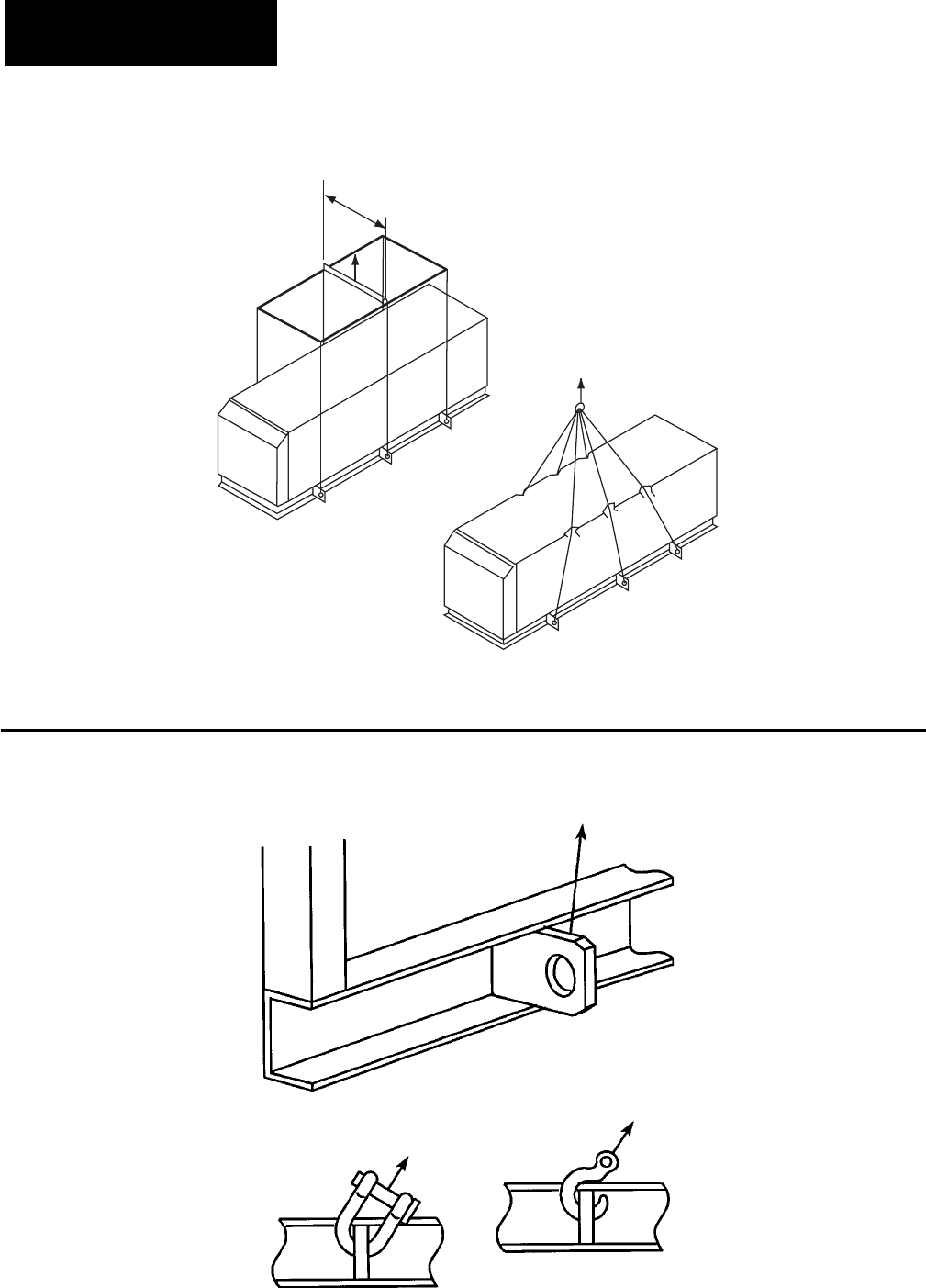
28 YORK INTERNATIONAL
FORM 201.19-NM1 (204)
88" (2250mm)
UNIT RIGGING
CORRECT!
WRONG!
LD03514
FIG. 3 – UNIT RIGGING
CORRECT!
WRONG!
LD03515
FIG. 4 – LIFTING LUGS
CORRECT!
WRONG!
✓
✗
Handling and Storage

29
YORK INTERNATIONAL
FORM 201.19-NM1 (204)
INSTALLATION
LOCATION REQUIREMENTS
To achieve optimum performance and trouble-free
ser vice, it is essential that the proposed installation
site meets with the location and space requirements
for the model being installed. For dimensions, weight
and space requirements, including service access, refer
to the Technical Data Section.
It is important to ensure that the minimum service ac-
cess space is maintained for cleaning and main te nance
purposes.
OUTDOOR INSTALLATIONS
The units can be installed at ground level, or on a
suitable rooftop location. In both cases an adequate
sup ply of air is required. Avoid locations where the
sound out put and air discharge from the unit may be
ob jec tion able.
The location should be selected for minimum sun ex-
po sure and away from boiler fl ues and other sources of
airborne chemicals that could attack the condenser coils
and steel parts of the unit.
If located in an area which is accessible to un au tho rized
persons, steps must be taken to prevent access to the
unit by means of a protective fence. This will help to
prevent the possibility of vandalism, accidental dam age,
or possible harm caused by unauthorized re mov al of
pro tec tive guards or opening panels to expose ro tat ing
or high voltage components.
For ground level locations, the unit must be installed
on a suitable fl at and level concrete base that extends
to fully support the two side channels of the unit base
frame. A one-piece concrete slab, with footings ex-
tend ing be low the frost line is recommended. To avoid
noise and vibration transmission the unit should not be
se cured to the building foundation.
On rooftop locations, choose a place with adequate
struc tur al strength to safely support the entire op er at ing
weight of the unit and service personnel. The unit can
be mount ed on a concrete slab, similar to ground fl oor
locations, or on steel channels of suitable strength. The
channels should be spaced at the same centres as the
vibration mounting holes in the unit base frame and
must be at least 4-3/4" (120 mm) wide at the con tact
points. This will allow vibration isolators to be fi tted
if required.
Any ductwork or attenuators fi tted to the unit must
not have a total static pressure resistance, at full unit
air fl ow, exceeding the capability of the fans installed
in the unit.
INDOOR INSTALLATIONS
The unit can be installed in an enclosed plant room
pro vid ing the fl oor is level and of suitable strength
to sup port the full operating weight of the unit. It is
es sen tial that there is adequate clearance for airfl ow
to the unit. The discharge air from the top of the unit
must be duct ed away to prevent recirculation of air
within the plant room. If common ducts are used for
fans, non-return damp ers must be fi tted to the outlet
from each fan.
The discharge ducting must be properly sized with a
total static pressure loss, together with any intake stat ic
pressure loss, less than the available static pressure
ca pa bil i ty for the type of fan fi tted.
The discharge air duct usually rejects outside the build-
ing through a louver. The outlet must be positioned to
pre vent the air being drawn directly back into the air
in take for the condenser coils, as such recirculation
will affect unit performance.
LOCATION CLEARANCES
Adequate clearances around the unit(s) are required for
the unrestricted airfl ow for the air-cooled con dens er
coils and to prevent recirculation of warm discharge
air back onto the coils. If clearances given are not
main tained, airfl ow restriction or recirculation will
cause a loss of unit performance, an increase in power
con sump tion and may cause the unit to malfunction.
Con sid er ation should also be given to the possibility of
down drafts, caused by ad ja cent buildings, which may
cause recirculation or un even unit airfl ow.
For locations where signifi cant cross winds are ex-
pect ed, such as exposed roof tops, an enclosure of
sol id or lou ver type is recommended to prevent wind
tur bu lence in ter fer ing with the unit airfl ow.
When units are installed in an enclosure, the en clo sure
height should not exceed the height of the unit on more
than one side. If the enclosure is of louvered con struc -
tion the same requirement of static pres sure loss ap plies
as for ducts and at ten u a tors stated above.
4
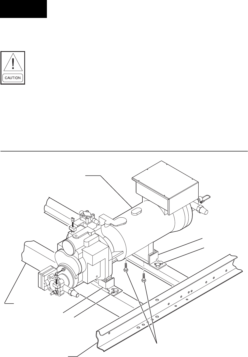
30 YORK INTERNATIONAL
FORM 201.19-NM1 (204)
Installation
COMPRESSOR FEET BOLT REMOVAL
After the chiller is placed in the fi nal location, remove
the four bolts, 1 , attaching the compressor feet to the
frame rails. These bolts are only used for shipping
purposes. The bolts are screwed into the compressor
feet from the bottom side of the frame rail. Refer to
Figure 5.
After the four shipping bolts are removed from the
compressor feet, the compressor will be held in place
by the four corner brackets, 2.
This assembly reduces compressor noise by isolating
the compressor from the base rails.
DO NOT remove the four 3/8" bolts, 3, mounting the
corner brackets, 2, to the frame rails.
1
2
2
COMPRESSOR
CHANNEL BASE
BASE SUPPORT
RAIL
3
3
LD09131
FIG. 5 – COMPRESSOR MOUNTING
Where accumulation of snow is likely, ad di tion al height
must be provided under the unit to ensure normal air fl ow
to the unit.
The clearance dimensions given are
nec es sary to main tain good airfl ow
and en sure cor rect unit op er a tion. It
is also nec es sary to con sid er access
re quire ments for safe op er a tion and
maintenance of the unit and power
and control pan els. Lo cal health and
safe ty reg u la tions, or prac ti cal con-
sid er ations for ser vice re place ment
of large com po nents, may require
larg er clear anc es than those given
in the Tech ni cal Data Section of this
manual, (page 90).
31
YORK INTERNATIONAL
FORM 201.19-NM1 (204)
VIBRATION ISOLATORS
Optional sets of vibration isolators can be supplied loose
with each unit.
Using the Isolator tables, refer to the Technical Data
Section, identify each mount and its cor rect lo ca tion
on the unit.
Installation
Place each mount in its correct position and lower the
unit carefully onto the mounts ensuring the mount en-
gag es in the mounting holes in the unit base frame.
On adjustable mounts, transfer the unit weight evenly to
the springs by turn ing the mount adjusting nuts (lo cat ed
just be low the top plate of the mount) counter-clock wise
to raise and clock wise to low er. This should be done
two turns at a time until the top plates of all mounts are
between 1/4" and 1/2" (6 and 12 mm) clear of top of
their hous ing and the unit base is level.
A more detailed installation in struc tion
is pro vid ed in the Installation Instruc-
tions for VMC Series AWR/AWMR and
CP Restrained Mountings Section of
this manual, (page 107).
SHIPPING BRACES
The chiller’s modular design does not require shipping
braces.
PIPEWORK CONNECTION
General Requirements
The following piping recommendations are intended
to ensure satisfactory operation of the unit(s). Failure
to follow these rec om men da tions could cause damage
to the unit, or loss of per for mance, and may in val i date
the warranty.
The maximum fl ow rate and pressure
drop for the evaporator must not be
ex ceed ed at any time. Re fer to the
Tech ni cal Data Sec tion for de tails.
The liquid must enter the evaporator
at the in let con nec tion. The inlet con-
nec tion for the evaporator is at the far
end of the unit when viewed from the
pow er and con trol pan els.
Water inlet is always nearest the suc-
tion gas outlet on the DX evaporators.
(chiller barrel)
A fl ow switch must be installed in the customer
pipework at the outlet of the evaporator and wired
back to the control panel using shielded ca ble. There
should be a straight run of piping of at least 5 pipe di-
am e ters on either side. The fl ow switch should be wired
to Ter mi nals 13 and 14 (see Figs. 13 and 14, pages 40
and 41). A fl ow switch is re quired pre vent dam age to
the evaporator caused by the unit op er at ing with out
ad e quate liquid fl ow.
The fl ow switch used must have gold plated contacts
for low voltage/current operation. Paddle type fl ow
switch es suitable for 150 PSIG (10 bar) (optional 300
PSIG) working pres sure and hav ing a 1" N.P.T. con-
nection can be obtained from YORK as an ac ces so ry
for the unit. Al ter na tive ly a dif fer en tial pres sure switch
sited across an orifi ce plate may be used, pref er a bly of
the high/low limit type.
The chilled liquid pump(s) installed in the pipework
system(s) should discharge directly into the unit evapora-
tor section of the system. The pump(s) may be controlled
external to the unit - but an override must be wired to the
control panel so that the unit can start the pump in the
event that the liquid temperature falls below the min i mum
setting. For details refer to “Electrical Con nec tion.”
4

32 YORK INTERNATIONAL
FORM 201.19-NM1 (204)
FIG. 6 – PIPEWORK ARRANGEMENT
Pipework and fi ttings must be separately supported to
prevent any loading on the evaporator. Flexible con-
nec tions are recommended which will also minimize
transmission of vibrations to the building. Flexible
connections must be used if the unit is mounted on
anti-vibration mounts as some movement of the unit
can be ex pect ed in normal operation.
Pipework and fi ttings immediately next to the evapora-
tor should be readily de-mountable to enable cleaning
be fore operation, and to facilitate visual inspection of
the exchanger nozzles.
The evaporator must be protected by a strainer, pref-
er a bly of 30 mesh, fi tted as close as possible to the
liq uid inlet connection, and provided with a means
of local isolation.
The evaporator must not be exposed to fl ushing veloci-
ties or debris released during fl ushing. It is recommended
that a suitably sized by-pass and valve arrangement is
in stalled to allow fl ushing of the pipework system. The
by-pass can be used during maintenance to isolate the
heat exchanger without disrupting fl ow to other units.
Thermometer and pressure gauge connections should
be provided on the inlet and outlet connections of each
evaporator.
Drain and air vent connections should be provided at all
low and high points in the pipework to permit drain age
of the system and to vent any air in the pipes.
Liquid systems at risk of freezing, due to low ambient
temperatures, should be protected using insulation and
heater tape and/or a suitable glycol solution. The liquid
pump(s) must also be used to ensure liquid is cir cu lat ed
when the ambient temperature approaches freez ing
point. Insulation should also be installed around the
evaporator noz zles. Heater tape of 21 watts per meter
un der the insulation is recommended, supplied in de -
pen dent ly and controlled by an ambient temperature
ther mo stat set to switch on at 37°F (21°C) above the
freez ing tem per a ture of the liquid.
The liquid circulation pump must be controlled by the
unit. This will ensure that when the liquid temperature
falls within 3° or 5°F (2° or 3°C) of freez ing, the pump
will start.
The evaporator is protected by heater mats un der the in-
su la tion which are supplied from the unit con trol system
pow er supply. Dur ing risk of freezing the control sys tem
should be powered to provide the freeze pro tec tion func-
tion un less the liq uid systems have been drained.
Any debris left in the water pipework
be tween the strain er and evaporator
could cause se ri ous damage to the
tubes in the evaporator and must be
avoided. The in stall er/user must also
en sure that the quality of the wa ter
in cir cu la tion is ad e quate, with out
any dis solved gas es which can cause
ox i da tion of steel parts within the
evaporator.
WATER TREATMENT
The unit performance given in the Design Guide is based
on a fouling factor of 0.00025 ft2hr°F/Btu (0.044m2/hr
°C/kW). Dirt, scale, grease and cer tain types of water
treat ment will ad verse ly affect the heat ex chang er sur-
fac es and there fore unit per for mance. Foreign mat ter
in the water system(s) can increase the heat ex chang er
pres sure drop, reducing the fl ow rate and caus ing po-
ten tial damage to the heat exchanger tubes.
Aerated, brackish or salt water is not recommended for
use in the water system(s). YORK recommends that a
wa ter treatment specialist is consulted to determine the
proposed water composition will not affect the evap o -
ra tor materials of carbon steel and copper. The pH val ue
of the water fl owing through the evaporator must be kept
be tween 7 and 8.5.
Installation
LD04739
Pipework
Isolating Valve - Normally Open
Isolating Valve - Normally Closed
Flow Regulating Valve
Flow Measurement Device
Strainer
Pressure Tapping
Flanged Connection
Flow Switch
Water
Out
Water
In
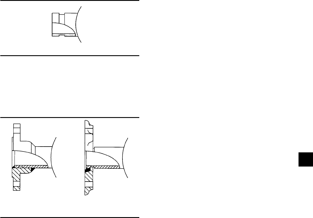
33
YORK INTERNATIONAL
FORM 201.19-NM1 (204)
4
Optional Flanges
One of two types of fl anges may be fi tted depending on
the customer or local Pressure Vessel Code re quire ments.
These are Victaulic-Adapter fl anges, normally supplied
loose, or weld fl anges which may be supplied loose or
ready fi tted. Victaulic-Adapter and weld fl ange dimen-
sions are to ISO 7005 - NP10.
REFRIGERANT RELIEF VALVE PIPING
Evaporators and oil separators are each protected
against internal refrigerant overpressure by refrigerant
relief valves. For evaporators, a pressure relief valve is
mounted on each of the main refrigerant lines connecting
the evaporator to the compressors.
It is recommended that a piece of pipe is fi tted to each
valve and directed so that if the valve is activated, the
release of high pressure gas and liquid cannot be a dan ger
or cause injury. For indoor installations pres sure re lief
valves should be piped to the exterior of the build ing.
The size of any pipework attached to a relief valve must
be of suffi cient diameter so as not to cause resistance to
the operation of the valve. Unless otherwise spec i fi ed
by local regulations, internal diameter de pends on the
length of pipe required and is given by the fol low ing
formula:
D5 = 1.447 x L
Where:
D = minimum pipe internal diameter in cm
L = length of pipe in meters
If relief pipework is common to more than one valve its
cross sectional area must be at least the total re quired
by each valve. Valve types should not be mixed on a
common pipe. Precautions should be taken to ensure
that the outlet of relief valves/vent pipe remain clear of
ob struc tions at all times.
DUCTWORK CONNECTION
General Requirements
The following ductwork rec om men da tions are in tend ed
to ensure sat is fac to ry op er a tion of the unit. Failure to
follow these rec om men da tions could cause damage to
the unit, or loss of per for mance, and may invalidate the
warranty.
When ducting is to be fi tted to the fan discharge it is
recommended that the duct should be the same cross sec-
tional area as the fan outlet and straight for at least three
feet (1 meter) to obtain static regain from the fan.
Ductwork should be suspended with fl exible hangers
to prevent noise and vibration being transmitted to the
struc ture. A fl exible joint is also recommended be tween
the duct attached to the fan and the next section for the
same reason. Flexible connectors should not be al lowed
to concertina.
The unit is not designed to take structural loading. No
signifi cant amount of weight should be allowed to rest
on the fan outlet fl ange, deck assemblies or condenser
coil module. No more than 3 feet (1 meter) of light
con struc tion ductwork should be supported by the unit.
Where cross winds may occur, any ductwork must be
sup port ed to prevent side loading on the unit.
PIPEWORK ARRANGEMENT
Figure #6 shows the suggested pipework arrangement
for single unit in stal la tions. For mul ti ple unit installa-
tions, each unit should be piped as shown.
CONNECTION TYPES & SIZES
For connection sizes relevant to individual models re fer
to the Technical Data Section.
EVAPORATOR CONNECTIONS
Standard chilled liquid connections on all evaporators
are of the Victaulic Groove type.
LD03521
FIG. 7 – VICTAULIC GROOVE
Weld Flange Victaulic Adapter
LD03523
FIG. 8 – FLANGE ATTACHMENTS

34 YORK INTERNATIONAL
FORM 201.19-NM1 (204)
If the ducts from two or more fans are to be combined
into a common duct, back-fl ow dampers should be fi t-
ted in the individual fan ducts. This will prevent re cir -
cu la tion of air when only one of the fans is running.
Units are supplied with outlet guards for safety and to
prevent damage to the fan blades. If these guards are re-
moved to fi t ductwork, adequate alternative pre cau tions
must be taken to ensure persons cannot be harmed or
put at risk from rotating fan blades.
ELECTRICAL CONNECTION
The following connection rec om men da tions are in-
tend ed to ensure safe and sat is fac to ry operation of the
unit. Failure to follow these recommendations could
cause harm to persons, or damage to the unit, and may
in val i date the warranty.
No additional controls (re lays, etc.)
should be mount ed in the control
pan el. Power and con trol wiring not
con nect ed to the con trol pan el should
not be run through the control pan el.
If these pre cau tions are not fol lowed it
could lead to a risk of elec tro cu tion. In
ad di tion, elec tri cal noise could cause
mal func tions or dam age the unit and
its con trols.
After connection do not switch on
main pow er to the unit. Some in ter nal
com po nents are live when main power
is switched on and this must only be
done by Au tho rized persons.
POWER WIRING
All electrical wiring should be carried out in ac cor dance
with local regulations. Route properly sized cables to
cable entries on both sides of the unit.
In accordance with U.L. Standard it is the re spon si bil i ty
of the user to install overcurrent pro tec tion devices
be tween the supply con duc tors and the power supply
ter mi nals on the unit.
To ensure that no eddy currents are set up in the power
panel, the cables forming each 3-phase power supply
must enter via the same cable entry.
All sources of supply to the unit must
be taken via a common point of iso-
la tion (not sup plied by YORK).
STANDARD UNITS WITH MULTI POINT POWER
SUPPLY WIRING
Standard units require two 3-phase sep a rate ly fused 3-
wire supplies plus a ground per re frig er ant system. One
supply to be connected to each of the power panels.
Connect each of the main 3-phase supplies to the cir-
cuit breakers, non-fused disconnect switches or ter mi nal
boards located in the power panels using lug sizes de-
tailed in the Technical Data Section.
Connect the ground wires to the main protective ground
terminals in each power panel.
Units with Single-Point Power Supply Wiring
Units require only one 3-phase supply plus ground.
Connect the 3-phase supplies to the terminal block or
non-fused disconnect switch/circuit breaker located in
the options pan el using lug sizes detailed in the Techni-
cal Data Section.
Connect a ground wire to the main protective ground
terminal.
115VAC CONTROL SUPPLY TRANSFORMER
A 3-wire high voltage to 115VAC supply transformer
is standard in the chiller. This transformer steps down
the high voltage supply to 115VAC to be used by the
Micro Panel, Pow er Pan el com po nents, so le noids, heat-
ers, etc.
The high voltage for the transformer pri ma ry is taken
from the chiller input to one of the sys tems. Fusing is
provided for the trans form er.
It is important to check that the cor-
rect primary tap ping has been used
and that it con forms to the site high
volt age sup ply.
Installation

35
YORK INTERNATIONAL
FORM 201.19-NM1 (204)
4
Removing high voltage power to the
chill er will re move the 115VAC sup-
ply voltage to the mi cro pro ces sor cir-
cuit ry and the evap o ra tor heater. In
cold weath er, this could cause serious
dam age to the chill er due to evap o ra tor
freeze-up. Do not re move power un less
alternate means are taken to as sure
op er a tion of the evap o ra tor heat er.
Remote Emergency Stop Device
If required, a remote emergency stop de vice can be wired
into the unit. The device should be wired into ter mi nals
31 and 32 (Figs. 13 and 14, pages 40 and 41.) in the
mi cro pro ces sor con trol pan el.
CONTROL PANEL WIRING
All wiring to the control panel terminal block terminals
13-19 is nom i nal 30VDC and must be run in shielded
cable, with the shield grounded at the panel end only.
Run shielded ca ble sep a rate ly from mains cables to
avoid electrical noise pick-up. Use the control panel
cable entry to avoid the pow er cables.
The voltage free contacts supplied must be suitable for
30VDC (gold contacts recommended). If the voltage
free con tacts are from a relay or contactor, the coil of
the device must be suppressed using a standard R/C
sup pres sor. The above precautions must be taken to
avoid electrical noise which could cause a malfunction
or dam age to the unit and its controls.
The length of cable to these terminals must not exceed
25 ft. (7.5 m) unless an isolator is fi t ted.
VOLTS FREE CONTACTS
Chilled Liquid Pump Starter
Terminals 25 and 26 (Figs. 13 and 14, pages 40 and 41)
close to start the chilled liquid pump. This contact can be
used as a master start/stop for the pump in con junc tion
with the daily start/stop schedule. See Section 8.1.15.
Run Contact
Terminals 29 and 30 (Figs. 13 and 14, pages 40 and 41)
close to in di cate that a sys tem is running.
Alarm Contacts
Each system has a voltage-free change over contact
which will operate to signal an alarm condition when-
ev er a system locks out, or there is a power failure. To
obtain system alarm signal, connect the alarm circuit
to volt free terminals 23 and 24 (Figs. 13 and 14, pages
40 and 41) for No. 1 Sys tem and to ter mi nals 27 and 28
(Figs. 13 and 14) for No. 2 Sys tem.
SYSTEM INPUTS
Flow Switch
A chilled water fl ow switch, (either by YORK or others)
MUST be installed in the leaving water piping of the
evaporator. There should be a straight horizontal run of
at least 5 diameters on each side of the switch. Adjust
the fl ow switch paddle to the minimum fl ow allowed
through the evaporator. (See manufacturer's instructions
furnished with the switch.) The switch is to be wired to
terminals 13 - 14 of CTB1 located in the control panel,
as shown on the unit wiring diagram.
Remote Run / Stop
Connect remote switch(es) in series with the fl ow switch
to provide remote run/stop control if required.
Remote Print
Closure of suitable contacts connected to terminals 13
and 18 (Figs. 13 and 14, pages 40 and 41) will cause a
hard copy printout of Operating Data/Fault History to
be made if an optional printer is con nect ed to the RS
232 port.
Remote Setpoint Offset – Temperature
Timed closure of suitable contacts connected to
ter mi nals 13 and 17 (PWM contacts) will provide
re mote off set function of the chilled liquid set point
if re quired. See Figs. 13 and 14, pages 40 and 41 for
contact lo ca tion.
Remote Setpoint Offset – Current
Timed contact closure of a suitable contact connected to
terminals 13 and 16 (PWM contacts) will provide re mote
offset of EMS% CURRENT LOAD LIMIT. See Figs.
13 and 14, pages 40 and 41 for contact lo ca tion.
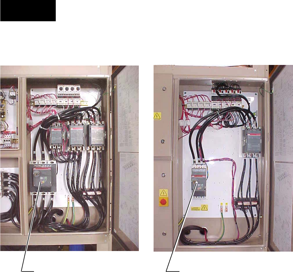
36 YORK INTERNATIONAL
FORM 201.19-NM1 (204)
POWER PANEL LAYOUTS (TYPICAL)
FIG. 9 – POWER PANEL SECTION
028972-G
Installation
(WYE-DELTA - TYPICAL) (ACROSS THE LINE - TYPICAL)
028973-G
OPTIONAL DISCONNECT SWITCH OPTIONAL CIRCUIT BREAKER SWITCH

37
YORK INTERNATIONAL
FORM 201.19-NM1 (204)
4
FIG. 10 – OPTION PANEL SECTION
OPTION PANEL LAYOUT (TYPICAL)
00246VIP
LOGIC PANEL
OPTION PANEL
WITH SINGLE
POINT TERMINAL
BLOCK
(OPTIONAL)
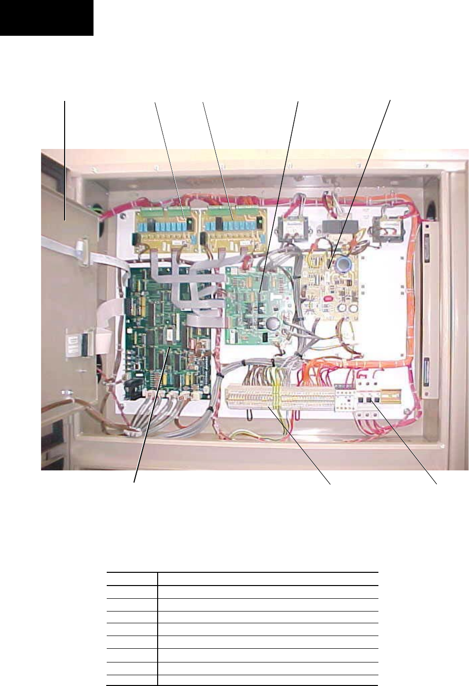
38 YORK INTERNATIONAL
FORM 201.19-NM1 (204)
Installation
60 Hz Models:
PHOTOGRAPH OF
60 HZ MODEL LOGIC SECTION
FIG. 11 – LOGIC SECTION LAYOUT
LOGIC SECTION LAYOUT
028975-G
ITEM
1
2
3
4
5
6
7
8
DESCRIPTION
Microprocessor Board
Back of Display
I/O Expansion Board #1
Power Supply Board
Relay Output Board #1
Relay Output Board #2
Flow Switch & Customer Connection Terminals
Circuit Breakers CB1, CB2, CB3
1
2
8
4
3
5 6
7
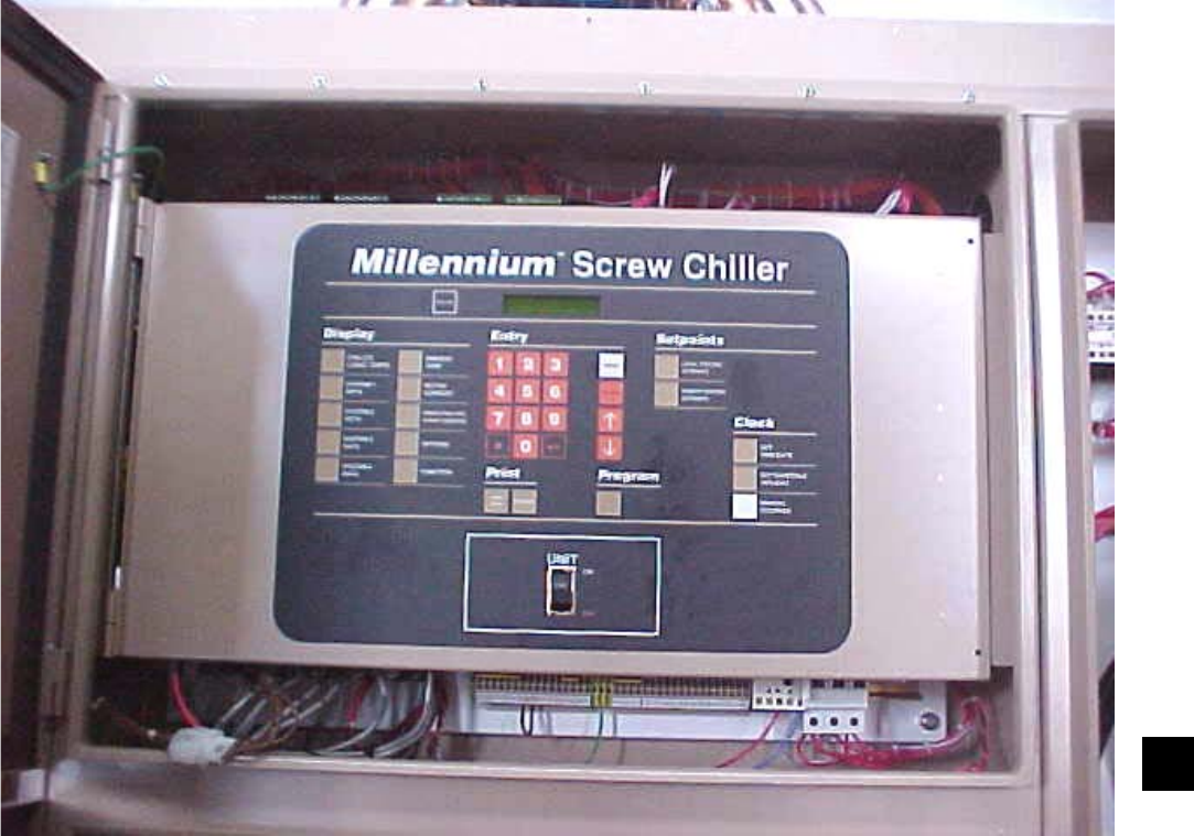
39
YORK INTERNATIONAL
FORM 201.19-NM1 (204)
4
FIG. 12 – LOGIC SECTION LAYOUT WITH CONTROL PANEL
LOGIC SECTION LAYOUT WITH CONTROL PANEL
028976-G
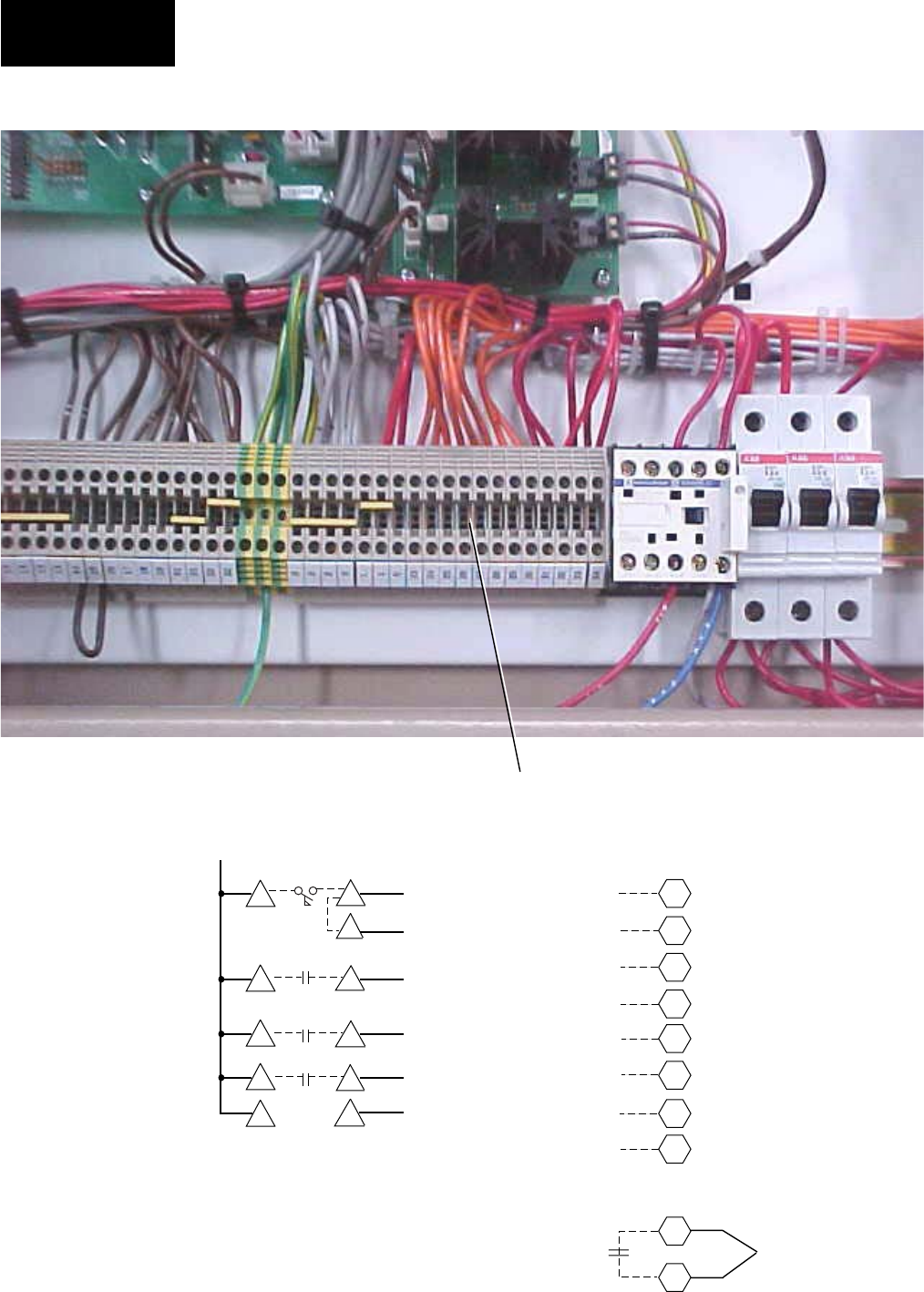
40 YORK INTERNATIONAL
FORM 201.19-NM1 (204)
Installation
FIG. 13 – CUSTOMER CONNECTIONS
CUSTOMER CONNECTIONS
LD03502
CONNECTION
POINTS FOR
EMERGENCY
STOPS
TERMINALS 13-34
028977-G
Print
Temperature
PWM
Current
PWM
Flow Switch System No. 1 Run
System No. 2 Run
14
15
16
17
18
19
23
24
25
26
27
28
29
30
System No. 1
Alarm Contacts
Chilled Liquid
Circulating Pump
Start
System No. 2
Alarm Contacts
Chiller Run
Isolator
Auxiliary
Interlock
31
32
13
13
13
13
13

41
YORK INTERNATIONAL
FORM 201.19-NM1 (204)
4
FIG. 14 – CUSTOMER CONNECTIONS
CUSTOMER CONNECTIONS
2028978-G
CIRCUIT
BREAKERS
CB1, CB2, CB3
CUSTOMER
CONNECTIONS
(FLOW SWITCH, ALARM, RUN, ETC.)
115 VAC SUPPLY
MICROPROCESSOR
CIRCUIT BOARD
RELAY BOARDS I/O EXPANSION BOARD
TRANSFORMERS
SYSTEM
SWITCHES

42 YORK INTERNATIONAL
FORM 201.19-NM1 (204)
or cop per line, but do not tighten the fl are nut. Using
clean oil of the correct type (“L” oil), pump oil until all
air has been purged from the hose then tight en the nut.
Stroke the oil pump to add oil to the oil sys tem. The oil
level should be between the mid dle of the low er and
mid dle of the up per sight glasses of the oil sep a ra tor.
Ap prox i mate ly 5 gal lons is present in the entire chill er
system, with 1-2 gal lons in the oil separator.
Fans
Check that all fans are free to rotate and are not dam-
aged. Ensure blades are at the same height when ro tat ed.
Ensure fan guard is securely fi xed.
Isolation/Protection
Verify that all sources of elec tri cal supply to the unit
are taken from a single point of iso la tion. Check that
the maximum recommended fuse siz es given in the
Tech ni cal Data Section have not been exceeded.
Control Panel
Check the panel to see that it is free of foreign ma te ri als
(wire, metal chips, etc.) and clean out if required.
Power Connections
Check to assure the customer power ca bles are connected
cor rect ly. Ensure that con nec tions of power cables within
the panels to the circuit breakers, terminal blocks or
switch disconnectors are tight.
Grounding
Verify that the unit’s protective terminal(s) are prop er ly
connected to a suitable grounding point. Ensure that all
unit internal ground connections are tight.
Overloads
Ensure that the fan overloads settings are correct for the
type of fan fi tted.
Supply Voltage
Verify that the site voltage supply cor re sponds to the
unit requirement and is within the lim its given in the
Tech ni cal Data Section.
Control Transformer
The 3-wire control transformer is mounted external to
the panel. It is important to check that the correct pri ma ry
tapping has been used:
With the supply voltage to the unit turned off, remove
the lid to the transformer box.
COMMISSIONING
PREPARATION
Commissioning of this unit should
only be car ried out by YORK Au tho -
rized per son nel.
The Millennium Microcomputer Con trol Sys tem
Op er at ing In struc tions must be read in con junc tion
with this sec tion.
PREPARATION – POWER OFF
The following checks should be made with the cus tom er
supply/supplies to the unit switched OFF.
Inspection
Inspect unit for installation dam age. If damage is found
take ac tion and/or repair as appropriate.
Refrigerant Charge
Units are normally shipped as stan dard with a full
re frig er ant operating charge. Check that refrigerant
pres sure is present in both systems and that no leaks
are ap par ent. If no pressure is present a leak test must be
un der tak en. The leak(s) should be located and re paired.
Re paired sys tems and units supplied with a ni tro gen
hold ing charge must be evacuated with a suit able vac-
uum pump/re cov ery unit as appropriate to be low 100
microns.
Do not liquid charge with static water in the evaporator.
Care must also be taken to liquid charge slowly to avoid
ex ces sive thermal stress at the charging point. Once the
vacuum is broken, charge into the condenser coils with
the full operating charge as given in the Technical Data
Section.
Valves
Open each compressor suction, economizer, and dis-
charge valve ful ly (counter-clockwise) then close one
turn of the stem to ensure operating pressure is fed to
the pres sure trans duc ers. Open the liquid line service
valve ful ly and en sure the oil re turn line ball valve is
open in each system.
Compressor Oil
To add oil to a circuit - connect a YORK hand oil pump
(Part No. 470-10654-000) to the 1/4" oil charging valve
on the oil separator piping with a length of clean hose
Commissioning

43
YORK INTERNATIONAL
FORM 201.19-NM1 (204)
5
Check that the tapping used conforms to the site sup ply
voltage. After the tapping is verifi ed, replace the lid.
Switch Settings
Ensure that the unit ON/OFF switch on the display door
and the micro board system switch es S2 through S5 are
set to “0” (OFF). Set the red han dled emergency stop
de vice on the options panel to “1” (ON). For units fi tted
with door interlocked circuit breakers the power panel
doors must be closed and the devices set to “1” (ON).
The customer’s power dis con nec tion devices can now
be set to ON.
The machine is now live!
The unit is fi tted with an under voltage circuit in each
pan el and it may take be tween 5 to 10 seconds for its
con tacts to close and energize the unit’s electronics,
in clud ing the dis play on the main panel.
Compressor Heaters
Verify the compressor heaters are en er gized. If
the ambient temperature is above 96°F (36°C) the
com pres sor heaters must be on for at least 8 hours before
start-up to ensure all refrigerant liquid is driven out of
the compressor. If the ambient tem per a ture is be low
86°F (30°C) then allow 24 hours.
Water System
Verify that the chilled liquid system has been installed
correctly, and has been commissioned with the correct
direction of water fl ow through the evaporator. The inlet
should be at the refrigerant pipework connection end of
the evaporator. Purge air from the top of the evaporator
using the plugged air vent mounted on the top of the
evaporator body. Flow rates and pressure drops must be
within the limits given in the Technical Data Section.
Op er a tion outside of these lim its is un de sir able and could
cause damage.
Flow Switch
Verify a chilled water fl ow switch is cor rect ly fi tted in
the customer’s pipework on the evaporator outlet, and
wired into the control panel correctly using shielded
cable. There should be a straight run of at least 5 pipe
di am e ters on either side of the fl ow switch. The fl ow
switch should be connected to terminals 13 and 14 in the
mi cro panel (Figs. 13 and 14, pages 40 and 41).
Temperature Sensor(s)
Ensure the leaving liquid tem per a ture sensor is coated
with heat conductive com pound (part no. 013-00890-
000) and is inserted in the water outlet sensor pocket
of the evaporator. This sensor also acts as the freeze
pro tec tion ther mo stat sensor and must always be in the
water OUTLET sen sor pocket.
Control Supply
Verify the control panel display is illuminated.
Programmed Options
Verify that the options factory programmed into the
Mi cro com put er Control Center are in accordance with
the cus tom er’s order re quire ments by pressing the ‘Op-
tions’ key on the keypad and read ing the settings from
the display.
Programmed Settings
Ensure the system cut-out and operational settings
are in accordance with the in struc tions provided in
Sec tion 8 (page 166) and with the general chiller op-
er a tion al re quire ments by press ing the ‘Pro gram’ key.
The chilled liquid tem per a ture con trol set tings need to
be set ac cord ing to the unit model and required op er -
at ing con di tions.
Date and Time
Program the date and time by fi rst en sur ing that the CLK
jumper J18 on the mi cro pro ces sor board is in the ON
position (top two pins). Then press the ‘Clock Set Time’
key and set the date and time. (See Section 7.)
Start/Stop Schedule
Program the daily and hol i day start/stop by pressing the
‘Set Schedule/Holiday’ key. (See Section 7.)
Setpoint and Remote Offset
Set the required leav ing chilled liquid temperature
set point and control range. If remote temperature reset
(off set) is to be used, the maximum reset must be pro-
grammed by pressing the ‘Remote Reset Temp’ key.
(See Section 6.)
44 YORK INTERNATIONAL
FORM 201.19-NM1 (204)
Commissioning
FIRST TIME START-UP
During the commissioning period
there should be suf fi cient heat load
to run the unit under sta ble full load
op er a tion to enable the unit con trols,
and sys tem op er a tion to be set up cor-
rect ly and a com mis sion ing log tak en.
Be sure that the Micro Panel is prop-
er ly pro grammed (page 166) and the
Sys tem Start-up Check list (page 117)
is com plet ed.
Interlocks
Verify that liquid is fl owing through the evaporator and
that heat load is present. Ensure that any remote run in-
ter locks are in the run position and that the run schedule
requires the unit to run or is overridden.
System Switches
Place the ‘Sys 1’ switch on the mi cro pro ces sor board to
the ‘ON’ position – (Fig. 46, page 130).
Start-up
Remove the locking device from the unit Auto/OFF
switch which prevents unauthorized starting of the unit
before commissioning. Press the ‘Status’ key, then turn
the unit switch to the “1” position to start the unit (there
may be a few seconds delay before the fi rst com pres sor
starts be cause of the anti-recycle timer). Be ready when
each com pres sor starts, to switch the unit OFF im me -
di ate ly if any unusual noises or other adverse con di tions
de vel op. Use the appropriate emergency stop de vice if
necessary.
Oil Pressure
When a compressor starts, press the rel e vant ‘System
Pressures’ key and verify that oil dif fer en tial pressure
develops immediately (Discharge Pressure minus Oil
Pressure). If oil pressure does not develop, the automatic
controls will shut down the compressor. Un der no cir-
cum stanc es should a restart attempt be made on a com-
pres sor which does not develop oil pres sure im me di ate ly.
Switch the unit switch to the ‘0’ po si tion (OFF).
Refrigerant Flow
When a compressor starts, a fl ow of liquid refrigerant
will be seen in the liquid line sight glass. After several
min utes operation and providing a full charge of re frig -
er ant is in the system, the bubbles will disappear and be
re placed by a solid column of liquid.
Fan Rotation
As discharge pressure rises, the con dens er fans op er ate
in stages to control the pressure. Verify that the fan op-
eration is correct for the type of unit.
Suction Superheat
Check suction superheat at steady full compressor load
only. Measure suction tem per a ture on the copper line
about 6" (150 mm) before the compressor suc tion ser-
vice valve. Measure suction pres sure at the com pres sor
service valve. Superheat should be 10°F to 12°F
(5.6°C to 6.7°C).
Expansion Valve
The electronic expansion valves are factory set and
should not need adjustment.
Economizer Superheat
(Not all models are equipped with economizers)
Check economizer su per heat at steady full com pres sor
load only, under conditions when the econ o miz er sole-
noid is energized. (See Section 1.22, page 134) Measure
gas tem per a ture on the econ o miz er outlet pipe next to the
ex pan sion valve bulb. Mea sure gas pressure at the back
seat port of the economizer ser vice valve. Su per heat as
measured should be 10°F to 12°F (5.6°C to 6.7°C).
Subcooling
Check liquid subcooling at steady full com pres sor
load only. It is important that all fans are run ning for
the sys tem. Measure liquid line temperature on the
copper line beside the main liquid line service valve.
Measure liq uid pressure at the liquid line service valve.
Subcooling should be 12°F to 15°F (6.7°C to 8.3°C).
No bubbles should show in the sight glass. If subcooling
is out of range add or re move re frig er ant as required.
Do not over charge the unit. The liq uid fl ow to the main
evaporator TXV is subcooled fur ther by the econ o miz er,
increasing subcooling to be tween 22°F and 28°F (12°C
and 15°C) at ambients above 90ºF.
General Operation
After completion of the above checks for System 1, stop
the unit, switch OFF the ‘SYS 1’ switch on the main
panel microprocessor board and repeat the pro cess for
each subsequent system. When all run cor rect ly, stop the
unit, switch all applicable switch es to the ‘ON’ po si tion
and restart the unit.

45
YORK INTERNATIONAL
FORM 201.19-NM1 (204)
5
This page intentionally left blank.

46 YORK INTERNATIONAL
FORM 201.19-NM1 (204)
Op er a tion
GENERAL DESCRIPTION
The units are designed to work independently, or in
con junc tion with other equipment via a YORK ISN
build ing management system or other automated con-
trol sys tem. When operating, the unit controls monitor
the chilled liquid system temperature at the unit and
take the ap pro pri ate action to maintain this temperature
with in de sired limits. This action will involve running
one or more compressors at a suitable load step to match
the cool ing effect of the refrigerating systems to the
heat load on the liquid system. The heat removed from
the chilled liquid is then rejected from the air cooled
con dens er coils.
The following sections give an overview of the op er a tion
of the unit. For detailed information, reference should
be made to the Chiller Control Panel Pro gram ming and
Data Access Op er at ing In struc tions for the unit (pages
122 - 192).
START-UP
Check the main power supplies to the unit are ‘ON’, all
refrigerant service valves are open (counter-clockwise
one turn short of fully open) and chilled liquid fl ow has
been es tab lished (unless the unit chilled liquid pump
start con trol is being used, in which case just ensure
the pump supply is on). Ensure only the correct system
switches (SYS 1-2) on the microprocessor cir cuit board
are in the ‘ON’ position.
Press the ‘STATUS’ key on the keypad and then switch
the unit ON/OFF switch below the keypad to the ON
position.
The controller will perform a pre-check to ensure that
the daily/holiday schedule and any remote interlocks will
allow the unit to run, all safety cut-outs are sat is fi ed and
that cooling load is required (i.e. that the chilled liquid
temperature is outside the set limits). Any prob lems
found by the pre-check will be displayed if present. If
no prob lems are present and cooling duty is required the
lead compressor will start.
The display will show the anti-coincidence timer sta tus
for the lag compressor, followed by ‘NO COOL LOAD’
until it is called to operate by the control sys tem.
NORMAL RUNNING AND CYCLING
Once the unit has been started, all operations are fully
automatic. After an initial period at minimum capacity
on the lead compressor, the control system will adjust
the unit load depending on the chilled liquid tem per a ture
and rate of temperature change. If high heat load is pres-
ent, the controller will increase the capacity of the lead
compressor and/or start-up the other compressor.
If very little heat load is present, the lead compressor
will continue at minimum capacity or may simply stop
again to avoid overcooling the liquid. If the latter is the
case, one compressor will restart automatically should
the liquid temperature rise again.
Once a compressor is running, discharge pressure ris es
as refrigerant is pumped into the air cooled con dens er
coils. This pressure is controlled by stages of fans to
ensure maximum unit effi ciency while main tain ing suf-
fi cient pressure for correct operation of the con dens ers
and expansion valves.
When a compressor is running, the controller monitors
oil pressure, motor current, and various other system
parameters such as discharge pressure, chilled liquid
temperature, etc. Should any problems occur, the con trol
system will immediately take appropriate action and
display the nature of the fault (Section 8).
SHUTDOWN
The unit can be stopped at any time by switching the
UNIT ON/OFF switch just below the keypad to the
OFF po si tion. The compressor heat er will en er gize to
prevent refrigerant condensing in the com pres sor rotors.
If ambient tem per a tures are low, the evaporator heater
mats will also en er gize to pre vent the possibility of liq-
uid freezing in the ves sels. The mains pow er to the unit
should not nor mal ly be switched OFF, even when the
unit is not re quired to run.
The system switches (S2-S5) on the microboard can be
used to cycle a system OFF. An automatic pumpdown
will occur using the system switches.
If mains power must be switched OFF, (for extended
main te nance or a shutdown period), the compressor suc-
tion, discharge and motor cooling service stop valves
should be closed (clockwise) and if there is a pos si bil i ty
of liq uid freezing due to low ambient temperatures, the
evaporators should be drained. Valves should be opened
and power must be switched on for at least 8 Hours
(36 Hours if ambient temperature is over 86°F [30°C])
be fore the unit is restarted.
OPERATION

47
YORK INTERNATIONAL
FORM 201.19-NM1 (204)
6
This page intentionally left blank.
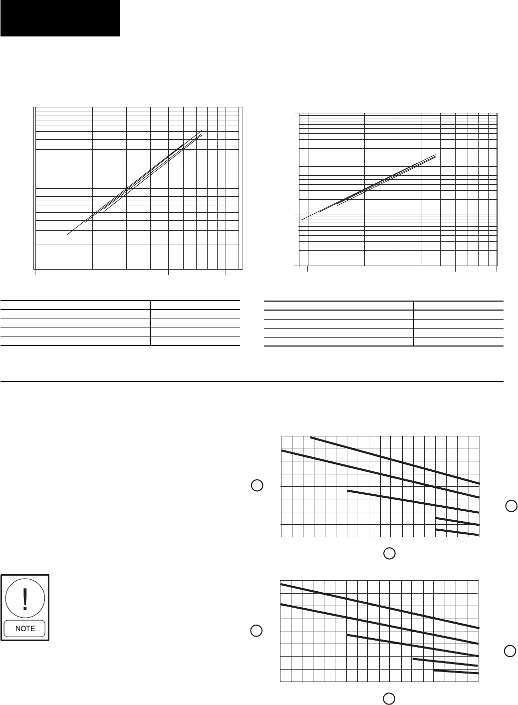
48 YORK INTERNATIONAL
FORM 201.19-NM1 (204)
TECHNICAL DATA
The evaporator is designed in accordance with ARI-590-
92 which allows for an increase in pres sure drop of up
to 15% above the design value given above. Debris in
the water may also cause additional pressure drop.
When using glycol solutions, pressure drops are high er
than with water (see correction factors to be applied
when using glycol solutions).
A = Correction Factor
B = Mean Temperature through Evaporator (°C)
C = Concentration W/W (%)
EVAPORATOR WATER PRESSURE DROP
(ENGLISH UNITS)
EVAPORATOR WATER PRESSURE DROP
(SI UNITS)
FIG. 15 – FLOW RATE AND PRESSURE DROP CHARTS
FIG. 16 – GLYCOL CORRECTION FACTORS
FLOW RATE AND PRESSURE DROP CHARTS
Excessive fl ow, above the max GPM,
will damage the evaporator.
LD09230A LD04482A
GLYCOL CORRECTION FACTORS
Technical Data
MODEL NUMBER YCAS EVAPORATOR
0130, 0140 A
0150, 0160, 0170, 0180, B
0200, 0210, C
0230 D
MODEL NUMBER YCAS EVAPORATOR
0130, 0140 A
0150, 0160, 0170, 0180, B
0200, 0210, C
0230 D
Pressure Conversion : Ft H20 = 2.3 x PSI
ETHYLENE GLYCOL
PROPYLENE GLYCOL
A
A
B
B
C
C
1.45
1.40
1.35
1.30
1.25
1.20
1.15
1.10
1.05
1.8
1.7
1.6
1.5
1.4
1.3
1.2
1.1
1.0
-10-8-6-4-20 2468
-10-8-6-4-20 2468
50%
40%
30%
20%
10%
50%
40%
30%
20%
10%
LD03504
°C
°C
GLYCOL CORRECTION EXAMPLE: (With YCAS0140)
• RWT = 36°F LWT = 28°F
• Average Water Temperature = 32°F (= 0°C)
• For 30% Propylene Glycol: From Graph, Find Correction Factor =
1.3 @ 0°C and 30%
• Actual Measured ∆P = 12' H20
• Corrected ∆P = 12'/1.3 = 9.2' H20
• From Flow Rate and Pressure Drop Chart, locate fl ow @ 9.2' ≈
300 GPM
YCAS0130 - 0230
1.00
10.00
100.00
1000.00
10.00 100.00
50.00
Flow, L/S
Press Drop, kPA
A
BCD
YCAS0130 - 0230
1.00
10.00
100.00
100 500 1000
Flow, GPM
Press Drop, Ft H2O
A
B
C
D
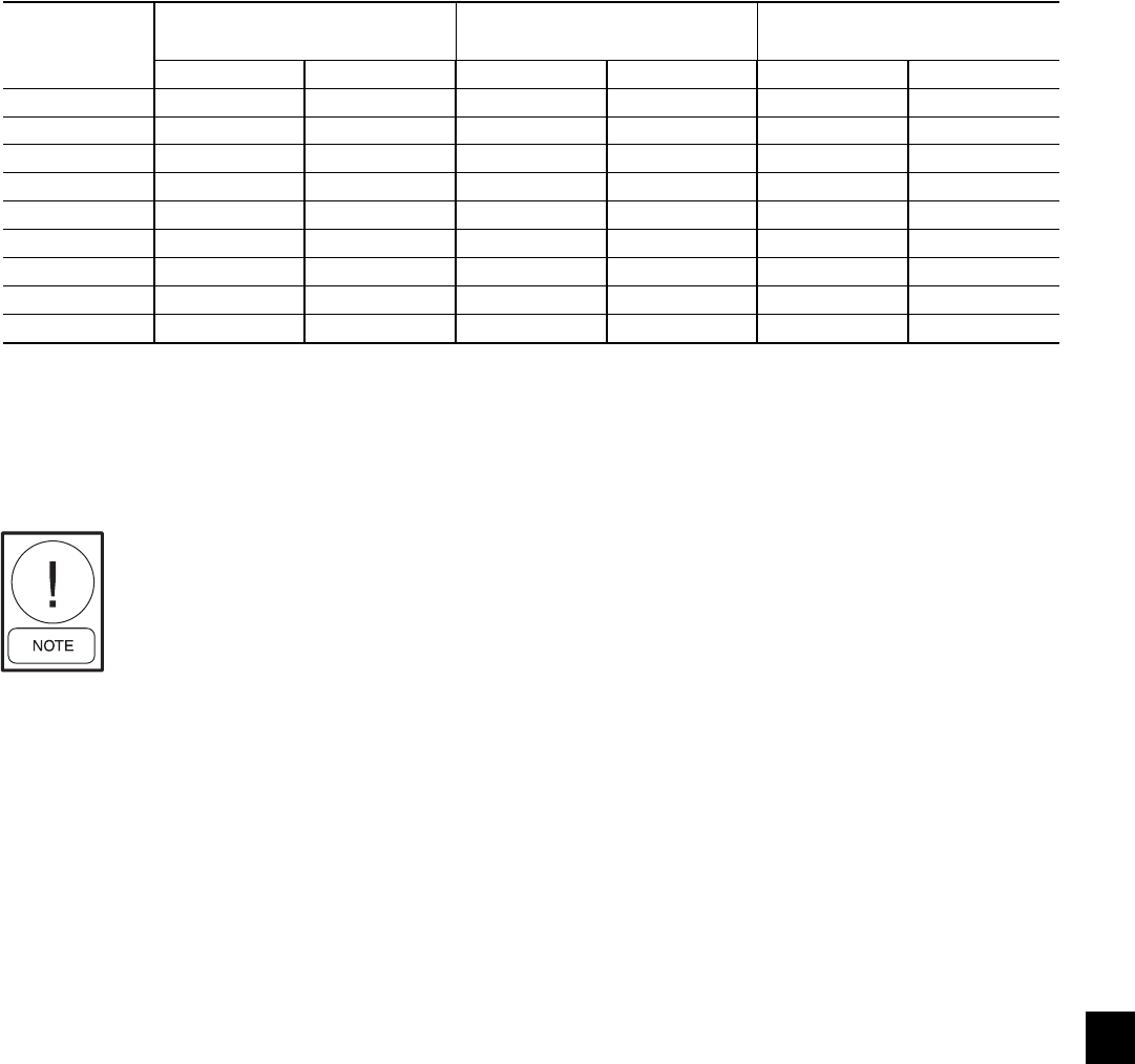
49
YORK INTERNATIONAL
FORM 201.19-NM1 (204)
TEMPERATURE AND FLOWS
(ENGLISH UNITS)
Excessive fl ow, above the max GPM,
will damage the evaporator.
MODEL
NUMBER
YCAS
LEAVING WATER
TEMPERATURE (°F)
EVAPORATOR FLOW
(GPM3)AIR ON CONDENSER (°F)
MIN.1MAX.2MIN. MAX. MIN. MAX
0130EC 40 55 138 525 0 125
0140EC 40 55 138 525 0 125
0150EC 40 55 200 600 0 125
0160EC 40 55 200 600 0 125
0170EC 40 55 200 600 0 125
0180EC 40 55 200 600 0 125
0200EC 40 55 250 750 0 125
0210EC 40 55 250 750 0 125
0230EC 40 55 250 750 0 125
NOTES:
1. For leaving brine temperature below 40°F (4.4°C), contact your nearest YORK offi ce for application requirements.
2. For leaving water temperature higher than 55°F (12.8°C), contact the nearest YORK offi ce for application guidelines.
3. The evaporator is protected against freezing to -20°F (-28.8°C) with an electric heater as standard.
7

50 YORK INTERNATIONAL
FORM 201.19-NM1 (204)
TEMPERATURE AND FLOWS
(SI UNITS)
Technical Data
MODEL
NUMBER
YCAS
LEAVING WATER
TEMPERATURE (°C)
Evaporator FLOW
(l/s3)AIR ON CONDENSER (°C)
MIN.1MAX.2MIN. MAX. MIN. MAX
0130EC 4.4 12.8 8.7 33.1 -17.7 51.7
0140EC 4.4 12.8 8.7 33.1 -17.7 51.7
0150EC 4.4 12.8 12.6 37.9 -17.7 51.7
0160EC 4.4 12.8 12.6 37.9 -17.7 51.7
0170EC 4.4 12.8 12.6 37.9 -17.7 51.7
0180EC 4.4 12.8 12.6 37.9 -17.7 51.7
0200EC 4.4 12.8 15.8 47.3 -17.7 51.7
0210EC 4.4 12.8 15.8 47.3 -17.7 51.7
0230EC 4.4 12.8 15.8 47.3 -17.7 51.7
Excessive fl ow, above the max GPM,
will damage the evaporator.
NOTES:
1. For leaving brine temperature below 40°F (4.4°C), contact your nearest YORK offi ce for application requirements.
2. For leaving water temperature higher than 55°F (12.8°C), contact the nearest YORK offi ce for application guidelines.
3. The evaporator is protected against freezing to -20°F (-28.8°C) with an electric heater as standard.

51
YORK INTERNATIONAL
FORM 201.19-NM1 (204)
PHYSICAL DATA
ENGLISH UNITS
7
MODEL NUMBER YCAS
0130EC 0140EC 0150EC 0160EC 0170EC 0180EC 0200EC 0210EC 0230EC
General Unit Data
Unit Capacity at ARI Conditions, Tons 121.1 130.1 145.3 157.1 164.3 171.6 186.7 194.8 209.1
Number of Independent Refrigerant Circuits 222222222
Refrigerant Charge, R-22, Ckt.-1 / Ckt.-2, lbs. 180 / 180 180 / 180 180 / 190 190 / 190 190 / 190 190/190 220/220 220/220 220/220
Oil Charge, Ckt.-1 / Ckt.-2, gallons 5 / 5 5 / 5 5 / 5 5 / 5 5 / 5 5 / 5 5 / 5 5 / 5 5 / 5
Shipping Weight:
Aluminum Fin Coils, lbs. 9,888 10,110 10,599 10,583 10,694 10,805 11,849 11,970 12,081
Copper Fin Coils, lbs. 11,154 11,376 11,865 11,849 11,960 12,071 13,441 13,552 13,663
Operating Weight:
Aluminum Fin Coils, lbs. 10,315 10,537 11,263 11,247 11,358 11,469 12,513 12,634 12,745
Copper Fin Coils, lbs. 11,581 11,803 12,529 12,513 12,624 12,735 14,105 14,216 14,327
Compressors, DXS Semihermetic Twin Screw
Quantity per Chiller 222222222
Nominal Ton Size, Ckt.-1 / Ckt.-2 62 / 62 68 / 68 78 / 68 78 / 78 85 / 78 85/85 95/95 105/95 105/105
Refrigerant Economizer, Ckt.-1 / Ckt.-2 No / No Yes / Yes No / Yes No / No Yes / No Yes / Yes No / No Yes / No Yes / Yes
Condensers, High Effi ciency Fin / Tube with Integral Subcooler
Total Chiller Coil Face Area, ft2256 256 256 256 256 256 320 320 320
Number of Rows 333333333
Fins per Inch 13 13 13 13 13 13 13 13 13
CONDENSER FANS
Number, Ckt.-1 / Ckt.-2 4 / 4 4 / 4 4 / 4 4 / 4 4 / 4 4 / 4 5 / 5 5 / 5 5 / 5
Standard Fans
Fan Motor, HP / kW 2 / 1.8 2 / 1.8 2 / 1.8 2 / 1.8 2 / 1.8 2 / 1.8 2 / 1.8 2 / 1.8 2 / 1.8
Fan & Motor RPM 1140 1140 1140 1140 1140 1140 1140 1140 1140
Fan Diameter, inches 35.4 35.4 35.4 35.4 35.4 35.4 35.4 35.4 35.4
Fan Tip Speed, feet/min. 10,575 10,575 10,575 10,575 10,575 10,575 10,575 10,575 10,575
Total Chiller Airfl ow, CFM 114,400 114,400 114,400 114,400 114,400 114,400 143,000 143,000 143,000
Low Noise Fans
Fan Motor, HP / kW 2 / 1.53 2 / 1.53 2 / 1.53 2 / 1.53 2 / 1.53 2 / 1.8 2 / 1.8 2 / 1.8 2 / 1.8
Fan & Motor Speed, RPM 840 840 840 840 840 1140 1140 1140 1140
Fan Diameter, inches 35.4 35.4 35.4 35.4 35.4 35.4 35.4 35.4 35.4
Fan Tip Speed, feet/min. 7,792 7,792 7,792 7,792 7,792 10,575 10,575 10,575 10,575
Total Chiller Airfl ow, cfm 112,400 112,400 112,400 112,400 112,400 114,400 143,000 143,000 143,000
High Static Fans
Fan Motor, HP / kW 5 / 3.79 5 / 3.79 5 / 3.79 5 / 3.79 5 / 3.79 5 / 3.79 5 / 3.79 5 / 3.79 5 / 3.79
Fan & Motor RPM 1140 1140 1140 1140 1140 1,140 1,140 1,140 1,140
Fan Diameter, inches 35.4 35.4 35.4 35.4 35.4 35.4 35.4 35.4 35.4
Fan Tip Speed, feet/min. 10,575 10,575 10,575 10,575 10,575 10,575 10,575 10,575 10,575
Total Chiller Airfl ow, CFM (@0.4" additional static) 114,400 114,400 114,400 114,400 114,400 114,400 143,000 143,000 143,000
Evaporator, Direct Expansion
Water Volume, gallons 53 53 55 55 55 55 79 79 79
Maximum1 Water Side Pressure, PSIG 150 150 150 150 150 150 150 150 150
Maximum Refrigerant Side Pressure, PSIG 350 350 350 350 350 350 350 350 350
Minimum Chilled Water Flow Rate, GPM 138 138 200 200 200 200 250 250 250
Maximum Chilled Water Flow Rate, GPM 525 525 600 600 600 600 750 750 750
Water Connections, inches 888888888
1 Optional 300 PSIG Waterside available

52 YORK INTERNATIONAL
FORM 201.19-NM1 (204)
PHYSICAL DATA
SI UNITS
Technical Data
1 Optional 300 PSIG Waterside available
MODEL NUMBER YCAS
0130EC 0140EC 0150EC 0160EC 0170EC 0180EC 0200EC 0210EC 0230EC
General Unit Data
Unit Capacity at 6.7°C water & 35°C ambient, kW 425.7 457.6 510.9 552.6 578.0 603.4 656.6 685.2 735.2
Number of Independent Refrigerant Circuits 222222222
Refrigerant Charge, R-22, Ckt.-1 / Ckt.-2, kg. 82 / 82 82 / 82 82 / 86 86 / 86 86 / 86 86 / 86 100 / 100 100 / 100 100 / 100
Oil Charge, Ckt.-1 / Ckt.-2, liters 19 / 19 19 / 19 19 / 19 19 / 19 19 / 19 19 / 19 19 / 19 19 / 19 19 / 19
Shipping Weight:
Aluminum Fin Coils, kg. 4,484 4,585 4,807 4,800 4,850 4,900 5,374 5,429 5,479
Copper Fin Coils, kg. 5,059 5,159 5,381 5,374 5,424 5,474 6,096 6,146 6,196
Operating Weight:
Aluminum Fin Coils, kg. 4,679 4,780 5,109 5,102 5,152 5,202 5,676 5,731 5,781
Copper Fin Coils, kg. 5,253 5,354 5,683 5,676 5,726 5,777 6,398 6,448 6,499
Compressors, DXS Semihermetic Twin Screw
Quantity per Chiller 222222222
Nominal kW Size, Ckt.-1 / Ckt.-2 220 / 220 240 / 240 275 / 240 275 / 275 300 / 275 300/300 335/335 370/335 370/370
Refrigerant Economizer, Ckt.-1 / Ckt.-2 No / No Yes / Yes No / Yes No / No Yes / No Yes / Yes No / No Yes / No Yes / Yes
Condensers, High Effi ciency Fin / Tube with Integral Subcooler
Total Chiller Coil Face Area, m223.78 23.78 23.78 23.78 23.78 23.78 29.73 29.73 29.73
Number of Rows 333333333
Fins per Meter 512 512 512 512 512 512 512 512 512
CONDENSER FANS
Number, Ckt.-1 / Ckt.-2 4 / 4 4 / 4 4 / 4 4 / 4 4 / 4 4 / 4 5 / 5 5 / 5 5 / 5
Standard Fans
Fan Motor, HP / kW 2 / 1.8 2 / 1.8 2 / 1.8 2 / 1.8 2 / 1.8 2 / 1.8 2 / 1.8 2 / 1.8 2 / 1.8
Fan & Motor Speed, rev./sec. 19.0 19.0 19.0 19.0 19.0 19.0 19.0 19.0 19.0
Fan Diameter, mm 900 900 900 900 900 900 900 900 900
Fan Tip Speed, m/sec. 40 40 40 40 40 54 54 54 54
Total Chiller Airfl ow, l/sec. 53,989 53,989 53,989 53,989 53,989 53,989 67,486 67,486 67,486
Low Noise Fans
Fan Motor, HP / kW 2 / 1.53 2 / 1.53 2 / 1.53 2 / 1.53 2 / 1.53 2 / 1.53 2 / 1.53 2 / 1.53 2 / 1.53
Fan & Motor Speed, rev./sec. 14 14 14 14 14 14 14 14 14
Fan Diameter, mm 900 900 900 900 900 900 900 900 900
Fan Tip Speed, m/sec. 40 40 40 40 40 40 40 40 40
Total Chiller Airfl ow, l/sec. 53,045 53,045 53,045 53,045 53,045 53,045 66,307 66,307 66,307
High Static Fans
Fan Motor, HP / kW 5 / 3.79 5 / 3.79 5 / 3.79 5 / 3.79 5 / 3.79 5 / 3.79 5 / 3.79 5 / 3.79 5 / 3.79
Fan Diameter, mm 900 900 900 900 900 19.0 19.0 19.0 19.0
Fan Tip Speed, m/sec. 54 54 54 54 54 900 900 900 900
Total Chiller Airfl ow, l/sec. (@0.4" additional static) 53,989 53,989 53,989 53,989 53,989 54 54 54 54
Fan & Motor Speed, rev./sec. 19.0 19.0 19.0 19.0 19.0 53,989 67,486 67,486 67,486
Evaporator, Direct Expansion
Water Volume, liters 200 200 208 208 208 208 299 299 299
Maximum1 Water Side Pressure, Bar 10 10 10 10 10 10 10 10 10
Maximum Refrigerant Side Pressure, Bar 24 24 24 24 24 24 24 24 24
Minimum Chilled Water Flow Rate, l/sec. 8.7 8.7 12.6 12.6 12.6 12.6 15.8 15.8 15.8
Maximum Chilled Water Flow Rate, l/sec. 33.1 33.1 37.9 37.9 37.9 37.9 47.3 47.3 47.3
Water Connections, inches 888888888
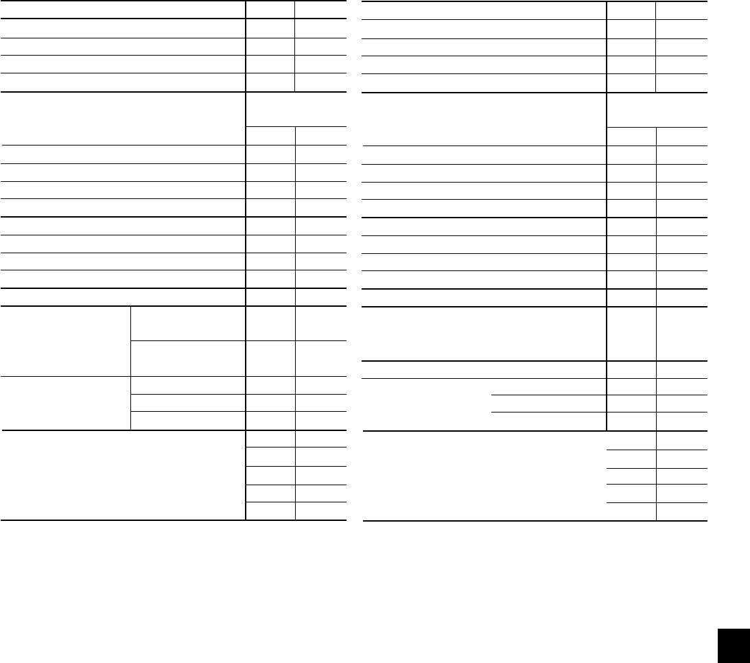
53
YORK INTERNATIONAL
FORM 201.19-NM1 (204)
OPERATING LIMITATIONS AND SOUND POWER DATA
7
OPERATING LIMITATIONS – ENGLISH UNITS
* Maximum Ambient w/ High Ambient Kit is 130°F.
MIN MAX
LEAVING CHILLED LIQUID TEMP ( °F) 40.1 59
CHILLED WATER TEMP DIFFERENCE ( °F) 5.5 18
WATER SIDE PRESSURE (PSIG) 150
REFRIGERANT SIDE PRESSURE (PSIG) 300
EVAPORATOR FLOW
MODEL GALLONS/MINUTE
YCAS MIN. MAX.
0130EC 141 403
0140EC 141 403
0150EC 180 769
0160EC 141 403
0170EC 180 768
0180EC 180 768
0200EC 180 768
0210EC 180 768
0230EC 180 768
AIR STANDARD FANS 0 115*
ENTERING HIGH PRESS. FANS 0 115*
CONDENSER (°F)
FAN STANDARD FANS 20
AVAILABLE STATIC HIGH PRESS. FANS OPTION 1 85
PRESSURE (Pa) HIGH PRESS. FANS OPTION 2 150
LOW NOISE (4 PL) 10
ELECTRICAL THREE PHASE 60 Hz (V) 200
230
380
460
575 440
OPERATING LIMITATIONS – SI UNITS
* Maximum Ambient w/ High Ambient Kit is 54°C.
MIN MAX
LEAVING CHILLED LIQUID TEMP ( °C) 4.5 15
CHILLED WATER TEMP DIFFERENCE ( °C) 3 10
WATER SIDE PRESSURE (BAR) – 10
REFRIGERANT SIDE PRESSURE (BAR) – 20
EVAPORATOR FLOW
MODEL LITERS/SECOND
YCAS MIN. MAX.
0130EC 8.9 25.43
0140EC 8.9 25.43
0150EC 11.3 48.45
0160EC 8.9 25.43
0170EC 11.3 48.45
0180EC 11.3 48.45
0200EC 11.3 48.45
0210EC 11.3 48.45
0230EC 11.3 48.45
AIR
STANDARD FANS –18 46
ENTERING
CONDENSER (°C)
FAN STANDARD FANS 20
AVAILABLE STATIC HIGH PRESS. FANS OPTION 1 85
PRESSURE (Pa) HIGH PRESS. FANS OPTION 2 150
SLOW SPEED FANS 10
ELECTRICAL THREE PHASE 60 Hz (V) 200
230
380
460
575
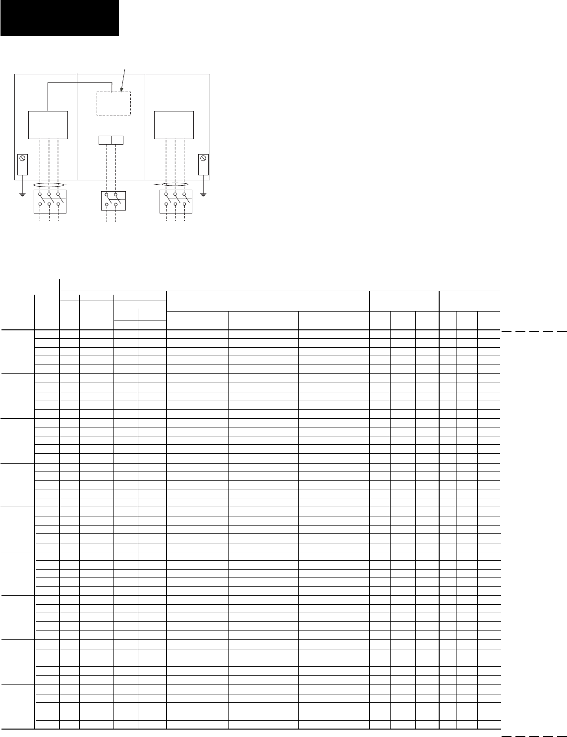
54 YORK INTERNATIONAL
FORM 201.19-NM1 (204)
ELECTRICAL DATA
Technical Data
MULTIPLE POINT POWER SUPPLY CONNECTION
Two fi eld provided power sup ply cir cuits to the unit. Field
Power Wiring connections to fac to ry provided, Non-Fused
Dis con nect Switches (Opt), Circuit Breakers (Opt) or
Ter mi nal Blocks (Opt).
Suitable for:
Y - ∆ Start and
Across-The-Line-Start
MULTIPLE POINT POWER SUPPLY CONNECTION - 2 COMPRESSOR UNITS
(Two Field Provided Power Supply Circuits To The Chiller. Field Connections to Factory Provided Terminal Block (Std), Disconnects (Opt),
or Individual System Circuit Breakers (Opt) in each of the two Motor Control Centers.)
See page 62 for Electrical Data footnotes.
LD05548
See page 62 for notes.
Options:
Term. Block
NF Disc SW
or Circ Brkr
1T
Control
Transformer
GRD
2 L
CTB
Options:
Term. Block
NF Disc SW
or Circ Brkr
GRD
CIRCUIT #1 CIRCUIT # 2
FIELD PROVIDED
UNIT POWER SUPPLY
FIELD PROVIDED
UNIT POWER SUPPLY STD FIELD PROVIDED
120-1-60Hz POWER SUP-
PLY (NOT REQUIRED IF
OPTIONAL CONTROL
TRANSFORMER FITTED)
OPTIONAL CONTROL
TRANSFORMER
SEE NOTE 3 SEE NOTE 3
SYSTEM #1 FIELD-SUPPLIED WIRING
MODEL VOLTS MIN NF FACTORY PROVIDED (LUGS) WIRE RANGE
7
COMPRESSOR FANS
11, 12
YCAS MCA
1
DISC SW
2, 9
STD. TERMINAL OPT. NF. OPT. C.B. RLA Y-LRA X-LRA QTY FLA LRA
MIN.
3, 5
MAX.
4, 6
BLOCK DISC SW. (EA.) (EA.)
200 340 400 450 500 (2)1/0 - 300 (2) 3/0-250 (3) 2/0-400 246 591 N/A 4 8.2 38.0
230 299 400 400 500 2/0 - (2) 4/0 (2) 3/0-250 (2) 3/0-250 214 481 N/A 4 7.8 33.0
0130EC 380 181 200 225 300 1/0 - 300 # 6 - 350 # 6 - 350 130 285 900 4 4.8 23.0
460 150 150 200 250 # 2 - 4/0 # 4 - 300 # 6 - 350 107 228 719 4 4.0 19.0
575 119 150 150 200 # 2 - 4/0 # 4 - 300 # 4 - 300 86 182 574 4 3.1 15.2
200 366 400 450 600 (2) 1/0 - 300 (2) 3/0-250 (3) 2/0-400 267 591 N/A 4 8.2 38.0
230 321 400 400 500 2/0 - (2) 4/0 (2) 3/0-250 (2) 3/0-250 232 481 N/A 4 7.8 33.0
0140EC 380 195 200 250 300 1/0 - 300 # 6 - 350 # 6 - 350 140 285 900 4 4.8 23.0
460 161 200 200 250 # 2 - 4/0 # 4 - 300 # 4 - 300 116 228 719 4 4.0 19.0
575 128 150 175 200 # 2 - 4/0 # 4 - 300 # 6 - 350 93 182 574 4 3.1 15.2
200 402 400 500 600 (2) 2/0 - 500 (2) 3/0-250 (3) 2/0-400 295 708 N/A 4 8.2 38.0
230 351 400 450 600 (2) 1/0 - 300 (2) 3/0-250 (3) 2/0-400 256 642 N/A 4 7.8 33.0
0150EC 380 213 250 300 350 2/0 - 500 # 6 - 350 (2) 3/0-250 155 343 1093 4 4.8 23.0
460 176 200 225 300 1/0 - 300 # 4 - 300 # 6 - 350 128 280 893 4 4.0 19.0
575 141 150 175 225 # 2 - 4/0 # 4 - 300 # 6 - 350 103 224 714 4 3.1 15.2
200 402 400 500 600 (2) 2/0 - 500 (2) 3/0-250 (3) 2/0-400 295 708 N/A 4 8.2 38.0
230 351 400 450 600 (2) 1/0 - 300 (2) 3/0-250 (3) 2/0-400 256 642 N/A 4 7.8 33.0
0160EC 380 213 250 300 350 # 1 - 300 # 6 - 350 (2) 3/0-250 155 343 1093 4 4.8 23.0
460 176 200 225 300 1/0 - 300 # 6 - 350 # 6 - 350 128 280 893 4 4.0 19.0
575 141 150 175 225 # 2 - 4/0 # 4 - 300 # 6 - 350 103 224 714 4 3.1 15.2
200 434 600 600 700 (2) 2/0 - 500 (3) 2/0-400 (3) 2/0-400 321 708 N/A 4 8.2 38.0
230 380 400 450 600 (2) # 1 - 300 (2) 3/0-250 (3) 2/0-400 279 642 N/A 4 7.8 33.0
0170EC 380 230 250 300 350 2/0 - 500 # 6 - 350 (2) 3/0-250 169 343 1093 4 4.8 23.0
460 191 200 250 300 1/0 - 300 # 6 - 350 # 6 - 350 140 280 893 4 4.0 19.0
575 152 150 200 250 # 2 - 4/0 # 4 - 300 # 6 - 350 112 224 714 4 3.1 15.2
200 434 600 600 700 (2) 2/0 - 500 (3) 2/0-400 (3) 2/0-400 321 708 N/A 4 8.2 38.0
230 380 400 450 600 (2) 2/0 - 500 (2) 3/0-250 (3) 2/0-400 279 642 N/A 4 7.8 33.0
0180EC 380 230 250 300 350 2/0 - 500 # 6 - 350 (2) 3/0-250 169 343 1093 4 4.8 23.0
460 191 200 250 300 1/0 - 300 # 6 - 350 # 6 - 350 140 280 893 4 4.0 19.0
575 152 150 200 250 # 2 - 4/0 # 4 - 300 # 6 - 350 112 224 714 4 3.1 15.2
200 469 600 600 800 (2) 2/0 - 500 (3) 2/0-400 (3) 2/0-400 342 708 N/A 5 8.2 38.0
230 412 400 500 700 (2) 2/0 - 500 (2) 3/0-250 (3) 2/0-400 298 642 N/A 5 7.8 33.0
0200EC 380 250 250 300 400 2/0 - 500 # 6 - 350 (2) 3/0-250 181 343 1093 5 4.8 23.0
460 206 200 250 350 # 1 - 300 # 6 - 350 # 6 - 350 149 280 893 5 4.0 19.0
575 164 200 200 250 1/0 - 300 # 6 - 350 # 6 - 350 119 224 714 5 3.1 15.2
200 509 600 700 800 (2) 2/0 - 500 (3) 2/0-400 (3) 2/0-400 374 708 N/A 5 8.2 38.0
230 445 600 600 700 (2) 2/0 - 500 (3) 2/0-400 (3) 2/0-400 325 642 N/A 5 7.8 33.0
0210EC 380 270 400 350 450 2/0 - 500 (2) 3/0-250 (2) 3/0-250 197 343 1093 5 4.8 23.0
460 224 250 300 350 2/0 - 500 # 6 - 350 (2) 3/0-250 163 280 893 5 4.0 19.0
575 178 200 225 300 1/0 - 300 # 6 - 350 # 6 - 350 130 224 714 5 3.1 15.2
200 509 600 700 800 (2) 2/0 - 500 (3) 2/0-400 (3) 2/0-400 374 708 N/A 5 8.2 38.0
230 445 600 600 700 (2) 2/0 - 500 (3) 2/0-400 (3) 2/0-400 325 642 N/A 5 7.8 33.0
0230EC 380 270 400 350 450 2/0 - 500 (2) 3/0-250 (2) 3/0-250 197 343 1093 5 4.8 23.0
460 224 250 300 350 2/0 - 500 # 6 - 350 (2) 3/0-250 163 280 893 5 4.0 19.0
575 178 200 225 300 1/0 - 300 # 6 - 350 # 6 - 350 130 224 714 5 3.1 15.2
OVER-CURRENT
PROTECTION
FIELD PROVIDED POW ER SUP PLY
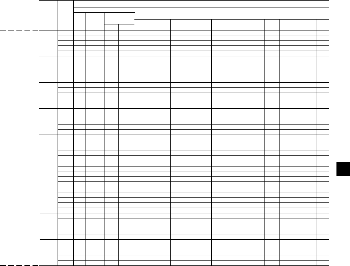
55
YORK INTERNATIONAL
FORM 201.19-NM1 (204)
ELECTRICAL DATA
7
SYSTEM #2 FIELD-SUPPLIED WIRING
MODEL VOLTS MIN NF FACTORY PROVIDED (LUGS) WIRE RANGE7
COMPRESSOR FANS11, 12
YCAS MCA1 DISC SW2, 9 STD. TERMINAL OPT. NF. OPT. C.B. RLA Y-LRA X-LRA QTY FLA LRA
MIN.3, 5 MAX.4, 6 BLOCK DISC SW. (EA.) (EA.)
200 343 400 450 500 (2) 1/0 - 300 (2) 3/0-250 (3) 2/0-400 246 591 N/A 4 8.2 38.0
230 298 400 400 500 2/0 - (2) 4/0 (2) 3/0-250 (2) 3/0-250 214 481 N/A 4 7.8 33.0
0130EC 380 180 200 225 300 1/0 - 300 # 6 - 350 # 6 - 350 130 285 900 4 4.8 23.0
460 149 150 200 250 # 2 - 4/0 # 4 - 300 # 6 - 350 107 228 719 4 4.0 19.0
575 119 150 150 200 # 2 - 4/0 # 4 - 300 # 4 - 300 86 182 574 4 3.1 15.2
200 368 400 450 600 (2) 1/0 - 300 (2) 3/0-250 (3) 2/0-400 267 591 N/A 4 8.2 38.0
230 320 400 400 500 2/0 - (2) 4/0 (2) 3/0-250 (2) 3/0-250 232 481 N/A 4 7.8 33.0
0140EC 380 194 200 250 300 1/0 - 300 # 6 - 350 # 6 - 350 140 285 900 4 4.8 23.0
460 160 200 200 250 # 2 - 4/0 # 4 - 300 # 6 - 350 116 228 719 4 4.0 19.0
575 128 150 175 200 # 2 - 4/0 # 4 - 300 # 4 - 300 93 182 574 4 3.1 15.2
200 366 400 450 600 (2) 1/0 - 300 (2) 3/0-250 (3) 2/0-400 265 591 N/A 4 8.2 38.0
230 318 400 400 500 (2) 1/0 - 300 (2) 3/0-250 (2) 3/0-250 230 481 N/A 4 7.8 33.0
0150EC 380 192 200 250 300 1/0 - 300 # 6 - 350 # 6 - 350 139 285 900 4 4.8 23.0
460 159 150 200 250 1/0 - 300 # 6 - 350 # 6 - 350 115 228 719 4 4.0 19.0
575 127 150 175 200 # 2 - 4/0 # 4 - 300 # 4 - 300 92 182 574 4 3.1 15.2
200 404 400 500 600 (2) 2/0 - 500 (2) 3/0-250 (3) 2/0-400 295 708 N/A 4 8.2 38.0
230 350 400 450 600 (2) 1/0 - 300 (2) 3/0-250 (3) 2/0-400 256 642 N/A 4 7.8 33.0
0160EC 380 212 200 300 350 2/0 - 500 # 6 - 350 (2) 3/0-250 155 343 1093 4 4.8 23.0
460 175 200 225 300 1/0 - 300 # 6 - 350 # 6 - 350 128 280 893 4 4.0 19.0
575 141 150 175 225 # 2 - 4/0 # 4 - 300 # 6 - 350 103 224 714 4 3.1 15.2
200 404 400 500 600 (2) 2/0 - 500 (2) 3/0-250 (3) 2/0-400 295 708 N/A 4 8.2 38.0
230 350 400 450 600 (2) 1/0 - 300 (2) 3/0-250 (3) 2/0-400 256 642 N/A 4 7.8 33.0
0170EC 380 212 200 300 350 # 1 - 300 # 6 - 350 (2) 3/0-250 155 343 1093 4 4.8 23.0
460 175 200 225 300 1/0 - 300 # 6 - 350 # 6 - 350 128 280 893 4 4.0 19.0
575 141 150 175 225 # 2 - 4/0 # 4 - 300 # 6 - 350 103 224 714 4 3.1 15.2
200 436 600 600 700 (2) 2/0 - 500 (3) 2/0-400 (3) 2/0-400 321 708 N/A 4 8.2 38.0
230 379 400 450 600 (2) 2/0 - 500 (2) 3/0-250 (3) 2/0-400 279 642 N/A 4 7.8 33.0
0180EC 380 230 250 300 350 2/0 - 500 # 6 - 350 (2) 3/0-250 169 343 1093 4 4.8 23.0
460 190 200 250 300 1/0 - 300 # 6 - 350 # 6 - 350 140 280 893 4 4.0 19.0
575 152 150 200 250 # 2 - 4/0 # 4 - 300 # 6 - 350 112 224 714 4 3.1 15.2
200 471 600 600 800 (2) 2/0 - 500 (3) 2/0-400 (3) 2/0-400 342 708 N/A 5 8.2 38.0
230 411 400 500 700 (2) 2/0 - 500 (2) 3/0-250 (3) 2/0-400 298 642 N/A 5 7.8 33.0
0200EC 380 249 250 300 400 2/0 - 500 # 6 - 350 (2) 3/0-250 181 343 1093 5 4.8 23.0
460 205 200 250 350 2/0 - 500 # 6 - 350 # 6 - 350 149 280 893 5 4.0 19.0
575 164 200 200 250 1/0 - 300 # 6 - 350 # 6 - 350 119 224 714 5 3.1 15.2
200 471 600 600 800 (2) 2/0 - 500 (3) 2/0-400 (3) 2/0-400 342 708 N/A 5 8.2 38.0
230 411 400 500 700 (2) 2/0 - 500 (2) 3/0-250 (3) 2/0-400 298 642 N/A 5 7.8 33.0
0210EC 380 249 250 300 400 2/0 - 500 # 6 - 350 (2) 3/0-250 181 343 1093 5 4.8 23.0
460 205 200 250 350 # 1 -300 # 6 - 350 # 6 - 350 149 280 893 5 4.0 19.0
575 164 200 200 250 1/0 - 300 # 4 - 300 # 6 - 350 119 224 714 5 3.1 15.2
200 511 600 700 800 (2) 2/0 - 500 (3) 2/0-400 (3) 2/0-400 374 708 N/A 5 8.2 38.0
230 444 600 600 700 (2) 2/0 - 500 (3) 2/0-400 (3) 2/0-400 325 642 N/A 5 7.8 33.0
0230EC 380 269 400 350 450 2/0 - 500 (2) 3/0-250 (2) 3/0-250 197 343 1093 5 4.8 23.0
460 223 250 300 350 2/0 - 500 # 6 - 350 (2) 3/0-250 163 280 893 5 4.0 19.0
575 178 200 225 300 1/0 - 300 # 6 - 350 # 6 - 350 130 224 714 5 3.1 15.2
OVER-CURRENT
PROTECTION
FIELD PROVIDED POW ER SUP PLY
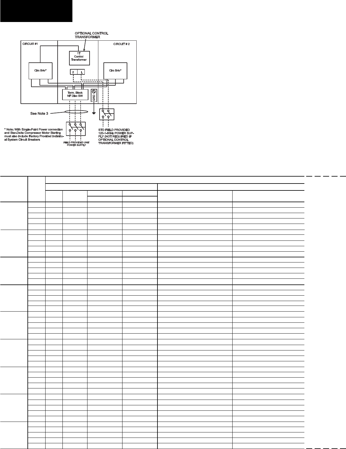
56 YORK INTERNATIONAL
FORM 201.19-NM1 (204)
ELECTRICAL DATA
Technical Data
One fi eld provided power supply circuit to the unit.
Field con nec tions to factory pro vid ed Non-Fused
Dis con nect Switch (Opt), or Terminal Block (Opt).
Factory con nec tions to Circuit Breakers on Ter mi nal
Blocks in each of the two Power Panels.
OPTIONAL SINGLE-POINT POWER SUPPLY
CONNECTION AND INDIVIDUAL SYSTEM CIRCUIT
BREAKERS
Suitable for:
Y - ∆ Start and
Across-The-Line-Start
See page 62 for notes.
OPTIONAL SINGLE-POINT POWER SUPPLY WITH INDIVIDUAL SYSTEM CIRCUIT BREAKERS –
2 COMPRESSOR UNITS
(One Field Provided Power Supply Circuit to the chiller. Field connections to Factory Provided Terminal Block (standard) or Non-Fused Disconnect (option).
Individual System Circuit Breakers in each Motor Control Center10)
See page 62 for Electrical Data footnotes.
CHILLER FIELD-SUPPLIED WIRING
MODEL VOLTS FIELD PROVIDED POWER SUPPLY FACTORY PROVIDED (LUGS) WIRE RANGE 7
YCAS MIN NF OVER-CURRENT PROTECTION13 STANDARD OPTIONAL NF
MCA1
DISC SW2, 9 MIN.3, 5 MAX.4, 6 TERMINAL BLOCK DISC. SWITCH
200 619.3 800 700 700 (3) 2/0 - 500 (3) 2/0-400
230 543.9 600 600 700 (2) 2/0 - 500 (2) 250-500
0130EC 380 329.8 400 400 450 (2) 1/0 - 300 (2) 3/0-250
460 272.8 400 300 350 2/0 - 500 (2) 3/0-250
575 217.4 250 250 300 2/0 - 500 # 6 - 350
200 665.9 800 800 800 (3) 2/0 - 500 (3) 2/0-400
230 584.4 800 700 800 (3) 2/0 - 500 (2) 250-500
0140EC 380 354.3 400 400 450 (2) 1/0 - 300 (2) 3/0-250
460 293.0 400 350 400 (2) 1/0 - 300 (2) 3/0-250
575 233.6 250 300 300 2/0 - 500 # 6 - 350
200 698.9 800 800 800 (3) 2/0 - 500 (3) 2/0-400
230 612.4 800 700 800 (3) 2/0 - 500 (3) 2/0-400
0150EC 380 371.4 400 450 500 (2) 2/0 - 500 (2) 3/0-250
460 307.0 400 350 400 (2) 1/0 - 300 (2) 3/0-250
575 245.6 400 300 300 2/0 - 500 (2) 3/0-250
200 729.4 800 1000 800 (3) 2/0 - 500 (3) 2/0-400
230 638.4 800 800 800 (3) 2/0 - 500 (3) 2/0-400
0160EC 380 387.2 600 450 500 (2) 2/0 - 500 (2) 250-500
460 320.0 400 400 400 (2) 1/0 - 300 (2) 3/0-250
575 256.6 400 300 300 2/0 - 500 (2) 3/0-250
200 761.9 800 1000 1000 (3) 2/0 - 500 (3) 2/0-400
230 667.2 800 800 800 (3) 2/0 - 500 (3) 2/0-400
0170EC 380 404.7 600 450 500 (2) 2/0 - 500 (2) 250-500
460 335.0 400 400 400 (2) 1/0 - 300 (2) 3/0-250
575 267.8 400 300 350 2/0 - 500 (2) 3/0-250
200 787.9 1000 1000 1000 N/A N/A
230 690.2 800 800 800 N/A N/A
0180EC 380 418.7 600 500 500 (2) 2/0 - 500 (2) 250-500
460 347.0 400 400 450 (2) 1/0 - 300 (2) 3/0-250
575 276.8 400 350 350 (2) 1/0 - 300 (2) 3/0-250
200 851.5 1000 1000 1000 N/A N/A
230 748.5 800 1000 800 N/A N/A
0200EC 380 455.3 600 600 500 (2) 2/0 - 500 (2) 250-500
460 375.3 400 450 450 (2) 2/0 - 500 (2) 3/0-250
575 298.8 400 350 350 (2) 1/0 - 300 (2) 3/0-250
200 891.5 1000 1000 1000 N/A N/A
230 782.3 1000 1000 1000 N/A N/A
0210EC 380 475.3 600 600 600 (2) 2/0 - 500 (2) 250-500
460 392.8 600 450 500 (2) 2/0 - 500 (2) 250-500
575 312.5 400 350 400 (2) 1/0 - 300 (2) 3/0-250
200 923.5 1000 1200 1200 N/A N/A
230 809.3 1000 1000 1000 N/A N/A
0230EC 380 491.3 600 600 600 (2) 2/0 - 500 (2) 250-500
460 406.8 600 450 500 (2) 2/0 - 500 (2) 250-500
575 323.5 400 400 450 (2) 1/0 - 300 (2) 3/0-250
LD05549
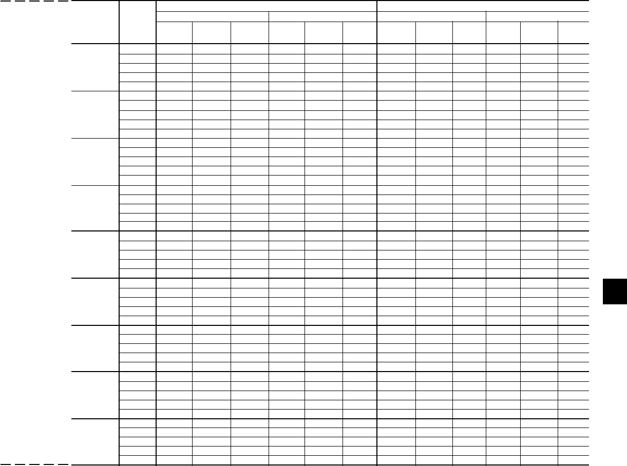
57
YORK INTERNATIONAL
FORM 201.19-NM1 (204)
ELECTRICAL DATA
7
SYSTEM #1 SYSTEM #2
MODEL VOLTS COMPRESSOR DATA FAN DATA11, 12 COMPRESSOR DATA FAN DATA11, 12
YCAS RLA Y-LRA X-LRA QTY FLA LRA RLA Y-LRA X-LRA QTY FLA LRA
(EA.) (EA) (EA) (EA)
200 246.1 591 1866 4 8.2 38.0 246.1 591 1866 4 8.2 38.0
230 214.0 481 1518 4 7.8 33.0 214.0 481 1518 4 7.8 33.0
0130EC 380 129.5 285 900 4 4.8 23.0 129.5 285 900 4 4.8 23.0
460 107.0 228 719 4 4.0 19.0 107.0 228 719 4 4.0 19.0
575 85.6 182 574 4 3.1 15.2 85.6 182 574 4 3.1 15.2
200 266.8 591 1866 4 8.2 38.0 266.8 591 1866 4 8.2 38.0
230 232.0 481 1518 4 7.8 33.0 232.0 481 1518 4 7.8 33.0
0140EC 380 140.4 285 900 4 4.8 23.0 140.4 285 900 4 4.8 23.0
460 116.0 228 719 4 4.0 19.0 116.0 228 719 4 4.0 19.0
575 92.8 182 574 4 3.1 15.2 92.8 182 574 4 3.1 15.2
200 295.0 708 2256 4 8.2 38.0 264.5 591 1866 4 8.2 38.0
230 256.0 642 2045 4 7.8 33.0 230.0 481 1518 4 7.8 33.0
0150EC 380 155.0 343 1093 4 4.8 23.0 139.2 285 900 4 4.8 23.0
460 128.0 280 893 4 4.0 19.0 115.0 228 719 4 4.0 19.0
575 103.0 224 714 4 3.1 15.2 92.0 182 574 4 3.1 15.2
200 295.0 708 2256 4 8.2 38.0 295.0 708 2256 4 8.2 38.0
230 256.0 642 2045 4 7.8 33.0 256.0 642 2045 4 7.8 33.0
0160EC 380 155.0 343 1093 4 4.8 23.0 155.0 343 1093 4 4.8 23.0
460 128.0 280 893 4 4.0 19.0 128.0 280 893 4 4.0 19.0
575 103.0 224 714 4 3.1 15.2 103.0 224 714 4 3.1 15.2
200 321.0 708 2256 4 8.2 38.0 295.0 708 2256 4 8.2 38.0
230 279.0 642 2045 4 7.8 33.0 256.0 642 2045 4 7.8 33.0
0170EC 380 169.0 343 1093 4 4.8 23.0 155.0 343 1093 4 4.8 23.0
460 140.0 280 893 4 4.0 19.0 128.0 280 893 4 4.0 19.0
575 112.0 224 714 4 3.1 15.2 103.0 224 714 4 3.1 15.2
200 321.0 N/A N/A 4 8.2 38.0 321.0 N/A N/A 4 8.2 38.0
230 279.0 N/A N/A 4 7.8 33.0 279.0 N/A N/A 4 7.8 33.0
0180EC 380 169.0 343 1093 4 4.8 23.0 169.0 343 1093 4 4.8 23.0
460 140.0 280 893 4 4.0 19.0 140.0 280 893 4 4.0 19.0
575 112.0 224 714 4 3.1 15.2 112.0 224 714 4 3.1 15.2
200 342.0 N/A N/A 5 8.2 38.0 342.0 N/A N/A 5 8.2 38.0
230 298.0 N/A N/A 5 7.8 33.0 298.0 N/A N/A 5 7.8 33.0
0200EC 380 181.0 343 1093 5 4.8 23.0 181.0 343 1093 5 4.8 23.0
460 149.0 280 893 5 4.0 19.0 149.0 280 893 5 4.0 19.0
575 119.0 224 714 5 3.1 15.2 119.0 224 714 5 3.1 15.2
200 374.0 N/A N/A 5 8.2 38.0 342.0 N/A N/A 5 8.2 38.0
230 325.0 N/A N/A 5 7.8 33.0 298.0 N/A N/A 5 7.8 33.0
0210EC 380 197.0 343 1093 5 4.8 23.0 181.0 343 1093 5 4.8 23.0
460 163.0 280 893 5 4.0 19.0 149.0 280 893 5 4.0 19.0
575 130.0 224 714 5 3.1 15.2 119.0 224 714 5 3.1 15.2
200 374.0 N/A N/A 5 8.2 38.0 374.0 N/A N/A 5 8.2 38.0
230 325.0 N/A N/A 5 7.8 33.0 325.0 N/A N/A 5 7.8 33.0
0230EC 380 197.0 343 1093 5 4.8 23.0 197.0 343 1093 5 4.8 23.0
460 163.0 280 893 5 4.0 19.0 163.0 280 893 5 4.0 19.0
575 130.0 224 714 5 3.1 15.2 130.0 224 714 5 3.1 15.2
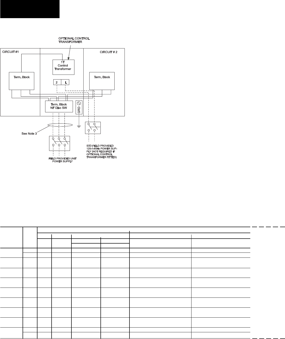
58 YORK INTERNATIONAL
FORM 201.19-NM1 (204)
ELECTRICAL DATA
One fi eld provided power supply circuit to the unit.
Field con nec tions to fac to ry pro vid ed Non-Fused
Dis con nect Switch (Opt), or Ter mi nal Block (Opt).
Factory con nec tions to Terminal Blocks in each of the
two Pow er Pan els.
OPTIONAL SINGLE-POINT POWER SUPPLY
CONNECTION WITH FIELD SUPPLIED CIRCUIT
PROTECTION
Suitable for:
Y - ∆ Start and
Across-The-Line-Start
OPTIONAL SINGLE-POINT POWER SUPPLY CONNECTION – 2 COMPRESSOR UNITS
(One Field Provided Power Supply Circuit to the Chiller. Field connections to Factory Provided Terminal Block (Standard) or Non-Fused Disconnect (option).
No Internal Branch Circuit Protection (Breakers) per Motor Control Center10)
See page 62 for Electrical Data footnotes.
See page 62 for notes.
Technical Data
CHILLER FIELD-SUPPLIED WIRING
MODEL VOLTS FIELD PROVIDED POWER SUPPLY FACTORY PROVIDED (LUGS) WIRE RANGE 7
YCAS MIN NF OVER-CURRENT PROTECTION13 STANDARD OPTIONAL NF
MCA1
DISC SW2, 9 MIN.3, 5 MAX.4, 6 TERMINAL BLOCK DISC. SWITCH
0130EC 460 273 400 300 350 # 1 - 500 (2) 3/0-250
575 217 250 250 300 # 1 - 500 # 6 - 350
0140EC 460 293 400 350 400 (2) # 2 - 300 (2) 3/0-250
575 234 250 300 300 # 1 - 500 # 6 - 350
0150EC 460 307 400 350 400 (2) # 2 - 300 (2) 3/0-250
575 246 400 300 300 # 1 - 500 (2) 3/0-250
0160EC 460 320 400 400 400 (2) # 2 - 300 (2) 3/0-250
575 257 400 300 350 # 1 - 500 (2) 3/0-250
0170EC 460 335 400 400 450 (2) # 2 - 300 (2) 3/0-250
575 268 400 300 350 # 1 - 500 (2) 3/0-250
0180EC 460 347 400 400 450 (2) # 2 - 300 (2) 3/0-250
575 277 400 350 350 (2) # 2 - 300 (2) 3/0-250
0200EC 460 375 400 450 500 (2) # 1 - 500 (2) 3/0-250
575 299 400 350 400 (2) # 2 - 300 (2) 3/0-250
0210EC 460 393 600 450 500 (2) # 1 - 500 (2) 250-500
575 313 400 350 400 (2) # 2 - 300 (2) 3/0-250
0230EC 460 407 600 450 500 (2) # 1 - 500 (2) 250-500
575 324 400 400 450 (2) # 2 - 300 (2) 3/0-250
LD05550

59
YORK INTERNATIONAL
FORM 201.19-NM1 (204)
7
ELECTRICAL DATA
SYSTEM #1 SYSTEM #2
MODEL VOLTS COMPRESSOR DATA FAN DATA11, 12 COMPRESSOR DATA FAN DATA11,12
YCAS RLA X-LRA QTY FLA LRA RLA X-LRA QTY FLA LRA
(EA.) (EA) (EA) (EA)
0130EC 460 107 719 4 4.0 19.0 107 719 4 4.0 19.0
575 86 574 4 3.1 15.2 86 574 4 3.1 15.2
0140EC 460 116 719 4 4.0 19.0 116 719 4 4.0 19.0
575 93 574 4 3.1 15.2 93 574 4 3.1 15.2
0150EC 460 128 893 4 4.0 19.0 115 719 4 4.0 19.0
575 103 714 4 3.1 15.2 92 574 4 3.1 15.2
0160EC 460 128 893 4 4.0 19.0 128 893 4 4.0 19.0
575 103 714 4 3.1 15.2 103 714 4 3.1 15.2
0170EC 460 140 893 4 4.0 19.0 128 893 4 4.0 19.0
575 112 714 4 3.1 15.2 103 714 4 3.1 15.2
0180EC 460 140 893 4 4.0 19.0 140 893 4 4.0 19.0
575 112 714 4 3.1 15.2 112 714 4 3.1 15.2
0200EC 460 149 893 5 4.0 19.0 149 893 5 4.0 19.0
575 119 714 5 3.1 15.2 119 714 5 3.1 15.2
0210EC 460 163 893 5 4.0 19.0 149 893 5 4.0 19.0
575 130 714 5 3.1 15.2 119 714 5 3.1 15.2
0230EC 460 163 893 5 4.0 19.0 163 893 5 4.0 19.0
575 130 714 5 3.1 15.2 130 714 5 3.1 15.2
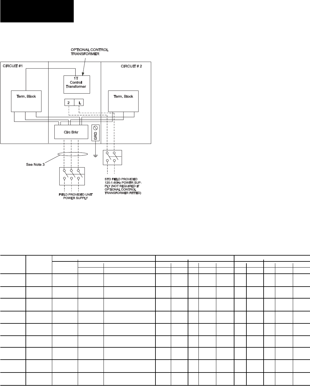
60 YORK INTERNATIONAL
FORM 201.19-NM1 (204)
ELECTRICAL DATA
Technical Data
Suitable for:
Across-The-Line-Start
One fi eld provided power supply circuit to the unit. Field
con nec tions to factory pro vid ed Circuit Breaker in the
Options Panel. Factory con nec tions to Terminal Blocks
in each of the two Power Pan els.
OPTIONAL SINGLE-POINT POWER SUPPLY
CONNECTION TO FACTORY CIRCUIT BREAKER
OPTIONAL SINGLE-POINT POWER SUPPLY CONNECTION TO FACTORY CIRCUIT BREAKER –
2 COMPRESSOR UNITS
(One Field Provided Power Supply Circuit to the chiller. Field Connections to Factory Provided Circuit Breaker.
No Internal Branch Circuit Protection (Breakers) per Motor Control Center10.)
NOTES: Wye-Delta Compressor Start not available with this op tion.
See page 62 for Electrical Data footnotes.
NOTES:
1. – – – – – – – Dashed Line indicates Field Provided Wiring.
2. The above recommendations are based on the National Electric Code and using copper connectors only.
Field wiring must also comply with local codes.
See page 62 for notes.
Technical Data
FIELD SUPPLIED WIRING SYSTEM #1 SYSTEM #2
MODEL VOLTS MCA1
FACTORY SUPPLIED BREAKER COMPRESSOR FANS11, 12 COMPRESSOR FANS11, 12
YCAS RATING2 WIRE RANGE7 (LUGS) RLA X-LRA QTY FLA(ea) LRA(ea) RLA X-LRA QTY FLA(ea) LRA(ea)
0130EC 460 273 400 (2) 3/0-250 107 719 4 4.0 19.0 107 719 4 4.0 19.0
575 217 250 # 6 - 350 86 574 4 3.1 15.2 86 574 4 3.1 15.2
0140EC 460 293 400 (2) 3/0-250 116 719 4 4.0 19.0 116 719 4 4.0 19.0
575 234 400 (2) 3/0-250 93 574 4 3.1 15.2 93 574 4 3.1 15.2
0150EC 460 307 400 (2) 3/0-250 128 893 4 4.0 19.0 115 719 4 4.0 19.0
575 246 400 (2) 3/0-250 103 714 4 3.1 15.2 92 574 4 3.1 15.2
0160EC 460 320 400 (2) 3/0-250 128 893 4 4.0 19.0 128 893 4 4.0 19.0
575 257 400 (2) 3/0-250 103 714 4 3.1 15.2 103 714 4 3.1 15.2
0170EC 460 335 400 (2) 3/0-250 140 893 4 4.0 19.0 128 893 4 4.0 19.0
575 268 400 (2) 3/0-250 112 714 4 3.1 15.2 103 714 4 3.1 15.2
0180EC 460 347 400 (2) 3/0-250 140 893 4 4.0 19.0 140 893 4 4.0 19.0
575 277 400 (2) 3/0-250 112 714 4 3.1 15.2 112 714 4 3.1 15.2
0200EC 460 375 600 (3) 2/0-400 149 893 5 4.0 19.0 149 893 5 4.0 19.0
575 299 400 (2) 3/0-250 119 714 5 3.1 15.2 119 714 5 3.1 15.2
0210EC 460 393 600 (3) 2/0-400 163 893 5 4.0 19.0 149 893 5 4.0 19.0
575 313 400 (2) 3/0-250 130 714 5 3.1 15.2 119 714 5 3.1 15.2
0230EC 460 407 600 (3) 2/0-400 163 893 5 4.0 19.0 163 893 5 4.0 19.0
575 324 400 (2) 3/0-250 130 714 5 3.1 15.2 130 714 5 3.1 15.2
LD05551
61
YORK INTERNATIONAL
FORM 201.19-NM1 (204)
ELECTRICAL DATA
COMPRESSOR DATA
MAXIMUM kW AND AMPERAGE VALUES FOR DXST COMPRESSORS
COMPRESSOR MODEL AND VOLTAGE CODE
DXS45LA – MOTOR CODE A DXS36LA – MOTOR CODE A DXS24LA – MOTOR CODE (TBD)
(B5N, B5E, B6N, B6E) (A5N, A5E, A6N, A6E) (C5N, C5E, C6N, C6E)
VOLTAGE CODE- -17 -28 -40 -46 -50 -58 -17 -28 -40 -46 -50 -58 -17 -28 -40 -46 -50 -56
MAX kW 150 150 150 150 113 150 150 150 150 150 113 150 105 105 105 105 80 105
MAX AMPS 492 428 259 214 193 171 492 428 259 214 193 171 338 294 178 147 135 118
7
62 YORK INTERNATIONAL
FORM 201.19-NM1 (204)
ELECTRICAL NOTES
NOTES:
1. Minimum circuit ampacity (MCA) is based on 125% of the rated load amps for the largest motor plus 100% of the rated load amps for all
other loads included in the circuit, per N.E.C. Article 430-24. If a Factory Mounted Control Transformer is pro vid ed, add the following to the
system #1 MCA values in the YCAS Tables: -17, add 15 amps; -28, add 12 amps; -40, add 7 amps; -46, add 6 amps; -58, add 5 amps.
2. The recommended disconnect switch is based on a minimum of 115% of the summation rated load amps of all the loads included in the circuit,
per N.E.C. 440 - 12A1.
3. Minimum recommended fuse size is based on 150% of the largest motor RLA plus 100% of the remaining RLAs. Minimum fuse rating = (1.5
x largest compressor RLA) + other compressor RLAs + (# fans x each fan motor FLA).
4. Maximum dual element fuse size is based on 225% maximum plus 100% of the rated load amps for all other loads included in the circuit, per
N.E.C. 440-22. Maximum fuse rating = (2.25 x largest compressor RLA) + other compressor RLAs + (# fans x each fan motor FLA).
5. Minimum recommended circuit breaker is 150% maximum plus 100% of rated load amps included in the circuit. Minimum circuit breaker rating
= (1.5 x largest compressor RLA) + other compressor RLAs + (# fans x each fan motor FLA).
6. Maximum circuit breaker is based on 225% maximum plus 100% of the rated load amps for all loads included in the circuit, per circuit, per
U.L. 1995 Fig. 36.2. Maximum circuit breaker rating = (2.25 x largest compressor RLA) + other com pres sor RLAs + ( # fans x each fan motor
FLA).
7. The Incoming Wire Range is the minimum and maximum wire size that can be accommodated by unit wiring lugs. The (1), (2), or (3) indicate
the number of termination points or lugs which are available per phase. Actual wire size and number of wires per phase must be determined
based on ampacity and job requirements using N.E.C. wire sizing information. The above recommendations are based on the National Electric
Code and using copper conductors only. Field wiring must also comply with local codes.
8. A ground lug is provided for each compressor system to accommodate fi eld grounding conductor per N.E.C. Article 250-54. A control circuit
grounding lug is also supplied. Incoming ground wire range is #6 - 350 MCM.
9. The fi eld supplied disconnect is a “Disconnecting Means” as defi ned in N.E.C. 100.B, and is intended for isolating the unit from the available
power supply to perform maintenance and troubleshooting. This disconnect is not intended to be a Load Break Device.
10.Two-Compressor machines with single-point power connection, and equipped with Star (Wye)-Delta Compressor motor start must also include
factory-provided individual system circuit breakers in each motor control center. All 3 & 4 Compressor machines equipped with Star-Delta
com pres sor motor start must also include factory-provided individual system circuit breakers in each motor control center.
11. Consult factory for Electrical Data on units equipped with “High Static Fan” option. High Static Fans are 3.8 kW each.
12.FLA for “Low Noise Fan” motors: 200V = 8.0A, 230V = 7.8A, 380V = 4.4A, 460V = 3.6A, 575V = 2.9A.
13.Group Rated breaker must be HACR type for cU.L. Machines.
NOTES & LEGEND
LEGEND
ACR-LINE ACROSS THE LINE START
C.B. CIRCUIT BREAKER
D.E. DUAL ELEMENT FUSE
DISC SW DISCONNECT SWITCH
FACT CB FACTORY-MOUNTED CIRCUIT BREAKER
FLA FULL LOAD AMPS
HZ HERTZ
MAX MAXIMUM
MCA MINIMUM CIRCUIT AMPACITY
MIN MINIMUM
MIN NF MINIMUM NON-FUSED
RLA RUNNING LOAD AMPS
S.P. WIRE SINGLE-POINT WIRING
Y-∆ WYE-DELTA START
X-LRA ACROSS-THE-LINE INRUSH LOCKED ROTOR AMPS
Y-LRA WYE-DELTA INRUSH LOCKED ROTOR AMPS
VOLTAGE CODE
-17 = 200-3-60
-28 = 230-3-60
-40 = 380-3-60
-46 = 460-3-60
-58 = 575-3-60
Technical Data
NO. OF CONTROL MCA MAX DUAL NON-FUSED
COMPRESSORS POWER (MAX LOAD ELEMENT DISCONNECT
SUPPLY CURRENT) FUSE SIZE SWITCH SIZE
2 115V-1Ø 20A 20A 20A
CONTROL POWER SUPPLY (UNITS WITHOUT STANDARD CONTROL CIRCUIT TRANSFORMER)

63
YORK INTERNATIONAL
FORM 201.19-NM1 (204)
This page intentionally left blank.
7
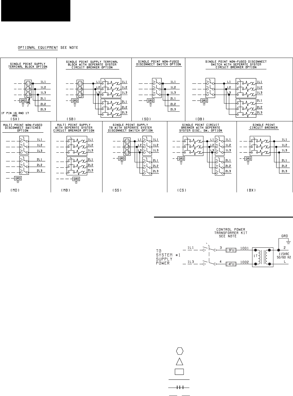
64 YORK INTERNATIONAL
FORM 201.19-NM1 (204)
Technical Data
WIRING DIAGRAM
ACROSS-THE-LINE START
NOTES:
1. Field wiring to be in accordance with the current edi tion of
the National Electrical Code as well as all oth er ap pli ca ble
codes and specifi cations.
2. Numbers along the right side of a diagram are line iden ti -
fi ca tion numbers. The numbers at each line in di cate the line
number lo ca tion of relay contacts. An unlined contact loca-
tion signifi es a nor mal ly closed contact. Numbers adjacent
to circuit lines are the cir cuit iden ti fi ca tion numbers.
3. Any customer supplied contacts must be suitable for
switching 24VDC. (Gold contacts rec om mend ed.) Con-
trol Wiring must not be run in the same conduit with any
line voltage wiring.
4. To cycle unit on and off automatically with contact
shown, install a cycling device in series with the fl ow
switch (FSLW). See Note 3 for contact rating and wiring
specifi cations. Also refer to cau tions on page 67.
5. To stop unit (Emergency Stop) with contacts other than
those shown, install the stop contact between 5 and 1. If
a stop device is not installed, a jumper must be con nect ed
between ter mi nals 5 and 1. De vice must have a min i mum
contact rating of 100VA at 115 volts A.C.
6. Alarm contacts are for annunciating alarm/unit mal func -
tion. Con tacts are rated at 115V, 100VA, re sis tive load only,
and must be suppressed at load by user.
7. See Installation, Operation and Maintenance Man u al when
op tion al equipment is used.
8. Control panel to be securely connected to earth ground.
9. Use 2KVA transformer in optional transformer kit un less
there are optional oil separator sump heaters which ne ces -
si tates using a 3KVA transformer.
LEGEND
Transient Voltage Suppression
Terminal Block for Customer Connections
Terminal Block for Customer Low Voltage
(Class 2) Connections. See Note 2
Terminal Block for YORK Connections Only
Wiring and Components by YORK
Optional Equipment
Wiring and/or Components by Others
T S
FIG. 17 – WIRING DIAGRAM – ACROSS-THE-LINE START
7.
LD09231
7.
LD09232
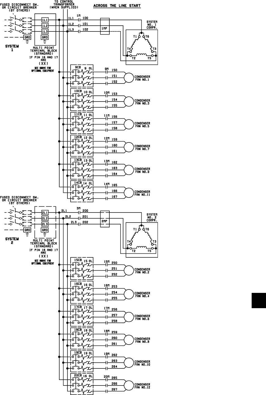
65
YORK INTERNATIONAL
FORM 201.19-NM1 (204)
LD09233
WIRING DIAGRAM
ACROSS-THE-LINE START
FIG. 18 – WIRING DIAGRAM – ACROSS-THE-LINE START
7

66 YORK INTERNATIONAL
FORM 201.19-NM1 (204)
Technical Data
ELEMENTARY DIAGRAM
FIG. 19 – ELEMENTARY DIAGRAM – ACROSS-THE-LINE START
3
4
6
5
LD09234
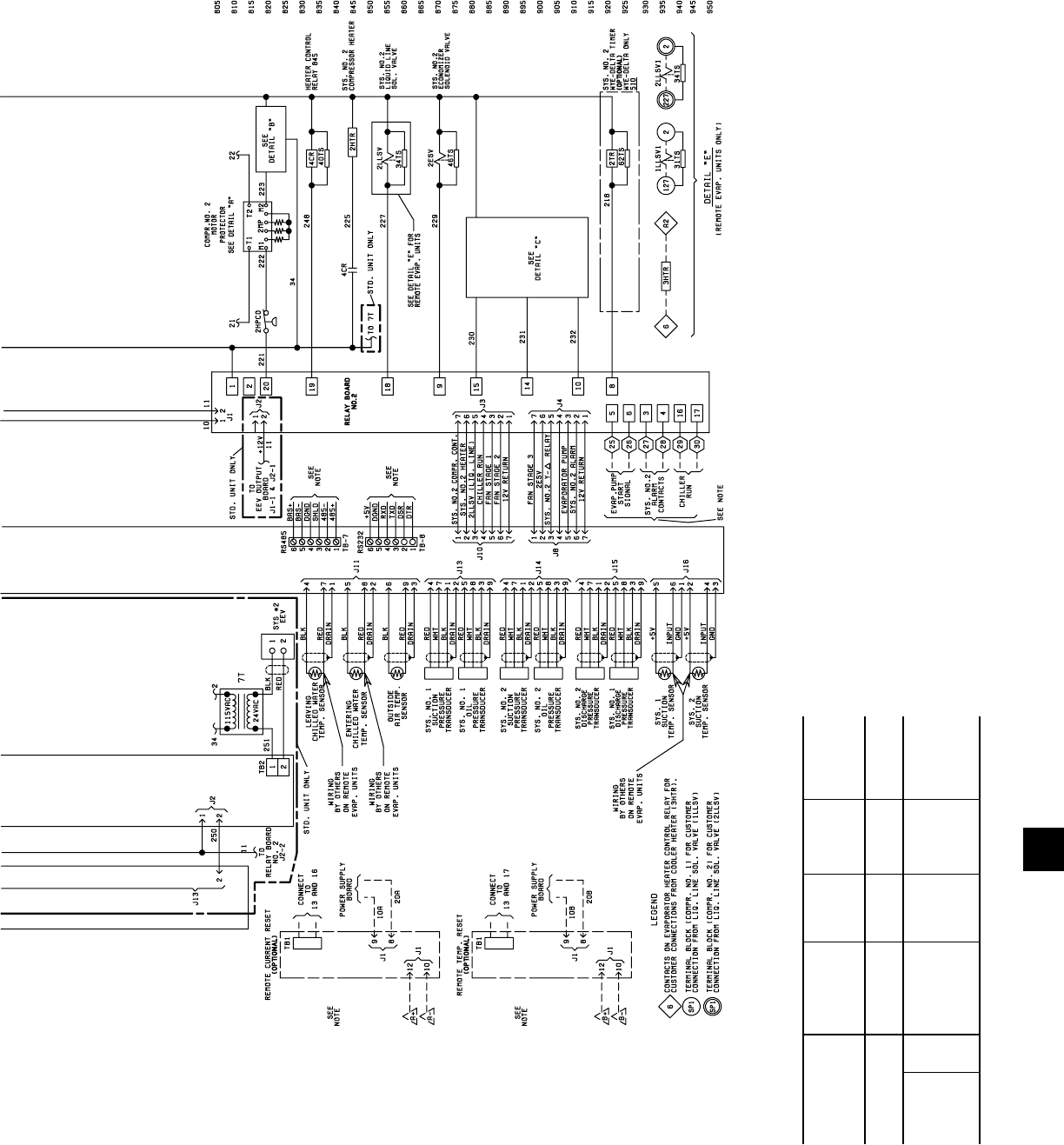
67
YORK INTERNATIONAL
FORM 201.19-NM1 (204)
CAUTION:
No Controls (relays, etc.) should
be mount ed in the Smart Panel
en clo sure or con nect ed to pow er
sup plies in the control pan el.
Additionally, con trol wir ing not
con nect ed to the Smart Panel
should not be run through the
cabinet. This could re sult in
nui sance faults.
CAUTION:
Any inductive devices (re lays)
wired in series with the flow
switch for start/stop, into the
Alarm cir cuit ry, or pilot relays
for pump start ers wired through
mo tor contactor aux il ia ry con-
tacts must be sup pressed with
YORK P/N 031-00808-000
sup pres sor across the re lay/
contactor coil.
Any contacts con nect ed to fl ow
switch inputs or BAS in puts on
ter mi nals 13 - 19 or TB3, or any
oth er ter mi nals, must be sup-
pressed with a YORK P/N 031-
00808-000 sup pres sor across the
re lay/con tac tor coil.
CAUTION:
Control wiring con nect ed to the
con trol panel should nev er be run
in the same con duit with pow er
wir ing.
ELEMENTARY DIAGRAM
7
7
7
6
7
7
FANS
LD09235
UNIT CONTROL MIN MAX DUAL NON-FUSED
VOLTAGE POWER CIRCUIT ELEMENT DISC.
SUPPLY AMP. FUSE SIZE SWITCH SIZE
ALL MODELS 115-1-50/60 20A 20A 250V 30A 240V
W/O TRANS.
MODELS -17 200-1-60 15A 15A 250V 30A 240V
WITH -28 230-1-60 15A 15A 250V 30A 240V
TRANS. -46 400-1-60 8A 8A 600V 30A 480V
* -58 575-1-60 8A 8A 600V 30A 600V
* All primary and secondary wiring between transformer and control panel in clud ed.
CONTROL POWER SUPPLY

68 YORK INTERNATIONAL
FORM 201.19-NM1 (204)
Technical Data
WIRING DIAGRAM
WYE-DELTA START
FIG. 20 – WIRING DIAGRAM – WYE-DELTA START
NOTES:
1. Field wiring to be in accordance with the current edi tion of
the National Electrical Code as well as all oth er ap pli ca ble
codes and specifi cations.
2. Numbers along the right side of a diagram are line iden ti -
fi ca tion numbers. The numbers at each line in di cate the line
number lo ca tion of relay contacts. An unlined contact loca-
tion signifi es a nor mal ly closed contact. Numbers adjacent
to circuit lines are the cir cuit iden ti fi ca tion numbers.
3. Any customer supplied contacts must be suitable for
switching 24VDC. (Gold contacts rec om mend ed.) Con-
trol Wiring must not be run in the same conduit with any
line voltage wiring.
4. To cycle unit on and off automatically with contact
shown, install a cycling device in series with the fl ow
switch (FSLW). See Note 3 for contact rating and wiring
specifi cations. Also refer to cau tions on page 71.
5. To stop unit (Emergency Stop) with contacts other than
those shown, install the stop contact between 5 and 1. If
a stop device is not installed, a jumper must be con nect ed
between ter mi nals 5 and 1. De vice must have a min i mum
contact rating of 100VA at 115 volts A.C.
6. Alarm contacts are for annunciating alarm/unit mal func -
tion. Con tacts are rated at 115V, 100VA, re sis tive load only,
and must be suppressed at load by user.
7. See Installation, Operation and Maintenance Man u al when
op tion al equipment is used.
8. Control panel to be securely connected to earth ground.
LEGEND
Transient Voltage Suppression
Terminal Block for Customer Connections
Terminal Block for Customer Low Voltage
(Class 2) Connections. See Note 2
Terminal Block for YORK Connections Only
Wiring and Components by YORK
Optional Equipment
Wiring and/or Components by Others
T S
7.
LD09231
7.
LD09232

69
YORK INTERNATIONAL
FORM 201.19-NM1 (204)
WIRING DIAGRAM
WYE-DELTA START
FIG. 21 – ELEMENTARY DIAGRAM – WYE-DELTA START
7
LD09236
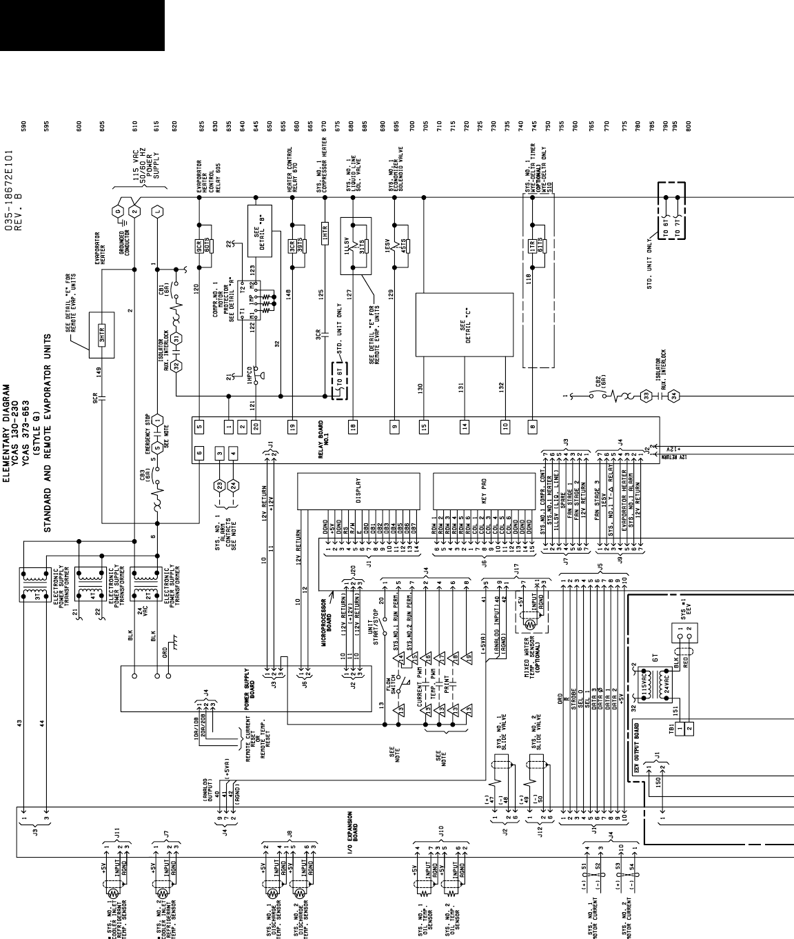
70 YORK INTERNATIONAL
FORM 201.19-NM1 (204)
Technical Data
ELEMENTARY DIAGRAM
FIG. 22 – ELEMENTARY DIAGRAM – WYE-DELTA START
3
4
6
5
LD09234

71
YORK INTERNATIONAL
FORM 201.19-NM1 (204)
CAUTION:
No Controls (relays, etc.) should
be mount ed in the Smart Panel
en clo sure or con nect ed to pow er
sup plies in the control pan el.
Additionally, con trol wir ing not
con nect ed to the Smart Panel
should not be run through the
cabinet. This could re sult in
nui sance faults.
CAUTION:
Any inductive devices (re lays)
wired in series with the flow
switch for start/stop, into the
Alarm cir cuit ry, or pilot relays
for pump start ers wired through
mo tor contactor aux il ia ry con-
tacts must be sup pressed with
YORK P/N 031-00808-000
sup pres sor across the re lay/
contactor coil.
Any contacts con nect ed to fl ow
switch inputs or BAS inputs on
ter mi nals 13 - 19 or TB3, or any
oth er ter mi nals, must be sup-
pressed with a YORK P/N 031-
00808-000 sup pres sor across the
re lay/con tac tor coil.
CAUTION:
Control wiring con nect ed to
the con trol panel should nev er
be run in the same con duit with
pow er wir ing.
ELEMENTARY DIAGRAM
7
7
7
6
7
7
FANS
LD09235
UNIT CONTROL MIN MAX DUAL NON-FUSED
VOLTAGE POWER CIRCUIT ELEMENT DISC.
SUPPLY AMP. FUSE SIZE SWITCH SIZE
ALL MODELS 115-1-50/60 20A 20A 250V 30A 240V
W/O TRANS.
MODELS -17 200-1-60 15A 15A 250V 30A 240V
WITH -28 230-1-60 15A 15A 250V 30A 240V
TRANS. -46 400-1-60 8A 8A 600V 30A 480V
* -58 575-1-60 8A 8A 600V 30A 600V
* All primary and secondary wiring between transformer and control panel in clud ed.
CONTROL POWER SUPPLY
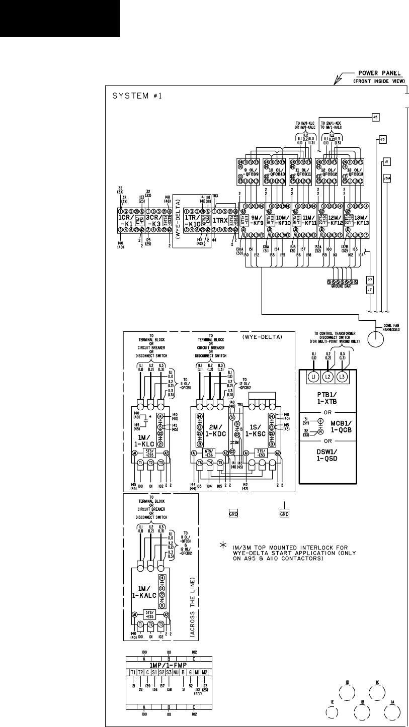
72 YORK INTERNATIONAL
FORM 201.19-NM1 (204)
Technical Data
FIG. 22A – POWER PANEL (SYSTEM #1) COMPONENT LO CA TIONS
LD09238

73
YORK INTERNATIONAL
FORM 201.19-NM1 (204)
LD09239
FIG. 22B – CONTROL PANEL COMPONENT LOCATION
7
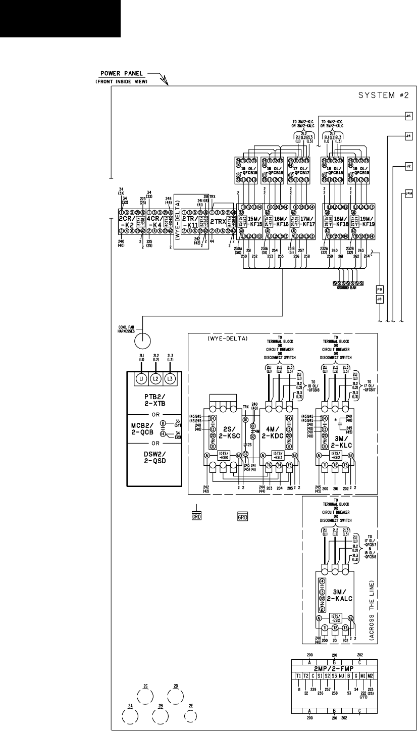
74 YORK INTERNATIONAL
FORM 201.19-NM1 (204)
Technical Data
FIG. 22C – POWER PANEL (SYSTEM #2) COMPONENT LO CA TIONS
LD09240
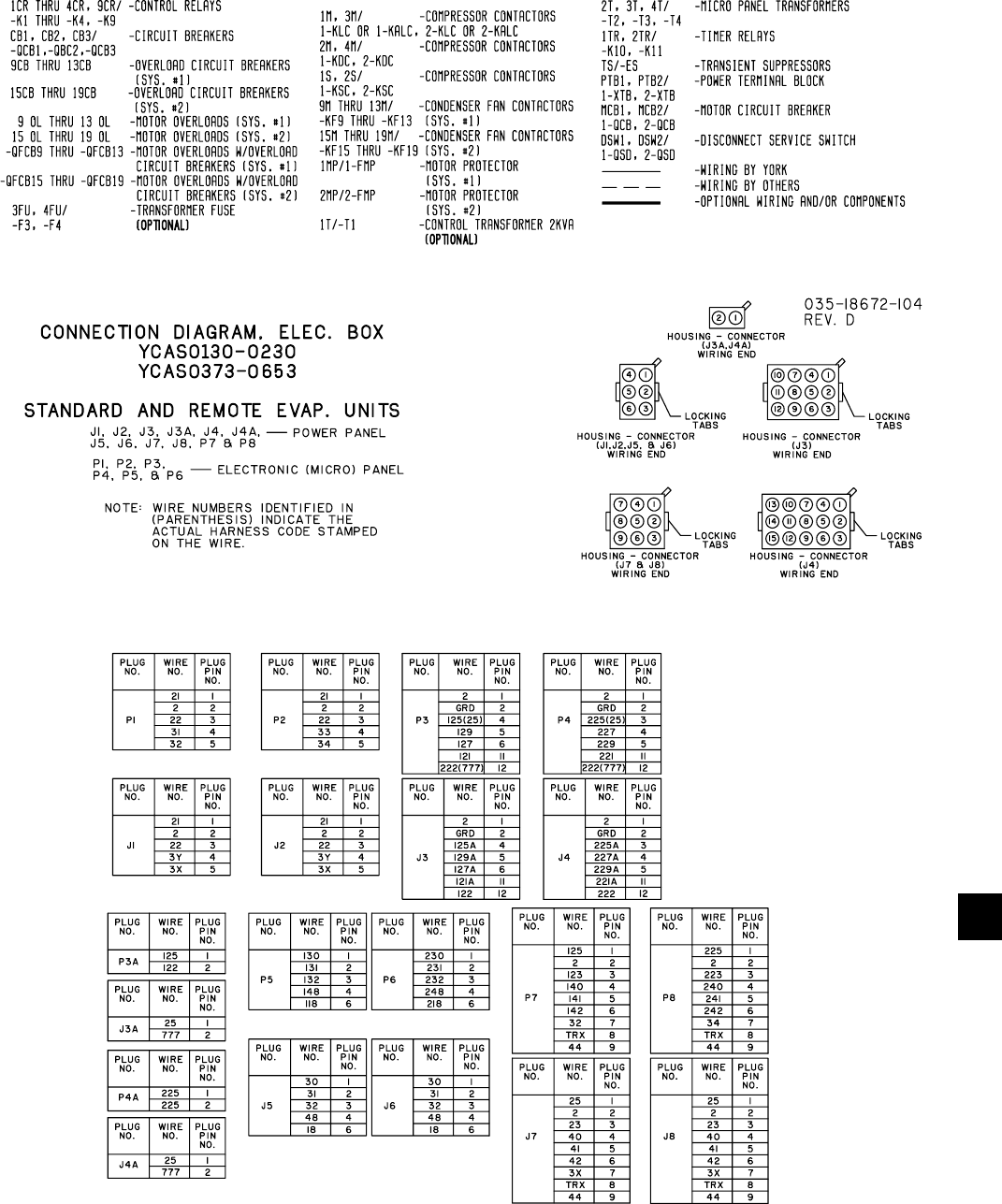
75
YORK INTERNATIONAL
FORM 201.19-NM1 (204)
7
LEGEND
LD09241
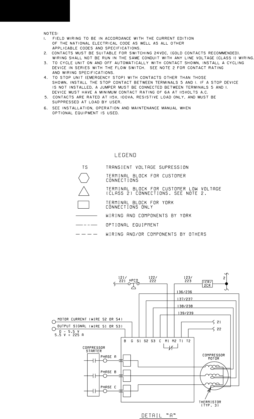
76 YORK INTERNATIONAL
FORM 201.19-NM1 (204)
Technical Data
LD03282
LD03283
2 ACE MOTOR
PROTECTOR MODULE
LD03284
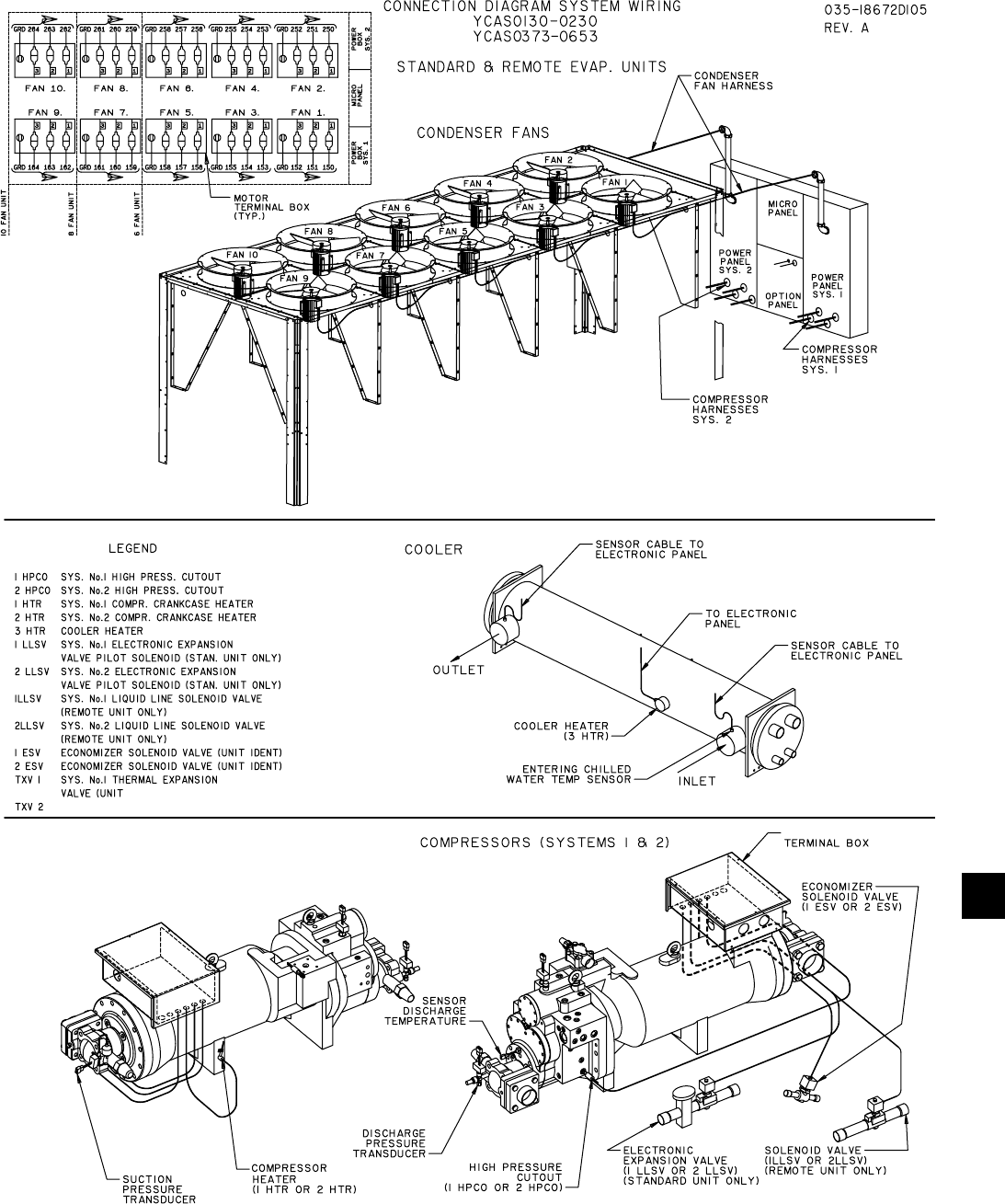
77
YORK INTERNATIONAL
FORM 201.19-NM1 (204)
7
CONNECTION DIAGRAM (SYSTEM WIRING)
LD09242

78 YORK INTERNATIONAL
FORM 201.19-NM1 (204)
Technical Data
COMPRESSOR TERMINAL BOX
LD09243
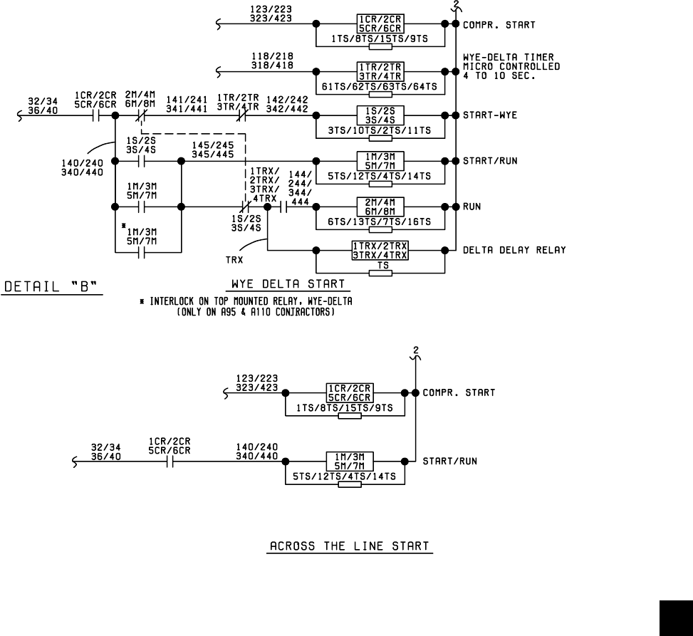
79
YORK INTERNATIONAL
FORM 201.19-NM1 (204)
7
LD09373
ELEMENTARY DIAGRAM
CONTROL CIRCUIT

80 YORK INTERNATIONAL
FORM 201.19-NM1 (204)
Technical Data
#3/#4
#5/#6
#3/#4
#5/#6
#7/#8
#5/#6
#3/#4
#7/#8
#9/#10
LD06840
ELEMENTARY DIAGRAM

81
YORK INTERNATIONAL
FORM 201.19-NM1 (204)
7
This page intentionally left blank.

82 YORK INTERNATIONAL
FORM 201.19-NM1 (204)
FIG. 23 – MODEL YCAS0130 - 0180 DIMENSIONS (ENGLISH)
Technical Data
DIMENSIONS – YCAS0130 - YCAS0180 (ENGLISH)
NOTES:
1. Placement on a level surface free of obstructions (including snow, for winter op er a tion) or air re cir cu la tion en sures rated per for mance, reli-
able operation and ease of maintenance. Site re stric tions may com pro mise minimum clearances in di cat ed be low, re sult ing in un pre dict able
air fl ow patterns and possible di min ished per for mance. YORK’s unit con trols will optimize op er a tion without nuisance high pres sure safe ty
cut out; how ev er, the system de sign er must consider po ten tial performance degradation. Access to the unit con trol center assumes the unit is
no higher than on spring isolators. Recommended min i mum clearances: Side to wall - 6'; rear to wall - 6'; control panel end to wall - 4'; top
- no obstructions allowed; distance be tween adjacent units - 10'. No more than one ad ja cent wall may be higher than the unit.
LD03742a
MODELS MODELS
DIMENSION 130 - 140 150 - 180
P 17-1/4" 18"
P
LD03742
0P0.71
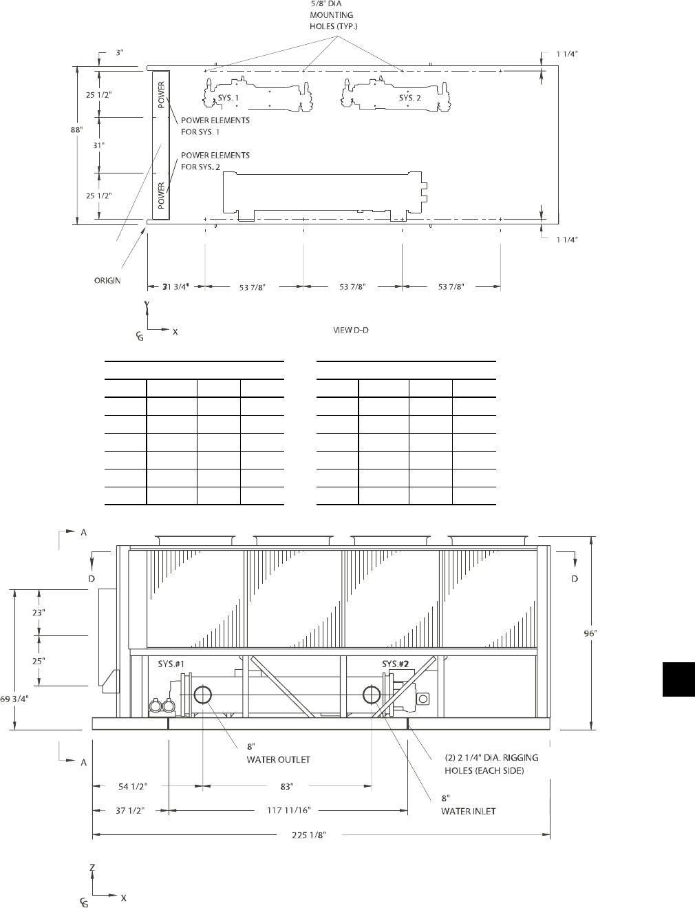
83
YORK INTERNATIONAL
FORM 201.19-NM1 (204)
DIMENSIONS – YCAS0130 - YCAS0180 (ENGLISH)
7
LD03744
CONTROL/OPTIONS
ABCD
EFG H
LD03743
CENTER OF GRAVITY (Cop per)
YCAS X Y Z
0130 103.5" 44.4" 40.7"
0140 103.5" 44.4" 40.7"
0150 108.2" 43.0" 39.2"
0160 108.4" 43.1" 39.1"
0170 108.4" 43.1" 39.1"
0180 108.4" 43.1" 39.1"
CENTER OF GRAVITY (Alum.)
YCAS X Y Z
0130 101.3" 44.4" 37.8"
0140 101.3" 44.4" 37.8"
0150 106.7" 42.8" 36.2"
0160 107.0" 43.0" 36.2"
0170 107.0" 43.0" 36.2"
0180 107.0" 43.0" 36.2"
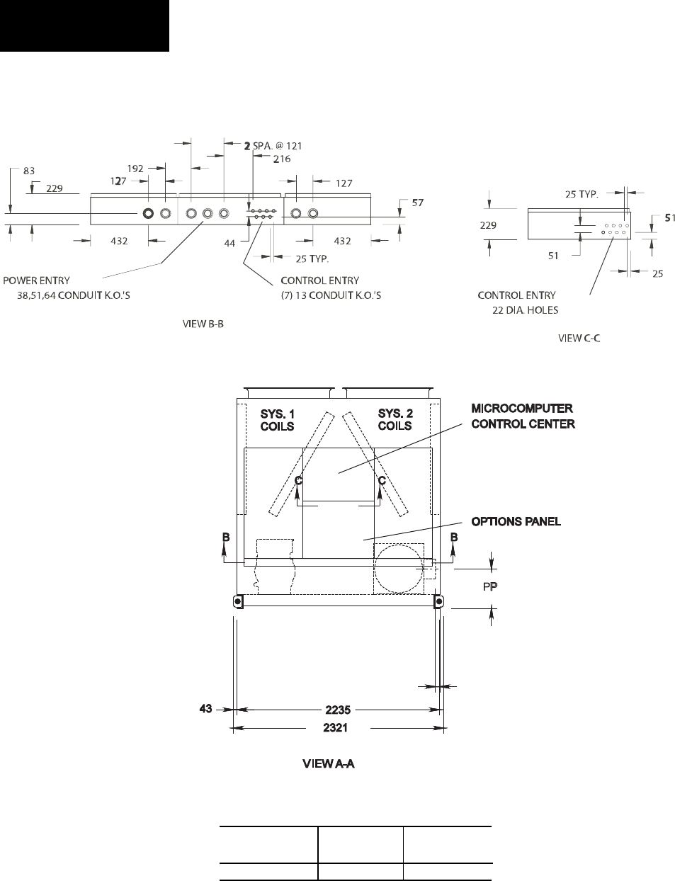
84 YORK INTERNATIONAL
FORM 201.19-NM1 (204)
FIG. 24 – MODEL YCAS0130 - 0180 DIMENSIONS (SI)
Technical Data
DIMENSIONS – YCAS0130 - YCAS0180 (SI)
All dimensions
are in mm un less
oth er wise not ed.
LD03745a
NOTES:
1. Placement on a level surface free of obstructions (including snow, for winter operation) or air recirculation ensures rated performance, reli-
able operation and ease of maintenance. Site re stric tions may compromise minimum clearances indicated below, resulting in un pre dict able
air fl ow patterns and possible diminished performance. YORK’s unit controls will optimize op er a tion without nuisance high pressure safety
cutout; however, the system designer must consider potential performance degradation. Access to the unit control center assumes the unit is
no higher than on spring isolators. Recommended minimum clearances: Side to wall - 2m; rear to wall - 2m; control panel end to wall - 1.2m;
top - no obstructions allowed; distance between adjacent units - 3m. No more than one adjacent wall may be higher than the unit.
MODELS MODELS
DIMENSION 130 - 140 150 - 180
P 438 457
46 (EDGE OF
UNIT TO COOLER
CONNECTION

85
YORK INTERNATIONAL
FORM 201.19-NM1 (204)
DIMENSIONS – YCAS0130 - YCAS0180 (SI)
7
CENTER OF GRAVITY (Alum.)
YCAS X Y Z
0130 2573.0 1127.8 960.1
0140 2573.0 1127.8 960.1
0150 2710.2 1087.1 919.5
0160 2717.8 1092.2 919.5
0170 2717.8 1092.2 919.5
0180 2717.8 1092.2 919.5
CENTER OF GRAVITY (Cop per)
YCAS X Y Z
0130 2628.9 1127.8 1033.8
0140 2628.9 1127.8 1033.8
0150 2748.3 1092.2 995.7
0160 2573.4 1094.7 993.1
0170 2573.4 1094.7 993.1
0180 2573.4 1094.7 993.1
LD03747
$"&
$"&
LD03746
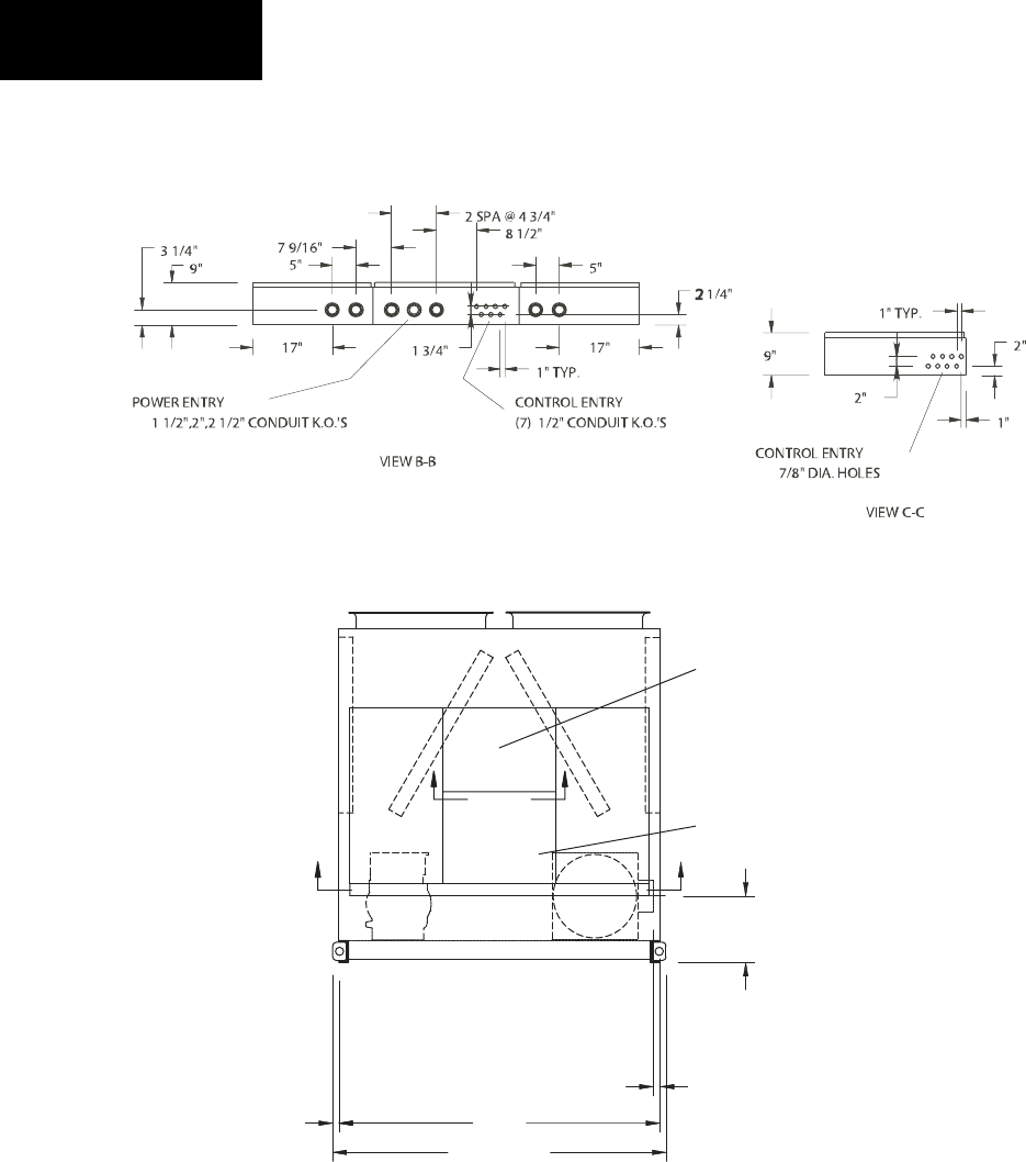
86 YORK INTERNATIONAL
FORM 201.19-NM1 (204)
FIG. 25 – MODEL YCAS0200 - YCAS0230 DIMENSIONS (ENGLISH)
Technical Data
DIMENSIONS – YCAS0200 - YCAS0230 (ENGLISH)
NOTES:
1. Placement on a level surface free of obstructions (including snow, for win ter operation) or air recirculation ensures rated performance, reli-
able operation and ease of maintenance. Site re stric tions may compromise minimum clearances indicated below, resulting in un pre dict able
air fl ow patterns and possible di min ished performance. YORK’s unit controls will optimize op er a tion without nui sance high pressure safety
cutout; however, the system de sign er must con sid er potential performance degradation. Access to the unit control center assumes the unit
is no higher than on spring isolators. Rec om mend ed minimum clearances: Side to wall - 6'; rear to wall - 6'; control panel end to wall - 4'; top
- no obstructions allowed; distance between adjacent units - 10'. No more than one adjacent wall may be higher than the unit.
LD03748a
LD03748
91 3/8"
91 3/8"
15/16" (EDGE OF
15/16" (EDGE OF
UNIT TO COOLER
UNIT TO COOLER
CONNECTION)
CONNECTION)
18"
18"
VIEW A-A
VIEW A-A
MICRO-COMPUTER
MICRO-COMPUTER
CONTROL CENTER
CONTROL CENTER
OPTIONS PANEL
OPTIONS PANEL
1 11/16"
1 11/16"
88"
88"
COILS
COILS
SYS.#1
SYS.#1
C
B
C
B
SYS.#2
SYS.#2
COILS
COILS

87
YORK INTERNATIONAL
FORM 201.19-NM1 (204)
DIMENSIONS – YCAS0200 - YCAS0230 (ENGLISH)
7
LD03750
CENTER OF GRAVITY (Alum.)
YCAS X Y Z
0200 119.4" 43.2" 38.0"
0210 119.4" 43.2" 38.0"
0230 119.4" 43.2" 38.0"
CENTER OF GRAVITY (Copper)
YCAS X Y Z
0200 122.3" 43.3" 41.0"
0210 122.3" 43.3" 41.0"
0230 122.3" 43.3" 41.0"
$
$
LD03749

88 YORK INTERNATIONAL
FORM 201.19-NM1 (204)
Technical Data
FIG. 26 – MODEL YCAS0200 - YCAS0230 DIMENSIONS (SI)
DIMENSIONS – YCAS0200 - YCAS0230 (SI)
All dimensions
are in mm un less
oth er wise not ed.
NOTES:
1. Placement on a level surface free of obstructions (including snow, for winter operation) or air recirculation ensures rated performance, re li able
operation and ease of maintenance. Site re stric tions may compromise min i mum clearances indicated below, resulting in un pre dict able air fl ow
pat terns and possible di min ished performance. YORK’s unit controls will optimize operation without nui sance high pres sure safety cutout;
however, the system designer must con sid er potential performance degradation. Access to the unit control center assumes the unit is no
higher than on spring isolators. Recommended minimum clearances: Side to wall - 2m; rear to wall - 2m; con trol panel end to wall - 1.2m;
top - no obstructions allowed; distance between adjacent units - 3m. No more than one adjacent wall may be higher than the unit.
LD03751
LD03751a
2321
24 (EDGE OF
UNIT TO COOLER
CONNECTION)
457
VIEW A-A
MICRO-COMPUTER
CONTROL CENTER
OPTIONS PANEL
43 2235
COILS
SYS.#1
C
B
C
B
SYS.#2
COILS
CONTROL ENTRY
(8) 22 DIA. HOLES
VIEW B-B
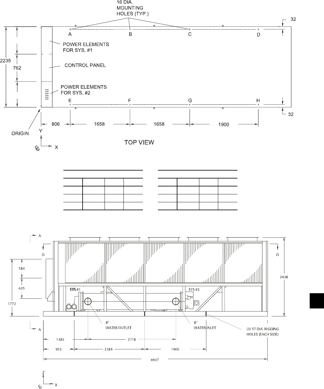
89
YORK INTERNATIONAL
FORM 201.19-NM1 (204)
DIMENSIONS – YCAS0200 - YCAS0230 (SI)
7
$"&
$"&
LD03753
LD03752
CENTER OF GRAVITY (Copper)
YCAS X Y Z
0200 3106.4 1099.8 1041.4
0210 3106.4 1099.8 1041.4
0230 3106.4 1099.8 1041.4
CENTER OF GRAVITY (Alum.)
YCAS X Y Z
0200 3032.8 1097.3 965.2
0210 3032.8 1097.3 965.2
0230 3032.8 1097.3 965.2

90 YORK INTERNATIONAL
FORM 201.19-NM1 (204)
(1.3 m) (2 m)
(2 m) (2 m)
TECHNICAL DATA
CLEARANCES
NOTES:
1. No obstructions allowed above the unit.
2. Only one adjacent wall may be higher than the unit.
3. Adjacent units should be 10 feet (3 meters) apart.
LD07011
FIG. 27 – CLEARANCES
Technical Data
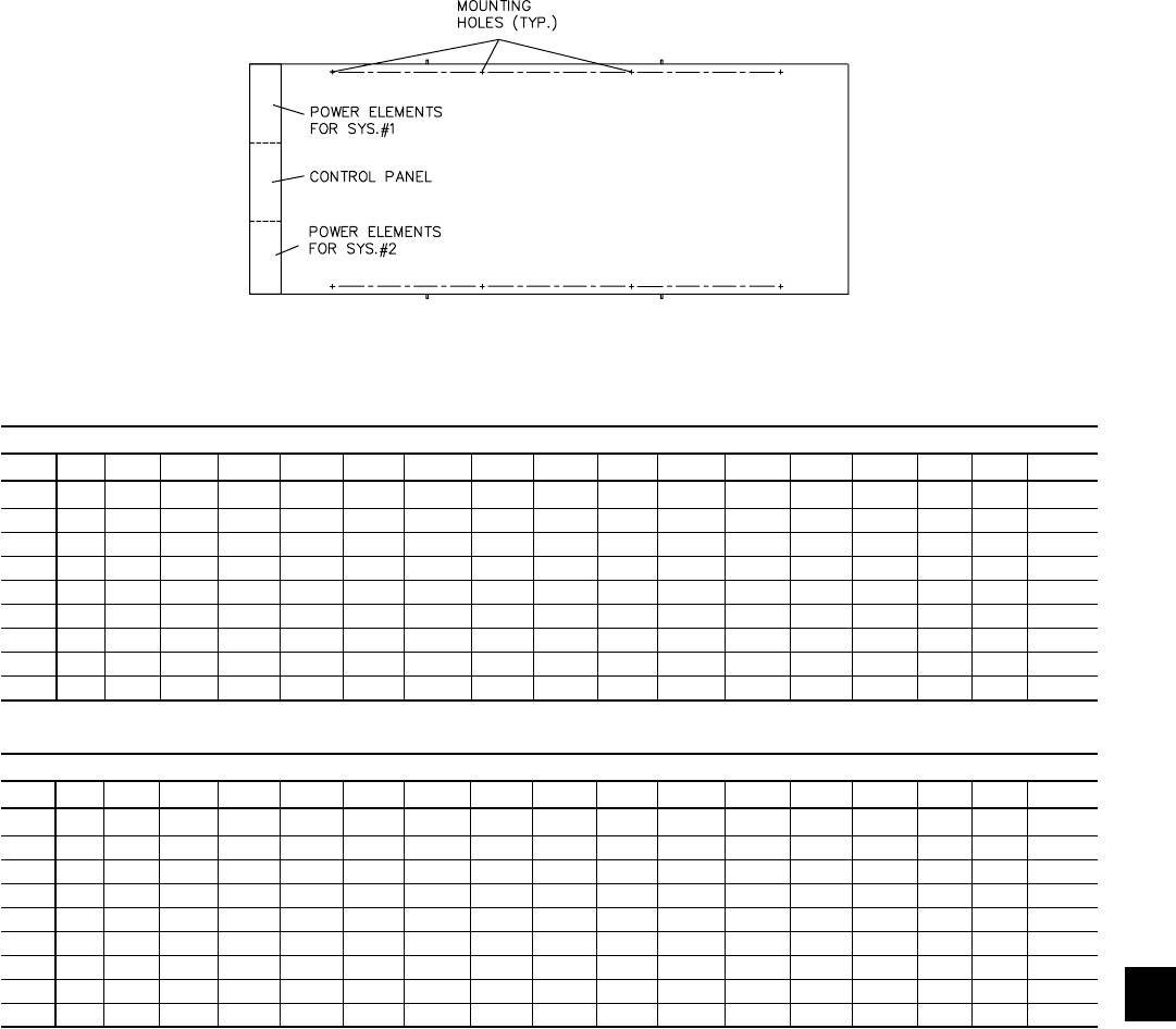
91
YORK INTERNATIONAL
FORM 201.19-NM1 (204)
7
Aluminium and Black Fin Condenser Coils
WEIGHT DISTRIBUTION AND ISOLATOR MOUNTING POSITIONS
LD09472
A
F
BDC
EGH
ALUMINUM FIN COIL WEIGHT DISTRIBUTION BY MODEL ( LBS )
YCAS A B C D E F G H I J K L M N O P TOTAL
0130 1,956 1,633 1,309 986 1,908 1,593 1,277 962 –– –– –– –– –– –– –– –– 11,625
0140 1,963 1,638 1,313 989 1,931 1,612 1,292 973 –– –– –– –– –– –– –– –– 11,711
0150 1,868 1,648 1,428 1,208 1,958 1,727 1,497 1,266 –– –– –– –– –– –– –– –– 12,599
0160 1,892 1,677 1,462 1,248 1,955 1,733 1,511 1,289 –– –– –– –– –– –– –– –– 12,768
0170 1,903 1,689 1,475 1,261 1,982 1,759 1,536 1,313 –– –– –– –– –– –– –– –– 12,919
0180 1,907 1,693 1,479 1,265 1,994 1,770 1,546 1,323 –– –– –– –– –– –– –– –– 12,978
0200 2,188 1,881 1,573 1,265 2,247 1,931 1,615 1,299 –– –– –– –– –– –– –– –– 13,998
0210 2,204 1,896 1,587 1,279 2,270 1,952 1,635 1,318 –– –– –– –– –– –– –– –– 14,141
0230 2,206 1,897 1,587 1,278 2,280 1,961 1,641 1,321 –– –– –– –– –– –– –– –– 14,171
ALUMINUM FIN COIL WEIGHT DISTRIBUTION BY MODEL ( KGS )
YCAS A B C D E F G H I J K L M N O P TOTAL
0130 887 741 594 447 865 723 579 436 –– –– –– –– –– –– –– –– 5,273
0140 890 743 596 449 876 731 586 441 –– –– –– –– –– –– –– –– 5,312
0150 847 748 648 548 888 783 679 574 –– –– –– –– –– –– –– –– 5,714
0160 858 761 663 566 887 786 685 585 –– –– –– –– –– –– –– –– 5,791
0170 863 766 669 572 899 798 697 596 –– –– –– –– –– –– –– –– 5,860
0180 865 768 671 574 904 803 701 600 –– –– –– –– –– –– –– –– 5,886
0200 992 853 714 574 1,019 876 733 589 –– –– –– –– –– –– –– –– 6,349
0210 1,000 860 720 580 1,030 885 742 589 –– –– –– –– –– –– –– –– 6,414
0230 1,001 861 720 580 1,034 890 744 599 –– –– –– –– –– –– –– –– 6,428
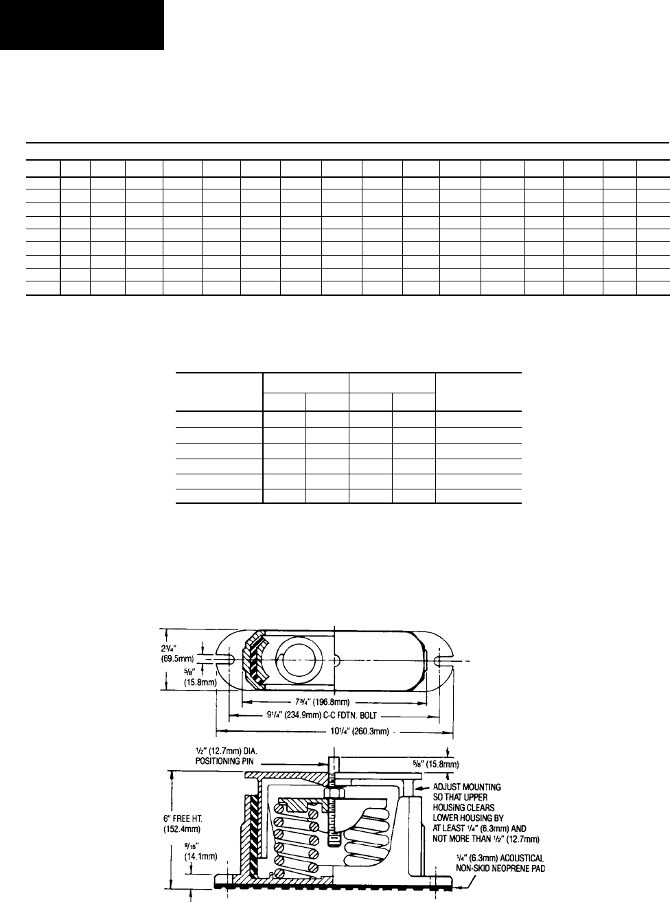
92 YORK INTERNATIONAL
FORM 201.19-NM1 (204)
Technical Data
Aluminium and Black Fin Condenser Coils
WEIGHT DISTRIBUTION AND ISOLATOR MOUNTING POSITIONS
ISOLATOR MAX LOAD DEFL. SPRING
TYPE & SIZE lbs. kg in. mm COLOR
CP-2-26 1,200 544.3 1.17 29.7 Purple
CP-2-27 1,500 680.4 1.06 26.9 Orange
CP-2-28 1,800 816.4 1.02 25.9 Green
CP-2-31 2,200 997.9 0.83 21.0 Gray
CP-2-32 2,600 1,179.3 0.74 18.7 White
CP-2-35 3,000 1,360.8 0.70 17.7 Gold
FIG. 28 – CP-2-XX
ISOLATOR DETAILS
LD01089
ALUMINUM FINS, 1" ISOLATOR SELECTIONS – VMC TYPE CP-2-XX (SEE TABLE BELOW)
YCAS A B C D E F G H I J K L M N O P
0130 31 28 27 26 31 27 28 26 –– –– –– –– –– –– –– ––
0140 31 28 27 26 31 27 28 26 –– –– –– –– –– –– –– ––
0150 31 28 27 27 31 27 28 27 –– –– –– –– –– –– –– ––
0160 31 28 27 27 31 27 28 27 –– –– –– –– –– –– –– ––
0170 31 28 27 27 31 27 28 27 –– –– –– –– –– –– –– ––
0180 31 28 27 27 31 27 28 27 –– –– –– –– –– –– –– ––
0200 31 28 28 28 31 28 31 28 –– –– –– –– –– –– –– ––
0210 31 28 28 28 31 28 31 28 –– –– –– –– –– –– –– ––
0230 31 28 28 28 31 28 31 28 –– –– –– –– –– –– –– ––
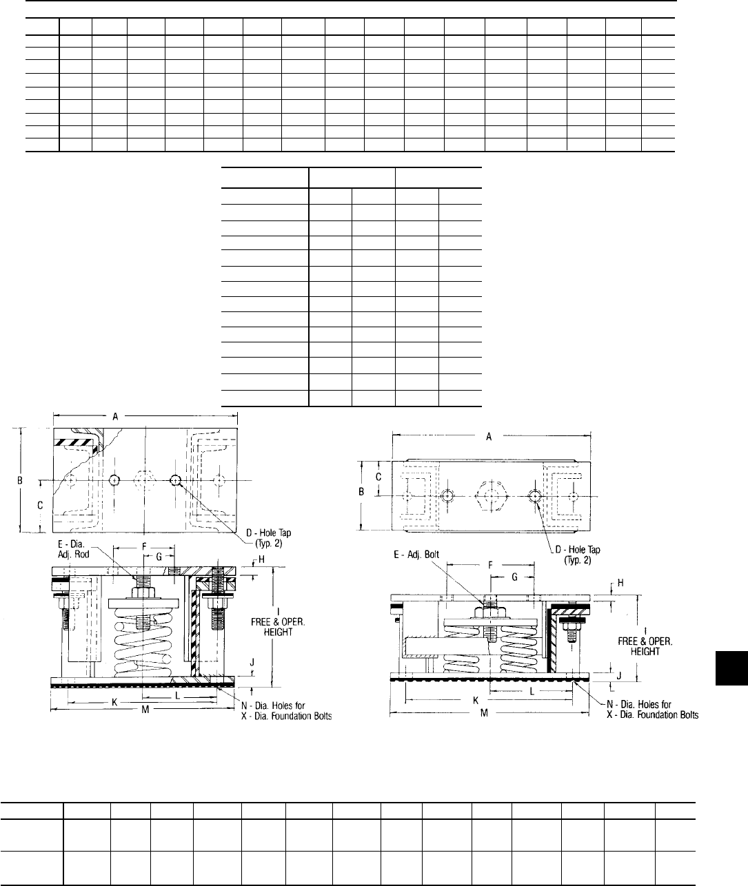
93
YORK INTERNATIONAL
FORM 201.19-NM1 (204)
7
LD02973
AWMR-1-XXX
LD02974
AWMR-2-XXX
Aluminium and Black Fin Condenser Coils
WEIGHT DISTRIBUTION AND ISOLATOR MOUNTING POSITIONS
FIG. 29 – TYPE AWMR ISOLATOR DETAILS
A B C D E F G H I J K L M N/X
AWMR-1 10-1/2 6 3 5/8 3/4 3-1/2 1-3/4 1/2 9 5/8 8-1/2 4-1/4 10-1/2 3/4
50-553 11NC 5/8
AWMR-2 15 6 3 3/4 1 7-1/2 3-3/4 1/2 9-1/2 5/8 14-1/2 7-1/4 17 3/4
50-553 10NC 5/8
DIMENSIONS - In.
ALUMINUM FINS, SEISMIC ISOLATOR SELECTIONS - VMC MODEL # AWMR-X-XXX
YCAS A B C D E F G H I J K L M N O P
0130 -1-553 -1-551 -1-532 -1-530 -1-553 -1-551 -1-532 -1-530 –– –– –– –– –– –– –– ––
0140 -1-553 -1-551 -1-532 -1-530 -1-553 -1-551 -1-532 -1-530 –– –– –– –– –– –– –– ––
0150 -1-552 -1-552 -1-532 -1-531 -1-553 -1-552 -1-551 -1-532 –– –– –– –– –– –– –– ––
0160 -1-552 -1-552 -1-532 -1-531 -1-553 -1-552 -1-551 -1-532 –– –– –– –– –– –– –– ––
0170 -1-553 -1-552 -1-532 -1-531 -1-553 -1-552 -1-551 -1-532 –– –– –– –– –– –– –– ––
0180 -1-553 -1-552 -1-532 -1-531 -1-553 -1-552 -1-551 -1-532 –– –– –– –– –– –– –– ––
0200 -1-553 -1-552 -1-552 -1-551 -1-553 -1-552 -1-552 -1-551 –– –– –– –– –– –– –– ––
0210 -1-553 -1-552 -1-552 -1-551 -1-553 -1-552 -1-552 -1-551 –– –– –– –– –– –– –– ––
0230 -1-553 -1-552 -1-552 -1-551 -1-553 -1-552 -1-552 -1-551 –– –– –– –– –– –– –– ––
ISOLATOR MAX LOAD DEFL.
TYPE & SIZE lbs. kg in. mm
AWMR-1-53 1,000 453.6 2 51
AWMR-1-530 1,150 521.6 2 51
AWMR-1-531 1,276 578.8 2 51
AWMR-1-532 1,500 680.4 2 51
AWMR-1-551 1,676 760.2 2 51
AWMR-1-552 1,900 861.8 2 51
AWMR-1-553 2,200 997.9 2 51
AWMR-2-520 1,300 589.7 2 51
AWMR-2-521 1,552 704.0 2 51
AWMR-2-53 2,000 907.2 2 51
AWMR-1-530 2,300 1,043.3 2 51
AWMR-2-531 2,552 1,157.6 2 51
AWMR-2-532 3,000 1,360.8 2 51
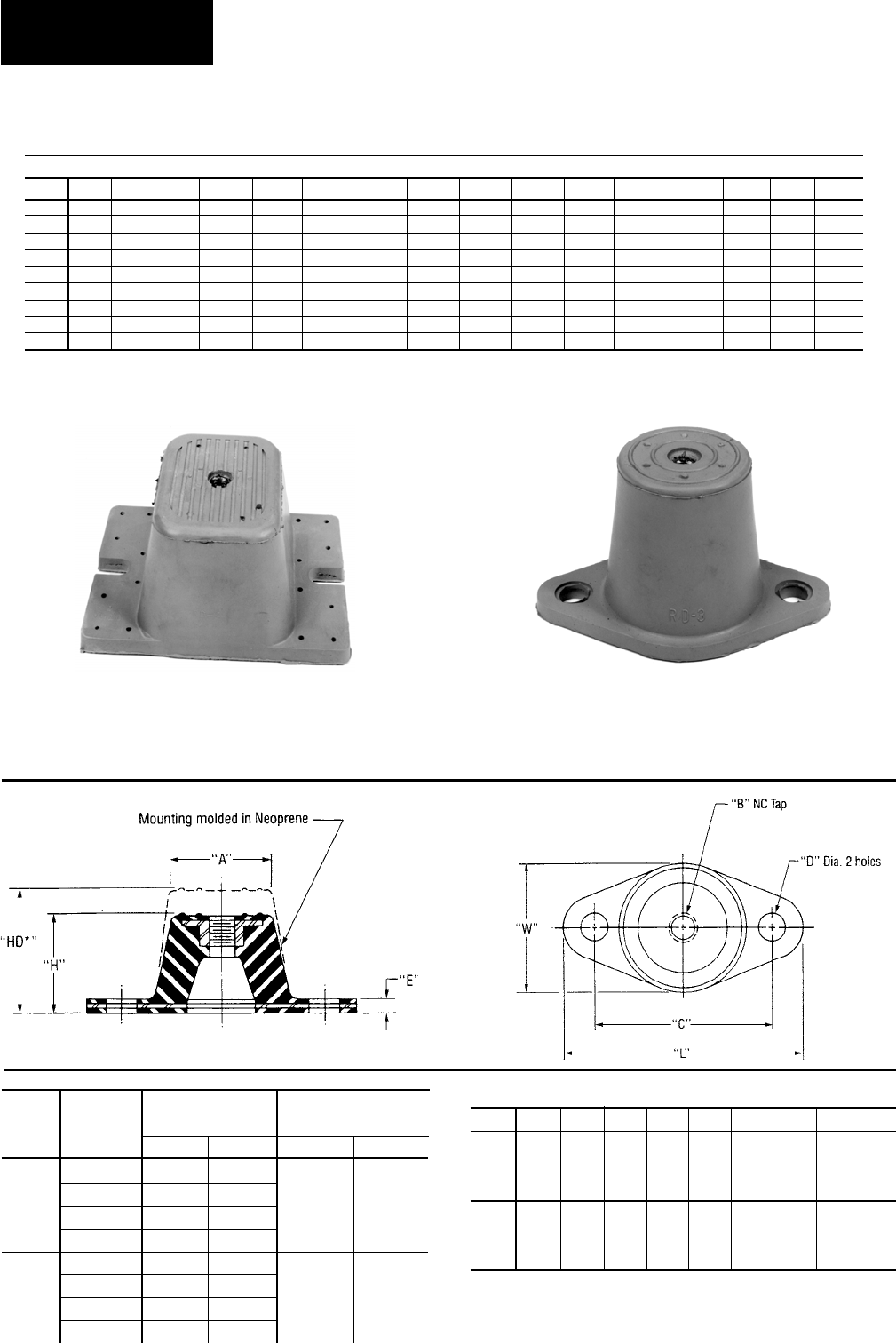
94 YORK INTERNATIONAL
FORM 201.19-NM1 (204)
Technical Data
LD04033
TYPE R OR RD
IF BOLTING IS PREFERRED–
Type R or RD mountings are
furnished with a tapped hole
in the center. This enables the
equipment to be bolted securely
to the mounting.
TYPE R OR RD
NO BOLTING IS
PREFERRED–
Type R or RD mountings are
may be used without bolting
under machines having no
lateral or severe vertical
motion.
NEW DESIGN FOR TYPE RD-4
NEOPRENE MOUNTINGS.
TYPE RD-3
LD04033
Aluminium and Black Fin Condenser Coils
WEIGHT DISTRIBUTION AND ISOLATOR MOUNTING POSITIONS
29518A 29517A
DEFLECTION
COLOR MAX. LOAD ins. (mm)
TYPE
CODE lbs. (kg) R RD
R-3 BLACK 250 (113.5)
0.25 0.50
OR RED 525 (238.3)
(6.3) (12.7)
RD-3 GREEN 750 (340.5)
GRAY 1,100 (499.4)
R-4 BLACK 1,500 (681.0)
0.25 0.50
OR RED 2,250 (1,021.5)
(6.3) (12.7) RD-4 GREEN 3,000 (1,362.0)
GRAY 4,000 (1,816.0)
TYPE L W H *HD A B C D E
R-3 5-1/2" 3-3/8" 1-3/4" 2-7/8" 2-1/2" 1/2" 4-1/8" 9/16" 1/4"
OR (139.7) (85.8) (44.4) (73.2) (63.5) (12.7) (104.8) (14.4) (6.3)
RD-3
R-4 6-1/4" 4-5/8" 1-5/8" 2-3/4" 3" 1/2" 5" 9/16" 3/8"
OR (158.7) (117.6) (41.4) (69.8) (76.2) (12.7) (127.0) (14.4) (9.6)
RD-4
DIMENSIONS: ins. (mm)
* HD dimension applies to double defl ection Type RD mountings only.
* VMC TYPE RD-3
ALUMINUM FINS, NEOPRENE MOUNT SELECTIONS – VMC TYPE RD-4
YCAS A B C D E F G H I J K L M N O P
0130 RED RED BLACK GRAY* RED RED BLACK GRAY* –– –– –– –– –– –– –– ––
0140 RED RED BLACK GRAY* RED RED BLACK GRAY* –– –– –– –– –– –– –– ––
0150 RED RED BLACK BLACK RED RED RED BLACK –– –– –– –– –– –– –– ––
0160 RED RED BLACK BLACK RED RED RED BLACK –– –– –– –– –– –– –– ––
0170 RED RED BLACK BLACK RED RED RED BLACK –– –– –– –– –– –– –– ––
0180 RED RED BLACK BLACK RED RED RED BLACK –– –– –– –– –– –– –– ––
0200 RED RED RED RED RED RED RED RED –– –– –– –– –– –– –– ––
0210 RED RED RED RED RED RED RED RED –– –– –– –– –– –– –– ––
0230 RED RED RED RED RED RED RED RED –– –– –– –– –– –– –– ––

95
YORK INTERNATIONAL
FORM 201.19-NM1 (204)
7
Copper Fin Condenser Coils
WEIGHT DISTRIBUTION AND ISOLATOR MOUNTING POSITIONS
COPPER FIN CONDENSER COILS WEIGHT DISTRIBUTION BY MODEL (LBS)
YCAS A B C D E F G H I J K L M N O P Total
0130 2,066 1,774 1,483 1,192 2,020 1,735 1,450 1,165 --- --- --- --- --- --- --- --- 12,885
0140 2,072 1,779 1,487 1,194 2,043 1,754 1,465 1,177 --- --- --- --- --- --- --- --- 12,971
0150 1,980 1,790 1,600 1,410 2,067 1,869 1,671 1,472 --- --- --- --- --- --- --- --- 13,859
0160 2,003 1,819 1,635 1,451 2,064 1,875 1,685 1,495 --- --- --- --- --- --- --- --- 14,028
0170 2,015 1,831 1,648 1,464 2,091 1,900 1,710 1,519 --- --- --- --- --- --- --- --- 14,179
0180 2,019 1,836 1,652 1,468 2,103 1,911 1,720 1,529 --- --- --- --- --- --- --- --- 14,238
0200 2,319 2,051 1,784 1,516 2,374 2,100 1,826 1,552 --- --- --- --- --- --- --- --- 15,522
0210 2,334 2,066 1,798 1,530 2,397 2,122 1,847 1,571 --- --- --- --- --- --- --- --- 15,665
0230 2,336 2,067 1,798 1,528 2,408 2,130 1,852 1,575 --- --- --- --- --- --- --- --- 15,695
LD09472
A
F
BDC
EGH
COPPER FIN CONDENSER COILS WEIGHT DISTRIBUTION BY MODEL (KGS)
YCAS A B C D E F G H I J K L M N O P Total
0130 937 805 673 541 916 787 658 528 --- --- --- --- --- --- --- --- 5,845
0140 940 807 674 542 927 796 665 534 --- --- --- --- --- --- --- --- 5,884
0150 898 812 726 640 938 848 758 668 --- --- --- --- --- --- --- --- 6,286
0160 909 825 742 658 936 850 764 678 --- --- --- --- --- --- --- --- 6,363
0170 914 831 748 664 948 862 776 689 --- --- --- --- --- --- --- --- 6,431
0180 916 833 749 667 954 867 780 694 --- --- --- --- --- --- --- --- 6,458
0200 1,052 930 809 688 1,077 953 828 704 --- --- --- --- --- --- --- --- 7,041
0210 1,059 937 816 694 1,087 963 838 713 --- --- --- --- --- --- --- --- 7,106
0230 1,060 938 815 693 1,092 966 840 714 --- --- --- --- --- --- --- --- 7,119
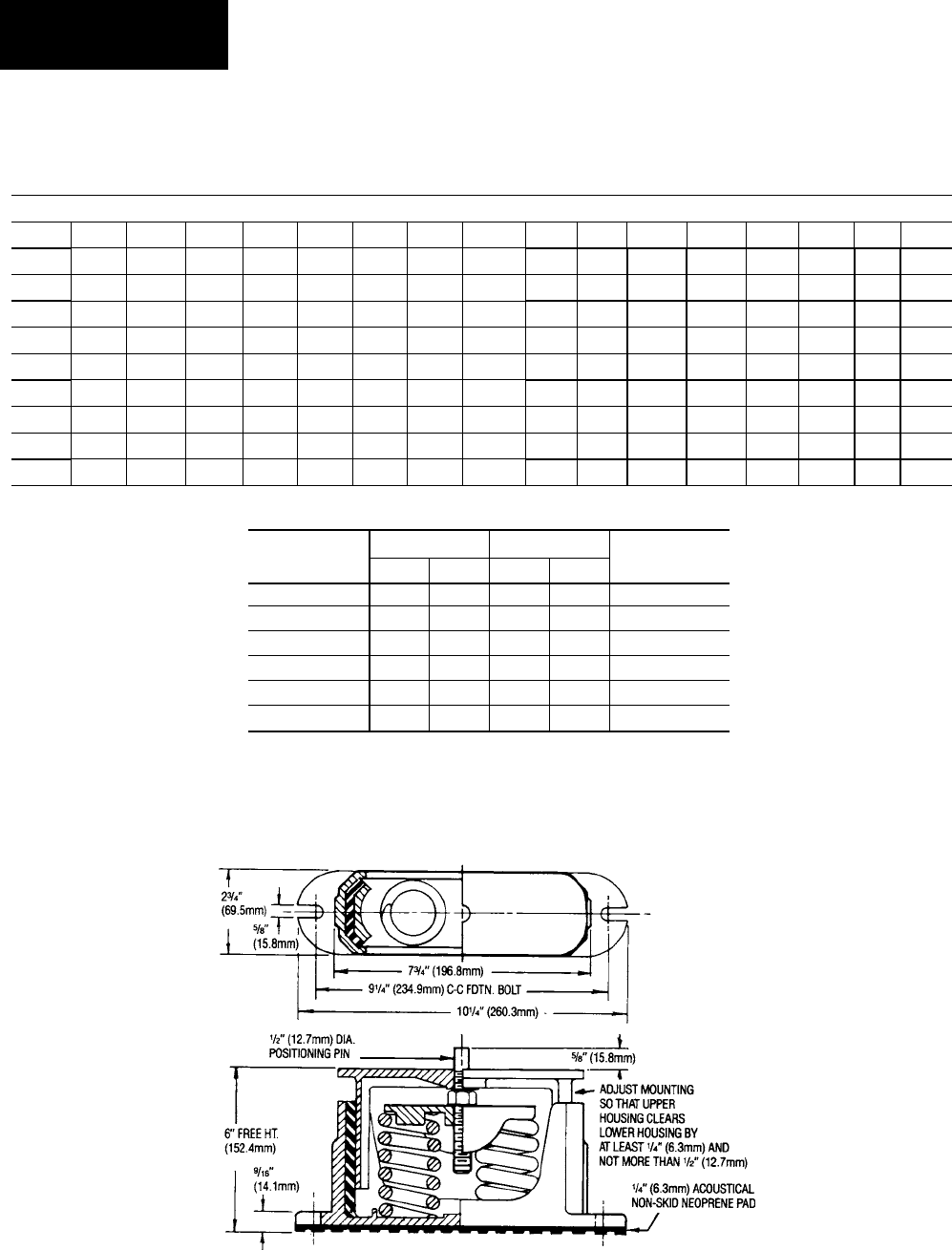
96 YORK INTERNATIONAL
FORM 201.19-NM1 (204)
Technical Data
FIG. 30 – CP-2-XX
Copper Fin Condenser Coils
WEIGHT DISTRIBUTION AND ISOLATOR MOUNTING POSITIONS
ISOLATOR MAX LOAD DEFL. SPRING
TYPE & SIZE lbs. kg in. mm COLOR
CP-2-26 1,200 544.3 1.17 29.7 Purple
CP-2-27 1,500 680.4 1.06 26.9 Orange
CP-2-28 1,800 816.4 1.02 25.9 Green
CP-2-31 2,200 997.9 0.83 21.0 Gray
CP-2-32 2,600 1179.3 0.74 18.7 White
CP-2-35 3,000 1360.8 0.70 17.7 Gold
ISOLATOR DETAILS
LD01089
60 HERTZ, COPPER FINS, 1” ISOLATOR SELECTIONS - VMC TYPE CP- (SEE TABLE BELOW)
YCAS A B C D E F G H I J K L M N O P
0130 2-31 2-28 2-28 2-27 2-31 2-28 2-28 2-27 --- --- --- --- --- --- --- ---
0140 2-31 2-28 2-28 2-27 2-31 2-28 2-28 2-27 --- --- --- --- --- --- --- ---
0150 2-31 2-31 2-28 2-28 2-31 2-31 2-31 2-31 --- --- --- --- --- --- --- ---
0160 2-31 2-31 2-28 2-28 2-31 2-31 2-31 2-31 --- --- --- --- --- --- --- ---
0170 2-31 2-31 2-28 2-28 2-31 2-31 2-31 2-31 --- --- --- --- --- --- --- ---
0180 2-31 2-31 2-28 2-28 2-31 2-31 2-31 2-31 --- --- --- --- --- --- --- ---
0200 2-32 2-31 2-31 2-28 2-32 2-31 2-31 2-28 --- --- --- --- --- --- --- ---
0210 2-32 2-31 2-31 2-28 2-32 2-31 2-31 2-28 --- --- --- --- --- --- --- ---
0230 2-32 2-31 2-31 2-28 2-32 2-31 2-31 2-28 --- --- --- --- --- --- --- ---

97
YORK INTERNATIONAL
FORM 201.19-NM1 (204)
7
WEIGHT DISTRIBUTION AND ISOLATOR MOUNTING POSITIONS
FIG. 31 – TYPE AWMR ISOLATOR DETAILS
A B C D E F G H I J K L M N/X
AWMR-1 10-1/2 6 3 5/8 3/4 3-1/2 1-3/4 1/2 9 5/8 8-1/2 4-1/4 10-1/2 3/4
50-553 11NC 5/8
AWMR-2 15 6 3 3/4 1 7-1/2 3-3/4 1/2 9-1/2 5/8 14-1/2 7-1/4 17 3/4
50-553 10NC 5/8
Copper Fin Condenser Coils
LD02973
AWMR-1-XXX
LD02974
AWMR-2-XXX
ISOLATOR MAX LOAD DEFL.
TYPE & SIZE lbs. kg in. mm
AWMR-1-53 1,000 453.6 2 51
AWMR-1-530 1,150 521.6 2 51
AWMR-1-531 1,276 578.8 2 51
AWMR-1-532 1,500 680.4 2 51
AWMR-1-551 1,676 760.2 2 51
AWMR-1-552 1,900 861.8 2 51
AWMR-1-553 2,200 997.9 2 51
AWMR-2-520 1,300 589.7 2 51
AWMR-2-521 1,552 704.0 2 51
AWMR-2-53 2,000 907.2 2 51
AWMR-1-530 2,300 1,043.3 2 51
AWMR-2-531 2,552 1,157.6 2 51
AWMR-2-532 3,000 1,360.8 2 51
60 HERTZ, CU. FINS, SEISMIC ISOLATOR SELECTIONS - VMC MODEL # AWMR-(SEE TABLE BELOW)
YCAS A B C D E F G H I J K L M N O P
0130 1-553 1-552 1-532 1-532 1-553 1-552 1-551 1-532 --- --- --- --- --- --- --- ---
0140 1-553 1-552 1-532 1-532 1-553 1-552 1-551 1-532 --- --- --- --- --- --- --- ---
0150 1-553 1-552 1-552 1-552 1-553 1-552 1-552 1-552 --- --- --- --- --- --- --- ---
0160 1-553 1-552 1-552 1-552 1-553 1-552 1-552 1-552 --- --- --- --- --- --- --- ---
0170 1-553 1-552 1-552 1-552 1-553 1-553 1-552 1-552 --- --- --- --- --- --- --- ---
0180 1-553 1-552 1-552 1-552 1-553 1-553 1-552 1-552 --- --- --- --- --- --- --- ---
0200 2-531 1-553 1-552 1-551 2-531 2-530 1-553 1-551 --- --- --- --- --- --- --- ---
0210 2-531 1-553 1-552 1-551 2-531 2-530 1-553 1-551 --- --- --- --- --- --- --- ---
0230 2-531 1-553 1-552 1-551 2-531 2-530 1-553 1-551 --- --- --- --- --- --- --- ---
DIMENSIONS - In.
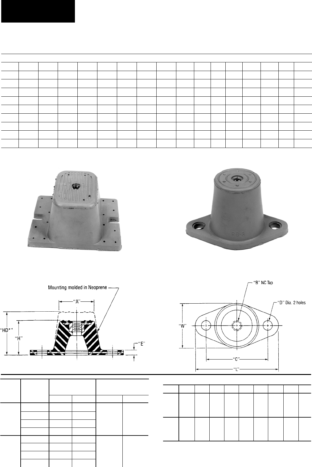
98 YORK INTERNATIONAL
FORM 201.19-NM1 (204)
Technical Data
DEFLECTION
COLOR MAX. LOAD ins. (mm)
TYPE
CODE lbs. (kg) R RD
R-3 BLACK 250 (113.5)
0.25 0.50
OR RED 525 (238.3)
(6.3) (12.7)
RD-3 GREEN 750 (340.5)
GRAY 1,100 (499.4)
R-4 BLACK 1,500 (681.0)
0.25 0.50
OR RED 2,250 (1021.5)
(6.3) (12.7) RD-4 GREEN 3,000 (1362.0)
GRAY 4,000 (1816.0)
Copper Fin Condenser Coils
WEIGHT DISTRIBUTION AND ISOLATOR MOUNTING POSITIONS
LD04033
TYPE R OR RD
IF BOLTING IS PREFERRED–
Type R or RD mountings are furnished with
a tapped hole in the center. This enables the
equipment to be bolted securely to the mounting.
TYPE R OR RD
NO BOLTING IS PREFERRED–
Type R or RD mountings are may be
used without bolting under machines
having no lateral or severe vertical
motion.
NEW DESIGN FOR TYPE RD-4
NEOPRENE MOUNTINGS.
TYPE RD-3
LD04033
29518A 29517A
TYPE L W H *HD A B C D E
R-3 5-1/2" 3-3/8" 1-3/4" 2-7/8" 2-1/2" 1/2" 4-1/8" 9/16" 1/4"
OR (139.7) (85.8) (44.4) (73.2) (63.5) (12.7) (104.8) (14.4) (6.3)
RD-3
R-4 6-1/4" 4-5/8" 1-5/8" 2-3/4" 3" 1/2" 5" 9/16" 3/8"
OR (158.7) (117.6) (41.4) (69.8) (76.2) (12.7) (127.0) (14.4) (9.6)
RD-4
DIMENSIONS: ins. (mm)
* HD dimension applies to double defl ection Type RD mountings only.
60 HERTZ, CU. FINS, NEOPRENE MOUNT SELECTION- VMC TYPE RD (SEE TABLE BELOW)
YCAS A B C D E F G H I J K L M N O P
0130 -4 Red -4 Red -4 Blk -4 Blk -4 Red -4 Red -4 Red -4 Blk --- --- --- --- --- --- --- ---
0140 -4 Red -4 Red -4 Blk -4 Blk -4 Red -4 Red -4 Red -4 Blk --- --- --- --- --- --- --- ---
0150 -4 Red -4 Red -4 Red -4 Red -4 Red -4 Red -4 Red -4 Red --- --- --- --- --- --- --- ---
0160 -4 Red -4 Red -4 Red -4 Red -4 Red -4 Red -4 Red -4 Red --- --- --- --- --- --- --- ---
0170 -4 Red -4 Red -4 Red -4 Red -4 Red -4 Red -4 Red -4 Red --- --- --- --- --- --- --- ---
0180 -4 Red -4 Red -4 Red -4 Red -4 Red -4 Red -4 Red -4 Red --- --- --- --- --- --- --- ---
0200 -4 Grn -4 Red -4 Red -4 Red -4 Grn -4 Red -4 Red -4 Red --- --- --- --- --- --- --- ---
0210 -4 Grn -4 Red -4 Red -4 Red -4 Grn -4 Red -4 Red -4 Red --- --- --- --- --- --- --- ---
0230 -4 Grn -4 Red -4 Red -4 Red -4 Grn -4 Red -4 Red -4 Red --- --- --- --- --- --- --- ---
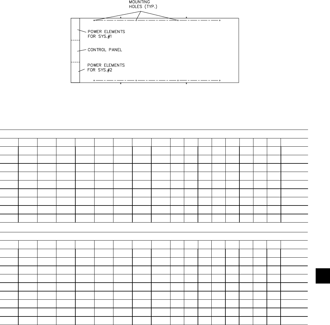
99
YORK INTERNATIONAL
FORM 201.19-NM1 (204)
7
Aluminium Fin Condenser Coils
with Silencer Kit
WEIGHT DISTRIBUTION AND ISOLATOR MOUNTING POSITIONS
ALUMINUM FIN COIL WEIGHT DISTRIBUTION BY MODEL ( LBS )
YCAS A B C D E F G H I J K L M N O P Total
0130 2,066 1,774 1,483 1,192 2,020 1,735 1,450 1,165 --- --- --- --- --- --- --- --- 12,885
0140 2,072 1,779 1,487 1,194 2,043 1,754 1,465 1,177 --- --- --- --- --- --- --- --- 12,971
0150 1,980 1,790 1,600 1,410 2,067 1,869 1,671 1,472 --- --- --- --- --- --- --- --- 13,859
0160 2,003 1,819 1,635 1,451 2,064 1,875 1,685 1,495 --- --- --- --- --- --- --- --- 14,028
0170 2,015 1,831 1,648 1,464 2,091 1,900 1,710 1,519 --- --- --- --- --- --- --- --- 14,179
0180 2,019 1,836 1,652 1,468 2,103 1,911 1,720 1,529 --- --- --- --- --- --- --- --- 14,238
0200 2,319 2,051 1,784 1,516 2,374 2,100 1,826 1,552 --- --- --- --- --- --- --- --- 15,522
0210 2,334 2,066 1,798 1,530 2,397 2,122 1,847 1,571 --- --- --- --- --- --- --- --- 15,665
0230 2,336 2,067 1,798 1,528 2,408 2,130 1,852 1,575 --- --- --- --- --- --- --- --- 15,695
LD09472
A
F
BDC
EGH
ALUMINUM FIN COIL WEIGHT DISTRIBUTION BY MODEL (KGS)
YCAS A B C D E F G H I J K L M N O P Total
0130 937 805 673 541 916 787 658 528 --- --- --- --- --- --- --- --- 5,845
0140 940 807 674 542 927 796 665 534 --- --- --- --- --- --- --- --- 5,884
0150 898 812 726 640 938 848 758 668 --- --- --- --- --- --- --- --- 6,286
0160 909 825 742 658 936 850 764 678 --- --- --- --- --- --- --- --- 6,363
0170 914 831 748 664 948 862 776 689 --- --- --- --- --- --- --- --- 6,431
0180 916 833 749 667 954 867 780 694 --- --- --- --- --- --- --- --- 6,458
0200 1,052 930 809 688 1,077 953 828 704 --- --- --- --- --- --- --- --- 7,041
0210 1,059 937 816 694 1,087 963 838 713 --- --- --- --- --- --- --- --- 7,106
0230 1,060 938 815 693 1,092 966 840 714 --- --- --- --- --- --- --- --- 7,119
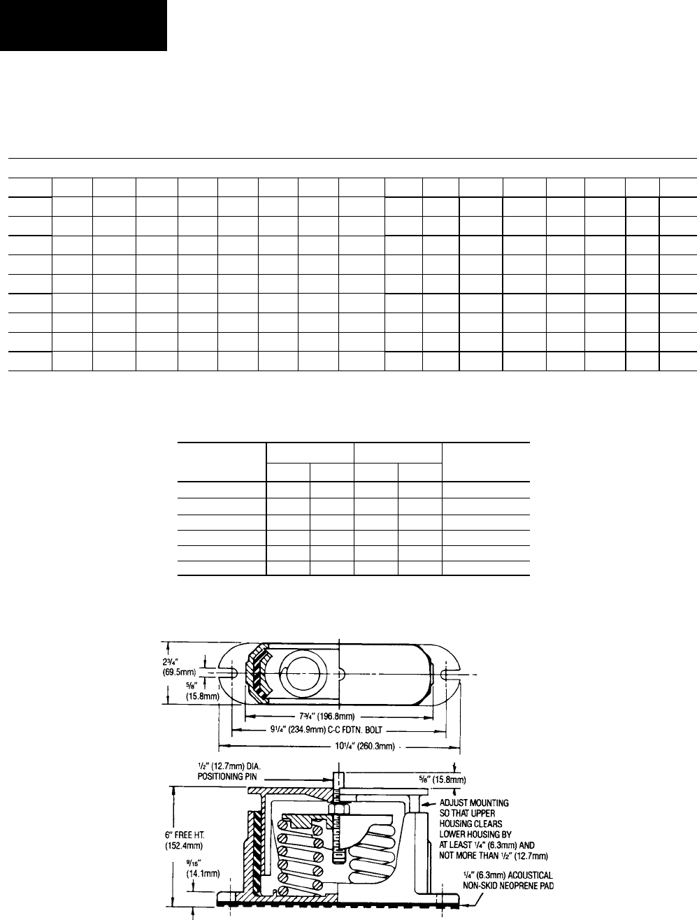
100 YORK INTERNATIONAL
FORM 201.19-NM1 (204)
Technical Data
Aluminium Fin Condenser Coils
with Silencer Kit
WEIGHT DISTRIBUTION AND ISOLATOR MOUNTING POSITIONS
ISOLATOR MAX LOAD DEFL. SPRING
TYPE & SIZE lbs. kg in. mm COLOR
CP-2-26 1,200 544.3 1.17 29.7 Purple
CP-2-27 1,500 680.4 1.06 26.9 Orange
CP-2-28 1,800 816.4 1.02 25.9 Green
CP-2-31 2,200 997.9 0.83 21.0 Gray
CP-2-32 2,600 1179.3 0.74 18.7 White
CP-2-35 3,000 1360.8 0.70 17.7 Gold
FIG. 32 – CP-2-XX
ISOLATOR DETAILS
LD01089
60 HERTZ, ALUMINUM FINS, 1” ISOLATOR SELECTIONS - VMC TYPE CP- (SEE TABLE BELOW)
YCAS A B C D E F G H I J K L M N O P
0130 2-31 2-28 2-28 2-27 2-31 2-28 2-28 2-27 --- --- --- --- --- --- --- ---
0140 2-31 2-28 2-28 2-27 2-31 2-28 2-28 2-27 --- --- --- --- --- --- --- ---
0150 2-31 2-31 2-28 2-28 2-31 2-31 2-31 2-31 --- --- --- --- --- --- --- ---
0160 2-31 2-31 2-28 2-28 2-31 2-31 2-31 2-31 --- --- --- --- --- --- --- ---
0170 2-31 2-31 2-28 2-28 2-31 2-31 2-31 2-31 --- --- --- --- --- --- --- ---
0180 2-31 2-31 2-28 2-28 2-31 2-31 2-31 2-31 --- --- --- --- --- --- --- ---
0200 2-32 2-31 2-31 2-28 2-32 2-31 2-31 2-28 --- --- --- --- --- --- --- ---
0210 2-32 2-31 2-31 2-28 2-32 2-31 2-31 2-28 --- --- --- --- --- --- --- ---
0230 2-32 2-31 2-31 2-28 2-32 2-31 2-31 2-28 --- --- --- --- --- --- --- ---
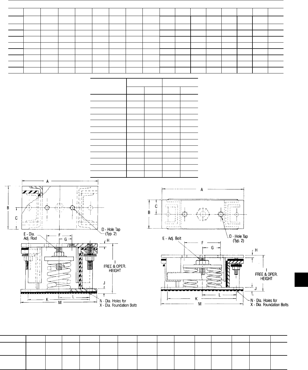
101
YORK INTERNATIONAL
FORM 201.19-NM1 (204)
7
LD02973
AWMR-1-XXX
LD02974
AWMR-2-XXX
WEIGHT DISTRIBUTION AND ISOLATOR MOUNTING POSITIONS
FIG. 33 – TYPE AWMR ISOLATOR DETAILS
A B C D E F G H I J K L M N/X
AWMR-1 10-1/2 6 3 5/8 3/4 3-1/2 1-3/4 1/2 9 5/8 8-1/2 4-1/4 10-1/2 3/4
50-553 11NC 5/8
AWMR-2 15 6 3 3/4 1 7-1/2 3-3/4 1/2 9-1/2 5/8 14-1/2 7-1/4 17 3/4
50-553 10NC 5/8
DIMENSIONS - In.
Aluminium Fin Condenser Coils with Silencer Kit
ISOLATOR MAX LOAD DEFL.
TYPE & SIZE lbs. kg in. mm
AWMR-1-53 1,000 453.6 2 51
AWMR-1-530 1,150 521.6 2 51
AWMR-1-531 1,276 578.8 2 51
AWMR-1-532 1,500 680.4 2 51
AWMR-1-551 1,676 760.2 2 51
AWMR-1-552 1,900 861.8 2 51
AWMR-1-553 2,200 997.9 2 51
AWMR-2-520 1,300 589.7 2 51
AWMR-2-521 1,552 704.0 2 51
AWMR-2-53 2,000 907.2 2 51
AWMR-1-530 2,300 1043.3 2 51
AWMR-2-531 2,552 1157.6 2 51
AWMR-2-532 3,000 1360.8 2 51
60 HERTZ, ALUMINUM FINS, SEISMIC ISOLATOR SELECTIONS - VMC MODEL # AWMR-(SEE TABLE BELOW)
YCAS A B C D E F G H I J K L M N O P
0130 1-553 1-552 1-532 1-532 1-553 1-552 1-551 1-532 --- --- --- --- --- --- --- ---
0140 1-553 1-552 1-532 1-532 1-553 1-552 1-551 1-532 --- --- --- --- --- --- --- ---
0150 1-553 1-552 1-552 1-552 1-553 1-552 1-552 1-552 --- --- --- --- --- --- --- ---
0160 1-553 1-552 1-552 1-552 1-553 1-552 1-552 1-552 --- --- --- --- --- --- --- ---
0170 1-553 1-552 1-552 1-552 1-553 1-553 1-552 1-552 --- --- --- --- --- --- --- ---
0180 1-553 1-552 1-552 1-552 1-553 1-553 1-552 1-552 --- --- --- --- --- --- --- ---
0200 2-531 1-553 1-552 1-551 2-531 2-530 1-553 1-551 --- --- --- --- --- --- --- ---
0210 2-531 1-553 1-552 1-551 2-531 2-530 1-553 1-551 --- --- --- --- --- --- --- ---
0230 2-531 1-553 1-552 1-551 2-531 2-530 1-553 1-551 --- --- --- --- --- --- --- ---

102 YORK INTERNATIONAL
FORM 201.19-NM1 (204)
Technical Data
DEFLECTION
COLOR MAX. LOAD ins. (mm)
TYPE
CODE lbs. (kg) R RD
R-3 BLACK 250 (113.5)
0.25 0.50
OR RED 525 (238.3)
(6.3) (12.7)
RD-3 GREEN 750 (340.5)
GRAY 1,100 (499.4)
R-4 BLACK 1,500 (681.0)
0.25 0.50
OR RED 2,250 (1021.5)
(6.3) (12.7) RD-4 GREEN 3,000 (1362.0)
GRAY 4,000 (1816.0)
Aluminum Fin Condenser Coils
WEIGHT DISTRIBUTION AND ISOLATOR MOUNTING POSITIONS
LD04033
TYPE R OR RD
IF BOLTING IS PREFERRED–
Type R or RD mountings are furnished with
a tapped hole in the center. This enables the
equipment to be bolted securely to the mounting.
TYPE R OR RD
NO BOLTING IS PREFERRED–
Type R or RD mountings are may be
used without bolting under machines
having no lateral or severe vertical
motion.
NEW DESIGN FOR TYPE RD-4
NEOPRENE MOUNTINGS.
TYPE RD-3
LD04033
29518A 29517A
TYPE L W H *HD A B C D E
R-3 5-1/2" 3-3/8" 1-3/4" 2-7/8" 2-1/2" 1/2" 4-1/8" 9/16" 1/4"
OR (139.7) (85.8) (44.4) (73.2) (63.5) (12.7) (104.8) (14.4) (6.3)
RD-3
R-4 6-1/4" 4-5/8" 1-5/8" 2-3/4" 3" 1/2" 5" 9/16" 3/8"
OR (158.7) (117.6) (41.4) (69.8) (76.2) (12.7) (127.0) (14.4) (9.6)
RD-4
DIMENSIONS: ins. (mm)
* HD dimension applies to double defl ection Type RD mountings only.
60 HERTZ, ALUMINUM FINS, NEOPRENE MOUNT SELECTION- VMC TYPE RD (SEE TABLE BELOW)
YCAS A B C D E F G H I J K L M N O P
0130 -4 Red -4 Red -4 Blk -4 Blk -4 Red -4 Red -4 Red -4 Blk --- --- --- --- --- --- --- ---
0140 -4 Red -4 Red -4 Blk -4 Blk -4 Red -4 Red -4 Red -4 Blk --- --- --- --- --- --- --- ---
0150 -4 Red -4 Red -4 Red -4 Red -4 Red -4 Red -4 Red -4 Red --- --- --- --- --- --- --- ---
0160 -4 Red -4 Red -4 Red -4 Red -4 Red -4 Red -4 Red -4 Red --- --- --- --- --- --- --- ---
0170 -4 Red -4 Red -4 Red -4 Red -4 Red -4 Red -4 Red -4 Red --- --- --- --- --- --- --- ---
0180 -4 Red -4 Red -4 Red -4 Red -4 Red -4 Red -4 Red -4 Red --- --- --- --- --- --- --- ---
0200 -4 Grn -4 Red -4 Red -4 Red -4 Grn -4 Red -4 Red -4 Red --- --- --- --- --- --- --- ---
0210 -4 Grn -4 Red -4 Red -4 Red -4 Grn -4 Red -4 Red -4 Red --- --- --- --- --- --- --- ---
0230 -4 Grn -4 Red -4 Red -4 Red -4 Grn -4 Red -4 Red -4 Red --- --- --- --- --- --- --- ---
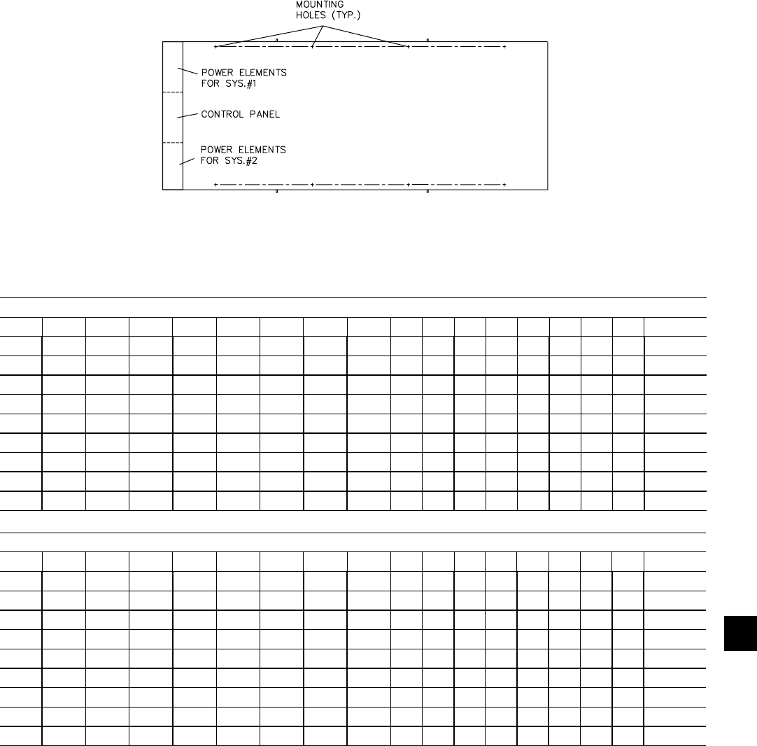
103
YORK INTERNATIONAL
FORM 201.19-NM1 (204)
7
Copper Fin Condenser Coils with Silencer Kit
WEIGHT DISTRIBUTION AND ISOLATOR MOUNTING POSITIONS
COPPER FIN CONDENSER COILS WITH SILENCER KIT WEIGHT DISTRIBUTION BY MODEL (LBS)
YCAS A B C D E F G H I J K L M N O P Total
0130 2,131 1,916 1,701 1,486 2,089 1,878 1,667 1,457 --- --- --- --- --- --- --- --- 14,325
0140 2,138 1,922 1,705 1,488 2,111 1,897 1,683 1,469 --- --- --- --- --- --- --- --- 14,411
0150 2,050 1,933 1,817 1,700 2,131 2,010 1,889 1,768 --- --- --- --- --- --- --- --- 15,299
0160 2,072 1,962 1,852 1,742 2,129 2,016 1,903 1,790 --- --- --- --- --- --- --- --- 15,468
0170 2,085 1,975 1,865 1,755 2,156 2,042 1,929 1,815 --- --- --- --- --- --- --- --- 15,621
0180 2,089 1,979 1,869 1,759 2,167 2,053 1,939 1,824 --- --- --- --- --- --- --- --- 15,678
0200 2,406 2,225 2,044 1,864 2,458 2,273 2,088 1,904 --- --- --- --- --- --- --- --- 17,262
0210 2,422 2,240 2,059 1,877 2,481 2,295 2,109 1,923 --- --- --- --- --- --- --- --- 17,405
0230 2,424 2,241 2,059 1,876 2,491 2,303 2,115 1,927 --- --- --- --- --- --- --- --- 17,435
LD09472
A
F
BDC
EGH
COPPER FIN CONDENSER COILS WITH SILENCER KIT WEIGHT DISTRIBUTION BY MODEL (KGS)
YCAS A B C D E F G H I J K L M N O P Total
0130 967 869 772 674 948 852 756 661 --- --- --- --- --- --- --- --- 6,498
0140 970 872 773 675 958 860 763 667 --- --- --- --- --- --- --- --- 6,537
0150 930 877 824 771 967 912 857 802 --- --- --- --- --- --- --- --- 6,940
0160 940 890 840 790 966 914 863 812 --- --- --- --- --- --- --- --- 7,016
0170 946 896 846 796 978 926 875 823 --- --- --- --- --- --- --- --- 7,086
0180 948 898 848 798 983 931 880 827 --- --- --- --- --- --- --- --- 7,111
0200 1,091 1,009 827 845 1,115 1,031 847 864 --- --- --- --- --- --- --- --- 7,830
0210 1,099 1,016 934 851 1,125 1,041 857 872 --- --- --- --- --- --- --- --- 7,895
0230 1,100 1,017 934 851 1,130 1,045 959 874 --- --- --- --- --- --- --- --- 7,908

104 YORK INTERNATIONAL
FORM 201.19-NM1 (204)
Technical Data
FIG. 34 – CP-2-XX
Copper Fin Condenser Coils with Silencer Kit
WEIGHT DISTRIBUTION AND ISOLATOR MOUNTING POSITIONS
ISOLATOR MAX LOAD DEFL. SPRING
TYPE & SIZE lbs. kg in. mm COLOR
CP-2-26 1,200 544.3 1.17 29.7 Purple
CP-2-27 1,500 680.4 1.06 26.9 Orange
CP-2-28 1,800 816.4 1.02 25.9 Green
CP-2-31 2,200 997.9 0.83 21.0 Gray
CP-2-32 2,600 1179.3 0.74 18.7 White
CP-2-35 3,000 1360.8 0.70 17.7 Gold
ISOLATOR DETAILS
LD01089
60 HERTZ, COPPER FINS WITH SILENCER KIT, 1” ISOLATOR SELECTIONS - VMC TYPE CP- (SEE TABLE BELOW)
YCAS A B C D E F G H I J K L M N O P
0130 2-31 2-31 2-28 2-28 2-31 2-31 2-28 2-28 --- --- --- --- --- --- --- ---
0140 2-31 2-31 2-28 2-28 2-31 2-31 2-28 2-28 --- --- --- --- --- --- --- ---
0150 2-31 2-31 2-31 2-31 2-31 2-31 2-31 2-31 --- --- --- --- --- --- --- ---
0160 2-31 2-31 2-31 2-31 2-31 2-31 2-31 2-31 --- --- --- --- --- --- --- ---
0170 2-31 2-31 2-31 2-31 2-31 2-31 2-31 2-31 --- --- --- --- --- --- --- ---
0180 2-31 2-31 2-31 2-31 2-31 2-31 2-31 2-31 --- --- --- --- --- --- --- ---
0200 2-35 2-32 2-31 2-28 2-35 2-32 2-31 2-31 --- --- --- --- --- --- --- ---
0210 2-35 2-32 2-31 2-28 2-35 2-32 2-31 2-31 --- --- --- --- --- --- --- ---
0230 2-35 2-32 2-31 2-28 2-35 2-32 2-31 2-31 --- --- --- --- --- --- --- ---
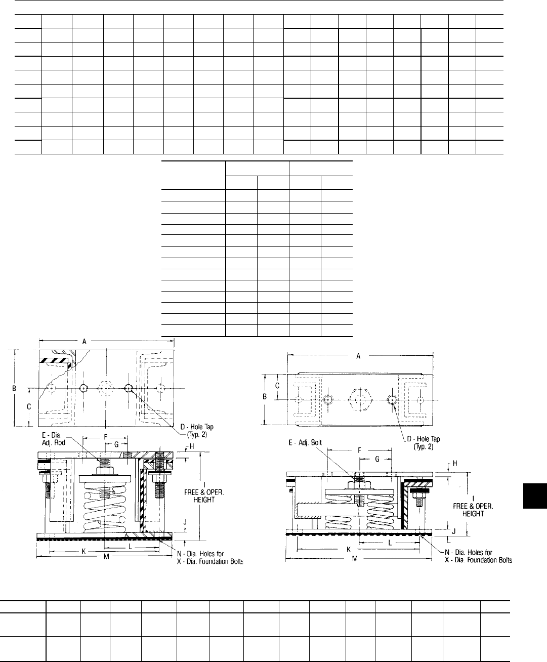
105
YORK INTERNATIONAL
FORM 201.19-NM1 (204)
7
WEIGHT DISTRIBUTION AND ISOLATOR MOUNTING POSITIONS
FIG. 35 – TYPE AWMR ISOLATOR DETAILS
A B C D E F G H I J K L M N/X
AWMR-1 10-1/2 6 3 5/8 3/4 3-1/2 1-3/4 1/2 9 5/8 8-1/2 4-1/4 10-1/2 3/4
50-553 11NC 5/8
AWMR-2 15 6 3 3/4 1 7-1/2 3-3/4 1/2 9-1/2 5/8 14-1/2 7-1/4 17 3/4
50-553 10NC 5/8
LD02973
AWMR-1-XXX
LD02974
AWMR-2-XXX
ISOLATOR MAX LOAD DEFL.
TYPE & SIZE lbs. kg in. mm
AWMR-1-53 1,000 453.6 2 51
AWMR-1-530 1,150 521.6 2 51
AWMR-1-531 1,276 578.8 2 51
AWMR-1-532 1,500 680.4 2 51
AWMR-1-551 1,676 760.2 2 51
AWMR-1-552 1,900 861.8 2 51
AWMR-1-553 2,200 997.9 2 51
AWMR-2-520 1,300 589.7 2 51
AWMR-2-521 1,552 704.0 2 51
AWMR-2-53 2,000 907.2 2 51
AWMR-1-530 2,300 1043.3 2 51
AWMR-2-531 2,552 1157.6 2 51
AWMR-2-532 3,000 1360.8 2 51
60 HERTZ, CU. FINS, SEISMIC ISOLATOR SELECTIONS - VMC MODEL # AWMR-(SEE TABLE BELOW)
YCAS A B C D E F G H I J K L M N O P
0130 1-553 1-552 1-552 1-553 1-553 1-552 1-552 1-531 --- --- --- --- --- --- --- ---
0140 1-553 1-552 1-552 1-553 1-553 1-552 1-552 1-531 --- --- --- --- --- --- --- ---
0150 1-553 1-553 1-553 1-553 1-553 1-553 1-553 1-553 --- --- --- --- --- --- --- ---
0160 1-553 1-553 1-553 1-553 1-553 1-553 1-553 1-553 --- --- --- --- --- --- --- ---
0170 1-553 1-553 1-553 1-553 1-553 1-553 1-553 1-553 --- --- --- --- --- --- --- ---
0180 1-553 1-553 1-553 1-553 1-553 1-553 1-553 1-553 --- --- --- --- --- --- --- ---
0200 2-532 2-553 1-553 1-551 2-532 2-531 1-553 2-53 --- --- --- --- --- --- --- ---
0210 2-532 2-553 1-553 1-551 2-532 2-531 1-553 2-53 --- --- --- --- --- --- --- ---
0230 2-532 2-553 1-553 1-551 2-532 2-531 1-553 2-53 --- --- --- --- --- --- --- ---
DIMENSIONS - In.
Copper Fin Condenser Coils with Silencer Kit

106 YORK INTERNATIONAL
FORM 201.19-NM1 (204)
Technical Data
Copper Fin Condenser Coils with Silencer Kit
WEIGHT DISTRIBUTION AND ISOLATOR MOUNTING POSITIONS
DEFLECTION
COLOR MAX. LOAD ins. (mm)
TYPE
CODE lbs. (kg) R RD
R-3 BLACK 250 (113.5)
0.25 0.50
OR RED 525 (238.3)
(6.3) (12.7)
RD-3 GREEN 750 (340.5)
GRAY 1,100 (499.4)
R-4 BLACK 1,500 (681.0)
0.25 0.50
OR RED 2,250 (1021.5)
(6.3) (12.7) RD-4 GREEN 3,000 (1362.0)
GRAY 4,000 (1816.0)
LD04033
TYPE R OR RD
IF BOLTING IS PREFERRED–
Type R or RD mountings are furnished with
a tapped hole in the center. This enables the
equipment to be bolted securely to the mounting.
TYPE R OR RD
NO BOLTING IS PREFERRED–
Type R or RD mountings are may be
used without bolting under machines
having no lateral or severe vertical
motion.
NEW DESIGN FOR TYPE RD-4
NEOPRENE MOUNTINGS.
TYPE RD-3
LD04033
29518A 29517A
TYPE L W H *HD A B C D E
R-3 5-1/2" 3-3/8" 1-3/4" 2-7/8" 2-1/2" 1/2" 4-1/8" 9/16" 1/4"
OR (139.7) (85.8) (44.4) (73.2) (63.5) (12.7) (104.8) (14.4) (6.3)
RD-3
R-4 6-1/4" 4-5/8" 1-5/8" 2-3/4" 3" 1/2" 5" 9/16" 3/8"
OR (158.7) (117.6) (41.4) (69.8) (76.2) (12.7) (127.0) (14.4) (9.6)
RD-4
DIMENSIONS: ins. (mm)
* HD dimension applies to double defl ection Type RD mountings only.
60 HERTZ, CU. FINS, NEOPRENE MOUNT SELECTION- VMC TYPE RD (SEE TABLE BELOW)
YCAS A B C D E F G H I J K L M N O P
0130 -4 Red -4 Red -4 Red -4 Red -4 Red -4 Red -4 Red -4 Red --- --- --- --- --- --- --- ---
0140 -4 Red -4 Red -4 Red -4 Red -4 Red -4 Red -4 Red -4 Red --- --- --- --- --- --- --- ---
0150 -4 Red -4 Red -4 Red -4 Red -4 Red -4 Red -4 Red -4 Red --- --- --- --- --- --- --- ---
0160 -4 Red -4 Red -4 Red -4 Red -4 Red -4 Red -4 Red -4 Red --- --- --- --- --- --- --- ---
0170 -4 Red -4 Red -4 Red -4 Red -4 Red -4 Red -4 Red -4 Red --- --- --- --- --- --- --- ---
0180 -4 Red -4 Red -4 Red -4 Red -4 Red -4 Red -4 Red -4 Red --- --- --- --- --- --- --- ---
0200 -4 Grn -4 Grn -4 Red -4 Red -4 Grn -4 Grn -4 Red -4 Red --- --- --- --- --- --- --- ---
0210 -4 Grn -4 Grn -4 Red -4 Red -4 Grn -4 Grn -4 Red -4 Red --- --- --- --- --- --- --- ---
0230 -4 Grn -4 Grn -4 Red -4 Red -4 Grn -4 Grn -4 Red -4 Red --- --- --- --- --- --- --- ---

107
YORK INTERNATIONAL
FORM 201.19-NM1 (204)
INSTALLATION INSTRUCTIONS FOR
VMC SERIES AWR/AWMR AND CP
RESTRAINED MOUNTINGS
1. Floor should be level and smooth.
2. For indoor applications, isolators do not nor mal ly
re quire bolting. If necessary, anchor iso la tors to
fl oor through bolt holes in base plate.
IM POR TANT: Iso la tors must be bolted to
sub struc ture and equip ment to isolators when
used under outdoor equip ment exposed to wind
forc es.
3. Lubricate threads of adjusting bolt. Loosen hold
down bolts to allow for isolator adjustment.
4. Block the equipment 1/4" higher than the spec-
i fi ed free height of the isolator. To use the iso la tor
as block ing for the equipment, insert a 1/4" shim
be tween the upper load plate and vertical up rights.
Lower the equip ment on the blocking or shimmed
isolators.
5. Complete piping and fi ll equipment with wa ter,
re frig er ant, etc.
6. Turn leveling bolt of fi rst isolator four full rev o -
lu tions and proceed to each mount in turn.
7. Continue turning leveling bolts until equip ment is
fully supported by all mountings and equip ment is
raised free of the spacer blocks or shims. Remove
blocks or shims.
8. Turn leveling bolt of all mountings in either di-
rec tion in order to level the installation.
9. Tighten nuts on hold down bolts to permit a clear-
ance of 1/8" between resilient washer and un der side
of channel cap plate.
10. Installation is now complete.
7
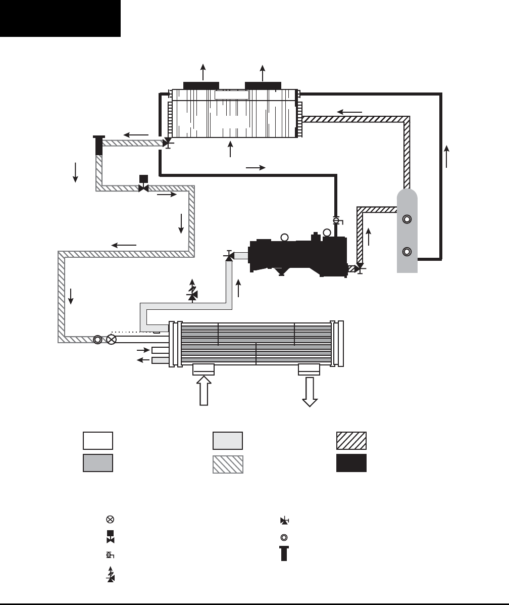
108 YORK INTERNATIONAL
FORM 201.19-NM1 (204)
REFRIGERANT FLOW DIAGRAM
Low pressure liquid refrigerant enters the evaporator and
is evaporated and superheated by the heat energy ab sorbed
from the chilled water passing through the evaporator
shell. Low pressure vapor enters the compressor where
pres sure and superheat are increased. High pres sure vapor
is passed through the oil separator where com pres sor oil
is removed and recirculated to the com pres sor via the
condenser. The high pressure oil-free vapor is fed to the
air cooled condenser coil where the heat is re moved. On
economized models, the fully con densed liquid enters
the econ o miz er.
FIG. 36 – REFRIGERANT FLOW DIAGRAM
A small percentage of the of the liquid passes through an
expansion valve, into the other side of the econ o miz er
where it is evaporated. This low pressure liquid subcools
the major part of the refrigerant. Me di um pres sure vapor
then returns to the compressor. The subcooled refrigerant
then passes through the ex pan sion valve where pressure
is reduced and fur ther cool ing takes place before return-
ing to the evaporator.
Low Pressure Liquid
Medium Pressure Vapour
Low Pressure Vapour
High Pressure Liquid
High Pressure Vapour
Oil
COMP - Compressor CDR -Condenser Coil CLR - Cooler EC - Economizer (Added to some models)
OC - Oil Cooler OS - Oil Separator
- Air Entering Compressor R-22 - Refrigerant Circuit Number
Thermostatic Expansion Valve
TXV Valve
Relief Valves
Filter or Drier
Sight Glass
Angle Stop Valve
Solenoid Valve
CLR
RC2
COMP.
OS
CDR
OC
m /s
3
Electronic
LD09428
Technical Data
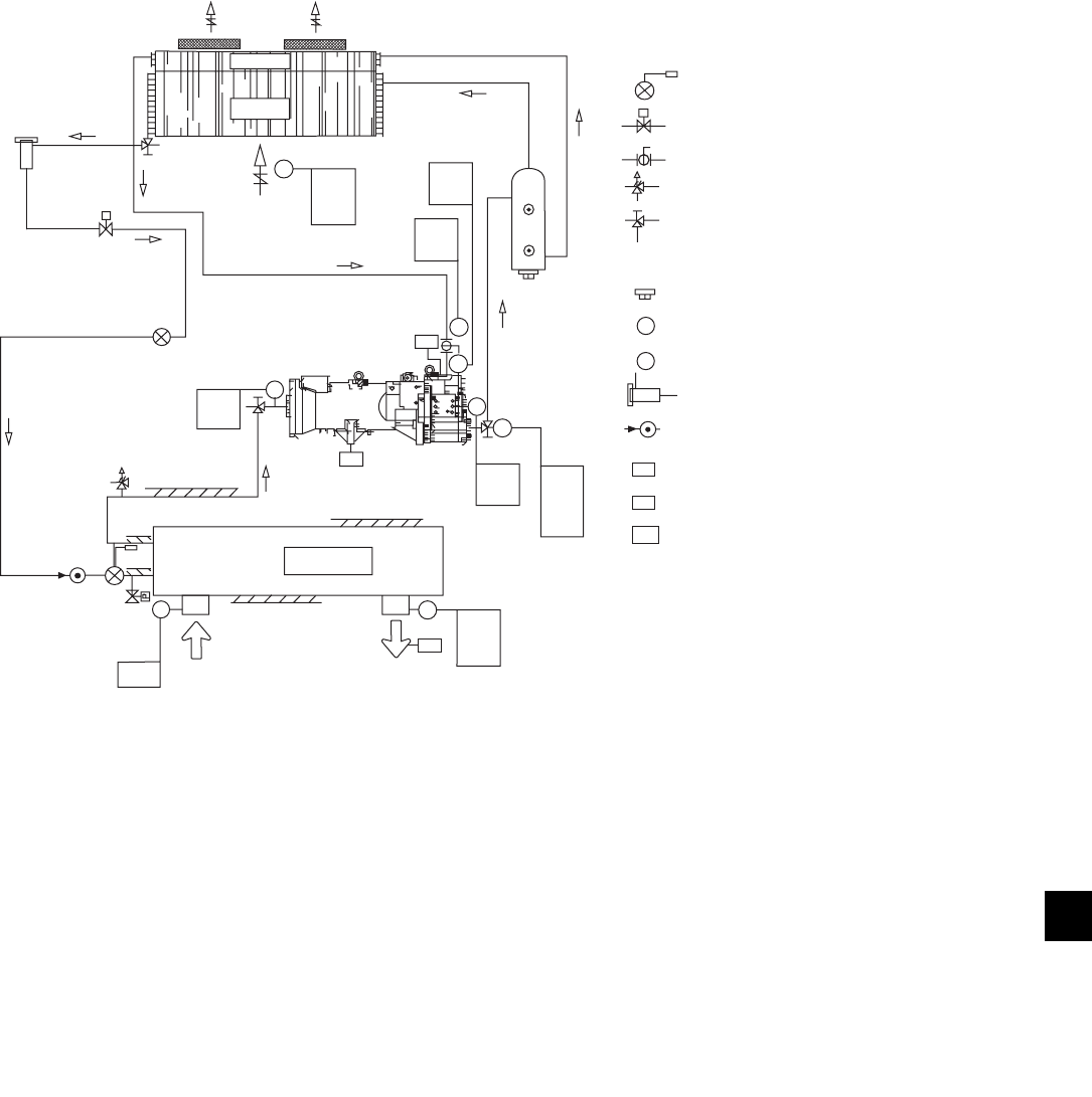
109
YORK INTERNATIONAL
FORM 201.19-NM1 (204)
PROCESS AND INSTRUMENTATION DIAGRAM
FIG. 37 – PROCESS AND INSTRUMENTATION DIAGRAM
LD09429
7
OC
CDR
AIR
FLOW
DV
HTC
LTC
DV
DIF
DV
HTC
OS
T
P
PS
T
P
DV
HTC
DV
HPC
HPL
DPF
COMP
HTR
P
T
SHV
HTR
TDV
CHT
LTC
FS
CLR
CHILLED WATER
FLOW
T
DV
S
P
P
T
FS
PS
HTR
SYSTEM COMPONENTS
MICROPROCESSOR CONTROL FUNCTIONS
MAJOR COMPONENTS
EXPANSION VALVE, THERMOSTATIC
SOLENOID VALVE
BALL VALVE
RELIEF VALVE
STOP VALVE ANGLE, ACCESS
PURGE VALVE
PLUG
PRESSURE SENSOR
TEMPERATURE SENSOR
REPLACEABLE CORE FILTER DRYER
SIGHT GLASS
FLOW SWITCH (option)
PRESSURE SWITCH
ELECTRIC HEATER
COMP COMPRESSOR
CDR CONDENSER COIL
CLR COOLER
OC OIL COOLER COIL
OS OIL SEPARATOR
CHT CHILLED LIQUID THERMOSTAT
DIF DIFFERENTIAL PRESSURE CUTOUT
DFP DISCHARGE PRESSURE FAN CONTROL
DV DISPLAY VALUE
HPL HIGH PRESSURE LOAD LIMITING
HTC HIGH TEMPERATURE CUTOUT
LPC LOW PRESSURE CUTOUT
LTC LOW TEMPERATURE CUTOUT
SHV SUPERHEAT VALVE
DV
LPC
S
ELECTRONIC
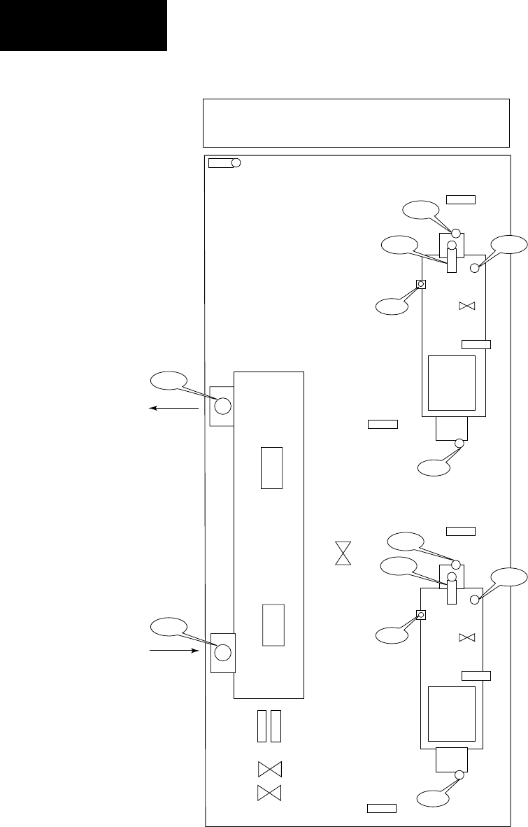
110 YORK INTERNATIONAL
FORM 201.19-NM1 (204)
COMPONENT LOCATIONS
FIG. 38 – COMPONENT LOCATIONS
LD07012
Technical Data
Control Panel
BAMB
1-BDP
1-BOT
EEH1
1-ZCPR
1-CCCV
1-ECH
1-XCMTB
2-YELSSV
EEH1
- BAMB AMBIENT
- BCLT COLD LEAVING TEMPERATURE
- BCRT COLD RETURN TEMPERATURE
- BDP DISCHARGE PRESSURE
- BDT DISCHARGE TEMPERATURE
- BOP OIL PRESSURE
- BOT OIL TEMPERATURE
- BSP SUCTION PRESSURE
- CCCV COMPRESSOR CAPACITY CONTROL VALVE
- ECH CRANK CASE HEATER
- EEH EVAPORATOR HEATER
- SHPI HIGH PRESSURE CUT-OUT
- STS SUCTION TEMPERATURE SENSOR
- RFTS REFRIGERANT FEED TEMPERATURE SENSOR (R407C only)
- XCMTB COMPRESSOR MOTOR TERMINAL BOX
- YELSSV ECONOMIZER LIQUID SUPPLY SOLENOID VALVE
- ZCPR COMPRESSOR
1-RFTS
1-STS
2-BOT
3-CCCV
3-ECH
3-XCMTB
3-ZCPR
1-BOT
2-STS
1-YELSSV
2-RFTS
2-YELSSV
1-BDP
3-BDT
3-BDP
3-SHPI
1-SHPI
1-BOP
3-BOP
1-BSP
3-BSP
BCRT
BCLT
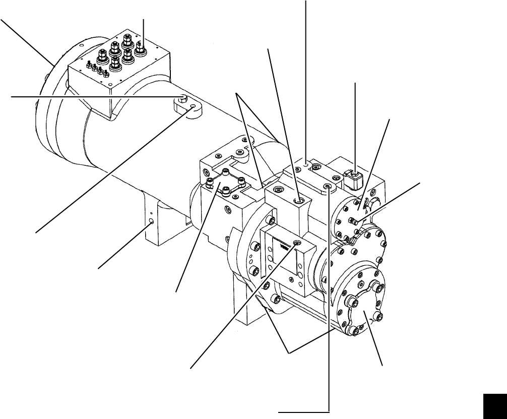
111
YORK INTERNATIONAL
FORM 201.19-NM1 (204)
COMPRESSOR COMPONENTS
FIG. 39 – COMPRESSOR COMPONENTS
SUCTION GAS IN MOTOR TERMINALS
LIFTING LUG
THREADED
HOLE
OIL
HEATER
ECONOMIZER
GAS IN
DISCHARGE
CASE
OIL INLET
FROM
CONDENSER
COOLING COIL
DISCHARGE GAS OUT
OIL FILTER
BLEED &
EVACUATION
POINT
OIL FILTER
COVER PLATE
CAPACITY CONTROL SOLENOID
(CAPACITY CONTROL, 3 WAY VALVE,
IS LOCATED UNDER THE SOLENOID)
LIFTING LUG
THREADED HOLE
OIL PRESSURE
TRANSDUCER
LOCATION
ROTOR CASE
LD03668
7
STATOR
LOCKING BOLT
EVACUATION
PORT
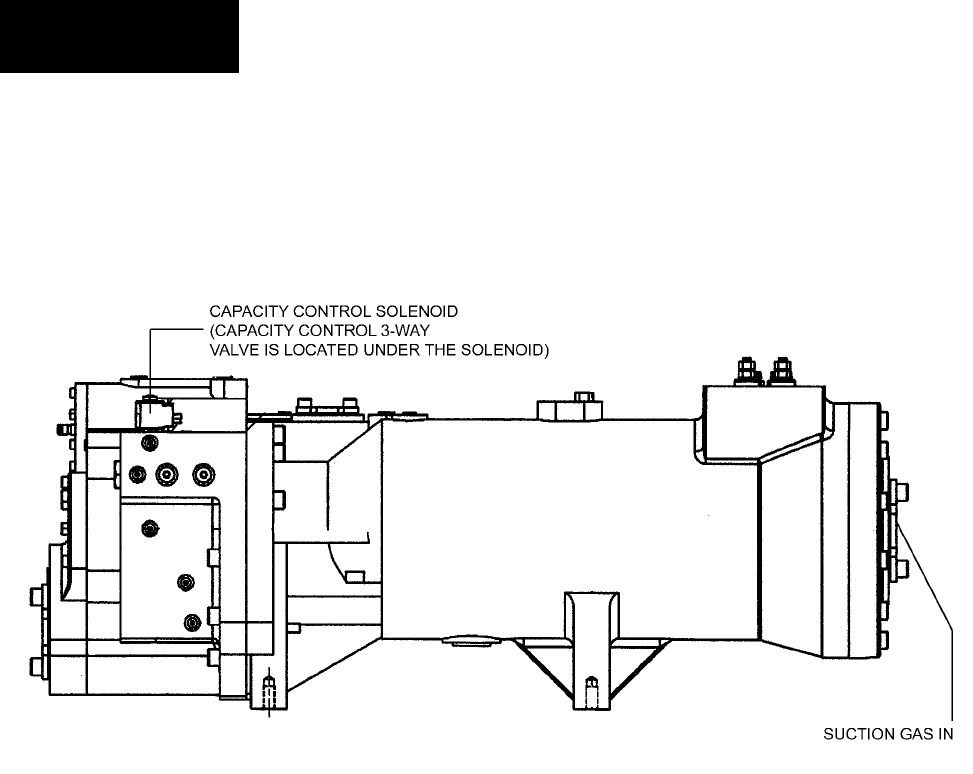
112 YORK INTERNATIONAL
FORM 201.19-NM1 (204)
COMPRESSOR COMPONENTS – CONT’D
FIG. 40 – COMPRESSOR COMPONENTS
LD03669
Technical Data
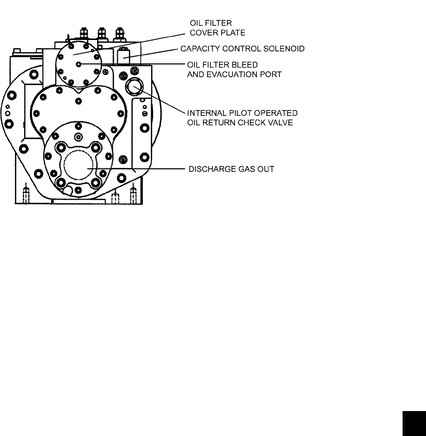
113
YORK INTERNATIONAL
FORM 201.19-NM1 (204)
COMPRESSOR COMPONENTS – CONT’D
FIG. 41 – COMPRESSOR COMPONENTS
LD03670
7
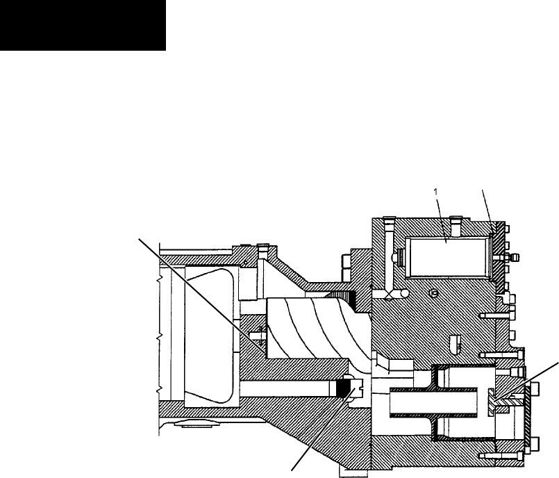
114 YORK INTERNATIONAL
FORM 201.19-NM1 (204)
COMPRESSOR COMPONENTS – CONT’D
FIG. 42 – COMPRESSOR COMPONENTS
Technical Data
LD06079
MALE ROTOR
RELIEF VALVE
DISCHARGE
CHECK VALVE
OIL FILTER
OIL FILTER
O-RING
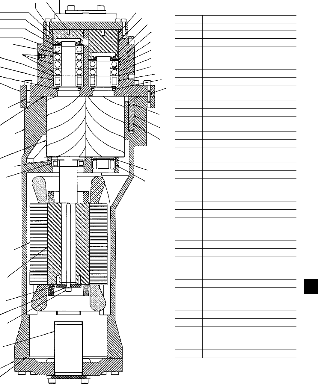
115
YORK INTERNATIONAL
FORM 201.19-NM1 (204)
COMPRESSOR COMPONENTS – CONT’D
NO. PART NAME
1 O-RING
2 SUCTION COVER
3 SUCTION STRAINER
4 ROTOR SCREW
5 ROTOR LOCK WASHER
6 ROTOR CLAMP WASHER
7 ROTOR
8 STATOR
9 MALE INLET BEARING
10 MALE ROTOR RETAINING RING
11 MALE ROTOR
12 ROTOR CASE
13 O-RING
14 DOWEL PIN
15 DISCHARGE CASE
16 LIP SEAL
17 DISCHARGE RADIAL BEARING
18 SPACER SHIM
19 THRUST BEARINGS
20 THRUST SPACE SHIM
21 REVERSE THRUST BEARING
22 BEARING CLAMP NUT
23 BEARING SPACER SLEEVE
24 BEARING PRELOAD SPRING
25 O-RING
26 BEARING BORE PLUG
27 DISCHARGE COVER
28 BEARING BORE PLUG
29 BEARING PRELOAD SPRING
30 BEARING SPACER SLEEVE
31 BEARING CLAMP NUT
32 REVERSE THRUST BEARING
33 THRUST SPACER SHIM
34 THRUST BEARINGS
35 SPACER SHIM
36 DISCHARGE RADIAL BEARING
37 LIP SEAL
38 DOWEL PIN
39 SUPPORT RING
40 ECONOMIZER PLUG
41 SUPPORT RING
42 FEMALE ROTOR RETAINING RING
43 FEMALE INLET BEARING
FIG. 43 – COMPRESSOR COMPONENTS
4
5
67
8
9
10
11
12
13
14
15 16 17 18
19
20
21 22 23 24
25
27
28
26
29
30
31
32
333435
36
37
38
394041
42
123
43
LD03673
7

116 YORK INTERNATIONAL
FORM 201.19-NM1 (204)
COMPRESSOR COMPONENTS – CONT’D
FIG. 44 – COMPRESSOR COMPONENTS
O-RING
MOTOR ROTOR /
MALE ROTOR LOCKING KEY
MALE ROTOR
FEMALE ROTOR
O-RING
RELIEF
VALVE
ECONOMIZER
PLUG
SUPPORT
RINGS
LD03672
SLIDE VALVE
RETURN
SPRING
SLIDE VALVE
Technical Data
117
YORK INTERNATIONAL
FORM 201.19-NM1 (204)
SYSTEM STARTUP CHECKLIST
op er ate the pump until oil drips from the fl are nut
joint, al low ing the air to be expelled, and tight en
the fl are nut. Open the oil charg ing valve on the
oil separator and pump in oil un til it reach es the
prop er lev el as de scribed above.
6. Assure water pumps are on. Check and ad just
wa ter pump fl ow rate and pressure drop across
the evaporator.
Excessive fl ow may cause cat a stroph ic
dam age to the evaporator.
7. Check the control panel to as sure it is free of
for eign material (wires, metal chips, etc.).
8. Visually inspect wiring (power and control).
Wir ing MUST meet N.E.C. and local codes.
See Fig. 9 and 10, pages 36 and 37.
9. Check tightness of power wir ing in side the pow er
pan el on both sides of the motor contactors and
in side the motor terminal boxes.
10. Check for proper size fuses in main and con trol
cir cuits.
11.Verify that fi eld wiring matches the 3-phase
pow er re quire ments of the compressor. See
chill er name plate (Pages 25 - 26).
12.Assure 115VAC Control Power has 30A min-
i mum capacity. See Fig. 14, page 41.
13.Be certain all water temp sensors are in sert ed
com plete ly in their respective wells and are
coat ed with heat conductive compound.
14.Assure that evaporator EEV bulbs are strapped
onto the suction lines at 4 or 8 o’clock po si -
tions.
15.Assure that the 15 ton economizer TXV bulbs
are strapped onto the compressor econ o miz er
sup ply lines at 4 or 8 o’clock po si tions.
JOB NAME: ______________________________
SALES ORDER #: _________________________
LOCATION: _______________________________
SOLD BY: ________________________________
INSTALLING
CONTRACTOR: ___________________________
START-UP
TECHNICIAN/
COMPANY: _______________________________
START-UP DATE : _________________________
CHILLER MODEL #: _______________________
SERIAL #: ________________________________
COMPRESSOR #1
MODEL#: ________________________________
SERIAL #: ________________________________
COMPRESSOR #2
MODEL#: ________________________________
SERIAL #: ________________________________
UNIT CHECKS (NO POWER)
Check the system 24 hours prior to initial start.
1. Inspect the unit for shipping or in stal la tion
damage.
2. Assure that all piping has been com plet ed.
3. Check that the unit is properly charged and that
there are no piping leaks.
4. Open each compressor suction service valve,
discharge service valve, econ o miz er service
valve, liq uid line stop valve, and oil line ball
valves.
5. The compressor oil level should be main tained
so that an oil level is visible in ei ther of the two
oil sep a ra tor sight glass es. In other words, oil
level should al ways be main tained, run ning or
not, above the bot tom of the low er sight glass
and below the top of the upper sight glass.
If it is necessary to add oil, con nect a YORK oil
pump to the charging valve on the oil sep a ra tor,
but do not tight en the fl are nut on the delivery
tub ing. With the bot tom (suc tion end) of the
pump sub merged in oil to avoid en trance of air,
In actual operation, due to splash ing,
an oil level may be seen in both sight
glass es. Run the com pres sor for a few
min utes fully loaded, shut the system
down, and as sure there is an oil lev el
show ing in the bot tom or top sight
glass with the com pres sor off.
7
118 YORK INTERNATIONAL
FORM 201.19-NM1 (204)
5. Program the required op er at ing val ues into the
mi cro for cut-outs, safe ties, etc. and record them
in the chart be low. See Page 166 for details.
Record programmed values in the chart below.
PROGRAMMED VALUES
Display Language =_________________________
Discharge Press Cutout = ___________PSIG (kPa)
Discharge Press Unload = ___________PSIG (kPa)
Suction Press Cutout = _____________PSIG (kPa)
High Amb Cutout = ___________________ °F (°C)
Low Amb Cutout = ____________________ °F (°C)
Leaving Chilled Liquid Temp Cutout = _____ °F (°C)
High Motor Current Unload = ____________ % FLA
Anti-Recycle Time = ____________________Secs
Local / Remote Mode = ______________________
Display Units = _________________________
Lead / Lag Control = ________________________
Power Failure Restart = _____________________
Suction Superheat Setpoint = __________ °F (°C)
6. Program the Chilled Liquid Setpoint/Range and
record:
Setpoint = __________________ °F (°C)
Range = +/- ________________ °F (°C)
Keep in mind that the setpoint temperature dis-
played by the micro should equal the de sired
leav ing wa ter tem per a ture.
7. Assure that the CLK jumper J18 on the Mi cro -
pro ces sor Board is in the ON position (Top 2
pins).
8. Set the Time and Date.
9. Program the Daily Schedule start and stop
times.
10.Check the Factory Service Mode programming
values, (See Section 8.9) assure they are correct,
and record the values below:
Refrigerant Type = __________________________
R407C Chiller Type = ________________________
Unit Type = _______________________________
16.Assure that the Flow Switch is properly in-
stalled, wired correctly, and working.
17. Assure bolts through compressor feet to bottom
frame rails are removed.
PANEL CHECKS
(Power ON – Both System Switches “OFF”)
1. Apply 3-phase power and verify its val ue (See
Fig. 9 and 10 pages 36 and 37).
2. Apply 115VAC and verify its value on the ter-
mi nal block in the lower left of the Power Pan el.
Make the mea sure ment between ter mi nals 5 and
2 (See Fig. 14, page 41). The voltage should be
115VAC +/- 10%.
3. Assure the heaters on each compressor are on.
Al low the compressor heaters to remain on a
min i mum of 24 hours before start- up. This is
im por tant to as sure that no re frig er ant is in
the com pres sor oil at start-up!
4. Program the dip switches on the mi cro pro ces sor
board for the desired operating re quire ments. See
Fig. 49, Page 147. OPEN = Left side of switch
pushed down. CLOSED = Right side of switch
pushed down.
SWITCH SWITCH "OPEN"
SETTING
SWITCH "CLOSED"
SETTING
1Water Cooling Glycol Cooling
2Standard Ambient
Control Low Ambient Control
3Refrigerant R-407C Refrigerant R-22
4Do Not Use YCAS
5Do Not Use
Motor Current
Averaging (Start-Up)
Disabled
6Heat Recovery
Disabled Do Not Use
7Expansion Valve
Thermostatic
Expansion Valve
Electronic*
8Standard Options
Enabled Do Not Use
*Expansion valve electronic should always be selected when an
EEV is installed.
Verify the selections by pressing the OP TIONS Key on
the control panel. Check them off in the chart above.
Damage to the chiller could result
if switch es are im prop er ly pro-
grammed.
Technical Data
119
YORK INTERNATIONAL
FORM 201.19-NM1 (204)
4. Check the system operating parameters. Do this
by selecting various displays such as pres sures
and tem per a tures. Compare these to test gauge
readings.
CHECKING SUBCOOLING AND SUPERHEAT
The subcooling should always be checked when charg-
ing the system with refrigerant and/or before setting
the superheat.
When the refrigerant charge is correct, there will be no
bubbles in the liquid sight glass with the system op er -
at ing under full load conditions, and there will be 12 -
15°F (6 - 8°C) subcooled liquid leaving the condenser.
An overcharged system should be guarded against.
Ev i denc es of overcharge are as follows:
a. If a system is overcharged, the discharge pres sure will
be higher than normal. (Normal discharge/con dens ing
pres sure can be found in the refrigerant tem per a ture/
pres sure chart; use entering air tem per a ture +30°F
(17°C) for nor mal condensing tem per a ture.
b. The temperature of the liquid refrigerant out of the
con dens er should be not be more than 15°F (8°C)
less than the condensing temperature (The tem-
per a ture cor re spond ing to the condensing pressure
from the re frig er ant tem per a ture/pressure chart).
The subcooling temperature of each system should be
calculated by recording the temperature of the liquid
line at the outlet of the condenser and subtracting it
from the recorded liquid line pressure at the liquid stop
valve, con vert ed to temperature from the temperature/
pres sure chart.
Example:
Liquid line pressure =
202 PSIG converted to 102°F (39°C)
minus liquid line temp. - 87°F (31°C)
SUBCOOLING = 15°F (8.3°C)
The subcooling should be adjusted to 12-15°F (6.7/- 8.3°C).
1. Record the liquid line pressure and its cor re -
spond ing temperature, liquid line tem per a ture
and subcooling below:
SYS 1 SYS 2
Liq Line Press = PSIG (kPa)
Temp = °F (°C)
Liq Line Temp = °F (°C)
Subcooling = °F (°C)
Heat Recovery = ___________________________
Sys #1 100% FLA = ____________________ Amps
Sys #2 100% FLA = ____________________ Amps
Sys #1 Motor Protector Input = ____________Volts
Sys #2 Motor Protector Input = ____________Volts
Typically, these values should not be
changed. Incorrect programming may
cause catastrophic chiller failure.
11.Check the Motor Protector Dip Switch program-
ming. The switches should correctly set at the
factory. The switches may be checked visibly
and the total ON switches added using binary
addition to determine the setting or by reading
the display on the motor protector. See Section
8 for programming information. Record the
values below:
Sys #1 Wires thru each hole of the C.T. = ________
Sys #1 MP Setting = ________
Sys #2 Wires thru each hole of the C.T. = ________
Sys #2 MP Setting = ________
INITIAL START-UP
After the control panel has been pro grammed and the
com pres sor heater has been on for 24 hours prior to
start-up, the chiller may be placed into operation.
1. Place the System Switches on the Mi cro pro -
ces sor Board to the ON position.
2. The compressor will start and a fl ow of re frig -
er ant will be not ed in the sight glass. Af ter
sev er al min utes of op er a tion, the bub bles in the
sight glass will dis ap pear and there will be a
solid col umn of liquid when the TXV sta bi liz es.
After the water tem per a ture sta bi liz es at de sired
op er at ing con di tions, the sight glass should be
clear.
3. Allow the compressor to run a short time, be ing
ready to stop it immediately if any unusual noise
or adverse conditions de vel op. Im me di ate ly at
start-up, the com pres sor will make sounds dif-
fer ent from its normal high pitched sound. This
is due to the com pres sor com ing up to speed and
lubrication chang ing from liq uid re frig er ant to
oil. This should be of no con cern and lasts for
only a short time.
7
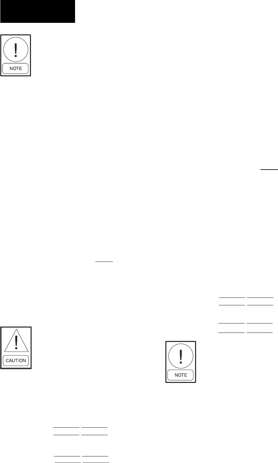
120 YORK INTERNATIONAL
FORM 201.19-NM1 (204)
If equipped with an economizer, the
economizer will provide approxi-
mately an additional 20ºF (11.1ºC)
subcooling at the expansion valve in
ambients above 90ºF (32ºC). Below
90ºF (32ºC), the economizer will not
provide additional subcooling.
After the subcooling is set, the suction superheat should
be checked. The superheat should be checked only af ter
steady state operation of the chiller has been es tab lished,
the leaving water temperature has been pulled down to
the required leaving water temperature, and the unit is
running in a fully loaded condition. Correct su per heat
setting for a system is 10 - 12°F (6 - 7°C).
The superheat is calculated as the difference between
the actual temperature of the returned refrigerant gas in
the suction line entering the compressor and the tem-
per a ture corresponding to the suction pressure as shown
in a standard pressure/temperature chart.
Example:
Suction Temp = 46°F (8°C)
minus Suction Press
60 PSIG converted
to Temp - 34°F (1°C)
12°F (7°C)
The suction temperature should be taken 6" (13 mm)
be fore the compressor suction service valve, and the
suc tion pres sure is taken at the compressor suction
ser vice valve.
The EEV is non-adjustable. Super-
heat setpoint is programmable from
the keypad.
2. Record the suc tion tem per a ture, suction pres sure,
suction pressure con vert ed to tem per a ture, and
su per heat of each sys tem below:
CHECKING ECONOMIZER SUPERHEAT
(IF APPLICABLE) (15 TON TXV)
The economizer superheat should be checked to as sure
proper economizer operation and motor cooling. Cor rect
superheat setting is approx. 10 - 12°F (6 - 7°C).
The superheat is calculated as the difference between
the pressure at the Economizer Service Valve on the
com pres sor converted to the corresponding tem per a ture
in a standard pressure/temperature chart and tem per a ture
of the gas at the bulb on the entering piping to the mo-
tor housing.
Example:
Motor Gas Temp = 90°F (32°C)
minus Economizer Press
139 PSIG converted
to Temp - 78°F (26°C)
12°F (6°C)
Normally, the thermal expansion valve need not be
ad just ed in the fi eld. If however, adjustment needs to
be made, the expansion valve adjusting screw should
be turned not more than one turn at a time, allowing
suf fi cient time (approximately 15 minutes) between
ad just ments for the system and the thermal expansion
valve to respond and settle out. Assure that superheat is
set between 10 - 12°F (6 - 7°C).
1. Record the motor gas temperature, econ o miz er
pres sure, economizer pressure con vert ed to
tem per a ture, and economizer su per heat below:
This superheat should only be checked
in an am bi ent above 90°F (32°C). Oth-
er wise, mid-range ad just ment (fac to ry
setting) is ac cept able. Below 90ºF
(32ºC) ambient, the economizer will
not provide additional subcooling.
LEAK CHECKING
1. Leak check compressors, fi ttings, and pip ing to
as sure no leaks.
If the unit is functioning satisfactorily during the initial
operating period, no safeties trip and the compressors
load and unload to control water temperature, the chill er
is ready to be placed into operation.
SYS 1 SYS 2
Suction Press = PSIG (kPa)
Suction Temp = °F (°C)
Suction Press
Converted
to Temp = °F (°C)
Superheat = °F (°C)
SYS 1 SYS 2
Economizer Press = PSIG (kPa)
Economizer Temp = °F (°C)
Economizer Press
Converted to Temp = °F (°C)
Superheat = °F (°C)
Technical Data

121
YORK INTERNATIONAL
FORM 201.19-NM1 (204)
7
This page intentionally left blank.
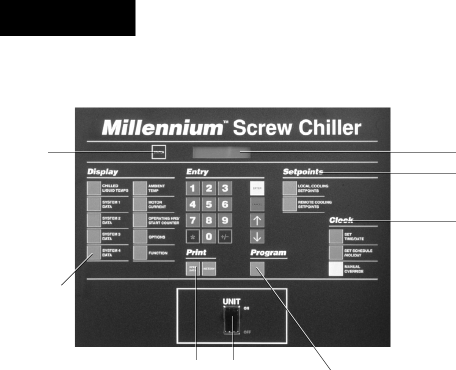
122 YORK INTERNATIONAL
FORM 201.19-NM1 (204)
29023A
CHILLER CONTROL PANEL
PROGRAMMING AND DATA ACCESS KEYS
CLOCK
SETPOINTS
PROGRAM &
SETUP KEY
ON / OFF
DISPLAY
INFORMATION KEYS
STATUS
PRINT
DISPLAY AND STATUS INFORMATION KEYS
Status Key - see Section 2
This key provides a display of the current operational
and/or fault status of the chiller or individual re frig er ant
systems.
Display Keys - see Section 3
Each key provides a real time display of commonly
re quired information about the chiller and individual
sys tem operating conditions and settings.
Print Keys - see Section 4
These keys allow control panel display or remote
print out of both current real-time operating and pro-
grammed data as well as fault history data from recent
safety shut downs.
ON / OFF ROCKER SWITCH
This switch shuts down the entire chiller when placed
in the OFF position. The switch must be ON for the
chiller to operate.
The systems will not pump down at shutdown when the
UNIT switch is switched off.
PROGRAM & SETUP KEYS
Entry Keys - see Section 5
The numeric and associated keys are used for entering
data required for programming the chiller. The EN TER
and keys are also used for scrolling through in for -
ma tion available after pressing certain keys.
Setpoints Keys - see Section 6
These keys are used for display and programming of
the local and remote offset chilled liquid temperature
setpoints.
Clock Keys - see Section 7
These keys are used for display and programming of the
clock and operating schedule for the chiller.
Program Key - see Section 8
This key is used for display and programming of the
chiller operational settings and limits.
DISPLAY
Micro Panel Contents
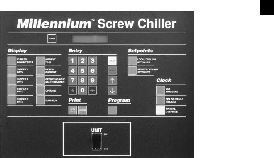
123
YORK INTERNATIONAL
FORM 201.19-NM1 (204)
1. INTRODUCTION & PHYSICAL DESCRIPTION
29023A
1.1 GENERAL
The YORK Screw Chiller Control Panel is a mi cro pro -
ces sor based control system fi tted to YCAS liq uid chill-
ers. It is capable of multi-re frig er ant system con trol to
maintain chilled liquid tem per a ture within pro grammed
limits and to provide safety control of the chill er. The
microprocessor monitors leav ing chilled liq uid tempera-
ture deviation from setpoint and the rate of change of this
temperature to start, stop, load and un load compressors
as required.
User interface is via a touch keypad and a liquid crystal
display allowing access to operating and programmed
data. Information can be displayed in English (Im pe ri al)
units or SI (Metric) units (Section 8.1). Con ver sion
ta bles are provided at the back of this man u al.
A master ON/OFF rocker switch is provided on the
chiller control panel to activate or deactivate the com-
plete chiller, while switches to activate or deactivate
individual refrigerant systems are provided on the Mi-
cro pro ces sor Board.
External interface is available for control of the chiller
via a YORK ISN System or YORK Remote Control
Center. In addition, EMS/BAS System connections are
provided for remote cycling, current limiting, remote
tem per a ture setpoint reset and alarm annunciation.
YCAS chillers each have a single split circuit evap o -
ra tor serving 2 independent refrigerant sys tems. YCAS 2
system chillers are confi gured as a sin gle self con tained
section with a single control pan el con trol ling the two
refrigerant systems.
1.2 KEYPAD & DISPLAY
An operator keypad allows complete control of the
chill er from a central location. The keypad offers a
multitude of commands available to access displays,
program setpoints, and initiate system commands.
Keys are grouped and color coded for clarity and ease
of use.
A 40 Character Liquid Crystal Display (2 lines of 20
char ac ters) is used for displaying system parameters
and op er a tor messages. The display has a lighted back-
ground for night viewing as well as a special feature
which in ten si fi es the display for viewing in direct
sunlight.
Displays will be updated every two seconds by the
mi cro pro ces sor.
8

124 YORK INTERNATIONAL
FORM 201.19-NM1 (204)
1.3 UNIT (CHILLER) ON / OFF SWITCH
A master UNIT (Chill er) ON / OFF switch is lo cat ed
just below the keypad. This switch allows the op er a tor
to turn the entire chiller OFF, if desired. The switch must
be placed in the ON po si tion for the chiller to op er ate.
Any time the switch is in the OFF position, a Status
mes sage indication will be displayed. See page 122 for
the location of this switch.
1.4 MICROPROCESSOR BOARD
The Microprocessor Board controls and makes de ci sions
for the chiller. Information inputs from trans duc ers and
sensors around the chiller are either con nect ed di rect ly
to the Microprocessor Board or are con nect ed to the I/O
Expansion Board and multiplexed be fore be ing sent to
the Mi cro proc es sor Board. The Mi cro pro ces sor Board
cir cuit ry multiplexes all of these analog in puts, dig i tiz es
them, and constantly scans them to mon i tor chill er
operating conditions. Based on this in for ma tion, the
Mi cro proc es sor issues commands to the Re lay Boards
to activate and de ac ti vate con tac tors, so le noids, etc. for
chilled liquid, op er at ing control, and safe ty con trol.
Commands are sent from the Microprocessor Board to
the I/O Expansion Board to control the slide valves for
chilled liquid control.
Keypad commands are acted upon by the micro to change
setpoints, cutouts, scheduling, operating re quire ments,
and to provide displays.
A +12VDC REG supply voltage from the Power Sup ply
Board is converted to +5V REG by a voltage reg u la tor
located on the Microprocessor Board. This volt age is
used to operate the integrated circuitry on the board.
System Switches 1 - 4
System Switches for each system are located on the
Microprocessor Board (Section 1.11, Item 5). These
switch es allow the operator to selectively turn a given
system on or off as desired.
Internal Clock & Memory Backup Battery
The Microprocessor Board contains a Real Time Clock
in te grat ed circuit chip (Section 1.11, Item 2) with an
in ter nal battery backup. The battery backup assures that
any programmed values (setpoints, clock, cutouts, etc.)
are not lost during a power failure or shutdown period
re gard less of the time involved.
The battery is a 10 year lithium type, but life will de pend
upon whether the Real Time Clock’s internal clock
cir cuit is energized. With the clock OFF, a rated life of
ap prox i mate ly 10 years can be expected. With the clock
ON, approximately 5 years. The clock is enabled and
dis abled using a jumper on the microprocessor board.
If the chiller is shut down or power failure is expected for
extended periods, it may be desirable to disable the clock
to save battery life. The clock can then be re ac ti vat ed and
reprogrammed when the chiller is returned to ser vice.
This will not affect the maintenance of pro grammed
values and stored data by the backup bat tery.
While a chiller is operating, the clock must be ON
(Sec tion 1.11, Item 1) or the internal clock on the
mi cro pro ces sor will not be active and the micro
cannot keep track of time, although all other functions
will operate nor mal ly. Failure to turn the Clock ON
could result in the chiller not starting due to the time
"frozen" on the clock falling outside the Start/Stop time
programmed in the Daily Schedule, see Section 7.3.
1.5 ANCILLARY CIRCUIT BOARDS
Power Sup ply Board
The on-board switching power supply is fuse protected
and converts 24VAC from the logic transformer 2T to
+12V REG which is supplied to the Microprocessor
Board, Relay Out put Boards, and the 40 character
dis play to operate the in te grat ed circuitry.
24VAC is filtered, but not regulated, to provide
un reg u lat ed +24VDC to supply the fl ow switch, PWM
re mote tem per a ture reset, PWM remote current reset,
lead / lag select, and remote print circuitry which may
be uti lized with user supplied contacts.
24VAC is also fi ltered and regulated to +24VDC to
be used by the optional EMS/BAS Circuit Boards for
re mote tem per a ture or remote current reset.
I/O Expansion Board
The I/O Expansion Board provides multiplexing to al low
additional inputs to be connected to the Mi cro pro ces sor
Board via a sin gle data line. The additional in puts are
multiplexed ac cord ing to the selection made by the
Mi cro pro ces sor through address lines.
Signals routed through the I/O Expansion Board in clude
Dis charge Temperature, Motor Protector Current
Transformer outputs (motor current signals from the
2ACE Module), and Oil Temperature.
Micro Panel Contents
125
YORK INTERNATIONAL
FORM 201.19-NM1 (204)
Included on the I/O Expansion Board are the outputs for
the slide valve control. This control consists of a Digital
to Analog Converter (DAC) and power tran sis tors to
modulate current through the slide valve so le noids.
Relay Output Boards
One Relay Output Board per system operates the mo tor
contactors/starters, solenoid valves, and heaters which
control system operation.
The relay boards are located in the logic section of
the control panel(s). The boards convert 0 - 12VDC
logic lev els outputs from the Microprocessor Board to
115VAC lev els used by the contactors, valves, etc.
The common side of all relays on the Relay Output
Board is connected to +12VDC REG. The open col lec tor
out puts of the Microprocessor Board energize the DC
re lays or triacs by pulling the other side of the relay
coil/triac to 0VDC. When not energized, both sides of
the relay coils or triacs will be at +12VDC potential.
1.6 CIRCUIT BREAKERS
Three Circuit Breakers are provided for the 115VAC
con trols.
• CB1 allows removal of control pow er from Sys tem
1 for control sys tem cir cuit ry ser vic ing: spe cifi cal ly,
the 115VAC feed to Relay Out put Board 1 which
en er giz es contactors, so le noids, and system #1
compressor heater.
• CB2 allows removal of control pow er from Sys tem
2 for control sys tem cir cuit ry ser vic ing: spe cifi cal ly,
the 115VAC feed to Relay Out put Board 2 which
en er giz es contactors, so le noids, and system #2
compressor heater.
• CB3 allows removal of control power to the Mi-
cro pro ces sor Board, Pow er Supply Board, I/O
Ex pan sion Board, and Evap o ra tor Heater.
The Circuit Breakers remove 115VAC
con trol power only. High voltage cir-
cuit ry will still be en er gized from the
high volt age sup ply.
REMOVING 115VAC power to CB3 or
open ing CB3 removes pow er from the
evap o ra tor heat ers. This could cause
evap o ra tor freeze-up in low am bi ent
tem per a tures. Removing power from
or opening CB1 or CB2 removes power
from the respective compressor heater
and should be avoided.
1.8 TRANSFORMERS
3 Transformers (2T, 3T, and 4T) are lo cat ed in the
Con trol Panel. These trans form ers convert the 115VAC
Control Pow er Input to 24VAC to operate the mi cro pro -
ces sor circuitry.
2T: This 75VA transformer supplies the 24VAC
to the power supply board.
3T: Supplies the I/O Expansion Board # 1 voltage
for slide valve control.
4T: Supplies 24VAC power to the 2ACE Motor
Protector Modules.
1.9 MOTOR PROTECTION MODULES
A Motor Protection Module for each compressor is lo-
cat ed in the Control Panel. These modules supply mo tor
over-temperature protection, 3-phase current pro tec tion,
phase imbalance, phase rotation, and a 7 segment display
for use when programming or troubleshooting.
The motor over-temperature protection is supplied by
3 temperature sensors imbedded in the motor wind ings
120 degrees apart. The module monitors these sensors,
allowing it to sense a hot winding and shut down the
compressor if motor cooling is inadequate.
The on-board C.T.s provide 3-phase cur rent pro tec tion.
The C.T.s look at current on each phase of power to the
motor and send an analog signal proportional to aver-
age motor cur rent to the I/O Expansion board and on to
the mi cro pro ces sor board for microprocessor low/high
current pro tec tion and current display. This allows the
micro to monitor cur rent and shut a system down if low
or high motor cur rent is sensed. This is a non-adjustable
pro tec tion cir cuit electronically sized to a system's mo-
tor spec i fi ca tions.
8
126 YORK INTERNATIONAL
FORM 201.19-NM1 (204)
Internally, the (3) on-board C.T.s and internal circuitry
allow the Motor Protection Module to protect against
high motor current as programmed on the Motor Pro-
tec tor dip switches. These switches are set at the fac to ry
ac cord ing to motor specifi cations.
The module also provides phase rotation protection to as-
sure the screw compressor does not rotate back wards.
A single phase protection circuit located in the module
also monitors for a phase imbalance. If phase to phase
current im bal ance exceeds the 17-25% average imbal-
ance thresholds internally set in the module, the Motor
Protector will shut the system down.
Whenever the Motor Protection Module senses a fault,
internal contacts M1-M2 will open, and shut the system
down. These contacts are wired in series with the com-
pressor motor contactor. When the contacts open, the
micro will attempt to start the system 2 more times. Since
the motor contactor sig nal path from the Re lay Out put
Board to the motor contactor is broken by the Mo tor
Protection Module contacts, it will lock the system out
after 3 faults. The Motor Protection Mod ule must then
be re set by re mov ing 115VAC power from the Con trol
Pan el using CB3. After the Motor Pro tec tor is reset, the
in di vid u al sys tem SYS switch (S2-S5) must be switched
OFF and then ON to re set the microprocessor to al low
re start of the sys tem.
Always review the data in the history
buffer when faults occur. Since the
Micro attempts to restart 2 more times
and fails to restart with the M1-M2
contacts open, the Micro will record
the last 2 faults of "Low Curr/MP/
HP". Hence, the third (3rd) history
buffer will show data related to the
true cause. See page 142 for additional
fault data.
Anytime the module faults, a thor ough
in ves ti ga tion of the problem should be
per formed be fore at tempt ing to re turn
the system to op er a tion. Fail ure to
per form this in ves ti ga tion could
lead to motor or com pres sor failure.
Always record the number displayed
on the module display before removing
power. Ad di tion al de tails on the Mo tor
Pro tec tion Mod ule can be found on
page 16.
Micro Panel Contents
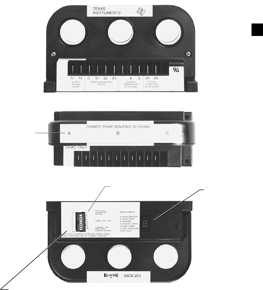
127
YORK INTERNATIONAL
FORM 201.19-NM1 (204)
FIG. 45 – MOTOR PROTECTION MODULE
SIDE VIEW 29119A
8
* DISPLAY
*NORMAL FLASHES
HA _ _ _. WHEN
IDLE, AND FLASHING
CIRCLE WHEN
SYSTEM IS
RUNNING.
ON
NUMERICAL
VALUES
29121A
TOP VIEWTOP VIEW 29121A
INTEGRAL
C.T.'S (3)
SWITCH PUSHED TO LEFT INDICATES
ON.
SWITCHES PLACED IN THE ON POSITION
ADD TO EQUAL THE OVERLOAD SETTING
VALUE.
FOR EXAMPLE, WITH 2 ON AND 128 ON,
DISPLAY WILL FLASH HA130.
SIDE VIEW
29120A
128 YORK INTERNATIONAL
FORM 201.19-NM1 (204)
1.10 EMS/BAS CONTROLS
The microprocessor system can accept remote signals
to Start/Stop the chiller, adjust maximum allowable run-
ning current for each compressor, and adjust the chilled
liquid leaving temperature setpoint. These func tions can
easily be controlled by connecting user sup plied “dry”
contacts to terminals in the control panel.
Remote Start/Stop
Remote Start/Stop can be accomplished using a time
clock, manual contact or other “dry” contact in series
with the fl ow switch which is connected to Terminals
13 and 14 in the logic section of the control pan el. The
contact must be closed to allow the chiller to run. Any
time this contact opens, the chill er will shut down and
the NO RUN PERM message will be dis played. The
lo ca tion of the fl ow switch connection is shown in Sec-
tion 1.12.
Nev er bypass a fl ow switch. This will
cause dam age to the chiller and void
any war ran ties.
Wir ing from remote “dry” contacts
(for stop/start and re set func tions)
should not ex ceed 25 ft. (8 m) and
should be run in ground ed con duit
that does not car ry any wiring other
than con trol wiring or shielded cable.
If an in duc tive device (re lay, contactor)
is sup ply ing these con tacts, the coil of
the de vice must be sup pressed with a
sup pres sor YORK Part Number 031-
00808-000 across the in duc tive coil.
Remote Current Reset
The maximum allowable running current for each com-
pres sor can be adjusted remotely to a lower value using
repeated timed closure of “dry” contacts connected to
Terminals 13 and 16 located in the logic section of the
control panel (See Section 1.12). The duration of the
contact clo sure will determine the amount of adjustment.
Gen er al ly, this input is used for purposes of demand limit
and operates as follows:
Closing the input contact for a defi ned period of time
allows reset of the % Cur rent Limit down ward. Con tact
closure of 1 - 11 seconds will allow % Current Lim it ing
to be ad just ed down ward from 105% by a max i mum
of 75%, i.e. to a minimum value of 30% FLA. EMS
Cur rent Lim it ing op er ates independently of the High
Av er age Cur rent Unload (See Sec tion 8.2). The micro
will always look at the two Cur rent Limit Set points and
choose the lower as the con trol ling val ue, when ev er
Remote Cur rent Lim it ing is uti lized. Con tact clo sures
of less than 1 sec ond will be ignored. A closure of 11
sec onds is the max i mum al low able clo sure and pro vides
a Current Limit re duc tion of 75%. The re mote reset cur-
rent can be cal cu lat ed as follows:
REMOTE
RESET = 105% FLA - {(Contact Closed Time -1sec) x (75% FLA)}
CURRENT 10 sec
For example, after a 4 second pulse, the offset would
equal:
Remote Reset Curr = 105% FLA - {(4sec - 1 sec) X (75%FLA)}
10 sec
= 105% - 225%FLA sec
10 sec
= 82.5% FLA
To maintain a given offset, the contact clo sure signal
must be repeated (refreshed) every 30 seconds - 30
minutes. The refresh is not accerted sooner than 30
seconds from the end of the last PWM signal, but must
be refreshed before 30 minutes has elapsed. After 30
min utes, if no refresh is pro vid ed, the setpoint will
change back to its original val ue.
After an offset signal, the new Re mote
Current Limit may be viewed on the
EMS current Lim it ing Dis play under
the Mo tor Current Key (see Sec tion
3.5). How ev er, if this dis play is being
viewed when the re set pulse oc curs, the
setpoint will not change on the dis play.
To view the new off set, fi rst press any
other dis play key on the key pad and
then press the Motor Current Key.
Remote EMS Reset will not operate
when a Re mote Control Center Op-
tion Kit is con nect ed to the mi cro.
The Re mote Con trol Center will al ways
de ter mine the setpoint.
Micro Panel Contents
129
YORK INTERNATIONAL
FORM 201.19-NM1 (204)
Wiring from remote “dry” contact (for
re set func tions) should not ex ceed 25
ft. (8 m) and should be run in ground ed
con duit that does not carry any wir ing
oth er than con trol wiring or shield ed
cable. If an in duc tive de vice (relay,
contactor) is sup ply ing these con tacts,
the coil of the device must be sup-
pressed with a sup pres sor YORK Part
Num ber 031-00808-000 across the
in duc tive coil.
Remote Current Reset must never be
used to control temperature. These
contacts are to be used only for peri-
odic demand limiting purposes.
Remote Setpoint Temperature Reset
The chilled liquid leaving temperature setpoint pro-
grammed into the micro can be remotely adjusted to
a higher value using repeated timed closure of “dry”
con tacts connected to Terminals 13 and 17 of TB4
located in the log ic section of the control panel (See
Section 8.1.12). The du ra tion of the contact closure will
determine the amount of ad just ment. This is achieved
as follows:
The maximum allowable reset value can be pro grammed
from 2°F - 40°F (1°C - 22°C), as appropriate to the
ap pli ca tion - see Section 6.4. Once the max i mum reset
is pro grammed, an input contact closure of 11 seconds
pro vides the maximum reset. Closure for less than 11
sec onds will provide a smaller reset. For noise im mu ni ty,
the micro will ignore closures of less than 1 sec ond. To
compute the necessary contact clo sure time to provide
a required Reset, use the following steps:
Reset Temp ={ (Contact Closure - 1sec) X Programmed Max Reset}
Offset 10 sec
For example, with a programmed setpoint of 44°F (7°C),
after a 4 second pulse and a programmed maximum off set
of 40°F (22°C), the temperature offset would equal:
Reset Temp = (4 sec - 1 sec) X 40°F
10 sec
Reset Temp = 120°Fsec
10 sec
= 12°F (6°C)
To determine the new setpoint, add the reset to the
setpoint programmed into mem o ry. In the example
above, if the pro grammed setpoint = 44°F (7°C), the
new setpoint after the 4 sec ond contact clo sure would
be 44°F (7°C)+ 12°F (6°C) = 56°F (13°C). This new
setpoint can be viewed on the display by pressing the
Re mote Reset Tem per a ture/Range key.
To maintain a given offset, the contact clo sure signal
must be repeated (refreshed) every 30 sec onds - 30
minutes. The refresh is not ac cept ed soon er than 30
sec onds from the end of the last PWM signal, but must
be refreshed be fore 30 minutes has elapsed. After 30
minutes, if no re fresh is provided, the setpoint will
change back to its orig i nal value.
After an offset signal, the new Re mote
Setpoint may be viewed by pressing the
Re mote Coding Setpoint Key. How ev er,
if this dis play is be ing viewed when the
reset pulse occurs, the set point will
not change on the dis play. To view the
new offset, fi rst press any oth er dis play
key on the key pad and then press the
Re mote Cooling Setpoint Range key.
The new setpoint will then ap pear.
Remote Setpoint Reset will not op er ate
when a Re mote Control Center Option
Kit is con nect ed to the Micro. The
Remote Control Center will al ways
de ter mine the setpoint.
Wiring from remote “dry” contact (for
reset func tions) should not exceed 25 ft.
(8 m) and should be run in ground ed
con duit that does not car ry any wir ing
oth er than control wir ing or shield ed
ca ble. If an in duc tive de vice (re lay,
contactor) is sup ply ing these con tacts,
the coil of the de vice must be sup pressed
with a sup pres sor YORK Part Num ber
031-00808-000 across the in duc tive
coil.
Remote Setpoint Reset must never be
used to control temperature. These
contacts are to be used only for
occasional temperature setback due to
outside ambient, changes in building
occupancy, or ice storage.
8
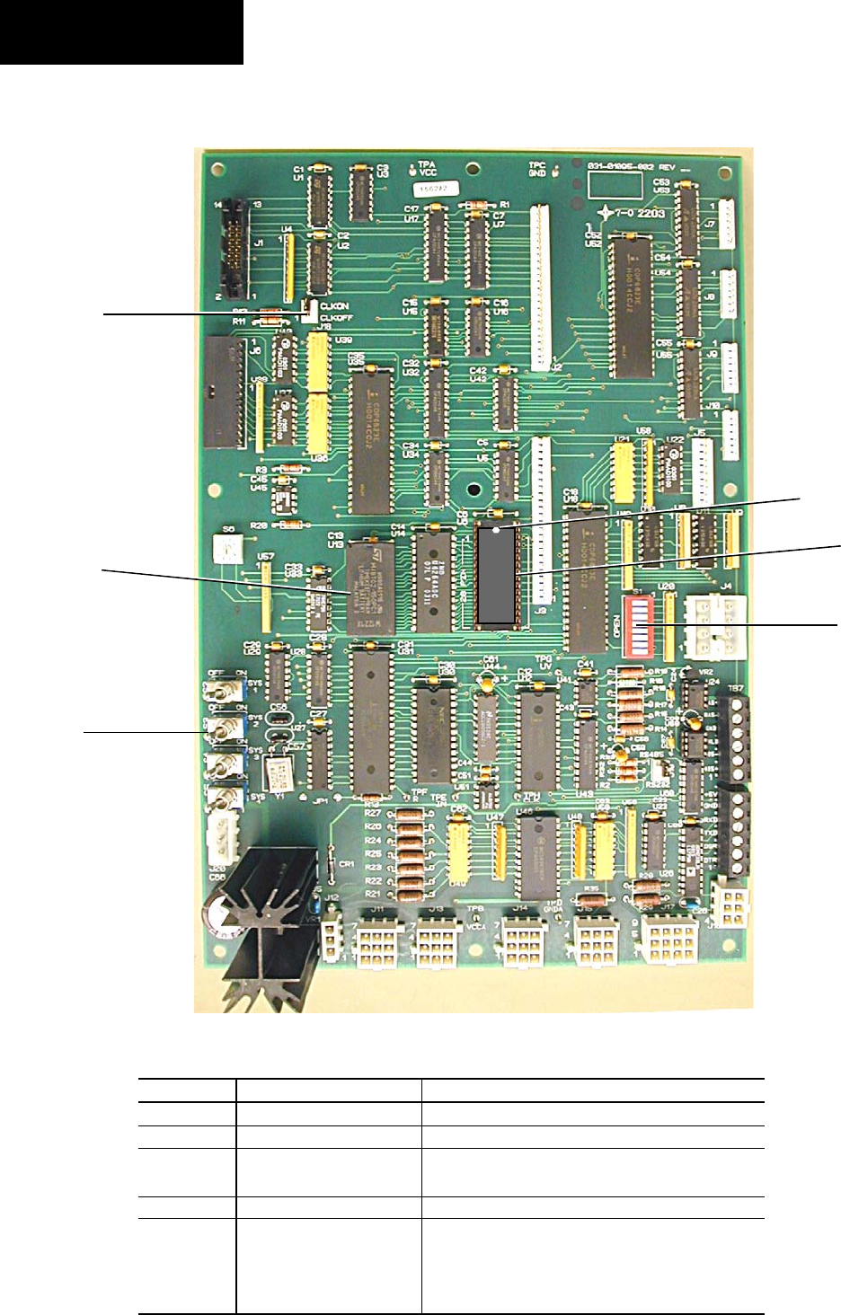
130 YORK INTERNATIONAL
FORM 201.19-NM1 (204)
ITEM
1
2
3
4
5
DESIGNATION
J18
RTC (U13)
EPROM
S1
S2 to S5
DESCRIPTION
Clock Enable/Disable Jump Contact
Real Time Clock and Battery Backup I.C.
Microprocessor I.C. (label shows version)
NOTE : Dimple is positioned at top edge (3A)
Dip Switch Set (8 switches)
System Switches S2 = System 1
S3 = System 2
S4 = System 3
S5 = System 4
1.11 MICROPROCESSOR BOARD LAYOUT
FIG. 46 – COMPONENT LAYOUT
2
5
1
028979-G
4
3
Micro Panel Contents
3A
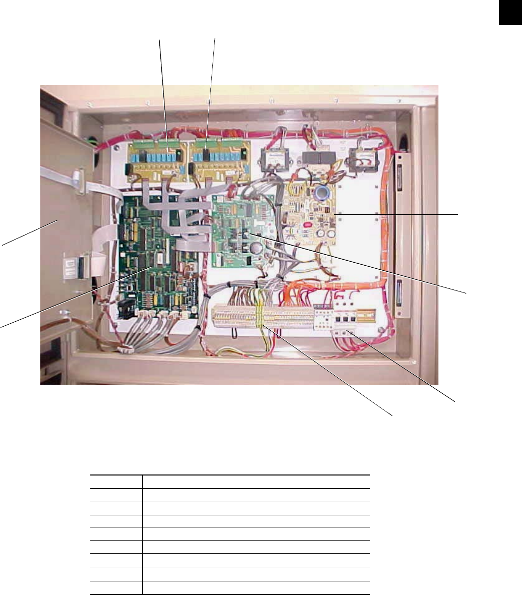
131
YORK INTERNATIONAL
FORM 201.19-NM1 (204)
1.12 LOGIC SECTION LAYOUT
60 Hz Models :
FIG. 47 – LOGIC SECTION LAYOUT
028980-G
1
2
56
4
3
7
8
60 HZ MODEL LOGIC SECTION
ITEM
1
2
3
4
5
6
7
8
DESCRIPTION
Microprocessor Board
Back of Keypad
I/O Expansion Board # 1
Power Supply Board
Relay Output Board #1
Relay Output Board #2
Flow Switch & Customer Connection Terminals (TB4)
Circuit Breakers (115V)
8

132 YORK INTERNATIONAL
FORM 201.19-NM1 (204)
1.13 ANTI-RECYCLE TIMER
The programmable Anti-Recycle Timer allows the user
to select the compressor anti-recycle time to best suit
their needs. Motor heating is a result of inrush current
when the motor is started. This heat must be dissipated
before another start takes place or motor damage may
result. The anti-recycle timer assures that the motor has
suffi cient time to cool before it is restarted.
An adjustable timer allows for the motor cooling, but
gives the user the ability to extend the anti-recycle
tim er to cut down on cycling. In some applications,
faster com pres sor start response is necessary and shorter
anti-recycle times are required. These needs should be
kept in mind, but whenever possible the timer should
be ad just ed for the longest period of time tolerable.
600 sec onds is recommended, although 300 seconds
provides adequate motor cooling time. Longer periods
will al low more heat dissipation, reduce cycling, and
pos si bly in crease motor life. See Section 8.2, page 166
for pro gram ming of the anti-recycle timer.
1.14 ANTI-COINCIDENCE TIMER
The Anti-Coincidence Timer assures that 2 systems
do not start simultaneously. This assures that inrush
cur rent is kept to a minimum. A 60 second time delay
will al ways separate motor starts. This timer is not
pro gram ma ble.
1.15 EVAPORATOR PUMP CONTROL
Dry contacts are provided which transition (close)
when the Daily Schedule is calling for chiller opera-
tion, the unit switch is on, and power has been applied
to the Micro Panel for 30 sec onds. If for some reason
the evaporator pump contacts have been closed to run
the pump and a power loss or Daily Schedule shuts the
pump down (contacts open), the contacts will not reclose
for any reason until 30 sec onds has elapsed after power
re-application or 30 sec onds have elapsed between a
Daily Schedule shut down and restart.
If the Daily Schedule is not used, (On/Off times equal
00:00) the contacts will be closed at all times.
1.16 COMPRESSOR HEATER CONTROL
Each compressor has its own heater. The heater will be
off whenever the compressor is running. As soon as the
compressor shuts off, the heater will turn on and stay on
for 5 minutes. After 5 minutes has elapsed, the heat er will
shut off if the discharge temperature rises above 150 °F
(66°C) and will turn on when the dis charge tem per a ture
is equal to or less than 150 °F (66°C).
1.17 EVAPORATOR HEATER CONTROL
The evaporator heater is controlled by ambient tem-
per a ture. When the ambient temperature drops below
40°F (4°C), the heater is turned on when the com pres sors
are turned off. When the temperature rises above 45°F
(7°C), the heater is turned off. An under voltage condi-
tion will keep the heater off until full voltage is restored
to the system. The heater will provide freeze protection
to -20°F (-28°C).
115VAC power must remain “ON”
through CB3 for freeze pro tec tion.
Oth er wise, the evap o ra tor must be
drained.
1.18 PUMPDOWN (EEV) CONTROL
Each compressor undergoes a pump down on shut-
down. This as sures that liq uid re frig er ant does not
enter the com pres sor on start-up, elim i nat ing the need
for recycling pump down, sav ing en er gy and re duc ing
com pres sor starts and wear.
On start-up, the controls unload the com pres sor and im-
mediately energize the pilot solenoid on the electronic
expansion valve. Normal operation commences without
pumpdown.
On shutdown, the microprocessor controls unload the
compressor, the pilot solenoid on the electronic expan-
sion valve is de-energized, and the Econ o miz er Liquid
Supply Solenoid Valve is de-energized. The compressor
continues to op er ate until it either pumps down to the
Micro Panel Contents
Remote evaporator applications equipped with
thermostatic TXV and Liquid Line solenoid will also
pump down on shutdown.

133
YORK INTERNATIONAL
FORM 201.19-NM1 (204)
low suction pres sure cutout setting or for 180 seconds,
whichever comes fi rst. Pump down occurs on “normal”
shut downs where cool ing demand has been satisfi ed or
when a system switch is turned off, a fl ow switch opens,
run per mis sive is lost or a Daily Schedule or a Remote
Shut down is called for.
No pumpdown will occur on a safety shutdown. See
page 138 for the pumpdown display message.
1.19 ALARMS
Internal contacts are provided in the Micro Panel (See
Section 1.12) which can be used to remotely signal a
warn ing whenever a fault lock out occurs on any sys tem
or if power is lost to the con trol panel. The internal
con tacts are normally open (N.O.) and will close when
con trol power is applied to the pan el, if no fault con di -
tions are present. When a fault occurs which locks out
a system, the respective contacts open. If chiller power
is lost or a unit fault oc curs, such as a Low Water Temp
fault, con tacts for all sys tems will open.
Contacts for SYS 1 are located on the bottom right of
the microprocessor panel, terminals 23 and 24. SYS 2
contacts are located on terminals 27 and 28. See Fig. 11,
Page 38 for the lo ca tion of these ter mi nals.
A 28VDC or 120VAC (60 Hz models) or up to 240VAC
(50 Hz models) external alarm circuit (supplied by oth-
ers) may be connected to these contacts. The contacts
are rated at 125VA.
If any inductive load devices (relay or
contactor) sup plied by the user are in
the elec tri cal cir cuit con nect ed to the
dry alarm contacts, the de vice must
be sup pressed at the load with a RC
sup pres sor YORK Part Num ber 031-
00808-000 across the in duc tive coil.
Fail ure to in stall sup pres sors will
result in nui sance faults and pos si ble
damage to the chill er.
If the alarm circuit is applied in an
ap pli ca tion used for critical duty (such
as pro cess duty or cool ing oth er crit-
i cal equip ment) and the alarm cir cuit
should fail to func tion, YORK will not
be li a ble for dam ag es.
1.20 RUN STATUS (CHILLER)
Internal Chiller Run Status contacts between Ter mi nal
28 and 29 close whenever one of the systems is run-
ning. These contacts are lo cat ed on the bottom right of
the Mi cro pro ces sor Board and are rated (voltage and
current) the same as the alarm contacts (Section 1.19).
Also use a suppressor, same as alarm contacts (Section
1.19). In di vid u al system “Run Status” contacts are not
available.
1.21 LEAD / LAG COMPRESSOR SELECTION
The chiller may be set up for AUTO or MANUAL Lead/
Lag. This is accomplished by programming the op tion
un der the Program Key. Details for programming the
Man u al/Auto Lead/Lag Selection are discussed in Pro-
gram Key Section 8, page 169.
When AUTO Lead/Lag is utilized, the micro attempts
to balance run time between the two compressors. A
number of conditions can occur which will prevent this
from happening. Factors determining lead/lag se lec tion
and the resulting lead/lag determination are:
1. The micro automatically defaults the lead to SYS 1
and the lag to SYS 2 if both compressors are ready
to start (Anti-recycle Timers timed out) and com-
pres sors have equal run time.
2. If all compressors are ready to start (Anti-recycle
tim ers timed out), the compressor with the lowest
run hours will start fi rst.
3. If all compressors are waiting to start (Anti-re cy cle
timers have not timed out), the micro will assign the
lead to the compressor with the shortest anti-re cy cle
time in a an effort to provide cooling quick ly.
4. If the lead compressor is locked out, faulted and
waiting to restart, SYS switch on the microboard
is off, or a run permissive is keeping an individual
sys tem from running, the lag compressor is swapped
to the lead. This is true regardless of whether the
lag compressor is ON or OFF.
8

134 YORK INTERNATIONAL
FORM 201.19-NM1 (204)
Micro Panel Contents
MANUAL Lead/Lag selection will be automatically
overridden by the micro to allow the lag compressor to
automatically become the lead anytime the selected lead
compressor shuts down due to a lock-out, lead system
faults and is waiting to restart, system switch on the
micro board is in the OFF position, or if a run permissive
is keeping the lead system off. Automatic switch over in
MANUAL mode is provided to try to maintain chilled
liquid temperature as close to setpoint as possible.
1.22 ECONOMIZER SOLENOID CONTROL
The economizer solenoid is controlled by the micro
based on the ability of the economizer to provide extra
capacity according to system operating conditions. This
ability is primarily based on outside ambient tempera-
ture. If the ambient is low with associated low discharge
pressure, the economizer will provide very little extra
subcooling. At an ambient of 90ºF (32ºC) or above
with associated high discharge pressure, the economizer
will begin to provide appreciable additional subcooling.
The extra subcooling may be as much as an additional
20ºF to 25ºF (11.1ºC to 13.8ºC), often making the total
subcooling at the TXV over 40ºF (4.4ºC).
This should not be confused with
subcooling at the liquid valve, which
should generally be 12ºF to 15ºF (6.7ºC
to 8.3ºC). The micro monitors the dif-
ference in pressure ratio between the
discharge and suction pressure along
with the step of unloading to determine
economizer solenoid on/off points.
The micro utilizes the formula below to compute pres-
sure ratio:
PR = (DP in PSIG)+14.7
(SP in PSIG)+14.7
For the fi rst 3 minutes of operation, the micro will not
energize the solenoid. After 3 minutes of operation. If
the step of loading is above step 60 and the PR>2.2, the
micro energizes the economizer solenoid.
Once on, the solenoid will remain on until the PR<2.0
or the step of loading falls below 50. If the conditions
drop below either of these points, the micro will turn
off the solenoid.
Economizer cycling is reduced by 2 timers. The timer
with the longest remaining time will dictate when the
economizer can turn on. The fi rst timer is an "on to on"
timer which assures at least 10 minutes elapses from the
time the economizer turns on, off, and then on again for
a second time. The second timer assures that a minimum
of 3 minutes elapses from the time the economizer turns
off to the next time it is called to turn on again.
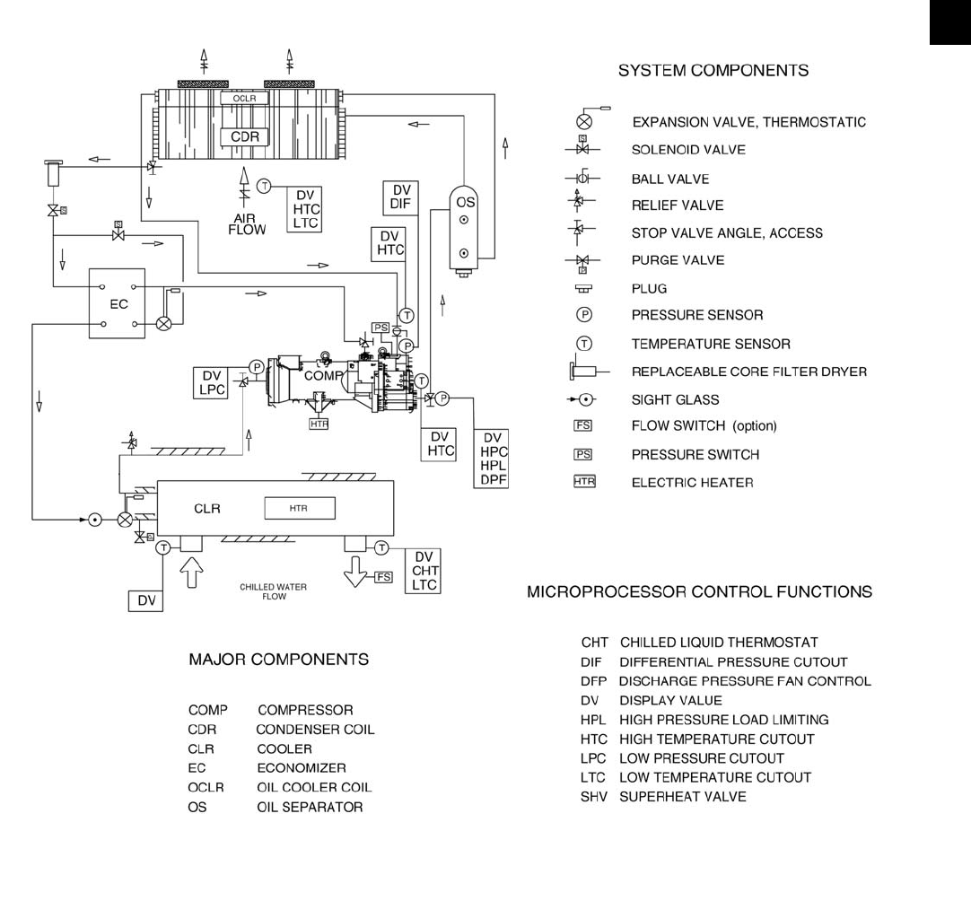
135
YORK INTERNATIONAL
FORM 201.19-NM1 (204)
PROCESS AND INSTRUMENTATION DIAGRAM
FIG. 47A – PROCESS AND INSTRUMENTATION DIAGRAM
LD03486
8
ECONOMIZER HX
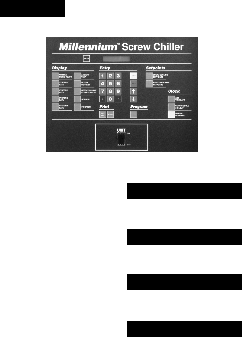
136 YORK INTERNATIONAL
FORM 201.19-NM1 (204)
2. STATUS KEY: GENERAL STATUS MESSAGES & FAULT WARNINGS
2.1 GENERAL
Pressing the Status key displays the current chiller or
individual system operational status. The messages dis-
played include running status, cooling demand, fault
sta tus, external cycling device status, load limiting, and
anti-recycle timer status. The display will show one mes-
sage relating to the “highest priority” information as
de ter mined by the microprocessor.
For individual system status or fault messages, the
dis play shows information for up to two refrigerant
sys tems.
The main categories of messages available using the
Status key are:
2.2 General Status Messages
2.3 Unit Warnings
2.4 Anticipation Control Status Messages
2.5 Chiller Fault Status Messages
2.6 System Fault Status Messages
These messages are described in detail below, with ex-
am ples of each display. In each example “#” is used as
applicable to represent the system number where mes-
sag es apply to individual systems.
2.2 GENERAL STATUS MESSAGES
Unit Switch OFF:
This message indicates that the Chiller ON / OFF Switch
on the Control Panel is in the OFF position which will
not allow the chiller to run.
Schedule Shutdown:
This message indicates that the that the chiller has been
shut down by the daily schedule programmed into the
Clock - Set Schedule / Holiday (Section 7.3).
Compressors Running:
This message indicates that the respective compressor
is running due to demand.
Remote Controlled Shutdown:
This message indicates that either an ISN or RCC (Re-
mote Control Center) has turned the unit OFF through
the RS-485 port.
U N I T S W I T C H O F F
S H U T D O W N
D A I L Y S C H E D U L E
S H U T D O W N
S Y S # C O M P R U N N I N G
S Y S # C O M P R U N N I N G
R E M O T E CO N T RO L L E D
S H U T D O W N
29023A
Micro Panel Contents

137
YORK INTERNATIONAL
FORM 201.19-NM1 (204)
System Switches OFF:
This message indicates that the system switch on the
Microprocessor Board for the respective system is in
the OFF position. A system can only run if the system
switch is in the ON position. The switch for System 1
and System 2 should normally be in the ON position for
all models. See Section 1.11, Figure 46, page 130 for the
lo ca tion of the system switches.
Anti-Recycle Timers:
The anti-recycle timer message shows the amount of
time remaining before a compressor can be called to
restart. The 300 - 600 sec. programmable timers begin
timing when a com pres sor starts, although a minimum
of two min utes must always elapse after a compressor
shuts down, be fore it may again restart. If a power failure
occurs, the anti-re cy cle timers will reset to 120 seconds
after pow er is re stored. The purpose of the timer is to
allow for motor cool ing to dissipate the heat generated
by in rush cur rent at start-up.
Anti-Coincidence Timers:
The anti-coincident timer guards against two or more
compressors starting simultaneously. This avoids ex-
ces sive instantaneous starting currents. A minimum of
60 seconds between compressor starts is maintained even
if demand is present and the anti-recycle timers are timed
out. The display shows the time before the respective
compressor can start. This display will only appear af ter
the anti-recycle timers have timed out.
Run Permissive Contacts OPEN:
This display indicates that an external cycling contact
and/or the fl ow switch connected to terminals 13 & 14 in
the Logic Section of the control panel is open. Whenever
the contact is open, the No Run Per mis sive message will
be displayed and the in di cat ed sys tem will not run.
System Loading Requirement:
This message indicates that chilled liquid temperature
is below the point where the microprocessor will bring
the lead system on and/or that the loading sequence has
not loaded the chiller far enough to bring the lag sys tem
on. The lag system will display this message until the
load ing sequence is ready for the lag system to start.
If the MANUAL OVERRIDE key is pressed during a
scheduled time clock shutdown, the STATUS display
will display the MANUAL OVERRIDE message in-
dicating that the schedule is being intentionally over-
ridden. Typically MANUAL OVERRIDE is only used
in an emergency. As a result, the message is a priority
message and will override other STATUS messages.
2.3 UNIT WARNINGS
Unit Warnings are often caused by conditions which
require operator intervention to start the unit or ex treme
operating conditions. All setpoints and programmable
values should be checked, if a chiller shutdown oc-
curred, before restarting the chiller. Unit Warnings are
not logged into the HISTORY BUFFER.
Low Battery Warning
On power-up the microprocessor will check the RTC
(Real Time Clock) memory back-up battery to make
sure it is still operational. Provided the battery checks
out, operation will continue normally. If a check is made
and the battery has failed, the microprocessor will not
allow the chiller to run and the above Status message
will appear.
If a low battery condition exists, the
mi cro will re store programmed cut-
outs, setpoints, and sched ules to their
de fault values.
Once a low battery condition is detected, the only way
to run the chiller is to use the Manual Override key - see
Section 8.7.4 page 165. This al lows re pro gram ming of
setpoints, cutouts, and sched ule.
S Y S # 1 S Y S S W I T C H O F F
S Y S # 2 S Y S S W I T C H O F F
S Y S # A R T I M E R 1 0 S
S Y S # A R T I M E R 1 2 0 S
S Y S # C O M P R U N N I N G
S Y S # A C T I M E R 2 2 S
! ! L O W B A T T E R Y ! !
C H E C K P R O G / S E T P / T I M E
S Y S # N O R U N P E R M
S Y S # N O R U N P E R M
S Y S # N O C O O L L O A D
S Y S # N O C O O L L O A D 8
M A N U A L
O V E R R I D E

138 YORK INTERNATIONAL
FORM 201.19-NM1 (204)
The U13 RTC chip should be re placed as soon as
pos si ble with Part # 031-00955-000. Otherwise, the
chill er will shutdown and lose all programmed points,
and re quire a MANUAL OVERRIDE restart, if a power
fail ure occurs.
Pump Down:
This message indicates that both refrigerant systems are
in a pumpdown cycle. Pumpdown display mes sag es oc-
cur on shutdowns where the cool ing load has been met,
or when a sys tem switch is turned OFF. Note that only
one com pres sor could be pump ing down, as shown in
the following display:
See Section 1.18 (page 132) for details of pumpdown
con trol.
When this message appears, the chiller will not run and
the Unit Switch must be cycled OFF and ON to start
the unit.
Incorrect Unit Type Warning:
The incorrect Unit Type Warning will occur if the DIP
Switch setting for unit type and the type programmed
into the micro "at the factory" are not the same. This
message will be displayed until the "factory" pro-
grammed unit type and DIP Switch setting agree. See
Page 179 for Service Mode Programming.
2.4 ANTICIPATION CONTROL STATUS
MESSAGES
Anticipation controls are built into the soft ware to
pre vent safety shutdowns by automatically overriding
the temperature controls, if system conditions approach
safe ty thresholds. This avoids total loss of cooling
re sult ing from a lockout by a safety control.
Anticipation controls monitor discharge pressure, mo tor
current and suction temperature for each com pres sor
and if maximum limits are approached, the slide valve
loading of the respective compressor will be re duced to
avoid exceeding the limit.
Displays of anticipation safety control messages and
their meanings are as follows:
Discharge Pressure Limiting:
Discharge Pressure Limiting takes effect when
com pres sor discharge pressure nears the point at which
the high pressure cutout would shut the system down.
When the above message appears, discharge pressure
has ex ceed ed the programmable threshold and the
com pres sor is being unloaded in an effort to prevent
shutdown on the high pressure cutout. The operation of
this safe ty is important if condenser coils become dirty,
if there is a problem with the condenser fan operation,
or if ex treme ambient or load conditions occur. See
Anticipatory Unloading Controls Page 161 for detailed
operation.
Incorrect Refrigerant Warning:
The incorrect Refrigerant Warning will occur if the
DIP Switch setting for refrigerant type and the type
pro grammed into the micro “at the factory” under the
Service Mode are not the same. This message will be
displayed until the non-pro gram ma ble “factory” pro-
grammed refrigerant type and DIP Switch setting agree.
See Page 179 for Service Mode programming.
Power Failure Warning:
The Power Failure Warning will only be displayed on
“power restoration” after a “power loss,” if manual re-
start on power failure is se lect ed under the PRO GRAM
key (page 170). If manual restart on pow er failure has
been selected, the following warning mes sage is dis-
played indefi nitely on power res to ra tion and the chiller
will not run until the UNIT Switch is cy cled OFF-and-on
to re start the unit. This safety is available for users who
de sire a chiller lock-out on pow er failure.
This is typically not a desirable
feature to select. Most applications re-
quire auto-reset after a power failure.
Therefore, "Automatic" is typically
selected and programmed under the
PROGRAM key. See page 170.
R E P R O G R A M T Y P E O F
R E F R I G E R A N T T O R U N
! ! P O W E R F A I L U R E ! !
C Y C L E U N I T S W I T C H
S Y S # D S C H L I M I T I N G
S Y S # D S C H L I M I T I N G
S Y S 1 P U M P I N G D O W N
S Y S 2 C O M P R U N N I N G
S Y S 1 P U M P I N G D O W N
S Y S 2 P U M P I N G D O W N
Micro Panel Contents
R E P R O G R A M
U N I T T Y P E

139
YORK INTERNATIONAL
FORM 201.19-NM1 (204)
S Y S # C U R R L I M I T I N G
S Y S # C U R R L I M I T I N G
S Y S # S U C T L I M I T I N G
S Y S # S U C T L I M I T I N G
ning of the chiller is not economical compared to the
use of “free” cooling techniques (see also Section 8.2
/ Low Ambient Temperature Cutout [page 168]). The
fault will clear when ambient temperature rises 2°F
(1°C) above the cut-out.
High Ambient Temperature Cutout:
The High Ambient Temperature Safety protects the
chiller from running in ambients above 130°F (54°C)
where potential malfunction of system mechanical and
electrical components may result. The High Ambient
Cutout is programmable and can be set for lower limit
values if required (see also Section 8.2 / High Ambient
Temperature Cutout [page 168]). The fault will clear
when ambient temperature drops 2°F (1°C) below the
cut-out.
Low Leaving Chilled Liquid Temperature Cutout:
The Low Liquid Temperature Safety assures that the
evaporator is not damaged from freezing due to im-
prop er ly set control points. It also attempts to protect
the chiller from freezing, if the fl ow switch should fail.
However, the fl ow switch should always be regarded
as the primary safety. Whenever the chilled liquid
temperature drops below the programmable cutout, the
chiller will shut down (see also Section 8.2 / Leaving
Water Temperature Cut out, page 168). The chiller fault
will clear when tem per a ture rises 4°F (2°C) above the
cut-out and cooling de mand exists.
115VAC Under Voltage Cut-Out:
The Under Voltage Safety assures that the system is
not operated at voltages where malfunction of the mi-
cro pro ces sor could result in system damage. When ev er
the microprocessor senses an on-board control power
supply failure while a compressor is running, the chill er
is shut down. The microprocessor circuitry is capable of
operating at voltages 10% below the nominal 115VAC
supply to the panel. Auto-restart of the chill er oc-
curs after a 2 minute start-up timer has elapsed from
the time when power is reapplied, if the AUTO RE-
START ON POWER FAILURE is enabled. Otherwise
the chill er must be manually reset. See Section 8.2
(page 170).
2.5 UNIT FAULT STATUS MESSAGES
A Unit Fault will shut the entire chiller down when a
preset safety threshold is exceeded. The chiller will
au to mat i cal ly restart after the condition causing the
shut down clears. Restart will occur only after anti-re-
cy cle timers are satisfi ed and cooling demand requires
ad di tion al cooling. A reset hysteresis is built into each
safe ty so repetitive faulting and clearing will not occur
in a short time period.
Continuous monitoring by the microprocessor assures
that instantaneous reaction results. When the chiller is
shut down on one of these safeties, a message will ap-
pear on the Status display informing the operator of the
problem as shown in the text that follows.
Any time that a Unit Fault occurs, the shutdown will be
logged into the HISTORY BUFFER.
Low Ambient Temperature Cutout:
The Low Ambient Temperature Safety prevents the
chill er from running in very low temperatures which
could cause damage due to low system pressures. This
feature is programmable and can also be used to shut
down the chiller at a temperature where continued run-
U N I T F A U L T
L O W A M B I E N T T E M P
U N I T F A U L T
H I G H A M B I E N T T E M P
U N I T F A U L T
L O W L I Q U I D T E M P
U N I T F A U L T
1 1 5 V A C U N D E R V O L T A G E
Compressor Motor Current Limiting:
The Motor Current Limiting message indicates that a
compressor motor current has reached a pro gram ma ble
threshold or a BAS current limit threshold, and the
system is being unloaded to as sure that motor current
does not be come ex ces sive ly high caus ing a fault. See
Anticipatory Unloading Controls Page 161 for detailed
operation.
Suction Temperature Limiting:
This message indicates that saturated suc tion tem per a ture
on a system has dropped to 24°F (-4.4°C) in the
water cooling mode and that any further temperature
reduction could cause some ic ing of the evaporator
tubes. Saturated suction tem per a ture is computed by the
micro by con vert ing suction pres sure to temperature.
See Anticipatory unloading controls page 161 for
deatailed operation. Suction limiting is not active in
the glycol mode.
8
140 YORK INTERNATIONAL
FORM 201.19-NM1 (204)
High Discharge Pressure Cutout:
The Discharge Pressure Safety prevents system pres sure
from exceeding safe working limits. This safety is a
backup for the mechanical High Pres sure Cutout in each
system. The Discharge Pressure Safety is pro gram ma ble
for a range of values below the system up per limit (see
Section 8.2 / Page 166, High Discharge Pres sure Cutout
for more details).
High Discharge Temperature Cutout:
This safety protects the compressor rotors from dam age
due to overheating, expansion, and breakdown of the oil
fi lm seal between the rotors. It also protects against ex-
cessive oil temperature in the discharge oil separator.
For the fi rst 4 seconds of operation discharge tem-
per a ture is ignored. After 4 seconds of operation the
com pres sor will shut down if the discharge temperature
ex ceeds 260°F (127°C).
High Oil Differential Pressure Cutout:
The High Oil Pressure Differential Safety protects the
compressors against loss of proper lubrication due to
oil line blockage. The “differential oil pressure” for this
safety is computed by measuring discharge pressure and
subtracting oil pressure re turn ing to the compressor
(Discharge - Oil = Oil PSID). Under normal operation,
the oil pressure differential dis play will be less than 25
PSID (1.7 bar), typical 2 - 10 PSID (0.1 to 0.7 bar). If
oil pres sure at the com pres sor drops due to fi l ter block-
age, the dif fer en tial pres sure on the dis play will in crease
and when the max i mum limit is reached, the com pres sor
will be shut down.
This safety is activated after 3 minutes of operation. Oil
pressure must be less than 65 PSID (4.4 bar) for R22
models as long as the compressor continues to run.
Flow Switch Open:
Closure of the fl ow switch is monitored to check that
fl ow is present in the evaporator when a com pres sor
is running. Any external cy cling de vic es fi tted by the
customer are connected in series with the fl ow switch.
YCAS 2 System chillers require a single fl ow switch
wired to the control panel. If the fl ow switch opens, all
sys tems will shut down and a NO RUN PERM (Per-
mis sive) mes sage will be dis played. Clos ing of the fl ow
switch, when fl ow is present, will cause the mes sage to
dis ap pear and auto-restart to oc cur.
Never bypass a fl ow switch. This will
cause dam age to the chiller and void
any war ran ties.
2.6 SYSTEM FAULT (SAFETY) STATUS
MESSAGES
A System Fault will shut the affected sys tem down
whenever a preset safety thresh old is ex ceed ed for 3
seconds. Automatic restart will occur af ter the fi rst 2
shut downs when the anti-re cy cle timer times out and
tem per a ture de mand exists. After any com bi na tion of 3
Manual Reset Safeties in a 90 minute time period, the
affected system will shut down and lock out on the last
fault. When one or more sys tems are shut down on one
of these safeties, a mes sage will appear on the Status
display in form ing the op er a tor of the prob lem.
The High Motor Current Safety is a
unique safe ty which will lock out a
sys tem after only a single fault.
To reset a locked out system, turn the Sys tem Switch
for the affected system to the OFF po si tion, then back
to the ON po si tion (see Sec tion 1.11, Page 130, Fig. 46
for switch locations).
Before returning a locked out sys tem
to ser vice, a thorough investigation of
the cause of the fault should be made.
Fail ure to repair the cause of the fault
while manually al low ing re pet i tive
re starts may cause fur ther ex pen sive
damage to the system.
S Y S # H I G H D S C H P R E S
S Y S # H I G H D S C H P R E S
S Y S # H I G H D S C H T E M P
S Y S # H I G H D S C H T E M P
S Y S # H I G H O I L D I F F
S Y S # H I G H O I L D I F F
Micro Panel Contents
S Y S # N O R U N P E R M
S Y S # N O R U N P E R M
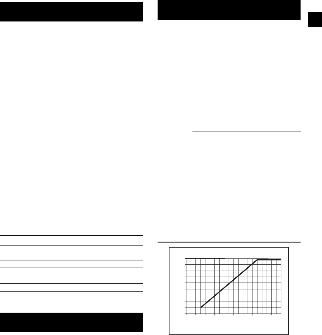
141
YORK INTERNATIONAL
FORM 201.19-NM1 (204)
Low Suction Pressure Cutout:
The Low Suction Pressure Cutout aids in protecting the
evaporator from damage due to ice build up caused by
operation at low refrigerant charge or restricted re frig -
er ant fl ow. A transient timer feature pre vents nuisance
trips during start-up, compressor load ing, etc. The Low
Suction Pressure Safety is pro gram ma ble (see Section
8.2 / Page 167, Low Suction Pres sure Cutout for more
details).
The suction pressure cut-out is ignored for the fi rst 45
seconds of operation. During the next 180 seconds of
running, suction pressure may be lower than the cut out,
but must be greater than:
SP Cutout= Programmed Cutout X (run Time - 25)
200
This cutout value increases with time (10% to 100%)
until after 225 seconds it equals the programmed cut-
out value. If suc tion pressure falls below the calculated
cutout value before 225 seconds of run time, the system
will be shut down.
The following graph shows a typical programmed suc-
tion pressure cutout of 44 PSIG (3 bar) and its change
from time = 0 sec of compressor run time to 225 sec onds
of compressor run time.
Low Oil Differential Pressure Cutout:
The Low Oil Pressure Differential Safety assures the
compressor receives proper lubrication by monitoring
the differential between oil pressure returning to the
compressor and suction pressure. Lack of a differential
indicates that the compressor is not pumping and no oil
is being pumped through the compressor to lubricate
the bearings and rotors.
This type of oil failure will not be picked up by the High
Oil Differential Safety since no fl ow will cause the dif-
fer en tial through the oil piping to drop to zero.
During normal operation, differential oil pressure must
be greater than 50 PSID. At start-up, the cut-out is
ramped over time according to ambient temperature.
For ambients above 50°F (10°C), the Low Oil Dif fer -
en tial Safety is activated after 1 minute of compressor
operation when the oil pressure differential must be
great er than 10 PSID (.7 bar). After 2 minutes it must
be greater than 20 PSID (1.4 bar); after 3 minutes, 30
PSID (2 bar); after 4 minutes, 40 PSID (2.7 bar); and
from 5 minutes of operation and onwards, oil pressure
must remain higher than 50 PSID (3.4 bar) or the sys tem
will be shut down. For lower ambients, the linear ramp
times are as follows:
AMBIENT TEMP RAMP TIME
>50°F (10°C) 5 Minutes
>45°F (7°C) 6 Minutes
>40°F (4°C) 7 Minutes
>35°F (2°C) 8 Minutes
>30°F (-1°C) 9 Minutes
<=30°F (-1°C) 10 Minutes
High Oil Temperature Cutout:
This safety assures oil temperature does not exceed a safe
operating temperature which affects compressor lubrica-
tion. Typical oil temperature during normal op er a tion
will be approximately 130 - 150°F (54 - 66°C).
The High Oil Temperature Safety is activated after 2
minutes of compressor operation, after which if oil
tem per a ture is above 225°F (107°C) for more than 3
sec onds, the compressor will shut down.
Suction Pressure Cutout With
44 PSIG Programmed Cutout
LD07013
FIG. 48 – SUCTION PRESSURE CUTOUT
S Y S # L O W S U C T P R E S S
S Y S # L O W S U C T P R E S S
0 30 60 90 120 150 180 210 240 270 310
45
40
35
30
25
20
15
10
5
0
Run Time (seconds)
Suction Pressure Cutout
S Y S # L O W O I L D I F F
S Y S # L O W O I L D I F F
S Y S # H I G H O I L T E M P
S Y S # H I G H O I L T E M P
8
142 YORK INTERNATIONAL
FORM 201.19-NM1 (204)
S Y S # L O W C U R R / M P / H P
S Y S # L O W C U R R / M P / H P
After 225 seconds of operation with suction pressure
op er at ing above the cut-out, a 30 second transient tim er
pre vents short term fl uctuations in suction pressure due
to load ing or fan cycling from causing shutdown. If
suc tion pres sure drops below the cutout point after 225
sec onds of operation, the transient tim er is activated.
While the tran sient timer is active, suction pressure must
not drop be low 10% of the cut-out initially pro grammed
and must be greater than:
C.O. = Programmed C.O. X ( Run Time -25 )
200
This transient cutout value increases with time until af ter
30 seconds it equals the programmed cutout val ue. If the
suction pressure falls below the value as cal cu lat ed by
the formula relative to time, the system will shut down
on a low suction pressure fault. If the suc tion pressure
rises above the programmed cutout val ue, the 30 second
timer will be reset.
If the Dip Switch on the microprocessor board is set
for “Water Cooling” (see page 146), the cutout is pro-
gram ma ble between 44 - 70 PSIG (3-5 bar) for both
R-22 and R407C models. In this mode, settings of 44
PSIG (3 bar) for R-22 and R407C are recommended. If
the Switch is set for “Brine Cooling” (glycol) the cut-
out is programmable between 5 - 70 PSIG (0.3 - 5 bar)
for R-22 and R407C models. In this mode, the cutout
should typically be set to the saturated refrigerant pres-
sure equivalent to 18°F (10°C) below the temperature
of the chilled liquid.
The sludge point of the glycol MUST be
at least 20°F (11°C) below the equiv a lent
cutout tem per a ture.
The Low Superheat Cutout is to protect the compressor(s)
from liquid fl oodback due to low suction superheat. This
safety is ignored for the fi rst 30 seconds of system run-
time.
This safety can be triggered by two events. The fi rst
is when suction superheat <0.5ºF. The second is when
the pilot solenoid is closed 10 times in 2 minutes due
to low superheat.
S Y S # H I G H M T R C U R R
S Y S # H I G H M T R C U R R
The High Motor Current Safety protects against ex ces -
sive ly high motor current and shuts a system down and
locks it out after only a single occurrence of a rise in
average motor cur rent above the cutout point. Motor
cur rent is mon i tored using 3 Current Trans form ers (CTs)
per motor, one on each phase. The C.T.'s are part of the
Motor Protector Module.
Average motor current is monitored after 7 seconds of
compressor operation. The sys tem will be shut down if
average motor cur rent ex ceeds 115% FLA. This safety
only requires one shutdown to lock out a system.
FLA (full load amps) is ap prox i mate ly
1.08 x RLA (rat ed load amps). RLA is
spec i fi ed on the mo tor / chill er name-
plate and is typ i cal current de mand
un der rated operating conditions in
a ful ly load ed sys tem. When a sys tem
is fully load ed, typ i cal motor cur rents
may be 60 - 85% FLA de pend ing on
op er at ing con di tions.
Low Motor Current Cutout / Motor Protector (Hi
Motor Winding Temp Cutout) / Mechanical High
Pressure Cutout / External Motor Overload:
The Low Motor Current Safety prevents a com pres sor
motor running with less current than would nor mal ly be
expected. This may result from loss of re frig er ant, a de-
fective contactor, power problems, or from a compressor
that is not pumping due to a mechanical malfunction.
The Sensor Failure Safety prevents the system from
running when the sensors measuring superheat are not
functioning properly. This safety is ignored for the fi rst
15 seconds of system runtime.
This safety will shut down a system if either suction tem-
perature or suction pressure sensors read out of range high
or low. This condition must be present for 3 seconds to
cause a system shutdown. The safety locks out a system
after the fi rst fault and will not allow automatic restarting.
High Compressor Motor Current Cutout:
Micro Panel Contents
S Y S # 1 L O W S U P E R H E A T
S Y S # 2 L O W S U P E R H E A T
S Y S # 1 S E N S O R F A I L U R E
S Y S # 2 S E N S O R F A I L U R E
143
YORK INTERNATIONAL
FORM 201.19-NM1 (204)
407C units. If the refrigerant temperature falls below
20°F (11.1°C) in water cooling mode, the system will
be shut down. If the refrigerant temp falls 15°F (8.3°C)
below the leaving chilled liquid temp in gly col cooling
mode, the system will shut down. If a malfunctioning or
missing evaporator inlet re frig er ant temp sensor reads
out of range low, the sys tem will also shut down. The
low evap temp safety is ignored for the fi rst 3 minutes
of operation. After 3 minutes of run time there is a 5
minute Low Evap Temp Safety Bypass Ramp: Any time
the evaporator inlet temperature drops below the cutout,
the cutout will be lowered 6ºF and ramped up to original
value over the next 5 minutes. If the evaporator inlet
temperature rises above the original cutout during the
ramp, the cutout will be reset to the original value and
the ramp will be ended.
2.7 PRINTOUT ON FAULT SHUTDOWN
If an optional printer is installed, the contents of His-
to ry Buffer 1 will be sent to the printer any time a fault
shut down occurs. This will allow record keeping of
in di vid u al faults, even if they do not cause a lockout of
the system. This information may be use ful to identify
de vel op ing prob lems and trou ble shoot ing.
The No Run Permissive fault messages will not be
stored in the History Buffer and will not cause an auto
print out.
Due to extreme operating conditions
or systems where control defi ciencies
are present, oc ca sion al faults may
occur with the corresponding au to -
mat ic print out. This is not a cause for
concern.
Motor current is monitored using 3 Cur rent Transform-
ers (CTs) per motor, one on each phase. The C.T.'s are
located in the Motor Protector Module.
Average motor current is monitored after 4 seconds of
compressor operation. From this time the system will
be shut down if average motor current is less than 10%
of FLA.
Compressor Motor Protection Modules, and Me-
chanical High Pres sure Cutouts are integral to each
system. All of these de vic es stop the compressor by
removing power from the motor contactor coils. This
causes the CTs to obviously sense a zero current draw
by the compressor motor and caus es a Low Motor Cur-
rent Fault to be displayed. These de vic es operate as
follows:
The Motor Protection Module protects against ex-
ces sive motor winding temperature by monitoring sen-
sors built into the motor windings. If the tem per a ture
becomes excessive, the module will cause power to be
removed from the compressor contactors shutting down
the compressor. Auto restart will not occur since manual
reset by power removal is required. A fault lockout will
au to mat i cal ly occur after the micro attempts 2 more
starts with the MP contacts open. Manual reset is ac-
complished by removing 115VAC control power from
the micro panel after the motor sensors have suffi cient
time to cool. Details relating to operation of the Motor
Pro tec tion Module can be found on page 16.
The Mechanical High Pressure Cutout protects against
excessive refrigerant discharge pressure and is set to
405 PSIG (28 bar). Auto-restart will be permitted after
shutdown on discharge pressure, when the pres sure
drops below 330 PSIG (23 bar) and the cutout con tacts
close. A fault lockout will result if safety thresh olds are
exceeded three times in a 90 minute period.
Low Evaporator Temperature Cutout (R407C Only):
The Low Evaporator Temperature Cutout is to pro tect
the evaporator from freeze-up with R-407C. This safety
uses the Evaporator Inlet Refrigerant Temp Sen sors to
mon i tor evaporator inlet refrigerant tem per a ture on
each system. These sensors are only installed on R-
S Y S 1 L O W E V A P T E M P
S Y S 2 L O W E V A P T E M P
8
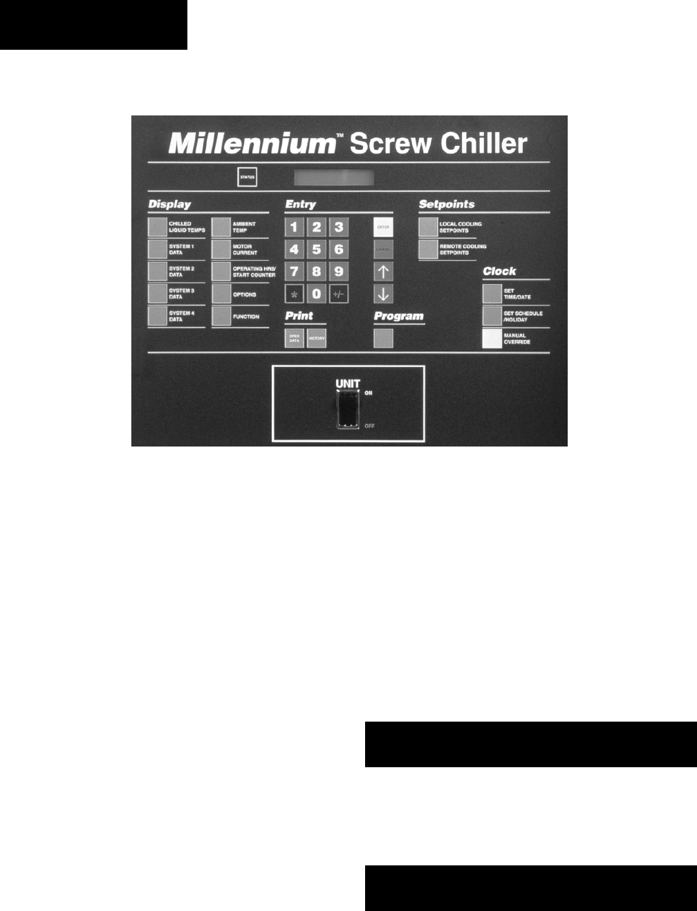
144 YORK INTERNATIONAL
FORM 201.19-NM1 (204)
is unlikely to occur unless a problem exists in the mea-
sur ing sensors or during extreme conditions.
The Display keys and the data available from each is
as follows:
3.2 CHILLED LIQUID TEMPS KEY
When the Chilled Liquid Temperatures key is pressed a
display of chilled liquid temperatures leaving the chill er
(LCHLT) and returning to the chiller (RCHLT) is pro-
vid ed as follows:
If the key is pressed again, the following message will
appear if an optional mixed chilled leaving temp sen sor
is installed for multi unit sequencing. If a sen sor is not
installed, pressing the key will have no effect.
3. DISPLAY KEYS & OPTION SWITCHES
3.1 GENERAL
The Display keys provide direct access to retrieve com-
mon ly required data about the operation of the chiller.
This is particularly useful during commissioning, mon-
i tor ing the operation of the chiller, diagnosing potential
future problems and service troubleshooting.
When a Display key is pressed, the corresponding mes-
sage will be displayed and will remain on the display
until another key is pressed.
Displayed data is in “real-time” and is updated ap-
prox i mate ly every 2 seconds. If updating of one of the
mes sag es is required faster than every 2 seconds, the
ap pro pri ate key for the desired display can be pushed
and held to provide updating every 0.4 seconds.
Display Messages may show characters indicating
“great er than” (>) or “less than” (<). These characters
indicate the actual values are greater than or less than
the values which are being displayed, but are outside
the ability of the micro to give an actual reading. This
L C H L T = 4 4 . 2 ° F
R C H L T = 5 4 . 0 ° F
M C H L T = 4 3 . 8 ° F
29023A
Micro Panel Contents
145
YORK INTERNATIONAL
FORM 201.19-NM1 (204)
3.3 SYSTEM # DATA KEYS
Pressing one of the System # Data keys a number
of times scrolls through displays of differential oil
pres sure (OIL), suction pressure (SP) and discharge
pres sure (DP), oil temperature, suction temperature
(ST), dis charge temperature (DT), saturated suction
tem per a ture, suction superheat, saturated discharge
tem per a ture, discharge superheat and compressor slide
valve position.
Examples of these displays are shown where # is the
appropriate system number:
The Evaporator Inlet Temp. display
will only appear if the chiller is selected
for R407C.
Temperatures and pressures are either mea sured di rect ly
by transducers and tem per a ture sensors, or com put ed
from these mea sure ments as follows:
Saturated discharge and suction temperatures are
com put ed by converting measured pressure to tem-
perature.
Slide Valve Position is computed based on the number
of loading steps that the micro has sent to the slide
valve solenoid in the form of a voltage signal. To the
mi cro pro ces sor, STEP 0 = fully unloaded and STEP 75
= fully loaded.
A M B I E N T A I R T E M P
= 7 1 . 9 ° F
S # S A T D S C H = 1 3 0 . 0 ° F
D S C H S H E A T = 5 4 . 3 ° F
S Y S # S V S T E P = 3 7
S Y S # C O O L E R I N L E T
R E F R I G T E M P = 2 8 . 2 ° F
S Y S # O I L = 1 7 6 P S I G
S P = 6 4 D P = 1 9 5 P S I G
S Y S # O I L = 1 5 7 . 4 ° F
S T = 3 1 . 0 D T = 1 2 3 . 2 ° F
S # S A T S U C T = 3 2 . 9 ° F
S U C T S H E A T = 1 5 . 0 ° F
Slide valve position is AP PROX I MATE
and should be used for ref er ence only.
Under actual conditions the com-
pres sor may be ful ly load ed be tween
step 60 - 75 and fully un load ed be tween
step 0 - 35.
Superheats are the difference between the respective
sat u rat ed temperature (converted from pres sure) and the
ac tu al. Display Lim its for the Sys tem Pressures and
Tem per a tures displays are as follows:
Minimum and maximum values may
change as software (EPROM) re vi -
sions are made.
*Below 9.0°F (13°C), the Suction
Temp. display will disappear. This will
in turn cause the Su per heat display to
dis ap pear.
3.4 AMBIENT TEMP KEY
When the Ambient Temperature key is pressed, am bi ent
air temperature, as mea sured sur round ing the chill er, is
displayed.
Display Limits: Minimum - 4.6°F (-20.3°C)
Maximum 137.9°F (58.8°C)
8
MIN. LIMIT MAX. LIMIT
Oil Pressure 208 PSID (14 Bar) 0 PSID (0 Bar)
Suction Pressure 0 PSIG (0 Bar) 199 PSIG (14 Bar)
Discharge Pressure 0 PSIG (0 Bar) 399 PSIG (28 Bar)
Suction Temp. 9.0 °F (-13°C) 84.2 °F (29°C)
Discharge Temp. 40.3 °F (5°C) 302.6 °F (150°C)
Oil Temp. 40.3 °F (5°C) 240.0 °F (116°C)
Sat. Discharge Temp. -41.0 °F (-41°C) 140.5 °F (60°C)
Sat. Suction Temp. -41.0 °F (-41°C) 101.3 °F (39°C)
Slide Valve Position 0% (0%) 100% (100%)
Suction Superheat -81.5 °F (-63.1°C) 60.9 °F (16°C)
Discharge Superheat 22.5 °F (-5.3°C) 216.0 °F (102.2°C)
*
*

146 YORK INTERNATIONAL
FORM 201.19-NM1 (204)
the switches is important during the com mis sion ing of
the chiller. The Options key can be used to verify the
Dip Switch positions without looking at or handling the
Microprocessor Board.
Each press of the key will scroll to the next option/dip
switch setting. Option Switch Messages (S1-1 to S1-
8) will then be displayed in sequence. At the end of the
sequence, the display will automatically revert to the
fi rst Option Switch message.
The following is a detailed guide to programming the
Dip Switches together with the associated display mes-
sage provided for each selection when the Options key
is pressed:
SWITCH 1: Water / Glycol Cooling
Open:
Water Cooling Mode is for water cooling applications
and allows the chilled liquid leaving temperature set-
point to be programmed from 40 to 70 °F (4 to 21°C).
Se lect ing this mode also auto-programs the Low Chilled
Liq uid Cut-Out at 36°F (2°C) and the Suction Pressure
Cut-Out at 44 PSIG (3 bar).
Closed:
Glycol Cooling Mode is for brine/glycol applications with
setpoints below 40°F (4°C) and allows the chilled liquid
leaving temperature setpoint to be programmed from 10 to
70°F (-12 - 21°C). In this mode, the Low Chilled Liq uid
Cut-Out can be programmed from 8 to 36° F (-13 to 2°C)
and the Suction Pressure Cut-Out programmed from 20
to 70 PSIG (1 to 5 bar) for R-22 models and 5 to 70 PSIG
(0.3 to 5 bar) for R407C mod els.
SWITCH 2: Ambient Temp. Range Low Ambient
Cutout
Open:
Standard Ambient Mode auto-programs the Low Am bi ent
Cutout setting at 25°F (-4°C) and is not ad just able.
S 1 - 2 A M B I E N T C O N T R O L
S T A N D A R D
3.5 % MOTOR CURRENT KEY
Pressing the Motor Current key displays compressor
current for each system:
This display shows the average motor current in amps
and average compressor motor current as a percentage
of FLA. All values are approximate.
On the second press of the of the Motor Current Key,
the current limit values as set by the ISN (Remote BAS
System) and EMS-PWM current limiting input are
dis played, if they are active. See Sections 1.10, and 2.4
for more details.
3.6 OPERATING HRS / START COUNTER KEY
When the Operating Hours / Starts Counter key is
pressed, the accumulated running hours and starts for
System 1 and 2 compressors are displayed. Where ap-
pli ca ble, pressing the key again displays the values for
Systems 3 and 4 on larger models:
Display Limits : Maximum run hours 99,999
Maximum starts 99,999
Values roll over to zero, if the maximum limit is ex-
ceed ed.
These counters are zeroed at the fac-
to ry, but may in di cate run time and
number of starts logged dur ing fac-
to ry testing prior to shipment.
3.7 OPTIONS KEY &
DIP SWITCH SETTINGS
The Options key provides a display of op tions which are
programmed by the po si tions of the S1 Dip Switch es
on the Mi cro pro ces sor Board. Proper pro gram ming of
H R S 1 = 1 1 4 3 . 2 = 1 3 8 2
S T R 1 = 2 8 5 . 2 = 3 2 2
H R S 3 = 1 2 5 5 . 4 = 1 0 9 5
S T R 3 = 3 6 5 . 4 = 4 5 5
S 1 - 1 C H I L L E D L I Q U I D
W A T E R
S 1 - 1 C H I L L E D L I Q U I D
G L Y C O L
C O M P 1 = 6 3 A M P 8 5 % F L A
C O M P 2 = 3 0 A M P 4 1 % F L A
I S N C R N T L I M I T : N O N E
E M S C R N T L I M I T : N O N E
Micro Panel Contents
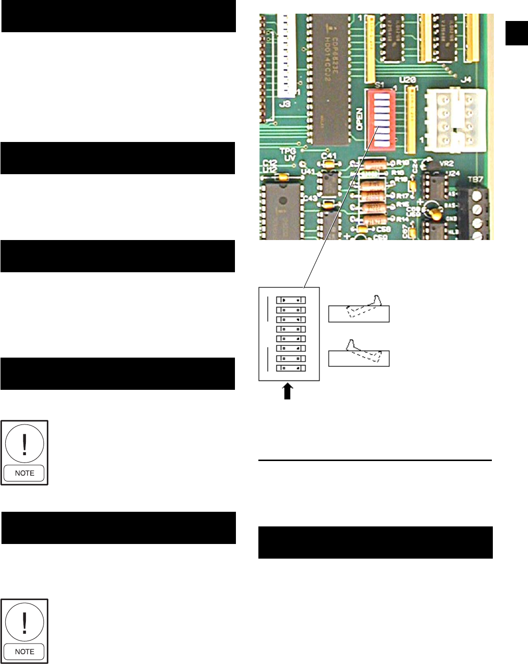
147
YORK INTERNATIONAL
FORM 201.19-NM1 (204)
Closed:
Low Ambient Mode allows the Low Ambient Cut-Out
to be programmed from 0 to 50 °F (-18 to 10°C). Val ues
above 25°F (-4°C) can be used to automatically shut
down the chiller when direct cooling methods be come
operational.
SWITCH 3: Refrigerant
Open:
The R-407C Mode MUST be selected for models us ing
refrigerant R-407C. Incorrect selection of this switch
may cause serious damage to the chiller.
Closed:
The R-22 Mode MUST be selected for models using
refrigerant type R-22. Incorrect selection of this switch
may cause serious damage to the chiller.
SWITCH 4: Unit Type
Open:
DO NOT USE THIS POSITION.
Incorrect programming may cause
damage to the chiller.
Closed:
Place the switch in the CLOSED position selects the
type of chiller as an air cooled chiller (YCAS). The
switch MUST always be in the CLOSED position.
Incorrect programming may cause
damage to the chiller.
S 1 - 2 A M B I E N T C O N T R O L
L O W A M B I E N T
S 1 - 3 R E F R I G E R A N T
R - 4 0 7 C
S 1 - 3 R E F R I G E R A N T
R - 2 2
Dip Switch Physical Location and Setting
FIG. 49 – ENLARGED PHOTOGRAPH OF DIP
SWITCHES ON MICROPROCESSOR BOARD
LD03511A
LD03511B
“OPEN” Position:
Left side of switch
pushed in
“CLOSED” Position:
Right side of switch
pushed in
8
S 1 - 4 Y C W S
S 1 - 4 Y C A S
SWITCH 5: Motor Current Average option
(start-up)
Open:
DO NOT USE THIS POSITION.
Nuisance trips at start-up could result.
S 1 - 5 M O T O R C U R R E N T
A V E R A G I N G E N A B L E D
028981-G
148 YORK INTERNATIONAL
FORM 201.19-NM1 (204)
Micro Panel Contents
Closed:
Placing the switch in the CLOSED position, disables
motor current averaging protection at start-up. It is rec-
ommended that this option be selected to avoid nuisance
start-up trips especially at extreme ambient/operating
conditions.
SWITCH 6: Heat Recovery
Open:
Placing the switch in the OPEN position, disables the
heat recovery option. The switch MUST be placed in
the OPEN position.
Incorrect programming may cause
damage to the chiller.
Closed:
DO NOT USE THIS POSITION.
Incorrect programming may cause
damage to the chiller.
SWITCH 7: Expansion Valve Type
Open:
Placing the switch in the OPEN position, confi gures the
chiller for a TXV. TXV's will never be used on standard
chiller packages. The switch MUST NEVER be placed
in the OPEN position.
Closed:
Placing the switch in the CLOSED position, confi gures
S 1 - 5 M O T O R C U R R E N T
A V E R A G I N G D I S A B L E D
S 1 - 6 H E A T R E C O V E R Y
D I S A B L E D
S 1 - 6 H E A T R E C O V E R Y
E N A B L E D
S 1 - 7 E X P A N S I O N V A L V E
T H E R M O S T A T I C
S 1 - 7 E X P A N S I O N V A L V E
E L E C T R O N I C
SUMMARY OF SETTINGS
The following table gives a summary of Modes (dis-
played messages) which can be selected using the Open
and Closed positions for each of the eight SW1 Dip
Switches.
SWITCH SWITCH "OPEN"
SETTING
SWITCH "CLOSED"
SETTING
1Water Cooling Glycol Cooling
2Standard Ambient
Control Low Ambient Control
3Refrigerant R-407C Refrigerant R-22
4Do Not Use YCAS
5Do Not Use
Motor Current
Averaging (Start-Up)
Disabled
6Heat Recovery
Disabled Do Not Use
7Expansion Valve
Thermostatic
Expansion Valve
Electronic*
8Standard Options
Enabled Do Not Use
3.8 FUNCTION KEY
Pressing the Function key only displays the same mes-
sage as pressing the Status key. Pressing the Function
key followed by another display key will scroll through
all the data available under that key once. E.g., press ing
the Function key followed by the System 1 Data key will
result in scrolling through the 5 displays shown in Sec tion
3.3 without the need to press the System 1 Data key to
scroll to the next display. After scrolling through the data,
the display returns to the status mes sage.
The following keys can be scrolled using the Function
Key: Chilled Liquid Temps, System # Data, Motor Cur-
rent and Options.
the chiller for an EEV (Electronic Expansion Valve).
The switch MUST be placed in the CLOSED posi-
tion.
Incorrect programming may cause
damage to the chiller.
SWITCH 8: Standard Options
Open:
Standard Options Enabled.
Closed:
Do ot use.
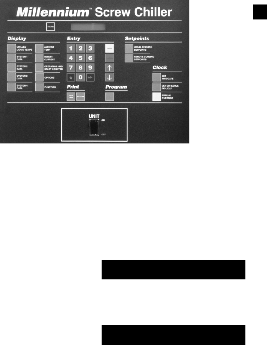
149
YORK INTERNATIONAL
FORM 201.19-NM1 (204)
Information available using the Operating Data key is de-
scribed in the following sections. In example displays “ # ”
is used to indicate system number where appropriate.
4.3 OPERATING DATA –
LOCAL DISPLAY MESSAGES
YCAS 2 System Models :
When the Operating Data key is pressed, the following
message appears:
Repetitively pressing the keys will scroll through
the following Common (whole chiller) Data and in di -
vid u al System Data information displays.
Common Data:
This message shows the time remaining on the Load
Timer and the Unload Timer. These Timers constantly
recycle and are used in conjunction with “rate control”
and “temperature deviation from setpoint” to de ter mine
when loading/unloading should occur.
4. PRINT KEYS
4.1 GENERAL
The Print keys provide access to two sets of in for ma tion
either locally on the panel display or, if an optional
printer is connected, remotely as hard copy printouts.
The Operating Data (Oper Data) key provides a real-
time list of system operating data and programmed
set tings. The History key provides a comprehensive
list of operating data and programmed settings “at the
in stant of fault” on each of the last six faults.
4.2 OPER DATA KEY
If a remote printer is not connected, pressing the Op er -
at ing Data key allows the user to scroll through in for -
ma tion, on the 40 character display, which is not di rect ly
available from the Display keys on the panel.
If a remote printer is connected, pressing the Operating
Data key causes a snapshot to be taken of system op er -
at ing conditions and of the user programming se lec tions.
The data is stored in temporary memory, then trans mit ted
from the microprocessor to the remote print er. As the
data is transmitted it is erased from the memory.
O P E R A T I N G D A T A
D I S P L A Y S
L O A D T I M E R 1 0 S E C
U N L O A D T I M E R 0 S E C
29023A
8

150 YORK INTERNATIONAL
FORM 201.19-NM1 (204)
System Data:
The following sequence of three displays are provided
fi rst for System 1, then for System 2, and then for Sys-
tems 3 and 4 as applicable.
This message indicates whether the compressor on this
system is ON or OFF.
This message indicates the compressor motor current in
amps and as a percentage of Full Load Amps.
This message indicates the system oil pressure, suction
pressure, and discharge pressure.
This message shows the system oil temperature, suction
temperature, and discharge temperature.
These messages indicate compressor suction gas satura-
tion temperature and superheat.
This message indicates compressor discharge gas satura-
tion temperature and superheat.
This message indicated the compressor slide valve po-
sition. 0 steps equals minimum capacity and 75 steps
equals fully loaded.
The upper message indicates the difference (error)
be tween actual leaving chilled liquid temperature and
the pro grammed Target temperature. The lower message
indicates the rate of change of the chilled liquid leaving
tem per a ture in degrees per minute. A minus sign (-)
in di cates falling temperature. No sign indicates rising
tem per a ture.
This message advises which system is programmed as
the lead.
This message indicates the position of the optional
aux il ia ry contacts for the evaporator water pump and
the status of the evaporator heater.
For the evaporator pump contacts, ON = contacts closed,
OFF = contacts open.
The Evaporator Heater status is controlled on ambient
temperature as follows: If measured ambient falls be low
40°F (4°C), the Evaporator Heater is switched ON. If
measured ambient then rises above 45°F (7°C) the heater
is switched OFF. The evaporator heater pre vents water
standing in the evaporator from freezing.
This message indicates that a remote device such as a
Remote Control Center, an ISN controller, or another
device sending a PWM signal for temperature or cur rent
reset is overriding control points programmed through
the keypad or default microprocessor set points. The
following displays may be encountered:
NONE – No remote control active. Remote
monitoring may be active.
ISN – YorkTalk via ISN or Remote Control
Center (remote mode).
PWM CURR – EMS PWM Current Limiting Enabled
PWM TEMP – EMS PWM Temp. Reset Enabled
CUR/TEMP – EMS PWM Current Limiting &
Temperature Reset Enabled
L E A D S Y S T E M I S
S Y S T E M N U M B E R #
E V A P P U M P I S O F F
E V A P H E A T E R I S O N
A C T I V E R E M O T E C T R L
N O N E
Micro Panel Contents
T E M P E R R O R 0 0 . 5 ° F
T E M P R A T E - 0 . 9 ° F / M
S Y S # C O M P R E S S O R
I S O N
S Y S # M O T O R C U R R E N T
1 3 5 A M P S 7 8 % F L A
S Y S # O I L = 1 7 5 P S I G
S P = 6 2 D P = 2 7 1 P S I G
S Y S # O I L = 1 5 4 . 8 ° F
S T = 3 9 . 0 D T = 1 2 3 . 7 ° F
S # S A T S U C T = 3 4 . 7 ° F
S U C T S H E A T = 1 0 . 5 ° F
S # S A T D S C H = 1 2 9 ° F
D S C H S H E A T = 6 2 . 8 ° F
S Y S # S V S T E P = 4 0

151
YORK INTERNATIONAL
FORM 201.19-NM1 (204)
S Y S # F A N S T A G E 3
C O M P H E A T E R I S O N
S Y S # R U N T I M E
1 - 3 - 4 8 - 1 7 D - H - M - S
S Y S # L L S V I S O N
E C O N T X V S O L I S O N
8
This message indicates the EEV preheat % and the suc-
tion superheat.
This message displays the accumulated Run Time since
the last start in Days (D), Hours (H), Minutes (M), and
Seconds (S).
This message indicates the Liquid Line Solenoid Valve
and the economizer TXV solenoid valve position: ON =
Energized/Open, OFF = De-energized/Closed.
This message advises the stage of con dens er fan op-
er a tion on this system and the status of the compressor
heater. See Sec tion 8.4 for details of fan staging.
Once the System Data sequence has been repeated for
the second system, pressing the or key again will
loop back to the beginning to the Load/Unload Tim er
dis play. To leave the sequence at any point, press a key
from another sec tion of the keypad.
SOFTWARE VERSION
The software version may be viewed by pressing the
* key.
The software version will be displayed similar to the
sample below:
4.4 OPERATING DATA –
REMOTE PRINTOUT
The follow text shows a typical example printout
ob tained by pressing the Operating Data key with an
op tion al printer attached. In this case, an example is
shown for a YCAS 2 System Chiller.
YORK INTERNATIONAL CORPORATION
MILLENNIUM SCREW CHILLER
UNIT STATUS
2:04PM 01 JUN 02
SYS 1 NO COOLING LOAD
SYS 2 COMPRESSOR RUNNING
OPTIONS
CHILLED LIQUID WATER
AMBIENT CONTROL STANDARD
REFRIGERANT TYPE R-22
UNIT TYPE YCAS
MOTOR CURRENT AVERAGING ENABLED
HEAT RECOVERY DISABLED
PROGRAM VALUES
DSCH PRESS CUTOUT 399 PSIG
DSCH PRESS UNLOAD 375 PSIG
SUCT PRESS CUTOUT 44 PSIG
HIGH AMBIENT CUTOUT 130.0 DEGF
LOW AMBIENT CUTOUT 25.0 DEGF
LEAVING LIQUID CUTOUT 36.0 DEGF
MOTOR CURRENT UNLOAD 100 %FLA
ANTI RECYCLE TIME 600 SECS
LOCAL/REMOTE MODE REMOTE
LEAD/LAG CONTROL AUTOMATIC
UNIT DATA
LEAVING LIQUID TEMP 49.0 DEGF
RETURN LIQUID TEMP 58.2 DEGF
SETPOINT 42.0 +/- 2.0 DEGF
REMOTE SETP 42.0 +/- 2.0 DEGF
AMBIENT AIR TEMP 74.8 DEGF
LEAD SYSTEM SYS 2
EVAPORATOR PUMP ON
EVAPORATOR HEATER OFF
ACTIVE REMOTE CONTROL NONE
SOFTWARE VERSION C.ACS.09.00
SYSTEM 1 DATA
COMPRESSORS STATUS OFF
RUN TIME 0- 0- 0- 0 D-H-M-S
MOTOR CURRENT 0 AMPS 0 %FLA
SUCTION PRESSURE 125 PSIG
DISCHARGE PRESSURE 131 PSIG
OIL PRESSURE 130 PSIG
SUCTION TEMPERATURE 68.4 DEGF
DISCHARGE TEMPERATURE 68.8 DEGF
OIL TEMPERATURE 68.8 DEGF
SAT SUCTION TEMP 71.8 DEGF
S Y S X E E V = 3 7 . 4 %
S U C T S H E A T = 1 0 . 2 ° F
S O F T W A R E V E R S I O N
C . A C S . 0 9 . 0 8

152 YORK INTERNATIONAL
FORM 201.19-NM1 (204)
The System Evaporator Inlet Refrig-
erant Tem per a ture will be printed if
the unit is in R407C mode.
SUCTION SUPERHEAT 3.4 DEGF
SAT DISCHARGE TEMP 74.5 DEGF
DISCHARGE SUPERHEAT 6.3 DEGF
SLIDE VALVE STEP 0
EEV OUTPUT 0.0 %
EVAPORATOR INLET REFRIG 44.6 DEGF
LIQUID LINE SOLENOID OFF
ECONOMIZER TXV SOLENOID OFF
CONDENSER FAN STAGE OFF
COMPRESSOR HEATER ON
WYE-DELTA RELAY OFF
SYSTEM 2 DATA
COMPRESSORS STATUS ON
RUN TIME 0- 0-15-26 D-H-M-S
MOTOR CURRENT 104 AMPS 87 %FLA
SUCTION PRESSURE 57 PSIG
DISCHARGE PRESSURE 233 PSIG
OIL PRESSURE 218 PSIG
SUCTION TEMPERATURE 42.9 DEGF
DISCHARGE TEMPERATURE 145.5 DEGF
OIL TEMPERATURE 102.8 DEGF
SAT SUCTION TEMP 31.7 DEGF
SUCTION SUPERHEAT 11.2 DEGF
SAT DISCHARGE TEMP 112.1 DEGF
DISCHARGE SUPERHEAT 33.4 DEGF
SLIDE VALVE STEP 70
EEV OUTPUT 35.6 %
EVAPORATOR INLET REFRIG 23.6 DEGF
LIQUID LINE SOLENOID ON
ECONOMIZER TXV SOLENOID ON
CONDENSER FAN STAGE 3
COMPRESSOR HEATER OFF
WYE-DELTA RELAY ON
DAILY SCHEDULE
S M T W T F S *=HOLIDAY
MON START=00:00AM STOP=00:00AM
TUE START=00:00AM STOP=00:00AM
WED START=00:00AM STOP=00:00AM
THU START=00:00AM STOP=00:00AM
FRI START=00:00AM STOP=00:00AM
SAT START=00:00AM STOP=00:00AM
HOL START=00:00AM STOP=00:00AM
Micro Panel Contents
4.5 HISTORY KEY
If a safety shutdown occurs on the chiller, a com pre -
hen sive list of operating and programmed settings data
is stored by the microprocessor. The information is
stored at the instant of the fault, regardless of whether
the fault caused a lockout to occur. This information is
not af fect ed by power failures or manual resetting of a
fault lockout.
The microprocessor stores data for up to 6 safety shut-
downs. Once this limit is reached, a fur ther shut down
will cause the oldest set of data to be discarded in favor
of storing the new shutdown data. The Safety Shut downs
are numbered from 1 to 6 with num ber 1 always being
the most recent.
If a remote printer is not connected, pressing the His-
to ry key allows the operator to locally scroll through
in for ma tion relating to the stored safety shutdowns on
the con trol panel display.
If a remote printer is connected, pressing the History key
will cause data from the last 6 shutdowns to be trans-
mitted from the mi cro pro ces sor to the remote print er.
The printout will begin with the most recent fault which
occurred. This does not affect the stored data and as
many prints as desired may be tak en. See Sec tion 4.7
for a HISTORY printout sample.
4.6 FAULT HISTORY DATA –
LOCAL DISPLAY MESSAGES
When the History key is pressed, the following mes sage
will appear:
To select a Safety Shutdown, press the appropriate key
on the numeric key pad, then press Enter. Remember that
the most recent fault information is stored as shut down
No. 1. After the ENTER Key is pressed, a mes sage in-
dicating the time and date of the Fault Shut down will
appear:
S H U T D O W N O C C U R R E D
5 : 5 9 A M 2 9 N O V 0 2
D I S P L A Y S A F E T Y S H U T -
D O W N N O . 1 ( 1 T O 6 )

153
YORK INTERNATIONAL
FORM 201.19-NM1 (204)
8
Repetitively pressing the Keys allows scrolling
through the information available in the Safety Shut-
down buffer. This is divided into Chill er Data and Indi-
vidual System Data displays as follows:
Chiller Data:
This message indicates the fault that caused the shut-
down; in this case, a high motor current in System 2
was the cause of the shutdown.
This message displays the type of chilled liquid se lect ed
(water or glycol) at the time of the fault.
This display indicates whether standard or low am bi ent
operation was selected at the time of the fault.
This message indicates the type of refrigerant that was
programmed at the time of the fault (R-22 or R407C).
This message indicates the type of Chiller (YCAS or
YCWS) programmed at the time of the fault. (MUST
BE IN YCAS MODE)
This message indicates whether motor current averaging
at start-up is enabled or disabled.
This message indicates whether heat recovery is dis-
abled or enabled. (HEAT RECOVERY MUST BE
DISABLED)
S 1 - 1 C H I L L E D L I Q U I D
W A T E R
S 1 - 2 A M B I E N T C O N T R O L
L O W A M B I E N T
S 1 - 3 R E F R I G E R A N T
R - 2 2
D I S C H A R G E P R E S S U R E
C U T O U T = 3 9 5 . 0 P S I G
D I S C H A R G E P R E S S U R E
U N L O A D = 3 7 5 . 0 P S I G
S U C T I O N P R E S S U R E
C U T O U T = 4 4 . 0 P S I G
S Y S 1 N O F A U L T S
S Y S 2 H I G H M T R C U R R
S 1 - 4 Y C A S
This message indicates whether electronic or thermo-
static expansion valve is selected. (ELECTRONIC
MUST BE SELECTED FOR EEV OPERATION).
(Remote barrel applications are programmed for
thermostatic).
This message indicates the discharge pressure cut-out
programmed at the time of the fault.
This display provides the discharge pressure unload
point, programmed at the time of the fault.
This message displays the suction pressure cut-out pro-
grammed at the time of the fault.
This message indicates the High Ambient Tem per a ture
Cutout at the time of the fault.
This display shows the Low Ambient Cutout pro-
grammed at the time of the fault.
This display shows the Low Leaving Chilled Liquid
Cut out programmed at the time of the fault.
This message shows the programmed %FLA Motor
Current Unload at the time of the fault.
H I G H A M B I E N T T E M P
C U T O U T = 1 3 0 . 0 ° F
L O W A M B I E N T T E M P
C U T O U T = 2 5 . 0 ° F
L E A V I N G L I Q U I D T E M P
C U T O U T = 3 6 . 0 ° F
H I G H M O T O R C U R R E N T
U N L O A D - 1 0 0 % F L A
S 1 - 6 H E A T R E C O V E R Y
D I S A B L E D
S 1 - 5 M O T O R C U R R E N T
A V E R A G I N G D I S A B L E D
S 1 - 7 E X P A N S I O N V A L V E
E L E C T R O N I C

154 YORK INTERNATIONAL
FORM 201.19-NM1 (204)
Micro Panel Contents
This message shows whether remote or local com mu -
ni ca tions was selected at the time of the fault.
This message displays the lead/lag selection pro-
grammed at the time of the fault.
This message indicates the leaving and return chilled
liquid temperature at the time of the fault.
This message indicates the mixed water temperature
at the time of the fault. A mixed water sensor may be
present when multi-unit sequencing is utilized. If no
mixed water temperature sensor is installed, the dis play
will not appear.
This message displays the programmed chilled liquid
setpoint and deviation (control range) programmed at
the time of the fault.
This message indicates the outdoor Ambient Air Tem-
per a ture at the time of the fault.
This message indicates which system was in the lead at
the time of the fault.
L O C A L / R E M O T E M O D E
L O C A L
L E A D / L A G C O N T R O L
A U T O M A T I C
L C H L T = 4 4 . 1 ° F
R C H L T = 5 2 . 9 ° F
M C H L T = 4 3 . 8 ° F
S E T P O I N T = 4 4 . 0 ° F
R A N G E = + / - 2 . 0 ° F
This message indicates the status of both the evap o ra tor
pump signal from the microprocessor and the evap o -
ra tor heater.
This message indicates that a remote device such as a
Remote Control Center, an ISN controller, or an oth er de-
vice is sending a PWM signal for tem per a ture or cur rent
reset is over rid ing control points programmed through
the keypad or default mi cro pro ces sor setpoints.
System Data:
Following the Common Data is a sequence of twen ty
information displays which are given twice, fi rst for
Sys tem 1, then for System 2. In each example, “#” is
used to indicate System number:
This message indicates whether the compressor on this
system was ON or OFF at the time of the fault.
This message shows the Run Time logged on the sys tem
since the last compressor start, in Days (D), Hours (H),
Minutes (M), and Seconds (S).
This message indicates the compressor motor current in
amps and as a percentage of Full Load Amps.
A M B I E N T A I R T E M P
7 7 . 6 ° F
L E A D S Y S T E M I S
S Y S T E M N U M B E R 1
E V A P P U M P I S O N
E V A P H E A T E R I S O F F
A C T I V E R E M O T E C T R L
N O N E
S Y S # C O M P R E S S O R
I S O N
S Y S # R U N T I M E
1 - 3 - 4 8 - 1 7 D - H - M - S
S Y S # M O T O R C U R R E N T
1 3 5 A M P S 7 8 % F L A

155
YORK INTERNATIONAL
FORM 201.19-NM1 (204)
8
This message indicates the system oil pressure, suc-
tion pressure, and discharge pressure at the time of the
fault.
This message shows the system oil temperature, suction
temperature, and discharge temperature at the time of
the fault.
These messages indicate compressor suction gas sat-
u ra tion temperature and superheat at the time of the
fault.
This message indicates compressor discharge gas sat-
u ra tion temperature and superheat at the time of the
fault.
This message indicates the compressor slide valve po-
si tion at the time of the fault. 0 steps equals minimum
capacity and 75 steps equals fully loaded.
This message indicates the EEV preheat % and the suc-
tion superheat.
This message, which is only displayed if the unit is in
R-407C mode, indicates the refrigerant temperature at
the inlet of the evaporator.
S Y S # O I L = 1 5 4 . 8 ° F
S T = 3 9 . 0 D T = 1 2 3 . 7 ° F
S Y S # O I L = 1 7 5 P S I G
S P = 6 2 D P = 2 7 1 P S I G
S # S A T S U C T = 3 4 . 7 ° F
S U C T S H E A T = 1 0 . 5 ° F
S # S A T D S C H = 1 2 9 ° F
D S C H S H E A T = 6 2 . 8 ° F
S Y S # S V S T E P = 4 0
S Y S # C O O L E R I N L E T
R E F R I G T E M P = 2 8 . 2 ° F
S Y S # L L S V I S O N
E C O N T X V S O L I S O F F
S Y S # F A N S T A G E 3
C O M P H E A T E R I S O F F
This message indicates the EEV PILOT So le noid Valve
and the economizer Thermal Expansion Valve So le noid
Valve position: ON = Energized / OFF = De-En er gized
(OFF) at the time of the fault.
This message indicates the stage of condenser fan op-
er a tion on the system and the status of the com pres sor
heat er at the time of the fault. See Section 8.4 for de tails
of fan staging.
This message indicate whether the WYE-DELTA out-
put to the compressor was energized at the time of the
fault
This message indicates whether the discharge cooling
solenoid was energized at the time of the fault and if the
WYE-DELTA output to the compressor was energized.
(Low Temperature Glycol Chillers Only)
S Y S X E E V = 3 7 . 4 %
S U C T S H E A T = 1 0 . 2 º F
S Y S # W Y E - D E L T A O N
S Y S X D S C H C L S V OFF
S Y S X W Y E - D E L T A OFF

156 YORK INTERNATIONAL
FORM 201.19-NM1 (204)
Micro Panel Contents
4.7 FAULT HISTORY DATA –
REMOTE PRINTOUT
A printout history of unit and system operating con di -
tions, at the time of the fault, can be obtained by press ing
the HISTORY Key with an optional printer in stalled. 2
compressor chillers will provide a history printout on
the last 6 faults.
An example of the HISTORY Printout is shown be-
low:
OIL TEMPERATURE 68.8 DEGF
SAT SUCTION TEMP 71.8 DEGF
SUCTION SUPERHEAT 3.4 DEGF
SAT DISCHARGE TEMP 74.5 DEGF
DISCHARGE SUPERHEAT 6.3 DEGF
SLIDE VALVE STEP 0
EEV OUTPUT 0.0 %
EVAPORATOR INLET REFRIG 44.6 DEGF
LIQUID LINE SOLENOID OFF
ECONOMIZER TXV SOLENOID OFF
CONDENSER FAN STAGE OFF
COMPRESSOR HEATER ON
WYE-DELTA RELAY OFF
SYSTEM 2 DATA
COMPRESSORS STATUS ON
RUN TIME 0- 0-15-26 D-H-M-S
MOTOR CURRENT 104 AMPS 87 %FLA
SUCTION PRESSURE 57 PSIG
DISCHARGE PRESSURE 233 PSIG
OIL PRESSURE 218 PSIG
SUCTION TEMPERATURE 42.9 DEGF
DISCHARGE TEMPERATURE 145.5 DEGF
OIL TEMPERATURE 102.8 DEGF
SAT SUCTION TEMP 31.7 DEGF
SUCTION SUPERHEAT 11.2 DEGF
SAT DISCHARGE TEMP 112.1 DEGF
DISCHARGE SUPERHEAT 33.4 DEGF
SLIDE VALVE STEP 70
EEV OUTPUT 35.6 %
EVAPORATOR INLET REFRIG 23.6 DEGF
LIQUID LINE SOLENOID ON
ECONOMIZER TXV SOLENOID ON
CONDENSER FAN STAGE 3
COMPRESSOR HEATER OFF
WYE-DELTA RELAY ON
DAILY SCHEDULE
S M T W T F S *=HOLIDAY
MON START=00:00AM STOP=00:00AM
TUE START=00:00AM STOP=00:00AM
WED START=00:00AM STOP=00:00AM
THU START=00:00AM STOP=00:00AM
FRI START=00:00AM STOP=00:00AM
SAT START=00:00AM STOP=00:00AM
HOL START=00:00AM STOP=00:00AM
YORK INTERNATIONAL CORPORATION
MILLENNIUM SCREW CHILLER
SAFETY SHUTDOWN NUMBER 1
SHUTDOWN @ 3:56PM 29 SEP 02
SYS 1 HIGH DSCH PRESS SHUTDOWN
SYS 2 NO FAULTS
OPTIONS
CHILLED LIQUID WATER
AMBIENT CONTROL STANDARD
REFRIGERANT TYPE R-22
UNIT TYPE YCAS
MOTOR CURRENT AVERAGING ENABLED
HEAT RECOVERY DISABLED
PROGRAM VALUES
DSCH PRESS CUTOUT 399 PSIG
DSCH PRESS UNLOAD 375 PSIG
SUCT PRESS CUTOUT 44 PSIG
HIGH AMBIENT CUTOUT 130.0 DEGF
LOW AMBIENT CUTOUT 25.0 DEGF
LEAVING LIQUID CUTOUT 36.0 DEGF
MOTOR CURRENT UNLOAD 100 %FLA
ANTI RECYCLE TIME 600 SECS
LOCAL/REMOTE MODE REMOTE
LEAD/LAG CONTROL AUTOMATIC
UNIT DATA
LEAVING LIQUID TEMP 49.0 DEGF
RETURN LIQUID TEMP 58.2 DEGF
SETPOINT 42.0 +/- 2.0 DEGF
REMOTE SETP 42.0 +/- 2.0 DEGF
AMBIENT AIR TEMP 74.8 DEGF
LEAD SYSTEM SYS 2
EVAPORATOR PUMP ON
EVAPORATOR HEATER OFF
ACTIVE REMOTE CONTROL NONE
SOFTWARE VERSION C.ACS.09.00
SYSTEM 1 DATA
COMPRESSORS STATUS OFF
RUN TIME 0- 0- 0- 0 D-H-M-S
MOTOR CURRENT 0 AMPS 0 %FLA
SUCTION PRESSURE 125 PSIG
DISCHARGE PRESSURE 131 PSIG
OIL PRESSURE 130 PSIG
SUCTION TEMPERATURE 68.4 DEGF
DISCHARGE TEMPERATURE 68.8 DEGF
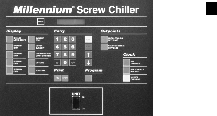
157
YORK INTERNATIONAL
FORM 201.19-NM1 (204)
8
5. ENTRY KEYS
5.1 GENERAL
The Entry keys allow the user to change numerical
val ues programmed in as chiller setpoints, cutouts,
clock, etc.
5.2 NUMERICAL KEYPAD
The Numerical keypad provides all keys necessary to
program numerical values into the Micro Panel.
The “*” key is used to designate holidays when pro gram -
ming special start/stop times for designated hol i days in
the SET SCHEDULE/HOLIDAY program mode.
The “+/-” key allows programming -C setpoints and
cut-outs in the metric display mode.
5.3 ENTER KEY
The Enter key must be pushed after any change is made
to setpoints, cutouts, or system clock. Pressing this key
tells the micro to accept new values into memory. If this
is not done, the new values entered will be lost and the
original values will be returned.
The Enter key is also used to scroll through available
data when using the Program or Set Schedule/Holiday
keys.
5.4 CANCEL KEY
When the Cancel key is pressed, the cursor will always
return to the fi rst character to be programmed in the
dis play message. This allows the operator to begin re-
pro gram ming, if an error is made. When the Cancel key
is pressed, the values already keyed in will be erased
and the original or internally programmed default val ues
will appear. In other instances the display will re main the
same and the only reaction will be the cursor re turn ing
to the fi rst character.
5.5 KEYS
The keys allow the user to scroll through data un der
the OPER DATA and HISTORY Key and to select the
correct day of the week and the correct month when
programming the micro with the cor rect time and date.
The key also operates as a tog gle AM/PM key if the
cursor is over “AM” or “PM” on the display. For ex-
am ple, pressing the key when the cursor is on “PM”
changes it to “AM.”
29023A
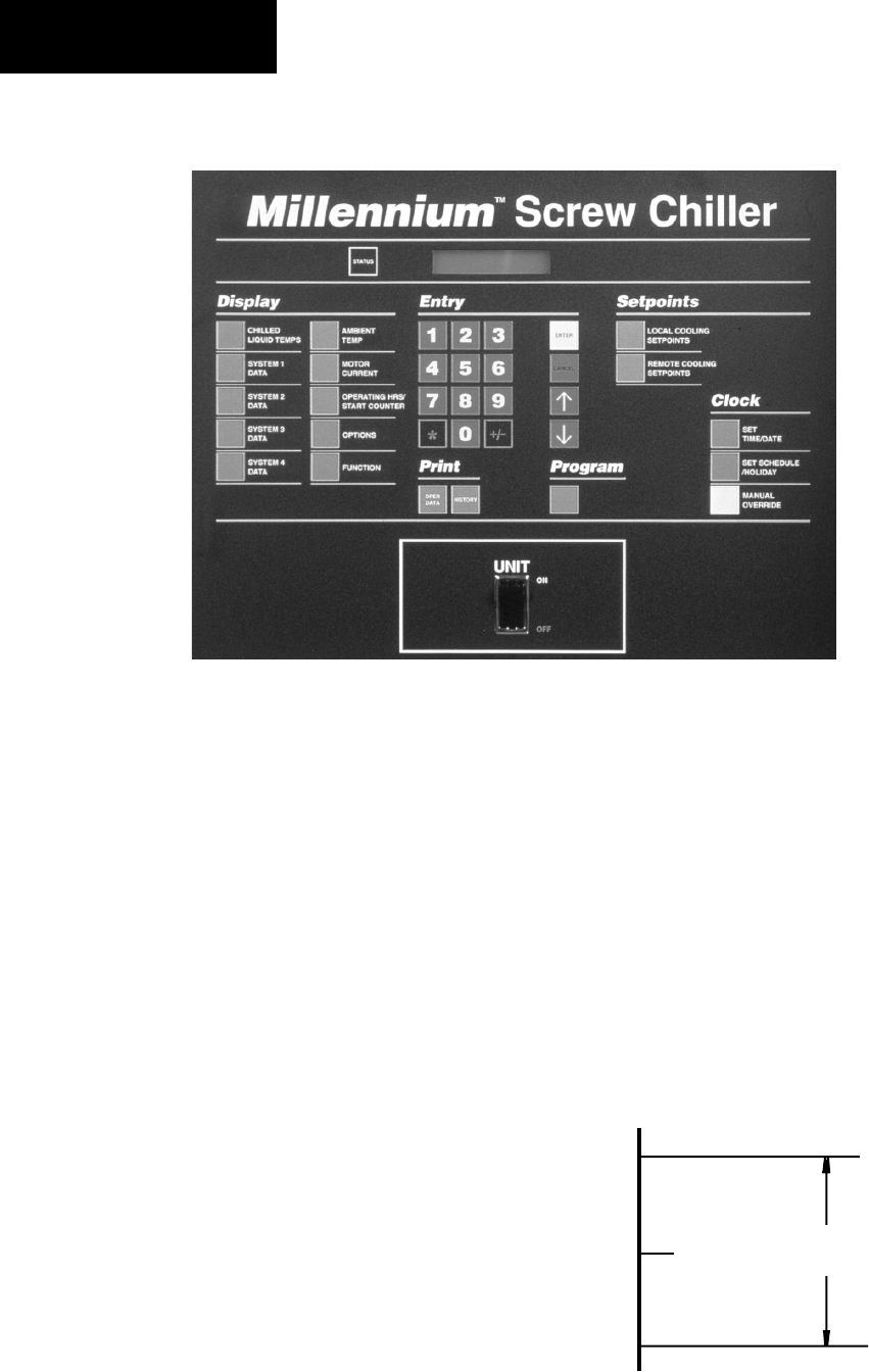
158 YORK INTERNATIONAL
FORM 201.19-NM1 (204)
Micro Panel Contents
de scribed as the maximum acceptable + and - deviation
from Setpoint.
The minimum acceptable temperature is the Lower
Range Limit and is calculated by subtracting the “-”
Range from the Setpoint. The Lower Range Limit is
the lowest ac cept able leaving temperature. The highest
acceptable temperature is referred to as the Upper Range
Limit and is calculated by adding the “+” Range to the
Setpoint. The Upper Range Limit is the highest accept-
able leaving tem per a ture. For example, if the desired
Setpoint temperature is 44.0°F (7°C) and the allowable
deviation (+ / - Range) from this temperature is +/- 2.0°F
(1°C), then the micro will attempt to control leaving
chilled liquid tem per a tures to 42.0°F (6°C) to 46.0°F
(8°C). This can be viewed pictorially as follows:
To assure that the chilled liquid leaving temperature
stays within the Control Range, the micro will attempt
to con trol the leaving temperature to the actual Set point
tem per a ture. This is accomplished by analyzing the tem-
per a ture error and the rate of change to determine the
amount of loading necessary to cool the chilled liq uid
6. SETPOINTS KEYS & CHILLED LIQUID CONTROL
6.1 GENERAL
The microprocessor monitors leaving chilled liquid
tem per a ture and adjusts the chiller cooling capacity to
main tain this temperature within a programmed range.
The capacity is controlled by switching compressors
on or off, and by varying a load/unload voltage to
each com pres sor slide valve to adjust the capacity of
the com pres sors. The microprocessor controls chilled
liquid tem per a ture through a combination of Fuzzy
Logic con trol and internal timers. Fuzzy logic enables
the micro to analyze the deviation from setpoint and
the rate of change and determine the amount of loading
and un load ing nec es sary to control to the desired chilled
liq uid setpoint temperature. The micro also attempts to
max i mize ef fi cien cy by spreading the cooling load be-
tween com pres sors, minimize compressor cycling, and
op ti mal ly uti lize evaporator tube surface (maximize
ef fi cien cy). This method of control is suitable for both
wa ter and glycol cooling. A control setpoints can be pro-
grammed into the chiller to establish the desired range
of leaving chilled liquid operating temperatures. A de-
scrip tion of the op er a tion and programming follows.
6.2 CHILLED LIQUID TEMPERATURE
CONTROL
The Setpoints keys are used to program the required
chilled water liquid temperature for the application.
This is accomplished by programming the “Setpoint”
and the acceptable deviation (+ or - Range) This devia-
tion is simply called the “Control Range” and is best
44.0°F
(7°C)
SETPOINT
Temp.
(User ac-
cept able
leaving
chilled liq-
uid operat-
ing range)
CON TROL
RANGE
46.0°F
(8°C)
42.0°F
(6°C)
29023A
159
YORK INTERNATIONAL
FORM 201.19-NM1 (204)
8
to the Setpoint Temperature. The amount of load ing is
var ied by changing the amount of DC Voltage signal to
the slide valve solenoid of each compressor. Voltage
increases with load (0 - approximately 9VDC at full
load).
Slide Valve Control
The slide valve of each compressor can be moved 75
steps, where “0” equals minimum capacity and fully
load ed equals 75 steps. The amount of movement that
occurs when the micro initiates changes may vary ac-
cord ing to the error or deviation from setpoint and the
rate of change of chilled liquid temperature. Each time a
change is made, the incremental change may vary from
1 to 10 steps as determined from the micro. In cases
where internal limiting is not in effect due to pos si ble
fault conditions, the micro will load the com pres sor with
the lowest number of steps, alternating loading back and
forth between compressors until both are fully load ed.
In some cases the micro will be required to make de-
ci sions regarding loading under conditions where the
temperature “er ror” and temperature “rate” confl ict. For
example, the micro may elect to unload a compressor
if the error is “0” (tem per a ture is at setpoint), while the
rate of change of chilled liquid temperature is negative
(falling). The micro may also elect to hold capacity when
error is “+” (tem per a ture is above setpoint) because the
rate of change of chilled liquid is “-”. Below is a chart
which illustrates these conditions.
Load Timers
Fixed timers are set to minimize undershoot and over-
shoot as a result of slide valve control.
• Load Timers are always set at 10 seconds be tween
changes.
• Unload Timers are set at 5 seconds between chang-
es.
Slide Valve Position
A slide valve position (S V STEP), under the keypad
system keys, of 75 indicates that the compressor is ful ly
loaded. However due to the non-exact movement of
the mechanism, a position less than 75, possibly 60,
could also mean that the compressor is fully loaded.
A compressor may also be fully unloaded at step 35
and below. Keep this potential indicator error in mind
when attempting to de ter mine slide valve position versus
actual com pres sor capacity.
Compressor Starting & Loading Sequence
If no compressors are running, the Daily Schedule
per mits, all safeties and run permissives are satisfi ed,
the anti-recycle timers have timed out, and the leaving
liq uid temperature rises above the upper range limit of
the Con trol Range, the lead compressor will be started.
A 0VDC signal is sent to the compressor slide valve
con trol solenoid to allow the internal spring to push the
slide valve to a minimum loading position to assure it is
fully unloaded at start. At the same time, the micro will
energize (open) the pilot solenoid on the EEV. After
an ini tial period of 15 seconds, the micro will begin to
load up the lead com pres sor to bring the chilled liquid
tem per a ture to setpoint.
After 5 minutes of run time, if leaving chilled liquid
temperature is not within the Control Range, the micro
will start the lag compressor. This is not dependent on
slide valve position which after 5 minutes will typi-
cally be fully loaded at a S V Step of “75”. The lead
compressor will be reduced in capacity to a slide valve
step of 40. The lag compressor will then be load ed until
it also reaches a slide valve step of 40 while the lead
compressor is maintained at a constant load. At this
point the compressors will be alternately loaded with
loading always occurring on the compressor with the
lowest slide valve step until the leaving chilled liq uid
is satisfi ed.
Compressor Loading
The micro loads and unloads individual compressors
by varying voltage to the Slide Valve solenoid which
con trols oil fl ow to the slide valve. The slide valve load
solenoid applies oil pressure to the slide valve to over-
come spring pressure from an internal spring, in creas ing
ca pac i ty. The in ter nal spring moves the slide valve in
the op po site di rec tion against oil pres sure to de crease
ca pac i ty.
ERROR
Negative Unload Unload Hold
Zero Unload Hold Load
Positive Hold Load Load
RATE
Negative Zero Positive

160 YORK INTERNATIONAL
FORM 201.19-NM1 (204)
Micro Panel Contents
Whenever chilled liquid leaving temperature is above
the Setpoint plus the control range, loading voltage will
increase to allow oil pressure to push against the internal
slide valve return spring and move the slide valve to
increase capacity. Every 10 seconds, when the load timer
decrements to 0, the micro will increment the slide valve
step from 1 to 10 steps according to error (de vi a tion from
setpoint) and rate of change of chilled liquid.
The micro will always choose the compressor with the
lowest slide valve position to load on increasing de mand,
provided the compressor is not pumping down, has run at
least 15 seconds, and is not in a “Limiting” condition.
Compressor Unloading and Shutdown Sequence
Whenever temperature is below the Setpoint, minus the
control range, the voltage to the slide valve solenoid
will decrease, which bypasses oil pressure to the slide
valve allowing the slide valve return spring to move the
slide valve forward to the fully unloaded position on the
compressor with highest slide valve step. Ev ery 5 sec-
onds, the micro will dec re ment the compressor with the
highest slide valve po si tion by 1 - 10 steps ac cord ing to
the error (de vi a tion from Setpoint) and the rate of change
of chilled liquid tem per a ture until the temperature falls
within the control range.
As load drops, the micro will continue to unload the
com pres sor with the highest slide valve step until all
com pres sor slide valves are at “0.” At this point, the
last lag com pres sor will pump down and cycle off, if
chilled liq uid tem per a ture drops below “Setpoint - Con-
trol Range/2”. When the lag compressor cycles off,
the lead compressor slide valve will increment to step
30. As load con tin ues to decrease, the lead com pres sor
will con tin ue to unload to a slide valve po si tion of “0”
and will pump down and cy cle off if the chilled liq uid
tem per a ture drops below “Setpoint – Con trol Range.”
The lag compressor may be shut down
be fore it is fully unloaded to avoid a
Chill er fault on a Low Wa ter Tem-
per a ture cut-out under the fol low ing
conditions: a) if chilled liq uid tem-
per a ture falls below the low end of the
Con trol Range (CR) for more than 37
sec onds, b) if chilled liq uid tem per a-
ture drops more than CR/4 be low the
low lim it of the Con trol Range.
The lead compressor may be shut down
be fore it is fully unloaded to avoid a
Chill er Fault on Low Wa ter Tem per a-
ture un der the fol low ing con di tions:
a) if chilled liquid tem per a ture drops
2°F below the low lim it of the Con trol
Range (CR), b) if chilled liq uid tem-
per a ture drops more than CR/2 be low
the low lim it of the Con trol Range.
ANTICIPATORY LOAD LIMITING CONTROLS
The purpose of the Anticipatory Load Limiting controls
is to prevent the system from ever reaching a point where
the micro would be forced to unload a system to prevent
the system from reaching a safety threshold. This in
turn prevents cycling of the slide valve as the micro
would load and unload the system as system operating
pressures and temperatures move above and below the
forced unload point.
Anticipatory load limiting controls monitor motor cur-
rent, discharge pressure, and saturated suction tempera-
ture. When the system is called to load in an attempt
to satisfy chilled liquid temperature, the micro looks at
these three operating parameters and determines if any
are nearing the user programmed or internal micropro-
cessor unload threshold points programmed into the
micro panel. If the micro determines that the unload
points could be exceeded, it limits the steps of loading
or may decide not to provide any further loading of the
specifi c system, even though there is a need for addi-
tional cooling. No status display will be present when
anticipatory load limiting occurs.
In the case of both Motor Current and Discharge Pres-
sure, the micro limits loading as follows based on the
programmed unload point. These thresholds are out-
lined in the following table:
Percentage of Motor
Current or Discharge
Pressure Unload Point
Maximum Steps of
Loading After Load
Timer Counts to "0"
> 70 % 3
> 80 % 2
> 90 % 1
> 95 % 0
In the case of Saturated suction temperature, the micro
limits loading based on saturated suction temperature
dropping toward the point of unloading. In the water
161
YORK INTERNATIONAL
FORM 201.19-NM1 (204)
8
cooling mode, the saturated suction temperature unload
point is 24ºF (-4.42ºC). In glycol cooling mode, the
control is inactive. The load limiting thresholds are
shown in the following table:
Temperature Difference
Between Saturated Suc-
tion Temperature and the
Unload Temperature
Maximum Steps of
Loading After Load
Timer Counts to "0"
< 7.0 3
< 4.5 2
< 2.5 1
< 1.0 0
ANTICIPATORY UNLOADING CONTROLS
The purpose of these controls is to prevent the system
from ever reaching a point where pressure or tempera-
ture safety threshold would be exceeded shutting down
a system. This is accomplished by forcibly unloading
the compressor.
Anticipatory unloading controls monitor motor current,
discharge pressure, and saturated suction temperature
every 2 seconds and compare the values with the user
or internally programmed unload points. When the
system exceeds the unload point, the micro unloads
the compressor based upon the difference between the
actual pressure/temperature and the unload point. This
action is taken even through there may be a need for
additional cooling.
In the case of both the Motor Current and Discharge
Pressure, the micro unloads the compressor as follows
based on the user programmed unload threshold. The
amount of unloading based upon the deviation versus
the number of steps of unloading which will take place
is outlined in the following table:
Percentage of Motor
Current or Discharge
Pressure Unload Point
Maximum Steps of
Unloading After Load
Timer Counts to "0"
> 100 % 1
> 102 % 2
> 104 % 3
> 106% 4
> 108 % 5
> 115 % 10
In the case of Saturated suction temperature, the unload-
ing is based on saturated suction temperature dropping
below the internally programmed unload threshold. In
the water cooling mode, the saturated suction tempera-
ture unload point is 24ºF (-4.42ºC) In the glycol cooling
mode, the saturated suction temperature unload point is
equal to the leaving chilled liquid setpoint -11ºF (6.1ºC).
The unload limiting thresholds are shown in the table
below:
Temperature Difference
Between Saturated Suc-
tion Temperature and the
Unload Temperature
Maximum Steps of
Unloading After Load
Timer Counts to "0"
< 0.0 1
< -0.5 2
< -1.0 3
< -1.5 4
< -2.0 5
< -3.5 10
Whenever these controls are active, a STATUS Message
will appear on the display indicating the condition. See
displays below:
DISCHARGE TEMPERATURE ANTICIPATORY
SHUTDOWN CONTROL
If the discharge temperature nears the safety shutdown
point, the micro may turn off the compressor to avoid a
high discharge temperature fault.
If the discharge temperature rises above 255ºF (123ºC),
the micro will pump down the compressor and shut it off.
The micro will not allow the affected system to restart
for a period of 15 minutes. A message indicating the
compressor start inhibit will be displayed. An example
of the display is shown below:
OIL TEMPERATURE ANTICIPATORY SHUTDOWN
CONTROL
If the oil temperature nears the safety shutdown point,
the micro may turn off the compressor to avoid a high
oil temperature fault.
S Y S # D S C H L I M I T I N G
S Y S # D S C H L I M I T I N G
S Y S # C U R R L I M I T I N G
S Y S # C U R R L I M I T I N G
S Y S # S U C T L I M I T I N G
S Y S # S U C T L I M I T I N G
S Y S # D S C H / O I L I N H I B
S Y S # D S C H / O I L I N H I B

162 YORK INTERNATIONAL
FORM 201.19-NM1 (204)
6.3 LOCAL COOLING SETPOINTS KEY
The Local Cooling Setpoints key is used to program the
required Leaving Chilled Liquid control tem per a tures
for the application. When the key is pressed, the fol-
low ing message will be displayed:
Key in the desired Chilled Liquid Setpoint and the
al low able deviation (Range). The micro will accept
val ues from 10.0 - 70.0°F (-12 to 21°C). For values
below 40°F (4.4°C), Dip Switch S1, Switch #1 on the
Mi cro pro ces sor Board must be properly programmed
for Glycol Cooling (see Section 3.7). If unacceptable
val ues are entered, or the switch is incorrectly selected
when setpoints below 40°F (4.4°C) are entered, the fol-
low ing message will be displayed before returning to
the Con trol Range message:
After the Setpoint is keyed in, the cursor will au to mat i-
cal ly advance to the fi rst digit of the Range as shown:
This value should be programmed for the maximum de-
sirable positive and negative chilled liquid tem per a ture
deviation that is acceptable from setpoint for the system
application. A typical value would be +/- 2.0°F (1.1°C).
The micro will accept a range from 1.5 - 2.5°F (0.9 to
1.4°C).
After the Setpoint and Range is keyed in, press the
ENTER Key to store the data in memory.
Failure to press the Enter key will
cause the new ly programmed values
to be ig nored and not en tered into
mem o ry.
After pressing the Enter key, the display will continue
to show the message until another key is pressed.
6.4 REMOTE COOLING SETPOINTS KEY
Remote Cooling Setpoints key allows resetting the set-
point upward from the programmed value in mem o ry
from a remote device. This feature is typically used for
demand limiting or ice storage applications. Reset is
accomplished by timed closure of external con tacts for
a defi ned period of time and allows reset of the set point
upward by up to 40°F (22°C) above the setpoint pro-
grammed in memory – see Section 1.7.
The maximum allowable reset must be programmed into
memory and can be a value of 2 to 40°F (1 to 22°C) de-
pending on user requirements. To program the maximum
reset, press the Remote Reset Temperature Range key.
The following message will appear:
The display indicates the Remote Setpoint which is
al ways equal to the chilled liquid setpoint programmed
by the Chilled Liquid Temperature/Range key plus the
off set from the remote reset signal. The display will also
show the Range which is the programmed max i mum de-
viation allowed for the application. The RANGE dis play
is not programmable, and only the setpoint will change
as a result of a signal from a remote device.
Pressing the REM RESET TEMP RANGE Key again
scrolls the display to the MAX EMS-PWM REMOTE
TEMP RESET which is programmable. This should be
programmed to the maximum offset which is required
for the application. The maximum programmable val ue
is 40° F (22°C), while the minimum programmable val ue
is 2°F (1.1°C).
The cursor will stop beneath the fi rst digit of the max-
i mum reset. Key in the maximum reset allowed for the
application, remembering to use a leading “0” for val ues
less than 10°F (or 10°C). Press the ENTER Key to store
the new value in memory.
O U T O F R A N G E -
T R Y A G A I N !
S E T P O I N T = 4 4 . 0 ° F
R A N G E = + / - 2 . 0 ° F
R E M S E T P = 4 4 . 0 ° F
R A N G E = + / - 2 . 0 ° F
M A X E M S - P W M R E M O T E
T E M P R E S E T = + 4 0 ° F
If the oil temperature rises above 220ºF (104ºC) and
SV position is <60 steps, the micro will pump down the
compressor and shut it off. The micro will not allow the
effected system to restart for a period of 15 minutes. A
message indicating the compressor start inhibit will be
displayed An example of the display is shown below.
S E T P O I N T = 4 4 . 0 ° F
R A N G E = + / - 2 . 0 ° F
Micro Panel Contents
S Y S # D S C H / O I L I N H I B
S Y S # D S C H / O I L I N H I B
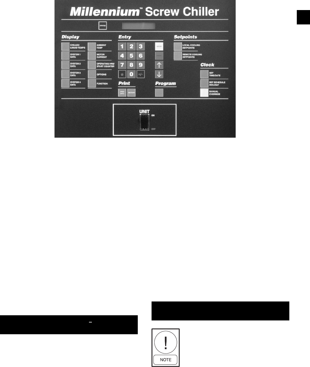
163
YORK INTERNATIONAL
FORM 201.19-NM1 (204)
“0” for times before 10 o’clock. e.g. 08:31. The cursor
will then advance to the AM/PM designation. If neces-
sary press the or key to change to the opposite
time pe ri od.
Next, key in the day of the month (the cursor will au-
to mat i cal ly skip from AM/PM to the fi rst digit of the
date when a “number key” is pressed). The cursor will
then skip to the fi rst digit of the year. Key in the year.
Al ways use two digits for the day and the year, using a
leading “0” for days 1-9 e.g. 02 FEB 03. Finally, change
the month as needed by repetitively pressing the or
key until the proper month appears. Once the desired
information is keyed in, it must be stored into memory
by pressing the Enter key.
Any valid time or date will be accepted. If an out of
range value is entered, the following message will be
displayed for 3 seconds then revert back to the Set Time
display message for reprogramming:
Pressing the Set Time key once, enters
the “pro gram ming” mode in which
the dis played time does not update.
Press ing the Set Time key a second
time enters “display” mode in which
the cursor will dis ap pear and the “live”
clock will be dis played.
7. CLOCK KEYS
O U T O F R A N G E -
T R Y A G A I N !
7.1 GENERAL
The microprocessor features a continuously running in-
ter nal Clock and calendar and can display actual time as
well as the day of the week and the date. An au to mat ic
schedule feature is provided for starting and stop ping
the chiller on individual days of the week, elim i nat ing
the need for an external time clock. Also pro vid ed are
a Holiday feature, allowing special start/stop times to
be set for designated holidays, and a Manual Over ride
feature to aid servicing. If the automatic sched ule feature
is not required, the micro can be pro grammed to run the
chiller on demand as long as the Chiller ON/OFF and
System switches are in the ON position.
Programming of the internal clock/calendar and op er -
at ing schedule are described below.
7.2 SET TIME KEY
When the Set Time key is pressed, a message showing
the day, time and date will be displayed with the cursor
below the fi rst digit of the time as shown:
First press the or key until the proper day appears.
Press ENTER to move on to the hour part of the display.
Next, key in the time (hours/minutes) using a leading
29023A
T O D A Y I S M O N 1 1 . 1 2 A M
1 9 F E B 2 0 0 3
8
164 YORK INTERNATIONAL
FORM 201.19-NM1 (204)
Programming the DAILY SCHED ULE
will not affect the holiday sched ule.
If the chiller is not required to run on a given day, the
Start time should be pro grammed for 00:00 AM and the
Stop time pro grammed for 12:00 AM.
Continue to program each day as needed. After SUN has
been entered, the Holiday message will be dis played:
The Holiday (HOL) Start / Stop allows a specifi c day(s)
to be assigned for special requirements. This is pro vid ed
so that a day(s) needing special start / stop re quire ments
can be programmed without disturbing the normal work-
ing schedule. The start / stop times for the Holiday sched-
ule are pro grammed just as any other day.
Only one start/stop time can be pro-
grammed which will apply to each of
the Hol i day days selected.
After the Enter key is pressed, a display to designate
which days of the week are holidays will ap pear:
When the display appears, the cursor will fi rst stop af-
ter Sunday as shown. To designate a day as a holiday,
press the “ * ” key. If a day marked as a holiday is not
to be a holiday, press the “ * ” key. When the “ * ” key
is pressed, the cursor will advance to the next day. Use
the or keys to move back and forth among days.
After all the holiday days are programmed, press Enter
to store the new data. The display will then return to the
beginning of the Daily Sched ule (MON).
The Holiday Schedule is only executed
once, then erased from mem o ry. This
avoids the need for re pro gram ming
after the hol i day, as most special Holi-
day Sched ule re quire ments occur only
oc ca sion al ly.
The displays for each day are scrolled through by re-
pet i tive ly pressing the set Schedule/Holiday key. To re-
program any of the daily schedules, key in the new Start
time then, if necessary, change the associated AM/PM
by pressing the or key.
The or key can only be pressed
once to change AM/PM. If an error is
made, press Cancel and begin again.
Next key in the Stop Time (the cursor will au to mat i cal ly
skip from AM/PM to the fi rst digit of the stop time when
a “number key” is pressed) and the AM/PM if nec es sary.
Now press the ENTER key to store the new sched ule.
The display will scroll to the next day. If an un ac cept able
time is entered, the following message will be displayed
for 3 seconds then return to the schedule dis play:
New start/stop times programmed for
Monday are automatically used for all
of the following days of the week.
Always use the Set Schedule/Holiday
key, not the Enter key to scroll through
the sched ule displays. Pressing the
ENTER key after viewing Monday
will change times programmed for the
re main der of the week to the Monday
schedule.
If the chiller is not cycled by the Daily Schedule, but is
required to run whenever remote cy cling devices, sys tem
switches, and main Chiller ON/OFF switch are in the
ON position, all 00.00s should be programmed into the
daily schedule. This can be done manually for in di vid u al
days or for all days by pressing Cancel and En ter for the
Monday Start/Stop schedule.
S * M T W T F S
H O L I D A Y N O T E D B Y *
7.3 SET SCHEDULE / HOLIDAY KEY
Messages showing each week day and the holiday
start/stop schedule, as shown below, can be displayed
using the Set Schedule / Holiday key:
M O N S T A R T = 0 6 : 0 0 A M
S T O P = 0 5 : 3 0 P M
H O L S T A R T = 0 8 : 3 0 A M
S T O P = 1 2 : 0 0 P M
O U T O F R A N G E
T R Y A G A I N !
Micro Panel Contents
165
YORK INTERNATIONAL
FORM 201.19-NM1 (204)
If an error is made while programming or a change is
required, press Cancel. This will clear the programmed
(*) “Holiday” days (the “0” key will not cancel out a
“ * ” and cannot be used for correcting a programming
error).
7.4 MANUAL OVERRIDE KEY
When the Manual Override key is pressed, the Daily
Schedule programmed into the chiller is ignored and
the chiller will start up when water temperature is above
the high limit of the Control Range, the Chiller ON/OFF
switch is ON, remote cycling devices are CLOSED, and
system switches permit.
Normally this key is only used for ser vic ing when the
chiller is required to run, but the Daily Sched ule is in
an OFF period. This key avoids the need to reprogram
the Daily Schedule. Once activated, Manual Over ride is
only active for a period of 30 min utes and the fol low ing
sta tus message will be ob served:
M A N U A L
O V E R R I D E
If a Warning – Low Battery fault
mes sage appears on the display, the
in ter nal clock, cal en dar, and pro-
gram set tings cannot be relied on for
accuracy. Default val ues are loaded
into the mi cro pro ces sor mem o ry and
the Man u al Over ride key can be used
to zero out the daily sched ule and al-
low un lim it ed operation re gard less of
the time on the internal clock. Re pro -
gram ming of the setpoints and cut out
values may also be nec es sary. When the
MAN U AL OVER RIDE key is pressed,
the low bat tery mes sage will disappear.
If a power fail ure should again occur,
the above pro cess will again need to be
re peat ed to bring the chill er back on
line. See also Section 2.5.
8
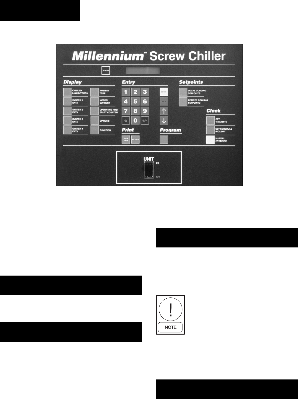
166 YORK INTERNATIONAL
FORM 201.19-NM1 (204)
If an unacceptable value is entered at any stage, the fol-
lowing message is displayed for a few seconds and the
entered value is ignored:
The following section shows examples of each pro gram -
ma ble value display in the order in which they appear
after pressing the Program key, along with guidance on
programming each parameter.
The programmable values under the
Pro gram Key must be checked and prop-
er ly programmed when com mis sion ing
the chiller. Failure to prop er ly program
these values may cause operating prob-
lems or dam age to the chiller.
8.2 PROGRAM KEY –
USER PROGRAMMABLE VALUES
High Discharge Pressure Cut-Out
The Discharge Pressure Cutout is a microprocessor
backup for the mechanical high pressure cutout lo cat ed
in each refrigerant circuit. This safety is bypassed for the
fi rst 5 seconds of operation after which if the cut out point
is exceeded for 3 seconds, the system will shut down.
Normally, air-cooled chillers, such as YCAS chillers,
D I S C H A R G E P R E S S U R E
C U T O U T = 3 9 5 . 0 P S I G
8. PROGRAM KEY
8.1 GENERAL
The Program key is used to program system op er at ing
parameters including cutout points for safeties, an tic i-
pa to ry unload points to avoid faults, and anti-re cy cle
timer duration.
When the Program key is pressed, the following mes-
sage will be displayed to indicate the display is in the
Program Mode:
Pressing the ENTER Key causes the display to show
the operator the language the control panel mes sages
are displayed.
The operator may select 7 display message languages.
The options are English, Spanish, French, Dutch, Italian,
Portuguese, and Chinese. The or keys can be used
to select the de sired language.
Pressing the Enter key repeatedly allows scrolling
through the programmable displays.
As each value is displayed, it may be reprogrammed
using the 12 Entry keys and Keys. New values
will be programmed into memory when the Enter key
is pressed and the display will scroll on to the next pro-
gram ma ble value.
P R O G R A M M O D E
D I S P L A Y L A N G U A G E
E N G L I S H
O U T O F R A N G E
T R Y A G A I N !
29023A
Micro Panel Contents

167
YORK INTERNATIONAL
FORM 201.19-NM1 (204)
should have the cutout set at 395 PSIG (27 bar) for R22
and R407C models. The micro will, however, accept
val ues between 200 - 399 PSIG (14 - 28 bar).
To program the Discharge Pressure Cutout, key in the
desired value and press the Enter key to store the value
into memory and scroll to the next display.
High Discharge Pressure Unload Point
The Discharge Pressure Unload point is used to avoid
a high pressure cutout shutdown by unloading a com-
pres sor, if its discharge pressure approaches the cutout
val ue. The chiller can then continue to run automatically
at reduced capacity until the cause of the excessive pres-
sure is attended to (e.g. dirty condenser coils) or ceas es
naturally (e.g. high ambient temperature).
For the fi rst 60 seconds of operation, discharge pres-
sure limiting is disabled. After this time, if discharge
pressure exceeds the programmed limit, un loading of
the affected compressor will occur until the discharge
pres sure drops below the programmed limit. The mes-
sage will be removed and reloading will take place
when dis charge pressure has dropped to 90% of the
programmed unload point..
Typically the unload point should be set 20 - 25 PSIG
(1.4 - 1.7 bar) below the below the discharge pressure
cutout setting. The micro will accept a range of pro gram -
ma ble values between 200 - 399 PSIG (14 - 28 bar).
To program the Discharge Pressure Unload, key in the
required setting and press the Enter key to store the value
into memory and scroll to the next display.
Low Suction Pressure Cutout
The Low Suction Pressure Cutout protects the evap o -
ra tor from damage due to ice build up caused by op-
er a tion at low refrigerant suction pressure.
After the compressor starts, and the pump down cycle is
completed (pump down to cutout or 30 seconds, which-
ev er comes fi rst.), suction pressure is monitored as long
as the compressor runs. For the fi rst 270 sec onds of run-
ning, suction pressure can be lower than the pro grammed
cutout, but must be greater than:
This cutout value increases with time, until after 270 sec-
onds, it equals the programmed cutout value. If suc tion
pressure falls below the calculated cutout value before
270 seconds, the system will be shut down.
After 270 seconds, a transient timer prevents short term
fl uctuations in suction pressure from caus ing shutdown
as follows: If suction pressure drops be low the cutout
point, a 90 second transient timer starts. Dur ing the 90
second time period, the suction pressure must be greater
than:
This cutout value increases with time, until after 90
sec onds, it equals the programmed cutout value. If the
suc tion pressure rises to more than 5 PSI (0.3 bar) above
the programmed cutout value during the 90 second time
period, the timer will be reset. If the suction pressure
does not rise to more than 5 PSI (0.3 bar) above the
cutout, the timer will remain at zero and if the pressure
then falls below the cutout again, the system will shut
down on a low pressure fault.
If the Dip Switch on the microprocessor board is set
for “Water Cooling” (see Section 3.7), the cutout is
pro gram ma ble between 44 - 70 PSIG (3-5 bar) for both
R22 and R-407c models. In this mode, settings of 44
PSIG (3 bar) for R22 and R-407C are recommended. If
the Switch is set for “Brine Cooling” (glycol) the cut out
is programmable between 5 - 70 PSIG (0.3 bar) for R22
and R-407c models. In this mode, the cutout should be
S U C T I O N P R E S S U R E
C U T O U T = 4 4 . 0 P S I G
D I S C H A R G E P R E S S U R E
U N L O A D = 3 6 0 . 0 P S I G
Programmed 100 - transient time remaining
Cutout 100
Example: If programmed Cutout = 44 PSIG (3 bar)
and the timer has run 30 seconds:
New Cutout = 44 PSIG X 100-60 = 17.6 PSIG (1.2 bar)
100
X
Programmed X Run Time/3 + 10
Cutout 100
Example: If programmed Cutout = 44 PSIG (3 bar)
and Run Time = 60 seconds
60/3 + 10
100
New Cutout = 44 X = 13.2 PSIG (0.9 bar)
8

168 YORK INTERNATIONAL
FORM 201.19-NM1 (204)
To program the Low Ambient Cutout, key in the re quired
setting and press the Enter key to store the value into
memory and scroll to the next display.
Low Leaving Liquid Temperature Cutout
The Low Leaving Liquid Temperature Cutout protects
the evaporator from damage due to ice build up caused
by operation below the chilled liquid freezing point.
If the leaving chilled liquid temperature (water or gly col)
drops below the cutout point, the chiller will shut down.
The chiller will restart automatically when tem per a ture
rises more than 4°F (2°C) above the cutout point and
cooling demand exists.
If the Dip Switch on the microprocessor board is set
for “Water Cooling” (see Section 3.7, page 146) the
cut out is automatically set at 36°F (2°C) and cannot be
re pro grammed. If the Switch is set for “Brine Cool ing”
(gly col) the cutout can be programmed between 08.0
- 36.0°F (-13 to -2°C). The cutout should normally be
set to 4°F (2°C) below the setpoint minus the range, i.e.
34°F (setpoint) – 2°F (range) - 4°F = 28°F (see Sec tion
6, page 158).
To program the Leaving Liquid Temperature Cutout, key
in the required setting and press the Enter key to store the
value into memory and scroll to the next dis play.
High Motor Current Unload Point
The Motor Current Unload point is used to avoid a
high motor current safety shutdown by unloading a
com pres sor, if current draw approaches the maximum
limit cut out value. The chiller can then continue to run
au to mat i cal ly at reduced capacity until the cause of the
ex ces sive current is attended to.
The micro will accept between 30 - 105% for the un load
point. The motor current safety will shut the com pres sor
down whenever current exceeds 115%.
If the programmable limit is set between 100% and
105% of full load current, this feature will protect
against ex ces sive current causing compressor shutdown
due to extremely high ambient, high chilled liquid tem-
per a ture, and condenser malfunction caused by dirt or
fan prob lems.
set to the saturated refrigerant pressure equivalent to
18°F (10°C) below the lowest temperature of the pro-
grammed chilled liquid Control Range (Section 6).
To program the Suction Pressure Cutout, key in the re-
quired setting and press the Enter key to store the value
into memory and scroll the next display.
High Ambient Temperature Cutout
The High Ambient Cutout is used to select the ambient
temperature above which the chiller may not operate.
If the ambient temperature rises 1°F (.5°C) above this
point, the chiller will shut down. Restart will occur au-
to mat i cal ly, when temperature falls more than 2°F (1°C)
below the cutout and cooling demand is present.
This cutout is normally set at 130°F (54°C) to allow op-
eration to the absolute maximum temperature ca pa bil i ty
of the electromechanical components; however, values
between 100.0 - 130.0°F (38 - 54°C) are ac cept ed.
To program the High Ambient Cutout, key in the re-
quired setting and press the Enter key to store the value
into memory and scroll to the next display.
Low Ambient Temperature Cutout
The Low Ambient Cutout is used to select the ambient
temperature below which the chiller may not operate.
If the ambient temperature falls 1°F (.5°C) below this
point, the chiller will shut down. Restart will occur
au to mat i cal ly, when temperature rises more than 2°F
(2ºC) above the cutout and cooling demand is present
(see also Section 2.5 page 139).
If the SW1 Dip Switch on the Microprocessor Board
is set for “Standard Ambient Control” (see Section
3.7) the low ambient cutout is set at 25°F (-4°C) and is
NOT programmable. If the Dip Switch is set for “Low
Am bi ent Control”, programming of the cutout be tween
00.0 - 50.0°F (-17.8 - 10°C) is allowed. This al lows
higher val ues than 25°F (-4°C) to be pro grammed to
shut down the chiller when other cooling methods
become op er a tion al. Values below 25°F (-4°C) can
be used for ap pli ca tions requiring chiller operation at
low er tem per a tures. The chiller will not operate below
0ºF (-17.8ºC).
H I G H A M B I E N T T E M P
C U T O U T = 1 3 0 . 0 ° F
L O W A M B I E N T T E M P
C U T O U T = 2 5 . 0 ° F
L E A V I N G L I Q U I D T E M P
C U T O U T = 3 6 . 0 ° F
H I G H M O T O R C U R R E N T
U N L O A D = 1 0 5 % F L A
Micro Panel Contents

169
YORK INTERNATIONAL
FORM 201.19-NM1 (204)
The EEV superheat setpoint is programmable. The
setpoint can be programmed for 9.0ºF (5.0ºC) to 15ºF
(8.3ºC) with 12.0ºF (6.6ºC) as the default.
Local/Remote Communications
The panel can be programmed for “Local” or “Re mote”
communications. “Local” mode allows monitoring only
through the RS-485 port. “Remote,” allows an ex ter nal
device such as an ISN or Remote Control Cen ter to
change setpoints and programming points, as well as
monitoring chiller parameters.
The keys are used to change from Local to Re mote.
The ENTER Key must be pressed to save the selection
in memory.
Imperial/SI Units Display
This allows the operator to select messages to display
Imperial Units (PSIG, °F, etc.) or SI (Sci en tifi c Interna-
tional, Bars, °C, etc.).
The keys are used to change from Imperial to SI
units. The ENTER Key must be pressed to save the
selection in memory.
Automatic/Manual “Lead/Lag”
The chiller may be selected for manual lead/lag or au to -
mat ic lead/lag. In some cases the operator may want to
manually select the system that is desired to be the lead
system. In most cases, automatic lead/lag is se lect ed to
allow the micro to attempt to balance run time between
the system. Details of manual and automatic lead / lag
operation are outlined in Section 1.21.
The keys are used to change from Automatic to
Manual lead/lag. The ENTER key must be pressed to
save the selection in memory.
If the programmable limit is set below 100% of full load
current, this control feature can be used for “demand
lim it ing”. This is important when demand limiting is
crit i cal due to power requirements or limitations in the
build ing (See also Section 1.10).
For the fi rst 60 seconds of operation, the unloading
control is disabled. After this time, if motor current
ex ceeds the programmed limit, the SYS X CURR
LIM IT ING mes sage will appear on the display and a
1 second unload pulse will be sent to the slide valve
of the af fect ed com pres sor every 5 seconds, until the
motor cur rent drops below the programmed limit. The
message will be re moved and additional loading will
take place when mo tor current drops below 90% of the
pro grammed thresh old.
Typically, this setpoint should be set at 100% for
maximum motor protection. Programming for 100%
is recommended. When programming values be low
100%, the use of a leading “0” is required, e.g. 085%.
To program the High Motor Current Unload, key in the
required setting and press the Enter key to store the value
into memory and scroll to the next display.
Anti-Recycle Time
The Anti-Recycle Timer controls the minimum time
between starts for each compressor. This is the time
available for the heat build-up caused by inrush current
at start to be dissipated before the next start. In suf fi cient
cooling time between starts can cause heat build-up
and motor damage. A fast compressor start re sponse
is needed in some applications and not in others. Al-
though the minimum setting allowed on this timer will
avoid excessive heat build up, adjusting the timer for
the longest period acceptable in each application will
reduce cycling and maximize motor life. 600 seconds
is recommended.
The micro will accept a range of programmable values
between 300 - 600 seconds.
To program the Anti-Recycle Time, key in the required
setting and press the Enter key to store the value into
memory and scroll to the next display.
A N T I R E C Y C L E T I M E R
= 6 0 0 S E C S
L O C A L / R E M O T E M O D E
L O C A L
D I S P L A Y U N I T S
I M P E R I A L
L E A D / L A G C O N T R O L
A U T O M A T I C
8
S U C T I O N S U P E R H E A T
S E T P O I N T = 1 2 . 0 º F
170 YORK INTERNATIONAL
FORM 201.19-NM1 (204)
Press the Program key again, key in the numbers “6140”,
then press Enter. As the code is being keyed in, the digits
are not displayed but are shown as “*” as shown:
When the Enter key is pressed, the following message
will appear:
Key in a “1” for if default setpoints are required, or a “0”
for individually programmed values, then press En ter to
store the selection into memory.
If individual programming is selected (0), the display
will now return to the Status display. If a default setpoints
have been selected, the display will momentarily dis play
the message shown below before returning to the Sta tus
display:
It is often easier to select Default
Set points and then reprogram a few
that require changing rath er than
pro gram ming each in di vid u al value
from scratch.
8.3 PROGRAMMING "DEFAULT" VALUES
Programmable values may be individually pro grammed at
start-up or any time thereafter. For ease of pro gram ming,
once the type of refrigerant is programmed un der the Pro-
gram key and in the Service Mode, a “defaults password”
may be pro grammed to automatically program default
values into memory. This will preset all programmable
values un der the Program key to values that will allow
operation of the chiller under most operating conditions.
This al lows quick start-up pro gram ming for typical
chilled wa ter ap pli ca tions.
To program the default values into memory, fi rst press
the PROGRAM key followed by the ENTER key, to
pro gram the “refrigerant type” .
P R O G R A M M O D E
* * * *
D E F A U L T S E T P O I N T S ?
1 = Y E S , 0 = N O, 1
P R O G R A M O P T I O N S S E T
T O D E F A U L T V A L U E S
If manual control is desired, press the or key. One
of the following messages will be displayed:
System 1 or 2 can be selected as the lead by press ing
the or key. The ENTER key must be pressed to
save the selection in memory.
Automatic/Manual Power Failure Restart
The chiller may be selected for “Automatic” or “Man-
u al” restart after a power failure. In most in stanc es,
“Au to mat ic Restart” is preferred to allow the chiller
to au to mat i cal ly restart when power is reapplied after
a power failure. When “Manual” is selected, the chiller
will not operate after re-application of power until the
ON / OFF Rocker Switch on the keypad is cycled OFF
and then ON.
In most applications, it is undesirable
to use Man u al Reset on power failure
since chillers nor mal ly are re quired to
auto-restart af ter a power failure.
L E A D / L A G C O N T R O L
M A N U A L S Y S 2 L E A D
L E A D / L A G C O N T R O L
M A N U A L S Y S 1 L E A D
P O W E R F A I L R E S T A R T
A U T O M A T I C
Micro Panel Contents

171
YORK INTERNATIONAL
FORM 201.19-NM1 (204)
8
Program Value Mode Low Limit High Limit Default
Display Language -- NA NA English
Discharge Pressure Cutout -- 200 PSIG 399 PSIG 399 PSIG
13.8 Bars 27.5 Bars 27.5 Bars
Discharge Pressure Unload -- 200 PSIG 399 PSIG 375 PSIG
13.8 Bars 27.5 Bars 25.9 Bars
Suction Pressure Cutout
Water Cooling 44.0 PSIG 70.0 PSIG 44.0 PSIG
3.03 Bars 4.83 Bars 30.3 Bars
Glycol Cooling 5.0 PSIG 70.0 PSIG 44.0 PSIG
0.34 Bars 4.83 Bars 3.03 Bars
High Ambient Air Temp Cutout -- 100.0 ºF 130.0 ºF 130.0 ºF
37.8 ºC 54.4 ºC 54.4 ºC
Low Ambient Ait Temperature Cutout
Standard -- -- 25.0 ºF
Ambient -- -- -3.9
Low 0 ºF 50.0 ºF 25.0 ºF
Ambient -17.8 ºC 10.0 ºC -3.9 ºC
Leaving Chilled Liquid Temp Cutout
Water Cooling -- -- 36.0
-- -- 2.2
Glycol Cooling 8.0 ºF 36.0 ºF 36.0 ºF
-13.3 ºC 2.2 ºC 2.2 ºC
Low Temp Glycol -5.0 ºF 36.0 ºF 36.0 ºF
-20.5 ºC 2.2 ºC 2.2 ºC
High Motor Current Unload -- 30% 105% 100
Anti Recycle Time -- 300 sec 600 sec 600 sec
Local / Remote Mode -- NA NA Local
Units Mode -- NA NA Imperial
Lead / Lag Control Mode -- NA NA Automatic
Power Failure Restart Mode -- NA NA Automatic
Motor Current Averaging Cutout -- 30% FLA 110% FLa 70 % FLA
Suction Superheat Setpoint EEV 9.0 ºF 15.0 ºF 12.0 ºF
5.0 ºC 8.3 ºC 6.6 ºC
The default values shown below are entered into
memory, when the program option is selected. The
list also provides the low and high limits the micro
will accept.
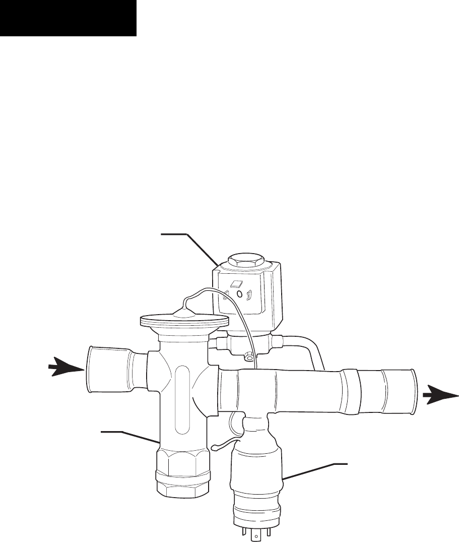
172 YORK INTERNATIONAL
FORM 201.19-NM1 (204)
Micro Panel Contents
8.4 ELECTRONIC EXPANSION VALVE
ELECTRONIC EXPANSION VALVE
The Electronic Expansion Valve (EEV) is an electroni-
cally controlled expansion valve. The control algo-
rithms to control the EEV reside in the micorprocessor
software. The superheat setpoint can be programmed
on the control panel.
The purpose of the EEV is to meter a fl ow of liquid
refrigerant into the evaporator to maintain a superheat
FIG. 50 – ELECTRONIC EXPANSION VALVE LD09132
120 VAC PILOT
SOLENOID
24 VAC HEAT
MOTOR
EXPANSION
VALVE
IN
OUT
setpoint. The refrigerant fl ow direction is designated
by an arrow on the expansion valve body.
There are two safeties associated with the EEV; Low
Superheat Cutout and Sensor Failure Cutout.

173
YORK INTERNATIONAL
FORM 201.19-NM1 (204)
EEV OPERATION
The EEV is an electronically controlled expansion valve
that meters a fl ow of liquid re frig er ant into the evapora-
tor to control superheat. The re frig er ant fl ow di rec tion is
des ig nat ed by an ar row on the ex pan sion valve body.
24VAC HEAT MOTOR
The 24VAC Heat Motor is fed from the EEV output
board in the con trol panel . The Heat Motor allows the
mi cro to open and close the valve to control suction
superheat.
The heat motor must be plugged into
the 24 volt shielded ca ble feed from
the EEV out put board. Dam age to the
heat mo tor will occur if it is plugged
into 120VAC wir ing for the Pilot So-
le noid.
CONTROLLER
When EEV is selected as the expansion valve type via
DIP switch on the micro board, the EEV con trol ler will
be come ac tive. When TXV is se lect ed, the EEV out put
will be fi xed at 0 and the low su per heat and sensor
failure safeties will be dis abled.
The EEV controller is a PI (Proportional plus In te gral)
controller. Gain sched ul ing var ies the pro por tion al gain
based on the su per heat error. As the su per heat er ror
gets small er the pro por tion al gain will get small er. The
in te gra tion time is adjusted to increase the controller re-
sponse during start-up and low superheat conditions.
The output from the PI controller is the EEV output
percentage which is shown on the display and print outs.
This output is then fed into a model of the ETRE bulb/
heat motor to over and under drive the heat motor for
faster valve response. The out put of this ETRE model
is the PWM per cent age that will be sent to the ETRE
heat motor. This PWM output is the percentage of a 1
second pe ri od that the 24VAC heat motor power signal
is energized.
MOP FEATURE
The controller also has an MOP feature (Max i mum Op-
erating Pressure) that overrides superheat con trol when
the MOP setpoint is exceeded. This con trol gen er al ly
will be active for hot water starts. The MOP setpoint is
60º F Saturated Suction Tem per a ture.
The MOP feature is also used to prevent un der shoot of
the superheat setpoint when the suction temperature of a
system being started is much higher than the return wa-
ter temperature. This pro vides better startup su per heat
control for high ambient, low water temp startups when
the su per heat measurement is artifi cially high due to
the warm suction line. If the return water temp sensor
is in range, run time is less than 5 minutes, and suc tion
temperature is greater than (RCHLT + 3º F), the MOP
setpoint is reset to RCHLT - Su per heat Setpoint. If this
val ue is higher than the fi xed MOP setpoint, the original
setpoint is retained.
VALVE PREHEAT FEATURE
The heat motor is preheated for moderate and low ambi-
ent standby conditions. When the ambient is be low 25º
F, the heat motor is preheated with a 25% duty cycle.
This preheated value is ramped from 25% to 0% from
25º F to 50º F. When the am bi ent is above 50º F the heat
motor is not pre heat ed.
PILOT SOLENOID (LLSV) CON TROL
The Pilot Solenoid allows the EEV to be used in the
same way as a Liquid Line Solenoid Valve. When the
Pilot So le noid is turned off, the EEV clos es im me di ate ly
and prevents the Heat Motor from opening the valve.
Each system has a Pump Down feature upon shut off.
Manual pump down from the keypad is not possible. On
a non-safety, non-unit switch shut down, the system will
fully unload. The Pilot So le noid will be turned off and
the system will run un load ed until the suc tion pressure
falls be low the cut out or for 180 sec onds, whichever
comes fi rst.
8.5 EEV OPERATION
8

174 YORK INTERNATIONAL
FORM 201.19-NM1 (204)
The Pilot Solenoid is also used as a low su per heat safety
de vice when EEV is selected as the ex pan sion valve
type, for YCAL units only. While the sys tem is run ning
and not in a pumpdown mode the Pilot So le noid will
close if the suction su per heat falls be low 4.0º F. The
Pilot Solenoid will open again when the su per heat ris es
above 7.0º F. This safe ty de vice is ignored for the fi rst
30 sec onds of sys tem run time. If the Pilot Solenoid is
closed 10 times in 2 min utes on the safe ty de vice, the
low su per heat safe ty will be trig gered.
LOW SUPERHEAT CUTOUT SAFETY
The Low Superheat Cutout is to protect the com pres sors
from liquid fl oodback due to low suc tion su per heat. This
safety is only active when EEV is selected as the expan-
sion valve type. This safe ty is ignored for the fi rst 30
seconds of system run time.
This safety can be triggered by two events. The fi rst is
when the suction superheat is less than 0.5º F (1.1ºC)
for 3 seconds. The second, only applies to YCAL units,
is when the Pilot Solenoid is closed 10 times in 2 min-
utes due to low superheat. Fol low ing are the safety fault
mes sag es for all sys tems:
SENSOR FAILURE CUTOUT SAFETY
The Sensor Failure Cutout is to prevent the EEV from
running when the sensors measuring su per heat are not
functioning properly. This safety is only active when
EEV is selected as the expansion valve type. This safe ty
is ignored for the fi rst 15 seconds of system run time.
This safety will shutdown a system if either suc tion tem-
per a ture or suction pressure sensors read out of range
high or low. This condition must be present for 3 sec onds
to cause a system shut down. This safety will lock out a
system the fi rst time and will not allow automatic restart-
ing. Fol low ing are the messages for all systems:
OPERATING DATA DISPLAYS
The following display relating to EEV operation is avail-
able under each systems Data Key: EEV Output% and
Suction Superheat.
HISTORY DATA DISPLAYS
The following display relating to EEV operation is avail-
able under each systems Data Key: EEV Output% and
Suction Superheat.
Micro Panel Contents
S Y S 1 L O W S U P E R H E A T
S Y S 2 L O W S U P E R H E A T
S Y S 1 S E N S O R F A I L U R E
S Y S 2 S E N S O R F A I L U R E
S Y S X E E V = X X X . X %
S U C T S H E A T = X X X . X º F
S Y S X E E V = X X X . X %
S U C T S H E A T = X X X . X º F
OPERATING DATA PRINTOUT
Pressing the PRINT key and then the OPER DATA key
allows the operator to obtain a printout of cur rent sys tem
operating parameters. When the OPER DATA key is
pressed, a snapshot will be taken of system operating
conditions and panel programming selections. This data
will be tem po rari ly stored in memory and transmission
of this data will begin to the printer. The following items
are added to the standard operational data print out when
EEV is selected:
SYSTEM 1 DATA
COMPRESSORS STATUS OFF
RUN TIME 0- 0- 0- 0 D-H-M-S
MOTOR CURRENT 0 AMPS 0 %FLA
SUCTION PRESSURE 125 PSIG
DISCHARGE PRESSURE 131 PSIG
OIL PRESSURE 130 PSIG
FAN DISCHARGE PRESS 254 PSIG(B HR)
SUCTION TEMPERATURE 68.4 DEGF
DISCHARGE TEMPERATURE 68.8 DEGF
OIL TEMPERATURE 68.8 DEGF
SAT SUCTION TEMP 71.8 DEGF
SUCTION SUPERHEAT 3.4 DEGF
SAT DISCHARGE TEMP 74.5 DEGF
DISCHARGE SUPERHEAT 6.3 DEGF
SLIDE VALVE STEP 0
EEV OUTPUT 0.0 %(EEV)
COOLER INLET REFRIG 44.6 DEGF
LIQUID LINE SOLENOID OFF
ECONOMIZER TXV SOLENOID OFF(YCAS)
OIL COOLING SOLENOID OFF(YCWS)
HEAT RECOVERY SOLENOID OFF(B HR)
DISCHARGE COOLING SOLENOID OFF(EC,LT)
CONDENSER FAN STAGE OFF
COMPRESSOR HEATER ON
WYE-DELTA RELAY OFF

175
YORK INTERNATIONAL
FORM 201.19-NM1 (204)
PROGRAM MODE DISPLAYS
The following value is programmable under the PRO-
GRAM key (See Table 2).
· System Suction Superheat Setpoint (9.0°F to 15.0°F)
(5.0ºC to 8.3ºC)
EXPANSION VALVE OPTIONS DISPLAY
When the expansion valve type is set to ther mo stat ic
by opening DIP switch #7, the EEV con trol ler, low
su per heat safe ty device, low superheat safety and the
sen sor fail ure safety will be dis abled. The EEV output
will be set to 0.
When the expansion valve type is set to electronic
by closing DIP switch #7 , the EEV controller, low
su per heat safe ty de vice, low superheat safety and the
sen sor fail ure safety will be en abled.
The Expansion Valve type selection is viewable un der
the OP TIONS key.
8.6 EEV PROGRAMMING
PROGRAM VALUE MODE LOW LIMIT HIGH LIMIT DEFAULT
SUPERHEAT SETPOINT EEV 9.0°F 15.0°F 12.0°F
(5.0°C) (8.3°C) (6.6°C)
TABLE 2 – PROGRAMMABLE VALUES TABLE (MINIMUM/MAXIMUM)
8
S1 - 7 E X P A N S I O N V A L V E
T H E R M O S T A T I C
S1 - 7 E X P A N S I O N V A L V E
T H E R M O S T A T I C
S U C T S U P E R H E A T
S E T P O I N T = X X . X º F

176 YORK INTERNATIONAL
FORM 201.19-NM1 (204)
8.7 EEV TROUBLESHOOTING
TROUBLESHOOTING
Below are problems and possible so lu tions or items
to check.
● The system shuts down on Low Suction
Pres sure
· Verify that all refrigerant valves are open.
· Verify that the system is not low on charge.
· Verify that the Expansion Valve Type is set to Elec-
tron ic.
· Verify that the pilot solenoid is energizing (use Service
Mode to manually energize the so le noid coil).
· Verify that the EEV is wired per the elementary dia-
gram.
· Verify that the Heat Motor is getting a 24VAC PWM
signal. (Use Service Mode to manually en er gize
the EEV output.
· If everything checks out, it is possible that the EEV
has failed. If the small charge in the bulb leaks, the
valve will not be able to open and the entire EEV
must be replaced.
● The system shuts down on Low Su per heat
· Verify that the suction temperature sensors are properly
installed. They should be located at 4 or 8 o’clock
on the suc tion line. They should not be located near
the out let of the evaporator. They should be installed
with cop per straps and be well insulated.
· Verify that the suction temperature sensor ca bles are
not swapped between systems (un plug ging one sen-
sor at a time with the chiller off can ver i fy prop er
wiring).
· Verify that the EEV heat motor is properly in su lat ed.
· For units with Hot Gas Bypass installed, check that the
Hot Gas Bypass valve is set correctly.
· For glycol units, verify that the glycol % is cor rect.
Micro Panel Contents
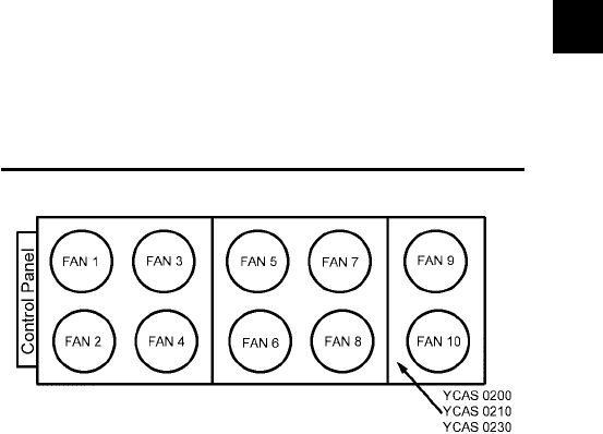
177
YORK INTERNATIONAL
FORM 201.19-NM1 (204)
8
The chiller is equipped with 8 or 10 condenser fans, with
4 or 5 fans per system as given below. Fan control is
via Outside Ambient Temperature (OAT) and Discharge
Pressure (DP). There are 4 or 5 stages of fan control,
utilizing 3 outputs per system. The fan stages will work
according to Table 3 and 4 depending on the number of
fans per system. There will be a variable delay between
all fan stages. The delay between turning on fan stages
is based on the ambient temperature. The time is ramped
from 30 seconds at 10ºF (-12.2ºC) to 5 seconds at 60ºF
(15.6ºC) (time delay = (35 - (oat/2)).
Condenser fan ON conditions are governed solely by the
Discharge Pressure (DP). When the DP rises above 230
PSIG, fan stage 1 is activated. From here, subsequent
fan stages are activated as the DP rises in increments of
10 - 20 PSIG. The system will remain at the highest fan
stage reached unless the OFF conditions are satisfi ed.
Condenser fan OFF conditions are governed by both
the DP and OAT. Fan staging will be decreased from
the highest fan stage reached if both the DP and OAT
requirements are met. For example, if a system is at
a fan stage of 4, and the DP falls under 205 PSIG and
the OAT drops below 75ºF (24ºC), the fan stage will be
reduced to 3.
FIG. 51 – CONDENSER FAN LAYOUT FOR DXST 2
COMPRESSOR UNITS
LD03676
Tables 3 and 4 describe fan operation and contactor data
for the fans involved in each fan stage. SYS 1 uses relay
board #1. SYS 2 uses relay board #2.
YCAS0130, 0140, 0150, 0160, 0170 and 0190 models
have 4 condenser fans/system:
8.8 CONDENSER FAN CONTROL
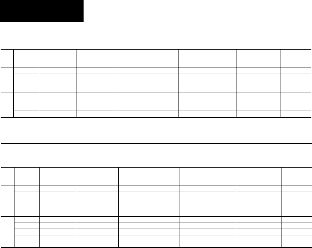
178 YORK INTERNATIONAL
FORM 201.19-NM1 (204)
Fan
ON * ** OFF *
Fan
Wire
Relay
Stage Fans Conditions Conditions Contactor Number Board
DP DP & OAT Output*
S 1 1 >230 PSIG <160 PSIG & <60°F 9M 130 15
Y 2 5 & 7 >250 PSIG <180 PSIG & <65°F 11M & 12M 132 10
S 3 1, 5, & 7 >265 PSIG <195 PSIG & <70°F 9M, 11M, & 12M 130 & 132 10 & 15
1 4 1, 3, 5, & 7 >275 PSIG <205 PSIG & <75°F 9M, 10M, 11M, & 12M 130, 131, & 132 10, 14, & 15
S 1 2 >230 PSIG <160 PSIG & <60°F 15M 230 15
Y 2 6 & 8 >250 PSIG <180 PSIG & <65°F 17M & 18M 232 10
S 3 2, 6, & 8 >265 PSIG <195 PSIG & <70°F 15M, 17M, & 18M 230 & 232 10 & 15
2 4 2, 4, 6, & 8 >275 PSIG <205 PSIG & <75°F 15M, 16M, 17M, & 18M 230, 231, & 232 10, 14, & 15
TABLE 3 – CONDENSER FAN CONTROL AND FAN CONTACTOR DATA FOR DXST UNITS
WITH 4 FANS/SYSTEM
* Sys 1 Outputs are on Relay Output Board #1 ** At ambients above 85ºF, Stages 3 and 4 will both turn on at 240 PSIG.
Sys 2 Outputs are on Relay Output Board #2
TABLE 4 – CONDENSER FAN CONTROL AND FAN CONTACTOR DATA FOR DXST UNITS
WITH 5 FANS/SYSTEM
* Sys 1 Outputs are on Relay Board #1 ** At ambients above 85ºF, Stages 3, 4 and 5 will both turn on at 240 PSIG.
Sys 2 Outputs are on Relay Output Board #2
Fan
ON * ** OFF *
Fan
Wire
Relay
Stage Fans Conditions Conditions Contactor Number Board
DP DP & OAT Output*
S 1 1 >230 PSIG <160 PSIG & <60°F 9M 130 15
Y 2 7 & 9 >250 PSIG <180 PSIG & <65°F 12M & 13M 132 10
S 3 1, 7, & 9 >265 PSIG <195 PSIG & <70°F 9M, 12M, & 13M 130 & 132 10 & 15
4 3, 5, 7, & 9 >275 PSIG <205 PSIG & <75°F 10M, 11M, 12M, & 13M 131 & 132 14 & 15
1 5 1, 3, 5, 7, & 9 >285 PSIG <210 PSIG & <80°F 9M, 10M, 11M, 12M, &13M 130, 131, & 132 10, 14, & 15
S 1 2 >230 PSIG <160 PSIG & <60°F 15M 230 15
Y 2 8, & 10 >250 PSIG <180 PSIG & <65°F 18M & 19M 232 10
S 3 2, 8, &10 >265 PSIG <195 PSIG & <70°F 15M, 18M, & 19M 230 & 232 10 & 15
4 4, 6, 8, & 10 >275 PSIG <205 PSIG & <75°F 16M, 17M, 18M, 19M 231 & 232 14 & 15
2 5 2, 4, 6, 8, & 10 >285 PSIG <210 PSIG & <80°F 15M, 16M, 17M, 18M, & 19M 230, 231, & 232 10, 14, & 15
Micro Panel Contents
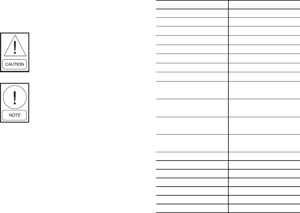
179
YORK INTERNATIONAL
FORM 201.19-NM1 (204)
8.9 SERVICE MODE: UNIT SETUP
The Service Mode allows programming unit set-up
values. These values are programmed before the
chiller leaves the factory and typically should never
be changed.
Catastrophic failure of chiller compo-
nents can occur if the set-up values are
improperly programmed. If for some
reason these values need to be checked
or changed, care should be exercised.
Whenever an EPROM is changed, the
programmed values should be record-
ed prior to removing the old EPROM.
These values should then be checked
and programmed into the micro when
the new EPROM is installed.
Setup values may be checked in the Service Mode by
pressing the PROGRAM, 5144, and ENTER keys.
Table 5 lists the value and the program range that will
be accepted.
SETUP MODE VALUE PROGRAMMABLE RANGE
Refrigerant Type R-22 or R-407C
R-407C Chiller Type Optimized or Drop-in
Unit Type YCAS or YCWS **
Heat Recovery Unit Enabled or Disabled ***
Sys 1 100% Full Load Amps 75 to 500 Amps *
Sys 2 100% Full Load Amps 75 to 500 Amps *
Sys 1 Motor Protector Input 1.0 to 5.0 volts *
Sys 2 Motor Protector Input 1.0 to 5.0 volts *
Oil Cooling On 167 to 203 ºF
180 ºF default ****
Oil Cooling Diff 9 to 18 ºF
9 ºF default ****
Discharge Cooling On 176.0 to 239.0 ºF
212.0 ºF default
Discharge Cooling Diff 7.2 to 27.0 ºF
18 ºF default
Data Logging Mode OFF or ON
Data Logging Timer 6 to 60 seconds
Sys 1 Operating Hours 0 to 99,999
Sys 2 Operating Hours 0 to 99,999
Sys 1 Starts 0 to 99,999
Sys 2 Starts 0 to 99,999
Clear History Buffer YES or NO
NOTE:
* See Table 6 or 7 for programming system 100% Full
Load Amps and System Motor Protector input volt-
age. Also assure that the correct number of wires
per phase pass through each C.T. The C.T. is built
internally into the 2ACE motor protector.
** The chiller must always be programmed for YCAS
*** Heat recovery must always be disabled.
**** Oil and discharge cooling is only utilized on spe-
cial low temp chiller.
TABLE 5 – SERVICE MODE
PROGRAMMABLE VALUES

180 YORK INTERNATIONAL
FORM 201.19-NM1 (204)
Micro Panel Contents
TABLE 6 – YCAS STYLE G, ACROSS THE LINE START - 60 HZ.
MODEL
NO.
VOLTAGE
CODE
CHILLER
NAMEPLATE
RLA
NO. OF
LEADS
PER PHASE
THRU CT.
100% FLA
OF SYSTEM
MP INPUT
VOLTAGE
130
17 246 *2 266 3.65
28 214 *2 231 3.2
40 130 2 140 3.89
46 107 1 116 3.2
58 86 1 93 2.58
140
17 267 *4 288 1.99
28 232 *2 251 3.49
40 140 2 151 4.2
46 116 1 125 3.49
58 93 1 100 2.78
150
SYS 1
17 295 *4 319 2.2
28 256 *4 276 1.91
40 155 2 167 4.64
46 128 2 138 3.84
58 103 1 111 3.09
150
SYS 2
17 265 *4 286 1.97
28 230 *2 248 3.44
40 139 2 150 4.18
46 115 1 124 3.44
58 92 1 99 2.75
160
17 295 *4 319 2.2
28 256 *4 276 1.91
40 155 2 167 4.64
46 128 2 138 3.84
58 103 1 111 3.09
170
SYS 1
17 321 *4 347 2.4
28 279 *4 301 2.09
40 169 *2 182 2.53
46 140 2 151 4.2
58 112 1 121 3.35
170
SYS 2
17 295 *4 319 2.2
28 256 *4 276 1.91
40 155 2 167 4.64
46 128 2 138 3.84
58 103 1 111 3.09
180
17 321 *4 347 2.4
28 279 *4 301 2.09
40 169 *2 182 2.53
46 140 2 151 4.2
58 112 1 121 3.35
* Indicates one lead/phase through motor protector.

181
YORK INTERNATIONAL
FORM 201.19-NM1 (204)
8
TABLE 6 – YCAS STYLE G, ACROSS THE LINE START - 60 HZ. (CONT'D)
MODEL
NO.
VOLTAGE
CODE
CHILLER
NAMEPLATE
RLA
NO. OF
LEADS
PER PHASE
THRU CT.
100% FLA
OF SYSTEM
MP INPUT
VOLTAGE
200
17 342 *4 369 2.55
28 298 *4 322 2.24
40 181 *2 195 2.71
46 149 2 161 4.46
58 119 1 129 3.58
210
SYS 1
17 374 *4 404 2.8
28 325 *4 351 2.44
40 197 *2 213 2.95
46 163 *2 176 2.44
58 130 2 140 3.89
210
SYS 2
17 342 *4 369 2.55
28 298 *4 322 2.24
40 181 *2 195 2.71
46 149 2 161 4.46
58 119 1 129 3.58
230
17 374 *4 404 2.8
28 325 *4 351 2.44
40 197 *2 213 2.95
46 163 *2 176 2.44
58 130 2 140 3.89
* Indicates one lead/phase through motor protector.

182 YORK INTERNATIONAL
FORM 201.19-NM1 (204)
Micro Panel Contents
TABLE 7 – YCAS STYLE G, WYE DELTA START - 60 HZ.
MODEL
NO.
VOLTAGE
CODE
CHILLER
NAMEPLATE
RLA
NO. OF
LEADS
PER PHASE
100% FLA
OF SYSTEM
MP SET
POINT
VOLTAGE
130
17 246 *4 266 2.13
28 214 *2 231 3.71
40 130 2 140 3.89
46 107 2 116 3.20
58 86 2 93 2.58
140
17 267 *4 288 2.31
28 232 *4 251 2.00
40 140 2 151 4.20
46 116 2 125 3.46
58 93 2 100 2.8
150
SYS 1
17 295 *4 319 2.56
28 256 *4 276 2.22
40 155 2 167 4.64
46 128 2 138 3.84
58 103 2 111 3.09
150
SYS 2
17 265 *4 286 2.31
28 230 *4 248 2.00
40 139 2 150 4.18
46 115 2 124 3.44
58 92 2 99 2.75
160
17 295 *4 319 2.56
28 256 *4 276 2.22
40 155 2 167 4.64
46 128 2 138 3.84
58 103 2 111 3.09
170
SYS 1
17 321 *4 347 2.8
28 279 *4 301 2.42
40 169 *2 182 2.93
46 140 2 151 4.20
58 112 2 121 3.35
170
SYS 2
17 295 *4 319 2.56
28 256 *4 276 2.22
40 155 2 167 4.64
46 128 2 138 3.84
58 103 2 111 3.09
180
17 321 *4 347 2.8
28 279 *4 301 2.42
40 169 *2 182 2.93
46 140 2 151 4.20
58 112 2 121 3.35
* Indicates one lead/phase through motor protector.

183
YORK INTERNATIONAL
FORM 201.19-NM1 (204)
8
TABLE 7 – YCAS STYLE G, WYE DELTA START - 60 HZ. (CONT'D)
MODEL
NO.
VOLTAGE
CODE
CHILLER
NAMEPLATE
RLA
NO. OF
LEADS
PER PHASE
THRU CT.
100% FLA
OF SYSTEM
MP INPUT
VOLTAGE
200
17 342 *4 369 2.98
28 298 *4 322 2.60
40 181 *2 195 3.15
46 149 2 161 4.47
58 119 2 129 3.58
210
SYS 1
17 374 *4 403 3.24
28 325 *4 351 2.82
40 197 *2 213 3.42
46 163 *2 176 2.84
58 130 2 140 3.89
210
SYS 2
17 342 *4 369 2.98
28 298 *4 322 2.60
40 181 *2 195 3.15
46 149 2 161 4.47
58 119 2 129 3.58
230
17 374 *4 403 3.24
28 325 *4 351 2.82
40 197 *2 213 3.42
46 163 *2 176 2.84
58 130 2 140 3.89
* Indicates one lead/phase through motor protector.

184 YORK INTERNATIONAL
FORM 201.19-NM1 (204)
Micro Panel Contents
SERVICE MODE: VIEWING INPUTS AND OUTPUTS
All digital and analog inputs and digital outputs can be
viewed by pressing the FUNCTION key and the press-
ing of the OPER DATA key. The UP and DOWN arrow
keys can then be used to scroll through the inputs and
outputs.
Each analog input will display the name of the measured
value, the input plug/pin number on the microboard, the
voltage read on the input, and the voltage converted to
pressure or temperature. An example is shown below:
Each digital input will display the name of the measured
value, the input plug/pin number on the micro board,
and the state of the input (ON or OFF). An example is
shown below:
Each digital output will display the name of the item
controlled by the output, the output plug/pin number
on the microboard and the state of the output (ON and
OFF). An example is shown below:
SERVICE MODE: OUTPUT ENABLE
The Service Mode allows the user to enable and disable
the outputs (except compressor). To enter the Service
Mode, turn the UNIT switch off and press PROGRAM,
9675, ENTER. A message will be displayed for 2 sec-
onds indicating that the service mode has been enabled.
Service Mode will time out after 60 minutes and return
to the normal mode. Service mode can also be disabled
by turning the UNIT switch on or by powering the 115
VAC off and on.
Once Service Mode is entered, all of the outputs will be
turned off. The outputs can be turned on by pressing.
FUNCTION and then the OPER DATA key and scroll-
ing past the input displays to the output displays. The
arrow keys are used to scroll forward and backwards in
the displays, while the ENTER key is used to toggle the
outputs on and off. Only one output will be allowed on
at a time. The only exception will be the compressors
which cannot be turned on and off in this mode.
S Y S 1 R U N P E R M
J 4 - 5 I S O F F
S Y S 1 S U C T P R J 1 3 - 7
X . X V D C = X X X X PSIG
S Y S 1 L L S V
J 7 - 3 I S O F F
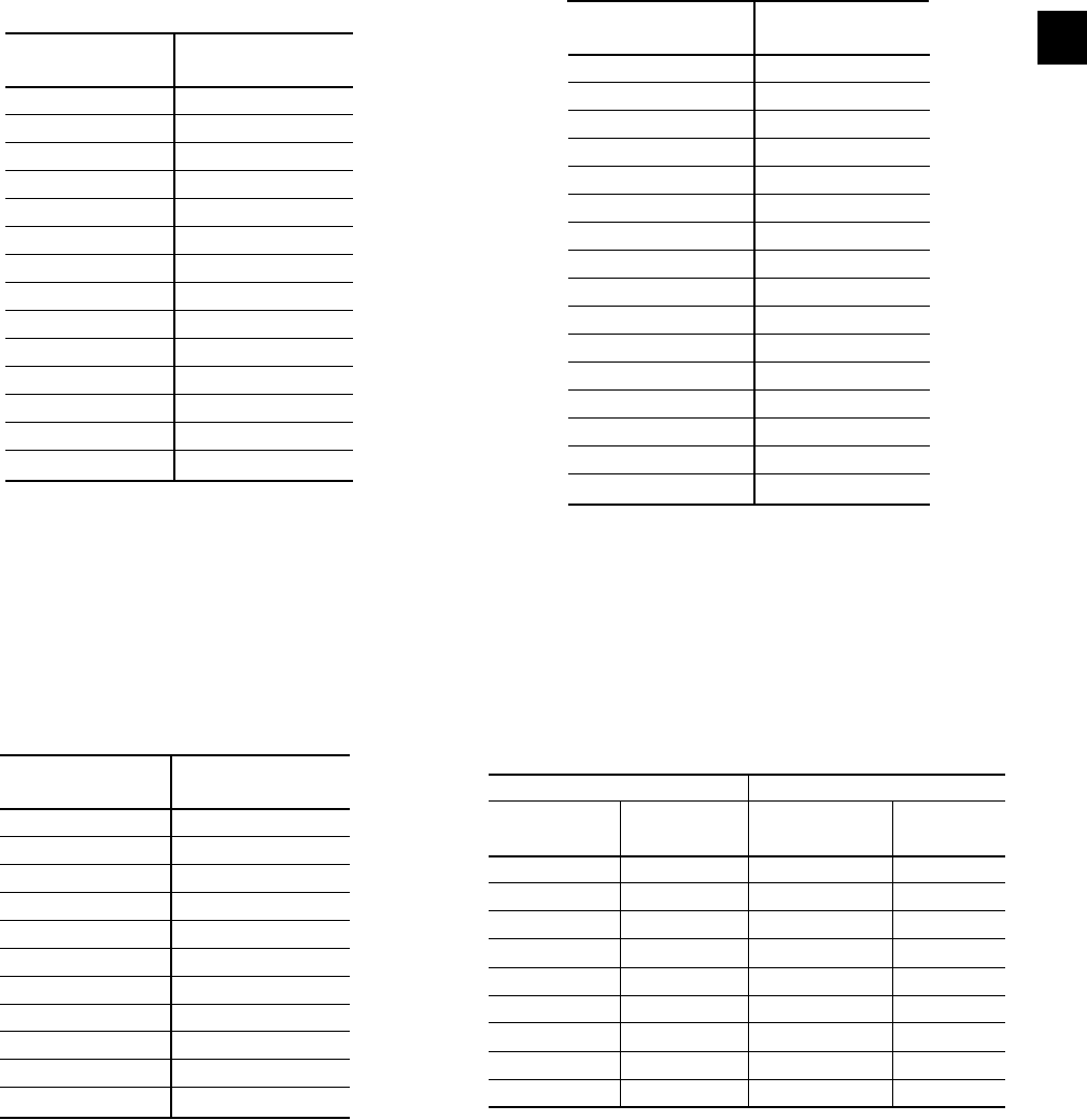
185
YORK INTERNATIONAL
FORM 201.19-NM1 (204)
8
Ambient Temperature Sensor
Temperature Voltage
°F (°C) VDC
14° (-10°) 0.97
23° (-5°) 1.20
32° (0.0°) 1.45
41° (5°) 1.72
50° (10°) 2.00
59° (15°) 2.29
68° (20°) 2.58
77° (25°) 2.85
86° (30°) 3.11
95° (35°) 3.35
104° (40°) 3.57
TEST POINTS:
Leaving Water ................................................... Microboard J11-7/1
Return Water ..................................................... Microboard J11-8/2
Temperature Voltage
°F (°C) VDC
32° (0°) 0.282
50° (10°) 0.447
68° (20°) 0.676
86° (30°) 0.976
104° (40°) 1.34
122° (50°) 1.76
140° (60°) 2.20
158° (70°) 2.63
176° (80°) 3.04
194° (90°) 3.40
212° (100°) 3.71
230° (110°) 3.96
248° (120°) 4.17
266° (130°) 4.33
284° (140°) 4.46
302° (150°) 4.57
Oil & Discharge Temperature Sensors
Leaving Chilled Liquid Temperature and
Return Chilled Liquid Temperature Sensors
Temperature Voltage
°F (C°) VDC
14° (-10°) 1.45
18° (-7.8°) 1.57
21° (-6.1°) 1.69
25° (-3.9°) 1.80
28° (-2.2°) 1.93
32° (0.0°) 2.05
36° (2.2°) 2.17
39° (3.9°) 2.30
43° (6.1°) 2.42
46° (7.8°) 2.54
50° (10°) 2.66
68° (20°) 3.22
86° (30°) 3.69
104° (40°) 4.05
TEST POINT:
Test Point........................................................... Microboard J11-9/3
8.10 SENSOR CALIBRATION CHARTS
Pressure Transducers
0 - 200 PSIG Transducer 0 - 400 PSIG Transducer
Pressure Voltage Pressure Voltage
PSIG VDC PSIG VDC
0 0.5 0 0.5
25 1.0 50 1.0
50 1.5 100 1.5
75 2.0 150 2.0
100 2.5 200 2.5
125 3.0 250 3.0
150 3.5 300 3.5
175 4.0 350 4.0
200 4.5 400 4.5
TEST POINTS:
Oil Temperature:
System 1: ..................................................Extension-board J10-7/3
System 2: ..................................................Extension-board J10-6/2
Discharge Temperature:
System 1: ....................................................Extension-board J8-4/1
System 2: ....................................................Extension-board J8-6/3
Red Wire = 5V, Black wire = 0V, White/Green Wire = signal
TEST POINTS:
Suction Pressure:
System 1: .......................................................... Microboard J13-7/1
System 2: .......................................................... Microboard J14-7/1
Oil Pressure:
System 1: .......................................................... Microboard J13-8/3
System 2: .......................................................... Microboard J14-8/3
Discharge Pressure:
System 1: .......................................................... Microboard J15-8/3
System 2: .......................................................... Microboard J15-7/1

186 YORK INTERNATIONAL
FORM 201.19-NM1 (204)
Micro Panel Contents
Tables 8 through 14 are a quick reference list providing
the connection points and a description of the inputs and
outputs respectively. All input and output connections
pertain to the connections at the microboard, relay, or
I/O Board.
TABLE 8 - DIGITAL OUTPUTS
Microboard / Relay Board 1 J7-1 / TB1-20 Sys 1 Compressor
Microboard / Relay Board 1 J7-2 / TB1-19 Sys 1 Compressor Heater
Microboard / Relay Board 1 J7-3 / TB1-18 Sys 1 Liquid Line Solenoid Valve
Microboard / Relay Board 1 J7-4 / TB1-17/16 SPARE
Microboard / Relay Board 1 J7-5 / TB1-15 Sys 1 Condenser Fans Output 1
Microboard / Relay Board 1 J7-6 / TB1-14 Sys 1 Condenser Fans Output 2
Microboard / Relay Board 1 J9-1 / TB1-10 Sys 1 Condenser Fans Output 3
Microboard / Relay Board 1 J9-2 / TB1-9 Sys 1 Economizer TXV Solenoid
Microboard / Relay Board 1 J9-3 / TB1-8 Sys 1 Wye Delta Relay
Microboard / Relay Board 1 J9-4 / TB1-7 SPARE
Microboard / Relay Board 1 J9-5 / TB1-6/5 Evaporator Heater
Microboard / Relay Board 1 J9-6 / TB1-4/3 Sys 1 Alarm
Microboard / Relay Board 2 J10 / TB1-20 Sys 2 Compressor
Microboard / Relay Board 2 J10-2 / TB1-19 Sys 2 Compressor Heater
Microboard / Relay Board 2 J10-3 / TB1-18 Sys 2 Liquid Line Solenoid Valve
Microboard / Relay Board 2 J10-4 / TB1-17/16 Chiller Run
Microboard / Relay Board 2 J10-5 / TB1-15 Sys 2 Condenser Fans Output 1
Microboard / Relay Board 2 J10-6 / TB1-14 Sys 2 Condenser Fans Output 2
Microboard / Relay Board 2 J8-1 / TB1-10 Sys 2 Condenser Fans Output 3
Microboard / Relay Board 2 J8-2 / TB1-9 Sys 2 Economizer TXV Solenoid
Microboard / Relay Board 2 J8-3 / TB1-8 Sys 2 Wye Delta Relay
Microboard / Relay Board 2 J8-4 / TB1-7 SPARE
Microboard / Relay Board 2 J8-5 / TB1-6/5 Evaporator Pump
Microboard / Relay Board 2 J8-6 / TB1-4/3 Sys 2 Alarm
I/O Expansion J13-1 Sys 1 EEV Heat Motor
I/O Expansion J13-2 Sys 2 EEV Heat Motor
8.11 CONTROL INPUTS/OUTPUTS

187
YORK INTERNATIONAL
FORM 201.19-NM1 (204)
8
ANALOG INPUTS
Not all of the sensors are installed in every unit as some
of them are optional. However, the software must still be
able to read the sensors if the optional ones are installed.
Table 9 lists all of the analog inputs and whether they
are on the Microboard or the I/O Expansion Board.
TABLE 9 - ANALOG INPUTS
Microboard J11-7 Leaving Chilled Liquid Temp Sensor
Microboard J11-8 Return Chilled Liquid Temp Sensor
Microboard J11-9 Ambient Air Temp Sensor
Microboard J12-1 SPARE
Microboard J12-3 SPARE
Microboard J13-7 Sys 1 Suction Pressure Transducer
Microboard J13-8 Sys 1 Oil Pressure Transducer
Microboard J14-7 Sys 2 Suction Pressure Transducer
Microboard J14-8 Sys 2 Oil Pressure Transducer
Microboard J15-7 Sys 2 Discharge Pressure Transducer
Microboard J15-8 Sys 1 Discharge Pressure Transducer
Microboard J16-4 Sys 2 Suction Temp Sensor
Microboard J16-6 Sys 1 Suction Temp Sensor
Microboard J17-9 Input from I/O Expansion Board
Microboard J17-10 SPARE
Microboard J17-11 Mixed Chilled Liquid Temp Sensor (optional)
Hot Leaving Temp Sensor (Heat Recovery only)
I/O Expansion J4-4 Sys 1 Motor Current
I/O Expansion J4-5 SPARE
I/O Expansion J4-8 SPARE
I/O Expansion J4-10 Sys 2 Motor Current
I/O Expansion J4-11 SPARE
I/O Expansion J4-12 SPARE
I/O Expansion J5-6 SPARE
I/O Expansion J5-7 SPARE
I/O Expansion J6-2 SPARE
Sys 1 Fan Pressure Transducer (Heat Recovery only)
I/O Expansion J7-2 Sys 2 Evaporator Inlet Refrigerant Temp Sensor (R-407c only)
I/O Expansion J8-4 Sys 1 Discharge Temp Sensor
I/O Expansion J8-6 Sys 2 Discharge Temp Sensor
I/O Expansion J9-2 SPARE
Sys 2 Fan Pressure Transducer (Heat Recovery only)
I/O Expansion J10-6 Sys 2 Oil Temp Sensor
I/O Expansion J10-7 Sys 1 Oil Temp Sensor
I/O Expansion J11-2 Sys 1 Evaporator Inlet Refrigeration Temp Sensor (R-407c only)
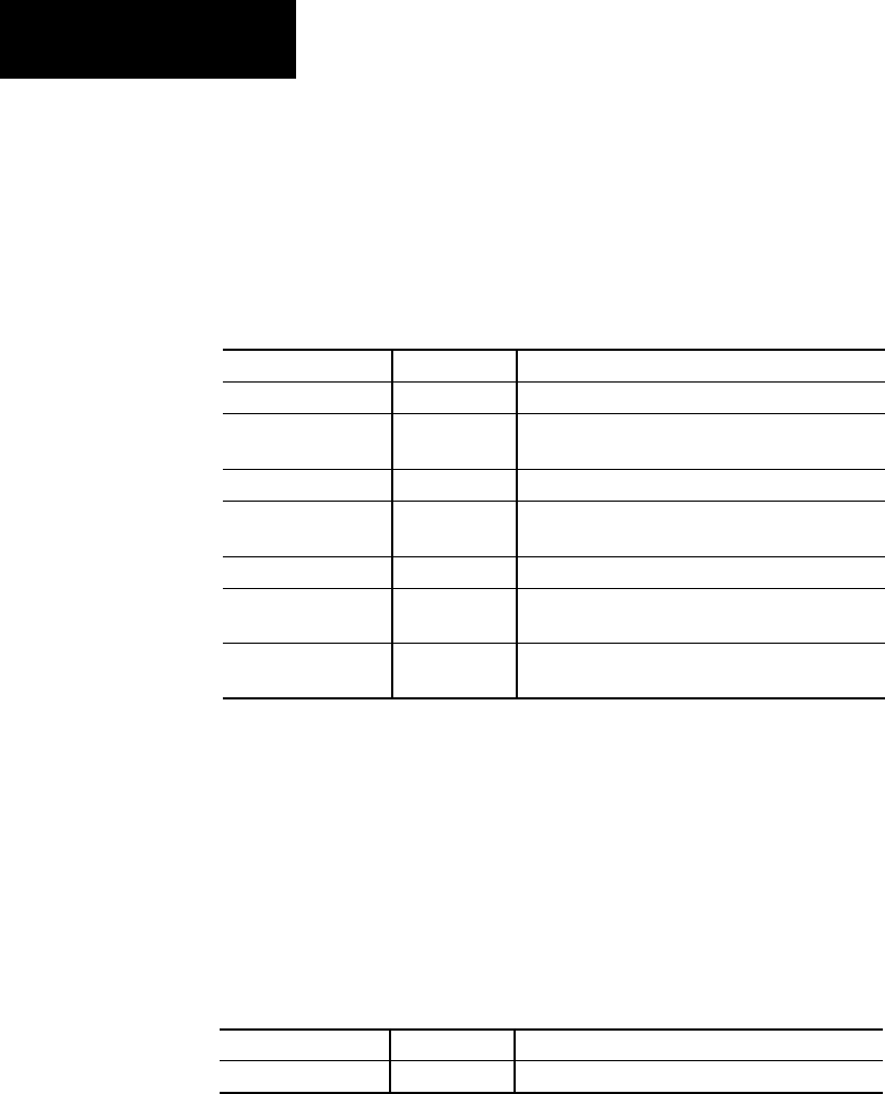
188 YORK INTERNATIONAL
FORM 201.19-NM1 (204)
Micro Panel Contents
DIGITAL INPUTS
Table 10 lists all of the digital inputs and whether they
are on the Microboard or the I/O Expansion Board.
TABLE 10 - DIGITAL INPUTS
ANALOG OUTPUTS
Table 11 lists all the analog outputs and what output
board they are on.
TABLE 11 - ANALOG OUTPUTS
Microboard J4-1 Unit Switch
Microboard J4-2 PWM Current Limit
Microboard J4-3 SPARE
Flow Switch (Euro CAT only)
Microboard J4-4 PWM Temp Reset
Microboard J4-5 Sys 1 Run Perm
Sys 1 Sys Switch (Euro CAT only)
Microboard J4-6 Print
Microboard J4-7 Sys 2 Run Perm
Sys 2 Sys Switch (Euro CAT only)
Microboard J4-8 SPARE
Hot Flow Switch (Heat Recovery only)
I/O Expansion J2-1 Sys 1 Slide Valve
I/O Expansion J12-1 Sys 2 Slide Valve
189
YORK INTERNATIONAL
FORM 201.19-NM1 (204)
8
RECEIVED DATA (CONTROL DATA)
The microprocessor receives 8 data values from the
ISN. The fi rst 4 are analog values and the last 4 are
digital values. These 8 data values are used as con trol
pa ram e ters when in RE MOTE mode. When the unit is
in LO CAL mode, these 8 values are ignored. If the unit
re ceives no valid ISN trans mis sion for 5 min utes it will
re vert back to all local control values. Table 12 lists
the 4 control pa ram e ters. These values are found under
fea ture 54 on the ISN.
TRANSMITTED DATA
After receiving a valid transmission from the ISN, the
unit will transmit either op er a tion al data or history buf-
f er data de pend ing on the “History Buffer Re quest” on
ISN PAGE 06. Data must be trans mit ted for every ISN
page un der fea ture 54. If there is no value to be sent to
a par tic u lar page, a zero will be sent. Tables 13 and 14
show the data val ues and page listings for this unit.
8.12 ISN CONTROL
TABLE 12 – ISN RECEIVED DATA
ISN CONTROL DATA
PAGE
P03 SETPOINT
P04 ISN Current Limit
P05 —
P06 —
P07 START/STOP COMMAND (0 = STOP, 1 = RUN)
P08 —
P09 —
P10 HISTORY BUFFER REQUEST
(0 = CURRENT DATA, 1 = LAST HISTORY DATA)
ISN
Page Character Type DXST Chiller Data
P11 8-11 Analog Leaving Chilled Liquid Temp
P12 12-15 A Return Chilled Liquid Temp
P13 16-19 A
Mixed Chilled Liquid Temp (optional) - YCAS
Leaving Hot Liquid Temp - YCWS
Hot Liquid Temp - Heat Recovery
P14 20-23 A Sys 1 Suction Temperature
P15 24-27 A Sys 1 Discharge Temperature
P16 28-31 A Ambient Air Temperature
P17 32-35 A Sys 1 Oil Temperature
P18 36-39 A Sys 1 Oil Pressure
P19 40-43 A Sys 1 Suction Pressure
P20 44-47 A Sys 1 Discharge Pressure
P21 48-51 A Sys 1 % Full Load Amps
P22 52-55 A Sys 1 Total Run Hours
P23 56-59 A Sys 1 Total Number of Stats
P24 60-63 A Sys 1 Anti-Recycle Timer
P25 64-67 A Anti-Coincident Timer
P26 68-71 A Sys 2 Oil Temperature
TABLE 13 – ISN TRANSMITTED DATA

190 YORK INTERNATIONAL
FORM 201.19-NM1 (204)
Micro Panel Contents
ISN
Page Character Type DXST Chiller Data
P27 72-75 A Sys 2 Oil Pressure
P28 76-79 A Sys 2 Suction Pressure
P29 80-83 A Sys 2 Discharge Pressure
P30 84-87 A Sys 2 % Full Load Amps
P31 88-91 A Sys 2 Total Run Hours
P32 92-95 A Sys 2 Total Number of Starts
P33 96-99 A Sys 2 Anti-Recycle Timer
P34 100-103 A Sys 1 Evaporator Inlet Refrigerant Temp (R-407c only)
P35 104-107 A Sys 2 Evaporator Inlet Refrigerant Temp (R-407c only)
P36 108 Diital Chiller Run
P37 109 D Chiller Alarm
P38 110 D Evaporator Heater Status (YCAS)
P39 111 D Evaporator Pump Status
P40 112 D Hot Liquid Flow Switch (Heat Recovery)
P41 113 D Sys 1 Spare
Sys 1 Discharge Cooling Solenoid Status (Euro CAT, Low Temp)
P42 114 D Sys 1 Liquid Line Solenoid Valve Status
P43 115 D
Sys 1 Economizer TXV Solenoid Status (YCAS)
Sys 1 Oil Cooling Solenoid Status (YCWS)
Sys 1 Condenser Solenoid Status (EURO CAT)
Sys 1 Heat Recovery Solenoid Status (Heat Recovery)
P44 116 D Sys 1 Wye-Delta
P45 117 D Sys 2 Spare
Sys 2 Discharge Cooling Solenoid Status (Euro CAT, Low Temp)
P46 118 D Sys 2 Liquid Line Solenoid Valve Status
P47 119 D
Sys 2 Economizer TXV Solenoid Status (YCAS)
Sys 2 Oil Cooling Solenoid Status (YCWS)
Sys 2 Condenser Solenoid Status (Euro CAT)
Sys 2 Heat Recovery Solenoid Status (Heat Recovery)
P48 120 D Sys 2 Wye-Delta Relay
P49 121 D —
P50 122 D S1-1 Cooling Type: 0=Water, 1=Glycol
P51 123 D S1-2 Ambient Ctrl: 0=Standard, 1=Low Ambient
P52 124 D S1-3 Refrigerant Type: 0=R407c, 1=R-22
P53 125 D S1-4 Unit Type: 0=YCWS, 1=YCAS
P54 126 D S1-5 Motor Current Averaging: 0=Disabled, 1=Enabled
P55 127 D S1-6 Heat recovery: 0=Disabled, 1=Enabled
P56 128 Coded *Sys 1 Operational Code
P57 129 C *Sys 1 Fault Code
P58 130 C *Sys 2 Operatioanal Code
P59 131 C *Sys 2 Fault Code
P60 132 C Sys 1 Slide Valve Step
P61 133 C Sys 1 Condenser Fan Stages Running (0-6)
P62 134 C Sys 2 Slide Valve Step
P63 135 C Sys 2 Condenser Fan Stages Running (0-6)
P64 136 C Lead Compressor Number
P65 137 C Debug Code
TABLE 13 – ISN TRANSMITTED DATA (CONT'D)

191
YORK INTERNATIONAL
FORM 201.19-NM1 (204)
8
ISN
Page Character Type DXST Chiller Data
P66 138-141 Analog Leaving Chilled Liquid Setpoint
P67 142-145 A Low Leaving Chilled Liquid Temp Cutout
P68 146-149 A Sys 1 EEV Output %
P69 150-153 A Sys 2 EEV Output %
P70 154-157 A Low Suction Pressure Cutout
P71 158-161 A High Discharge Pressure Cutout
P72 162-165 A Remote Leaving Chilled Liquid Setpoint
P73 166-169 A Sys 1 Suction Superheat
P74 170-173 A Cooling Range
P75 174-177 A Sys 1 Discharge Superheat
P76 178-181 A Sys 2 Suction Temperature
P77 182-185 A Sys 2 Discharge Temperature
P78 186-189 A Sys 2 Suction Superheat
P79 190-193 A Sys 2 Discharge Superheat
P80 194 Digital S1-7 Expansion Valve Type: 0=TXV, 1=EEV
P81 195 D S1-8 SPARE
P82 196 D —
P83 197 D —
P84 198 D —
TABLE 13 – ISN TRANSMITTED DATA (CONT'D)

192 YORK INTERNATIONAL
FORM 201.19-NM1 (204)
Micro Panel Contents
P56/58 C1 Operational Code P57/59 C1 Fault Code
0 No Abnormal Condition 0 No Fault
1 Unit Switch Off 1 VAC Under Voltage
2 System Switch Off 2 Low Ambient Temperature
3 Lock - Out 3 High Ambient Temperature
4 Unit Fault 4 Low Leaving Chilled Liquid Temp
5 System Fault 5 High Discharge Pressure
6 Remote Shutdown 6 High Differential Oil Pressure
7 Daily Schedule Shutdown 7 Low Suction Pressure
8No Run Permissive
Flow Switch Open (Euro CAT) 8 High Motor Current
9 No Cool Load 9 LLSV Not On
10 Anti-Coincidence Timer Active 10 Low Battery Warning
11 Anti-Recycle Timer Active 11 High Oil Temperature
12 Manual Override 12 High Discharge Temperature
13 Suction Limiting 13 Improper Phase Rotation
14 Discharge Limiting 14 Low Motor Current / MP / HPCO
15 Current Limiting 15 Motor Current Unbalanced
16 Load Limiting 16 Low Differential Oil Pressure
17 Compressor Running 17 Ground Fault
18 MP / HPCO
19 Low Evaporator Temperature
20 Incorrect Refrigerant Programmed
21 Power Failure, Manual reset Required
22 I/O Board Failure
23 Low Superheat
24 Sensor Fault
25 Reprogram Unit Type
26 MP / HPCO Inhibit
27 Heat Recovery Select
TABLE 14 – ISN OPERATIONAL AND FAULT CODES
* The operational and fault codes are defi ned in table 14. Note that this table of fault and operational codes is for
all DX products. The codes that are grayed out are not used on this unit.

193
YORK INTERNATIONAL
FORM 201.19-NM1 (204)
8
This page intentionally left blank.
194 YORK INTERNATIONAL
FORM 201.19-NM1 (204)
GENERAL REQUIREMENTS
The units have been designed to operate continuously,
provided they are regularly maintained and operated
with in the limitations given in this manual. Each unit
should be included in a routine schedule of daily main-
te nance checks by the operator/customer, backed up by
regular service inspection and maintenance visits by a
suitably qualifi ed Service Engineer.
It is the responsibility of the owner to provide mainte-
nance on the system.
It is entirely the responsibility of the owner to provide
for these regular maintenance requirements and/or en ter
into a maintenance agreement with a York In ter na tion al
ser vice organization to protect the operation of the unit.
If damage or a system failure occurs due to improper
main te nance during the warranty period, YORK shall
not be liable for costs incurred to return the unit to sat-
isfactory condition.
If system failure occurs due to improp-
er maintenance during the warranty
period, YORK will not be liable for
costs incurred to return the system to
satisfactory operation. The following
is intended only as a guide and covers
only the chiller unit components. It
does not cover other related system
components which may or may not be
furnished by YORK. System compo-
nents should be maintained accord-
ing to the individual manufacture's
recommendations as their operation
will affect the operation of the chiller.
This maintenance section applies to
the basic unit only and may, on in di -
vid u al contracts, be sup ple ment ed by
additional requirements to cover any
mod i fi ca tions or ancillary equipment
as applicable.
The Safety Section of this manual
should be read care ful ly before at-
tempt ing any main te nance op er a tions
on the unit.
Daily/Weekly Maintenance
The following maintenance checks should be carried
out on a daily/weekly basis by the operator/customer.
Please note that the units are not generally user service-
able and no attempt should be made to rectify faults or
prob lems found during daily checks unless competent
and equipped to do so. If in any doubt, contact your local
YORK Service Agent.
Unit Status: Press the ‘STATUS’ key on the keypad
and ensure no fault messages are displayed (refer to
the MBCS Manual for explanation of messages and the
Trou ble Shooting section for courses of action).
Refrigerant Leaks: Visually check the heat ex chang ers,
compressors and pipework for damage and gas leaks.
CONDENSER COILS
Dirt and foreign material should not be allowed to accu-
mulate on the condenser coil surfaces. Cleaning should
be as often as necessary to keep coil clean.
Exercise care when cleaning the coil
so that the coil fi ns are not damaged.
Operating conditions: Read the operating pressures and
temperatures at the control panel using the dis play keys
and check that these are within the operating lim i ta tions
in this Manual.
Compressor oil level: Check the compressor oil level
after the compressor has been operating on ‘FULL
LOAD’ for approximately half an hour. The oil level
should be visible in the upper of the two sight glasses.
When the compressor is operating at ‘PART LOAD’,
the level may fall as far as half way down the lower
sight glass but should not fall below this level. When
the com pres sor returns to full load the level will return
to the upper sight glass. If oil is added, be aware it is
MAINTENANCE
Maintenance

195
YORK INTERNATIONAL
FORM 201.19-NM1 (204)
9
"L" Type POE oil. Always add oil from a new unopened
container. Dispose of the remaining oil using environ-
mentally friendly procedures.
Refrigerant charge: When a system starts up, or some-
times after a change of capacity, a fl ow of bub bles will
be seen in the liquid line sight glass. After a few min utes
of stable operation, the bubbles should clear, leav ing
just liquid refrigerant showing in the sight glass.
Chiller / Compressor Operating Log
A Chiller/Compressor Operating Log is supplied on
the following page for logging compressor and chiller
op er at ing data.
Regular checks of the system should be preformed to
ensure that operating temperatures and pressures are
within limitations, and that the operating controls are set
within proper limits. Refer to the Operation, Start-Up,
and Installation sections of this manual.
Scheduled Maintenance
The maintenance operations detailed in the ta ble follow-
ing the Operating Log Form should be carried out on a
regular basis by a suit ably qualifi ed Service Engineer.
It should be noted that the interval necessary between
each ‘minor’ and ‘ma jor’ ser vice can vary depending on,
for instance, ap pli ca tion, site conditions and expected
operating sched ule. Nor mal ly a ‘minor’ service should
be carried out every three to six months and a ‘major’
service once a year. It is recommended that your local
YORK Service Cen ter is contacted for recommendations
for in di vid u al sites.
ON-BOARD BATTERY BACK-UP
U17 is the Real Time Clock chip that maintains the date/
time and stores customer programmed setpoints. Any-
time the chiller is to be off (no power to the microboard)
for an extended time (weeks/months), the clock should
be turned off to conserve power of the on-board battery.
To accomplish this, the J11 jumper on the microboard
must be moved to the "CLKOFF" position while power
is still supplied to the microboard.
The unit evaporator heater is 120VAC.
Disconnecting 120VAC power from the
unit, at or below freezing temperatures,
can result in damage to the evapora-
tor and unit as a result of the chilled
liquid freezing.
OVERALL UNIT INSPECTION
In addition to the checks listed on this page, periodic
overall inspections of the unit should be accomplished
to ensure proper equipment operation. Items such as
loose hardware, component operation, refrigeration
leaks, unusual noises, etc. should be investigated and
corrected immediately.
196 YORK INTERNATIONAL
FORM 201.19-NM1 (204)
Operating Log
COMPRESSOR UNIT OPERATION
YORK Order No. ________________________
Compr. Ser. No. _________________________
Unit Ser. No. ___________________________
Refrigerant_____________________________
CHILLER/COMPRESSOR
Operating Log
Date
Time
Hour Meter Reading
Equipment Room Temp./Outdoor Temp. / / / / / / / / / /
Suction Pressure
Suction Temperature
Suction Superheat
Discharge Pressure
Actual Discharge Temperature
Oil Pressure
Oil Temperature
FLA % (Motor - )
Oil Level (example )
Oil Added (gallons or liters)
Inlet Temperature
Outlet Temperature
Pressure Drop
Flow Rate - GPM or l/s
Air On Temperature
Air Off Temperature
Inlet Temperature
Outlet Temperature
Pressure Drop
Flow Rate - GPM or l/s
Leaving Liquid Refrigerant Temperature
Remarks:
Compressor
Oil
Sep.
Evap.
Brine
Condenser
Air
Water
Note: Temperature and Pressure Units in °F and PSIG respectively unless otherwise noted.
Maintenance
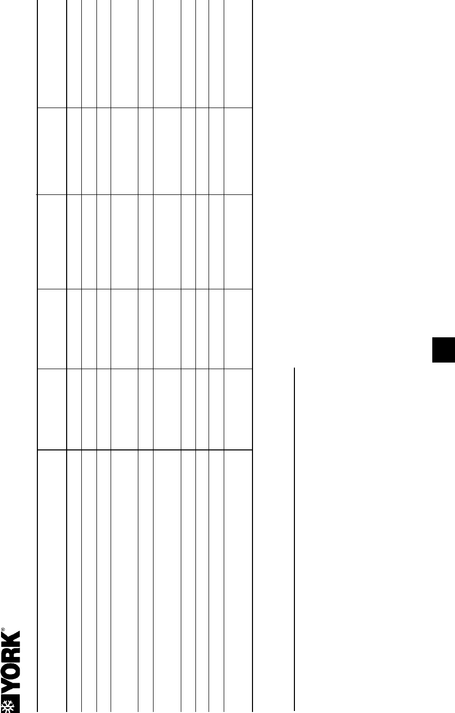
197
YORK INTERNATIONAL
FORM 201.19-NM1 (204)
PROCEDURE WEEKLY QUARTERLY SEMI-ANNUALLY YEAR LY EVERY
___ HOURS
Check oil level in oil separator sight glass X
Check liquid line sight glass / moisture indicator X
Record system operating pressures and temperatures X
Check programmable operating setpoints and safety cutouts
and assure they are correct for particular application. X
Check condenser coils for dirt/debris and clean if necessary X
Check compressor superheat on evaporator and economizer
TXV’s; Check condenser and economizer subcooling1 X
Check compressor and evaporator heaters for operation X
Sample compressor oil and replace oil if necessary1 X
Leak check the chiller1 X
Disconnect power source and lock out; Check tightness of
power wiring connections1 X
MAINTENANCE REQUIREMENTS FOR YORK YCAS SCREW CHILLERS
*
* Reserved for customer use for any special site determined requirements.
1 This procedure must be performed at the specifi ed time interval by an Industry Certifi ed Technician who has been trained and qualifi ed to work on this type of YORK
equipment. A record of this procedure being successfully carried out must be maintained on fi le by the equipment owner should proof of adequate maintenance
be required at a later date for warranty validation purposes.
9

198 YORK INTERNATIONAL
FORM 201.19-NM1 (204)
GENERAL PERIODIC MAINTENANCE CHECKS
STANDARD UNITS
SERVICE SCHEDULE MINOR SERVICE MAJOR SERVICE
All items under Minor Service plus:
Unit general: Check thermal insulation. Check main structure.
Check vibration isolators. Check paint-work.
Refrigerant systems general: Check relief valves. Check solenoid valves.
Check fusible plugs.
Check for pipework damage.
Check for leaks.
Check moisture indicator.
Check suction superheat.
Check economizer superheat.
Check liquid subcooling.
Compressors / Oil separator: Check oil level.
Check oil pressure.
Check slide valve operation.
Check compressor heater.
Check condition of oil.
Check discharge superheat.
Evaporator Check water fl ow. Check water pH / glycol strength.
Check water pressure drop.
Check heater.
Air cooled condensers: Check for airfl ow obstructions. Brush fi ns. Clean with mild, low
pH cleaner.
Check fi ns. Check fan motor bearings.
Check fans and fan guards.
Power & Control system general: Check panel condition. Check all connections.
Check mains and control wiring. Check compressor contactors.
Check sensor location. Check fan contactors / overloads.
Check mechanical HP cutouts. Check sensor / transducer calibration.
Check emergency stop. Check motor protectors.
Check overload devices.
Microprocessor controls: Check fault history. Check fan control function.
Check program settings. Check ambient cut-out function.
Check HP / LP cutout functions
Check pump-down function.
Check load / unload function.
Maintenance
199
YORK INTERNATIONAL
FORM 201.19-NM1 (204)
SPARE PARTS
Recommended Spares
It is recommended that the following common spare
parts are held for preventative of cor rec tive main te nance
op er a tions.
Description Part Number
Pressure Transducer 200PSI (14 Bar) 025-29583-000
Pressure Transducer 400PSI (28 Bar) 025-29139-001
Sensor, High Temperature 025-30440-000
Sensor, Ambient Temperature 025-28663-001
Sensor, Water Temperature 025-29964-000
Sensor, Water Temperature 025-29964-000
Oil Filter 026-35601-000
O-Ring 028-13849-000
Other spare parts vary depending on the unit mod el.
Review the chiller Renewal Parts Manual or Contact
your local YORK Sales and Ser vice Center for
in for ma tion (Please quote the unit model num ber and
serial number).
When ordering spare parts, we will require the fol low ing
information to ensure the correct parts are sup plied:
Full unit model number, serial number, ap pli ca tion and
details of the parts required.
All requests for parts should be made to your lo cal
YORK Sales and Service Center.
Recommended Compressor Oils
The correct type of oil must be used in the unit as shown
on the unit data plate and labels. Stan dard units use the
following oils:
The oil utilized is a POE oil. Once a
container is opened, it quickly absorbs
moisture. Any unused oil should be
disposed of using environmentally
friendly procedures.
REFRIGERANT COMPRESSOR OIL
R-22 and R407C YORK Type L
(5 Gal: 011-00592-000)
10
For Parts, Service, or Sales,
Call Toll Free:
1-866-YORK SRV
(1-866-9675-778)

200 YORK INTERNATIONAL
FORM 201.19-NM1 (204)
TROUBLESHOOTING GUIDE
Troubleshooting
PROBLEM POSSIBLE CAUSE ACTION POSSIBLE CAUSE ACTION
No display on panel - Main supply to control system OFF. Switch on main supply if safe to do so.
unit will not start
Emergency stop device off.
Check if control panel emergency stop switch
and any remote emergency stop devices are in
the OFF position. Turn to ON position (1) if safe
to do so.
CB3 tripped. Check CB3.
No supply to - T2. Check 115VAC to L & 2.
No 24VAC supply to power board. Check wiring from - T2 to powerboard and fuse.
No +12V output from powerboard. Replace powerboard or isolate excessive load on
the board.
NO RUN PERM displayed No liquid fl ow through the evaporator. Ensure that liquid pumps are running. Valves are
(No run permissive) correctly set and fl ow is established.
Flow switch contacts are not made.
Check that the fl ow switch is functional and is
installed according to the manufacturer’s instructions.
Check cycling contacts.
SYS # HIGH OIL TEMP Poor airfl ow through the condenser Check for airfl ow restrictions caused by blockages on
coils. intake faces of air coils.
Measured temperature incorrect. Check oil temp sensor and wiring.
Chiller FAULT: LOW Ambient air temperature is lower Use the ‘ambient temp.’ key to display the
AMBIENT TEMP displayed than the programmed operating temperature and confi rm that the displayed value is
limit. approximately correct. The warning message should
clear when the ambient air temperature rises above
the programmed operating limit.
Check the programmed settings are correct for the
options fi tted to the unit.
Measured temperature is incorrect. Check ambient sensor and wiring.
Chiller FAULT: HIGH Ambient air temperature is higher Use the ‘ambient temp.’ key to display the
AMBIENT TEMP displayed than the programmed operating limit. temperature and confi rm that the displayed value is
approximately correct. The warning message should
clear when the ambient air temperature falls below
the programmed operating limit.
Check that the programmed settings are correct for
the options fi tted to the unit.
Resid. heat is not being dissipated. Check fans are operating correctly and the rotation is
correct. Check for airfl ow recirculation.
Measured temperature is incorrect. Check ambient sensor and wiring.
Chiller FAULT: LOW Leaving liquid drops below the Check for restrictions in the liquid fl ow line.
WATER TEMP displayed programmed low limit faster than the Check that the liquid fl ow is stable.
unit can unload.
Unit is not unloading. Check the voltage to the unloader valve solenoid.
Check that the compressor unloads correctly.
Measured temperature is incorrect. Check water temp sensor and wiring.
Chiller FAULT: VAC Check main supply is stable and within allowable
UNDERVOLTAGE Poor main supply voltage. limits.
displayed. Check for voltage dip on compressor start.
Flow switch or cycling contacts are
not made.
Recirculated air is affecting the sensor.

201
YORK INTERNATIONAL
FORM 201.19-NM1 (204)
TROUBLESHOOTING GUIDE - CONT’D
11
PROBLEM POSSIBLE ACTION
SYS # HIGH DSCH
displayed (High discharge
pressure trip)
Poor airfl ow through condenser
coils.
Check for airfl ow restrictions caused by blockages
on intake faces of air coils.
Check for damaged fi ns/return bends.
Check for correct fan operation and direction of
rotation.
Check for non-condensables (air) in system.
Excessive refrigerant charge. Check that the sub-cooling is correct.
Measured pressure is incorrect. Check discharge transducer and wiring.
SYS # HIGH DSCH TEMP
displayed (High discharge
temperature)
Suction superheat too high. Check suction superheat is within range.
Poor airfl ow through the condenser
coils.
Check for airfl ow restrictions caused by blockages
on intake faces of air coils.
Measured temperature incorrect. Check discharge sensor calibration, location and
wiring.
SYS # DSCH LIMITING
displayed (Discharge pres-
sure unloading)
Discharge pressure unloading due
to unit operating above load limit.
See also SYS # HIGH DSCH.
Check chilled liquid temperature is within range.
Check fan operation.
Check if ambient air temperature is above design
conditions.
Check programmed unload point.
SYS # HIGH OIL PRESS
DIFF is displyed. (High oil
differential pressure.)
Ball valve in oil circuit closed.
Dirty / blocked oil fi lter.
Check ball valves are open position.
Check and change oil fi lter cartridge.
SYS # LOW SUCTION
displayed
Badly adjusted or faulty expansion
valve.
Check superheat.
Reduced evaporator performance. Check for restricted chilled liquid fl ow.
Check for fouled tube surfaces.
Check superheat.
Low refrigerant charge. Check subcooling is correct.
Check for leaks.
Restricted refrigerant fl ow. Check for blocked fi lter / drier.
Check LLSV is opening correctly.
Measured pressure incorrect. Check suction pressure transducer and wiring.
SYS # LOW CURR/MP/HP
displayed
Compressor current too low. Check the compressor main supply voltage, fuses,
contactors and wiring. Check main supply voltage is
within tolerance. Check 2ACE MP fault code.
Measured current is incorrect. Check for defective Motor Protector Module.
Compressor motor protector signal
failure.
Check motor protector and wiring.
Mechanical high pressure cut-out
trip.
Check compressor discharge valve is open.
Check cut-out and wiring.
No motor cooling. Check superheat.
Check operation of economizer, TXV, and liquid
solenoid valve.
SYS # CURR LIMITING
displayed
(Compressor current un-
loading.)
High compressor motor current
has activated unloading.
Check if liquid temperature is within operating limits.
Check if ambient air temperature is above operating
limits.

202 YORK INTERNATIONAL
FORM 201.19-NM1 (204)
Troubleshooting
LIMITED WARRANTY YORK AMERICAS ENGINEERED SYSTEMS
WARRANTY ON NEW EQUIPMENT
York International Corporation (“YORK”) warrants all equip-
ment and associated factory supplied materials, or start-
up services performed by YORK in connection therewith,
against defects in workmanship and material for a period
of eigh teen (18) months from date of shipment. Subject to
the exclusions listed below, YORK, at its option, will re pair
or replace, FOB point of shipment, such YORK prod ucts
or components as it fi nds de fec tive.
Exclusions: Unless specifi cally agreed to in the con tract
documents, this warranty does not include the following
costs and expenses:
1. Labor to remove or reinstall any equip ment, ma te ri als,
or components.
2. Shipping, handling, or transportation charges.
3. Cost of refrigerants.
No warranty repairs or replacements will be made until
payment for all equipment, materials, or components has
been received by YORK.
WARRANTY ON RECONDITIONED OR
REPLACEMENT MATERIALS
Except for reciprocating compressors, which YORK war-
rants for a period of one year from date of ship ment, YORK
warrants reconditioned or re place ment ma te ri als, or start-
up ser vic es performed by YORK in connection therewith,
against defects in work man ship or material for a period
of ninety (90) days from date of shipment. Sub ject to the
exclusions listed be low, YORK, at its option, will repair or
replace, FOB point of shipment, such materials or parts as
YORK fi nds defective. However, where reconditioned or
replacement materials or parts are placed on equipment
still under the original new equipment warranty, then such
re con di tioned or replacement parts are warranted only until
the ex pi ra tion of such original new equipment warranty.
Exclusions: Unless specifi cally agreed to in the con tract
documents, this warranty does not include the following
costs and expenses:
1. Labor to remove or reinstall any equip ment, ma te ri als,
or components.
2. Shipping, handling, or transportation charges.
3. Cost of refrigerant.
No warranty repairs or replacements will be made until
payment for all equipment, materials, or components has
been received by YORK.
ALL WARRANTIES AND GUARANTEES ARE VOID IF:
1. Equipment is used with refrigerants, oil, or an ti freeze
agents other than those authorized by YORK.
2. Equipment is used with any material or any equip ment
such as evaporators, tubing, other low side equip ment,
or refrigerant controls not approved by YORK.
3. Equipment has been damaged by freezing because
it is not properly protected during cold weather, or
dam aged by fi re or any other conditions not or di nari ly
en coun tered.
4. Equipment is not installed, operated, maintained and
serviced in accordance with instructions issued by
YORK.
5. Equipment is damaged due to dirt, air, moisture, or
oth er foreign matter entering the refrigerant system.
6. Equipment is not properly stored, protected or in-
spect ed by the customer during the period from date
of ship ment to date of initial start.
7. Equipment is damaged due to acts of God, abuse,
neglect, sabotage, or acts of terrorism.
THIS WARRANTY IS IN LIEU OF ALL OTHER
WAR RAN TIES AND LIABILITIES, EXPRESS OR
IM PLIED IN LAW OR IN FACT, INCLUDING THE
WAR RAN TIES OF MERCHANTABILITY AND
FITNESS FOR A PARTICULAR PURPOSE. THE
WAR RAN TIES CONTAINED HEREIN SET FORTH
BUY ER’S SOLE AND EXCLUSIVE REM E DY IN
THE EVENT OF A DEFECT IN WORK MAN SHIP
OR MA TE RI ALS. IN NO EVENT SHALL YORK’S
LIABILITY FOR DIRECT OR COMPENSATORY
DAMAGES EX CEED THE PAYMENTS RECEIVED
BY YORK FROM BUY ER FOR THE MATERIALS
OR EQUIP MENT INVOLVED. NOR SHALL YORK
BE LIABLE FOR ANY SPECIAL, INCIDENTAL, OR
CON SE QUEN TIAL DAMAGES. THESE LIMITA-
TIONS ON LI A BIL I TY AND DAMAGES SHALL
APPLY UN DER ALL THEORIES OF LIABILITY
OR CAUSES OF ACTION, INCLUDING, BUT
NOT LIMITED TO, CONTRACT, WARRANTY,
TORT (INCLUDING NEGLIGENCE) OR STRICT
LIABILITY. THE ABOVE LIMITATIONS SHALL IN-
URE TO THE BEN E FIT OF YORK’S SUPPLIERS
AND SUB CON TRAC TORS.

203
YORK INTERNATIONAL
FORM 201.19-NM1 (204)
11
Temperature Conversion Chart -
Actual Temperatures
TEMPERATURE CONVERSION CHART
Temperature Conversion Chart -
Differential Temperatures
Pressure Conversion Chart -
Gauge or Differential
° F = ° C °C = °F
0 -17.8 -18 -0.4
4 -15.6 -16 3.2
8 -13.3 -14 6.8
12 -11.1 -12 10.4
16 -8.9 -10 14
20 -6.7 -8 17.6
24 -4.4 -6 21.2
28 -2.2 -4 24.8
32 0.0 -2 28.4
36 2.2 0 32
40 4.4 2 35.6
44 6.7 4 39.2
48 8.9 6 42.8
52 11.1 8 46.4
56 13.3 10 50
60 15.6 12 53.6
64 17.8 14 57.2
68 20.0 16 60.8
72 22.2 18 64.4
76 24.4 20 68
80 26.7 22 71.6
84 28.9 24 75.2
88 31.1 26 78.8
92 33.3 28 82.4
96 35.6 30 86
100 37.8 32 89.6
104 40.0 34 93.2
108 42.2 36 96.8
112 44.4 38 100.4
116 46.7 40 104
120 48.9 42 107.6
124 51.1 44 111.2
128 53.3 46 114.8
132 55.6 48 118.4
136 57.8 50 122
140 60.0 52 125.6
144 62.2 54 129.2
148 64.4 56 132.8
152 66.7 58 136.4
156 68.9 60 140
160 71.1 62 143.6
164 73.3 64 147.2
168 75.6 66 150.8
172 77.8 68 154.4
176 80.0 70 158
180 82.2 72 161.6
184 84.4 74 165.2
188 86.7 76 168.8
192 88.9 78 172.4
196 91.1 80 176
200 93.3 82 179.6
204 95.6 84 183.2
208 97.8 86 186.8
212 100.0 88 190.4
216 102.2 90 194
220 104.4 92 197.6
224 106.7 94 201.2
228 108.9 96 204.8
232 111.1 98 208.4
236 113.3 100 212
240 115.6 102 215.6
244 117.8 104 219.2
° F = ° C °C = °F
0 0 0 0
4 2.2 2 3.6
8 4.4 4 7.2
12 6.7 6 10.8
16 8.9 8 14.4
20 11.1 10 18
24 13.3 12 21.6
28 15.6 14 25.2
32 17.8 16 28.8
36 20 18 32.4
40 22.2 20 36
44 24.4 22 39.6
48 26.7 24 43.2
52 28.9 26 46.8
56 31.1 28 50.4
60 33.3 30 54
PSI = BAR BAR = PSI
20 1.38 1.5 21.8
30 2.07 2 29
40 2.76 2.5 36.3
50 3.45 3 43.5
60 4.14 3.5 50.8
70 4.83 4 58
80 5.52 4.5 65.3
90 6.21 5 72.5
100 6.9 5.5 79.8
110 7.59 6 87
120 8.28 6.5 94.3
130 8.97 7 101.5
140 9.66 7.5 108.8
150 10.34 8 116
160 11.03 8.5 123.3
170 11.72 9 130.5
180 12.41 9.5 137.8
190 13.1 10 145
200 13.79 10.5 152.3
210 14.48 11 159.5
220 15.17 11.5 166.8
230 15.86 12 174
240 16.55 12.5 181.3
250 17.24 13 188.5
260 17.93 13.5 195.8
270 18.62 14 203
280 19.31 14.5 210.3
290 20 15 217.5
300 20.69 15.5 224.8
310 21.38 16 232
320 22.07 16.5 239.3
330 22.76 17 246.5
340 23.45 17.5 253.8
350 24.14 18 261
360 24.83 18.5 268.3
370 25.52 19 275.5
380 26.21 19.5 282.8
390 26.9 20 290
400 27.59 20.5 297.3

Tele. 800-861-1001
www.york.com
P.O. Box 1592, York, Pennsylvania USA 17405-1592 Subject to change without notice. Printed in USA
Copyright © by York International Corporation 2004 ALL RIGHTS RESERVED
Form 201.19-NM1 (204)
New Release
