York Tm8Y Technical Guide 5129592 YTG A 0815
2015-09-09
: York Tm8Y-Technical-Guide york-tm8y-technical-guide-811958 york pdf
Open the PDF directly: View PDF ![]() .
.
Page Count: 4
5129592-YTG-A-0815
FOR DISTRIBUTION USE ONLY - NOT TO BE USED AT POINT OF RETAIL SALE
TECHNICAL GUIDE
GAS-FIRED RESIDENTIAL
TWO STAGE STANDARD ECM
MULTI-POSITION GAS FURNACES
STANDARD & Low NOx MODELS
MODELS: TM8Y
NATURAL GAS
60 - 120 MBH INPUT
Due to continuous product improvement, specifications
are subject to change without notice.
Visit us on the web at
www.upgnet.com and www.york.com
Additional rating information can be found at
www.ahridirectory.org
WARRANTY
20-year limited warranty on the heat exchanger.
10-year heat exchanger warranty on commercial applications.
Standard 5-year limited Parts warranty.
Extended 10-year limited parts warranty when product is
registered online within 90 days of purchase for replace-
ment or closing for new home construction.
DESCRIPTION
These compact units employ induced combustion, reliable hot
surface ignition and high heat transfer aluminized steel tubular
heat exchangers. The units are factory shipped for installation
in upflow or horizontal applications and may be converted for
downflow applications.
These furnaces are designed for residential installation in a
basement, closet, alcove, attic, recreation room or garage and
are also ideal for commercial applications. All units are factory
assembled, wired and tested to assure safe dependable and
economical installation and operation.
These units are Category I listed and may be common vented
with another gas appliance as allowed by the National Fuel Gas
Code.
FEATURES
• Two stage heating operation includes two stage gas valve,
two stage inducer operation and standard ECM blower
operation. Auto-staging allows two stage operation with a
single stage thermostat.
• Easily applied in upflow, horizontal left or right, or downflow
installation with minimal conversion necessary.
• Compact, easy to install, ideal height 33" tall cabinet.
• Blower-off delay for cooling SEER improvement.
• Easy access to controls to connect power/control wiring.
• Built-in, high level self diagnostics with fault code display.
• Low unit current requirement for easy replacement
application.
• All models are convertable to use propane (LP) gas.
• Electronic Hot Surface Ignition saves fuel cost with
increased dependability and reliability.
• 100% shut off main gas valve for extra safety.
• 24V, 40 VA control transformer and integrated control
supplied for add-on cooling.
• Hi-tech tubular aluminized steel primary heat exchanger.
• Solid removable bottom panel allows easy conversion.
• Airflow leakage less than 1% of nominal airflow for
ductblaster conditions.
• No knockouts to deal with, making installation easier.
• Movable duct connector flanges for application flexibility.
• Quiet inducer operation, burner, and blower operation.
• Inducer rotates for easy conversion of venting options.
• Fully supported blower assembly for easy access and
removal of blower.
• External air filters used for maximum flexibility in meeting
customers IAQ needs.
• Insulated blower compartment for thermal and acoustic
performance.
• Low NOx models have been designed to meet specific
code requirements.
• Venting applications may be installed as a common vent
with other gas-fired appliances or use a lined masonry
chimney.
• 1/4 turn knobs provided for easy independent door
removal.
5129592-YTG-A-0815
2Johnson Controls Unitary Products
Annual Fuel Utilization Efficiency (AFUE) numbers are determined in accordance with DOE Test procedures.
Wire size and over current protection must comply with the National Electrical Code (NFPA-70-latest edition) and all local codes.
The furnace shall be installed so that the electrical components are protected from water.
LEFT SIDE RIGHT SIDE
.5”
.5”
RETURN END
B
24.25”
29.5”
28.5”
Electrical
Entry
Gas Pipe
Entry
Thermostat
Wiring
FRONT
14”
1”
1.5”
23”
SUPPLY END
C
24.38”
20”
.5”
B
Gas Pipe
Entry
Thermostat
Wiring
33”
A
.5”
Electrical
Entry
Vent Connection
Outlet
Vent
Connection
Outlet
4” Diameter
Outlet
Vent Connection
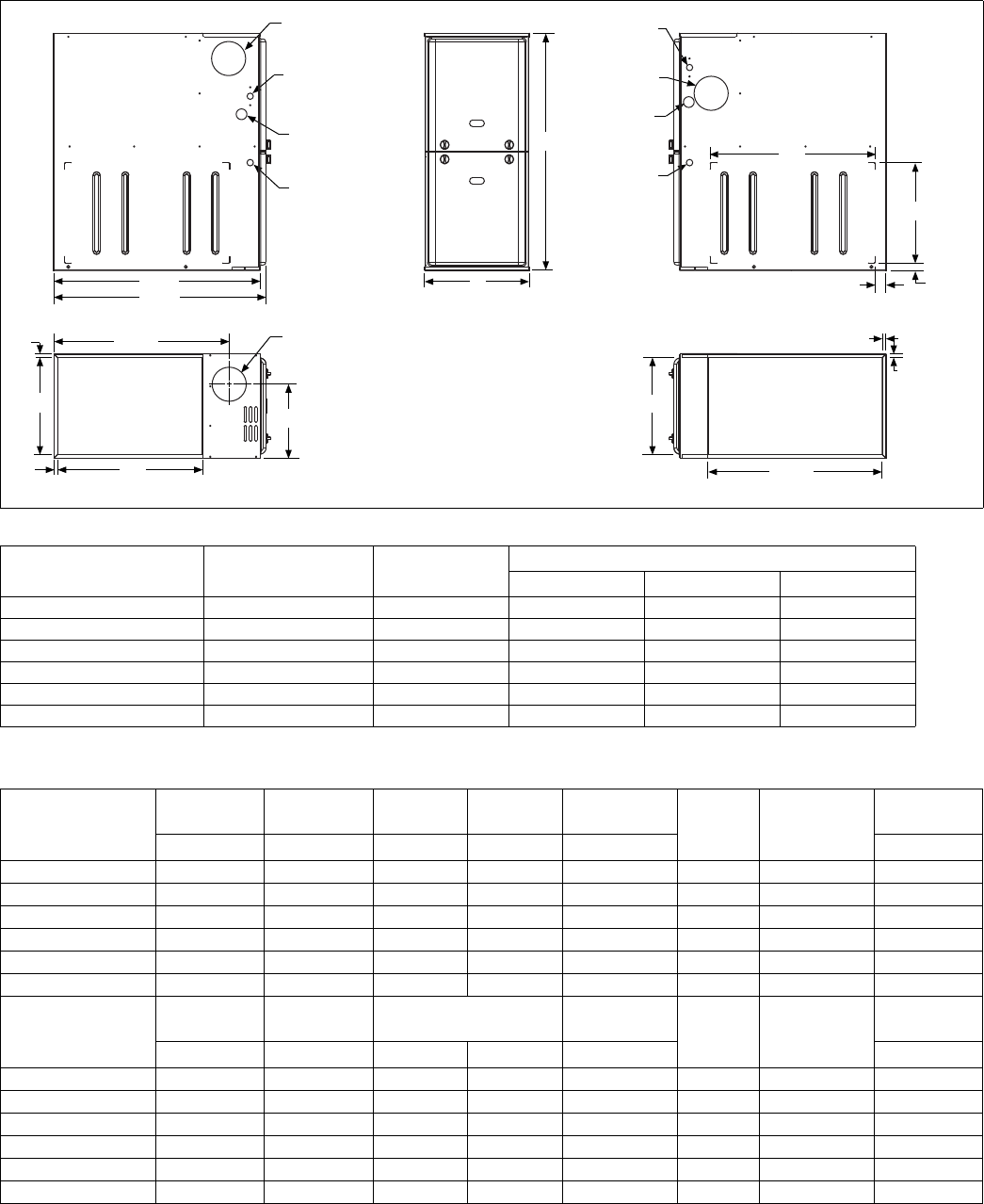
Cabinet and Duct Dimensions
BTUH (kW)
Input
Nominal
CFM (m3/min)
Cabinet
Size
Cabinet Dimensions (Inches)
ABC
TM8Y060A12MP11 1200 (34.0) A 14 1/2 13 3/8 10.3
TM8Y080B12MP11 1200 (34.0) B 17 1/2 16 3/8 11.8
TM8Y080C16MP11 1600 (45.3) C 21 19 7/8 13.6
TM8Y100C16MP11 1600 (45.3) C 21 19 7/8 13.6
TM8Y100C20MP11 2000 (56.6) C 21 19 7/8 13.6
TM8Y120C20MP11 2000 (56.6) C 21 19 7/8 13.6
Ratings & Physical / Electrical Data
Models
High Fire
Input Low Fire
Input High Fire
Output Low Fire
Output Nominal
Airflow AFUE Max
Over-Current
Protection
Max. Outlet
Air Temp
MBH MBH MBH MBH CFM °F
TM8Y060A12MP11 60 39 48 31.2 1200 80.0 15 160
TM8Y080B12MP11 80 52 64 41.6 1200 80.0 15 160
TM8Y080C16MP11 80 52 64 41.6 1600 80.0 15 160
TM8Y100C16MP11 100 65 80 52 1600 80.0 15 160
TM8Y100C20MP11 100 65 80 52 2000 80.0 15 160
TM8Y120C20MP11 120 78 96 62.4 2000 80.0 15 160
Models
High Fire Air
Temp. Rise Low Fire Air
Temp. Rise Blower Blower
Size Total Unit
Amps
Min. wire Size
(awg) @ 75 ft
one way
Operating
Weight
°F °F HP Amps In. Lbs.
TM8Y060A12MP11 30-60 20-50 1/2 6.8 11 x 8 9.3 14 94
TM8Y080B12MP11 35-65 20-50 1/2 6.8 11 x 8 9.3 14 103
TM8Y080C16MP11 30-60 20-50 1/2 6.8 11 x 10 9.3 14 114
TM8Y100C16MP11 30-60 20-50 1/2 6.8 11 x 10 9.3 14 118
TM8Y100C20MP11 30-60 20-50 3/4 8.4 11 x 11 10.9 14 122
TM8Y120C20MP11 35-65 20-50 3/4 8.4 11 x 11 10.9 14 129
5129592-YTG-A-0815
Johnson Controls Unitary Products 3
HORIZONTAL SIDEWALL VENTING
For applications where vertical venting is not possible, the only
approved method of horizontal venting is the use of an auxiliary
power vent. Auxiliary power venter's must be approved by CSA,
UL, or other recognized safety agencies. Follow all application
and installation details provided by the manufacturer of the
power vent.
FILTER PERFORMANCE
The airflow capacity data published in the “Blower Perfor-
mance” table shown represents blower performance WITHOUT
filters.
All applications of these furnaces require the use of field
installed air filters. All filter media and mounting hardware or
provisions must be field installed external to the furnace cabi-
net. DO NOT attempt to install any filters inside the furnace. 1. Air velocity through throwaway type filters may not exceed 300 feet per min-
ute (91.4 m/min). All velocities over this require the use of high velocity fil-
ters.
2. Do not exceed 1800 CFM using a single side return and a 16x25 filter. For
CFM greater than 1800, you may use two side returns or one side and the
bottom or one return with a transition to allow use of a 20x25 filter.
ACCESSORIES
Propane (LP) Conversion Kit -
1NP0347 - All Models
This accessory conversion kit may be used to convert natural
gas units for propane (LP) operation.
Side Return Filter Racks -
1SR0200 - All Models
1SR0302 - All Models
1SF0101 - All Models
Bottom Return Filter Racks -
1BR0514 or 1BR0614 - For 14-1/2” cabinets
1BR0517 or 1BR0617 - For 17-1/2” cabinets
1BR0521 or 1BR0621 - For 21” cabinets
1BR05xx series are galvanized steel filter racks. 1BR06xx are
pre-painted steel filter racks to match the appearance of the fur-
nace cabinet.
Masonry Chimney Kits -
For installations where these furnaces are vented using existing
or new lined masonry chimneys.
1CK0603
1CK0604
Combustible Floor Base Kit -
For installation of these furnaces in downflow applications
directly onto combustible flooring material, These kits are
required to prevent potential overheating situations. These kits
are also required in any applications where the furnace in
installed in a downflow configuration without an evaporator coil,
where the combustible floor base kit provides access for com-
bustible airflow.
1CB0514 - For 14-1/2” cabinets
1CB0517 - For 17-1/2” cabinets
1CB0521 - For 21” cabinets
High Altitude Pressure Switches -
For installation where the altitude is less than 5,000 feet it is not
required that the pressure switch be changed. For altitudes
above 5,000 feet, see kits below.
1PS3309
Thermostats - Compatible thermostat controls are available
through accessory sourcing. For optimum performance and
installation, refer to the UPGNET “Low Voltage Wiring Diagram”
document to select and apply controls.
Single side return above 1800 CFM is approved as long as
the filter velocity does not exceed filter manufacturer’s rec-
ommendation and a transition is used to allow use on a
20x25 filter.
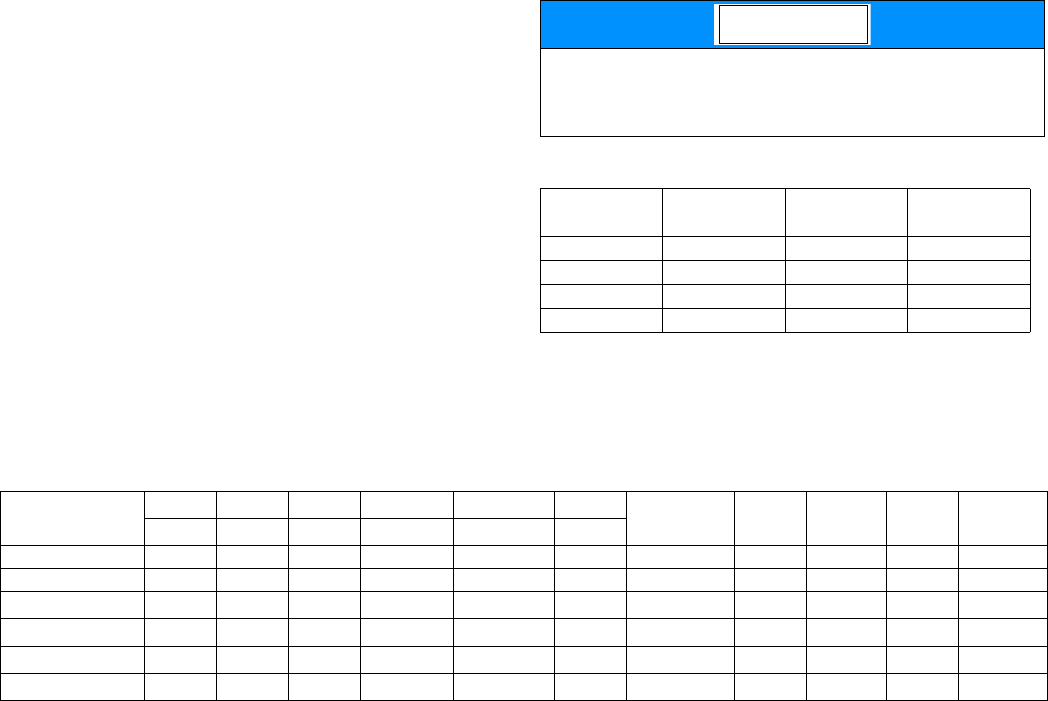
Recommended Filter Sizes
CFM Cabinet
Size Side
(in) Bottom
(in)
1200 A 16 x 25 14 x 25
1200 B 16 x 25 16 x 25
1600 C 16 x 25 20 x 25
2000 C (2) 16 x 25 20 x 25
NOTICE
Unit Clearances to Combustibles (All Dimensions in Inches, and All Surfaces Identified with the Unit in an Upflow Configuration)
Application Top Front Rear Left Side Right Side Flue Floor/
Bottom Closet Alcove Attic Line
Contact
In. (cm) In. (cm) In. (cm) In. (cm) In. (cm) In. (cm)
Upflow 1 (2.5) 1 (2.5) 0 (0.0) 0 (0.0) 0 (0.0) 6 (15.2) Combustible Yes Yes Yes No
Upflow B-Vent 1 (2.5) 1 (2.5) 0 (0.0) 0 (0.0) 0 (0.0) 1 (2.5) Combustible Yes Yes Yes No
Downflow 1 (2.5) 1 (2.5) 0 (0.0) 0 (0.0) 0 (0.0) 6 (15.2) 1 (25.4)1
1. Combustion floor base accessory or air conditioning coil required for use on combustible floor.
Yes Yes Yes No
Downflow B-Vent 1 (2.5) 1 (2.5) 0 (0.0) 0 (0.0) 0 (0.0) 1 (2.5) 1 (25.4)1Yes Yes Yes No
Horizontal 1 (2.5) 1 (2.5) 0 (0.0) 0 (0.0) 0 (0.0) 6 (15.2) Combustible No Yes Yes Yes2
2. Line contact only permitted between lines formed by the intersection of the rear panel and side panel (top in horizontal position) of the furnace jacket and building
joists, studs or framing.
Horizontal B-Vent 1 (2.5) 1 (2.5) 0 (0.0) 0 (0.0) 0 (0.0) 1 (2.5) Combustible No Yes Yes Yes2
Subject to change without notice. Published in U.S.A. 5129592-YTG-A-0815
Copyright © 2015 by Johnson Controls, Inc. All rights reserved. Supersedes: Nothing
York International Corp.
5005 York Drive
Norman, OK 73069
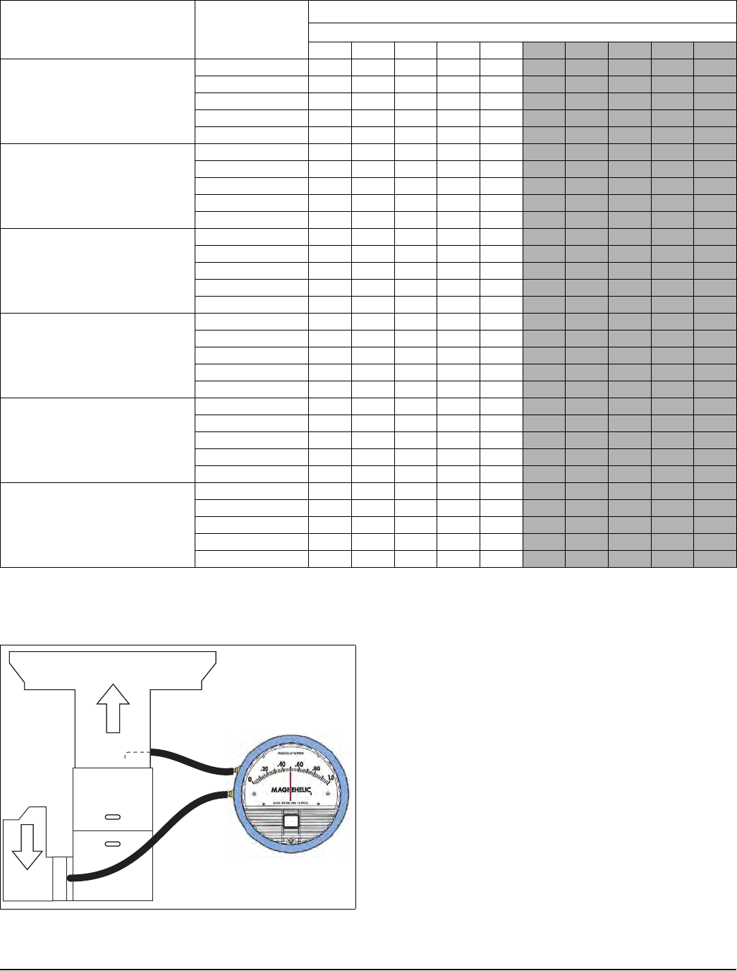
Note: Operation at external static pressure higher than rating on furnace data plate is not recommended.
EXTERNAL STATIC PRESSURE SETUP Set appropriate airflow per temperature rise for gas heating. Set
appropriate airflow per Table 14 for cooling/heat pump heating
operating based on outdoor unit size and external static pres-
sure.
To measure external static pressure:
• Measure the supply air static pressure
• Record this positive number
• Measure the return air static pressure
• Record this negative number
• Treat the negative number as a positive and add the two
numbers together
• This is total system static
Blower Performance CFM - Any Position (without filter)
Models Speed
Airflow Data (SCFM)1, 2
1. Airflow expressed in standard cubic feet per minute (SCFM).
2. Motor voltage at 115 V.
Ext. Static Pressure (in. H2O)
0.1 0.2 0.3 0.4 0.5 0.6 0.7 0.8 0.9 1.0
060A12
High 1260 1220 1180 1150 1110 1070 1030 990 940 900
Medium High 1160 1120 1080 1030 990 950 900 850 800 760
Medium 1010 960 920 880 830 780 740 680 640 590
Medium Low 860 810 770 710 670 580 560 510 460 410
Low 800 760 710 650 610 550 500 460 390 350
080B12
High 1330 1300 1270 1240 1210 1160 1130 1090 1050 1000
Medium High 1140 1100 1070 1020 990 950 900 850 800 760
Medium 990 960 920 870 830 780 730 680 630 580
Medium Low 920 890 840 790 740 700 640 600 550 510
Low 820 770 730 680 630 580 540 480 430 390
080C16
High 1730 1700 1660 1610 1580 1520 1470 1410 1360 1300
Medium High 1560 1530 1490 1450 1400 1350 1310 1270 1220 1170
Medium 1370 1330 1280 1230 1180 1130 1080 1030 970 910
Medium Low 1190 1140 1090 1040 990 930 870 820 750 680
Low 1000 940 880 820 750 680 600 540 460 410
100C16
High 1730 1690 1650 1610 1570 1530 1470 1420 1360 1310
Medium High 1570 1530 1490 1440 1400 1360 1320 1270 1220 1170
Medium 1360 1310 1260 1220 1180 1130 1070 1010 950 890
Medium Low 1210 1160 1110 1050 1000 940 880 810 760 700
Low 1010 950 900 820 760 680 610 540 500 430
100C20
High 2230 2180 2130 2070 2020 1960 1900 1850 1790 1720
Medium High 1820 1780 1740 1680 1620 1580 1530 1470 1410 1350
Medium 1610 1550 1500 1440 1390 1340 1280 1230 1170 1110
Medium Low 1440 1380 1320 1270 1210 1150 1090 1030 960 890
Low 1210 1150 1080 1020 960 890 820 740 680 640
120C20
High 2150 2020 2040 1990 1930 1880 1820 1770 1720 1660
Medium High 1780 1740 1690 1640 1590 1540 1490 1430 1380 1310
Medium 1580 1520 1470 1420 1370 1320 1270 1220 1160 1090
Medium Low 1410 1350 1290 1240 1180 1130 1070 1020 950 890
Low 1190 1130 1060 1000 940 880 820 760 680 630
Supply Duct
Return
Duct
