York Tm9V Technical Guide 700706 YTG G 0615
2015-09-09
: York Tm9V-Technical-Guide york-tm9v-technical-guide-811962 york pdf
Open the PDF directly: View PDF ![]() .
.
Page Count: 4
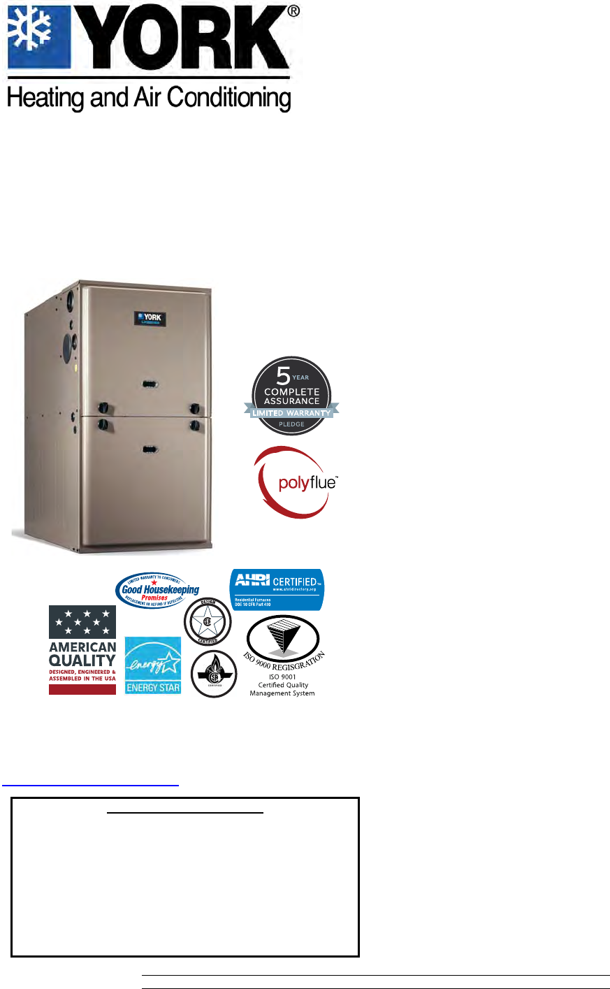
TECHNICAL GUIDE
96% AFUE TWO STAGE VARIABLE SPEED ECM
RESIDENTIAL GAS FURNACES
MULTI-POSITION
MODELS: TM9V*C
NATURAL GAS
40 - 120 MBH INPUT
Due to continuous product improvement, specifications are
subject to change without notice.
Visit us on the web at www.york.com
Additional rating information can be found at
www.ahridirectory.org
WARRANTY SUMMARY
A 20-year limited warranty on heat exchangers in residen-
tial applications.
A 10-year warranty on the heat exchanger in commercial
applications.
Standard 5-year limited Parts warranty.
Extended lifetime heat exchanger and 10-year limited
parts warranty when product is registered online within
90 days of purchase for replacement or closing for new
home construction.
See Limited Warranty certificate in Users Information Manual for details.
700706-YTG-G-0615
FOR DISTRIBUTION USE ONLY - NOT TO BE USED AT POINT OF RETAIL SALE
DESCRIPTION
These compact units employ induced combustion, reliable hot
surface ignition and high heat transfer aluminized tubular heat
exchangers. The units are factory shipped for installation in
upflow or horizontal applications and may be converted for
downflow applications.
These furnaces are designed for residential installation in a
basement, closet, alcove, attic, recreation room or garage and
are also ideal for commercial applications. All units are factory
assembled, wired and tested to assure safe dependable and
economical installation and operation.
These units are Category IV, National Fuel Gas Code and may
be vented either through side wall or roof applications using
approved plastic combustion air and vent piping. Approved plas-
tic combustion air and vent piping include Polyflue (a polypropyl-
ene venting systems).
FEATURES
• Two stage heating operation includes two stage gas valve,
two stage inducer operation and variable speed ECM
blower operation. Adjustable delay timer allows two stage
operation with a single stage thermostat.
• Easily applied in upflow, horizontal left or right, or downflow
installation with minimal conversion necessary.
• Compact, easy to install, ideal height 33" tall cabinet.
• ECM variable speed drive for cooling SEER enhancement,
improved comfort with optional airflow delay profiles, and
continuous fan options for IAQ performance.
• Easy access to controls to connect power/control wiring.
• Built-in, high level self diagnostics with fault code display.
• Low unit amp requirement for easy replacement application.
• All models are convertible to use propane (LP) gas.
• Electronic Hot Surface Ignition saves fuel cost with
increased dependability and reliability.
• 100% shut off main gas valve for extra safety.
• 24V, 40 VA control transformer and blower relay supplied
for add-on cooling.
• Hi-tech tubular aluminized steel primary heat exchanger
with stainless steel tube/aluminum fin secondary heat
exchanger for outstanding efficiency.
• Solid removable bottom panel allows easy conversion.
• Airflow leakage less than 1% of nominal airflow for duct
blaster conditions.
• No knockouts to deal with, making installation easier.
• Movable duct connector flanges for application flexibility.
• Quiet inducer operation, burner, and blower operation.
• Inducer rotates for easy conversion of venting options.
• Fully supported blower assembly for easy access and
removal of blower.
• External air filters used for maximum flexibility in meeting
customers IAQ needs.
• Insulated blower compartment for thermal and acoustic per-
formance.
• 1/4 turn knobs provided for easy independent door removal.
• Internal condensate trap design (patent pending) provides
condensate management options and is self priming to pre-
vent nuisance problems.
• Protection included from air intake, exhaust vent or conden-
sate blockage.
• Venting applications maybe installed as either 2 pipe sealed
combustion or single pipe vent using indoor combustion air.
• These models may be connected as part of a communicat-
ing control system using a 4-wire connection bus.
700706-YTG-G-0615
2Johnson Controls Unitary Products
Annual Fuel Utilization Efficiency (AFUE) numbers are determined in accordance with DOE Test procedures.
Wire size and over current protection must comply with the National Electrical Code (NFPA-70-latest edition) and all local codes.
The furnace shall be installed so that the electrical components are protected from water.
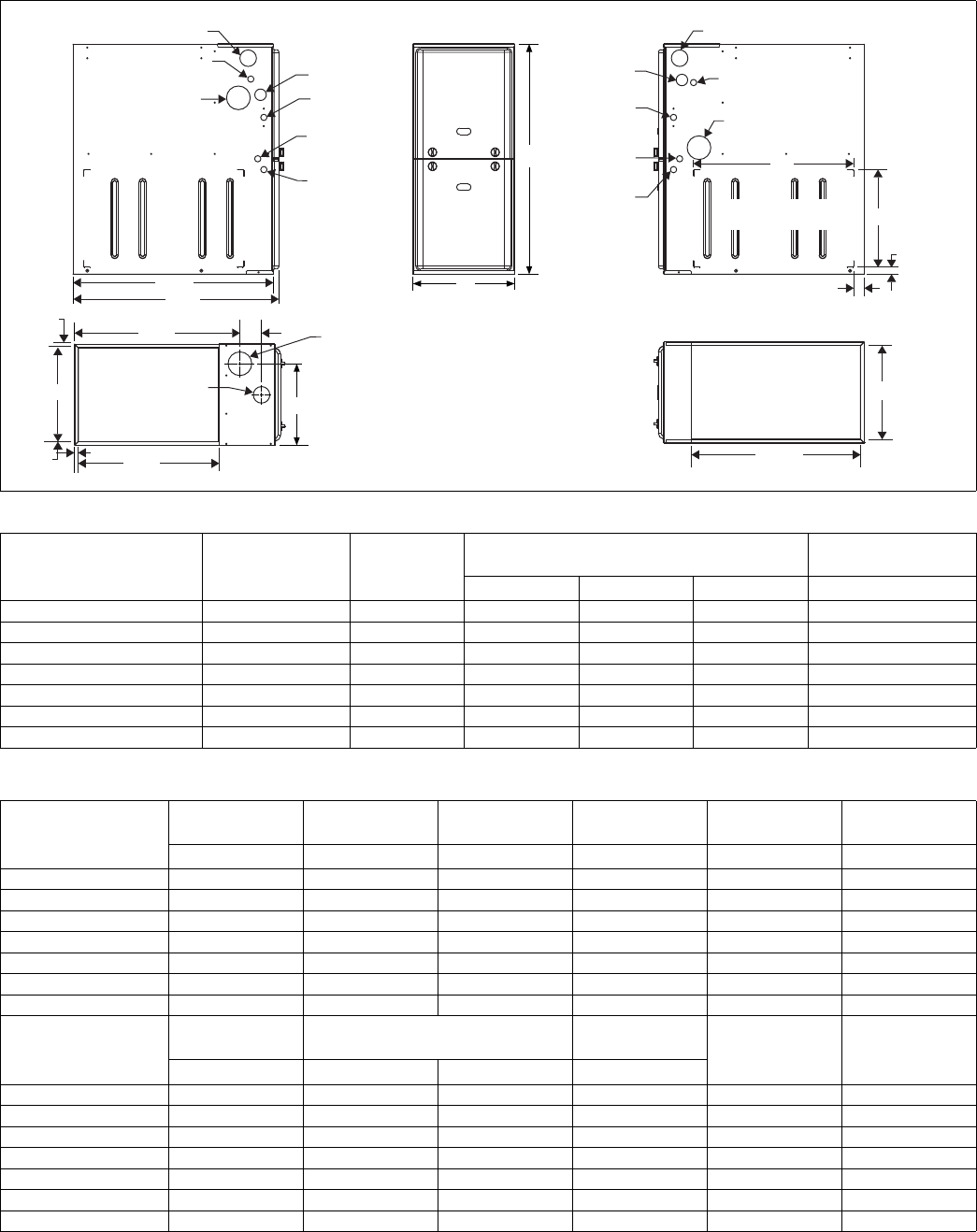
FRONT
33
A
LEFT SIDE
Combustion Air Inlet
Condensate Drain
(Downflow)
Vent Outlet
Thermostat
Wiring
28.5”
Gas Pipe
Entry
Electrical
Entry
Condensate
Drain
Thermostat
Wiring
RIGHT SIDE
Vent Outlet
Condensate Drain
(Downflow)
14”
1”
1.5”
23”
Combustion Air Inlet
Gas Pipe
Entry
Electrical
Entry
Condensate
Drain
Optional Return Air
Cutout (Either side)
29.5”
C
SUPPLY END
.56”
.56”
20”
B
3”
23.8”
.56”
Combustion
Air Inlet
Vent
Outlet
RETURN END
B
24.25”
Cabinet & Duct Dimensions
Model Nominal
CFM (m3/min)
Cabinet
Size
Cabinet Dimensions (Inches) Approximate
Operating Weights
ABC Lbs
TM9V040A10MP11C 1000 A 14-1/2 13-3/8 11-3/4 113
TM9V060B12MP11C 1200 B 17-1/2 16-3/8 13-1/4 122
TM9V080B12MP11C 1200 B 17-1/2 16-3/8 13-1/4 126
TM9V080C16MP11C 1600 C 21 19-7/8 16-1/2 136
TM9V100C16MP11C 1600 C 21 19-7/8 18-1/4 142
TM9V100C20MP11C 2000 C 21 19-7/8 18-1/4 145
TM9V120D20MP11C 2000 D 24-1/2 23-3/8 21-3/4 156
Ratings & Physical / Electrical Data
Model
Input
High/Low Output
High/Low Total
Unit AFUE High Fire
Air Temp. Rise Low Fire
Air Temp. Rise
MBH MBH Amps % °F °F
TM9V040A10MP11C 40/26 38/25 9 96 30 - 60 20 - 50
TM9V060B12MP11C 60/39 58/37 9 96 35 - 65 35 - 65
TM9V080B12MP11C 80/52 77/50 9 96 40 - 70 35 - 65
TM9V080C16MP11C 80/52 77/50 12 96 35 - 65 35 - 65
TM9V100C16MP11C 100/65 96/62 12 96 35 - 65 30 - 65
TM9V100C20MP11C 100/65 96/62 14 96 35 - 65 35 - 65
TM9V120D20MP11C 120/78 115/75 14 96 35 - 65 35 - 65
Model
Max. Outlet
Air Temp. Blower Blower Size
Max.
Over-current
Protect
Min. Wire Size
(awg) @ 75 ft.
One Way
°F HP Amps In.
TM9V040A10MP11C 180 1/2 7 11 X 8 15 14
TM9V060B12MP11C 180 1/2 7 11 x 8 15 14
TM9V080B12MP11C 175 1/2 7 11 x 8 15 14
TM9V080C16MP11C 165 3/4 10.2 11 x 10 15 14
TM9V100C16MP11C 180 3/4 10.2 11 x 10 15 14
TM9V100C20MP11C 170 1 12.7 11 x 11 20 12
TM9V120D20MP11C 180 1 12.7 11 x 11 20 12
700706-YTG-G-0615
Johnson Controls Unitary Products 3
FILTER PERFORMANCE
The airflow capacity data published in the “Blower Perfor-
mance” table shown represents blower performance WITHOUT
filters.
All applications of these furnaces require the use of field
installed air filters. All filter media and mounting hardware or
provisions must be field installed external to the furnace cabi-
net. DO NOT attempt to install any filters inside the furnace.
1. Air velocity through throwaway type filters may not exceed 300 feet per min-
ute (91.4 m/min). All velocities over this require the use of high velocity fil-
ters.
2. Do not exceed 1800 CFM using a single side return and a 16x25 filter. For
CFM greater than 1800, you may use two side returns or one side and the
bottom or one return with a transition to allow use of a 20x25 filter.
* - 24" clearance in front and 18" on side recommended for service
access.
All furnaces approved for alcove and attic installation.
ACCESSORIES
Propane (LP) Conversion Kit - This accessory conversion kit
may be used to convert natural gas (N) units for propane (LP)
operation.
S1-1NP0347 - All Models
Concentric Vent Termination - For use through rooftop, side-
wall. Allows combustion air to enter and exhaust to exit through
single common hole. Eliminates unsightly elbows for a cleaner
installation.
S1-1CT0302 (2") & S1-1CT0302-636 (2")
S1-1CT0303 (3") & S1-1CT0303-636 (3")
Sidewall Vent Termination Kit - For use on sidewall, two-pipe
installations only. Provide a more attractive termination for loca-
tions where the terminal is visible on the side of the home.
S1-1HT0901 (3")
S1-1HT0902 (2")
Condensate Neutralizer Kit - Neutralizer cartridge has a 1/2”
plastic tube fittings for installation in the drain line. Calcium car-
bonate refill media is also available from the Source 1 Parts
(P/N 026-30228-000).
1NK0301
Side Return Filter Racks -
S1-1SR0200 - All Models
S1-1SR0402 - All Models
Bottom Return Filter Racks - 1BR05xx series are galvanized
steel filter racks. 1BR06xx are pre-painted steel filter racks to
match the appearance of the furnace cabinet.
S1-1BR0514 or 1BR0614 - For 14-1/2” cabinets
S1-1BR0517 or 1BR0617 - For 17-1/2” cabinets
S1-1BR0521 or 1BR0621 - For 21” cabinets
S1-1BR0524 or 1BR0624 - For 24-1/2” cabinets
Combustible Floor Base Kit - For installation of these fur-
naces in downflow applications directly onto combustible floor-
ing material, These kits are required to prevent potential
overheating situations.tible floor base kit provides access for
combustible airflow.
S1-1CB0514 - For 14-1/2” cabinets
S1-1CB0517 - For 17-1/2” cabinets
S1-1CB0521 - For 21” cabinets
S1-1CB0524 - For 24-1/2” cabinets
High Altitude Pressure Switches - For installation where the
altitude is less than 5,000 feet it is not required that the pres-
sure switch be changed. For altitudes above 5,000 feet, see kits
below.
S1-1PS3308 - All Models
Thermostats - Compatible thermostat controls are available
through accessory sourcing. For optimum performance, these
indoor units are fully compatible with the Residential Touch-
screen Communicating Control S1-TTSCC01.
NOTICE
Single side return above 1800 CFM is approved as long as
the filter velocity does not exceed filter manufacturer’s rec-
ommendation and a transition is used to allow use on a
20x25 filter.
Recommended Filter Sizes (High velocity 600 FPM)
CFM Cabinet
Size Side
(in) Bottom
(in)
1000 A 16 x 25 14 x 25
1200 B 16 x 25 16 x 25
1600 C 16 x 25 20 x 25
2000 C (2) 16 x 25 20 x 25
2000 D (2) 16 x 25 22 x 25
Unit Clearances to Combustibles
Application Upflow Downflow Horizontal
Top 1" 0" 0"
Vent 0" 0" 0"
Rear 0" 0" 0"
Side 0" 0" 1"
Front* 0" 0" 0"
Floor Combustible Combustible1
1. For combustible floors only when used with special sub-base.
Combustible
Closet Yes Yes Yes
Line Contact No No Yes
Subject to change without notice. Published in U.S.A. 700706-YTG-G-0615
Copyright © 2015 by Johnson Controls, Inc. All rights reserved. Supersedes: 700706-YTG-F-0315
York International Corp.
5005 York Drive
Norman, OK 73069
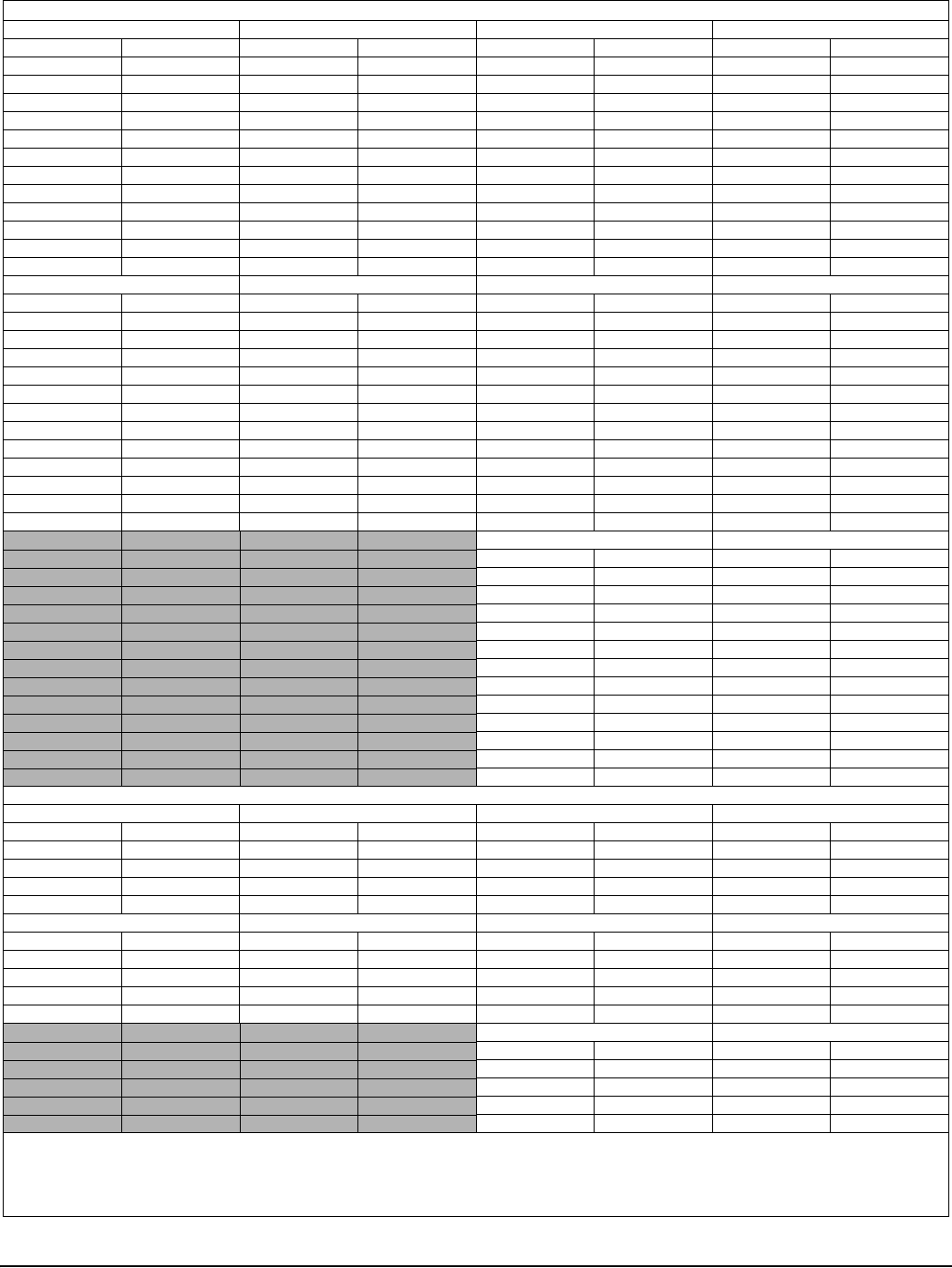
Air Flow Data
HIGH / LOW SPEED COOLING AND HEAT PUMP CFM
040A10 060B12 080B12 Jumper Settings
High Low High Low High Low COOL Tap ADJ Tap
1073 704 1320 858 1320 858 A B
957 622 1100 715 1100 715 B B
975 640 1200 780 1200 780 A A
870 565 1000 650 1000 650 B A
878 576 1080 702 1080 702 A C
770 501 880 572 880 572 C B
783 509 900 585 900 585 B C
649 440 660 440 660 440 D B
700 455 800 520 800 520 C A
590 400 600 400 600 400 D A
630 410 720 468 720 468 C C
531 400 540 400 540 400 D C
080C16 100C16 100C20 Jumper Settings
High Low High Low High Low COOL Tap ADJ Tap
1760 1144 1760 1144 2200 1430 A B
1540 1001 1540 1001 1760 1144 B B
1600 1040 1600 1040 2000 1300 A A
1400 910 1400 910 1600 1040 B A
1440 936 1440 936 1800 1170 A C
1320 858 1320 858 1540 1001 C B
1260 819 1260 819 1440 936 B C
1100 715 1100 715 1320 858 D B
1200 780 1200 780 1400 910 C A
1000 650 1000 650 1200 780 D A
1080 702 1080 702 1260 819 C C
900 585 900 585 1080 702 D C
120D20 Jumper Settings
High Low COOL Tap ADJ Tap
2200 1430 A B
1760 1144 B B
2000 1300 A A
1600 1040 B A
1800 1170 A C
1540 1001 C B
1440 936 B C
1320 858 D B
1400 910 C A
1200 780 D A
1260 819 C C
1080 702 D C
HIGH/LOW HEAT CFM
040A10 060B12 080B12 Jumper Settings
High Low High Low High Low HEAT Tap ADJ Tap
890 770 1200 870 1366 1156 A Any
790 660 1070 770 1293 1022 B Any
711 578 970 693 1185 924 C Any
646 514 890 630 1094 840 D Any
080C16 100C16 100C20 Jumper Settings
High Low High Low High Low HEAT Tap ADJ Tap
1580 1156 1975 1444 1975 1284 A Any
1422 1027 1778 1284 1778 1156 B Any
1293 924 1616 1156 1616 1050 C Any
1185 840 1481 1050 1481 963 D Any
120D20 Jumper Settings
High Low HEAT Tap ADJ Tap
2250 1539 A Any
2133 1385 B Any
1939 1259 C Any
1778 1154 D Any
All CFM’s are shown at 0.5” w.c. external static pressure.These units have variable speed motors that automatically adjust to provide constant CFM from 0.0” to 0.6”
w.c. static pressure. From 0.6” to 1.0” static pressure, CFM is reduced by 2% per 0.1” increase in static. Operation on duct systems with greater than 1.0” w.c. external
static pressure is not recommended.
NOTE: At some settings, LOW COOL and/or LOW HEAT airflow may be lower that what is required to operate an airflow switch on certain models of electronic air
cleaners. Consult the instructions for the electronic air cleaner for further details.
* The ADJ “D” tap should not be used.
