York Ycal0041 Users Manual Air Cooled Scroll Chiller (Style D) YCAL0041–YCAL0065 (47–60 TON) R 22 (50 & 60HZ)
YCAL0041 to the manual f2e4a920-9955-493f-bd43-b1337a709bdc
2015-02-02
: York Ycal0041-Users-Manual york-ycal0041-users-manual-455205 york pdf
Open the PDF directly: View PDF ![]() .
.
Page Count: 80
- FORM 150.64-EG1 (505)
- Introduction
- Specification
- Options and Accessories
- Selection Data
- Design Parameters
- Water Pressure Drop
- Ratings - R-22 (60Hz - English Units)
- Ratings - R-22 (60Hz - English Units) - Cont.
- Ratings - R-22 (60Hz - SI Units)
- Ratings - R-22 (50Hz - English Units)
- Ratings - R-22 (50Hz - English Units) - Cont.
- Ratings - R-22 (50Hz - SI Units)
- Part Load Ratings - R-22 (English Units)
- Part Load Ratings - R-22 (SI)
- Physical Data
- Sound Data
- Dimensions - YCAL0041 (English)
- Dimensions - YCAL0045 (English)
- Dimensions - YCAL0051 (English)
- Dimensions - YCAL0055EC - (English)
- Dimensions - YCAL0061 (English)
- Dimensions - YCAL0065 (English)
- Dimensions - YCAL0041 (SI)
- Dimensions - YCAL0045 (SI)
- Dimensions - YCAL0051 (SI)
- Dimensions -YCAL0055 (SI)
- Dimensions - YCAL0061 (SI)
- Dimensions - YCAL0065 (SI)
- Isolator Selections
- Isolator Details (cont'd)
- Electrical Data
- Electrical Data - 60Hz
- Electrical Data - 50Hz
- Power Wiring
- Control Wiring
- Application Data
- Guide Specifications
FORM 150.64-EG1 (505)
AIR-COOLED
SCROLL CHILLERS
STYLE D
YCAL0041 – YCAL0065
50 AND 60HZ
47 – 60 TON
165 – 210 KW
R-22
YORK INTERNATIONAL
2
Table of Contents
FORM 150.64-EG1 (405) ....................................................................................................................................................................................... 1
Introduction ........................................................................................................................................................................................................... 3
Specification ......................................................................................................................................................................................................... 4
Options and Accessories .................................................................................................................................................................................... 7
Selection Data ......................................................................................................................................................................................................11
Design Parameters ............................................................................................................................................................................................. 13
Water Pressure Drop .......................................................................................................................................................................................... 14
Ratings - R-22 (60Hz - English Units) ............................................................................................................................................................... 16
Ratings - R-22 (60Hz - English Units) - Cont. ................................................................................................................................................... 18
Ratings - R-22 (60Hz - SI Units) ......................................................................................................................................................................... 20
Ratings - R-22 (50Hz - English Units) ............................................................................................................................................................... 22
Ratings - R-22 (50Hz - English Units) - Cont. ................................................................................................................................................... 24
Ratings - R-22 (50Hz - SI Units) ......................................................................................................................................................................... 26
Part Load Ratings - R-22 (English Units) ......................................................................................................................................................... 28
Part Load Ratings - R-22 (SI) ............................................................................................................................................................................. 29
Physical Data ..................................................................................................................................................................................................... 30
Sound Data .......................................................................................................................................................................................................... 32
Dimensions - YCAL0041 (English) .................................................................................................................................................................... 34
Dimensions - YCAL0045 (English) .................................................................................................................................................................... 36
Dimensions - YCAL0051 (English) .................................................................................................................................................................... 38
Dimensions - YCAL0055EC - (English) ............................................................................................................................................................. 40
Dimensions - YCAL0061 (English) .................................................................................................................................................................... 42
Dimensions - YCAL0065 (English) .................................................................................................................................................................... 44
Dimensions - YCAL0041 (SI) ............................................................................................................................................................................. 46
Dimensions - YCAL0045 (SI) ............................................................................................................................................................................. 48
Dimensions - YCAL0051 (SI) ............................................................................................................................................................................. 50
Dimensions -YCAL0055 (SI) .............................................................................................................................................................................. 52
Dimensions - YCAL0061 (SI) ............................................................................................................................................................................. 54
Dimensions - YCAL0065 (SI) ............................................................................................................................................................................. 56
Isolator Selections ............................................................................................................................................................................................. 58
Isolator Details (cont'd) ...................................................................................................................................................................................... 60
Electrical Data ..................................................................................................................................................................................................... 62
Electrical Data - 60Hz ......................................................................................................................................................................................... 64
Electrical Data - 50Hz ......................................................................................................................................................................................... 66
Power Wiring ....................................................................................................................................................................................................... 68
Control Wiring ..................................................................................................................................................................................................... 71
Application Data ................................................................................................................................................................................................. 72
Guide Specifications .......................................................................................................................................................................................... 74
YORK INTERNATIONAL 3
FORM 150.64-EG1
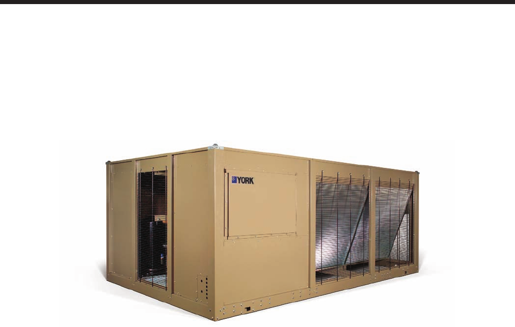
YORK Air-Cooled Scroll Chillers provide chilled water for all air conditioning applications using
central station air handling or terminal units. They are completely self-contained and are designed
for outdoor (roof or ground level) installation. Each unit includes hermetic scroll compressors,
a liquid cooler, air cooled condenser, and a weather resistant microprocessor control center, all
mounted on a pressed steel base.
Introduction

YORK INTERNATIONAL
4
Specification
GENERAL
The 47 - 60 Ton (165 - 210 kW) YCAL models are
shipped complete from the factory ready for installation
and use.
The unit is pressure-tested, evacuated, and fully charged
with Refrigerant-22 (HCFC-22) and includes an initial
oil charge. After assembly, a complete operational test
is performed with water flowing through the cooler to
assure that the refrigeration circuit operates correctly.
The unit structure is heavy-gauge, galvanized steel. This
galvanized steel is coated with baked-on powder paint,
which, when subjected to ASTM B117 1000 hour, salt
spray testing, yields a minimum ASTM 1654 rating of
“6”. Corrosion resistant wire mesh panels are added to
protect the condenser coil from incidental damage and
restrict unauthorized access to internal components.
Units are designed in accordance with NFPA 70 (Na-
tional Electric Code), ASHRAE/ANSI 15 Safety code for
mechanical refrigeration, ASME, Listed and labeled with
Intertek Testing Services (ETL) and rated in accordance
with ARI Standard 550/590-2003.
COMPRESSORS
The chiller has suction-gas cooled, hermetic, scroll com-
pressors. The YCAL compressors incorporate a compli-
ant scroll design in both the axial and radial direction. All
rotating parts are statically and dynamically balanced. A
large internal volume and oil reservoir provides greater
liquid tolerance. Compressor crankcase heaters are also
included for extra protection against liquid migration.
COOLER
The cooler is equipped with a heater controlled by a
separate thermostat. The heater provides freeze protec-
tion for the cooler down to -20°F (-29°C) ambient. The
cooler is covered with 3/4” (19mm) flexible, closed-cell,
foam insulation (K~0.25).
Brazed plate heat exchangers shall be UL (Underwriters
Laboratories) listed. Installing contractor must include
accommodations in the chilled water piping to allow
proper drainage and venting of the heat exchanger.
Water inlet and outlet connections are grooved for com-
patibility with factory supplied victaulic connections.
A strainer with a mesh size between .5 and 1.5 mm (40
mesh) is recommended upstream of the heat exchanger
to prevent clogging.
CONDENSER
Coils – Fin and tube condenser coils of seamless, inter-
nally-enhanced, high-condensing-coefficient, corrosion
resistant copper tubes are arranged in staggered rows,
mechanically expanded into aluminum fins. Integral
subcooling is included. The design working pressure of
the coil is 450 PSIG (31 bar).
Low Sound Fans – The condenser fans are composed
of corrosion resistant aluminum hub and glass-fiberrein-
forced composite blades molded into a low noise airfoil
section. They are designed for maximum efficiency and
are statically and dynamically balanced for vibration free
operation. They are directly driven by independent mo-
tors, and positioned for vertical air discharge. All blades
are statically and dynamically balanced for vibration-free
operation. The fan guards are constructed of heavy-
gauge, rust-resistant, PVCcoated steel wire.
Motors – The fan motors are Totally Enclosed Air-Over,
squirrel-cage type, current protected. They feature
ball bearings that are double-sealed and permanently
lubricated.

YORK INTERNATIONAL 5
FORM 150.64-EG1
MILLENNIUM CONTROL CENTER
All controls are contained in a NEMA 3R/12 (and
equivalent to IP55*) cabinet with hinged outer door and
includes:
Liquid Crystal Display with Light Emitting Diode back-
lighting for outdoor viewing:
Two display lines
Twenty characters per line
Color coded 12-button non-tactile keypad with sections
for:
DISPLAY/PRINT of typical information:
Chilled liquid temperatures
Ambient temperature
System pressures (each circuit)
Operating hours and starts (each compressor)
Print calls up to the liquid crystal display:
Operating data for the systems
History of fault shutdown data for up to
the last six fault shutdown conditions
An RS-232 port, in conjunction with this
press-to-print button, is provided to permit
the capability of hard copy print-outs via a
separate printer (by others).
ENTRY section to:
ENTER setpoints or modify system values
SETPOINTS updating can be performed to:
Chilled liquid temperature setpoint and range
Remote reset temperature range
Set daily schedule/holiday for start/stop
Manual override for servicing
Low and high ambient cutouts
Number of compressors
Low liquid temperature cutout
Low suction pressure cutout
High discharge pressure cutout
Anti-recycle timer (compressor start cycle
time)
Anti-coincident timer (delay compressor
starts)
UNIT section to:
Set time
Set unit options
UNIT ON/OFF switch
The microprocessor control center is capable of dis-
playing the following:
• Return and leaving liquid temperature
• Low leaving liquid temperature cutout setting
• Low ambient temperature cutout setting
• Outdoor air temperature
• English or Metric data
• Suction pressure cutout setting
• Each system suction pressure
• Discharge pressure (optional)
• Liquid Temperature Reset via a YORK ISN DDC or
Building Automation System (by others) via:
- a pulse width modulated (PWM) input as stan-
dard
- a 4-20 milliamp or 0 -10 VDC input, or contact
closure with the optional B.A.S. interface option
• Anti-recycle timer status for each system
• Anti-coincident system start timer condition
• Compressor run status
• No cooling load condition
• Day, date and time
• Daily start/stop times
• Holiday status
• Automatic or manual system lead/lag control
• Lead system definition
• Compressor starts & operating hours
(each compressor)
• Status of hot gas valves, evaporator heater
and fan operation
• Run permissive status
• Number of compressors running
• Liquid solenoid valve status
• Load & unload timer status
• Water pump status
* Intensity of Protection European Standard

YORK INTERNATIONAL
6
Provisions are included for: pumpdown at shutdown;
optional remote chilled water temperature reset and two
steps of demand load limiting from an external building
automation system. Unit alarm contacts are standard.
The operating program is stored in non-volatile memory
(EPROM) to eliminate chiller failure due to AC powered
failure/battery discharge. Programmed setpoints are
retained in lithium battery-backed RTC memory for 5
years minimum.
POWER PANEL
Each panel contains:
• Compressor power terminals
• Compressor motor starting contactors per l.E.C.**
• Control power terminals to accept incoming for
115-1-60 control power
• Fan contactors & overload current protection
The power wiring is routed through liquid-tight conduit
to the compressors and fans.
** International Electrotechnical Commission

YORK INTERNATIONAL 7
FORM 150.64-EG1
Options and Accessories
POWER OPTIONS:
COMPRESSOR POWER CONNECTIONS – Single-
point (YCAL0041-0065) terminal block connection(s) are
provided as standard. The following power connections
are available as options. (See electrical data for specific
voltage and options availability.) (Factory-Mounted.)
SINGLE-POINT SUPPLY TERMINAL BLOCK – (stan-
dard on YCAL0041 - 0065 models). Includes enclosure,
terminal-block and interconnecting wiring to the com-
pressors. Separate external protection must be supplied,
by others, in the incoming compressor-power wiring. (Do
not include this option if either the SinglePoint NonFused
Disconnect Switch or Single-Point Circuit Breaker op-
tions have been included.)
SINGLE-POINT NON-FUSED DISCONNECT SWITCH
– Unit-mounted disconnect switch with external, lockable
handle (in compliance with Article 440-14 of N.E.C.),
can be supplied to isolate the unit power voltage for
servicing. Separate external fusing must be supplied,
by others in the power wiring, which must comply with
the National Electrical Code and/or local codes.
SINGLE-POINT CIRCUIT BREAKER – A unit mounted
circuit breaker with external, lockable handle (in com-
pliance with N.E.C. Article 440-14), can be supplied
to isolate the power voltage for servicing. (This option
includes the Single-Point Power connection.)
CONTROL TRANSFORMER – Converts unit power
voltage to 115-1-60 (0.5 or 1.0 KVA capacity). Fac-
tory mounting includes primary and secondary wiring
between the transformer and the control panel. (Fac-
tory-Mounted.)
POWER FACTOR CORRECTION CAPACITORS – Will
correct unit compressor power factors to a 0.90-0.95.
(Factory-Mounted.)
CONTROL OPTIONS:
AMBIENT KIT (LOW) – Units will operate to 25°F (-4°C).
This accessory includes all necessary components to
permit chiller operation to 0°F (-18°C). (This option in-
cludes the Discharge Pressure Transducer / Readout
Capability option.) For proper head pressure control in
applications below 25°F (-4°C), where wind gusts may
exceed five mph, it is recommended that Optional Con-
denser Louvered Enclosure Panels also be included.
(Factory-Mounted.)
AMBIENT KIT (HIGH) – Required if units are to operate
when the ambient temperature is above 115°F (46°C).
Includes discharge pressure transducers. (This option
includes the Discharge Pressure Transducer / Readout-
Capability option.) (Field-Mounted.)
BUILDING AUTOMATION SYSTEM INTERFACE – The
factory addition of a Printed Circuit Board to accept a
4-20 milliamp, 0-10VDC or contact closure input to reset
the leaving chiller liquid temperature from a Building Au-
tomation System. (Only one of following options can be
offered on a unit at a time: BAS, Remote Control Panel
or Multi-unit Sequence Control.) (Factory-Mounted.)
(The standard unit capabilities include remote startstop,
remote water temperature reset via a PWM input signal
or up to two steps of demand (load) limiting depending
on model.) (The standard control panel can be directly
connected to a YORK Building Automated System via
the standard onboard RS485 communication port.)
LANGUAGE LCD AND KEYPAD DISPLAY – Spanish,
French, and German unit LCD controls and keypad
display available. Standard language is English.
DISCHARGE PRESSURE TRANSDUCERS AND
READOUT CAPABILITY – The addition of pressure
transducers allows models to sense and display dis-
charge pressure. This is recommended for brine chilling
applications. (This option is included with either the low
or high ambient kits.) (Factory-Mounted.)
• Suction Pressure Transducers: Permits unit to
sense and display suction pressure. This capability
is standard on YCAL0041-0065 models.
MOTOR CURRENT MODULE – Capable of monitoring
compressor motor current. Provides extra protection
against compressor reverse rotation, phase-loss and
phase imbalance. Option consists of one module per
electrical system. (Factory-Mounted.)
OPTIVIEW REMOTE CONTROL PANEL - Graphical
interface panel to remotely control and monitor up to 8
different units. (Refer to form 201.18-SG4 for detailed
information)
MULTI-UNIT SEQUENCING – A separate Sequencing
Control Center is provided to handle sequencing control
of up to eight chillers in parallel based on mixed liquid
temperature (interconnecting wiring by others). (Only
one of following options can be offered on a unit at a
time: BAS, Remote Control Panel or Multi-unit Sequence
Control.) (Factory-Mounted.)
COMPRESSOR, PIPING, EVAPORATOR
OPTIONS:
LOW TEMPERATURE BRINE – Required for brine

YORK INTERNATIONAL
8
chilling below 30°F (-1°C) leaving brine temperature
for YCAL0041 - 0065 models. Option includes resized
thermal expansion valve. (Factory-Mounted)
CHICAGO CODE RELIEF VALVES – Unit will be pro-
vided with relief valves to meet Chicago code require-
ments. (Factory-Mounted)
SERVICE ISOLATION VALVE – Service suction and
discharge (ball type) isolation valves are added to unit
per system. This option also includes a system high
pressure relief valve in compliance with ASHRAE 15.
(Factory-Mounted)
HOT GAS BY-PASS – Permits continuous, stable opera-
tion at capacities below the minimum step of compressor
unloading to as low as 5% capacity (depending on both
the unit and operating conditions) by introducing an
artificial load on the cooler. Hot gas by-pass is installed
on only refrigerant system #1 on two-circuited units.
(Factory-Mounted)
DX COOLER 300 PSIG (21 bar) DWP WATERSIDE
– The waterside will be of 300 PSIG (21 bar) instead of
the standard 150 PSIG DWP. 300 PSIG R.F. flanges are
included on the DX cooler nozzles. (Factory-Mounted.)
The companion flanges will be field-supplied by oth-
ers.
FLANGES (VICTAULIC TYPE) – Consists of two (2)
Flange adapters for grooved end pipe (standard 150
psi [10.5 bar] cooler).
FLOW SWITCH – The flow switch or its equivalent must
be furnished with each unit.
150 PSIG (10.5 bar) DWP – For standard units. Johnson
Controls model F61MG-1C Vapor-proof SPDT, NEMA
4X switch (150 PSIG [10.5 bar] DWP), -20°F to 250°F
(-29°C to 121°C), with 1” NPT connection for upright
mounting in horizontal pipe. (Field-Mounted.)
300 psig (21 bar) DWP – For units with optional 300
PSIG (21 bar) DX cooler. McDonnell & Miller model
FS74W Vapor-proof SPDT, NEMA 4X switch (300 PSIG
(21 bar) DWP), -20°F to 300°F (-29°C to 149°C), with 1¼
inch MPT connection for upright mounting in horizontal
pipe. (Field-Mounted.)
DIFFERENTIAL PRESSURE SWITCH – Alternative
to an above mentioned flow switch. Pretempco model
DPS300AP40PF-82582-5 (300 psi max. working pres-
sure), SPDT 5 amp 125/250VAC switch, Range 0 - 40
PSID, deadband 0.5 - 0.8 psi, with 1/4” NPTE Pressure
Connections.
REMOTE DX COOLER – A split system arrangement
with the cooler, leaving & return water sensors, liquid
line solenoid valves, filter driers, sightglasses & TXVs
shipped loose for field connection to the air-cooled con-
densing section. The DX cooler and outdoor section will
have a nitrogen holding charge. Interconnecting rigid
piping, wiring and refrigerant are by others. Includes
YORK Service startup. See Form 150.62-NM1.1 (200)
for other application information. (This option includes
the Crankcase Heater option.)(Field-Mounted.)
CONDENSER AND CABINET OPTIONS:
Condenser coil protection against corrosive environ-
ments is available by choosing any of the following op-
tions. For additional application recommendations, refer
to FORM 150.12-ES1. (Factory-Mounted.)
PRE-COATED FIN CONDENSER COILS – The unit's
coils are constructed with black epoxy coated aluminum
fins. This can provide corrosion resistance comparable
to copper-fin coils in typical seashore locations. Either
these or the post-coated coils (below), are recommend-
ed for units being installed at the seashore or where salt
spray may hit the unit.
POST-COATED DIPPED CONDENSER COILS – The
unit's coils are constructed with dipped-cured condenser
coils. This is another choice for seashore and other
corrosive applications (with the exception of strong al-
kalies, oxidizers and wet bromine, chlorine and fluorine
in concentrations greater than 100 ppm).
COPPER FIN CONDENSER COILS – The unit's coils
are constructed with copper fins. (This is not recom-
mended for units in areas where they may be exposed
to acid rain.)
ENCLOSURE PANELS (UNIT) – Tamperproof En-
closure Panels prevent unauthorized access to units.
Enclosure Panels can provide an aesthetically pleas-
ing alternative to expensive fencing. Additionally, for
proper head pressure control, YORK recommends the
use of :
LOUVERED PANELS (Full Unit) – Louvered panels
surround the front, back, and sides of the unit. They
prevent unauthorized access and visually screen unit
components. Unrestricted air flow is permitted through
generously sized louvered openings. This option is ap-
plicable for any outdoor design ambient temperature up
to 115°F (46°C). (Factory-Mounted.)
SOUND ATTENUATION – One or both of the follow-
ing sound attenuation options are recommended for

YORK INTERNATIONAL 9
FORM 150.64-EG1
residential or other similar sound-sensitive locations.
Louvered Panels can be ordered for winter applications
where wind gusts may exceed five miles per hour. The
following types of enclosure options are available:
COMPRESSOR ACOUSTIC SOUND BLANKET – Each
compressor is individually enclosed by an acoustic
sound blanket. The sound blankets are made with one
layer of acoustical absorbent textile fiber of 5/8” (15mm)
thickness; one layer of anti-vibrating heavy material
thickness of 1/8” (3mm). Both are closed by two sheets
of welded PVC, reinforced for temperature and UV
resistance. (Factory-Mounted.)
ULTRA QUIET FANS – Lower RPM, 8-pole fan motors
are used with steeper-pitch fans. (Factory-Mounted.)
VIBRATION ISOLATORS – Level adjusting, spring
type 1” (25.4mm) or seismic deflection or neoprene
pad isolators for mounting under unit base rails. (Field-
Mounted.)

YORK INTERNATIONAL
10
This page intentionally left blank.
YORK INTERNATIONAL 11
FORM 150.64-EG1
GUIDE TO SELECTION
Capacity ratings for YORK YCAL Packaged Air-Cooled
Liquid Chillers, shown on pages 16 through 39 cover
the majority of design applications for these units. For
unusual applications or uses beyond the scope of this
catalog, please consult your nearest YORK Office or
representative.
SELECTION RULES
1. Ratings – Ratings may be interpolated, but must
not be extrapolated. The Ratings given on pages 16
through 39 and the DESIGN PARAMETERS given
on page 11 indicate the limits of application for these
chillers.
2. Cooler Water – Ratings are based upon 2.4 GPM
per ton which is equal to a 10°F chilled water range
and a 0.0001 fouling factor for the cooler at sea level.
Tables on pages 16 through 39 give capacity, com-
pressor kW required, cooler GPM and unit EER.
3. Condenser – Ratings are given in terms of air on
condenser in degrees Fahrenheit.
4. Copper Fin Condenser Ratings – Since the ther-
mal conductivity of copper is slightly higher than
aluminum, apply the following corrections to the
standard ratings. Tons x 0.97 and compressor kW
x 0.99.
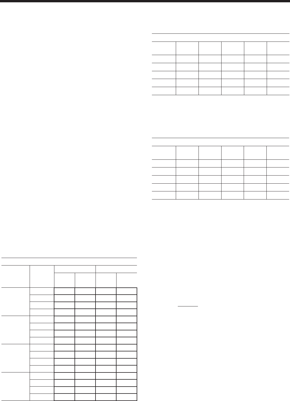
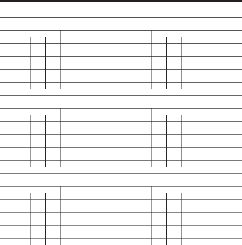
5. Performance Data Correction Factors – Ratings
are based on 0.0001 cooler fouling factor, 10°F
chilled water range and at sea level. For operation at
different conditions, apply the appropriate correction
factor from the following table.
METHOD OF SELECTION
To select of YORK Packaged Air-Cooled Liquid Chiller,
the following data must be known:
1. Design Capacity in tons refrigeration (TR).
2. Entering and Leaving Liquid Temperatures.
3. Outside ambient air temperature in degrees F.
4. GPM of chilled liquid.
Determine capacity requirements from the following
formula:
GPM = TR x 24
RANGE (°F)
EXAMPLE – WATER CHILLING
1. Given: Provide a capacity of 50 tons at 42 F leav-
ing water at 10 F range. 0.0001FF, 85 F air on the
condenser, at sea level and 60 Hz.
2. Find: Unit Size, Compressor KW Output
3. From the ratings on page 18.
Select: YCAL0061 (English Units)
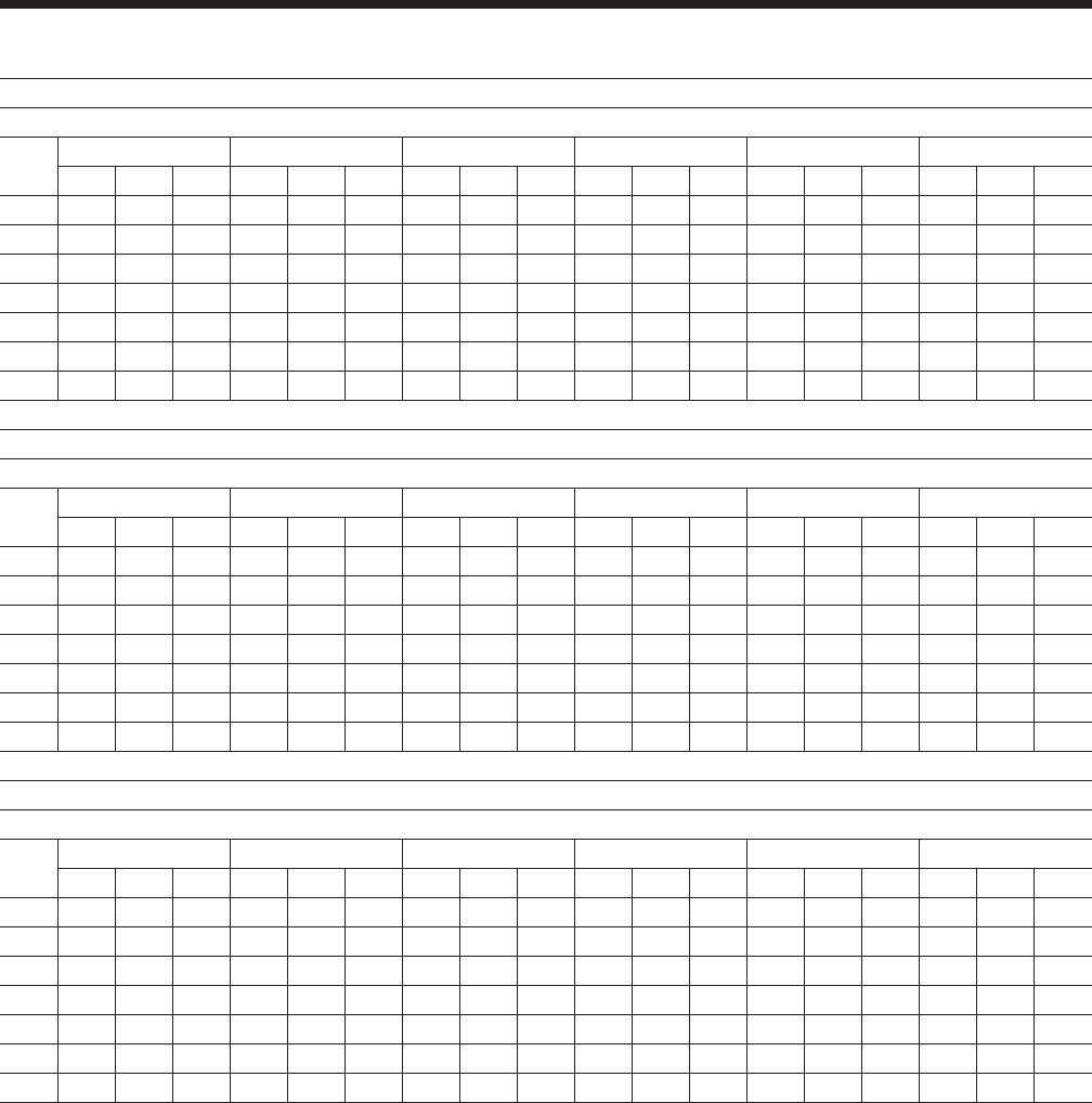
6. Ethylene Glycol Correction Factors – The fol-
lowing factors are to be applied to the standard
ratings for units cooling ethylene glycol.
7. Propylene Glycol Correction Factors – The fol-
lowing factors are to be applied to the standard
ratings for units cooling propylene glycol.
Selection Data
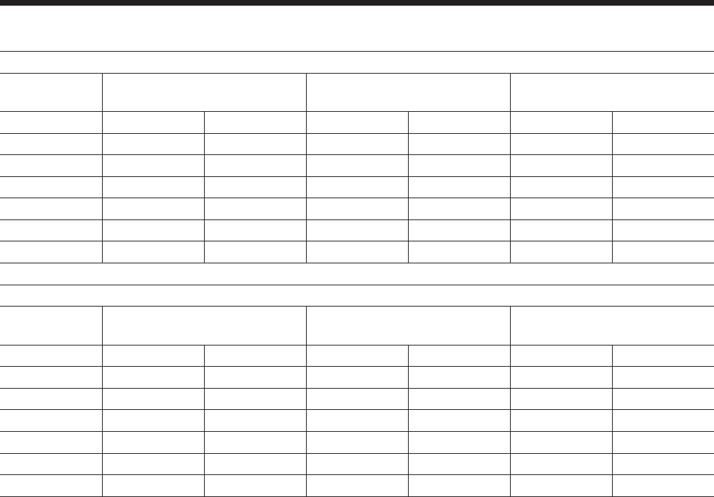
FOULING FACTOR
ALTITUDE TEMP
SPLIT
0.0001 0.00025
TONS COMPR
kW TONS COMPR
kW
SEA LEVEL
8 0.990 0.998 0.979 0.996
10 1.000 1.000 0.991 0.998
12 1.012 1.003 1.002 1.001
14 1.021 1.005 1.012 1.003
2000 FT.
8 0.987 1.005 0.978 1.003
10 0.997 1.008 0.988 1.006
12 1.009 1.010 1.000 1.008
14 1.018 1.012 1.009 1.010
4000 FT.
8 0.983 1.014 0.975 1.012
10 0.994 1.016 0.985 1.014
12 1.005 1.019 1.111 1.017
14 1.014 1.021 1.006 1.019
6000 FT.
8 0.980 1.023 0.971 1.021
10 0.990 1.025 0.982 1.023
12 1.002 1.028 0.993 1.026
14 1.011 1.030 1.002 1.028
PROPYLENE GLYCOL
%
WEIGHT TONS COMPR
KW
GPM
°F/TON
PRESS
DROP
FREEZE
PT
10 0.995 0.999 24.0 1.014 26
20 0.984 0.997 24.3 1.104 19
30 0.973 0.994 24.9 1.234 9
40 0.960 0.992 25.6 1.399 -6
50 0.943 0.989 26.6 1.599 -28
ETHYLENE GLYCOL
%
WEIGHT TONS COMPR
KW
GPM
°F/TON
PRESS
DROP
FREEZE
PT
10 0.996 0.999 24.3 1.049 26.2
20 0.991 0.998 25.1 1.124 17.9
30 0.984 0.997 25.9 1.258 6.7
40 0.976 0.995 26.9 1.430 -8.1
50 0.968 0.994 28.0 1.650 -28.9

YORK INTERNATIONAL
12
a. 56.1 Tons
b. 55.9 Compressor KW
c. 10.7 Unit EER
4. Calculate Compressor kW at 50 Tons:
5. Calculate GPM:
6. From page ____, read 6 ft of water cooler pressure
drop from GPM:
7. A YCAL0061 is suitable.
EXAMPLE - BRINE CHILLING
Example - Brine Chilling
1. Given: Provide a capacity of 34 tons cooling 30% by
weight Ethylene Glycol from 50 F to 40 F, 0.00025FF,
95 F air on the condenser, 60 Hz and 4000 ft. alti-
tude.
2. Determine:
a. Unit Size
b. KW Input
c. Ethylene Glycol GPM
d. Cooler Pressure Drop
3. See E.G. correction factors, for 30% by weight
E.G.
READ: 0.984 Tons Factor
0.997 Compr. KW factor
26.1 Gal,/ F/Tons Factor
4. See Performance Data Correction Factors for
0.00025 fouling factor and 4,000 ft. altitude.
READ: 0.975 Tons factor
1.012 kW factor
5. From RATINGS on page 16.
SELECT: YCAL0045 (English Units)
35.3 Tons
41.1 Compressor kW
6. Determine YCAL0045 brine cooling capacity and
Compressor kW requirement from pg 14:
a. TONS: = 35.3 x 0.984 x 0.975 = 33.87
b. Compr. KW = 41.1 x 0.997 x 1.012 = 41.77
7. Determine average full load Compressor kW at 34
tons
8. Determine E.G. GPM:
9. Determine Cooler Pressure Drop:
a. See E.G. correction factors for 30% by weight
E.G.
READ: 1.258 Pressure Drop factor
b. See page 14 at 88.7 GPM for YCAL0045
READ: 6.5_Water H2O PD
c. Cooler Pressure Drop = 6.5 x 1.258 or 8.17
A YCAL0045 is suitable.
kWkWxkW 8.499.55
1.56
50 ==
GPM
FRange
Tons
GPM120
10
24
)50( =
°
×
=
kWCompressorx
tons
tons 93
.41)77.41(
87
.33
34 =
Range
TonfactorFGalTons
GPMmin/
/.°×
=
)(7.88
10
1.260.34 GPMGPM =
×
=
YORK INTERNATIONAL 13
FORM 150.64-EG1
NOTES:
1. For leaving brine temperature below 40°F (4.4°C), contact your nearest YORK Office for application requirements.
2. For leaving water temperature higher than 55°F (12.8°C), contact the nearest YORK Office for application guidelines.
3. The evaporator is protected against freezing to -20°F (-28.8°C) with an electric heater as standard.
4. For operation at temperatures below 25°F (-3.9°C), the optional Low Ambient Kit will need to be installed on the system (for YCAL0041-0065
models only).
5. For operation at temperatures above 115°F (46.1°C), the optional High Ambient Kit will need to be installed on the system.
Design Parameters
ENGLISH
YCAL LEAVING WATER
TEMPERATURE (°F) COOLER FLOW (GPM) AIR ON CONDENSER (°F)
MIN MAX MIN MAX MIN MAX
0041 40 55 40 200 0 125
0045 40 55 40 200 0 125
0051 40 55 40 200 0 125
0055 40 55 60 300 0 125
0061 40 55 60 300 0 125
0065 40 55 60 300 0 125
SI UNITS
YCAL LEAVING WATER
TEMPERATURE (°DC) COOLER FLOW (L/S) AIR ON CONDENSER (°C)
MIN MAX MIN MAX MIN MAX
0041 4.4 12.8 2.5 12.6 -17.7 51.7
0045 4.4 12.8 2.5 12.6 -17.7 51.7
0051 4.4 12.8 2.5 12.6 -17.7 51.7
0055 4.4 12.8 3.8 18.9 -17.7 51.7
0061 4.4 12.8 3.8 18.9 -17.7 51.7
0065 4.4 12.8 3.8 18.9 -17.7 51.7
YORK INTERNATIONAL
14
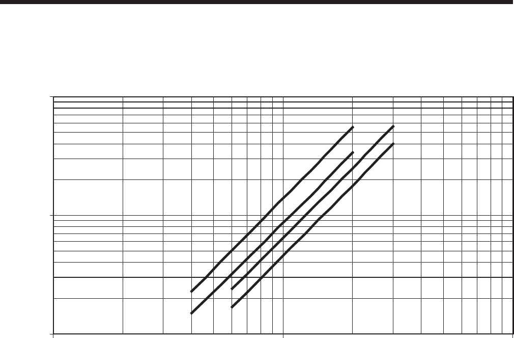
Water Pressure Drop
Note: Water Pressure Drop Curves may extend past the minimum and maximum water flow ranges. See page 13 for minimum and maximum
flow points.
ENGLISH
1
10
100
10 100 1000
FLOW, GPM
Press Drop, Ft H 2O
A
B
C
D
YORK INTERNATIONAL 15
FORM 150.64-EG1
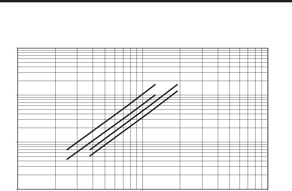
Note: Water Pressure Drop Curves may extend past the minimum and maximum water flow ranges. See page 13 for minimum and maximum
flow points.
SI
1
10
100
1000
1 10 100
FLOW, L/S
Press Drop, kPA
B
A C
D

YORK INTERNATIONAL
16
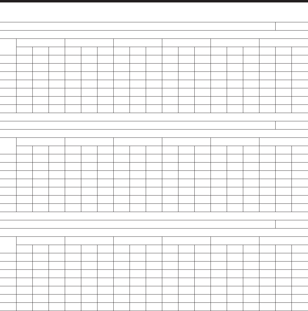
NOTES:
1. kW = Compressor Input Power
2. EER = Chiller EER (includes power from compressors, fans, and the control panels 0.8 kW)
3. LCWT = Leaving Chilled Water Temperature
4. Ratings are based upon 2.4 GPM cooler water per ton and 0.0001 fouling factor
5. Rated in accordance with ARI Standard 550/590-98
6. The shaded points are certified in accordance with ARI Standard 550/590-98
Ratings - R-22 (60Hz - English Units)
MODEL: YCAL0041EC IPLV= 13.9
AIR TEMPERATURE ON - CONDENSER (°F)
LCWT
(°F)
75.0 80.0 85.0 90.0 95.0 100.0
TONS KW EER TONS KW EER TONS KW EER TONS KW EER TONS KW EER TONS KW EER
40.0 35.8 30.3 12.0 35.1 32.0 11.2 34.4 33.8 10.5 33.7 35.7 9.8 32.9 37.7 9.1 32.1 39.9 8.5
42.0 37.0 30.6 12.3 36.2 32.2 11.5 35.5 34.0 10.8 34.8 35.9 10.0 34.0 38.0 9.4 33.2 40.1 8.7
44.0 38.1 30.8 12.6 37.4 32.5 11.8 36.7 34.3 11.0 35.9 36.2 10.3 35.1 38.2 9.6 34.3 40.4 8.9
45.0 38.7 31.0 12.7 38.0 32.6 11.9 37.2 34.4 11.2 36.4 36.3 10.4 35.6 38.4 9.7 34.8 40.6 9.0
46.0 39.3 31.1 12.9 38.6 32.8 12.1 37.8 34.5 11.3 37.0 36.5 10.6 36.2 38.5 9.8 35.3 40.7 9.2
48.0 40.6 31.4 13.2 39.8 33.0 12.4 39.0 34.8 11.6 38.2 36.7 10.8 37.3 38.8 10.1 36.5 41.0 9.4
50.0 41.8 31.7 13.5 41.0 33.3 12.6 40.2 35.1 11.8 39.4 37.0 11.1 38.5 39.1 10.3 37.6 41.2 9.6
MODEL: YCAL0045EC IPLV= 14.0
AIR TEMPERATURE ON - CONDENSER (°F)
LCWT
(°F)
75.0 80.0 85.0 90.0 95.0 100.0
TONS KW EER TONS KW EER TONS KW EER TONS KW EER TONS KW EER TONS KW EER
40.0 39.0 33.4 12.0 38.1 35.1 11.2 37.2 37.0 10.5 36.3 39.0 9.8 35.4 41.2 9.1 34.4 43.5 8.4
42.0 40.3 33.7 12.3 39.3 35.4 11.5 38.4 37.3 10.8 37.5 39.3 10.0 36.6 41.5 9.3 35.6 43.8 8.7
44.0 41.5 34.0 12.6 40.6 35.7 11.8 39.7 37.6 11.0 38.7 39.6 10.3 37.8 41.8 9.6 36.8 44.1 8.9
45.0 42.2 34.1 12.7 41.2 35.9 11.9 40.3 37.7 11.2 39.3 39.8 10.4 38.4 41.9 9.7 37.4 44.2 9.0
46.0 42.8 34.3 12.9 41.9 36.0 12.1 40.9 37.9 11.3 40.0 39.9 10.5 39.0 42.1 9.8 38.0 44.4 9.1
48.0 44.1 34.6 13.2 43.2 36.4 12.3 42.2 38.2 11.6 41.2 40.3 10.8 40.2 42.4 10.1 39.2 44.7 9.4
50.0 45.5 35.0 13.4 44.5 36.7 12.6 43.5 38.6 11.8 42.5 40.6 11.0 41.5 42.8 10.3 40.5 45.1 9.6
MODEL: YCAL0051EC IPLV= 14.3
AIR TEMPERATURE ON - CONDENSER (°F)
LCWT
(°F)
75.0 80.0 85.0 90.0 95.0 100.0
TONS KW EER TONS KW EER TONS KW EER TONS KW EER TONS KW EER TONS KW EER
40.0 45.0 38.9 12.1 43.9 41.0 11.3 42.8 43.2 10.5 41.8 45.6 9.8 40.7 48.1 9.1 39.7 50.8 8.4
42.0 46.4 39.2 12.4 45.4 41.3 11.6 44.3 43.5 10.8 43.2 45.9 10.1 42.1 48.4 9.4 41.1 51.1 8.7
44.0 47.9 39.5 12.8 46.9 41.6 11.9 45.8 43.8 11.1 44.7 46.2 10.4 43.6 48.7 9.6 42.5 51.4 8.9
45.0 48.7 39.7 12.9 47.6 41.7 12.1 46.5 43.9 11.3 45.4 46.3 10.5 44.3 48.9 9.8 43.2 51.6 9.1
46.0 49.5 39.8 13.1 48.4 41.9 12.2 47.2 44.1 11.4 46.1 46.5 10.6 45.0 49.0 9.9 43.9 51.7 9.2
48.0 51.0 40.1 13.4 49.9 42.2 12.5 48.8 44.4 11.7 47.6 46.8 10.9 46.5 49.3 10.2 45.3 52.1 9.4
50.0 52.6 40.5 13.7 51.4 42.5 12.8 50.3 44.7 12.0 49.1 47.1 11.2 48.0 49.7 10.4 46.8 52.4 9.7

YORK INTERNATIONAL 17
FORM 150.64-EG1
NOTES:
1. kW = Compressor Input Power
2. EER = Chiller EER (includes power from compressors, fans, and the control panels 0.8 kW)
3. LCWT = Leaving Chilled Water Temperature
4. Ratings are based upon 2.4 GPM cooler water per ton and 0.0001 fouling factor
5. Rated in accordance with ARI Standard 550/590-98
6. The shaded points are certified in accordance with ARI Standard 550/590-98
MODEL: YCAL0041EC IPLV= 13.9
AIR TEMPERATURE ON - CONDENSER (°F)
LCWT
(°F)
105 110.0 115.0 120.0 125.0
TONS KW EER TONS KW EER TONS KW EER TONS KW EER TONS KW EER
40.0 31.3 42.2 7.9 30.5 44.7 7.3 29.6 47.4 6.7 28.7 50.2 6.2 27.8 53.2 5.7
42.0 32.4 42.5 8.1 31.5 45.0 7.5 30.6 47.6 6.9 29.7 50.4 6.4 28.7 53.4 5.8
44.0 33.4 42.7 8.3 32.5 45.2 7.7 31.6 47.9 7.1 30.7 50.7 6.5 29.7 53.7 6.0
45.0 34.0 42.9 8.4 33.1 45.3 7.8 32.1 48.0 7.2 31.2 50.8 6.6 30.2 53.8 6.1
46.0 34.5 43.0 8.5 33.6 45.5 7.9 32.7 48.1 7.3 31.7 50.9 6.7 30.7 53.9 6.2
48.0 35.6 43.3 8.7 34.7 45.7 8.1 33.7 48.4 7.5 32.8 51.2 6.9 31.8 54.1 6.4
50.0 36.7 43.6 9.0 35.8 46.0 8.3 34.8 48.6 7.7 33.8 51.4 7.1 32.8 54.4 6.6
MODEL: YCAL0045EC IPLV= 14.0
AIR TEMPERATURE ON - CONDENSER (°F)
LCWT
(°F)
105 110.0 115.0 120.0 125.0
TONS KW EER TONS KW EER TONS KW EER TONS KW EER TONS KW EER
40.0 33.5 45.9 7.8 32.5 48.6 7.2 31.5 51.4 6.6 30.4 54.4 6.1 29.3 57.5 5.6
42.0 34.6 46.2 8.0 33.6 48.9 7.4 32.6 51.7 6.8 31.5 54.7 6.3 30.4 57.8 5.7
44.0 35.8 46.5 8.2 34.8 49.2 7.6 33.7 52.0 7.0 32.6 55.0 6.5 31.5 58.1 5.9
45.0 36.4 46.7 8.4 35.4 49.4 7.7 34.3 52.1 7.1 33.2 55.1 6.6 32.0 58.3 6.0
46.0 37.0 46.9 8.5 36.0 49.5 7.8 34.9 52.3 7.2 33.8 55.3 6.7 32.6 58.5 6.1
48.0 38.2 47.2 8.7 37.2 49.8 8.0 36.0 52.7 7.4 34.9 55.6 6.8 33.7 58.8 6.3
50.0 39.4 47.6 8.9 38.4 50.2 8.3 37.2 53.0 7.6 36.1 56.0 7.0 34.9 59.1 6.5
MODEL: YCAL0051EC IPLV= 14.3
AIR TEMPERATURE ON - CONDENSER (°F)
LCWT
(°F)
105 110.0 115.0 120.0 125.0
TONS KW EER TONS KW EER TONS KW EER TONS KW EER TONS KW EER
40.0 38.6 53.7 7.8 37.5 56.7 7.2 36.3 59.9 6.7 35.1 63.3 6.1 33.9 66.8 5.6
42.0 39.9 54.0 8.0 38.8 57.0 7.4 37.6 60.2 6.9 36.4 63.6 6.3 35.1 67.2 5.8
44.0 41.3 54.3 8.3 40.1 57.4 7.7 38.9 60.6 7.1 37.7 64.0 6.5 36.4 67.6 6.0
45.0 42.0 54.5 8.4 40.8 57.5 7.8 39.6 60.8 7.2 38.3 64.2 6.6 37.0 67.8 6.1
46.0 42.7 54.6 8.5 41.5 57.7 7.9 40.3 60.9 7.3 39.0 64.4 6.7 37.7 68.0 6.1
48.0 44.1 55.0 8.7 42.9 58.0 8.1 41.6 61.3 7.5 40.3 64.7 6.9 39.0 68.3 6.3
50.0 45.6 55.3 9.0 44.3 58.4 8.3 43.0 61.7 7.7 41.7 65.1 7.1 40.3 68.7 6.5
YORK INTERNATIONAL
18
NOTES:
1. kW = Compressor Input Power
2. EER = Chiller EER (includes power from compressors, fans, and the control panels 0.8 kW)
3. LCWT = Leaving Chilled Water Temperature
4. Ratings are based upon 2.4 GPM cooler water per ton and 0.0001 fouling factor
5. Rated in accordance with ARI Standard 550/590-98
6. The shaded points are certified in accordance with ARI Standard 550/590-98
Ratings - R-22 (60Hz - English Units) - Cont.
MODEL: YCAL0055EC IPLV= 13.6
AIR TEMPERATURE ON - CONDENSER (°F)
LCWT
(°F)
75.0 80.0 85.0 90.0 95.0 100.0
TONS KW EER TONS KW EER TONS KW EER TONS KW EER TONS KW EER TONS KW EER
40.0 48.6 42.1 11.9 47.6 44.4 11.2 46.6 46.8 10.5 45.6 49.4 9.7 44.6 52.2 9.1 43.5 55.1 8.4
42.0 50.2 42.4 12.3 49.2 44.7 11.5 48.2 47.1 10.7 47.1 49.7 10.0 46.1 52.5 9.3 44.9 55.4 8.7
44.0 51.8 42.7 12.6 50.8 44.9 11.8 49.8 47.4 11.0 48.7 50.0 10.3 47.6 52.8 9.6 46.4 55.7 8.9
45.0 52.7 42.8 12.8 51.6 45.1 12.0 50.6 47.5 11.2 49.5 50.2 10.4 48.4 52.9 9.7 47.2 55.9 9.0
46.0 53.5 43.0 12.9 52.5 45.2 12.1 51.4 47.7 11.3 50.3 50.3 10.6 49.1 53.1 9.9 48.0 56.1 9.2
48.0 55.2 43.3 13.3 54.2 45.5 12.4 53.1 48.0 11.6 51.9 50.6 10.9 50.7 53.4 10.1 49.5 56.4 9.4
50.0 57.0 43.6 13.6 55.9 45.9 12.8 54.7 48.3 11.9 53.6 50.9 11.2 52.4 53.7 10.4 51.1 56.7 9.7
MODEL: YCAL0061EC IPLV= 14.2
AIR TEMPERATURE ON - CONDENSER (°F)
LCWT
(°F)
75.0 80.0 85.0 90.0 95.0 100.0
TONS KW EER TONS KW EER TONS KW EER TONS KW EER TONS KW EER TONS KW EER
40.0 56.8 49.8 12.1 55.6 52.6 11.3 54.5 55.5 10.5 53.3 58.7 9.8 52.0 62.0 9.1 50.8 65.5 8.4
42.0 58.7 50.2 12.4 57.5 53.0 11.5 56.3 56.0 10.8 55.0 59.1 10.0 53.8 62.5 9.3 52.5 66.0 8.7
44.0 60.6 50.6 12.7 59.4 53.4 11.8 58.1 56.4 11.0 56.9 59.6 10.3 55.6 62.9 9.6 54.2 66.5 8.9
45.0 61.5 50.9 12.8 60.3 53.6 12.0 59.1 56.6 11.2 57.8 59.8 10.4 56.5 63.2 9.7 55.1 66.7 9.0
46.0 62.5 51.1 13.0 61.3 53.9 12.1 60.0 56.8 11.3 58.7 60.0 10.6 57.4 63.4 9.8 56.0 67.0 9.1
48.0 64.5 51.5 13.3 63.2 54.3 12.4 61.9 57.3 11.6 60.6 60.5 10.8 59.2 63.9 10.1 57.8 67.5 9.4
50.0 66.5 52.0 13.6 65.2 54.8 12.7 63.9 57.8 11.9 62.5 61.0 11.1 61.1 64.4 10.3 59.7 68.0 9.6
MODEL: YCAL0065EC IPLV= 14.5
AIR TEMPERATURE ON - CONDENSER (°F)
LCWT
(°F)
75.0 80.0 85.0 90.0 95.0 100.0
TONS KW EER TONS KW EER TONS KW EER TONS KW EER TONS KW EER TONS KW EER
40.0 & & & & & & 59.9 61.4 10.6 58.5 64.8 9.8 57.2 68.4 9.1 55.8 72.2 8.5
42.0 64.5 55.7 12.4 63.2 58.7 11.6 61.8 61.9 10.8 60.5 65.3 10.1 59.1 68.9 9.4 57.6 72.8 8.7
44.0 66.5 56.2 12.7 65.2 59.2 11.9 63.9 62.5 11.1 62.5 65.9 10.3 61.0 69.5 9.6 59.6 73.4 8.9
45.0 67.6 56.5 12.8 66.3 59.5 12.0 64.9 62.7 11.2 63.5 66.2 10.4 62.0 69.8 9.7 60.5 73.7 9.0
46.0 68.7 56.8 13.0 67.3 59.8 12.1 65.9 63.0 11.3 64.5 66.5 10.6 63.0 70.1 9.8 61.5 74.0 9.1
48.0 70.8 57.3 13.3 69.5 60.4 12.4 68.0 63.6 11.6 66.5 67.1 10.8 65.0 70.8 10.1 63.5 74.7 9.4
50.0 73.1 57.9 13.6 71.6 61.0 12.7 70.2 64.2 11.9 68.7 67.7 11.1 67.1 71.4 10.3 65.5 75.3 9.6
YORK INTERNATIONAL 19
FORM 150.64-EG1
NOTES:
1. kW = Compressor Input Power
2. EER = Chiller EER (includes power from compressors, fans, and the control panels 0.8 kW)
3. LCWT = Leaving Chilled Water Temperature
4. Ratings are based upon 2.4 GPM cooler water per ton and 0.0001 fouling factor
5. Rated in accordance with ARI Standard 550/590-98
6. The shaded points are certified in accordance with ARI Standard 550/590-98
MODEL: YCAL0055EC IPLV= 13.6
AIR TEMPERATURE ON - CONDENSER (°F)
LCWT
(°F)
105 110.0 115.0 120.0 125.0
TONS KW EER TONS KW EER TONS KW EER TONS KW EER TONS KW EER
40.0 42.3 58.2 7.8 41.2 61.4 7.2 39.9 64.8 6.7 29.0 48.0 6.4 28.0 50.6 5.9
42.0 43.8 58.5 8.1 42.6 61.8 7.5 41.3 65.2 6.9 30.0 48.3 6.6 29.0 50.9 6.0
44.0 45.3 58.8 8.3 44.0 62.1 7.7 42.7 65.6 7.1 31.1 48.5 6.8 30.1 51.2 6.2
45.0 46.0 59.0 8.4 44.7 62.3 7.8 43.4 65.8 7.2 31.6 48.6 6.9 30.6 51.3 6.3
46.0 46.8 59.1 8.5 45.5 62.5 7.9 44.2 65.9 7.3 32.2 48.7 7.0 31.1 51.4 6.4
48.0 48.3 59.5 8.8 47.0 62.8 8.1 45.6 66.3 7.5 33.3 49.0 7.2 32.2 51.7 6.6
50.0 49.8 59.9 9.0 48.5 63.2 8.3 47.1 66.7 7.7 34.4 49.2 7.4 33.3 51.9 6.8
MODEL: YCAL0061EC IPLV= 14.2
AIR TEMPERATURE ON - CONDENSER (°F)
LCWT
(°F)
105 110.0 115.0 120.0 125.0
TONS KW EER TONS KW EER TONS KW EER TONS KW EER TONS KW EER
40.0 49.5 69.2 7.8 48.2 73.1 7.2 46.8 77.2 6.7 45.4 81.5 6.2 34.7 63.9 5.9
42.0 51.1 69.7 8.0 49.8 73.6 7.4 48.4 77.8 6.9 46.9 82.1 6.3 35.9 64.3 6.1
44.0 52.9 70.2 8.2 51.5 74.1 7.6 50.0 78.3 7.1 48.5 82.7 6.5 37.2 64.7 6.2
45.0 53.7 70.5 8.4 52.3 74.4 7.7 50.9 78.6 7.2 49.3 83.0 6.6 37.8 64.9 6.3
46.0 54.6 70.7 8.5 53.2 74.7 7.8 51.7 78.9 7.2 50.2 83.3 6.7 38.5 65.1 6.4
48.0 56.4 71.3 8.7 54.9 75.3 8.0 53.4 79.4 7.4 51.8 83.9 6.9 39.8 65.6 6.6
50.0 58.2 71.8 8.9 56.7 75.8 8.2 55.1 80.0 7.6 53.5 84.5 7.0 41.1 66.0 6.8
MODEL: YCAL0065EC IPLV= 14.5
AIR TEMPERATURE ON - CONDENSER (°F)
LCWT
(°F)
105 110.0 115.0 120.0 125.0
TONS KW EER TONS KW EER TONS KW EER TONS KW EER TONS KW EER
40.0 54.3 76.3 7.9 52.8 80.6 7.3 51.3 85.1 6.7 49.7 89.9 6.2 38.2 73.1 5.7
42.0 56.2 76.9 8.1 54.6 81.2 7.5 53.1 85.8 6.9 51.4 90.6 6.3 39.6 73.6 5.9
44.0 58.0 77.5 8.3 56.5 81.9 7.6 54.9 86.5 7.1 53.2 91.3 6.5 28.9 42.9 7.0
45.0 59.0 77.8 8.4 57.4 82.2 7.7 55.8 86.8 7.2 54.1 91.7 6.6 29.4 43.1 7.1
46.0 59.9 78.2 8.5 58.3 82.5 7.8 56.7 87.2 7.2 55.0 92.1 6.7 29.9 43.2 7.2
48.0 61.9 78.8 8.7 60.3 83.2 8.0 58.6 87.9 7.4 56.8 92.8 6.8 31.0 43.4 7.4
50.0 63.9 79.5 8.9 62.2 83.9 8.2 60.5 88.6 7.6 58.7 93.5 7.0 32.0 43.6 7.6

YORK INTERNATIONAL
20
Ratings - R-22 (60Hz - SI Units)
NOTES:
1. kW = Compressor Input Power
2. EER = Chiller EER (includes power from compressors, fans, and the control panels 0.8 kW)
3. LCWT = Leaving Chilled Water Temperature
4. Ratings are based upon 2.4 GPM cooler water per ton and 0.0001 fouling factor
5. Rated in accordance with ARI Standard 550/590-98
6. The shaded points are certified in accordance with ARI Standard 550/590-98
MODEL: YCAL0041EC
AIR TEMPERATURE ON - CONDENSER (°C)
LCWT
(°C)
25.0 30.0 35.0 40.0 45.0 50.0
KW KW COP KW KW COP KW KW COP KW KW COP KW KW COP KW KW COP
5.0 126.9 31.1 3.5 122.4 34.3 3.1 117.6 37.9 2.7 112.5 41.9 2.4 107.1 46.4 2.1 101.3 51.5 1.8
6.0 130.6 31.3 3.5 125.9 34.5 3.1 121.0 38.1 2.8 115.8 42.1 2.4 110.3 46.6 2.1 104.4 51.7 1.8
7.0 134.3 31.6 3.6 129.6 34.7 3.2 124.5 38.3 2.8 119.2 42.3 2.5 113.6 46.9 2.2 107.6 51.9 1.9
8.0 138.1 31.8 3.7 133.2 35.0 3.3 128.1 38.6 2.9 122.7 42.6 2.6 116.9 47.1 2.2 110.9 52.1 1.9
9.0 142.0 32.1 3.8 137.0 35.2 3.4 131.7 38.8 3.0 126.1 42.8 2.6 120.3 47.3 2.3 114.1 52.4 2.0
10.0 145.9 32.3 3.9 140.8 35.5 3.4 135.4 39.1 3.0 129.7 43.1 2.7 123.8 47.6 2.3 117.5 52.6 2.0
11.0 149.9 32.6 3.9 144.6 35.8 3.5 139.1 39.3 3.1 133.3 43.4 2.7 127.3 47.8 2.4 120.9 52.8 2.1
MODEL: YCAL0045EC
AIR TEMPERATURE ON - CONDENSER (°C)
LCWT
(°C)
25.0 30.0 35.0 40.0 45.0 50.0
KW KW COP KW KW COP KW KW COP KW KW COP KW KW COP KW KW COP
5.0 138.1 34.2 3.5 132.3 37.5 3.1 126.4 41.3 2.7 120.4 45.6 2.4 114.1 50.4 2.0 107.3 55.8 1.8
6.0 142.1 34.5 3.6 136.2 37.8 3.1 130.2 41.6 2.8 124.1 45.8 2.4 117.7 50.6 2.1 110.7 56.0 1.8
7.0 146.1 34.7 3.6 140.1 38.1 3.2 134.1 41.9 2.8 127.9 46.1 2.5 121.4 50.9 2.2 114.3 56.3 1.9
8.0 150.2 35.0 3.7 144.1 38.4 3.3 138.0 42.2 2.9 131.7 46.4 2.5 125.0 51.2 2.2 117.9 56.6 1.9
9.0 154.3 35.3 3.8 148.2 38.7 3.4 142.0 42.5 3.0 135.5 46.7 2.6 128.7 51.5 2.3 121.5 56.9 1.9
10.0 158.5 35.7 3.8 152.3 39.0 3.4 146.0 42.8 3.0 139.4 47.1 2.7 132.5 51.9 2.3 125.2 57.2 2.0
11.0 162.7 36.0 3.9 156.4 39.3 3.5 150.0 43.1 3.1 143.3 47.4 2.7 136.4 52.2 2.4 128.9 57.5 2.0
MODEL: YCAL0051EC
AIR TEMPERATURE ON - CONDENSER (°C)
LCWT
(°C)
25.0 30.0 35.0 40.0 45.0 50.0
KW KW COP KW KW COP KW KW COP KW KW COP KW KW COP KW KW COP
5.0 159.2 39.9 3.5 152.4 43.8 3.1 145.7 48.3 2.7 138.8 53.2 2.4 131.6 58.8 2.0 123.9 64.8 1.8
6.0 163.9 40.1 3.6 157.0 44.1 3.2 150.2 48.5 2.8 143.2 53.5 2.4 135.8 59.1 2.1 127.9 65.2 1.8
7.0 168.6 40.4 3.7 161.7 44.3 3.2 154.7 48.8 2.8 147.5 53.8 2.5 140.0 59.4 2.2 132.0 65.5 1.9
8.0 173.5 40.7 3.8 166.4 44.6 3.3 159.3 49.1 2.9 152.0 54.1 2.5 144.4 59.7 2.2 136.2 65.8 1.9
9.0 178.3 41.0 3.8 171.2 44.9 3.4 164.0 49.4 3.0 156.5 54.4 2.6 148.7 60.0 2.3 140.4 66.2 2.0
10.0 183.3 41.3 3.9 176.0 45.2 3.5 168.7 49.7 3.1 161.1 54.7 2.7 153.2 60.3 2.3 144.7 66.5 2.0
11.0 188.3 41.6 4.0 180.9 45.5 3.5 173.4 50.0 3.1 165.7 55.0 2.7 157.7 60.7 2.4 149.0 66.9 2.1

YORK INTERNATIONAL 21
FORM 150.64-EG1
NOTES:
1. kW = Compressor Input Power
2. EER = Chiller EER (includes power from compressors, fans, and the control panels 0.8 kW)
3. LCWT = Leaving Chilled Water Temperature
4. Ratings are based upon 2.4 GPM cooler water per ton and 0.0001 fouling factor
5. Rated in accordance with ARI Standard 550/590-98
6. The shaded points are certified in accordance with ARI Standard 550/590-98
MODEL: YCAL0055EC
AIR TEMPERATURE ON - CONDENSER (°C)
LCWT
(°C)
25.0 30.0 35.0 40.0 45.0 50.0
KW KW COP KW KW COP KW KW COP KW KW COP KW KW COP KW KW COP
5.0 172.2 43.1 3.5 166.0 47.5 3.1 159.3 52.3 2.7 152.2 57.7 2.4 144.6 63.6 2.1 102.4 49.2 1.8
6.0 177.4 43.4 3.5 170.9 47.7 3.1 164.1 52.6 2.8 156.8 58.0 2.4 149.0 63.9 2.1 105.7 49.4 1.9
7.0 182.6 43.6 3.6 176.0 48.0 3.2 169.0 52.9 2.8 161.6 58.3 2.5 153.6 64.3 2.2 109.0 49.6 1.9
8.0 187.9 43.9 3.7 181.1 48.3 3.3 173.9 53.2 2.9 166.3 58.6 2.6 158.2 64.6 2.2 112.4 49.8 2.0
9.0 193.3 44.2 3.8 186.4 48.5 3.4 179.0 53.4 3.0 171.1 58.9 2.6 162.9 64.9 2.3 115.9 50.1 2.0
10.0 198.8 44.5 3.9 191.7 48.8 3.5 184.1 53.7 3.1 176.1 59.2 2.7 167.7 65.3 2.3 119.4 50.3 2.1
11.0 204.4 44.8 4.0 197.1 49.1 3.5 189.4 54.0 3.1 181.1 59.6 2.7 172.5 65.6 2.4 122.9 50.5 2.2
MODEL: YCAL0061EC
AIR TEMPERATURE ON - CONDENSER (°C)
LCWT
(°C)
25.0 30.0 35.0 40.0 45.0 50.0
KW KW COP KW KW COP KW KW COP KW KW COP KW KW COP KW KW COP
5.0 201.3 51.1 3.5 193.8 56.4 3.1 186.0 62.2 2.7 177.8 68.7 2.4 169.3 75.8 2.1 160.3 83.6 1.8
6.0 207.2 51.5 3.6 199.6 56.8 3.1 191.6 62.6 2.8 183.2 69.2 2.4 174.4 76.3 2.1 165.2 84.1 1.8
7.0 213.3 51.9 3.6 205.4 57.2 3.2 197.3 63.1 2.8 188.7 69.6 2.5 179.7 76.8 2.2 170.2 84.7 1.9
8.0 219.5 52.3 3.7 211.4 57.6 3.3 203.0 63.5 2.9 194.2 70.1 2.5 185.1 77.3 2.2 175.4 85.2 1.9
9.0 225.7 52.7 3.8 217.5 58.0 3.4 208.9 63.9 3.0 199.9 70.5 2.6 190.5 77.8 2.3 143.0 63.5 2.0
10.0 232.1 53.1 3.9 223.7 58.4 3.4 214.9 64.4 3.0 205.7 71.0 2.7 196.0 78.3 2.3 147.3 63.9 2.1
11.0 238.6 53.5 4.0 230.0 58.9 3.5 221.0 64.8 3.1 211.6 71.5 2.7 201.7 78.8 2.4 151.7 64.2 2.1
MODEL: YCAL0065EC
AIR TEMPERATURE ON - CONDENSER (°C)
LCWT
(°C)
25.0 30.0 35.0 40.0 45.0 50.0
KW KW COP KW KW COP KW KW COP KW KW COP KW KW COP KW KW COP
5.0 221.3 56.6 3.5 213.0 62.3 3.1 204.4 68.7 2.7 195.3 75.7 2.4 185.7 83.6 2.1 175.5 92.3 1.8
6.0 227.7 57.1 3.6 219.3 62.8 3.2 210.5 69.2 2.8 201.2 76.3 2.4 191.3 84.2 2.1 180.9 92.9 1.8
7.0 234.3 57.6 3.6 225.7 63.3 3.2 216.7 69.7 2.8 207.2 76.9 2.5 197.1 84.8 2.2 186.5 93.6 1.9
8.0 241.1 58.1 3.7 232.2 63.8 3.3 223.0 70.3 2.9 213.3 77.4 2.5 203.0 85.4 2.2 192.1 94.2 1.9
9.0 247.9 58.6 3.8 238.9 64.3 3.4 229.4 70.8 3.0 219.5 78.0 2.6 209.0 86.0 2.3 197.9 94.9 2.0
10.0 254.9 59.1 3.9 245.7 64.9 3.4 236.0 71.4 3.0 225.8 78.6 2.7 215.1 86.7 2.3 162.8 73.4 2.0
11.0 262.1 59.6 4.0 252.6 65.4 3.5 242.7 71.9 3.1 232.3 79.2 2.7 221.3 87.3 2.4 167.7 74.0 2.1

YORK INTERNATIONAL
22
Ratings - R-22 (50Hz - English Units)
NOTES:
1. kW = Compressor Input Power
2. EER = Chiller EER (includes power from compressors, fans, and the control panels 0.8 kW)
3. LCWT = Leaving Chilled Water Temperature
4. Ratings are based upon 2.4 GPM cooler water per ton and 0.0001 fouling factor
5. Rated in accordance with ARI Standard 550/590-98
6. The shaded points are certified in accordance with ARI Standard 550/590-98
MODEL: YCAL0041EC IPLV= 16.2
AIR TEMPERATURE ON - CONDENSER (°F)
LCWT
(°F)
75.0 80.0 85.0 90.0 95.0 100.0
TONS KW EER TONS KW EER TONS KW EER TONS KW EER TONS KW EER TONS KW EER
40.0 30.4 23.6 13.6 29.8 25.1 12.6 29.1 26.7 11.7 28.5 28.4 10.8 27.9 30.2 10.0 27.2 32.2 9.2
42.0 31.4 23.8 13.9 30.8 25.3 12.9 30.1 26.9 12.0 29.5 28.6 11.1 28.8 30.4 10.3 28.1 32.3 9.5
44.0 32.4 24.0 14.3 31.8 25.5 13.3 31.1 27.1 12.3 30.4 28.8 11.4 29.8 30.6 10.6 29.1 32.5 9.7
45.0 33.0 24.1 14.4 32.3 25.6 13.4 31.6 27.2 12.5 30.9 28.9 11.6 30.2 30.7 10.7 29.5 32.6 9.9
46.0 33.5 24.2 14.6 32.8 25.7 13.6 32.1 27.3 12.6 31.4 29.0 11.7 30.7 30.8 10.8 30.0 32.7 10.0
48.0 34.5 24.5 15.0 33.8 25.9 13.9 33.1 27.5 12.9 32.5 29.2 12.0 31.7 31.0 11.1 31.0 33.0 10.3
50.0 35.6 24.7 15.3 34.9 26.2 14.2 34.2 27.7 13.2 33.5 29.4 12.3 32.8 31.2 11.4 32.0 33.2 10.5
MODEL: YCAL0045EC IPLV= 16.1
AIR TEMPERATURE ON - CONDENSER (°F)
LCWT
(°F)
75.0 80.0 85.0 90.0 95.0 100.0
TONS KW EER TONS KW EER TONS KW EER TONS KW EER TONS KW EER TONS KW EER
40.0 32.9 25.9 13.6 32.2 27.5 12.6 31.5 29.2 11.7 30.8 31.0 10.8 30.0 32.9 10.0 29.2 35.0 9.2
42.0 34.0 26.2 13.9 33.3 27.8 12.9 32.6 29.4 12.0 31.8 31.2 11.1 31.1 33.2 10.2 30.2 35.3 9.4
44.0 35.1 26.4 14.2 34.4 28.0 13.2 33.7 29.7 12.3 32.9 31.5 11.4 32.1 33.4 10.5 31.3 35.5 9.7
45.0 35.7 26.5 14.4 34.9 28.1 13.4 34.2 29.8 12.4 33.4 31.6 11.5 32.6 33.5 10.6 31.8 35.6 9.8
46.0 36.2 26.7 14.5 35.5 28.2 13.5 34.7 29.9 12.6 34.0 31.7 11.7 33.2 33.7 10.8 32.3 35.7 10.0
48.0 37.4 26.9 14.9 36.6 28.5 13.8 35.9 30.2 12.9 35.1 32.0 11.9 34.2 33.9 11.1 33.4 36.0 10.2
50.0 38.5 27.2 15.2 37.8 28.8 14.2 37.0 30.5 13.2 36.2 32.3 12.2 35.3 34.2 11.3 34.4 36.3 10.5
MODEL: YCAL0051EC IPLV= 15.7
AIR TEMPERATURE ON - CONDENSER (°F)
LCWT
(°F)
75.0 80.0 85.0 90.0 95.0 100.0
TONS KW EER TONS KW EER TONS KW EER TONS KW EER TONS KW EER TONS KW EER
40.0 37.9 30.8 13.3 37.1 32.6 12.4 36.3 34.6 11.5 35.5 36.7 10.7 34.6 38.9 9.9 33.8 41.3 9.1
42.0 39.1 31.0 13.7 38.3 32.9 12.7 37.5 34.8 11.8 36.7 36.9 11.0 35.8 39.1 10.1 34.9 41.5 9.4
44.0 40.4 31.3 14.0 39.6 33.1 13.1 38.8 35.1 12.2 37.9 37.1 11.3 37.0 39.4 10.4 36.1 41.7 9.6
45.0 41.0 31.4 14.2 40.2 33.2 13.2 39.4 35.2 12.3 38.5 37.3 11.4 37.6 39.5 10.6 36.7 41.9 9.8
46.0 41.7 31.5 14.4 40.9 33.4 13.4 40.0 35.3 12.5 39.2 37.4 11.6 38.3 39.6 10.7 37.3 42.0 9.9
48.0 43.0 31.8 14.7 42.2 33.6 13.7 41.3 35.6 12.8 40.4 37.6 11.9 39.5 39.9 11.0 38.5 42.2 10.2
50.0 44.4 32.1 15.1 43.5 33.9 14.1 42.6 35.8 13.1 41.7 37.9 12.2 40.8 40.1 11.3 39.8 42.5 10.4

YORK INTERNATIONAL 23
FORM 150.64-EG1
NOTES:
1. kW = Compressor Input Power
2. EER = Chiller EER (includes power from compressors, fans, and the control panels 0.8 kW)
3. LCWT = Leaving Chilled Water Temperature
4. Ratings are based upon 2.4 GPM cooler water per ton and 0.0001 fouling factor
5. Rated in accordance with ARI Standard 550/590-98
6. The shaded points are certified in accordance with ARI Standard 550/590-98
MODEL: YCAL0041EC IPLV= 16.2
AIR TEMPERATURE ON - CONDENSER (°F)
LCWT
(°F)
105 110.0 115.0 120.0 125.0
TONS KW EER TONS KW EER TONS KW EER TONS KW EER TONS KW EER
26.5 40.0 34.3 8.5 25.7 36.5 7.8 25.0 39.0 7.1 24.1 41.6 6.5 23.2 44.4 5.8
27.4 42.0 34.5 8.7 26.6 36.7 8.0 25.8 39.2 7.3 25.0 41.8 6.7 24.1 44.6 6.0
28.3 44.0 34.7 9.0 27.5 36.9 8.2 26.7 39.4 7.5 25.9 42.0 6.9 24.9 44.8 6.2
28.8 45.0 34.8 9.1 28.0 37.0 8.4 27.2 39.5 7.6 26.3 42.1 7.0 25.4 44.9 6.3
29.3 46.0 34.9 9.2 28.5 37.1 8.5 27.6 39.6 7.8 26.8 42.2 7.1 25.8 45.0 6.4
30.2 48.0 35.1 9.5 29.4 37.3 8.7 28.6 39.8 8.0 27.7 42.4 7.3 26.7 45.2 6.6
31.2 50.0 35.3 9.7 30.4 37.5 8.9 29.5 40.0 8.2 28.6 42.6 7.5 27.6 45.4 6.8
MODEL: YCAL0045EC IPLV= 16.1
AIR TEMPERATURE ON - CONDENSER (°F)
LCWT
(°F)
105 110.0 115.0 120.0 125.0
TONS KW EER TONS KW EER TONS KW EER TONS KW EER TONS KW EER
28.4 40.0 37.3 8.4 27.6 39.7 7.7 26.6 42.2 7.0 25.7 45.0 6.4 24.7 47.9 5.8
29.4 42.0 37.5 8.7 28.5 39.9 7.9 27.6 42.5 7.2 26.6 45.2 6.6 25.6 48.2 6.0
30.4 44.0 37.7 8.9 29.5 40.1 8.2 28.6 42.7 7.5 27.6 45.4 6.8 26.5 48.4 6.2
30.9 45.0 37.8 9.0 30.0 40.2 8.3 29.1 42.8 7.6 28.1 45.6 6.9 27.0 48.5 6.3
31.4 46.0 38.0 9.2 30.5 40.4 8.4 29.6 42.9 7.7 28.5 45.7 7.0 27.5 48.6 6.4
32.5 48.0 38.2 9.4 31.5 40.6 8.6 30.6 43.2 7.9 29.5 45.9 7.2 28.4 48.9 6.6
33.5 50.0 38.5 9.6 32.6 40.9 8.9 31.6 43.4 8.1 30.5 46.2 7.4 29.4 49.1 6.7
MODEL: YCAL0051EC IPLV= 15.7
AIR TEMPERATURE ON - CONDENSER (°F)
LCWT
(°F)
105 110.0 115.0 120.0 125.0
TONS KW EER TONS KW EER TONS KW EER TONS KW EER TONS KW EER
32.8 40.0 43.8 8.4 31.9 46.4 7.7 30.9 49.3 7.1 29.8 52.3 6.5 28.7 55.4 5.9
34.0 42.0 44.0 8.6 33.0 46.7 7.9 32.0 49.5 7.3 30.9 52.5 6.7 29.8 55.7 6.1
35.1 44.0 44.3 8.9 34.2 46.9 8.2 33.1 49.8 7.5 32.0 52.8 6.9 30.9 56.0 6.3
35.7 45.0 44.4 9.0 34.7 47.0 8.3 33.7 49.9 7.6 32.6 52.9 7.0 31.4 56.1 6.4
36.3 46.0 44.5 9.1 35.3 47.2 8.4 34.2 50.0 7.7 33.1 53.0 7.1 32.0 56.2 6.5
37.5 48.0 44.7 9.4 36.5 47.4 8.6 35.4 50.3 7.9 34.3 53.3 7.3 33.1 56.5 6.6
38.8 50.0 45.0 9.6 37.7 47.7 8.9 36.6 50.5 8.2 35.4 53.6 7.5 34.2 56.8 6.8

YORK INTERNATIONAL
24
Ratings - R-22 (50Hz - English Units) - Cont.
NOTES:
1. kW = Compressor Input Power
2. EER = Chiller EER (includes power from compressors, fans, and the control panels 0.8 kW)
3. LCWT = Leaving Chilled Water Temperature
4. Ratings are based upon 2.4 GPM cooler water per ton and 0.0001 fouling factor
5. Rated in accordance with ARI Standard 550/590-98
6. The shaded points are certified in accordance with ARI Standard 550/590-98
MODEL: YCAL0055EC IPLV= 15.0
AIR TEMPERATURE ON - CONDENSER (°F)
LCWT
(°F)
75.0 80.0 85.0 90.0 95.0 100.0
TONS KW EER TONS KW EER TONS KW EER TONS KW EER TONS KW EER TONS KW EER
40.0 41.2 33.8 13.1 40.4 35.7 12.2 39.6 37.8 11.4 38.7 40.0 10.6 37.8 42.4 9.8 36.9 44.9 9.1
42.0 42.6 34.0 13.5 41.7 36.0 12.6 40.9 38.0 11.7 40.0 40.3 10.9 39.1 42.6 10.1 38.2 45.1 9.4
44.0 44.0 34.3 13.8 43.1 36.2 12.9 42.3 38.3 12.0 41.4 40.5 11.2 40.4 42.8 10.4 39.5 45.4 9.6
45.0 44.7 34.4 14.0 43.8 36.3 13.1 43.0 38.4 12.2 42.1 40.6 11.3 41.1 43.0 10.5 40.1 45.5 9.8
46.0 45.4 34.5 14.2 44.5 36.4 13.3 43.7 38.5 12.4 42.7 40.7 11.5 41.8 43.1 10.7 40.8 45.6 9.9
48.0 46.9 34.7 14.6 46.0 36.7 13.6 45.1 38.8 12.7 44.1 40.9 11.8 43.1 43.3 11.0 42.1 45.8 10.2
50.0 48.4 35.0 14.9 47.5 36.9 14.0 46.5 39.0 13.0 45.6 41.2 12.1 44.5 43.6 11.3 43.5 46.1 10.4
MODEL: YCAL0061EC IPLV= 15.7
AIR TEMPERATURE ON - CONDENSER (°F)
LCWT
(°F)
75.0 80.0 85.0 90.0 95.0 100.0
TONS KW EER TONS KW EER TONS KW EER TONS KW EER TONS KW EER TONS KW EER
40.0 48.0 40.0 13.1 47.0 42.3 12.2 46.0 44.8 11.3 45.0 47.5 10.5 44.0 50.3 9.8 43.0 53.3 9.0
42.0 49.6 40.3 13.5 48.6 42.6 12.5 47.6 45.1 11.6 46.6 47.8 10.8 45.5 50.6 10.0 44.4 53.6 9.3
44.0 51.2 40.6 13.8 50.2 42.9 12.9 49.1 45.5 12.0 48.1 48.1 11.1 47.0 51.0 10.3 45.9 54.0 9.5
45.0 52.0 40.7 14.0 51.0 43.1 13.0 49.9 45.6 12.1 48.9 48.3 11.2 47.8 51.1 10.4 46.7 54.2 9.7
46.0 52.9 40.9 14.2 51.8 43.3 13.2 50.8 45.8 12.3 49.7 48.5 11.4 48.6 51.3 10.6 47.4 54.3 9.8
48.0 54.6 41.2 14.5 53.5 43.6 13.5 52.4 46.1 12.6 51.3 48.8 11.7 50.2 51.6 10.8 49.0 54.7 10.0
50.0 56.3 41.6 14.9 55.2 43.9 13.8 54.1 46.5 12.9 52.9 49.1 12.0 51.8 52.0 11.1 50.6 55.1 10.3
MODEL: YCAL0065EC IPLV= 15.8
AIR TEMPERATURE ON - CONDENSER (°F)
LCWT
(°F)
75.0 80.0 85.0 90.0 95.0 100.0
TONS KW EER TONS KW EER TONS KW EER TONS KW EER TONS KW EER TONS KW EER
40.0 52.5 44.2 13.1 51.4 46.7 12.2 50.3 49.4 11.3 49.2 52.3 10.5 48.1 55.4 9.7 46.9 58.7 9.0
42.0 54.2 44.5 13.4 53.1 47.1 12.5 52.0 49.8 11.6 50.9 52.7 10.8 49.7 55.8 10.0 48.5 59.1 9.2
44.0 55.9 44.9 13.8 54.8 47.5 12.8 53.7 50.2 11.9 52.5 53.1 11.1 51.3 56.2 10.2 50.1 59.6 9.5
45.0 56.8 45.1 13.9 55.7 47.7 13.0 54.6 50.4 12.1 53.4 53.3 11.2 52.2 56.4 10.4 50.9 59.8 9.6
46.0 57.7 45.3 14.1 56.6 47.9 13.1 55.4 50.6 12.2 54.2 53.5 11.3 53.0 56.7 10.5 51.7 60.0 9.7
48.0 59.6 45.7 14.4 58.4 48.3 13.4 57.2 51.0 12.5 56.0 54.0 11.6 54.7 57.1 10.8 53.4 60.4 10.0
50.0 61.4 46.1 14.7 60.2 48.7 13.7 59.0 51.5 12.8 57.7 54.4 11.9 56.5 57.5 11.0 55.1 60.9 10.2

YORK INTERNATIONAL 25
FORM 150.64-EG1
NOTES:
1. kW = Compressor Input Power
2. EER = Chiller EER (includes power from compressors, fans, and the control panels 0.8 kW)
3. LCWT = Leaving Chilled Water Temperature
4. Ratings are based upon 2.4 GPM cooler water per ton and 0.0001 fouling factor
5. Rated in accordance with ARI Standard 550/590-98
6. The shaded points are certified in accordance with ARI Standard 550/590-98
MODEL: YCAL0055EC IPLV= 15.0
AIR TEMPERATURE ON - CONDENSER (°F)
LCWT
(°F)
105 110.0 115.0 120.0 125.0
TONS KW EER TONS KW EER TONS KW EER TONS KW EER TONS KW EER
36.0 40.0 47.5 8.4 35.0 50.3 7.7 33.9 53.3 7.1 32.8 56.4 6.5 31.7 59.7 6.0
37.2 42.0 47.8 8.6 36.2 50.6 8.0 35.1 53.6 7.3 34.0 56.7 6.7 32.8 60.0 6.2
38.5 44.0 48.0 8.9 37.4 50.9 8.2 36.3 53.8 7.6 35.2 57.0 6.9 34.0 60.3 6.4
39.1 45.0 48.2 9.0 38.1 51.0 8.3 36.9 54.0 7.7 35.8 57.1 7.0 34.6 60.5 6.4
39.8 46.0 48.3 9.1 38.7 51.1 8.4 37.6 54.1 7.8 36.4 57.3 7.1 35.2 60.6 6.5
41.1 48.0 48.5 9.4 40.0 51.4 8.7 38.8 54.4 8.0 37.6 57.6 7.3 36.4 60.9 6.7
42.4 50.0 48.8 9.7 41.3 51.7 8.9 40.1 54.7 8.2 38.9 57.9 7.6 37.6 61.2 6.9
MODEL: YCAL0061EC IPLV= 15.7
AIR TEMPERATURE ON - CONDENSER (°F)
LCWT
(°F)
105 110.0 115.0 120.0 125.0
TONS KW EER TONS KW EER TONS KW EER TONS KW EER TONS KW EER
41.9 40.0 56.5 8.3 40.7 59.9 7.7 39.5 63.5 7.0 38.2 67.3 6.4 36.8 71.3 5.9
43.3 42.0 56.8 8.6 42.1 60.3 7.9 40.9 63.8 7.2 39.5 67.7 6.6 38.1 71.7 6.1
44.8 44.0 57.2 8.8 43.6 60.6 8.1 42.3 64.3 7.4 40.9 68.1 6.8 39.5 72.2 6.2
45.5 45.0 57.4 8.9 44.3 60.8 8.2 43.0 64.5 7.5 41.6 68.3 6.9 40.2 72.4 6.3
46.3 46.0 57.6 9.0 45.0 61.0 8.3 43.7 64.7 7.6 42.3 68.5 7.0 40.8 72.6 6.4
47.8 48.0 57.9 9.3 46.5 61.4 8.5 45.1 65.1 7.9 43.7 68.9 7.2 42.2 73.0 6.6
49.3 50.0 58.3 9.5 48.0 61.8 8.8 46.6 65.5 8.1 45.2 69.4 7.4 43.7 73.5 6.8
MODEL: YCAL0065EC IPLV= 15.8
AIR TEMPERATURE ON - CONDENSER (°F)
LCWT
(°F)
105 110.0 115.0 120.0 125.0
TONS KW EER TONS KW EER TONS KW EER TONS KW EER TONS KW EER
45.6 40.0 62.2 8.3 44.3 65.9 7.6 42.8 69.9 7.0 41.3 74.2 6.3 39.6 78.7 5.8
47.2 42.0 62.7 8.5 45.8 66.4 7.8 44.3 70.4 7.2 42.8 74.7 6.5 41.1 79.2 5.9
48.8 44.0 63.1 8.7 47.4 66.9 8.0 45.9 70.9 7.4 44.3 75.2 6.7 42.6 79.8 6.1
49.6 45.0 63.3 8.8 48.2 67.1 8.1 46.7 71.2 7.5 45.1 75.5 6.8 43.4 80.1 6.2
50.4 46.0 63.6 9.0 49.0 67.4 8.2 47.4 71.4 7.6 45.8 75.7 6.9 44.1 80.3 6.3
52.0 48.0 64.0 9.2 50.6 67.9 8.5 49.0 72.0 7.8 47.4 76.3 7.1 35.1 54.3 7.2
53.7 50.0 64.5 9.4 52.2 68.4 8.7 50.6 72.5 8.0 49.0 76.8 7.3 36.3 54.6 7.4

YORK INTERNATIONAL
26
Ratings - R-22 (50Hz - SI Units)
NOTES:
1. kW = Compressor Input Power
2. EER = Chiller EER (includes power from compressors, fans, and the control panels 0.8 kW)
3. LCWT = Leaving Chilled Water Temperature
4. Ratings are based upon 2.4 GPM cooler water per ton and 0.0001 fouling factor
5. Rated in accordance with ARI Standard 550/590-98
6. The shaded points are certified in accordance with ARI Standard 550/590-98
MODEL: YCAL0041EC
AIR TEMPERATURE ON - CONDENSER (°C)
LCWT
(°C)
25.0 30.0 35.0 40.0 45.0 50.0
KW KW COP KW KW COP KW KW COP KW KW COP KW KW COP KW KW COP
5.0 107.8 24.3 3.9 103.7 27.1 3.4 99.6 30.3 3.0 95.2 33.9 2.6 90.4 38.1 2.2 85.1 42.8 1.9
6.0 111.0 24.5 4.0 106.9 27.3 3.5 102.6 30.5 3.0 98.1 34.1 2.6 93.3 38.2 2.3 87.8 43.0 1.9
7.0 114.2 24.7 4.1 110.0 27.5 3.6 105.7 30.6 3.1 101.1 34.3 2.7 96.1 38.4 2.3 90.6 43.2 2.0
8.0 117.5 24.9 4.2 113.2 27.6 3.7 108.8 30.8 3.2 104.1 34.5 2.8 99.1 38.6 2.4 93.4 43.3 2.0
9.0 120.8 25.1 4.3 116.4 27.9 3.7 112.0 31.0 3.3 107.2 34.6 2.8 102.0 38.8 2.4 96.3 43.5 2.1
10.0 124.2 25.3 4.4 119.7 28.1 3.8 115.2 31.2 3.3 110.3 34.8 2.9 105.0 39.0 2.5 99.2 43.7 2.1
11.0 127.6 25.5 4.5 123.1 28.3 3.9 118.4 31.4 3.4 113.5 35.0 3.0 108.1 39.2 2.6 102.2 43.9 2.2
MODEL: YCAL0045EC
AIR TEMPERATURE ON - CONDENSER (°C)
LCWT
(°C)
25.0 30.0 35.0 40.0 45.0 50.0
KW KW COP KW KW COP KW KW COP KW KW COP KW KW COP KW KW COP
5.0 116.7 26.7 3.9 112.2 29.7 3.4 107.4 33.1 3.0 102.2 36.9 2.6 96.7 41.3 2.2 90.6 46.3 1.8
6.0 120.2 26.9 4.0 115.6 29.9 3.5 110.7 33.3 3.0 105.4 37.1 2.6 99.7 41.5 2.2 93.5 46.5 1.9
7.0 123.7 27.1 4.1 119.0 30.1 3.6 114.0 33.5 3.1 108.6 37.3 2.7 102.8 41.7 2.3 96.5 46.7 1.9
8.0 127.2 27.3 4.2 122.4 30.3 3.7 117.3 33.7 3.2 111.9 37.6 2.7 106.0 41.9 2.4 99.6 46.9 2.0
9.0 130.8 27.6 4.2 125.9 30.6 3.7 120.7 33.9 3.3 115.2 37.8 2.8 109.2 42.2 2.4 102.7 47.1 2.0
10.0 134.4 27.8 4.3 129.4 30.8 3.8 124.2 34.2 3.3 118.6 38.0 2.9 112.4 42.4 2.5 105.8 47.3 2.1
11.0 138.1 28.1 4.4 133.0 31.1 3.9 127.7 34.4 3.4 122.0 38.2 2.9 115.7 42.6 2.5 109.0 47.6 2.2
MODEL: YCAL0051EC
AIR TEMPERATURE ON - CONDENSER (°C)
LCWT
(°C)
25.0 30.0 35.0 40.0 45.0 50.0
KW KW COP KW KW COP KW KW COP KW KW COP KW KW COP KW KW COP
5.0 134.2 31.6 3.9 129.2 35.1 3.4 123.9 39.0 2.9 118.2 43.4 2.5 112.0 48.2 2.2 105.3 53.6 1.9
6.0 138.2 31.9 3.9 133.1 35.3 3.5 127.7 39.2 3.0 121.8 43.6 2.6 115.5 48.5 2.2 108.7 53.9 1.9
7.0 142.3 32.1 4.0 137.1 35.5 3.5 131.5 39.4 3.1 125.5 43.8 2.7 119.1 48.7 2.3 112.1 54.1 2.0
8.0 146.4 32.3 4.1 141.1 35.8 3.6 135.4 39.6 3.2 129.3 44.0 2.7 122.7 48.9 2.4 115.6 54.3 2.0
9.0 150.6 32.5 4.2 145.2 36.0 3.7 139.3 39.9 3.2 133.1 44.3 2.8 126.4 49.1 2.4 119.2 54.6 2.1
10.0 154.9 32.8 4.3 149.3 36.2 3.8 143.4 40.1 3.3 137.0 44.5 2.9 130.1 49.4 2.5 122.8 54.8 2.1
11.0 159.2 33.0 4.4 153.5 36.5 3.9 147.4 40.4 3.4 140.9 44.7 2.9 134.0 49.6 2.5 126.5 55.1 2.2
YORK INTERNATIONAL 27
FORM 150.64-EG1
NOTES:
1. kW = Compressor Input Power
2. EER = Chiller EER (includes power from compressors, fans, and the control panels 0.8 kW)
3. LCWT = Leaving Chilled Water Temperature
4. Ratings are based upon 2.4 GPM cooler water per ton and 0.0001 fouling factor
5. Rated in accordance with ARI Standard 550/590-98
6. The shaded points are certified in accordance with ARI Standard 550/590-98
MODEL: YCAL0055EC
AIR TEMPERATURE ON - CONDENSER (°C)
LCWT
(°C)
25.0 30.0 35.0 40.0 45.0 50.0
KW KW COP KW KW COP KW KW COP KW KW COP KW KW COP KW KW COP
5.0 146.1 34.7 3.8 140.9 38.4 3.3 135.3 42.5 2.9 129.3 47.1 2.5 122.9 52.2 2.2 115.9 57.8 1.9
6.0 150.5 34.9 3.9 145.1 38.6 3.4 139.4 42.7 3.0 133.3 47.3 2.6 126.7 52.5 2.3 119.6 58.1 1.9
7.0 155.0 35.1 4.0 149.5 38.8 3.5 143.6 42.9 3.1 137.4 47.6 2.7 130.6 52.7 2.3 123.3 58.4 2.0
8.0 159.5 35.3 4.1 153.9 39.0 3.6 147.9 43.1 3.2 141.5 47.8 2.7 134.6 53.0 2.4 127.1 58.7 2.0
9.0 164.2 35.5 4.2 158.3 39.2 3.7 152.2 43.3 3.2 145.6 48.0 2.8 138.6 53.2 2.4 131.0 58.9 2.1
10.0 168.9 35.7 4.3 162.9 39.4 3.8 156.6 43.6 3.3 149.9 48.2 2.9 142.7 53.4 2.5 134.9 59.2 2.1
11.0 173.7 36.0 4.4 167.5 39.6 3.9 161.1 43.8 3.4 154.2 48.5 2.9 146.8 53.7 2.6 138.9 59.5 2.2
MODEL: YCAL0061EC
AIR TEMPERATURE ON - CONDENSER (°C)
LCWT
(°C)
25.0 30.0 35.0 40.0 45.0 50.0
KW KW COP KW KW COP KW KW COP KW KW COP KW KW COP KW KW COP
5.0 170.1 41.1 3.8 163.9 45.5 3.3 157.4 50.5 2.9 150.5 56.0 2.5 143.0 62.2 2.2 134.7 69.0 1.9
6.0 175.2 41.3 3.9 168.8 45.8 3.4 162.2 50.7 3.0 155.1 56.3 2.6 147.5 62.5 2.2 139.0 69.4 1.9
7.0 180.3 41.6 4.0 173.8 46.1 3.5 167.0 51.1 3.0 159.8 56.7 2.6 152.0 62.9 2.3 143.3 69.8 2.0
8.0 185.6 41.9 4.1 178.9 46.4 3.6 171.9 51.4 3.1 164.6 57.0 2.7 156.6 63.3 2.3 147.8 70.2 2.0
9.0 190.9 42.2 4.1 184.0 46.7 3.6 176.9 51.7 3.2 169.4 57.3 2.8 161.2 63.6 2.4 152.2 70.6 2.0
10.0 196.4 42.5 4.2 189.3 47.0 3.7 182.0 52.0 3.3 174.3 57.6 2.8 165.9 64.0 2.4 156.7 71.0 2.1
11.0 201.9 42.8 4.3 194.7 47.3 3.8 187.2 52.3 3.3 179.3 58.0 2.9 170.7 64.3 2.5 161.3 71.4 2.1
MODEL: YCAL0065EC
AIR TEMPERATURE ON - CONDENSER (°C)
LCWT
(°C)
25.0 30.0 35.0 40.0 45.0 50.0
KW KW COP KW KW COP KW KW COP KW KW COP KW KW COP KW KW COP
5.0 186.0 45.4 3.8 179.1 50.2 3.3 171.9 55.6 2.9 164.0 61.7 2.5 155.3 68.5 2.1 145.5 76.2 1.8
6.0 191.4 45.7 3.9 184.4 50.5 3.4 177.0 56.0 3.0 169.0 62.1 2.6 160.2 69.0 2.2 150.2 76.7 1.9
7.0 197.0 46.0 4.0 189.8 50.9 3.5 182.2 56.4 3.0 174.1 62.5 2.6 165.1 69.4 2.3 155.0 77.2 1.9
8.0 202.7 46.4 4.0 195.3 51.3 3.5 187.6 56.7 3.1 179.3 62.9 2.7 170.1 69.9 2.3 159.9 77.7 2.0
9.0 208.4 46.8 4.1 200.9 51.6 3.6 193.0 57.1 3.2 184.5 63.3 2.7 175.2 70.3 2.4 164.8 78.1 2.0
10.0 214.3 47.1 4.2 206.6 52.0 3.7 198.5 57.5 3.2 189.8 63.8 2.8 180.3 70.8 2.4 169.8 78.6 2.1
11.0 220.3 47.5 4.3 212.4 52.4 3.8 204.1 58.0 3.3 195.2 64.2 2.9 185.6 71.3 2.5 174.9 79.2 2.1
YORK INTERNATIONAL
28
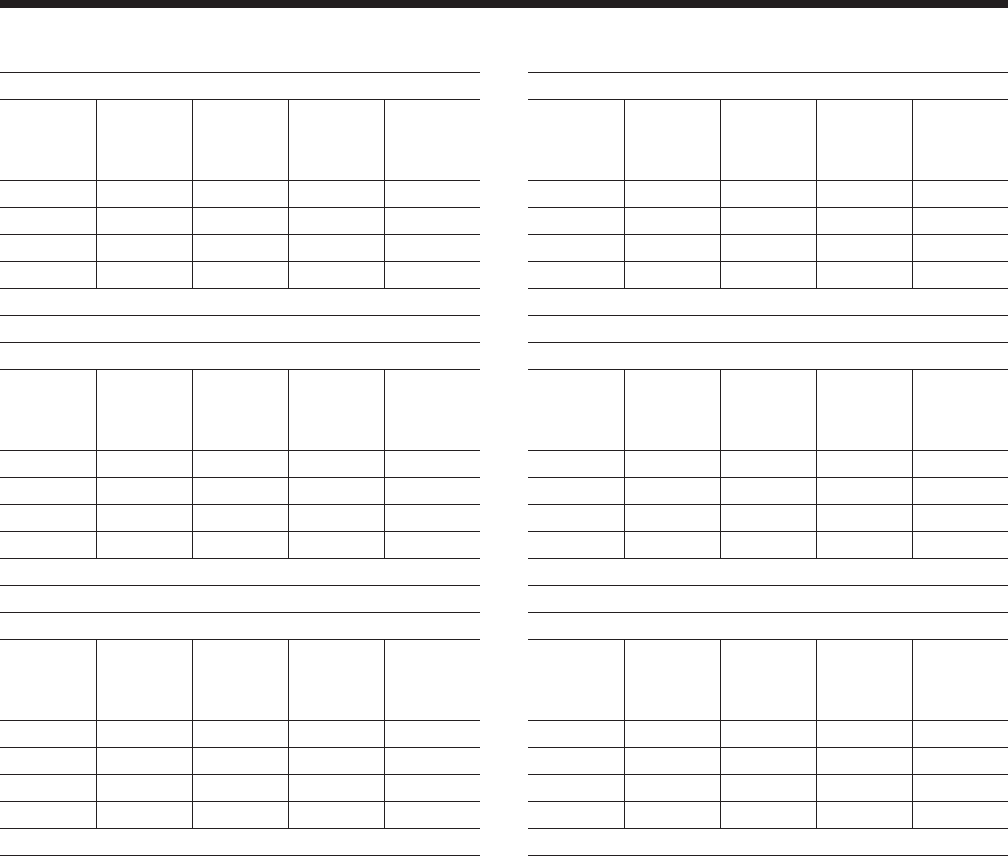
Part Load Ratings - R-22 (English Units)
YCAL0041
% FULL
LOAD
DISPL.
TONS KW Ambient
°F
UNIT
EER
100.0 35.0 38.2 95.0 9.6
75.0 28.2 24.5 83.3 11.2
50.0 20.2 14.0 69.7 14.4
25.0 10.6 6.1 55.0 17.0
IPLV: 14.0 EER
YCAL0045
% FULL
LOAD
DISPL.
TONS KW Ambient
°F
UNIT
EER
100.0 37.8 41.8 95.0 9.6
73.2 30.3 26.0 83.0 11.5
50.0 22.1 15.5 70.0 14.5
23.2 10.8 6.2 55.0 17.0
IPLV: 14.1 EER
YCAL0051
% FULL
LOAD
DISPL.
TONS KW Ambient
°F
UNIT
EER
100.0 43.5 48.7 95.0 9.6
69.2 33.7 28.3 81.4 11.9
48.3 24.4 17.2 68.6 14.6
20.9 13.3 7.2 55.0 18.7
IPLV: 14.4 EER
YCAL0055
% FULL
LOAD
DISPL.
TONS KW Ambient
°F
UNIT
EER
100.0 47.6 52.8 95.0 9.6
73.5 37.2 32.3 81.9 11.4
47.0 25.0 17.2 66.5 14.6
23.5 13.0 7.8 55.0 16.3
IPLV: 13.6 EER
YCAL0061
% FULL
LOAD
DISPL.
TONS KW Ambient
°F
UNIT
EER
100.0 55.7 62.9 95.0 9.6
69.3 42.4 35.8 80.7 11.9
46.2 30.1 20.4 67.5 15.2
23.1 15.7 9.1 55.0 17.5
IPLV: 14.3 EER
YCAL0065
% FULL
LOAD
DISPL.
TONS KW Ambient
°F
UNIT
EER
100.0 60.0 68.3 95.0 9.6
71.5 47.4 40.3 82.4 12.1
50.0 34.7 25.3 69.6 14.5
21.5 16.2 9.0 55.0 18.2
IPLV: 14.5 EER

YORK INTERNATIONAL 29
FORM 150.64-EG1
Part Load Ratings - R-22 (SI)
YCAL0041
% FULL
LOAD
DISPL.
KW Comp
KW
Ambient
°C
UNIT
COP
100.0 123.0 38.2 35.0 2.8
75.0 99.0 24.5 28.5 3.3
50.0 71.2 14.0 21.0 4.2
25.0 37.4 6.1 12.8 5.0
IPLV: 4.10 COP
YCAL0045
% FULL
LOAD
DISPL.
KW Comp
KW
Ambient
°C
UNIT
COP
100.0 133.1 41.8 35.0 2.8
73.2 106.5 26.0 28.3 3.4
50.0 77.6 15.5 21.1 4.2
23.2 37.9 6.2 12.8 5.0
IPLV: 4.12 COP
YCAL0051
% FULL
LOAD
DISPL.
KW Comp
KW
Ambient
°C
UNIT
COP
100.0 153.1 48.7 35.0 2.8
69.2 118.5 28.3 27.5 3.5
48.3 85.7 17.2 20.3 4.3
20.9 46.8 7.2 12.8 5.5
IPLV: 4.23 COP
YCAL055
% FULL
LOAD
DISPL.
KW Comp
KW
Ambient
°C
UNIT
COP
100.0 167.3 52.8 35.0 2.8
73.5 130.8 32.3 27.7 3.4
47.0 87.8 17.2 19.2 4.3
23.5 45.6 7.8 12.8 4.8
IPLV: 4.00 COP
YCAL0061
% FULL
LOAD
DISPL.
KW Comp
KW
Ambient
°C
UNIT
COP
100.0 195.8 62.9 35.0 2.8
69.3 149.0 35.8 27.0 3.5
46.2 106.0 20.4 19.7 4.5
23.1 55.3 9.1 12.8 5.1
IPLV: 4.18 COP
YCAL0065
% FULL
LOAD
DISPL.
KW Comp
KW
Ambient
°C
UNIT
SCOP
100.0 211.1 68.3 35.0 2.8
71.5 166.6 40.3 28.0 3.6
50.0 121.9 25.3 20.9 4.3
21.5 56.9 9.0 12.8 5.3
IPLV: 4.24 COP
YORK INTERNATIONAL
30
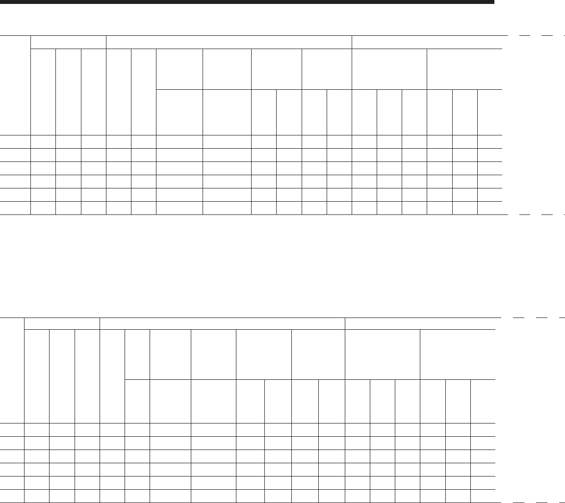
Physical Data
YCAL
Model
No.
Dimension General Unit Data Nominal Compressor Capacity Condenser Condenser Fans, Low Sound Condenser Fans, Ultra Quiet Evaporator
Length Width Height
Nomi-
nal
Tons,
R-22
Num-
ber of
Refrig-
erant
Circuits
Refrigerant
Charge,
Operating,
R-22 (lbs)
Oil Charge,
gallons
Shipping
Weight
Operating
Weight Circuit 1 Ciruict 2
Total Face
Area ft2
Number of
Rows
Fins
per
Inch
Number of
Fans
Fan
Power
hp/fan
Fan
RPM
Total
Chiller
CFM
Number of
Fans
Fan hp Fan
RPM
Total
Chiller
CFM
Water
Volume,
gallons
Maxi-
mum
Water
Side
Pres-
sure,
PSIG
Maxi-
mum
Refrig-
erant
Side
Pres-
sure,
PSIG
Mini-
mum
Chiller
Water
Flow
Rate,
gpm
Maxi-
mum
Chiller
Water
Flow
Rate,
gpm
Nomi-
nal
Water
Con-
nec-
tions
Size,
inches
ckt1/ckt2 ckt1/ckt2
Alumi-
num
Fin
Coils,
lbs
Copper
Fin
Coils,
lbs
Alumi-
num
Fin
Coils,
lbs
Copper
Fin
Coils,
lbs
Com-
pres-
sor 1
Com-
pres-
sor 2
Com-
pres-
sor 3
Com-
pres-
sor 4
Com-
pres-
sor 5
Com-
pres-
sor 6
Ckt. 1/Ckt. 2 Ckt. 1/Ckt. 2 ckt1/ckt2
0041 144.8 90.6 47.8 34.9 2 35/35 1.7/1.7 2942 3300 2967 3325 10 10 - 10 10 - 87.0 2/2 17 2/2 2 1140 47400 2/2 2 838 47400 2.7 300 450 40 200 3
0045 144.8 90.6 47.8 38.0 2 40/35 1.7/1.7 2968 3326 3001 3359 12 12 - 10 10 - 87.0 2/2 17 2/2 2 1140 47400 2/2 2 838 47400 3.5 300 450 40 200 3
0051 144.8 90.6 47.8 43.4 2 40/45 1.7/2.2 3448 3985 3480 4017 12 12 - 13 15 - 87.0 3/3 17 2/2 2 1140 47400 2/2 2 838 47400 3.5 300 450 40 200 3
0055 144.8 90.6 62.6 47.4 2 50/50 2.2/2.2 3558 4035 3595 4073 15 13 - 13 15 - 116.0 2/2 17 2/2 2 1140 52000 2/2 2 838 52000 4.1 300 450 60 300 3
0061 144.8 90.6 62.6 56.0 2 55/55 2.3/2.2 3863 4436 3908 4481 20 15 - 15 15 - 116.0 3/2 17 2/2 2 1140 52000 2/2 2 838 52000 4.9 300 450 60 300 3
0065 153.6 90.6 62.6 60.1 2 60/55 2.3/2.2 4097 4703 4142 4748 20 20 - 15 15 - 128.0 3/3 13 2/2 2 1140 52000 2/2 2 838 52000 4.9 300 450 60 300 3
YCAL
Model
No.
Dimension General Unit Data Nominal Compressor Capacity Condenser Condenser Fans, Low Sound Condenser Fans, Ultra Quiet Evaporator
Length Width Height
Nomi-
nal
KW,
R-22
Num-
ber of
Refrig-
erant
Circuits
Refrigerant
Charge,
Operating,
R-22 (kg)
Oil Charge,
liters Shipping Weight Operating
Weight Circuit 1 Circuit 2
Total
Face
Area
m2
Number of
Rows
Fins
per cm
Number of
Fans
Fan
Power
kw/fan
Fan
RPM
Total
Chiller
fpm
Number of Fans
Fan
Power
kw/fan
Fan
RPM
Total
Chiller
CFM
Water
Volume,
gallons
Maxi-
mum
Water
Side
Pres-
sure,
psig
Maxi-
mum
Refrig-
erant
Side
Pres-
sure,
psig
Mini-
mum
Chiller
Water
Flow
Rate,
gpm
Maxi-
mum
Chiller
Water
Flow
Rate,
gpm
Nominal
Water Con-
nections
Size, inches
ckt1/ckt2 ckt1/ckt2
Alumi-
num Fin
Coils, lb
Cop-
per Fin
Coils, lb
Alumi-
num Fin
Coils, lb
Cop-
per Fin
Coils, lb
Com-
pres-
sor 1
Com-
pres-
sor 2
Com-
pres-
sor 3
Com-
pres-
sor 4
Com-
pres-
sor 5
Com-
pres-
sor 6
Ckt. 1/Ckt. 2 Ckt. 1/Ckt. 2 ckt1/ckt2
0041 145.8 91.20 47.75 29.6 2.0 35.0 / 35.0 1.7 / 1.7 2942.0 3300.0 2967.0 3325.0 8.3 8.3 - 8.3 8.3 - 87.0 2.0 / 2.0 17.0 2.0 / 2.0 1.2 950.0 39500.0 2.0 / 2.0 1.2 698.3 39500.0 2.7 300.0 450.0 40.0 200.0 3.0
0045 145.8 91.20 47.75 32.3 2.0 40.0 / 35.0 1.7 / 1.7 2968.0 3326.0 3001.0 3359.0 10.0 10.0 - 8.3 8.3 - 87.0 2.0 / 2.0 17.0 2.0 / 2.0 1.2 950.0 39500.0 2.0 / 2.0 1.2 698.3 39500.0 3.5 300.0 450.0 40.0 200.0 3.0
0051 145.8 91.20 47.75 37.3 2.0 40.0 / 45.0 1.7 / 2.2 3448.0 3985.0 3480.0 4017.0 10.0 10.0 - 10.8 12.5 - 87.0 3.0 / 3.0 17.0 2.0 / 2.0 1.2 950.0 39500.0 2.0 / 2.0 1.2 698.3 39500.0 3.5 300.0 450.0 40.0 200.0 3.0
0055 145.8 91.20 62.73 40.2 2.0 50.0 / 50.0 2.2 / 2.2 3558.0 4035.0 3595.0 4073.0 12.5 10.8 - 10.8 12.5 - 116.0 2.0 / 2.0 17.0 2.0 / 2.0 1.2 950.0 43333.3 2.0 / 2.0 1.2 698.3 43333.3 4.1 300.0 450.0 60.0 300.0 3.0
0061 145.8 91.20 62.73 47.6 2.0 55.0 / 55.0 2.3 / 2.2 3863.0 4436.0 3908.0 4481.0 16.7 12.5 - 12.5 12.5 - 116.0 3.0 / 2.0 17.0 2.0 / 2.0 1.2 950.0 43333.3 2.0 / 2.0 1.2 698.3 43333.3 4.9 300.0 450.0 60.0 300.0 3.0
0065 154.6 91.20 62.73 50.9 2.0 60.0 / 55.0 2.3 / 2.2 4097.0 4703.0 4142.0 4748.0 16.7 16.7 - 12.5 12.5 - 128.0 3.0 / 3.0 13.0 2.0 / 2.0 1.2 950.0 43333.3 2.0 / 2.0 1.2 698.3 43333.3 4.9 300.0 450.0 60.0 300.0 3.0
60Hz
50Hz
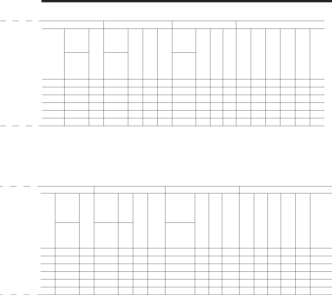
YORK INTERNATIONAL 31
FORM 150.64-EG1
YCAL
Model
No.
Dimension General Unit Data Nominal Compressor Capacity Condenser Condenser Fans, Low Sound Condenser Fans, Ultra Quiet Evaporator
Length Width Height
Nomi-
nal
Tons,
R-22
Num-
ber of
Refrig-
erant
Circuits
Refrigerant
Charge,
Operating,
R-22 (lbs)
Oil Charge,
gallons
Shipping
Weight
Operating
Weight Circuit 1 Ciruict 2
Total Face
Area ft2
Number of
Rows
Fins
per
Inch
Number of
Fans
Fan
Power
hp/fan
Fan
RPM
Total
Chiller
CFM
Number of
Fans
Fan hp Fan
RPM
Total
Chiller
CFM
Water
Volume,
gallons
Maxi-
mum
Water
Side
Pres-
sure,
PSIG
Maxi-
mum
Refrig-
erant
Side
Pres-
sure,
PSIG
Mini-
mum
Chiller
Water
Flow
Rate,
gpm
Maxi-
mum
Chiller
Water
Flow
Rate,
gpm
Nomi-
nal
Water
Con-
nec-
tions
Size,
inches
ckt1/ckt2 ckt1/ckt2
Alumi-
num
Fin
Coils,
lbs
Copper
Fin
Coils,
lbs
Alumi-
num
Fin
Coils,
lbs
Copper
Fin
Coils,
lbs
Com-
pres-
sor 1
Com-
pres-
sor 2
Com-
pres-
sor 3
Com-
pres-
sor 4
Com-
pres-
sor 5
Com-
pres-
sor 6
Ckt. 1/Ckt. 2 Ckt. 1/Ckt. 2 ckt1/ckt2
0041 144.8 90.6 47.8 34.9 2 35/35 1.7/1.7 2942 3300 2967 3325 10 10 - 10 10 - 87.0 2/2 17 2/2 2 1140 47400 2/2 2 838 47400 2.7 300 450 40 200 3
0045 144.8 90.6 47.8 38.0 2 40/35 1.7/1.7 2968 3326 3001 3359 12 12 - 10 10 - 87.0 2/2 17 2/2 2 1140 47400 2/2 2 838 47400 3.5 300 450 40 200 3
0051 144.8 90.6 47.8 43.4 2 40/45 1.7/2.2 3448 3985 3480 4017 12 12 - 13 15 - 87.0 3/3 17 2/2 2 1140 47400 2/2 2 838 47400 3.5 300 450 40 200 3
0055 144.8 90.6 62.6 47.4 2 50/50 2.2/2.2 3558 4035 3595 4073 15 13 - 13 15 - 116.0 2/2 17 2/2 2 1140 52000 2/2 2 838 52000 4.1 300 450 60 300 3
0061 144.8 90.6 62.6 56.0 2 55/55 2.3/2.2 3863 4436 3908 4481 20 15 - 15 15 - 116.0 3/2 17 2/2 2 1140 52000 2/2 2 838 52000 4.9 300 450 60 300 3
0065 153.6 90.6 62.6 60.1 2 60/55 2.3/2.2 4097 4703 4142 4748 20 20 - 15 15 - 128.0 3/3 13 2/2 2 1140 52000 2/2 2 838 52000 4.9 300 450 60 300 3
YCAL
Model
No.
Dimension General Unit Data Nominal Compressor Capacity Condenser Condenser Fans, Low Sound Condenser Fans, Ultra Quiet Evaporator
Length Width Height
Nomi-
nal
KW,
R-22
Num-
ber of
Refrig-
erant
Circuits
Refrigerant
Charge,
Operating,
R-22 (kg)
Oil Charge,
liters Shipping Weight Operating
Weight Circuit 1 Circuit 2
Total
Face
Area
m2
Number of
Rows
Fins
per cm
Number of
Fans
Fan
Power
kw/fan
Fan
RPM
Total
Chiller
fpm
Number of Fans
Fan
Power
kw/fan
Fan
RPM
Total
Chiller
CFM
Water
Volume,
gallons
Maxi-
mum
Water
Side
Pres-
sure,
psig
Maxi-
mum
Refrig-
erant
Side
Pres-
sure,
psig
Mini-
mum
Chiller
Water
Flow
Rate,
gpm
Maxi-
mum
Chiller
Water
Flow
Rate,
gpm
Nominal
Water Con-
nections
Size, inches
ckt1/ckt2 ckt1/ckt2
Alumi-
num Fin
Coils, lb
Cop-
per Fin
Coils, lb
Alumi-
num Fin
Coils, lb
Cop-
per Fin
Coils, lb
Com-
pres-
sor 1
Com-
pres-
sor 2
Com-
pres-
sor 3
Com-
pres-
sor 4
Com-
pres-
sor 5
Com-
pres-
sor 6
Ckt. 1/Ckt. 2 Ckt. 1/Ckt. 2 ckt1/ckt2
0041 145.8 91.20 47.75 29.6 2.0 35.0 / 35.0 1.7 / 1.7 2942.0 3300.0 2967.0 3325.0 8.3 8.3 - 8.3 8.3 - 87.0 2.0 / 2.0 17.0 2.0 / 2.0 1.2 950.0 39500.0 2.0 / 2.0 1.2 698.3 39500.0 2.7 300.0 450.0 40.0 200.0 3.0
0045 145.8 91.20 47.75 32.3 2.0 40.0 / 35.0 1.7 / 1.7 2968.0 3326.0 3001.0 3359.0 10.0 10.0 - 8.3 8.3 - 87.0 2.0 / 2.0 17.0 2.0 / 2.0 1.2 950.0 39500.0 2.0 / 2.0 1.2 698.3 39500.0 3.5 300.0 450.0 40.0 200.0 3.0
0051 145.8 91.20 47.75 37.3 2.0 40.0 / 45.0 1.7 / 2.2 3448.0 3985.0 3480.0 4017.0 10.0 10.0 - 10.8 12.5 - 87.0 3.0 / 3.0 17.0 2.0 / 2.0 1.2 950.0 39500.0 2.0 / 2.0 1.2 698.3 39500.0 3.5 300.0 450.0 40.0 200.0 3.0
0055 145.8 91.20 62.73 40.2 2.0 50.0 / 50.0 2.2 / 2.2 3558.0 4035.0 3595.0 4073.0 12.5 10.8 - 10.8 12.5 - 116.0 2.0 / 2.0 17.0 2.0 / 2.0 1.2 950.0 43333.3 2.0 / 2.0 1.2 698.3 43333.3 4.1 300.0 450.0 60.0 300.0 3.0
0061 145.8 91.20 62.73 47.6 2.0 55.0 / 55.0 2.3 / 2.2 3863.0 4436.0 3908.0 4481.0 16.7 12.5 - 12.5 12.5 - 116.0 3.0 / 2.0 17.0 2.0 / 2.0 1.2 950.0 43333.3 2.0 / 2.0 1.2 698.3 43333.3 4.9 300.0 450.0 60.0 300.0 3.0
0065 154.6 91.20 62.73 50.9 2.0 60.0 / 55.0 2.3 / 2.2 4097.0 4703.0 4142.0 4748.0 16.7 16.7 - 12.5 12.5 - 128.0 3.0 / 3.0 13.0 2.0 / 2.0 1.2 950.0 43333.3 2.0 / 2.0 1.2 698.3 43333.3 4.9 300.0 450.0 60.0 300.0 3.0
60Hz
50Hz
YORK INTERNATIONAL
32
Sound Data
60Hz Line Frequency
Low Noise Fan R-22
63 125 250 500 1000 2000 4000 8000 dBA
YCAL0041 92 91 92 90 86 81 77 74 92
YCAL0045 92 91 92 90 86 81 77 74 92
YCAL0051 91 92 92 91 87 82 78 75 92
YCAL0055 93 95 95 93 90 85 81 77 95
YCAL0061 93 95 95 93 90 86 82 77 95
YCAL0065 94 94 95 93 90 86 82 77 95
60Hz Line Frequency
Low Noise Fan with compressor sound blankets installed R-22
63 125 250 500 1000 2000 4000 8000 dBA
YCAL0041 92 91 92 90 86 81 77 73 91
YCAL0045 92 91 92 90 86 81 77 73 91
YCAL0051 91 92 92 90 86 81 77 73 91
YCAL0055 93 95 95 93 89 84 80 76 94
YCAL0061 93 95 95 93 89 84 80 76 94
YCAL0065 94 94 95 93 89 84 80 75 94
60Hz Line Frequency
Ultra Quiet Fan R-22
63 125 250 500 1000 2000 4000 8000 dBA
YCAL0041 94 88 88 87 83 79 75 74 88
YCAL0045 94 88 88 87 83 79 75 74 88
YCAL0051 94 90 89 88 84 80 76 75 90
YCAL0055 96 93 91 90 87 83 79 77 92
YCAL0061 96 93 91 90 87 84 80 77 92
YCAL0065 96 92 91 90 87 84 81 77 92
60Hz Line Frequency
Ultra Quiet Fan with compressor sound blankets installed R-22
63 125 250 500 1000 2000 4000 8000 dBA
YCAL0041 94 88 88 85 82 77 74 73 87
YCAL0045 94 88 88 85 82 77 74 73 87
YCAL0051 94 90 89 86 83 78 74 73 88
YCAL0055 96 93 91 89 85 81 77 76 91
YCAL0061 96 93 91 89 85 81 78 76 91
YCAL0065 96 92 91 89 86 81 78 75 91
YORK INTERNATIONAL 33
FORM 150.64-EG1
50Hz Line Frequency
Low Noise Fan R-22
63 125 250 500 1000 2000 4000 8000 dBA
YCAL0041 88 87 88 87 83 78 74 71 88
YCAL0045 88 87 88 87 83 78 74 71 88
YCAL0051 88 89 89 87 83 79 75 72 89
YCAL0055 89 92 92 90 86 82 78 74 91
YCAL0061 90 91 91 90 86 82 78 74 92
YCAL0065 90 91 91 90 86 83 79 73 92
50Hz Line Frequency
Low Noise Fan with compressor sound blankets installed R-22
63 125 250 500 1000 2000 4000 8000 dBA
YCAL0041 88 87 88 86 82 77 73 69 87
YCAL0045 88 87 88 86 82 77 73 69 87
YCAL0051 88 89 89 86 82 77 73 69 88
YCAL0055 89 92 92 89 85 80 76 72 90
YCAL0061 90 91 91 89 85 80 76 72 90
YCAL0065 90 91 91 89 85 80 77 72 90
50Hz Line Frequency
Ultra Quiet Fan R-22
63 125 250 500 1000 2000 4000 8000 dBA
YCAL0041 90 84 84 84 80 75 72 71 85
YCAL0045 90 84 84 84 80 75 72 71 85
YCAL0051 90 88 86 85 81 78 73 72 87
YCAL0055 92 90 88 87 84 80 76 74 89
YCAL0061 92 90 88 87 84 81 77 74 89
YCAL0065 92 89 87 87 84 81 78 73 89
50Hz Line Frequency
Ultra Quiet Fan with compressor sound blankets installed R-22
63 125 250 500 1000 2000 4000 8000 dBA
YCAL0041 90 84 84 82 78 73 70 69 84
YCAL0045 90 84 84 82 78 73 70 69 84
YCAL0051 90 88 86 82 79 74 71 69 84
YCAL0055 92 90 88 85 82 77 74 72 87
YCAL0061 92 90 88 85 82 77 74 72 87
YCAL0065 92 89 87 85 82 77 74 72 87

YORK INTERNATIONAL
34
Dimensions - YCAL0041 (English)
NOTE:
Placement on a level surface of free of obstructions (including snow, for winter operation) or air circulation ensures rated performance, reli-
able operation, and ease of maintenance. Site restrictions may compromise minimum clearances indicated below, resulting in unpredictable
airflow patterns and possible diminished performance. YORK’s unit controls will optimize operation without nuisance high-pressure safety
cutouts; however, the system designer must consider potential performance degradation. Recommended minimum clearances: front to wall
– 6'; rear to wall – 6'; cooler end to wall – 4'0"; coil end to wall - 6'; top – no obstructions allowed; distance between adjacent units – 10'.
No more than one adjacent wall may be higher than the unit. 1" nominal deflection isolators (not shown) will increase overall unit height by
6".
VIEW B-B
3 15/16"
3 1/4"
6 3/4"
BOTTOM OF PANEL
7/8" TYP.
47 3/4"
46 15/16"
45 1/8"
12 5/8"
3" VICTAULIC (typ)
90 1/4" BASE WIDTH
LEFT END
LIQUID OUT
34 5/8"
15 3/4"
9 15/16"
ELECTRICAL ACCESS
PANEL
LIQUID IN
Aluminum Copper
YCAL Center of Gravity (in.) YCAL Center of Gravity (in.)
X Y X Y
0041 59.6 43.6 0041 63.6 43.7
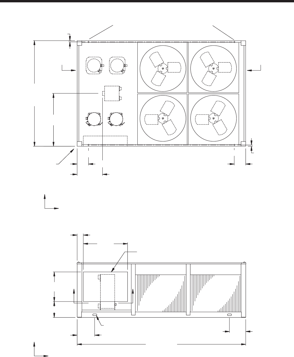
YORK INTERNATIONAL 35
FORM 150.64-EG1
90 9/16"
45 5/16"
Y
C
G
X
1 1/16"
ORIGIN
END CAP
WIDTH
21 13/16" TOP VIEW
9 13/16"
1 1/16"
9 13/16"
9/16" DIA MOUNTING HOLES(typ)
144 13/16"
15 1/16" 13 15/16"
TWO LIFTING HOLES
BOTH SIDES
FRONT VIEW
C
GX
Z
38"
5 5/16"
25 3/8"
13 5/8"
BB
COIL
END
COOLER
END
CONTROL PANEL
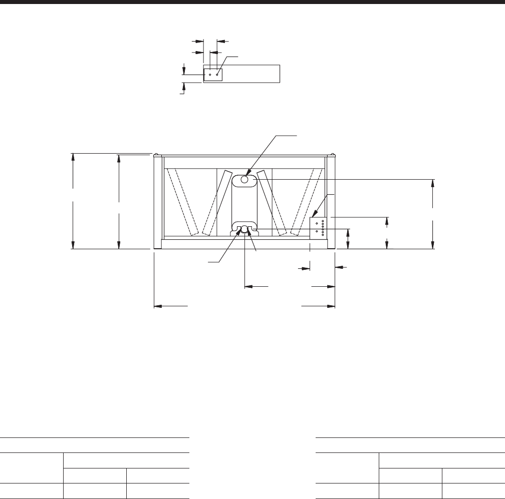
YORK INTERNATIONAL
36
Dimensions - YCAL0045 (English)
VIEW B-B
3 15/16"
3 1/4"
6 3/4"
BOTTOM OF PANEL
7/8" TYP.
47 3/4"
46 15/16"
45 1/8"
12 5/8"
3" VICTAULIC (typ)
90 1/4" BASE WIDTH
LEFT END
LIQUID OUT
34 5/8"
15 3/4"
9 15/16"
ELECTRICAL ACCESS
PANEL
LIQUID IN
Aluminum Copper
YCAL Center of Gravity (in.) YCAL Center of Gravity (in.)
X Y X Y
0045 59.2 43.5 0045 63.2 43.7
NOTE:
Placement on a level surface of free of obstructions (including snow, for winter operation) or air circulation ensures rated performance, reli-
able operation, and ease of maintenance. Site restrictions may compromise minimum clearances indicated below, resulting in unpredictable
airflow patterns and possible diminished performance. YORK’s unit controls will optimize operation without nuisance high-pressure safety
cutouts; however, the system designer must consider potential performance degradation. Recommended minimum clearances: front to wall
– 6'; rear to wall – 6'; cooler end to wall – 4'0"; coil end to wall - 6'; top – no obstructions allowed; distance between adjacent units – 10'.
No more than one adjacent wall may be higher than the unit. 1" nominal deflection isolators (not shown) will increase overall unit height by
6".
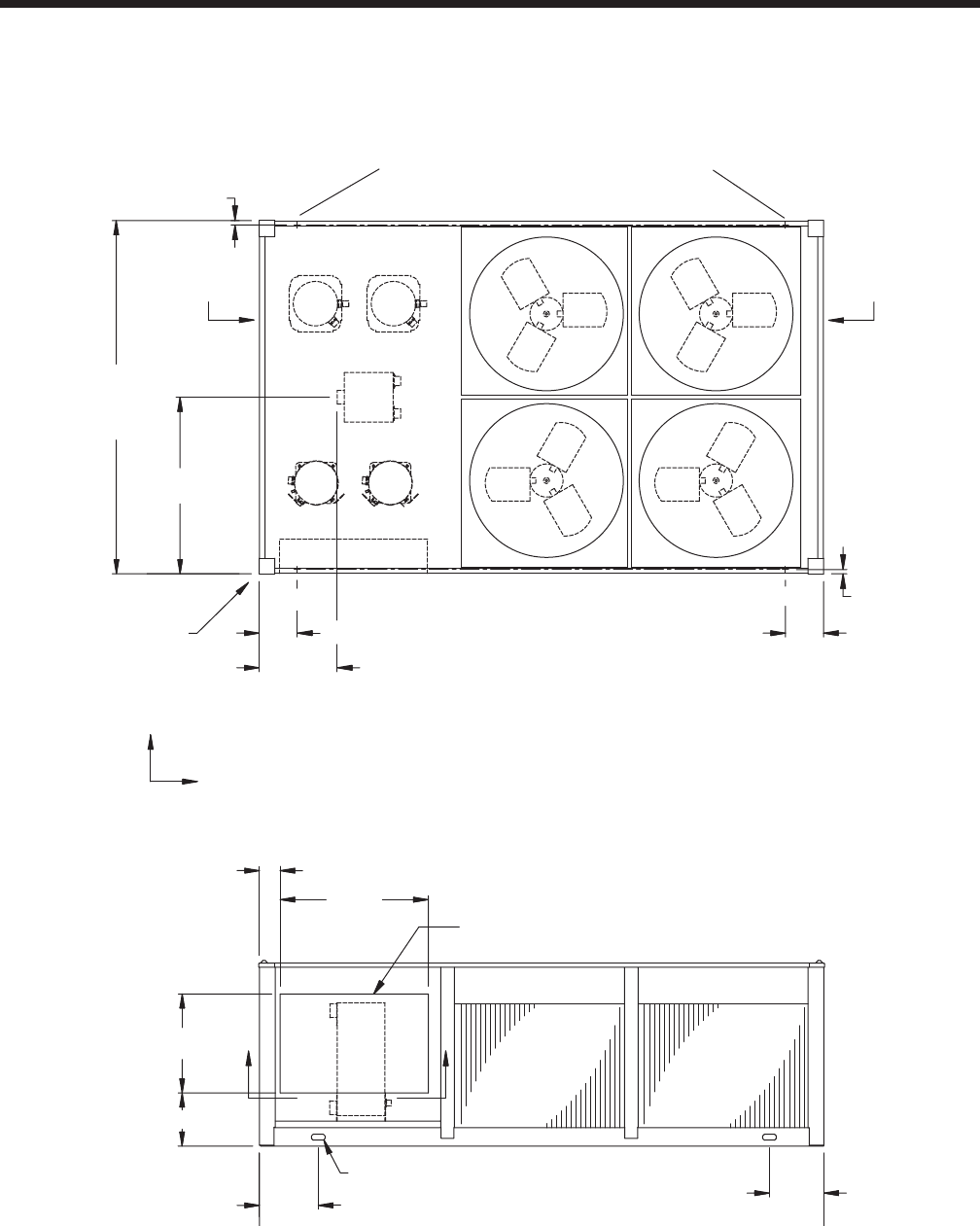
YORK INTERNATIONAL 37
FORM 150.64-EG1
90 9/16"
45 5/16"
Y
C
G
X
1 1/16"
ORIGIN
END CAP
WIDTH
20 1/16" TOP VIEW
9 13/16"
1 1/16"
9 13/16"
9/16" DIA MOUNTING HOLES(typ)
144 13/16"
15 1/16" 13 15/16"
TWO LIFTING HOLES
BOTH SIDES
FRONT VIEW
C
GX
Z
38"
5 5/16"
25 3/8"
13 5/8"
BB
COIL
END
COOLER
END
CONTROL PANEL
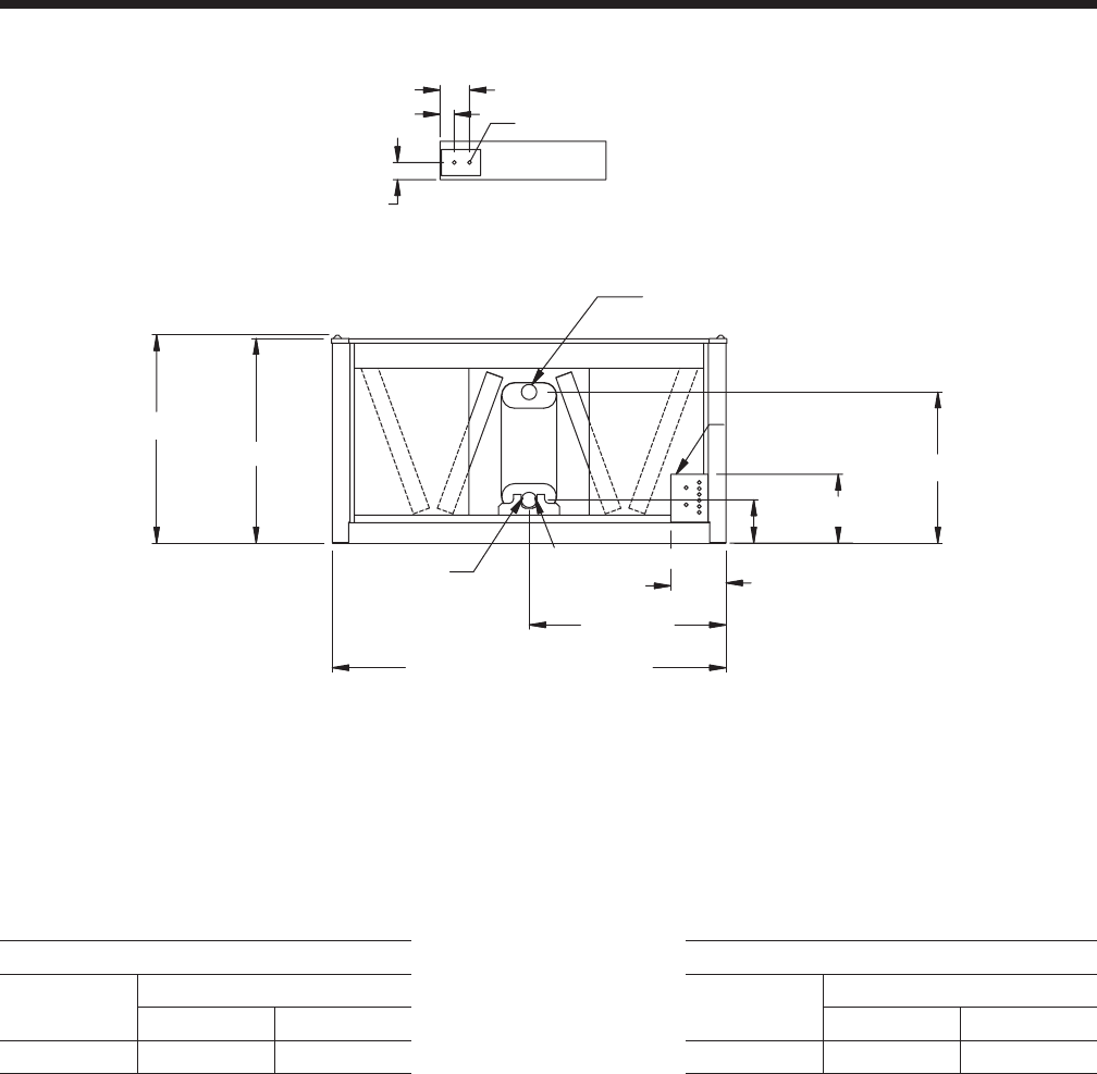
YORK INTERNATIONAL
38
Dimensions - YCAL0051 (English)
VIEW B-B
3 15/16"
3 1/4"
6 3/4"
BOTTOM OF PANEL
7/8" TYP.
47 3/4"
46 15/16"
45 1/8"
12 5/8"
3" VICTAULIC (typ)
90 1/4" BASE WIDTH
LEFT END
LIQUID OUT
34 5/8"
15 3/4"
9 15/16"
ELECTRICAL ACCESS
PANEL
LIQUID IN
Aluminum Copper
YCAL Center of Gravity (in.) YCAL Center of Gravity (in.)
X Y X Y
0051 59.2 42.6 0051 64.3 42.9
NOTE:
Placement on a level surface of free of obstructions (including snow, for winter operation) or air circulation ensures rated performance, reli-
able operation, and ease of maintenance. Site restrictions may compromise minimum clearances indicated below, resulting in unpredictable
airflow patterns and possible diminished performance. YORK’s unit controls will optimize operation without nuisance high-pressure safety
cutouts; however, the system designer must consider potential performance degradation. Recommended minimum clearances: front to wall
– 6'; rear to wall – 6'; cooler end to wall – 4'0"; coil end to wall - 6'; top – no obstructions allowed; distance between adjacent units – 10'.
No more than one adjacent wall may be higher than the unit. 1" nominal deflection isolators (not shown) will increase overall unit height by
6".
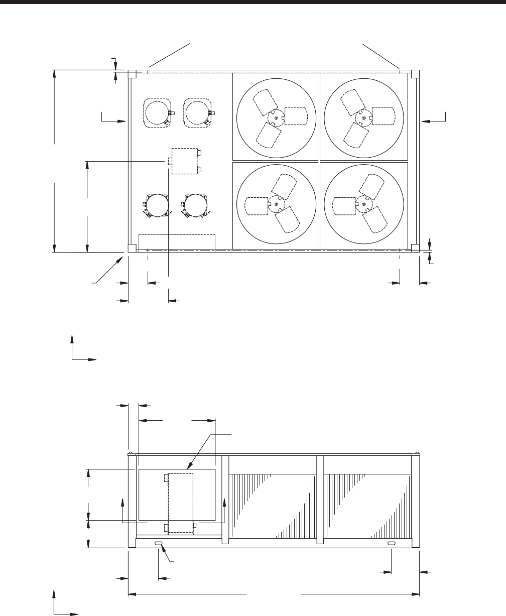
YORK INTERNATIONAL 39
FORM 150.64-EG1
90 9/16"
45 5/16"
Y
C
G
X
1 1/16"
ORIGIN
END CAP
WIDTH
20 1/16" TOP VIEW
9 13/16"
1 1/16"
9 13/16"
9/16" DIA MOUNTING HOLES(typ)
144 13/16"
15 1/16" 13 15/16"
TWO LIFTING HOLES
BOTH SIDES
FRONT VIEW
C
GX
Z
38"
5 5/16"
25 3/8"
13 5/8"
BB
COIL
END
COOLER
END
CONTROL PANEL
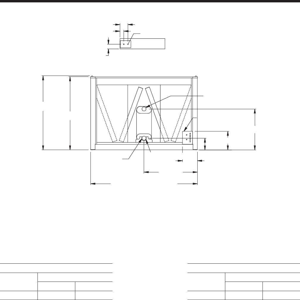
YORK INTERNATIONAL
40
Dimensions - YCAL0055EC - (English)
VIEW B-B
3 15/16"
3 1/4"
6 3/4"
BOTTOM OF PANEL
7/8" TYP.
62 5/8"
61 7/8"
45 1/8"
12 5/8"
3" VICTAULIC (typ)
90 1/4" BASE WIDTH
LEFT END
LIQUID OUT
34 11/16"
15 3/4"
9 15/16"
ELECTRICAL ACCESS
PANEL
LIQUID IN
Aluminum Copper
YCAL Center of Gravity (in.) YCAL Center of Gravity (in.)
X Y X Y
0055 57.9 43.0 0055 62.5 43.2
NOTE:
Placement on a level surface of free of obstructions (including snow, for winter operation) or air circulation ensures rated performance, reli-
able operation, and ease of maintenance. Site restrictions may compromise minimum clearances indicated below, resulting in unpredictable
airflow patterns and possible diminished performance. YORK’s unit controls will optimize operation without nuisance high-pressure safety
cutouts; however, the system designer must consider potential performance degradation. Recommended minimum clearances: front to wall
– 6'; rear to wall – 6'; cooler end to wall – 4'0"; coil end to wall - 6'; top – no obstructions allowed; distance between adjacent units – 10'.
No more than one adjacent wall may be higher than the unit. 1" nominal deflection isolators (not shown) will increase overall unit height by
6".
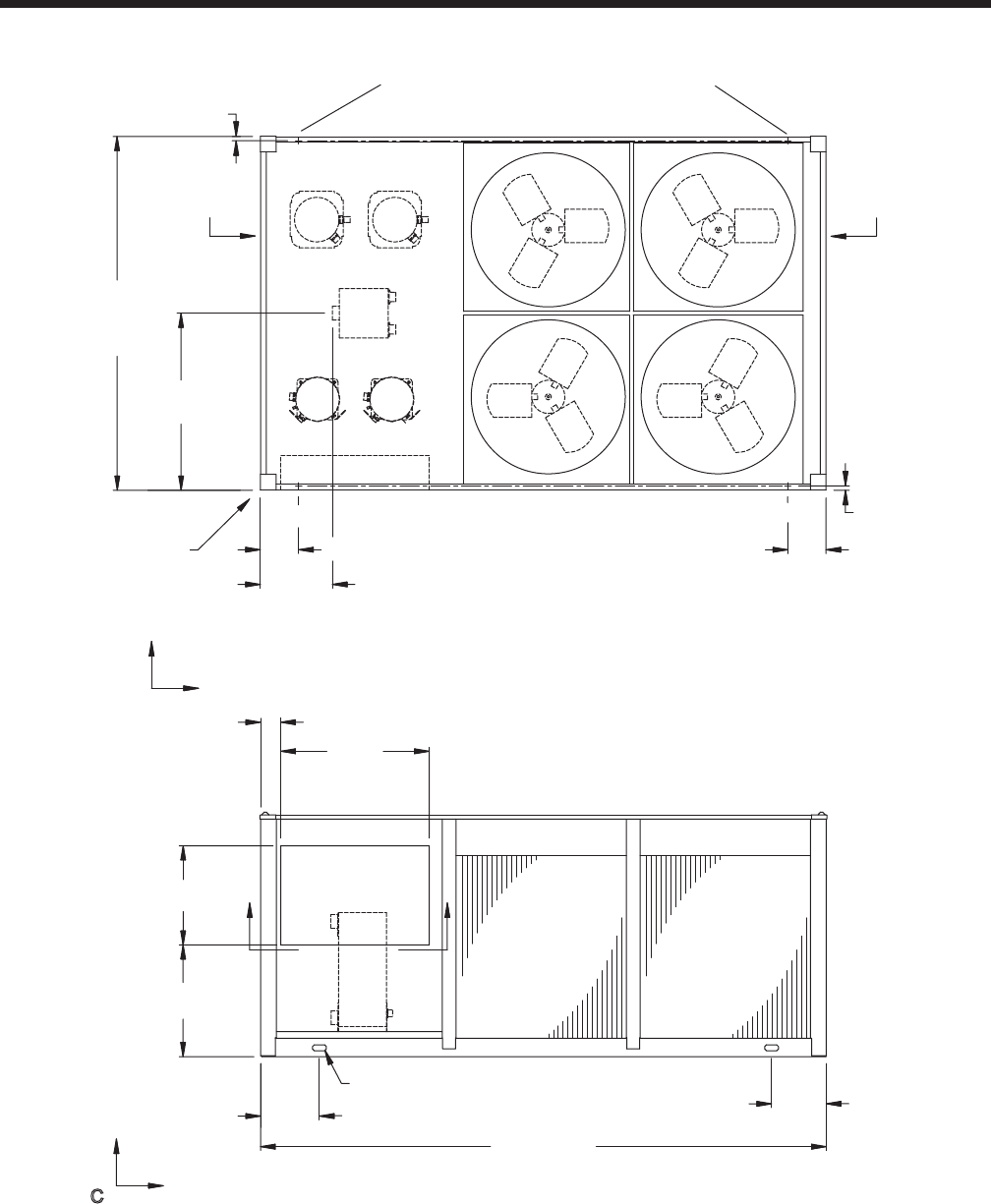
YORK INTERNATIONAL 41
FORM 150.64-EG1
90 9/16"
45 5/16"
Y
C
G
X
1 1/16"
ORIGIN
END CAP
WIDTH
18 7/16" TOP VIEW
9 13/16"
1 1/16"
9 13/16"
9/16" DIA MOUNTING HOLES(typ)
144 13/16"
15 1/16" 14"
TWO LIFTING HOLES
BOTH SIDES
FRONT VIEW
C
GX
Z
38"
5 3/16"
25 3/8"
28 9/16"
BB
COIL
END
COOLER
END
CONTROL
PANEL
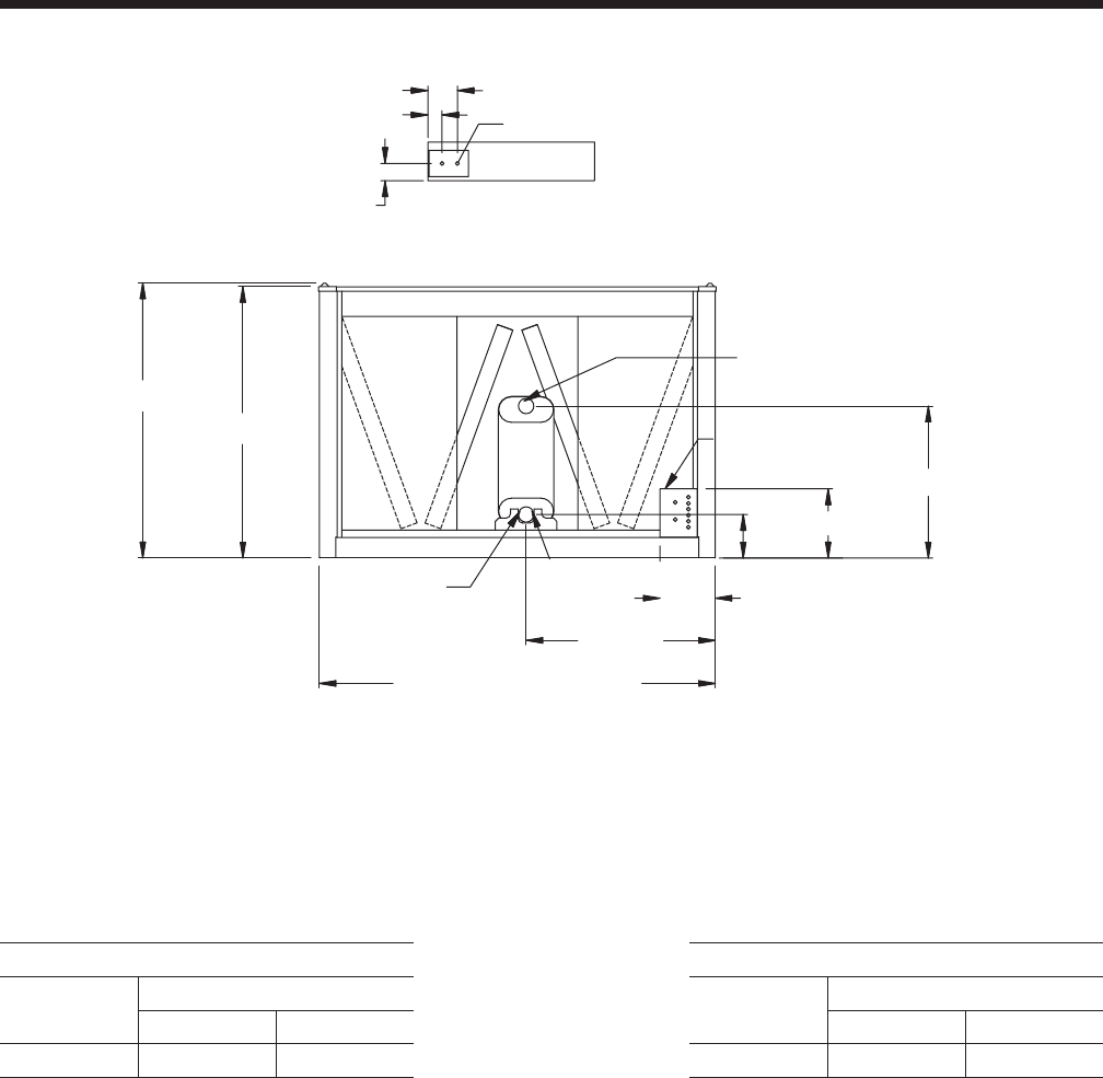
YORK INTERNATIONAL
42
Dimensions - YCAL0061 (English)
VIEW B-B
3 15/16"
3 1/4"
6 3/4"
BOTTOM OF PANEL
7/8" TYP.
62 5/8"
61 7/8"
43 1/8"
12 5/8"
3" VICTAULIC (typ)
90 1/4" BASE WIDTH
LEFT END
LIQUID OUT
34 11/16"
15 3/4"
9 15/16"
ELECTRICAL ACCESS
PANEL
LIQUID IN
Aluminum Copper
YCAL Center of Gravity (in.) YCAL Center of Gravity (in.)
X Y X Y
0061 56.6 45.2 0061 61.8 45.8
NOTE:
Placement on a level surface of free of obstructions (including snow, for winter operation) or air circulation ensures rated performance, reli-
able operation, and ease of maintenance. Site restrictions may compromise minimum clearances indicated below, resulting in unpredictable
airflow patterns and possible diminished performance. YORK’s unit controls will optimize operation without nuisance high-pressure safety
cutouts; however, the system designer must consider potential performance degradation. Recommended minimum clearances: front to wall
– 6'; rear to wall – 6'; cooler end to wall – 4'0"; coil end to wall - 6'; top – no obstructions allowed; distance between adjacent units – 10'.
No more than one adjacent wall may be higher than the unit. 1" nominal deflection isolators (not shown) will increase overall unit height by
6".
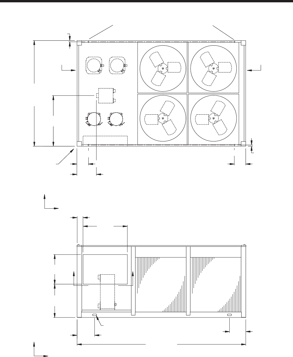
YORK INTERNATIONAL 43
FORM 150.64-EG1
90 9/16"
43 5/16"
Y
C
G
X
1 1/16"
ORIGIN
END CAP
WIDTH
16 11/16" TOP VIEW
9 13/16"
1 1/16"
9 13/16"
9/16" DIA MOUNTING HOLES(typ)
144 13/16"
15 1/16" 14"
TWO LIFTING HOLES
BOTH SIDES
FRONT VIEW
C
GX
Z
38"
5 3/16"
25 3/8"
28 9/16"
BB
COIL
END
COOLER
END
CONTROL
PANEL
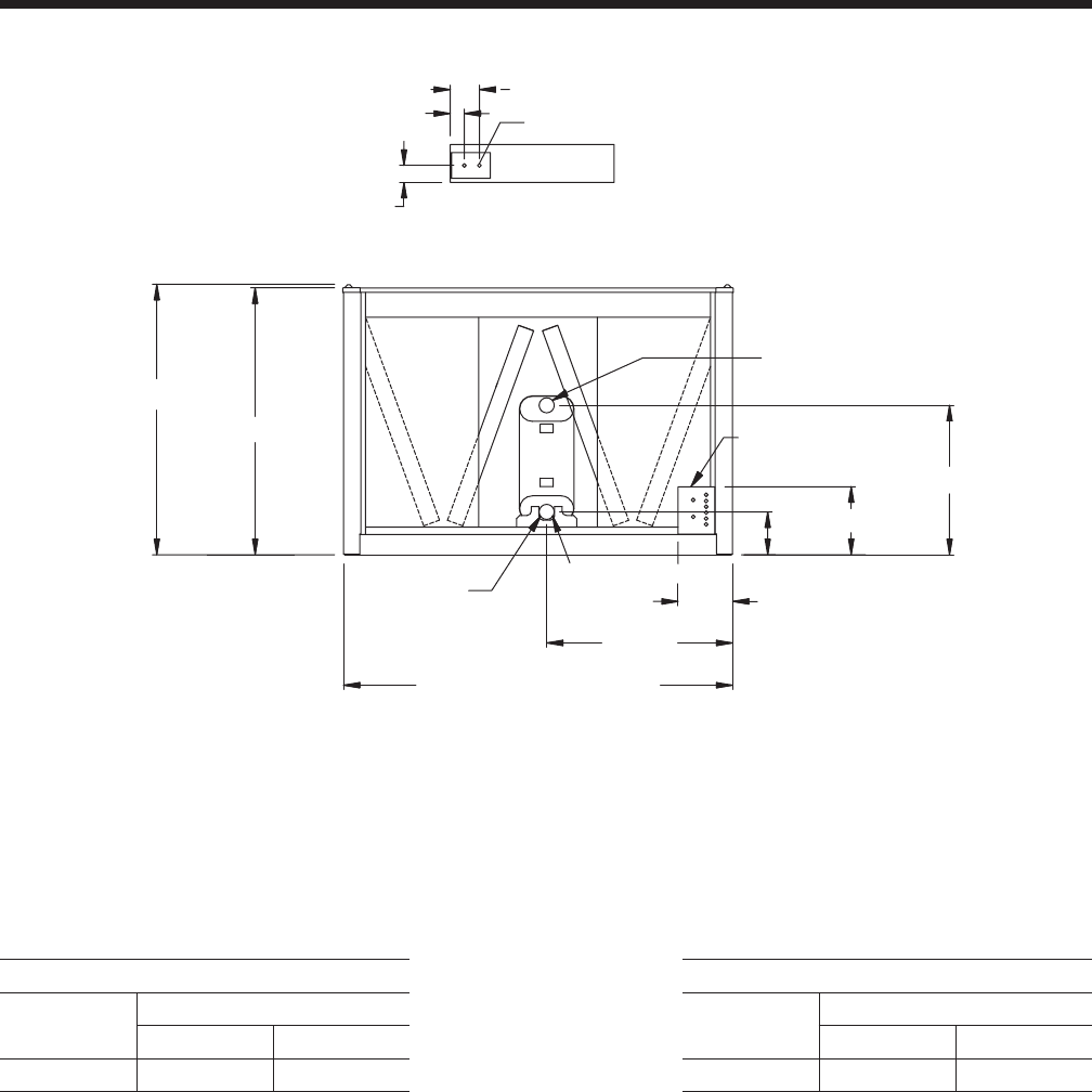
YORK INTERNATIONAL
44
Dimensions - YCAL0065 (English)
62 5/8"
61 7/8"
34 11/16"
15 3/4"
9 15/16"
43 1/8"
12 5/8"
3" VICTAULIC (typ)
ELECTRICAL ACCESS
PANEL
90 1/4" BASE WIDTH
LEFT END
LIQUID OUT
LIQUID IN
VIEW B-B
7/8" TYP.
3 15/16"
3 1/4"
6 3/4"
BOTTOM OF PANEL
Aluminum Copper
YCAL Center of Gravity (in.) YCAL Center of Gravity (in.)
X Y X Y
0065 59.7 44.9 0065 65.2 44.9
NOTE:
Placement on a level surface of free of obstructions (including snow, for winter operation) or air circulation ensures rated performance, reli-
able operation, and ease of maintenance. Site restrictions may compromise minimum clearances indicated below, resulting in unpredictable
airflow patterns and possible diminished performance. YORK’s unit controls will optimize operation without nuisance high-pressure safety
cutouts; however, the system designer must consider potential performance degradation. Recommended minimum clearances: front to wall
– 6'; rear to wall – 6'; cooler end to wall – 4'0"; coil end to wall - 6'; top – no obstructions allowed; distance between adjacent units – 10'.
No more than one adjacent wall may be higher than the unit. 1" nominal deflection isolators (not shown) will increase overall unit height by
6".
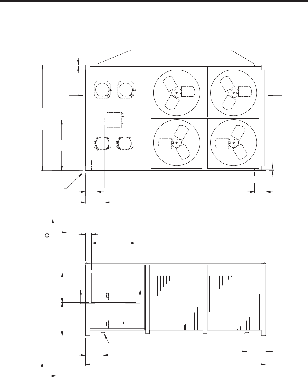
YORK INTERNATIONAL 45
FORM 150.64-EG1
90 9/16"
43 5/16"
16 11/16"
38"
5 3/16"
153 5/8"
15 1/16"
16"
25 3/8"
28 9/16"
CONTROL
PANEL
TWO LIFTING HOLES
BOTH SIDES
Y
TOP VIEW
C
GX
FRONT VIEW
C
G
X
Z
1 1/16"
1 1/16"
ORIGIN
9 13/16"
9 13/16"
BB
9/16" DIA MOUNTING HOLES(typ)
END CAP
WIDTH
COIL
END
COOLER
END
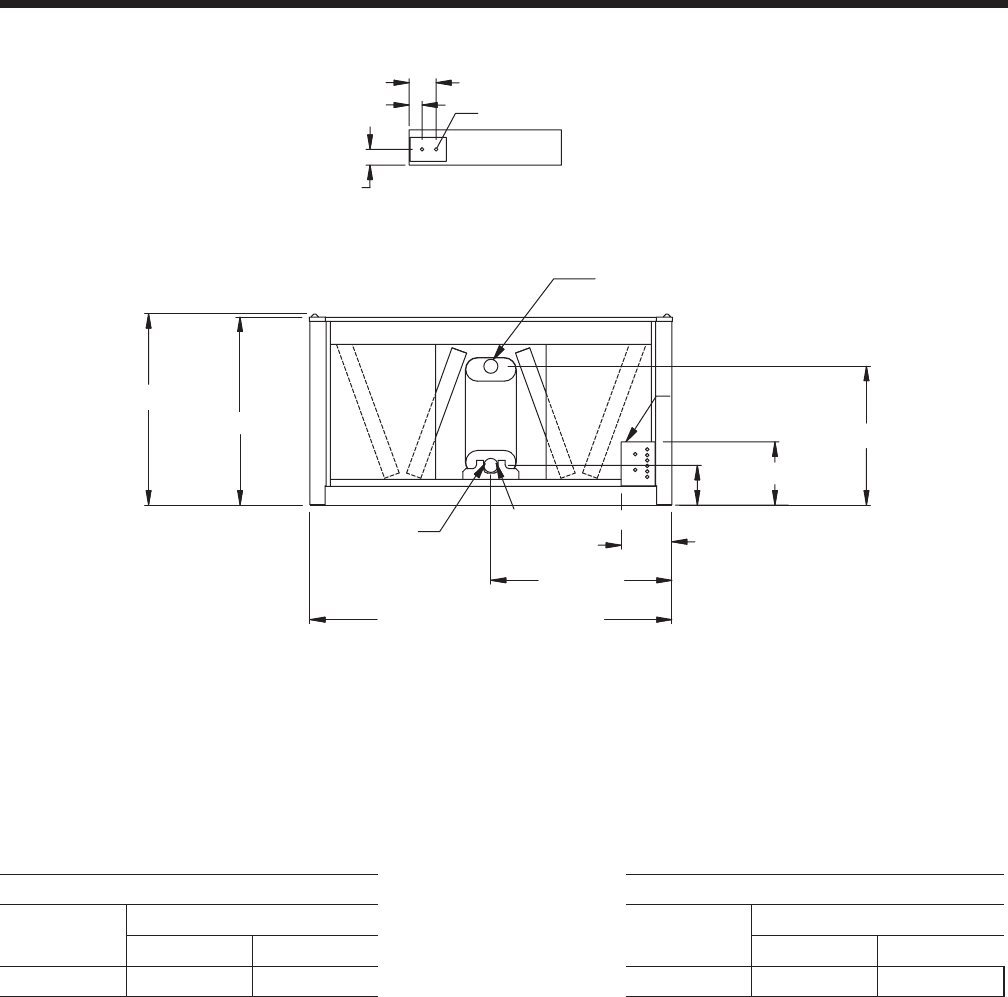
YORK INTERNATIONAL
46
NOTE:
Placement on a level surface of free of obstructions (including snow, for winter operation) or air circulation ensures rated performance, reliable
operation, and ease of maintenance. Site restrictions may compromise minimum clearances indicated below, resulting in unpredictable airflow
patterns and possible diminished performance. YORK’s unit controls will optimize operation without nuisance high-pressure safety cutouts;
however, the system designer must consider potential performance degradation. Recommended minimum clearances: front to wall – 2m;
rear to wall – 2m; cooler end to wall – 1.2m; coil end to wall - 2m; top – no obstructions allowed; distance between adjacent units – 3m.
No more than one adjacent wall may be higher than the unit. 1" nominal deflection isolators (not shown) will increase overall unit height by
152mm.
Dimensions - YCAL0041 (SI)
NOTE: All dimensions are in mm unless specified otherwise.
VIEW B-B
100
82
171
BOTTOM OF PANEL
22 TYP.
1213
1192
1146
321
76 VICTAULIC (typ)
2292 BASE WIDTH
LEFT END
LIQUID OUT
879
401
252
ELECTRICAL ACCESS
PANEL
LIQUID IN
Aluminum Copper
YCAL Center of Gravity (in.) YCAL Center of Gravity (in.)
X Y X Y
0041 1513.7 1107.0 0041 1616.1 1111.1
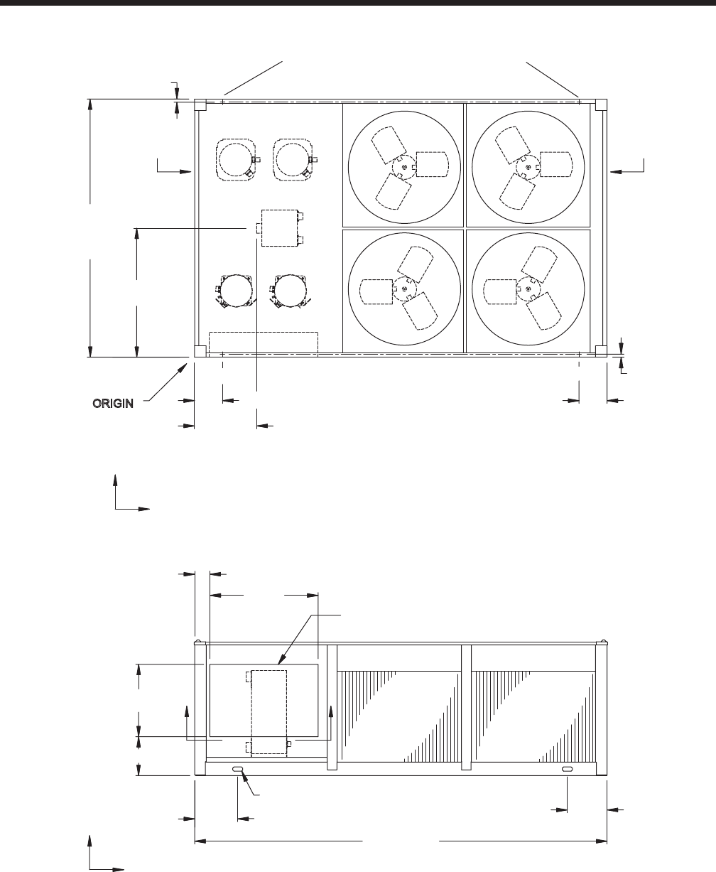
YORK INTERNATIONAL 47
FORM 150.64-EG1
2301
1150
Y
C
G
X
28
ORIGIN
END CAP
WIDTH
554 TOP VIEW
249
28
249
14 DIA MOUNTING HOLES(typ)
3678
383 355
TWO LIFTING HOLES
BOTH SIDES
FRONT VIEW
C
GX
Z
965
135
645
346
BB
COIL
END
COOLER
END
CONTROL PANEL
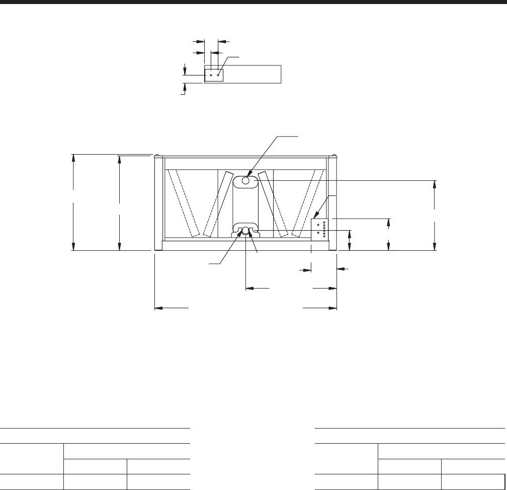
YORK INTERNATIONAL
48
Dimensions - YCAL0045 (SI)
VIEW B-B
100
82
171
BOTTOM OF PANEL
22 TYP.
1213
1192
1146
321
76 VICTAULIC (typ)
2292 BASE WIDTH
LEFT END
LIQUID OUT
879
401
252
ELECTRICAL ACCESS
PANEL
LIQUID IN
Aluminum Copper
YCAL Center of Gravity (in.) YCAL Center of Gravity (in.)
X Y X Y
0045 1503.5 1105.5 0045 1605.9 1109.7
NOTE:
Placement on a level surface of free of obstructions (including snow, for winter operation) or air circulation ensures rated performance, reliable
operation, and ease of maintenance. Site restrictions may compromise minimum clearances indicated below, resulting in unpredictable airflow
patterns and possible diminished performance. YORK’s unit controls will optimize operation without nuisance high-pressure safety cutouts;
however, the system designer must consider potential performance degradation. Recommended minimum clearances: front to wall – 2m;
rear to wall – 2m; cooler end to wall – 1.2m; coil end to wall - 2m; top – no obstructions allowed; distance between adjacent units – 3m.
No more than one adjacent wall may be higher than the unit. 1" nominal deflection isolators (not shown) will increase overall unit height by
152mm.
NOTE: All dimensions are in mm unless specified otherwise.
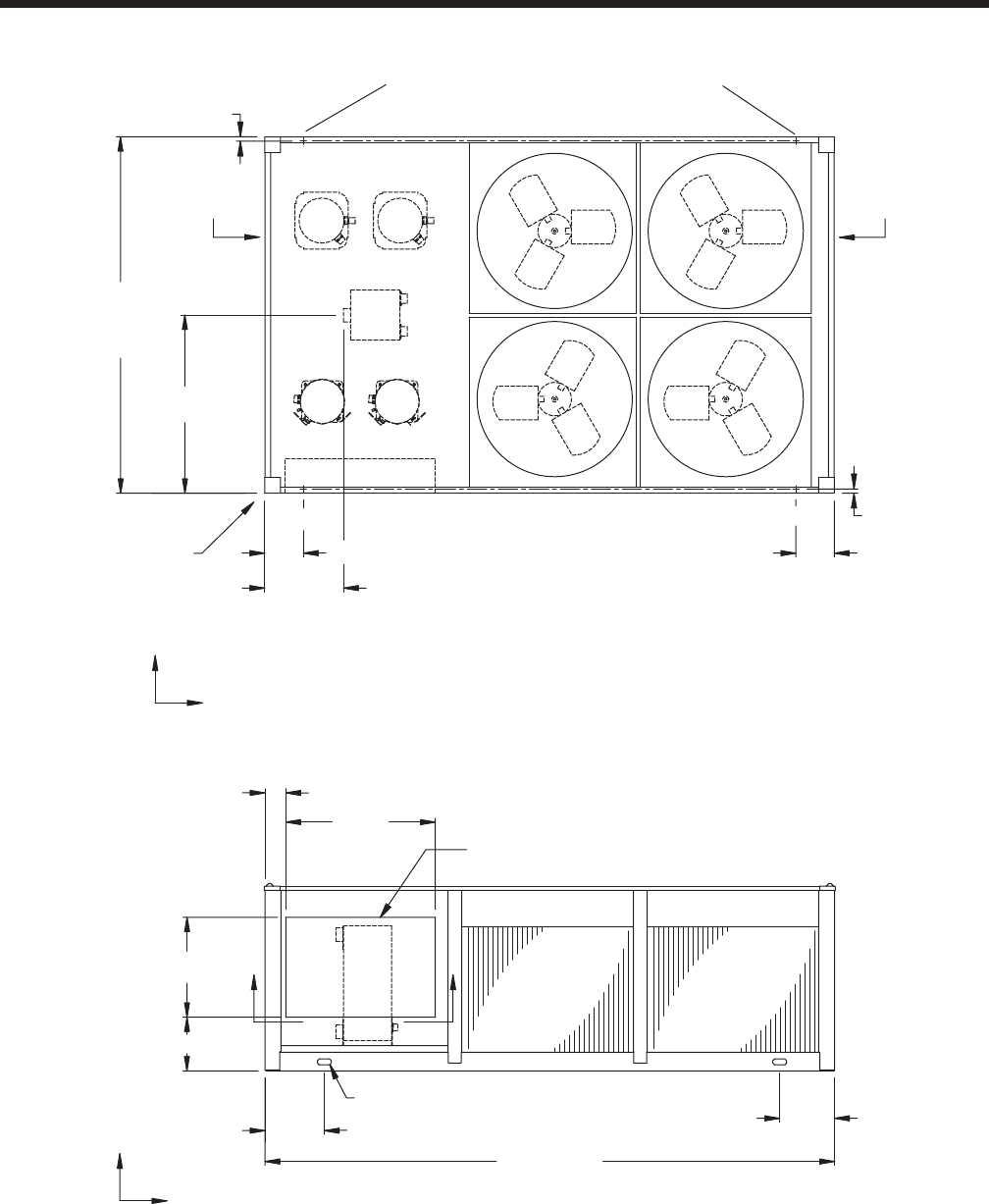
YORK INTERNATIONAL 49
FORM 150.64-EG1
2301
1150
Y
C
G
X
28
ORIGIN
END CAP
WIDTH
509 TOP VIEW
249
28
249
14 DIA MOUNTING HOLES(typ)
3678
383 355
TWO LIFTING HOLES
BOTH SIDES
FRONT VIEW
C
GX
Z
965
135
645
346
BB
COIL
END
COOLER
END
CONTROL PANEL
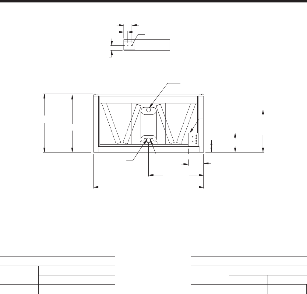
YORK INTERNATIONAL
50
Dimensions - YCAL0051 (SI)
VIEW B-B
100
82
171
BOTTOM OF PANEL
22 TYP.
1213
1192
1146
321
76 VICTAULIC (typ)
2292 BASE WIDTH
LEFT END
LIQUID OUT
879
401
252
ELECTRICAL ACCESS
PANEL
LIQUID IN
Aluminum Copper
YCAL Center of Gravity (in.) YCAL Center of Gravity (in.)
X Y X Y
0051 1504.6 1082.4 0051 1633.0 1090.8
NOTE:
Placement on a level surface of free of obstructions (including snow, for winter operation) or air circulation ensures rated performance, reliable
operation, and ease of maintenance. Site restrictions may compromise minimum clearances indicated below, resulting in unpredictable airflow
patterns and possible diminished performance. YORK’s unit controls will optimize operation without nuisance high-pressure safety cutouts;
however, the system designer must consider potential performance degradation. Recommended minimum clearances: front to wall – 2m;
rear to wall – 2m; cooler end to wall – 1.2m; coil end to wall - 2m; top – no obstructions allowed; distance between adjacent units – 3m.
No more than one adjacent wall may be higher than the unit. 1" nominal deflection isolators (not shown) will increase overall unit height by
152mm.
NOTE: All dimensions are in mm unless specified otherwise.

YORK INTERNATIONAL 51
FORM 150.64-EG1
2301
1150
Y
C
G
X
28
ORIGIN
END CAP
WIDTH
509 TOP VIEW
249
28
249
14 DIA MOUNTING HOLES(typ)
3678
383 355
TWO LIFTING HOLES
BOTH SIDES
FRONT VIEW
C
GX
Z
965
135
645
346
BB
COIL
END
COOLER
END
CONTROL PANEL
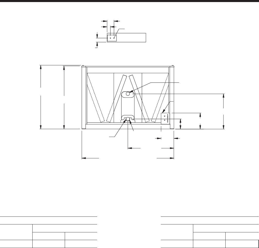
YORK INTERNATIONAL
52
Dimensions -YCAL0055 (SI)
VIEW B-B
100
82
171
BOTTOM OF PANEL
22 TYP.
1590
1572
1146
321
76 VICTAULIC (typ)
2292 BASE WIDTH
LEFT END
LIQUID OUT
880
401
252
ELECTRICAL ACCESS
PANEL
LIQUID IN
Aluminum Copper
YCAL Center of Gravity (in.) YCAL Center of Gravity (in.)
X Y X Y
0055 1470.3 1092.0 0055 1586.9 1098.3
NOTE:
Placement on a level surface of free of obstructions (including snow, for winter operation) or air circulation ensures rated performance, reliable
operation, and ease of maintenance. Site restrictions may compromise minimum clearances indicated below, resulting in unpredictable airflow
patterns and possible diminished performance. YORK’s unit controls will optimize operation without nuisance high-pressure safety cutouts;
however, the system designer must consider potential performance degradation. Recommended minimum clearances: front to wall – 2m;
rear to wall – 2m; cooler end to wall – 1.2m; coil end to wall - 2m; top – no obstructions allowed; distance between adjacent units – 3m.
No more than one adjacent wall may be higher than the unit. 1" nominal deflection isolators (not shown) will increase overall unit height by
152mm.
NOTE: All dimensions are in mm unless specified otherwise.
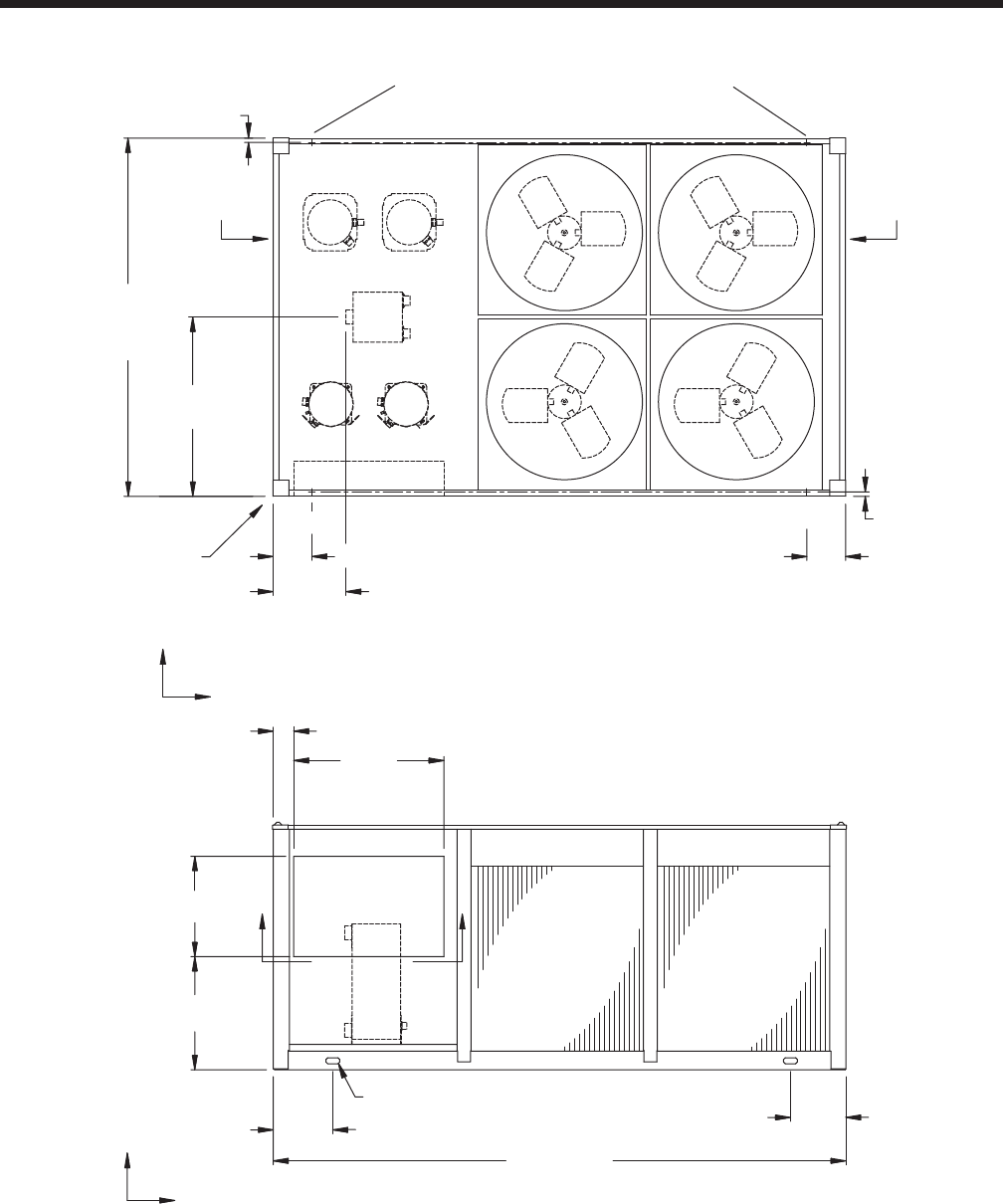
YORK INTERNATIONAL 53
FORM 150.64-EG1
2301
1151
Y
C
G
X
28
ORIGIN
END CAP
WIDTH
468 TOP VIEW
249
28
249
14 DIA MOUNTING HOLES(typ)
3678
383 356
TWO LIFTING HOLES
BOTH SIDES
FRONT VIEW
C
GX
Z
965
131
645
726
BB
COIL
END
COOLER
END
CONTROL
PANEL
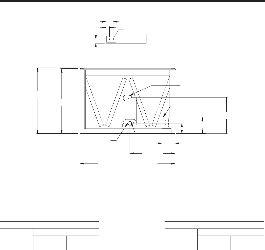
YORK INTERNATIONAL
54
Dimensions - YCAL0061 (SI)
VIEW B-B
100
82
171
BOTTOM OF PANEL
22 TYP.
1590
1572
1095
321
76 VICTAULIC (typ)
2292 BASE WIDTH
LEFT END
LIQUID OUT
880
401
252
ELECTRICAL ACCESS
PANEL
LIQUID IN
Aluminum Copper
YCAL Center of Gravity (in.) YCAL Center of Gravity (in.)
X Y X Y
0061 1438.0 1147.1 0061 1569.3 1162.9
NOTE:
Placement on a level surface of free of obstructions (including snow, for winter operation) or air circulation ensures rated performance, reliable
operation, and ease of maintenance. Site restrictions may compromise minimum clearances indicated below, resulting in unpredictable airflow
patterns and possible diminished performance. YORK’s unit controls will optimize operation without nuisance high-pressure safety cutouts;
however, the system designer must consider potential performance degradation. Recommended minimum clearances: front to wall – 2m;
rear to wall – 2m; cooler end to wall – 1.2m; coil end to wall - 2m; top – no obstructions allowed; distance between adjacent units – 3m.
No more than one adjacent wall may be higher than the unit. 1" nominal deflection isolators (not shown) will increase overall unit height by
152mm.
NOTE: All dimensions are in mm unless specified otherwise.
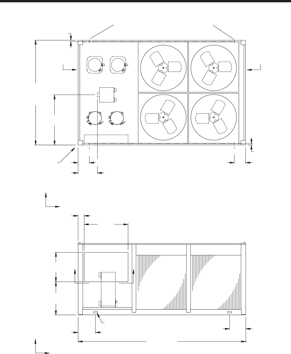
YORK INTERNATIONAL 55
FORM 150.64-EG1
2301
1100
Y
C
G
X
28
ORIGIN
END CAP
WIDTH
424 TOP VIEW
R1
249
28
R2
249
L1 L2
14 DIA MOUNTING HOLES(typ)
3678
383 356
TWO LIFTING HOLES
BOTH SIDES
FRONT VIEW
C
GX
Z
965
131
645
726
BB
COIL
END
COOLER
END
CONTROL
PANEL
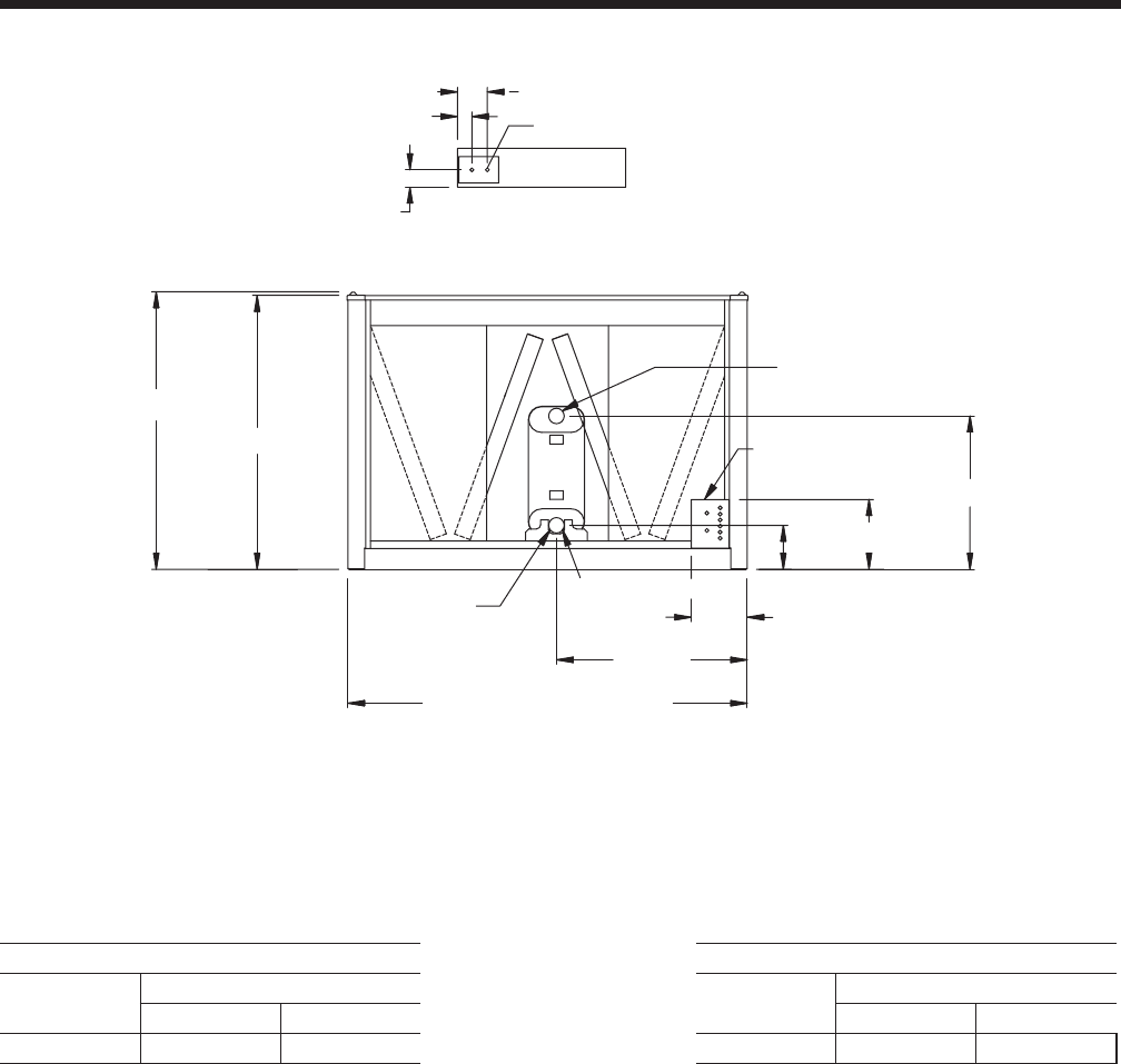
YORK INTERNATIONAL
56
Dimensions - YCAL0065 (SI)
1590
1572
880
401
252
1095
321
76 VICTAULIC (typ)
ELECTRICAL ACCESS
PANEL
2292 BASE WIDTH
LEFT END
LIQUID OUT
LIQUID IN
VIEW B-B
22 TYP.
100
82
171
BOTTOM OF PANEL
Aluminum Copper
YCAL Center of Gravity (in.) YCAL Center of Gravity (in.)
X Y X Y
0065 1517.6 1140.3 0065 1655.5 1141.1
NOTE:
Placement on a level surface of free of obstructions (including snow, for winter operation) or air circulation ensures rated performance, reliable
operation, and ease of maintenance. Site restrictions may compromise minimum clearances indicated below, resulting in unpredictable airflow
patterns and possible diminished performance. YORK’s unit controls will optimize operation without nuisance high-pressure safety cutouts;
however, the system designer must consider potential performance degradation. Recommended minimum clearances: front to wall – 2m;
rear to wall – 2m; cooler end to wall – 1.2m; coil end to wall - 2m; top – no obstructions allowed; distance between adjacent units – 3m.
No more than one adjacent wall may be higher than the unit. 1" nominal deflection isolators (not shown) will increase overall unit height by
152mm.
NOTE: All dimensions are in mm unless specified otherwise.
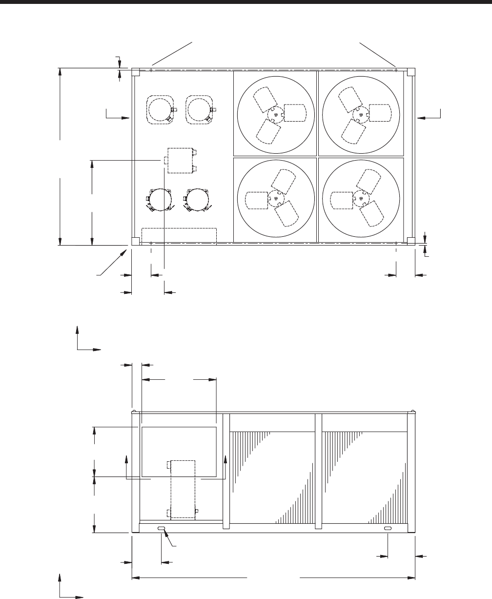
YORK INTERNATIONAL 57
FORM 150.64-EG1
2301
1100
Y
C
G
X
28
ORIGIN
END CAP
WIDTH
424 TOP VIEW
R1
249
28
R2
249
L1 L2
14 DIA MOUNTING HOLES(typ)
3678
383 356
TWO LIFTING HOLES
BOTH SIDES
FRONT VIEW
C
GX
Z
965
131
645
726
BB
COIL
END
COOLER
END
CONTROL
PANEL
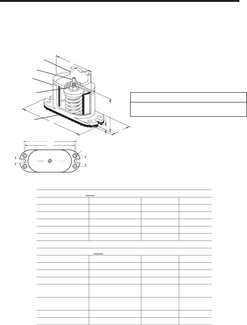
YORK INTERNATIONAL
58
Isolator Selections
FOR UNITS WITH ALL POINT LOADS LESS THATN 1404 LBS (637 KG)
Weight Range (lbs) Weight Range (kg) Model Number Color
239 to 384 lbs 108 to 174 kg CIP-B- Red
384 to 639 lbs 174 to 290 kg CIP-B- White
639 to 851 lbs 290 to 386 kg CIP-B- Blue
851 to 1064 lbs 386 to 483 kg CIP-B- Gray
1064 to 1404 lbs 483 to 637 kg CIP-B- Black
FOR UNITS WITH ANY POINT LOAD ABOVE 1404 LBS (637 KG)
Weight Range (lbs) Weight Range (kg) Model Number Color
Up to 851 lbs Up to 386 kg CIP-C- Black
851 to 1149 lbs 386 to 521 kg CIP-C- Yellow
1149 to 1489 lbs 521 to 675 kg CIP-C- Black
1489 to 1786 lbs 675 to 910 kg CIP-C- Yellow w/
Red
1786 to 2028 lbs 910 to 920 kg CIP-C- Yellow w/
Green
2028 to 2254 lbs 920 to 1022 kg CIP-C- Red w/ Red
2254 to 2936 lbs 1022 to 1332 kg CIP-C- Red w/ Green
CIP-X-
ONE INCH DEFLECTION SPRING ISOLATOR CROSS-REFERENCE
E
Illustration shows single spring CIP-B or CIP-C mount.
HCL
SBC
Slot Width - SW HCW
MAX BOLT
DIA. - MBD
BASE PLATE DIMENSIONS
NON-SKID NEOPRENE
A
COUSTICAL ISOLATION PAD
(Bolting to floor is not necessary for
indoor applications)
All springs have additional
travel to solid equal to 50%
of the rated deflection.
A
L
FREE &
OPERATING
HEIGHT
TW
FERROUS HOUSING
SIDE ACCESS INTERNAL
ADJUSTMENT BOLT
Turn clockwise to load
spring and maintain Free
& Operating Height.
Dowel Pin is 3/8" dia. for
CIP-A & 1/2" thereafter
Mounting may be
operated 1/2" above
Free & Operating
Height.
NOTE-
CIP Mounts are not
to be used in seismic
or wind load
applications.
EQUIPMENT BASE
TYPE CIP DIMENSIONS (inches)†
†Casting dimensions may vary ±1/8"
Size A L T W SW HCL HCW MBD SBC
Free
Ht.
CIP-B 8 /4/2/16 8
CIP-C 6 /8/16 /8
5
117
7
3
3
/8
1
6 /4
3
/
5/4
3
8/8
7/16
9
2/4
3
3/2
1
/2
/4
1
1
6
7
/2
/4
1
3
1
1
/4
/8
1
7
7
7
Min
Ht.
5 /4
1
6 /4
3
6
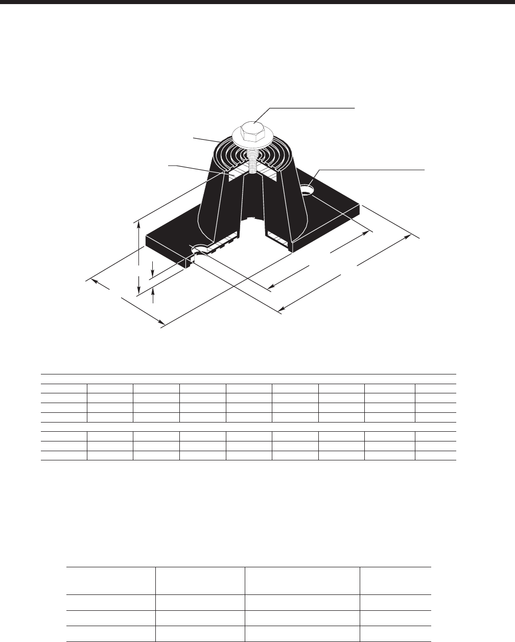
YORK INTERNATIONAL 59
FORM 150.64-EG1
Weight Range
(lbs)
Weight Range
(kg) Model Number Color
Up to 751 lbs Up to 341 kg ND-C Yellow
751 to 1651 lbs 341 to 749 kg ND-D Yellow
1651 to 3226 lbs 749 to 1463 kg ND-E Yellow
"CS" Cap Screw
BC
"MBD" Max. Bolt Dia.
Steel Plate - Top &
Bottom Neoprene
covered to prevent
corrosion
L
T
H
W
D
ENGLISH
Size D H L T W BC CS MBD
ND-C 2 9/16 2 3/ 4 5 1/ 2 1/ 4 2 5/16 4 1/80 1/2- 13 x 1” 1/ 2"
ND-D 3 3/ 8 2 3/ 4 6 1/ 4 5/16 4 5 1/2- 13 x 1” 1/ 2"
ND-E 4 1/ 2 4 3/ 4 7 3/ 8 1/ 4 5 1/80 6 1/80 1/2- 13 x 1” 1/ 2"
SI
ND-C 65.1 69.9 139.7 6.4 58.7 101.9 1/2- 13 x 1” 1/ 2"
ND-D 85.7 69.9 158.8 7.9 101.6 127.0 1/2- 13 x 1” 1/ 2"
ND-E 114.3 120.7 187.3 6.4 127.3 152.7 1/2- 13 x 1” 1/ 2"
ND-X
NEOPRENE ISOLATOR CROSS-REFERENCE
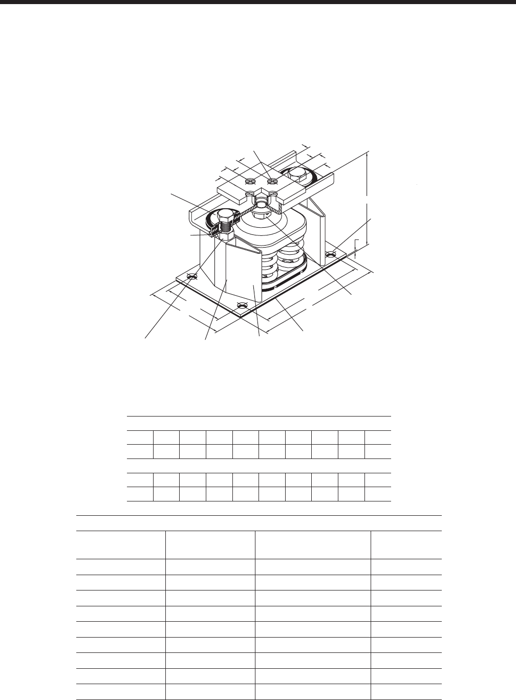
YORK INTERNATIONAL
60
Isolator Details (cont'd)
ENGLISH
SIZE H T D E L HCL W HCW MBD
2-C2 8 1/2 3/8 5/8 1 3/8 14 12 1/4 5 1/4 3 1/ 2 5/8"
SI
SIZE H T D E L HCL W HCW MBD
2-C2 215.9 9.5 15.9 34.9 355.6 311.2 133.4 88.9 5/8"
SLRS
*Weight Range
(lbs)
Weight Range
(kg) Model Number Color
Up to 358 lbs Up to 162 kg SLRS-2-C2- Red
358 to 443 lbs 162 to 201 kg SLRS-2-C2- White
443 to 582 lbs 201 to 264 kg SLRS-2-C2- Black
582 to 783 lbs 264 to 335 kg SLRS-2-C2- Blue
783 to 1038 lbs 335 to 471 kg SLRS-2-C2- Green
1038 to 1497 lbs 471 to 679 kg SLRS-2-C2- Gray
1497 to 2058 lbs 679 to 933 kg SLRS-2-C2- Silver
2058 to 2619 lbs 933 to 1188 kg SLRS-2-C2- Gray w/ red
2619 to 3180 lbs 1188 to 1442 kg SLRS-2-C2- Silver w/ red
TWO INCH DEFLECTION, SEISMIC SPRING ISOLATOR CROSS-REFERENCE
‡‡
‡‡
SLRS-2-C2 has 2 springs.
E
E
E
E
H
T
HCW
WL
HCL
"D" Tap - 4 Holes unless
otherwise requested
Adjustment
Bolt
Vertical Limit
Stops-Out of
contact during
normal operation
Non-Skid Neoprene Pad-
Pad can be removed if
mounts are welded
into position.
Enclosed
Steel
Housing
Internal
Neoprene
Acoustical
Pad
Lower
Restraining
Nut
Rubber
Snubbing
Collar
MBD -Max
Bolt
Diameter

YORK INTERNATIONAL 61
FORM 150.64-EG1
INTENTIONALLY LEFT BLANK

YORK INTERNATIONAL
62
Electrical Data
1. Minimum Circuit Ampacity (MCA) is based on 125% of the rated load amps for the largest motor plus 100% of
the rated load amps for all other loads included in the circuit, per N.E.C. Article 430-24. If the optional Factory
Mounted Control Transformer is provided, add the following MCA values to the electrical tables for the system
providing power to the transformer: -17, add 2.5 amps; -28, add 2.3 amps; -40, add 1.5 amps, -46, add 1.3 amps;
-58, add 1 amps.
2. The minimum recommended disconnect switch is based on 115% of the rated load amps for all loads included
in the circuit, per N.E.C. Article 440.
3. Minimum fuse size is based upon 150% of the rated load amps for the largest motor plus 100% of the rated load
amps for all other loads included in the circuit to avoid nuisance trips at start-up due to lock rotor amps. It is not
recommended in applications where brown outs, frequent starting and stopping of the unit, and/or operation at
ambient temperatures in excess of 95ºF (35ºC) is anticipated.
4. Maximum fuse size is based upon 225% of the rated load amps for the largest motor plus 100% of the rated
load amps for all other loads included in the circuit, per N.E.C. Article 440-22.
5. Circuit breakers must be UL listed and CSA certified and maximum size is based on 225% of the rated load amps
for the largest motor plus 100% of the rated load amps for all other loads included in the circuit. Otherwise, an
HACR-type circuit breakers must be used. Maximum HACR circuit breaker rating is based on 225% of the rated
load amps for the largest motor plus 100% of the rated load amps for all other loads included in the circuit.
6. The “INCOMING WIRE RANGE” is the minimum and maximum wire size that can be accommodated by the
unit wiring lugs. The (2) preceding the wire range indicates the number of termination points available per phase
of the wire range specified. Actual wire size and number of wires per phase must be determined based on the
National Electrical Code, using copper connectors only. Field wiring must also comply with local codes.
7. A ground lug is provided for each compressor system to accommodate a field grounding conductor per N.E.C.
Table 250-95. A control circuit grounding lug is also supplied.
8. The supplied disconnect is a “Disconnecting Means” as defined in the N.E.C. 100, and is intended for isolating the
unit for the available power supply to perform maintenance and troubleshooting. This disconnect is not intended
to be a Load Break Device.
9. Field Wiring by others which complies to the National Electrical Code & Local Codes.
NOTES:
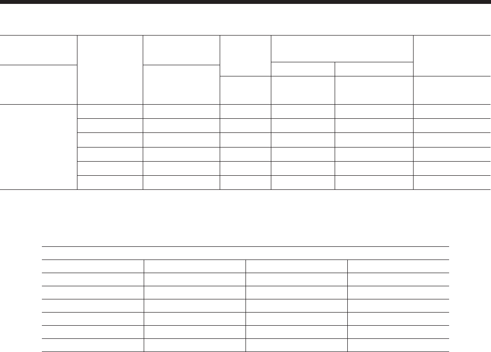
YORK INTERNATIONAL 63
FORM 150.64-EG1
LEGEND
ACR-LINE ACROSS THE LINE START
C.B. CIRCUIT BREAKER
D.E. DUAL ELEMENT FUSE
DISC SW DISCONNECT SWITCH
FACT MOUNT CB FACTORY MOUNTED CIRCUIT BREAKER
FLA FULL LOAD AMPS
HZ HERTZ
MAX MAXIMUM
MCA MINIMUM CIRCUIT AMPACITY
MIN MINIMUM
MIN NF MINIMUM NON FUSED
RLA RATED LOAD AMPS
S.P. WIRE SINGLE POINT WIRING
UNIT MTD SERV SW UNIT MOUNTED SERVICE (NON-FUSED DISCONNECT
SWITCH)
LRA LOCKED ROTOR AMPS
VOLTAGE RANGE
VOLTAGE CODE UNIT POWER MIN. MAX.
-17 200-3-60 180 220
-28 230-3-60 207 253
-40 380/415-3-60 342 440
-46 460-3-60 414 506
-50 380/415-3-50 342 440
-58 575-3-60 517 633
UNIT VOLTAGE
UNIT
VOLTAGE
CONTROL
POWER MCA
NOTE A
OVER CURRENT PROTECTION,
SEE NOTE B NF DISC Sw
MIN MAX
MODELS w/o
CONTROL
TRANS
115-1-60/50 15A 10A 15A 30 A / 240V
MODELS w/
CONTROL
TRANS
-17 200-1-60 15A 10A 15A 30 A / 240V
-28 230-1-60 15A 10A 15A 30 A / 240V
-40 380-1-60 15A 10A 15A 30 A / 480V
-46 460-1-60 15A 10A 15A 30 A / 480V
-50 380/415-1-60 15A 10A 15A 30A / 415V
-58 575-1-60 15A 10A 15A 30 A / 600V
A. Minimum #14 AWG, 75°C, Copper Recommended
B. Minimum and Maximum Over Current Protection, Dual Element Fuse or Circuit Breaker
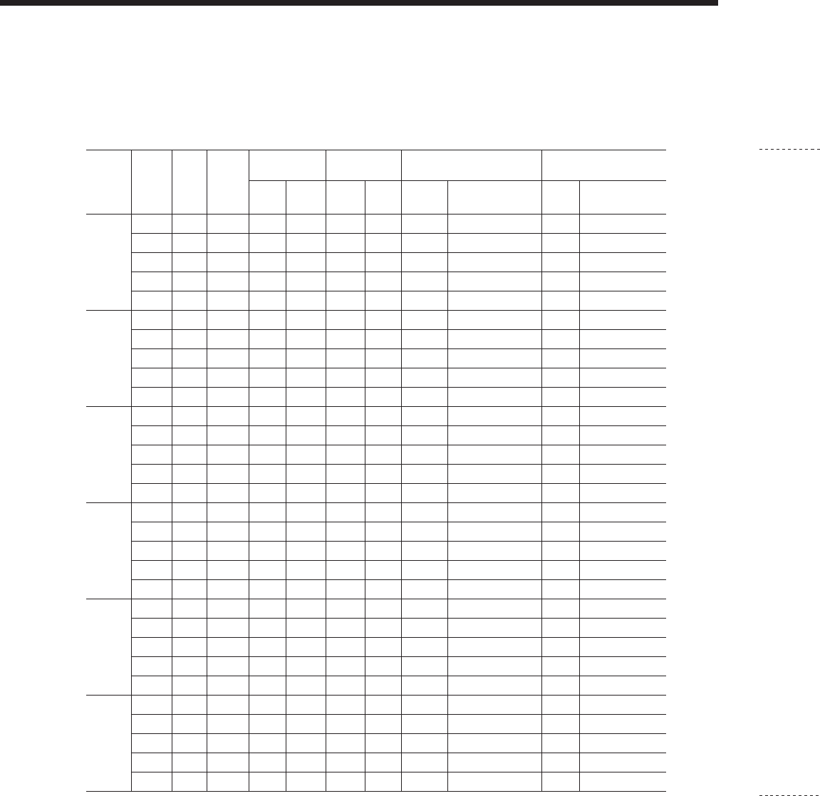
YORK INTERNATIONAL
64
Electrical Data - 60Hz
YCAL0041 - YCAL0065
SINGLE POINT FIELD SUPPLIED POWER WIRING (See Fig. 2)
(One Field Provided Power Supply to the chiller. Field connections to Factory Provided Power Terminal Block (standard), Non-Fused Discon-
nect Switch (optional) or Circuit Breaker (optional).)
See Notes on page 100.
MODEL
YCAL VOLT MCA1
MIN N/F
DISC
SW2
D.E. FUSE CKT. BKR.5FIELD WIRING LUGS6
TERMINAL BLOCK (std)
FIELD WIRING LUGS6
NF DISC. SWITCH (opt)
REC. MAX4REC. MAX LUGS/
PHASE LUG WIRE RANGE LUGS/
PHASE LUG WIRE RANGE
0041
200 197 250 225 225 225 225 1 6awg - 500MCM 1 6awg - 350MCM
230 184 250 200 200 200 200 1 6awg - 500MCM 1 6awg - 350MCM
380 107 150 125 125 125 125 1 6awg - 500MCM 1 6awg - 350MCM
460 90 100 100 100 100 100 1 6awg - 500MCM 1 6awg - 350MCM
575 71 100 80 80 80 80 1 6awg - 500MCM 1 6awg - 350MCM
0045
200 199 250 225 225 225 225 1 6awg - 500MCM 1 6awg - 350MCM
230 186 250 200 200 200 200 1 6awg - 500MCM 1 6awg - 350MCM
380 108 150 125 125 125 125 1 6awg - 500MCM 1 6awg - 350MCM
460 91 100 100 100 100 100 1 6awg - 500MCM 1 6awg - 350MCM
575 71 100 80 80 80 80 1 6awg - 500MCM 1 6awg - 350MCM
0051
200 228 250 250 250 250 250 1 6awg - 500MCM 2 3/0 - 250MCM
230 212 250 225 250 225 250 1 6awg - 500MCM 2 3/0 - 250MCM
380 123 150 150 150 150 150 1 6awg - 500MCM 1 6awg - 350MCM
460 103 150 110 110 110 110 1 6awg - 500MCM 1 6awg - 350MCM
575 81 100 90 90 90 90 1 6awg - 500MCM 1 6awg - 350MCM
0055
200 250 400 300 300 300 300 1 6awg - 500MCM 2 3/0 - 250MCM
230 233 400 250 300 250 300 1 6awg - 500MCM 2 3/0 - 250MCM
380 135 150 150 150 150 150 1 6awg - 500MCM 1 6awg - 350MCM
460 113 150 125 125 125 125 1 6awg - 500MCM 1 6awg - 350MCM
575 89 100 100 100 100 100 1 6awg - 500MCM 1 6awg - 350MCM
0061
200 274 400 300 300 300 300 1 6awg - 500MCM 1 250MCM - 500MCM
230 255 400 300 300 300 300 1 6awg - 500MCM 1 250MCM - 500MCM
380 148 200 175 175 175 175 1 6awg - 500MCM 1 6awg - 350MCM
460 125 150 150 150 150 150 1 6awg - 500MCM 1 6awg - 350MCM
575 98 150 110 110 110 110 1 6awg - 500MCM 1 6awg - 350MCM
0065
200 292 400 350 350 350 350 1 6awg - 500MCM 1 250MCM - 500MCM
230 272 400 300 300 300 300 1 6awg - 500MCM 1 250MCM - 500MCM
380 158 200 175 175 175 175 1 6awg - 500MCM 1 6awg - 350MCM
460 132 150 150 150 150 150 1 6awg - 500MCM 1 6awg - 350MCM
575 104 150 110 125 110 125 1 6awg - 500MCM 1 6awg - 350MCM
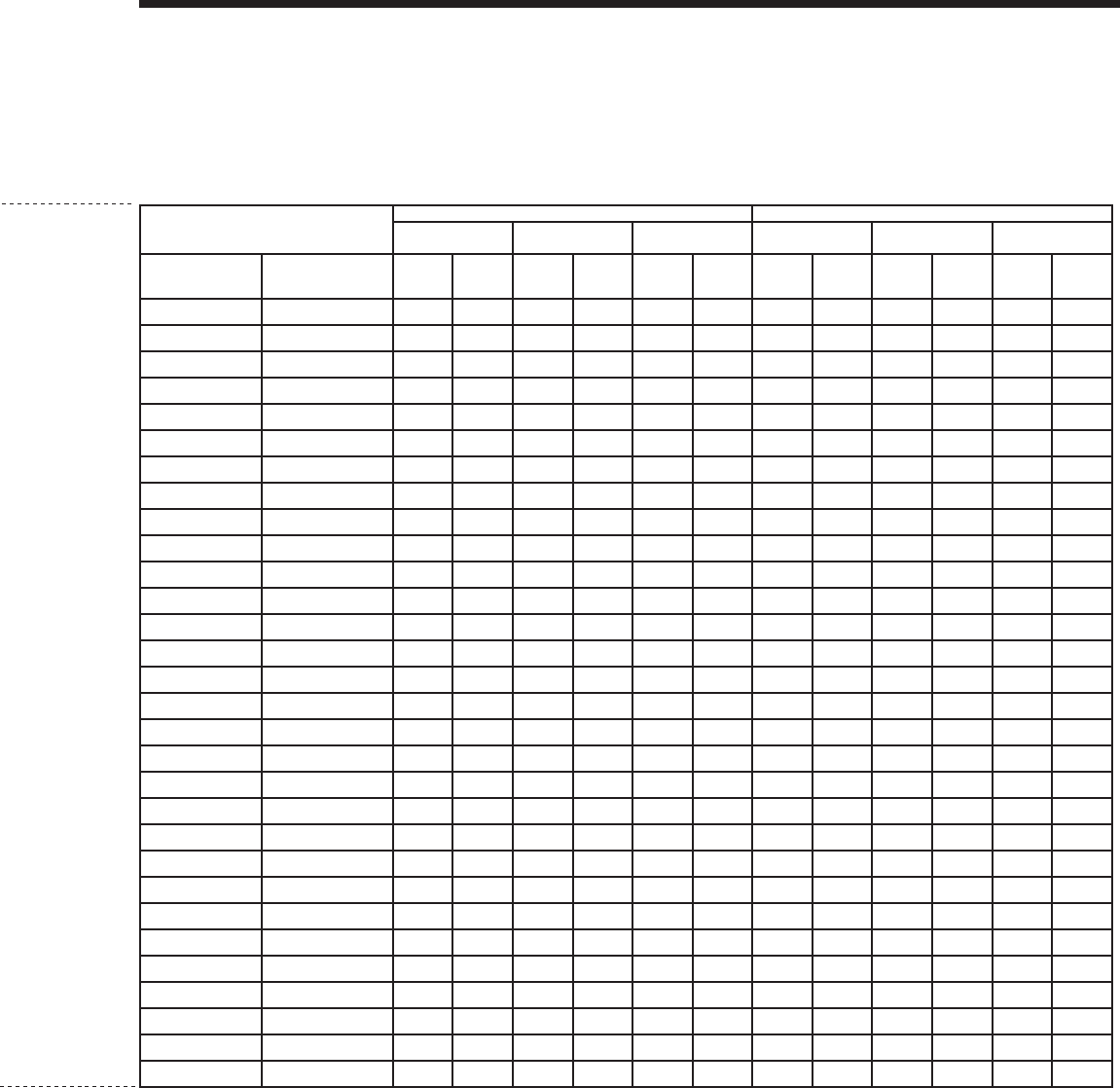
YORK INTERNATIONAL 65
FORM 150.64-EG1
YCAL0041 - YCAL0065
SINGLE POINT FIELD SUPPLIED POWER WIRING (See Fig. 2)
(One Field Provided Power Supply to the chiller. Field connections to Factory Provided Power Terminal Block (standard), Non-Fused Discon-
nect Switch (optional) or Circuit Breaker (optional).)
FIELD WIRING LUGS6
CIRCUIT BREAKER (opt)
SYSTEM #1 COMPRESSOR & FAN SYSTEM #2 COMPRESSOR & FAN
COMPR. #1 COMPR. #2 FANS COMPR. #1 COMPR. #2 FANS
LUGS/ PHASE LUG WIRE RANGE RLA LRA RLA LRA QTY FLA(EA) RLA LRA RLA LRA QTY FLA(EA)
1 6awg - 350MCM 39.1 250 39.1 250 2 7.6 39.1 250 39.1 250 2 7.6
1 6awg - 350MCM 36.2 250 36.2 250 2 7.4 36.2 250 36.2 250 2 7.4
1 6awg - 350MCM 20.9 155 20.9 155 2 4.5 20.9 155 20.9 155 2 4.5
1 6awg - 350MCM 17.2 125 17.2 125 2 4 17.2 125 17.2 125 2 4
1 6awg - 350MCM 13.8 100 13.8 100 2 2.9 13.8 100 13.8 100 2 2.9
1 6awg - 350MCM 40.0 250 40.0 250 2 7.6 39.1 250 39.1 250 2 7.6
1 6awg - 350MCM 37.0 250 37.0 250 2 7.4 36.2 250 36.2 250 2 7.4
1 6awg - 350MCM 21.3 155 21.3 155 2 4.5 20.9 155 20.9 155 2 4.5
1 6awg - 350MCM 17.6 125 17.6 125 2 4 17.2 125 17.2 125 2 4
1 6awg - 350MCM 14.1 100 14.1 100 2 2.9 13.8 100 13.8 100 2 2.9
2 3/0 - 250MCM 40.0 350 40.0 350 2 7.6 49.4 316 53.8 374 2 7.6
2 3/0 - 250MCM 37.0 350 37.0 350 2 7.4 45.8 316 49.8 374 2 7.4
1 6awg - 350MCM 21.3 195 21.3 195 2 4.5 26.4 199 28.7 235 2 4.5
1 6awg - 350MCM 17.6 167 17.6 167 2 4 21.8 158 23.7 187 2 4
1 6awg - 350MCM 14.1 125 14.1 125 2 2.9 17.4 126 19.0 150 2 2.9
2 3/0 - 250MCM 53.8 374 49.4 316 2 7.6 49.4 316 53.8 374 2 7.6
2 3/0 - 250MCM 49.8 374 45.8 316 2 7.4 45.8 316 49.8 374 2 7.4
1 6awg - 350MCM 28.7 235 26.4 199 2 4.5 26.4 199 28.7 235 2 4.5
1 6awg - 350MCM 23.7 187 21.8 158 2 4 21.8 158 23.7 187 2 4
1 6awg - 350MCM 19.0 150 17.4 126 2 2.9 17.4 126 19.0 150 2 2.9
1 250MCM - 500MCM 68.3 505 53.8 425 2 7.6 53.8 425 53.8 425 2 7.6
1 250MCM - 500MCM 63.3 505 49.8 425 2 7.4 49.8 425 49.8 425 2 7.4
1 6awg - 350MCM 36.5 280 28.7 239 2 4.5 28.7 239 28.7 239 2 4.5
1 6awg - 350MCM 30.1 225 23.7 198 2 4 23.7 198 23.7 198 2 4
1 6awg - 350MCM 24.1 180 19.0 148 2 2.9 19.0 148 19.0 148 2 2.9
1 250MCM - 500MCM 68.3 505 68.3 505 2 7.6 53.8 425 53.8 425 2 7.6
1 250MCM - 500MCM 63.3 505 63.3 505 2 7.4 49.8 425 49.8 425 2 7.4
1 6awg - 350MCM 36.5 280 36.5 280 2 4.5 28.7 239 28.7 239 2 4.5
1 6awg - 350MCM 30.1 225 30.1 225 2 4 23.7 198 23.7 198 2 4
1 6awg - 350MCM 24.1 180 24.1 180 2 2.9 19.0 148 19.0 148 2 2.9
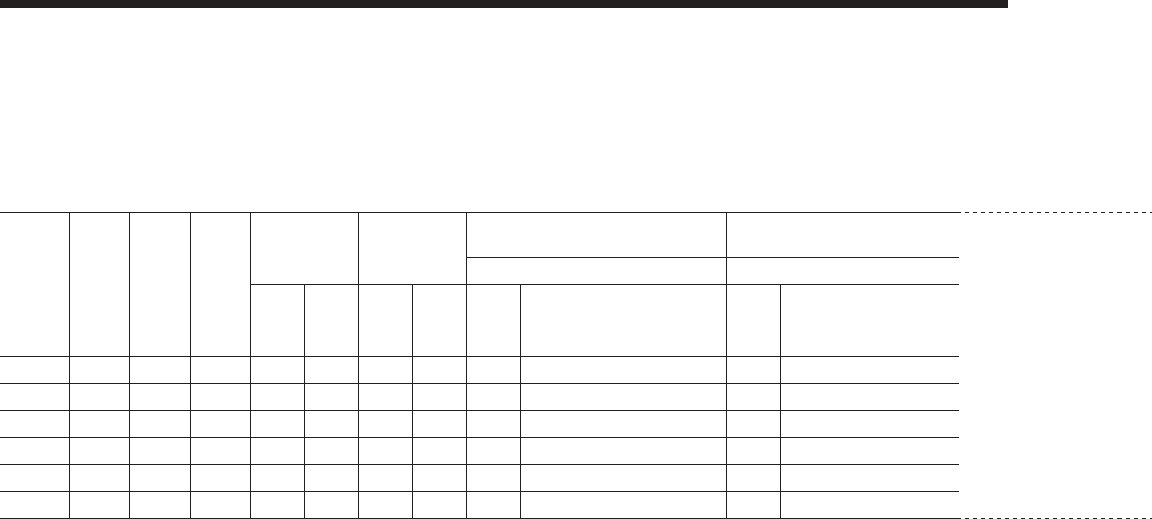
YORK INTERNATIONAL
66
Electrical Data - 50Hz
MODEL
YCAL VOLT MCA1
MIN
N/F DISC
SW2
D.E. FUSE CKT. BKR.5FIELD WIRING LUGS6 FIELD WIRING LUGS6 FIELD WIRING LUGS6 SYSTEM #1 COMPRESSOR & FAN SYSTEM #2 COMPRESSOR & FAN
TERMINAL BLOCK (std) NF DISC. SWITCH (opt) CIRCUIT BREAKER (opt) COMPR. #1 COMPR. #2 FANS COMPR. #1 COMPR. #2 FANS
REC. MAX4REC. MAX LUGS/
PHASE LUG WIRE RANGE LUGS/
PHASE LUG WIRE RANGE LUGS/
PHASE LUG WIRE RANGE RLA LRA RLA LRA QTY FLA
(EA) RLA LRA RLA LRA QTY FLA
(EA)
0041 380/415 90 100 100 100 100 100 1 6awg - 500MCM 1 6awg - 350MCM 1 6awg - 350MCM 17.2 125 17.2 125 2 4 17.2 125 17.2 125 2 4
0045 380/415 91 100 100 100 100 100 1 6awg - 500MCM 1 6awg - 350MCM 1 6awg - 350MCM 17.6 125 17.6 125 2 4 17.2 125 17.2 125 2 4
0051 380/415 103 150 110 110 110 110 1 6awg - 500MCM 1 6awg - 350MCM 1 6awg - 350MCM 17.6 158 17.6 158 2 4 21.8 127 23.7 187 2 4
0055 380/415 113 150 125 125 125 125 1 6awg - 500MCM 1 6awg - 350MCM 1 6awg - 350MCM 23.7 187 21.8 127 2 4 21.8 127 23.7 187 2 4
0061 380/415 124 150 150 150 150 150 1 6awg - 500MCM 1 6awg - 350MCM 1 6awg - 350MCM 30.1 225 23.7 198 2 4 23.7 167 23.7 167 2 4
0065 380/415 132 150 150 150 150 150 1 6awg - 500MCM 1 6awg - 350MCM 1 6awg - 350MCM 30.1 225 30.1 225 2 4 23.7 198 23.7 198 2 4
YCAL0041 - YCAL0065
SINGLE POINT FIELD SUPPLIED POWER WIRING (See Fig. 2)
(One Field Provided Power Supply to the chiller. Field connections to Factory Provided Power Terminal Block (standard), Non-Fused Discon-
nect Switch (optional) or Circuit Breaker (optional).)
YORK INTERNATIONAL 67
FORM 150.64-EG1
MODEL
YCAL VOLT MCA1
MIN
N/F DISC
SW2
D.E. FUSE CKT. BKR.5FIELD WIRING LUGS6 FIELD WIRING LUGS6 FIELD WIRING LUGS6 SYSTEM #1 COMPRESSOR & FAN SYSTEM #2 COMPRESSOR & FAN
TERMINAL BLOCK (std) NF DISC. SWITCH (opt) CIRCUIT BREAKER (opt) COMPR. #1 COMPR. #2 FANS COMPR. #1 COMPR. #2 FANS
REC. MAX4REC. MAX LUGS/
PHASE LUG WIRE RANGE LUGS/
PHASE LUG WIRE RANGE LUGS/
PHASE LUG WIRE RANGE RLA LRA RLA LRA QTY FLA
(EA) RLA LRA RLA LRA QTY FLA
(EA)
0041 380/415 90 100 100 100 100 100 1 6awg - 500MCM 1 6awg - 350MCM 1 6awg - 350MCM 17.2 125 17.2 125 2 4 17.2 125 17.2 125 2 4
0045 380/415 91 100 100 100 100 100 1 6awg - 500MCM 1 6awg - 350MCM 1 6awg - 350MCM 17.6 125 17.6 125 2 4 17.2 125 17.2 125 2 4
0051 380/415 103 150 110 110 110 110 1 6awg - 500MCM 1 6awg - 350MCM 1 6awg - 350MCM 17.6 158 17.6 158 2 4 21.8 127 23.7 187 2 4
0055 380/415 113 150 125 125 125 125 1 6awg - 500MCM 1 6awg - 350MCM 1 6awg - 350MCM 23.7 187 21.8 127 2 4 21.8 127 23.7 187 2 4
0061 380/415 124 150 150 150 150 150 1 6awg - 500MCM 1 6awg - 350MCM 1 6awg - 350MCM 30.1 225 23.7 198 2 4 23.7 167 23.7 167 2 4
0065 380/415 132 150 150 150 150 150 1 6awg - 500MCM 1 6awg - 350MCM 1 6awg - 350MCM 30.1 225 30.1 225 2 4 23.7 198 23.7 198 2 4
YCAL0041 - YCAL0065
SINGLE POINT FIELD SUPPLIED POWER WIRING (See Fig. 2)
(One Field Provided Power Supply to the chiller. Field connections to Factory Provided Power Terminal Block (standard), Non-Fused Discon-
nect Switch (optional) or Circuit Breaker (optional).)
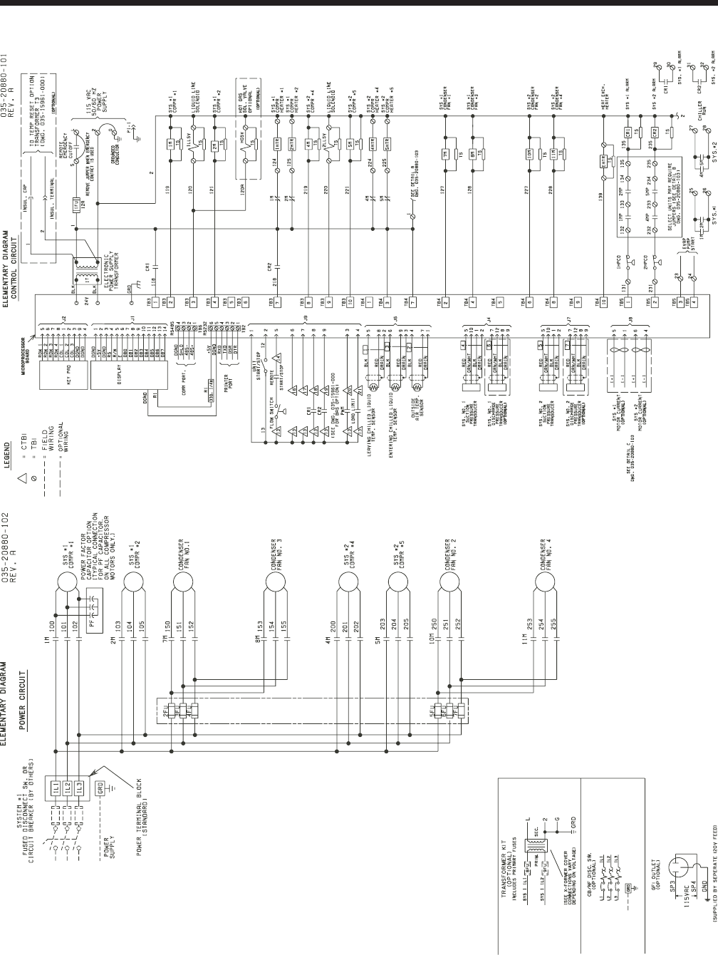
YORK INTERNATIONAL
68
Power Wiring
FIG. 1 – STANDARD POWER SUPPLY WIRING – (YCAL 0014 - 0080)
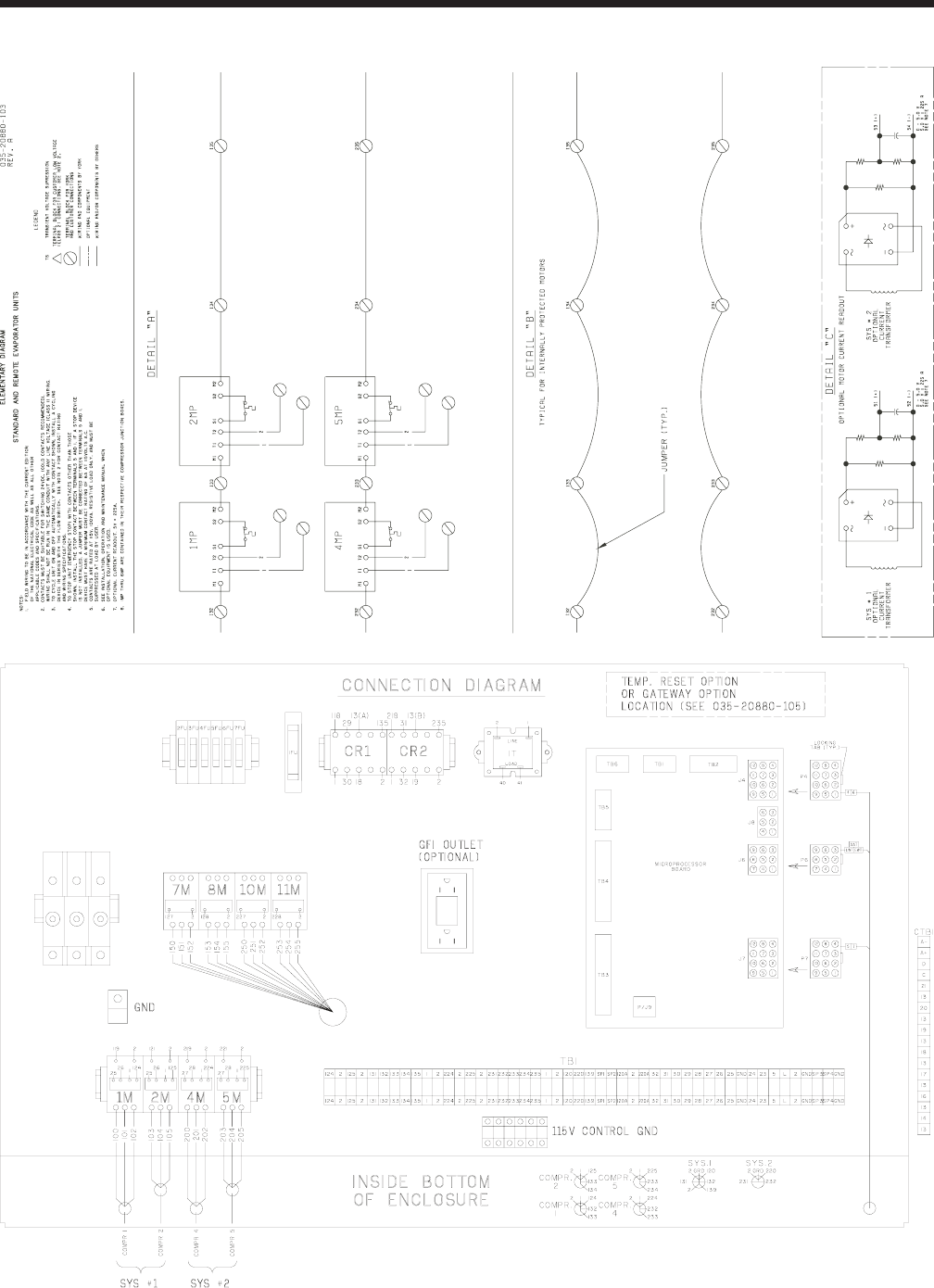
YORK INTERNATIONAL 69
FORM 150.64-EG1
FIG. 1 – STANDARD POWER SUPPLY WIRING – (YCAL 0014 - 0080)
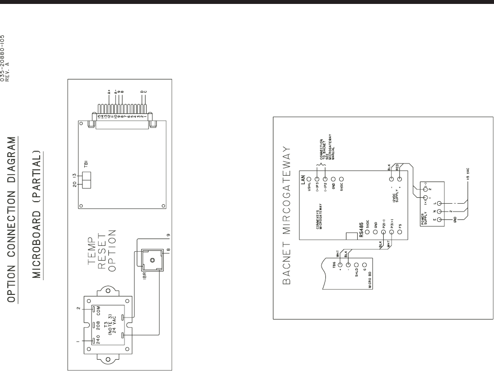
YORK INTERNATIONAL
70
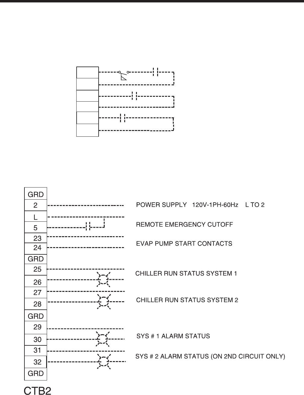
YORK INTERNATIONAL 71
FORM 150.64-EG1
CTB1
21
13
20
13
14
13
FLOW SW REMOTE START/STOP
PWM INPUT
LOAD LIMIT INPUT
*
* Factory wired with optional transformer.
Control Wiring
LD03611

YORK INTERNATIONAL
72
Application Data
UNIT LOCATION
The YCAL chillers are designed for outdoor installation.
When selecting a site for installation, be guided by the
following conditions:
1. For outdoor locations of the unit, select a place
having an adequate supply of fresh air for the con-
denser.
2. Avoid locations beneath windows or between
structures where normal operating sounds may be
objectionable.
3. Installation sites may be either on a roof, or at ground
level. (See FOUNDATION.)
4. The condenser fans are the propeller-type, and
are not recommended for use with duct work in the
condenser air stream.
5. When it is desirable to surround the unit(s), it is
recommended that the screening be able to pass
the required chiller CFM without exceeding 0.1” of
water external static pressure.
6. Protection against corrosive environments is avail-
able by supplying the units with either copper fin,
cured epoxy-dipped, or epoxy-coated fins on the
condenser coils. The epoxy-dipped or epoxy-coated
coils should be offered with any units being installed
at the seashore or where salt spray may hit the
unit.
In installations where winter operation is intended and
snow accumulations are expected, additional height
must be provided to ensure normal condenser air
flow.
Recommended clearances for units are given in DI-
MENSIONS. When the available space is less, the
unit(s) must be equipped with the discharge pressure
transducer option to permit high pressure unloading in
the event that air recirculation were to occur.
FOUNDATION
The unit should be mounted on a flat and level founda-
tion, ground or roof, capable of supporting the entire
operating weight of the equipment. Operating weights
are given in the PHYSICAL DATA tables.
ROOF LOCATIONS – Choose a spot with adequate
structural strength to safely support the entire weight
of the unit and service personnel. Care must be taken
not to damage the roof during installation. If the roof is
“bonded”, consult the building contractor or architect
for special installation requirements. Roof installations
should incorporate the use of spring-type isolators to
minimize the transmission of vibration into the building
structure.
GROUND LEVEL INSTALLATIONS – It is important that
the units be installed on a substantial base that will not
settle, causing strain on the liquid lines and resulting in
possible leaks. A one-piece concrete slab with footers
extending below the frost line is highly recommended.
Additionally, the slab should not be tied to the main
building foundation, as noises will telegraph.
Mounting holes (11/16” diameter) are provided in the
steel channel for bolting the unit to its foundation. See
DIMENSIONS.
For ground level installations, precautions should be
taken to protect the unit from tampering by or injury
to unauthorized persons. Screws on access panels
will prevent casual tampering; however, further safety
precautions, such as unit enclosure options, a fenced-in
enclosure, or locking devices on the panels may be ad-
visable. Check local authorities for safety regulations.
CHILLED LIQUID PIPING
The chilled liquid piping system should be laid out so
that the circulating pump discharges into the cooler.
The inlet and outlet cooler liquid connections are given
in DIMENSIONS.
Hand stop valves are recommended for use in all lines
to facilitate servicing. Drain connections should be
provided at all low points to permit complete drainage
of the cooler and system piping. Additionally, a strainer
(40 mesh) is recommended for use on the INLET line
to the cooler.
Pressure gauge connections are recommended for
installation in the inlet and outlet water lines. Gauges
are not furnished with the unit and are to be furnished
by other suppliers.
The chilled liquid lines that are exposed to outdoor am-
bients should be wrapped with a supplemental heater
cable and covered with insulation. As an alternative,
ethylene glycol should be added to protect against
freezeup during low ambient periods.
A flow switch is available as an accessory on all units.
The flow switch (or its equivalent) must be installed in
the leaving water piping of the cooler and must not be
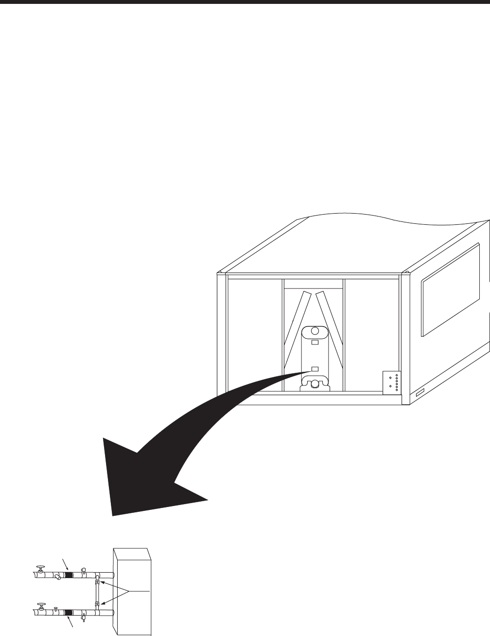
YORK INTERNATIONAL 73
FORM 150.64-EG1
Typical Piping for Brazed-Plate
Coolers
Notes:
1. Placement on a level surface free of obstructions
(including snow, for winter operation) or air recircula-
tion ensures rated performance, reliable operation
and ease of maintenance.
2. Piping and wiring shown is for reference use only
and is not in accordance with any national or local
standards.
3. All wiring and piping must comply with applicable
local and national codes.
4. All wiring and piping must follow standard piping
techniques as discussed in the ASHRAE hand-
book.
5. A strainer with a mesh size between .5 and 1.5 mm
is recommended upstream of the heat exchanger to
prevent clogging.
Pressure
Gauge
INLET
OUTLET
Drain
Vibration
Eliminators
Vibration
Eliminators
Shut Off
Valves
Strainer Vent
Flow
Switch
Isolation
Valves

YORK INTERNATIONAL
74
Guide Specifications
PART 1 – GENERAL
1.01 SCOPE
A. The requirements of the General Conditions, Sup-
plementary Conditions, Division 1, and Drawings
apply to all Work herein.
B. Provide Microprocessor controlled, multiple-scroll
compressor, air-cooled, liquid chillers of the sched-
uled capacities as shown and indicated on the
Drawings, including but not limited to:
1. Chiller package
2. Electrical power and control connections
3. Chilled water connections
4. Change of refrigerant oil (for factory mounted
evaporator) or (evaporator shipped separately
for field installation and piping by contractor)
1.02 QUALITY ASSURANCE
A. Products shall be Designed, Tested, Rated and
Certified in accordance with, and installed in com-
pliance with applicable sections of the following
Standards and Codes:
1. ANSI/ASHRAE Standard 15 – Safety Code for
Mechanical Refrigeration
2. ASHRAE 90.1– Energy Efficiency compli
ance.
3. ANSI/NFPA Standard 70 – National Electrical
Code (N.E.C.).
4. ASME Boiler & Pressure Vessel Code, Sec
tion VIII, Division 1.
5. ARI Standard 550/590 – Positive Displacement
Compressors and Air Cooled Rotary Screw
Water-Chilling Packages.
6. Conform to Intertek Testing Services, formerly
ETL, for construction of chillers and provide
ETL/cETL Listing label.
7. Manufactured in facility registered to ISO
9002.
8. OSHA - Occupational Safety and Health Act
B. Factory Test: Chiller shall be pressure-tested, evac-
uated and fully charged with refrigerant and oil, and
shall be factory operational run tested with water
flowing through the vessel.
C. Chiller manufacturer shall have a factory trained
and supported service organization that is within a
50 mile radius of the site.
D. Warranty: Manufacturer shall Warrant all equipment
and material of its manufacture against defects in
workmanship and material for a period of one year
from date of initial start-up or eighteen (18) months
from date of shipment, whichever occurs first.
1.03 DELIVERY AND HANDLING
A. Unit shall be delivered to job site fully assembled,
and charged with refrigerant and oil by the Manu-
facturer. (Contractor is responsible for providing and
installing the refrigerant charge including the charge
required for the field installed interconnecting piping.
Chiller components shall ship with a dry nitrogen
holding charge – Remote Evaporator option).
B. Unit shall be stored and handled per Manufacturer’s
instructions.
PART 2 - PRODUCTS
2.01 CHILLER MATERIALS AND COMPONENTS
A. General: Install and commission, as shown on the
schedules and plans, factory assembled, charged,
and tested air cooled scroll compressor chiller(s) as
specified herein. Chiller shall be designed, selected,
and constructed using a refrigerant with Flamma-
bility rating of “1”, as defined by ANSI/ASHRAE
STANDARD - 34 Number Designation and Safety
Classification of Refrigerants. Chiller shall include,
but is not limited to: a complete system with a single
refrigerant circuit 35 tons (123kW) and below, and
not less than two refrigerant circuits above 35 tons
(123kW), scroll compressors, direct expansion
type evaporator, air-cooled condenser, refrigerant,
lubrication system, interconnecting wiring, safety
and operating controls including capacity controller,
control center, motor starting components, and
special features as specified herein or required for
safe, automatic operation.
B. Cabinet: External structural members shall be con-
structed of heavy gauge, galvanized steel coated
with baked on powder paint which, when subject to
ASTM B117, 1000 hour, 5% salt spray test, yields
minimum ASTM 1654 rating of “6”. Add Wire Panels
of heavy gauge, welded wire-mesh, coated to resist
corrosion, to protect condenser coils from incidental
damage and restrict unauthorized access to internal
components. Factory installed.
2.02 COMPRESSORS
Compressors: Shall be hermetic, scroll-type, in-
cluding:
1. Compliant design for axial and radial sealing

YORK INTERNATIONAL 75
FORM 150.64-EG1
2. Refrigerant flow through the compressor with 100%
suction cooled motor.
3. Large suction side free volume and oil sump to
provide liquid handling capability.
4. Compressor crankcase heaters to provide extra
liquid migration protection.
5. Annular discharge check valve and reverse vent
assembly to provide low pressure drop, silent shut-
down and reverse rotation protection.
6. Initial Oil charge.
7. Oil Level sightglass.
8. Vibration isolator mounts for compressors.
9. Brazed-type connections for fully hermetic refrig-
erant circuits.
2.03 REFRIGERANT CIRCUIT COMPONENTS
Each refrigerant circuit shall include: liquid line shutoff
valve with charging port, low side pressure relief device,
filter-drier, solenoid valve, sight glass with moisture indi-
cator, expansion valves, and flexible, closed-cell foam
insulated suction line.
2.04 HEAT EXCHANGERS
A. Evaporator:
1. Evaporator shall be brazed-plate stainless
steel construction, single or dual circuit heat
exchangers capable of refrigerant working
pressure of 450 psig (3103 kPa) and
liquid side pressure of 150 psig (1034 kPa)
(Option for 300 psig [2068 kPa] available.)
2. Evaporator shall be covered in 3/4" (19mm)
flexible, closed cell insulation, thermal conduc
tivity of 0.26k (BTU/HR-FT2-°F]/in.) maximum.
3. Cooler shall have thermostati
cally controlled heaters to protect to -20°F
(29°C) ambient in off-cycle.
4. Brazed plate heat exchangers shall be UL
listed.
5. Installing contractor must include accomoda
tions in the chilled water piping to allow prop
er drainage and venting of the heat exchang
er. A strainer with a mesh size between 0.5
and 1.5mm (40 mesh) is recommended up
stream of the heat exchanger to prevent clog
ging.
B. Air Cooled Condenser:
1. Coils: Internally enhanced, seamless copper
tubes, mechanically expanded into aluminum
alloy fins with full height collars. Subcooling coil
an integral part of condenser. Design working
pressure shall be 450 PSIG (31 bar).
2. Low Noise Fans: Shall be dynamically and
statically bal anced, direct drive, corrosion re
sistant glass fiber reinforced composite blades
molded into a low noise, full-airfoil cross section,
providing vertical air discharge and low
sound. Each fan in its own compartment
to prevent crossflow d u r i n g f a n
cycling. Guards of heavy gauge, P V C
(polyvinylchloride) coated or galvanized
steel.
3. Fan Motors: High efficiency, direct drive, 6 pole,
3 phase, insulation class “F”, current protected,
Totally Enclosed Air-Over (TEAO), rigid
mounted, with double sealed, permanently lu-
bricated, ball bearings.
2.05 CONTROLS
A. General: Automatic start, stop, operating, and pro-
tection sequences across the range of scheduled
conditions and transients.
B. Microprocessor Enclosure: Rain and dust tight
NEMA 3R/12 (IP55) powder painted steel cabinet
with hinged, latched, and gasket sealed door.
C. Microprocessor Control Center:
1. Automatic control of compressor start/stop,
anti-coincidence and anti-recycle timers, au-
tomatic pumpdown on shutdown, condenser
fans, evaporator pump, evaporator heater, unit
alarm contacts, and chiller operation from 0°F
to 125°F (-18°C to 52°C) ambient. Automatic
reset to normal chiller operation after power
failure.
2. Remote water temperature reset via a Pulse
Width Modulated (PWM) input signal or up to
two steps of demand (load) limiting.
3. Software stored in non-volatile memory, with
programmed setpoints retained in lithium bat-
tery backed real time clock (RTC) memory for
minimum 5 years.
4. Forty character liquid crystal display, descrip-
tions in English (or Spanish, French, Italian, or
German), numeric data in English (or Metric)
units. Sealed keypad with sections for Setpoints,
Display/Print, Entry, Unit Options & clock, and
On/Off Switch.
5. Programmable Setpoints (within Manufacturer
limits): display language; chilled liquid tempera-
ture setpoint and range, remote reset tempera-
ture range, set daily schedule/holiday for start/
stop, manual override for servicing, low and high
ambient cutouts, number of compressors, low

YORK INTERNATIONAL
76
liquid temperature cutout, low suction pressure
cutout, high discharge pressure cutout, anti-re-
cycle timer (compressor start cycle time), and
anti-coincident timer (delay compressor
starts).
6. Display Data: Return and leaving liquid tem-
peratures, low leaving liquid temperature cut-
out setting, low ambient temperature cutout set-
ting, outdoor air temperature, English or metric
data, suction pressure cutout setting, each
system suction pressure,discharge pres-
sure (standard on YCAL0041-0065 models),
liquid temperature reset via a YORK ISN DDC
or Building Automation System (by others) via
PWM input as standard or a 4-20milliamp or 0-
10 VDC input or contact closure with optional
BAS interface, anti-recycle timer status for each
compressor, anti-coincident system start timer
condition, compressor run status, no cooling
load condition, day, date and time, daily start/
stop times, holiday status, automatic or manual
system lead/lag control, lead system definition,
compressor starts/operating hours (each), sta-
tus of hot gas valves, evaporator heater and
fan operation, run permissive status, number
of compressors running, liquid solenoid valve
status, load & unload timer status, water pump
status.
7. System Safeties: Shall cause individual com
pressor systems to perform auto shut down;
manual reset required after the third trip in 90
minutes. Includes: high discharge pressure, low
suction pressure, high pressure switch, and
motor protector. Compressor motor protector
shall protect against damage due to high input
current or thermal overload of windings.
8. Unit Safeties: Shall be automatic reset and
cause compressors to shut down if low ambi-
ent, low leaving chilled liquid temperature, un-
der voltage, and flow switch operation. Contrac-
tor shall provide flow switch and wiring per chiller
manufacturer requirements.
9. Alarm Contacts: Low ambient, low leaving
chilled liquid temperature, low voltage, low
battery, and (per compressor circuit): high dis-
charge pressure, and low suction pressure.
D. Manufacturer shall provide any controls not listed
above, necessary for automatic chiller operation.
Mechanical Contractor shall provide field control
wiring necessary to interface sensors to the chiller
control system.
2.06 POWER CONNECTION AND DISTRI-
BUTION
A. Power Panels:
1. NEMA 3R/12 (IP55) rain/dust tight, powder
painted steel cabinets with hinged, latched, and
gasket sealed outer doors. Provide main power
connection(s), control power connections, com-
pressor and fan motor start contactors, current
overloads, and factory wiring.
2. Power supply shall enter unit at a single loca-
tion, be 3 phase of scheduled voltage, and
connect to individual terminal blocks per com-
pressor. Separate disconnecting means and/
or external branch circuit protection (by Con-
tractor) required per applicable local or national
codes.
B. Exposed compressor, control and fan motor power
wiring shall be routed through liquid tight conduit.
2.07 ACCESSORIES AND OPTIONS
Some accessories and options supercede standard
product features. Your YORK representative will be
pleased to provide assistance.
A. Microprocessor controlled, Factory installed Across-
the-Line type compressor motor starters as stan-
dard.
B. Outdoor Ambient Temperature Control
1. Low Ambient Control: Permits unit operation to
0°F ambient. .
2. High Ambient Control: Permits unit operation
above 115°F ambient.
C. Power Supply Connections:
1. Single Point Power Supply: Single point Termi-
nal Block for field connection and interconnect-
ing wiring to the compressors. Separate exter-
nal protection must be supplied, by others, in
the incoming power wiring, which must comply
with the National Electric Code and/or local
codes. Standard unit controls to 25°F
ambient. Low Ambient Control standard on
YCAL0041-0065 models
2. Single Point Power Supply with individual Sys-
tem Breakers: Single or Terminal Block(s) for
field connection and factory interconnecting
wiring to factory supplied system breakers .
Available on YCAL0090-0134 models.
3. Single Point or Disconnect: Single or Dual point
Non-Fused Disconnect(s) and lockable exter-
nal handle (in compliance with Article 440-14

YORK INTERNATIONAL 77
FORM 150.64-EG1
of N.E.C.) can be supplied to isolate the unit
power voltage for servicing. Separate external
fusing must be supplied, by others, in the in
coming power wiring, which must comply with
the National Electric Code and/or local codes.
4. Single Point Disconnect with Individual System
Breakers: Single point Terminal Block with Non-
Fused Disconnect and lockable external handle
(in compliance with Article 440-14 of N.E.C.)
can be supplied to isolate power voltage for
servicing. Factory interconnecting wiring from
disconnect to factory supplied circuit breakers.
Available on YCAL0041-0065.
5. Single Point Circuit Breaker: Single point Ter-
minal Block with Circuit Breaker and lockable
external handle (in compliance with Article 440
14 of N.E.C.) can be supplied to isolate power
voltage for servicing. Incoming power wiring
must comply with the National Electric Code
and/or local codes. Single Point Circuit Break
ers available on YCAL0041-0065 models.
D. Pressure Transducers and Readout Capability
1. Discharge Pressure Transducers: Permits unit
to sense and display discharge pressure. Stan-
dard on YCAL0080-0134 models.
E. Control Power Transformer: Converts unit power
voltage to 120-1-60 (500 VA capacity). Factory-
mounting includes primary and secondary wiring
between the transformer and the control panel.
F. Motor Current Module: Capable of monitoring com-
pressor motor current. Provides extra protection
against compressor reverse rotation, phase-loss
and phase imbalance. Option consists of one mod-
ule per electrical system. (Factory-mounted.)
G. Power Factor Correction Capacitors: Provided to
correct unit compressor factors to a 0.90-0.95.
H. Condenser Coil Environmental Protection:
1. Pre-Coated: Epoxy coated aluminum fin stock to
guard from corrosive agents and insulate
against galvanic potential. For mild seashore
or industrial locations.
2. Copper Fin: Provide copper fins in lieu of alumi-
num.
3. Post-Coated Dipped: Dipped-cured coating on
condenser coils for seashore and other corro-
sive applications (with the exception of strong
alkalis, oxidizers, and wet bromine, chlorine and
fluorine in concentrations greater than
100ppm).
I. Protective Chiller Panels (Factory or Field Mounted
1. Louvered Panels (condenser coils only):
Painted steel as per remainder of unit cabinet,
over external condenser coil faces.
2. Wire Panels (full unit): Heavy gauge, welded
wire-mesh, PVC -coated to resist corrosion, to pro-
tect condenser coils from incidental damage
and restrict unauthorized access to internal
components.
3. Louvered Panels (full unit): Painted steel as per
remainder of unit cabinet, to protect condenser
coils from incidental damage, visually screen
internal components, and prevent unauthorized
access to internal components.
4. Louvered/Wire Panels: Louvered steel panels
on external condenser coil faces, painted as
per remainder of unit cabinet. Heavy gauge,
welded wire-mesh, coated to resist corrosion,
around base of machine to restrict unauthorized
access.
J. Flow Switch (Field-mounted): Vapor proof SPDT,
NEMA 4X switch ( ___150 PSIG or ___300 PSIG),
-20°F to 250°F.
K. Differential Pressure Switch: Alternative to an
above mentioned flow switch. Pretempco model
DPS300A-P40PF-82582-5 (300 psi max. working
pressure) SPDT 5 amp 125/250VAC switch, Range
0 - 40 PSID, deadband 0.5 - 0.8 psi, with 1/4” NPTE
Pressure Connections.
L. Evaporator options:
1. Provide 1½" cooler insulation in lieu of standard
¾".
2. Provide DX Cooler with 300 PSIG water-side
design working pressure in lieu of standard 150
PSIG.
3. Provide Raised Face Flanges for field instal-
lation on cooler nozzles and field piping:
a. 150 PSIG, welded Flanges.
b. 300 PSIG, welded Flanges.
M. Service Isolation valves: Service suction and dis
charge (ball type) isolation valves are added to unit
per system. This option also includes a system high
pressure relief valve in compliance with ASHRAE
15. (Factory-mounted.)
N. Remote Cooler: Manufacturer shall provide sep-
arately: chiller less evaporator, leaving and return

YORK INTERNATIONAL
78
water sensors, and liquid line components (solenoid
valves, filter driers, sight glasses, and TXVs), as
discrete elements of a complete factory system.
Contractor shall be field erect system and provide
interconnecting refrigerant piping and wiring in
accordance with Manufacturer recommendations,
and project plans and schedules. Where not oth-
erwise specified, Contractor provided system piping
shall be in accordance with applicable sections of
ASHRAE Handbook.
O. Hot Gas By-Pass: Permits continuous, stable op-
eration at capacities below the minimum step of
unloading to as low as 5% capacity (depending on
both the unit & operating conditions) by introducing
an artificial load on the cooler. Hot gas by-pass is
installed on only one refrigerant circuit (System
#1).
P. Microprocessor Membrane Keypad Graphics on in
lieu of Standard English:
1. French language.
2. German language.
3. Spanish language.
4. Italian language.
Q. Thermal Storage: Leaving chilled liquid setpoint
range for charge cycle from 25°F to 20°F minimum,
with automatic reset of the leaving brine temperature
up to 40°F above the setpoint. (Works with Option
T)
R. Low Temperature Process Brine: Leaving chilled
liquid setpoint range 20°F to 30°F.
S. Chicago Code Relief Valves to meet Chicago Code
requirements.
T. Building Automation System (EMS) Reset Interface:
Chiller to accept 4 to 20mA, 0 to 10 VDC, or discrete
contact closure input to reset the leaving chilled
liquid temperature.
U. Remote Control Panel (Field-mounted): Auxiliary
panel for remote user interface for functions nor-
mally made at the unit control center. Available on
YCAL0014-0080 models.
V. OptiView Remote Control Panel (Field-mounted):
Graphical interface panel to remotely control and
monitor up to 8 different units.
W. Multi-Unit Sequencing Panel (Field-mounted):
Separate Sequencing control center is provided to
permit control of up to eight chillers in parallel based
on mixed liquid temperature.
X. Sound Reduction (Factory-mounted):
1. Ultra quiet, low speed, reduced noise fans
2. Compressor Acoustic Sound Blankets
Y. Vibration Isolation (Field-mounted):
1. Neoprene Pad Isolators.
2. 1 Inch Deflection Spring Isolators: Level ad-
justable, spring and cage type isolators for
mounting under the unit base rails.
3. 2 Inch Deflection Seismic Isolators: Level ad-
justable, restrained mounts in rugged welded
steel housing with vertical and horizontal limit
stops. Housings shall be designed to withstand
a minimum 1.0g accelerated force in all direc-
tions to 2 inches.
PART 3 - EXECUTION
3.01 INSTALLATION
A. General: Rig and Install in full accordance with
Manufacturers requirements, Project drawings, and
Contract documents.
B. Location: Locate chiller as indicated on drawings,
including cleaning and service maintenance clear-
ance per Manufacturer instructions. Adjust and level
chiller on support structure. If equipment provided
exceeds height of scheduled chiller, installing con-
tractor is responsible for additional costs associated
with extending the height of parapet or screening
walls/enclosures
C. Components: Installing Contractor shall provide and
install all auxiliary devices and accessories for fully
operational chiller.
D. Electrical: Coordinate electrical requirements and
connections for all power feeds with Electrical Con-
tractor (Division 16).
E. Controls: Coordinate all control requirements and
connections with Controls Contractor.
F. Finish: Installing Contractor shall paint damaged and
abraded factory finish with touch-up paint matching
factory finish.

YORK INTERNATIONAL 79
FORM 150.64-EG1

ALL RIGHTS RESERVED
P.O.Box 1592 York, Pennsylvania USA 17405-1592
Copyright © by York International Corporation 2004
Subject to change without notice. Printed in the USA
Form 150.62-EG1 (103)
Supersedes: 150.62-EG1 (102)
RPC 3M 303 9.28
Codes: DXL, ET2
