York Ychbc Users Manual 115.20 NOM2_105
YCHBC to the manual ce5e4c1f-a3b5-4ec9-9ab6-17fc424d99b4
2015-02-02
: York Ychbc-Users-Manual york-ychbc-users-manual-455207 york pdf
Open the PDF directly: View PDF ![]() .
.
Page Count: 16
L23952Y 1-05
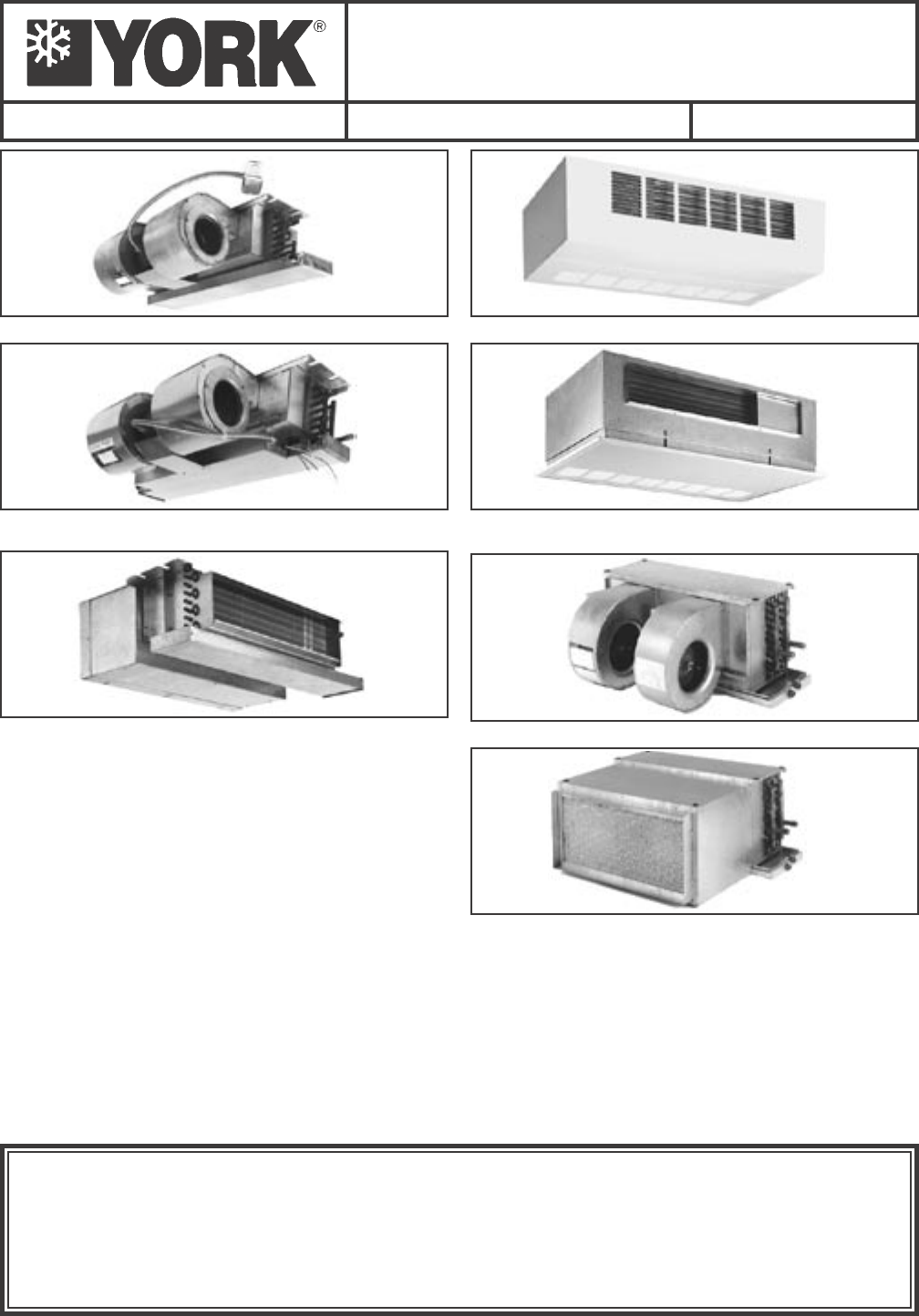
INSTALLATION, OPERATION, & MAINTENANCE
FAN COIL
AIR CONDITIONERS
Supersedes: Form 115.20-NOM2 (1199) Form 115.20-NOM2 (105)
***** WARNING TO INSTALLER, SERVICE PERSONNEL AND OWNER *****
Altering the product or replacing parts with non authorized factory parts voids all warranty or
implied warranty and may result in adverse operational performance and/or a possible hazardous
safety condition to service personnel and occupants. Company employees and/or contractors are
not authorized to waive this warning.
MODEL YHBC – Ceiling Concealed Model
MODEL YHH – Ceiling Concealed Model with Electric Heat
MODEL YPHBC – Ceiling Concealed Model with Insulated
Return. Plenum and Filter
MODEL YPHH – Ceiling Concealed Model with Electric
Heat, Insulated Return Plenum and Filter
MODEL YCHBC – Ceiling Cabinet Model
MODEL YRHBC – Telescoping / Recessed Ceiling Model
MODEL YHYB – High Capacity Ceiling Concealed Model
MODEL YPHYB – High Capacity Ceiling Concealed Model
with Insulated Return Plenum and Filter
Notes:
1. 2-Pipe units have one water coil. 4-Pipe units have two water coils.
2. Changeover is used to select heating or cooling mode.
3. YORK International does not recommend “fan cycle” applications for cooling on unit mounted thermostats.
4. For proper operation, control valve must be normally closed.
5. Aquastats provided where required.
6. Electric Heat is only available in the YHH and YPHH units. These units require a remote thermostat (low voltage 4 wire thermostat).
00168VIP
00170VIP
00171VIP
00172VIP
00173VIP
00174VIP
00175VIP
YORK INTERNATIONAL
2
FORM 115.20-NOM2 (105)
3
YORK INTERNATIONAL
INSTALLATION
FORM 115.20-NOM2 (105)
TABLE OF CONTENTS
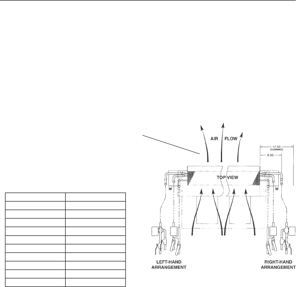
UNIT SIZE CFM
3 300
4 400
5 500
6 600
8 800
10 1000
12 1200
13 1300
16 1600
20 2000
TABLE 1 - NOMINAL AIRFLOWS
FIG. 1 – DETERMINATION OF RIGHT-HAND /
LEFT-HAND REFERENCES
LD04775
NOTE:
Use direction of airow
for selecting right- and
left-hand units.
PLENUM
(OPTIONAL)
RECEIVING..........................................................................................................................................................3
STORAGE............................................................................................................................................................3
PREPARE CEILING FOR MOUNTING................................................................................................................3
WIRING ...............................................................................................................................................................3
PIPING .................................................................................................................................................................6
DRAIN PIPING.....................................................................................................................................................7
DRAWINGS...................................................................................................................................................8 - 14
STARTUP...........................................................................................................................................................15
MAINTENANCE.................................................................................................................................................16
Reference Documents:
• IOM for YVC-YVF-YVS Form 115.20-NOM3 (Latest)
• IOM for YSHW, YSHX Form115.22-NOM5 (Latest)
• IOM for YSVW, YSVX Form 115.22-NOM2(Latest)
• Parts List Form 115.20-RP2(Latest)
These documents can be ordered through Publications Dept.
or downloaded @ http://intranet.york.com/web0003/library/default.asp
YORK INTERNATIONAL
2
FORM 115.20-NOM2 (105)
3
YORK INTERNATIONAL
INSTALLATION
FORM 115.20-NOM2 (105)
RECEIVING
Material in this shipment has been inspected at the
factory and released to the transportation agency in
good condition. When received, a visual inspection of
all cartons should be made immediately. Any evidence
of rough handling or apparent damage should be noted
on the delivery receipt and the material inspected in the
presence of the carrier's representative.
If damage is found, a claim should be
led against the carrier immediately.
STORAGE
If the equipment is not to be immediately installed, store
it in a dry location with the motor protected against
moisture, dust, corrosion and physical damage.
PREPARE CEILING FOR MOUNTING
Depending upon building construction, provisions
for mounting the unit must be made by the contractor
according to architects; drawings.
It is important to ensure that the fan coils are securely
mounted and the structure is sufcient to support the
weight of the equipment. All anchors for mounting the
equipment must be placed and sized to ensure a safe
and durable installation.
The YHBC, YPHBC, YRHBC, YHH, YHHS, YPHH,
YHYB, and YPHYB units are designed for installation
in a horizontal position above a dropped ceiling. The
YCHBC is a cabinet unit intended for horizontal
exposed surface mounting.
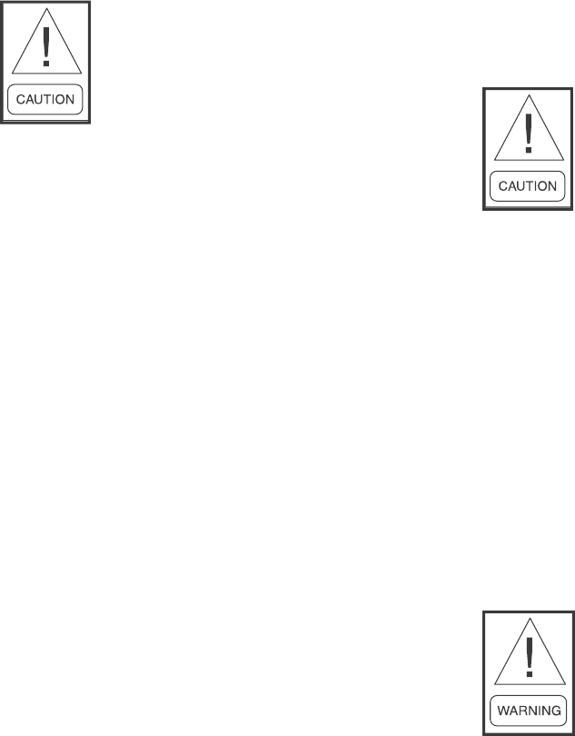
Unit must not be operated during
building construction due to ex-
cessive airborne dust and debris. The
units must not be operated under any
circumstances without an air lter in
place.
WIRING
All wiring must comply with the local and national code
requirements. Units are provided with wiring diagrams
and nameplate data to provide information required for
necessary eld wiring.
For power wiring a 4 x 4 electrical box is provided on
the cabinet for connection of power supply and is located
on the same side as piping.
On YHBC units, the box is shipped unattached, it is
eld attached to the unit in a location convenient to
electrical entrance.
Any devices such as fan switches or
thermostats that have been furnished
by the factory for eld installation
must be wired in strict accordance
with the wiring diagram that is sup-
plied with the unit. Failure to do so
could result in damage or injury.
In free (non-ducted return air) return installations of
YHBC, YHH, YHHS and YHYB units; the furred
down area must be completely sealed (except return
air grille) to ensure that all return air is pulled from
the conditioned space and not from other areas of the
building structure.
Access must be provided for servicing the unit. If
this access is provided by a removable ceiling panel,
ample space must be allowed for removal of the blower
panel and to provide access to electrical and plumbing
controls.
INSTALLATION
4YORK INTERNATIONAL
FORM 115.20-NOM2 (105)
5
YORK INTERNATIONAL
INSTALLATION
FORM 115.20-NOM2 (105)
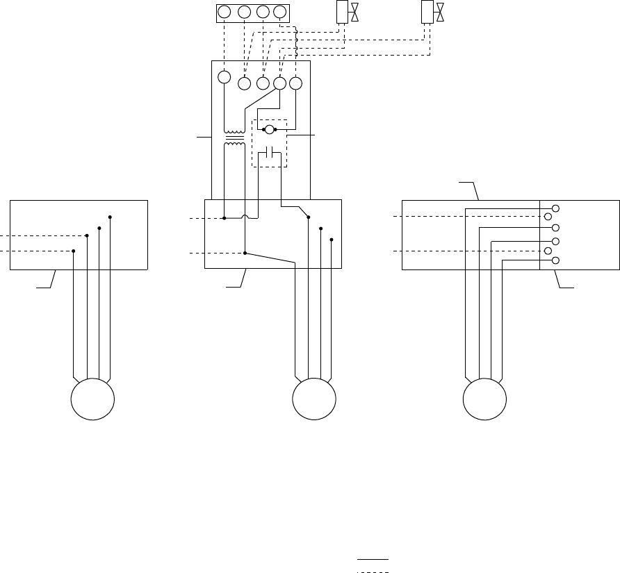
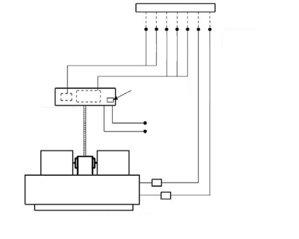
FIG. 2 – HORIZONTAL UNITS - TYPICAL WIRING
LD010198
INSTALLATION
4YORK INTERNATIONAL
FORM 115.20-NOM2 (105)
5
YORK INTERNATIONAL
INSTALLATION
FORM 115.20-NOM2 (105)
T334 THERMOSTAT
Heat-Off Cool, Fan Auto-On, 24V, Manual changeover, 4-Wire Thermostat (R, G, Y, W) Adj. Heat Anticipator,
Fixed Cooling Anticipator, Fan Cycling (Cooling) or (Heating/Cooling), No Heating Required.
T404 THERMOSTAT
Heat-Off Cool, Fan Auto-On, 24V, Manual changeover, 6-Wire Thermostat (R, G, O, Y, W, B)
Adj. Heat / Fixed Cool Anticipator, Fixed Cooling Anticipator, Fan Cycling.
(O & B can be used for cool and heat relays respectively, or for cool & heat water valves.)
T200 THERMOSTAT OPTION (W/CONTROLLER)
Heat-Off Cool, Fan -On, 24V, Manual changeover, 7-Wire Thermostat (R, C, Hi, Med, Lo, 24V Heat,
24V Coil), Auto fan speed control, digital readout, auto-overide.
LD010200
FIG. 3 – WIRING SCHEMATIC FOR HBC/PHBC/CHBC/RHBC/HYB/PHYB
LD010200
INSTALLATION
6YORK INTERNATIONAL
FORM 115.20-NOM2 (105)
7
YORK INTERNATIONAL
INSTALLATION
FORM 115.20-NOM2 (105)
Prior to connecting to the fan coil,
all external piping must be purged
of debris.
When connecting piping or valve
kits to fan coil units, do not bend or
reposition the coil header tubing for
alignment purposes. This could cause
a tubing fracture resulting in a water
leak when water pressure is applied
to the system.
Many valve packages will not phys-
ically allow all components to fit
over an auxiliary drain pan. It is the
installers responsibility to ensure ad-
equate condensation prevention. The
installer must also ensure that there
is no condensate drippage onto elec-
trical components beneath insulated
components.
PRECAUTIONS
1. Flush all eld piping prior to connection to remove
all debris.
2. Use wet cotton rags to cool valve bodies when
soldering.
3. Open all valves (mid-way for hand valves, manually
open on motorized valves) prior to soldering.
4. When soldering to bronze or brass, heat the pip-
ing while in the socket/cup and begin introducing
the solder when the ux boils rapidly. Avoid direct
ame into the solder joint.
5. Heat can only be applied to the cup of the valve body
for a minimal time before damage occurs (even with
the use of wet rags.
6. Avoid rapid quenching of solder joints, as this will
produce joints of inferior quality.
7. The valve package will not support the weight of
the connecting pipes. All pipes, which are connected
to the units, must be completely supported prior to
connection to the unit.
8. Provisions must be made for expansion and con-
traction of piping systems. All horizontal and
vertical risers, including runouts, must be able to
withstand signicant movement with temperature
changes. Failure to do so will result in damage and
failure of piping, ttings and valves throughout the
building.
9. Never insulate the heads or motorized portion of
control valves. Damage can occur in the form of
excessive heat build up and interference to the
operation and moving parts will result.
10. All piping made in the eld should be installed with
consideration of additional space for any electrical
routing that may be required.
11. Hydronic systems are not designed to hold pres-
surized air and should only be tested with water.
After the system has been proven leak free, all lines and
valve control packages must be insulated as specied
on the building plans.
These units are provided with six (6) mounting holes
(see drawings for details). Metal washers and nuts of
the proper size are to be provided by the installer. When
necessary, use shims to obtain the proper level. This will
ensure that the condensate will drain from the unit.
PIPING
These units employ a hydronic coil designed for use
with either hot or chilled water.
All piping must be adequately sized to meet the design
water ow requirements as specied for the specic
installation. Piping must be installed in accordance with
all applicable codes.
PIPE SIZES
All models except YHYB/YPHYB:
• HW/CW coils are 3/8" OD tubing.
• Tubing connections are 5/8" OD.
Models YHYB/YPHYB:
• HW/CW coils are 1/2" OD tubing.
• Tubing connections are 7/8" OD.
Manual air vents are provided standard on all coils
All chilled water piping must be insulated to prevent
condensation.
INSTALLATION
6YORK INTERNATIONAL
FORM 115.20-NOM2 (105)
7
YORK INTERNATIONAL
INSTALLATION
FORM 115.20-NOM2 (105)
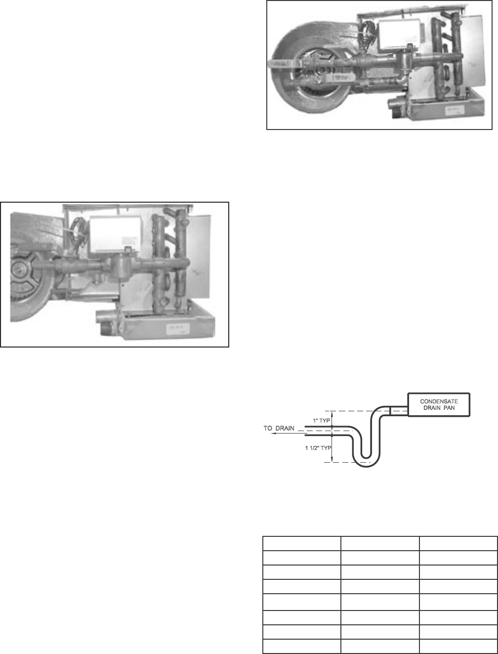
VALVE CLUSTER
2-Way Motorized Valve Assemblies
1. The motorized valve assembly should be attached to
the supply header, which is the connection nearest
the air outlet ange on the unit.
2. Prior to soldering the joints, operate all the hand
valves to ensure that the handles will fully open and
close without interference to other valves, ceiling,
wall, plenum or other accessories.
3. All valves will operate at any angle with the excep-
tion of the motorized valve, which must be installed
with the power head above horizontal. The actuator
box requires a 3/4" clearance for removal.
3-Way Motorized Valve Assembly
1. The 3-way valve assemblies will mount to the
coil in only one position. On four-pipe right hand
systems, a "B" valve assembly is required for the
chilled water connection and an "A" valve assembly
is required for the hot water connection. On left
hand systems, an "A" valve assembly is required
for the chilled water connection and the hot water
connection. (See gure 4.)
2. Prior to soldering the joints, operate all the hand
valves to ensure that the handles will fully open and
close without interference to other valves, ceiling,
wall, plenum or other accessories.
3. All valves will operate at any angle with the excep-
tion of the motorized valve, which must be installed
with the power head above horizontal. The actuator
box requires a 3/4" clearance for removal.
FIG. 5 – 3 WAY MOTORIZED VALVE ASSEMBLY
00187VIP
FIG. 4 – 2 WAY MOTORIZED VALVE ASSEMBLY
00186VIP
DRAIN PIPING
Condensate drain lines must be installed with adequate
slope away from the unit to assure positive drainage.
YRHBC and YCHBC fan coil units require a minimum
trap of 1-1/2 inches be provided in the drain line to
assure proper drainage. YHBC, YPHBC, YHH, YPHH,
YHYB, and YPHYB fan coil units may be located where
the return air space is large enough that a negative
pressure is not present, however, a trapped condensate
line is recommended to ensure proper drainage of unit in
case a negative condition should occur (see Installation
Drawings for locations and sizes).
The drain should always be connected or piped to an
acceptable disposal point sloped away from the unit at
least 1/8" per foot
LD04801
FIG. 6 – TYPICAL CONDENSATE PIPING
UNIT PRIMARY SECONDARY
YHBC 3/4 MPT 5/8 OD
YPHBC 3/4 MPT 3/4 MPT
YRHBC 3/4 MPT 3/4 MPT
YHH 3/4 MPT 7/8 OD
YPHH 3/4 MPT 7/8 OD
YHYB 3/4 MPT 3/4 MPT
YPHYB 3/4 MPT 3/4 MPT
TABLE 2 - DRAIN LINE SIZES
INSTALLATION
8YORK INTERNATIONAL
FORM 115.20-NOM2 (105)
9
YORK INTERNATIONAL
INSTALLATION
FORM 115.20-NOM2 (105)
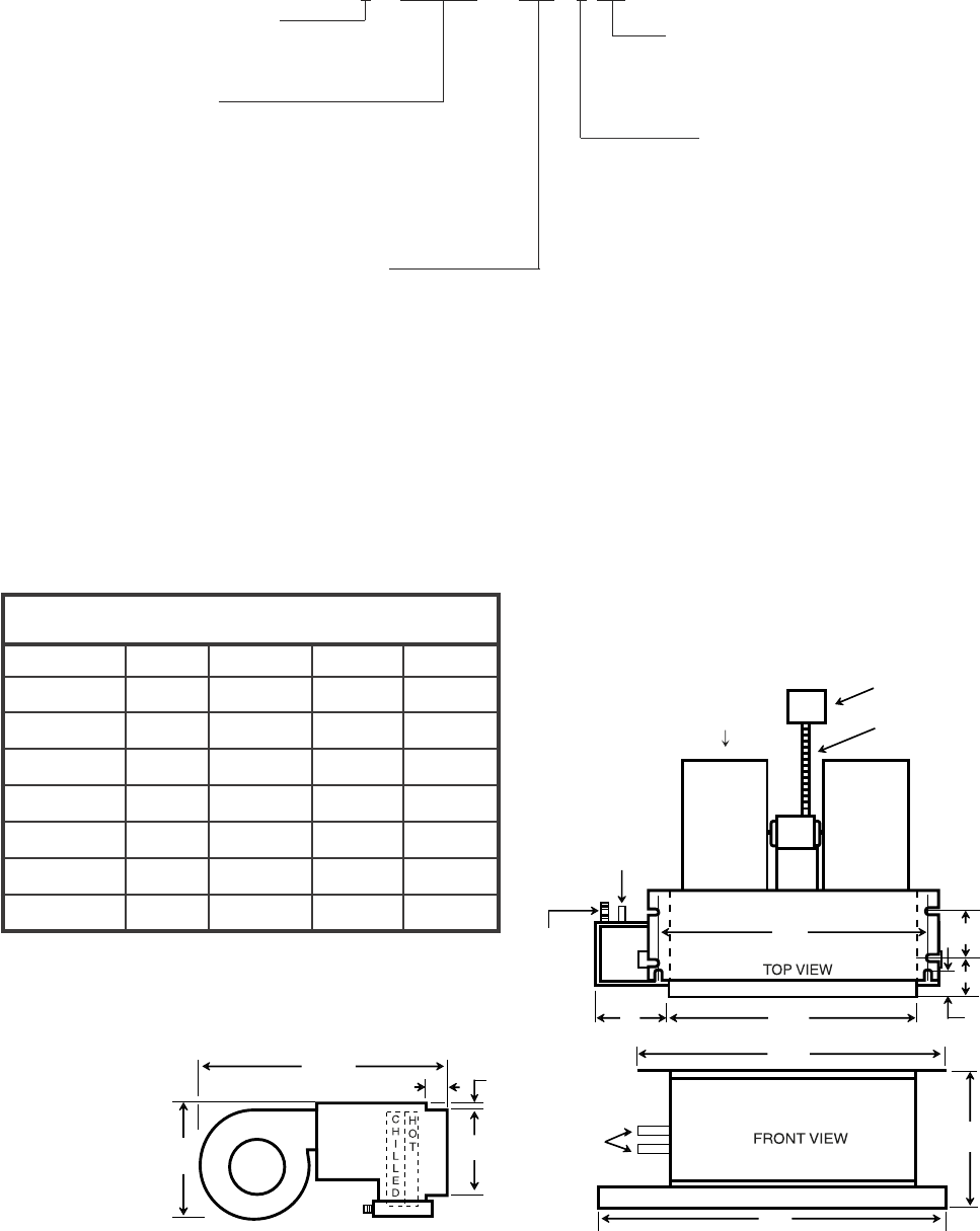
NOM. CFM (100's)
3, 4, 5, 6, 8, 10 or 13
Unit Style
Y - Ceiling Concealed
YP - with return plenum & lter
YR - recessed w/telescoping panel
YC - cabinet exposed
Coil Conguration
3 = 2 Pipe Coil, 3 Row
4 = 2 Pipe Coil, 4 Row
31 = 4 Pipe Coil, 3 Row Cool
1 Row Heat
32 = 4 Pipe Coil, 3 Row Cool
2 Row Heat
41 = 4 Pipe Coil, 4 Row Cool
1 Row Heat
Unit Voltage
126 - 120V – 1 Ph – 60 Hz
Coil Connections (looking with airow,
from blower end)
RH = Right Hand
LH = Left Hand
NOTES:
1. Model 3 YHBC has only one blower
2. Model 13 YHBC has four blowers and two motors
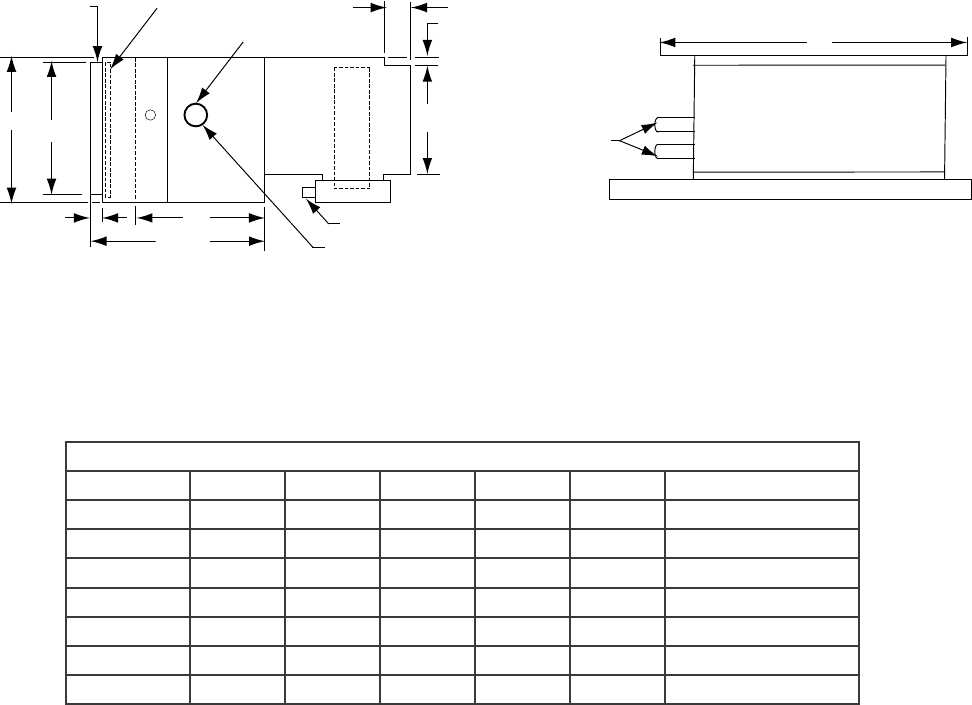
PHYSICAL DIMENSIONS (inches)
MODEL A B C D
3YHBC
4YHBC
5YHBC
6YHBC
8YHBC
10YHBC
13YHBC
30-1/8
36-1/8
40-1/8
40-1/8
46-1/8
52-1/8
59-1/8
27-1/4
33-1/4
37-1/4
37-1/4
43-1/4
49-1/4
56-1/4
20-1/8
26-1/8
30-1/8
30-1/8
36-1/8
42-1/8
49-1/8
25-1/4
31-1/4
35-1/4
35-1/4
41-1/4
47-1/4
54-1/4
HBC - Horizontal Blower Coil
Ceiling Concealed Model – MODEL YHBC
6 YP HBC - 126 - 3 RH
Filter Note:
YHBC units are not available with lters. YHBC units can be eld converted YHBC to YPHBC by adding an accessory plenum. See instruction
below for details on eld conversion.
FIELD CONVERSION YHBC TO YPHBC
Remove 2 screws holding the motor/blower assembly to the fan coil unit; remove and discard the drip guard; remove the bottom panel from
the plenum; attach the plenum box to the fan coil unit using 5 screws; re-install the motor/blower assembly to the fan coil unit; for wiring,
remove the motor leads from the j-box and attach the box to the outside of the plenum; route the motor leads to the j-box; replace the bottom
panel; install the lter; if hanger brackets are needed, attach to the plenum, both ends.
LD047768B
INSTALLATION
8YORK INTERNATIONAL
FORM 115.20-NOM2 (105)
9
YORK INTERNATIONAL
INSTALLATION
FORM 115.20-NOM2 (105)
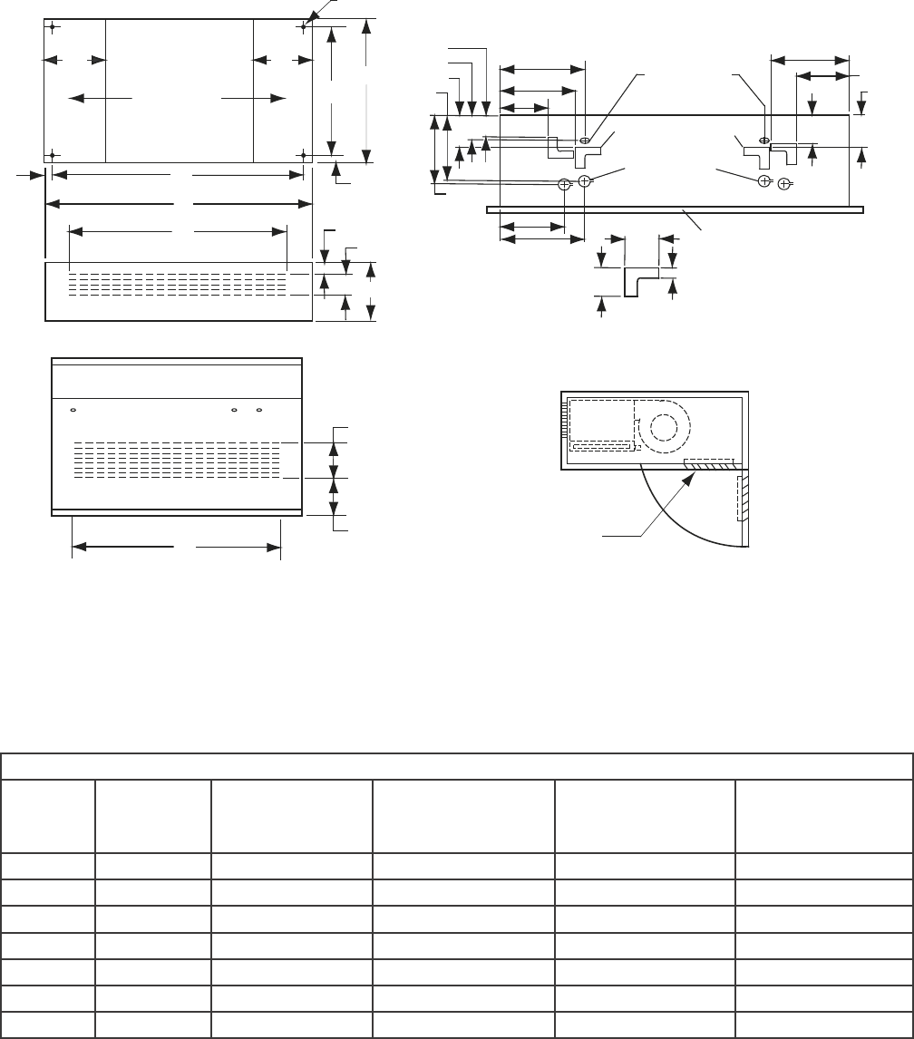
Ceiling Concealed Model with Insulated Return Plenum and Filter – MODEL YPHBC
.
PHYSICAL DIMENSIONS - INCHES
MODEL A B C D E FILTER SIZE
3YPHBC 24 22 20-1/8 30-1/8 27-1/4 10 X 24 X 1
4YPHBC 30 28 26-1/8 36-1/8 33-1/4 10 X 30 X 1
5YPHBC 34 32 30-1/8 40-1/8 37-1/4 10 X 34 X 1
6YPHBC 34 32 30-1/8 40-1/8 37-1/4 10 X 34 X 1
8YPHBC 40 38 36-1/8 46-1/8 43-1/4 10 X 40 X 1
10YPHBC 46 44 42-1/8 52-1/8 49-1/4 10 X 46 X 1
13YPHBC 53 51 49-1/8 59-1/8 56-1/4 10 X 53 X 1
1) Return plenums are insulated
2) YPHBC units are provided with lters in the plenum.
3) Standard plenums are end return and can be eld converted to bottom return by trading
the blockoff and face panel of the plenum.
4) Filter has seperate lter access panel for easier service.
LD010229
NOTES:
INSTALLATION
10 YORK INTERNATIONAL
FORM 115.20-NOM2 (105)
11
YORK INTERNATIONAL
INSTALLATION
FORM 115.20-NOM2 (105)
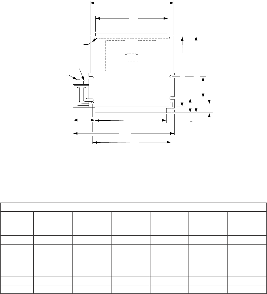
CEILING EXPOSED CABINET – MODEL YCHBC
GENERAL DIMENSIONS
MODEL UNIT WIDTH
A
MOUNTING WIDTH
B
SUPPLY LOUVERED
PANEL WIDTH
C
RETURN LOUVERED
PANEL WIDTH
E
FILTER SIZE (INCL)
3YCHBC 38 34 26 31-1/2 10 X 37 X1
4YCHBC 44 40 31-1/2 37 10 X 43 X1
5YCHBC 48 44 37 42-1/2 10 X 46 X1
6YCHBC 48 44 37 42-1/2 10 X 46 X1
8YCHBC 54 50 42-1/2 48 10 X 53 X1
10YCHBC 60 56 48 53 10 X 59 X1
13YCHBC 67 63 53 58-1/2 10 X 65 X1
LD010230
INSTALLATION
10 YORK INTERNATIONAL
FORM 115.20-NOM2 (105)
11
YORK INTERNATIONAL
INSTALLATION
FORM 115.20-NOM2 (105)
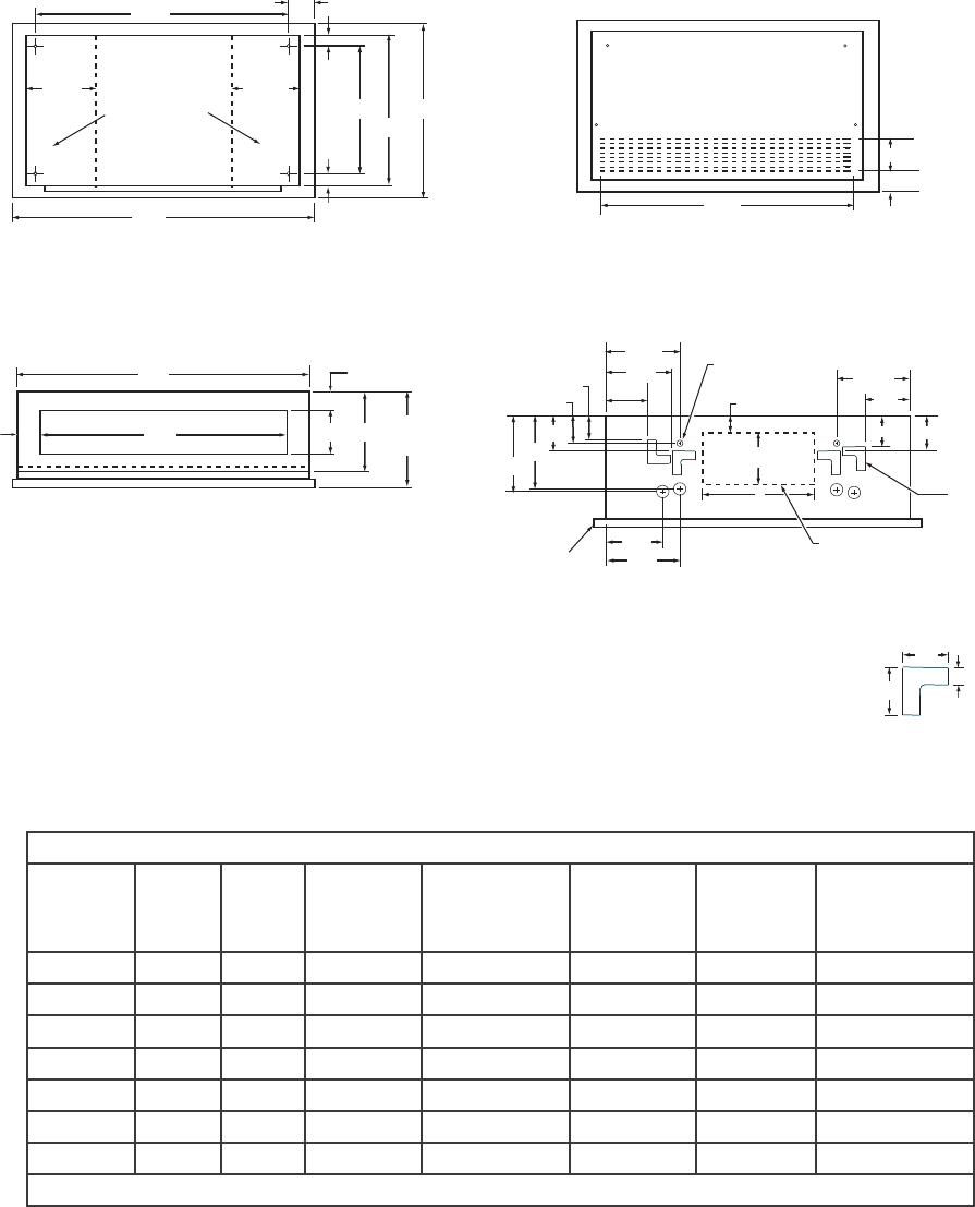
All 1-1/2" dia. K.O.;s
* 4-Pipe system only
NOTES:
1. Telescoping panel allows the cabinet to be installed to within 2
inches of the ceiling line.
2. Telescoping access panel shipped as seperate item.
3. YRHBC units are available with lters on units with louvered
access panels ONLY.
GENERAL DIMENSIONS (Inches)
MODEL PANEL
WIDTH
(A)
UNIT
WIDTH
(B)
SUPPLY
OPENING
(C)
LOUVERED
PANEL'WIDTH
(E)
MOUNTING
WIDTH
(H)
RETURN
OPENING*
(I)
FILTER
SIZE
(INCL)
3YRHBC 41 38-3/8 29 36-5/8 35 14 10 x 37 x 1
4YRHBC 47 44-3/8 35 41-3/4 41 20 10 x 43 x 1
5YRHBC 51 48-3/8 39 47-1/4 45 24 10 x 47.5 x 1
6YRHBC 51 48-3/8 39 47-1/4 45 24 10 x 47.5 x 1
8YRHBC 57 54-3/8 45 52-1/2 51 30 10 x 53 x 1
10YRHBC 67 60-3/8 51 57-7/8 57 36 10 x 59 x 1
13YRHBC 70 67-3/8 58 63-1/8 64 42 10 x 65 x 1
* Field cut for above ceiling return.
RECESSED CEILING – MODEL YRHBC
LD010220
INSTALLATION
12 YORK INTERNATIONAL
FORM 115.20-NOM2 (105)
13
YORK INTERNATIONAL
INSTALLATION
FORM 115.20-NOM2 (105)
6 Y HHS - 6.0 - 240 - 3 - RH
NOM. CFM (100's)
3,4,6,8,10 or 12
Unit Style
Y - basic unit
YP - with insulated return plenum
Motor Type
HH - PSC Motor
HHS - SP Motor
Coil Connections
(looking with airow,
from blower end)
RH = Right Hand
LH = Left Hand
Coil Conguration
3 = 2 Pipe Coil, 3 Row
4 = 2 Pipe Coil, 4 Row
Voltage
(1) 240 / 1 / 60
(2) 208 / 1 / 60
(3) 277 / 1 / 60
Electric Heat (kW)
6.0 kW
10.0 kW
Ceiling Concealed Model with Electric Heat – MODEL YHH
Notes:
1. Fuse size and wire size per ampacities on unit nameplate.
Follow NEC guidelines in absence of local codes.
2. YHH units are not available with lters.
PHYSICAL DIMENSIONS (INCHES)
MODEL OVERALL
WIDTH
A
MOUNTING
WIDTH
B
SUPPLY
OPENING
C
3YHHS 25 19-11/16 15
4YHHS
6YHHS
6YHH
8YHH
40 34-11/16 30
10YHH 46 40-11/16 36
12YHH 52 46-11/16 42
LD010233
INSTALLATION
12 YORK INTERNATIONAL
FORM 115.20-NOM2 (105)
13
YORK INTERNATIONAL
INSTALLATION
FORM 115.20-NOM2 (105)
Ceiling Concealed Model with Electric Heat,
Insulated Return Plenum and Filter – MODEL YPHH
PHYSICAL DIMENSIONS (INCHES)
MODEL OVERALL
WIDTH
A
MOUNTING
WIDTH
B
SUPPLY
OPENING
C
PLENUM
WIDTH
D
RETURN
OPENING
E
FILTER
(INCL)
3YPHHS 25 19-11/16 15 20 18 10 X 20 X 1
4YPHHS
6YPHHS
6YPHH
8YPHH
40 34-11/16 30 34 32 10 X 34 X 1
10YPHH 46 40-11/16 36 40 38 10 X 40 X 1
12YPHH 52 46-11/16 42 46 44 10 X 46 X 1
YPHH FEATURES: 1) Return Plenums are insulated.
2) All plenums include throw away lter.
LD010231
INSTALLATION
14 YORK INTERNATIONAL
FORM 115.20-NOM2 (105)
15
YORK INTERNATIONAL
FORM 115.20-NOM2 (105)
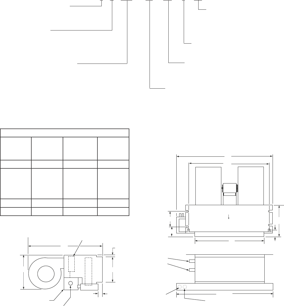
FEATURES:
1. Manual air vents
2. 4-speed direct drive motors
3. 1/2" copper tubing
4. Primary and secondary condensate
drains on one end
5. 120/1/60Hz. motors (2)
6. 3-row and 6-row models available
7. Rubber isolation grommets
8. Insulated and coated drain pan
NOM. CFM (100's)
12,16 or 20
Unit Style
Y -high capacity ceiling concealed
YP - with return plenum & lter
HYB - Horizontal Blower Coil
12 YP HYB - 126 - 3 RH
Unit Voltage
126 - 120V – 1 Ph – 60 Hz
277 - 277V – 1 Ph – 60 Hz
Coil Connections
(looking with airow, from blower end)
RH = Right Hand
LH = Left Hand
Coil Conguration
3 = 2 Pipe Coil, 3 Row
4 = 2 Pipe Coil, 4 Row
6 = 2 Pipe Coil, 6 Row
31 = 4 Pipe Coil, 3 Row Cool, 1 Row Heat
32 = 4 Pipe Coil, 3 Row Cool, 2 Row Heat
41 = 4 Pipe Coil, 4 Row Cool, 1 Row Heat
42 = 4 Pipe Coil, 4 Row Cool, 2 Row Heat
61 = 4 Pipe Coil, 6 Row Cool, 1 Row Heat
62 = 4 Pipe Coil, 6 Row Cool, 2 Row Heat
LD04781
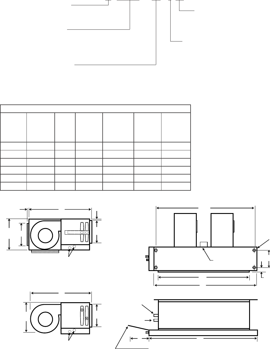
MODEL YHYB – High Capacity Ceiling Concealed Model
PHYSICAL DIMENSIONS (INCHES)
MODEL OVERALL
WIDTH
A
TOP
PLATE
WIDTH
B
SUPPLY
OPENING
C
MOUNTING
WIDTH
D
RETURN
OPENING
E
FILTER
(INCL)
12YHYB 41 35-1/2 28 31-1/4 23-1/4 ___
12YPHYB 41 35-1/2 28 31-1/4 23-1/4 14 x 28 x 1
16YHYB 51 42-1/2 38 41-1/4 38-1/4 ___
16YPHYB 51 42-1/2 38 41-1/4 38-1/4 14 x 38 x 1
20YHYB 60 51-1/2 47 50-1/4 47-1/4 ___
20YPHYB 60 51-1/2 47 50-1/4 47-1/4 14 x 43 x 1
1. YHYB units are not available with lters.
2. YPHYB units are provided with lters in the plenum.
Notes:
INSTALLATION
14 YORK INTERNATIONAL
FORM 115.20-NOM2 (105)
15
YORK INTERNATIONAL
FORM 115.20-NOM2 (105)
FAN COILS START - UP CHECKLIST
Fan INSPECTION -
The fan should be inspected and cleaned, in conjunction with maintenance of the motor and bearings. It is
important to keep the wheel clean in order to avoid imbalance and vibration.
Check tightness of fan bearing locking collar.
With power off, check blower wheel set screws for tightness and ensure that the blower wheel(s) rotate freely and quietly.
Check tightness of all motor base and mounting bolts.
Check motor connections to ensure that they are secure and made in accordance with the wiring diagram
Rotate all moving components manually. Adjust as required.
Installer has cleaned out interior.
Ensure drain pan free from foreign material.
Ensure air lters are clean, installed properly and secured. Use the directional arrows or other information on the lter to
determine the proper ow direction.
INSTALL CHECKLIST
Equipment received as ordered.
Unit checked for damage interior and exterior.
Make sure all ductwork is complete and available for full air ow.
Unit installed level to ensure proper drainage and operation.
Unit installed with proper clearances.
Ensure condensate water will drain toward the drain connection. An overow drain may be required as a back up to a clogged
primary drain.
Check that coil(s), valves and piping have been leak checked and insulated as required.
Main coil drain pan must be properly trapped and charged with water before units are started.
Ensure that all air has been vented from the system.
Return valves to their proper operating positions prior to start-up.
Repair any solder joint leaks and gently tighten any leaking valve packing nuts and piping accessories as required.
Install all panels.
NOTE: If the motor and fan have not been operated in the last (4) four weeks or more, lubricate all the bearings and rotate the motor and fan
monthly to prevent moisture from accumulating in the bearings. (See Form 50.20-NM3, Long Term Storage)
CLEANING CHECKLIST
CONTROLS CHECKLIST
Check that supply voltage matches nameplate data.
Ensure that the unit is properly grounded.
Controls installation complete
Check all electrical connections for tightness.
Review electrical print for correct wiring.
MAINTENANCE
MOTOR
The blower motor should be cleaned annually and if it
has oiling ports, it should be oiled with a good grade of
SAE 20 oil. Normally a few drops of oil in each bearing
is sufcient.
COIL
The coil must be kept clean by any of the following
methods.
1. Cleaning with low-pressure compressed air.
2. Flushing or rinsing with water (a detergent is ad-
visable for greasy surfaces).
3. Prior to the water system start-up and balancing, the
chilled/hot water systems should be ushed to clean
out dirt and debris, which may have accumulated
during construction. All unit service valves are to
be closed during this process. Strainers are to be
installed in the piping mains to prevent this material
from entering the units during normal operation.
FILTERS
The intervals at which filters require replacement
depend on local conditions.
Tele. 800-861-1001
www.York.com
P.O. Box 1592, York, Pennsylvania USA 17405-1592 Subject to change without notice. Printed in USA
Copyright © by York International Corporation 2004 ALL RIGHTS RESERVED
Form 115.20-NOM2 (105)
Supercedes 115.20-NOM2 (904)
Because of dust and lint in the room, room-air lters
load up much more rapidly than outdoor-air lters.
Under normal conditions, the room air lter requires
replacement every six to eight weeks.
To ensure proper maintenance of the lters, it is best
to follow an organized maintenance procedure. The
following one is recommended:
Divide the total number of units on the job into six
equal groups. Each week inspect, clean or replace the
lters in each group, in rotation. This insures a uniform
servicing interval. The interval may be lengthened or
shortened as determined by experience. If inspection
shows only the room-air lter to be dirty, this one alone
should be replaced.
Dirty lters reduce the air and heat-
ing capacities of the Unit Ventilator.
When the lters are excessively dirty,
the unit heating capacity will be so re-
duced that it is ineffective for heating
the room. When a room fails to heat,
always check the lters.
CLEAN UNIT INTERIOR
Once a year clean the fans and coils of the unit
thoroughly. Remove the access panel as necessary.
Wipe the interior of the unit clean with a rag. Wipe the
motor and inside and outside of the fan housings. (In
cooling units, clean out the drain pan.)
Clean or Replace Air Filters Regu-
larly
