York Z Millennium R410A Technical Guide
2015-09-09
: York Z-Millennium-R410A-Technical-Guide york-z-millennium-r410a-technical-guide-812249 york pdf
Open the PDF directly: View PDF ![]() .
.
Page Count: 82
- GENERAL
- OVERVIEW
- FEATURES AND BENEFITS
- TABLE 1: GENERAL PHYSICAL DATA
- TABLE 2: REFRIGERANT FACTORY CHARGE R-410A
- SeLECTION PROCEDURE
- TABLE 3: standard GAS HEATING CAPACITIES
- TABLE 4: temperature rise
- TABLE 5: minimum heating cfm
- TABLE 6: modulating GAS HEATING CAPACITIES
- TABLE 7: modulating heat
- TABLE 8: ELECTRIC HEATING CAPACITIES
- Hot Water Heating
- TABLE 9: WATER PRESSURE DROP (1 ROW, 25 & 30 TON)
- TABLE 10: STATIC RESISTANCE HOT WATER COIL (25 & 30 TON)
- TABLE 11: HOT WATER COIL (1 ROW, 25 & 30 TON)
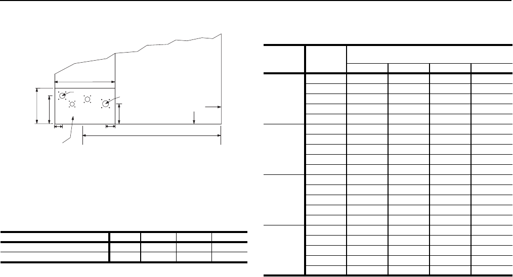
- FIGURE 1 - HOT WATER PIPING CROSS- SECTION
- TABLE 12: STATIC RESISTANCE HOT WATER COIL (1 ROW, 40 TON)
- TABLE 13: HOT WATER COIL (1 ROW 40 TON)
- FIGURE 2 - HOT WATER COIL - 25 & 30 TON, 1 ROW, AT 10 GPM
- FIGURE 3 - HOT WATER COIL - 25 & 30 TON, 1 ROW, AT 20 GPM
- FIGURE 4 - HOT WATER COIL - 25 & 30 TON, 1 ROW, AT 30 GPM
- FIGURE 5 - HOT WATER COIL - 25 & 30 TON, 1 ROW, AT 40 GPM
- FIGURE 6 - HOT WATER COIL - 40 TON, 1 ROW, AT 10 GPM
- FIGURE 7 - HOT WATER COIL - 40 TON, 1 ROW, AT 20 GPM
- FIGURE 8 - HOT WATER COIL - 40 TON, 1 ROW, AT 30 GPM
- FIGURE 9 - HOT WATER COIL - 40 TON, 1 ROW, AT 40 GPM
- TABLE 14: WATER PRESSURE DROP (2 ROW, 25 & 30 TON)
- TABLE 15: STATIC RESISTANCE HOT WATER COIL (25 & 30 TON)
- TABLE 16: HOT WATER COIL (2 ROW, 25 & 30 TON)1(CONT.)
- TABLE 17: HOT WATER COIL (2 ROWS, 40 TON)
- TABLE 18: STATIC RESISTANCE HOT WATER COIL (40 TON)
- TABLE 19: WATER PRESSURE DROP (2 ROW, 40 TON)
- FIGURE 10 - HOT WATER COIL - 25 & 30 TON, 2 ROW, AT 20 GPM
- FIGURE 11 - HOT WATER COIL - 25 & 30 TON, 2 ROW, AT 40 GPM
- FIGURE 12 - HOT WATER COIL - 25 & 30 TON, 2 ROW, AT 60 GPM
- FIGURE 13 - HOT WATER COIL - 25 & 30 TON, 2 ROW, AT 80 GPM
- FIGURE 14 - HOT WATER COIL - 40 TON, 2 ROW, AT 20 GPM
- FIGURE 15 - HOT WATER COIL - 40 TON, 2 ROW, AT 40 GPM
- FIGURE 16 - HOT WATER COIL - 40 TON, 2 ROW, AT 60 GPM
- FIGURE 17 - HOT WATER COIL - 40 TON, 2 ROW, AT 80 GPM
- Steam Heating
- TABLE 20: STEAM COIL (1 ROW, 25 & 30 TON)
- TABLE 21: STATIC RESISTANCE STEAM COIL (1 ROW, 25 & 30 TON)
- TABLE 22: STEAM COIL (1 ROW, 40 TON)
- TABLE 23: STATIC RESISTANCE STEAM COIL (1 ROW, 40 TON)
- FIGURE 18 - STEAM PIPING CROSS SECTION
- FIGURE 19 - STEAM COIL - 25 & 30 TON, 1 ROW
- FIGURE 20 - STEAM COIL - 40 TON, 1 ROW
- TABLE 24: EXHAUST FAN DRIVE DATA
- TABLE 25: SUPPLY FAN MOTOR AND DRIVE DATA
- Supply Air Drive Adjustment
- TABLE 26: 25 TON DRIVE ADJUSTMENT
- TABLE 27: 30 TON DRIVE ADJUSTMENT
- TABLE 28: 40 TON DRIVE ADJUSTMENT
- TABLE 29: DRIVE ADJUSTMENT FOR POWER EXHAUST - 25 TON
- TABLE 30: DRIVE ADJUSTMENT FOR POWER EXHAUST - 30 & 40 TON
- TABLE 31: COOLING PERFORMANCE - 25 TON R-410A
- TABLE 32: COOLING PERFORMANCE - 30 TON R-410A
- TABLE 33: COOLING PERFORMANCE - 40 TON R-410A
- TABLE 34: ALTITUDE CORRECTION FACTORS
- FIGURE 21 - ALTITUDE/TEMPERATURE CONVERSION FACTOR
- FIGURE 22 - FAN PERFORMANCE - 25 TON
- FIGURE 23 - FAN PERFORMANCE - 30 TON
- FIGURE 24 - FAN PERFORMANCE - 40 TON
- FIGURE 25 - POWER EXHAUST - ONE FORWARD CURVE FAN - 25 TONS
- FIGURE 26 - POWER EXHAUST - TWO FORWARD CURVED FANS - 30 & 40 TONS
- TABLE 53: UNIT WEIGHTS
- TABLE 54: SUPPLY FAN MOTOR VFD WEIGHTS
- TABLE 55: EXHAUST FAN MOTOR VFD WEIGHTS
- FIGURE 27 - CENTER OF GRAVITY
- TABLE 56: UNIT CENTER OF GRAVITY
- TABLE 57: UNIT CORNERWEIGHT
- TABLE 58: INDOOR SOUND POWER RATING
- TABLE 59: ATTENUATION FACTORS
- TABLE 60: OUTDOOR SOUND POWER RATING
- FIGURE 28 - COMPONENT LOCATION
- FIGURE 29 - END RETURN, BOTTOM SUPPLY
- FIGURE 30 - BOTTOM SUPPLY AND RETURN
- FIGURE 31 - BOTTOM RETURN, FRONT & REAR SUPPLY
- FIGURE 32 - END RETURN, FRONT & REAR SUPPLY
- FIGURE 33 - MILLENNIUM OVERHEAD VIEW
- FIGURE 34 - MILLENNIUM MAJOR COMPONENT LAYOUT
- FIGURE 35 - 40 TON SIDE & CONDENSER END VIEW
- FIGURE 36 - MILLENNIUM CABINET DOOR CONFIGURATION
- FIGURE 37 - CLEARANCES - HOOD/ECONOMIZER & MOTOR DRIVE - SIDE
- FIGURE 38 - CLEARANCES - HOOD/ECONOMIZER & MOTOR DRIVE - FRONT & END
- FIGURE 39 - PARTIAL ROOF CURB MODEL 1RC0455P
- GUIDE SPECIFICATIONS - YORK MILLENNIUM 25, 30, & 40 TON UNITS
- GENERAL
- DESCRIPTION
- CONSTRUCTION
- SUPPLY AIR SYSTEM
- BEARINGS AND DRIVES
- AIR FILTERING SYSTEM
- AIR INLET SYSTEM
- Energy recovery ventilation (FIELD INSTALLED OPTION)
- HEATING SYSTEM
- REFRIGERATION SYSTEM
- CONTROLS
- COMFORT CONTROL FEATURES
- Optional SIMPLICITY®LINC gateway
- optional control
- AVAILABLE ACCESSORIES
- Partial perimeter roof curbs
- Burglar Bars
- Field Installed Barometric Relief
- Programmable thermostat, with or without remote sensor (required for constant volume units)
- Remote Wall Mounted Temperature Sensors
- Dirty Filter Switch
- Propane conversion kits
- High altitude conversion kits
- Energy Recovery Ventilators
246837-YTG-L-1012
FOR DISTRIBUTION USE ONLY - NOT TO BE USED AT POINT OF RETAIL SALE
TECHNICAL GUIDE
MILLENNIUM®
SINGLE PACKAGE ROOFTOP UNITS
Z42, Z33 & Z34 (R-410A)
25, 30, & 40 TON
25, 30 & 40 Ton (Efficiencies up to 10.5 EER)
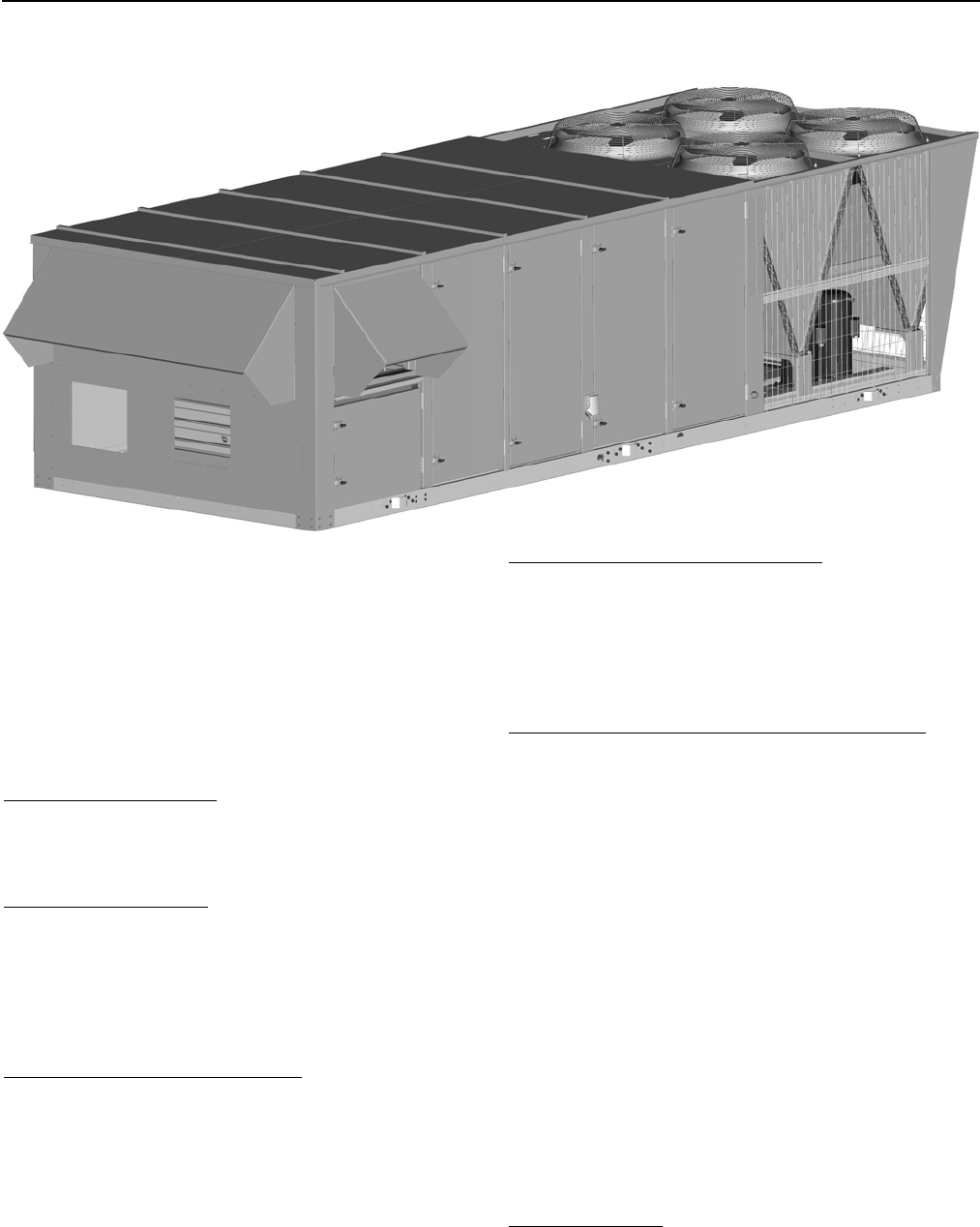
40 TON UNIT SHOWN
TOMORROW’S UNIT TODAY
GENERAL
Introducing the YORK Millennium 25, 30, & 40 ton rooftop
line - units designed to provide peak performance and value
both today and for years to come. Millennium units are manu-
factured at an ISO 9001 registered facility, and each rooftop
is completely computer-run tested prior to shipment.
The Millennium is designed to be flexible enough to meet
your needs today and in the future. The true value of YORK’s
Millennium is that it can be designed to fit any need, from
cooling only, constant volume applications to variable air vol-
ume systems with variable frequency drive.
FEATURING:
• Cooling Only Units
• Cooling/Gas Heating Units (Natural) Standard or
Modulating Gas Heat available
• Cooling/Electric Heating Units
• Cooling/Hot Water Heating Units
• Cooling/Steam Heating Units
• Industry Leading Efficiency
• Double Wall Construction
• Stainless Steel or Powder Coated Drain Pan
• Multiple Scroll Compressors
• Multiple Refrigeration Circuits
• Upgradable Motor Efficiency
• Enhanced Filtration
• Vibration Isolated Supply Fan and Motor
• TechniCoated Evaporator and Condenser Coils
• Single Power Point Connection
• Easy Access Hinged Doors
• Variable Air Volume
• Constant Air Volume
• Factory Installed Economizers/Disconnect/Convenience
Outlet/Control Options
• Low Profile
MILLENNIUM SIMPLICITY® ELITE™ FEATURES:
• Single Button Programming and LED Display
• Designed to operate on both constant and variable air
volume units
• 365-Day real time clock
• Occupancy Schedule allowing two schedules per day
• 20 Holiday schedules with programmable schedules that
can start at any time, day or night
• Patented Comfort Ventilation operation for economical
and comfortable economizer operation
• Demand Ventilation option to assure proper IAQ condi-
tions based on available space or return air CO2 levels
• Temperature/Humidity programming algorithm allows
programmable limits to help control humidity in the space
• Smoke Purge automatically ventilates the space when
smoke is detected
• Monitors dirty filters and proves airflow before starting
heating or cooling
• Intelligent recovery to bring the space temperature up to
occupied setting quicker and more economically

246837-YTG-L-1012
2 Johnson Controls Unitary Products
TABLE OF CONTENTS
GENERAL . . . . . . . . . . . . . . . . . . . . . . . . . . . . . . . . . 1
FEATURING: . . . . . . . . . . . . . . . . . . . . . . . . . . . . . . . . . .1
MILLENNIUM SIMPLICITY® ELITE™ FEATURES: . . .1
OVERVIEW . . . . . . . . . . . . . . . . . . . . . . . . . . . . . . . . 5
FEATURES AND BENEFITS . . . . . . . . . . . . . . . . . . 5
INSTALLATION FEATURES . . . . . . . . . . . . . . . . . . . . . .6
CONSTRUCTION FEATURES . . . . . . . . . . . . . . . . . . . .7
LIST OF FEATURES AND BENEFITS . . . . . . . . . . . . . . . 8
STANDARD FEATURES . . . . . . . . . . . . . . . . . . . . . . . . . . 8
FACTORY INSTALLED OPTIONS . . . . . . . . . . . . . . . . . . 8
FIELD INSTALLED ACCESSORIES . . . . . . . . . . . . . . . . . 8
SELECTION PROCEDURE . . . . . . . . . . . . . . . . . . 11
SELECT UNIT: . . . . . . . . . . . . . . . . . . . . . . . . . . . . . . . .11
SELECT FAN SPEED AND HORSEPOWER
REQUIREMENTS OF SUPPLY AIR FAN . . . . . . . . . . .11
SIZE OVERCURRENT PROTECTION DEVICE AND
DETERMINE CIRCUIT AMPACITY . . . . . . . . . . . . . . . .11
HOT WATER HEATING . . . . . . . . . . . . . . . . . . . . . 14
PHYSICAL DATA HOT WATER COIL - 1 ROW . . . . . .14
PIPING CONNECTIONS . . . . . . . . . . . . . . . . . . . . . . . .14
PHYSICAL DATA HOT WATER COIL - 2 ROW . . . . . .20
STEAM HEATING . . . . . . . . . . . . . . . . . . . . . . . . . . 25
PHYSICAL DATA STEAM COIL - 1 ROW . . . . . . . . . . .25
PIPING CONNECTIONS . . . . . . . . . . . . . . . . . . . . . . . .25
SUPPLY AIR DRIVE ADJUSTMENT . . . . . . . . . . . 28
CFM, STATIC PRESSURE, AND POWER - ALTITUDE
AND TEMPERATURE CORRECTIONS . . . . . . . . . . . .34
GUIDE SPECIFICATIONS - YORK
MILLENNIUM 25, 30, & 40 TON UNITS . . . . . . . . . 75
GENERAL . . . . . . . . . . . . . . . . . . . . . . . . . . . . . . . . . . . 75
DESCRIPTION . . . . . . . . . . . . . . . . . . . . . . . . . . . . . . . . 75
CONSTRUCTION . . . . . . . . . . . . . . . . . . . . . . . . . . . . . . 75
BASE . . . . . . . . . . . . . . . . . . . . . . . . . . . . . . . . . . . . . . . . 75
CASING . . . . . . . . . . . . . . . . . . . . . . . . . . . . . . . . . . . . . . 75
SUPPLY AIR SYSTEM . . . . . . . . . . . . . . . . . . . . . . . . . . 75
SUPPLY AIR FAN . . . . . . . . . . . . . . . . . . . . . . . . . . . . . . 75
OPTIONAL . . . . . . . . . . . . . . . . . . . . . . . . . . . . . . . . . . . . 75
BEARINGS AND DRIVES . . . . . . . . . . . . . . . . . . . . . . . 75
AIR FILTERING SYSTEM . . . . . . . . . . . . . . . . . . . . . . . 76
OPTIONAL . . . . . . . . . . . . . . . . . . . . . . . . . . . . . . . . . . . . 76
AIR INLET SYSTEM . . . . . . . . . . . . . . . . . . . . . . . . . . . . 76
GENERAL . . . . . . . . . . . . . . . . . . . . . . . . . . . . . . . . . . . . 76
ECONOMIZER (OPTIONAL) . . . . . . . . . . . . . . . . . . . . . . 76
RELIEF SYSTEM (OPTIONAL) . . . . . . . . . . . . . . . . . . . . 76
BAROMETRIC RELIEF (OPTIONAL) . . . . . . . . . . . . . . . 76
EXHAUST AIR FANS (OPTIONAL) . . . . . . . . . . . . . . . . . 76
ENERGY RECOVERY VENTILATION
(FIELD INSTALLED OPTION) . . . . . . . . . . . . . . . . . . . . 76
GENERAL . . . . . . . . . . . . . . . . . . . . . . . . . . . . . . . . . . . . 76
HEATING SYSTEM . . . . . . . . . . . . . . . . . . . . . . . . . . . . 76
GAS-FIRED HEATING SECTION (OPTIONAL) . . . . . . . 76
ELECTRIC HEATING SECTION . . . . . . . . . . . . . . . . . . . 77
HOT WATER HEATING COIL . . . . . . . . . . . . . . . . . . . . . 77
STEAM HEATING COIL . . . . . . . . . . . . . . . . . . . . . . . . . 77
REFRIGERATION SYSTEM . . . . . . . . . . . . . . . . . . . . . 77
EVAPORATOR COILS . . . . . . . . . . . . . . . . . . . . . . . . . . 77
COMPRESSORS . . . . . . . . . . . . . . . . . . . . . . . . . . . . . . 78
CONDENSER COILS . . . . . . . . . . . . . . . . . . . . . . . . . . . 78
CONDENSER FANS AND MOTORS . . . . . . . . . . . . . . . 78
REFRIGERANT PIPING . . . . . . . . . . . . . . . . . . . . . . . . . 78
HOT GAS BYPASS (OPTIONAL ON CV; STANDARD
ON VAV) . . . . . . . . . . . . . . . . . . . . . . . . . . . . . . . . . . . . . 78
CONTROLS . . . . . . . . . . . . . . . . . . . . . . . . . . . . . . . . . . 78
GENERAL DESCRIPTION . . . . . . . . . . . . . . . . . . . . . . . 78
COMPRESSOR CONTROL . . . . . . . . . . . . . . . . . . . . . . 78
FAN CONTROL . . . . . . . . . . . . . . . . . . . . . . . . . . . . . . . . 79
EQUIPMENT CONTROL FEATURES . . . . . . . . . . . . . . . 79
COMFORT CONTROL FEATURES . . . . . . . . . . . . . . . 80
OPTIONAL SIMPLICITY®LINC GATEWAY . . . . . . . . . 81
OVERVIEW . . . . . . . . . . . . . . . . . . . . . . . . . . . . . . . . . . . 81
OPTIONAL CONTROL . . . . . . . . . . . . . . . . . . . . . . . . . 81
YORK COMMERCIAL COMFORT SYSTEM (YCCS) . . . 81
AVAILABLE ACCESSORIES . . . . . . . . . . . . . . . . . . . . . 81
PARTIAL PERIMETER ROOF CURBS . . . . . . . . . . . . . . 81
BURGLAR BARS . . . . . . . . . . . . . . . . . . . . . . . . . . . . . . . 81
FIELD INSTALLED BAROMETRIC RELIEF . . . . . . . . . . 81
PROGRAMMABLE THERMOSTAT, WITH OR WITHOUT
REMOTE SENSOR (REQUIRED FOR CONSTANT
VOLUME UNITS) . . . . . . . . . . . . . . . . . . . . . . . . . . . . . . . 81
REMOTE WALL MOUNTED TEMPERATURE
SENSORS . . . . . . . . . . . . . . . . . . . . . . . . . . . . . . . . . . . . 81
DIRTY FILTER SWITCH . . . . . . . . . . . . . . . . . . . . . . . . . 81
PROPANE CONVERSION KITS . . . . . . . . . . . . . . . . . . . 81
HIGH ALTITUDE CONVERSION KITS . . . . . . . . . . . . . . 81
ENERGY RECOVERY VENTILATORS . . . . . . . . . . . . . 81

246837-YTG-L-1012
Johnson Controls Unitary Products 3
LIST OF FIGURES
Fig.# Pg.#
1 HOT WATER PIPING CROSS-SECTION . . . . . . . . . 15
2 HOT WATER COIL - 25 & 30 TON, 1 ROW,
AT 10 GPM . . . . . . . . . . . . . . . . . . . . . . . . . . . . . . . . . 16
3 HOT WATER COIL - 25 & 30 TON, 1 ROW,
AT 20 GPM . . . . . . . . . . . . . . . . . . . . . . . . . . . . . . . . . 16
4 HOT WATER COIL - 25 & 30 TON, 1 ROW,
AT 30 GPM . . . . . . . . . . . . . . . . . . . . . . . . . . . . . . . . . 17
5 HOT WATER COIL - 25 & 30 TON, 1 ROW,
AT 40 GPM . . . . . . . . . . . . . . . . . . . . . . . . . . . . . . . . . 17
6 HOT WATER COIL - 40 TON, 1 ROW, AT 10 GPM . . 18
7 HOT WATER COIL - 40 TON, 1 ROW, AT 20 GPM . . 18
8 HOT WATER COIL - 40 TON, 1 ROW, AT 30 GPM . . 19
9 HOT WATER COIL - 40 TON, 1 ROW, AT 40 GPM . . 19
10 HOT WATER COIL - 25 & 30 TON, 2 ROW,
AT 20 GPM . . . . . . . . . . . . . . . . . . . . . . . . . . . . . . . . . 21
11 HOT WATER COIL - 25 & 30 TON, 2 ROW,
AT 40 GPM . . . . . . . . . . . . . . . . . . . . . . . . . . . . . . . . . 21
12 HOT WATER COIL - 25 & 30 TON, 2 ROW,
AT 60 GPM . . . . . . . . . . . . . . . . . . . . . . . . . . . . . . . . . 22
13 HOT WATER COIL - 25 & 30 TON, 2 ROW,
AT 80 GPM . . . . . . . . . . . . . . . . . . . . . . . . . . . . . . . . . 22
14 HOT WATER COIL - 40 TON, 2 ROW, AT 20 GPM . . 23
15 HOT WATER COIL - 40 TON, 2 ROW, AT 40 GPM . . 23
16 HOT WATER COIL - 40 TON, 2 ROW, AT 60 GPM . . 24
17 HOT WATER COIL - 40 TON, 2 ROW, AT 80 GPM . . 24
18 STEAM PIPING CROSS SECTION . . . . . . . . . . . . . . 25
19 STEAM COIL - 25 & 30 TON, 1 ROW . . . . . . . . . . . . 26
Fig.# Pg.#
20 STEAM COIL - 40 TON, 1 ROW . . . . . . . . . . . . . . . . 26
21 ALTITUDE/TEMPERATURE CONVERSION
FACTOR . . . . . . . . . . . . . . . . . . . . . . . . . . . . . . . . . . 35
22 FAN PERFORMANCE - 25 TON . . . . . . . . . . . . . . . . 37
23 FAN PERFORMANCE - 30 TON . . . . . . . . . . . . . . . . 39
24 FAN PERFORMANCE - 40 TON . . . . . . . . . . . . . . . . 41
25 POWER EXHAUST - ONE FORWARD CURVE FAN
- 25 TONS . . . . . . . . . . . . . . . . . . . . . . . . . . . . . . . . . 44
26 POWER EXHAUST - TWO FORWARD CURVED FANS
- 30 & 40 TONS . . . . . . . . . . . . . . . . . . . . . . . . . . . . . 46
27 CENTER OF GRAVITY . . . . . . . . . . . . . . . . . . . . . . . 64
28 COMPONENT LOCATION . . . . . . . . . . . . . . . . . . . . 66
29 END RETURN, BOTTOM SUPPLY . . . . . . . . . . . . . . 67
30 BOTTOM SUPPLY AND RETURN . . . . . . . . . . . . . . 68
31 BOTTOM RETURN, FRONT & REAR SUPPLY . . . . 69
32 END RETURN, FRONT & REAR SUPPLY . . . . . . . . 70
33 MILLENNIUM OVERHEAD VIEW . . . . . . . . . . . . . . . 71
34 MILLENNIUM MAJOR COMPONENT LAYOUT . . . . 71
35 40 TON SIDE & CONDENSER END VIEW . . . . . . . . 71
36 MILLENNIUM CABINET DOOR CONFIGURATION . 72
37 CLEARANCES - HOOD/ECONOMIZER & MOTOR
DRIVE - SIDE . . . . . . . . . . . . . . . . . . . . . . . . . . . . . . . 73
38 CLEARANCES - HOOD/ECONOMIZER & MOTOR
DRIVE - FRONT & END . . . . . . . . . . . . . . . . . . . . . . . 73
39 PARTIAL ROOF CURB MODEL 1RC0455P . . . . . . . 74

246837-YTG-L-1012
4 Johnson Controls Unitary Products
LIST OF TABLES
Tbl.# Pg.#
1 GENERAL PHYSICAL DATA . . . . . . . . . . . . . . . . . . .10
2 REFRIGERANT FACTORY CHARGE R-410A . . . . .11
3 STANDARD GAS HEATING CAPACITIES . . . . . . . .12
4 TEMPERATURE RISE . . . . . . . . . . . . . . . . . . . . . . . .12
5 MINIMUM HEATING CFM . . . . . . . . . . . . . . . . . . . . . 12
6 MODULATING GAS HEATING CAPACITIES . . . . . . 12
7 MODULATING HEAT . . . . . . . . . . . . . . . . . . . . . . . . .13
8 ELECTRIC HEATING CAPACITIES . . . . . . . . . . . . . .13
9 WATER PRESSURE DROP (1 ROW,
25 & 30 TON) . . . . . . . . . . . . . . . . . . . . . . . . . . . . . . .14
10 STATIC RESISTANCE HOT WATER COIL
(25 & 30 TON) . . . . . . . . . . . . . . . . . . . . . . . . . . . . . . . 14
11 HOT WATER COIL (1 ROW, 25 & 30 TON) . . . . . . . .14
12 STATIC RESISTANCE HOT WATER COIL
(1 ROW, 40 TON) . . . . . . . . . . . . . . . . . . . . . . . . . . . .15
13 HOT WATER COIL (1 ROW 40 TON) . . . . . . . . . . . .15
14 WATER PRESSURE DROP (2 ROW,
25 & 30 TON) . . . . . . . . . . . . . . . . . . . . . . . . . . . . . . .20
15 STATIC RESISTANCE HOT WATER COIL
(25 & 30 TON) . . . . . . . . . . . . . . . . . . . . . . . . . . . . . . . 20
16 HOT WATER COIL (2 ROW, 25 & 30 TON) . . . . . . . .20
17 HOT WATER COIL (2 ROWS, 40 TON) . . . . . . . . . . .20
18 STATIC RESISTANCE HOT WATER COIL
(40 TON) . . . . . . . . . . . . . . . . . . . . . . . . . . . . . . . . . . . 20
19 WATER PRESSURE DROP (2 ROW, 40 TON) . . . . . 20
20 STEAM COIL (1 ROW, 25 & 30 TON) . . . . . . . . . . . . 25
21 STATIC RESISTANCE STEAM COIL
(1 ROW, 25 & 30 TON) . . . . . . . . . . . . . . . . . . . . . . . .25
22 STEAM COIL (1 ROW, 40 TON) . . . . . . . . . . . . . . . .25
23 STATIC RESISTANCE STEAM COIL
(1 ROW, 40 TON) . . . . . . . . . . . . . . . . . . . . . . . . . . . .25
24 EXHAUST FAN DRIVE DATA . . . . . . . . . . . . . . . . . .27
25 SUPPLY FAN MOTOR AND DRIVE DATA . . . . . . . . 27
26 25 TON DRIVE ADJUSTMENT . . . . . . . . . . . . . . . . .29
27 30 TON DRIVE ADJUSTMENT . . . . . . . . . . . . . . . . .29
28 40 TON DRIVE ADJUSTMENT . . . . . . . . . . . . . . . . .29
29 DRIVE ADJUSTMENT FOR POWER EXHAUST
- 25 TON . . . . . . . . . . . . . . . . . . . . . . . . . . . . . . . . . . .30
30 DRIVE ADJUSTMENT FOR POWER EXHAUST
- 30 & 40 TON . . . . . . . . . . . . . . . . . . . . . . . . . . . . . . .30
31 COOLING PERFORMANCE - 25 TON R-410A . . . . .31
Tbl.# Pg.#
32 COOLING PERFORMANCE - 30 TON R-410A . . . . . 32
33 COOLING PERFORMANCE - 40 TON R-410A . . . . . 33
34 ALTITUDE CORRECTION FACTORS . . . . . . . . . . . . 34
35 FAN PERFORMANCE - 25 TON, . . . . . . . . . . . . . . . 36
36 FAN PERFORMANCE - 30 TON , . . . . . . . . . . . . . . . 38
37 FAN PERFORMANCE - 40 TON, . . . . . . . . . . . . . . . . 40
38 COMPONENT STATIC RESISTANCE, . . . . . . . . . . 42
39 POWER EXHAUST - ONE FORWARD CURVED
FAN 25 TON . . . . . . . . . . . . . . . . . . . . . . . . . . . . . . . . 43
40 POWER EXHAUST - TWO FORWARD CURVED FANS
- 30 & 40 TON . . . . . . . . . . . . . . . . . . . . . . . . . . . . . . 45
41 ELECTRICAL DATA 25 TON BASIC UNIT R-410A . . 47
42 ELECTRICAL DATA 30 TON BASIC UNIT R-410A . . 47
43 ELECTRICAL DATA 40 TON BASIC UNIT R-410A . . 48
44 ELECTRICAL DATA 25 TON W/ELECTRIC HEAT
R-410A . . . . . . . . . . . . . . . . . . . . . . . . . . . . . . . . . . . . 49
45 ELECTRICAL DATA 30 TON W/ELECTRIC HEAT
R-410A . . . . . . . . . . . . . . . . . . . . . . . . . . . . . . . . . . . . 50
46 ELECTRICAL DATA 40 TON W/ELECTRIC HEAT
R-410A . . . . . . . . . . . . . . . . . . . . . . . . . . . . . . . . . . . . 51
47 ELECTRICAL DATA 25 TON W/POWER EXHAUST
R-410A . . . . . . . . . . . . . . . . . . . . . . . . . . . . . . . . . . . . 52
48 ELECTRICAL DATA 30 TON W/POWER EXHAUST
R-410A . . . . . . . . . . . . . . . . . . . . . . . . . . . . . . . . . . . . 53
49 ELECTRICAL DATA 40 TON W/POWER EXHAUST
R-410A . . . . . . . . . . . . . . . . . . . . . . . . . . . . . . . . . . . . 54
50 ELECTRICAL DATA 25 TON W/ELECTRIC HEAT AND
POWER EXHAUST R-410A . . . . . . . . . . . . . . . . . . . . 55
51 ELECTRICAL DATA 30 TON W/ELECTRIC HEAT AND
POWER EXHAUST R-410A . . . . . . . . . . . . . . . . . . . . 58
52 ELECTRICAL DATA 40 TON W/ELECTRIC HEAT AND
POWER EXHAUST R-410A . . . . . . . . . . . . . . . . . . . . 61
53 UNIT WEIGHTS . . . . . . . . . . . . . . . . . . . . . . . . . . . . . 64
54 SUPPLY FAN MOTOR VFD WEIGHTS . . . . . . . . . . . 64
55 EXHAUST FAN MOTOR VFD WEIGHTS . . . . . . . . . 64
56 UNIT CENTER OF GRAVITY . . . . . . . . . . . . . . . . . . . 64
57 UNIT CORNERWEIGHT . . . . . . . . . . . . . . . . . . . . . . 65
58 INDOOR SOUND POWER RATING . . . . . . . . . . . . . 65
59 ATTENUATION FACTORS . . . . . . . . . . . . . . . . . . . . 65
60 OUTDOOR SOUND POWER RATING . . . . . . . . . . . 66
246837-YTG-L-1012
Johnson Controls Unitary Products 5
YORK Millennium®
OVERVIEW
Introducing the YORK Millennium 25, 30, & 40 ton rooftop
line - units designed to provide peak performance and value
both today and for years to come. When we asked our cus-
tomers what they wanted in a new rooftop line, we were care-
ful to listen to both the needs of today and tomorrow. So,
you'll find that Millennium units not only help you solve
today's problems, but can handle tomorrow's difficulties as
well:
Industry Leading Efficiency - The Millennium with EER rat-
ings of up to 10.5 make it the most frugal energy consumer in
its class. When it comes to lower operating costs, Millennium
simply outperforms the competition.
Double Wall Construction - Millennium units come double
walled as standard. The galvanized sheet metal liner pro-
vides the best protection against microbial growth, helping
both the unit and the indoor air stay fresh and clean. And, the
rigid sheet metal inner liner keeps the insulation completely
out of the air stream, eliminating concerns about fiberglass
particles.
Drain Pan Whisks Away Condensate - Condensate is fre-
quently the source of microbial contamination. Competitive
drain pans often are insufficiently sloped to properly drain all
of the condensate, causing drain pan corrosion and bacterial
growth to begin almost immediately. The YORK design is
sloped at the 1/4” per foot recommended by the ASHRAE
62.1-2004 ventilation draft standard, with an extra large drain
connection capable of removing up to three gallons of con-
densate per minute. It is available in either powder coat
painted steel or stainless steel for long life.
Efficient, Durable Scroll Compressors - The Millennium
design uses industrial grade hermetic scroll compressors for
peak efficiency and low noise operation. The compressor
design is so durable that it can actually hold more liquid
charge without slugging than is present in each refrigerant
circuit at shipment, dramatically reducing the chances of ever
slugging a compressor with liquid charge.
Multiple Refrigeration Circuits for Greater Turndown - The
YORK Millennium unit has intertwined circuits giving the best
unloading capability in the industry. With more and more
designs requiring higher outside air quantities, the lower
capacity capability is an outstanding way to neutralize outside
air without over-conditioning the space on off-peak days.
And, Millennium's high quality balance-port thermal expan-
sion valves are more effective at metering refrigerant flow in
part-load conditions, making Millennium a peak-performer
across a wide capacity range.
FEATURES AND BENEFITS
When it comes to flexibility, Millennium really shines. Our cus-
tomers were clear about one thing - not all installations are
the same. Some have very simple needs, others are more
involved. The YORK Millennium serves both markets - and all
of those in between - extremely well. YORK engineers crafted
a design which is both uniquely flexible and competitive, giv-
ing you the best of both worlds. In addition to a competitive
base product, Millennium offers unparalleled flexibility.
Optional features include:
Variable Air Volume - YORK gives you the ability to vary air
volume by inlet guide vanes or variable frequency drive - the
choice is yours. All Millennium VAV units come standard with
hot gas bypass to give extended operation range.
246837-YTG-L-1012
6 Johnson Controls Unitary Products
Optional Head Pressure Control - For those applications
where mechanical cooling is required below 40°F, optional
low ambient operation allows compressor operation down to
0°F.
Easily Upgrade Motor Efficiency to Meet Tighter Codes -
Optional high efficiency motors help you make simple
upgrades to meet more demanding building and energy
codes.
Enhanced Filtration Options - Millennium gives designers the
flexibility to meet various IAQ requirements with a full range
of rigid and throwaway filters at different efficiency levels.
Vibration Isolation - The Millennium's neoprene mounts are
typically sufficient for most applications but when sound and
vibration transmission are a major concern, YORK offers 1"
and 2" isolation springs for even greater protection from sup-
ply air fan noise and vibration.
Corrosion Resistant Coils- Many industrial and seacoast
applications require enhanced protection from corrosive envi-
ronments.
Optional TechniCoated Coated Condenser and Evapo-
rator Coils - Many industrial and seacoast applications
require enhanced protection from corrosive environ-
ments. The special dipped phenolic coating process
provides a high level of protection for the exposed con-
denser coil.
Optional Copper-Copper Condenser and Evaporator
Coils - For corrosion resistance.
Variety of Exhaust Air Options - YORK Millennium offers a
wide variety of exhaust air options, including barometric
relief, non-modulating power exhaust, and modulating power
exhaust. And, because Millennium units use forward-curved
blowers for power exhaust fans, they can exhaust up to 100%
of the nominal supply air at much greater static pressure
loads than competitive units. Not available on end return.
NOTE: In most applications, the supply fan will keep the
return at negative pressure. A barometric relief will
function better when ducted to building space, not
the return.
Optional Factory Installed Economizers - Millennium units
offer economizers with Standard or Optional low leak damp-
ers. Comparative enthalpy, single enthalpy and dry bulb con-
trol are available.
Optional Factory Installed Disconnect - A conveniently
located actuator handle in the front of the unit can disconnect
line power to the entire unit, eliminating the need for a field
provided disconnect. The handle may also be locked in either
position through the use of a standard padlock. Millennium's
single point power connection makes this option particularly
appealing. If desired, the disconnect may be ordered with a
115 volt, GFCI protected convenience outlet, including a fac-
tory wired transformer to power the outlet from the single
point power connection; the convenience outlet remains
operational when the disconnect is open.
Heating Done Your Way - Millennium offers the choice of nat-
ural gas standard or modulating gas heat, electric resistance
heat, hot water heat, steam, or no heat at all. Very simply, the
choice is yours.
INSTALLATION FEATURES
With YORK Millennium, high performance doesn't mean high
complexity. YORK listened carefully to make sure that Millen-
nium was as simple as possible, and service convenience
comes standard with each unit. From a single curb size to the
easy service access, you'll find that Millennium was designed
to be easy from start to finish.
Full Range of Air Flows and Static Pressures - The Millen-
nium design gives a complete offering of supply air flows and
static pressure combinations to meet most every application
requirement.
Single Power Point Connection - Millennium units have a sin-
gle gas and electric connection, minimizing time at the job
site. For further installation flexibility, power and gas connec-
tions may be brought up from the curb or through the side of
the unit.
Simple Controls - Millennium's controls system is easy to
understand and apply, and it doesn't lock you into proprietary
devices. A choice for YORK Millennium today does not limit
your choices tomorrow.
Rain Hoods Rotate Into Place - No bulky, field--installed rain
hoods here. Millennium rain hoods ship rotated inside the
unit. Once on the job, installer merely rotates the hood
upward and puts in a few screws - an easy one-person job.
Excellent Access for Service - Service access on Millennium
is a snap. Hinged and latched doors give access on both
sides of the unit to all major components. All doors have pos-
itive action slide latches for even greater ease of access. All
service fittings are conveniently located to minimize time and
effort.
246837-YTG-L-1012
Johnson Controls Unitary Products 7
CONSTRUCTION FEATURES
YORK's Millennium rooftop line is built for the long haul, with
high end features and construction offered at a competitive
price. Millennium units are manufactured at an ISO 9001 reg-
istered facility, and each rooftop is completely computer-run
tested prior to shipment. Some of the valuable construction
features of the Millennium which are not found on competitive
units include:
Double Wall Construction - Each unit has both an exterior
and an interior wall, which make for a more rigid design with
panels and doors that are solid, not flimsy. The unit features a
fully framed construction for even greater stability.
Powder Paint - Industry leading 1000 salt spray hour paint
keeps the unit in great condition for years to come.
Low Profile - Millennium units stand only 64” above their
curb, minimizing potential aesthetic conflicts.
Extended flue connection - Each gas unit ships with a field
mounted external flue. The flue lifts all products of furnace
combustion far above the unit - eliminating the possibility of
corrosion in the furnace heat exchanger from recirculating
flue gases.
Protective Covering - Special polyurethane sleeves which
cover the distributor tubing keep distributor tubes from con-
tacting each other and wearing out.
Built-in Hail Guard - Condenser coils angled at 30 degrees
from the vertical are inherently protected from damage due to
shipment, hail, etc.
Induced Draft Furnace - This design provides a positive
exhaust of all combustion products.
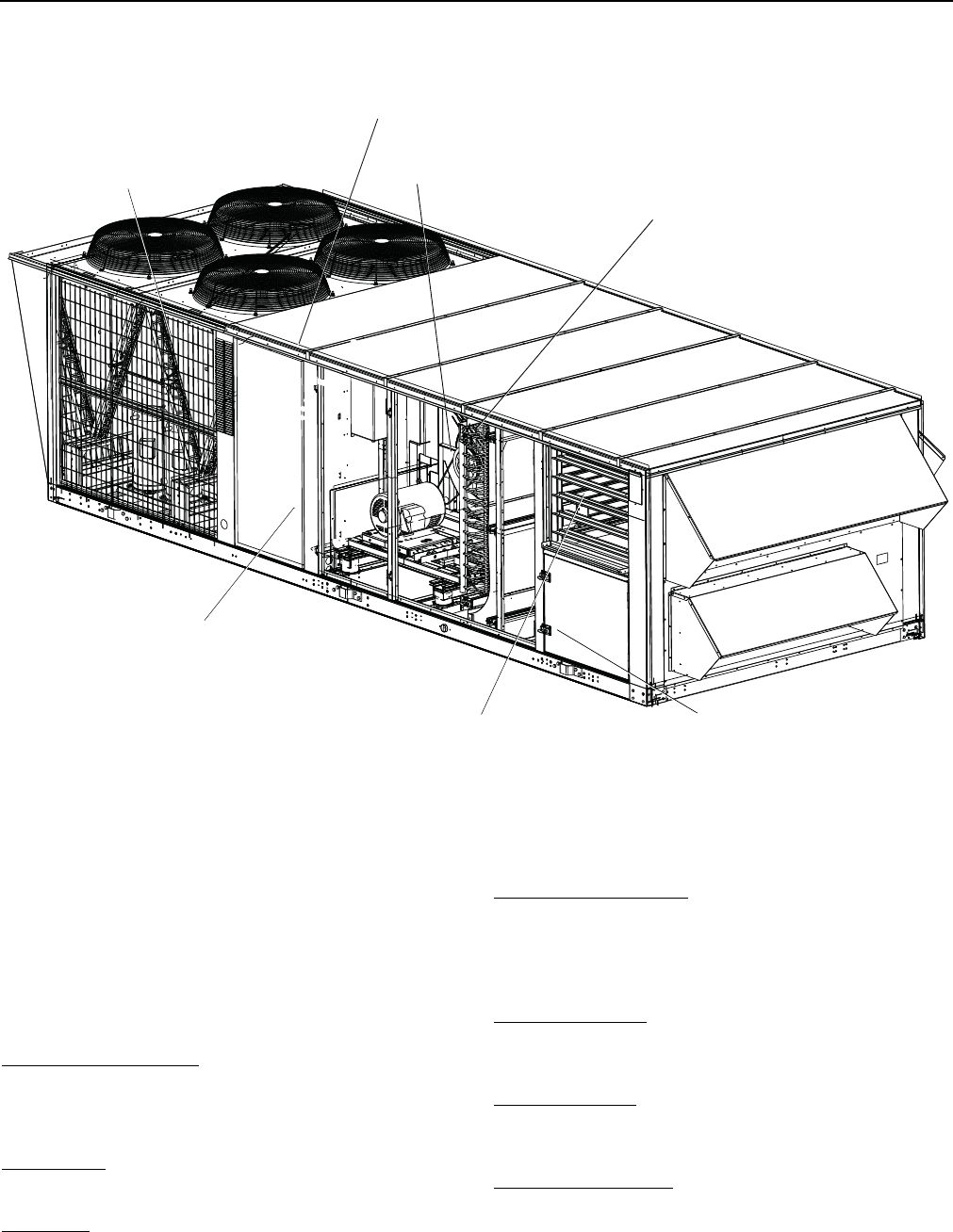
ANGLED CONDENSER
COILS
PITCHED ROOF
SOLID, CLASS II FAN CONSTRUCTION
INTERTWINED COIL
DOUBLE WALL CONSTRUCTION
LOW LEAK DAMPERS
HINGED, LATCHED
ACCESS DOORS

246837-YTG-L-1012
8 Johnson Controls Unitary Products
LIST OF FEATURES AND BENEFITS
Standard Features
• Efficiencies up to 10.5 EER
• Double wall construction
• Major components have hinged and latched access
doors
• Industrial duty scroll compressors
• Sturdy framed construction
• Sloped stainless steel or powder coated drain pan
• Four independent cooling circuits
• Intertwined evaporator coil
• Angled condenser coils for superior protection
• Single power point connection
• Through-the-curb or through-the-base utility connections
•Simplicity® Elite™ controls
• Powder paint tested to 1000 salt spray hours
• Mechanical cooling from 40° F to 125° F
• 1-1/2” insulation
• Sloped unit roof with drip lip
• High and low refrigerant pressure protection
• Polyurethane sleeves to protect small diameter tubing
• Steel framing around blowers with deflection springs or
rubber isolators for low vibration
• Fully factory packaged and run-tested
• 10 year gas heat exchanger warranty
• One year compressor warranty
• One year warranty on all parts
Factory Installed Options
• Economizer with standard or low leak dampers
• Retractable outside air hoods (economizer only)
• Natural gas standard or modulating gas heat with reli-
able induced draft design
• Electric heat in three sizes
• Variable air volume using either inlet guide vanes, wired
for VFD (variable frequency drive), or factory installed
VFD.
• 3 position (Line/Drive/Test) bypass switch for either sup-
ply or exhaust VFDs.
• 1, 2” blower isolator springs or rubber isolators
• A variety of blower horsepower offerings
• High efficiency motors
• High efficiency filtration
• Barometric relief
• Power exhaust of 100% of nominal air flow
• Technicoat corrosive resistant coating on condenser and
evaporator coils
• Copper-Copper corrosive resistant condenser and evap-
orator coils
• 0°F low ambient operation of mechanical cooling
• Hot gas bypass (standard on all VAV units)
• Single unit disconnect
• Convenience outlet and transformer factory wired
• Hot water heating coil with one or two rows
• One row steam heating coil
• Synthesis controls
•Simplicity®LINC Gateway
• York Commercial Comfort System (YCCS)
Field Installed Accessories
• 7-Day Programmable Wall Thermostat-Can be used with
or without remote sensors. Can be used on CV and VAV
units when wall thermostat is required for scheduling and
temperature control.
• Energy Recovery Ventilators- 8,000 and 13,000 CFM
models available. Great for applications involving 30% or
more of required outdoor air where energy use and com-
fort must be optimized.
• Wall Sensors- Remote space sensors used with CV or
VAV unit for unit control via the Simplicity® Elite™ con-
trol. Standard sensor, sensor with override and sensor
with override and + 5 degree adjustment.
•Simplicity® Transporter- Device allows internet control
and monitoring of HVAC units equipped with Simplicity®
Elite™ controls.
• Phase Monitor Kit- Includes control and wiring to monitor
and protect the unit from phase reversal, phase loss and
low voltage.
• Burglar Bars- Prevent any type of building entry through
the RTU unit with bars that block the return and supply
openings on downflow applications.
• Partial perimeter roofcurb- Designed for application on
all 25-40 ton Millennium rooftop units. 14" height.
• Barometric Relief Kit- Provides barometric relief hood
and dampers for duct mounting on units requiring end
return.
• Natural Gas to Propane Conversion Kits- Contains ori-
fices and gas valves parts to convert from Natural Gas to
Propane. (Not available on modulating heat.)
• High Altitude Kit- Natural gas kit designed for natural gas
heating applications between 2,000 and 6,000 feet
above sea level.
246837-YTG-L-1012
Johnson Controls Unitary Products 9
NOMENCLATURE
123 4
CONTROL
ADDITIONAL
D = SYNTHESYS CONTROL
CONFIGURATION
VOLTAGE
E = SYNTHESYS CONTROL,
OPTIONS
2 = 208/230-60
DISC., 110V OUTLET
Cu/Cu Condenser Coil
3 = 380-60
F = SYNTHESYS, DISC.
Cu/Cu Evaporator Coil
4 = 460-60
Exhaust VFD (Customer)
5 = 575-60
H = SIMPLICITY CONTROL
(see note 3)
7 = 380/415-50
I = SIMPLICITY CONTROL, DISC
NOTES:
110V OUTLET
1. 108KW not available with 208/230V.
J = SIMPLICITY CONTROL,
* Premium Cabinet (6 doors)
2. Standard efficiency motor meets Canadian
DISC, NO 110V OUTLET
* Standard Cabinet (4 doors)
ID BLOWER
(See note 4)
minimum efficiency regulations mandated
K = SIMPLICITY CONTROL W/SIMPLICITY LINC
* Drain Pan - powder coat
in Canadian Energy Efficiency Regulations.
L = SIMPLICITY CONTROL W/SIMPLICITY LINC
* Drain Pan - stainless steel
3. (VFD-CUSTOMER) = Wired for VFD
DISC, 110V OUTLET
only; VFD will be customer supplied and
M = SIMPLICITY CONTROL W/SIMPLICITY LINC
N = YCCS CONTROL
P = YCCS CONTROL W/DISC., 110V OUTLET
Q = YCCS ZONING CONTROL
R = YCCS ZONING CONTROL W/DISC.,
110V OUTLET
S = YCCS-VAV CONTROL
T = YCCS-VAV CONTROL W/DISC.,
110V OUTLET
field installed. If VFD Exh is also
DISC, NO 110V OUTLET
specified, it will also be cust supplied.
4. VAV ID Blower requires hot gas bypass .
5. Power exhaust and barometric relief not
available in end return configuration.
CONFIGURATION
6. Air foil fan available on cooling only.
A = 1,2 1 - BOTTOM RETURN
Contact engineering for
B = 1,4 2 - BOTTOM SUPPLY
air foil applications.
C = 1,5 3 - END RETURN
(5)
Air Volume
ECONOMIZER
D = 3,2 4 - REAR SUPPLY
a = CV
A = DUAL ENTH Low leak type
E = 3,4 5 - FRONT SUPPLY
b = VAV (VFD-FACTORY INSTALLED)
B, = SINGLE ENTH Low leak type
F = 3,5
c = BYPASS FACTORY VFD
C, = DRY BULB ENTH Low leak type
FRONT SUPPLY - COOLING ONLY
d = VAV (VFD-CUSTOMER) (3)
D = MANUAL Low leak (Not w/PE)
HOT WATER, STEAM & ELECTRIC HEAT -
Fan (See note 6)
E = NONE
BOTTOM SUPPLY ONLY
e = FORWARD CURVE FAN Class I
B = 2,3,5,7
F = DUAL ENTH Std type
GAS HEAT - BOTTOM OR REAR SUPPLY ONLY
f = FORWARD CURVE FAN Class II
C = 1,4,5,7
Y = 1,3,9,8
G = SINGLE ENTH Std type
g = AIR FOIL FAN [always Class II]
D = 2,4,5,7
Z = 2,3,9,8
H = DRY BULB Std type
HEAT SOURCE
2 = 2,4,9,8
N = NATURAL GAS
Blower Mount
Q = 1,3,9,7
S = NATURAL GAS, SS HEAT EXCHANGER
h = Neoprene
R = 2,3,9,7
EXHAUST
(See note 5)
D = NATURAL GAS, MODULATING HEAT*
i = 1 inch deflection spring
S = 1,4,9,7
A = BARO J = 2, 5 S = A, 3
T = NATURAL GAS, MODULATING HEAT, SS *
j = 2 inch deflection spring
I = 1,3,5,8
T = 2,4,9,7
B = 1, 3 K = 2, 6 T = A, 4
HEAT EXCHANGE
R
J = 2,3,5,8
7 = 1,4,9,8
C = 1, 4 L = 2, 7 U = A, 5
E = ELECTRIC HEAT
D = 1, 5 M = 2, 8 V = A, 6
C = COOLING ONLY
9 = Non-Std
E = 1, 6 N = NONE W = A, 7
W = HOT WATER COIL
ID MOTOR
(See note 2)
F = 1, 7 O = 1, 9 X = A, 8
X = STEAM COIL
Condenser Coil Head Press. Ctrl.
G = 1, 8 P = 1, 0 Y = A, 9
1 = STANDARD 7 = YES
H = 2, 3 Q = 2, 9 Z = A, 0
2 = TECHNICOAT 8 = NO
I = 2, 4 R = 2, 0 2 = 8,000 CFM ERV
HEAT CAPACITY
Piping
(See note 4)
3 = 13,000 CFM ERV
3 = 267 MBH
5 = 10 HI-EFF
3 = STANDARD 4 = HOT GAS BYPASS
5 = 533 MBH
6 = 15 HI-EFF
Evaporator Coil
9 = Non Std Config
8 = 800 MBH (40T ONLY)
7 = 20 HI-EFF
5 = STANDARD
Power Exhaust
4 = 40 KW
8 = 25 HI-EFF (Except 25T)
1 = MODULATING DAMPERS A = VFD MODULATING
MOTOR
8 = 80 KW
9 = STD W/TECHNICOAT
2 = NON-MOD. (ON/OFF)
1 = 108 KW (1)
0 = 7.5 HI-EFF (25T Only)
0 (ZERO) NO HEAT
Motor
1 = 1 ROW
0 = 5 HP HI-EFF (25T Only)
2 = 2 ROW
6 = 7.5 HP HI-EFF
1 = 1 ROW
7 = 10 HP HI-EFF
8 = 15 HP HI-EFF (Except 25 Ton)
Config
A
13
D
14
3
3
N
5
A
4
PACKAGE
3
6
4
7
FILTERS
C
12
B
8
1
9
A
10
A
11
GENERATION
3
2
Z
1
Z = York Brand R-410A
A = STAND.
B = 65%
C = 95%
D = 2" HI-EFF
A = 1,3,5,7
REFRIGERATION
(30T/40T)
3 = 30 TON
4 = 40 TON
2 = 25 TON
L = 2,4,5,8
BASIC UNIT
Class I blower is limited to 15HP in 25/30Ton
Class I blower is limited to 20HP in 40Ton
Class II blowers are not HP limited
K = 1,4,5,8
A = A, F, I L = D, G, J W = D, E, J
B = A, G, I M = B, F, I X = D, F, H
C = A, F, J N = B, F, J Y = B, E, H
D = A, G, J O = B, G, I Z = B, E, I
E = A, E, H P = B, G, J 2 = B, E, J
F = A, E, I Q = C, F, I 3 = B, F, H
G = A, E, J R = C, F, J 4 = C, E, H
H = A, F, H S = C, G, I 6 = C, E, I
I = D, F, I T = C, G, J 7 = C, E, J
J = D, F, J U = D, E, H 8 = C, F, H
9 = D, G, H
K = D, G, I V = D, E, I
®
®
®

246837-YTG-L-1012
10 Johnson Controls Unitary Products
TABLE 1: GENERAL PHYSICAL DATA
UNIT SIZE 25 TON 30 TON 40 TON
UNIT EER / IPLV
(STANDARD CAPACITY EVAPORATOR)10.5 / 12.3 10.11 / 11.0 10.5 / 11.2
COMPRESSOR DATA
NUMBER/SIZE 4 x 5.7Ton 4 x 7 Ton 4 x 8.6 Ton
TYPE Scroll Scroll Scroll
UNIT CAPACITY STEPS 25%, 50%, 75%, 100% 25%, 50%, 75%, 100% 25%, 50%, 75%, 100%
INDOOR FAN AND DRIVE
NUMBER / TYPE 1 / FC 1 / FC 1 / FC
DIAMETER X WIDTH (INCHES)22 x20 22 x 20 25 x 22
HP RANGE 7.5 - 20 10 - 25 10 - 25
CFM RANGE (FULL LOAD)6,000 - 12,500 6,000 - 15,000 8,000 - 18,000
ESP RANGE 0.2” - 4.0” 0.2" - 4.0” 0.2" - 4.0"
EXHAUST FAN
NUMBER/SIZE/TYPE 1/FC 2/FC 2/FC
HP RANGE (SINGLE MOTOR)5 - 10 7.5 - 15 7.5 - 15
CFM 3,000 - 9,000 4,000 - 15,000 4,000 - 18,000
EVAPORATOR COIL
SIZE (SQ. FT.) 26.0 26.0 30.4
ROWS/FPI 3 / 16 4 / 16 4 / 16
CONDENSER COIL
SIZE (SQ. FT.) 65 78 104
ROWS/FPI 2/16 2 /16 2 /16
CONDENSER FANS
QUANTITY / DIAMETER (INCHES)4 / 24 4 / 24 4 / 30
NOMINAL CFM 6,800 7,200 9,600
MOTOR HP 1.0 1.5 1.5
ELECTRIC HEAT
KW RANGE 40 - 108 40 - 108 40 - 108
40 KW / CAPACITY STEPS (CV/VAV) 111
80 KW / CAPACITY STEPS (CV/VAV) 2 / 1 2 / 1 2 / 1
108 KW / CAPACITY STEPS (CV/VAV) 3 / 123 / 123 / 12
NATURAL GAS HEAT
UNIT SIZE 25 TON 30 TON 40 TON
267 MBH CAPACITY STEPS (CV/VAV) 1 / 1 1 / 1 1 / 1
533 MBH CAPACITY STEPS (CV/VAV) 2 / 1 2 / 1 2 / 1
800 MBH CAPACITY STEPS (CV/VAV) --
3 / 12
267 MBH “MODULATING” CAPACITY STEPS (CV ONLY)6 / 1 6 / 1 6 / 1
533 MBH “MODULATING” CAPACITY STEPS (CV ONLY)12 / 2 12 / 2 12 / 2
800 MBH “MODULATING” CAPACITY STEPS (CV ONLY)- - 17 / 3
HOT WATER COIL
SIZE (INCHES)22.5” x 65” 22.5" X 65” 22.5" X 65”
CAPACITY 25 Ton 30 Ton 40 Ton
STEAM COIL
SIZE (INCHES)21" X 65"
TYPE Steam Coil
FILTERS 2" TA
NUMBER / SIZE 4 / 16 x 25 & 6 / 20 x 25 4 / 16 x 25 & 6 / 20 x 25 4 / 16 x 25 & 6 / 20 x 25
FACE AREA (SQ. FT.) 30.4 30.4 30.4
FILTERS 2" PLEATED, 30%
NUMBER / SIZE 4 / 16 x 25 & 6 / 20 x 25 4 / 16 x 25 & 6 / 20 x 25 4 / 16 x 25 & 6 / 20 x 25
FACE AREA (SQ. FT.) 30.4 30.4 30.4
FILTERS 65% RIGID W/ 2” TA PREFILTERS
NUMBER / SIZE 4 / 16 x 25 & 6 / 20 x 25 4 /16 x 25 & 6 / 20 x 25 4 / 16 x 25 & 6 / 20 x 25
FACE AREA (SQ. FT.) 30.4 30.4 30.4
FILTERS 95% RIGID W/ 2” TA PREFILTERS
NUMBER / SIZE 4 ea. 16 x 25 / 6 ea. 20 x 25 4 ea. 16 x 25 / 6 ea. 20 x 25 4 ea. 16 x 25 / 6 ea. 20 x 25
FACE AREA (SQ. FT.) 30.4 30.4 30.4
1. Cooling Only Unit Efficiency/ Gas Electric Unit Efficiency is 10.0
2. Unit Control Board with 3 heating outputs only, all other Unit Control Boards 2 / 1.
246837-YTG-L-1012
Johnson Controls Unitary Products 11
SELECTION PROCEDURE
GIVEN:
Required Cooling Capacity 460,000 Btuh
Required Sensible Cooling 390,000 Btuh
Required Heating (Gas) 320,000 Btuh
Entering Air on Evaporator 83° F DB/ 67° F WB
Outside Design Temperature 95° F
Supply Fan CFM 13,000 CFM
External Static Pressure 1.25 IWG
Electrical Supply Voltage 460-3-60
Economizer Required
2” Throw Away Filters
Constant Volume
SELECT UNIT:
1. Determine nominal tons:
460,000 / 12,000 = 38.33 Tons
Thus, a nominal 40 ton unit is selected.
2. Reference Cooling Capacity Table for a 40 ton unit.
a. Locate the table for the 40 ton evaporator coil with
95° F air on the condenser.
b. Enter table at 13,000 CFM and 67°F WB air on
evaporator
c. Trace to 83° F Entering Dry Bulb column.
d. Read 493 MBH total capacity and 403 MBH sensi-
ble capacity.
The 40 ton unit will meet the cooling requirements. From
the nomenclature, the unit will be a Z34. Choose the
appropriate configuration for the next digit. Assuming
bottom return and supply, the fourth digit would be an
“A,” making the model Z34A.
3. Find Gas Heating Capacity Table.
a. Trace down Output column.
b. Find output which exceeds 320,000 Btuh require-
ment. The N5 option gives 426 MBH output.
c. Ensure that it is offered in the Z34 unit. Read option
model as N5.
From the basic nomenclature, the model now becomes
Z34AN5. Add voltage code of “4” for 460-3-60. Nomen-
clature becomes Z34AN44.
SELECT FAN SPEED AND HORSEPOWER
REQUIREMENTS OF SUPPLY AIR FAN
1. Find Supply Air Performance Tables for the 40 ton unit.
a. Check footnotes and make necessary additions or
deductions to static resistance of ductwork:
Ductwork static resistance 1.25 IWG
Economizer static resistance addition (interpolate) =.25
IWG + Gas Heat (High) = 0.5 IWG
Total Static Resistance 2.0 IWG
b. Enter Fan Performance Table at 13,000 CFM and
2.0 IWG static pressure:
RPM = 733
BHP = 11.8
NOTE: Either Class I or Class II blower could be used.
c. Enter the Fan Motor Drive Tables. Selecting a 15 hp
motor allows (service factor of 1.5) for a maximum
operating BHP greater than the 11.8 BHP require-
ment.
SIZE OVERCURRENT PROTECTION DEVICE AND
DETERMINE CIRCUIT AMPACITY
1. Find electrical tables for the basic 40 ton unit.
a. Enter table for 460-3-60 voltage.
b. Find 15 hp in the Supply Air Fan column.
c. Trace to Minimum Circuit Ampacity column - read
105.
d. Trace to Max. Fuse/Breaker Size column - read 125
amps.
e. Size wire and overprotection device accordingly.
f. Check all footnotes.
TABLE 2: REFRIGERANT FACTORY CHARGE R-410A
UNIT (TONS) MODEL CHARGE
SYSTEM #1 SYSTEM #2 SYSTEM #3 SYSTEM #4
25 wo/HGBP 13lb 8oz 12lb 8oz 12lb 8oz 12lb 8oz
25 w/HGBP 14lb 12lb 8oz 12lb 8oz 12lb 8oz
30 wo/HGBP 16lb 16lb 8oz 14lb 18lb 4oz
30 w/HGBP 16lb 8oz 17lb 14lb 8oz 18lb 12oz
40 wo/HGBP 17lb 10oz 17lb 10oz 19lb 13oz 19lb 13oz
40 w/HGBP 18lb 2oz 18lb 2oz 20lb 5oz 20lb 5oz
246837-YTG-L-1012
12 Johnson Controls Unitary Products
TABLE 3: STANDARD GAS HEATING CAPACITIES
GAS HEAT
OPTION
AVAILABLE ON
MODELS
INPUT CAPACITY (MBH)1
1. Heating capacity is only staged on CV models. VAV models use only one stage at full capacity.
OUTPUT
CAPACITY
(MBH)2
2. Blower motor heat not included.
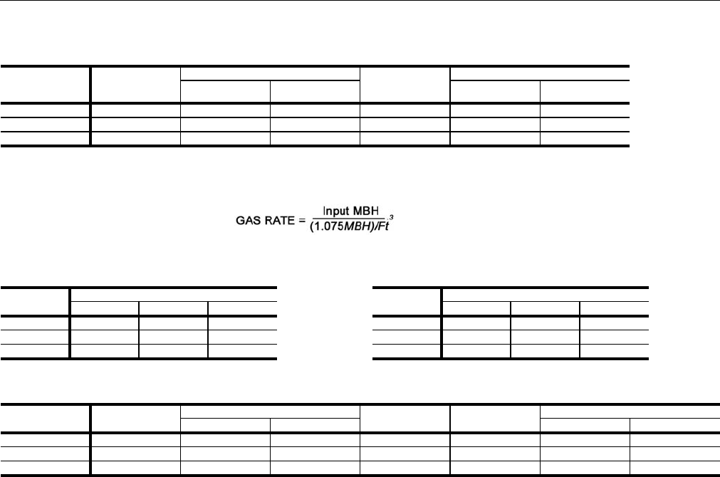
GAS RATE, CU. FT./HR.3
3. Based on a heat content of 1075 Btu/Ft.3
1ST STAGE TOTAL 1ST STAGE TOTAL
N3 Z42/Z33/Z34 267 267 213 247 247
N5 Z42/Z33/Z34 267 533 426 247 495
N8 Z34 ONLY 2674
4. Unit Control Board with 3 heating outputs only. For all other Unit Control Boards the 1st Stage is 533 MBH.
800 638 247 742
TABLE 4: TEMPERATURE RISE
TON MODULES
123
25 5-35 25-55 -
30 5-35 20-50 -
40 5-30 10-45 25-55
TABLE 5: MINIMUM HEATING CFM
TON MODULES
123
25 5,644 7,183 -
30 5,644 7,901 -
40 6,584 8,779 13,169
TABLE 6: MODULATING GAS HEATING CAPACITIES
GAS HEAT OPTION AVAILABLE ON
MODELS
INPUT CAPACITY (MBH) STEPS OUTPUT CAPACITY
(MBH)1
1. Output Capacity at Full Fire.
GAS RATE, CU. FT./HR.
MINIMUM MAXIMUM MINIMUM MAXIMUM
D32
2. Modulating Gas Heat available on CV models only.
Z42/Z33/Z34 69 267 6 213 64 247
D52Z42/Z33/Z34 69 533 12 426 64 495
D82Z34 ONLY 69 800 17 638 64 744

246837-YTG-L-1012
Johnson Controls Unitary Products 13
TABLE 7: MODULATING HEAT
STAGES OF GAS CONTROL (% OF FULL HEAT OUTPUT)
GAS HEAT OPTION AVAILABLE ON MODELS STEP INPUT OUTPUT % OF TOTAL OUTPUT
D3
(Turn down ratio
3.8 to 1) Z42, Z33, Z34
1 69,333 55,466 26%
2 106,666 85,333 40%
3 165,332 132,266 62%
4 202,665 162,132 76%
5 229,332 183,466 86%
6 266,666 213,333 100%
D5
(Turn down ratio
7.7 to 1) Z42, Z33, Z34
1 69,333 55,466 13%
2 106,666 85,333 20%
3 165,332 132,266 31%
4 202,665 162,132 38%
5 229,332 183,466 43%
6 266,666 213,333 50%
7 325,331 260,265 61%
8 362,664 290,132 68%
9 389,331 311,465 73%
10 426,664 341,331 80%
11 495,997 396,798 93%
12 533,330 426,664 100%
D8
(Turn down ratio
11.5 to 1) Z34 Only
1 69,333 55,466 9%
2 106,666 85,333 13%
3 165,332 132,266 21%
4 202,665 162,132 25%
5 229,332 183,466 29%
6 266,666 213,333 33%
7 325,331 260,265 41%
8 362,664 290,132 45%
9 389,331 311,465 49%
10 426,664 341,331 53%
11 495,997 396,798 62%
12 533,330 426,664 67%
13 586,663 469,330 73%
14 655,996 524,797 82%
15 693,329 554,663 87%
16 762,662 610,130 95%
17 799,995 639,996 100%
TABLE 8: ELECTRIC HEATING CAPACITIES
ELECTRIC
HEAT OPTION
AVAILABLE ON
MODELS
RATED
VOLTAGE NOMINAL KW NOMINAL
MBH1
MBH AND KW PER STAGE2
STAGE 1STAGE 2
KW MBH KW MBH
E4 Z42, Z33, Z34 2403/4804/
575 40 137 40 137 0 0
E8 Z42, Z33, Z34 2402/4803/
575 80 273 40 137 40 137
E1 Z42, Z33, Z34
(460 & 575
volt only) 4803/575 108 369 72 246 36 123
1. Supply air fan motor heat not included.
2. Heating capacity is only staged on CV models. VAV models use only one stage at full capacity.
3. For 208 volts, multiply kW and MBH values by .751. For 230 volts, multiply kW and MBH values by .918
4. For 460 volts, multiply kW and MBH values by .918.
246837-YTG-L-1012
14 Johnson Controls Unitary Products
HOT WATER HEATING1
The YORK Millennium Rooftop units (30 - 40 Ton sizes) can
be furnished with a YORK hot water coil as the source of heat
(Bottom Supply Only). A one or two row coil will be factory
installed in the heating section downstream of the supply air
fan and just above the supply air opening in the bottom of the
unit.
The hot water control valve will not be provided. The installer
will need to field supply a water valve. The installer must also
connect the hot water piping, and valve wiring at the job site
for the hot water heat section to be operational.
For all hot water coils the entering water temperature should
not exceed 200°F.
PHYSICAL DATA HOT WATER COIL - 1 ROW
Coil Casing . . . . . . . . . . . . . . . . . . . .Galvanized Steel
Coil Construction. . . . . . . . . . . . . . . . Al Fin / Cu. Tube
Rows Deep . . . . . . . . . . . . . . . . . . . . . . . . . . . . . . . . 1
Fin Thickness . . . . . . . . . . . . . . . . . . . . . . . . . . . .006”
Tube Wall . . . . . . . . . . . . . . . . . . . . . . . . . . . . . . .016”
Tubes / Circuit . . . . . . . . . . . . . . . . . . . . . . . . . . . . . . 2
Fins Per Inch. . . . . . . . . . . . . . . . . . . . . . . . . . . . . . . 8
Tubes High . . . . . . . . . . . . . . . . . . . . . . . . . . . . 22.50”
Tube Length . . . . . . . . . . . . . . . . . . . . . . . . . . . . . . 65”
Face Area . . . . . . . . . . . . . . . . . . . . . . . . . . . .10.16ft.2
Weight. . . . . . . . . . . . . . . . . . . . . . . . . . . . . . . . .71lbs.
Operating Weight . . . . . . . . . . . . . . . . . . . . . . . .83lbs.
NOTE: Water pressure drop numbers are based on 60°F
entering air temperature, 2.00” maximum air pres-
sure drop across the hot water coil(s). AHRI certified
ratings at other conditions are available upon
request. Hot water coils are approved for use with
glycol (rates available upon request).
PIPING CONNECTIONS
The hot water piping must enter the unit through the floor of
the heat section compartment. The access doors to the com-
partment are gasketed so the compartment can be sealed.
However, as added protection for water leakage into the
space, the piping access holes should be sealed with a heat
resistant mastic (see the following illustration for approximate
location of the compartment and piping connections.
1. Hot water, steam or electric heat is not available for
front or rear supply.
TABLE 9: WATER PRESSURE DROP (1 ROW, 25 &
30 TON)
GPM 10 20 30 40
WATER PRESSURE DROP 0.9 3.0 6.0 10.0
TABLE 10: STATIC RESISTANCE HOT WATER COIL
(25 & 30 TON)
CFM 6000 8000 10000 15000
AIR PRESSURE DROP 1 ROW 0.07 0.11 0.16 0.32
AIR PRESSURE DROP 2 ROW 0.14 0.23 0.33 0.65
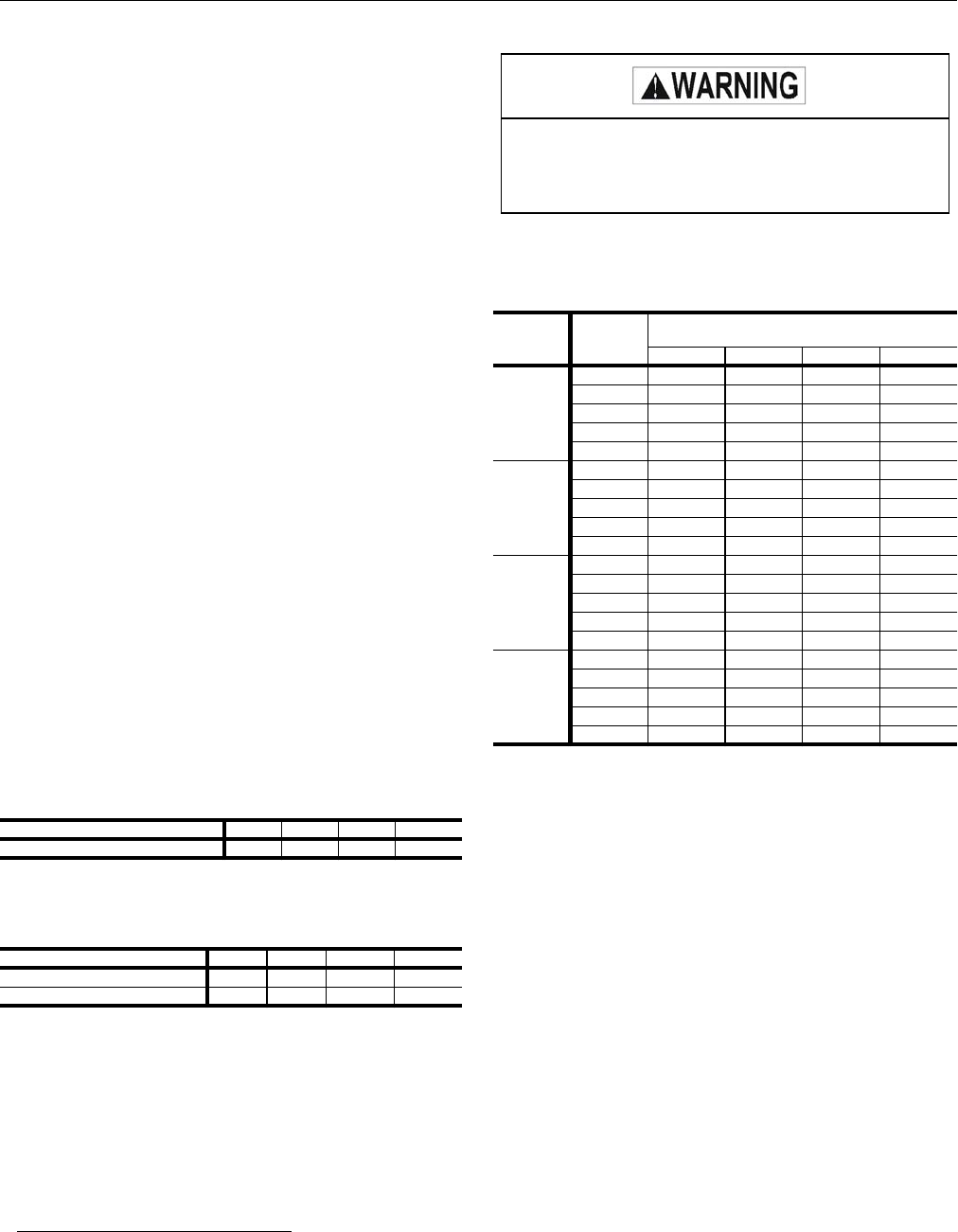
DO NOT use tin based solder. Brazing with tin
based solder could cause equipment damage or
possible injury to OCCUPANTS of the structure
that is being conditioned.
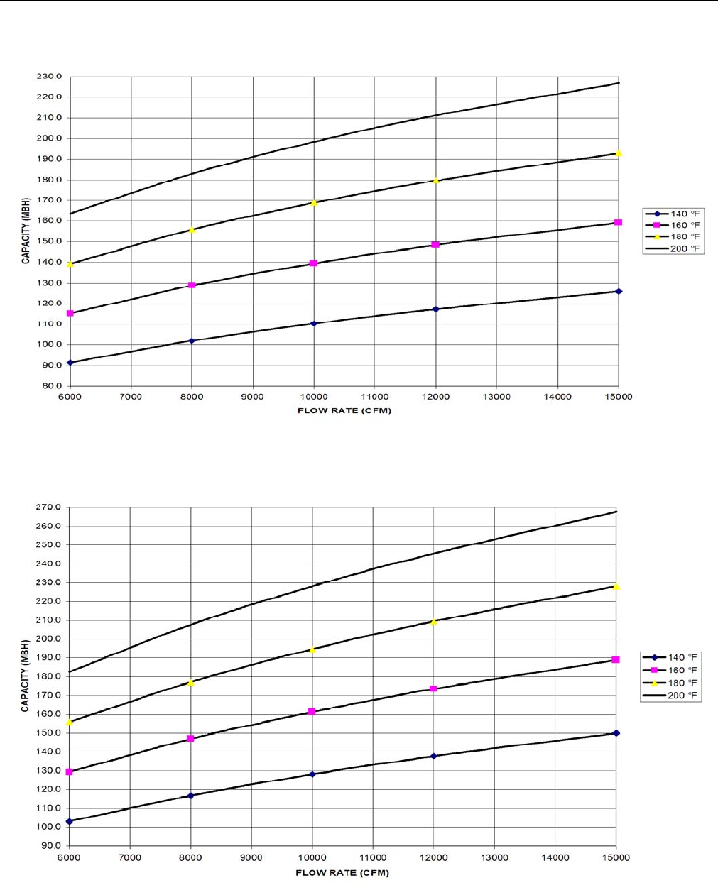
TABLE 11: HOT WATER COIL (1 ROW, 25 & 30
TON)1
1. Based on 60°F entering air temperature, 2.00” maximum pres-
sure drop across the hot water coil.
GPM CFM CAPACITY (MBH) AT ENTERING WATER
TEMPERATURE
140 °F 160 °F 180 °F 200 °F
10
6000 91.4 115.3 139.3 163.6
8000 102 128.8 155.8 182.9
10000 110.4 139.5 168.8 198.4
12000 117.3 148.4 179.6 211.2
15000 125.9 159.2 192.9 226.9
20
6000 103 129.4 156 182.7
8000 116.8 147 177.2 207.7
10000 128.2 161.3 194.7 228.2
12000 137.8 173.6 209.5 245.6
15000 150 189 228.2 267.8
30
6000 107.6 135 162.5 190.1
8000 122.8 154.3 185.8 217.5
10000 135.5 170.3 205.1 240.2
12000 146.4 184 221.8 259.7
15000 160.3 201.6 243 284.8
40
6000 110.1 138 166 194.1
8000 126.1 158.2 190.5 222.8
10000 139.6 175.2 210.9 246.8
12000 151.2 189.8 228.5 267.5
15000 166.1 208.6 251.3 294.1
246837-YTG-L-1012
Johnson Controls Unitary Products 15
FIGURE 1 - HOT WATER PIPING CROSS-
SECTION
TABLE 12: STATIC RESISTANCE HOT WATER COIL
(1 ROW, 40 TON)
CFM 8000 11000 14000 20000
AIR PRESSURE DROP 1 ROW 0.11 0.19 0.29 0.52
AIR PRESSURE DROP 2 ROW 0.23 0.39 0.58 1.06
HOT WATER
COIL
CONDENSING
SECTION
INLET (2")
OUTLET (2")
C
L
2.55"
8.38"
2.25"
11.88"
26"
15.8"
88.75"
HEAT SECTION
COMPARTMENT
(1 OR 2 ROW)
OUTSIDE OF
BASE RAIL
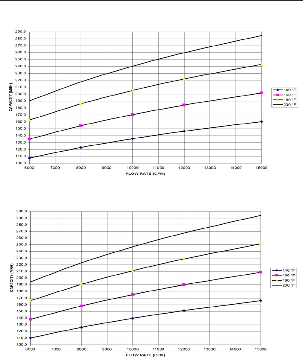
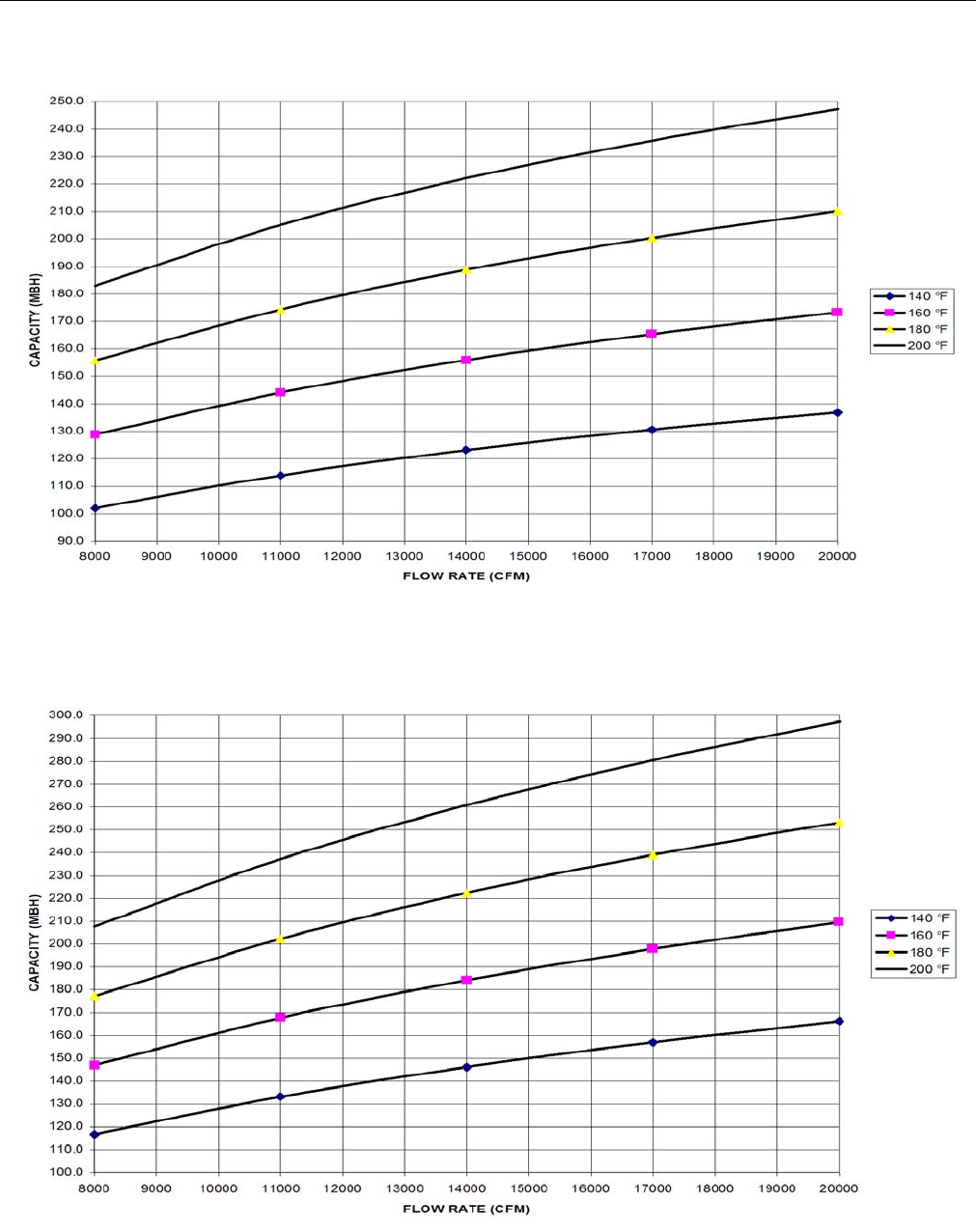
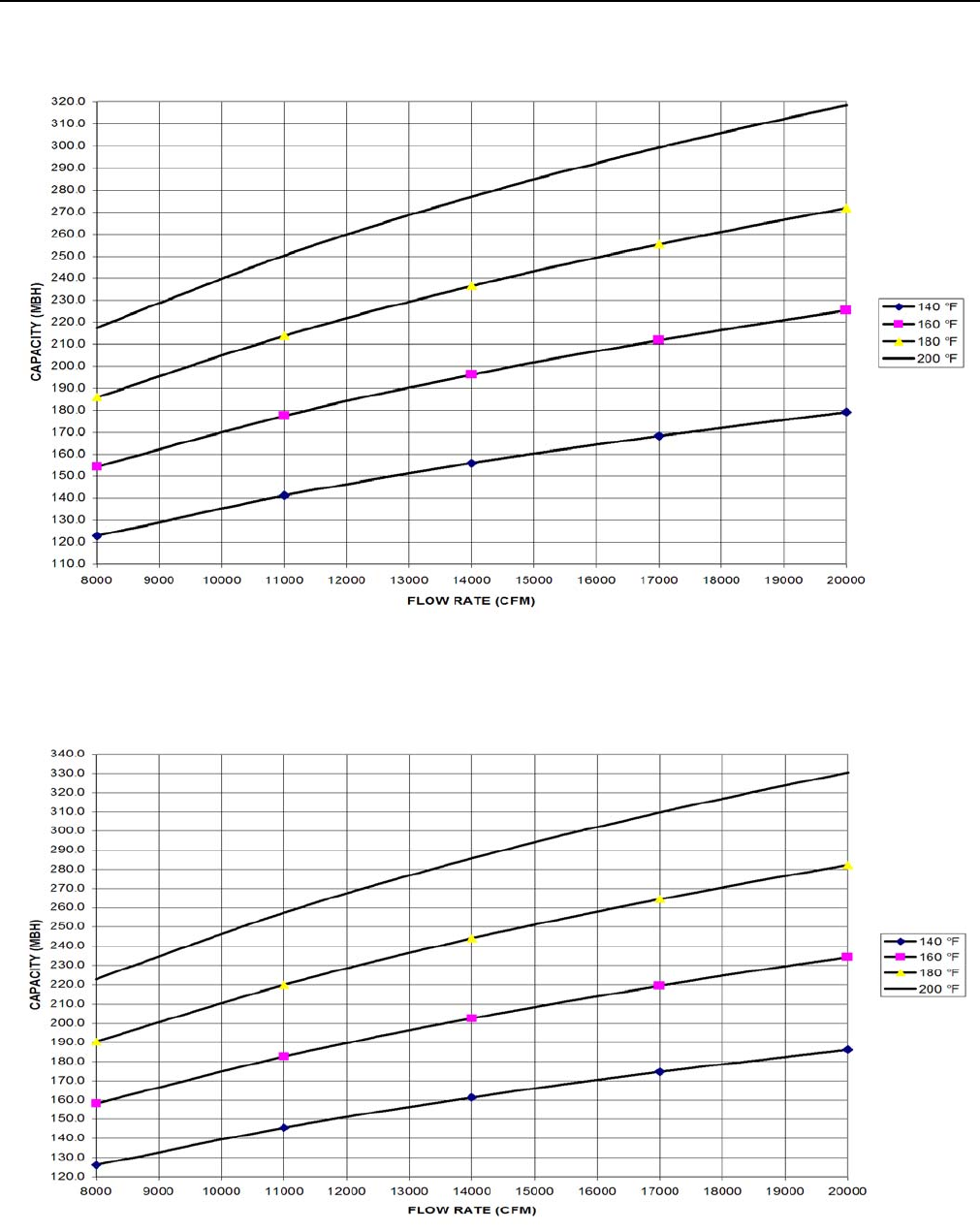
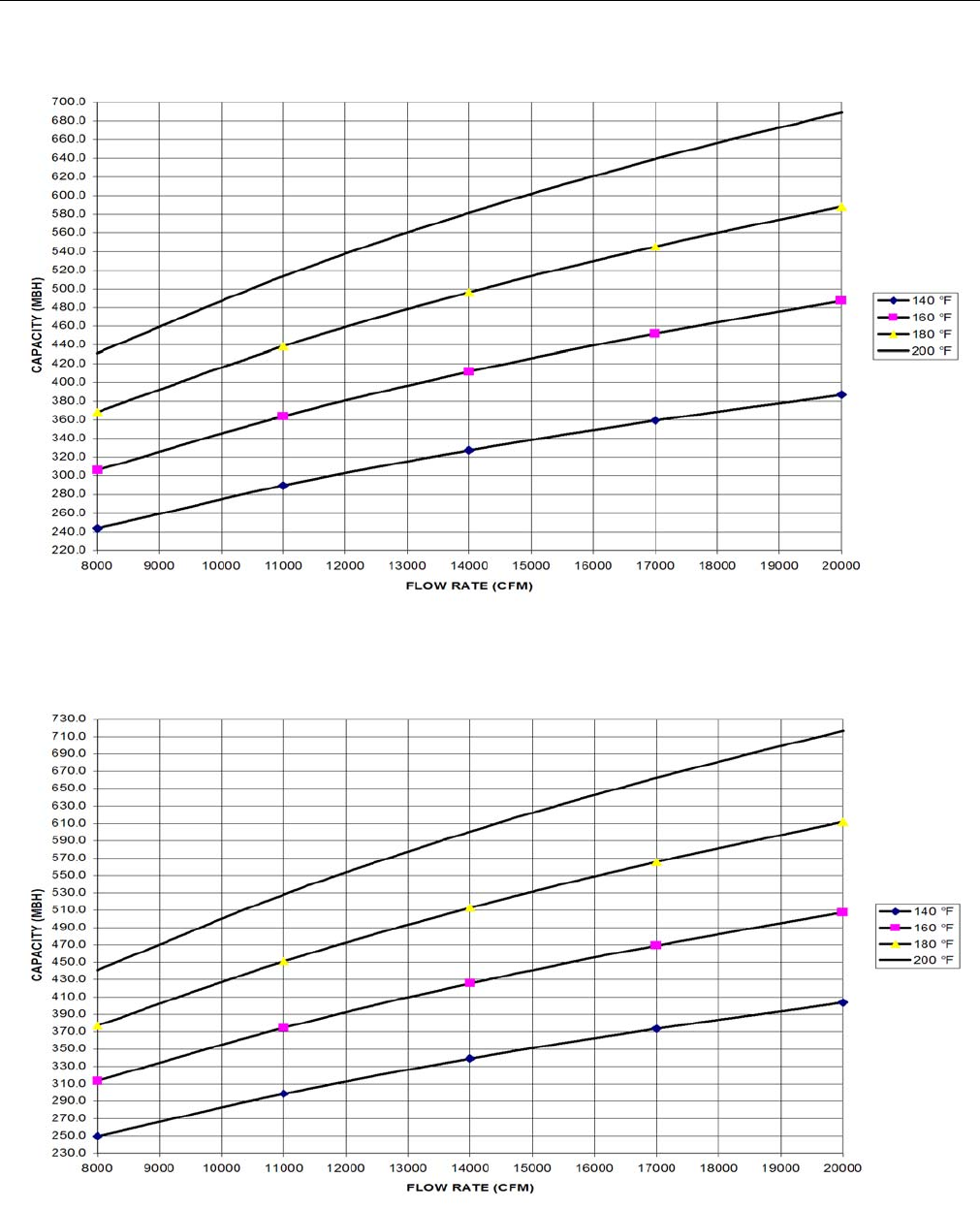
TABLE 13: HOT WATER COIL (1 ROW 40 TON)1
GPM CFM CAPACITY (MBH) AT ENTERING WATER
TEMPERATURE
140 °F 160 °F 180 °F 200 °F
10
8000 102 128.8 155.8 182.9
11000 114 144.1 174.4 205.1
14000 123.2 155.9 188.8 222.1
17000 130.6 165.4 200.4 235.8
20000 136.8 173.3 210.1 247.3
20
8000 116.8 147 177.2 207.7
11000 133.2 167.7 202.3 237.2
14000 146.2 184.2 222.4 260.8
17000 157 197.9 239 280.5
20000 166.2 209.6 253.2 297.3
30
8000 122.8 154.3 185.8 217.5
11000 141.2 177.4 213.8 250.3
14000 155.9 196.1 236.4 276.9
17000 168.3 211.8 255.4 299.3
20000 179.1 225.3 271.8 318.6
40
8000 126.1 158.2 190.5 222.8
11000 145.6 182.7 220 257.5
14000 161.4 202.6 244.1 285.8
17000 174.7 219.5 264.5 309.7
20000 186.3 234.2 282.3 330.6
1. Based on 60°F entering air temperature, 2.00” maximum pres-
sure drop across the hot water coil.
246837-YTG-L-1012
16 Johnson Controls Unitary Products
FIGURE 2 - HOT WATER COIL - 25 & 30 TON, 1 ROW, AT 10 GPM
FIGURE 3 - HOT WATER COIL - 25 & 30 TON, 1 ROW, AT 20 GPM
246837-YTG-L-1012
Johnson Controls Unitary Products 17
FIGURE 4 - HOT WATER COIL - 25 & 30 TON, 1 ROW, AT 30 GPM
FIGURE 5 - HOT WATER COIL - 25 & 30 TON, 1 ROW, AT 40 GPM
246837-YTG-L-1012
18 Johnson Controls Unitary Products
FIGURE 6 - HOT WATER COIL - 40 TON, 1 ROW, AT 10 GPM
FIGURE 7 - HOT WATER COIL - 40 TON, 1 ROW, AT 20 GPM
246837-YTG-L-1012
Johnson Controls Unitary Products 19
FIGURE 8 - HOT WATER COIL - 40 TON, 1 ROW, AT 30 GPM
FIGURE 9 - HOT WATER COIL - 40 TON, 1 ROW, AT 40 GPM
246837-YTG-L-1012
20 Johnson Controls Unitary Products
PHYSICAL DATA HOT WATER COIL - 2 ROW
Coil Casing . . . . . . . . . . . . . . . . . . . .Galvanized Steel
Coil Construction. . . . . . . . . . . . . . . . Al Fin / Cu. Tube
Rows Deep . . . . . . . . . . . . . . . . . . . . . . . . . . . . . . . . 2
Fin Thickness . . . . . . . . . . . . . . . . . . . . . . . . . . . .006”
Tube Wall . . . . . . . . . . . . . . . . . . . . . . . . . . . . . . .016”
Tubes / Circuit . . . . . . . . . . . . . . . . . . . . . . . . . . . . . 2
Fins Per Inch. . . . . . . . . . . . . . . . . . . . . . . . . . . . . . . 8
Tubes High . . . . . . . . . . . . . . . . . . . . . . . . . . . . 22.50”
Tube Length . . . . . . . . . . . . . . . . . . . . . . . . . . . . . . 65”
Face Area . . . . . . . . . . . . . . . . . . . . . . . . . . . 10.16 ft.2
Weight. . . . . . . . . . . . . . . . . . . . . . . . . . . . . . . . .90 lbs
Operating Weight . . . . . . . . . . . . . . . . . . . . . . .110 lbs
NOTE: Water pressure drop numbers are based on 60°F
entering air temperature, 2.00” maximum air pres-
sure drop across the hot water coil(s). AHRI certified
ratings at other conditions are available upon
request. Hot water coils are approved for use with
glycol (rates available upon request.)
1. Based on 60°F entering air temperature, 2.00” maximum pres-
sure drop across the hot water coil.
TABLE 14: WATER PRESSURE DROP (2 ROW, 25 &
30 TON)
GPM 20 40 60 80
WATER
PRESSURE
DROP
0.9 3.0 6.0 10.0
TABLE 15: STATIC RESISTANCE HOT WATER COIL
(25 & 30 TON)
CFM 6000 8000 10000 15000
AIR PRESSURE DROP
1 ROW 0.07 0.11 0.16 0.32
AIR PRESSURE DROP
2 ROW 0.14 0.23 0.33 0.65
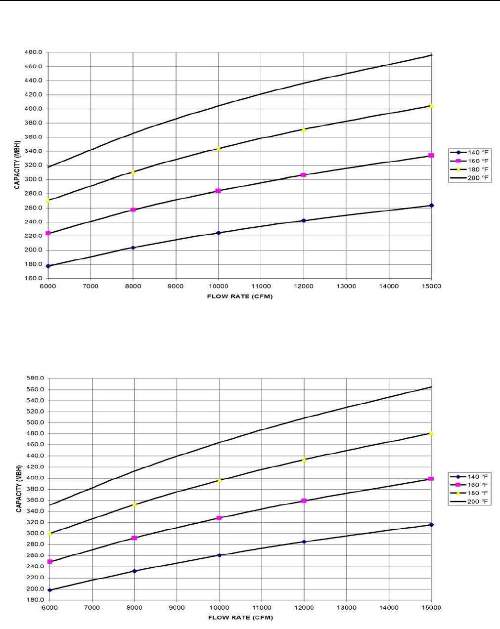
TABLE 16: HOT WATER COIL (2 ROW, 25 & 30
TON)1
GPM CFM CAPACITY (MBH) AT ENTERING WATER TEMPERATURE
140 °F 160 °F 180 °F 200 °F
20
6000 177.5 223.8 270.4 317.3
8000 203.8 257.2 311.1 365.5
10000 224.8 284.1 343.9 404.2
12000 242.2 306.4 371.1 436.4
15000 263.6 333.8 404.6 476.1
40
6000 198.1 248.9 300.0 351.3
8000 232.2 292.0 352.2 412.7
10000 260.7 328.1 395.9 464.1
12000 285.0 359.0 433.4 508.3
15000 316.0 398.4 481.3 564.8
60
6000 206.1 258.7 311.4 364.2
8000 243.6 305.9 368.4 431.1
10000 275.3 345.9 416.8 488.0
12000 302.9 380.7 458.9 537.6
15000 338.4 425.7 513.4 601.7
80
6000 210.5 263.9 317.4 371.1
8000 249.8 313.3 377.1 441.1
10000 283.3 355.6 428.2 501.0
12000 312.7 392.7 473.0 553.6
15000 351.0 440.9 531.3 622.1
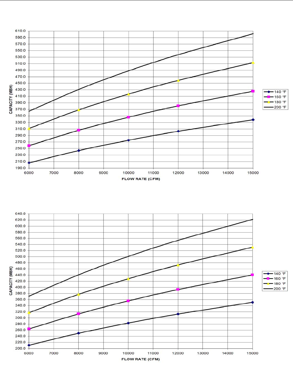
TABLE 17: HOT WATER COIL (2 ROWS, 40 TON)1
1. Based on 60°F entering air temperature, 2.00” maximum air
pressure drop across the hot water coil.
AHRI certified ratings at other conditions available upon
request.
Hot water coils are approved for use with glycol (ratings avail-
able upon request).
GPM CFM CAPACITY (MBH) AT ENTERING WATER
TEMPERATURE
140 °F 160 °F 180 °F 200 °F
20
8000 203.8 257.2 311.1 365.5
11000 233.9 295.7 358.1 421.0
14000 257.0 325.3 394.2 463.8
17000 275.5 349.0 423.3 498.3
20000 290.9 368.7 447.4 526.9
40
8000 232.2 292.0 352.2 412.7
11000 273.3 344.1 415.3 487.0
14000 306.3 386.0 466.3 547.1
17000 333.9 421.1 508.9 597.3
20000 357.5 451.1 545.4 640.5
60
8000 243.6 305.9 368.4 431.1
11000 289.5 363.9 438.5 513.6
14000 327.2 411.5 496.3 581.5
17000 359.2 452.0 545.3 639.2
20000 386.9 487.1 587.9 689.4
80
8000 249.8 313.3 377.1 441.1
11000 298.5 374.7 451.2 528.1
14000 338.9 425.7 512.8 600.5
17000 373.4 469.3 565.6 662.5
20000 403.6 507.5 611.8 716.8
TABLE 18: STATIC RESISTANCE HOT WATER
COIL (40 TON)
CFM 8000 11000 14000 20000
AIR PRESSURE DROP 1 ROW 0.11 0.19 0.29 0.52
AIR PRESSURE DROP 2 ROW 0.23 0.39 0.58 1.06
TABLE 19: WATER PRESSURE DROP (2 ROW, 40
TON)
GPM 20 40 60 80
WATER PRESSURE DROP 0.9 3.0 6.0 10.0
TABLE 16: HOT WATER COIL (2 ROW, 25 & 30
TON)1(CONT.)
GPM CFM CAPACITY (MBH) AT ENTERING WATER TEMPERATURE
140 °F 160 °F 180 °F 200 °F
246837-YTG-L-1012
Johnson Controls Unitary Products 21
FIGURE 10 - HOT WATER COIL - 25 & 30 TON, 2 ROW, AT 20 GPM
FIGURE 11 - HOT WATER COIL - 25 & 30 TON, 2 ROW, AT 40 GPM
246837-YTG-L-1012
22 Johnson Controls Unitary Products
FIGURE 12 - HOT WATER COIL - 25 & 30 TON, 2 ROW, AT 60 GPM
FIGURE 13 - HOT WATER COIL - 25 & 30 TON, 2 ROW, AT 80 GPM

246837-YTG-L-1012
Johnson Controls Unitary Products 23
FIGURE 14 - HOT WATER COIL - 40 TON, 2 ROW, AT 20 GPM
FIGURE 15 - HOT WATER COIL - 40 TON, 2 ROW, AT 40 GPM
246837-YTG-L-1012
24 Johnson Controls Unitary Products
FIGURE 16 - HOT WATER COIL - 40 TON, 2 ROW, AT 60 GPM
FIGURE 17 - HOT WATER COIL - 40 TON, 2 ROW, AT 80 GPM
246837-YTG-L-1012
Johnson Controls Unitary Products 25
STEAM HEATING
The YORK Millennium units (25, 30, and 40 ton sizes) can be
manufactured with a steam heat coil (Bottom Supply only).
YORK's one row steam coil is installed in the heating section
just downstream of the supply air fan and just above the sup-
ply air opening in the bottom of the unit.
The steam control valve will not be provided. The installer will
need to field supply a steam control valve. Connect the steam
piping and valve power wiring at the job site for the steam
heat section to be operational.
There are no provisions in the coil or control sequence to pre-
vent freezing of condensate. The control valve, piping and
field installed wiring connections are particularly vulnerable
because they are installed in the vestibule outside of the con-
ditioned air stream.
All piping, control valves, and wiring that is field installed must
conform to all local and national codes
Condensate can freeze on the control valve and piping if they
are not properly insulated.
PHYSICAL DATA STEAM COIL - 1 ROW
Coil Casing . . . . . . . . . . . . . . . . . . . . Galvanized Steel
Coil Construction . . . . . . . . . . . . . . . Al Fin / Cu. Tube
Rows Deep . . . . . . . . . . . . . . . . . . . . . . . . . . . . . . . . .1
Fin Thickness . . . . . . . . . . . . . . . . . . . . . . . . . . . .010”
Tube Wall . . . . . . . . . . . . . . . . . . . . . . . . . . . . . . .035”
Tubes / Circuit. . . . . . . . . . . . . . . . . . . . . . . . . . . . . . .2
Fins Per Inch. . . . . . . . . . . . . . . . . . . . . . . . . . . . . . . .6
Tubes High . . . . . . . . . . . . . . . . . . . . . . . . . . . . . . . 21”
Tube Length . . . . . . . . . . . . . . . . . . . . . . . . . . . . . . 65”
Face Area . . . . . . . . . . . . . . . . . . . . . . . . . . . . 9.48 ft.2
Weight. . . . . . . . . . . . . . . . . . . . . . . . . . . . . . . . 92 lbs.
*Hot water, steam coil or electric heat not available for front or
rear supply.
PIPING CONNECTIONS
The steam piping must enter the unit through the floor of the
heat section compartment. The access doors to the compart-
ment are gasketed to the compartment can be sealed. How-
ever, as added protection for condensate leakage into the
space, the piping access holes should be sealed with a heat
resistant mastic. The following figure illustrates the approxi-
mate location of the compartment and piping connections.
FIGURE 18 - STEAM PIPING CROSS SECTION
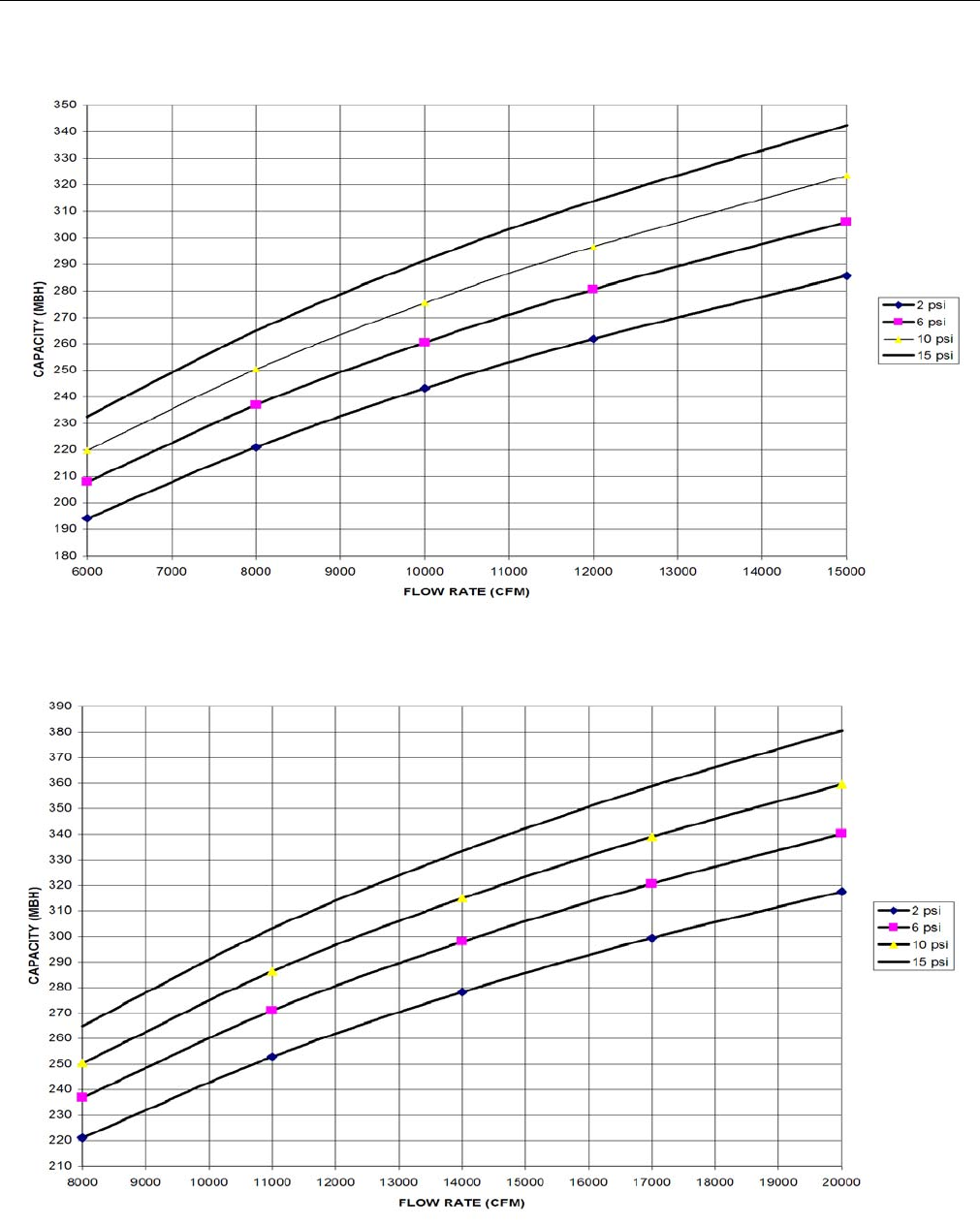
TABLE 20: STEAM COIL (1 ROW, 25 & 30 TON)1
1. Based on 60°F entering air temperature, 2.00” maximum air
pressure drop across the coil.
CFM CAPACITY (MBH) AT STEAM PRESSURE (PSI)
2 6 10 15
6000 194.1 207.9 219.8 232.6
8000 221.1 236.9 250.4 265.0
10000 243.2 260.5 275.4 291.4
12000 261.9 280.6 296.6 313.9
15000 285.6 306.0 323.5 342.4
TABLE 21: STATIC RESISTANCE STEAM COIL
(1 ROW, 25 & 30 TON)
CFM 6000 8000 10000 12000 15000
AIR PRESSURE DROP 0.11 0.18 0.26 0.36 0.54
TABLE 22: STEAM COIL (1 ROW, 40 TON)1
1. Based on 60°F entering air temperature, 2.00” maximum air
pressure drop across the coil.
CFM CAPACITY (MBH) AT STEAM PRESSURE (PSI)
2 6 10 15
8000 221.1 236.9 250.4 265.0
11000 252.9 271.0 286.4 303.1
14000 278.2 298.0 315.0 333.4
17000 299.4 320.7 339.0 358.8
20000 317.6 340.2 359.6 380.6
TABLE 23: STATIC RESISTANCE STEAM COIL
(1 ROW, 40 TON)
CFM 8000 11000 14000 17000 20000
AIR PRESSURE DROP 0.18 0.31 0.48 0.67 0.88
DO NOT use tin based solder. Brazing with tin
based solder could cause equipment damage or
possible injury to OCCUPANTS of the structure that
is being conditioned.
STEAM
C O I L
C O N D E N S I N G
S E C T I O N
O U T L E T ( 1 1 / 2 " )
C
L
2 . 5 5 "
8 . 3 8 "
26"
1 5 . 8 "
I N L E T ( 2 " )
8 "
9 "
H E A T S E C T I O N
C O M P A R T M E N T
8 8 . 7 5 "
T O P V I E W
O U T S I D E O F
B A S E R A I L
246837-YTG-L-1012
26 Johnson Controls Unitary Products
FIGURE 19 - STEAM COIL - 25 & 30 TON, 1 ROW
FIGURE 20 - STEAM COIL - 40 TON, 1 ROW
246837-YTG-L-1012
Johnson Controls Unitary Products 27
TABLE 24: EXHAUST FAN DRIVE DATA
Model Blower
RPM
Range
Motor Motor Pulley Blower Pulley Belts
HP Frame
Size
Motor Eff
(Std.
Motor)
Motor
Eff (Hi
Eff opt)
Pitch Dia
(Inches) Bore
(Inches) Pitch Dia
(Inches) Bore
(Inches) Designation Qty
25
Ton
758 5 213T 87.5 89.5 4.9 1-3/8 11.3 2-3/16 BX63 2
852 7.5 215T 88.5 91.7 5.5 1-3/8 11.3 2-3/16 BX63 2
976 10 215T 89.5 91 6.3 1-5/8 11.3 2-3/16 BX63 2
30
Ton
852 7.5 213T 84 86.5 5.5 1-3/8 11.3 1-11/16 B65 2
976 10 215T 86.5 89.5 6.3 1-3/8 11.3 1-11/16 B65 2
1069 15 254T 85.7 89.5 6.9 1-3/8 11.3 1-11/16 B65 2
40
Ton
852 7.5 184T 84 86.5 5.5 1-3/8 11.3 1-11/16 B65 2
976 10 215T 86.5 89.5 6.3 1-3/8 11.3 1-11/16 B65 2
1069 15 254T 85.7 89.5 6.9 1-3/8 11.3 1-11/16 B65 2
TABLE 25: SUPPLY FAN MOTOR AND DRIVE DATA
Model Blower
RPM
Range
Motor Motor Pulley Blower Pulley Belts
HP Frame
Size
Motor
Efficiency
(Std. Motor)
Motor
Efficiency
(Ultra Hi
Eff Opt)
Pitch Dia
(Inches) Bore
(Inches) Pitch Dia
(Inches) Bore
(Inches) Designation Qty
25 Ton
567 7.5 213T 88.5 91.7 4.5 1-3/8 13.9 2-3/16 BX56 2
692 10 215T 89.5 91 5.5 1-3/8 13.9 2-3/16 BX56 2
793 15 254T 91 91.7 6.3 1-5/8 13.9 2-3/16 BX56 2
894 20 256T 91 93 7.1 1-5/8 13.9 2-3/16 BX56 2
30 Ton
617 10 215T 89.5 91 4.9 1-3/8 13.9 2-3/16 BX56 2
743 15 254T 91 91.7 5.9 1-5/8 13.9 2-3/16 BX56 2
856 20 256T 91 93 6.7 1-5/8 13.7 2-3/16 5VX610 2
907 25 284T 91.7 93.6 7.1 1-7/8 13.7 2-3/16 5VX610 2
40 Ton
617 10 215T 89.5 91 4.9 1-3/8 13.9 2-7/16 BX67 2
652 15 254T 91 91.7 5.1 1-5/8 13.7 2-7/16 5VX710 2
728 20 256T 91 93 5.7 1-5/8 13.7 2-7/16 5VX710 2
780 25 284T 91.7 93.6 6.1 1-7/8 13.7 2-7/16 5VX710 2
246837-YTG-L-1012
28 Johnson Controls Unitary Products
SUPPLY AIR DRIVE ADJUSTMENT
At unit start-up, the measured CFM may be higher or lower
than the specified CFM shown in Figures 22, 23, and 24. To
achieve the specified CFM, the speed of the drive may have
to be decreased or increased by changing the pitch diameter
(PD) of the motor sheave as outlined below:
Example:
A 30-ton unit was selected to deliver 12,000 CFM with a 20
HP motor and a 856 RPM drive, but the unit is only delivering
11,000 CFM per Figure 23.
Use the equation to determine the required PD for the new
motor sheave (12,000 CFM / 11,000 CFM) x 6.7” = 7.31”.
Use the 30 ton table to select a Browning 2B5V74 which will
increase the speed of the unit’s drive and its supply air CFM
to 111.9%. Thus select the 7.5” PD at 112% increase over
standard.
New drive speed = 1.119 x 856 = 957.9 RPM
New supply air = 1.119 x 11,000 = 12,309 CFM
Re-use the existing belts and blower sheave.
New motor BHP = (speed increase)3 x estimated motor
BHP at original start-up with 11,000 CFM and 856 RPM =
(1.119)3 x 11 BHP = 1.4012 x 11 BHP = 15.41 BHP New
motor amps = (speed increase)3 x measured motor amps
at original start-up with 11,000 CFM and 856 RPM.
Failure to properly adjust the total system air quan-
tity can result in extensive blower damage.
Before making any blower speed changes review
the installation for any installation errors, leaks or
undesirable systems effects that can result in loss
of air flow.
Even small changes in blower speed can result in
substantial changes in static pressure and bhp.
Bhp or amp draw of the blower motor will increase
(see table) by the cube ratio of the blower speed.
Static pressure will increase by the square ratio of
the blower speed. Tables 26, 27 and 28 are for ref-
erence only. All blower speed changes must be
made by qualified personnel with strict adherence
to the fan laws.
246837-YTG-L-1012
Johnson Controls Unitary Products 29
TABLE 26: 25 TON DRIVE ADJUSTMENT
7.5 HP MOTOR & 567 RPM DRIVE 10 HP MOTOR & 692 RPM DRIVE 15 HP MOTOR & 793 RPM DRIVE 20 HP MOTOR & 894 RPM DRIVE
%RPM
& CFM REQ’D
PD BROWNING
2B5V_ _ %RPM
& CFM REQ’D
PD BROWNING
2B5V_ _ %RPM
& CFM REQ’D
PD BROWNING
2B5V_ _ %RPM
& CFM REQ’D
PD BROWNING
2B5V_ _
- - - 82 4.5 42 84 5.3 50 86 6.1 58
- - - 86 4.7 44 87 5.5 52 89 6.3 60
100 (Std.)4.5 42 89 4.9 46 90 5.7 54 91 6.5 62
104 4.7 44 93 5.1 48 94 5.9 56 94 6.7 64
109 4.9 46 96 5.3 50 97 6.1 58 97 6.9 66
113 5.1 48 100 (Std.)5.5 52 100 (Std)6.3 60 100 (Std.)7.1 68
118 5.3 50 104 5.7 54 103 6.5 62 103 7.3 70
122 5.5 52 107 5.9 56 106 6.7 64 108 7.7 74
126 5.7 54 111 6.1 58 110 6.9 66 117 8.3 80
- - - 115 6.3 60 113 7.1 68 125 8.9 86
- - - 118 6.5 62 116 7.3 70 - - -
- - - 122 6.7 64 122 7.7 74 - - -
TABLE 27: 30 TON DRIVE ADJUSTMENT
10 HP MOTOR & 617 RPM DRIVE 15 HP MOTOR & 743 RPM DRIVE 20 HP MOTOR & 856 RPM DRIVE 25 HP MOTOR & 907 RPM DRIVE
%RPM
& CFM REQ’D
PD BROWNING
2B5V_ _ %RPM
& CFM REQ’D
PD BROWNING
2B5V_ _ %RPM
& CFM REQ’D
PD BROWNING
2B5V_ _ %RPM
& CFM REQ’D
PD BROWNING
2B5V_ _
91.8 4.5 42 86.4 5.1 48 82.1 5.5 54 86.3 6.1 60
95.9 4.7 44 89.8 5.3 50 85.1 5.7 56 89.0 6.3 62
100.0 (Std.)
4.9 46 93.2 5.5 52 88.1 5.9 58 91.8 6.5 64
104.1 5.1 48 96.6 5.7 54 91.0 6.1 60 94.5 6.7 66
108.2 5.3 50 100.0 (Std.)
5.9 56 94.0 6.3 62 97.3 6.9 68
112.2 5.5 52 103.4 6.1 58 97.0 6.5 64 100.0 (Std.)
7.1 70
116.3 5.7 54 106.8 6.3 60 100.0 (Std.)
6.7 66 105.5 7.5 74
120.4 5.9 56 110.2 6.5 62 103.0 6.9 68 113.7 8.1 80
124.5 6.1 58 113.6 6.7 64 106.0 7.1 70 121.9 8.7 86
- - - 116.9 6.9 66 112.0 7.5 74 - - -
- - - 120.3 7.1 68 120.9 8.1 80 - - -
- - - 123.7 7.3 70 129.9 8.7 86 - - -
TABLE 28: 40 TON DRIVE ADJUSTMENT
10 HP MOTOR & 617 RPM DRIVE 15 HP MOTOR & 652 RPM DRIVE 20 HP MOTOR & 728 RPM DRIVE 25 HP MOTOR & 780 RPM DRIVE
%RPM
& CFM REQ’D
PD BROWNING
2B5V_ _ % RPM
& CFM REQ’D
PD BROWNING
2B5V_ _ %RPM
& CFM REQ’D
PD BROWNING
2B5V_ _ %RPM
& CFM REQ’D
PD BROWNING
2B5V_ _
91.8 4.5 42 88.2 4.5 44 82.5 4.7 46 83.7 5.1 50
95.9 4.7 44 92.1 4.7 46 86.0 4.9 48 86.9 5.3 52
100.0 (Std.)
4.9 46 96.0 4.9 48 89.5 5.1 50 90.2 5.5 54
104.1 5.1 48 100.0 (Std.)
5.1 50 93.0 5.3 52 93.4 5.7 56
108.2 5.3 50 103.9 5.3 52 96.5 5.5 54 96.7 5.9 58
112.2 5.5 52 107.8 5.5 54 100.0 (Std.)
5.7 56 100.0 (Std.)
6.1 60
116.3 5.7 54 111.7 5.7 56 103.5 5.9 58 103.3 6.3 62
- - - 115.6 5.9 58 107.0 6.1 60 106.6 6.5 64
- - - 119.5 6.1 60 110.5 6.3 62 109.8 6.7 66
- - - 123.4 6.3 62 114.0 6.5 64 113.1 6.9 68
- - - 127.4 6.5 64 117.5 6.7 66 116.4 7.1 70
- - - - - 66 121.1 6.9 68 119.7 7.5 74
246837-YTG-L-1012
30 Johnson Controls Unitary Products
TABLE 29: DRIVE ADJUSTMENT FOR POWER EXHAUST - 25 TON
5 HP Motor & 758 RPM Drive 7.5 HP Motor & 852 RPM Drive 10 HP Motor & 976 RPM Drive
%RPM
& CFM Req’d
PD Browning
2b5v_ _ %RPM
& CFM Req’d
PD Browning
2b5v_ _ %RPM
& CFM Req’d PD Browning
2b5v_ _
100 4.9 (Std.) 46 92 5.1 48 93 5.9 56
104 5.1 48 96 5.3 50 97 6.1 58
109 5.3 50 100 5.5 (Std.) 52 100 6.3 (Std.) 60
113 5.5 52 104 5.7 54 103 6.5 62
117 5.7 54 108 5.9 56 107 6.7 64
122 5.9 56 112 6.1 58 110 6.9 66
TABLE 30: DRIVE ADJUSTMENT FOR POWER EXHAUST - 30 & 40 TON
7.5 HP MOTOR & 852 RPM DRIVE 10 HP MOTOR & 976 RPM DRIVE 15 HP MOTOR & 1069 RPM DRIVE
% RPM
& CFM REQ’D
PD (IN)BROWNING
2B5V_ _ % RPM
& CFM REQ’D
PD (IN)BROWNING
2B5V_ _ % RPM
& CFM REQ’D
PD (IN)BROWNING
2B5V_ _
96.4 5.3 52 93.7 5.9 58 94.2 6.5 64
100.0 (Std.) 5.5 54 96.8 6.1 60 97.1 6.7 66
103.6 5.7 56 100.0 (Std.) 6.3 62 100.0 (Std.) 6.9 68
107.3 5.9 58 103.2 6.5 64 102.9 7.1 70
110.9 6.1 60 106.3 6.7 66 108.7 7.5 74
114.5 6.3 62 109.5 6.9 68 117.4 8.1 80
246837-YTG-L-1012
Johnson Controls Unitary Products 31
TABLE 31: COOLING PERFORMANCE - 25 TON R-410A
Air on Evaporator
Coil
Temperature of Air on Condenser Coil
75°F 85°F
CFM WB
(°F)
Total
Cap.1
(MBH)
Total2
Input
(kW)
Sensible Capacity (MBH)*
Return Dry Bulb (°F) Total
Cap.1
(MBH)
Total2
Input
(kW)
Sensible Capacity (MBH)*
Return Dry Bulb (°F)
86 83 80 77 74 71 68 86 83 80 77 74 71 68
7500
72 365.8 21.0 202.1 183.9 165.7 147.5 129.3 - - 352.2 23.2 192.9 174.9 156.9 138.9 120.9 - -
67 342.4 20.5 248.8 230.6 212.4 194.2 176.1 157.9 139.7 325.5 22.9 239.4 221.5 203.5 185.5 167.5 149.5 131.5
62 311.7 20.4 302.2 284.0 265.8 247.6 229.4 211.2 193.0 299.6 22.4 286.0 268.0 250.0 232.0 214.0 196.0 178.0
57 300.0 19.7 300.0 299.5 281.3 263.1 244.9 226.7 208.6 289.8 22.0 289.8 284.4 266.5 248.5 230.5 212.5 194.5
8750
72 376.3 21.2 214.5 193.8 173.1 152.4 131.7 - - 357.7 23.5 205.1 184.6 164.2 143.7 123.2 - -
67 352.0 20.7 263.3 242.6 221.9 201.2 180.5 159.8 139.1 330.6 23.2 253.8 233.3 212.8 192.4 171.9 151.5 131.0
62 320.6 20.6 315.9 298.4 277.7 257.0 236.3 215.6 194.9 304.3 22.6 297.5 282.0 261.6 241.1 220.6 200.2 179.7
57 308.6 19.9 308.6 308.4 293.9 273.2 252.5 231.8 211.1 294.3 22.2 294.3 291.6 278.8 258.3 237.8 217.4 196.9
10000
72 386.7 21.4 226.9 203.7 180.5 157.3 134.1 - - 363.2 23.7 217.3 194.3 171.4 148.5 125.6 - -
67 361.7 20.9 277.8 254.6 231.4 208.2 185.0 161.8 138.6 335.7 23.4 268.1 245.2 222.2 199.3 176.4 153.4 130.5
62 329.5 20.8 329.5 312.8 289.6 266.4 243.2 220.0 196.8 309.0 22.9 309.0 296.0 273.1 250.2 227.3 204.3 181.4
57 317.2 20.1 317.2 317.2 306.4 283.2 260.0 236.8 213.6 298.8 22.5 298.8 298.8 291.1 268.1 245.2 222.3 199.3
11250
72 400.1 21.5 248.4 223.6 198.7 173.9 149.1 - - 377.0 23.7 237.8 213.3 188.8 164.3 139.8 - -
67 374.2 21.0 304.4 279.6 254.8 229.9 205.1 180.3 155.5 348.5 23.4 293.8 269.3 244.8 220.3 195.8 171.3 146.8
62 340.9 20.9 340.9 332.5 318.8 294.0 269.2 244.4 219.5 320.7 22.9 320.7 314.2 300.8 276.3 251.8 227.3 202.8
57 328.2 20.2 328.2 328.2 322.8 298.0 273.1 248.3 223.5 310.2 22.5 310.2 310.2 306.3 281.8 257.3 232.8 208.3
12500
72 413.5 21.6 269.8 243.4 217.0 190.5 164.1 - - 390.8 23.7 258.3 232.2 206.2 180.1 154.0 - -
67 386.8 21.1 331.0 304.6 278.1 251.7 225.3 198.8 172.4 361.2 23.4 319.4 293.4 267.3 241.2 215.2 189.1 163.0
62 352.3 21.0 352.3 352.3 348.1 321.6 295.2 268.8 242.3 332.4 22.8 332.4 332.4 328.5 302.4 276.4 250.3 224.2
57 339.1 20.3 339.1 339.1 339.1 312.7 286.2 259.8 233.4 321.5 22.5 321.5 321.5 321.5 295.5 269.4 243.3 217.3
95°F 105°F
7500
72 338.5 25.4 183.8 166.0 148.2 130.3 112.5 - - 310.7 28.6 171.7 154.3 136.8 119.3 101.9 - -
67 308.7 25.4 230.1 212.3 194.5 176.7 158.9 141.1 123.2 286.0 28.3 219.1 201.6 184.1 166.7 149.2 131.7 114.3
62 287.4 24.4 269.9 252.1 234.2 216.4 198.6 180.8 163.0 266.3 27.5 257.5 241.5 224.0 206.6 189.1 171.6 154.2
57 279.5 24.3 279.5 269.4 251.6 233.8 216.0 198.2 180.4 264.1 27.5 264.1 252.8 235.3 217.8 200.4 182.9 165.4
8750
72 339.0 25.7 195.7 175.5 155.2 135.0 114.8 - - 310.9 28.7 184.1 164.1 144.1 124.0 104.0 - -
67 309.2 25.7 244.2 224.0 203.8 183.5 163.3 143.1 122.9 286.1 28.5 234.0 214.0 193.9 173.9 153.9 133.8 113.8
62 287.9 24.7 279.1 265.7 245.5 225.2 205.0 184.8 164.5 266.4 27.7 262.0 251.7 236.0 215.9 195.9 175.9 155.8
57 280.0 24.6 280.0 274.9 263.6 243.4 223.2 202.9 182.7 264.2 27.6 264.2 258.5 247.8 227.8 207.7 187.7 167.7
10000
72 339.6 26.1 207.7 185.0 162.3 139.7 117.0 - - 311.0 28.9 196.5 173.9 151.3 128.7 106.1 - -
67 309.7 26.0 258.4 235.7 213.1 190.4 167.8 145.1 122.5 286.2 28.6 248.9 226.3 203.8 181.2 158.6 136.0 113.4
62 288.4 25.0 288.4 279.3 256.7 234.0 211.3 188.7 166.0 266.5 27.8 266.5 261.9 247.9 225.3 202.7 180.1 157.5
57 280.4 24.9 280.4 280.4 275.7 253.0 230.4 207.7 185.0 264.3 27.8 264.3 264.3 260.3 237.7 215.1 192.5 169.9
11250
72 353.9 25.9 227.2 203.0 178.9 154.7 130.5 - - 324.0 28.9 214.9 190.8 166.8 142.7 118.6 - -
67 322.7 25.8 283.1 259.0 234.8 210.6 186.4 162.2 138.1 298.2 28.7 272.6 248.6 224.5 200.5 176.4 152.3 128.3
62 300.5 24.8 300.5 295.9 282.8 258.6 234.4 210.3 186.1 277.6 27.9 277.6 275.4 267.4 243.4 219.3 195.3 171.2
57 292.2 24.8 292.2 292.2 289.8 265.6 241.5 217.3 193.1 275.4 27.8 275.4 275.4 273.4 249.3 225.3 201.2 177.2
12500
72 368.1 25.8 246.8 221.1 195.4 169.7 144.0 - - 337.1 29.0 233.2 207.7 182.2 156.7 131.1 - -
67 335.7 25.7 307.9 282.2 256.5 230.8 205.1 179.4 153.7 310.2 28.7 296.3 270.8 245.3 219.7 194.2 168.7 143.2
62 312.6 24.7 312.6 312.6 308.9 283.2 257.5 231.8 206.1 288.8 27.9 288.8 288.8 287.0 261.5 235.9 210.4 184.9
57 304.0 24.6 304.0 304.0 304.0 278.3 252.6 226.9 201.2 286.5 27.9 286.5 286.5 286.5 261.0 235.5 209.9 184.4
115°F 125°F
7500
72 283.0 31.7 159.7 142.6 125.5 108.3 91.2 - - 255.3 34.9 147.7 130.9 114.1 97.3 80.5 - -
67 263.3 31.3 208.0 190.9 173.8 156.7 139.5 122.4 105.3 240.6 34.2 197.0 180.2 163.5 146.7 129.9 113.1 96.3
62 245.1 30.7 245.1 230.9 213.8 196.7 179.5 162.4 145.3 223.9 33.8 223.9 220.4 203.6 186.8 170.0 153.2 136.4
57 248.8 30.6 248.8 236.1 219.0 201.9 184.7 167.6 150.5 233.4 33.8 233.4 219.5 202.7 185.9 169.1 152.3 135.6
8750
72 282.7 31.8 172.6 152.7 132.9 113.1 93.2 - - 254.5 34.8 161.0 141.3 121.7 102.1 82.5 - -
67 263.0 31.3 223.8 203.9 184.1 164.3 144.4 124.6 104.8 239.9 34.1 213.5 193.9 174.3 154.6 135.0 115.4 95.7
62 244.8 30.7 244.8 237.7 226.5 206.6 186.8 167.0 147.2 223.3 33.7 223.3 223.3 217.0 197.4 177.7 158.1 138.5
57 248.5 30.7 248.5 242.2 232.0 212.2 192.3 172.5 152.7 232.8 33.7 232.8 225.8 216.2 196.5 176.9 157.3 137.6
10000
72 282.4 31.8 185.4 162.9 140.3 117.8 95.3 - - 253.7 34.6 174.3 151.8 129.3 106.9 84.4 - -
67 262.7 31.3 239.5 217.0 194.4 171.9 149.3 126.8 104.3 239.2 34.0 230.0 207.6 185.1 162.6 140.1 117.6 95.2
62 244.5 30.7 244.5 244.5 239.2 216.6 194.1 171.5 149.0 222.6 33.6 222.6 222.6 222.6 207.9 185.5 163.0 140.5
57 248.2 30.7 248.2 248.2 245.0 222.4 199.9 177.4 154.8 232.1 33.5 232.1 232.1 229.6 207.2 184.7 162.2 139.7
11250
72 294.2 32.0 202.5 178.6 154.6 130.7 106.8 - - 264.4 35.0 190.2 166.4 142.5 118.7 94.9 - -
67 273.7 31.5 262.1 238.2 214.2 190.3 166.4 142.4 118.5 249.2 34.3 249.2 227.8 204.0 180.2 156.3 132.5 108.7
62 254.8 30.9 254.8 254.8 252.1 228.2 204.2 180.3 156.4 232.0 33.9 232.0 232.0 232.0 212.9 189.1 165.3 141.5
57 258.6 30.9 258.6 258.6 257.0 233.1 209.1 185.2 161.3 241.8 33.9 241.8 241.8 240.6 216.8 193.0 169.1 145.3
12500
72 306.0 32.2 219.6 194.3 169.0 143.6 118.3 - - 275.0 35.4 206.1 180.9 155.7 130.6 105.4 - -
67 284.8 31.7 284.7 259.4 234.1 208.7 183.4 158.1 132.7 259.3 34.7 259.3 248.0 222.9 197.7 172.6 147.4 122.2
62 265.0 31.1 265.0 265.0 265.0 239.7 214.4 189.0 163.7 241.3 34.3 241.3 241.3 241.3 218.0 192.8 167.6 142.5
57 269.0 31.1 269.0 269.0 269.0 243.7 218.3 193.0 167.7 251.6 34.3 251.6 251.6 251.6 226.4 201.2 176.1 150.9
1. These capacities are gross ratings. For net capacity, deduct the supply air blower motor heat (MBH = 3.415 x kW). Refer to the appropriate Blower
Performance Table for the kW of the supply air blower motor.
2. These ratings include the condenser fan motors and the compressor motors but not the supply air blower motor.
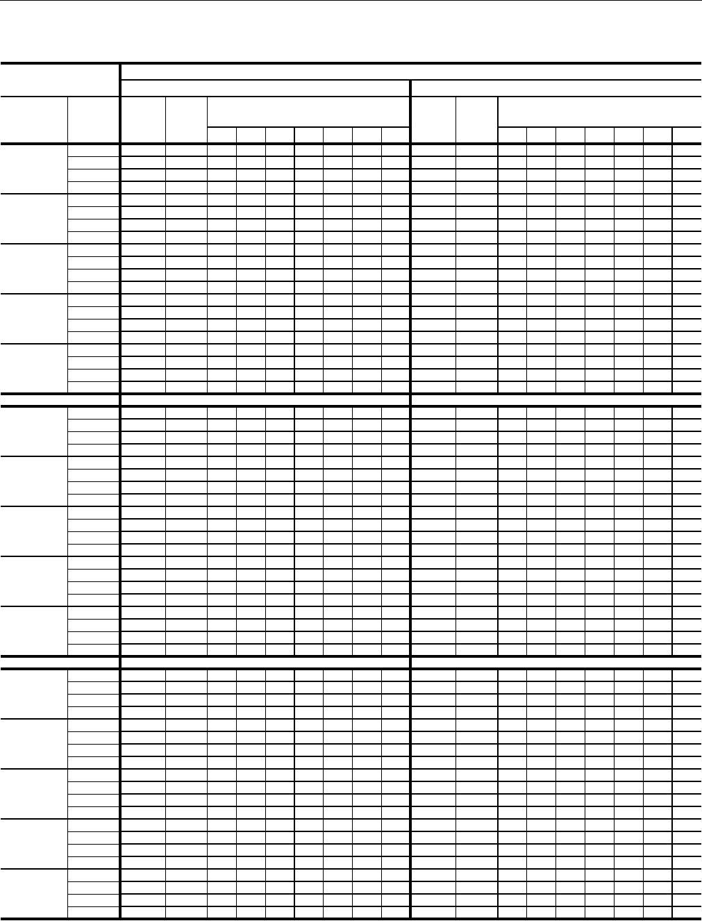
246837-YTG-L-1012
32 Johnson Controls Unitary Products
TABLE 32: COOLING PERFORMANCE - 30 TON R-410A
Air on Evaporator
Coil
Temperature of Air on Condenser Coil
75°F 85°F
CFM WB
(°F)
Total
Cap.1
(MBH)
Total2
Input
(kW)
Sensible Capacity (MBH)*
Return Dry Bulb (°F) Total
Cap.1
(MBH)
Total2
Input
(kW)
Sensible Capacity (MBH)*
Return Dry Bulb (°F)
86 83 80 77 74 71 68 86 83 80 77 74 71 68
9000
72 438.1 25.5 255.0 231.9 208.9 185.8 162.8 - - 417.5 27.8 247.3 224.4 201.6 178.7 155.8 - -
67 411.1 25.1 316.7 293.6 270.6 247.5 224.5 201.4 178.4 391.4 27.4 307.6 284.7 261.9 239.0 216.1 193.3 170.4
62 383.5 24.6 383.5 357.8 334.8 311.7 288.7 265.6 242.6 366.6 27.0 366.6 347.4 324.6 301.7 278.8 255.9 233.1
57 381.2 24.6 381.2 372.6 349.6 326.5 303.5 280.4 257.3 365.6 26.9 365.6 356.5 333.7 310.8 287.9 265.0 242.2
10500
72 449.0 25.7 276.2 250.1 224.0 197.9 171.8 - - 427.7 27.9 268.2 242.4 216.6 190.8 165.0 - -
67 421.4 25.3 342.4 316.3 290.2 264.1 238.0 211.9 185.8 401.0 27.5 333.0 307.2 281.4 255.6 229.9 204.1 178.3
62 393.2 24.8 393.2 380.3 359.1 333.0 306.9 280.8 254.7 375.6 27.1 375.6 366.0 348.8 323.0 297.2 271.4 245.7
57 390.8 24.7 390.8 386.5 374.9 348.8 322.7 296.6 270.5 374.5 27.1 374.5 370.0 358.6 332.8 307.0 281.2 255.4
12000
72 460.0 25.8 297.5 268.3 239.2 210.0 180.9 - - 437.9 28.1 289.0 260.3 231.7 203.0 174.3 - -
67 431.7 25.5 368.1 339.0 309.8 280.7 251.5 222.4 193.3 410.6 27.6 358.3 329.7 301.0 272.3 243.6 214.9 186.2
62 402.8 25.0 402.8 402.8 383.3 354.2 325.1 295.9 266.8 384.5 27.3 384.5 384.5 373.0 344.3 315.6 286.9 258.2
57 400.3 24.9 400.3 400.3 400.3 371.2 342.0 312.9 283.7 383.5 27.2 383.5 383.5 383.5 354.8 326.1 297.4 268.7
13500
72 466.7 25.9 316.2 284.7 253.1 221.6 190.0 - - 444.3 28.1 308.7 277.3 245.9 214.6 183.2 - -
67 438.0 25.5 391.0 359.4 327.9 296.3 264.8 233.2 201.6 416.6 27.7 382.3 350.9 319.5 288.1 256.8 225.4 194.0
62 408.7 25.0 408.7 408.7 399.0 367.4 335.9 304.3 272.8 390.2 27.3 390.2 390.2 384.4 353.0 321.6 290.3 258.9
57 406.2 25.0 406.2 406.2 406.2 374.6 343.1 311.5 280.0 389.1 27.3 389.1 389.1 389.1 357.7 326.3 294.9 263.6
15000
72 473.5 26.0 335.0 301.0 267.0 233.1 199.1 - - 450.7 28.2 328.4 294.3 260.2 226.2 192.1 - -
67 444.4 25.6 413.8 379.9 345.9 311.9 278.0 244.0 210.0 422.6 27.8 406.2 372.2 338.1 304.0 270.0 235.9 201.8
62 414.6 25.1 414.6 414.6 414.6 380.6 346.7 312.7 278.7 395.8 27.4 395.8 395.8 395.8 361.7 327.7 293.6 259.5
57 412.1 25.1 412.1 412.1 412.1 378.1 344.1 310.2 276.2 394.7 27.4 394.7 394.7 394.7 360.6 326.6 292.5 258.4
95°F 105°F
9000
72 396.9 30.0 239.6 216.9 194.3 171.6 148.9 - - 375.8 32.9 231.0 208.5 186.1 163.6 141.2 - -
67 371.8 29.6 298.5 275.9 253.2 230.5 207.8 185.1 162.4 352.1 32.5 289.7 267.2 244.7 222.3 199.8 177.4 154.9
62 349.7 29.3 349.7 337.0 314.3 291.6 268.9 246.2 223.6 333.9 32.2 333.9 322.6 300.2 277.7 255.3 232.8 210.3
57 350.0 29.3 350.0 340.4 317.8 295.1 272.4 249.7 227.0 334.1 32.2 334.1 324.3 301.9 279.4 257.0 234.5 212.1
10500
72 406.4 30.1 260.1 234.7 209.2 183.7 158.3 - - 384.5 33.0 251.4 226.1 200.8 175.4 150.1 - -
67 380.6 29.7 323.6 298.1 272.6 247.2 221.7 196.2 170.8 360.2 32.6 314.7 289.4 264.1 238.8 213.5 188.1 162.8
62 358.0 29.4 358.0 351.7 338.5 313.0 287.6 262.1 236.6 341.7 32.3 341.7 336.0 323.9 298.5 273.2 247.9 222.6
57 358.3 29.4 358.3 353.5 342.2 316.7 291.3 265.8 240.3 341.8 32.3 341.8 336.9 325.7 300.4 275.1 249.8 224.5
12000
72 415.8 30.3 280.6 252.4 224.1 195.9 167.7 - - 393.2 33.2 271.8 243.6 215.5 187.3 159.1 - -
67 389.5 29.8 348.6 320.3 292.1 263.9 235.6 207.4 179.1 368.4 32.7 339.8 311.6 283.4 255.2 227.1 198.9 170.7
62 366.3 29.5 366.3 366.3 362.7 334.4 306.2 277.9 249.7 349.4 32.5 349.4 349.4 347.6 319.4 291.2 263.0 234.9
57 366.6 29.5 366.6 366.6 366.6 338.4 310.2 281.9 253.7 349.5 32.5 349.5 349.5 349.5 321.4 293.2 265.0 236.9
13500
72 421.9 30.4 301.2 270.0 238.8 207.6 176.4 - - 398.7 33.2 291.7 260.7 229.7 198.7 167.7 - -
67 395.2 29.9 373.6 342.4 311.2 280.0 248.8 217.6 186.4 373.6 32.8 358.7 333.2 302.2 271.2 240.2 209.2 178.2
62 371.7 29.6 371.7 371.7 369.8 338.6 307.4 276.2 245.0 354.3 32.5 354.3 354.3 353.4 322.4 291.4 260.4 229.3
57 372.0 29.6 372.0 372.0 372.0 340.8 309.6 278.4 247.1 354.4 32.5 354.4 354.4 354.4 323.4 292.4 261.4 230.4
15000
72 428.0 30.4 321.8 287.6 253.4 219.3 185.1 - - 404.2 33.3 311.7 277.8 244.0 210.2 176.3 - -
67 400.9 30.0 398.7 364.5 330.3 296.1 261.9 227.7 193.6 378.7 32.9 377.6 354.8 321.0 287.1 253.3 219.5 185.6
62 377.0 29.7 377.0 377.0 377.0 342.8 308.7 274.5 240.3 359.2 32.6 359.2 359.2 359.2 325.3 291.5 257.7 223.8
57 377.4 29.7 377.4 377.4 377.4 343.2 309.0 274.8 240.6 359.3 32.6 359.3 359.3 359.3 325.5 291.7 257.8 224.0
115°F 125°F
9000
72 354.6 35.8 222.3 200.1 177.9 155.7 133.4 - - 333.5 38.7 213.6 191.7 169.7 147.7 125.7 - -
67 332.4 35.4 280.8 258.5 236.3 214.1 191.9 169.7 147.5 312.7 38.3 271.9 249.9 227.9 205.9 183.9 162.0 140.0
62 318.2 35.1 318.2 308.2 286.0 263.8 241.6 219.4 197.1 302.4 38.0 302.4 293.8 271.8 249.9 227.9 205.9 183.9
57 318.2 35.1 318.2 308.2 286.0 263.8 241.6 219.3 197.1 302.3 38.0 302.3 292.1 270.1 248.1 226.1 204.2 182.2
10500
72 362.6 35.9 242.6 217.5 192.3 167.2 142.0 - - 340.7 38.8 233.9 208.9 183.9 158.9 133.9 - -
67 339.8 35.5 305.8 280.7 255.5 230.4 205.2 180.0 154.9 319.5 38.4 297.0 272.0 247.0 222.0 196.9 171.9 146.9
62 325.3 35.3 325.3 320.3 309.2 284.1 258.9 233.8 208.6 309.0 38.2 309.0 304.7 294.6 269.6 244.6 219.6 194.6
57 325.3 35.3 325.3 320.3 309.2 284.1 258.9 233.7 208.6 308.8 38.2 308.8 303.7 292.7 267.7 242.7 217.7 192.7
12000
72 370.6 36.0 263.0 234.9 206.8 178.7 150.6 - - 347.9 38.9 254.2 226.1 198.1 170.1 142.0 - -
67 347.3 35.6 330.9 302.8 274.7 246.6 218.5 190.4 162.3 326.2 38.5 322.1 294.1 266.0 238.0 210.0 181.9 153.9
62 332.5 35.4 332.5 332.5 332.5 304.4 276.3 248.2 220.0 315.5 38.3 315.5 315.5 315.5 289.3 261.3 233.3 205.2
57 332.4 35.4 332.4 332.4 332.4 304.3 276.2 248.1 220.0 315.3 38.3 315.3 315.3 315.3 287.3 259.3 231.2 203.2
13500
72 375.5 36.1 282.3 251.5 220.7 189.9 159.1 - - 352.3 38.9 272.8 242.2 211.6 181.0 150.4 - -
67 351.9 35.7 343.8 324.0 293.2 262.4 231.6 200.8 170.0 330.3 38.6 328.8 314.8 284.2 253.6 223.0 192.4 161.8
62 336.9 35.4 336.9 336.9 336.9 306.1 275.3 244.5 213.7 319.5 38.3 319.5 319.5 319.5 289.8 259.2 228.6 198.1
57 336.9 35.4 336.9 336.9 336.9 306.1 275.3 244.5 213.7 319.3 38.3 319.3 319.3 319.3 288.7 258.1 227.5 196.9
15000
72 380.5 36.1 301.6 268.1 234.6 201.1 167.6 - - 356.7 39.0 291.4 258.3 225.1 192.0 158.8 - -
67 356.6 35.7 356.6 345.1 311.7 278.2 244.7 211.2 177.7 334.4 38.6 334.4 334.4 302.3 269.2 236.0 202.9 169.7
62 341.3 35.5 341.3 341.3 341.3 307.8 274.3 240.9 207.4 323.5 38.3 323.5 323.5 323.5 290.3 257.2 224.0 190.9
57 341.3 35.5 341.3 341.3 341.3 307.8 274.3 240.8 207.3 323.3 38.3 323.3 323.3 323.3 290.2 257.0 223.8 190.7
1. These capacities are gross ratings. For net capacity, deduct the supply air blower motor heat (MBH = 3.415 x kW). Refer to the appropriate Blower
Performance Table for the kW of the supply air blower motor.
2. These ratings include the condenser fan motors and the compressor motors but not the supply air blower motor.

246837-YTG-L-1012
Johnson Controls Unitary Products 33
TABLE 33: COOLING PERFORMANCE - 40 TON R-410A
Air on Evaporator
Coil
Temperature of Air on Condenser Coil
75°F 85°F
CFM WB
(°F)
Total
Cap.1
(MBH)
Total2
Input
(kW)
Sensible Capacity (MBH)*
Return Dry Bulb (°F) Total
Cap.1
(MBH)
Total2
Input
(kW)
Sensible Capacity (MBH)*
Return Dry Bulb (°F)
86 83 80 77 74 71 68 86 83 80 77 74 71 68
12000
72 570.6 32.2 340.7 309.3 277.8 246.4 215.0 - - 542.3 35.4 330.1 298.7 267.4 236.0 204.7 - -
67 532.3 31.6 420.3 388.9 357.4 326.0 294.5 263.1 231.7 506.1 34.9 409.3 378.0 346.6 315.3 283.9 252.6 221.2
62 495.7 31.1 495.7 474.7 443.3 411.8 380.4 348.9 317.5 475.2 34.4 475.2 458.9 427.5 396.2 364.8 333.5 302.1
57 495.9 31.1 495.9 484.4 453.0 421.5 390.1 358.6 327.2 475.3 34.4 475.3 463.7 432.4 401.0 369.7 338.3 307.0
14000
72 584.8 32.4 369.1 333.8 298.5 263.2 227.9 - - 555.3 35.6 358.0 322.9 287.7 252.6 217.4 - -
67 545.5 31.8 454.7 419.4 384.1 348.8 313.5 278.2 242.9 518.2 35.0 443.3 408.2 373.0 337.8 302.7 267.5 232.4
62 508.0 31.3 508.0 497.5 476.3 441.0 405.7 370.4 335.1 486.6 34.6 486.6 478.5 460.0 424.9 389.7 354.6 319.4
57 508.2 31.3 508.2 502.5 486.7 451.4 416.1 380.8 345.5 486.7 34.6 486.7 480.9 465.3 430.1 394.9 359.8 324.6
16000
72 598.9 32.6 397.6 358.4 319.3 280.1 240.9 - - 568.3 35.8 386.0 347.0 308.0 269.1 230.1 - -
67 558.7 32.0 489.0 449.8 410.7 371.5 332.4 293.2 254.1 530.4 35.2 477.3 438.3 399.4 360.4 321.4 282.5 243.5
62 520.3 31.5 520.3 520.3 509.3 470.2 431.0 391.9 352.7 498.0 34.7 498.0 498.0 492.6 453.6 414.6 375.6 336.7
57 520.5 31.5 520.5 520.5 520.5 481.4 442.2 403.0 363.9 498.1 34.7 498.1 498.1 498.1 459.2 420.2 381.2 342.3
18000
72 608.2 32.7 422.8 380.6 338.4 296.3 254.1 - - 576.8 35.9 411.0 369.1 327.1 285.2 243.3 - -
67 567.4 32.2 525.1 477.5 435.4 393.2 351.0 308.9 266.7 538.2 35.4 508.0 466.1 424.1 382.2 340.3 298.3 256.4
62 528.3 31.6 528.3 528.3 522.8 480.7 438.5 396.3 354.2 505.4 34.9 505.4 505.4 502.7 460.7 418.8 376.9 334.9
57 528.6 31.6 528.6 528.6 528.6 486.4 444.2 402.0 359.9 505.5 34.9 505.5 505.5 505.5 463.6 421.6 379.7 337.8
20000
72 617.4 32.9 448.0 402.8 357.6 312.5 267.3 - - 585.2 36.1 436.0 391.1 346.2 301.3 256.4 - -
67 576.0 32.3 561.2 505.2 460.0 414.9 369.7 324.5 279.3 546.1 35.5 538.7 493.8 448.9 404.0 359.1 314.2 269.3
62 536.4 31.7 536.4 536.4 536.4 491.2 446.0 400.8 355.6 512.8 35.0 512.8 512.8 512.8 467.9 423.0 378.1 333.2
57 536.6 31.7 536.6 536.6 536.6 491.4 446.2 401.0 355.9 512.9 35.0 512.9 512.9 512.9 468.0 423.1 378.2 333.3
95°F 105°F
12000
72 514.0 38.7 319.4 288.2 256.9 225.7 194.4 - - 485.9 42.7 308.8 277.7 246.7 215.7 184.6 - -
67 479.8 38.1 398.4 367.1 335.9 304.6 273.3 242.1 210.8 453.8 42.1 387.0 356.0 325.0 293.9 262.9 231.9 200.8
62 454.7 37.7 454.7 443.1 411.8 380.5 349.3 318.0 286.8 433.8 41.7 433.8 421.7 390.7 359.6 328.6 297.6 266.5
57 454.7 37.7 454.7 443.0 411.8 380.5 349.3 318.0 286.8 433.8 41.7 433.8 421.7 390.7 359.6 328.6 297.6 266.5
14000
72 525.9 38.9 346.9 311.9 276.9 241.9 206.8 - - 496.8 42.8 336.1 301.2 266.4 231.6 196.8 - -
67 490.9 38.3 432.0 397.0 361.9 326.9 291.9 256.9 221.9 463.9 42.3 420.6 385.8 350.9 316.1 281.3 246.5 211.7
62 465.3 37.9 465.3 459.4 443.8 408.8 373.7 338.7 303.7 443.4 41.9 443.4 437.4 421.9 387.1 352.2 317.4 282.6
57 465.2 37.9 465.2 459.4 443.8 408.7 373.7 338.7 303.7 443.4 41.9 443.4 437.4 421.9 387.0 352.2 317.4 282.6
16000
72 537.8 39.0 374.4 335.6 296.8 258.1 219.3 - - 507.6 43.0 363.4 324.8 286.1 247.5 208.9 - -
67 502.0 38.4 465.6 426.8 388.0 349.3 310.5 271.7 232.9 474.0 42.4 454.1 415.5 376.9 338.3 299.7 261.1 222.5
62 475.8 38.0 475.8 475.8 475.8 437.0 398.2 359.4 320.6 453.1 42.0 453.1 453.1 453.1 414.5 375.9 337.3 298.7
57 475.8 38.0 475.8 475.8 475.8 437.0 398.2 359.4 320.6 453.1 42.0 453.1 453.1 453.1 414.5 375.9 337.2 298.6
18000
72 545.4 39.2 399.2 357.5 315.8 274.1 232.4 - - 514.8 43.1 388.0 346.4 304.9 263.3 221.7 - -
67 509.1 38.6 490.9 454.6 412.9 371.2 329.5 287.8 246.1 480.8 42.5 470.8 443.1 401.6 360.0 318.5 276.9 235.3
62 482.5 38.1 482.5 482.5 482.5 440.8 399.1 357.4 315.7 459.5 42.2 459.5 459.5 459.5 418.0 376.4 334.8 293.3
57 482.5 38.1 482.5 482.5 482.5 440.8 399.1 357.4 315.7 459.5 42.2 459.5 459.5 459.5 417.9 376.4 334.8 293.2
20000
72 552.9 39.3 424.1 379.5 334.8 290.2 245.6 - - 522.0 43.2 412.6 368.1 323.6 279.1 234.6 - -
67 516.2 38.7 516.2 482.3 437.7 393.1 348.5 303.9 259.3 487.5 42.7 487.5 470.6 426.3 381.7 337.2 292.7 248.2
62 489.2 38.3 489.2 489.2 489.2 444.6 400.0 355.4 310.8 466.0 42.3 466.0 466.0 466.0 421.5 376.9 332.4 287.9
57 489.2 38.3 489.2 489.2 489.2 444.6 400.0 355.4 310.7 466.0 42.3 466.0 466.0 466.0 421.4 376.9 332.4 287.9
115°F 125°F
12000
72 457.9 46.7 298.1 267.3 236.5 205.7 174.9 - - 429.9 50.6 287.5 256.9 226.3 195.7 165.1 - -
67 427.9 46.2 375.7 344.9 314.1 283.3 252.5 221.7 190.8 402.0 50.2 364.4 333.8 303.2 272.6 242.0 211.4 180.9
62 412.8 45.8 412.8 400.4 369.5 338.7 307.9 277.1 246.3 391.9 49.8 391.9 379.0 348.4 317.8 287.3 256.7 226.1
57 412.8 45.8 412.8 400.3 369.5 338.7 307.9 277.1 246.3 391.9 49.8 391.9 379.0 348.4 317.8 287.2 256.7 226.1
14000
72 467.6 46.8 325.2 290.6 256.0 221.4 186.7 - - 438.5 50.8 314.4 279.9 245.5 211.1 176.7 - -
67 437.0 46.3 409.2 374.6 339.9 305.3 270.7 236.1 201.5 410.1 50.3 397.8 363.4 328.9 294.5 260.1 225.7 191.3
62 421.6 45.9 421.6 415.4 400.0 365.4 330.7 296.1 261.5 399.8 50.0 399.8 393.4 378.1 343.7 309.2 274.8 240.4
57 421.6 45.9 421.6 415.4 400.0 365.3 330.7 296.1 261.5 399.8 50.0 399.8 393.3 378.1 343.6 309.2 274.8 240.4
16000
72 477.4 46.9 352.3 313.9 275.4 237.0 198.6 - - 447.2 50.9 341.3 303.0 264.8 226.5 188.2 - -
67 446.1 46.4 442.7 404.2 365.8 327.4 288.9 250.5 212.1 418.2 50.4 418.2 393.0 354.7 316.4 278.2 239.9 201.7
62 430.4 46.1 430.4 430.4 430.4 392.0 353.5 315.1 276.7 407.7 50.1 407.7 407.7 407.7 369.5 331.2 293.0 254.7
57 430.4 46.1 430.4 430.4 430.4 392.0 353.5 315.1 276.6 407.7 50.1 407.7 407.7 407.7 369.4 331.2 292.9 254.7
18000
72 484.2 47.0 376.8 335.3 293.9 252.5 211.0 - - 453.6 51.0 365.5 324.2 282.9 241.6 200.3 - -
67 452.5 46.5 450.8 431.6 390.3 348.9 307.4 266.0 224.6 424.2 50.5 424.2 420.1 379.0 337.7 296.4 255.1 213.8
62 436.6 46.2 436.6 436.6 436.6 395.1 353.7 312.3 270.8 413.6 50.2 413.6 413.6 413.6 372.3 331.0 289.7 248.4
57 436.6 46.2 436.6 436.6 436.6 395.1 353.7 312.2 270.8 413.6 50.2 413.6 413.6 413.6 372.3 331.0 289.7 248.4
20000
72 491.0 47.1 401.2 356.8 312.4 267.9 223.5 - - 460.1 51.1 389.8 345.5 301.1 256.8 212.4 - -
67 458.9 46.6 458.9 458.9 414.8 370.4 326.0 281.5 237.1 430.2 50.6 430.2 430.2 403.4 359.0 314.7 270.3 226.0
62 442.7 46.3 442.7 442.7 442.7 398.3 353.9 309.4 265.0 419.5 50.3 419.5 419.5 419.5 375.2 330.8 286.5 242.1
57 442.7 46.3 442.7 442.7 442.7 398.3 353.8 309.4 265.0 419.5 50.3 419.5 419.5 419.5 375.1 330.8 286.4 242.1
1. These capacities are gross ratings. For net capacity, deduct the supply air blower motor heat (MBH = 3.415 x kW). Refer to the appropriate Blower
Performance Table for the kW of the supply air blower motor.
2. These ratings include the condenser fan motors and the compressor motors but not the supply air blower motor.
246837-YTG-L-1012
34 Johnson Controls Unitary Products
CFM, STATIC PRESSURE, AND POWER - ALTI-
TUDE AND TEMPERATURE CORRECTIONS
The information below should be used to assist in application
of product when being applied at altitudes at or exceeding
1000 feet above sea level.
The air flow rates listed in the standard blower performance
tables are based on standard air at sea level. As the altitude
or temperature increases, the density of air decreases. In
order to use the indoor blower tables for high altitude applica-
tions, certain corrections are necessary.
A centrifugal fan is a "constant volume" device. This means
that, if the rpm remains constant, the CFM delivered is the
same regardless of the density of the air. However, since the
air at high altitude is less dense, less static pressure will be
generated and less power will be required than a similar
application at sea level. Air density correction factors are
shown in Table 34 and Figure 21.
The examples below will assist in determining the airflow per-
formance of the product at altitude.
Example 1: What are the corrected CFM, static pressure,
and BHP at an elevation of 5,000 ft. if the blower performance
data is 6,000 CFM, 1.5 IWC and 4.0 BHP?
Solution: At an elevation of 5,000 ft the indoor blower will still
deliver 6,000 CFM if the rpm is unchanged. However, Table
34 must be used to determine the static pressure and BHP.
Since no temperature data is given, we will assume an air
temperature of 70°F. Table 34 shows the correction factor to
be 0.832.
Corrected static pressure = 1.5 x 0.832 = 1.248 IWC
Corrected BHP = 4.0 x 0.832 = 3.328
Example 2: A system, located at 5,000 feet of elevation, is to
deliver 6,000 CFM at a static pressure of 1.5". Use the unit
blower tables to select the blower speed and the BHP
requirement.
Solution: As in the example above, no temperature informa-
tion is given so 70°F is assumed.
The 1.5" static pressure given is at an elevation of 5,000 ft.
The first step is to convert this static pressure to equivalent
sea level conditions.
Sea level static pressure = 1.5 / .832 = 1.80"
Enter the blower table at 6000 sCFM and static pressure of
1.8". The rpm listed will be the same rpm needed at 5,000 ft.
Suppose that the corresponding BHP listed in the table is 3.2.
This value must be corrected for elevation.
BHP at 5,000 ft = 3.2 x .832 = 2.66
TABLE 34: ALTITUDE CORRECTION FACTORS
AIR TEMP ALTITUDE (FEET)
0 1000 2000 3000 4000 5000 6000 7000 8000 9000 10000
40 1.060 1.022 0.986 0.950 0.916 0.882 0.849 0.818 0.788 0.758 0.729
50 1.039 1.002 0.966 0.931 0.898 0.864 0.832 0.802 0.772 0.743 0.715
60 1.019 0.982 0.948 0.913 0.880 0.848 0.816 0.787 0.757 0.729 0.701
70 1.000 0.964 0.930 0.896 0.864 0.832 0.801 0.772 0.743 0.715 0.688
80 0.982 0.947 0.913 0.880 0.848 0.817 0.787 0.758 0.730 0.702 0.676
90 0.964 0.929 0.897 0.864 0.833 0.802 0.772 0.744 0.716 0.689 0.663
100 0.946 0.912 0.880 0.848 0.817 0.787 0.758 0.730 0.703 0.676 0.651
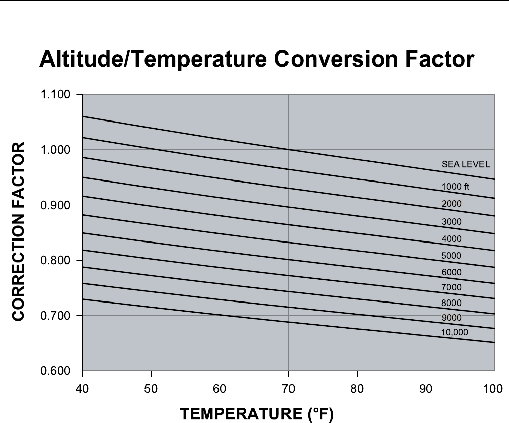
246837-YTG-L-1012
Johnson Controls Unitary Products 35
FIGURE 21 - ALTITUDE/TEMPERATURE CONVERSION FACTOR
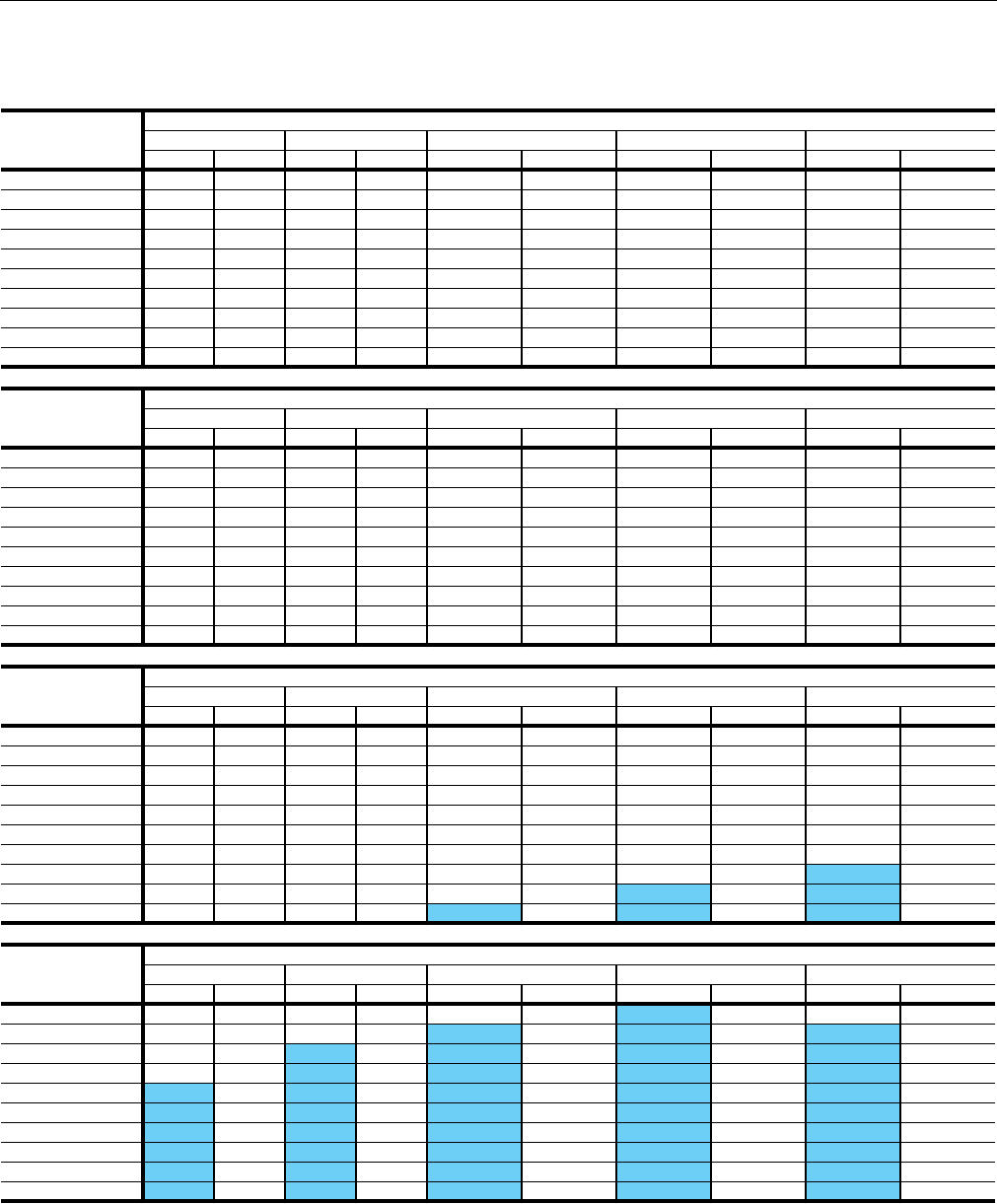
246837-YTG-L-1012
36 Johnson Controls Unitary Products
4. Shaded RPMs require Class II blower.
TABLE 35: FAN PERFORMANCE - 25 TON1, 2
AIRFLOW CFM
AVAILABLE EXTERNAL STATIC PRESSURE (IWG)
0.2 0.4 0.6 0.8 1.0
RPM BHP3RPM BHP3RPM BHP3RPM BHP3RPM BHP3
4000 302 0.5 365 0.7 422 1.0 475 1.3 523 1.5
5000 341 0.9 396 1.1 447 1.4 495 1.7 540 2.0
6000 380 1.2 427 1.5 473 1.8 516 2.1 557 2.5
7000 416 1.8 459 2.1 500 2.5 540 2.8 578 3.2
8000 452 2.3 491 2.7 528 3.1 565 3.5 600 3.9
9000 492 3.2 527 3.6 561 4.0 594 4.5 626 4.9
10000 532 4.2 563 4.5 594 4.9 624 5.4 653 5.8
11000 578 5.5 605 5.9 632 6.3 659 6.7 686 7.2
12000 623 6.8 647 7.2 671 7.6 695 8.1 719 8.6
12500 639 7.4 664 7.9 688 8.4 712 8.9 736 9.5
AIRFLOW CFM
AVAILABLE EXTERNAL STATIC PRESSURE (IWG)
1.2 1.4 1.6 1.8 2.0
RPM BHP3RPM BHP3RPM BHP3RPM BHP3RPM BHP3
4000 568 1.8 609 2.2 646 2.5 681 2.8 713 3.2
5000 582 2.4 621 2.7 657 3.1 692 3.5 724 3.9
6000 596 2.9 633 3.3 669 3.7 702 4.1 735 4.5
7000 615 3.6 650 4.0 683 4.5 716 4.9 747 5.4
8000 633 4.4 666 4.8 698 5.3 729 5.7 759 6.2
9000 658 5.3 688 5.8 718 6.3 747 6.8 776 7.3
10000 682 6.3 710 6.8 738 7.3 766 7.8 793 8.4
11000 713 7.7 739 8.2 765 8.8 791 9.3 816 9.9
12000 743 9.1 767 9.7 791 10.2 815 10.8 839 11.4
12500 760 10.0 784 10.6 807 11.2 830 11.7 853 12.3
AIRFLOW CFM
AVAILABLE EXTERNAL STATIC PRESSURE (IWG)
2.2 2.4 2.6 2.8 3.0
RPM BHP3RPM BHP3RPM BHP3RPM BHP3RPM BHP3
4000 743 3.5 770 3.9 796 4.3 821 4.6 844 5.0
5000 754 4.3 783 4.7 810 5.1 836 5.5 861 5.9
6000 766 5.0 795 5.4 824 5.9 851 6.4 878 6.8
7000 777 5.8 806 6.3 834 6.8 861 7.3 888 7.8
8000 788 6.7 817 7.2 844 7.7 871 8.2 898 8.8
9000 804 7.8 831 8.3 857 8.9 883 9.5 909 10.0
10000 819 8.9 845 9.5 870 10.1 896 10.7 920 11.3
11000 841 10.5 866 11.1 890 11.7 914 12.3 938 12.9
12000 863 12.0 887 12.6 910 13.2 933 13.9 956 14.5
12500 876 12.9 899 13.6 921 14.2 943 14.8 965 15.5
AIRFLOW CFM
AVAILABLE EXTERNAL STATIC PRESSURE (IWG)
3.2 3.4 3.6 3.8 4.0
RPM BHP3RPM BHP3RPM BHP3RPM BHP3RPM BHP3
4000 867 5.4 890 5.8 912 6.2 935 6.6 958 6.9
5000 885 6.4 909 6.8 932 7.2 956 7.6 979 8.0
6000 903 7.3 928 7.8 953 8.2 976 8.7 1000 9.1
7000 914 8.3 939 8.8 963 9.4 988 9.9 1012 10.5
8000 924 9.3 949 9.9 974 10.5 999 11.2 1023 11.8
9000 934 10.6 959 11.2 983 11.9 1007 12.5 1030 13.2
10000 944 11.9 968 12.6 992 13.2 1015 13.8 1037 14.5
11000 961 13.6 984 14.2 1007 14.9 1029 15.6 1051 16.2
12000 978 15.2 1000 15.9 1022 16.6 1043 17.3 1064 18.0
13000 986 16.2 1008 16.8 1029 17.5 1050 18.2 1070 19.0
1. Fan performance is based on wet evaporator coils, clean 2” throwaway filters and system/cabinet effects at standard air density and 0 feet elevation.
2. Refer to Tables 10, 15, 21 and 38 for component additions and deductions to fan performance tables.
3. BHP includes drive losses.
246837-YTG-L-1012
Johnson Controls Unitary Products 37
FIGURE 22 - FAN PERFORMANCE - 25 TON
012345678910 11 12
CFM (x1000)
0.0
0.5
1.0
1.5
2.0
2.5
3.0
3.5
4.0
4.5
5.0
5.5
6.0
6.5
7.0
7.5
1100R
PM
900
800
700
600
500
1000
A
10
15BHP
7.5
ddUit

246837-YTG-L-1012
38 Johnson Controls Unitary Products
4. Shaded RPMs require Class II blower.
TABLE 36: FAN PERFORMANCE - 30 TON 1, 2
AIRFLOW (CFM)
AVAILABLE EXTERNAL STATIC PRESSURE (IWG)
0.2 0.4 0.6 0.8 1.0
RPM BHP3RPM BHP3RPM BHP3RPM BHP3RPM BHP3
6000 405 1.3 450 1.6 494 2.0 535 2.3 575 2.7
7000 444 1.9 485 2.3 524 2.7 562 3.0 599 3.4
8000 483 2.6 519 2.9 555 3.3 589 3.7 623 4.2
9000 520 3.5 554 3.9 586 4.3 618 4.7 649 5.2
10000 558 4.5 588 4.8 618 5.2 647 5.7 676 6.2
11000 603 5.7 629 6.2 656 6.7 683 7.2 709 7.7
12000 647 7.0 671 7.5 695 8.1 718 8.6 742 9.2
13000 687 8.9 709 9.3 731 9.9 753 10.4 776 10.9
14000 728 10.7 748 11.2 768 11.6 789 12.2 809 12.7
15000 767 12.7 786 13.2 805 13.8 825 14.4 845 15.0
AIRFLOW (CFM)
AVAILABLE EXTERNAL STATIC PRESSURE (IWG)
1.2 1.4 1.6 1.8 2.0
RPM BHP3RPM BHP3RPM BHP3RPM BHP3RPM BHP3
6000 612 3.1 649 3.5 683 3.9 717 4.3 748 4.7
7000 634 3.8 668 4.3 701 4.7 733 5.1 763 5.6
8000 655 4.6 687 5.1 719 5.5 749 6.0 779 6.5
9000 680 5.6 710 6.1 739 6.6 768 7.2 796 7.7
10000 704 6.7 732 7.2 760 7.7 787 8.3 813 8.9
11000 735 8.2 761 8.7 787 9.3 812 9.8 837 10.4
12000 766 9.7 790 10.3 814 10.8 837 11.4 861 12.0
13000 798 11.5 820 12.1 843 12.7 865 13.3 887 13.9
14000 830 13.3 851 13.9 872 14.6 893 15.2 914 15.9
15000 864 15.6 884 16.3 904 16.9 923 17.6 943 18.3
AIRFLOW (CFM)
AVAILABLE EXTERNAL STATIC PRESSURE (IWG)
2.2 2.4 2.6 2.8 3.0
RPM BHP3RPM BHP3RPM BHP3RPM BHP3RPM BHP3
6000 779 5.1 808 5.5 837 6.0 864 6.4 890 6.9
7000 793 6.1 822 6.6 850 7.0 877 7.5 903 8.1
8000 807 7.0 836 7.6 863 8.1 890 8.6 916 9.2
9000 823 8.3 850 8.8 877 9.4 902 10.0 928 10.6
10000 839 9.5 865 10.1 890 10.7 915 11.3 940 12.0
11000 862 11.0 886 11.6 910 12.2 934 12.9 957 13.5
12000 884 12.5 907 13.2 930 13.8 953 14.4 975 15.0
13000 909 14.6 931 15.2 953 15.9 975 16.5 996 17.2
14000 935 16.6 956 17.3 976 18.0 997 18.7 1017 19.4
15000 963 18.9 982 19.6 1002 20.4 1021 21.1 1040 21.8
AIRFLOW (CFM)
AVAILABLE EXTERNAL STATIC PRESSURE (IWG)
3.2 3.4 3.6 3.8 4.0
RPM BHP3RPM BHP3RPM BHP3RPM BHP3RPM BHP3
6000 916 7.4 940 7.9 964 8.3 988 8.8 1011 9.3
7000 928 8.6 953 9.1 977 9.6 1000 10.1 1023 10.7
8000 941 9.8 965 10.3 989 10.9 1013 11.5 1035 12.0
9000 952 11.2 976 11.8 1000 12.4 1023 13.0 1045 13.6
10000 964 12.6 987 13.2 1010 13.9 1033 14.5 1055 15.1
11000 981 14.1 1003 14.8 1025 15.5 1047 16.1 1069 16.8
12000 997 15.7 1019 16.4 1040 17.1 1061 17.8 1082 18.5
13000 1017 17.9 1038 18.6 1058 19.4 1078 20.1 1097 20.8
14000 1037 20.2 1056 20.9 1076 21.6 1094 22.4 1113 23.1
15000 1059 22.6 1078 23.3 1097 24.1 1115 24.9 1134 25.7
1. Fan performance is based on wet evaporator coils, clean 2” throwaway filters and system/cabinet effects at standard air density and 0 feet elevation.
2. Refer to Tables 10, 15, 21 and 38 for component additions and deductions to fan performance tables.
3. BHP includes drive losses.
246837-YTG-L-1012
Johnson Controls Unitary Products 39
FIGURE 23 - FAN PERFORMANCE - 30 TON
FIGURE 23 - FAN PERFORMANCE - 30 TON
0 1 2 3 4 5 6 7 8 9 10 11 12 13 14
CFM (x1000)
0.0
0.5
1.0
1.5
2.0
2.5
3.0
3.5
4.0
4.5
5.0
5.5
6.0
6.5
7.0
7.5
8.0
Total Static Pressure (IWG)
1100RPM
900
800
700
600
500
1000
A
30 Ton Forward Curv
10
15
20B
HP
A - Standard Unit
Note: Standard Unit includes wet evaporator coil, clean 2" throwaway filters, system
and cabinet effects at standard air density and 0' elevation.
246837-YTG-L-1012
40 Johnson Controls Unitary Products
4. Shaded RPMs require Class II blower.
TABLE 37: FAN PERFORMANCE - 40 TON1,2
AIRFLOW (CFM)
AVAILABLE EXTERNAL STATIC PRESSURE (IWG)
0.2 0.4 0.6 0.8 1.0
RPM BHP3RPM BHP3RPM BHP3RPM BHP3RPM BHP3
8000 367 1.9 409 2.3 448 2.8 485 3.3 519 3.8
9000 396 2.5 433 3.0 469 3.5 504 4.0 536 4.5
10000 424 3.1 458 3.6 491 4.1 523 4.6 553 5.2
11000 454 4.0 486 4.5 516 5.1 546 5.6 574 6.2
12000 484 5.0 513 5.5 542 6.1 569 6.6 596 7.2
13000 507 5.9 535 6.5 562 7.1 589 7.8 614 8.4
14000 530 6.9 557 7.6 583 8.2 608 8.9 633 9.6
15000 560 8.4 584 9.1 609 9.7 632 10.4 655 11.2
16000 589 9.8 612 10.5 634 11.3 656 12.0 678 12.7
17000 613 11.7 635 12.4 657 13.1 678 13.8 699 14.6
18000 638 13.6 659 14.3 680 15.0 700 15.7 721 16.5
AIRFLOW (CFM)
AVAILABLE EXTERNAL STATIC PRESSURE (IWG)
1.2 1.4 1.6 1.8 2.0
RPM BHP3RPM BHP3RPM BHP3RPM BHP3RPM BHP3
8000 552 4.2 583 4.7 612 5.2 639 5.7 665 6.2
9000 567 5.0 596 5.5 624 6.0 651 6.6 677 7.1
10000 582 5.7 610 6.3 637 6.9 663 7.4 688 8.0
11000 602 6.8 628 7.4 654 8.0 679 8.6 703 9.2
12000 621 7.9 647 8.5 671 9.1 695 9.8 718 10.4
13000 639 9.1 664 9.7 687 10.4 710 11.1 733 11.8
14000 657 10.3 681 11.0 704 11.7 726 12.5 748 13.2
15000 678 11.9 700 12.6 722 13.3 744 14.1 765 14.9
16000 699 13.5 720 14.2 741 15.0 761 15.8 781 16.5
17000 720 15.4 740 16.1 760 16.9 780 17.8 799 18.6
18000 740 17.3 760 18.1 780 18.9 799 19.7 818 20.6
AIRFLOW (CFM)
AVAILABLE EXTERNAL STATIC PRESSURE (IWG)
2.2 2.4 2.6 2.8 3.0
RPM BHP3RPM BHP3RPM BHP3RPM BHP3RPM BHP3
8000 690 6.7 713 7.2 736 7.7 758 8.2 779 8.8
9000 701 7.7 725 8.2 747 8.8 769 9.4 790 10.0
10000 712 8.7 736 9.3 759 9.9 781 10.6 802 11.2
11000 726 9.9 749 10.5 771 11.2 793 11.9 814 12.6
12000 740 11.1 762 11.8 784 12.5 805 13.2 826 13.9
13000 755 12.5 776 13.3 797 14.0 818 14.7 838 15.5
14000 769 14.0 790 14.7 811 15.5 831 16.3 851 17.1
15000 785 15.6 805 16.4 825 17.2 845 18.0 864 18.9
16000 801 17.3 820 18.1 839 19.0 858 19.8 877 20.6
17000 819 19.4 837 20.3 856 21.1 874 22.0 892 22.9
18000 836 21.5 855 22.4 873 23.3 890 24.2 908 25.1
AIRFLOW (CFM)
AVAILABLE EXTERNAL STATIC PRESSURE (IWG)
3.2 3.4 3.6 3.8 4.0
RPM BHP3RPM BHP3RPM BHP3RPM BHP3RPM BHP3
8000 799 9.3 819 9.9 839 10.6 859 11.2 879 11.9
9000 811 10.6 831 11.3 851 11.9 871 12.6 891 13.3
10000 823 11.9 843 12.6 863 13.3 883 13.9 902 14.6
11000 834 13.3 855 14.0 874 14.7 894 15.4 913 16.1
12000 846 14.6 866 15.4 885 16.1 905 16.8 924 17.5
13000 858 16.3 877 17.0 896 17.8 915 18.6 934 19.3
14000 870 17.9 889 18.7 908 19.5 926 20.3 944 21.1
15000 882 19.7 901 20.5 919 21.4 937 22.2 955 23.1
16000 895 21.5 913 22.4 931 23.3 948 24.2 966 25.1
17000 910 23.8 928 24.7 945 25.6 962 - - -
18000 925 26.0 --------
1. Fan performance is based on wet evaporator coils, clean 2” throwaway filters and system/cabinet effects at standard air density and 0 feet elevation.
2. Refer to Tables 12, 18, 23 and 38 for component additions and deductions to fan performance tables.
3. BHP includes drive losses.
246837-YTG-L-1012
Johnson Controls Unitary Products 41
FIGURE 24 - FAN PERFORMANCE - 40 TON
40 Ton Forward Curve
A - Standard Unit
Note: Standard Unit includes wet evaporator coil, clean 2" throwaway filters, system
and cabinet effects at standard air density and 0' elevation.
0 2 4 6 8 10 12 14 16 18 20
CFM (x1000)
0.0
0.5
1.0
1.5
2.0
2.5
3.0
3.5
4.0
4.5
5.0
5.5
6.0
6.5
7.0
Total Static Pressure (IWG)
900RPM
800
700
600
500
400
300
10
15
20
25BHP
A
246837-YTG-L-1012
42 Johnson Controls Unitary Products
TABLE 38: COMPONENT STATIC RESISTANCE1, 2
COMPONENT COIL
LOSSES CFM
4,000 6,000 8,000 10,000 12,000 14,000 16,000 18,000
COIL LOSSES 25T
3 Row, 16 FPI, dry -0.14 -0.18 -0.24 -0.34 -0.45 - - -
3 Row, 16 FPI, wet Baseline Baseline Baseline Baseline Baseline - - -
COIL LOSSES 30T
4 Row, 16 FPI, dry -0.18 -0.22 -0.32 -0.45 -0.60 -0.76 - -
4 Row, 16 FPI, wet Baseline Baseline Baseline Baseline Baseline Baseline - -
COIL LOSSES 40T
4 Row, 16 FPI, dry -0.15 -0.22 -0.26 -0.31 -0.42 -0.53 -.0.65 -0.79
4 Row, 16 FPI, wet Baseline Baseline Baseline Baseline Baseline Baseline Baseline Baseline
FILTER LOSSES
2” TA or HI EFF. Baseline Baseline Baseline Baseline Baseline Baseline Baseline Baseline
Rigid 6”, 65% 0.06 0.12 0.19 0.27 0.36 0.46 0.58 0.70
Rigid 6”, 95% 0.13 0.26 0.41 0.60 0.81 1.04 1.29 1.57
IGV LOSSES
25 & 30 Ton F.C. 0.02 0.05 0.08 0.13 0.19 0.26 0.34 0.43
40 Ton F.C. 0.01 0.03 0.05 0.08 0.11 0.15 0.19 0.25
GAS HEAT
267 MBH Heat 0.07 0.11 0.14 0.18 0.21 0.25 0.28 0.32
533 MBH Heat 0.14 0.21 0.28 0.35 0.42 0.49 0.57 0.64
800 MBH Heat 0.21 0.32 0.42 0.53 0.64 0.74 0.85 0.95
ELECTRIC HEAT
40KW 0.01 0.02 0.04 0.06 0.10 0.20 0.31 0.40
80KW 0.01 0.04 0.08 0.13 0.20 0.31 0.44 0.56
108KW 0.02 0.05 0.10 0.15 0.31 0.43 0.53 0.68
ECONOMIZER 0.03 0.06 0.10 0.15 0.21 0.28 0.35 0.43
POWER EXHAUST 0.02 0.05 0.08 0.13 0.18 0.25 0.32 0.41
1. Baseline losses based on system/cabinet effects, wet standard coil and 2” throwaway filters at 70°F, 0 feet elevation with standard air.
2. See Tables 10, 12, 15, 18 and 21 for hot water and steam water coil static resistance.
246837-YTG-L-1012
Johnson Controls Unitary Products 43
TABLE 39: POWER EXHAUST - ONE FORWARD CURVED FAN 25 TON1
AIRFLOW CFM
AVAILABLE EXTERNAL STATIC PRESSURE (IWG)
0.2 0.4 0.6 0.8 1.0
RPM BHP2RPM BHP2RPM BHP2RPM BHP2RPM BHP2
2000 --- --- --- --- 524 0.3 609 0.4 685 0.6
3000 --- --- 450 0.4 531 0.5 605 0.7 672 0.8
4000 442 0.7 496 0.8 562 0.9 626 1.1 687 1.2
5000 524 1.2 566 1.4 609 1.5 663 1.7 717 1.8
6000 612 1.9 646 2.2 679 2.4 717 2.6 762 2.7
7000 703 3.0 731 3.3 759 3.5 787 3.7 820 4.0
8000 791 3.8 821 4.3 844 4.8 868 5.2 892 5.5
9000 877 5.8 911 6.2 932 6.5 953 6.9 974 7.3
10000 967 8.4 1004 8.8 1022 9.1 1041 9.4 1059 9.8
AIRFLOW CFM
AVAILABLE EXTERNAL STATIC PRESSURE (IWG)
1.2 1.4 1.6 1.8 2.0
RPM BHP2RPM BHP2RPM BHP2RPM BHP2RPM BHP2
2000 754 0.7 819 0.8 878 0.9 933 1.1 986 1.2
3000 736 1.0 797 1.1 854 1.3 909 1.5 961 1.7
4000 743 1.4 799 1.5 850 1.7 900 1.9 948 2.1
5000 768 2.0 818 2.2 865 2.4 911 2.6 955 2.8
6000 806 2.9 850 3.1 895 3.3 937 3.6 978 3.8
7000 857 4.2 895 4.4 933 4.6 972 4.8 1010 5.0
8000 921 5.7 953 6.0 985 6.2 1018 6.5 1052 6.8
9000 995 7.6 1020 8.0 1048 8.3 1075 8.5 1103 8.8
10000 1077 10.1 1096 10.4 1119 10.8 1143 11.1 1167 11.4
1. Fan performance is based on system/cabinet effects and back draft damper effects at standard air density and 0 feet of elevation.
2. BHP includes 5% drive losses.
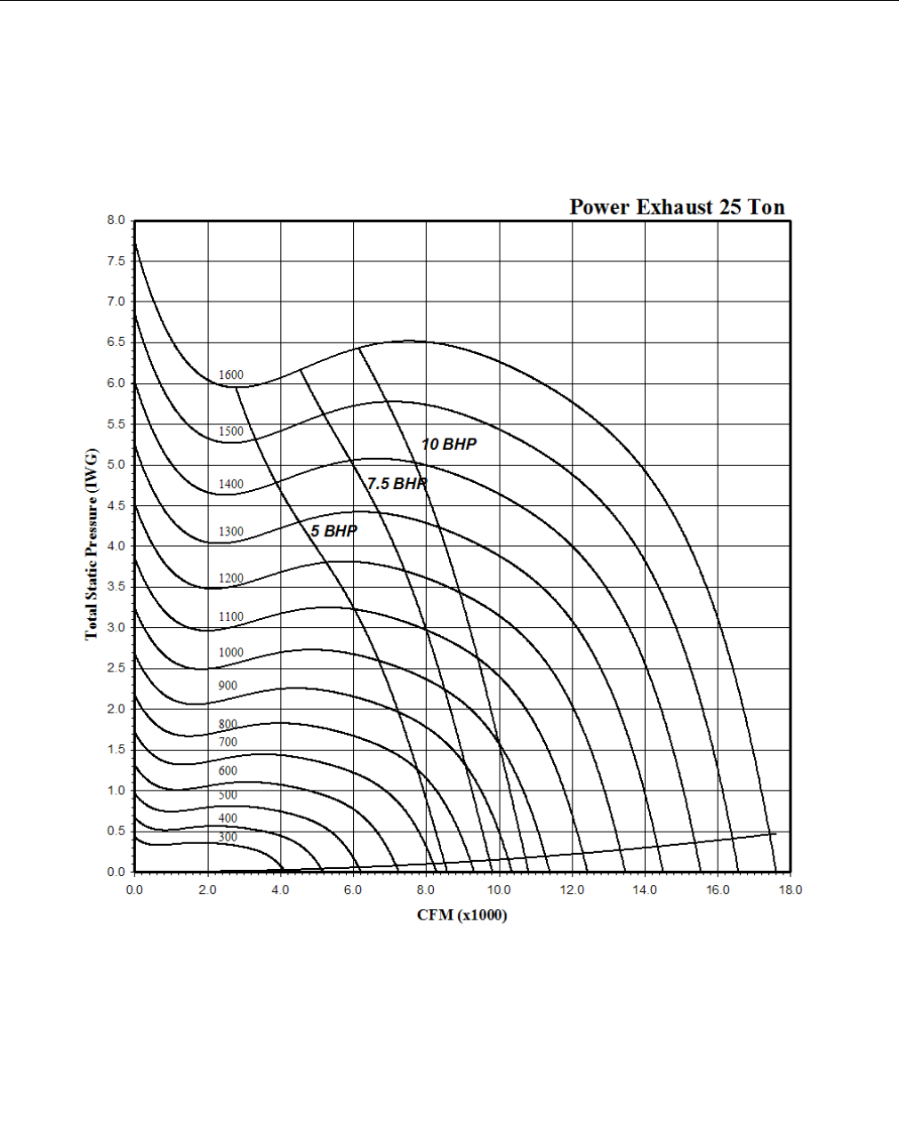
246837-YTG-L-1012
44 Johnson Controls Unitary Products
FIGURE 25 - POWER EXHAUST - ONE FORWARD CURVE FAN - 25 TONS
246837-YTG-L-1012
Johnson Controls Unitary Products 45
TABLE 40: POWER EXHAUST - TWO FORWARD CURVED FANS - 30 & 40 TON1
AIRFLOW CFM
AVAILABLE EXTERNAL STATIC PRESSURE (IWG)
0.2 0.4 .06 0.8 1.0
RPM BHP2 3RPM BHP2 3 RPM BHP2 3 RPM BHP2 3 RPM BHP2 3
4000 363 0.3 468 0.5 560 0.7 641 0.9 716 1.2
5000 402 0.5 494 0.7 576 1.1 652 1.3 722 1.5
6000 445 0.8 527 1.1 602 1.4 670 1.7 735 2.0
7000 494 1.3 565 1.6 633 1.8 697 2.1 757 2.5
8000 544 1.8 609 2.1 670 2.4 729 2.7 784 3.2
9000 597 2.4 654 2.8 711 3.2 765 3.5 817 3.9
10000 651 3.3 703 3.7 754 4.0 805 4.4 853 4.8
11000 705 4.3 753 4.7 801 5.1 847 5.6 893 6.0
12000 761 5.5 805 5.9 849 6.3 893 6.8 934 7.2
13000 817 6.9 858 7.4 899 7.8 939 8.3 979 8.8
14000 874 8.5 912 9.0 950 9.6 988 10.0 1025 10.5
15000 932 10.4 967 10.9 1002 11.6 1037 12.1 1072 12.6
16000 989 12.6 1022 13.2 1055 13.8 1088 14.3 --- ---
AIRFLOW CFM
AVAILABLE EXTERNAL STATIC PRESSURE (IWG)
1.2 1.4 1.6 1.8 2
RPM BHP2 3 RPM BHP2 3 RPM BHP2 3 RPM BHP2 3 RPM BHP2 3
4000 783 1.5 844 1.7 903 1.9 956 2.2 1008 2.4
5000 788 1.8 848 2.1 906 2.4 959 2.6 1011 2.9
6000 798 2.2 855 2.6 911 2.9 963 3.3 1014 3.6
7000 814 2.8 869 3.2 922 3.5 972 3.9 1021 4.2
8000 837 3.5 889 3.9 938 4.2 987 4.6 1033 5.0
9000 866 4.3 915 4.7 961 5.1 1007 5.6 1050 6.0
10000 900 5.3 945 5.7 989 6.2 1032 6.6 1073 7.1
11000 936 6.4 979 6.9 1020 7.4 1061 7.9 1101 8.3
12000 976 7.8 1016 8.3 1055 8.7 1094 9.2 1131 9.8
13000 1018 9.3 1055 9.9 1093 10.4 1129 10.9 1165 11.6
14000 1061 11.1 1098 11.7 1133 12.3 1167 12.9 1202 13.4
15000 1107 13.2 1141 13.8 1175 14.4 1208 14.9 1240 15.5
16000 --- --- --- --- --- --- --- --- --- ---
1. Fan performance is based on system/cabinet effects and back draft damper effects at standard air density and 0 feet of elevation.
2. BHP includes the sum of both exhaust fan blowers.
3. BHP includes 5% drive losses.
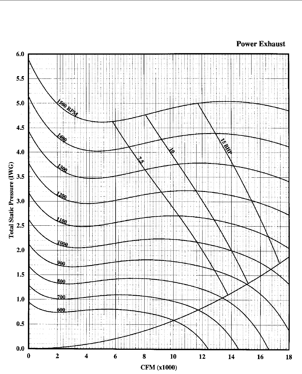
246837-YTG-L-1012
46 Johnson Controls Unitary Products
FIGURE 26 - POWER EXHAUST - TWO FORWARD CURVED FANS - 30 & 40 TONS
246837-YTG-L-1012
Johnson Controls Unitary Products 47
TABLE 41: ELECTRICAL DATA 25 TON BASIC UNIT R-410A
Voltage
Compressors (each) OD Fan Motors Supply Blower
Motor MCA1
(Amps)
Max Fuse2/
Breaker3
Size
(Amps)
Qty RLA LRA MCC Qty FLA HP FLA
208-3-60 4 22.4 149 35 4 4.5
7.5 24.2 138 150
10 30.8 146 175
15 46.2 165 200
20 59.4 182 225
230-3-60 4 22.4 149 35 4 4.3
7.5 22 134 150
10 28 142 150
15 42 159 200
20 54 174 225
460-3-60 4 10.6 75 16.5 4 2.15
7.5 11 65 70
10 14 69 80
15 21 77 90
20 27 85 110
575-3-60 4 7.7 54 12 4 1.7
7.5 9 49 50
10 11 51 60
15 17 59 70
20 22 65 80
1. Minimum Circuit Ampacity.
2. Dual Element, Time Delay Type.
3. HACR type per NEC.
TABLE 42: ELECTRICAL DATA 30 TON BASIC UNIT R-410A
Voltage
Compressors (each) OD Fan Motors Supply Blower
Motor MCA1
(Amps)
Max Fuse2/
Breaker3
Size
(Amps)
Qty RLA LRA MCC Qty FLA HP FLA
208-3-60 4 25.0 164 39 4 5.8
10 30.8 162 175
15 46.2 181 225
25 74.8 217 250
20 59.4 197 250
230-3-60 4 25.0 164 39 4 5.8
10 28 158 175
15 42 176 200
25 68 208 250
20 54 191 225
460-3-60 4 12.0 100 19 4 2.9
10 14 77 90
15 21 86 100
20 27 93 110
25 34 102 125
575-3-60 4 9.0 78 14 4 2.2
10 11 59 60
15 17 66 80
20 22 72 90
25 27 79 100
1. Minimum Circuit Ampacity.
2. Dual Element, Time Delay Type.
3. HACR type per NEC.
246837-YTG-L-1012
48 Johnson Controls Unitary Products
TABLE 43: ELECTRICAL DATA 40 TON BASIC UNIT R-410A
Voltage
Compressors (each) OD Fan Motors Supply Blower
Motor MCA1
(Amps)
Max Fuse2/
Breaker3
Size
(Amps)
Qty RLA LRA MCC Qty FLA HP FLA
208-3-60 4 30.1 255 47 4 5.8
10 30.8 182 200
15 46.2 201 225
20 59.4 218 250
25 74.8 237 300
230-3-60 4 30.1 255 47 4 5.8
10 28 179 200
15 42 196 225
20 54 211 250
25 68 229 250
460-3-60 4 16.7 114 26 4 2.9
10 14 97 110
15 21 105 125
20 27 112 125
25 34 121 150
575-3-60 4 12.2 80 19 4 2.2
10 11 72 80
15 17 79 90
20 22 85 100
25 27 91 110
1. Minimum Circuit Ampacity.
2. Dual Element, Time Delay Type.
3. HACR type per NEC.
246837-YTG-L-1012
Johnson Controls Unitary Products 49
TABLE 44: ELECTRICAL DATA 25 TON w/ELECTRIC HEAT R-410A
Voltage
Compressors
(each)
OD Fan
Motors
(each)
Supply Blower
Motor Electric Heat Option MCA1
(Amps)
Max Fuse2/
Breaker3
Size
(Amps)
Qty RLA LRA MCC FLA HP FLA Option KW Applied Stages Amps
208-3-60 4 22.4 149 35 4.5
7.5 24.2
E4 40 30 1 83
138 150
10 30.8 146 175
15 46.2 165 200
20 59.4 182 225
7.5 24.2
E8 80 60 2 167
197 225
10 30.8 205 225
15 46.2 225 250
20 59.4 241 300
230-3-60 4 22.4 149 35 4.3
7.5 22
E4 40 36.8 1 92
143 150
10 28 150 150
15 42 168 200
20 54 183 225
7.5 22
E8 80 73.6 2 184
212 250
10 28 220 250
15 42 237 250
20 54 252 300
460-3-60 4 10.6 75 16.5 2.15
7.5 11
E4 40 36.8 1 46
71 80
10 14 75 80
15 21 84 90
20 27 91 110
7.5 11
E8 80 73.6 2 92
106 125
10 14 110 125
15 21 119 125
20 27 126 150
7.5 11
E1 108 99.4 3 125
138 150
10 14 142 175
15 21 151 175
20 27 158 175
575-3-60 4 7.7 54 12 1.7
7.5 9
E4 40 36.8 1 40
62 70
10 11 64 70
15 17 72 80
20 22 78 80
7.5 9
E8 80 73.6 2 80
92 110
10 11 94 110
15 17 102 110
20 22 108 125
7.5 9
E1 108 99.4 3 108
120 150
10 11 122 150
15 17 130 150
20 22 136 150
1. Minimum Circuit Ampacity.
2. Dual Element, Time Delay Type.
3. HACR type per NEC.
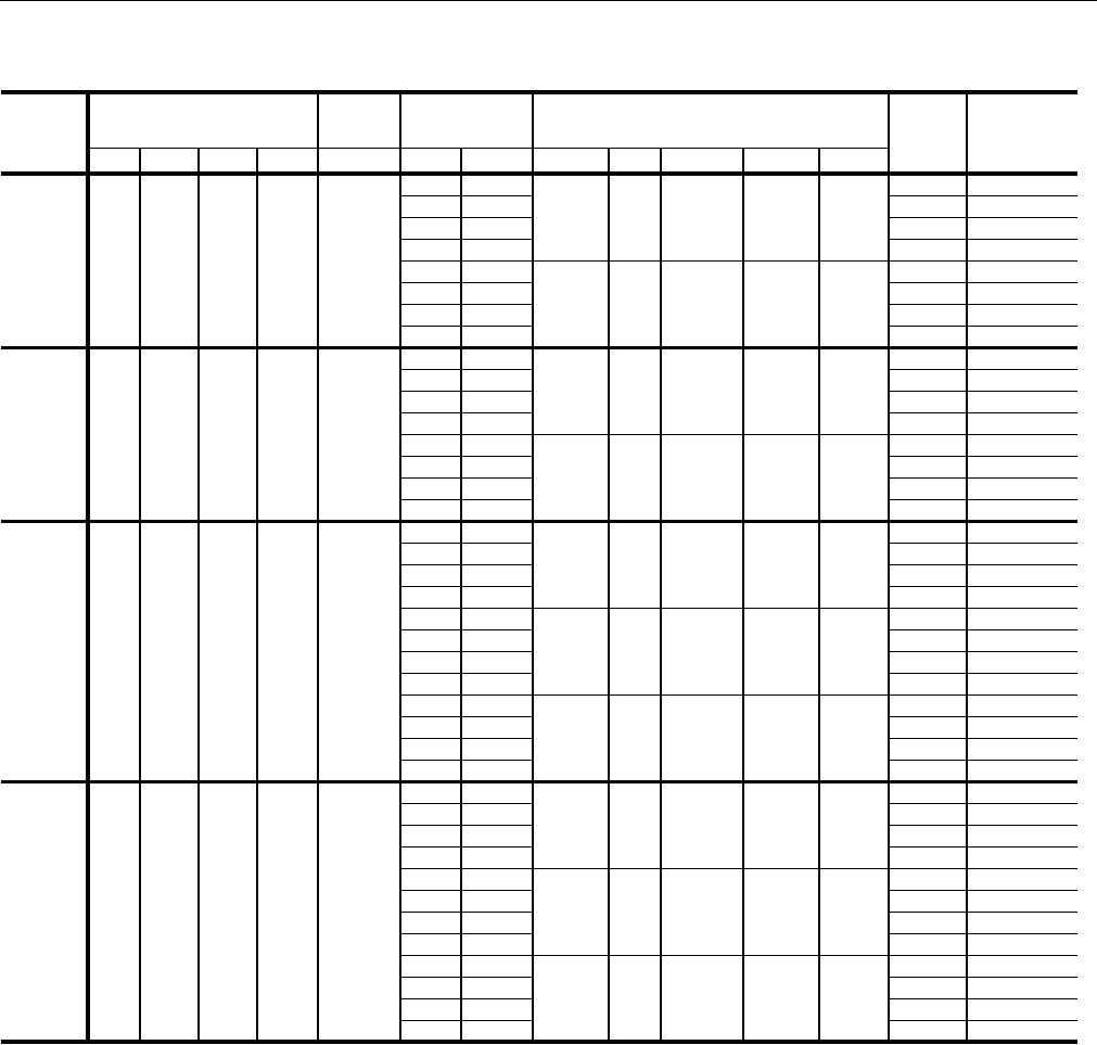
246837-YTG-L-1012
50 Johnson Controls Unitary Products
TABLE 45: ELECTRICAL DATA 30 TON w/ELECTRIC HEAT R-410A
Voltage
Compressors
(each)
OD Fan
Motors
(each)
Supply Blower
Motor Electric Heat Option MCA1
(Amps)
Max Fuse2/
Breaker3
Size
(Amps)
Qty RLA LRA MCC FLA HP FLA Option KW Applied Stages Amps
208-3-60 4 25.0 164 39 5.8
10 30.8
E4 40 30 1 83
162 175
15 46.2 181 225
20 59.4 197 250
25 74.8 217 250
10 30.8
E8 80 60 2 167
205 225
15 46.2 225 250
20 59.4 241 300
25 74.8 260 300
230-3-60 4 25.0 164 39 5.8
10 28
E4 40 36.8 1 92
158 175
15 42 176 200
20 54 191 225
25 68 208 250
10 28
E8 80 73.6 2 184
220 250
15 42 237 250
20 54 252 300
25 68 270 300
460-3-60 4 12.0 100 19 2.9
10 14
E4 40 36.8 1 46
77 90
15 21 86 100
20 27 93 110
25 34 102 125
10 14
E8 80 73.6 2 92
110 125
15 21 119 125
20 27 126 150
25 34 135 150
10 14
E1 108 99.4 3 125
142 175
15 21 151 175
20 27 158 175
25 34 167 200
575-3-60 4 9.0 78 14 2.2
10 11
E4 40 36.8 1 40
64 70
15 17 72 80
20 22 78 90
25 27 84 100
10 11
E8 80 73.6 2 80
94 110
15 17 102 110
20 22 108 125
25 27 114 125
10 11
E1 108 99.4 3 108
122 150
15 17 130 150
20 22 136 150
25 27 142 150
1. Minimum Circuit Ampacity.
2. Dual Element, Time Delay Type.
3. HACR type per NEC.

246837-YTG-L-1012
Johnson Controls Unitary Products 51
TABLE 46: ELECTRICAL DATA 40 TON w/ELECTRIC HEAT R-410A
Voltage
Compressors
(each)
OD Fan
Motors
(each)
Supply Blower
Motor Electric Heat Option MCA1
(Amps)
Max Fuse2/
Breaker3
Size
(Amps)
Qty RLA LRA MCC FLA HP FLA Option KW Applied Stages Amps
208-3-60 4 30.1 255 47 5.8
10 30.8
E4 40 30 1 83
182 200
15 46.2 201 225
20 59.4 218 250
25 74.8 237 300
10 30.8
E8 80 60 2 167
205 225
15 46.2 225 250
20 59.4 241 300
25 74.8 260 300
230-3-60 4 30.1 255 47 5.8
10 28
E4 40 36.8 1 92
179 200
15 42 196 225
20 54 211 250
25 68 229 250
10 28
E8 80 73.6 2 184
220 250
15 42 237 250
20 54 252 300
25 68 270 300
460-3-60 4 16.7 114 26 2.9
10 14
E4 40 36.8 1 46
97 110
15 21 105 125
20 27 112 125
25 34 121 150
10 14
E8 80 73.6 2 92
110 125
15 21 119 125
20 27 126 150
25 34 135 150
10 14
E1 108 99.4 3 125
142 175
15 21 151 175
20 27 158 175
25 34 167 200
575-3-60 4 12.2 80 19 2.2
10 11
E4 40 36.8 1 40
72 80
15 17 79 90
20 22 85 100
25 27 91 110
10 11
E8 80 73.6 2 80
94 110
15 17 102 110
20 22 108 125
25 27 114 125
10 11
E1 108 99.4 3 108
122 150
15 17 130 150
20 22 136 150
25 27 142 150
1. Minimum Circuit Ampacity.
2. Dual Element, Time Delay Type.
3. HACR type per NEC.

246837-YTG-L-1012
52 Johnson Controls Unitary Products
TABLE 47: ELECTRICAL DATA 25 TON w/POWER EXHAUST R-410A
Voltage
Compressors
(each)
OD Fan
Motors
(each)
Supply Blower
Motor Pwr Exh Motor MCA1
(Amps)
Max Fuse2/
Breaker3
Size
(Amps)
Qty RLA LRA MCC FLA HP FLA HP FLA
208-3-60 4 22.4 149 35 4.5
7.5 24.2
5 16.7 155 175
7.5 24.2 162 175
10 30.8 170 200
10 30.8
5 16.7 163 175
7.5 24.2 170 200
10 30.8 177 200
15 46.2
5 16.7 182 225
7.5 24.2 190 225
10 30.8 196 225
20 59.4
5 16.7 199 250
7.5 24.2 206 250
10 30.8 213 250
230-3-60 4 22.4 149 35 4.3
7.5 22
5 15.2 150 150
7.5 22 156 175
10 28 164 175
10 28
5 15.2 157 175
7.5 22 164 175
10 28 170 175
15 42
5 15.2 175 200
7.5 22 181 200
10 28 187 225
20 54
5 15.2 190 225
7.5 22 196 250
10 28 202 250
460-3-60 4 10.6 75 16.5 2.15
7.5 11
5 7.6 72 80
7.5 11 76 80
10 14 80 90
10 14
5 7.6 76 90
7.5 11 80 90
10 14 83 90
15 21
5 7.6 85 100
7.5 11 88 100
10 14 91 110
20 27
5 7.6 92 110
7.5 11 96 110
10 14 99 125
575-3-60 4 7.7 54 12 1.7
7.5 9
5 6.1 55 60
7.5 9 58 60
10 11 60 70
10 11
5 6.1 57 60
7.5 9 60 70
10 11 62 70
15 17
5 6.1 65 80
7.5 9 68 80
10 11 70 80
20 22
5 6.1 71 90
7.5 9 74 90
10 11 76 90
1. Minimum Circuit Ampacity.
2. Dual Element, Time Delay Type.
3. HACR type per NEC.
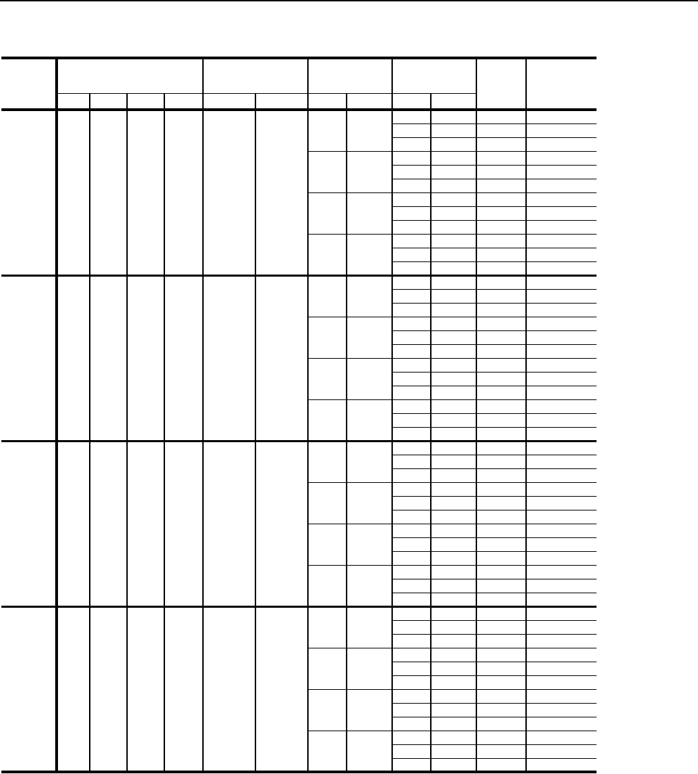
246837-YTG-L-1012
Johnson Controls Unitary Products 53
TABLE 48: ELECTRICAL DATA 30 TON w/POWER EXHAUST R-410A
Voltage
Compressors
(each)
OD Fan
Motors
(each)
Supply Blower
Motor Pwr Exh Motor MCA1
(Amps)
Max Fuse2/
Breaker3
Size
(Amps)
Qty RLA LRA MCC Qty FLA HP FLA HP FLA
208-3-60 4 25.0 164 39 4 5.8
10 30.8
7.5 24.2 186 200
10 30.8 193 200
15 46.2 212 250
15 46.2
7.5 24.2 205 250
10 30.8 212 250
15 46.2 227 250
20 59.4
7.5 24.2 222 250
10 30.8 228 250
15 46.2 244 300
25 74.8
7.5 24.2 241 300
10 30.8 248 300
15 46.2 263 300
230-3-60 4 25.0 164 39 4 5.8
10 28
7.5 22 180 200
10 28 186 200
15 42 204 225
15 42
7.5 22 198 225
10 28 204 225
15 42 218 250
20 54
7.5 22 213 250
10 28 219 250
15 42 233 250
25 68
7.5 22 230 250
10 28 236 300
15 42 250 300
460-3-60 4 12.0 100 19 4 2.9
10 14
7.5 11 88 100
10 14 91 100
15 21 100 110
15 21
7.5 11 97 110
10 14 100 110
15 21 107 125
20 27
7.5 11 104 125
10 14 107 125
15 21 114 125
25 34
7.5 11 113 125
10 14 116 150
15 21 123 150
575-3-60 4 9.0 78 14 4 2.2
10 11
7.5 9 68 70
10 11 70 80
15 17 77 90
15 17
7.5 9 75 90
10 11 77 90
15 17 83 100
20 22
7.5 9 81 100
10 11 83 100
15 17 89 110
25 27
7.5 9 88 110
10 11 90 110
15 17 96 110
1. Minimum Circuit Ampacity.
2. Dual Element, Time Delay Type.
3. HACR type per NEC.

246837-YTG-L-1012
54 Johnson Controls Unitary Products
TABLE 49: ELECTRICAL DATA 40 TON w/POWER EXHAUST R-410A
Voltage
Compressors
(each)
OD Fan
Motors
(each)
Supply Blower
Motor Pwr Exh Motor MCA1
(Amps)
Max Fuse2/
Breaker3
Size
(Amps)
Qty RLA LRA MCC Qty FLA HP FLA HP FLA
208-3-60 4 30.1 225 47.0 4 5.8
10 30.8
7.5 24 206 225
10 31 213 225
15 46 232 250
15 46.2
7.5 24 226 250
10 31 232 250
15 46 248 250
20 59.4
7.5 24 242 300
10 31 249 300
15 46 264 300
25 74.8
7.5 24 261 300
10 31 268 300
15 46 283 350
230-3-60 4 30.1 225 47.0 4 5.2
10 28.0
7.5 22 199 225
10 28 205 225
15 42 222 250
15 42.0
7.5 22 216 250
10 28 222 250
15 42 236 250
20 54.0
7.5 22 231 250
10 28 237 250
15 42 251 300
25 68.0
7.5 22 248 300
10 28 254 300
15 42 268 300
460-3-60 4 16.7 114 26.0 4 2.6
10 14.0
7.5 11 108 110
10 14 111 125
15 21 119 125
15 21.0
7.5 11 116 125
10 14 119 125
15 21 126 150
20 27.0
7.5 11 123 150
10 14 126 150
15 21 133 150
25 34.0
7.5 11 132 150
10 14 135 150
15 21 142 175
575-3-60 4 12.2 80 19.0 4 2.2
10 11.0
7.5 9 81 90
10 11 83 90
15 17 90 100
15 17.0
7.5 9 88 100
10 11 90 100
15 17 96 110
20 22.0
7.5 9 94 110
10 11 96 110
15 17 102 110
25 27.0
7.5 9 100 125
10 11 102 125
15 17 108 125
1. Minimum Circuit Ampacity.
2. Dual Element, Time Delay Type.
3. HACR type per NEC.
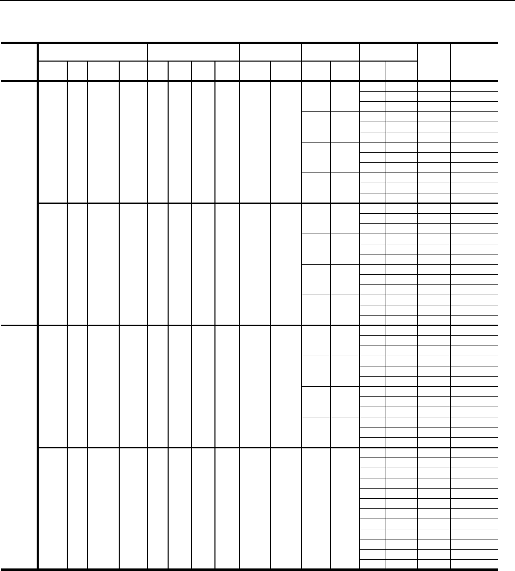
246837-YTG-L-1012
Johnson Controls Unitary Products 55
TABLE 50: ELECTRICAL DATA 25 TON w/ELECTRIC HEAT and POWER EXHAUST R-410A
Voltage
Electric Heat Option Compressors
(each) OD Fan Motors
(each) Supply Blower
Motor Pwr Exh Motor MCA1
(Amps)
Max Fuse2/
Breaker3
Size
(Amps)
Model KW Stages Amps Qty RLA LRA MCC Qty FLA HP FLA HP FLA
208-3-60
E4 40 1 83 4 22.4 149 35 4 4.5
7.5 24.2
5 16.7 155 175
7.5 24.2 162 175
10 30.8 170 200
10 30.8
5 16.7 163 175
7.5 24.2 170 200
10 30.8 177 200
15 46.2
5 16.7 182 225
7.5 24.2 190 225
10 30.8 196 225
20 59.4
5 16.7 199 250
7.5 24.2 206 250
10 30.8 213 250
E8 80 2 167 4 22.4 149 35 4 4.5
7.5 24.2
5 16.7 214 225
7.5 24.2 221 225
10 30.8 230 250
10 30.8
5 16.7 222 250
7.5 24.2 230 250
10 30.8 236 250
15 46.2
5 16.7 241 250
7.5 24.2 249 250
10 30.8 256 300
20 59.4
5 16.7 258 300
7.5 24.2 265 300
10 30.8 272 300
230-3-60
E4 40 1 92 4 22.4 149 35 4 4.3
7.5 22
5 15.2 158 175
7.5 22 165 175
10 28 172 175
10 28
5 15.2 166 175
7.5 22 172 175
10 28 178 200
15 42
5 15.2 183 200
7.5 22 190 200
10 28 196 225
20 54
5 15.2 198 225
7.5 22 205 250
10 28 211 250
E8 80 2 184 4 22.4 149 35 4 4.3
7.5 22
5 15.2 227 250
7.5 22 234 250
10 28 242 250
10 28
5 15.2 235 250
7.5 22 242 250
10 28 248 250
15 42
5 15.2 252 300
7.5 22 259 300
10 28 265 300
20 54
5 15.2 267 300
7.5 22 274 300
10 28 280 300

246837-YTG-L-1012
56 Johnson Controls Unitary Products
460-3-60
E4 40 1 46 4 10.6 75 16.5 4 2.15
7.5 11
5 7.6 79 80
7.5 11 82 90
10 14 86 90
10 14
5 7.6 83 90
7.5 11 86 90
10 14 89 90
15 21
5 7.6 92 100
7.5 11 95 100
10 14 98 110
20 27
5 7.6 99 110
7.5 11 102 110
10 14 105 125
E8 80 2 92 4 10.6 75 16.5 4 2.15
7.5 11
5 7.6 114 125
7.5 11 117 125
10 14 121 125
10 14
5 7.6 117 125
7.5 11 121 125
10 14 124 125
15 21
5 7.6 126 150
7.5 11 130 150
10 14 133 150
20 27
5 7.6 134 150
7.5 11 137 150
10 14 140 150
E1 108 3 125 4 10.6 75 16.5 4 2.15
7.5 11
5 7.6 146 175
7.5 11 149 175
10 14 153 175
10 14
5 7.6 150 175
7.5 11 153 175
10 14 156 175
15 21
5 7.6 158 175
7.5 11 162 175
10 14 165 175
20 27
5 7.6 166 175
7.5 11 169 175
10 14 172 175
TABLE 50: ELECTRICAL DATA 25 TON w/ELECTRIC HEAT and POWER EXHAUST R-410A (CONT.)
Voltage
Electric Heat Option Compressors
(each) OD Fan Motors
(each) Supply Blower
Motor Pwr Exh Motor MCA1
(Amps)
Max Fuse2/
Breaker3
Size
(Amps)
Model KW Stages Amps Qty RLA LRA MCC Qty FLA HP FLA HP FLA

246837-YTG-L-1012
Johnson Controls Unitary Products 57
575-3-60
E4 40 1 40 4 7.7 54 12 4 1.7
7.5 9
5 6.1 68 70
7.5 9 71 70
10 11 73 80
10 11
5 6.1 70 70
7.5 9 73 80
10 11 75 80
15 17
5 6.1 78 80
7.5 9 81 90
10 11 83 90
20 22
5 6.1 84 90
7.5 9 87 90
10 11 89 100
E8 80 2 80 4 7.7 54 12 4 1.7
7.5 9
5 6.1 98 110
7.5 9 101 110
10 11 103 110
10 11
5 6.1 100 110
7.5 9 103 110
10 11 105 110
15 17
5 6.1 108 110
7.5 9 111 125
10 11 113 125
20 22
5 6.1 114 125
7.5 9 117 125
10 11 119 125
E1 108 3 108 4 4 7.7 54 12 4
7.5 9
5 6.1 126 150
7.5 9 129 150
10 11 131 150
10 11
5 6.1 128 150
7.5 9 131 150
10 11 133 150
15 17
5 6.1 136 150
7.5 9 139 150
10 11 141 150
20 22
5 6.1 142 150
7.5 9 145 150
10 11 147 150
1. Minimum Circuit Ampacity.
2. Dual Element, Time Delay Type.
3. HACR type per NEC.
TABLE 50: ELECTRICAL DATA 25 TON w/ELECTRIC HEAT and POWER EXHAUST R-410A (CONT.)
Voltage
Electric Heat Option Compressors
(each) OD Fan Motors
(each) Supply Blower
Motor Pwr Exh Motor MCA1
(Amps)
Max Fuse2/
Breaker3
Size
(Amps)
Model KW Stages Amps Qty RLA LRA MCC Qty FLA HP FLA HP FLA

246837-YTG-L-1012
58 Johnson Controls Unitary Products
TABLE 51: ELECTRICAL DATA 30 TON w/ELECTRIC HEAT and POWER EXHAUST R-410A
Voltage
Electric Heat Option Compressors
(each) OD Fan Motors
(each) Supply Blower
Motor Pwr Exh Motor MCA1
(Amps)
Max Fuse2/
Breaker3
Size
(Amps)
Model KW Stages Amps Qty RLA LRA MCC Qty FLA HP FLA HP FLA
208-3-60
E4 40 1 83 4 25.0 164 39 4 5.8
10 30.8
7.5 24.2 186 200
10 30.8 193 200
15 46.2 212 250
15 46.2
7.5 24.2 205 250
10 30.8 212 250
15 46.2 227 250
20 59.4
7.5 24.2 222 250
10 30.8 228 250
15 46.2 244 300
25 74.8
7.5 24.2 241 300
10 30.8 248 300
15 46.2 263 300
E8 80 2 167 4 25.0 164 39 4 5.8
10 30.8
7.5 24.2 230 250
10 30.8 236 250
15 46.2 256 300
15 46.2
7.5 24.2 249 250
10 30.8 256 300
15 46.2 271 300
20 59.4
7.5 24.2 265 300
10 30.8 272 300
15 46.2 287 300
25 74.8
7.5 24.2 285 350
10 30.8 291 350
15 46.2 307 350
230-3-60
E4 40 1 92 4 25.0 164 39 4 5.8
10 28
7.5 22 180 200
10 28 186 200
15 42 204 225
15 42
7.5 22 198 225
10 28 204 225
15 42 218 250
20 54
7.5 22 213 250
10 28 219 250
15 42 233 250
25 68
7.5 22 230 250
10 28 236 300
15 42 250 300
E8 80 2 184 4 25.0 164 39 4 5.8
10 28
7.5 22 242 250
10 28 248 250
15 42 265 300
15 42
7.5 22 259 300
10 28 265 300
15 42 279 300
20 54
7.5 22 274 300
10 28 280 300
15 42 294 300
25 68
7.5 22 292 350
10 28 298 350
15 42 312 350
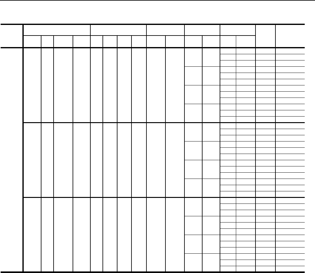
246837-YTG-L-1012
Johnson Controls Unitary Products 59
460-3-60
E4 40 1 46 4 12.0 100 19 4 2.9
10 14
7.5 11 88 100
10 14 91 100
15 21 100 110
15 21
7.5 11 97 110
10 14 100 110
15 21 107 125
20 27
7.5 11 104 125
10 14 107 125
15 21 114 125
25 34
7.5 11 113 125
10 14 116 150
15 21 123 150
E8 80 2 92 4 12.0 100 19 4 2.9
10 14
7.5 11 121 125
10 14 124 125
15 21 133 150
15 21
7.5 11 130 150
10 14 133 150
15 21 140 150
20 27
7.5 11 137 150
10 14 140 150
15 21 147 150
25 34
7.5 11 146 175
10 14 149 175
15 21 156 175
E1 108 3 125 4 12.0 100 19 4 2.9
10 14
7.5 11 153 175
10 14 156 175
15 21 165 175
15 21
7.5 11 162 175
10 14 165 175
15 21 172 175
20 27
7.5 11 169 175
10 14 172 175
15 21 179 200
25 34
7.5 11 178 200
10 14 181 200
15 21 188 200
TABLE 51: ELECTRICAL DATA 30 TON w/ELECTRIC HEAT and POWER EXHAUST R-410A (CONT.)
Voltage
Electric Heat Option Compressors
(each) OD Fan Motors
(each) Supply Blower
Motor Pwr Exh Motor MCA1
(Amps)
Max Fuse2/
Breaker3
Size
(Amps)
Model KW Stages Amps Qty RLA LRA MCC Qty FLA HP FLA HP FLA
246837-YTG-L-1012
60 Johnson Controls Unitary Products
575-3-60
E4 40 1 40 4 9.0 78 14 4 2.2
10 11
7.5 9 73 80
10 11 75 80
15 17 83 90
15 17
7.5 9 81 90
10 11 83 90
15 17 89 100
20 22
7.5 9 87 100
10 11 89 100
15 17 95 110
25 27
7.5 9 93 110
10 11 95 110
15 17 101 110
E8 80 2 80 4 9.0 78 14 4 2.2
10 11
7.5 9 103 110
10 11 105 110
15 17 113 125
15 17
7.5 9 111 125
10 11 113 125
15 17 119 125
20 22
7.5 9 117 125
10 11 119 125
15 17 125 125
25 27
7.5 9 123 150
10 11 125 150
15 17 131 150
E1 108 3 108 4 9.0 78 14 4 2.2
10 11
7.5 9 131 150
10 11 133 150
15 17 141 150
15 17
7.5 9 139 150
10 11 141 150
15 17 147 150
20 22
7.5 9 145 150
10 11 147 150
15 17 153 175
25 27
7.5 9 151 175
10 11 153 175
15 17 159 175
1. Minimum Circuit Ampacity.
2. Dual Element, Time Delay Type.
3. HACR type per NEC.
TABLE 51: ELECTRICAL DATA 30 TON w/ELECTRIC HEAT and POWER EXHAUST R-410A (CONT.)
Voltage
Electric Heat Option Compressors
(each) OD Fan Motors
(each) Supply Blower
Motor Pwr Exh Motor MCA1
(Amps)
Max Fuse2/
Breaker3
Size
(Amps)
Model KW Stages Amps Qty RLA LRA MCC Qty FLA HP FLA HP FLA

246837-YTG-L-1012
Johnson Controls Unitary Products 61
TABLE 52: ELECTRICAL DATA 40 TON w/ELECTRIC HEAT and POWER EXHAUST R-410A
Voltage
Electric Heat Option Compressors
(each) OD Fan Motors
(each) Supply Blower
Motor Pwr Exh Motor MCA1
(Amps)
Max Fuse2/
Breaker3
Size
(Amps)
Model KW Stages Amps Qty RLA LRA MCC Qty FLA HP FLA HP FLA
208-3-60
E4 40 1 83 4 30.1 255 47 4 5.8
10 30.8
7.5 24.2 206 225
10 30.8 213 225
15 46.2 232 250
15 46.2
7.5 24.2 226 250
10 30.8 232 250
15 46.2 248 250
20 59.4
7.5 24.2 242 300
10 30.8 249 300
15 46.2 264 300
25 74.8
7.5 24.2 261 300
10 30.8 268 300
15 46.2 283 350
E8 80 2 167 4 30.1 255 47 4 5.8
10 30.8
7.5 24.2 230 250
10 30.8 236 250
15 46.2 256 300
15 46.2
7.5 24.2 249 250
10 30.8 256 300
15 46.2 271 300
20 59.4
7.5 24.2 265 300
10 30.8 272 300
15 46.2 287 300
25 74.8
7.5 24.2 285 350
10 30.8 291 350
15 46.2 307 350
230-3-60
E4 40 1 92 4 30.1 255 47 4 5.8
10 28
7.5 22 201 225
10 28 207 225
15 42 224 250
15 42
7.5 22 218 250
10 28 224 250
15 42 238 250
20 54
7.5 22 233 250
10 28 239 250
15 42 253 300
25 68
7.5 22 251 300
10 28 257 300
15 42 271 300
E8 80 2 184 4 30.1 255 47 4 5.8
10 28
7.5 22 242 250
10 28 248 250
15 42 265 300
15 42
7.5 22 259 300
10 28 265 300
15 42 279 300
20 54
7.5 22 274 300
10 28 280 300
15 42 294 300
25 68
7.5 22 292 350
10 28 298 350
15 42 312 350

246837-YTG-L-1012
62 Johnson Controls Unitary Products
460-3-60
E4 40 1 46 4 16.7 114 26 4 2.9
10 14
7.5 11 108 110
10 14 111 125
15 21 119 125
15 21
7.5 11 116 125
10 14 119 125
15 21 126 150
20 27
7.5 11 123 150
10 14 126 150
15 21 133 150
25 34
7.5 11 132 150
10 14 135 150
15 21 142 175
E8 80 2 92 4 16.7 114 26 4 2.9
10 14
7.5 11 121 125
10 14 124 125
15 21 133 150
15 21
7.5 11 130 150
10 14 133 150
15 21 140 150
20 27
7.5 11 137 150
10 14 140 150
15 21 147 150
25 34
7.5 11 146 175
10 14 149 175
15 21 156 175
E1 108 3 125 4 16.7 114 26 4 2.9
10 14
7.5 11 153 175
10 14 156 175
15 21 165 175
15 21
7.5 11 162 175
10 14 165 175
15 21 172 175
20 27
7.5 11 169 175
10 14 172 175
15 21 179 200
25 34
7.5 11 178 200
10 14 181 200
15 21 188 200
TABLE 52: ELECTRICAL DATA 40 TON w/ELECTRIC HEAT and POWER EXHAUST R-410A (CONT.)
Voltage
Electric Heat Option Compressors
(each) OD Fan Motors
(each) Supply Blower
Motor Pwr Exh Motor MCA1
(Amps)
Max Fuse2/
Breaker3
Size
(Amps)
Model KW Stages Amps Qty RLA LRA MCC Qty FLA HP FLA HP FLA

246837-YTG-L-1012
Johnson Controls Unitary Products 63
575-3-60
E4 40 1 40 4 12.2 80 19 4 2.2
10 11
7.5 9 81 90
10 11 83 90
15 17 90 100
15 17
7.5 9 88 100
10 11 90 100
15 17 96 110
20 22
7.5 9 94 110
10 11 96 110
15 17 102 110
25 27
7.5 9 100 125
10 11 102 125
15 17 108 125
E8 80 2 80 4 12.2 80 19 4 2.2
10 11
7.5 9 103 110
10 11 105 110
15 17 113 125
15 17
7.5 9 111 125
10 11 113 125
15 17 119 125
20 22
7.5 9 117 125
10 11 119 125
15 17 125 125
25 27
7.5 9 123 150
10 11 125 150
15 17 131 150
E1 108 3 108 4 12.2 80 19 4 2.2
10 11
7.5 9 131 150
10 11 133 150
15 17 141 150
15 17
7.5 9 139 150
10 11 141 150
15 17 147 150
20 22
7.5 9 145 150
10 11 147 150
15 17 153 175
25 27
7.5 9 151 175
10 11 153 175
00 0 0
1. Minimum Circuit Ampacity.
2. Dual Element, Time Delay Type.
3. HACR type per NEC.
TABLE 52: ELECTRICAL DATA 40 TON w/ELECTRIC HEAT and POWER EXHAUST R-410A (CONT.)
Voltage
Electric Heat Option Compressors
(each) OD Fan Motors
(each) Supply Blower
Motor Pwr Exh Motor MCA1
(Amps)
Max Fuse2/
Breaker3
Size
(Amps)
Model KW Stages Amps Qty RLA LRA MCC Qty FLA HP FLA HP FLA
246837-YTG-L-1012
64 Johnson Controls Unitary Products
NOTE: If the Millennium is VAV with ERV, add the weight of an
exhaust VFD - it will be in the unit.
TABLE 53: UNIT WEIGHTS
COMPONENT 25 TON 30 TON 40 TON
Basic Unit 4410 4565 4845
Gas Heat
267 MBH 180 180 180
533 MBH 320 320 320
800 MBH - - 450
Electric Heat
40KW 40 40 40
80KW 105 105 105
108KW 110 110 110
Hot Water Heat
1 Row Coil 70 70 70
2 Row Coil 85 85 85
Steam Heat
1 Row Coil 85 85 85
Blower
Forward Curve Fan (Std Fan) 0 0 0
FC IGV 155 155 175
Air Foil Fan 135 135 155
AF IGV 155 155 180
Motor - Supply Fan
7.5hp 110 - -
10hp 145 145 145
15hp 200 200 200
20hp 240 240 240
25hp - 300 300
Supply Fan Motor VFD See Table 54
Refrigeration
T-Coat Evap. 32 30 40
T-Coat cond. 32 30 40
Hot Gas Bypass 10 10 10
Low Ambient Head Pressure Control
208-230/380/460 5 5 5
575 25 25 25
Filters
6" Rigid 70 70 70
Exhaust1
1. If ERV and Supply Fan VAV are selected, add the weight of an
Exhaust VFD, Table 54.
Exhaust Type
Barometric 45 65 65
Modulated 140 275 275
Exhaust Motor
5hp 80 80 80
7.5hp 110 110 110
10hp 145 145 145
15hp 200 200 200
Exhaust Motor VFD See Table 55
Economizer
Std. Econ. 235 235 235
Econ. w/ERV 50 50 50
Control
Disconnect 15 15 15
110V outlet 55 55 55
Optilogic 20 20 20
Roof Curb
Partial Curb 415 415 415
TABLE 54: SUPPLY FAN MOTOR VFD WEIGHTS
Supply Fan Motor VFD 230V 460V 575V
W/O Bypass
7.5hp 60 25 30
10hp 60 25 30
15hp 75 50 60
20hp 75 50 60
25hp 115 50 60
W/Bypass
7.5hp 155 90 120
10hp 155 90 120
15hp 185 140 155
20hp 185 140 155
25hp 255 140 155
TABLE 55: EXHAUST FAN MOTOR VFD WEIGHTS
Exhaust Fan Motor 230V 460V 575V
W/O Bypass
5hp 15 10 20
7.5hp 50 15 20
10hp 50 15 20
15hp 65 40 50
FIGURE 27 - CENTER OF GRAVITY
TABLE 56: UNIT CENTER OF GRAVITY
MODEL 25 TON 30 TON 40 TON
X*YX
*YX
*Y
BASIC UNIT 99” 48” 100” 47” 96” 46"
BASIC UNIT /W
ECON.110” 48” 110” 47” 100” 46"
BASIC UNIT /W
ECON. & GAS OR
ELECT. HEAT,
STEAM OR HOT
WATER HEAT
104” 48” 104” 46” 99” 45"
BASIC UNIT /W
ECON. & GAS OR
ELECT. HEAT, &
POWER EXHAUST
118” 47” 114” 46” 111” 45"
D
RIGHT END
CONDENSER
COILS
FRONT
CENTER OF
GRAVITY
REAR
240”
92”
A
B
Y
X
C

246837-YTG-L-1012
Johnson Controls Unitary Products 65
NOTES:Basic Unit = cooling only, 10hp FC fan.
+ Econ = +235lb
+ Heat = single stage gas, 180 lb
+ Power Exhaust = modulating 7.5hp
Sound Power Ratings for Supply Air Blowers in our Millenium
Units with High Gas Heat, Economizer, 2: T/A Filters and Wet
DX Sound power calculations complements of Lau’s revised
“Whirlwind” application selection software for air moving com-
ponents.
The sound ratings above occur at the blower wheel. To deter-
mine the sound rating at a unit’s supply and return air duct
connection, subtract the attenuation factors listed below.
TABLE 57: UNIT CORNERWEIGHT
UNIT
DESCRIPTION 25 TON 30 TON 40 TON
ABCDAB CDABCD
BASIC UNIT 870 949 1352 1239 930 972 1360 1303 969 969 1454 1454
BASIC UNIT WITH
ECONOMIZER 1018 1111 1313 1203 1076 1124 1328 1272 1058 1058 1482 1482
BASIC UNIT WITH
ECONOMIZER AND
GAS OR ELECTRIC
HEAT
994 1084 1418 1300 1073 1073 1403 1403 1102 1055 1503 1570
BASIC UNIT WITH
ECONOMIZER AND
GAS OR ELECTRIC
HEAT AND POWER
EXHAUST
1220 1275 1318 1262 1275 1275 1410 1410 1335 1278 1485 1551
TABLE 58: INDOOR SOUND POWER RATING
MODEL NUMBER CFM ESP BLOWER SOUND POWER (DB 10-12 WATTS)
OCTAVE BAND CENTERLINE FREQUENCY (Hz) dba
IWG RPM BHP 63 125 250 500 1000 2000 4000 8000
Z42 10,000 1.5 750 7.5 90 88 85 85 80 78 74 68 87
Z33 12750 1.5 840 12.8 93 91 88 88 83 81 77 71 90
Z34 17500 1.3 800 20 95 92 89 89 84 83 78 72 91
TABLE 59: ATTENUATION FACTORS
LOCATION
OCTAVE BAND CENTERLINE FREQUENCY (HZ)
63 125 250 500 1000 2000 4000 8000
SOUND ATTENUATION (DB12 WATTS)
SUPPLY AIR 11 13 18 10 21 21 23 23
RETURN AIR 13 15 22 23 25 25 29 29
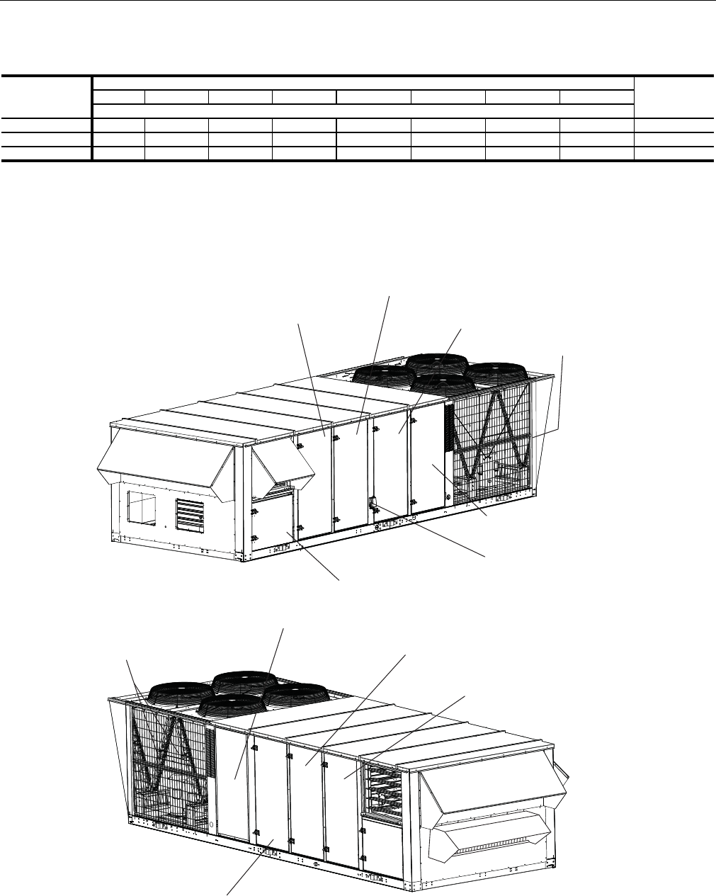
246837-YTG-L-1012
66 Johnson Controls Unitary Products
NOTE: These values have been accessed using a model of
sound propagation from a point source into the
hemispheric free field (AMCA 303-79). The dBA val-
ues provided are to be used for reference only. Cal-
culation of dBA values cover matters of system
design, and the fan manufacturer has no way of
knowing the details of each system. This constitutes
an exception to any specification or guarantee
requiring a dBA value or sound data in any other
form than sound power level ratings.
TABLE 60: OUTDOOR SOUND POWER RATING
MODEL
Octave Band Centerline Frequency (Hertz)
db(A)65 125 250 500 1000 2000 4000 8000
Sound Power Level, db (10)-12 Watts
Z42 88 91 89 86 82 79 76 72 88
Z33 87 90 88 86 82 80 77 73 88
Z34 88 91 89 86 82 80 77 73 88
FIGURE 28 - COMPONENT LOCATION
FILTER ACCESS
EVAPORATOR COIL
AND DRAIN PAN ACCESS
POWER & CONTROL WIRING
COMPRESSOR ACCESS
HEAT SECTION
POWER EXHAUST ACCESS
FILTER ACCESS
HEAT SECTION
SUPPLY BLOWER & MOTOR
FILTER DRIERS
RIGHT
END
LEFT END
FRONT
REAR
REAR
OPTIONAL POWER
OUTLET (115V)
EVAPORATOR COIL
AND DRAIN PAN ACCESS
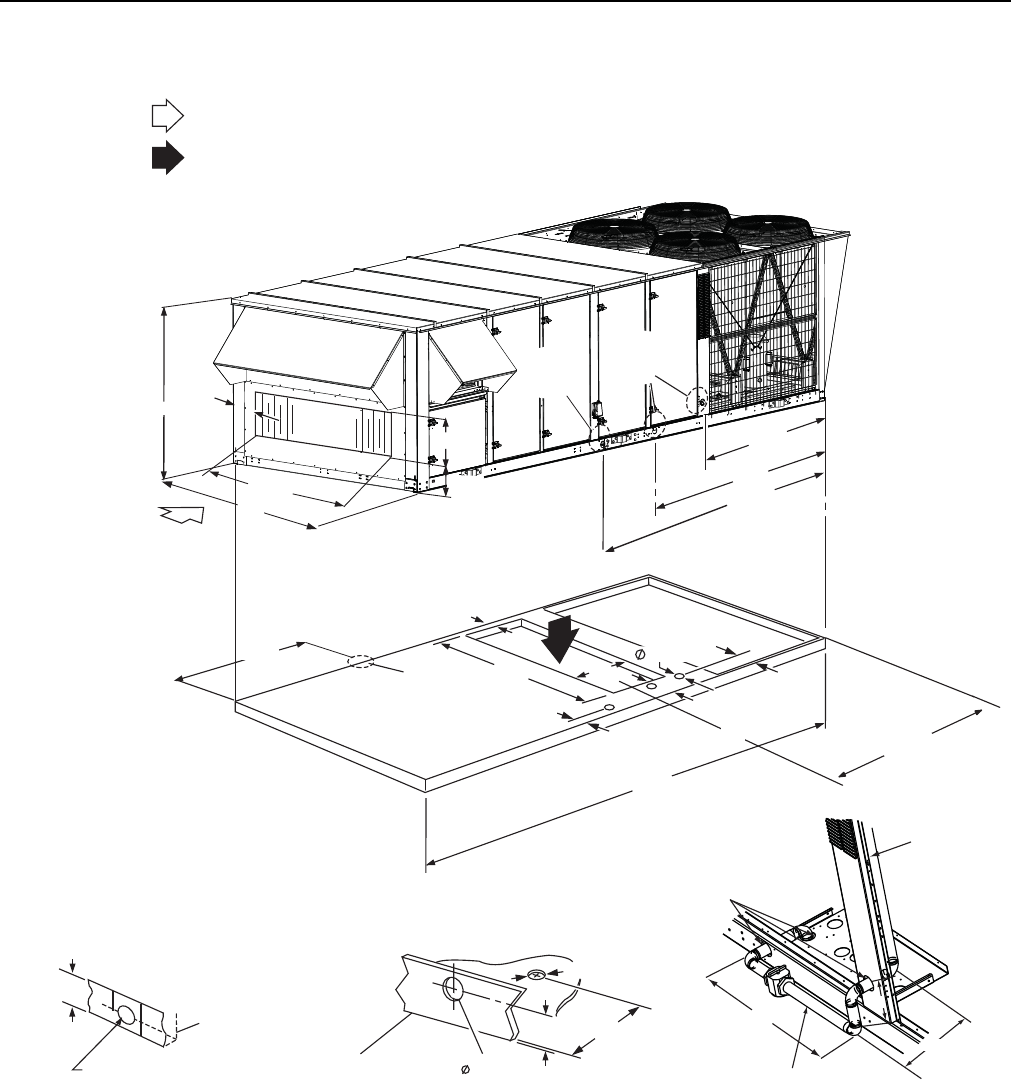
246837-YTG-L-1012
Johnson Controls Unitary Products 67
FIGURE 29 - END RETURN, BOTTOM SUPPLY
RETURN AIR
SUPPLY AIR
1-1/2" FPT
2.31”
3-5/8"
6.45"
2-1/2"
NOTE:
FACTORY INSTALLED POWER
EXHAUST CANNOT BE ORDERED
WITH END RETURN.
DETAIL A
(DRAIN CONNECTION)
DETAIL B
(ELECTRICAL CONNECTION)
FOR COOLING ONLY AND ALL HEATING APPLICATIONS
BASE RAIL
BASE RAIL
28”
2-1/2”
DIA. HOLES
TO GAS VALVE
MANIFOLD
7”
1-1/4” NPT
11”
DETAIL C
(GAS CONNECTION
THROUGH CURB)
4-5/8”
240"
64"
SEE
DETAIL
A
99.5”
131.5”
SEE
DETAIL
B
72.25”
OPEN
7-7/8”
76-3/8”
24.9”
"
6.25”
26"
4.5"
15.89"
71.61"
SEE
DETAIL
C
3.625"
6.46"
12"
MIN
C
L
88.7"
REAR
RIGHT END
LEFT END FRONT
FRONT
RIGHT
END
LEFT END
REAR
92"
80.93"
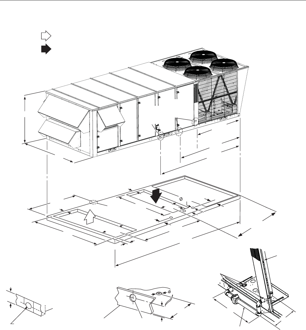
246837-YTG-L-1012
68 Johnson Controls Unitary Products
FIGURE 30 - BOTTOM SUPPLY AND RETURN
88.7"
C
L
C
L
240"
38.59"
83"
4.5"
4.5"
64"
92"
80.93"
SEE
DETAIL
A
26"
4.5"
15.89"
71.61"
127.5"
72.25”
OPEN
3.625"
6.46"
12"
MIN
SUPPLY AIR
RETURN AIR
REAR
REAR
LEFT
END
LEFT
END
RIGHT
END
RIGHT
END
FRONT
FRONT
2.31”
Ø 2-1/2”
3-5/8"
6.45"
BASE RAIL
DETAIL B
(ELECTRICAL CONNECTION)
FOR COOLING ONLY AND ALL HEATING APPLICATIONS
28”
2-1/2”
DIA. HOLES
TO GAS VALVE
MANIFOLD
7”
1-1/4” NPT
11”
DETAIL C
(GAS CONNECTION
THROUGH CURB)
1-1/2" FPT
DETAIL A
(DRAIN CONNECTION)
BASE RAIL
4-5/8”
SEE
DETAIL
C
SEE
DETAIL
B
99.5”
131.5”

246837-YTG-L-1012
Johnson Controls Unitary Products 69
FIGURE 31 - BOTTOM RETURN, FRONT & REAR SUPPLY
1-1/2" FPT
2.31”
3-5/8"
6.45"
2-1/2"
DETAIL A
(DRAIN CONNECTION)
DETAIL B
(ELECTRICAL CONNECTION)
FOR COOLING ONLY AND ALL HEATING APPLICATIONS
BASE RAIL
BASE RAIL
28”
2-1/2”
DIA. HOLES
TO GAS VALVE
MANIFOLD
7”
1-1/4” NPT
11”
DETAIL C
(GAS CONNECTION
THROUGH CURB)
4-5/8”
FRONT SUPPLY: FOR COOLING ONLY APPLICATIONS
REAR SUPPLY: FOR COOLING ONLY OR GAS HEAT APPLICATIONS
RETURN AIR
SUPPLY AIR
240"
38.59"
83"
4.5"
4.5"
64"
92"
80.93"
SEE
DETAIL
A
99.5”
131.5”
72.25”
OPEN
26"
3.625"
6.46"
12"
MIN
SEE
DETAIL
C
SEE
DETAIL
B
8.15"
FRONT
FRONT
FRONT
REAR
REAR
LEFT END
LEFT END
REAR
RIGHT END
RIGHT
END
55"
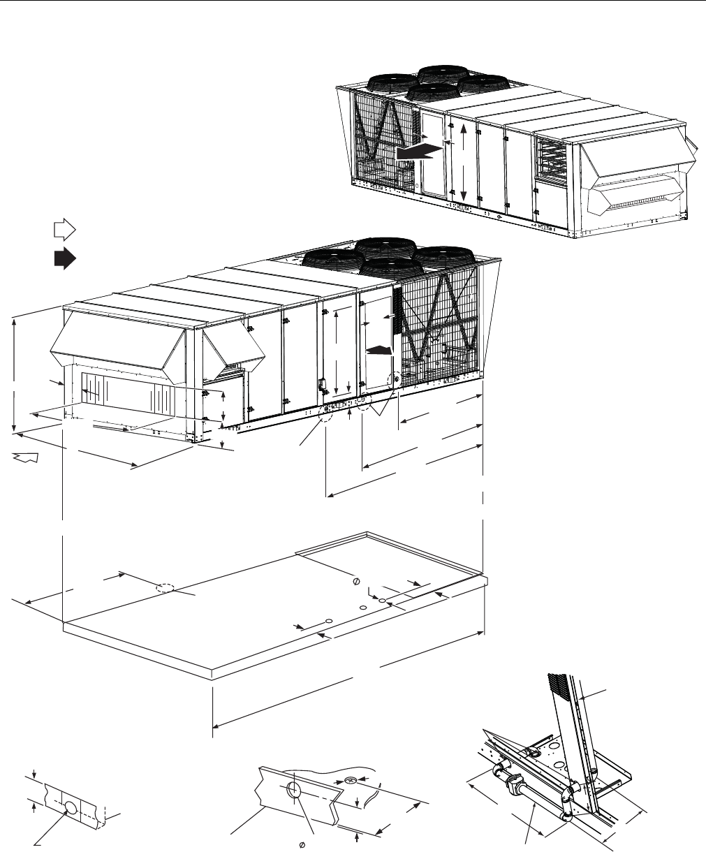
246837-YTG-L-1012
70 Johnson Controls Unitary Products
FIGURE 32 - END RETURN, FRONT & REAR SUPPLY
FRONT SUPPLY: FOR COOLING ONLY APPLICATIONS
REAR SUPPLY: FOR COOLING ONLY OR GAS HEAT APPLICATIONS
RETURN AIR
SUPPLY AIR
2 4 0 "
64”
92”
8 0 . 9 3 "
SEE
DETAIL
A
99.5”
131.5”
SEE
DETAIL
C
SEE
DETAIL
B
26"
55"
72.25”
OPEN
7-7/8”
8.15"
24.9”
6.25”
3 . 6 2 5 "
6 . 4 6 "
1 2 "
M I N
55"
RIGHT
END
RIGHT
END
LEFT
END
LEFT
END
REAR
REAR
REAR
FRONT
FRONT
1-1/2" FPT
2.31”
3-5/8"
6.45"
2-1/2"
DETAIL A
(DRAIN CONNECTION)
DETAIL B
(ELECTRICAL CONNECTION)
FOR COOLING ONLY AND ALL HEATING APPLICATIONS
BASE RAIL
BASE RAIL
28”
2-1/2”
DIA. HOLES
TO GAS VALVE
MANIFOLD
7”
1-1/4” NPT
11”
DETAIL C
(GAS CONNECTION
THROUGH CURB)
4-5/8”
FRONT
26"
26"
76-3/8”
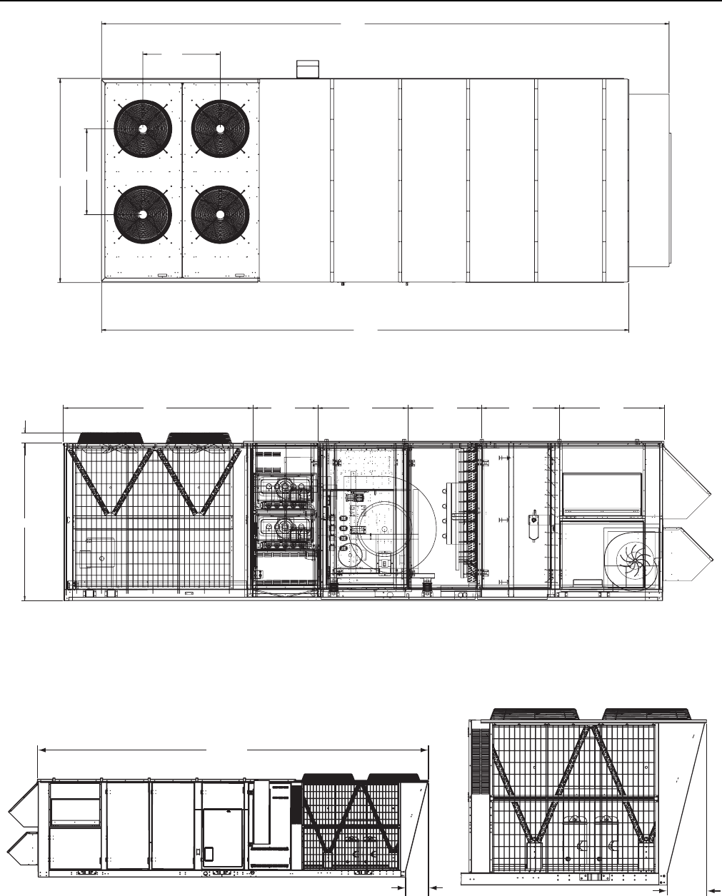
246837-YTG-L-1012
Johnson Controls Unitary Products 71
FIGURE 33 - MILLENNIUM OVERHEAD VIEW
259.68
35.42
39.31
93.43
241.22
FIGURE 34 - MILLENNIUM MAJOR COMPONENT LAYOUT
CONDENSER SECTION GAS HEAT
SECTION
BLOWER
SECTION
EVAPORATOR
SECTION
FILTER
SECTION
ECONOMIZER POWER
EXHAUST SECTION
64”
4.19”
75.93” 25.95” 36.08” 29.73” 31.13” 41.94”
FIGURE 35 - 40 TON SIDE & CONDENSER END VIEW
255.00
15.00
40 TON ONLY
15.00
40 TON CONDENSER SECTION

246837-YTG-L-1012
72 Johnson Controls Unitary Products
FIGURE 36 - MILLENNIUM CABINET DOOR CONFIGURATION
BACK VIEW
123 4
Hinged,
Tool-Free
Door
Optional
Hinged,
Tool-Free
Door
Hinged,
Tool-Free
Door
Hinged, Tool-Free
w/PE Option
5
Hinged, Tool-Free
w/PE Option
67 8
Hinged,
Tool-Free
Door
Optional
Hinged,
Tool-Free
Door
Hinged,
Tool-Free
Door
9
Hinged,
Tool-Free
w/Gas
or Other
Heat Source
FRONT VIEW
1.
2.
3.
STD Cabinet Option includes Hinged, Tool-Free
Doors # 1, 3, 6, 8.
Premium Cabinet Option includes Hinged, Tool-Free
Doors # 1, 2, 3, 6, 7, 8.
Doors # 4, 5, 9 are dependent upon unit Heating
and Power Exhaust Options.
Doors 1, 2, 3, 6, 7, 8 & 9 are 56.31 inches high by
27.33 inches wide.
Doors 4 & 5 are 26.5 inches high by 33.63 inches
wide.
4.
5.
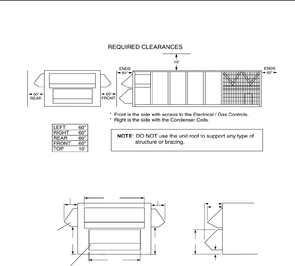
246837-YTG-L-1012
Johnson Controls Unitary Products 73
FIGURE 37 - CLEARANCES - HOOD/ECONOMIZER & MOTOR DRIVE - SIDE
FIGURE 38 - CLEARANCES - HOOD/ECONOMIZER & MOTOR DRIVE - FRONT & END
RAIN HOOD FOR
FIXED OUTSIDE AIR
OR ECONOMIZER
RAIN HOOD FOR
OPTIONAL POWER EXHAUST
OR BAROMETRIC RELIEF
(NOT AVAILABLE WITH
END RETURN OR WITH
FIXED OUTSIDE AIR)
HOOD FOR
OPTIONAL
EXHAUST AIR
(NOT AVAILABLE WITH
END RETURN
OR WITH
FIXED OUTSIDE AIR
)
33.90
15.93 79.0 15.93
19.6
20.12
29.36
7.94
33.90
59.52
LEFT END
FRONT SIDE
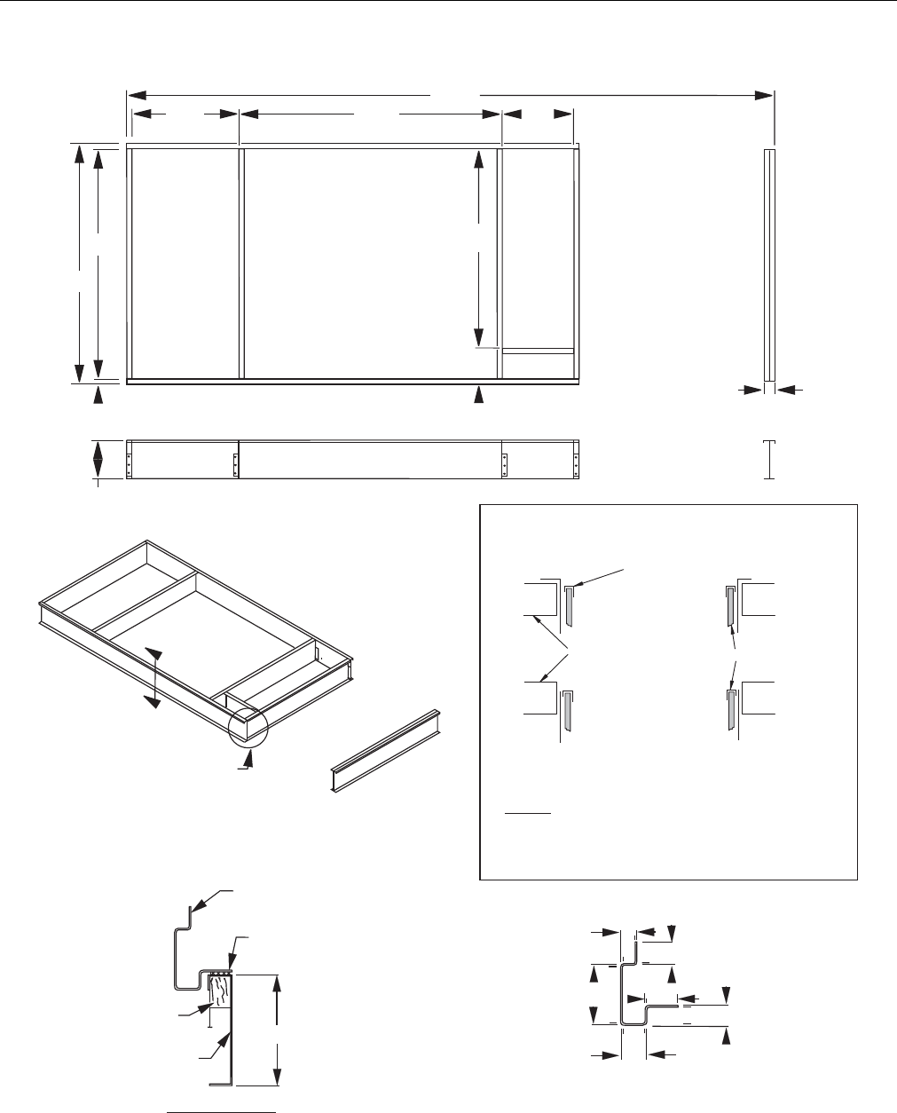
246837-YTG-L-1012
74 Johnson Controls Unitary Products
FIGURE 39 - PARTIAL ROOF CURB MODEL 1RC0455P
8 3 . 0 0
8 7 . 0 0
3 8 . 5 9 9 5 . 0 9 2 6 . 0 0
2 3 5 . 0 0
4 . 0 0
2 . 0 0
1 4 . 0 0
7 1 . 6 1
1 1 . 3 9
S U P P L Y
A I R
O P E N I N G
R E T U R N
A I R
O P E N I N G
BASE RAIL
( Y O R K U N I T )
C U R B G A S K E T
2 " X 4 "
N A I L E R
1 4 G A . G A L V S T E E L
R O O F C U R B
S E C T I O N " A - A "
( 1 4 . 0 0 )
A
A
S E E S E C T I O N " A - A "
B A S E R A I L C R O S S - S E C T I O N
1.25"
1.75"
2.50"
1.50"
2.00"
4 . 6 3 "
I n s u l a t i o n E d g e
P r o t e c t o r
( S h e e t M e t a l
N o s e P i e c e )
F I E L D S U P P L I E D
D U C T
A
B
A - I F U N I T I S N O T I N S T A L L E D
B - I F U N I T I S A L R E A D Y I N S T A L L E D
N O T E : P r o t e c t i n s u l a t i o n w i t h a s h e e t m e t a l
n o s e p i e c e w h e n i n s t a l l i n g a i n t e r n a l l y i n s u l a t e d
d u c t w o r k .
T y p i c a l I n s u l a t i o n
T Y P I C A L D U C T I N S T A L L A T I O N S

246837-YTG-L-1012
Johnson Controls Unitary Products 75
GUIDE SPECIFICATIONS - YORK
MILLENNIUM 25, 30, & 40 TON UNITS
GENERAL
Units shall be manufactured by Johnson Controls Unitary
Products in an ISO 9001 certified facility. Introducing the
YORK Millennium 25, 30, & 40 ton rooftop line - units
designed to provide peak performance and value both today
and for years to come. Millennium units are manufactured at
an ISO 9001 registered facility, and each rooftop is com-
pletely computer-run tested prior to shipment. The Millennium
is designed to be flexible enough to meet your needs today
and in the future. The true value of York's Millennium is that it
can be designed to fit any need, from cooling only, constant
volume applications to variable air volume systems with vari-
able frequency drive.
DESCRIPTION
Supply York Millennium packaged rooftop system in accor-
dance with the capacities in the plans. Units shall be rated by
the manufacturer at a minimum 10.0 EER according to AHRI
360. Units shall be shipped in a single package, fully charged
with R-410A refrigerant. The manufacturing facility shall be
registered under ISO 9001 Quality Standards for Manufactur-
ing. Units shall carry both ETL and CGA safety approval rat-
ings. Tags and decals to aid in the service or indicate caution
areas shall be provided. Installation and maintenance manu-
als shall be supplied with each unit. Units shall be capable of
providing mechanical cooling down to 40°F (0°F with low
ambient kit). Unit shall be capable of starting and running at
125°F. Unit electric and gas connections shall be either
through the curb or the side of the unit.
CONSTRUCTION
Base
The base rail shall be constructed of 12 gauge galvanized
steel, extending the full perimeter of the unit. All components
shall be supported from the base, and the base shall include
integral lifting lugs. The unit base rail shall overhang the roof
curb for water runoff and shall have a fabricated recess with a
continuous flat surface to seat on the roof curb gasket, pro-
viding a positive, weather tight seal between the unit and the
curb.
Casing
The unit cabinet shall be double wall construction to provide
both maximum resistance to bacterial growth in the air stream
and superior structural integrity. All sheet metal shall be G90
mill galvanized sheet metal, formed and reinforced to provide
a rigid assembly. Sheet metal shall be cleaned in an alkaline
and zinc phosphate bath, and the exterior surfaces shall be
coated with a 1.5 mil powder paint, capable of withstanding
1000 salt spray hours in accordance with ASTM B-117. The
unit shall be insulated with 1-1/2," 1 pound fiberglass insula-
tion between the two sheet metal skins. Insulation shall meet
NFPA-90A regulations for smoke and flame spread ratings.
The cabinet corner post and the intermediate side supports
shall be 16 gauge steel. All access doors shall be 18 gauge
on the exterior surfaces, and 20 gauge on the interior. Floor
shall be 18 gauge, and 24 gauge. All serviceable sections
shall have hinged access doors with latches on both sides of
the unit. All access doors shall be constructed of 20 gauge
steel on the outside, with 24 gauge on the inside. Each door
shall seal against a rubber gasket to prevent air and water
leakage. The roof shall be double wall, with 18 gauge on the
external surface and 24 gauge on the interior. The roof shall
be formed with a 45 degree drip lip overhanging the sidewalls
to prevent precipitation drainage from streaming down the
side of the unit. Roof sections shall be connected together via
integral channels fastened with screws and sealed with rub-
ber gasketing. Each fastened seam shall be further protected
by a sheet metal channel covering the full length of the gas-
ket surface, making a completely water tight seal.
SUPPLY AIR SYSTEM
SUPPLY AIR FAN
Fans shall be centrifugal type - Class I or Class II, statically
and dynamically balanced in the factory. Fan wheels shall be
designed for continuous operation at the maximum rate of fan
speed and motor HP. The fan and motor assembly shall be
mounted on a common base to allow consistent belt tension
with no relative motion between the fan and motor shafts.
The entire assembly shall be isolated from the unit base with
(optional 1”, 2" deflection springs or rubber isolators). The fan
discharge shall be connected to the cabinet through a rein-
forced neoprene flexible connection to eliminate vibration
transmission from the fan to the unit casing. Fans shall be
double-width, double-inlet with forward curved blades.
OPTIONAL
On variable air volume units without variable frequency
drives, fans shall be provided with heavy gauge, corrosion
resistant blades, with zinc-plated steel inter-locking operating
mechanism. Both inlet vanes must operate from a single
shaft and be synchronized for precise control.
Units equipped with variable frequency drive on supply fan
must be controlled by a duct static transducer providing a 2-
10 VDC signal to the drive. Supply fan variable frequency
drives shall have factory option of being equipped with a
manual drive bypass.
BEARINGS AND DRIVES
Bearings shall be self-aligning pillow-block re-greasable ball
bearings with an average life expectancy of 200,000 hours.
Grease fittings shall be accessible through access doors. Fan
motors shall be NEMA designed, Standard efficiency (option,
Hi-efficiency) ball bearing type with electrical characteristics

246837-YTG-L-1012
76 Johnson Controls Unitary Products
and horsepower as specified. Motors shall be 1750 RPM,
open drip proof type. The motor shall be located within the
unit on an adjustable, heavy steel base. All fan motor drives
shall be selected for a minimum service factor of 1.2 and
have fixed pitched sheaves.
AIR FILTERING SYSTEM
All filter holding frames shall be of heavy duty construction
designed for industrial applications. All filters shall be either
side accessible or front loading with access doors provided
on both sides of the filter section. All filter media shall be
Class II listed under UL Standard 900. Filter efficiencies shall
be rated in accordance with ASHRAE Standard 52-76 2"
Throwaway Filters with fiberglass media multiple shall be
standard
OPTIONAL
Two inch pleated, throwaway filters with 30% efficiency. Rigid
filters shall be high performance, expanded area, disposable
type filters. Rigid filter sections shall be preceded by a 2
throwaway prefilter assembly. Filter efficiency shall be 95%
(Option: 65%) based on ASHRAE Standard 52-76.
AIR INLET SYSTEM
General
Outside Air inlet openings shall be covered by a factory
installed rain hood permanently attached to the cabinet to
prevent windblown precipitation from entering the unit. The
rain hoods on the front and back of the unit shall be rotated
into the cabinet and secured for shipment so that upon instal-
lation they need only be rotated upwards and screwed into
place. The outside air hood shall contain a removable and
cleanable filter with an efficiency rating of 50% based on
ASHRAE 52- 76. All damper assemblies shall be of low leak
design. Damper blades shall be fabricated from a minimum of
16 gauge galvanized steel. Blade ends and edges shall be
covered with vinyl seals. Damper shafts shall be fabricated
from solid steel and mounted in the frame with bronze bear-
ings.
Economizer (Optional)
An economizer shall have outdoor air and return air dampers
that are interlocked and positioned by fully modulating, solid
state damper actuators. The actuators shall be spring loaded
so that the outside air damper will close when power to the
unit is interrupted. The operation of the economizer shall be
fully integrated into the cooling control system. The econo-
mizer shall be available for control via a dry bulb sensor
(Optional: single or dual enthalpy sensors).
RELIEF SYSTEM (Optional)
All units with relief must have an economizer.
On all units not equipped with an economizer, an option shall
be available for a manually adjustable outside air damper that
shall be capable of admitting 0-25% outside air.
Barometric Relief (Optional)
Building air exhaust shall be accomplished through baromet-
ric relief dampers installed in the return air plenum. The
dampers will open relative to the building pressure. The
opening pressure shall be adjustable.
Exhaust Air Fans (Optional)
General - forward curved centrifugal fan(s) shall be installed
in the return air plenum for positive power exhaust. Fans shall
be on a common shaft, driven by a single motor. The fans,
motors and drives shall be of the same quality and design as
specified for the Supply Air Fan, except the fans shall be
Class I. Fans shall be capable of exhausting up to 100% of
the nominal CFM of the unit. Non-modulating Exhaust - Units
with non-modulating power exhaust shall have a barometric
relief damper to prevent outside air from entering in the off
cycle. The fans shall cycle on and off with building pressure.
Modulating Operation - The fans shall be capable of modulat-
ing the amount of air from 0% to 100% of nominal CFM. Mod-
ulation shall be through discharge dampers or variable
frequency motor speed modulation. Dampers or VFD shall be
controlled by static pressure in the conditioned space or
return air duct.
ENERGY RECOVERY VENTILATION (FIELD
INSTALLED OPTION)
General
The packaged rooftop unit shall have attached at the jobsite a
powered exhaust combined with an air intake through a rotat-
ing energy receovery wheel, which captures sensible and
latent heat from the exhaust air stream and returns it to the
incoming air stream. The energy recovery module will be con-
tained in a separate enclosure designed to attach to the end
of the Millennium packaged rooftop unit equipped with Sim-
plicity® Elite™ control.
The Energy Recovery Ventilation module will be capable of
exhausting up to 8,000 (13,000) CFM.
Control parameters for the ERV will be preset in the unit con-
trol.
HEATING SYSTEM
Gas-fired Heating Section (Optional)
One or more gas-fired heating modules shall be installed to
provide the heating requirements per the schedule shown on
the plans. The heat exchanger shall be of tubular design.
Tubes shall be 2-1/4” OD and constructed of minimum 20
gauge, G160 aluminized steel (1.6 mil aluminum silicone
alloy) for corrosion resistance (Optional: 409 Stainless Steel).

246837-YTG-L-1012
Johnson Controls Unitary Products 77
Flue baffles shall be made of 430 stainless steel. Each gas-
fired heat module shall have an induced draft combustion fan
with energy efficient intermittent pilot spark ignition and
redundant main gas valves with pressure regulator. Units with
standing pilot ignition shall not be acceptable. An induced
draft fan shall be provided to maintain a positive flow of air
through each tube, to expel the flue gas and to maintain a
negative pressure within the heat exchanger relative to the
conditioned space. Induced draft fans shall be direct-drive.
One (1) high limit controller per heating module, with auto-
matic reset to prevent the heat exchanger from operating at
an excessive temperature will be installed. A pressure switch
on the combustion section must be provided to prevent igni-
tion until sufficient air flow is established through the heat
exchanger. Secondary airflow safety shall be provided by roll-
out switch protection. The rollout switch shall discontinue fur-
nace operation if the flue becomes restricted. Units shall ship
with an external flue to be shipped in the unit and mounted on
the job site. The flue shall discharge products of combustion
above the unit, preventing recycling of corrosive combustion
gases back through the heat exchanger. Gas heating sec-
tions shall be both ETL and CGA approved to both US and
Canadian safety standards.
Optional Modulating Furnace control or Single Stage control
available.
Electric Heating Section
An electric slip-in heater shall be installed within the rooftop
unit to provide the heating requirements per the schedule
shown on the plans. The electric heater shall be wired in such
a manner as to provide two equal steps of capacity (80 and
108 kW) or a single step of capacity (40 kW). The furnace
shall be an industrial grade design using an open coil(s)
made of the highest grade resistance wire containing 80%
nickel and 20% chromium. The resistance coil(s) shall be
adequately supported in the air stream using ceramic bush-
ings in the supporting framework. Terminals of the coil(s)
shall be stainless steel with high temperature ceramic bush-
ings. The primary high temperature protection shall be an
automatic reset type thermal cut out. Secondary protection
shall be an automatic reset type thermal cut out. Secondary
protection shall be a replaceable thermal link. The operation
of the electric heater shall be an integral part of the roof top
control system. Power connection to the strip heater shall be
through the single power point connection for the entire unit.
Electric heat shall be ETL certified to both US and Canadian
safety standards.
Hot Water Heating Coil
The manufacturer shall furnish and factory install a hot water
coil in the rooftop units, as described in the following specifi-
cations. Water coil capacities and pressure drops shall be
certified in accordance with AHRI Standard 410. The hot
water coil shall have eight fins per inch, 2 tubes per circuit,
and 2" inlet and outlet connection. Primary surface shall be 1/
2" OD copper tube, staggered in direction of airflow. Tubes
shall be mandrel expanded to form fin bond and provide bur-
nished, work-hardened interior surface. Return bends shall
be die formed and silver-brazed to tubes. Headers shall be of
heavy seamless copper tubing, silver-brazed to tubes. Con-
nections shall be of red brass, with male pipe threads, silver
brazed to headers. Connections also have 1/4" FPT drain
plug on each connection. Extended surface shall consist of
die-formed, continuous, aluminum fins with formed channels,
and surface treatment to minimize moisture carry-over. Fins
shall have fully drawn collars to accurately space fins, and to
form a protective sheath for the primary surface. A structural
galvanized steel casing shall protect the coil. Tube sheets on
each end shall have drawn collars to support tubes. An inter-
mediate coil support shall be provided. The coil shall be cir-
cuited to provide free draining and venting, through one vent
and drain. Completed coil, including headers, connections
and return bends shall be tested with 325 pounds com-
pressed air under water. Coils shall be designed for operation
at 250 psig design working pressure.
Steam Heating Coil
The manufacturer shall furnish and factory install a steam
heating coil in the rooftop units, as described in the following
specifications. Steam coil capacities and pressure drops shall
be certified in accordance with AHRI standard 410. The
steam coil shall be constructed in the non-freeze style. The
steam coil shall have six fins per inch, and 2" inlet, and 1 1/2"
outlet connection. Tubes shall be 1" OD seamless copper
tubing with a minimum wall thickness of 0.035" and expanded
into the fin collars for maximum fin-tube bond. Inner distribut-
ing tubes shall be 5/8" OD seamless copper tubing with a
minimum wall thickness of 1/4". The copper to copper joints
shall be joined with high temperature, silver solder. Corru-
gated fins with integral spacing collars shall cover the entire
tube surface. Headers shall be constructed of seamless cop-
per. The header tube holes shall be extruded providing better
tube to header contact for a stronger braze connection. All
header connections shall be of red brass or steel, with male
pipe threads and silver braze to headers. Casing shall be 16
gauge galvanized steel. Chafing shall be prevented by
extruding and flaring the holes in the tube sheet and interme-
diate tube sheet. The core shall be pitched in the direction of
the condensate connection for proper drainage. The com-
pleted coil (including headers and connections) shall be
tested underwater with 325 lbs. compressed air to ensure a
leak free coil.
REFRIGERATION SYSTEM
Units shall have four independent refrigerant circuits for max-
imum load-matching capability. Each refrigerant circuit shall
be controlled with a balance-port thermal expansion valve for
maximum control at low load conditions.
Evaporator Coils
Evaporator coils shall be direct expansion type with inter-
twined circuiting to assure complete coil face activity during
part load operation. Coil fins shall be enhanced aluminum

246837-YTG-L-1012
78 Johnson Controls Unitary Products
type. Coil types shall be 3/8” OD copper, internally enhanced
and mechanically expanded to bond with the fins. Coil casing
shall be fabricated from heavy gauge galvanized steel. All
coils shall be pressure tested at a minimum of 450 PSIG. A
galvanized powder painted steel drain pan shall be provided
under the entire length and width of the evaporator coil,
including all return bends. The main drain pan shall be sloped
a total of 1/4” per foot towards the drainage point. Main drain
pan shall be easily cleanable in the field. The condensate
drain opening shall be flush with the bottom of the drain pan
to allow complete drainage. Coils in excess of 48 inches high
shall have an intermediate drain pan, also fabricated of galva-
nized powder painted steel extending the entire finned length
of the coil to provide better water drainage. Drainage from the
intermediate drain pan shall be to the primary drain pan.
OPTIONAL: Drain pans shall be constructed of stainless
steel. OPTIONAL: Evaporator coils shall be protected by the
TechniCoat 10-1 four coat process. Coils shall be dipped in a
phenolic coating, which provides substantial resistance to
corrosion of aluminum and copper. OPTIONAL: Copper-tube/
Copper-finned evaporator coil assemblies.
Compressors
Units shall have four industrial duty hermetic scroll compres-
sors, independently piped and charged. Compressors shall
have an enlarged liquid carrying capacity to withstand rugged
operating conditions. Compressor frame shall be cast iron,
with cast iron fixed and orbiting scrolls. Each compressor
shall feature a solid state protection module, designed to pro-
tect the compressor from over temperature and overcurrent
conditions. Each compressor shall include the following
safety and convenience devices: replaceable suction screen,
discharge line check valve, and oil sight glass. Compressors
shall be vibration isolated from the unit, and installed in an
easily accessible area of the unit.
Condenser Coils
Condenser coils shall have 3/8” seamless copper tubes,
arranged in staggered rows, mechanically expanded into alu-
minum fins. Coils shall be protected from hail damage with a
V configuration, with individual flat coils rotated 30 from the
vertical plane for each condensing circuit. Condensing coils
shall have an integral subcooler for more efficient, stable
operation. OPTIONAL: Condenser coils shall be protected by
the TechniCoat 10-1 four coat process. Coils shall be dipped
in a phenolic coating, which provides substantial resistance
to corrosion of aluminum and copper. OPTIONAL: Copper-
tube/Copper-finned condenser coil assemblies.
Condenser Fans and Motors
Condenser fans shall be direct drive, propeller type, discharg-
ing vertically. Condenser fan motors shall be 3 phase, totally
enclosed air over (TEAO) type, with built in thermal overload
protection.
Refrigerant Piping
All interconnecting piping between refrigeration components
shall be copper tubing with brazed joints. Each refrigerant cir-
cuit shall be equipped with liquid line filter drier, and moisture
indicating sight glass. Each circuit shall also have both high
and low pressure switches installed on either side of the com-
pressor and include shrader depressors for replacement of
the pressure switches without removing charge. All small
diameter distributor tubing to the evaporator coil shall be pro-
tected by polyurethane sleeves over the length of the tubing
to prevent the tubes from copper-to-copper contact during
shipment or operation.
Hot Gas Bypass (Optional on CV; standard on VAV)
Unit shall have hot gas bypass factory installed on the lead
compressor.
CONTROLS
GENERAL DESCRIPTION
Equipment with Simplicity® as standard shall be factory run-
tested through the control, after the test is complete; there will
be no wires to re-connect. All control wiring points shall be
tested and verified through communication.
The control shall be UL or CSA recognized. The control shall
be manufactured in a manufacturing facility that is certified to
ISO 9001.
COMPRESSOR CONTROL
The control shall have a five-minute Anti-Short Cycle Delay to
prevent excessive compressor cycling. The control shall
have a three-minute minimum run time to insure that oil gets
returned to the compressor each time it starts. The minimum
runtime shall be programmable up to 10 minutes.
The control shall monitor the High Pressure switch, the Low
Pressure switch, and the Compressor Overloads separately
for each refrigeration circuit. The control shall have a 30 sec-
ond Low Pressure Switch bypass when it starts any compres-
sor.
A hard compressor lockout shall occur if the control detects
the same switch trip three times in a two-hour window, which
starts when the first trip occurs. On the first and second trips,
the control will turn the compressor off and wait five-minutes
after the switch re-closes, before restarting the compressor.
The control shall be capable of operating both compressors
and the economizer when there is a call for both stages of
cooling.
The control shall have a means of locking out mechanical
compression below a programmable low ambient trip point.
This must be done without adding extra components to the
unit.

246837-YTG-L-1012
Johnson Controls Unitary Products 79
The control shall have a means of locking out the mechanical
compression when the economizer is operating in free cool-
ing mode without additional components
The control shall have a means of starting the compressor
before the indoor Fan comes on when operating with a Ther-
mostat in the AUTO FAN mode.
FAN CONTROL
The control shall have fully adjustable Fan ON and Fan OFF
delays for both Heating and Cooling settable at the control or
via communication.
The control's default Fan OFF delay for Cooling shall be 30
seconds to take advantage of the remaining capacity in the
coil after the compressor has been turned off.
The control shall lock on the Fan if the high temperature limit
trips three times in one hour of operation.
The control will have a software programmable Fan Mode
Switch for Auto operation or Continuous operation.
When the Fan is in the Continuous mode, it will run continu-
ously during the occupied schedule and in the Auto mode
when in an unoccupied schedule.
The control shall be capable of operating the fan without a G
or fan signal from the thermostat.
EQUIPMENT CONTROL FEATURES
The control shall be capable of communicating on the Stan-
dard Open protocol, Modbus® RTU.
The register data for the Modbus® must be publicly available
and open.
Monitoring Software shall be provided at no cost. The moni-
toring software shall have a flashing icon when any unit wired
to the computer has an alarm. Clicking the flashing icon shall
display the fault code and the details of the fault.
The networking setup shall be completed by connecting a
three-wire daisy chain cable to each unit, then powering all
the units up and pushing a button on each control. There
shall not be any dipswitches to configure the network
address.
The control shall use a communication driver that is capable
of having 64 nodes on the bus before a repeater is needed.
The control shall use non-volatile memory to store the last
five alarms. There shall be a single button to push to recall
these last five alarms. The alarms shall be stored first in last
out. The first flash code shall be the last alarm that occurred.
There shall be a button press sequence to clear the alarms in
non-volatile memory.
The control shall have a button to reset compressor lockouts
without powering the unit down.
The control shall have a button to clear compressor Anti-
Short Cycle Delays. When this button is pressed it will only
clear the Anti-Short Cycle Delays for one cycle only and not
permanently.
The control will be compatible with any BAS (Building Auto-
mation System). Any BAS shall be able to control the equip-
ment when wired to the control's Thermostat Terminal Strip.
The control shall have loading of at least 25 milliamps on all
thermostat inputs for controllers and thermostats that use out-
put TRIACs.
The control shall have a Smoke Detector Shutdown input on
the board. The control shall be powered through this input, so
when the Smoke Detector trips, the control will shut down the
unit immediately.
The control will have low voltage protection for the contactors
and will not energize a contactor if the voltage is below 19.2
VAC, to insure contactor pull-in. If the control has a compres-
sor contactor energized when the voltage drops, it shall not
de-energize the contactor until the voltage drops below 16
VAC, which is the drop out voltage for most contactors.
The control shall have a means of storing compressor run
time. This data shall be available through communication.
The control shall have the ability to clear this data when a
compressor is replaced.
The control shall have the ability to store a name of at least
26 characters in length. The control will leave the factory with
the serial number of the equipment it is in, stored in non-vola-
tile memory in the Name location.
The control shall have the ability to store the model number
of the equipment of at least 26 characters in length. The con-
trol will leave the factory with the model number of the equip-
ment it is in, stored in non-volatile memory.
The control shall have the ability to store the serial number of
the equipment of at least 26 characters in length. The control
will leave the factory with the serial number of the equipment
it is in, stored in non-volatile memory.
The control shall not power the contactors through the ther-
mostat wiring. Dropping voltage over the thermostat wiring
causes chattering contactors when the contactors are pow-
ered in this manner.
The control will operate and monitor up to 3 stages of heat
independently.
The control shall monitor the Gas Heat operation in the heat-
ing mode. It shall monitor the gas valve when there is a call

246837-YTG-L-1012
80 Johnson Controls Unitary Products
for heating. The control shall alarm when there is a call for
heat and no gas valve voltage after 5 minutes.
There will only be one control board for this series of units, for
both CV and VAV operation.
COMFORT CONTROL FEATURES
The control will be installed and tested at the factory where
the equipment is assembled.
The control will use a Wall Senor that has a means of overrid-
ing the unoccupied mode for a programmable amount of
time.
The Unoccupied Override time will be programmed in min-
utes up to 4 hours.
The control will use a Wall Sensor that has a warmer/cooler
dial so the occupants can offset the programmed setpoint by
a programmed amount between 1 and 5 degrees.
The control will have a Supply Air Sensor as standard.
The control will have a Return Air Sensor as standard.
The control will have an Outside Air Sensor as standard.
The control will use the Return Air Sensor in place of the
Space Sensor if the Space Sensor fails for any reason, the
control will have a 365 day Real Time Clock.
The Real Time Clock will be able to do automatic Daylight
Savings Time adjustment.
The control will have an Occupancy Schedule that allows two
different Occupied schedules per day for each of the seven
days of the week individually.
The control will have 20 Holiday Schedules, each capable of
99 days.
The control's Holiday Schedules will have a start time associ-
ated with each schedule.
The control will control the Economizer directly.
The control will be capable of operating the Economizer using
Dry Bulb, Outside Enthalpy, or Differential Enthalpy.
When the control is using Enthalpy to control the Economizer,
it will also have an Outside Air Temperature enable Setpoint.
The control will use two setpoints for Supply Air Temperature
for the Economizer operation. One will be for a small space
cooling demand and one for a large space cooling demand.
The control will have the ability to do Demand Ventilation
using one CO2 sensor.
The control will have a programmable maximum Outside Air
Damper Position for IAQ operation.
The control will have the ability to temper the ventilation air
during times when heating or cooling is not required.
The control will have the ability to offset the operating set-
point based on high Humidity in the Space.
The control will have programmable limits when offsetting the
Operating Setpoint to control Humidity.
The control must be able to lockout Cooling below a program-
mable Outside Air Temperature Setpoint.
The control will be able to lockout Heating above a program-
mable Outside Air Temperature Setpoint.
The control will have a Space Temperature Alarm.
The control will have a Supply Air Temperature Alarm for
Heating and Cooling. The Alarm temperature will be pro-
grammable
The Control will be able to do a Pre-Occupancy Purge at a
Programmable Time.
The control will have a hardware Smoke-Purge input.
The control will have the ability to read a dirty filter switch.
The control will have the capability of reading a Fan proving
switch.
The control will have an intelligent recovery function that will
bring the space to the Occupied Setpoint just before or at the
beginning of the first Occupied schedule each day. The con-
trol will learn and apply the minimum run time required to heat
or cool the space to setpoint for the first Occupied period of a
day.
The control will have Software controllable Mode Switches
(Heat, Cool, and Fan).
The control will meter and track Unoccupied Override Time
for billing purposes.

246837-YTG-L-1012
Johnson Controls Unitary Products 81
OPTIONAL SIMPLICITY®LINC GATEWAY
Overview
The Simplicity®LINC Gateway operates as a Modbus® Client
providing an interface between a BACnet® control system
and devices that communicate using the Modbus® RTU pro-
tocol. The Simplicity®LINC is preconfigured to provide an
interface to YORK UP products equipped with an Intelli-Com-
fort or Simplicity® controller and allows monitoring and con-
trol by a third-party BACnet® Building Automation System
(BAS).
The Simplicity®LINC mounts inside the control panel of the
UP unit and utilizes 24 VAC power from the unit's control
transformer. One port is connected to the UP controller. The
other port must be connected to the BACnet® network.
The Simplicity®LINC Gateway is preconfigured to obtain
operational data points from the controller and expose them
on a BACnet® network.
"The Simplicity®LINC device is primary a control offered and
configured by York's ESG (Engineering Systems Group). The
device can be used with other BACnet® MS/TP systems, but
a qualified controls contractor must be involved. UP cannot
support the Simplicity®LINC device beyond its hardware
functionality and cannot guarantee functionality with the ISN
or other third party BAS device."
Please refer to the Simplicity®LINC Application manual Part
Number 514067.
OPTIONAL CONTROL
York Commercial Comfort System (YCCS)
Provides rooftop system integration for YCCS single zone,
change-over bypass and VAV systems.
AVAILABLE ACCESSORIES
The following accessories shall be available:
Partial perimeter roof curbs
14" high roof curb with wood nailer. The partial perimeter roof
curb surrounds the portion of the unit which has airflow, and
includes a support at the compressor end of the unit.
Burglar Bars
This accessory mounts in the supply and return opening of
the partial perimeter curb to prevent entry into the building
through the ductwork.
Field Installed Barometric Relief
This accessory is a set of barometric relief dampers and hood
used for the millennium barometric relief option that is fully
assembled for mounting to return ductwork. This accessory is
intended for use on horizontal return applications.
Programmable thermostat, with or without remote sen-
sor (required for constant volume units)
Provides 2 Heat/4 Cool control and 7 day programming.
Remote Wall Mounted Temperature Sensors
Attractive wall mounted temperature sensors are available to
precisely control multiple or individual zone temperature.
Sensors are available without adjustment, with override and
override with programmable setpoint adjustment.
Dirty Filter Switch
A Dirty Filter pressure switch kit is available for field installa-
tion. Switches will monitor pressure drop across the units air
filters and provide an alarm when filters become dirty.
Propane conversion kits
Contains the necessary orifices and gas valve parts to con-
vert from natural gas to propane. Propane cannot be used on
modulating gas heat units.
High altitude conversion kits
These kits are required for natural gas applications between
2,000 and 6,000 feet.
Energy Recovery Ventilators
8,000 and 13,000 CFM models available. Great applications
involving 30% or more of required outdoor air where energy
use and comfort must be optimized.

Subject to change without notice. Published in U.S.A. 246837-YTG-L-1012
Copyright © 2012 by Johnson Controls, Inc. All rights reserved. Supersedes: 246837-YTG-K-0712
Johnson Controls Unitary Products
5005 York Drive
Norman, OK 73069
