York Zf Sunline R410A Users Manual 1056292 XTG A 0613
XTG 1056292-XTG-A-0613
2015-09-09
: York Zf-Sunline-R410A-Users-Manual york-zf-sunline-r410a-users-manual-812386 york pdf
Open the PDF directly: View PDF ![]() .
.
Page Count: 38
- Description
- Table of Contents
- Component Location
- Nomenclature
- Features and Benefits
- Guide Specifications
- Physical Data
- Capacity Performance
- Airflow Performance
- Sound Performance
- Electrical Data
- Weights and Dimensions
®
FOR DISTRIBUTION USE ONLY - NOT TO BE USED AT POINT OF RETAIL SALE
1056292-XTG-A-0613
TECHNICAL GUIDE
R-410A
ZF SERIES
15 & 20 TON/53 & 70 KW
50 Hertz
Description
YORK® ZF Series Sunline™ units are convertible single
package high efficiency rooftops. All models have independent
refrigeration circuits for efficient part load operation.
Although the units are primarily designed for curb mounting on
a roof, they can also be slab-mounted at ground level or set on
steel beams above a finished roof.
All ZF units are self-contained and assembled on rigid full
perimeter base rails allowing for overhead rigging. Every unit is
completely charged, wired, piped, and tested at the factory to
provide a quick and easy field installation.
All models (including those with an economizer) are convertible
between bottom and horizontal duct connections.
ZF units are available in the following configurations: cooling
only, cooling with electric heat, and cooling with gas heat.
Electric heaters are available as factory-installed options only.

1056292-XTG-A-0613
2Johnson Controls Unitary Products
Table of Contents
Description . . . . . . . . . . . . . . . . . . . . . . . . . . . . . . . . . . . . . . . . . . . . . . . . . . . . . . . . . . . . . . . . . . . . . . . . . . . . . . . . . . . . . . . . . . . . 1
Table of Contents . . . . . . . . . . . . . . . . . . . . . . . . . . . . . . . . . . . . . . . . . . . . . . . . . . . . . . . . . . . . . . . . . . . . . . . . . . . . . . . . . . . . . . . 2
Component Location . . . . . . . . . . . . . . . . . . . . . . . . . . . . . . . . . . . . . . . . . . . . . . . . . . . . . . . . . . . . . . . . . . . . . . . . . . . . . . . . . . . . 3
Nomenclature . . . . . . . . . . . . . . . . . . . . . . . . . . . . . . . . . . . . . . . . . . . . . . . . . . . . . . . . . . . . . . . . . . . . . . . . . . . . . . . . . . . . . . . . . . 4
Features and Benefits . . . . . . . . . . . . . . . . . . . . . . . . . . . . . . . . . . . . . . . . . . . . . . . . . . . . . . . . . . . . . . . . . . . . . . . . . . . . . . . . . . . . 5
Guide Specifications . . . . . . . . . . . . . . . . . . . . . . . . . . . . . . . . . . . . . . . . . . . . . . . . . . . . . . . . . . . . . . . . . . . . . . . . . . . . . . . . . . . . . 8
Physical Data . . . . . . . . . . . . . . . . . . . . . . . . . . . . . . . . . . . . . . . . . . . . . . . . . . . . . . . . . . . . . . . . . . . . . . . . . . . . . . . . . . . . . . . . . . 11
Capacity Performance . . . . . . . . . . . . . . . . . . . . . . . . . . . . . . . . . . . . . . . . . . . . . . . . . . . . . . . . . . . . . . . . . . . . . . . . . . . . . . . . . . 13
Airflow Performance . . . . . . . . . . . . . . . . . . . . . . . . . . . . . . . . . . . . . . . . . . . . . . . . . . . . . . . . . . . . . . . . . . . . . . . . . . . . . . . . . . . . 21
Sound Performance . . . . . . . . . . . . . . . . . . . . . . . . . . . . . . . . . . . . . . . . . . . . . . . . . . . . . . . . . . . . . . . . . . . . . . . . . . . . . . . . . . . . 29
Electrical Data . . . . . . . . . . . . . . . . . . . . . . . . . . . . . . . . . . . . . . . . . . . . . . . . . . . . . . . . . . . . . . . . . . . . . . . . . . . . . . . . . . . . . . . . . 30
Weights and Dimensions . . . . . . . . . . . . . . . . . . . . . . . . . . . . . . . . . . . . . . . . . . . . . . . . . . . . . . . . . . . . . . . . . . . . . . . . . . . . . . . . 32
1056292-XTG-A-0613
Johnson Controls Unitary Products 3
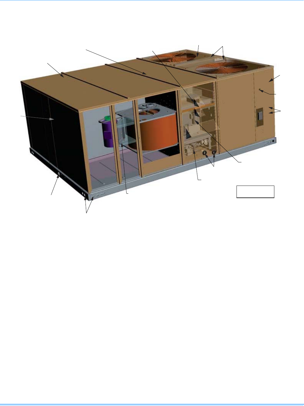
Component Location
(ZF shown)
ELECTRIC HEATER LOCATION
(OPTIONAL ELECTRIC/ELECTRIC UNITS)
HIGH
EFFICIENCY
COMPRESSORS
COPPER TUBE/ALUMINUM FIN
CONDENSER COILS
ELECTRICAL
DISCONNECT
MOUNTING
LOCATION
(Field installed)
KNOCKOUT FOR
SIDE CONTROL
WIRING ENTRY
KNOCKOUT
FOR SIDE
POWER WIRING
ENTRY SIDE
KNOCKOUTS FOR SIDE
GAS SUPPLY ENTRY
HOLE FOR BOTTOM
GAS SUPPLY ENTRY
POWER VENTOR MOTOR
WITH POST PURGE CYCLE
BELT-DRIVE
BLOWER MOTOR
FULL PERIMETER
14 GAUGE BASE RAILS
WITH LIFTING HOLES
1" NPTI
CONDENSATE DRAIN
2" DISPOSABLE
FILTERS
LONG LASTING
POWDER PAINT FINISH
20 GAUGE
ALUMINIZED STEEL
TUBULAR HEAT EXCHANGERS
GAS/ELECTRIC
UNIT SHOWN
1056292-XTG-A-0613
4Johnson Controls Unitary Products
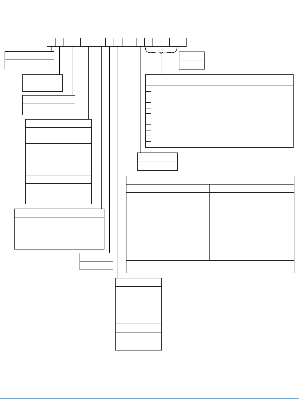
Nomenclature
Z F 180 N24 A 7 A AA 1 0 1 2 4 A
Z = A/C, Single Pkg.
Product Category
Airflow
A = Hi Static
B = Hi Static/Economizer
C = Hi Static/Economizer/Power Exhaust
(Downflow Only)
D = Hi Static/Motorized Damper
E = Hi Static/Motorized Damper/Barometric Relief
J = Hi Static/Economizer/Barometric Relief
1 = First Generation
Product Generation
C00 = Cooling Only. No field installed
electric heat
Heat Type and Nominal Heat Capacity
N24 = 240 MBH Output Aluminized Steel
N32 = 320 MBH Output Aluminized Steel
S24 = 240 MBH Output Stainless Steel
S32 = 320 MBH Output Stainless Steel
E18 = 18 KW
E36 = 36 KW
E54 = 54 KW
E72 = 72 KW
Gas Heat Options
Electric Heat Options
180 = 15 Ton
Nominal Cooling Capacity
240 = 20 Ton
Product Identifier
F = R-410A
Voltage
7 = 380/415-3-50
Product Style
A = Style A
A = No Options Installed
Installation Options
B = Option 1
E = Option 3
F = Option 4
G = Options 1 & 3
H = Options 1 & 4
L = Options 1,3 & 4
R = Options 3 & 4
1 = Disconnect
3 = Smoke Detector S.A.
4 = Smoke Detector R.A.
Options
SS Drain Pan
Configuration Options (not required for all units)
These four digits will not be assigned until a quote is requested, or an order placed.
CPC Controller, DFS, APS
Johnson Controller, DFS, APS
Honeywell Controller, DFS, APS
Novar Controller, DFS, APS
Simplicity IntelliComfort Controller
Simplicity IntelliComfort Controller w/ModLinc
2" Pleated filters
4" Pleated filters
BAS Ready Economizer (2-10 V.D.C. Actuator without a controller)
Any Combination of Additional Options that Don’t Have an Option Code Pre-assigned
AA = None
Standard Cabinet
AB = Phase Monitor
AC = Coil Guard
AD = Dirty Filter Switch
AE = Phase Monitor & Coil Guard
AF = Phase Monitor & Dirty Filter Switch
AG = Coil Guard & Dirty Filter Switch
AH = Phase Monitor, Coil Guard & Dirty Filter Switch
RC = Coil Guard & American Flag
TA = Technicoat Condenser Coil
TJ = Technicoat Evaporator Coil
TS = Technicoat Evaporator & Condenser Coils
BA = Hinged Filter Door & Tool Free Access Panels
Additional Options
Hinged Filter Door & Tool Free Access Cabinet
BB = Phase Monitor, Hinged Filter Door & Tool Free
Access Panels
BC = Coil Guard, Hinged Filter Door & Tool Free
Access Panels
BD = Dirty Filter Switch, Hinged Filter Door &
Tool Free Access Panels
BE = Phase Monitor & Coil Guard, Hinged Filter
Door & Tool Free Access Panels
BF = Phase Monitor & Dirty Filter Switch, Hinged
Filter Door & Tool Free Access Panels
BG = Coil Guard & Dirty Filter Switch, Hinged Filter
Door & Tool Free Access Panels
BH = Phase Monitor, Coil Guard & Dirty Filter Switch,
Hinged Filter Door & Tool Free Access Panels
15 & 20 Ton Sunline Model Number Nomenclature
ZZ = If desired option combination is not listed above, ZZ will be assigned and configuration options will be
located in digits 15-18.
1056292-XTG-A-0613
Johnson Controls Unitary Products 5
Features and Benefits
Standard Features
•High Efficiency - High efficiency units reach as high as
10.9 EER. Gas/electric units have electronic spark ignition
and power vented combustion with steady state efficiencies
of 80%.
•Balanced Heating -
•Gas Heat - All gas heat units are built with two heating
sections for two equal stages of capacity control. Each
section includes a durable heat exchanger with
aluminized steel or optional stainless steel tubes, a
redundant gas valve, spark ignition, power venting, an
ignition module for 100% shut-off and all of the safety
controls required to meet the latest ANSI standards.
The gas supply piping can be routed into the heating
compartment through a hole in the base pan of the unit
or through a knockout in the piping panel on the front of
the unit.
•Electric Heat - All electric heat models (factory installed
only) are wired for a single power source and include a
bank of nickel chromium elements mounted at the
discharge of the supply air blower to provide a high velocity
and uniform distribution of air across the heating elements.
Every element is fully protected against excessive current
and temperature by fuses and two thermal limit switches.
The power supply wiring can be routed into the control
box through a threaded pipe connection in the base pan
of the unit or through a knockout in the wiring panel on
the front of the unit.
•BAS Controls - York’s Sunline™ series units offer factory
mounted BAS controls such as Simplicity
® Intelli-Comfort
II
™, Novar, Honeywell, Johnson, York Commercial
Comfort System (YCCS) and CPC.
•Convertible Airflow Design - All models (including those
with an economizer) are suitable for either bottom or
horizontal duct connections. Models with factory
installed power exhaust are suitable for bottom duct
connections only. For bottom duct, you remove the sheet
metal panels from the supply and return air openings
through the base of the unit. For horizontal duct, you
replace the supply and return air panels on the rear of the
unit with a side duct flange accessory.
•Factory Mounted Outdoor Air Dampers - All models are
available with these "factory mounted" outdoor air damper
options:
• Single enthalpy economizer with or without power
exhaust
• BAS-ready economizer with or without power exhaust
• Motorized outdoor air damper
• Barometric Relief Damper
A fixed outdoor air intake assembly will be shipped in the
return air compartment of all units ordered without an
economizer or motorized outdoor air damper option. The
assembly includes a rain hood with a damper that can be set
for 10, 15 or 25% outdoor air. With bottom duct connections,
the fixed outdoor air intake assembly should be mounted
over the opening in the return air panel. With horizontal
ductwork, it should be mounted on the return air duct.
•System Protection - Suction line freezestats are supplied
on all units to protect against loss of charge and coil frosting
when the economizer operates at low outdoor air
temperatures while the compressors are running. Every unit
has solid-core liquid line filter-driers and high and low-
pressure switches. Internal compressor protection is
standard on all compressors. Phase Monitors are optional
on all units. This accessory monitors the incoming power to
the unit and protects the unit from phase loss and reversed
phase rotation.
•Advanced Controls - Simplicity™ ZF control boards
have standardized a number of features previously
available only as options or by utilizing additional controls.
•Low Ambient - An integrated low-ambient control
allows all units to operate in the cooling mode down to
0F outdoor ambient without additional assistance.
Optionally, the control board can be programmed to
lockout the compressors when the outdoor air
temperature is low or when free cooling is available.
•Anti-Short Cycle Protection - To aid compressor life,
an anti-short cycle delay is incorporated into the
standard controls. Compressor reliability is further
ensured by programmable minimum run times. For
testing, the anti-short cycle delay can be temporarily
overridden with the push of a button.
•Lead-Lag - An integrated Lead-Lag option allows equal
run time hours on all compressors, thereby extending
the life of all compressors. This option is selectable on
the unit control board.
•Fan Delays - Fan on and fan off delays are fully
programmable. Furthermore, the heating and cooling
fan delay times are independent of one another. All units
are programmed with default values based upon their
configuration of cooling and heat.
•Safety Monitoring - The control board monitors the
high and low-pressure switches, the freezestats, the gas
valve, if applicable, and the temperature limit switch on
gas and electric heat units. The unit control board will
alarm on ignition failures, compressor lockouts and
repeated limit switch trips.
•Nuisance Trip Protection and Strikes - To prevent
nuisance trouble calls, the control board uses a “three
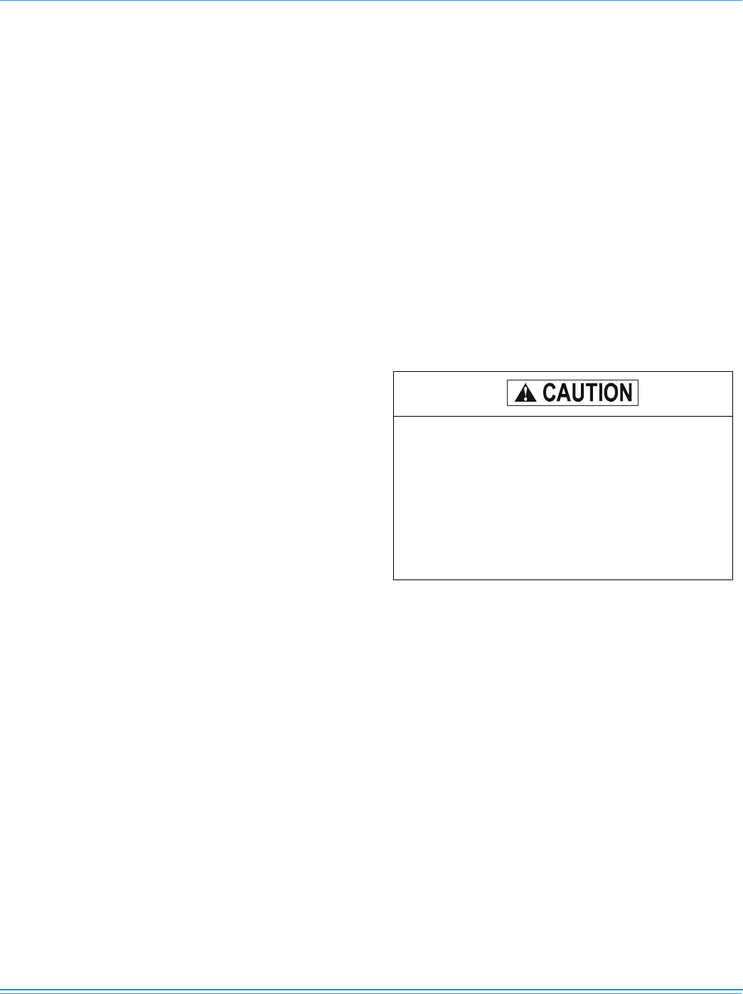
The Simplicity® control board used in this product
will effectively operate the cooling system down to
25°F when this product is applied in a comfort
cooling application for people. An economizer is
typically included in this type of application. When
applying this product for process cooling applications
(computer rooms, switchgear, etc.), please
reference applications bulletin AE-011-07 or call the
applications department for Unitary Products @ 1-
877-UPG-SERV for guidance.

1056292-XTG-A-0613
6Johnson Controls Unitary Products
times, you’re out” philosophy. The high and low-
pressure switches and the freezestats must trip three
times within two hours before the unit control board will
lock out the associated compressor.
•On Board Diagnostics - Each alarm will energize a
trouble light on the thermostat, if so equipped, and flash
an alarm code on the control board LED. Each high and
low-pressure switch alarm as well as each freezestat
alarm has its own flash code. The control board saves
the five most recent alarms in memory, and these alarms
can be reviewed at any time. Alarms and programmed
values are retained through the loss of power.
•Reliable - From the beginning - All units undergo
computer automated testing before they leave the factory.
Units are tested for refrigerant charge and pressure, unit
amperage, and 100% functionality. For the long term - All
units are painted with a long lasting, powder paint that
stands up over the life of the unit. The paint used has
been proven by a 1000 hour salt spray test.
•Full Perimeter Base Rails - The permanently attached
base rails provide a solid foundation for the entire unit and
protect the unit during shipment. The rails offer rigging
holes so that an overhead crane can be used to place the
units on a roof.
•Easy Installation - Gas and electric utility knockouts are
supplied in the unit underside as well as the side of the
unit. Utility connections can be made quickly and with a
minimum amount of field labor. All units are shipped with
2" throw-away filters installed.
•Wide Range of Indoor Airflows - All supply air blowers
are equipped with a belt drive that can be adjusted to
meet the exact requirements of the job.
•Warranty - All models include a 1-year limited warranty
on the complete unit. Compressors and electric heater
elements each carry a 5-year warranty. Aluminized steel
and stainless steel tubular heat exchangers carry a 10-
year warranty.
Factory Installed Options
YORK® offers several equipment options factory installed, for
the ZF Series.
•Single Input Electronic Enthalpy Economizers -
Includes a slide-in / plug-in damper assembly with fully
modulating spring-return motor actuator capable of
introducing up to 100% outdoor air with nominal 1%
leakage type dampers.
The enthalpy system contains one sensor that monitors
the outdoor air and determines when the air is cool
enough and dry enough to provide free cooling.
The rainhood is painted to match the basic unit and must
be field-assembled before installing.
• BAS-Ready Economizer - Includes a slide-in / plug-in
damper assembly with fully modulating spring-return
motor actuator with zero to 95-degree rotation capable of
introducing up to 100% outdoor air with nominal 1%
leakage type dampers.
Actuator requires 2-10 VDC input from an external source,
such as a field-installed or factory-installed BAS
controller. BAS-ready actuators have an adjustable
auxiliary end-switch for optional power exhaust control.
For units with optional VAV or Simplicity® Intelli-Comfort
II™ control, a factory-installed, dry bulb sensor
determines if outdoor air temperature is low enough to
provide free-cooling operation. (Field-installed humidity
sensors for either outdoor air or outdoor & return air
streams are available for single enthalpy and differential
enthalpy configurations, respectively).
The rain hood is painted to match the basic unit and must
be field-assembled before installing.
•Power Exhaust - Our economizer options are available
with power exhaust. Whenever the outdoor air intake
dampers are opened for free cooling, the exhaust fan will
be energized to prevent the conditioned space from being
over-pressurized during economizer operation.
The exhaust fan, motor and controls are installed and
wired at the factory. The rain hood must be assembled
and installed in the field.
The power exhaust option can only be used on bottom
duct configurations.
•Motorized Outdoor Air Intake Damper - Includes a
slide-in / plug-in damper assembly with a 2- position,
spring return motor actuator which opens to a pre-set
position whenever the supply air blower is operating and
will drive fully closed when the blower unit shuts down.
The rain hood is painted to match the basic unit and must
be field assembled before installing.
•Barometric Relief Damper - This damper option can be
used to relieve internal building air pressure on units with
an economizer without power exhaust. This accessory
includes a rain hood, a bird screen and a fully assembled
damper. With bottom duct connections, the damper
should be mounted over the opening in the return air
panel. With horizontal ductwork, the accessory should be
mounted on the return air duct.
• Technicoat Condenser Coils - The condenser coils are
coated with a phenolic coating for protection against
corrosion due to harsh environments.
• Technicoat Evaporator Coil - The evaporator coils are
coated with a phenolic coating for protection against
corrosion due to harsh environments.
•Electric Heaters - wired for single point power supply.
These nickel chromium heater elements are provided with
limit and automatic reset capability to prevent operation at
excessive temperatures.
•Filter Options - Standard units are shipped with 2" throw-
away filters installed. 2" pleated and 4" pleated filters are
offered as a factory installed option.
•Disconnect Switch - For gas heat units and cooling units
with electric heat, a HACR breaker sized to the unit is
provided. For cooling only units, a switch sized to the
largest electric heat available for the particular unit is
provided. Factory installed option only.
•York Commercial Comfort System (YCCS) - Provides
rooftop system integration for YCCS single zone, change-
over bypass and VAV systems.

1056292-XTG-A-0613
Johnson Controls Unitary Products 7
•Smoke Detectors - (supply air & return air) The smoke
detectors stop operation of the unit by interrupting power
to the control board if smoke is detected within the air
compartment.
•Coil Guard - Customers can purchase a coil guard kit to
protect the condenser coil from damage. This is not a hail
guard kit.
•Stainless Steel Heat Exchanger - For applications in
corrosive environments, this option provides a full
stainless steel heat exchanger assembly.
•Stainless Steel Drain Pan - An optional rustproof
stainless steel drain pan is available to provide years of
trouble-free operation in corrosive environments.
•Phase Monitors - Designed to prevent unit damage. The
phase monitor will shut the unit down in an out-of phase
condition.
•Dirty Filter Switch - This kit includes a differential
pressure switch that energizes the fault light on the unit
thermostat, indicating that there is an abnormally high
pressure drop across the filters. Factory installed option or
field installed accessory.
•Hinged Filter Door/"Tool Free" Blower And Access
Panels (Not Hinged) - This option allows for easy access
and maintenance.
NOTE: Knobs are shipped separately within the unit to prevent
shipping damage. These must be field installed for tool
free operation.
•Hinged/"Tool Free" Blower, Blower Motor, Filter And
Electric Access Panels - This option allows for complete
hinged and tool free access to the unit’s blower, blower
motor, filters and electrical panel sections.
Control Options
• BAS - Building Automation System Controls
(available on two-system cooling product only).
Simplicity™ Intelli-Comfort II™ Control - The York®
Simplicity™ INTELLI-CO2 sensor to perform Differential
Demand Ventilation. It uses a Patented Comfort
Ventilation algorithm to provide comfortable ventilation air
temperature. The patented economizer-loading algorithm
will protect the equipment when harsh operating
conditions exist. It uses the INTELLI-Start™ algorithm to
maximize energy savings by recovering the building from
the Unoccupied Setpoints to the Occupied Setpoints just
in time for the Occupied Time Period to begin. The
Simplicity™ Intelli-Comfort II™ balances space
temperature, ventilation air temperature, CO2 and
humidity for ultimate comfort.
Simplicity™ Intelli-Comfort II™ with Simplicity™LINC
Control - The York® Simplicity™ Intelli-Comfort II™ with
Simplicity™LINC control is factory installed. It includes all
the features of the Intelli-Comfort II™ control with an
additional control to translate communications from
MODBUS to the BACnet MSTP protocol.
Novar® BAS Control - The Novar® building automation
system controller is factory installed. Incudes supply air
sensor, return air sensor, dirty filter indicator switch, and
air proving switch.
Johnson Controls BAS Control - The Johnson Control
YK-UNT-1126 building automation system controller is
factory installed. Includes supply air sensor, return air
sensor, dirty filter indicator switch, and air proving switch.
CPC BAS Control - The Computer Process Controls
Model 810-3060 ARTC Advanced Rooftop building
automation system controller is factory installed. Includes
supply air sensor, return air sensor, dirty filter indicator
switch and air proving switch.
Honeywell BAS Control - The Honeywell W7750C
building automation system controller is factory installed.
Includes air supply sensor, return air sensor, dirty filter
indicator switch, and air proving switch.
Field Installed Accessories
YORK® offers several equipment accessories for field
installation, for the ZF Series.
•Single Input Electronic Enthalpy Economizers -
Includes a slide-in / plug-in damper assembly with fully
modulating spring-return motor actuator capable of
introducing up to 100% outdoor air with nominal 1%
leakage type dampers.
The enthalpy system contains one sensor that monitors
the outdoor air and determines when the air is cool
enough and dry enough to provide free cooling.
The rain hood is painted to match the basic unit and must
be field-assembled before installing.
•Motorized Outdoor Air Intake Damper - Includes a
slide-in / plug-in damper assembly with a 2-position,
spring return motor actuator which opens to some pre-set
position whenever the supply air blower is operating and
will drive fully closed when the blower unit shuts down.
The rain hood is painted to match the basic unit and must
be field assembled before installing.
•Roof Curbs - Fourteen-inch high roof curbs provide a
water-tight seal between the unit and the finished roof.
These full perimeter curbs meet the requirements of the
National Roofing Contractors Association (NRCA) and are
shipped knocked-down for field assembly.
They're designed to fit inside the base rails of the unit and
include both a wood nailing strip and duct hanger supports.
•High Altitude Natural Gas - Burner orifices and pilot
orifices are provided for proper furnace operation at
altitudes up to 6,000 feet.
•Propane - Burner orifices, pilot orifices and gas valve parts
are provided to convert a natural gas furnace to propane.
•High Altitude Propane - Burner orifices and pilot orifices
are provided for proper furnace operation at altitudes up
Factory installed smoke detectors in the return air, may
be subjected to freezing temperatures during “off” times
due to out side air infiltration. these smoke detectors have
an operational limit of 32°F to 131°F. smoke detectors
installed in areas that could be out side those limitations
will have to be moved to prevent having false alarms.

1056292-XTG-A-0613
8Johnson Controls Unitary Products
to 6,000 feet. This accessory supplements the basic
propane conversion kit.
•Side Duct Flanges - One-inch flanges replace the supply
and return air panels on the rear of the unit to accommodate
horizontal duct connections. These flanges can also be used
individually for bottom supply / horizontal return or horizontal
supply/bottom return. They cannot be used on units with
power exhaust.
•Barometric Relief Damper - This damper accessory can
be used to relieve internal building air pressure on units
with an economizer without power exhaust. This
accessory includes a rain hood, a bird screen and a fully
assembled damper. With bottom duct connections, the
damper should be mounted over the opening in the return
air panel. With horizontal ductwork, the accessory should
be mounted on the return air duct.
•Enthalpy Accessory Control Kit - This kit contains the
required components to convert a single enthalpy
economizer to dual enthalpy.
•Burglar Bars - Mount in the supply and return openings
to prevent entry into the duct work.
•Flue Exhaust Extension Kit - In locations with wind or
weather conditions which may interfere with proper
exhausting of furnace combustion products, this kit can be
installed to prevent the flue exhaust from entering nearby
fresh air intakes.
•Wood Skid - Allows unit to be handled with 90" forks.
•CO2 Sensor - Senses CO2 levels and automatically
overrides the economizer when levels rise above the
present limits.
•Coil Guard - Customers can purchase a coil guard kit to
protect the condenser coil from damage. This is not a hail
guard kit.
•Phase Monitors - Designed to prevent unit damage. The
phase monitor will shut the unit down in an out-of phase
condition.
Guide Specifications
General
Units shall be manufactured by Johnson Controls Unitary
Products in an ISO 9001 certified facility.
ZF models have 2 condenser fan motors and compressors. All
compressors include crankcase heat and internal discharge
temperature protection. Every refrigerant circuit includes an
expansion valve, a liquid line filter-drier, a discharge line high
pressure switch and a suction line with a freezestat and low
pressure/loss of charge switch. The unit control circuit includes
75 VA and 150 VA transformers, a 24-volt circuit breaker and a
relay board with two compressor lockout circuits, a terminal
strip for thermostat wiring, plus an additional set of pin
connectors to simplify the interface of additional field controls.
All units have long lasting powder paint cabinets with 1000 hour
salt spray test approval under ASTM-B117 procedures. All
models include a 1-year limited warranty on the complete unit.
Compressors and electric heater elements carry an additional
4-year warranty. Aluminized steel tubular heat exchangers
carry an additional 9-year warranty.
Description
ZF units shall be factory-assembled, single packaged, ZF***N
Electric Cooling/Gas Heat, ZF***C/E Electric Cooling/Optional
Electric Heat, designed for outdoor mounted installation.
They shall have built-in field convertible duct connections for
down discharge supply/return or horizontal discharge supply/
return, and be available with factory installed options or field
installed accessories. The units shall be factory wired, piped,
charged with R-410A refrigerant and factory tested prior to
shipment. All unit wiring shall be both numbered and color
coded. All units shall be manufactured in a facility certified to
ISO 9001 standards and the cooling performance shall be rated
in accordance with DOE and AHRI test procedures. Units shall
be classified to ANSIZ21.47 standards, UL 1995/CAN/CSA No.
236-M90 conditions.
Unit Cabinet
Unit cabinet shall be constructed of galvanized steel, with
exterior surfaces coated with a non-chalking, powdered paint
finish, certified at 1000 hours salt spray test per ASTM-B117
standards. Indoor blower section shall be insulated with a
minimum 1/2" thick insulation, coated on the airside. Aluminum
foil faced insulation shall be used in the furnace compartment
and be fastened with rigid fasteners to prevent insulation from
entering the air stream. Cabinet panels shall be easily
removable for servicing and maintenance. Full perimeter base
rails shall be provided to assure reliable transit of equipment,
overhead rigging and proper sealing on roof curb applications.
Disposable 2" filters shall be furnished and be accessible
through a removable access door, sealed airtight. Units filter
track shall be designed to accommodate either 2" or 4" filters.
Fan performance measuring ports shall be provided on the
outside of the cabinet to allow accurate air measurements of
evaporator fan performance without removing panels or
creating air by-pass of the coils. Condensate pan shall be
internally sloped and conform to ASHRAE 62-89 self-draining
standards. Condensate connection shall be a minimum of 1"
I.D. female and be a ridged mount connection. Unit shall
incorporate a fixed outdoor air damper with an outdoor air
intake opening covered with a bird screen and a rain hood
painted to match the exterior of the unit.
Indoor (Evaporator) Fan Assembly
Fan shall be a belt drive assembly and include an adjustable-
pitch motor pulley. Job site selected (B.H.P.) brake horsepower
shall not exceed the motors nameplate horsepower rating, plus
the service factor. Units shall be designed not to operate above
service factor. Fan wheel shall be double-inlet type with
forward-curved blades, dynamically balanced to operate
smoothly throughout the entire range of operation. Airflow
design shall be constant air volume.

1056292-XTG-A-0613
Johnson Controls Unitary Products 9
Outdoor (Condenser) Fan Assembly
The outdoor fans shall be of the direct-driven propeller type,
discharge air vertically, have aluminum blades riveted to
corrosion resistant steel spider brackets and shall be
dynamically balanced for smooth operation. The 2 outdoor fan
motors shall be totally enclosed with permanently lubricated
bearings, internally protected against overload conditions and
staged independently.
Refrigerant Components
Compressors:
a. Shall be Scroll compressors internally protected with
internal discharge temperature protection over
temperature protection.
b. Shall have internal spring isolation and sound muffling to
minimize vibration and noise, and be externally isolated
on a dedicated, independent mounting.
Coils:
a. Evaporator and condenser coils shall have aluminum
plate fins mechanically bonded to seamless internally
enhanced copper tubes with all joints brazed. Special
Phenolic coating shall be available as a factory option.
b. Evaporator and Condenser coils shall be of the direct
expansion, draw-thru, design.
Refrigerant Circuit and Refrigerant Safety Components shall
include:
a. Balance-port thermostatic expansion valve with
independent circuit feed system.
b. Filter drier/strainer to eliminate any moisture or foreign
matter.
c. Accessible service gage connections on both suction
and discharge lines to charge, evacuate, and measure
refrigerant pressure during any necessary servicing or
troubleshooting, without losing charge.
d. The refrigeration system shall provide at least 10° F of
sub-cooling at design conditions.
e. All models shall have two independent circuits.
Unit Controls
a. Unit shall be complete with self-contained low-voltage
control circuit protected by a resettable circuit breaker on
the 24-volt transformer side.
b. Unit shall incorporate a lockout circuit which provides
reset capability at the space thermostat or base unit,
should any of the following standard safety devices trip
and shut off compressor.
c. Loss-of-charge/Low-pressure switch.
1. High-pressure switch.
2. Freeze-protection thermostat, evaporator coil. If any of
the above safety devices trip, a LED (light-emitting
diode) indicator shall flash a diagnostic code that
indicates which safety switch has tripped.
d. Unit shall incorporate "AUTO RESET" compressor over
temperature, over current protection.
e. Unit shall operate with conventional thermostat designs
and have a low voltage terminal strip for easy hook-up.
f. Unit control board shall have on-board diagnostics and
fault code display.
g. Standard controls shall include anti-short cycle and low
voltage protection, and permit cooling operation down to
25°F.
h. Control board shall monitor each refrigerant safety switch
independently.
i. Control board shall retain last 5 fault codes in non volatile
memory, which will not be lost in the event of a power
loss.
Gas Heating Section (ZF***N Models)
Shall be designed with induced draft combustion with post purge
logic and energy saving direct spark ignition, redundant main gas
valve. Ventor wheel shall be constructed of stainless steel for
corrosion resistance. The heat exchanger shall be of the tubular
type, constructed of T1-40 aluminized steel for corrosion
resistance and allowing minimum mixed air entering temperature
of 25 °F. Burners shall be of the in-shot type, constructed of
aluminum coated steel and contain air mixture adjustments. All
gas piping shall enter the unit cabinet at a single location through
either the side or curb, without any field modifications. An
integrated control board shall provide timed control of evaporator
fan functioning and burner ignition. Heating section shall be
provided with the following minimum protection:
a. Primary and auxiliary high-temperature limit switches.
b. Induced draft motor speed sensor.
c. Flame roll out switch (automatic reset).
d. Flame proving controls. Unit shall have two independent
stages of capacity.
Electric Heating (ZF***C/E Models)
Nickel chromium electric heating elements shall be provided as
required by the application with 1 or 2 stage control, as
required, from 18 KW to 72 KW nominal capacities. The heating
section shall have a primary limit control(s) and automatic reset
to prevent the heating element system from operating at an
excessive temperature. Units with Electric Heating shall be
wired for a single point power supply with branch circuit fusing
(where required).
Unit Operating Characteristics
Unit shall be capable of starting and running at 125° F outdoor
temperature, exceeding maximum load criteria of AHRI
Standard 340/360. The compressor, with standard controls,
shall be capable of operation down to 25° F outdoor
temperature. Unit shall be provided with fan time delay to
prevent cold air delivery before heat exchanger warms up (Gas
heat only).

1056292-XTG-A-0613
10 Johnson Controls Unitary Products
Electrical Requirements
All unit power wiring shall enter unit cabinet at a single factory
provided location and be capable of side or bottom entry, to
minimize roof penetrations and avoid unit field modifications.
Separate side and bottom openings shall be provided for the
control wiring.
Standard Limited Warranties
• Compressor 5 Years
• Heat Exchanger 10 Years
• Electric Heat Element 5 Years
• Other Parts 1 Year
Optional Outdoor Air (Shall be made available by either/or):
•Electronic Enthalpy Automatic Economizer - Outdoor
and return air dampers that are interlocked and positioned
by a fully-modulating, spring-return damper actuator. The
maximum leakage rate for the outdoor air intake dampers
shall not exceed 2% when dampers are fully closed and
operating against a pressure differential of 0.5 IWG. A
unit-mounted potentiometer shall be provided to adjust
the outdoor and return air damper assembly to take in
CFM of outdoor air to meet the minimum ventilation
requirement of the conditioned space during normal
operation. During economizer operation, a mixed-air
temperature control shall modulate the outdoor and return
air damper assembly to prevent the supply air
temperature from dropping below 55°F. Changeover from
compressor to economizer operation shall be provided by
an integral electronic enthalpy control that feeds input into
the basic module. The outdoor intake opening shall be
covered with a rain hood that matches the exterior of the
unit. Water eliminator/filters shall be provided.
Simultaneous economizer/compressor operation is also
possible. Dampers shall fully close on power loss.
•Motorized Outdoor Air Dampers - Outdoor and return
air dampers that are interlocked and positioned by a 2-
position, spring-return damper actuator. The maximum
leakage rate for the outdoor air intake dampers shall not
exceed 2% when dampers are fully closed and operating
against a pressure differential of 0.5 IWG. A unit-mounted
potentiometer shall be provided to adjust the outdoor and
return air damper assembly to take in the design CFM of
outdoor air to meet the ventilation requirements of the
conditioned space during normal operation. Whenever the
indoor fan motor is energized, the dampers open up to
one of two pre-selected positions - regardless of the
outdoor air enthalpy. Dampers return to the fully closed
position when the indoor fan motor is de-energized.
Dampers shall fully close on power loss.
Other Pre-engineered Accessories Available
•Roof Curb - 14" high, full perimeter curb with wood nailer
(shipped knocked-down).
•100% Barometric Relief Damper - Contains a rain hood,
air inlet screen, exhaust damper and mounting hardware.
Used to relieve internal air pressure through the unit.
•Propane Conversion Kit - Contains new orifices and gas
valve parts to convert from natural to L.P. gas. One per
unit required.
•High Altitude - Natural Gas - Contains orifices required
for applications between 2000 and 6000 feet altitude.
•High Altitude - Propane Gas - Contains orifices required
for applications between 2000 and 6000 feet altitude.
Must be used with propane conversion kit.
•Burglar Bars - Designed to work with above roof curbs,
depending on unit model. Fits duct openings of curb
supply and return air openings.
•Side Duct Flange - Supply and return air duct flanges for
side duct applications. Do not use on units with power
exhaust.
•Wood Skid - Allows unit to be handled with 90" forks.
•Economizer/motorized Damper Rain Hood
(ZFN/E/C240 only) - Contains all hood panels and the
hardware for assembling.
•Anti-Recycle Timer - Assures 5-minute off time between
compressor cycles.
•Coil Guard Kit - Guard for cooling coil.
OTHER FACTORY INSTALLED OPTIONS
•Power Exhaust Option - To work in conjunction with
economizers.
• Stainless Steel Heat Exchanger
• Stainless Steel Drain Pan
• Technicoat Phenolic Coated Condenser And
Evaporator Coil
•Electronic Single Enthalpy Economizer
• Dirty Filter Switch
• Phase Monitor
• Coil Guard
•Bas Controls - Simplicity
® Intelli-Comfort II
™, CPC,
JOHNSON, HONEYWELL, NOVAR, YORK
COMMERCIAL COMFORT SYSTEM (YCCS)
•BAS Ready Economizer (2-10 V.D.C. Actuator Without a
Controller)
• Hinged Filter Door Access And Tool Free Access
Panels
• Hinged Tool Free Blower, Blower Motor, Filter And
Electrical Access Panels
• 2" Pleated Filters, MERV 7
• 4" Pleated Filters, MERV 13
• Disconnect Switch
• Supply Air Smoke Detector
• Return Air Smoke Detector

1056292-XTG-A-0613
Johnson Controls Unitary Products 11
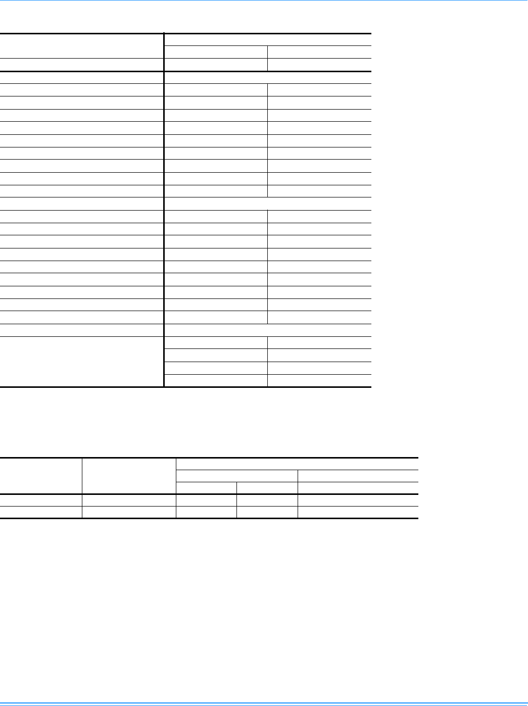
Physical Data
ZF180-240 Physical Data
Component Models
ZF180 ZF240
Nominal Tonnage 15 20
AHRI COOLING PERFORMANCE
Gross Capacity @ AHRI A point (K Btu) 204 259
AHRI net capacity (K Btu) 195 246
EER 10.9 10.4
SEER - -
IEER 11.26 10.88
Nominal CFM 6000 8000
System power (KW) 17.9 23.7
Refrigerant type R-410A R-410A
Refrigerant charge (lb-oz)
System 1 22-8 20-4
System 2 21-8 21-4
AHRI HEATING PERFORMANCE
Heating model 24 32 24 32
Heat input (K Btu) 300 400 300 400
Heat output (K Btu) 240 320 240 320
AFUE% - - - -
Steady state efficiency (%) 80 80 80 80
No. burners 6 8 6 8
No. stages 2 2 2 2
Temperature Rise Range (ºF) 20-50 35-65 20-50 35-65
Gas Limit Setting (ºF) 195 195 195 195
Gas piping connection (in.) 1 1 1 1
DIMENSIONS (inches)
Length 125-1/4 136-1/4
Width 92 92
Height 48-5/8 52-5/8
OPERATING WT. (lbs.) 1680 2400
COMPRESSORS
Type Scroll Scroll
Quantity 2 2
Unit Capacity Steps (%) 50 / 100 50 / 100
CONDENSER COIL DATA
Face area (Sq. Ft.) 36.0 43.3
Rows 3 3
Fins per inch 13.5 15
Tube diameter (in.) 3/8 3/8
Circuitry Type Standard Standard
EVAPORATOR COIL DATA
Face area (Sq. Ft.) 15.5 20.1
Rows 4 4
Fins per inch 14 14
Tube diameter 3/8 3/8
Circuitry Type Intertwined Intertwined
Refrigerant control TXV TXV
1056292-XTG-A-0613
12 Johnson Controls Unitary Products
CONDENSER FAN DATA
Quantity 2 2
Fan diameter (Inch) 30 30
Type Prop Prop
Drive type Direct Direct
No. speeds 1 1
Number of motors 2 2
Motor HP each 1.25 1.25
RPM 950 950
Nominal total CFM 6000 8000
BELT DRIVE EVAP FAN DATA
Quantity 1 1
Fan Size (Inch) 15 X 15 18 X 15
Type Centrifugal Centrifugal
Motor Sheave 1VP62 1VP75
Blower Sheave BK75 BK100
Belt BX68 BX75
Motor HP each 4.0 6.3
RPM 1450 1450
Frame size 184T 213T
FILTERS
Quantity - Size
5 - (18 x 24 x 2)1,2 12 - (12 x 24 x 2)1,2
--
5 - (18 x 24 x 4)32 - (20 x 24 x 4),
- 4 - (24 x 24 x 4)3
1. 2 In. Throwaway, Standard, MERV (Minimum Efficiency Reporting Value) 3.
2. 2 In. Pleated, Optional, MERV 7.
3. 4 In. Pleated, Optional, MERV 13.
ZF180-240 Unit Limitations
Size (Tons) Unit Voltage
Unit Limitations
Applied Voltage Outdoor DB Temp
Min Max Max (°F) / (°C)
180 (15) 380/415-3-50 342 457 125.6 / 52
240 (20) 380/415-3-50 342 457 125.6 / 52
ZF180-240 Physical Data (Continued)
Component Models
ZF180 ZF240
Nominal Tonnage 15 20
1056292-XTG-A-0613
Johnson Controls Unitary Products 13
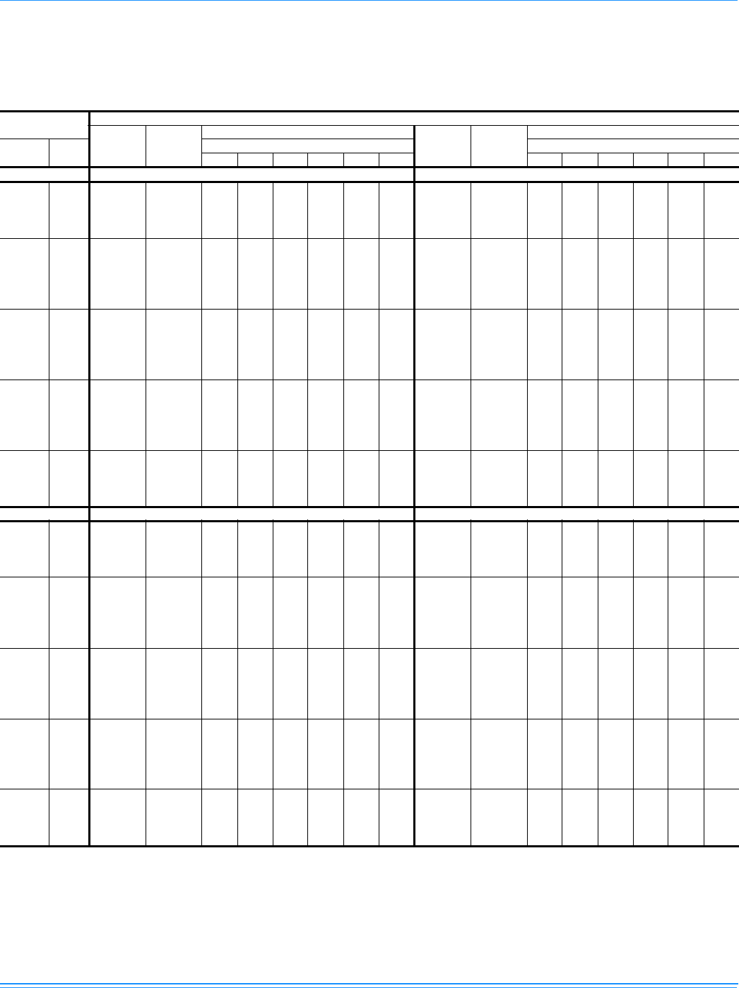
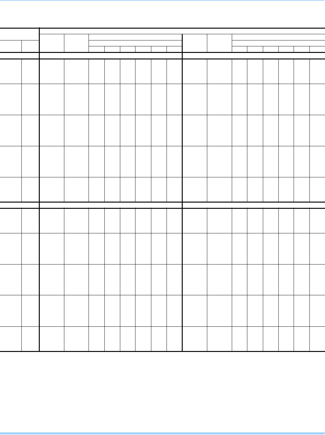
Capacity Performance
ZF180-240 Cooling Capacities
ZF180 (15 Ton) Imperial
Air on
Evaporator Coil Temperature of Air on Condenser Coil
Total
Capacity1,2
(MBh)
Total
Input
(kW)3
Sensible Capacity (MBh) Total
Capacity1,2
(MBh)
Total
Input
(kW)3
Sensible Capacity (MBh)
CFM WB
(°F) Return Dry Bulb (°F) Return Dry Bulb (°F)
90 85 80 75 70 65 90 85 80 75 70 65
85°F 95°F
3750
77 236.4 15.8 101.2 86.6 72.0 - - - 204.0 17.5 91.0 76.7 62.5 - - -
72 205.4 15.7 121.0 106.4 91.8 77.1 - - 182.0 17.2 112.3 98.1 83.9 69.6 - -
67 174.3 15.5 140.8 126.2 111.6 96.9 82.3 - 159.9 16.9 133.7 119.5 105.2 91.0 76.8 -
62 162.6 15.3 162.6 156.0 137.2 122.6 107.9 93.3 146.5 16.8 146.5 146.5 130.7 116.5 102.3 88.0
4500
77 253.8 16.2 114.6 97.4 80.3 - - - 222.1 17.8 103.4 86.8 70.1 - - -
72 220.5 16.1 136.6 119.5 102.4 85.3 - - 198.1 17.5 127.4 110.7 94.1 77.4 - -
67 187.2 15.9 158.7 141.6 124.5 107.4 90.2 - 174.1 17.3 151.4 134.7 118.0 101.4 84.7 -
62 174.6 15.7 174.6 170.2 153.1 136.0 118.8 101.7 159.5 17.1 159.5 159.5 145.7 129.0 112.3 95.7
57 172.9 15.7 172.9 172.9 156.4 139.3 122.1 105.0 156.9 16.7 156.9 156.9 145.3 128.7 112.0 95.3
5250
77 271.3 16.6 127.9 108.3 88.7 - - - 240.2 18.1 115.9 96.8 77.7 - - -
72 235.7 16.5 152.3 132.6 113.0 93.4 - - 214.2 17.9 142.5 123.4 104.3 85.2 - -
67 200.1 16.3 176.6 157.0 137.4 117.8 98.2 - 188.3 17.6 169.1 150.0 130.9 111.8 92.6 -
62 186.6 16.1 186.6 184.4 169.0 149.4 129.7 110.1 172.5 17.4 172.5 172.5 160.6 141.5 122.4 103.3
57 184.8 16.1 184.8 184.8 172.6 153.0 133.4 113.8 169.7 17.0 169.7 169.7 160.3 141.1 122.0 102.9
6000
77 288.7 17.0 141.2 119.1 97.0 - - - 258.3 18.5 128.4 106.9 85.3 - - -
72 250.8 16.9 167.9 145.8 123.7 101.5 - - 230.4 18.2 157.6 136.1 114.5 93.0 - -
67 212.9 16.7 194.5 172.4 150.3 128.2 106.1 - 202.5 17.9 186.8 165.2 143.7 122.1 100.6 -
62 198.6 16.5 198.6 198.6 184.9 162.8 140.6 118.5 185.5 17.7 185.5 185.5 175.6 154.1 132.5 111.0
57 196.7 16.5 196.7 196.7 188.8 166.7 144.6 122.5 182.5 17.3 182.5 182.5 175.2 153.6 132.1 110.5
6750
72 254.9 17.9 175.3 151.0 126.8 102.5 - - 234.1 19.5 167.1 143.4 119.7 96.0 - -
67 216.3 17.8 202.6 178.4 154.1 129.9 105.6 - 205.8 19.2 197.9 173.9 156.8 126.5 102.9 -
62 201.8 17.5 201.8 201.8 189.5 165.3 141.0 116.8 188.6 19.0 188.6 188.6 183.6 159.9 136.2 112.5
57 199.9 17.5 199.9 199.9 193.6 169.4 145.1 120.8 185.5 18.6 185.5 185.5 181.8 158.1 134.5 110.8
105°F 115°F
3750
77 182.9 19.0 84.6 69.9 55.3 - - - 161.8 20.6 78.2 63.1 48.1 - - -
72 167.5 18.7 107.7 93.1 78.4 63.8 - - 153.1 20.3 103.1 88.0 73.0 57.9 - -
67 152.2 18.4 130.8 116.2 101.6 86.9 72.3 - 144.5 19.9 128.0 112.9 97.9 82.8 67.8 -
62 140.0 18.3 140.0 140.0 124.9 110.2 95.6 81.0 133.5 19.9 133.5 133.5 119.0 104.0 88.9 73.9
4500
77 197.5 19.4 95.1 78.3 61.5 - - - 173.0 20.9 86.8 69.9 53.0 - - -
72 180.9 19.1 121.2 104.4 87.6 70.8 - - 163.7 20.6 114.9 98.0 81.0 64.1 - -
67 164.3 18.8 147.2 130.4 113.6 96.8 80.0 - 154.5 20.3 142.9 126.0 109.1 92.2 75.2 -
62 151.1 18.6 151.1 151.1 138.9 122.1 105.3 88.5 142.7 20.2 142.7 142.7 132.1 115.2 98.3 81.3
57 149.4 18.4 149.4 149.4 137.0 120.2 103.4 86.6 141.9 20.1 141.9 141.9 128.6 111.7 94.8 77.9
5250
77 212.2 19.7 105.7 86.8 67.8 - - - 184.2 21.2 95.5 76.7 57.9 - - -
72 194.3 19.4 134.6 115.7 96.7 77.7 - - 174.3 20.9 126.7 107.9 89.1 70.3 - -
67 176.4 19.1 163.5 144.5 125.6 106.6 87.6 - 164.5 20.6 157.9 139.1 120.3 101.5 82.6 -
62 162.2 18.9 162.2 162.2 153.0 134.0 115.0 96.1 151.9 20.5 151.9 151.9 145.3 126.4 107.6 88.8
57 160.4 18.7 160.4 160.4 150.8 131.9 112.9 93.9 151.1 20.4 151.1 151.1 141.4 122.6 103.8 85.0
6000
77 226.8 20.0 116.3 95.2 74.1 - - - 195.4 21.5 104.2 83.5 62.8 - - -
72 207.7 19.7 148.1 127.0 105.8 84.7 - - 184.9 21.2 138.6 117.9 97.1 76.4 - -
67 188.5 19.4 179.9 158.7 137.6 116.5 95.3 - 174.5 20.9 172.9 152.2 131.5 110.8 90.1 -
62 173.4 19.2 173.4 173.4 167.0 145.9 124.7 103.6 161.2 20.8 161.2 161.2 158.4 137.7 117.0 96.2
57 171.4 19.0 171.4 171.4 164.7 143.6 122.4 101.3 160.3 20.7 160.3 160.3 154.2 133.5 112.8 92.1
6750
72 210.4 20.7 155.1 131.4 107.7 84.1 - - 186.7 21.9 143.0 119.4 95.8 72.1 - -
67 190.9 20.4 187.0 165.0 144.6 117.7 94.1 - 176.0 21.7 176.0 156.1 132.5 108.9 85.2 -
62 175.9 20.0 175.9 175.9 169.9 146.2 122.6 98.9 163.3 21.1 163.3 163.3 156.2 132.5 108.9 85.3
57 173.9 19.8 173.9 173.9 166.9 143.3 119.6 96.0 162.4 20.9 162.4 162.4 152.0 128.4 104.8 81.1

1056292-XTG-A-0613
14 Johnson Controls Unitary Products
118.4°F 125°F
3750
77 159.3 21.1 75.0 60.8 45.6 - - - 140.7 22.1 69.0 56.3 40.9 - - -
72 152.7 20.8 101.5 86.3 71.1 56.0 - - 138.7 21.8 98.4 83.0 67.5 52.1 - -
67 146.1 20.4 127.0 111.8 96.6 81.5 65.7 - 136.7 21.4 125.1 109.7 94.2 78.8 61.7 -
62 135.2 20.4 131.3 131.3 117.0 101.8 86.7 71.5 126.9 21.4 126.9 126.9 113.1 97.7 82.3 66.8
4500
77 169.6 21.4 84.0 67.0 50.1 - - - 148.4 22.4 78.5 61.5 44.4 - - -
72 162.6 21.1 112.8 95.8 78.8 61.8 - - 146.5 22.1 108.6 91.6 74.5 57.5 - -
67 155.7 20.8 141.5 124.5 107.6 90.6 73.6 - 144.6 21.8 138.7 121.7 104.6 87.6 70.5 -
62 144.0 20.7 139.8 139.8 129.8 112.9 95.9 78.9 134.3 21.7 134.3 134.3 125.4 108.3 91.2 74.2
57 143.6 20.6 139.4 139.4 125.8 108.8 91.9 74.9 134.4 21.7 134.4 134.4 120.3 103.2 86.2 69.1
5250
77 179.9 21.7 93.0 73.3 54.5 - - - 156.2 22.7 88.1 66.6 48.0 - - -
72 172.6 21.4 124.1 105.3 86.5 67.7 - - 154.4 22.4 118.8 100.2 81.5 62.8 - -
67 165.2 21.1 156.0 137.3 118.5 99.7 80.9 - 152.5 22.1 152.4 133.7 115.0 96.3 79.2 -
62 152.9 21.0 148.4 148.4 142.5 123.9 105.1 86.3 141.7 22.0 141.7 141.7 137.6 118.9 100.2 81.5
57 152.4 20.9 148.0 148.0 138.2 119.4 100.7 81.9 141.8 22.0 141.8 141.8 132.0 113.3 94.6 76.0
6000
77 190.2 22.0 102.0 79.5 59.0 - - - 163.9 23.0 97.7 71.8 51.5 - - -
72 182.5 21.7 135.3 114.8 94.2 73.6 - - 162.2 22.7 129.1 108.8 88.5 68.2 - -
67 174.8 21.4 168.7 150.0 129.4 108.8 88.3 - 160.4 22.4 160.4 145.7 125.4 105.1 84.8 -
62 161.8 21.3 157.0 157.0 155.2 134.9 114.3 93.7 149.0 22.3 149.0 149.0 149.0 129.5 109.2 88.9
57 161.2 21.2 156.5 156.5 150.6 130.1 109.5 88.9 149.2 22.3 149.2 149.2 143.7 123.4 103.1 82.8
6750
72 184.0 22.3 138.9 115.3 91.7 68.1 - - 163.0 23.0 131.0 107.4 83.8 60.2 - -
67 182.2 22.4 170.9 153.1 128.4 105.9 82.2 - 161.1 22.9 161.1 147.2 120.4 100.0 76.4 -
62 163.7 21.4 159.0 159.0 151.5 127.9 104.3 80.6 150.6 22.1 150.6 150.6 142.4 118.8 95.2 71.6
57 163.2 21.3 158.5 158.5 147.0 123.3 99.7 76.1 150.9 22.1 150.9 150.9 137.1 113.5 89.9 66.3
1. These capacities are gross ratings. For net capacity, deduct air blower motor heat, MBh = 3.415 x kW.
2. Capacity ratings are based on 80°F (26.7°C) Entering Air Dry Bulb Temperature.
3. These ratings are total input kW, thus include the two condenser fan motors, compressor motors, and the supply air blower motor at 0.40"
WC.
ZF180 (15 Ton) Imperial (Continued)
Air on
Evaporator Coil Temperature of Air on Condenser Coil
Total
Capacity1,2
(MBh)
Total
Input
(kW)3
Sensible Capacity (MBh) Total
Capacity1,2
(MBh)
Total
Input
(kW)3
Sensible Capacity (MBh)
CFM WB
(°F) Return Dry Bulb (°F) Return Dry Bulb (°F)
90 85 80 75 70 65 90 85 80 75 70 65
1056292-XTG-A-0613
Johnson Controls Unitary Products 15
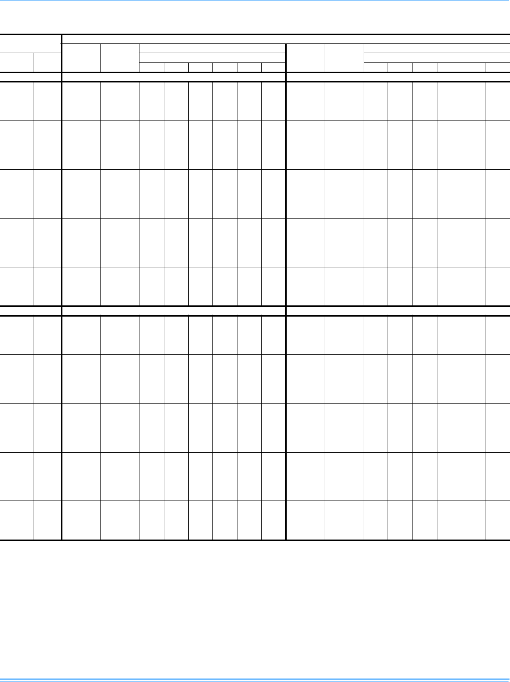
ZF180 (15 Ton) Metric
Air on
Evaporator Coil Temperature of Air on Condenser Coil
Total
Capacity1,2
(kW)
Total
Input
(kW)3
Sensible Capacity (MBh) Total
Capacity1,2
(MBh)
Total
Input
(kW)3
Sensible Capacity (MBh)
M3/sec WB
(°C) Return Dry Bulb (°C) Return Dry Bulb (°C)
32 29 27 24 21 18 32 29 27 24 21 18
29.4°C 35°C
1.77
25 69.3 15.8 29.7 25.4 21.1 - - - 59.8 17.5 26.6 22.5 18.3 - - -
22 60.2 15.7 35.5 31.2 26.9 22.6 - - 53.3 17.2 32.9 28.7 24.6 20.4 - -
19 51.1 15.5 41.3 37.0 32.7 28.4 24.1 - 46.9 16.9 39.2 35.0 30.8 26.7 22.5 -
17 47.6 15.3 47.6 45.7 40.2 35.9 31.6 27.3 42.9 16.8 42.9 42.9 38.3 34.1 30.0 25.8
2.12
25 74.4 16.2 33.6 28.5 23.5 - - - 65.1 17.8 30.3 25.4 20.5 - - -
22 64.6 16.1 40.0 35.0 30.0 25.0 - - 58.0 17.5 37.3 32.4 27.6 22.7 - -
19 54.8 15.9 46.5 41.5 36.5 31.5 26.4 - 51.0 17.3 44.4 39.5 34.6 29.7 24.8 -
17 51.1 15.7 51.1 49.9 44.9 39.8 34.8 29.8 46.7 17.1 46.7 46.7 42.7 37.8 32.9 28.0
14 50.7 15.7 50.7 50.7 45.8 40.8 35.8 30.8 46.0 16.7 46.0 46.0 42.6 37.7 32.8 27.9
2.48
25 79.5 16.6 37.5 31.7 26.0 - - - 70.4 18.1 34.0 28.4 22.8 - - -
22 69.1 16.5 44.6 38.9 33.1 27.4 - - 62.8 17.9 41.8 36.2 30.6 25.0 - -
19 58.6 16.3 51.8 46.0 40.3 34.5 28.8 - 55.2 17.6 49.5 43.9 38.3 32.7 27.1 -
17 54.7 16.1 54.7 54.0 49.5 43.8 38.0 32.3 50.6 17.4 50.6 50.6 47.1 41.5 35.9 30.3
14 54.2 16.1 54.2 54.2 50.6 44.8 39.1 33.3 49.7 17.0 49.7 49.7 47.0 41.4 35.8 30.2
2.83
25 84.6 17.0 41.4 34.9 28.4 - - - 75.7 18.5 37.6 31.3 25.0 - - -
22 73.5 16.9 49.2 42.7 36.2 29.8 - - 67.5 18.2 46.2 39.9 33.5 27.2 - -
19 62.4 16.7 57.0 50.5 44.0 37.6 31.1 - 59.3 17.9 54.7 48.4 42.1 35.8 29.5 -
17 58.2 16.5 58.2 58.2 54.2 47.7 41.2 34.7 54.4 17.7 54.4 54.4 51.5 45.1 38.8 32.5
14 57.6 16.5 57.6 57.6 55.3 48.8 42.4 35.9 53.5 17.3 53.5 53.5 51.3 45.0 38.7 32.4
3.19
25 74.7 17.9 51.4 44.3 37.1 30.0 - - 68.6 19.5 49.0 42.0 35.1 28.1 - -
22 63.4 17.8 59.4 52.3 45.2 38.1 30.9 - 60.3 19.2 58.0 51.0 45.9 37.1 30.1 -
19 59.1 17.5 59.1 59.1 55.5 48.4 41.3 34.2 55.2 19.0 55.2 55.2 53.8 46.9 39.9 33.0
17 58.6 17.5 58.6 58.6 56.7 49.6 42.5 35.4 54.3 18.6 54.3 54.3 53.3 46.3 39.4 32.5
40.6°C 46.1°C
1.77
25 53.6 19.0 24.8 20.5 16.2 - - - 47.4 20.6 22.9 18.5 14.1 - - -
22 49.1 18.7 31.6 27.3 23.0 18.7 - - 44.9 20.3 30.2 25.8 21.4 17.0 - -
19 44.6 18.4 38.3 34.0 29.8 25.5 21.2 - 42.3 19.9 37.5 33.1 28.7 24.3 19.9 -
17 41.0 18.3 41.0 41.0 36.6 32.3 28.0 23.7 39.1 19.9 39.1 39.1 34.9 30.5 26.1 21.7
2.12
25 57.9 19.4 27.9 23.0 18.0 - - - 50.7 20.9 25.4 20.5 15.5 - - -
22 53.0 19.1 35.5 30.6 25.7 20.7 - - 48.0 20.6 33.7 28.7 23.7 18.8 - -
19 48.1 18.8 43.1 38.2 33.3 28.4 23.4 - 45.3 20.3 41.9 36.9 32.0 27.0 22.0 -
17 44.3 18.6 44.3 44.3 40.7 35.8 30.9 25.9 41.8 20.2 41.8 41.8 38.7 33.8 28.8 23.8
14 43.8 18.4 43.8 43.8 40.1 35.2 30.3 25.4 41.6 20.1 41.6 41.6 37.7 32.7 27.8 22.8
2.48
25 62.2 19.7 31.0 25.4 19.9 - - - 54.0 21.2 28.0 22.5 17.0 - - -
22 56.9 19.4 39.4 33.9 28.3 22.8 - - 51.1 20.9 37.1 31.6 26.1 20.6 - -
19 51.7 19.1 47.9 42.4 36.8 31.2 25.7 - 48.2 20.6 46.3 40.8 35.2 29.7 24.2 -
17 47.5 18.9 47.5 47.5 44.8 39.3 33.7 28.1 44.5 20.5 44.5 44.5 42.6 37.0 31.5 26.0
14 47.0 18.7 47.0 47.0 44.2 38.6 33.1 27.5 44.3 20.4 44.3 44.3 41.4 35.9 30.4 24.9
2.83
25 66.5 20.0 34.1 27.9 21.7 - - - 57.2 21.5 30.5 24.5 18.4 - - -
22 60.8 19.7 43.4 37.2 31.0 24.8 - - 54.2 21.2 40.6 34.5 28.5 22.4 - -
19 55.2 19.4 52.7 46.5 40.3 34.1 27.9 - 51.1 20.9 50.7 44.6 38.5 32.5 26.4 -
17 50.8 19.2 50.8 50.8 48.9 42.7 36.5 30.4 47.2 20.8 47.2 47.2 46.4 40.3 34.3 28.2
14 50.2 19.0 50.2 50.2 48.3 42.1 35.9 29.7 47.0 20.7 47.0 47.0 45.2 39.1 33.0 27.0
3.19
25 61.7 20.7 45.4 38.5 31.6 24.6 - - 54.7 21.9 41.9 35.0 28.1 21.1 - -
22 55.9 20.4 54.8 48.3 42.4 34.5 27.6 - 51.6 21.7 51.6 45.7 38.8 31.9 25.0 -
19 51.5 20.0 51.5 51.5 49.8 42.8 35.9 29.0 47.8 21.1 47.8 47.8 45.8 38.8 31.9 25.0
17 51.0 19.8 51.0 51.0 48.9 42.0 35.0 28.1 47.6 20.9 47.6 47.6 44.5 37.6 30.7 23.8

1056292-XTG-A-0613
16 Johnson Controls Unitary Products
48°C 51.7°C
1.77
25 46.7 21.1 22.0 17.8 13.4 - - - 41.2 22.1 20.2 16.5 12.0 - - -
22 44.7 20.8 29.7 25.3 20.8 16.4 - - 40.6 21.8 28.8 24.3 19.8 15.3 - -
19 42.8 20.4 37.2 32.8 28.3 23.9 19.3 - 40.1 21.4 36.7 32.1 27.6 23.1 18.1 -
17 39.6 20.4 38.5 38.5 34.3 29.8 25.4 20.9 37.2 21.4 37.2 37.2 33.2 28.6 24.1 19.6
2.12
25 49.7 21.4 24.6 19.6 14.7 - - - 43.5 22.4 23.0 18.0 13.0 - - -
22 47.6 21.1 33.0 28.1 23.1 18.1 - - 42.9 22.1 31.8 26.8 21.8 16.8 - -
19 45.6 20.8 41.5 36.5 31.5 26.5 21.6 - 42.4 21.8 40.6 35.6 30.7 25.7 20.7 -
17 42.2 20.7 41.0 41.0 38.0 33.1 28.1 23.1 39.3 21.7 39.3 39.3 36.7 31.7 26.7 21.7
14 42.1 20.6 40.8 40.8 36.9 31.9 26.9 21.9 39.4 21.7 39.4 39.4 35.2 30.2 25.3 20.3
2.48
25 52.7 21.7 27.3 21.5 16.0 - - - 45.8 22.7 25.8 19.5 14.1 - - -
22 50.6 21.4 36.3 30.8 25.3 19.8 - - 45.2 22.4 34.8 29.3 23.9 18.4 - -
19 48.4 21.1 45.7 40.2 34.7 29.2 23.7 - 44.7 22.1 44.6 39.2 33.7 28.2 23.2 -
17 44.8 21.0 43.5 43.5 41.8 36.3 30.8 25.3 41.5 22.0 41.5 41.5 40.3 34.8 29.4 23.9
14 44.7 20.9 43.4 43.4 40.5 35.0 29.5 24.0 41.6 22.0 41.6 41.6 38.7 33.2 27.7 22.3
2.83
25 55.7 22.0 29.9 23.3 17.3 - - - 48.0 23.0 28.6 21.0 15.1 - - -
22 53.5 21.7 39.7 33.6 27.6 21.6 - - 47.5 22.7 37.8 31.9 25.9 20.0 - -
19 51.2 21.4 49.4 43.9 37.9 31.9 25.9 - 47.0 22.4 47.0 42.7 36.7 30.8 24.8 -
17 47.4 21.3 46.0 46.0 45.5 39.5 33.5 27.5 43.7 22.3 43.7 43.7 43.7 37.9 32.0 26.0
14 47.2 21.2 45.9 45.9 44.1 38.1 32.1 26.1 43.7 22.3 43.7 43.7 42.1 36.2 30.2 24.3
3.19
25 53.9 22.3 40.7 33.8 26.9 19.9 - - 47.8 23.0 38.4 31.5 24.6 17.6 - -
22 53.4 22.4 50.1 44.9 37.6 31.0 24.1 - 47.2 22.9 47.2 43.1 35.3 29.3 22.4 -
19 48.0 21.4 46.6 46.6 44.4 37.5 30.5 23.6 44.1 22.1 44.1 44.1 41.7 34.8 27.9 21.0
17 47.8 21.3 46.4 46.4 43.1 36.1 29.2 22.3 44.2 22.1 44.2 44.2 40.2 33.3 26.4 19.4
1. These capacities are gross ratings. For net capacity, deduct air blower motor heat, MBh = 3.415 x kW.
2. Capacity ratings are based on 80°F (26.7°C) Entering Air Dry Bulb Temperature.
3. These ratings are total input kW, thus include the two condenser fan motors, compressor motors, and the supply air blower motor at 0.40"
WC.
ZF180 (15 Ton) Metric
Air on
Evaporator Coil Temperature of Air on Condenser Coil
Total
Capacity1,2
(kW)
Total
Input
(kW)3
Sensible Capacity (MBh) Total
Capacity1,2
(MBh)
Total
Input
(kW)3
Sensible Capacity (MBh)
M3/sec WB
(°C) Return Dry Bulb (°C) Return Dry Bulb (°C)
32 29 27 24 21 18 32 29 27 24 21 18
1056292-XTG-A-0613
Johnson Controls Unitary Products 17
ZF240 (20 Ton) Imperial
Air on
Evaporator Coil Temperature of Air on Condenser Coil
Total
Capacity1,2
(kW)
Total
Input
(kW)3
Sensible Capacity (MBh) Total
Capacity1,2
(MBh)
Total
Input
(kW)3
Sensible Capacity (MBh)
CFM WB
(°F) Return Dry Bulb (°F) Return Dry Bulb (°F)
90 85 80 75 70 65 90 85 80 75 70 65
85°F 95°F
5000
77 241.7 20.5 114.0 93.5 73.0 - - - 221.4 22.7 105.3 84.8 64.4 - - -
72 236.0 20.2 153.9 133.3 112.8 92.3 - - 217.3 22.2 144.4 124.0 103.6 83.2 - -
67 230.2 20.0 193.7 173.2 152.6 132.1 111.6 - 213.1 21.8 183.6 163.2 142.8 122.3 101.9 -
62 216.8 19.6 216.8 214.4 186.2 165.7 145.2 124.7 193.7 21.5 193.7 193.7 172.1 151.7 131.3 110.8
6000
77 254.5 21.2 126.1 102.9 79.7 - - - 237.5 23.4 118.2 95.0 71.8 - - -
72 248.4 20.9 169.6 146.4 123.2 100.0 - - 233.0 22.9 161.8 138.6 115.4 92.2 - -
67 242.3 20.6 213.2 189.9 166.7 143.5 120.3 - 228.5 22.4 205.5 182.3 159.1 135.9 112.7 -
62 228.2 20.3 228.2 226.6 203.4 180.2 157.0 133.8 207.7 22.1 207.7 207.7 192.2 169.0 145.9 122.7
57 219.9 20.2 219.9 219.9 206.9 183.7 160.5 137.3 203.4 22.0 203.4 203.4 190.9 167.7 144.5 121.3
7000
77 267.2 21.8 138.2 112.3 86.4 - - - 253.5 24.1 131.1 105.1 79.1 - - -
72 260.9 21.6 185.4 159.5 133.6 107.7 - - 248.7 23.6 179.2 153.2 127.3 101.3 - -
67 254.5 21.3 232.6 206.7 180.8 154.9 129.0 - 244.0 23.1 227.3 201.3 175.4 149.4 123.5 -
62 239.7 20.9 239.7 238.9 220.6 194.7 168.8 142.9 221.8 22.8 221.8 221.8 212.4 186.4 160.4 134.5
57 230.9 20.8 230.9 230.9 224.4 198.5 172.6 146.7 217.1 22.8 217.1 217.1 210.9 184.9 159.0 133.0
8000
77 280.0 22.5 150.4 121.8 93.2 - - - 269.5 24.7 144.0 115.2 86.5 - - -
72 273.3 22.2 201.2 172.6 144.0 115.4 - - 264.5 24.2 196.6 167.8 139.1 110.4 - -
67 266.6 22.0 252.1 223.5 194.9 166.3 137.7 - 259.4 23.7 249.2 220.4 191.7 163.0 134.3 -
62 251.1 21.6 251.1 251.1 237.8 209.2 180.6 152.0 235.8 23.4 235.8 235.8 232.5 203.8 175.0 146.3
57 241.9 21.4 241.9 241.9 241.9 213.3 184.7 156.1 230.9 23.6 230.9 230.9 230.9 202.1 173.4 144.7
8800
72 289.0 23.7 223.2 191.0 158.8 126.5 - - 269.4 25.7 216.9 184.3 151.7 119.0 - -
67 281.5 23.0 274.7 247.0 214.8 182.6 150.4 - 264.2 25.0 259.2 241.6 209.0 176.4 143.8 -
62 265.5 22.4 265.5 265.5 258.9 226.7 194.5 162.2 240.2 24.3 240.2 240.2 238.6 205.9 173.3 140.7
57 255.8 22.0 255.8 255.8 255.8 223.6 191.4 159.1 235.2 24.2 235.2 235.2 235.2 202.6 170.0 137.4
105°F 115°F
5000
77 209.3 24.3 95.9 79.0 58.8 - - - 197.1 25.9 86.5 73.1 53.3 - - -
72 204.3 24.0 137.8 117.6 97.5 77.3 - - 191.3 25.8 131.1 111.3 91.4 71.5 - -
67 199.3 23.7 179.7 156.3 136.1 116.0 95.8 - 185.4 25.6 175.7 149.4 129.5 109.6 89.7 -
62 184.0 23.3 184.0 184.0 161.3 141.2 121.0 100.9 174.3 25.2 174.3 174.3 150.6 130.7 110.8 90.9
6000
77 223.3 25.0 111.8 88.8 65.8 - - - 209.2 26.6 105.4 82.6 59.8 - - -
72 218.0 24.7 154.8 131.8 108.8 85.8 - - 203.0 26.4 147.9 125.0 102.2 79.4 - -
67 212.7 24.3 197.9 174.9 151.9 128.8 105.8 - 196.8 26.3 190.3 167.5 144.6 121.8 99.0 -
62 196.4 24.0 196.4 196.4 180.3 157.3 134.3 111.3 185.0 25.9 185.0 185.0 168.4 145.5 122.7 99.8
57 193.7 24.0 193.7 193.7 180.2 157.1 134.1 111.1 184.1 25.9 184.1 184.1 169.4 146.6 123.7 100.9
7000
77 237.4 25.7 127.7 98.6 72.7 - - - 221.2 27.3 124.3 92.0 66.2 - - -
72 231.7 25.4 171.9 146.0 120.1 94.3 - - 214.7 27.1 164.6 138.8 113.0 87.2 - -
67 226.0 25.0 216.1 193.5 167.6 141.7 115.8 - 208.1 26.9 204.9 185.6 159.8 134.0 108.2 -
62 208.7 24.7 208.7 208.7 199.3 173.4 147.5 121.6 195.6 26.7 195.6 195.6 186.2 160.4 134.6 108.8
57 205.9 24.8 205.9 205.9 199.1 173.2 147.4 121.5 194.7 26.7 194.7 194.7 187.3 161.5 135.7 109.9
8000
77 251.4 26.4 143.6 108.4 79.6 - - - 233.3 28.0 143.2 101.5 72.7 - - -
72 245.4 26.0 189.0 160.2 131.5 102.7 - - 226.4 27.8 181.3 152.6 123.8 95.1 - -
67 239.4 25.7 234.3 212.0 183.3 154.6 125.8 - 219.5 27.6 219.5 203.7 174.9 146.1 117.4 -
62 221.0 25.5 221.0 221.0 218.2 189.5 160.8 132.0 206.3 27.5 206.3 206.3 204.0 175.3 146.5 117.7
57 218.1 25.5 218.1 218.1 218.1 189.3 160.6 131.8 205.3 27.5 205.3 205.3 205.3 176.5 147.7 119.0
8800
72 252.4 27.2 204.4 171.9 139.4 106.8 - - 235.4 28.7 191.8 159.4 127.0 94.7 - -
67 243.7 26.8 240.7 228.0 196.3 163.8 131.3 - 223.2 28.6 222.3 214.4 183.6 151.2 118.8 -
62 224.6 26.1 224.6 224.6 223.2 190.7 158.2 125.7 209.0 27.9 209.0 209.0 207.8 175.5 143.1 110.7
57 221.6 26.0 221.6 221.6 221.6 189.1 156.6 124.1 207.9 27.9 207.9 207.9 207.9 175.6 143.2 110.8
1056292-XTG-A-0613
18 Johnson Controls Unitary Products
118.4°F 125°F
5000
77 192.2 26.4 82.6 71.0 51.4 - - - 182.6 27.2 75.0 67.0 47.7 - - -
72 186.9 26.4 128.9 109.1 89.3 69.5 - - 178.3 27.5 124.5 104.9 85.3 65.7 - -
67 180.7 26.2 174.3 147.0 127.2 107.5 86.8 - 171.6 27.5 171.6 142.5 122.9 103.3 81.2 -
62 171.0 25.8 171.0 171.0 146.9 127.1 107.3 87.5 164.6 27.0 164.6 164.6 139.8 120.2 100.5 80.9
6000
77 204.4 27.2 103.9 80.5 57.7 - - - 195.0 28.3 100.9 76.4 53.7 - - -
72 197.9 27.0 145.5 122.7 99.9 77.2 - - 188.0 28.2 140.9 118.2 95.6 72.9 - -
67 191.4 26.9 187.1 165.0 142.2 119.4 96.6 - 180.9 28.2 180.9 160.1 137.4 114.8 92.1 -
62 181.1 26.6 181.1 181.1 164.3 141.5 118.8 96.0 173.6 27.9 173.6 173.6 156.4 133.8 111.1 88.4
57 180.1 26.6 180.1 180.1 165.7 143.0 120.2 97.4 172.4 27.8 172.4 172.4 158.6 136.0 113.3 90.7
7000
77 216.6 28.0 125.2 89.9 64.1 - - - 207.5 29.3 126.8 85.8 59.8 - - -
72 208.9 27.7 162.1 136.4 110.6 84.8 - - 197.6 28.9 157.3 131.6 105.9 80.2 - -
67 202.0 27.6 199.9 182.9 157.1 131.3 105.6 - 190.2 28.9 190.2 177.7 152.0 126.2 103.0 -
62 191.2 27.4 191.2 191.2 181.7 156.0 130.2 104.4 182.6 28.7 182.6 182.6 173.1 147.4 121.7 95.9
57 190.8 27.4 190.8 190.8 183.0 157.6 131.8 106.0 183.4 28.7 183.4 183.4 175.5 149.8 124.1 98.4
8000
77 228.8 28.8 146.5 99.4 70.4 - - - 220.0 30.3 152.8 95.2 65.9 - - -
72 219.9 28.6 178.8 150.0 121.2 92.5 - - 207.3 30.1 173.7 145.0 116.2 87.4 - -
67 211.0 28.4 211.0 200.6 172.0 143.3 114.5 - 194.7 29.9 194.7 194.7 166.5 137.7 109.0 -
62 201.3 28.2 201.3 201.3 199.2 170.4 141.6 112.9 191.5 29.6 191.5 191.5 189.8 161.0 132.2 103.5
57 200.2 28.2 200.2 200.2 200.2 172.1 143.4 114.6 190.3 29.5 190.3 190.3 190.3 163.7 134.9 106.1
8800
72 229.6 29.4 187.6 155.2 122.9 90.5 - - 218.4 30.9 179.3 147.0 114.7 82.5 - -
67 221.5 28.9 215.7 209.8 179.2 146.9 114.5 - 202.8 30.8 202.8 200.8 170.8 138.6 106.3 -
62 203.7 28.7 203.7 203.7 202.6 170.3 137.9 105.6 193.4 30.1 193.4 193.4 192.5 160.2 127.9 95.7
57 202.2 28.6 202.2 202.2 202.2 171.0 138.6 106.2 191.0 30.1 191.0 191.0 191.0 162.0 129.8 97.5
1. These capacities are gross ratings. For net capacity, deduct air blower motor heat, MBh = 3.415 x kW.
2. Capacity ratings are based on 80°F (26.7°C) Entering Air Dry Bulb Temperature.
3. These ratings are total input kW, thus include the two condenser fan motors, compressor motors, and the supply air blower motor at 0.40"
WC.
ZF240 (20 Ton) Imperial (Continued)
Air on
Evaporator Coil Temperature of Air on Condenser Coil
Total
Capacity1,2
(kW)
Total
Input
(kW)3
Sensible Capacity (MBh) Total
Capacity1,2
(MBh)
Total
Input
(kW)3
Sensible Capacity (MBh)
CFM WB
(°F) Return Dry Bulb (°F) Return Dry Bulb (°F)
90 85 80 75 70 65 90 85 80 75 70 65
1056292-XTG-A-0613
Johnson Controls Unitary Products 19
ZF240 (20 Ton) Metric
Air on
Evaporator Coil Temperature of Air on Condenser Coil
Total
Capacity1,2
(kW)
Total
Input
(kW)3
Sensible Capacity (MBh) Total
Capacity1,2
(MBh)
Total
Input
(kW)3
Sensible Capacity (MBh)
M3/sec WB
(°C) Return Dry Bulb (°C) Return Dry Bulb (°C)
32 29 27 24 21 18 32 29 27 24 21 18
29.4°C 35°C
2.36
25 70.8 20.5 33.4 27.4 21.4 - - - 64.9 22.7 30.8 24.9 18.9 - - -
22 69.1 20.2 45.1 39.1 33.1 27.0 - - 63.7 22.2 42.3 36.3 30.4 24.4 - -
19 67.4 20.0 56.8 50.7 44.7 38.7 32.7 - 62.4 21.8 53.8 47.8 41.8 35.8 29.9 -
17 63.5 19.6 63.5 62.8 54.6 48.6 42.5 36.5 56.8 21.5 56.8 56.8 50.4 44.4 38.5 32.5
2.83
25 74.6 21.2 37.0 30.2 23.3 - - - 69.6 23.4 34.6 27.8 21.0 - - -
22 72.8 20.9 49.7 42.9 36.1 29.3 - - 68.3 22.9 47.4 40.6 33.8 27.0 - -
19 71.0 20.6 62.5 55.7 48.9 42.0 35.2 - 67.0 22.4 60.2 53.4 46.6 39.8 33.0 -
17 66.9 20.3 66.9 66.4 59.6 52.8 46.0 39.2 60.9 22.1 60.9 60.9 56.3 49.5 42.7 35.9
14 64.4 20.2 64.4 64.4 60.6 53.8 47.0 40.2 59.6 22.0 59.6 59.6 55.9 49.1 42.3 35.6
3.30
25 78.3 21.8 40.5 32.9 25.3 - - - 74.3 24.1 38.4 30.8 23.2 - - -
22 76.4 21.6 54.3 46.7 39.1 31.6 - - 72.9 23.6 52.5 44.9 37.3 29.7 - -
19 74.6 21.3 68.2 60.6 53.0 45.4 37.8 - 71.5 23.1 66.6 59.0 51.4 43.8 36.2 -
17 70.2 20.9 70.2 70.0 64.6 57.0 49.5 41.9 65.0 22.8 65.0 65.0 62.2 54.6 47.0 39.4
14 67.6 20.8 67.6 67.6 65.7 58.2 50.6 43.0 63.6 22.8 63.6 63.6 61.8 54.2 46.6 39.0
3.78
25 82.0 22.5 44.1 35.7 27.3 - - - 79.0 24.7 42.2 33.8 25.3 - - -
22 80.1 22.2 59.0 50.6 42.2 33.8 - - 77.5 24.2 57.6 49.2 40.8 32.3 - -
19 78.1 22.0 73.9 65.5 57.1 48.7 40.3 - 76.0 23.7 73.0 64.6 56.2 47.8 39.3 -
17 73.6 21.6 73.6 73.6 69.7 61.3 52.9 44.5 69.1 23.4 69.1 69.1 68.1 59.7 51.3 42.9
14 70.9 21.4 70.9 70.9 70.9 62.5 54.1 45.7 67.6 23.6 67.6 67.6 67.6 59.2 50.8 42.4
4.15
25 84.7 23.7 65.4 56.0 46.5 37.1 - - 78.9 25.7 63.5 54.0 44.4 34.9 - -
22 82.5 23.0 80.5 72.4 62.9 53.5 44.1 - 77.4 25.0 75.9 70.8 61.2 51.7 42.1 -
19 77.8 22.4 77.8 77.8 75.9 66.4 57.0 47.5 70.4 24.3 70.4 70.4 69.9 60.3 50.8 41.2
17 74.9 22.0 74.9 74.9 74.9 65.5 56.1 46.6 68.9 24.2 68.9 68.9 68.9 59.4 49.8 40.2
40.6°C 46.1°C
2.36
25 61.3 24.3 28.1 23.1 17.2 - - - 57.8 25.9 25.4 21.4 15.6 - - -
22 59.9 24.0 40.4 34.5 28.6 22.7 - - 56.0 25.8 38.4 32.6 26.8 20.9 - -
19 58.4 23.7 52.6 45.8 39.9 34.0 28.1 - 54.3 25.6 51.5 43.8 37.9 32.1 26.3 -
17 53.9 23.3 53.9 53.9 47.3 41.4 35.5 29.6 51.1 25.2 51.1 51.1 44.1 38.3 32.5 26.6
2.83
25 65.4 25.0 32.8 26.0 19.3 - - - 61.3 26.6 30.9 24.2 17.5 - - -
22 63.9 24.7 45.4 38.6 31.9 25.1 - - 59.5 26.4 43.3 36.6 29.9 23.2 - -
19 62.3 24.3 58.0 51.2 44.5 37.7 31.0 - 57.7 26.3 55.8 49.1 42.4 35.7 29.0 -
17 57.5 24.0 57.5 57.5 52.8 46.1 39.3 32.6 54.2 25.9 54.2 54.2 49.3 42.6 35.9 29.3
14 56.8 24.0 56.8 56.8 52.8 46.0 39.3 32.6 53.9 25.9 53.9 53.9 49.6 42.9 36.2 29.6
3.30
25 69.5 25.7 37.4 28.9 21.3 - - - 64.8 27.3 36.4 27.0 19.4 - - -
22 67.9 25.4 50.4 42.8 35.2 27.6 - - 62.9 27.1 48.2 40.7 33.1 25.6 - -
19 66.2 25.0 63.3 56.7 49.1 41.5 33.9 - 61.0 26.9 60.0 54.4 46.8 39.3 31.7 -
17 61.1 24.7 61.1 61.1 58.4 50.8 43.2 35.6 57.3 26.7 57.3 57.3 54.6 47.0 39.4 31.9
14 60.3 24.8 60.3 60.3 58.3 50.8 43.2 35.6 57.0 26.7 57.0 57.0 54.9 47.3 39.8 32.2
3.78
25 73.7 26.4 42.1 31.8 23.3 - - - 68.4 28.0 42.0 29.7 21.3 - - -
22 71.9 26.0 55.4 46.9 38.5 30.1 - - 66.3 27.8 53.1 44.7 36.3 27.9 - -
19 70.2 25.7 68.7 62.1 53.7 45.3 36.9 - 64.3 27.6 64.3 59.7 51.2 42.8 34.4 -
17 64.8 25.5 64.8 64.8 63.9 55.5 47.1 38.7 60.4 27.5 60.4 60.4 59.8 51.3 42.9 34.5
14 63.9 25.5 63.9 63.9 63.9 55.5 47.0 38.6 60.1 27.5 60.1 60.1 60.1 51.7 43.3 34.9
4.15
25 74.0 27.2 59.9 50.4 40.8 31.3 - - 69.0 28.7 56.2 46.7 37.2 27.7 - -
22 71.4 26.8 70.5 66.8 57.5 48.0 38.5 - 65.4 28.6 65.1 62.8 53.8 44.3 34.8 -
19 65.8 26.1 65.8 65.8 65.4 55.9 46.4 36.8 61.2 27.9 61.2 61.2 60.9 51.4 41.9 32.4
17 64.9 26.0 64.9 64.9 64.9 55.4 45.9 36.4 60.9 27.9 60.9 60.9 60.9 51.4 41.9 32.5

1056292-XTG-A-0613
20 Johnson Controls Unitary Products
48°C 51.7°C
2.36
25 56.3 26.4 24.2 20.8 15.0 - - - 53.5 27.2 22.0 19.6 14.0 - - -
22 54.8 26.4 37.8 32.0 26.2 20.4 - - 52.2 27.5 36.5 30.7 25.0 19.2 - -
19 53.0 26.2 51.1 43.1 37.3 31.5 25.4 - 50.3 27.5 50.3 41.7 36.0 30.3 23.8 -
17 50.1 25.8 50.1 50.1 43.0 37.2 31.4 25.6 48.2 27.0 48.2 48.2 41.0 35.2 29.5 23.7
2.83
25 59.9 27.2 30.4 23.6 16.9 - - - 57.1 28.3 29.6 22.4 15.7 - - -
22 58.0 27.0 42.6 36.0 29.3 22.6 - - 55.1 28.2 41.3 34.6 28.0 21.4 - -
19 56.1 26.9 54.8 48.3 41.7 35.0 28.3 - 53.0 28.2 53.0 46.9 40.3 33.6 27.0 -
17 53.1 26.6 53.1 53.1 48.1 41.5 34.8 28.1 50.9 27.9 50.9 50.9 45.8 39.2 32.6 25.9
14 52.8 26.6 52.8 52.8 48.6 41.9 35.2 28.5 50.5 27.8 50.5 50.5 46.5 39.8 33.2 26.6
3.30
25 63.5 28.0 36.7 26.3 18.8 - - - 60.8 29.3 37.2 25.1 17.5 - - -
22 61.2 27.7 47.5 40.0 32.4 24.8 - - 57.9 28.9 46.1 38.6 31.0 23.5 - -
19 59.2 27.6 58.6 53.6 46.0 38.5 30.9 - 55.7 28.9 55.7 52.1 44.5 37.0 30.2 -
17 56.0 27.4 56.0 56.0 53.3 45.7 38.1 30.6 53.5 28.7 53.5 53.5 50.7 43.2 35.6 28.1
14 55.9 27.4 55.9 55.9 53.6 46.2 38.6 31.1 53.7 28.7 53.7 53.7 51.4 43.9 36.4 28.8
3.78
25 67.0 28.8 42.9 29.1 20.6 - - - 64.4 30.3 44.8 27.9 19.3 - - -
22 64.4 28.6 52.4 43.9 35.5 27.1 - - 60.7 30.1 50.9 42.5 34.0 25.6 - -
19 61.8 28.4 61.8 58.8 50.4 42.0 33.6 - 57.0 29.9 57.0 57.0 48.8 40.4 31.9 -
17 59.0 28.2 59.0 59.0 58.4 49.9 41.5 33.1 56.1 29.6 56.1 56.1 55.6 47.2 38.7 30.3
14 58.6 28.2 58.6 58.6 58.6 50.4 42.0 33.6 55.7 29.5 55.7 55.7 55.7 48.0 39.5 31.1
4.15
25 67.3 29.4 55.0 45.5 36.0 26.5 - - 64.0 30.9 52.5 43.1 33.6 24.2 - -
22 64.9 28.9 63.2 61.5 52.5 43.0 33.6 - 59.4 30.8 59.4 58.8 50.1 40.6 31.1 -
19 59.7 28.7 59.7 59.7 59.4 49.9 40.4 30.9 56.7 30.1 56.7 56.7 56.4 46.9 37.5 28.0
17 59.2 28.6 59.2 59.2 59.2 50.1 40.6 31.1 56.0 30.1 56.0 56.0 56.0 47.5 38.0 28.6
1. These capacities are gross ratings. For net capacity, deduct air blower motor heat, MBh = 3.415 x kW.
2. Capacity ratings are based on 80°F (26.7°C) Entering Air Dry Bulb Temperature.
3. These ratings are total input kW, thus include the two condenser fan motors, compressor motors, and the supply air blower motor at 0.40"
WC.
ZF240 (20 Ton) Metric (Continued)
Air on
Evaporator Coil Temperature of Air on Condenser Coil
Total
Capacity1,2
(kW)
Total
Input
(kW)3
Sensible Capacity (MBh) Total
Capacity1,2
(MBh)
Total
Input
(kW)3
Sensible Capacity (MBh)
M3/sec WB
(°C) Return Dry Bulb (°C) Return Dry Bulb (°C)
32 29 27 24 21 18 32 29 27 24 21 18
1056292-XTG-A-0613
Johnson Controls Unitary Products 21
Airflow Performance
ZF180-240 Side Duct Application
ZF180 (15 Ton) Side Duct Imperial
Air Flow
(CFM)
Available External Static Pressure - IWG1
0.4 0.6 0.8 1.0 1.2 1.4 1.6 1.8 2.0 2.2 2.4 2.6
RPM BHP RPM BHP RPM BHP RPM BHP RPM BHP RPM BHP RPM BHP RPM BHP RPM BHP RPM BHP RPM BHP RPM BHP
High Static 4.0 HP & Field Supplied Drive High Static 4.0 HP & OEM Supplied Drive
4400 760 1.56 798 1.90 835 2.20 878 2.47 950 2.81 1014 3.11 1069 3.38 1115 3.61 1154 3.81 1184 3.97 1205 4.09 1218 4.18
4800 786 1.93 824 2.27 861 2.57 904 2.84 976 3.18 1040 3.48 1095 3.75 1142 3.98 1180 4.18 1210 4.34 1231 4.46 1244 4.55
5200 815 2.34 853 2.68 890 2.98 933 3.25 1005 3.59 1068 3.89 1123 4.16 1170 4.39 1208 4.59 1238 4.75 1260 4.87 1273 4.96
5600 845 2.79 883 3.13 920 3.43 963 3.70 1035 4.04 1099 4.34 1154 4.61 1200 4.84 1239 5.04 1269 5.20 1290 5.32 1303 5.41
6000 877 3.28 915 3.62 952 3.92 995 4.19 1067 4.53 1131 4.83 1186 5.10 1232 5.33 1271 5.53 - - ----
6400 911 3.81 949 4.15 986 4.45 1029 4.72 1101 5.06 1164 5.36 1219 5.63 ----------
6800 946 4.38 984 4.72 1021 5.02 1064 5.29 - - --------------
7200 982 4.98 1020 5.32 1057 5.62 ------------------
Field Supplied Motor & Drive
1. Blower performance includes gas heat exchangers and 2” filters. See STATIC RESISTANCE table for additional applications.
2. See RPM SELECTION table to determine desired motor sheave setting and to determine the maximum continuous BHP.
3. kW = BHP x 0.838.
ZF180 (15 Ton) Side Duct Metric
Air Flow
M3/sec.
Available External Static Pressure - Pa1
1. Blower performance includes gas heat exchangers and 2” filters. See STATIC RESISTANCE table for additional applications.
2. See RPM SELECTION table to determine desired motor sheave setting and to determine the maximum continuous BHP.
100 149 199 249 299 349 399 448 498 548 598 648
RPM kW RPM kW RPM kW RPM kW RPM kW RPM kW RPM kW RPM kW RPM kW RPM kW RPM Kw RPM kW
High Static 4.0 HP & Field Supplied Drive High Static 4.0 HP & OEM Drive
2.08 760 1.16 798 1.42 835 1.64 878 1.84 950 2.09 1014 2.32 1069 2.52 1115 2.69 1154 2.84 1184 2.96 1205 3.50 1218 3.12
2.27 786 1.44 824 1.69 861 1.92 904 2.12 976 2.37 1040 2.60 1095 2.80 1142 2.97 1180 3.12 1210 3.24 1231 3.33 1244 2.39
2.45 815 1.75 853 2.00 890 2.22 933 2.42 1005 2.68 1068 2.90 1123 3.10 1170 3.27 1208 3.42 1238 3.54 1260 3.63 1273 3.70
2.64 845 2.08 883 2.33 920 2.56 963 2.76 1035 3.01 1099 3.24 1154 3.44 1200 3.61 1239 3.76 1269 3.88 1290 3.97 1303 4.03
2.83 877 2.45 915 2.70 952 2.92 995 3.12 1067 3.38 1131 3.60 1186 3.80 1232 3.97 1271 4.12 - - - - - -
3.02 911 2.84 949 3.10 986 3.32 1029 3.52 1101 3.77 1164 4.00 1219 4.20 - - - - - - - - - -
3.21 946 3.27 984 3.52 1021 3.74 1064 3.94 - - - - - - - - - - - - - - - -
3.40 982 3.71 1020 3.97 1057 4.19 - - - - - - - - - - - - - - - - - -
Field Supplied Motor & Drive
1056292-XTG-A-0613
22 Johnson Controls Unitary Products
ZF240 (20 Ton) Side Duct Imperial
Air Flow
(CFM)
Available External Static Pressure - IWG1
1. Blower performance includes gas heat exchangers and 2” filters. See STATIC RESISTANCE table for additional applications.
2. See RPM SELECTION table to determine desired motor sheave setting and to determine the maximum continuous BHP.
3. kW = BHP x 0.838.
0.4 0.6 0.8 1.0 1.2 1.4 1.6 1.8 2.0 2.2 2.4 2.6
RPM BHP RPM BHP RPM BHP RPM BHP RPM BHP RPM BHP RPM BHP RPM BHP RPM BHP RPM BHP RPM BHP RPM BHP
High Static 6.3 HP & Field Supplied Drive High Static 6.3 HP & OEM Drive
5200 678 1.35 715 1.83 751 2.28 787 2.70 823 3.09 858 3.43 892 3.74 925 3.99 957 4.19 987 4.33 1015 4.41 1042 4.42
5600 697 1.74 733 2.22 770 2.67 806 3.09 842 3.48 876 3.82 911 4.13 944 4.38 975 4.58 1005 4.72 1034 4.80 1060 4.82
6000 717 2.17 754 2.65 790 3.10 826 3.52 862 3.90 897 4.25 931 4.55 964 4.81 996 5.01 1026 5.15 1054 5.23 1081 5.24
6400 740 2.64 776 3.11 812 3.57 848 3.99 884 4.37 919 4.72 953 5.02 986 5.28 1018 5.48 1048 5.62 1076 5.70 1103 5.71
6800 763 3.15 800 3.63 836 4.08 872 4.50 908 4.88 943 5.23 977 5.53 1010 5.79 1042 5.99 1072 6.13 1100 6.21 1127 6.22
7200 789 3.71 825 4.18 861 4.63 898 5.05 933 5.44 968 5.79 1002 6.09 1035 6.34 1067 6.55 1097 6.69 1126 6.77 1152 6.78
7600 815 4.31 852 4.79 888 5.24 924 5.66 960 6.04 995 6.39 1029 6.69 1062 6.95 1094 7.15 1124 7.29 1152 7.37 1179 7.38
8000 844 4.96 880 5.44 916 5.89 952 6.31 988 6.70 1023 7.04 1057 7.34 1090 7.60 1122 7.80 1152 7.94 1180 8.02 - -
8400 873 5.66 909 6.13 946 6.59 982 7.01 1018 7.39 1053 7.74 1087 8.04 1120 8.30 1151 8.50 1182 8.64 ----
8800 904 6.40 940 6.88 977 7.33 1013 7.75 1048 8.14 1083 8.48 1117 8.79 ----------
9200 936 7.19 972 7.67 1009 8.12 1045 8.54 1080 8.93 --------------
9600 969 8.03 1005 8.50 1042 8.96 ------------------
10000 1003 8.91 ----------------------
Field Supplied Motor & Drive
ZF240 (20 Ton) Side Duct Metric
Air
Flow
M3/sec.
Available External Static Pressure - Pa1
1. Blower performance includes gas heat exchangers and 2” filters. See STATIC RESISTANCE table for additional applications.
2. See RPM SELECTION table to determine desired motor sheave setting and to determine the maximum continuous BHP.
100 149 199 249 299 349 399 448 498 548 598 648
RPM kW RPM kW RPM kW RPM kW RPM kW RPM kW RPM kW RPM kW RPM kW RPM kW RPM kW RPM kW
High Static 6.3 HP & Field Supplied Drive High Static 6.3 HP & OEM Drive
2.45 678 1.01 715 1.36 751 1.70 787 2.01 823 2.30 858 2.56 892 2.79 925 2.98 957 3.12 987 3.23 1015 3.29 1042 3.30
2.64 697 1.30 733 1.66 770 1.99 806 2.30 842 2.60 876 2.85 911 3.08 944 3.27 975 3.42 1005 3.52 1034 3.58 1060 3.59
2.83 717 1.62 754 1.98 790 2.31 826 2.62 862 2.91 897 3.17 931 3.39 964 3.59 996 3.74 1026 3.84 1054 3.90 1081 3.91
3.02 740 1.97 776 2.32 812 2.66 848 2.98 884 3.26 919 3.52 953 3.74 986 3.94 1018 4.09 1048 4.19 1076 4.25 1103 4.26
3.21 763 2.35 800 2.71 836 3.04 872 3.36 908 3.64 943 3.90 977 4.12 1010 4.32 1042 4.47 1072 4.57 1100 4.63 1127 4.64
3.40 789 2.77 825 3.12 861 3.45 898 3.77 933 4.06 968 4.32 1002 4.54 1035 4.73 1067 4.88 1097 4.99 1126 5.05 1152 5.06
3.59 815 3.21 852 3.57 888 3.91 924 4.22 960 4.50 995 4.77 1029 4.99 1062 5.18 1094 5.33 1124 5.44 1152 5.50 1179 5.50
3.78 844 3.70 880 4.06 916 4.39 952 4.71 988 5.00 1023 5.25 1057 5.47 1090 5.67 1122 8.82 1152 5.92 1180 5.98 1207 5.99
3.96 873 4.22 909 4.57 946 4.91 982 5.23 1018 5.51 1053 5.77 1087 6.00 1120 6.19 1151 6.34 1182 6.44 1210 6.50 - -
4.15 904 4.77 940 5.13 977 5.47 1013 5.78 1048 6.07 1083 6.32 1117 6.55 - - - -------
4.34 936 5.36 972 5.70 1009 6.06 1045 6.37 1080 6.66 - - ------------
4.539695.9910056.3410426.68------------------
4.7210036.64----------------------
Field Supplied Motor & Drive
1056292-XTG-A-0613
Johnson Controls Unitary Products 23
ZF180-240 Bottom Duct Application
ZF180 (15 Ton) Bottom Duct Imperial
Air Flow
(CFM)
Available External Static Pressure - IWG1
1. Blower performance includes gas heat exchangers and 2” filters. See STATIC RESISTANCE table for additional applications.
2. See RPM SELECTION table to determine desired motor sheave setting and to determine the maximum continuous BHP.
3. kW = BHP x 0.838.
0.4 0.6 0.8 1.0 1.2 1.4 1.6 1.8 2.0 2.2 2.4 2.6
RPM BHP RPM BHP RPM BHP RPM BHP RPM BHP RPM BHP RPM BHP RPM BHP RPM BHP RPM BHP RPM BHP RPM BHP
High Static 4.0 HP &
Field Supplied Drive High Static 4.0 HP & OEM Drive Field Supplied Motor & Drive
4400 803 1.70 841 2.00 877 2.28 919 2.52 991 2.84 1055 3.13 1110 3.38 1155 3.59 1193 3.78 1221 3.93 1242 4.04 1253 4.12
4800 832 2.11 870 2.42 906 2.69 948 2.93 1020 3.25 1084 3.54 1139 3.79 1185 4.01 1222 4.19 1250 4.34 1271 4.45 1282 4.53
5200 863 2.55 900 2.86 936 3.14 979 3.38 1051 3.70 1115 3.99 1169 4.24 1215 4.46 1253 4.64 1281 4.79 1301 4.90 1313 4.98
5600 896 3.03 933 3.34 969 3.62 1011 3.86 1084 4.19 1147 4.47 1202 4.73 1248 4.94 1285 5.13 1314 5.27 1334 5.39 1345 5.47
6000 930 3.54 967 3.86 1003 4.13 1045 4.38 1118 4.70 1181 4.99 1236 5.24 1282 5.46 --------
6400 965 4.09 1002 4.41 1038 4.68 1081 4.93 1153 5.25 1217 5.54 ------------
6800 1002 4.67 1039 4.99 1075 5.27 1117 5.51 - - --------------
7200 1040 5.28 1077 5.60 --------------------
ZF180 (15 Ton) Bottom Duct Metric
Air Flow
M3/sec.
Available External Static Pressure - Pa1
100 149 199 249 299 349 399 448 498 548 598 648
RPM kW RPM kW RPM kW RPM kW RPM kW RPM kW RPM kW RPM kW RPM kW RPM kW RPM kW RPM kW
High Static 4.0 HP & Field Supplied Drive High Static 4.0 HP & OEM Drive Field Supplied Motor & Drive
2.08 803 1.27 841 1.49 877 1.70 919 1.88 991 2.12 1055 2.33 1110 2.52 1155 2.68 1193 2.82 1221 2.93 1242 3.01 1253 3.07
2.27 832 1.57 870 1.80 906 2.01 948 2.18 1020 2.42 1084 2.64 1139 2.83 1185 2.99 1222 3.12 1250 3.24 1271 3.32 1282 3.38
2.45 863 1.90 900 2.13 936 2.34 979 2.52 1051 2.76 1115 2.98 1169 3.16 1215 3.33 1253 3.46 1281 3.57 1301 3.65 1313 3.71
2.64 896 2.26 933 2.49 969 2.70 1011 2.88 1084 3.12 1147 3.33 1202 3.53 1248 3.68 1285 3.83 1314 3.93 1334 4.02 1345 4.08
2.83 930 2.64 967 2.88 1003 3.08 1045 3.27 1118 3.50 1181 3.72 1236 3.91 1282 4.07 --------
3.02 965 3.05 1002 3.29 1038 3.49 1081 3.68 1153 3.91 1217 4.13 ------------
3.21 1002 3.48 1039 3.72 1075 3.93 1117 4.11 - - --------------
3.4010403.9410774.18--------------------
1. Blower performance includes gas heat exchangers and 2” filters. See STATIC RESISTANCE table for additional applications.
2. See RPM SELECTION table to determine desired motor sheave setting and to determine the maximum continuous BHP.
1056292-XTG-A-0613
24 Johnson Controls Unitary Products
ZF240 (20 Ton) Bottom Duct Imperial
Air Flow
(CFM)
Available External Static Pressure - IWG1
1. Blower performance includes gas heat exchangers and 2” filters. See STATIC RESISTANCE table for additional applications.
2. See RPM SELECTION table to determine desired motor sheave setting and to determine the maximum continuous BHP.
3. kW = BHP x 0.838.
0.4 0.6 0.8 1.0 1.2 1.4 1.6 1.8 2.0 2.2 2.4 2.6
RPM BHP RPM BHP RPM BHP RPM BHP RPM BHP RPM BHP RPM BHP RPM BHP RPM BHP RPM BHP RPM BHP RPM BHP
High Static 6.3 HP & Field Supplied Drive High Static 6.3 HP & OEM Drive
5200 711 1.47 747 1.92 782 2.34 818 2.73 853 3.09 887 3.42 921 3.70 953 3.94 985 4.13 1014 4.26 1042 4.34 1068 4.35
5600 732 1.89 768 2.33 803 2.76 839 3.15 874 3.51 908 3.84 942 4.12 974 4.36 1005 4.54 1035 4.68 1063 4.75 1089 4.76
6000 754 2.35 790 2.79 826 3.21 862 3.61 897 3.97 931 4.29 965 4.58 997 4.81 1028 5.00 1058 5.14 1086 5.21 1112 5.22
6400 779 2.85 814 3.29 850 3.71 886 4.11 921 4.47 955 4.79 989 5.08 1021 5.31 1052 5.50 1082 5.64 1110 5.71 1136 5.72
6800 804 3.39 840 3.84 876 4.26 912 4.65 947 5.01 981 5.34 1015 5.62 1047 5.86 1078 6.05 1108 6.18 1136 6.26 1162 6.27
7200 832 3.98 868 4.43 903 4.85 939 5.24 974 5.60 1008 5.93 1042 6.21 1074 6.45 1105 6.64 1135 6.77 1163 6.85 1189 6.86
7600 860 4.62 896 5.06 932 5.49 967 5.88 1002 6.24 1037 6.56 1070 6.85 1103 7.09 1134 7.27 1164 7.41 1192 7.48 - -
8000 890 5.30 926 5.74 962 6.17 997 6.56 1032 6.92 1067 7.24 1100 7.53 1133 7.77 1164 7.95 1194 8.09 ----
8400 921 6.02 957 6.47 993 6.89 1028 7.28 1064 7.64 1098 7.97 1131 8.25 1164 8.49 1195 8.68 - - ----
8800 954 6.79 989 7.24 1025 7.66 1061 8.05 1096 8.41 1130 8.74 ------------
9200 987 7.60 1023 8.05 1059 8.47 1094 8.86 - - --------------
9600 1021 8.45 1057 8.90 --------------------
100005464.895645.11--------------------
Field Supplied Motor & Drive
ZF240 (20 Ton) Bottom Duct Metric
Air
FlowM3/
sec.
Available External Static Pressure - Pa1
100 149 199 249 299 349 399 448 498 548 598 648
RPM kW RPM kW RPM kW RPM kW RPM kW RPM kW RPM kW RPM kW RPM kW RPM kW RPM kW RPM kW
High Static 6.3 HP & Field Supplied Drive High Static 6.3 HP & OEM Drive
2.45 711 1.10 747 1.43 782 1.75 818 2.04 853 2.30 887 2.55 921 2.76 953 2.94 985 3.08 1014 3.18 1042 3.24 1068 3.24
2.64 732 1.41 768 1.74 803 2.06 839 2.35 874 2.62 908 2.86 942 3.07 974 3.25 1005 3.39 1035 3.49 1063 3.54 1089 3.55
2.83 754 1.75 790 2.08 826 2.39 862 2.69 897 2.82 931 3.20 965 3.42 997 3.59 1028 3.72 1058 3.83 1086 3.89 1112 3.89
3.02 779 2.13 814 2.45 850 2.77 886 3.07 921 3.33 955 3.57 989 3.79 1021 3.96 1052 4.10 1082 4.21 1110 4.26 1136 4.27
3.21 804 2.53 840 2.86 876 3.18 912 3.47 947 3.74 981 3.98 1015 4.19 1047 4.37 1078 4.51 1108 4.61 1136 4.67 1162 4.68
3.40 832 2.97 868 3.30 903 3.62 939 3.91 974 4.18 1008 4.42 1042 4.63 1074 4.81 1105 4.95 1135 5.05 1163 5.11 1189 5.12
3.59 860 3.45 896 3.77 932 4.09 967 4.39 1002 4.65 1037 4.89 1070 5.11 1103 5.29 1134 5.42 1164 5.53 1192 5.58 - -
3.78 890 3.95 926 4.28 962 4.6 997 4.89 1032 5.16 1067 5.40 1100 5.62 1133 5.79 1164 5.93 1194 6.03 - - - -
3.96 921 4.49 957 4.82 993 5.14 1028 5.43 1064 5.70 1098 5.94 1131 6.15 1164 6.33 1195 6.47 ------
4.15 954 5.06 989 5.40 1025 5.71 1061 6.00 1096 6.27 1130 6.52 ------------
4.34 987 5.67 1023 6.00 1059 6.32 1094 6.61 - - --------------
4.5310216.3010576.64--------------------
Field Supplied Motor & Drive
1. Blower performance includes gas heat exchangers and 2” filters. See STATIC RESISTANCE table for additional applications.
2. See RPM SELECTION table to determine desired motor sheave setting and to determine the maximum continuous BHP.
3. kW = BHP x 0.838.
1056292-XTG-A-0613
Johnson Controls Unitary Products 25
RPM Selection
Size
(Tons) Model HP Max BHP Motor
Sheave Blower
Sheave 6 Turns
Open 5 Turns
Open 4 Turns
Open 3 Turns
Open 2 Turns
Open 1 Turn
Open Fully
Closed
1 8 0
(15) ZF 4.0 4.72 1VP62 BK75 925 967 1009 1051 1093 1135 N/A
2 4 0
(20) ZF 6.3 7.13 1VP75 BK100 895 926 956 987 1018 1049 N/A
* Maximum blower speed is 1400 RPM for ZF180 and 1200 RPM for ZF240
Additional Static Resistance
Size
(Tons) Model CFM Cooling Only1
1. Add these values to the available static resistance in the respective Blower Performance Tables.
Economizer2 3
2. Deduct these values from the available external static pressure shown in the respective Blower Performance Tables.
3. The pressure drop through the economizer is greater for 100% outdoor air than for 100% return air. If the resistance of the
return air duct is less than 0.25 IWG, the unit will deliver less CFM during full economizer operation.
Electric Heat kW2
18 36 54 72
180
(15) ZF
4500 0.10 0.10 0.10 0.10 0.20 0.20
6000 0.10 0.10 0.10 0.20 0.30 0.40
7500 0.10 0.10 0.10 0.30 0.40 0.60
240 (20) ZF
6000 0.10 0.10 0.10 0.10 0.20 0.20
7500 0.10 0.10 0.10 0.20 0.30 0.40
9000 0.15 0.15 0.10 0.30 0.40 0.60
10500 0.15 0.15 0.20 0.40 0.60 0.80
12000 0.20 0.20 0.30 0.50 0.70 0.90
1056292-XTG-A-0613
26 Johnson Controls Unitary Products
Drive Selection
1. Determine side or bottom supply duct application.
2. Determine desired airflow
3. Calculate or measure the amount of external static pressure.
4. Using the operating point determined from steps 1, 2 & 3, locate this point on the appropriate supply air blower performance
table. (Linear interpolation may be necessary.)
5. Noting the RPM and BHP from step 4, locate the appropriate motor and/or drive on the RPM selection table.
6. Review the BHP compared to the motor options available. Select the appropriate motor and/or drive.
7. Review the RPM range for the motor options available. Select the appropriate drive if multiple drives are available for the
chosen motor.
8. Determine turns open to obtain the desired operation point.
Example
1. 6800 CFM
2. 2.0 iwg
3. Using the supply air blower performance table below, the following data point was located: 1020 RPM & 5.92 BHP.
4. Using the RPM selection table below, Size X and Model Y is found.
5. 5.92 BHP exceeds the maximum continuous BHP rating of the 5.0 HP motor. The 7.5 HP motor is required.
6. 1020 RPM is within the range of the 7.5 HP drives.
7. Using the 7.5 HP motor and drive, 3.5 turns open will achieve 1020 RPM.
Example Supply Air Blower Performance
Air Flow
(CFM)
Available External Static Pressure - IWG
0.4 0.6 0.8 1.0 1.2 1.4 1.6 1.8 2.0 2.2 2.4 2.6
RPM BHP RPM BHP RPM BHP RPM BHP RPM BHP RPM BHP RPM BHP RPM BHP RPM BHP RPM BHP RPM BHP RPM BHP
Standard
5 HP & Field
Supplied
Drive
Standard 5 HP & Drive High Static 7.5 HP & Drive
6400 719 2.55 756 3.03 792 3.49 828 3.92 864 4.32 899 4.67 933 4.98 966 5.24 998 5.45 1028 5.59 1056 5.67 1083 5.68
6800 742 3.02 778 3.51 814 3.97 850 4.40 886 4.79 921 5.15 955 5.46 988 5.72 1020 5.92 1050 6.07 1078 6.15 1105 6.16
7200 765 3.54 802 4.03 838 4.49 874 4.92 910 5.32 945 5.67 979 5.98 1012 6.24 1044 6.44 1074 6.59 1102 6.67 1129 6.68
7600 790 4.11 827 4.60 863 5.06 899 5.49 935 5.88 970 6.24 1004 6.55 1037 6.81 1069 7.01 1099 7.16 1127 7.24 1154 7.25
7.5 HP & Field
Supplied Drive
Table X: RPM Selection
Size
(Tons) Model HP Max
BHP Motor
Sheave Blower
Sheave 6 Turns
Open 5 Turns
Open 4 Turns
Open 3 Turns
Open 2 Turns
Open 1 Turn
Open Fully
Closed
XY5 5.75 1VP60 BK110 730 765 800 835 870 905 N/A
7.5 8.63 1VP60 BK090 905 950 990 1035 1075 1120 N/A
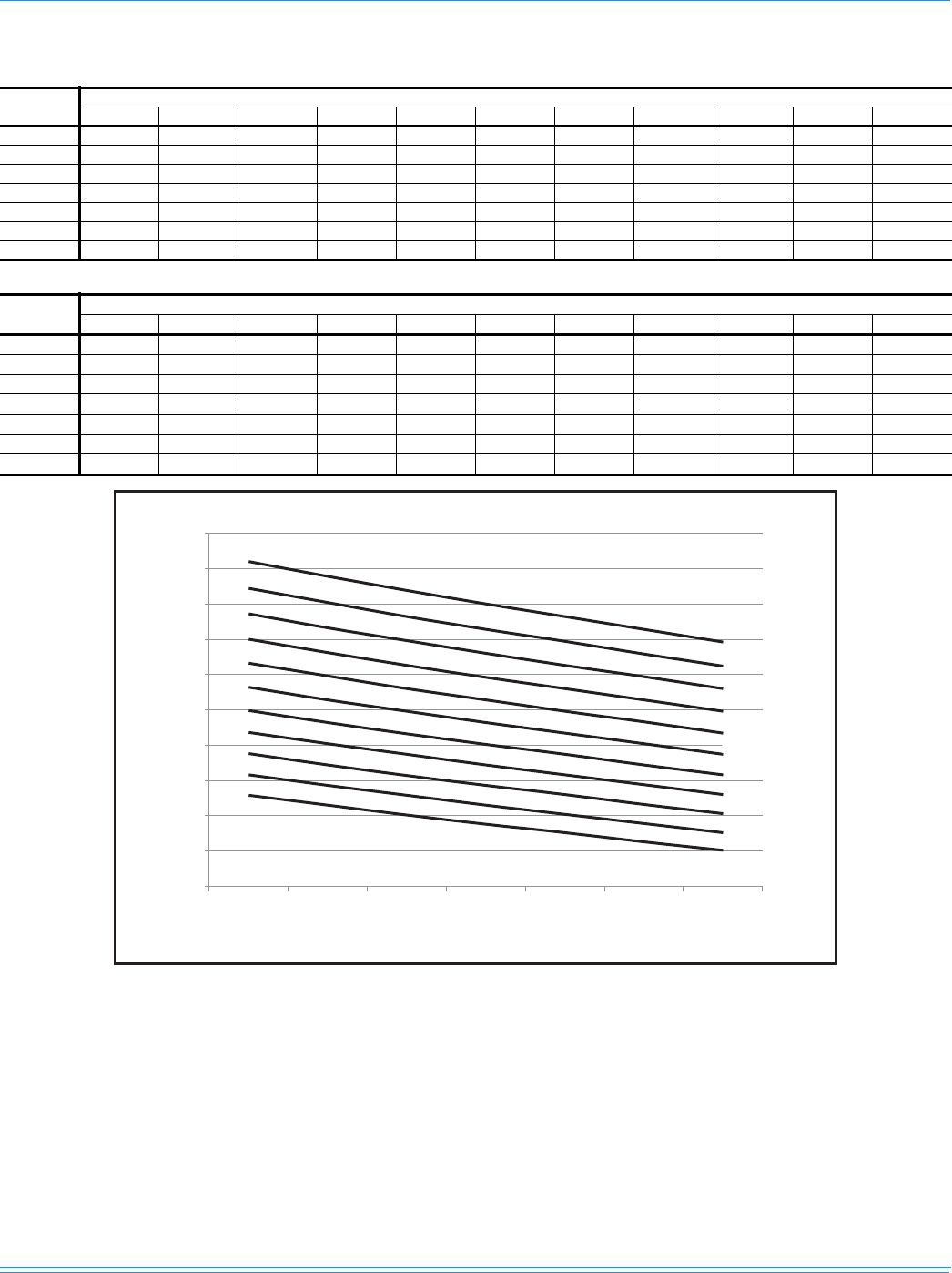
1056292-XTG-A-0613
Johnson Controls Unitary Products 27
Altitude/Temperature Correction Factors Imperial
Altitude/Temperature Correction Factors Imperial
Air
Temp. F Altitude (Ft.)
0 1000 2000 3000 4000 5000 6000 7000 8000 9000 10000
40 1.060 1.022 0.986 0.950 0.916 0.882 0.849 0.818 0.788 0.758 0.729
50 1.039 1.002 0.966 0.931 0.898 0.864 0.832 0.802 0.772 0.743 0.715
60 1.019 0.982 0.948 0.913 0.880 0.848 0.816 0.787 0.757 0.729 0.701
70 1.000 0.964 0.930 0.896 0.864 0.832 0.801 0.772 0.743 0.715 0.688
80 0.982 0.947 0.913 0.880 0.848 0.817 0.787 0.758 0.730 0.702 0.676
90 0.964 0.929 0.897 0.864 0.833 0.802 0.772 0.744 0.716 0.689 0.663
100 0.946 0.912 0.880 0.848 0.817 0.787 0.758 0.730 0.703 0.676 0.651
Altitude/Temperature Correction Factors Metric
Air
Temp. C
Altitude (Meter)
0 305 610 914 1219 1524 1829 2134 2438 2743 3048
4.4 1.060 1.022 0.986 0.950 0.916 0.882 0.849 0.818 0.788 0.758 0.729
10.0 1.039 1.002 0.966 0.931 0.898 0.864 0.832 0.802 0.772 0.743 0.715
15.5 1.019 0.982 0.948 0.913 0.880 0.848 0.816 0.787 0.757 0.729 0.701
21.0 1.000 0.964 0.930 0.896 0.864 0.832 0.801 0.772 0.743 0.715 0.688
26.6 0.982 0.947 0.913 0.880 0.848 0.817 0.787 0.758 0.730 0.702 0.676
32.0 0.964 0.929 0.897 0.864 0.833 0.802 0.772 0.744 0.716 0.689 0.663
38.0 0.946 0.912 0.880 0.848 0.817 0.787 0.758 0.730 0.703 0.676 0.651
0.600
0.650
0.700
0.750
0.800
0.850
0.900
0.950
1.000
1.050
1.100
40 50 60 70 80 90 100
Air Temperature (ºF)
Correction Factor
Sea Level
1000 ft
2000 ft
3000 ft
4000 ft
6000 ft
7000 ft
8000 ft
9000 ft
10000 ft
5000 ft
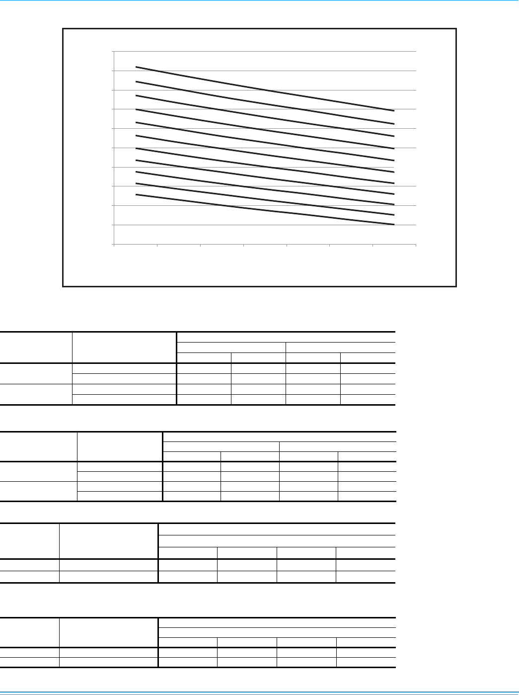
1056292-XTG-A-0613
28 Johnson Controls Unitary Products
Altitude/Temperature Correction Factors Metric
0.600
0.650
0.700
0.750
0.800
0.850
0.900
0.950
1.000
1.050
1.100
Air Temperature (ºC)
Correction Factor
Sea Level
305 Meter
610 Meter
914 Meter
1219 Meter
1829 Meter
2134 Meter
2430 Meter
2743 Meter
3048 Meter
1524 Meter
4.4 10 15.5 21 26.6 32 38
Gas Heat Minimum Supply Air Imperial
Size
(Tons) Heat Size
Supply Air (CFM)
Cooling Heating
Min Max Min Max
180
(15)
24 4500 7000 4500 7000
32 4500 7000 4500 7000
240
(20)
24 6000 9400 6000 9400
32 6000 9400 6000 9400
Gas Heat Minimum Supply Air Metric
Size
(Tons) Heat Size Supply Air (M3/S)
Cooling Heating
Min Max Min Max
180
(15)
24 2.13 3.3 2.13 3.3
32 2.13 3.3 2.13 3.3
240
(20)
24 2.83 4.44 2.83 4.44
32 2.83 4.44 2.83 4.44
Electric Heat Minimum Supply Air Imperial
Size (Tons) Voltage
Minimum Supply Air (CFM)
Heater kW
18 36 54 72
180 (15) 380/415-3-50 4500 4500 5000 5000
240 (20) 380/415-3-50 6000 6000 6000 6000
Electric Heat Minimum Supply Air Metric
Size (Tons) Voltage Minimum Supply Air (M3/S)
Heater kW
18 36 54 72
180 (15) 380/415-3-50 2.12 2.12 2.36 2.36
240 (20) 380/415-3-50 2.83 2.83 2.83 2.83
1056292-XTG-A-0613
Johnson Controls Unitary Products 29
Sound Performance
Indoor Blower Specifications
Size
(Tons) Model Motor Motor Sheave Blower Sheave Belt
HP RPM Eff. SF Frame Datum Dia.
(in.) Bore (in.) Model Datum Dia.
(in.) Bore (in.) Model
180 (15) ZF 4.0 1450 0.89 1.15 184T 4.4 - 5.4 1 1/8 1VP62 6.9 1 BK75 BX68
240 (20) ZF 6.3 1450 0.91 1.15 213T 5.8 - 6.8 1 3/8 1VP75 9.4 1 3/16 BK100 BX81
Power Exhaust Specifications
Voltage Motor Motor CFM @
0.2 ESP
HP RPM1
1. Motors are multi-tapped and factory wired for high speed.
QTY LRA FLA MCA
460-1-60 3/4 1075 1 4.1 2.2 2.75 5250
Electric Heat Multipliers
Voltage kW Capacity Multipliers1
1. Electric heaters are rated at nominal voltage. Use this table to
determine the electric heat capacity for heaters applied at
lower voltages.
Nominal Applied
480 415 0.75
480 380 0.63
ZF Indoor Sound Power Levels
Size
(Tons) CFM ESP
(IWG)
Blower Sound Power, dB (10-12) Watts
Sound Rating1
dB (A)
Octave Band Centerline Frequency (Hz)
RPM BHP 63 125 250 500 1000 2000 4000 8000
180 (15) 6000 1.0 1,080 4.6 91 88 90 90 87 85 81 81 76
240 (20) 8000 1.0 1,020 6.6 86 85 85 83 82 82 78 75 70
1. These values have been accessed using a model of sound propagation from a point source into the hemispheric/free field. The dBA values
provided are to be used for reference only. Calculation of dBA values cover matters of system design and the fan manufacturer has no way
of knowing the details of each system. This constitutes an exception to any specification or guarantee requiring a dBA value of sound data
in any other form than sound power level ratings.
ZF Outdoor Sound Power Levels
Size
(Tons) Sound Rating1
dB (A)
Sound Power, dB (10-12) Watts
Octave Band Centerline Frequency (Hz)
63 125 250 500 1000 2000 4000 8000
180 (15) 92 90 93 91 89 86 83 80 75
240 (20) 92 91 94 92 89 87 83 81 76
1. Rated in accordance with AHRI 270 standard.
1056292-XTG-A-0613
30 Johnson Controls Unitary Products
Electrical Data
ZF180 - 240
ZF180-240 - High Static Drive
Size
(Tons) Volt
Compressors
(each)
OD Fan
Motors
(each)
Supply
Blower
Motor Electric Heat Option MCA1
(Amps)
1. Minimum Circuit Ampacity.
Max Fuse2/
Breaker3
Size
(Amps)
2. Dual Element, Time Delay Type.
3. HACR type per NEC.
RLA LRA MCC FLA FLA Model kW Stages Amps
C1 C2 C1 C2 C1 C2
180
(15)
380-3-50 18.6 14.5 100.0 90.5 26.0 20.3 2.1 6.3
None -- -- -- 49 60
E18 11.3 1 17.1 49 60
E36 22.6 2 34.3 51 60
E54 33.8 2 51.4 73 80
E72 45.1 2 68.6 90 100
415-3-50 18.6 14.5 111.0 101.0 26.0 20.3 2.1 6.7
None -- -- -- 49 60
E18 13.5 1 18.7 49 60
E36 26.9 2 37.4 56 60
E54 40.0 2 56.2 79 80
E72 53.8 2 74.9 84 90
240
(20)
380-3-50 20.7 20.0 110.0 110.0 29.0 28.0 2.1 8.2
None -- -- -- 60 70
E18 11.3 1 17.1 60 70
E36 22.6 2 34.3 60 70
E54 33.8 2 51.4 75 80
E72 45.1 2 68.6 96 100
415-3-50 20.7 20.0 118.0 118.0 29.0 28.0 2.1 9.1
None -- -- -- 60 70
E18 13.5 1 18.7 60 70
E36 26.9 2 37.4 60 70
E54 40.0 2 56.2 82 80
E72 53.8 2 74.9 87 90
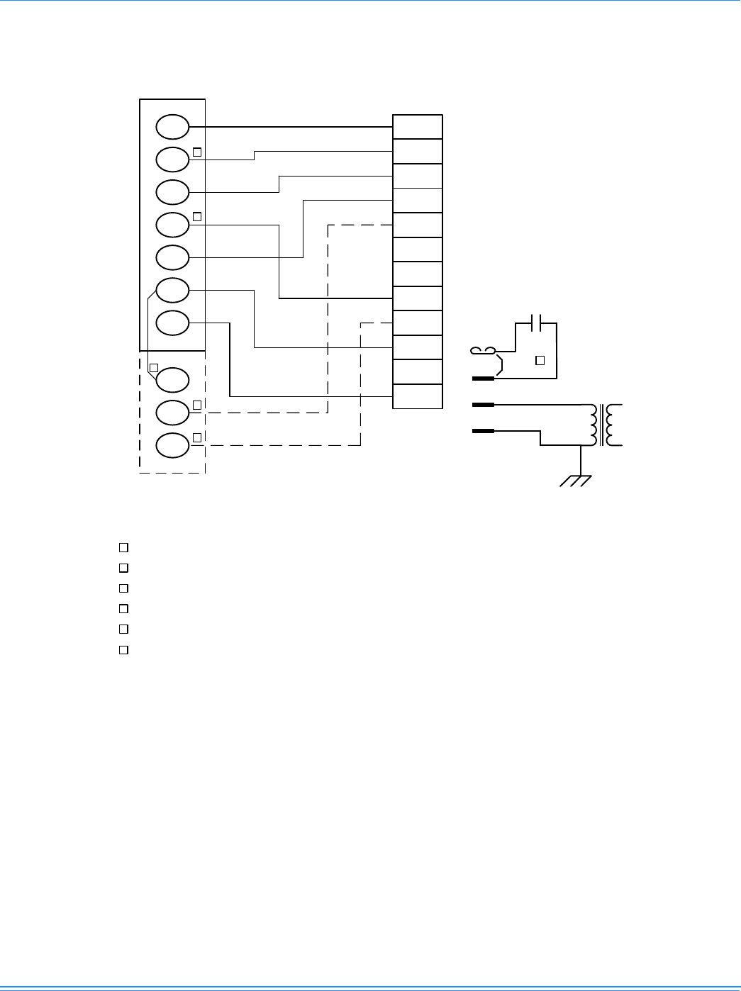
1056292-XTG-A-0613
Johnson Controls Unitary Products 31
ZF180-240 Wiring Diagrams
ZF180-240 Typical Control Diagram
W1
W2
Y1
G
OCC
P
P1
Y2
X
R
SD
C
C
SD
SD
R
OCC
C
RC
G
Y2
Y1
W2
W1
Jumper
Smoke
Detector
24 VAC
Class 2
X
R
THERMOSTAT
TERMINALS
CONTROL
TERMINAL
BLOCK
TERMINALS ON
A LIMITED
NUMBER OF
THERMOSTATS
3
1
2
4
3
1
2
4
Second stage heating not required on single stage heating units.
Second stage cooling not required on single stage cooling units.
Jumper is required if there is no Smoke Detector circuit.
Jumper is required for any combination of R, RC, or RH.
6
5
5
6
OCC is an output from the thermostat to indicate the Occupied condition.
X is an input to the thermostat to display Error Status conditions.
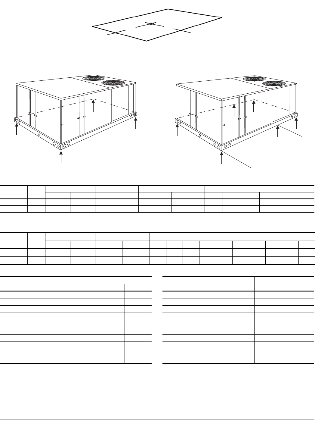
1056292-XTG-A-0613
32 Johnson Controls Unitary Products
Weights and Dimensions
ZF Unit 4 Point Load Weight ZF Unit 6 Point Load Weight
XY
LEFT FRONT
A
B
C
D
FRONT
A
C
D
F
B
E
FRONT
1624 (64”) (180)
1758 (69”) (240)
ZF180-240 Unit Weights Imperial
Size
(Tons) Model Weight (lbs.) Center of Gravity 4 Point Load Location (lbs.) 6 Point Load Location (lbs.)
ShippingOperatingX Y ABCD A B C D E F
180 (15) ZF 1685 1680 66.5 45.7 391 443 449 397 256 277 302 306 281 259
240 (20) ZF 2405 2400 70 44 558 590 643 609 369 382 397 433 417 402
ZF180-240 Unit Weights Metric
Size
(Tons) Model Weight (kg.) Center of Gravity (mm) 4 point Load Location (kg.) 6 point Load Location (kg.)
ShippingOperatingX Y ABCDABCDEF
180 (15) ZF 766 764 1689 1161 178 202 204 180 116 126 137 139 128 118
240 (20) ZF 1093 1091 1778 1118 254 268 292 277 168 174 180 197 189 183
ZF180-240 Unit Accessory Weights Imperial
Unit Accessory Weight (lbs.)
Shipping Operating
Economizer 165 160
Power Exhaust 90 85
Electric Heat140 40
Gas Heat2240 240
Motorized Damper 150 150
Barometric Damper 50 45
Econ./Motorized Damper Rain Hood 60 55
Econ./Power Exhaust Rain Hood 95 90
Wood Skid 220 220
Roof Curb 190 185
1. Weight given is for the maximum heater size available
(54KW).
2. Weight given is for the maximum number of tube heat
exchangers available (8 tube).
ZF180-240 Unit Accessory Weights Metric
Unit Accessory Weight (kg.)
Shipping Operating
Economizer 74.8 72.6
Power Exhaust 40.8 40.8
Electric Heat118.1 18.1
Gas Heat2108.9 108.9
Motorized Damper 68 68
Barometric Damper 22.7 22.7
Econ./Motorized Damper Rain Hood 27.2 27.2
Econ./Power Exhaust Rain Hood 43.1 43.1
Wood Skid 99.8 99.8
Roof Curb 86.2 86.2
1. Weight given is for the maximum heater size available
(54KW).
2. Weight given is for the maximum number of tube heat
exchangers available (8 tube).
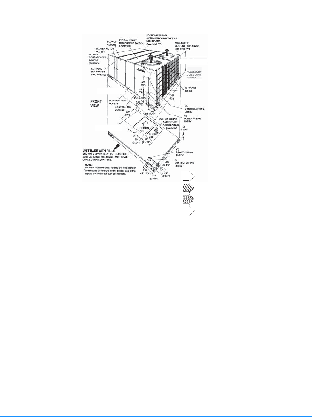
1056292-XTG-A-0613
Johnson Controls Unitary Products 33
Unit Dimensions
RETURN AIR
SUPPLY AIR
OUTDOOR AIR
(Discharge)
OUTDOOR AIR
(Economizer)
3181 (125-1/4") (180)
3461 (136-1/4") (240)
1235 (48-5/8") (180)
1337 (52-5/8") (240)
616 (24-1/4") (180)
895 (35-1/4") (240)
Unit Dimensions - ZF Cool & Cool/electric Heat
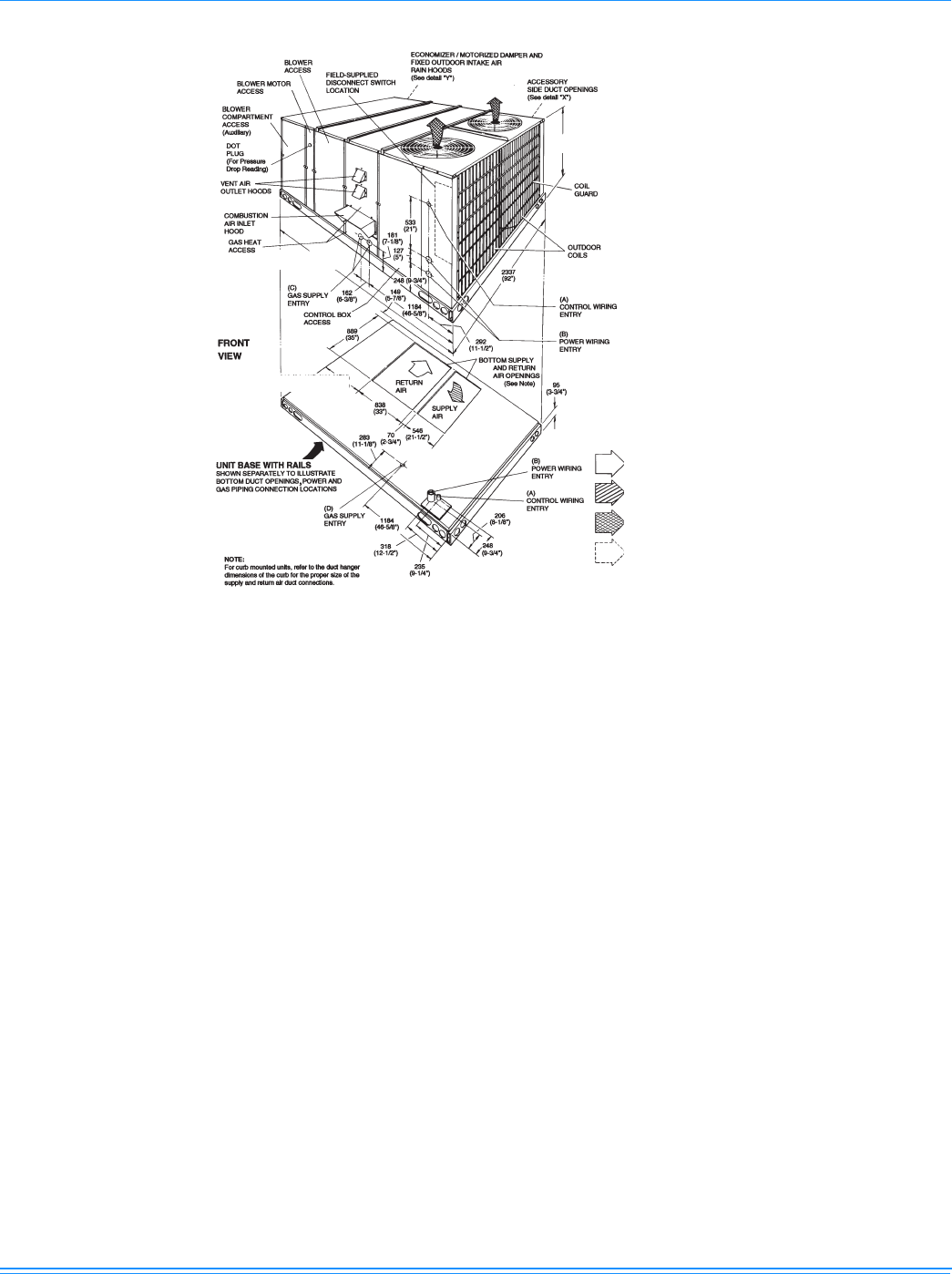
1056292-XTG-A-0613
34 Johnson Controls Unitary Products
1235 (48-5/8") (180)
1337 (52-5/8") (240)
3181 (125-1/4") (180)
3461 (136-1/4") (240)
616 (24-1/4") (180)
895 (35-1/4") (240)
RETURN AIR
OUTDOOR AIR
(Economizer)
SUPPLY AIR
OUTDOOR AIR
(Discharge)
Unit Dimensions - ZF Gas Heat
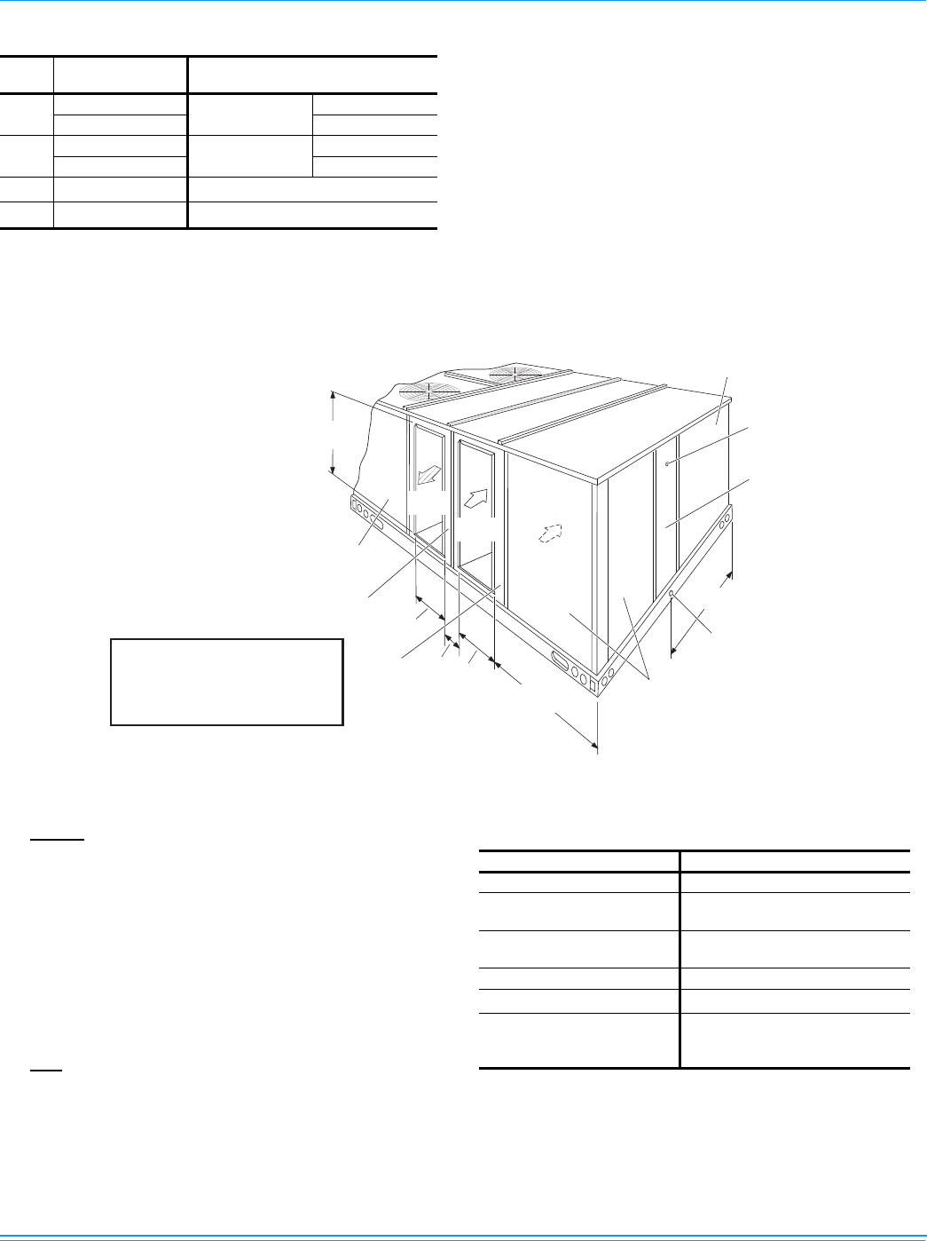
1056292-XTG-A-0613
Johnson Controls Unitary Products 35
Rear View Dimensions
NOTE: Units are shipped with the bottom duct openings covered. An accessory flange kit is available for connecting side ducts.
For bottom duct applications:
1. Remove the side panels from the supply and return air
compartments to gain access to the bottom supply and
return air duct covers.
2. Remove and discard the bottom duct covers. Duct
openings are closed with sheet metal covers except when
the unit includes a power exhaust option. The covering
consists of a heavy black paper composition.
3. Replace the side supply and return air compartment
panels.
For side duct applications:
1. Replace the side panels on the supply and return air
compartments with the side duct flange accessory kit
panels.
2. Connect ductwork to the flanges on those panels.
Utilities Entry Data
HOLE OPENING SIZE
(DIA.) (MM/IN.) USED FOR
A29/1-1/8” KO Control Wiring Side
19/3/4” NPS (Fem.) Bottom
B92/3-5/8” KO Power Wiring Side
76/3” NPS (Fem.) Bottom
C60/2-3/8” KO Gas Piping (Front)1
1. One-inch gas piping NPT required.
D43/1-11/16” Hole Gas Piping (Bottom)1, 2
2. Opening in the bottom of the unit can be located by the slice in
the insulation.
NOTE: All entry holes should be field sealed to prevent rain
water entry into the building.
SUPPLY
AIR
RETURN
AIR
OUTDOOR
AIR
130
(5-1/8")
474
(18-5/8")
705
(27-3/4")
ZF180 727 (28-5/8”)
ZF240 1006 (39-5/8")
1029
(40-1/2")
OUTDOOR AIR
COMPARTMENT
ACCESS
FILTER
ACCESS
1" NPT FEMALE
COND. DRAIN
CONNECTION
DOT PLUG
(For pressure
drop reading)
EVAPORATOR
SECTION
1026
(40-3/8")
COMPRESSOR
ACCESS
SUPPLY AIR
ACCESS
RETURN AIR
ACCESS
REAR
VIEW
Dimensions listed are for side
duct flange openings; see
Field Accessories for Side
Duct Flange Kit.
Minimum Clearances (MM/IN.)
LOCATION CLEARANCE
Front 914/36”
Rear 610/24” (Less Economizer)
1245/49” (With Economizer)
Left Side (Filter Access) 610/24” (Less Economizer)
914/36” (With Economizer)3
Right Side (Cond. Coil) 914/36”
Below Unit1
1. Units may be installed on combustible floors made from wood
or class A, B, or C roof covering material.
0/0”
Above Unit2
2. Units must be installed outdoors. Overhanging structures or
shrubs should not obstruct condenser air discharge outlet.
3. If economizer is factory installed, the unassembled rain hood
must be removed from its ride along position in front of evapo-
rator coil, or in the outdoor air compartment, prior to final instal-
lation.
1829/72” With 914/36” Maximum
Horizontal Overhang (For
Condenser Air Discharge)
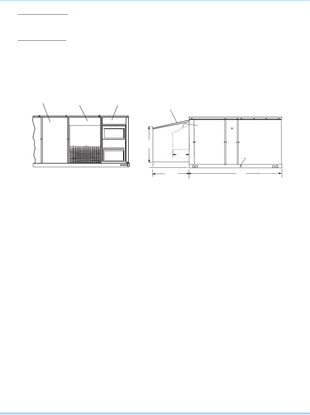
1056292-XTG-A-0613
36 Johnson Controls Unitary Products
NOTE: ELEC / ELEC Models: Units and ductwork are approved
for zero clearance to combustible material when
equipped with electric heaters.
GAS / ELEC Models: A 25mm/1” clearance must be
provided between any combustible material and the
supply air ductwork for a distance of .9 meter/3 feet from
the unit.
The products of combustion must not be allowed to
accumulate within a confined space and recirculate.
Locate unit so that the vent air outlet hood is at least:
• .9 meters/3 feet above any force air inlet located within
3.0 meters/10 horizontal feet (excluding those integral
to the unit).
• 1.2 meters/4 feet below, four horizontal feet from, or
one foot above any door or gravity air inlet into the
building.
• 1.2 meters/4 feet from electric and gas meters,
regulators and relief equipment.
Unit Clearances And Rainhood Dimensions (15 & 20 Ton)
REAR VIEW
DETAIL “Y”
UNIT WITH RAIN HOODS
LH VIEW
716
(28-3/16”)
2337
(92”)
930
(36-5/8”)
127 (5”)
410
(16-1/8”)
SUPPLY AIR
COMPARTMENT
POWER EXHAUST
RAIN HOOD
(on Return Air Compartment)
ECONOMIZER
MOTORIZED
DAMPER
RAIN HOOD
(on Outdoor Air Compartment) ECONOMIZER / MOTORIZED DAMPER
AND POWER EXHAUST RAIN HOODS
FIXED
OUTDOOR AIR
INTAKE HOOD
(located on
Return Air
Compartment)
25 (1“) CONDENSATE
DRAIN
(Must be trapped)
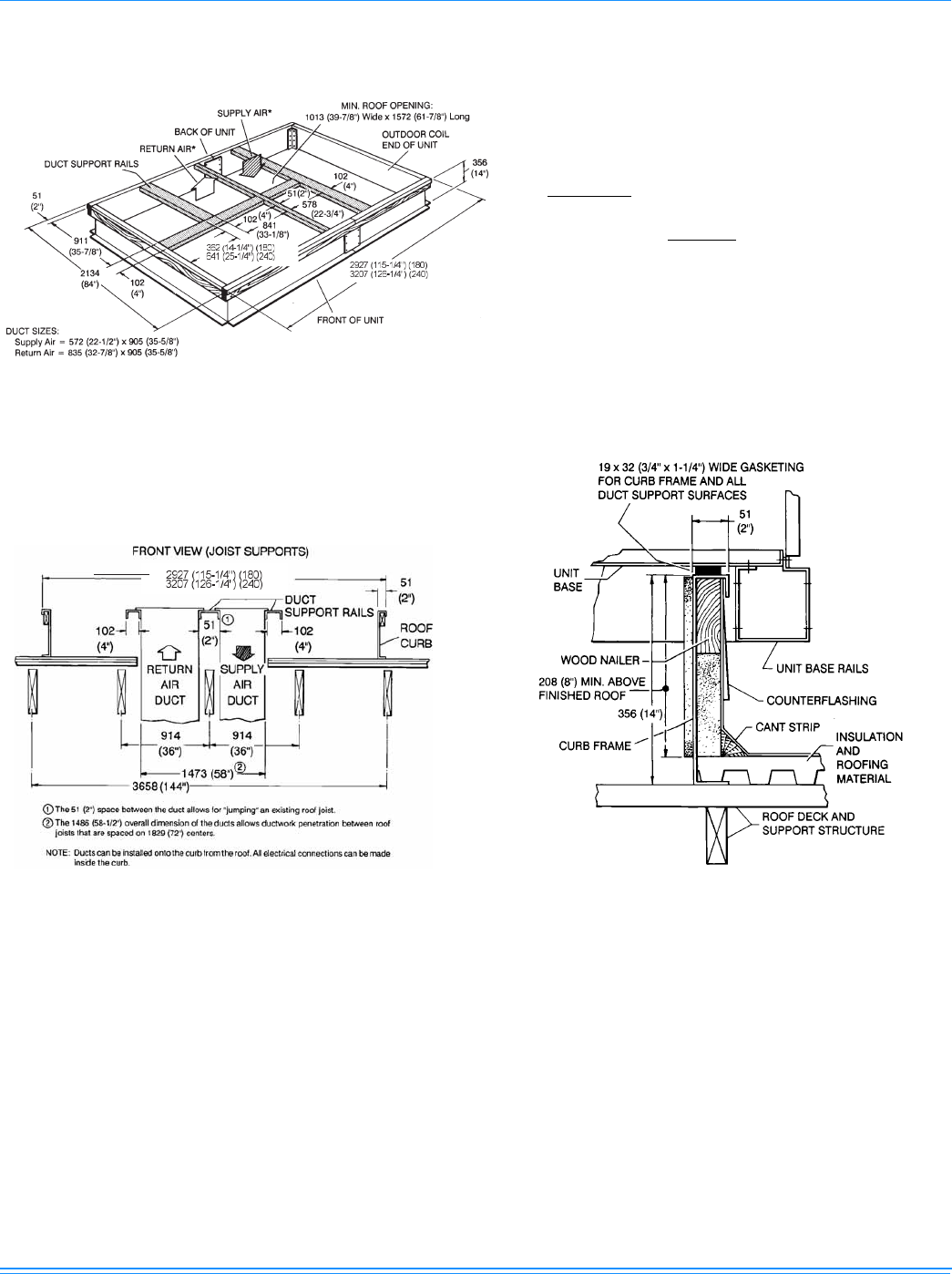
1056292-XTG-A-0613
Johnson Controls Unitary Products 37
Roof Curb Dimensions (All Models)
* Supply and Return air (including duct
support rails) as shown, are typical for
Downflow duct applications
For location of Sideflow duct applica-
tions (on back of unit), refer to Unit
Dimension details.
Roof Curb Benefits Unit Curb And Applications
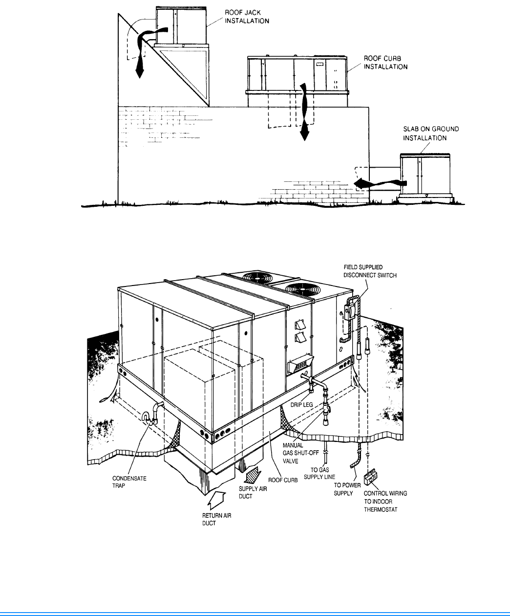
Subject to change without notice. Printed in U.S.A. 1056292-XTG-A-0613
Copyright © 2014 by Johnson Controls, Inc. All rights reserved. Supersedes: Nothing
York International Corporation
5005 York Drive
Norman, OK 73069
Typical Application
Typical Roof-top Installation (Gas/electric Unit Shown)
