Z Com 0XG880M Wireless CF Module User Manual Client EvalTool
Z Com Inc Wireless CF Module Client EvalTool
Z Com >
Contents
- 1. Test Report
- 2. Users Manual
Users Manual
Manufacturing Test Suite
Libertas™ 802.11g Client Card
Evaluation Tool User Guide
Doc. No. MV-S101517-00, Rev. –
August 5, 2003
Model No.: XG-880M

Proprietary Information
This document provides preliminary information about the products described, and such information should not be used for purpose of final design. Visit the Marvell® web
site at www.marvell.com or call 1-866-674-7253 for the latest information on Marvell products.
Disclaimer
No part of this document may be reproduced or transmitted in any form or by any means, electronic or mechanical, including photocopying and recording, for any purpose,
without the express written permission of Marvell. Marvell retains the right to make changes to this document at any time, without notice. Marvell makes no warranty of any
kind, expressed or implied, with regard to any information contained in this document, including, but not limited to, the implied warranties of merchantability or fitness for
any particular purpose. Further, Marvell does not warrant the accuracy or completeness of the information, text, graphics, or other items contained within this document.
Marvell makes no commitment either to update or to keep current the information contained in this document. Marvell products are not designed for use in life-support
equipment or applications that would cause a life-threatening situation if any such products failed. Do not use Marvell products in these types of equipment or applications.
The user should contact Marvell to obtain the latest specifications before finalizing a product design. Marvell assumes no responsibility, either for use of these products or
for any infringements of patents and trademarks, or other rights of third parties resulting from its use. No license is granted under any patents, patent rights, or trademarks
of Marvell.These products may include one or more optional functions. The user has the choice of implementing any particular optional function. Should the user choose to
implement any of these optional functions, it is possible that the use could be subject to third party intellectual property rights. Marvell recommends that the user investigate
whether third party intellectual property rights are relevant to the intended use of these products and obtain licenses as appropriate under relevant intellectual property
rights.
Marvell comprises Marvell Technology Group Ltd. (MTGL) and its subsidiaries, Marvell International Ltd. (MIL), Marvell Semiconductor, Inc. (MSI), Marvell Asia Pte Ltd.
(MAPL), Marvell Japan K.K. (MJKK), Marvell Semiconductor Israel Ltd. (MSIL), SysKonnect GmbH, and Radlan Computer Communications, Ltd.
Export Controls. With respect to any of Marvell’s Information, the user or recipient, in the absence of appropriate U.S. government authorization, agrees: 1) not to re-export
or release any such information consisting of technology, software or source code controlled for national security reasons by the U.S. Export Control Regulations ("EAR"),
to a national of EAR Country Groups D:1 or E:2; 2) not to export the direct product of such technology or such software, to EAR Country Groups D:1 or E:2, if such technol-
ogy or software and direct products thereof are controlled for national security reasons by the EAR; and, 3) in the case of technology controlled for national security reasons
under the EAR where the direct product of the technology is a complete plant or component of a plant, not to export to EAR Country Groups D:1 or E:2 the direct product of
the plant or major component thereof, if such direct product is controlled for national security reasons by the EAR, or is subject to controls under the U.S. Munitions List
("USML"). At all times hereunder, the recipient of any such information agrees that they shall be deemed to have manually signed this document in connection with their
receipt of any such information.
Copyright © 2003. Marvell. All rights reserved. Marvell, the Marvell logo, Moving Forward Faster, Alaska, and GalNet are registered trademarks of Marvell. Discovery,
Fastwriter, GalTis, Horizon, Libertas, Link Street, NetGX, PHY Advantage, Prestera, Raising The Technology Bar, UniMAC, Virtual Cable Tester, and Yukon are trademarks
of Marvell. All other trademarks are the property of their respective owners.
Marvell
700 First Avenue
Sunnyvale, CA 94089
Phone: (408) 222 2500
Sales Fax: (408) 752 9029
Email: commsales@marvell.com
802.11g Client Card Evaluation Tool User Guide
Document Status
Advanced
Information
This document contains design specifications for initial product development. Specifications may
change without notice. Contact Marvell Field Application Engineers for more information.
Preliminary
Information
This document contains preliminary data, and a revision of this document will be published at a
later date. Specifications may change without notice. Contact Marvell Field Application Engineers
for more information.
Final
Information
This document contains specifications on a product that is in final release. Specifications may
change without notice. Contact Marvell Field Application Engineers for more information.
Revision Code:
Proprietary Technical Publication:
Doc. No. MV-S101517-00 Rev. – CONFIDENTIAL Copyright © 2003 Marvell
Page 2 Document Classification: Proprietary Information August 5, 2003, Proprietary

Table of Contents
Copyright © 2003 Marvell CONFIDENTIAL Doc. No. MV-S101517-00 Rev. –
August 5, 2003, Preliminary Document Classification: Preliminary Information Page 3
Table of Contents
Section 1. Getting Started .................................................................................................... 5
1.1 Overview ................................................................................................................................... 5
1.2 Equipment ................................................................................................................................. 5
1.2.1 Test Setup...................................................................................................................................5
1.2.2 Calibration ...................................................................................................................................6
1.3 System Requirements...............................................................................................................6
Section 2. Software Requirements ....................................................................................... 7
2.1 Manufacturing Test Software Suite Contents............................................................................ 7
2.2 Software Installation..................................................................................................................7
2.3 Windows Driver Installation.......................................................................................................8
2.3.1 Driver Installation Procedure .......................................................................................................8
2.3.2 Programming Configuration Information .....................................................................................9
Section 3. Command Line Interface ................................................................................... 11
3.1 Using the Manual Test Module ...............................................................................................11
3.1.1 DUT Interface ............................................................................................................................11
3.1.2 Golden Unit Interface ................................................................................................................12
3.1.3 Additional Menu Interface..........................................................................................................13
3.1.4 Before Getting Started...............................................................................................................15
3.2 Receiver Sensitivity Test.........................................................................................................16
3.2.1 Overview ...................................................................................................................................16
3.2.2 Test Procedure..........................................................................................................................16
3.3 Transmitter Tests .................................................................................................................... 17
3.4 Command Descriptions...........................................................................................................18
3.4.1 RF Commands ..........................................................................................................................18
3.4.2 FER Commands........................................................................................................................22
3.4.3 Configuration Information Access Commands ..........................................................................24
3.4.4 SPI/Flash Access Commands...................................................................................................25
3.4.5 Device Specific Commands ......................................................................................................27
3.4.6 Exit Test Command...................................................................................................................28
Appendix A.Sample CalDataFile.txt...................................................................................... 29
Section 4. Index.................................................................................................................. 33
Section 5. Revision History................................................................................................. 35

802.11g Client Card Evaluation Tool User Guide
Doc. No. MV-S101517-00 Rev. – CONFIDENTIAL Copyright © 2003 Marvell
Page 4 Document Classification: Preliminary Information August 5, 2003, Preliminary
This page is intentionally left blank.
Getting Started
Overview
Copyright © 2003 Marvell CONFIDENTIAL Doc. No. MV-S101517-00 Rev. –
August 5, 2003, Preliminary Document Classification: Preliminary Information Page 5
Section 1. Getting Started
1.1 Overview
This document explains how to use the software command line interface for the following Libertas™ Wireless LAN
(WLAN) client cards:
•Marvell® CB-32 802.11g WLAN CardBus Card
•Marvell® MB-31 802.11g WLAN Mini PCI Card
These cards include the highly integrated Libertas™ IEEE 802.11g two-chip solutions for client applications. The
chipset consists of the 88W8000G Radio Frequency Transceiver and the 88W8310 WLAN Client device.
1.2 Equipment
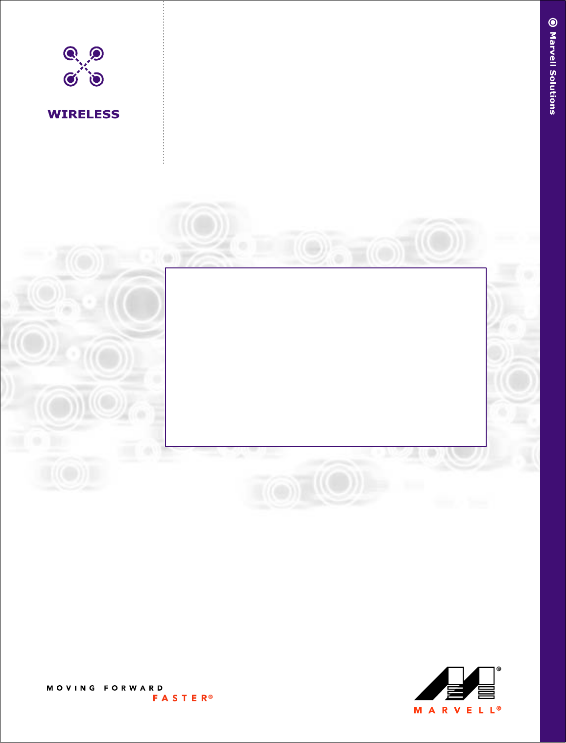
The overall setup for testing the capabilities and performance of the Libertas™ family of WLAN chipset solutions is
shown in Figure 1. The setup shows the equipment required to test the transmit/receive chains and throughput
between a DUT and a golden source. Proper shielding is required for both the DUT and the golden source.
1.2.1 Test Setup
Figure 1: Test Setup
Shielding Box
DUT Switch
Power
Supply
Power
Meter
Host Interface
(control and data)
GPIB
RF Cable
GPIB
Power
Fast Ethernet/ Host Interface (control and data)
PCB
PC
Test Controller
Attenuator
Attenuator
Fast Ethernet
optional
Splitter
Spectrum
Analyzer
Splitter
Attenuator/
Switch Driver
Variable
Attenuator Attenuator
Shielding Box
Golden Source
Attenuator Attenuator
Doc. No. MV-S101517-00 Rev. – CONFIDENTIAL Copyright © 2003 Marvell
Page 6 Document Classification: Preliminary Information August 5, 2003, Preliminary
Libertas™ 802.11g Client Card
Evaluation Tool User Guide
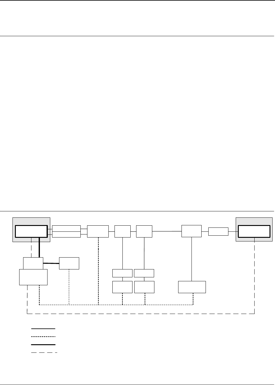
1.2.2 Calibration
It is critical to obtain accurate measurements of the path loss (due to cables, connectors, etc.) from the DUT to the
Golden Unit and from the DUT to the power meter. For path loss measurements, sum the loss of each individual
component along the path. Figure 2 shows the RF path loss for calibration. Figure 3 shows the switch settings for
the programmable attenuator.
Figure 2: RF Path
Figure 3: Switch Driver
1.3 System Requirements
•300 MHz or faster CPU
•Windows® 2000 or 98SE (Second Edition)
•Marvell Libertas™ Client Card (CardBus or Mini PCI)
Divider
6 dB
Agilent WLAN Test Set
Attenuator
6 dB
Attenuator
6 dB
LAN
DUT
Master PC
Divider
6 dB
Attenuator
6 dB
ESA
Attenuator/
Switch Driver
Programmable
Attenuator
Attenuator
6 dB
Golden
Unit
Slave PC
8762B
8494H/8496H
Attenuator
6 dB
Power
Meter
8493A 11636B11636B
Antenna 1 (2) to ESA = 18dB
Antenna 1 (2) to PM = 24dB
Antenna 1 (2) to Golden = 24dB
Golden to PM = 18dB
Attenuator X
1 dB 2 dB 4 dB 4 dB
1234
Attenuator Y Switches
Agilent 11713A Attenuator/Switch Driver
5
10 dB 20 dB 40 dB 40 dB
678 90
Software Requirements
Manufacturing Test Software Suite Contents
Copyright © 2003 Marvell CONFIDENTIAL Doc. No. MV-S101517-00 Rev. –
August 5, 2003, Preliminary Document Classification: Preliminary Information Page 7
Section 2. Software Requirements
2.1 Manufacturing Test Software Suite Contents
2.2 Software Installation
1. Copy the manufacturing test software files to a directory on the C: drive. DutApiPci98_G.exe, DutApi98Dll.dll,
and SetUp.ini must be in the same directory.
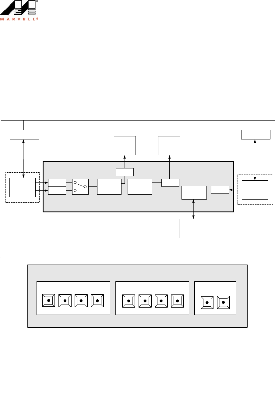
2. Open the Setup.ini file with a text editor. When running both the DutApiPci98_G.exe and GoldenAP.exe test
files, the Setup.ini should contain the Golden Unit IP addresses and DUT and Golden setup information:
Figure 4: Setup File
Table 1: Manufacturing Test Software
Filename Description
SetUp.ini Setup file. See Figure 4.
DutApi98Dll.dll DLL file for DUT.
DutApiPci98_G.exe Manual test module executable for client card.
GoldenAP.exe Manual test module executable for AP golden unit.
CalDataFile.txt Example manufacturing calibration data file. See Appendix A. "Sample CalDataFile.txt" .
Spi.hex Hexadecimal file to program SPI (see command 35).
Doc. No. MV-S101517-00 Rev. – CONFIDENTIAL Copyright © 2003 Marvell
Page 8 Document Classification: Preliminary Information August 5, 2003, Preliminary
Libertas™ 802.11g Client Card
Evaluation Tool User Guide
2.3 Windows Driver Installation
Installation of the driver will allow the user to access hardware memory space. The following files are required:
•MWLAN_G.inf
•windrvr.vxd
•DutApiPci98_G.exe
•wdreg.exe
2.3.1 Driver Installation Procedure
Windows explorer may not show *.Vxd file on the folder. At the MS-DOS command prompt, use the directory (DIR)
command to check the entire contents of the installation disk.
Notes
• In some of the commands below you are asked to type a text string enclosed in double quotes. Do not
type the quotes, they are just there for clarity.
• Commands that you type in are in bold.
• Pressing the Enter key after typing in a text string is assumed.
1. Copy windrvr.vxd from the installation disk to c:\windows\system\vmm32 directory.
2. Create an application directory (for example, “mkdir c:\mactest”).
3. Copy DutApiPci98_G.exe and wdreg.exe from the installation disk to the application directory.
4. Insert the Marvell card and Windows 98SE will run the device installation wizard.
Use the INF file (a:\MWLAN_G.inf) on the installation disk to install the device.
5. Open the MS-DOS command prompt window and change the directory to the application directory
(for example, “cd c:\mactest”).
6. Type “WDREG.EXE -VXD install” to run the registration program. This is CASE-SENSITIVE.
The following messages should appear:
Creating driver entry... OK
Starting driver entry.… OK
7. Open the MS-DOS command prompt window:
a) Change the directory to the application directory (for example, “cd c:\mactest”).
b) Type “DutApiPci98_G.exe” to run the test program.

Software Requirements
Windows Driver Installation
Copyright © 2003 Marvell CONFIDENTIAL Doc. No. MV-S101517-00 Rev. –
August 5, 2003, Preliminary Document Classification: Preliminary Information Page 9
2.3.2 Programming Configuration Information
The configuration information (MAC address, calibration data, CIS table, etc.) are saved in EEPROM and are
accessed through the SPI interface. The image can be also programmed through the PCI interface. There are two
ways to program the image (build-in SPI or with a hex file). Although the build-in image is more stable, loading the
image from a hex file allows access to more recent information and allows more flexibility.
To program build-in image:
1. Type the command 37.
2. Type 38 to verify the image against the build-in image. There should be no errors reported.
3. Type 48.
This command programs the sub-PID and sub-VID for the Marvell Mini PCI card (47 for the CardBus).
To program the image from the file:
1. Type 39.
The current file name is displayed in brackets. The default is Spi.hex.
When prompted for filename, either press Enter or type Spi.hex.
If there is no change to the configuration, press Enter. If there is a change, the configuration information from
the file name entered is retained for this execution (replaces the information in the default file).
2. Type 40.
This command will verify the image against the given file.
3. Type 48.
This command programs the sub-PID and sub-VID for the Marvell Mini PCI card (47 for the CardBus).
After downloading the image, or if the image already exists, the MAC address is programmed as follows:
1. Type “46 xx.xx.xx.xx.xx.xx”.
This command writes the MAC address (xx.xx.xx.xx.xx.xx). Use command 45 to view the MAC address cur-
rently programmed.
a) Use hexadecimal values in the following format: xx.xx.xx.xx.xx.xx for the MAC address.
b) Enter the values with a period (.) in between number pairs.
2. Type 99 to exit.
Notes
• To view the these commands, run the DutApiPci98_G.exe file as follows: “DutApiPci98_G.exe -m”.
The space is required between DutApiPci98_G.exe and -m.
See 3.1.3 "Additional Menu Interface" on page 13.
• Command 37 can be used to download the build-in Spi.hex file. However, when a new Spi.hex is
available, use command 39. When using command 37, use command 48 to program PID/VID.

Doc. No. MV-S101517-00 Rev. – CONFIDENTIAL Copyright © 2003 Marvell
Page 10 Document Classification: Preliminary Information August 5, 2003, Preliminary
This page is intentionally left blank.
Libertas™ 802.11g Client Card
Evaluation Tool User Guide

Command Line Interface
Using the Manual Test Module
Copyright © 2003 Marvell CONFIDENTIAL Doc. No. MV-S101517-00 Rev. –
August 5, 2003, Preliminary Document Classification: Preliminary Information Page 11
Section 3. Command Line Interface
3.1 Using the Manual Test Module
The manual test module runs through a simple menu-driven interface. Two executable files are needed for the
test. The Setup.ini file must be located in the same directory as the executable files.
•DutApiPci98_G.exe. Controls the CardBus and Mini PCI cards.
•GoldenAP.exe. Controls the Golden unit. Needed for Rx Sensitivity tests (unless a signal generator is used).
•Setup.ini
Run both the DutApiPci98_G.exe and GoldenAP.exe files to launch the tool. Each command is numbered, and
some commands accept input parameters. For example, to retrieve the current channel setting, type 11 and press
Enter. This command returns the current channel. To set the channel to 6, type “12 6” and press Enter, where 12
is the command and 6 is the input parameter.
3.1.1 DUT Interface
Figure 5: PCI Interface Test Menu (DutApiPci98_G.exe)
Doc. No. MV-S101517-00 Rev. – CONFIDENTIAL Copyright © 2003 Marvell
Page 12 Document Classification: Preliminary Information August 5, 2003, Preliminary
Libertas™ 802.11g Client Card
Evaluation Tool User Guide
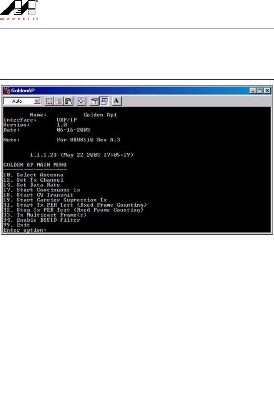
3.1.2 Golden Unit Interface
Figure 6: Golden AP Main Menu (GoldenAP.exe)
Command Line Interface
Using the Manual Test Module
Copyright © 2003 Marvell CONFIDENTIAL Doc. No. MV-S101517-00 Rev. –
August 5, 2003, Preliminary Document Classification: Preliminary Information Page 13
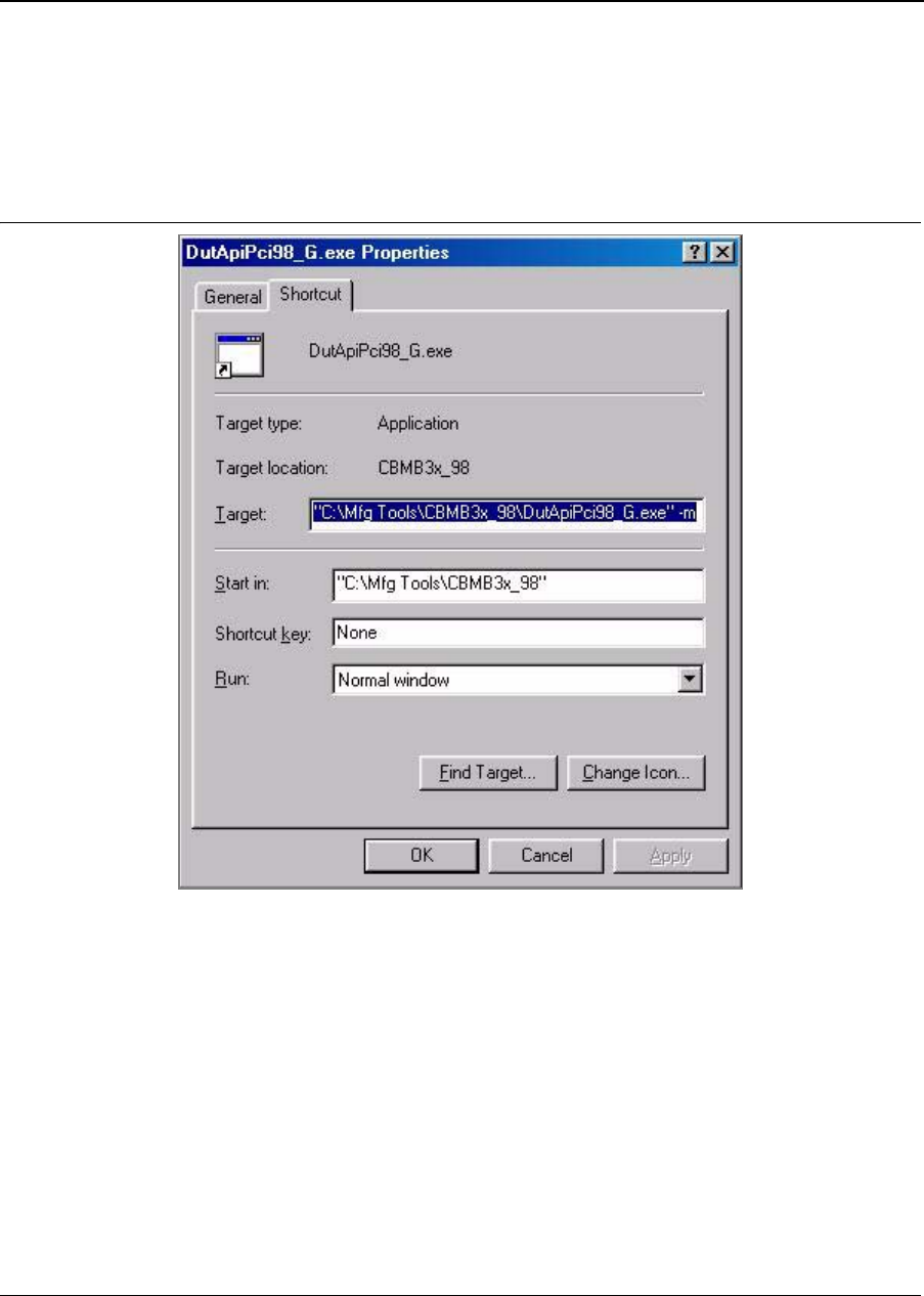
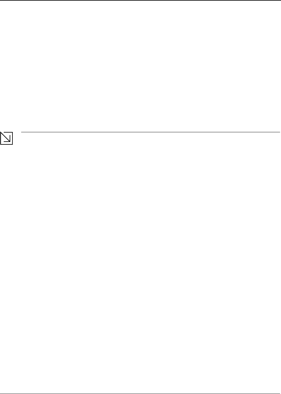
3.1.3 Additional Menu Interface
There is also an additional menu of commands available. To open the menu, add a “-m” argument in the target line
after typing the file name. Figure 7 shows how to create a shortcut for the additional menu interface.
Figure 7: Additional Menu Shortcut
Doc. No. MV-S101517-00 Rev. – CONFIDENTIAL Copyright © 2003 Marvell
Page 14 Document Classification: Preliminary Information August 5, 2003, Preliminary
Libertas™ 802.11g Client Card
Evaluation Tool User Guide
Figure 8: PCI Interface Test Menu (DutApiPci98_G.exe -m)
Command Line Interface
Using the Manual Test Module
Copyright © 2003 Marvell CONFIDENTIAL Doc. No. MV-S101517-00 Rev. –
August 5, 2003, Preliminary Document Classification: Preliminary Information Page 15
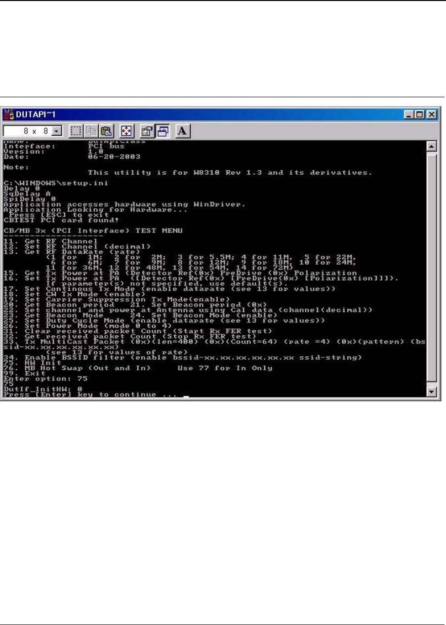
3.1.4 Before Getting Started
Initialize the device after launching the manual test module. Enter command 75 before running any RF tests.
Figure 9: Initialize Device (Command 75)

Doc. No. MV-S101517-00 Rev. – CONFIDENTIAL Copyright © 2003 Marvell
Page 16 Document Classification: Preliminary Information August 5, 2003, Preliminary
Libertas™ 802.11g Client Card
Evaluation Tool User Guide
3.2 Receiver Sensitivity Test
3.2.1 Overview
The receiver sensitivity test is based on frame error rate (FER). The test will send a known number of frames,
count the number of frames received on the DUT, and calculate the frame error rate. According to the IEEE spec-
ification, sensitivity is the lowest input power level needed to achieve a FER less than 8% for 802.11b data rates,
and 10% for 802.11g data rates.
For the manufacturing test, the Golden Unit is used to transmit packets.
3.2.2 Test Procedure
1. Launch the GoldenAP.exe and DutApiPci98_G.exe files.
2. Type 75 to initialize the DUT (in the DutApiPci98_G.exe menu).
3. Type “12 x” (where “x” is the channel number) to set the desired channel on the DUT.
4. Type 31 to clear the received packet counter.
5. OPTIONAL: Type “34 1 11.22.33.44.55.66” to filter on BSSID.
In this example, only frames with BSSID = 11.22.33.44.55.66 will be counted.
6. Set the channel for the Golden Unit (in the GoldenAP.exe menu).
Type 33. The user is prompted to enter the length, count, data rate, pattern, and BSSID as parameters.
7. Type 32 to read the received packet counter. The DUT will report the number of frames received correctly (for
example, no CRC error), the number of multicast frames received correctly, and the number of frames
received with CRC errors. Calculate the FER based on the number of frames sent by the Golden Unit.
8. If necessary, adjust the settings on the programmable attenuators to achieve the desired FER.
Note
To verify the DUT is properly shielded, clear the received packet counter, wait a few seconds, and read
the packet counter. The packet counter should read 0.
Command Line Interface
Transmitter Tests
Copyright © 2003 Marvell CONFIDENTIAL Doc. No. MV-S101517-00 Rev. –
August 5, 2003, Preliminary Document Classification: Preliminary Information Page 17
3.3 Transmitter Tests
As an example, this section describes how to use the manual test module to set the DUT to Tx mode.
1. Connect antenna port 1 to the spectrum analyzer and power meter.
2. Start the manual test module.
3. Type 75 to initialize the DUT.
4. Type “12 x” (where “x” is the channel number) to set the desired channel on the DUT.
5. Type “17 1 13” to enable continuous transmission at the 54 Mbps data rate. The device will output a continu-
ous modulated signal.
6. Type “17 0” to disable continuous transmission.
7. Type “18 1” to enable carrier wave continuous transmission.
8. Type “18 0” to disable carrier wave continuous transmission.
9. Type “33 400 64 13 AAAAAAAA xx.xx.xx.xx.xx.xx” (where AA’s are the frame pattern and xx’s are the BSSID)
to transmit 100 1 KB data packets at a 54 Mbps data rate.
Notes
• The default register values provided by Marvell are the settings used to achieve the highest output
power while still meeting the IEEE specification requirements.
• If the measured EVM is higher than specified in the IEEE specification, please contact your Marvell
Field Applications Engineer.

Doc. No. MV-S101517-00 Rev. – CONFIDENTIAL Copyright © 2003 Marvell
Page 18 Document Classification: Preliminary Information August 5, 2003, Preliminary
Libertas™ 802.11g Client Card
Evaluation Tool User Guide
3.4 Command Descriptions
This section describes each command in detail.
3.4.1 RF Commands
3.4.1.1 Get RF Channel
3.4.1.2 Set RF Channel
3.4.1.3 Get RF Data Rate
Command Number 11
Name Get RF Channel.
Parameters none
Description Returns current RF channel number.
Example n/a
Command Number 12
Name Set RF Channel
Parameters Channel (1 through 14)
Description Sets the RF channel.
Example “12 11” sets the channel to 11.
Command Number 13
Name Get RF data rate
Parameters none
Description Returns the current data rate:
1 = 1 Mbps
2 = 2 Mbps
3 = 5.5 Mbps
4 = 11 Mbps
5 = 22 Mbps (Marvell proprietary)
6 = 6 Mbps
7 = 9 Mbps
8 = 12 Mbps
9 = 18 Mbps
10 =24 Mbps
11 = 36 Mbps
12 = 48 Mbps
13 = 54 Mbps
14 = 72 Mbps (Marvell proprietary)
Example n/a
Negative Number Unable to be detected when MAC/BBP controls data rate through frame informa-
tion. The data rate is unable to be detected.

Command Line Interface
Command Descriptions
Copyright © 2003 Marvell CONFIDENTIAL Doc. No. MV-S101517-00 Rev. –
August 5, 2003, Preliminary Document Classification: Preliminary Information Page 19
3.4.1.4 Get Tx Power at PA
3.4.1.5 Set Tx Power at PA
3.4.1.6 Set Continuous Modulated Waveform Mode
3.4.1.7 Set Continuous Waveform Transmission Mode
3.4.1.8 Set Carrier Suppression Mode
3.4.1.9 Set Channel and Power at Antenna with Calibration Data
Command Number 15
Name Get Tx Power at PA
Parameters None
Description Returns the RF power settings.
(RF power detector reference; predrive and polarization values).
Example n/a
Command Number 16
Name Set Tx Power at PA
16 [RefDac [predriver [externalPApolarization]]
Parameters Detector Reference
Predrive
Polarization
Description Sets the RF power.
Example “16 [DetRef] [Predrive] [Polarization]”
Command Number 17 [enable_dataRate]
Name Set Continuous Modulated Waveform Mode
Parameters Enable (1 = enable, 0 = disable) data rate
Description Sets the device for continuous transmission of a modulated waveform.
Example “17 1 13” sets the device for continuous transmission at the 54 Mbps data rate.
“17 0” disables continuous transmission.
Command Number 18
Name Set Continuous Waveform Transmission Mode
Parameters Enable (1 = enable, 0 = disable)
Description Sets the device to continuously transmit a carrier waveform.
Example “18 1” sets the device to continuously transmit a carrier waveform.
“18 0” disables this mode.
Command Number 19
Name Set Carrier Suppression Transmission Mode
Parameters Enable (1 = enable, 0 = disable)
Description Sets the device for Carrier Suppression Transmission Mode.
Example “19 1” sets the device for Carrier Suppression Transmission Mode.
Command Number 22
Name Set channel and RF power at antenna with calibration data for the channel

Doc. No. MV-S101517-00 Rev. – CONFIDENTIAL Copyright © 2003 Marvell
Page 20 Document Classification: Preliminary Information August 5, 2003, Preliminary
Libertas™ 802.11g Client Card
Evaluation Tool User Guide
Parameters Channel 1 through 14:
1 = Channel 1
2 = Channel 2
3 = Channel 3
4 = Channel 4
5 = Channel 5
6 = Channel 6
7 = Channel 7
8 = Channel 8
9 = Channel 9
10 = Channel 10
11 = Channel 11
12 = Channel 12
13 = Channel 13
14 = Channel 14
Description Sets the power using calibration data.
Example “22 6” sets the channel to 6 and RF power using calibration data for channel 6.

Command Line Interface
Command Descriptions
Copyright © 2003 Marvell CONFIDENTIAL Doc. No. MV-S101517-00 Rev. –
August 5, 2003, Preliminary Document Classification: Preliminary Information Page 21
3.4.1.10 Set Duty Cycle Transmission Mode
3.4.1.11 Set Power Mode (Not Implemented)
Command Number 25
Name Set duty cycle transmission mode
Parameters Enable (1 = enable, 0 = disable)
Data rate:
1 = 1 Mbps
2 = 2 Mbps
3 = 5.5 Mbps
4 = 11 Mbps
5 = 22 Mbps (Marvell proprietary)
6 = 6 Mbps
7 = 9 Mbps
8 = 12 Mbps
9 = 18 Mbps
10 =24 Mbps
11 = 36 Mbps
12 = 48 Mbps
13 = 54 Mbps
14 = 72 Mbps (Marvell proprietary)
Description Sets the device to duty cycle transmit. The duty cycle is about 50% for lower date
rates and decreases as the data rate increases.
Example “25 1 13” sets device to duty cycle transmit at 54 Mbps.
Command Number 26
Name Set power mode
Parameters Power mode:
0 = active
1 = standby long
2 = power down
3 = deep sleep
4 = standby short
Description Sets the power mode of the device. This command is not implemented yet.
Example “26 0” sets device to active power mode.

Doc. No. MV-S101517-00 Rev. – CONFIDENTIAL Copyright © 2003 Marvell
Page 22 Document Classification: Preliminary Information August 5, 2003, Preliminary
Libertas™ 802.11g Client Card
Evaluation Tool User Guide
3.4.2 FER Commands
3.4.2.1 Clear Received Packet Counter
3.4.2.2 Get Received Packet Counter
Note
Because of the timing difference in Reading the counters, if you are in an environment that has continuous
traffic, MultiCPckt count could be larger than RxPckt count.
Command Number 31
Name Clear Received packet counter
Parameters none
Description Clears the received packet counter.
Example n/a
Command Number 32
Name Get received packet counter
Parameters none
Description Returns the following values:
GetRxPckt: Number of correctly received packets (no CRC error), including
unicast and multicast.
GetRxMultiCPkt: Number of correctly received multicast packets (a subset of the
first number).
GetRxErrPckt: Number of received packets with CRC errors. Frame error rate
based on detected packets [GetRxErrPckt/(GetRxPckt +
GetRxErrPckt)].
Example n/a

Command Line Interface
Command Descriptions
Copyright © 2003 Marvell CONFIDENTIAL Doc. No. MV-S101517-00 Rev. –
August 5, 2003, Preliminary Document Classification: Preliminary Information Page 23
3.4.2.3 Transmit Multicast Frames
3.4.2.4 Enable BSSID Filter
Command Number 33
Name Transmit Multicast Frames
Parameters Frame Length, in bytes (hex)
Frame Count (hex)
Data rate (hex):
1 = 1 Mbps
2 = 2 Mbps
3 = 5.5 Mbps
4 = 11 Mbps
5 = 22 (Marvell proprietary)
6 = 6 Mbps
7 = 9 Mbps
8 = 12 Mbps
9 = 18 Mbps
A =24 Mbps
B = 36 Mbps
C = 48 Mbps
D = 54 Mbps
E = 72 Mbps (Marvell proprietary)
BSSID (xx.xx.xx.xx.xx.xx) - BSSID field
Description Transmits specified number of frames of specified length, at specified data rate,
with BSSID set to specified value.
Example “33 400 64 13 AAAAAAAA 00.11.22.33.44.55” sends 100 1 KB packets at the 54
Mbps data rate, with BSSID set to 00.11.22.33.44.55 (0x400 = 1024 decimal,
0x64 = 100 decimal).
Command Number 34
Name Enable BSSID filter
Parameters Enable (1 = enable, 0 = disable)
BSSID (xx.xx.xx.xx.xx.xx)
Description Sets the received packets counter to include only frames that have the specified
BSSID field.
Example “34 1 00.11.22.33.44.55” sets the filter to be BSSID = 00.11.22.33.44.55.
“34 0” disables the filter.
Doc. No. MV-S101517-00 Rev. – CONFIDENTIAL Copyright © 2003 Marvell
Page 24 Document Classification: Preliminary Information August 5, 2003, Preliminary
Libertas™ 802.11g Client Card
Evaluation Tool User Guide
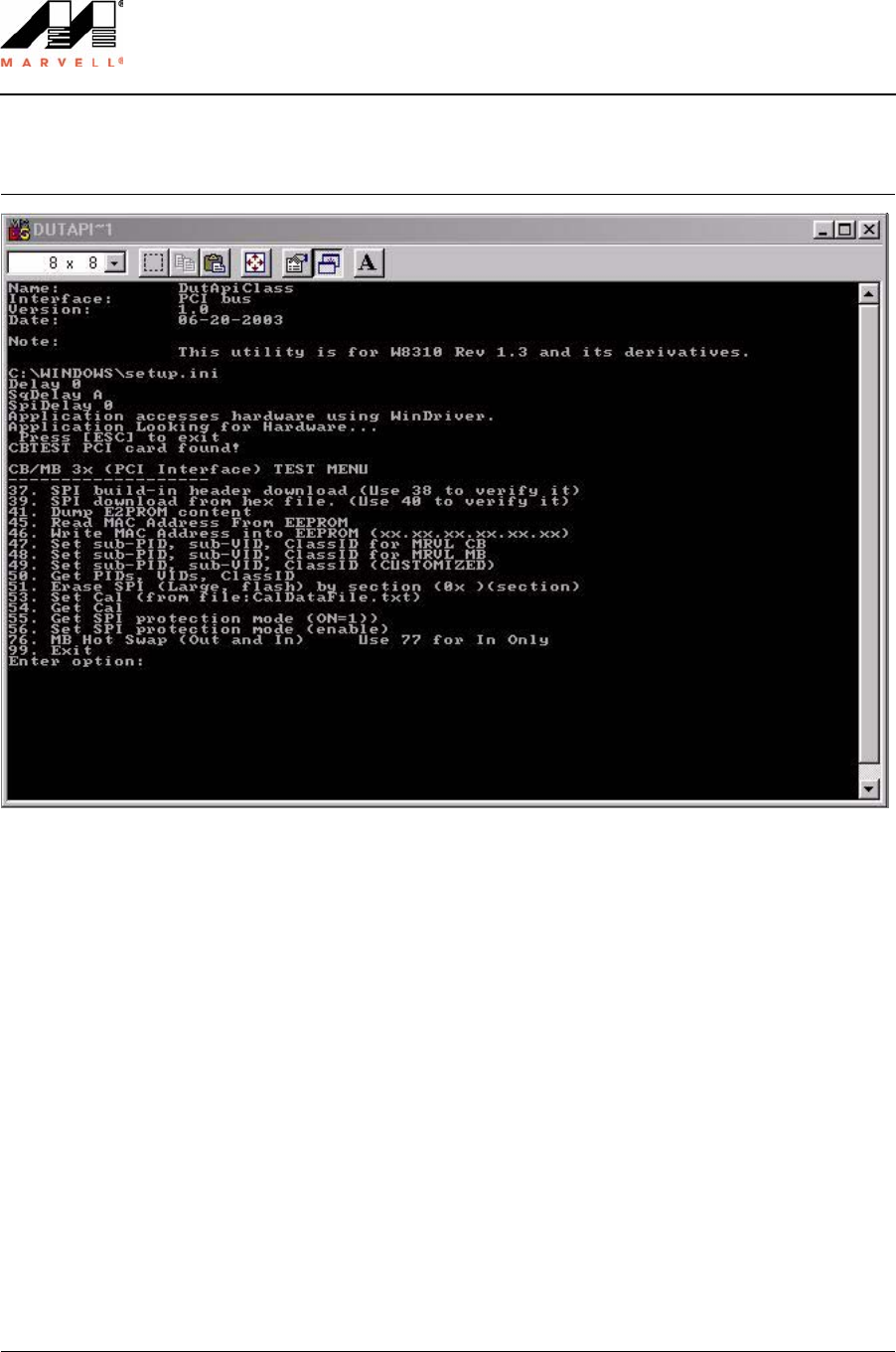
3.4.3 Configuration Information Access Commands
Figure 10: PCI Command Line Interface
3.4.3.1 SPI Build-In Header Download
3.4.3.2 SPI Header Verify
Command Number 37
Name SPI Build-In Header Download
Parameters None
Description Programs SPI header into EEPROM. Use command 39 with a hex file.
Example 37
Command Number 38
Name SPI Header Verify
Parameters None
Description Compares SPI built-in header with SPI header in EEPROM. Returns the error
count and value of mismatched double words.
Example 38

Command Line Interface
Command Descriptions
Copyright © 2003 Marvell CONFIDENTIAL Doc. No. MV-S101517-00 Rev. –
August 5, 2003, Preliminary Document Classification: Preliminary Information Page 25
3.4.3.3 SPI Download
3.4.3.4 SPI Verify
3.4.3.5 Display SPI EEPROM Content
3.4.4 SPI/Flash Access Commands
3.4.4.1 Read MAC Address
Command Number 39
Name SPI Download from Hexadecimal File
Parameters None
Description Programs the SPI header using a hex file. The command will prompt the user for
the filename (Spi.hex is default).
Example 39
Command Number 40
Name SPI Verify from Hexadecimal File
Parameters None
Description Compares SPI built-in header with hex file. Returns the error count and value of
mismatched double words.
Example 40
Command Number 41
Name Display SPI EEPROM Content
Parameters (0x)(0x)(startAddress)(Length)
Description Displays the SPI EEPROM.
Example “41 0 20” will display 32 DWORDS starting from offset 0.
Command Number 45
Name Read MAC Address
Parameters None
Description Returns the MAC address programmed in the EEPROM.
Example 45

Doc. No. MV-S101517-00 Rev. – CONFIDENTIAL Copyright © 2003 Marvell
Page 26 Document Classification: Preliminary Information August 5, 2003, Preliminary
Libertas™ 802.11g Client Card
Evaluation Tool User Guide
3.4.4.2 Write MAC Address
3.4.4.3 Set sub-PID sub-VID Class ID for Marvell CardBus Card
3.4.4.4 Set sub-PID sub-VID Class ID for Marvell Mini PCI Card
3.4.4.5 Set sub-PID sub-VID Class ID (Customized)
3.4.4.6 Get PID VID Class ID
Command Number 46
Name Write MAC Address into EEPROM/Flash
Parameters xx.xx.xx.xx.xx.xx
Description Writes the MAC address.
Example “46 10.22.33.44.55.66”
Command Number 47
Name Set sub-PID sub-VID Class ID for Marvell CardBus Card
Parameters None
Description Writes the Product ID and Vendor ID for CardBus.
Example 47
Command Number 48
Name Set sub-PID sub-VID Class ID for Marvell Mini PCI Card
Parameters None
Description Writes the Product ID and Vendor ID for Mini PCI.
Example 48
Command Number 49
Name Set sub-PID sub-VID Class ID (Customized)
Parameters Will read back current IDs then prompt for new IDs.
Description Programs a customized ID.
Example 49
Command Number 50
Name Get PID VID Class ID
Parameters None
Description Returns the PID and VID.
Example 50

Command Line Interface
Command Descriptions
Copyright © 2003 Marvell CONFIDENTIAL Doc. No. MV-S101517-00 Rev. –
August 5, 2003, Preliminary Document Classification: Preliminary Information Page 27
3.4.4.7 Erase Flash
3.4.4.8 Write Calibration Table
3.4.4.9 Read Calibration Table
3.4.4.10 Get SPI Protection
3.4.4.11 Set SPI Protection
3.4.5 Device Specific Commands
3.4.5.1 Client Hardware Initialization
Command Number 51
Name Erase Flash
Parameters (0x)(section)
Description Erases Flash memory. This command is only supported for large EEPROM sizes
(1 Mbit) and will not erase small EEPROM.
Example n/a
Command Number 53
Name Write Calibration Table
Parameters none
Description Writes calibration table data from the file CalDataFile.txt.
Example 53 <<Given sample file here>>
Command Number 54
Name Read Calibration Table
Parameters None
Description Returns the calibration table data.
Example 54
Command Number 55
Name Get SPI Protection
Parameters None
Description Retrieves setting of SPI protection status bit.
Example 55
Command Number 56
Name Set SPI Protection
Parameters 1 = enables protection
0 = disables protection
Description Sets SPI protection.
Example “56 1” enables protection.
“56 0” disables protection.
Note: Each write action from this program will set SPI protection mode to enable to prvent accidental crash-
ing of the image.
Command Number 75
Name HW Init

Doc. No. MV-S101517-00 Rev. – CONFIDENTIAL Copyright © 2003 Marvell
Page 28 Document Classification: Preliminary Information August 5, 2003, Preliminary
Libertas™ 802.11g Client Card
Evaluation Tool User Guide
3.4.5.2 Mini PCI Hot Swap (Out and In)
3.4.5.3 Mini PCI Hot Swap (In Only)
3.4.6 Exit Test Command
3.4.6.1 Exit Test
Parameters none
Description Hardware initialization. This command must be used before starting the RF tests.
Example n/a
Command Number 76
Name Mini PCI Hot Swap (Out and In)
Parameters none
Description Prompts you to put in a new card. After the new card is replaced, press Enter
twice. This command must be followed by command 75 (HW Init) to use the new
card.
Example n/a
Command Number 77
Name Mini PCI Hot Swap (In Only)
Parameters none
Description Prompts you to put in a new card. After the new card is replaced, press Enter
twice. This command must be followed by command 75 (HW Init) to use the new
card.
Example n/a
Command Number 99
Name Exit
Parameters none
Description Exits the program.
Example n/a

Sample CalDataFile.txt
Copyright © 2003 Marvell CONFIDENTIAL Doc. No. MV-S101517-00 Rev. –
August 5, 2003, Preliminary Document Classification: Preliminary Information Page 29
Appendix A. Sample CalDataFile.txt
[Configuration]
Board = MB31-001
StructRev = 1
Pa_External = 3
AntHw =0x0a
[LED]
Led0 = 0xFF
Led1 = 0xFF
Led2 = 0xFF
Led3 = 0xFF
[CC]
CC_primary = 0x10
CC_secondary = 0xFF
[CCA1]
CCA_0 = 0xff
CCA_1 = 0xff
CCA_2 = 0xff
CCA_3 = 0xff
[CCA2]
CCA_0 = 0xff
CCA_1 = 0xff
CCA_2 = 0xff
CCA_3 = 0xff
[Cus]
Cus_0 = 0xff
Cus_1 = 0xff

Doc. No. MV-S101517-00 Rev. – CONFIDENTIAL Copyright © 2003 Marvell
Page 30 Document Classification: Preliminary Information August 5, 2003, Preliminary
Libertas™ 802.11g Client Card
Evaluation Tool User Guide
[CalData]
CalTableOption =1
ant2NotCaled = 1
ExtPaPolar_neg = 0
ExterPA_PartId = 0x3
ExterPA_PreDriv = 0x4
Xosc =1635
;Channel1_Ant2Adjust =0
;Channel1_Loss = 4
;Channel1_Tune = 4
Channel1_PDref = 0x60
Channel2_PDref = 0x5e
Channel3_PDref = 0x5c
Channel4_PDref = 0x58
Channel5_PDref = 0x58
Channel6_PDref = 0x56
Channel7_PDref = 0x54
Channel8_PDref = 0x53
Channel9_PDref = 0x53
Channel10_PDref = 0x54
Channel11_PDref = 0x56
Channel12_PDref = 0x56
Channel13_PDref = 0x56
Channel14_PDref = 0x56
Channel1_Pa1 = 0xFF
Channel1_Pa2 = 0xFF
Channel2_Pa1 = 0xFF
Channel2_Pa2 = 0xFF
Channel3_Pa1 = 0xFF

Sample CalDataFile.txt
Copyright © 2003 Marvell CONFIDENTIAL Doc. No. MV-S101517-00 Rev. –
August 5, 2003, Preliminary Document Classification: Preliminary Information Page 31
Channel3_Pa2 = 0xFF
Channel4_Pa1 = 0xFF
Channel4_Pa2 = 0xFF
Channel5_Pa1 = 0xFF
Channel5_Pa2 = 0xFF
Channel6_Pa1 = 0xFF
Channel6_Pa2 = 0xFF
Channel7_Pa1 = 0xFF
Channel7_Pa2 = 0xFF
Channel8_Pa1 = 0xFF
Channel8_Pa2 = 0xFF
Channel9_Pa1 = 0xFF
Channel9_Pa2 = 0xFF
Channel10_Pa1 = 0xFF
Channel10_Pa2 = 0xFF
Channel11_Pa1 = 0xFF
Channel11_Pa2 = 0xFF
Channel12_Pa1 = 0xFF
Channel12_Pa2 = 0xFF
Channel13_Pa1 = 0xFF
Channel13_Pa2 = 0xFF
Channel14_Pa1 = 0xFF
Channel14_Pa2 = 0xFF

Doc. No. MV-S101517-00 Rev. – CONFIDENTIAL Copyright © 2003 Marvell
Page 32 Document Classification: Preliminary Information August 5, 2003, Preliminary
This page is intentionally left blank.
Libertas™ 802.11g Client Card
Evaluation Tool User Guide

Index
Copyright © 2003 Marvell CONFIDENTIAL Doc. No. MV-S101516-00 Rev. –
August 5, 2003, Preliminary Document Classification: Preliminary Information Page 33
Not Approved by Document Control
Section 4. Index
A
Additional Menu Interface 13
Additional Menu Shortcut 13
B
Before Getting Started 15
C
CalDataFile.txt 7
Calibration 6
Clear Received Packet Counter 22
Client Hardware Initialization 27
Command 75 15
Command Descriptions 18
Command Line Interface 11
Configuration Information Access Commands 24
D
Device Specific Commands 27
Display SPI EEPROM Content 25
Driver Installation Procedure 8
DUT Interface 11
DutApi98Dll.dll 7
DutApiPci98_G.exe 7, 8, 11, 14
E
Enable BSSID Filter 23
Equipment 5
Erase Flash 27
Exit Test 28
Exit Test Command 28
F
FER Commands 22
G
Get PID VID Class ID 26
Get Received Packet Counter 22
Get RF Channel 18
Get RF Data Rate 18
Get SPI Protection 27
Get Tx Power at PA 19
Getting Started 5
Golden AP Main Menu 12
Golden Unit Interface 12
GoldenAP.exe 7, 12
I
Initialize Device 15
M
Manufacturing Test Software 7
Manufacturing Test Software Suite Contents 7
Mini PCI Hot Swap 28
MWLAN_G.inf 8
P
PCI Command Line Interface 24
PCI Interface Test Menu 11, 14
Programming Configuration Information 9
R
Read Calibration Table 27
Read MAC Address 25
Receiver Sensitivity Test 16
RF Commands 18
RF Path 6
S
Set Carrier Suppression Mode 19
Set Channel and Power at Antenna with Calibration
Data 19
Set Continuous Modulated Waveform Mode 19
Set Continuous Waveform Transmission Mode 19
Set Duty Cycle Transmission Mode 21
Set Power Mode 21
Set RF Channel 18
Set SPI Protection 27
Set sub-PID sub-VID Class ID 26
Set sub-PID sub-VID Class ID for Marvell CardBus Card
26
Set sub-PID sub-VID Class ID for Marvell Mini PCI Card

Doc. No. MV-S101516-00 Rev. – CONFIDENTIAL Copyright © 2003 Marvell
Page 34 Document Classification: Preliminary Information August 5, 2003, Preliminary
Not Approved by Document Control
Libertas™ 802.11g Client Card
Evaluation Tool User Guide
26
Set Tx Power at PA 19
Setup File 7
SetUp.ini 7
Software Installation 7
Software Requirements 7
SPI Build-In Header Download 24
SPI Download 25
SPI Header Verify 24
SPI Verify 25
Spi.hex 7
SPI/Flash Access Commands 25
Switch Driver 6
System Requirements 6
T
Test Setup 5
Transmit Multicast Frames 23
Transmitter Tests 17
U
Using the Manual Test Module 11
W
wdreg.exe 8
Windows Driver Installation 8
windrvr.vxd 8
Write Calibration Table 27
Write MAC Address 26

Revision History
Copyright © 2003 Marvell CONFIDENTIAL Doc. No. MV-S101517-00 Rev. –
August 5, 2003, Preliminary Document Classification: Preliminary Information Page 35
Section 5. Revision History
Table 2: Revision History
Document Revision Document Change
Rev. - First release.

US and Worldwide Offices
Marvell Semiconductor, Inc.
700 First Avenue
Sunnyvale, CA 94089
Tel: 1.408.222.2500
Fax: 1.408.752.9028
Marvell Asia Pte, Ltd.
151 Lorong Chuan, #02-05
New Tech Park
Singapore 556741
Tel: 65.6756.1600
Fax: 65.6756.7600
Marvell Japan K.K.
Shinjuku Center Bldg. 50F
1-25-1, Nishi-Shinjuku, Shinjuku-ku
Tokyo 163-0650
Tel: 81.(0).3.5324.0355
Fax: 81.(0).3.5324.0354
Marvell Semiconductor Israel, Ltd.
Moshav Manof
D.N. Misgav 20184
Israel
Tel: 972.4.995.1000
Fax: 972.4.995.1001
Worldwide Sales Offices
Western US Sales Office
Marvell
700 First Avenue
Sunnyvale, CA 94089
Tel: 1.408.222.2500
Fax: 1.408.752.9028
Sales Fax: 1.408.752.9029
Central US Sales Office
Marvell
11709 Boulder Lane, Ste. #220
Austin, TX 78726
Tel: 1.512.336.1551
Fax: 1.512.336.1552
Eastern US/Canada Sales Office
Marvell
Knox Trail Office Bldg.
2352 Main Street
Concord, MA 01742
Tel: 1.978.461.0563
Tel: 1.978.461.1406
Fax: 1.978.461.1405
Europe Sales Office
Marvell
3 Clifton Court
Corner Hall
Hemel Hempstead
Hertfordshire, HP3 9XY
United Kingdom
Tel: 44.(0).1442.211668
Fax: 44.(0).1442.211543
Marvell
Fagerstagatan 4
163 08 Spanga
Stockholm, Sweden
Tel: 46.16.146348
Fax: 46.16.482425
Marvell
5 Rue Poincare
56400 Le Bono
France
Tel: 33.297.579697
Fax: 33.297.578933
Israel Sales Office
Marvell
Ofek Center Bldg. 2, Floor 2
Northern Industrial Zone
LOD 71293
Israel
Tel: 972.8.914.1300
Fax: 972.8.914.1301
China Sales Office
Marvell
5J, 1800 Zhong Shan West Road
Shanghai, China 200233
Tel: 86.21.6440.1350
Fax: 86.21.6440.0799
Japan Sales Office
Marvell
Helios Kannai Bldg. 12F
3-21-2 Motohama-cho, Naka-ku
Yokohama, Kanagawa
Japan 231-0004
Tel: 81.45.222.8811
Fax: 81.45.222.8812
Taiwan Sales Office
Marvell
2Fl., No. 1, Alley 20, Lane 407
Ti-Ding Blvd., Nei Fu District
Taipei, Taiwan 114, R. O. C
Tel: (886-2).7720.5700
FAX: (886-2).7720.5707
Copyright © 2003 Marvell. All rights reserved. Marvell, the Marvell logo, Moving Forward Faster, Alaska, and GalNet are registered trademarks of Marvell.
Discovery, Fastwriter, GalTis, Horizon, Libertas, Link Street, NetGX, PHY Advantage, Prestera, Raise The Technology Bar, UniMAC, Virtual Cable Tester,
and Yukon are trademarks of Marvell. All other trademarks are the property of their respective owners.
Marvell Semiconductor, Inc.
700 First Avenue
Sunnyvale, CA 94089
Phone 408.222.2500
Fax 408.752.9028
www.marvell.com
For more information, visit our website at: www.marvell.com

Federal Communication Commission Interference Statement
This equipment has been tested and found to comply with the limits for a Class B digital device,
pursuant to Part 15 of the FCC Rules. These limits are designed to provide reasonable
protection against harmful interference in a residential installation. This equipment generates,
uses and can radiate radio frequency energy and, if not installed and used in accordance with
the instructions, may cause harmful interference to radio communications. However, there
is no guarantee that interference will not occur in a particular installation. If this equipment
does cause harmful interference to radio or television reception, which can be determined by
turning the equipment off and on, the user is encouraged to try to correct the interference by one of
the following measures:
- Reorient or relocate the receiving antenna.
- Increase the separation between the equipment and receiver.
- Connect the equipment into an outlet on a circuit different from that to which the receiver is
connected.
- Consult the dealer or an experienced radio/TV technician for help.
This device complies with Part 15 of the FCC Rules. Operation is subject to the
following two conditions: (1) This device may not cause harmful interference, and (2) this
device must accept any interference received, including interference that may cause
undesired operation.
FCC Caution: Any changes or modifications not expressly approved by the party
responsible for compliance could void the user's authority to operate this equipment.
This transmitter must not be co-located or operating in conjunction with any other antenna
or transmitter.
IMPORTANT NOTE:
FCC Radiation Exposure Statement:
This equipment complies with FCC radiation exposure limits set forth for an uncontrolled
environment. This equipment should be installed and operated with minimum distance 20cm
between the radiator & your body.
This transmitter must not be co-located or operating in conjunction with any other antenna or
transmitter.
This device is intended only for OEM integrators under the following conditions:
1) The antenna must be installed such that 20 cm is maintained between the antenna and users,
and
2) The transmitter module may not be co-located with any other transmitter or antenna.
As long as 2 conditions above are met, further transmitter test will not be required. However,
theOEM integrator is still responsible for testing their end-product for any additional
compliance requirements required with this module installed (for example, digital device
emissions, PC peripheral requirements, etc.).

IMPORTANT NOTE: In the event that these conditions can not be met (for example certain
laptop configurations or co-location with another transmitter), then the FCC authorization is no
longer considered valid and the FCC ID can not be used on the final product. In these
circumstances, the OEM integrator will be responsible for re-evaluating the end product
(including the transmitter) and obtaining a separate FCC authorization.
End Product Labeling
This transmitter module is authorized only for use in device where the antenna may be installed
such that 20 cm may be maintained between the antenna and users. The final end product must
be labeled in a visible area with the following:“Contains TX FCC ID: M4Y-0XG880M”.
Manual Information That Must be Included
The users manual for OEM integrators must include the following information in a prominent
location “ IMPORTANT NOTE: To comply with FCC RF exposure compliance requirements,
theantenna used for this transmitter must be installed to provide a separation distance of at least
20cm from all persons and must not be co-located or operating in conjunction with any other
antenna or transmitter.