Contents
- 1. User Manual 01
- 2. User Manual 02
- 3. User Manual 03
User Manual 02
VG300 Quick Installation Guide
1. Product Package
Please go through each item listed below. Your VG300 package
contains the following items:
One VG300 Wireless Data Unit
One SMA Attached CDPD Antenna
One Power Connector (Pin 1 is “+”, Pin2 is “-“)
One VG300 User’s Quick Installation Guide
2. Installation & Setup
Step 1 Establish Hardware Connection
a. Connect the cellular antenna and GPS antenna to the VG300
b. Using the power connector to connect to available DC power supply
(DC 12V or Car Battery)
c. Connect the RS-232 9 pins interface cable to the VG300.
d. Connect the RS-232 cable with a male DB9 connector to your host.
If your host has a DB25 connecting port, you need to get a DB25
to DB9 adapter from the local electronics store.
Step 2 Establish Software Test Environment for Terminal Program
To send AT Command to VG300, you must find a communications
program to be operated in ASCII terminal emulation mode under
your PCs (host). This will enable the PC to function as a terminal
attached to the modem and will permit you to enter the AT Command
required for modem setup and diagnostics. The followings are some
example programs:
WINDOWS TERMINAL in WINDOWS 3.1
HYPER TERMINAL in WINDOWS 95
TELIX or similar alternatives
In the Terminal Program you choose, set the parameters of RS-232
cable as follows:

19200 bps, 8 data bits, No parity check and 1 stop bit.
Caution:The above RS-232 parameters are set up for the
communication between VG300 and the host. They are
default values for VG300 Data Module. You must set the
same parameters with your Terminal Programs so that the
host can obtain initial connection to the module.
3. Connect to the CDPD Network
Following procedures are available for the CDPD mode only . Please
switch the operation mode to the CDPD. (There are two operation
modes for VG300. One is CDPD , the other is GPS.)
A. Set the IP Address
The IP Address, in form of ×××.×××.×××.××× (××× means
decimal numbers from 0-255), should be provided by the
CDPD network carrier or the service provider. Use the
command AT!I ×××.×××.×××.××× to set the IP Address.
B. Set the Destination Server IP Address
The Destination AVL(Automatic Vehicle Location) Server
IP Address, in form of ×××.×××.×××.××× (××× means
decimal numbers from 0-255). Use the command
Ats40=×××.×××.×××.×××/port # to set the IP Address and
port number. e.g. Ats40=203.67.40.233/1025.
C. Set UDP Tx.
Use the command AT!g1 to set the VG300 in the UDP Tx.
Mode.
D. Set Side Preference
Contact your CDPD network carrier or the service provider
for the appointed Side Preference. If this information is not
available, you can use either the command AT\N3 or AT\N4
to set Side Preference. (AT\N3: A Side Preference, AT\N4:
B Side Preference)
E. Set the Auto Scan Mode
Set the channel scan mode as “Auto Scan” with the

command AT!A1.
F. Turn off the Hardware Flow Control
Turn off the hardware flow control with the AT\Q0
command.
G.. Save the set-up values
Use the command AT&W to save all the above values.
H. Reset Z-Card 300
Use the command ATZ to reset VG300.
I. Check the connection
Enter the command ATS57 to check if a response indicates
ATS57=129 appears. If yes, then Congratulations! You have
connected to the CDPD network successfully.
Then you can switch the operation mode back to GPS and power on
the VG300 again.
4. AT Command Sets for VG300
By using the terminal program, you can use the following AT
Command to configure the VG300
1. AT@GPS0 Modem will send customer-defined special packet for
AVL Serve r
2. AT@RMCn Customer-Defined Packet Tx Time Interval n=0~3600
EX AT@RMC30
3. AT@GPS1 Modem will send standard NMEA 0183 GPS Packets.
NMEA 0183 GPS packets can configure the time interval by using
the following AT Commands
4. AT@GGAn Set GGA data transmission time interval, n=0~3600
sec. Ex. AT@GGA1
5. AT@GLLn Set GGA data transmission time interval, n=0~3600
sec. Ex. AT@GLL2
6. AT@GSAn Set GGA data transmission time interval, n=0~3600
sec. Ex. AT@GSA0
7. AT@GSV Set GGA data transmission time interval, n=0~3600 sec.
Ex. AT@GSV4
8. AT@RMCn Set GGA data transmission time interval, n=0~3600
sec. Ex. AT@RMC1
9. AT@VTGn Set GGA data transmission time interval, n=0~3600
sec. Ex. AT@VTG1
10. AT@ID To set the vehicle ID #
11. AT@GAPn The time interval for saving the packets into the
memory when the modem is not in CDPD coverage n=0~255
minutes
12. AT@GPS to check the GPS setting profile
Example:
AT@GPS
Result:
AT@GPS1
AT@GGA=1 transmit GGA data every 1 sec.
AT@GLL=2 transmit GLL data every 2 sec.
AT@GSA=0 don’t transmit GSA data.
AT@GSV=4 transmit GLL data every 4 sec.
AT@RMC=1 transmit RMC data every 1 sec.
AT@VTG=30 transmit VTG data every 30 sec.
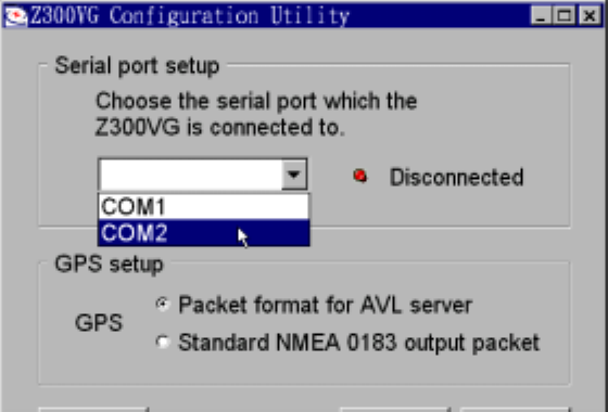
GUI of VG300 Configuration Utility
˙main form
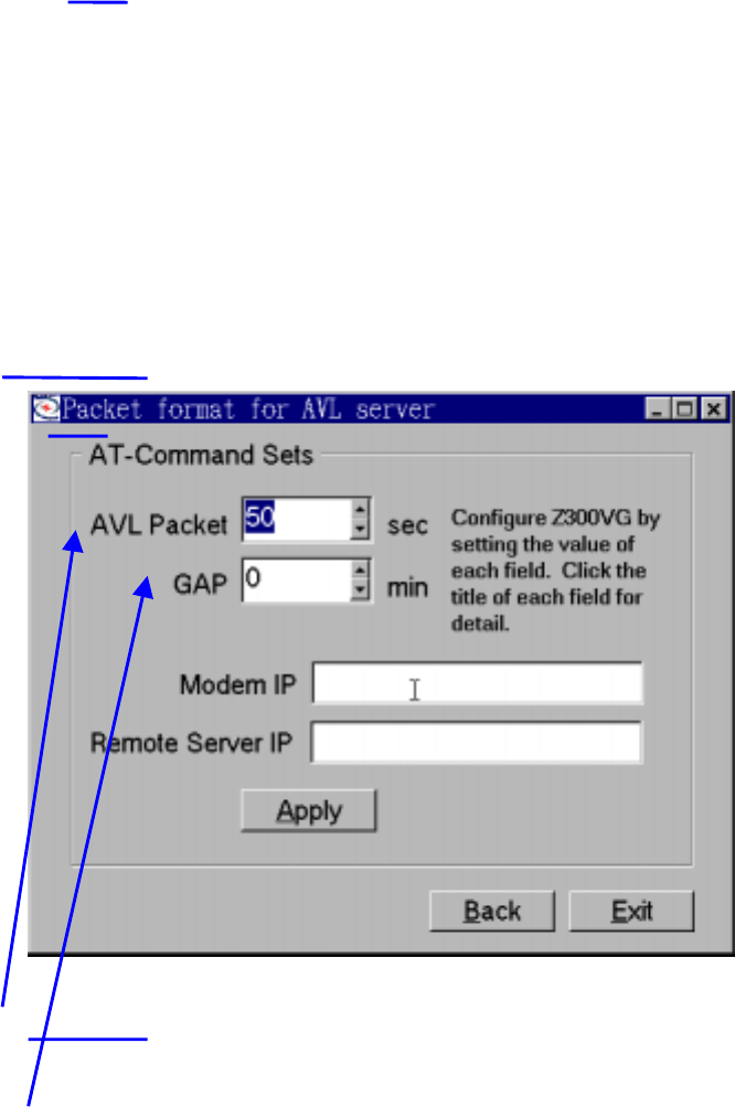
˙form of Packet format for AVL server
˙form of Standard NMEA 0183 output packet
Modem will send customer-defined special packet for AVL Server.
Modem will send standard NMEA 0183 GPS Packets. NMEA 0183
GPS packets can configure the time interval by user.
Customer-Defined Packet Tx Time Interval = 0~3600 second.
The time interval for saving the packets into the memory when the
modem is not in CDPD coverage. Time Interval = 0~255 minutes
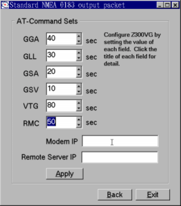
GGA data transmission time interval = 0~3600 sec.
GLL data transmission time interval = 0~3600 sec.
GSA data transmission time interval = 0~3600 sec.
GSV data transmission time interval = 0~3600 sec.
VTG data transmission time interval = 0~3600 sec.
RMC data transmission time interval = 0~3600 sec.