ZKTECO SF400ID Access Control Terminal User Manual
ZKTECO CO., LTD. Access Control Terminal Users Manual
UserManual.wiki
>
ZKTECO
>
SF400ID User Manual
Users Manual
Navigation menu
Upload a User Manual
Namespaces
Wiki Guide
HTML
PDF
Info
Views
User Manual
Discussion / Help
Navigation

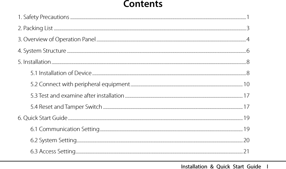
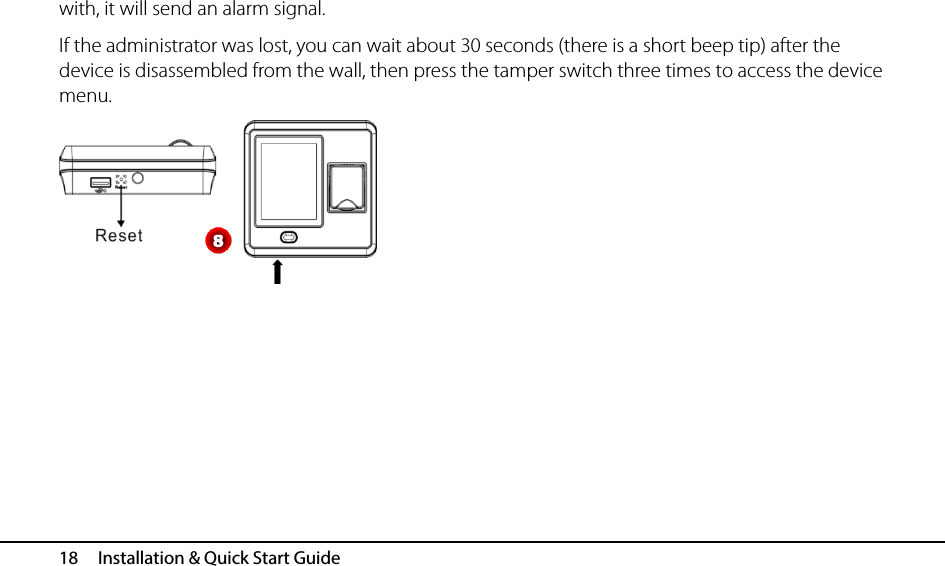
![5. Installation 17 5.3 Test and examine after installation Make a test and examine prior to power on, inspect whether the lock driver is OK or not. 1. The green LED begins to glitter after power up. 2. Enter [Main menu] > [Autotest] > [Test All]. 3. Enter [Main menu] > [User Mgt.] > [New User] > [Fingerprint], enroll a fingerprint, and use the fingerprint to test access system and door lock. 4. If there is no any problem, please delete this enrolled fingerprint. 5.4 Reset and Tamper Switch Reset: Due to operation error or other accidents, which leads the device failed to work, you can restart device through reset button. To reset the device use a small tool (e.g., pin or paperclip) to push in the reset button (labeled Reset, shown as Figure 8) located on the underside of the device. Note: It does NOT erase any stored data (i.e. templates, transactions, settings). This information will be available as soon as power is restored. Tamper Switch is located on the back of the device, when the device detects it is being “tampered”](https://usermanual.wiki/ZKTECO/SF400ID/User-Guide-3613656-Page-21.png)
![6. Quick Start Guide 19 6. Quick Start Guide Press to enter main menu, include User Management (User Mgt.), User Role Setting (User Role), Communication Setting (COMM.), System Setting (System), Personalize Setting (Personalize), Data Management (Data Mgt.), Access Control Setting (Access Control), USB Management (USB Manager),Attendance Search, Print Setting (Print), Autotest and System Information (System Info). 6.1 Communication Setting Press [COMM.] icon in main menu to enter the communication setting (COMM.) Interface. Ethernet: Set IP address (The default value is 192.168.1.201), Subnet Mask (The default value is 255.255.255.0), Gate Way (The default value is 192.168.1.254), DNS (The default value is 0.0.0.0), TCP COMM. Port (The default value is 4370), DHCP (The default setting is OFF) and set whether to enable Display in Status Bar for device. Serial Comm: Set function of serial port, the baud rate for the communication between the device](https://usermanual.wiki/ZKTECO/SF400ID/User-Guide-3613656-Page-23.png)
![20 Installation & Quick Start Guide and external reader, whether to enable the print function, and baud rate for the communication between the device and printer. PC Connection: Set Device ID and password for the connection between the device and software. The default password is 0 (that is, no password). Wiegand: To configure Wiegand Function. 6.2 System Setting Press [System] icon in main menu to enter the system setting (System) Interface Date/Time: To set device’s Date and Time, and Daylight Saving Time as required. Attendance: To set the attendance parameters as required, such as Duplicate Punch Period, Attendance Log Alert, Cyclic Delete ATT Data, Confirm Screen Delay and Verification Result Font Size. Fingerprint: To set the fingerprint parameters as required, such as 1:1](https://usermanual.wiki/ZKTECO/SF400ID/User-Guide-3613656-Page-24.png)
![6. Quick Start Guide 21 Match Threshold, 1:N Match Threshold, FP Sensor Sensitivity, 1:1 Retry Times and Fingerprint Image. Reset: To restore all system parameters to factory default settings (Note: All users’ information and verification records saved in the device will not be deleted after reset). USB Upgrade: To upgrade the firmware with the upgrade file saved in the U disk (It is not recommend to upgrade firmware in general case). 6.3 Access Setting Press [Access] icon in main menu to enter the access setting (Access) Interface. Access Control Options: To set parameters of the lock and other related devices. Time Schedule: To set a maximum of 50 time zones. Each time zone consists of 7 spaces (for one week from sunday to saturday). Holidays: To set dates of holiday and the access control time period for that holiday. Access Groups: Access Group refers to one selected Time Period or several selected Time Period s that can be opened by verification. (Note: The Access Group must be set under Access setting.)](https://usermanual.wiki/ZKTECO/SF400ID/User-Guide-3613656-Page-25.png)
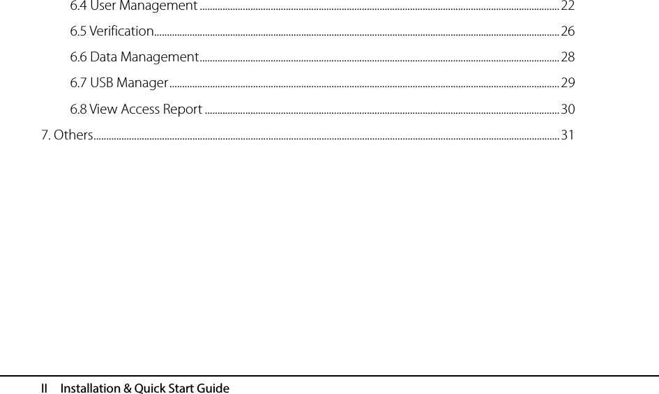
![22 Installation & Quick Start Guide Combined Verification: To set access control combinations. A combination consists of a maximum of 5 access control groups. Anti-Passback Setup: To prevent passing back which causes risks to security. Once it is enabled, entry and exit records must be matched in order to open door. In Anti-Passback, Out Anti- Passback and In / Out Anti-Passback functions are available. Duress Options: Set the duress alarm ways and alarm delay time as required. 6.4 User Management Press [User Mgt.] icon in main menu to enter the user management (User Mgt.) Interface. New User: Input User ID(The max length is 9)and Name, select the User Role (Normal User or Super Admin), enroll Fingerprint, Badge Number, and Password(The maximum length is6, set the access control role as required. All Users: Input user ID or name to start searching, you can also edit and delete the user. Display Style: Set the display style of all enrolled users.](https://usermanual.wiki/ZKTECO/SF400ID/User-Guide-3613656-Page-26.png)
![6. Quick Start Guide 23 Enroll Fingerprint 1. Press[Fingerprint] in New User,the Enroll Fingerprint interface is displayed. 2. According to the operation prompt information, place finger on the Fingerprint Sensor properly three times until enrollment succeeds, and then return to the New User interface automatically. 3. Press to return and save user information. Enroll Badge Number 1. Press [Badge Number]in New User,the Enroll Badge Number interface is displayed. 2. According to the operation prompt information, punch card at the punch area (around the Fingerprint Sensor); after enrollment succeed, return to the New User interface automatically. 3. Press to return and save user information.](https://usermanual.wiki/ZKTECO/SF400ID/User-Guide-3613656-Page-27.png)
![24 Installation & Quick Start Guide Search User 1. Press [All Users] icon in Use Mgt. to enter All Users interface, shown as left figure. 2. Input user ID or name in the search box. (Note: You can input user name with the intelligent input.) 3. Press [OK] to locate the specified user. Edit User After search the specified user, click the user to enter left interface. Press [Edit] to enter the Edit interface. Detail operations of editing are the same as adding user (The user ID cannot be edited).](https://usermanual.wiki/ZKTECO/SF400ID/User-Guide-3613656-Page-28.png)
![6. Quick Start Guide 25 Delete User 1. After search the specified user, click the user and press [Delete] to enter left interface. 2.Select delete type (Delete User, Delete Fingerprint Only, Delete Password Only, Delete Badge Number Only), and then press [OK] to confirm and carry out the corresponding delete operation. Note: (1) Based on the information registered by a user, the device displays the optional operation types. For example, if the user does not register the password, the option Delete Password Only is not available. (2) If Delete User is selected, the user's fingerprint, password, and badge number information will be deleted.](https://usermanual.wiki/ZKTECO/SF400ID/User-Guide-3613656-Page-29.png)
![26 Installation & Quick Start Guide User Access 1. In [New User] or [Edit] interface, press [Access Control Role] to enter the Access Control setting interface, shown as left figure. 2. Set the Access Group, Verification Mode, Time Period and select Duress Fingerprint as required. 6.5 Verification Verification by Fingerprint or Card Place finger on the Fingerprint Sensor properly or punch card in the punch area (around the Fingerprint Sensor); after verification succeed, the interface shown as figure 1 (Fingerprint Verification), figure 2 (Card Verification).](https://usermanual.wiki/ZKTECO/SF400ID/User-Guide-3613656-Page-30.png)
![6. Quick Start Guide 27 figure 1 figure 2 Verification by Password 1. In initial interface, press to enter the user ID Input interface, shown as figure 3. 2. Input user ID which needs to do password verification and press [OK], figure 4 will display. 3. Press icon to enter password input interface, shown as figure 5. 4. Input the correct password (same as inputting ID Number) and press [OK] to confirm the password. After verification succeed, figure6 will display.](https://usermanual.wiki/ZKTECO/SF400ID/User-Guide-3613656-Page-31.png)
![28 Installation & Quick Start Guide figure 3 figure 4 figure 5 figure 6 6.6 Data Management Press [Data Mgt.] icon in main menu to enter the Data Management (Data Mgt.) interface. Delete Data: Delete data saved in the device, such as attendance data, all data, admin role, access control, wallpaper, screen savers and backup data. Backup Data: Backup the business data or system data to device or USB disk.](https://usermanual.wiki/ZKTECO/SF400ID/User-Guide-3613656-Page-32.png)
![6. Quick Start Guide 29 Restore Data: Restore the backup data saved in device or USB disk to device. 6.7 USB Manager Press [USB Manager] icon in main menu to enter the USB Manager interface. Download: Download all attendance logs or user information to the USB Disk. And then import logs into the Access 3.5 software through Import Data From USB disk function, and then view Access Report as required. Upload: Upload user information, screen saver or wallpaper (stored in USB Disk) into the device.](https://usermanual.wiki/ZKTECO/SF400ID/User-Guide-3613656-Page-33.png)