ZKTECO SF400ID Access Control Terminal User Manual
ZKTECO CO., LTD. Access Control Terminal Users Manual
ZKTECO >
Users Manual

Installation & Quick Start Guide
Smart Series Access Control Terminal
Version: V2.0
Date: April, 2017
About This Manual
All design and specification declared are subject to change without notice in advance.
Not all products have the functions with , the real product shall prevail.

Installation & Quick Start Guide I
Contents
1. Safety Precautions ................................................................................................................................................................ 1
2. Packing List ............................................................................................................................................................................... 3
3. Overview of Operation Panel ........................................................................................................................................ 4
4. System Structure ................................................................................................................................................................... 6
5. Installation ................................................................................................................................................................................. 8
5.1 Installation of Device ............................................................................................................................................ 8
5.2 Connect with peripheral equipment ...................................................................................................... 10
5.3 Test and examine after installation ........................................................................................................... 17
5.4 Reset and Tamper Switch ............................................................................................................................... 17
6. Quick Start Guide ............................................................................................................................................................... 19
6.1 Communication Setting .................................................................................................................................. 19
6.2 System Setting ....................................................................................................................................................... 20
6.3 Access Setting ........................................................................................................................................................ 21

II Installation & Quick Start Guide
6.4 User Management .............................................................................................................................................. 22
6.5 Verification ................................................................................................................................................................ 26
6.6 Data Management .............................................................................................................................................. 28
6.7 USB Manager .......................................................................................................................................................... 29
6.8 View Access Report ............................................................................................................................................ 30
7. Others ........................................................................................................................................................................................ 31

1. Safety Precautions 1
1. Safety Precautions
Thank you for using our products. Please read this manual carefully before using this product for a
comprehensive understanding so as to avoid causing unnecessary damages to the product.
Important Notes
1. Do not place the device under strong light.
2. Use regulated 12V DC power source (separately purchased and recommend using
Uninterrupted Power Supply with backup battery option considering of power failure).
3. Do not place the device in a vulnerable location where it might be subjected to vandalism.
Before Installation
1. Prior to beginning installation, cut off all power to prevent personal injury and damage to the
device and peripheral equipment.
2. Connect the ground wire first, in order to prevent electro-static damage to the device.
3. Connect 12V DC power supply to the device at last. If the device does not operate properly,
always cut off power to it before examining/dismantling. Be advised that wiring the device
while power is on may cause damage to the terminal. Possible resulting damage from not
powering off the device prior to wiring is not covered by manufacturer’s warranty.

2 Installation & Quick Start Guide
4. Mount the device at a comfortable height, typically between 1.4~1.5 meter from the ground.
5. After installation, remove protective film from the device display and fingerprint sensor.
6. To prevent being accidentally locked out while testing the exit button, keep a person on the
inside of the door.
7. Run the auto-test function to confirm that installation is successful.
8. In order to maximize the life of the device, use the auto-sleep functions, sleep time could be
set in the system parameter menu.
9. The rated voltage of the device is DC 12V, and the rated current is 300mA. If the incorrect
voltage is used, the device may be damaged or may not operate the electric door lock (if
attached).
10. Improper wiring may cause the device's main circuit board and fingerprint sensor to burn out.
Resulting damage from improper wiring is not covered under manufacturer’s warranty.
11. Only use supplied transformer and cord. Do not attempt extending the cord by cutting and
splicing.
12. Refer to the user handbook and operating instructions for further information.
2. Packing List 3
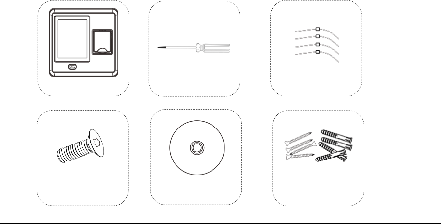
2. Packing List
1 Access Device
4 Diodes (FR107)
1 Screw Driver
4 Wall Plugs /Screws
1 CD
1 Star Screw
4 Installation & Quick Start Guide
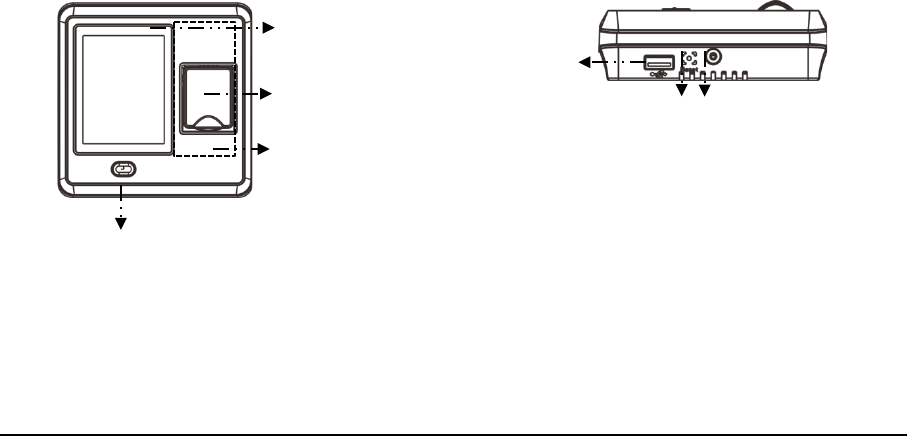
3. Overview of Operation Panel
Front Bottom
Touch Screen
Fingerprint Sensor
Card Swipe Area
(which around
fingerprint sensor)
USB Port
Reset Screws
Doorbell
3. Overview of Operation Panel 5
Back
6 Installation & Quick Start Guide
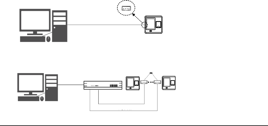
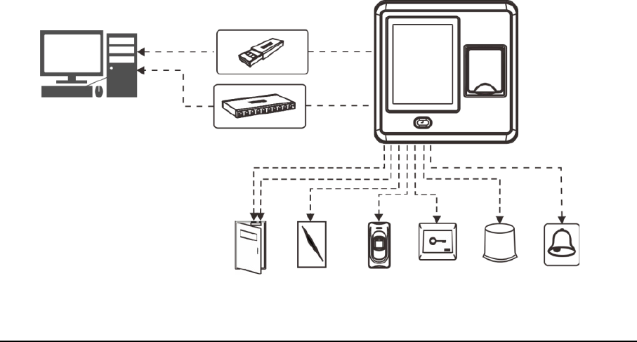
4. System Structure
Directly connect with PC through TCP/IP
Connect with PC through TCP/IP network
PC TCP/IP
RJ45
PC TCP/IP
TCP/IP
TCP/IP
RJ45 接口
4. System Structure 7
The diagram of system construction
PC
U Disk
TCP/IP
Door
Lock Sensor
Door Wiegand RS485 Exit Alarm Doorbell
Card Card Button
8 Installation & Quick Start Guide
5. Installation
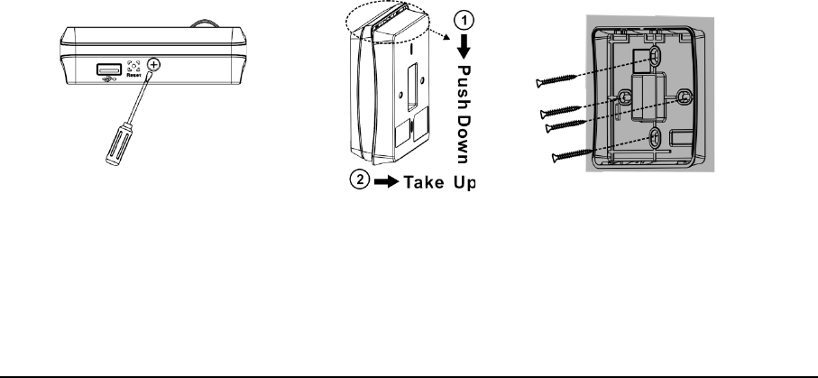
5.1 Installation of Device
2. Take out the
Back Cover
.
1. Remove the bottom screw.
3. Fix the
Back Cover
on the wall
with screwdriver.
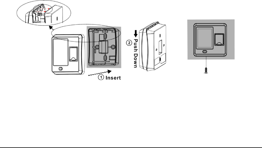
5. Installation 9
5. Tighten the bottom screw.
4. Fix the device on the
Back Cover
.
10 Installation & Quick Start Guide
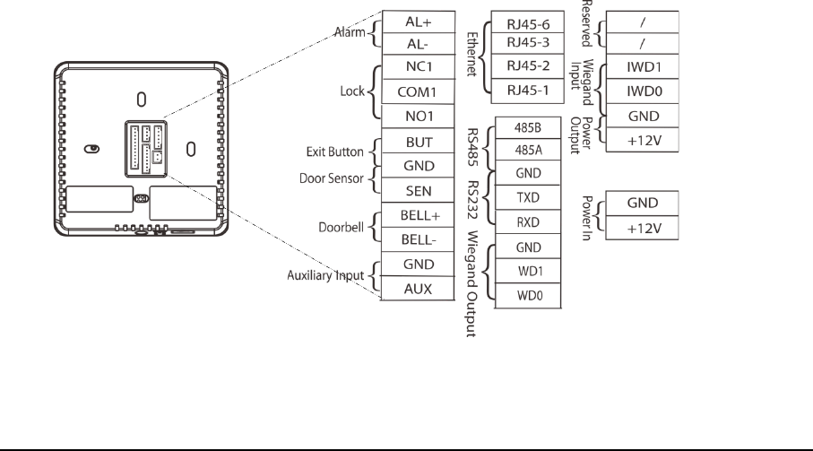
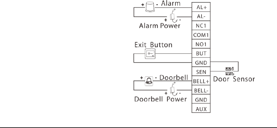
5.2 Connect with peripheral equipment
Caution: Please make sure the power is cut off before wiring; otherwise it is possible to damage the
device.
1). Door Sensor Connection
2). Button Connection
3). Alarm Connection
4). Doorbell Connection
5). Lock Connection

5. Installation 11
Selecting door lock: The choice of lock depends firstly on the door-electric strikes or bolts,
magnetic locks, turnstiles or barriers are all options depending firstly on the
architecture-and secondly on the required resistance to attach. Please
consult your supplier for more info.
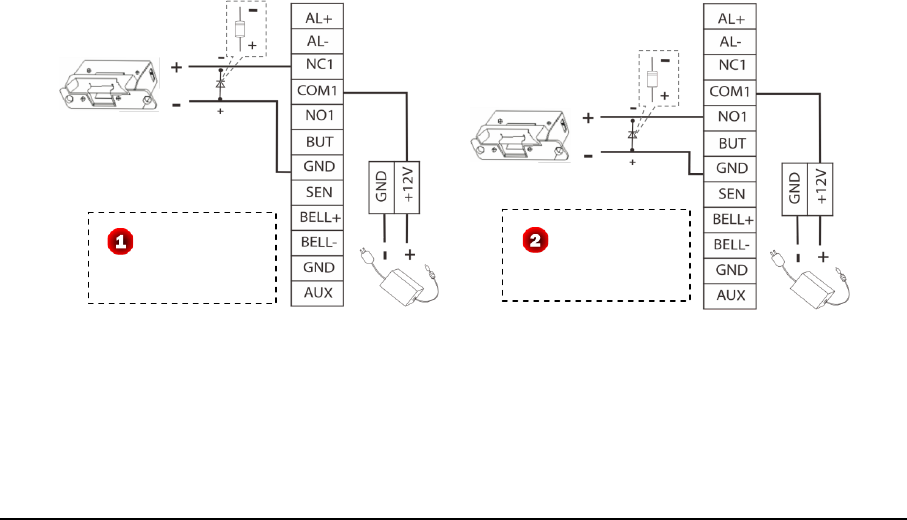
Connect with electric lock: After the user verified the identity, the device will output the unlock
signal. The device supports NO (Normally Open) LOCK and NC
(Normally Close) LOCK.
NO LOCK: the door is normally open at power on, so it closes the door at power off.
NC LOCK: the door is normally closed at power on, so it opens the door at power off.
The device can supply power directly to a door lock, please refer to Figure 1, 2. (Ensure that proper
voltages are applied to the lock terminals and check on the current ratings of the locks.)
12 Installation & Quick Start Guide
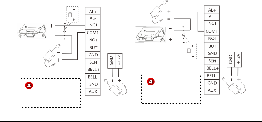
However, in the following three scenarios, it is recommended that the door lock has an
independent power source, and is NOT powered by the device. Show as Figure 3, 4.
1. If the door lock voltage is not 12V DC, then provides separate power to the door lock.
The device and
lock are powered by
one adapter.
The device and
lock are powered by
one adapter.
FR107
DC 12V
NC Lock
FR107
DC 12V
NO Lock
5. Installation 13
2. If the door lock runs on 12V DC, but requires more than 1A (amp), then provide separate
power to the door lock.
3. If the distance between the device and door lock is greater than 15 feet, then provide separate
power to the door lock.
The device and
lock are powered by
independent adapter.
The device and
lock are powered by
independent adapter.
FR107
DC 12V
NC Lock
Lock Power
FR107
DC 12V
NO Lock
Lock Power
14 Installation & Quick Start Guide
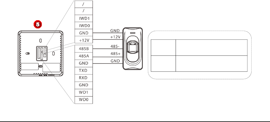
6). RS485 Connection
RS485 serial port will not be used as the communication port between the device and PC, which
only connect external 485 reader (such as FR1200/ FR1300). Connection of 485 reader is shown as
Figure 5.
Terminal Definition
485A RS485 communication +
485B RS485 communication -

5. Installation 15
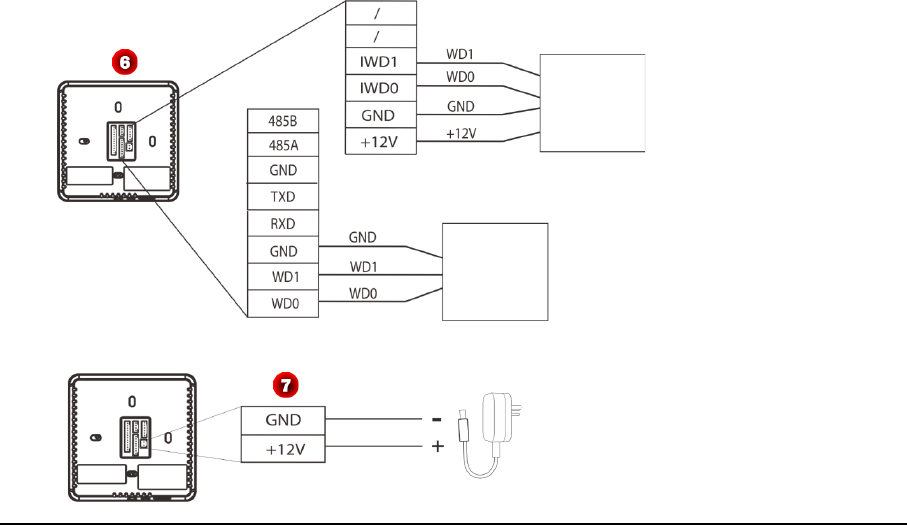
7). Wiegand Function
Wiegand Output: This device provides standard Wiegand 26 output, which can be used as reader.
The distance from the controller to device cannot be more than 15 meter (If the signal must be
transferred much further or there is a strong interference around, please adopt a Wiegand signal
amplifier).
Wiegand Input: The device has Wiegand input function, can connect the external card reader.
Device and card reader can be installed respectively inside and outside of the door, control the lock
together, control out & in. (For detail, please see Figure 6.)
Note: No matter the device is powered by access controller or not, the ground ports of them have
to be properly together to ensure the Wiegand transfer reliable.
16 Installation & Quick Start Guide
8). Power Connection
:
DC 12V
Wiegand
Card
Reader
Access
Controller

5. Installation 17
5.3 Test and examine after installation
Make a test and examine prior to power on, inspect whether the lock driver is OK or not.
1. The green LED begins to glitter after power up.
2. Enter [Main menu] > [Autotest] > [Test All].
3. Enter [Main menu] > [User Mgt.] > [New User] > [Fingerprint], enroll a fingerprint, and use
the fingerprint to test access system and door lock.
4. If there is no any problem, please delete this enrolled fingerprint.
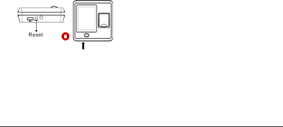
5.4 Reset and Tamper Switch
Reset: Due to operation error or other accidents, which leads the device failed to work, you can
restart device through reset button.
To reset the device use a small tool (e.g., pin or paperclip) to push in the reset button (labeled Reset,
shown as Figure 8) located on the underside of the device.
Note: It does NOT erase any stored data (i.e. templates, transactions, settings). This information will
be available as soon as power is restored.
Tamper Switch is located on the back of the device, when the device detects it is being “tampered”
18 Installation & Quick Start Guide
with, it will send an alarm signal.
If the administrator was lost, you can wait about 30 seconds (there is a short beep tip) after the
device is disassembled from the wall, then press the tamper switch three times to access the device
menu.

6. Quick Start Guide 19
6. Quick Start Guide
Press to enter main menu, include User Management (User Mgt.),
User Role Setting (User Role), Communication Setting (COMM.), System
Setting (System), Personalize Setting (Personalize), Data Management
(Data Mgt.), Access Control Setting (Access Control), USB Management
(USB Manager),Attendance Search, Print Setting (Print), Autotest and
System Information (System Info).
6.1 Communication Setting
Press [COMM.] icon in main menu to enter the communication setting (COMM.) Interface.
Ethernet: Set
IP address
(The default value is 192.168.1.201),
Subnet Mask
(The default value is
255.255.255.0),
Gate Way
(The default value is 192.168.1.254),
DNS
(The default value is 0.0.0.0),
TCP
COMM. Port
(The default value is 4370),
DHCP
(The default setting is OFF) and set whether to
enable
Display in Status Bar
for device.
Serial Comm: Set function of serial port, the baud rate for the communication between the device

20 Installation & Quick Start Guide
and external reader, whether to enable the print function, and baud rate
for the communication between the device and printer.
PC Connection: Set Device ID and password for the connection between
the device and software. The default password is 0 (that is, no password).
Wiegand: To configure Wiegand Function.
6.2 System Setting
Press [System] icon in main menu to enter the system setting (System)
Interface
Date/Time: To set device’s Date and Time, and Daylight Saving Time as
required.
Attendance: To set the attendance parameters as required, such as
Duplicate Punch Period, Attendance Log Alert, Cyclic Delete ATT Data,
Confirm Screen Delay and Verification Result Font Size.
Fingerprint: To set the fingerprint parameters as required, such as 1:1
6. Quick Start Guide 21
Match Threshold, 1:N Match Threshold, FP Sensor Sensitivity, 1:1 Retry Times and Fingerprint Image.
Reset: To restore all system parameters to factory default settings (Note: All users’ information and
verification records saved in the device will not be deleted after reset).
USB Upgrade: To upgrade the firmware with the upgrade file saved in the U disk (It is not
recommend to upgrade firmware in general case).
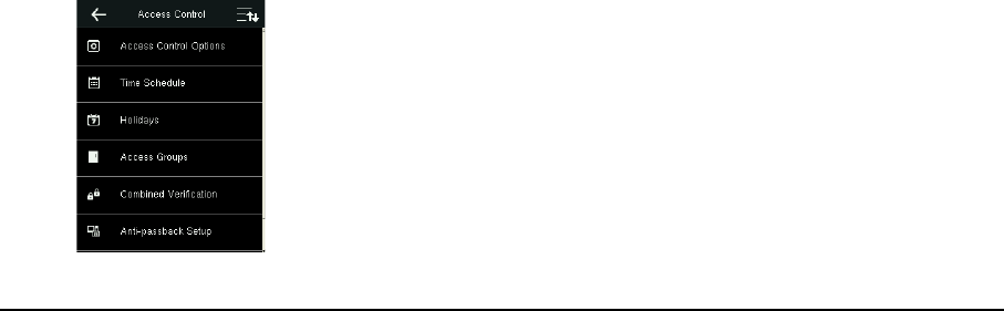
6.3 Access Setting
Press [Access] icon in main menu to enter the access setting (Access) Interface.
Access Control Options: To set parameters of the lock and other related
devices.
Time Schedule: To set a maximum of 50 time zones. Each time zone
consists of 7 spaces (for one week from sunday to saturday).
Holidays: To set dates of holiday and the access control time period for
that holiday.
Access Groups: Access Group refers to one selected Time Period or
several selected Time Period s that can be opened by verification. (Note:
The Access Group must be set under Access setting.)

22 Installation & Quick Start Guide
Combined Verification: To set access control combinations. A combination consists of a maximum
of 5 access control groups.
Anti-Passback Setup: To prevent passing back which causes risks to security. Once it is enabled,
entry and exit records must be matched in order to open door. In Anti-Passback, Out Anti- Passback
and In / Out Anti-Passback functions are available.
Duress Options: Set the duress alarm ways and alarm delay time as required.
6.4 User Management
Press [User Mgt.] icon in main menu to enter the user management (User Mgt.) Interface.
New User: Input User ID(The max length is 9)and Name, select the User
Role (Normal User or Super Admin), enroll Fingerprint, Badge Number,
and Password(The maximum length is6, set the access control role as
required.
All Users: Input user ID or name to start searching, you can also edit and
delete the user.
Display Style: Set the display style of all enrolled users.
6. Quick Start Guide 23
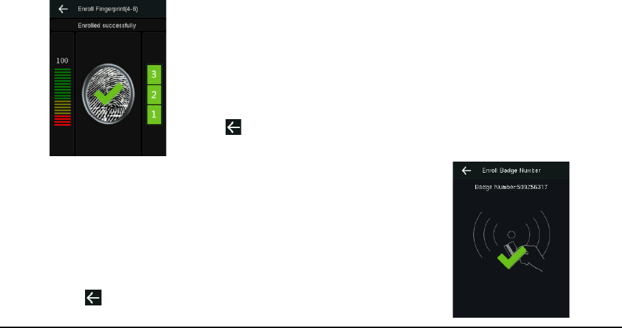
Enroll Fingerprint
1. Press
[
Fingerprint] in New User,the Enroll Fingerprint interface is
displayed.
2. According to the operation prompt information, place finger on the
Fingerprint Sensor properly three times until enrollment succeeds, and
then return to the New User interface automatically.
3. Press to return and save user information.
Enroll Badge Number
1. Press
[
Badge Number
]
in New User,the Enroll Badge Number
interface is displayed.
2. According to the operation prompt information, punch card at the
punch area (around the Fingerprint Sensor); after enrollment succeed,
return to the New User interface automatically.
3. Press to return and save user information.
24 Installation & Quick Start Guide
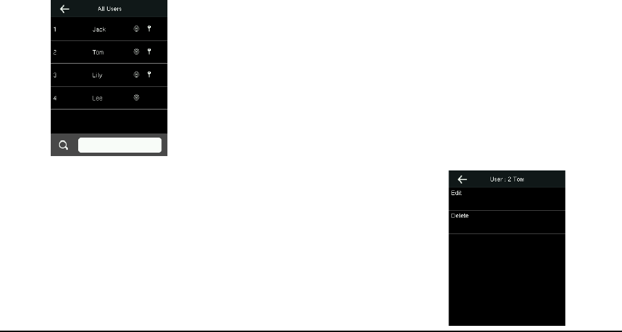
Search User
1. Press
[
All Users] icon in Use Mgt. to enter All Users interface, shown
as left figure.
2. Input user ID or name in the search box. (Note: You can input user
name with the intelligent input.)
3. Press [OK] to locate the specified user.
Edit User
After search the specified user, click the user to enter left interface. Press
[Edit] to enter the Edit interface. Detail operations of editing are the
same as adding user (The user ID cannot be edited).

6. Quick Start Guide 25
Delete User
1. After search the specified user, click the user and press [Delete] to
enter left interface.
2.Select delete type (Delete User, Delete Fingerprint Only, Delete
Password Only, Delete Badge Number Only), and then press [OK] to
confirm and carry out the corresponding delete operation.
Note:
(1) Based on the information registered by a user, the device displays the optional operation types.
For example, if the user does not register the password, the option
Delete Password
Only
is not
available.
(2) If
Delete User
is selected, the user's fingerprint, password, and badge number information will be
deleted.

26 Installation & Quick Start Guide
User Access
1. In [New User] or [Edit] interface, press [Access Control Role] to enter
the Access Control setting interface, shown as left figure.
2. Set the Access Group, Verification Mode, Time Period and select Duress
Fingerprint as required.
6.5 Verification
Verification by Fingerprint or Card
Place finger on the Fingerprint Sensor properly or punch card in the punch area (around the
Fingerprint Sensor); after verification succeed, the interface shown as figure 1 (Fingerprint
Verification), figure 2 (Card Verification).
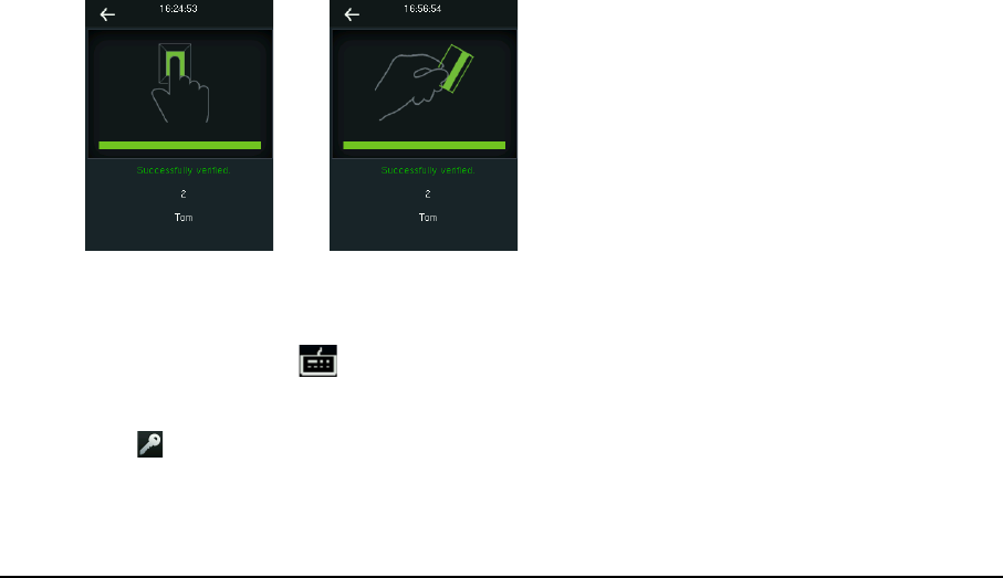
6. Quick Start Guide 27
figure 1 figure 2
Verification by Password
1. In initial interface, press to enter the user ID Input interface, shown as figure 3.
2. Input user ID which needs to do password verification and press [OK], figure 4 will display.
3. Press icon to enter password input interface, shown as figure 5.
4. Input the correct password (same as inputting ID Number) and press [OK] to confirm the
password. After verification succeed, figure6 will display.
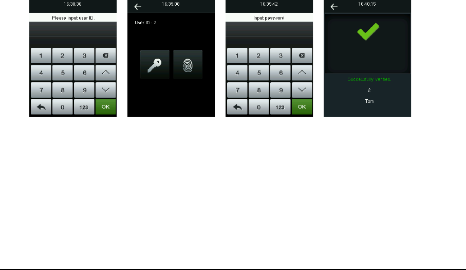
28 Installation & Quick Start Guide
figure 3 figure 4 figure 5 figure 6
6.6 Data Management
Press [Data Mgt.] icon in main menu to enter the Data Management (Data Mgt.) interface.
Delete Data: Delete data saved in the device, such as attendance data, all data, admin role, access
control, wallpaper, screen savers and backup data.
Backup Data: Backup the business data or system data to device or USB disk.
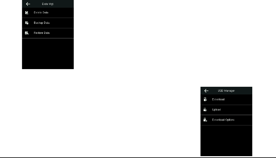
6. Quick Start Guide 29
Restore Data: Restore the backup data saved in device or USB disk to
device.
6.7 USB Manager
Press [USB Manager] icon in main menu to enter the USB Manager
interface.
Download: Download all attendance logs or user information to the USB
Disk. And then import logs into the Access 3.5 software through Import
Data From USB disk function, and then view Access Report as required.
Upload: Upload user information, screen saver or wallpaper (stored in
USB Disk) into the device.

30 Installation & Quick Start Guide
Download Options: Set whether to enable the Delete ATT Data option.
6.8 View Access Report
1. Connect the device to the network.
2. Run Access3.5 software.
3. Add the device to the software, download logs from device (you can use the USB Disk to
download logs too), and then analyze logs and view the access report as required.
Bundled
Access3.5 Security System
is unique software. For detailed operations, refer to Access3.5
software user manual in the CD.
7. Others 31
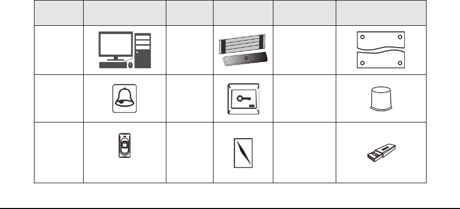
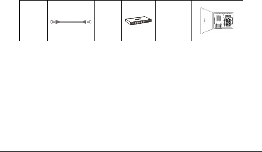
7. Others
The following equipments are needed for an access control system but are not included in the
standard package.
Name Picture Name Picture Name Picture
PC
Lock
Door
Sensor
Doorbell
Exit
Button
Alarm
485
Reader
Wiegand
Card
Reader
USB Disk
32 Installation & Quick Start Guide
Ethernet
Cable Switch
Access
Control
Panel

7. Others 33
This device complies with Part 15 of the FCC Rules.
Operation is subject to the following two conditions:
(1) This device may not cause harmful interference, and
(2) This device must accept any interference received,
including interference that may cause undesired operation.
Warning: Changes or modifications to this unit not expressly approved by the party responsible for
compliance could void the user’s authority to operate the equipment.
Note: This equipment has been tested and found to comply with the limits for a Class B digital
device, pursuant to Part 15 of the FCC Rules.These limits are designed to provide reasonable
protection against harmful interference in a residential installation. This equipment generates, uses
and can radiate radio frequency energy and, if not installed and used in accordance with the
instructions, may cause harmful interference to radio communications. However, there is no
guarantee that interference will not occur in a particular installation. If this equipment does cause
harmful interference to radio or television reception, which can be determined by turning the
equipment off and on, the user is encouraged to try to correct the interference by one or more of
the following measures:
Reorient or relocate the receiving antenna.

34 Installation & Quick Start Guide
Increase the separation between the equipment and receiver.
Connect the equipment into an outlet on a circuit different from that to which the receiver is
connected.
Consult the dealer or an experienced radio/TV technician for help.