ZONDA HOBBY TECHNOLOGIES ELECTRONIC HK0004 Transmitter User Manual 11
ZONDA HOBBY TECHNOLOGIES ELECTRONIC LIMITED Transmitter 11
Users manual
Global Distribution
Zonda Hobby Technologies Electronic Limited
Official Website: www.zondahobby.com / www.zondahobby.com.cn

Foreword
Warning Label Legend
Safety Precautions and Warning
Pre-flight check
FORBIDDEN
FORBIDDEN
Do not attempt under any circumstances.
WARNING
Mishandling due to failure to follow these instructions may result in danger or injury.
CAUTION
Mishandling due to failure to follow these instructions may result in danger.
WARNING
Statement
Thank you for choosing GWY Product. To help you to understand and use this AH6T Transmitter, We hope
you reading this manual carefully before operate.
To learn more information, please visit our official website:www.zondahobby.com/www.zondahobby.com.cn
RC helicopter is controlled by radio signals. It may be interfered by other radio signals during operation.
These interference may cause the helicopter lose control.
This is a sophisticated hobby product and NOT a toy. It must be operated with caution and common sense
and requires some basic mechanical ability. Failure to operate this Product in a safe and responsible
manner could result in injury or damage to the product or other property. This product is not intended for use
by children without direct adult supervision. Do not attempt disassembly, use with incompatible components
or augment product in any way without the approval of GWY. This manual contains instructions for safety,
operation and maintenance. It is essential to read and follow all the instructions and warnings in the manual,
prior to assembly, setup or use, in order to operate correctly and avoid damage or serious injury.
1. An RC Model is not a toy! Improper operation or misuse may lead to serious damage or loss. It is
prohibited for children under 14 years to operate this product.
2. Keep it away from high temperature environment and corrosive chemicals for storage and flight.
(the operation temperature: from -1 O.C to 50.C)
3. If you are not an experienced pilot or have not flown this type of model before, we recommend that
you get assistance of an experienced pilot for your first flights. Please avoid flying with other RC models
with same frequency.
4. Please choose a open flight area and use the training gear set for your first fight in order to minimize
your loss due to control mistakes.
1. To avoid the loss of the property of others, please keep away from high tension power lines, high
buildings or any other obstacles while flying.
2. Keep away from crowds in case of accidents.
3. Do NOT operate in rain, thunder, storms, lighting, strong wind or any other bad weathers to ensure
your and the helicopter’s safety.
4. Please avoid using in a bathroom or a rainy day to prevent moisture or water vapor from entering the
helicopter inside which may lead mechanical or electronic components malfunction and cause
unexpected accidents!
5. Do Not re-equip, upgrade or repair your helicopter with the accessories outside the DTS parts catalog
in order to ensure the safety of the model structure.
6. Keep people and objects away from the spinning unit and parts in case of damage or injury.
1. Please make sure the helicopter frequency will not interfered with others before every flight.
2. You should confirm the batteries of your transmitter and helicopter are fully charged before every flight
and your first flight.
3. Both the throttle stick (left-hand stick) and throttle trim MUST be in their lowest position before every
flight. Each time before your flight, you must ALWAYS turn on the transmitter power first before
connecting the flight battery to the receiver. After your flight, you should disconnect the flight battery from
the receiver before turn off the transmitter.
4. Please make sure that every servos function properly with correct directions after powering on.
5. Make sure every connection of pushrods is proper and the helicopter battery placed in fixed position.
2

Table of Contents
Included Items
Transmitter Identification
Key Input and Display Functions
Digital Trims
Inactivity Warning
Battery Alarm and Display
Programmable Alarm
AH6R/AH6RS Receiver
Receiver Installation
Binding
SmartSafe
Hold Last Command
Preset Failsafe
System Setup
To Access The System Setup List
Model select (Helicopter,Airplane,Multicopter)
Model Type (Helicopter,Airplane,Multicopter)
Model Name (Helicopter,Airplane,Multicopter)
Wing Type (Airplane)
Switch Select (Airplane)
Swash Type (Airplane)
Switch Select (Helicopter,Multicopter)
Trims Step (Helicopter,Airplane,Multicopter)
Model Reset (Helicopter,Airplane,Multicopter)
Model Copy (Helicopter,Airplane,Multicopter)
Warnings (Helicopter,Airplane,Multicopter)
Power Setting (Helicopter,Airplane,Multicopter)
Trainer (Helicopter,Airplane,Multicopter)
Failsafes (Helicopter,Airplane,Multicopter)
System Settings (Helicopter,Airplane,Multicopter)
4 14
14
15
15
15
16
17
17
17
18
19
19
20
21
21
22
24
24
25
26
27
5
6
6
6
6
6
6
7
7
7
7
7
8
8
8
9
9
9
10
10
10
10
11
11
12
12
12
13
13
Function Mode
Servo Reverse (Helicopter,Airplane,Multicopter)
Servo Travel (Helicopter,Airplane,Multicopter)
Servo Speed & Trim(Helicopter,Airplane,Multicopter)
D/R & Exponential (Helicopter,Airplane,Multicopter)
Differential (Airplane)
Throttle Cut (Helicopter,Airplane,Multicopter)
Throttle Curve (Airplane,Multicopter)
Throttle Curve (Helicopter)
Flap System (Airplane)
Swashplate (Helicopter)
GYRO (Helicopter)
Pitch Curve (Helicopter)
Mixing (Airplane)
Aileron to Rudder Mix (Airplane)
Mixing (Helicopter)
Programmable Mixes (Multicopter)
Timer (Helicopter,Airplane,Multicopter)
Monitor (Helicopter,Airplane,Multicopter)
Mode Changes
Adjustable Stick Tension
3
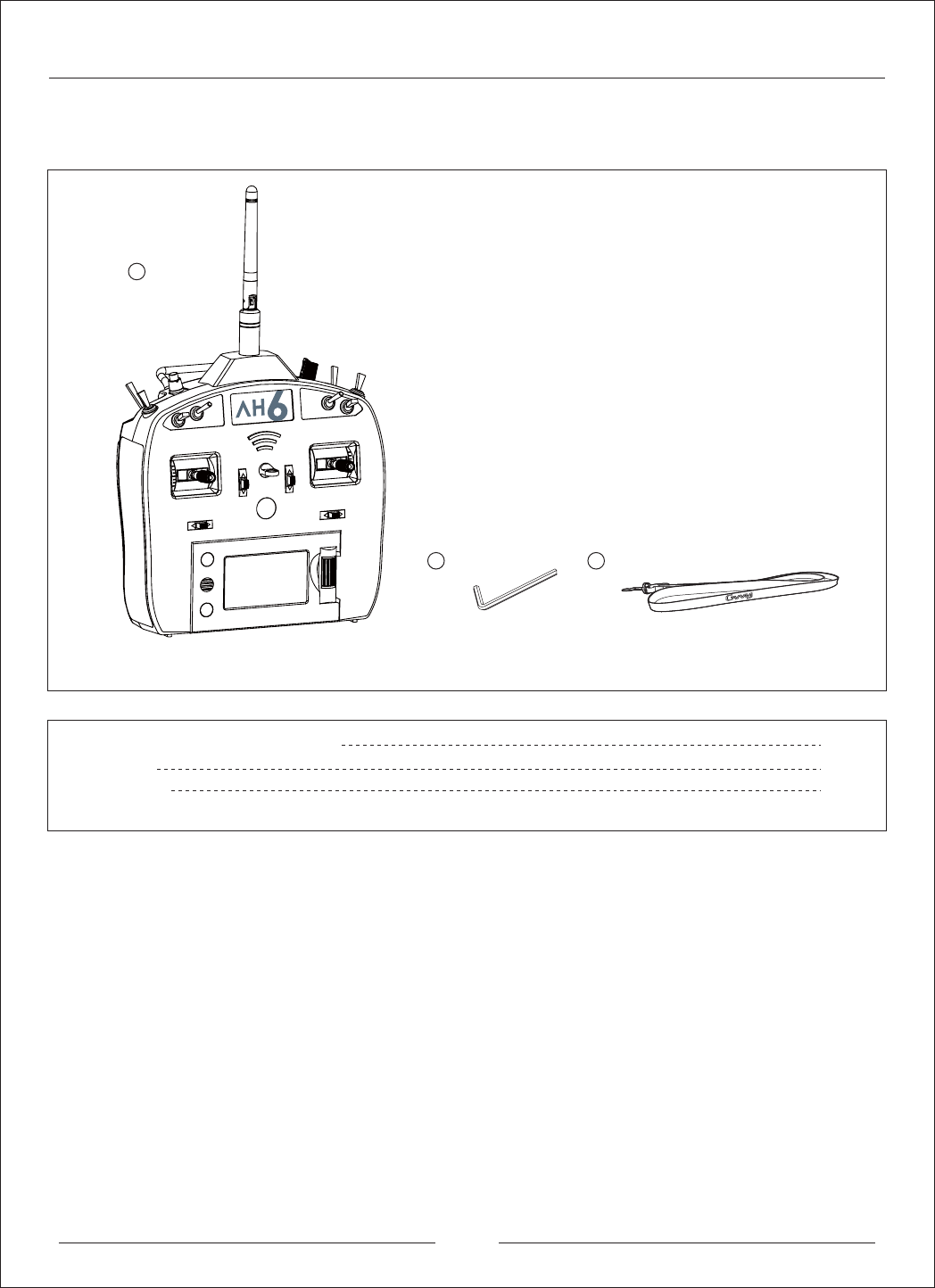
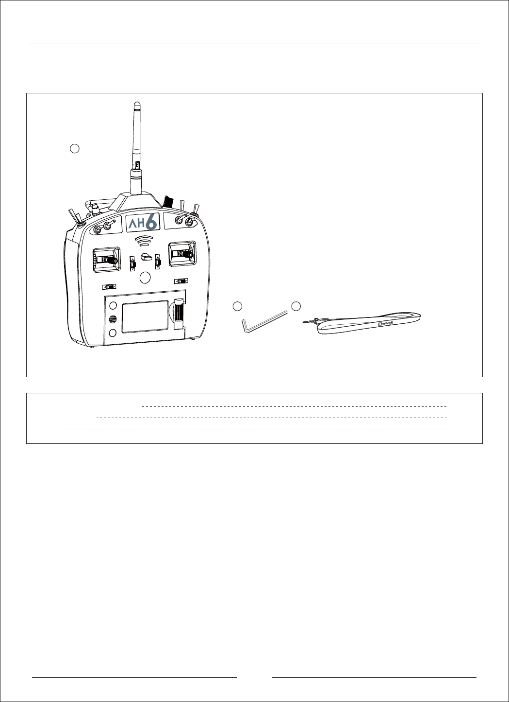
Included Items
1
2 3
1
1. AH6T 2.4G 6-Channel Transmitter
2. Hex key
3. Neckstrap
1
1
Please check the parts and accessories in the package. In the event of defective or missing parts, please
contact the retailer for help.
4
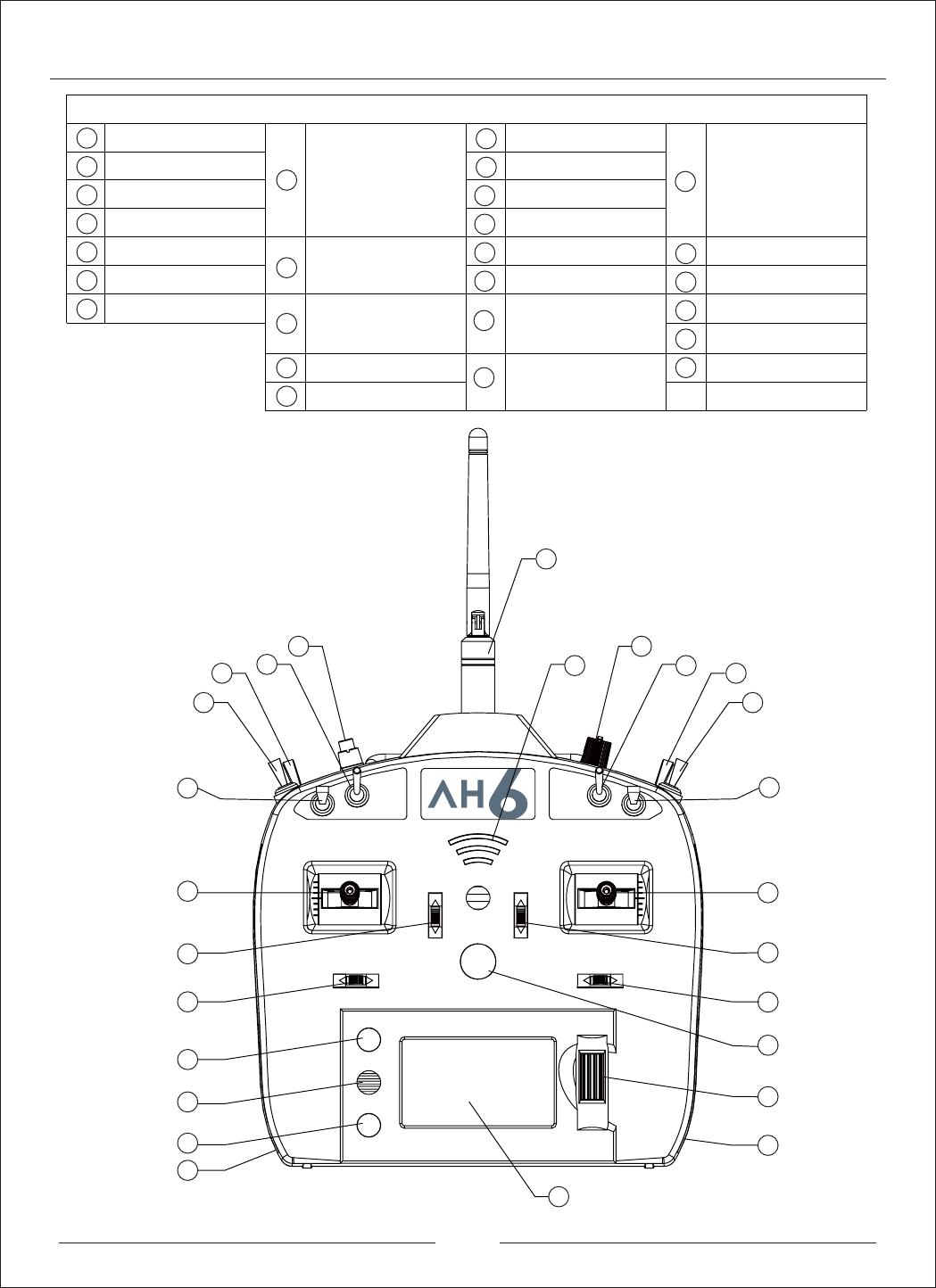
Transmitter Identification
Antenna
Signal Light
Knob
Swtich E
Swtich C
Swtich B
Swtich A
Swtich D
Bind Button / Switch I
Swtich H
Swtich G
Swtich F
Power Swtich
Display Screen
Left Rubber Panels
Right Rubber Panels
Clear Button
Back Button
Speaker
Rolling Selector
1
1
2
3
4
5
6
7
8
9
10
11
12
13
14
15
16
17
18
19
20
21
22
23
24
25
26
3
5
4
2
6
7
8
9
11
10
12
13
14
15
16
17
18
19
20
21
22
23
24 25
26
Mode 1 Elevator / Rudder Stick
Mode 2 Throttle / Rudder Stick
Mode 3 Elevator / Aileron Stick
Mode 4 Throttle / Aileron Stick
Mode 1 Throttle / Aileron Stick
Mode 2 Elevator / Aileron Stick
Mode 3 Throttle / Rudde Stick
Mode 4 Elevator / Rudde Stick
Mode 1/Mode 3 Throttle Trim
Mode 2/Mode 4 Elevator Trim
Mode 1/Mode 2Aileron Trim
Mode 3/Mode 4Rudder Trim
Mode 1/Mode 2
Rudder Trim
Mode 3/Mode 4
Aileron Trim
Mode 1/Mode 3Elevator Trim
Mode 2/Mode 4Throttle Trim
5

Key Input and Display Funcitons
Programmable Alarms
AH6R/AH6RS Receiver
AH6R Receiver
(JR Connect Port)
AH6SR Receiver
(JST 1.5mm Connect Port)
Digital Trims
Inactive Warning
Data Error Warning
NOTICE: Please choose the corresponding receiver
according to different cable
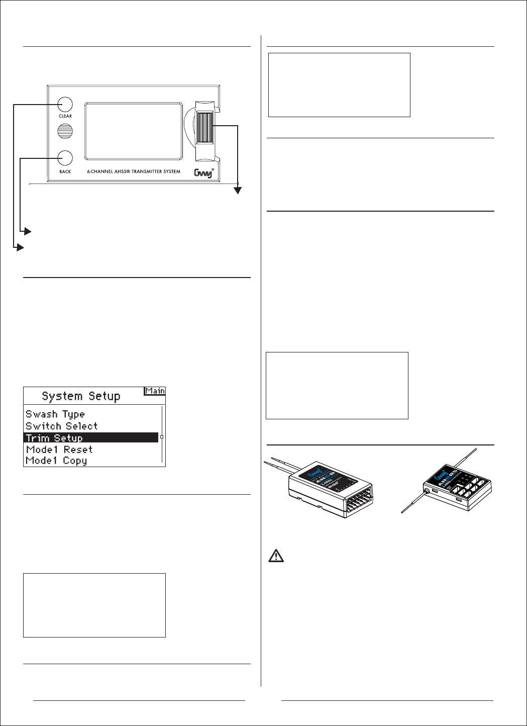
Press the CLEAR button to return the highlighted value to
its default setting
Press the BACK button to return to the previous screen
Rotate the ROLLER to adjust values or to select options
Press the ROLLER to access screens or functions.
Battery Alarm and Display
The AH6T utilizes a roller that can be rotated or pressed
and two buttons, Back and Clear that are used to access
and program all functions.
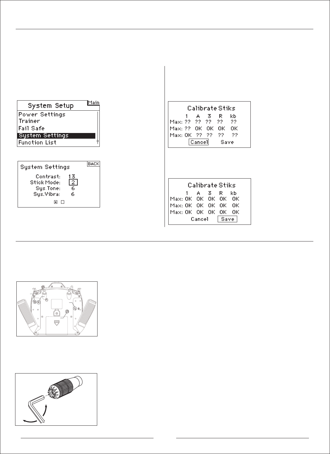
The AH6T 2.4G features advanced digital trims. The Main
screen displays the graphic position for the trims. The
Throttle Aileron, Elevator and Rudder trim levers, and
when activated the right and left trimmers, feature an
audible center trim beep and a pause. You can adjust the
amount of travel per each trim in the Trim Step Function,
located in System Setup Mode.
Note: When The transmitter is turned off, the trims and left and
right trimmer values are stored in memory and recalled when the
system is turned back on.
The AH6T features an inactivity warning that warns if the
transmitter is left on preventing draining the batteries. If the
transmitter is left on and no input is given to the sticks of
switches for 10 minutes, an alarm will sound and warning
screen appear. Moving any stick or switch will clear the
alarm. Normal RF modulation continues throughout the
alarm maintaining the RF link.
If the transmitter shutdown unexpected, flash data will be
damage, reboot the transmitter will display the warning as
below and it will automatically repair.
When the transmitter voltage drops below 4.3 volts,
"Warning Low Battery" will flash and an alarm sound. If you
are flying when this occurs, land immediately.
The AH6 features programmable alarms that warn of a
potential unsafe switch or stick position when the
transmitter is turned on. In Acro mode programmable
alarms include high throttle, gear and mid and land flap
positions while in helicopter mode warnings include high
throttle, Stunt 1, Stunt 2, and Hold. If any of these switches
or throttle stick position is in an unsafe position when the
transmitter is turned on, an alarm will sound, the screen will
display the offending switch position and the transmitter will
not transmit a signal. Moving the switch or stick to the
desired position will clear the warning and normal operation
will resume.
Specifications:
Voltage Range : DC4.8-6V
Current : <=150mA
Modulation : GFSK
Wireless Operation Mode : FHSS
Frequency Channel : 2406MHz -- 2476MHz
Band Resolution : 1Mhz
Baud Rate : 250Khz
Frame Rate : 11ms
CE, FCC Cert.
6

Receiver Installation
Power System Requirements
Binding
SmartSafe
Hold Last Command
Preset Failsafe
In gas and glow aircraft install the main receiver by
wrapping it in protective foam and fastening it in place
using rubber bands or hook and loop strap.
In electric airplanes or helicopters, you can use thick
double-sided foam tape to fasten the main receiver in
place.
Mount the remote in a slightly different location from the
primary receiver. This gives tremendous improvements in
path diversity. Essentially, each receiver sees a different
RF environment and this is key to maintaining a solid RF
link. This is especially the case in aircraft with substantial
conductive materials (e.g., larger gas engines, carbon
fiber, pipes etc), which can weaken the signal.
Receiver antenna as far as possible away from power
lines. Ideally perpendicular to each antenna.
Onboard power systems must provide adequate power,
without interruption, to the receiver even when the system
is fully loaded (servos at maximum flight loads).
Inadequate power systems are a primary cause of in-flight
failures. Some components that affect the ability to
properly deliver adequate power include: the selected
receiver battery pack (number of cells, capacity, cell type,
state of charge), switch harness, battery leads and, if
used, the regulator and power bus. The AH6R/AH6RS
minimum operational voltage is 3.5-volts. Test the system
per the following guidelines to a minimum voltage of
4.8-volts during ground testing. This will compensate for
battery discharging or actual flight loads that are greater
than ground test loads.
You must bind the receiver to the transmitter before the
receiver will operate. Binding teaches the receiver the
specific code of the transmitter, so it will only connect to
that transmitter.
1. To bind an AH6R/AH6RS to a AH6T transmitter, insert
the bind plug in the BATT/BIND port on the receiver.
2. Power the receiver. The LED on the receiver will be
flashing, indicating the receiver is ready to be bound to the
transmitter.
3. Move the sticks and switches on the transmitter to the
desired failsafe positions (low throttle and neutral control
positions).
4.
Press and hold the Blind button(Switch I) while powering
on transmitter.
5. The system will connect within a few seconds. Once
connected, the LED on the receiver will go solid indicating
connection.
6. Remove the bind plug from the BATT/BND port on the
receiver. Power off the transmitter and store the bind plug
in a convenient place.
7. After setting up your model, rebind the system so the
true low throttle and neutral control surface positions are set.
When you bind your transmitter, you are programming the
receiver with failsafe defaults. If connection is lost between
the transmitter and receiver, the receiver immediately
operates in those preprogrammed default positions. Those
positions are failsafes. The AH6R AH6RS has three
failsafes: SmartSafe Failsafe, Hold Last Command
Failsafe, and Preset Failsafe.
SmartSafe Failsafe is always active in both hold last
command failsafe and in preset failsafe. SmartSafe is a
safety feature on the throttle channel only that offers the
following benefits:
3UHYHQWVHOHFWULFPRWRUVIURPRSHUDWLQJZKHQWKHUHFHLYHU
only is turned on (no signal present)
3UHYHQWVHOHFWULFPRWRUVIURPRSHUDWLQJZKHQWKHUHFHLYHU
only is turned on (no signal present)
3UHYHQWVWKHVSHHGFRQWUROOHUIURPDUPLQJXQWLOWKHWKURWWOH
is moved to low throttle position after connection is made
6KXWVRIIHOHFWULFPRWRUDQGUHGXFHVJDVJORZHQJLQHVWR
idle if signal is lost
,IWKURWWOHLVDWDQ\SRVLWLRQRWKHUWKDQORZWKH(6&ZRQ¶W
arm
,IFRQQHFWLRQLVORVWLQIOLJKW
-SmartSafe sets the throttle to the position it was in during
the binding process.
How To Program
SmartSafe is automatically set when hold last command
failsafe or Preset failsafe is programmed or the system is
bound. Note: It’s important to have the throttle stick in the
low position to store low throttle during binding.
To Test
Confirm the failsafe setting is correct by turning off the
transmitter. The throttle should go to the preset low throttle
position.
CAUTION: Make sure the aircraft is restrained on the
ground. If failsafe is not set, your aircraft might advance to
mid or full throttle.
If you lose connection, all channels except for throttle
channel hold last given command and the aircraft continues
on its path. So, if you were turning when connection was
lost, your aircraft would continue turning.
How To Program
1. Leave the bind plug in the bind port through the entire
binding process.
2. Remove bind plug only after receiver connects to
transmitter
To Test
Confirm the failsafe settings are correct by turning off the
transmitter. All channels except for the throttle should hold
the last command.
CAUTION: Make sure the aircraft is restrained on the
ground. If failsafe is not set, your aircraft might advance to
mid or full throttle.
If the signal is lost, all channels are driven to their failsafe
position set during binding.
Preset Failsafe is ideal for sailplanes, as spoliers can be
deployed during loss of signal, preventing a flyaway.
How To Program
1. Insert the bind plug and power on the receiver.
2. When the receiver LEDs blink indicating bind mode,
remove bind plug before binding the transmitter to the
receiver.
7
To Access the System Setup List
Model Select
System Setup
Airplane Model
Model Select
Model Type
Model Name
Wing Type
Switch Select
Trim Setup
Model Reset
Model Copy
Warnings
Power Settings
Trainer
Fail Safe
System Settings
Multicopter Model
Model Select
Model Type
Model Name
Swash Type
Switch Select
Trim Setup
Model Reset
Model Copy
Warnings
Power Settings
Trainer
Fail Safe
System Settings
Helicopter Model
Model Select
Model Type
Model Name
Swash Type
Switch Select
Trim Setup
Model Reset
Model Copy
Warnings
Power Settings
Trainer
Fail Safe
System Settings
3. LED lights will continue to blink.
4. Move transmitter’s control sticks and switches to the
desired Preset Failsafe positions then turn it on in bind
mode.
5. The system should connect in less than 15 seconds.
NOTICE: Failsafe features vary according to receiver, so
if using a receiver other than the AH6R AH6RS, consult
your receiver’s instructions for the failsafes that apply.
Before flight, ALWAYS confirm your binding is good and
failsafe is set. To do this, make sure the system is
connected, turn your transmitter off. Confirm that
low-throttle is active.
CAUTION: Make sure the aircraft is restrained on the
ground. If failsafe is not set, your aircraft might advance
to mid or full throttle.
The AH6T organizes the programming screens in two
separate categories: System Setup Mode and Functions
Mode. The System Setup Mode contains programming
that is generally used when initially setting up a model,
and seldom used at the field. System Setup functions
includes Model Type, Model Name, Wing Type,
(Swashplate Type for Helis) Model Reset, etc. Note: No
radio transmission occurs when a System Setup screen
is displayed to prevent accidental servo operation. This
protects linkages/servo gears from damage when making
programming changes. System Setup in Airplane,
Helicopter and Multicopter Model type includes the
following screens.
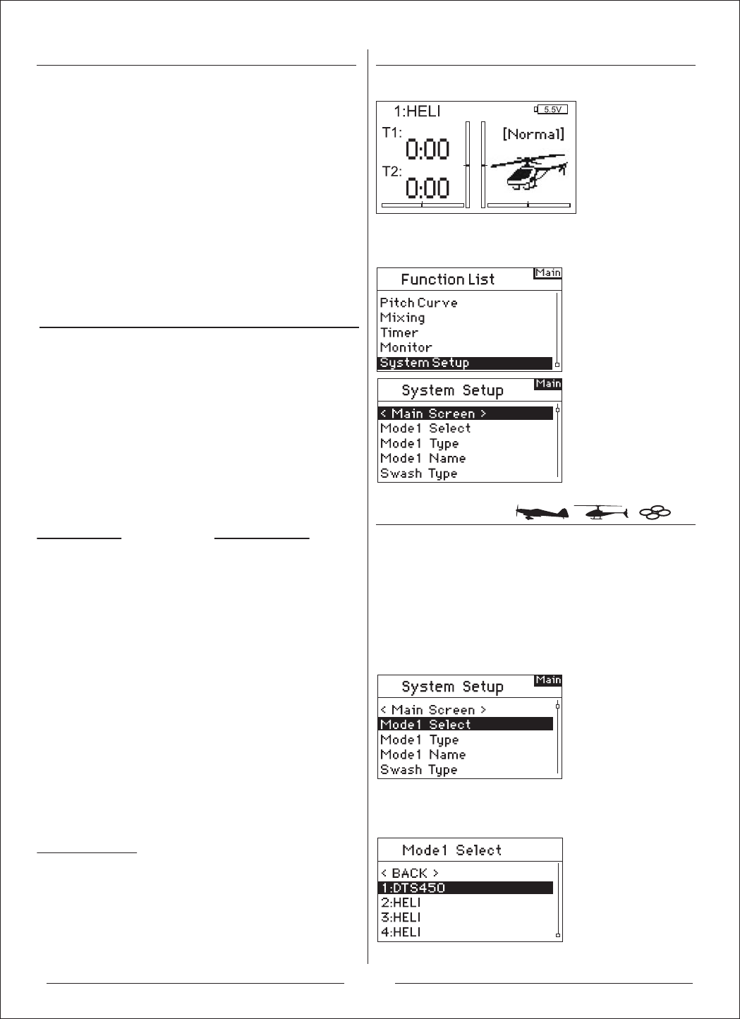
Press Power Switch to turn on the transmitter and enter
the main screen.
Press and hold the roller while turning on the transmitter.
When System Setup appears on the screen, release the
roller. The AH6T is now in System Setup Mode.
The Model Select function is used to change to a different
model memory, typically when switching from the current
model. You can store up to 20 models in the AH6T’s
model memory. You can access the model select function
through the System Setup mode or through Direct Model
Access. Direct Model Access allows you to access the
model select function at any time the main screen or a
telemetry screen is displayed.
The following screen appears. Rotate the roller to
highlight the desired model then press to select. The
model name will display on the main screen.
8
Model Type
Wing Type
Model Name
To Access the Wing Type Function
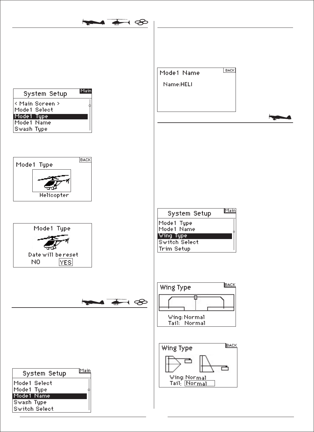
Model Type programs the selected model memory to
function in Helicopter, Airplane or Multicopter
programming. You should program Model Type first when
setting up a new model. Note: You can assign each model
memory its own model type.
To Access the Model Type Function
Press and hold the roller while turning on the transmitter.
When System Setup appears on the screen, release the
roller. The AH6T is now in System Setup Mode.
Rotate the roller to highlight the desired character
then press to accept.
Repeat the process until complete. The name will
display on the main screen. Pressing Clear will
erase the current character.
Use the Wing Type function to program the wing and tail
mix to match your airplane. Eight wing types (Normal,
elevon, dual aileron, 1 aileron and 1 flap, flaperon, 1
aileron and 2 flaps, 2 ailerons and 1 flap, 2 ailerons and 2
flaps) and five tail types (normal, V-Tail, dual elevator, dual
rudder, dual rudder/ elevator) are available. You must
select the correct wing and tail type to match your airplane
before doing any other wing or tail related programming
(e.g., Flaps, Travel Adjust, Sub-Trim, etc.).
Rotate the roller to highlight Wing Type then press to
access the function.
The following screen appears:
Rotate the roller to highlight Wing and press to access the
function. Rotate the roller to the desired wing mix. Press
the roller to select.
Rotate the roller to highlight Tail then press.
Rotate the roller to access the desired tail type. Press the
roller to select.
To access the Tail Type
Rotate the roller to highlight Model Type then press to
access the function (Helicopter, Airplane or Multicopter).
The following screen appears:
The following screen appears. Rotate the roller to highlight
YES then press the roller to accept the model type.
Selecting NO will return you to the previous screen.
Note: When you change model types (Heli to Acro or Acro
to Heli) all current programming in the selected model
memory will reset to the factory default settings. All
previous settings will be lost.
The Model Name function allows you to name a model
using up to 10 characters. This makes identifying and
selecting models much easier. Naming a model is
normally done during initial setup. You can modify or
change names at any time without affecting other
programming. Note that upper case, lower case, numbers
and symbols are available.
Rotate the roller to highlight Model Name then press to
access the function.
The following screen appears:
9
10
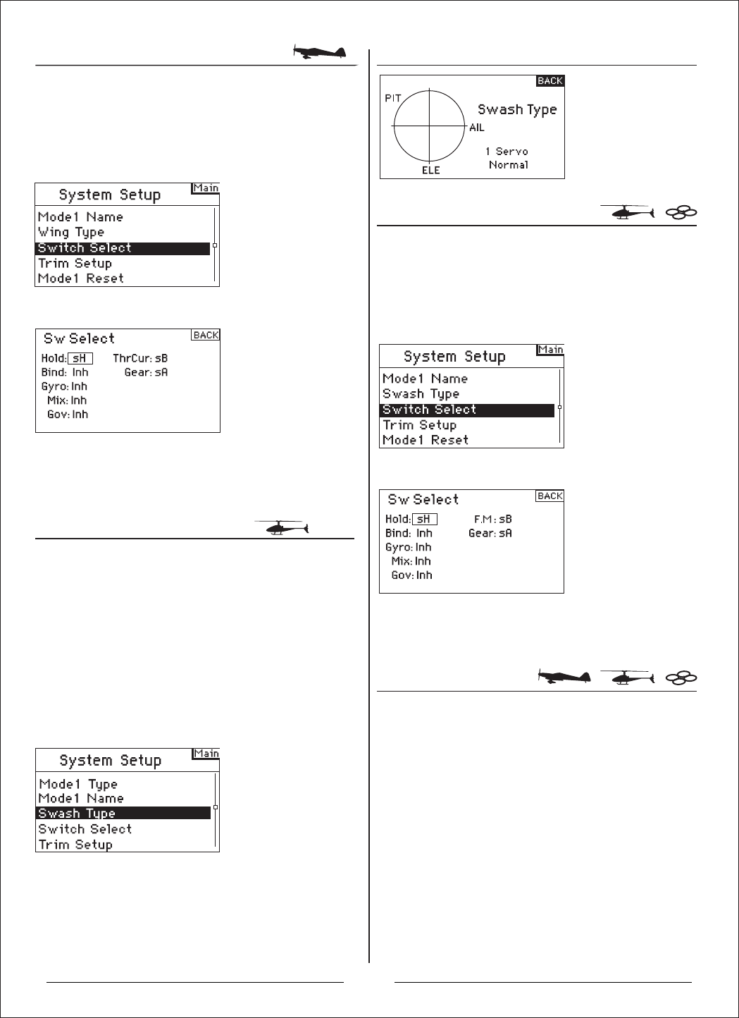
Switch Select
Swashplate Type
Switch Select
Trim Step
The Switch Select function allows the switches, knob and
right and left trimmers to be assigned to the gear, Aux1,
Aux2 or Aux3 channels or inhibit.
Press and hold the roller while turning on the transmitter.
When System Setup appears on the screen, release the
roller. The AH6T is now in System Setup Mode.
The Switch Select function allows the switch, knob, right
and left trimmers, hold, throttle curve.
To Program the Switch Select Functions
Press and hold the roller while turning on the transmitter.
When System Setup appears on the screen, release the
roller. The AH6T is now in System Setup Mode.
Rotate the roller to highlight the desired switch, knob or
trimmer then press.
Select the channel or function you wish to assign. See
chart for options. Press the roller to accept. Note that a
channel or function can only be assigned once.
Repeat to select all desired switch positions.
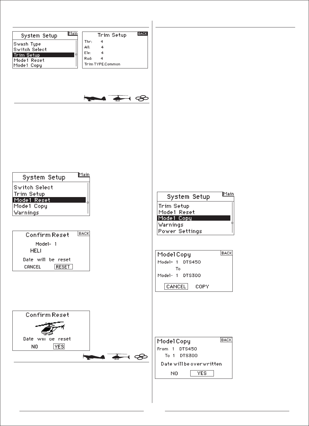
The Trim Step function allows servo movement
adjustment per click of trim. For example you usually want
a large trim step (8 to 10) for a new model. Each click of
trim will have a large amount of trim travel so you can
quickly adjust an out-of-trim model in flight. Later you can
use a finer trim step (1-5) to adjust for precise flight. The
Trim Step function allows the trims to be common or
independent in each active flight mode. Many helicopter
pilots use independent trims because they are
automatically active when a flight mode is activated.
Important: The trim step function has no effect on the
overall trim travel, only the total number of clicks
available. If you select a 0 value in trim step, the trim is
turned off.
To Access the Trim Step Function
Press and hold the roller while turning on the transmitter.
When System Setup appears on the screen, release the
roller. The AH6T is now in System Setup Mode.
Rotate the roller to highlight the desired switch, knob or
trimmer then press the roller to access.
Rotate the roller to select the desired channel or function
you wish the switch, knob or trimmer to operate. Press the
roller to accept. Note that the channel or function can only
be assigned once.
Repeat to select all desired switch positions.
Use the Swash Type screen to program the swashplate
mix to match your helicopter swashplate type. Six
swashplate types are available: Normal, 3-servo 120
CCPM, 3-servo 140 CCPM, 3-servo 90 CCPM, 3-servo
135 CCPM, and 2-servo 180 CCPM. Select the correct
swashplate type to match the specific helicopter before
doing any other cyclic programming e.g., Pitch Curve,
Travel Adjust, Sub-Trim, etc.). If in doubt consult your
helicopter’s manual for correct swashplate mixing.
Rotate the roller to highlight Swash Type then press the
roller to access the function. The following screen
appears:
Highlight the current swashplate type then rotate the roller
to select the desired swashplate mix. When the desired
Swashplate mix is displayed press the roller to select. In
Systems Settings highlight User Name then press the
roller to select that function. Select the desired mode then
press to accept.
To Access the Swash Type Function
Model Reset
Model Copy
To Access the Model Copy Function
Highlight the desired Trim value then press the roller to
access. Rotate the roller to change to the desired trim
value. Press to accept. Repeat to adjust all trim steps.
Model Reset is typically used to clear the programming for
a model you will no longer be flying. Model Reset resets
the programming for the selected model to factory defaults.
No other model memories will be affected. When a model’s
memory is reset all programming for that model is
permanently deleted and cannot be recovered.
To Access the Model Reset Function
Press and hold the roller while turning on the transmitter.
When System Setup appears on the screen, release the
roller. The AH6T is now in System Setup Mode.
Rotate the roller to highlight Model Reset then press to
access the function.The following screen appears:
Verify that the model displayed on this screen is the model
you wish to reset. Rotate the roller to highlight Reset and
then press to access the Confirm Reset screen.
Highlight YES If you’re sure you want to reset this model to
factory default settings, press the roller. The screen will
return to the main screen.
The Model Copy function copies the currently selected
model’s programming of another model memory. Thirty
model memories are available. Some of the more common
uses of the Model Copy function include:
0RYLQJWKHRUGHURIPRGHOVDURXQGLQPRGHOPHPRU\VR
they can be organized by category, type, etc. Note: You will
need to re-bind after moving models.
Note: You will need to re-bind after moving models
([SHULPHQWLQJZLWKWKHSURJUDPPLQJIRUDQDLUFUDIWZKLOH
preserving a copy of the original setup. Note: If you want to
use the model copy function to try two slightly different
setups with the same model you will need to rebind the
receiver each time you switch between model memories.
&RS\LQJWKHSURJUDPPLQJIRUDQH[LVWLQJPRGHORYHUWRD
new model that is similar. Many pilots find this to be a good
way to provide more accurate baseline programming for the
new model. For example Vibe 50 w/120CCPM mixing, gyro
and governor programming provides a good base
programming for any other nitro powered 120CCPM mixing
helicopter. An Extra 300 with dual aileron and elevator
servos that is properly programmed with dual flap and
dual elevator mixing in Wing Type provides good
foundational programming for another aerobatic airplane
with the same basic control system.
Important: The model memory you are copying to will be
over-written by the copied programming, permanently
deleting any programming that may already exist.
Press and hold the roller while turning on the transmitter.
When System Setup appears on the screen, release the
roller. The AH6T is now in System Setup Mode.
Rotate the roller to highlight Model Copy then press.
The following screen appears:
Verify that the current model displayed on this screen is the
model you wish to copy. If not then see the previous Model
Select to access the desired model. Rotate the roller to
select the model memory (1 - 20) that the model will be
copied to. Select an unused model memory to copy to.
When the desired model memory is displayed, press the
roller to access the Confirm Copy screen.
If you want to Copy this model to the selected model
memory, press the roller to copy. The screen returns to the
main screen when the copy is complete. The original model
memory you just copied will still be selected.
11
Warnings
Trainer
Power Setting
To Access the Power Setting Function
To Access the Warnings Screen
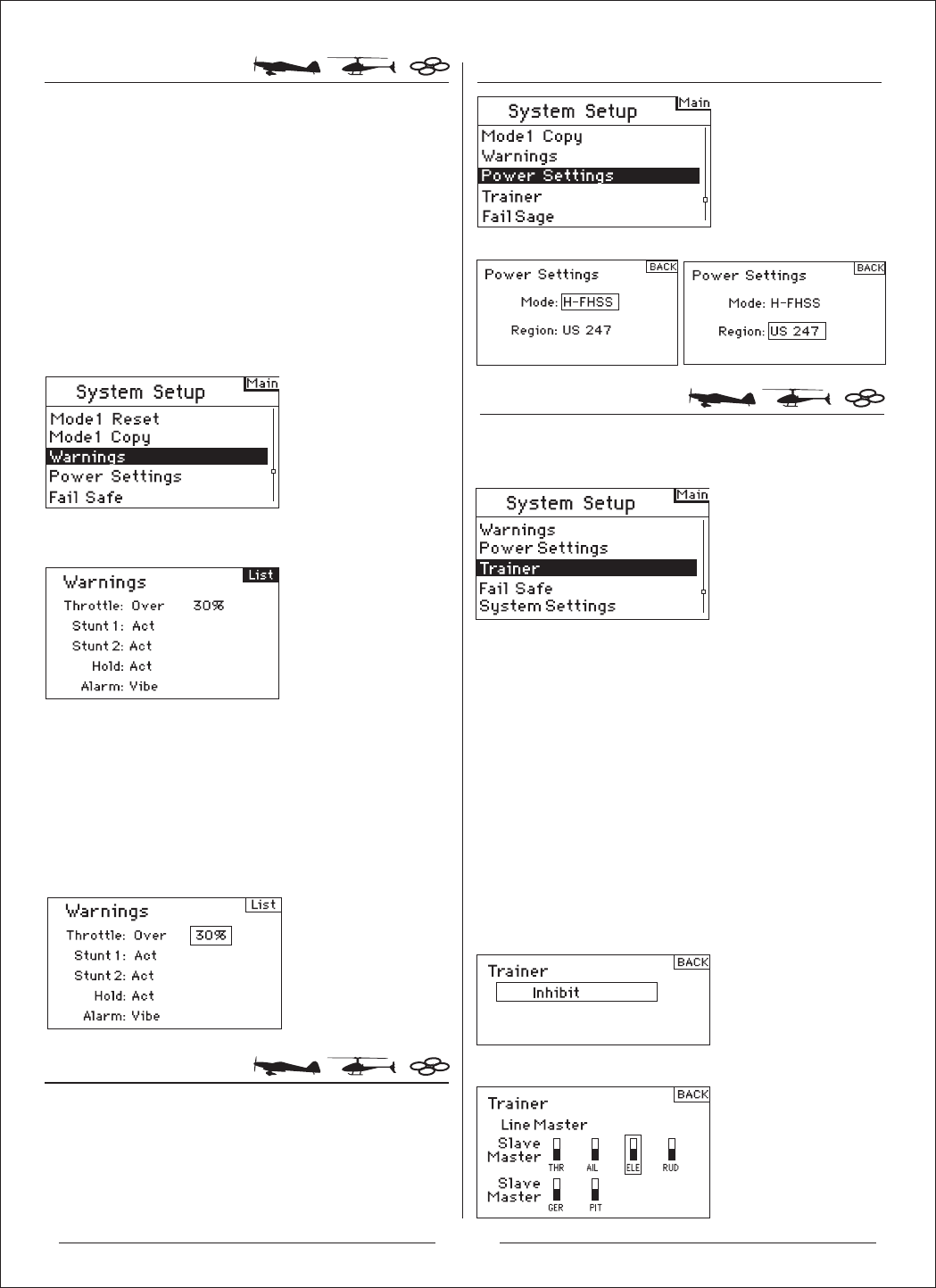
The Warnings function programs an alarm to sound if
specific switches or stick positions are in an unsafe
position when the transmitter is first turned on. In
helicopter model type default warnings include Throttle,
Stunt 1, Stunt 2 and Hold. In airplane model type these
warnings include Throttle Low, Flaps, Gear, Flight Mode
1 and Flight Mode 2. If you turn the transmitter on and
any of these switches or the throttle is not at the low
position, the alarm will sound; the screen will display the
warning and no transmission will occur until the stick or
switch is in the correct position.
Press and hold the roller while turning on the transmitter.
When System Setup appears on the screen, release the
roller. The AH6T is now in System Setup Mode.
Rotate the roller to highlight Warning then press.
The following screen appears:
Highlight the desired warning (Throttle, Stunt 1, Stunt 2
or Hold or Throttle, Flaps, Gear, Flight Mode 1 and Flight
Mode 2 for airplane model) then press the roller to
select. Now rotate the roller to inhibit or activate the
selected warning.
To verify the warning is functioning turn the transmitter
off, move the selected switch or throttle in the offending
position then turn the transmitter on. The alarm will
sound; the screen will display the specific warning and
no modulation will occur.
The Power Setting function is used to setting the
transmitter mode and region.
Press and hold the roller while turning on the transmitter.
When System Setup appears on the screen, release the
roller. The AH6T is now in System Setup Mode.
Enter Power Setting to setup the mode and region
Press and hold the roller while turning on the transmitter.
When System Setup appears on the screen, release the
roller. The AH6T is now in System Setup Mode.
Rotate the roller to highlight Trainer then press. The
following screen appears:
Inhibit: In Inhibit you can use the transmitter as a slave
only. However, the slave transmitter must have the same
programming as the master (e.g., servo reversing, travel
adjust, sub-trim, trims).
Line / Wireless Master: When Line / Wireless Master is
selected the slave transmitter has control of the stick
function only (aileron, elevator rudder and throttle) while
the master maintains control of all other channels and
functions including D/R and switch positions. This is ideal
for complex models as the master maintains control of all
secondary functions and controls all other channels.
Slave: Use Slave mode when flying with the AH6T as a
slave when the master radio has activated its
Link/Wireless Master. In this case, there is no need to
match programming between the slave and master
transmitter.
Rotate the roller to switch the channel then press. The
following screen appears:
12

System Settings
To Access the System Settings Function
To Adjust Contrast
To Select a Mode
To Access the Sound Setting
Fail safe
When using Wireless Master, Rotate the roller to Bind
then press. The following screen appears:
Slave turn on the transmitter and bind it simultaneously.
Enter Slave mode :
Press and hold the roller while turning on the transmitter.
When System Setup appears on the screen, release the
roller. The AH6T is now in System Setup Mode.
Rotate the roller to the channel you need to setup then
press
Rotate the roller to the digital you need to setup then
press and set the parameter.
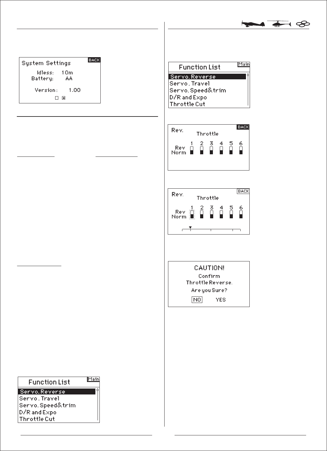
Use the System Setting screen to establish the overall
transmitter setting that will apply to ALL model memories.
Press and hold the roller while turning on the transmitter.
When System Setup appears on the screen, release the
roller. The AH6T is now in System Setup Mode.
Highlight System Settings then press. The following
screen appears:
Then the following screen appears:
In the Systems Settings screen rotate the roller to
highlight User Contrast then press.
Rotate the roller to adjust the contrast (from 1 to 20)
noting it on screen. Press to accept.
Rotate the roller to select the mode then press
Rotate the roller to select the mode (from 1 to 4)
Press to accept.
In the Systems Settings screen rotate the roller to
highlight Sound Setting then press to adjust the speaker
sound.
13
Function Mode
Airplane Model
Servo. Reverse
Servo. Travel
Servo. Speed&trim
D/R and Expo
Differential
Throttle Cut
Throttle Curve
Flap System
Mixing
Timer
Monitor
Multicopter Model
Servo. Reverse
Servo. Travel
Servo. Speed&trim
D/R and Expo
Helicopter Model
Servo. Reverse
Servo. Travel
Servo. Speed&trim
D/R and Expo
Throttle Cut
Throttle Curve
Swashplate
Gyro
Pitch Curve
Mixing
Timer
Monitor
Servo Reverse
To Access the Inactive Warning Time Setting
To Access the Reverse Function
Throttle Cut
Throttle Curve
Program Aux
Timer
Monitor
Rotate the roller to access the inactive warning time
setting then press and set the parameter.
The AH6T organizes the programming screens in two
separate categories: System Setup Mode and Functions
Mode. Function Mode programming adjusts a model’s
flight characteristics at the field.
To Access the Function List
With the transmitter on and the main or telemetry screen
displayed, press the roller. The Function list displays.
Rotate the roller to highlight Servo.Reverse then press.
The following screen appears:
Rotate the roller to the channel you need to setup then
press
If it is Throttle Channel, the following screen appears:
Press "Yes", to change the direction of servo / channel.
14
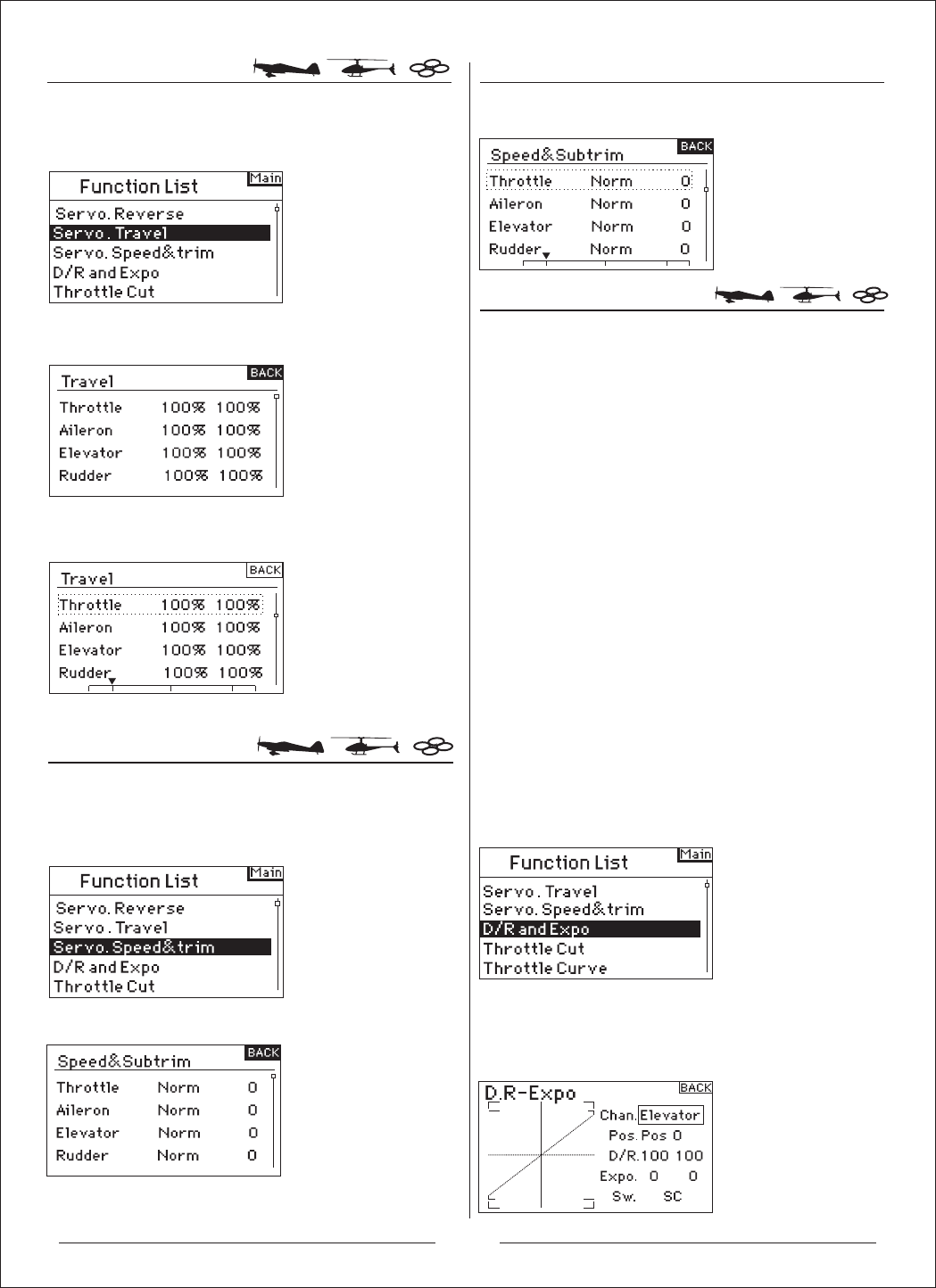
Servo.Travel
Servo Speed & Trim
D/R & Exponential
To Access the Servo.Travel
To Access the Servo.Speed&Trim To Access the D/R and Expo Function
Rotate the roller to highlight Servo.Travel then press. The
following screen appears:
Then the following screen appears:
Rotate the roller to the channel you need to setup then
press.
after that rotate the roller to adjust the parameter.
Rotate the roller to highlight Servo.Speed&Trim then
press. The following screen appears:
Then the following screen appears:
Rotate the roller to the channel you need to setup then
press after that rotate the roller to adjust the parameter.
Dual Rates and exponentials are available on the aileron,
elevator and rudder channels. You can assign them to
numerous switches including the flight mode switch.
Dual Rate
Affects the overall travel which in turn affects control
response sensitivity equally throughout the range of that
channel. Reducing the dual rate reduces the maximum
control rate as well as overall sensitivity.
Exponential
Affects the sensitivity around center but has no affect on
the overall travel. Positive Exponential reduces control
sensitivity around neutral for more precise control but
does not affect the maximum control response.
Note: Positive and negative exponential values are
available. A positive expo value reduces control sensitivity
around center. It does not affect maximum travel and is
recommended. Negative exponential values increase
sensitivity around neutral and is seldom used.
Rotate the roller to highlight D/R and Expo then press to
access.
To Select a Channel
Highlight the channel then press the roller to access.
Rotate the roller to select the aileron, elevator or rudder
channel. Press to accept.
15
16
Differential
To Access the Differential Screen
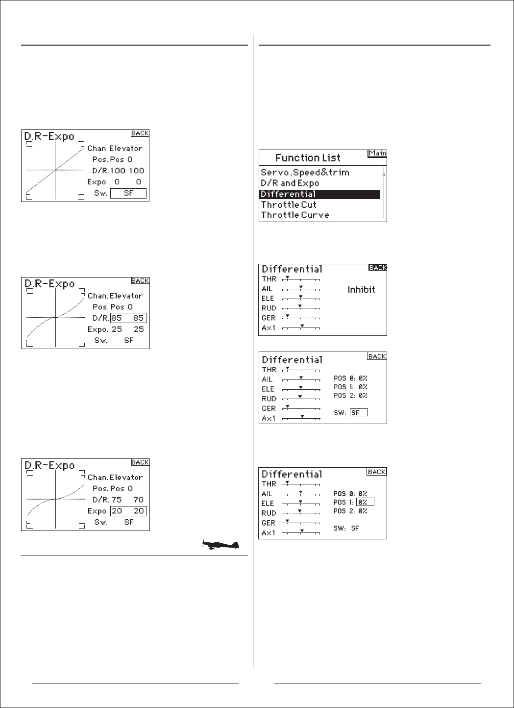
To Select Switch
Rotate the roller to highlight Sw (switch) then press to
access the switch options. Select the desired switch to
change the dual rate for that channel or inhibit then press
the roller to make it active.
Note: You can assign multiple channels to a single switch
to affect the dual and exponential rates of all.
To Select Switch Position to Adjust
Note Pos: Pos 0 in the center of the screen. Move the
switch displayed at the bottom of the screen to one of
three positions from 0,1,2. When you make D/R or Expo
adjustments, values are assigned and automatically active
when the switch is in that position (Pos 0, 1or 2).
To Select D/R and Expo Values
Confirm that the desired channel and switch position are
selected. Rotate the roller to highlight the D/R or Expo
value then press to access. When the corresponding
channel’s control stick is centered both values are
highlighted. If you move the control stick to its endpoint,
only one value will be highlighted.
This allows the D/R or Expo value in that direction only to
change. With the desired value selected, rotate the roller
to select.
The Differential function provides precise adjustments of
up/down aileron travel of each aileron (or elevon if Delta
wing is activated). Typically, you can use Aileron
differential to reduce unwanted yaw characteristics. In
aerobatic airplanes adjusting differential provides an axial
roll (minimum displacement of yaw during a roll). You can
program up to three Differential values and assign them to
a switch. Note that positive + and negative – differential is
available; however, normally more up aileron travel is
required than down aileron.
Note: The Differential function is only available if Dual Aileron,
Flaperon, 2 ailerons 1 flap, 2 ailerons 2 flaps or Elevon is selected
in Wing Type an d each aileron servo is controlled by its own
channel.
Rotate the roller to highlight Differential then press. The
following screen appears:
Differential defaults to Inhibit. Press the roller to highlight
Inhibit then select one of the following switch positions:
Highlight the desired differential position/value and press
the roller to access.
Rotate the roller to change the value then press the roller.
Repeat for all switch positions desired.
Positive differential values provide more up than down
aileron travel. Negative differential values provide more
down than up travel. The differential values screen also
allows you to select/change switch positions. Use the roller
to highlight SW then rotate to change to the desired switch
position or inhibit the function.
17
Throttle Cut Throttle Curve
Throttle Curve
The Throttle Cut function allows you to shut off an engine
with the Trainer switch, Gear switch or the Right or Left
trimmer. When you activate the programmed switch, the
throttle channel is driven to it’s preprogrammed value
normally off. This effectively kills the engine. Release the
programmed throttle cut switch/trimmer, and normal
throttle operation resumes.
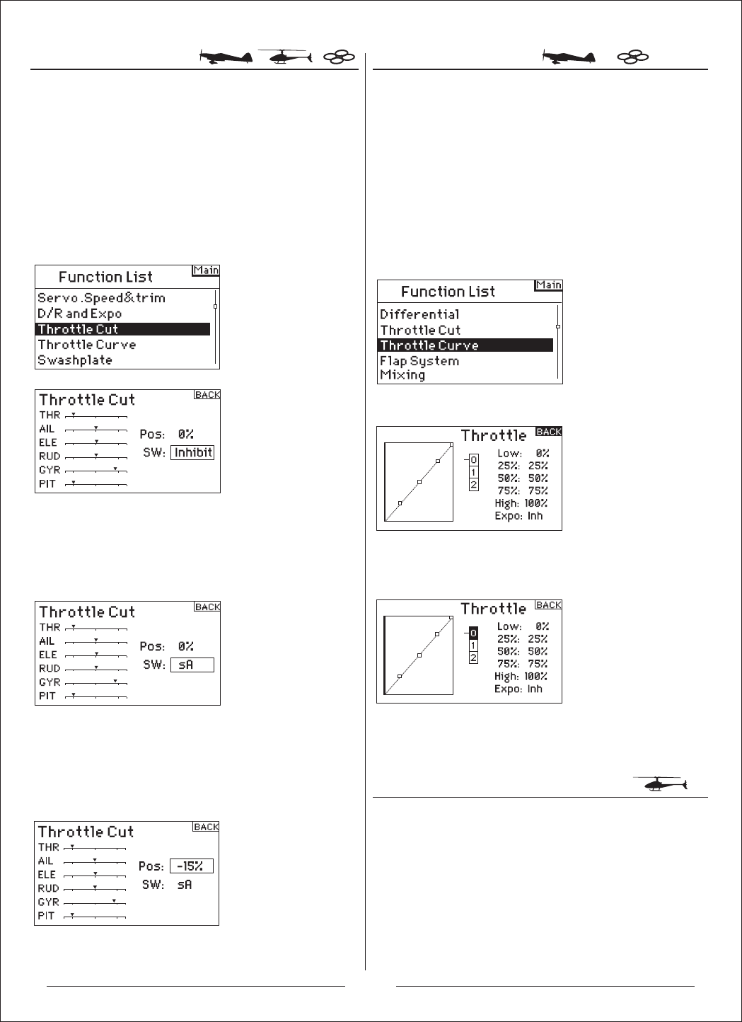
To Activate Throttle Cut and
Assign it to a Switch or Trimmer
Rotate the roller to highlight Throttle Cut then press to
access the Throttle Cut screen.
Highlight Inhibit then press the roller to access the switch
options.
Rotate the roller to the desired switch to cut the throttle
(Trainer, Gear, Mix , L trim or R trim) then press the roller
to program that switch.
Program a Throttle Cut position. Note that 0%= low
throttle, mid trim and negative values are available. To test
the Throttle Cut function, activate the programmed switch.
Note the throttle servo position or the position of the
throttle channel in the servo monitor. The system should
drive the servo position to the low throttle position when
you activate Throttle Cut.
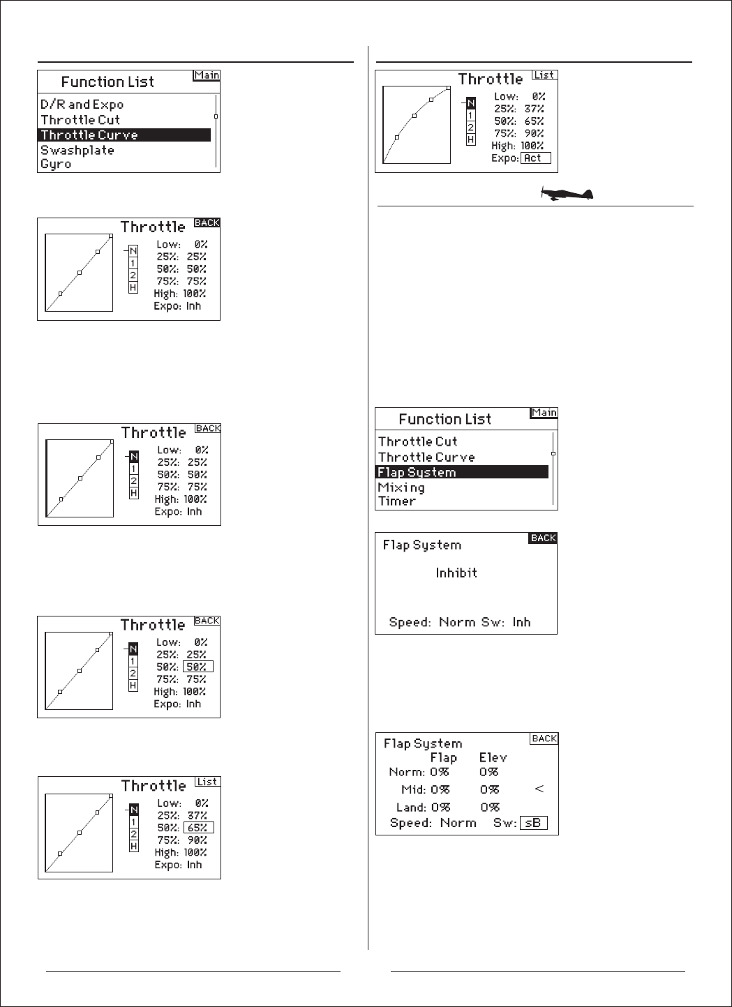
The Throttle Curve function allows throttle output vs. input
positions to be adjusted. This is typically used to alter the
throttle response to give a linear rate or to adjust the
throttle response sensitivity when hovering or torque
rolling. You can program a single curve (switch to On) or
up to three curves and select them via a programmed
switch. The screen displays a graphic 5-point throttle curve
on its left side to aid in selecting throttle curve values. An
Expo function is available that smoothes out the Throttle
curve.
To Program the Throttle Curve Function
With the transmitter on and the main or telemetry screen
displayed, press the roller. The Function list displays
Rotate the roller to highlight Throttle Curve then press the
roller to access the Throttle Curve screen.
With the switch listed at the bottom of the screen in the
position desired for this curve, rotate the roller to highlight
one of the five available throttle curve values (Low, 25%,
50%,75, High). Press the roller to access.
To Activate the Expo Function
Rotate the roller to highlight EXPO then press the roller to
access the Throttle Curve Expo function. Select Inh or Act to
inhibit or activate the Expo function then press to accept.
The AH6T features a 5-point throttle curve. You can assign
up to four separate throttle curves. A graph displays at the
left side of the screen to aid in adjusting throttle curves. An
Expo function is also available that smoothes out the curve.
To Program Throttle Curves
With the transmitter on and the main or telemetry screen
displayed, press the roller. The Function list displays.
18
Flap System
To Activate the Flap Function
To Select a Switch
Setting Flap and Elevator Positions
Selecting a Flight Mode
Adjusting the Curve
To Activate the Expo Function
Rotate the roller to highlight Throttle Curve then press to
access that screen.
Highlight the desired flight mode at the top of the screen
then press the roller to select. The selected flight mode
will darken confirming your selection.
N= Normal / 1= Stunt 1 / 2= Stunt 2 / H= hold
Move the flight mode switch in the position you wish to
adjust. Rotate the roller to highlight one of the five
available throttle curve values (Low, 25%, 50%, 75%,
High). Press the roller to access that value.
Rotate the roller to adjust the selected point to the
desired output position. Note the position on the graph at
the left of the screen.
Repeat this for all desired points.
Rotate the roller to highlight EXPO then press to access
the Throttle Curve Expo function. Select Inh or Act to
inhibit or activate the Expo function. Press the roller to
accept.
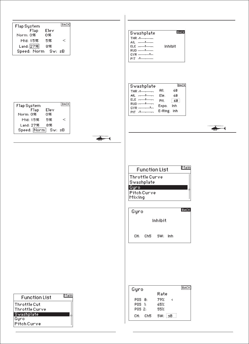
The AH6T flap system offers up to three programmable
flap and elevator positions (normal, mid and land). You
can assign them to a variety of switches. You can
program a Speed function to slow flap and elevator
compensation travel for a scale effect. A graphic display
on the left side of the Flap System screen provides a
visual display of servo position aiding in setting up and
adjusting the flaps.
Notice: The Flap function is only available on wing types
with flaps.
With the transmitter on and the main or telemetry screen
displayed, press the roller. The Function list displays.
Rotate the roller to highlight Flap System then press.
The Flap System defaults to Inhibit. To activate the Flap
System, rotate the roller to highlight Inhibit then press to
access the switch function. Rotate the roller to the
desired Flaps control switch. Press to access that screen.
Rotate the roller to select desired Flap positions value
then press the roller to
access that value. Now rotate to adjust the flap position
value. Note: it is recommended that the flap switch
position match the flap adjustment that
is being adjusted. This will allow you to observe the
effects of the flap adjustment.
19
Swashplate
Gyro
To Access the Swashplate Function
Adjusting the Flap Speed To adjust a Swashplate Value
To Access the Gyro Function
To Select a Switch
Repeat this for all desired Flap and elevator positions
(Normal, mid and land).
Rotate the roller to select Speed then press. Now rotate
the roller to adjust the flap speed. Press the roller to
accept. The flap speed affects the flap and elevator
compensation. The flap and elevator will reach their flap
positions at the same time.
The Swashplate screen adjusts the amount and direction
of travel for the aileron, elevator and pitch functions when
you activate CCPM mixing in Swash Type. This screen
also allows an Expo function that compensates for the
effect of the servo’s rotation at extremes of travel. An
E-ring function also prevents servo over-travel when
simultaneous extreme aileron and elevator inputs are
given. Unless using a linear servo or a type of linkage
that eliminates this effect, you should turn on the Expo
function when any CCPM mix is enabled. Swashplate
values increase or decrease the overall control travel of
the selected channel. For example if you increase Pitch
value, the travel of all three servos that control pitch will
increase. If you increase aileron, the aileron and pitch
servos will increase. Increasing or decreasing this value
affects the travel of that function and not the individual
servo. Note: Negative and positive swashplate values are
available. To achieve the correct travel direction for
Aileron, Elevator and Pitch, first use the reversing
function to set the servo direction on the aileron, elevator
and pitch channels. Do this so that when an aileron input
on the transmitter’s stick tilts the swashplate right and
left, an elevator input tilts the swashplate fore and aft,
and a pitch input raises and lowers the swashplate. You
synchronize the outputs with this function. Then you can
adjust swashplate values positively or negatively to
achieve the overall correct travel direction for aileron,
elevator and pitch.
With the transmitter on and the main or telemetry screen
displayed, press the roller. The Function list displays.
Rotate the roller to highlight Swashplate then press to access.
Highlight the desired function then press the roller to
access.
Use the Gyro function to program and adjust gyro gain.
Rotate the roller to highlight Gyro then press. The
following screen appears:
The Gyro function defaults to Inhibit. To activate the
Gyro function, highlight Inhibit, then press the roller to
access the switch function. Rotate the roller to access
the desired gyro control switch. Press the roller to
access the Gyro gain screen.
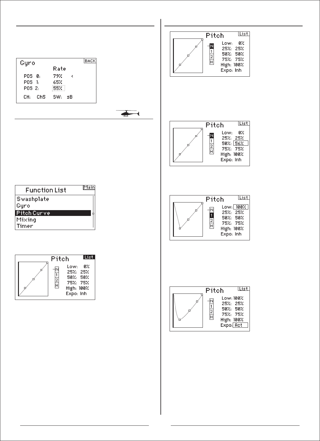
Pitch Curve
To Program Pitch Curves
Selecting a Flight Mode
Adjusting the Rate Values
Rotate the roller to the parameter you need to setup then
press. Adjust the parameter, Repart this to set all
parameter.
The AH6T features a 5-point Pitch curve. You can set up
to four separate Pitch curves. A graph displays at the left
side of the screen to aid in adjusting pitch curves. An
Expo function is available that smooths out the curve.
With the transmitter on and the main or telemetry screen
displayed, press the roller. The Function list displays.
Rotate the roller to highlight Pitch Curve then press.
Highlight the desired flight mode at the top of the screen.
Press the roller to select. The selected flight mode will
darken to confirm the selection.
N= Normal / 1= Stunt 1 / 2= Stunt 2 / H= hold
Adjusting the Curve
Move the flight mode switch in the position you wish to
adjust. Rotate the roller to highlight one of the five
available pitch curve values (Low, 25%, 50%,75%,
High). Press to access that value.
20
Rotate the roller to adjust the selected point to the desired
output position. Note the position on the graph at the left of
the screen.
Repeat this for all desired points.
To Activate the Expo Function
Highlight EXPO then press the roller to access the Pitch
Curve Expo function. Select Inh or Act to inhibit or activate
the Expo function. Press the roller to accept.
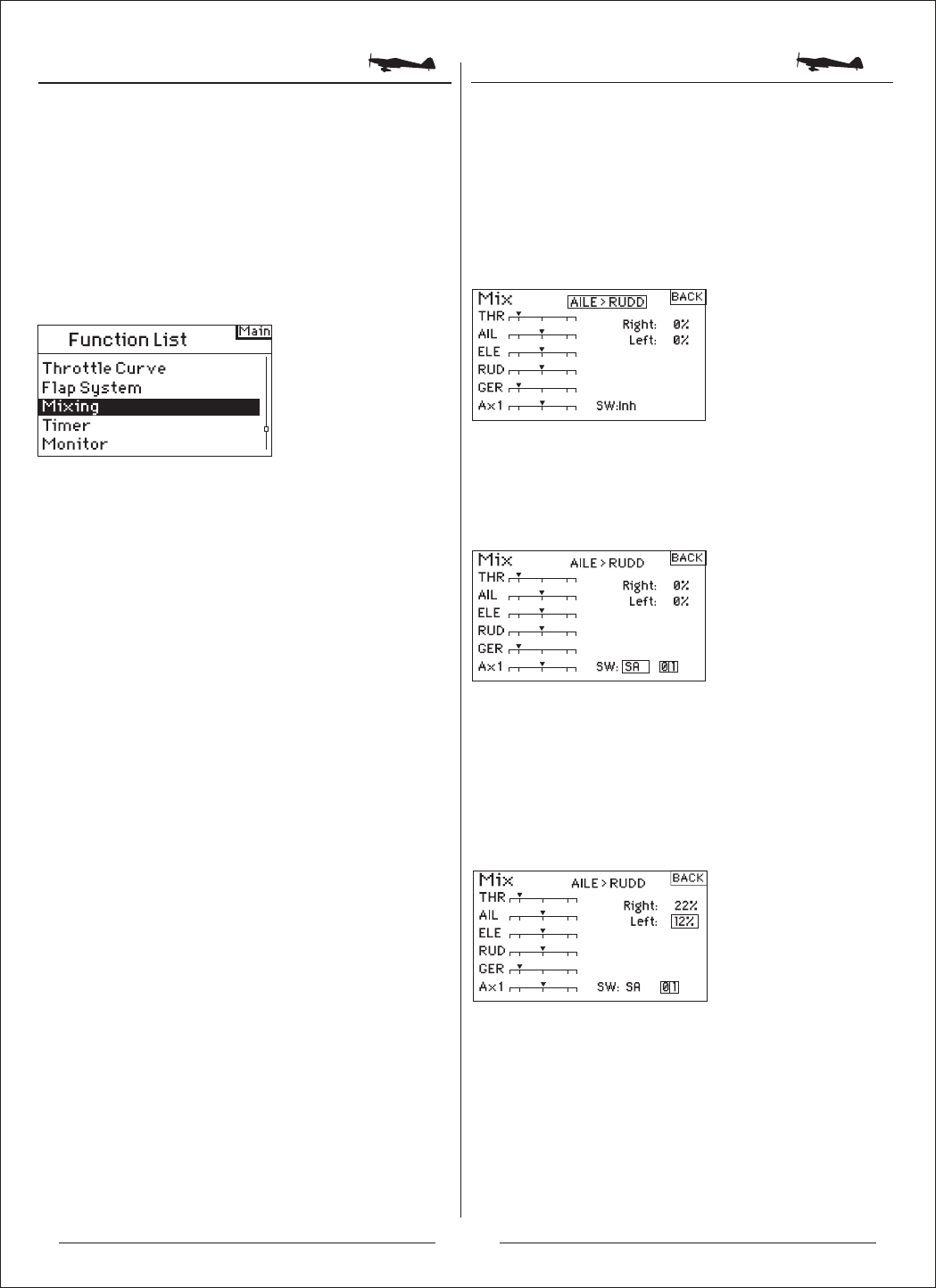
Mixing Aileron to Rudder Mix
To Program Mixing Function
To access Aileron to Rudder Mix
Use Aileron to Rudder mixing to overcome adverse yaw
characteristics with certain types of aircraft such as the J3
Cub and make coordinating turns easier.
If you accessed the flap option in wing type in the system
setup mode, the elevator to flap mix will display. Rotate the
roller to highlight ELE > FLP then press. Now rotate the
roller to select Ail > RUD and press. The aileron to rudder
Mix screen appears.
Assigning Aileron to Rudder Mix to a Switch
Rotate the roller to highlight Sw: at the bottom of the
screen. Press the roller to access the switch select function
then select the desired switch to turn on/off the aileron to
rudder mix. If you select On, the mix will always be on.
Adjusting Aileron to Rudder Mix Rates
Rotate the roller to highlight the rate values then press.
Note that both rates are boxed. Moving the aileron stick
right or left causes the right or left value only to be
highlighted so you can adjust the values individually. Move
the aileron stick in position to highlight the desired rates
then rotate the roller to adjust the value. Note that positive +
and negative - values reverse the direction of the mix.
Press the roller to accept the rate.
Verify the aileron to rudder mix is working properly and in
the correct direction by placing the active switch in the
active position and moving the aileron stick noting the
rudder position. If the rudder moves in the opposite
direction than desired, the opposite value (positive vs.
negative value) is needed.
Note: the Elevator to Flap mix operates in the same fashion as
alieron to rudder mix.
The Ah6T offers eight mixes in airplane model type. There
is an Elevator to Flap mix, Aileron to Rudder mix, and six
user-programmable mixes that allow the mixing of any
channel to any other channel. Programmable mixes
include a trim offset function that adjusts the mix crossover
point and a trim include function that applies the master’s
trim to the slave channel.
Rotate the roller to highlight Mixing then press. The
following screen appears:
21
Mixing
To Access the Mixing Functions
To Access Programmable Mixes (1 thru 6)
Offset
Trim Include
Programmable mixes allow any channel to be mixed to
any other channel or to itself. Popular programmable
mixes include rudder to steerable nose wheel, dual rudder
mix, dual elevator mix, rudder to aileron and rudder to
elevator mix for knife edge correction.
With the Elevator to Flap mix screen displayed, rotate the
roller to highlight Ele > Flp then press the roller. Now rotate
the roller to select programmable Mix, 1, 2, 3, 4, 5, or 6
and press the roller. The Mix screen appears.
The offset function establishes the point at which the two
mix rates converge. Typically this rate is center or 0%. If
an offset is needed do the following:
Rotate the roller to highlight Offset then press the roller to
highlight the Offset rate. Rotate the roller to adjust the
value. Positive + and negative - values are available
shifting the offset in either direction. Press the roller to
accept the offset value.
The trim include function applies trim to the slave channel
when the master channel you select is a channel that has
trim (throttle, aileron, elevator and rudder). Typically, this is
used when more than one channel is used to operate a
primary control surface (dual rudder servos, etc.) With trim
include activated, the master channel’s trim affects the
master and slave channels.
Activating Trim Include
Rotate the roller to highlight Trim. Press the roller to toggle
between INH and ACT.
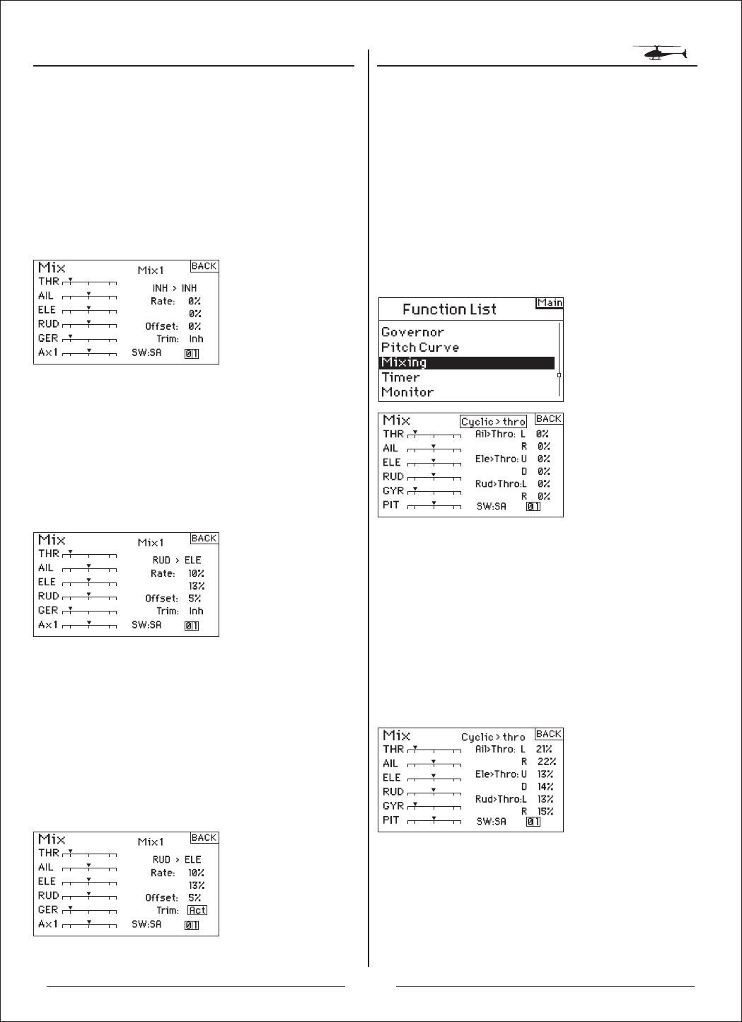
The AH6T offers eight mixes in helicopter model type. You
can program a cyclic-to-throttle mix to advance the throttle
when aileron, elevator and or rudder inputs are given. This
prevents rpm decay during cyclic and rudder inputs. A
Swashplate Mix mixes Aileron to Elevator and Elevator to
Aileron to adjust swashplate timing. Six programmable
mixes allow the mixing of any channel to any other channel.
You can assign Mixes to activate in various flight modes as
well as with the gear switch. Programmable mixes include a
trim offset function that adjusts the mix crossover point and
a trim include function that applies the master’s trim to the
slave channel.
Rotate the roller to highlight Mixing then press. The
following screen appears:
Cyclic-to-Throttle Mix
Cyclic-to-throttle mix prevents rpm decay when aileron,
elevator and or rudder inputs are given. This mix advances
the throttle position with cyclic or rudder control to maintain
rpm. At full throttle, programming prevents the throttle from
overdriving the servo.
Important: When using a governor, Cyclic to throttle mix is
not recommended.
Adjusting Swashplate Rates
Rotate the roller to highlight the desired rate then press.
Rotate the roller to adjust the value. You can reverse the
direction of the slave channel with positive + and negative –
values. Adjust the rate for all desired Swashplate values.
Adjusting Cyclic Mix Rates
To verify that Cyclic mix is working properly and in the
correct direction, place the flight mode switch in one of the
active positions. Move the programmed cyclic or rudder
channel noting the throttle position. The throttle position
should increase. If it decreases then the opposite value
(positive vs. negative) is needed.
22
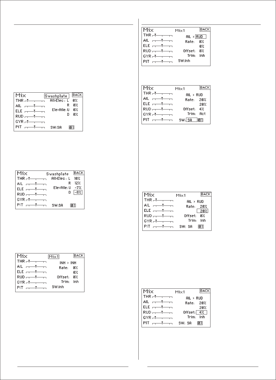
Swashplate Mix
The Swashplate Mix typically corrects swashplate timing
issues by mixing Aileron to Elevator and Elevator to
Aileron. When adjusted correctly, the Swashplate causes
the helicopter to roll and pitch accurately with minimal
inter-reaction.
To access Swashplate Mix
With the C Mix screen displayed, rotate the roller to
highlight Cyclic > Thro then press. Select Swashplate
and press the roller. The Swashplate Mix screen
appears.
Adjusting Swashplate Rates
Rotate the roller to highlight the desired rate then press.
Rotate the roller to adjust the value. You can reverse the
direction of the slave channel with positive + and
negative – values. Adjust the rate for all desired
Swashplate values.
Programmable Mixes
To Access Programmable Mixes (1 thru 6).
With the C Mix screen displayed, rotate the roller to
highlight Cyclic > Thro, then press the roller. Select
programmable Mix, 1, 2, 3, 4, 5, or 6 and press the roller.
The Mix screen appears.
To Select Master and Slave Channels
The Master channel is the controlling channel and is
mixed to the slave channel. The slave channel follows
the master channel’s input based on the rate that is
programmed.
Rotate the roller to highlight the left INH then press to
access the master channel. Select the desired master
channel. Press the roller to accept.
To Select the Switch
Rotate Roller to highlight "SW", and the switch.
Adjusting Programmable Mix Rateas
Rotate the roller to highlight the desired rate then press.
Rotate the roller to adjust the value. You can reverse the
direction of the slave channel with positive and negative
values. Adjust the rate for both directions/values.
You should verify that the programmable mix is working
properly and in the correct direction. Place the flight
mode switch in one of the active positions.
Move the programmed master channel while observing
the slave channel. The slave channel should move
accordingly.
Offset
The Offset function establishes the point at which the two
mix rates converge. Typically, this rate is center or 0%. If
an offset is needed (normally not in a helicopter), do the
following.
Programming an Offset
Rotate the roller to highlight Offset then press. Rotate the
roller to adjust the value. Positive + and negative - values
shift the offset in either direction. Press the roller to
accept.
Trim Include
The trim include function applies trim to the slave
channel when the selected master channel has trim
(throttle, aileron, elevator and rudder). Typically this is
used when more than one channel operates a primary
control surface (dual aileron servos, etc.) With trim
23

Timer
Program AUX
include activated, the master channel’s trim affects the
slave channel’s trim as well.
Activating Trim Include
Rotate Roller to highlight Trim then press to select INH or
ACT.
AUX0 , 1 can customize the output of 10 different states.
Notice : Priority output low position.
To access the Program AUX Function
Rotate the roller to highlight Program AUX then press.
The following screen appears:
Rotate the roller to the channel you need to setup then
press.
Rotate the roller to the channel you need to setup then
press.
Rotate the roller to the channel you need to setup then
press.
after that rotate the roller to adjust the parameter.
Rotate the roller to the switch you need to ues then
press,after that select the relevant switch.
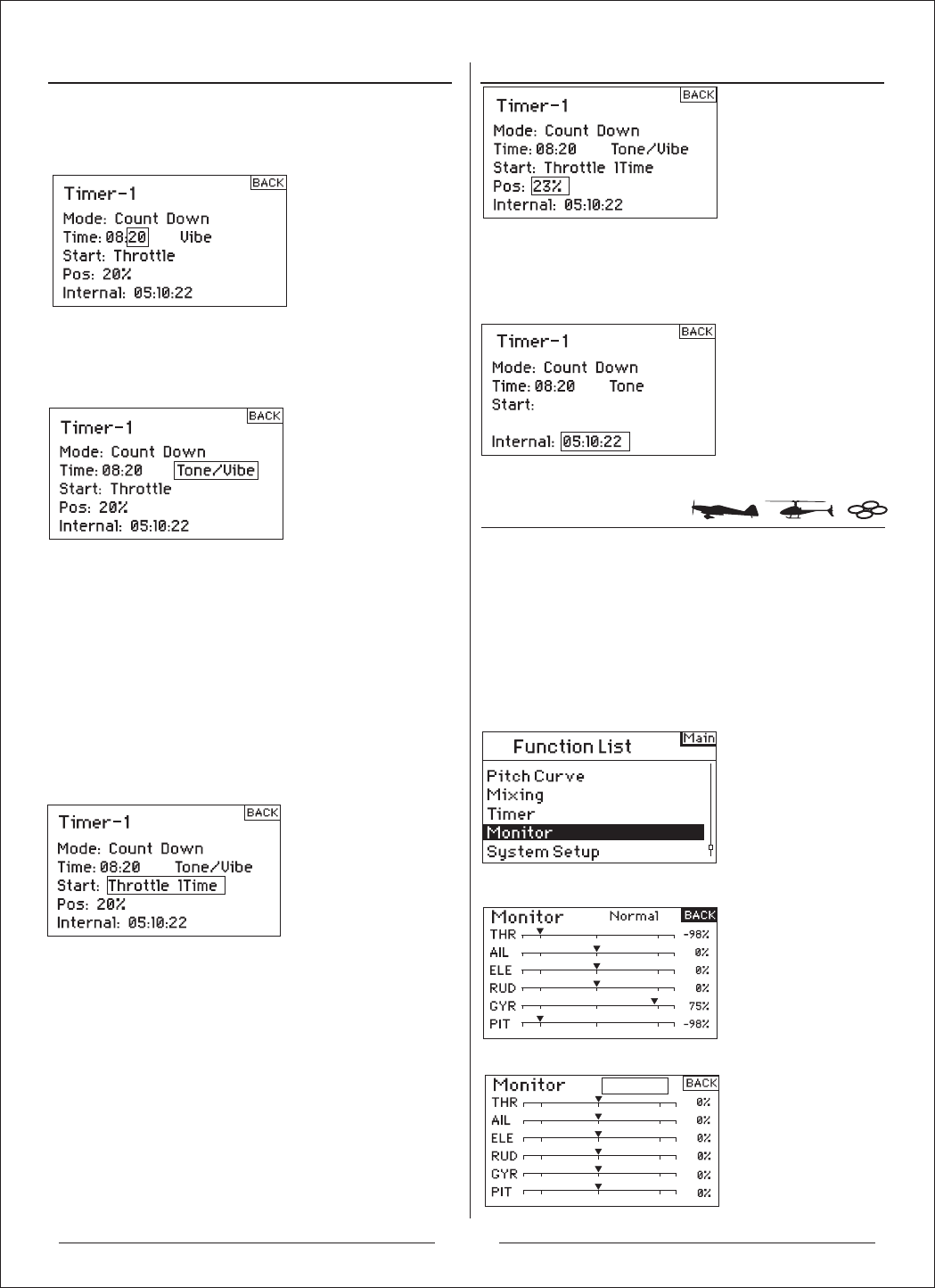
The AH6T Timer function allows you to program a Count
Down timer or Stop Watch (count up timer) to display on
the main screen. An alarm sounds when the programmed
time is reached. You can program the timer to start using
the trainer switch, the left or right trimmers or
automatically when throttle is raised above a
preprogrammed position. Also, an internal timer that
shows run time for a specific model displays on the main
screen.
To access the Timer Screen
With the transmitter on and the main or telemetry screen
displayed, press the roller. The Function list displays.
Rotate the roller to highlight Timer then press.
Rotate the roller to highligh Timer then press, and enter
the function screen.
To select the Timer Mode- Inhibit, Count Down or Stop
Watch. Highlight Mode then press.
Rotate the roller to select the Timer which you want then
press, and enter the function screen.
24
Neutral
Monitor
sA
To Program a Time
Rotate the roller to highlight Time then press to access.
You can highlight the seconds or minutes. Press the roller
to access minutes or second.
Rotate the roller to select the desired time. Press to
accept.
To program a Tone, Vibe, Tone/ Vibe or Inhibit
Rotate the roller to highlight Tone then press to access. You
can Select Inh. Tone, Vibe or Tone /Vibe
To Select the Timer Start Method
Rotate the roller to highlight Start then press to access. Five
start options are available: Trainer switch, Throttle, Throttle
1-Time, L Trim and R Trim.
Throttle 1-time - The timer starts when the programmed
throttle position is exceeded and will continue regardless of
the throttle position.
Throttle - The timer starts when the programmed throttle
position is exceeded. Anytime you lower the throttle below
the programmed position, the timer will pause then continue
anytime the throttle is raised above that position.
Rotate the roller to select the mode need to activate then
press.
Programming a Throttle Stick Position-
Only if Throttle Start is Selected
If you select Throttle or Throttle 1-Time in the Start function,
the Stick appears below Start in the Timer screen. This is the
stick position where throttle activates the timer. Rotate the
roller to highlight Stick then press to access the Stick values.
You can adjust the value from 0 to 100%. This correlates to
the actual throttle stick position.
Rotate the roller to select the desired Stick value then press
the roller to accept the displayed value.
Rotate the roller to select the desired Stick value then press
the roller to accept the displayed value.
There are a couple of ways to reset the internal timer. Rotate
the roller to highlight Internal: Reset then press the roller to
reset the internal timer to 0:00:00
To reset the Count Down or Stop Watch timer on the main
screen, press the Clear button.
The Monitor screen displays the servo positions for each
channel graphically and numerically. This is useful to verify
programming functions, trim settings, mix directions, etc. The
numeric value is directly relative to the travel adjust and mix
values (e.g., 100% travel adjust equals 100% value in the
Monitor).
To Access the Monitor screen
With the transmitter on and the main or telemetry screen
displayed, press the roller. The Function list will display.
Rotate the roller to highlight Monitor then press to
access.
After enter the screen, rotate the roller to test the servo.
25
Mode Changes
A
B
C
D
E
F
MODE 1
Rudder Stick Aileron Stick
MODE 2
MODE 3 MODE 4
Elevator Stick
Throttle Stick
Elevator Stick
Elevator Stick
Throttle Stick
Throttle Stick
Elevator Stick
Throttle Stick
Rudder StickAileron Stick Rudder StickAileron Stick
Rudder Stick Aileron Stick
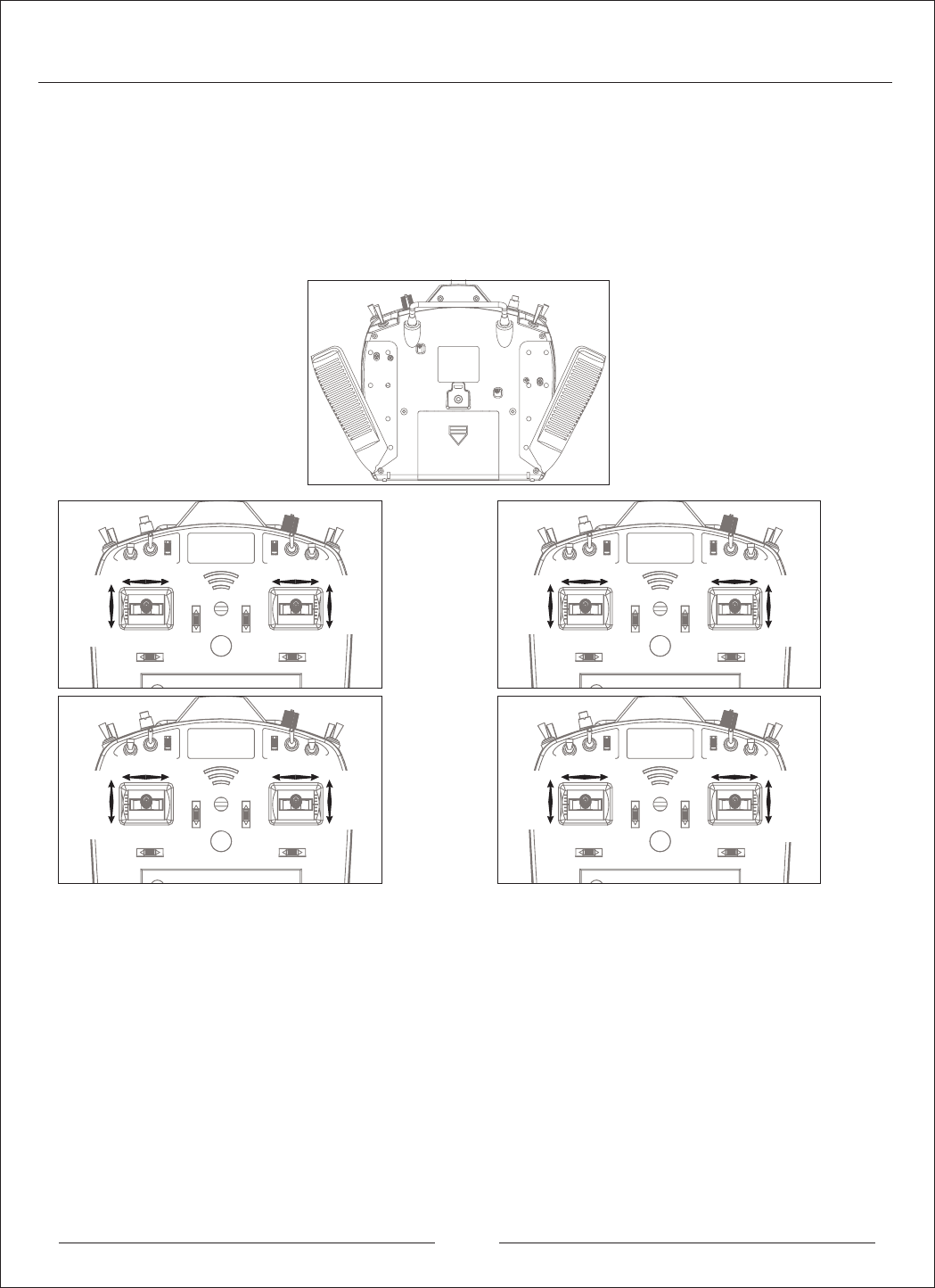
The AH6T can be easily converted to mode 1, 2, 3, or 4. This conversion requires a mechanical and a programming
change. (Stick and switch positions for mode 1 and 2 are illustrated on pages 8 and 9.) Following are detailed instructions
on making mode changes.
Mechanical Conversion
Mechanical conversion is required to switch between modes 1 and 2 or between modes 3 and 4. The centering spring for
elevator and the friction straps for throttle must be engaged on the appropriate gimbal and throttle limiting wedges must
be swapped.
Step 1. Carefully pull back the rear grips and side rubber panels and unscrew the A,B,C,D,E and F head screws shown.
Step 2.
Left Throttle to Right Trottle (Mode 2 / Mode 4 to Mode 1 / Mode 3)
i) Use a cross-drive screw driver to loosen Screw A. Keep loosening until the stick can move up and down without friction.
ii) Tighten Screw B. Keep tightening until the stick can move up and down with rebounds.
iii) Loosen Screw C. Keep loosening until the stick can move up and down without rebounds.
iv) Tighten Screw D. Keep tightening until the stick can move up and down with friction.
Right Throttle to Left Trottle (Mode 1 / Mode 3 to Mode 2 / Mode 4)
i) Use a cross-drive screw driver to loosen Screw D. Keep loosening until the stick can move up and down without friction.
ii) Tighten Screw C. Keep tightening until the stick can move up and down with rebounds.
iii) Loosen Screw B. Keep loosening until the stick can move up and down without rebounds.
iv) Tighten Screw A. Keep tightening until the stick can move up and down with friction.
Step 3. When satisfied with the stick tension, reinstall the grips and rubber plugs.
26
Adjustable Stick Tension
MODE 2
Elevator Aileron
Throttle
Rudder
Programming Conversion
When making a mode conversion, the programming must also be changed and when changing throttle elevator
positions the transmitter must be recalibrated in the systems setting screen.
Adjustable Stick Length
The AH6T allows you to adjust the control stick’s length. Use the included 2mm Allen wrench to loosen the setscrew by
turning it counterclockwise. Then, turn the stick clockwise to shorten or counterclockwise to lengthen. After adjusting the
control stick length tighten the 2mm setscrew.
The AH6T offers adjustable tension on the throttle, aileron, elevator and rudder sticks. Rubber plugs are installed in the
back of the case allowing easy access to the stick tension screws without having to remove the back case.
To adjust stick tension:
To Access the System Settings Function
Highlight System Settings then press the roller to access
the System Settings function. The System Settings
screen will appear.
When changing modes that swap throttle and elevator
positions it’s necessary to recalibrate the sticks. When the
mode change is programmed, the calibration screen will
automatically appear the next time the transmitter is turned
on and the following screen appears:
To calibrate, move the sticks throughout their range then
back to center including the throttle. Once all sticks have
been centered, press SAVE to complete calibration.
Step 1. Remove the two rubber plugs and pull back the grips as shown to access the
throttle, aileron, elevator and rudder tension screws.
Step 2. Using a Phillips screwdriver, adjust the stick tension screw for the desired
control. Clockwise to tighten and counterclockwise to loosen.
Step 3. When satisfied with the stick tension, reinstall the grips and rubber plugs.
27

FCC Statement:
This equipment has been tested and found to comply with the limits for a Class B digital
device, pursuant to part 15 of the FCC Rules. These limits are designed to provide
reasonable protection against harmful interference in a residential installation. This
equipment generates, uses and can radiate radio frequency energy and, if not installed and
used in accordance with the instructions, may cause harmful interference to radio
communications.
However, there is no guarantee that interference will not occur in a particular installation. If
this equipment does cause harmful interference to radio or television reception, which
can be determined by turning the equipment off and on, the user is encouraged to try to
correct the interference by one or more of the following measures:
• Reorient or relocate the receiving antenna.
• Increase the separation between the equipment and receiver.
• Connect the equipment to an outlet on a circuit different from that to which the
receiver is connected.
This device complies with part 15 of the FCC rules. Operation is subject to the following two
conditions: (1) This device may not cause harmful interference, and (2) this device must
accept any interference received, including interference that may cause undesired operation.
Note: Modifications to this product will void the user’s authority to operate this equipment.
感谢您选择GWY的产品。为了让您能够更好的了解和使用这台AH6T发射机,我们衷心的希望您认真地阅
读完这本说明书之后再进行相关操作,并请妥善保管以备后用。
如需了解更多资讯,请访问官方网址:www.zondahobby.com / www.zondahobby.com.cn
前言
标志说明
安全注意事项和警告
飞行前检查
重要声明
禁 止
禁 止
在任何禁止的环境下,请勿尝试操作。
警 告 因为疏忽这些操作说明,而使用错误可能造成财产损失或严重伤害。
注 意 因为疏忽这些操作说明,而使用错误可能造成危险。
遥控模型是通过无线电信号控制的,在操作时,可能会受到其它无线电信号的干扰,此干扰可能会导
致直升机失控。
警 告
遥控模型不是玩具!为避免危险事故的发生,请勿随意操作遥控模型,模型商品必须在当地政府允许和
规定的情况或条件下使用。消费者自购买当日起即承担该模型使用的一切风险,产品售出后GWY将不负任何
操作和使用控制上的任何性能与安全责任。也无法对消费者零件使用的损耗异常或组装不当所发生的意外负
任何责任.为了您的切身安全,GWY建议模型新手在操作之前,请咨询或求助于专业模型玩家或当地的模型店。
模型产品包含部分消耗零件,反复拆装、长期使用会造成零部件损耗,属于正常范围。请定期检测并更
换损耗配件,以确保安全飞行。在购买配件时,如果您所购买的不是GWY原装产品,可能会导致遥控模型性
能不匹配、甚至不能正常运行等问题,本公司对此概不负责。
请妥善保存该产品的说明书,以协助您顺利的进行直升机的调整、维修等作业。
1.遥控模型不是玩具!具有一定的危险性,禁止14岁以下人士进行操作!
2.遥控模型在存放与飞行时,需要远离高温环境或其他具有腐蚀性的化学物品!(使用温度范围:-10℃到50℃)
3.初学者请勿独自操控!初次飞行时最好请有经验的飞行员进行指导之后再进行飞行,请避免相同频率的
模型直升机同时飞行。
4.开机前请将油门摇杆及油门微调打到最低点。开关机时请务必遵守开关机的顺序,开机时请先开发射机
电源,再接通直升机电源;关机时请先断开直升机电源,然后再关闭发射机电源。
1.飞行时应该远离高压线或其他影响飞行的建筑物,避免操控不当造成自己与他人财产的损失!
2.飞行时要远离人群,避免旁人围观!以免误伤他人!
3.不要在遥控器电力低时,操控模型。
4.请勿在下雨、打雷、阴天或是视线不清楚的天气进行飞行,以确保本身及直升机的安全!
5.遥控内部是由许多精密的电子零件组成,所以必须绝对的防止潮气或水气,避免在浴室或雨天时使
用,防止不气进入机身内部导致机件及电子零件故障而引发不可预期的意外!
6.请勿自行改造加工,任何的升级改装或维修,请使用GWY产品目录中的零件,以确保结构的安全。
1.检查遥控器和接收机电池组电压,遥控器低于4.3伏特或接收机低于4.7伏特时,请勿飞行。若低于此限
制,飞机会坠毁。注意:当您检查电池时,确认扩充电压表的正负极是正确的。
2.每日飞行前,检查所有硬件(连接装置、螺丝、螺帽和螺栓)。确定所有零件都正确锁紧。
3.启动飞机前,先关闭遥控器,然后重新打开。每次启动飞机时都要这么做。如果任何开关在不知情的
情况下打开,这时遥控器的警示器会警告您。
4.检查所有微调杆设于正确的位置。
5.所有舵机连接线和开关线束插头应该要固定在接收机上。确定开关线束在两个方向可以随时移动。
2

目录
检查包装物及配件
发射机各部位介绍介绍
按键与屏幕功能
数位微调
无动作警示
电池警示及屏幕
编程警示
AH6R/AH6RS接收机
安装接收机
对码操作
安全保护
保留最后指令安全保护
预设安全保护
系统设定
进入系统设定菜单
机种模式选择(直升机、飞机、多旋翼)
机种型式(直升机、飞机、多旋翼)
模型名称(直升机、飞机、多旋翼)
机翼型式选择(飞机)
开关选择(飞机)
倾斜盘模式(直升机)
开关选择(直升机、多旋翼)
微调设置(直升机、飞机、多旋翼)
模式重设(直升机、飞机、多旋翼)
复制模式(直升机、飞机、多旋翼)
警告(直升机、飞机、多旋翼)
功率设定(直升机、飞机、多旋翼)
可编程教练(直升机、飞机、多旋翼)
信号丢失保护(直升机、飞机、多旋翼)
系统设定(直升机、飞机、多旋翼)
4 14
14
15
15
15
16
17
17
17
18
19
19
20
21
21
22
24
24
25
26
27
5
6
6
6
6
6
6
7
7
7
7
7
8
8
8
9
9
9
10
10
10
10
11
11
12
12
12
13
13
功能模式
正反舵(直升机、飞机、多旋翼)
行程调整(直升机、飞机、多旋翼)
速度&辅助微调(直升机、飞机、多旋翼)
双重比率和感度指数(直升机、飞机、多旋翼)
副翼差动(飞机)
关闭油门(直升机、飞机、多旋翼)
油门曲线(飞机、多旋翼)
油门曲线(直升机)
襟翼系统(飞机)
倾斜盘(直升机)
陀螺仪(直升机)
螺距曲线(直升机)
混控(飞机)
副翼-方向舵混控(飞机)
混控(直升机)
可编程辅助通道(多旋翼)
定时器(直升机、飞机、多旋翼)
监控(直升机、飞机、多旋翼)
更换模式
调整摇杆松紧度
3
检查包装物及配件
打开包装盒后,请先检查整机与附送配件是否齐全,若有遗漏,请向所销售单位反映,索取。
1
2 3
1
1. AH6T 2.4G六通道发射机
2. L型螺丝扳手
3. 吊带
1
1
4

发射机各部位介绍
天线
指示灯
旋钮
开关 E
开关 C
开关 B
开关 A
开关 D
对码按钮/开关 I
开关 H
开关 G
开关 F
电源开关
LCD显示屏
左橡胶握手
右橡胶握手
清除按钮
返回按钮
蜂鸣器
滚轮
1
1
2
3
4
5
6
7
8
9
10
11
12
13
14
15
16
17
18
19
20
21
22
23
24
25
26
3
5
4
2
6
7
8
9
11
10
12
13
14
15
16
17
18
19
20
21
22
23
24 25
26
Mode 1 升降及方向摇杆
Mode 2 油门及方向摇杆
Mode 3 升降及副翼摇杆
Mode 4 油门及副翼摇杆
Mode 1 油门及副翼摇杆
Mode 2 升降及副翼摇杆
Mode 3 油门及方向摇杆
Mode 4 升降及方向摇杆
Mode 1/Mode 3油门微调
Mode 2/Mode 4升降微调
Mode 1/Mode 2副翼微调
Mode 3/Mode 4方向微调
Mode 1/Mode 2方向微调
Mode 3/Mode 4副翼微调
Mode 1/Mode 3升降微调
Mode 2/Mode 4油门微调
5
按键与屏幕功能
编程警示
AH6R/AH6RS接收机
AH6R接收机
(JR连接头)
AH6RS接收机
(JST 1.5mm连接头)
数位微调
无动作警示
数据错误警示
注意:请根据不同的连接线选择相应的接收机。
接收机规格参数:
1)输入电源:DC4.8-6V
2)工作电流:P$
3)调制方式:GFSK
4)无线工作模式:FHSS(跳频)
5)工作带宽:2406MHz--2476MHz
6)频道分辩率:1MHz
7)空中波特率:250KHz
8)数据刷新频率:11ms
9)符合CE,FCC安规认证要求
AH6T的滚轮功能可以选取列表。另外,清除键和返
回键可以用来操作所有功能。
按下清除键,就会将选择的设定值回复到默认值。
按下返回键,可以返回前一个画面。
转动滚轮,就可以使用屏幕上的功能。将滚轮按住,
调整设定值或是选取选项。
AH6T 2.4G 可以调数字微调。主画面显示微调的位
置。其中包含油门/副翼、升降/方向微调。当操作左
右侧微调时,会响起哔一声及停顿一下。您可以在
微调设置(Trim Setup)调整以上的微调功能,在系统
设定可以找到此选项。
注意:当摇控器关机时,微调及左右微调设置值会储
存于内存中,并于系统开机后重新叫出。
System is inactive!
Flash data be damaged
reboot automatically repair
Throttle high
WARNING
F MODE 2
AH6T配有无动作警示功能,用来防止遥控器待机浪
费电量。若遥控器待机,动一下摇杆及按键,无输
入任何指令长达用户预设的时间,警示就会响起,
并在屏幕上出现警告。动一下摇杆或按键,就可以解
除警报。通常RF调制会持续警示,维持RF连结。
如果摇控器非法关机或意外断电,损坏内部存贮的数
据,开机就会显示如下警示界面,重新开机可自动修复。
电池警示及屏幕
当遥控器电压低于4.3伏特时,"低电量警示"就会闪烁,
并发出警示音。若操控飞机时有上述情形发生,请立
即降落。
AH6T拥有编程警示的功能。当摇控器开机时,摇杆或
按键的位置不正确或不安全,这个功能就会启动。在
飞机模式中,编程警示包含高油门,以及起落架/mid/
降落襟翼位置。而在直升机模式中,则包含油门杆太
高、特技1、特技2,以及油门固定。若遥控器开机时,
摇杆或按键的位置不正确且安全,警示音及警示画面
就会出现,此情况下,遥控器无法传送讯号。将摇杆
或按键的位置调整成安全理想位置,就不会有警示,
也可正常运作。
6

安装接收机
接收机电源需求
对码操作
安全保护
保留最后指令安全保护
预设安全保护
使用汽油与甲醇发动机飞机时,用保护泡棉把主接
收机包好,并用橡皮筋,或钩子、吊条将之固定住。
使用电动飞机或直升机,您可用厚双面泡棉胶带固
定接收机。注意,飞机有很多材质容易导电(例如:
较大型汽油发动机, 碳纤维, 导管等),讯号可能会
减弱。
注意:接收机天线尽可能的远离电源线,最理想的
是天线相互垂直。
当系统完全负载时,机载电源系统提供无中断的足够
电力是重要的(舵机最大的飞行负荷)。不足的电源系
统是造成肇事的主因。一些电源系统零件会影响适机
载传输足够电力,包含:挑选的接收机电池组(一些电
池、电容、电池种类、充电状况)、开关线束、电池
引线(如果有使用)、调节器(如果有使用)。AH6R最小
的操作电压3.5伏特。地面测试时,以下的指南可以
接受的最低电压为4.8伏特。这会弥补电池放电或大
于地面测试负载的实际飞行负载。
接收机在操作前一定要先与遥控器对码。对码是要让
接收机知道遥控器的特定代码,所以它会连接特定的
遥控器。
1.将对码插头插入接收机的对码插槽。
2.打开接收机开关。接收机的LED灯会亮,表示接收
机已与遥控器连接。
3.设定想要的故障安全防护操纵杆位置(通常为低油
门和飞行控制中枢)。
4.打开发射机电源时,按住"对码"按钮(开关"I")。
5.系统在几秒内就会连接。接收机的LED灯会亮,表
示系统已连接。
6.将对码插头从接收机连接插槽拔除。关掉遥控器,
并把对码插头放置方便拿取的地方。
注意:拔除对码插头,以预防下次开机时,系统显
示为对码模式。
7.设定模式后,重新链接系统是很重要的,因此低油
门和中枢控制面位置才能被设定。
当你连结遥控器时,你正将安全保护系统与接收机做
默认。若遥控器与接收机失去连结,接收机会立即启
用预设,也就是安全保护。AH6R有三个安全保护:
SmartSafe安全保护、保留最后指令安全保护,以及
预设安全保护。
SmartSafe安全保护在保留最后指令安全保护与默认
安全保护中执行。SmartSafe是油门通道的特色,提
供下列好处:
防止只有接收机开机时,电动马达突然启动(无讯号)。
防止变速器启动。直到链接后,才变成低油门位置。
当讯号消失时,可以关闭电动马达及让汽油/甲醇发
动机怠速。
油门低于标准,变速器不会启动。
若飞行时,失去连结:
-在接收机固定时,SmartSafe设定油门为正确位置。
如何编程:
当设定保留最后指令与默认安全保护或系统链接时,
SmartSafe会被自动设定。注意:在连结时,把油门
杆调为低油门位置以维持低油门是重要的。
测试:
将遥控器关机,以确认安全保护设定是否正确。油门
应会跑到默认的低油门位置。
特别注意:请确认您的飞机是在地上。若安全保护没有
设定,飞机的油门位置可能会变成中段或全满。
若您失去链接,所有信道外只有油门信道保留最后指
令,且飞机还是持续飞行。因此,若失去连结,您的
飞机还是可以继续飞行。
如何编程:
1.将连接插头在链接过程中插在连接插槽。
2.在接收机与遥控器链接后,拔除连接插头。
测试:
将遥控器关机,以确认安全保护设定是否正确。所有
通道外只有油门信道保留最后指令。
特别注意: 请确认您的飞机是在地上。若安全保护没
有设定,飞机的油门位置可能会变成中段或全满。
若讯号消失,所有通道会转成接收机连结时的安全保
护位置。
预设安全保护很适合用于滑翔机,当讯号消失时,阻
流板会启动,以防飞机飞走。
如何编程:
1.把连接插头接上接收机,并打开开关。
2.连接器LED灯闪烁,显示固定模式,先拔除连接插
头。再将遥控器与接收机连结。
7
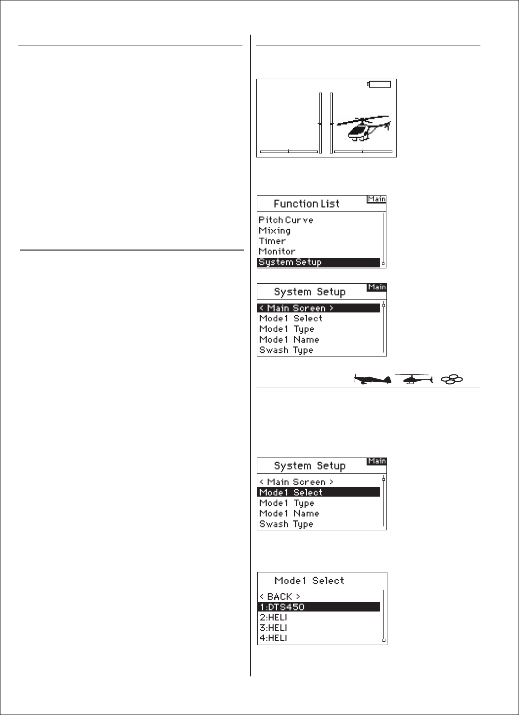
进入系统设定菜单
机种模式选择
系统设定
[Normal]
0:00
3.LED灯会持续闪烁。
4.将遥控器的摇杆及按键设为理想的默认安全回复位
置,并将之调成固定模式。
5.系统链接时间应少于15秒。
注意:任何接收机有所不同,安全回复也不大一样,
若使用AH6R或AH6RS以外的接收机,请参照接收机
手册。
飞行前,随时确认接收机固定是否正确以及安全回
复是否设定。您可以确认您的系统是否链接,关掉
遥控器。确认是否为低油门位置。
特别注意:请确认您的飞机是在地上。若安全回复没
有设定,飞机的油门位置可能会变成中段或全满。
AH6T有两个编程分类:系统设定模式及功能模式。
系统设定模式的编程通常用于设定机种。其中包含:
机种型式、模式名称、机翼型式选择、(直升机倾斜
盘型式),机种重设等。注意:于系统设定模式时,会
没有无线电传输,以防止舵机意外运作。在编程变
换时,这可以让舵机起落架不会损害。飞机、直升机
和多旋翼的系统设定模式如下:
飞机系统设定模式
Model Select
Model Type
Model Name
Wing Type
Switch Select
Trim Setup
Model Reset
Model Copy
Warnings
Power Settings
Trainer
Fail Safe
System Settings
多旋翼系统设定模式
Model Select
Model Type
Model Name
Swash Type
Switch Select
Trim Setup
Model Reset
Model Copy
Warnings
Power Settings
Trainer
Fail Safe
System Settings
直升机系统设定模式
Model Select
Model Type
Model Name
Swash Type
Switch Select
Trim Setup
Model Reset
Model Copy
Warnings
Power Settings
Trainer
Fail Safe
System Settings
按一下发射机电源开关,打开发射机,进入发射机主
界面。
按一下滚轮键,进入功能模式菜单,通过滚轮键选择
菜单“System Setup”,选择“YES”进入系统设计模式菜单。
机种模式选择可用来改变不同模式记忆,从目前的模
式变成另一个。AH6T可以储存高达20个模式记忆。
进入系统设计模式菜单后,选择机种模式菜单,并
按下滚轮,进入该选项:
出现下面画面。滚动滚轮,以选择所需模式,并按下
滚轮,选取模式。机种模式的名称会出现在主屏幕中。
1:HELI 5.5V
T1:
0:00
T2:
8

机种型式
机种型式是用来选择直升机、飞机及多旋翼的编程。
首次设定新模型时可以选择机种型式。注意:您可以
分配机种型式给每个内存。
进入机种型式
进入系统设计模式菜单后,选择机种型式菜单,并
按下滚轮,进入该选项:
选择此项后,会出现以下界面,滚动滚轮,选择欲选
的字,按下滚轮选取。重复上述步骤,以命名名称。
您在主画面会看到设好的名称。按下清除键就可以删
除目前名称的字。
使用机翼型式选择,您可以调整飞机的机翼及尾翼混
控。共有四种机翼型式(标准、双副翼、升降舵、双
襟翼、)以及两种尾翼型式(标准、V尾翼、)。在设定
其他机翼或尾翼相关编程(襟翼、行程调整、辅助微
调等)前,您必须选择飞机的正确机翼及尾翼型式。
选择此项后,会出现以下界面,滚动滚轮,选择所需
的机种型式(直升机、飞机或多旋翼),并按下滚轮,
选取模型。
选择此项后,会出现以下界面,滚动滚轮选择机翼型
式选择,按下滚轮进入该选项。用滚轮选择欲选的机
翼混控,并按下滚轮选取。
滚动滚轮,选择尾翼型式选择,按下滚轮进入该选项。
用滚轮选取欲选的尾翼型式,并按下滚轮选取。
选择YES选项,并按下滚轮选取此机种模式。选取
NO,则会返回之前的画面。
您可以用模型名称的功能,为模型命名可达十个字数
的名称。这可以让您更容易辨别及选取模型。一开始
系统设定时,通常会为模型命名。您可以随时变更名
称,且不会影响到其他编程。
进入系统设计模式菜单后,选择模型名称菜单,并
按下滚轮,进入该选项:
注意:当您切换机种模式时(直升机转飞机或飞机转直
升机),目前选取的模式内存会重设,变为默认值。
所有先前的设定会消失。
机翼型式选择
模型名称
进入系统设计模式菜单后,选择机翼型式菜单,并
按下滚轮,进入该选项:
进入机翼型式选择
进入尾翼型式选择
9

开关选择
倾斜盘模式
开关选择
开关选择用于分配开关、旋钮,以及左右微调杆给起
落架、油门保持、油门曲线。
编程开关选择
开关选择用于分配开关、旋钮,以及左右微调杆给起
落架、油门保持、油门曲线。
编程开关选择
微调设置
进入系统设计模式菜单后,选择开关选择菜单,并
按下滚轮,进入该选项:
进入系统设计模式菜单后,选择开关选择菜单,并
按下滚轮,进入该选项:
进入系统设计模式菜单后,选择微调设置菜单,并
按下滚轮,进入该选项:
滚动滚轮,选择欲选开关、旋钮,或是微调杆,并按
下滚轮。
选择您想指定的通道或功能。您可由列表中选择选项。
按下滚轮接受选择。重复上述动作,选取全部欲选的
开关位置。
微调设置用于调整舵机运作,每次按下微调就可以做
调整。比如说:新的模型,通常是使用大的微调调整
(八到十)。只要每按一次,就会有大幅度的微调行程,
当飞行时失去失衡时,您可以藉此立即调整。您也可
以使用适当幅度的微调(一到五),来调整为更精确的
飞行。微调设置能让任何飞行模式的微调更一般或独
树一格。由于微调会自动启动,许多直升机玩家会使
用独特的微调。重点:微调设置不会影响所有微调行
程,只有微调次数会影响。若您选择的设定值为零,
微调就会关闭。
进入系统设计模式菜单后,选择倾斜盘模式菜单,并
按下滚轮,进入该选项:
滚动滚轮,选择所需的开关、旋钮或微调杆,并按下
滚轮进入选项:
滚动滚轮选择您希望使用的开关、旋钮或微调杆信道
或功能,按下滚轮选取。信道或功能只能分配一次。
重复上述动作,选取全部欲选的开关位置。
使用倾斜盘型式,您可以调整直升机的倾斜盘混控。
共有六种倾斜盘型式(标准、3-servo 120 CCPM、
3-servo 140 CCPM、3-servo 90 CCPM、3-servo
135 CCPM,以及2-servo 180 CCPM)。在设定其他
倾斜盘编程(螺距曲线、行程调整、辅助微调等)前,
您得选择直升机的正确倾斜盘型式。
进入倾斜盘模式
滚动滚轮,选择所需倾斜盘混控模式。
当欲选的倾斜盘混控出现在屏幕上,按下滚轮选取。
在系统设定画面时,选择使用者名称,并按下滚轮选
取该功能。选取欲选的模式,并按下滚轮,使用该功
能。
进入微调设置
10
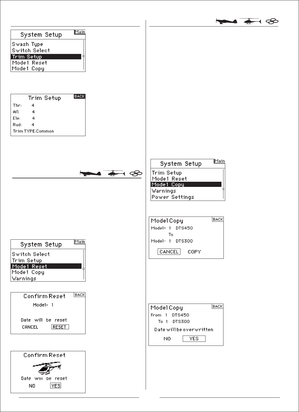
复制模式
模式重设
HELI
进入系统设计模式菜单后,选择模式重设菜单,并
按下滚轮,进入该选项:
滚动滚轮,选择微调设置,并按下滚轮,就会出现该
选项。会出现下面画面:
就会出现该选项。会出现下面画面:
就会出现该选项。会出现下面画面:
确定画面中的模式是您想要复制的。若不是,请参照前
面模式机种模式选择。滚动滚轮,选择模式内存(1到
20),模式就会被复制。若欲选的模式内存出现在画面
上,按下滚轮,确认复制的画面就会出现:
按下滚轮,复制这个模式到选择的模式内存。复制完成
后,会回到主画面。原先复制的模式内存会被选择。
选择欲选的微调值,并按下滚轮,选择设定值。滚动
滚轮,变更微调值。按下滚轮,并选取设定好的值。
重复上述动作,调整所有微调幅度。
模式重设一般用于清除不再使用的模式编程。这可以
重新设定选择的模式,调回默认值。并不会影响其他
模式内存。若重设模式,则该模式的编程就会永久删
除且不能恢复。
进入模式重设
进入系统设计模式菜单后,选择复制模式菜单,并按下
滚轮,进入该选项:
进入复制模式
确定画面中的模式是您想要重设的。滚动滚轮,选择
重设,并按下滚轮,接受确认。
复制模式用于目前选择的模式编程。有二十个模式内存
可用。一些常用的复制模式功能包含:
可以移动内存的模式次序,按照种类及型式整理等。
附注:移动模式后,您须要重新固定装置。
飞机编程时,可以复制原先的设定。附注:若您想要以
同样的模式另外复制两个模式,您必须重新固定装置。
复制目前的模式编程至相似的新模式。许多玩家认为
这是个好方法,可以准确编程新模式。比方说, Vibe
50 w/120CCPM混控、陀螺仪和调速器编程,可以提
供不错的编程给其他甲醇动力的120CCPM混控直升机。
注:要被复制的模式会被取代,目前的编程会被永久删除。
11
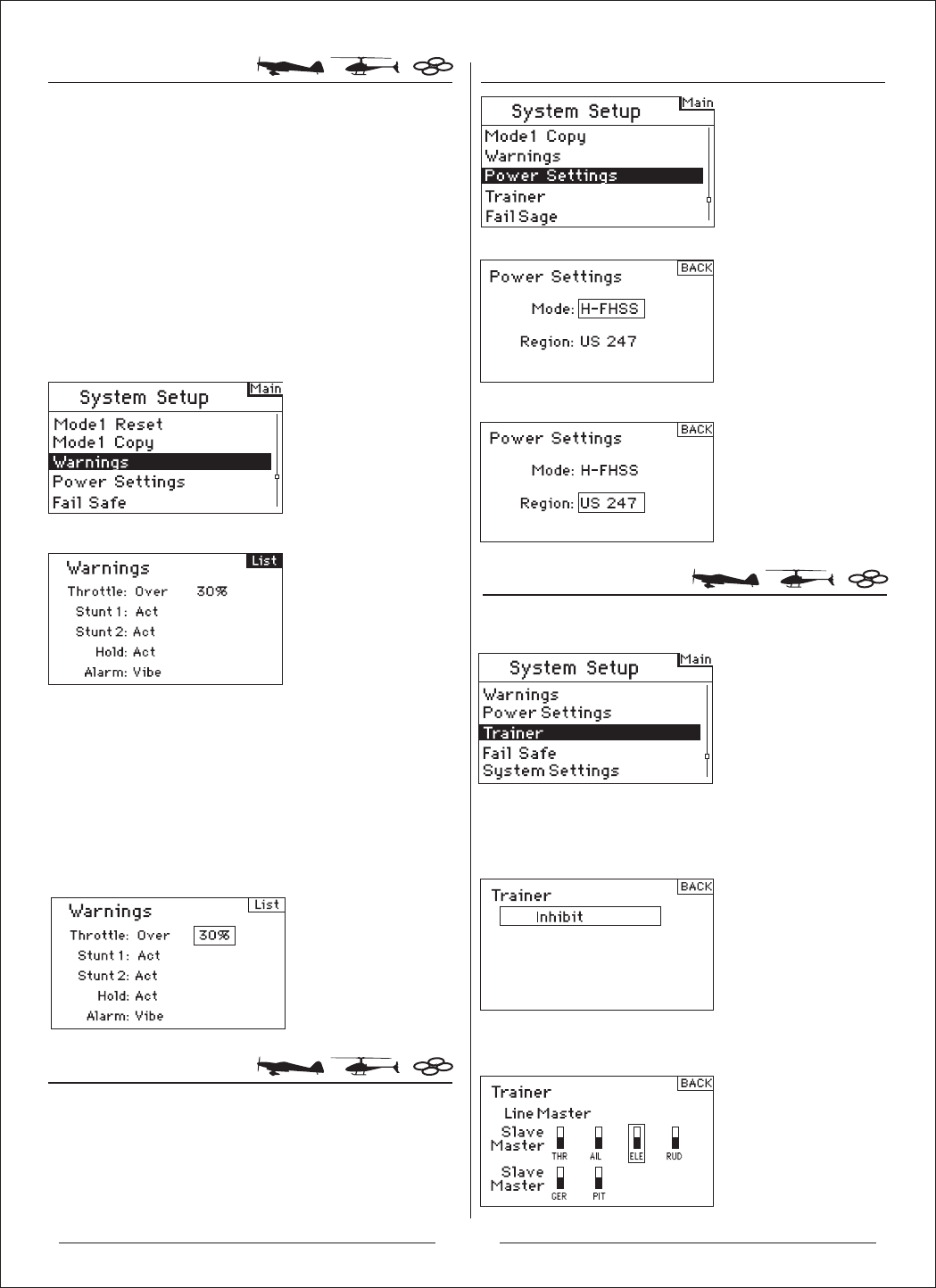
警告
可编程教练
功率设定
就会出现该选项。会出现下面画面:
滚动滚轮,选择相应模式并按下,会出现下面界面:
滚动滚轮,选择需要打开的教学通道并按下,会出现
下面界面:
Inhibit:禁用 Line Master:有线教练模式
Wireless Master:无教练模式 Slave:学员模式
选择欲选的警告(飞机模式下可选用:油门、特技1、
特技2,或油门固定、油门、襟翼、起落架、飞行模
式1和飞行模式2),并按下滚轮选择。现在滚动滚轮,
关闭或启动选择的警告。将遥控器关机,以确认警
告是否运作,并将选择的开关或油门杆调到不正确的
位置,再打开遥控器。警告音会响;屏幕会显示警告,
也没有任何调制发生。
进入系统设计模式菜单后,选择功率设定菜单,并按下
滚轮,进入该选项:
此菜单可设置发射机工作区域,高频工作模式。
进入功率
进入系统设计模式菜单后,选择警告菜单,并按下滚
轮,进入该选项:
进入系统设计模式菜单后,选择可编程教练菜单,并
按下滚轮,进入该选项:
进入Mode可设置发射机工作模式:
进入警告
警告功能用于警示遥控器开机时特定开关或摇杆位置
不正确或安全。直升机模式中,默认的警告包含:油
门、特技1、特技2,和油门固定。飞机模式中,警告
则包含:低油门位置、襟翼、起落架、飞行模式和飞
行模式2。若遥控器开机时,任何开关或摇杆没有在
低位置,警告音就会响起;屏幕会出现警告,也不会
有讯号传送。等到摇杆或开关回到正确位置,警告才
会解除。
进入Region可设置发射机工作区域:
12
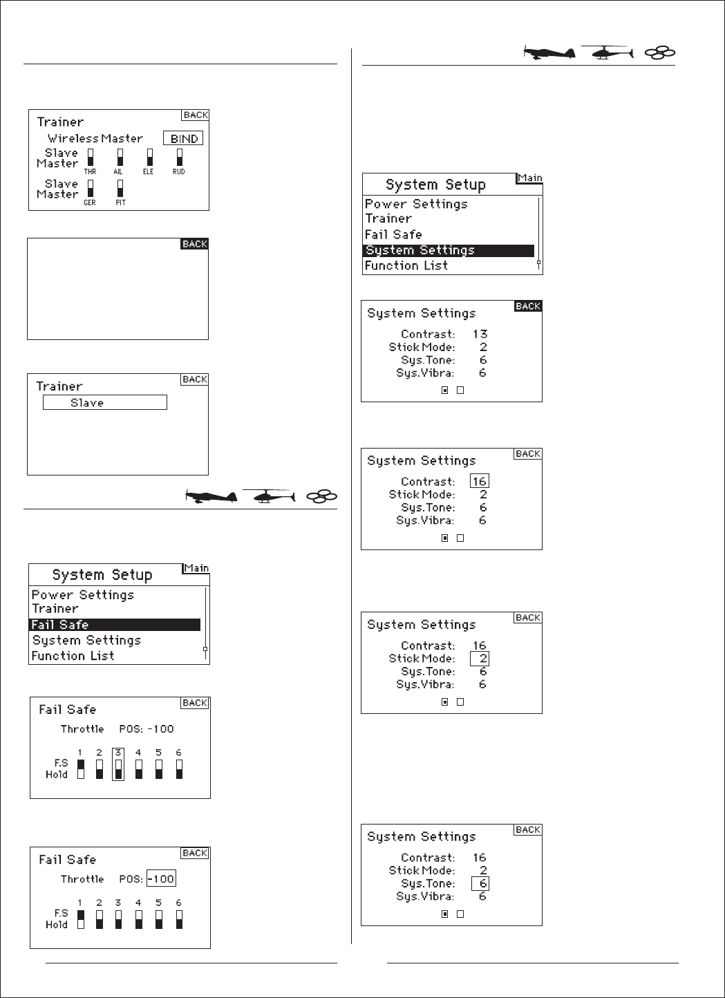
Binding......
系统设定
就会出现该选项。会出现下面画面:
进入系统设计模式菜单后,选择信号丢失保护菜单,
并按下滚轮,进入该选项:
进入系统设计模式菜单后,选择系统设定菜单,并按
下滚轮,进入该选项:
在无线教练模式下,第一次使用,应滚动滚轮致Bind
进行对码,如下图:
此时学员机需要开机进行对码:
进入学员模式:
系统设定
在系统设定画面中,滚动滚轮,选择对比,并按下滚轮。
滚动滚轮,调整对比(1到20),并按下滚轮确认。
滚动滚轮,根据需要选择1到4不同的模式,并按下滚
轮确认。
滚动滚轮至需要设置的通道,并按下滚轮确认。
进入调整对比
在系统设定画面中,滚动滚轮,选择模式选择,并按下滚轮。
进入模式选择
在系统设定画面中,滚动滚轮,选择声音设置,并按下滚
轮,可调整发射机蜂鸣器声音。
进入声音设置
进入系统设定的画面,可以改变整个遥控器设定,套
用于任何模式内存。
信号丢失保护
滚动滚轮至需要设置的数字处,并按下滚轮,设置需
要的参数。
13
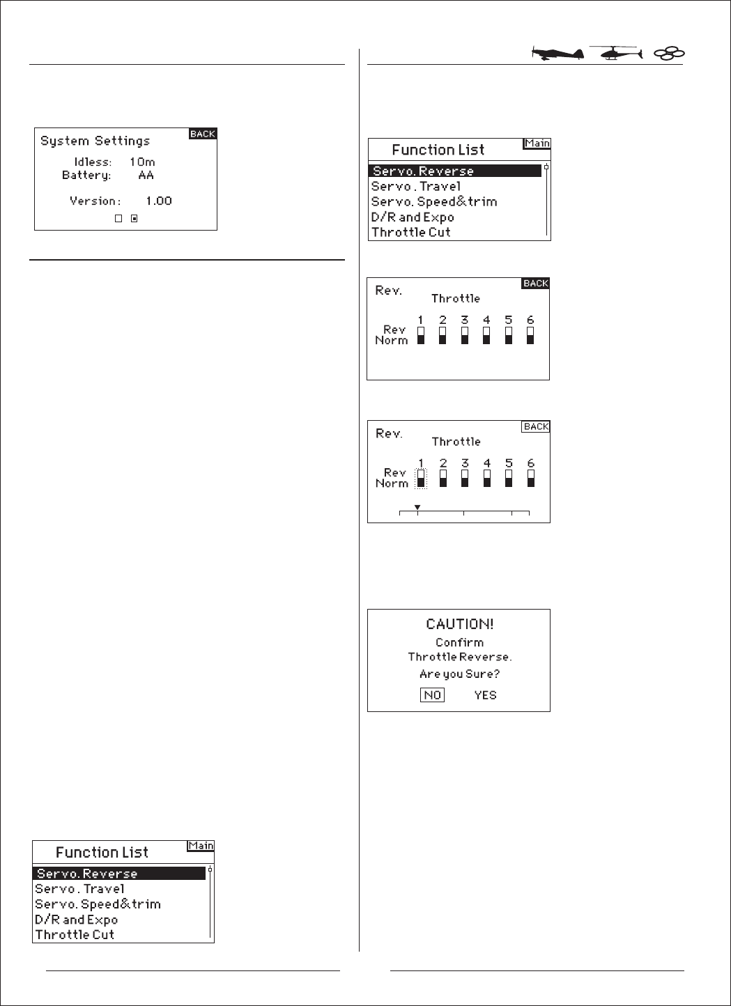
功能模式
飞机功能模式
Servo. Reverse
Servo. Travel
Servo. Speed&trim
D/R and Expo
Differential
Throttle Cut
Throttle Curve
Flap System
Mixing
Timer
Monitor
多旋翼功能模式
Servo. Reverse
Servo. Travel
Servo. Speed&trim
D/R and Expo
直升机功能模式
Servo. Reverse
Servo. Travel
Servo. Speed&trim
D/R and Expo
Throttle Cut
Throttle Curve
Swashplate
Gyro
Pitch Curve
Mixing
Timer
Monitor
正反舵
选择您想要的通道,按下滚轮,以选择通道。
如果是油门通道,按下滚轮后,出现以下界面,选择
“YES”,就可以改变舵机/通道动作方向,其它通道按
下滚轮后确认。
在系统设定画面中,滚动滚轮,选择闲时报警时间设置,
并按下滚轮,可设置闲时报警时间。
进入闲时报警时间设置
进入功能模式菜单后,选择正反舵菜单,并按下滚轮,
进入该选项:
进入正反舵
AH6T的编程有两种分类:系统设定和功能模式。功能
模式用于调整模型的飞行型式。
进入功能模式选单
遥控器开机后,发射机主界面出现时,按下滚轮。
会出现功能选单。
Throttle Cut
Throttle Curve
Program Aux
Timer
Monitor
14

行程调整
速度&辅助微调
双重比率和感度指数
就会出现该选项,会出现下面画面:
就会出现该选项,会出现下面画面:
选择您想要的通道,按下滚轮,就可以滚动滚轮调整
其数据,确认后再次按下滚轮键即可。
选择您想要的通道,按下滚轮,就可以滚动滚轮调整
其数据,确认后再次按下滚轮键即可。
进入功能模式菜单后,选择行程调整菜单,并按下滚
轮,进入该选项:
双重比率和感度指数可用于副翼、升降舵和方向舵通
道。您可以指定它们到许多开关,包含飞行模式开关。
双重比率
会影响整体限位,也会影响整体控制反应敏感度。减
少双重比率,就可以降低最大控制限位,也会降低整
体敏感度。
感度指数
会影响围绕机体中枢的灵敏度,而不影响整体控制灵
敏度。感度指数正值会降低机体中枢的控制灵敏度,
以准确地调整控制感度,而不会影响最大控制反应。
注意:感度指数正值和负值都可使用。感度指数正值
会降低机体中枢的敏感度。这并不会影响最大控制权
限,建议使用感度指数正值。感度指数负值会增加机
体中枢灵敏度,通常不会用到。
进入行程调整
进入功能模式菜单后,选择速度&辅助微调菜单,并
按下滚轮,进入该选项:
进入速度&辅助微调 进入功能模式菜单后,选择双重比率和感度指数菜单,
并按下滚轮,进入该选项:
进入双重比率和感度指数
进入选择通道
选择通道,并按下滚轮,进入该功能,包含:副翼、升
降舵或方向舵通道。按下滚轮,确认通道。
15
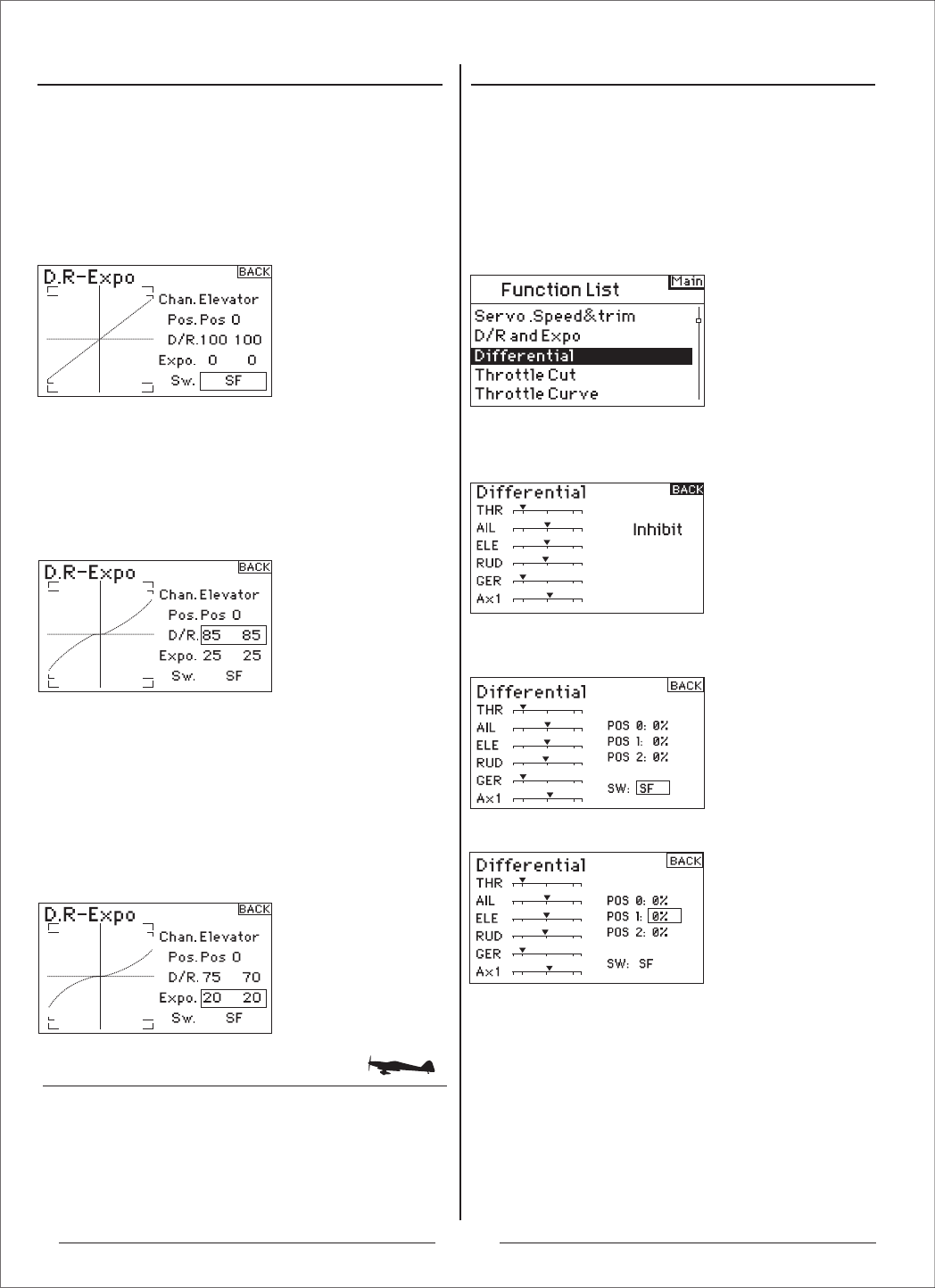
副翼差动
进入功能模式菜单后,选择差速器菜单,并按下滚
轮,进入该选项:
差速器的默认值为关闭。按下滚轮,选择Inhibit,并选
择下列开关位置:
差速器的默认值为关闭。按下滚轮,选择Inhibit,并选
择下列开关位置:
选择您想要的差速器位置/数值,并按下滚轮。
滚动滚轮,调整数值,并按下滚轮。重复此步骤,调整
所有想要的开关位置。差速器正值会让上行程比下行程
多。差速器负值则会让下行程比上行程多。差速器画面
也能让您选择/改变开关位置。滚动滚轮,选择开关,
并按下滚轮,改变或关闭开关位置。
进入开关选择
滚动滚轮,选择开关,按下滚轮,进入开关选项。选
择您想要的调整双重比率的开关,按下滚轮,启动该
功能。
注意:您可以指定多个通道给单一开关,调整双重比
率和感度指数。
进入选择调整开关位置
注意位置:画面中央的位置数值为0。移动画面下方的
开关位置,范围从0、1到2。当您调整双重比率或感
度指数时,数值会被选定。当开关在所在位置(0、1
或2)时,就会自动启用数值。.
进入差速器
进入双重比率和感度指数
确认已选择您想要的信道和开关位置。滚动滚轮,选
择双重比率或感度指数数值,按下滚轮。若反应通道
的控制杆在中央时,两个数值就会被选择。若您移动
控制杆到端点,只有一个数值会被选择。
这能让改变双重比率或感度指数数值。滚动滚轮,选
择您想要的数值。
差速器可用于准确地调整两个副翼的上下行程(当三角
翼启动时,可用于升降辅助翼)。副翼差速器可用于减
少多余的偏航。调整差速器可以让飞机做滚转(在飞机
翻转时,比较不会偏航)。您可以编程三种差速器数值,
并指定给一个开关。注意差速器的频率范围为正值到
负值。然而,通常副翼的上行程比下行程,还要重要。
注意:只有双襟副翼或升降舵辅助翼启动时才有用,每
个副翼舵机都要有各自的通道。
16
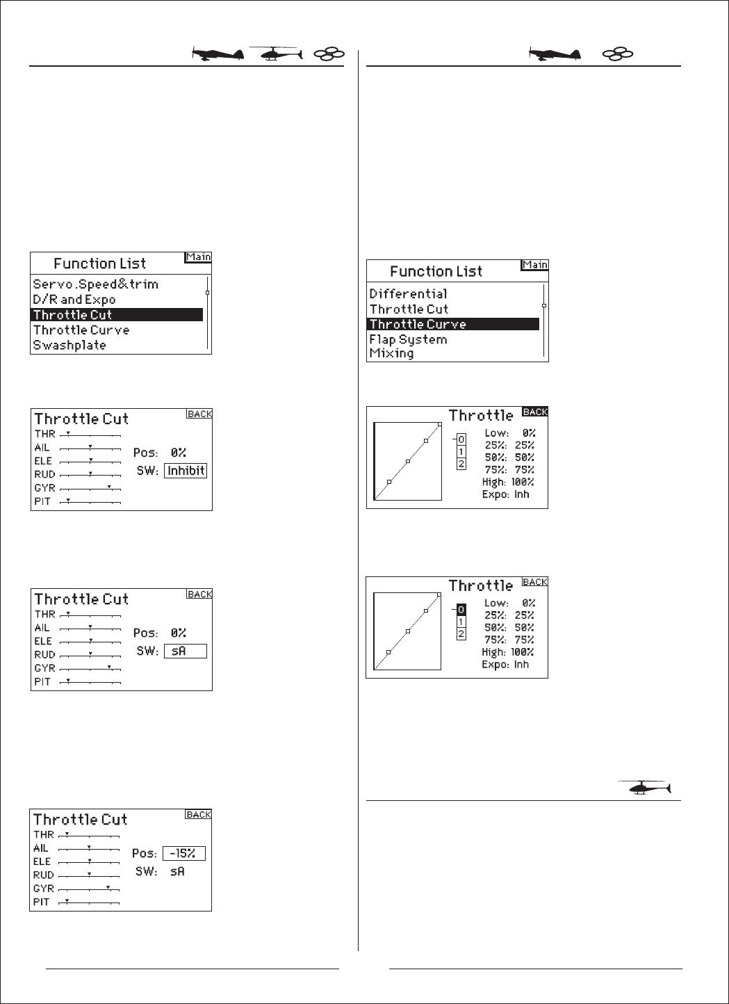
关闭油门 油门曲线
油门曲线
进入功能模式菜单后,选择关闭油门菜单,并按下滚
轮,进入该选项:
滚动滚轮,选择关闭油门,并按下滚轮后,就会进
入关闭油门画面。
滚动滚轮,选择油门曲线,并按下滚轮后,就会进
入油门曲线画面。
滚动滚轮,选择五个曲线数值选项(低、25%,、50%、
75%,以及高),择一选择。按下滚轮,选取数值。
注意左边曲线图上的位置。重复步骤,调整所有数值。
滚动滚轮,选择EXPO,并按下滚轮,进入油门曲线
Expo功能。选择Inh或Act,关闭或启动Expo功能,
并按下滚轮,确认关闭或启用该功能。
AH6T拥有五点油门曲线。您可以分配四个不同的油门
曲线。画面左边的曲线图,能帮助您调整油门曲线。
使用Expo功能可以消除油门曲线。
选择关闭,并按下滚轮,进入开关选项。滚动滚轮,
选择想要关闭油门的开关 (教练、起落架、混控、
左微调或右微调),按下滚轮,为开关编程。
编程关闭油门位置.注意数值0%代表低油门、中微调,
以及负值。启动已编程的开关,测试关闭油门是否
运作。注意舵机油门位置或油门信道位置出现在舵
机监测中。当您启动关闭油门时,系统应当将舵机
位置设为低油门位置。
您可以用教练按钮、起落架开关或左右微调杆关闭发
动机。若您启动已编程的开关,油门通道就会切换到
编程的设定值,通常显示关闭。发动机就会被关掉。
放开以编程的关闭油门开关/微调杆,油门就会重新
启动。
油门曲线可用于调整油门输出与输入的位置。通常在
飞机盘旋或滚翻飞行时,油门曲线可用于提高油门反
应,或调整油门反应敏感度。用编程开关,您可将油
门曲线设定为单一曲线(调成)开启,或是设定为三个
曲线。在画面左边有个五点油门曲线图,可以用来调
整油门曲线数值。Expo功能可用来消除油门曲线。
启动关闭油门,并分配到开关或微调杆
进入功能模式菜单后,选择油门曲线菜单,并按下滚
轮,进入该选项:
进入油门曲线
进入功能模式菜单后,选择油门曲线菜单,并按下滚
轮,进入该选项:
进入油门曲线
启动Expo功能
17
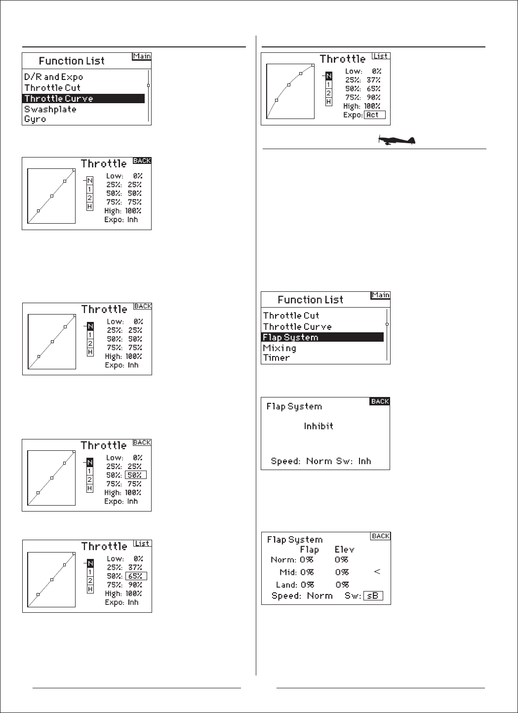
襟翼系统
滚动滚轮,选择油门曲线,并按下滚轮后,就会进
入油门曲线画面。
滚动滚轮,选择襟翼系统,并按下滚轮后,就会进
入襟翼系统画面。
进入功能模式菜单后,选择襟翼系统菜单,并按下滚
轮,进入该选项:
进入襟翼系统
襟翼系统默认为关闭。滚动滚轮,选择关闭,按下滚
轮,进入开关选项。启动襟翼系统,滚动滚轮,到您
想要的襟翼控制开关.按下滚轮,就可以进入调整画面。
选择开关
滚动滚轮,选择您想要的襟翼位置数值,并按下滚轮,
以调整数值。滚动滚轮,调整数值。注意:建议您将襟
翼开关位置与襟翼调整搭配。这能让您知道襟翼调整
的效果。
设定襟翼和升降舵位置
选择画面中您想要的飞行模式,并按下滚轮,选择。
被选择的飞行模式会变暗,显示您的选择。
AH6T的襟翼系统有三个可编程襟翼和升降舵位置(标
准、中央、降落)。您可以分配不同的开关操作。您
可以使用速度功能,减缓襟翼和升降舵补整。襟翼系
统画面左边的图表显示舵机位置,可用来设定和调整
襟翼。
注意:襟翼系统只能使用于机翼型式为襟翼。
选择飞行模式
移动飞行模式开关到您想要调整的位置。滚动滚轮,
选择五个曲线数值选项(低、25%,、50%、75%,
以及高),择一选择。按下滚轮,选取数值。
滚动滚轮,调整选择的输出数值。注意左边曲线图上
的位置。重复步骤,调整所有数值。
调整油门曲线
滚动滚轮,选择EXPO,并按下滚轮,进入油门曲线
Expo功能。选择Inh或Act,关闭或启动Expo功能,
并按下滚轮,确认关闭或启用该功能。
启动Expo功能
N= 标准 / 1= 特技1 / 2= 特技 2 / H= 固定油门
18
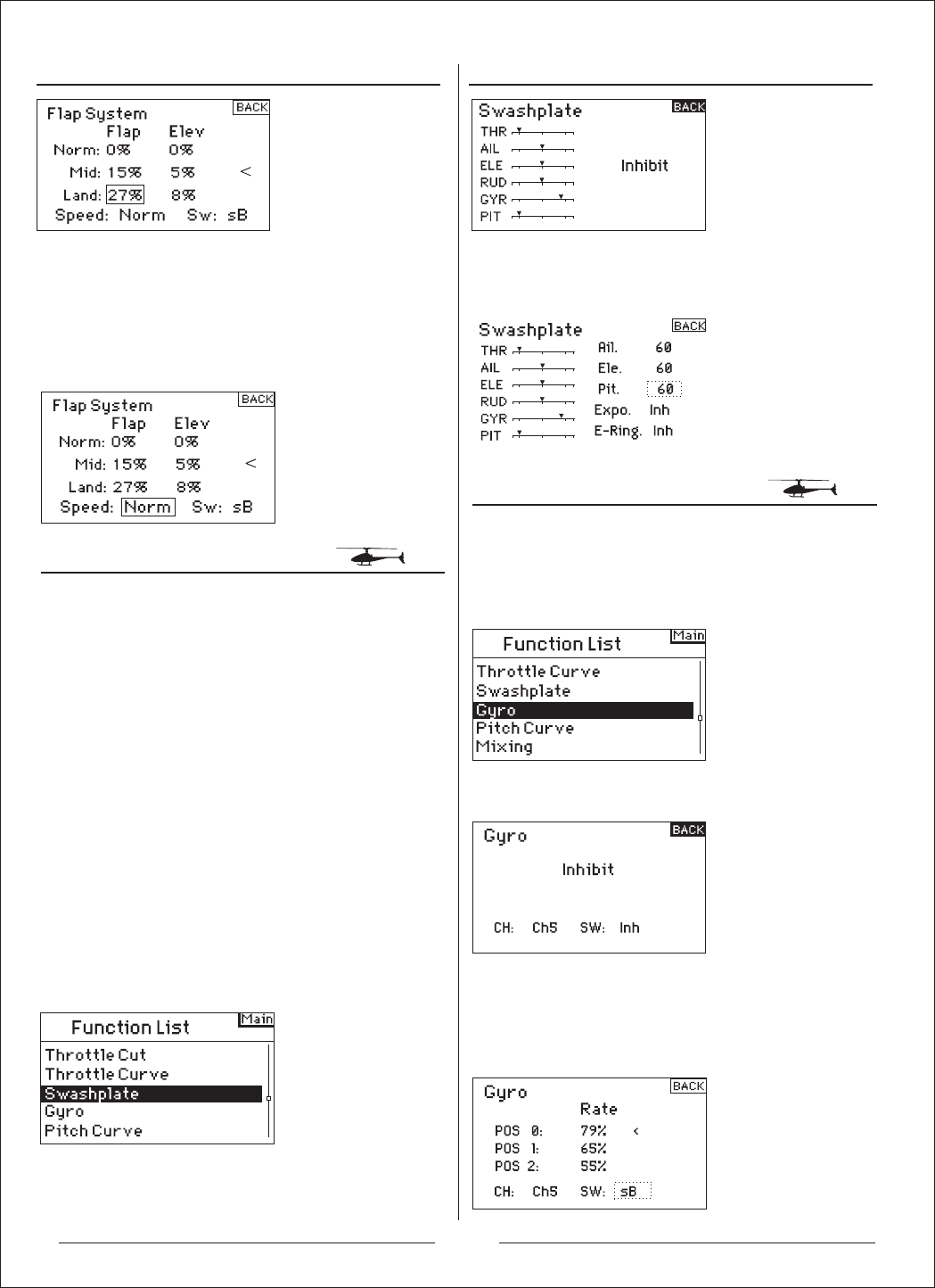
倾斜盘
陀螺仪
滚动滚轮,选择倾斜盘功能,并按下滚轮后,就会进
入倾斜盘功能画面。
滚动滚轮,选择陀螺仪功能,并按下滚轮后,就会进
入陀螺仪功能画面。
进入功能模式菜单后,选择倾斜盘功能菜单,并按下
滚轮,进入该选项:
进入功能模式菜单后,选择陀螺仪功能菜单,并按下
滚轮,进入该选项:
进入倾斜盘功能
滚动滚轮,选择速度,并按下滚轮。滚动滚轮,调整
襟翼速度。按下滚轮,以确认选择。襟翼速度会影响
襟翼和升降舵补整。同时,襟翼和升降舵会调整位置。
在倾斜盘画面中,启动CCPM混控时,您可以调整副
翼、升降舵,以及螺距的行程。倾斜盘数值会提高或
降低已选择通道的整体控制行程。比方说,若您提高
螺距数值,三个控制螺距的舵机运作就会提高。若您
提高副翼数值,副翼和螺距舵机运作也会提高。提高
或降低数值,会影响功能行程,而不只是影响个别舵
机而已。注意:倾斜盘数值有正值及负值。要达到正确
的副翼、升降舵和螺距行程,要先使用正反舵功能,
设定舵机的副翼、升降舵和螺距通道方向。当副翼输
入摇杆偏向倾斜盘左和右,方向舵输入摇杆偏向倾斜
盘前和后时,您可以使用上述方法。您可以用这个功
能,同步输出。就可以调整倾斜盘正值与负值,让副
翼、升降舵和螺距的行程方向正确。
调整襟翼速度
滚动滚轮,调整倾斜盘数值,注意数值有正值及负值。
按下滚轮,确认数值。
陀螺仪功能可以编程和调整陀螺仪增益。
调整倾斜盘数值
进入陀螺仪功能
陀螺仪功能默认为关闭。选择关闭,按下滚轮进入开
关功能,启动陀螺仪。滚动滚轮,选择想要的陀螺仪
控制开关。按下滚轮,进入陀螺仪画面。
选择开关
重复步骤,调整所有襟翼和升降舵位置(标准、中央,
以及降落)。
19
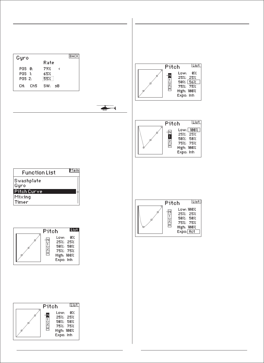
螺距曲线
滚动滚轮,选择螺距曲线功能,并按下滚轮后,就会
进入螺距曲线功能画面。
进入功能模式菜单后,选择螺距曲线功能菜单,并按
下滚轮,进入该选项:
进入螺距曲线功能
选择画面中您想要的飞行模式,并按下滚轮,选择。
被选择的飞行模式会变暗,显示您的选择。
选择飞行模式
移动飞行模式开关到您想要调整的位置。滚动滚轮,
选择五个曲线数值选项(低、25%,、50%、75%,以
及高),择一选择。按下滚轮,选取数值。
调整螺距曲线
滚动滚轮,选择想要的数值,并按下滚轮。选择数值。
重复步骤,设定所有数值。
AH6T有五点螺距曲线。您可以设定4个个别的螺距曲
线。画面左边的图表,可以辅助调整螺距曲线。
Expo功能可用于消除螺距曲线。
调整幅度数值
N= 标准 / 1= 特技1 / 2= 特技2 / H= 固定油门
启动Expo功能
滚动滚轮,选择EXPO,并按下滚轮,进入Expo功能。
选择Inh或Act,关闭或启动Expo功能,并按下滚轮,
确认关闭或启用该功能。
滚动滚轮,调整选择的输出位置数值。注意左边曲线
图上的位置。
重复步骤,完成所有调整。
20

混控 副翼-方向舵混控
进入功能模式菜单后,选择混控功能菜单,并按下滚
轮,进入该选项:
滚动滚轮,选择混控,并按下滚轮。注意若选择适当
的机翼型式,升降舵-襟翼混控会出现在画面。
进入混控功能 若您进入系统设定的机翼型式,选择襟翼选项,方向
舵-襟翼混控会出现。滚动滚轮,选择ELE > FLP,并
按下滚轮。滚动滚轮,选择Ail > RUD,并按下滚轮。
就会出现副翼-方向舵混控的画面。
进入副翼-方向舵混控
滚动滚轮,选择Sw:在画面的最下方。按下滚轮,进入
开关选择功能,再按下滚轮,选择想要的开关,开启/
关闭副翼-方向舵混控.若您选择On,混控就会永远开启。
滚动滚轮,选择幅度数值,并按下滚轮。注意两个数
值在方格中。向左或右移动副翼摇杆,这样才能个别
调整左数值或右数值。移动副翼摇杆,选择想要的幅
度,并滚动滚轮,调整数值。注意正值为+,负值为-,
使混控方向相反。按下滚轮,确认数值。
打开开关,并移动副翼摇杆到方向舵位置,以确认副
翼-方向舵混控运作正常,且方向正确。若方向舵移动
与想要的位置成反向,那么就需要相反数值(正值与负
值)。
注意:升降舵-襟翼混控的操作方法与副翼-方向舵混控
方法相同。
指定副翼-方向舵混控开关
调整副翼-方向舵混控幅度
AH6T有八个飞机混控。包含升降舵-襟翼混控、副翼-
方向舵混控,以及六个使用者编程混控,可以混控通
道。可编程混控包含,一个调整补差微调,以及一个
具有教练-学生通道的微调。
使用副翼-方向舵混控可以解决J3 Cub飞机的逆偏航,
并更容易做出翻转。
21

混控
进入功能模式菜单后,选择混控功能菜单,并按下滚
轮,进入该选项:
滚动滚轮,选择混控,并按下滚轮。倾斜盘-油门混控
会出现在画面。
倾斜盘-油门混控
倾斜盘-油门混控可防止,当有副翼、升降舵和/或方
向舵输入时,转速减少的情形发生。这可让油门位置
与倾斜盘或方向舵控制维持转速。当油门全满时,这
个编程能防止舵机过度负荷。重要:当使用调速器时,
则不建议使用倾斜盘-油门混控。
调整倾斜盘幅度
滚动滚轮,选择想要的幅度,并按下滚轮。滚动滚轮,调
整数值.数值有正值+和负值-,与油门混控的方向相反。
调整所以想要通道的数值。
进入混控功能
打开飞行模式开关,确认倾斜盘混控是否正常运作。
移动可编程倾斜盘或方向舵信道,注意油门位置。
油门位置应该会提高。若油门位置降低,那么就需要
相反数值(正值与负值)
进入混控功能
AH6T有八个直升机混控。当有副翼、升降舵和/或方
向舵输入时,您可以编程倾斜盘-油门混控。当倾斜盘
和方向舵输入时,这可防止转速减少。
混合副翼-升降舵混控和升降舵-副翼混控,以调整倾
斜盘时程。有六个可编程混控,可混控通道。包含起
落架开关在内,您可以在多个飞行模式中,操作混控。
可编程混控包含微调offset功能,可用来调整混控交错。
而微调内含功能则可用于教练微调与学生通道链接。
可编程混控可用于通道相互混控或本身各自混控。
普遍的可编程混控包含,方向舵-可操作前轮、双方
向舵混控、双升降舵混控、方向舵-副翼混控和方向
舵-升降舵混控。
进入可编程混控(1到6)
升降舵-襟翼混控显示在画面中,滚动滚轮,选择Ele
> Flp,并按下滚轮。滚动滚轮,选择可编程混控1、
2、3、4、5或6,并按下滚轮。混控画面会出现。
Offset功能
当两个混控聚合时,就可以使用Offset功能。通常这
个数值是0%。若需要调整补差,可以使用下列方法:
滚动滚轮,选择Offset,并按下滚轮,选择Offset幅
度。滚动滚轮,调整数值。数值有正值+和负值-,可
以改变offset。按下滚轮,确认offset数值。
微调内含功能
当您选择的教练通道是有微调的通道时(油门、副翼、
升降舵和方向舵),微调内含功能可用于微调学生通
道。通常,当有多个通道用于操作主要控制接口(双
重方向舵舵机等)时,就会使用微调内含功能。微调
内含功能启动时,教练通道会影响其他教练及学生
通道。
启动微调内含功能
滚动滚轮,选择微调。按下滚轮,选择INH或ACT。
22
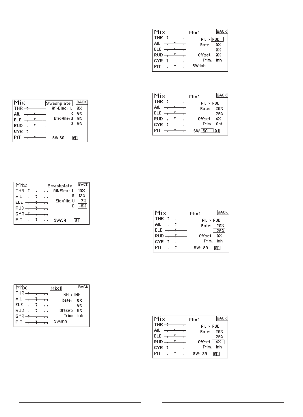
倾斜盘混控
混合副翼-升降舵混控和升降舵-副翼混控,以调整倾
斜盘时程。当正确调整时,倾斜盘会让准确俯仰翻转
,相互效应达到最小。
进入倾斜盘混控
倾斜盘混控画面出现时,滚动滚轮,选择Cyclic > Thro,
并按下滚轮。选择选转盘,并按下滚轮。倾斜盘画面
会出现。
调整倾斜盘幅度
滚动滚轮,选择想要的幅度,并按下滚轮。滚动滚轮,
调整数值。数值有正值+和负值-,与油门混控的方向
相反。调整所以想要通道的数值。
开关选择
滚动滚轮,选择“SW”项,选择所需开关和开关位置。
调整可编程混控幅度
滚动滚轮,选择想要的幅度,并按下滚轮。滚动滚轮,
调整数值。您可用正值或负值,使学生通道方向相反。
调整两个方向/数值的幅度。
确认可编程混控运作正常,以及方向正确。打开飞行
模式开关。
移动可编程教练通道时,观察学生通道。学生信道应
跟随教练通道移动。
Offset功能
当两个混控聚合时,就可以使用Offset功能。通常这
个数值是0%。若需要调整补差,可以使用下列方法:
编程Offset
滚动滚轮,选择Offset,并按下滚轮,选择Offset幅度。
滚动滚轮,调整数值。数值有正值+和负值-,可以改
变offset。按下滚轮,确认offset数值。
微调内含功能
当您选择的教练通道是有微调的通道时(油门、副翼、
升降舵和方向舵),微调内含功能可用于微调学生通道。
通常,当有多个通道用于操作主要控制接口(双重副翼
可编程混控
可编程混控可用于通道相互混控或本身各自混控。
进入可编程混控(1到6)
遥控盘混控画面出现时,滚动转轴,选择Cyclic >
Thro,按下滚轮选择可编程混控,1、2、3、4、5,
或6,再按下滚轮。会出现混控画面。
选择教练和学生通道
教练信道是个控制信道,与学生信道混控。依据编程
幅度,学生信道跟随教练信道。
滚动滚轮,选择左边的INH,并下滚轮,进入教练模
式。选择想要的教练通道。按下滚轮,确认通道。
选择右边的INH,按下滚轮,进入学生通道。选择想
要的学生通道。按下滚轮,确认通道。
23
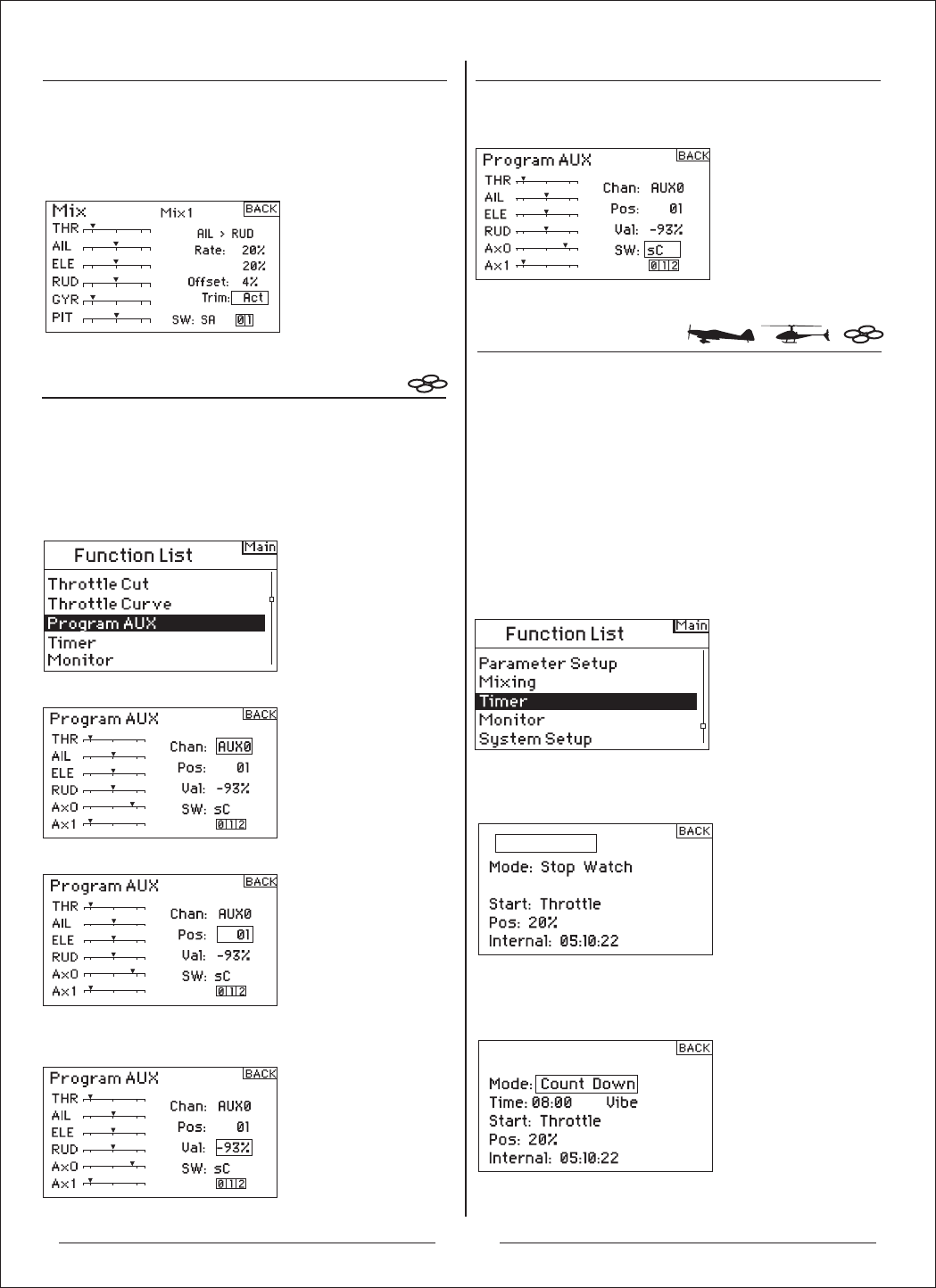
Timer-1
Timer-1
定时器
可编程辅助通道
滚动滚轮,选择定时器功能,并按下滚轮后,就会进
入定时器功能画面。
滚动滚轮,选择你想要定时器,并按下滚轮确认。
进入功能模式菜单后,选择定时器功能菜单,并按下
滚轮,进入该选项:
进入定时器画面
滚动滚轮,选择需要设置的通道,并按下滚轮。
滚动滚轮,选择需要设置的位置,并按下滚轮。
滚动滚轮,选择需要设定的值位置,并按下滚轮,转
动进行设定。
滚动滚轮,选择需要控制的开关处,并按下滚轮,选
择相应的开关和位置。
进入功能模式菜单后,选择可编程辅助通道菜单,并
按下滚轮,进入该选项:
进入可编程辅助通道
辅助通道0、1可以自定义输出10个不同的状态。
注意:输出结果低位置的优先输出。
选择定时器模式-关闭、倒数计时或定时
选择模式,并按下滚轮,选择关闭、倒数计时或定时。
按下滚轮,确认选择。
舵机等)时,就会使用微调内含功能。微调内含功能启
动时,教练通道微调会影响学生通道微调。
启动微调内含功能
滚动滚轮,选择微调。按下滚轮,选择INH或ACT。
AH6T拥有两组定时器功能,在主画面中可以使用倒数
计时或定时。当计时的时间一到,就会有警示响起。
您可以用教练按钮、左或右微调杆来启动定时器,或
是油门提高,超过设定范围时,自动启动定时器。此外,
在主画面中,透过内部定时器,您可以看到模型的操
作时间。
24

Timer-1
Timer-1
Neutral
Timer-1
Timer-1
Timer-1
监控
滚动滚轮,选择想要的启动模式,按下滚轮,确认选择。
编程油门摇杆位置
只有当油门启动选择时
若您选择油门或油门1计时启动,在定时器画面中,
摇杆位置低于启动位置。这是油门启动定时器的摇杆
位置。滚动滚轮,选择摇杆,并按下滚轮,进入摇杆
数值。数值的幅度从0到100%。这与实际油门摇杆的
位置互相有关联。
滚动滚轮,选择监控功能,并按下滚轮后,就会进
入监控功能画面。
进入界面后,滚动滚轮,可以选择舵机测试功能。
进入功能模式菜单后,选择监控功能菜单,并按下
滚轮,进入该选项:
进入监控画面
滚动滚轮,选择时间,并按下滚轮,进入选项。您可
以选择分钟或秒钟。按下滚轮,确认选择分钟或秒钟。
滚动滚轮,选择想要的启动模式(教练、油门、油门1
定时器、左微调杆、右微调杆)。按下滚轮,确认选择。
滚动滚轮,选择想要的摇杆数值,并按下滚轮,确认数值。
重设内部定时器
您可用一些方法重设内部定时器。滚动滚轮,选择内部
定时器:重设,按下滚轮,重新设定定时器为0:00:00
您可以按下清除键,重新设定倒数定时器或定时器。
监控画面中的图表和数字可以指出各信道舵机的位置。
这可以用来确认编程功能、微调设置、混控方向等。数
值与行程调整和混控数值有直接关联(比方说,100%行
程调整值等于监控画面中出现的100%数值)。
滚动滚轮,选择想要的时间。按下滚轮,确定选择。
编程时间
滚动滚轮,选择音调,并按下滚轮,确认选择。您可
以选择关闭、音调、震动或音调/震动。
编程音调、震动、音调/震动或关闭
滚动滚轮,选择启动,并按下滚轮,进入选项。共有
五种启动模式:教练开关、油门、油门1定时器、左或
右微调杆。
油门1定时器- 当油门位置超过标准时,定时器会启
动。不管油门位置,定时器会持续运作。
油门 - 当油门位置超过标准时,定时器会启动。若
您将油门低于编程位置,定时器就会暂停,当油门高
过编程位置时,定时器就会恢复运作。这对操作电子
发动机飞机的玩家来说很有用,马达运作时间才是最
重要的。
选择定时器启动模式
sA
25

更换模式
机械功能切换
AH6T可以切换模式,从1、2、3到4。这种切换有机械功能及程序的改变(前面有介绍模式1和2、模式3和4的摇
杆和开关图示。)具体操作方法如下:
机械功能切换需要变更模式1及模式2或模式3及模式4的开关。方向舵中心弹簧及油门压片要装在适当的阻尼条
上,油门杆必须切换。
1. 将发射机后扶手的橡胶握手拉开和两个橡胶塞,出现A、B、C、D、E、F螺丝孔(如下图发射机背面图所示)
2. 左手换右手
1)用十字螺丝批将A调节螺丝拧松,调至摇杆上下移动无阻力状态即可。
2)用十字螺丝批将B调节螺丝锁紧,调至摇杆上下移动后可自动反弹状态即可。
3)用十字螺丝批将C调节螺丝拧松,调至摇杆上下移动无反弹状态即可。
4)用十字螺丝批将D调节螺丝锁紧,调至摇杆上下移动有阻力状态即可。
3. 右手换左手
1)用十字螺丝批将D调节螺丝拧松,调至摇杆上下移动无阻力状态即可。
2)用十字螺丝批将C调节螺丝锁紧,调至摇杆上下移动后可自动反弹状态即可。
3)用十字螺丝批将B调节螺丝拧松,调至摇杆上下移动无反弹状态即可。
4)用十字螺丝批将A调节螺丝锁紧,调至摇杆上下移动有阻力状态即可。
4. 完成以上操作后装上发射机后扶手的橡胶握手和橡胶塞。
发射机背面图
A
B
C
D
E
F
MODE 1
升降摇杆
方向摇杆
油门摇杆
副翼摇杆
MODE 2
方向摇杆
油门摇杆
副翼摇杆
升降摇杆
MODE 3
升降摇杆
油门摇杆
副翼摇杆
MODE 4
油门摇杆
副翼摇杆
升降摇杆
方向摇杆 方向摇杆
26
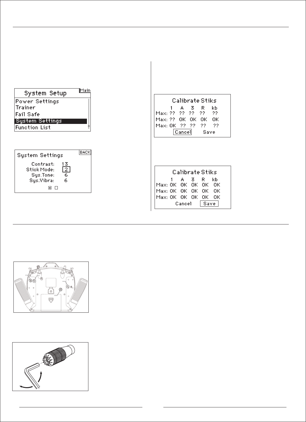
进入系统设计模式菜单后,选择系统设定菜单,并
按下滚轮,进入该选项:
按下滚轮后就会出现以下菜单
滚动滚轮,选择想要的模式,按下滚轮,进入模式。
切换模式时,改变油门和升降舵位置,重新设定摇杆,
这很重要。若编程模式切换,下次开机时,设定画面
会自动出现。如下图:
此时请大幅度移动摇杆几圈,并调回中央(包含油门摇
杆及发射机旋钮键)。若所有摇杆都调回中央,当出现
以下界面时,按下储存,完成设定。
AH6T有调整油门、副翼、升降舵和方向舵松紧度功能。橡胶栓在机壳后面,您可轻松找到摇杆螺丝,调整松
紧度,而无需取下整个外壳。
调整摇杆松紧度
1.取下两个橡胶塞,并取下握把。您可以找到油门、副翼、升降舵和方向舵螺丝。
调整摇杆松紧度
程序功能切换
进入系统设定
切换模式时,您也必须改变编程,另外,改变油门和升降舵位置时,要在遥控器系统设定中重新设定。
调整摇杆长度
您可以调整AH6T的摇杆长度。使用内附的2mm 内六角板手,逆时针调松螺丝。接着,顺时针转动摇杆,
缩短长度;或是,逆时针转动摇杆,增长长度。调整好摇杆长度后,锁上2mm螺丝。
MODE 2
调节升降
螺丝
调节副翼
螺丝
调节油门
螺丝
调节方向
螺丝
2.使用十字螺丝批,调整螺丝松紧度。顺时针锁紧螺丝,逆时针则可松开螺丝。
3.若调整到满意的摇杆松紧度,就将握把和橡胶塞装回去。
27

Global Distribution Office:
Zonda Hobby Technologies Electronic Limited
Room 1, 1/F, Kam Hon Industrial Building, No.8 Wang Kwun Road, Kowloon Bay, Kowloon, Hong Kong
Tel: (852) 3160 8886 Fax: (852) 3160 8884
Official Website: www.zondahobby.com / www.zondahobby.com.cn
※本型号机型在尚未进行重大改版之前,配件可能进行调整,外观、型号可能稍有不同。GWY保留配件内容更改权,并不另行通知。
Before this model has being significantly changed to another new version, the parts, appearance and the existing version can be developed and
modified that would lead to a slight difference from the original design. GWY reserve ALL the Rights of change of parts and contents WITHOUT
specified notification.