ZTE 1800-2SW Intelligent Integrated Multi-Services Router User Manual ZXR10 ZSR Intelligent Integrated Multi Service Router Hardware Description
ZTE Corporation Intelligent Integrated Multi-Services Router ZXR10 ZSR Intelligent Integrated Multi Service Router Hardware Description
ZTE >
Contents
- 1. ZXR10 ZSR Intelligent Integrated Multi-Service Router Hardware Description
- 2. ZXR10 ZSR Intelligent Integrated Multi-Service Router Product Description
- 3. ZXR10 ZSR Intelligent Integrated Multi-Service Router Safety Precautions
ZXR10 ZSR Intelligent Integrated Multi-Service Router Hardware Description

ZXR10ZSRV2
IntelligentIntegratedMulti-ServiceRouter
HardwareDescription
Version:2.00.20
ZTECORPORATION
No.55,Hi-techRoadSouth,ShenZhen,P .R.China
Postcode:518057
Tel:+86-755-26771900
Fax:+86-755-26770801
URL:http://support.zte.com.cn
E-mail:support@zte.com.cn
LEGALINFORMATION
Copyright©2014ZTECORPORATION.
Thecontentsofthisdocumentareprotectedbycopyrightlawsandinternationaltreaties.Anyreproductionor
distributionofthisdocumentoranyportionofthisdocument,inanyformbyanymeans,withoutthepriorwritten
consentofZTECORPORATIONisprohibited.Additionally,thecontentsofthisdocumentareprotectedby
contractualcondentialityobligations.
Allcompany,brandandproductnamesaretradeorservicemarks,orregisteredtradeorservicemarks,ofZTE
CORPORATIONoroftheirrespectiveowners.
Thisdocumentisprovided“asis”,andallexpress,implied,orstatutorywarranties,representationsorconditions
aredisclaimed,includingwithoutlimitationanyimpliedwarrantyofmerchantability,tnessforaparticularpurpose,
titleornon-infringement.ZTECORPORATIONanditslicensorsshallnotbeliablefordamagesresultingfromthe
useoforrelianceontheinformationcontainedherein.
ZTECORPORATIONoritslicensorsmayhavecurrentorpendingintellectualpropertyrightsorapplications
coveringthesubjectmatterofthisdocument.ExceptasexpresslyprovidedinanywrittenlicensebetweenZTE
CORPORATIONanditslicensee,theuserofthisdocumentshallnotacquireanylicensetothesubjectmatter
herein.
ZTECORPORATIONreservestherighttoupgradeormaketechnicalchangetothisproductwithoutfurthernotice.
UsersmayvisittheZTEtechnicalsupportwebsitehttp://support.zte.com.cntoinquireforrelatedinformation.
TheultimaterighttointerpretthisproductresidesinZTECORPORATION.
RevisionHistory
RevisionNo.RevisionDateRevisionReason
R1.02015-03-30Firstedition
SerialNumber:SJ-20150204153047-004
PublishingDate:2015-03-30(R1.0)
SJ-20150204153047-004|2015-03-30(R1.0)ZTEProprietaryandCondential

Contents
AboutThisManual.........................................................................................I
Chapter1HardwareOverview...................................................................1-1
Chapter2ZXR103800-8Chassis..............................................................2-1
2.1Structure............................................................................................................2-1
2.1.1OverviewandStructure............................................................................2-1
2.1.2SlotLayout..............................................................................................2-2
2.1.3SystemParameters..................................................................................2-3
2.2PowerSupply.....................................................................................................2-4
2.2.1ACPowerSupplyModule.........................................................................2-4
2.2.2DCPowerSupplyModule.........................................................................2-5
2.3FANModule.......................................................................................................2-6
Chapter3ZXR102800-4Chassis..............................................................3-1
3.1Structure............................................................................................................3-1
3.1.1OverviewandStructure............................................................................3-1
3.1.2SlotLayout..............................................................................................3-2
3.1.3SystemParameters..................................................................................3-3
3.2PowerSupply.....................................................................................................3-3
3.2.1ACPowerSupplyModule.........................................................................3-4
3.2.2DCPowerSupplyModule.........................................................................3-5
3.3Fan...................................................................................................................3-6
Chapter4ZXR101800-2SChassis...........................................................4-1
4.1Structure............................................................................................................4-1
4.1.1OverviewandStructure............................................................................4-1
4.1.2SlotLayout..............................................................................................4-4
4.1.3SystemParameters..................................................................................4-5
4.2PowerSupply.....................................................................................................4-6
Chapter5ZXR102800-3EChassis...........................................................5-1
5.1Structure............................................................................................................5-1
5.1.1OverviewandStructure............................................................................5-1
5.1.2SlotDeployment.......................................................................................5-3
5.1.3SystemParameters..................................................................................5-4
5.2PowerSupplies..................................................................................................5-5
5.2.1ACPowerModule....................................................................................5-5
I
SJ-20150204153047-004|2015-03-30(R1.0)ZTEProprietaryandCondential

5.2.2DCPowerModule....................................................................................5-6
Chapter6ZXR101800-2EChassis...........................................................6-1
6.1Structure............................................................................................................6-1
6.1.1OverviewandStructure............................................................................6-1
6.1.2Slots........................................................................................................6-3
6.1.3SystemParameters..................................................................................6-4
6.2PowerSupplies..................................................................................................6-4
6.2.1ACPowerModule....................................................................................6-5
6.2.2DCPowerModule....................................................................................6-6
Chapter7MPFU..........................................................................................7-1
7.1RAC-2838-MPFU-A............................................................................................7-1
7.2RAC-2838-MPFU-B/RAC-2838-MPFU-C.............................................................7-3
Chapter8GeneralProcessingBoards.....................................................8-1
8.1RAC-DPIU-OSU-A1...........................................................................................8-1
8.2RAC-DPIU-OSU-A2...........................................................................................8-3
8.3RAC-DPIU-FW-A...............................................................................................8-4
Chapter9LineInterfaceBoards...............................................................9-1
9.1RAC-SPIU-02CE1-75.........................................................................................9-2
9.2RAC-SPIU-02UE1-75.........................................................................................9-3
9.3RAC-SPIU-02CE1-120.......................................................................................9-5
9.4RAC-SPIU-02UE1-120.......................................................................................9-6
9.5RAC-SPIU-02HS................................................................................................9-8
9.6RAC-SPIU-04GE................................................................................................9-9
9.7RAC-PIU-LTE...................................................................................................9-11
9.8RAC-PIU-01DSLB............................................................................................9-13
9.9RAC-PIU-04SHDSL.........................................................................................9-15
9.10RAC-PIU-04HS.............................................................................................9-16
9.11RAC-PIU-04CE1-75........................................................................................9-18
9.12RAC-PIU-04CE1-120......................................................................................9-19
9.13RAC-PIU-04UE1-75.......................................................................................9-21
9.14RAC-PIU-04UE1-120......................................................................................9-22
9.15RAC-PIU-16CE1............................................................................................9-23
9.16RAC-PIU-16CE1-CES....................................................................................9-25
9.17RAC-PIU-01P12-SFP.....................................................................................9-26
9.18RAC-PIU-02P3-SFP.......................................................................................9-28
9.19RAC-PIU-04P3-SFP.......................................................................................9-29
9.20RAC-PIU-02CP3-SFP.....................................................................................9-31
II
SJ-20150204153047-004|2015-03-30(R1.0)ZTEProprietaryandCondential

9.21RAC-PIU-04CP3-SFP.....................................................................................9-32
9.22RAC-PIU-04GE-SFP......................................................................................9-34
9.23RAC-PIU-08GE-SFP......................................................................................9-35
9.24RAC-PIU-05GE-4E1SFP................................................................................9-36
9.25RAC-PIU-09GE-8E1SFP................................................................................9-39
9.26RAC-PIU-08FE1GE-1SFP..............................................................................9-41
9.27RAC-DPIU-16GE-12SFP4E............................................................................9-43
9.28RAC-DPIU-01XGE-SFP+................................................................................9-45
Chapter10Cables....................................................................................10-1
10.1PowerCablesandGroundingCables..............................................................10-1
10.1.1DCPowerCables.................................................................................10-1
10.1.2ACPowerCables.................................................................................10-3
10.1.3GroundingCables................................................................................10-4
10.2SignalCables.................................................................................................10-4
10.2.1AUXCables.........................................................................................10-4
10.2.2ConsoleCables....................................................................................10-5
10.2.3EthernetCables...................................................................................10-6
10.2.4OpticalFibers.......................................................................................10-7
10.2.5SHDSLCables.....................................................................................10-9
10.2.6Synchronous/AsynchronousSerialCable..............................................10-10
10.2.7E1TrunkCable...................................................................................10-13
AppendixABoardQuickTable(WeightandPowerConsumption)......A-1
AppendixBOpticalModulesQuickTable...............................................B-1
Figures.............................................................................................................I
Tables.............................................................................................................V
Glossary......................................................................................................XIII
III
SJ-20150204153047-004|2015-03-30(R1.0)ZTEProprietaryandCondential

Thispageintentionallyleftblank.
IV
SJ-20150204153047-004|2015-03-30(R1.0)ZTEProprietaryandCondential

AboutThisManual
Purpose
Thismanualdescribesthehardwarestructure,components,systemcongurations,
performance,physicalparametersandsupportedboardsandcablesoftheZXR10ZSR
V2seriesrouters.
IntendedAudience
Thismanualisintendedfor:
lNetworkplanningengineers
lEquipmentinstallationengineers
lInstallationsupervisionengineers
WhatIsinThisManual
Thismanualcontainsthefollowingchaptersandappendixes.
Chapter1,HardwareOverviewDescribesthehardwareoverviewoftheZXR10ZSRV2
seriessrouters.
Chapter2,ZXR103800-8Chassis
Describesthestructure,components,slots,systempa-
rameters,powersupplies,andtheheatdissipationsys-
temoftheZXR103800-8chassis.
Chapter3,ZXR102800-4Chassis
Describesthestructure,components,slotlayout,system
parameters,powersupplies,andtheheatdissipationsys-
temoftheZXR102800-4chassis.
Chapter4,ZXR101800-2SChassis
Describesthestructure,components,slotlayout,system
parameters,powersupplies,andtheheatdissipationsys-
temoftheZXR101800-2Schassis.
Chapter5,ZXR102800-3EChassis
Describesthestructure,slotdeployment,systempa-
rameters,powermodules,andfanmodulesofaZXR10
2800-3Echassis.
Chapter6,ZXR101800-2EChassis
Describesthestructure,slotdeployment,systempa-
rameters,powermodules,andfanmodulesofaZXR10
1800-2Echassis.
Chapter7,MPFUDescribestheMPFUsupportedbyallZXR10ZSRV2
seriesrouters.
Chapter8,GeneralProcessingBoardsDescribesgeneralprocessingboardsthattheZXR10
ZSRV2seriesrouterssupport.
I
SJ-20150204153047-004|2015-03-30(R1.0)ZTEProprietaryandCondential
Chapter9,LineInterfaceBoardsDescribesthelineinterfaceboardssupportedbyall
ZXR10ZSRV2seriesrouters.
Chapter10,CablesDescribesthepowercables,protectivegroundingcables,
andsignalcablesoftheZXR10ZSRV2seriesrouters.
AppendixA,BoardQuickT able(Weight
andPowerConsumption)
Describestheweightandpowerconsumptionofthe
boardssupportedbytheZXR10ZSRV2seriesrouters.
AppendixB,OpticalModulesQuickTableDescribestheinformationoftheopticalmodulessup-
portedbytheZXR10ZSRV2seriesrouters.
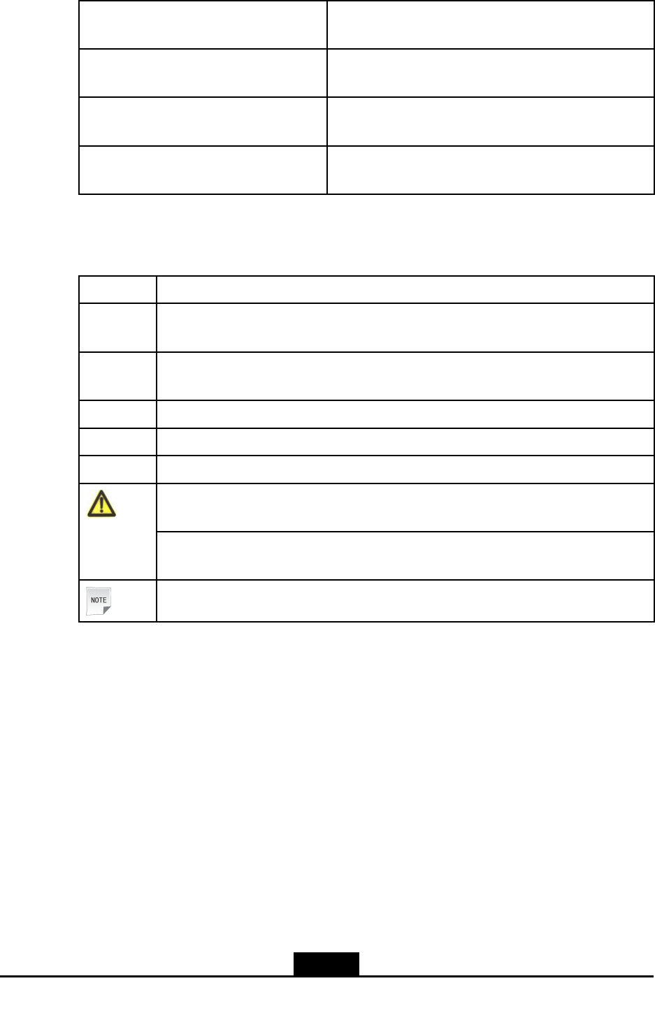
Conventions
Thismanualusesthefollowingconventions.
ItalicsVariablesincommands.Itmayalsorefertootherrelatedmanualsanddocuments.
BoldMenus,menuoptions,functionnames,inputelds,optionbuttonnames,checkboxes,
drop-downlists,dialogboxnames,windownames,parameters,andcommands.
Constant
width
Textthatyoutype,programcodes,lenames,directorynames,andfunctionnames.
[]Optionalparameters.
{}Mandatoryparameters.
|Separatesindividualparametersinaseriesofparameters.
Warning:indicatesapotentiallyhazardoussituation.Failuretocomplycanresultin
seriousinjury,equipmentdamage,orinterruptionofmajorservices.
Caution:indicatesapotentiallyhazardoussituation.Failuretocomplycanresultin
moderateinjury,equipmentdamage,orinterruptionofminorservices.
Note:providesadditionalinformationaboutacertaintopic.
II
SJ-20150204153047-004|2015-03-30(R1.0)ZTEProprietaryandCondential

Chapter1
HardwareOverview
ForthemajorhardwarecomponentsandmodelsoftheZXR10ZSRV2,refertoT able1-1.
Thecomponentsvarywiththenetworkscaleandcapacity.Determinetheconguration
accordingtoyouractualrequirements.
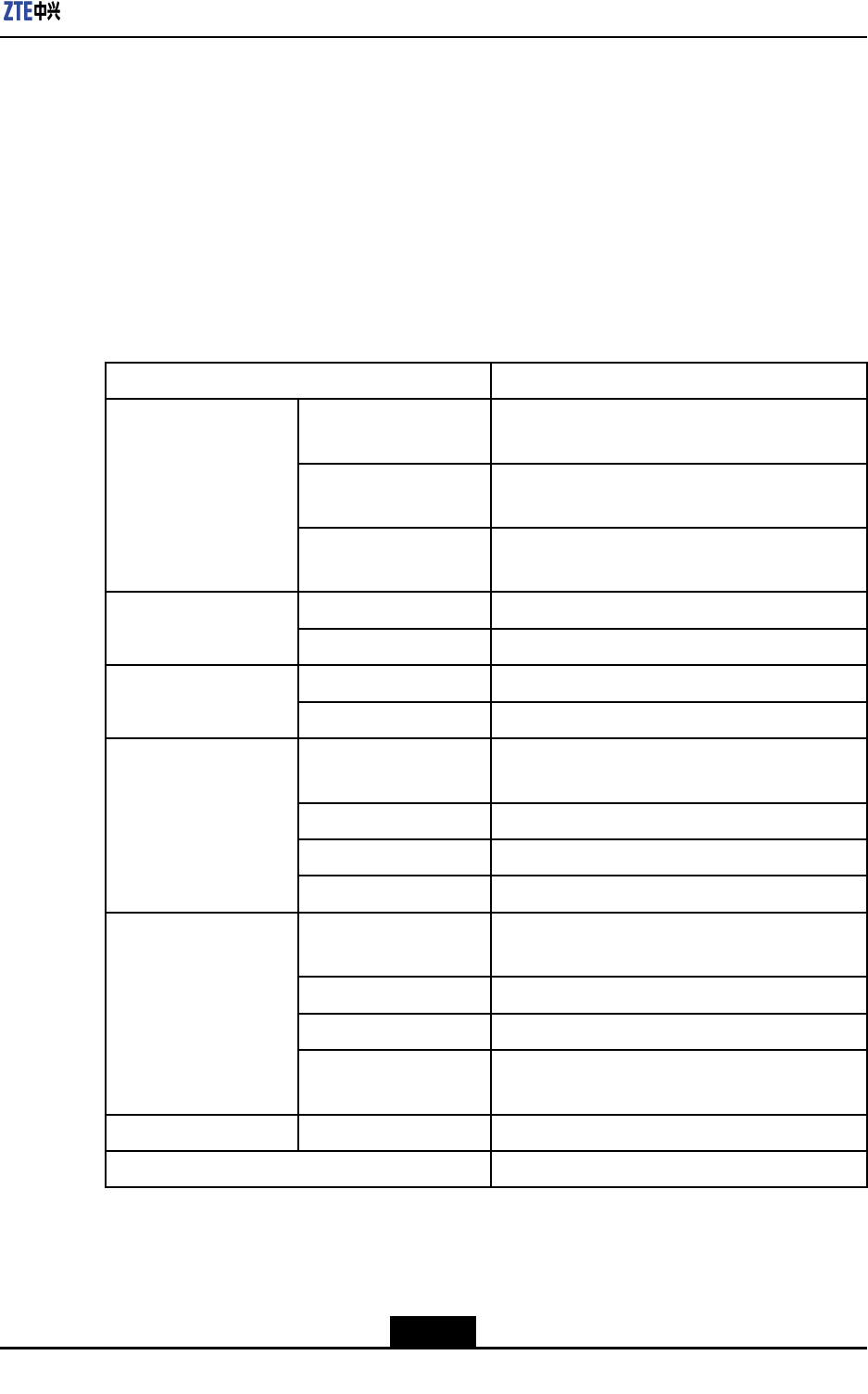
Table1-1ComponentModels
ComponentModelDescription
Cabinet-Usedasrequired.TheZXR101800-2Sisadesktop
product,theZXR101800-2EandZXR102800-3E
canbeinstalledonadesktoporinacabinet,while
theZXR102800-4andZXR103800-8canbe
installedinanIEC297standardcabinetorETSI
standardcabinet.
ShelfZXR103800-8Chassis
ZXR102800-4Chassis
ZXR101800-2S
Chassis
Containschassisstructure,powersupplymodule,
fananddustscreenmoduleandLCDmodule.
MPFURefertoChapter7
MPFU.
ContainsMPFU.
General
processingboards
RefertoChapter8
GeneralProcessing
Boards.
GeneralprocessingboardsthattheZXR10ZSRV2
seriesrouterssupport.
LineInterface
Boards
RefertoChapter9Line
InterfaceBoards.
Containslineinterfaceboards.
CableRefertoChapter10
Cables.
Containspowercables,groundingcablesandsignal
cables.
1-1
SJ-20150204153047-004|2015-03-30(R1.0)ZTEProprietaryandCondential

ZXR10ZSRV2HardwareDescription
Thispageintentionallyleftblank.
1-2
SJ-20150204153047-004|2015-03-30(R1.0)ZTEProprietaryandCondential
Chapter2
ZXR103800-8Chassis
TheZXR10ZSRV2seriesroutersarehighlyexiblebyusingthemodularstructure,and
theboardsandcomponentsarehotswappable.Theentirerouterconsistsofthechassis,
backplane,MPFU,lineinterfaceboards,powersupplymodules,andfanmodules.
TheZXR103800-8chassisusestheplatemetalstructure.Theboards,powersupply
modules,andfanmodulesareinstalledonthefrontpanel,andthefrontleading-outmode
(opticalberinterfaces)isused.ThewidthoftheZXR103800-8chassiscomplieswith
the19-inchstandardandcanbeinstalledinIEC297orETSIstandardcabinets.
TableofContents
Structure....................................................................................................................2-1
PowerSupply.............................................................................................................2-4
FANModule...............................................................................................................2-6
2.1Structure
2.1.1OverviewandStructure
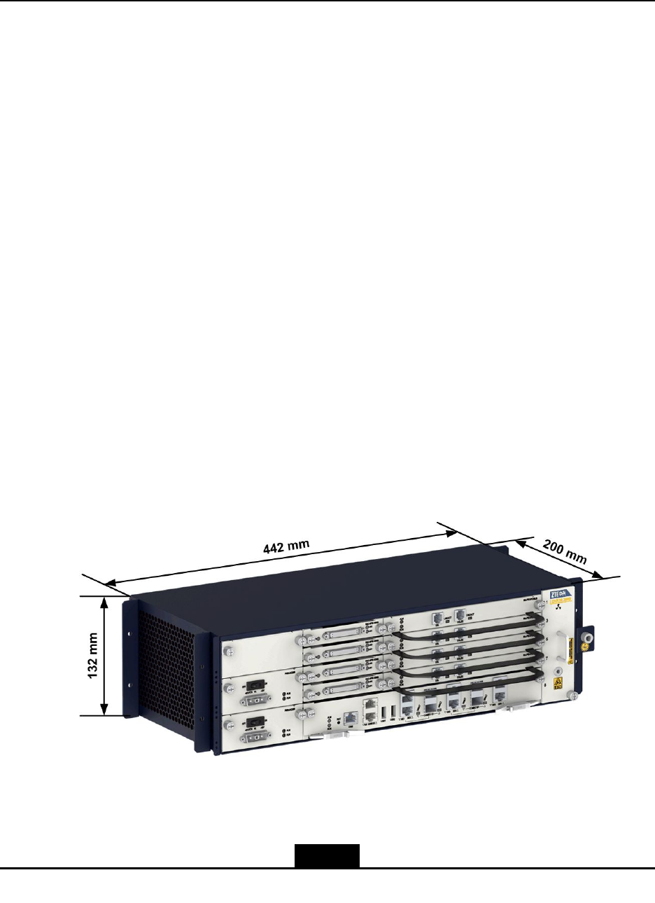
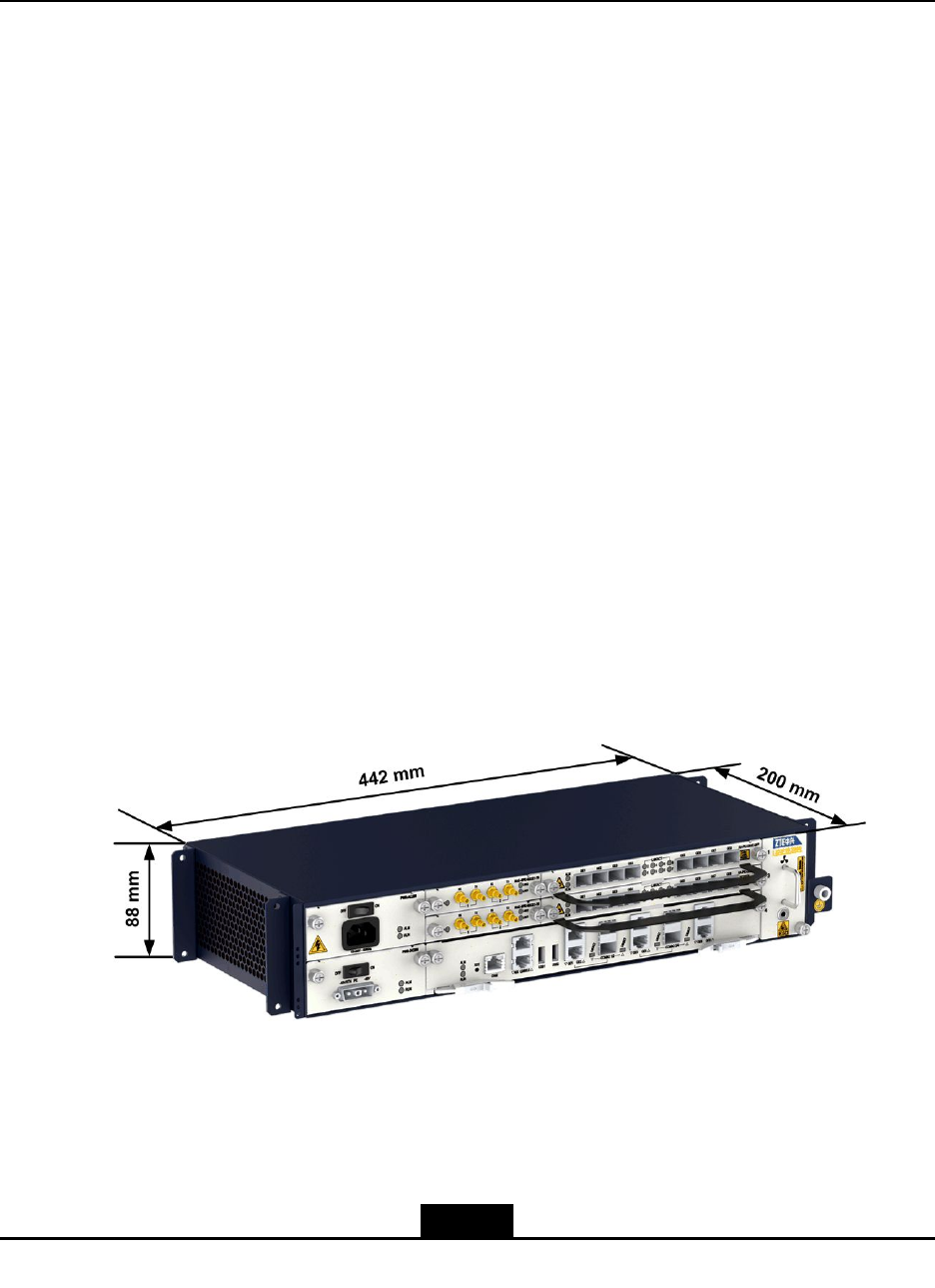
TheheightoftheZXR103800-8chassisis3U(1U=1.75in.=44.45mm),andthe
dimensions(width×height×depth)are17.41in.×5.20in.×7.88in.(442mm×132mm
×200mm).ForthemaincomponentsoftheZXR103800-8chassis,seeFigure2-1.
Figure2-1MainComponentsontheFrontSideoftheZXR103800-8Chassis
ForthefrontviewoftheZXR103800-8chassis,seeFigure2-2.
2-1
SJ-20150204153047-004|2015-03-30(R1.0)ZTEProprietaryandCondential
ZXR10ZSRV2HardwareDescription
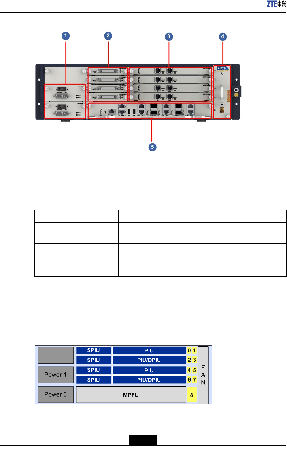
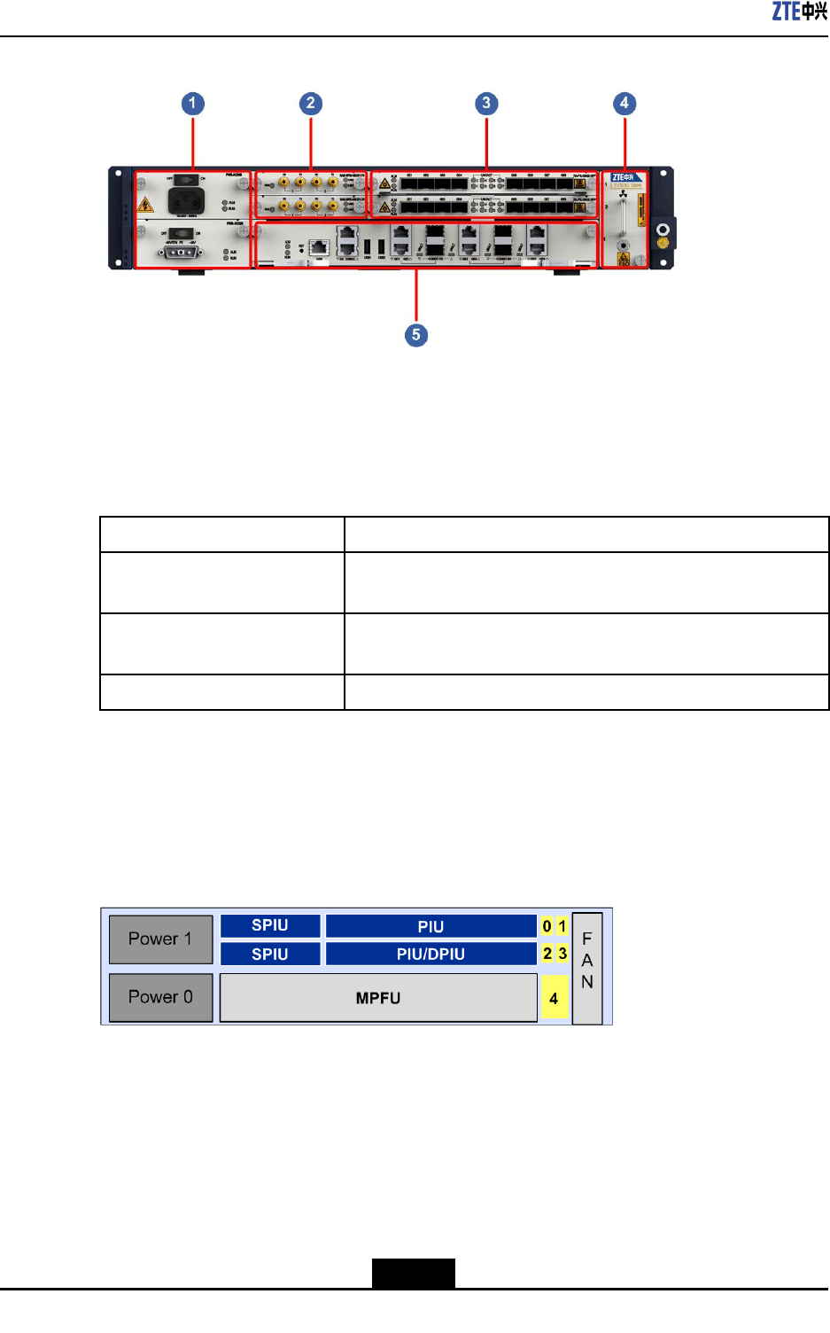
Figure2-2FrontViewoftheZXR103800-8Chassis
1.Powersupplymodule
2.SPIUlineinterfaceboard
slots
3.PIU/DPIUlineinterface
boardslots
4.Fanmodule
5.MPFUslots
ForadescriptionofthemaincomponentsoftheZXR103800-8chassis,refertoT able2-1.
Table2-1DescriptionoftheMainComponentsoftheZXR103800-8Chassis
ComponentNameDescription
BoardareaTheZXR103800-8providesoneslotforthemaincontrol
forwardingboardandatmosteightslotsforlineinterfaces.
PowersupplymoduleTheZXR103800-8providestwoslotsforpowermodules.Y oucan
congureoneortwopowermodules.
FanmoduleTheZXR103800-8providesoneverticallyinstalledfanmodule.
2.1.2SlotLayout
ForafrontviewoftheZXR103800-8chassis,seeFigure2-3.
Figure2-3FrontViewoftheZXR103800-8Chassis
TheZXR103800-8chassisprovidesnineserviceslotsandboardsarehorizontallyinstalled
inthechassis.
2-2
SJ-20150204153047-004|2015-03-30(R1.0)ZTEProprietaryandCondential
Chapter2ZXR103800-8Chassis
lTheMPFUisinstalledinslot8.
lPIUs/DPIUsandSPIUsareinstalledinslots0to7.
TheSPIUslotsareapplicabletoSPIUboards.ThePIUslotsareapplicabletoPIU
boards.TheDPIUboardusestwoslots,includingonePIUslotanditsneighboring
PIU/DPIUslot.
2.1.3SystemParameters
ForthesystemparametersoftheZXR103800-8,refertoTable2-2.
Table2-2SystemParametersoftheZXR103800-8
ParameterSpecication
Dimensions(width×
height×depth)
17.41in.×5.20in.×7.88in.(442mm×132
mm×200mm)
Weight(full
conguration)
<25.4lb.(11.5kg)
Physicalparameter
Maximumpower
consumption
<240W
Memory2GB Storagecapacity
FLASH4GB
Totalnumberofslots9 Slot
NumberofPIUslots8
Redundancymode1+1redundancy,supportingACandDCmixed
powersupply
Maximumoutputpower250W
Ratedinputvoltage-60VDCto-48VDC
DCpower(single)
Inputvoltagerange-72VDCto-38VDC
Redundancymode1+1redundancy,supportingACandDCmixed
powersupply
Ratedinputvoltage100VACto240VAC
Inputfrequencyrange50Hzto60Hz
ACpower(single)
Ratedoutputpowerper
module
250W
HeatdissipationsystemNumberoffanmodules1
GroundingresistanceResistanceofjointgrounding<5Ω
2-3
SJ-20150204153047-004|2015-03-30(R1.0)ZTEProprietaryandCondential
ZXR10ZSRV2HardwareDescription
2.2PowerSupply
TheZXR10ZSRV2seriesrouterssupport100Vto240V,50Hzto60HzACpower
supplyand-72Vto-38VDCpowersupply.TheZXR103800-8supportsACandDC
mixedpowersuppliesoperatingin1+1redundancymode,andthepowersupplymodules
arehotswappable.
Apowersupplymoduleprovidesthefollowingfunctions:
lInput/outputover/undervoltagealarmandprotection.
lOutputovercurrentalarmandprotection.
lTemperaturealarmandoverheatingprotection.
Caution!
Pleasedisconnectallpowersupplybeforeservicing.
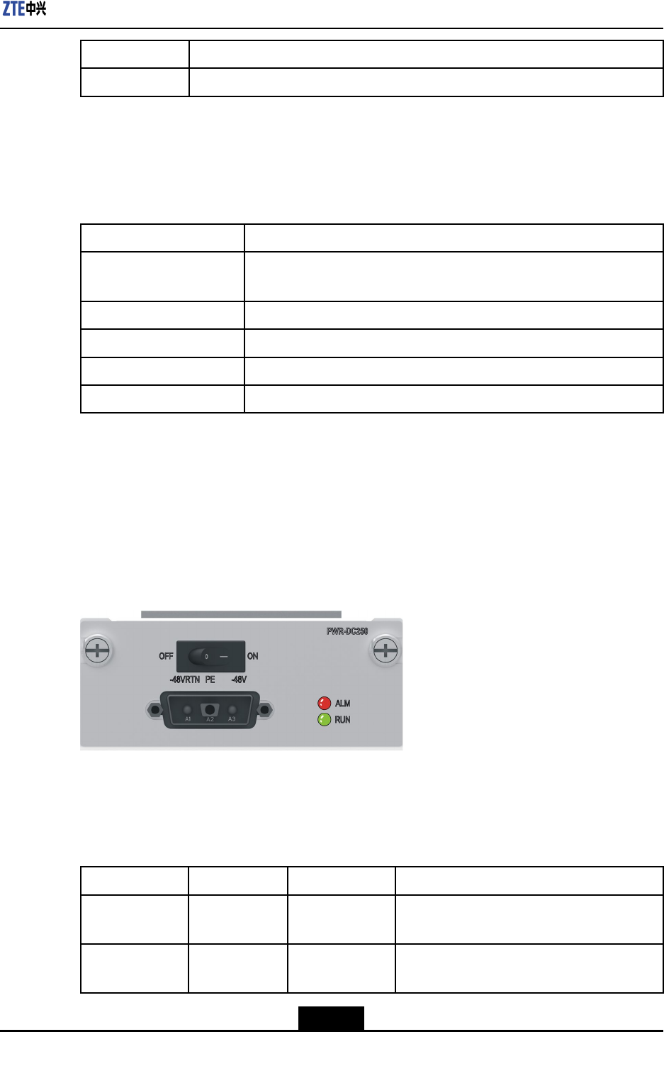
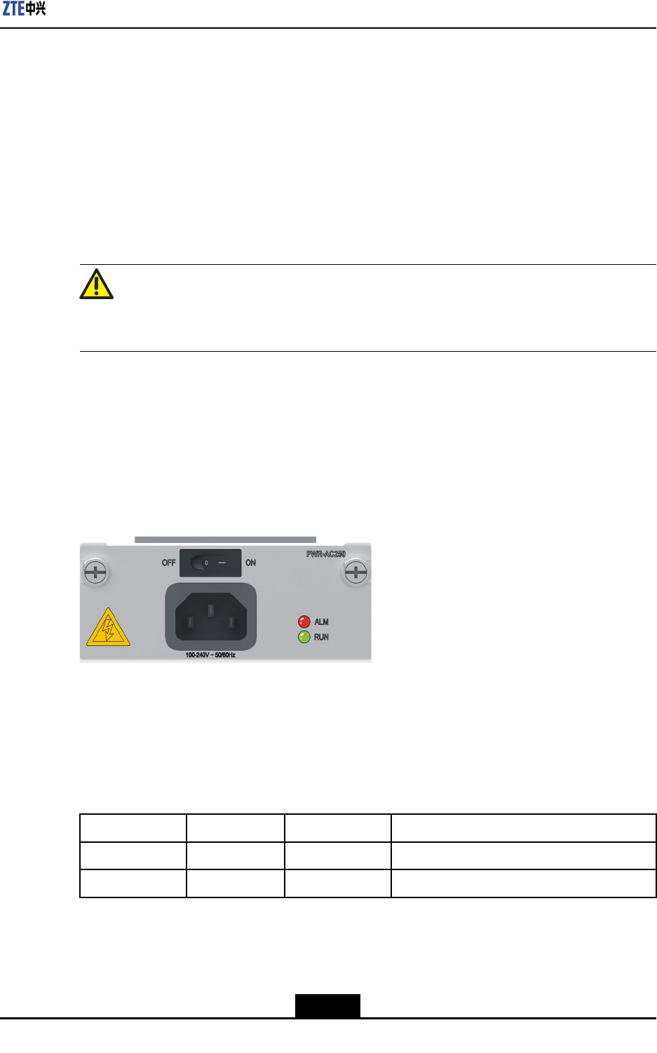
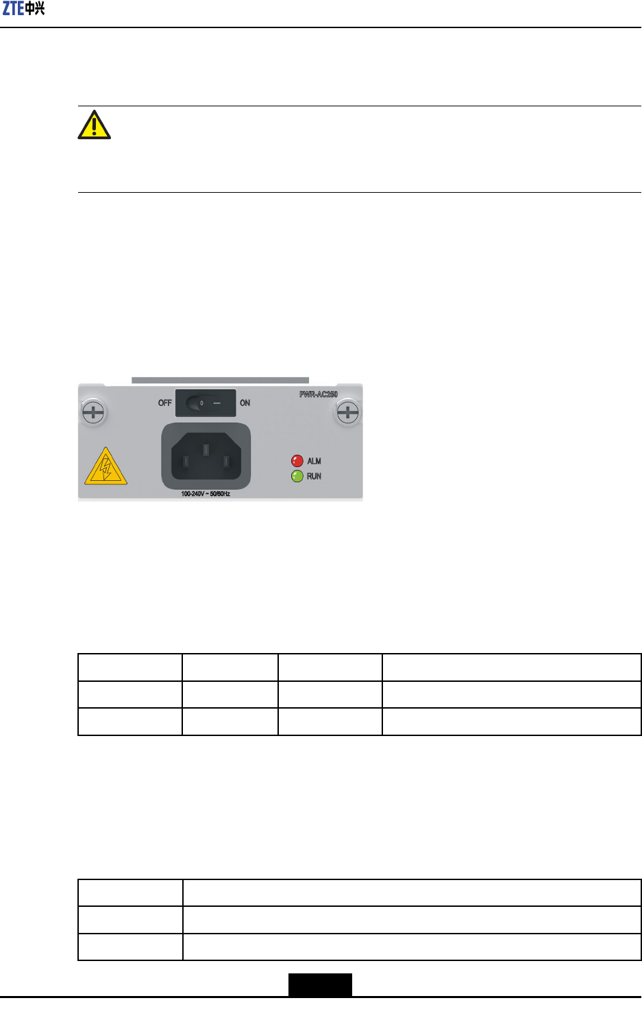
2.2.1ACPowerSupplyModule
Panel
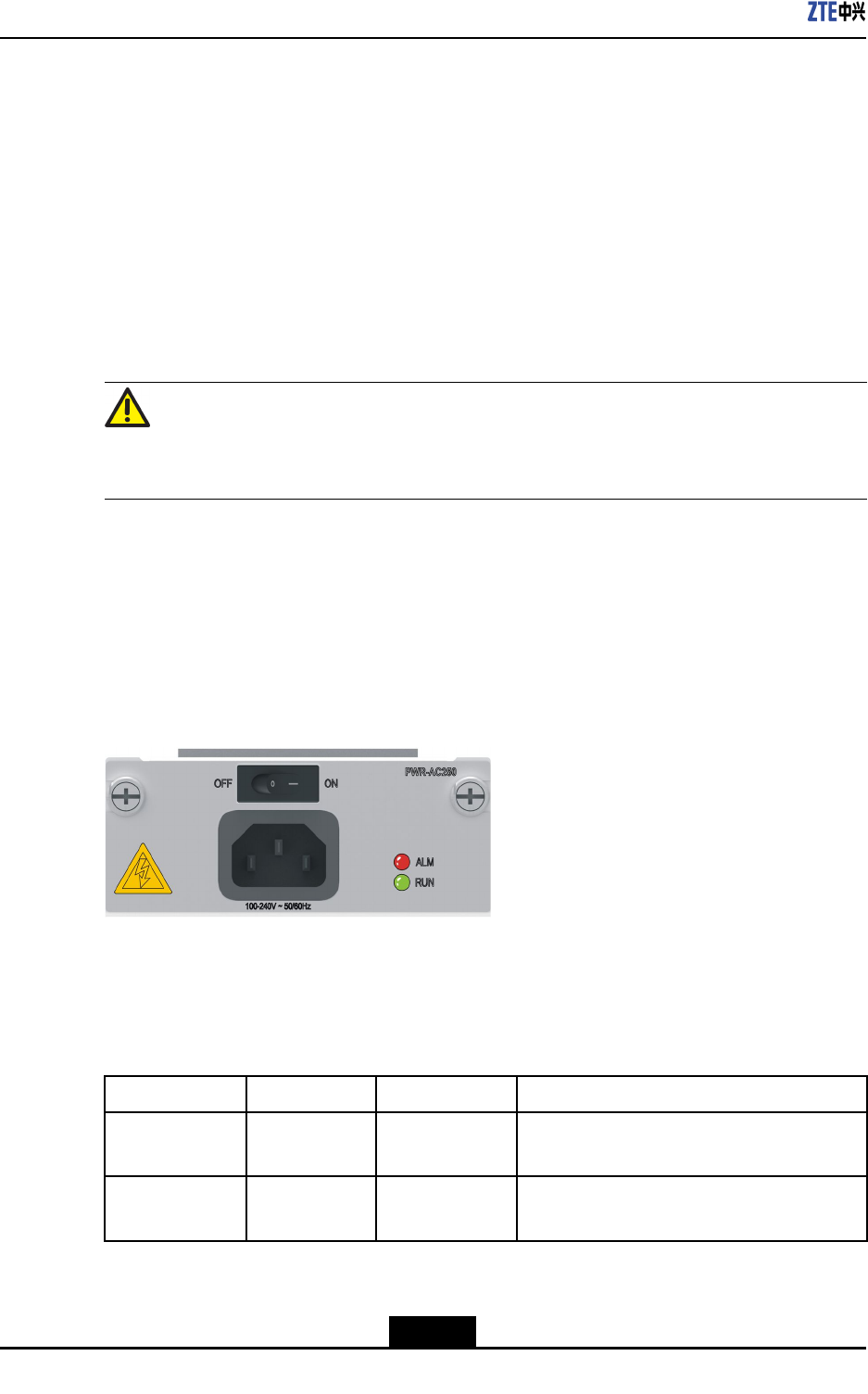
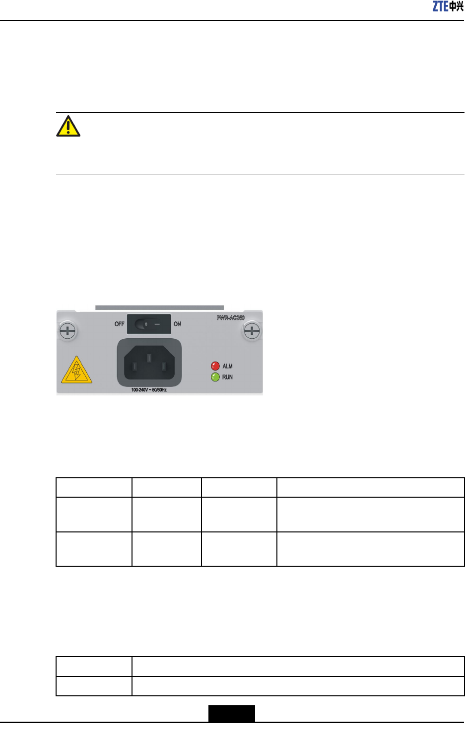
ForthefrontviewoftheACpowersupplymoduleoftheZXR103800-8,seeFigure2-4.
Figure2-4PaneloftheACPowerSupplyModule
Indicators
ForadescriptionoftheZXR103800-8ACpowersupplyindicators,refertoT able2-3.
Table2-3IndicatorDescriptionsfortheZXR103800-8ACPowerSupplyModule
IndicatorNumberColorDescription
RUN1GreenIndicatesthatthepowersupplymodule
operatesproperly.
ALM1RedIndicatesthatthepowersupplymodulehas
analarm.
2-4
SJ-20150204153047-004|2015-03-30(R1.0)ZTEProprietaryandCondential
Chapter2ZXR103800-8Chassis
Buttons
ThereisonepowerbuttonontheZXR103800-8ACpowersupplymodule.Fora
descriptionofthebutton,refertoT able2-4.
Table2-4PowerButtonDescriptionfortheZXR103800-8ACPowerSupplyModule
ButtonDescription
ON(—)Powersonthepowersupplymodule.
OFF(O)Powersoffthepowersupplymodule.
TechnicalParameters
ForthetechnicalparametersoftheACpowerrectieroftheZXR103800-8,refertoTable
2-5.
Table2-5TechnicalParametersoftheACPowerRectieroftheZXR103800-8
ParameterSpecication
Dimensions(height×
width×depth)
3.15in.×1.57in.×6.89in.(80mm×40mm×175mm)
Weight0.68kg
Inputvoltagerange100VACto240VAC
ACinputfrequency50Hzto60Hz
Ratedoutputpower250W
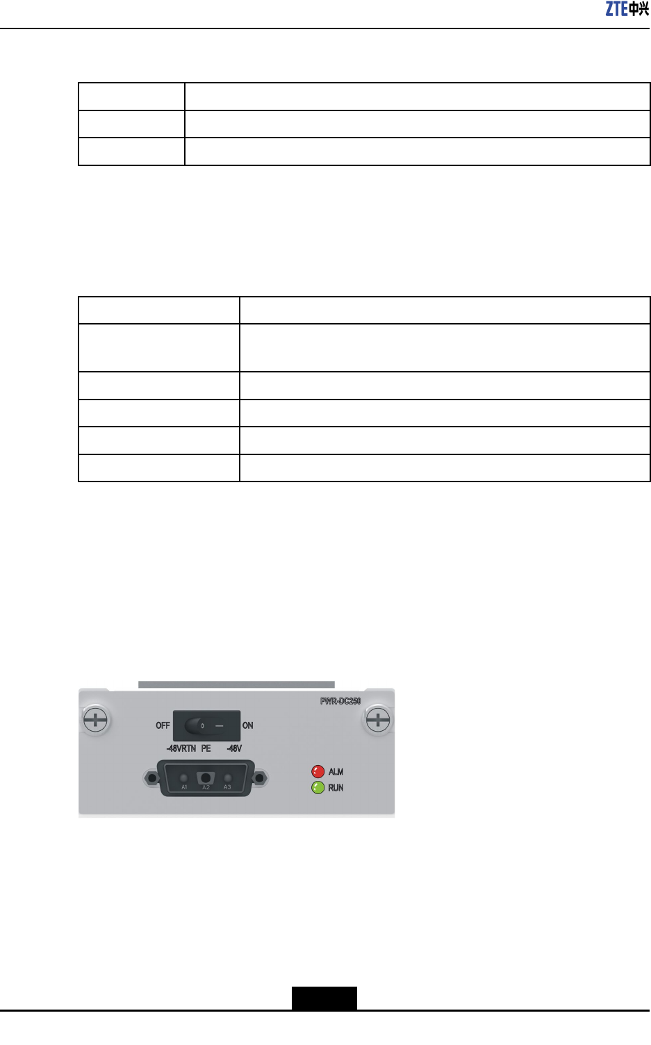
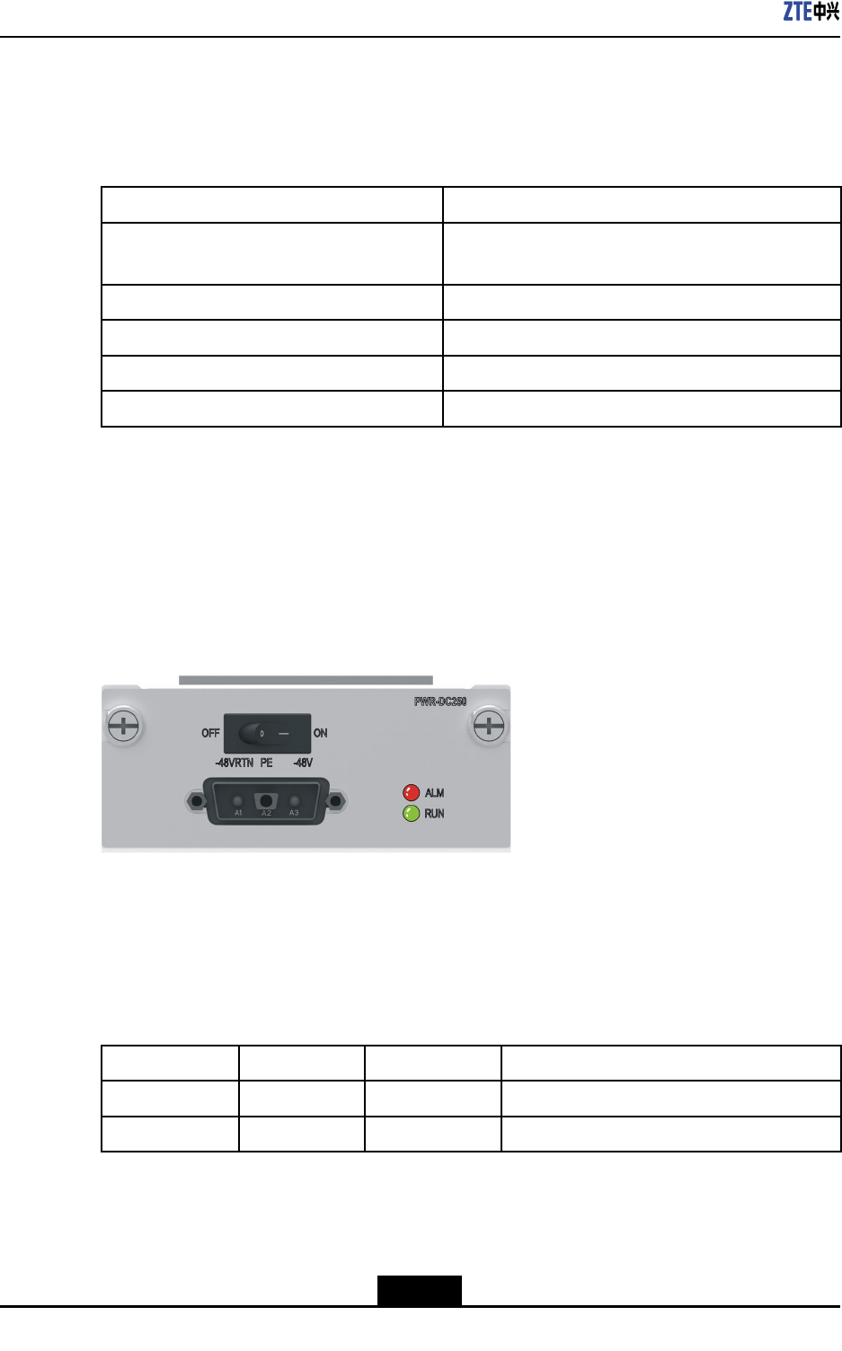
2.2.2DCPowerSupplyModule
Panel
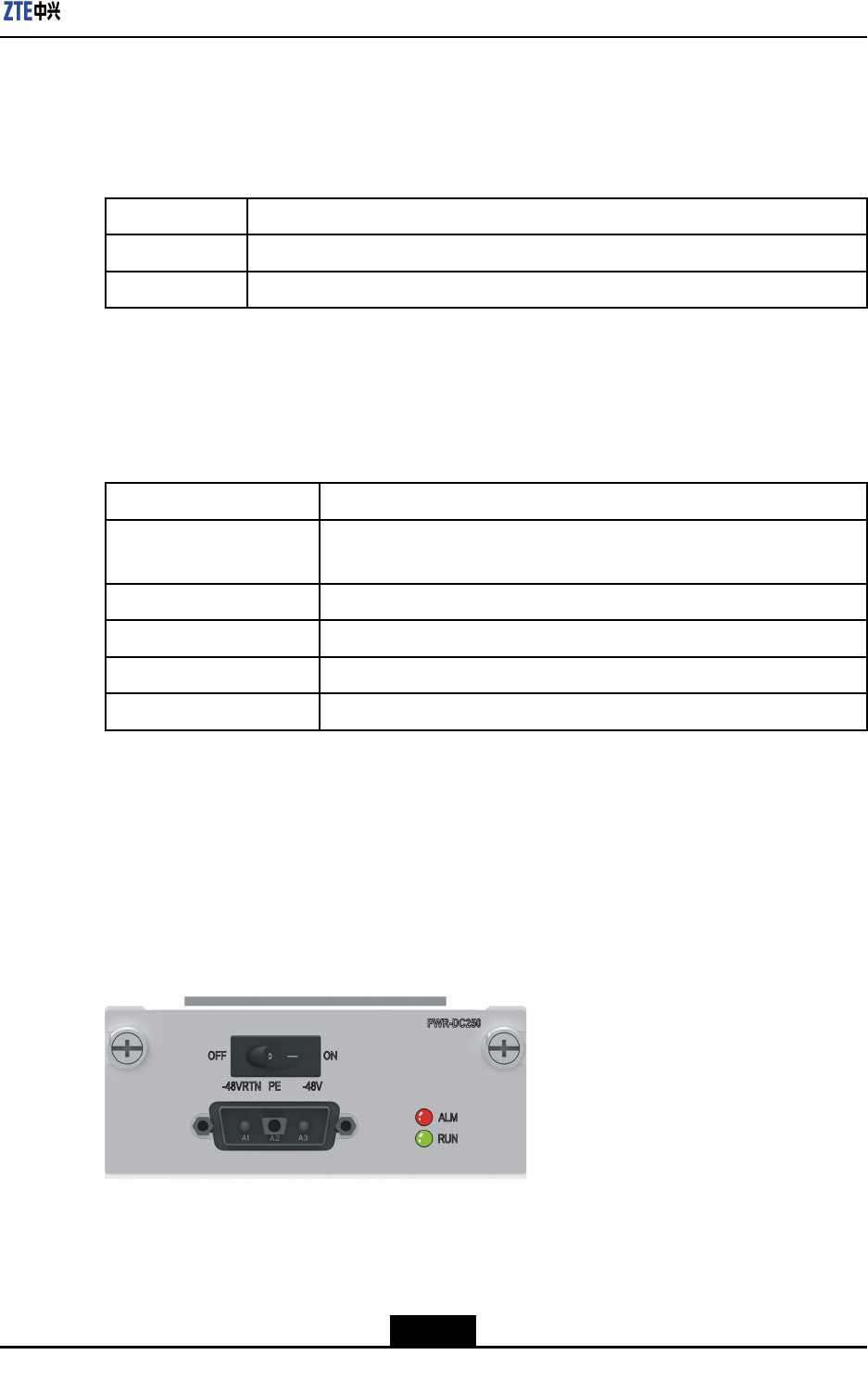
ForthefrontviewoftheDCpowersupplymoduleoftheZXR103800-8,seeFigure2-5.
Figure2-5PaneloftheDCPowerSupplyModule
Indicators
ForadescriptionoftheZXR103800-8DCpowersupplyindicators,refertoTable2-6.
2-5
SJ-20150204153047-004|2015-03-30(R1.0)ZTEProprietaryandCondential
ZXR10ZSRV2HardwareDescription
Table2-6IndicatorDescriptionsfortheZXR103800-8DCPowerSupplyModule
IndicatorNumberColorDescription
RUN1GreenIndicatesthatthepowersupplymodule
operatesproperly.
ALM1RedIndicatesthatthepowersupplymodulehas
analarm.
Buttons
ThereisonepowerbuttonontheZXR103800-8DCpowersupplymodule.Fora
descriptionofthebutton,refertoT able2-7.
Table2-7PowerButtonDescriptionfortheZXR103800-8DCPowerSupplyModule
ButtonDescription
ON(—)Powersonthepowersupplymodule.
OFF(O)Powersoffthepowersupplymodule.
TechnicalParameters
ForthetechnicalparametersoftheDCpowersupplymoduleoftheZXR103800-8,refer
toTable2-8.
Table2-8TechnicalParametersoftheDCPowerSupplyModuleoftheZXR103800-8
ParameterSpecication
Dimensions(height×width×
depth)
3.15in.×1.57in.×6.89in.(80mm×40mm×175mm)
Weight1.45lb.(0.52kg)
Inputvoltagerange-72VDCto-48VDC
Maximumoutputpower250W
Ratedinputcurrent8.5A
2.3FANModule
ThereisaverticalfanmoduleintheZXR103800-8chassis,whichconsistsoffourfans.
Thecoolairentersthechassisfromitslateralside,owstotheboardsandpowersupply
modules,andthenisblownoutfromtheotherside.
Thefanmodulecanautomaticallyadjustthefanspeedaccordingtotheequipment
operationandsupportsthestatusmonitoringandalarmfunctions.
ForthetechnicalspecicationsoftheZXR103800-8fanmodule,refertoTable2-9.
2-6
SJ-20150204153047-004|2015-03-30(R1.0)ZTEProprietaryandCondential

Chapter2ZXR103800-8Chassis
Table2-9ZXR103800-8FanSpecications
ParameterSpecication
Size(W×H×D)40.8mm×125.7mm×186mm
Weight0.62kg
Powerconsumption45W
Maximumwindpressure23mmH2O
Maximumwind287CFM
Maximumnoise60dBA
Operationvoltage12V
2-7
SJ-20150204153047-004|2015-03-30(R1.0)ZTEProprietaryandCondential

ZXR10ZSRV2HardwareDescription
Thispageintentionallyleftblank.
2-8
SJ-20150204153047-004|2015-03-30(R1.0)ZTEProprietaryandCondential
Chapter3
ZXR102800-4Chassis
TheZXR10ZSRV2seriesroutersarehighlyexiblebyusingthemodularstructure,and
theboardsandcomponentsarehotswappable.Theentirerouterconsistsofthechassis,
backplane,MPFU,lineinterfaceboards,powersupplymodules,andfanmodules.
TheZXR102800-4chassisusestheplatemetalstructure.Theboards,powersupply
modules,andfanmodulesareinstalledonthefrontpanel,andthefrontleading-outmode
(opticalberinterfaces)isused.ThewidthoftheZXR102800-4chassiscomplieswith
the19-inchstandardandcanbeinstalledinIEC297orETSIstandardcabinets.
TableofContents
Structure....................................................................................................................3-1
PowerSupply.............................................................................................................3-3
Fan............................................................................................................................3-6
3.1Structure
3.1.1OverviewandStructure
TheheightoftheZXR102800-4chassisis2U(1U=1.75in.=44.45mm),andthe
dimensions(width×height×depth)are17.41in.×3.46in.×7.88in.(442mm×88mm
×200mm).ForthemaincomponentsoftheZXR102800-4chassis,seeFigure3-1.
Figure3-1MainComponentsontheFrontSideoftheZXR102800-4Chassis
ForthefrontviewoftheZXR102800-4chassis,seeFigure3-2.
3-1
SJ-20150204153047-004|2015-03-30(R1.0)ZTEProprietaryandCondential
ZXR10ZSRV2HardwareDescription
Figure3-2FrontViewoftheZXR102800-4Chassis
1.Powersupplymodule
2.SPIUlineinterfaceboard
slots
3.PIU/DPIUlineinterface
boardslots
4.Fanmodule
5.MPFUslots
ForadescriptionofthemaincomponentsoftheZXR102800-4chassis,refertoT able3-1.
Table3-1DescriptionoftheMainComponentsoftheZXR102800-4Chassis
ComponentNameDescription
BoardareaTheZXR102800-4providesoneslotforthemaincontrol
forwardingboardandatmostfourslotsforlineinterfaces.
PowersupplymoduleTheZXR102800-4providestwoslotsforpowermodules.Youcan
congureoneortwopowermodules.
FanmoduleTheZXR102800-4providesoneverticallyinstalledfanmodule.
3.1.2SlotLayout
ForafrontviewoftheZXR102800-4chassis,seeFigure3-3.
Figure3-3FrontViewoftheZXR102800-4Chassis
TheZXR102800-4chassisprovidesveserviceslotsandboardsarehorizontallyinstalled
inthechassis.
lTheMPFUisinstalledinslot4.
lPIUs/DPIUsandSPIUsareinstalledinslots0to3.
TheSPIUslotsareapplicabletoSPIUboards.ThePIUslotsareapplicabletoPIU
boards.TheDPIUboardusestwoslots,includingonePIUslotanditsneighboring
PIU/DPIUslot.
3-2
SJ-20150204153047-004|2015-03-30(R1.0)ZTEProprietaryandCondential
Chapter3ZXR102800-4Chassis
3.1.3SystemParameters
ForthesystemparametersoftheZXR102800-4,refertoTable3-2.
Table3-2SystemParametersoftheZXR102800-4
ParameterSpecication
Dimensions(width×
height×depth)
17.41in.×3.46in.×7.88in.(442mm×88mm
×200mm)
Weight(full
conguration)
<19.0lb.(8.6kg)
Physicalparameter
Maximumpower
consumption
<160W
Memory2GB Storagecapacity
FLASH4GB
Totalnumberofslots5 Slot
NumberofPIUslots4
Redundancymode1+1redundancy,supportingACandDCmixed
powersupply
Maximumoutput
power
250W
Ratedinputvoltage-60VDCto-48VDC
DCpower(single)
Inputvoltagerange-72VDCto-38VDC
Redundancymode1+1redundancy,supportingACandDCmixed
powersupply
Ratedinputvoltage100VACto240VAC
Inputfrequencyrange50Hzto60Hz
ACpower(single)
Ratedoutputpower
permodule
250W
HeatdissipationsystemNumberoffan
modules
1
GroundingresistanceResistanceofjointgrounding<5Ω
3.2PowerSupply
TheZXR10ZSRV2seriesrouterssupport100Vto240V,50Hzto60HzACpower
supplyand-72Vto-38VDCpowersupply.TheZXR102800-4supportsACandDC
mixedpowersuppliesoperatingin1+1redundancymode,andthepowersupplymodules
arehotswappable.
3-3
SJ-20150204153047-004|2015-03-30(R1.0)ZTEProprietaryandCondential
ZXR10ZSRV2HardwareDescription
Apowersupplymoduleprovidesthefollowingfunctions:
lInput/outputover/undervoltagealarmandprotection.
lOutputovercurrentalarmandprotection.
lTemperaturealarmandoverheatingprotection.
Caution!
Pleasedisconnectallpowersupplybeforeservicing.
3.2.1ACPowerSupplyModule
Panel
ForthefrontviewoftheACpowersupplymoduleoftheZXR102800-4,seeFigure3-4.
Figure3-4PaneloftheACPowerSupplyModule
Indicators
ForadescriptionoftheZXR102800-4ACpowersupplyindicators,refertoT able3-3.
Table3-3IndicatorDescriptionsfortheZXR102800-4ACPowerSupplyModule
IndicatorNumberColorDescription
RUN1GreenIndicatesthatthepowersupplymodule
operatesproperly.
ALM1RedIndicatesthatthepowersupplymodulehas
analarm.
Buttons
ThereisonepowerbuttonontheZXR102800-4ACpowersupplymodule.Fora
descriptionofthebutton,refertoT able3-4.
Table3-4PowerButtonDescriptionfortheZXR102800-4ACPowerSupplyModule
ButtonDescription
ON(—)Powersonthepowersupplymodule.
3-4
SJ-20150204153047-004|2015-03-30(R1.0)ZTEProprietaryandCondential
Chapter3ZXR102800-4Chassis
ButtonDescription
OFF(O)Powersoffthepowersupplymodule.
TechnicalParameters
ForthetechnicalparametersoftheACpowerrectieroftheZXR102800-4,refertoTable
3-5.
Table3-5TechnicalParametersoftheACPowerRectieroftheZXR102800-4
ParameterSpecication
Dimensions(height×
width×depth)
3.15in.×1.57in.×6.89in.(80mm×40mm×175mm)
Weight0.68kg
Inputvoltagerange100VACto240VAC
ACinputfrequency50Hzto60Hz
Ratedoutputpower250W
3.2.2DCPowerSupplyModule
Panel
ForthefrontviewoftheDCpowersupplymoduleoftheZXR102800-4,seeFigure3-5.
Figure3-5PaneloftheDCPowerSupplyModule
Indicators
ForadescriptionoftheZXR102800-4DCpowersupplyindicators,refertoTable3-6.
Table3-6IndicatorDescriptionsfortheZXR102800-4DCPowerSupplyModule
IndicatorNumberColorDescription
RUN1GreenIndicatesthatthepowersupplymodule
operatesproperly.
ALM1RedIndicatesthatthepowersupplymodulehas
analarm.
3-5
SJ-20150204153047-004|2015-03-30(R1.0)ZTEProprietaryandCondential
ZXR10ZSRV2HardwareDescription
Buttons
ThereisonepowerbuttonontheZXR102800-4DCpowersupplymodule.Fora
descriptionofthebutton,refertoT able3-7.
Table3-7PowerButtonDescriptionfortheZXR102800-4DCPowerSupplyModule
ButtonDescription
ON(—)Powersonthepowersupplymodule.
OFF(O)Powersoffthepowersupplymodule.
TechnicalParameters
ForthetechnicalparametersoftheDCpowersupplymoduleoftheZXR102800-4,refer
toTable3-8.
Table3-8TechnicalParametersoftheDCPowerSupplyModuleoftheZXR102800-4
ParameterSpecication
Dimensions(height×width×
depth)
3.15in.×1.57in.×6.89in.(80mm×40mm×175mm)
Weight1.45lb.(0.52kg)
Inputvoltagerange-72VDCto-38VDC
Maximumoutputpower250W
Ratedinputcurrent8.5A
3.3Fan
ThereisaverticalfanmoduleintheZXR102800-4chassis,whichconsistsoftwofans.
Thecoolairentersthechassisfromitslateralside,owstotheboardsandpowersupply
modules,andthenisblownoutfromtheotherside.
Thefanmodulecanautomaticallyadjustthefanspeedaccordingtotheequipment
operationandsupportsthestatusmonitoringandalarmfunctions.
ForthetechnicalspecicationsoftheZXR102800-4fanmodule,refertoTable3-9.
Table3-9ZXR102800-4FanSpecications
ParameterSpecication
Size(W×H×D)40.8mm×81.1mm×186mm
Weight0.44kg
Powerconsumption30W
Maximumwindpressure23mmH2O
Maximumwind191CFM
3-6
SJ-20150204153047-004|2015-03-30(R1.0)ZTEProprietaryandCondential

Chapter3ZXR102800-4Chassis
ParameterSpecication
Maximumnoise58dBA
Operationvoltage12V
3-7
SJ-20150204153047-004|2015-03-30(R1.0)ZTEProprietaryandCondential

ZXR10ZSRV2HardwareDescription
Thispageintentionallyleftblank.
3-8
SJ-20150204153047-004|2015-03-30(R1.0)ZTEProprietaryandCondential

Chapter4
ZXR101800-2SChassis
TheZXR10ZSRV2seriesroutersarehighlyexiblebyusingthemodularstructure,and
theboardsandcomponentsarehotswappable.Theentirerouterconsistsofthechassis,
backplane,MPFU,lineinterfaceboards,powersupplymodules,andfanmodules.
TheZXR101800-2Sisadesktopproduct.ThepowersupplymoduleandMPFUarexed
inthechassis.Theserviceboardsareinstalledontherearpanelandtherearleading-out
modeisused.
TheZXR101800-2Shastwoextensiontypesconguredwithwirelessmodules:ZXR10
1800-2S(G)andZXR101800-2S(W).
lTheZXR101800-2S(G)hasabuilt-inLTEmodule,whereaSIMcardslotisavailable
forsupportingGSM,WCDMA,TD-SCDMA,orLTEnetworks.
lTheZXR101800-2S(W)hasabuilt-inWiFimoduleforsupportingtheWiFifunction.
TableofContents
Structure....................................................................................................................4-1
PowerSupply.............................................................................................................4-6
4.1Structure
4.1.1OverviewandStructure
Overview
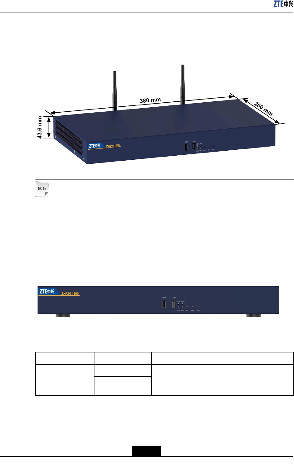
TheheightoftheZXR101800-2Schassis(excludingtheantenna)is1U(1U=44.45mm),
andthedimension(width×height×depth)380mm×43.6mm×200mm.Foradescription
ofthemaincomponentsoftheZXR101800-2S,refertoTable4-1.
Table4-1DescriptionsoftheMainComponentsoftheZXR101800-2S
ComponentNameDescription
BoardareaTheZXR101800-2Sprovidesamaximumoftwolineinterface
cardslots.
MPFUTheMPFUoftheZXR101800-2Sisintegratedintothechassis
andcannotberemoved.
PowersupplymoduleThepowersupplymoduleoftheZXR101800-2Sisintegratedon
thedevice,andcannotberemovedorinstalled.
4-1
SJ-20150204153047-004|2015-03-30(R1.0)ZTEProprietaryandCondential
ZXR10ZSRV2HardwareDescription
FrontPanel
Figure4-1showsthefrontviewoftheZXR101800-2S.
Figure4-1ZXR101800-2SFrontView
Note:
BothoftheZXR101800-2S(G)andtheZXR101800-2S(W)supportthewirelessfunction.
Eachofthemisconguredwithawirelessmoduleandapairofantennas.Ifnowireless
moduleiscongured,thechassishasnoantenna.
Figure4-2showsthepanelviewoftheZXR101800-2S.
Figure4-2ZXR101800-2SFrontPanel
ForadescriptionoftheZXR101800-2Sfrontpanel,refertoT able4-2.
Table4-2ZXR101800-2SFrontPanelDescriptions
ComponentSilkScreenNameDescription
USB1 USBinterfaces
USB2
USB2.0interface,usedforstoringinstallation
packagesandotherdata,supporting3Gextension
andcommissioningthroughUSB.
4-2
SJ-20150204153047-004|2015-03-30(R1.0)ZTEProprietaryandCondential
Chapter4ZXR101800-2SChassis
ComponentSilkScreenNameDescription
ALMAlarmindicator,red.
PWRPowersupplyindicator,green.
SYSSystemoperationindicator,green.
Indicators
WIFI/WWANWirelessoperationindicator,green
lIfaWiFimoduleiscongured,WIFIisdisplayed
ontheindicatorlabel.Thisindicatorindicates
whethertheWiFifunctionoperatesproperly.
lIfanLTEmoduleiscongured,WWANis
displayedontheindicatorlabel.Thisindicator
indicateswhethertheLTEfunctionoperates
properly.
RSTResetbutton.
WIFIWiFifunctionbutton,whichisavailableonlyonthe
chassisoftheZXR101800-2S(W).
Buttons
WPSWiFiconnectionreestablishmentbutton,which
isavailableonlyonthechassisoftheZXR10
1800-2S(W).
Note:
TheZXR101800-2SwithoutanywirelessmoduledoesnothavetheWIFIindicator,WIFI
button,orWPSbutton.
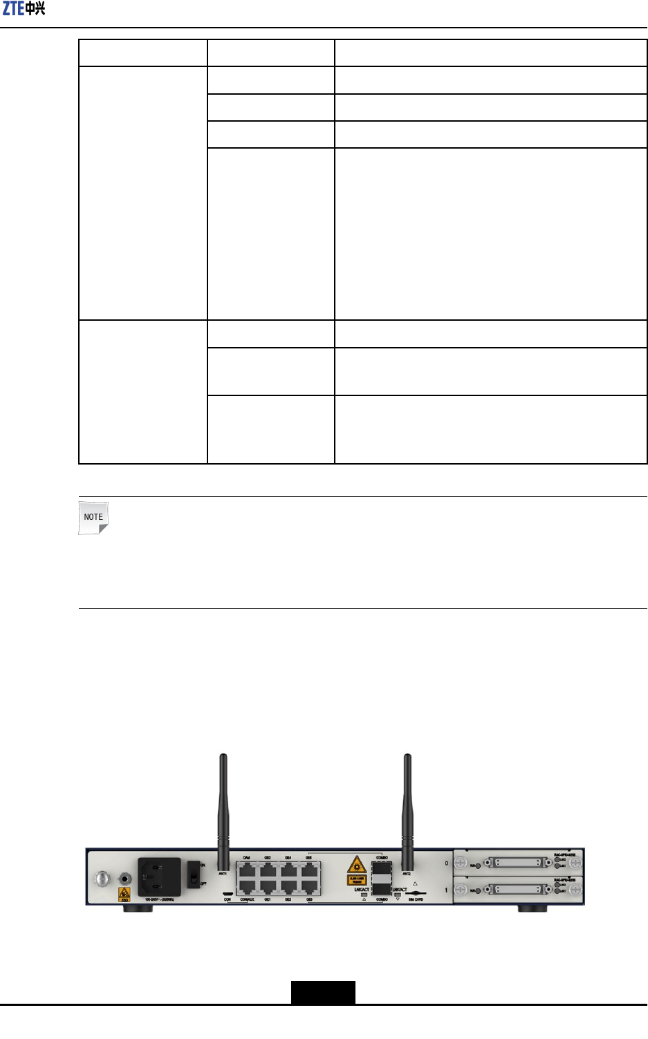
RearPanel
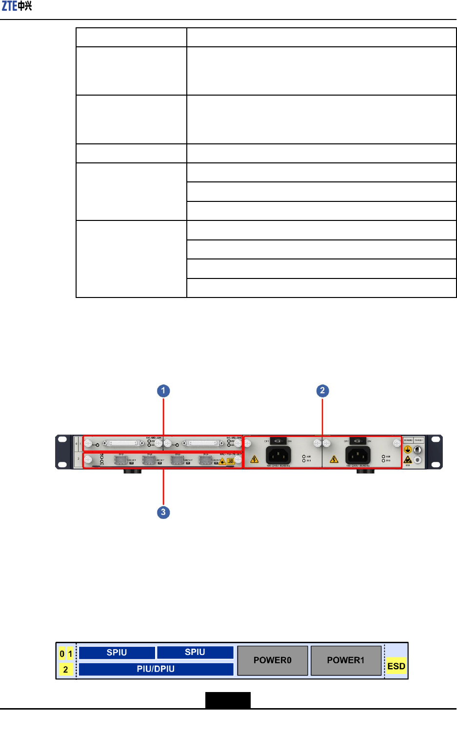
Figure4-3showstherearpaneloftheZXR101800-2S.
Figure4-3ZXR101800-2SRearPanel
4-3
SJ-20150204153047-004|2015-03-30(R1.0)ZTEProprietaryandCondential
ZXR10ZSRV2HardwareDescription
Note:
BothoftheZXR101800-2S(G)andtheZXR101800-2S(W)supportthewirelessfunction.
Eachofthemisconguredwithawirelessmoduleandapairofantennas.Ifnowireless
moduleiscongured,thechassishasnoantenna.
ForadescriptionoftheZXR101800-2Srearpanel,refertoT able4-3.
Table4-3ZXR101800-2SRearPanelDescriptions
ComponentSilkScreenNameDescription
ANT1–2AntennainterfaceAntennaslot,whereanantennaisinstalledifa
wirelessmoduleiscongured.
OAMNetworkinterface
(RJ45)
Networkport(10M/100M/1000M)usedforsystem
maintenanceandprogramdownloading.
CONMicroUSBinterfaceMicroUSBconsoleinterface.Thefunctionsarethe
sameasthoseoftheRJ45CON/AUXinterface.
EitheroftheMicroUSBconsoleinterfaceortheRJ45
CON/AUXinterfaceisused.Thepriorityishigh.
CON/AUXSerialport(RJ45)Debuggingportforsystemmanagementand
conguration.
GE1–4GEelectrical
interface
4GEelectricalinterfaces.
COMBO,GE5–6Combointerface2electrical/opticalcombointerfaces.
SIMCARDSIMcardinterfaceSIMcardinterfaceforsupportingGSM,CDMA2000,
WCDMA,TD-SCDMA,orLTEnetworks.
LNK/ACTIndicatorLinkstatusindicatorsingreenforthetwoCombo
interfaces.
4.1.2SlotLayout
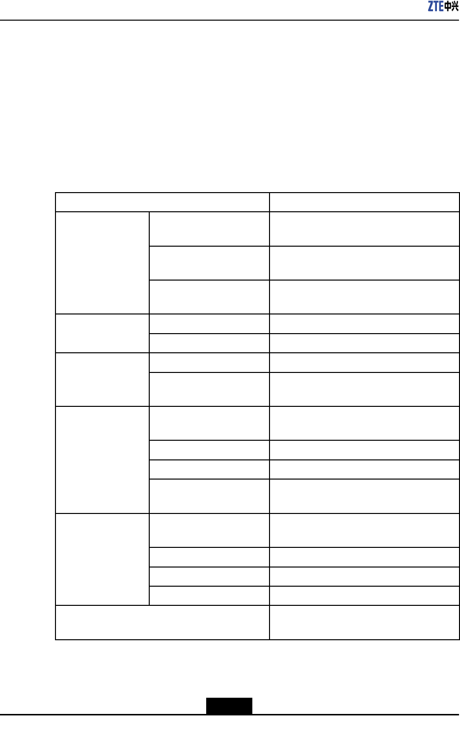
ForafrontviewoftheZXR101800-2Schassis,seeFigure4-4.
Figure4-4FrontViewoftheZXR101800-2SChassis
TheZXR101800-2Schassisprovidestwoserviceslotsandboardsarehorizontally
installedinthechassis.
4-4
SJ-20150204153047-004|2015-03-30(R1.0)ZTEProprietaryandCondential
Chapter4ZXR101800-2SChassis
lBoththepowermoduleandtheMPFUareintegratedintothedevice.Theycannotbe
removed.
lSPIUsareinstalledinslots0and1.
4.1.3SystemParameters
ForthesystemparametersoftheZXR101800-2S,refertoT able4-4.
Table4-4SystemParametersoftheZXR101800-2S
ParameterSpecication
Dimensions(width×
height×depth)
14.96in.×1.72in.×7.88in.(380mm×43.6mm
×200mm)
Weight(full
conguration)
<6.83lb.(3.10kg)
Physical
parameter
Maximumpower
consumption
<55W
Supportedfrequency
band
2.4G WiFifunction
Supportedsystem
standard
IEEE802.11b/g/n
Memory2GB Storagecapacity
FLASH1GB
Totalnumberofslots2 Slot
NumberofPIUslots2
Maximumoutput
power
60W
Ratedinputvoltage-60VDCto-48VDC
DCpower(single)
Inputvoltagerange-72VDCto-38VDC
Ratedinputvoltage100VACto240VAC
Inputfrequencyrange50Hz–60Hz
ACpower(single)
Ratedoutputpower
permodule
60W
GroundingresistanceResistanceofjointgrounding<5Ω
4-5
SJ-20150204153047-004|2015-03-30(R1.0)ZTEProprietaryandCondential
ZXR10ZSRV2HardwareDescription
4.2PowerSupply
Function
TheZXR10ZSRV2seriesrouterssupport100Vto240V,50Hzto60HzACpowersupply
and-72Vto-38VDCpowersupply.TheZXR101800-2SuseseitheroneACpower
supplyoroneDCpowersupply,andthepowersupplymodulesarenothotswappable.
Apowersupplymoduleprovidesthefollowingfunctions:
lInput/outputover/undervoltagealarmandprotection.
lOutputovercurrentalarmandprotection.
lTemperaturealarmandoverheatingprotection.
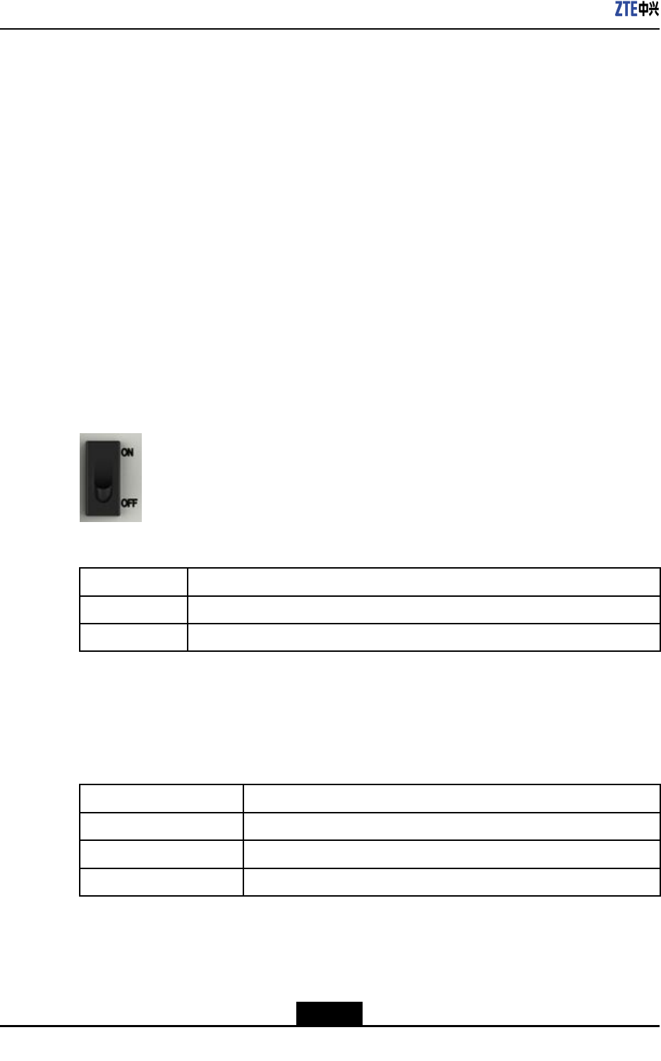
Buttons
ThereisonepowerbuttonontheZXR101800-2Spowersupplymodule,seeFigure4-5.
Foradescriptionofthebutton,refertoT able4-5.
Figure4-5PowerButton
Table4-5PowerButtonDescriptionfortheZXR101800-2SACPowerSupplyModule
ButtonDescription
ONPowersonthepowersupplymodule.
OFFPowersoffthepowersupplymodule.
TechnicalParameters
ForthetechnicalparametersoftheACpowerrectieroftheZXR101800-2S,refertoT able
4-6.
Table4-6TechnicalParametersoftheACPowerRectieroftheZXR101800-2S
ParameterSpecication
Inputvoltagerange100VACto240VAC
ACinputfrequency50Hz–60Hz
Ratedoutputpower60W
ForthetechnicalparametersoftheDCpowerrectieroftheZXR101800-2S,refertoT able
4-7.
4-6
SJ-20150204153047-004|2015-03-30(R1.0)ZTEProprietaryandCondential

Chapter4ZXR101800-2SChassis
Table4-7TechnicalParametersoftheDCPowerRectieroftheZXR101800-2S
ParameterSpecication
Inputvoltagerange-72VDCto-38VDC
Ratedoutputpower60W
4-7
SJ-20150204153047-004|2015-03-30(R1.0)ZTEProprietaryandCondential

ZXR10ZSRV2HardwareDescription
Thispageintentionallyleftblank.
4-8
SJ-20150204153047-004|2015-03-30(R1.0)ZTEProprietaryandCondential

Chapter5
ZXR102800-3EChassis
TheZXR10ZSRV2serialroutershaveastructuredesignedbasedonmodularization.The
boardsandcomponentssupportonlinehotswappingandhaveaexibleexpendability.
AZXR102800-3Echassisiscomposedofasubrack,abackplane,acontrollingand
transferringunit,lineinterfaceboards,powermodules,andfanmodules.
TheZXR102800-3Esubrackhasasheetmetalstructure.Whereinthecontrollingand
transferringunitandfanmodulesarexedonaZXR10ZSRV2router,theserviceboard
andpowermodulesareinstalledattheback,cablesareledoutfromtheback,andthree
lineinterfaceboardscanbeinstalled.TheentireZXR102800-3Echassishasastandard
widthof19"andcanbeinstalledintoastandardIEC297cabinetoranETSIcabinet.
AZXR102800-3E(G)submodelcanbederivedfromaZXR102800-3Echassisby
expandingthewirelessfunctionmodule.TheZXR102800-3E(G)submodelhasa3Gor
LTEmoduleinsideandaslotforaSIMcardonthepanel,supportingaGSM,WCDMA,
TD-SCDMA,orLTEnetwork.
TableofContents
Structure....................................................................................................................5-1
PowerSupplies..........................................................................................................5-5
5.1Structure
5.1.1OverviewandStructure
Overview
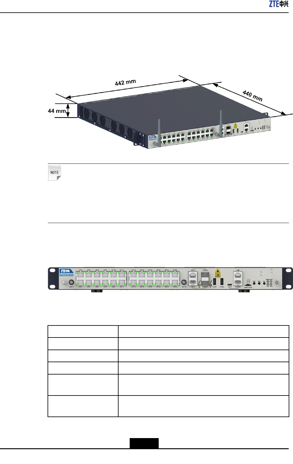
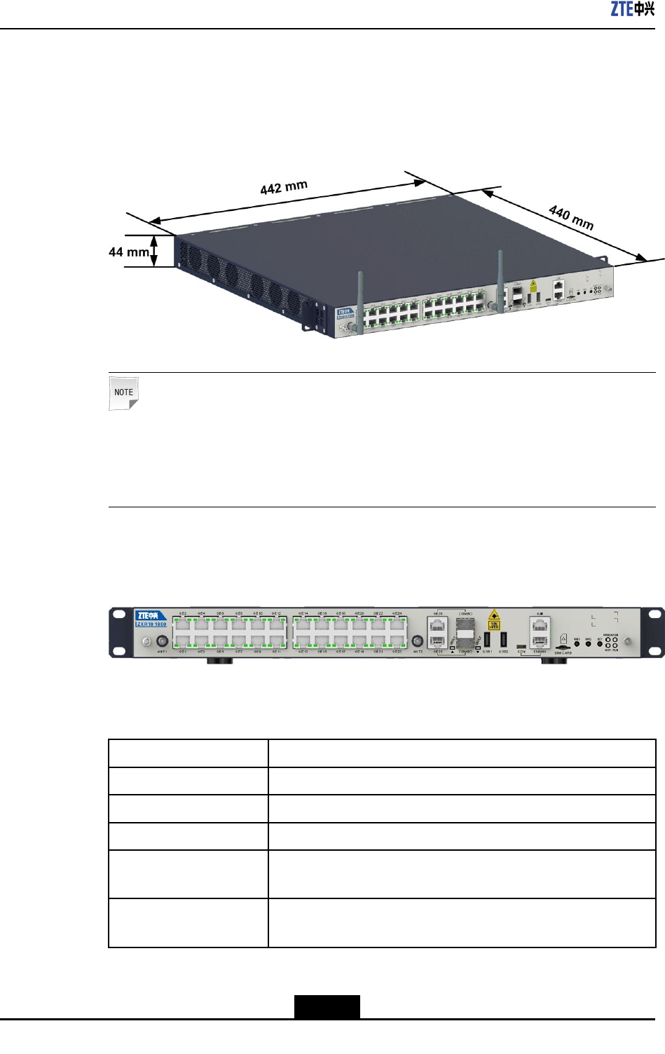
AchassisofaZXR102800-3Erouterhasaheight(withouttheantenna)ofabout1U
(1U=44.45mm),andadimensionof442mm×44mm×440mm(width×height×depth).
Foritscomponentsanddescriptions,refertoT able5-1.
Table5-1MainComponentsofaZXR102800-3EChassis
ComponentDescription
Controllingandtransferring
board
Integratedontherouterandcannotbepluggedorunplugged.
BoardsTheZXR102800-3Echassisprovidesthreeslotsforlineinterface
boards.
PowermodulesTheZXR102800-3Echassisprovidestwoslotsforoneortwo
powermodules.
5-1
SJ-20150204153047-004|2015-03-30(R1.0)ZTEProprietaryandCondential
ZXR10ZSRV2HardwareDescription
FrontPanel
ThefollowingdescribesthefrontviewandfrontpanelofaZXR102800-3Echassis.
lFigure5-1showsthefrontviewofaZXR102800-3Echassis.
Figure5-1FrontStructureGraphforaZXR102800-3EChassis
Note:
TheZXR102800-3E(G)submodeloftheZXR102800-3Echassissupportsthe
wirelessfunction,withabuilt-inwirelessmoduleandantennas.Ifthewireless
moduleisnotcongured,thechassisdoesnothaveanantenna.
lFigure5-2showsthefrontpanelofaZXR102800-3Echassis.
Figure5-2FrontPanelofaZXR102800-3EChassis
Foradescriptionofthefrontpanel,refertoTable5-2.
Table5-2DescriptionsofInterfacesontheFrontPanelofaZXR102800-3EChassis
PartTypeDescription
AntennainterfaceAntennaslot.
GEinterface24GEelectricalinterfaces,supportingtherouteswitchingfunction.
COMBOinterfacesTwoCombointerfaces.
USBinterfacesUSB2.0interfaces,whichareusedtostoreapplicationsandother
dataandsupportcommissioning.
Networkinterface(RJ45)Maintenancenetworkinterface(10M/100M/1000M),whichisused
forsystemcontrolandapplicationdownload.
5-2
SJ-20150204153047-004|2015-03-30(R1.0)ZTEProprietaryandCondential
Chapter5ZXR102800-3EChassis
PartTypeDescription
MicroUSBinterfacesConsoleinterfacesoftheMicroUSBmodel,whichhavethesame
functionsasthoseoftheCON/AUXinterfacesoftheRJ45model
butahigherpriority.Selecteitherone.
Serialinterface(RJ45)Debuggingserialinterfaces(Console/AUXinterfaces)oftheRJ45
model,whichareusedfordevicemanagementandfunction
conguration.
InterfaceforaSIMcardInterfacefora3GorLTESIMcard.
WIFIfunctionbutton.
Buttonforre-establishingaWIFIconnection.
Buttons
Systemresetbutton.
GreenindicatorsforlinkstatusoftwoCombointerfaces.
Redindicatorforsystemfaults.
Greenindicatorforsystemoperationstatus.
Indicators
Greenindicatorfortheoperationstatusofthe3GorLTEnetwork.
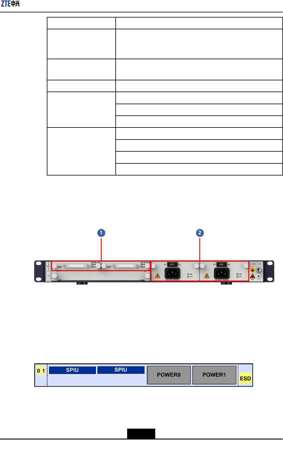
BackPanel
Figure5-3showsthebackpanelofaZXR102800-3Echassis.
Figure5-3BackPanelofaZXR102800-3EChassis
1.Slotforaninterfaceboard
oftheSPIUline
2.Powermodule3.Slotforaninterfaceboard
ofthePIU/SPIUline
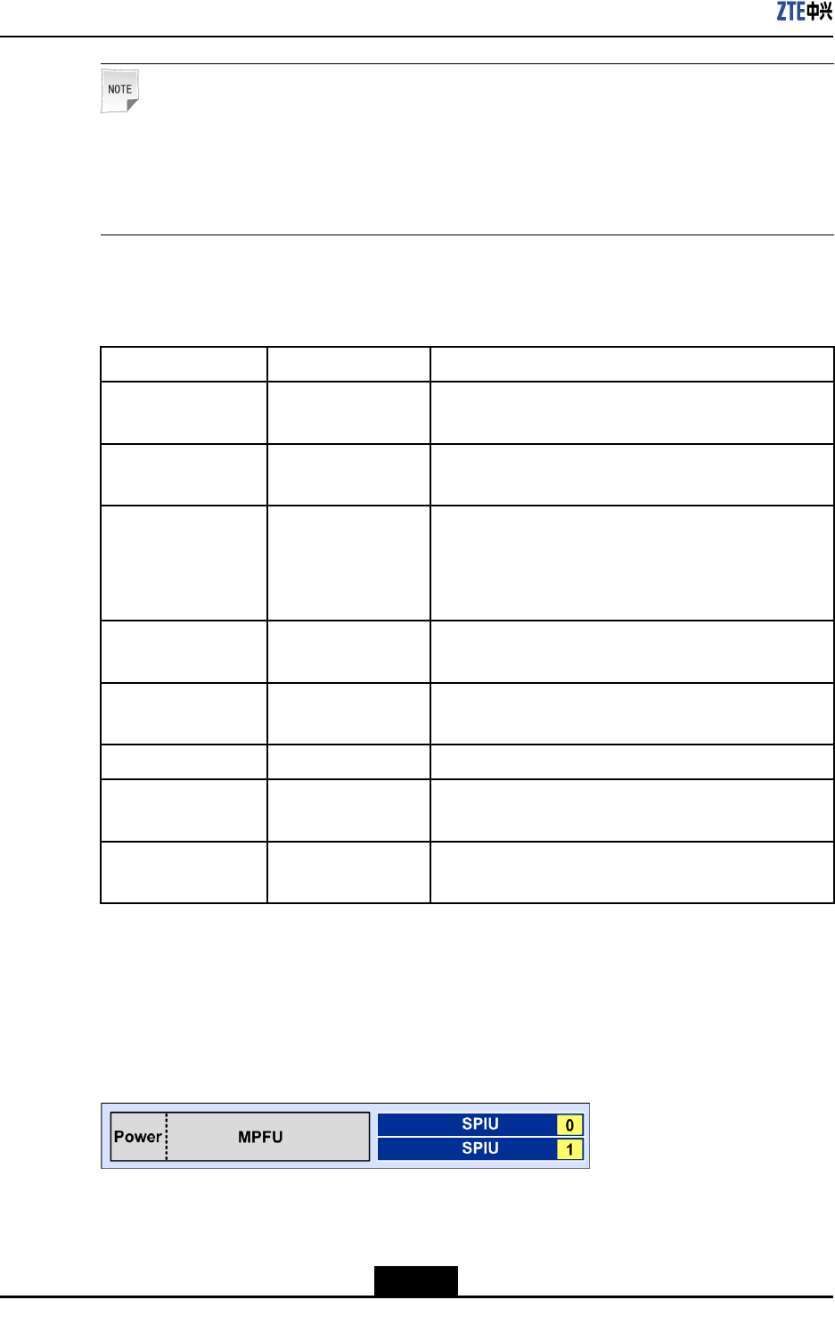
5.1.2SlotDeployment
Figure5-4showsslotsandslotIDsonthebackofaZXR102800-3Echassis.
Figure5-4SlotsontheBackofaZXR102800-3EChassis
5-3
SJ-20150204153047-004|2015-03-30(R1.0)ZTEProprietaryandCondential
ZXR10ZSRV2HardwareDescription
AZXR102800-3Echassishasastructuresuitableforhorizontalinstallation.Threeservice
boardslotsaredesignedforthechassis,whicharenumberedas0-2inorder.Wherein:
lSlot0isusedforanSPIUinterfaceboard.
lSlot1isusedanSPIUinterfaceboard.
lSlot2isusedaPIUorDPIUinterfaceboard.
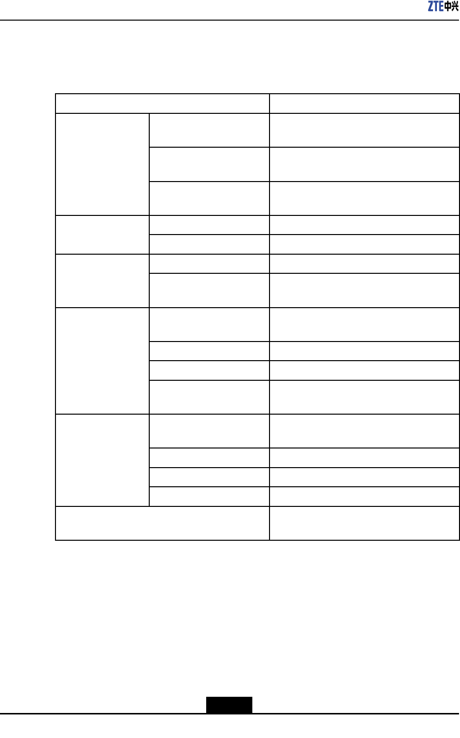
5.1.3SystemParameters
ForsystemparametersofaZXR102800-3Echassis,refertoT able5-3.
Table5-3SystemParametersofaZXR102800-3EChassis
ItemPhysicalParameters
Dimension(width×height×
depth)
17.41in.×1.73in.×17.32in.(442mm×44
mm×440mm)
Weight(withfull
conguration)
<19.0lb.(8.6kg)
PhysicalParameters
Maximumpower
consumption
<120W
Memory2GB Storagecapacity
Flash4GB
Numberofslots5 Slot
Numberofslotsforline
interfaceboards
3
Redundancybackup1+1redundancybackup,supportingbothAC
andDCpowers.
Ratedoutputpower250W
RatedinputvoltageFrom-60VDCto-48VDC
DCpower(single)
Rangeofthemaximuminput
voltage
From-72VDCto-38VDC
Redundancybackup1+1redundancybackup,supportingbothAC
andDCpowers.
Ratedinputvoltage100VAC–240VAC
Rangeoftheinputfrequency50Hz–60Hz
ACpower(single)
Ratedoutputpower250W
GroundingresistanceGroundingresistancewithcommonearthing,
whichislowerthan5Ω.
5-4
SJ-20150204153047-004|2015-03-30(R1.0)ZTEProprietaryandCondential
Chapter5ZXR102800-3EChassis
5.2PowerSupplies
ZXR10ZSRV2serialrouterssupportavoltagewithintherangeof100V–240V,ACpower
of50Hz–60Hz,andDCpowerfrom-38Vto-72V.The1+1dual-powerredundancymode
andpowersupplyswappingareavailable.
Thepowermoduleshavethefollowingfunctions:
lAlarmsaregeneratedduetoahighinputoroutputvoltage.
lAlarmsaregeneratedduetoahighoutputcurrent.
lAlarmsaregeneratedduetoahighorlowtemperature.
Caution!
TurnoffbothpowersuppliesbeforeinstallingandmaintainingtheZXR10ZSRV2.
5.2.1ACPowerModule
Panel
Figure5-5showsthepaneloftheACpowermoduleofaZXR102800-3Echassis.
Figure5-5PaneloftheACPowerModule
Indicators
ForfunctionsoftheindicatorsontheACpowermoduleoftheZXR102800-3Echassis,
refertoT able5-4.
Table5-4FunctionsoftheIndicatorsonthePaneloftheACPowerModuleofthe
ZXR102800-3EChassis
IndicatorNumberColorDescription
RUN1GreenThepowermoduleisoperatingproperly.
ALM1RedThepowermoduleisoperatingimproperly.
Buttons
ForfunctionsofthepowerbuttonsontheACpowermoduleoftheZXR102800-3Echassis,
refertoT able5-5.
5-5
SJ-20150204153047-004|2015-03-30(R1.0)ZTEProprietaryandCondential
ZXR10ZSRV2HardwareDescription
Table5-5FunctionsofthePowerButtonsoftheACPowerModuleoftheZXR10
2800-3EChassis
ButtonDescription
ON(—)DialthebuttontoONtoturnonthemodule.
OFF(O)DialthebuttontoOFFtoturnoffthepower.
TechnicalParameters
FortechnicalparametersofarectieroftheACpowermoduleoftheZXR102800-3E
chassis,refertoTable5-6.
Table5-6TechnicalParametersoftheACPoweroftheZXR102800-3EChassis
ParameterDescription
Dimension(width×height
×depth)
3.15in.×1.57in.×6.89in.(80mm×40mm×175mm)
Weight0.68kg
Rangeoftheinputvoltage100VAC–240VAC
InputACfrequency50Hz–60Hz
Ratedoutputpower250W
5.2.2DCPowerModule
Panel
Figure5-6showsthepaneloftheDCpowermoduleofaZXR102800-3Echassis.
Figure5-6PaneloftheDCPowerModule
Indicators
ForfunctionsoftheindicatorsontheDCpowermoduleoftheZXR102800-3Echassis,
refertoT able5-7.
5-6
SJ-20150204153047-004|2015-03-30(R1.0)ZTEProprietaryandCondential
Chapter5ZXR102800-3EChassis
Table5-7FunctionsoftheIndicatorsonthePaneloftheDCPowerModuleofthe
ZXR102800-3EChassis
IndicatorNumberColorDescription
RUN1GreenThepowermoduleisoperatingproperly.
ALM1RedThepowermoduleisoperatingimproperly.
Buttons
ForfunctionsofthepowerbuttonsontheDCpowermoduleoftheZXR102800-3Echassis,
refertoT able5-8.
Table5-8FunctionsofthePowerButtonsoftheDCPowerModuleoftheZXR10
2800-3EChassis
ButtonDescription
ON(—)DialthebuttontoONtoturnonthemodule.
OFF(O)DialthebuttontoOFFtoturnoffthepower.
TechnicalParameters
FortechnicalparametersoftheDCpowermoduleoftheZXR102800-3Echassis,referto
Table5-9.
Table5-9TechnicalParametersoftheDCPowerModuleoftheZXR102800-3EChassis
ParameterDescription
Dimension(width×height×
depth)
3.15in.×1.57in.×6.89in.(80mm×40mm×175mm)
Weight0.52kg
RangeoftheinputvoltageFrom-72VDCto-38VDC
Ratedoutputpower250W
Ratedinputcurrent8.5A
5-7
SJ-20150204153047-004|2015-03-30(R1.0)ZTEProprietaryandCondential

ZXR10ZSRV2HardwareDescription
Thispageintentionallyleftblank.
5-8
SJ-20150204153047-004|2015-03-30(R1.0)ZTEProprietaryandCondential

Chapter6
ZXR101800-2EChassis
ZXR10ZSRV2seriesroutershaveamodularstructure.Theboardsandcomponents
supporthotswappingandhaveexibleexpandability.AZXR102800-3Echassisis
composedofasubrack,abackplane,acontrollingandtransferringunit,lineinterface
boards,powermodules,andfanmodules.
AZXR101800-2Esubrackhasasheetmetalstructure.Thecontrollingandtransferring
unitandfanmodulesarexedontherouter,serviceboardandpowermodulesareinstalled
attheback,cablesareledoutfromtheback,andtwolineinterfaceboardscanbeinstalled.
AZXR101800-2Echassishasastandardwidthof19"andcanbeinstalledintoastandard
IEC297cabinetoranETSIcabinet.
AZXR101800-2E(G)submodelcanbederivedfromaZXR101800-2Echassisby
expandingthewirelessfunctionmodule.AZXR101800-2E(G)hasa3GorLTEmodule
insideandaslotforaSIMcardonthepanel,supportingaGSM,WCDMA,TD-SCDMA,
orLTEnetwork.
TableofContents
Structure....................................................................................................................6-1
PowerSupplies..........................................................................................................6-4
6.1Structure
6.1.1OverviewandStructure
Overview
AchassisofaZXR101800-2Erouterhasaheight(withouttheantenna)ofabout1U
(1U=44.45mm),andadimensionof442mm×44mm×440mm(width×height×depth).
Foritscomponentsanddescriptions,refertoT able6-1.
Table6-1MainComponentsofaZXR101800-2EChassis
ComponentDescription
Controllingandtransferring
board
ThecontrollingandtransferringboardofaZXR101800-2Echassis
isintegratedontherouterandcannotbepluggedorunplugged.
BoardTheZXR101800-2Echassisprovidestwoslotsforlineinterface
boards.
PowermoduleTheZXR101800-2Echassisprovidestwoslotsforoneortwo
powermodules.
6-1
SJ-20150204153047-004|2015-03-30(R1.0)ZTEProprietaryandCondential
ZXR10ZSRV2HardwareDescription
FrontView
ThefollowingdescribesthestructureofaZXR101800-2Echassisanditsfrontpanel.
lFigure6-1showsthefrontviewofaZXR101800-2Echassis.
Figure6-1FrontViewofaZXR101800-2EChassis
Note:
TheZXR101800-2E(G)submodeloftheZXR101800-2Echassissupportsthe
wirelessfunction,withabuilt-inwirelessmoduleandanantenna.Ifthewireless
moduleisnotcongured,thechassisdoesnothaveanantenna.
lFigure6-2showsthefrontpanelofaZXR101800-2Echassis.
Figure6-2FrontPanelofaZXR101800-2EChassis
Foradescriptionofthefrontpanel,refertoTable6-2.
Table6-2DescriptionsofInterfacesontheFrontPanelofaZXR101800-2EChassis
ComponentTypeDescription
AntennainterfacesAntennaslots.
GEinterfaces24GEelectricalinterfaces.
COMBOinterfacesTwoCombointerfaces.
USBinterfacesUSB2.0interfaces,whichareusedtostoreapplicationsandother
dataandsupportcommissioning.
Networkinterfaces(RJ45)Maintenancenetworkinterfaces(10M/100M/1000M),whichare
usedtocontrolthesystemanddownloadapplications.
6-2
SJ-20150204153047-004|2015-03-30(R1.0)ZTEProprietaryandCondential
Chapter6ZXR101800-2EChassis
ComponentTypeDescription
MicroUSBinterfacesConsoleinterfacesoftheMicroUSBmodel,whichhavethesame
functionsasthoseoftheCON/AUXinterfacesoftheRJ45model
butahigherpriority.Selecteitherone.
Serialinterfaces(RJ45)Debuggingserialinterfaces(Console/AUXinterfaces)oftheRJ45
model,whichareusedtomanageroutersandcongurefunctions.
InterfaceforaSIMcardInterfacefora3GorLTESIMcard.
WIFIfunctionbutton.
Buttonforre-establishingaWIFIconnection.
Buttons
Systemresetbutton.
GreenindicatorsforlinkstatusesoftwoCombointerfaces.
Redindicatorforsystemfaults.
Greenindicatorforsystemoperationstatus.
Indicators
Greenindicatorfortheoperationstatusofa3GorLTEnetwork.
BackPanel
Figure6-3showsthebackpanelofaZXR101800-2Echassis.
Figure6-3BackPanelofaZXR101800-2EChassis
1.SlotsforSPIUlineinterface
boards
2.Powermodules
6.1.2Slots
Figure6-4showsslotsandslotIDsonthebackofaZXR101800-2Echassis.
Figure6-4SlotsontheBackofaZXR101800-2EChassis
AZXR101800-2Echassishasastructuresuitableforhorizontalinstallation.Twoservice
boardslotsaredesignedforthechassis,whicharenumberedas0-1inorder.Slots0and
1areusedtoinstallSPIUinterfaceboards.
6-3
SJ-20150204153047-004|2015-03-30(R1.0)ZTEProprietaryandCondential
ZXR10ZSRV2HardwareDescription
6.1.3SystemParameters
ForsystemparametersofaZXR101800-2Erouter,refertoTable6-3.
Table6-3SystemParametersofaZXR101800-2EChassis
ItemPhysicalParameters
Dimension(width×height×
depth)
17.41in.×1.73in.×17.32in.(442mm×44
mm×440mm)
Weight(withfull
conguration)
<19.0lb.(8.6kg)
PhysicalParameters
Maximumpower
consumption
<80W
Memory2GB Storagecapacity
FLASH1GB
Numberofslots4 Slot
Numberofslotsforline
interfaceboards
2
Redundancybackup1+1redundancybackup,supportingbothAC
andDC
Ratedoutputpower250W
RatedinputvoltageFrom-60VDCto-48VDC
DCpower(single)
Rangeofthemaximuminput
voltage
From-72VDCto-38VDC
Redundancybackup1+1redundancybackup,supportingbothAC
andDC
Ratedinputvoltage100VAC–240VAC
Rangeoftheinputfrequency50Hz–60Hz
ACpower(single)
Ratedoutputpower250W
GroundingresistanceGroundingresistancewithcommonearthing,
whichislowerthan5Ω
6.2PowerSupplies
ZXR10ZSRV2serialrouterssupportavoltagewithintherangeof100V–240V,ACpower
of50Hz–60Hz,andDCpowerfrom-38Vto-72V.The1+1dual-powerredundancymode
andpowersupplyswappingareavailable.
Thepowermoduleshavethefollowingfunctions:
lAlarmsaregeneratedduetoahighorlowinputoroutputvoltage.
6-4
SJ-20150204153047-004|2015-03-30(R1.0)ZTEProprietaryandCondential
Chapter6ZXR101800-2EChassis
lAlarmsaregeneratedduetoahighoutputcurrent.
lAlarmsaregeneratedduetoahighorlowtemperature.
Caution!
TurnoffbothpowersuppliesbeforeinstallingandmaintainingtheZXR10ZSRV2.
6.2.1ACPowerModule
Panel
Figure6-5showsthepaneloftheACpowermoduleofaZXR101800-2Echassis.
Figure6-5PaneloftheACPowerModule
Indicators
ForfunctionsoftheindicatorsontheACpowermoduleoftheZXR101800-2Echassis,
refertoT able6-4.
Table6-4FunctionsoftheIndicatorsonthePaneloftheACPowerModuleofthe
ZXR101800-2EChassis
IndicatorNumberColorDescription
RUN1GreenThepowermoduleisoperatingproperly.
ALM1RedThepowermoduleisoperatingimproperly.
Buttons
ForfunctionsofthepowerbuttonsontheACpowermoduleoftheZXR101800-2Echassis,
refertoT able6-5.
Table6-5FunctionsofthePowerButtonsoftheACPowerModuleoftheZXR10
1800-2EChassis
ButtonDescription
ON(—)DialthebuttontoONtoturnonthemodule.
OFF(O)DialthebuttontoOFFtoturnoffthepower.
6-5
SJ-20150204153047-004|2015-03-30(R1.0)ZTEProprietaryandCondential
ZXR10ZSRV2HardwareDescription
TechnicalParameters
FortechnicalparametersoftherectieroftheACpowermoduleoftheZXR101800-2E
chassis,refertoTable6-6.
Table6-6TechnicalParametersoftheACPoweroftheZXR101800-2EChassis
ParameterDescription
Dimension(width×height×depth)3.15in.×1.57in.×6.89in.(80mm×40mm×175
mm)
Weight0.68kg
Rangeoftheinputvoltage100VAC–240VAC
InputACfrequency50Hz–60Hz
Ratedoutputpower250W
6.2.2DCPowerModule
Panel
Figure6-6showsthepaneloftheDCpowermoduleofaZXR101800-2Echassis.
Figure6-6PaneloftheDCPowerModule
Indicators
ForfunctionsoftheindicatorsontheDCpowermoduleoftheZXR101800-2Echassis,
refertoT able6-7.
Table6-7FunctionsoftheIndicatorsonthePaneloftheDCPowerModuleofthe
ZXR101800-2EChassis
IndicatorNumberColorDescription
RUN1GreenThepowermoduleisoperatingproperly.
ALM1RedThepowermoduleisoperatingimproperly.
Buttons
ForfunctionsofthepowerbuttonsontheDCpowermoduleoftheZXR101800-2Echassis,
refertoT able6-8.
6-6
SJ-20150204153047-004|2015-03-30(R1.0)ZTEProprietaryandCondential
Chapter6ZXR101800-2EChassis
Table6-8FunctionsofthePowerButtonsoftheDCPowerModuleoftheZXR10
1800-2EChassis
ButtonDescription
ON(—)DialthebuttontoONtoturnonthemodule.
OFF(O)DialthebuttontoOFFtoturnoffthepower.
TechnicalParameters
FortechnicalparametersoftheDCpowermoduleoftheZXR101800-2Echassis,referto
Table6-9.
Table6-9TechnicalParametersoftheDCPowerModuleoftheZXR101800-2EChassis
ParameterDescription
Dimension(width×height×depth)3.15in.×1.57in.×6.89in.(80mm×40mm×175mm)
Weight0.52kg
RangeoftheinputvoltageFrom-72VDCto-38VDC
Ratedoutputpower250W
Ratedinputcurrent8.5A
6-7
SJ-20150204153047-004|2015-03-30(R1.0)ZTEProprietaryandCondential

ZXR10ZSRV2HardwareDescription
Thispageintentionallyleftblank.
6-8
SJ-20150204153047-004|2015-03-30(R1.0)ZTEProprietaryandCondential

Chapter7
MPFU
TheManagementandPacketForwardingUnit(MPFU)isthecontrolnodeoftherouter.
TheMPFUforwardspacketsandmanagesandmaintainstheentiredevice.
TheMPFUconsistsofthepacketforwardingmodule,managementandcontrolmodule,
clockprocessingmodule,andalarmmonitoringmodule.Itforwardspackets,andmanages
thesystemclocksource,controlplane,systemmaintenanceplaneandenvironmental
monitoringplane.
lThepacketforwardingmoduleclassiesandforwardsthepacketsthattheline
interfaceboardsreceiveandcontrolsthepackettrafc.
lThemanagementandcontrolmoduleprovidesthefollowingfunctions:
àProcessesprotocolsandsignalingmessagestocontrolandnotifythesystem
status.Therouteprotocolcontrollayerandthecongurationandoperationlayer
areseparatedtoenhancethecontrollayerstabilityandequipmentmanageability.
àConguresandmaintainsthesystemstatus.Itprovidesthesystemdata
congurationandupgradefunctionsandsystemoperationlogs.Itsupportstwo
typesofmanagementinterfaces:serialportandRJ45port.
lThealarmmonitoringmodulemonitorstheoperationconditionsoftheboards,power
supplymodules,andfanmodulesandgeneratesalarmswhennecessary.Itprovides
auser-friendlyman-machineinterfacethroughtheCLIorSNMPnetworkmanagement
system.
TheMPFUoftheZXR102800-3E,ZXR101800-2EorZXR101800-2Sisintegratedinto
thechassisandcannotberemoved.
TheMPFUboardsoftheZXR102800-4andZXR103800-8canbedividedintothree
types:RAC-2838-MPFU-A,RAC-2838-MPFU-B,andRAC-2838-MPFU-C.
TableofContents
RAC-2838-MPFU-A....................................................................................................7-1
RAC-2838-MPFU-B/RAC-2838-MPFU-C...................................................................7-3
7.1RAC-2838-MPFU-A
Overview
RAC-2838-MPFU-AisthetypeAMPFUoftheZXR102800-4andZXR103800-8.The
MPFUprovidesthefollowingfunctions:
lSupportshotswappingwithamodularstructure.
7-1
SJ-20150204153047-004|2015-03-30(R1.0)ZTEProprietaryandCondential
ZXR10ZSRV2HardwareDescription
lSupportsseparationoftheforwardingplaneandcontrolplane.
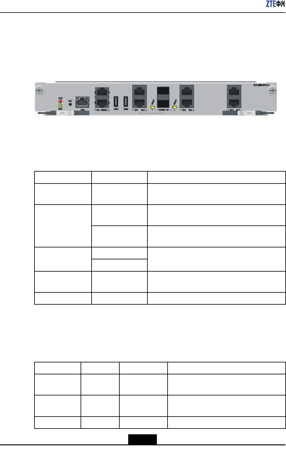
Panel
ForthepaneloftheRAC-2838-MPFU-A,seeFigure7-1.
Figure7-1PaneloftheRAC-2838-MPFU-A
Interfaces
ForadescriptionoftheinterfacesoftheRAC-2838-MPFU-A,refertoT able7-1.
Table7-1DescriptionoftheInterfacesoftheRAC-2838-MPFU-A
InterfaceTypeSilkScreenNameDescription
Networkinterface
(RJ45)
OAMNetworkport(10M/100M/1000M)usedforsystem
maintenanceandprogramdownloading
CONSOLEDebuggingportforsystemmanagementand
conguration
Serialport(RJ45)
AUXDebuggingserialportofaPIUandModem
convergenceport
USB1 USBinterface
USB2
USB2.0interface,whichtransmitstheprogramdata
andotherdata
GEelectronic
interface
GE3–6FourGEelectronicinterfaces
COMBOinterfaceCOMBO1/2,GE1–2TwoCOMBOinterfaces
Indicators
ForadescriptionoftheLEDindicatorsonthepaneloftheRAC-2838-MPFU-A,referto
Table7-2.
Table7-2IndicatorDescriptionsfortheRAC-2838-MPFU-A
IndicatorNumberColorDescription
RUN1GreenTheindicatorislitwhentheboardisoperating
properly.
ALM1RedTheindicatorislitiftheboardisnotoperating
properly.
LINK/ACT2GreenLinkstateindicatorsofCOMBOinterfaces.
7-2
SJ-20150204153047-004|2015-03-30(R1.0)ZTEProprietaryandCondential
Chapter7MPFU
Buttons
ForadescriptionoftheRSTbuttononthepaneloftheRAC-2838-MPFU-A,refertoT able
7-3.
Table7-3RSTButtonDescriptionfortheRAC-2838-MPFU-A
ButtonDescription
RSTResetstheboard.
TechnicalParameters
ForthetechnicalparametersoftheRAC-2838-MPFU-A,refertoT able7-4.
Table7-4TechnicalParametersoftheRAC-2838-MPFU-A
ParameterSpecication
SilkscreennameRAC-2838-MPFU-A
Dimensions(H×W×D)11.7in.×1.58in.×6.9in.(296.3mm×40.24mm×175mm)
Powerconsumption35W
Weight2.38lb.(1.08kg)
7.2RAC-2838-MPFU-B/RAC-2838-MPFU-C
Overview
TheRAC-2838-MPFU-BandRAC-2838-MPFU-CareMPFUboardsoftheZXR102800-4
andZXR103800-8.
lTheRAC-2838-MPFU-BandRAC-2838-MPFU-Cwithdifferentforwardingcapacity
areprovidedfortheZXR102800-4andZXR103800-8.
lBothofthemsupporthotswappingwithamodularstructure.
lBothofthemsupportseparationoftheforwardingplaneandcontrolplane.
Panel
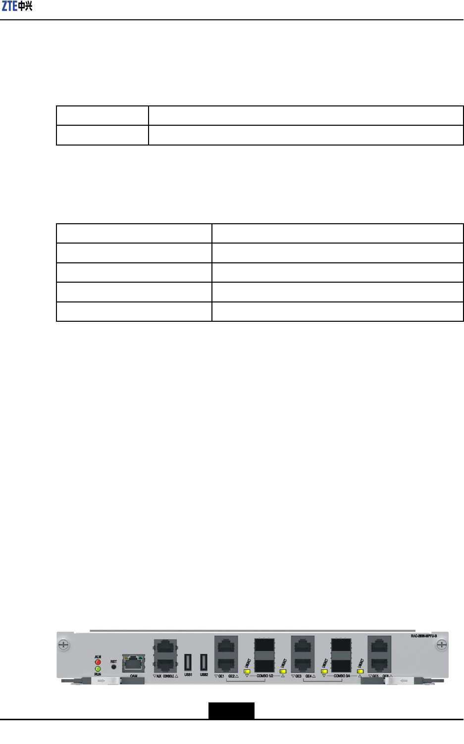
TheRAC-2838-MPFU-BandRAC-2838-MPFU-Chavethesameoverviewexceptthesilk
screenname.ForanoverviewoftheRAC-2838-MPFU-B/RAC-2838-MPFU-C,seeFigure
7-2.
Figure7-2RAC-2838-MPFU-BandRAC-2838-MPFU-C
7-3
SJ-20150204153047-004|2015-03-30(R1.0)ZTEProprietaryandCondential
ZXR10ZSRV2HardwareDescription
Interfaces
ForadescriptionoftheinterfacesoftheRAC-2838-MPFU-B/RAC-2838-MPFU-C,referto
Table7-5.
Table7-5DescriptionoftheInterfacesoftheRAC-2838-MPFU-B/RAC-2838-MPFU-C
InterfaceTypeSilkScreenNameDescription
Networkinterface
(RJ45)
OAMNetworkport(10M/100M/1000M)usedforsystem
maintenanceandprogramdownloading
CONSOLEDebuggingportforsystemmanagementand
conguration
Serialport(RJ45)
AUXDebuggingserialportofaPIUandModem
convergenceport
USB1
USBinterface
USB2
USB2.0interface,whichtransmitstheprogramdata
andotherdata
GEelectronic
interface
GE5–6TwoGEelectronicinterfaces
COMBOinterfaceCOMBO1/2,
COMBO3/4,GE1–4
FourCOMBOinterfaces
Indicators
ForadescriptionoftheLEDindicatorsonthepanelofthe
RAC-2838-MPFU-B/RAC-2838-MPFU-C,refertoT able7-6.
Table7-6DescriptionoftheIndicatorsonthePanelofthe
RAC-2838-MPFU-B/RAC-2838-MPFU-C
IndicatorNumberColorDescription
RUN1GreenTheindicatorislitwhentheboardis
operatingproperly.
ALM1RedTheindicatorislitiftheboardisnot
operatingproperly.
LINK/ACT4GreenLinkstateindicatorsofCOMBOinterfaces.
Buttons
ForadescriptionoftheRSTbuttononthepanelofthe
RAC-2838-MPFU-B/RAC-2838-MPFU-C,refertoT able7-7.
Table7-7DescriptionoftheRSTButtononthePanelofthe
RAC-2838-MPFU-B/RAC-2838-MPFU-C
ButtonDescription
RSTResetstheboard.
7-4
SJ-20150204153047-004|2015-03-30(R1.0)ZTEProprietaryandCondential
Chapter7MPFU
TechnicalParameters
ForthetechnicalparametersoftheRAC-2838-MPFU-B/RAC-2838-MPFU-C,referto
Table7-8.
Table7-8TechnicalParametersoftheRAC-2838-MPFU-B/RAC-2838-MPFU-C
ParameterSpecication
SilkscreennameRAC-2838-MPFU-B/RAC-2838-MPFU-C
Dimensions(H×W×D)11.7in.×1.58in.×6.9in.(296.3mm×40.24mm×175mm)
Powerconsumption35W
Weight2.38lb.(1.08kg)
7-5
SJ-20150204153047-004|2015-03-30(R1.0)ZTEProprietaryandCondential

ZXR10ZSRV2HardwareDescription
Thispageintentionallyleftblank.
7-6
SJ-20150204153047-004|2015-03-30(R1.0)ZTEProprietaryandCondential
Chapter8
GeneralProcessingBoards
Generalprocessingboardsareinstalledinslotsforfull-heightDPIUinterfacecardsand
usedtoclassifyandmonitormessagesfromthemaincontrolboard.
TableofContents
RAC-DPIU-OSU-A1...................................................................................................8-1
RAC-DPIU-OSU-A2...................................................................................................8-3
RAC-DPIU-FW-A........................................................................................................8-4
8.1RAC-DPIU-OSU-A1
Overview
AsthegeneralprocessingboardoftheZXR102800-4andZXR103800-8,an
RAC-DPIU-OSU-A1boardisinstalledinaslotforafull-heightDPIUinterfacecardand
hasthefollowingfunctions:
lClassies,monitors,lters,andtransfersreceivedmessagesdependingon
applications.
lProvidesfourlinesofhigh-speedserialinterfacesfortheinternalgigabitEthernetand
onelineofelectricalinterfacefortheexternalgigabitEthernet.
lGEelectricalinterfacessupport10BASE-T/100BASE-TX/1000BASE-T .
Panel
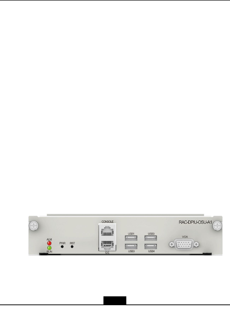
ForthepaneloftheRAC-DPIU-OSU-A1boardofthegeneralprocessingboard,seeFigure
8-1.
Figure8-1PanelofanRAC-DPIU-OSU-A1Board
Interfaces
ForadescriptionofinterfacesontheRAC-DPIU-OSU-A1board,refertoTable8-1.
8-1
SJ-20150204153047-004|2015-03-30(R1.0)ZTEProprietaryandCondential
ZXR10ZSRV2HardwareDescription
Table8-1DescriptionsofInterfacesontheRAC-DPIU-OSU-A1Board
InterfaceTypeDescription
Networkinterface(RJ45)Servicenetworkinterface,a10/100/1000BASE-Telectricalinterface.
Serialinterface(RJ45)SerialinterfaceinterconnectedwithaPC.
VGAinterface(DB15)X86VGAoutputinterface.
USBinterfacesUSB2.0interfacesusedtoinstalltheX86system.
Indicators
TheRAC-DPIU-OSU-A1boardprovidesmultipleLEDindicatorsonitspanel.Fortheir
functions,refertoTable8-2.
Table8-2FunctionsoftheIndicatorsonthePaneloftheRAC-DPIU-OSU-A1Board
IndicatorColorDescription
ALMRedIfthisindicatorissolidonorashing,theboardis
faulty.
RUNGreenIndicatesthattheboardisoperatingproperly.
Buttons
TheRAC-DPIU-OSU-A1boardprovidestwobuttonsonitspanel.Fortheirfunctions,refer
toTable8-3.
Table8-3FunctionsoftheButtonsonthePaneloftheRAC-DPIU-OSU-A1Board
ButtonDescription
RSTBoardresetbutton
PWRBoardpowerbutton
TechnicalParameters
FortechnicalparametersoftheRAC-DPIU-OSU-A1board,refertoTable8-4.
Table8-4TechnicalParametersoftheRAC-DPIU-OSU-A1Board
ParameterDescription
BoardnamesilkscreenRAC-DPIU-OSU-A1
Dimension(width×height×depth)7.76in.×1.58in.×6.9in.(197.2mm×40.24mm
×175mm)
Powerconsumption40W
Weight2.71lb.(1.23kg)
MemoryDefaultcapacity(byte)4Gor8G(optional)
HarddiskDefaultcapacity(byte)500Gor1T(optional)
8-2
SJ-20150204153047-004|2015-03-30(R1.0)ZTEProprietaryandCondential
Chapter8GeneralProcessingBoards
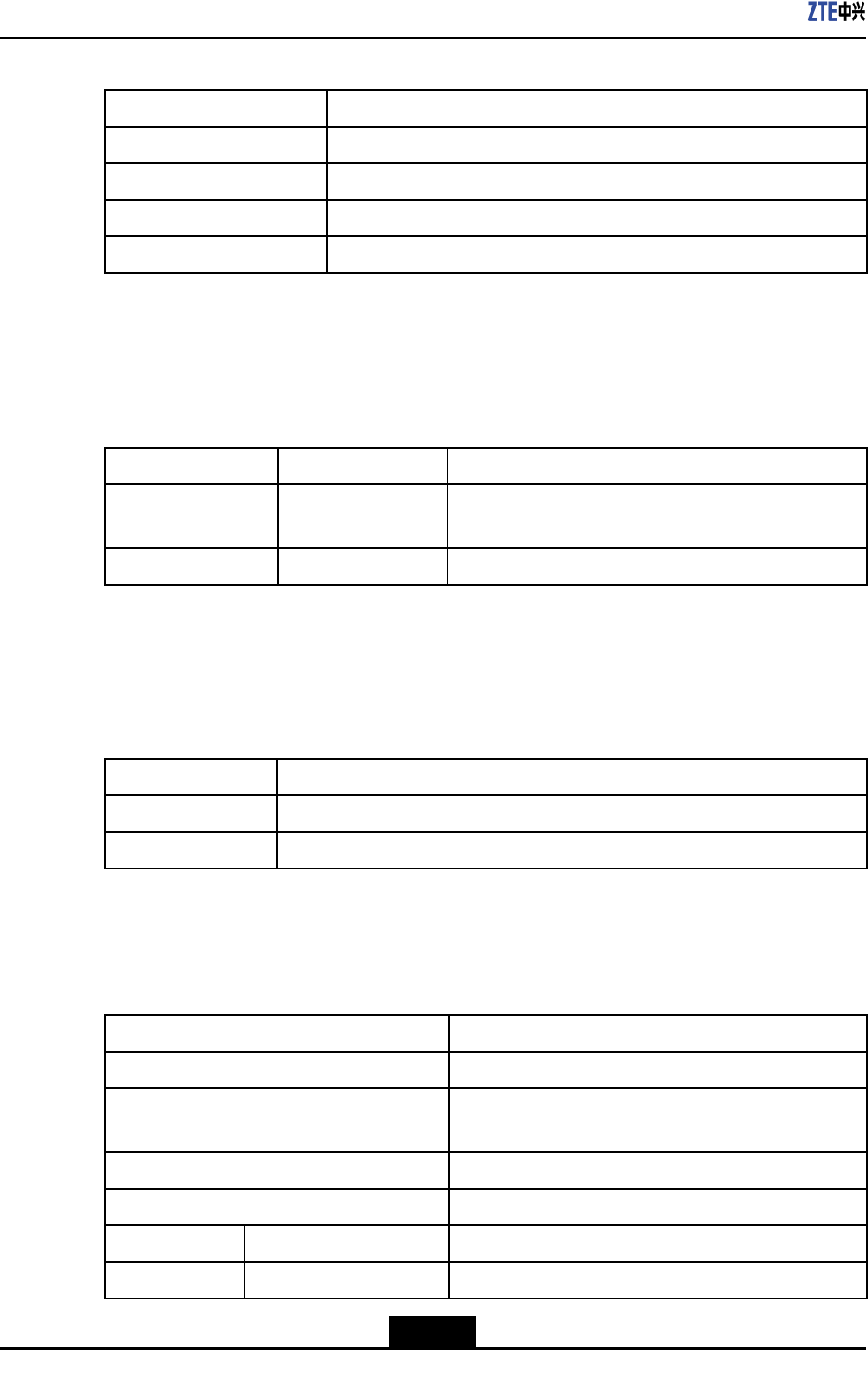
8.2RAC-DPIU-OSU-A2
Overview
AsthegeneralprocessingboardoftheZXR102800-4andZXR103800-8,an
RAC-DPIU-OSU-A2boardisinstalledinaslotforafull-heightDPIUinterfacecardand
hasthefollowingfunctions:
lClassies,monitors,lters,andtransfersreceivedmessagesdependingon
applications.
lProvidesfourlinesofhigh-speedserialinterfacesfortheinternalgigabitEthernetand
onelineofelectricalinterfacefortheexternalgigabitEthernet.
lGEelectricalinterfacessupport10BASE-T/100BASE-TX/1000BASE-T .
Panel
ForthepaneloftheRAC-DPIU-OSU-A2boardofthegeneralprocessingboard,seeFigure
8-2.
Figure8-2PanelofanRAC-DPIU-OSU-A2Board
Interfaces
ForadescriptionofinterfacesontheRAC-DPIU-OSU-A2board,refertoTable8-5.
Table8-5DescriptionofInterfacesontheRAC-DPIU-OSU-A2Board
InterfaceTypeDescription
Networkinterface(RJ45)Servicenetworkinterface,a10/100/1000BASE-Telectrical
interface.
Serialinterface(RJ45)SerialinterfaceinterconnectedwithaPC.
VGAinterface(DB15)X86VGAoutputinterface.
USBinterfacesUSB2.0interfacesusedtoinstalltheX86system.
Indicator
TheRAC-DPIU-OSU-A2boardprovidesmultipleLEDindicatorsonitspanel.Fortheir
functions,refertoTable8-6.
8-3
SJ-20150204153047-004|2015-03-30(R1.0)ZTEProprietaryandCondential
ZXR10ZSRV2HardwareDescription
Table8-6FunctionsoftheIndicatorsonthePaneloftheRAC-DPIU-OSU-A2Board
IndicatorColorDescription
ALMRedIfthisindicatorissolidonorashing,theboardis
faulty.
RUNGreenIndicatesthattheboardisoperatingproperly.
Button
TheRAC-DPIU-OSU-A2boardprovidestwobuttonsonitspanel.Fortheirfunctions,refer
toTable8-7.
Table8-7FunctionsoftheButtonsonthePaneloftheRAC-DPIU-OSU-A2Board
ButtonDescription
RSTBoardresetbutton
PWRBoardpowerbutton
TechnicalParameters
FortechnicalparametersoftheRAC-DPIU-OSU-A2board,refertoTable8-8.
Table8-8TechnicalParametersoftheRAC-DPIU-OSU-A2Board
ParameterDescription
BoardnamesilkscreenRAC-DPIU-OSU-A2
Dimension(width×height×depth)7.76in.×1.58in.×6.9in.(197.2mm×40.24mm
×175mm)
Powerconsumption40W
Weight2.71lb.(1.23kg)
MemoryDefaultcapacity(byte)4Gor8G(optional)
HarddiskDefaultcapacity(byte)500Gor1T(optional)
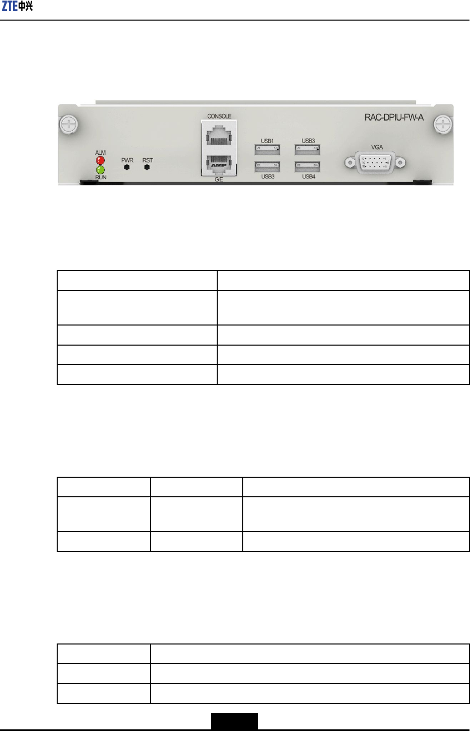
8.3RAC-DPIU-FW-A
Overview
AsarewallboardoftheZXR103800-8andZXR102800-4,anRAC-DPIU-FW-Aboard
isinstalledinaslotforafull-heightDPIUinterfacecardandhasthefollowingfunctions:
lClassies,monitors,lters,andtransfersreceivedmessagesdependingon
applications.
lProvidesfourlinesofhigh-speedserialinterfacesfortheinternalgigabitEthernetand
onelineofelectricalinterfacefortheexternalgigabitEthernet.
lGEelectricalinterfacessupport10BASE-T/100BASE-TX/1000BASE-T .
8-4
SJ-20150204153047-004|2015-03-30(R1.0)ZTEProprietaryandCondential
Chapter8GeneralProcessingBoards
Panel
ForthepaneloftheRAC-DPIU-FW-Aboard,seeFigure8-3.
Figure8-3PanelofanRAC-DPIU-FW-ABoard
Interfaces
ForadescriptionofinterfacesonaRAC-DPIU-FW-Aboard,refertoT able8-9.
Table8-9DescriptionofInterfacesonanRAC-DPIU-FW-ABoard
InterfaceTypeDescription
Networkinterface(RJ45)Servicenetworkinterface,a10/100/1000BASE-Telectrical
interface.
Serialinterface(RJ45)SerialinterfaceinterconnectedwithaPC.
VGAinterface(DB15)X86VGAoutputinterface.
USBinterfacesUSB2.0interfacesusedtoinstalltheX86system.
Indicators
ForfunctionsofLEDindicatorsonthepanelofaRAC-DPIU-FW-Aboard,refertoTable
8-10.
Table8-10FunctionsofIndicatorsonthePanelofanRAC-DPIU-FW-ABoard
IndicatorColorDescription
ALMRedIfthisindicatorissolidonorashing,theboardis
faulty.
RUNGreenIndicatesthattheboardisoperatingproperly.
Buttons
AnRAC-DPIU-FW-Aboardhastwobuttonsonitspanel.Fortheirfunctions,refertoTable
8-11.
Table8-11FunctionsofButtonsonthePanelofanRAC-DPIU-FW-ABoard
ButtonDescription
RSTBoardresetbutton.
PWRBoardpowerbutton.
8-5
SJ-20150204153047-004|2015-03-30(R1.0)ZTEProprietaryandCondential
ZXR10ZSRV2HardwareDescription
TechnicalParameters
FortechnicalparametersofanRAC-DPIU-FW-Aboard,refertoT able8-12.
Table8-12TechnicalParametersofanRAC-DPIU-FW-ABoard
ParameterDescription
BoardnamesilkscreenRAC-DPIU-FW-A
Dimension(width×height×depth)7.76in.×1.58in.×6.9in.(197.2mm×40.24mm
×175mm)
Powerconsumption35W
Weight2.31lb.(1.05kg)
MemoryDefaultcapacity(byte)4Gor8G(optional)
HarddiskDefaultcapacity(byte)2G
8-6
SJ-20150204153047-004|2015-03-30(R1.0)ZTEProprietaryandCondential

Chapter9
LineInterfaceBoards
Alineinterfaceboardisanexternalinterfaceofawire-speedrouterandimplements
theaccessofinterfacesofvariousratesandtypes.Theboardprovidesoneormore
high-speednetworkinterfaces.TheZXR10ZSRV2providesvariouslineinterfaceboards
andsupportsvariousinterfaceratesandportdensitytomeettherequirementsofdifferent
networksandservices.
ForthetypesoflineinterfaceboardsthattheZXR10ZSRV2seriesrouterssupport,refer
toTable9-1.
Table9-1LineInterfaceBoardTypes
TypeDimensions(Width×
Height×Depth)
Applicable
Device
Slot
DPIU(full-height)7.76in.×1.58in.×6.9
in.(197.2mm×40.24mm
×175mm)
3800-8,2800-43800-8:combinedslots1and
3,orcombinedslots5and7
2800-4:combinedslots1and
3
DPIU(full-height)7.76in.×0.79in.×6.9
in.(197.2mm×19.92mm
×175mm)
3800-8,2800-4,
2800-3E
3800-8:slot3or7
2800-4:slot3
2800-3E:slots2
PIU7.76in.×0.79in.×6.9
in.(197.2mm×19.92mm
×175mm)
3800-8,2800-4,
2800-3E
3800-8:slot1,3,5,or7
2800-4:slot1or3
2800-3E:slot2
SPIU3.86in.×0.79in.×6.9
in.(98.1mm×19.92mm
×175mm)
3800-8,2800-4,
1800-2S,2800-3E,
1800-2E
3800-8:slot0,2,4,or6
2800-4:slot0or2
1800-2S:slot0or1
2800-3E:slot0or1
1800-2E:slot0or1
TheDPIUisafast-speedinterfaceboard,andthePIUandSPIUarecommon-speed
interfaceboards.TheZXR102800-4andZXR103800-8supportthecombinationof
differenttypesoflineinterfaceboards.
TableofContents
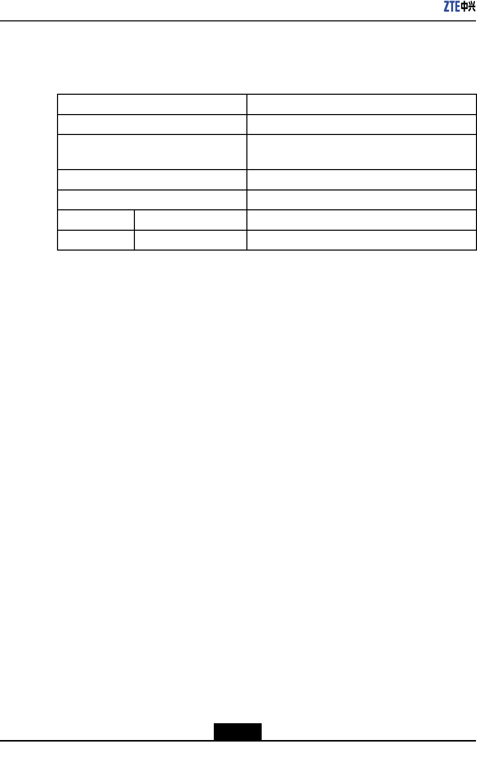
RAC-SPIU-02CE1-75.................................................................................................9-2
RAC-SPIU-02UE1-75.................................................................................................9-3
RAC-SPIU-02CE1-120...............................................................................................9-5
RAC-SPIU-02UE1-120...............................................................................................9-6
RAC-SPIU-02HS........................................................................................................9-8
9-1
SJ-20150204153047-004|2015-03-30(R1.0)ZTEProprietaryandCondential
ZXR10ZSRV2HardwareDescription
RAC-SPIU-04GE........................................................................................................9-9
RAC-PIU-LTE...........................................................................................................9-11
RAC-PIU-01DSLB....................................................................................................9-13
RAC-PIU-04SHDSL.................................................................................................9-15
RAC-PIU-04HS.......................................................................................................9-16
RAC-PIU-04CE1-75.................................................................................................9-18
RAC-PIU-04CE1-120...............................................................................................9-19
RAC-PIU-04UE1-75.................................................................................................9-21
RAC-PIU-04UE1-120...............................................................................................9-22
RAC-PIU-16CE1......................................................................................................9-23
RAC-PIU-16CE1-CES..............................................................................................9-25
RAC-PIU-01P12-SFP...............................................................................................9-26
RAC-PIU-02P3-SFP.................................................................................................9-28
RAC-PIU-04P3-SFP.................................................................................................9-29
RAC-PIU-02CP3-SFP..............................................................................................9-31
RAC-PIU-04CP3-SFP..............................................................................................9-32
RAC-PIU-04GE-SFP................................................................................................9-34
RAC-PIU-08GE-SFP................................................................................................9-35
RAC-PIU-05GE-4E1SFP..........................................................................................9-36
RAC-PIU-09GE-8E1SFP..........................................................................................9-39
RAC-PIU-08FE1GE-1SFP........................................................................................9-41
RAC-DPIU-16GE-12SFP4E.....................................................................................9-43
RAC-DPIU-01XGE-SFP+.........................................................................................9-45
9.1RAC-SPIU-02CE1-75
Overview
RAC-SPIU-02CE1-75boardprovidesthefollowingfunctions:
lProvidestwochannelized/unchannelizedE1(75ohm)interfaces.
lRestoresthelineclockandprovidingittoanMPFUboardforreference.
lSupportstheprocessingofvariousservices,suchasPPPandML-PPP.
lSupportshotswapping.
lSupportsboardinformationqueryandtemperaturemonitoring.
Panel
ForthepaneloftheRAC-SPIU-02CE1-75board,seeFigure9-1.
Figure9-1FrontPaneloftheRAC-SPIU-02CE1-75Board
9-2
SJ-20150204153047-004|2015-03-30(R1.0)ZTEProprietaryandCondential
Chapter9LineInterfaceBoards
InterfaceProperty
TheRAC-SPIU-02CE1-75boardprovidesmicrocoaxialinterfaces,anditonlysupports
75ohmnon-balancedE1interfaces.Foradescriptionoftheinterfaceproperties,referto
Table9-2.
Table9-2InterfacePropertiesoftheRAC-SPIU-02CE1-75Board
PropertyDescription
ConnectortypeMicrocoaxial
OperationalmodeFullduplex
AppliedstandardITU-TG.703,G.704
SupportedlinkprotocolPPP ,ML-PPP ,HDLC,FR
Supportednetwork
protocol
IP
Indicators
ForadescriptionoftheindicatorsoftheRAC-SPIU-02CE1-75board,refertoT able9-3.
Table9-3DescriptionoftheIndicatorsonthePaneloftheRAC-SPIU-02CE1-75Board
IndicatorColorDescription
RUNGreenTheindicatorislitwhentheboardisoperatingproperly.
LNK1/LNK2GreenTheindicatorislitwhenthelinkisoperatingproperly,andis
notlitwhenthelinkisidle.
TechnicalParameters
ForthetechnicalparametersoftheRAC-SPIU-02CE1-75board,refertoT able9-4.
Table9-4TechnicalParametersoftheRAC-SPIU-02CE1-75Board
ParameterSpecication
SilkscreennameRAC-SPIU-02CE1-75
Dimensions(W×H×D)3.86in.×0.79in.×6.9in.(98.1mm×19.92mm×175mm)
Powerconsumption6W
Weight0.53lb.(0.24kg)
Rate2.048Mbps×2
9.2RAC-SPIU-02UE1-75
Overview
RAC-SPIU-02UE1-75boardprovidesthefollowingfunctions:
9-3
SJ-20150204153047-004|2015-03-30(R1.0)ZTEProprietaryandCondential
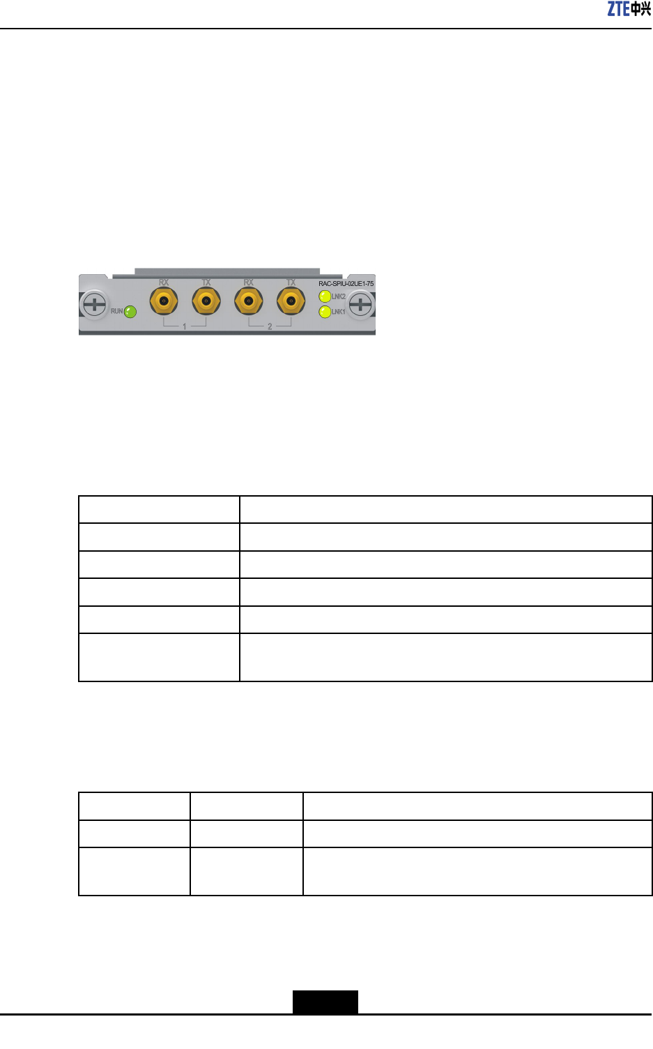
ZXR10ZSRV2HardwareDescription
lProvidestwounchannelizedE1(75ohm)interfaces.
lRestoresthelineclockandprovidingittoanMPFUboardforreference.
lSupportstheprocessingofvariousservices,suchasPPPandML-PPP.
lSupportshotswapping.
lSupportsboardinformationqueryandtemperaturemonitoring.
Panel
ForthepaneloftheRAC-SPIU-02UE1-75board,seeFigure9-2.
Figure9-2FrontPaneloftheRAC-SPIU-02UE1-75Board
InterfaceProperty
TheRAC-SPIU-02UE1-75boardprovidesmicrocoaxialinterfaces,anditonlysupports
75ohmnon-balancedE1interfaces.Foradescriptionoftheinterfaceproperties,referto
Table9-5.
Table9-5InterfacePropertiesoftheRAC-SPIU-02UE1-75Board
PropertyDescription
ConnectortypeMicrocoaxial
OperationalmodeFullduplex
AppliedstandardITU-TG.703,G.704
SupportedlinkprotocolPPP ,ML-PPP ,HDLC,FR
Supportednetwork
protocol
IP
Indicators
ForadescriptionoftheindicatorsoftheRAC-SPIU-02UE1-75board,refertoT able9-6.
Table9-6DescriptionoftheIndicatorsonthePaneloftheRAC-SPIU-02UE1-75Board
IndicatorColorDescription
RUNGreenTheindicatorislitwhentheboardisoperatingproperly.
LNK1/LNK2GreenTheindicatorislitwhenthelinkisoperatingproperly,andis
notlitwhenthelinkisidle.
TechnicalParameters
ForthetechnicalparametersoftheRAC-SPIU-02UE1-75board,refertoT able9-7.
9-4
SJ-20150204153047-004|2015-03-30(R1.0)ZTEProprietaryandCondential
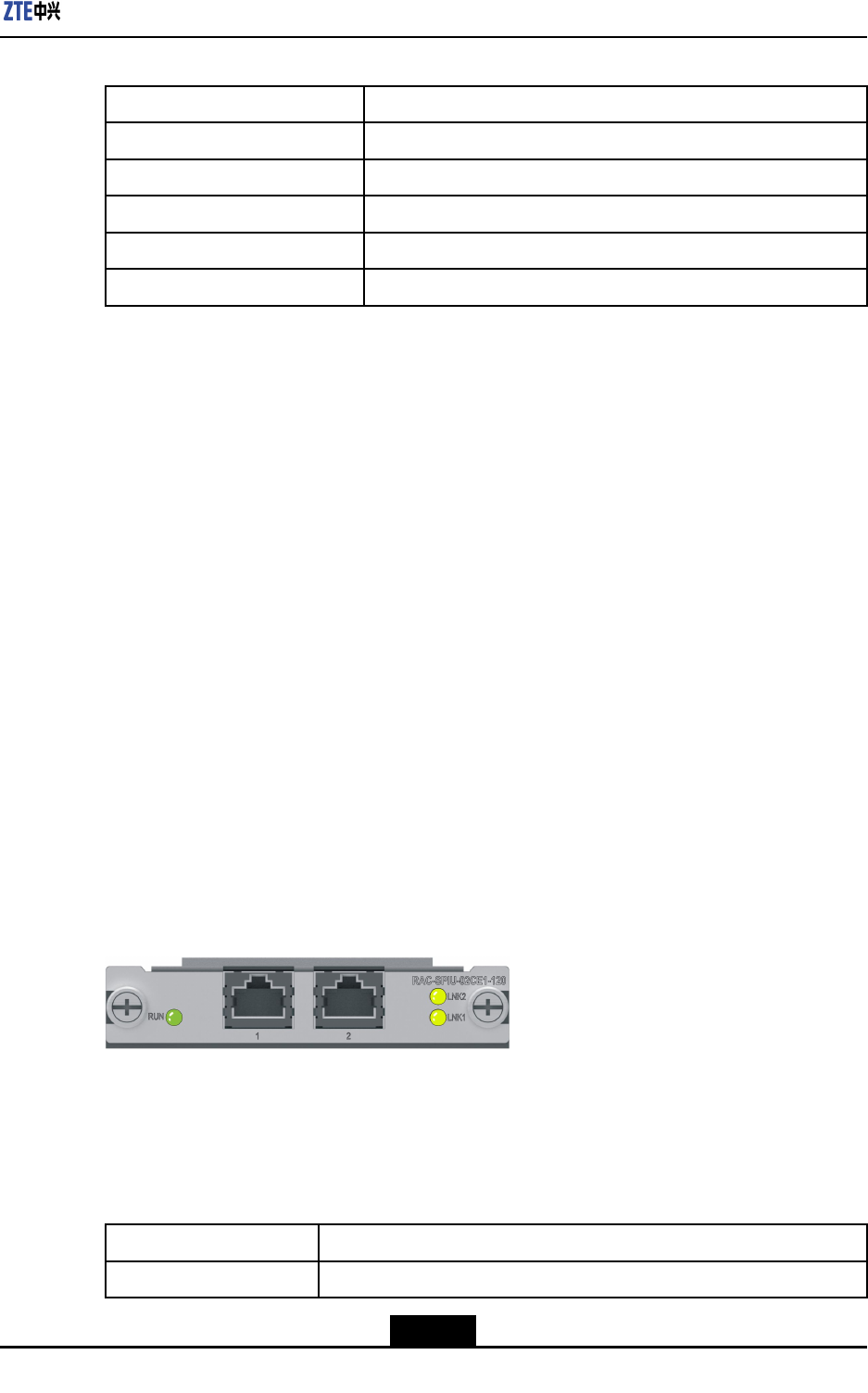
Chapter9LineInterfaceBoards
Table9-7TechnicalParametersoftheRAC-SPIU-02UE1-75Board
ParameterSpecication
SilkscreennameRAC-SPIU-02UE1-75
Dimensions(W×H×D)3.86in.×0.79in.×6.9in.(98.1mm×19.92mm×175mm)
Powerconsumption6W
Weight0.53lb.(0.24kg)
Rate2.048Mbps×2
9.3RAC-SPIU-02CE1-120
Overview
RAC-SPIU-02CE1-120boardprovidesthefollowingfunctions:
lProvidestwochannelized/unchannelizedE1(120ohm)interfaces.
lRestoresthelineclockandprovidingittoanMPFUboardforreference.
lSupportstheprocessingofvariousservices,suchasPPPandML-PPP.
lSupportshotswapping.
lSupportsboardinformationqueryandtemperaturemonitoring.
lSupportsthedelayedpower-onfunction.
Whentherouterispoweredon,alltheboardsarestartedup,causingahighpressure
onthepowersupply.Thedelayedpower-onfunctioncanreducetheelectriccurrent
impactcausedbytheboardsandprotectcomponentsfromdamageduetothe
instantaneoussurgecurrent.
Panel
ForthepaneloftheRAC-SPIU-02CE1-120board,seeFigure9-3.
Figure9-3FrontPaneloftheRAC-SPIU-02CE1-120Board
InterfaceProperty
TheRAC-SPIU-02CE1-120boardprovidesRJ48interfaces,anditonlysupports120ohm
E1interfaces.Foradescriptionoftheinterfaceproperties,refertoT able9-8.
Table9-8InterfacePropertiesoftheRAC-SPIU-02CE1-120Board
PropertyDescription
ConnectortypeRJ48
9-5
SJ-20150204153047-004|2015-03-30(R1.0)ZTEProprietaryandCondential
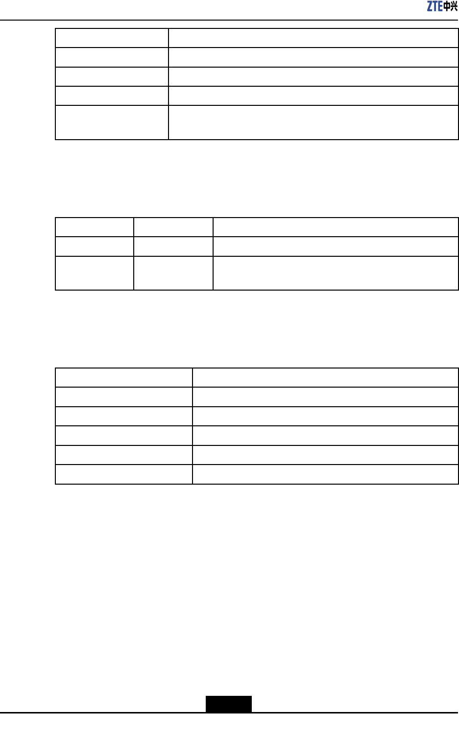
ZXR10ZSRV2HardwareDescription
PropertyDescription
OperationalmodeFullduplex
AppliedstandardITU-TG.703,G.704
SupportedlinkprotocolPPP ,ML-PPP ,HDLC,FR
Supportednetwork
protocol
IP
Indicators
ForadescriptionoftheindicatorsoftheRAC-SPIU-02CE1-120board,refertoTable9-9.
Table9-9DescriptionoftheIndicatorsonthePaneloftheRAC-SPIU-02CE1-120Board
IndicatorColorDescription
RUNGreenTheindicatorislitwhentheboardisoperatingproperly.
LNK1/LNK2GreenTheindicatorislitwhenthelinkisoperatingproperly,andis
notlitwhenthelinkisidle.
TechnicalParameters
ForthetechnicalparametersoftheRAC-SPIU-02CE1-120board,refertoTable9-10.
Table9-10TechnicalParametersoftheRAC-SPIU-02CE1-120Board
ParameterSpecication
SilkscreennameRAC-SPIU-02CE1-120
Dimensions(W×H×D)3.86in.×0.79in.×6.9in.(98.1mm×19.92mm×175mm)
Powerconsumption6W
Weight0.53lb.(0.24kg)
Rate2.048Mbps×2
9.4RAC-SPIU-02UE1-120
Overview
RAC-SPIU-02UE1-120boardprovidesthefollowingfunctions:
lProvidestwounchannelizedE1(120ohm)interfaces.
lRestoresthelineclockandprovidingittoanMPFUboardforreference.
lSupportstheprocessingofvariousservices,suchasPPPandML-PPP.
lSupportshotswapping.
lSupportsboardinformationqueryandtemperaturemonitoring.
lSupportsthedelayedpower-onfunction.
9-6
SJ-20150204153047-004|2015-03-30(R1.0)ZTEProprietaryandCondential
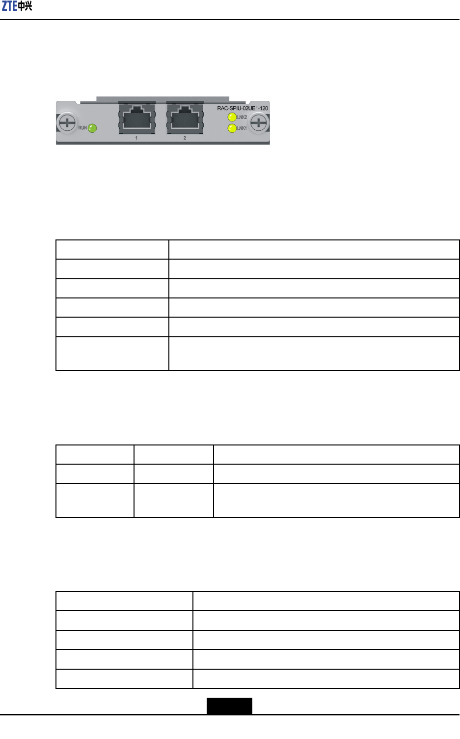
Chapter9LineInterfaceBoards
Panel
ForthepaneloftheRAC-SPIU-02UE1-120board,seeFigure9-4.
Figure9-4FrontPaneloftheRAC-SPIU-02UE1-120Board
InterfaceProperty
TheRAC-SPIU-02UE1-120boardprovidesRJ48interfaces,anditonlysupports120ohm
E1interfaces.Foradescriptionoftheinterfaceproperties,refertoTable9-11.
Table9-11InterfacePropertiesoftheRAC-SPIU-02UE1-120Board
PropertyDescription
ConnectortypeRJ48
OperationalmodeFullduplex
AppliedstandardITU-TG.703,G.704
SupportedlinkprotocolPPP ,ML-PPP ,HDLC,FR
Supportednetwork
protocol
IP
Indicators
ForadescriptionoftheindicatorsoftheRAC-SPIU-02UE1-120board,refertoT able9-12.
Table9-12DescriptionoftheIndicatorsonthePaneloftheRAC-SPIU-02UE1-120Board
IndicatorColorDescription
RUNGreenTheindicatorislitwhentheboardisoperatingproperly.
LNK1/LNK2GreenTheindicatorislitwhenthelinkisoperatingproperly,andis
notlitwhenthelinkisidle.
TechnicalParameters
ForthetechnicalparametersoftheRAC-SPIU-02UE1-120board,refertoTable9-13.
Table9-13TechnicalParametersoftheRAC-SPIU-02UE1-120Board
ParameterSpecication
SilkscreennameRAC-SPIU-02UE1-120
Dimensions(W×H×D)3.86in.×0.79in.×6.9in.(98.1mm×19.92mm×175mm)
Powerconsumption6W
Weight0.53lb.(0.24kg)
9-7
SJ-20150204153047-004|2015-03-30(R1.0)ZTEProprietaryandCondential
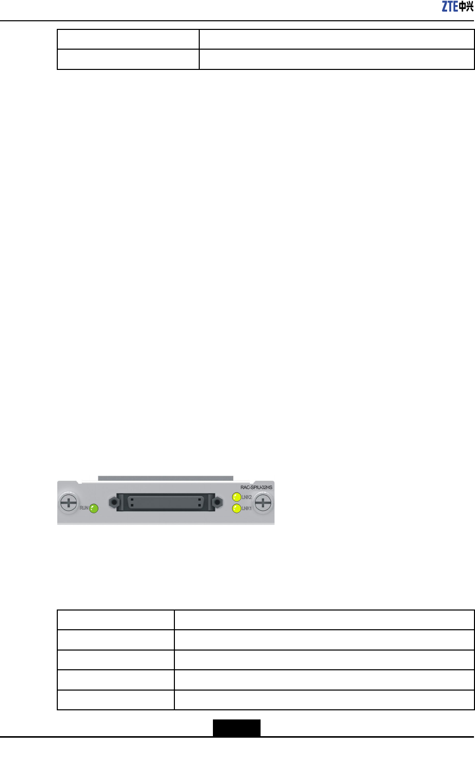
ZXR10ZSRV2HardwareDescription
ParameterSpecication
Rate2.048Mbps×2
9.5RAC-SPIU-02HS
Overview
RAC-SPIU-02HSboardprovidesthefollowingfunctions:
lProvides2-wireserialportssupportingasynchronousorsynchronousdata
transmissionmode.
àForsynchronousdatatransmissionmode,theportscanbeconnectedtoDTEs
orDCEs.ThecircuitsidesupportstheV.24,V.35orX.21interfaces.TheV.24
interfacesupportsamaximumrateof115.2Kbps.TheV.35interfacesupports
amaximumrateof4.096Mbps.TheX.21interfacesupportsamaximumrateof
48Kbps.
àAsynchronousdatatransmissionmodesupportstheRS232interfacethat
supportsamaximumrateof115.2Kbps.
lSupportstheprocessingofvariousservices,suchasPPPandHDLC.
lSupportshotswapping.
lSupportsboardinformationqueryandtemperaturemonitoring.
Panel
ForthepaneloftheRAC-SPIU-02HSboard,seeFigure9-5.
Figure9-5FrontPaneloftheRAC-SPIU-02HSBoard
InterfaceProperty
Foradescriptionoftheinterfaceproperties,refertoT able9-14.
Table9-14InterfacePropertiesoftheRAC-SPIU-02HSBoard
PropertyDescription
ConnectortypeDB50
OperationalmodeAsynchronousorsynchronous
AppliedstandardV.24,V.35,X.21,orRS232
SupportedlinkprotocolPPP,HDLC,andFR
9-8
SJ-20150204153047-004|2015-03-30(R1.0)ZTEProprietaryandCondential
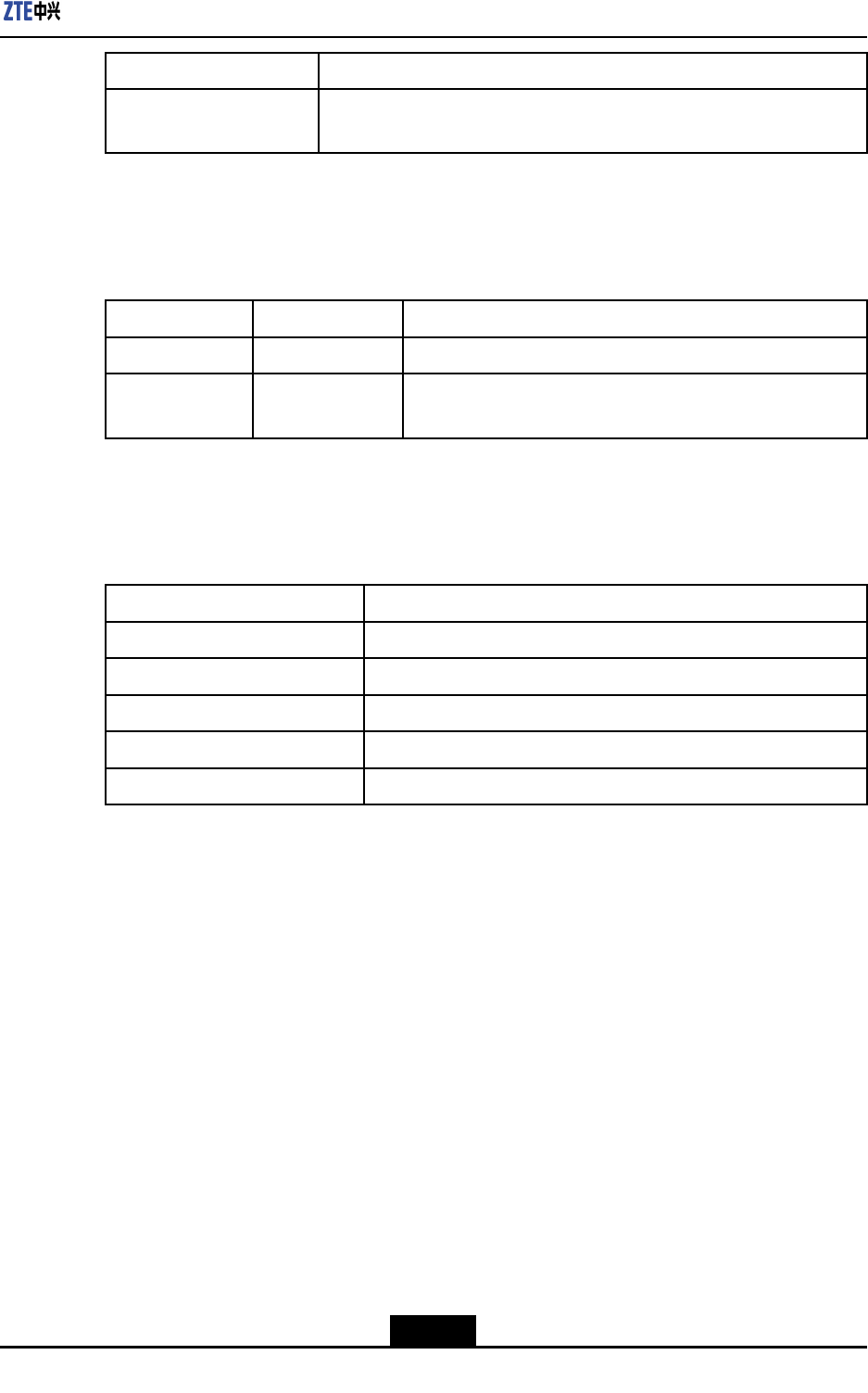
Chapter9LineInterfaceBoards
PropertyDescription
Supportednetwork
protocol
IP
Indicators
ForadescriptionoftheindicatorsoftheRAC-SPIU-02HSboard,refertoT able9-15.
Table9-15DescriptionoftheIndicatorsonthePaneloftheRAC-SPIU-02HSBoard
IndicatorColorDescription
RUNGreenTheindicatorislitwhentheboardisoperatingproperly.
LNK1/LNK2GreenTheindicatorislitwhenthelinkisoperatingproperly,andis
notlitwhenthelinkisidle.
TechnicalParameters
ForthetechnicalparametersoftheRAC-SPIU-02HSboard,refertoT able9-16.
Table9-16TechnicalParametersoftheRAC-SPIU-02HSBoard
ParameterSpecication
SilkscreennameRAC-SPIU-02HS
Dimensions(W×H×D)3.86in.×0.79in.×6.9in.(98.1mm×19.92mm×175mm)
Powerconsumption7W
Weight0.46lb.(0.21kg)
RateMultiplerates,upto4.096Mbps.
9.6RAC-SPIU-04GE
Overview
AnRAC-SPIU-04GEboardhasthefollowingfunctions:
lProvidesfourlinesofelectricalinterfacesforgigabitEthernetinterfacecards.
lSupportsself-adaptive10/100/1000BASE-T.
lSupportshopswappingofboards.
lSupportsboardtemperaturedetectionandboardIDread.
Panel
ForthepanelofanRAC-SPIU-04GEboard,seeFigure9-6.
9-9
SJ-20150204153047-004|2015-03-30(R1.0)ZTEProprietaryandCondential

ZXR10ZSRV2HardwareDescription
Figure9-6FrontPanelofanRAC-SPIU-04GEBoard
AttributesofInterfaces
AnRAC-SPIU-04GEboardprovideselectricalinterfaces.Forattributesoftheseelectrical
interfaces,refertoTable9-17.
Table9-17AttributesofInterfacesonanRAC-SPIU-04GEBoard
DescriptionDescription
InterfaceTypeRJ45
WorkingModeFullduplex,andhalfduplex
StandardIEEE802.3zGigabitEthernetstandard
LinkprotocolEthernetframe
NetwortprotocolIP
Indicators
ForfunctionsofindicatorsonthepaneloftheRAC-SPIU-04GEboard,refertoT able9-18.
Table9-18DescriptionofFunctionsoftheIndicatorsonthePanelofthe
RAC-SPIU-04GEBoard
IndicatorColorDescription
Electrical
interface
indicator
GreenandyellowFourgroupsoflinkstatus/datacommunicationindicators
forGEelectricalinterfaces:
lIfthelinkisproperlyconnected,theindicatorinthetop
rightcorneroftheinterfaceturnssoldgreen.
lIfdataistransmittedontheboard,theindicatorinthe
toprightcorneroftheinterfaceashesyellow.
lIfnodataistransmittedandnolinkisconnected,the
indicatorturnsoff.
TechnicalParameters
FortechnicalparametersofanRAC-SPIU-04GEboard,refertoT able9-19.
Table9-19TechnicalParametersofanRAC-SPIU-04GEBoard
ParameterDescription
BoardnamesilkscreenRAC-SPIU-04GE
Dimension(width×height×
depth)
3.86in.×0.79in.×6.9in.(98.1mm×19.92mm×175mm)
9-10
SJ-20150204153047-004|2015-03-30(R1.0)ZTEProprietaryandCondential
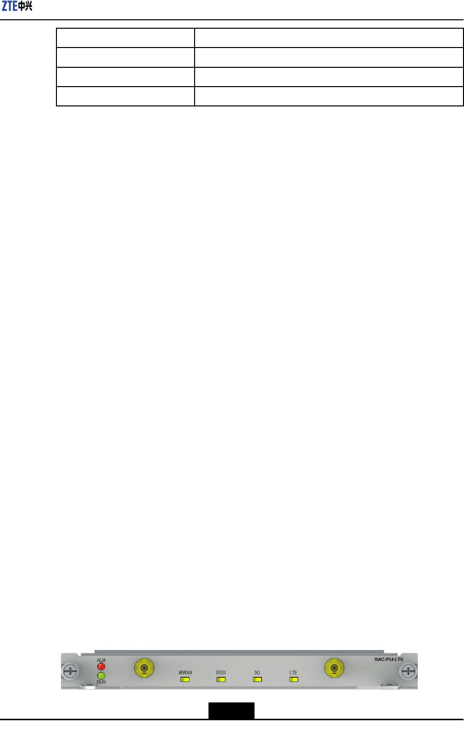
Chapter9LineInterfaceBoards
ParameterDescription
Powerconsumption7W
Weight0.22lb.(0.1kg)
Rate1GE×4
9.7RAC-PIU-LTE
Overview
TheRAC-PIU-LTEisa3G/LTEinterfaceboardfortheZXR102800-4andZXR103800-8.
Itsupports3G/LTEradionetworkaccess.Itcanoperateastheprimaryorsecondarylink
forenterprisestoaccesstheInternettotransferaudio,data,andvideoles.
lSupportsTD-LTE,FDD-LTE,TD-SCDMA,WCDMA,andHSPA+.
lSupportsthefrequencybandsofmultiplenetworks,including:
àGSM/GPRSQuadBand(850,900,1800,and1900)
àTD-SCDMAB34,andB39
àWCDMAB1,B2,andB5
àLTEB38,B39,B40,andB41
àLTEFDDB1,B2,B3,B5,andB7
àGPSL1
lSupportsdifferentnetworkspeedsfordifferentnetworks.
àForFDD-LTEandTD-LTE,theboardsupportsnetworkspeedsof100Mbpsand
50Mbps.
àForTD-SCDMA,theboardsupportsnetworkspeedsof2.8Mbpsand2.2Mbps.
àForWCDMADC-HSPA+,theboardsupportsnetworkspeedsof42Mbpsand5.7
Mbps.
àForWCDMAHSDPA,theboardsupportsnetworkspeedsof21Mbpsand5.76
Mbps.
lSupportshot-swapping.
Panel
Figure9-7showsthepaneloftheRAC-PIU-LTEboard.
Figure9-7RAC-PIU-LTEBoardPanel
9-11
SJ-20150204153047-004|2015-03-30(R1.0)ZTEProprietaryandCondential
ZXR10ZSRV2HardwareDescription
InterfaceAttribute
TheRAC-PIU-LTEboardtransfersdatathroughtheradiosignalsontheSub-Miniature-A
(SMA)interface(whipomnidirectionalantenna).Thepanelhasnootherexternal
interfaces.
Note:
TheSMAisacommonmodelofantennainterfaces.
Indicators
ForadescriptionoftheindicatorsonthepaneloftheRAC-PIU-LTEboard,refertoT able
9-20.
Table9-20RAC-PIU-LTEBoardIndicatorDescriptions
IndicatorColorDescription
RUNGreenOperationalstatusindicator.Itisonwhentheboardis
operatingproperly.
ALMRedAlarmindicator.Itisoniftheboardhasanalarm.
WWANGreenRadionetworkaccessindicator.Itasheswhentheboard
triestoaccessaradionetwork.Itisonwhentheboard
accessestheradionetworksuccessfully.Itisoffiftheboard
failstoaccesstheradionetwork.
RSSIGreenSignalstrengthindicator.
lRSSI≤-100dbm:Thereisnosignal.Theindicatoris
off.
l-99dbm≤RSSI≤-90dbm:Thesignalisweak.The
indicatorashes.
lRSSI≥-89dbm:Thesignalisstrong.Theindicator
ison.
3GGreen3Gsignalindicator.Itisonaftertheboardaccessesa3G
network.
LTEGreenLTEsignalindicator.Itisonaftertheboardaccessesan
LTEnetwork.
TechnicalSpecications
ForadescriptionofthetechnicalspecicationsoftheRAC-PIU-LTEboard,refertoT able
9-21.
9-12
SJ-20150204153047-004|2015-03-30(R1.0)ZTEProprietaryandCondential
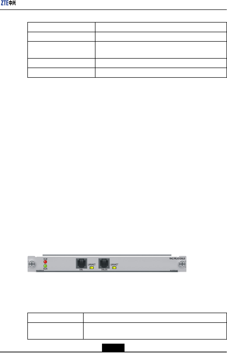
Chapter9LineInterfaceBoards
Table9-21RAC-PIU-LTEBoardTechnicalSpecications
ParameterDescriptions
SilkscreennameRAC-PIU-LTE
Dimensions(Width×Height×
Depth)
7.76in.×0.79in.×6.9in.(197.2mm×19.92mm×175mm)
Powerconsumption7W
Weight1.23lb.(0.56kg)
9.8RAC-PIU-01DSLB
Overview
RAC-PIU-01DSLBboardprovidesthefollowingfunctions:
lProvidesoneDSLinterface,whichsupportstheVDSL2/ADSL2+mode.
lProvidesoneDSL(B)interface,whichsupportstobeboundwiththeDSLinterface.
Forsingle-interfaceaccess,theDSLinterfaceisused.Fordual-interfaceaccess,
boththeDSLandDSL(B)interfacesareusedanditisnotallowedtousetheDSL
(B)interfaceonly.
lSupportstheDyingGaspfunction.
Itisapower-downalarmfunction.Whentheinputvoltagecannotmeetthenormal
operationrequirement,theboardgeneratesanalarmwiththelastelectricenergy.
lSupportshotswapping.
lSupportsboardinformationqueryandtemperaturemonitoring.
Panel
ForthepaneloftheRAC-PIU-01DSLBboard,seeFigure9-8.
Figure9-8FrontPaneloftheRAC-PIU-01DSLBBoard
InterfaceProperty
Foradescriptionoftheinterfaceproperties,refertoT able9-22.
Table9-22InterfacePropertiesoftheRAC-PIU-01DSLBBoard
PropertyDescription
ConnectortypeRJ-11interface,whichcanbeconnectedtoaDSLAMthrougha
commontelephonecable
9-13
SJ-20150204153047-004|2015-03-30(R1.0)ZTEProprietaryandCondential
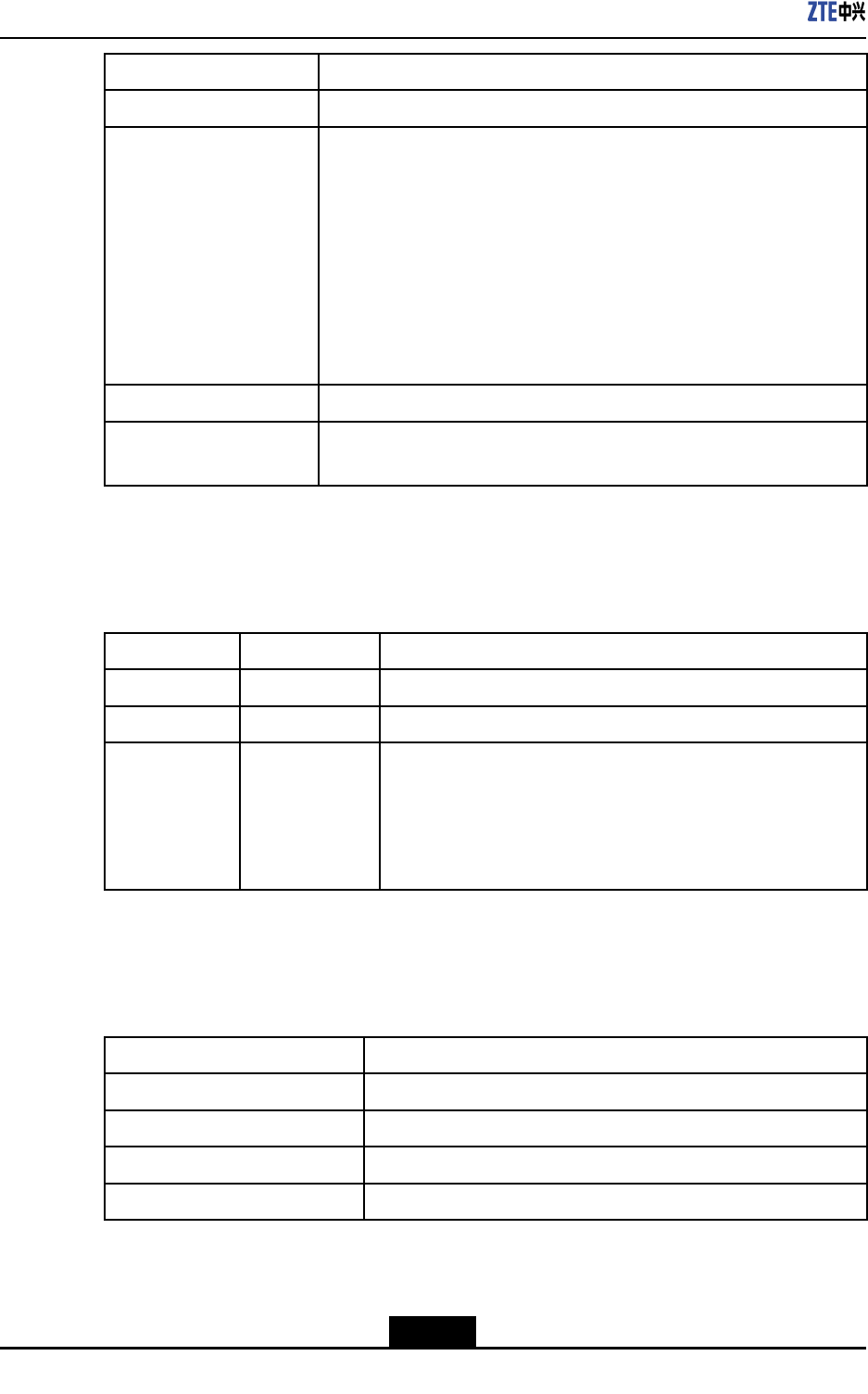
ZXR10ZSRV2HardwareDescription
PropertyDescription
OperationalmodeVDSL2/ADSL2+mode
AppliedstandardVDSL:
lITU-TG.993.2(VDSL2)
lITU-TG.993.5(G.vector)
ADSL:
lITU-TG.992.1(G.dmt),AnnexA,B,andC
lITU-TG.992.2(G.lite),AnnexAandC
lANSIT1.413
lITU-TG.992.3(ADSL2),AnnexA,B,C,L,andM
lITU-TG.992.5(ADSL2+),AnnexA,B,C,andM
SupportedlinkprotocolATM,PTM
Supportednetwork
protocol
PPPoEoA,IPoEoA
Indicators
ForadescriptionoftheindicatorsoftheRAC-PIU-01DSLBboard,refertoTable9-23.
Table9-23DescriptionoftheIndicatorsonthePaneloftheRAC-PIU-01DSLBBoard
IndicatorColorDescription
RUNGreenTheindicatorislitwhentheboardisoperatingproperly.
ALMRedAlarmindicator,whichislitwhentheboardhasanalarm.
LNK/ACTGreen,Yellow
Linkstatus/datatransmissionindicator:
lIfthelinkisnormal,theindicatorislitingreen.
lIfdataisbeingtransmitted,theindicatorashesinyellow.
lIfthereisnodatabeingtransmittedornoconnection,the
indicatorisnotlit.
TechnicalParameters
ForthetechnicalparametersoftheRAC-PIU-01DSLBboard,refertoT able9-24.
Table9-24TechnicalParametersoftheRAC-PIU-01DSLBBoard
ParameterSpecication
SilkscreennameRAC-PIU-01DSLB
Dimensions(W×H×D)7.76in.×0.79in.×6.9in.(197.2mm×19.92mm×175mm)
Powerconsumption16W
Weight0.88lb.(0.4kg)
9-14
SJ-20150204153047-004|2015-03-30(R1.0)ZTEProprietaryandCondential
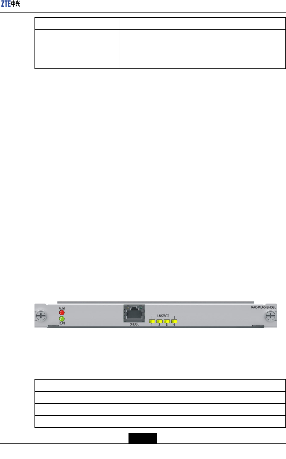
Chapter9LineInterfaceBoards
ParameterSpecication
RateInADSL2+fullratemode(ITU-T992.5):Thedownlinkratecan
reach24Mbpsandtheuplinkratecanreach1Mbps.
InVDSL2mode(ITU-T993.2):Thedownlinkratecanreach100
Mbpsandtheuplinkratecanreach50Mbps.
9.9RAC-PIU-04SHDSL
Overview
RAC-PIU-04SHDSLboardprovidesthefollowingfunctions:
lProvidesoneG.SHDSL(SHDSLgroup)interface,whichprovidesfourSHDSL
electricalinterfaces.
SymmetricHighbitrateDigitalSubscriberLine(SHDSL)evolvesfromHDSLand
complieswiththeITU-TG.991.2andG.994.2standards.Onlyonepairoftelephone
linesarerequiredfordatatransmission,whichreducestherequirementoncopper
wireresources.SHDSLusestheTC-PAM16/32/64codingmode,whereagreater
numberrepresentsafastertransmissionspeed.Itcanbeusedforaudio,video,and
datatransmission.
lSupportstheATMandEFMprotocolencapsulationmodes.
lSupportshotswapping.
lSupportsboardinformationqueryandtemperaturemonitoring.
Panel
ForthepaneloftheRAC-PIU-04SHDSLboard,seeFigure9-9.
Figure9-9FrontPaneloftheRAC-PIU-04SHDSLboard
InterfaceProperties
Foradescriptionoftheinterfaceproperties,refertoT able9-25.
Table9-25InterfacePropertiesoftheRAC-PIU-04SHDSLBoard
PropertyDescription
ConnectortypeRJ45interface,connectedtofourRJ11interfacesatthepeerend
OperationalmodeFullduplex
AppliedstandardITU-TG.991.2
9-15
SJ-20150204153047-004|2015-03-30(R1.0)ZTEProprietaryandCondential
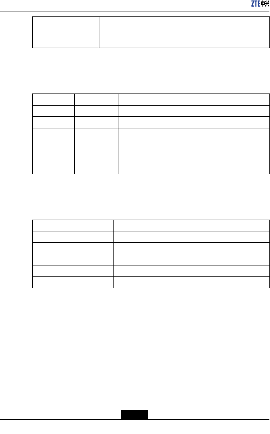
ZXR10ZSRV2HardwareDescription
PropertyDescription
Supportednetwork
protocol
IP
Indicators
ForadescriptionoftheindicatorsoftheRAC-PIU-04SHDSLboard,refertoT able9-26.
Table9-26DescriptionoftheIndicatorsonthePaneloftheRAC-PIU-04SHDSLBoard
IndicatorColorDescription
RUNGreenTheindicatorislitwhentheboardisoperatingproperly.
ALMRedTheindicatorislitiftheboardproducesanalarm.
LNK/ACTGreen,Yellow
Linkstatus/datatransmissionindicator:
lIfthelinkisnormal,theindicatorislitingreen.
lIfdataisbeingtransmitted,theindicatorashesinyellow.
lIfthereisnodatabeingtransmittedornoconnection,the
indicatorisnotlit.
TechnicalParameters
ForthetechnicalparametersoftheRAC-PIU-04SHDSLboard,refertoT able9-27.
Table9-27TechnicalParametersoftheRAC-PIU-04SHDSLBoard
ParameterSpecication
SilkscreennameRAC-PIU-04SHDSL
Dimensions(W×H×D)7.76in.×0.79in.×6.9in.(197.2mm×19.92mm×175mm)
Powerconsumption10W
Weight1.19lb.(0.54kg)
Rate5.696Mbit/s/pair
9.10RAC-PIU-04HS
Overview
RAC-PIU-04HSboardprovidesthefollowingfunctions:
lProvides4-wireserialportssupportingasynchronousorsynchronousdata
transmissionmode.
àForsynchronousdatatransmissionmode,theportscanbeconnectedtoDTEs
orDCEs.ThecircuitsidesupportstheV.24,V.35,orX.21interfaces.TheV.24
interfacesupportsamaximumrateof115.2Kbps.TheV.35interfacesupports
9-16
SJ-20150204153047-004|2015-03-30(R1.0)ZTEProprietaryandCondential
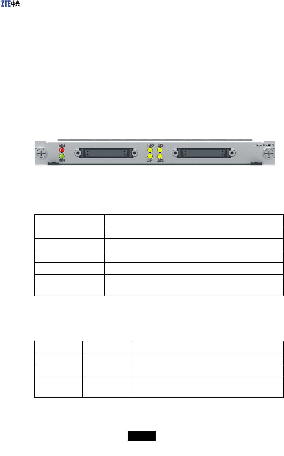
Chapter9LineInterfaceBoards
amaximumrateof4.096Mbps.TheX.21interfacesupportsamaximumrateof
48Kbps.
àAsynchronousdatatransmissionmodesupportstheRS232interfacethat
supportsamaximumrateof115.2Kbps.
lSupportstheprocessingofvariousservices,suchasPPPandHDLC.
lSupportshotswapping.
lSupportsboardinformationqueryandtemperaturemonitoring.
Panel
ForthepaneloftheRAC-PIU-04HSboard,seeFigure9-10.
Figure9-10FrontPaneloftheRAC-PIU-04HSBoard
InterfaceProperty
Foradescriptionoftheinterfaceproperties,refertoT able9-28.
Table9-28InterfacePropertiesoftheRAC-PIU-04HSBoard
PropertyDescription
ConnectortypeDB50
OperationalmodeAsynchronousorsynchronous
AppliedstandardV.24,V.35,X.21orRS232
SupportedlinkprotocolPPP,HDLCorFR
Supportednetwork
protocol
IP
Indicators
ForadescriptionoftheindicatorsoftheRAC-PIU-04HSboard,refertoTable9-29.
Table9-29DescriptionoftheIndicatorsonthePaneloftheRAC-PIU-04HSBoard
IndicatorColorDescription
RUNGreenTheindicatorislitwhentheboardisoperatingproperly.
ALMRedTheindicatorislitiftheboardproducesanalarm.
LNK1–LNK4GreenTheindicatorislitwhenthelinkisoperatingproperly,andis
notlitwhenthelinkisidle.
TechnicalParameters
ForthetechnicalparametersoftheRAC-PIU-04HSboard,refertoTable9-30.
9-17
SJ-20150204153047-004|2015-03-30(R1.0)ZTEProprietaryandCondential
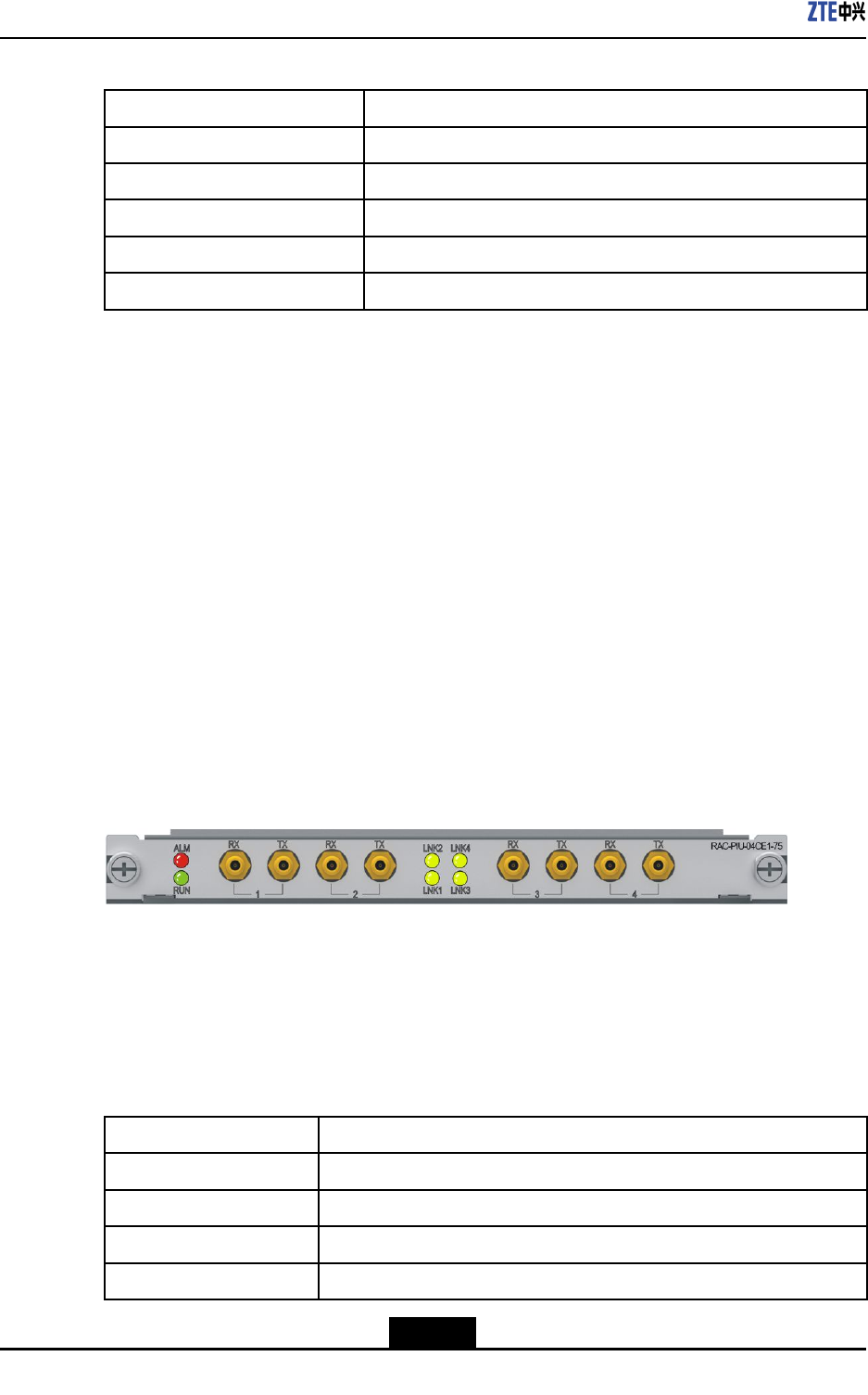
ZXR10ZSRV2HardwareDescription
Table9-30TechnicalParametersoftheRAC-PIU-04HSBoard
ParameterSpecication
SilkscreennameRAC-PIU-04HS
Dimensions(W×H×D)7.76in.×0.79in.×6.9in.(197.2mm×19.92mm×175mm)
Powerconsumption10W
Weight1.19lb.(0.54kg)
Rate1200bps–4.096Mbps×4
9.11RAC-PIU-04CE1-75
Overview
RAC-PIU-04CE1-75boardprovidesthefollowingfunctions:
lProvidesfourchannelized/unchannelizedE1(75ohm)interfaces.
lRestoresthelineclockandprovidingittoanMPFUboardforreference.
lSupportstheprocessingofvariousservices,suchasPPPandML-PPP.
lSupportshotswapping.
lSupportsboardinformationqueryandtemperaturemonitoring.
Panel
ForthepaneloftheRAC-PIU-04CE1-75board,seeFigure9-11.
Figure9-11FrontPaneloftheRAC-PIU-04CE1-75Board
InterfaceProperty
TheRAC-PIU-04CE1-75boardprovidesmicrocoaxialinterfaces,anditonlysupports75
ohmnon-balancedE1interfaces.Foradescriptionoftheinterfaceproperties,referto
Table9-31.
Table9-31InterfacePropertiesoftheRAC-PIU-04CE1-75Board
PropertyDescription
ConnectortypeMicrocoaxial
OperationalmodeFullduplex
AppliedstandardITU-TG.703,G.704
SupportedlinkprotocolPPP ,ML-PPP ,HDLC,FR
9-18
SJ-20150204153047-004|2015-03-30(R1.0)ZTEProprietaryandCondential
Chapter9LineInterfaceBoards
PropertyDescription
Supportednetwork
protocol
IP
Indicators
ForadescriptionoftheindicatorsoftheRAC-PIU-04CE1-75board,refertoT able9-32.
Table9-32DescriptionoftheIndicatorsonthePaneloftheRAC-PIU-04CE1-75Board
IndicatorColorDescription
RUNGreenTheindicatorislitwhentheboardisoperatingproperly.
ALMRedTheindicatorislitiftheboardproducesanalarm.
LNK1–LNK4GreenTheindicatorislitwhenthelinkisoperatingproperly,andis
notlitwhenthelinkisidle.
TechnicalParameters
ForthetechnicalparametersoftheRAC-PIU-04CE1-75board,refertoT able9-33.
Table9-33TechnicalParametersoftheRAC-PIU-04CE1-75Board
ParameterSpecication
SilkscreennameRAC-PIU-04CE1-75
Dimensions(W×H×D)7.76in.×0.79in.×6.9in.(197.2mm×19.92mm×175mm)
Powerconsumption11W
Weight1.19lb.(0.54kg)
Rate2.048Mbps×4
9.12RAC-PIU-04CE1-120
Overview
RAC-PIU-04CE1-120boardprovidesthefollowingfunctions:
lProvidesfourchannelized/unchannelizedE1(120ohm)interfaces.
lRestoresthelineclockandprovidingittoanMPFUboardforreference.
lSupportstheprocessingofvariousservices,suchasPPPandML-PPP.
lSupportshotswapping.
lSupportsboardinformationqueryandtemperaturemonitoring.
lSupportsthedelayedpower-onfunction.
Panel
ForthepaneloftheRAC-PIU-04CE1-120board,seeFigure9-12.
9-19
SJ-20150204153047-004|2015-03-30(R1.0)ZTEProprietaryandCondential
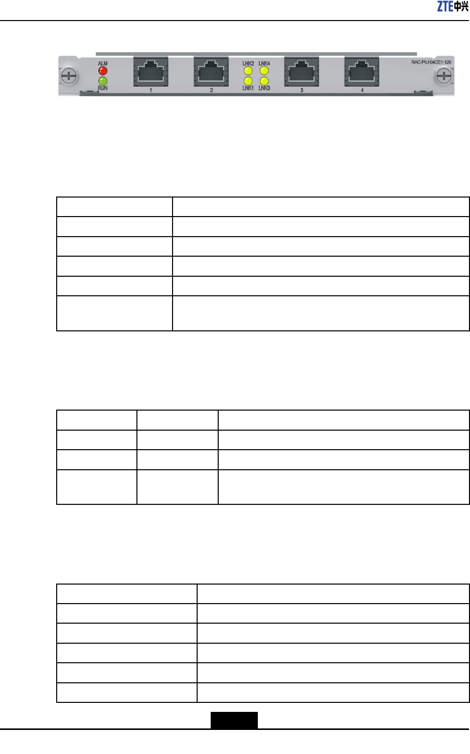
ZXR10ZSRV2HardwareDescription
Figure9-12FrontPaneloftheRAC-PIU-04CE1-120Board
InterfaceProperty
TheRAC-PIU-04CE1-120boardprovidesRJ48interfaces,anditonlysupports120ohm
E1interfaces.Foradescriptionoftheinterfaceproperties,refertoTable9-34.
Table9-34InterfacePropertiesoftheRAC-PIU-04CE1-120Board
PropertyDescription
ConnectortypeRJ48
OperationalmodeFullduplex
AppliedstandardITU-TG.703,G.704
SupportedlinkprotocolPPP ,ML-PPP ,HDLC,FR
Supportednetwork
protocol
IP
Indicators
ForadescriptionoftheindicatorsoftheRAC-PIU-04CE1-120board,refertoTable9-35.
Table9-35DescriptionoftheIndicatorsonthePaneloftheRAC-PIU-04CE1-120Board
IndicatorColorDescription
RUNGreenTheindicatorislitwhentheboardisoperatingproperly.
ALMRedTheindicatorislitiftheboardproducesanalarm.
LNK1–LNK4GreenTheindicatorislitwhenthelinkisoperatingproperly,andis
notlitwhenthelinkisidle.
TechnicalParameters
ForthetechnicalparametersoftheRAC-PIU-04CE1-120board,refertoT able9-36.
Table9-36TechnicalParametersoftheRAC-PIU-04CE1-120Board
ParameterSpecication
SilkscreennameRAC-PIU-04CE1-120
Dimensions(W×H×D)7.76in.×0.79in.×6.9in.(197.2mm×19.92mm×175mm)
Powerconsumption11W
Weight1.19lb.(0.54kg)
Rate2.048Mbps×4
9-20
SJ-20150204153047-004|2015-03-30(R1.0)ZTEProprietaryandCondential
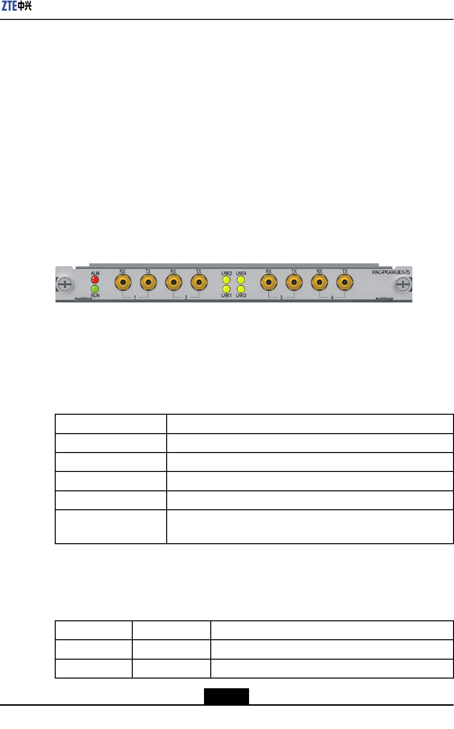
Chapter9LineInterfaceBoards
9.13RAC-PIU-04UE1-75
Overview
RAC-PIU-04UE1-75boardprovidesthefollowingfunctions:
lProvidesfourunchannelizedE1(75ohm)interfaces.
lRestoresthelineclockandprovidingittoanMPFUboardforreference.
lSupportstheprocessingofvariousservices,suchasPPPandML-PPP.
lSupportshotswapping.
lSupportsboardinformationqueryandtemperaturemonitoring.
Panel
ForthepaneloftheRAC-PIU-04UE1-75board,seeFigure9-13.
Figure9-13FrontPaneloftheRAC-PIU-04UE1-75Board
InterfaceProperty
TheRAC-PIU-04UE1-75boardprovidesmicrocoaxialinterfaces,anditonlysupports75
ohmnon-balancedE1interfaces.Foradescriptionoftheinterfaceproperties,referto
Table9-37.
Table9-37InterfacePropertiesoftheRAC-PIU-04UE1-75Board
PropertyDescription
ConnectortypeMicrocoaxial
OperationalmodeFullduplex
AppliedstandardITU-TG.703,G.704
SupportedlinkprotocolPPP ,ML-PPP ,HDLC,FR
Supportednetwork
protocol
IP
Indicators
ForadescriptionoftheindicatorsoftheRAC-PIU-04UE1-75board,refertoT able9-38.
Table9-38DescriptionoftheIndicatorsonthePaneloftheRAC-PIU-04UE1-75Board
IndicatorColorDescription
RUNGreenTheindicatorislitwhentheboardisoperatingproperly.
ALMRedTheindicatorislitiftheboardproducesanalarm.
9-21
SJ-20150204153047-004|2015-03-30(R1.0)ZTEProprietaryandCondential
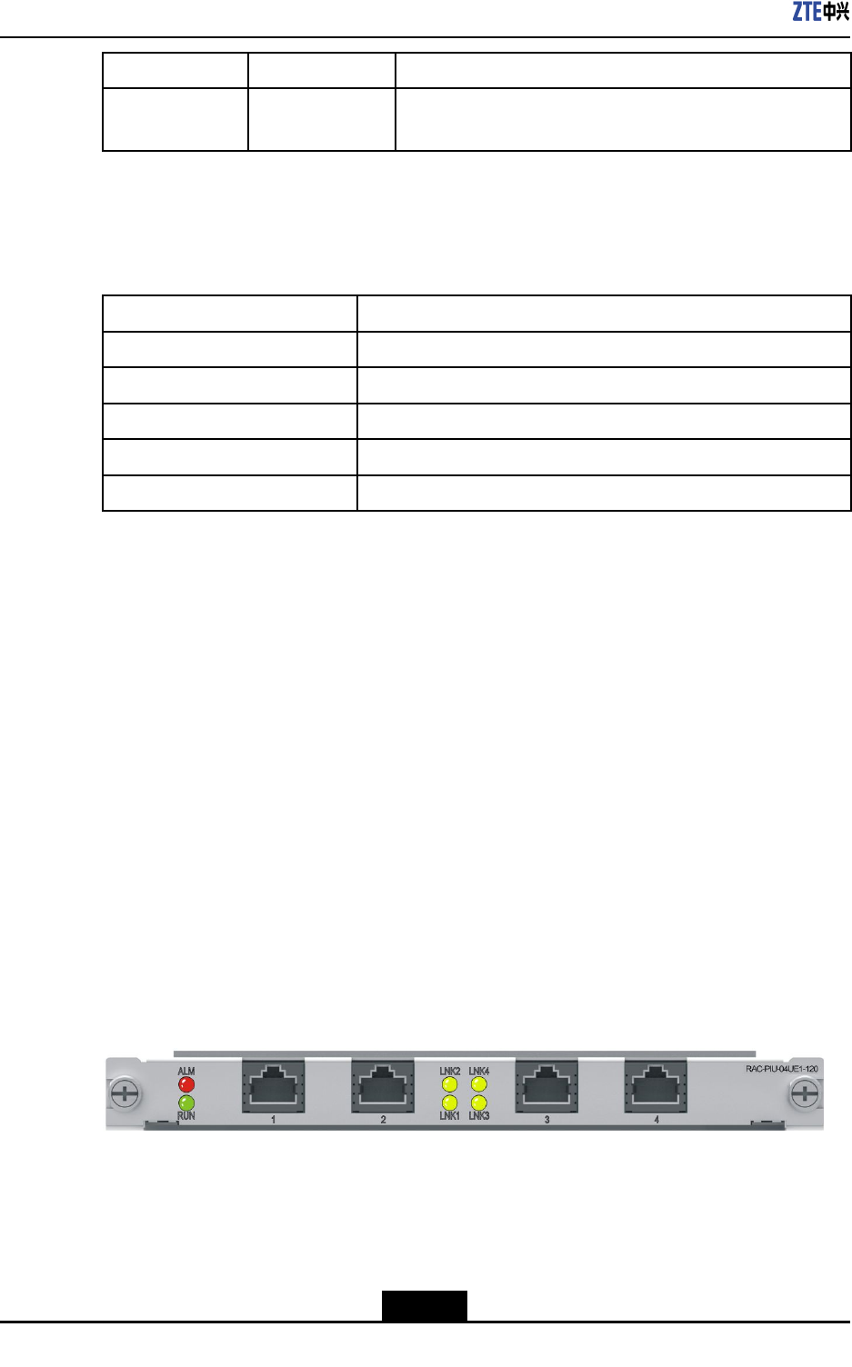
ZXR10ZSRV2HardwareDescription
IndicatorColorDescription
LNK1–LNK4GreenTheindicatorislitwhenthelinkisoperatingproperly,andis
notlitwhenthelinkisidle.
TechnicalParameters
ForthetechnicalparametersoftheRAC-PIU-04UE1-75board,refertoT able9-39.
Table9-39TechnicalParametersoftheRAC-PIU-04UE1-75Board
ParameterSpecication
SilkscreennameRAC-PIU-04UE1-75
Dimensions(W×H×D)7.76in.×0.79in.×6.9in.(197.2mm×19.92mm×175mm)
Powerconsumption11W
Weight1.19lb.(0.54kg)
Rate2.048Mbps×4
9.14RAC-PIU-04UE1-120
Overview
RAC-PIU-04UE1-120boardprovidesthefollowingfunctions:
lProvidesfourunchannelizedE1(120ohm)interfaces.
lRestoresthelineclockandprovidingittoanMPFUboardforreference.
lSupportstheprocessingofvariousservices,suchasPPPandML-PPP.
lSupportshotswapping.
lSupportsboardinformationqueryandtemperaturemonitoring.
lSupportsthedelayedpower-onfunction.
Panel
ForthepaneloftheRAC-PIU-04UE1-120board,seeFigure9-14.
Figure9-14FrontPaneloftheRAC-PIU-04UE1-120Board
InterfaceProperty
TheRAC-PIU-04UE1-120boardprovidesRJ48interfaces,anditonlysupports120ohm
E1interfaces.Foradescriptionoftheinterfaceproperties,refertoTable9-40.
9-22
SJ-20150204153047-004|2015-03-30(R1.0)ZTEProprietaryandCondential
Chapter9LineInterfaceBoards
Table9-40InterfacePropertiesoftheRAC-PIU-04UE1-120Board
PropertyDescription
ConnectortypeRJ48
OperationalmodeFullduplex
AppliedstandardITU-TG.703,G.704
SupportedlinkprotocolPPP ,ML-PPP ,HDLC,FR
Supportednetwork
protocol
IP
Indicators
ForadescriptionoftheindicatorsoftheRAC-PIU-04UE1-120board,refertoTable9-41.
Table9-41DescriptionoftheIndicatorsonthePaneloftheRAC-PIU-04UE1-120Board
IndicatorColorDescription
RUNGreenTheindicatorislitwhentheboardisoperatingproperly.
ALMRedTheindicatorislitiftheboardproducesanalarm.
LNK1–LNK4GreenTheindicatorislitwhenthelinkisoperatingproperly,andis
notlitwhenthelinkisidle.
TechnicalParameters
ForthetechnicalparametersoftheRAC-PIU-04UE1-120board,refertoT able9-42.
Table9-42TechnicalParametersoftheRAC-PIU-04UE1-120Board
ParameterSpecication
SilkscreennameRAC-PIU-04UE1-120
Dimensions(W×H×D)7.76in.×0.79in.×6.9in.(197.2mm×19.92mm×175mm)
Powerconsumption11W
Weight1.19lb.(0.54kg)
Rate2.048Mbps×4
9.15RAC-PIU-16CE1
Overview
RAC-PIU-16CE1boardprovidesthefollowingfunctions:
lProvides16channelized/unchannelizedE1interfaces.
lSupportstheprocessingofvariousservices,suchasPPPandML-PPP.
lSupportshotswapping.
9-23
SJ-20150204153047-004|2015-03-30(R1.0)ZTEProprietaryandCondential
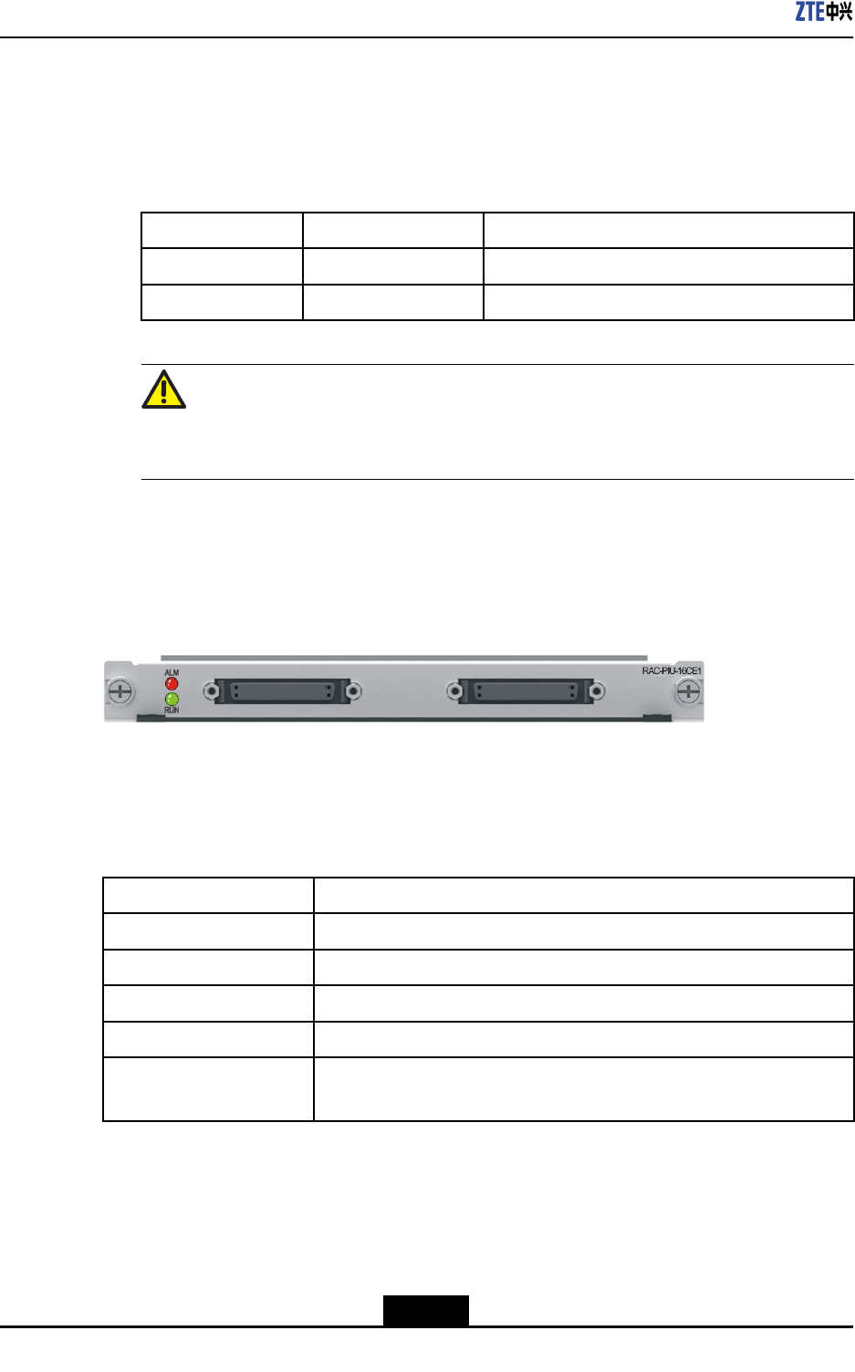
ZXR10ZSRV2HardwareDescription
lSupportsboardinformationqueryandtemperaturemonitoring.
lSupportsthe75Ωor120Ωconguration.
TheboardprovidesjumpersX6,X9,andX10toconguretheinterfaceresistanceto
75Ωor120Ω.Bydefault,theinterfaceresistanceis75Ω.Fortheinterfaceresistance
conguration,refertothefollowingtable.
Jumper75Ω120Ω
X62-3:ON1-2:ON
X9andX10ONOFF
Caution!
Thejumpercongurationcanbeperformedbyprofessionalsonly.
Panel
ForthepaneloftheRAC-PIU-16CE1board,seeFigure9-15.
Figure9-15FrontPaneloftheRAC-PIU-16CE1Board
InterfaceProperties
FortheinterfacepropertiesoftheRAC-PIU-16CE1board,refertoTable9-43.
Table9-43InterfacePropertiesoftheRAC-PIU-16CE1Board
PropertyDescription
ConnectortypeDB50
OperationalmodeFullduplex
AppliedstandardITU-TG.703,G.704
SupportedlinkprotocolPPP ,ML-PPP ,HDLC,FR
Supportednetwork
protocol
IP
Indicators
ForadescriptionoftheindicatorsoftheRAC-PIU-16CE1board,refertoT able9-44.
9-24
SJ-20150204153047-004|2015-03-30(R1.0)ZTEProprietaryandCondential
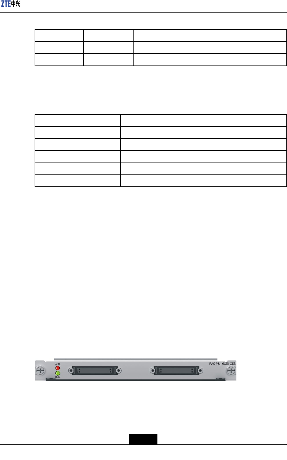
Chapter9LineInterfaceBoards
Table9-44DescriptionoftheIndicatorsonthePaneloftheRAC-PIU-16CE1Board
IndicatorColorDescription
RUNGreenTheindicatorislitwhentheboardisoperatingproperly.
ALMRedTheindicatorislitiftheboardproducesanalarm.
TechnicalParameters
ForthetechnicalparametersoftheRAC-PIU-16CE1board,refertoT able9-45.
Table9-45TechnicalParametersoftheRAC-PIU-16CE1Board
ParameterSpecication
SilkscreennameRAC-PIU-16CE1
Dimensions(W×H×D)7.76in.×0.79in.×6.9in.(197.2mm×19.92mm×175mm)
Powerconsumption16W
Weight1.19lb.(0.54kg)
Rate2.048Mbps×16
9.16RAC-PIU-16CE1-CES
Overview
RAC-PIU-16CE1-CESboardprovidesthefollowingfunctions:
lProvides16channelized/unchannelizedE1interfaces.
lSupportstheprocessingofvariousservices,suchasTDM,PPPandML-PPP.
lSupportshotswapping.
lSupportsboardinformationqueryandtemperaturemonitoring.
lSupportsthe75Ωor120Ωconguration.
Panel
ForthepaneloftheRAC-PIU-16CE1-CESboard,seeFigure9-16.
Figure9-16FrontPaneloftheRAC-PIU-16CE1-CESBoard
InterfaceProperties
FortheinterfacepropertiesoftheRAC-PIU-16CE1-CESboard,refertoT able9-46.
9-25
SJ-20150204153047-004|2015-03-30(R1.0)ZTEProprietaryandCondential

ZXR10ZSRV2HardwareDescription
Table9-46InterfacePropertiesoftheRAC-PIU-16CE1-CESBoard
PropertyDescription
ConnectortypeDB50
OperationalmodeFullduplex
AppliedstandardITU-TG.703,G.704
SupportedlinkprotocolTDM
Indicators
ForadescriptionoftheindicatorsoftheRAC-PIU-16CE1-CESboard,refertoTable9-47.
Table9-47DescriptionoftheIndicatorsonthePaneloftheRAC-PIU-16CE1-CESBoard
IndicatorColorDescription
RUNGreenTheindicatorislitwhentheboardisoperatingproperly.
ALMRedTheindicatorislitiftheboardproducesanalarm.
TechnicalParameters
ForthetechnicalparametersoftheRAC-PIU-16CE1-CESboard,refertoTable9-48.
Table9-48TechnicalParametersoftheRAC-PIU-16CE1-CESBoard
ParameterSpecication
SilkscreennameRAC-PIU-16CE1-CES
Dimensions(W×H×D)7.76in.×0.79in.×6.9in.(197.2mm×19.92mm×175mm)
Powerconsumption16W
Weight1.19lb.(0.54kg)
Rate2.048Mbps×16
9.17RAC-PIU-01P12-SFP
Overview
RAC-PIU-01P12-SFPboardprovidesthefollowingfunctions:
lSupports1-wireOC-12/STM-4POSapplications.
lSupportstheprocessingofvariousservices,suchasPPPandHDLC.
lSupportshotswapping.
lSupportsboardinformationqueryandtemperaturemonitoring.
Panel
ForthepaneloftheRAC-PIU-01P12-SFPboard,seeFigure9-17.
9-26
SJ-20150204153047-004|2015-03-30(R1.0)ZTEProprietaryandCondential
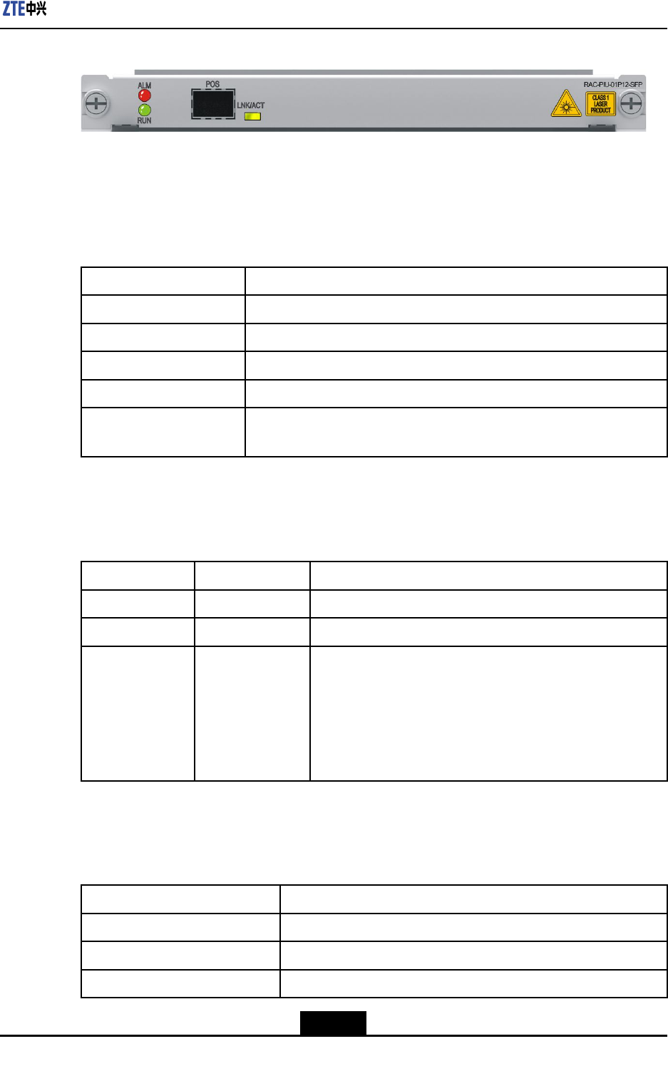
Chapter9LineInterfaceBoards
Figure9-17FrontPaneloftheRAC-PIU-01P12-SFPBoard
InterfaceProperty
TheRAC-PIU-01P12-SFPboardusesSFPopticalmodules.Foradescriptionofthe
interfaceproperties,refertoT able9-49.
Table9-49InterfacePropertiesoftheRAC-PIU-01P12-SFPBoard
PropertyDescription
ConnectortypeLC-typeSFPopticalmoduleinterface
OperationalmodeFullduplex
AppliedstandardSONETGR-253-CORE/ITU-TG.707
SupportedlinkprotocolPPP ,HDLC,FR,POSGROUP
Supportednetwork
protocol
IP
Indicators
ForadescriptionoftheindicatorsoftheRAC-PIU-01P12-SFPboard,refertoTable9-50.
Table9-50DescriptionoftheIndicatorsonthePaneloftheRAC-PIU-01P12-SFPBoard
IndicatorColorDescription
RUNGreenTheindicatorislitwhentheboardisoperatingproperly.
ALMRedTheindicatorislitiftheboardproducesanalarm.
LNK/ACTGreen/Yellow
Linkstatus/datatransmissionindicator:
lIfthelinkisnormal,theindicatorislitingreen.
lIfdataisbeingtransmitted,theindicatorashesin
yellow.
lIfthereisnodatabeingtransmittedornoconnection,
theindicatorisnotlit.
TechnicalParameters
ForthetechnicalparametersoftheRAC-PIU-01P12-SFPboard,refertoT able9-51.
Table9-51TechnicalParametersoftheRAC-PIU-01P12-SFPBoard
ParameterSpecication
SilkscreennameRAC-PIU-01P12-SFP
Dimensions(W×H×D)7.76in.×0.79in.×6.9in.(197.2mm×19.92mm×175mm)
Powerconsumption16W
9-27
SJ-20150204153047-004|2015-03-30(R1.0)ZTEProprietaryandCondential
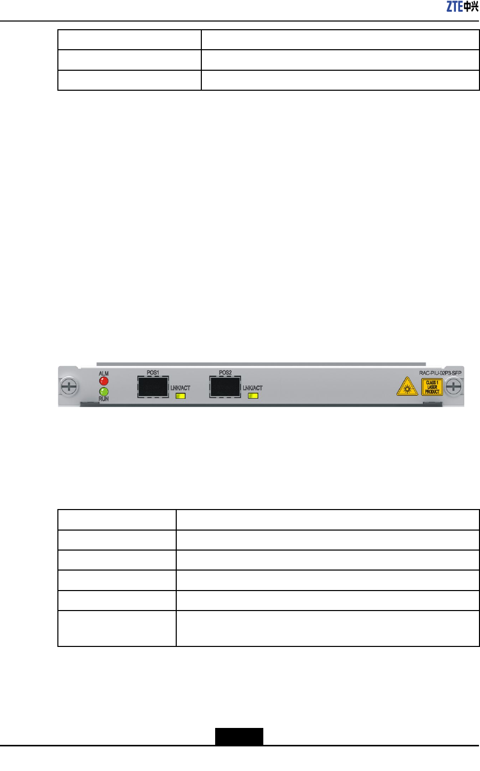
ZXR10ZSRV2HardwareDescription
ParameterSpecication
Weight1.19lb.(0.54kg)
Rate622.08Mbps
9.18RAC-PIU-02P3-SFP
Overview
RAC-PIU-02P3-SFPboardprovidesthefollowingfunctions:
lSupports2-wireOC-3/STM-1POSapplications.
lSupportstheprocessingofvariousservices,suchasPPPandHDLC.
lSupportshotswapping.
lSupportsboardinformationqueryandtemperaturemonitoring.
Panel
ForthepaneloftheRAC-PIU-02P3-SFPboard,seeFigure9-18.
Figure9-18FrontPaneloftheRAC-PIU-02P3-SFPBoard
InterfaceProperty
TheRAC-PIU-02P3-SFPboardusesSFPopticalmodules.Foradescriptionofthe
interfaceproperties,refertoT able9-52.
Table9-52InterfacePropertiesoftheRAC-PIU-02P3-SFPBoard
PropertyDescription
ConnectortypeLC-typeSFPopticalmoduleinterface
OperationalmodeFullduplex
AppliedstandardSONETGR-253-CORE/ITU-TG.707
SupportedlinkprotocolPPP ,HDLC,FR,POSGROUP
Supportednetwork
protocol
IP
Indicators
ForadescriptionoftheindicatorsoftheRAC-PIU-02P3-SFPboard,refertoT able9-53.
9-28
SJ-20150204153047-004|2015-03-30(R1.0)ZTEProprietaryandCondential
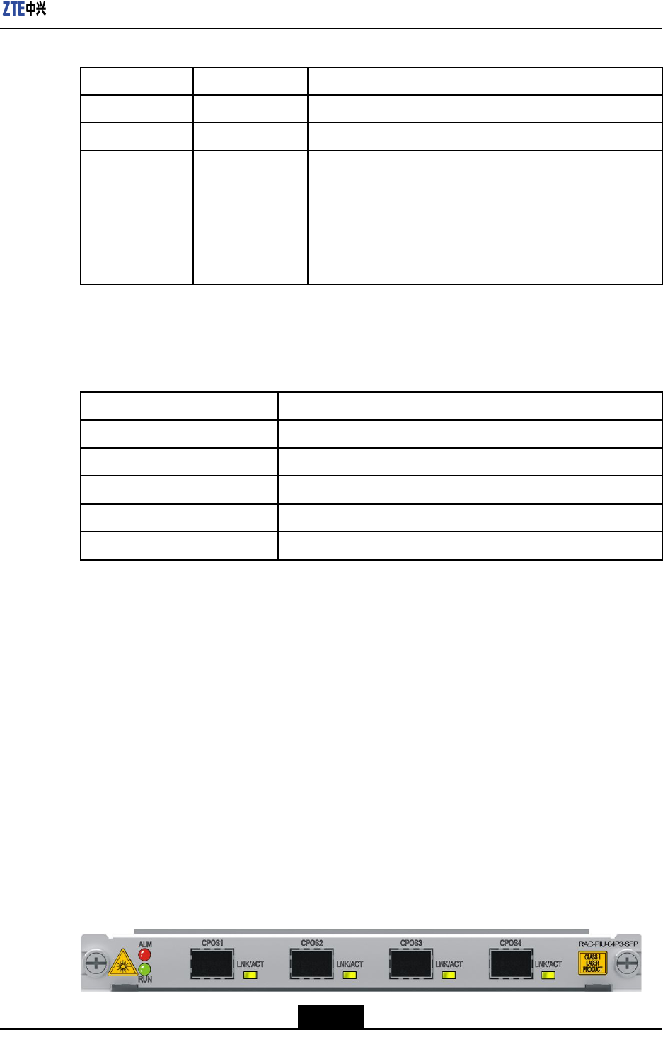
Chapter9LineInterfaceBoards
Table9-53DescriptionoftheIndicatorsonthePaneloftheRAC-PIU-02P3-SFPBoard
IndicatorColorDescription
RUNGreenTheindicatorislitwhentheboardisoperatingproperly.
ALMRedTheindicatorislitiftheboardproducesanalarm.
LNK/ACTGreen/Yellow
Linkstatus/datatransmissionindicator:
lIfthelinkisnormal,theindicatorislitingreen.
lIfdataisbeingtransmitted,theindicatorashesin
yellow.
lIfthereisnodatabeingtransmittedornoconnection,
theindicatorisnotlit.
TechnicalParameters
ForthetechnicalparametersoftheRAC-PIU-02P3-SFPboard,refertoT able9-54.
Table9-54TechnicalParametersoftheRAC-PIU-02P3-SFPBoard
ParameterSpecication
SilkscreennameRAC-PIU-02P3-SFP
Dimensions(W×H×D)7.76in.×0.79in.×6.9in.(197.2mm×19.92mm×175mm)
Powerconsumption16.5W
Weight1.19lb.(0.54kg)
Rate155.52Mbps×2
9.19RAC-PIU-04P3-SFP
Overview
RAC-PIU-04P3-SFPboardprovidesthefollowingfunctions:
lProvidesfourOC-3/STM-1interfacestoimplementPOSapplications.
lSupportstheprocessingofvariousservices,suchasPPPandHDLC.
lSupportshotswapping.
lSupportsboardinformationqueryandtemperaturemonitoring.
Panel
ForthepaneloftheRAC-PIU-04P3-SFPboard,seeFigure9-19.
Figure9-19FrontPaneloftheRAC-PIU-04P3-SFPBoard
9-29
SJ-20150204153047-004|2015-03-30(R1.0)ZTEProprietaryandCondential
ZXR10ZSRV2HardwareDescription
InterfaceProperties
TheRAC-PIU-04P3-SFPboardusesSFPopticalmodules.Foradescriptionofthe
interfaceproperties,refertoT able9-55.
Table9-55InterfacePropertiesoftheRAC-PIU-04P3-SFPBoard
PropertyDescription
ConnectortypeLC-typeSFPopticalmoduleinterface
OperationalmodeFullduplex
AppliedstandardSONETGR-253-CORE/ITU-TG.707
SupportedlinkprotocolPPP ,HDLC,FR,POSGROUP
Supportednetwork
protocol
IP
Indicators
ForadescriptionoftheindicatorsoftheRAC-PIU-04P3-SFPboard,refertoT able9-56.
Table9-56DescriptionoftheIndicatorsonthePaneloftheRAC-PIU-04P3-SFPBoard
IndicatorColorDescription
RUNGreenTheindicatorislitwhentheboardisoperatingproperly.
ALMRedTheindicatorislitiftheboardproducesanalarm.
LNK/ACTGreen/Yellow
Linkstatus/datatransmissionindicator:
lIfthelinkisnormal,theindicatorislitingreen.
lIfdataisbeingtransmitted,theindicatorashesin
yellow.
lIfthereisnodatabeingtransmittedornoconnection,
theindicatorisnotlit.
TechnicalParameters
ForthetechnicalparametersoftheRAC-PIU-04P3-SFPboard,refertoT able9-57.
Table9-57TechnicalParametersoftheRAC-PIU-04P3-SFPBoard
ParameterSpecication
SilkscreennameRAC-PIU-04P3-SFP
Dimensions(W×H×D)7.76in.×0.79in.×6.9in.(197.2mm×19.92mm×175mm)
Powerconsumption18W
Weight1.19lb.(0.54kg)
Rate155.52Mbps×4
9-30
SJ-20150204153047-004|2015-03-30(R1.0)ZTEProprietaryandCondential
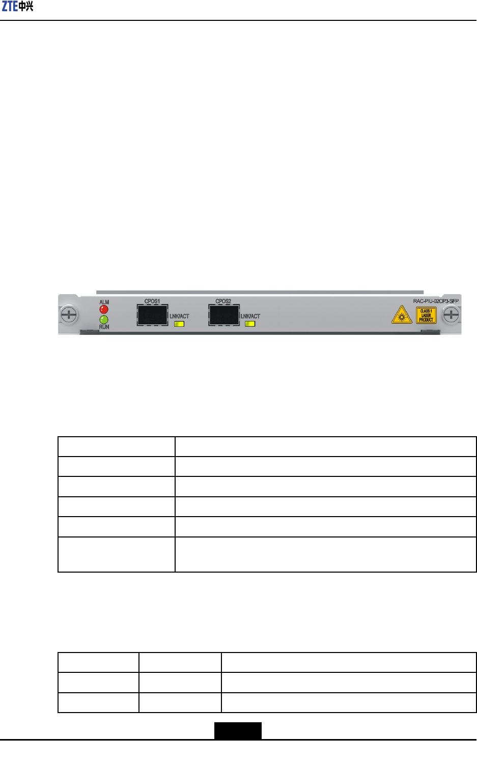
Chapter9LineInterfaceBoards
9.20RAC-PIU-02CP3-SFP
Overview
RAC-PIU-02CP3-SFPboardprovidesthefollowingfunctions:
lSupports2-wirechannelizedOC-3/STM-1POSapplications.
lRestorestheopticalchanneldataclockandprovidingittoanMPFUboardforrefer-
ence.
lSupportstheprocessingofvariousservices,suchasPPPandHDLC.
lSupportshotswapping.
lSupportsboardinformationqueryandtemperaturemonitoring.
Panel
ForthepaneloftheRAC-PIU-02CP3-SFPboard,seeFigure9-20.
Figure9-20FrontPaneloftheRAC-PIU-02CP3-SFPBoard
InterfaceProperty
TheRAC-PIU-02CP3-SFPboardusesSFPopticalmodules.Foradescriptionofthe
interfaceproperties,refertoT able9-58.
Table9-58InterfacePropertiesoftheRAC-PIU-02CP3-SFPBoard
PropertyDescription
ConnectortypeLC-typeSFPopticalmoduleinterface
OperationalmodeFullduplex
AppliedstandardSONETGR-253-CORE/ITU-TG.707
SupportedlinkprotocolPPP ,HDLC,FR,MPPP
Supportednetwork
protocol
IP
Indicators
ForadescriptionoftheindicatorsoftheRAC-PIU-02CP3-SFPboard,refertoTable9-59.
Table9-59DescriptionoftheIndicatorsonthePaneloftheRAC-PIU-02CP3-SFPBoard
IndicatorColorDescription
RUNGreenTheindicatorislitwhentheboardisoperatingproperly.
ALMRedTheindicatorislitiftheboardproducesanalarm.
9-31
SJ-20150204153047-004|2015-03-30(R1.0)ZTEProprietaryandCondential
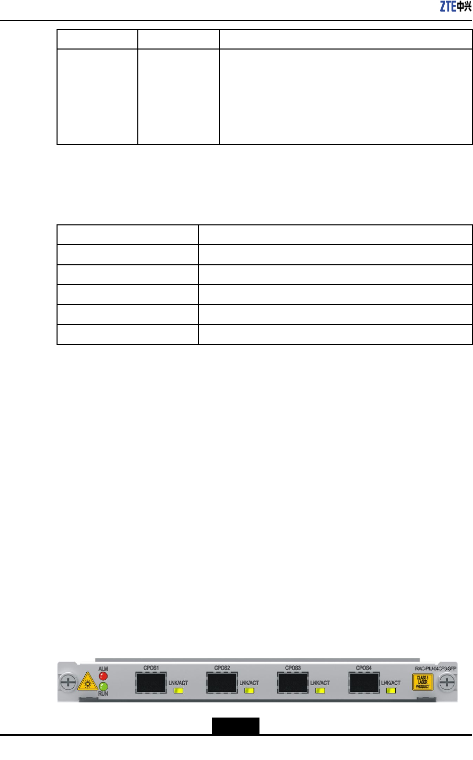
ZXR10ZSRV2HardwareDescription
IndicatorColorDescription
LNK/ACTGreen/Yellow
Linkstatus/datatransmissionindicator:
lIfthelinkisnormal,theindicatorislitingreen.
lIfdataisbeingtransmitted,theindicatorashesin
yellow.
lIfthereisnodatabeingtransmittedornoconnection,
theindicatorisnotlit.
TechnicalParameters
ForthetechnicalparametersoftheRAC-PIU-02CP3-SFPboard,refertoT able9-60.
Table9-60TechnicalParametersoftheRAC-PIU-02CP3-SFPBoard
ParameterSpecication
SilkscreennameRAC-PIU-02CP3-SFP
Dimensions(W×H×D)7.76in.×0.79in.×6.9in.(197.2mm×19.92mm×175mm)
Powerconsumption16.5W
Weight1.19lb.(0.54kg)
Rate155.52Mbps×2
9.21RAC-PIU-04CP3-SFP
Overview
RAC-PIU-04CP3-SFPboardprovidesthefollowingfunctions:
lProvidesfourchannelizedOC3/STM-1interfacestoimplementPacketOver
SONET/SDHapplications.
lRestorestheopticalchanneldataclockandprovidesittoanMPFUboardfor
reference.
lSupportstheprocessingofvariousservices,suchasPPPandHDLC.
lSupportshotswapping.
lSupportsboardinformationqueryandtemperaturemonitoring.
Panel
ForthepaneloftheRAC-PIU-04CP3-SFPboard,seeFigure9-21.
Figure9-21FrontPaneloftheRAC-PIU-04CP3-SFPBoard
9-32
SJ-20150204153047-004|2015-03-30(R1.0)ZTEProprietaryandCondential
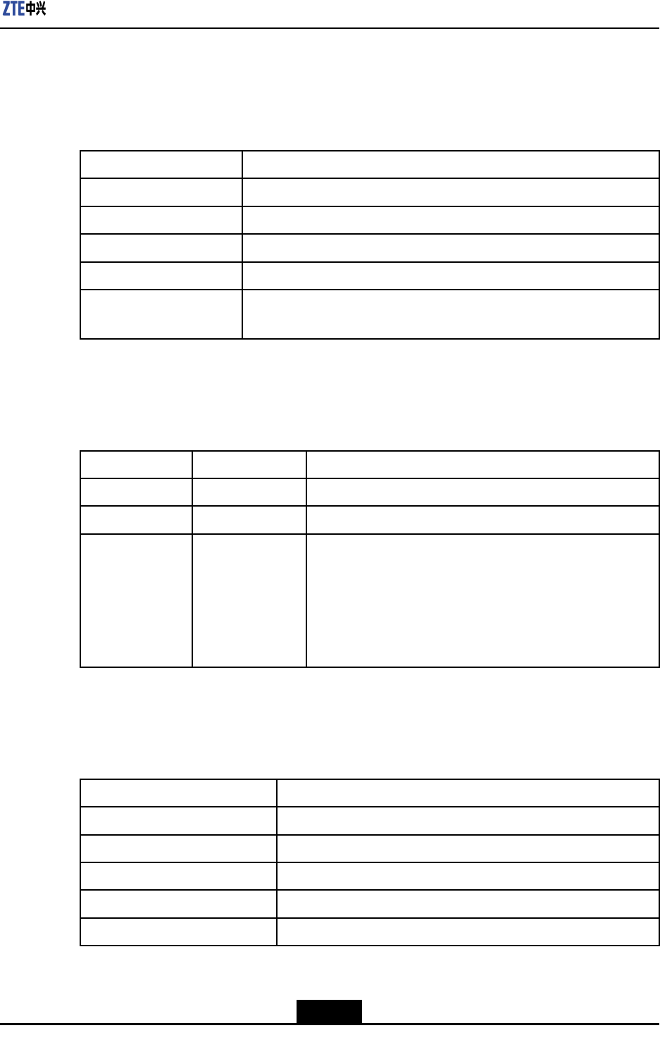
Chapter9LineInterfaceBoards
InterfaceProperties
TheRAC-PIU-04CP3-SFPboardusesSFPopticalmodules.Foradescriptionofthe
interfaceproperties,refertoT able9-61.
Table9-61InterfacePropertiesoftheRAC-PIU-04CP3-SFPBoard
PropertyDescription
ConnectortypeLC-typeSFPopticalmoduleinterface
OperationalmodeFullduplex
AppliedstandardSONETGR-253-CORE/ITU-TG.707
SupportedlinkprotocolPPP ,HDLC,FR,MPPP
Supportednetwork
protocol
IP
Indicators
ForadescriptionoftheindicatorsoftheRAC-PIU-04CP3-SFPboard,refertoTable9-62.
Table9-62DescriptionoftheIndicatorsonthePaneloftheRAC-PIU-04CP3-SFPBoard
IndicatorColorDescription
RUNGreenTheindicatorislitwhentheboardisoperatingproperly.
ALMRedTheindicatorislitiftheboardproducesanalarm.
LNK/ACTGreen/Yellow
Linkstatus/datatransmissionindicator:
lIfthelinkisnormal,theindicatorislitingreen.
lIfdataisbeingtransmitted,theindicatorashesin
yellow.
lIfthereisnodatabeingtransmittedornoconnection,
theindicatorisnotlit.
TechnicalParameters
ForthetechnicalparametersoftheRAC-PIU-04CP3-SFPboard,refertoT able9-63.
Table9-63TechnicalParametersoftheRAC-PIU-04CP3-SFPBoard
ParameterSpecication
SilkscreennameRAC-PIU-04CP3-SFP
Dimensions(W×H×D)7.76in.×0.79in.×6.9in.(197.2mm×19.92mm×175mm)
Powerconsumption18W
Weight1.19lb.(0.54kg)
Rate155.52Mbps×4
9-33
SJ-20150204153047-004|2015-03-30(R1.0)ZTEProprietaryandCondential
ZXR10ZSRV2HardwareDescription
9.22RAC-PIU-04GE-SFP
Overview
RAC-PIU-04GE-SFPboardprovidesthefollowingfunctions:
lProvidesfourGEopticalinterfaceswhichsupport1000BASE-X.
lSupportshotswapping.
lSupportsboardinformationqueryandtemperaturemonitoring.
Panel
ForthepaneloftheRAC-PIU-04GE-SFPboard,seeFigure9-22.
Figure9-22FrontPaneloftheRAC-PIU-04GE-SFPBoard
InterfaceProperties
TheRAC-PIU-04GE-SFPboardusesSFPopticalmodules.Foradescriptionofthe
interfaceproperties,refertoT able9-64.
Table9-64InterfacePropertiesoftheRAC-PIU-04GE-SFPBoard
PropertyDescription
ConnectortypeLC-typeSFPopticalmoduleinterface
OperationalmodeFullduplex
AppliedstandardIEEE802.3zGigabitEthernetstandard
SupportedlinkprotocolEthernetFrame
Supportednetwork
protocol
Ethernet
Indicators
ForadescriptionoftheindicatorsoftheRAC-PIU-04GE-SFPboard,refertoT able9-65.
Table9-65DescriptionoftheIndicatorsonthePaneloftheRAC-PIU-04GE-SFPBoard
IndicatorColorDescription
RUNGreenTheindicatorislitwhentheboardisoperatingproperly.
ALMRedTheindicatorislitiftheboardproducesanalarm.
9-34
SJ-20150204153047-004|2015-03-30(R1.0)ZTEProprietaryandCondential
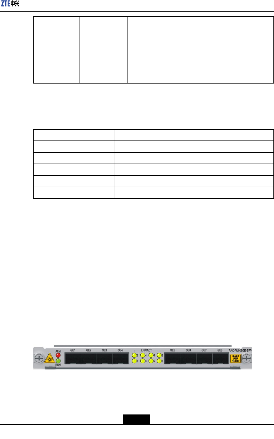
Chapter9LineInterfaceBoards
IndicatorColorDescription
LNK/ACTGreen/Yellow
Linkstatus/datatransmissionindicator:
lIfthelinkisnormal,theindicatorislitingreen.
lIfdataisbeingtransmitted,theindicatorashesin
yellow.
lIfthereisnodatabeingtransmittedornoconnection,
theindicatorisnotlit.
TechnicalParameters
ForthetechnicalparametersoftheRAC-PIU-04GE-SFPboard,refertoT able9-66.
Table9-66TechnicalParametersoftheRAC-PIU-04GE-SFPBoard
ParameterSpecication
SilkscreennameRAC-PIU-04GE-SFP
Dimensions(W×H×D)7.76in.×0.79in.×6.9in.(197.2mm×19.92mm×175mm)
Powerconsumption13W
Weight1.19lb.(0.54kg)
Rate1GE×4
9.23RAC-PIU-08GE-SFP
Overview
RAC-PIU-08GE-SFPboardprovidesthefollowingfunctions:
lProvideseightGEopticalinterfaceswhichsupport1000BASE-X.
lSupportshotswapping.
lSupportsboardinformationqueryandtemperaturemonitoring.
Panel
ForthepaneloftheRAC-PIU-08GE-SFPboard,seeFigure9-23.
Figure9-23FrontPaneloftheRAC-PIU-08GE-SFPBoard
InterfaceProperties
TheRAC-PIU-08GE-SFPboardusesSFPopticalmodules.Foradescriptionofthe
interfaceproperties,refertoT able9-67.
9-35
SJ-20150204153047-004|2015-03-30(R1.0)ZTEProprietaryandCondential
ZXR10ZSRV2HardwareDescription
Table9-67InterfacePropertiesoftheRAC-PIU-08GE-SFPBoard
PropertyDescription
ConnectortypeLC-typeSFPopticalmoduleinterface
OperationalmodeFullduplex
AppliedstandardIEEE802.3zGigabitEthernetstandard
SupportedlinkprotocolEthernetFrame
Supportednetwork
protocol
Ethernet
Indicators
ForadescriptionoftheindicatorsoftheRAC-PIU-08GE-SFPboard,refertoT able9-68.
Table9-68DescriptionoftheIndicatorsonthePaneloftheRAC-PIU-08GE-SFPBoard
IndicatorColorDescription
RUNGreenTheindicatorislitwhentheboardisoperatingproperly.
ALMRedTheindicatorislitiftheboardproducesanalarm.
LNKGreen
Linkstatus/datatransmissionindicator:
lIfthelinkisnormal,theindicatorislitingreen.
lIfdataisbeingtransmitted,theindicatorashesin
yellow.
lIfthereisnodatabeingtransmittedornoconnection,
theindicatorisnotlit.
TechnicalParameters
ForthetechnicalparametersoftheRAC-PIU-08GE-SFPboard,refertoT able9-69.
Table9-69TechnicalParametersoftheRAC-PIU-08GE-SFPBoard
ParameterSpecication
SilkscreennameRAC-PIU-08GE-SFP
Dimensions(W×H×D)7.76in.×0.79in.×6.9in.(197.2mm×19.92mm×175mm)
Powerconsumption15W
Weight1.19lb.(0.54kg)
Rate1GE×8
9.24RAC-PIU-05GE-4E1SFP
Overview
RAC-PIU-05GE-4E1SFPboardprovidesthefollowingfunctions:
9-36
SJ-20150204153047-004|2015-03-30(R1.0)ZTEProprietaryandCondential
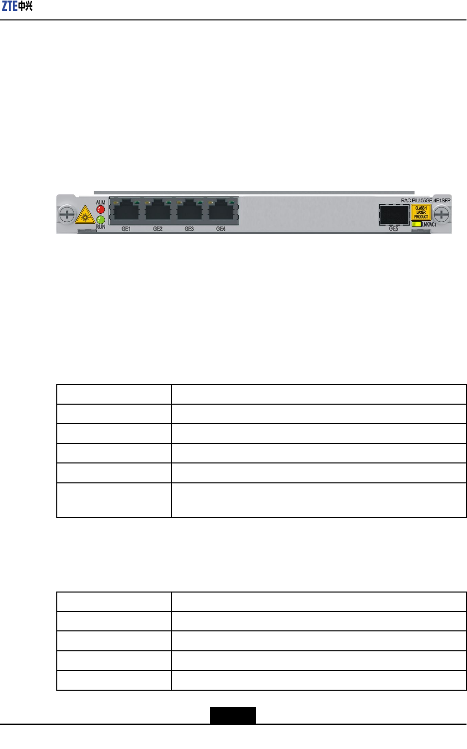
Chapter9LineInterfaceBoards
lProvidesfourGEelectricalinterfacesandoneGEopticalinterface.
lTheGEelectricalinterfacessupport10BASE-T/100BASE-TX/1000BASE-TXandthe
GEopticalinterfacesupports1000BASE-X.
lSupportshotswapping.
lSupportsboardinformationqueryandtemperaturemonitoring.
Panel
ForthepaneloftheRAC-PIU-05GE-4E1SFPboard,seeFigure9-24.
Figure9-24FrontPaneloftheRAC-PIU-05GE-4E1SFPBoard
InterfaceProperties
TheRAC-PIU-05GE-4E1SFPboardprovideselectricalandopticalinterfaces(GE1–GE5),
whicharenotdistinguishedbysilkscreenname.Theycanbedistinguishedbythe
interfaceoverviewandindicators.
ForadescriptionoftheGEelectricalinterfacepropertiesoftheRAC-PIU-05GE-4E1SFP
board,refertoTable9-70.
Table9-70GEElectricalInterfacePropertiesoftheRAC-PIU-05GE-4E1SFPBoard
PropertyDescription
ConnectortypeRJ-45
OperationalmodeFullduplex,Halfduplex
AppliedstandardIEEE802.3zGigabitEthernetstandard
SupportedframeformatEthernetframe
Supportednetwork
protocol
IP
TheRAC-PIU-05GE-4E1SFPboardusesSFPopticalmodules.Foradescriptionofthe
opticalinterfaceproperties,refertoTable9-71.
Table9-71OpticalInterfacePropertiesoftheRAC-PIU-05GE-4E1SFPBoard
PropertyDescription
ConnectortypeLC-typeSFPopticalmoduleinterface
OperationalmodeFullduplex
AppliedstandardIEEE802.3zGigabitEthernetstandard
SupportedframeformatEthernetframe
9-37
SJ-20150204153047-004|2015-03-30(R1.0)ZTEProprietaryandCondential
ZXR10ZSRV2HardwareDescription
PropertyDescription
Supportednetwork
protocol
IP
Indicators
ForadescriptionoftheindicatorsoftheRAC-PIU-05GE-4E1SFPPboard,refertoTable
9-72.
Table9-72DescriptionoftheIndicatorsonthePaneloftheRAC-PIU-05GE-4E1SFP
Board
IndicatorColorDescription
RUNGreenTheindicatorislitwhentheboardisoperatingproperly.
ALMRedTheindicatorislitiftheboardproducesanalarm.
Electricalport
indicator
Green/YellowLinkstatus/datatransmissionindicatorsforfourGEelectrical
interfaces:
lIfthelinkisnormal,therightgreenindicatorislit.
lIfdataisbeingtransmitted,theleftyellowindicatorashes.
lIfthereisnodatabeingtransmittedornoconnection,the
indicatorsarenotlit.
LNK/ACTGreen/Yellow
Linkstatus/datatransmissionindicatorsfortheGEoptical
interface:
lIfthelinkisnormal,theindicatorislitingreen.
lIfdataisbeingtransmitted,theindicatorashesinyellow.
lIfthereisnodatabeingtransmittedornoconnection,the
indicatorisnotlit.
TechnicalParameters
ForthetechnicalparametersoftheRAC-PIU-05GE-4E1SFPboard,refertoT able9-73.
Table9-73TechnicalParametersoftheRAC-PIU-05GE-4E1SFPBoard
ParameterSpecication
SilkscreennameRAC-PIU-05GE-4E1SFP
Dimensions(W×H×D)7.76in.×0.79in.×6.9in.(197.2mm×19.92mm×175mm)
Powerconsumption11W
Weight0.88lb.(0.4kg)
Rate1GE×5
9-38
SJ-20150204153047-004|2015-03-30(R1.0)ZTEProprietaryandCondential
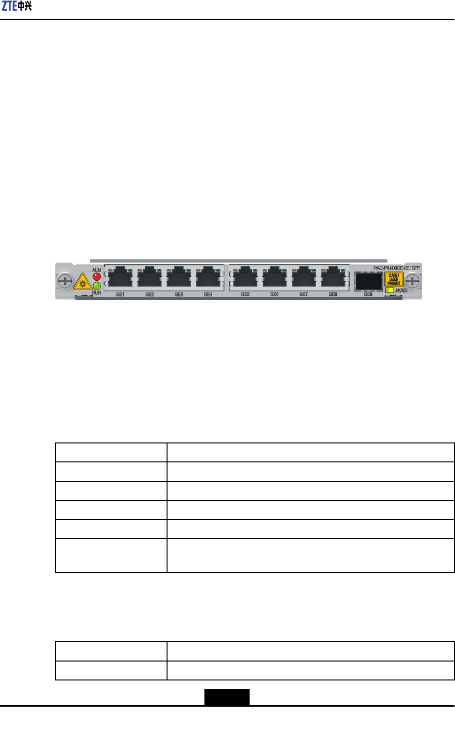
Chapter9LineInterfaceBoards
9.25RAC-PIU-09GE-8E1SFP
Overview
RAC-PIU-09GE-8E1SFPboardprovidesthefollowingfunctions:
lProvideseightGEelectricalinterfacesandoneGEopticalinterface.
lTheGEelectricalinterfacessupport10BASE-T/100BASE-TX/1000BASE-TXandthe
GEopticalinterfacesupports1000BASE-X.
lSupportshotswapping.
lSupportsboardinformationqueryandtemperaturemonitoring.
Panel
ForthepaneloftheRAC-PIU-09GE-8E1SFPboard,seeFigure9-25.
Figure9-25FrontPaneloftheRAC-PIU-09GE-8E1SFPBoard
InterfaceProperties
TheRAC-PIU-09GE-8E1SFPboardprovideselectricalandopticalinterfaces(GE1–GE9),
whicharenotdistinguishedbysilkscreenname.Theycanbedistinguishedbythe
interfaceoverviewandindicators.
ForadescriptionoftheGEelectricalinterfacepropertiesoftheRAC-PIU-09GE-8E1SFP
board,refertoTable9-74.
Table9-74GEElectricalInterfacePropertiesoftheRAC-PIU-09GE-8E1SFPBoard
PropertyDescription
ConnectortypeRJ45
OperationalmodeFullduplex,Halfduplex
AppliedstandardIEEE802.3zGigabitEthernetstandard
SupportedframeformatEthernetframe
Supportednetwork
protocol
IP
TheRAC-PIU-09GE-8E1SFPboardusesSFPopticalmodules.Foradescriptionofthe
opticalinterfaceproperties,refertoTable9-75.
Table9-75OpticalInterfacePropertiesoftheRAC-PIU-09GE-8E1SFPBoard
PropertyDescription
ConnectortypeLC-typeSFPopticalmoduleinterface
9-39
SJ-20150204153047-004|2015-03-30(R1.0)ZTEProprietaryandCondential
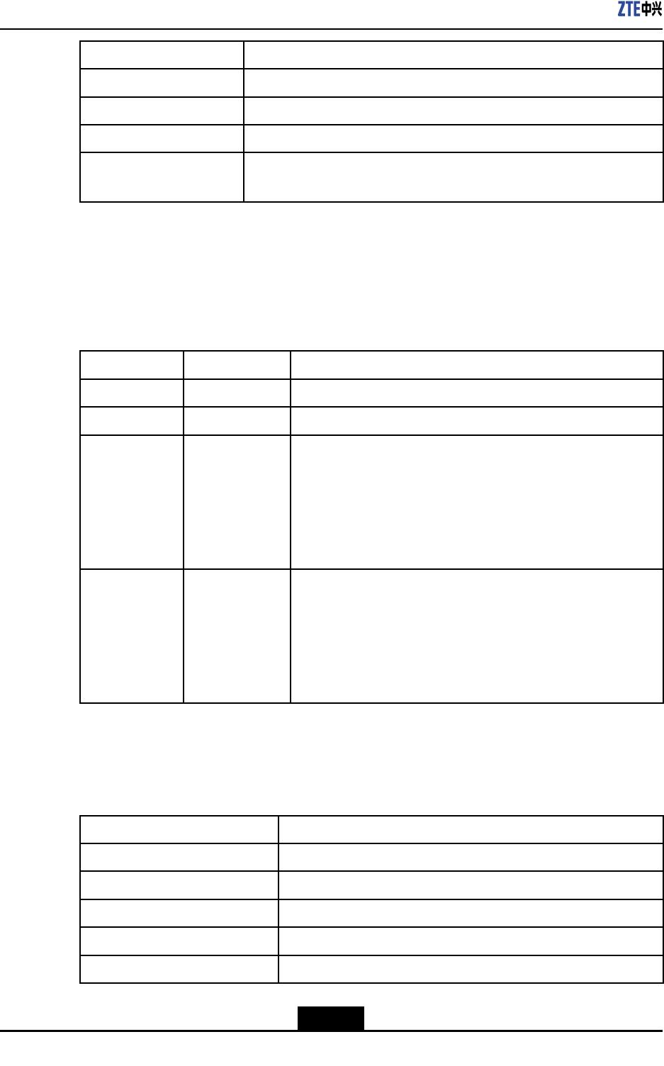
ZXR10ZSRV2HardwareDescription
PropertyDescription
OperationalmodeFullduplex
AppliedstandardIEEE802.3zGigabitEthernetstandard
SupportedframeformatEthernetframe
Supportednetwork
protocol
IP
Indicators
ForadescriptionoftheindicatorsoftheRAC-PIU-09GE-8E1SFPboard,refertoT able
9-76.
Table9-76DescriptionoftheIndicatorsonthePaneloftheRAC-PIU-09GE-8E1SFP
Board
IndicatorColorDescription
RUNGreenTheindicatorislitwhentheboardisoperatingproperly.
ALMRedTheindicatorislitiftheboardproducesanalarm.
Electricalport
indicator
Green/YellowLinkstatus/datatransmissionindicatorsforfourGEelectrical
interfaces:
lIfthelinkisnormal,therightgreenindicatorislit.
lIfdataisbeingtransmitted,theleftyellowindicatorashes.
lIfthereisnodatabeingtransmittedornoconnection,the
indicatorsarenotlit.
LNK/ACTGreen/Yellow
Linkstatus/datatransmissionindicatorsfortheGEoptical
interface:
lIfthelinkisnormal,theindicatorislitingreen.
lIfdataisbeingtransmitted,theindicatorashesinyellow.
lIfthereisnodatabeingtransmittedornoconnection,the
indicatorisnotlit.
TechnicalParameters
ForthetechnicalparametersoftheRAC-PIU-09GE-8E1SFPboard,refertoT able9-77.
Table9-77TechnicalParametersoftheRAC-PIU-09GE-8E1SFPBoard
ParameterSpecication
SilkscreennameRAC-PIU-09GE-8E1SFP
Dimensions(W×H×D)7.76in.×0.79in.×6.9in.(197.2mm×19.92mm×175mm)
Powerconsumption12W
Weight1.19lb.(0.54kg)
Rate1GE×9
9-40
SJ-20150204153047-004|2015-03-30(R1.0)ZTEProprietaryandCondential
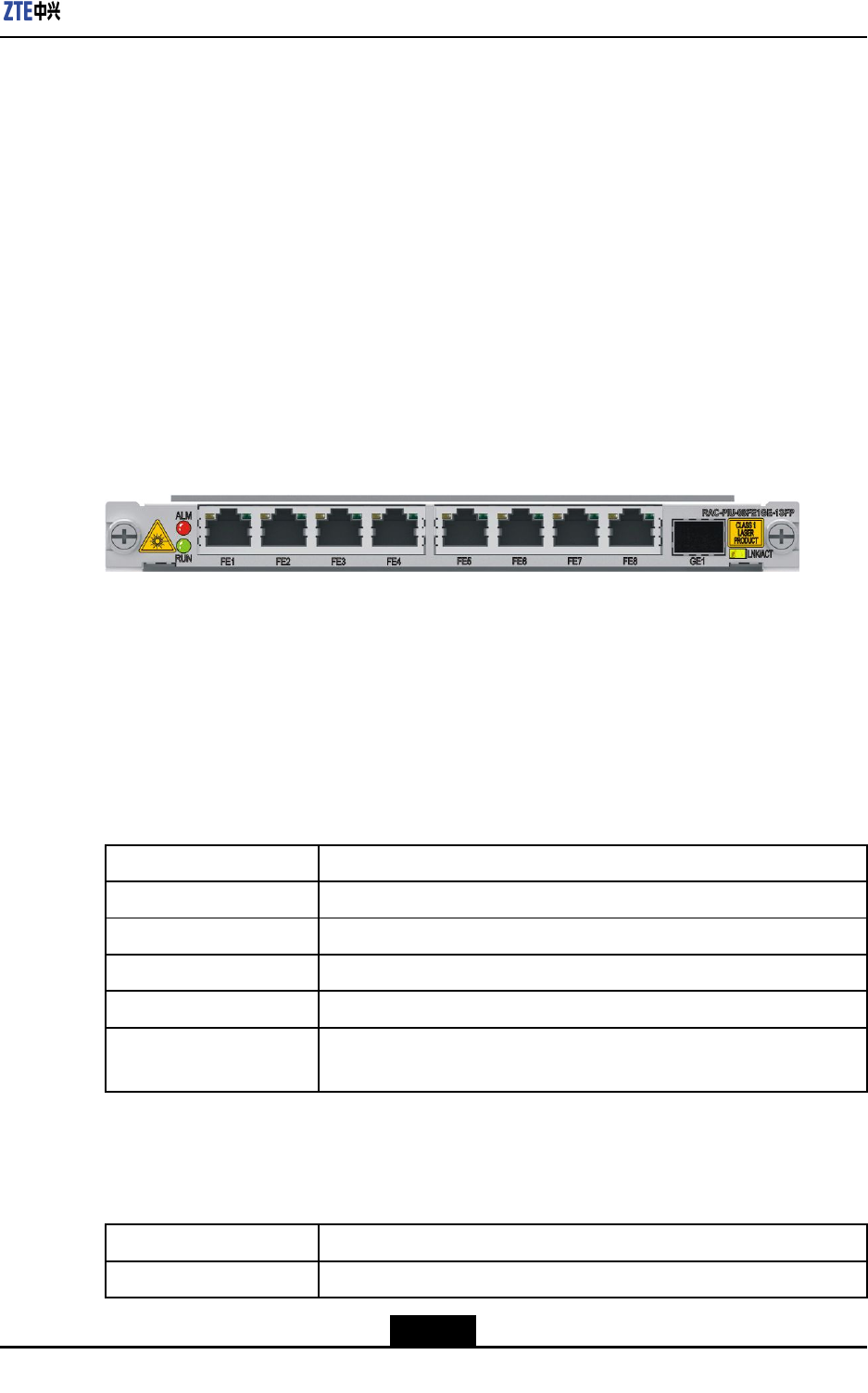
Chapter9LineInterfaceBoards
9.26RAC-PIU-08FE1GE-1SFP
Overview
RAC-PIU-08FE1GE-1SFPboardprovidesthefollowingfunctions:
lProvideseightFEelectricalinterfacesandoneGEopticalinterface.
lTheFEelectricalinterfacessupport100BASE-TXandtheGEopticalinterfacesup-
ports1000BASE-X.
lSupportshotswapping.
lSupportsboardinformationqueryandtemperaturemonitoring.
Panel
ForthepaneloftheRAC-PIU-08FE1GE-1SFPboard,seeFigure9-26.
Figure9-26FrontPaneloftheRAC-PIU-08FE1GE-1SFPBoard
InterfaceProperties
TheRAC-PIU-08FE1GE-1SFPboardprovideselectricalandopticalinterfaces(FE1–FE8,
GE1),whicharedistinguishedbysilkscreenname.Theycanbealsodistinguishedbythe
interfaceoverviewandindicators.
ForadescriptionoftheFEelectricalinterfacepropertiesoftheRAC-PIU-08FE1GE-1SFP
board,refertoTable9-78.
Table9-78GEElectricalInterfacePropertiesoftheRAC-PIU-08FE1GE-1SFPBoard
PropertyDescription
ConnectortypeRJ45
OperationalmodeFullduplex,Halfduplex
AppliedstandardIEEE802.3uFastEthernetstandard
SupportedframeformatEthernetframe
Supportednetwork
protocol
IP
TheRAC-PIU-08FE1GE-1SFPboardusesSFPopticalmodules.Foradescriptionofthe
opticalinterfaceproperties,refertoTable9-79.
Table9-79OpticalInterfacePropertiesoftheRAC-PIU-08FE1GE-1SFPBoard
PropertyDescription
ConnectortypeLC-typeSFPopticalmoduleinterface
9-41
SJ-20150204153047-004|2015-03-30(R1.0)ZTEProprietaryandCondential

ZXR10ZSRV2HardwareDescription
PropertyDescription
OperationalmodeFullduplex
AppliedstandardIEEE802.3zGigabitEthernetstandard
SupportedframeformatEthernetframe
Supportednetwork
protocol
IP
Indicators
ForadescriptionoftheindicatorsoftheRAC-PIU-08FE1GE-1SFPboard,refertoT able
9-80.
Table9-80DescriptionoftheIndicatorsonthePaneloftheRAC-PIU-08FE1GE-1SFP
Board
IndicatorColorDescription
RUNGreenTheindicatorislitwhentheboardisoperatingproperly.
ALMRedTheindicatorislitiftheboardproducesanalarm.
Electricalport
indicator
Green/YellowLinkstatus/datatransmissionindicatorsforfourGEelectrical
interfaces:
lIfthelinkisnormal,therightgreenindicatorislit.
lIfdataisbeingtransmitted,theleftyellowindicatorashes.
lIfthereisnodatabeingtransmittedornoconnection,the
indicatorsarenotlit.
LNK/ACTGreen/Yellow
Linkstatus/datatransmissionindicatorsfortheGEoptical
interface:
lIfthelinkisnormal,theindicatorislitingreen.
lIfdataisbeingtransmitted,theindicatorashesinyellow.
lIfthereisnodatabeingtransmittedornoconnection,the
indicatorisnotlit.
TechnicalParameters
ForthetechnicalparametersoftheRAC-PIU-08FE1GE-1SFPboard,refertoTable9-81.
Table9-81TechnicalParametersoftheRAC-PIU-08FE1GE-1SFPBoard
ParameterSpecication
SilkscreennameRAC-PIU-08FE1GE-1SFP
Dimensions(W×H×D)7.76in.×0.79in.×6.9in.(197.2mm×19.92mm×175mm)
Powerconsumption11W
Weight1.19lb.(0.54kg)
Rate1GE×1,1FE×8
9-42
SJ-20150204153047-004|2015-03-30(R1.0)ZTEProprietaryandCondential
Chapter9LineInterfaceBoards
9.27RAC-DPIU-16GE-12SFP4E
Overview
RAC-DPIU-16GE-12SFP4Eboardprovidesthefollowingfunctions:
lProvidesfourGEelectricalinterfacesandtwelveGEopticalinterface.
lTheGEelectricalinterfacessupport10BASE-T/100BASE-TX/1000BASE-Tandthe
GEopticalinterfacessupport1000BASE-X/100BASE-FX.
lSupportshotswapping.
lSupportsboardinformationqueryandtemperaturemonitoring.
Panel
ForthepaneloftheRAC-DPIU-16GE-12SFP4Eboard,seeFigure9-27.
Figure9-27FrontPaneloftheRAC-DPIU-16GE-12SFP4EBoard
InterfaceProperties
TheRAC-DPIU-16GE-12SFP4Eboardprovideselectricalandopticalinterfaces
(GE1–GE16),whicharenotdistinguishedbysilkscreenname.Theycanbedistinguished
bytheinterfaceoverviewandindicators.
ForadescriptionoftheGEelectricalinterfacepropertiesofthe
RAC-DPIU-16GE-12SFP4Eboard,refertoTable9-82.
Table9-82GEElectricalInterfacePropertiesoftheRAC-DPIU-16GE-12SFP4EBoard
PropertyDescription
ConnectortypeRJ45
OperationalmodeFullduplex,Halfduplex
AppliedstandardIEEE802.3zGigabitEthernetstandard
SupportedframeformatEthernetframe
Supportednetwork
protocol
IP
TheRAC-DPIU-16GE-12SFP4EboardusesSFPopticalmodules.Foradescriptionofthe
opticalinterfaceproperties,refertoTable9-83.
9-43
SJ-20150204153047-004|2015-03-30(R1.0)ZTEProprietaryandCondential
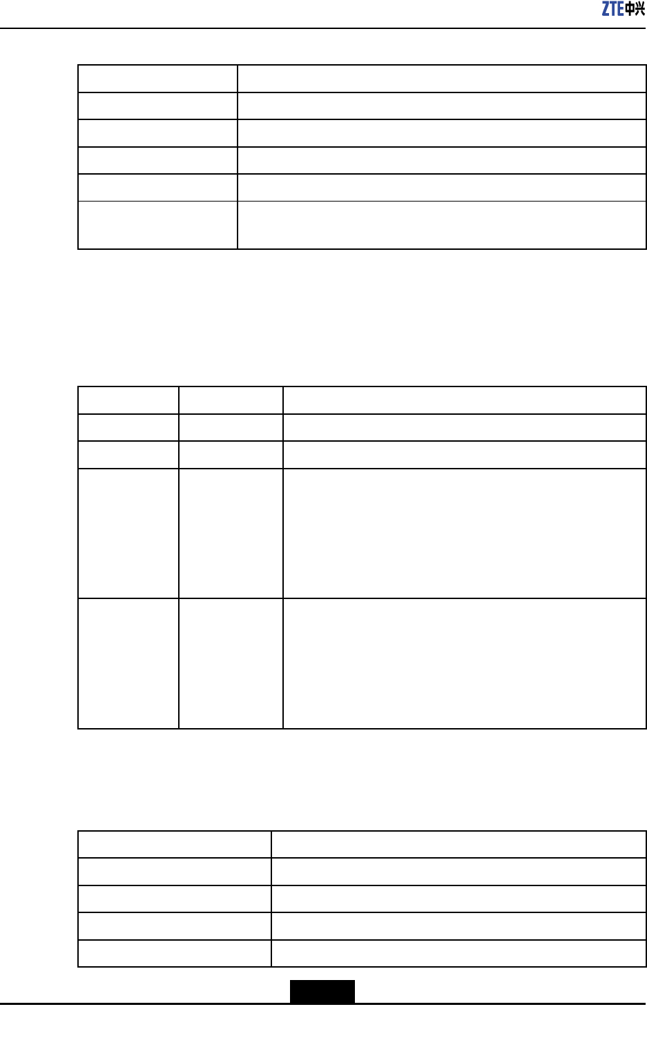
ZXR10ZSRV2HardwareDescription
Table9-83OpticalInterfacePropertiesoftheRAC-DPIU-16GE-12SFP4EBoard
PropertyDescription
ConnectortypeLC-typeSFPopticalmoduleinterface
OperationalmodeFullduplex
AppliedstandardIEEE802.3zGigabitEthernetstandard
SupportedframeformatEthernetframe
Supportednetwork
protocol
IP
Indicators
ForadescriptionoftheindicatorsoftheRAC-DPIU-16GE-12SFP4Eboard,refertoTable
9-84.
Table9-84DescriptionoftheIndicatorsonthePaneloftheRAC-DPIU-16GE-12SFP4E
Board
IndicatorColorDescription
RUNGreenTheindicatorislitwhentheboardisoperatingproperly.
ALMRedTheindicatorislitiftheboardproducesanalarm.
Electricalport
indicator
Green/YellowLinkstatus/datatransmissionindicatorsforfourGEelectrical
interfaces:
lIfthelinkisnormal,therightgreenindicatorislit.
lIfdataisbeingtransmitted,theleftyellowindicatorashes.
lIfthereisnodatabeingtransmittedornoconnection,the
indicatorsarenotlit.
LNK/ACT
Green/Yellow
Linkstatus/datatransmissionindicatorsfor12GEoptical
interfaces:
lIfthelinkisnormal,theindicatorislitingreen.
lIfdataisbeingtransmitted,theindicatorashesinyellow.
lIfthereisnodatabeingtransmittedornoconnection,the
indicatorisnotlit.
TechnicalParameters
ForthetechnicalparametersoftheRAC-DPIU-16GE-12SFP4Eboard,refertoTable9-85.
Table9-85TechnicalParametersoftheRAC-DPIU-16GE-12SFP4EBoard
ParameterSpecication
SilkscreennameRAC-DPIU-16GE-12SFP4E
Dimensions(W×H×D)7.76in.×1.58in.×6.9in.(197.2mm×40.24mm×175mm)
Powerconsumption36W
Weight0.6kg
9-44
SJ-20150204153047-004|2015-03-30(R1.0)ZTEProprietaryandCondential
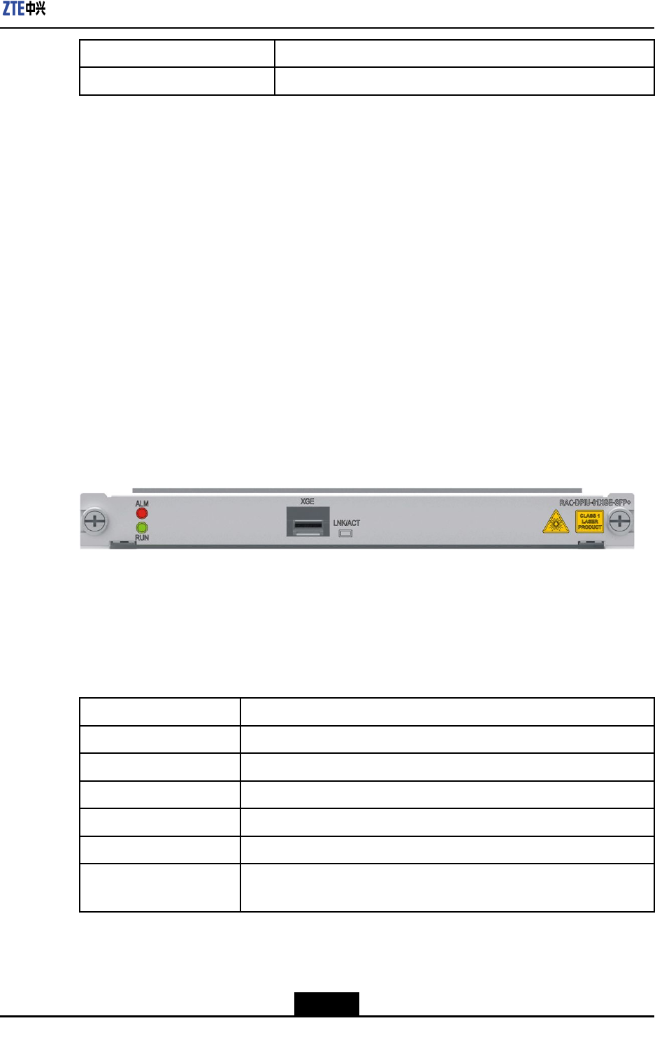
Chapter9LineInterfaceBoards
ParameterSpecication
Rate1GE×16
9.28RAC-DPIU-01XGE-SFP+
Overview
Thesilkscreennameofthe1-portXGEinterfaceboardisRAC-DPIU-01XGE-SFP+,which
supports10GEapplications.Itprovidesthefollowingfunctions:
lProvidesone10GELAN/WANSFP+opticalinterface,whichsupports10GLAN/10G
WAN.
lSupportspowerramponcontrolandhotswapping
lSupportstemperaturemeasurementandboardIDreading.
Panel
ForthepaneloftheRAC-DPIU-01XGE-SFP+board,seeFigure9-28.
Figure9-28FrontPaneloftheRAC-DPIU-01XGE-SFP+Board
InterfaceProperty
TheRAC-DPIU-01XGE-SFP+boardusesSFP+opticalmodules.Foradescriptionofthe
interfaceproperties,refertoT able9-86.
Table9-86InterfacePropertiesoftheRAC-DPIU-01XGE-SFP+Board
PropertyDescription
ConnectortypeLC
OpticalinterfacepropertyDeterminedbytheattributesoftheselectedSFP+opticalmodule
OperationalmodeFullduplex
AppliedstandardIEEE802.3ae
SupportedlinkprotocolEthernetframe/SONET/SDH
Supportednetwork
protocol
IP
9-45
SJ-20150204153047-004|2015-03-30(R1.0)ZTEProprietaryandCondential
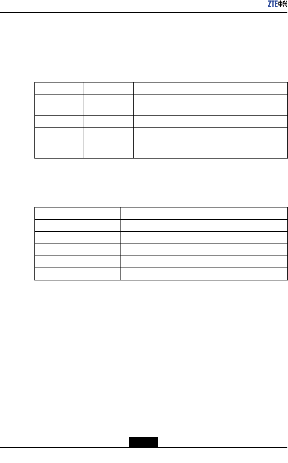
ZXR10ZSRV2HardwareDescription
Indicators
OnthepaneloftheRAC-DPIU-01XGE-SFP+board,therearetwoboardoperation
indicators(RUNandALM)andoneportoperationindicators(LNK/ACT ,green/yellow).
Foradescriptionoftheindicators,refertoT able9-87.
Table9-87DescriptionoftheIndicatorsonthePaneloftheRAC-DPIU-01XGE-SFP+
Board
IndicatorColorDescription
RUNGreenTheindicatorashesoncepersecondiftheboardoperates
properly.
ALMRedTheindicatorislitiftheboardproducesanalarm.
LNK/ACTGreen/Yellow
Opticalportoperationindicator.
Thegreenindicatorislitiftheportisinlinkupstatus,and
theyellowindicatorashesifthereistrafc.
TechnicalParameters
ForthetechnicalparametersoftheRAC-DPIU-01XGE-SFP+board,refertoT able9-88.
Table9-88TechnicalParametersoftheRAC-DPIU-01XGE-SFP+Board
ParameterSpecication
SilkscreennameRAC-DPIU-01XGE-SFP+
Dimensions(H×W×D)0.78in.×7.77in.×6.9in(19.92mm×197.2mm×175mm)
Powerconsumption16W
Weight0.68kg
Rate10G×1
9-46
SJ-20150204153047-004|2015-03-30(R1.0)ZTEProprietaryandCondential

Chapter10
Cables
ForcablescommonlyusedbytheZXR10ZSRV2router,refertoT able10-1.
Table10-1CommonCablesoftheZXR10ZSRV2Router
ClassicationCableTypeFunction
DCpowercableUsedwhenDCpowerissuppliedtoadevice.
ACpowercableUsedwhenACpowerissuppliedtoadevice.
Powercablesand
groundingcables
GroundingcableConnectsacabinet,chassis,orcabinetdoortothe
groundtoguaranteesafepowersupply.
AUXcableConnectstheAUXportofadevicetoaModemfor
transmittingdevicecongurationdata.
ConsolecableConnectstheConsoleportofadevicetotheserial
portofthecontrolconsolefortransmittingdevice
congurationdata.
EthernetcableUsedforEthernetcommunicationbetweendevices
orbetweenadeviceandaterminal.
OpticalberUsedforhigh-speedcommunicationbetween
devices.
SHDSLcableTransmitsmultipletypesofsignals,includingvoice,
data,andvideosignals.
Synchronous/Asyn-
chronousserialcable
Transmitssynchronous/asynchronoussignals.
Signalcables
E1trunkcableTransmitsE1trunksignals.
TableofContents
PowerCablesandGroundingCables.......................................................................10-1
SignalCables...........................................................................................................10-4
10.1PowerCablesandGroundingCables
10.1.1DCPowerCables
ADCpowercableoftheZXR10ZSRV2isablack/bluere-retardantPVCinsulatedcable,
seeFigure10-1.
10-1
SJ-20150204153047-004|2015-03-30(R1.0)ZTEProprietaryandCondential
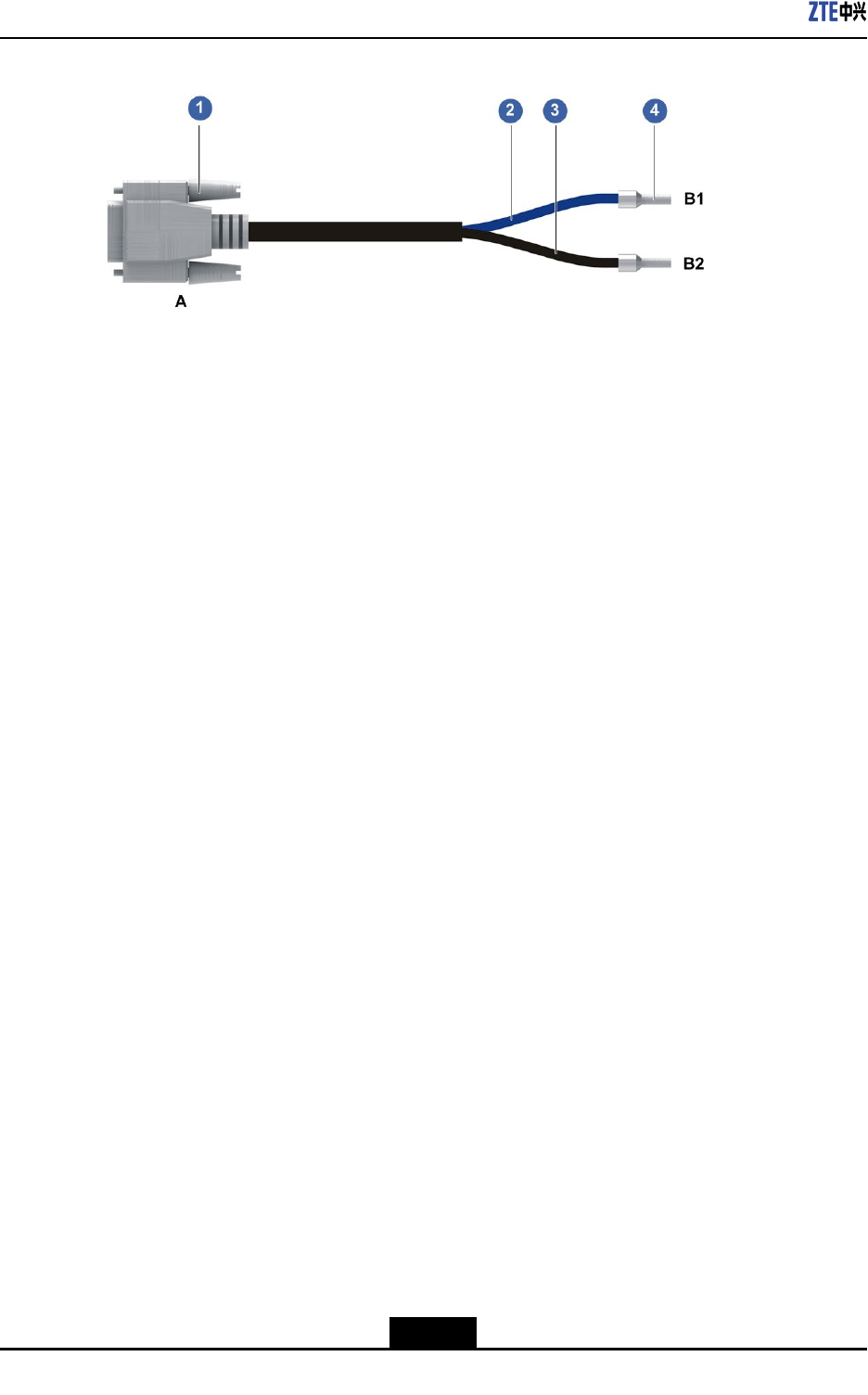
ZXR10ZSRV2HardwareDescription
Figure10-1DCPowerCable
1.D-type3-corestraight
solderconnector(hole+
pin+hole,withprotective
edges)
2.12AWGbluemulti-strand
heat-resistantcable
3.12AWGblackUL1015
cable
4.Pre-insulatedtubeterminal
10-2
SJ-20150204153047-004|2015-03-30(R1.0)ZTEProprietaryandCondential
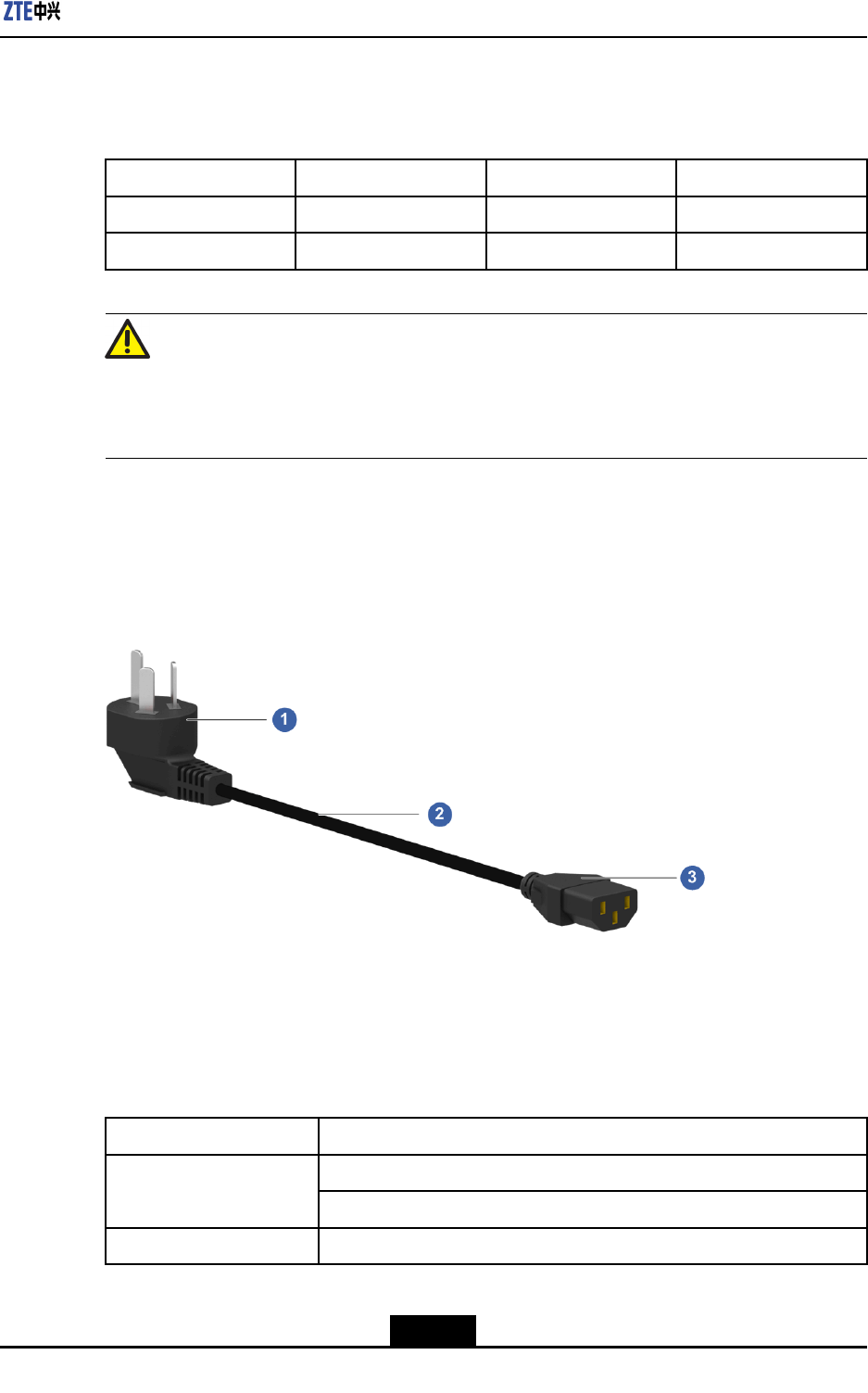
Chapter10Cables
FortherelationshipbetweenDCpowercablecorewiresandpinpositions,refertoTable
10-2.
Table10-2CoreWiresofaDCPowerCable
EndAColorEndBTag
A1BlackB2-48VRTN
A3BlueB1-48V
Caution!
DCpowercablesoftheZXR10ZSRV2arededicatedcables.Itisforbiddentousethem
forotherpurposes.
10.1.2ACPowerCables
FortheoverviewofanACpowercableoftheZXR10ZSRV2,seeFigure10-2.
Figure10-2ACPowerCable
1.10Ainternationalstandard
3-pinflatmaleplug
2.3×0.75mm2powercable
(with3Ccertification)
3.10Ainternationalstandard
T-shapedfemaleplug
ForthemodelsandspecicationsoftheACpowercablesoftheZXR10ZSRV2,referto
Table10-3.
Table10-3TechnicalParametersofanACPowerCable
ItemDescription
10Ainternationalstandard3-pinatmaleplug Terminalmodel
10AinternationalstandardT-shapedfemaleplug
Cablemodel3×0.0012sq.in.(0.75mm2),with3Ccertication
10-3
SJ-20150204153047-004|2015-03-30(R1.0)ZTEProprietaryandCondential
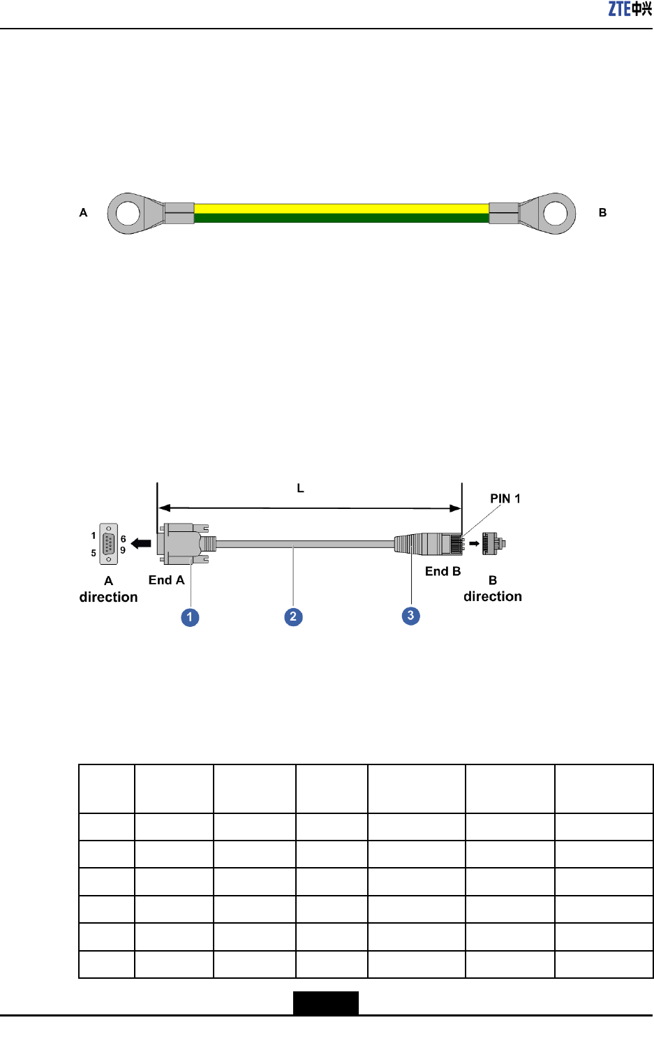
ZXR10ZSRV2HardwareDescription
10.1.3GroundingCables
Groundingcablesconnectacabinet,chassis,orcabinetdoortothegroundtoguarantee
safepowersupply.
Agroundingcableisayellowgreencopper-corecable,seeFigure10-3
Figure10-3OverviewofaProtectiveGroundingCable
10.2SignalCables
10.2.1AUXCables
TheAUXcableisan8-coreshieldedcable.OneendofthecableisanRJ45connector
connectingtotheMPUAUXinterface.Theotherendconnectstothecomputerserialport.
ForanAUXcableconnectedtotheDB9port,seeFigure10-4.
Figure10-4AUXCable(DB9)
1.D-type9-corestraight
plasticinjectionmold(hole)
2.CAT5enetworkcable3.8P8Cstraightcablecrimp
shieldedplug
FortherelationshipbetweenAUXcable(DB9)corewiresandpinpositions,refertoT able
10-4.
Table10-4CoreWiresofanAUXCable
RJ45
Pin
PCBAUX
Signal
Signal
Direction
DB9PinPCDB9(Hole)
Signal
ModemDB-9
(Pin)Pin
ModemDB-9
(Pin)Signal
1CTS←7RTS8CTS
2DTR→6DSR4DTR
3TXD→2RXD3TXD
4DCD←1DCD1DCD
5GND—5GND5GND
6RXD←3TXD2RXD
10-4
SJ-20150204153047-004|2015-03-30(R1.0)ZTEProprietaryandCondential
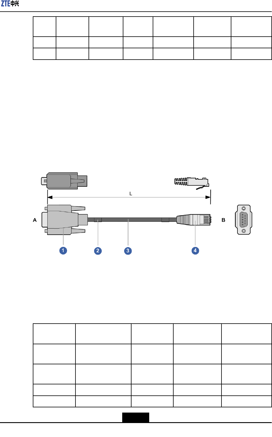
Chapter10Cables
RJ45
Pin
PCBAUX
Signal
Signal
Direction
DB9PinPCDB9(Hole)
Signal
ModemDB-9
(Pin)Pin
ModemDB-9
(Pin)Signal
7DSR←4DTR6DSR
8RTS→8CTS7RTS
10.2.2ConsoleCables
ConnectingtheZXR10ZSRV2consoleporttotheconsoleserialport,theconsolecable
transmitsdevicecongurationdata.
Theconsolecommunicationcableisan8-coreshieldedcable.Oneendofthecableis
anRJ45connectorconnectingtotheMPUconsoleport.Theotherendconnectstothe
serverserialport.
Fortheoverviewoftheconsolecable,seeFigure10-5.
Figure10-5ConsoleCableStructure
1.D-type9-coreplastic
injectionmoldedcableplug
(hole)
2.Label/self-coveringwinder
laserprint(typeII)
3.Horizontaltwistedpair
SBVVP-2×2
4.8P8Cstraightcablesolder
connector
Fortherelationshipbetweenconsolecablecorewiresandpinpositions,refertoTable
10-5.
Table10-5CoreWiresofaConsoleCable
RJ45PinPCBCONSOLE
Signal
Signal
Direction
DB9PinPCDB9(Hole)
Signal
1Nosignalincaseof
threewires
←7RTS
2Nosignalincaseof
threewires
→6DSR
3TXD→2RXD
4GND←1DCD
10-5
SJ-20150204153047-004|2015-03-30(R1.0)ZTEProprietaryandCondential
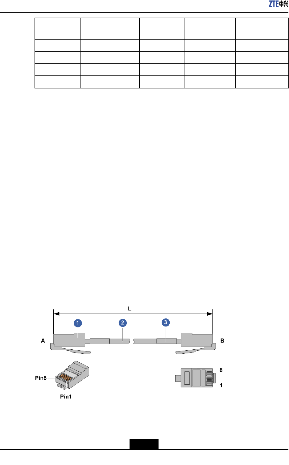
ZXR10ZSRV2HardwareDescription
RJ45PinPCBCONSOLE
Signal
Signal
Direction
DB9PinPCDB9(Hole)
Signal
5GND—5GND
6RXD←3TXD
7DSR←4DTR
8RTS→8CTS
10.2.3EthernetCables
TherearetwotypesofEthernetcables,crossovercablesandstraight-throughcables.
Straight-throughEthernetcablesareusedinthefollowingcases:
lEthernetconnectionbetweenZXR10ZSRV2andalineconcentrator.
lEthernetconnectionbetweenZXR10ZSRV2andanEthernetswitch.
lEthernetconnectionbetweenacomputerandalineconcentrator.
lEthernetconnectionbetweenacomputerandanEthernetswitch.
CrossoverEthernetcablesareusedinthefollowingcases:
lEthernetconnectionbetweentwoZXR10ZSRV2devices.
lEthernetconnectionbetweenZXR10ZSRV2andacomputerEthernetcard.
lEthernetconnectionbetweentwolineconcentrators.
lEthernetconnectionbetweenalineconcentratorandanEthernetswitch.
lEthernetconnectionbetweentwoEthernetswitches.
lEthernetcardconnectionbetweentwocomputers.
AnEthernetcableconsistsofRJ45connectorsandaneight-wiretwistedpaircable.For
anoverviewoftheEthernetcable,seeFigure10-6.
Figure10-6Ethernetcable
1.Ethernetcableconnector2.StandardshieldedEthernet
cable
3.Cablelabel
Forthewiringsequenceofthestraight-throughEthernetcable,refertoTable10-6.
10-6
SJ-20150204153047-004|2015-03-30(R1.0)ZTEProprietaryandCondential
Chapter10Cables
Table10-6WiringSequenceoftheStraight-ThroughEthernetCable
ColorEndAEndBColor
White/orange11White/orange
Orange22Orange
White/green33White/green
Blue44Blue
White/blue55White/blue
Green66Green
White/brown77White/brown
Brown88Brown
Forthewiringsequenceofthecross-overEthernetcable,refertoT able10-7.
Table10-7WiringSequenceoftheCross-OverEthernetCable
ColorEndAEndBColor
White/orange13White/green
Orange26Green
White/green31White/orange
Blue44Blue
White/blue55White/blue
Green62Orange
White/brown77White/brown
Brown88Brown
ForthetechnicalparametersoftheEthernetcable,refertoTable10-8.
Table10-8TechnicalParametersoftheEthernetCable
Cableconnector8P8Cstraightcablecrimpconnector
ModelE5088-001023
TechnicalparameterRatedcurrent:1.5A,ratedvoltage:125V,connectedtoASG24-28#
gaugeroundwires
10.2.4OpticalFibers
Overview
Theopticalberisacommunicationmediumthatusesabundleofthinglassrodsto
transmitthemodulatedlight.Therearetwotypesofopticalbers,single-modeoptical
10-7
SJ-20150204153047-004|2015-03-30(R1.0)ZTEProprietaryandCondential
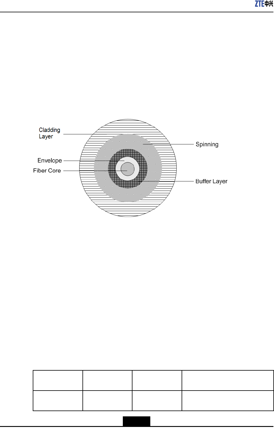
ZXR10ZSRV2HardwareDescription
bersandmultimodeopticalbers.Theusermayselectoneinaccordancewiththe
particularsituation.
lMultimodeopticalber:Transmitssignalsbyusingmultiplemodesoflight(for
short-distancetransmission).
lSingle-modeopticalber:Transmitssignalsbyusingasinglemodeoflight(for
long-distancetransmission).
Eachopticalberiscomposedofthebercore,claddinglayer,bufferlayer,strengthening
layer,andtheouterjacket.Forthephysicalcross-sectionalareaofabercable,see
Figure10-7.
Figure10-7OpticalFiberCross-sectionalArea
Thebercoreistheopticaltransmissioncomponentlocatedatthecore.Itismadeof
siliconorglass.Thechemicalcompositionsofabercorearepartiallydifferentfromthose
ofthecladdinglayer,sothatthelightenteringataspeciedangleisreectedcontinuously
bythebercoreandcladdinglayer.Therefore,lightremainsinthebercoreduringthe
wholetransmissionprocess.
OpticalFiberConnectors
Selectionofopticalberconnectorsdependsontheoperatingenvironmentanddevices.
TheZXR10ZSRV2routerusesthefollowingtypesofopticalberconnectors:
lLCconnector
lSCconnector
lFCconnector
Connectorsatthetwoendsoftheopticalbercanbeofthesametypeordifferenttypes.
Fortheconnectorpairingandusage,refertoTable10-9.
Table10-9OpticalFiberConnectorPairingandUsage
Device-end
Connectortype
Opposite-end
Connectortype
CableTypeCableUsage
LCFCSingle-mode
indooropticalber
Connectionbetweenadevice
interfacelinecardandODF
10-8
SJ-20150204153047-004|2015-03-30(R1.0)ZTEProprietaryandCondential
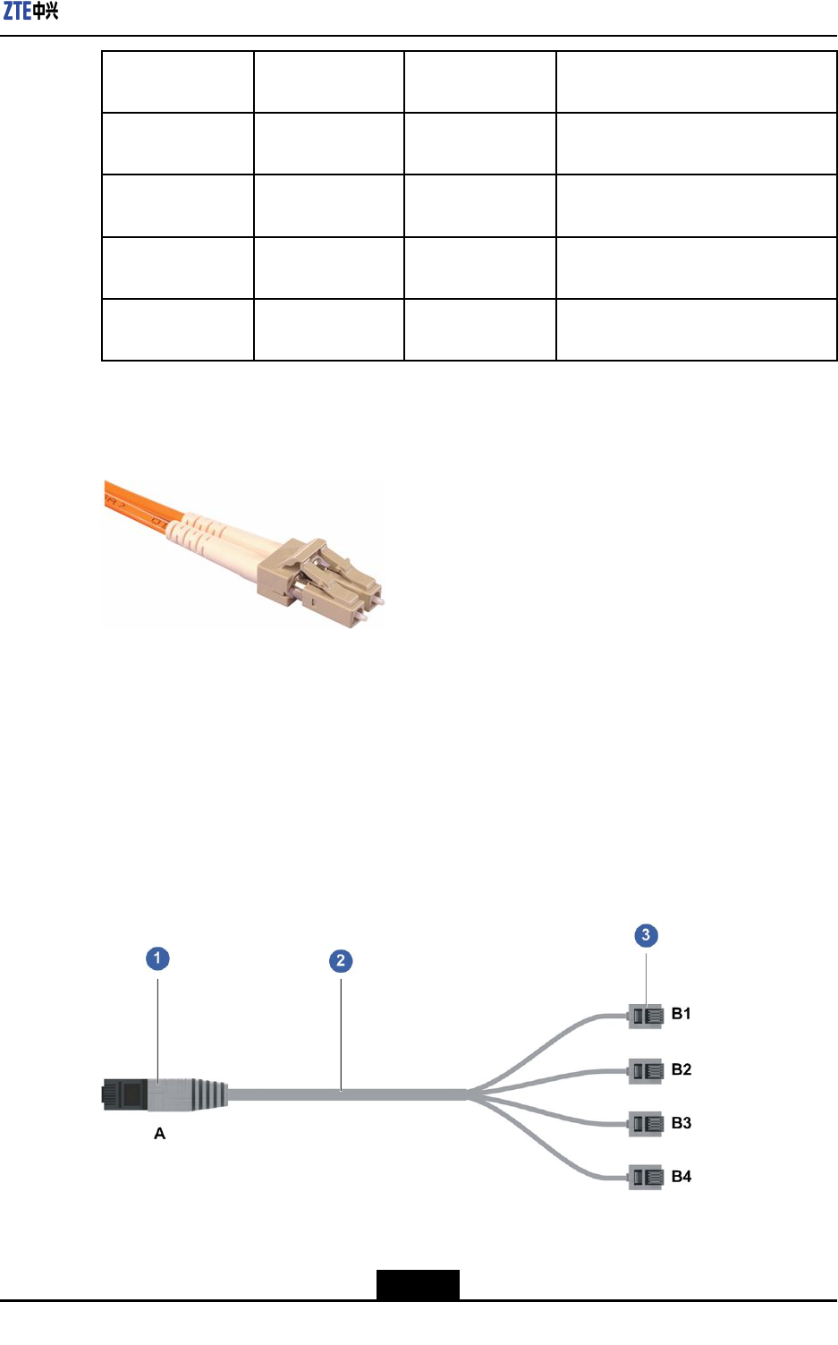
Chapter10Cables
Device-end
Connectortype
Opposite-end
Connectortype
CableTypeCableUsage
LCLCSingle-mode
indooropticalber
Connectionbetweeninterfaceline
cards
LCSCMultimodeindoor
opticalber
Connectionbetweeninterfaceline
cards
LCSCSingle-mode
indooropticalber
Connectionbetweenaninterfaceline
cardandothertypesofdevices
LCLCMultimodeindoor
opticalber
Connectionbetweenaninterfaceline
cardandothertypesofdevices
InterfaceboardsoftheZXR10ZSRV2mainlyuseLC-typeconnectors,seeFigure10-8.
Figure10-8LC-typeFiberConnector
10.2.5SHDSLCables
AnSHDSLcableisaneight-coreCAT5e100-ohmnon-shieldedtwistedpaircable.One
endisconnectedtooneRJ45connector,andtheotherendisconnectedtofourRJ11
connectors.TheSHDSLcablescanbeusedfortransmittingmultipletypesofsignals,
includingvoice,data,andvideosignals.
ForanoverviewoftheSHDSLcable,seeFigure10-9.
Figure10-9SHDSLCable
1.RJ45connector2.Eight-coreCAT5e100-ohm
non-shieldedtwistedpair
cable
3.RJ11connector
10-9
SJ-20150204153047-004|2015-03-30(R1.0)ZTEProprietaryandCondential
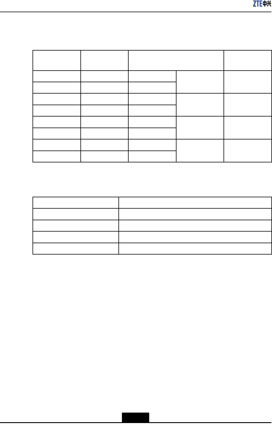
ZXR10ZSRV2HardwareDescription
AnSHDSLcableprovidesfourports(twowiresforeachport)attheRJ11connectorside.
ForthewiringsequenceoftheSHDSLcable,refertoTable10-10.
Table10-10WiringSequenceoftheSHDSLCable
PinNumberat
EndA
ColorPinNumberatEndBLabel
4(Line0A)White/green3
5(Line0B)Green4
B1port1
1(Line1A)White/orange3
2(Line1B)Orange4
B2port2
3(Line2A)White/blue3
6(Line2B)Blue4
B3port3
7(Line3A)White/brown3
8(Line3B)Brown4
B4port4
ForthetechnicalparametersoftheSHDSLcable,refertoTable10-11.
Table10-11TechnicalParametersoftheSHDSLCable
ParameterSpecication
Impedance100ohms
CabletypeSymmetricCAT5etwistedpaircable
Wiregauge(innerconductor)24AWG
Core8
10.2.6Synchronous/AsynchronousSerialCable
TheZXR10ZSRV2seriesroutersusesynchronousorasynchronousserialcablesto
transmitsynchronousorasynchronoussignals.Theserialcablescanbedividedintothe
followingtypes:
lV.35/V.24DTEcable(RA-DTE-DB50-DB25):ADB25maleconnectorisusedatthe
networkend.
lV.35/V.24DCEcable(RA-DCE-DB50-DB25):ADB25femaleconnectorisusedat
thenetworkend.
lV.35/V.24DTEcable(RA-DTE-DB50-34pole):A34polemaleconnectorisusedatthe
networkend.
lV.35/V.24DCEcable(RA-DCE-DB50-34pole):A34polefemaleconnectorisusedat
thenetworkend.
ForanoverviewoftheV.35/V.24DTEcable(RA-DTE-DB50-DB25),seeFigure10-10.
10-10
SJ-20150204153047-004|2015-03-30(R1.0)ZTEProprietaryandCondential
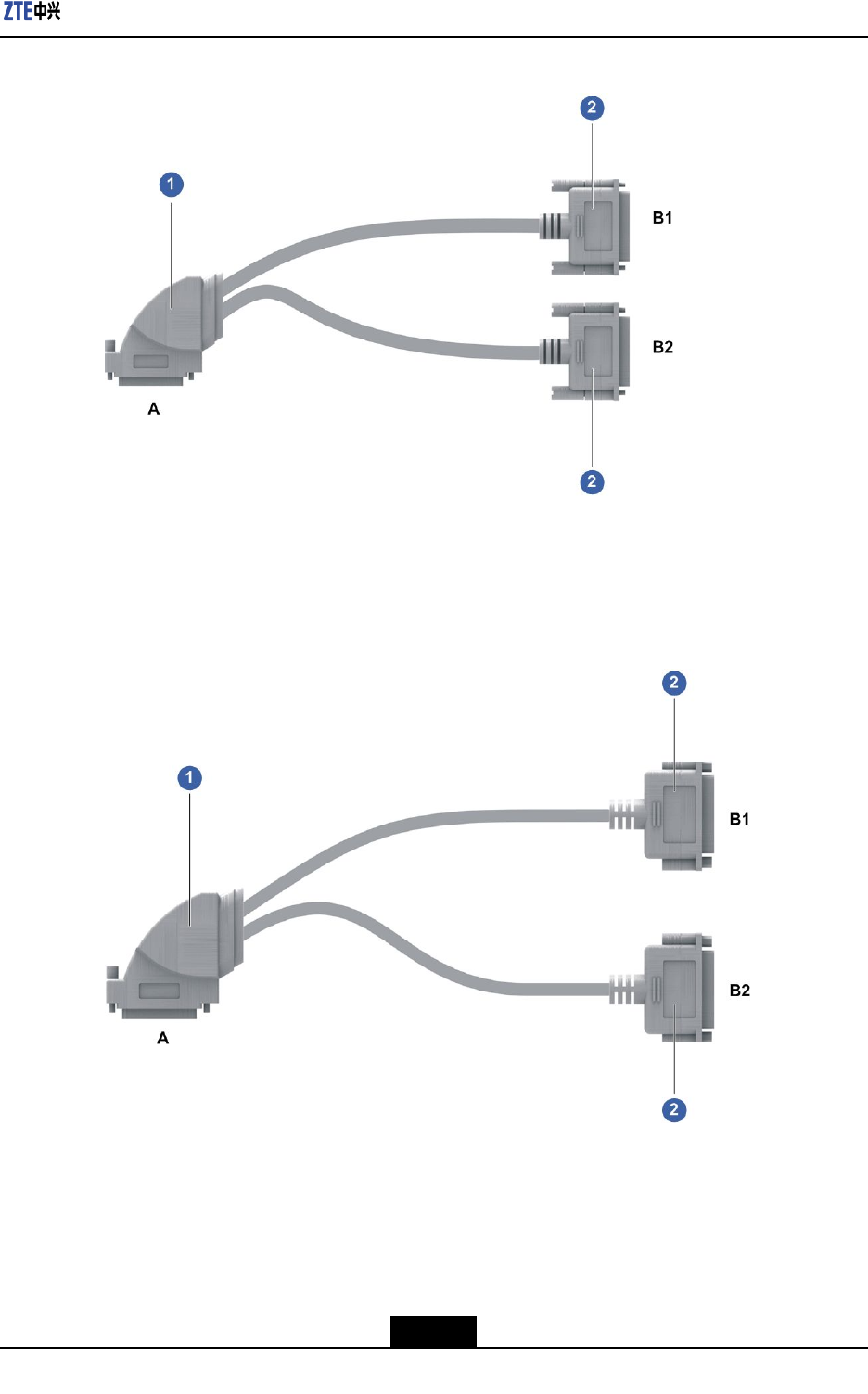
Chapter10Cables
Figure10-10V.35/V.24DTECable(RA-DTE-DB50-DB25)
1.Device-endconnector
DB50
2.Network-endconnector
DB25(male)
ForanoverviewoftheV.35/V.24DCEcable(RA-DCE-DB50-DB25),seeFigure10-11.
Figure10-11V.35/V.24DCECable(RA-DCE-DB50-DB25)
1.Device-endconnector
DB50
2.Network-endconnector
DB25(female)
ForanoverviewoftheV.35/V.24DTEcable(RA-DTE-DB50-34pole),seeFigure10-12.
10-11
SJ-20150204153047-004|2015-03-30(R1.0)ZTEProprietaryandCondential
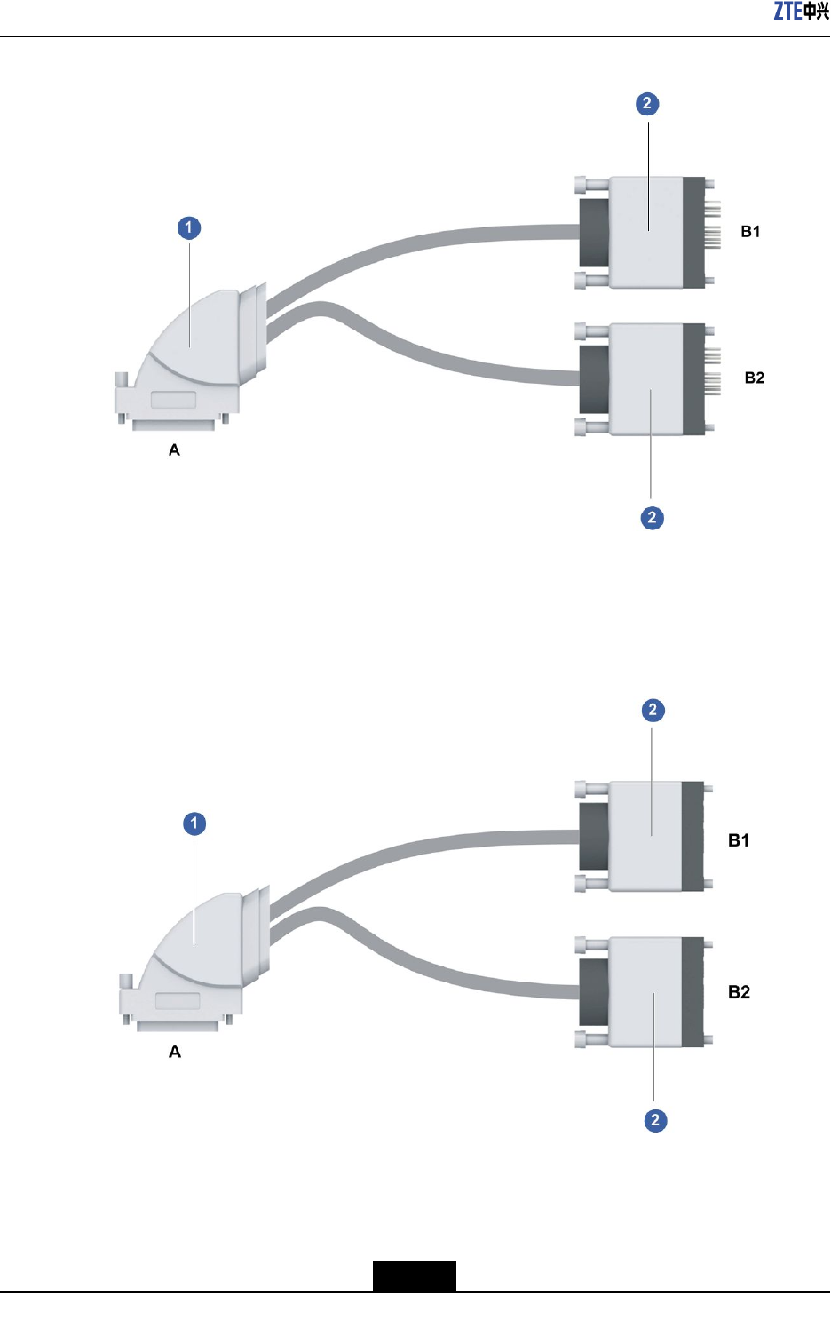
ZXR10ZSRV2HardwareDescription
Figure10-12V.35/V.24DTECable(RA-DTE-DB50-34pole)
1.Device-endconnector
DB50
2.Network-endconnector
34pole(male)
ForanoverviewoftheV.35/V.24DCEcable(RA-DCE-DB50-34pole),seeFigure10-13.
Figure10-13V.35/V.24DCECable(RA-DCE-DB50-34pole)
1.Device-endconnector
DB50
2.Network-endconnector
34pole(female)
Foradescriptionofthesynchronous/asynchronousserialcabletypes,refertoT able10-12.
10-12
SJ-20150204153047-004|2015-03-30(R1.0)ZTEProprietaryandCondential
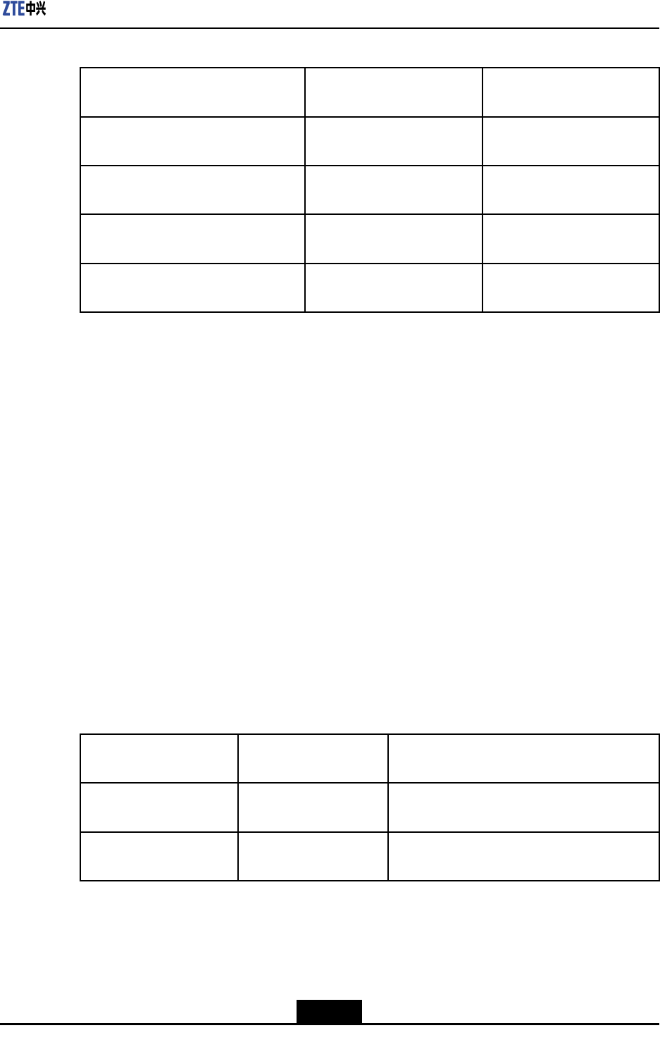
Chapter10Cables
Table10-12Synchronous/AsynchronousSerialCableTypes
Synchronous/AsynchronousSerial
Cable
Device-EndConnectorNetwork-EndConnector
V.35/V.24DTEcable(RA-DTE-DB50-
DB25)
DB50DB25maleconnector
V.35/V.24DCEcable(RA-DCE-
DB50-DB25)
DB50DB25femaleconnector
V.35/V.24DTEcable(RA-DTE-DB50-
34pole)
DB5034polemaleconnector
V.35/V.24DCEcable(RA-DCE-
DB50-34pole)
DB5034polefemaleconnector
10.2.7E1TrunkCable
Overview
TheE1trunkcablesthattheRAC-PIU-16CE1andRAC-PIU-16CE1-CESboardsofthe
ZXR10ZSRV2seriesroutersusecanbedividedintothefollowingtypes:
l75Ωunbalancedcoaxialcable
IftheinterfaceresistanceoftheRAC-PIU-16CE1orRAC-PIU-16CE1-CESboardis
conguredto75Ω,the75ΩunbalancedcoaxialcableisusedastheE1trunkcable.
l120Ωbalancedtwisted-paircable
IftheinterfaceresistanceoftheRAC-PIU-16CE1orRAC-PIU-16CE1-CESboardis
conguredto120Ω,the120Ωbalancedtwisted-paircableisusedastheE1trunk
cable.
FortheE1trunkcableconnections,refertoTable10-13.
Table10-13E1TrunkCableConnections
Synchronous/Asyn-
chronousSerialCable
Device-EndConnectorNetwork-EndConnector
75Ωunbalancedcoaxial
cable
DB50Sixteencoaxialcablesintwogroups,
connectedtotheconnectorsasrequired
120Ωbalanced
twisted-paircable
DB50Sixteentwisted-paircablesintwogroups,
connectedtotheconnectorsasrequired
75ΩUnbalancedCoaxialCable
Foranoverviewofthe75Ωunbalancedcoaxialcable,seeFigure10-14.
10-13
SJ-20150204153047-004|2015-03-30(R1.0)ZTEProprietaryandCondential
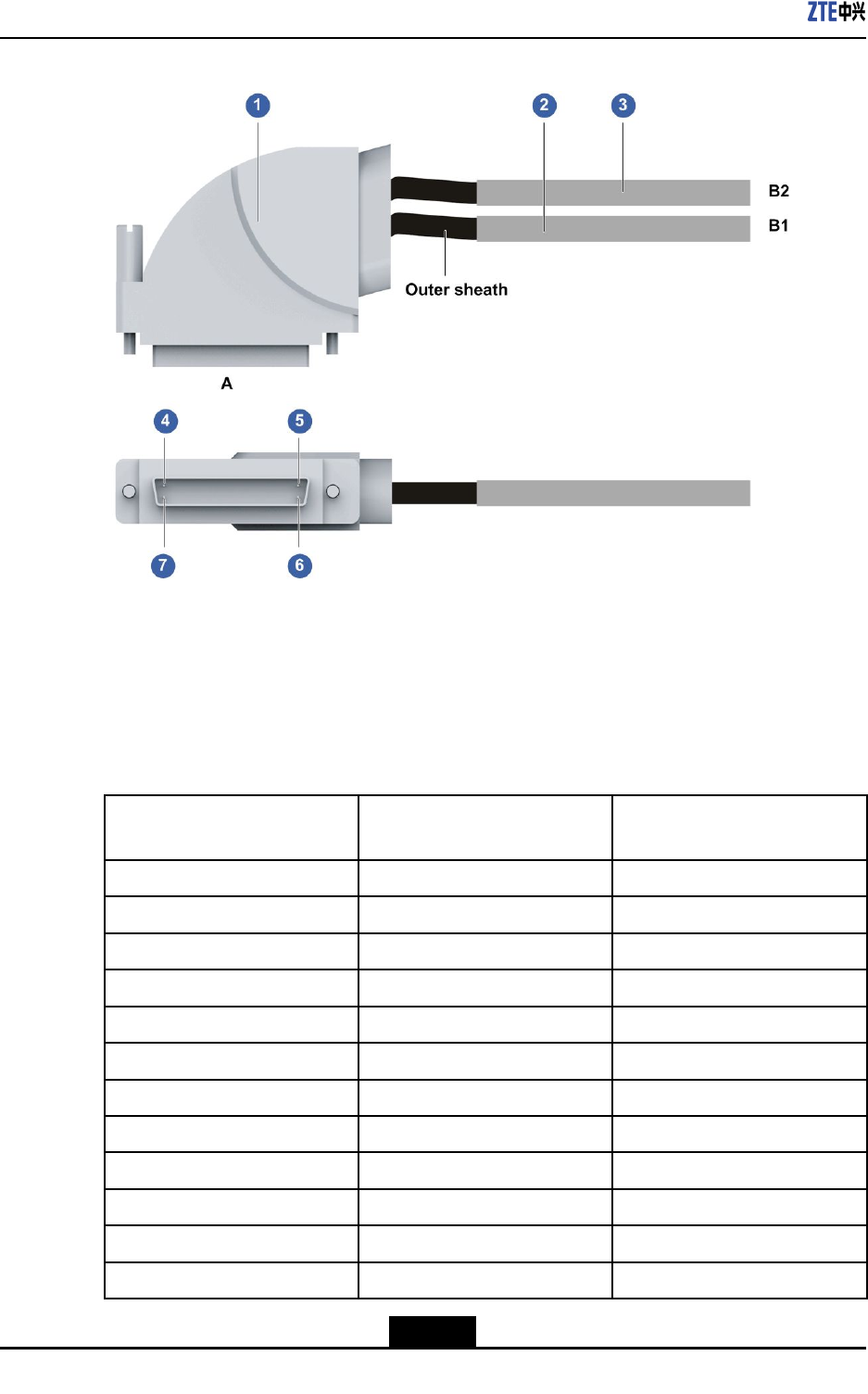
ZXR10ZSRV2HardwareDescription
Figure10-1475ΩUnbalancedCoaxialCable
1.Device-endDB50
connector
2.8-coremicro-coaxialA
3.8-coremicro-coaxialB
4.Pin1atendA
5.Pin25atendA
6.Pin50atendA
7.Pin26atendA
Forthecorrespondencerelationshipsbetweentheend-Apinsandtheend-B1coresofthe
75Ωunbalancedcoaxialcable,refertoTable10-14.
Table10-14CorrespondenceRelationshipsBetweentheEnd-APinsandEnd-B1Cores
ofthe75ΩUnbalancedCoaxialCable
PinatEndAEndB1(Eight-Core
Micro-CoaxialA)
Signal
25A-1coreR1+
50A-1shieldR1–
24A-2coreT1+
49A-2shieldT1–
23A-3coreR2+
48A-3shieldR2–
22A-4coreT2+
47A-4shieldT2–
21A-5coreR3+
46A-5shieldR3–
20A-6coreT3+
45A-6shieldT3–
10-14
SJ-20150204153047-004|2015-03-30(R1.0)ZTEProprietaryandCondential
Chapter10Cables
PinatEndAEndB1(Eight-Core
Micro-CoaxialA)
Signal
19A-7coreR4+
44A-7shieldR4–
18A-8coreT4+
43A-8shieldT4–
Forthecorrespondencerelationshipsbetweentheend-Apinsandtheend-B2coresofthe
75Ωunbalancedcoaxialcable,refertoTable10-15.
Table10-15CorrespondenceRelationshipsBetweentheEnd-APinsandEnd-B2Cores
ofthe75ΩUnbalancedCoaxialCable
PinatEndAEndB2(Eight-Core
Micro-CoaxialB)
Signal
17B-1coreR5+
42B-1shieldR5–
16B-2coreT5+
41B-2shieldT5–
15B-3coreR6+
40B-3shieldR6–
14B-4coreT6+
39B-4shieldT6–
13B-5coreR7+
38B-5shieldR7–
12B-6coreT7+
37B-6shieldT7–
11B-7coreR8+
36B-7shieldR8–
10B-8coreT8+
35B-8shieldT8–
120ΩBalancedTwisted-PairCable
Foranoverviewofthe120Ωbalancedtwisted-paircable,seeFigure10-15.
10-15
SJ-20150204153047-004|2015-03-30(R1.0)ZTEProprietaryandCondential
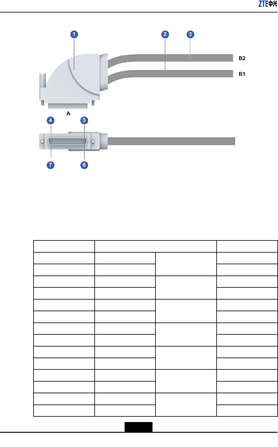
ZXR10ZSRV2HardwareDescription
Figure10-15120ΩBalancedTwisted-PairCable
1.Device-endconnector
DB50
2.8-coremicro-coaxialA
3.8-coremicro-coaxialB
4.Pin1atendA
5.Pin25atendA
6.Pin50atendA
7.Pin26atendA
Forthecorrespondencerelationshipsbetweentheend-Apinsandtheend-B1coresofthe
120Ωbalancedtwisted-paircable,refertoT able10-16.
Table10-16CorrespondenceRelationshipsBetweentheEnd-APinsandEnd-B1Cores
ofthe120ΩBalancedTwisted-PairCable
PinatEndAEndB1(16-CoreCableA)Signal
25BlueR1+
50White
Twistedpair
R1–
24OrangeT1+
49White
Twistedpair
T1–
23GreenR2+
48White
Twistedpair
R2–
22BrownT2+
47White
Twistedpair
T2–
21GreyR3+
46White
Twistedpair
R3–
20BlueT3+
45Red
Twistedpair
T3–
19OrangeR4+
44Red
Twistedpair
R4–
10-16
SJ-20150204153047-004|2015-03-30(R1.0)ZTEProprietaryandCondential
Chapter10Cables
PinatEndAEndB1(16-CoreCableA)Signal
18GreenT4+
43Red
Twistedpair
T4–
Forthecorrespondencerelationshipsbetweentheend-Apinsandtheend-B2coresofthe
120Ωbalancedtwisted-paircable,refertoT able10-17.
Table10-17CorrespondenceRelationshipsBetweentheEnd-APinsandEnd-B2Cores
ofthe120ΩBalancedTwisted-PairCable
PinatEndAEndB2(16-CoreCableB)Signal
17BlueR5+
42White
Twistedpair
R5–
16OrangeT5+
41White
Twistedpair
T5–
15GreenR6+
40White
Twistedpair
R6–
14BrownT6+
39White
Twistedpair
T6–
13GreyR7+
38White
Twistedpair
R7–
12BlueT7+
37Red
Twistedpair
T7–
11OrangeR8+
36Red
Twistedpair
R8–
10GreenT8+
35Red
Twistedpair
T8–
10-17
SJ-20150204153047-004|2015-03-30(R1.0)ZTEProprietaryandCondential

ZXR10ZSRV2HardwareDescription
Thispageintentionallyleftblank.
10-18
SJ-20150204153047-004|2015-03-30(R1.0)ZTEProprietaryandCondential
AppendixA
BoardQuickTable(Weight
andPowerConsumption)
FortheweightandpowerconsumptionoftheboardssupportedbytheZXR10ZSRV2
seriesrouters,refertoTableA-1.
TableA-1BoardWeightandPowerConsumptionoftheZXR10ZSRV2SeriesRouters
BoardTypeSilkScreenNameWeightPowerConsumption
RAC-2838-MPFU-A2.38lb.(1.08kg)35W
RAC-2838-MPFU-B2.38lb.(1.08kg)35W
MPFU
RAC-2838-MPFU-C2.38lb.(1.08kg)35W
RAE-DPIU-OSU-A12.71lb.(1.23kg)40W
RAE-DPIU-OSU-A22.71lb.(1.23kg)40W
General
processingboard
RAE-DPIU-FW-A2.31lb.(1.05kg)35W
RAC-SPIU-02CE1-750.53lb.(0.24kg)6W
RAC-SPIU-02CE1-1200.53lb.(0.24kg)6W
RAC-SPIU-02UE1-750.53lb.(0.24kg)6W
RAC-SPIU-02UE1-1200.53lb.(0.24kg)6W
RAC-SPIU-02HS0.46lb.(0.21kg)7W
RAC-SPIU-04GE0.22lb.(0.1kg)7W
RAC-PIU-LTE1.23lb.(0.56kg)7W
RAC-PIU-01DSLB0.88lb.(0.4kg)16W
RAC-PIU-04SHDSL1.19lb.(0.54kg)10W
RAC-PIU-04HS1.19lb.(0.54kg)10W
RAC-PIU-04CE1-751.19lb.(0.54kg)11W
RAC-PIU-04CE1-1201.19lb.(0.54kg)11W
RAC-PIU-04UE1-751.19lb.(0.54kg)11W
RAC-PIU-04UE1-1201.19lb.(0.54kg)11W
RAC-PIU-16CE11.19lb.(0.54kg)16W
RAC-PIU-16CE1-CES1.19lb.(0.54kg)16W
RAC-PIU-01P12-SFP1.19lb.(0.54kg)16W
PIU
A-1
SJ-20150204153047-004|2015-03-30(R1.0)ZTEProprietaryandCondential
ZXR10ZSRV2HardwareDescription
BoardTypeSilkScreenNameWeightPowerConsumption
RAC-PIU-02P3-SFP1.19lb.(0.54kg)16.5W
RAC-PIU-04P3-SFP1.19lb.(0.54kg)18W
RAC-PIU-02CP3-SFP1.19lb.(0.54kg)16.5W
RAC-PIU-04CP3-SFP1.19lb.(0.54kg)18W
RAC-PIU-04GE-SFP1.19lb.(0.54kg)13W
RAC-PIU-08GE-SFP1.19lb.(0.54kg)15W
RAC-PIU-05GE-4E1SFP0.88lb.(0.4kg)11W
RAC-PIU-09GE-8E1SFP1.19lb.(0.54kg)12W
RAC-PIU-08FE1GE-1SFP1.19lb.(0.54kg)11W
RAC-DPIU-16GE-12SFP4E1.32lb.(0.6kg)36W
RAC-DPIU-01XGE-SFP+1.50lb.(0.68kg)16W
A-2
SJ-20150204153047-004|2015-03-30(R1.0)ZTEProprietaryandCondential
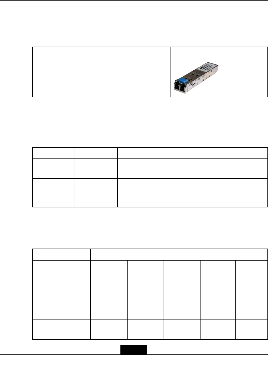
AppendixB
OpticalModulesQuickTable
Overview
ZXR10ZSRV2routersusetheSFPopticalmodules,refertoT ableB-1.
TableB-1SFPOpticalModules
TypeExample
SFP(SmallForm-factorPluggable)
Indicators
AnopticalmodulealwayshastheACTandLNKindicators.Forindicatordescriptions,
refertoT ableB-2.
TableB-2OpticalModuleIndicatorDescriptions
IndicatorColorDescription
ACTGreenTransmissionstatusindicatorofanopticalport.Whendatais
beingtransmitted,thisindicatorashes.
LNKGreenPhysicalconnectionstatusindicatorofanopticalport.Ifthe
physicalconnectionoftheopticalportisnormal,thisindicatoris
on.Otherwise,thisindicatorisoff.
SFPAttributes
Fortheattributesofan155MSFPopticalmodule,refertoT ableB-3.
TableB-3155MSFPAttributes
AttributeParameters
Transmissiondistance
(km)
2154080100
Centralwavelength
(nm)
13101310131015501310
Referencewavelength
range(nm)
1260~15701261~13601263~13601480~15801480~1580
Transmittingoptical
powerrange(dBm)
-19~-14-15~-8-5~0-5~00~5
B-1
SJ-20150204153047-004|2015-03-30(R1.0)ZTEProprietaryandCondential
ZXR10ZSRV2HardwareDescription
AttributeParameters
Receivingsensitivity
(dBm)
-30-28-34-34-34
Overloadopticalpower
(dBm)
-10-8-10-10-10
FibertypeMultimodeSinglemodeSinglemodeSinglemodeSingle
mode
InterfacetypeLC-SFPLC-SFPLC-SFPLC-SFPLC-SFP
Fortheattributesofan622MSFPopticalmodule,refertoT ableB-4.
TableB-4622MSFPAttributes
AttributeParameters
Transmissiondistance
(km)
154080
Centralwavelength
(nm)
131013101550
Referencewavelength
range(nm)
1274~13561280~13351480~1580
Transmittingoptical
powerrange(dBm)
-15~-8-3~2-3~2
Receivingsensitivity
(dBm)
-28-28-28
Overloadopticalpower
(dBm)
-8-8-8
FibertypeSinglemodeSinglemodeSinglemode
InterfacetypeLC-SFPLC-SFPLC-SFP
Fortheattributesofan1.25GSFPopticalmodule,refertoT ableB-5.
TableB-51.25GSFPAttributes
AttributeParameters
Transmission
distance(km)
0.510404080120
Centralwavelength
(nm)
85013101310155015501550
Reference
wavelengthrange
(nm)
770~8601260~136
0
1260~136
0
1480~158
0
1480~158
0
1480~158
0
B-2
SJ-20150204153047-004|2015-03-30(R1.0)ZTEProprietaryandCondential
AppendixBOpticalModulesQuickT able
AttributeParameters
Transmittingoptical
powerrange(dBm)
-9.5~-3-11.5~-3-4.5~5-5~0-2~50~5
Receiving
sensitivity(dBm)
-17-19-22-22-22-30
Overloadoptical
power(dBm)
0-3-5-3-5-9
FibertypeMultimodeSingle
mode
Single
mode
Single
mode
Single
mode
Single
mode
InterfacetypeLC-SFPLC-SFPLC-SFPLC-SFPLC-SFPLC-SFP
B-3
SJ-20150204153047-004|2015-03-30(R1.0)ZTEProprietaryandCondential

ZXR10ZSRV2HardwareDescription
Thispageintentionallyleftblank.
B-4
SJ-20150204153047-004|2015-03-30(R1.0)ZTEProprietaryandCondential

Figures
Figure2-1MainComponentsontheFrontSideoftheZXR103800-8Chassis...........2-1
Figure2-2FrontViewoftheZXR103800-8Chassis.................................................2-2
Figure2-3FrontViewoftheZXR103800-8Chassis.................................................2-2
Figure2-4PaneloftheACPowerSupplyModule.....................................................2-4
Figure2-5PaneloftheDCPowerSupplyModule....................................................2-5
Figure3-1MainComponentsontheFrontSideoftheZXR102800-4Chassis...........3-1
Figure3-2FrontViewoftheZXR102800-4Chassis.................................................3-2
Figure3-3FrontViewoftheZXR102800-4Chassis.................................................3-2
Figure3-4PaneloftheACPowerSupplyModule.....................................................3-4
Figure3-5PaneloftheDCPowerSupplyModule....................................................3-5
Figure4-1ZXR101800-2SFrontView.....................................................................4-2
Figure4-2ZXR101800-2SFrontPanel....................................................................4-2
Figure4-3ZXR101800-2SRearPanel....................................................................4-3
Figure4-4FrontViewoftheZXR101800-2SChassis..............................................4-4
Figure4-5PowerButton...........................................................................................4-6
Figure5-1FrontStructureGraphforaZXR102800-3EChassis...............................5-2
Figure5-2FrontPanelofaZXR102800-3EChassis................................................5-2
Figure5-3BackPanelofaZXR102800-3EChassis................................................5-3
Figure5-4SlotsontheBackofaZXR102800-3EChassis.......................................5-3
Figure5-5PaneloftheACPowerModule................................................................5-5
Figure5-6PaneloftheDCPowerModule................................................................5-6
Figure6-1FrontViewofaZXR101800-2EChassis.................................................6-2
Figure6-2FrontPanelofaZXR101800-2EChassis................................................6-2
Figure6-3BackPanelofaZXR101800-2EChassis................................................6-3
Figure6-4SlotsontheBackofaZXR101800-2EChassis.......................................6-3
Figure6-5PaneloftheACPowerModule................................................................6-5
Figure6-6PaneloftheDCPowerModule................................................................6-6
Figure7-1PaneloftheRAC-2838-MPFU-A.............................................................7-2
Figure7-2RAC-2838-MPFU-BandRAC-2838-MPFU-C..........................................7-3
Figure8-1PanelofanRAC-DPIU-OSU-A1Board....................................................8-1
Figure8-2PanelofanRAC-DPIU-OSU-A2Board....................................................8-3
Figure8-3PanelofanRAC-DPIU-FW-ABoard........................................................8-5
I
SJ-20150204153047-004|2015-03-30(R1.0)ZTEProprietaryandCondential

ZXR10ZSRV2HardwareDescription
Figure9-1FrontPaneloftheRAC-SPIU-02CE1-75Board.......................................9-2
Figure9-2FrontPaneloftheRAC-SPIU-02UE1-75Board.......................................9-4
Figure9-3FrontPaneloftheRAC-SPIU-02CE1-120Board.....................................9-5
Figure9-4FrontPaneloftheRAC-SPIU-02UE1-120Board.....................................9-7
Figure9-5FrontPaneloftheRAC-SPIU-02HSBoard..............................................9-8
Figure9-6FrontPanelofanRAC-SPIU-04GEBoard.............................................9-10
Figure9-7RAC-PIU-LTEBoardPanel....................................................................9-11
Figure9-8FrontPaneloftheRAC-PIU-01DSLBBoard..........................................9-13
Figure9-9FrontPaneloftheRAC-PIU-04SHDSLboard........................................9-15
Figure9-10FrontPaneloftheRAC-PIU-04HSBoard.............................................9-17
Figure9-11FrontPaneloftheRAC-PIU-04CE1-75Board......................................9-18
Figure9-12FrontPaneloftheRAC-PIU-04CE1-120Board....................................9-20
Figure9-13FrontPaneloftheRAC-PIU-04UE1-75Board......................................9-21
Figure9-14FrontPaneloftheRAC-PIU-04UE1-120Board....................................9-22
Figure9-15FrontPaneloftheRAC-PIU-16CE1Board...........................................9-24
Figure9-16FrontPaneloftheRAC-PIU-16CE1-CESBoard..................................9-25
Figure9-17FrontPaneloftheRAC-PIU-01P12-SFPBoard...................................9-27
Figure9-18FrontPaneloftheRAC-PIU-02P3-SFPBoard.....................................9-28
Figure9-19FrontPaneloftheRAC-PIU-04P3-SFPBoard.....................................9-29
Figure9-20FrontPaneloftheRAC-PIU-02CP3-SFPBoard...................................9-31
Figure9-21FrontPaneloftheRAC-PIU-04CP3-SFPBoard...................................9-32
Figure9-22FrontPaneloftheRAC-PIU-04GE-SFPBoard.....................................9-34
Figure9-23FrontPaneloftheRAC-PIU-08GE-SFPBoard.....................................9-35
Figure9-24FrontPaneloftheRAC-PIU-05GE-4E1SFPBoard..............................9-37
Figure9-25FrontPaneloftheRAC-PIU-09GE-8E1SFPBoard..............................9-39
Figure9-26FrontPaneloftheRAC-PIU-08FE1GE-1SFPBoard............................9-41
Figure9-27FrontPaneloftheRAC-DPIU-16GE-12SFP4EBoard..........................9-43
Figure9-28FrontPaneloftheRAC-DPIU-01XGE-SFP+Board...............................9-45
Figure10-1DCPowerCable..................................................................................10-2
Figure10-2ACPowerCable..................................................................................10-3
Figure10-3OverviewofaProtectiveGroundingCable...........................................10-4
Figure10-4AUXCable(DB9).................................................................................10-4
Figure10-5ConsoleCableStructure......................................................................10-5
Figure10-6Ethernetcable......................................................................................10-6
Figure10-7OpticalFiberCross-sectionalArea.......................................................10-8
II
SJ-20150204153047-004|2015-03-30(R1.0)ZTEProprietaryandCondential

Figures
Figure10-8LC-typeFiberConnector......................................................................10-9
Figure10-9SHDSLCable......................................................................................10-9
Figure10-10V.35/V.24DTECable(RA-DTE-DB50-DB25)...................................10-11
Figure10-11V.35/V.24DCECable(RA-DCE-DB50-DB25)...................................10-11
Figure10-12V.35/V.24DTECable(RA-DTE-DB50-34pole).................................10-12
Figure10-13V.35/V.24DCECable(RA-DCE-DB50-34pole).................................10-12
Figure10-1475ΩUnbalancedCoaxialCable......................................................10-14
Figure10-15120ΩBalancedTwisted-PairCable.................................................10-16
III
SJ-20150204153047-004|2015-03-30(R1.0)ZTEProprietaryandCondential

Figures
Thispageintentionallyleftblank.
IV
SJ-20150204153047-004|2015-03-30(R1.0)ZTEProprietaryandCondential

Tables
Table1-1ComponentModels...................................................................................1-1
Table2-1DescriptionoftheMainComponentsoftheZXR103800-8Chassis...........2-2
Table2-2SystemParametersoftheZXR103800-8.................................................2-3
Table2-3IndicatorDescriptionsfortheZXR103800-8ACPowerSupply
Module.....................................................................................................2-4
Table2-4PowerButtonDescriptionfortheZXR103800-8ACPowerSupply
Module.....................................................................................................2-5
Table2-5TechnicalParametersoftheACPowerRectieroftheZXR10
3800-8.....................................................................................................2-5
Table2-6IndicatorDescriptionsfortheZXR103800-8DCPowerSupply
Module.....................................................................................................2-6
Table2-7PowerButtonDescriptionfortheZXR103800-8DCPowerSupply
Module.....................................................................................................2-6
Table2-8T echnicalParametersoftheDCPowerSupplyModuleoftheZXR10
3800-8.....................................................................................................2-6
Table2-9ZXR103800-8FanSpecications.............................................................2-7
Table3-1DescriptionoftheMainComponentsoftheZXR102800-4Chassis...........3-2
Table3-2SystemParametersoftheZXR102800-4.................................................3-3
Table3-3IndicatorDescriptionsfortheZXR102800-4ACPowerSupply
Module.....................................................................................................3-4
Table3-4PowerButtonDescriptionfortheZXR102800-4ACPowerSupply
Module.....................................................................................................3-4
Table3-5TechnicalParametersoftheACPowerRectieroftheZXR10
2800-4.....................................................................................................3-5
Table3-6IndicatorDescriptionsfortheZXR102800-4DCPowerSupply
Module.....................................................................................................3-5
Table3-7PowerButtonDescriptionfortheZXR102800-4DCPowerSupply
Module.....................................................................................................3-6
Table3-8T echnicalParametersoftheDCPowerSupplyModuleoftheZXR10
2800-4.....................................................................................................3-6
Table3-9ZXR102800-4FanSpecications.............................................................3-6
Table4-1DescriptionsoftheMainComponentsoftheZXR101800-2S...................4-1
Table4-2ZXR101800-2SFrontPanelDescriptions.................................................4-2
Table4-3ZXR101800-2SRearPanelDescriptions..................................................4-4
V
SJ-20150204153047-004|2015-03-30(R1.0)ZTEProprietaryandCondential

ZXR10ZSRV2HardwareDescription
Table4-4SystemParametersoftheZXR101800-2S...............................................4-5
Table4-5PowerButtonDescriptionfortheZXR101800-2SACPowerSupply
Module.....................................................................................................4-6
Table4-6TechnicalParametersoftheACPowerRectieroftheZXR10
1800-2S...................................................................................................4-6
Table4-7TechnicalParametersoftheDCPowerRectieroftheZXR10
1800-2S...................................................................................................4-7
Table5-1MainComponentsofaZXR102800-3EChassis.......................................5-1
Table5-2DescriptionsofInterfacesontheFrontPanelofaZXR102800-3E
Chassis....................................................................................................5-2
Table5-3SystemParametersofaZXR102800-3EChassis.....................................5-4
Table5-4FunctionsoftheIndicatorsonthePaneloftheACPowerModuleofthe
ZXR102800-3EChassis..........................................................................5-5
Table5-5FunctionsofthePowerButtonsoftheACPowerModuleoftheZXR10
2800-3EChassis......................................................................................5-6
Table5-6TechnicalParametersoftheACPoweroftheZXR102800-3E
Chassis....................................................................................................5-6
Table5-7FunctionsoftheIndicatorsonthePaneloftheDCPowerModuleofthe
ZXR102800-3EChassis..........................................................................5-7
Table5-8FunctionsofthePowerButtonsoftheDCPowerModuleoftheZXR10
2800-3EChassis......................................................................................5-7
Table5-9T echnicalParametersoftheDCPowerModuleoftheZXR102800-3E
Chassis....................................................................................................5-7
Table6-1MainComponentsofaZXR101800-2EChassis.......................................6-1
Table6-2DescriptionsofInterfacesontheFrontPanelofaZXR101800-2E
Chassis....................................................................................................6-2
Table6-3SystemParametersofaZXR101800-2EChassis.....................................6-4
Table6-4FunctionsoftheIndicatorsonthePaneloftheACPowerModuleofthe
ZXR101800-2EChassis..........................................................................6-5
Table6-5FunctionsofthePowerButtonsoftheACPowerModuleoftheZXR10
1800-2EChassis......................................................................................6-5
Table6-6TechnicalParametersoftheACPoweroftheZXR101800-2E
Chassis....................................................................................................6-6
Table6-7FunctionsoftheIndicatorsonthePaneloftheDCPowerModuleofthe
ZXR101800-2EChassis..........................................................................6-6
Table6-8FunctionsofthePowerButtonsoftheDCPowerModuleoftheZXR10
1800-2EChassis......................................................................................6-7
Table6-9T echnicalParametersoftheDCPowerModuleoftheZXR101800-2E
Chassis....................................................................................................6-7
VI
SJ-20150204153047-004|2015-03-30(R1.0)ZTEProprietaryandCondential

Tables
Table7-1DescriptionoftheInterfacesoftheRAC-2838-MPFU-A............................7-2
Table7-2IndicatorDescriptionsfortheRAC-2838-MPFU-A.....................................7-2
Table7-3RSTButtonDescriptionfortheRAC-2838-MPFU-A..................................7-3
Table7-4TechnicalParametersoftheRAC-2838-MPFU-A......................................7-3
Table7-5DescriptionoftheInterfacesofthe
RAC-2838-MPFU-B/RAC-2838-MPFU-C.................................................7-4
Table7-6DescriptionoftheIndicatorsonthePanelofthe
RAC-2838-MPFU-B/RAC-2838-MPFU-C.................................................7-4
Table7-7DescriptionoftheRSTButtononthePanelofthe
RAC-2838-MPFU-B/RAC-2838-MPFU-C.................................................7-4
Table7-8TechnicalParametersofthe
RAC-2838-MPFU-B/RAC-2838-MPFU-C.................................................7-5
Table8-1DescriptionsofInterfacesontheRAC-DPIU-OSU-A1Board.....................8-2
Table8-2FunctionsoftheIndicatorsonthePaneloftheRAC-DPIU-OSU-A1
Board.......................................................................................................8-2
Table8-3FunctionsoftheButtonsonthePaneloftheRAC-DPIU-OSU-A1
Board.......................................................................................................8-2
Table8-4TechnicalParametersoftheRAC-DPIU-OSU-A1Board............................8-2
Table8-5DescriptionofInterfacesontheRAC-DPIU-OSU-A2Board.......................8-3
Table8-6FunctionsoftheIndicatorsonthePaneloftheRAC-DPIU-OSU-A2
Board.......................................................................................................8-4
Table8-7FunctionsoftheButtonsonthePaneloftheRAC-DPIU-OSU-A2
Board.......................................................................................................8-4
Table8-8TechnicalParametersoftheRAC-DPIU-OSU-A2Board............................8-4
Table8-9DescriptionofInterfacesonanRAC-DPIU-FW-ABoard............................8-5
Table8-10FunctionsofIndicatorsonthePanelofanRAC-DPIU-FW-A
Board.......................................................................................................8-5
Table8-11FunctionsofButtonsonthePanelofanRAC-DPIU-FW-ABoard............8-5
Table8-12TechnicalParametersofanRAC-DPIU-FW-ABoard...............................8-6
Table9-1LineInterfaceBoardTypes........................................................................9-1
Table9-2InterfacePropertiesoftheRAC-SPIU-02CE1-75Board............................9-3
Table9-3DescriptionoftheIndicatorsonthePaneloftheRAC-SPIU-02CE1-75
Board.......................................................................................................9-3
Table9-4TechnicalParametersoftheRAC-SPIU-02CE1-75Board.........................9-3
Table9-5InterfacePropertiesoftheRAC-SPIU-02UE1-75Board............................9-4
Table9-6DescriptionoftheIndicatorsonthePaneloftheRAC-SPIU-02UE1-75
Board.......................................................................................................9-4
Table9-7TechnicalParametersoftheRAC-SPIU-02UE1-75Board.........................9-5
VII
SJ-20150204153047-004|2015-03-30(R1.0)ZTEProprietaryandCondential

ZXR10ZSRV2HardwareDescription
Table9-8InterfacePropertiesoftheRAC-SPIU-02CE1-120Board..........................9-5
Table9-9DescriptionoftheIndicatorsonthePaneloftheRAC-SPIU-02CE1-120
Board.......................................................................................................9-6
Table9-10TechnicalParametersoftheRAC-SPIU-02CE1-120Board.....................9-6
Table9-11InterfacePropertiesoftheRAC-SPIU-02UE1-120Board.........................9-7
Table9-12DescriptionoftheIndicatorsonthePaneloftheRAC-SPIU-02UE1-120
Board.......................................................................................................9-7
Table9-13TechnicalParametersoftheRAC-SPIU-02UE1-120Board.....................9-7
Table9-14InterfacePropertiesoftheRAC-SPIU-02HSBoard.................................9-8
Table9-15DescriptionoftheIndicatorsonthePaneloftheRAC-SPIU-02HS
Board.......................................................................................................9-9
Table9-16TechnicalParametersoftheRAC-SPIU-02HSBoard..............................9-9
Table9-17AttributesofInterfacesonanRAC-SPIU-04GEBoard...........................9-10
Table9-18DescriptionofFunctionsoftheIndicatorsonthePanelofthe
RAC-SPIU-04GEBoard.........................................................................9-10
Table9-19TechnicalParametersofanRAC-SPIU-04GEBoard.............................9-10
Table9-20RAC-PIU-LTEBoardIndicatorDescriptions...........................................9-12
Table9-21RAC-PIU-LTEBoardTechnicalSpecications.......................................9-13
Table9-22InterfacePropertiesoftheRAC-PIU-01DSLBBoard..............................9-13
Table9-23DescriptionoftheIndicatorsonthePaneloftheRAC-PIU-01DSLB
Board.....................................................................................................9-14
Table9-24TechnicalParametersoftheRAC-PIU-01DSLBBoard..........................9-14
Table9-25InterfacePropertiesoftheRAC-PIU-04SHDSLBoard...........................9-15
Table9-26DescriptionoftheIndicatorsonthePaneloftheRAC-PIU-04SHDSL
Board.....................................................................................................9-16
Table9-27TechnicalParametersoftheRAC-PIU-04SHDSLBoard........................9-16
Table9-28InterfacePropertiesoftheRAC-PIU-04HSBoard..................................9-17
Table9-29DescriptionoftheIndicatorsonthePaneloftheRAC-PIU-04HS
Board.....................................................................................................9-17
Table9-30TechnicalParametersoftheRAC-PIU-04HSBoard...............................9-18
Table9-31InterfacePropertiesoftheRAC-PIU-04CE1-75Board...........................9-18
Table9-32DescriptionoftheIndicatorsonthePaneloftheRAC-PIU-04CE1-75
Board.....................................................................................................9-19
Table9-33TechnicalParametersoftheRAC-PIU-04CE1-75Board........................9-19
Table9-34InterfacePropertiesoftheRAC-PIU-04CE1-120Board.........................9-20
Table9-35DescriptionoftheIndicatorsonthePaneloftheRAC-PIU-04CE1-120
Board.....................................................................................................9-20
VIII
SJ-20150204153047-004|2015-03-30(R1.0)ZTEProprietaryandCondential

Tables
Table9-36TechnicalParametersoftheRAC-PIU-04CE1-120Board......................9-20
Table9-37InterfacePropertiesoftheRAC-PIU-04UE1-75Board...........................9-21
Table9-38DescriptionoftheIndicatorsonthePaneloftheRAC-PIU-04UE1-75
Board.....................................................................................................9-21
Table9-39TechnicalParametersoftheRAC-PIU-04UE1-75Board........................9-22
Table9-40InterfacePropertiesoftheRAC-PIU-04UE1-120Board.........................9-23
Table9-41DescriptionoftheIndicatorsonthePaneloftheRAC-PIU-04UE1-120
Board.....................................................................................................9-23
Table9-42TechnicalParametersoftheRAC-PIU-04UE1-120Board......................9-23
Table9-43InterfacePropertiesoftheRAC-PIU-16CE1Board................................9-24
Table9-44DescriptionoftheIndicatorsonthePaneloftheRAC-PIU-16CE1
Board.....................................................................................................9-25
Table9-45TechnicalParametersoftheRAC-PIU-16CE1Board.............................9-25
Table9-46InterfacePropertiesoftheRAC-PIU-16CE1-CESBoard.......................9-26
Table9-47DescriptionoftheIndicatorsonthePaneloftheRAC-PIU-16CE1-CES
Board.....................................................................................................9-26
Table9-48TechnicalParametersoftheRAC-PIU-16CE1-CESBoard....................9-26
Table9-49InterfacePropertiesoftheRAC-PIU-01P12-SFPBoard........................9-27
Table9-50DescriptionoftheIndicatorsonthePaneloftheRAC-PIU-01P12-SFP
Board.....................................................................................................9-27
Table9-51TechnicalParametersoftheRAC-PIU-01P12-SFPBoard.....................9-27
Table9-52InterfacePropertiesoftheRAC-PIU-02P3-SFPBoard..........................9-28
Table9-53DescriptionoftheIndicatorsonthePaneloftheRAC-PIU-02P3-SFP
Board.....................................................................................................9-29
Table9-54TechnicalParametersoftheRAC-PIU-02P3-SFPBoard.......................9-29
Table9-55InterfacePropertiesoftheRAC-PIU-04P3-SFPBoard..........................9-30
Table9-56DescriptionoftheIndicatorsonthePaneloftheRAC-PIU-04P3-SFP
Board.....................................................................................................9-30
Table9-57TechnicalParametersoftheRAC-PIU-04P3-SFPBoard.......................9-30
Table9-58InterfacePropertiesoftheRAC-PIU-02CP3-SFPBoard........................9-31
Table9-59DescriptionoftheIndicatorsonthePaneloftheRAC-PIU-02CP3-SFP
Board.....................................................................................................9-31
Table9-60TechnicalParametersoftheRAC-PIU-02CP3-SFPBoard.....................9-32
Table9-61InterfacePropertiesoftheRAC-PIU-04CP3-SFPBoard........................9-33
Table9-62DescriptionoftheIndicatorsonthePaneloftheRAC-PIU-04CP3-SFP
Board.....................................................................................................9-33
Table9-63TechnicalParametersoftheRAC-PIU-04CP3-SFPBoard.....................9-33
IX
SJ-20150204153047-004|2015-03-30(R1.0)ZTEProprietaryandCondential

ZXR10ZSRV2HardwareDescription
Table9-64InterfacePropertiesoftheRAC-PIU-04GE-SFPBoard..........................9-34
Table9-65DescriptionoftheIndicatorsonthePaneloftheRAC-PIU-04GE-SFP
Board.....................................................................................................9-34
Table9-66TechnicalParametersoftheRAC-PIU-04GE-SFPBoard.......................9-35
Table9-67InterfacePropertiesoftheRAC-PIU-08GE-SFPBoard..........................9-36
Table9-68DescriptionoftheIndicatorsonthePaneloftheRAC-PIU-08GE-SFP
Board.....................................................................................................9-36
Table9-69TechnicalParametersoftheRAC-PIU-08GE-SFPBoard.......................9-36
Table9-70GEElectricalInterfacePropertiesoftheRAC-PIU-05GE-4E1SFP
Board.....................................................................................................9-37
Table9-71OpticalInterfacePropertiesoftheRAC-PIU-05GE-4E1SFP
Board.....................................................................................................9-37
Table9-72DescriptionoftheIndicatorsonthePanelofthe
RAC-PIU-05GE-4E1SFPBoard.............................................................9-38
Table9-73TechnicalParametersoftheRAC-PIU-05GE-4E1SFPBoard................9-38
Table9-74GEElectricalInterfacePropertiesoftheRAC-PIU-09GE-8E1SFP
Board.....................................................................................................9-39
Table9-75OpticalInterfacePropertiesoftheRAC-PIU-09GE-8E1SFP
Board.....................................................................................................9-39
Table9-76DescriptionoftheIndicatorsonthePanelofthe
RAC-PIU-09GE-8E1SFPBoard.............................................................9-40
Table9-77TechnicalParametersoftheRAC-PIU-09GE-8E1SFPBoard................9-40
Table9-78GEElectricalInterfacePropertiesoftheRAC-PIU-08FE1GE-1SFP
Board.....................................................................................................9-41
Table9-79OpticalInterfacePropertiesoftheRAC-PIU-08FE1GE-1SFP
Board.....................................................................................................9-41
Table9-80DescriptionoftheIndicatorsonthePanelofthe
RAC-PIU-08FE1GE-1SFPBoard...........................................................9-42
Table9-81TechnicalParametersoftheRAC-PIU-08FE1GE-1SFPBoard..............9-42
Table9-82GEElectricalInterfacePropertiesoftheRAC-DPIU-16GE-12SFP4E
Board.....................................................................................................9-43
Table9-83OpticalInterfacePropertiesoftheRAC-DPIU-16GE-12SFP4E
Board.....................................................................................................9-44
Table9-84DescriptionoftheIndicatorsonthePanelofthe
RAC-DPIU-16GE-12SFP4EBoard.........................................................9-44
Table9-85TechnicalParametersoftheRAC-DPIU-16GE-12SFP4EBoard............9-44
Table9-86InterfacePropertiesoftheRAC-DPIU-01XGE-SFP+Board...................9-45
Table9-87DescriptionoftheIndicatorsonthePanelofthe
RAC-DPIU-01XGE-SFP+Board.............................................................9-46
X
SJ-20150204153047-004|2015-03-30(R1.0)ZTEProprietaryandCondential

Tables
Table9-88TechnicalParametersoftheRAC-DPIU-01XGE-SFP+Board................9-46
Table10-1CommonCablesoftheZXR10ZSRV2Router.....................................10-1
Table10-2CoreWiresofaDCPowerCable..........................................................10-3
Table10-3TechnicalParametersofanACPowerCable........................................10-3
Table10-4CoreWiresofanAUXCable.................................................................10-4
Table10-5CoreWiresofaConsoleCable.............................................................10-5
Table10-6WiringSequenceoftheStraight-ThroughEthernetCable.....................10-7
Table10-7WiringSequenceoftheCross-OverEthernetCable..............................10-7
Table10-8TechnicalParametersoftheEthernetCable.........................................10-7
Table10-9OpticalFiberConnectorPairingandUsage...........................................10-8
Table10-10WiringSequenceoftheSHDSLCable...............................................10-10
Table10-11TechnicalParametersoftheSHDSLCable........................................10-10
Table10-12Synchronous/AsynchronousSerialCableTypes...............................10-13
Table10-13E1TrunkCableConnections.............................................................10-13
Table10-14CorrespondenceRelationshipsBetweentheEnd-APinsandEnd-B1
Coresofthe75ΩUnbalancedCoaxialCable......................................10-14
Table10-15CorrespondenceRelationshipsBetweentheEnd-APinsandEnd-B2
Coresofthe75ΩUnbalancedCoaxialCable......................................10-15
Table10-16CorrespondenceRelationshipsBetweentheEnd-APinsandEnd-B1
Coresofthe120ΩBalancedTwisted-PairCable.................................10-16
Table10-17CorrespondenceRelationshipsBetweentheEnd-APinsandEnd-B2
Coresofthe120ΩBalancedTwisted-PairCable.................................10-17
TableA-1BoardWeightandPowerConsumptionoftheZXR10ZSRV2Series
Routers....................................................................................................A-1
TableB-1SFPOpticalModules................................................................................B-1
TableB-2OpticalModuleIndicatorDescriptions.......................................................B-1
TableB-3155MSFPAttributes................................................................................B-1
TableB-4622MSFPAttributes................................................................................B-2
TableB-51.25GSFPAttributes...............................................................................B-2
XI
SJ-20150204153047-004|2015-03-30(R1.0)ZTEProprietaryandCondential

Tables
Thispageintentionallyleftblank.
XII
SJ-20150204153047-004|2015-03-30(R1.0)ZTEProprietaryandCondential

Glossary
ATM
-AsynchronousTransferMode
CLI
-CommandLineInterface
DCE
-DataCircuit-terminatingEquipment
DSL
-DigitalSubscriberLine
DSLAM
-DigitalSubscriberLineAccessMultiplexer
DTE
-DataT erminalEquipment
EFM
-EthernetintheFirstMile
ETSI
-EuropeanT elecommunicationsStandardsInstitute
FR
-FrameRelay
HDLC
-High-levelDataLinkControl
IEC
-InternationalElectrotechnicalCommission
IEEE
-InstituteofElectricalandElectronicsEngineers
IP
-InternetProtocol
ITU-T
-InternationalTelecommunicationUnion-T elecommunicationStandardization
Sector
ML-PPP
-Multilink-PointtoPointProtocol
ODF
-OpticalDistributionFrame
POS
-PacketOverSONET/SDH
XIII
SJ-20150204153047-004|2015-03-30(R1.0)ZTEProprietaryandCondential

ZXR10ZSRV2HardwareDescription
PPP
-PointtoPointProtocol
RSSI
-ReceivedSignalStrengthIndicator
SDH
-SynchronousDigitalHierarchy
SHDSL
-Single-pairHighDigitalSubscriberLine
SNMP
-SimpleNetworkManagementProtocol
SONET
-SynchronousOpticalNetwork
TDM
-TimeDivisionMultiplexing
XIV
SJ-20150204153047-004|2015-03-30(R1.0)ZTEProprietaryandCondential