ZTE AC8730 CDMA 1X WIRELESS DATA TERMINAL User Manual in Scrap 4
ZTE Corporation CDMA 1X WIRELESS DATA TERMINAL in Scrap 4
UserManual.wiki
>
ZTE
>
AC8730 User Manual
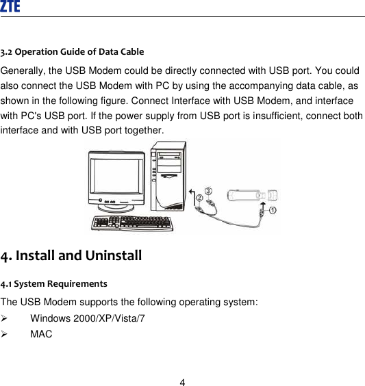
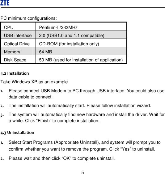
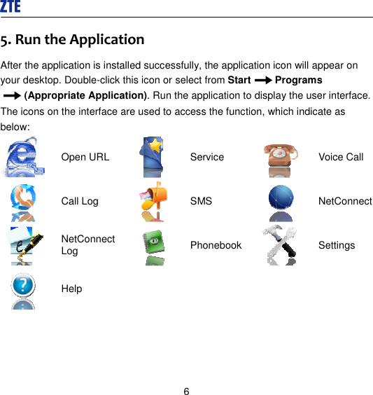
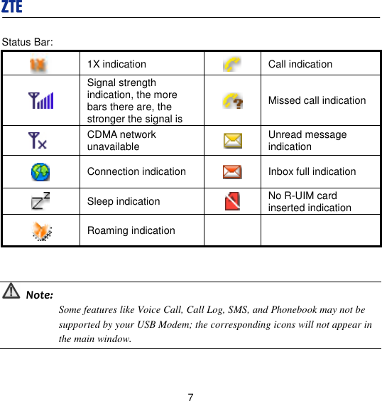
USERS MANUAL
Navigation menu
Upload a User Manual
Namespaces
Wiki Guide
HTML
PDF
Info
Views
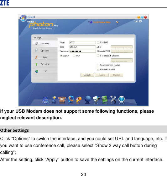
User Manual
Discussion / Help
Navigation