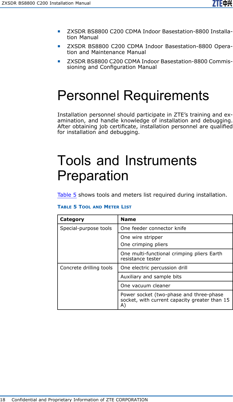
ZTE BS8800C200 CDMA Indoor Base Station User Manual

ZTE Corporation CDMA Indoor Base Station Users Manual

Users Manual

ZXSDRBS8800C200CDMAIndoorBasestation-8800InstallationManualZTECORPORATIONZTEPlaza,KejiRoadSouth,Hi-TechIndustrialPark,NanshanDistrict,Shenzhen,P .R.China518057Tel:(86)75526771900Fax:(86)75526770801URL:http://ensupport.zte.com.cnE-mail:support@zte.com.cn
LEGALINFORMATIONCopyright©2006ZTECORPORATION.Thecontentsofthisdocumentareprotectedbycopyrightlawsandinternationaltreaties.Anyreproductionordistributionofthisdocumentoranyportionofthisdocument,inanyformbyanymeans,withoutthepriorwrittenconsentofZTECORPO-RATIONisprohibited.Additionally,thecontentsofthisdocumentareprotectedbycontractualcondentialityobligations.Allcompany,brandandproductnamesaretradeorservicemarks,orregisteredtradeorservicemarks,ofZTECORPORATIONoroftheirrespectiveowners.Thisdocumentisprovided“asis” ,andallexpress,implied,orstatutorywarranties,representationsorconditionsaredis-claimed,includingwithoutlimitationanyimpliedwarrantyofmerchantability,tnessforaparticularpurpose,titleornon-in-fringement.ZTECORPORATIONanditslicensorsshallnotbeliablefordamagesresultingfromtheuseoforrelianceontheinformationcontainedherein.ZTECORPORATIONoritslicensorsmayhavecurrentorpendingintellectualpropertyrightsorapplicationscoveringthesubjectmatterofthisdocument.ExceptasexpresslyprovidedinanywrittenlicensebetweenZTECORPORATIONanditslicensee,theuserofthisdocumentshallnotacquireanylicensetothesubjectmatterherein.ZTECORPORATIONreservestherighttoupgradeormaketechnicalchangetothisproductwithoutfurthernotice.UsersmayvisitZTEtechnicalsupportwebsitehttp://ensupport.zte.com.cntoinquirerelatedinformation.TheultimaterighttointerpretthisproductresidesinZTECORPORATION.RevisionHistoryRevisionNo.RevisionDateRevisionReasonR1.101/30/2009OptimizeManualR1.009/30/2008FirstEditionSerialNumber:sjzl20083046
ContentsPreface...............................................................iSafetyInstruction.............................................1SafetySpecicationsGuide..............................................1SafetySymbols..............................................................2SafetyInstructions.........................................................3InstallationOverview........................................7Appearance...................................................................7EngineeringIndices........................................................7InstallationFlow.............................................................8InstallationPrecautions...................................................9InstallationPreparation..................................11CabinetInstallationEnvironmentCheck............................11EquipmentRoomSpaceRequirements..........................11EquipmentRoomEnvironmentRequirements................13EquipmentRoomPowerSupplyRequirements...............14LightningandGroundingRequirements........................15TransmissionRequirements.........................................15WiringRequirements..................................................16TechnicalMaterialPreparation.........................................17PersonnelRequirements.................................................18ToolsandInstrumentsPreparation...................................18UnpackingAcceptance....................................................20CountingGoods.........................................................20CrateUnpacking........................................................20CartonUnpacking......................................................21AcceptanceandGoodsHandover.................................22InstallingCabinet............................................23CabinetInstallationFlow................................................23InstallingSingle-cabinet.................................................24InstallingComponents....................................31ModulePositionSchematicDiagram.................................31
InstallingRSUModule....................................................33InstallingBBU...............................................................35InstallingBBUHorizontalModule.....................................37InstallingBBUVerticalModule.........................................38InstallingCable...............................................41On-siteCableInstallationList..........................................41CableInstallationFlow...................................................42InstallingDCPowerCable...............................................43InstallingGroundingCable..............................................46InstallingDataCable......................................................47Installing75ΩE1Cable..................................................49Installing120ΩE1Cable................................................51Installing100ΩT1Cable................................................52InstallingAbisInterfaceEthernetCable............................53InstallingDryContactInput/outputCable.........................55InstallingRS232/RS485MonitoringCable.........................58InstallingFiberbetweenBBUandRSU..............................59InstallingAISGControlCable..........................................59InstallingGPSJumper....................................................61InstallingRFJumper......................................................63InstallingGPSAntennaFeederSystem...........65GPSAntennaFeederSystemInstallationFlow...................65GPSAntennaFeederSystemInstallationPreparation..........66InstallingGPSAntenna...................................................66GPSAntennaInstallationPosition................................66InstallingGPSAntennainVerticalPlacement.................67InstallingGPSAntennainHorizontalPlacement.............69InstallingGPSAntennainWall-mountMode..................71InstallingGPSFeeder.....................................................73GPSFeederSelectionPrinciple....................................73WiringGPSFeeder.....................................................73InstallingGPS1/4”FeederGroundingKit......................75LeadingGPSFeederintoRoom....................................77InstallingMainAntennaFeederSystem..........79AntennaFeederSystemInstallationPreparation................79FoundationalFacilityRequirements..............................79CheckingIncomingMaterial........................................80MakingFeederConnector...........................................81AssemblingOmnidirectionalAntenna............................83AssemblingDirectionalAntenna...................................86
HoistingAntennaandFeeder......................................89InstallingIndoorGroundingBar.......................................90InstallingAntenna.........................................................93InstallingDirectionalAntennaonTop-tower..................93InstallingDirectionalAntennaonRoof........................100InstallingOmnidirectionalAntennaonTop-tower..........111InstallingOmnidirectionalAntennaonRoof.................115InstallingAntennaJumper........................................123InstallingFeederHermetic-window................................125InstallingandGroundingFeederandJumper...................127FeederCuttingPrinciple............................................127FeederLayoutPrinciple............................................128InstallingFeederonTower........................................128InstallingFeederonRoof..........................................130FeederGroundingPrinciple.......................................132InstallingFeederGroundingKit.................................134FeederIndoorIngoing..................................................135FeederIndoorArrangementPrinciple..........................135LeadingMainFeederintoRoom................................136InstallingTop-equipmentJumper...............................138PerformingAntennaFeederSystemTest.........................139PerformingOutdoor-connectorWaterproofProcess-ing....................................................................140PerformingFeederHermetic-windowWaterproofProcessing..........................................................142InstallationCheck.........................................147CheckingEquipmentInstallation....................................147CabinetInspectionItems..........................................147CableCheckItems...................................................147Socket,PlugandLockingPieceInspectionItems..........148LabelInspectionItems.............................................148On-siteEnvironmentInspectionItems........................149CheckingAntennaFeederSystemInstallation..................149CheckingFeeder......................................................149VSWRTest..............................................................150CheckingWater-proofProcessing...............................150CheckingPoweron......................................................151Figures..........................................................153Tables...........................................................157
ListofGlossary..............................................159
PrefacePurposeTheZXSDRBS8800C200isaradiotransceiverdevicetoprovideserviceforacertaincell.TheZXSDRBS8800C200canfulllmostfunctionsconcerningCDMApatenttechnologies.Thepri-maryfunctionsofZXSDRBS8800C200are:basebandmodulationanddemodulation,RFsignaltransmissionanddemodulation,ra-dioresourcesdistribution,callprocessing,powercontrolandsofthandoff.ThismanualprovidesfundamentalinstallationoperationguideforZXSDRBS8800C200hardwareinstallationengineersandatthesametimeactsasareferencematerialforoperationmaintenancepersonnel.IntendedAudienceThisdocumentisintendedforengineersandtechnicianswhoper-forminstallationactivitiesonZXSDRBS8800C200.PrerequisiteSkillandKnowledgeTousethisdocumenteffectively,usersshouldhaveageneralun-derstandingofZXSDRBS8800C200equipmentanditscompo-nents.Familiaritywiththefollowingishelpful:�cdma2000fundamental�ZXSDRBS8800C200hardwarestructureWhatisinthisManualThismanualcontainsthefollowingchapters:ChapterSummaryChapter1SafetyInstructionDescribessafetyprecautionsduringZXSDRBS8800C200installationoroperationmaintenanceaswellasmeaningsofvarioussafetysymbols.Chapter2InstallationOverviewDescribestheZXSDRBS8800C200installationowsandinstallationprecautions.Chapter3InstallationPreparationDescribesinstallationenvironmentinspection,requirementsofinstallationpersonnel,toolsanddocuments,aswellasunpackingandacceptancebeforeinstallation.Chapter4InstallingCabinetDescribesinstallationmodesofZXSDRBS8800C200cabinetandtheinstallationprocess.Chapter5InstallingComponentsDescribesinstallationmethodsofZXSDRBS8800C200modulesandsubrack.Chapter6InstallingCableDescribestheinstallationprocessofcables.ConfidentialandProprietaryInformationofZTECORPORATIONi
ZXSDRBS8800C200InstallationManualChapterSummaryChapter7InstallingGPSAntennaFeederSystemDescribestheinstallationmethodsofGPSantennafeedersystem.Chapter8InstallingMainAntennaFeederSystemDescribestheinstallationmethodsofmainantennafeedersystem.Chapter9InstallationCheckDescribestheinspectionprocessafterinstallationcompletion.iiConfidentialandProprietaryInformationofZTECORPORATION
ZXSDRBS8800C200InstallationManualNote:ZTECorporationdoesnotbearanyliabilitiesincurredbecauseofviolationoftheuniversalsafetyoperationrequirements,orviola-tionofsafetystandardsfordesigning,manufacturingandusingtheequipment.SafetySymbolsTa b l e 1 listssafetysymbols.TheyaretoprompttheuserofthesafetyprecautionstobeobservedduringZXSDRBS8800C200operationandmaintenance.TABLE1SAFETYSYMBOLSDESCRIPTIONSafetySymbolsMeaningNosmoking:SmokingisforbiddenNoflammables:Noflammablescanbestored.Notouching:Donottouch.Universalalertingsymbol:Generalsafetyattentions.Electricshock:Riskofelectricshock.Electrostatic:Thedevicemaybesensitivetostaticelectricity.Microwave:Bewareofstrongelectromagneticfield.Laser:Bewareofstronglaserbeam.Scald:Bewareofscald.Amongstthesesafetysymbols,theuniversalalarmsymbolsareclassiedintothreelevels:danger ,warning,andcaution.Theformatsandmeaningsofthethreelevelsaredescribedasbelow:2ConfidentialandProprietaryInformationofZTECORPORATION
Chapter1SafetyInstructionDanger:Indicatesapotentiallyhazardoussituationwhich,ifnotavoided,willresultindeathorseriousinjuryofpeople,orequipmentdam-agesandbreakdown.Warning:Indicatesapotentiallyhazardoussituationwhich,ifnotavoided,couldresultindeathorseriousinjury.Caution:Indicatesapotentiallyhazardoussituationwhich,ifnotavoided,couldresultinseriousinjuries,equipmentdamagesorinterruptionofpartservices.SafetyInstructionsThissectiondescribesthesafetyinstructionsrelatedtoelectricalsafety,antistatic,heavyobjectsandmodules.ElectricalSafetyInstructionsThefollowingaretheelectricalsafetyinstructionsabouttools,highvoltage,powercables,holesandlightning:�ToolsUsespecialtoolsratherthancommontoolsforhigh-voltageandACoperations.�HighVoltageDanger:Highvoltageishazardous.Directorindirectcontactwithhighvoltageormainsupplyusingawetobjectcouldresultindeath.�StrictlyfollowlocalsafetyrulestoinstallACpowerequip-ments.�Installationstaffmustbequaliedforperforminghigh-volt-ageandACoperations.�Donotwearanywatch,handchain,bracelet,ringoranyotherconductiveobjectduringsuchoperations.�Preventmoisturefromaccumulatingontheequipmentdur-ingoperationsinadampenvironment.�PowerCableConfidentialandProprietaryInformationofZTECORPORATION3
ZXSDRBS8800C200InstallationManualWarning:Neverinstalloruninstallpowercableswhiletheyarelive.Oth-erwise,thepowercable,whencontactingaconductor ,mayre-sultinsparksorelectricarccausingareorevendamagetoeyes.�Makesuretoshutoffpowersupplybeforeinstallingordis-connectingapowercable.�Beforeconnectingthepowercable,makesurethatthecon-nectingcableanditslabelisappropriatefortheactualin-stallationrequirements.�DrillingHolesWarning:Itisnotallowedtodrillcabinetholeswithoutpermission.�Unqualieddrillingcoulddamagewiringandcablesinsidethecabinet.Additionally,metalpiecesinsidethecabinetcreatedbythedrillingcouldresultinashortcircuit.Useinsulationprotectionglovesandrstmovecablesinsideacabinetawaywhendrillingisnecessaryonacabinet.�Protecteyesduringdrillingasdustoryingdebrismaydamageeyes.�Cleananydebrisintimeafterdrilling.�LightningDanger:Donotperformhigh-voltage,AC,irontowerormastoperationsinathunderstorm.Thunderstormswouldgiverisetoastrongelectromagneticeldintheatmosphere.Therefore,theequipmentmustbegroundedandprotectedintimeagainstlightningstrikes.AntistaticSafetyInstructionsElectrostatic:Staticelectricityproducedbyhumanbodycandamagestatic-sen-sitivecomponentsoncircuitboard,suchaslarge-scaleintegratedcircuits.�Frictioncausedbyhumanbodyactivitiesistherootcauseofelectrostaticchargeaccumulation.Staticvoltagecarriedbyahumanbodyinadryenvironmentcanbeupto30kV ,andcanremaininthereforalongtime.Anoperatorwithstaticelectricitymaydischargeelectricitythroughacomponentwhenhe/shetouchestheconductorandcausingdamage.4ConfidentialandProprietaryInformationofZTECORPORATION
Chapter1SafetyInstruction�Wearanantistaticwriststrap(theotherendofwriststrapmustbewellgrounded)beforetouchingtheequipmentorholdingaplug-inboard,circuitboard,IntegratedCircuit(IC)chiporotherdevices,topreventhumanstaticelectricityfromdamag-ingsensitivecomponents.�Aresistorover1MΩshouldbeconnectedinseriesonthecablebetweentheantistaticwriststrapandthegroundingpoint,toprotecttheoperatoragainstaccidentalelectricshock.Resis-tanceover1MΩislowenoughtodischargestaticvoltage.�Theantistaticwriststrapusedmustbesubjecttoregularcheck.Donotreplacethecableofanantistaticwriststrapwithanyothercable.�Donotcontactstatic-sensitivemoduleswithanyobjectthateasilygeneratesstaticelectricity.Forexample,frictionofpack-agebag,transferboxandtransferbeltmadefrominsulationplasticmaycausestaticelectricityoncomponents.Dischargeofstaticelectricitymaydamagecomponentswhentheycon-tactahumanbodyortheground.�Modulesshouldonlycontactmaterialssuchasantistaticbag.Keepmodulesinantistaticbagsduringstorageandtransporta-tion.�Dischargestaticelectricityofthetestdevicebeforeuse,thatis,groundthetestdevicerst.�DonotplacethemodulenearastrongDCmagneticeld,suchasthecathode-raytubeofamonitor .Keepthemoduleatleast10cmaway.HoistingHeavyObjectsWarning:Whenhoistingheavyobjects,ensurethatnobodyisstandingorwalkingunderthehoistedobject.�Ensurethehoistercanmeethoistingrequirementswhendis-assemblingheavyequipment,ormovingandreplacingequip-ment.�Theinstallationpersonnelmustbedulytrainedandqualiedforhoistingoperations.�Hoistingtoolsmustbeinspectedandcompletebeforeservice.�Makesurethathoistingtoolsarexedrmlyonasufcientlysecuredobjectorwallbeforethehoistingoperation.�Givebrieforalinstructionsduringhoistingoperationstopre-ventanymishap.Unplugging/Plug-gingaModule�Neverplugamodulewithexcessiveforce,toensurethatthepinsonthebackplanedonotgetdeformed.�Plugthemodulerightintotheslotandmakesuremodulecir-cuitfacesdonotcontacteachotherlestanyshortcircuitmayoccur .�Keephandsoffthemodulecircuit,components,connectorsandcabletroughwhenholdingamodule.ConfidentialandProprietaryInformationofZTECORPORATION5
ZXSDRBS8800C200InstallationManualOtherSafetyInstructionsNote:Donotperformmaintenanceordebuggingindependently,unlessaqualiedpersonispresent.�Replacinganypartsormakinganychangestotheequipmentmightresultinanunexpecteddanger .Therefore,besurenottoreplaceanypartsorperformanychangestotheequipmentunlessauthorizedotherwise.�DuetothatRRUisinhightemperatureduringrunning,theRRUshouldbeinstalledinsomeregionsoutofoperators’reachorstrictlyrestricted.�DuetothatRRUisinhightemperatureduringrunning,theRRUshouldbeinstalledinsomeregionsoutofoperators’reachorstrictlyrestricted.�ContactZTEofceifyouhaveanyquestion,toensureyoursafety.6ConfidentialandProprietaryInformationofZTECORPORATION
C h a p t e r 2InstallationOverviewTableofContents:Appearance.......................................................................7EngineeringIndices............................................................7InstallationFlow.................................................................8InstallationPrecautions.......................................................9AppearanceFi g u r e 1 showstheappearanceofZXSDRBS8800C100.FIGURE1ZXSDRBS8800C200APPEARANCEEngineeringIndicesTa b l e 2 liststheengineeringindicesofZXSDRBS8800C200.ConfidentialandProprietaryInformationofZTECORPORATION7
ZXSDRBS8800C200InstallationManualTABLE2ZXSDRBS8800C200ENGINEERINGINDICESItemIndexDimension950mm×600mm×450mm(height×width×depth)Weight<200kgPowerSupply-48VDC:-40V~-57VWorkingTemperature-40℃to55℃(-40℉to131℉)OverallPowerConsumption<3000W(fullconfiguration)WorkingHumidity5%RH~95%RHGrounding<5ΩInstallationFlowTheZXSDRBS8800C200installationowislistedinFi g u r e 2 .8ConfidentialandProprietaryInformationofZTECORPORATION
Chapter2InstallationOverviewFIGURE2INSTALLATIONFLOWInstallationPrecautionsWarning:Nonprofessionalpersonnelprohibitsinstallinganddebuggingde-vicesalone,exceptwithguideofprofessionalpersonnel.�Readthismanualaswellascorrespondingmanualscarefullybeforeinstallationandperforminstallationaccordingtothein-stallationowandspecicationsinthismanual.�ZXSDRBS8800C200hardwareinstallationpersonnelmustparticipateinsometrainingrelatedtocommunicationequip-mentinstallationandownskilledinstallationtechnique.�Duringinstallation,ensurepersonalsafetyandavoidaccidentssuchaselectricshockorbruise.ConfidentialandProprietaryInformationofZTECORPORATION9
ZXSDRBS8800C200InstallationManual�Duringinstallationintheequipmentroom,installationper-sonnelshouldwearinsulationshoesandtakeoffnecklaces,braceletsandwatches.�Duringinsertingandextractingboards,installationpersonnelshouldwearantistaticwriststrapsandmakesuretheotherendofitgrounding.�Duringinstallationandmaintenanceofopticalber ,prohibitdirectlystaringatasectionofopticalberorasocketofopticalterminalincasethatlaserbeamsdamageeyes.�Insertboardsalongslots,avoidcontactbetweenparalleledboardscausingshortcircuit.Makeproperforceincaseofpinsdistorted.�Takeholdoftheedgeofboardsandnottouchthecircuit,com-ponentsandwires.�Replacingcomponentsormodifyingdevicesmaybringextrarisks.Withoutauthorization,prohibitreplacingormodifyingdevices.10ConfidentialandProprietaryInformationofZTECORPORATION
C h a p t e r 3InstallationPreparationTableofContents:CabinetInstallationEnvironmentCheck................................11TechnicalMaterialPreparation.............................................17PersonnelRequirements.....................................................18ToolsandInstrumentsPreparation.......................................18UnpackingAcceptance........................................................20CabinetInstallationEnvironmentCheckEquipmentRoomSpaceRequirementsTheminimuminstallationspaceofcabinetisrequiredasshowninFi g u r e 3 .ConfidentialandProprietaryInformationofZTECORPORATION11
ZXSDRBS8800C200InstallationManualFIGURE3INSTALLATIONSPACEREQUIREMENTThedetailedrequirementsisasfollows:�Thisequipmentcanbeinstalledalongsideawallandperformmaintenanceforallboardsundertheconditionthatthebackdoorisclosed;keepthecabinetadistanceofmorethan100mmfromthewall.�Whenthereareotherequipmentatbothsidesoftheequip-ment,makeitabuttingagainstotherequipment;whentherearewallsatbothsidesoftheequipment,keepadistanceofmorethan100mmfromthebothwalls.�Keepamorethan800mmspacefromthefaceofequipment.12ConfidentialandProprietaryInformationofZTECORPORATION
Chapter3InstallationPreparationEquipmentRoomEnvironmentRequirementsEquipmentRoomLayoutRequirementsThelayoutofequipmentroomincludescabletraylayoutandcabi-netlayout.Accordingtotheengineeringdesigndrawing,installa-tionpersonnelshouldmarkandlocatebasedonequipmentroomspaceandcabinetdimension.Thedirectionfromfeedertocabinetshouldbeconsideredenoughduringcabinetlayout.Thefeedershouldbeshortaspossibleasitcan,andthebendingradiusoffeedershouldbenottoosmall.Iftwocabinetsormorearerequired,themaincabinetshouldbeputinthemiddleofallcabinets.Cabinetlayoutadoptingarowormulti-rows(putinthesameequipmentroomwithBSCorMSC)isdeterminedbythesizeofequipmentroomandcabinetquantity.Inordertobeconvenientforoperation,suggestthatcabinetlayoutshouldmeetthefollowingrequirements:�Thedistancefromcabinettowallshouldbemorethan10cm.�Arowofcabinetskeeps1mdistanceatleastfromanotherneighboringrowofcabinets.�Whenmultiplecabinetsareputsidebyside,thesecabinetsshouldkeepinline.�Thefaceofcabinetkeeps1mdistanceatleastfromanob-struction.EquipmentRoomBuildingTheengineeringforequipmentroommustmeetthefollowingre-quirements:�Theleveloordifferencepersquaremeterisnotmorethan2mm.�Theoor ,wall,ceiling,reservedinstallationholesandgroovesofequipmentroomshouldaccordwiththedesignrequire-ments.�Preventwaterontheoutdooroorintotheindooroorwhilein-stallationholespassesanoutdoorwall.T akemeasuresagainstdampnessforthegrooves.�Selectsomematerialwhichisdifculttodeformandcrackforhiddenpipes,holesandslotsbetweencoverplates.�Prepareatemporaryroomtostoreinstallationmaterialsanddevices.ConfidentialandProprietaryInformationofZTECORPORATION13
ZXSDRBS8800C200InstallationManualNote:High-voltagepowerwire,strongmagneticled,strongelectricalsparkaswellasotherfactorsbringingdangerforequipmentroommustbeawayfromtheequipmentroom.TemperatureandHumidityTheair-conditiondevicesshouldmeetthefollowingconditions:�EnvironmentT emperature:-5℃~+45℃(Suggestmaintain-ingtheenvironmenttemperaturebetween15℃and30℃).�RelativeHumidity:15%~90%(Suggestmaintainingtherela-tivehumiditybetween15%and90%).NoiseConsideringmaintenancepersonnel’sphysicalandmentalhealth,noiseintheequipmentroomshouldbelowerthan70dB.FireProtectionThereprotectionconditionsofequipmentroommustmeet:�Theindoorwallshouldmaintaindryness,andthewallsurfaceandceilingarecoatedwithwhitenoncombustiblelusterlesspaintorotherame-retardantmaterials.�Prohibitstoringammableandexplosivesubstancesandequipnecessaryreprotectiondevices.DustproofThedustproofrequirementsofequipmentroomshouldmeetthefollowing:�Alldoorsandwindowsshouldbeclosed.�Ventilationpipelinesintheequipmentroomshouldbecleaned,andairconditiondevicesshouldbeinstalledwithdustscreens.�HolesCommunicatingbetweenequipmentroomsandpassageforcablelayoutshouldbeclosedtodecreasedustowbetweenrooms.LightingThelightingconditionsofequipmentroomshouldreachthere-quirementsofequipmentmaintenance.Dailylighting,standbylightingandemergencylightingsystemsshouldbeprepared.WaterSupplyandDrainingPipelinesofwaresupply,drainingandreprotectionshouldnotbeequippedinsidetheequipmentroom.EquipmentRoomPowerSupplyRequirementsThepowersupplyofequipmentroommustmeetthefollowingre-quirements:�Equipadieselenginetoprovidestandbypower .TheACpowerisresponsibleforpowersupplyalone.Thevoltagerange:380V±10%;220V±10%.�ThesupplypowervoltageofDCdistributiondeviceshouldbestableandthenominalvalueis-48V(-57V~-40V).�Thebatterycapacityshouldbeadequate.14ConfidentialandProprietaryInformationofZTECORPORATION
Chapter3InstallationPreparation�Differentpowersocketsintheequipmentroomshouldhaveobviousmarks.Thepowerelectricityshouldbedistinguishedfromthelightingelectricityobviously.�Whenthephenomenaofpowerundercurrent,under-voltageandover-voltageoccur ,thereshouldbesound-and-lightalarms.�Whileusing220Vor380VACvoltage,paygreatattentionincaseofelectricshock.�WhileinstallingDCpower ,makesurepowerpolaritiesconsis-tent.ElectricShock:Whilecheckingpowers,examinethecurrentstatusofallswitchesandwatchoutelectricshock.LightningandGroundingRequirementsThelightningandgroundingintheequipmentroomshouldmeetthefollowingrequirements:�Thegroundingresistanceisnotmorethan5Ω.�Theindoorgroundingsystemconnectsdirectlywithaground-ingbar .Alldevicegroundingconnectstothisgroundingbar .Andthenthegroundingbarconnectswiththeprimaryground-ingbarofthebuilding.TransmissionRequirementsTheexternalinterfacesofZXSDRBS8800C200locateontheRSUmodulesandBBUsubsystem,referringtoTa b l e 3 .TABLE3ZXSDRBS8800C200EXTERNALINTERFACEINDEXDESCRIPTIONTransmissionCategoryModuleInterfaceNameConnectorDescriptionE1/T1SA-datacableB2interfaceDB44ConnectstheZXSDRBS8800C200withtheBSC;E1provides75Ωand120Ωloadinterfaces;T1provides100Ωloadinterface.ConfidentialandProprietaryInformationofZTECORPORATION15
ZXSDRBS8800C200InstallationManualTransmissionCategoryModuleInterfaceNameConnectorDescriptionETH0RJ45ConnectstheZXSDRBS8800C200withtheBSC.EthernetcableCCETH1RJ45ConnectstheZXSDRBS8800C200andPCforLMTmaintenance.RS232/RS485monitoringcableSA-datacableB4DB9ProvidesinternalandexternalenvironmentmonitoringforZXSDRBS8800C200.DrycontactcableSA-datacableB3DB25Importdrycontactsignalfromexternaldevices;Exportdrycontactsignalfromthisdevice.AISGcontrolcableRSUAISGDB9Controlselectricaladjustmentantenna.GPSjumperCCANTSMAImportsatellitesignalintothecabinet.WiringRequirementsWiringRequirements�Beforelayoutofpowercableandprotectivegroundcable,wrapcableconnectorswellwithinsulationadhesivetape.�Thepowercableandprotectivegroundcableshouldbesepa-ratefromthesignalcable.�Whenthepowercableandprotectivegroundcableareparallelwiththesignalcable,thedistancefromthesignalcablekeeps10mmatleastinsidethecabinetand100mmatleastoutsidethecabinet.�Ifthesignalcableiscrossedwiththepowercable,thecrossedanglemustbe90°.�Attheturningofcable,thebendingradiusshouldbemorethanvetimesofthecablediameter .�Whenthepowercableconnectstoaconnectingterminalofdistributionpowerboxinsidethecabinet,thewiringshouldbestraightandtheradianofturningshouldbesmooth.�Theactualinstallationpositionofcablesshouldbeconsistentwithrequirementsofengineeringsurveyanddatacongura-tion.�Theroutofcablelayoutshouldbeclearandreasonable,ac-cordingtotheengineeringdesigndrawing.�Thelayoutofsignalcableshouldbeorderly,smoothandnon-crossed.�Thelayoutofcablesshouldbeconvenientformaintenanceandcapacityexpansion.16ConfidentialandProprietaryInformationofZTECORPORATION
Chapter3InstallationPreparation�。Beforefeederlayout,learnofthewiringrouteanddrawapracticalwiringrouteonthepaperincasefeedercrossed�Theminimumbendingradiumoffeederisnotlessthan20timesofthefeederradium.�TherequirementsoffeederbendingradiumareasshowninTa b l e 4 .TABLE4BENDINGRADIUMREQUIREMENTSTheMinimumBendingRadius(recommended) FeederBendingBendingforOnceConsecutiveBending(<=15times)Super–soft1/2"Feeder15cm30cm1/2"Feeder50cm125cm7/8"Feeder90cm250cm5/4"Feeder150cm380cmBindingRequirements�Thebindingtapeisboundneatlyandproperly,andthespacesbetweenwirefastenersanddirectionsoffastenerskeepcon-sistent.�Cutredundantbindingtapeandmakeitatandtidy.�Thepowercableandprotectivegroundcableareboundsepa-ratelyfromthesignalcable.�Thecablesinsidethecabinetisboundontoawirebushing.�Whilelayingoutcablesalongthecabletray,thecableshouldbeboundtogetherclose.�Remainproperlengthincableforinsertingandextractingcon-nectors.TechnicalMaterialPreparationItisnecessarytopreparethefollowingtechnicalmaterialforZXSDRBS8800C200installation:�ZXSDRBS8800C200CDMAIndoorBasestation-8800Engi-neeringSurveyReport�ZXSDRBS8800C200CDMAIndoorBasestation-8800Environ-mentAcceptanceReportZXSDRBS8800C200kitmaterialsinclude:�ZXSDRBS8800C200CDMAIndoorBasestation-8800TechnicalManual�ZXSDRBS8800C200CDMAIndoorBasestation-8800Hard-wareManualConfidentialandProprietaryInformationofZTECORPORATION17
ZXSDRBS8800C200InstallationManual�ZXSDRBS8800C200CDMAIndoorBasestation-8800Installa-tionManual�ZXSDRBS8800C200CDMAIndoorBasestation-8800Opera-tionandMaintenanceManual�ZXSDRBS8800C200CDMAIndoorBasestation-8800Commis-sioningandCongurationManualPersonnelRequirementsInstallationpersonnelshouldparticipateinZTE’strainingandex-amination,andhandleknowledgeofinstallationanddebugging.Afterobtainingjobcerticate,installationpersonnelarequaliedforinstallationanddebugging.ToolsandInstrumentsPreparationTa b l e 5 showstoolsandmeterslistrequiredduringinstallation.TABLE5TOOLANDMETERLISTCategoryNameOnefeederconnectorknifeOnewirestripperOnecrimpingpliersSpecial-purposetoolsOnemulti-functionalcrimpingpliersEarthresistancetesterOneelectricpercussiondrillAuxiliaryandsamplebitsOnevacuumcleanerConcretedrillingtoolsPowersocket(two-phaseandthree-phasesocket,withcurrentcapacitygreaterthan15A)18ConfidentialandProprietaryInformationofZTECORPORATION
Chapter3InstallationPreparationCategoryNameCrossscrewdrivers(4”,6”and8”each)Flatheadscrewdrivers(4,6”and8”each)Adjustablewrenches(6” ,8”,10”and12)Dual-purposespanners(17”and19”each)Onesetofsocketwrench5kg(11lb)nailhammerOne300WironOne40WironSolderwiresHotblowerOilpaintbrushPliersScissorGeneral-purposetoolsPaperknifeOne50m(164feet)tapemeasureOne5m(16feet)steeltapeOne400mm(16inches)levelbarOneanglemeterOnecompassMeasurementtoolsPlumbAntistaticwriststrapSafetyhelmetProtectiontoolsPairofglovesOnehacksaw(withseveralsawblades)Onepairofsharp-nosepliers(8″)Onepairofdiagonalpliers(8″)Onepairofslipjointpliers(8″)Onepairofvices(8″)ClamptoolsCrowbarChainwheelRopeLadderAuxiliarytoolsForkliftConfidentialandProprietaryInformationofZTECORPORATION19
ZXSDRBS8800C200InstallationManualUnpackingAcceptanceCountingGoodsPrerequisiteThetransportedcargoshouldhavereachedtheinstallationsite.ContextTherepresentativeofcustomerandtheprojectsupervisormustbepresentonsiteduringcountingofgoodsreceived.Ifanypartyisnotpresentatthattime,transportermustholdtheresponsibilityforanydifferenceingoods.Thestepsinvolvedincountinggoodsareasfollows:Steps1.CheckDeliveryChecklistofZTECorporation.Checktotalnum-berofgoods,intactnessofpackingboxes,andcheckwhetherarrivalplaceistheactualinstallationplaceagainstpackinglistnumberattachedtopackingboxes.Ifgoodsareintact,starttounpackandinspectthem.Note:Itisrecommendedtounpackthegoodsafterabout30minutesofreceivingthecargo,sincethereisapossibilityofmoisturecontentduetotemperaturevariationsifany.2.Equipmentinspectionlistandunpackingacceptancereportarepresentintherstpackingcarton.Firstly,openrstpackingcartonandtakeouttheUnpackingAcceptanceReporttocheckwhetherthegoodsreceivedareinaccordancewiththeinspec-tionlist.3.Duringthecountingandunpackinginspectionprocess,ifanymaterialisfoundshort,orgoodsdamaged,thenll-inUnpack-ingAcceptanceFeedbackTableandcontactZTEpromptly.ENDOFSTEPS.CrateUnpackingPrerequisitePreparetheappropriatetoolssuchasstraightscrewdriver ,pliers,andcrowbar .ContextPerformthefollowingstepstoopenthecrate:Steps1.Insertastraightscrewdriverintotheslitbetweencrateandfrontcoverboardtomakeitloose;theninsertcrowbartoun-clenchcoverboard.2.Pullthecoverboardoutfromthecrate.3.Removetheotherboardsofthecrate,asshowninFi g u r e 4 .20ConfidentialandProprietaryInformationofZTECORPORATION
Chapter3InstallationPreparationFIGURE4CRATEUNPACKING1.Accessories2.Coverplate3.Equipment4.Foampiece5.CrateENDOFSTEPS.CartonUnpackingPrerequisitePreparetheappropriatetoolssuchasstraightscrewdriver ,diago-nalpliers,andpaperknife.ContextPerformthefollowingstepstounpackthecarton:Steps1.Usediagonalplierstocutpackingstraps.2.Useapaperknifetocutadhesivetapealongtheslitsoncartoncover ,avoiddamaginggoodsinside.3.Openthecarton,andremovethefoamboard.ConfidentialandProprietaryInformationofZTECORPORATION21
ZXSDRBS8800C200InstallationManual4.Checkthegoodswithinthecarton.Note:�Avoiddamagingtheantistaticbag(Itcanbeusedinthefutureforstorageofspareparts)duringunpacking.�Whiletheequipmentismovedtoahotteranddamperplace,waitfor30minutesbeforeunpackingtheequipment.Otherwise,moisturemaycondenseonthesurfaceoftheequipmentandcausedamage.�Properlydisposeofrecycledesiccants.ENDOFSTEPS.AcceptanceandGoodsHandoverContextPerformthisprocedureforacceptinggoods,andhandingthemovertooperators.Steps1.AcceptanceBaseduponthename,categoryandnumbermentionedontheshippinglist,carefullycheckthegoodspiecebypiece.Makesurethatgoodsfullthefollowingconditions:i.Makesurethattherearenobubbly,peeling,nickandlthmarkonthesurfaceofthechassis.ii.Ensurethatoilpaintonthechassissurfaceisintact.iii.Ensureclampingscrewsaretightandintact.iv.Allthecomponentsareproperlyinstalledattheirrespectivepositions.v.Laydowntheinspectedgoodsaccordingtocategories.2.HandoverAftercompletingtheunpackingprocedure,representativeofcustomerandprojectsupervisorshouldapproveandsignUn-packingforInspectionReport.EachpartyshouldhaveacopyofUnpackingforInspectionReport.Ifthegoodsarestillun-derthesupervisionoftheoperatorevenafteracceptance,thengoodswillnotbehandedovertotheoperatoruntilbothpartiessignonthereport.ENDOFSTEPS.22ConfidentialandProprietaryInformationofZTECORPORATION
C h a p t e r 4InstallingCabinetTableofContents:CabinetInstallationFlow....................................................23InstallingSingle-cabinet.....................................................24CabinetInstallationFlowZXSDRBS8800C200cabinetinstallationowislistedinFi g u r e 5 .ConfidentialandProprietaryInformationofZTECORPORATION23
ZXSDRBS8800C200InstallationManualFIGURE5CABINETINSTALLATIONFLOWInstallingSingle-cabinetSteps1.Conrmtheinstallationpositionofcabinetbasedontheref-erencedimensionandcabinetdimensiongivenbytheengi-neeringdesigndrawing.Measuresomemarkingpointswithameasuringtapeanddrawtwostraightlinesparalleledwiththereferencelinewithaninkingpot.Makesuretheholepositionsforcabinetinstallationonthestraightlinesaccordingtothedesigndrawing.Thepositionofsingle-cabinetisasshowninFi g u r e 6 .24ConfidentialandProprietaryInformationofZTECORPORATION
Chapter4InstallingCabinetFIGURE6SINGLE-CABINETINSTALLATIONPOSITION2.Drillsomeφ12holeswith60mmdepthbasedontheexpansionboltmarks,asshowninFi g u r e 7 .FIGURE7HOLINGNote:�Whileusingahammerdrilloranelectrichammer ,makesurethedrillbitverticalwiththehorizontalground,claspthedrillstockwithhandsandpressitverticallydownwards.�Whileholing,useacleanertocleandustandmakesurecleanoutallgarbageafterconstruction.�Ifthedrillbitisunabletoxduetotoosmoothoor ,inordertohelppositioningdrillbit,rstcutaholeonthemarkedpositionswithapunch.3.Installexpansionnuts.i.Beforeinstallation,usethecleanertogetridofalldustinsideandoutsideholes.ConfidentialandProprietaryInformationofZTECORPORATION25
ZXSDRBS8800C200InstallationManualii.Installfourinsulationsleevesontheinstallationholestomakesuretheexpansionnutsinsulatedwiththeground,asshowninFi g u r e 8 .FIGURE8INSULATIONSLEEVEINSTALLATIONiii.Inserttheexpansionnutsverticallyintotheinsulationsleeves,andknockthenutswitharubberhammertomakethemcompletelyintotheground,asshowninFi g u r e9.FIGURE9EXPANSIONNUTINSTALLATION4.Adjustaninsulationsheetandaligntwoholesontheinsulationsheetwiththoseontheground,asshowninFi g u r e 1 0 .FIGURE10INSULATIONSHEETINSTALLATION26ConfidentialandProprietaryInformationofZTECORPORATION
Chapter4InstallingCabinet5.Aligninstallationholesonthebaseinstallationassemblywithholesofexpansionnuts.InserttheM10boltthroughabigwasher ,insulationwasher ,installationholeofbaseinstallationassemblyandinsulationwasherinturn.Screwdowntheboltsandxtheinstallationassemblyonthecementoor ,asshowninFi g u r e 1 1 andF i g u r e 1 2 .FIGURE11BASEINSTALLATIONASSEMBLY(1)FIGURE12BASEINSTALLATIONASSEMBLY(2)6.Implementaninsulationtest.i.Adjustthemultimetertotheresistancegrade.ii.Forresistancemeasurement,onemeasuringprobeofthemultimetercontactswiththemetalpartofbaseassemblyandtheotherwiththeexpansionnuts.Ifthecircuitdis-ConfidentialandProprietaryInformationofZTECORPORATION27
ZXSDRBS8800C200InstallationManualplaysanopenstatus,theinsulationtestcompletes.Ifnot,continuethenext.iii.Checkwhethertheinsulationsleevesaredamagedorfor-gottentoinstall.Suchasthissituation,repeattheaboveow(installthebaseassembly)andperformaninsulationtestagain.7.Fixthecabinet.i.Movethecabinettothefrontofbaseassemblyandthebackofcabinetfacestothebaseassembly.Note:Consideringtheweightofcabinet,thetopofcabinetpro-videsliftingeyesandsuggestahoistinginstallationmode.ii.Alignthelocationholesatthebottomofcabinetwiththeorientationpinboltsonthebaseassembly,andmovethecabinetslowlyandcarefullytomaketwoanglesupportsinsertingtheslotsatthebottomofcabinet,asshowninFi g u r e 1 3 .FIGURE13FIXINGCABINET(1)1.LocationHole2.OrientationPinBolt3.AngleSupport28ConfidentialandProprietaryInformationofZTECORPORATION
Chapter4InstallingCabinetCaution:Prohibitdrillingholeonthecabinetbyself.Drillingholethatdoesnotmeetrequirementswilldamagethecablesandcableconnectioninsidethecabinet.Themetaldustcausedbydrillingwillresultinshortcircuit.iii.Measurewhetherthecabinetislevelwithalevelbar .Ifnot,addalevellingsheetunderthecabinettoadjusttolevel.iv.Openthefrontdoorofcabinetanddisplaytwocircularholesatthebottom,asshowninFi g u r e 1 4 .InserttheM10boltthroughawasher ,insulationwasherandovalhole,andscrewdownthebolt.FIGURE14FIXINGCABINET(2)1.CircularHoleNote:Theinsulationwasherhasbeenrivetedatthebottomofcabinet.8.AccordingtoStep6,performasolutiontestformetalcompo-nentsatthefrontofcabinet.9.Closethefrontdoorandxthecabinet,asshowninFi g u r e 1 5 .ConfidentialandProprietaryInformationofZTECORPORATION29
ZXSDRBS8800C200InstallationManualFIGURE15CABINETINSTALLATIONCOMPLETIONENDOFSTEPS.30ConfidentialandProprietaryInformationofZTECORPORATION
C h a p t e r 5InstallingComponentsTableofContents:ModulePositionSchematicDiagram.....................................31InstallingRSUModule........................................................33InstallingBBU...................................................................35InstallingBBUHorizontalModule.........................................37InstallingBBUVerticalModule.............................................38ModulePositionSchematicDiagramZXSDRBS8800C200BasebandThemainmodulesofZXSDRBS8800C200areinstalledintheRFlayerandbasebandlayer .TheinternalstructureisasshowninConfidentialandProprietaryInformationofZTECORPORATION31
ZXSDRBS8800C200InstallationManualandRFCabinetInternalStructureFi g u r e 1 6 .FIGURE16BASEBAND-RFCABINETINTERNALSTRUCTURE1.RFSubrack2.CableTray3.PowerDistributionSubrack4.FanSubrack5.Wind-guidePlace6.BasebandSubrackRFModuleLayoutTheRFmodulesareconguredintherstsubrack,asshowninFi g u r e 1 7 .32ConfidentialandProprietaryInformationofZTECORPORATION
Chapter5InstallingComponentsFIGURE17RFSUBRACKAPPEARANCE1.RFUnitSixRSUmulti-carrierRFunitscanbeconguredinSlot1~Slot6.BasebandMoudleLayoutZXSDRBS8800C200basebandsubrackisasshowninFi g u r e 1 8 .FIGURE18BASEBANDSUBRACKAPPEARANCE1.PM2.FS3.CC4.SA5.CHV6.FA7.CHDInstallingRSUModulePrerequisite�InstalltheZXSDRBS8800C200cabinetcompletely.�WearanantistaticwriststraptoavoiddamagingtheRSU.Steps1.Conrmslotsofmoduletobeinstalled.2.HoldpartofametalpanelwiththerighthandandsupportthelowerpartofRSUwiththelefthand.Inthisway,keepthemetalpanelerect.3.Pushthemodulegentlyintoaslotalongaguideway,keepiterectandlocateupperandlowerendsintotheslots.4.Holdthemoduleatmiddleandpushitslowlyonce2/3rdofboardisinserted.Whenthemoduletouchestoabackplanesocket,pushitlittleforciblyandmakeitintothesocketofbackplane.ConfidentialandProprietaryInformationofZTECORPORATION33
ZXSDRBS8800C200InstallationManual5.ScrewdownsixM5X20panheadassemblyscrewsontheRFmodule.ThepositionsofsixscrewsareasshowninFi g u r e 1 9 .FIGURE19SCREWPOSITIONSONRFMODULE1.M5X20panheadassemblyscrew6.ScrewdownallscrewsasshowninFi g u r e 2 0 andconnecttheRSUgroundingsheet.34ConfidentialandProprietaryInformationofZTECORPORATION
Chapter5InstallingComponentsFIGURE20SCREWPOSITION1.M5*10panheadscrewwithcrossrecessedENDOFSTEPS.InstallingBBUPrerequisite�InstalltheZXSDRBS8800C200cabinet.�WearanantistaticwriststraptoavoiddamagingtheBBU.Steps1.InsertthemoduleintotheZXSDRBS8800C200cabinetalongtheguidewayandxitwithfourM5×16combinedscrews(tworespectivelyatleftandright),asshowninFi g u r e 2 1 .ConfidentialandProprietaryInformationofZTECORPORATION35
ZXSDRBS8800C200InstallationManualFIGURE21BBUINSTALLATION1.M5×16screw2.ConnectthegroundinglugofBBUtothecabinetwithaM6×16screw.ThepositionofM6×16screwisasshowninFi g u r e 2 2 .FIGURE22M6×16SCREWPOSITION1.Groundinglug2.M6×16screw36ConfidentialandProprietaryInformationofZTECORPORATION
Chapter5InstallingComponentsENDOFSTEPS.InstallingBBUHorizontalModulePrerequisiteBeforeinstallation,makesurewearinganantistaticwriststraptoavoiddamagingthePCBboard.ContextThehorizontalmodulesofZXSDRBS8800C200includeasfollows:�Controlandclockmodule(CC)�Channelmodule(CH)�Fabricswitchmodule(FS)�Sitealarmmodule(SA)�Powermodule(PM)Steps1.InsertthemodulesintotheZXSDRBS8800C200subrackalongtheleftandrightguideways,asshowninFi g u r e 2 3 .FIGURE23HORIZONTALMODULEINSTALLATION1.HorizontalInsertionandEx-tractionHandleConfidentialandProprietaryInformationofZTECORPORATION37
ZXSDRBS8800C200InstallationManual2.HoldhandlesatbothsidesofsubracktopushintothemoduleandmakesurethehandlelockedwiththeZXSDRBS8800C200subrack.ENDOFSTEPS.InstallingBBUVerticalModulePrerequisiteMakesurewearinganantistaticwristwrapincaseofdamagingthePCBboard.ContextTheZXSDRBS8800C200verticalmodulesincludethefanarray(FA)anddustproofassembly.Steps1.FastentheFAmodulewiththefourself-clinchingboltslocatingatthebottomplateofthefansubrackwithM3×8combinationscrews.2.InsertthedustproofassemblyalongtherightguidewayofFAsubrackandmakesurethatthespringplateontheFAsubrackisfastenedwiththedustproofassembly,asshowninFi g u r e24.FIGURE24DUSTPROOFASSEMBLYINSTALLATION38ConfidentialandProprietaryInformationofZTECORPORATION
Chapter5InstallingComponents3.PushtheequippedFAsubrackanddustproofassemblyintotheZXSDRBS8800C200untilhearinglockingsound,asshowninFi g u r e 2 5 .FIGURE25VERTICALMODULEINSTALLATIONENDOFSTEPS.ConfidentialandProprietaryInformationofZTECORPORATION39
ZXSDRBS8800C200InstallationManualThispageisintentionallyblank.40ConfidentialandProprietaryInformationofZTECORPORATION
C h a p t e r 6InstallingCableTableofContents:On-siteCableInstallationList..............................................41CableInstallationFlow.......................................................42InstallingDCPowerCable...................................................43InstallingGroundingCable..................................................46InstallingDataCable..........................................................47Installing75ΩE1Cable......................................................49Installing120ΩE1Cable....................................................51Installing100ΩT1Cable....................................................52InstallingAbisInterfaceEthernetCable................................53InstallingDryContactInput/outputCable.............................55InstallingRS232/RS485MonitoringCable.............................58InstallingFiberbetweenBBUandRSU..................................59InstallingAISGControlCable..............................................59InstallingGPSJumper........................................................61InstallingRFJumper..........................................................63On-siteCableInstallationListInternalcablesinstalledonsitearelistedasfollows:�Internalopticalber�Receivingdiversitycable�CascadingEthernetcable�SApanelcableExternalcablesinstalledonsitearelistedasfollows:�Externalpowercable�Protectivegroundcable�E1/T1externalcable�Abis/Iubinterfaceopticalber�Abis/IubinterfaceEthernetcable�Drycontactcable�RS232/RS485cable�AntennafeederandjumperConfidentialandProprietaryInformationofZTECORPORATION41
ZXSDRBS8800C200InstallationManual�GPSjumperCableInstallationFlowThecableinstallationowislistedinFi g u r e 2 6 .FIGURE26CABLEINSTALLATIONFLOW42ConfidentialandProprietaryInformationofZTECORPORATION
Chapter6InstallingCableNote:�Thetrunkshouldbeselectedaccordingtotheon-sitesituation.�Generally,theGPSjumperisinstalledbeforedelivery.InstallingDCPowerCablePrerequisite1.Layouttherouteandlengthofcablesalongacabletraybe-tweenthepowercabinetandtheZXSDRBS8800C200.Thepowercableandtheprotectivegroundcableshouldbesepa-ratelyarrangedandbandedfromothercables.Thebandingdistancepersegmentis200mm.The0.2m~0.5lengthatbothendsisreserved.Note:Thepowercableandtheprotectivegroundcableshouldbeintactandavoidjointsappearinginthemiddleofcables.2.Makesurethepowersupplyoutputcutoff.Danger:Makesurecheckingthestatusofcircuitbreakerinsidethepowercabinet.Prohibitinstallingpowercablesinalivesta-tus.ContextTherearetwoDCpowercables,madeupofstrandsofame-retardantwire.ThecrosssectionalareaofDCpowercableis16mm2.Oneisa-48Vbluepowerinputcableandtheotherisablackgroundcable.TheappearanceofDCpowercableisasshowninFi g u r e 2 7 .FIGURE27DCPOWERCABLEAPPEARANCESteps1.Makeblueandblackcableswith16mm2crosssectionalareaandconnecttheironeendstothepowercabinet.Theotherendsofblueandblackcablesarereservedforstandby.ConfidentialandProprietaryInformationofZTECORPORATION43
ZXSDRBS8800C200InstallationManual2.Leadthe-48VDC(blue)and-48VRTN(black)cablesthroughthecableinletontheequipmenttop,asshowninFi g u r e 2 8 .FIGURE28DCPOWERCABLEINLET3.Layoutthepowercabletothepowerdistributionsubrackalongtheverticalcabletrayontheleftsideofcabinet.4.Screwoffthescrewsontheprotectivecoverattheleftsideofpowerdistributionsubrackwithascrewdriver ,andtakeofftheprotectivecover .5.Installrespectivelythe–48VDC(blue)and–48VRTN(black)cablestotheconnectionterminalsofthepowerdistributionsubrack,theconnectionrelationshipasshowninFi g u r e 2 9 .44ConfidentialandProprietaryInformationofZTECORPORATION
Chapter6InstallingCableFIGURE29POWERDISTRIBUTIONSUBRACKCONNECTION1.—48VRTN2.—48VDCCaution:RefertoFi g u r e 2 9 toconnectthepositiveandnegativeelec-trodesofpowercableandmakesurenotconnectioninreverse.6.Rextheprotectivecovertothepowerdistributionsubrack.ENDOFSTEPS.ResultTheinstallationofpowercableiscompleted,asshowninF i g u r e30.ConfidentialandProprietaryInformationofZTECORPORATION45
ZXSDRBS8800C200InstallationManualFIGURE30POWERCABLEINSTALLATIONCOMPLETIONInstallingGroundingCableSteps1.Basedonthedistancefromthecabinettotheprotectiveground,cutaproperlengthofprotectivegroundcable.46ConfidentialandProprietaryInformationofZTECORPORATION
Chapter6InstallingCableNote:Makesuresomecablesleftwhilecutting.2.InstalltheprotectivegroundcabletothePEbindingpostontheequipmenttop,asshowninFi g u r e 3 1 .FIGURE31GROUNDCABLEINSTALLATIONENDOFSTEPS.InstallingDataCablePrerequisiteInstalltheBBUandtheFSboardcompletely.ContextDuetoahigh—integrationdesignfortheBBU,interfacesonthepanelarelimited.Adoptadatacablefortransfer ,foritisconve-nientforaccessoftheinternal/externalenvironmentmonitoring,drycontactmonitoringandE1/T1(Abisinterface).ThereisoneinterfacetoconnecttheSAmoduleatEndAofdatacable.Therearemultipletri-interfaceatEndB,connectingtheinternal/exter-nalenvironmentmonitoring,drycontactmonitoringandE1/T1.TheexplodedviewofdatacableisasshowninFi g u r e 3 2 .ConfidentialandProprietaryInformationofZTECORPORATION47
ZXSDRBS8800C200InstallationManualFIGURE32DATACABLEAPPEARANCE1.Groundterminal2.E1/T1cable3.RS232/RS4854.Drycontactinput/outputSteps1.Connectthedatacabletothe“Monitoring/Abis”interfaceofFSmoduleandscrewdowntwoboltsatthejunction.2.ConnectEndB1tothegroundterminalofcabinet.3.ConnectEndB2totheDB44connectorofE1/T1cableandscrewdowntwoboltsatthejunction.4.ConnectEndB3totheDB9connectorofRS485/RS232en-vironmentmonitoringcableandscrewdowntwoboltsatthejunction.5.ConnectEndB4totheDB25connectoroftheexternaldrycon-tactcableandscrewdowntwoboltsatthejunction.ENDOFSTEPS.ResultThedatacableisinstalledcompletely,asshowninF i g u r e 3 3 .48ConfidentialandProprietaryInformationofZTECORPORATION
Chapter6InstallingCableFIGURE33DATACABLEINSTALLATIONCOMPLETION1.Groundterminal2.E1/T1cable3.RS232/RS4854.Drycontactinput/outputPostrequisiteContinuetoinstalltheE1/T1,RS232/RS485,drycontactin-put/outputcables.Installing75ΩE1CablePrerequisiteInstalltheSAmoduleanditspanelconnectioncable.ContextAbis-interface75ΩE1cableisthetransmissioncablebetweenZXSDRBS8800C200andBSC,transmittingtheinterfacemessagebetweenZXSDRBS8800C200andBSC.Theappearanceof75ΩE1cableisasshowninFi g u r e 3 4 .EndaofthecableisaDB44straightconnector .Therearetwotypesofcable:inFi g u r e 3 4 ,theabovecablesupportseightE1cablesandthefollowingsupportsfourE1cables.ConfidentialandProprietaryInformationofZTECORPORATION49
ZXSDRBS8800C200InstallationManualNote:IneightE1cable,1–4E1cablesareafxedwithlabelsandothersarenot.FIGURE34ABIS/IUBINTERFACE75ΩE1CABLEAPPEARANCESteps1.Leadthe75ΩE1cablethroughacableslotonthetopintothecabinet.2.Layoutthe75ΩE1cablealongtheverticalcabletrayattherightsideofcabinettotheB2connector(E1cableconnector)ofdatacablebelongingtothebaseband.RefertoIn s t a l l i n g D a t a C a b l e fortheinstructionofdatacable.3.ConnecttheDB44connectorof75ΩE1cabletotheB2inter-face(E1cableinterface)ofdatacablethroughtheSAmodule.ENDOFSTEPS.ResultAfterinstallationcompleted,theappearanceof75ΩE1cableisasshowninFi g u r e 3 5 .50ConfidentialandProprietaryInformationofZTECORPORATION
Chapter6InstallingCableFIGURE3575ΩE1CABLEINSTALLATIONCOMPLETIONInstalling120ΩE1CablePrerequisiteInstalltheSAmoduleanddatacable.ConfidentialandProprietaryInformationofZTECORPORATION51
ZXSDRBS8800C200InstallationManualContextThe120ΩE1cableisthetransmissioncablebetweenZXSDRBS8800C200andBSC,transmittingtheinterfacemessagebe-tweenZXSDRBS8800C200andBSC.Theappearanceof120ΩE1cableisasshowninFi g u r e 3 6 .EndAofcableisaDB44straightplug.FIGURE36120ΩE1CABLEAPPEARANCETherearetwotypesof120ΩE1:onesupports8E1cablesandtheothersupports4E1cables.Theappearancesoftwocablesaresimilar ,butthenumberofcorewireisdifferent.Steps1.Leadthe120ΩE1cablethroughaslotonthetopintothecabinet.2.Layoutthe120ΩE1cablealongtheverticalcabletrayattherightsideofcabinettotheB2connector(E1/T1cableconnec-tor)ofdatacable.RefertoIn s t a l l i n g D a t a C a b l e fortheinstructionofdatacable.3.ConnecttheDB44connectorof120ΩE1cabletotheB2in-terface(E1/T1cableinterface)ofdatacablethroughtheSApanel.ENDOFSTEPS.ResultAfterinstallationcompleted,theappearanceof120ΩE1cableisasshowninFi g u r e 3 5 .Installing100ΩT1CablePrerequisiteInstalltheSAmoduleanddatacable.ContextThe100ΩT1cableisthetransmissioncablebetweenZXSDRBS8800C200andBSC,transmittingtheinterfacemessagebe-tweenZXSDRBS8800C200andBSC.Theappearanceof100ΩT1cableisasshowninFi g u r e 3 7 .EndAofcableisaDB44straightplug.52ConfidentialandProprietaryInformationofZTECORPORATION
Chapter6InstallingCableFIGURE37100ΩT1CABLEAPPEARANCESteps1.Leadthe100ΩT1cablethroughaslotonthetopintothecabinet.2.Layoutthe100ΩT1cablealongtheverticalcabletrayattherightsideofcabinettotheB2connector(E1/T1cableconnec-tor)ofdatacable.RefertoIn s t a l l i n g D a t a C a b l e fortheinstructionofdatacable.3.ConnecttheDB44connectorof100ΩT1cabletotheB2in-terface(E1/T1cableinterface)ofdatacablethroughtheSAmodule.ENDOFSTEPS.ResultAfterinstallationcompleted,theappearanceof120ΩE1cableisasshowninFi g u r e 3 5 .InstallingAbisInterfaceEthernetCablePrerequisite�ThetransmissionbetweenBTSandBSCisbasedontheIPbearernetwork.�InstalltheCCmodule.ContextBothendsofEthernetcablearecrimpedwiththeRJ45connector ,asshowninFi g u r e 3 8 .ConfidentialandProprietaryInformationofZTECORPORATION53
ZXSDRBS8800C200InstallationManualFIGURE38ETHERNETCABLEAPPEARANCESteps1.LeadtheAbisinterfacethroughawireinletattherightsideofcabinet.2.LayouttheAbisinterfaceEthernetcablealongtheverticalca-bletrayattherightsideofcabinettoCCmoduleofthebase-band,asshowninFi g u r e 3 9 .54ConfidentialandProprietaryInformationofZTECORPORATION
Chapter6InstallingCableFIGURE39ABISINTERFACEETHERNETCABLELAYOUT3.ConnecttheRJ45connectorofEthernetcabletotheETH0in-terfaceontheCCmodule.ENDOFSTEPS.InstallingDryContactInput/outputCablePrerequisiteInstalltheSAmoduleanddatacable.ConfidentialandProprietaryInformationofZTECORPORATION55
ZXSDRBS8800C200InstallationManualContextThedrycontactinput/outputcableisusedtoimport/exportdrycontactsignalsfromexternalequipment.Theappearanceofdrycontactinput/outputcableisasshowninFi g u r e 4 0 .EndAofthecableisaDB25straightplugandEndBisnakedwire.FIGURE40DRYCONTACTINPUT/OUTPUTCABLEAPPEARANCESteps1.Leadthedrycontactcablethroughaslotonthetopintothecabinet.2.LayoutthedrycontactcablealongtheverticalcabletrayattherightsideofcabinettoSAmoduleofthebaseband.3.ConnecttheDB25connectorofdrycontactcabletotheB4interface(DB25)ofdatacablefromtheSAmodule.ENDOFSTEPS.ResultAfterinstallationcompleted,theappearanceofdrycableisasshowninFi g u r e 4 1 .56ConfidentialandProprietaryInformationofZTECORPORATION
Chapter6InstallingCableFIGURE41DRYCONTACTINSTALLATIONCOMPLETIONConfidentialandProprietaryInformationofZTECORPORATION57
ZXSDRBS8800C200InstallationManualInstallingRS232/RS485MonitoringCablePrerequisite�InstalltheSAmodule.�ConnecttheSApanelconnectioncable(datacable)totheSAmodule.ContextTheRS232/RS485monitoringcableprovidesfunctionsofinter-nalandexternalenvironmentmonitoringfortheZXSDRBS8800C200.Theenvironmentmonitoringinvolvesthesmogmonitoring,accesscontrolmonitoring,temperatureandhumiditymonitoring,andoodingmonitoring.TheappearanceofRS232/RS485moni-toringcableisasshowninFi g u r e 4 2 .Thedenitionofcore-cablesignalsisdescribedinTa b l e 6 .FIGURE42RS232/RS485MONITORINGCABLETABLE6RS232/RS485MONITORINGCABLEDESCRIPTIONSignalDefinitionGNDD0_RS485–RX-_EM0_RS485–RX+_EMGNDD1_RS485–RX-_EM1_RS485–RX+_EM0_UART-RX_EM1_UART-TX_EMGNDDGNDEndAPinNo.167489235DB9metalsheathCableColorWhiteWhite&BlueGreenWhite&OrangeBlueOrangeWhiteShieldingLayerEndBNameB1B2ShieldingLayerSteps1.ConnectEndA(DB9connector)ofRS232/RS485monitoringcabletotheB3connector(DB9)ofSApanelconnectioncable-datacable.2.Fastenjunctionsoftheconnectorswithtapes.ENDOFSTEPS.58ConfidentialandProprietaryInformationofZTECORPORATION
Chapter6InstallingCableInstallingFiberbetweenBBUandRSUPrerequisite�Installthecabinetcompletely.�InstalltheZXSDRBS8800C200andallmodules.ContextTheappearanceofZXSDRBS8800C200opticalberisasshowninFi g u r e 4 3 .FIGURE43OPTICALFIBERAPPEARANCESteps1.ConnectoneendofopticalbertotheopticalinterfaceoftheFSmoduleintheZXSDRBS8800C200.2.ConnecttheotherendofopticalbertotheTX1/RX1opticalinterfaceofRSU.ENDOFSTEPS.InstallingAISGControlCableContextTheAISGcontrolcableisusedforcontroloftheelectric-adjust-mentantenna.Thecablecanfulllalong-distancecontrolofdipanglesorphasesofantennatoadjustthecoveragerangeofwire-lesssignal.ThestructureofAISGcontrolcableisasshowninFi g u r e 4 4 .ConfidentialandProprietaryInformationofZTECORPORATION59
ZXSDRBS8800C200InstallationManualFIGURE44AISGCONTROLCABLESTRUCTURESteps1.ConnectEndAofAISGcontrolcabletothedebugginginter-face(AISG)ofZXSDRBS8800C200andfastenscrewsoftheinterface.2.ConnectEndBofAISGcontrolcabletothecontrolinterfaceofelectric-adjustmentantennaandfastenscrewsoftheinterface.ENDOFSTEPS.ResultTheAISGcontrolcableisinstalledcompletely,asshowninF i g u r e45.FIGURE45AISGCONTROLINSTALLATIONCOMPLETION60ConfidentialandProprietaryInformationofZTECORPORATION
Chapter6InstallingCableInstallingGPSJumperPrerequisite�Installthecabinetcompletely.�InstalltheZXSDRBS8800C200andmodules.�InstalltheGPSarrester .ContextTheGPSjumperisasectorofcabletoconnecttheGPSinterfaceofCCmodulewiththeGPSarrester ,theappearanceasshowninFi g u r e 4 6 .FIGURE46GPSJUMPERAPPEARANCESteps1.ConnectEndAofjumpertothe“REF”antennainterfaceofCCmodule.2.ConnectEndBtotheGPSarrester .ENDOFSTEPS.ResultTheGPSjumperisinstalledcompletely,asshowninF i g u r e 4 7 .ConfidentialandProprietaryInformationofZTECORPORATION61
ZXSDRBS8800C200InstallationManualFIGURE47GPSJUMPERINSTALLATIONCOMPLETION62ConfidentialandProprietaryInformationofZTECORPORATION
Chapter6InstallingCableInstallingRFJumperContextTheRFjumperisasectionofcabletoconnectthemainfeederwiththeantennafeederinterfaceofZXSDRBS8800C200.Usually,installtheRFjumperafterthemainfeederinstalledcompletely.TheRFjumperadoptsanished1/2″typewith5m.TheinstallationpositionofRFjumperisasshowninFi g u r e 4 8 .FIGURE48RFJUMPERINSTALLATIONPOSITIONSteps1.ConnectthemaleDINconnectorofRFjumperwiththefemaleDINconnectorofmainfeeder .2.ConnectthemaleDINconnectorofRFjumpertotheRFan-tennainterfaceofRSU.3.Carryoutwaterproofhandlingforconnectors.ENDOFSTEPS.ConfidentialandProprietaryInformationofZTECORPORATION63
ZXSDRBS8800C200InstallationManualThispageisintentionallyblank.64ConfidentialandProprietaryInformationofZTECORPORATION
C h a p t e r 7InstallingGPSAntennaFeederSystemTableofContents:GPSAntennaFeederSystemInstallationFlow.......................65GPSAntennaFeederSystemInstallationPreparation..............66InstallingGPSAntenna.......................................................66InstallingGPSFeeder.........................................................73GPSAntennaFeederSystemInstallationFlowTheinstallationowofGPSantennafeedersystemislistedinFi g -u r e 4 9 .FIGURE49GPSANTENNAFEEDERSYSTEMINSTALLATIONFLOWConfidentialandProprietaryInformationofZTECORPORATION65
ZXSDRBS8800C200InstallationManualGPSAntennaFeederSystemInstallationPreparationTheinstallationpreparationoftheGPSantennafeedersystemisasfollows:�PreparetheGPSantenna.�Assigninstallationpersonnel.�Preparetechnicaldocuments,toolsandmeasureinstrument.�MakeconnectorsofGPSfeederandjumper .InstallingGPSAntennaGPSAntennaInstallationPositionGPSAntennaInstallationPositioningTheGPSantennainstallationpositionshouldmeetthefollowingrequirements:�Theinstallationpositionshouldbefarawayfromhighandlargebuildingsaswellassomebuildingsonthetopofwhichsmallafliatedconstructionslocate.Theupward—verticallyvisualangleofantennaismorethan90°.TheinstallationpositionofantennaisasshowninF i g u r e 5 0 .FIGURE50GPSANTENNAINSTALLATIONPOSITION1.Ambientconstructionorotherobstructions2.GPSantenna�Theinstallationpositioncannotberadiatedinaneardistancebyafaceofmainlobeofmobilecommunicationantenna.Donotlocatetheantennaundermicrowavesignalfrommicrowaveantenna,high-voltagecablesandstrongradiationfromaTVemissiontower .66ConfidentialandProprietaryInformationofZTECORPORATION
Chapter7InstallingGPSAntennaFeederSystem�Consideringfromlightning,selectthecenterofroofforanin-stallationposition.Donotinstalltheantennaonthesunkfencearoundtheroofaswellasatacorneroftheroof,inordertopreventfromlightning.�Thereshouldbeotherspecialandsimilarequipmentneartotheinstallationposition,suchasotheroperation’stower .Makesuretheantennawithinaprotectiveareaofarrester .Ifthereisnoirontowerorarrester ,installaspecialarrestertomeettherequirementoflightningdesign.TheleveldistancebetweenarresterandGPSantennashouldkeep2~3mandbe0.5mhigherthanthereceivingconnectorofGPSantennaatleast.InstallingGPSAntennainVerticalPlacementPrerequisiteFollowingtoolsmustbeready.�Adjustablespanner�NormalSpannerItisrecommendedtohaveapolewithadiameterbetween30mm~60mm(48mmisrecommended).Theantennashouldnotbeinstalledduringrainandheavywind.Steps1.OpenthepackageandtakeoutGPSantennaandtheGPSrack.2.UsetheU-shapeclamptoinstalltheGPSracktothemountingpole.InsertspringwasherandwasherbetweentheU-shapedclampandmountingpole.3.UseM6nuttoxtheU-shapeclampandthepoletogetherrmly.Fi g u r e 5 1 showsthexingprocess.ConfidentialandProprietaryInformationofZTECORPORATION67
ZXSDRBS8800C200InstallationManualFIGURE51U-SHAPEDCLAMPINSTALLATION1.GPSsettledclamp2.Cablestrip3.Mountingpole4.U-shapeclamp4.FixtheGPSantennatotheGPSsettledclamp.Screwthebolt(M4x14)tormlyxtheantenna.ENDOFSTEPS.ResultF i g u r e 5 2 showstheantennaxedintheverticalposition.68ConfidentialandProprietaryInformationofZTECORPORATION
Chapter7InstallingGPSAntennaFeederSystemFIGURE52GPSANTENNAVERTICALINSTALLATION1.GPSsettledclamp2.Feeder3.Feederstrip4.GPSantenna5.Mountingpole6.U-shapeclampInstallingGPSAntennainHorizontalPlacementPrerequisiteConrmtheinstallationmodeandinstallationpositionofGPSan-tenna.Followingtoolsmustbeready:�Adjustablespanner�NormalSpannerContext�Itisrecommendedtohaveapolewithadiameterbetween30mm~60mm(48mmisoptimal).�ThepoleusedtoxGPSantennamustbegroundedwell.�Theantennacannotbeinstalledduringrainandheavywind.Steps1.OpenthepackageandtakeoutGPSantennaandtheGPSrack.2.UsetheU-shapeclamptoinstalltheGPSracktothemountingpole.3.TheinstallationsupportofGPSantennaisasshowninFi g u r e53.AlignholesontheU-shapeclampwithHole1andHole3,orHole4andHole6ontheinstallationsupport.ThencoverConfidentialandProprietaryInformationofZTECORPORATION69
ZXSDRBS8800C200InstallationManualaspringwashandatwasherrespectivelyontheseholesandfastenthemwithM6screws,asshowninFi g u r e 5 4 .FIGURE53GPSANTENNARACKINSTALLATIONSUPPORT–1~6holepositionFIGURE54GPSRACKINSTALLATION(HORIZONTALPLACEMENT)4.FixtheGPSantennatotheGPSsettledclamp.Screwdownthebolt(M4x14)tormlyxtheantenna.ENDOFSTEPS.ResultF i g u r e 5 5 showstheGPSantennaxedhorizontally.70ConfidentialandProprietaryInformationofZTECORPORATION
Chapter7InstallingGPSAntennaFeederSystemFIGURE55GPSANTENNAFIXEDHORIZONTALLY1.GPSsettledclamp2.Feeder3.Feederstrip4.GPSantenna5.Mountingpole6.U-shapeclampInstallingGPSAntennainWall-mountModePrerequisiteFollowingtoolsmustbeready.�Adjustablespanner�NormalSpanner�Hammer�ExpansionAnchorBolts(M5x30orM5x40)ContextForinstallingtheGPSAntennaonthewall,theU-shapeclampisnotnecessary.Steps1.OpenthepackageandtakeoutGPSantennaandtheGPSrack.2.UsetheDesigntemplateformarkingholesonthewall.Thendrillholesonthewallaccordingthesizeoftheexpansionan-chorboltsthattobeused.Fi g u r e 5 6 showsthedesigntemplate.ConfidentialandProprietaryInformationofZTECORPORATION71
ZXSDRBS8800C200InstallationManualFIGURE56DESIGNTEMPLATEFORMARKINGHOLES3.Inserttheexpansionbolts,andhammerthemtoxproperly.4.InstallGPSantennaracktothecorrespondingboltposition.5.InsertaspringwasherandatwasherontoexpansionboltsandusetheM6nuttoxtherackonthewallrmly.Note:Thetorqueusedtoxtheclampis45Nm.6.FixtheGPSantennatotheGPSsettledclampandscrewtheM4x14bolttightly.ENDOFSTEPS.ResultF i g u r e 5 7 showstheGPSantennaxedonthewall.72ConfidentialandProprietaryInformationofZTECORPORATION
Chapter7InstallingGPSAntennaFeederSystemFIGURE57GPSANTENNAFIXEDONWALLInstallingGPSFeederGPSFeederSelectionPrincipleGPSfeederselectioncomplieswiththefollowingprinciples:�WhenthelengthofGPSfeederislessthan100m,select1/4"feeder .�WhenthelengthofGPSfeederismorethan100m,pleasecontactwithZTElocalofce.WiringGPSFeederPrerequisiteBeforefeederlayout,checklayoutenvironmentsuchastheirontowerandroof;accordingtotherequirementsofengineeringde-signdrawing,makesuretheplanningandproceduresoflayout.ContextTakenoticeofthefollowingitemswhileperforminglayoutoftheGPSfeeder:�Thefeederpassagefromtheinstallationpositiontotheequip-mentroomshouldbeunhinderedandaccordswiththewiringrequirements;takesomemeasurementsforrainprotectionandanticorrosion.�Makeawateravoidancecrookwhilethefeederisimportedfromoutdoorstoindoors;thelowestpointofwateravoidancecrookkeepsaverticaldistanceof200mmatleastfromtheinletforwaterproof.�Unusedfeederconnectorsshouldbeprotectedwithsolidma-terial,suchaspackingbags,fromdamagingthereconnectorsduringcablelayout.ConfidentialandProprietaryInformationofZTECORPORATION73
ZXSDRBS8800C200InstallationManual�Unfoldthefeederandlayoutit;avoidtwistingaspossibleasyoucan;ifitisnecessaryforbending,makesuretheradiusofbendingnotlessthantheminimumradiusofbendingpermittedbycables.�IftheGPSantennaisinstalledontheroof,xthefeederalongthewallfootontheroofwithplasticclipswhichsteelnailsareattachedto;keepandistanceof1mbetweenplasticclips;thedirectionsofplasticclipheadarestaggeredmutuallyandregularly;twofeedersafterjunctionshouldbeboundtogetherincaseoftwistingmutuallyandbending.Steps1.Attachamarkrespectivelyatthebothendsoffeeder .2.Protectthefeederconnectorwithlinen(alsoadoptaantistaticpagingbagwithprotectivefoam)andfastenthebagwithabandingtape.3.MovetheGPSfeederneartotheGPSantenna.4.MakeanGPSfeederconnectoratoneendthroughthebidingtape,connectwiththeGPSantennaandscrewdownthecon-nectorclockwise,asshowninFi g u r e 5 8 .FIGURE58CONNECTIONBETWEENFEEDERTOGPSANTENNA1.GPSAntenna2.Pole3.HoopIron4.GPSMountingPanel5.GPSFeeder6.FeederBindingT apeNote:Whilexingthefeeder ,itisrequiredtoscrewdownthefeederclockwise.Soconsideringthesituation,aftercompletingtheabovestep,layoutthefeeder ,orelseitisinconvenientforinstallation.5.Accomplishtheperformancemeasureofantennaandfeeder ,makesurethatthesystemoperationisnormal,andthenmake74ConfidentialandProprietaryInformationofZTECORPORATION
Chapter7InstallingGPSAntennaFeederSystemawaterproofprotectionatthebackofGPSmountingpanelaswellasatthejunctionofGPSfeederandGPSantenna.6.FixtheGPSfeederwiththebindingtapeandcutaredundantpartatlyafterbinding.ENDOFSTEPS.InstallingGPS1/4”FeederGroundingKitPrerequisite1.CompletetheinstallationandroutingofGPSfeeder .2.Prepareinstallationmaterialsandtools.�Theinstallationmaterialsinclude:–Groundingkit(tinningcopperbraidattached)–TwoM6×25hexagonheadscrew(springwasherandplainwasherattached)–OneM8×25hexagonheadscrew(springwasherandplainwasherattached),usedtoconnectthegroundca-bleandgroundbar .–Assembled1/4"feedergroundcable–Apackageoftungoil(10ml).�Theinstallationtoolsinclude:–Electricalknife–M6screwdriver–M8screwdriver .ContextOnlyinstalltheGPS1/4"feedergroundingkitbeforethefeedercomesintotheequipmentroom,anddonotallowtoinstallitatotheranypositions.ThestructureofGPS1/4"feedergroundingkitisasshowninFi g -u r e 5 9 .ConfidentialandProprietaryInformationofZTECORPORATION75
ZXSDRBS8800C200InstallationManualFIGURE59GPS1/4"FEEDERGROUNDINGKITSTRUCTURE1.Groundingkit2.M6hexagonheadscrew(plainwasherandspringwasherat-tached)3.GroundcableThestructureofgroundcableisasshowninFi g u r e 6 0 .FIGURE601/4"FEEDERGROUNDCABLESTRUCTURE1.Groundterminal(onthesideofgroundingkit)2.Φ12heatshrinkablesleeve3.Groundcable4.Groundterminal(onthesideofcoopergroundbar)76ConfidentialandProprietaryInformationofZTECORPORATION
Chapter7InstallingGPSAntennaFeederSystemSteps1.Makesurethegroundingpositionof1/4"GPSfeeder;stripasectionofthesheathofGPSfeeder(about25mm)accordingtothesizeofgroundingkit,andplacethegroundingkitthroughthestrippedpositionofGPSfeeder .2.Fastenthegroundterminal(onthesideofgroundingkit,withtwogroundingholes)ontothegroundingkitwithM6hexagonheadscrews,placetheattachedspringwasherandplainwasherbetweenscrewandgroundterminal,andscrewdownthescrewwithaM6screwdriver .3.Fastentheothergroundterminal(onthesideofcoopergroundbar)ontothecoopergroundbarwiththeM8×25hexagonheadscrew,andplacetheplainwasherandspringwasherbetweenscrewandcoppergroundbar .4.Coveralayeroftungoilontheexposedmetalsurface.ENDOFSTEPS.LeadingGPSFeederintoRoomContextThisstepisadoptableforanindoorBTS.WhileinstallingthefeederforanoutdoorBTS,thestepisnoneed.Throughafeederhermeticwindow,leadtheGPSfeederintotheequipmentroom.DetailedstepsrefertoLe a d i n g M a i n F e e d e r i n t oR o o m .ConfidentialandProprietaryInformationofZTECORPORATION77
ZXSDRBS8800C200InstallationManualThispageisintentionallyblank.78ConfidentialandProprietaryInformationofZTECORPORATION
C h a p t e r 8InstallingMainAntennaFeederSystemTableofContents:AntennaFeederSystemInstallationPreparation....................79InstallingIndoorGroundingBar...........................................90InstallingAntenna.............................................................93InstallingFeederHermetic-window....................................125InstallingandGroundingFeederandJumper.......................127FeederIndoorIngoing......................................................135PerformingAntennaFeederSystemTest.............................139PerformingOutdoor-connectorWaterproofProcessing...........140PerformingFeederHermetic-windowWaterproofProcess-ing................................................................................142AntennaFeederSystemInstallationPreparationFoundationalFacilityRequirementsIronTowerInordertoinsureequipmentsecurity,thefollowingmustbeper-formedduringinstalling:�Makesuretheheightandstrengthofirontowercomplyingwiththerequirementsofcontract.�Checkwhetheragroundcopperbararoundtheirontowerismadeanditsgroundingresistanceaccordswiththerequire-ments.�Checkwhethertheplatformofirontowerispreparedaccordingtotherequirements.InstallationPoleNormally,aninstallationpoleismadeofgalvanizedsteeltube.Theouterdiameterofinstallationpoleis48mm~100mmandthethicknessoftubeisnotlessthan2mm.Theheightofpoleis3masareference.Duetovariousantennatypes,adjusttheactualdimensionofpoleaccordingtothespecicationofdifferentantennas.Inordertoinsureequipmentsecurity,thefollowingmustbeper-formedduringinstalling:ConfidentialandProprietaryInformationofZTECORPORATION79
ZXSDRBS8800C200InstallationManual�Forinstallingantennawithapole,thedistancebetweenpolesshouldaccordwiththerequirementsofengineeringdesign.Inthesamesector ,ahorizontaldiversitydistanceoftwo900MHzreceivingantennasmaintains4m~6m,andthatoftwo1800MHzreceivingantennasmaintains2m~3m.Ifthereareothertypes,complywiththedesigndocument.�Ontheirontower ,usuallyinstalltheantennapoleontheen-closureofplatform,morethan1mawayfromthetowerbody.�Completeantennainstallationandcheckwhetherthepoleisverticalwiththelevel,anerrornotover1°.�Installtheantennapoleclosetotheedgeofbuildingtoppos-sibly.Whileselectingadirectxationmodeonthesideofwall,makesurethatthewallcansupportadequateintensity.�Whileadoptingadirectxationmodeonthebuildingtop,makeacementbaseandpreventdrillingonthebuildingtopfromcausingafaultofwaterproofequipment.CableTrayInordertoinsureequipmentsecurity,thefollowingmustbeper-formedduringinstalling:�Adoptastandardcabletraywith400mmwidthintheequip-mentroom.Thecabletrayisusuallyinstalledabovethecabi-netataverticaldistanceof2600mmfromtheoorofequip-mentroom.Afterinstallationcompletion,makesurethatthewholecabletrayisunmovable.�Thelengthsleftofexpansionboltsshouldbeconsistent.Afterscrewingdownnuts,remainasectionofexpansionboltwith5mmormorethantwocircles.�Thepaintcolorsofcabletraykeepconsistent.�Theindoorcabletrayshouldbegroundedatintervalof5m.Afterinstallationcompletion,performanelectrictestandmakesuregroundingreliable.CheckingIncomingMaterialSteps1.Checkwhetherthepackingoffeederandinstallationacces-soriesareintact.2.Checkmaterialappearanceandmakesureitundamaged.3.Checkwhetherthequantityanddimensionofmaterialsaccordwiththerequirementsofpackinglist.4.Beforeinstallation,makesureallmaterialsavedaccordingtotherequirements.ENDOFSTEPS.80ConfidentialandProprietaryInformationofZTECORPORATION
Chapter8InstallingMainAntennaFeederSystemMakingFeederConnectorContextMakefeederconnectorsonsite.Suggestthatconnectorsinstalledatthetowershouldbepreparedandwrappedwithspongebeforehanginstallation.Ifafeederconnectorisnotmadecompletely,orisamadeconnec-torbutnotconnectedwiththejumper ,performsimpliedwater-proofprocessingforit.Therearetwofeasibleprocessingmethods:wraptheconnectorwithwaterproofadhesivetape,oraftercover-ingaplasticbagwrapitwithwaterproofadhesivetapeagain.Steps1.Straightenanendofconnector .Thencutandstripoffthefeedersheathata50mmpositionofftheend,asshowninFi g u r e 6 1 .FIGURE61STRIPOFFSHEATH2.Putthefeederconnectorintoaslotofcuttingtoolandmakethisslotclosetothefeedersheathpossibly.Closethecuttingtooslowlyandpressitslightly.Facingthefeederport,rotatethecuttingtoolclockwiseuntilthefrontbladecutsofftheinnerandouterconductorcompletely.Rotatetwocircleswithslightpressureagainandmakesurethebackbladeexscindingthefeedersheath.3.PutanO-typeringintherstwavetroughofouterconduc-tor ,outsidethefeedersheathandcoveralayeroflubricatingoil.Locatethesidewithscrewthreadoutwards,coverafas-teningpiecethroughtheconnectorandpushittothepositionwhereonewavetroughontheouterconductorisuncovered,asshowninFi g u r e 6 2 .FIGURE62O-TYPERINGLOCATIONConfidentialandProprietaryInformationofZTECORPORATION81
ZXSDRBS8800C200InstallationManual4.Putaspringringintothewavetroughontheouterconductor .5.Pressafoammaterialinsidetheconnectorfromtheoutercon-ductortotheinnerconductorforcibly.6.Insertanendofconnectorassemblyintotheinnerconductorcarefullyandinstallit,asshowninFi g u r e 6 3 .FIGURE63CONNECTION7.Movetheconnectorassemblyontothefasteningpieceroundandround.Duringoperation,keeptheconnectorassemblyunmovableandonlyrotatethefasteningpiecewithawrench.Clearawaycopperscrapsonthefoammaterialwithabrush,especiallycooperscrapsonthecrosssectionofthefoamma-terial,asshowninFi g u r e 6 4 .FIGURE64COPPERSCRAPCLEARNESSONTHECROSSSECTION8.T akeaparttheconnectorandchecktheprolestateofouterconductor .Theproleofouterconductorshouldbeorderlyandclean.Whiledisassemblingtheconnector ,rstunscrewtheconnectorassemblyinan1/4circle,thenkeeptheconnectorassemblyunmovableandonlyrotatethefasteningpiecewithawrench,asshowninFi g u r e 6 5 .82ConfidentialandProprietaryInformationofZTECORPORATION
Chapter8InstallingMainAntennaFeederSystemFIGURE65ROTATINGCONNECTORFASTENINGPIECE9.Rotatethefasteningpieceontotheconnectorassemblyagain,asshowninFi g u r e 6 6 .FIGURE66CONNECTINGASSEMBLYENDOFSTEPS.AssemblingOmnidirectionalAntennaContextTheappearanceofomnidirectionalantennaisasshowninF i g u r e67.ConfidentialandProprietaryInformationofZTECORPORATION83
ZXSDRBS8800C200InstallationManualFIGURE67OMNIDIRECTIONALANTENNAAPPEARANCESteps1.Assembletwoxationclipsofomnidirectionalantennaandfas-tenjunctionswiththeantenna,asshowninF i g u r e 6 8 .84ConfidentialandProprietaryInformationofZTECORPORATION
Chapter8InstallingMainAntennaFeederSystemFIGURE68FIXINGOMNIDIRECTIONALANTENNA1.Omnidirectionalantenna2.Antennasheath3.FixationclipConfidentialandProprietaryInformationofZTECORPORATION85
ZXSDRBS8800C200InstallationManualNote:Therearevariousomnidirectionalantennaswithdifferentin-stallationmodes.So,duringthepracticaloperation,performinstallationbasedonaspeciedcondition.Installaspringwasherandatwasherforantennaxation.Firstputaatwasherandthenaspringwasher .2.Connectandscrewdownthejumperconnectorandthean-tennaconnector .3.Performwaterproofprocessingfortheconnectorbetweenan-tennaandjumper ,referringtoPe r f o r m i n g O u t d o o r - c o n n e c t o rW a t e r p r o o f P r o c e s s i n g .Note:Iftheabovetwostepsareperformedonthetower ,suggestwrappingalayerofelectricinsulationadhesivetaperoundtheconnectorrequiredtosealandthenwrappingalayerofsemi-conductiveself-adhesivetapeagain.ENDOFSTEPS.AssemblingDirectionalAntennaContextTheappearanceofdirectionalantennaisasshowninF i g u r e 6 9 .86ConfidentialandProprietaryInformationofZTECORPORATION
Chapter8InstallingMainAntennaFeederSystemFIGURE69DIRECTIONALANTENNAAPPEARANCETherearesomeaccessoriesofdirectionalantenna,asfollows:�Directional-antennaxationclip,asshowninFi g u r e 7 0 .FIGURE70DIRECTIONAL-ANTENNAFIXATIONCLIP�Depressionangleandelevationangleadjustment,asshowninFi g u r e 7 1 .ConfidentialandProprietaryInformationofZTECORPORATION87
ZXSDRBS8800C200InstallationManualFIGURE71DEPRESSIONANGLEANDELEVATIONANGLEADJUSTMENTNote:Thexationclipaswellasdepressionangleandelevationangleadjustmentmustbebothequippedwithaspringwasherandatwasher .Firstputaatwasherandthenaspringwasher .Steps1.Accordingtothemarksatthebackofantenna,makesuretwoxedadjustmentpointsrespectivelyatthetopandbottomofantenna(theadjustmentpointatthetopisusedfortheelevationangleadjustmentandtheadjustmentpointatthebottomisusedtoxtheantennaandtherack).2.Referringtotheaccessoryequipmentdrawingprovidesbysup-pliersstrictly,installallaccessoriestocorrespondingpositions.3.Connectajumperconnectorwithantennaconnector ,andthenscrewdownthem.4.Performwaterproofprocessingfortheconnectorbetweenan-tennaandjumper ,referringtoPe r f o r m i n g O u t d o o r - c o n n e c t o rW a t e r p r o o f P r o c e s s i n g .ConnectionbetweendirectionalantennaandjumperaswellasthejumperconnectorafterprocessingareasshowninFi g u r e72.88ConfidentialandProprietaryInformationofZTECORPORATION
Chapter8InstallingMainAntennaFeederSystemFIGURE72CONNECTIONBETWEENDIRECTIONALANTENNAANDJUMPERENDOFSTEPS.HoistingAntennaandFeederContextWhilehoistingantennaandfeeder ,complywiththefollowing:�Installationpersonnelonthetowerpullsropeupwardandtheotherpersonnelunderthetowerdrawstheropetocontrolanascendingdirectionofantenna.�Duringhoisting,makesurenopeoplestandingunderthegoodshungintheair .Whilewalkingoutoftheplatform,installationpersonnelmustwearsafebelts.�。Somesmallmetalgoodsortools,forexample,antennax-ationclipsandwrenches,shouldbeputinacanvastoolbag,sealedandthenhoisted.�Afterhoistinggoodstotheplatformonthetopoftower ,puttheminasecurepositionandtakesecuritymeasures.�Theabovemethodisadoptableforhoistingofothergoods.Steps1.Installaxedpulleyonthetopoftower .2.Makearopethroughthexedpulleyandtieknotswiththeropeatthetwoendsofantenna.3.Installationpersonnelonthetowerandunderthetowerhoisttheantennatothepositionofxingantennatogether .HoistingantennaisasshowninFi g u r e 7 3 .ConfidentialandProprietaryInformationofZTECORPORATION89
ZXSDRBS8800C200InstallationManualFIGURE73HOISTINGANTENNAENDOFSTEPS.InstallingIndoorGroundingBarPrerequisiteAccordingtotheengineeringdesigndrawing,conrmtheinstalla-tionlocation.ContextAnindoorgroundingbarisusedtoconnectaprotectivegroundwithaworkground.Fi g u r e 7 4 showsthestructureofindoorgroundingbar .90ConfidentialandProprietaryInformationofZTECORPORATION
Chapter8InstallingMainAntennaFeederSystemFIGURE74INDOORGROUNDINGBARSTRUCTURE1.M8boltWhileinstallingtheindoorgroundingbar ,accordwiththefollowingrequirements:�Installtheindoorgroundingbaronthewallwhichisneartoacabinetandisthesameheightwithacabletray.�Theindoorgroundingbarshouldbexedparallellyonthewall.�Whileinstallingexpansionbolts,useaninsulationwasherandmakesurethegroundingbarinsulatedwiththewall.StepsFixthegroundingbaronthewallwithexpansionbolts,asshowninFi g u r e 7 5 andF i g u r e 7 6 .ConfidentialandProprietaryInformationofZTECORPORATION91
ZXSDRBS8800C200InstallationManualFIGURE75INDOORGROUNDINGBARINSTALLATION(1)1.M12bolt2.Springwasher123.Bigatwasher4.Insulationwashera5.Insulationwasherb6.ExpansionpipeandexpansionnutFIGURE76INDOORGROUNDINGBARINSTALLATION(2)1.M12bolt2.Springwasher123.Bigatwasher4.Insulationwashera5.Indoorgroundingbar6.Insulationwasherb7.ExpansionpipeandexpansionnutENDOFSTEPS.92ConfidentialandProprietaryInformationofZTECORPORATION
Chapter8InstallingMainAntennaFeederSystemInstallingAntennaInstallingDirectionalAntennaonTop-towerContextInstallationrequirementsaredescribedasfollows:�Aninstallationplaneofantennarackshouldkeepverticalwiththelevel.�Installamastoftowerarrestersingly.Theheightofmastmeetsprotectiverequirementsofallantennaarresters.Whenanantennarackextendsoutoftheplatformofirontower ,makesuretheantennawithinaprotectiveareaof30°downtiltofarrestertop,asshowninFi g u r e 7 7 .FIGURE77ARRESTERPROTECTIVEAREA1.Arrester2.Antenna3.Arrestermast�Makesureaninstallationdirectionofantennaracknotaffectingreceivingandtransmittingperformanceofdirectionalantennaaswellasdirectionadjustment.�Makesuretheantennawithinaprotectiveareaofironarrester .Thedistancethattheantennaextendsoutofironplatformis1matleast.�Thegainofantennashouldbe15dBi,theisolationbe30dBandthehalf-poweranglebe65°.�Reinforcearotationalmastwithanenhancedmast.Thelengthsofacollapsiblemastandarotationalmastshouldbecutaccordingtoon-sitecondition.Weldacoverboardonthecutsectiontoavoidleakage.�Makesureallweldingpartsfastenedandnofaultyorlackingwelding.Suggestadoptinggalvanizedsteelfortherackandcoveringalayerofantirustsliver-powderpaintonthesurfaceofrack.�Whileinstallingandadjustingtheantenna,protectthesein-stalledantennasfromanydamage.ConfidentialandProprietaryInformationofZTECORPORATION93
ZXSDRBS8800C200InstallationManual�Whileusingacompass,keepfarawayfromtheironaspossi-bleasyoucanandatthesametimecheckwhetherthereisabnormalgeomagnetismphenomenon.�Themainanddiversityoftwoportsofdirectionalantennainthesametypeshouldkeepconsistentindenition,forexam-ple,-45°portdenesamainsetportand45°portdenesadiversityport.Steps1.InstallingtheantennarackTherearevarioustypesofironantennaracks.Takeonetypeforexample.TherackstructureisasshowninFi g u r e 7 8 .FIGURE78IRONANTENNARACKSTRUCTURE(UNIT:MM)1.M12×220bolt2.Connectingbottomplate3.M12×45bolt4.Collapsiblemast5.Fixedmast6.Rotationalmast7.Enhancedmast94ConfidentialandProprietaryInformationofZTECORPORATION
Chapter8InstallingMainAntennaFeederSystemi.Installaxedpulleyattopofthetowerthetower .Hoisttherackontotheironplatformwithoneortworopesthroughthecrownblock.Inaddition,controlanascendingdirectionofrackwithanotherrope.ii.Accordingtotheinstallationdrawingofantennaandfeederintheengineeringdesigndrawing,conrmtheinstallationpositionofantennarack.iii.ExtendtherackoutoftheironplatformandfastenitonthetowerbodywithU-shapexationclips(connectionbarandU-shapeboltincluded),asshowninFi g u r e 7 9 .FIGURE79ANTENNARACKINSTALLATION1.Connectionbar2.U-shapebolt3.Ironplatformiv.Connectguardbarsofplatformandconnectbottomplates.Ifitisinconvenienttoconnecttheantennarackwiththeguardbars,weldthemandmakesureweldingfastened.Coveralayerofantirustpaintontheallpartsweldedandonthesurfaceofrack.2.Installingthedirectionalantennai.Accordingtotheengineeringdesigndrawing,makesuretheinstallationdirectionofantenna.ii.Hoisttheantennatoaspeciedpositionwithablockandrope.Makesuretheantennawithintheprotectiveareaofarrester .iii.Installaxationrackofantennaandmaketherackcol-lapsed,asshowninFi g u r e 8 0 .ConfidentialandProprietaryInformationofZTECORPORATION95
ZXSDRBS8800C200InstallationManualFIGURE80ANTENNAFIXATIONRACKiv.Adjusttheantennatoaproperheight.FixthexationrackontheantennapolewithboltsandU-shapebolts.Makesureinputandoutputportsofantennadownward,asshowninFi g u r e 8 1 .FIGURE81FIXINGANTENNATheappearanceofU-shapeboltisasshowninF i g u r e 8 2 .96ConfidentialandProprietaryInformationofZTECORPORATION
Chapter8InstallingMainAntennaFeederSystemFIGURE82U-SHAPEBOLT3.AdjustingtheazimuthofantennaWithKathreinazimuthadjustmenttools,makesureanormaldirectionofantennaradiationconsistentwithanazimuthofantennainthenetworkingplanning.Kathreinazimuthadjust-menttoolsareasshowninFi g u r e 8 3 .FIGURE83KATHREINAZIMUTHADJUSTMENTTOOLS1.Telescope2.Dial3.FasteningpieceNote:Inthismanual,explaintheazimuthadjustmentmethodbyKathreinazimuthadjustmenttools.Duringpracticalcommis-sioning,theadjustmentmethodisdeterminedbyon-sitetools.i.Useamaptondanobviousaim(forexample,tallbuilding,mountainortower).Measuretheangledifferencebetweentheaimandthedesignedazimuth.ii.Adjustanangleofspecialazimuthadjustmenttooltotheangledifferencevaluemeasuredbytheabovestep.ConfidentialandProprietaryInformationofZTECORPORATION97
ZXSDRBS8800C200InstallationManualiii.Putthespecialazimuthadjustmenttoolontheantenna,aimatthetargetbytelescope,androtatetheantennatothedesignedangle,asshowninFi g u r e 8 4 .FIGURE84USAGEOFAZIMUTHADJUSTMENTTOOL1.Antenna2.T argetdirection3.Observationdirection4.Telescope5.Dialiv.Fastenallscrewswithawrench.4.AdjustingtheantennadowntiltAdjustthedowntiltofantennawithadowntiltmeasuringin-strument.ThedowntiltmeasuringinstrumentisasshowninFi g u r e 8 5 .FIGURE85DOWNTILTMEASURINGINSTRUMENTAPPEARANCENote:Thedowntiltofantennashouldbeconsistentwithanangleofdowntiltxationrack,theerrornotbeyond1。.i.Rotateadialofdowntiltmeasuringinstrumenttoasetan-gle.98ConfidentialandProprietaryInformationofZTECORPORATION
Chapter8InstallingMainAntennaFeederSystemii.Putthedecliningobjectclosetothechassisofdialandmovethemsynchronouslyuntilairbubblesintheair-bub-blepipelocateatthemiddleoftworings,asshowninFi g -u r e 8 6 .FIGURE86ADJUSTINGDOWNTILTiii.Fastenallscrewswithawrench.ENDOFSTEPS.ResultThedirectionalantennainstallationontheirontowerisasshowninFi g u r e 8 7 .ConfidentialandProprietaryInformationofZTECORPORATION99
ZXSDRBS8800C200InstallationManualFIGURE87DIRECTIONALANTENNAINSTALLATIONONTHETOWERPLATFORM1.Irontower2.Antennarack3.Directionalantenna4.WirefastenerInstallingDirectionalAntennaonRoofContextInstallationrequirementsaredescribedasfollows:�Keepawayfromobstructorsandblindareas.�Theinstallationpositionofconnectorofenhancedmastshouldhavenoimpactonadjustmentofantennadirectionandangle.�Keepanantennarackverticalwiththelevel.�Whenthedirectionalantennaisinstalledatopabuilding,therackmustbeequippedwithanarresterandbealsoconnectedwithalightningnetofthebuilding.�Allweldingpartsofantennarackshouldbecoveredalayerofantirustpaintonthesurface.Makesureallweldingpartsfastenedandnofaultyorlackingwelding.Steps1.InstallingtheantennarackontheroofTherearetwoconditionsforinstallation:�Installingtherackontheroofwithoutawall�Installingtherackinconvenienttoxontheroofwithawall100ConfidentialandProprietaryInformationofZTECORPORATION
Chapter8InstallingMainAntennaFeederSystemTherearevarioustypesofantennaracks.Takeonetypeforexample.ThestructureofantennarackisasshowninFi g u r e88.FIGURE88ANTENNARACKSTRUCTURE1.Antennaarrester2.Weldedjoint3.Supportpole24.M10×80bolt5.Enhancedmast6.Supportpole17.Supportpolebase8.EnhancedmastfoundationInstallingtherackontheroofwithoutawallConfidentialandProprietaryInformationofZTECORPORATION101
ZXSDRBS8800C200InstallationManuali.Movetheracktotheroof.ii.Accordingtotheinstallationdrawingofantennaandfeederintheengineeringdesigndrawing,conrmtheinstallationpositionofantennarack.iii.Weldanarresterontoasupportpole1.iv.FastentheantennarackbasewitheightM10×45expansionboltsontheroof,asshowninFi g u r e 8 9 .FIGURE89ANTENNARACKBASESTRUCTUREANDINSTALLATION1.M10×50hexagonbolt2.Connectorofenhancedmast3.Supportpole14.Supportpolebase5.M10×50expansionbolt102ConfidentialandProprietaryInformationofZTECORPORATION
Chapter8InstallingMainAntennaFeederSystemv.Fixthesupportpolewiththeenhancedmasts.Thelengthofenhancedmastisdeterminedbythelengthofsupportpole.Connecttheenhancedmastswiththesupportpolebyaconnector .Thenconnecttheenhancedmastfoundationswiththeenhancedmasts.FixeveryfoundationsontheroofwithtwoM10×45expansionboltsandmakesurejunctionsofenhancedmastsnotbetwisted.vi.Connectthesupportpole2tothesupportpole1withsixM10×80bolts.vii.Iftheantennarackontheroofisnotweldedwithanout-doorcabletray,ortheoutdoorcabletrayweldedwiththeantennarackisnotconnectedwiththelightningnetofbuilding,theantennarackbasemustbeconnectedwiththelightningnetviaalightningjunctionbar .viii.Coveralayerofantirustpaintonthesurfaceofallweldedpartsandtherackbase.Coverconcreteontheantennarackbase,enhancedmastandexpansionbolts.InstallingtherackinconvenienttoxontheroofwithawallWhenitisinconvenienttoinstalltherackontheroof,iftheroofissurroundedbythewall,installitontothewall,asshowninFi g u r e 9 0 .FIGURE90INSTALLINGANTENNARACKONTHEWALL1.M12×120expansionbolt2.V-shapeconnector3.180°connector4.M12×140bolt5.FastnessboardIftheheightofwallisnotlessthan1200mm,xthesup-portpoleonthewallwithexpansionboltsandxationclips,asshowninFi g u r e 9 1 .ConfidentialandProprietaryInformationofZTECORPORATION103
ZXSDRBS8800C200InstallationManualFIGURE91ANTENNARACKFIXEDONTHEWALLCOMPLETELY(HEIGHTOFWALLNOTLESSTHAN1200MM)Iftheheightofwallislessthan1200mm,xanendofsupportpoleonthewallwithexpansionboltsandaxationclip,andxtheotherpointofsupportpolewiththeroof,asshowninFi g u r e 9 2 .104ConfidentialandProprietaryInformationofZTECORPORATION
Chapter8InstallingMainAntennaFeederSystemFIGURE92ANTENNARACKFIXEDONTHEWALL(HEIGHTOFWALLLESSTHAN1200MM)2.Installingthedirectionalantennai.Accordingtotheengineeringdesigndrawing,makesuretheinstallationdirectionofantenna.ii.Hoisttheantennatoaspeciedpositionwithablockandrope.Makesuretheantennawithintheprotectiveareaofarrester .iii.Installaxationrackofantennaandmaketherackcol-lapsed,asshowninFi g u r e 9 3 .ConfidentialandProprietaryInformationofZTECORPORATION105
ZXSDRBS8800C200InstallationManualFIGURE93FIXATIONRACKiv.Adjusttheantennatoaproperheight.FixthexationrackontheantennapolewithboltsandU-shapebolts.Makesureinputandoutputportsofantennadownward,asshowninFi g u r e 9 4 .FIGURE94FIXINGANTENNATheappearanceofU-shapeboltisasshowninF i g u r e 9 5 .106ConfidentialandProprietaryInformationofZTECORPORATION
Chapter8InstallingMainAntennaFeederSystemFIGURE95U-SHAPEBOLT3.AdjustingtheazimuthofantennaWithKathreinazimuthadjustmenttools,makesureanormaldirectionofantennaradiationconsistentwithanazimuthofantennainthenetworkingplanning.Kathreinazimuthadjust-menttoolsareasshowninFi g u r e 9 6 .FIGURE96KATHREINAZIMUTHADJUSTMENTTOOLS1.Telescope2.Dial3.FasteningpieceNote:Inthismanual,explaintheazimuthadjustmentmethodbyKathreinazimuthadjustmenttools.Duringpracticalcommis-sioning,theadjustmentmethodisdeterminedbyon-sitetools.i.Useamaptondanobviousaim(forexample,tallbuilding,mountainortower).Measuretheangledifferencebetweentheaimandthedesignedazimuth.ii.Adjustanangelofspecialazimuthadjustmenttooltotheangeldifferencevaluemeasuredbytheabovestep.ConfidentialandProprietaryInformationofZTECORPORATION107
ZXSDRBS8800C200InstallationManualiii.Putthespecialazimuthadjustmenttoolontheantenna,aimatthetargetbytelescope,androtatetheantennatothedesignedangel,asshowninFi g u r e 9 7 .FIGURE97USAGEOFAZIMUTHADJUSTMENTTOOL1.Antenna2.T argetdirection3.Observationdirection4.Telescope5.Dialiv.Fastenallscrewswithawrench.4.AdjustingtheantennadowntiltAdjustthedowntiltofantennawithadowntiltmeasuringin-strument.ThedowntiltmeasuringinstrumentisasshowninFi g u r e 9 8 .FIGURE98DOWNTILTMEASURINGINSTRUMENTAPPEARANCENote:Thedowntiltofantennashouldbeconsistentwithanangelofdowntiltxationrack,theerrornotbeyond1。.i.Rotateadialofdowntiltmeasuringinstrumenttoasetan-gle.108ConfidentialandProprietaryInformationofZTECORPORATION
Chapter8InstallingMainAntennaFeederSystemii.Putthedecliningobjectclosetothechassisofdialandmovethemsynchronouslyuntilairbubblesintheair-bub-blepipelocateatthemiddleoftworings,asshowninFi g -u r e 9 9 .FIGURE99ADJUSTINGDOWNTILTiii.Fastenallscrewswithawrench.ENDOFSTEPS.ResultThedirectionalantennainstallationontheroofisasshowninF i g -u r e 1 0 0 andF i g u r e 1 0 1 .ConfidentialandProprietaryInformationofZTECORPORATION109
ZXSDRBS8800C200InstallationManualFIGURE100DIRECTIONALANTENNAINSTALLATIONONTHEROOF(WITHOUTWALLBUTWITHTOWERAMPLIFIER)1.Antenna2.Wirefastener3.Feeder4.Enhancedmast5.SupportpolebaseFIGURE101DIRECTIONALANTENNAINSTALLATIONONTHEROOF(WITHWALLANDTOWERAMPLIFIER)1.Antenna2.Wirefastener3.Toweramplier4.Jumper5.Feeder110ConfidentialandProprietaryInformationofZTECORPORATION
Chapter8InstallingMainAntennaFeederSystemInstallingOmnidirectionalAntennaonTop-towerContextInstallationrequirementsaredescribedasfollows:�Aninstallationplaneofantennarackshouldkeepverticalwiththelevel.�Installamastoftowerarrestersingly.Theheightofmastmeetprotectiverequirementsofallantennaarresters.Whenanantennarackextendsoutoftheplatformofirontower ,makesuretheantennawithinaprotectiveareaof30°downtiltofarrestertop,asshowninFi g u r e 1 0 2 .FIGURE102ARRESTERPROTECTIVEAREA1.Arrester2.Antenna3.Arrestermast�Makesureaninstallationdirectionofantennaracknotaffectingreceivingandtransmittingperformanceofdirectionalantennaaswellasdirectionadjustment.�Makesuretheantennawithinaprotectiveareaofironarrester .Thedistancethattheantennaextendsoutofironplatformis1matleast.�Reinforcearotationalmastwithanenhancedmast.Thelengthsofacollapsiblemastandarotationalmastshouldbecutaccordingtoon-sitecondition.Weldacoverboardonthecutsectiontoavoidleakage.�Makesureallweldingpartsfastenedandnofaultyorlackingwelding.Suggestadoptinggalvanizedsteelfortherackandcoveringalayerofantirustsliver-powderpaintonthesurfaceofrack.�Makesuretheantennawithinaprotectiveareaofironarrester .Thedistancefromthebodyofirontoweris2matleast.�Theaxesofantennashouldbeverticalwiththelevelandtheerrorshouldbelessthan±1。.�Thegainofantennashouldbe11dBiandtheisolationbe30dB.ConfidentialandProprietaryInformationofZTECORPORATION111
ZXSDRBS8800C200InstallationManual�Makeawaterproofbendingforthejumper .Steps1.InstallingtheantennarackTherearevarioustypesofironantennaracks.Takeonetypeforexample.TherackstructureisasshowninFi g u r e 1 0 3 .FIGURE103IRONANTENNARACKSTRUCTURE(UNIT:MM)1.M12×220bolt2.Connectingbottomplate3.M12×45bolt4.Collapsiblemast5.Fixedmast6.Rotationalmast7.Enhancedmasti.Installacrownblockatopthetower .Hoisttherackontotheironplatformwithoneortworopesthroughthecrownblock.Inaddition,controlanascendingdirectionofrackwithanotherrope.112ConfidentialandProprietaryInformationofZTECORPORATION
Chapter8InstallingMainAntennaFeederSystemii.Accordingtotheinstallationdrawingofantennaandfeederintheengineeringdesigndrawing,conrmtheinstallationpositionofantennarack.iii.ExtendtherackoutoftheironplatformandfastenitonthetowerbodywithU-shapexationclips(connectionbarandU-shapeboltincluded),asshowninFi g u r e 1 0 4 .FIGURE104ANTENNARACKINSTALLATION1.Connectionbar2.U-shapebolt3.Ironplatformiv.Connectguardbarsofplatformandconnectbottomplates.Ifitisinconvenienttoconnecttheantennarackwiththeguardbars,weldthemandmakesureweldingfastened.Coveralayerofantirustpaintontheallpartsweldedandonthesurfaceofrack.2.Installingtheomnidirectionalantennai.Accordingtotheengineeringdesigndrawing,makesuretheinstallationdirectionofantenna.ii.Fixtheantennaonthexationmastofrack,asshowninFi g u r e 1 0 5 .ConfidentialandProprietaryInformationofZTECORPORATION113
ZXSDRBS8800C200InstallationManualFIGURE105OMNIDIRECTIONALANTENNAINSTALLATION1.Omnidirectionalantenna2.Fixationclip3.Fixationpole4.Connectionpiece5.Ironbeam6.U-shapebolt7.Jumperwaterproofbend-ingCaution:Thesheathtopofomnidirectionalantennashouldbeinalevelwiththexationmasttopofrackorhigherthanthexationmasttop.Theemissionpartofantennashouldbehigherthanthetopofxationmast.Thedegreeoftight-nessofantennashouldbemoderatetoavoiddamagingtheantennasheath.iii.Checkwhethertheantennaaxesisverticalwiththelevelwithanangletestinstrument.Iftheerrorisequalormorethan±1。,refastenitafteradjustment.iv.Fixtheantennauntilnotpushit.v.Makethewaterproofbendingofjumper .Whiledistributingthejumper ,bindthejumperalongtherackrailwithblackwirefasteners.Cutoffredundanttailsofwirefasteners.Caution:Duringjumperlayout,thebendingisnaturalandtheradiusofbendingisusually20timesmorethanthediameterofjumper .Keepwirefastenersinthesamedirection.Remain5~10mmredundancywhilecuttingthetailofwirefastener .Thecuttingsectionshouldbeatandorderly.vi.Extendtheinstalledrationalmastoutoftheironplatformandxtheconnectingbottomplatewithbolts.114ConfidentialandProprietaryInformationofZTECORPORATION
Chapter8InstallingMainAntennaFeederSystemNote:Ifthereisnoguardbarsontheplatform,foroperationsecurity,bindapieceofsolidboardtotwoarmsoftworackstobuildupaspringboard.Whilexingasideofantenna,toweramplierandfeederconnection,modifythepositionofboardontherackarmstoxothers.ENDOFSTEPS.ResultTheomnidirectionalantennainstallationontheIronTowerisasshowninFi g u r e 1 0 6 .FIGURE106OMNIDIRECTIONALANTENNAINSTALLATIONONTHEIRONTOWER1.Irontower2.Toweramplier3.Antennarack4.Omnidirectionalantenna5.WirefastenerInstallingOmnidirectionalAntennaonRoofContextInstallationrequirementsaredescribedasfollows:�Keepawayfromobstructorsandblindareas.ConfidentialandProprietaryInformationofZTECORPORATION115
ZXSDRBS8800C200InstallationManual�Theinstallationpositionofconnectorofenhancedmastshouldhavenoimpactonadjustmentofantennadirectionandangle.�Keepanantennarackverticalwiththelevel.�Ifinstallinganarresterontherackofomnidirectionalantenna,extendtherack1~1.5maway.�Ifthereisnoarresterontheantennarack,installanarrester .Thehorizontalintervalbetweenomnidirectionalantennaandarrestershouldbenotlessthan2.5m.Locatetheantennawithinaprotectiveareaof30°downtiltofarrestertop.�Allweldingpartsofantennarackshouldbecoveredalayerofantirustpaintonthesurface.Makesureallweldingpartsfastenedandnofaultyorlackingwelding.Steps1.InstallingtheantennarackontheroofTherearetwoconditionsforinstallation:�Installingtherackontheroofwithoutawall�InstallingtherackinconvenienttoxontheroofwithawallTherearevarioustypesofantennaracks.Takeonetypeforexample.ThestructureofantennarackisasshowninFi g u r e107.116ConfidentialandProprietaryInformationofZTECORPORATION
Chapter8InstallingMainAntennaFeederSystemFIGURE107ANTENNARACKSTRUCTURE1.Antennaarrester2.Weldedjoint3.Supportpole24.M10×80bolt5.Enhancedmast6.Supportpole17.Supportpolebase8.EnhancedmastfoundationInstallingtherackontheroofwithoutawalli.Movetheracktotheroof.ConfidentialandProprietaryInformationofZTECORPORATION117
ZXSDRBS8800C200InstallationManualii.Accordingtotheinstallationdrawingofantennaandfeederintheengineeringdesigndrawing,conrmtheinstallationpositionofantennarack.iii.Weldanarresterontoasupportpole1.iv.FastentheantennarackbasewitheightM10×45expansionboltsontheroof,asshowninFi g u r e 1 0 8 .FIGURE108ANTENNARACKBASESTRUCTUREANDINSTALLATION1.M10×50hexagonbolt2.Connectorofenhancedmast3.Supportpole14.Supportpolebase5.M10×50expansionboltv.Fixthesupportpolewiththeenhancedmasts.Thelengthofenhancedmastisdeterminedbythelengthofsupport118ConfidentialandProprietaryInformationofZTECORPORATION
Chapter8InstallingMainAntennaFeederSystempole.Connecttheenhancedmastswiththesupportpolebyaconnector .Thenconnecttheenhancedmastfoundationswiththeenhancedmasts.FixeveryfoundationsontheroofwithtwoM10×45expansionboltsandmakesurejunctionsofenhancedmastsnotbetwisted.vi.Connectthesupportpole2tothesupportpole1withsixM10×80bolts.vii.Iftheantennarackontheroofisnotweldedwithanout-doorcabletray,ortheoutdoorcabletrayweldedwiththeantennarackisnotconnectedwiththelightningnetofbuilding,theantennarackbasemustbeconnectedwiththelightningnetviaalightningjunctionbar .viii.Coveralayerofantirustpaintonthesurfaceofallweldedpartsandtherackbase.Coverconcreteontheantennarackbase,enhancedmastandexpansionbolts.InstallingtherackinconvenienttoxontheroofwithawallWhenitisinconvenienttoinstalltherackontheroof,iftheroofissurroundedbythewall,installitontothewall,asshowninFi g u r e 1 0 9 .FIGURE109INSTALLINGANTENNARACKONTHEWALL1.M12×120expansionbolt2.V-shapeconnector3.180°connector4.M12×140bolt5.FastnessboardIftheheightofwallisnotlessthan1200mm,xthesup-portpoleonthewallwithexpansionboltsandxationclips,asshowninFi g u r e 1 1 0 .ConfidentialandProprietaryInformationofZTECORPORATION119
ZXSDRBS8800C200InstallationManualFIGURE110ANTENNARACKFIXEDONTHEWALLCOMPLETELY(HEIGHTOFWALLNOTLESSTHAN1200MM)Iftheheightofwallislessthan1200mm,xanendofsupportpoleonthewallwithexpansionboltsandaxationclip,andxtheotherpointofsupportpolewiththeroof,asshowninFi g u r e 1 1 1 .120ConfidentialandProprietaryInformationofZTECORPORATION
Chapter8InstallingMainAntennaFeederSystemFIGURE111ANTENNARACKFIXEDONTHEWALL(HEIGHTOFWALLLESSTHAN1200MM)2.Installingtheomnidirectionalantennai.Accordingtotheengineeringdesigndrawing,makesuretheinstallationdirectionofantenna.ii.Fixtheantennaonthexationmastofrack,asshowninFi g u r e 1 1 2 .ConfidentialandProprietaryInformationofZTECORPORATION121
ZXSDRBS8800C200InstallationManualFIGURE112OMNIDIRECTIONALANTENNAINSTALLATION1.Omnidirectionalantenna2.Fixationclip3.Fixationpole4.Connectionpiece5.Ironbeam6.U-shapebolt7.Jumperwaterproofbend-ingCaution:Thesheathtopofomnidirectionalantennashouldbeinalevelwiththexationmasttopofrackorhigherthanthexationmasttop.Theemissionpartofantennashouldbehigherthanthetopofxationmast.Thedegreeoftight-nessofantennashouldbemoderatetoavoiddamagingtheantennasheath.iii.Checkwhethertheantennaaxesisverticalwiththelevelwithanangletestinstrument.Iftheerrorisequalormorethan±1。,refastenitafteradjustment.iv.Fixtheantennauntilnotpushit.v.Makethewaterproofbendingofjumper .Whiledistributingthejumper ,bindthejumperalongtherackrailwithblackwirefasteners.Cutoffredundanttailsofwirefasteners.Caution:Duringjumperlayout,thebendingisnaturalandtheradiusofbendingisusually20timesmorethanthediameterofjumper .Keepwirefastenersinthesamedirection.Remain5~10mmredundancywhilecuttingthetailofwirefastener .Thecuttingsectionshouldbeatandorderly.vi.Extendtheinstalledrationalmastoutoftheironplatformandxtheconnectingbottomplatewithbolts.122ConfidentialandProprietaryInformationofZTECORPORATION
Chapter8InstallingMainAntennaFeederSystemNote:Ifthereisnoguardbarsontheplatform,foroperationsecurity,bindapieceofsolidboardtotwoarmsoftworackstobuildupaspringboard.Whilexingasideofantenna,toweramplierandfeederconnection,modifythepositionofboardontherackarmstoxothers.ENDOFSTEPS.ResultTheomnidirectionalantennainstallationontheroofisasshowninFi g u r e 1 1 3 .FIGURE113OMNIDIRECTIONALANTENNAINSTALLATIONONTHEROOF1.Arrester2.Antenna3.Omnidirectionalantennaxationclip4.Antennasupportpole5.Road6.Enhancedmast7.RoofInstallingAntennaJumperContextTheantennajumperisasupersoftjumperconnectinganantennawithamainfeeder .ForamobileBTS,adopt1/2inchsupersoftjumper .Aconnectorofjumperisdeterminedbytheantennaandthemainfeeder .Normally,twoconnectorsofjumperarebothmaleDIN-type.ConfidentialandProprietaryInformationofZTECORPORATION123
ZXSDRBS8800C200InstallationManualSteps1.Conrmaproperjumperroutewhichshouldbereliable,con-venient,shortaspossibleitcan.Makesureraindropinthemiddleofjumperbutnotattheconnector .2.Makesureapropertorque(connectiontorqueofDINis1.7N.mtypicallyandthemaximumvalueisnotmorethan2.3N.m)toconnectaconnectorbetweenantennaandjumper .Andmakesurethisconnectornolateralforce,asshowninFi g u r e 1 1 4 .FIGURE114JUMPERCONNECTION3.Makesureapropertorque(connectiontorqueofDINis1.7N.mtypicallyandthemaximumvalueisnotmorethan2.3N.m)toconnectaconnectorbetweenmainfeederandjumper .Andmakesurethisconnectornolateralforce.4.Fixthejumperwithfeederkits,asshowninFi g u r e 1 1 5 .Thedistanceoffeederkitsisnotbeyond0.76m.Whenthespeedofwindisover160km/h,shortenthedistancebetweenfeederkitsappropriately.FIGURE115FEEDERKITFIXATION124ConfidentialandProprietaryInformationofZTECORPORATION
Chapter8InstallingMainAntennaFeederSystem5.Carryoutperformancemeasurementofantennaandfeederandmakesurethesystemrunningnormally.Finallysealtheconnectorwithself-adhesivewaterprooftapeandPVCtape.ENDOFSTEPS.InstallingFeederHermetic-windowContextInstallationrequirementsaredescribedasfollows:�Theinstallationpositionofhermeticwindowshouldbeclosetoacabletraypossibly.�Thehermeticwindowcanbemountedagainstanindoorwalloroutdoorwallandthesideofprotuberantmetalcirclesmustputtowardsoutdoors�Ifthefeederentersintoaroomfromaroof,thehermeticwin-dowcanbemountedontheroofandthesideofprotuberantmetalcirclesmustputtowardsoutdoors.Thefollowdescribesthestepsof12holehermeticwindowinstalledagainstthewall.Steps1.Accordingtotherequirementsofengineeringdesigndrawingandthedimensionofhermeticwindow,makesuretheinstal-lationpositionofhermeticwindowonthewallandatthesametimemarkholepositionsofexpansionboltsandahollowroomleftforthehermeticwindow.2.Cuta250mm×250mmsquarebigholeandthendrilleightholesofexpansionblotswithapercussivedrill,asshowninFi g u r e 1 1 6 .ConfidentialandProprietaryInformationofZTECORPORATION125
ZXSDRBS8800C200InstallationManualFIGURE116INSTALLATIONHOLEPOSITIONS(UNIT:MM)3.Fixafeederhermetic-windowpanelwithexpansionbolts,asshowninFi g u r e 1 1 7 .Whileinstallingexpansionbolts,rstputaatwasherandthenaspringwasher .126ConfidentialandProprietaryInformationofZTECORPORATION
Chapter8InstallingMainAntennaFeederSystemFIGURE117HERMETICWINDOWINSTALLATION1.M8×80expansionbolt2.Feederhermetic-windowpanelENDOFSTEPS.InstallingandGroundingFeederandJumperFeederCuttingPrincipleAccordingtothenalfeederrouteconsultedwithusers,conrmthelengthoffeedersonsite.Cutfeedersbasedonthelengthofvariousfeeders.Consideringdifferentinstallationpositions,therearetwomodesofcuttingfeeder ,asfollows:FeederInstallationontheBuildingTop1.Accordingtothepracticalfeederroute,measurethefeederlengthofeverysectorwithatape.2.Cutthefeederandremainan1m~2mredundantlengthcomparedwiththepracticallengthinmeasure.ConfidentialandProprietaryInformationofZTECORPORATION127
ZXSDRBS8800C200InstallationManual3.Aftercuttingonefeeder ,afxrelevanttemporarylabelsatthetwoendsoffeeder ,suchas:ANT0andANT0.4.Movethecutfeedertothetopofbuilding,andmakesurethefeederundamagedandnotpressed.5.Finallyafxaformallabelonthefeeder .FeederInstallationontheIron1.Hoistanendoffeedertothetopoftower .Beforehoisting,makeanupperfeederconnector .2.Installationpersonnelunderthetowercutthefeederaccordingtoarequiredlengthoffeederintoaroomandremainacertainredundantlength.Atemporarylabelmustbeafxedtothefeeder .3.Finallyafxaformallabelonthefeeder .FeederLayoutPrincipleTheprinciplesoffeederlayoutaredescribedasfollows:�Feederlayoutshouldbeorderlyandproper .Avoidcrossedlay-outoffeeder .�Beforefeederlayout,knowtherouteoffeederwell.Topre-ventfromcrossedfeeder ,suggestdrawingapracticalrouteoffeederonthepaper.�Theminimumbendingradiusoffeederisnotlessthantwentytimesthantheradiusoffeeder .�TherequirementsofbendingradiusarelistedinTa b l e 7 .TABLE7BENDINGRADIUSREQUIREMENTSOFVARIOUSFEEDERSTheminimumbendingradiusrecommended FeederTypeBendingforonceContinuousbending(≤15times)Supersoft1/2"feeder15mm30mm1/2"feeder50mm125mm7/8"feeder90mm250mm5/4"feeder150mm380mmInstallingFeederonTowerSteps1.Makesurefeedermarkscorrectafxedtotwoendsoffeeder.2.Protectafeederconnectorwithaxoranantistaticbagaddingfoamandbindthemtightlywithbindingtape.3.Hoistthefeederatopthetowerwithagroupofhoistingpulleys.4.Installathree-linkagefeederkittoxthefeederevery1.5malongatoweroracabletray.Thedetailedintervalisde-terminedbyanon-siteinstallationcondition,buttheintervalbetweentwofeederkitscannotbebeyond1.65m.Theinter-nalbetweenfeederkitsshouldkeepequalandthedirections128ConfidentialandProprietaryInformationofZTECORPORATION
Chapter8InstallingMainAntennaFeederSystemshouldkeepconsistent.Inthesamecabletray,iftwolinesoffeederkitsareinstalled,keepthemparalleledandorderly.FixationoffeederonthetowerisasshowninFi g u r e 1 1 8 andFi g u r e 1 1 9 .FIGURE118FEEDERFIXATIONONTHETOWER(ONEKITANDTWOFIXATIONCLIPS)FIGURE119FEEDERFIXATIONONTHETOWER(ONEKITANDTHREEFIXATIONCLIPS)ENDOFSTEPS.ResultCompletefeederinstallationonthetower ,asshowninF i g u r e 1 2 0 .ConfidentialandProprietaryInformationofZTECORPORATION129
ZXSDRBS8800C200InstallationManualFIGURE120FEEDERLAYOUTFROMTOWERTOPTOHERMETICWINDOW1.Intervalbetweenxationkits2.Fixationkit3.FeederhermeticwindowInstallingFeederonRoofSteps1.Makesurefeedermarkscorrectafxedtotwoendsoffeeder.2.Accordingtothelabels,xthefeederintofeederxationclips.Screwsonthexationclipsarenotfastenedtemporarily.Aftercompletingfeederlayout,screwdownthesescrews.Thexationclipsshouldkeepverticalwiththefeeder .Thefeedersinaxationclipshouldkeepparalleledmutually,asshowninFi g u r e 1 2 1 .130ConfidentialandProprietaryInformationofZTECORPORATION
Chapter8InstallingMainAntennaFeederSystemFIGURE121FIXINGFEEDERINTOFIXATIONCLIP3.Thefeederentersintoaroomalongawallfromtheroof.Ifthedistancefromtherooftotheroomisbeyond1m,prepareacableladderandfastenthefeederonthecableladderwithxationclips,asshowninFi g u r e 1 2 2 .ConfidentialandProprietaryInformationofZTECORPORATION131
ZXSDRBS8800C200InstallationManualFIGURE122FEEDERLAYOUTFROMROOFTOHERMETICWINDOW1.Feeder2.Buildingtop3.Feederxationclip4.Outdoorcabletray5.Outdoorgroundingbar6.Connectingoutdoorlightninggrounding7.FeederhermeticwindowENDOFSTEPS.FeederGroundingPrinciple�Intheon-towerinstallation,twofeedergroundingkitsshouldbeinstalledonthemainfeeder .Onegroundingkitlocatesaroundthetowerplatformandtheotherlocatesatthepositionofmainfeederoffthetower ,asshowninFi g u r e 1 2 3 .132ConfidentialandProprietaryInformationofZTECORPORATION
Chapter8InstallingMainAntennaFeederSystemFIGURE123FEEDERGROUNDING1.Antenna2.Towerplatform3.Groundingkit4.Feeder5.Groundgrid6.Coppergroundbar7.Cabinetjumper8.GroundcableNote:i.Iftheheightoftowerisover60m,addagroundpointinthemiddleoftower .ii.Ifthefeederlengthoffthetowerisover5m,addagroundpointbeforeconnectingtothecabinetjumper .�Theantennafeedersystem,antennabracketandcabletrayinstalledatopbuildingsshouldbeweldedtothelightningnetofbuildings.Twogroundingkitsshouldbeinstalledonthefeederatleast,andthepositionsrespectivelyis:thefeederofftheConfidentialandProprietaryInformationofZTECORPORATION133
ZXSDRBS8800C200InstallationManualantennapoleandthefeederoffthebuilding-topplatform.Ifthefeederlengthoffthepoleisover5m,installagroundingkitbeforeconnectingthecabinetjumper .Ifthelengthofmainfeederisover60m,addagroundingkitinthemiddleofmainfeeder ,usuallyinstallingoneper20m.�Theoutdoorwiringladderofmainfeedermustbegrounded.Note:Ifthelengthoffeederislessthan5m,thegroundprocessingisunnecessary.InstallingFeederGroundingKitPrerequisite�Installthefeeder .�Preparegroundingkitsinpropertypeandquantityaswellasinstallationtools,suchaspaperknife,atheadscrewdriver ,wrenchandsharp-nosepliers.Steps1.Selectanappropriateinstallationpositionforagroundingkit,andcutoffthesheathoffeederaccordingtothesizeofground-ingkit,thestructureasshowninFi g u r e 1 2 4 .FIGURE124GROUNDINGKITSTRUCTURE1.Groundterminal2.Groundcable3.Feeder4.Groundcablecirclip5.Feederoutercoopercore6.Groundcablecoppersheet2.Leadthegroundcableofgroundingkittowardsagroundgrid.Theanglebetweengroundcableandmainfeedershouldbenotmorethan15°.Theorientationofgroundcableshouldcomplywiththefollowingspecications:i.Whileinstallingtheantennafeedersystemonatower ,makesurethegroundcableofgroundingkitdownwardsalongthetower .ii.Whileinstallingtheantennafeedersystematopabuilding,leadthegroundcableofgroundingkittowardsalightningnet.3.Beforeinstallingthegroundingkit,inordertoenhancesealingeffectandavoidwaterintofeederinneralongthegroundca-134ConfidentialandProprietaryInformationofZTECORPORATION
Chapter8InstallingMainAntennaFeederSystemble,rstwrapwaterproofself-adhesivetaperoundthegroundcableclosetoacoppersheet,asshowninFi g u r e 1 2 5 .FIGURE125WATERPROOFADHESIVETAPEWRAP4.Clampanouterconductoroffeederwithacoppersheetofgroundcableandasnapspringandmakethecoppersheetcombinedwiththeouterconductor .5.Performwaterproofandsealedprocessingforjunctionbetweengroundkitandfeeder .Themethodsarelistedasfollows:i.Firstwrapwaterproofself-adhesivetapeandthenwrapPVCadhesivetape.ii.Forwaterproofself-adhesivetape,rstwrapfromlowertoupperlayerbylayer ,thenwrapfromuppertolowerlayerbylayer ,andnallywrapfromlowertoupperlayerbylayer .Duringwrapping,theformerlayercoversahalfofthenextlayer .6.Thegroundingterminalofgroundkitcanbeconnectedtoabodyoftoweroracabletrayonthetopofbuilding.Thiscabletrayconnectswiththelightningnetofbuilding.Clearawayoilpaintandoxidearoundthejunctionandcoveralayerofantioxidationcreamonthisareaforgoodelectricitycontact.Finally,coveralayerantirustpaintagain.ENDOFSTEPS.FeederIndoorIngoingFeederIndoorArrangementPrincipleThearrangementprinciplesoffeederintoaroomcomplywiththefollowing:�Therearefourbigholesona12–holefeederhermetic-window.Everybigholehasthreesmallholes,everyofwhichafeederpassesthrough.�AccordingtotheserialNo.ontheengineeringlabelsattachedonthefeeder ,layoutthefeederthroughthreesmallholesinthesamebigholeclockwiseoranticlockwise.ConfidentialandProprietaryInformationofZTECORPORATION135
ZXSDRBS8800C200InstallationManual�Feederlayoutinthehermeticwindowshouldbeconvenientforcapacityexpansion.Donotmodifytheinitialfeederlayoutinthehermeticwindowduringcapacityexpansion,andonlyallowaddingfeederormodifyjumperconnectionofcabinet.�Feederlayoutinthehermeticwindowshouldbeconvenientforlayoutonacabletrayandconnectiontoacabinet.Thefeedershouldbeparallelandnotcrossedduringroutingandconnecting.LeadingMainFeederintoRoomContextF i g u r e 1 2 6 andF i g u r e 1 2 7 showtwocommonmodesofmainfeederintoaroom.Whilethemainfeederisenteringintotheequipmentroom,donotbringwaterintotheequipmentroom.FIGURE126FEEDERINTOROOMMODE(1)1.Feederwindow2.Cabletray3.Feederkit136ConfidentialandProprietaryInformationofZTECORPORATION
Chapter8InstallingMainAntennaFeederSystemFIGURE127FEEDERINTOROOMMODE(2)1.Feederwindow2.Cabletray3.FeederkitSteps1.Unscrewafastnesshoopoffeederwindowtoproperextent.Pulloutsealingcoversofsmallholesthatthefeederpassesthrough.2.Leadthemainfeederintotheequipmentroom.Whenthemainfeederentersintoanindoorcabletrayfromanoutdoorcabletray,itisnecessaryfortwoinstallationpersonnel’scooperationrespectivelyindoorsandoutdoors.Inthisway,avoiddamagingthemainfeederandotherindoordevicesbyimproperforceduringinstallation.Screwdownthefastnesshoopuntilthemainfeederispulltothespeciedposition.3.Cutthemainfeeder .Beforeandaftercutting,makesuretem-porarylabelsonthemainfeederintact.ConfidentialandProprietaryInformationofZTECORPORATION137
ZXSDRBS8800C200InstallationManualNote:Accordingtodetailedequipmentenvironment(forexample,cabinetinstallationposition,jumperlengthonthecabinettop,arrestercongurationorarresterrackinstallationposition),thebendingradiusrequirementofmainfeederandthebeautifulrequirementofcablelayoutintheequipmentroom,selectacuttingpositionofmainfeedercable.4.Makeanindoorconnectorofmainfeeder .5.Connectthemainfeederwithanarrester .Note:�Foranarresterwithoutgroundcable,duringinstallation,connectthearrestertothemainfeederdirectly.�Foranarresterwithanarresterrack,duringinstallation,adjusteverymainfeedercarefully.Makesureascrewfas-tenerconnectedwellwhichconnectsthemainfeedercon-nectorwiththearrester .ENDOFSTEPS.InstallingTop-equipmentJumperContextTherequirementsofjumperinstallationareasfollows:�Jumperlayoutfromcabinettoptocabletrayshouldbeparallelandorderly,butnotcrossed.�Duringrouting,thejumpermustpassthroughthecabletrayinnertoitsupperside.Prohibitjumpingthecabletrayoutsidesdirectly.�Thebendingofjumperisreasonableandnatural.Suggestthatthebendingradiusofjumpershouldbetwentytimesmorethanitsdiameter .�Duringlayoutfromcabinettoptocabletray,thetensilestrengthforthejumpershouldbemoderate.�Thejumpershouldbeboundwitheveryrailofcabletray.Thedirectionsofallwirefastenerskeepconsistentandafterbind-ing,thewirefastenersarecutatly.�Labelsmustbeafxedtoallindoorjumpersata100mmdis-tancefrombothendsofjumper .Steps1.Thejumperpassesthroughawiringslotonthetopofcabinet.2.ConnectaDINconnectoroffeedertoanANTinterfaceofRSU.3.ConnecttheotherDINconnectorofjumpertoaDINconnectoroffeeder .138ConfidentialandProprietaryInformationofZTECORPORATION
Chapter8InstallingMainAntennaFeederSystemF i g u r e 1 2 8 showstheinstallationprocess.FIGURE128ANTENNA,FEEDERANDJUMPERINSTALLATION1.Feeder2.Jumper3.RSU4.Wiringslot4.Afxjumperengineeringlabels.ENDOFSTEPS.PerformingAntennaFeederSystemTestSteps1.Afterunpacking,checkwhetherasurfaceofantennaandan-tennaconnectorsareundamaged.2.Afterconnectingantennaandjumper ,andscrewingdowntheconnector ,checktheSVWRwithaSVWRtester .IfThenSVWR≥1.5UnqualiedSVWR<1.5QualiedConfidentialandProprietaryInformationofZTECORPORATION139
ZXSDRBS8800C200InstallationManualNote:Duringmeasuring,moveanantennaorchangethepositionofantenna.IftheSVWRsinalldirectionsareunqualied,itindicatesthattheantennaisfaulty.IftheSVWRsinsomedirectionsareunqualied,checktheantennaafterthewholeantennaandfeedersysteminstalledcompletely.ENDOFSTEPS.PerformingOutdoor-connectorWaterproofProcessingPrerequisiteWhileanoverallinstallationofantennafeedersystemiscompletedandgetsthroughatest,performwaterproofprocessingforacon-nectorbetweenoutdoorjumperandtowertopamplieraswellasaconnectorbetweenjumperandfeederimmediately.ContextTherearetwotypesofadhesivetapesforwaterproofprocessing:waterproofinsulationadhesivetape,asshowninFi g u r e 1 2 9 ,andPVCadhesivetape,asshowninFi g u r e 1 3 0 .FIGURE129WATERPROOFINSULATIONADHESIVETAPE140ConfidentialandProprietaryInformationofZTECORPORATION
Chapter8InstallingMainAntennaFeederSystemFIGURE130PVCADHESIVETAPESteps1.Cleanoutdustandstainonthefeederconnectororfeedergroundingclip.2.Expandthewaterproofinsulationadhesivetapeandstripoffreleasepaper .Theadhesivetapestickstotheconnectororthefeederwhichis20–50mmawayfromthelowerendofgroundingclip.3.Extendtheadhesivetapetoupto1/2–3/4oftheformerwidth,inordertokeepacertainextensionstrength.Bindthefeederinanoverlappingwayfromlowertoupperandtheup-peradhesivetapecoversahalfoftheloweradhesivetape,asshowninFi g u r e 1 3 1 .FIGURE131WATERPROOFINSULATIONADHESIVETAPEWRAPConfidentialandProprietaryInformationofZTECORPORATION141
ZXSDRBS8800C200InstallationManualCaution:Theextendedwidthofadhesivetapeisnotover1/2thantheformerwidth,orelsedestroymolecularstructureofadhesivetapeduetoextensiontoomuch.4.Whilewrappingtotheconnector ,repeatitfortwiceandthesequencerespectivelyis:fromuppertolowerandfromlowertoupper .5.Afterwrappingthewaterproofinsulationadhesivetape,presstheadhesivetapeatthebindingwithhandsmakeitafxedtightly.6.WrapalayerPVCadhesivetapearoundthewaterproofinsula-tionadhesivetapetoavoidabrasionandaging.7.WrapthePVCadhesivetapeinanoverlappingmode,similartothewaterproofinsulationadhesivetape.Theoverlappingrateisabout1/2.Wrapthreelayersintotal,andthesequencerespectivelyis:fromlowertoupper ,fromuppertolowerandfromlowertoupper .Makesureproperstretchstrengthduringwrapping.ENDOFSTEPS.ResultTheappearanceofconnectorafterprocessingisasshowninF i g u r e132.FIGURE132CONNECTORAFTERPROCESSINGPerformingFeederHermetic-windowWaterproofProcessingContextTherearetwotypesoffeederhermetic-window:142ConfidentialandProprietaryInformationofZTECORPORATION
Chapter8InstallingMainAntennaFeederSystem�12holefeederhermetic-window�27holefeederhermetic-windowNormally,adoptthe12holefeederhermetic-window,itsdimen-sionasshowninFi g u r e 1 3 3 anditsstructureasshowninF i g u r e134.FIGURE133FEEDERHERMETIC-WINDOWDIMENSION(UNIT:MM)FIGURE13412FEEDERHERMETIC-WINDOWSTRUCTUREInstallationrequirements:�Theinstallationpositionofhermeticwindowshouldbeclosetoacabletray.ConfidentialandProprietaryInformationofZTECORPORATION143
ZXSDRBS8800C200InstallationManual�Thehermeticwindowcanbemountedagainstanindoorwalloroutdoorwallandthesideofprotuberantmetalcirclesmustputtowardsoutdoors.�Ifthefeederentersintoaroomfromaroof,thehermeticwin-dowcanbemountedagainsttheroofandhesideofprotuber-antmetalcirclesmustputtowardsoutdoors.Steps1.Accordingtotherequirementsofengineeringdesigndrawingandthedimensionofhermeticwindow,makesuretheinstal-lationpositionofhermeticwindowonthewallandatthesametimemarkholepositionsofexpansionboltsandahollowroomleftforthehermeticwindow.2.Cuta250mm×250mmsquarebigholeandthendrilleightholesofexpansionblotswithapercussivedrill,asshowninFi g u r e 1 3 5 .FIGURE135INSTALLATIONHOLEPOSITIONS(UNIT:MM)3.Fixafeederhermetic-windowpanelwithexpansionbolts,asshowninFi g u r e 1 3 6 .Whileinstallingexpansionbolts,aatwasherandaspringwashermustbeinstalledinturn.144ConfidentialandProprietaryInformationofZTECORPORATION
Chapter8InstallingMainAntennaFeederSystemAsealingwasherandasealingcovermaybeinstalledtogetherwithfeederenteringintotheroom.FIGURE136FEEDERHERMETIC-WINDOWINSTALLATION1.M8×80expansionbolt2.Feederhermetic-windowpanelENDOFSTEPS.ConfidentialandProprietaryInformationofZTECORPORATION145
ZXSDRBS8800C200InstallationManualThispageisintentionallyblank.146ConfidentialandProprietaryInformationofZTECORPORATION
C h a p t e r 9InstallationCheckTableofContents:CheckingEquipmentInstallation........................................147CheckingAntennaFeederSystemInstallation......................149CheckingPoweron..........................................................151CheckingEquipmentInstallationCabinetInspectionItemsCabinetinspectionitemsinclude:�Aftercompletingcabinetinstallation,makesurethecabinetxedandorderly.Arowofcabinetsshouldbeinline.Thesidesofalineofcabinetsshouldkeepinthesamelevel,theerrorlessthan5mm.�Checkwhetherallfasteningpiecesarescreweddown.�Checkwhetherallcomponentsonthecabinetareintact,andconnectionareunbroken.Makesuremarksorderly,intactandclear .�Checkwhetherthecabinetsurfacesinsideandoutsideareclean.Aftercabinetinstallationcompleted,itisnecessarytocleanupthecabinetsurfaces.�Checkwhetherthepush-and-pullcoverplatesofcableoutletsareinproperposition.Aftercompletingallcablelayout,thecoverplateshouldbepushedforwardtotheproperpositionincaseofanimalsintruding.CableCheckItemsPowerCableandgroundcableInspectionPowercableandgroundcableinspectionitemsincluded:�Checkwhetherallcablesareconnectedwellandtheirpolaritiesarecorrect.ConfidentialandProprietaryInformationofZTECORPORATION147
ZXSDRBS8800C200InstallationManual�CheckwhetherthePEwirepoleofgroundcableisproperandrm.InternalCableInspectionChecktheinternalcablesasfollows,andmakesure:�Theinternalcableofrackishungintheair .�TheRFcableofthefrontpanel,clockcable,powerandalarmcableaswellastestcableareconnectedwellandproperly.�Thecablelayoutrouteandbindingspacearereasonableandcorrect.�Layoutoftheberbellowsinsidetherackisbeautifulandrea-sonable.�Theprotectivegroundcableofrackdoorisconnectedwell,avoidinglackandloosenessphenomena.�Thecablesurfaceiscleanwithoutanyengineeringmarkandthesheathinsulationlayerisundamaged.Socket,PlugandLockingPieceInspectionItemsThesocket,plugandlockingpieceinspectionitemsinclude:�Checkwhetherconnectionofthesocket,plugandlockingpieceisproper ,avoidingmisconnectionandleakingconnection.�Checkwhetherconnectionbetweenplugandsocketisfas-tened.Thefastnessscrewontheboardsshouldbescreweddown,andthelocatorcardshouldbeputinproperpositionwithoutanydamage.�Checkwhethertheplugmadeonsitedoesnotdamagethecorecable.�Checkwhetherthecableplugandlickingpiecearefastened.Makesurenobin-lackedorbinbent-phenomenonoccurringinthesocketandplug.LabelInspectionItemsLabelinspectionitemsinclude:�CheckwhetherthelabeladoptsaspecialadhesivepaperforZTE.�Checkwhetherthedirectionsofafxedlabelsareconsistent.Tobeconvenientforreading,asideoflabelthatindicatesca-bleorientationshouldbeplacedupwardsortowardsamain-tenanceandoperationside.�Checkwhetherlabelcontentofrackrowandracklineaccordswiththerequirementsofengineeringdesign.AllZTEdevicesintheequipmentroomshouldbedistributedinorder .148ConfidentialandProprietaryInformationofZTECORPORATION
Chapter9InstallationCheck�Checkwhethercircuitbreakersofpowercableareafxedinapowercabinetandpowerdistributioncabinetinorder.�Checkwhethercircuitbreakersofpowercableinapowercab-inetandpowerdistributioncabinetindicateconnectionorien-tationwithalabel.�Checkwhetherlabelsareafxedtobothendsofallcables(groundcable,transmissioncableandjumper ,exceptprotec-tivegroundcablesofcabinetdoorandsidedoor).Makesurehandwritingclearonthelabelsandlabelpositionsconsistent.�Ifalabelisrequiredtoclingtoaboard,makesurehandwritingclearandafxedlabelpositionsorderly.On-siteEnvironmentInspectionItemsOn-siteenvironmentinspectionitemsinclude:�Checkwhetherredundantsundriesleftinsidethecabinet,aswellasthefront,backandsidedoorareclean.Aftercabinetinstallationcompletion,cleanupthecabinetsurfacesinsideandoutside.�Checkwhetherredundantgoodsintheequipmentroomisclearedoutaswellastheoperationplatformandoorarecleanandinorder .Makesuregoodsintheequipmentroomorderly.�Checkwhetherthecabletray,cabinetbottomandoorroundthecabinetarecleanup.Makesureallcablesinorder .CheckingAntennaFeederSystemInstallationCheckingFeederPrerequisiteInstalltheGPSantennafeedersystem.Steps1.Makesurethehungheightofantennaconsistentwithnetworkplanning.2.Makesuretheinstallationpositionofantennainaccordancewiththedesigndrawing.3.Makesurethatconnectionbetweenantennarackandirontowerisfastened.4.Makesuretheantennapositionwithinaprotectiveareaofar-rester .5.Makesureclampingnutsscreweddownandspringwashespressedlevelly.ConfidentialandProprietaryInformationofZTECORPORATION149
ZXSDRBS8800C200InstallationManual6.MakesuretheVSWRofantennafeedernotlessthan1.3.7.Makesurealloutdoorjumperconnectorswithwaterproofandsealedhandling.8.Makesurefeedersboundequallyandthemaximumdistanceisnotbeyond0.5m.ENDOFSTEPS.VSWRTestPrerequisite�Installthesystemofmainantennafeedercompletely.�PrepareSiteMasterinstrumentforVSWRtest.Steps1.UseSiteMastetoperformaVSWRtestofantennafeeder .TheVSWRmustbelowerthan1.5.2.IftheVSWRtestisfailed,checktheantennafeedersystem,asfollows:�Whetherfeederconnectorinstallationisfaulty.�Whetherantennaisfaulty.�Whetherfeedersurfaceisdamagedandthebendingoffeederissmallerthantheminimalbendingradiuspermit-ted.�Whetherarrestorinstallationisfaulty.3.RepeattheabovestepstonishVSWRtestsofallantennafeedercables.Note:ThemethodhowtouseSiteMasterforaVSWRtestreferstoAppendixBSiteMasterUsage.ENDOFSTEPS.CheckingWater-proofProcessingSteps1.Checkwhetheraproperwaterproofhandlingiscarriedoutforallfeederconnectors.2.Makesurefeedersleadingintotheroomthroughthefeederhermeticwindow.ENDOFSTEPS.150ConfidentialandProprietaryInformationofZTECORPORATION
Chapter9InstallationCheckCheckingPoweronPrerequisite�Installpowercablesandgroundcablesofcabinetandpowersupply.�Installpowercableandgroundcableinsidethecabinet.�Installsubracksandmodulesinsidethecabinet.�Checkwhetherallrequiredtoolsareprepared.ContextThecabinetadoptsDCpowersupply.Thenominalvalueofinputpoweris-48V(-57V~-40V),referringtoCabinetPowerSupplyRequirements.Steps1.Wearantistaticwriststrapsproperlyandmakesureitground-ing.2.SetupallpowerswitchesofdistributionsubrackinOFFstatus.3.Adjustamultimetertoaresistancegrade.Measurethepowerinputterminalofdistributionsubrackwiththemultimeterandmakesure-48Vpowernotshortcircuit.4.Adjustthemultimetertoavoltageend.Measurethe-48VoutputterminalofDCpowerwiththemultimeterandmakesurethatoutputvoltageis-48V .5.Oneendofpowercableconnectstothe-48VoutputterminalofDCpower ,andtheotherendconnectstothe-48Voutputterminalofcabinet.ThefrontpanelindicatorsofdistributionsubrackinONstatus(PWRIN)indicatesthatthecabinetisprovidedwithpowersupplybutdonotpoweron.6.SetupthePWRswitchofpowersubrackinONstatus.TheindicatorsinONstatusshowsthatpowersubrackpowerson.7.Consideringasubrackasaunit,setupitsrelevantswitchonthecabinetpowersubrackinONstatus.Ta b l e 8 describesthestatusofallpowerindicatorsonthedistributionsubrackcorrespondingtovarioussubracks.TABLE8DISTRIBUTIONSUBRACKPANELINDICATORDESCRIPTIONSilkScreenNameDescriptionPWROverallcabinetpowerandembeddedtransmissionsubrackpowerONindicatespoweron,andOFFindicatespoweroff.BBU1DigitalsubrackpowerONindicatespoweron,andOFFindicatespoweroff.BBU2DigitalsubrackpowerONindicatespoweron,andOFFindicatespoweroff.FANFansubrackpowerONindicatespoweron,andOFFindicatespoweroff.RU1RFU1powerONindicatespoweron,andOFFindicatespoweroff.ConfidentialandProprietaryInformationofZTECORPORATION151
ZXSDRBS8800C200InstallationManualSilkScreenNameDescriptionRU2RFU2powerONindicatespoweron,andOFFindicatespoweroff.RU3RFU3powerONindicatespoweron,andOFFindicatespoweroff.RU4RFU4powerONindicatespoweron,andOFFindicatespoweroff.RU5RFU5powerONindicatespoweron,andOFFindicatespoweroff.RU6RFU6powerONindicatespoweron,andOFFindicatespoweroff.8.Normally,aftersubrackpowerson,theRUNindicatoronthepanelshowsinONorFlashingstate.Ifthismodulehasnore-action(allindicatorsareoff),subrackpowercables,themod-uleormoduleslotmaybefaulty.Ifmakesurepowercablesnormal,replacethemodulewithanormalmodule.However ,iftheindicatorsonthenormalmodulearestilloff,pleasecon-tactwithZTEengineersfortroubleshooting.Fortheindicatordescription,refertoBS8800C200HardwareManual.9.RepeatStep7andStep8tonishpower-oninspectionforallsubracksandmodule.ENDOFSTEPS.152ConfidentialandProprietaryInformationofZTECORPORATION
FiguresFigure1ZXSDRBS8800C200Appearance.............................7Figure2InstallationFlow.....................................................9Figure3InstallationSpaceRequirement...............................12Figure4CrateUnpacking...................................................21Figure5CabinetInstallationFlow........................................24Figure6Single-cabinetInstallationPosition..........................25Figure7HOLING...............................................................25Figure8INSULATIONSLEEVEINSTALLATION........................26Figure9EXPANSIONNUTINSTALLATION..............................26Figure10INSULATIONSHEETINSTALLATION........................26Figure11BASEINSTALLATIONASSEMBLY(1).......................27Figure12BASEINSTALLATIONASSEMBLY(2).......................27Figure13FIXINGCABINET(1)............................................28Figure14FIXINGCABINET(2)............................................29Figure15CABINETINSTALLATIONCOMPLETION...................30Figure16Baseband-RFCabinetInternalStructure.................32Figure17RFSUBRACKAPPEARANCE...................................33Figure18BASEBANDSUBRACKAPPEARANCE........................33Figure19SCREWPOSITIONSONRFMODULE.......................34Figure20ScrewPosition....................................................35Figure21BBUInstallation..................................................36Figure22M6×16ScrewPosition..........................................36Figure23HORIZONTALMODULEINSTALLATION....................37Figure24DustproofAssemblyInstallation............................38Figure25VerticalModuleInstallation...................................39Figure26CableInstallationFlow.........................................42Figure27DCPOWERCABLEAPPEARANCE............................43Figure28DCPowerCableInlet...........................................44Figure29PowerDistributionSubrackConnection...................45Figure30PowerCableInstallationCompletion.......................46Figure31GroundCableInstallation.....................................47Figure32DataCableAppearance........................................48Figure33DataCableInstallationCompletion........................49Figure34Abis/IubInterface75ΩE1CableAppearance..........50ConfidentialandProprietaryInformationofZTECORPORATION153
ZXSDRBS8800C200InstallationManualFigure3575ΩE1CableInstallationCompletion....................51Figure36120ΩE1CableAppearance..................................52Figure37100ΩT1CableAppearance..................................53Figure38EthernetcableAppearance...................................54Figure39AbisInterfaceEthernetCableLayout......................55Figure40DryContactInput/outputCableAppearance............56Figure41DryContactInstallationCompletion.......................57Figure42RS232/RS485MonitoringCable.............................58Figure43OpticalFiberAppearance......................................59Figure44AISGControlCableStructure................................60Figure45AISGControlInstallationCompletion.....................60Figure46GPSJumperAppearance.......................................61Figure47GPSJumperInstallationCompletion.......................62Figure48RFJumperInstallationPosition..............................63Figure49GPSAntennaFeederSystemInstallationFlow.........65Figure50GPSAntennaInstallationPosition.........................66Figure51U-shapedClampInstallation.................................68Figure52GPSAntennaVerticalInstallation...........................69Figure53GPSAntennaRackInstallationSupport..................70Figure54GPSRackInstallation(HorizontalPlacement)..........70Figure55GPSAntennaFixedHorizontally.............................71Figure56DesignTemplateforMarkingHoles........................72Figure57GPSAntennaFixedonWall...................................73Figure58ConnectionbetweenFeedertoGPSAntenna...........74Figure59GPS1/4"FEEDERGROUNDINGKITSTRUCTURE......76Figure601/4"FEEDERGROUNDCABLESTRUCTURE..............76Figure61StripoffSheath...................................................81Figure62O-typeRingLocation...........................................81Figure63Connection.........................................................82Figure64CopperScrapClearnessontheCrossSection..........82Figure65RotatingConnectorFasteningPiece........................83Figure66ConnectingAssembly...........................................83Figure67OmnidirectionalAntennaAppearance.....................84Figure68FixingOmnidirectionalAntenna.............................85Figure69DirectionalAntennaAppearance............................87Figure70Directional-antennaFixationClip...........................87Figure71DepressionAngleandElevationAngleAdjustment...88Figure72ConnectionbetweenDirectionalAntennaandJumper............................................................89Figure73HoistingAntenna.................................................90154ConfidentialandProprietaryInformationofZTECORPORATION
FiguresFigure74IndoorGroundingBarStructure............................91Figure75IndoorGroundingBarInstallation(1).....................92Figure76IndoorGroundingBarInstallation(2).....................92Figure77ArresterProtectiveArea.......................................93Figure78IronAntennaRackStructure(Unit:mm)................94Figure79AntennaRackInstallation.....................................95Figure80AntennaFixationRack..........................................96Figure81FixingAntenna....................................................96Figure82U-shapeBolt.......................................................97Figure83KathreinAzimuthAdjustmentTools........................97Figure84UsageofAzimuthAdjustmentTool.........................98Figure85DowntiltMeasuringInstrumentAppearance............98Figure86AdjustingDowntilt...............................................99Figure87DirectionalAntennaInstallationontheT owerPlatform.........................................................100Figure88AntennaRackStructure......................................101Figure89AntennaRackBaseStructureandInstallation........102Figure90InstallingAntennaRackontheWall.....................103Figure91AntennaRackFixedontheWallCompletely(Heightofwallnotlessthan1200mm)...............104Figure92AntennaRackFixedontheWall(Heightofwalllessthan1200mm).........................................105Figure93FixationRack....................................................106Figure94FixingAntenna..................................................106Figure95U-shapeBolt.....................................................107Figure96KathreinAzimuthAdjustmentTools......................107Figure97UsageofAzimuthAdjustmentTool.......................108Figure98DowntiltMeasuringInstrumentAppearance..........108Figure99AdjustingDowntilt.............................................109Figure100DirectionalAntennaInstallationontheRoof(withoutwallbutwithtoweramplier)...............110Figure101DirectionalAntennaInstallationontheRoof(withwallandtoweramplier)..................................110Figure102ArresterProtectiveArea....................................111Figure103IronAntennaRackStructure(Unit:mm)............112Figure104AntennaRackInstallation.................................113Figure105OmnidirectionalAntennaInstallation..................114Figure106OmnidirectionalAntennaInstallationontheIronTower............................................................115Figure107AntennaRackStructure....................................117ConfidentialandProprietaryInformationofZTECORPORATION155
ZXSDRBS8800C200InstallationManualFigure108AntennaRackBaseStructureandInstallation......118Figure109InstallingAntennaRackontheWall...................119Figure110AntennaRackFixedontheWallCompletely(Heightofwallnotlessthan1200mm)...............120Figure111AntennaRackFixedontheWall(Heightofwalllessthan1200mm).........................................121Figure112OmnidirectionalAntennaInstallation..................122Figure113OmnidirectionalAntennaInstallationontheRoof..123Figure114JumperConnection..........................................124Figure115FeederKitFixation...........................................124Figure116InstallationHolePositions(Unit:mm)................126Figure117HermeticWindowInstallation............................127Figure118FeederFixationontheT ower(onekitandtwoxationclips)..................................................129Figure119FeederFixationontheTower(onekitandthreexationclips)..................................................129Figure120FeederLayoutfromTowerT optoHermeticWindow..........................................................130Figure121FixingFeederintoFixationClip..........................131Figure122FeederLayoutfromRooftoHermeticWindow......132Figure123FeederGrounding...........................................133Figure124GroundingKitStructure....................................134Figure125WaterproofAdhesiveT apeWrap.........................135Figure126FeederintoRoomMode(1)...............................136Figure127FeederintoRoomMode(2)...............................137Figure128Antenna,FeederandJumperInstallation............139Figure129WaterproofInsulationAdhesiveTape..................140Figure130PVCAdhesiveT ape...........................................141Figure131WaterproofInsulationAdhesiveTapeWrap..........141Figure132ConnectorafterProcessing................................142Figure133FeederHermetic-windowDimension(Unit:mm)..143Figure13412FeederHermetic-windowStructure................143Figure135InstallationHolePositions(Unit:mm)................144Figure136FeederHermetic-windowInstallation..................145156ConfidentialandProprietaryInformationofZTECORPORATION
TablesTable1SafetySymbolsDescription.......................................2Table2ZXSDRBS8800C200EngineeringIndices...................8Table3ZXSDRBS8800C200ExternalInterfaceIndexDescription.......................................................15Table4BENDINGRADIUMREQUIREMENTS...........................17Table5ToolandMeterList..................................................18Table6RS232/RS485MonitoringCableDescription................58Table7BendingRadiusRequirementsofVariousFeeders......128Table8DistributionSubrackPanelIndicatorDescription.......151ConfidentialandProprietaryInformationofZTECORPORATION157
ZXSDRBS8800C200InstallationManualThispageisintentionallyblank.158ConfidentialandProprietaryInformationofZTECORPORATION
ListofGlossaryAISG-AntennaInterfaceStandardsGroupBBU-BaseBandUnitBSC-BaseStationControllerCC-ControlandClockModuleCH-ChannelProcessingModuleFA-FanArrayModuleFS-FabricSwitchModuleGPS-GlobalPositioningSystemLMT-LocalMaintenanceTerminalPCB-PrintedCircuitBoardPM-PowerModuleRSU-RFSystemUnitSA-SiteAlarmModuleConfidentialandProprietaryInformationofZTECORPORATION159

Navigation menu