ZTE BS8800C200 CDMA Indoor Base Station User Manual
ZTE Corporation CDMA Indoor Base Station Users Manual
ZTE >
Users Manual

ZXSDRBS8800C200
CDMAIndoorBasestation-8800
InstallationManual
ZTECORPORATION
ZTEPlaza,KejiRoadSouth,
Hi-TechIndustrialPark,
NanshanDistrict,Shenzhen,
P .R.China
518057
Tel:(86)75526771900
Fax:(86)75526770801
URL:http://ensupport.zte.com.cn
E-mail:support@zte.com.cn

LEGALINFORMATION
Copyright©2006ZTECORPORATION.
Thecontentsofthisdocumentareprotectedbycopyrightlawsandinternationaltreaties.Anyreproductionordistributionof
thisdocumentoranyportionofthisdocument,inanyformbyanymeans,withoutthepriorwrittenconsentofZTECORPO-
RATIONisprohibited.Additionally,thecontentsofthisdocumentareprotectedbycontractualcondentialityobligations.
Allcompany,brandandproductnamesaretradeorservicemarks,orregisteredtradeorservicemarks,ofZTECORPORATION
oroftheirrespectiveowners.
Thisdocumentisprovided“asis” ,andallexpress,implied,orstatutorywarranties,representationsorconditionsaredis-
claimed,includingwithoutlimitationanyimpliedwarrantyofmerchantability,tnessforaparticularpurpose,titleornon-in-
fringement.ZTECORPORATIONanditslicensorsshallnotbeliablefordamagesresultingfromtheuseoforrelianceonthe
informationcontainedherein.
ZTECORPORATIONoritslicensorsmayhavecurrentorpendingintellectualpropertyrightsorapplicationscoveringthesubject
matterofthisdocument.ExceptasexpresslyprovidedinanywrittenlicensebetweenZTECORPORATIONanditslicensee,
theuserofthisdocumentshallnotacquireanylicensetothesubjectmatterherein.
ZTECORPORATIONreservestherighttoupgradeormaketechnicalchangetothisproductwithoutfurthernotice.
UsersmayvisitZTEtechnicalsupportwebsitehttp://ensupport.zte.com.cntoinquirerelatedinformation.
TheultimaterighttointerpretthisproductresidesinZTECORPORATION.
RevisionHistory
RevisionNo.RevisionDateRevisionReason
R1.101/30/2009OptimizeManual
R1.009/30/2008FirstEdition
SerialNumber:sjzl20083046

Contents
Preface...............................................................i
SafetyInstruction.............................................1
SafetySpecicationsGuide..............................................1
SafetySymbols..............................................................2
SafetyInstructions.........................................................3
InstallationOverview........................................7
Appearance...................................................................7
EngineeringIndices........................................................7
InstallationFlow.............................................................8
InstallationPrecautions...................................................9
InstallationPreparation..................................11
CabinetInstallationEnvironmentCheck............................11
EquipmentRoomSpaceRequirements..........................11
EquipmentRoomEnvironmentRequirements................13
EquipmentRoomPowerSupplyRequirements...............14
LightningandGroundingRequirements........................15
TransmissionRequirements.........................................15
WiringRequirements..................................................16
TechnicalMaterialPreparation.........................................17
PersonnelRequirements.................................................18
ToolsandInstrumentsPreparation...................................18
UnpackingAcceptance....................................................20
CountingGoods.........................................................20
CrateUnpacking........................................................20
CartonUnpacking......................................................21
AcceptanceandGoodsHandover.................................22
InstallingCabinet............................................23
CabinetInstallationFlow................................................23
InstallingSingle-cabinet.................................................24
InstallingComponents....................................31
ModulePositionSchematicDiagram.................................31
InstallingRSUModule....................................................33
InstallingBBU...............................................................35
InstallingBBUHorizontalModule.....................................37
InstallingBBUVerticalModule.........................................38
InstallingCable...............................................41
On-siteCableInstallationList..........................................41
CableInstallationFlow...................................................42
InstallingDCPowerCable...............................................43
InstallingGroundingCable..............................................46
InstallingDataCable......................................................47
Installing75ΩE1Cable..................................................49
Installing120ΩE1Cable................................................51
Installing100ΩT1Cable................................................52
InstallingAbisInterfaceEthernetCable............................53
InstallingDryContactInput/outputCable.........................55
InstallingRS232/RS485MonitoringCable.........................58
InstallingFiberbetweenBBUandRSU..............................59
InstallingAISGControlCable..........................................59
InstallingGPSJumper....................................................61
InstallingRFJumper......................................................63
InstallingGPSAntennaFeederSystem...........65
GPSAntennaFeederSystemInstallationFlow...................65
GPSAntennaFeederSystemInstallationPreparation..........66
InstallingGPSAntenna...................................................66
GPSAntennaInstallationPosition................................66
InstallingGPSAntennainVerticalPlacement.................67
InstallingGPSAntennainHorizontalPlacement.............69
InstallingGPSAntennainWall-mountMode..................71
InstallingGPSFeeder.....................................................73
GPSFeederSelectionPrinciple....................................73
WiringGPSFeeder.....................................................73
InstallingGPS1/4”FeederGroundingKit......................75
LeadingGPSFeederintoRoom....................................77
InstallingMainAntennaFeederSystem..........79
AntennaFeederSystemInstallationPreparation................79
FoundationalFacilityRequirements..............................79
CheckingIncomingMaterial........................................80
MakingFeederConnector...........................................81
AssemblingOmnidirectionalAntenna............................83
AssemblingDirectionalAntenna...................................86
HoistingAntennaandFeeder......................................89
InstallingIndoorGroundingBar.......................................90
InstallingAntenna.........................................................93
InstallingDirectionalAntennaonTop-tower..................93
InstallingDirectionalAntennaonRoof........................100
InstallingOmnidirectionalAntennaonTop-tower..........111
InstallingOmnidirectionalAntennaonRoof.................115
InstallingAntennaJumper........................................123
InstallingFeederHermetic-window................................125
InstallingandGroundingFeederandJumper...................127
FeederCuttingPrinciple............................................127
FeederLayoutPrinciple............................................128
InstallingFeederonTower........................................128
InstallingFeederonRoof..........................................130
FeederGroundingPrinciple.......................................132
InstallingFeederGroundingKit.................................134
FeederIndoorIngoing..................................................135
FeederIndoorArrangementPrinciple..........................135
LeadingMainFeederintoRoom................................136
InstallingTop-equipmentJumper...............................138
PerformingAntennaFeederSystemTest.........................139
PerformingOutdoor-connectorWaterproofProcess-
ing....................................................................140
PerformingFeederHermetic-windowWaterproof
Processing..........................................................142
InstallationCheck.........................................147
CheckingEquipmentInstallation....................................147
CabinetInspectionItems..........................................147
CableCheckItems...................................................147
Socket,PlugandLockingPieceInspectionItems..........148
LabelInspectionItems.............................................148
On-siteEnvironmentInspectionItems........................149
CheckingAntennaFeederSystemInstallation..................149
CheckingFeeder......................................................149
VSWRTest..............................................................150
CheckingWater-proofProcessing...............................150
CheckingPoweron......................................................151
Figures..........................................................153
Tables...........................................................157

Preface
PurposeTheZXSDRBS8800C200isaradiotransceiverdevicetoprovide
serviceforacertaincell.TheZXSDRBS8800C200canfulll
mostfunctionsconcerningCDMApatenttechnologies.Thepri-
maryfunctionsofZXSDRBS8800C200are:basebandmodulation
anddemodulation,RFsignaltransmissionanddemodulation,ra-
dioresourcesdistribution,callprocessing,powercontrolandsoft
handoff.
Thismanualprovidesfundamentalinstallationoperationguidefor
ZXSDRBS8800C200hardwareinstallationengineersandatthe
sametimeactsasareferencematerialforoperationmaintenance
personnel.
Intended
Audience
Thisdocumentisintendedforengineersandtechnicianswhoper-
forminstallationactivitiesonZXSDRBS8800C200.
PrerequisiteSkill
andKnowledge
Tousethisdocumenteffectively,usersshouldhaveageneralun-
derstandingofZXSDRBS8800C200equipmentanditscompo-
nents.Familiaritywiththefollowingishelpful:
�cdma2000fundamental
�ZXSDRBS8800C200hardwarestructure
Whatisinthis
Manual
Thismanualcontainsthefollowingchapters:
ChapterSummary
Chapter
1Safety
Instruction
DescribessafetyprecautionsduringZXSDRBS8800
C200installationoroperationmaintenanceaswellas
meaningsofvarioussafetysymbols.
Chapter2
Installation
Overview
DescribestheZXSDRBS8800C200installationows
andinstallationprecautions.
Chapter3
Installation
Preparation
Describesinstallationenvironmentinspection,
requirementsofinstallationpersonnel,toolsand
documents,aswellasunpackingandacceptance
beforeinstallation.
Chapter4
Installing
Cabinet
DescribesinstallationmodesofZXSDRBS8800C200
cabinetandtheinstallationprocess.
Chapter5
Installing
Components
DescribesinstallationmethodsofZXSDRBS8800
C200modulesandsubrack.
Chapter6
Installing
Cable
Describestheinstallationprocessofcables.
ConfidentialandProprietaryInformationofZTECORPORATIONi

ZXSDRBS8800C200InstallationManual
ChapterSummary
Chapter7
Installing
GPSAntenna
Feeder
System
DescribestheinstallationmethodsofGPSantenna
feedersystem.
Chapter8
Installing
MainAntenna
Feeder
System
Describestheinstallationmethodsofmainantenna
feedersystem.
Chapter9
Installation
Check
Describestheinspectionprocessafterinstallation
completion.
iiConfidentialandProprietaryInformationofZTECORPORATION
ZXSDRBS8800C200InstallationManual
Note:
ZTECorporationdoesnotbearanyliabilitiesincurredbecauseof
violationoftheuniversalsafetyoperationrequirements,orviola-
tionofsafetystandardsfordesigning,manufacturingandusing
theequipment.
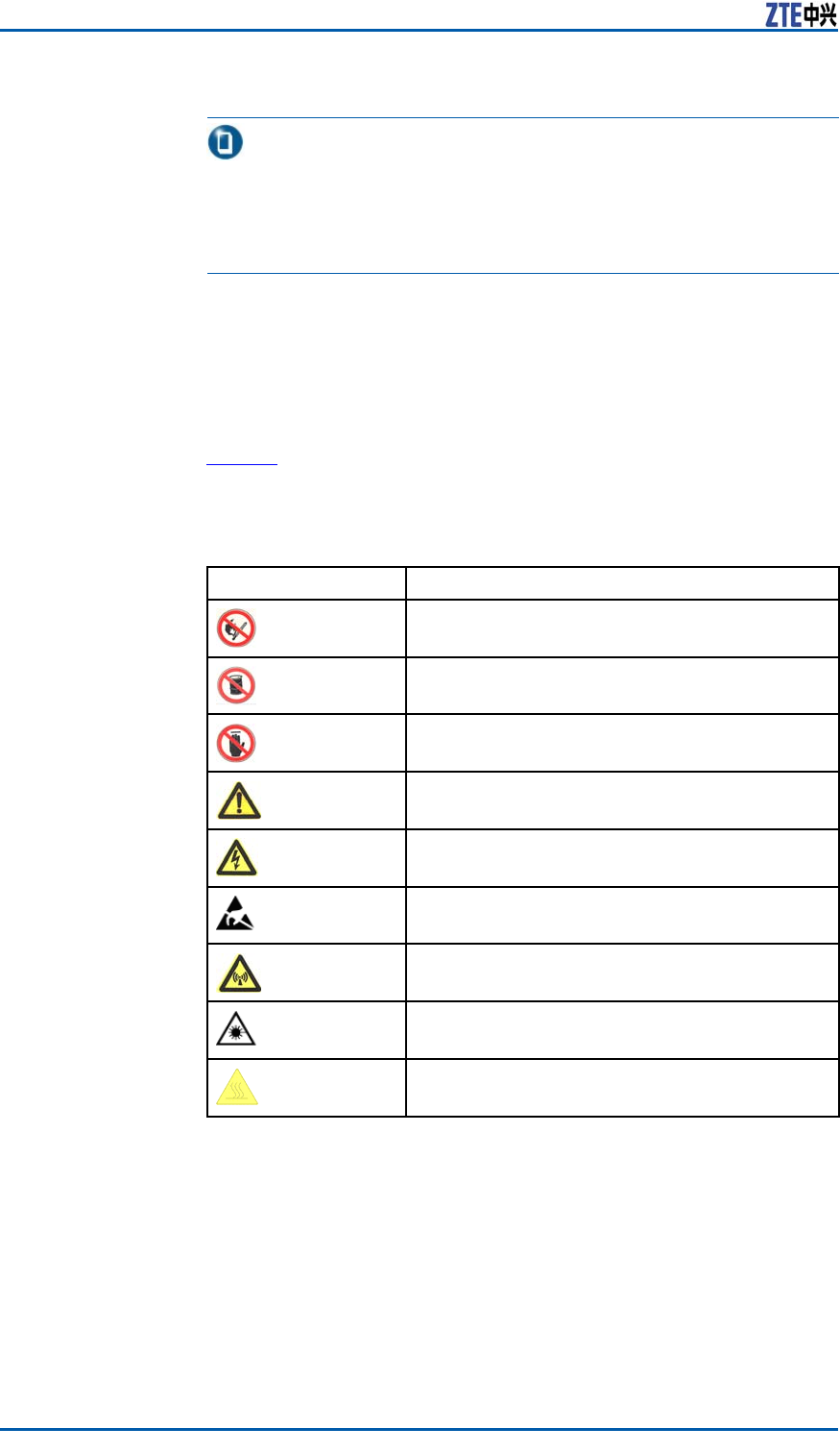
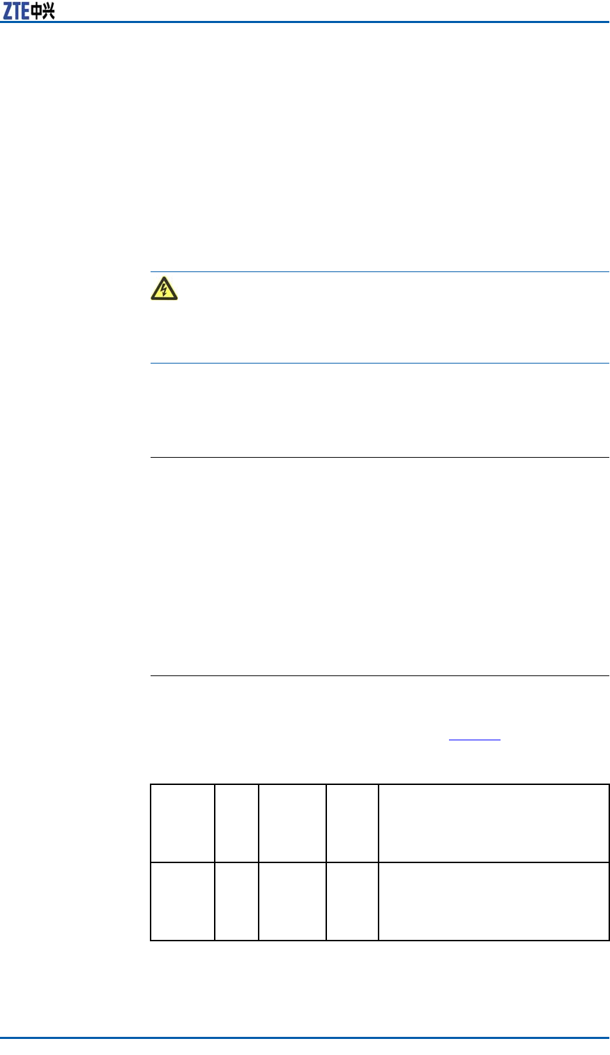
SafetySymbols
T
a b l e 1 listssafetysymbols.Theyaretoprompttheuserofthe
safetyprecautionstobeobservedduringZXSDRBS8800C200
operationandmaintenance.
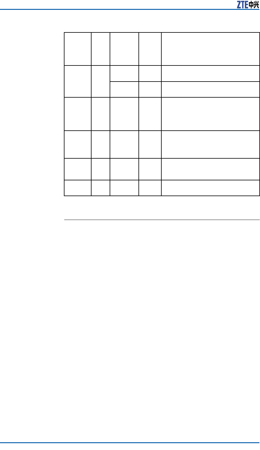
TABLE1SAFETYSYMBOLSDESCRIPTION
SafetySymbolsMeaning
Nosmoking:Smokingisforbidden
Noflammables:Noflammablescanbestored.
Notouching:Donottouch.
Universalalertingsymbol:Generalsafety
attentions.
Electricshock:Riskofelectricshock.
Electrostatic:Thedevicemaybesensitiveto
staticelectricity.
Microwave:Bewareofstrongelectromagnetic
field.
Laser:Bewareofstronglaserbeam.
Scald:Bewareofscald.
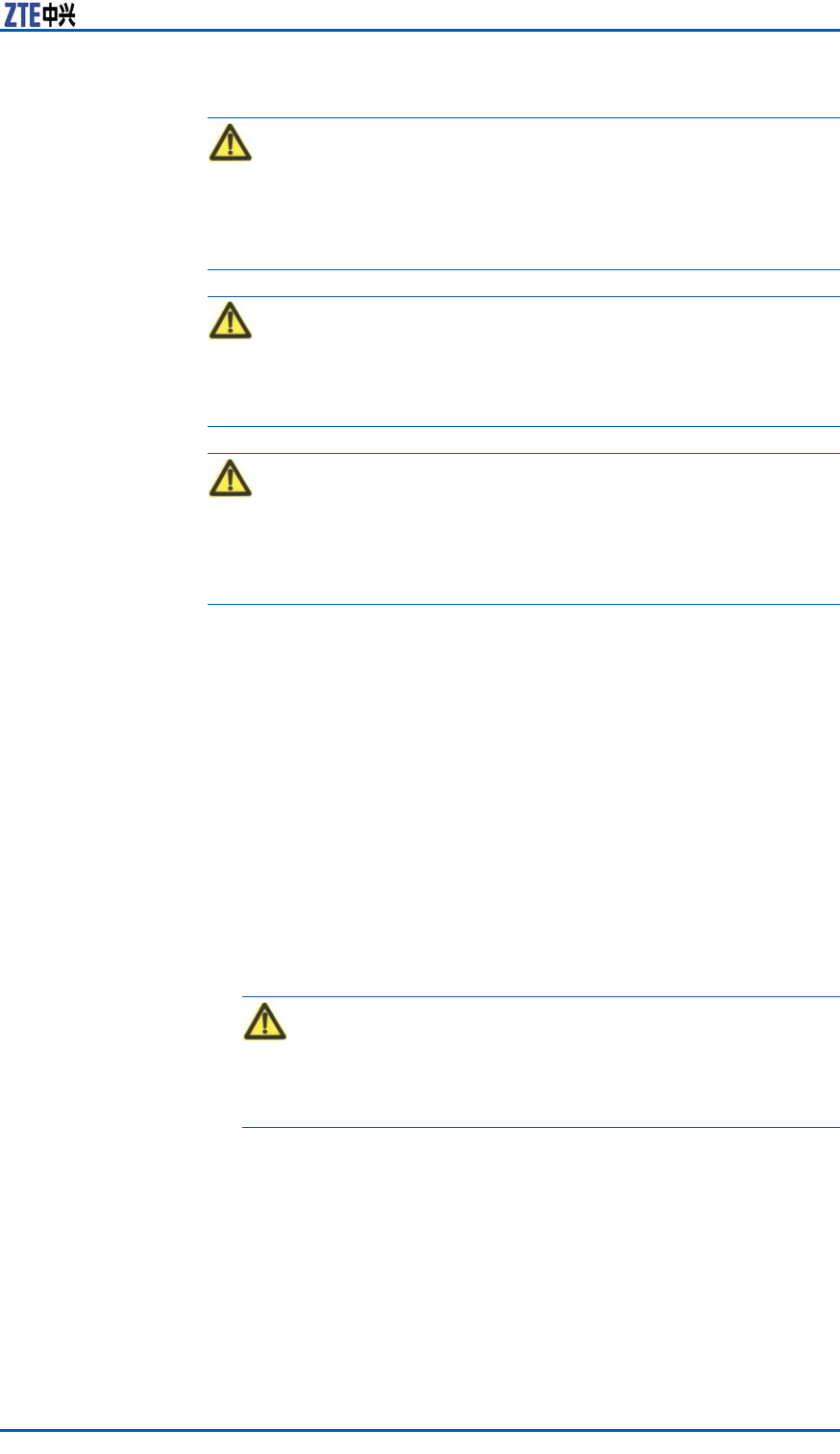
Amongstthesesafetysymbols,theuniversalalarmsymbolsare
classiedintothreelevels:danger ,warning,andcaution.The
formatsandmeaningsofthethreelevelsaredescribedasbelow:
2ConfidentialandProprietaryInformationofZTECORPORATION
Chapter1SafetyInstruction
Danger:
Indicatesapotentiallyhazardoussituationwhich,ifnotavoided,
willresultindeathorseriousinjuryofpeople,orequipmentdam-
agesandbreakdown.
Warning:
Indicatesapotentiallyhazardoussituationwhich,ifnotavoided,
couldresultindeathorseriousinjury.
Caution:
Indicatesapotentiallyhazardoussituationwhich,ifnotavoided,
couldresultinseriousinjuries,equipmentdamagesorinterruption
ofpartservices.
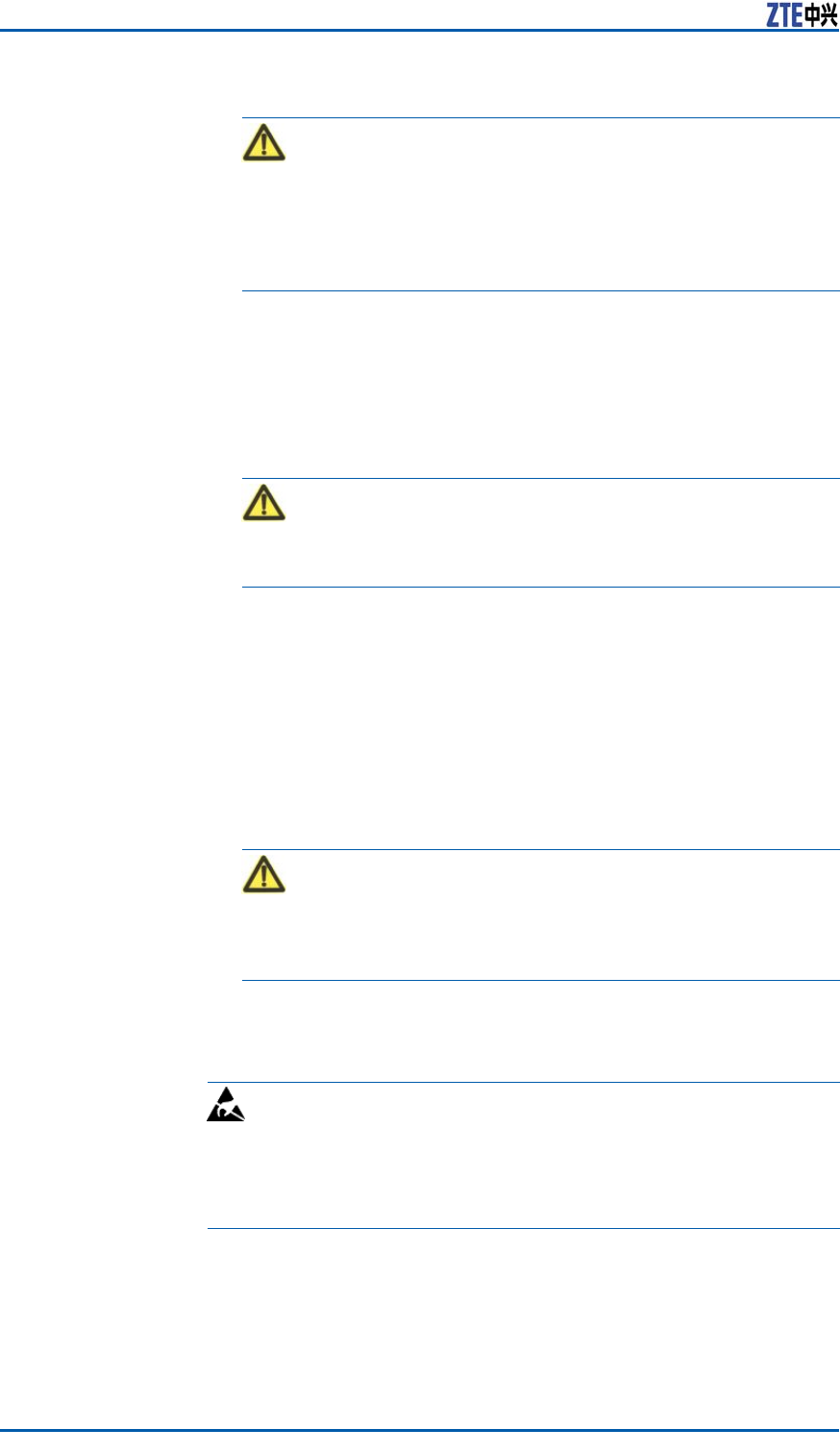
SafetyInstructions
Thissectiondescribesthesafetyinstructionsrelatedtoelectrical
safety,antistatic,heavyobjectsandmodules.
ElectricalSafety
Instructions
Thefollowingaretheelectricalsafetyinstructionsabouttools,high
voltage,powercables,holesandlightning:
�Tools
Usespecialtoolsratherthancommontoolsforhigh-voltage
andACoperations.
�HighVoltage
Danger:
Highvoltageishazardous.Directorindirectcontactwithhigh
voltageormainsupplyusingawetobjectcouldresultindeath.
�StrictlyfollowlocalsafetyrulestoinstallACpowerequip-
ments.
�Installationstaffmustbequaliedforperforminghigh-volt-
ageandACoperations.
�Donotwearanywatch,handchain,bracelet,ringorany
otherconductiveobjectduringsuchoperations.
�Preventmoisturefromaccumulatingontheequipmentdur-
ingoperationsinadampenvironment.
�PowerCable
ConfidentialandProprietaryInformationofZTECORPORATION3
ZXSDRBS8800C200InstallationManual
Warning:
Neverinstalloruninstallpowercableswhiletheyarelive.Oth-
erwise,thepowercable,whencontactingaconductor ,mayre-
sultinsparksorelectricarccausingareorevendamageto
eyes.
�Makesuretoshutoffpowersupplybeforeinstallingordis-
connectingapowercable.
�Beforeconnectingthepowercable,makesurethatthecon-
nectingcableanditslabelisappropriatefortheactualin-
stallationrequirements.
�DrillingHoles
Warning:
Itisnotallowedtodrillcabinetholeswithoutpermission.
�Unqualieddrillingcoulddamagewiringandcablesinside
thecabinet.Additionally,metalpiecesinsidethecabinet
createdbythedrillingcouldresultinashortcircuit.Use
insulationprotectionglovesandrstmovecablesinsidea
cabinetawaywhendrillingisnecessaryonacabinet.
�Protecteyesduringdrillingasdustoryingdebrismay
damageeyes.
�Cleananydebrisintimeafterdrilling.
�Lightning
Danger:
Donotperformhigh-voltage,AC,irontowerormastoperations
inathunderstorm.
Thunderstormswouldgiverisetoastrongelectromagnetic
eldintheatmosphere.Therefore,theequipmentmustbe
groundedandprotectedintimeagainstlightningstrikes.
AntistaticSafety
InstructionsElectrostatic:
Staticelectricityproducedbyhumanbodycandamagestatic-sen-
sitivecomponentsoncircuitboard,suchaslarge-scaleintegrated
circuits.
�Frictioncausedbyhumanbodyactivitiesistherootcauseof
electrostaticchargeaccumulation.Staticvoltagecarriedbya
humanbodyinadryenvironmentcanbeupto30kV ,and
canremaininthereforalongtime.Anoperatorwithstatic
electricitymaydischargeelectricitythroughacomponentwhen
he/shetouchestheconductorandcausingdamage.
4ConfidentialandProprietaryInformationofZTECORPORATION
Chapter1SafetyInstruction
�Wearanantistaticwriststrap(theotherendofwriststrapmust
bewellgrounded)beforetouchingtheequipmentorholding
aplug-inboard,circuitboard,IntegratedCircuit(IC)chipor
otherdevices,topreventhumanstaticelectricityfromdamag-
ingsensitivecomponents.
�Aresistorover1MΩshouldbeconnectedinseriesonthecable
betweentheantistaticwriststrapandthegroundingpoint,to
protecttheoperatoragainstaccidentalelectricshock.Resis-
tanceover1MΩislowenoughtodischargestaticvoltage.
�Theantistaticwriststrapusedmustbesubjecttoregular
check.Donotreplacethecableofanantistaticwriststrap
withanyothercable.
�Donotcontactstatic-sensitivemoduleswithanyobjectthat
easilygeneratesstaticelectricity.Forexample,frictionofpack-
agebag,transferboxandtransferbeltmadefrominsulation
plasticmaycausestaticelectricityoncomponents.Discharge
ofstaticelectricitymaydamagecomponentswhentheycon-
tactahumanbodyortheground.
�Modulesshouldonlycontactmaterialssuchasantistaticbag.
Keepmodulesinantistaticbagsduringstorageandtransporta-
tion.
�Dischargestaticelectricityofthetestdevicebeforeuse,that
is,groundthetestdevicerst.
�DonotplacethemodulenearastrongDCmagneticeld,such
asthecathode-raytubeofamonitor .Keepthemoduleatleast
10cmaway.
HoistingHeavy
Objects
Warning:
Whenhoistingheavyobjects,ensurethatnobodyisstandingor
walkingunderthehoistedobject.
�Ensurethehoistercanmeethoistingrequirementswhendis-
assemblingheavyequipment,ormovingandreplacingequip-
ment.
�Theinstallationpersonnelmustbedulytrainedandqualied
forhoistingoperations.
�Hoistingtoolsmustbeinspectedandcompletebeforeservice.
�Makesurethathoistingtoolsarexedrmlyonasufciently
securedobjectorwallbeforethehoistingoperation.
�Givebrieforalinstructionsduringhoistingoperationstopre-
ventanymishap.
Unplugging/Plug-
gingaModule
�Neverplugamodulewithexcessiveforce,toensurethatthe
pinsonthebackplanedonotgetdeformed.
�Plugthemodulerightintotheslotandmakesuremodulecir-
cuitfacesdonotcontacteachotherlestanyshortcircuitmay
occur .
�Keephandsoffthemodulecircuit,components,connectors
andcabletroughwhenholdingamodule.
ConfidentialandProprietaryInformationofZTECORPORATION5

ZXSDRBS8800C200InstallationManual
OtherSafety
Instructions
Note:
Donotperformmaintenanceordebuggingindependently,unless
aqualiedpersonispresent.
�Replacinganypartsormakinganychangestotheequipment
mightresultinanunexpecteddanger .Therefore,besurenot
toreplaceanypartsorperformanychangestotheequipment
unlessauthorizedotherwise.
�DuetothatRRUisinhightemperatureduringrunning,theRRU
shouldbeinstalledinsomeregionsoutofoperators’reachor
strictlyrestricted.
�DuetothatRRUisinhightemperatureduringrunning,theRRU
shouldbeinstalledinsomeregionsoutofoperators’reachor
strictlyrestricted.
�ContactZTEofceifyouhaveanyquestion,toensureyour
safety.
6ConfidentialandProprietaryInformationofZTECORPORATION
C h a p t e r 2
InstallationOverview
TableofContents:
Appearance.......................................................................7
EngineeringIndices............................................................7
InstallationFlow.................................................................8
InstallationPrecautions.......................................................9
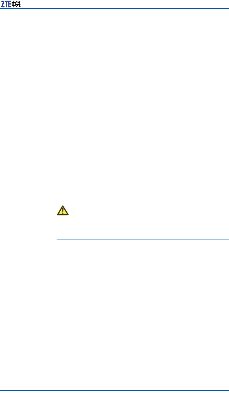
Appearance
F
i g u r e 1 showstheappearanceofZXSDRBS8800C100.
FIGURE1ZXSDRBS8800C200APPEARANCE
EngineeringIndices
T
a b l e 2 liststheengineeringindicesofZXSDRBS8800C200.
ConfidentialandProprietaryInformationofZTECORPORATION7

ZXSDRBS8800C200InstallationManual
TABLE2ZXSDRBS8800C200ENGINEERINGINDICES
ItemIndex
Dimension950mm×600mm×450mm(height×width
×depth)
Weight<200kg
PowerSupply-48VDC:-40V~-57V
WorkingTemperat
ure
-40℃to55℃(-40℉to131℉)
OverallPower
Consumption
<3000W(fullconfiguration)
WorkingHumidity5%RH~95%RH
Grounding<5Ω
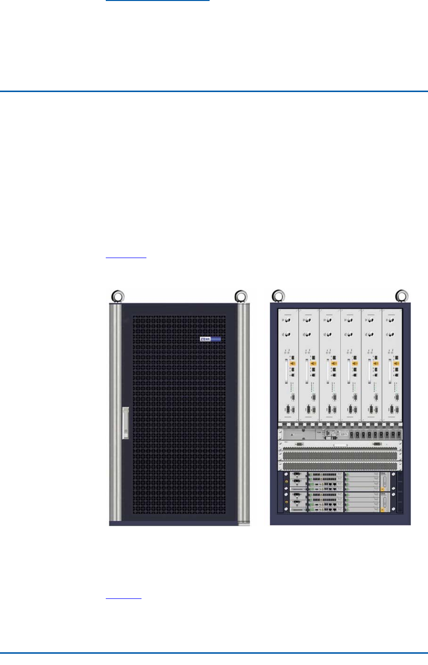
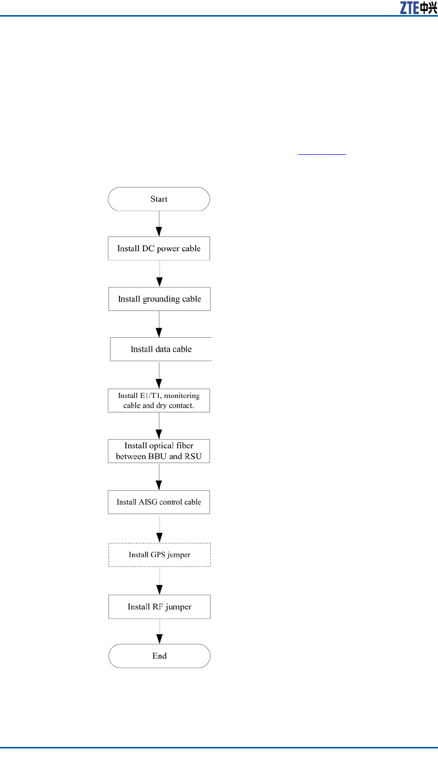
InstallationFlow
TheZXSDRBS8800C200installationowislistedinF
i g u r e 2 .
8ConfidentialandProprietaryInformationofZTECORPORATION
Chapter2InstallationOverview
FIGURE2INSTALLATIONFLOW
InstallationPrecautions
Warning:
Nonprofessionalpersonnelprohibitsinstallinganddebuggingde-
vicesalone,exceptwithguideofprofessionalpersonnel.
�Readthismanualaswellascorrespondingmanualscarefully
beforeinstallationandperforminstallationaccordingtothein-
stallationowandspecicationsinthismanual.
�ZXSDRBS8800C200hardwareinstallationpersonnelmust
participateinsometrainingrelatedtocommunicationequip-
mentinstallationandownskilledinstallationtechnique.
�Duringinstallation,ensurepersonalsafetyandavoidaccidents
suchaselectricshockorbruise.
ConfidentialandProprietaryInformationofZTECORPORATION9

ZXSDRBS8800C200InstallationManual
�Duringinstallationintheequipmentroom,installationper-
sonnelshouldwearinsulationshoesandtakeoffnecklaces,
braceletsandwatches.
�Duringinsertingandextractingboards,installationpersonnel
shouldwearantistaticwriststrapsandmakesuretheother
endofitgrounding.
�Duringinstallationandmaintenanceofopticalber ,prohibit
directlystaringatasectionofopticalberorasocketofoptical
terminalincasethatlaserbeamsdamageeyes.
�Insertboardsalongslots,avoidcontactbetweenparalleled
boardscausingshortcircuit.Makeproperforceincaseofpins
distorted.
�Takeholdoftheedgeofboardsandnottouchthecircuit,com-
ponentsandwires.
�Replacingcomponentsormodifyingdevicesmaybringextra
risks.Withoutauthorization,prohibitreplacingormodifying
devices.
10ConfidentialandProprietaryInformationofZTECORPORATION

C h a p t e r 3
InstallationPreparation
TableofContents:
CabinetInstallationEnvironmentCheck................................11
TechnicalMaterialPreparation.............................................17
PersonnelRequirements.....................................................18
ToolsandInstrumentsPreparation.......................................18
UnpackingAcceptance........................................................20
CabinetInstallation
EnvironmentCheck
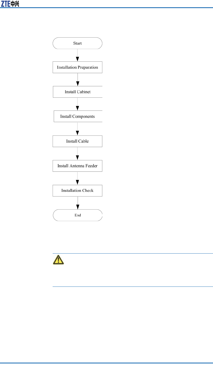
EquipmentRoomSpace
Requirements
Theminimuminstallationspaceofcabinetisrequiredasshownin
F
i g u r e 3 .
ConfidentialandProprietaryInformationofZTECORPORATION11
ZXSDRBS8800C200InstallationManual
FIGURE3INSTALLATIONSPACEREQUIREMENT
Thedetailedrequirementsisasfollows:
�Thisequipmentcanbeinstalledalongsideawallandperform
maintenanceforallboardsundertheconditionthattheback
doorisclosed;keepthecabinetadistanceofmorethan100
mmfromthewall.
�Whenthereareotherequipmentatbothsidesoftheequip-
ment,makeitabuttingagainstotherequipment;whenthere
arewallsatbothsidesoftheequipment,keepadistanceof
morethan100mmfromthebothwalls.
�Keepamorethan800mmspacefromthefaceofequipment.
12ConfidentialandProprietaryInformationofZTECORPORATION

Chapter3InstallationPreparation
EquipmentRoomEnvironment
Requirements
Equipment
RoomLayout
Requirements
Thelayoutofequipmentroomincludescabletraylayoutandcabi-
netlayout.Accordingtotheengineeringdesigndrawing,installa-
tionpersonnelshouldmarkandlocatebasedonequipmentroom
spaceandcabinetdimension.
Thedirectionfromfeedertocabinetshouldbeconsideredenough
duringcabinetlayout.Thefeedershouldbeshortaspossibleas
itcan,andthebendingradiusoffeedershouldbenottoosmall.
Iftwocabinetsormorearerequired,themaincabinetshouldbe
putinthemiddleofallcabinets.
Cabinetlayoutadoptingarowormulti-rows(putinthesame
equipmentroomwithBSCorMSC)isdeterminedbythesizeof
equipmentroomandcabinetquantity.
Inordertobeconvenientforoperation,suggestthatcabinetlayout
shouldmeetthefollowingrequirements:
�Thedistancefromcabinettowallshouldbemorethan10cm.
�Arowofcabinetskeeps1mdistanceatleastfromanother
neighboringrowofcabinets.
�Whenmultiplecabinetsareputsidebyside,thesecabinets
shouldkeepinline.
�Thefaceofcabinetkeeps1mdistanceatleastfromanob-
struction.
EquipmentRoom
Building
Theengineeringforequipmentroommustmeetthefollowingre-
quirements:
�Theleveloordifferencepersquaremeterisnotmorethan2
mm.
�Theoor ,wall,ceiling,reservedinstallationholesandgrooves
ofequipmentroomshouldaccordwiththedesignrequire-
ments.
�Preventwaterontheoutdooroorintotheindooroorwhilein-
stallationholespassesanoutdoorwall.T akemeasuresagainst
dampnessforthegrooves.
�Selectsomematerialwhichisdifculttodeformandcrackfor
hiddenpipes,holesandslotsbetweencoverplates.
�Prepareatemporaryroomtostoreinstallationmaterialsand
devices.
ConfidentialandProprietaryInformationofZTECORPORATION13

ZXSDRBS8800C200InstallationManual
Note:
High-voltagepowerwire,strongmagneticled,strongelectrical
sparkaswellasotherfactorsbringingdangerforequipmentroom
mustbeawayfromtheequipmentroom.
Temperatureand
Humidity
Theair-conditiondevicesshouldmeetthefollowingconditions:
�EnvironmentT emperature:-5℃~+45℃(Suggestmaintain-
ingtheenvironmenttemperaturebetween15℃and30℃).
�RelativeHumidity:15%~90%(Suggestmaintainingtherela-
tivehumiditybetween15%and90%).
NoiseConsideringmaintenancepersonnel’sphysicalandmentalhealth,
noiseintheequipmentroomshouldbelowerthan70dB.
FireProtectionThereprotectionconditionsofequipmentroommustmeet:
�Theindoorwallshouldmaintaindryness,andthewallsurface
andceilingarecoatedwithwhitenoncombustiblelusterless
paintorotherame-retardantmaterials.
�Prohibitstoringammableandexplosivesubstancesandequip
necessaryreprotectiondevices.
DustproofThedustproofrequirementsofequipmentroomshouldmeetthe
following:
�Alldoorsandwindowsshouldbeclosed.
�Ventilationpipelinesintheequipmentroomshouldbecleaned,
andairconditiondevicesshouldbeinstalledwithdustscreens.
�HolesCommunicatingbetweenequipmentroomsandpassage
forcablelayoutshouldbeclosedtodecreasedustowbetween
rooms.
LightingThelightingconditionsofequipmentroomshouldreachthere-
quirementsofequipmentmaintenance.Dailylighting,standby
lightingandemergencylightingsystemsshouldbeprepared.
WaterSupplyand
Draining
Pipelinesofwaresupply,drainingandreprotectionshouldnotbe
equippedinsidetheequipmentroom.
EquipmentRoomPowerSupply
Requirements
Thepowersupplyofequipmentroommustmeetthefollowingre-
quirements:
�Equipadieselenginetoprovidestandbypower .TheACpower
isresponsibleforpowersupplyalone.Thevoltagerange:380
V±10%;220V±10%.
�ThesupplypowervoltageofDCdistributiondeviceshouldbe
stableandthenominalvalueis-48V(-57V~-40V).
�Thebatterycapacityshouldbeadequate.
14ConfidentialandProprietaryInformationofZTECORPORATION
Chapter3InstallationPreparation
�Differentpowersocketsintheequipmentroomshouldhave
obviousmarks.Thepowerelectricityshouldbedistinguished
fromthelightingelectricityobviously.
�Whenthephenomenaofpowerundercurrent,under-voltage
andover-voltageoccur ,thereshouldbesound-and-light
alarms.
�Whileusing220Vor380VACvoltage,paygreatattentionin
caseofelectricshock.
�WhileinstallingDCpower ,makesurepowerpolaritiesconsis-
tent.
ElectricShock:
Whilecheckingpowers,examinethecurrentstatusofallswitches
andwatchoutelectricshock.
LightningandGrounding
Requirements
Thelightningandgroundingintheequipmentroomshouldmeet
thefollowingrequirements:
�Thegroundingresistanceisnotmorethan5Ω.
�Theindoorgroundingsystemconnectsdirectlywithaground-
ingbar .Alldevicegroundingconnectstothisgroundingbar .
Andthenthegroundingbarconnectswiththeprimaryground-
ingbarofthebuilding.
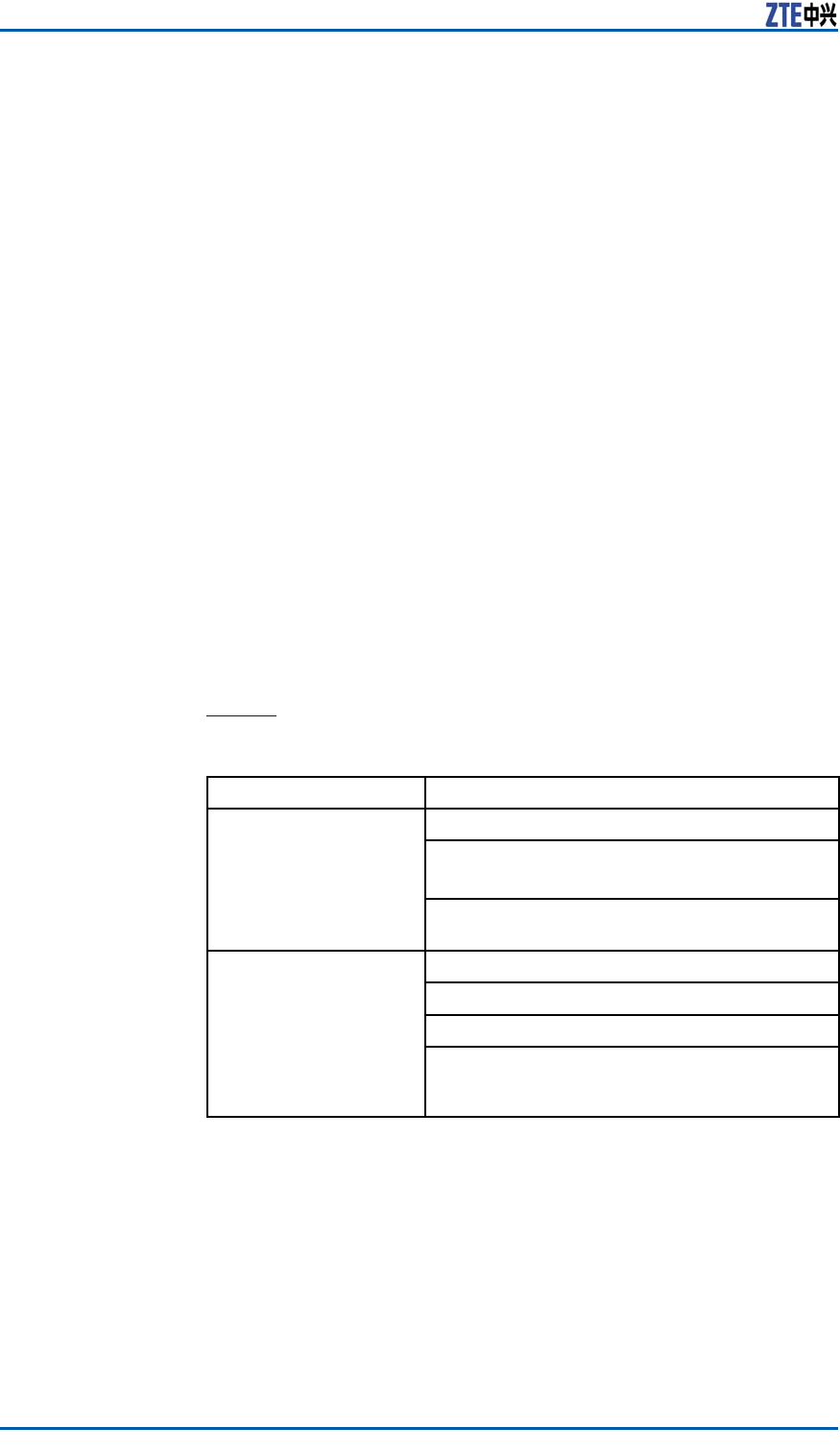
TransmissionRequirements
TheexternalinterfacesofZXSDRBS8800C200locateontheRSU
modulesandBBUsubsystem,referringtoT
a b l e 3 .
TABLE3ZXSDRBS8800C200EXTERNALINTERFACEINDEXDESCRIPTION
Tran
smis
sion
Categ
ory
M
odule
Inte
rface
Name
Conn
ector
Description
E1/T1S
A-d
ata
cable
B2inter
face
DB44ConnectstheZXSDRBS8800
C200withtheBSC;
E1provides75Ωand120Ωload
interfaces;
T1provides100Ωloadinterface.
ConfidentialandProprietaryInformationofZTECORPORATION15
ZXSDRBS8800C200InstallationManual
Tran
smis
sion
Categ
ory
M
odule
Inte
rface
Name
Conn
ector
Description
ETH0RJ45ConnectstheZXSDRBS8800
C200withtheBSC.
Ethe
rnet
cable
CC
ETH1RJ45ConnectstheZXSDRBS8800C200
andPCforLMTmaintenance.
RS232/
RS485
monit
oring
cable
S
A-d
ata
cable
B4DB9Providesinternalandexternal
environmentmonitoringfor
ZXSDRBS8800C200.
Dry
contact
cable
S
A-d
ata
cable
B3DB25Importdrycontactsignalfrom
externaldevices;
Exportdrycontactsignalfromthis
device.
AISG
control
cable
RSUAISGDB9Controlselectricaladjustment
antenna.
GPS
jumper
CCANTSMAImportsatellitesignalintothe
cabinet.
WiringRequirements
Wiring
Requirements
�Beforelayoutofpowercableandprotectivegroundcable,wrap
cableconnectorswellwithinsulationadhesivetape.
�Thepowercableandprotectivegroundcableshouldbesepa-
ratefromthesignalcable.
�Whenthepowercableandprotectivegroundcableareparallel
withthesignalcable,thedistancefromthesignalcablekeeps
10mmatleastinsidethecabinetand100mmatleastoutside
thecabinet.
�Ifthesignalcableiscrossedwiththepowercable,thecrossed
anglemustbe90°.
�Attheturningofcable,thebendingradiusshouldbemorethan
vetimesofthecablediameter .
�Whenthepowercableconnectstoaconnectingterminalof
distributionpowerboxinsidethecabinet,thewiringshouldbe
straightandtheradianofturningshouldbesmooth.
�Theactualinstallationpositionofcablesshouldbeconsistent
withrequirementsofengineeringsurveyanddatacongura-
tion.
�Theroutofcablelayoutshouldbeclearandreasonable,ac-
cordingtotheengineeringdesigndrawing.
�Thelayoutofsignalcableshouldbeorderly,smoothandnon-
crossed.
�Thelayoutofcablesshouldbeconvenientformaintenanceand
capacityexpansion.
16ConfidentialandProprietaryInformationofZTECORPORATION

Chapter3InstallationPreparation
�。Beforefeederlayout,learnofthewiringrouteanddrawa
practicalwiringrouteonthepaperincasefeedercrossed
�Theminimumbendingradiumoffeederisnotlessthan20
timesofthefeederradium.
�Therequirementsoffeederbendingradiumareasshownin
T
a b l e 4 .
TABLE4BENDINGRADIUMREQUIREMENTS
TheMinimumBendingRadius(recommended) Feeder
BendingBendingforOnceConsecutiveBending
(<=15times)
Super–soft
1/2"Feeder
15cm30cm
1/2"Feeder50cm125cm
7/8"Feeder90cm250cm
5/4"Feeder150cm380cm
Binding
Requirements
�Thebindingtapeisboundneatlyandproperly,andthespaces
betweenwirefastenersanddirectionsoffastenerskeepcon-
sistent.
�Cutredundantbindingtapeandmakeitatandtidy.
�Thepowercableandprotectivegroundcableareboundsepa-
ratelyfromthesignalcable.
�Thecablesinsidethecabinetisboundontoawirebushing.
�Whilelayingoutcablesalongthecabletray,thecableshould
beboundtogetherclose.
�Remainproperlengthincableforinsertingandextractingcon-
nectors.
TechnicalMaterial
Preparation
Itisnecessarytopreparethefollowingtechnicalmaterialfor
ZXSDRBS8800C200installation:
�ZXSDRBS8800C200CDMAIndoorBasestation-8800Engi-
neeringSurveyReport
�ZXSDRBS8800C200CDMAIndoorBasestation-8800Environ-
mentAcceptanceReport
ZXSDRBS8800C200kitmaterialsinclude:
�ZXSDRBS8800C200CDMAIndoorBasestation-8800Technical
Manual
�ZXSDRBS8800C200CDMAIndoorBasestation-8800Hard-
wareManual
ConfidentialandProprietaryInformationofZTECORPORATION17
ZXSDRBS8800C200InstallationManual
�ZXSDRBS8800C200CDMAIndoorBasestation-8800Installa-
tionManual
�ZXSDRBS8800C200CDMAIndoorBasestation-8800Opera-
tionandMaintenanceManual
�ZXSDRBS8800C200CDMAIndoorBasestation-8800Commis-
sioningandCongurationManual
PersonnelRequirements
InstallationpersonnelshouldparticipateinZTE’strainingandex-
amination,andhandleknowledgeofinstallationanddebugging.
Afterobtainingjobcerticate,installationpersonnelarequalied
forinstallationanddebugging.
ToolsandInstruments
Preparation
T
a b l e 5 showstoolsandmeterslistrequiredduringinstallation.
TABLE5TOOLANDMETERLIST
CategoryName
Onefeederconnectorknife
Onewirestripper
Onecrimpingpliers
Special-purposetools
Onemulti-functionalcrimpingpliersEarth
resistancetester
Oneelectricpercussiondrill
Auxiliaryandsamplebits
Onevacuumcleaner
Concretedrillingtools
Powersocket(two-phaseandthree-phase
socket,withcurrentcapacitygreaterthan15
A)
18ConfidentialandProprietaryInformationofZTECORPORATION

Chapter3InstallationPreparation
CategoryName
Crossscrewdrivers(4”,6”and8”each)
Flatheadscrewdrivers(4,6”and8”each)
Adjustablewrenches(6” ,8”,10”and12)
Dual-purposespanners(17”and19”each)
Onesetofsocketwrench
5kg(11lb)nailhammer
One300Wiron
One40Wiron
Solderwires
Hotblower
Oilpaintbrush
Pliers
Scissor
General-purposetools
Paperknife
One50m(164feet)tapemeasure
One5m(16feet)steeltape
One400mm(16inches)levelbar
Oneanglemeter
Onecompass
Measurementtools
Plumb
Antistaticwriststrap
Safetyhelmet
Protectiontools
Pairofgloves
Onehacksaw(withseveralsawblades)
Onepairofsharp-nosepliers(8″)
Onepairofdiagonalpliers(8″)
Onepairofslipjointpliers(8″)
Onepairofvices(8″)
Clamptools
Crowbar
Chainwheel
Rope
Ladder
Auxiliarytools
Forklift
ConfidentialandProprietaryInformationofZTECORPORATION19

ZXSDRBS8800C200InstallationManual
UnpackingAcceptance
CountingGoods
PrerequisiteThetransportedcargoshouldhavereachedtheinstallationsite.
ContextTherepresentativeofcustomerandtheprojectsupervisormustbe
presentonsiteduringcountingofgoodsreceived.Ifanypartyis
notpresentatthattime,transportermustholdtheresponsibility
foranydifferenceingoods.
Thestepsinvolvedincountinggoodsareasfollows:
Steps1.CheckDeliveryChecklistofZTECorporation.Checktotalnum-
berofgoods,intactnessofpackingboxes,andcheckwhether
arrivalplaceistheactualinstallationplaceagainstpackinglist
numberattachedtopackingboxes.Ifgoodsareintact,start
tounpackandinspectthem.
Note:
Itisrecommendedtounpackthegoodsafterabout30minutes
ofreceivingthecargo,sincethereisapossibilityofmoisture
contentduetotemperaturevariationsifany.
2.Equipmentinspectionlistandunpackingacceptancereportare
presentintherstpackingcarton.Firstly,openrstpacking
cartonandtakeouttheUnpackingAcceptanceReporttocheck
whetherthegoodsreceivedareinaccordancewiththeinspec-
tionlist.
3.Duringthecountingandunpackinginspectionprocess,ifany
materialisfoundshort,orgoodsdamaged,thenll-inUnpack-
ingAcceptanceFeedbackTableandcontactZTEpromptly.
ENDOFSTEPS.
CrateUnpacking
PrerequisitePreparetheappropriatetoolssuchasstraightscrewdriver ,pliers,
andcrowbar .
ContextPerformthefollowingstepstoopenthecrate:
Steps1.Insertastraightscrewdriverintotheslitbetweencrateand
frontcoverboardtomakeitloose;theninsertcrowbartoun-
clenchcoverboard.
2.Pullthecoverboardoutfromthecrate.
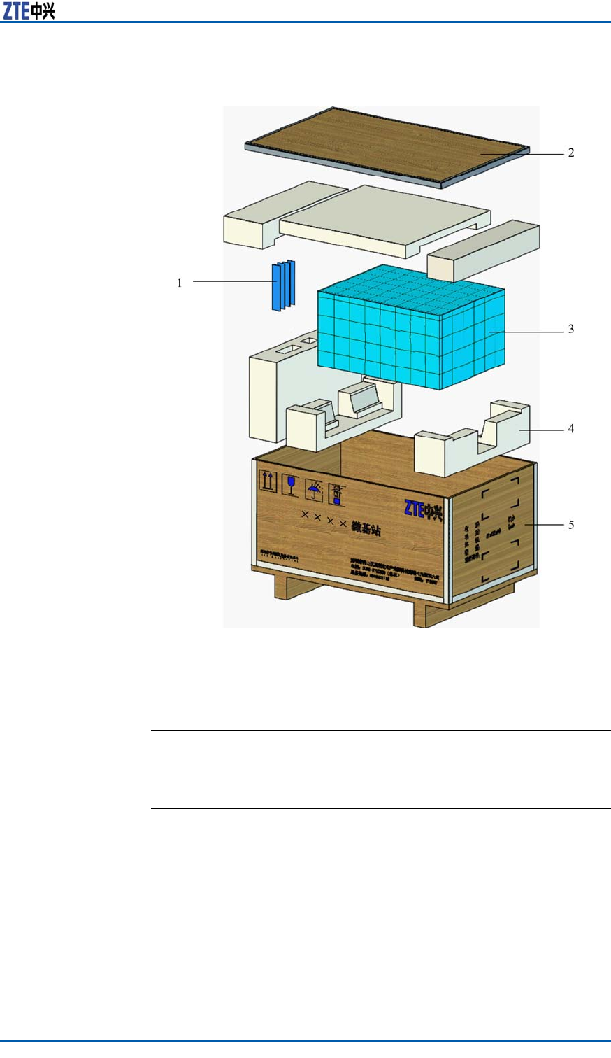
3.Removetheotherboardsofthecrate,asshowninF
i g u r e 4 .
20ConfidentialandProprietaryInformationofZTECORPORATION
Chapter3InstallationPreparation
FIGURE4CRATEUNPACKING
1.Accessories
2.Coverplate
3.Equipment
4.Foampiece
5.Crate
ENDOFSTEPS.
CartonUnpacking
PrerequisitePreparetheappropriatetoolssuchasstraightscrewdriver ,diago-
nalpliers,andpaperknife.
ContextPerformthefollowingstepstounpackthecarton:
Steps1.Usediagonalplierstocutpackingstraps.
2.Useapaperknifetocutadhesivetapealongtheslitsoncarton
cover ,avoiddamaginggoodsinside.
3.Openthecarton,andremovethefoamboard.
ConfidentialandProprietaryInformationofZTECORPORATION21

ZXSDRBS8800C200InstallationManual
4.Checkthegoodswithinthecarton.
Note:
�Avoiddamagingtheantistaticbag(Itcanbeusedinthe
futureforstorageofspareparts)duringunpacking.
�Whiletheequipmentismovedtoahotteranddamper
place,waitfor30minutesbeforeunpackingtheequipment.
Otherwise,moisturemaycondenseonthesurfaceofthe
equipmentandcausedamage.
�Properlydisposeofrecycledesiccants.
ENDOFSTEPS.
AcceptanceandGoodsHandover
ContextPerformthisprocedureforacceptinggoods,andhandingthem
overtooperators.
Steps1.Acceptance
Baseduponthename,categoryandnumbermentionedonthe
shippinglist,carefullycheckthegoodspiecebypiece.Make
surethatgoodsfullthefollowingconditions:
i.Makesurethattherearenobubbly,peeling,nickandlth
markonthesurfaceofthechassis.
ii.Ensurethatoilpaintonthechassissurfaceisintact.
iii.Ensureclampingscrewsaretightandintact.
iv.Allthecomponentsareproperlyinstalledattheirrespective
positions.
v.Laydowntheinspectedgoodsaccordingtocategories.
2.Handover
Aftercompletingtheunpackingprocedure,representativeof
customerandprojectsupervisorshouldapproveandsignUn-
packingforInspectionReport.Eachpartyshouldhaveacopy
ofUnpackingforInspectionReport.Ifthegoodsarestillun-
derthesupervisionoftheoperatorevenafteracceptance,then
goodswillnotbehandedovertotheoperatoruntilbothparties
signonthereport.
ENDOFSTEPS.
22ConfidentialandProprietaryInformationofZTECORPORATION

C h a p t e r 4
InstallingCabinet
TableofContents:
CabinetInstallationFlow....................................................23
InstallingSingle-cabinet.....................................................24
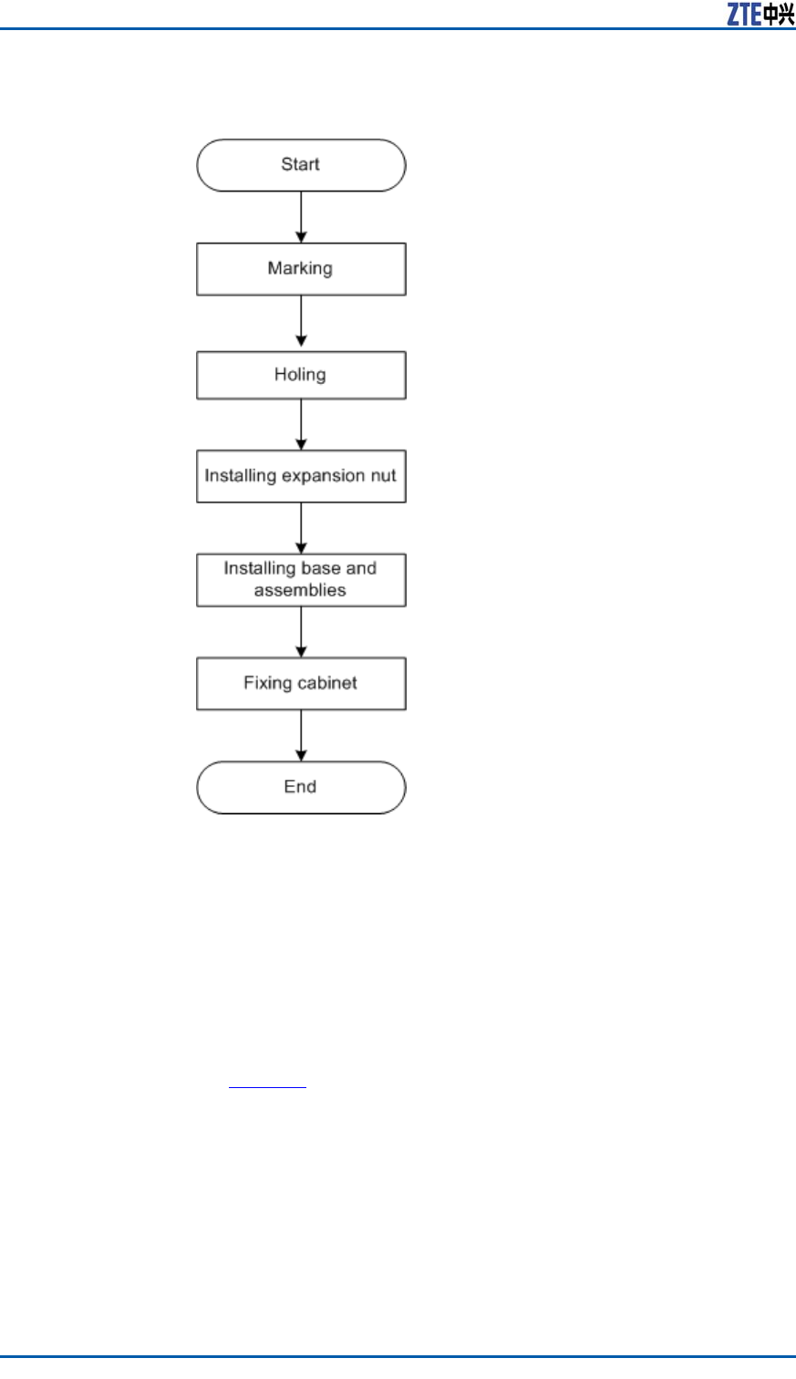
CabinetInstallationFlow
ZXSDRBS8800C200cabinetinstallationowislistedinF
i g u r e 5 .
ConfidentialandProprietaryInformationofZTECORPORATION23
ZXSDRBS8800C200InstallationManual
FIGURE5CABINETINSTALLATIONFLOW
InstallingSingle-cabinet
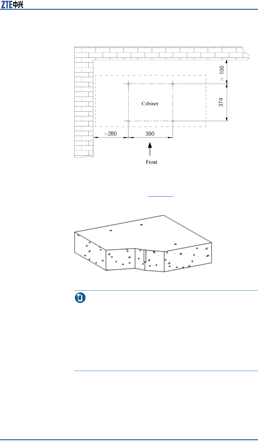
Steps1.Conrmtheinstallationpositionofcabinetbasedontheref-
erencedimensionandcabinetdimensiongivenbytheengi-
neeringdesigndrawing.Measuresomemarkingpointswitha
measuringtapeanddrawtwostraightlinesparalleledwiththe
referencelinewithaninkingpot.Makesuretheholepositions
forcabinetinstallationonthestraightlinesaccordingtothe
designdrawing.Thepositionofsingle-cabinetisasshownin
F
i g u r e 6 .
24ConfidentialandProprietaryInformationofZTECORPORATION
Chapter4InstallingCabinet
FIGURE6SINGLE-CABINETINSTALLATIONPOSITION
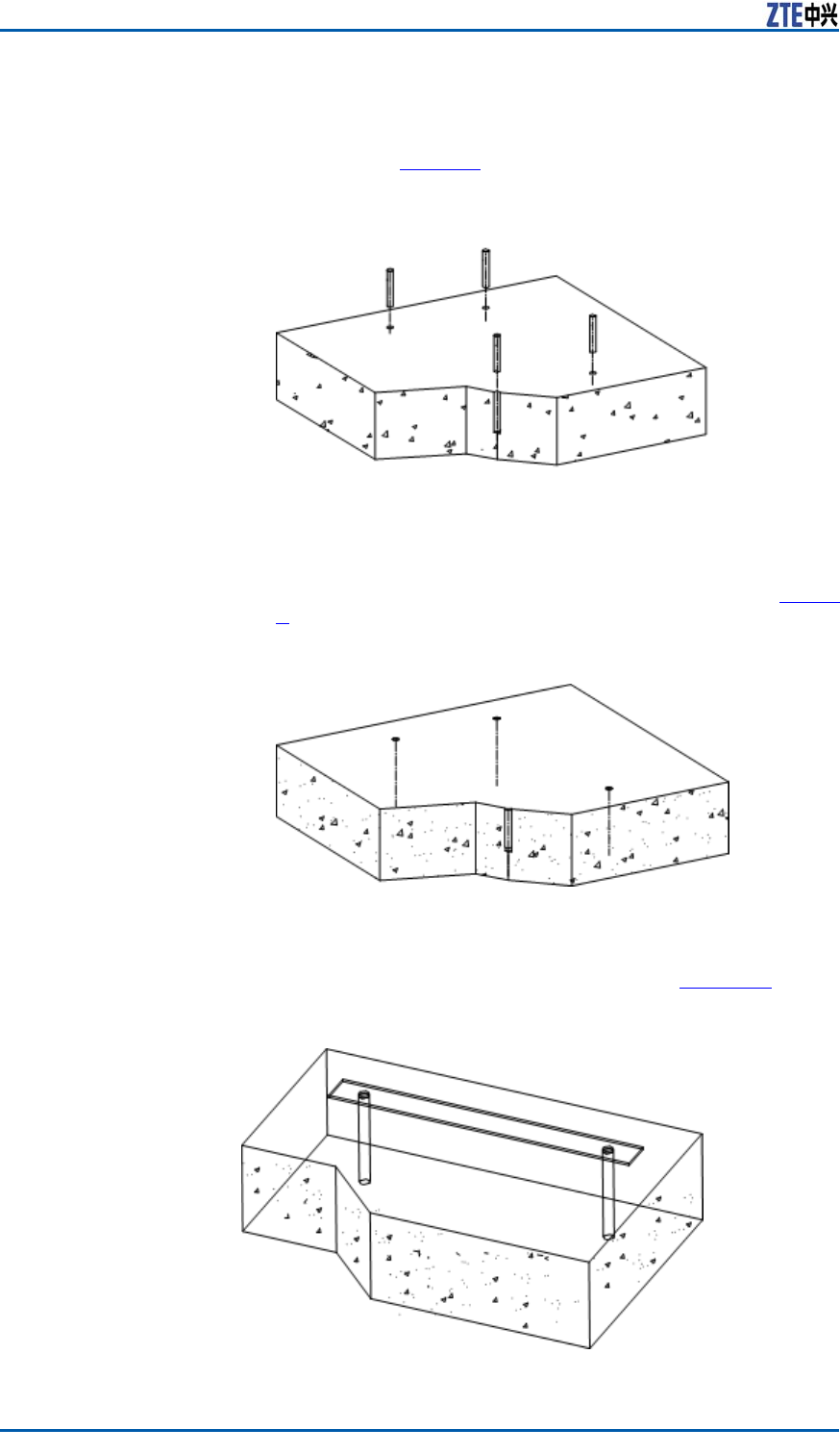
2.Drillsomeφ12holeswith60mmdepthbasedontheexpansion
boltmarks,asshowninF
i g u r e 7 .
FIGURE7HOLING
Note:
�Whileusingahammerdrilloranelectrichammer ,make
surethedrillbitverticalwiththehorizontalground,clasp
thedrillstockwithhandsandpressitverticallydownwards.
�Whileholing,useacleanertocleandustandmakesure
cleanoutallgarbageafterconstruction.
�Ifthedrillbitisunabletoxduetotoosmoothoor ,in
ordertohelppositioningdrillbit,rstcutaholeonthe
markedpositionswithapunch.
3.Installexpansionnuts.
i.Beforeinstallation,usethecleanertogetridofalldust
insideandoutsideholes.
ConfidentialandProprietaryInformationofZTECORPORATION25
ZXSDRBS8800C200InstallationManual
ii.Installfourinsulationsleevesontheinstallationholesto
makesuretheexpansionnutsinsulatedwiththeground,
asshowninF
i g u r e 8 .
FIGURE8INSULATIONSLEEVEINSTALLATION
iii.Inserttheexpansionnutsverticallyintotheinsulation
sleeves,andknockthenutswitharubberhammerto
makethemcompletelyintotheground,asshowninF
i g u r e
9.
FIGURE9EXPANSIONNUTINSTALLATION
4.Adjustaninsulationsheetandaligntwoholesontheinsulation
sheetwiththoseontheground,asshowninF
i g u r e 1 0 .
FIGURE10INSULATIONSHEETINSTALLATION
26ConfidentialandProprietaryInformationofZTECORPORATION
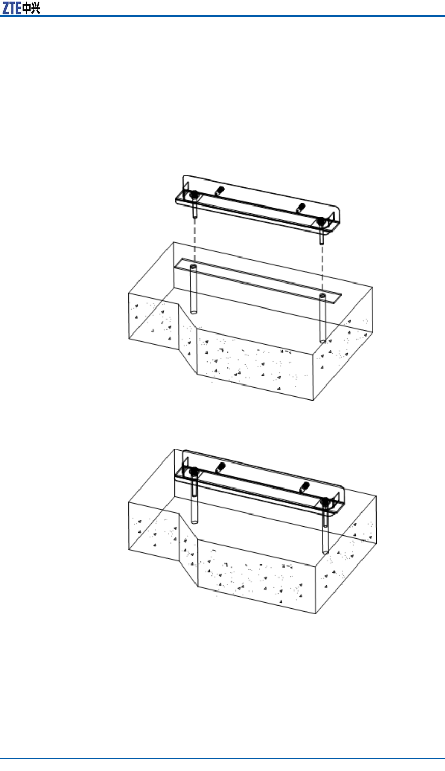
Chapter4InstallingCabinet
5.Aligninstallationholesonthebaseinstallationassemblywith
holesofexpansionnuts.InserttheM10boltthroughabig
washer ,insulationwasher ,installationholeofbaseinstallation
assemblyandinsulationwasherinturn.Screwdownthebolts
andxtheinstallationassemblyonthecementoor ,asshown
inF
i g u r e 1 1 andF i g u r e 1 2 .
FIGURE11BASEINSTALLATIONASSEMBLY(1)
FIGURE12BASEINSTALLATIONASSEMBLY(2)
6.Implementaninsulationtest.
i.Adjustthemultimetertotheresistancegrade.
ii.Forresistancemeasurement,onemeasuringprobeofthe
multimetercontactswiththemetalpartofbaseassembly
andtheotherwiththeexpansionnuts.Ifthecircuitdis-
ConfidentialandProprietaryInformationofZTECORPORATION27
ZXSDRBS8800C200InstallationManual
playsanopenstatus,theinsulationtestcompletes.Ifnot,
continuethenext.
iii.Checkwhethertheinsulationsleevesaredamagedorfor-
gottentoinstall.Suchasthissituation,repeattheabove
ow(installthebaseassembly)andperformaninsulation
testagain.
7.Fixthecabinet.
i.Movethecabinettothefrontofbaseassemblyandthe
backofcabinetfacestothebaseassembly.
Note:
Consideringtheweightofcabinet,thetopofcabinetpro-
videsliftingeyesandsuggestahoistinginstallationmode.
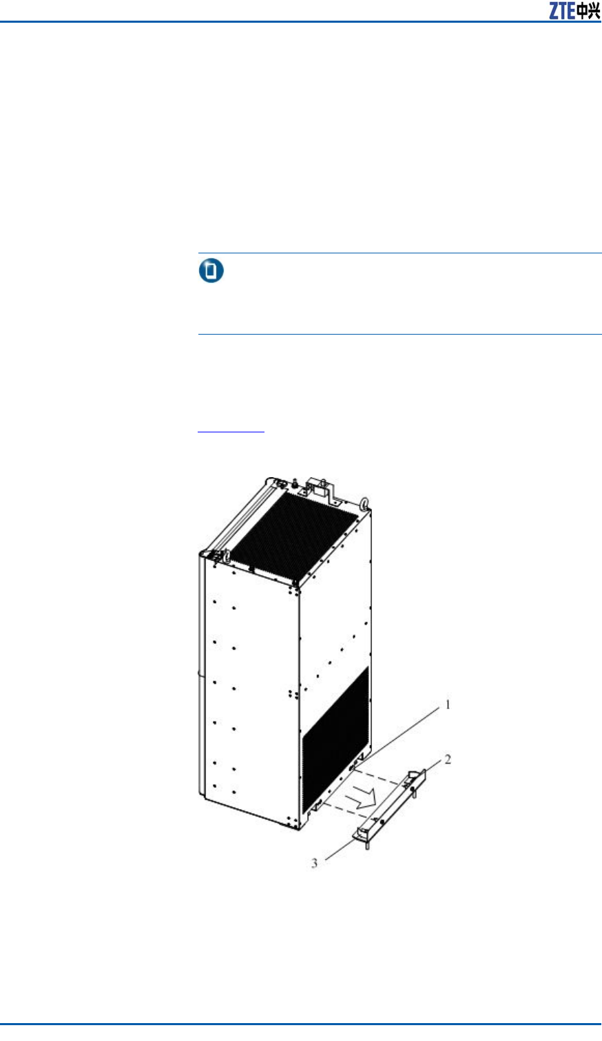
ii.Alignthelocationholesatthebottomofcabinetwiththe
orientationpinboltsonthebaseassembly,andmovethe
cabinetslowlyandcarefullytomaketwoanglesupports
insertingtheslotsatthebottomofcabinet,asshownin
F
i g u r e 1 3 .
FIGURE13FIXINGCABINET(1)
1.LocationHole
2.OrientationPinBolt
3.AngleSupport
28ConfidentialandProprietaryInformationofZTECORPORATION
Chapter4InstallingCabinet
Caution:
Prohibitdrillingholeonthecabinetbyself.Drillinghole
thatdoesnotmeetrequirementswilldamagethecables
andcableconnectioninsidethecabinet.Themetaldust
causedbydrillingwillresultinshortcircuit.
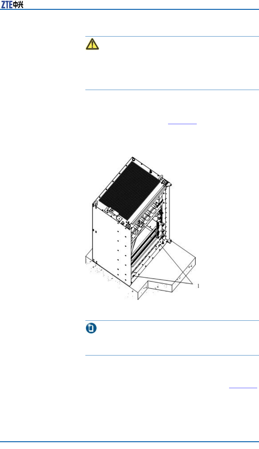
iii.Measurewhetherthecabinetislevelwithalevelbar .Ifnot,
addalevellingsheetunderthecabinettoadjusttolevel.
iv.Openthefrontdoorofcabinetanddisplaytwocircularholes
atthebottom,asshowninF
i g u r e 1 4 .InserttheM10bolt
throughawasher ,insulationwasherandovalhole,and
screwdownthebolt.
FIGURE14FIXINGCABINET(2)
1.CircularHole
Note:
Theinsulationwasherhasbeenrivetedatthebottomof
cabinet.
8.AccordingtoStep6,performasolutiontestformetalcompo-
nentsatthefrontofcabinet.
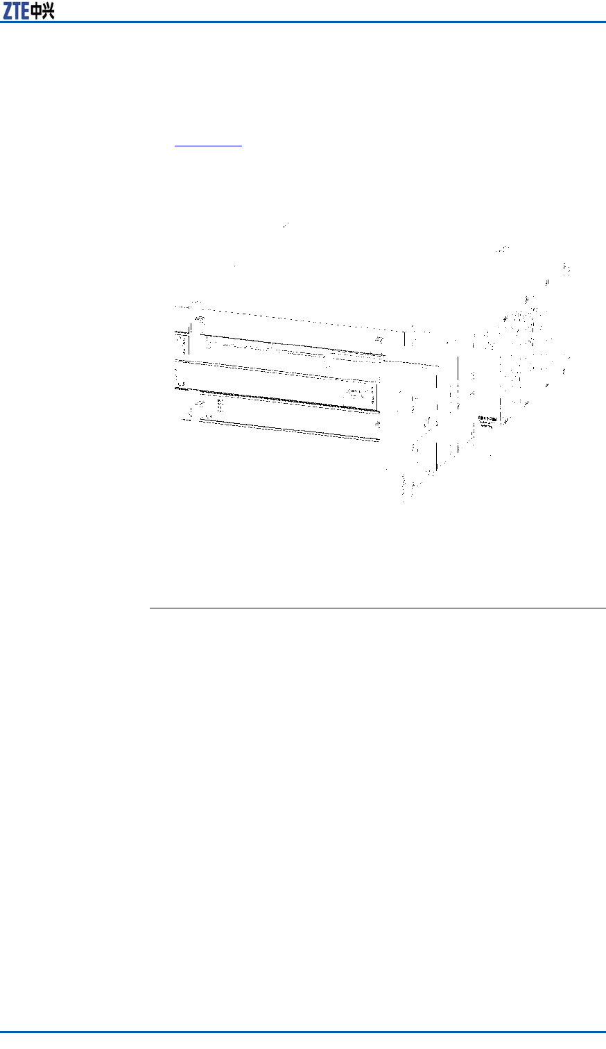
9.Closethefrontdoorandxthecabinet,asshowninF
i g u r e 1 5 .
ConfidentialandProprietaryInformationofZTECORPORATION29
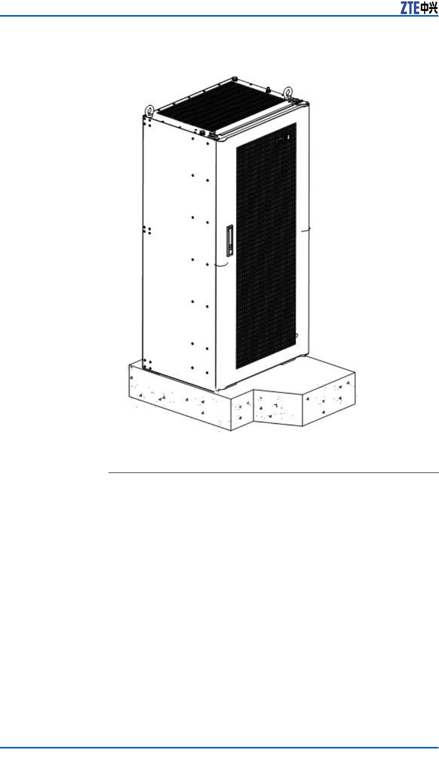
ZXSDRBS8800C200InstallationManual
FIGURE15CABINETINSTALLATIONCOMPLETION
ENDOFSTEPS.
30ConfidentialandProprietaryInformationofZTECORPORATION

C h a p t e r 5
InstallingComponents
TableofContents:
ModulePositionSchematicDiagram.....................................31
InstallingRSUModule........................................................33
InstallingBBU...................................................................35
InstallingBBUHorizontalModule.........................................37
InstallingBBUVerticalModule.............................................38
ModulePositionSchematic
Diagram
ZXSDRBS8800
C200Baseband
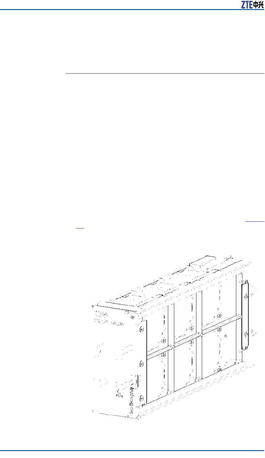
ThemainmodulesofZXSDRBS8800C200areinstalledintheRF
layerandbasebandlayer .Theinternalstructureisasshownin
ConfidentialandProprietaryInformationofZTECORPORATION31
ZXSDRBS8800C200InstallationManual
andRFCabinet
InternalStructure
F
i g u r e 1 6 .
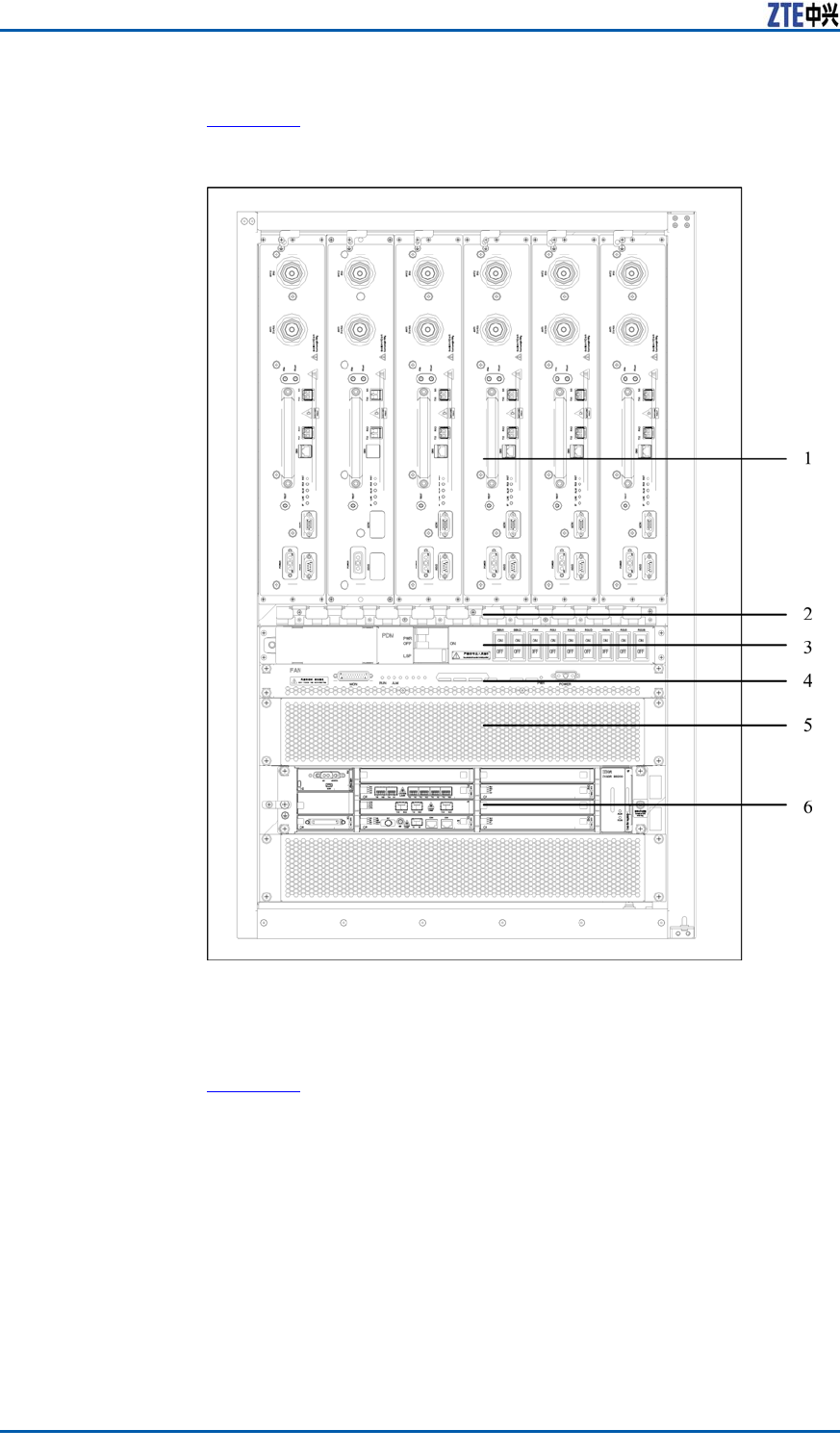
FIGURE16BASEBAND-RFCABINETINTERNALSTRUCTURE
1.RFSubrack
2.CableTray
3.PowerDistributionSubrack
4.FanSubrack
5.Wind-guidePlace
6.BasebandSubrack
RFModuleLayoutTheRFmodulesareconguredintherstsubrack,asshownin
F
i g u r e 1 7 .
32ConfidentialandProprietaryInformationofZTECORPORATION
Chapter5InstallingComponents
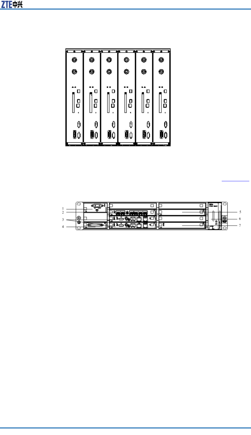
FIGURE17RFSUBRACKAPPEARANCE
1.RFUnit
SixRSUmulti-carrierRFunitscanbeconguredinSlot1~Slot6.
BasebandMoudle
Layout
ZXSDRBS8800C200basebandsubrackisasshowninF
i g u r e 1 8 .
FIGURE18BASEBANDSUBRACKAPPEARANCE
1.PM
2.FS
3.CC
4.SA
5.CHV
6.FA
7.CHD
InstallingRSUModule
Prerequisite�InstalltheZXSDRBS8800C200cabinetcompletely.
�WearanantistaticwriststraptoavoiddamagingtheRSU.
Steps1.Conrmslotsofmoduletobeinstalled.
2.Holdpartofametalpanelwiththerighthandandsupportthe
lowerpartofRSUwiththelefthand.Inthisway,keepthe
metalpanelerect.
3.Pushthemodulegentlyintoaslotalongaguideway,keepit
erectandlocateupperandlowerendsintotheslots.
4.Holdthemoduleatmiddleandpushitslowlyonce2/3rdof
boardisinserted.Whenthemoduletouchestoabackplane
socket,pushitlittleforciblyandmakeitintothesocketof
backplane.
ConfidentialandProprietaryInformationofZTECORPORATION33
ZXSDRBS8800C200InstallationManual
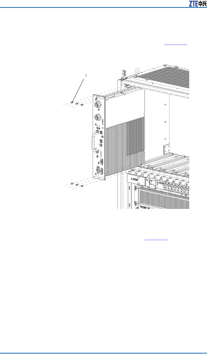
5.ScrewdownsixM5X20panheadassemblyscrewsontheRF
module.
ThepositionsofsixscrewsareasshowninF
i g u r e 1 9 .
FIGURE19SCREWPOSITIONSONRFMODULE
1.M5X20panheadassembly
screw
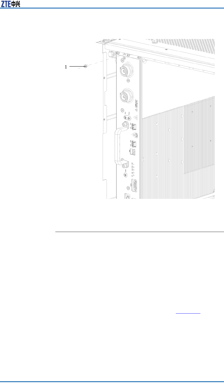
6.ScrewdownallscrewsasshowninF
i g u r e 2 0 andconnectthe
RSUgroundingsheet.
34ConfidentialandProprietaryInformationofZTECORPORATION
Chapter5InstallingComponents
FIGURE20SCREWPOSITION
1.M5*10panheadscrewwith
crossrecessed
ENDOFSTEPS.
InstallingBBU
Prerequisite�InstalltheZXSDRBS8800C200cabinet.
�WearanantistaticwriststraptoavoiddamagingtheBBU.
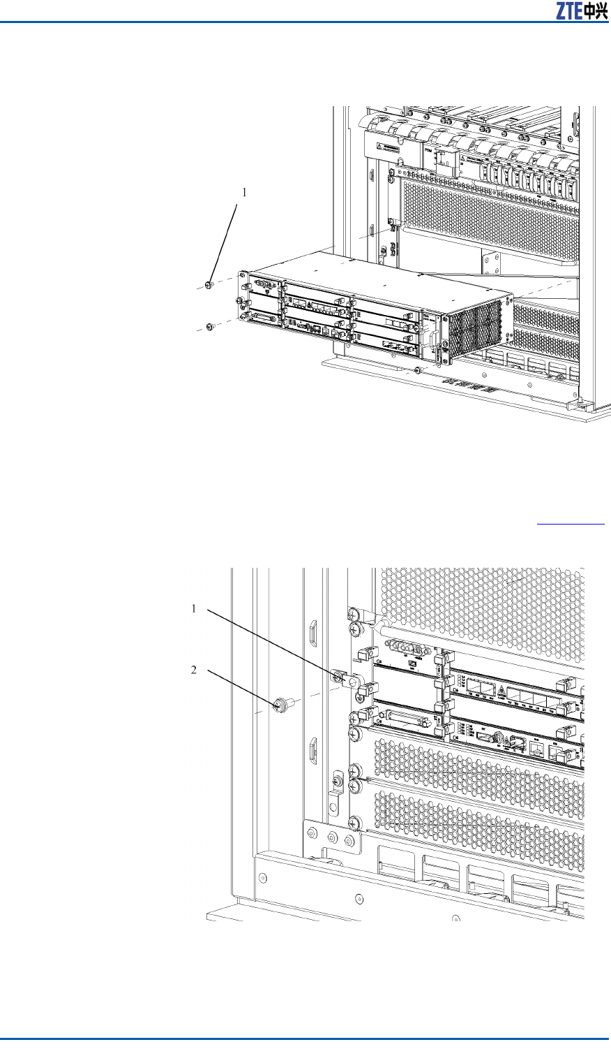
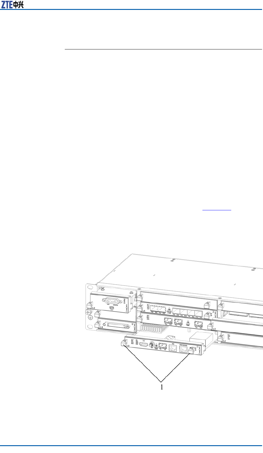
Steps1.InsertthemoduleintotheZXSDRBS8800C200cabinetalong
theguidewayandxitwithfourM5×16combinedscrews(two
respectivelyatleftandright),asshowninF
i g u r e 2 1 .
ConfidentialandProprietaryInformationofZTECORPORATION35
Chapter5InstallingComponents
ENDOFSTEPS.
InstallingBBUHorizontal
Module
PrerequisiteBeforeinstallation,makesurewearinganantistaticwriststrapto
avoiddamagingthePCBboard.
ContextThehorizontalmodulesofZXSDRBS8800C200includeasfollows:
�Controlandclockmodule(CC)
�Channelmodule(CH)
�Fabricswitchmodule(FS)
�Sitealarmmodule(SA)
�Powermodule(PM)
Steps1.InsertthemodulesintotheZXSDRBS8800C200subrackalong
theleftandrightguideways,asshowninF
i g u r e 2 3 .
FIGURE23HORIZONTALMODULEINSTALLATION
1.HorizontalInsertionandEx-
tractionHandle
ConfidentialandProprietaryInformationofZTECORPORATION37
ZXSDRBS8800C200InstallationManual
2.Holdhandlesatbothsidesofsubracktopushintothemodule
andmakesurethehandlelockedwiththeZXSDRBS8800C200
subrack.
ENDOFSTEPS.
InstallingBBUVertical
Module
PrerequisiteMakesurewearinganantistaticwristwrapincaseofdamaging
thePCBboard.
ContextTheZXSDRBS8800C200verticalmodulesincludethefanarray
(FA)anddustproofassembly.
Steps1.FastentheFAmodulewiththefourself-clinchingboltslocating
atthebottomplateofthefansubrackwithM3×8combination
screws.
2.InsertthedustproofassemblyalongtherightguidewayofFA
subrackandmakesurethatthespringplateontheFAsubrack
isfastenedwiththedustproofassembly,asshowninF
i g u r e
24.
FIGURE24DUSTPROOFASSEMBLYINSTALLATION
38ConfidentialandProprietaryInformationofZTECORPORATION

ZXSDRBS8800C200InstallationManual
Thispageisintentionallyblank.
40ConfidentialandProprietaryInformationofZTECORPORATION

C h a p t e r 6
InstallingCable
TableofContents:
On-siteCableInstallationList..............................................41
CableInstallationFlow.......................................................42
InstallingDCPowerCable...................................................43
InstallingGroundingCable..................................................46
InstallingDataCable..........................................................47
Installing75ΩE1Cable......................................................49
Installing120ΩE1Cable....................................................51
Installing100ΩT1Cable....................................................52
InstallingAbisInterfaceEthernetCable................................53
InstallingDryContactInput/outputCable.............................55
InstallingRS232/RS485MonitoringCable.............................58
InstallingFiberbetweenBBUandRSU..................................59
InstallingAISGControlCable..............................................59
InstallingGPSJumper........................................................61
InstallingRFJumper..........................................................63
On-siteCableInstallation
List
Internalcablesinstalledonsitearelistedasfollows:
�Internalopticalber
�Receivingdiversitycable
�CascadingEthernetcable
�SApanelcable
Externalcablesinstalledonsitearelistedasfollows:
�Externalpowercable
�Protectivegroundcable
�E1/T1externalcable
�Abis/Iubinterfaceopticalber
�Abis/IubinterfaceEthernetcable
�Drycontactcable
�RS232/RS485cable
�Antennafeederandjumper
ConfidentialandProprietaryInformationofZTECORPORATION41
Chapter6InstallingCable
Note:
�Thetrunkshouldbeselectedaccordingtotheon-sitesituation.
�Generally,theGPSjumperisinstalledbeforedelivery.
InstallingDCPowerCable
Prerequisite1.Layouttherouteandlengthofcablesalongacabletraybe-
tweenthepowercabinetandtheZXSDRBS8800C200.The
powercableandtheprotectivegroundcableshouldbesepa-
ratelyarrangedandbandedfromothercables.Thebanding
distancepersegmentis200mm.The0.2m~0.5lengthat
bothendsisreserved.
Note:
Thepowercableandtheprotectivegroundcableshouldbe
intactandavoidjointsappearinginthemiddleofcables.
2.Makesurethepowersupplyoutputcutoff.
Danger:
Makesurecheckingthestatusofcircuitbreakerinsidethe
powercabinet.Prohibitinstallingpowercablesinalivesta-
tus.
ContextTherearetwoDCpowercables,madeupofstrandsofame-
retardantwire.ThecrosssectionalareaofDCpowercableis16
mm2.Oneisa-48Vbluepowerinputcableandtheotherisa
blackgroundcable.
TheappearanceofDCpowercableisasshowninF
i g u r e 2 7 .
FIGURE27DCPOWERCABLEAPPEARANCE
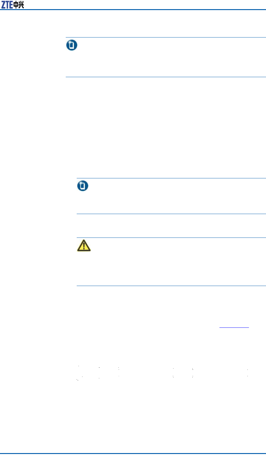
Steps1.Makeblueandblackcableswith16mm2crosssectionalarea
andconnecttheironeendstothepowercabinet.Theother
endsofblueandblackcablesarereservedforstandby.
ConfidentialandProprietaryInformationofZTECORPORATION43
ZXSDRBS8800C200InstallationManual
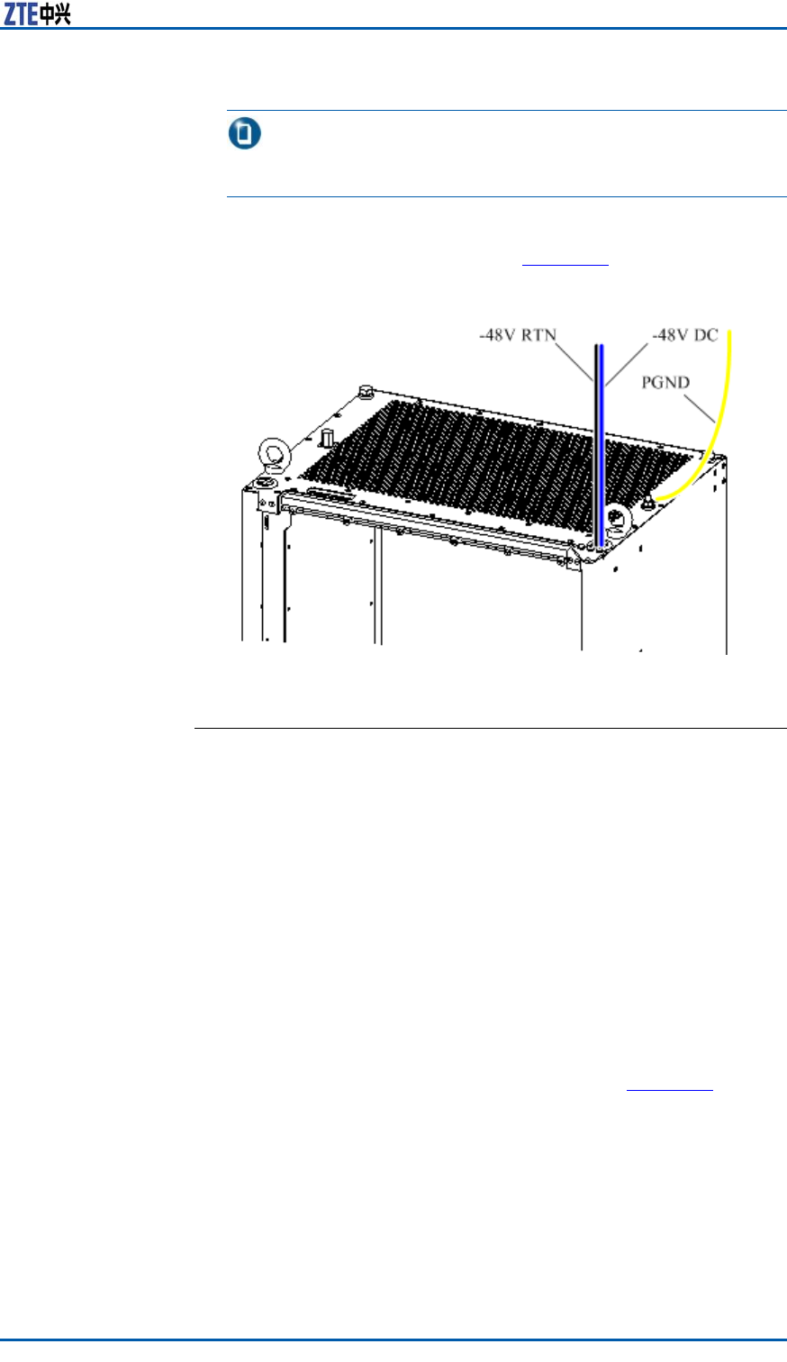
2.Leadthe-48VDC(blue)and-48VRTN(black)cablesthrough
thecableinletontheequipmenttop,asshowninF
i g u r e 2 8 .
FIGURE28DCPOWERCABLEINLET
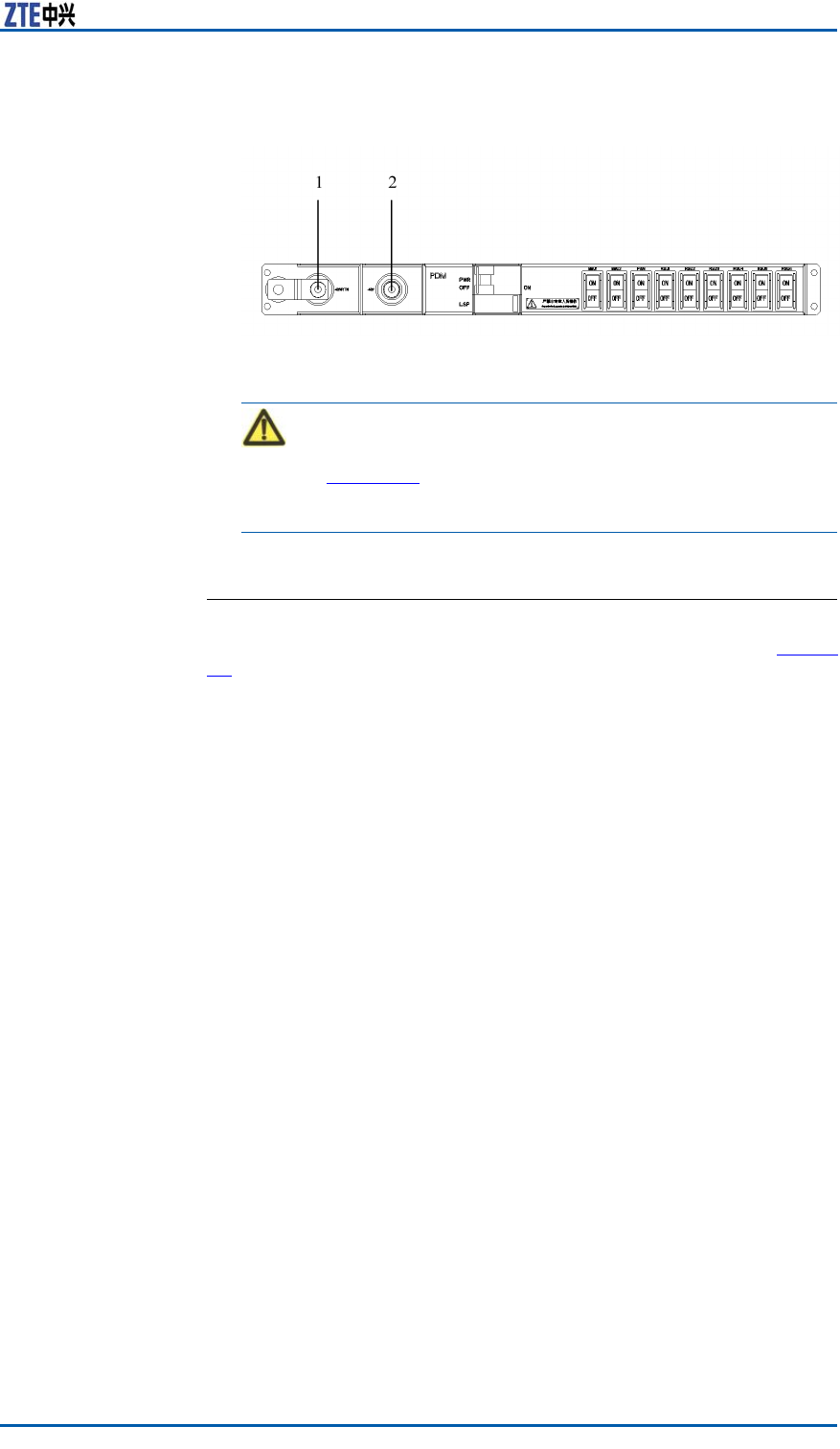
3.Layoutthepowercabletothepowerdistributionsubrackalong
theverticalcabletrayontheleftsideofcabinet.
4.Screwoffthescrewsontheprotectivecoverattheleftsideof
powerdistributionsubrackwithascrewdriver ,andtakeoffthe
protectivecover .
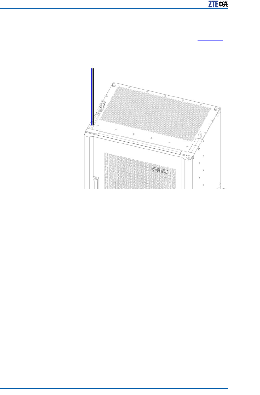
5.Installrespectivelythe–48VDC(blue)and–48VRTN(black)
cablestotheconnectionterminalsofthepowerdistribution
subrack,theconnectionrelationshipasshowninF
i g u r e 2 9 .
44ConfidentialandProprietaryInformationofZTECORPORATION
Chapter6InstallingCable
FIGURE29POWERDISTRIBUTIONSUBRACKCONNECTION
1.—48VRTN2.—48VDC
Caution:
RefertoF
i g u r e 2 9 toconnectthepositiveandnegativeelec-
trodesofpowercableandmakesurenotconnectioninreverse.
6.Rextheprotectivecovertothepowerdistributionsubrack.
ENDOFSTEPS.
ResultTheinstallationofpowercableiscompleted,asshowninF i g u r e
30.
ConfidentialandProprietaryInformationofZTECORPORATION45
ZXSDRBS8800C200InstallationManual
FIGURE30POWERCABLEINSTALLATIONCOMPLETION
InstallingGroundingCable
Steps1.Basedonthedistancefromthecabinettotheprotective
ground,cutaproperlengthofprotectivegroundcable.
46ConfidentialandProprietaryInformationofZTECORPORATION
Chapter6InstallingCable
Note:
Makesuresomecablesleftwhilecutting.
2.InstalltheprotectivegroundcabletothePEbindingposton
theequipmenttop,asshowninF
i g u r e 3 1 .
FIGURE31GROUNDCABLEINSTALLATION
ENDOFSTEPS.
InstallingDataCable
PrerequisiteInstalltheBBUandtheFSboardcompletely.
ContextDuetoahigh—integrationdesignfortheBBU,interfacesonthe
panelarelimited.Adoptadatacablefortransfer ,foritisconve-
nientforaccessoftheinternal/externalenvironmentmonitoring,
drycontactmonitoringandE1/T1(Abisinterface).Thereisone
interfacetoconnecttheSAmoduleatEndAofdatacable.There
aremultipletri-interfaceatEndB,connectingtheinternal/exter-
nalenvironmentmonitoring,drycontactmonitoringandE1/T1.
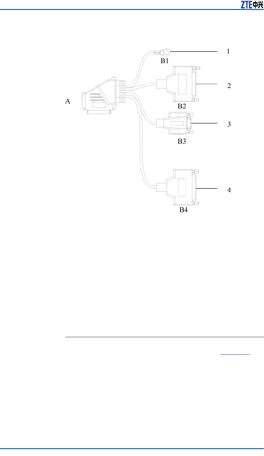
TheexplodedviewofdatacableisasshowninF
i g u r e 3 2 .
ConfidentialandProprietaryInformationofZTECORPORATION47
ZXSDRBS8800C200InstallationManual
FIGURE32DATACABLEAPPEARANCE
1.Groundterminal
2.E1/T1cable
3.RS232/RS485
4.Drycontactinput/output
Steps1.Connectthedatacabletothe“Monitoring/Abis”interfaceofFS
moduleandscrewdowntwoboltsatthejunction.
2.ConnectEndB1tothegroundterminalofcabinet.
3.ConnectEndB2totheDB44connectorofE1/T1cableand
screwdowntwoboltsatthejunction.
4.ConnectEndB3totheDB9connectorofRS485/RS232en-
vironmentmonitoringcableandscrewdowntwoboltsatthe
junction.
5.ConnectEndB4totheDB25connectoroftheexternaldrycon-
tactcableandscrewdowntwoboltsatthejunction.
ENDOFSTEPS.
ResultThedatacableisinstalledcompletely,asshowninF i g u r e 3 3 .
48ConfidentialandProprietaryInformationofZTECORPORATION
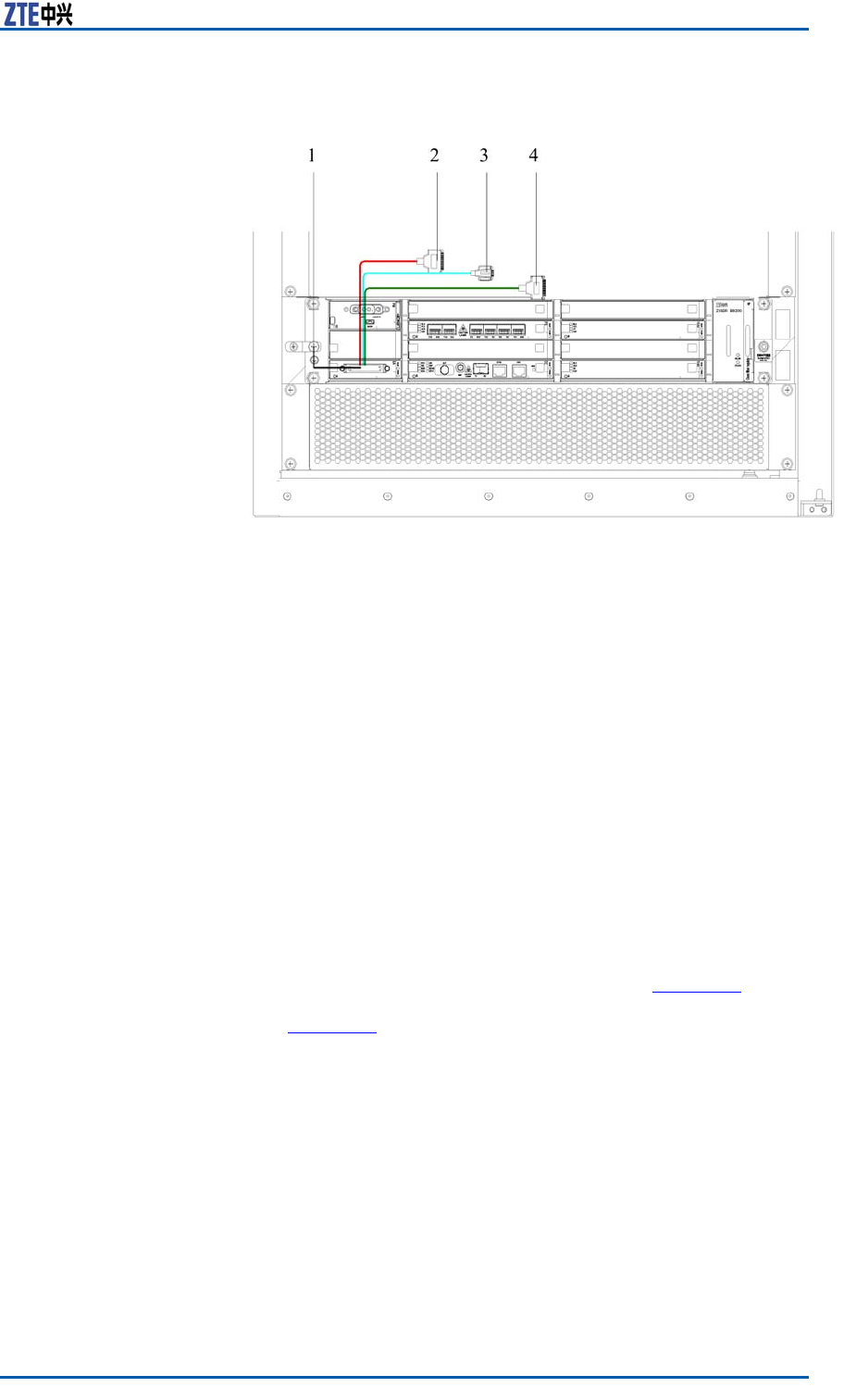
Chapter6InstallingCable
FIGURE33DATACABLEINSTALLATIONCOMPLETION
1.Groundterminal
2.E1/T1cable
3.RS232/RS485
4.Drycontactinput/output
PostrequisiteContinuetoinstalltheE1/T1,RS232/RS485,drycontactin-
put/outputcables.
Installing75ΩE1Cable
PrerequisiteInstalltheSAmoduleanditspanelconnectioncable.
ContextAbis-interface75ΩE1cableisthetransmissioncablebetween
ZXSDRBS8800C200andBSC,transmittingtheinterfacemessage
betweenZXSDRBS8800C200andBSC.
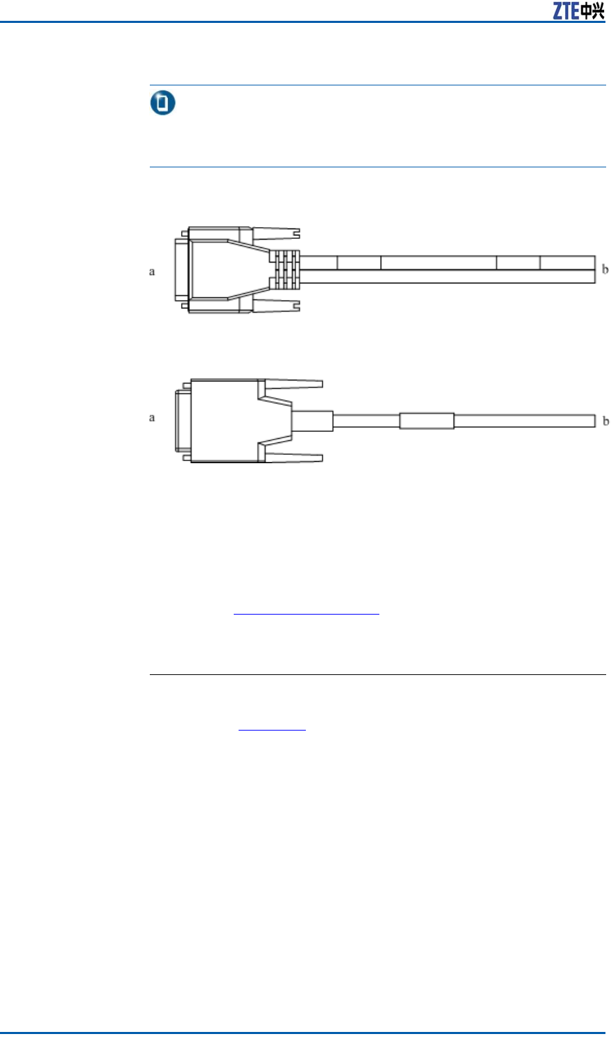
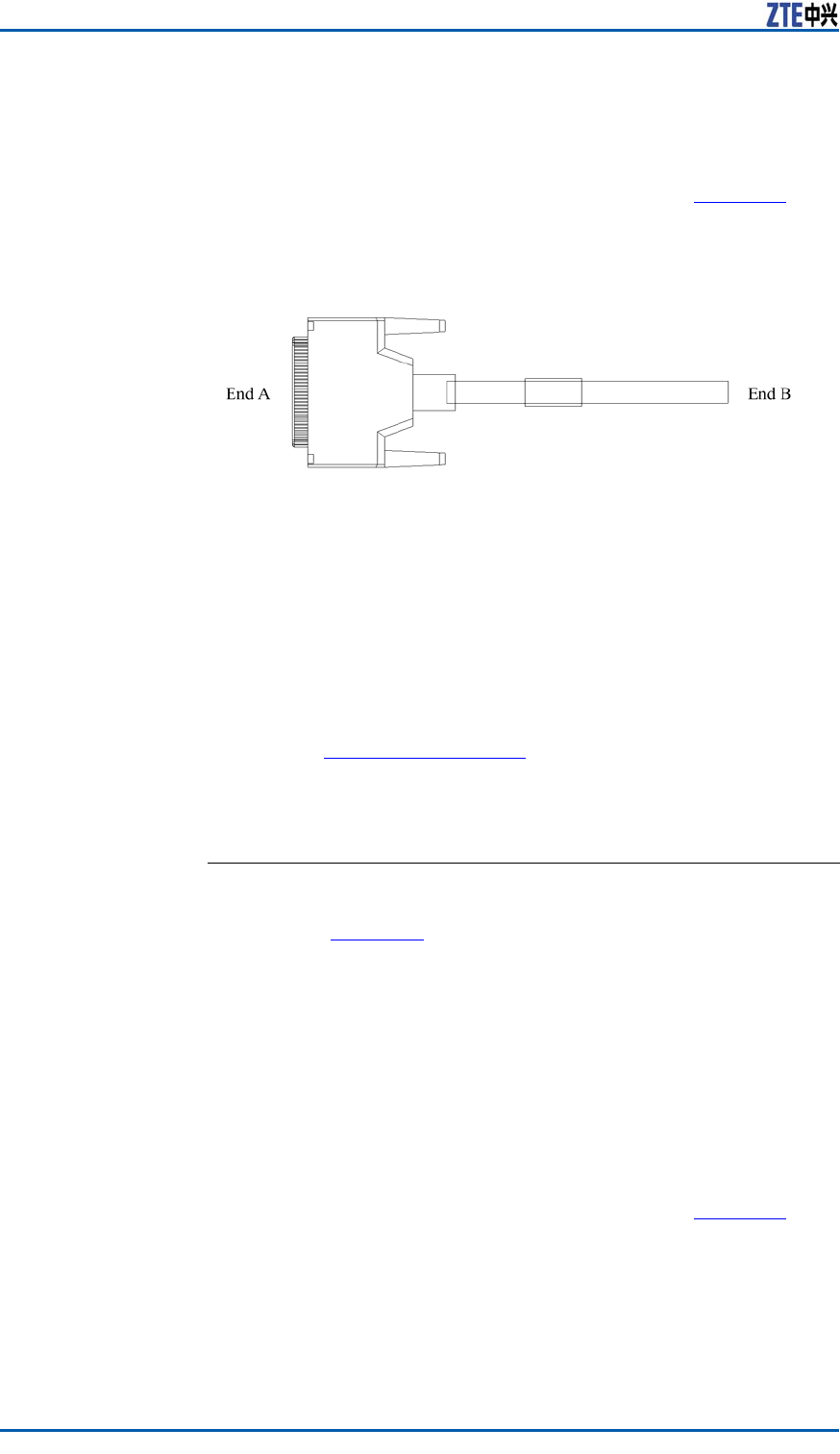
Theappearanceof75ΩE1cableisasshowninF
i g u r e 3 4 .Enda
ofthecableisaDB44straightconnector .Therearetwotypesof
cable:inFi g u r e 3 4 ,theabovecablesupportseightE1cablesand
thefollowingsupportsfourE1cables.
ConfidentialandProprietaryInformationofZTECORPORATION49
ZXSDRBS8800C200InstallationManual
Note:
IneightE1cable,1–4E1cablesareafxedwithlabelsandothers
arenot.
FIGURE34ABIS/IUBINTERFACE75ΩE1CABLEAPPEARANCE
Steps1.Leadthe75ΩE1cablethroughacableslotonthetopintothe
cabinet.
2.Layoutthe75ΩE1cablealongtheverticalcabletrayatthe
rightsideofcabinettotheB2connector(E1cableconnector)
ofdatacablebelongingtothebaseband.
RefertoI
n s t a l l i n g D a t a C a b l e fortheinstructionofdatacable.
3.ConnecttheDB44connectorof75ΩE1cabletotheB2inter-
face(E1cableinterface)ofdatacablethroughtheSAmodule.
ENDOFSTEPS.
ResultAfterinstallationcompleted,theappearanceof75ΩE1cableis
asshowninF
i g u r e 3 5 .
50ConfidentialandProprietaryInformationofZTECORPORATION
Chapter6InstallingCable
FIGURE3575ΩE1CABLEINSTALLATIONCOMPLETION
Installing120ΩE1Cable
PrerequisiteInstalltheSAmoduleanddatacable.
ConfidentialandProprietaryInformationofZTECORPORATION51
ZXSDRBS8800C200InstallationManual
ContextThe120ΩE1cableisthetransmissioncablebetweenZXSDR
BS8800C200andBSC,transmittingtheinterfacemessagebe-
tweenZXSDRBS8800C200andBSC.
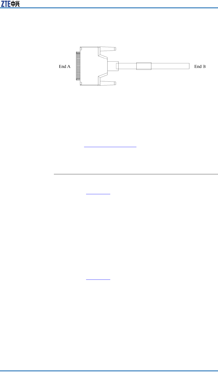
Theappearanceof120ΩE1cableisasshowninF
i g u r e 3 6 .End
AofcableisaDB44straightplug.
FIGURE36120ΩE1CABLEAPPEARANCE
Therearetwotypesof120ΩE1:onesupports8E1cablesand
theothersupports4E1cables.Theappearancesoftwocablesare
similar ,butthenumberofcorewireisdifferent.
Steps1.Leadthe120ΩE1cablethroughaslotonthetopintothe
cabinet.
2.Layoutthe120ΩE1cablealongtheverticalcabletrayatthe
rightsideofcabinettotheB2connector(E1/T1cableconnec-
tor)ofdatacable.
RefertoI
n s t a l l i n g D a t a C a b l e fortheinstructionofdatacable.
3.ConnecttheDB44connectorof120ΩE1cabletotheB2in-
terface(E1/T1cableinterface)ofdatacablethroughtheSA
panel.
ENDOFSTEPS.
ResultAfterinstallationcompleted,theappearanceof120ΩE1cableis
asshowninF
i g u r e 3 5 .
Installing100ΩT1Cable
PrerequisiteInstalltheSAmoduleanddatacable.
ContextThe100ΩT1cableisthetransmissioncablebetweenZXSDR
BS8800C200andBSC,transmittingtheinterfacemessagebe-
tweenZXSDRBS8800C200andBSC.
Theappearanceof100ΩT1cableisasshowninF
i g u r e 3 7 .End
AofcableisaDB44straightplug.
52ConfidentialandProprietaryInformationofZTECORPORATION
Chapter6InstallingCable
FIGURE37100ΩT1CABLEAPPEARANCE
Steps1.Leadthe100ΩT1cablethroughaslotonthetopintothe
cabinet.
2.Layoutthe100ΩT1cablealongtheverticalcabletrayatthe
rightsideofcabinettotheB2connector(E1/T1cableconnec-
tor)ofdatacable.
RefertoI
n s t a l l i n g D a t a C a b l e fortheinstructionofdatacable.
3.ConnecttheDB44connectorof100ΩT1cabletotheB2in-
terface(E1/T1cableinterface)ofdatacablethroughtheSA
module.
ENDOFSTEPS.
ResultAfterinstallationcompleted,theappearanceof120ΩE1cableis
asshowninF
i g u r e 3 5 .
InstallingAbisInterface
EthernetCable
Prerequisite�ThetransmissionbetweenBTSandBSCisbasedontheIP
bearernetwork.
�InstalltheCCmodule.
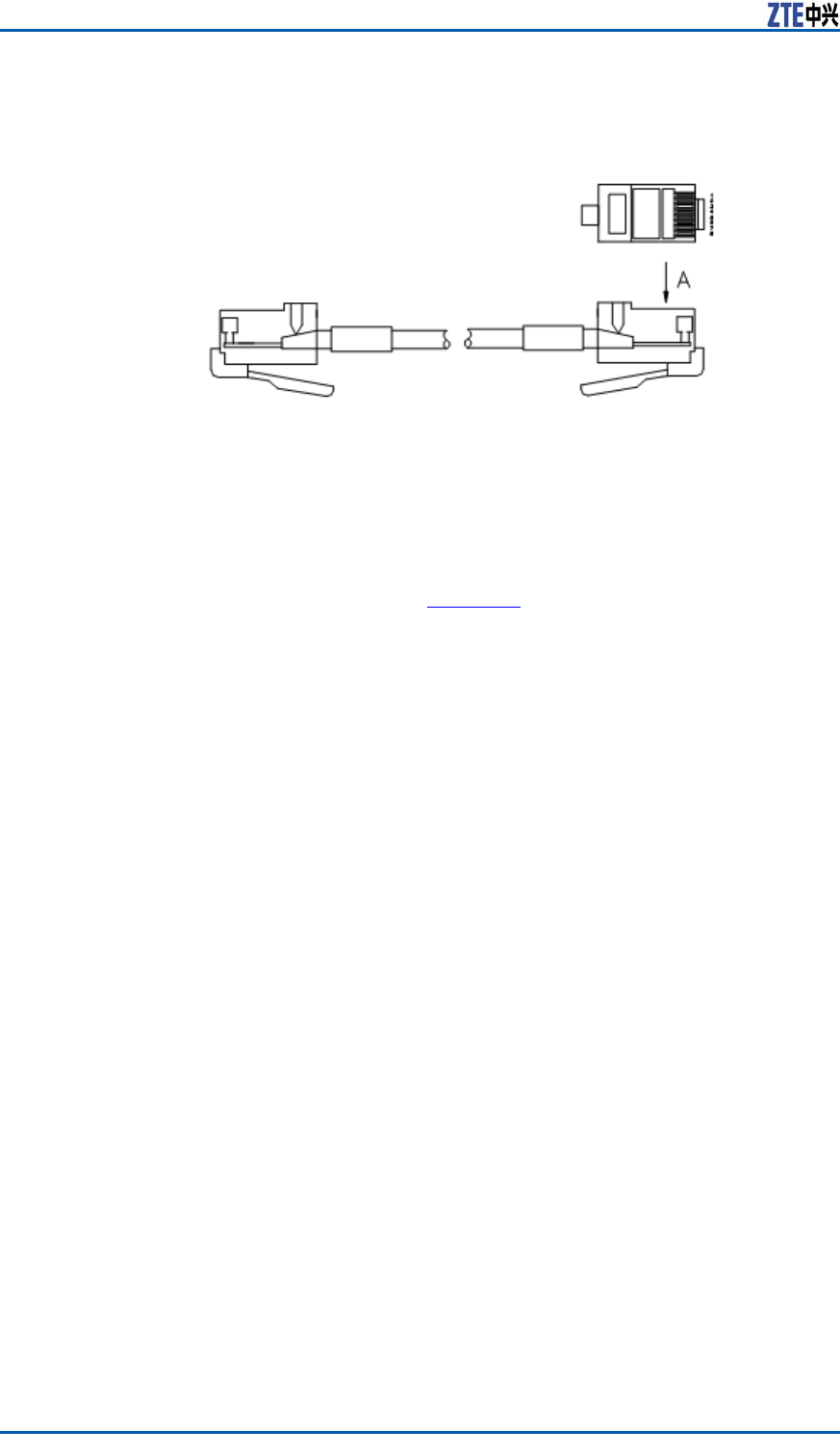
ContextBothendsofEthernetcablearecrimpedwiththeRJ45connector ,
asshowninFi g u r e 3 8 .
ConfidentialandProprietaryInformationofZTECORPORATION53
ZXSDRBS8800C200InstallationManual
FIGURE38ETHERNETCABLEAPPEARANCE
Steps1.LeadtheAbisinterfacethroughawireinletattherightsideof
cabinet.
2.LayouttheAbisinterfaceEthernetcablealongtheverticalca-
bletrayattherightsideofcabinettoCCmoduleofthebase-
band,asshowninF
i g u r e 3 9 .
54ConfidentialandProprietaryInformationofZTECORPORATION
Chapter6InstallingCable
FIGURE39ABISINTERFACEETHERNETCABLELAYOUT
3.ConnecttheRJ45connectorofEthernetcabletotheETH0in-
terfaceontheCCmodule.
ENDOFSTEPS.
InstallingDryContact
Input/outputCable
PrerequisiteInstalltheSAmoduleanddatacable.
ConfidentialandProprietaryInformationofZTECORPORATION55
ZXSDRBS8800C200InstallationManual
ContextThedrycontactinput/outputcableisusedtoimport/exportdry
contactsignalsfromexternalequipment.
Theappearanceofdrycontactinput/outputcableisasshownin
F
i g u r e 4 0 .EndAofthecableisaDB25straightplugandEndBis
nakedwire.
FIGURE40DRYCONTACTINPUT/OUTPUTCABLEAPPEARANCE
Steps1.Leadthedrycontactcablethroughaslotonthetopintothe
cabinet.
2.Layoutthedrycontactcablealongtheverticalcabletrayat
therightsideofcabinettoSAmoduleofthebaseband.
3.ConnecttheDB25connectorofdrycontactcabletotheB4
interface(DB25)ofdatacablefromtheSAmodule.
ENDOFSTEPS.
ResultAfterinstallationcompleted,theappearanceofdrycableisas
showninF
i g u r e 4 1 .
56ConfidentialandProprietaryInformationofZTECORPORATION
Chapter6InstallingCable
FIGURE41DRYCONTACTINSTALLATIONCOMPLETION
ConfidentialandProprietaryInformationofZTECORPORATION57
ZXSDRBS8800C200InstallationManual
InstallingRS232/RS485
MonitoringCable
Prerequisite�InstalltheSAmodule.
�ConnecttheSApanelconnectioncable(datacable)totheSA
module.
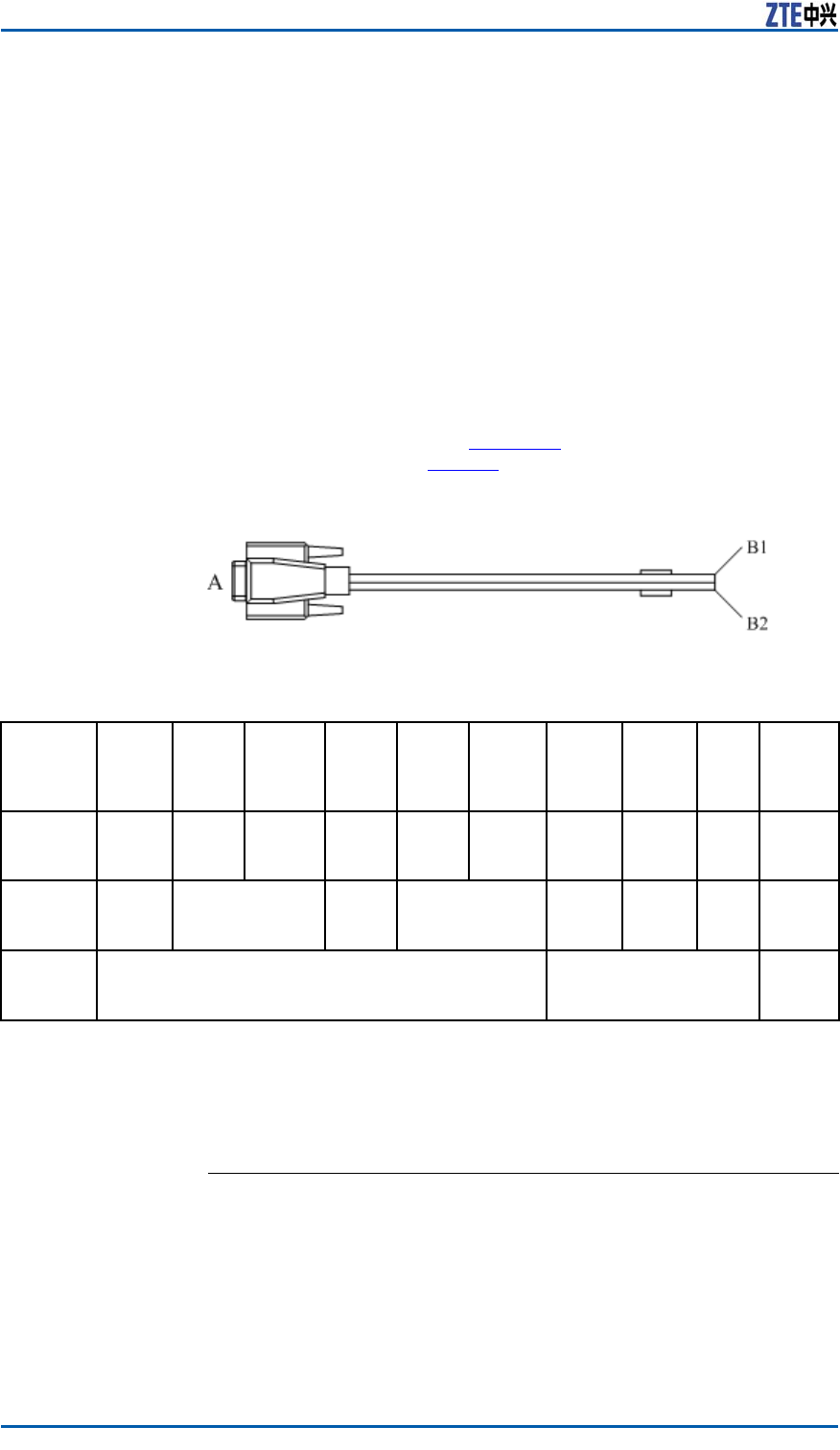
ContextTheRS232/RS485monitoringcableprovidesfunctionsofinter-
nalandexternalenvironmentmonitoringfortheZXSDRBS8800
C200.Theenvironmentmonitoringinvolvesthesmogmonitoring,
accesscontrolmonitoring,temperatureandhumiditymonitoring,
andoodingmonitoring.TheappearanceofRS232/RS485moni-
toringcableisasshowninF
i g u r e 4 2 .Thedenitionofcore-cable
signalsisdescribedinTa b l e 6 .
FIGURE42RS232/RS485MONITORINGCABLE
TABLE6RS232/RS485MONITORINGCABLEDESCRIPTION
Signal
Definit
ion
GNDD0_RS
485
–RX-
_EM
0_RS4
85–RX
+_EM
GNDD1_RS
485
–RX-
_EM
1_RS4
85–RX
+_EM
0_UA
RT-RX
_EM
1_UA
RT-TX
_EM
G
NDD
GND
EndA
PinNo.
167489235DB9
metal
sheath
Cable
Color
WhiteWhite&BlueGreenWhite&
Orange
BlueO
range
W
hite
Shie
lding
Layer
EndB
Name
B1B2Shie
lding
Layer
Steps1.ConnectEndA(DB9connector)ofRS232/RS485monitoring
cabletotheB3connector(DB9)ofSApanelconnectioncable-
datacable.
2.Fastenjunctionsoftheconnectorswithtapes.
ENDOFSTEPS.
58ConfidentialandProprietaryInformationofZTECORPORATION
Chapter6InstallingCable
InstallingFiberbetween
BBUandRSU
Prerequisite�Installthecabinetcompletely.
�InstalltheZXSDRBS8800C200andallmodules.
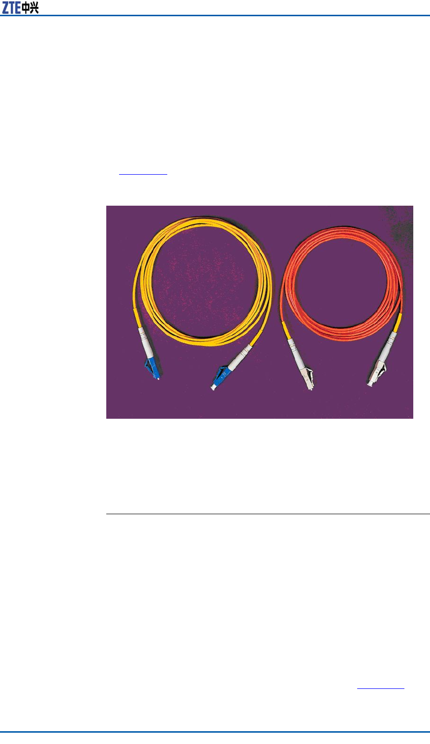
ContextTheappearanceofZXSDRBS8800C200opticalberisasshown
inF
i g u r e 4 3 .
FIGURE43OPTICALFIBERAPPEARANCE
Steps1.Connectoneendofopticalbertotheopticalinterfaceofthe
FSmoduleintheZXSDRBS8800C200.
2.ConnecttheotherendofopticalbertotheTX1/RX1optical
interfaceofRSU.
ENDOFSTEPS.
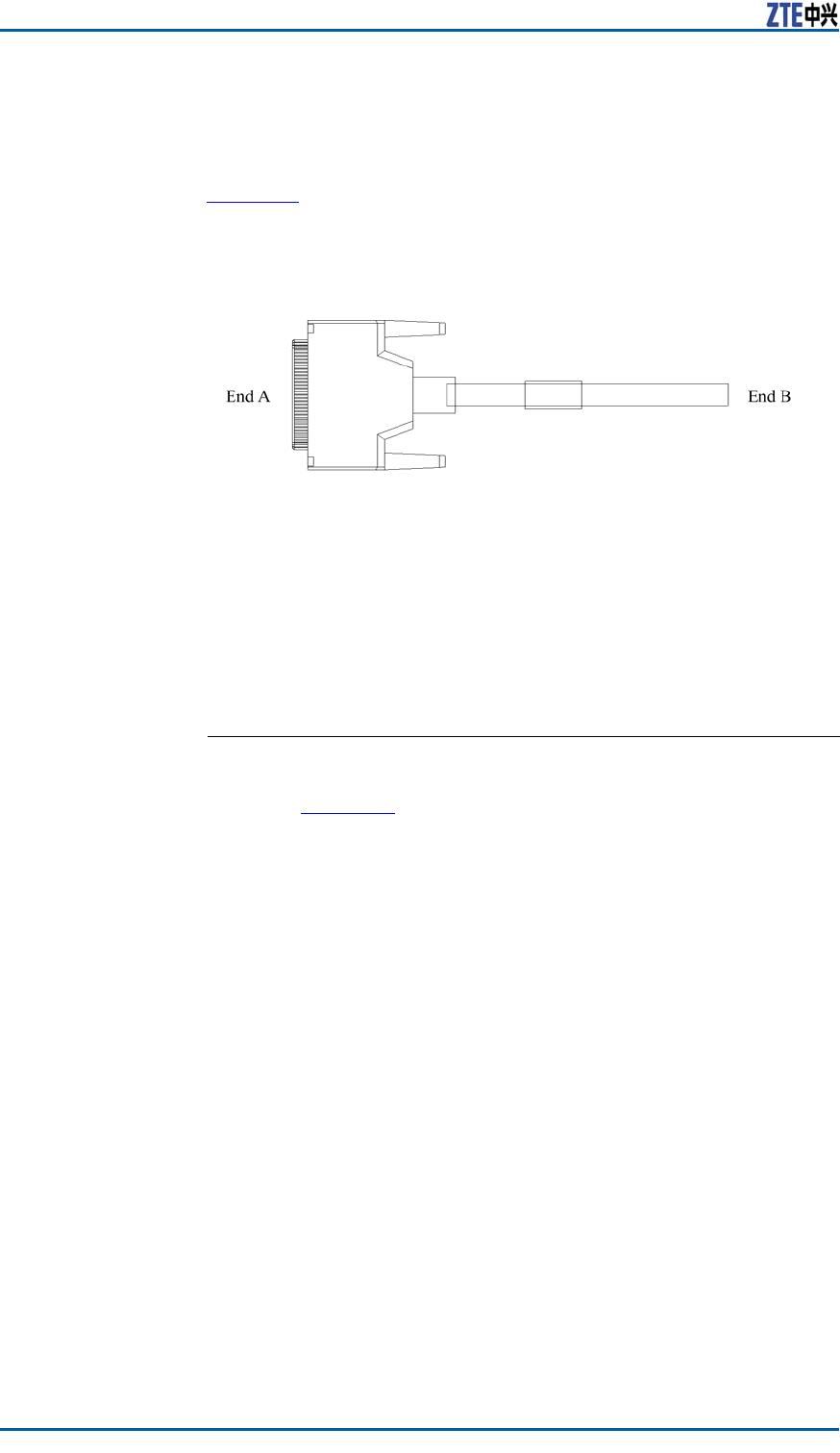
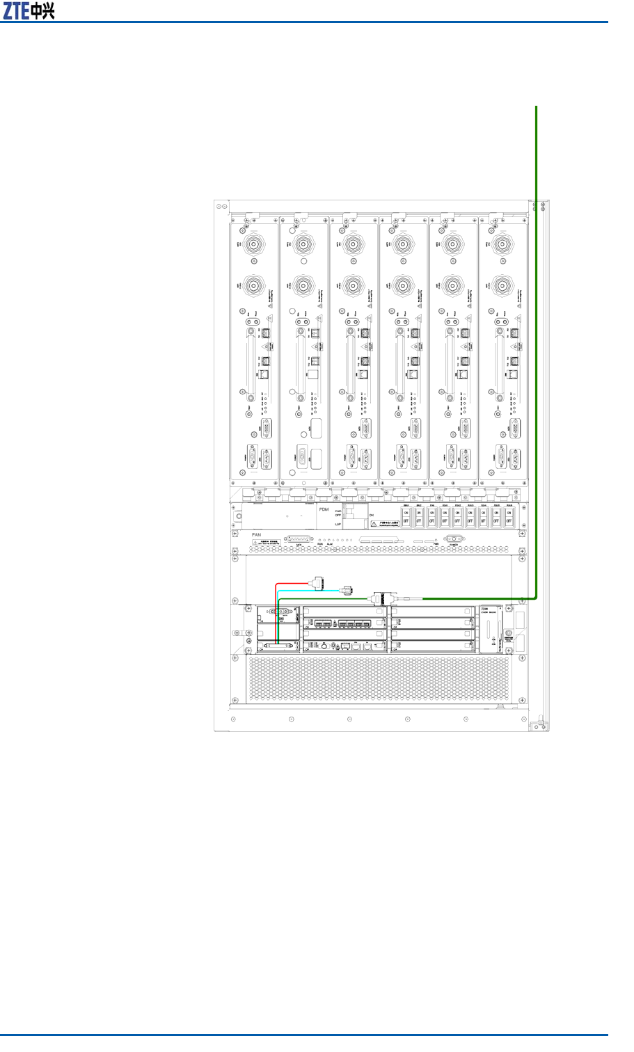
InstallingAISGControl
Cable
ContextTheAISGcontrolcableisusedforcontroloftheelectric-adjust-
mentantenna.Thecablecanfulllalong-distancecontrolofdip
anglesorphasesofantennatoadjustthecoveragerangeofwire-
lesssignal.
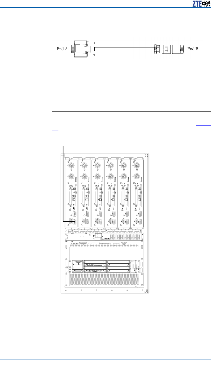
ThestructureofAISGcontrolcableisasshowninF
i g u r e 4 4 .
ConfidentialandProprietaryInformationofZTECORPORATION59
ZXSDRBS8800C200InstallationManual
FIGURE44AISGCONTROLCABLESTRUCTURE
Steps1.ConnectEndAofAISGcontrolcabletothedebugginginter-
face(AISG)ofZXSDRBS8800C200andfastenscrewsofthe
interface.
2.ConnectEndBofAISGcontrolcabletothecontrolinterfaceof
electric-adjustmentantennaandfastenscrewsoftheinterface.
ENDOFSTEPS.
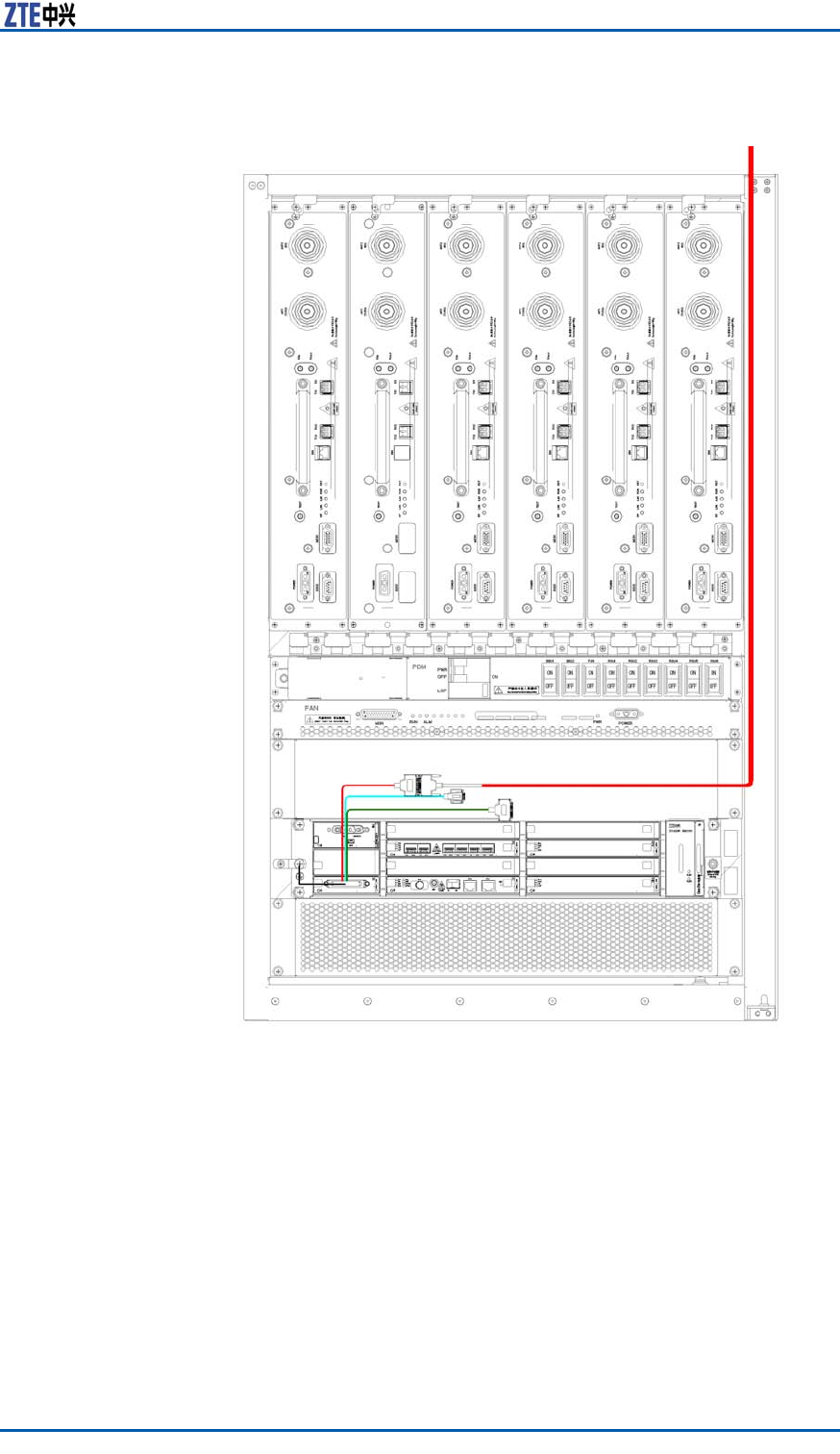
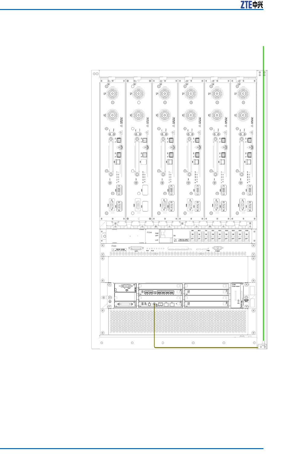
ResultTheAISGcontrolcableisinstalledcompletely,asshowninF i g u r e
45.
FIGURE45AISGCONTROLINSTALLATIONCOMPLETION
60ConfidentialandProprietaryInformationofZTECORPORATION

Chapter6InstallingCable
InstallingGPSJumper
Prerequisite�Installthecabinetcompletely.
�InstalltheZXSDRBS8800C200andmodules.
�InstalltheGPSarrester .
ContextTheGPSjumperisasectorofcabletoconnecttheGPSinterface
ofCCmodulewiththeGPSarrester ,theappearanceasshownin
F
i g u r e 4 6 .
FIGURE46GPSJUMPERAPPEARANCE
Steps1.ConnectEndAofjumpertothe“REF”antennainterfaceofCC
module.
2.ConnectEndBtotheGPSarrester .
ENDOFSTEPS.
ResultTheGPSjumperisinstalledcompletely,asshowninF i g u r e 4 7 .
ConfidentialandProprietaryInformationofZTECORPORATION61
ZXSDRBS8800C200InstallationManual
FIGURE47GPSJUMPERINSTALLATIONCOMPLETION
62ConfidentialandProprietaryInformationofZTECORPORATION
Chapter6InstallingCable
InstallingRFJumper
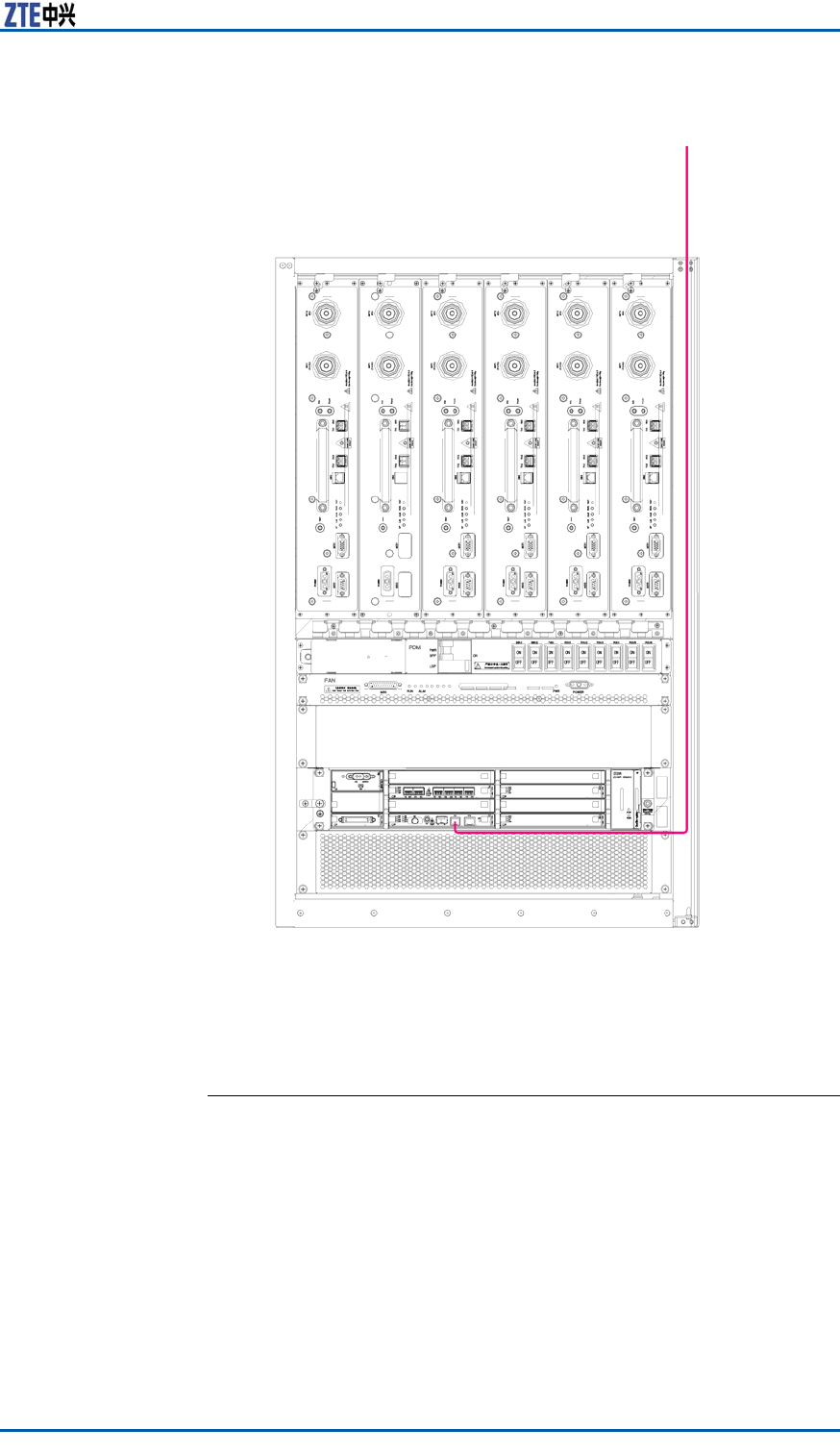
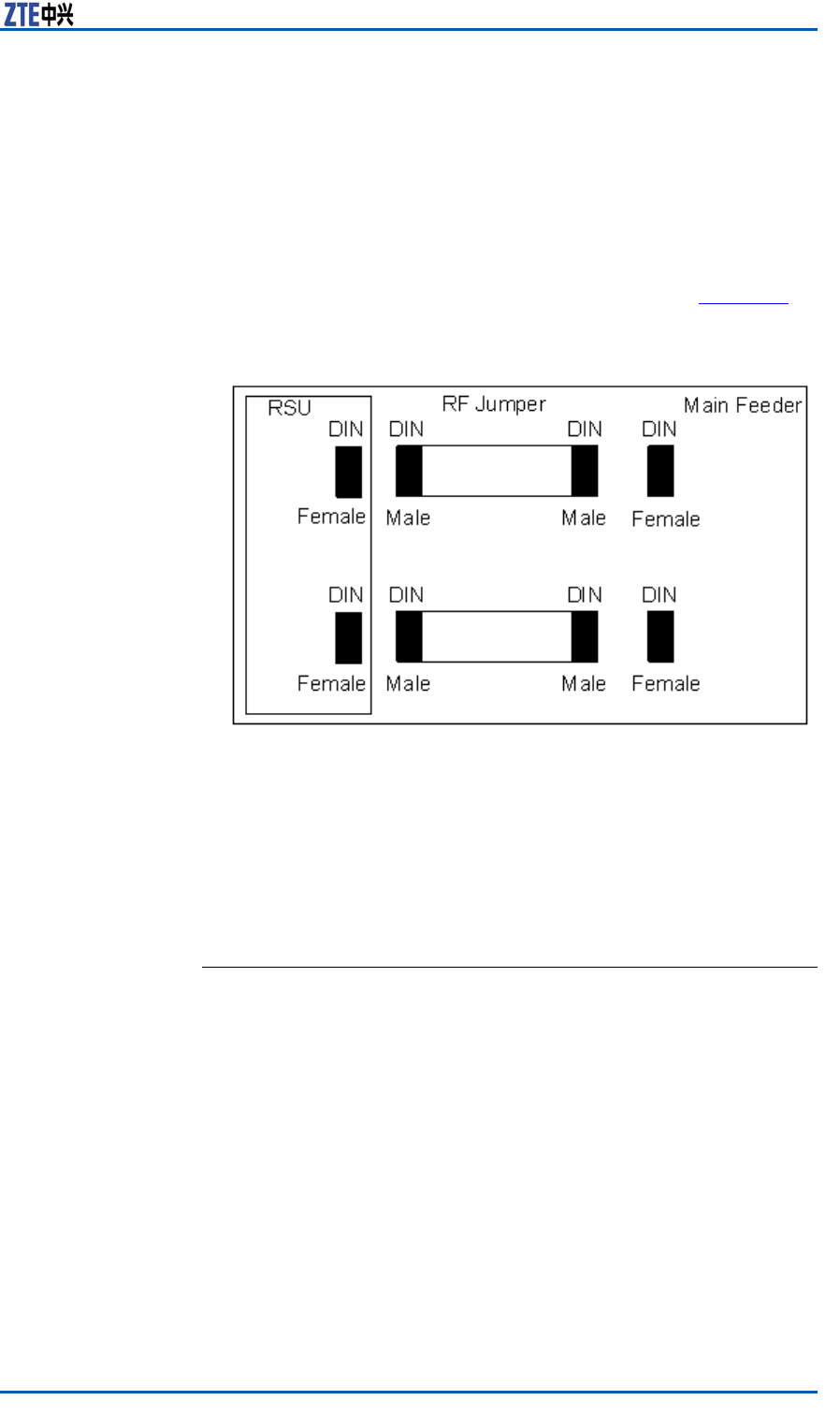
ContextTheRFjumperisasectionofcabletoconnectthemainfeederwith
theantennafeederinterfaceofZXSDRBS8800C200.Usually,
installtheRFjumperafterthemainfeederinstalledcompletely.
TheRFjumperadoptsanished1/2″typewith5m.
TheinstallationpositionofRFjumperisasshowninF
i g u r e 4 8 .
FIGURE48RFJUMPERINSTALLATIONPOSITION
Steps1.ConnectthemaleDINconnectorofRFjumperwiththefemale
DINconnectorofmainfeeder .
2.ConnectthemaleDINconnectorofRFjumpertotheRFan-
tennainterfaceofRSU.
3.Carryoutwaterproofhandlingforconnectors.
ENDOFSTEPS.
ConfidentialandProprietaryInformationofZTECORPORATION63

ZXSDRBS8800C200InstallationManual
Thispageisintentionallyblank.
64ConfidentialandProprietaryInformationofZTECORPORATION
C h a p t e r 7
InstallingGPSAntenna
FeederSystem
TableofContents:
GPSAntennaFeederSystemInstallationFlow.......................65
GPSAntennaFeederSystemInstallationPreparation..............66
InstallingGPSAntenna.......................................................66
InstallingGPSFeeder.........................................................73
GPSAntennaFeeder
SystemInstallationFlow
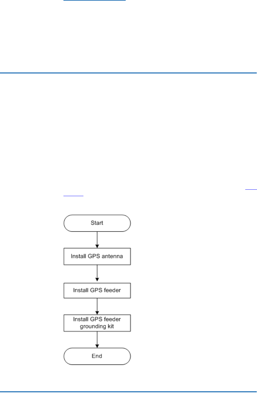
TheinstallationowofGPSantennafeedersystemislistedinF
i g -
u r e 4 9 .
FIGURE49GPSANTENNAFEEDERSYSTEMINSTALLATIONFLOW
ConfidentialandProprietaryInformationofZTECORPORATION65
ZXSDRBS8800C200InstallationManual
GPSAntennaFeeder
SystemInstallation
Preparation
TheinstallationpreparationoftheGPSantennafeedersystemis
asfollows:
�PreparetheGPSantenna.
�Assigninstallationpersonnel.
�Preparetechnicaldocuments,toolsandmeasureinstrument.
�MakeconnectorsofGPSfeederandjumper .
InstallingGPSAntenna
GPSAntennaInstallationPosition
GPSAntenna
Installation
Positioning
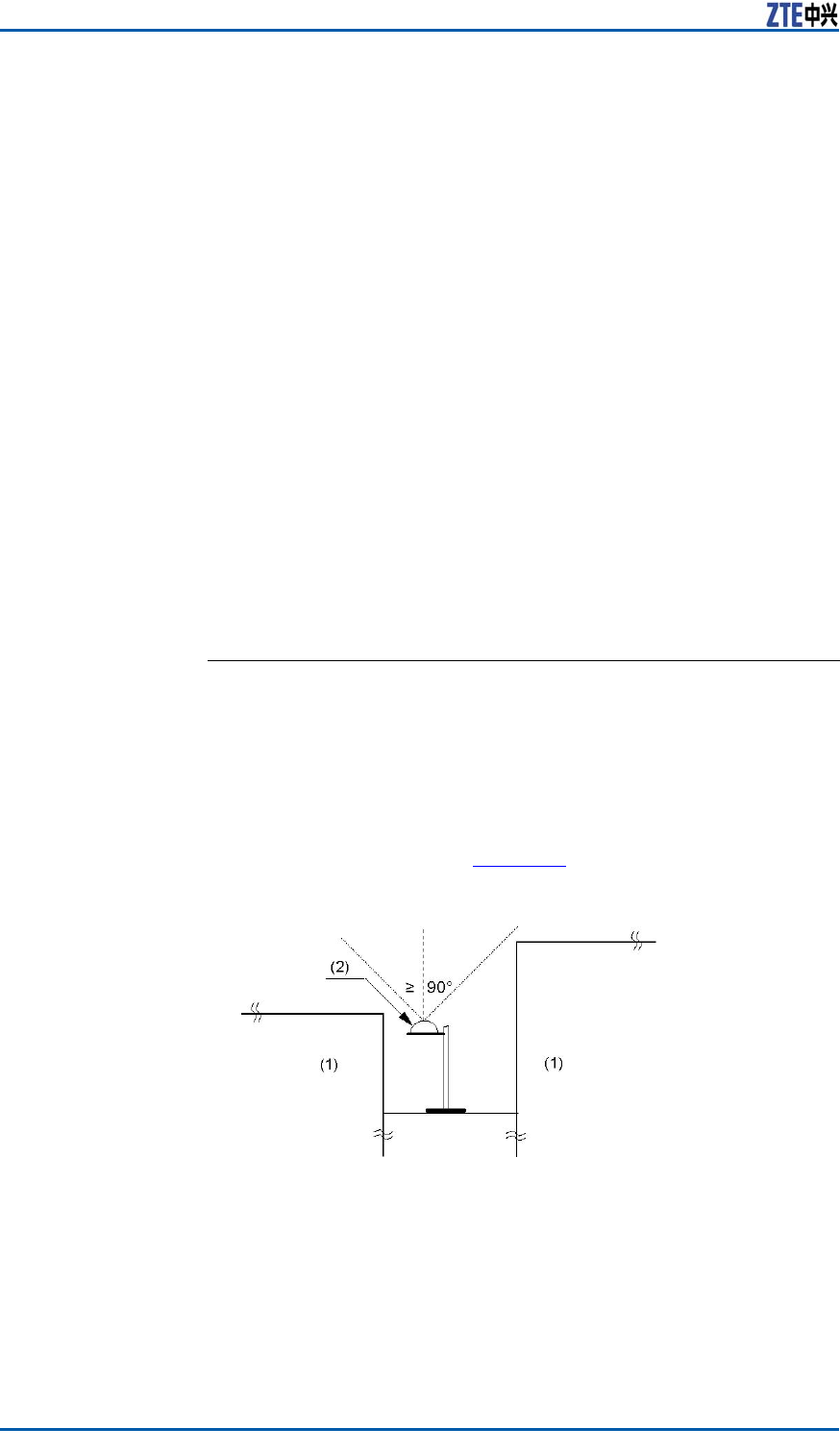
TheGPSantennainstallationpositionshouldmeetthefollowing
requirements:
�Theinstallationpositionshouldbefarawayfromhighandlarge
buildingsaswellassomebuildingsonthetopofwhichsmall
afliatedconstructionslocate.Theupward—verticallyvisual
angleofantennaismorethan90°.Theinstallationpositionof
antennaisasshowninF i g u r e 5 0 .
FIGURE50GPSANTENNAINSTALLATIONPOSITION
1.Ambientconstructionorother
obstructions
2.GPSantenna
�Theinstallationpositioncannotberadiatedinaneardistance
byafaceofmainlobeofmobilecommunicationantenna.Do
notlocatetheantennaundermicrowavesignalfrommicrowave
antenna,high-voltagecablesandstrongradiationfromaTV
emissiontower .
66ConfidentialandProprietaryInformationofZTECORPORATION

Chapter7InstallingGPSAntennaFeederSystem
�Consideringfromlightning,selectthecenterofroofforanin-
stallationposition.Donotinstalltheantennaonthesunkfence
aroundtheroofaswellasatacorneroftheroof,inorderto
preventfromlightning.
�Thereshouldbeotherspecialandsimilarequipmentnearto
theinstallationposition,suchasotheroperation’stower .Make
suretheantennawithinaprotectiveareaofarrester .Ifthereis
noirontowerorarrester ,installaspecialarrestertomeetthe
requirementoflightningdesign.Theleveldistancebetween
arresterandGPSantennashouldkeep2~3mandbe0.5m
higherthanthereceivingconnectorofGPSantennaatleast.
InstallingGPSAntennainVertical
Placement
PrerequisiteFollowingtoolsmustbeready.
�Adjustablespanner
�NormalSpanner
Itisrecommendedtohaveapolewithadiameterbetween30mm
~60mm(48mmisrecommended).Theantennashouldnotbe
installedduringrainandheavywind.
Steps1.OpenthepackageandtakeoutGPSantennaandtheGPSrack.
2.UsetheU-shapeclamptoinstalltheGPSracktothemounting
pole.InsertspringwasherandwasherbetweentheU-shaped
clampandmountingpole.
3.UseM6nuttoxtheU-shapeclampandthepoletogether
rmly.
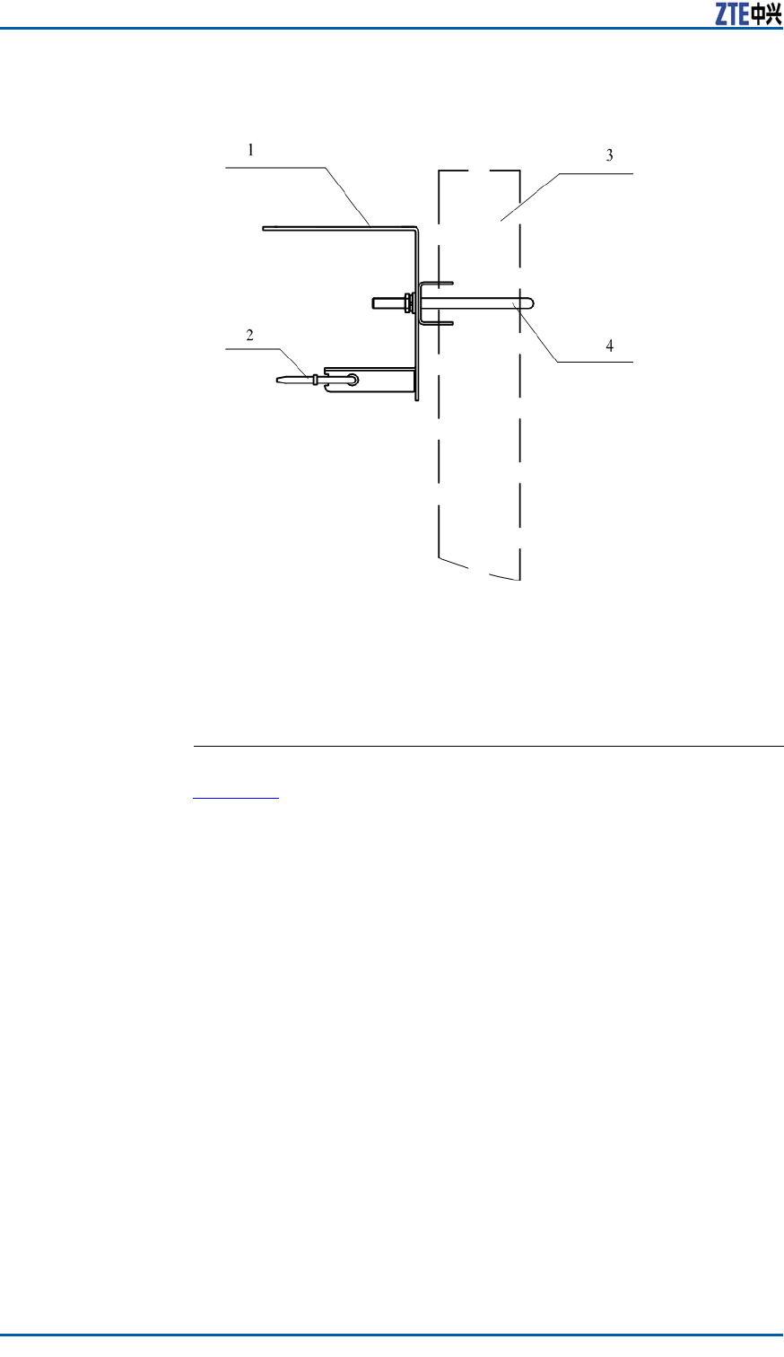
F
i g u r e 5 1 showsthexingprocess.
ConfidentialandProprietaryInformationofZTECORPORATION67
ZXSDRBS8800C200InstallationManual
FIGURE51U-SHAPEDCLAMPINSTALLATION
1.GPSsettledclamp
2.Cablestrip
3.Mountingpole
4.U-shapeclamp
4.FixtheGPSantennatotheGPSsettledclamp.Screwthebolt
(M4x14)tormlyxtheantenna.
ENDOFSTEPS.
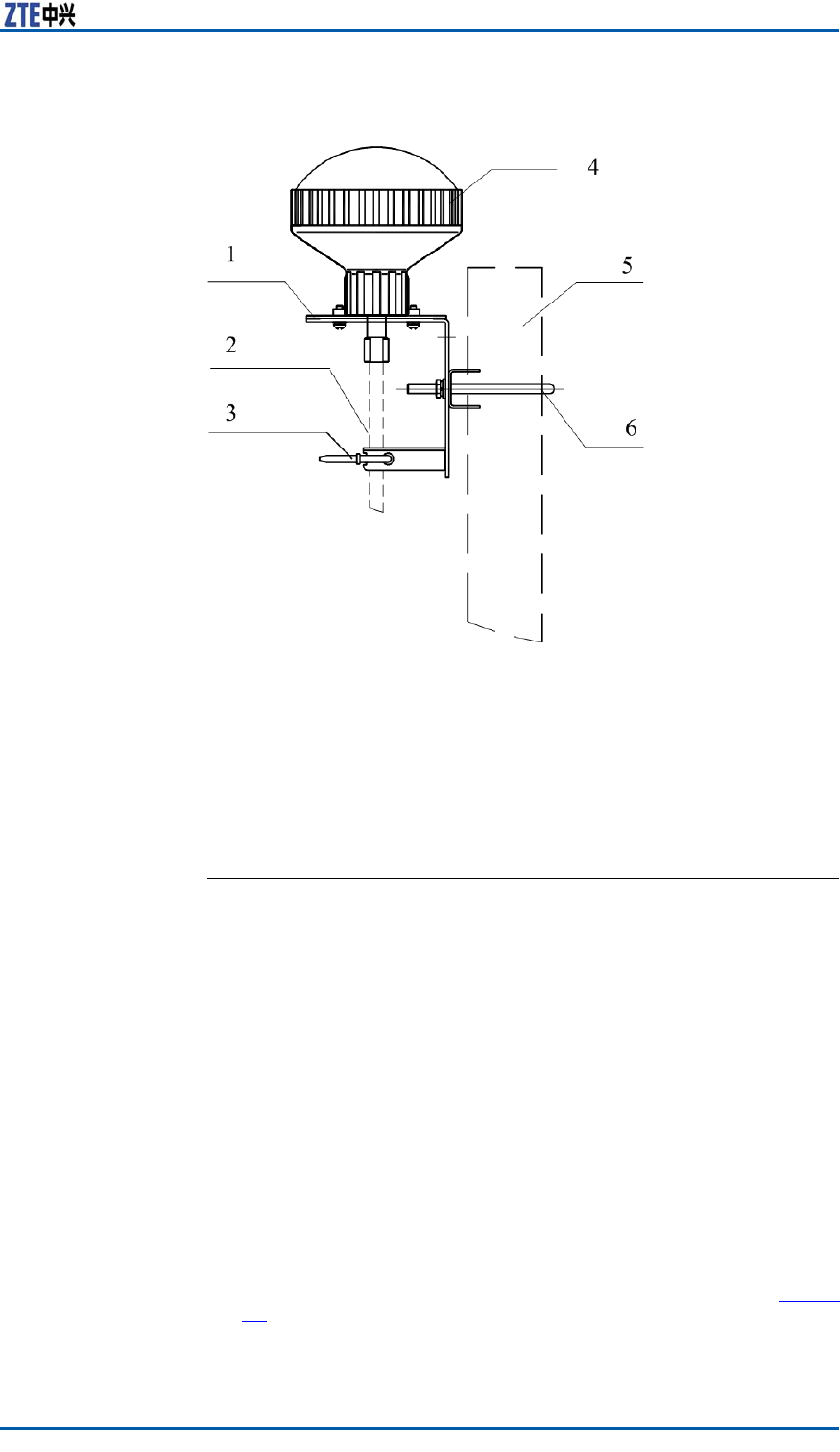
ResultF i g u r e 5 2 showstheantennaxedintheverticalposition.
68ConfidentialandProprietaryInformationofZTECORPORATION
Chapter7InstallingGPSAntennaFeederSystem
FIGURE52GPSANTENNAVERTICALINSTALLATION
1.GPSsettledclamp
2.Feeder
3.Feederstrip
4.GPSantenna
5.Mountingpole
6.U-shapeclamp
InstallingGPSAntennainHorizontal
Placement
PrerequisiteConrmtheinstallationmodeandinstallationpositionofGPSan-
tenna.
Followingtoolsmustbeready:
�Adjustablespanner
�NormalSpanner
Context�Itisrecommendedtohaveapolewithadiameterbetween30
mm~60mm(48mmisoptimal).
�ThepoleusedtoxGPSantennamustbegroundedwell.
�Theantennacannotbeinstalledduringrainandheavywind.
Steps1.OpenthepackageandtakeoutGPSantennaandtheGPSrack.
2.UsetheU-shapeclamptoinstalltheGPSracktothemounting
pole.
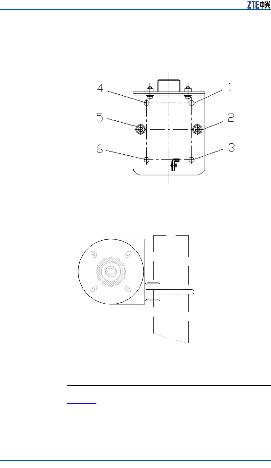
3.TheinstallationsupportofGPSantennaisasshowninF
i g u r e
53.AlignholesontheU-shapeclampwithHole1andHole3,
orHole4andHole6ontheinstallationsupport.Thencover
ConfidentialandProprietaryInformationofZTECORPORATION69
ZXSDRBS8800C200InstallationManual
aspringwashandatwasherrespectivelyontheseholesand
fastenthemwithM6screws,asshowninF
i g u r e 5 4 .
FIGURE53GPSANTENNARACKINSTALLATIONSUPPORT
–1~6holeposition
FIGURE54GPSRACKINSTALLATION(HORIZONTALPLACEMENT)
4.FixtheGPSantennatotheGPSsettledclamp.Screwdown
thebolt(M4x14)tormlyxtheantenna.
ENDOFSTEPS.
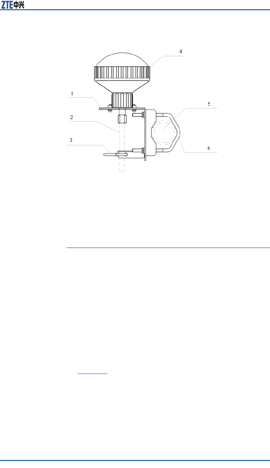
ResultF i g u r e 5 5 showstheGPSantennaxedhorizontally.
70ConfidentialandProprietaryInformationofZTECORPORATION
Chapter7InstallingGPSAntennaFeederSystem
FIGURE55GPSANTENNAFIXEDHORIZONTALLY
1.GPSsettledclamp
2.Feeder
3.Feederstrip
4.GPSantenna
5.Mountingpole
6.U-shapeclamp
InstallingGPSAntennainWall-mount
Mode
PrerequisiteFollowingtoolsmustbeready.
�Adjustablespanner
�NormalSpanner
�Hammer
�ExpansionAnchorBolts(M5x30orM5x40)
ContextForinstallingtheGPSAntennaonthewall,theU-shapeclampis
notnecessary.
Steps1.OpenthepackageandtakeoutGPSantennaandtheGPSrack.
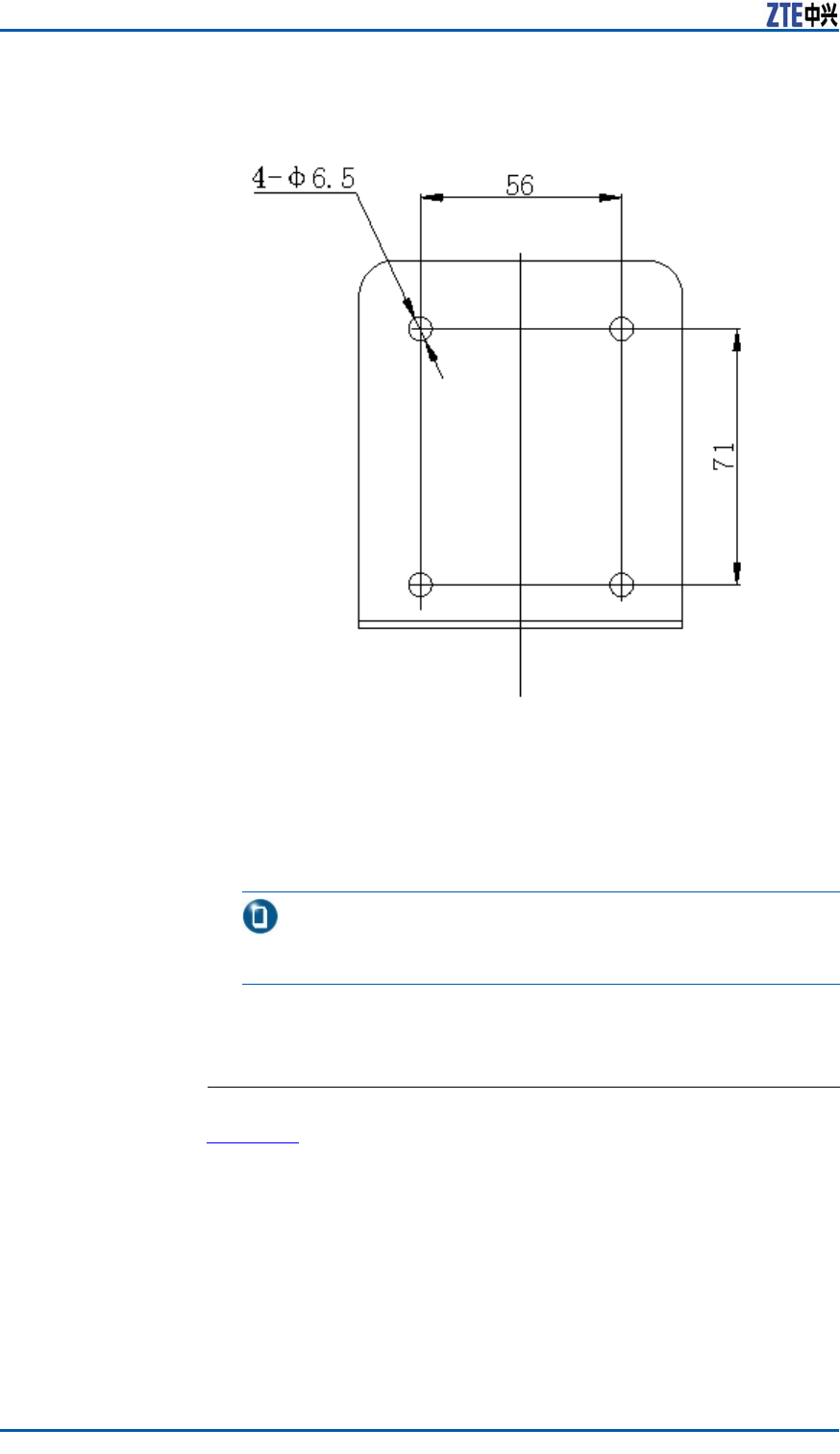
2.UsetheDesigntemplateformarkingholesonthewall.Then
drillholesonthewallaccordingthesizeoftheexpansionan-
chorboltsthattobeused.
F
i g u r e 5 6 showsthedesigntemplate.
ConfidentialandProprietaryInformationofZTECORPORATION71
ZXSDRBS8800C200InstallationManual
FIGURE56DESIGNTEMPLATEFORMARKINGHOLES
3.Inserttheexpansionbolts,andhammerthemtoxproperly.
4.InstallGPSantennaracktothecorrespondingboltposition.
5.Insertaspringwasherandatwasherontoexpansionbolts
andusetheM6nuttoxtherackonthewallrmly.
Note:
Thetorqueusedtoxtheclampis45Nm.
6.FixtheGPSantennatotheGPSsettledclampandscrewthe
M4x14bolttightly.
ENDOFSTEPS.
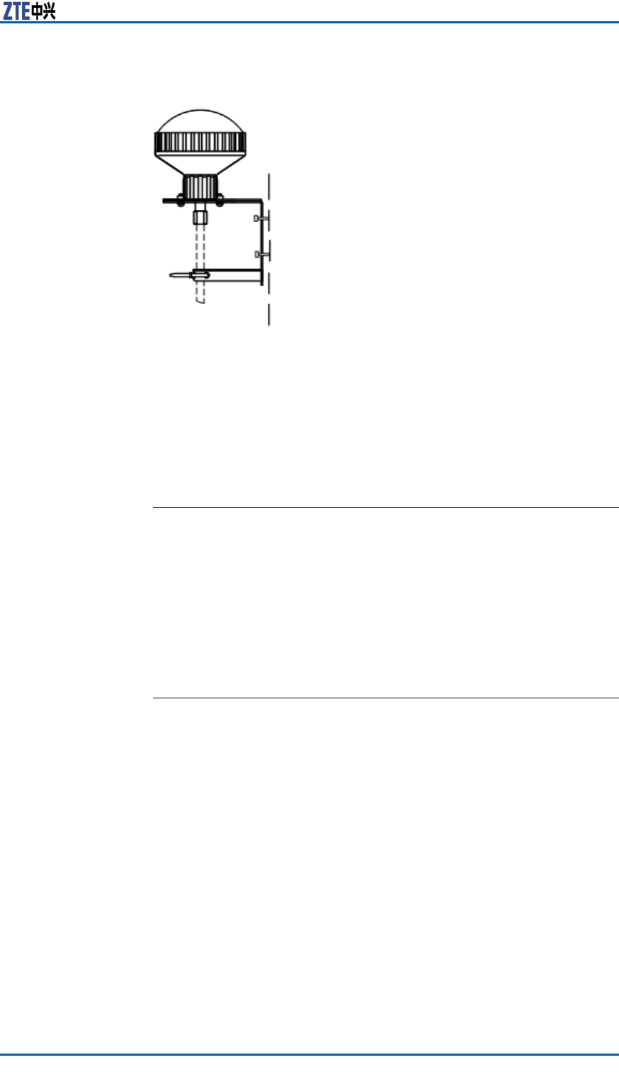
ResultF i g u r e 5 7 showstheGPSantennaxedonthewall.
72ConfidentialandProprietaryInformationofZTECORPORATION
Chapter7InstallingGPSAntennaFeederSystem
FIGURE57GPSANTENNAFIXEDONWALL
InstallingGPSFeeder
GPSFeederSelectionPrinciple
GPSfeederselectioncomplieswiththefollowingprinciples:
�WhenthelengthofGPSfeederislessthan100m,select1/4"
feeder .
�WhenthelengthofGPSfeederismorethan100m,please
contactwithZTElocalofce.
WiringGPSFeeder
PrerequisiteBeforefeederlayout,checklayoutenvironmentsuchastheiron
towerandroof;accordingtotherequirementsofengineeringde-
signdrawing,makesuretheplanningandproceduresoflayout.
ContextTakenoticeofthefollowingitemswhileperforminglayoutofthe
GPSfeeder:
�Thefeederpassagefromtheinstallationpositiontotheequip-
mentroomshouldbeunhinderedandaccordswiththewiring
requirements;takesomemeasurementsforrainprotection
andanticorrosion.
�Makeawateravoidancecrookwhilethefeederisimported
fromoutdoorstoindoors;thelowestpointofwateravoidance
crookkeepsaverticaldistanceof200mmatleastfromthe
inletforwaterproof.
�Unusedfeederconnectorsshouldbeprotectedwithsolidma-
terial,suchaspackingbags,fromdamagingthereconnectors
duringcablelayout.
ConfidentialandProprietaryInformationofZTECORPORATION73
ZXSDRBS8800C200InstallationManual
�Unfoldthefeederandlayoutit;avoidtwistingaspossibleas
youcan;ifitisnecessaryforbending,makesuretheradiusof
bendingnotlessthantheminimumradiusofbendingpermitted
bycables.
�IftheGPSantennaisinstalledontheroof,xthefeederalong
thewallfootontheroofwithplasticclipswhichsteelnails
areattachedto;keepandistanceof1mbetweenplasticclips;
thedirectionsofplasticclipheadarestaggeredmutuallyand
regularly;twofeedersafterjunctionshouldbeboundtogether
incaseoftwistingmutuallyandbending.
Steps1.Attachamarkrespectivelyatthebothendsoffeeder .
2.Protectthefeederconnectorwithlinen(alsoadoptaantistatic
pagingbagwithprotectivefoam)andfastenthebagwitha
bandingtape.
3.MovetheGPSfeederneartotheGPSantenna.
4.MakeanGPSfeederconnectoratoneendthroughthebiding
tape,connectwiththeGPSantennaandscrewdownthecon-
nectorclockwise,asshowninF
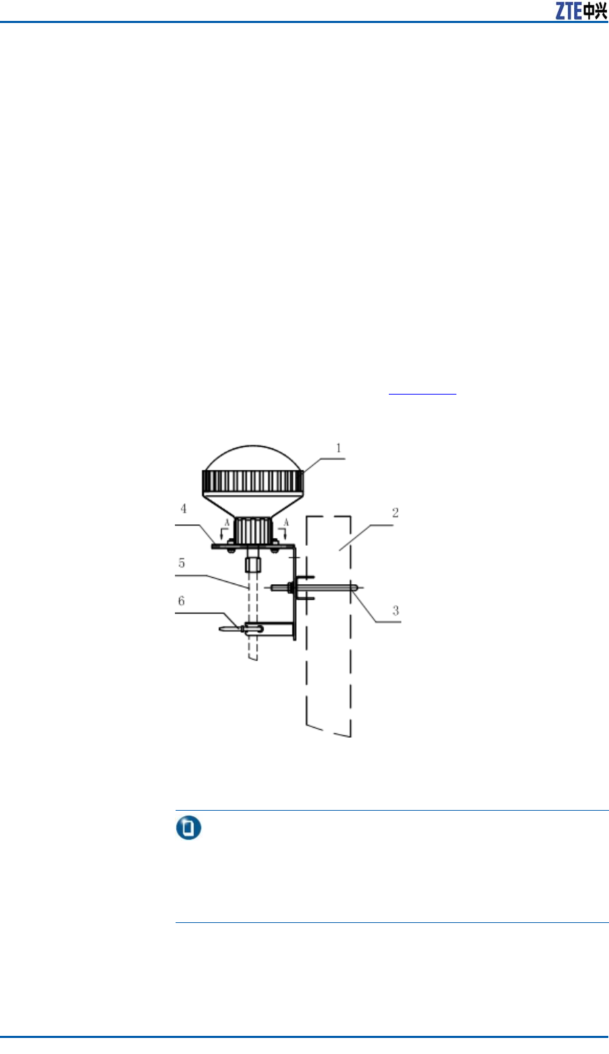
i g u r e 5 8 .
FIGURE58CONNECTIONBETWEENFEEDERTOGPSANTENNA
1.GPSAntenna
2.Pole
3.HoopIron
4.GPSMountingPanel
5.GPSFeeder
6.FeederBindingT ape
Note:
Whilexingthefeeder ,itisrequiredtoscrewdownthefeeder
clockwise.Soconsideringthesituation,aftercompletingthe
abovestep,layoutthefeeder ,orelseitisinconvenientfor
installation.
5.Accomplishtheperformancemeasureofantennaandfeeder ,
makesurethatthesystemoperationisnormal,andthenmake
74ConfidentialandProprietaryInformationofZTECORPORATION

Chapter7InstallingGPSAntennaFeederSystem
awaterproofprotectionatthebackofGPSmountingpanelas
wellasatthejunctionofGPSfeederandGPSantenna.
6.FixtheGPSfeederwiththebindingtapeandcutaredundant
partatlyafterbinding.
ENDOFSTEPS.
InstallingGPS1/4”FeederGrounding
Kit
Prerequisite1.CompletetheinstallationandroutingofGPSfeeder .
2.Prepareinstallationmaterialsandtools.
�Theinstallationmaterialsinclude:
–Groundingkit(tinningcopperbraidattached)
–TwoM6×25hexagonheadscrew(springwasherand
plainwasherattached)
–OneM8×25hexagonheadscrew(springwasherand
plainwasherattached),usedtoconnectthegroundca-
bleandgroundbar .
–Assembled1/4"feedergroundcable
–Apackageoftungoil(10ml).
�Theinstallationtoolsinclude:
–Electricalknife
–M6screwdriver
–M8screwdriver .
ContextOnlyinstalltheGPS1/4"feedergroundingkitbeforethefeeder
comesintotheequipmentroom,anddonotallowtoinstallitat
otheranypositions.
ThestructureofGPS1/4"feedergroundingkitisasshowninF
i g -
u r e 5 9 .
ConfidentialandProprietaryInformationofZTECORPORATION75
ZXSDRBS8800C200InstallationManual
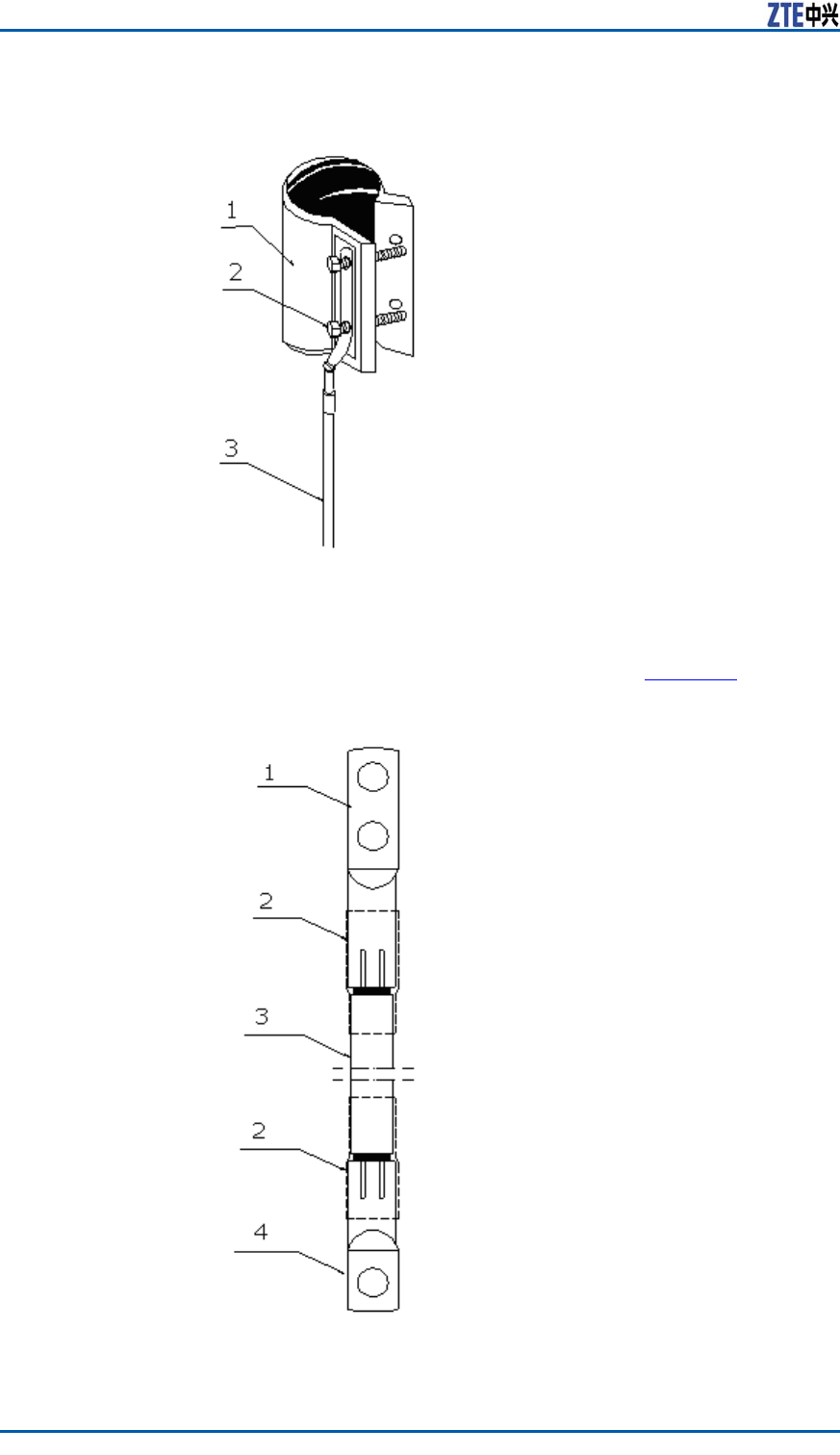
FIGURE59GPS1/4"FEEDERGROUNDINGKITSTRUCTURE
1.Groundingkit
2.M6hexagonheadscrew(plain
washerandspringwasherat-
tached)
3.Groundcable
ThestructureofgroundcableisasshowninF
i g u r e 6 0 .
FIGURE601/4"FEEDERGROUNDCABLESTRUCTURE
1.Groundterminal(onthesideof
groundingkit)
2.Φ12heatshrinkablesleeve
3.Groundcable
4.Groundterminal(onthesideof
coopergroundbar)
76ConfidentialandProprietaryInformationofZTECORPORATION

Chapter7InstallingGPSAntennaFeederSystem
Steps1.Makesurethegroundingpositionof1/4"GPSfeeder;stripa
sectionofthesheathofGPSfeeder(about25mm)accordingto
thesizeofgroundingkit,andplacethegroundingkitthrough
thestrippedpositionofGPSfeeder .
2.Fastenthegroundterminal(onthesideofgroundingkit,with
twogroundingholes)ontothegroundingkitwithM6hexagon
headscrews,placetheattachedspringwasherandplain
washerbetweenscrewandgroundterminal,andscrewdown
thescrewwithaM6screwdriver .
3.Fastentheothergroundterminal(onthesideofcooperground
bar)ontothecoopergroundbarwiththeM8×25hexagonhead
screw,andplacetheplainwasherandspringwasherbetween
screwandcoppergroundbar .
4.Coveralayeroftungoilontheexposedmetalsurface.
ENDOFSTEPS.
LeadingGPSFeederintoRoom
ContextThisstepisadoptableforanindoorBTS.Whileinstallingthefeeder
foranoutdoorBTS,thestepisnoneed.
Throughafeederhermeticwindow,leadtheGPSfeederintothe
equipmentroom.DetailedstepsrefertoL
e a d i n g M a i n F e e d e r i n t o
R o o m .
ConfidentialandProprietaryInformationofZTECORPORATION77

ZXSDRBS8800C200InstallationManual
Thispageisintentionallyblank.
78ConfidentialandProprietaryInformationofZTECORPORATION

C h a p t e r 8
InstallingMainAntenna
FeederSystem
TableofContents:
AntennaFeederSystemInstallationPreparation....................79
InstallingIndoorGroundingBar...........................................90
InstallingAntenna.............................................................93
InstallingFeederHermetic-window....................................125
InstallingandGroundingFeederandJumper.......................127
FeederIndoorIngoing......................................................135
PerformingAntennaFeederSystemTest.............................139
PerformingOutdoor-connectorWaterproofProcessing...........140
PerformingFeederHermetic-windowWaterproofProcess-
ing................................................................................142
AntennaFeederSystem
InstallationPreparation
FoundationalFacilityRequirements
IronTowerInordertoinsureequipmentsecurity,thefollowingmustbeper-
formedduringinstalling:
�Makesuretheheightandstrengthofirontowercomplyingwith
therequirementsofcontract.
�Checkwhetheragroundcopperbararoundtheirontoweris
madeanditsgroundingresistanceaccordswiththerequire-
ments.
�Checkwhethertheplatformofirontowerispreparedaccording
totherequirements.
InstallationPoleNormally,aninstallationpoleismadeofgalvanizedsteeltube.
Theouterdiameterofinstallationpoleis48mm~100mmand
thethicknessoftubeisnotlessthan2mm.Theheightofpole
is3masareference.Duetovariousantennatypes,adjustthe
actualdimensionofpoleaccordingtothespecicationofdifferent
antennas.
Inordertoinsureequipmentsecurity,thefollowingmustbeper-
formedduringinstalling:
ConfidentialandProprietaryInformationofZTECORPORATION79

ZXSDRBS8800C200InstallationManual
�Forinstallingantennawithapole,thedistancebetweenpoles
shouldaccordwiththerequirementsofengineeringdesign.In
thesamesector ,ahorizontaldiversitydistanceoftwo900MHz
receivingantennasmaintains4m~6m,andthatoftwo1800
MHzreceivingantennasmaintains2m~3m.Ifthereareother
types,complywiththedesigndocument.
�Ontheirontower ,usuallyinstalltheantennapoleontheen-
closureofplatform,morethan1mawayfromthetowerbody.
�Completeantennainstallationandcheckwhetherthepoleis
verticalwiththelevel,anerrornotover1°.
�Installtheantennapoleclosetotheedgeofbuildingtoppos-
sibly.Whileselectingadirectxationmodeonthesideofwall,
makesurethatthewallcansupportadequateintensity.
�Whileadoptingadirectxationmodeonthebuildingtop,make
acementbaseandpreventdrillingonthebuildingtopfrom
causingafaultofwaterproofequipment.
CableTrayInordertoinsureequipmentsecurity,thefollowingmustbeper-
formedduringinstalling:
�Adoptastandardcabletraywith400mmwidthintheequip-
mentroom.Thecabletrayisusuallyinstalledabovethecabi-
netataverticaldistanceof2600mmfromtheoorofequip-
mentroom.Afterinstallationcompletion,makesurethatthe
wholecabletrayisunmovable.
�Thelengthsleftofexpansionboltsshouldbeconsistent.After
screwingdownnuts,remainasectionofexpansionboltwith5
mmormorethantwocircles.
�Thepaintcolorsofcabletraykeepconsistent.
�Theindoorcabletrayshouldbegroundedatintervalof5m.
Afterinstallationcompletion,performanelectrictestandmake
suregroundingreliable.
CheckingIncomingMaterial
Steps1.Checkwhetherthepackingoffeederandinstallationacces-
soriesareintact.
2.Checkmaterialappearanceandmakesureitundamaged.
3.Checkwhetherthequantityanddimensionofmaterialsaccord
withtherequirementsofpackinglist.
4.Beforeinstallation,makesureallmaterialsavedaccordingto
therequirements.
ENDOFSTEPS.
80ConfidentialandProprietaryInformationofZTECORPORATION
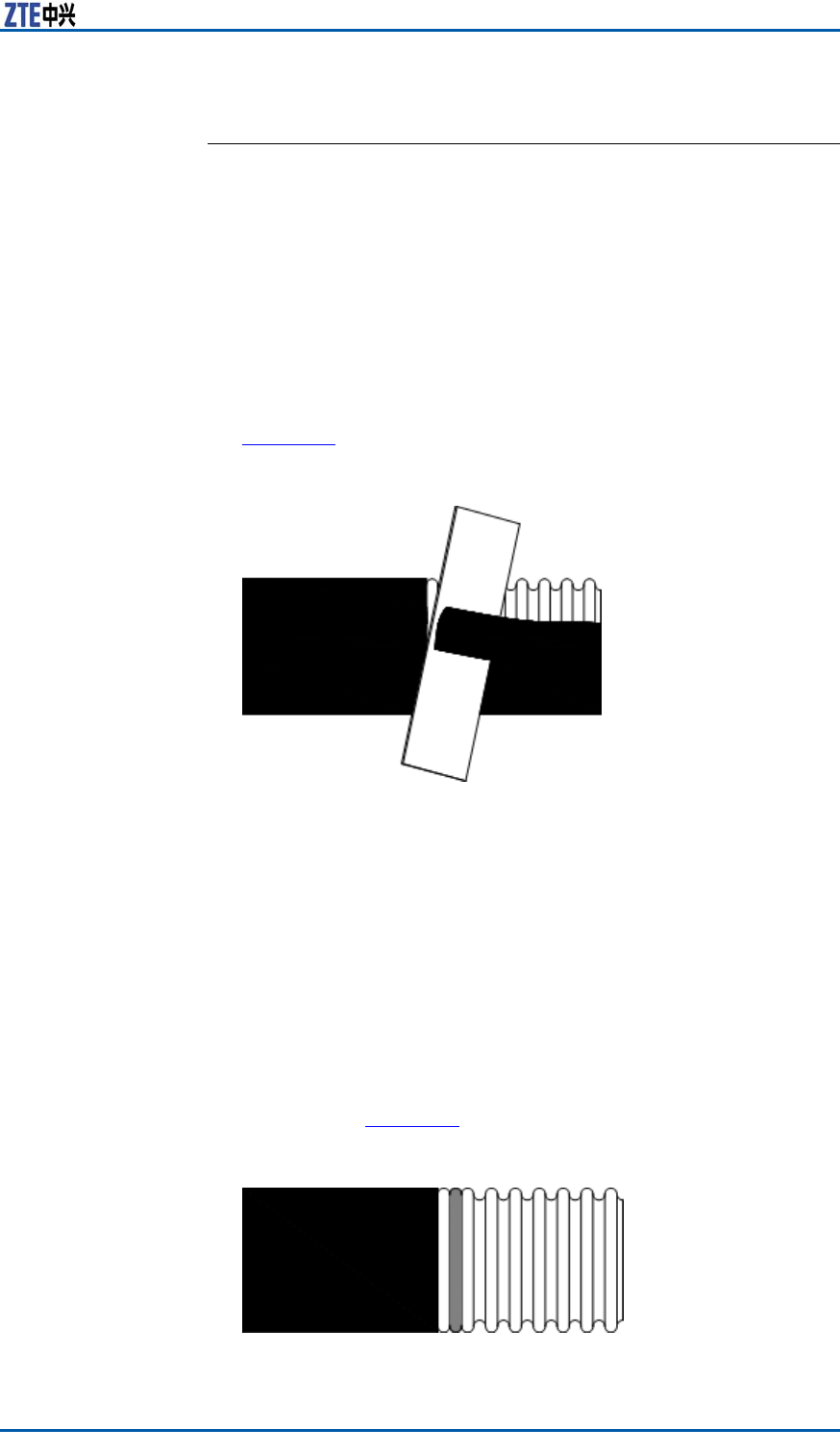
Chapter8InstallingMainAntennaFeederSystem
MakingFeederConnector
ContextMakefeederconnectorsonsite.Suggestthatconnectorsinstalled
atthetowershouldbepreparedandwrappedwithspongebefore
hanginstallation.
Ifafeederconnectorisnotmadecompletely,orisamadeconnec-
torbutnotconnectedwiththejumper ,performsimpliedwater-
proofprocessingforit.Therearetwofeasibleprocessingmethods:
wraptheconnectorwithwaterproofadhesivetape,oraftercover-
ingaplasticbagwrapitwithwaterproofadhesivetapeagain.
Steps1.Straightenanendofconnector .Thencutandstripoffthe
feedersheathata50mmpositionofftheend,asshownin
F
i g u r e 6 1 .
FIGURE61STRIPOFFSHEATH
2.Putthefeederconnectorintoaslotofcuttingtoolandmake
thisslotclosetothefeedersheathpossibly.Closethecutting
tooslowlyandpressitslightly.Facingthefeederport,rotate
thecuttingtoolclockwiseuntilthefrontbladecutsofftheinner
andouterconductorcompletely.Rotatetwocircleswithslight
pressureagainandmakesurethebackbladeexscindingthe
feedersheath.
3.PutanO-typeringintherstwavetroughofouterconduc-
tor ,outsidethefeedersheathandcoveralayeroflubricating
oil.Locatethesidewithscrewthreadoutwards,coverafas-
teningpiecethroughtheconnectorandpushittotheposition
whereonewavetroughontheouterconductorisuncovered,
asshowninF
i g u r e 6 2 .
FIGURE62O-TYPERINGLOCATION
ConfidentialandProprietaryInformationofZTECORPORATION81
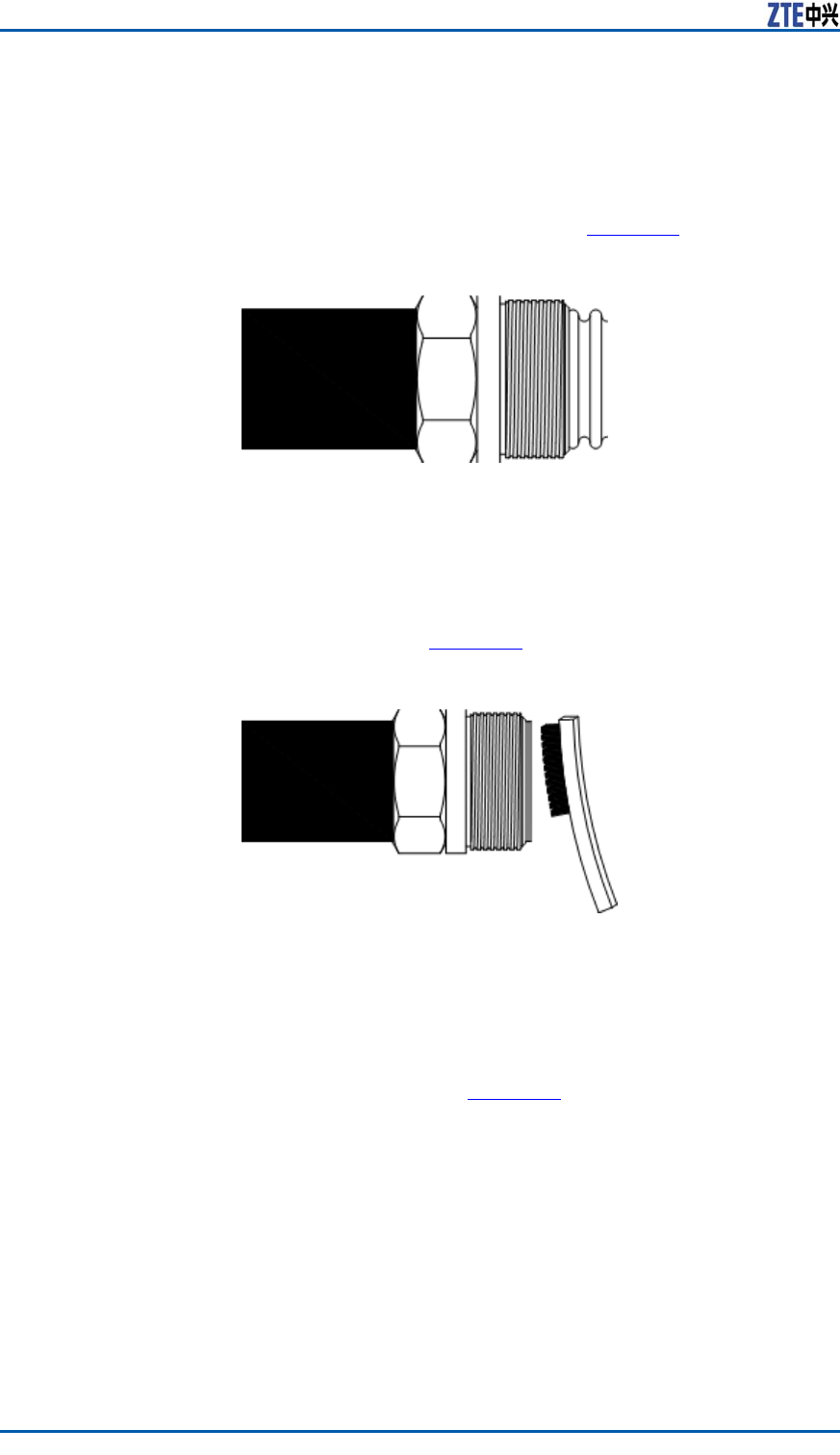
ZXSDRBS8800C200InstallationManual
4.Putaspringringintothewavetroughontheouterconductor .
5.Pressafoammaterialinsidetheconnectorfromtheoutercon-
ductortotheinnerconductorforcibly.
6.Insertanendofconnectorassemblyintotheinnerconductor
carefullyandinstallit,asshowninF
i g u r e 6 3 .
FIGURE63CONNECTION
7.Movetheconnectorassemblyontothefasteningpieceround
andround.Duringoperation,keeptheconnectorassembly
unmovableandonlyrotatethefasteningpiecewithawrench.
Clearawaycopperscrapsonthefoammaterialwithabrush,
especiallycooperscrapsonthecrosssectionofthefoamma-
terial,asshowninF
i g u r e 6 4 .
FIGURE64COPPERSCRAPCLEARNESSONTHECROSSSECTION
8.T akeaparttheconnectorandchecktheprolestateofouter
conductor .Theproleofouterconductorshouldbeorderlyand
clean.Whiledisassemblingtheconnector ,rstunscrewthe
connectorassemblyinan1/4circle,thenkeeptheconnector
assemblyunmovableandonlyrotatethefasteningpiecewith
awrench,asshowninF
i g u r e 6 5 .
82ConfidentialandProprietaryInformationofZTECORPORATION
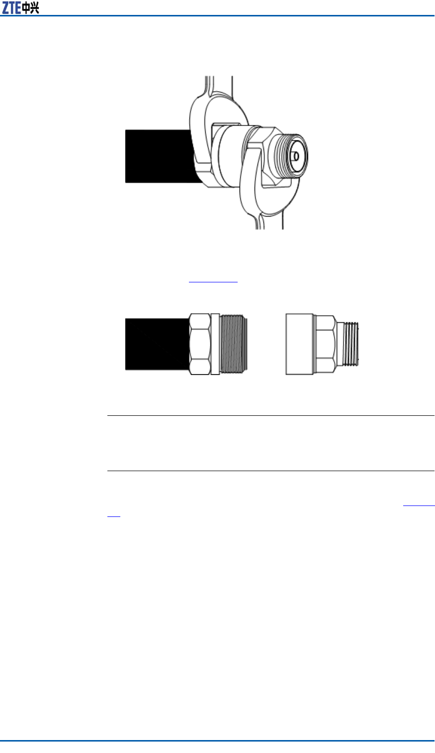
Chapter8InstallingMainAntennaFeederSystem
FIGURE65ROTATINGCONNECTORFASTENINGPIECE
9.Rotatethefasteningpieceontotheconnectorassemblyagain,
asshowninF
i g u r e 6 6 .
FIGURE66CONNECTINGASSEMBLY
ENDOFSTEPS.
AssemblingOmnidirectionalAntenna
ContextTheappearanceofomnidirectionalantennaisasshowninF i g u r e
67.
ConfidentialandProprietaryInformationofZTECORPORATION83

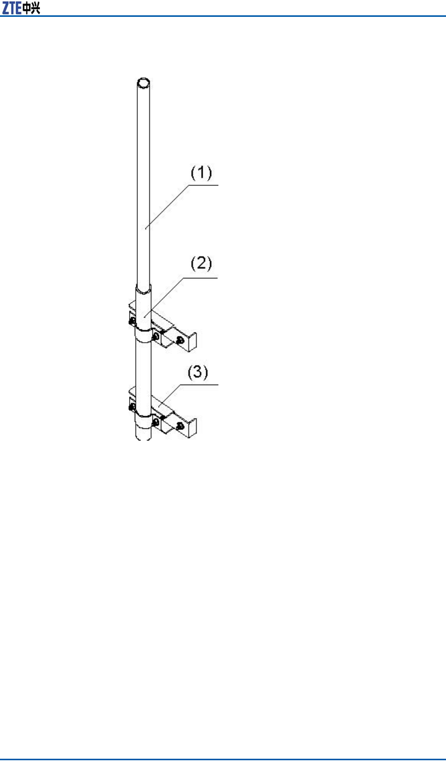
Chapter8InstallingMainAntennaFeederSystem
FIGURE68FIXINGOMNIDIRECTIONALANTENNA
1.Omnidirectionalantenna
2.Antennasheath
3.Fixationclip
ConfidentialandProprietaryInformationofZTECORPORATION85

ZXSDRBS8800C200InstallationManual
Note:
Therearevariousomnidirectionalantennaswithdifferentin-
stallationmodes.So,duringthepracticaloperation,perform
installationbasedonaspeciedcondition.
Installaspringwasherandatwasherforantennaxation.
Firstputaatwasherandthenaspringwasher .
2.Connectandscrewdownthejumperconnectorandthean-
tennaconnector .
3.Performwaterproofprocessingfortheconnectorbetweenan-
tennaandjumper ,referringtoP
e r f o r m i n g O u t d o o r - c o n n e c t o r
W a t e r p r o o f P r o c e s s i n g .
Note:
Iftheabovetwostepsareperformedonthetower ,suggest
wrappingalayerofelectricinsulationadhesivetaperoundthe
connectorrequiredtosealandthenwrappingalayerofsemi-
conductiveself-adhesivetapeagain.
ENDOFSTEPS.
AssemblingDirectionalAntenna
ContextTheappearanceofdirectionalantennaisasshowninF i g u r e 6 9 .
86ConfidentialandProprietaryInformationofZTECORPORATION
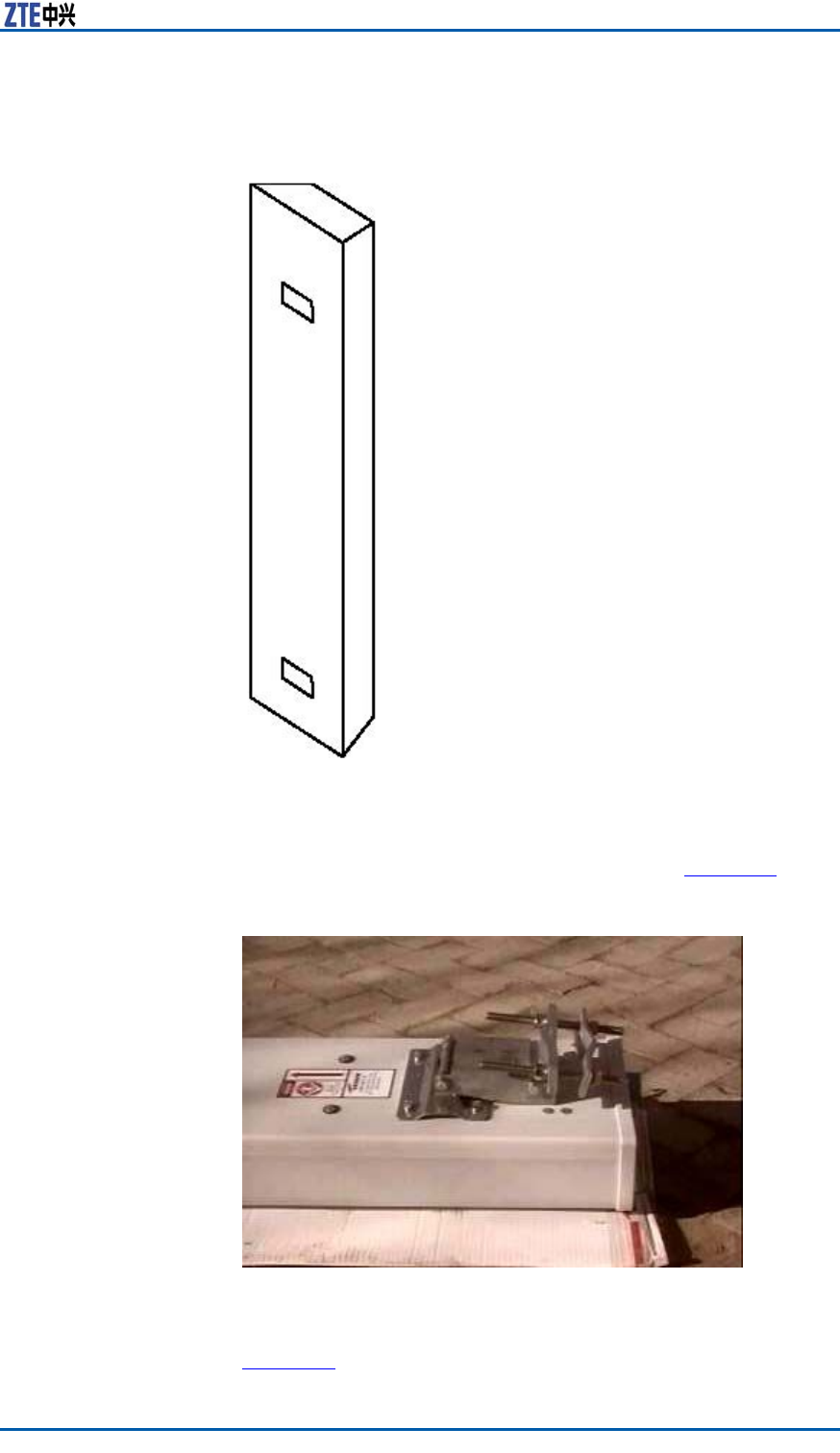
Chapter8InstallingMainAntennaFeederSystem
FIGURE69DIRECTIONALANTENNAAPPEARANCE
Therearesomeaccessoriesofdirectionalantenna,asfollows:
�Directional-antennaxationclip,asshowninF
i g u r e 7 0 .
FIGURE70DIRECTIONAL-ANTENNAFIXATIONCLIP
�Depressionangleandelevationangleadjustment,asshownin
F
i g u r e 7 1 .
ConfidentialandProprietaryInformationofZTECORPORATION87
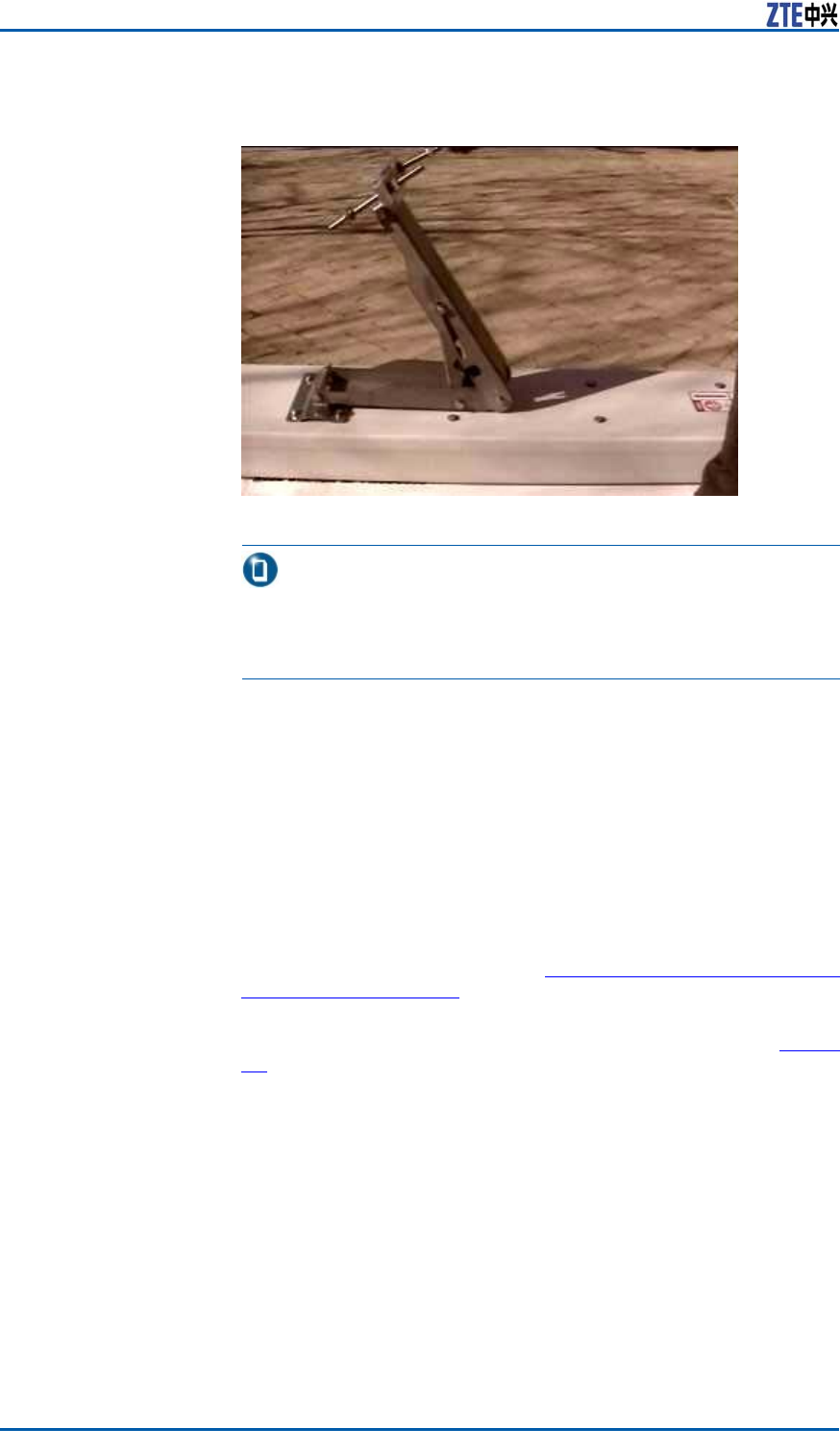
ZXSDRBS8800C200InstallationManual
FIGURE71DEPRESSIONANGLEANDELEVATIONANGLEADJUSTMENT
Note:
Thexationclipaswellasdepressionangleandelevationangle
adjustmentmustbebothequippedwithaspringwasherand
atwasher .Firstputaatwasherandthenaspringwasher .
Steps1.Accordingtothemarksatthebackofantenna,makesure
twoxedadjustmentpointsrespectivelyatthetopandbottom
ofantenna(theadjustmentpointatthetopisusedforthe
elevationangleadjustmentandtheadjustmentpointatthe
bottomisusedtoxtheantennaandtherack).
2.Referringtotheaccessoryequipmentdrawingprovidesbysup-
pliersstrictly,installallaccessoriestocorrespondingpositions.
3.Connectajumperconnectorwithantennaconnector ,andthen
screwdownthem.
4.Performwaterproofprocessingfortheconnectorbetweenan-
tennaandjumper ,referringtoP
e r f o r m i n g O u t d o o r - c o n n e c t o r
W a t e r p r o o f P r o c e s s i n g .
Connectionbetweendirectionalantennaandjumperaswellas
thejumperconnectorafterprocessingareasshowninF
i g u r e
72.
88ConfidentialandProprietaryInformationofZTECORPORATION
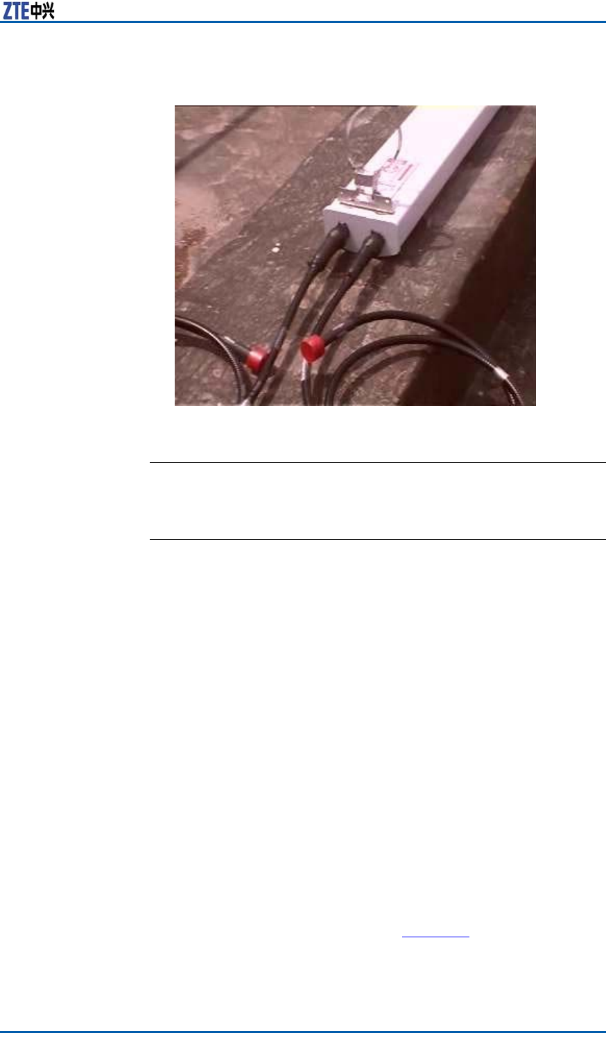
Chapter8InstallingMainAntennaFeederSystem
FIGURE72CONNECTIONBETWEENDIRECTIONALANTENNAANDJUMPER
ENDOFSTEPS.
HoistingAntennaandFeeder
ContextWhilehoistingantennaandfeeder ,complywiththefollowing:
�Installationpersonnelonthetowerpullsropeupwardandthe
otherpersonnelunderthetowerdrawstheropetocontrolan
ascendingdirectionofantenna.
�Duringhoisting,makesurenopeoplestandingunderthegoods
hungintheair .Whilewalkingoutoftheplatform,installation
personnelmustwearsafebelts.
�。Somesmallmetalgoodsortools,forexample,antennax-
ationclipsandwrenches,shouldbeputinacanvastoolbag,
sealedandthenhoisted.
�Afterhoistinggoodstotheplatformonthetopoftower ,put
theminasecurepositionandtakesecuritymeasures.
�Theabovemethodisadoptableforhoistingofothergoods.
Steps1.Installaxedpulleyonthetopoftower .
2.Makearopethroughthexedpulleyandtieknotswiththe
ropeatthetwoendsofantenna.
3.Installationpersonnelonthetowerandunderthetowerhoist
theantennatothepositionofxingantennatogether .
HoistingantennaisasshowninF
i g u r e 7 3 .
ConfidentialandProprietaryInformationofZTECORPORATION89

ZXSDRBS8800C200InstallationManual
FIGURE73HOISTINGANTENNA
ENDOFSTEPS.
InstallingIndoorGrounding
Bar
PrerequisiteAccordingtotheengineeringdesigndrawing,conrmtheinstalla-
tionlocation.
ContextAnindoorgroundingbarisusedtoconnectaprotectiveground
withaworkground.F
i g u r e 7 4 showsthestructureofindoor
groundingbar .
90ConfidentialandProprietaryInformationofZTECORPORATION
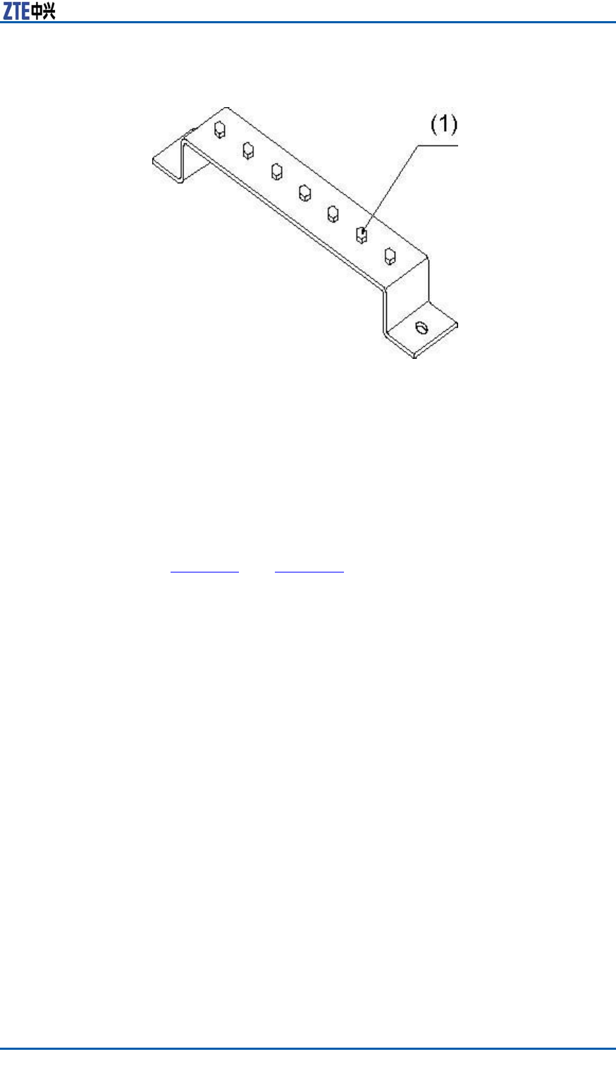
Chapter8InstallingMainAntennaFeederSystem
FIGURE74INDOORGROUNDINGBARSTRUCTURE
1.M8bolt
Whileinstallingtheindoorgroundingbar ,accordwiththefollowing
requirements:
�Installtheindoorgroundingbaronthewallwhichisneartoa
cabinetandisthesameheightwithacabletray.
�Theindoorgroundingbarshouldbexedparallellyonthewall.
�Whileinstallingexpansionbolts,useaninsulationwasherand
makesurethegroundingbarinsulatedwiththewall.
StepsFixthegroundingbaronthewallwithexpansionbolts,asshown
inF
i g u r e 7 5 andF i g u r e 7 6 .
ConfidentialandProprietaryInformationofZTECORPORATION91
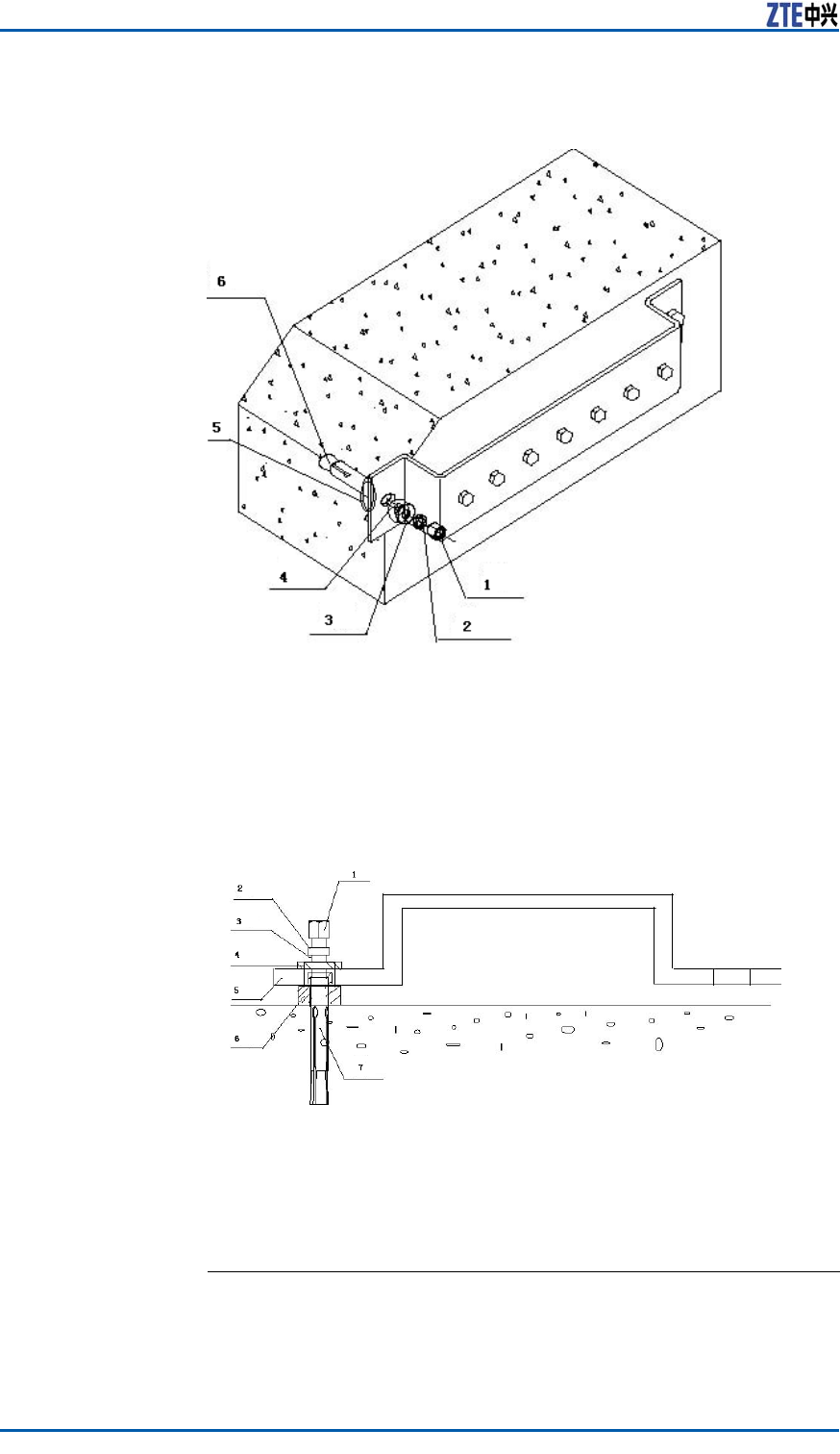
ZXSDRBS8800C200InstallationManual
FIGURE75INDOORGROUNDINGBARINSTALLATION(1)
1.M12bolt
2.Springwasher12
3.Bigatwasher
4.Insulationwashera
5.Insulationwasherb
6.Expansionpipeandexpansionnut
FIGURE76INDOORGROUNDINGBARINSTALLATION(2)
1.M12bolt
2.Springwasher12
3.Bigatwasher
4.Insulationwashera
5.Indoorgroundingbar
6.Insulationwasherb
7.Expansionpipeandexpansionnut
ENDOFSTEPS.
92ConfidentialandProprietaryInformationofZTECORPORATION
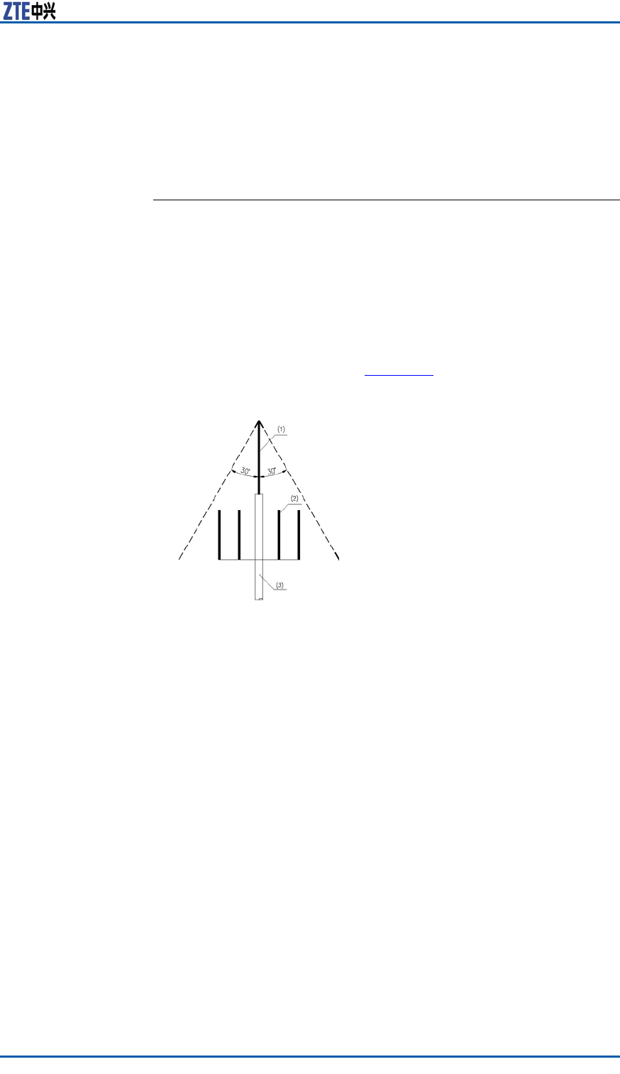
Chapter8InstallingMainAntennaFeederSystem
InstallingAntenna
InstallingDirectionalAntennaon
Top-tower
ContextInstallationrequirementsaredescribedasfollows:
�Aninstallationplaneofantennarackshouldkeepverticalwith
thelevel.
�Installamastoftowerarrestersingly.Theheightofmast
meetsprotectiverequirementsofallantennaarresters.When
anantennarackextendsoutoftheplatformofirontower ,make
suretheantennawithinaprotectiveareaof30°downtiltof
arrestertop,asshowninF
i g u r e 7 7 .
FIGURE77ARRESTERPROTECTIVEAREA
1.Arrester
2.Antenna
3.Arrestermast
�Makesureaninstallationdirectionofantennaracknotaffecting
receivingandtransmittingperformanceofdirectionalantenna
aswellasdirectionadjustment.
�Makesuretheantennawithinaprotectiveareaofironarrester .
Thedistancethattheantennaextendsoutofironplatformis
1matleast.
�Thegainofantennashouldbe15dBi,theisolationbe30dBand
thehalf-poweranglebe65°.
�Reinforcearotationalmastwithanenhancedmast.The
lengthsofacollapsiblemastandarotationalmastshouldbe
cutaccordingtoon-sitecondition.Weldacoverboardonthe
cutsectiontoavoidleakage.
�Makesureallweldingpartsfastenedandnofaultyorlacking
welding.Suggestadoptinggalvanizedsteelfortherackand
coveringalayerofantirustsliver-powderpaintonthesurface
ofrack.
�Whileinstallingandadjustingtheantenna,protectthesein-
stalledantennasfromanydamage.
ConfidentialandProprietaryInformationofZTECORPORATION93
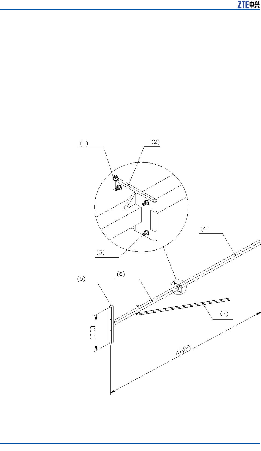
ZXSDRBS8800C200InstallationManual
�Whileusingacompass,keepfarawayfromtheironaspossi-
bleasyoucanandatthesametimecheckwhetherthereis
abnormalgeomagnetismphenomenon.
�Themainanddiversityoftwoportsofdirectionalantennain
thesametypeshouldkeepconsistentindenition,forexam-
ple,-45°portdenesamainsetportand45°portdenesa
diversityport.
Steps1.Installingtheantennarack
Therearevarioustypesofironantennaracks.Takeonetype
forexample.
TherackstructureisasshowninF
i g u r e 7 8 .
FIGURE78IRONANTENNARACKSTRUCTURE(UNIT:MM)
1.M12×220bolt
2.Connectingbottomplate
3.M12×45bolt
4.Collapsiblemast
5.Fixedmast
6.Rotationalmast
7.Enhancedmast
94ConfidentialandProprietaryInformationofZTECORPORATION
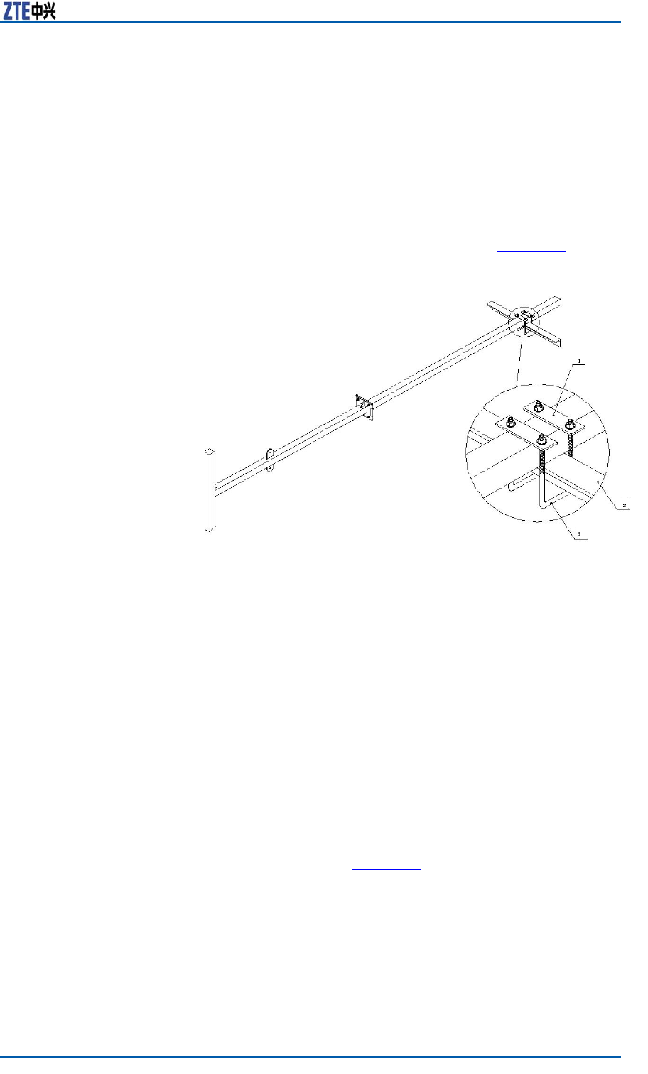
Chapter8InstallingMainAntennaFeederSystem
i.Installaxedpulleyattopofthetowerthetower .Hoistthe
rackontotheironplatformwithoneortworopesthrough
thecrownblock.Inaddition,controlanascendingdirection
ofrackwithanotherrope.
ii.Accordingtotheinstallationdrawingofantennaandfeeder
intheengineeringdesigndrawing,conrmtheinstallation
positionofantennarack.
iii.Extendtherackoutoftheironplatformandfasteniton
thetowerbodywithU-shapexationclips(connectionbar
andU-shapeboltincluded),asshowninF
i g u r e 7 9 .
FIGURE79ANTENNARACKINSTALLATION
1.Connectionbar
2.U-shapebolt
3.Ironplatform
iv.Connectguardbarsofplatformandconnectbottomplates.
Ifitisinconvenienttoconnecttheantennarackwiththe
guardbars,weldthemandmakesureweldingfastened.
Coveralayerofantirustpaintontheallpartsweldedand
onthesurfaceofrack.
2.Installingthedirectionalantenna
i.Accordingtotheengineeringdesigndrawing,makesure
theinstallationdirectionofantenna.
ii.Hoisttheantennatoaspeciedpositionwithablockand
rope.Makesuretheantennawithintheprotectiveareaof
arrester .
iii.Installaxationrackofantennaandmaketherackcol-
lapsed,asshowninF
i g u r e 8 0 .
ConfidentialandProprietaryInformationofZTECORPORATION95

ZXSDRBS8800C200InstallationManual
FIGURE80ANTENNAFIXATIONRACK
iv.Adjusttheantennatoaproperheight.Fixthexation
rackontheantennapolewithboltsandU-shapebolts.
Makesureinputandoutputportsofantennadownward,
asshowninF
i g u r e 8 1 .
FIGURE81FIXINGANTENNA
TheappearanceofU-shapeboltisasshowninF i g u r e 8 2 .
96ConfidentialandProprietaryInformationofZTECORPORATION
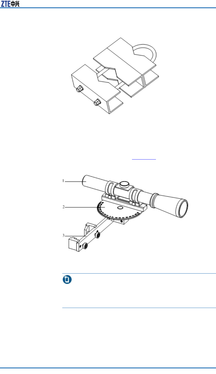
Chapter8InstallingMainAntennaFeederSystem
FIGURE82U-SHAPEBOLT
3.Adjustingtheazimuthofantenna
WithKathreinazimuthadjustmenttools,makesureanormal
directionofantennaradiationconsistentwithanazimuthof
antennainthenetworkingplanning.Kathreinazimuthadjust-
menttoolsareasshowninF
i g u r e 8 3 .
FIGURE83KATHREINAZIMUTHADJUSTMENTTOOLS
1.Telescope
2.Dial
3.Fasteningpiece
Note:
Inthismanual,explaintheazimuthadjustmentmethodby
Kathreinazimuthadjustmenttools.Duringpracticalcommis-
sioning,theadjustmentmethodisdeterminedbyon-sitetools.
i.Useamaptondanobviousaim(forexample,tallbuilding,
mountainortower).Measuretheangledifferencebetween
theaimandthedesignedazimuth.
ii.Adjustanangleofspecialazimuthadjustmenttooltothe
angledifferencevaluemeasuredbytheabovestep.
ConfidentialandProprietaryInformationofZTECORPORATION97
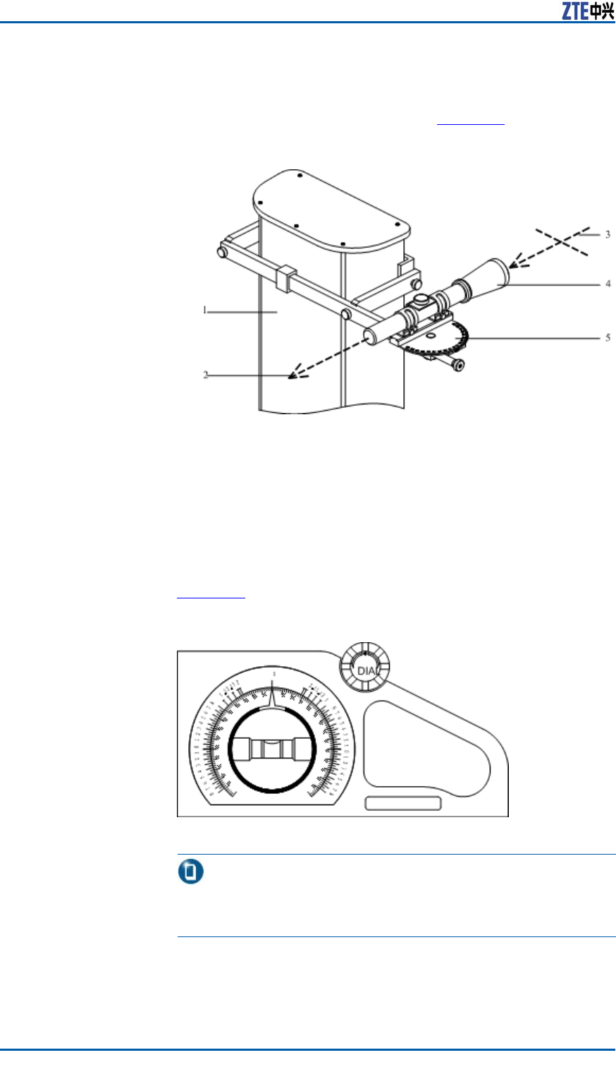
ZXSDRBS8800C200InstallationManual
iii.Putthespecialazimuthadjustmenttoolontheantenna,
aimatthetargetbytelescope,androtatetheantennato
thedesignedangle,asshowninF
i g u r e 8 4 .
FIGURE84USAGEOFAZIMUTHADJUSTMENTTOOL
1.Antenna
2.T argetdirection
3.Observationdirection
4.Telescope
5.Dial
iv.Fastenallscrewswithawrench.
4.Adjustingtheantennadowntilt
Adjustthedowntiltofantennawithadowntiltmeasuringin-
strument.Thedowntiltmeasuringinstrumentisasshownin
Fi g u r e 8 5 .
FIGURE85DOWNTILTMEASURINGINSTRUMENTAPPEARANCE
Note:
Thedowntiltofantennashouldbeconsistentwithanangleof
downtiltxationrack,theerrornotbeyond1。.
i.Rotateadialofdowntiltmeasuringinstrumenttoasetan-
gle.
98ConfidentialandProprietaryInformationofZTECORPORATION
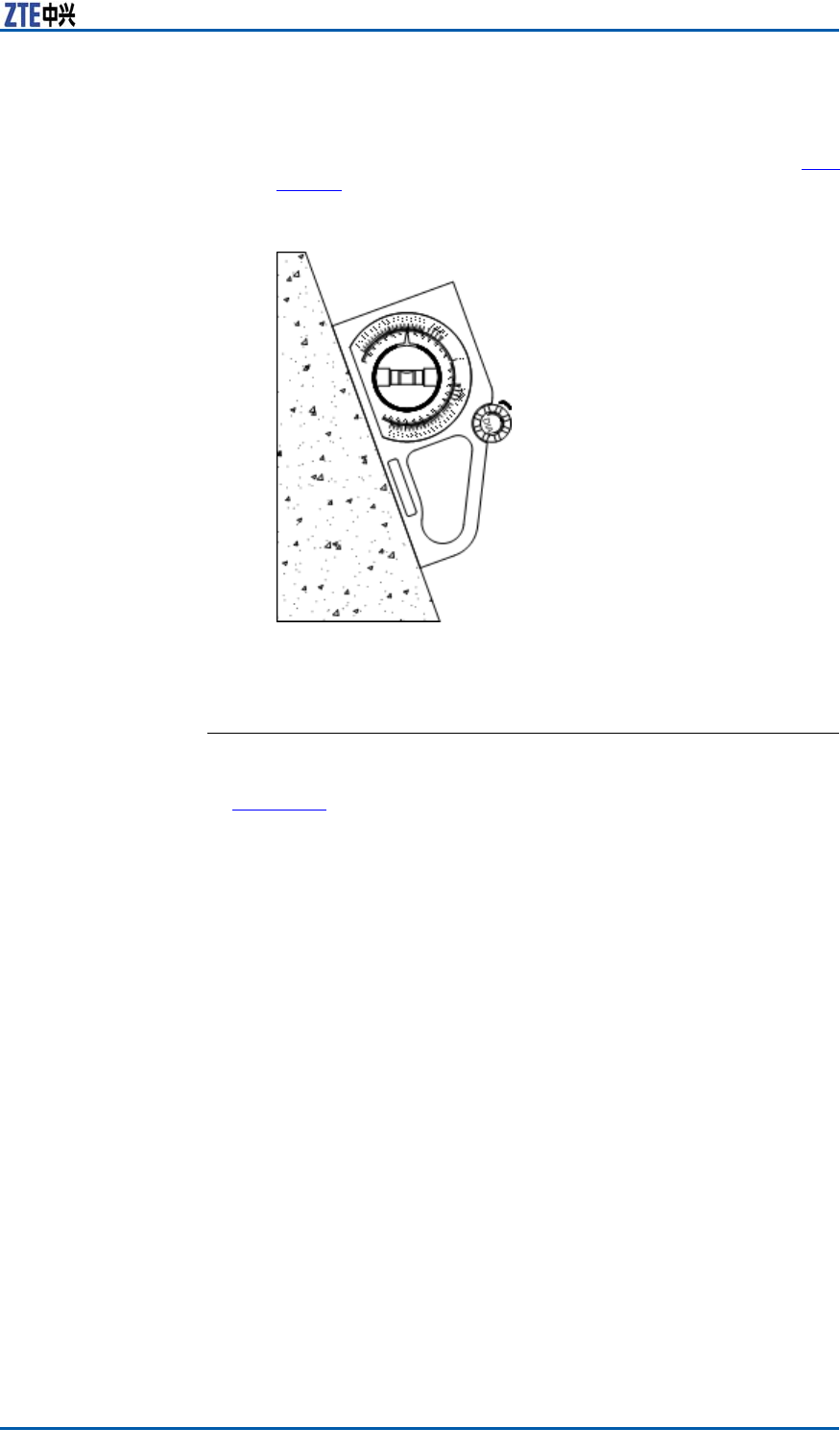
Chapter8InstallingMainAntennaFeederSystem
ii.Putthedecliningobjectclosetothechassisofdialand
movethemsynchronouslyuntilairbubblesintheair-bub-
blepipelocateatthemiddleoftworings,asshowninF
i g -
u r e 8 6 .
FIGURE86ADJUSTINGDOWNTILT
iii.Fastenallscrewswithawrench.
ENDOFSTEPS.
ResultThedirectionalantennainstallationontheirontowerisasshown
inF
i g u r e 8 7 .
ConfidentialandProprietaryInformationofZTECORPORATION99
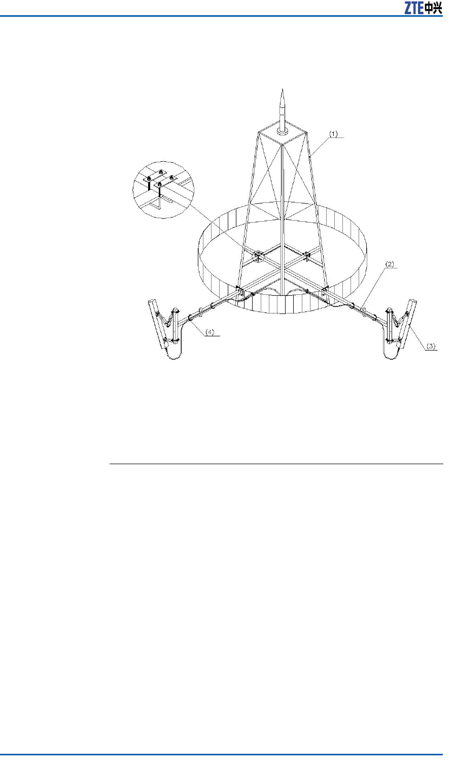
ZXSDRBS8800C200InstallationManual
FIGURE87DIRECTIONALANTENNAINSTALLATIONONTHETOWERPLATFORM
1.Irontower
2.Antennarack
3.Directionalantenna
4.Wirefastener
InstallingDirectionalAntennaonRoof
ContextInstallationrequirementsaredescribedasfollows:
�Keepawayfromobstructorsandblindareas.
�Theinstallationpositionofconnectorofenhancedmastshould
havenoimpactonadjustmentofantennadirectionandangle.
�Keepanantennarackverticalwiththelevel.
�Whenthedirectionalantennaisinstalledatopabuilding,the
rackmustbeequippedwithanarresterandbealsoconnected
withalightningnetofthebuilding.
�Allweldingpartsofantennarackshouldbecoveredalayer
ofantirustpaintonthesurface.Makesureallweldingparts
fastenedandnofaultyorlackingwelding.
Steps1.Installingtheantennarackontheroof
Therearetwoconditionsforinstallation:
�Installingtherackontheroofwithoutawall
�Installingtherackinconvenienttoxontheroofwithawall
100ConfidentialandProprietaryInformationofZTECORPORATION
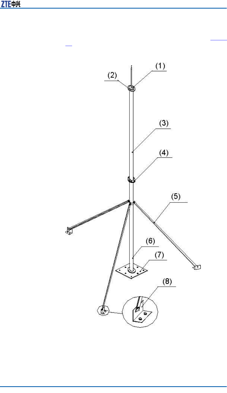
Chapter8InstallingMainAntennaFeederSystem
Therearevarioustypesofantennaracks.Takeonetypefor
example.ThestructureofantennarackisasshowninF
i g u r e
88.
FIGURE88ANTENNARACKSTRUCTURE
1.Antennaarrester
2.Weldedjoint
3.Supportpole2
4.M10×80bolt
5.Enhancedmast
6.Supportpole1
7.Supportpolebase
8.Enhancedmastfoundation
Installingtherackontheroofwithoutawall
ConfidentialandProprietaryInformationofZTECORPORATION101
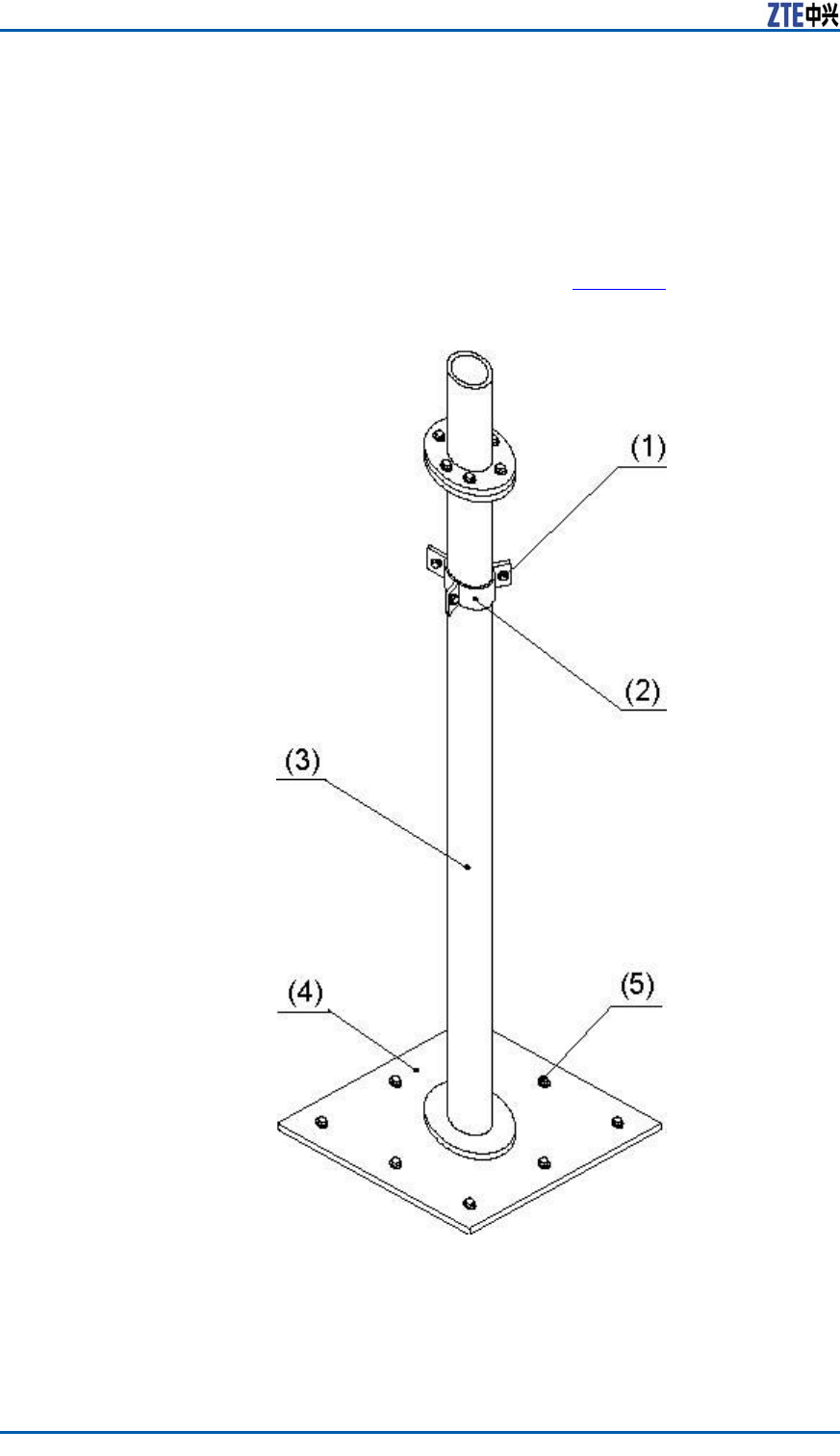
ZXSDRBS8800C200InstallationManual
i.Movetheracktotheroof.
ii.Accordingtotheinstallationdrawingofantennaandfeeder
intheengineeringdesigndrawing,conrmtheinstallation
positionofantennarack.
iii.Weldanarresterontoasupportpole1.
iv.FastentheantennarackbasewitheightM10×45expansion
boltsontheroof,asshowninF
i g u r e 8 9 .
FIGURE89ANTENNARACKBASESTRUCTUREANDINSTALLATION
1.M10×50hexagonbolt
2.Connectorofenhanced
mast
3.Supportpole1
4.Supportpolebase
5.M10×50expansionbolt
102ConfidentialandProprietaryInformationofZTECORPORATION
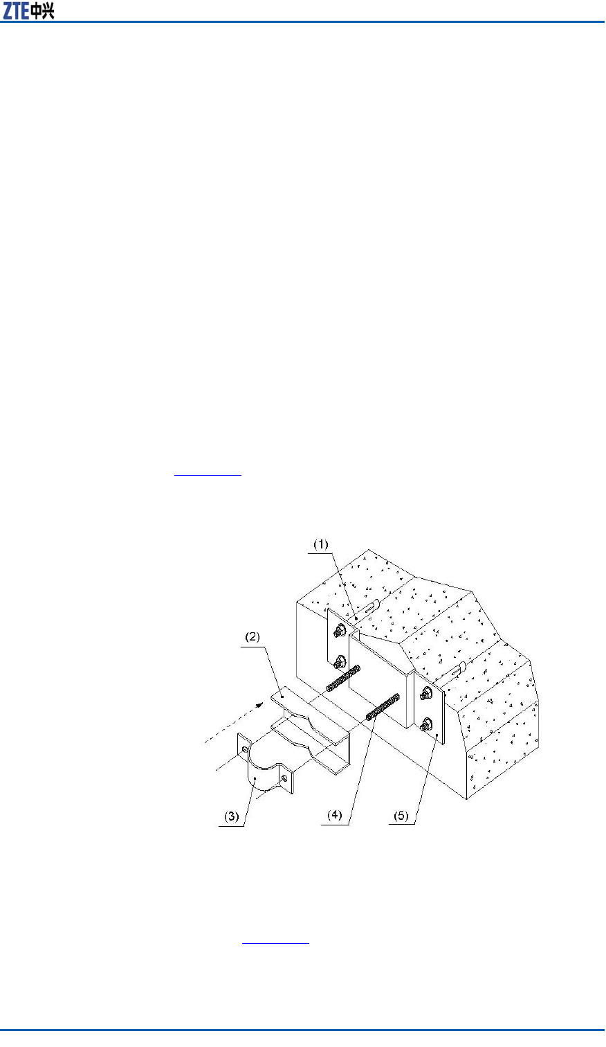
Chapter8InstallingMainAntennaFeederSystem
v.Fixthesupportpolewiththeenhancedmasts.Thelength
ofenhancedmastisdeterminedbythelengthofsupport
pole.Connecttheenhancedmastswiththesupportpoleby
aconnector .Thenconnecttheenhancedmastfoundations
withtheenhancedmasts.Fixeveryfoundationsontheroof
withtwoM10×45expansionboltsandmakesurejunctions
ofenhancedmastsnotbetwisted.
vi.Connectthesupportpole2tothesupportpole1withsix
M10×80bolts.
vii.Iftheantennarackontheroofisnotweldedwithanout-
doorcabletray,ortheoutdoorcabletrayweldedwiththe
antennarackisnotconnectedwiththelightningnetof
building,theantennarackbasemustbeconnectedwith
thelightningnetviaalightningjunctionbar .
viii.Coveralayerofantirustpaintonthesurfaceofallwelded
partsandtherackbase.Coverconcreteontheantenna
rackbase,enhancedmastandexpansionbolts.
Installingtherackinconvenienttoxontheroofwitha
wall
Whenitisinconvenienttoinstalltherackontheroof,iftheroof
issurroundedbythewall,installitontothewall,asshownin
F
i g u r e 9 0 .
FIGURE90INSTALLINGANTENNARACKONTHEWALL
1.M12×120expansionbolt
2.V-shapeconnector
3.180°connector
4.M12×140bolt
5.Fastnessboard
Iftheheightofwallisnotlessthan1200mm,xthesup-
portpoleonthewallwithexpansionboltsandxationclips,as
showninF
i g u r e 9 1 .
ConfidentialandProprietaryInformationofZTECORPORATION103
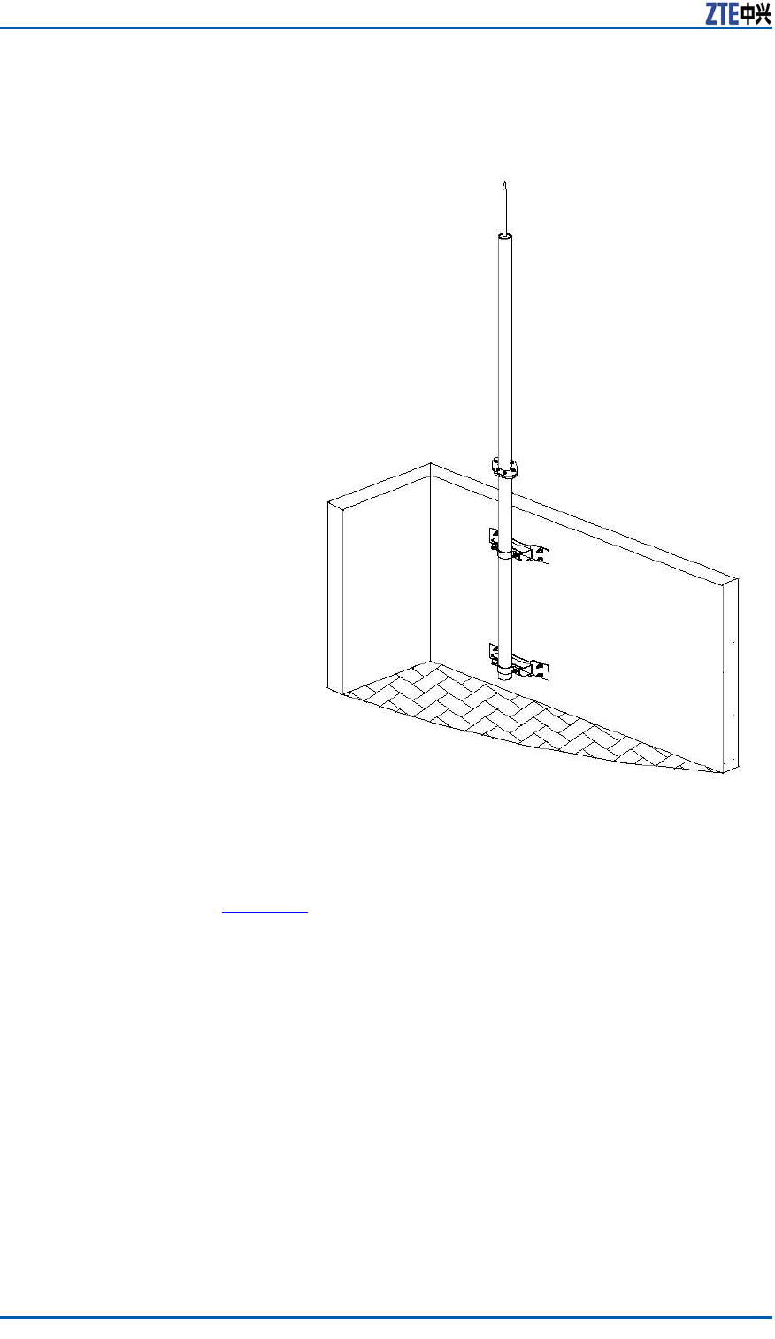
ZXSDRBS8800C200InstallationManual
FIGURE91ANTENNARACKFIXEDONTHEWALLCOMPLETELY(HEIGHT
OFWALLNOTLESSTHAN1200MM)
Iftheheightofwallislessthan1200mm,xanendofsupport
poleonthewallwithexpansionboltsandaxationclip,and
xtheotherpointofsupportpolewiththeroof,asshownin
F
i g u r e 9 2 .
104ConfidentialandProprietaryInformationofZTECORPORATION
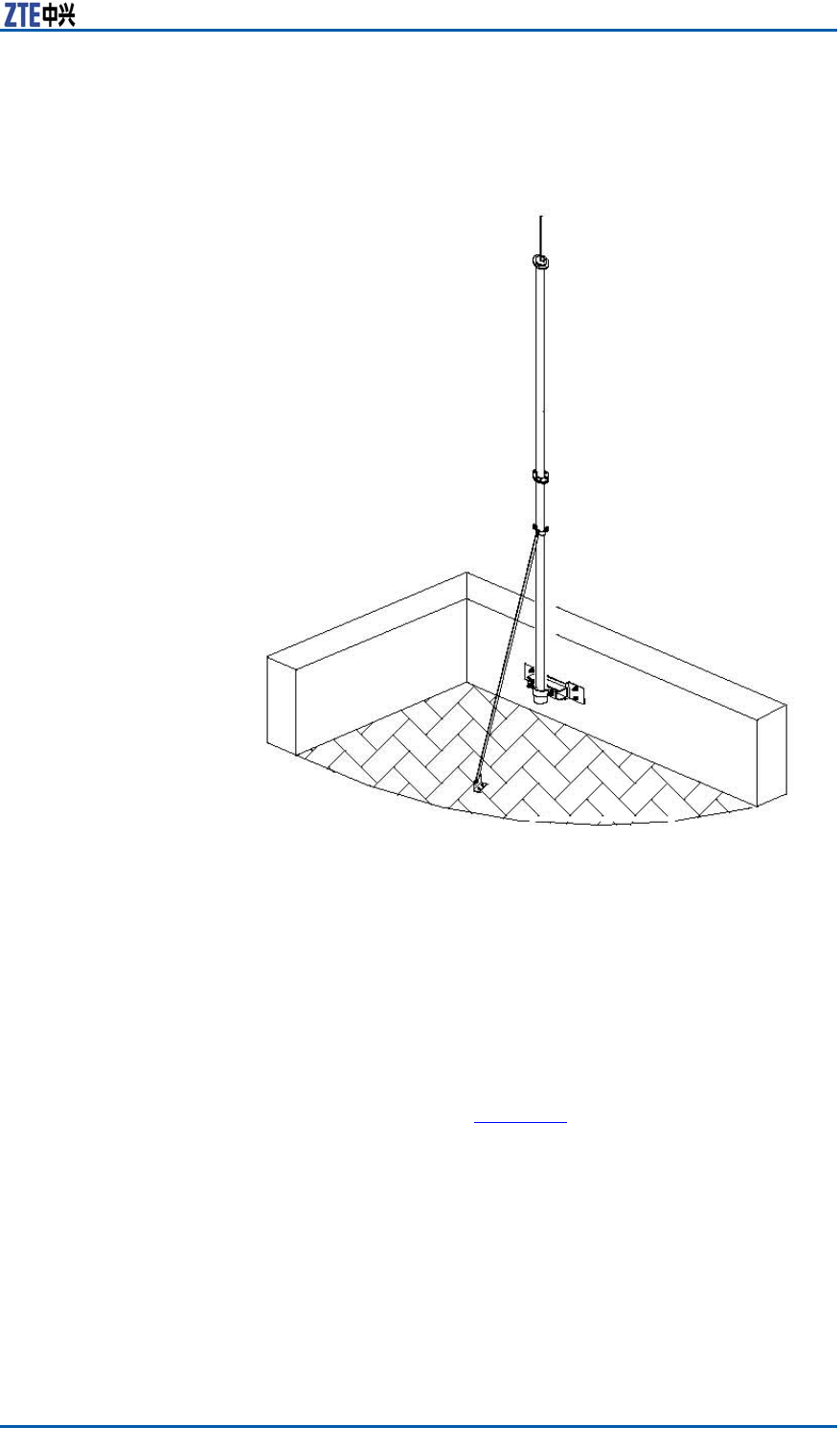
Chapter8InstallingMainAntennaFeederSystem
FIGURE92ANTENNARACKFIXEDONTHEWALL(HEIGHTOFWALL
LESSTHAN1200MM)
2.Installingthedirectionalantenna
i.Accordingtotheengineeringdesigndrawing,makesure
theinstallationdirectionofantenna.
ii.Hoisttheantennatoaspeciedpositionwithablockand
rope.Makesuretheantennawithintheprotectiveareaof
arrester .
iii.Installaxationrackofantennaandmaketherackcol-
lapsed,asshowninF
i g u r e 9 3 .
ConfidentialandProprietaryInformationofZTECORPORATION105
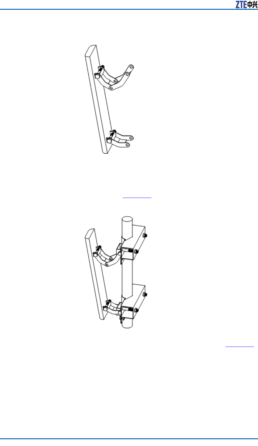
ZXSDRBS8800C200InstallationManual
FIGURE93FIXATIONRACK
iv.Adjusttheantennatoaproperheight.Fixthexation
rackontheantennapolewithboltsandU-shapebolts.
Makesureinputandoutputportsofantennadownward,
asshowninF
i g u r e 9 4 .
FIGURE94FIXINGANTENNA
TheappearanceofU-shapeboltisasshowninF i g u r e 9 5 .
106ConfidentialandProprietaryInformationofZTECORPORATION
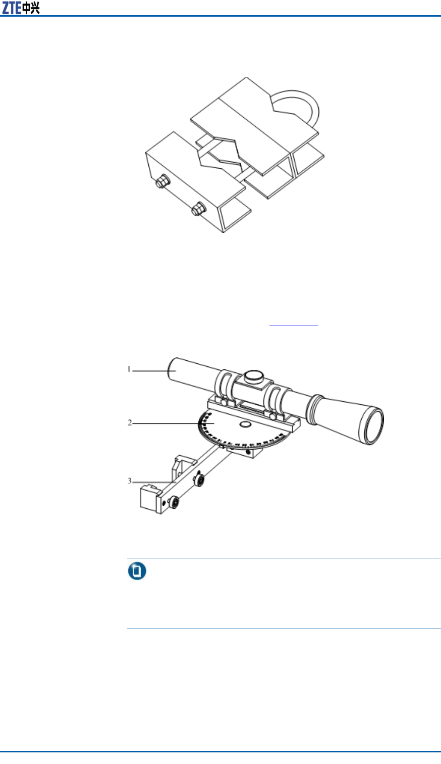
Chapter8InstallingMainAntennaFeederSystem
FIGURE95U-SHAPEBOLT
3.Adjustingtheazimuthofantenna
WithKathreinazimuthadjustmenttools,makesureanormal
directionofantennaradiationconsistentwithanazimuthof
antennainthenetworkingplanning.Kathreinazimuthadjust-
menttoolsareasshowninF
i g u r e 9 6 .
FIGURE96KATHREINAZIMUTHADJUSTMENTTOOLS
1.Telescope
2.Dial
3.Fasteningpiece
Note:
Inthismanual,explaintheazimuthadjustmentmethodby
Kathreinazimuthadjustmenttools.Duringpracticalcommis-
sioning,theadjustmentmethodisdeterminedbyon-sitetools.
i.Useamaptondanobviousaim(forexample,tallbuilding,
mountainortower).Measuretheangledifferencebetween
theaimandthedesignedazimuth.
ii.Adjustanangelofspecialazimuthadjustmenttooltothe
angeldifferencevaluemeasuredbytheabovestep.
ConfidentialandProprietaryInformationofZTECORPORATION107

ZXSDRBS8800C200InstallationManual
iii.Putthespecialazimuthadjustmenttoolontheantenna,
aimatthetargetbytelescope,androtatetheantennato
thedesignedangel,asshowninF
i g u r e 9 7 .
FIGURE97USAGEOFAZIMUTHADJUSTMENTTOOL
1.Antenna
2.T argetdirection
3.Observationdirection
4.Telescope
5.Dial
iv.Fastenallscrewswithawrench.
4.Adjustingtheantennadowntilt
Adjustthedowntiltofantennawithadowntiltmeasuringin-
strument.Thedowntiltmeasuringinstrumentisasshownin
Fi g u r e 9 8 .
FIGURE98DOWNTILTMEASURINGINSTRUMENTAPPEARANCE
Note:
Thedowntiltofantennashouldbeconsistentwithanangelof
downtiltxationrack,theerrornotbeyond1。.
i.Rotateadialofdowntiltmeasuringinstrumenttoasetan-
gle.
108ConfidentialandProprietaryInformationofZTECORPORATION

Chapter8InstallingMainAntennaFeederSystem
ii.Putthedecliningobjectclosetothechassisofdialand
movethemsynchronouslyuntilairbubblesintheair-bub-
blepipelocateatthemiddleoftworings,asshowninF
i g -
u r e 9 9 .
FIGURE99ADJUSTINGDOWNTILT
iii.Fastenallscrewswithawrench.
ENDOFSTEPS.
ResultThedirectionalantennainstallationontheroofisasshowninF i g -
u r e 1 0 0 andF i g u r e 1 0 1 .
ConfidentialandProprietaryInformationofZTECORPORATION109
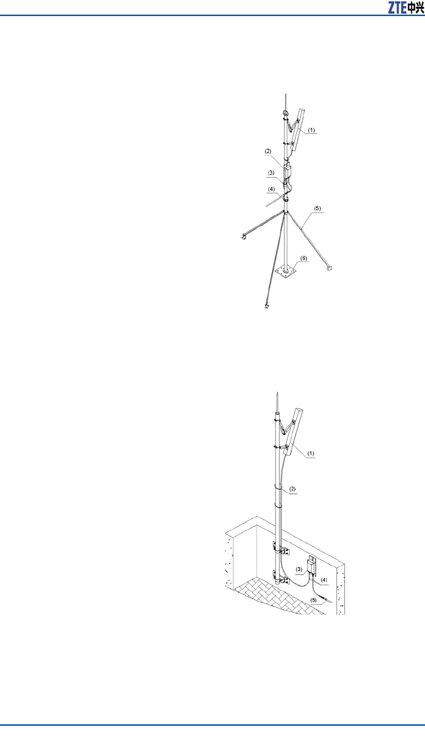
ZXSDRBS8800C200InstallationManual
FIGURE100DIRECTIONALANTENNAINSTALLATIONONTHEROOF
(WITHOUTWALLBUTWITHTOWERAMPLIFIER)
1.Antenna
2.Wirefastener
3.Feeder
4.Enhancedmast
5.Supportpolebase
FIGURE101DIRECTIONALANTENNAINSTALLATIONONTHEROOF(WITH
WALLANDTOWERAMPLIFIER)
1.Antenna
2.Wirefastener
3.Toweramplier
4.Jumper
5.Feeder
110ConfidentialandProprietaryInformationofZTECORPORATION

Chapter8InstallingMainAntennaFeederSystem
InstallingOmnidirectionalAntennaon
Top-tower
ContextInstallationrequirementsaredescribedasfollows:
�Aninstallationplaneofantennarackshouldkeepverticalwith
thelevel.
�Installamastoftowerarrestersingly.Theheightofmast
meetprotectiverequirementsofallantennaarresters.When
anantennarackextendsoutoftheplatformofirontower ,make
suretheantennawithinaprotectiveareaof30°downtiltof
arrestertop,asshowninF
i g u r e 1 0 2 .
FIGURE102ARRESTERPROTECTIVEAREA
1.Arrester
2.Antenna
3.Arrestermast
�Makesureaninstallationdirectionofantennaracknotaffecting
receivingandtransmittingperformanceofdirectionalantenna
aswellasdirectionadjustment.
�Makesuretheantennawithinaprotectiveareaofironarrester .
Thedistancethattheantennaextendsoutofironplatformis
1matleast.
�Reinforcearotationalmastwithanenhancedmast.The
lengthsofacollapsiblemastandarotationalmastshouldbe
cutaccordingtoon-sitecondition.Weldacoverboardonthe
cutsectiontoavoidleakage.
�Makesureallweldingpartsfastenedandnofaultyorlacking
welding.Suggestadoptinggalvanizedsteelfortherackand
coveringalayerofantirustsliver-powderpaintonthesurface
ofrack.
�Makesuretheantennawithinaprotectiveareaofironarrester .
Thedistancefromthebodyofirontoweris2matleast.
�Theaxesofantennashouldbeverticalwiththelevelandthe
errorshouldbelessthan±1。.
�Thegainofantennashouldbe11dBiandtheisolationbe30dB.
ConfidentialandProprietaryInformationofZTECORPORATION111
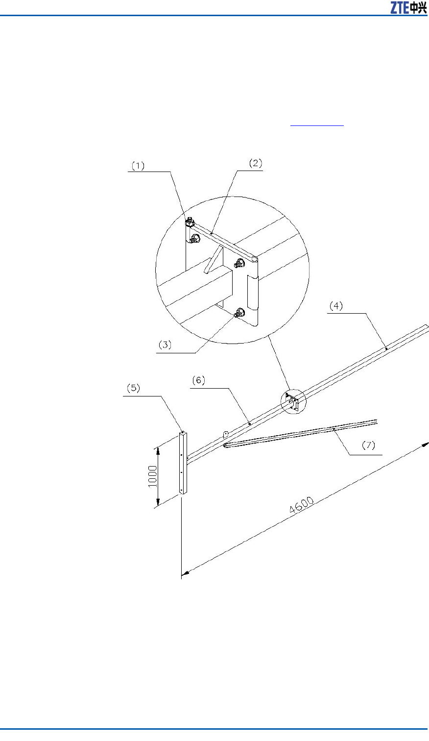
ZXSDRBS8800C200InstallationManual
�Makeawaterproofbendingforthejumper .
Steps1.Installingtheantennarack
Therearevarioustypesofironantennaracks.Takeonetype
forexample.
TherackstructureisasshowninF
i g u r e 1 0 3 .
FIGURE103IRONANTENNARACKSTRUCTURE(UNIT:MM)
1.M12×220bolt
2.Connectingbottomplate
3.M12×45bolt
4.Collapsiblemast
5.Fixedmast
6.Rotationalmast
7.Enhancedmast
i.Installacrownblockatopthetower .Hoisttherackonto
theironplatformwithoneortworopesthroughthecrown
block.Inaddition,controlanascendingdirectionofrack
withanotherrope.
112ConfidentialandProprietaryInformationofZTECORPORATION
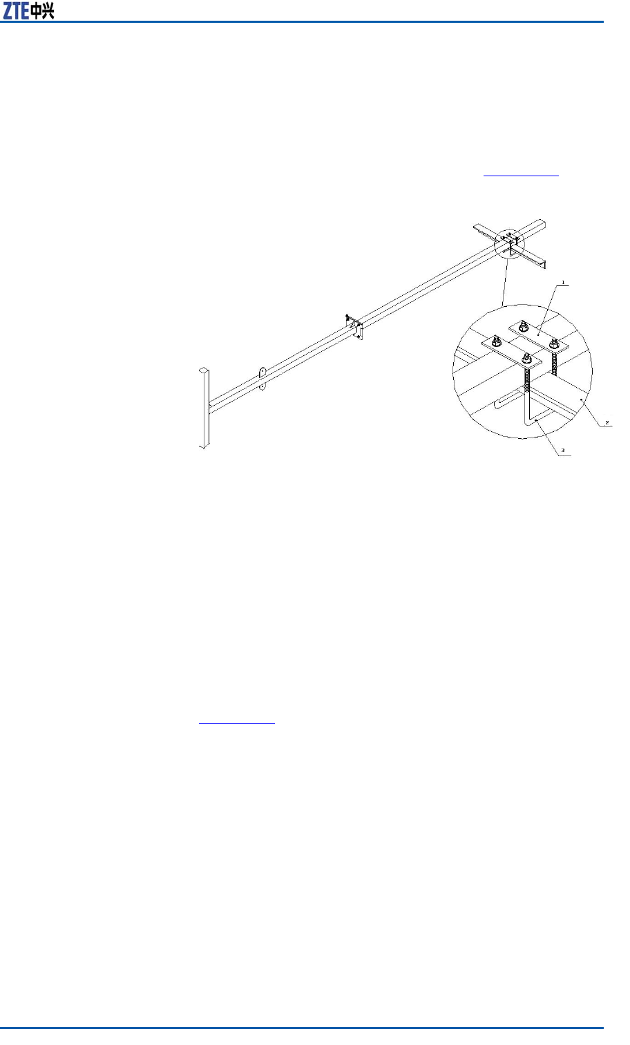
Chapter8InstallingMainAntennaFeederSystem
ii.Accordingtotheinstallationdrawingofantennaandfeeder
intheengineeringdesigndrawing,conrmtheinstallation
positionofantennarack.
iii.Extendtherackoutoftheironplatformandfasteniton
thetowerbodywithU-shapexationclips(connectionbar
andU-shapeboltincluded),asshowninF
i g u r e 1 0 4 .
FIGURE104ANTENNARACKINSTALLATION
1.Connectionbar
2.U-shapebolt
3.Ironplatform
iv.Connectguardbarsofplatformandconnectbottomplates.
Ifitisinconvenienttoconnecttheantennarackwiththe
guardbars,weldthemandmakesureweldingfastened.
Coveralayerofantirustpaintontheallpartsweldedand
onthesurfaceofrack.
2.Installingtheomnidirectionalantenna
i.Accordingtotheengineeringdesigndrawing,makesure
theinstallationdirectionofantenna.
ii.Fixtheantennaonthexationmastofrack,asshownin
F
i g u r e 1 0 5 .
ConfidentialandProprietaryInformationofZTECORPORATION113

ZXSDRBS8800C200InstallationManual
FIGURE105OMNIDIRECTIONALANTENNAINSTALLATION
1.Omnidirectionalantenna
2.Fixationclip
3.Fixationpole
4.Connectionpiece
5.Ironbeam
6.U-shapebolt
7.Jumperwaterproofbend-
ing
Caution:
Thesheathtopofomnidirectionalantennashouldbeina
levelwiththexationmasttopofrackorhigherthanthe
xationmasttop.Theemissionpartofantennashouldbe
higherthanthetopofxationmast.Thedegreeoftight-
nessofantennashouldbemoderatetoavoiddamagingthe
antennasheath.
iii.Checkwhethertheantennaaxesisverticalwiththelevel
withanangletestinstrument.Iftheerrorisequalormore
than±1。,refastenitafteradjustment.
iv.Fixtheantennauntilnotpushit.
v.Makethewaterproofbendingofjumper .Whiledistributing
thejumper ,bindthejumperalongtherackrailwithblack
wirefasteners.Cutoffredundanttailsofwirefasteners.
Caution:
Duringjumperlayout,thebendingisnaturalandtheradius
ofbendingisusually20timesmorethanthediameterof
jumper .Keepwirefastenersinthesamedirection.Remain
5~10mmredundancywhilecuttingthetailofwirefastener .
Thecuttingsectionshouldbeatandorderly.
vi.Extendtheinstalledrationalmastoutoftheironplatform
andxtheconnectingbottomplatewithbolts.
114ConfidentialandProprietaryInformationofZTECORPORATION
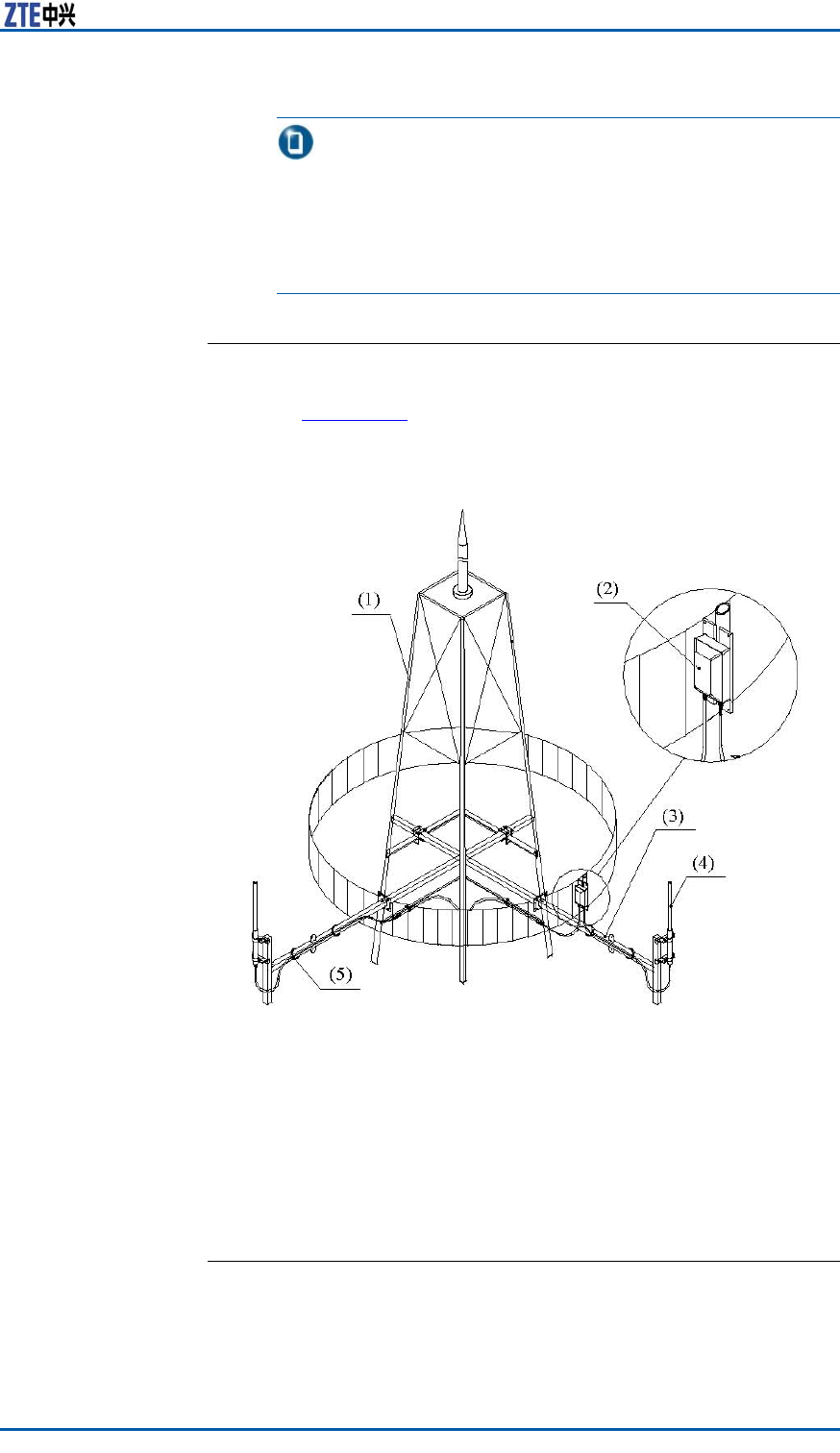
Chapter8InstallingMainAntennaFeederSystem
Note:
Ifthereisnoguardbarsontheplatform,foroperation
security,bindapieceofsolidboardtotwoarmsoftworacks
tobuildupaspringboard.Whilexingasideofantenna,
toweramplierandfeederconnection,modifytheposition
ofboardontherackarmstoxothers.
ENDOFSTEPS.
ResultTheomnidirectionalantennainstallationontheIronTowerisas
showninF
i g u r e 1 0 6 .
FIGURE106OMNIDIRECTIONALANTENNAINSTALLATIONONTHEIRON
TOWER
1.Irontower
2.Toweramplier
3.Antennarack
4.Omnidirectionalantenna
5.Wirefastener
InstallingOmnidirectionalAntenna
onRoof
ContextInstallationrequirementsaredescribedasfollows:
�Keepawayfromobstructorsandblindareas.
ConfidentialandProprietaryInformationofZTECORPORATION115

ZXSDRBS8800C200InstallationManual
�Theinstallationpositionofconnectorofenhancedmastshould
havenoimpactonadjustmentofantennadirectionandangle.
�Keepanantennarackverticalwiththelevel.
�Ifinstallinganarresterontherackofomnidirectionalantenna,
extendtherack1~1.5maway.
�Ifthereisnoarresterontheantennarack,installanarrester .
Thehorizontalintervalbetweenomnidirectionalantennaand
arrestershouldbenotlessthan2.5m.Locatetheantenna
withinaprotectiveareaof30°downtiltofarrestertop.
�Allweldingpartsofantennarackshouldbecoveredalayer
ofantirustpaintonthesurface.Makesureallweldingparts
fastenedandnofaultyorlackingwelding.
Steps1.Installingtheantennarackontheroof
Therearetwoconditionsforinstallation:
�Installingtherackontheroofwithoutawall
�Installingtherackinconvenienttoxontheroofwithawall
Therearevarioustypesofantennaracks.Takeonetypefor
example.ThestructureofantennarackisasshowninF
i g u r e
107.
116ConfidentialandProprietaryInformationofZTECORPORATION
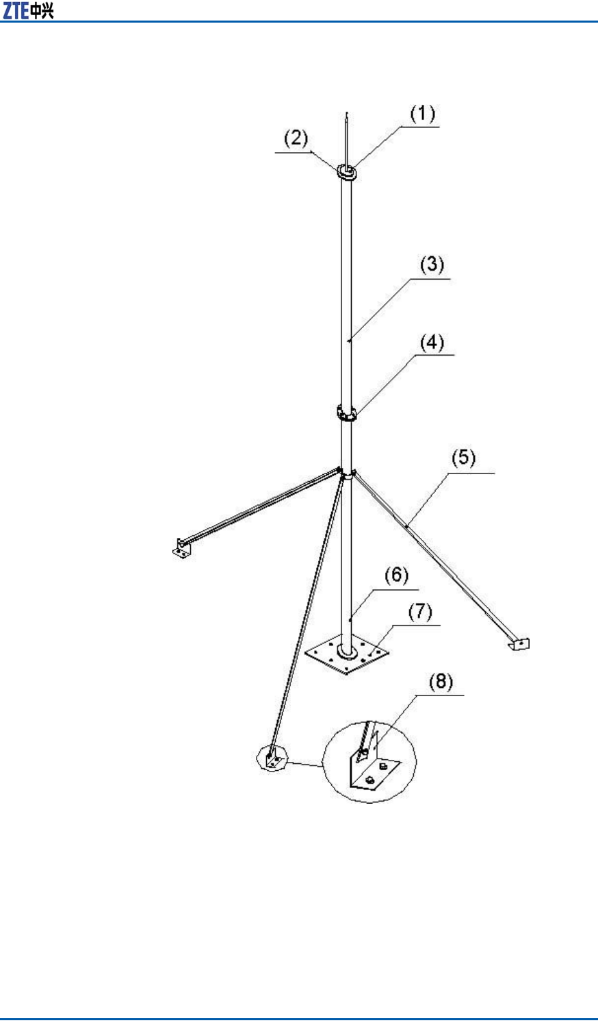
Chapter8InstallingMainAntennaFeederSystem
FIGURE107ANTENNARACKSTRUCTURE
1.Antennaarrester
2.Weldedjoint
3.Supportpole2
4.M10×80bolt
5.Enhancedmast
6.Supportpole1
7.Supportpolebase
8.Enhancedmastfoundation
Installingtherackontheroofwithoutawall
i.Movetheracktotheroof.
ConfidentialandProprietaryInformationofZTECORPORATION117
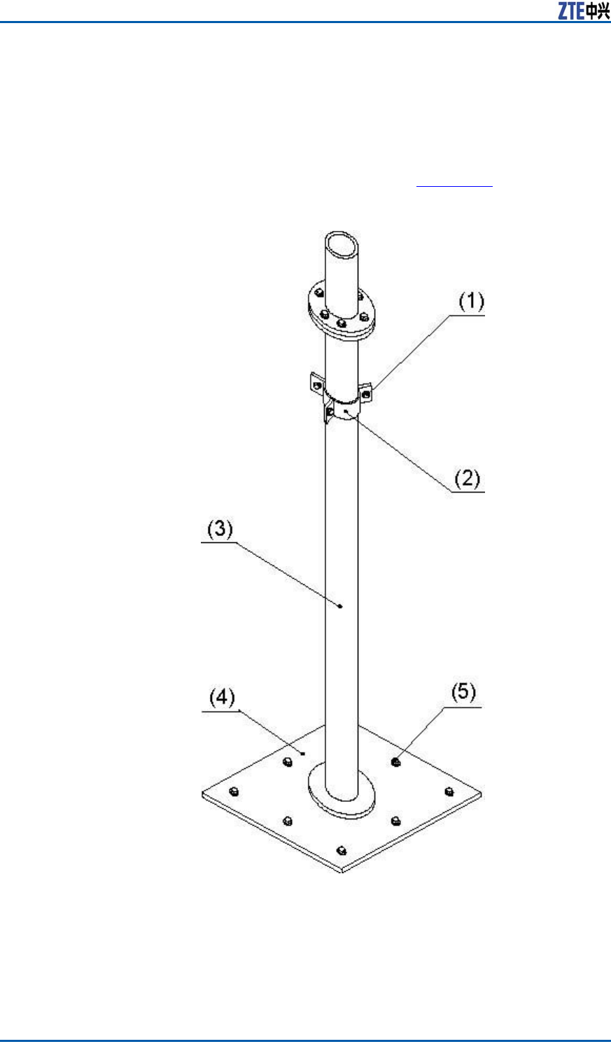
ZXSDRBS8800C200InstallationManual
ii.Accordingtotheinstallationdrawingofantennaandfeeder
intheengineeringdesigndrawing,conrmtheinstallation
positionofantennarack.
iii.Weldanarresterontoasupportpole1.
iv.FastentheantennarackbasewitheightM10×45expansion
boltsontheroof,asshowninF
i g u r e 1 0 8 .
FIGURE108ANTENNARACKBASESTRUCTUREANDINSTALLATION
1.M10×50hexagonbolt
2.Connectorofenhanced
mast
3.Supportpole1
4.Supportpolebase
5.M10×50expansionbolt
v.Fixthesupportpolewiththeenhancedmasts.Thelength
ofenhancedmastisdeterminedbythelengthofsupport
118ConfidentialandProprietaryInformationofZTECORPORATION
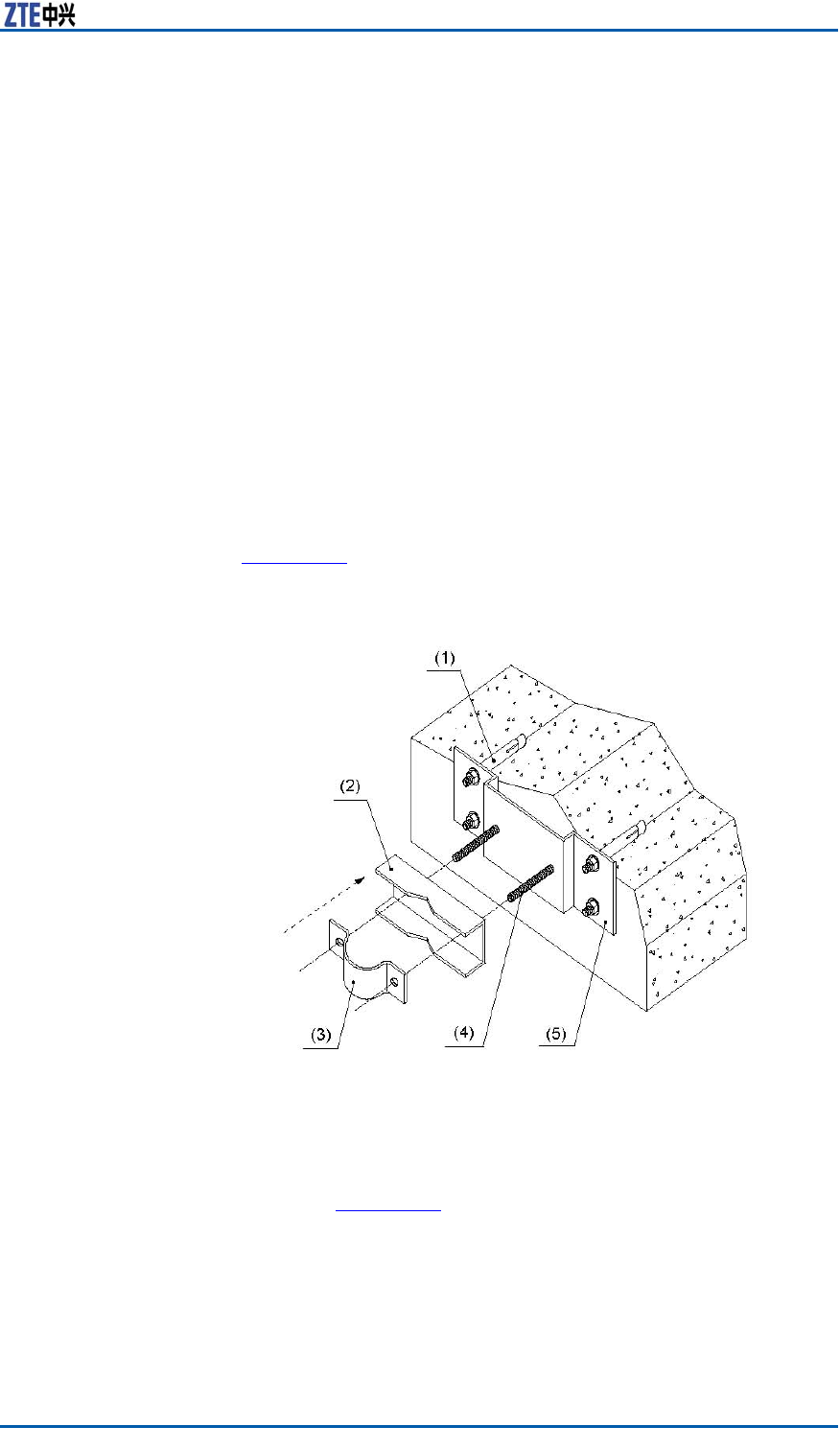
Chapter8InstallingMainAntennaFeederSystem
pole.Connecttheenhancedmastswiththesupportpoleby
aconnector .Thenconnecttheenhancedmastfoundations
withtheenhancedmasts.Fixeveryfoundationsontheroof
withtwoM10×45expansionboltsandmakesurejunctions
ofenhancedmastsnotbetwisted.
vi.Connectthesupportpole2tothesupportpole1withsix
M10×80bolts.
vii.Iftheantennarackontheroofisnotweldedwithanout-
doorcabletray,ortheoutdoorcabletrayweldedwiththe
antennarackisnotconnectedwiththelightningnetof
building,theantennarackbasemustbeconnectedwith
thelightningnetviaalightningjunctionbar .
viii.Coveralayerofantirustpaintonthesurfaceofallwelded
partsandtherackbase.Coverconcreteontheantenna
rackbase,enhancedmastandexpansionbolts.
Installingtherackinconvenienttoxontheroofwithawall
Whenitisinconvenienttoinstalltherackontheroof,iftheroof
issurroundedbythewall,installitontothewall,asshownin
Fi g u r e 1 0 9 .
FIGURE109INSTALLINGANTENNARACKONTHEWALL
1.M12×120expansionbolt
2.V-shapeconnector
3.180°connector
4.M12×140bolt
5.Fastnessboard
Iftheheightofwallisnotlessthan1200mm,xthesup-
portpoleonthewallwithexpansionboltsandxationclips,as
showninF
i g u r e 1 1 0 .
ConfidentialandProprietaryInformationofZTECORPORATION119

ZXSDRBS8800C200InstallationManual
FIGURE110ANTENNARACKFIXEDONTHEWALLCOMPLETELY(
HEIGHTOFWALLNOTLESSTHAN1200MM)
Iftheheightofwallislessthan1200mm,xanendofsupport
poleonthewallwithexpansionboltsandaxationclip,and
xtheotherpointofsupportpolewiththeroof,asshownin
F
i g u r e 1 1 1 .
120ConfidentialandProprietaryInformationofZTECORPORATION
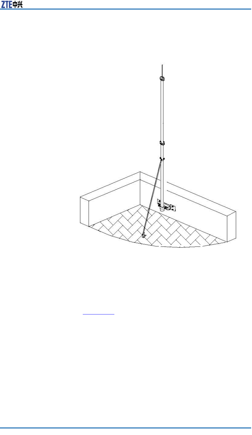
Chapter8InstallingMainAntennaFeederSystem
FIGURE111ANTENNARACKFIXEDONTHEWALL(HEIGHTOFWALL
LESSTHAN1200MM)
2.Installingtheomnidirectionalantenna
i.Accordingtotheengineeringdesigndrawing,makesure
theinstallationdirectionofantenna.
ii.Fixtheantennaonthexationmastofrack,asshownin
F
i g u r e 1 1 2 .
ConfidentialandProprietaryInformationofZTECORPORATION121
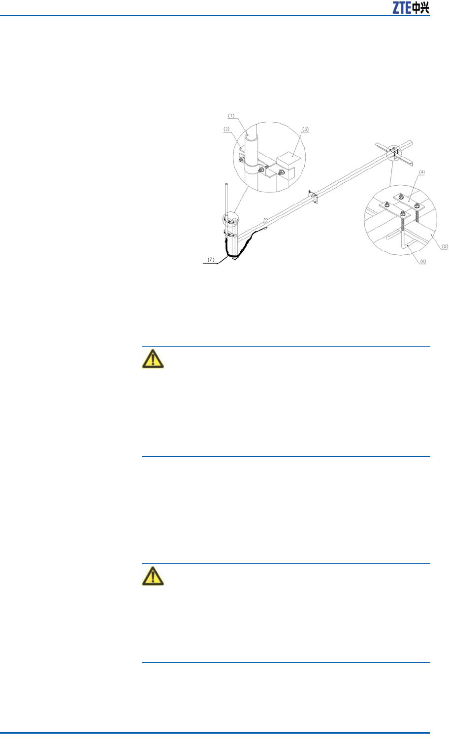
ZXSDRBS8800C200InstallationManual
FIGURE112OMNIDIRECTIONALANTENNAINSTALLATION
1.Omnidirectionalantenna
2.Fixationclip
3.Fixationpole
4.Connectionpiece
5.Ironbeam
6.U-shapebolt
7.Jumperwaterproofbend-
ing
Caution:
Thesheathtopofomnidirectionalantennashouldbeina
levelwiththexationmasttopofrackorhigherthanthe
xationmasttop.Theemissionpartofantennashouldbe
higherthanthetopofxationmast.Thedegreeoftight-
nessofantennashouldbemoderatetoavoiddamagingthe
antennasheath.
iii.Checkwhethertheantennaaxesisverticalwiththelevel
withanangletestinstrument.Iftheerrorisequalormore
than±1。,refastenitafteradjustment.
iv.Fixtheantennauntilnotpushit.
v.Makethewaterproofbendingofjumper .Whiledistributing
thejumper ,bindthejumperalongtherackrailwithblack
wirefasteners.Cutoffredundanttailsofwirefasteners.
Caution:
Duringjumperlayout,thebendingisnaturalandtheradius
ofbendingisusually20timesmorethanthediameterof
jumper .Keepwirefastenersinthesamedirection.Remain
5~10mmredundancywhilecuttingthetailofwirefastener .
Thecuttingsectionshouldbeatandorderly.
vi.Extendtheinstalledrationalmastoutoftheironplatform
andxtheconnectingbottomplatewithbolts.
122ConfidentialandProprietaryInformationofZTECORPORATION
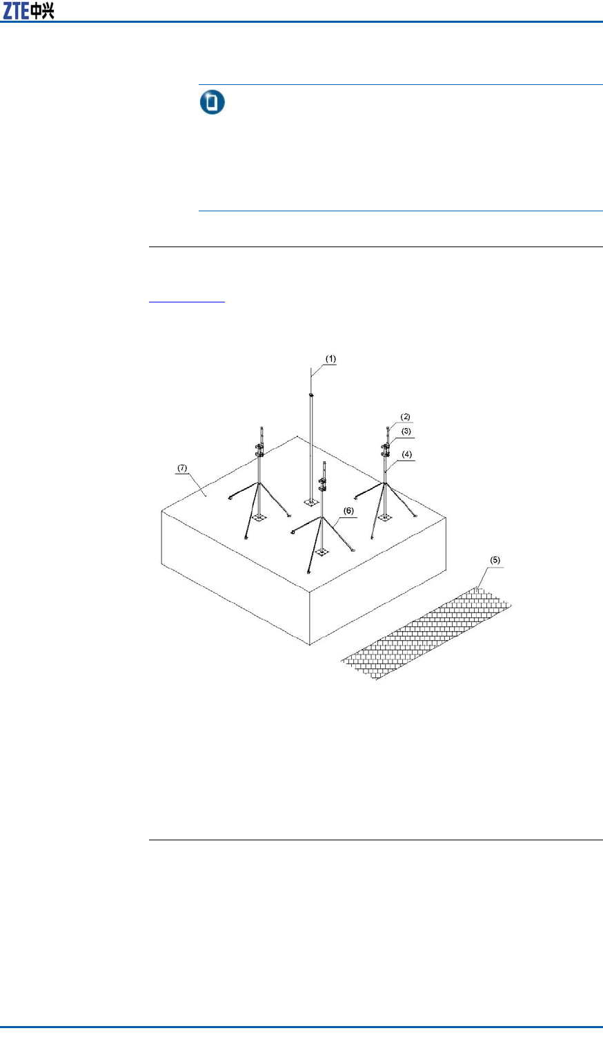
Chapter8InstallingMainAntennaFeederSystem
Note:
Ifthereisnoguardbarsontheplatform,foroperation
security,bindapieceofsolidboardtotwoarmsoftworacks
tobuildupaspringboard.Whilexingasideofantenna,
toweramplierandfeederconnection,modifytheposition
ofboardontherackarmstoxothers.
ENDOFSTEPS.
ResultTheomnidirectionalantennainstallationontheroofisasshownin
F
i g u r e 1 1 3 .
FIGURE113OMNIDIRECTIONALANTENNAINSTALLATIONONTHEROOF
1.Arrester
2.Antenna
3.Omnidirectionalantennaxation
clip
4.Antennasupportpole
5.Road
6.Enhancedmast
7.Roof
InstallingAntennaJumper
ContextTheantennajumperisasupersoftjumperconnectinganantenna
withamainfeeder .ForamobileBTS,adopt1/2inchsupersoft
jumper .Aconnectorofjumperisdeterminedbytheantennaand
themainfeeder .Normally,twoconnectorsofjumperareboth
maleDIN-type.
ConfidentialandProprietaryInformationofZTECORPORATION123
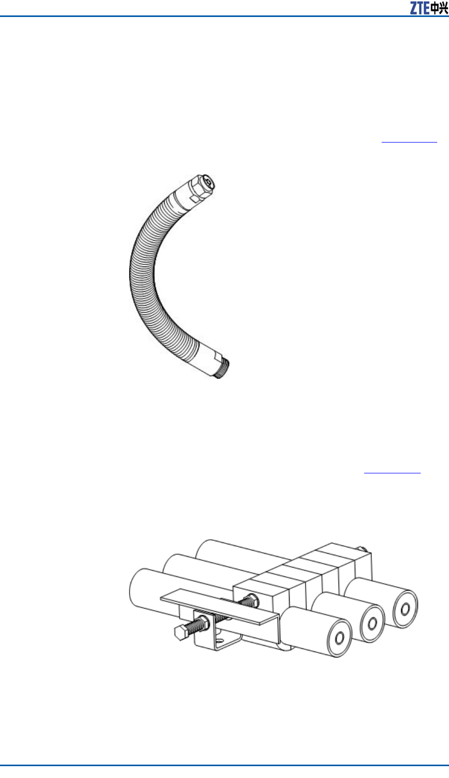
ZXSDRBS8800C200InstallationManual
Steps1.Conrmaproperjumperroutewhichshouldbereliable,con-
venient,shortaspossibleitcan.Makesureraindropinthe
middleofjumperbutnotattheconnector .
2.Makesureapropertorque(connectiontorqueofDINis1.7N.m
typicallyandthemaximumvalueisnotmorethan2.3N.m)to
connectaconnectorbetweenantennaandjumper .Andmake
surethisconnectornolateralforce,asshowninF
i g u r e 1 1 4 .
FIGURE114JUMPERCONNECTION
3.Makesureapropertorque(connectiontorqueofDINis1.7N.m
typicallyandthemaximumvalueisnotmorethan2.3N.m)to
connectaconnectorbetweenmainfeederandjumper .And
makesurethisconnectornolateralforce.
4.Fixthejumperwithfeederkits,asshowninF
i g u r e 1 1 5 .The
distanceoffeederkitsisnotbeyond0.76m.Whenthespeed
ofwindisover160km/h,shortenthedistancebetweenfeeder
kitsappropriately.
FIGURE115FEEDERKITFIXATION
124ConfidentialandProprietaryInformationofZTECORPORATION

Chapter8InstallingMainAntennaFeederSystem
5.Carryoutperformancemeasurementofantennaandfeeder
andmakesurethesystemrunningnormally.Finallysealthe
connectorwithself-adhesivewaterprooftapeandPVCtape.
ENDOFSTEPS.
InstallingFeeder
Hermetic-window
ContextInstallationrequirementsaredescribedasfollows:
�Theinstallationpositionofhermeticwindowshouldbecloseto
acabletraypossibly.
�Thehermeticwindowcanbemountedagainstanindoorwall
oroutdoorwallandthesideofprotuberantmetalcirclesmust
puttowardsoutdoors
�Ifthefeederentersintoaroomfromaroof,thehermeticwin-
dowcanbemountedontheroofandthesideofprotuberant
metalcirclesmustputtowardsoutdoors.
Thefollowdescribesthestepsof12holehermeticwindowinstalled
againstthewall.
Steps1.Accordingtotherequirementsofengineeringdesigndrawing
andthedimensionofhermeticwindow,makesuretheinstal-
lationpositionofhermeticwindowonthewallandatthesame
timemarkholepositionsofexpansionboltsandahollowroom
leftforthehermeticwindow.
2.Cuta250mm×250mmsquarebigholeandthendrilleight
holesofexpansionblotswithapercussivedrill,asshownin
F
i g u r e 1 1 6 .
ConfidentialandProprietaryInformationofZTECORPORATION125
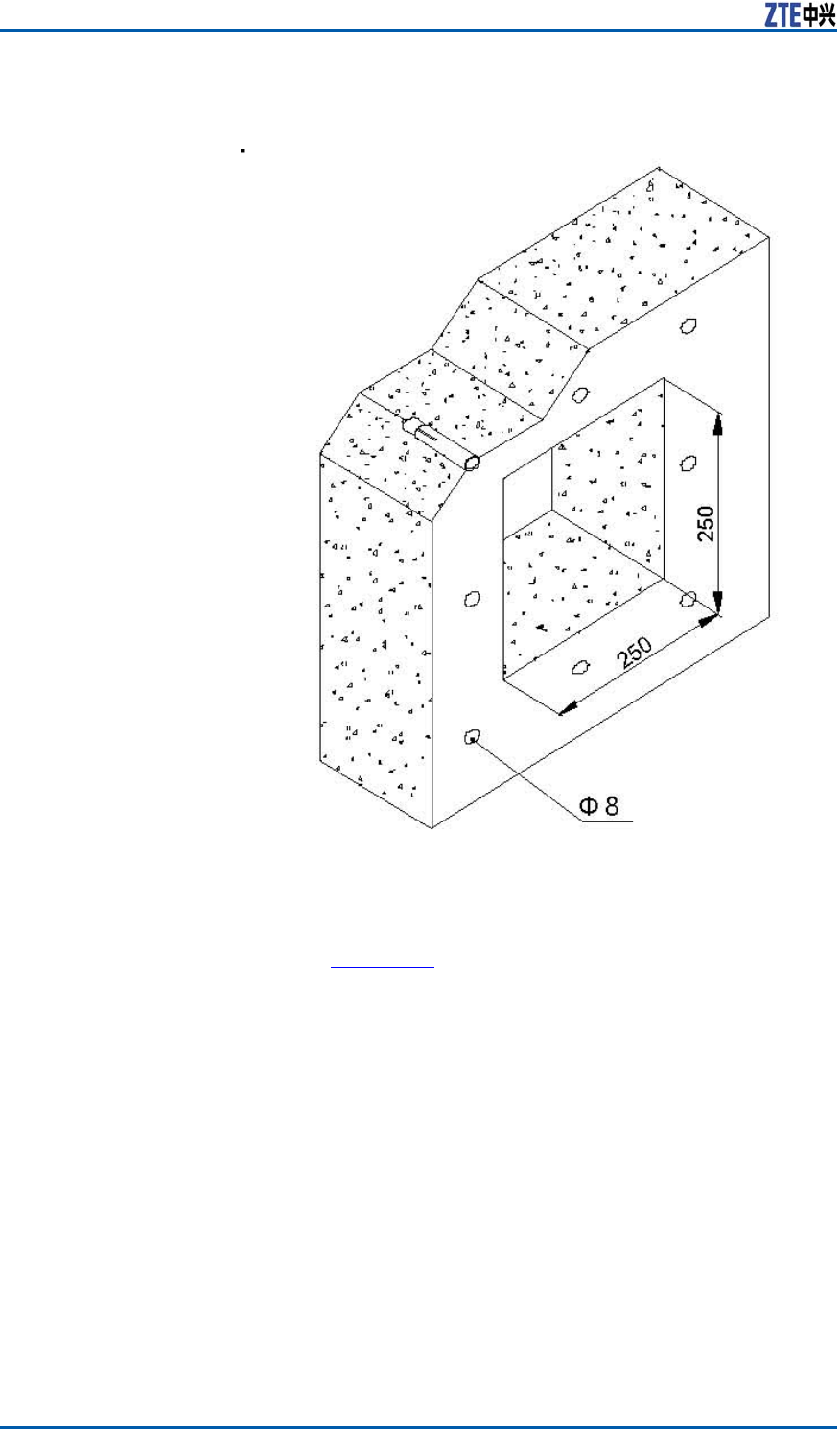
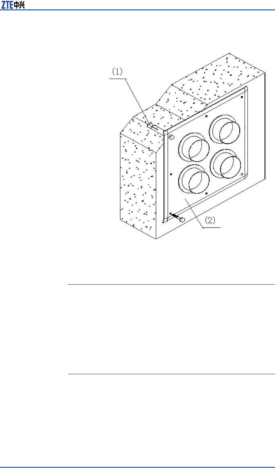
Chapter8InstallingMainAntennaFeederSystem
FIGURE117HERMETICWINDOWINSTALLATION
1.M8×80expansionbolt2.Feederhermetic-window
panel
ENDOFSTEPS.
InstallingandGrounding
FeederandJumper
FeederCuttingPrinciple
Accordingtothenalfeederrouteconsultedwithusers,conrm
thelengthoffeedersonsite.Cutfeedersbasedonthelengthof
variousfeeders.Consideringdifferentinstallationpositions,there
aretwomodesofcuttingfeeder ,asfollows:
Feeder
Installationon
theBuildingTop
1.Accordingtothepracticalfeederroute,measurethefeeder
lengthofeverysectorwithatape.
2.Cutthefeederandremainan1m~2mredundantlength
comparedwiththepracticallengthinmeasure.
ConfidentialandProprietaryInformationofZTECORPORATION127
ZXSDRBS8800C200InstallationManual
3.Aftercuttingonefeeder ,afxrelevanttemporarylabelsatthe
twoendsoffeeder ,suchas:ANT0andANT0.
4.Movethecutfeedertothetopofbuilding,andmakesurethe
feederundamagedandnotpressed.
5.Finallyafxaformallabelonthefeeder .
Feeder
Installationon
theIron
1.Hoistanendoffeedertothetopoftower .Beforehoisting,
makeanupperfeederconnector .
2.Installationpersonnelunderthetowercutthefeederaccording
toarequiredlengthoffeederintoaroomandremainacertain
redundantlength.Atemporarylabelmustbeafxedtothe
feeder .
3.Finallyafxaformallabelonthefeeder .
FeederLayoutPrinciple
Theprinciplesoffeederlayoutaredescribedasfollows:
�Feederlayoutshouldbeorderlyandproper .Avoidcrossedlay-
outoffeeder .
�Beforefeederlayout,knowtherouteoffeederwell.Topre-
ventfromcrossedfeeder ,suggestdrawingapracticalrouteof
feederonthepaper.
�Theminimumbendingradiusoffeederisnotlessthantwenty
timesthantheradiusoffeeder .
�TherequirementsofbendingradiusarelistedinT
a b l e 7 .
TABLE7BENDINGRADIUSREQUIREMENTSOFVARIOUSFEEDERS
Theminimumbendingradiusrecommended FeederType
BendingforonceContinuousbending
(≤15times)
Supersoft
1/2"feeder
15mm30mm
1/2"feeder50mm125mm
7/8"feeder90mm250mm
5/4"feeder150mm380mm
InstallingFeederonTower
Steps1.Makesurefeedermarkscorrectafxedtotwoendsoffeeder.
2.Protectafeederconnectorwithaxoranantistaticbagadding
foamandbindthemtightlywithbindingtape.
3.Hoistthefeederatopthetowerwithagroupofhoistingpulleys.
4.Installathree-linkagefeederkittoxthefeederevery1.5
malongatoweroracabletray.Thedetailedintervalisde-
terminedbyanon-siteinstallationcondition,buttheinterval
betweentwofeederkitscannotbebeyond1.65m.Theinter-
nalbetweenfeederkitsshouldkeepequalandthedirections
128ConfidentialandProprietaryInformationofZTECORPORATION
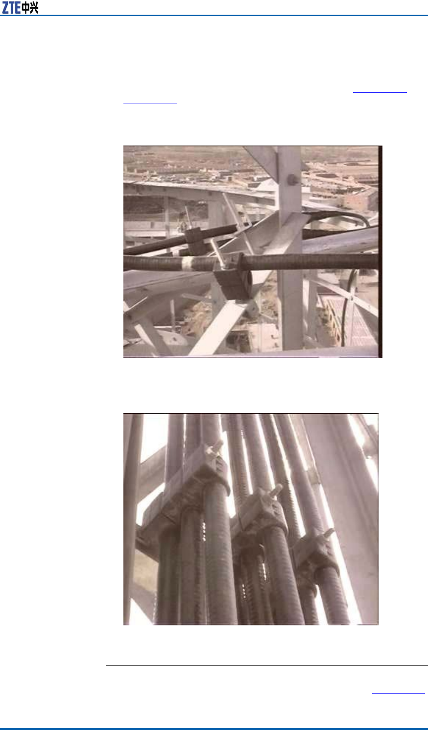
Chapter8InstallingMainAntennaFeederSystem
shouldkeepconsistent.Inthesamecabletray,iftwolinesof
feederkitsareinstalled,keepthemparalleledandorderly.
FixationoffeederonthetowerisasshowninF
i g u r e 1 1 8 and
Fi g u r e 1 1 9 .
FIGURE118FEEDERFIXATIONONTHETOWER(ONEKITANDTWO
FIXATIONCLIPS)
FIGURE119FEEDERFIXATIONONTHETOWER(ONEKITANDTHREE
FIXATIONCLIPS)
ENDOFSTEPS.
ResultCompletefeederinstallationonthetower ,asshowninF i g u r e 1 2 0 .
ConfidentialandProprietaryInformationofZTECORPORATION129
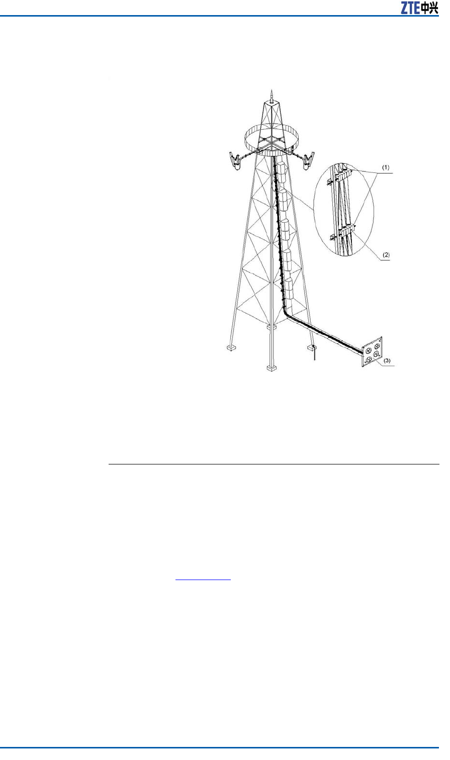
ZXSDRBS8800C200InstallationManual
FIGURE120FEEDERLAYOUTFROMTOWERTOPTOHERMETICWINDOW
1.Intervalbetweenxationkits
2.Fixationkit
3.Feederhermeticwindow
InstallingFeederonRoof
Steps1.Makesurefeedermarkscorrectafxedtotwoendsoffeeder.
2.Accordingtothelabels,xthefeederintofeederxationclips.
Screwsonthexationclipsarenotfastenedtemporarily.After
completingfeederlayout,screwdownthesescrews.
Thexationclipsshouldkeepverticalwiththefeeder .The
feedersinaxationclipshouldkeepparalleledmutually,as
showninF
i g u r e 1 2 1 .
130ConfidentialandProprietaryInformationofZTECORPORATION
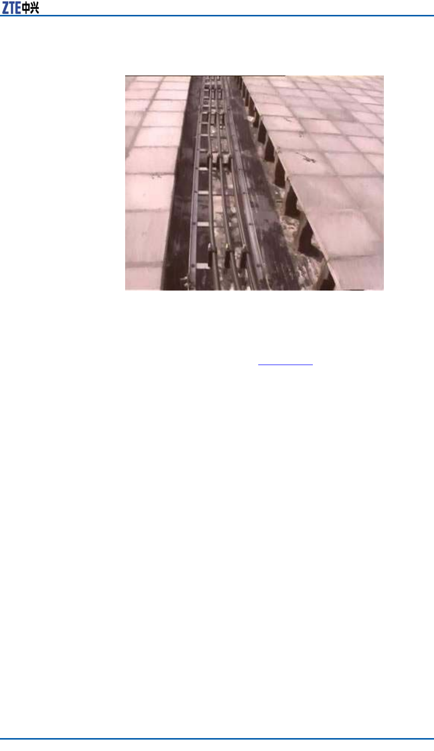
Chapter8InstallingMainAntennaFeederSystem
FIGURE121FIXINGFEEDERINTOFIXATIONCLIP
3.Thefeederentersintoaroomalongawallfromtheroof.If
thedistancefromtherooftotheroomisbeyond1m,prepare
acableladderandfastenthefeederonthecableladderwith
xationclips,asshowninF
i g u r e 1 2 2 .
ConfidentialandProprietaryInformationofZTECORPORATION131
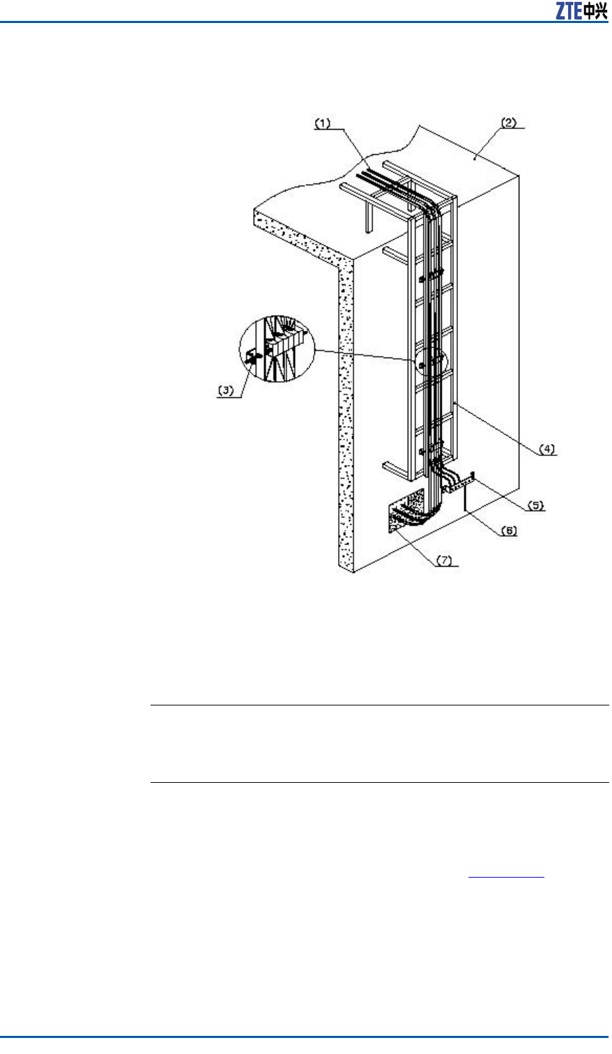
ZXSDRBS8800C200InstallationManual
FIGURE122FEEDERLAYOUTFROMROOFTOHERMETICWINDOW
1.Feeder
2.Buildingtop
3.Feederxationclip
4.Outdoorcabletray
5.Outdoorgroundingbar
6.Connectingoutdoorlightning
grounding
7.Feederhermeticwindow
ENDOFSTEPS.
FeederGroundingPrinciple
�Intheon-towerinstallation,twofeedergroundingkitsshould
beinstalledonthemainfeeder .Onegroundingkitlocates
aroundthetowerplatformandtheotherlocatesattheposition
ofmainfeederoffthetower ,asshowninF
i g u r e 1 2 3 .
132ConfidentialandProprietaryInformationofZTECORPORATION
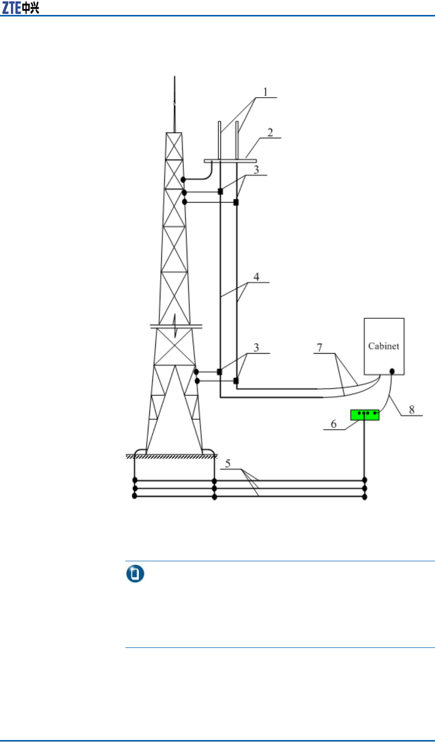
Chapter8InstallingMainAntennaFeederSystem
FIGURE123FEEDERGROUNDING
1.Antenna
2.Towerplatform
3.Groundingkit
4.Feeder
5.Groundgrid
6.Coppergroundbar
7.Cabinetjumper
8.Groundcable
Note:
i.Iftheheightoftowerisover60m,addagroundpointin
themiddleoftower .
ii.Ifthefeederlengthoffthetowerisover5m,addaground
pointbeforeconnectingtothecabinetjumper .
�Theantennafeedersystem,antennabracketandcabletray
installedatopbuildingsshouldbeweldedtothelightningnetof
buildings.Twogroundingkitsshouldbeinstalledonthefeeder
atleast,andthepositionsrespectivelyis:thefeederoffthe
ConfidentialandProprietaryInformationofZTECORPORATION133
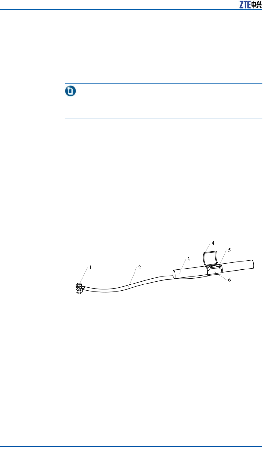
ZXSDRBS8800C200InstallationManual
antennapoleandthefeederoffthebuilding-topplatform.If
thefeederlengthoffthepoleisover5m,installagrounding
kitbeforeconnectingthecabinetjumper .Ifthelengthofmain
feederisover60m,addagroundingkitinthemiddleofmain
feeder ,usuallyinstallingoneper20m.
�Theoutdoorwiringladderofmainfeedermustbegrounded.
Note:
Ifthelengthoffeederislessthan5m,thegroundprocessingis
unnecessary.
InstallingFeederGroundingKit
Prerequisite�Installthefeeder .
�Preparegroundingkitsinpropertypeandquantityaswellas
installationtools,suchaspaperknife,atheadscrewdriver ,
wrenchandsharp-nosepliers.
Steps1.Selectanappropriateinstallationpositionforagroundingkit,
andcutoffthesheathoffeederaccordingtothesizeofground-
ingkit,thestructureasshowninF
i g u r e 1 2 4 .
FIGURE124GROUNDINGKITSTRUCTURE
1.Groundterminal
2.Groundcable
3.Feeder
4.Groundcablecirclip
5.Feederoutercoopercore
6.Groundcablecoppersheet
2.Leadthegroundcableofgroundingkittowardsagroundgrid.
Theanglebetweengroundcableandmainfeedershouldbenot
morethan15°.Theorientationofgroundcableshouldcomply
withthefollowingspecications:
i.Whileinstallingtheantennafeedersystemonatower ,
makesurethegroundcableofgroundingkitdownwards
alongthetower .
ii.Whileinstallingtheantennafeedersystematopabuilding,
leadthegroundcableofgroundingkittowardsalightning
net.
3.Beforeinstallingthegroundingkit,inordertoenhancesealing
effectandavoidwaterintofeederinneralongthegroundca-
134ConfidentialandProprietaryInformationofZTECORPORATION
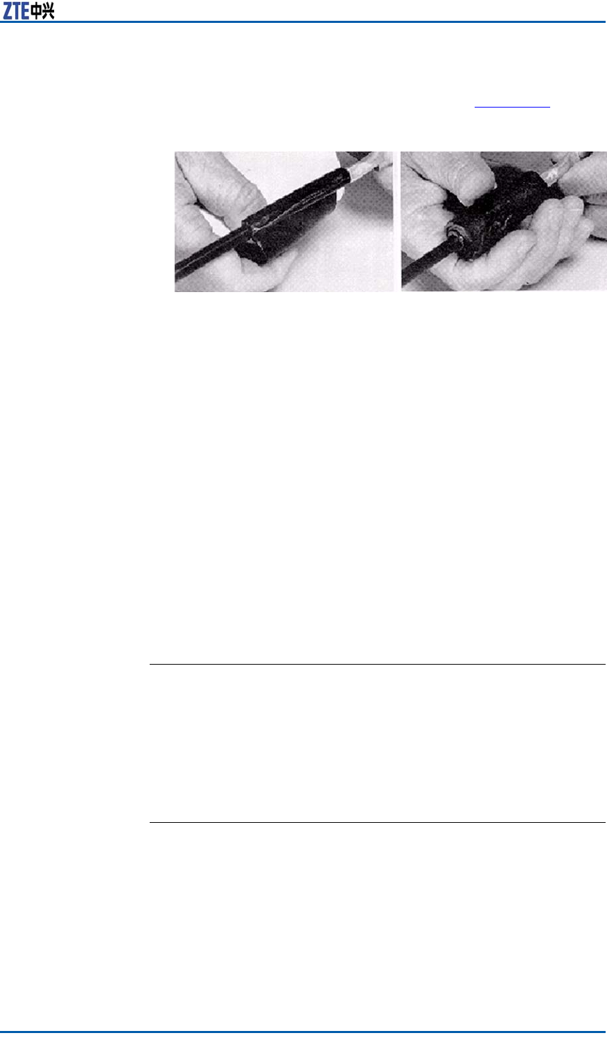
Chapter8InstallingMainAntennaFeederSystem
ble,rstwrapwaterproofself-adhesivetaperoundtheground
cableclosetoacoppersheet,asshowninF
i g u r e 1 2 5 .
FIGURE125WATERPROOFADHESIVETAPEWRAP
4.Clampanouterconductoroffeederwithacoppersheetof
groundcableandasnapspringandmakethecoppersheet
combinedwiththeouterconductor .
5.Performwaterproofandsealedprocessingforjunctionbetween
groundkitandfeeder .Themethodsarelistedasfollows:
i.Firstwrapwaterproofself-adhesivetapeandthenwrapPVC
adhesivetape.
ii.Forwaterproofself-adhesivetape,rstwrapfromlowerto
upperlayerbylayer ,thenwrapfromuppertolowerlayer
bylayer ,andnallywrapfromlowertoupperlayerbylayer .
Duringwrapping,theformerlayercoversahalfofthenext
layer .
6.Thegroundingterminalofgroundkitcanbeconnectedtoa
bodyoftoweroracabletrayonthetopofbuilding.Thiscable
trayconnectswiththelightningnetofbuilding.Clearaway
oilpaintandoxidearoundthejunctionandcoveralayerof
antioxidationcreamonthisareaforgoodelectricitycontact.
Finally,coveralayerantirustpaintagain.
ENDOFSTEPS.
FeederIndoorIngoing
FeederIndoorArrangementPrinciple
Thearrangementprinciplesoffeederintoaroomcomplywiththe
following:
�Therearefourbigholesona12–holefeederhermetic-window.
Everybigholehasthreesmallholes,everyofwhichafeeder
passesthrough.
�AccordingtotheserialNo.ontheengineeringlabelsattached
onthefeeder ,layoutthefeederthroughthreesmallholesin
thesamebigholeclockwiseoranticlockwise.
ConfidentialandProprietaryInformationofZTECORPORATION135
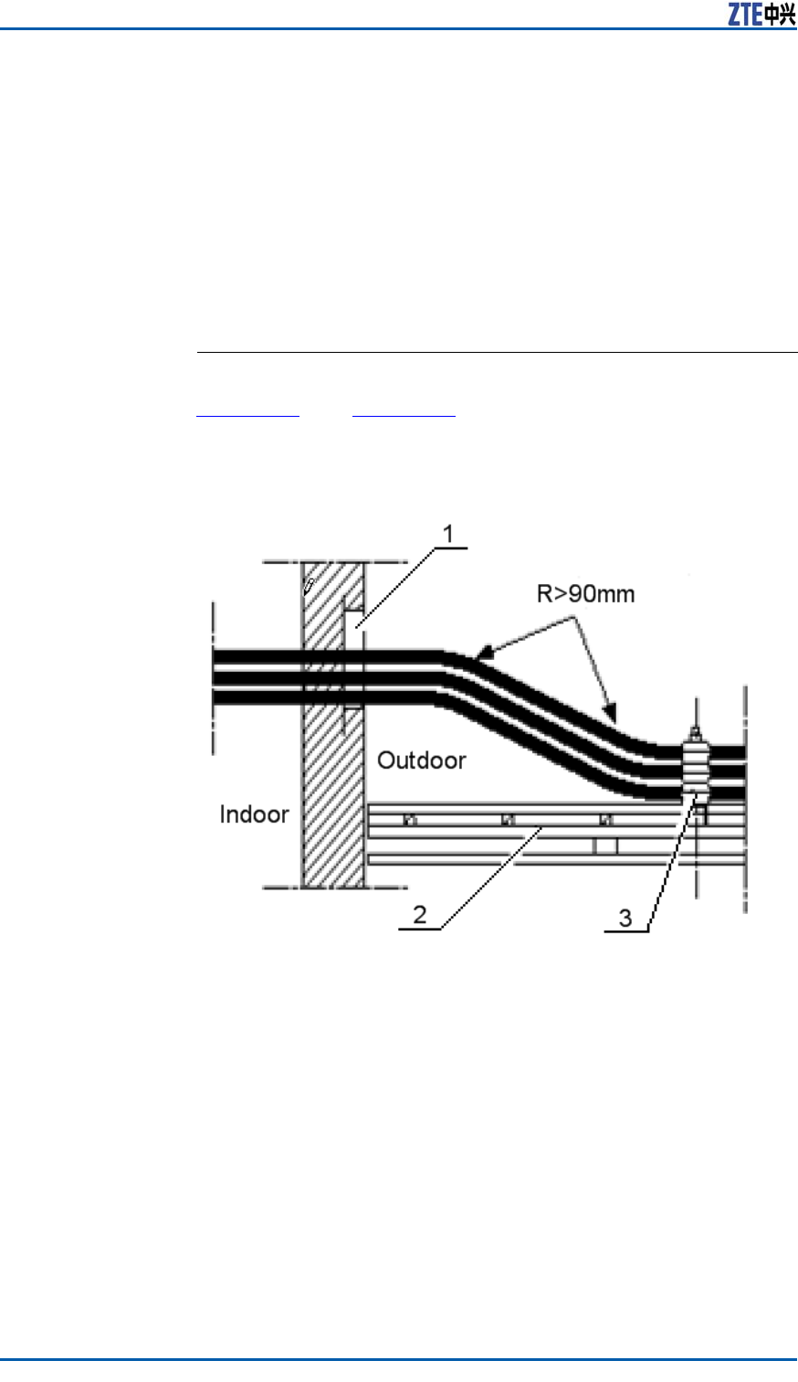
ZXSDRBS8800C200InstallationManual
�Feederlayoutinthehermeticwindowshouldbeconvenientfor
capacityexpansion.Donotmodifytheinitialfeederlayoutin
thehermeticwindowduringcapacityexpansion,andonlyallow
addingfeederormodifyjumperconnectionofcabinet.
�Feederlayoutinthehermeticwindowshouldbeconvenient
forlayoutonacabletrayandconnectiontoacabinet.The
feedershouldbeparallelandnotcrossedduringroutingand
connecting.
LeadingMainFeederintoRoom
ContextF i g u r e 1 2 6 andF i g u r e 1 2 7 showtwocommonmodesofmain
feederintoaroom.Whilethemainfeederisenteringintothe
equipmentroom,donotbringwaterintotheequipmentroom.
FIGURE126FEEDERINTOROOMMODE(1)
1.Feederwindow
2.Cabletray
3.Feederkit
136ConfidentialandProprietaryInformationofZTECORPORATION
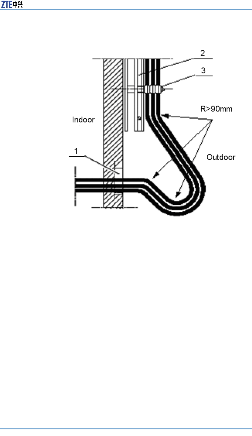
Chapter8InstallingMainAntennaFeederSystem
FIGURE127FEEDERINTOROOMMODE(2)
1.Feederwindow
2.Cabletray
3.Feederkit
Steps1.Unscrewafastnesshoopoffeederwindowtoproperextent.
Pulloutsealingcoversofsmallholesthatthefeederpasses
through.
2.Leadthemainfeederintotheequipmentroom.Whenthemain
feederentersintoanindoorcabletrayfromanoutdoorcable
tray,itisnecessaryfortwoinstallationpersonnel’scooperation
respectivelyindoorsandoutdoors.Inthisway,avoiddamaging
themainfeederandotherindoordevicesbyimproperforce
duringinstallation.Screwdownthefastnesshoopuntilthe
mainfeederispulltothespeciedposition.
3.Cutthemainfeeder .Beforeandaftercutting,makesuretem-
porarylabelsonthemainfeederintact.
ConfidentialandProprietaryInformationofZTECORPORATION137

ZXSDRBS8800C200InstallationManual
Note:
Accordingtodetailedequipmentenvironment(forexample,
cabinetinstallationposition,jumperlengthonthecabinettop,
arrestercongurationorarresterrackinstallationposition),the
bendingradiusrequirementofmainfeederandthebeautiful
requirementofcablelayoutintheequipmentroom,selecta
cuttingpositionofmainfeedercable.
4.Makeanindoorconnectorofmainfeeder .
5.Connectthemainfeederwithanarrester .
Note:
�Foranarresterwithoutgroundcable,duringinstallation,
connectthearrestertothemainfeederdirectly.
�Foranarresterwithanarresterrack,duringinstallation,
adjusteverymainfeedercarefully.Makesureascrewfas-
tenerconnectedwellwhichconnectsthemainfeedercon-
nectorwiththearrester .
ENDOFSTEPS.
InstallingTop-equipmentJumper
ContextTherequirementsofjumperinstallationareasfollows:
�Jumperlayoutfromcabinettoptocabletrayshouldbeparallel
andorderly,butnotcrossed.
�Duringrouting,thejumpermustpassthroughthecabletray
innertoitsupperside.Prohibitjumpingthecabletrayoutsides
directly.
�Thebendingofjumperisreasonableandnatural.Suggestthat
thebendingradiusofjumpershouldbetwentytimesmorethan
itsdiameter .
�Duringlayoutfromcabinettoptocabletray,thetensile
strengthforthejumpershouldbemoderate.
�Thejumpershouldbeboundwitheveryrailofcabletray.The
directionsofallwirefastenerskeepconsistentandafterbind-
ing,thewirefastenersarecutatly.
�Labelsmustbeafxedtoallindoorjumpersata100mmdis-
tancefrombothendsofjumper .
Steps1.Thejumperpassesthroughawiringslotonthetopofcabinet.
2.ConnectaDINconnectoroffeedertoanANTinterfaceofRSU.
3.ConnecttheotherDINconnectorofjumpertoaDINconnector
offeeder .
138ConfidentialandProprietaryInformationofZTECORPORATION
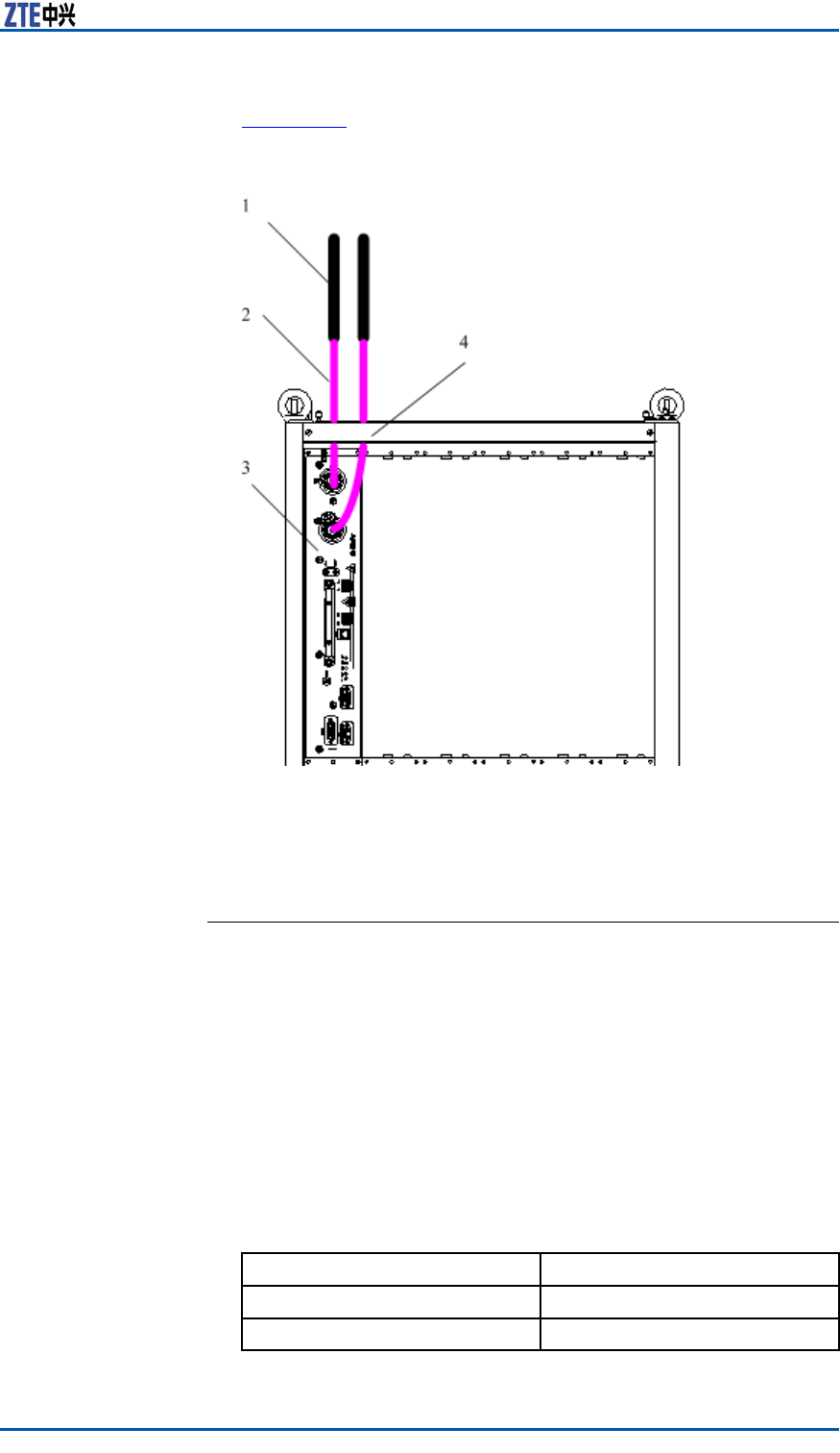
Chapter8InstallingMainAntennaFeederSystem
F i g u r e 1 2 8 showstheinstallationprocess.
FIGURE128ANTENNA,FEEDERANDJUMPERINSTALLATION
1.Feeder
2.Jumper
3.RSU
4.Wiringslot
4.Afxjumperengineeringlabels.
ENDOFSTEPS.
PerformingAntennaFeeder
SystemTest
Steps1.Afterunpacking,checkwhetherasurfaceofantennaandan-
tennaconnectorsareundamaged.
2.Afterconnectingantennaandjumper ,andscrewingdownthe
connector ,checktheSVWRwithaSVWRtester .
IfThen
SVWR≥1.5Unqualied
SVWR<1.5Qualied
ConfidentialandProprietaryInformationofZTECORPORATION139
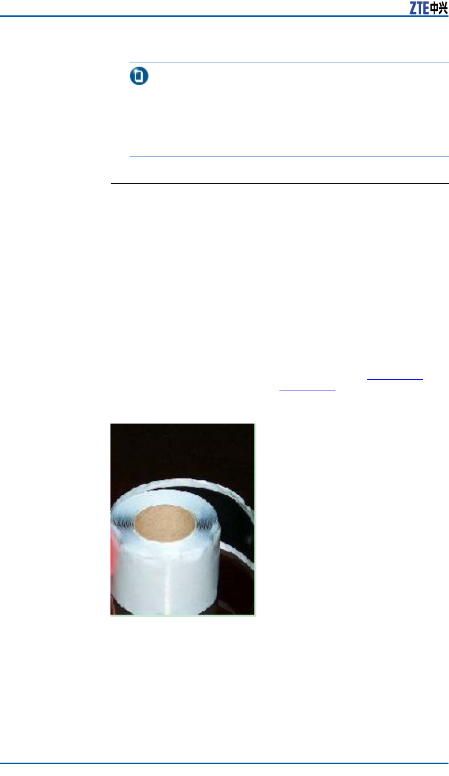
ZXSDRBS8800C200InstallationManual
Note:
Duringmeasuring,moveanantennaorchangetheposition
ofantenna.IftheSVWRsinalldirectionsareunqualied,it
indicatesthattheantennaisfaulty.IftheSVWRsinsome
directionsareunqualied,checktheantennaafterthewhole
antennaandfeedersysteminstalledcompletely.
ENDOFSTEPS.
PerformingOutdoor-connec
torWaterproofProcessing
PrerequisiteWhileanoverallinstallationofantennafeedersystemiscompleted
andgetsthroughatest,performwaterproofprocessingforacon-
nectorbetweenoutdoorjumperandtowertopamplieraswellas
aconnectorbetweenjumperandfeederimmediately.
ContextTherearetwotypesofadhesivetapesforwaterproofprocessing:
waterproofinsulationadhesivetape,asshowninF
i g u r e 1 2 9 ,and
PVCadhesivetape,asshowninFi g u r e 1 3 0 .
FIGURE129WATERPROOFINSULATIONADHESIVETAPE
140ConfidentialandProprietaryInformationofZTECORPORATION
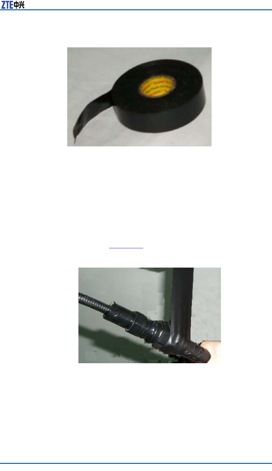
Chapter8InstallingMainAntennaFeederSystem
FIGURE130PVCADHESIVETAPE
Steps1.Cleanoutdustandstainonthefeederconnectororfeeder
groundingclip.
2.Expandthewaterproofinsulationadhesivetapeandstripoff
releasepaper .Theadhesivetapestickstotheconnectoror
thefeederwhichis20–50mmawayfromthelowerendof
groundingclip.
3.Extendtheadhesivetapetoupto1/2–3/4oftheformer
width,inordertokeepacertainextensionstrength.Bindthe
feederinanoverlappingwayfromlowertoupperandtheup-
peradhesivetapecoversahalfoftheloweradhesivetape,as
showninF
i g u r e 1 3 1 .
FIGURE131WATERPROOFINSULATIONADHESIVETAPEWRAP
ConfidentialandProprietaryInformationofZTECORPORATION141
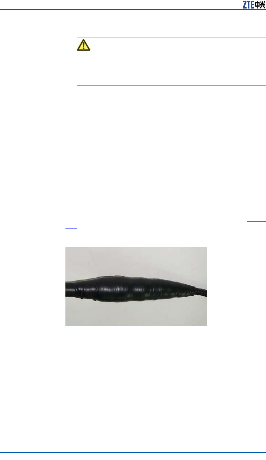
ZXSDRBS8800C200InstallationManual
Caution:
Theextendedwidthofadhesivetapeisnotover1/2thanthe
formerwidth,orelsedestroymolecularstructureofadhesive
tapeduetoextensiontoomuch.
4.Whilewrappingtotheconnector ,repeatitfortwiceandthe
sequencerespectivelyis:fromuppertolowerandfromlower
toupper .
5.Afterwrappingthewaterproofinsulationadhesivetape,press
theadhesivetapeatthebindingwithhandsmakeitafxed
tightly.
6.WrapalayerPVCadhesivetapearoundthewaterproofinsula-
tionadhesivetapetoavoidabrasionandaging.
7.WrapthePVCadhesivetapeinanoverlappingmode,similarto
thewaterproofinsulationadhesivetape.Theoverlappingrate
isabout1/2.Wrapthreelayersintotal,andthesequence
respectivelyis:fromlowertoupper ,fromuppertolowerand
fromlowertoupper .Makesureproperstretchstrengthduring
wrapping.
ENDOFSTEPS.
ResultTheappearanceofconnectorafterprocessingisasshowninF i g u r e
132.
FIGURE132CONNECTORAFTERPROCESSING
PerformingFeeder
Hermetic-window
WaterproofProcessing
ContextTherearetwotypesoffeederhermetic-window:
142ConfidentialandProprietaryInformationofZTECORPORATION
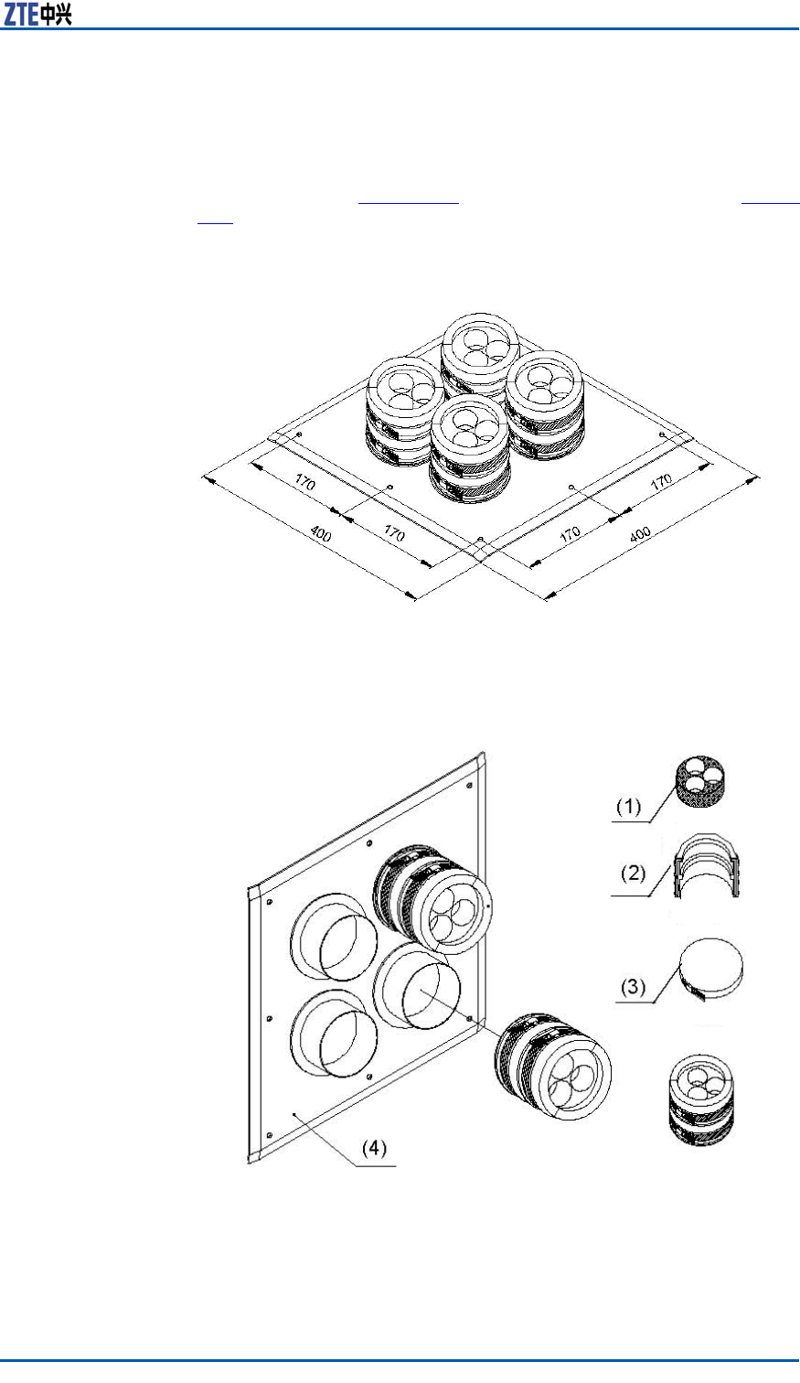
Chapter8InstallingMainAntennaFeederSystem
�12holefeederhermetic-window
�27holefeederhermetic-window
Normally,adoptthe12holefeederhermetic-window,itsdimen-
sionasshowninF
i g u r e 1 3 3 anditsstructureasshowninF i g u r e
134.
FIGURE133FEEDERHERMETIC-WINDOWDIMENSION(UNIT:MM)
FIGURE13412FEEDERHERMETIC-WINDOWSTRUCTURE
Installationrequirements:
�Theinstallationpositionofhermeticwindowshouldbecloseto
acabletray.
ConfidentialandProprietaryInformationofZTECORPORATION143
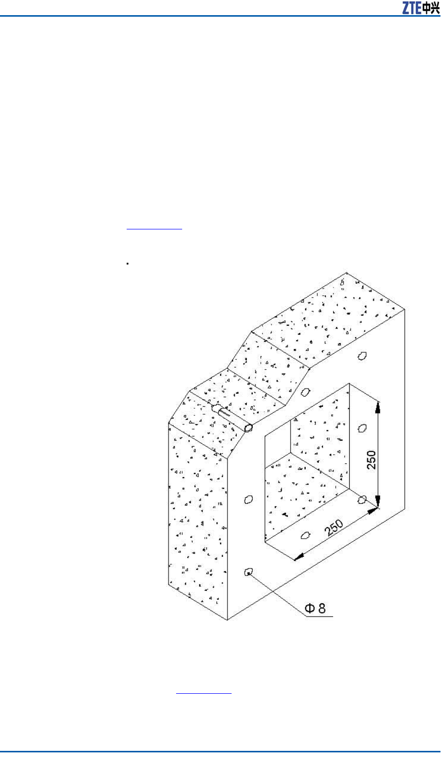
ZXSDRBS8800C200InstallationManual
�Thehermeticwindowcanbemountedagainstanindoorwall
oroutdoorwallandthesideofprotuberantmetalcirclesmust
puttowardsoutdoors.
�Ifthefeederentersintoaroomfromaroof,thehermeticwin-
dowcanbemountedagainsttheroofandhesideofprotuber-
antmetalcirclesmustputtowardsoutdoors.
Steps1.Accordingtotherequirementsofengineeringdesigndrawing
andthedimensionofhermeticwindow,makesuretheinstal-
lationpositionofhermeticwindowonthewallandatthesame
timemarkholepositionsofexpansionboltsandahollowroom
leftforthehermeticwindow.
2.Cuta250mm×250mmsquarebigholeandthendrilleight
holesofexpansionblotswithapercussivedrill,asshownin
F
i g u r e 1 3 5 .
FIGURE135INSTALLATIONHOLEPOSITIONS(UNIT:MM)
3.Fixafeederhermetic-windowpanelwithexpansionbolts,as
showninF
i g u r e 1 3 6 .
Whileinstallingexpansionbolts,aatwasherandaspring
washermustbeinstalledinturn.
144ConfidentialandProprietaryInformationofZTECORPORATION
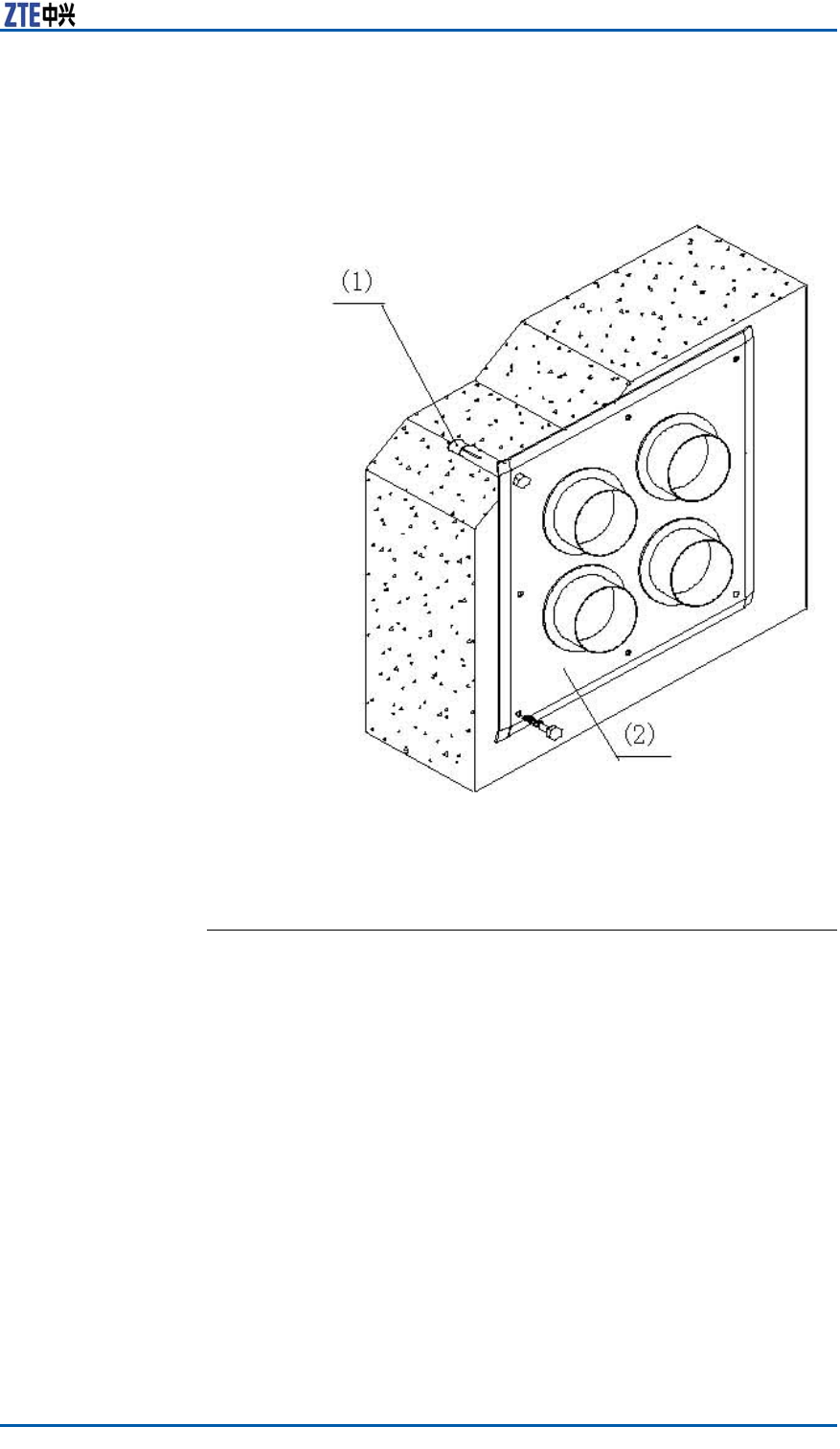
Chapter8InstallingMainAntennaFeederSystem
Asealingwasherandasealingcovermaybeinstalledtogether
withfeederenteringintotheroom.
FIGURE136FEEDERHERMETIC-WINDOWINSTALLATION
1.M8×80expansionbolt2.Feederhermetic-window
panel
ENDOFSTEPS.
ConfidentialandProprietaryInformationofZTECORPORATION145

ZXSDRBS8800C200InstallationManual
Thispageisintentionallyblank.
146ConfidentialandProprietaryInformationofZTECORPORATION

C h a p t e r 9
InstallationCheck
TableofContents:
CheckingEquipmentInstallation........................................147
CheckingAntennaFeederSystemInstallation......................149
CheckingPoweron..........................................................151
CheckingEquipment
Installation
CabinetInspectionItems
Cabinetinspectionitemsinclude:
�Aftercompletingcabinetinstallation,makesurethecabinet
xedandorderly.Arowofcabinetsshouldbeinline.The
sidesofalineofcabinetsshouldkeepinthesamelevel,the
errorlessthan5mm.
�Checkwhetherallfasteningpiecesarescreweddown.
�Checkwhetherallcomponentsonthecabinetareintact,and
connectionareunbroken.Makesuremarksorderly,intactand
clear .
�Checkwhetherthecabinetsurfacesinsideandoutsideare
clean.Aftercabinetinstallationcompleted,itisnecessaryto
cleanupthecabinetsurfaces.
�Checkwhetherthepush-and-pullcoverplatesofcableoutlets
areinproperposition.Aftercompletingallcablelayout,the
coverplateshouldbepushedforwardtotheproperpositionin
caseofanimalsintruding.
CableCheckItems
PowerCableand
groundcable
Inspection
Powercableandgroundcableinspectionitemsincluded:
�Checkwhetherallcablesareconnectedwellandtheirpolarities
arecorrect.
ConfidentialandProprietaryInformationofZTECORPORATION147

ZXSDRBS8800C200InstallationManual
�CheckwhetherthePEwirepoleofgroundcableisproperand
rm.
InternalCable
Inspection
Checktheinternalcablesasfollows,andmakesure:
�Theinternalcableofrackishungintheair .
�TheRFcableofthefrontpanel,clockcable,powerandalarm
cableaswellastestcableareconnectedwellandproperly.
�Thecablelayoutrouteandbindingspacearereasonableand
correct.
�Layoutoftheberbellowsinsidetherackisbeautifulandrea-
sonable.
�Theprotectivegroundcableofrackdoorisconnectedwell,
avoidinglackandloosenessphenomena.
�Thecablesurfaceiscleanwithoutanyengineeringmarkand
thesheathinsulationlayerisundamaged.
Socket,PlugandLockingPiece
InspectionItems
Thesocket,plugandlockingpieceinspectionitemsinclude:
�Checkwhetherconnectionofthesocket,plugandlockingpiece
isproper ,avoidingmisconnectionandleakingconnection.
�Checkwhetherconnectionbetweenplugandsocketisfas-
tened.Thefastnessscrewontheboardsshouldbescrewed
down,andthelocatorcardshouldbeputinproperposition
withoutanydamage.
�Checkwhethertheplugmadeonsitedoesnotdamagethe
corecable.
�Checkwhetherthecableplugandlickingpiecearefastened.
Makesurenobin-lackedorbinbent-phenomenonoccurringin
thesocketandplug.
LabelInspectionItems
Labelinspectionitemsinclude:
�Checkwhetherthelabeladoptsaspecialadhesivepaperfor
ZTE.
�Checkwhetherthedirectionsofafxedlabelsareconsistent.
Tobeconvenientforreading,asideoflabelthatindicatesca-
bleorientationshouldbeplacedupwardsortowardsamain-
tenanceandoperationside.
�Checkwhetherlabelcontentofrackrowandracklineaccords
withtherequirementsofengineeringdesign.AllZTEdevices
intheequipmentroomshouldbedistributedinorder .
148ConfidentialandProprietaryInformationofZTECORPORATION

Chapter9InstallationCheck
�Checkwhethercircuitbreakersofpowercableareafxedina
powercabinetandpowerdistributioncabinetinorder.
�Checkwhethercircuitbreakersofpowercableinapowercab-
inetandpowerdistributioncabinetindicateconnectionorien-
tationwithalabel.
�Checkwhetherlabelsareafxedtobothendsofallcables
(groundcable,transmissioncableandjumper ,exceptprotec-
tivegroundcablesofcabinetdoorandsidedoor).Makesure
handwritingclearonthelabelsandlabelpositionsconsistent.
�Ifalabelisrequiredtoclingtoaboard,makesurehandwriting
clearandafxedlabelpositionsorderly.
On-siteEnvironmentInspectionItems
On-siteenvironmentinspectionitemsinclude:
�Checkwhetherredundantsundriesleftinsidethecabinet,as
wellasthefront,backandsidedoorareclean.Aftercabinet
installationcompletion,cleanupthecabinetsurfacesinside
andoutside.
�Checkwhetherredundantgoodsintheequipmentroomis
clearedoutaswellastheoperationplatformandoorare
cleanandinorder .Makesuregoodsintheequipmentroom
orderly.
�Checkwhetherthecabletray,cabinetbottomandoorround
thecabinetarecleanup.Makesureallcablesinorder .
CheckingAntennaFeeder
SystemInstallation
CheckingFeeder
PrerequisiteInstalltheGPSantennafeedersystem.
Steps1.Makesurethehungheightofantennaconsistentwithnetwork
planning.
2.Makesuretheinstallationpositionofantennainaccordance
withthedesigndrawing.
3.Makesurethatconnectionbetweenantennarackandiron
towerisfastened.
4.Makesuretheantennapositionwithinaprotectiveareaofar-
rester .
5.Makesureclampingnutsscreweddownandspringwashes
pressedlevelly.
ConfidentialandProprietaryInformationofZTECORPORATION149
ZXSDRBS8800C200InstallationManual
6.MakesuretheVSWRofantennafeedernotlessthan1.3.
7.Makesurealloutdoorjumperconnectorswithwaterproofand
sealedhandling.
8.Makesurefeedersboundequallyandthemaximumdistance
isnotbeyond0.5m.
ENDOFSTEPS.
VSWRTest
Prerequisite�Installthesystemofmainantennafeedercompletely.
�PrepareSiteMasterinstrumentforVSWRtest.
Steps1.UseSiteMastetoperformaVSWRtestofantennafeeder .The
VSWRmustbelowerthan1.5.
2.IftheVSWRtestisfailed,checktheantennafeedersystem,
asfollows:
�Whetherfeederconnectorinstallationisfaulty.
�Whetherantennaisfaulty.
�Whetherfeedersurfaceisdamagedandthebendingof
feederissmallerthantheminimalbendingradiuspermit-
ted.
�Whetherarrestorinstallationisfaulty.
3.RepeattheabovestepstonishVSWRtestsofallantenna
feedercables.
Note:
ThemethodhowtouseSiteMasterforaVSWRtestrefersto
AppendixBSiteMasterUsage.
ENDOFSTEPS.
CheckingWater-proofProcessing
Steps1.Checkwhetheraproperwaterproofhandlingiscarriedoutfor
allfeederconnectors.
2.Makesurefeedersleadingintotheroomthroughthefeeder
hermeticwindow.
ENDOFSTEPS.
150ConfidentialandProprietaryInformationofZTECORPORATION

Chapter9InstallationCheck
CheckingPoweron
Prerequisite�Installpowercablesandgroundcablesofcabinetandpower
supply.
�Installpowercableandgroundcableinsidethecabinet.
�Installsubracksandmodulesinsidethecabinet.
�Checkwhetherallrequiredtoolsareprepared.
ContextThecabinetadoptsDCpowersupply.Thenominalvalueofinput
poweris-48V(-57V~-40V),referringtoCabinetPowerSupply
Requirements.
Steps1.Wearantistaticwriststrapsproperlyandmakesureitground-
ing.
2.SetupallpowerswitchesofdistributionsubrackinOFFstatus.
3.Adjustamultimetertoaresistancegrade.Measurethepower
inputterminalofdistributionsubrackwiththemultimeterand
makesure-48Vpowernotshortcircuit.
4.Adjustthemultimetertoavoltageend.Measurethe-48V
outputterminalofDCpowerwiththemultimeterandmake
surethatoutputvoltageis-48V .
5.Oneendofpowercableconnectstothe-48Voutputterminal
ofDCpower ,andtheotherendconnectstothe-48Voutput
terminalofcabinet.Thefrontpanelindicatorsofdistribution
subrackinONstatus(PWRIN)indicatesthatthecabinetis
providedwithpowersupplybutdonotpoweron.
6.SetupthePWRswitchofpowersubrackinONstatus.The
indicatorsinONstatusshowsthatpowersubrackpowerson.
7.Consideringasubrackasaunit,setupitsrelevantswitchon
thecabinetpowersubrackinONstatus.T
a b l e 8 describes
thestatusofallpowerindicatorsonthedistributionsubrack
correspondingtovarioussubracks.
TABLE8DISTRIBUTIONSUBRACKPANELINDICATORDESCRIPTION
SilkScreenNameDescription
PWROverallcabinet
powerandembe
ddedtransmission
subrackpower
ONindicatespower
on,andOFF
indicatespoweroff.
BBU1Digitalsubrack
power
ONindicatespower
on,andOFF
indicatespoweroff.
BBU2Digitalsubrack
power
ONindicatespower
on,andOFF
indicatespoweroff.
FANFansubrackpowerONindicatespower
on,andOFF
indicatespoweroff.
RU1RFU1powerONindicatespower
on,andOFF
indicatespoweroff.
ConfidentialandProprietaryInformationofZTECORPORATION151

ZXSDRBS8800C200InstallationManual
SilkScreenNameDescription
RU2RFU2powerONindicatespower
on,andOFF
indicatespoweroff.
RU3RFU3powerONindicatespower
on,andOFF
indicatespoweroff.
RU4RFU4powerONindicatespower
on,andOFF
indicatespoweroff.
RU5RFU5powerONindicatespower
on,andOFF
indicatespoweroff.
RU6RFU6powerONindicatespower
on,andOFF
indicatespoweroff.
8.Normally,aftersubrackpowerson,theRUNindicatoronthe
panelshowsinONorFlashingstate.Ifthismodulehasnore-
action(allindicatorsareoff),subrackpowercables,themod-
uleormoduleslotmaybefaulty.Ifmakesurepowercables
normal,replacethemodulewithanormalmodule.However ,
iftheindicatorsonthenormalmodulearestilloff,pleasecon-
tactwithZTEengineersfortroubleshooting.Fortheindicator
description,refertoBS8800C200HardwareManual.
9.RepeatStep7andStep8tonishpower-oninspectionforall
subracksandmodule.
ENDOFSTEPS.
152ConfidentialandProprietaryInformationofZTECORPORATION

Figures
Figure1ZXSDRBS8800C200Appearance.............................7
Figure2InstallationFlow.....................................................9
Figure3InstallationSpaceRequirement...............................12
Figure4CrateUnpacking...................................................21
Figure5CabinetInstallationFlow........................................24
Figure6Single-cabinetInstallationPosition..........................25
Figure7HOLING...............................................................25
Figure8INSULATIONSLEEVEINSTALLATION........................26
Figure9EXPANSIONNUTINSTALLATION..............................26
Figure10INSULATIONSHEETINSTALLATION........................26
Figure11BASEINSTALLATIONASSEMBLY(1).......................27
Figure12BASEINSTALLATIONASSEMBLY(2).......................27
Figure13FIXINGCABINET(1)............................................28
Figure14FIXINGCABINET(2)............................................29
Figure15CABINETINSTALLATIONCOMPLETION...................30
Figure16Baseband-RFCabinetInternalStructure.................32
Figure17RFSUBRACKAPPEARANCE...................................33
Figure18BASEBANDSUBRACKAPPEARANCE........................33
Figure19SCREWPOSITIONSONRFMODULE.......................34
Figure20ScrewPosition....................................................35
Figure21BBUInstallation..................................................36
Figure22M6×16ScrewPosition..........................................36
Figure23HORIZONTALMODULEINSTALLATION....................37
Figure24DustproofAssemblyInstallation............................38
Figure25VerticalModuleInstallation...................................39
Figure26CableInstallationFlow.........................................42
Figure27DCPOWERCABLEAPPEARANCE............................43
Figure28DCPowerCableInlet...........................................44
Figure29PowerDistributionSubrackConnection...................45
Figure30PowerCableInstallationCompletion.......................46
Figure31GroundCableInstallation.....................................47
Figure32DataCableAppearance........................................48
Figure33DataCableInstallationCompletion........................49
Figure34Abis/IubInterface75ΩE1CableAppearance..........50
ConfidentialandProprietaryInformationofZTECORPORATION153

ZXSDRBS8800C200InstallationManual
Figure3575ΩE1CableInstallationCompletion....................51
Figure36120ΩE1CableAppearance..................................52
Figure37100ΩT1CableAppearance..................................53
Figure38EthernetcableAppearance...................................54
Figure39AbisInterfaceEthernetCableLayout......................55
Figure40DryContactInput/outputCableAppearance............56
Figure41DryContactInstallationCompletion.......................57
Figure42RS232/RS485MonitoringCable.............................58
Figure43OpticalFiberAppearance......................................59
Figure44AISGControlCableStructure................................60
Figure45AISGControlInstallationCompletion.....................60
Figure46GPSJumperAppearance.......................................61
Figure47GPSJumperInstallationCompletion.......................62
Figure48RFJumperInstallationPosition..............................63
Figure49GPSAntennaFeederSystemInstallationFlow.........65
Figure50GPSAntennaInstallationPosition.........................66
Figure51U-shapedClampInstallation.................................68
Figure52GPSAntennaVerticalInstallation...........................69
Figure53GPSAntennaRackInstallationSupport..................70
Figure54GPSRackInstallation(HorizontalPlacement)..........70
Figure55GPSAntennaFixedHorizontally.............................71
Figure56DesignTemplateforMarkingHoles........................72
Figure57GPSAntennaFixedonWall...................................73
Figure58ConnectionbetweenFeedertoGPSAntenna...........74
Figure59GPS1/4"FEEDERGROUNDINGKITSTRUCTURE......76
Figure601/4"FEEDERGROUNDCABLESTRUCTURE..............76
Figure61StripoffSheath...................................................81
Figure62O-typeRingLocation...........................................81
Figure63Connection.........................................................82
Figure64CopperScrapClearnessontheCrossSection..........82
Figure65RotatingConnectorFasteningPiece........................83
Figure66ConnectingAssembly...........................................83
Figure67OmnidirectionalAntennaAppearance.....................84
Figure68FixingOmnidirectionalAntenna.............................85
Figure69DirectionalAntennaAppearance............................87
Figure70Directional-antennaFixationClip...........................87
Figure71DepressionAngleandElevationAngleAdjustment...88
Figure72ConnectionbetweenDirectionalAntennaand
Jumper............................................................89
Figure73HoistingAntenna.................................................90
154ConfidentialandProprietaryInformationofZTECORPORATION

Figures
Figure74IndoorGroundingBarStructure............................91
Figure75IndoorGroundingBarInstallation(1).....................92
Figure76IndoorGroundingBarInstallation(2).....................92
Figure77ArresterProtectiveArea.......................................93
Figure78IronAntennaRackStructure(Unit:mm)................94
Figure79AntennaRackInstallation.....................................95
Figure80AntennaFixationRack..........................................96
Figure81FixingAntenna....................................................96
Figure82U-shapeBolt.......................................................97
Figure83KathreinAzimuthAdjustmentTools........................97
Figure84UsageofAzimuthAdjustmentTool.........................98
Figure85DowntiltMeasuringInstrumentAppearance............98
Figure86AdjustingDowntilt...............................................99
Figure87DirectionalAntennaInstallationontheT ower
Platform.........................................................100
Figure88AntennaRackStructure......................................101
Figure89AntennaRackBaseStructureandInstallation........102
Figure90InstallingAntennaRackontheWall.....................103
Figure91AntennaRackFixedontheWallCompletely(
Heightofwallnotlessthan1200mm)...............104
Figure92AntennaRackFixedontheWall(Heightofwall
lessthan1200mm).........................................105
Figure93FixationRack....................................................106
Figure94FixingAntenna..................................................106
Figure95U-shapeBolt.....................................................107
Figure96KathreinAzimuthAdjustmentTools......................107
Figure97UsageofAzimuthAdjustmentTool.......................108
Figure98DowntiltMeasuringInstrumentAppearance..........108
Figure99AdjustingDowntilt.............................................109
Figure100DirectionalAntennaInstallationontheRoof
(withoutwallbutwithtoweramplier)...............110
Figure101DirectionalAntennaInstallationontheRoof(with
wallandtoweramplier)..................................110
Figure102ArresterProtectiveArea....................................111
Figure103IronAntennaRackStructure(Unit:mm)............112
Figure104AntennaRackInstallation.................................113
Figure105OmnidirectionalAntennaInstallation..................114
Figure106OmnidirectionalAntennaInstallationontheIron
Tower............................................................115
Figure107AntennaRackStructure....................................117
ConfidentialandProprietaryInformationofZTECORPORATION155

ZXSDRBS8800C200InstallationManual
Figure108AntennaRackBaseStructureandInstallation......118
Figure109InstallingAntennaRackontheWall...................119
Figure110AntennaRackFixedontheWallCompletely(
Heightofwallnotlessthan1200mm)...............120
Figure111AntennaRackFixedontheWall(Heightofwall
lessthan1200mm).........................................121
Figure112OmnidirectionalAntennaInstallation..................122
Figure113OmnidirectionalAntennaInstallationontheRoof..123
Figure114JumperConnection..........................................124
Figure115FeederKitFixation...........................................124
Figure116InstallationHolePositions(Unit:mm)................126
Figure117HermeticWindowInstallation............................127
Figure118FeederFixationontheT ower(onekitandtwo
xationclips)..................................................129
Figure119FeederFixationontheTower(onekitandthree
xationclips)..................................................129
Figure120FeederLayoutfromTowerT optoHermetic
Window..........................................................130
Figure121FixingFeederintoFixationClip..........................131
Figure122FeederLayoutfromRooftoHermeticWindow......132
Figure123FeederGrounding...........................................133
Figure124GroundingKitStructure....................................134
Figure125WaterproofAdhesiveT apeWrap.........................135
Figure126FeederintoRoomMode(1)...............................136
Figure127FeederintoRoomMode(2)...............................137
Figure128Antenna,FeederandJumperInstallation............139
Figure129WaterproofInsulationAdhesiveTape..................140
Figure130PVCAdhesiveT ape...........................................141
Figure131WaterproofInsulationAdhesiveTapeWrap..........141
Figure132ConnectorafterProcessing................................142
Figure133FeederHermetic-windowDimension(Unit:mm)..143
Figure13412FeederHermetic-windowStructure................143
Figure135InstallationHolePositions(Unit:mm)................144
Figure136FeederHermetic-windowInstallation..................145
156ConfidentialandProprietaryInformationofZTECORPORATION

Tables
Table1SafetySymbolsDescription.......................................2
Table2ZXSDRBS8800C200EngineeringIndices...................8
Table3ZXSDRBS8800C200ExternalInterfaceIndex
Description.......................................................15
Table4BENDINGRADIUMREQUIREMENTS...........................17
Table5ToolandMeterList..................................................18
Table6RS232/RS485MonitoringCableDescription................58
Table7BendingRadiusRequirementsofVariousFeeders......128
Table8DistributionSubrackPanelIndicatorDescription.......151
ConfidentialandProprietaryInformationofZTECORPORATION157

ZXSDRBS8800C200InstallationManual
Thispageisintentionallyblank.
158ConfidentialandProprietaryInformationofZTECORPORATION

ListofGlossary
AISG-AntennaInterfaceStandardsGroup
BBU-BaseBandUnit
BSC-BaseStationController
CC-ControlandClockModule
CH-ChannelProcessingModule
FA-FanArrayModule
FS-FabricSwitchModule
GPS-GlobalPositioningSystem
LMT-LocalMaintenanceTerminal
PCB-PrintedCircuitBoard
PM-PowerModule
RSU-RFSystemUnit
SA-SiteAlarmModule
ConfidentialandProprietaryInformationofZTECORPORATION159