ZTE BTSBI18A CDMA2000 Compact Base Transceiver Station II User Manual users manual
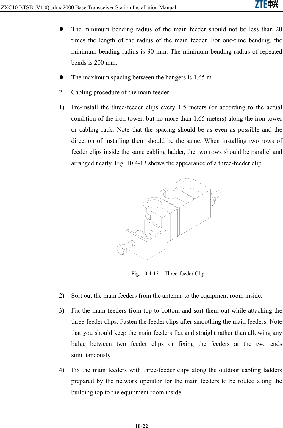
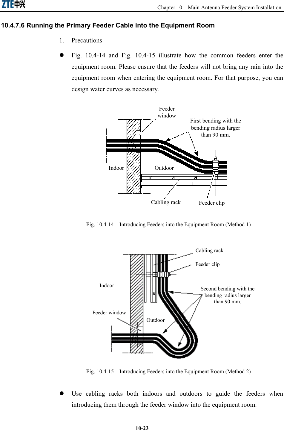
ZTE Corporation CDMA2000 Compact Base Transceiver Station II users manual
UserManual.wiki
>
ZTE
>
BTSBI18A User Manual
users manual
Navigation menu
Upload a User Manual
Namespaces
Wiki Guide
HTML
PDF
Info
Views
User Manual
Discussion / Help
Navigation
![Chapter 6 Grounding System Installation describes the installation procedure of the BTSB grounding system. Chapter 7 Cable Installation in Cabinet introduces the types of BTSB cabinet internal cables, and describes the installation procedure of them. Chapter 8 Trunk Cable Installation describes the installation procedure of the BTSB trunk cables, and explains how to prepare the E1 cables and how to convert the 75 Ω trunk cables into the 120 Ω trunk cables. Chapter 9 Monitoring System Installation introduces the composition of the monitoring system and describes its installation procedure. Chapter 10 Main Antenna Feeder System Installation describes the installation preparation, the installation flow and the specific installation procedure of the main antenna feeder system, and explains how to check and test the antenna feeder and how to conduct waterproof treatment on the connector. Chapter 11 GPS Antenna Feeder System Installation describes the installation preparation, the installation flow and the specific installation procedure of the GPS antenna feeder system. Chapter 12 Board Installation describes the types and functions of boards used in the BTSB system, and how to install and replace them. Chapter 13 Hardware Installation Check describes the hardware installation check requirements of the BTSB system. Chapter 14 Power-on/Power-off describes the check prior to the BTSB power-on, and the detailed power-on and power-off operation procedures. Appendix A - Appendix D gives supplementary information on the BTSB technical performance indices and board indicators, and an abbreviation form. Conventions Describing notational conventions, keyboard operation convention, mouse operation convention and four safety signs. 1. Notational conventions Angular brackets "<and>" identify names of keys and buttons, and the information typed by an operator from a terminal. Square brackets "[and]"](https://usermanual.wiki/ZTE/BTSBI18A/User-Guide-608737-Page-6.png)
![indicate a man-machine interface, menu item, data list, or field name. The symbol "-->" separates a multi-level menu, e.g., [File --> New --> Folder] indicates the [Folder] menu item under the [New] submenu of the menu [File]. 2. Keyboard operation conventions Format Description Character within angular brackets Indicating a key or button name, e.g., <Enter>, <Tab>, <Backspace>, and <a> <key 1+key 2> Indicating to hold several keys down at the same time. For example, <Ctrl+Alt+A> indicates to hold down “Ctrl”, “Alt” and “A” three keys <key 1, key 2> Press Key 1 first. Then release Key 1 and press Key 2. For example, <Alt, F> indicates to press and release <Alt> key, and then press <F> key 3. Mouse operation conventions Format Description Click Refers to clicking the primary mouse button (usually the left mouse button) once Double-click Refers to quickly clicking the primary mouse button (usually the left mouse button) twice Right-click Refers to clicking the secondary mouse button (usually the right mouse button) once Drag Refers to pressing and holding a mouse button and move the mouse 4. Signs Four eye-catching signs are used in this manual to emphasize important and critical information. Note, Caution, Warning, and Danger: Used to indicate the precautions during the operation. Statement: The actual product may differ from what is described in this manual due to frequent update of ZTE products and fast development of technologies. Please contact the local ZTE office for the latest updating information of the product.](https://usermanual.wiki/ZTE/BTSBI18A/User-Guide-608737-Page-7.png)
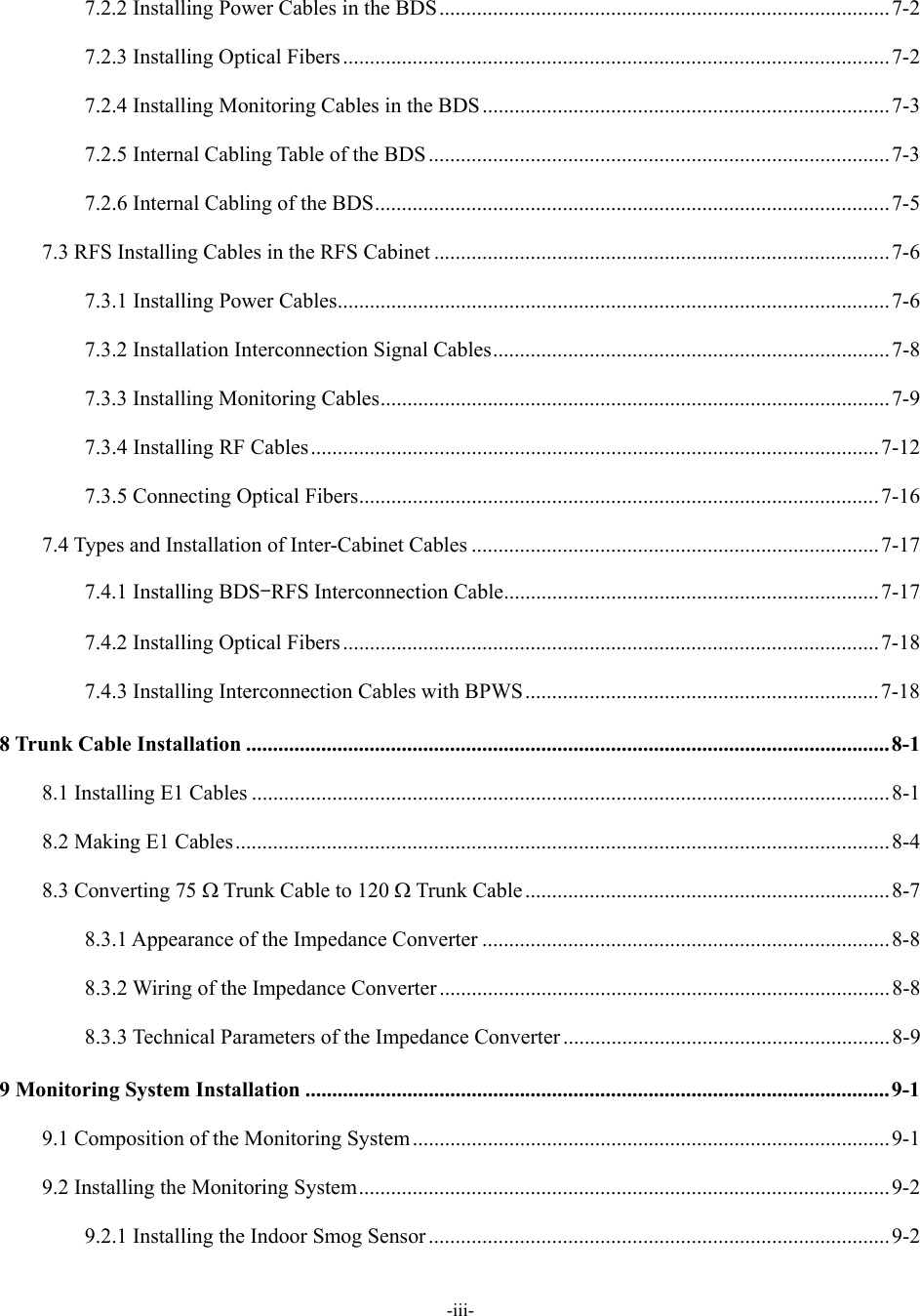
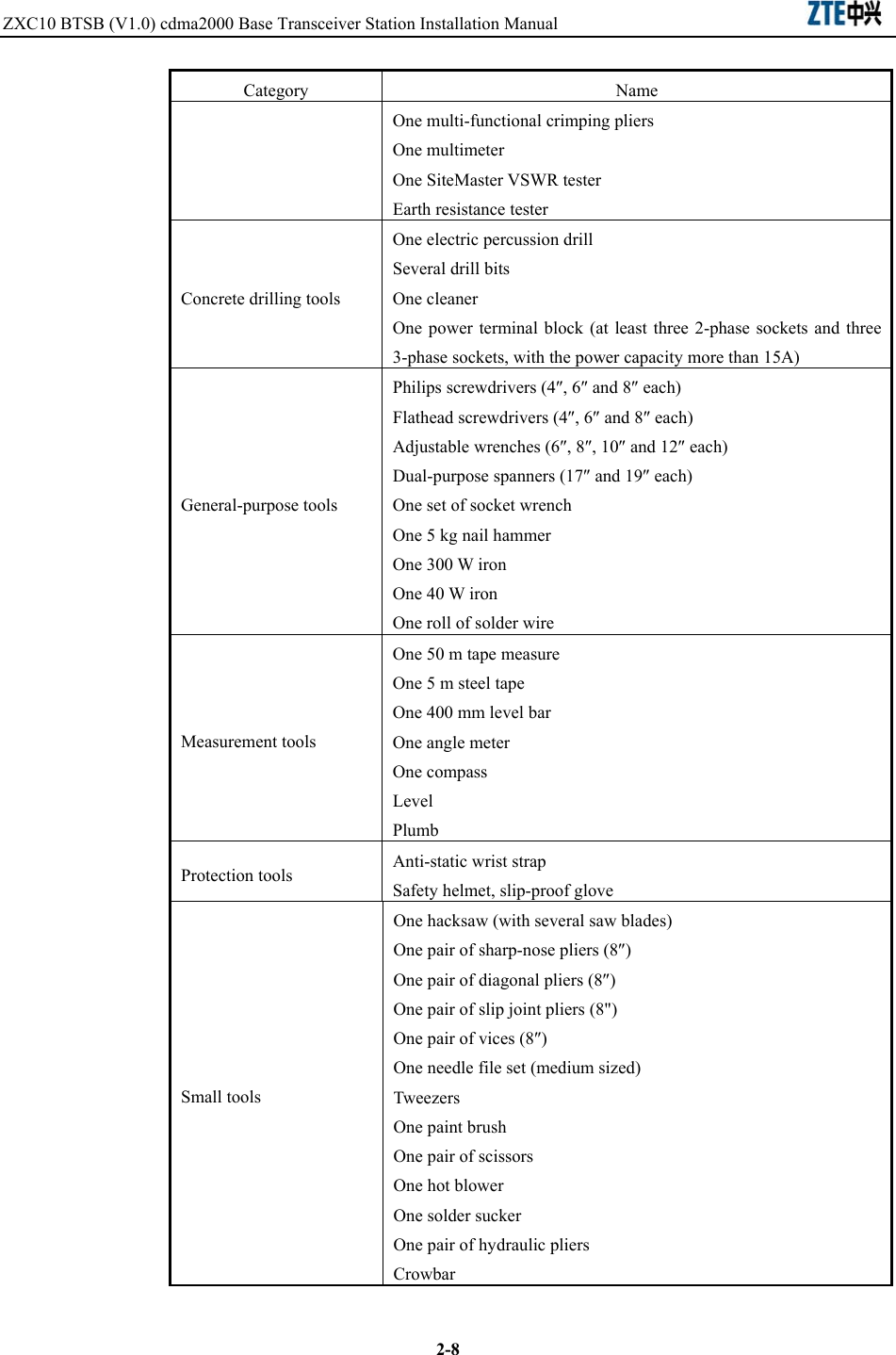
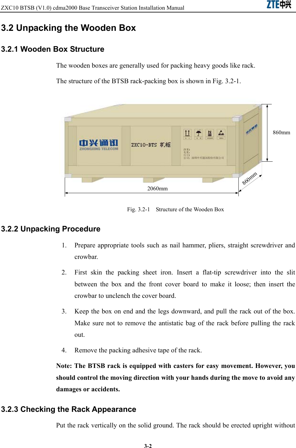


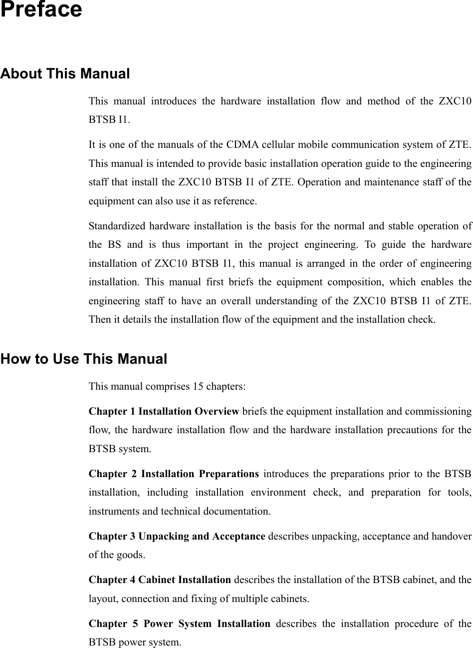
![B-1Appendix B Using SiteMaster Different models of SiteMaster are used differently. For usage information, please refer to the documents came with the device. B.1 Selecting a frequency range 1. Press <ON> of SiteMaster to turn on the meter. 2. Press <FREQ> on the main menu. 3. Press <F1> on the [Frequency] menu. 4. Input the frequency for [Lower], such as “825MHz”, and then press <ENTER> for confirmation. 5. Press <F2> on the [Frequency] menu. 6. Input the frequency for [Higher], such as “880MHz”, and then press <ENTER> for confirmation. 7. When confirmed, press <MAIN> to return to the main menu. B.2 Checking SiteMaster SiteMaster shall be checked in the case of frequency, environment and feeder parameters changes. Follow these steps to check: 1. Make sure that a correct frequency range is input in SiteMaster, then begin the check. 2. Press <STARTCAL> to begin the check. 3. Press <Measuring OPEN>, <MeasuringSHORT>, and <Measuring Load> one by one as prompted to complete the check. 4. Include the extension cable came with the meter to the check for measurement accuracy.](https://usermanual.wiki/ZTE/BTSBI18A/User-Guide-608737-Page-183.png)
![ZXC10 BTSB (V1.0) cdma2000 Base Transceiver Station Installation Manual B-2B.3 Inputting feeder parameters 1. Press <DIST>. 2. Press <MORE>. 3. Press <LOSS> to enter the feeder loss per meter (dB), which varies with providers and models. Then press <ENTER> for confirmation. 4. Press <PROP V> to enter the relative transmission rate, which varies with providers and models. Then press <ENTER> for confirmation. 5. Press <MAIN> to return to the main menu. B.4 Installing the tester Connect one end of the self-contained extension cable to the RFE jumper connector inside the rack and the other terminal to the Refl interface of the meter. If there is an active device like a tower top amplifier or a trunk amplifier in the feeder measuring, jumpers shall be used to dodge it. B.5 Measuring SWR 1. Press<OPT>. 2. Press <B1> to choose [MODE]. 3. Press <Up> or <Down> to select [SWR] and press <ENTER> for confirmation. 4. Press<MAIN> to return to the main menu. 5. Input a proper frequency range if necessary. 6. Check the meter if necessary. 7. Press<MAIN> to return to the main menu. 8. Press<RUN> to begin the measure. 9. Press <AUTOSCALE> to adjust the Y-coordinate. 10. View the SWR values of the frequency points within this frequency band, as shown in Fig. B.5-1.](https://usermanual.wiki/ZTE/BTSBI18A/User-Guide-608737-Page-184.png)
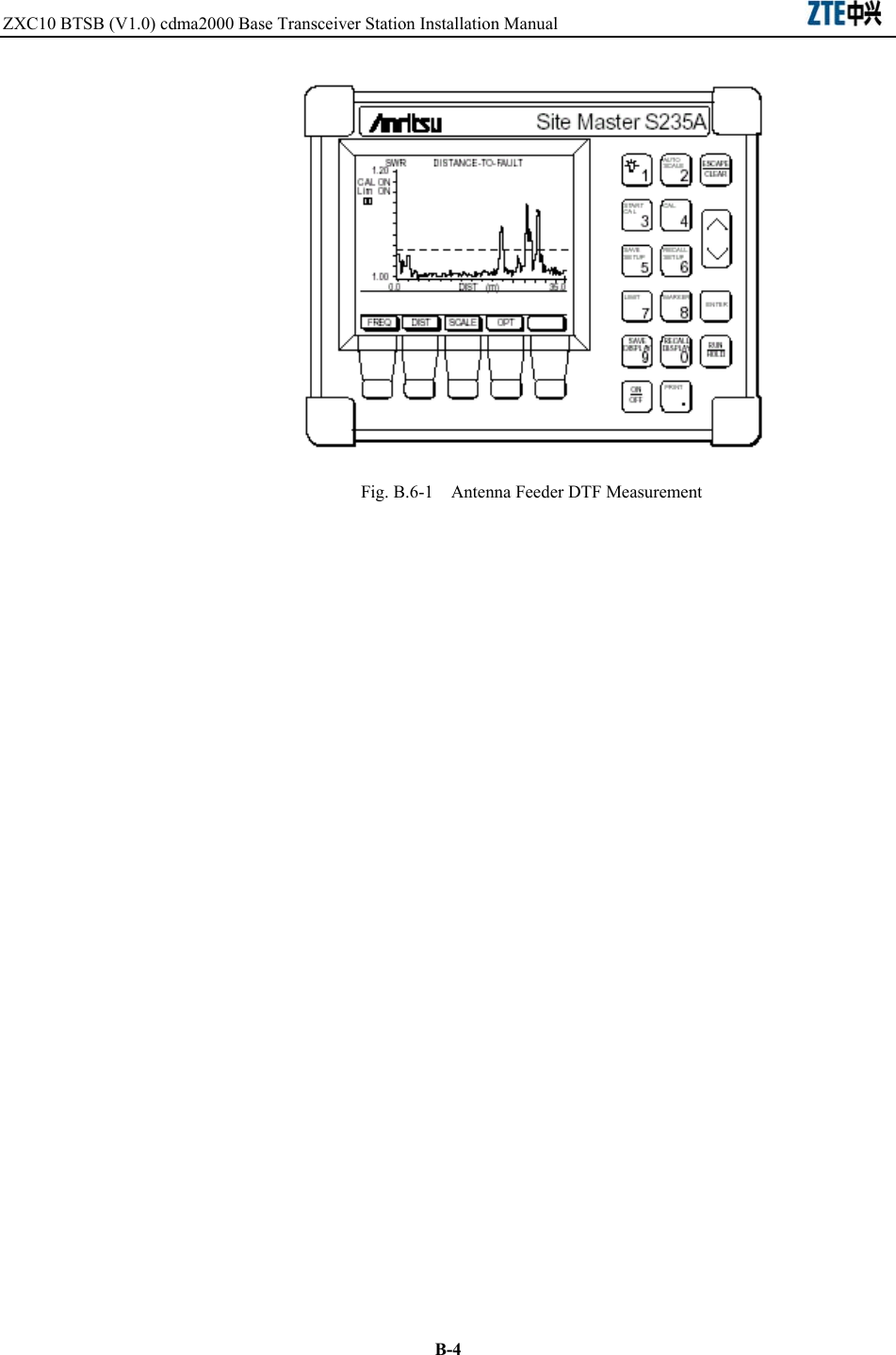
![Appendix B Using SiteMaster B-311. Press <Save Display> to save the data. Fig. B.5-1 SWR Test for the Antenna Feeder B.6 Measuring DTF 1. Press <OPT>. 2. Press <B1> to choose [MODE]. 3. Press <Up> or <Down> to choose [SWR], and press <ENTER> for confirmation. 4. Press <MAIN> to return to the main menu. 5. Input a proper frequency range if necessary. 6. Check the meter if necessary. 7. Input a proper feeder length if necessary. 8. Press <MAIN> to return to the main menu. 9. Press <RUN> to begin the measure. 10. Press <AUAOSCALE> to adjust the Y-coordinate. 11. Press <Mark> to view the SWR value of each frequency point within this frequency band. Check the fault, as shown in Fig. B.6-1. 12. Press <Save Display> to save the data.](https://usermanual.wiki/ZTE/BTSBI18A/User-Guide-608737-Page-185.png)
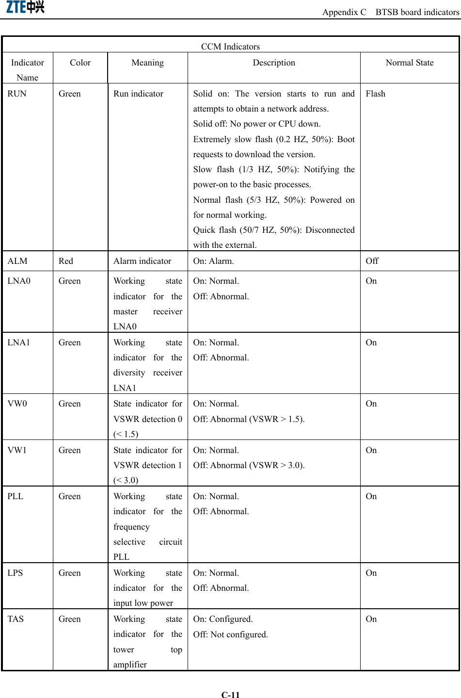
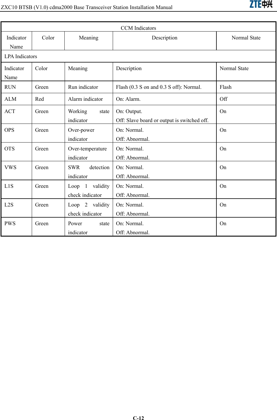
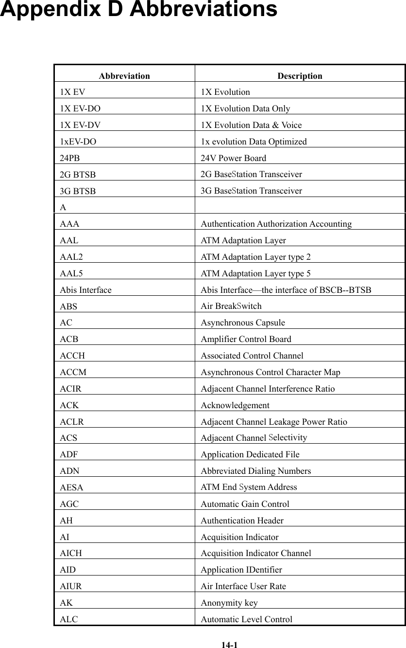
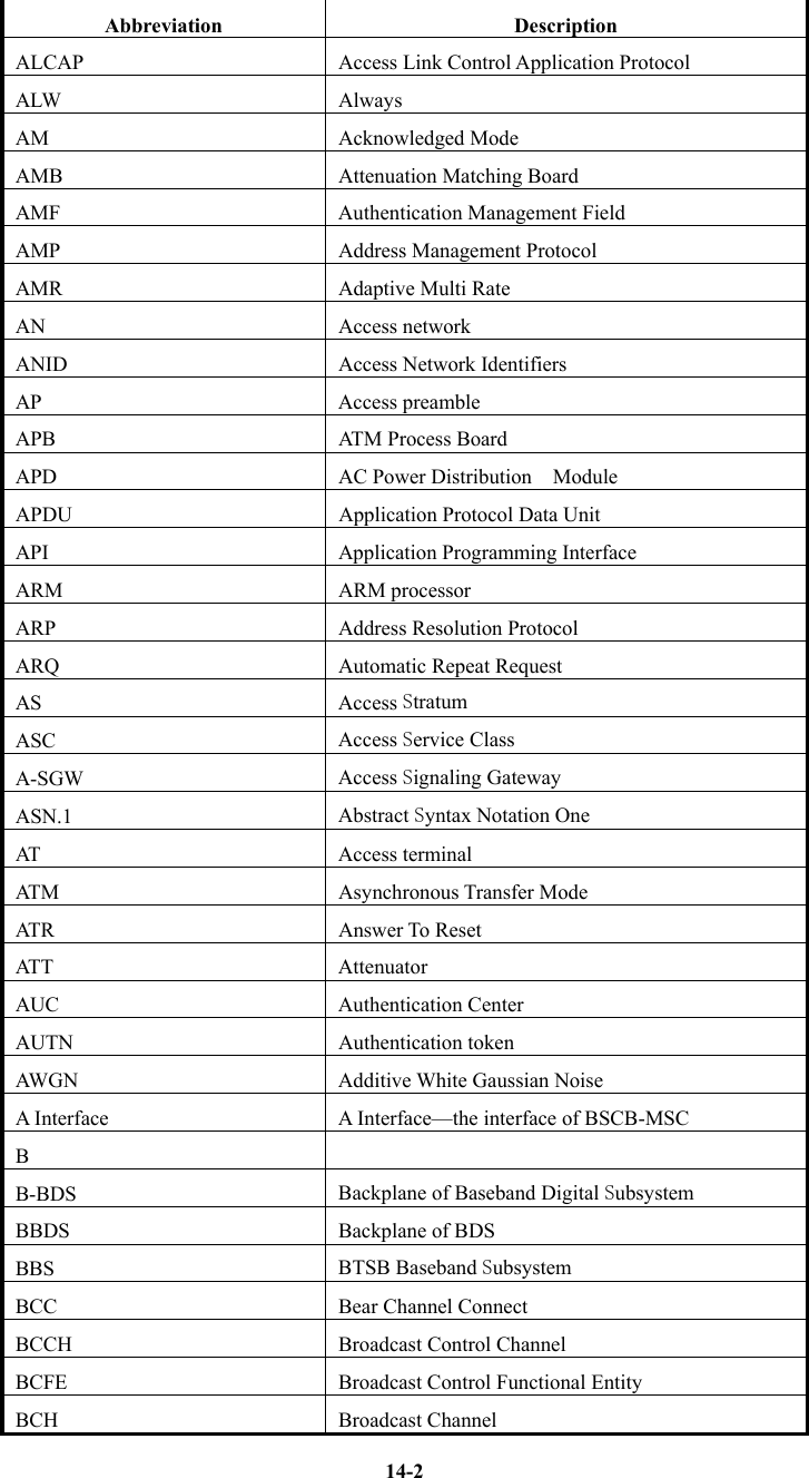
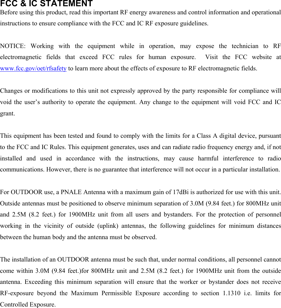
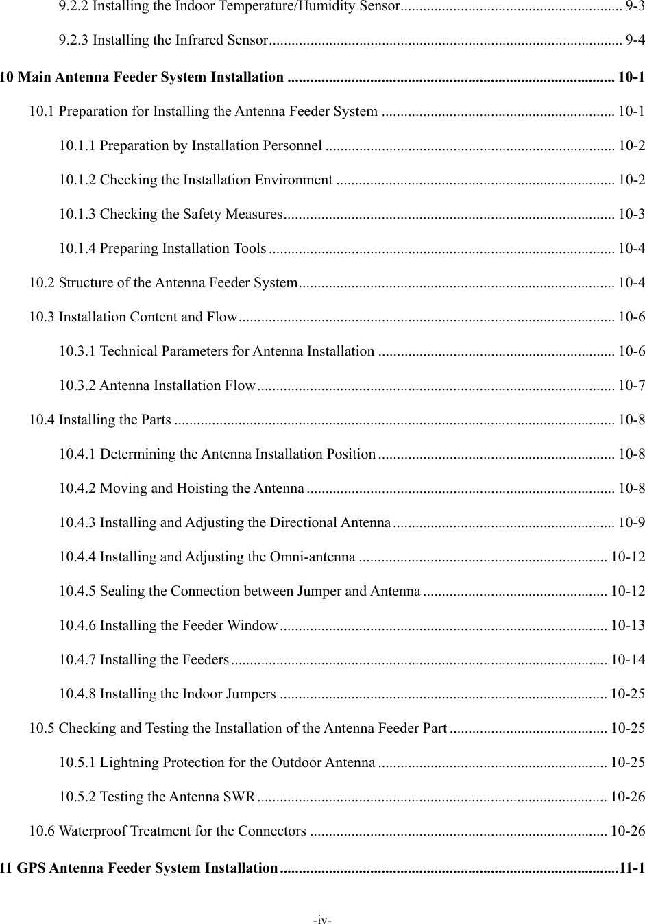
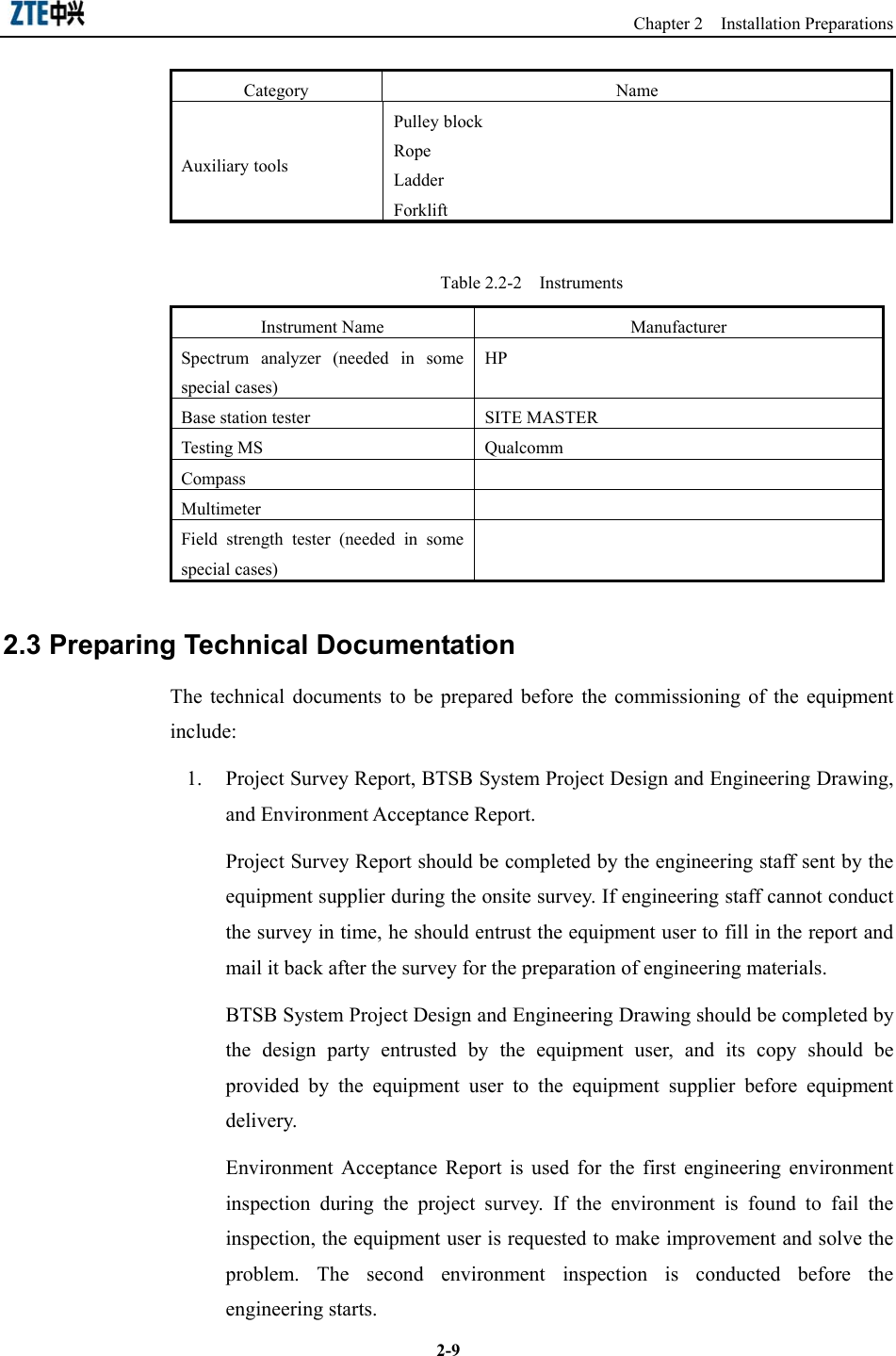
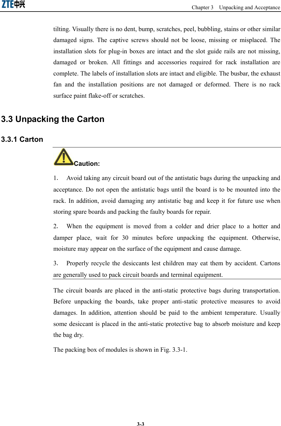
![Appendix C BTSB board indicators C-7CCM Indicators Indicator Name Color Meaning Description Normal State RUN Green RUN indicator Solid on: The version starts to run and attempts to obtain a network address. Off: No power or CPU down. Extremely slow flash (0.2 HZ, 50%): Boot requests to download the version. Slow flash (1/3 HZ, 50%): Notifying the power-on to the basic processes. Normal flash (5/3 HZ, 50%): Powered on for normal working. Quick flash (50/7 HZ, 50%): Disconnected with the external. Normal flash (5/3 HZ, 50%) ALM Red Alarm indicator Solid on: Fault. Solid off: No fault. Solid off SCS Green System clock stateRun indicator of system clock Solid on: Normal Solid off: Abnormal Solid on BLS Green Baseband link state Run (forward/reverse) indicator of baseband link Solid on: Normal Solid off: Abnormal Solid on TYPE Green CHM type Channel board type indicator (LEDs of different colors indicate different board types [CHM versions]). Solid on: Normal Solid on RIM Indicators Indicator Name Color Meaning Description Normal State RUN Green Power indicator Quick flash: Normal. Off: Abnormal. Quick flash ALM Red Alarm indicator Solid on: Alarm. Off: Normal. Solid off M/S Green Master/Slave indicator Solid on: Master board. Off: Slave board. Solid on/off](https://usermanual.wiki/ZTE/BTSBI18A/User-Guide-608737-Page-193.png)
![ZXC10 BTSB (V1.0) cdma2000 Base Transceiver Station Installation Manual C-10CCM Indicators Indicator Name Color Meaning Description Normal State FSS Green Frequency synthesizer state Run indicator for the frequency synthesizer including reference, RF local oscillator and IF local oscillator PLL working state Solid on: Normal. Solid off: Abnormal or not in position. Solid on BLS Green Baseband link state Run indicator for baseband link (forward) Solid on: Normal. Solid off: Abnormal. Solid on MDS Green Master/Diversity receiver state Run indicator for the master/diversity receivers Solid on: Normal Solid off: Unbalancing between master/diversity receivers Solid on TYPE Green TRX type TRX module types (on the panel, LEDs of different colors indicate different types [TRX versions]) . Not on: Linear predistortion not supported. Solid on: Linear predistortion supported. Depend on the type RFE Indicators Indicator Name Color Meaning Description Normal State](https://usermanual.wiki/ZTE/BTSBI18A/User-Guide-608737-Page-196.png)