ZTE BTSBI18A CDMA2000 Compact Base Transceiver Station II User Manual users manual
ZTE Corporation CDMA2000 Compact Base Transceiver Station II users manual
ZTE >
users manual
3G Mobile Communication cdma2000 System – All-IP Architecture
ZXC10 BTSB I1 (V1.0)
cdma2000 Base Transceiver Station
Installation Manual
ZTE CORPORATION
ZXC10 BTSB I1(V1.0)
cdma2000 Base Transceiver Station
Installation Manual
Manual Version 20040615-R1.1
Product Version V1.0
Copyright © 2003 ZTE Corporation
All rights reserved.
No part of this documentation may be excerpted, reproduced, translated, annotated or
duplicated, in any form or by any means without the prior written permission of ZTE
Corporation.
ZTE CORPORATION
ZTE Plaza, Keji Road South, Hi-Tech Industrial Park, Nanshan District, Shenzhen, P.R.China
Website: http://www.zte.com.cn
Postcode: 518057
Customer Support Center: (+86755) 26771900 800-9830-9830
Fax: (+86755) 26770801
Email: support@zte.com.cn
* * * *
S.N.: sjzl20041524
FAX: 0086-755-26770160
Suggestions and Feedback
To improve the quality of ZTE product documentation and offer better services to our
customers, we hope you can give us your suggestions and comments on our
documentation and fax this form to +86-755-26770160; or mail to “Marketing center
3rd floor ZTE Plaza, Keji Road South, Hi-Tech Industrial Park, Nanshan District,
Shenzhen, P. R. China”. Our postcode is 518057.
Document name
ZXC10 BTSB (V1.0) cdma2000 Base Transceiver Station
Installation Manual
Product version V1.0 Document version 20040615-R1.1
Equipment installation time
Your information
Name Company
Postcode Company address
Telephone E-mail
Presentation: How is information presented? (Introductions, procedures, illustrations, others)
Good Fair Average Poor Bad
Accessibility: Can you find the information you want? (Table of contents, Index, headings,
numbering, others)
Good Fair Average Poor Bad
Your evaluation
of this
documentation
Intelligibility: Can you understand it when you find it? (Language, vocabulary, readability, others)
Good Fair Average Poor Bad
Presentation:
Accessibility:
Your suggestions
for improvement
of this
documentation
Intelligibility:
Your other
suggestions on
ZTE product
documentation
Preface
About This Manual
This manual introduces the hardware installation flow and method of the ZXC10
BTSB I1.
It is one of the manuals of the CDMA cellular mobile communication system of ZTE.
This manual is intended to provide basic installation operation guide to the engineering
staff that install the ZXC10 BTSB I1 of ZTE. Operation and maintenance staff of the
equipment can also use it as reference.
Standardized hardware installation is the basis for the normal and stable operation of
the BS and is thus important in the project engineering. To guide the hardware
installation of ZXC10 BTSB I1, this manual is arranged in the order of engineering
installation. This manual first briefs the equipment composition, which enables the
engineering staff to have an overall understanding of the ZXC10 BTSB I1 of ZTE.
Then it details the installation flow of the equipment and the installation check.
How to Use This Manual
This manual comprises 15 chapters:
Chapter 1 Installation Overview briefs the equipment installation and commissioning
flow, the hardware installation flow and the hardware installation precautions for the
BTSB system.
Chapter 2 Installation Preparations introduces the preparations prior to the BTSB
installation, including installation environment check, and preparation for tools,
instruments and technical documentation.
Chapter 3 Unpacking and Acceptance describes unpacking, acceptance and handover
of the goods.
Chapter 4 Cabinet Installation describes the installation of the BTSB cabinet, and the
layout, connection and fixing of multiple cabinets.
Chapter 5 Power System Installation describes the installation procedure of the
BTSB power system.
Chapter 6 Grounding System Installation describes the installation procedure of the
BTSB grounding system.
Chapter 7 Cable Installation in Cabinet introduces the types of BTSB cabinet
internal cables, and describes the installation procedure of them.
Chapter 8 Trunk Cable Installation describes the installation procedure of the BTSB
trunk cables, and explains how to prepare the E1 cables and how to convert the 75 Ω
trunk cables into the 120 Ω trunk cables.
Chapter 9 Monitoring System Installation introduces the composition of the
monitoring system and describes its installation procedure.
Chapter 10 Main Antenna Feeder System Installation describes the installation
preparation, the installation flow and the specific installation procedure of the main
antenna feeder system, and explains how to check and test the antenna feeder and how
to conduct waterproof treatment on the connector.
Chapter 11 GPS Antenna Feeder System Installation describes the installation
preparation, the installation flow and the specific installation procedure of the GPS
antenna feeder system.
Chapter 12 Board Installation describes the types and functions of boards used in the
BTSB system, and how to install and replace them.
Chapter 13 Hardware Installation Check describes the hardware installation check
requirements of the BTSB system.
Chapter 14 Power-on/Power-off describes the check prior to the BTSB power-on, and
the detailed power-on and power-off operation procedures.
Appendix A - Appendix D gives supplementary information on the BTSB technical
performance indices and board indicators, and an abbreviation form.
Conventions
Describing notational conventions, keyboard operation convention, mouse operation
convention and four safety signs.
1. Notational conventions
Angular brackets "<and>" identify names of keys and buttons, and the
information typed by an operator from a terminal. Square brackets "[and]"

indicate a man-machine interface, menu item, data list, or field name. The
symbol "-->" separates a multi-level menu, e.g., [File --> New --> Folder]
indicates the [Folder] menu item under the [New] submenu of the menu [File].
2. Keyboard operation conventions
Format Description
Character within angular
brackets
Indicating a key or button name, e.g., <Enter>, <Tab>,
<Backspace>, and <a>
<key 1+key 2>
Indicating to hold several keys down at the same time. For
example, <Ctrl+Alt+A> indicates to hold down “Ctrl”, “Alt”
and “A” three keys
<key 1, key 2>
Press Key 1 first. Then release Key 1 and press Key 2. For
example, <Alt, F> indicates to press and release <Alt> key, and
then press <F> key
3. Mouse operation conventions
Format Description
Click Refers to clicking the primary mouse button (usually the left
mouse button) once
Double-click Refers to quickly clicking the primary mouse button (usually the
left mouse button) twice
Right-click Refers to clicking the secondary mouse button (usually the right
mouse button) once
Drag Refers to pressing and holding a mouse button and move the
mouse
4. Signs
Four eye-catching signs are used in this manual to emphasize important and
critical information.
Note, Caution, Warning, and Danger: Used to
indicate the precautions during the operation.
Statement: The actual product may differ from what is described in this
manual due to frequent update of ZTE products and fast development of
technologies. Please contact the local ZTE office for the latest updating
information of the product.

FCC & IC STATEMENT
Before using this product, read this important RF energy awareness and control information and operational
instructions to ensure compliance with the FCC and IC RF exposure guidelines.
NOTICE: Working with the equipment while in operation, may expose the technician to RF
electromagnetic fields that exceed FCC rules for human exposure. Visit the FCC website at
www.fcc.gov/oet/rfsafety to learn more about the effects of exposure to RF electromagnetic fields.
Changes or modifications to this unit not expressly approved by the party responsible for compliance will
void the user’s authority to operate the equipment. Any change to the equipment will void FCC and IC
grant.
This equipment has been tested and found to comply with the limits for a Class A digital device, pursuant
to the FCC and IC Rules. This equipment generates, uses and can radiate radio frequency energy and, if not
installed and used in accordance with the instructions, may cause harmful interference to radio
communications. However, there is no guarantee that interference will not occur in a particular installation.
For OUTDOOR use, a PNALE Antenna with a maximum gain of 17dBi is authorized for use with this unit.
Outside antennas must be positioned to observe minimum separation of 3.0M (9.84 feet.) for 800MHz unit
and 2.5M (8.2 feet.) for 1900MHz unit from all users and bystanders. For the protection of personnel
working in the vicinity of outside (uplink) antennas, the following guidelines for minimum distances
between the human body and the antenna must be observed.
The installation of an OUTDOOR antenna must be such that, under normal conditions, all personnel cannot
come within 3.0M (9.84 feet.)for 800MHz unit and 2.5M (8.2 feet.) for 1900MHz unit from the outside
antenna. Exceeding this minimum separation will ensure that the worker or bystander does not receive
RF-exposure beyond the Maximum Permissible Exposure according to section 1.1310 i.e. limits for
Controlled Exposure.
-i-
Contents
1 Installation Overview..............................................................................................................................1-1
1.1 BTSB Installation Overview..........................................................................................................1-1
1.2 BTSB Installation Flow Chart........................................................................................................1-3
1.3 BTSB Precautions for Hardware Installation.................................................................................1-6
2 Installation Preparations ........................................................................................................................2-1
2.1 Checking the Installation Environment..........................................................................................2-1
2.1.1 Checking the Equipment Room ..........................................................................................2-1
2.1.2 Checking the Indoor Environment of the Equipment Room...............................................2-2
2.1.3 Checking the Power Supply System ...................................................................................2-3
2.1.4 Checking the Grounding System.........................................................................................2-5
2.1.5 Checking the Outdoor Installation Environment for the Antenna Feeder System ..............2-6
2.1.6 Checking the Safety Conditions..........................................................................................2-7
2.1.7 Checking Other Auxiliary Equipment.................................................................................2-7
2.2 Preparing Tools and Instruments....................................................................................................2-7
2.3 Preparing Technical Documentation ..............................................................................................2-9
3 Unpacking and Acceptance ....................................................................................................................3-1
3.1 Checking Goods against the Packing List......................................................................................3-1
3.2 Unpacking the Wooden Box...........................................................................................................3-2
3.2.1 Wooden Box Structure ........................................................................................................3-2
3.2.2 Unpacking Procedure..........................................................................................................3-2
3.2.3 Checking the Rack Appearance...........................................................................................3-2
3.3 Unpacking the Carton ....................................................................................................................3-3
3.3.1 Carton..................................................................................................................................3-3
-ii-
3.3.2 Unpacking Procedure.......................................................................................................... 3-4
3.3.3 Checking the Boards........................................................................................................... 3-4
3.4 Goods Acceptance and Handover.................................................................................................. 3-4
4 Cabinet Installation ................................................................................................................................ 4-1
4.1 Cabinet Types ................................................................................................................................ 4-1
4.2 RFS Cabinet Installation................................................................................................................ 4-2
4.2.1 RFS Installation Flow ......................................................................................................... 4-2
4.2.2 Support Installation Mode .................................................................................................. 4-3
4.2.3 Base Installation Mode ....................................................................................................... 4-9
4.2.4 Cabinet Stacking Mode..................................................................................................... 4-14
4.2.5 Installing Cabinet Accessories.......................................................................................... 4-17
4.2.6 Cabinet Installation Specifications ................................................................................... 4-20
5 Power Supply System Installation......................................................................................................... 5-1
5.1 Introduction to Power Cables ........................................................................................................ 5-1
5.2 Installation Flow of Power Cables................................................................................................. 5-2
5.3 Cable Installation Procedure.......................................................................................................... 5-2
6 Grounding System Installation.............................................................................................................. 6-1
6.1 Grounding System Overview ........................................................................................................ 6-1
6.2 Installing the Grounding System ................................................................................................... 6-3
6.2.1 Installing the Outdoor Grounding Copper Bar ................................................................... 6-3
6.2.2 Installing the Feeder Grounding Clip ................................................................................. 6-3
6.2.3 Installing the Indoor Lightning Arrester ............................................................................. 6-6
7 Cable Installation in Cabinet................................................................................................................. 7-1
7.1 BTSB Cable Installation Overview ............................................................................................... 7-1
7.2 Installing Cables in the BDS Cabinet ............................................................................................ 7-2
7.2.1 BDS Cable Types................................................................................................................ 7-2
-iii-
7.2.2 Installing Power Cables in the BDS....................................................................................7-2
7.2.3 Installing Optical Fibers......................................................................................................7-2
7.2.4 Installing Monitoring Cables in the BDS............................................................................7-3
7.2.5 Internal Cabling Table of the BDS ......................................................................................7-3
7.2.6 Internal Cabling of the BDS................................................................................................7-5
7.3 RFS Installing Cables in the RFS Cabinet .....................................................................................7-6
7.3.1 Installing Power Cables.......................................................................................................7-6
7.3.2 Installation Interconnection Signal Cables.......................................................................... 7-8
7.3.3 Installing Monitoring Cables...............................................................................................7-9
7.3.4 Installing RF Cables..........................................................................................................7-12
7.3.5 Connecting Optical Fibers.................................................................................................7-16
7.4 Types and Installation of Inter-Cabinet Cables ............................................................................7-17
7.4.1 Installing BDS-RFS Interconnection Cable......................................................................7-17
7.4.2 Installing Optical Fibers....................................................................................................7-18
7.4.3 Installing Interconnection Cables with BPWS..................................................................7-18
8 Trunk Cable Installation ........................................................................................................................8-1
8.1 Installing E1 Cables .......................................................................................................................8-1
8.2 Making E1 Cables..........................................................................................................................8-4
8.3 Converting 75 Ω Trunk Cable to 120 Ω Trunk Cable....................................................................8-7
8.3.1 Appearance of the Impedance Converter ............................................................................8-8
8.3.2 Wiring of the Impedance Converter....................................................................................8-8
8.3.3 Technical Parameters of the Impedance Converter .............................................................8-9
9 Monitoring System Installation .............................................................................................................9-1
9.1 Composition of the Monitoring System .........................................................................................9-1
9.2 Installing the Monitoring System...................................................................................................9-2
9.2.1 Installing the Indoor Smog Sensor ......................................................................................9-2
-iv-
9.2.2 Installing the Indoor Temperature/Humidity Sensor........................................................... 9-3
9.2.3 Installing the Infrared Sensor.............................................................................................. 9-4
10 Main Antenna Feeder System Installation ....................................................................................... 10-1
10.1 Preparation for Installing the Antenna Feeder System .............................................................. 10-1
10.1.1 Preparation by Installation Personnel ............................................................................. 10-2
10.1.2 Checking the Installation Environment .......................................................................... 10-2
10.1.3 Checking the Safety Measures........................................................................................ 10-3
10.1.4 Preparing Installation Tools ............................................................................................ 10-4
10.2 Structure of the Antenna Feeder System.................................................................................... 10-4
10.3 Installation Content and Flow.................................................................................................... 10-6
10.3.1 Technical Parameters for Antenna Installation ............................................................... 10-6
10.3.2 Antenna Installation Flow............................................................................................... 10-7
10.4 Installing the Parts ..................................................................................................................... 10-8
10.4.1 Determining the Antenna Installation Position ............................................................... 10-8
10.4.2 Moving and Hoisting the Antenna .................................................................................. 10-8
10.4.3 Installing and Adjusting the Directional Antenna........................................................... 10-9
10.4.4 Installing and Adjusting the Omni-antenna .................................................................. 10-12
10.4.5 Sealing the Connection between Jumper and Antenna ................................................. 10-12
10.4.6 Installing the Feeder Window ....................................................................................... 10-13
10.4.7 Installing the Feeders.................................................................................................... 10-14
10.4.8 Installing the Indoor Jumpers ....................................................................................... 10-25
10.5 Checking and Testing the Installation of the Antenna Feeder Part .......................................... 10-25
10.5.1 Lightning Protection for the Outdoor Antenna ............................................................. 10-25
10.5.2 Testing the Antenna SWR............................................................................................. 10-26
10.6 Waterproof Treatment for the Connectors ............................................................................... 10-26
11 GPS Antenna Feeder System Installation..........................................................................................11-1
-v-
11.1 Preparation for Installing the Antenna Feeder System ............................................................... 11-1
11.2 Structure of the Antenna Feeder System .................................................................................... 11-1
11.3 Installation Flow......................................................................................................................... 11-2
11.4 Installing the Parts...................................................................................................................... 11-2
11.4.1 Preparing the GPS Coaxial Cable Connectors ................................................................ 11-2
11.4.2 Installing the Lightning Arrester ..................................................................................... 11-4
12 Board Installation ...............................................................................................................................12-1
12.1 BTSB Board Types.....................................................................................................................12-1
12.2 RF Cabinet Boards .....................................................................................................................12-2
12.2.1 Receiver Front End (RFE)...............................................................................................12-2
12.2.2 Power Amplifier (PA)......................................................................................................12-3
12.2.3 Transceiver (TRX) ..........................................................................................................12-4
12.3 Cabinet Front Boards .................................................................................................................12-5
12.3.1 Board Overview ..............................................................................................................12-5
12.3.2 Installing and Replacing the Boards................................................................................12-6
12.4 Interface Boards at the Back of the Baseband Cabinet ..............................................................12-7
12.4.1 Interface Board Overview ...............................................................................................12-7
12.4.2 Interface Board Diagram.................................................................................................12-9
12.4.3 Interface Board Structure ..............................................................................................12-10
12.4.4 Installing and Replacing the Interface Boards ..............................................................12-10
12.5 Board Installation Sequence.....................................................................................................12-10
13 Hardware Installation Check.............................................................................................................13-1
13.1 Checking the Cabinet .................................................................................................................13-1
13.2 Checking the Cable Racks .........................................................................................................13-2
13.3 Checking Cable Laying, Binding and Identifying......................................................................13-2
13.4 Checking the Power Cables and Grounding Cables...................................................................13-3
-vi-
13.5 Checking the E1 Cables............................................................................................................. 13-5
13.6 Checking the Sensors................................................................................................................. 13-5
13.7 Checking the Internal Connections of the Cabinet .................................................................... 13-6
13.8 Checking Indoor 1/2" Jumpers .................................................................................................. 13-6
13.9 Checking the Lightning Arrester................................................................................................ 13-6
13.10 Checking the Lightning Arrester Rack .................................................................................... 13-7
13.11 Checking the Primary Feeder Cables and GPS Feeder Cables ................................................ 13-7
13.12 Checking the Feeder Cable Window and Water-Blocking Curve of the Primary Feeder Cable
........................................................................................................................................................... 13-9
13.13 Checking the Three-Way Feeder Cards ................................................................................... 13-9
13.14 Checking the Outdoor 1/2" Jumpers...................................................................................... 13-10
13.15 Checking the Antenna............................................................................................................ 13-11
13.16 Checking Feeders of SWR..................................................................................................... 13-14
13.17 Checking Indoor & Outdoor Environments........................................................................... 13-15
13.18 Base Station Information Table.............................................................................................. 13-15
14 Power-on/Power-off ............................................................................................................................ 14-1
14.1 Checking before Power-on ........................................................................................................ 14-1
14.1.1 Checking the External Connections of the Rack ............................................................ 14-1
14.1.2 Checking the Internal of the Rack .................................................................................. 14-2
14.2 Procedure of Power-on .............................................................................................................. 14-3
14.2.1 Initial Power-on .............................................................................................................. 14-3
14.2.2 Normal Power-on............................................................................................................ 14-4
14.3 Procedure of Power-off.............................................................................................................. 14-4
14.4 Hot Swap ................................................................................................................................... 14-5
Appendix A Technical performance indices of the BTSB...................................................................... A-1
A.1 Mechanical indices ...................................................................................................................... A-1
A.2 Power indices............................................................................................................................... A-1
-vii-
Appendix B Using SiteMaster.................................................................................................................. B-1
B.1 Selecting a frequency range.......................................................................................................... B-1
B.2 Checking SiteMaster .................................................................................................................... B-1
B.3 Inputting feeder parameters.......................................................................................................... B-2
B.4 Installing the tester ....................................................................................................................... B-2
B.5 Measuring SWR ........................................................................................................................... B-2
B.6 Measuring DTF ............................................................................................................................ B-3
Appendix C BTSB board indicators........................................................................................................ C-1
C.1 RMM indicators ........................................................................................................................... C-1
C.2 Board indicators ........................................................................................................................... C-2
Appendix D Abbreviations ......................................................................................................................14-1
-i-
List of Figures
Fig. 1.1-1 BTSB Cabinet Composed of RF Chassis/BDS Chassis/PWS Chassis 1-2
Fig. 1.1-2 Appearance of BTSB Macro Base Station and PWS/BDS/RFS Chassis 1-2
Fig. 1.1-3 BTSB Installation Hardware 1-3
Fig. 1.2-1 Hardware Installation Flow 1-5
Fig. 3.2-1 Structure of the Wooden Box 3-2
Fig. 3.3-1 Packing Box of Modules 3-4
Fig. 4.1-1 Flexible Combination of ZXC10 BTSB I1 Subracks 4-2
Fig. 4.2-1 Cabinet Installation Flow 4-3
Fig. 4.2-2 Zoom-in Diagram of Support Fixing 4-4
Fig. 4.2-3 Support Installation Flow 4-4
Fig. 4.2-4 Position of Caster Wheels and Supports 4-5
Fig. 4.2-5 Rotating Supports Downward 4-6
Fig. 4.2-6 Positions of Installation Holes of Cabinet Supports 4-7
Fig. 4.2-7 Installing Supports and Pressure Plate 4-8
Fig. 4.2-8 Cabinet after Installation 4-9
Fig. 4.2-9 Installation on Universal Base 4-10
Fig. 4.2-10 Base Installation Flow 4-11
Fig. 4.2-11 Locations of the Installation Holes for the Four Bases 4-12
Fig. 4.2-12 Installing Pressure Plate of the Base 4-13
Fig. 4.2-13 Fixation of Supports, Pressure Plate and Base 4-14
Fig. 4.2-14 Installation of BDS Unit 4-15
Fig. 4.2-15 Installation of PWS Unit 4-16
Fig. 4.2-16 Appearance of the BDS and PWS Units after Installation 4-17
-ii-
Fig. 4.2-17 Installation of Feeder Fixing Rack 4-18
Fig. 4.2-18 Feeder Fixing Rack after Installation 4-19
Fig. 4.2-19 Installation and Replacement of Dust Filters 4-19
Fig. 5.1-1 BDS Power Cable Installation on BTSB 5-1
Fig. 5.2-1 Installation Flow of RFS Power 5-2
Fig. 5.3-1 RFS Power Cabling 5-3
Fig. 5.3-2 BDS Power Cabling 5-3
Fig. 5.3-3 Connection between Busbar and Backplane 5-4
Fig. 5.3-4 Connecting Power Cable (1) 5-5
Fig. 5.3-5 Connecting Power Cable (2) 5-6
Fig. 6.1-1 Wiring for the BTSB Grounding.............................................................................. 6-2
Fig. 6.2-1 Appearance of the Grounding Copper Bar 6-3
Fig. 6.2-2 Structure of the Grounding Clip............................................................................... 6-4
Fig. 6.2-3 Wrapping the Grounding Cable of the Grounding Clip with Waterproof Tape 6-5
Fig. 6.2-4 Installing the Lightning Arrester Frame 6-7
Fig. 7.2-1 Internal Cabling of BDS 7-5
Fig. 7.3-1 Power Cabling in RFS 7-8
Fig. 7.3-2 RFS Backplane Layout 7-10
Fig. 7.3-3 Layout of the Interface Board on the Top of RFS Cabinet 7-11
Fig. 7.3-4 Signal and Monitoring Cabling in the RFS 7-12
Fig. 7.3-5 RF Cable Interface in RFS ..................................................................................... 7-15
Fig. 7.3-6 RF Cabling in the RFS 7-16
Fig. 7.4-1 Interconnection Cables between BDS and RFS Cabinets 7-18
Fig. 8.1-1 D_SUB44-core Connector Connecting BDS 8-1
Fig. 8.1-2 Structure of 75 Ω E1 Cable 8-2
Fig. 8.1-3 Structure of 120 Ω E1 Cable .................................................................................... 8-3
-iii-
Fig. 8.2-1 Assembly of thCC4Y-J32 Coaxial Cable Connector 8-5
Fig. 8.2-2 Coaxial Connector of the DDF 8-6
Fig. 8.2-3 Assembling DDF Coaxial Cable Plug 8-7
Fig. 8.3-1 Appearance and Wiring of an Impedance Converter 8-8
Fig. 8.3-2 Wiring of the Impedance Converter 8-9
Fig. 9.1-1 Structure of External Monitoring Cable of RFS 9-1
Fig. 9.2-1 Installing the Smog Sensor Base 9-3
Fig. 9.2-2 Installation of Temperature-Humidity Converter 9-4
Fig. 9.2-3 Location of the Infrared Sensor 9-5
Fig. 9.2-4 Structure of Infrared Sensor 9-6
Fig. 9.2-5 Structure of Infrared Sensor Cable 9-7
Fig. 10.2-1 Typical Structure of the Antenna Feeder System with Three Sectors 10-5
Fig. 10.3-1 Antenna Installation Flow 10-7
Fig. 10.4-1 Hoisting an Antenna 10-9
Fig. 10.4-2 Installing the KATHRAIN Antenna.................................................................... 10-11
Fig. 10.4-3 Adjusting the Pitch Angle of the Antenna 10-12
Fig. 10.4-4 Structure of the Feeder Window 10-14
Fig. 10.4-5 Structure of a BTSB Feeder 10-15
Fig. 10.4-6 Cutting Tool for the 7/8" Feeder Connector 10-16
Fig. 10.4-7 Cutting the Feeder with a Cutter 10-17
Fig. 10.4-8 Checking the Cutting Length of the Feeder 10-17
Fig. 10.4-9 Expanding the External Conductor of the Feeder with a Tube Expander 10-18
Fig. 10.4-10 Connecting the Front Part and the Back Part of the Feeder Connector 10-18
Fig. 10.4-11 Fixing the Front Part and the Back Part of the Feeder 10-19
Fig. 10.4-12 Pulling the Feeder Cable up the Iron Tower ..................................................... 10-21
Fig. 10.4-13 Three-feeder Clip 10-22
-iv-
Fig. 10.4-14 Introducing Feeders into the Equipment Room (Method 1) 10-23
Fig. 10.4-15 Introducing Feeders into the Equipment Room (Method 2) 10-23
Fig. 10.5-1 Installation and Lightning Protection of Arrester 10-25
Fig. 10.6-1 Wrapping the Waterproof Adhesive Tapes (1) 10-27
Fig. 10.6-2 Wrapping the Waterproof Adhesive Tapes (2) 10-27
Fig. 10.6-3 Wrapping the Waterproof Adhesive Tapes (3) 10-28
Fig. 11.2-1 Composition of the GPS Antenna Feeder System 11-2
Fig. 11.4-1 Stripping GPS Cable 11-3
Fig. 11.4-2 Welding GPS Connector Pin 11-3
Fig. 11.4-3 Structure of the N-J7A Cable Connection Part 11-3
Fig. 12.3-1 Board Mechanical Structure 12-5
Fig. 12.3-2 Picture of a Board................................................................................................. 12-6
Fig. 12.3-3 Loosening the Screws and Unplugging the RFE 12-7
Fig. 12.4-1 BIM Interface Board Structure............................................................................. 12-8
Fig. 12.4-2 Structure of a Back Interface Board 12-10
Fig. 12.5-1 Positions of Boards ............................................................................................ 12-11
Fig. 13.14-1 Waterproof Outdoor 1/2” Jumper 13-11
Fig. 13.15-1 Antenna Installation Checking the Feeder SWR 13-14
Fig. B.5-1 SWR Test for the Antenna Feeder B-3
Fig. B.6-1 Antenna Feeder DTF Measurement B-4
Fig. C.1-1 Indicators on the RMM C-1
-i-
List of Tables
Table 2.1-1 DC Power Supply Indices for the Normal Operation of BTSB .....................................2-4
Table 2.1-2 Power Consumption Indices for the Normal Operation of BTSB..................................2-4
Table 2.2-1 Tools...............................................................................................................................2-7
Table 2.2-2 Instruments.....................................................................................................................2-9
Table 7.2-1 Internal Cabling Table of BDS.......................................................................................7-3
Table 7.2-2 Internal Optical Fiber Cabling of BDS ..........................................................................7-4
Table 7.3-1 Connection Relationship of RFS Power Cables.............................................................7-6
Table 7.3-2 Interconnection Signal Cabling in RFS Cabinet..........................................................7-9
Table 7.3-3 Monitoring Cabling in RFS Cabinet ..............................................................................7-9
Table 7.3-4 RF Cable Connection in the RFS Cabine.....................................................................7-13
Table 7.3-5 Optical Fiber Connection Table in RFS Cabinet..........................................................7-17
Table 7.4-1 Optical Fiber Connection between BDS and RFS .......................................................7-18
Table 7.4-2 Signal Connection Relationships of the Interconnecting Cable with BPWS ...............7-19
Table 8.1-1 Internal Connection Relationship of a 75 Ω E1 Cable...................................................8-2
Table 8.1-2 Internal Connection Relationship of the 120 Ω E1 Cable..............................................8-3
Table 8.1-3 Correspondence between Cable Pairs at End B and Signals..........................................8-4
Table 8.3-1 Wiring Correspondence of the Impedance Converter ....................................................8-9
Table 9.1-1 Content of Labels Placed on the Connectors .................................................................9-1
Table 9.2-1 Terminal Connection of the Smog Sensor Cable Connector..........................................9-3
Table 9.2-2 Terminal Connection of the Temperature/Humidity Sensor Cable Connector...............9-4
Table 12.4-1 BIM Interface Board Interfaces .................................................................................12-8
Table A.1-1 Weight of the Integrated Machine ................................................................................ A-1
Table A.2-1 BTS Power Consumption Indices in Normal Operation .............................................. A-2
-ii-
Table C.2-1 BTSB Board Indicators.................................................................................................C-2

1-1
1 Installation Overview
Summary:
z Hardware installation flow of the BTSB system
z Precautions for BTSB installation
1.1 BTSB Installation Overview
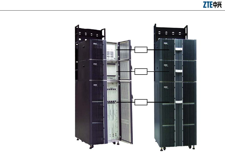
The cabinet of ZXC10 BTSB I1 comprises three basic chassis: RF chassis (RFS),
baseband chassis (BDS) and power chassis (PWS). These chassis can be combined in
different ways in a cabinet, as shown in Fig. 1.1-1. The appearance of the BTSB macro
base station of ZTE is shown in Fig. 1.1-2.
The BTSB system installation involves the following parts:
1. The BTSB cabinet, including the cabinet, internal cables and boards.
2. The power system, which provides -48V operating power for the system.
3. The grounding system, which provides protection ground for the parts of the
BTSB.
4. The antenna system, including the antenna, jumpers and feeders (a test of the
antenna & feeder system is necessary).
5. The GPS system, including the GPS and the feeder.
6. The trunk cable, that is, connecting the cables with the connectors.
7. The monitoring system, including the temperature, humidity and other
environment sensors.
BTSB system installation is shown in Fig. 1.1-3.
ZXC10 BTSB (V1.0) cdma2000 Base Transceiver Station Installation Manual
1-2
RF chassis
Master baseband
chassis
RF chassis
Master baseband
chassis
Slave baseband
chassis
Slave baseband
chassis
Slave baseband
chassis
Slave baseband
chassis
RF chassis
Master baseband
chassis
Power chassis
Power chassis
Fig. 1.1-1 BTSB Cabinet Composed of RF Chassis/BDS Chassis/PWS Chassis
PWS
BDS
RFS
Fig. 1.1-2 Appearance of BTSB Macro Base Station and PWS/BDS/RFS Chassis
Chapter 1 Installation Overview
1-3
GPS installation
Rack
installation
Internal cable
installation
Board
installation
BTSB cabinet installation
Trunk cable
installation
Power supply
system installation
Grounding system
installation
Monitoring system
installation
Antenna system
installation
Fig. 1.1-3 BTSB Installation Hardware
1.2 BTSB Installation Flow Chart
The normal operation of ZXC10 BTSB I1 depends heavily on the quality of the
installation engineering. The equipment must be installed in a systematic and
standardized way to eliminate stability problems caused by improper installation and
improve the reliability of the system.
This manual introduces the installation of BTSB and its parts step by step in an attempt
to guide the engineering staff in their equipment installation.
The indoor installation of ZXC10 BTSB I1 includes cabinet installation and indoor
cable connection and cabling. Please strictly follow these steps for installation:
1. Fix the rack base to the rack.
2. Position the rack and score & drill to fix it.
3. Install the power cable of the cabinet.
4. Install the monitoring cables and temperature/humidity sensors of the BTSB.
5. Install and connect the trunk cable.
6. Install boards and modules in the cabinet.
7. Connect the RF cable of the cabinet.

ZXC10 BTSB (V1.0) cdma2000 Base Transceiver Station Installation Manual
1-4
The detailed hardware installation flow of the BTSB system is shown in Fig. 1.2-1.
This manual describes the specific installation procedure by chapters according to this
flow.
Chapter 1 Installation Overview
1-5
Survey report
Engineering design file
Environment acceptance
report
Cabling rack, power supply
system, grounding system
and other accessories
Packing list Consistence
Yes
Delivery error feedback
form
Replacement
application form
Power supply system
installation
Cabinet installation
Grounding system
installation
Cable installation in
cabinet
Monitoring system
installation
Main antenna feeder
system installation
Board installation
GPS installation
Hardware
installation checking
End
Start
Trunk cable installation
Engineering installation
preparation
Unpacking and
acceptance
Construction condition
checking
Fig. 1.2-1 Hardware Installation Flow

ZXC10 BTSB (V1.0) cdma2000 Base Transceiver Station Installation Manual
1-6
1.3 BTSB Precautions for Hardware Installation
Precautions for the BTSB hardware installation include:
1. Take careful precautions for the safety of yourself and the equipment during the
installation.
2. Avoid hot swap during module installation.
3. In case of lightning, never install the antenna & feeder system.
4. Before the thunderstorm season every year, check whether the lightning arrester
is in proper contact. In case any lightning arrester is damaged, replace it
immediately.
5. Lock the door right after cabinet installation.

2-1
2 Installation Preparations
Summary:
z Environment check prior to the BTSB installation
z Tool and instrument preparation prior to the BTSB installation
z Technical documentation preparation prior to the BTSB installation
2.1 Checking the Installation Environment
Check the following environment items before installation:
Before installation, the customer should prepare the equipment room, power supply
and grounding cables, and provide necessary facilities for the project implementation.
The area and height of the equipment room should satisfy the requirements of the
equipment layout. Otherwise, reconstructions are required to eliminate the problems
faced during the installation, operation and maintenance of the equipment.
The BTSB should not be used in the environment with high temperature, thick dust,
harmful gases, explosive articles or low air pressure. It shall be put far from
transformer stations and traction substations, and shall not be in places with frequent
shaking or great noises.
As the equipment of BTSB cannot be moved easily, the equipment room construction
should be under a long-term plan.
The BTSB equipment room should comply with fire prevention regulations.
2.1.1 Checking the Equipment Room
The items for the equipment room inspection include:
1. The civil engineering of the equipment room and corridor has been completed,
and the wall is fully dry.
2. The height and width of the doors in the equipment room should not cause any
inconvenience for transporting the equipment. Usually, the height of the main

ZXC10 BTSB (V1.0) cdma2000 Base Transceiver Station Installation Manual
2-2
doors in the equipment room should be no less than 2.2 meters, and the width
should be no less than 1 meter. The net height of the equipment room should be
no less than 3 meters. The equipment room should have a sufficient area for the
equipment with extra free space. For easy equipment operation and maintenance,
the space for opening the front door should be no less than 1 meter, and the
space at the rack rear should be no less than 0.8 meter.
3. The equipment room floor should be able to bear the weight over 450kg/m2.
4. The wall and ceiling of the equipment room should not chalk or peel off and
should be free of dust accumulation. Fire-retardant materials should be used for
decoration.
5. The shock-proof design of the equipment room should be one degree higher than
the local anti-seismic requirements. Generally, the equipment room should be
able to bear the earthquake of 7 on the Ritcher Scale. Otherwise, shock-proof
reinforcement measures must be adopted for the equipment.
6. Air-conditioning facilities should be provided to maintain desired temperature
and humidity in the equipment room.
7. Lightning screen or lightning arrester should be installed for the places in the
equipment room vulnerable to the lightning. Outdoor metal pipelines should be
grounded when being led into the equipment room.
2.1.2 Checking the Indoor Environment of the Equipment Room
The inspection of the indoor equipment room environment includes the inspection of
humidity, temperature, air pressure, antistatic protection, anti-interference requirement,
air conditioning, ventilation, dust proof, rodent proof, fire protection, lighting, and
drainage facilities.
1. Requirements for the ambient temperature and humidity
Working temperature: -5 °C ~ +55 °C
Relative humidity: 15% ~ 93% RH
2. Requirements for the equipment room floor
The level difference per square meter of the floor should not be more than 2
mm.

Chapter 2 Installation Preparations
2-3
3. Cleanness
Cleanness is related to the amount of dust and harmful gases in the air. The
equipment room should meet the following cleanness requirements:
z No explosive, conductive, magnetic or corrosive dust.
z Density of the dust whose diameter is larger than 5µm must be less than or equal
to 3*104 particles/m3.
z No corrosive metal or gas that is harmful to insulations, such as SO2, NH3.
z The equipment room should be always kept clean, with the doors and windows
properly sealed.
4. Lighting
The equipment room should be equipped with 3 types of lighting facilities:
Common lighting, guaranteed lighting and emergency lighting.
5. Fire-proof requirements
The paint and decoration materials in the equipment room should be fire-proof.
The cabling holes through the wall should be filled with fire-retardant materials.
Fire-fighting devices should be equipped at the appropriate positions.
2.1.3 Checking the Power Supply System
1. DC power supply requirements:
1) BTSB employs -48V DC power supply so the equipment room should be
equipped with an AC/DC power supply converter for working power supply.
The DC voltage is allowed to range from -57V to -40V.
2) To guarantee uninterrupted operation of the BTSB even in case of mains supply
failure, uninterrupted power supply facilities such as diesel engine generator
group and storage battery should be available.
3) The noise level indices of DC power voltages shall meet the technical
specifications by the former Ministry of Posts and Telecommunications.
4) The DC power supply should be provided with over-voltage/over-current
protection and indicators.
2. AC power requirements (including the AC power for construction purpose and
ZXC10 BTSB (V1.0) cdma2000 Base Transceiver Station Installation Manual
2-4
that used for local operation & maintenance consoles)
1) Three-phase power supply: 380V, with the voltage fluctuation range of no more
than 10%, frequency fluctuation range of no more than 5%, line voltage
waveform distortion factor of less than 5%.
2) Single-phase power supply: 220V, with the voltage fluctuation range of no more
than 10%, frequency fluctuation range of no more than 5%, line voltage
waveform distortion factor of less than 5%.
3. Cabling requirements of the power supply system
Cabling of the power supply system should be correct, tidy and in good order,
and has excellent insulation and reasonable arrangement. To prevent the power
supply system from interfering with other signal lines, power cables and other
cables should be laid separately, with special cabling troughs preferred.
In addition, during the cabling of the power supply system, the cross sections of
the cable feeders and the busbars shall be able to meet the requirements for the
medium-term or long-term capacity expansion.
2.1.3.1 Power System Range
Please see Table 2.1-1 for the DC power indices for the normal operation of ZXC10
BTSB I1 (supporting 24V DC power supply).
Table 2.1-1 DC Power Supply Indices for the Normal Operation of BTSB
Item DC Voltage
Nominal value -48V
Allowed fluctuation -40 ~ -57V
2.1.3.2 Power Consumption
Power supply and power consumption: The power consumption of ZXC10 BTSB I1
refers to the overall power consumption when the operating voltage is -48V and the
output power of each power amplifier is 20W, as shown in Table 2.1-2.
Table 2.1-2 Power Consumption Indices for the Normal Operation of BTSB
Configuration Amplification
Output
Working
Voltage
1X Maximum Power
Consumption (W)
DO Maximum Power
Consumption (W)
1-carrier 1-sector 40W/carrier -48V About 1400W About 1400W

Chapter 2 Installation Preparations
2-5
Configuration Amplification
Output
Working
Voltage
1X Maximum Power
Consumption (W)
DO Maximum Power
Consumption (W)
2-carrier 1-sector 40W/carrier -48V About 1400W About 1400W
3-carrier 1-sector 40W/carrier -48V About 1400W About 1400W
5-carrier 1-sector 40W/carrier -48V About 2000W About 2000W
7-carrier 1-sector 40W/carrier -48V About 2000W About 2100W
1-carrier 3-sector 40W/carrier -48V About 2500W About 2600W
2-carrier 3-sector 40W/carrier -48V About 2600W About 2600W
3-carrier 3-sector 40W/carrier -48V About 2600W About 2700W
4-carrier 3-sector 40W/carrier -48V About 2600W About 2700W
5-carrier 3-sector 40W/carrier -48V About 4400W About 4500W
7-carrier 3-sector 40W/carrier -48V About 4500W About 4600W
8-carrier 3-sector 40W/carrier -48V About 4500W About 4700W
1-carrier 6-sector 40W/carrier -48V About 4300W About 4400W
2-carrier 6 -sector 40W/carrier -48V About 4400W About 4500W
3-carrier 6-sector 40W/carrier -48V About 4500W About 4600W
4-carrier 6-sector 40W/carrier -48V About 4500W About 4700W
2.1.4 Checking the Grounding System
The grounding regulations and resistance requirements (including the lightning
protection requirements) are as follows:
The communication equipment should be well grounded for reliable operation. Good
grounding ensures lightning protection and interference resistance. The grounding
cables in the equipment room should be routed in a radiating or flat way. Three
independent grounding cables should be used: The protection ground of the DC power
distribution system, the work ground of the power system and the lightning protection
ground.
The equipment adopts joint grounding with the grounding resistance less than 1 Ω.
Generally, the grounding resistance of BTSB should be less than 5 Ω. The engineering
requires the grounding resistance to be the smallest possible. The magnitude of
grounding resistance is affected by grounding post resistance, leading wire resistance,
contact resistance between the grounding post and soil as well as the soil type. The
greatest impact on grounding resistance comes from soil type. In areas with poor soil
conditions, some resistance-reducing agent (such as propenamide) may be added
around the grounding stake to meet the requirements. Changes in temperature will also
cause variations in resistance. In cold areas, the impact of temperature on the resistance

ZXC10 BTSB (V1.0) cdma2000 Base Transceiver Station Installation Manual
2-6
may be reduced by burying the stake deeply into the ground. Grounding stakes are
usually made of galvanized materials in proper size. The connection cables from the
grounding stake to the equipment should adopt copper-sheathed wires of good
conductivity (core wire section area less than 50 mm2, and length as short as possible).
If necessary, anti-erosion protection can be provided to the grounding connection parts
to guarantee low-resistance connection.
The working ground refers to the loop formed through the earth to transmit energy and
information. For instance, the 3-phase AC power supply neutral line ground and the
positive battery ground are both working grounds. This grounding approach can resist
electromagnetic interference and cross talk.
The protection ground refers to the grounding of the metal shell of the power supply
equipment to prevent hazards to human body due to power leakage.
In addition, the ground for lightning protection should be used to prevent lightning
stroke from damaging the equipment and to protect the safety of lives and properties.
2.1.5 Checking the Outdoor Installation Environment for the Antenna Feeder
System
1. Check whether the height and size of the feeder window comply with the
requirements of the BTSB equipment and the engineering design drawing.
2. Check whether the height, weight bearing and grounding of the outdoor cabling
rack comply with the engineering design.
3. Check whether the height, weight bearing and grounding of the indoor cabling
rack comply with the engineering design.
4. Check the height, diameter, weight bearing, wind resistance, grounding,
lightning protection and position of the antenna pole of the BTSB on the roof to
make sure they comply with the BTSB equipment requirements and the
engineering design drawing.
5. Check the height, diameter, weight bearing, wind resistance, grounding,
lightning protection and position of the antenna pole of the BTSB on the iron
tower to make sure they comply with the BTSB equipment requirements and the
engineering design drawing.

Chapter 2 Installation Preparations
2-7
2.1.6 Checking the Safety Conditions
Appropriate fire-fighting devices should be equipped in the equipment room, such as a
certain quantity of portable powder fire-extinguishers. As for a large equipment room, a
complete set of automatic fire-fighting system should be equipped. No inflammable or
explosive articles should be placed in the equipment room.
1. Storage of flammable and explosive materials in the equipment room is strictly
prohibited and necessary firefighting equipment must be installed.
2. Different outlets in the equipment room shall bear noticeable marks, and
dynamic electricity and lighting electricity should be noticeably differentiated.
3. The equipment room should be far from high-voltage power lines, strong
magnetic fields, strong electric sparks, or other factors that may threaten the
security of the equipment room.
4. Reserved holes in the floors should be covered with safety cover plates.
5. Proper lightning protection facilities should be in place before the power lines
and transmission lines are led into the equipment room.
2.1.7 Checking Other Auxiliary Equipment
Check the following items against the configuration requirements specified in the
contract:
1. Check whether the external power supply and the power cable connecting the
racks are ready.
2. Check whether the E1 cable connecting the BTSB and the BSCB is ready.
2.2 Preparing Tools and Instruments
A number of tools and instruments are to be used during the BTSB installation process.
Prepare the tools and instruments as given in Table 2.2-1 and Table 2.2-2 below.
Table 2.2-1 Tools
Category Name
Special tools
One feeder connector knife
One wire skinner for 75 Ω coaxial cables
One crimping pliers for 75 Ω coaxial cables

ZXC10 BTSB (V1.0) cdma2000 Base Transceiver Station Installation Manual
2-8
Category Name
One multi-functional crimping pliers
One multimeter
One SiteMaster VSWR tester
Earth resistance tester
Concrete drilling tools
One electric percussion drill
Several drill bits
One cleaner
One power terminal block (at least three 2-phase sockets and three
3-phase sockets, with the power capacity more than 15A)
General-purpose tools
Philips screwdrivers (4″, 6″ and 8″ each)
Flathead screwdrivers (4″, 6″ and 8″ each)
Adjustable wrenches (6″, 8″, 10″ and 12″ each)
Dual-purpose spanners (17″ and 19″ each)
One set of socket wrench
One 5 kg nail hammer
One 300 W iron
One 40 W iron
One roll of solder wire
Measurement tools
One 50 m tape measure
One 5 m steel tape
One 400 mm level bar
One angle meter
One compass
Level
Plumb
Protection tools Anti-static wrist strap
Safety helmet, slip-proof glove
Small tools
One hacksaw (with several saw blades)
One pair of sharp-nose pliers (8″)
One pair of diagonal pliers (8″)
One pair of slip joint pliers (8")
One pair of vices (8″)
One needle file set (medium sized)
Tweezers
One paint brush
One pair of scissors
One hot blower
One solder sucker
One pair of hydraulic pliers
Crowbar
Chapter 2 Installation Preparations
2-9
Category Name
Auxiliary tools
Pulley block
Rope
Ladder
Forklift
Table 2.2-2 Instruments
Instrument Name Manufacturer
Spectrum analyzer (needed in some
special cases)
HP
Base station tester SITE MASTER
Testing MS Qualcomm
Compass
Multimeter
Field strength tester (needed in some
special cases)
2.3 Preparing Technical Documentation
The technical documents to be prepared before the commissioning of the equipment
include:
1. Project Survey Report, BTSB System Project Design and Engineering Drawing,
and Environment Acceptance Report.
Project Survey Report should be completed by the engineering staff sent by the
equipment supplier during the onsite survey. If engineering staff cannot conduct
the survey in time, he should entrust the equipment user to fill in the report and
mail it back after the survey for the preparation of engineering materials.
BTSB System Project Design and Engineering Drawing should be completed by
the design party entrusted by the equipment user, and its copy should be
provided by the equipment user to the equipment supplier before equipment
delivery.
Environment Acceptance Report is used for the first engineering environment
inspection during the project survey. If the environment is found to fail the
inspection, the equipment user is requested to make improvement and solve the
problem. The second environment inspection is conducted before the
engineering starts.

ZXC10 BTSB (V1.0) cdma2000 Base Transceiver Station Installation Manual
2-10
2. ZXC10BTSB (V 1.0) cdma2000 Base Transceiver Station Installation Manual
ZXC10 BTSB (V1.0) cdma2000 Base Transceiver Station Technical Manual
ZXC10 BTSB (V1.0) cdma2000 Base Transceiver Station Hardware Manual
ZXC10 BTSB (V1.0) cdma2000 Base Transceiver Station Maintenance Manual
3. Installation Acceptance Report and Test Acceptance Report.
Installation Acceptance Report and Test Acceptance Report are the engineering
materials for acceptance after the BTSB commissioning. They are provided by
the equipment supplier to the equipment user at the time of delivery. They
should be completed properly after the commissioning of the BTSB.

3-1
3 Unpacking and Acceptance
Summary:
z Unpacking of BTSB
z Acceptance of BTSB
3.1 Checking Goods against the Packing List
1. Check the Delivery Checklist of ZTE Corporation.
2. Unpacking inspection is conducted by the Project Supervising Committee and
representatives from the user. First, check the total number of goods, the
intactness of the packing boxes, and check whether the arrival place is the
actual installation place against the packing list number attached to the packing
boxes;
3. The packages can be opened if they are not damaged. Each package has a
Packing List. The engineering supervisor should check item by item according
to the Packing List. The Unpacking Inspection Report is placed in the packing
box numbered 1#. First open the 1# packing box and take out the Unpacking
Inspection Report. To check the total number of the goods against the
inspection list and record it for filing.
4. During the unpacking inspection process, if there is any short and wrong
shipment or goods damage, you should contact the ZTE headquarters.
5. The goods of ZTE may be packed in crate or carton. Different tools are
required to open them on site.
Caution:
The ZXC10 BTSB I1 equipment is relatively expensive. During transportation, it shall
be well packaged with clear waterproof and quake-resistant marks. Handle the
equipment with care and protect it from sunshine and rain.
ZXC10 BTSB (V1.0) cdma2000 Base Transceiver Station Installation Manual
3-2
3.2 Unpacking the Wooden Box
3.2.1 Wooden Box Structure
The wooden boxes are generally used for packing heavy goods like rack.
The structure of the BTSB rack-packing box is shown in Fig. 3.2-1.
2060mm
860mm
860mm
Fig. 3.2-1 Structure of the Wooden Box
3.2.2 Unpacking Procedure
1. Prepare appropriate tools such as nail hammer, pliers, straight screwdriver and
crowbar.
2. First skin the packing sheet iron. Insert a flat-tip screwdriver into the slit
between the box and the front cover board to make it loose; then insert the
crowbar to unclench the cover board.
3. Keep the box on end and the legs downward, and pull the rack out of the box.
Make sure not to remove the antistatic bag of the rack before pulling the rack
out.
4. Remove the packing adhesive tape of the rack.
Note: The BTSB rack is equipped with casters for easy movement. However, you
should control the moving direction with your hands during the move to avoid any
damages or accidents.
3.2.3 Checking the Rack Appearance
Put the rack vertically on the solid ground. The rack should be erected upright without
Chapter 3 Unpacking and Acceptance
3-3
tilting. Visually there is no dent, bump, scratches, peel, bubbling, stains or other similar
damaged signs. The captive screws should not be loose, missing or misplaced. The
installation slots for plug-in boxes are intact and the slot guide rails are not missing,
damaged or broken. All fittings and accessories required for rack installation are
complete. The labels of installation slots are intact and eligible. The busbar, the exhaust
fan and the installation positions are not damaged or deformed. There is no rack
surface paint flake-off or scratches.
3.3 Unpacking the Carton
3.3.1 Carton
Caution:
1. Avoid taking any circuit board out of the antistatic bags during the unpacking and
acceptance. Do not open the antistatic bags until the board is to be mounted into the
rack. In addition, avoid damaging any antistatic bag and keep it for future use when
storing spare boards and packing the faulty boards for repair.
2. When the equipment is moved from a colder and drier place to a hotter and
damper place, wait for 30 minutes before unpacking the equipment. Otherwise,
moisture may appear on the surface of the equipment and cause damage.
3. Properly recycle the desiccants lest children may eat them by accident. Cartons
are generally used to pack circuit boards and terminal equipment.
The circuit boards are placed in the anti-static protective bags during transportation.
Before unpacking the boards, take proper anti-static protective measures to avoid
damages. In addition, attention should be paid to the ambient temperature. Usually
some desiccant is placed in the anti-static protective bag to absorb moisture and keep
the bag dry.
The packing box of modules is shown in Fig. 3.3-1.

ZXC10 BTSB (V1.0) cdma2000 Base Transceiver Station Installation Manual
3-4
Fig. 3.3-1 Packing Box of Modules
3.3.2 Unpacking Procedure
Take the following steps to unpack a carton:
1. Use the diagonal pliers to cut the straps.
2. Use a paper knife to cut the adhesive tape along the slits on the box covers. Note
that the cut shall not be too deep and damage the goods inside.
3. Count the quantity and types of boards inside the carton against the packing list
attached and sign for the acceptance with the customer on site.
3.3.3 Checking the Boards
Check the boards against the delivery list and contact the equipment supplier in time if
any incompliance is found.
3.4 Goods Acceptance and Handover
After the unpacking acceptance, both parties sign on the Unpacking Acceptance Report.
after which the goods shall be handed over to the customer if they are to be kept by the
customer after acceptance according to the contract terms. Each party shall hold a copy
of the Unpacking Inspection Report and the Project Supervisor shall feedback the
Acceptance Conclusion of the Report to be archived by the equipment supplier.

4-1
4 Cabinet Installation
Summary:
z Appearance and structure of the BTSB cabinet
z Installation procedure of a single BTSB cabinet
z Arrangement of the BTSB cabinets
z Connection and fixation between BTSB cabinets
z Standard of installing the BTSB cabinets
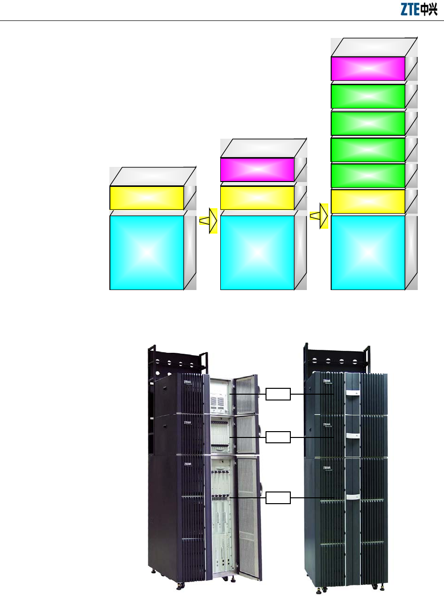
4.1 Cabinet Types
ZXC10 BTSB I1 is composed of three types of subracks, PWS, BDS and RFS, that can
be combined flexibly into super base stations, as shown in Fig. 4.1-1These subracks
provide powerful functions with lighter weight and small footprint, allowing easy
movement and installation.
ZXC10 BTSB (V1.0) cdma2000 Base Transceiver Station Installation Manual
4-2
PWS
BDS
RFS
Fig. 4.1-1 Flexible Combination of ZXC10 BTSB I1 Subracks
4.2 RFS Cabinet Installation
The RFS cabinet supports base installation and support installation. The following
sections detail the procedures of these two installations.
4.2.1 RFS Installation Flow
The base installation mode is to mount the cabinet on an adjustable base provided by
ZTE in the case that there is antistatic floor in the equipment room. The support
installation mode is to fix the cabinet with the pressure plate assembly to the floor in
the cast that there are feet under the cabinet (the four feet of the cabinet). The cabinet
installation flow is shown in Fig. 4.2-1.
Chapter 4 Cabinet Installation
4-3
Base installation
Base installation
mode
Fixing the cabinet to
the base
Cabinets fixing
Cabinet accessories
installation
Installation check
End
Support
installation
Support
installation mode
Fig. 4.2-1 Cabinet Installation Flow
4.2.2 Support Installation Mode
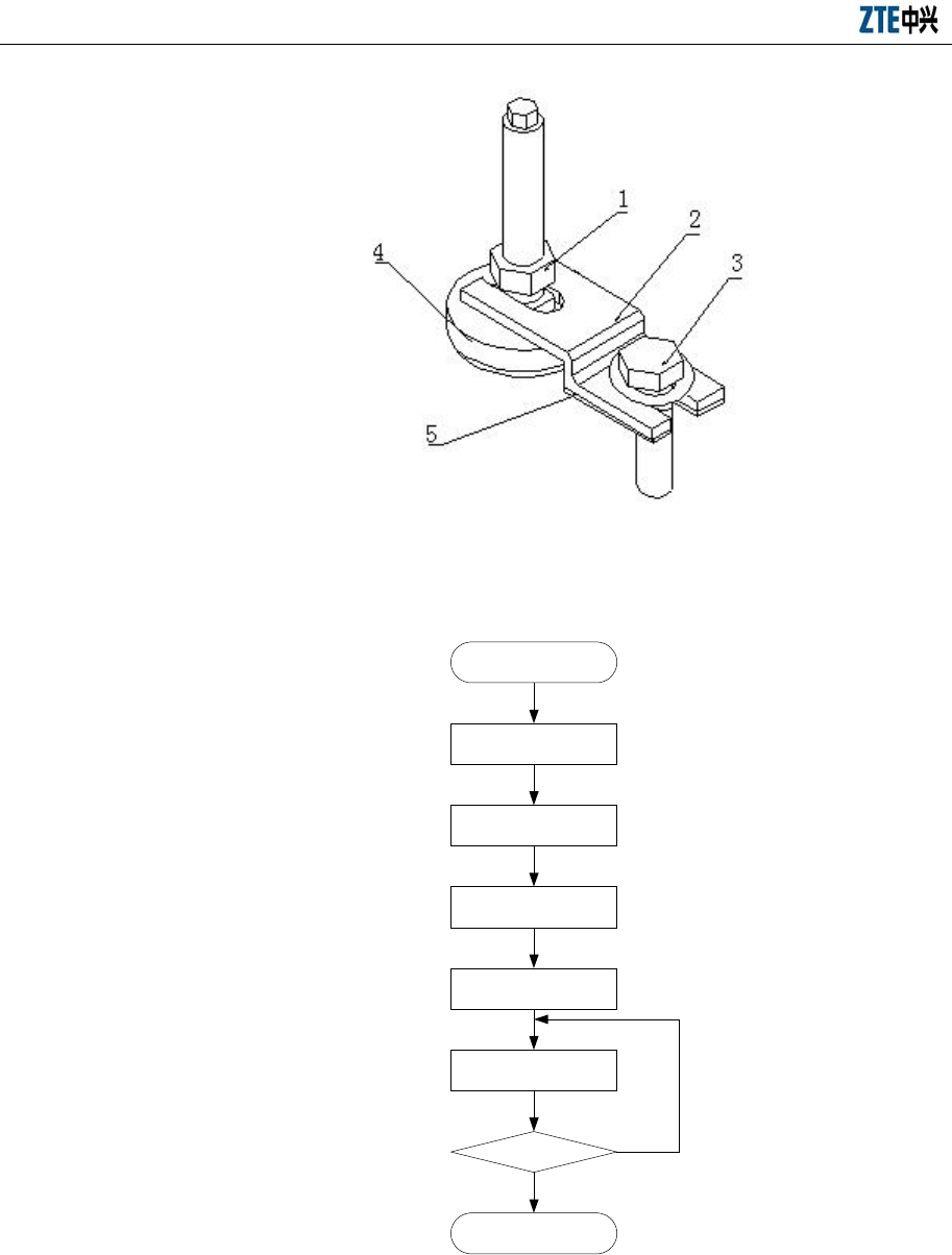
4.2.2.1 Support and Pressure Plate Assembly
The support fixing amplification is shown in Fig. 4.2-2.
4.2.2.2 Support Installation Flow
Firstly, install the pressure plate assembly on the support as shown in Fig. 4.2-3.
ZXC10 BTSB (V1.0) cdma2000 Base Transceiver Station Installation Manual
4-4
1. Locking nut 2. Pressure plate 3. M10X25 bolt 4. Support 5. Insulating washer
Fig. 4.2-2 Zoom-in Diagram of Support Fixing
Support installation
Pressure plate
assembly positioning
Start
Expansion bolts
installation
Cabinet positioning
Pressure plate
assembly installation
Insulation test N
Y
End
Fig. 4.2-3 Support Installation Flow
Chapter 4 Cabinet Installation
4-5
4.2.2.3 Adjusting the Supports
The cabinet base is equipped with supports and caster wheels. The supports should be
suspended so that the cabinet can move with the caster wheels. Fig. 4.2-4
1. Cabinet 2. Caster wheels 3. Support
Fig. 4.2-4 Position of Caster Wheels and Supports
In the equipment room, screw off the support to make it 80 mm lower than the cabinet
bottom. Thus, there is room for the baffle and the caster wheels. Rotate the supports
downward , as shown in Fig. 4.2-5.
ZXC10 BTSB (V1.0) cdma2000 Base Transceiver Station Installation Manual
4-6
80mm
Fig. 4.2-5 Rotating Supports Downward
4.2.2.4 Positioning the Pressure Plate Assembly
1. Scoring
Decide the position to install the base according to the basic size and cabinet
size given in the construction plane design drawing; measure a few marking
points with a tape measure, and mark two lines spaced 670 mm and parallel to
the base line with an ink fountain; according to the design, mark the positions of
the four installation holes for the first cabinet on the two lines; then mark the
installation holes for other cabinets one by one. This is shown in Fig. 4.2-6.
Chapter 4 Cabinet Installation
4-7
Support area
Rack area
M10X40 embedded expansion nut
ф12 drill bit is recommended for
holes of 43 mm deep
Fig. 4.2-6 Positions of Installation Holes of Cabinet Supports
2. Drilling
After the scoring in Fig. 4.2-6, select φ12 bit for drilling. Keep the bit vertical to
the floor. Use both hands to hold the drill handle tightly and straightly without
swing to avoid damaging floor and incline the hole.
The hole depth should be equal to the length of the expansion tube of expansion
nut (or bolt) plus the flare head length. While drilling holes, use a vacuum
cleaner to remove dust. Suck the dust in the holes once again after the holes are
drilled. Measure the space between holes and place the base to check whether
the holes are matched. For holes with large deviation, it is necessary to
reposition and re-drill the holes before installing the expansion bolts (expansion
nuts).
4.2.2.5 Installing the Embedded Expansion Nuts
Place the embedded expansion bolts in a drilled hole and hammer it fully into the
ZXC10 BTSB (V1.0) cdma2000 Base Transceiver Station Installation Manual
4-8
ground with a dedicated hammer or a rubber hammer.
4.2.2.6 Positioning the Cabinet
Move the cabinet to the right position, revolve the screws of the cabinet feet to adjust
the height of the cabinet, select three points on the shelf and measure them with a level
meter to make the rack level.
4.2.2.7 Installing the Pressure Plate Assembly
Put on the pressure plates onto the supports and fix the pressure plate with four M10 ×
25 bolts, as shown in Fig. 4.2-7.
1 Pressure plate 2 Support
Fig. 4.2-7 Installing Supports and Pressure Plate
4.2.2.8 Installing the Baffle Assembly
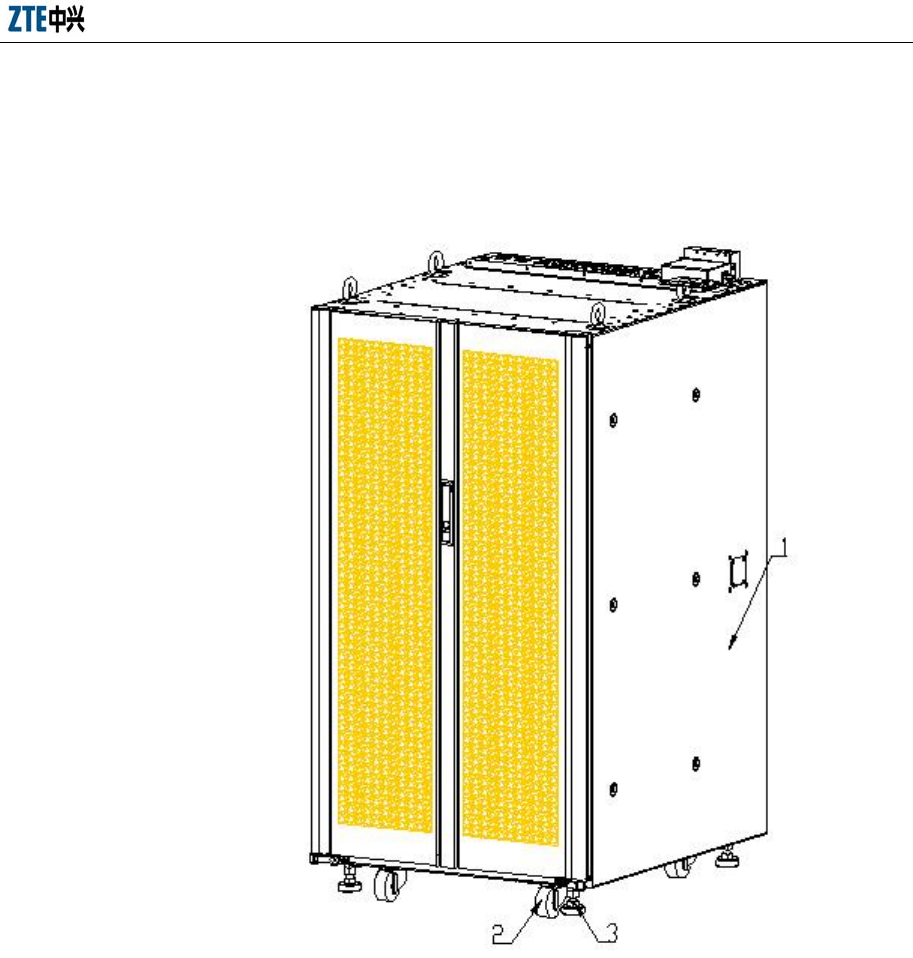
Install the baffle assembly around the cabinet. The completion of the cabinet
Chapter 4 Cabinet Installation
4-9
installation is shown in Fig. 4.2-8.
1. Cabinet 2. Baffle 3. Lock 4. Vent
Fig. 4.2-8 Cabinet after Installation
4.2.3 Base Installation Mode
4.2.3.1 Base Structure
The server cabinet is installed on ZTE’s universal base that is composed of four
independent square piers, two connection boards and some other accessories. Three
types, different in adjustable heights, are available:
1. Type A 150 mm ~ 205 mm
2. Type B 185 mm ∼ 285 mm
3. Type C 275 mm ∼ 450 mm
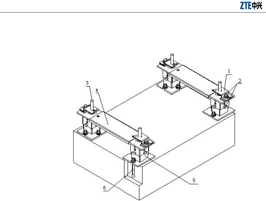
ZXC10 BTSB (V1.0) cdma2000 Base Transceiver Station Installation Manual
4-10
The adjustable height means the height from the bottom of an installed cabinet to floor.
The installation on universal base is shown in Fig. 4.2-9.
1. Pressure plate 2. M10 × 25 bolts 3 Cabinet support 4. Bracket 5. Base 6. M10 × 40 embedded expansion (12 φ
bit, 43 hole depth)
Fig. 4.2-9 Installation on Universal Base
The bracket shown in the Fig. 4.2-9 is optional. When the bracket is not installed, the
pressure plate can be installed at the inner side of the cabinet feet. The base installation
flow is shown in Fig. 4.2-10.
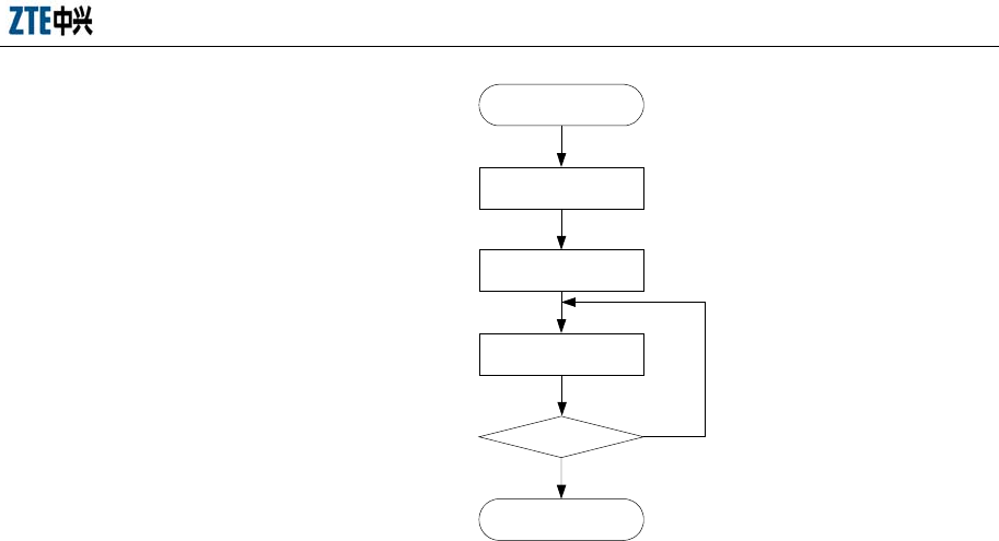
Chapter 4 Cabinet Installation
4-11
End
Base Positioning
Base installation
Start
Cabinets fixing
Insulation test N
Y
Fig. 4.2-10 Base Installation Flow
4.2.3.2 Positioning the Base
1. Scoring
Decide the installation positions of the bases according to the benchmark
dimensions and the cabinet dimensions given in the construction floor plan, get
a few marking points by measuring with a long tape, and mark two lines that are
670 mm apart and parallel to the base line with an ink fountain. According to the
design, determine the locations of the installation holes for the four bases one by
one Fig. 4.2-11.
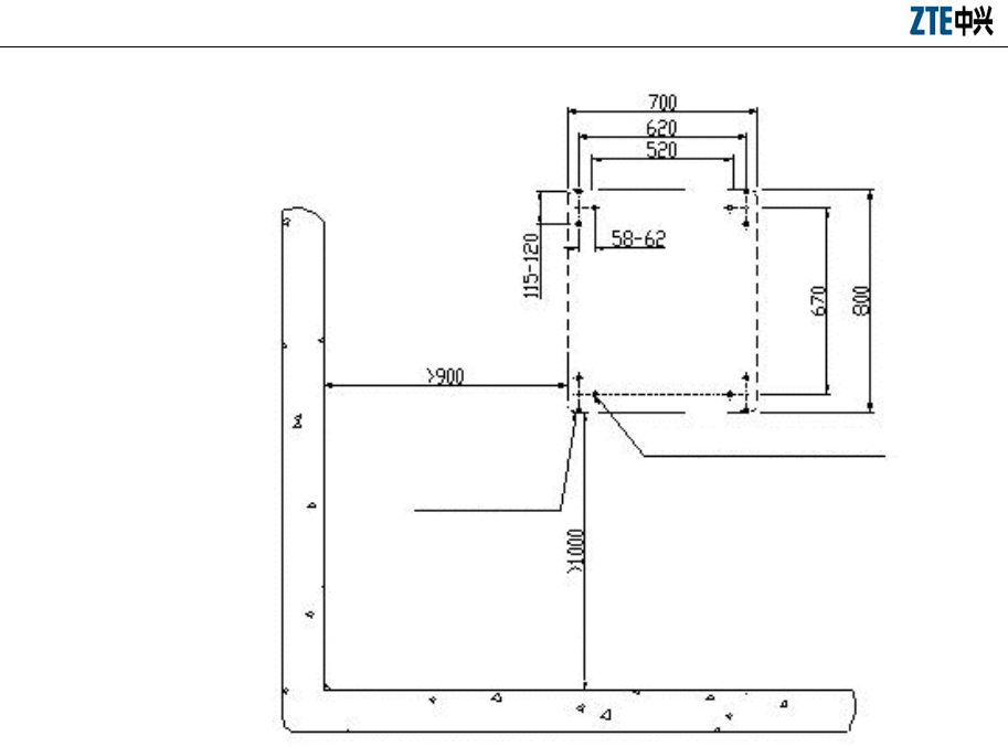
ZXC10 BTSB (V1.0) cdma2000 Base Transceiver Station Installation Manual
4-12
Rack area M10X40 embedded expansion nut
ф12 drill bit is recommended for
holes of 43 mm deep
Fig. 4.2-11 Locations of the Installation Holes for the Four Bases
2. Drilling
After the scoring according to Fig. 4.2-11, select φ12 bit for drilling. Keep the
bit vertical to the floor. Use both hands to hold the drill handle tightly and
straightly without swing, to avoid damaging floor and incline the hole.
The hole depth should be equal to the length of the expansion tube of expansion
nut (or bolt) plus the flare head length. While drilling holes, use a vacuum
cleaner to remove dust. Measure the space between holes, place the adjustable
base and check whether the holes are matched. For holes with large deviation, it
is necessary to reposition and re-drill the holes before installing the expansion
bolts.
Insert the expansion nut and expansion tube into the hole. Strike the expansion
bolt with a rubber hammer till the expansion tube of the expansion bolt fully
enters the floor. If the expansion bolt is being installed, the washer and nut on
the bolt should be removed first.
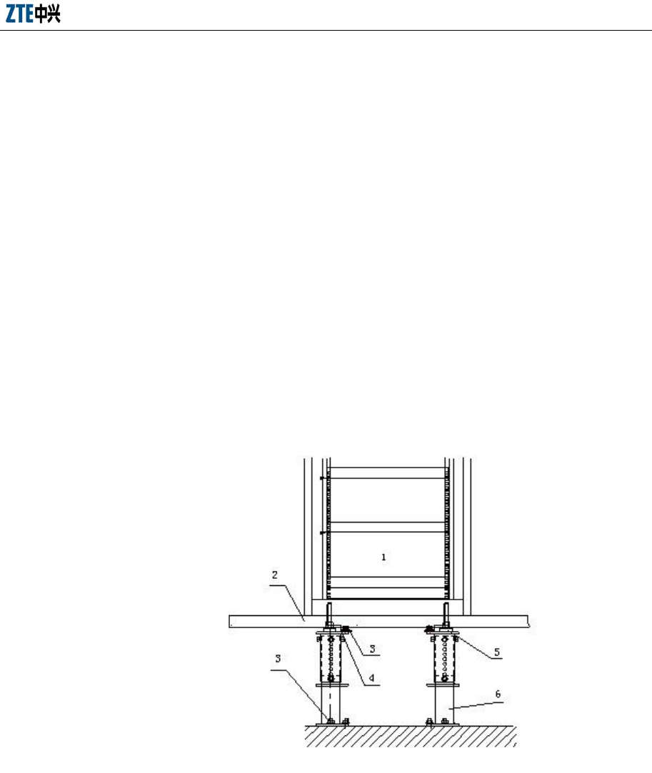
Chapter 4 Cabinet Installation
4-13
4.2.3.3 Installing the Base
Arrange the base according to the scoring position and connect the parts according to
Fig. 4.2-9. Adjust the height and tighten all bolts. Screw 12 M10 × 25 bolts in the
embedded expansion nuts to fix the base parts.
4.2.3.4 Fixing the Cabinet
Lift the cabinet onto the base after adjusting the four feet of the cabinet 65 mm above
the cabinet bottom. These four feet are nearly in the middle of the square plane of the
base to align the pressure plates with the installation holes on the base.
Rotate the threaded rod of the support to adjust the height of the cabinet, and choose
three points in the frame to keep the rack level with gradienter.
Clip the pressure plate parts onto the cabinet support. Tighten the retaining nuts. Fix
the pressure plates on the base with four M10 × 25 bolts to fix the cabinet. The bracket
is not installed, as shown in Fig. 4.2-12.
1. Inner equipment 2. Antistatic floor 3. M10 × 25 bolt 4. Pressure plate assembly 5. Cabinet support 6. Base
Fig. 4.2-12 Installing Pressure Plate of the Base
The view of the pressure plate in the above diagram is enlarged to show their detailed
fixing relations, as shown in Fig. 4.2-13.
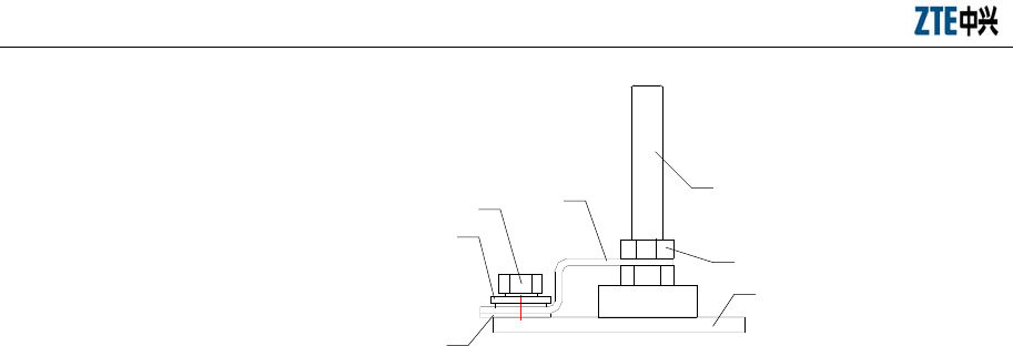
ZXC10 BTSB (V1.0) cdma2000 Base Transceiver Station Installation Manual
4-14
1
2
4
3
5
6
7
1. Pressure plate 2. M10 × 25 bolts 3 Washer 4. Insulation pad 5. Cabinet support 6. Retaining nut 7. Base
Fig. 4.2-13 Fixation of Supports, Pressure Plate and Base
4.2.3.5 Testing Insulation
Connect the cabinet to the floor. The test is passed if electricity cannot be conducted
through the connection.
4.2.4 Cabinet Stacking Mode
BDS and PWS are put on RFS.
4.2.4.1 Installing the BDS Unit
On the front cover, screw five M5 bolts inside RFS through the holes on the top of
cabinet to the nut inside the BDS unit. On the back cover, fix the BDS unit to the RFS
cabinet by screwing nine screws with the edge iron, as shown in Fig. 4.2-14.
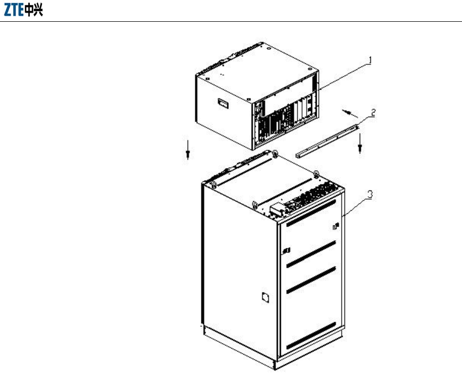
Chapter 4 Cabinet Installation
4-15
1. BDS unit 2. Jointing edge iron 3. RFS unit
Fig. 4.2-14 Installation of BDS Unit
4.2.4.2 Installing the PWS Unit
The PWS units are stacked on the BDS unit. Similarly, screw five M5 screws on the
front cover and fix the two units together with ten screws and flat connection plate, as
shown in Fig. 4.2-15.
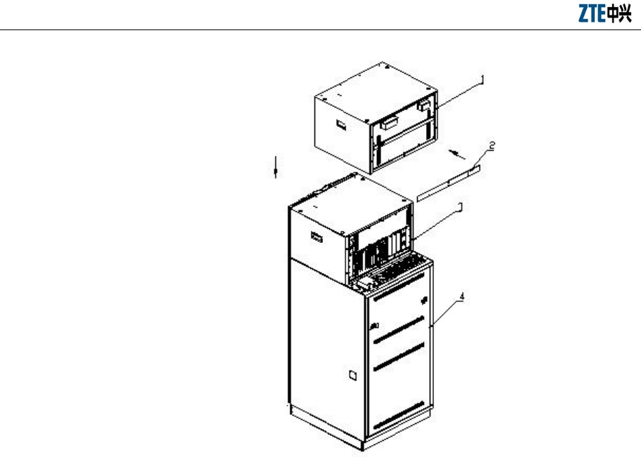
ZXC10 BTSB (V1.0) cdma2000 Base Transceiver Station Installation Manual
4-16
1. PWS unit 2. Flat connection board 3. BDS unit (May be multiple) 4. RFS unit
Fig. 4.2-15 Installation of PWS Unit
The appearance of the BDS and PWS units after installation is shown in Fig. 4.2-16.
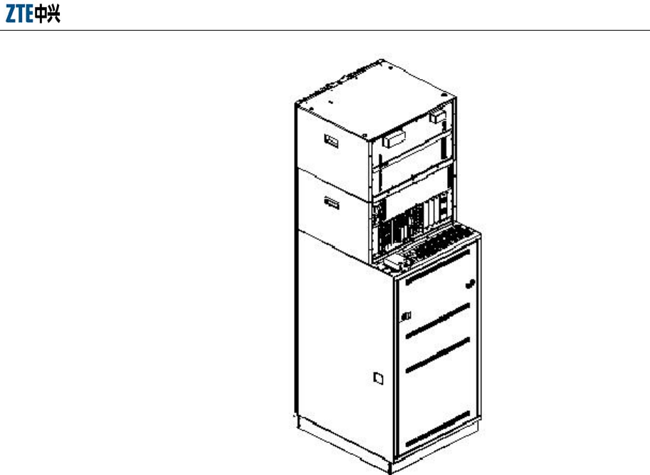
Chapter 4 Cabinet Installation
4-17
Fig. 4.2-16 Appearance of the BDS and PWS Units after Installation
4.2.5 Installing Cabinet Accessories
4.2.5.1 Feeder Fixing Rack
The feeder fixing rack is installed at the rear part of the top cover of the RFS cabinet,
as shown in Fig. 4.2-17.
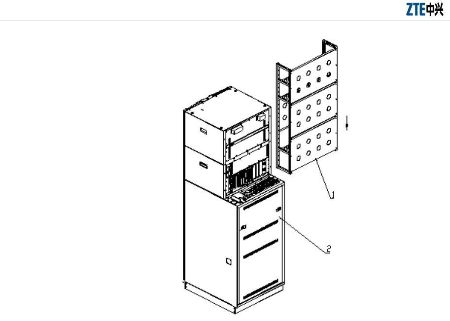
ZXC10 BTSB (V1.0) cdma2000 Base Transceiver Station Installation Manual
4-18
1. Feeder fixing rack 2. RFS cabinet
Fig. 4.2-17 Installation of Feeder Fixing Rack
A properly installed feeder fixing rack is shown in Fig. 4.2-18.
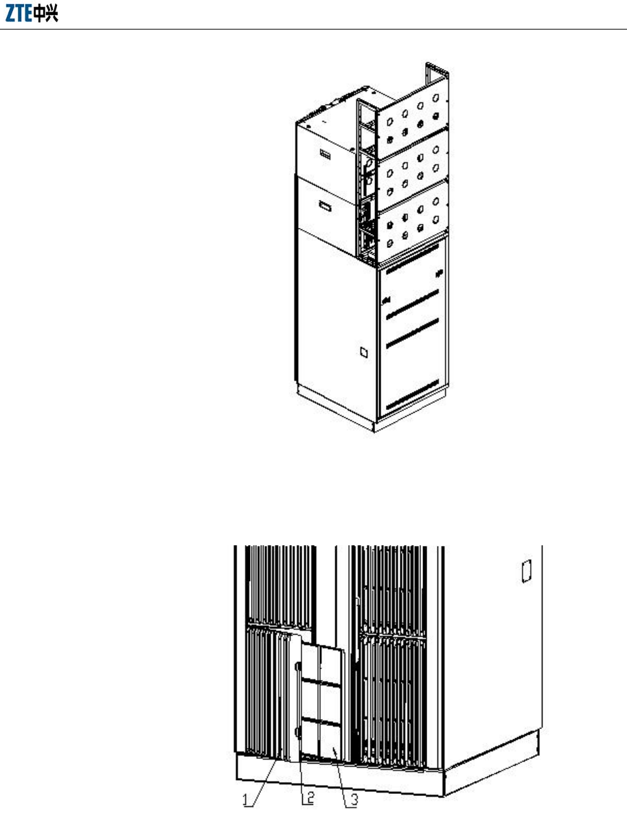
Chapter 4 Cabinet Installation
4-19
Fig. 4.2-18 Feeder Fixing Rack after Installation
4.2.5.2 Dust Filter
1. Plastic decoration panel 2. Pin 3. Dust-filtering network board
Fig. 4.2-19 Installation and Replacement of Dust Filters

ZXC10 BTSB (V1.0) cdma2000 Base Transceiver Station Installation Manual
4-20
The dust filters at the front of the cabinet of 3G can be replaced conveniently. Pull open
the pin of the plastic decoration board. The decoration board can turn about 20 degrees
to draw out the dust filtering network board for cleaning and replacement, as shown in
Fig. 4.2-19. The dust filters are cleaned once every three hours or half year according
to the specific environments of the equipment room.
4.2.6 Cabinet Installation Specifications
The layout, installation positions and directions of the cabinets should conform to the
requirements in engineering design drawings.
1. The vertical error of the cabinet should be less than 3 mm.
2. When the cabinets are to be combined in a row, the adjacent cabinets should be
close to each other. The cabinet fronts or backs should be in the same plane.
3. The captive screws must be fastened. The protrusion (height) of the same type
nuts should be identical.
4. The PCB plug-in components should be in secure contact and can be
plugged/unplugged easily. They should be in the same level when plugged in
slots.
5. The parts on the cabinet should not be loose or damaged. The paint coating
should not be peeled off or damaged. Otherwise, the lost paint should be
supplemented.
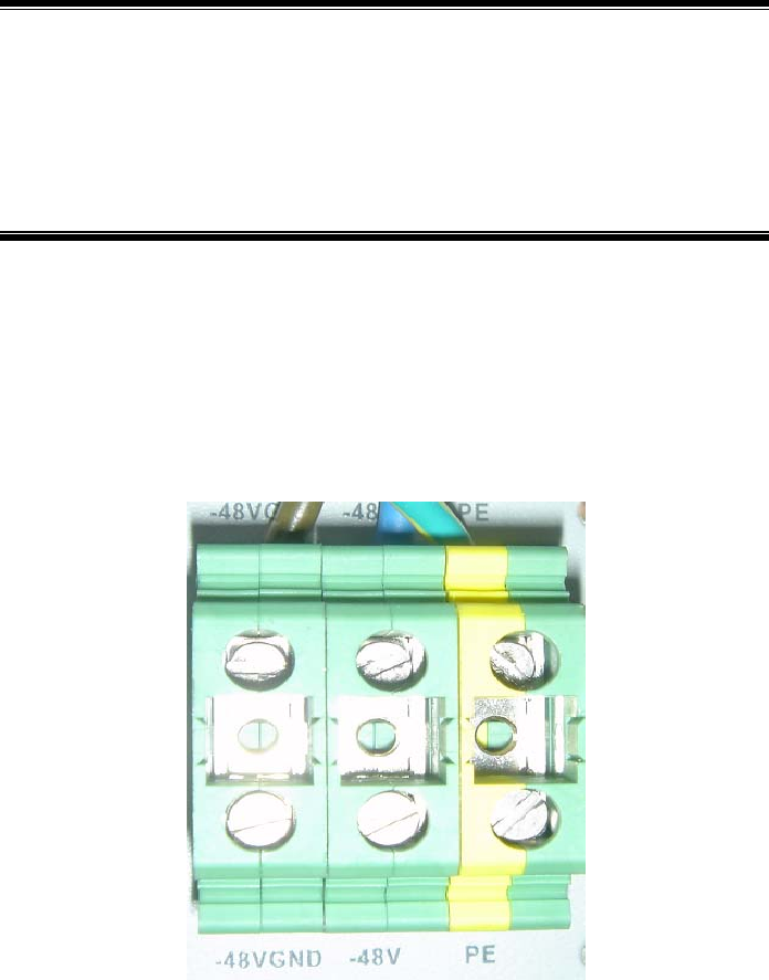
5-1
5 Power Supply System Installation
Summary:
z Power cables of BTSB
z Installation method of the BTSB power supply
z Installation procedure of the BTSB power supply
5.1 Introduction to Power Cables
The DC power supply cables consist of the -48V cable (black), grounding cable (blue)
and protection grounding cable (yellow green). The connector of the BDS power cable
on BTSB is shown in Fig. 5.1-1.
Fig. 5.1-1 BDS Power Cable Installation on BTSB
The diameter of the main power cable should be calculated by the actual capacity. The
specifications of the three commonly used BTSB power cables are:
1. Black with the cross section area as 25 mm2 (working grounding cable).
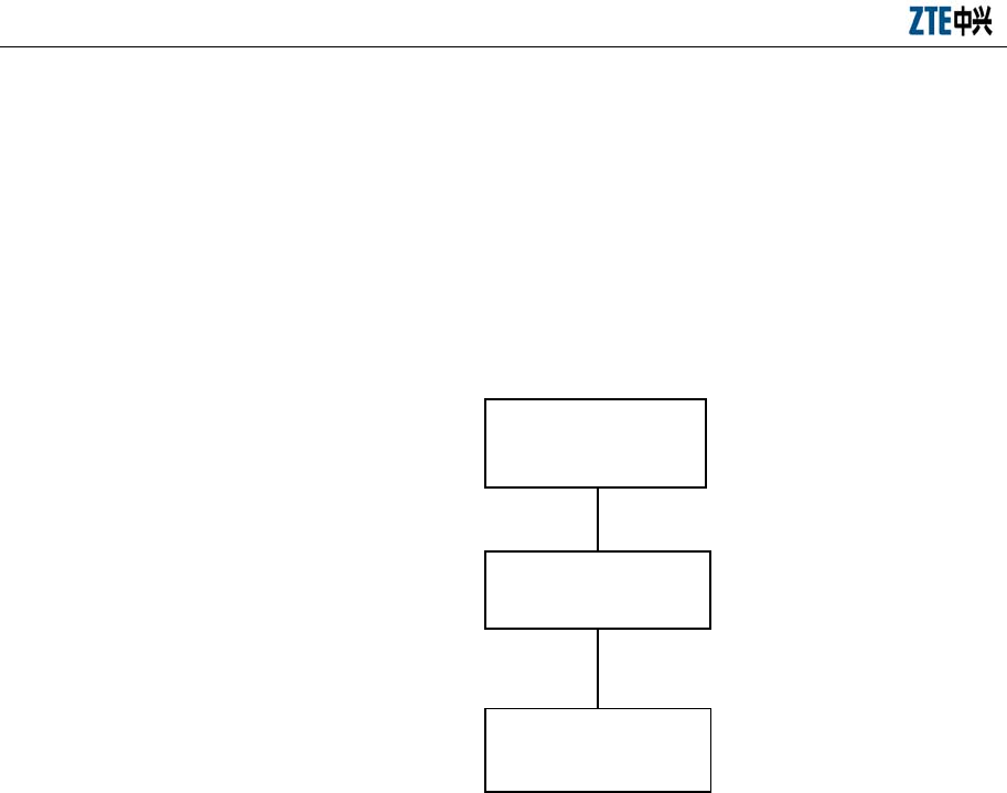
ZXC10 BTSB (V1.0) cdma2000 Base Transceiver Station Installation Manual
5-2
2. Blue with the cross section area as 25 mm2 in section area (-48V).
3. Yellow green with the cross section area as 35 mm2 (protection grounding
cable).
5.2 Installation Flow of Power Cables
The power cable installation flow is shown in Fig. 5.2-1.
Power cabling in the
cabinet
Power cable
leading from the
distribution frame
Connecting to the filter on
the cabinet
Fig. 5.2-1 Installation Flow of RFS Power
5.3 Cable Installation Procedure
The power supply is led into the filters by the power cables, distributed to the busbars
on the two sides of the cabinet by PD, and then led to the backplane of each plug-in
box by the busbars, As show Fig. 5.3-1.
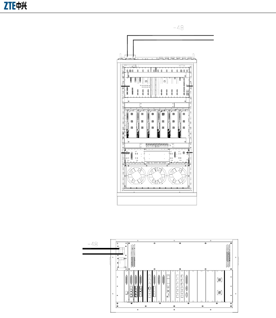
Chapter 5 Power Supply System Installation
5-3
Fig. 5.3-1 RFS Power Cabling
Fig. 5.3-2 BDS Power Cabling
The connection between the busbar and backplane through the -48V power cable is
shown in Fig. 5.3-3.
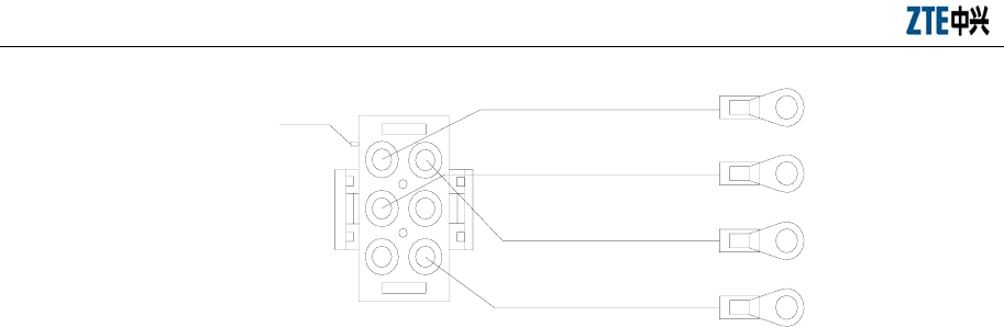
ZXC10 BTSB (V1.0) cdma2000 Base Transceiver Station Installation Manual
5-4
1
2
3
4
5
6
6-core power connector
for backplane
Locating key
Lug for busbar
-48V
GNDP
GND
- 48VGND
Blue
Yellow
Black
Black
Fig. 5.3-3 Connection between Busbar and Backplane
End B of the power cable on the busbar usually has been connected before delivery. If
the backplane of the plug-in box has been installed, the End A of the cable has been
connected to the backplane. Only when the equipment capacity is to be expanded or the
backplane is to be replaced, the power cables need to be connected on site.
1. Connection between the DC distribution cabinet and the DC distribution panel
The PE grounding bar of the DC distribution cabinet must be reliably connected
to the protective grounding bar provided by the carrier through the yellow/green
wire with the copper core, plastic insulation layer and the same diameter as the
power cable.
The two -48V terminal blocks of the DC distribution cabinet should be reliably
connected to the -48V DC negative busbars of the active/standby DC
distribution panels respectively. The GND terminal blocks of the DC distribution
cabinet should be reliably connected to the -48V DC positive busbars of the
active/standby DC distribution panels respectively.
If there is no DC distribution cabinet, PE wiring terminals of the cabinets must
be reliably connected with the protective terminal blocks provided by the carrier.
The power cables led out from -48 V and GND wiring terminals of each cabinet
are directly connected to the -48V DC negative busbar and -48V DC positive
busbar of the DC distribution panel.
2. Connection between the DC distribution cabinet and the cabinet
Connect one end of the -48V power cable (blue, 16 mm2) to the -48V wiring
terminal on the filter of the cabinet, and the other end to the -48V busbar of the
DC distribution cabinet.
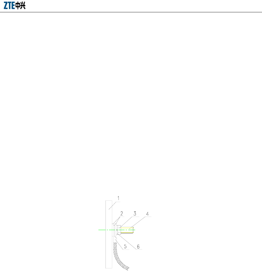
Chapter 5 Power Supply System Installation
5-5
Connect one end of the -48V grounding cable (black, 16 mm2) to the GND
wiring terminal on the filter of the cabinet, and the other end to the GND busbar
of the DC distribution cabinet.
Connect the Protection Earth wire (PE) (yellow green, 25 mm2): one end is
connected to the PE wiring terminal on the P power supply of the cabinet, and
the other end to the PE busbar of the DC distribution cabinet.
3. Intra-module cabinet cascading
In the same module, the GND wiring terminals of each cabinet should be
connected with each other via a shorted cable.
4. Precautions for connecting power cables
While fixing the lug at one end of the DC distribution frame, add the flat washer
and spring washer to make sure that the lug is reliably fixed and that the cable
and wiring bar are in good contact to minimize the contact resistance. For details,
see Fig. 5.3-4.
2-Plain washer
3-Nut
4-Bolt
5-Cable
1-Copper bar
6-Spring washer
Fig. 5.3-4 Connecting Power Cable (1)
When installing lugs, if two or more cables need to be installed on one wiring
post, the lugs should be crossed or installed in a back-to-back way, instead of
being overlapped. If they must be overlapped, they should be bent into 45o or
90o before installation. Note that the big lug should be put under the small one.
It is recommended to adopt this method in all the places where the lugs need to
be installed. For details, see Fig. 5.3-5.
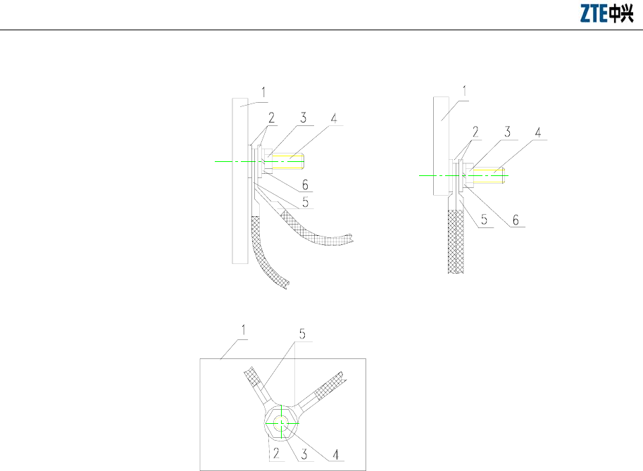
ZXC10 BTSB (V1.0) cdma2000 Base Transceiver Station Installation Manual
5-6
Cross
connection
45º or 50º bending connection Back-to-back
connection
2-Plain washer
3-Nut
4-Bolt
5-Cable
1-Copper bar
6-Spring washer
Fig. 5.3-5 Connecting Power Cable (2)

6-1
6 Grounding System Installation
Summary:
z Overview of BTSB grounding system installation
z Installation procedure of the BTSB grounding system
6.1 Grounding System Overview
This section describes the grounding of the BTSB equipment and the installation of the
grounding device accessories required for the BTSB installation. It covers the
installation of the grounding copper bar, the feeder grounding clip and the lightning
arrester.
The purpose of grounding is to ensure the safety of human body and equipment and to
improve the capability of the equipment to resist electromagnetic interference.
The grounding system consists of indoor part, outdoor part and underground ground
grid of the building.
As to the engineering, the user is responsible for the basic ground grid construction of
the grounding system, the grounding engineering of the iron tower and the building,
and the provision of the connecting point for the indoor and the outdoor grounding
copper bars to connect the ground grid via separate 50 mm2 wires, as shown in Fig.
6.1-1.
The wire of the indoor rack protection ground (PGND) is connected to the indoor
grounding copper bar.
The wire of the BTSB rack working ground (–48VGND) is connected to the working
ground terminal of the BTSB DC power rack.
To ground the lightning arrester, connect it to the outdoor grounding copper bar with a
wire. To ground the feeder, connect each feeder to the outdoor grounding copper bar
through a grounding clip before it enters the equipment room. This is shown in Fig.
6.1-1.
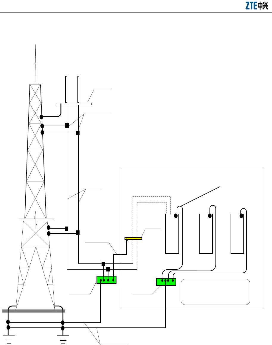
ZXC10 BTSB (V1.0) cdma2000 Base Transceiver Station Installation Manual
6-2
B
T
S
DC power
supply shelf
Other
equipments
Grounding cable 50mm²
Outdoor
busbar
Indoor
busbar
Feeder
All protection grounds
(including cable racks) in the
equipment room are connected
to the indoor grounding bar.
Grounding cable 35 mm²
Feeder grounding clip
Lightening
arrester
shelf
Grounding cable
of the lightning
arrester
Iron tower
platform
Fig. 6.1-1 Wiring for the BTSB Grounding
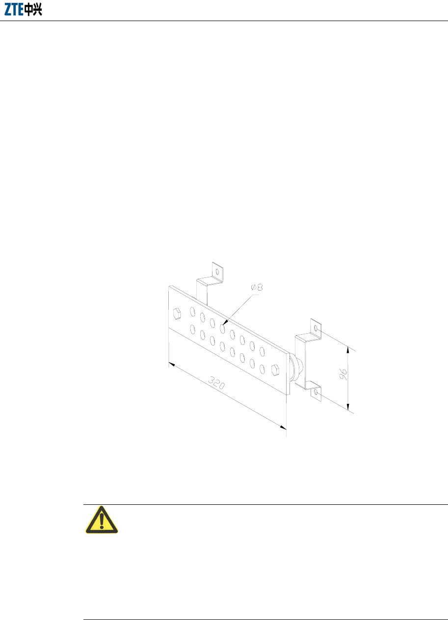
Chapter 6 Grounding System Installation
6-3
6.2 Installing the Grounding System
6.2.1 Installing the Outdoor Grounding Copper Bar
The outdoor grounding copper bar is used for lightning protection grounding. It is
usually installed on the wall outside the feeder window. The best place for it is right
under the feeder window or on the rainproof wall of the feeder well on the roof top. In
principle, it is better to put it close to the feeder window.
During the practical installation, first determine the installation position of the
grounding copper bar by following the engineering design drawing, and then install the
grounding copper bar on the wall with the expansion bolts. See Fig. 6.2-1 for the
structure of the grounding copper bar.
Fig. 6.2-1 Appearance of the Grounding Copper Bar
6.2.2 Installing the Feeder Grounding Clip
Caution:
No installation of grounding clip shall be performed in case of any lightning stroke, lest
bodily injury may be incurred.
When installing the grounding clip, keep the feeder at the joint of the grounding clip
and the feeder straight.
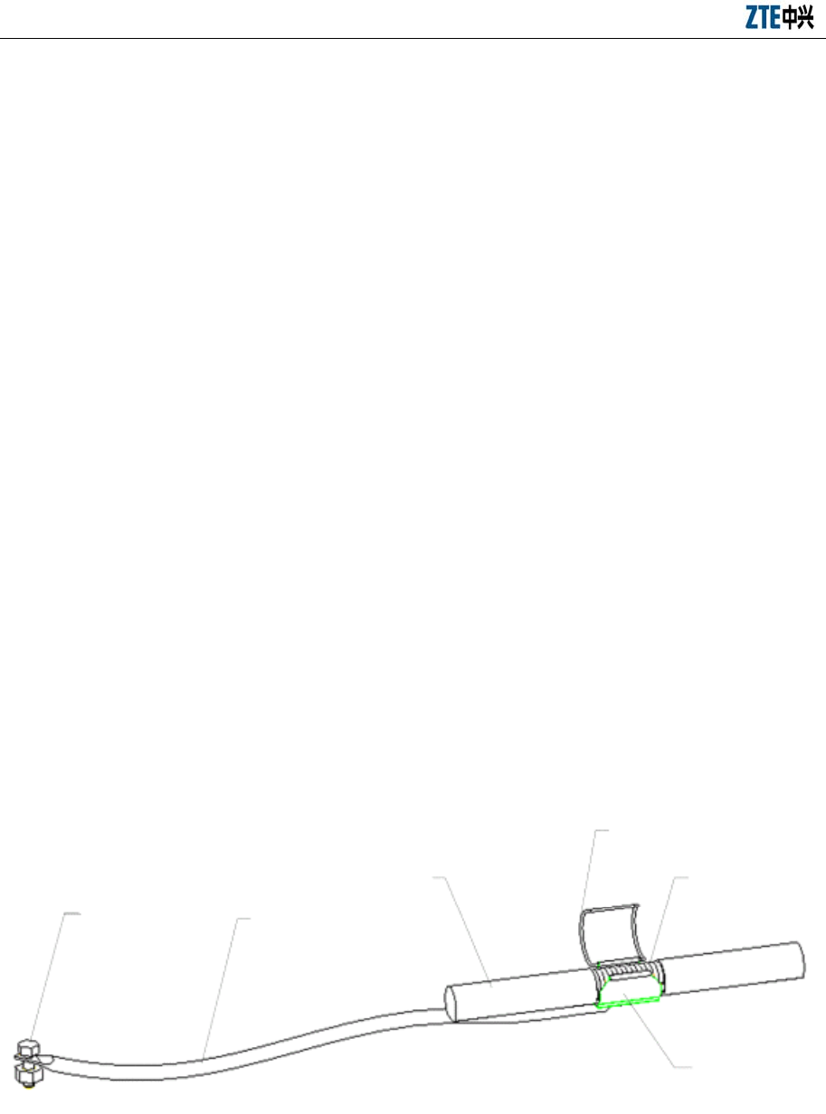
ZXC10 BTSB (V1.0) cdma2000 Base Transceiver Station Installation Manual
6-4
6.2.2.1 Grounding Principles of the Main Feeders
1. Usually, each main feeder should be grounded with grounding clips at least at
three positions: on the tower platform, at the place where the main feeder leaves
the tower for the outdoor cabling rack, and before the cable enters the equipment
room. When the main feeder is over 60m, grounding clips should be added in
the middle of it. Generally, a grounding clip is installed every 20m on the feeder.
2. The antenna feeder system, antenna support and new cabling rack installed on
the roof top should be welded to the lightning protection grid of the building.
The feeder should also be grounded at three positions: where it leaves the
antenna pole, where it leaves the roof top, and where it enters the equipment
room.
3. When the main feeder enters the equipment room from the roof top along the
wall, the outdoor cabling ladder provided by the network operator must be
grounded. If not, urge the network operator to finish it as soon as possible.
6.2.2.2 Installing the Grounding Clip
1. Prepare the tools: Paper cutter, flathead screwdrivers, wrench and sharp-nose
pliers.
2. Select a proper installation position for the grounding clip. Cut open the sheath
of the 7/8" feeder to the size of the grounding clip. The structure of the
grounding clip is shown in Fig. 6.2-2.
Grounding
terminal Grounding cable
Feeder
Locking spring plate of
the grounding cable
External copper
core of the feeder
Copper sheet of the
grounding cable
Fig. 6.2-2 Structure of the Grounding Clip
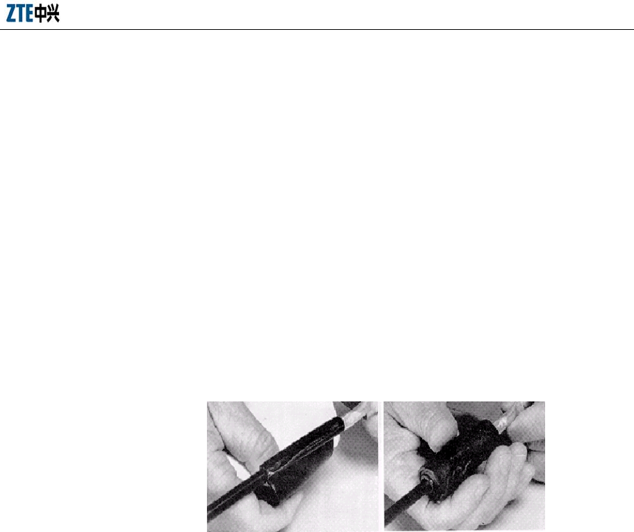
Chapter 6 Grounding System Installation
6-5
3. Lead the grounding cable of the feeder lightning grounding clip to the ground
grid. No reverse direction is allowed. The angle formed by the grounding cable
and the main feeder should not be more than 15o. No reverse folding is allowed.
In the case the antenna feeder system is installed on the tower, the grounding
cable of the grounding clip should be led downward along the tower body.
In the case the antenna feeder system is installed on the roof top, the grounding
cable of the grounding clip should be led close to the building lightning
protection grid.
4. Before installing the grounding clip, wrap the grounding cable at the grounding
clip end that is close to the grounding cable copper sheet with the waterproof
adhesive tape, as shown in Fig. 6.2-3. This can improve the sealing effect and
prevent the rain from falling into the feeder interior along the grounding cable.
Fig. 6.2-3 Wrapping the Grounding Cable of the Grounding Clip with Waterproof Tape
5. Clamp the feeder external conductor with the grounding cable copper sheet and
the locking spring plate, so that the grounding cable copper sheet and the feeder
external conductor are fully meshed.
6. Take the following steps to conduct the waterproof treatment to the joint of the
grounding clip and the feeder:
1) First wrap the waterproof adhesive tapes and then wrap the PVC tapes.
2) To wrap the waterproof adhesive tapes, apply them layer by layer from bottom
to top first, then from top to bottom once again, and finally from bottom to top
thrice, that is, wrap three layers of them. During the process, make sure the
upper layer overlaps the lower layer by about half the width of the tapes.
7. The grounding end of the grounding clip can be connected to the main tower
body or the outdoor cabling rack (connected to the lightning protection grid of

ZXC10 BTSB (V1.0) cdma2000 Base Transceiver Station Installation Manual
6-6
the building) on the roof top. Remove paint and oxide within the radius of about
13 mm at the connection place, and cover the clean area with antioxidant to
ensure good electric contact. When the grounding end is connected, paint
another coat of antirust paint.
8. Before the main feeder enters the room, the grounding end of the grounding clip
can be connected to the outdoor grounding bar.
6.2.3 Installing the Indoor Lightning Arrester
For the wide-band lightning arrester that need not be grounded separately, you may
directly connect it in serial to the place between the main feeder and the indoor cabinet
top jumper. During the installation, the lightning arrester and indoor equipment as the
cabling rack should be insulated.
For the lightning arrester that need be grounded, a lightning arrester frame should be
provided. Please refer to the assembly instructions provided by the supplier for the
assembling of the lightning arrester frame. The installation steps are as follows:
1. Install the lightning arrester on its frame in advance.
During the installation, please note that the connectors at both ends of the
lightning arrester are different: One end is a DIN male connector (DIN-M) and
the other is a DIN female connector (DIN-F). Make sure that the DIN-M
connector of all the lightning arresters installed on the frame are in the same
direction, and the DIN-F connector of all the lightning arresters are in the same
direction. The lightning arrester should be securely installed on the frame and in
close contact with the frame.
2. Fix the assembled lightning arrester to the cabling rack.
Plan the installation position carefully to make both the main feeder and the
cabinet top jumper easily be connected to the lightning arrester and to enable
easy cabling.
The lower part of the lightning arrester frame that is secured to the cabling rack
can be adjusted according to the width of the cabling rack.
When the lightning arrester frame is installed on the cabling rack, make sure that
its DIN-M connector points to the main feeder and its DIN-F connector points to
the connection line from the jumper to the rack.
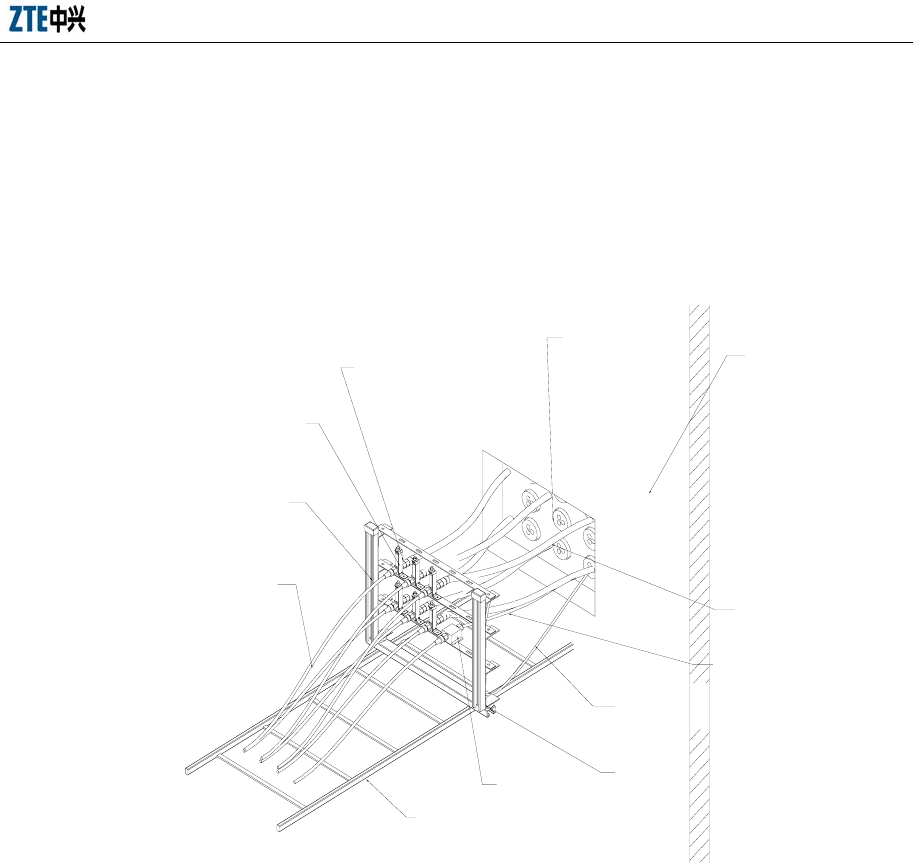
Chapter 6 Grounding System Installation
6-7
3. The lightning arrester is installed indoor. Its grounding cable should be
connected to the outdoor grounding copper bar and should not contact with the
conductor of the indoor cabling rack. The lightning arrester frame is insulated
from the cabling rack.
The installation of the lightning arrester frame is shown in Fig. 6.2-4.
Wall
Feeder
window
Antenna feeder cable
GPS Feeder
GPS lightning
arrester
Cabling
rack
Jumper
Lightening
arrester shelf
Antenna feeder
arrester
Fixing board of
the lightning
arrester
Insulation
tube
The lightning arrester is
connected to the outdoor busbar
through a grounding cable
Fig. 6.2-4 Installing the Lightning Arrester Frame

7-1
7 Cable Installation in Cabinet
Summary:
z BTSB cable types
z Cable installation in the BDS cabinet
z Cable installation in the RFS cabinet
z Types and installation of inter-cabinet cables
7.1 BTSB Cable Installation Overview
ZXC10 BTSB I1 has a BDS cabinet and an RFS that is usually mounted on the RFS
cabinet. This chapter describes the internal cables of the BDS and RFS and the
connection cables between them.
Note:
1. The sequence numbers 1, 2, 3, 4 and so on in the wiring table represent the
numbers of cable components in the wiring diagram.
2. The combinations of the numbers and the terminal category symbols in the
wiring diagram represent the directions of End As or End Bs in the wiring table.
3. Multiple terminals in different directions of the cable component of the same
number are represented with code/B1 and code/B2.
4. Cable direction in the wiring table represents where the terminals of each cable
component will go.
Example
Final connection location identification (or
socket No. + socket pin No.)
Board slot identification (defaulted when there is
no board slot, for example, a transfer socket)
Identification of plug-in box or backplane
Cabinet identification

ZXC10 BTSB (V1.0) cdma2000 Base Transceiver Station Installation Manual
7-2
5. Generally the internal cables have been installed before delivery, so you only
need to check their status after the cabinet installation. Check whether the cables
are properly connected, whether the socket connectors are firmly and properly
inserted, and whether the distributed cables are in good order and without
shortages. If any socket connector is damaged or loosened or any cable is
scratched, try to repair it or re-distribute the cable.
7.2 Installing Cables in the BDS Cabinet
7.2.1 BDS Cable Types
The cables inside the BDS include power cables, optical fibers and internal monitoring
cables. All these cables have been installed before delivery.
7.2.2 Installing Power Cables in the BDS
The power cables inside the BDS include those between the filter and the air switch,
the air switch and the busbar on the right, the busbar and the BDS/FAN backplane.
1. The power cable between the filter -48V and the air switch is a 4 mm2 black
cable identified by the blue heat-shrinkable tubes on both ends.
2. The power cable between the filter -48VGND and a -48VGND terminal of the
right busbar is a 4 mm2 black cable with a lug crimped to the terminal for
busbar.
3. The power cable between the filter PGND and the GND terminal of the right
busbar is a 4 mm2 yellow green cable with a lug crimped to the terminal for
busbar.
4. The power cable between the busbar and the BDS backplane is a 9-core cable,
connecting to -48V, -48VGND and PE according to the identifications at the
backplane and the busbar.
5. The power cable between the busbar and the BDS backplane is a 3-core cable,
connecting to -48V, -48VGND and GND according to the identifications at the
backplane and the busbar.
7.2.3 Installing Optical Fibers
Optical fibers should be installed to meet the configuration requirements in the contract.

Chapter 7 Cable Installation in Cabinet
7-3
They are usually used to connect a remote RF cabinet.
The optical fiber jumpers connect the blind match connectors of the BDS backplane
RIM0 master/slave slots to the optical adaptors on the two BIM6 interface boards. The
jumpers are available with the following types: MTP4-LC-0.5M, BMTP8-LC-0.5M
and BMTP12-LC-0.5M, and the optical fibers are connected in the spectrum order of
blue, orange, green, brown, gray, white, red, black, yellow, purple, pink and cyan.
When installing optical fibers, make sure that the bending radius is larger than 40 mm
to prevent any damages. In addition, the optical fibers should not be bundled too tight
and there should be some space kept between an optical fiber and the clips.
7.2.4 Installing Monitoring Cables in the BDS
The internal monitoring cables of the BDS include cables for front access control
monitoring, CCM board temperature monitoring, CHM board temperature monitoring,
flooding monitoring and fan monitoring.
The internal monitoring cables adopt the one-to-eight structure with the ends being A
and B1 ~ B8. End A is connected to the X154EMSOCKET socket on the BDS
backplane; B1 is connected to the front door position switch along the right side of the
chassis; B2 is designed to be connected to the back door position switch (now idle); B3,
B4 and B5 are temperature sensors connected to the top of the CCM and CHM boards;
B6 is connected to the DB25 socket of the fan plug-in box backplane; B7 is to the
lightning-proof board of the BDS filter; B8 is to the flooding sensor (unnecessary when
the BDS is mounted on the RFS cabinet) at the lower right corner of the BDS.
7.2.5 Internal Cabling Table of the BDS
The internal cabling of BDS is shown in Table 7.2-1.
Table 7.2-1 Internal Cabling Table of BDS
Sequence No. Cable Component
Name End A Direction End B Direction
1 PWR Filter –48v Left connecting hole of the air switch
(front view of cabinet)
2 PWR Right connecting hole of the
air-break (front view of cabinet) Right busbar -48V
3 PWR
Filter -48VGND Right busbar -48VGND
ZXC10 BTSB (V1.0) cdma2000 Base Transceiver Station Installation Manual
7-4
Sequence No. Cable Component
Name End A Direction End B Direction
4 PWR Filter GNDP Right busbar GND
Right busbar -48VGND
5 PWR Tandem grounding on the top of the
BDS cabinet Right busbar GND
BDS-BBDS-X1_1 Right busbar -48V
_7 Right busbar -48VGND
_8, 9 Right busbar GND
_5, 6 Right busbar -48VGND
6 PWR
_2, 3 Right busbar -GNDA
Right busbar -48V/B3
Right busbar -48VGND/B2
7 PWR BDS-BFAN0-X1
Right busbar –GNDP/B1
BDS front door position switch/B1
FAN0TEMP/B3
FAN1TEMP/B4
FAN2TEMP/B5
BFAN0-X5/B6
Filter TPB0/B7
8 MON BBDS-X154/A
Right corner of BDS cabinet/B8
9 GCMRF GCM interface board-GCMANT BBDS-GCMA-ANT
10 GCMRF GCM interface board-GCMANT BBDS-GCMA-ANT
11 JDX Left grounding screw of the plug-in
box Left grounding screw of the front door
12 JDX Right grounding screw of the plug-in
box Right grounding screw of the front door
Internal optical fiber cabling of BDS is shown in Table 7.2-2.
Table 7.2-2 Internal Optical Fiber Cabling of BDS
Sequence
No.
Cable Component
Name End A Direction End B Direction
BDS-BIM6_OPT0-RX (blue)
BDS-BIM6_OPT0-TX (orange)
BDS-BIM6_OPT1-RX (green)
BDS-BIM6_OPT1-TX (brown)
BDS-BIM6_OPT1-TX (grey)
13 BMTP-LC BBDS-RIMA-BMTP
BDS-BIM6_OPT1-TX (white)
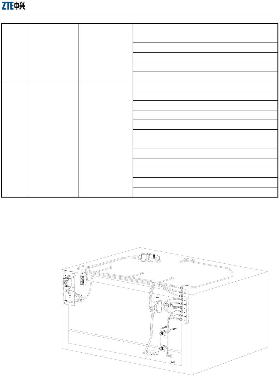
Chapter 7 Cable Installation in Cabinet
7-5
BDS-BIM6_OPT1-TX (red)
BDS-BIM6_OPT1-TX (black)
BDS-BIM6_OPT1-TX (yellow)
BDS-BIM6_OPT1-TX (purple)
BDS-BIM6_OPT1-TX (pink)
BDS-BIM6_OPT1-TX (cyan)
BDS-BIM6_OPT0-RX (blue)
BDS-BIM6_OPT0-TX (orange)
BDS-BIM6_OPT1-RX (green)
BDS-BIM6_OPT1-TX (brown)
BDS-BIM6_OPT1-TX (grey)
BDS-BIM6_OPT1-TX (white)
BDS-BIM6_OPT1-TX (red)
BDS-BIM6_OPT1-TX (black)
BDS-BIM6_OPT1-TX (yellow)
BDS-BIM6_OPT1-TX (purple)
BDS-BIM6_OPT1-TX (pink)
14 BMTP-LC BBDS-RIMA-BMTP
BDS-BIM6_OPT1-TX (cyan)
7.2.6 Internal Cabling of the BDS
The internal cabling of BDS is shown in Fig. 7.2-1.
1/B
2/A
8/B5
8/B4
8/B3
8/B1
6/A
8/A
9/B
10/B
9/A
10/A
7/A
2/B
3/B
4/B
8/B7
1/A
3/A
4/A
8/B6
8/B7
8/B2
7/B
7/B
7/B
Fig. 7.2-1 Internal Cabling of BDS
ZXC10 BTSB (V1.0) cdma2000 Base Transceiver Station Installation Manual
7-6
7.3 RFS Installing Cables in the RFS Cabinet
The cables inside the RFS cabinet include power cable, signal cable, RF cable and
monitoring cable. All these cables have been installed before delivery.
7.3.1 Installing Power Cables
The power cables inside RFS include the power cables between the filter and the air
switch/the –48v bus bar, the busbar and the RFS backplane/linear amplifier LPA and
the grounding cable between the backplane to the busbar.
The connection relationship of the RFS power cable is shown in Table 7.3-1.
Table 7.3-1 Connection Relationship of RFS Power Cables
Sequence No. Cable Component
Name End A Direction End B Direction
15 PWR Filter –48v Left connecting hole of the air switch
(front view of cabinet)
16 PWR Right connecting hole of the
air-break (front view of cabinet) Right busbar -48V
17 PWR Filter -48VGND Right busbar -48VGND
Right busbar -48V
Right busbar -48VGND
18 PWR BDS-BFAN0-X1
Right busbar –PE1PE1
RFS-BTRX-X166_1 Right busbar -48V
_7 Right busbar -48VGND
_8, 9 Right busbar GNDD
_5, 6 Right busbar –PE1
19 PWR
_2, 3 Right busbar -GNDA
RFS-BRFE-X6_1 Right busbar -48V
_7 Right busbar -48VGND
_8, 9 Right busbar GNDD
_5, 6 Right busbar –PE1
20 PWR
_2, 3 Right busbar -GNDA
RFS-BLPA-X72_1 Right busbar -48V
_7 Right busbar -48VGND
_8, 9 Right busbar GNDD
_5, 6 Right busbar –PE2
21 PWR
_2, 3 Right busbar -GNDA
22 PWR RFS-BLPA-LPA0_-48V Left busbar -48V

Chapter 7 Cable Installation in Cabinet
7-7
Sequence No. Cable Component
Name End A Direction End B Direction
RFS-BLPA-LPA1_-48V
RFS-BLPA-LPA2_-48V
23 PWR
RFS-BLPA-LPA3_-48V
Left busbar -48V
RFS-BLPA-LPA4_-48V
24 PWR
RFS-BLPA-LPA5_-48V
Left busbar -48V
25 PWR RFS-BLPA-LPA6_-48V Left busbar -48V
RFS-BLPA-LPA0_-48VGND
26 PWR
RFS-BLPA-LPA1_-48VGND
Left busbar -48VGND
RFS-BLPA-LPA2_-48VGND
27 PWR
RFS-BLPA-LPA3_-48VGND
Left busbar -48VGND
RFS-BLPA-LPA4_-48VGND
28 PWR
RFS-BLPA-LPA5_-48VGND
Left busbar -48VGND
29 PWR RFS-BLPA-LPA6_-48VGND left busbar -48VGND
RFS-right busbar -48VGND
RFS-right busbar GNDP
30 PWR
RFS-right busbar GNDP
Busbar 1 on the top of the RFS
RFS right busbar-PE1 31
PWR
RFS right busbar-PE2
Busbar 2 on the top of RFS
32 FAN LPAFAN0 BLPA-FAN0
33 FAN LPAFAN1 BLPA-FAN1
34 FAN LPAFAN2 BLPA-FAN2
35 JDX Grounding screw of the left column Grounding screw of the left front door
36 JDX Grounding screw of the left column Grounding screw of the left front door
37 JDX Grounding screw of the left column Grounding screw of the left front door
Power cable connection inside RFS is shown in Fig. 7.3-1.
ZXC10 BTSB (V1.0) cdma2000 Base Transceiver Station Installation Manual
7-8
RF_IN
RF_OUT
-48VGND
-48V
-48VGND
RF_OUT
RF_IN
-48V
RF_IN
-48V
-48VGND
RF_OUT
RF_IN
-48V
-48VGND
RF_OUT
-48V
-48VGND
RF_IN
RF_OUT
RF_IN
-48VGND
-48V
RF_OUT
-48VGND
RF_OUT
RF_IN
-48V
BFAN
BTRX
BRFE
BLPA
GNDA
GNDD
PE1
PE2
滤波器
-48V
-48V
空开
GND
F3
F2
F1
-48V
-48VGND
POW9PIN
POW9PIN
POW9PIN
Fig. 7.3-1 Power Cabling in RFS
7.3.2 Installation Interconnection Signal Cables
The signal cable inside the RFS cabinet includes signal interconnection cable and
lightening-proof signal cable. The inter-frame interconnection is between the TRX
layer and the RFE layer and between the TRX layer and the LPA layer. And the
inter-cabinet connection is between the RFS cabinet and BDS cabinet or between RFS
Chapter 7 Cable Installation in Cabinet
7-9
cabinet and BDS cabinet. The lightning-proof signal cable is connected to the TRX
layer through the lightning board on the top of the cabinet and transit on the top of the
cabinet.
The interconnection signal cable connection relationship in RFS cabinet is shown in
Table 7.3-2.
Table 7.3-2 Interconnection Signal Cabling in RFS Cabinet
Sequence
No. Cable Component Name End A Direction End B Direction
38 LINK RFS-BTRX_BBDS RFS-Cabinet top_BDS
39 LINK RFS-BTRX_BBDS RFS-Cabinet top BPWS
40 LINK RFS-BTRX-MON_485 RFS-Cabinet top EXT_MON
41 LINK RFS-BTRX-OUT_MON RFS-Cabinet top OUT_MON _
42 LINK RFS-BTRX_BRFE RFS-BRFE_BTRX
43 LINK RFS-BTRX_BLPA RFS-BLPA_BTRX
7.3.3 Installing Monitoring Cables
The monitoring cables inside RFS include the front door/back door access control
monitoring, RMM/TRX board temperature monitoring, flooding monitoring and fan
plug-in monitoring.
The monitoring cable connection relationship inside RFS cabinet is shown in Table
7.3-3.
Table 7.3-3 Monitoring Cabling in RFS Cabinet
Sequence No. Cable Component
Name End A Direction End B Direction
RFS front door position switch/B1
RFS back door position switch/B2
RFS-TRXFAN0/B3
RFS-TRXFAN1/B4
RFS-LPAFAN0/B5
RFS-LPAFAN1/B6
RFS-BFAN0-X5/B7
RFS cabinet top RPD/B8
44 MON RFS-BTRX-IN_MON/A
Right corner of RFS cabinet/B9
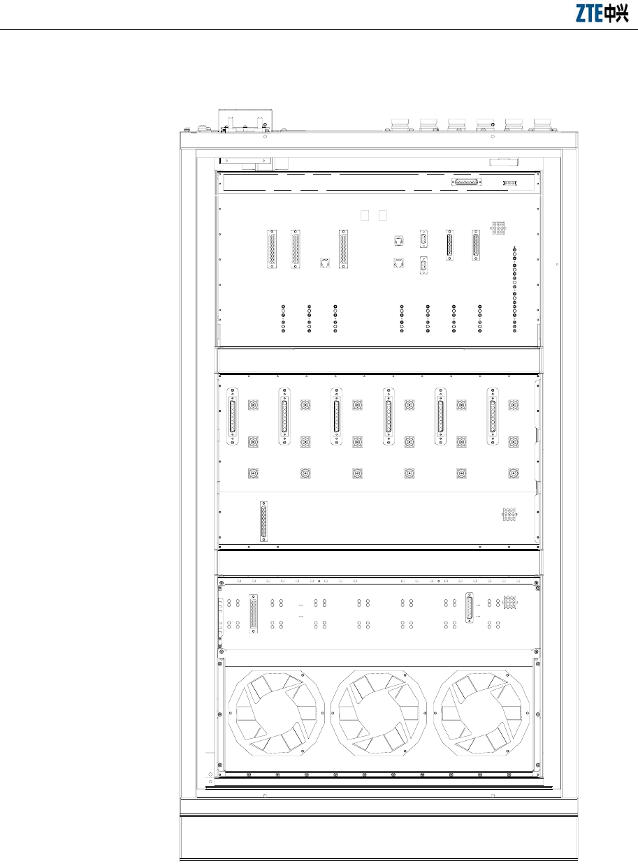
ZXC10 BTSB (V1.0) cdma2000 Base Transceiver Station Installation Manual
7-10
The RFS backplane layout is shown in Fig. 7.3-2.
OUT_MON
RFE0
RX_M
RPT_RX_M
RX_D
BTM_D
TX_FB
RPT_TX
BTM_M
RPT_RX_D
LPA3
RF_IN
RF_OUT
-48VGND
-48V
LPA6 BTRX LPA5
RF_INRF_IN
LPA4
RF_OUT
-48V
-48VGND
RF_OUT
-48VGND
-48V
RF_OUT
-48VGND
-48V
RF_INRF_IN
RF_OUT
-48VGND
-48V
LPA2
RF_IN
RF_OUT
-48VGND
-48V
LPA1 LPA0
DB25
RPT_RX_D
RPT_RX_M
TXTX RPT_RX_D
RPT_RX_D
BTM_M
RPT_TX
TX_FB
BTM_M
RPT_TX
TX_FB
BTM_M
RPT_TX
TX_FB
BTM_D
RX_D
RX_M
RPT_RX_M
RPT_RX_M
BTM_D
RX_D
RX_M
ANT1
RFE5
ANT0
ANT1
BTM_D
RX_D
RX_M
ANT0
RFE4 RFE3
TX TX TX
RPT_RX_D
RPT_RX_D
BTM_M
RPT_TX
TX_FB
BTM_M
RPT_TX
TX_FB
ANT0
ANT1
BTM_D
RX_D
RPT_RX_M
RX_M
ANT1
RFE2
ANT0
RX_D
RX_M
BTM_D
RPT_RX_M
ANT1
RFE1
ANT0
TFB
DRX
MRX
TX
MRXMRX
DRX DRX
TFB
TX
TFB
TX
BBDS
BLPA
RSM TSM
BRFE
TRX5TRX6 TRX4
TFB
DRX
MRXMRX
DRX
TX
TFB
TX
MRXMRX
DRX DRX
TFB
TX TX
TFB
TRX3
IN_MONBPWS
TRX1TRX2 TRX0
RF_IN
BLPA
-48VGND
TX
ANT1
BRFE
ANT0
EXT MON
BTRX
BFAN
BRFE
BTRX
Fig. 7.3-2 RFS Backplane Layout
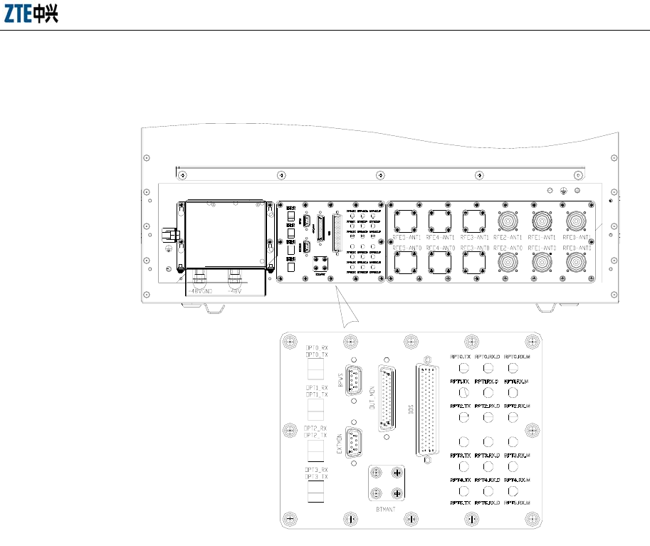
Chapter 7 Cable Installation in Cabinet
7-11
The layout of the interface board on the top of RFS cabinet is shown in Fig. 7.3-3.
Fig. 7.3-3 Layout of the Interface Board on the Top of RFS Cabinet
The cabling of signal cables and monitoring cables inside RFS is shown in Fig.
7.3-4.
ZXC10 BTSB (V1.0) cdma2000 Base Transceiver Station Installation Manual
7-12
38/A
42/A
43/A 40/A
39/A
41/A 44/A
44/B4 44/B3
44/B1
38/B
39/B
44/B8 40/B 41/B 44/B2
44/B7
44/B9
44/B5
44/B6
43/B
42/B
Fig. 7.3-4 Signal and Monitoring Cabling in the RFS
7.3.4 Installing RF Cables
The RF cables in the RFS cabinet refers to the FR cables from TRX to RFE, TRX to
LPA, RFE to LPA and RFE to antenna feeder system. The first two cables are fully

Chapter 7 Cable Installation in Cabinet
7-13
configured in 8-carrier 3-section mode and the RF cable from RFE to the antenna
feeder system is installed according to the specific configuration with two cables for
one RFE.
The RF cable connection relationship inside an RFS cabinet is shown in Table 7.3-4.
Table 7.3-4 RF Cable Connection in the RFS cabinet
Sequence No. Cable Component
Name
Length End A Direction End B Direction
45 3GRF22-001 340 BTRX-TRX0-MRX_TRX BRFE-RFE0-RX_M
46 3GRF22-001 340 BTRX-TRX0-DRX_TRX BRFE-RFE0-RX_D
47 3GRF22-002 380 BTRX-TRX0-TFB_TRX BRFE-RFE0-TX_FB
48 3GRF22-001 340 BTRX-TRX1-MRX_TRX BRFE-RFE1-RX_M
49 3GRF22-001 340 BTRX-TRX1-DRX_TRX BRFE-RFE1-RX_D
50 3GRF22-002 380 BTRX-TRX1-TFB_TRX BRFE-RFE1-TX_FB
51 3GRF22-002 380 BTRX-TRX2-MRX_TRX BRFE-RFE2-RX_M
52 3GRF22-002 380 BTRX-TRX2-DRX_TRX BRFE-RFE2-RX_D
53 3GRF22-004 410 BTRX-TRX2-TFB_TRX BRFE-RFE2-TX_FB
54 3GRF22-004 410 BTRX-TRX3-MRX_TRX BRFE-RFE3-RX_M
55 3GRF22-004 410 BTRX-TRX3-DRX_TRX BRFE-RFE3-RX_D
56 3GRF22-006 440 BTRX-TRX3-TFB_TRX BRFE-RFE3-TX_FB
57 3GRF22-004 410 BTRX-TRX4-MRX_TRX BRFE-RFE4-RX_M
58 3GRF22-004 410 BTRX-TRX4-DRX_TRX BRFE-RFE4-RX_D
59 3GRF22-006 440 BTRX-TRX4-TFB_TRX BRFE-RFE4-TX_FB
60 3GRF22-006 440 BTRX-TRX5-MRX_TRX BRFE-RFE5-RX_M
61 3GRF22-006 440 BTRX-TRX5-DRX_TRX BRFE-RFE5-RX_D
62 3GRF22-007 470 BTRX-TRX5-TFB_TRX BRFE-RFE5-TX_FB
63 3GRF22-008 1060 BTRX-TRX0-TX_TRX BLPA-LPA0-RF_IN
64 3GRF22-009 1180 BTRX-TRX1-TX_TRX BLPA-LPA1-RF_IN
65 3GRF22-010 1300 BTRX-TRX2-TX_TRX BLPA-LPA2-RF_IN
66 3GRF22-011 1420 BTRX-TRX3-TX_TRX BLPA-LPA3-RF_IN
67 3GRF22-010 1300 BTRX-TRX4-TX_TRX BLPA-LPA4-RF_IN
68 3GRF22-009 1180 BTRX-TRX5-TX_TRX BLPA-LPA5-RF_IN
69 3GRF30-001 400 BRFE-RFE0-TX_R BLPA-LPA0-RF_OUT
70 3GRF30-001 400 BRFE-RFE1-TX_R BLPA-LPA1-RF_OUT
71 3GRF30-001 400 BRFE-RFE2-TX_R BLPA-LPA2-RF_OUT
72 3GRF30-002 430 BRFE-RFE3-TX_R BLPA-LPA3-RF_OUT
73 3GRF30-002 430 BRFE-RFE4-TX_R BLPA-LPA4-RF_OUT
74 3GRF30-002 430 BRFE-RFE5-TX_R BLPA-LPA5-RF_OUT
75 3GRF20-001 630 BRFE-RFE0-ANT0 RFS cabinet top-RFE0_0

ZXC10 BTSB (V1.0) cdma2000 Base Transceiver Station Installation Manual
7-14
Sequence No. Cable Component
Name
Length End A Direction End B Direction
76 3GRF20-002 710 BRFE-RFE0-ANT1 RFS cabinet top-RFE0_1
77 3GRF20-003 760 BRFE-RFE1-ANT0 RFS cabinet top-RFE1_0
78 3GRF20-004 840 BRFE-RFE1-ANT1 RFS cabinet top -RFE1_1
79 3GRF20-004 840 BRFE-RFE2-ANT0 RFS cabinet top-RFE2_0
80 3GRF20-005 920 BRFE-RFE2-ANT1 RFS cabinet top-RFE2_1
81 3GRF20-007 1260 BRFE-RFE3-ANT0 RFS cabinet top-RFE3_0
82 3GRF20-008 1310 BRFE-RFE3-ANT1 RFS cabinet top-RFE3_1
83 3GRF20-009 1110 BRFE-RFE4-ANT0 RFS cabinet top-RFE4_0
84 3GRF20-010 1210 BRFE-RFE4-ANT1 RFS cabinet top -RFE4_1
85 3GRF20-006 1010 BRFE-RFE5-ANT0 RFS cabinet top-RFE5_0
86 3GRF20-011 1040 BRFE-RFE5-ANT1 RFS cabinet top-RFE5_1
Note: Cables 81 ~ 86 are configured as required usually for the high carrier.
The RF cable interface of RFS cabinet is shown in Fig. 7.3-5 and the cabling of the RF
cables in RFS is shown in Fig. 7.3-6.
Chapter 7 Cable Installation in Cabinet
7-15
Fig. 7.3-5 RF Cable Interface in RFS
ZXC10 BTSB (V1.0) cdma2000 Base Transceiver Station Installation Manual
7-16
71/B
48-50/B
80/A
79/A
65/A
53/A
52/A
51/A
60-62/B
67/B
74/B
68/B 66/B 65/B
72/B
73/B
54-56/B
74/A 73/A
57-59/B
72/A 71/A
51-53/B
60/A
61/A
68/A
62/A 57/A
58/A 55/A
67/A
59/A
66/A
56/A
54/A
64/B 63/B
70/B 69/B
75/A
76/A
70/A 69/A
77/A
78/A
49/A 46/A
63/A
47/A
45/A
64/A
50/A
48/A
78/A
77/A
79/A
80/A 76/B
75/B
45-47/B
Fig. 7.3-6 RF Cabling in the RFS
7.3.5 Connecting Optical Fibers
The optical fibers in RFS refer to the optical fibers between the TRX subsystem and
the BDS subsystem. They are connected from the RMM board on the BTRX backplane
to the adaptor on the cabinet top for a transition. The optical fibers are configured
pursuant to the contract. Optical fiber connection in RFS cabinet.

Chapter 7 Cable Installation in Cabinet
7-17
Table 7.3-5 Optical Fiber Connection Table in RFS Cabinet
Sequence
No. Cable Component Name End A Direction End B Direction
RFS-Cabinet top-OIBA_RX_0
RFS-Cabinet top-OIBA_TX_0
RFS-Cabinet top-OIBA_RX_1
87 BMTP4-LC RFS-BTRX-RMMA-OIBA
RFS-Cabinet top-OIBA_TX_1
RFS-Cabinet top-OIBB_RX_0
RFS-Cabinet top-OIBB_TX_0
RFS-Cabinet top-OIBB_RX_1
88 BMTP4-LC RFS-BTRX-RMMB-OIBB
RFS-Cabinet top-OIBB_TX_1
The overlong part of the optical fiber should be reeled into a ring shape with a diameter
bigger than 80 mm and be hung on the horizontal cabling rack at the TRX layer loose
with a clip.
7.4 Types and Installation of Inter-Cabinet Cables
The inter-cabinet cables include the interconnection cables between BDS and RFS
(connect with the remote RFS via an optical fiber) an interconnection cable connecting
the PWS cabinet and an E1 cable connecting BSC.
7.4.1 Installing BDS-RFS Interconnection Cable
The interconnection cables between the BDS cabinet and the RFS cabinet is used for
all the signal connection between the two cabinets. End A is connected to the LRPS
interface on the BIM4 interface of the BDS cabinet, while End B is connected to the
BDS interface on the interface board on the top of the RFS cabinet. The connection
relationship between the interconnection cables is as shown in Fig. 7.4-1.
ZXC10 BTSB (V1.0) cdma2000 Base Transceiver Station Installation Manual
7-18
AB
Fig. 7.4-1 Interconnection Cables between BDS and RFS Cabinets
7.4.2 Installing Optical Fibers
The clock signals and other interconnection signals between BDS and the remote RFS
cabinet are transmitted through the optical fibers. There are four pairs of active/standby
optical fibers. The optical interface connecting the BDS and RFS cabinets are LC
connectors, which is connected through the optical fiber connector box. For the
connection relationship, see the following Table 7.4-1.
Table 7.4-1 Optical Fiber Connection between BDS and RFS
Sequence
No.
Cable Component
Name End A Direction End B Direction
1 LC/PC-LC/PC BDS-S11-BIM6_OPT0_TX RFS-Cabinet top-OPT0_RX
2 LC/PC-LC/PC BDS-S11-BIM6_OPT0_RX RFS-Cabinet top-OPT0_TX
3 LC/PC-LC/PC BDS-S11-BIM6_OPT1_TX RFS-Cabinet top-OPT1_RX
4 LC/PC-LC/PC BDS-S11-BIM6_OPT1_RX RFS-Cabinet top-OPT1_TX
5 LC/PC-LC/PC BDS-10-BIM6_OPT0_TX RFS-Cabinet top-OPT2_RX
6 LC/PC-LC/PC BDS-S10-BIM6_OPT0_RX RFS-Cabinet top-OPT2_TX
7 LC/PC-LC/PC BDS-S10-BIM6_OPT1_TX RFS-Cabinet top-OPT3_RX
8 LC/PC-LC/PC BDS-S10-BIM6_OPT1_RX RFS-Cabinet top-OPT3_TX
7.4.3 Installing Interconnection Cables with BPWS
The cables for interconnecting with the BPWS cabinet have the DE9-core connector at
the two ends. If BDS cabinets exist, connect BDS with BPWS, while if there is no BDS
at the local end, connect the DE9-core socket on the top of the RFS cabinet to BPWS.
See Table 7.4-2 for the specific signal connection relation.

Chapter 7 Cable Installation in Cabinet
7-19
Table 7.4-2 Signal Connection Relationships of the Interconnecting Cable with BPWS
Pin No. at End A 1 2 3 4 5 6 7 8
9 Shell
Length (mm)
Color (White/Blue) (White/Orange) (White)
(White/Brown) (Red/Blue) Shielded wire
1200
Pin No. at End B 1 2 3 4 5 6 7 8
9 shell
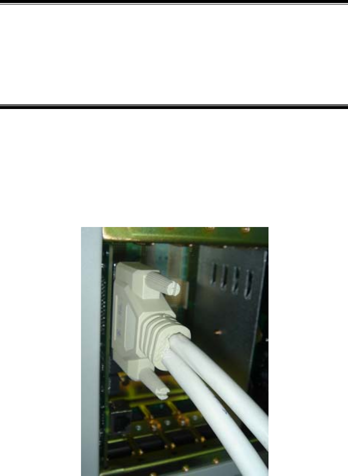
8-1
8 Trunk Cable Installation
Summary:
z Installation methods of the BTSB trunk cables
z Preparation of the E1 cables
z Conversion from the 75 Ω trunk cable to the 120 Ω trunk cable
8.1 Installing E1 Cables
E1 cables are available in two types, 75 Ω and 120 Ω cables. The connectors
connecting BDS are equipped with a high-density D_SUB44 core. It is shown in Fig.
8.1-1.
Fig. 8.1-1 D_SUB44-core Connector Connecting BDS
8.1.1.1 75 Ω E1 Cable
A 75 Ω E1 cable includes 8 channels of E1 signals using two 8-core 75 Ω micro
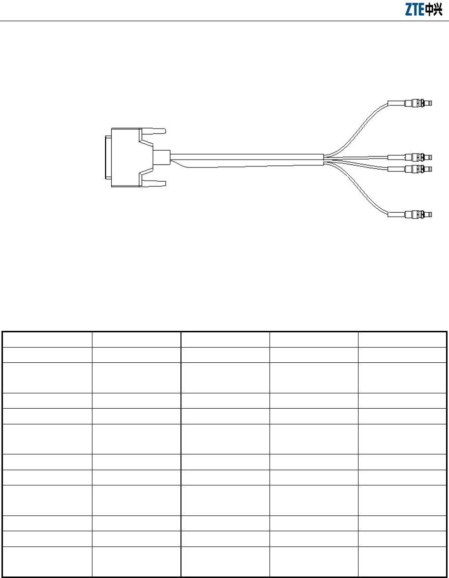
ZXC10 BTSB (V1.0) cdma2000 Base Transceiver Station Installation Manual
8-2
coaxial cables of the type SFYE-75-2-1*8. The diameter of the single-core cable
should be less than 2.05 mm. The structure of a 75 Ω E1 cable is shown in Fig. 8.1-2.
Fig. 8.1-2 Structure of 75 Ω E1 Cable
The internal cable connection relationship of a 75 Ω E1 cable is shown in Table 8.1-1.
Table 8.1-1 Internal Connection Relationship of a 75 Ω E1 Cable
Signal Definitions IN0 OUT0 IN1 OUT1
Pin No. at End A 22 23 24 25 1 2 3 4
Cable Sequence No. 1-1-internal
1-1-external
1-2-internal
1-2-external
1-3-internal
1-3-external
1-4-internal
1-4-external
Signal Definitions IN2 OUT2 IN3 OUT3
Pin No. at End A 5 6 7 8 9 10 11 12
Cable Sequence No. 1-5-internal
1-5-external
1-6-internal
1-6-external
1-7-internal
1-7-external
1-8-internal
1-8-external
Signal Definitions IN4 OUT4 IN5 OUT5
Pin No. at End A 13 14 43 44 39 40 41 42
Cable Sequence No. 2-1-internal
2-1-external
2-2-internal
2-2-external
2-3-internal
2-3-external
2-4-internal
2-4-external
Signal Definitions IN6 OUT6 IN7 OUT7
Pin No. at End A 35 36 37 38 31 32 33 34
Cable Sequence No. 2-5-internal
2-5-external
2-6-internal
2-6-external
2-7-internal
2-7-external
2-8-internal
2-8-external
Note: “1-1-internal, 1-1-external” refers to the internal and external conductors of the No.1 core wire of the first 8-core cable.
The labeled cable is the first 8-core cable. The signal sequence at End B is: IN0, OUT0
IN3, OUT3 for the first coaxial cable and IN4, OUT4 IN7 and OUT7 for the second
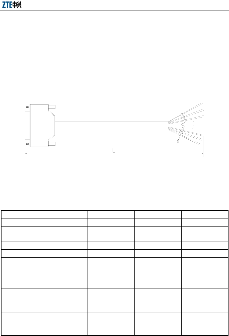
Chapter 8 Trunk Cable Installation
8-3
coaxial cable.
End A of the E1 cable is connected to the E1 interface on the BIM0 interface board at
the back of BDS cabinet, while End B is connected to the silk screen interface on the
transfer board at the feeder rack.
8.1.1.2 120 Ω E1 Cable
The 120 Ω E1 cable has three cores with the type being PCM-120-16*2*0.4sn. The
structure of the cable is shown in Fig. 8.1-3.
Fig. 8.1-3 Structure of 120 Ω E1 Cable
The internal cable connection relationship of an E1 cable is shown in Table 8.1-2.
Table 8.1-2 Internal Connection Relationship of the 120 Ω E1 Cable
Signal Definitions IN0 OUT0 IN1 OUT1
Pin No. at End A 22 23 24 25 1 2 3 4
Cable Color Blue/1 red blue/1
black
Pink/1 red pink/1
black
Green/1 red green/1
black
Yellow/1 red yellow/1
black
Signal Definitions IN2 OUT2 IN3 OUT3
Pin No. at End A 5 6 7 8 9 10 11 12
Cable Color Grey/1 red grey/1
black
Blue/2 red blue/2
black
Pink/2 red pink/2
black
Green/2 red green/2
black
Signal Definitions IN4 OUT4 IN5 OUT5
Pin No. at End A 13 14 43 44 39 40 41 42
Cable Color Yellow/2 red
yellow/2 black
Grey/2 red grey/2
black
Blue/3 red blue/3
black
Pink/3 red pink/3
black
Signal Definitions IN6 OUT6 IN7 OUT7
Pin No. at End A 35 36 37 38 31 32 33 34
Cable Color Green/3 red green/3
black
Yellow/3 red
yellow/3 black
Grey/3 red grey/3
black
Blue/4 red blue/4
black

ZXC10 BTSB (V1.0) cdma2000 Base Transceiver Station Installation Manual
8-4
Note: Blue/1 red indicates that there is one red identification on the blue line, and
pink/2 red indicates that there are two identifications on the pink line.
End A of E1 cable is connected to the E1 interface on the BIM0 interface board at the
back of the BDS chassis and End B is connected to DDF rack along the cabling ladder.
The correspondence between the pair at End B and signals is shown in Table 8.1-3.
Table 8.1-3 Correspondence between Cable Pairs at End B and Signals
1 (IN0) 2 (OUT0) 3 (IN1) 4 (OUT1)
Blue/1 red blue/1 black Pink/1 red pink/1 black Green/1 red green/1 black Yellow/1 red yellow/1
black
5(IN2) 6(OUT2) 7(IN3) 8(OUT3)
Grey/1 red grey/1 black Blue/2 red blue/2 black Pink/2 red pink/2 black Green/2 red green/2 black
9(IN4) 10(OUT4) 11(IN5) 12(OUT5)
Yellow/2 Red Yellow/2
Black
Grey/2 Red Grey/2 Black Blue/3 Red Blue/3 Black Pink/3 Red Pink/3 Black
13(IN6) 14(OUT6) 15(IN7) 16(OUT7)
Green/3 red green/3 black Yellow/3 red yellow/3 black Grey/3 red grey/3 black Blue/4 red blue/4 black
8.2 Making E1 Cables
This section describes the preparation of the E1 cables.
1. Making the CC4Y-J32 connector for the E1 cable
The method and procedure to make the connector at the ZXC10 BTSB I1 side is
shown in Fig. 8.2-1.
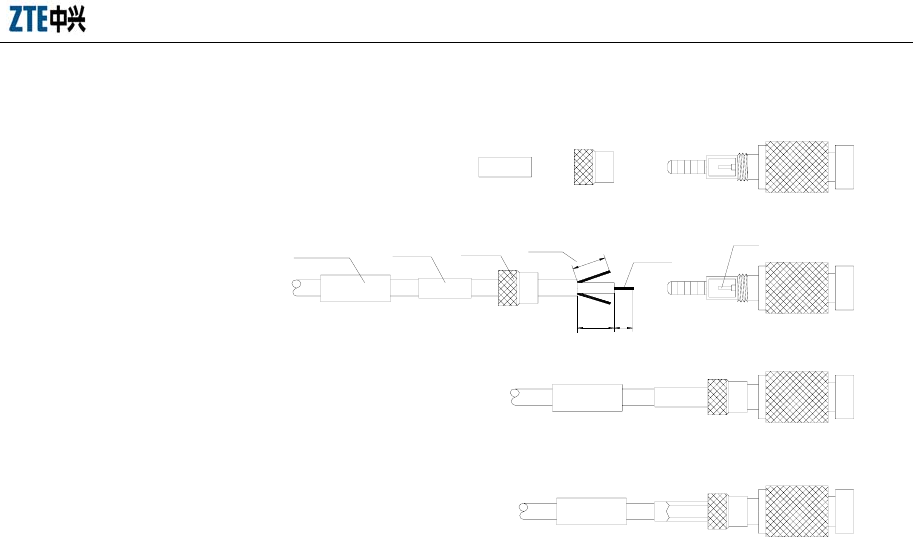
Chapter 8 Trunk Cable Installation
8-5
7 3
6
Shielding
layer Core wire
Soldering pin
Part 1 Part 2 Part 3
d)
c)
b)
a)
Heat-shrinkable
tube Part 1 Part 2
Fig. 8.2-1 Assembly of the CC4Y-J32 Coaxial Cable Connector
1) The plug parts of the CC4Y-J32 RF coaxial connector, as shown in a) of Fig.
8.2-1.
2) As shown in b) of Fig. 8.2-1, slip parts 1 and 2 around the cable, peel one end of
the cable, tin the core wire, and then open the shielding layer forth to help
inserting the plug crimping position.
3) After welding the core wire, screw part 2 to part 3, as shown in c) of Fig. 8.2-1.
4) Mount the crimping tube and crimp it with a special tool, as shown in d) of Fig.
8.2-1.
2. Make the coaxial connector plug at the DDF side
The structure of the connector is shown in Fig. 8.2-2.
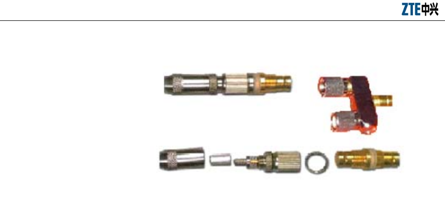
ZXC10 BTSB (V1.0) cdma2000 Base Transceiver Station Installation Manual
8-6
Y test plug
Cable connector Socket
Socket
Cable connector
Fig. 8.2-2 Coaxial Connector of the DDF
Follow these steps to make a coaxial connector plug:
1) Peel the outer jacket of the cable for about 14 mm, as shown in a) of Fig. 8.2-3 .
2) Slip in sequence the cable connector sheath, the heat-shrink tube and the
crimping tube. Open the shielding net forth with a net opening sleeve (or do it
manually). And then strip the internal insulation layer to expose 3 mm of the
internal conductor, as shown in b) of Fig. 8.2-3 .
3) Insert the core into the plug. Pay attention that the core wire must be inserted
into the soldering pin at the back of the inner conductor, solder it securely, and
trim the shielding mesh with 6 mm exposed, as shown in Fig. 8.2-3 c).
4) Push the crimping tube and the shielding net to the end of the connector, as
shown in d) of Fig. 8.2-3 .
5) Use crimp pliers to crimp the crimping tube into a regular hexahedron. During
the operation, crimp twice in different angles, as shown in Fig. 8.2-3 e).
6) Slip the heat shrink tube onto the crimped tube, heat it around with a hair drier
to have it shrink, and then screw the tail cover, as shown in Fig. 8.2-3 f).
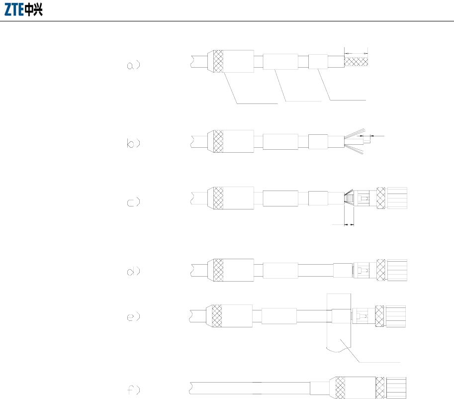
Chapter 8 Trunk Cable Installation
8-7
Crimping
tube
Hot shrink
tube
Cable
connector
sheath
Crimping
pliers
14
3
6
Fig. 8.2-3 Assembling DDF Coaxial Cable Plug
3. Trunk cable test
The internal conductors of the connector at both ends and the inner conductors
of the coaxial cable should be soldered securely without dry joint.
In the connector at both ends, the internal conductors are conductive and the
external conductors are conductive, while the internal and external conductors
should not be shorted.
8.3 Converting 75 Ω Trunk Cable to 120 Ω Trunk Cable
Currently the impedance converter coded "5160087" is used to convert the 75 Ω trunk
cable into the 120 Ω trunk cable. The following section describes the impedance
converter.
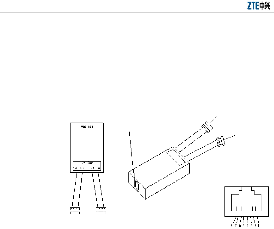
ZXC10 BTSB (V1.0) cdma2000 Base Transceiver Station Installation Manual
8-8
8.3.1 Appearance of the Impedance Converter
Each converter is to serve for only one E1 cable. The interface for the 75 Ω trunk cable
is a BNC connector, while that for the 120 Ω trunk cable is an 8P8C network cable
socket.
The appearance and the connection relationship of the impedance converter are shown
in Fig. 8.3-1.
RJ-45 Socket
RX in
Connector
TX out
Connector
RJ-45 Socket
Fig. 8.3-1 Appearance and Wiring of an Impedance Converter
8.3.2 Wiring of the Impedance Converter
The wiring of the impedance converter is shown in Fig. 8.3-2:
1. Pins 1 and 2 are connected to the balanced signal. The balanced signal is
converted into unbalanced signal by the converting chip and is then output from
the coaxial TX end.
2. The unbalanced signal is converted into balanced signal at the RX end by the
converting chip and is then connected to the RJ45 socket.
3. The shielding layer at the RX end can be connected to Pin 6 of the RJ45 socket
through jumper JP2.
4. Usually, the shielding layer of the TX end is directly connected to the shielding
layer of the RJ45 connector. It may also be connected to Pin 3 of the RJ45
socket through jumper JP1.
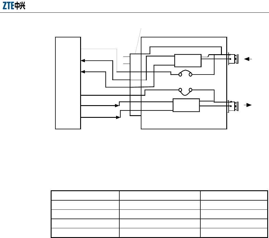
Chapter 8 Trunk Cable Installation
8-9
Chip
Chip
Network
device
2
1
4
3
5
RJ-45 socket
RX shielding
8
7
6
JP1GND
Signal
JP2
Signal
GND
TX
RX
TX shielding
Fig. 8.3-2 Wiring of the Impedance Converter
See Table 8.3-1 for the specific wiring relation.
Table 8.3-1 Wiring Correspondence of the Impedance Converter
RJ45 Socket Chip Function
1&2 JP1 TX pair
3 JP1 TX shielded
4&5 JP2 RX pair
6 JP2 RX shielded
8.3.3 Technical Parameters of the Impedance Converter
Technical parameters of the impedance converter are as follows:
1. ITU-T G703 standard compliant
2. Rate: 2.048 Mbps
3. Balanced interface: 120 Ω RJ45 (8P8C, with shielded end)
4. Unbalanced interface: 75 Ω BNC (female)
5. Temperature: 0 °C – 50 °C
6. Humidity: 5% - 95% (non-condensing)
7. External power supply: unnecessary
8. Insulation: 100V
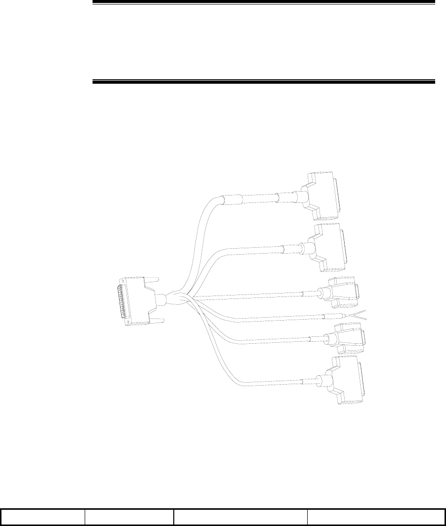
9-1
9 Monitoring System Installation
Summary:
z Composition of the monitoring system
z Installation procedure of the monitoring system
9.1 Composition of the Monitoring System
The structure of an external monitoring cable of an RFS is shown in Fig. 9.1-1.
A End
B1 End
B2 End
B3 End
B4 End
B5 End
B6 End
Fig. 9.1-1 Structure of External Monitoring Cable of RFS
The content of labels placed on the connectors are as shown in Table 9.1-1.
Table 9.1-1 Content of Labels Placed on the Connectors
End A End B1 End B2 End B3

ZXC10 BTSB (V1.0) cdma2000 Base Transceiver Station Installation Manual
9-2
End A End B1 End B2 End B3
Cable code/A
OUT_MON
Cable code/B1 ~ B10
SW_IN
Cable code/B11 ~ B15
CTRL_OUT
Cable code/B16
HUM. TEMP_MON
End B4 End B5 End B6
Cable code/B17
DOOR_MON
Cable code/B18
INFRARED_MON
Cable code/B19
SMOG_MON
End A is connected to the socket OUT_MON on the BIM4 interface board of the BDS
cabinet (if there is no BDS, it is connected to the OUT_MON D_SUB44 socket on the
top of RFS cabinet). B1 to B3 and B5 to B6 are transferred to the installation board of
the feeder rack. End B1 provides input for 10 pairs of switches, End B2 outputs 5 pairs
of control variables, End B3 connects with the cables of temperature and humidity
sensor, End B4 connects with the access control sensor of the equipment room, B5
connects with the infrared sensor cable and B6 connects with the smog sensor cable.
The installation of the temperature/humidity sensor and the smog sensor are the same
as that of the IS95/1X system.
9.2 Installing the Monitoring System
9.2.1 Installing the Indoor Smog Sensor
The smog sensor should be installed on the ceiling as close to the rack as possible. The
installation steps are as follows:
1. As shown in b) of Fig. 9.2-1, separate the upper part and the lower part of the
smog sensor.
2. Connect the green and red cables (as shown in a) of Fig. 9.2-1) at End B of the
10 m smog sensor cable to the two terminals marked 1 and 3 at the bottom of the
smog sensor (as shown in c) of Fig. 9.2-1).
3. Reassemble the upper and lower parts together, as shown in b) of Fig. 9.2-1.
4. Connect the DB25 plug at End A to the End B6 of the external monitoring cable
of RFS.
The terminal connection of the smog sensor cable connector is described in Fig. 9.2-1.
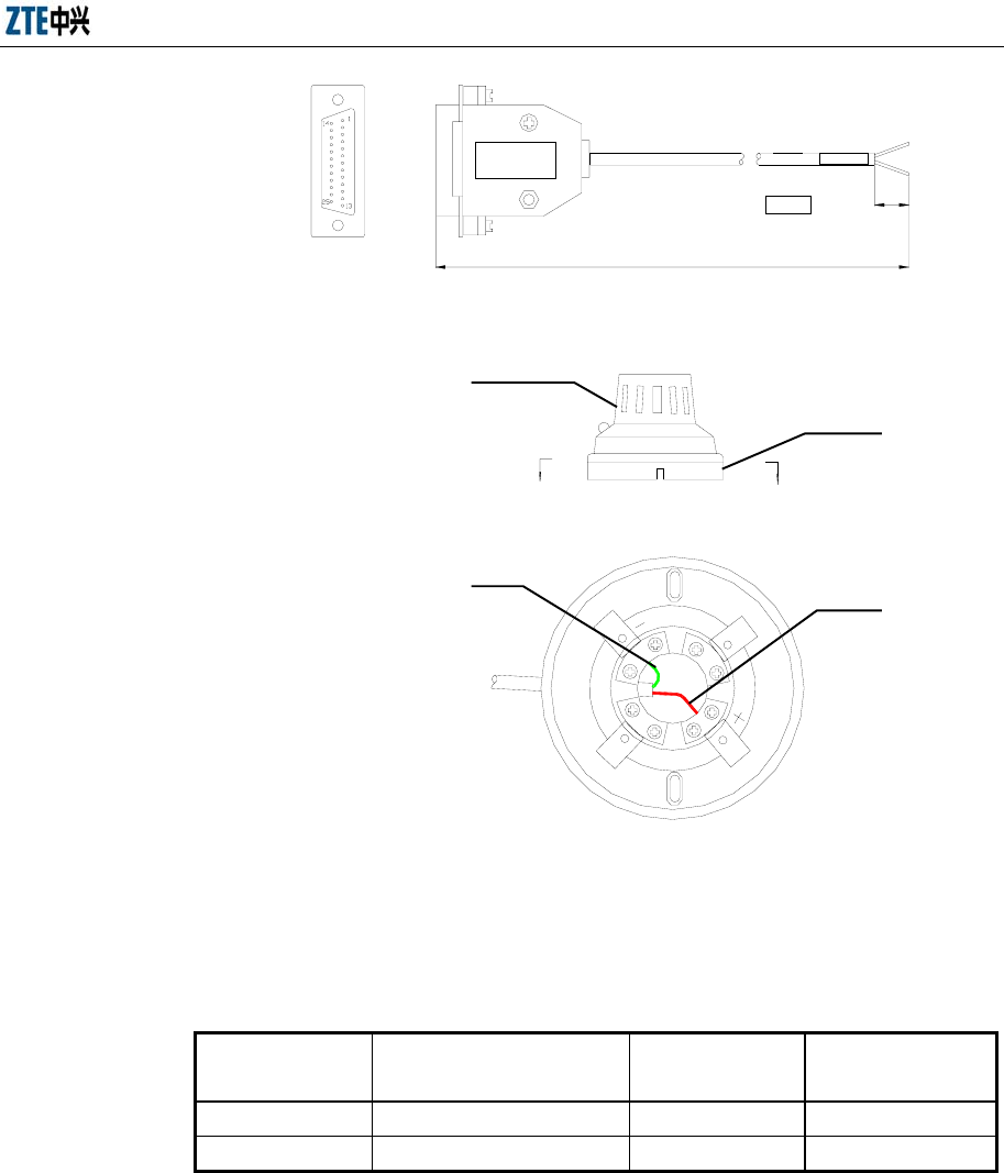
Chapter 9 Monitoring System Installation
9-3
B-B
Pin No. sequence of the
25-pin male connector
End
A End B
Red
Green
30
10m
Label
B
B
1
23
4
Lower part of the
smog sensor
Upper part of the
smog sensor
(b)
(a)
(c)
Red line
Green line
Label
Fig. 9.2-1 Installing the Smog Sensor Base
Table 9.2-1 Terminal Connection of the Smog Sensor Cable Connector
Signal Definitions 25-pin Male Connector at
End A
Cable Sequence
No.
Smog Sensor Base at
End B
+12V 10 Red 3 (+)
-12V 11 Green
1 (-)
9.2.2 Installing the Indoor Temperature/Humidity Sensor
The temperature/humidity sensor is mounted on the wall. Select a proper position on
the wall in the equipment room, drill a hole of ϕ 6, put in a rubber cork, tighten the
captive screw, and finally hang the sensor on the wall through the hole. The dimensions
of the sensor are shown in b of Fig. 9.2-2.
Both the two ends of the sensor are the DB9 plug. The male plug at End A is connected
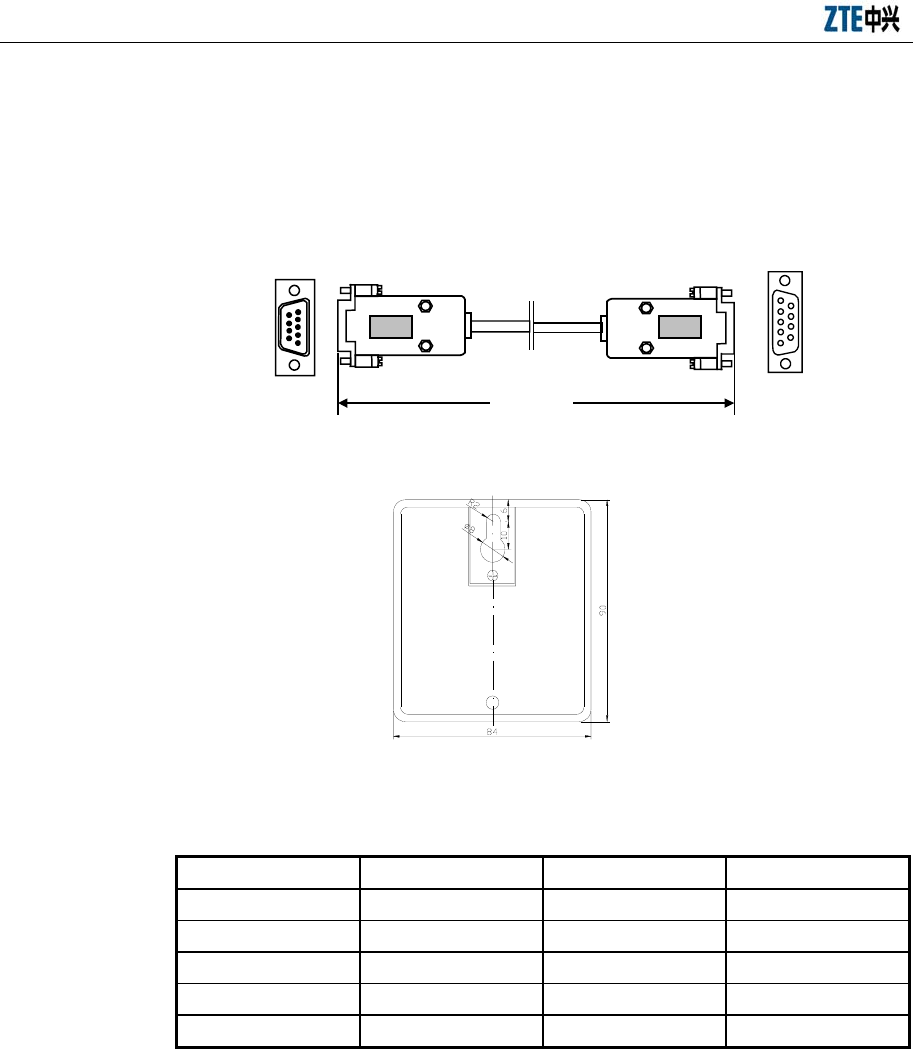
ZXC10 BTSB (V1.0) cdma2000 Base Transceiver Station Installation Manual
9-4
with End B3 of the RFS external monitoring cable. The DB9 female connector at End
B is connected to the sensor.
The terminal connection of the cable connector is described in Table 9.2-2.
Pin No. sequence of DB9
male connector at End A
1
6
9 5
End A
Label
End B
Pin No. sequence of DB9
male connector at End B
1
5
6
9
Label
L= 10 m
(a)
(b)
Fig. 9.2-2 Installation of Temperature-Humidity Converter
Table 9.2-2 Terminal Connection of the Temperature/Humidity Sensor Cable Connector
Signal Definitions Pin No. at End A Cable Color Pin No. at End B
HUM 1 White 3
TEMP 7 Blue 4
GND 3 White 1
+5V 8 Orange 5
6 Shielded cable
9.2.3 Installing the Infrared Sensor
9.2.3.1 Installation Position
The infrared sensor should be installed on the upper part of a corner in the equipment
room, so that it can detect the persons entering the equipment room through the door or
window. The installation location of the infrared sensor is shown in Fig. 9.2-3.
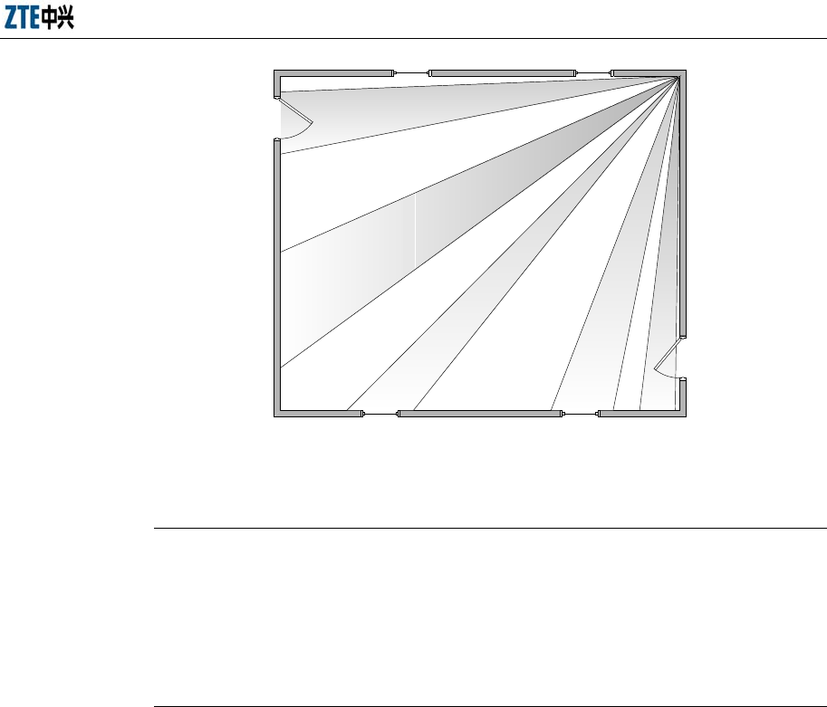
Chapter 9 Monitoring System Installation
9-5
.
Fig. 9.2-3 Location of the Infrared Sensor
9.2.3.2 Structure of the Infrared Sensor
Note:
There is a wide variety of infrared sensors. The following describes only one of them.
When installing an infrared sensor on-site, you may find the actual structure of the
infrared sensor is different from the one introduced here. Please follow the
specifications of this product for the installation guide.
The structure of an infrared sensor is shown in Fig. 9.2-4.
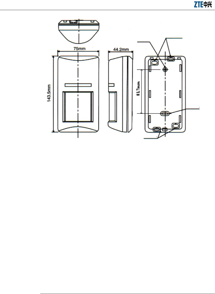
ZXC10 BTSB (V1.0) cdma2000 Base Transceiver Station Installation Manual
9-6
holes
Pre-set hole
Cable outlet
hole
Cable outlet hole
Fig. 9.2-4 Structure of Infrared Sensor
9.2.3.3 Installation and Cabling
1. Installation
The infrared sensor is to be mounted on wall.
To install the infrared sensor, drill two φ6 holes (to a depth suitable for placing
the plastic expansion bolts, which is recommended to be no less than 30 mm) on
the wall 81.7 mm apart. The line between the centers of the two holes should be
vertical to the floor.
Put the plastic expansion bolts to the two holes and tap them fully into the holes
with a hammer.
Take down the base from the infrared sensor, put two φ4 screws through the two
holes on the base and screw them into the two plastic expansion bolts on the
wall.
2. Cable connection
Note:
The cables of the infrared sensor will have been properly connected before delivery.
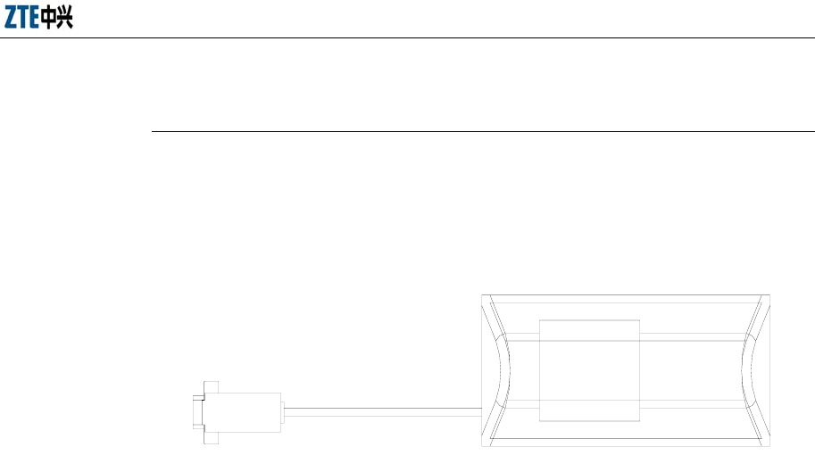
Chapter 9 Monitoring System Installation
9-7
The job to do on-site is to sheath each cable in a metal pipe or a PVC fire-retardant
pipe.
Fasten the infrared sensor to its base with one end being the DB9 connector and the
DB9 male connector at the B5 end of the external monitoring cable of RFS, and the
infrared sensor is at the other end, as shown in Fig. 9.2-5.
Fig. 9.2-5 Structure of Infrared Sensor Cable

10-1
10 Main Antenna Feeder System
Installation
Summary:
z Installation preparation for the BTSB main antenna feeder system
z Structure of the BTSB main antenna feeder system
z Installation items and flow of the BTSB main antenna feeder system
z Installation procedure of the parts of the BTSB main antenna feeder
system
z Installation check and test for the antenna feeder part
z Waterproof treatment of the connectors
The configuration of the BTSB antenna system is closely related to network planning.
Different coverage areas and environments may require very different antenna feeder
systems. Before installation, network planning has to be predetermined and should
contain the layout, elevation, dip, gain and even diversity reception mode of the
antenna.
Proper installation of the antenna is essential to the communication performance of the
coverage areas and to the reliable operation of the mobile BTSB system. The antennas
installed should be in correct direction, including correct dip and azimuth of the
antenna in each sector. Besides, the antennas should have wind resistance capability
(i.e. capability to withstand wind at the speed of 150 km/h).
Install the feeder properly so as to minimize signal loss during transmission. Make sure
that it can operate reliably in all environments.
10.1 Preparation for Installing the Antenna Feeder System
This includes the preparations of staff, safety measures, tools and instruments, and
technical documents, and the installation environment check.

ZXC10 BTSB (V1.0) cdma2000 Base Transceiver Station Installation Manual
10-2
The installation of the antenna feeder equipment is important to the installation of the
BTSB equipment. Its construction quality is directly related to the operating
performance of the entire BTSB system. Moreover, most of the BTSB installation
engineering is the installation of the antenna feeder equipment that generally takes up
80% of the installation time of the whole BTSB system. The installation of the antenna
feeder equipment involves the installation of the antenna, the jumper, the routing of the
main feeder, and the installation of the lightning protection system and the GPS.
Different antenna may be used, and the installation method and procedure also vary
with the terrain, population density and installation environment. With the quality
guaranteed, the installation supervisor should have the antenna installed flexibly and
reasonably as required in specific situations by following the BTSB engineering design
documents and the installation instructions of the special antenna provided by the
manufacturer.
Prior to the installation of the antenna feeder system, inspect the qualification of the
installation staff to work at heights, check and prepare the installation environment, the
installation measures, the installation tools and the antenna feeder to be installed so that
the installation can be carried out successfully.
10.1.1 Preparation by Installation Personnel
The engineering of the antenna feeder is generally conducted by the antenna feeder
installation personnel under the supervision of the installation supervisor.
The installation supervisor should be familiar with the materials, tools and operation
methods for the antenna engineering, organize and coordinate the installation persons
for proper work with the spirit of top safety, especially in the operations on tower. The
engineering supervisor fills the engineering data with sincere attitude.
Requirements for the installation staff: Staff that can conduct the installation
professionally under the instruction of the supervisor. The staff working at heights
should have no acrophobia and be in good health. In addition, he should have the
qualification and certificate for working at heights, observe the requirements for using
the safety tools and have purchased life insurance policy. Besides, alcohol drinking is
prohibited.
10.1.2 Checking the Installation Environment
During the environment inspection, you should focus on the following: Whether the
Chapter 10 Main Antenna Feeder System Installation
10-3
outdoor lightning protection grounding cable has been in place with the core diameter
more than 50 mm2, whether the distances between the antenna lightning arrester, the
lightning protection grounding point, the outdoor cabling rack, and the antenna pole
meet the design requirement and whether the strength and the wind-withstanding
capability of the pole meet the design requirements. Check the necessary devices and
auxiliary materials and negotiate with the user for specific wiring for the main feeder.
As to the installation of the antenna support, the equipment supplier puts forward
requirements for the antenna structure and dimensions, while the network operator
completes the installation as parts of the equipment room accordingly.
The network operator is also responsible for the installation of the antenna feeder
installation environment such as the outdoor cabling rack, the lightning arrester, the
lightning protection grounding peg, and the outdoor lightning protection grounding
cable. The installation of the main feeder entry window requires the holing operation
on the wall or roof of the building. It may deal with the infrastructure of the equipment
room and should be implemented by the network operation, as a condition of the
equipment room.
10.1.3 Checking the Safety Measures
Caution:
Operators on the tower must wear safety belt. Persons under the tower must wear
safety helmet. Never climb the tower with loose clothes and slippery shoes.
1. Emphasize the safety precautions to the engineering staff.
2. Arrange the outdoor construction of the antenna feeder at daytime in clear
weather and without strong wind.
3. Set up distinct marks at the engineering site to keep off people irrelevant. The
persons under the tower are responsible for supervising the irrelative persons,
especially kids, to be away from the construction field. The tools used on the
tower, which may drop and injure the persons under the tower, must be treated
seriously. For example, the tools and metal installation parts are cased in the
canvas bag securely once they are not used. The canvas bag keeps enclosed
unless a tool or part is to be taken out.

ZXC10 BTSB (V1.0) cdma2000 Base Transceiver Station Installation Manual
10-4
10.1.4 Preparing Installation Tools
The installation tools comprise:
1. Measurement tools: Compass, multimeter, angle meter, tape
2. Communication tools: Two MSs
3. Hoisting tools: Pulley, rope to pull the main feeder
4. Special tools: Main feeder cutter, special tools for preparing main feeder
connectors
5. General-purpose tools: Adjustable wrench, sharp-nose pliers, diagonal pliers,
electrical knife, file, hacksaw
6. Safety protection tools: Safety belt (used by engineering staff who step out of
the platform on the tower), safety helmet, safety rope, thick uniform, RF-proof
clothing, canvas tool bag, gloves, multi-purpose power socket
7. Others: Standing ladder, wooden axle hoisting tool for the main feeder (this can
be borrowed from the local user).
10.2 Structure of the Antenna Feeder System
As shown in Fig. 10.2-1, the antenna feeder system comprises antenna, antenna jumper,
main feeder, lightning arrester, cabinet-top jumper, grounding parts and others.
Chapter 10 Main Antenna Feeder System Installation
10-5
Lightning arrester
Antennas
(6 pairs of
directional
antennas)
Jumpers (1/2, six)
Lightening protection
grounding clip
Main feeders
(7/8, six)
Jumpers (1/2, six)
Lightning arrester
Equipment
room
Tower
BTS cabinet
Cabling rack
Lightening protection
grounding clip
Lightening protection
grounding clip
Fig. 10.2-1 Typical Structure of the Antenna Feeder System with Three Sectors
ZXC10 BTSB (V1.0) cdma2000 Base Transceiver Station Installation Manual
10-6
10.3 Installation Content and Flow
Caution:
1. Take careful precautions for the safety of yourself and the equipment during the
whole antenna installation process.
2. When adjusting the antenna that has started working, take certain measures (for
example, wear radiation-shielding clothing), and turn off the high power amplifier to
avoid the direct radiation of the antenna to human body.
10.3.1 Technical Parameters for Antenna Installation
1. Antenna height
It is determined by network planning.
2. Azimuth of antenna
It is determined by network planning.
3. Pitch angle of antenna
It is determined by network planning and is adjustable in the range of 0 °C ~ 10
°C.
4. Antenna direction
It is determined by the azimuth of the antenna. Two antennas in the same sector
should point to the same direction.
5. Distance between diversity antennas
The two antennas in the same sector are diversity receiving antenna to each
other with the same vertical height. The horizontal distance (d) is as large as
possible to satisfy the engineering requirements just by following the formula
below.
d ≥10 ~ 20λ (or H/d = 11), where d is the horizontal distance between the
diversity antennas, and H is the vertical height from the antenna to the floor. The
diversity distance of the 1900 M carrier shall be more than 1.5 m while that of
the 800 M carrier shall be more than 3.5 m.
Chapter 10 Main Antenna Feeder System Installation
10-7
10.3.2 Antenna Installation Flow
The antenna installation flow is shown in Fig. 10.3-1.
Star
Directional antenna
Initial assembly of
directional antenna fittings
Installation and sealing of
antennas and jumpers
Antenna fixing
End
Antenna hoisting and
moving
Installation position
determination
Omni-directional
antenna
Direction and pitch angle
adjustment of directional
antenna
Initial fixing of omni-
directional antenna
Vertically adjustment of
omni-directional antenna
Initial fixing of
directional antenna
Fig. 10.3-1 Antenna Installation Flow
ZXC10 BTSB (V1.0) cdma2000 Base Transceiver Station Installation Manual
10-8
10.4 Installing the Parts
10.4.1 Determining the Antenna Installation Position
During the installation, the antenna installation position should be determined
according to the antenna feeder installation drawing among the engineering design
drawings. If the antenna support is installed in a place different as that shown in the
engineering design drawing, second design should be done based on the network
coverage requirement of the local BTSB, antenna diversity requirement, antenna
azimuth and pitch angle. And design modification solution should be make then after
consultation with the user representative and the design institution, lest the network
coverage after the installation be affected.
10.4.2 Moving and Hoisting the Antenna
Caution:
Personnel both on and under the tower should coordinate to hoist the antenna. During
the hoisting process, the personnel under the tower should pull the antenna away from
the tower body by maneuvering the rope to keep the antenna from rubs with the tower
body.
In the case the antenna is to be installed on the tower, use the rope and pulley block to
hoist the antenna, the 3m antenna jumper and all the accessories (such as tools, safety
belts, adhesive tapes and straps) to the tower-top platform and place them in a safe
place. Take corresponding safety measures during the process. Small metal staff as
antenna fixing parts and wrenches should be put in a sealed canvas tool bag before
hoisting, as shown in Fig. 10.4-1.
Both ends of the directional antenna and the omni-antenna should be knotted for easy
coordination of the staff both on and under the tower during the hoisting.
In the case the antenna is to be installed on the roof, move the antenna and the
installation materials to the installation position manually.
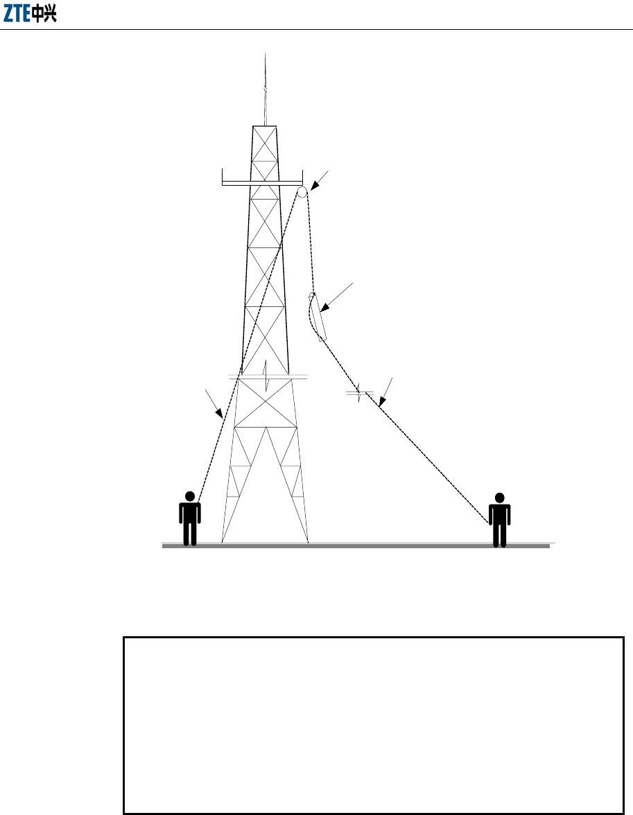
Chapter 10 Main Antenna Feeder System Installation
10-9
Pulley block
Hoisting rope
Knot the hoisting rope
on and under the tower
Pull the antenna away from the tower
body by pulling the rope to prevent
the antenna from being damaged.
Fig. 10.4-1 Hoisting an Antenna
10.4.3 Installing and Adjusting the Directional Antenna
Note:
The installation methods of antennas of different models vary from one
manufacturer to another. This section takes the KATHRAIN antenna as an
example to describe the antenna installation process. Please carefully read
the installation instructions provided along with the antenna during the
installation and install the antenna according to actual situation.
1. Initial assembly of the directional antenna fittings
The directional antenna has a number of installation fasteners. For example, the
KATHRAIN antenna has two types of fasteners: 738516 and 737974. Before
fixing the antenna, assemble fastener 737974 to the ends of the antenna, as

ZXC10 BTSB (V1.0) cdma2000 Base Transceiver Station Installation Manual
10-10
shown in Fig. 10.4-2, and then connect fasteners 737974 and 738516. Thus the
initial installation of the directional antenna is completed. All accessories must
be installed with spring and flat washers. Please refer to the instructions attached
to the product for descriptions of other fasteners for the antenna of other
manufacturers or of KATHRAIN.
Usually the antenna fixing accessories and the angle adjustment device
accessories have been installed on the antenna under the tower.
2. Initial fixing of the directional antenna on the antenna pole
Mount the directional antenna installed with clamp accessories on the antenna
pole: The screw should not be too tight that you are unable to adjust the
direction and the pitch angle of the antenna, nor too loose lest the antenna might
slip downward.
3. Adjusting the azimuth of the antenna
1) Use a compass to determine the azimuth of the antenna. And determine the
installation direction of the directional antenna according to the engineering
design drawing.
2) Turn the antenna slightly to adjust its facing direction, as shown in Fig. 10.4-2.
At the same time measure the direction of the antenna with a compass till the
error is within the engineering design requirements (generally not more than 5°).
3) Tighten the fastener 738516 after adjusting the azimuth of the antenna.
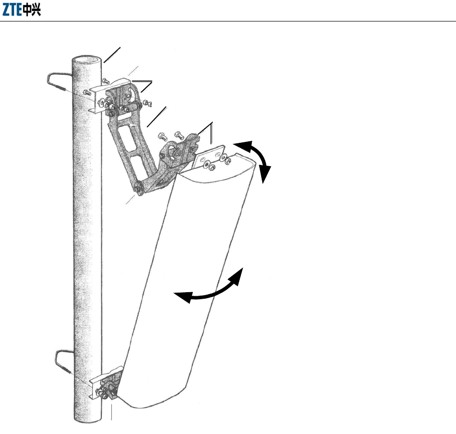
Chapter 10 Main Antenna Feeder System Installation
10-11
Ф75 mm embracing pole of the antenna
73 8 5 1 6
737 974
Scale
0o~16
o
KATHRE I N
65o
Directional antenna
737 974
After the initial installation, move
the antenna left and right to adjust
the pitch angle of the antenna.
After the initial installation, move the
antenna up and down to adjust the
pitch angle of the antenna.
Connect the antenna and the fastener with short bolts and
add the spring washer and the flat washer. Add the water-
proof washer in the inner side of nut.
Connect the two with short bolts and fix the two nuts to
enhance fixation.
Fig. 10.4-2 Installing the KATHRAIN Antenna
4. Adjusting the pitch angle of the antenna
1) Adjust the pitch angle of the dip meter to the angle required by the engineering
design.
2) Turn the top of the antenna slightly, let go or hold fast the antenna at its top.
Adjust the pitch angle of the antenna till the bead is centered when the adjusted
dip meter is next to the directional antenna, as shown in Fig. 10.4-3.
3) Tighten the fastener 737974 after adjusting the pitch angle of the antenna.
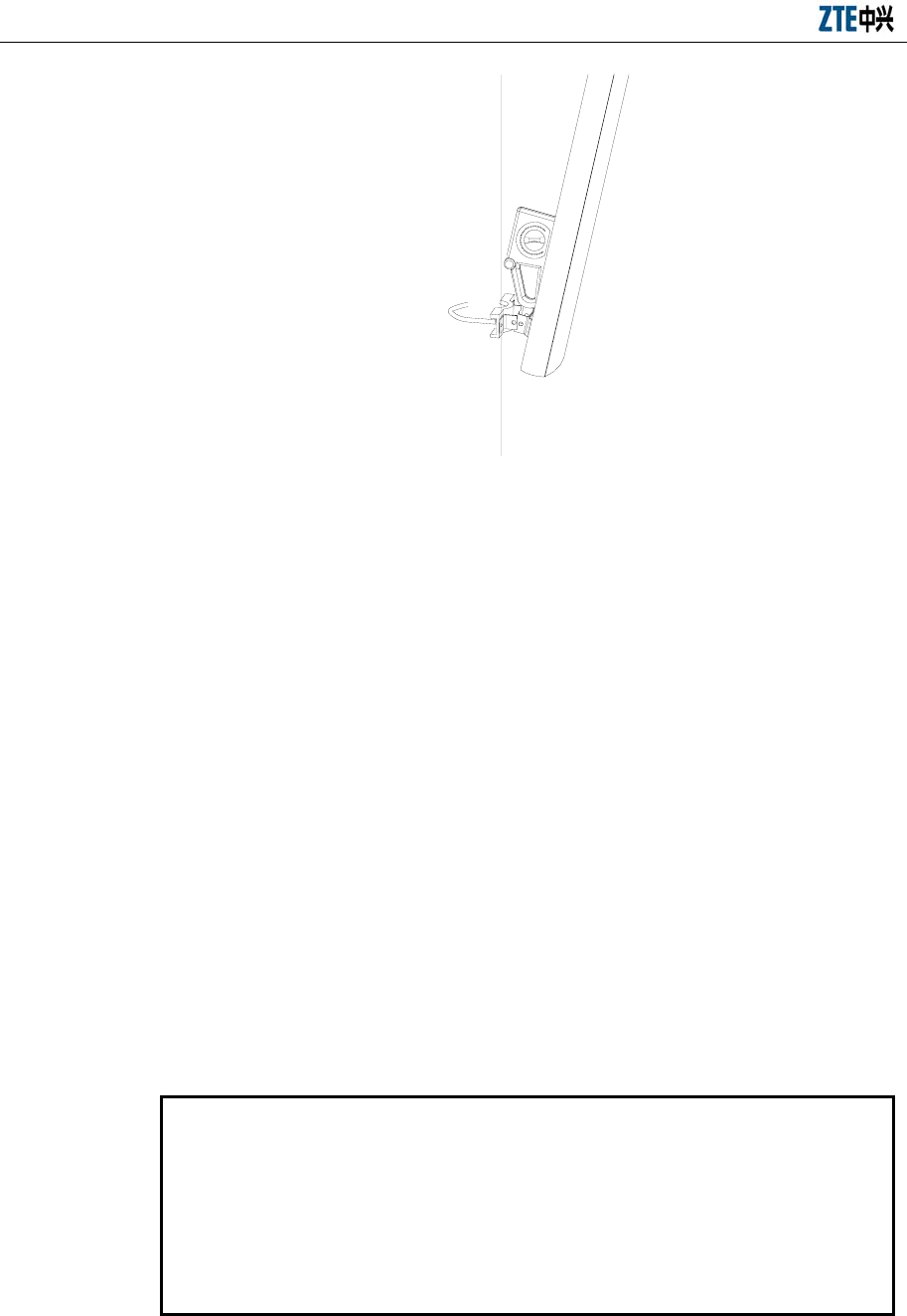
ZXC10 BTSB (V1.0) cdma2000 Base Transceiver Station Installation Manual
10-12
Fig. 10.4-3 Adjusting the Pitch Angle of the Antenna
10.4.4 Installing and Adjusting the Omni-antenna
Take the following steps to install the omni-antenna:
1. Put the jacket at the antenna lower part close to the support backbone. The top of
the jacket should be flush with or slightly higher than the support top.
2. Fix the jacket at the antenna lower part and the support backbone at two points
with antenna fixing clips. They should be fixed tight enough to bear weight and
withstand wind, and should not be too loose or too tight lest the antenna jacket
be damaged.
3. Check the antenna verticality. The omni antenna must be vertical. Make sure the
antenna is vertical, and then fix it to the antenna pole.
4. Stick the support installed with the antenna out of the tower platform, and adjust
the support to make the antenna vertical.
10.4.5 Sealing the Connection between Jumper and Antenna
Note:
The antenna and the jumper can be connected and waterproof treatment can
be conducted on the joint before the antenna is fixed on the pole. This can
reduce the working time at heights and improve the joint connection and
waterproof quality.

Chapter 10 Main Antenna Feeder System Installation
10-13
The installation steps are as follows:
1. Align the connector of the antenna jumper to the antenna interface and screw it
tightly.
2. Perform waterproof treatment to the joint (See 10.6" Waterproof Treatment on
Joint" for details):
1) Wrap starting from the root of the antenna joint with waterproof adhesive tape in
the same direction as the fastening direction of the antenna jumper.
2) Stretch the waterproof adhesive tape to double its length, and apply it layer by
layer till it covers about 5 cm of the bottom of the feeder joint. During the
process, make sure the upper layer overlaps the lower layer by half the width of
the tape.
3) Grip the tape with hands to make the tape tightly adhered;
4) Apply the PVC tape layer by layer on top of the waterproof adhesive tape.
During the process, make sure the upper layer overlaps the lower layer by half
the width of the tape.
10.4.6 Installing the Feeder Window
Note:
The size of the feeder cable window provided by ZTE is 400 mm × 400 mm. It
is a four-hole window and 12 pieces of feeder cables can pass through it. A 300
mm × 300 mm hole should be drilled on the wall for the installation of this
feeder cable window. If the user provides a special feeder window, then make
the wall cavity according to the actual dimensions of the feeder window.
The feeder window is usually mounted on the wall outside the equipment room
between the indoor and the outdoor cabling racks.
If the main feeder window is to be installed on the building-top, sealing and waterproof
treatment should be conducted on it. You may use asphalt or glass cement to seal the
feeder window.
There are 4 holes in a feeder window through which a total of 12 feeder cables can pass
through, as shown in Fig. 10.4-4. Follow the steps below to install a feeder window.
1. Determine the installation position of the feeder window as required by the
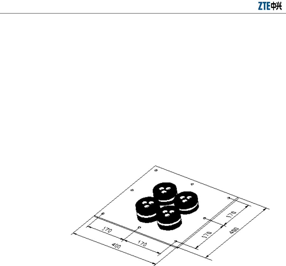
ZXC10 BTSB (V1.0) cdma2000 Base Transceiver Station Installation Manual
10-14
engineering design drawing.
2. Make a cavity on the wall according to the size of the feeder window.
3. Use a percussion drill to drill holes for the expansion bolts and fix the main
board of the feeder window with expansion bolts.
4. The sealing gasket and sealing tube of the feeder window can be installed when
the main feeder is introduced into the room. See 10.4.7.6 "Running the Primary
Feeder Cable into the Equipment Room".
5. For cold areas with sand storms, even if the wall is thick, it is necessary to install
timber baffle plates inside the equipment room to keep warm and keep sands
outside.
Fig. 10.4-4 Structure of the Feeder Window
10.4.7 Installing the Feeders
This section only describes the making of the 7/8" feeder connector, the connection and
sealing of the jumper and the main feeder, the connection and sealing of the jumper and
the antenna, and the layout and fixation of the feeder. It contains the following
contents:
1. Determining and measuring the feeder route
2. Hoisting and cutting the feeder, and labeling the feeder
3. Making the feeder connector
4. Distributing and fixing the feeder
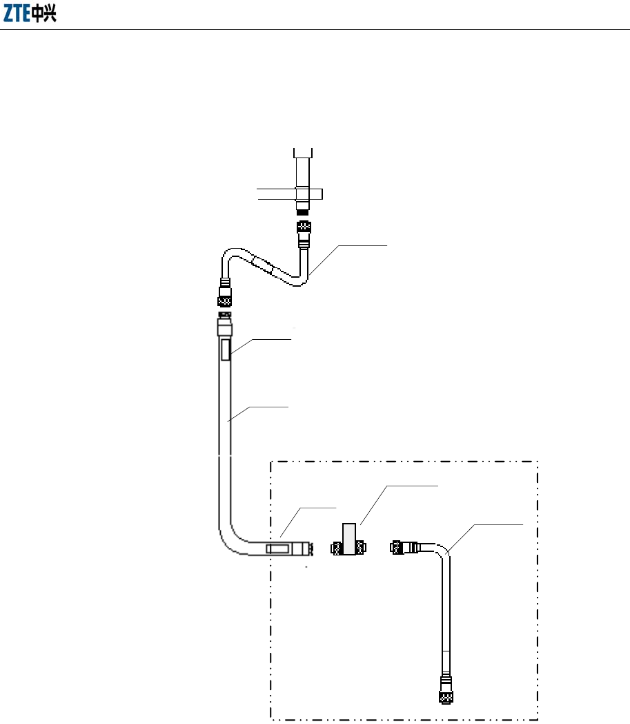
Chapter 10 Main Antenna Feeder System Installation
10-15
5. Installing the outdoor jumper and conducting waterproof treatment on the joint
The overall structure of a BTSB feeder is shown in Fig. 10.4-5.
Lightning arrester
Indoor
Outdoor
Feeder
Antenna
jumper
Cabinet top
jumper
Label
Label
Fig. 10.4-5 Structure of a BTSB Feeder
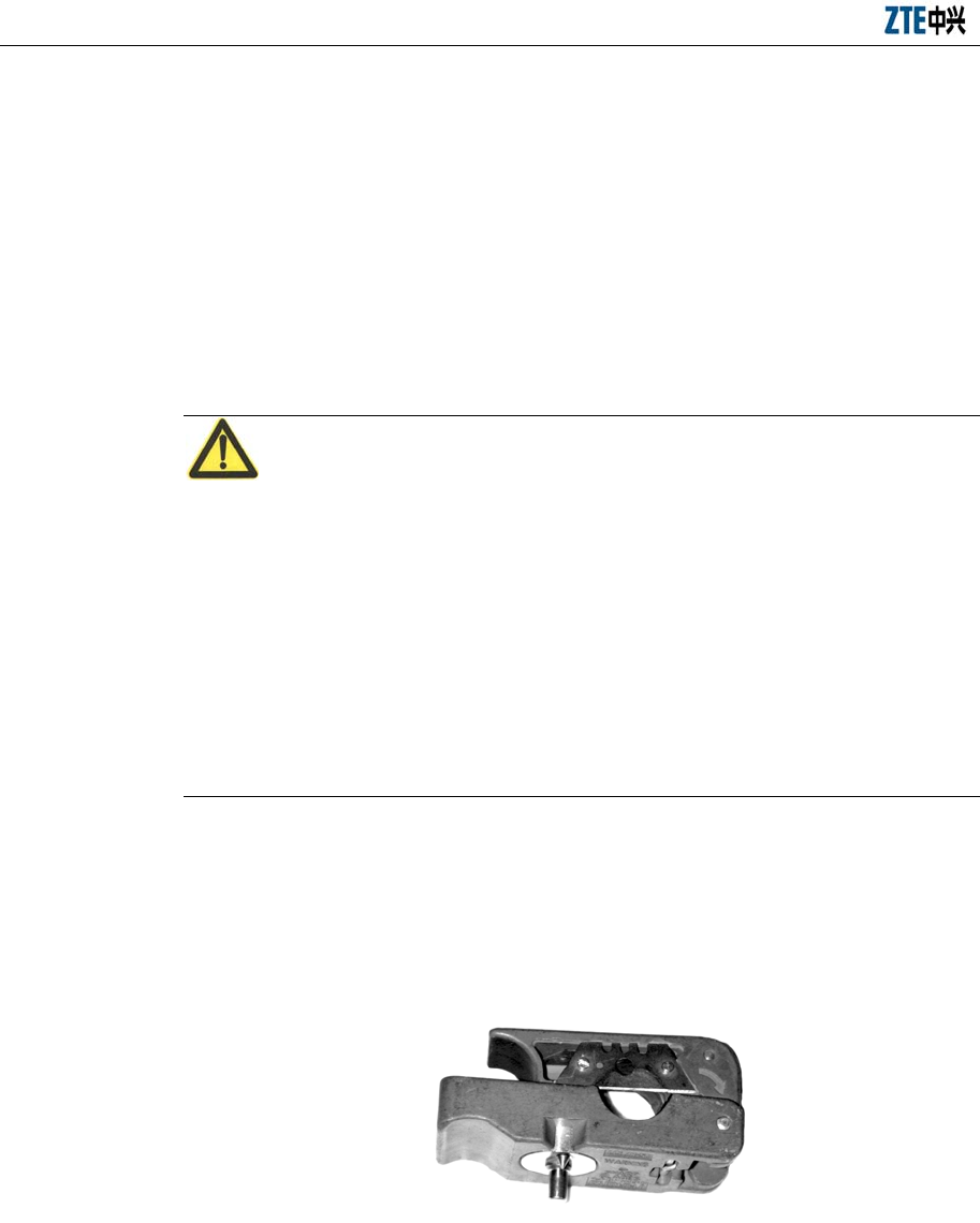
ZXC10 BTSB (V1.0) cdma2000 Base Transceiver Station Installation Manual
10-16
10.4.7.1 Determining the Feeder Cable Route
During the engineering installation phase, the layout of the feeder should be
determined according to the feeder wiring drawing among the engineering design
drawings. If the layout of the feeder need be modified according to the practical
situation, you should consult the user representative and try to solve the problem as
early as possible. Please note that the length of the main feeder should be as short as
possible.
10.4.7.2 Making Connectors of the Primary Feeder Cable
Caution:
The preparation of the feeder connector is the most important part in the antenna feeder
installation engineering. The quality of the job directly relates to the equipment
operation and the network quality.
Since the cutting tool used is sharp, use it correctly to avoid body injury.
This section takes the Rosenberger’s 7/8" feeder connector as an example to describe
the preparation process. For the installation of the feeder connector of other
specifications or other manufacturers, please refer to their installation instructions.
Take the 7/8" main feeder connector as an example. The procedure to make the
connector is as follows:
1. The common cutting tool for making the feeder connector is shown in Fig.
10.4-6.
Fig. 10.4-6 Cutting Tool for the 7/8" Feeder Connector
2. Measure a straight feeder section of about 150 mm to be installed with the
connector, and cut and use a safety cutting tool to strip the feeder sheath 50 mm
away from the end.
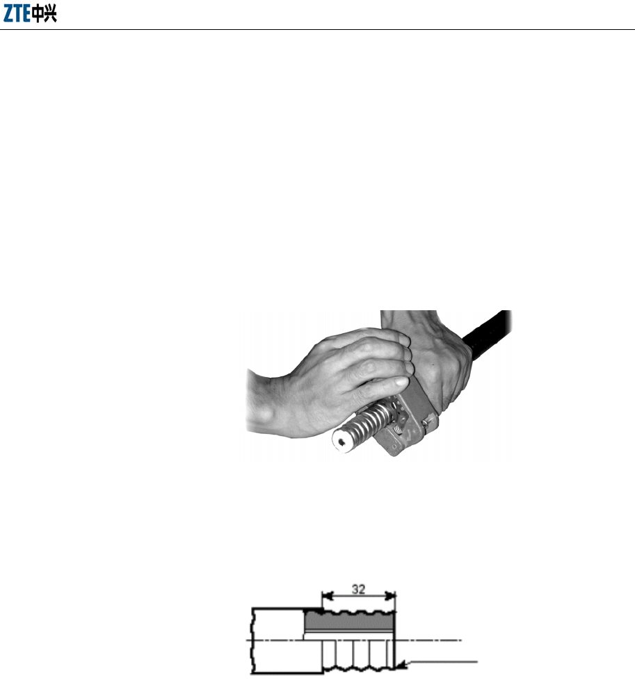
Chapter 10 Main Antenna Feeder System Installation
10-17
3. Put the feeder into the notch of the cutter (EASIAX), leaving a length of four
sheath threads from the main blade. And then close the cutter handles. Since the
position of the cutter is determined according to the threads on the external
copper sheath of the feeder, the main blade should just be aligned to the crest at
the center of a thread of the feeder.
4. Turn the cutter in the direction as marked on the cutter till the handles are
completely closed and cut the internal and external copper conductors of the
feeder completely. At the same time, the auxiliary blade of the cutter cuts the
external plastic protection sheath of the feeder, as shown in Fig. 10.4-7.
Fig. 10.4-7 Cutting the Feeder with a Cutter
5. Check the cutting length of the feeder, as shown in Fig. 10.4-8.
Wave location
Fig. 10.4-8 Checking the Cutting Length of the Feeder
6. Separate the front part and back part of the feeder connector, and insert the back
part into the feeder till it contacts with the first corrugation of the feeder.
7. Firmly insert the tube expander of the cutter into the feeder and turn it left and
right to expand the external copper conductor of the feeder, so that it presses
against the back part of the feeder connector. This is shown in Fig. 10.4-9.
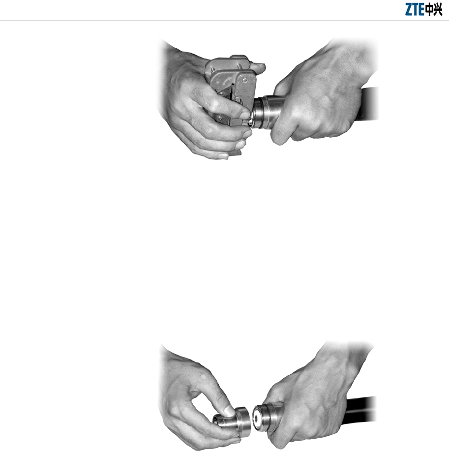
ZXC10 BTSB (V1.0) cdma2000 Base Transceiver Station Installation Manual
10-18
Fig. 10.4-9 Expanding the External Conductor of the Feeder with a Tube Expander
8. Check whether there is residual copper scraps. The external copper sheath
should be evenly expanded without burrs. Pull the back part of the feeder
connector outward while keeping it from slipping away from the feeder. Make it
again if necessary.
9. Connect the front part and the back part of the feeder connector, as shown in Fig.
10.4-10.
Fig. 10.4-10 Connecting the Front Part and the Back Part of the Feeder Connector
10. Screw the front part of the feeder connector, and fix it with an appropriate
wrench, so that it does not move against the feeder. Then screw the back part of
the feeder connector with the wrench till it is fixed, as shown in Fig. 10.4-11.
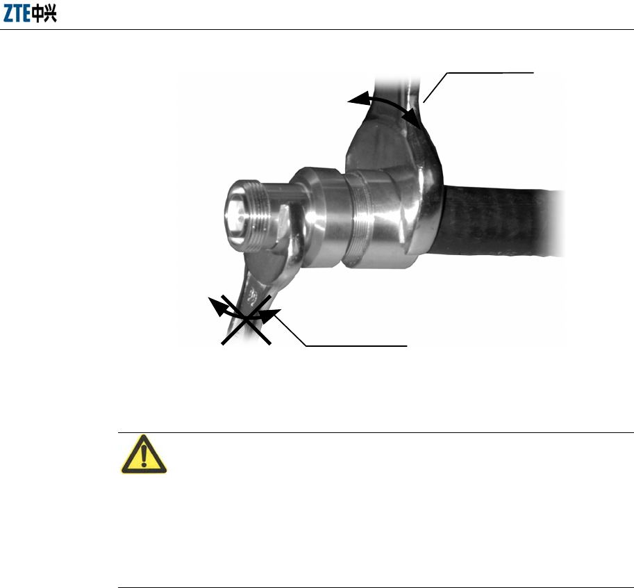
Chapter 10 Main Antenna Feeder System Installation
10-19
Rotate this wrench only
Keep this wrench stay
Fig. 10.4-11 Fixing the Front Part and the Back Part of the Feeder
10.4.7.3 Cutting the Feeders
Caution:
When cutting the main feeder, label it at both ends. Temporary label can also be
attached to the middle of the feeder. It’s very important to keep all the labels consistent.
Otherwise, the feeder may not be correctly connected and the sectors may not
correspond to the feeder.
Usually the feeder is rolled over to the installation site. The length of the main feeder
should be exactly measured again on site according to the final route negotiated with
the user. The feeder should be cut into sections as required. The cutting steps are as
follows:
1. For the antenna feeder to be installed on the roof
1) Determine the length of the main feeder in each sector again with a tape measure
according to the actual route.
2) Cut the feeder to the length of the measured actual length plus 1 m to 2 m.
3) Attach the corresponding temporary labels (such as ANT1, ANT2, ANT3, ANT4,
ANT5 and ANT6) to both ends of a main feeder after cutting it. When the feeder
is installed, attach the formal label to it.
4) Move the cut feeders to the roof. During the process, take care that the feeders
ZXC10 BTSB (V1.0) cdma2000 Base Transceiver Station Installation Manual
10-20
are not damaged or pressed.
2. For the antenna feeder to be installed on the tower
1) Use roller support, pulley block and hoisting rope to lift one end of the feeder to
the tower top. The person on the ground cuts the feeder to the length with which
the feeder can reach the lightning arrester frame inside the equipment room (plus
certain redundancy). Attach temporary labels to the lower part of the feeder.
Once the feeder enters the equipment room, attach a formal label to it.
2) It is better to make the upper connector of the main feeder before hoisting it to
reduce the time that the staff works at heights and to better ensure the
installation quality of the feeder connector.
10.4.7.4 Raising the Main Feeder Cable of the Iron Tower
Caution:
During the hoisting, rough operations are not allowed, lest the sheath of the main
feeder be damaged or scratched. The partial damage of a single main feeder will cause
the whole cable be rejected as useless.
Take precautions for personal safety when hoisting the feeders.
If the antenna feeder system is to be installed on an iron tower, a pulley block should
be used to hoist the primary feeder cables, as shown in Fig. 10.4-12. For the installation,
you should follow the steps below:
1. Check again that the main feeder labels attached 0.3 m away from both ends of
the main feeder are correct.
2. Wrap the main feeder connector made under the tower with flax (or antistatic
packing bag together with foam) and strap it tightly.
3. Knot and fix the hoisting rope 0.4 m and 3.4 m away from the feeder connector
to help the staff both on and under the tower pull up the feeder and to prevent
the feeder and its connector from damage caused by their bumping into the
tower during the hoisting process.
4. Hoist the feeder to the tower platform and fix the upper end of the cable to a
proper place at several points, lest the cable fall down from the tower.
Chapter 10 Main Antenna Feeder System Installation
10-21
Hoisting rope
Feeder connector wrapping
Knotting the hoisting rope at the 0.4
M or 3.4 M distance of the feeder
Pulling the antenna away from the tower body with the
hoisting rope to prevent the antenna from being damaged
Pulley block
Hoisting rope
Label
Fig. 10.4-12 Pulling the Feeder Cable up the Iron Tower
10.4.7.5 Laying and Fastening the Main Feeder Cable
1. Cabling principle of the main feeder
z The main feeder entering the equipment room from the feeder window and is
routed along the indoor cabling rack should be bound neatly without crossing.
z The main feeder that is routed along the indoor cabling rack and the cabling rack
on the tower should have no crossing.
z Make yourself familiar with the routing of the main feeder before cabling it. It is
better to take down its actual route on paper to avoid rework due to crossing the
cable.
ZXC10 BTSB (V1.0) cdma2000 Base Transceiver Station Installation Manual
10-22
z The minimum bending radius of the main feeder should not be less than 20
times the length of the radius of the main feeder. For one-time bending, the
minimum bending radius is 90 mm. The minimum bending radius of repeated
bends is 200 mm.
z The maximum spacing between the hangers is 1.65 m.
2. Cabling procedure of the main feeder
1) Pre-install the three-feeder clips every 1.5 meters (or according to the actual
condition of the iron tower, but no more than 1.65 meters) along the iron tower
or cabling rack. Note that the spacing should be as even as possible and the
direction of installing them should be the same. When installing two rows of
feeder clips inside the same cabling ladder, the two rows should be parallel and
arranged neatly. Fig. 10.4-13 shows the appearance of a three-feeder clip.
Fig. 10.4-13 Three-feeder Clip
2) Sort out the main feeders from the antenna to the equipment room inside.
3) Fix the main feeders from top to bottom and sort them out while attaching the
three-feeder clips. Fasten the feeder clips after smoothing the main feeders. Note
that you should keep the main feeders flat and straight rather than allowing any
bulge between two feeder clips or fixing the feeders at the two ends
simultaneously.
4) Fix the main feeders with three-feeder clips along the outdoor cabling ladders
prepared by the network operator for the main feeders to be routed along the
building top to the equipment room inside.
Chapter 10 Main Antenna Feeder System Installation
10-23
10.4.7.6 Running the Primary Feeder Cable into the Equipment Room
1. Precautions
z Fig. 10.4-14 and Fig. 10.4-15 illustrate how the common feeders enter the
equipment room. Please ensure that the feeders will not bring any rain into the
equipment room when entering the equipment room. For that purpose, you can
design water curves as necessary.
Feeder
window First bending with the
bending radius larger
than 90 mm.
Cabling rack Feeder clip
OutdoorIndoor
Fig. 10.4-14 Introducing Feeders into the Equipment Room (Method 1)
Feeder window
Outdoor
Indoor Second bending with the
bending radius larger
than 90 mm.
Cabling rack
Feeder clip
Fig. 10.4-15 Introducing Feeders into the Equipment Room (Method 2)
z Use cabling racks both indoors and outdoors to guide the feeders when
introducing them through the feeder window into the equipment room.

ZXC10 BTSB (V1.0) cdma2000 Base Transceiver Station Installation Manual
10-24
2. Installation procedure
1) Loosen the fixing hoop from the feeder window to the proper position with
reference to 10.4.6 "Installing the Feeder Window", and pull away the sealing
cover of the aperture to thread the feeders.
2) Lead the feeders into the equipment room: Two persons are needed to cooperate
with each other, one indoors and the other outdoors, to introduce the feeders
from the outdoor cabling racks into the indoor cabling racks. During this process,
care should be taken to avoid damaging the indoor equipment or damaging the
feeder due to improper force applied on the outdoor feeder. Fasten the fixing
hoop after pulling the feeders in place.
3) Do the following before cut the feeders:
z Check the labels:
Ensure that the temporary labels on the feeders are complete before feeder
cutting and are still attached on the feeders after cutting. This is very important
to avoid feeder chaos.
z Determine the cutting position:
When cutting the feeders, select the cutting position according to the equipment
room conditions (such as the rack installation position, the cabinet-top jumper
length, the lightning arrester configuration or the installation position of the
lightning arrester frame), the bending radius of the feeders and the cabling
requirements of the equipment room.
4) Prepare the indoor connectors for the main feeders.
5) Connect the main feeders to the lightning arresters.
If a lightning arrester is not grounded, it should be directly mounted onto the
feeders to ensure proper insulation between the lightning arrester and the cabling
rack.
If a lightning arrester is equipped with a lightning arrester frame, each feeder
should be thoroughly adjusted to ensure the screw threads properly fit in with
the lightning arrester when the main feed and the arrester are connected. For
details, refer to 6.2.3, "Installing the Indoor Lightning Arrester".
Chapter 10 Main Antenna Feeder System Installation
10-25
10.4.8 Installing the Indoor Jumpers
Indoor cabinet-top jumpers are used between the lightning arrester connected to the
main feeder and the rack. Usually the finished 2m cabinet-top jumpers are used, or the
jumpers can be prepared on site according to the actual length required.
If the 2 m finished jumpers are used, they can be directly installed between the
lightning arrester and the rack top.
If the jumpers are prepared on site, 1/2'' feeders should be prepared through cutting
according to the specific length of each jumper. Assemble proper feeder connectors
onto both ends of the feeders according to the feeder connector assembly instructions,
and connect the jumpers between the lightning arrester and rack top.
10.5 Checking and Testing the Installation of the Antenna Feeder
Part
10.5.1 Lightning Protection for the Outdoor Antenna
For details of the lightning protection to the antenna, see Fig. 10.5-1.
Lightning
arrester
45 protection angle
Lightning
protection belt
45 protection
angle
Antenna and
outdoor unit
Fig. 10.5-1 Installation and Lightning Protection of Arrester
ZXC10 BTSB (V1.0) cdma2000 Base Transceiver Station Installation Manual
10-26
Installation standards involved in this figure:
1. The radio frequency antenna and GPS antenna must be installed within the 45°
protection angle for arrester.
2. If necessary, install independent arrester for the GPS antenna.
10.5.2 Testing the Antenna SWR
After installing all the antenna feeders, conduct the SWR test on each of them. The
measured SWR should be less than 1.5 and usually less than 1.3. If this is not satisfied,
check immediately the feeder connectors installed, antenna, feeders and lightning
arresters to find where the problem comes from. For the method of SWR test with
SiteMaster, refer to Appendix G.
10.6 Waterproof Treatment for the Connectors
Caution:
The waterproof sealing for the outdoor jumpers and the feeder grounding clips of the
antenna feeder system is an important part of the antenna feeder installation. It is of
special concern. In the installation process, make sure to use waterproof tapes properly
to ensure the quality of installing the antenna feeder system.
Use 1/2'' jumpers, generally the 3 m finished jumpers, between the antenna and main
feeder for transition. Connect the 1/2'' jumper and the feeder and seal their connectors
as follows:
1. Connect and fasten the antenna jumper and the main feeder connector.
2. Make waterproof treatment on the connectors in the following steps:
1) Cut waterproof adhesive tapes about 200 mm long.
2) Wrap the waterproof adhesive tapes from a low position where the connector is
connected and apply them about 200 mm long to fill the low-lying parts of the
connector, as shown in Fig. 10.6-1.
Chapter 10 Main Antenna Feeder System Installation
10-27
Fig. 10.6-1 Wrapping the Waterproof Adhesive Tapes (1)
3) Extend the adhesive tapes to double their length when wrapping them. The
direction of wrapping should be the same as the direction of screwing the feeder
connector, lest the feeder connector be loosened during the wrapping process.
4) As shown in Fig. 10.6-2, wrap the adhesive tapes layer by layer and then wrap
them again in the reverse direction. The upper layer covers the lower layer by
about 1/3 to avoid water penetration. Finally, reverse the direction and wrap
them layer by layer again. Apply the tape with three layers without any cut in the
entire process. Wrap the tapes around the feeder connector till they protrude
about 20 mm from the feeder connector.
Fig. 10.6-2 Wrapping the Waterproof Adhesive Tapes (2)
5) Grip the waterproof adhesive tapes after wrapping them to ensure firm bonding
between the tapes and the feeders/feeder connectors, as shown in Fig. 10.6-3.

ZXC10 BTSB (V1.0) cdma2000 Base Transceiver Station Installation Manual
10-28
Fig. 10.6-3 Wrapping the Waterproof Adhesive Tapes (3)
6) Apply two layers of the PVC tape on top of the waterproof adhesive tape.
During the process, make sure the upper layer overlaps the lower layer by half
the width of the tape.
7) Grip the PVC tapes and the waterproof adhesive tapes to make them tightly
adhered to each other.
8) Tie the two ends of the adhesive tape with straps to prevent it from being aged
or falling off.

11-1
11 GPS Antenna Feeder System
Installation
Summary:
z Installation preparation for the GPS antenna feeder system
z Structure of the GPS antenna feeder system
z Installation flow of the GPS antenna feeder system
z Installation procedure of the parts of the GPS antenna feeder system
z Waterproof treatment for the connectors
11.1 Preparation for Installing the Antenna Feeder System
As the clock and frequency reference for CDMA, the GPS plays a very important role.
According to the passive distance measurement principles, GPS antenna receives the
navigation positioning signals from the GPS satellites and demodulates frequency and
clock signals through the GPS signal receiver for use by the related units of the CDMA
base station.
Requirements for the installation of the GPS antenna: The installation position of the
GPS antenna should have a broad view so that the GPS antenna can track satellites as
many as possible. Usually, select a safe place on the roof or at the lower part of the
tower and try to make the GPS feeder short to reduce attenuation.
Lightning protection requirement of the GPS antenna: The GPS antenna is usually
installed in the 45° lightning area of the iron tower. Otherwise, the user should make
and install a special lightning arrestor.
Please note that the pole fixing the GPS antenna must be grounded.
11.2 Structure of the Antenna Feeder System
The composition of the GPS antenna feeder system is shown in Fig. 11.2-1.
ZXC10 BTSB (V1.0) cdma2000 Base Transceiver Station Installation Manual
11-2
Base
station
GPS antenna
Coaxial cable
Lightning
protection arrester
Fixing clip
Tube
Grounding
cable
Fig. 11.2-1 Composition of the GPS Antenna Feeder System
11.3 Installation Flow
Follow these steps to install the GPS antenna feeder system:
1. Make the outdoor connector for the coaxial cable as making a GPS coaxial cable
connector.
2. Thread the connector through the GPS accessory tube and distribute the coaxial
cable from the GPS antenna to the GPS lightning arrester.
3. Screw the outdoor connector of the coaxial cable to the GPS antenna connector.
4. Keep the GPS antenna still while screwing the tube on the GPS antenna.
5. Fix the tube to the pole with a fixing clamp.
6. Cut the coaxial cable according to the installation of the GPS arrestor, make the
indoor connector of the cable and connect it with the lightning arrestor. Note that
the equipment end and the feeder end of the GPS lightning arrester must be
correctly connected.
7. Distribute the coaxial cable between the GPS lightning arrester and the GPS port
on the BTSB equipment.
11.4 Installing the Parts
11.4.1 Preparing the GPS Coaxial Cable Connectors
1. Peeling dimensions
Chapter 11 GPS Antenna Feeder System Installation
11-3
The GPS coaxial cable is peeled according to the dimensions shown in Fig.
11.4-1.
6.2
16.7
Fig. 11.4-1 Stripping GPS Cable
2. Welding core
Before welding the core wire, thread the parts with the cable in the sequence as
shown in Fig. 11.4-2. Then, weld the cable core with the pin. The shielding layer
of the cable should be opened and covered on the bush.
Pin
Insulating
gasket
Cable
shielding
Jacket
Crimp
jacket Nut CableCore wire
Tin
soldering
Fig. 11.4-2 Welding GPS Connector Pin
3. Installing parts
After welding the core, install the parts on the case. The structure of the cable
assembly is shown in Fig. 11.4-3.
Insulating
gasket Jacket
Crimp
jacket
Shell Nut
Pin
Fig. 11.4-3 Structure of the N-J7A Cable Connection Part

ZXC10 BTSB (V1.0) cdma2000 Base Transceiver Station Installation Manual
11-4
11.4.2 Installing the Lightning Arrester
Each GPS has its own lightning arrester installed between the GPS antenna and the
BTSB rack. The lightning arrester should be connected to the outdoor grounding
copper bar via a 6 mm2 grounding cable. For the base station installed with a lightning
arrester frame, you may fix the GPS lightning arrester onto the frame. In this case, the
6 mm2 grounding cable is unnecessary. Be sure to connect the lightning arrester
correctly.
Refer to 10.5.1 for more information about lightning protection of GPS antenna.

12-1
12 Board Installation
Summary:
z BTSB board types
z Installation and replacement of BTSB boards
z Installation sequence of BTSB boards
12.1 BTSB Board Types
The baseband system consists of the following boards:
The CHM implements Channel Elements (CEs) processing. The CE processing
modules of each baseband system form a series of baseband processing sharing pools.
The RIM implements forward signal summary and reverse signal distribution as the
interface between baseband and radio frequency. The RIM can run in active/standby
mode.
The CCM implements control over base stations and switching for the base station
networks. It can run in active/standby mode.
The DSM acts as the ABIS interface to the BSCB, and can run in active/standby mode.
The SNM acts as the SDH interface, and can run in active/standby mode.
The SAM monitors the environment.
The GCM provides an accurate GPS clock for the base station. It can run in
active/standby mode.
The BIM base station interface module implements interface transfer between the
active and standby BDSs, between baseband and radio frequency, and between the
basest ion and the base station controller.
The PD distributes the power.
The Radio Frequency System (RFS) is located between the baseband system and the
mobile station to implement air RF interface in the air, and data interface to the

ZXC10 BTSB (V1.0) cdma2000 Base Transceiver Station Installation Manual
12-2
baseband system at the wireline side. The RFS consists of the following boards:
The TRX implements signal frequency conversion and supports 6+1 backup.
The RMM provides interface between RF and baseband and can run in active/standby
mode.
The PA amplifies the power of forward signals and supports 6+1 backup for linear
power amplification.
The PIM provides interface for power amplification.
The RFE provides antenna feeder interface and reverse low noise amplification.
The BTM performs base station radio tests.
The SAM monitors the environment.
The TSM implements cross-OR operation on the TRX forward signals for backup.
The RSM implements cross-AND operation on the TRX reverse signals for backup.
The PD distributes the power.
12.2 RF Cabinet Boards
12.2.1 Receiver Front End (RFE)
The RFE module amplifies the reverse received signals with low noise, implements
detachment, filter, SWR and power check for received/sent signals, and extracts &
injects the BTM. Its performance has a direct impact on the transmission indices of the
whole BTSB system.
The system requires a single cabinet to provide 24-carrier/sector. To this end, linear
power amplifiers with 4-carrier are configured for the base station in most cases, and
single-carrier higher-power amplifiers are adopted in special cases. The RFE is
designed to adapt to all the possible configurations of the system, including the
single-rack 6-sector configuration.
The principles and functions of the RFE are as follows:
Integrate duplexer (DUP) and filter (DIV) into one box. Then each RFE consists of 5
modules of 4 types (DUP, DIV, 2XLNA and PVD) to bear 4-carrier forward signals and
two channels of reverse signals.

Chapter 12 Board Installation
12-3
Filter the weak signals received by an antenna and amplify them with low noise.
Distribute power for the signals amplified with low noise, output them to the RSM and
the TEST_PORT through two splitters.
Provide duplex functions.
Filter forward transmitting power signals.
Monitor the low noise amplifier state.
Check the standing wave of the transmission channel to determine the matching state
of the antenna feeder.
Monitor the forward power, including the total power and the single carrier power.
Provide more accurate channel power detection table through frequency selective
circuit, thus a more accurate output power detection value for each carrier.
Incorporate in the automatic calibration of the output power.
Inject and acquire the BTM signals (DUP forward acquisition and DUP reverse/DIV
injection).
Provide the TX test port for pre-distortion sampling.
Report to the RMM via the serial port about the power, VSWR alarms, and the LNA
state. The RMM also controls the variable attenuator on the power detection link of the
PVD for the expansion of the dynamic range of the detection link.
Support external tower top amplifier with the LNA design for links that makes gain
adjustment through the background.
Detect the power of the all-channel bandwidth (5M) of 4-carrier and a given carrier at
the same time.
12.2.2 Power Amplifier (PA)
The PA is the power amplification module for the whole RFS. With its great working
current and high working temperature, it is required to provide some special linearity to
be applied to CDMA systems. Therefore, the implementation of it, a key module in the
BTSB, is a great challenge. High PA (for signal carrier amplification) or linear PA (for
multi-carrier amplification) can be chosen for the base station. This section only
addresses the principles of the linear PA (LPA).
The functions and principles of the LPA are as follows:

ZXC10 BTSB (V1.0) cdma2000 Base Transceiver Station Installation Manual
12-4
Depending on the input cross choice for the TSM and the output cross choice for the
BLPA backplane, seven LPAs are configured for 6+1 backup.
The CDMA system adopts the QPSK modulation mode, a linear modulation mode. To
reduce the spectral expansion of signals, some linear features are required from the PA.
In addition, the PA shall also provide constant gain and precisely controllable output
power. In the CDMA system, the ratio of peak power to average power of a signal is
usually around 10 dB. To ensure the inter-modulation index, the PA shall provide a
peak output power around 10 dB. Thus, the efficiency of the PA is reduced due to its
great back off. To improve the efficiency of the PA, a technology in trend provides
linear pre-distortion. In this solution, interfaces for linear distortion are reserved for
forward compatibility with the subsequent R&D achievements.
Excellent performance is expected from the LPA in an environment with appropriate
temperature and power drift. A thorough alarming system is thus required. At present
six types of alarms are to be provided: Over-heat alarms, over-power alarms, VSWR
alarms, loop 1 failure alarms, loop 2 failure alarms and power alarms.
Fully distributed power supply is adopted, and the centralized power shelf is removed.
–48V direct power supply requires support from the LPA. As the power supply is
converted to 27V by the internal power module, the heat consumption caused by the
power conversion should be taken into account during the heat design of LPA.
12.2.3 Transceiver (TRX)
The TRX is to convert the forward/reverse link signals, such as the conversion from
forward/reverse digital baseband signals to analog RF signals. The digital intermediate
frequency (software radio) and the multi-carrier technologies enhance the performance
and the integration of the system.
The working principles and functions of the TRX are as follows:
A TRX can transmit forward/reverse 4-carriers.
Process forward link signals: Receive forward baseband signals from the RMM;
perform digital filtering, digital up-conversion, digital quadrature modulation, and
digital intermediate frequency combination through the processing of the forward
digital intermediate frequency; D/A convert, amplify and filter the signals through the
intermediate frequency; simulate the up-frequency to the RF; control the forward
power attenuation, amplify the RF; output the RF filter; switch TSM and then deliver
Chapter 12 Board Installation
12-5
the signals to PA for power amplification.
Process reverse link signals: Input TRX_RX0/1 for the main/diversity RF signals from
the RFE-LNA through the RSM switch for RF filtering, RF amplification, RF analog
down-conversion, intermediate frequency amplification, intermediate frequency SAW
filtering, reverse attenuation control, Automatic Gain Control (AGC) (when needed),
and direct intermediate sampling (A/D); and then process by the reverse digital
intermediate frequency RSP for digital quadrature modulation (down-conversion),
digital splitting, digital filtering, digital sampling of the baseband signal; and output the
reverse to the corresponding baseband time slot through baseband filter FIR, forward
Digital AGC (DAGC) and reverse selection.
12.3 Cabinet Front Boards
12.3.1 Board Overview
12.3.1.1 Board Structure and Diagram
The mechanical structure of a common BTSB board is shown in Fig. 12.3-1.
The picture of a common BTSB board is shown in Fig. 12.3-2.
Fig. 12.3-1 Board Mechanical Structure
ZXC10 BTSB (V1.0) cdma2000 Base Transceiver Station Installation Manual
12-6
Fig. 12.3-2 Picture of a Board
12.3.1.2 Structure Overview
As shown in Fig. 12.3-1, the board has a panel in the front, and plug-ins at the back.
Two ejector levers and some indicators are on the front panel.
12.3.2 Installing and Replacing the Boards
Open the ejector lever before the installation, align the board with the corresponding
slot and push the board vertically until it reaches its position, and then push and press
the ejector lever with some strength. A click sound indicates the board is in full
position. Then fasten the M3x11 captive screws on the ejector lever.
To remove the board, loosen the M3x11 captive screws on the ejector lever, then hold
the upper and lower of it with each hand, press the locks on the ends of the ejector
lever with thumbs, pull it outside with both thumbs with some strength until the ejector
lever detached from the guide rail, and then unplug the board. Fig. 12.3-3 shows the
operation process.
Chapter 12 Board Installation
12-7
Fig. 12.3-3 Loosening the Screws and Unplugging the RFE
12.4 Interface Boards at the Back of the Baseband Cabinet
12.4.1 Interface Board Overview
The BIM of the BDS system provides interface between the BDS cabinet (single shelf
equipment) and the external equipment (PWS, BDS and RFS). Due to the great amount
of the BIM interfaces, the functions of the BIM are assigned to 12 interface boards.
The BIM is inserted from the back of the BBDS backplane to provide access for the
external interfaces for 7 types of interface boards: BIM0, BIM1, BIM2, BIM3, BIM4,
BIM5 and BIM6. Among these, boards BIM0 through BIM5 are pluggable passive
boards, and BIM6 is an unpluggable optical interface board. For the detailed
information on interfaces, see Table 12.4-1. Each type of board corresponds to a special
slot and the cabinet is designed to prevent wrong insertion, as shown in Fig. 12.4-1.
ZXC10 BTSB (V1.0) cdma2000 Base Transceiver Station Installation Manual
12-8
B
I
M
4
B
I
M
5
B
I
M
2
B
I
M
3
B
I
M
6
B
I
M
6
B
I
M
4
B
I
M
5
B
I
M
1
B
I
M
2
B
I
M
3
B
I
M
6
B
I
M
6
B
I
M
0
B
I
M
1
B
I
M
1
B
I
M
1
slot
0
slot
1
slot
2
slot
3
slot
4
slot
5
slot
6
slot
7
slot
8
slot
9
slot
12
slot
11
B
I
M
6
slot
13
B
I
M
6
slot
10
Fig. 12.4-1 BIM Interface Board Structure
The interfaces of the BIM interface boards are described in Table 12.4-1.
Table 12.4-1 BIM Interface Board Interfaces
Slot ID BIM Version Interface
Name
Description
ABIS circuit interface, E1X8, connected only in the BTS-BSC direction. 0 BIM0 BSC
ABIS FE interface for the connection between the BDS shelf and the BSC.
Media stream communication interfaces between the BDS and the MBDS,
consisting of a master interface and a slave interface.
FE interfaces for the control stream, consisting of a master one and a slave
one.
1
BIM1
MBDS
Cascading data interfaces between the SBDS and the MBDS for the system
clock, circuit clock, control reset line, HW signals and order-wire signals.
Media stream communication interfaces between the SBDS and the MBDS,
consisting of a master one and a slave one.
FE interfaces for the control stream, consisting of a master one and a slave
one.
2
BIM1
SBDS0
Cascading data interfaces between the SBDS and the MBDS for the system
clock, circuit clock, control reset line, HW signals and order-wire signals.
Media stream communication interfaces between the SBDS and the MBDS,
consisting of a master one and a slave one.
FE interfaces for the control stream, consisting of a master one and a slave
one.
3
BIM1
SBDS1
Cascading data interfaces between the SBDS and the MBDS for the system
clock, circuit clock, control reset line, HW signals and order-wire signals.
4 Null The location for the BIM6 fiber spooler, covered by a fake panel.
5 BIM6 BSC The 2 X GE optical ports to connect to the BSC, and the 4 X SDH optical
ports (fixed).
6
BIM1
SBDS2
Media stream communication interfaces between the MBDS and the SBDS0,
consisting of a master one and a slave one.

Chapter 12 Board Installation
12-9
Slot ID BIM Version Interface
Name
Description
Control stream communication interfaces between the MBDS and the
SBDS0, consisting of a master one and a slave one.
Cascading data interfaces between the MBDS and the SBDS0 for the system
clock, circuit clock, control reset line, HW signals and order-wire signals.
Notes: When cascaded with the SBDS3, the control stream/media stream
communication interface does not star-connect to the MBDS, but cascades
with SBDS0-SBDS2.
7
BIM2
SBDS3
Cascading data interfaces between the MBDS and the SBDS1 for the system
clock, circuit clock, control reset line, HW signals and order-wire signals.
8 BIM3 EXTEND The daisy chain cascade of the BTS uplinks, or the expanded access interface
of the external equipment (when the SNM is configured, provide up to 8XE1
accesses).
Also the expanded E1 interface of the BTS uplinks for up to 16 E1s.
FE debugging interfaces of the BTS control stream, the direct access points
of LMT.
FE debugging interfaces of the BTS media stream.
BTS order-wire telephone interface.
9 BIM4 RFS
TEST
The LRFS electrical interface for the system clock, RF reference clock,
baseband – RF interface data, and the control reset line.
10 Null The location for the BIM6 fiber spooler, covered by a fake panel.
11 BIM6 RRFS Six pairs of optical ports that are connected with the RRFS. The master RIM
supports 6 pairs (fixed).
12 BIM6 RRFS Six pairs of optical ports that are connected with the RRFS. The master RIM
supports 6 pairs (fixed).
PWS electrical interface for the RS485 communication interface, control
reset cable, and single-chip remote download cable.
The external expanded RS232/RS485 interface.
External sensor interface for temperature, humidity, smog, flooding, and
access control of the equipment room.
Expanded Boolean input interface.
13 BIM5 PWS
EM
The GPS interface in compliance with the specifications of the Ministry of
Posts and Telecommunications.
12.4.2 Interface Board Diagram
The structure of the interface board at the back is shown in Fig. 12.4-2.
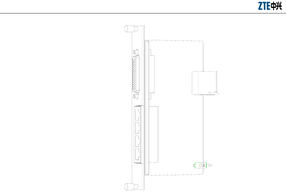
ZXC10 BTSB (V1.0) cdma2000 Base Transceiver Station Installation Manual
12-10
Fig. 12.4-2 Structure of a Back Interface Board
12.4.3 Interface Board Structure
As shown in Fig. 12.4-2, the interface board at the back has a panel in the front, and
plug-ins at the back. Two captive screws and some plug-ins are on the panel.
12.4.4 Installing and Replacing the Interface Boards
To install a board, align the board with its slot, push the board vertically until it is in
position, and fasten the captive screws.
To remove the board, loosen the screws, grasp the screws and unplug the board.
12.5 Board Installation Sequence
Install the boards into their corresponding slots as shown in Fig. 12.5-1 or by referring
to the diagram in the hardware manual.
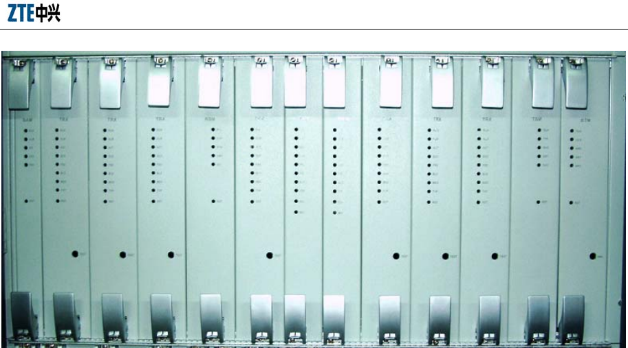
Chapter 12 Board Installation
12-11
Fig. 12.5-1 Positions of Boards

13-1
13 Hardware Installation Check
Summary:
z M452/R452 hardware installation check
Check the installed items before you power on the BTSB.
13.1 Checking the Cabinet
The installation of an indoor cabinet involves the installation of a BTSB rack and other
cabinets (such as DC/AC power cabinets). After cabinet installation, check the
following items:
1. The rack installation location conforms to the design drawing.
2. A rack, when fixed, should be firmly erected to resist a 7.0 earthquake.
3. The levelness error of a cabinet should be less than 3 mm, but its vertical
missing should be no more than 3 mm. The gap between two adjacent stands
should be no more than 3 mm.
4. The front door of the rack should be flush with the front edges of other
equipment, without any concave or convex.
5. The front of the rack should be no less than 1 m away from the wall, and the rear
of the rack, 0.8 m away from the wall.
6. The parts on the rack should not fall off or be damaged. The rack should be
painted well and the labels on it should be correct, clear and complete.
7. Check all over the cabinet to make sure that no metal scrap or conducting wire is
left. The cabinet inside is clean and has no leftover.
8. All screws should be tightened with flat washers or spring washers placed
correctly.
9. Each stand should be equipped with 4 partition insulators. If installed close to
walls, some of them should be placed between each stand and walls to make a

ZXC10 BTSB (V1.0) cdma2000 Base Transceiver Station Installation Manual
13-2
cabinet and walls insulated.
10. The stand supporter should be consistent with the hole sites of expansion
screws.
11. The upper plane of the conductive floor in the equipment room is no higher than
the lower surface of the stand lest the radiating of a stand should be affected.
12. After all cables are laid out, the small cover plates of the wire outlets at the
cabinet top should be pushed forward to cover the wire outlets and to prevent
rodents entering the cabinet.
13. In the case of a combined cabinet, check whether the cabinets are well arranged
and the connecting pieces at the combined cabinet top are firmly installed.
14. The surface of the integrated equipment should be clean and tidy, and the paint
outside it should be in good condition. The identifications should be correct,
clear and complete.
15. The front door of the cabinet can be easily opened or closed.
13.2 Checking the Cable Racks
Requirements:
1. The location and height of the cable rack should meet engineering design
requirements.
2. The flat steel of the cable rack should be flat and straight, without any apparent
warping or obliqueness.
3. Each cable rack should be equipped with a grounding cable. All connection
points should be superior in electrical performance and they are well connected
with the grounding body in the equipment room.
13.3 Checking Cable Laying, Binding and Identifying
Principles:
1. The cables are laid flat and straight, without any apparent fluctuation, skewness,
crossing or jump wire in air. Any remaining length should be curled, bound and
laid in a cable trough.

Chapter 13 Hardware Installation Check
13-3
2. Cables should be bent smoothly and evenly and the outer part of the arc should
be as vertical or horizontal.
3. Power cables and signal cables are separated from each other with at least 150
mm in between.
4. Both cable ends should be clearly labeled or marked to prevent connection
mistakes.
5. Connector locations should be compact, firm, well-contacted and upright
without broken or bending.
6. After being laid, cables should be trimmed to look straight, tidy and pleasing to
the eye, without any crossing.
7. Cable straps should be made tidy and pleasing to the eye. Cable ties should be
evenly spaced, neither too tight nor loose, and go in the same direction.
8. Any excess cable strap should be cut and all indoor cable straps must be cut
from the root, without any tips left.
9. Cable straps shall be left with some margins when cut after binding.
10. All cable straps must be cut from the root, and no tip shall be left.
11. Each label identifies the uses of the cable and the same content should be written
for the labels attached on both cable ends.
12. Wrap labels with some cellulose tape to prevent any loosening.
13. All cables, especially main feeders and indoor 1/2" jumpers, should be labeled.
All labels should be arranged in a tidy and beautiful way and in the same
direction.
13.4 Checking the Power Cables and Grounding Cables
Requirements:
1. The power cables and grounding cables in the equipment room shall be laid in
accordance with engineering design requirements.
2. The PGND cable on a BTS rack employs 35 mm2 yellowish green or yellow
copper-core cables and are connected with indoor PGND copper bars. They
shall be well contacted and firm. The GND/BGND cable adopts the black

ZXC10 BTSB (V1.0) cdma2000 Base Transceiver Station Installation Manual
13-4
copper-core cable with the cross-section area 25 mm2. The -48V power cable
adopts the blue copper-core cable with the cross-section area 25 mm2. All these
cables are laid straight and connected reliably.
3. A grounding bus cable should be directly connected with an indoor ground cable
bus without connected to any intermediate equipment. The diameter of the
grounding bus cable shall be more than 50 mm2.
4. Each grounding point on the grounding copper bar can only be connected with
one piece of equipment.
5. The protective grounding cable and the AC neutral cable are separated instead of
being placed or used together.
6. The AC neutral line in the power room is independently grounded.
7. The outdoor grounding resistance shall be less than 5 ohm
8. Each cable is identified clearly and correctly.
9. The grounding cable of a power cable, when laid, should be bound separately
from other cables.
10. The remaining length of the grounding cable and power cable should be cut off
instead of coiling it up and reserving it.
11. The copper lugs on both ends of power cables and grounding cables shall be
soldered or pressed firm.
12. The power cable and the grounding cable should be of whole material and no
connector is allowed in the middle.
13. The grounding bar shall be insulated from walls and the grounding cable shall
extend as short as possible.
14. The primary power supply is correctly connected to the power supply terminals
on the rack.
15. The lifting lug of a power cable should be soldered or pressed firm and upright.
16. The power cable and copper lug must be contacted in a reliable and firm way
and are sealed with an adhesive tape. The copper lug must be connected firmly
with the power cabinet (or the BTS rack).
17. Insulated protective sleeves are well installed on both connecting terminals of

Chapter 13 Hardware Installation Check
13-5
the power supply on the rack top.
18. Power cables, ground cables, trunk cables and RF cables should not be broken
or damaged.
19. The labels on both ends of the power cable and ground cable shall be clear and
correct.
20. The bare wires at the connecting terminals and lug handle should be tightly
wrapped with insulating tape or a heat-shrink tube instead of being exposed.
21. The connecting terminals should be equipped with flat washers and spring
washers.
13.5 Checking the E1 Cables
Requirements:
1. E1 cable connectors are reliably installed, without any short-circuit or damage.
2. E1 cables are connected correctly and labeled clearly.
3. No E1 connector gets loose. Test with a multimeter whether the connector shell
and grounding system are well connected. Otherwise, the ring flange of the
connector and shell are in poor contact.
4. The E1 cables on the set top should reserve some margin length. Do not stress
them in case they cannot be reliably connected with the rack connectors when
the cable rack vibrates.
5. E1 cable connectors must be connected reliably.
13.6 Checking the Sensors
Requirements:
1. The temperature/humidity sensor is vertically installed and cables are correctly
connected to the cabinet top.
2. The smog sensor is horizontally installed and cables are correctly connected to
the cabinet top.

ZXC10 BTSB (V1.0) cdma2000 Base Transceiver Station Installation Manual
13-6
13.7 Checking the Internal Connections of the Cabinet
Requirements:
1. The RF cables between modules within the rack shall be reliably connected.
2. The screws of all modules within the rack must be fastened to the greatest extent
to prevent any unreliable connection.
3. Any unused connector is screwed on with a matching terminal.
4. The RF cables shall avoid crossing and over stretching. Some margins are
expected to be reserved at the turning corner and the connectors shall connect
firmly.
13.8 Checking Indoor 1/2" Jumpers
Requirements:
1. According to the name plate of the main feeder, use 1/2" jumpers to connect
with the connecting terminals on the rack top.
2. The labels of 1/2" indoor jumpers should indicate the corresponding sectors and
the length of the main feeder.
3. Indoor jumpers should be tidy and in appropriate length. They should be bound
on the cable rack in order.
4. The cabling should provide convenience for maintenance and capacity
expansion.
5. Jumpers should be laid by layers and sectors.
6. There should be 30 cm flat and straight where jumpers and a lightning arrester
are connected.
13.9 Checking the Lightning Arrester
Requirements:
1. The RF lightning arrester is connected to the connectors of the feeder, and
fastened tightly.
2. The 6 mm2 yellow ground cable of the GPS lightning arrester shall be reliably
connected to the outdoor grounding bar.

Chapter 13 Hardware Installation Check
13-7
3. The RF lightning arrester and the GPS lightning arrester should be mounted
between two crosspieces of the cable rack without touching the cable rack.
Insulation from the cable rack is required.
13.10 Checking the Lightning Arrester Rack
Requirement:
1. The lightning arrester rack installed should be insulated from the cable rack.
2. The lightning arrester should be installed on the lightning arrester rack in a firm,
reliable and beautiful way.
3. The grounding copper cable of the lightning arrester rack must be routed to the
outdoor grounding copper bars for reliable grounding.
4. When led outdoors, the grounding copper cable of the lightning arrester rack
must be insulated from indoor conductors.
13.11 Checking the Primary Feeder Cables and GPS Feeder Cables
Requirements:
1. To make a main feeder connector, you have to use a special cutter. The profile
of the main feeder should be flat and smooth. The main feeder has no copper
scraps in its copper tube. The feeder connector should meet the standards and be
connected tightly.
2. 7/8" feeder connector should be tightened with a big spanner and installed in
place to avoid any abnormal SWR caused by false connections.
3. The feeder between the tower top and the equipment room should be grounded
in at least three points. The first location is within 1 m from the tower up to the
platform. The second is within 1 m from the tower to the front of the outdoor
cable rack. The third is within 1m between the feeder and the feeder window.
The grounding points should be bound firmly with proper waterproof measures.
Where a grounding kit is installed, the sheath of a feeder is removed according
to the kit size. When installing the grounding kit, pay attention to waterproof
measures. The terminal of the grounding kit connected with a grounding cable
should face downward lest any rainwater should flow into the feeder along the
grounding cable.

ZXC10 BTSB (V1.0) cdma2000 Base Transceiver Station Installation Manual
13-8
4. If a tower is above 60 m and needs a longer feeder, another feeder grounding
clip should be placed in the middle of the tower.
5. If a feeder is off the tower and routed for above 20 m at the building top or on
the cable rack before going into the room, another grounding clip for lightning
protection should be put at the building top or on the cable rack.
6. The terminals of the grounding clip of a feeder should be fixed on the steel plate
of a nearby tower.
7. The outdoor grounding copper bar employs a special reliable path to an
underground ground grid. The line width should be more than 50 mm2.
Otherwise, users should lay connecting cables as soon as possible.
8. For a building without a tower, the antenna feeder ground at the top should be
connected with the nearby lightning protection ground grid on the roof.
9. If the feeder employs a downward cable ladder to go along walls downward
from the building top and enters a room, the cable ladder should be grounded.
10. The grounding cable of a feeder should be led from up to down. The separation
angle between the feeder and grounding cable should be no more than 15º.
11. The cabling of the feeders should be visually appealing without crisscrossing.
They should be well arranged and have no apparent twists and turns. The feeders
entering a room should be tidy, flat, straight and with identical bending angle.
The main feeders are correctly connected and the sectors concerned are correct
too.
12. The minimum bending radius of a feeder should be no more than 20 times the
feeder radius, and the bending radius of the main feeder should be more than 0.3
m.
13. The cabling of the main feeders should be planned. When the cabinet front is
parallel to the direction in which a feeder enters a room or the cabinet back is
facing the direction in which a feeder enters a room, the main feeders within a
sector should be arranged as a row. The arrangement order of each row should
be consistent. When the cabinet front faces the direction in which a feeder enters
a room, one sector is arranged as a column and the arrangement order of each
column should be consistent.
14. The feeder connector should have no bare copper sheet. Two name labels should

Chapter 13 Hardware Installation Check
13-9
be bound on both terminals of a feeder to ensure that feeders correspond to
antennas. Write corresponding lengths on a feeder name plate.
15. Avoid any dry joint in soldering GPS core wire.
16. GPS copper core and external outer layer cannot be short-circuited. The core pin
of a feeder connector should be parallel to the external end face of a GPS feeder
connector.
17. Tighten the GPS feeder connectors.
13.12 Checking the Feeder Cable Window and Water-Blocking
Curve of the Primary Feeder Cable
Requirements:
1. A feeder window is fixed on one indoor wall and the feeder hole bulging on the
feeder window faces outdoors.
2. The glue injection hole on the packing gland on the feeder sealing window
should be sealed upward and window boards should be installed on one indoor
wall.
3. When a feeder window is installed at the building top to lead a feeder into the
room, it should be well sealed.
4. When an outdoor feeder enters the equipment room, a waterproof bend must be
made at the outdoor feeder window. The lowest point of the waterproof bend is
required to be 10 cm ~20 cm lower than the lower edge of the feeder window.
5. The minimum bending radius of a feeder should be no more than 20 times the
feeder radius, and the bending radius of the main feeder should be more than 0.3
m.
6. The indoor and outdoor parts of a feeder should be both above 0.5 m. There
should be 0.3 m flat and straight at the lightning protection rack.
13.13 Checking the Three-Way Feeder Cards
Requirements:
1. The three-way feeder card should be fixed on the outdoor cable rack.

ZXC10 BTSB (V1.0) cdma2000 Base Transceiver Station Installation Manual
13-10
2. The intervals between the feeder fixing clips should be even and in the same
direction.
3. A feeder card should be installed every 1.5m on the main feeder.
13.14 Checking the Outdoor 1/2" Jumpers
Requirements:
1. Antennas and 1/2" jumpers. The 1/2" jumpers and main feeders should also be
correctly connected. The threads of the connectors should fit in and the
connectors are tightened.
2. The jumper connected with an antenna should be bound to the support crossbar
to the steel frame of the tower.
3. The wrapping requirements between an antenna and 1/2" jumper connector and
the wrapping between a 1/2" jumper and the main feeder connector are as
follows: a. the connector is wrapped with some waterproof self-adhesive tape; b.
the waterproof self-adhesive tape at an antenna terminal must be wrapped until
the antenna root; c. the feeder terminal should be wrapped until 10 cm away
from the connector; d. the waterproof self-adhesive tape is wrapped with an
insulating tape longer than the waterproof self-adhesive tape.
4. At the joint between the jumper and the antennas, they should be parallel to each
other with 30 cm in between.
5. The connector is wrapped with a waterproof self-adhesive tape, which must be
extended to an antenna root. Wrap the feeder terminal until 10 cm away from
the connector. Wrap the waterproof self-adhesive tape with an insulating tape
longer than the waterproof self-adhesive tape.
6. All outdoor jumper connectors should be waterproof and the jumper should be
equipped with a waterproof bend.
Fig. 13.14-1 shows the waterproof method for the outdoor 1/2” jumper.
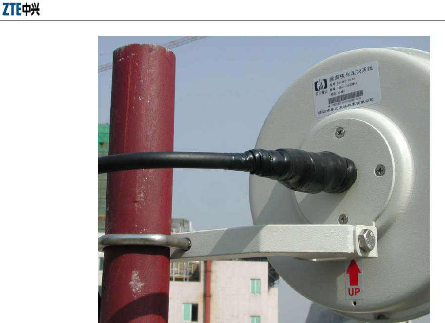
Chapter 13 Hardware Installation Check
13-11
Fig. 13.14-1 Waterproof Outdoor 1/2” Jumper
13.15 Checking the Antenna
Requirements:
1. An antenna support and a tower should be connected in a reliable and firm way.
2. Check the model of the antenna in use to make sure that it conforms to
networking planning.
3. The hanging height of an antenna refers to the distance between the ground and
the middle of the antenna. It is required that the actual hanging height of an
antenna conforms to network planning, and the antenna should be installed as
designed.
4. The RF antenna and the GPS antenna should be included in the protection area
of a lightning arrester (the area within the downdip of 450 from the lightning
arrester).
5. Measure the azimuth of an antenna. In case of a unipolarization directional
antenna, each antenna should be measured. The actual azimuth of an antenna

ZXC10 BTSB (V1.0) cdma2000 Base Transceiver Station Installation Manual
13-12
conforms to network planning and two antennas within the same sector goes in
the same direction. The azimuth error of the directional antenna is no more than
±0.50.
6. Measure the actual mechanical downdip of an antenna with an angulometer. In
case of a unipolarization antenna, each antenna should be measured. An omni
antenna will not be checked and a directional antenna should have the azimuth
error of no more than ±0.50. The actual mechanical downdip of an antenna
conforms to network planning and two unipolarization antennas have consistent
downdips.
7. The electrically controlled pointer antenna is adjusted with a ejector lever , and
the electrically controlled digital antenna is controlled with key input in the
equipment room. Note that the control line connected with the antenna is
vulnerable. In the case it is broken, it has to be directly adjusted with a spanner
at the antenna terminal. Each of the unipolarization antennas should be
measured. The actual electrically controlled downdip of an antenna conforms to
network planning and two unipolarization antennas should have consistent
downdips. This is not required if it is not an electrically controlled antenna.
8. All antenna poles should be firmly installed and well grounded. All antenna
poles are required to be vertical to the ground and the vertical error should be
less than 20. In particular, all antennas must be vertical to the ground. Check
with a line hammer to keep the vertical error less than 20.
9. The receive/transmit horizontal interval of an omni antenna should be no less
than 3.5 m.
10. An omni antenna should be at least 1.5 m away from the tower while a
directional antenna should be at least 1 m away from the tower.
11. The jacket top of an omni antenna should be level to a support or slightly higher
than the support top.
12. When an omni antenna is installed on a roof, the horizontal interval between the
omni antenna and antenna lightning arrester should be no less than 2.5 m.
13. An omni antenna installed on a roof should avoid blind area.
14. Check the matching relationship of the main diversity antennas within the
sectors and the set top jumpers on the rack.

Chapter 13 Hardware Installation Check
13-13
15. The diversity distance between two antennas within one sector refers to the
vertical distance between the parallel lines of the two antennas front surfaces. It
is not the distance between two antennas. Diversity distance is irrelevant to
bipolarization antenna. The diversity distance should be 3.5 m for the 800M
system, 1.5 m for the 1.9G system, and 6.7 m for the 450M system.
16. The vertical interval between directional antennas within different sectors
installed on the same antenna support should be more than 0.6 m.
17. When isolated from an antenna in G network, the vertical separation should be
more than 1 m, and the horizontal separation more than should be more than 2
m.
18. GPS antenna should be vertical, secure, in a position as low as possible, and
without barrier. The GPS spatial angle should be more than 900.
19. When there is no tower, the GPS antenna should be installed on the building top
and equipped with an independent lightning arrester.
Fig. 13.15-1 shows the installation of the transmission antenna.
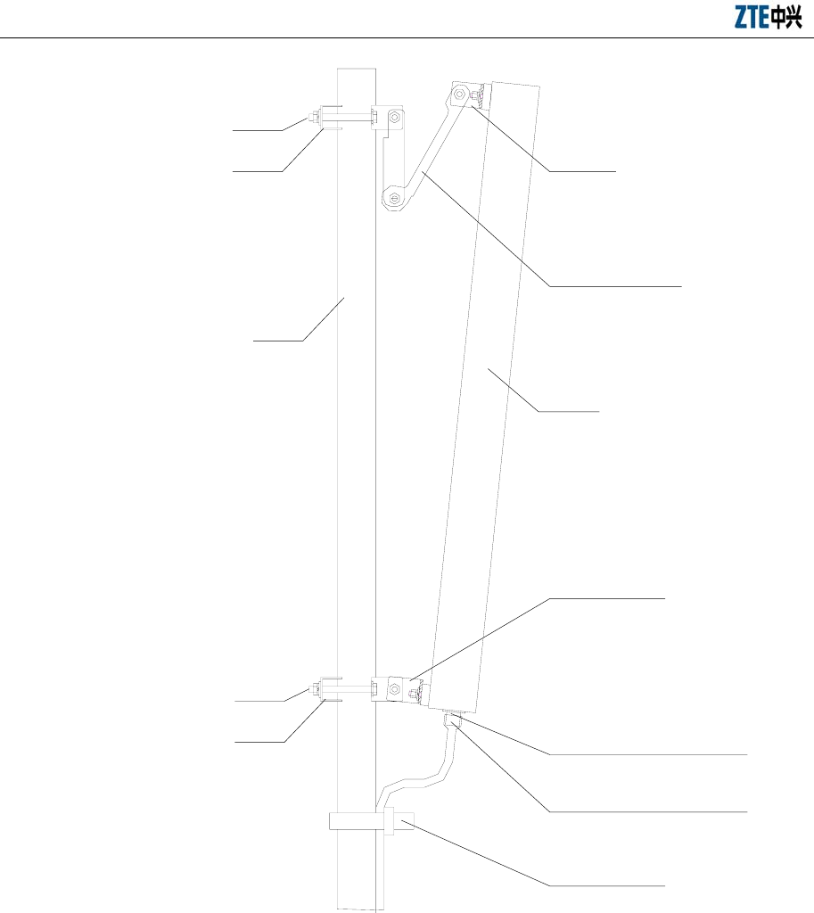
ZXC10 BTSB (V1.0) cdma2000 Base Transceiver Station Installation Manual
13-14
Bolt
Clamp Installation part 1
Adjustable
antenna arm
Installation part 2
Cable strap
Antenna pole
Antenna
Antenna RF socket
RF cable socket (with
waterproof treatment)
Bolt
Clamp
Fig. 13.15-1 Antenna Installation Checking the Feeder SWR
13.16 Checking Feeders of SWR
Requirements:
1. Measure the SWR after antennas and all feeders are installed.
2. The terminal of the indoor 1/2" jumper to the rack is connected with an SWR
tester for testing. The SWR should be less than 1.5, preferably 1.3.

Chapter 13 Hardware Installation Check
13-15
3. Fill in a corresponding vswr value and provide vswr test-chart.
13.17 Checking Indoor & Outdoor Environments
Requirements:
1. Clean outdoor engineering waste. After the installation is over, the outdoor work
site should be recovered to what it was, without any cable strap, stub, waste
paper box, waste cable or waste plastic bag. The whole site should be clean and
tidy.
2. Put away indoor unused materials. The materials to be put in the equipment
room should be kept in order. Keep everything indoor clean and tidy. No
littering is allowed.
3. Remove any cable strap, stub, desiccant and other engineering materials under
the raised floors at the rack bottom and around the rack.
4. Clean the front door, rear door and side plate of the rack, leaving no visible
stains caused by hand touching. There should be no dirt inside and outside the
rack (dead angle) and inside the cabinet, there should be no cable clip or
sundries left.
5. Clean the fingerprint or other stains on the cabinet surface.
13.18 Base Station Information Table
Record the model and the sequence number of all parts installed for the required base
station information table.

14-1
14 Power-on/Power-off
Summary:
z Power-on/Power-off of the PWS (AC/DC) of the BTSB
z Power-on/Power-off the BDS shelf
z Power-on/Power-off the RFS shelf
14.1 Checking before Power-on
Check the following power switches:
1 The upper level switch of the AC power
2. The input AC power switch of the system
3. The DC power switch of the BDS shelf
4. The DC power switch of the RFS shelf
5. The battery loop switch that is in the rupturing state
14.1.1 Checking the External Connections of the Rack
1. Check the AC power connection: Examine carefully whether the power cable
connected to the AC power cable terminal of the PWS shelf at the cabinet top is
correctly connected. (Note: This power supply can be AC 220V 3-wire input
with voltage ranging 150V ∼ 285V, or AC tri-phrase five-wire input with voltage
ranging 150V ∼ 285V and line voltage 270V ∼ 490V.) Do not reversely connect
the live wire and the null wire and be sure to fasten the screws.
2. Check the DC power connection: Examine carefully whether the terminal block
is correctly connected to the DC battery of the PWS shelf. Be sure that the
polarity is not reversely connected, the voltage is in the range of -40V ∼ -57V,
and the screws are fastened.
3. Make sure that E1 cables are correctly connected without insecure connections.

ZXC10 BTSB (V1.0) cdma2000 Base Transceiver Station Installation Manual
14-2
4. Check the antenna feeder system. Check with an SWR tester to see whether the
SWR of the antenna feeder is less than 1.5 (generally less than 1.3). Feeder
connectors should be well assembled and no feeder or antenna is faulty.
5. Check whether the grounding cable is reliable.
6. Check whether the cable labels are pasted securely, correctly and beautifully.
14.1.2 Checking the Internal of the Rack
1. Open the front door of the upper rack, check the switches on the upper door of
the PWS shelf and the lightning arrester to see if they are reliable. There shall be
no stubs, wires or anything else in the slots for the rectifier module in the lower
shelf.
2. Open the front door to the BDS shelf of the rack in the middle. There shall be no
stubs, wires or anything else.
3. Open the front door to the RFS shelf of the lower rack. Connectors shall be
provided at the back of the corresponding slot of the RF module.
4. Check the connections at the rear part of the rack to see whether the BDS and
RFS cables are correctly and firmly connected, and whether connectors are
connected correctly and firmly according to the cable labels.
5. Check whether the RF cables at the rear part of the rack are correctly and firmly
connected, and whether connectors are connected correctly and firmly according
to the cable labels.
6. Open the back door of the rack and check whether the labels and the connections
are correct, whether the connections become insecure because of moving,
particularly the RF cables, and the connection between the power busbar of the
rack and the power connector on the board.
7. Check the DIP switches on the backplane for incorrect setting. Check whether
the DIP switches on the backplane of the rear part of the rack are in the right
position when necessary.

Chapter 14 Power-on/Power-off
14-3
14.2 Procedure of Power-on
14.2.1 Initial Power-on
1. Open the front door of the upper rack, check whether the rectifier module of the
PWS shelf is pluggable. When the rectifier module is unplugged, it shall be
partially seated in the shelf. When the PMM is inserted into the slot, it shall be
partially seated in the shelf.
2. Open the front door to the BDS shelf of the rack in the middle, insert a board,
and then abort the insertion to make it partially seated in the shelf. Insert the fan
shelf, and then abort the insertion to make it partially seated in the shelf.
3. Open the front door to the RFS shelf of the lower rack, unplug all boards to
make them all partially seated in the shelf. Insert the RF module, connect all
cables, and make sure the switch is off.
4. AC power-on: Switch on the upper level AC power, and connect the
corresponding AC voltage for the terminal. Switch on the AC input. It is over
when the D-level lightning-proof indicators on the right corner of the front panel
are all on.
5. DC power-on: Insert a rectifier module and start it. The indicators shall present
no alarms with the current zero, and the output DC voltage 48V ∼ 54V. Insert the
rectifier module in turn with the others unplugged, the indicators shall be normal.
Keep one rectifier module plugged, and insert the PMM to complete the PWS
shelf check.
6. Switch on the BDS shelf, insert and start the fan, and insert a board to complete
power-on. If the fan is not started, check for any error on the DC 48V or an ill
plugging of the fan.
7. Switch on the RFS shelf, insert and start the fan, and insert a board to complete
power-on. If the fan is not started, check for any error on the DC 48V or the fan.
8. Switch on the loop of the battery to see if it is normal. Disconnect the switch
after the power-on is complete.
9. Insert into the rectifier modules, BDS boards, RFS boards and modules in turn
to see if they are normal.
10. Switch on the loop of the battery to complete the power-on.

ZXC10 BTSB (V1.0) cdma2000 Base Transceiver Station Installation Manual
14-4
If any exception occurs, switch off the power for a check.
14.2.2 Normal Power-on
1. AC power-on: Switch on the upper level AC power, connect the corresponding
AC voltage for the terminals, switch off the AC power input, and complete when
the D-level lightning-proof indicators on the right corner of the front panel are
all on.
2. DC power-on: Insert and start one rectifier module. The indicators shall present
no alarms with the current zero, and the output DC voltage 48V ∼ 54V. Insert the
rectifier module in turn with the others unplugged, the indicators shall be normal.
Keep one rectifier module plugged, and insert the PMM to complete the PWS
shelf check.
3. Switch on the BDS shelf, insert and start the fan, and then insert a board to
complete a normal power-on. If the fan cannot be started, check for errors on the
DC 48V or an ill insertion of the fan.
4. Switch on the RFS shelf, insert and start the fan, and then insert a board to
complete a normal power-on. If the fan can not be started, check for errors on
the DC 48V or an ill insertion of the fan.
5. Switch on the loop of the battery to complete the battery power-on. If it is
normal, the power-on is completed.
14.3 Procedure of Power-off
1. Power off the LPA module.
2. Power off the BDS shelves.
3. Power off the RFS shelf.
4. Power off the battery loop.
5. Cut the AC power input.
6. Cut the AC power for the external of the rack.

Chapter 14 Power-on/Power-off
14-5
14.4 Hot Swap
The LPA and PIM in the BTSB rack have their own power switches and shall be
plugged/unplugged only when their power switches are turned off.
The other boards in the BTSB rack, such as PRM, PMM, CHM, CCM, DSM, SNM,
RIM, GCM, SAM, BTM, RMM, TSM, RSM, TRX and RFE, are all hot-swappable.

A-1
Appendix A Technical performance indices
of the BTSB
A.1 Mechanical indices
Dimensions and weight:
Single cabinet (baseband cabinet + RF cabinet): 700 mm (W) × 800 mm (D) × 1600
mm (H)
RFS cabinet: 700 mm (W) × 800 mm (D) × 1200 mm (H)
BDS cabinet: 700 mm (W) × 600 mm (D) × 400 mm (H)
Optional PWS rack: 700 mm (W) × 600 mm (D) × 400 mm (H)
BTS cabinet color: Black
Table A.1-1 indicates the weight of the integrated machine and the bearing capability
of the equipment room floor:
Table A.1-1 Weight of the Integrated Machine
Configuration Weight
4-carrier 1-sector About 150 kg
4-carrier 3-sector About 180 kg
4-carrier 6-sector/8-carrier 3-sector About 240 kg
A.2 Power indices
Power supply and power consumption: The power consumption of ZTC10-BTS refers
to the overall power consumption when the operating voltage is 48V and the output
power of each power amplifier is 20W, as shown in Table A.2-1.

ZXC10 BTSB (V1.0) cdma2000 Base Transceiver Station Installation Manual
A-2
Table A.2-1 BTS Power Consumption Indices in Normal Operation
Configuration Power Amplifier Output
Working
Voltage
Maximum Power
Consumption of 1X (W)
Maximum power
consumption of DO (W)
1-carrier 1-sector 40 W/carrier -48V About 1400 W About 1400 W
2-carrier 1-sector 40 W/carrier -48V About 1400 W About 1400 W
3-carrier 1-sector 40 W/carrier -48V About 1400 W About 1400 W
5-carrier 1-sector 40 W/carrier -48V About 2000 W About 2000 W
7-carrier 1-sector 40 W/carrier -48V About 2000 W About 2100 W
1-carrier 3-sector 40 W/carrier -48V About 2500 W About 2600 W
2-carrier 3-sector 40 W/carrier -48V About 2600 W About 2600 W
3-carrier 3-sector 40 W/carrier -48V About 2600 W About 2700 W
4-carrier 3-sector 40 W/carrier -48V About 2600 W About 2700 W
5-carrier 3-sector 40 W/carrier -48V About 4400 W About 4500 W
7-carrier 3-sector 40 W/carrier -48V About 4500 W About 4600 W
8-carrier 3-sector 40 W/carrier -48V About 4500 W About 4700 W
1-carrier 6-sector 40 W/carrier -48V About 4300 W About 4400 W
2-carrier 6-sector 40 W/carrier -48V About 4400 W About 4500 W
3-carrier 6-sector 40 W/carrier -48V About 4500 W About 4600 W
4-carrier 6-sector 40 W/carrier -48V About 4500 W About 4700 W
B-1
Appendix B Using SiteMaster
Different models of SiteMaster are used differently. For usage information, please refer
to the documents came with the device.
B.1 Selecting a frequency range
1. Press <ON> of SiteMaster to turn on the meter.
2. Press <FREQ> on the main menu.
3. Press <F1> on the [Frequency] menu.
4. Input the frequency for [Lower], such as “825MHz”, and then press <ENTER>
for confirmation.
5. Press <F2> on the [Frequency] menu.
6. Input the frequency for [Higher], such as “880MHz”, and then press <ENTER>
for confirmation.
7. When confirmed, press <MAIN> to return to the main menu.
B.2 Checking SiteMaster
SiteMaster shall be checked in the case of frequency, environment and feeder
parameters changes. Follow these steps to check:
1. Make sure that a correct frequency range is input in SiteMaster, then begin the
check.
2. Press <STARTCAL> to begin the check.
3. Press <Measuring OPEN>, <MeasuringSHORT>, and <Measuring Load> one
by one as prompted to complete the check.
4. Include the extension cable came with the meter to the check for measurement
accuracy.

ZXC10 BTSB (V1.0) cdma2000 Base Transceiver Station Installation Manual
B-2
B.3 Inputting feeder parameters
1. Press <DIST>.
2. Press <MORE>.
3. Press <LOSS> to enter the feeder loss per meter (dB), which varies with
providers and models. Then press <ENTER> for confirmation.
4. Press <PROP V> to enter the relative transmission rate, which varies with
providers and models. Then press <ENTER> for confirmation.
5. Press <MAIN> to return to the main menu.
B.4 Installing the tester
Connect one end of the self-contained extension cable to the RFE jumper connector
inside the rack and the other terminal to the Refl interface of the meter.
If there is an active device like a tower top amplifier or a trunk amplifier in the feeder
measuring, jumpers shall be used to dodge it.
B.5 Measuring SWR
1. Press<OPT>.
2. Press <B1> to choose [MODE].
3. Press <Up> or <Down> to select [SWR] and press <ENTER> for confirmation.
4. Press<MAIN> to return to the main menu.
5. Input a proper frequency range if necessary.
6. Check the meter if necessary.
7. Press<MAIN> to return to the main menu.
8. Press<RUN> to begin the measure.
9. Press <AUTOSCALE> to adjust the Y-coordinate.
10. View the SWR values of the frequency points within this frequency band, as
shown in Fig. B.5-1.
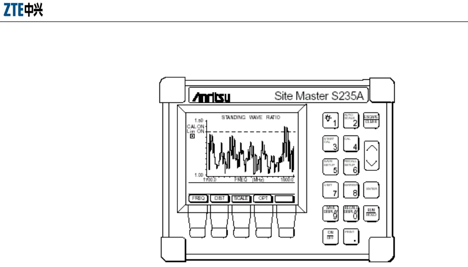
Appendix B Using SiteMaster
B-3
11. Press <Save Display> to save the data.
Fig. B.5-1 SWR Test for the Antenna Feeder
B.6 Measuring DTF
1. Press <OPT>.
2. Press <B1> to choose [MODE].
3. Press <Up> or <Down> to choose [SWR], and press <ENTER> for
confirmation.
4. Press <MAIN> to return to the main menu.
5. Input a proper frequency range if necessary.
6. Check the meter if necessary.
7. Input a proper feeder length if necessary.
8. Press <MAIN> to return to the main menu.
9. Press <RUN> to begin the measure.
10. Press <AUAOSCALE> to adjust the Y-coordinate.
11. Press <Mark> to view the SWR value of each frequency point within this
frequency band. Check the fault, as shown in Fig. B.6-1.
12. Press <Save Display> to save the data.
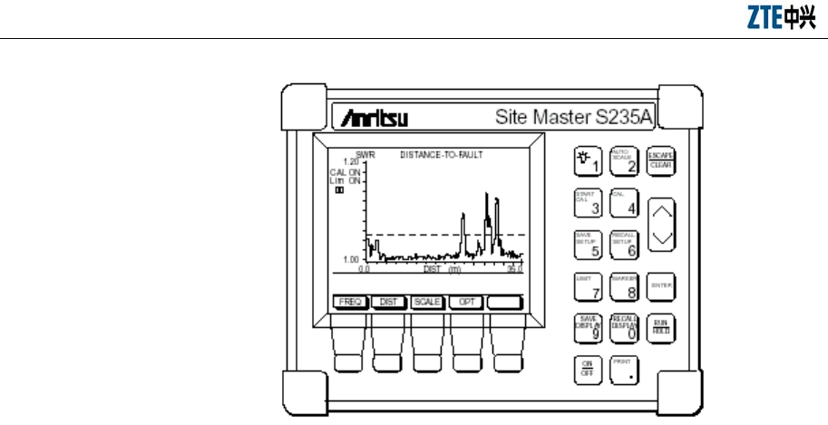
ZXC10 BTSB (V1.0) cdma2000 Base Transceiver Station Installation Manual
B-4
Fig. B.6-1 Antenna Feeder DTF Measurement

C-1
Appendix C BTSB board indicators
C.1 RMM indicators
The BTSB has more than ten boards. The first three indicators, RUN, ALM and M/S,
on these boards function similarly. This section takes the indicators on the RMM as an
example.
z RUN indicates the operating state of the board.
z ALM indicates exception occurred on the board.
z M/S indicates whether the board is the master one.
Fig. C.1-1 shows the indicators of the RMM.
RMM
RUN
ALM
M/S
TFS
F0S
F1S
BLS
TYP
RST
M/S
Fig. C.1-1 Indicators on the RMM

ZXC10 BTSB (V1.0) cdma2000 Base Transceiver Station Installation Manual
C-2
C.2 Board indicators
Table C.2-1 shows the states and meanings of the indicators on the BTSB boards.
Table C.2-1 BTSB Board Indicators
CCM Indicators
Indicator
Name
Color Meaning Description Normal State
RUN Green RUN indicator Solid on: The version starts to run and
attempts to obtain a network address.
Solid off: No power or CPU down.
Extremely slow flash: (0.2 HZ, 50%):
BOOT requests for a version download.
Slow flash (1/3 HZ, 50%): Notifying the
power-on to the basic processes.
Normal flash (5/3 HZ, 50%): Powered on
for normal working.
Quick flash (50/7 HZ, 50%):
Disconnected with the external.
Normal flash (5/3 HZ,
50%)
ALM Red Alarm indicator Solid on: Alarm.
Off: Normal.
Solid off
M/S Green Master/Slave
indicator
Solid on: Master board.
Solid off: Slave board.
Solid on/off
HES Green Run indicator for
signaling stream
IP communication
platform
Solid on: Normal
Solid off: Abnormal or not in position
Solid on
SES Green Run indicator for
media stream IP
communication
platform
Solid on: Normal
Solid off: Abnormal or not in position
Solid on
DSM Indicators
Indicator
Name
Color Meaning Descriptions Normal State
RUN Green Run indicator Solid off: No power or CPU down.
Solid on and quick flash: Loading version
(20 HZ).
Slow flash: Normal (2 HZ)
Flash
ALM Red Alarm indicator Solid on: Alarm.
Off: Normal
Off

Appendix C BTSB board indicators
C-3
CCM Indicators
Indicator
Name
Color Meaning Description Normal State
M/S Green Master/Slave
indicator
Solid on: Master board
Off: Slave board
Solid on for master
board.
Solid off for slave
board.
E0S Green Group 0 E1
indicator
Running state for the uplink DT0 through
DT3
Flash green with flash frequency as 0.125
HZ and period as 8 S: Normal.
1S (On Off Off Off Off Off Off Off Off
Off): DT0 is normal.
Not on: DT0 is abnormal.
2S (Off Off Off Off Off Off Off Off Off
Off) interval
3S (On Off On Off Off Off Off Off Off
Off): DT1 is normal.
Not on: DT1 is abnormal.
4S (Off Off Off Off Off Off Off Off Off
Off) interval
5S (On Off On Off On Off Off Off Off Off):
DT2 is normal.
Not on: DT2 is abnormal.
6S (Off Off Off Off Off Off Off Off Off
Off) interval
7S (On Off On Off On Off On Off Off Off):
DT3 is normal.
Not on: DT3 is abnormal.
8S (Off Off Off Off Off Off Off Off Off
Off) interval
Solid off: 4 × E1 are abnormal.
Flash
ZXC10 BTSB (V1.0) cdma2000 Base Transceiver Station Installation Manual
C-4
CCM Indicators
Indicator
Name
Color Meaning Description Normal State
E1S Green Group 1 E1
indicator
Running state of the uplink DT4 through
DT7
Flash green with flash frequency as 0.125
HZ and period as 8 S: Normal.
1S (On Off Off Off Off Off Off Off Off
Off): DT4 is normal.
Not on: DT4 is abnormal.
2S (Off Off Off Off Off Off Off Off Off
Off) interval
3S (On Off On Off Off Off Off Off Off
Off): DT5 is normal.
Not on: DT5 is abnormal.
4S (Off Off Off Off Off Off Off Off Off
Off) interval
5S (On Off On Off On Off Off Off Off Off):
DT6 is normal.
Not on: DT6 is abnormal.
6S (Off Off Off Off Off Off Off Off Off
Off) interval
7S (On Off On Off On Off On Off Off Off):
DT7 is normal.
Not on: DT7 is abnormal.
8S (Off Off Off Off Off Off Off Off Off
Off) interval
Solid off: 4 × E1 are abnormal.
Flash
Appendix C BTSB board indicators
C-5
CCM Indicators
Indicator
Name
Color Meaning Description Normal State
E2S Green Group 2 E1
indicator
Running state for the downlink DT0
through DT3
Flash green with flash frequency as 0.125
HZ and period as 8 S: Normal.
1S (On Off Off Off Off Off Off Off Off
Off): DT0 is abnormal.
Not on: DT0 is abnormal.
2S (Off Off Off Off Off Off Off Off Off
Off) interval
3S (On Off On Off Off Off Off Off Off
Off): DT1 is abnormal.
Not on: DT1 is abnormal.
4S (Off Off Off Off Off Off Off Off Off
Off) interval
5S (On Off On Off On Off Off Off Off Off):
DT2 is abnormal.
Not on: DT2 is abnormal.
6S (Off Off Off Off Off Off Off Off Off
Off) interval
7S (On Off On Off On Off On Off Off Off):
DT3 is abnormal.
Not on: DT3 is abnormal.
8S (Off Off Off Off Off Off Off Off Off
Off) interval
Solid off: 4 × E1 are abnormal.
Flash

ZXC10 BTSB (V1.0) cdma2000 Base Transceiver Station Installation Manual
C-6
CCM Indicators
Indicator
Name
Color Meaning Description Normal State
E3S Green Group 3 E1
indicator
Running state of the downlink DT4 through
DT7
Flash green with flash frequency as 0.125
HZ and period as 8 S: Normal.
1S (On Off Off Off Off Off Off Off Off
Off): DT4 is normal.
Not on: DT4 is abnormal.
2S (Off Off Off Off Off Off Off Off Off
Off) interval
3S (On Off On Off Off Off Off Off Off
Off): DT5 is abnormal.
Not on: DT5 is abnormal.
4S (Off Off Off Off Off Off Off Off Off
Off) interval
5S (On Off On Off On Off Off Off Off Off):
DT6 is abnormal.
Not on: DT6 is abnormal.
6S (Off Off Off Off Off Off Off Off Off
Off) interval
7S (On Off On Off On Off On Off Off Off):
DT7 is abnormal.
Not on: DT7 is abnormal.
8S (Off Off Off Off Off Off Off Off Off
Off) interval
Solid off: 4 × E1 are abnormal.
Flash
HWS Green Run indicator of
the HW link
Solid on: Normal
Solid off: Abnormal or no HW signal
Solid on when there are
HW signals, and solid
off when there is not.
CHM1 Indicators
Indicator
Name
Color Meaning Description Normal State

Appendix C BTSB board indicators
C-7
CCM Indicators
Indicator
Name
Color Meaning Description Normal State
RUN Green RUN indicator Solid on: The version starts to run and
attempts to obtain a network address.
Off: No power or CPU down.
Extremely slow flash (0.2 HZ, 50%): Boot
requests to download the version.
Slow flash (1/3 HZ, 50%): Notifying the
power-on to the basic processes.
Normal flash (5/3 HZ, 50%): Powered on
for normal working.
Quick flash (50/7 HZ, 50%): Disconnected
with the external.
Normal flash (5/3 HZ,
50%)
ALM Red Alarm indicator Solid on: Fault.
Solid off: No fault.
Solid off
SCS Green System clock state
Run indicator of
system clock
Solid on: Normal
Solid off: Abnormal
Solid on
BLS Green Baseband link
state
Run
(forward/reverse)
indicator of
baseband link
Solid on: Normal
Solid off: Abnormal
Solid on
TYPE Green CHM type
Channel board
type indicator
(LEDs of different
colors indicate
different board
types
[CHM versions]).
Solid on: Normal Solid on
RIM Indicators
Indicator
Name
Color Meaning Description Normal State
RUN Green Power indicator Quick flash: Normal.
Off: Abnormal.
Quick flash
ALM Red Alarm indicator Solid on: Alarm.
Off: Normal.
Solid off
M/S Green Master/Slave
indicator
Solid on: Master board.
Off: Slave board.
Solid on/off

ZXC10 BTSB (V1.0) cdma2000 Base Transceiver Station Installation Manual
C-8
CCM Indicators
Indicator
Name
Color Meaning Description Normal State
SCS Green Slave
RLS0 Green PP2S clock
indicator
Flash every 2 seconds: Normal.
Off: Abnormal.
Flash every 2 seconds
RLS1 Green OIB6 optical port
lock indicator
Solid on: Locked.
Off: Unlocked.
Solid on/off
LLS Green Slave
BLS Green Slave
GCM Indicators
Indicator
Name
Color Meaning Description Normal State
RUN Green Run indicator 2/3 HZ: Powering on.
10/3 Hz: Normal.
3 Hz flash
ALM Red Alarm indicator Off: No alarm.
10/3 HZ flash: Logic × CS50 self-test fails.
2/3 HZ flash: Logic EPF6016 self-test fails
when the CCB is in position.
Solid off
M/S Green Master/Slave
indicator
Solid on: Master.
Solid off: Slave.
Solid on/off
ANT Green GPS antenna
feeder indicator
Solid on: Normal
Solid off: The antenna feeder and the
satellite are initializing.
2/3 Hz: Antenna feeder circuit broken.
10/3 Hz: The antenna is normal but fail to
receive satellite signals.
0.4 HZ: Antenna short-circuit.
Solid on
SCS Green System clock
indicator
Solid on: Normal.
Solid off: Fault.
Solid on
RCS Green RF clock indicator Solid on: Normal.
Solid off: Fault.
Solid on
CCS Green Circuit clock
indicator
Solid on: Board in position and normal.
Solid off: Board not in position or
abnormal.
Solid on with board.
Solid off without board.
TYP Green Receiver type
indicator
Solid off: GPS single receiver
Solid on: GPS/GNS bimodal receiver
1 HZ flash
RMM Indicators
Indicator
Name
Color Meaning Description Normal State

Appendix C BTSB board indicators
C-9
CCM Indicators
Indicator
Name
Color Meaning Description Normal State
RUN Green Run indicator Solid off: Normal.
Off: Abnormal.
Solid on
ALM Red Alarm indicator Solid on: Alarm.
Off: Normal.
Solid off
M/S Green Master/Slave
indicator
Solid on: Master board.
Off: Slave board.
Solid on/off
TFS Green PP2S clock
indicator
Flash every 2 seconds: Normal.
Off: Abnormal.
Flash every 2 seconds
FOS Green OIB0 optical port
lock indicator
Solid on: Locked.
Off: Unlocked.
Solid on/off
F1S Green OIB1 optical port
lock indicator
Solid on: Locked.
Off: Unlocked.
Solid on/off
BLS Green Slave
TYP Green Phase-lock Loop
(PLL) lock
indicator
Solid on: Locked.
Off: Unlocked.
Solid on
TRX Indicators
Indicator
Name
Color Meaning Description Normal Status
RUN Green Run indicator Solid on: Powering on.
Slow flash: Normal.
Quick flash (20 HZ, 50%): Downloading
the version.
Slow flash (2 HZ, 50%)
ALM Red Alarm indicator Solid off: Fault.
Solid off: No fault
Solid off
ACT Green Active state
Working state
indicator
On: In operation.
Solid off: Slave board.
Solid on indicates the
board is in operation,
and solid off indicates
the board is a slave
board.
SCS Green System clock state
Run indicator for
the system clock
Solid on: Normal.
Solid off: Abnormal.
Solid on

ZXC10 BTSB (V1.0) cdma2000 Base Transceiver Station Installation Manual
C-10
CCM Indicators
Indicator
Name
Color Meaning Description Normal State
FSS Green Frequency
synthesizer state
Run indicator for
the frequency
synthesizer
including
reference, RF
local oscillator
and IF local
oscillator PLL
working state
Solid on: Normal.
Solid off: Abnormal or not in position.
Solid on
BLS Green Baseband link
state
Run indicator for
baseband link
(forward)
Solid on: Normal.
Solid off: Abnormal.
Solid on
MDS Green Master/Diversity
receiver state
Run indicator for
the
master/diversity
receivers
Solid on: Normal
Solid off: Unbalancing between
master/diversity receivers
Solid on
TYPE Green TRX type
TRX module
types (on the
panel, LEDs of
different colors
indicate different
types
[TRX versions]) .
Not on: Linear predistortion not supported.
Solid on: Linear predistortion supported.
Depend on the type
RFE Indicators
Indicator
Name
Color Meaning Description Normal State

Appendix C BTSB board indicators
C-11
CCM Indicators
Indicator
Name
Color Meaning Description Normal State
RUN Green Run indicator Solid on: The version starts to run and
attempts to obtain a network address.
Solid off: No power or CPU down.
Extremely slow flash (0.2 HZ, 50%): Boot
requests to download the version.
Slow flash (1/3 HZ, 50%): Notifying the
power-on to the basic processes.
Normal flash (5/3 HZ, 50%): Powered on
for normal working.
Quick flash (50/7 HZ, 50%): Disconnected
with the external.
Flash
ALM Red Alarm indicator On: Alarm. Off
LNA0 Green Working state
indicator for the
master receiver
LNA0
On: Normal.
Off: Abnormal.
On
LNA1 Green Working state
indicator for the
diversity receiver
LNA1
On: Normal.
Off: Abnormal.
On
VW0 Green State indicator for
VSWR detection 0
(< 1.5)
On: Normal.
Off: Abnormal (VSWR > 1.5).
On
VW1 Green State indicator for
VSWR detection 1
(< 3.0)
On: Normal.
Off: Abnormal (VSWR > 3.0).
On
PLL Green Working state
indicator for the
frequency
selective circuit
PLL
On: Normal.
Off: Abnormal.
On
LPS Green Working state
indicator for the
input low power
On: Normal.
Off: Abnormal.
On
TAS Green Working state
indicator for the
tower top
amplifier
On: Configured.
Off: Not configured.
On

ZXC10 BTSB (V1.0) cdma2000 Base Transceiver Station Installation Manual
C-12
CCM Indicators
Indicator
Name
Color Meaning Description Normal State
LPA Indicators
Indicator
Name
Color Meaning Description Normal State
RUN Green Run indicator Flash (0.3 S on and 0.3 S off): Normal. Flash
ALM Red Alarm indicator On: Alarm. Off
ACT Green Working state
indicator
On: Output.
Off: Slave board or output is switched off.
On
OPS Green Over-power
indicator
On: Normal.
Off: Abnormal.
On
OTS Green Over-temperature
indicator
On: Normal.
Off: Abnormal.
On
VWS Green SWR detection
indicator
On: Normal.
Off: Abnormal.
On
L1S Green Loop 1 validity
check indicator
On: Normal.
Off: Abnormal.
On
L2S Green Loop 2 validity
check indicator
On: Normal.
Off: Abnormal.
On
PWS Green Power state
indicator
On: Normal.
Off: Abnormal.
On

14-1
Appendix D Abbreviations
Abbreviation Description
1X EV 1X Evolution
1X EV-DO 1X Evolution Data Only
1X EV-DV 1X Evolution Data & Voice
1xEV-DO 1x evolution Data Optimized
24PB 24V Power Board
2G BTSB 2G BaseStation Transceiver
3G BTSB 3G BaseStation Transceiver
A
AAA Authentication Authorization Accounting
AAL ATM Adaptation Layer
AAL2 ATM Adaptation Layer type 2
AAL5 ATM Adaptation Layer type 5
Abis Interface Abis Interface—the interface of BSCB--BTSB
ABS Air BreakSwitch
AC Asynchronous Capsule
ACB Amplifier Control Board
ACCH Associated Control Channel
ACCM Asynchronous Control Character Map
ACIR Adjacent Channel Interference Ratio
ACK Acknowledgement
ACLR Adjacent Channel Leakage Power Ratio
ACS Adjacent Channel Selectivity
ADF Application Dedicated File
ADN Abbreviated Dialing Numbers
AESA ATM End System Address
AGC Automatic Gain Control
AH Authentication Header
AI Acquisition Indicator
AICH Acquisition Indicator Channel
AID Application IDentifier
AIUR Air Interface User Rate
AK Anonymity key
ALC Automatic Level Control

14-2
Abbreviation Description
ALCAP Access Link Control Application Protocol
ALW Always
AM Acknowledged Mode
AMB Attenuation Matching Board
AMF Authentication Management Field
AMP Address Management Protocol
AMR Adaptive Multi Rate
AN Access network
ANID Access Network Identifiers
AP Access preamble
APB ATM Process Board
APD AC Power Distribution Module
APDU Application Protocol Data Unit
API Application Programming Interface
ARM ARM processor
ARP Address Resolution Protocol
ARQ Automatic Repeat Request
AS Access Stratum
ASC Access Service Class
A-SGW Access Signaling Gateway
ASN.1 Abstract Syntax Notation One
AT Access terminal
ATM Asynchronous Transfer Mode
ATR Answer To Reset
ATT Attenuator
AUC Authentication Center
AUTN Authentication token
AWGN Additive White Gaussian Noise
A Interface A Interface—the interface of BSCB-MSC
B
B-BDS Backplane of Baseband Digital Subsystem
BBDS Backplane of BDS
BBS BTSB Baseband Subsystem
BCC Bear Channel Connect
BCCH Broadcast Control Channel
BCFE Broadcast Control Functional Entity
BCH Broadcast Channel

Appendix D Abbreviations
14-3
Abbreviation Description
BCS BTSB Communication Subsystem
BCSN Backplane of Circuit Switch Network
BCTC Backplane of Control Center
BDM Baseband Digital Module
BDM1900 1.9G Baseband Digital Module
BDM800 800M Baseband Digital Module
BDS Baseband Digital System
BER Bit Error Ratio
BGPS Backplane of GPS
BGT Block Guard Time
BIC Baseline Implementation Capabilities
BID Binding Identity
BIM BDS Interface Module
B-ISDN ISDN Broadband ISDN
BLER Block Error Rate
BLPA Backplane of LPA
BMC Broadcast/Multicast Control
BOC Bell Operating Company
BPD BDS Power Distribute
BPSK Binary Phase Shift Keying
BPSN Backplane of Packet Switch Network
BPWS Backplane of PWS
BRFE Backplane of RFE
BRFS Backplane of TRX and BDM/RFM
BS Base Station
BSCB Base Station Controller
BSM Base Station Management
BSP Board Support Package
BSS Base Station System
BSSAP Base Station System Application Part
BTM BTSB Test Module
BTRX Backplane of TRX
BTSB Base Transceiver System
BUSN Backplane of Universal Switching Network
BWT Block Waiting Time
C
CA Certificate Authentication
CAA Capacity Allocation Acknowledgement

14-4
Abbreviation Description
CAMEL Customized Application for Mobile network
Enhanced Logic
CAP CAMEL Application Part
C-APDU Command APDU
CB Cell Broadcast
CBA IPI CMM-Based Appraisals for Internal Process
Improvement
CBR Constant Bit Rate
CBS Cell Broadcast Service
CC Control Channel
CC/PP Composite Capability/Preference Profiles
CCB Configuration Control Board
CCBS Completion of Calls to BusySuBSCBriber
CCCH Common Control Channel
CCF Call Control Function
CCH Control Channel
CCK Corporate Control Key
CCM Communication Control Module
CCP Compression Control Protocol
CCPCH Common Control Physical Channel
CCTrCH Coded Composite Transport Channel
CD Capacity Deallocation/Collision Detection
CDA Capacity Deallocation Acknowledgement
CDF Command Dispatch Functions
CDMA Code Division Multiple Access
CDR Call Detail Record
CDSU Channel/DataService Unit
CE Channel Element
CEB Channel Element Board
CES Channel ElementSubsystem
CFN Connection Frame Number
CGI Common Gateway Interface
CHAP Challenge Handshake Authentication Protocol
CHM Channel Processing Module
CHM-1X Channel Processing Module for cdma2000
CHM-95 Channel Processing Module for IS-95
CHUB Control HUB

Appendix D Abbreviations
14-5
Abbreviation Description
CIB Circuit-bearer Interface Board
CIC Circle Identify Code
CLA Class
CLK Clock
CLKD CLOCK Distributor
CLKG CLOCKGenerator
CLNP Connectionless network protocol
CLNS Connectionless network Service
CM Configuration Management
CMB Combiner
CMF Connection Monitor Function
CMIP Common Management Information Protocol
CMIS Common Management Information Service
CMM Capability Maturity Model
CMU Carnegie-Mellon University
CN Core Network
CNAP Calling Name Presentation
CNL Co-operative Network List
COA Care-of-Address
COCOMO Constructive Cost Model
CONS Connection-oriented network Service
CPCH Common Packet Channel
CPCS Common Part Convergence Sublayer
CPICH Common Pilot Channel
CPM Calling Processing Module
CPP Core Processor Part
CPS Common PartSublayer
CPU Central Processing Unit
CR Change Request
CRC Cyclic Redundancy Check
CRF Command Resolve Function
CRNC Controlling Radio Network Controller
C-RNTI Cell Radio Network Temporary Identity
CS Circuit Switched
CSCF Call Server Control Function
CSE CamelService Environment
CS-GW Circuit Switched Gateway
CSM CellSite Modem

14-6
Abbreviation Description
CSM5000 CellSite Modem ASIC 5000
CSU/DSU Channel Service Unit/ Digital Service Unit
CTCH Common Traffic Channel
CTDMA Code Time Division Multiple Access
C-TPDU Command TPDU
CW Continuous Wave (unmodulatedSignal)
D
D_K DBS Kernel Module
D_M D_Method
D_S D_Service
D_V D_View
DAC Digital-to-Analog Converter
DAD Destination Adress
DAM DECT Authentication Module
DBS Database Subsystem
DC Dedicated Control (SAP)
DCA Dynamic Channel Allocation
DCCH Dedicated Control Channel
DCH Dedicated Channel
DDI Direct Dial In
DECT Digital Enhanced Cordless Telecommunications
DF Dedicated File
DHCP Dynamic Host Configuration Protocol
DHO Diversity Handover
DIF Data Intermediate Frequency Module
diff-serv Differentiated Services
DIU Digital Interface Module
DL Downlink (Forward Link)
DLC Data Link Control
DN Destination Network
DNS Directory Name Service
DO Data Object
DoD Department of Defense
DOI Domain of Interpretation
DP Defect Prevention
DPC Destination Point Code
DPCCH Dedicated Physical Control Channel

Appendix D Abbreviations
14-7
Abbreviation Description
DPCH Dedicated Physical Channel
DPDCH Dedicated Physical Data Channel
DRAC Dynamic Resource Allocation Control
DRC Data Rate Control
DRNC Drift Radio Network Controller
DRNS Drift RNS
DRX Discontinuous Reception
DSA DigitalSignature Algorithm
DS-CDMA Direct-Sequence Code Division Multiple Access
DSCH Downlink Shared Channel
DSM Data Service Module
DTB Digital Trunk Board
DTCH Dedicated Traffic Channel
DTI Digital Trunk Interface Element
DTMF Dual Tone Multiple Frequency
DTX Discontinuous Transmission
DUP Duplexer
E
ECTRA European Committee of Telecommunications
Regulatory Affairs
EDC Error Detection Code byte
EDGE Enhanced Data rates for GSM Evolution
EF Elementary File
EFD Event Forwarding Discriminator
E-GGSN Enhanced GGSN
EGPRS Enhanced GPRS
EHB (Ethernet HUB Board)
E-HLR Enhanced HLR
EIRP Equivalent Isotropic Radiated Power
EJB Enterprise Java Beans
EMC Electromagnetic Compatibility
EMF Network Element Mediation Function
EMI Electromagnetic interference
EMS Electromagnetic Susceptibility
ESB Ethernet Switch Board
ESD electrostatic discharge
ESP Encapsulating Security Payload
ESU Extended SuBSCBriber unit

14-8
Abbreviation Description
ETSI European Telecommunications Standards Institute
etu elementary time unit
EUT equipment under test
F
F/R-CCCH Forward / Reverse Common Control Channel
F/R-DSCH Forward/Reverse Dedicated Signal Channel
F/R-DCCH Forward / Reverse Dedicated Control Channel
F/R-FCH Forward / Reverse Fundamental Channel
F/R-PICH Forward / Reverse Pilot Channel
F/R-SCCH Forward / Reverse Supplemental Code Channel
F/R-SCH Forward / Reverse Supplemental Channel
FA Foreign Agent
FAC Foreign Agent Challenge
FACH Forward Access Channel
F-APICH Dedicated Auxiliary Pilot Channel
F-ATDPICH Auxiliary Transmit Diversity Pilot Channel
FAUSCH Fast Uplink Signaling Channel
FAX Facsimile
F-BCCH Broadcast Control Channel
FBI Feedback Information
F-CACH Common Assignment Channel
FCI File Control Information
FCP Flow Control Protocol
F-CPCCH Common Power Control Channel
FCS Frame Check Sequence
FD Full duplex
FDD Frequency Division Duplex
FDMA Frequency Division Multiple Access
FE Front End
FEC Forward Error Correction
FER Frame Erasure Rate/Frame Error Rate
FFS For Further Study
Flexible-Rate Flexible Data Rate
FLPC Forward Link Power Control
FM Fault Management
FN Frame Number
FNUR Fixed Network User Rate

Appendix D Abbreviations
14-9
Abbreviation Description
FP Function Point
F-PCH Paging Channel
F-QPCH Quick Paging Channel
FS Frequency Synthesizer
FSB Frequency Synthesizer Board
F-SYNCH Sync Channel
FTAM File Transfer Access Maintenance
FTB Fiber Transceiver Board
FTC Forward Traffic Channel
F-TDPICH Transmit Diversity Pilot Channel
FTP File Transfer Protocol
G
GC General Control (SAP)
GCM GPS Control Module
GID1 Group Identifier (level 1)
GID2 Group Identifier (level 2)
GLI GE Line Interface
GMSC Gateway MSC
GMSK Gaussian Minimum Shift Keying
GP Guard Period
GPCM General Purpose Chip-select Machine
GPRS General Packet Radio Service
GPS GPS Timing Module
GPSR Global Position System Receiver
GPSTM GPS Timing Module
GRE Generic Routing Encapsulation
GSM Globe System for Mobil Communication
GSN GPRS Support Nodes
GTP GPRS Tunneling Protocol
H
HA Home Agent
HCS Hierarchical Cell Structure
H-CSCF Home CSCF
HDLC High-level data link control
HDR High Data Rate
HE-VASP Home Environment Value Added Service Provider
HF Human Factors
HHO Hard Handover

14-10
Abbreviation Description
HIRS High-speed Interconnect Router Subsystem
HLR Home Location Register
HN Home Network
HO Handover
HPA High Power Amplifier
HPLMN Home Public Land Mobile Network
HPS Handover Path Switching
HRPD High rate packet data
HRR Handover Resource Reservation
HSCSD HighSpeed Circuit Switched Data
HSS Home SuBSCBriber Server
HTTP Hyper Text Transfer Protocol
HTTPS Hyper Text Transfer Protocol
HWB HW-signal process Board
I
I/O Input/Output
IANA Internet Assigned Numbering Authority
I-Block Information Block
IC Intergroup Coordination
ICC Integrated Circuit Card
ICGW Incoming Call Gateway
ID Identifier
IDEAL Initiating-Diagnosing-Establishing-Acting-Leveraging
IE Information Element
IEC International Electrotechnical Commission
IETF Internet Engineering Task Force
IF Intermediate Frequency
IFS Information FieldSizes
IFSC Information FieldSize for the UICC
IFSD Information FieldSize for the Terminal
IIC Integrated Circuit Interface Circuit
IKE Internet Key Exchange
IM Intermodulation
IMA Inverse Multiplexing on ATM
IMAB IMA Board
IMEI International Mobile Equipment Identity
IMGI International mobile group identity

Appendix D Abbreviations
14-11
Abbreviation Description
IMSI International MobileSuBSCBriber Identity
IMT-2000 International Mobile Telecommunications 2000
IMUN International Mobile User Number
IN Intelligent Network
INAP Intelligent Network Application Part
INF INFormation field
IP Internet Protocol
IPB IP Process Board
IPCP IP Control Protocol
IP-M IP Multicast
IPSec IP Security
ISAKMP InternetSecurity Association and Key Management
Protocol
ISCP Interference Signal Code Power
ISDN Integrated Services Digital Network
ISM Integrated Software Management
ISO International Standardization Organization
ISP Internet Service Provider
ISUP ISDN User Part
ITU International Telecommunications Union
IUI International USIM Identifier
IWFB Inter Working Function Board
J
J2EE Java 2 Platform Enterprise Edition
JAR file Java Archive File
JD Joint Detection
JDMK Java Dynamic Management Kit
JMS Java MessageService
JNDI Java Naming Directory Interface
JP Joint Predistortion
JPEG Joint Photographic Experts Group
JTAPI Java Telephony Application Programming Interface
JTS Java TransactionService
JVM Java Virtual Machine
K
kbps kilo-bits perSecond
KP Key Practice
KPA Key Process Area

14-12
Abbreviation Description
KSLOC KiloSource Lines Of Code
ksps kilo-symbols perSecond
L
L1 Layer 1 (physical layer)
L2 Layer 2 (data link layer)
L3 Layer 3 (network layer)
L3Addr Layer 3 Address
LAC Link Access Control
LAI Location Area Identity
LAN Local Area Network
LATA Local Access and Transport Area
LCD Low Constrained Delay
LCF Link Control Function
LCP Link Control Protocol
LCS LocationServices
LE Local Exchange
LEN Length
LFM Local Fibre Module
LLC Logical Link Control
LMF
LMT Local Management Terminal
LN Logical Name
LNA Low Noise Amplifier
LOMC Local OMC
LOS Line OfSight
LPA Linear Power Amplifier
LPF Low Pass Filter
LRU Large Replacing Unite
LSA Localised Service Area
LSB Least Significant Bit
LTZ Local Time Zone
LUP Location Update Protocol
M
M&C Monitor and Control
MA Multiple Access
MAC Message authentication code (encryption context)
MAF Application Management Features

Appendix D Abbreviations
14-13
Abbreviation Description
MAHO Mobile Assisted Handover
MAP Mobile Application Part
MC Message Center
MCC Mobile Country Code
MCE Module Control Element
Mcps Mega-chips perSecond
MCU Media Control Unit
MDIV Diversity
MDIV800 Micro Diversity
MDN Mobile Directory Number
MDS Multimedia DistributionService
MDUP Duplex
MDUP800 Micro Duplex
ME Mobile Equipment
MEHO Mobile evaluated handover
MER Message Error Rate
MExE MobileStation (application) Execution Environment
MF Mediation Function
MGCF Media Gateway Control Function
MGCP Media Gateway Control Part
MGPS Micro GPS
MGT Mobile Global Title
MGW Media GateWay
MHEG Multimedia and Hypermedia Information Coding
Expert Group
MHz Mega Hertz
MIB Management Information Base
MIF Management Information Function
MIN Mobile Identification Number
MIP Mobil IP
MIPS Million Instructions PerSecond
MIT MO Instance Tree
MLNA Micro Low Noise Amplifier
MLNA800 Micro Low Noise Amplifier
MM Mobility Management
MMI Man Machine Interface
MML Man Machine Language
MNC Mobile Network Code

14-14
Abbreviation Description
MNIC Multi-service Network Interface Card
MNP Mobile Number Portability
MO Mobile Originated
MOF MO administration Function
MOHO Mobile Originated Handover
MONB MONIOTR BOARD
MOS Mean OpinionScore
MPA Micro Power Amplifier
MPA800 Micro Power Amplifier
MPB Main Process Board
MPC8260 Motorola Power PC 8260
MPC860
MPD Micro-BTSB Power Distribution
MPEG Moving Pictures Experts Group
MPM MSC Processing Module
MRB Media Resource Board
MRF Media Resource Function
MS MobileStation
MSB MostSignificant Bit
MSC MobileSwitching Center
MSE MExEService Environment
MSG ManagementSteering Group
MSID MobileStation Identifier
MSIN MobileStation Identification Number
MSM MessageSwitching Module
MSP MultipleSuBSCBriber Profile
MSU MainSuBSCBriber unit
MT Mobile Termination
MTBF
MTP Message Transfer Part
MTP3-B Message Transfer Part level 3
MTRX800 Micro Transmitter & Receiver
MTSI Master ToSlave Interface
MUI Mobile User Identifier
N
NAD Node Address byte
NAI Network Access Identifier

Appendix D Abbreviations
14-15
Abbreviation Description
NAS Non-AccessStratum
NBAP Node B Application Part
NCK Network Control Key
NCM Network Control Module
NDC National Destination Code
NDUB Network Determined User Busy
NE Network Element
NEF Network Element Function
NEHO Network evaluated handover
NIM Network Interface Module
NITZ Network Identity and Time Zone
NMC Network Management Center
NMSI National MobileStation Identifier
NNI Network-Node Interface
NO Network Operator
NP Network Performance
NPA Numbering Plan Area
NPI Numbering Plan Identifier
NRT Non-Real Time
NSAP Network Service Access Point
NSCK Network Subset Control Key
NSDU Network Service data unit
NSS Network SubSystem
NT Non Transparent
Nt Notification (SAP)
NUI National User / USIM Identifier
NW Network
O
O&M Operations and Maintenance
O_AMP O_AlarmManagementPart
O_CMP O_Configuration Management Part
O_PMP O_Performance Management Part
O_RMP O_Right Management Part
O_TMP O_Test Management Part
OCCCH ODMA Common Control Channel
ODCCH ODMA Dedicated Control Channel
ODCH ODMA Dedicated Channel
ODMA Opportunity Driven Multiple Access

14-16
Abbreviation Description
ODTCH ODMA Dedicated Traffic Channel
OIB Opticall Interface Board
OIM Optical Interface Module
OMC Operation Maintenance Centre
OMF Operation Maintenance Function
OMI Operation Maintenance Interface
OMM Operation Maintenance Module
OMS Operation & Maintenance Subsystem
OO Object-Oriented
OOF Operation Outputting Function
OPD Organization Process Definition
OPF Organization Process Focus
OPRM Optical Receiver Module
OPTM Optical Transmitter Module
ORACH ODMA Random Access Channel
OSA Open Service Architecture
OSF Operations Systems Function
OSS Operating Systems Subsystem
OSS_CLP OSS_Communicating Link Part
OSS_FMP OSS_File Management Part
OSS_RSP OSS_Running Support Part
OSS_SCP OSS_Status Control Part
OSS_SWD OSS_Software Download
OVSF Orthogonal Variable Spreading Factor
OWB Order Wire Board
P
PA Power Amplifier
PAB Power Amplify Board
PACA Priority Access and Channel Assignment
PAM Power Alarm Module
PAP Password Authentication Protocol
PBP Paging Block Periodicity
PBX Private Branch eXchange
PC Power Control
PCB Protocol Control Byte
PCCC Parallel Concatenated Convolutional Code
PCCH Paging Control Channel

Appendix D Abbreviations
14-17
Abbreviation Description
PCCPCH Primary Common Control Physical Channel
PCF Packet Control Function
PCH Paging Channel
PCK Personalisation Control Key
PCM Process Change Management
PCMCIA Personal Computer Memory Card International
Association
PCP Packet Consolidation Protocol
PCPCH Physical Common Packet Channel
PCS Personal Communication System
PCU Packet Control Unit
PD Power Divider
PDB Process Database
PDCP Packet Data Convergence Protocol
PDF Detecting of Power Direction Forward
PDH Plesiochronous Digital Hierarchy
PDN Public Data Network
PDP Packet Data Protocol
PDR Detecting of Power Direction Reverse
PDSCH Physical DownlinkShared Channel
PDSN Packet DataServing Node
PDU Protocol Data Unit
PERT Program Evaluation and Review Technique
PG Processing Gain
PHB Per Hop Behavior
PHS Personal Handyphone System
PHY Physical layer
PhyCH Physical Channel
PI Page Indicator
PICH Pilot Channel
PID Packet Identification
PIM Power Amplifier Interface Module
PIN Personal Identify Number
PL Physical Layer
PLI POS Line Interface
PLMN Public Land Mobile Network
PM Project Manager
PMD

14-18
Abbreviation Description
PMM Power Monitor Module
PN Pseudo Noise
PNP Private Numbering Plan
POMC
POTS Plain Old Telephony Service
PowerQUICC
PP2S
PPM Protocol Process Module
PPP Point-to-Point Protocol
PPS Protocol and Parameter Select (response to the ATR)
PR Peer Reviews
PRACH Physical Random Access Channel
PRE Pre-amplifiy Board
PRM Power Rectifier Module
PRX Predistortion Receiver Board
PS Packet Switched
PSB Power Splitter Board
PSC Primary Synchronization Code
PSCH Physical Shared Channel
PSE PersonalService Environment
PSI PCF Session ID
PSM Power Supplier Module
PSN Packet Switch Network
PSOS
PSPDN
PSTN Public Switched Telephone Network
PTM Power Transition Module
PTM-G PTM Group Call
PTM-M PTM Multicast
PTP Point to point
PU Payload Unit
PUSCH Physical Uplink Shared Channel
PVD Power VSWR Detect Board
PWRD POWER Distributor
PWS Power System
Q
QA Quality Assurance

Appendix D Abbreviations
14-19
Abbreviation Description
QAF Q3 Adaptor Function
QC Quality Control
QoS Quality of Service
QPM Quantitative Process Management
QPSK Quadri PhaseShift Keying
QXF Qx Interface Function
R
R_CLP Communication Link Part
R_CLP_InSubsystem
R_CLP_InterSubsystem
R_CLP_MasterSlave
R_CLP_TrafficData
R_FMP File Management Part
R_FMP_Background
R_FMP_Foreground
R_RSP Running Support Part
R_RSP_AbnormityProcess
R_RSP_MemoryManagement
R_RSP_ProcessCommunication
R_RSP_ProcessDispatch
R_RSP_StartupConfigration
R_RSP_SystemObservation
R_RSP_Timer Management
R_SCP System Control Part
R_SCP_Boot
R_SCP_MainControl
R_SCP_StatusControlManagement
R00 Release 2000-01-18
R99 Release 1999
RA Routing Area
RAB Reverse Activity Bit
RAC Reverse Access Channel
R-ACH Access Channel
RACH Random Access Channel
RADIUS Remote Authentication Dial-In User Service
RAI Routing Area Identity
RAN Radio Access Network
RANAP Radio Access Network Application Part

14-20
Abbreviation Description
R-APDU Response APDU
RB Radio Bearer
R-Block Receive-ready Block
RC Radio Configuration
RDF Resource Description Format
R-EACH Enhanced Access Channel
RF Radio Frequency
RFCM RF Control Module
RFE Routing Functional Identity
RFF RF Filter
RFIM RF Interface Module
RFM Remote Fiber Module
RFM1900 1.9G Remote Fiber Module
RFM800 Remote Fiber Module
RFS RFIM
RFU Reserved for Future Use
RIM RF Interface Module
RL Radio Link
RLC Radio Link Control
RLCP Radio Link Control Protocol
RLP Radio Link Protocol
RM Requirements Management
RMI Remote Method Invocation
RMM RF Management Module
RN Radio Network
RNC Radio Network Controller
RNS Radio Network Subsystem
RNSAP Radio Network Subsystem Application Part
RNTI Radio Network Temporary Identity
ROI Return On Investment
RPB Router Protocol Process Board
RPC Reverse Power Control
RPD RFS Power Distribute
RPT Repeater
RRC Radio Resource Control
RRI Reverse Rate Indication
RRM Radio Resource Management

Appendix D Abbreviations
14-21
Abbreviation Description
RRP Mobile IP Registration Reply
RRQ Mobile IP Registration Request
RSA Rivest-Shamir-Adleman public key algorithm
RSCP ReceivedSignal Code Power
R-SGW Roaming Signalling Gateway
RSM Reverse Switch Module
RSSI Received Signal Strength Indicator
RST Reset
RSVP Resource Reser Vation Protocol
RT Real Time
RTC Reverse Traffic Channel
RTOS Real Time Operate System
RTP Real Time Protocol
R-TPDU Response TPDU
RU Resource Unit
RUM Route Update Message
RUP Route Update Protocol
RX Receive
Rx Receiver
RX Receiver
RXB Receiver Board
S
S/N Signal/Noise
S_BSSAP BaseStation System Application Part
S_CCHSP SPS Control Channel Signal Process
S_CEC SPS Channel Element Controller
S_CEM Channel Element Modem
S_MTP Message Transfer Part
S_MTP3 Message Transfer Part3
S_RCM SPS_Radio Channel Control Mange
S_SCCP Signalling Connection Control Part
S_SVLP Selector Vocoder Low-Layer Process
S_TCHL2P Traffic Channel Layer2 Process
S_TCHL3P Traffic Channel Layer3 Process
S_TLH Traffic Link Handler
S_VIM Vocoder Interface Module
SA Security Association
SAAL Signaling ATM Adaptation Layer

14-22
Abbreviation Description
SACCH Slow Associated Control Channel
SAD Source ADdress
SAM Site Alarm Module
SAP Service Access Point
SAPI Service Access Point Identifier
SAR Segmentation and Reassembly
SAT SIM Application Toolkit
SB Storage Battery
S-Block Supervisory Block
SC Synchronous Capsule
SCC Serial Communication Controller
SCCB Software Configuration Control Board
SCCH Synchronization Control Channel
SCCP Signaling Connection Control Part
SCCPCH Secondary Common Control Physical Channel
SCE Software Capability Evaluation
SCF Service Control Function
SCH Synchronization Channel
SCI SuBSCBriber Controlled Input
SCM Sub-BDS Control Module
SCP Session Configuration Protocol
SCS System Control Subsystem
S-CSCF Serving CSCF
SCWLL
SDCCH Stand-Alone Dedicated Control Channel
SDF Service Discovery Function
SDH Synchronous Digital Hierarchy
SDHB SDH Board
SDL Specification & Description Language
SDP Software Development Plan
SDTB Sonet Digital Trunk Board
SDU Service Data Unit
SE Security Environment
SEI Software Engineering Institute
SEPG Software Engineering Process Group
SF Spreading Factor
SFI Short EF Identifier

Appendix D Abbreviations
14-23
Abbreviation Description
SFN System Frame Number
SGSN Serving GPRS Support Node
SHA Secure Hash Algorithm
SHCCH Shared Channel Control Channel
SIC Service Implementation Capabilities
SIE Sector Interface Element
SIM GSMSuBSCBriber Identity Module
SINR Signal to interface plus noise ratio
SIP Session Initiated Protocol
SIR Signal-to-Interference Ratio
SLA Service Level Agreement
SLOC Source Lines Of Code
SLP Signaling Link Protocol
SMC Serial Management Controller
SME
SMF Session Management Function
SMP Session Management Protocol
SMS Short Message Service
SMS-CB SMS Cell Broadcast
SN Serving Network
SNM Switching Network Module
SNP Signaling Network protocol
SoLSA Support of Localised Service Area
SOW Statement Of Works
SP Switching Point/Service Provider
SPA Software Process Assessment
SPB Signaling Process Board
SPCK Service Provider Control Key
SPE Software Product Engineering
SPI Software Process Improvement
SPLL System Phase Lock Loop
SPM Service Process Module
SPP Software Project Planning
SPS Signal Process Subsystem
SPTO Software Project Tracking and Oversight
SQA Software Quality Assurance
SQM Software Quality Management
SQN Sequence number

14-24
Abbreviation Description
SR1 Spreading Rate 1
SRNC Serving Radio Network Controller
SRNS Serving RNS
S-RNTI SRNC Radio Network Temporary Identity
SRS Software Requirement Specification
SS7 Signaling System No.7
SSC Secondary Synchronization Code
SSCF Service Specific Co-ordination Function
SSCF-NNI Service Specific Coordination Function-Network
Node Interface
SSCOP Service Specific Connection Oriented Protocol
SSCS Service Specific Convergence Sublayer
SSDT Site Selection Diversity Transmission
SSF System Support Function
SSM Software Subcontract Management
SSSAR Service Specific Segmentation and Re-assembly
Sublayer
STC Signaling Transport Converter
STTD Space Time Transmit Diversity
SVBS Selector & Vocoder Bank Subsystem
SVC Switched virtual circuit
SVE Selector & Vocoder Element
SVICM Selector & Vocoder Interface Control Module
SVM Selector & Vocoder Module
SVP Selector & Vocoder Processor
SVPM Selector & Vocoder & PCF Module
SVPP Selector & Vocoder & PCF Processor
SW Status Word
T
TC Transmission Convergence
TCH Traffic Channel
TCM Technology Change Management
TCP Transmission Control Protocol
TCP/IP
TD-CDMA Time Division-Code Division Multiple Access
TDD Time Division Duplex
TDMA Time Division Multiple Access

Appendix D Abbreviations
14-25
Abbreviation Description
TE Terminal Equipment
TE9 Terminal Equipment 9
(ETSISub-technical committee)
TF Transport Format
TFC Transport Format Combination
TFCI Transport Format Combination Indicator
TFCS Transport Format CombinationSet
TFI Transport Format Indicator
TFM Timing Frequency Mudule
TFS Timeing &FrequencySubsystem
TLLI Temporary Link Level Identity
TLS Transport LayerSecurity
TLV Tag Length Value
TMB Traffic Manage Board
TMN Telecommunication Management Network
TMSI Temporary MobileSuBSCBriber Identity
TN Termination Node
TOD Time of Date
TP Training Program
TPC Transmit Power Control
TPDU Transfer Protocol Data Unit
TPTL Transmission Power Track Loop
TQM Total Quality Management
TR Technical Report
TrCH Transport Channel
TRX Transmitter and Receiver
TS Technical Specification
T-SGW Transport Signalling Gateway
TSM Transmit Switch Module
TSNB TDM Switch Network Board
TSTD Time Switched Transmit Diversity
TTI Transmission Timing Interval
TWG Technical Work Group
TX Transmit
Tx Transmitter
TXB Transmitter Board
U
UAF User Applications Function

14-26
Abbreviation Description
UARFCN UTRA Absolute Radio Frequency Channel Number
UARFN UTRA Absolute Radio Frequency Number
UART Universal Asynchronous Receiver Transmitter
UATI Unicast Access Terminal Identification
UCS2 Universal CharacterSet 2
UDD Unconstrained Delay Data
UDP User Datagram Protocol
UDR User Data Record
UE User Equipment
UER User Equipment with ODMA relay operation enabled
UI User Interface
UICC Universal Integrated Circuit Card
UIM Universal Interface Module
UL Uplink (Reverse Link)
ULB Universal LED Board
UM Unacknowledged Mode
UMS User Mobility Server
UMTS Universal Mobile Telecommunications System
Um Interface Um Interface—the interface of MS-BTSB
UNI User-Network Interface
UP User Plane
UPM User Programming Machine
UPT Universal Personal Telecommunication
URA User Registration Area
URAN UMTS Radio Access Network
URI Uniform Resource Identifier
URL Uniform Resource Locator
U-RNTI UTRAN Radio Network Temporary Identity
USC UE Service Capabilities
USCH Uplink Shared Channel
USIM Universal SuBSCBriber Identity Module
USSD Unstructured Supplementary Service Data
UT Universal Time
UTD Detecting Voltage of Temperature
UTRA Universal Terrestrial Radio Access
UTRAN Universal Terrestrial Radio Access Network
UUAF Unit User Applications Function

Appendix D Abbreviations
14-27
Abbreviation Description
UUI User-to-User Information
UUS UuStratum
UWSF Unit Workstation Functions
V
VA Voice Activity factor
Variable-Rate Variable Data Rate
VASP Value Added Service Provider
VBR Variable Bit Rate
VBS Voice Broadcast Service
VC Virtual Circuit
VCO Voltage Control Oscillator
VGCS Voice Group Call Service
VHE Virtual Home Environment
VLR Vistor Location Register
VMS
VoIP Voice Over IP
VPLMN Visited Public Land Mobile Network
VPM VLR Processing Module
VPN Virtual Private Network
VSWR Voltage Standing Wave Ratio
VTC Voice Transcoder Card
W
WAE Wireless Application Environment
WAP Wireless Application Protocol
WBS Work Breakdown Structure
WCDMA Wideband Code Division Multiple Access
WCF Workstation Control Function
WDP Wireless Datagram Protocol
WIN Wireless Intelligent Network
WMF Windows Management Function
WPB Wireless Protocol Process Board
WSF Workstation Function
WSP Wireless Session Protocol
WTA Wireless Telephony Applications
WTAI Wireless Telephony Applications Interface
WTLS Wireless Transport Layer Security
WTP Wireless Transaction Protocol
WTX Waiting Time eXtenstion

14-28
Abbreviation Description
WWT Work Waiti ng Time
WWW World Wide Web
X
XRES Expected user RESponse
Z
ZXC10- BSSB cdma2000 BaseStation System
ZXC10- BSCB cdma2000 Base Station Controller
ZXC10- BTSB cdma2000 Base Transceiver Station
ZXC10- MBTS cdma2000 Micro Base Transceiver Station
ZXC10- BDSB cdma2000 Baseband Digital System
ZXC10- PWSB cdma2000 Power System
ZXC10- RFSB cdma2000 Radio Frequency System
ZXC10- CBTS cdma2000 Compact Base Transceiver Station
ZXC10- PBTS cdma2000 Pico Base Transceiver Station
ZXC10- AGWB cdma2000 Access Gateway
ZXC10- MGWB cdma2000 Media Gateway
ZXC10-BSS
ZXC10-BSC
ZXC10-BTS
ZXC10-BSS 1X
ZXC10-BSC 1X
ZXC10-BTS 1X45
ZXC10-BTS 1X80
ZXC10-BTS 1X19
ZXC10-BTS 1X21
ZXCBTS M800
ZXCBTS M802
ZXCBTS M803
ZXCBTS M804
ZXCBTS M190
ZXCBTS M191
ZXCBTS M192
ZXCBTS R800
ZXCBTS R802
ZXCBTS R804
ZXCBTS R190
ZXCBTS R191

Appendix D Abbreviations
14-29
Abbreviation Description
ZXCBTS R192
ZXICS C800
ZXPOS CNA1
ZXPOS CNT1
ZXRPT C800
ZXRPT C801
ZXRPT C810
ZXRPT C190
ZXRPT C191