ZTE BTSBI219 cdma2000 Base Transceiver Station User Manual BTSB I219 Installation Manual
ZTE Corporation cdma2000 Base Transceiver Station BTSB I219 Installation Manual
UserManual.wiki
>
ZTE
>
BTSBI219 User Manual
Users Manual
Navigation menu
Upload a User Manual
Namespaces
Wiki Guide
HTML
PDF
Info
Views
User Manual
Discussion / Help
Navigation
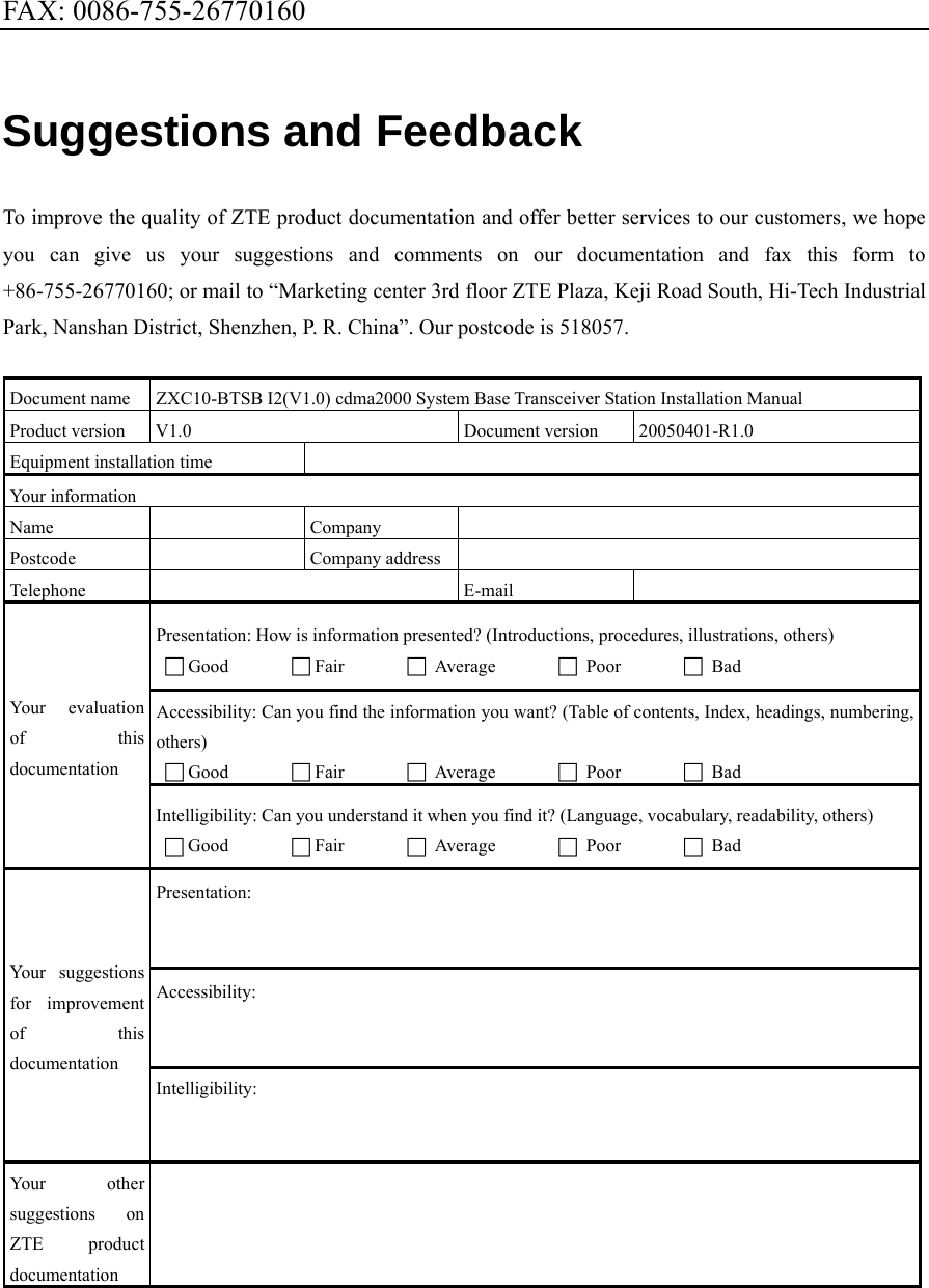
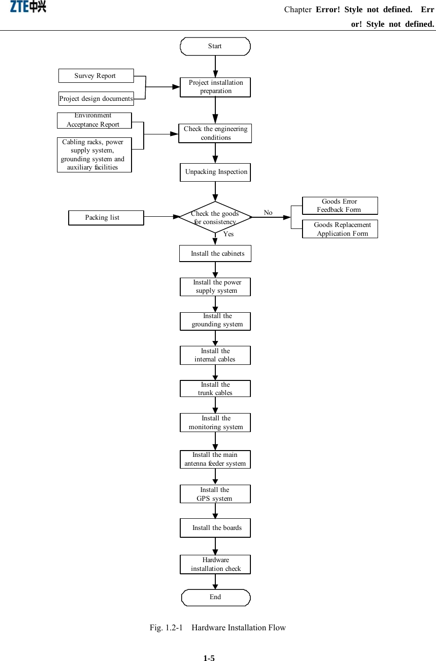
![Chapter 6 Installing the Grounding System describes the installation procedure of the BTSB grounding system. Chapter 7 Installing the Cabinet Internal Cables introduces the types of BTSB cabinet internal cables, and describes the installation procedure of them. Chapter 8 Installing the Trunk Cables describes the installation procedure of the BTSB trunk cables, and explains how to prepare the E1 cables and how to convert the 75 Ω trunk cables into the 120 Ω trunk cables. Chapter 9 Installing the Monitoring System introduces the composition of the monitoring system and describes its installation procedure. Chapter 10 Installing the Main Antenna Feeder System describes the installation preparation, the installation flow and the specific installation procedure of the main antenna feeder system, and explains how to check and test the antenna feeder and how to conduct waterproof treatment on the connector. Chapter 11 Installing the GPS Antenna Feeder System describes the installation preparation, the installation flow and the specific installation procedure of the GPS antenna feeder system. Chapter 12 Installing the Board describes the types and functions of boards used in the BTSB system, and how to install and replace them. Chapter 13 Hardware Installation Check describes the hardware installation check requirements of the BTSB system. Chapter 14 Power-on/Power-off describes the check prior to the BTSB power-on, and the detailed power-on and power-off operation procedures. Appendix A gives an abbreviation form. Conventions Describing notational conventions, keyboard operation convention, mouse operation convention and four safety signs. 1. Notational conventions Angular brackets "<and>" identify names of keys and buttons, and the information typed by an operator from a terminal. Square brackets "[and]" indicate a man-machine interface, menu item, data list, or field name. The](https://usermanual.wiki/ZTE/BTSBI219/User-Guide-555469-Page-6.png)
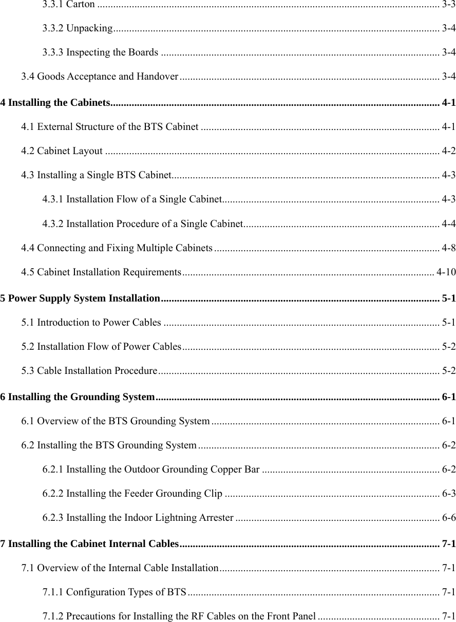
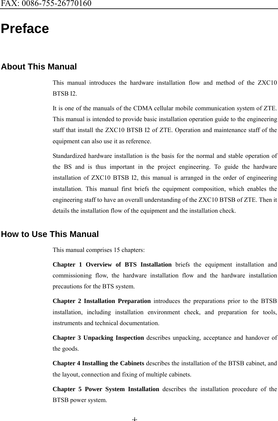
![symbol "-->" separates a multi-level menu, e.g., [File --> New --> Folder] indicates the [Folder] menu item under the [New] submenu of the menu [File]. 2. Keyboard operation conventions Format Description Character within angular brackets Indicating a key or button name, e.g., <Enter>, <Tab>, <Backspace>, and <a> <key 1+key 2> Indicating to hold several keys down at the same time. For example, <Ctrl+Alt+A> indicates to hold down “Ctrl”, “Alt” and “A” three keys <key 1, key 2> Press Key 1 first. Then release Key 1 and press Key 2. For example, <Alt, F> indicates to press and release <Alt> key, and then press <F> key 3. Mouse operation conventions Format Description Click Refers to clicking the primary mouse button (usually the left mouse button) once Double-click Refers to quickly clicking the primary mouse button (usually the left mouse button) twice Right-click Refers to clicking the secondary mouse button (usually the right mouse button) once Drag Refers to pressing and holding a mouse button and move the mouse 4. Signs Four eye-catching signs are used in this manual to emphasize important and critical information. Note, Caution, Warning, and Danger: Used to indicate the precautions during the operation. Statement: The actual product may differ from what is described in this manual due to frequent update of ZTE products and fast development of technologies. Please contact the local ZTE office for the latest updating information of the product.](https://usermanual.wiki/ZTE/BTSBI219/User-Guide-555469-Page-7.png)