ZTE CBTSI18A CDMA2000 Compact Base Transceiver Station-I1 User Manual users manual
ZTE Corporation CDMA2000 Compact Base Transceiver Station-I1 users manual
ZTE >
users manual

ZXC10 CBTS
cdma2000 Compact Base Transceiver Station
Technical Manual
Version 1.0
ZTE CORPORATION
ZTE Plaza, Keji Road South,
Hi-Tech Industrial Park,
Nanshan District, Shenzhen,
P. R. China
518057
Tel: (86) 755 26771900 800-9830-9830
Fax: (86) 755 26772236
URL: http://support.zte.com.cn
E-mail: doc@zte.com.cn

LEGAL INFORMATION
Copyright © 2005 ZTE CORPORATION.
The contents of this document are protected by copyright laws and international treaties. Any reproduction or distribution of
this document or any portion of this document, in any form by any means, without the prior written consent of ZTE
CORPORATION is prohibited. Additionally, the contents of this document are protected by contractual confidentiality
obligations.
All company, brand and product names are trade or service marks, or registered trade or service marks, of ZTE
CORPORATION or of their respective owners.
This document is provided “as is”, and all express, implied, or statutory warranties, representations or conditions are
disclaimed, including without limitation any implied warranty of merchantability, fitness for a particular purpose, title or non-
infringement. ZTE CORPORATION and its licensors shall not be liable for damages resulting from the use of or reliance on
the information contained herein.
ZTE CORPORATION or its licensors may have current or pending intellectual property rights or applications covering the
subject matter of this document. Except as expressly provided in any written license between ZTE CORPORATION and its
licensee, the user of this document shall not acquire any license to the subject matter herein.
The contents of this document and all policies of ZTE CORPORATION, including without limitation policies related to support
or training are subject to change without notice.
Revision History
Date Revision No. Serial No. Description
2005/05/01 R1.0 Sjzl20051666

ZTE CORPORATION
Values Your Comments & Suggestions!
Your opinion is of great value and will help us improve the quality of our product
documentation and offer better services to our customers.
Please fax to: (86) 755-26772236; or mail to Publications R&D Department, ZTE
CORPORATION, ZTE Plaza, A Wing, Keji Road South, Hi-Tech Industrial Park,
Shenzhen, P. R. China 518057.
Thank you for your cooperation!
Document
Name ZXC10 CBTS (V1.0) cdma2000 Compact Base Transceiver Station Technical Manual
Product
Version V1.0 Document
Revision Number R1.0
Equipment Installation Date 20050501
Presentation:
(Introductions, Procedures, Illustrations, Completeness, Level of Detail, Organization,
Appearance)
Good Fair Average Poor Bad N/A
Accessibility:
(Contents, Index, Headings, Numbering, Glossary)
Good Fair Average Poor Bad N/A
Your
evaluation of
this
documentation
Intelligibility:
(Language, Vocabulary, Readability & Clarity, Technical Accuracy, Content)
Good Fair Average Poor Bad N/A
Your
suggestions for
improvement
of this
documentation
Please check the suggestions which you feel can improve this documentation:
Improve the overview/introduction Make it more concise/brief
Improve the Contents Add more step-by-step procedures/tutorials
Improve the organization Add more troubleshooting information
Include more figures Make it less technical
Add more examples Add more/better quick reference aids
Add more detail Improve the index
Other suggestions
__________________________________________________________________________
__________________________________________________________________________
__________________________________________________________________________
__________________________________________________________________________
__________________________________________________________________________
# Please feel free to write any comments on an attached sheet.
If you wish to be contacted regarding your comments, please complete the following:
Name Company
Postcode Address
Telephone E-mail

FCC & IC STATEMENT
Before using this product, read this important RF energy awareness and
control information and operational instructions to ensure compliance with
the FCC and IC RF exposure guidelines.
NOTICE: Working with the equipment while in operation, may expose the
technician to RF electromagnetic fields that exceed FCC rules for human
exposure. Visit the FCC website at www.fcc.gov/oet/rfsafety to learn more
about the effects of exposure to RF electromagnetic fields.
Changes or modifications to this unit not expressly approved by the party
responsible for compliance will void the user’s authority to operate the
equipment. Any change to the equipment will void FCC and IC grant.
This equipment has been tested and found to comply with the limits for a
Class A digital device, pursuant to the FCC and IC Rules. This equipment
generates, uses and can radiate radio frequency energy and, if not
installed and used in accordance with the instructions, may cause harmful
interference to radio communications. However, there is no guarantee that
interference will not occur in a particular installation.
For OUTDOOR use, a PNALE Antenna with a maximum gain of 17dBi is
authorized for use with this unit. Outside antennas must be positioned to
observe minimum separation of 3.0M (9.84 feet.) for 800MHz unit and
2.5M (8.2 feet.) for 1900MHz unit from all users and bystanders. For the
protection of personnel working in the vicinity of outside (uplink) antennas,
the following guidelines for minimum distances between the human body
and the antenna must be observed.
The installation of an OUTDOOR antenna must be such that, under normal
conditions, all personnel cannot come within 3.0M (9.84 feet.)for 800MHz
unit and 2.5M (8.2 feet.) for 1900MHz unit from the outside antenna.
Exceeding this minimum separation will ensure that the worker or
bystander does not receive RF-exposure beyond the Maximum Permissible
Exposure according to section 1.1310 i.e. limits for Controlled Exposure.
This page is intentionally blank.

Contents
About this Manual .....................................................................................xi
Purpose of This Manual .......................................................................................... xi
How to Use This Manual ......................................................................................... xi
Typographical Conventions.....................................................................................xii
How to Get in Touch ..............................................................................................xii
Customer Support ..................................................................................................................xii
Documentation Support..........................................................................................................xii
Chapter 1................................................................................... 13
System Overview .................................................................................... 13
Position of BTS in the CDMA System ...................................................................... 14
System Features .................................................................................................. 16
Multiple Frequency Bands Supported...................................................................................... 16
Large Capacity ......................................................................................................................16
Compactness ........................................................................................................................16
Technological Advantages ...................................................................................................... 16
High Reliability ...................................................................................................................... 17
Flexible Networking ...............................................................................................................17
Smooth Expansion and Upgrade ............................................................................................17
Easy Operation and Maintenance ...........................................................................................18
Functions ............................................................................................................. 19
International Standards Followed by BTS................................................................ 20
Chapter 2................................................................................... 22
BTS Hardware.......................................................................................... 22
Hardware Structure .............................................................................................. 23
BTS Physical Structure...........................................................................................................23
Logical Structure ................................................................................................................... 24
List of All BTS Boards.............................................................................................................25
BDS .................................................................................................................... 26
BDS Schematic Diagram........................................................................................................ 26
BDS Working Principle ...........................................................................................................27
Technological Advantages of BDS...........................................................................................27
BDS Hardware Configuration ................................................................................................. 28
RFS ..................................................................................................................... 30
RFS Schematic Diagram ........................................................................................................31
RFS Working Principle............................................................................................................31
Technological Advantages of RFS ...........................................................................................32
Hardware Configuration ......................................................................................................... 33
PWS .................................................................................................................... 34
PWS Schematic Diagram ....................................................................................................... 34
PWS Working Principle...........................................................................................................35
Hardware Configuration ......................................................................................................... 35
Chapter 3................................................................................... 36
BTS Software ........................................................................................... 36
BTS Software Overview......................................................................................... 37
CCM Software ...................................................................................................... 39
CHM0 Software .................................................................................................... 40
CHM1 Software .................................................................................................... 41
RMM Software ...................................................................................................... 42
TRX Software ....................................................................................................... 43
Chapter 4................................................................................... 44
BTS Networking and Configuration ........................................................ 44
Networking through Abis Interface ......................................................................... 45
BTS Networking.................................................................................................... 47
LS Mode ...............................................................................................................................48
RS Mode ...............................................................................................................................49
LEA Mode..............................................................................................................................49
LEB Mode..............................................................................................................................51
RE Mode ............................................................................................................................... 52
ME Mode............................................................................................................................... 53
BTS Configuration................................................................................................. 53
BDS Configuration ................................................................................................................. 53
RFS Configuration .................................................................................................................54
PWS Configuration ................................................................................................................54
Chapter 5................................................................................... 55
Technical Indices..................................................................................... 55
Environment Indices ............................................................................................. 56
Performance Indices ............................................................................................. 58
Reliability ..............................................................................................................................58
Interface ...............................................................................................................................58
Capacity................................................................................................................................58
Frequency Band ....................................................................................................................58
Specs of Bands 800 MHz, 450 MHz and 850 MHz....................................................................58
Specs of 1.9 GHz and 2.1GHz ................................................................................................ 61
Clock ....................................................................................................................................62
Noise ....................................................................................................................................63
Appendix A................................................................................ 65
Abbreviations .......................................................................................... 65
Figures.......................................................................................... 71
Tables ........................................................................................... 73
This page is intentionally blank.

Confidential and Proprietary Information of ZTE CORPORATION xi
About this Manual
Purpose of This Manual
Current radio mobile networks include CDMA and GSM systems, both are
on the way to evolving into 3G radio mobile networks. The purpose of this
book is to provide a clear understanding of the technology adopted in 3rd-
generaton (3G) networks and build a systematic understanding of the
working principles, performance indices, hardware structure and system
configuration of ZTE 3G cdma2000 compact-model base station
transceiver. This book is intended to help readers make better use of other
relevant product literature and lay the foundation for system operation
and maintenance.
The all-IP base station mentioned in this manual refers to the base station
of cdma2000 system.
In this book, ZXC10 CBTS is briefed as BTS, ZXC10 BSCB, as BSC and
ZXC10 BSSB, as BSS.
How to Use This Manual
This manual consists of five chapters:
Chapter 1 System Overview
It describes the position and functions of the BTS in the CDMA system and
presents the standards followed by ZXC-BTS.
Chapter 2 Hardware
It describes the overall hardware structure and module functions of the
BTS.
Chapter 3 Software
It describes the software structure and function modules of the software in
BTS.
Chapter 4 Networking and Configuration
It describes the connection, networking modes and configurations of BTS.
ZXC10 CBTS (V1.0)Technical Manual
xii Confidential and Proprietary Information of ZTE CORPORATION
Chapter 5 Technical Indices
It describes briefly the performance indices of BTS.
Appendix A Abbreviations
It lists the abbreviations used in this manual and other common ones
concerning CDMA topics.
Typographical Conventions
ZTE documents employ with the following typographical conventions.
TYPOGRAPHICAL CONVENTIONS
How to Get in Touch
The following sections provide information on how to obtain support for
the documentation and the software.
Customer Support
If you have problems, questions, comments, or suggestions regarding
your product, contact us by e-mail at support@zte.com.cn. You can also
call our customer support center at (86) 755 26771900 and (86) 800-
9830-9830.
Documentation Support
ZTE welcomes your comments and suggestions on the quality and
usefulness of this document. For further questions, comments, or
suggestions on the documentation, you can contact us by e-mail at
doc@zte.com.cn; or you can fax your comments and suggestions to (86)
755 26772236. You can also explore our website at
http://support.zte.com.cn, which contains various interesting subjects like
documentation, knowledge base, forum and service request.
Typeface Meaning
Italics
References to other guides and documents.
Note: Provides additional information about a certain topic.

Confidential and Proprietary Information of ZTE CORPORATION 13
Chapter 1
System Overview
In this chapter, you will learn about:
Position of BTS in the CDMA system
Architecture, functions and features of BTS
Standards followed by BTS

ZXC10 CBTS (V1.0)Technical Manual
14 Confidential and Proprietary Information of ZTE CORPORATION
Position of BTS in the CDMA
System
The Base Transceiver Station (BTS) connects a Mobile Station (MS) to the
mobile network in a mobile communications system through its radio
interface functionalities. It best reflects the radio transmission features in
a CDMA system.
BTSB (all-IP BTS), developed by ZTE Corporation, is an IP-based new
generation BTS that is designed to fill in the varying needs of our
customers. It features large capacity, abundant transmission modes and
high adaptability.
An all-IP network is made up of three parts: MS (Mobile Station), RAN
(Radio Access Network) and CN (Core Network).
MS: A mobile phone, mobile station or mobile terminal;
RAN: Located between MS and CN and connects these two parts. It
processes radio signals and consists of two parts: BSCB/PCF/IWF
(combined as BSCB) and BTS;
CN: Provides authentication at the network side and interfaces with a
public network.
As a member of the BTSB family, ZXC10 CBTS is special for its compact
structure, in addition to other advantages such as large capacity and high
integration level.
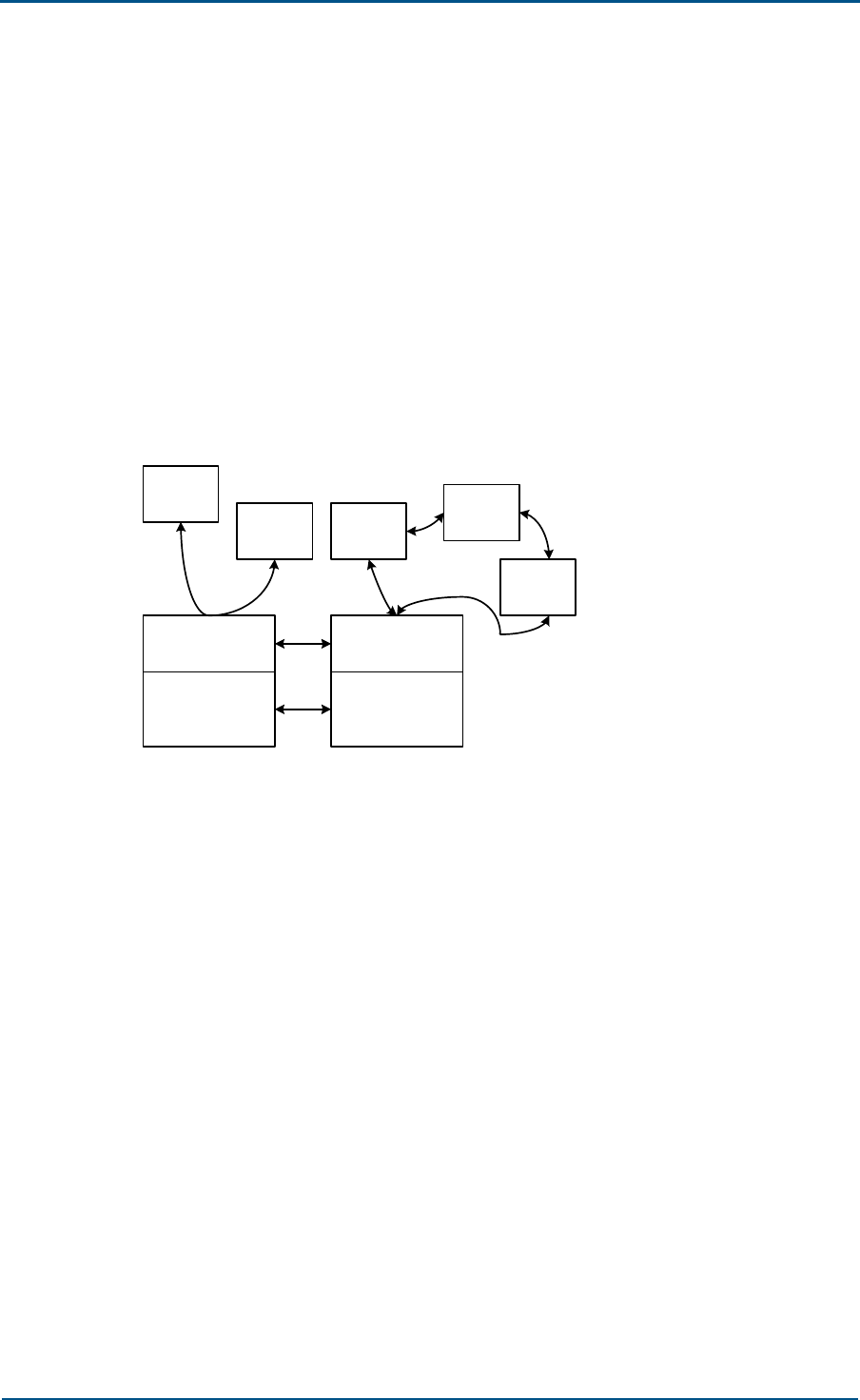
The position of BTS in Base Station Subsystem (BSS) is shown in Fig. 1.
FIG. 1 POSITION OF BTS IN BSS
PSTN
Um Abis
BSC
MSC
PDSN
SS7 network
BTS
MS
95 MS
1X MS
1X DO
MS RAN CN
IP
network
MS
MS
BTS
A
interface

Chapter 1 - System Overview
Confidential and Proprietary Information of ZTE CORPORATION 15
As seen from the diagram, BTS is located between mobile stations (MSs)
and the Base Station Controller (BSC). It encodes, decodes, modulates
and demodulates CDMA signals, performs up-conversion and down-
conversion for subscriber data, amplifies RF power, and transmits /
receives radio signals.

ZXC10 CBTS (V1.0)Technical Manual
16 Confidential and Proprietary Information of ZTE CORPORATION
System Features
Multiple Frequency Bands Supported
BTS supports frequency bands of 450 MHz, 800 MHz, 850 MHz, 1900 MHz
and 2100 MHz, as shown in Table 1.
TABLE 1 FREQUENCY BANDS SUPPORTED BY BTS
Serial
No. Frequency Band Upper Frequency
Limit (MHz)
Lower Frequency
Limit (MHz)
1 800 MHz (Band Class 0) 824~849 869~894
2 1900 MHz (Band Class 1) 1850~1910 1930~1990
3 450 MHz (Band Class 5) 450~457.5 460~467.5
4 2100 MHz (Band Class 6) 1920~1980 2110~2170
5 850 MHz (Band Class 10) 806~821 851~866
Large Capacity
The LRFS (Local RFS) in one cabinet supports up to 12 carrier sectors
and another 12 carrier sectors by connecting an RRFS (Remote RFS).
Two combined BTS cabinets support up to 8-carrier 3-sector or 4-
carrier 6-sector configuration, and another 8-carrier 3-sector or 4-
carrier 6-sector configuration by connecting an RRFS.
One BDS supports at least 4-carrier 3-sector configuration (CE
resource of 4-carrier 3-sector for EV-DO, and 8-carrier 3-sector or 4-
carrier 6-sector for 1X).
The large capacity advantage of BTS allows for less BTS needed for
traffic-hot areas, and in turn saves investment in transmission device,
equipment room, power supply and telecom towers.
Compactness
The compact BTS, as its name implies, is small in size and one cabinet
(W700 × H800 × D800, unit: mm) has only two shelves. It is actually
the smallest BTS ever produced by the industry.
The compactness advantage plus high capacity requires less space for
installing the BTS and also other auxiliary equipment.
Technological Advantages
Support smooth evolution to 1X EV-DV and CDMA2000-3X.
Employ all-IP architecture with large switching capacity, high QoS
guarantee and robust reliability.

Chapter 1 - System Overview
Confidential and Proprietary Information of ZTE CORPORATION 17
Adopt the IP-based cUDP/PPPMux/MultilinkPPP for its Abis interface for
higher transmission efficiency at a lower cost.
Use the multi-frequency digital intermediate frequency technology to
make do with less RF modules.
Support transmission diversity, intelligent antenna and linear pre-
distortion amplifier.
High channel efficiency.
Support different configurations such as 4-carrier 3-sector, 2-carrier 6-
sector and 1-carrier 12-sector.
Adopt high reuse-efficiency transmission system between its BDS and
RFS subsystems and data of 24 carrier sectors can be transmitted over
one fibre pair.
Support dynamic downloading of board software, making upgrade and
maintenance convenient.
High Reliability
Advanced EMC (Electromagnetic Compatibility) and EMI
(Electromagnetic Interference) design.
The RRFS supports ring networking through fibres and link backup for
switchover when necessary. Link switchover is independent of board
switchover to enhance transmission reliability.
The clock system is compatible with the GPS and GLONASS system.
All important boards are configured in 1+1 hot backup mode.
The GCM provides reliable clock for a short term and ensures the
locked status of clock during 72 hours after the GPS synchronous
signal is lost.
Flexible Networking
Abis interface for flexible networking:
Support Ethernet direct connection for when BTS and BSC are installed
in the same room or not far from each other.
Support star, chain, tree and ring networking.
Support 75 Ω / 120 Ω E1 interface, 100Ω T1 interface, and built-in
SDH transmission interface.
The BTS can use 220V AC or –48V DC and it has the built-in primary
power supply.
Smooth Expansion and Upgrade
All boards support hot swapping, convenient for online upgrade and
maintenance.
The Channel Module (CHM) can be configured easily as a subcard.

ZXC10 CBTS (V1.0)Technical Manual
18 Confidential and Proprietary Information of ZTE CORPORATION
One BDS supports up to 24 carrier sectors and more BDS shelves can
be added to expand capacity.
Capacity can be expanded with more channel modules and RF modules.
Support RRFS with multiple sectors.
Support CHM configuration of different scales in 1X system, as well as
mixed configuration EV-DO and EV-DV CHMs.
Easy Operation and Maintenance
Support order wire phone from a BTS to its BSC or to another BTS
through the network management access of SDH.
The RRFS is also available with an orderwire interface for
communicating with the BDS and BSC.
Provide online test and performance evaluation for the BTS through its
BTM (BTS Test Module).
Support local operation & maintenance of BTS through its 10M
Ethernet test port to control BDS and RFS, test their functions and
collect their performance parameters.
Support online upgrade. Support remote downloading of logic, MCU
MCU program, BOOT program and FLASH file.
Provide graphical user interface for easy operation and maintenance.
The interface shows the topology maps, tool bars and real rack layout.

Chapter 1 - System Overview
Confidential and Proprietary Information of ZTE CORPORATION 19
Functions
BTS functions as a bridge connecting mobile stations to BSC in the CDMA
system. Details are given below:
BTS communicates with MS (mobile station) through a CDMA air
interface.
BTS communicates with BSC (Base Station Controller) through an Abis
interface.
In the forward link, BTS first receives data from BSC through the Abis
interface, then encodes and modulates the data, next converts
baseband signals into radio frequency signals, finally transmits them
through a power amplifier, the radio frequency front end (RFE) and an
antenna.
In the reverse link, BTS first receives weak radio signals through the
antenna feeder and RFE. The signals then undergo low noise
amplification, down frequency conversion, and decoding and
demodulation. Finally, BTS sends the data through the Abis interface to
BSC.

ZXC10 CBTS (V1.0)Technical Manual
20 Confidential and Proprietary Information of ZTE CORPORATION
International Standards Followed
by BTS
1. 3GPP2 C.S0002-A version 6.0 (IS-2000 Release A).
2. 3GPP2 A.S0001-A version 2.0 (3G-IOSv4.1).
3. 3GPP2 A.S0011-A v1.0 (3G-IOS v4.3).
4. ANSI J-STD-008, Personal Station-Base Station Compatibility
Requirement for 1.8 to 2.0 GHz Code Division Multiple Access (CDMA)
Personal Communications System, 1996.
5. TIA/EIA/TSB-74, Support for 14.4 Kbps Data Rate and PCS Interaction
for Wideband Spread Spectrum Cellular System, 1995.
6. TIA/EIA/IS-95-A, Mobile Station-Base Station Compatibility Standard
for Dual-Mode Wideband Spread Spectrum Cellular Systems.
7. TIA/EIA/IS-95, Mobile Station-Base Station Compatibility Standard for
Dual-Mode Wideband Spread Spectrum Cellular Systems.
8. TIA/EIA/IS-637 Short Message Services for Wideband Spread
Spectrum Cellular Systems, 1997.
9. TIA/EIA/IS-127, Enhanced Variable Rate Codec Speech Service Option
3 for Wideband Spread Spectrum Digital Systems, 1996.
10. TIA/EIA/IS-658, Data Service Interworking Function Interface for
Wideband Spread Spectrum Systems.
11. CDG RF36, Markov Service Option for Wideband Spread Spectrum
Communications Sytems.
12. TIA/EIA/IS-725, Over-the-Air Service Provisioning of Mobile Stations in
Wideband Spread Spectrum Systems, 1997.
13. TIA/EIA/IS-728, Inter-System Link Protocol.
14. TIA/EIA/IS-733, High Rate Speech Service Option 17 for Wideband
Spread Spectrum Communication Systems.
15. TIA/EIA/IS-707, Data Service Options for Wideband Spread Spectrum
Systems, 1998.
16. TIA/EIA/IS-707-A-2 Data Service Options for Spread Spectrum
Systems Addendum 2, 2000.
17. ITU-T Q.714 Signaling connection control part (SCCP).
18. ITU-T Q.704 Signal link (MTP3).
19. ITU-T Q.703 Signal link (MTP2).
20. 3GPP2 C.S0024, cdma2000 High Rate Packet Data Air Interface
Specification,December 2001.
21. 3GPP2 A.S0007, 1xEV-DO Inter-Operability Specification (IOS) for
cdma2000 Access Network Interface, June 2001.

Chapter 1 - System Overview
Confidential and Proprietary Information of ZTE CORPORATION 21
22. 3GPP2 C.S0029, Test Application Specification (TAS) for High Rate
Packet Data Air Interface, July 2001.
23. TIA/EIA/IS-97D,Recommended Minimum Performance Standards for
Base Stations Supporting Dual Mode Spread Spectrum Systems, 2001.

Confidential and Proprietary Information of ZTE CORPORATION 22
Chapter 2
BTS Hardware
In this chapter, you will learn about:
Hardware structure
Composition of subsystems
Features and functions of each subsystem
Chapter 2 - BTS Hardware
Confidential and Proprietary Information of ZTE CORPORATION 23
Hardware Structure
A BTS is made up of BDS, RFS and PWS (optional) in terms of hardware.
Physically, they are racks, shelves and boards.
The hardware structure of BTS can be seen either from a physical or
logical point of view. This chapter describes the hardware structure of BTS,
however, for more information on the boards, please refer to ZXC10 CBTS
(V1.0) cdma2000 Compact Base Transceiver Station Hardware Manual.
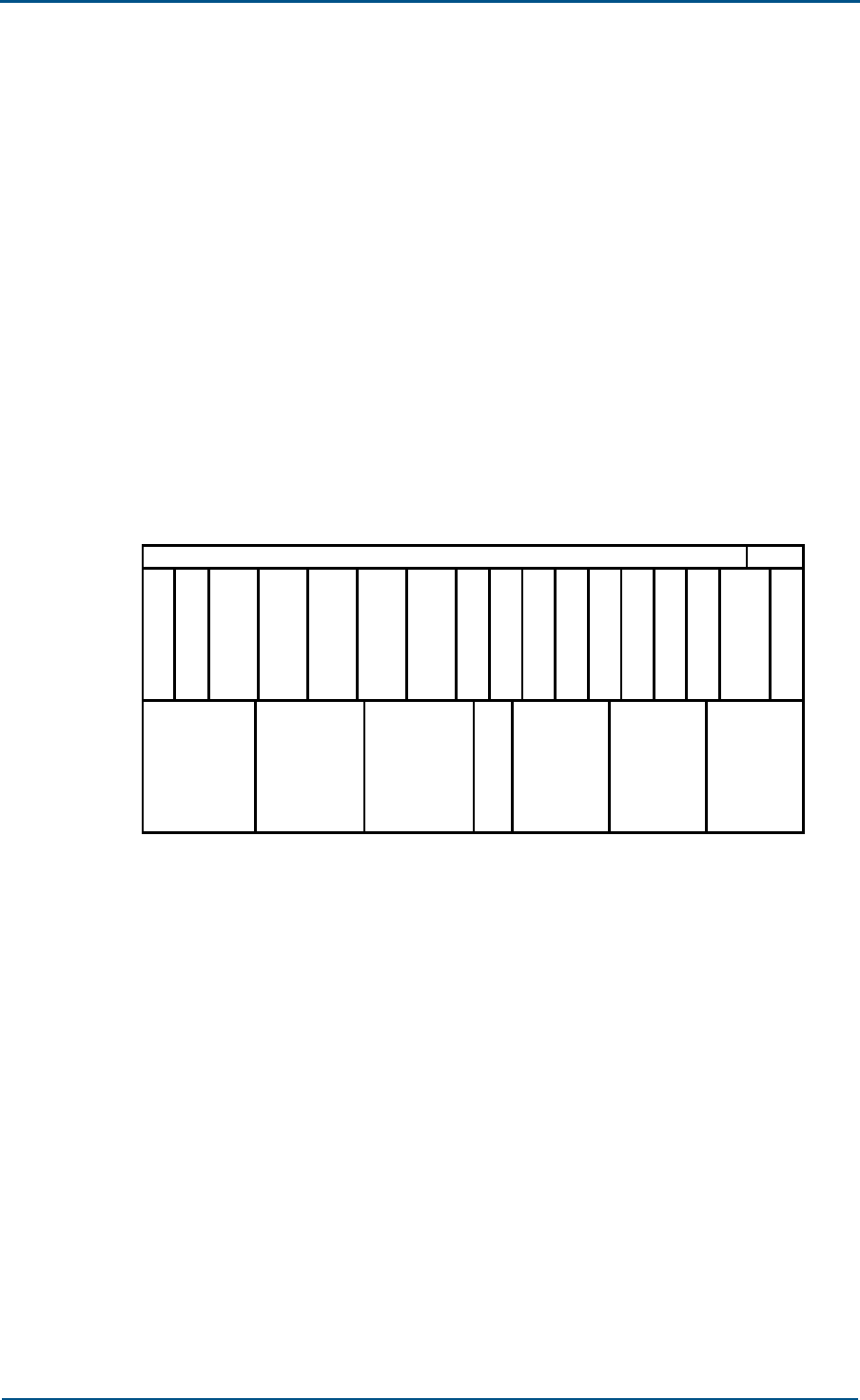
BTS Physical Structure
Fig. 2 shows the physical structure of a BTS cabinet.
FIG. 2 BTS PHYSICAL STRUCTURE
C
H
M
C
H
M
C
H
M
C
H
M
T
R
X
T
R
X
T
R
X
R
M
M
R
I
M
RPD
S
A
M
C
C
M
C
C
M
D
S
M
G
C
M
L
P
A
P
I
M
L
P
A
L
P
A
R
F
E
R
F
E
R
F
E
B
IM
S
N
M
B
IM
As the above figure shows, BTS is physically divided into two shelves. The
top one has 17 slots for accommodating the BDS and TRX boards and the
bottom one has 7 slots for the RFE, LPA and PIM boards.
ZXC10 CBTS (V1.0)Technical Manual
24 Confidential and Proprietary Information of ZTE CORPORATION
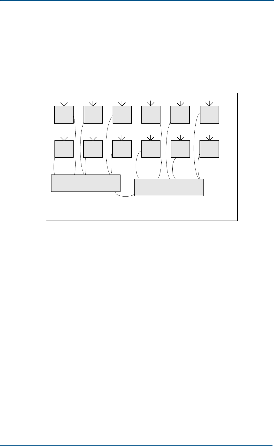
Logical Structure
BTS is logically divided into BDS and RFS, as shown in Fig. 3. The PWS is
also necessary in case there is no available –48V DC secondary power
supply on site.
FIG. 3 BTS LOGICAL STRUCTURE
SBDS
To BSC
RFS
BDS
MBDS
RRFS
LRFS
SBDS
LRFS LRFS LRFS LRFS LRFS
RRFS RRFS RRFS RRFS RRFS
...
... ... ... ... ...
MBDS SBDS
RRFSRRFS
1. BDS
BDS is further divided into three functional entities: BCS (BTS
Communication Subsystem), BBS (BTS Baseband Subsystem) and TFS
(Time Frequency Subsystem).
One BTS suffices for configuration no higher than 12 carrier sectors.
Two BTS cabinets can be combined for configuration higher than 12
carrier sectors. For two combined cabinets, one is the master one
(Master BDS, MBDS) and the other is the slave one (Slave BDS, SBDS).
MBDS and SBDS have the same structure and working principle but
with different configurations.
2. RFS
RFS is further divided into two parts: TRX and PA + RFE amplifier +
RFE subsystem. Its work includes some baseband processing, IF
processing, digital-to-analog conversion, RF modulation and
demodulation, forward signal power amplification, and backward signal
low noise amplification.
Please note that an RFS can be an LRFS (Local RFS) or RRFS (Remote
RFS), to meet different networking needs. If no otherwise specified,
the RFS in this book refers to an LRFS.
3. PWS
This subsystem supplies power to the whole BTS and it comprises
primary power supply (converts 200 V/1110 V AC to –48 V DC,

Chapter 2 - BTS Hardware
Confidential and Proprietary Information of ZTE CORPORATION 25
optional part) and secondary power supply (converts –48 V DC to what
is needed by the BTS boards).
A description of BTS hardware (logical) focused on board functions is
given below.
List of All BTS Boards
All BTS boards are listed in Table 2.
TABLE 2 BTS BOARDS
Abbreviations Full Name
BDS
CCM Communication Control Module
DSM Data Service Module
CHM Channel Processing Module
RIM RF Interface Module
GCM GPS Control Module
SNM SDN Network Module
SAM Site Alarm Module
BIM BDS Interface Module
RFS
RMM RF Management Module
TRX Transmitter and Receiver
BTM BTS Test Module
LPA Linear Power Amplifier
PIM Power Amplifier Interface Module
RFE Radio Frequency End
PWS
APD AC Power Distribute
PMM Power Monitor Module
PRM Power Rectifier Module
RPD RFS Power Distribute
ZXC10 CBTS (V1.0)Technical Manual
26 Confidential and Proprietary Information of ZTE CORPORATION
BDS
BDS is the control center and communication platform of the BTS. In BDS
we see many key CDMA technologies, such as diversity technology, RAKE
reception, softer handoff and power control. .
Located between BSC and RFS, BDS connects the two and it is responsible
for baseband signal modulation / demodulation and encoding / decoding,
and generation / distribution of clocks for the whole BTS.
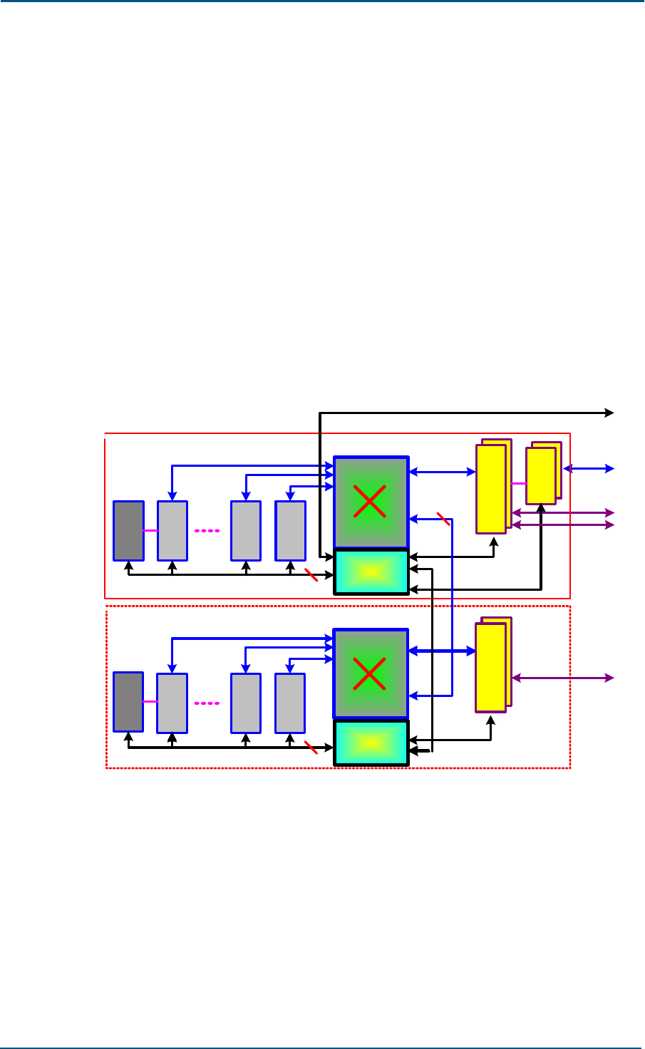
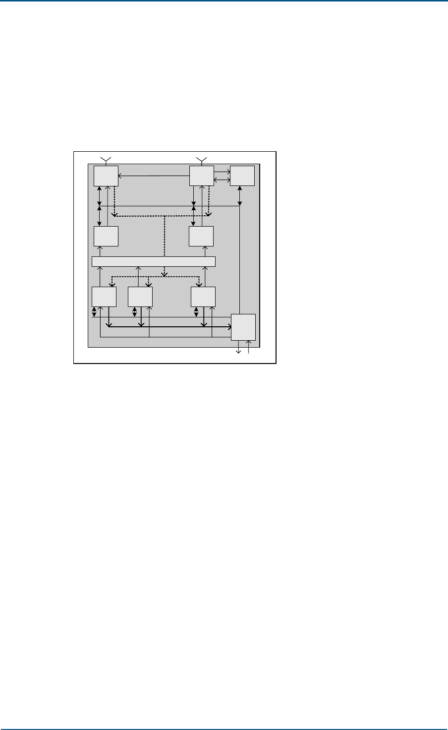
BDS Schematic Diagram
Fig. 4 shows the working principle of BDS.
FIG. 4 BDS SCHEMATIC DIAGRAM
IP SW
IP
C
H
M
CCM
C
H
M
C
H
M
178
D
S
M
BDS
BSC
FE TEST PORT
STM-1
16X E1
D
S
M
Media Stream
Signaling Stream
D
S
M
S
D
H
R
I
M
9
GE/FE
IP
C
H
M
SCM
C
H
M
C
H
M
78
D
S
M
SBDS
D
S
M
IP
HUB
Media Stream
Signaling Stream
1
R
I
M
9
16X E1
2
As seen from the diagram above, the components of BDS are:
CHM: performs CE processing (spread-spectrum modulation and
despread-spectrum demodulation). The CHM of each BDS is a CE
resource-sharing pool.
RIM: provides interface to connect BDS and RFS, and performs forward
signal summation and backward signal distribution. It also distributes
clocks from GCM to CHM and CCM.

Chapter 2 - BTS Hardware
Confidential and Proprietary Information of ZTE CORPORATION 27
CCM: performs BTS control and network switching. Two CCM boards
can be configured, one active and the other standby. For a single rack
or in the MBDS of combined racks, it’s the CCM board. In the SMDS of
combined racks, it’s the SCM board.
DSM: provides Abis interface to connect with BSC.
SNM: An optional board that works as the SDH interface.
SAM: monitors environment indices, including temperature, humidity,
smog and dust.
GCM: receives synchronous signals from the satellite to generate
system clocks consistent with the UTC (Coordinated Universal Time).
Two GCMs (active + standby) can be configured.
BIM: provides interfaces between master and slave racks, between
BDS and RFS, and between BTS and BSC.
BDS Working Principle
The call processing flow in BDS is as follows.
Forward call processing flow
In the forward link, DSM receives and decompresses the packets
coming from the Abis interface. After that, the packets are resolved
into media stream and control stream.
The media stream is switched on the media stream IP communication
platform of CCM, then goes to CHM, gets encoded and modulated,
changed to forward baseband data stream. Next it goes to RIM for
summation and is finally sent to RFS.
The control stream is switched on the control stream IP communication
platform of CCM. Then it goes to CHM or CCM.
Reverse call processing flow
The reverse call data stream coming from RFS is distributed by RIM to
all CHMs. In CHM the data stream is decoded and demodulated and
then put into packets again before being sent to CCM for switching.
The switched packets are then sent to DSM to be packaged and
compressed once again. Finally the packets are sent to BSC.
Technological Advantages of BDS
An all-IP platform. It uses two Ethernets to switch and control the
media stream and control stream.
Two Ethernets for the switching and transmission of media stream and
signaling (control) stream
High integration: baseband CE resource of 12 carrier sectors for EV-DO
and 24 carrier sectors for 1X
Channel sharing: the baseband CE resource (a shared pool) for 12/24
carrier sectors can be used by any sectors through static or dynamic
CE assignment.
ZXC10 CBTS (V1.0)Technical Manual
28 Confidential and Proprietary Information of ZTE CORPORATION
With the standard “BDS-RFS interface”, the BDS and RFS can be
installed in the same or different cabinets.
The future-proof design of BTS supports a smooth evolution path to 1X
EV-DO, 1X EV-DV or CDMA2000-3X. Different CHMs (CHM0 and CHM1)
can be used in BDS, therefore the same BTS can support both
CDMA2000-1X and EV-DO services at the same time.
In the case BSC and BTS are installed in the same room, BDS can
provide Ethernet interface so as to avoid complex Abis protocol
processing. This is an economy and also reliability-enhancing approach.
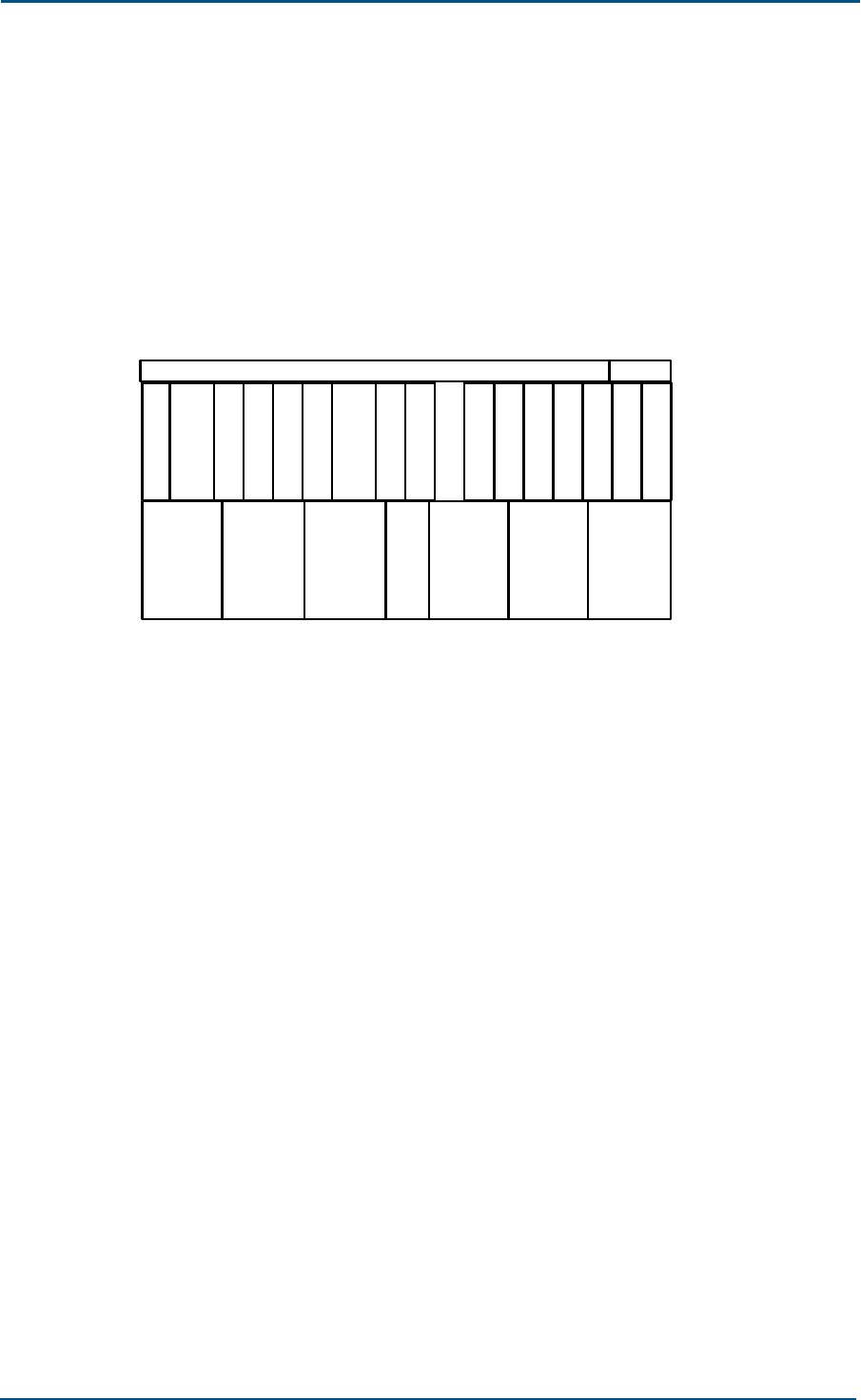
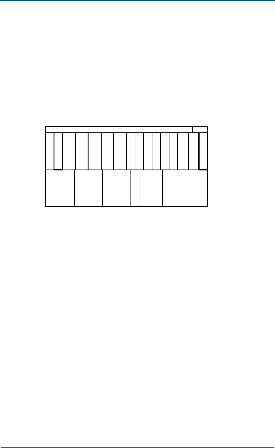
BDS Hardware Configuration
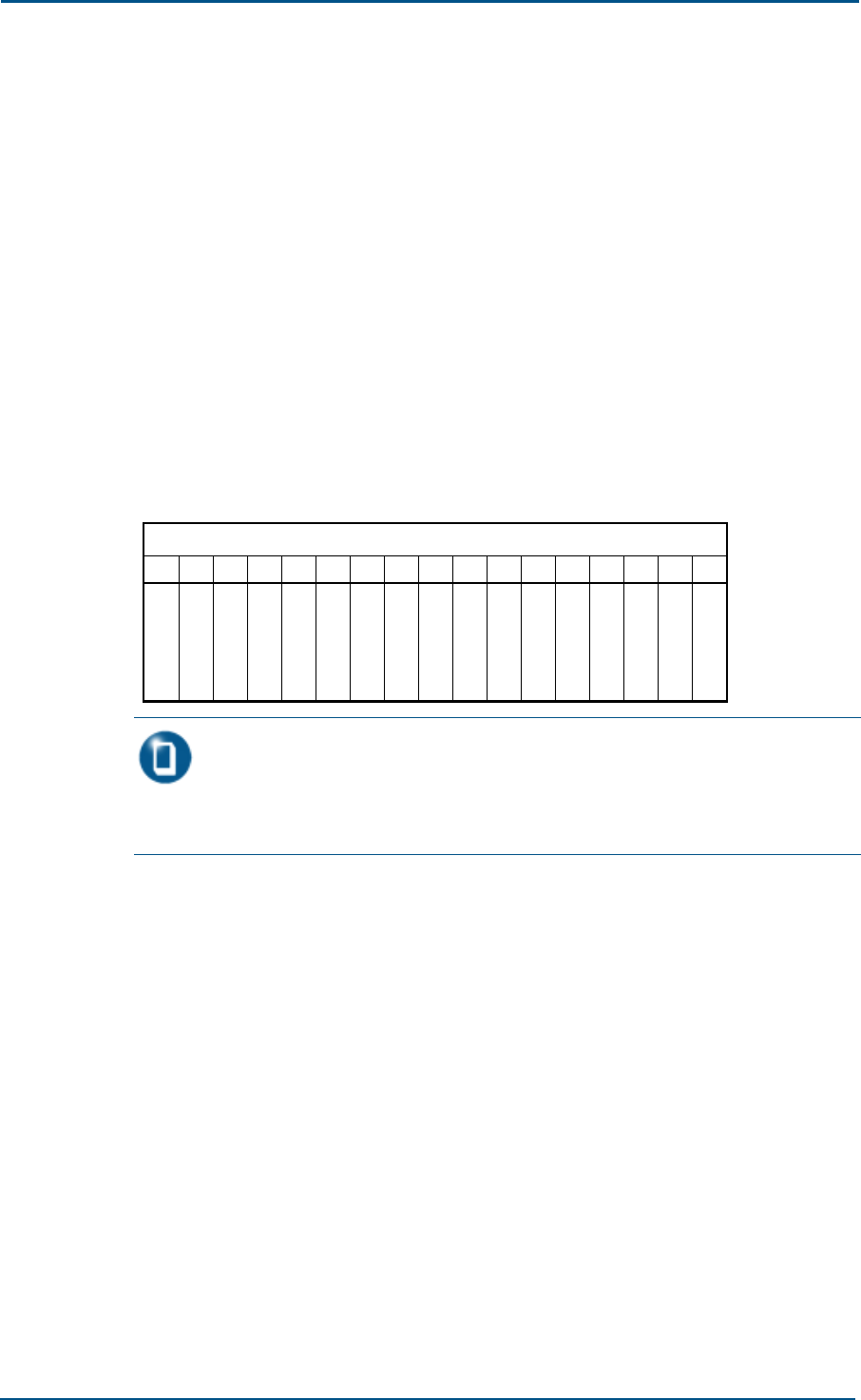
The BDS shelf has 17 slots as shown below. All boards given here are BDS
boards.
FIG. 5 BDS CONFIGURATION
1716151413121110987654321
S
A
M
C
H
M
C
H
M
C
H
M
C
C
M
C
C
M
D
S
M
R
I
M
S
N
M
G
C
M
BDS
C
H
M
B
I
M
Note:
There are two types of CHM boards, CHM0 and CHM1, for 1X and EV-DO services
respectively.
As seen from the board layout, two CCM boards are configured: one active
and the other standby. SNM is an optional board that is necessary only
when there is no available optical transmission on site. For a full
configuration of BDS, there are four CHM slots to deliver pure 1X service
with 24 carrier sectors, or pure EV-DO service with 12 carrier sectors.
Besides, the number of CHM boards can be adjusted to adapt to the
capacity requirement.

Chapter 2 - BTS Hardware
Confidential and Proprietary Information of ZTE CORPORATION 29
The SBDS is required if there are more than 12 carrier sectors. Fig. 6
below shows a fully configured SBDS shelf.
FIG. 6 SBDS CONFIGURATION
1716151413121110987654321
S
A
M
C
H
M
C
H
M
C
H
M
S
C
M
S
C
M
R
I
M
SBDS
C
H
M
B
I
M
The SBDS has no GCM, DSM and SNM boards (while the MBDS does). The
CCM board in MBDS is changed to SCM in SBDS.

ZXC10 CBTS (V1.0)Technical Manual
30 Confidential and Proprietary Information of ZTE CORPORATION
RFS
The RFS (radio frequency subsystem) in a mobile cellular network is used
basically for air interfacing through the antenna. The RFS in a CDMA
system equipped by such technologies as power control, cell breathing,
soft handoff, GPS timing, and diversity reception is different from those in
other cellular networks.
Besides the function related with the air interface, RFS connects to BDS
through the RMM board. It also transmits CDMA signals after modulation
and receives CDMA signals after demodulation. It has other functions such
as detection, monitoring, configuration, control, and cell breathing,
blossoming and wilting.
The whole RFS subsystem consists of the antenna feeder system outside
BTS and the TRX, HPA and RFE (the parts that are involved in signal
transmission and reception) inside BTS. A typical antenna feeder system is
made up of the antenna, antenna jumper, main feeder, lightning arrester,
rack-top jumper, and other components for grounding.
Further description on the antenna feeder system is omitted in this book.
If not otherwise specified, the RFS in this book refers to its parts inside
BTS.
Chapter 2 - BTS Hardware
Confidential and Proprietary Information of ZTE CORPORATION 31
RFS Schematic Diagram
Located between BDS and MS (Mobile Station), RFS connects to the BDS
through a data interface and to the MS through the air RF interface. Its
working principle is shown in Fig. 7.
FIG. 7 RFS SCHEMATIC DIAGRAM
Ctl-Bus
& clk
Rev.Link
Fwd.Link
......
......
Rev.Link
Rev.Link
......
Co n t r o l Bu s & C l k
RFS
......
Control Bus & Clk
BDS
RFE RFE
PA PA
BTM
Combin/TSM/RSM
TRX TRX TRX
RMM
Functions of RFS are:
TRX: performs signal up- and down-frequency conversion.
RMM: Connects RFS and BDS.
LPA: performs signal power amplification on the forward link.
RFE: performs low noise amplification, being the interface between RFS
and the antenna feeder.
BTM: performs the radio test for the BTS.
PIM: works as the interface of power amplifier.
RFS Working Principle
Call processing flow in RFS is as follows.
In the forward link, the data stream from the BDS converges in RMM
and then is distributed to TRX. The stream in TRX changes to
intermediate frequency (IF) signals first and then goes to RFE for up-
conversion. The RF signals generated are finally transmitted through
RFE and antenna feeder after power amplification.

ZXC10 CBTS (V1.0)Technical Manual
32 Confidential and Proprietary Information of ZTE CORPORATION
In the reverse link, the radio signals received from the antenna run
through the LPA of RFE to the TRX for down-conversion processing.
They become IF signals first, undergo digital IF processing, then turn
into sample signals of the BDS, and are finally sent to RMM. RMM puts
all data sent from TRX into a packet and sends it to BDS.
The GCM board in BDS provides clock signal for RIM. RIM then
provides RFS with the clock signal.
Technological Advantages of RFS
LRFS and RRFS are both RFS but with different applications. As one
BTS may have no more than one LRFS, it may connect to several
RRFSs. While LRFS is always set up in the same equipment room as
the BDS, RRFS can be placed miles away from the BDS in the cave,
subway or other irregular locations.
BDS and RFS can be connected in the star, chain or ring networking
modes through the RIM.
One TRX may provide the capacity of 4 carriers and adopt the LPA for
4 carriers.
In a single cabinet, there can be 12 carrier sectors (1~4 carriers × 1~3
sectors).
Chapter 2 - BTS Hardware
Confidential and Proprietary Information of ZTE CORPORATION 33
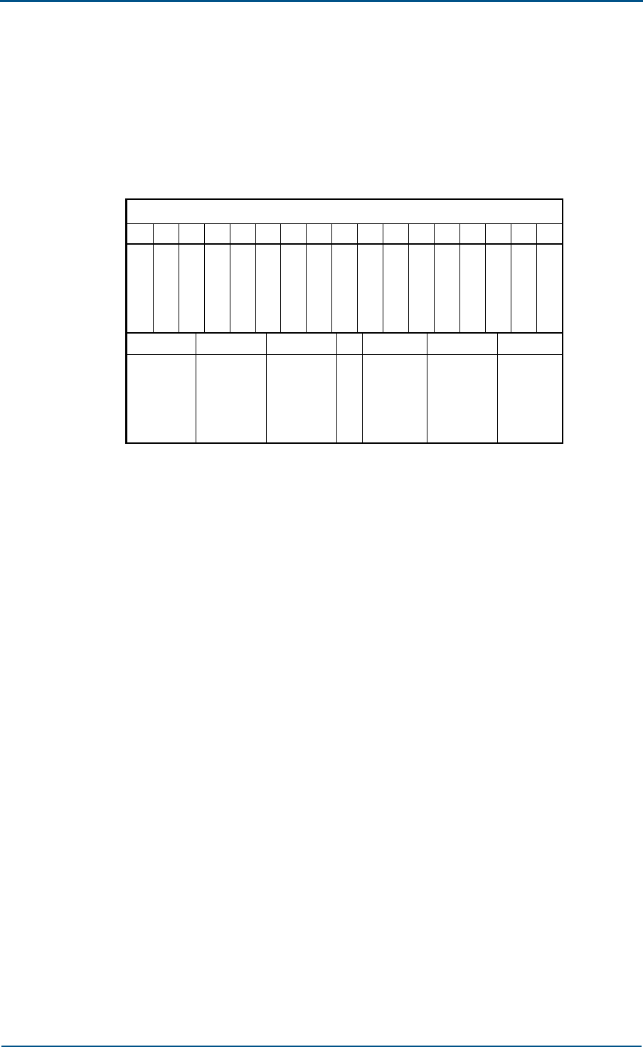
Hardware Configuration
The RFS boards are located in both shelves of the BTS as shown below.
FIG. 8 RFE CONFIGURATION
1716151413121110987654321
RFS
41
R
F
E
P
I
M
L
P
A
L
P
A
L
P
A
R
F
E
B
T
M
T
R
X
T
R
X
T
R
X
R
M
M
R
F
E
23567
ZXC10 CBTS (V1.0)Technical Manual
34 Confidential and Proprietary Information of ZTE CORPORATION
PWS
The PWS subsystem supplies power for the whole BTS cabinet. It converts
AC to DC, performs power distribution and monitoring, and manages the
storage battery.
A PWS can comprise the primary (not required if the –48 V is usable on
site) and secondary power supply. The primary one converts 220 V/110 V
AC to -48 V while the secondary one converts and distributes the –48 V
DC again to ±12 V, ±5 V, 27 V, 3.3 V and 2.5V.
PWS Schematic Diagram
In the case the 220 V/110 V AC is available on site, the PWS works in the
way as shown below:
FIG. 9 PWS SCHEMATIC DIAGRAM
APD
220V/110V AC In
-48V DC Out
P
R
M
P
R
M
P
R
M
P
R
M
P
R
M
CCM/RMM
PMM
Temperature,Door...
P
R
M
Components of PWS include:
PMM (Power Monitor Module): monitors the power system and
reporting the status.
APD (AC Power Distribution Module): Converts the 220 V/110 V AC to -
48 V DC, used when the user provides the 220 V/110 V AC only.
PRM (Power Rectifier Module): used for AC input and can be configured
in 5+1 mode.
RPD (RFS Power Distribute): converts –48 V to provide suitable power
supplies for the RFS boards.

Chapter 2 - BTS Hardware
Confidential and Proprietary Information of ZTE CORPORATION 35
PWS Working Principle
The 220 V/110 V AC is distributed by APD first, then rectified by PRM,
converted to primary power supply, next output as –48 V DC.
The primary –48 V DC is again converted and distributed by RPD into ±12
V, ±5 V, 27 V, 3.3 V and 2.5V for the RFS boards.
Hardware Configuration
The primary power supply part of PWS is an optional configuration that
can be detached from the BTS. The RPD board is the secondary power
supply part of PWS that is inseparable from the BTS.
This section covers the hardware configuration of the primary power
supply only (see the diagram below). For configuration details of the
secondary power supply, please refer to the hardware manual.
FIG. 10 PRIMARY POWER SUPPLY OF PWS
21
APD
P
R
M
3456
P
M
M
P
R
M
P
R
M
P
R
M
P
R
M

Confidential and Proprietary Information of ZTE CORPORATION 36
Chapter 3
BTS Software
In this chapter, you will learn about:
BTS software subsystems and functions
Software of CCM, CHM, RMM and TRX boards
Chapter 3 - BTS Software
Confidential and Proprietary Information of ZTE CORPORATION 37
BTS Software Overview
This chapter covers a brief introduction to the BTS software system,
especially the software functions of boards CCM, CHM, RMM and TRX. For
details of the BTS composition of software that is the same as that of BSC,
refer to ZXC10 BSCB (V1.0) cdma2000 Base Station Controller Technical
Manual.
In terms of functions, BTS software is composed of the following parts:
OSS (Operation System Subsystem), SCS (System Control Subsystem),
SPS (Service Processing Subsystem), OMC (Operation and Maintenance
Center), BSP&Driver (operation system subsystem) and DBS (Database
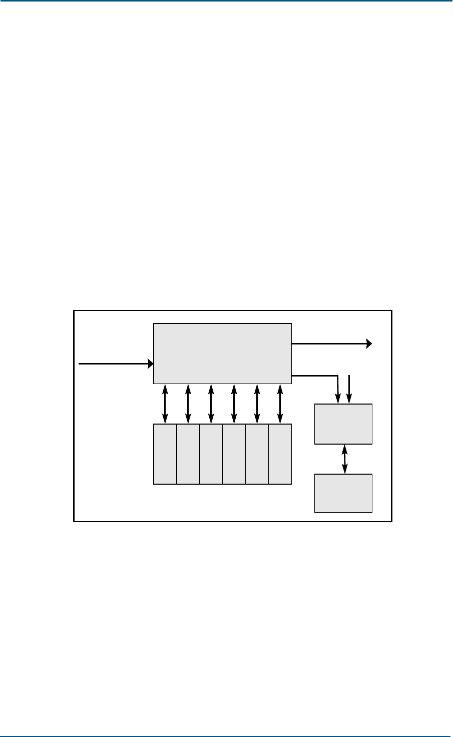
Subsystem), as shown in Fig. 11.
FIG. 11 BTS SOFTWARE STRUCTURE
SCS OMC
DBS SIG BRS
SPS
OSS CORE
BSP & Driver
The BTS software is distributed in various boards and the OMC.
1. SPS delivers cdma2000 1X, EV-DV services based on the air Um
interface standard (IS-2000).
2. OMC provides interfaces to authorized administrators and upper NM
system for the purpose of operation & maintenance of the whole BTS.
3. DBS provides centralized management on BSS data and is the support
system of the upper-layer applications (SPS and OMS).
4. BSP&Driver is the basis of all the other subsystems. It shields the
hardware details from the subscriber process, and provides process
dispatching, timer, communication and memory management services.
The core of BSP&Drive is the commercial operating system kernel.
Above the kernel is the encapsulation layer, which encapsulates the
kernel system invoking and shields unnecessary functions from the

ZXC10 CBTS (V1.0)Technical Manual
38 Confidential and Proprietary Information of ZTE CORPORATION
subscriber process. The encapsulation layer provides the subscriber
process with necessary primitive and function invoking interfaces.
5. SCS performs monitoring, startup and version downloading of the BTS
software system. It runs on the operating system and database
subsystem.

Chapter 3 - BTS Software
Confidential and Proprietary Information of ZTE CORPORATION 39
CCM Software
CCM, Communication Control Module, is located in the BDS shelf.
Functions of CCM software include:
Allocate all BTS radio resources.
Process related signaling for the voice and data services of the BTS it is
responsible for.
Implement centralized management on BTS data, including physical
configuration data and wireless data.
Communicate through the Ethernet and HDLC communication with the
BSC and other boards of BTS.
Monitor BDS and RFS boards and report alarms.
Control power-on and configuration of other BTS boards.
Support active / standby changeover of CCM.
Support downloading and query of software version and logic of BTS
boards.

ZXC10 CBTS (V1.0)Technical Manual
40 Confidential and Proprietary Information of ZTE CORPORATION
CHM0 Software
CHM0 is responsible for the cdma20001x channel modulation and
demodulation. Its functions are as follows.
Provide communication interface with CCM.
Modulate voice and data frames coming from CCM in the forward link,
and send the modulated data to RIM.
Demodulate antenna signals coming from the RIM through the BDS
interface in the reverse link into voice and data frames, and send them
to CCM for switching.
Support the cdma2000 physical layer protocol: IS-2000-2 RELASE A.
Support OTD (Orthogonal Transmit Diversity) and STS.
Support forward links, including: pilot channels such as F-PICH, F-
TDPICH, F-APICH and F-ATDPICH; control channels such as F-SYNCH,
F-PCH, F-BCH, F-QPCH, F-CPCCH, F-CACH and F-CCCH; and traffic
channels such as F-DCCH, F-FCH, F-SCH and F-SCCH. .
Support reverse links, including: access channels such as R-ACH, R-
EACH and R-CCCH; and traffic channels such as R-DCCH, R-FCH, R-
SCH and R-SCCH.
Support board hot swapping.
Allow online version downloading via a transmission bus.
Control system’s remote soft reset and backplane interface disabling .

Chapter 3 - BTS Software
Confidential and Proprietary Information of ZTE CORPORATION 41
CHM1 Software
Software CES-HRPD runs on CHM1 to deliver EV-DO service. It is designed
on the CSM5500 chip.
CHM-HRPD runs under CES-HRPD control, and processes HRPD air
interface control channel signaling and service data frames.

ZXC10 CBTS (V1.0)Technical Manual
42 Confidential and Proprietary Information of ZTE CORPORATION
RMM Software
Functions of RMM software include:
Monitor the RFS boards.
Communicate with BDS boards and other RFS boards.
Support downloading and query of RFS boards’ software version and
logic.
Support power-on, address acquisition and data configuration of RFS
boards.
Manage RFS boards’ status.
Control the switchover of RFS fiber links.
Control TRX switchover.
Control PA switchover.
Support the diagnostic test for RFS boards.

Chapter 3 - BTS Software
Confidential and Proprietary Information of ZTE CORPORATION 43
TRX Software
The TRX board is the core of RFS in a BTS. It is responsible for signal
conversion in both forward and reverse links, including conversion from
digital baseband signal to analog RF signals. It uses the digital IF and
multi-carrier technologies.
TRX software provides the following functions.
Query and report RSSI signal energy.
Attenuation and gain control in both forward and reverse links.
Configure RFS boards.
Monitor board status.
DSP configuration.
Auto-scaling control.
Diagnostic test of TRX board.
Support cell blossom, wilting and breathing.
Board backup control.
If BTM is configured, it provides test signals for the transceiving
devices located in the BTS sectors with the help of test MS, for the
purpose of online test on system performance.

Confidential and Proprietary Information of ZTE CORPORATION 44
Chapter 4
BTS Networking and
Configuration
In this chapter, you will learn about:
BTS networking modes
BTS networking configuration
Chapter 4 - BTS Networking and Configuration
Confidential and Proprietary Information of ZTE CORPORATION 45
Networking through Abis Interface
This chapter starts with describing the BSS networking mode, next BTS
networking mode and finally BTS networking configuration.
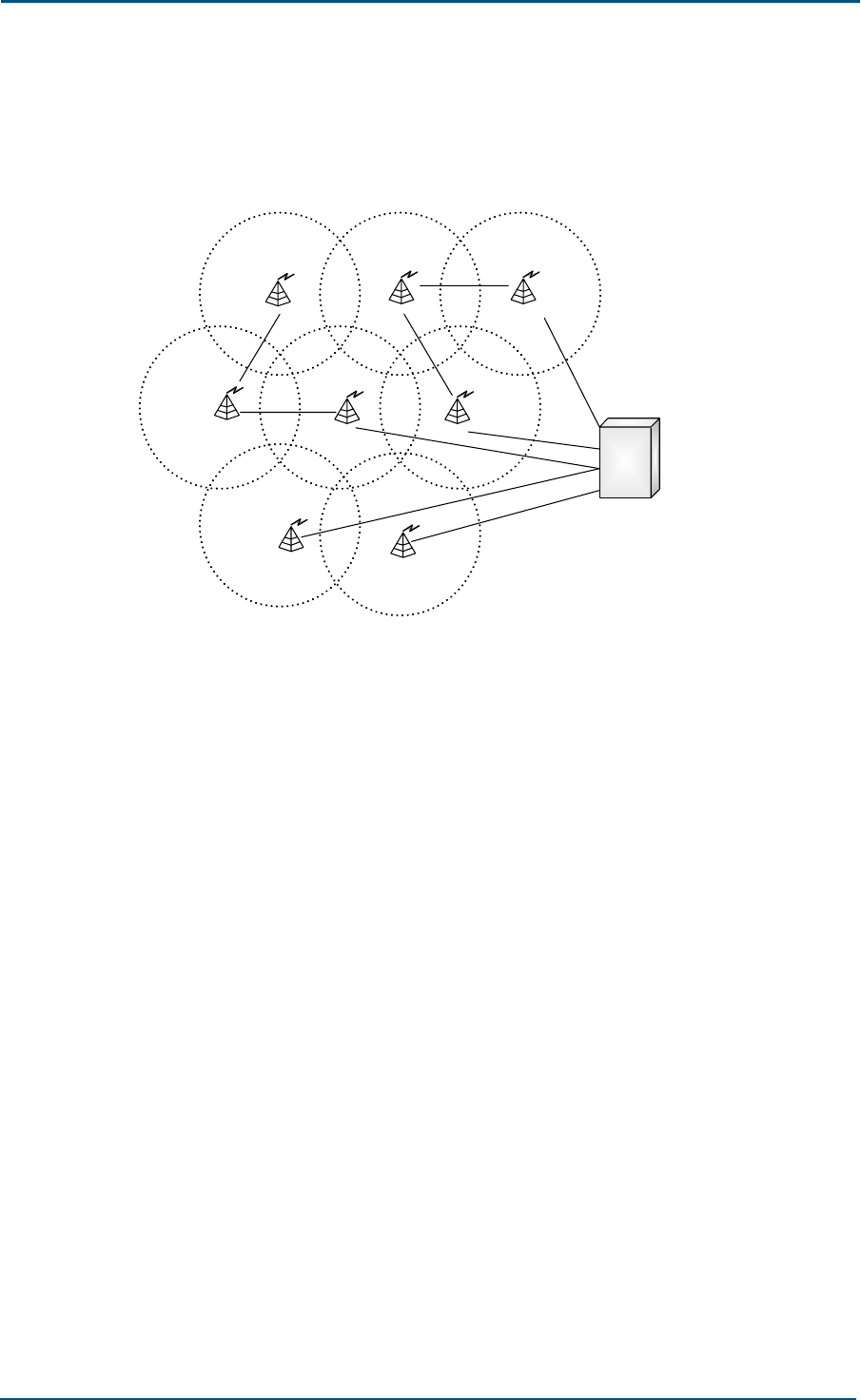
BSS (Base Station System) includes BTS (Base Transceiver Station) and
BSC (Base Station Controller). BTS is composed of BDS, local RFS (LRFS)
and remote RFS (RRFS). Multiple networking modes are workable as
shown in Fig. 12
FIG. 12 CDMA2000 BSS NETWORKING
BSC
BTS = Macro BTS
or Micro BTS
or Compact BTS
BTS
....
BTS BTS BTS
.... .... ....
....
BTS BTS BTS
....
Abis
E1 or SDH Abis Star
Abis Chain
Abis Ring
BSC connects with BTS (macro or micro) through the Abis interface to
form various network shapes, such as star, chain, and ring.
Star networking
By star-shaped networking, it means that each BTS connects with BSC
individually and directly, or indirectly through external transmission
device.
Ring networking
Several BTS connect in serial to BSC as in a ring structure.
Chain networking
In a chain networking mode, several BTS are connected to form a
chain with the last BTS connecting to BSC through E1/T1 or SDH.
ZXC10 CBTS (V1.0)Technical Manual
46 Confidential and Proprietary Information of ZTE CORPORATION
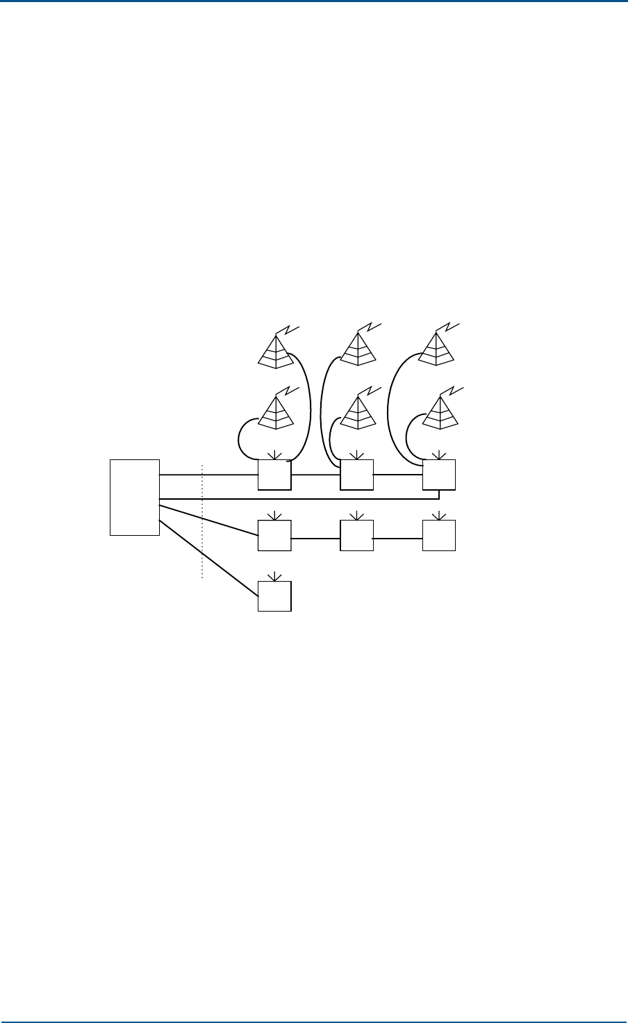
Actual BSS networking may adopt a combined mode of ring, star and
chain, as shown in Fig. 13.
FIG. 13 BSS NETWORKING
BSC
BSC connects with BTS through E1/T1, SDH or Ethernet interface. The
Ethernet approach applies when BSC is near BTS and in this way, the
complex Abis link compression protocol is avoided, the networking cost cut
down and reliability enhanced.

Chapter 4 - BTS Networking and Configuration
Confidential and Proprietary Information of ZTE CORPORATION 47
BTS Networking
BTS is in terms of hardware a set of radio transceiving devices that serve
a cell, which can be of omni-directional, 2-sector, 3-sector or 6-sector
structure. It modulates and demodulates signals, but in a more complex
way than a regular modem.
BTS bears radio service functions of BSS, including radio transmission with
the MS (Mobile Station) through IS2000 air interface and control over the
radio channel. It is connected with BSC through Abis interface and
controlled by BSC.
In BTS, BDS and RFS are connected flexibly through a standard interface
to fill in different networking needs.
Table 3 lists some commonly used BTS networking modes.
TABLE 3 BTS NETWORKING MODES
Mode Full Name Description
LS Local Single Mode Support 4-carrier 3-sector (1X/EV-DO),
not support RRFS
RS Remote Single Mode May work as the RRFS, support 4-carrier
3-sector (1X/DO)
LEA Local Extend Mode A
RFS added in combined cabinet to support
voice service (1X) for configuration of 8-
carrier 3-sector or 4-carrier 6-sector
LEB Local Extend Mode B
BDS and RFS added in combined cabinet
to support 1X/EV-DO for configuration of
8-carrier 3-sector or 4-carrier 6-sector
RE Remote Extend Mode
Remote CBTS or MBTS-RFS added
through fiber connection. LRFS+RRFS
supports 12 carrier sectors for EV-DO or
nearly 24 carrier sectors for 1X
ME MIX Extend Mode
BDS and RFS added in combined cabinet,
with remote CBTS or MBTS-RFS added
through fiber connection, to support 24
carrier sectors for EV-DO or nearly 48
carrier sectors for 1X
ZXC10 CBTS (V1.0)Technical Manual
48 Confidential and Proprietary Information of ZTE CORPORATION
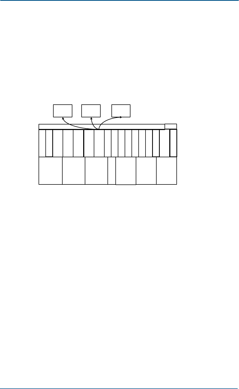
LS Mode
The LS networking mode is suitable for the economy configuration of 12
carrier sectors for EV-DO and 24 carrier sectors for 1X service.
With the 4-carrier 3-sector configuration in this mode, 2 (max. 3) CHM0
can be used with 2 slots left idle to deliver pure 1X service, or 4 CHM1 be
used for pure EV-DO service. Fig. 14 shows the slot diagram.
FIG. 14 BTS BOARD LAYOUT IN LS MODE
RPD
R
F
E
1
R
F
E
1
R
F
E
1
L
P
A
L
P
A
L
P
A
R
I
M
1
C
H
M
0
C
H
M
0
T
R
X
R
M
M
2
C
C
M
C
C
M
B
T
M
D
S
M
T
R
X
G
C
M
S
A
M
0
S
N
M
P
I
M
0
T
R
X
B
I
M
Chapter 4 - BTS Networking and Configuration
Confidential and Proprietary Information of ZTE CORPORATION 49
RS Mode
The RS networking mode applies when the RRFS is used independently
and 4-carrier 3-sector is configured. It is another economy approach.
In the RS mode, the BDS is locally installed and it can be a super BTS,
single macro BTSB or CBTS; while the remote CBTS accommodates only
the RFS. Such configuration (see below) supports 12 carrier sectors for
either EV-DO or 1X.
FIG. 15 RS MODE
T
R
X
T
R
X
T
R
X
R
M
M
1
RPD
S
A
M
0
L
P
A
P
I
M
0
L
P
A
L
P
A
RFE
1
RFE
1
RFE
1
B
T
M
B
I
M
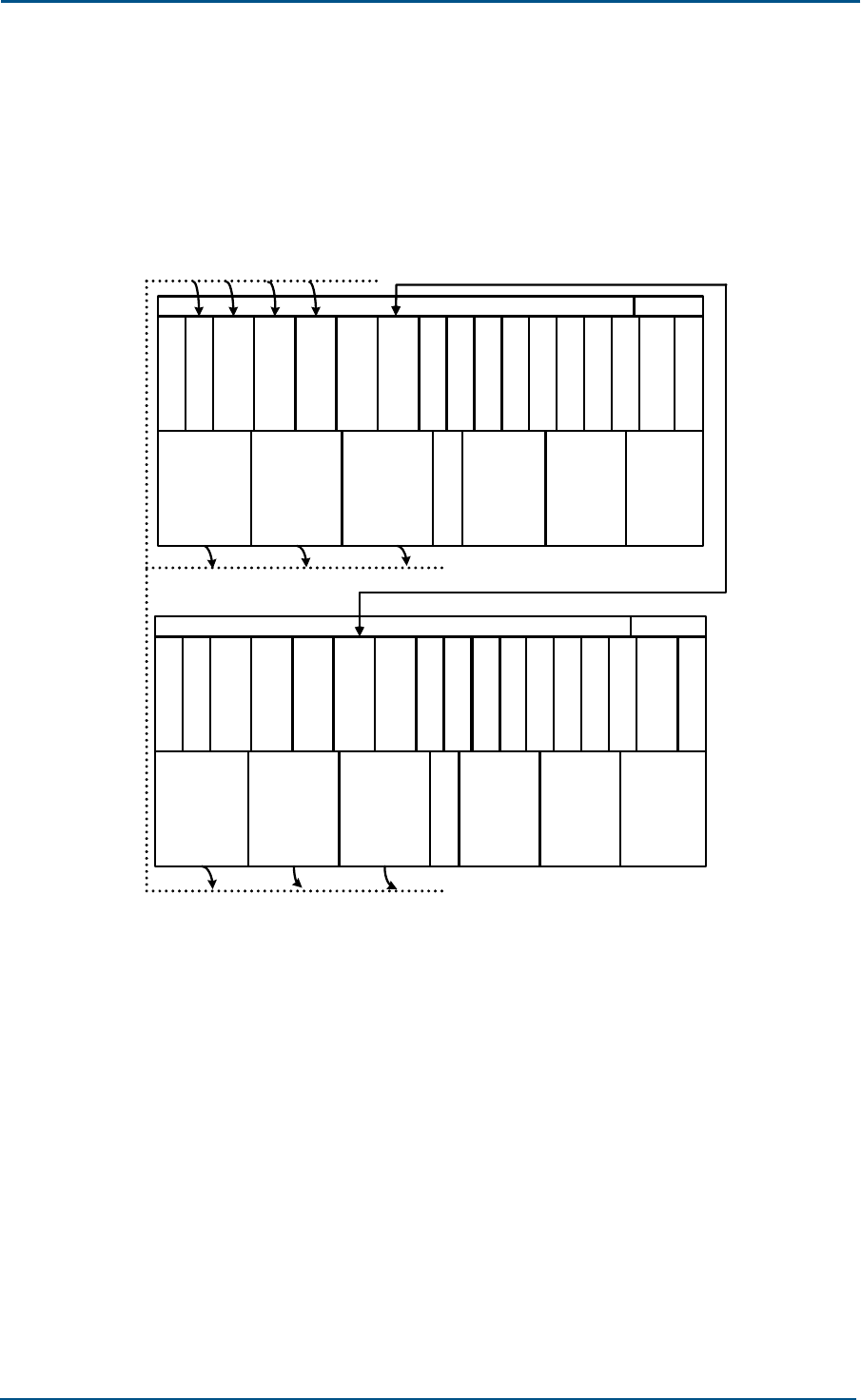
LEA Mode
The LEA networking mode applies when the CBTS system is deployed with
4-carrier 3-sector to deliver pure 1X or 1X + EV-DO services, however the
local RFS has to be extended to fit in system configuration (while the
baseband resource is enough).
In the LEA mode, two CBTS cabinets are combined with the additional one
configured with only RFS (no BDS). This mode provides a capacity of 24
carrier sectors to deliver pure 1X service, or 4-carrier 3-sector for 1X +
EV-DO. (In this mode, the BDS supports only 12 carrier sectors to deliver
pure EV-DO service. That’s why the LS mode is more preferable for pure
EV-DO service.)
ZXC10 CBTS (V1.0)Technical Manual
50 Confidential and Proprietary Information of ZTE CORPORATION
There are two workable approaches for local RFS extension: carrier
extension (more than 4 carriers) and sector extension (more than 3
sectors). The two extension modes differ in the RFE board and the cable
that connects two cabinets. Fig. 16 shows the board layout in LEA mode.
FIG. 16 LEA MODE
C
H
M
0
C
H
M
0
T
R
X
T
R
X
T
R
X
R
M
M
0
R
I
M
0
RPD
S
A
M
0
C
C
M
C
C
M
D
S
M
G
C
M
L
P
A
P
I
M
0
L
P
A
L
P
A
S
N
M
B
T
M
T
R
X
T
R
X
T
R
X
R
M
M
1
RPD
S
A
M
1
L
P
A
P
I
M
0
L
P
A
L
P
A
C
H
M
0
C
H
M
0
RFE
5
RFE
5
RFE
5
RFE
5
RFE
5
RFE
5
‘BASE-RF’optical fiber
RF combined cabnet alternate cabl
e
RF combined cabnet alternate cable
RF combined cabnet alternate cable
B
I
M
B
I
M
Chapter 4 - BTS Networking and Configuration
Confidential and Proprietary Information of ZTE CORPORATION 51
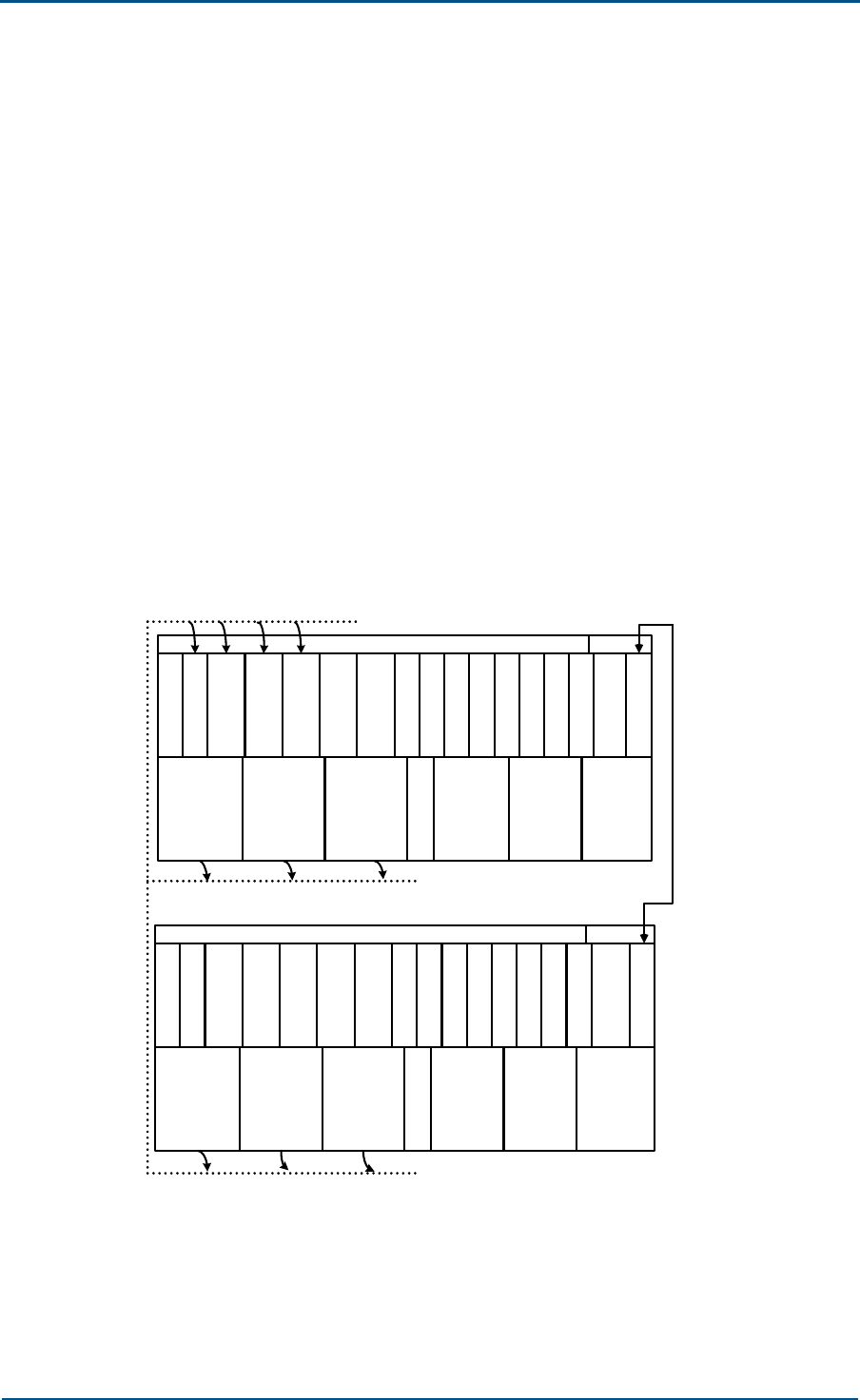
LEB Mode
The LEB mode is basically a BDS + RFS extension approach to deliver pure
DO or 1X + DO service.
Two BTS cabinets are combined in this mode with the additional cabinet
configured with both baseband and RF resource. This mode allows no
sharing of baseband, that is, both master BTS and slave BTS have their
own baseband and RF resource. However, both cabinets share the CCM
and Abis interface.
This mode provides a capacity of 24 carrier sectors to deliver pure DO
service, or 4-carrier 3-sector for 1X + DO.
There are two extension approaches for this mode: carrier extension
(more than 4 carriers) and sector extension (more than 3 sectors). The
two extension modes differ in the RFE board and the cable that connects
two cabinets. Fig. 17 shows the board layout in LEA mode.
FIG. 17 LEB MODE
C
H
M
1
C
H
M
1
T
R
X
T
R
X
T
R
X
R
M
M
2
R
I
M
1
RPD
S
A
M
0
C
C
M
C
C
M
D
S
M
G
C
M
L
P
A
P
I
M
0
L
P
A
L
P
A
S
N
M
B
T
M
T
R
X
T
R
X
T
R
X
R
M
M
2
RPD
S
A
M
1
L
P
A
P
I
M
0
L
P
A
L
P
A
C
H
M
1
C
H
M
1
RFE
5
RFE
5
RFE
5
RFE
5
RFE
5
RFE
5
RF combined cabnet alternate cable
RF combined cabnet alternate cable
RF combined cabnet alternate cable
B
I
M
B
I
M
C
H
M
1
C
H
M
1
R
I
M
1
S
C
M
S
C
M
C
H
M
1
C
H
M
1
BASE cascade cable
ZXC10 CBTS (V1.0)Technical Manual
52 Confidential and Proprietary Information of ZTE CORPORATION
RE Mode
In the RE mode, the RFS is installed in a remote place from the BTS with
the fiber used for connection. This mode applies when the remote RFS
needs to share the local surplus BDS resource. For the BDS (4×CHM) in a
single BTS, this mode provides a capacity of 12 carrier sectors to deliver
pure EV-DO service and 24 carrier sectors to deliver pure 1X service. See
below for the configuration.
FIG. 18 RE MODE
C
H
M
0
C
H
M
0
T
R
X
T
R
X
T
R
X
R
M
M
0
R
I
M
3
RPD
S
A
M
0
C
C
M
C
C
M
D
S
M
G
C
M
S
N
M
B
T
M
C
H
M
0
C
H
M
0
RFE
1
RFE
1
RFE
1
P
I
M
0
L
P
A
L
P
A
L
P
A
B
I
M
RRFS RRFS RRFS
Chapter 4 - BTS Networking and Configuration
Confidential and Proprietary Information of ZTE CORPORATION 53
ME Mode
The ME mode is a combination of LEB and RE modes. Both local extension
(BDS and RFS) and remote extension (RFS, with fiber used for connection)
are necessary for this mode. After BDS extension, the mode provides a
max. capacity of 24 carrier sectors to deliver pure EV-DO service, or 48
carrier sectors to deliver 1X service. If the local master BTS is configured
with 4-carrier 3-sector or less, the slave BTS may have no local RFS
configured. If the local master BTS is configured with more than 4-carrier
3-sector, then the slave BTS should have RFS configured. The redundant
BDS resource can be shared with the remote RFS. See below for the
configuration.
FIG. 19 ME MODE
BDS
LRFS
BDS
LRFS
RRFS
RRFSRRFS
RRFS
RRFS
M-CBTS S-CBTS
BTS Configuration
BDS Configuration
A master BDS includes SAM, GCM, CHM, RIM, CCM, DSM, SNM, BIM and
RPD boards.
A slave BDS is configured to suit different networking modes.
Configuration requirement:
CCM: usually configured in active/standby pairs.
SNM: optional, usually not needed.
CHM: configured according to the number of carriers.
CHM0: As one CHM0 provides 256 CEs for 1X service, the number of CHM0
needed is k/256 (k is the total traffic erl).

ZXC10 CBTS (V1.0)Technical Manual
54 Confidential and Proprietary Information of ZTE CORPORATION
CHM1: As one CHM1 provides the capacity of 3 carrier sectors for EV-DO
service, the number of CHM1 is n/3 (n is the total number EV-DO carrier
sectors).
CHM0 and CHM1 can be used together in the same shelf.
RFS Configuration
An RFS can be made up of LRFS and RRFS. LRFS works for the local BTS,
while RRFS can work either for the local BTS or another BTS.
This sector covers the configuration of LRFS only.
The LRFS has such boards as BTM, TRX, RMM, LPA and RFE.
The number of TRX and LPA to be configured depends on number of
carriers and sectors. If 4 carriers are enough for continuous coverage,
number of TRX/LPA is the same as that of sectors. If two 4 × carriers are
needed, number of TRX/LPA is twice that of sectors. For example:
3 TRX and 3 LPA for 1-carrier 3-sector.
3 TRX and 3 LPA for 2-carrier (continuous) 3-sector.
3 TRX and 3 LPA for 3-carrier (continuous) 3-sector.
3 TRX and 3 LPA for 4-carrier (continuous) 3-sector.
TRX and 6 LPA for 8-carrier (continuous) 3-sector (3 of the 6 TRX and
3 of the 6 LPA can be installed in the added cabinet).
TRX and 6 LPA for 4-carrier (continuous) 6-sector (3 of the 6 TRX and
3 of the 6 LPA can be installed in the added cabinet).
Neither LPA nor TRX is configured in active/standby pairs.
PWS Configuration
The primary power shelf can be omitted if the –48 VDC is ready on site.
The primary power shelf needs to be prepared if there is only 220
V/110VAC ready on site.

Confidential and Proprietary Information of ZTE CORPORATION 55
Chapter 5
Technical Indices
In this chapter, you will learn about:
Environment indices of the BTS system
Performance indices (parameter requirements) of the functional
components of the BTS system
ZXC10 CBTS (V1.0)Technical Manual
56 Confidential and Proprietary Information of ZTE CORPORATION
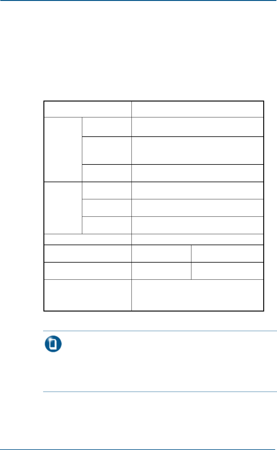
Environment Indices
The environment indices set requirements on the physical parameters,
power supply, grounding, temperature, humidity and cleanness, which are
given in Table 4.
TABLE 4 ENVIRONMENT INDICES
Environment Indices Requirements
Dimension (mm) Single cabinet (mm): W700 × D800 × H800
PWS cabinet (optional): W700 × D600 × H400
Weight (kg)
4-carrier 1–sector: 155
4-carrier 3-sector: 211
4-carrier 6-sector or 8-carrier 3-sector: 422
Physical
Index
Load-bearing of
the floor (kg/m2)>377
Primary power
supply input
150 V~300 V for 200 V AC or 90 V ~138 V for 100
V AC
Secondary power
supply input -42.3 V ~ -56.5 V if -48 V DC is used
Power
supply
Power
consumption Varies with the configuration (refer to Table 5.1-2)
Grounding Joint grounding resistance ≤ 1 Ω
Temperature Long-term: -
5°C~50°C Short-term: -20°C~60°C
Humidity Long-term:
15%~80% Short-term:5%~95%
Cleanness
Dust granule diameter <5 μm, dust granule
density ≤ 13 ° 104 granules/m3 (dust granules
should be non-conductive, non-magnetic and non-
corrosive)
Note:
Temperature and humidity values are measured 2m above floor and 0.4m in front
of equipment that has no fender at the front or back.
By “short-term” it means less than continuous 48 hours or less than cumulative 15
days in a year.

Chapter 5 - Technical Indices
Confidential and Proprietary Information of ZTE CORPORATION 57
TABLE 5 BTS POWER CONSUMPTION
Configuration
Power
Amplifier
Output
Working
Voltage
Max. Power
Consumption
for 1X
Max. Power
Consumption for
DO
Single-carrier
single-sector
LPA, 40 W -48 V Approx. 1400 W Approx. 1400 W
2-carrier 1–sector LPA, 40 W -48 V Approx. 1400 W Approx. 1400 W
3-carrier 1–sector LPA, 40 W -48 V Approx. 1400 W Approx. 1400 W
5-carrier 1-sector LPA, 40 W -48 V Approx. 2000 W Approx. 2000 W
7-carrier 1-sector LPA, 40 W -48 V Approx. 2000 W Approx. 2100 W
1-carrier 3–sector LPA, 40 W -48 V Approx. 2500 W Approx. 2600 W
2-carrier 3–sector LPA, 40 W -48 V Approx. 2600 W Approx. 2600 W
3-carrier 3-sector LPA, 40 W -48 V Approx. 2600 W Approx. 2700 W
4-carrier 3-sector LPA, 40 W -48 V Approx. 2600 W Approx. 2700 W
5-carrier 3-sector LPA, 40 W -48 V Approx. 4400 W Approx. 4500 W
7-carrier 3-sector LPA, 40 W -48 V Approx. 4500 W Approx. 4600 W
8-carrier 3-sector LPA, 40 W -48 V Approx. 4500 W Approx. 4700 W
1-carrier 6-sector LPA, 40 W -48 V Approx. 4300 W Approx. 4400 W
2-carrier 6-sector LPA, 40 W -48 V Approx. 4400 W Approx. 4500 W
3-carrier 6-sector LPA, 40 W -48 V Approx. 4500 W Approx. 4600 W
4-carrier 6-sector LPA, 40 W -48 V Approx. 4500 W Approx. 4700 W

ZXC10 CBTS (V1.0)Technical Manual
58 Confidential and Proprietary Information of ZTE CORPORATION
Performance Indices
The performance indices set requirements on the reliability, interface,
capacity, frequency band and clock.
Reliability
Mean Time Between Critical Faults (MTBCF): > 100000 hours;
Mean Time Between Faults (MTBF): > 63492 hours;
Mean Time To Recovery (MTTR): 0.5 hours.
Availability: > 99.987%.
Interface
Abis interface: E1/T1 and SDH connection;
Interface between BDS and RRFS: fiber connection.
Capacity
A single BTS cabinet can be configured with 24 carrier sectors for 1X
service or 12 carrier sectors for EV-DO service.
RRFS networking: star-, chain- or ring-shaped networking.
RRFS: One BDS can work with at most 24 RRFS sites.
A single LRFS (indoor) can be configured with at most 24 carrier
sectors.
Frequency Band
The system supports five frequency bands as set forth in IS-97D “CDMA
BTS Minimum Performance Standard”: Band Class 0 (800 MHz), Band
Class 1 (1.9 GMHz), Band Class 5 (450 MHz), Band Class 6 (2.1 GMHz)
and Band Class 10 (850 MHz).
Specs of Bands 800 MHz, 450 MHz and
850 MHz
1. Receiver (with an LNA)
TABLE 6 RECEIVER INDEX AT 800 MHZ, 450 MHZ AND 850 MHZ
Working
bands 800 MHz, 450 MHz and 850 MHz
Channel
bandwidth 1.23 MHz(800 MHz), 1.25 MHz (450 MHz, 850 MHz)

Chapter 5 - Technical Indices
Confidential and Proprietary Information of ZTE CORPORATION 59
Working
bands 800 MHz, 450 MHz and 850 MHz
Rx sensibility ≤ -125 dBm
Rx dynamic
range
Rx sensibility ≤ dynamic range ≤ Noise level -65 dBm/1.23
MHz (Eb/N0 = 10 dB ± 1 dB ), FER < 1%
Block-proof
800 MHz:
± 750 kHz offset center freq; if monotone = 50dB (as
opposed to CDMA signal level), when FER < 1.5%; increase
of MS output power ≤ 3 dB;
± 900 kHz offset center freq; if monotone = 87dB (as
opposed to CDMA signal level), when FER < 1.5%; increase
of MS output power ≤ 3 dB;
450 MHz:
± 900 kHz offset center freq; if monotone = 87dB (as
opposed to CDMA signal level), when FER < 1.5%; increase
of MS output power ≤ 3 dB;
850 MHz:
± 1.25MHz offset center freq; if monotone = 80dB (as
opposed to CDMA signal level), when FER < 1.5%; increase
of MS output power ≤ 3 dB;
Inter-
modulation
spurious
response
attenuation
sensibility
800 MHz and 450 MHz:
900kHz ~ 1.7MHz and –900kHz ~ -1.7MHz offset center
freq; if dual-tone = 72dB (as opposed to CDMA signal level,
when FER < 1.5%; increase of MS output power ≤ 3 dB;
850 MHz:
1.25MHz ~ 2.05MHz and -1.25MHz ~ -2.05MHz offset
center freq; if dual-tone = 72dB (as opposed to CDMA signal
level, when FER < 1.5%; increase of MS output power ≤ 3
dB;
Rx conductive
and emissive
spurious
range
< -80 dBm (within the BTS Rx frequency)
< -60 dBm (within the BTS Tx frequency)
< -47 dBm (at other frequencies), RBW = 30 kHz
VSWR of RFE
(Rx) < 1.50
2. Transmitter
TABLE 7 TRANSMITTER INDEX AT 800 MHZ, 450 MHZ AND 850 MHZ
Working bands 800 MHz, 450 MHz and 850 MHz
Transmitter
frequency tolerance ≤ 5×10⁻⁸
Channel bandwidth 1.23 MHz (800 MHz), 1.25 MHz (450 MHz, 850 MHz)
Tx modulation Quadrature modulation
Conductive /
emissive spurious
transmission
< -45 dBc @±750 kHz offset center freq (RBW 30
kHz)
< -60 dBc @
±
1.98 MHz offset center
f
re
q(
RBW

ZXC10 CBTS (V1.0)Technical Manual
60 Confidential and Proprietary Information of ZTE CORPORATION
Working bands 800 MHz, 450 MHz and 850 MHz
suppression 30kHz)
> 4 MHz offset:
< -36 dBm (RBW 1 kHz) @ 9KHz < f < 150 kHz
< -36 dBm (RBW 10 kHz) @ 150KHz < f < 30
MHz
< -30 dBm (RBW 1 MHz) @ 1GHz < f < 12.5 GHz
4MHz ~ 6.4 MHz offset:
< -36 dBm (RBW 1kHz) @ 30 MHz < f < 1 GHz
6.4MHz ~ 16MHz offset:
< 36 dBm (RBW 10 kHz) @ 30 MHz < f < 1 GHz
> 16 MHz offset:
< -36 dBm (RBW 100 kHz) @ 30 MHz < f < 1 GHz
Code domain power
(inactive channel) 32 dB less than the total output power
Total power Rated power -4 dB ~ rated power + 2 dB (refer to
IS-97D for the definition and test of total power)
Waveform quality
(multi-carrier) ρ> 0.97
Pilot time tolerance
< 3 us; ±1 us between every two CDMA channels of
the same BTS; If the outer system clock is
interrupted, the time difference between the BTS
and CDMA should be kept no more than ±10 us
during 8 hours’ time
Pilot channel and
code-division
channel time
tolerance
< ±50 ns in the same CDMA channel
Pilot channel and
code-division
channel phase
tolerance
≤ 0.05 (in radian) in the same CDMA channel
Pilot power Ratio of pilot power / total power ≤ ±0.5 dB of the
configured value
Rated output power
of amplifier LPA: 40 W; DPA: 40 W /80 W
Output linear
dynamic range > 30 dB
RF (Tx) front end
VSWR < 1.50

Chapter 5 - Technical Indices
Confidential and Proprietary Information of ZTE CORPORATION 61
Specs of 1.9 GHz and 2.1GHz
1. Receiver (with an LNA)
TABLE 8 RECEIVER INDEX AT 1.9 GHZ AND 2.1GHZ
Working band 1.9 GHz、2.1GHz
Channel bandwidth 1.25 MHz
Rx sensibility < -125 dBm
Rx dynamic range
Rx sensibility (less than –127dBm) ≤ dynamic range
≤ Noise level of the antenna (no less than -65
dBm/1.25 MHz, when Eb/N0 = 10 dB ± 1 dB, FER <
1%
Block-proof
± 1.25 MHz offset center freq; if monotone = 80dB
(as opposed to CDMA signal level without
interference), when FER < 1.5%; increase of MS
output power ≤ 3 dB
Inter-modulation
spurious response
attenuation
sensibility
1.25 MHz ~ 2.05 MHz and -1.25 MHz ~ -2.05 MHz
offset center freq; if dual-tone = 70dB (as opposed
to CDMA signal level without interference), FER <
1.5%; increase of MS output power ≤ 3 dB
Rx conductive and
emission spurious
range
< -80 dBm (in BTS Rx band); < -60 dBm (in BTS Tx
band)
1.9 GHz:
< -47 dBm, RBW(30kHz) and all other frequencies
2.1 GHz:
-57dBm (RBW 100KHz) 30MHz < f < 1GHz
-47dBm (RBW 1MHz) 1GHz < f < 12.75GHz
RF (Rx) front end
VSWR < 1.50
2. Transmitter
TABLE 9 TRANSMITTER INDEX AT 1.9 GHZ AND 2.1GHZ
Working bands 1.9 GHz and 2.1GHz
Transmitter frequency
tolerance ≤ 5×10⁻⁸
Channel bandwidth 1.25 MHz
Tx modulation Quadrature modulation
Conductive / emissive
spurious transmission
suppression
In Band Class 6:
< -45 dBc @±885 kHz offset center freq
(RBW 30 kHz)
< -55 dBc @±1.98MHz offset center freq
(RBW 30 kHz)
< -13 dBm @
±
2.75MHz offset center
f
re
q

ZXC10 CBTS (V1.0)Technical Manual
62 Confidential and Proprietary Information of ZTE CORPORATION
Working bands 1.9 GHz and 2.1GHz
(RBW 1MHz)
> 4MHz offset:
< -36 dBm(RBW 1 kHz) @ 9KHz < f <150 kHz
< -36 dBm(RBW 10 kHz) @ 150KHz < f < 30
MHz
< -36 dBm(RBW 100 kHz) @ 30MHz < f < 1
GHz
4-16MHz offset:
< -30 dBm (RBW 30 kHz) @ 1 GHz < f < 12.5
GHz
16 M ~ 19.2 M offset:
< -30 dBm (RBW 300 kHz) @ 1 GHz < f <
12.5 GHz
Code domain power
(inactive channel) 32 dB less than the total output power
Total power
Rated power -4 dB ~ rated power + 2 dB
(refer to IS-97D for the definition and test of
total power)
Waveform quality ρ > 0.97
Pilot time tolerance
< 3 us; ±1 us between every two CDMA
channels of the same BTS; If the outer system
clock is interrupted, the time difference
between the BTS and CDMA should be kept no
more than ±10 us during 8 hours’ time
Pilot channel and code-
division channel time
tolerance
< ±50 ns in the same CDMA channel
Pilot channel and code-
division phase tolerance ≤ 0.05 (in radian) in the same CDMA channel
Pilot power Ratio of pilot power / total power ≤ ±0.5 dB of
the configured value
Output power of amplifier LPA: 40W; DPA: 40W /80W
Output linear dynamic
range > 30 dB
RF (Tx) front end VSWR < 1.50
Clock
1. BTS Clock technical parameters
Frequency benchmark: The accuracy of frequency 10 MHz is better
than 10-11 in GPS locked status and is better than 10-10 in the holdover
status.
The temperature variation is required to be less than ±0.5 ×10⁻⁹.
2. Clock Synchronization Source

Chapter 5 - Technical Indices
Confidential and Proprietary Information of ZTE CORPORATION 63
The GCM provides reliable clock for a short term and ensures the
locked status of clock during 72 hours after the GPS synchronous
signal is lost.
3. Clock System Performance
The frequency difference is less than 0.05 ppm, and phase difference
less than 10 us.
Noise
The ambient noise of BTS is no greater than 75dBA.

ZXC10 CBTS (V1.0)Technical Manual
64 Confidential and Proprietary Information of ZTE CORPORATION
This page is intentionally blank.

Appendix A - Abbreviations
Confidential and Proprietary Information of ZTE CORPORATION 65
Appendix A
Abbreviations
Abbreviation Full name
1X EV 1X Evolution
1X EV-DO 1X Evolution Data Only
1X EV-DV 1X Evolution Data & Voice
2G BTS 2G Base Station Transceiver
3G BTS 3G Base Station Transceiver
3GPP2 3rd Generation Partnership Project 2
A
AAA Authentication, Authorization, Accounting
Abis Abis Interface—the interface of BSC--BTS
AN Access network
APD AC Power Distribution Module
AUC Authentication Center
A interface A Interface—the interface of BSC-MSC
B
BBDS Backplane of BDS
B-BDS Backplane of Baseband Digital Subsystem
BBS BTS Baseband Subsystem
BCS BTS Communication Subsystem
BDM Baseband Digital Module
BDS Baseband Digital System
BGPS Backplane of GPS
BIM BDS Interface Module
BLPA Backplane of LPA
BPD BDS Power Distribute
BPWS Backplane of PWS

ZXC10 CBTS (V1.0)Technical Manual
66 Confidential and Proprietary Information of ZTE CORPORATION
Abbreviation Full name
BRFE Backplane of RFE
BRFS Backplane of TRX and BDM/RFM
BS Base Station
BSC Base Station Controller
BSS Base Station System
BTM BTS Test Module
BTRX Backplane of TRX
BTS Base Transceiver Station
C
CDMA Code Division Multiple Address
CDMA2000-1X CDMA2000 Phase One
CHM Channel Processing Module
CHM-1X Channel Processing Module for CDMA2000
CHM-95 Channel Processing Module for IS-95
CLK Clock
CN Core Network
CSM5000 Cell Site Modem ASIC 5000
CSM5500 Cell Site Modem ASIC 5500
CTDMA Code and Time Division Multiple Address
D
DBS Database Subsystem
DS-CDMA Direct-Sequence Code Division Multiple Address
DSM Data Service Module
DUP Duplexer
E
EMC Electromagnetic Compatibility
EMF Network Element Mediation Function
EMI Electromagnetic interference
EMS electromagnetic susceptibility
F
FD Full duplex
FDD Frequency Division Duplex
FDMA Frequency Division Multiple Access
G
GCM GPS Control Module

Appendix A - Abbreviations
Confidential and Proprietary Information of ZTE CORPORATION 67
Abbreviation Full name
GLI GE Line Interface
GPS Global Position System
GSM Globe System for Mobil Communication
H
HA Home Agent
HLR Home Location Register
HPA High Power Amplifier
HRPD High rate packet data
I
I/O Input/Output
ID Identifier
IMT-2000 International Mobile Telecommunications 2000
IP Internet Protocol
ISO International Standardization Organization
ISP Internet Service Provider
ITU International Telecommunications Union
K
kbps kilo-bits per second
L
LPA Linear Power Amplifier
M
MSC Mobile Switching Center
O
OIM Optical Interface Module
OMC Operation Maintenance Centre
OMF Operation Maintenance Function
OMI Operation Maintenance Interface
OMM Operation Maintenance Module
OSS Operating Systems Subsystem
OTD Orthogonal Transmit Diversity
P
PA Power Amplifier
PCF Packet Control Function
PCH Paging Channel
PDSN Packet Data Service Node

ZXC10 CBTS (V1.0)Technical Manual
68 Confidential and Proprietary Information of ZTE CORPORATION
Abbreviation Full name
PI Page Indicator
PLMN Public Land Mobile Network
PMM Power Monitor Module
PPM Power Process Module
PRM Power Rectifier Module
PSMC Power Supplier Module C
PSMD Power Supplier Module D
PSTN Public Switched Telephone Network
PWS Power System
Q
QoS Quality of Service
R
RFS RFIM
RIM RF Interface Module
RMM RF Management Module
RPD RFS Power Distribute
RX Receiver
RXB Receiver Board
S
SAM Site Alarm Module
SDH Synchronous Digital Hierarchy
SPS Signal Process Subsystem
SS7 Signaling System No.7
STS
T
TCP Transmission Control Protocol
TCP/IP Transmission Control Protocol/Internet Protocol
TD-CDMA Time Division-Code Division Multiple Access
TDD Time Division Duplex
TDMA Time Division Multiple Address
TOD Time of Date
TRX Transmitter and Receiver
TX Transmit
TXB Transmitter Board
U

Appendix A - Abbreviations
Confidential and Proprietary Information of ZTE CORPORATION 69
Abbreviation Full name
UI User Interface
Um interface Um Interface—the interface of MS-BTS
Z
ZXC10 AGWB cdma2000 Access Gateway
ZXC10 BDSB cdma2000 Baseband Digital System
ZXC10 BSCB cdma2000 Base Station Controller
ZXC10 BTSB cdma2000 Base Transceiver Station
ZXC10 CBTS cdma2000 Compact Base Transceiver Station
ZXC10 MBTS cdma2000 Micro Base Transceiver Station
ZXC10 MGWB cdma2000 Media Gateway)
ZXC10 PBTS cdma2000 Pico Base Transceiver Station
ZXC10 PWSB cdma2000 Power System
ZXC10 RFSB cdma2000 Radio Frequency System

Confidential and Proprietary Information of ZTE CORPORATION 71
Figures
Fig. 1 Position of BTS in BSS.......................................................................14
Fig. 2 BTS Physical Structure ......................................................................23
Fig. 3 BTS Logical Structure........................................................................24
Fig. 4 BDS Schematic Diagram....................................................................26
Fig. 5 BDS Configuration .............................................................................28
Fig. 6 SBDS Configuration ..........................................................................29
Fig. 7 RFS Schematic Diagram ....................................................................31
Fig. 8 RFE Configuration.............................................................................33
Fig. 9 PWS Schematic Diagram ...................................................................34
Fig. 10 Primary Power Supply of PWS...........................................................35
Fig. 11 BTS Software Structure ...................................................................37
Fig. 12 cdma2000 BSS Networking ..............................................................45
Fig. 13 BSS Networking .............................................................................46
Fig. 14 BTS Board Layout in LS Mode ............................................................48
Fig. 15 RS Mode........................................................................................49
Fig. 16 LEA Mode ......................................................................................50
Fig. 17 LEB Mode ......................................................................................51
Fig. 18 RE Mode........................................................................................52
Fig. 19 ME Mode .......................................................................................53

ZXC10 CBTS (V1.0)Technical Manual
72 Confidential and Proprietary Information of ZTE CORPORATION
This page is intentionally blank.

Confidential and Proprietary Information of ZTE CORPORATION 73
Tables
Table 1 Frequency Bands Supported by BTS..................................................16
Table 2 BTS Boards ...................................................................................25
Table 3 BTS Networking Modes ...................................................................47
Table 4 Environment Indices.......................................................................56
Table 5 BTS Power Consumption .................................................................57
Table 6 Receiver Index at 800 MHz, 450 MHz and 850 MHz .............................58
Table 7 Transmitter Index at 800 MHz, 450 MHz and 850 MHz.........................59
Table 8 Receiver Index at 1.9 GHz and 2.1GHz..............................................61
Table 9 Transmitter Index at 1.9 GHz and 2.1GHz .........................................61