ZTE R8860EGU198A Outdoor GSM/UMTS Dual Mode Remote Radio Unit User Manual II
ZTE Corporation Outdoor GSM/UMTS Dual Mode Remote Radio Unit II
ZTE >
Contents
- 1. User Manual
- 2. User Manual II
User Manual II
Chapter4Installation
4.5CabinetInstallation
4.5.1InstallationModeInstruction
Accordingtodifferentinstallationenvironments,therearethreemodesofR8860EGU198
installation:
lPole-mountinstallation
lWall-mountinstallation
lGantry-mountinstallation
lSimplied-cabinetintegrativeInstallation
4.5.2InstallationMethodsandAccessories
TherearetwoinstallationmethodsforR8860EGU198,asbelow:
lPolemountedinstallation(PoleMountingKit):Itissuggestedthatthediameterof
installationpoleshouldbe60mm~120mm.
lPolemountedinstallation(UniversalSheet-MetalKit):Itissuggestedthatthe
diameterofinstallationpoleshouldbe60mm~114mm.
lWallmountedinstallation.
Note:
Theuniversalsheet-metalkitalsosupportchannelironandangleiron.Thesupported
channelwidthis50mm–100mm.Thesupportedangleironwidthis63mm-80mm.(The
installationmethodissimilartothepoleinstallation.)
4.5.2.1InstallationAccessories
TheinstallationaccessoriesofR8860EGU198andtheirfunctionsareshowninTable4-3.
4-21
SJ-20101210110401-002|2011-05-31ZTEProprietaryandCondential
ZXSDRR8860EGU198UserManual
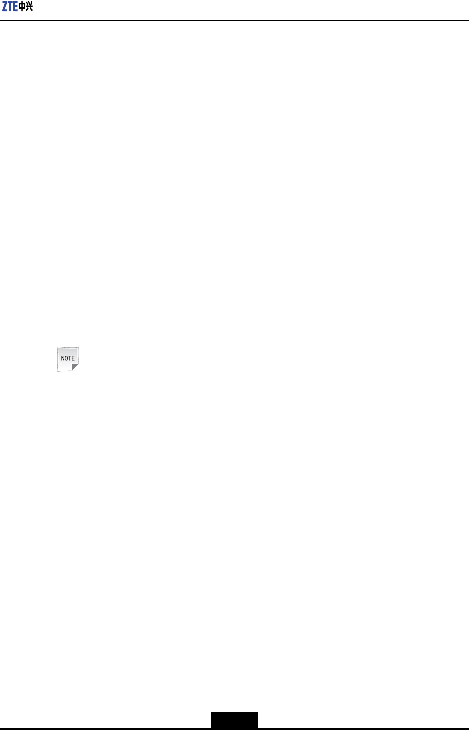
Table4-3INSTALLATIONACCESSORIESOFR8860EGU198ANDTHEIRFUNCTIONS
NameShapeFunction
Wallmounted
installation
assembly
Usedbywall
mountedandpole
mountedinstallation
(clampassembly
forpolemounted
installation)
Clampassembly
forpolemounted
installation
Forthepolewith
1or2R8860E
GU198polemounted
installation
Mountingbracket
assemblyfor
polemounted
installation
Forthepolewith3
R8860EGU198pole
mountedinstallation
4-22
SJ-20101210110401-002|2011-05-31ZTEProprietaryandCondential
Chapter4Installation
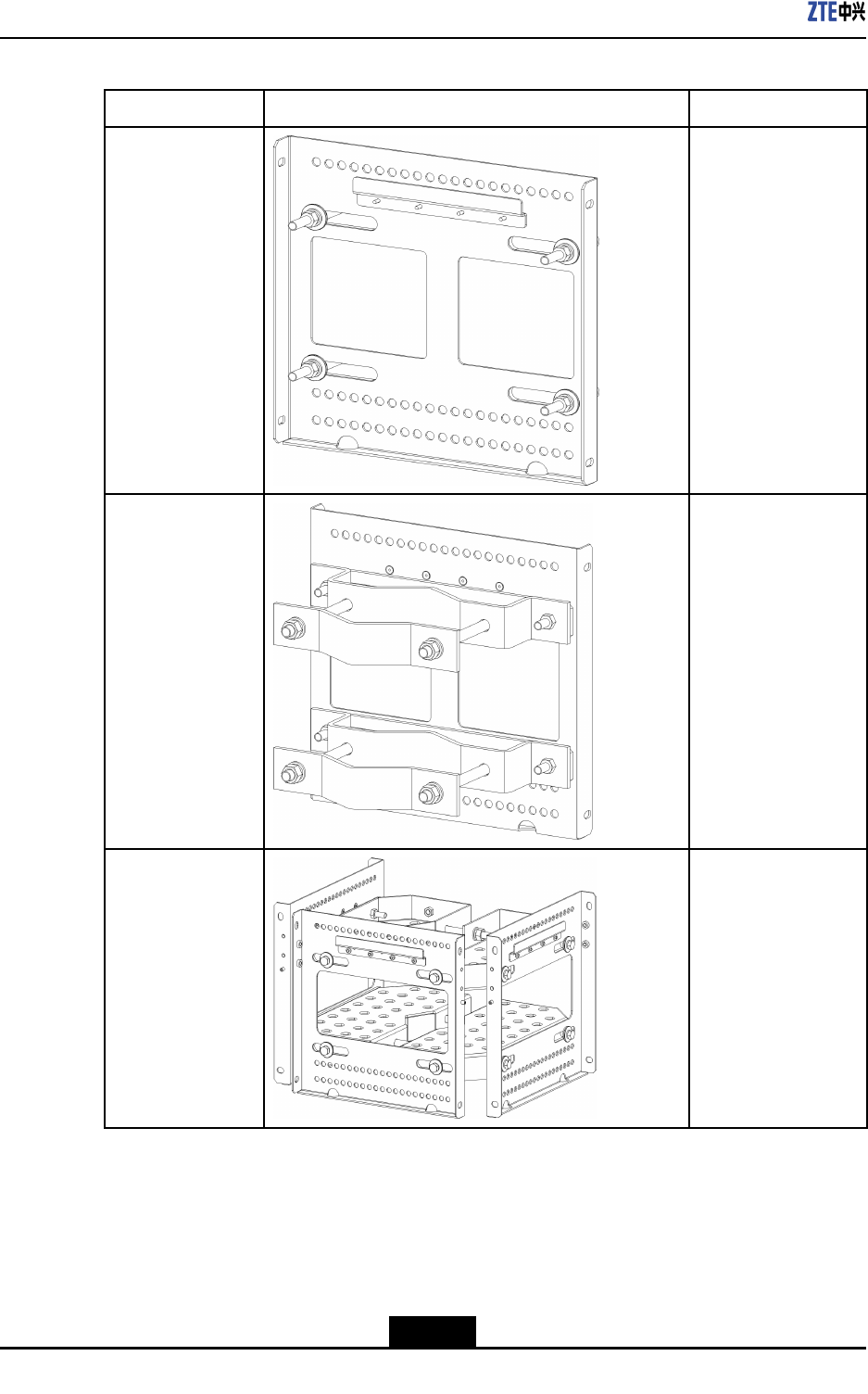
NameShapeFunction
MountingBaseUsedbypole
mountedinstallation
ofR8860EGU198
MountingPieceUsedbyxingonthe
pole
Lightningpretector
piece
Usedbypole
mountedinstallation
ofLightningpretector
box
ExpansionpieceForthepolewith
thethirdR8860E
GU198polemounted
installation
4-23
SJ-20101210110401-002|2011-05-31ZTEProprietaryandCondential
ZXSDRR8860EGU198UserManual
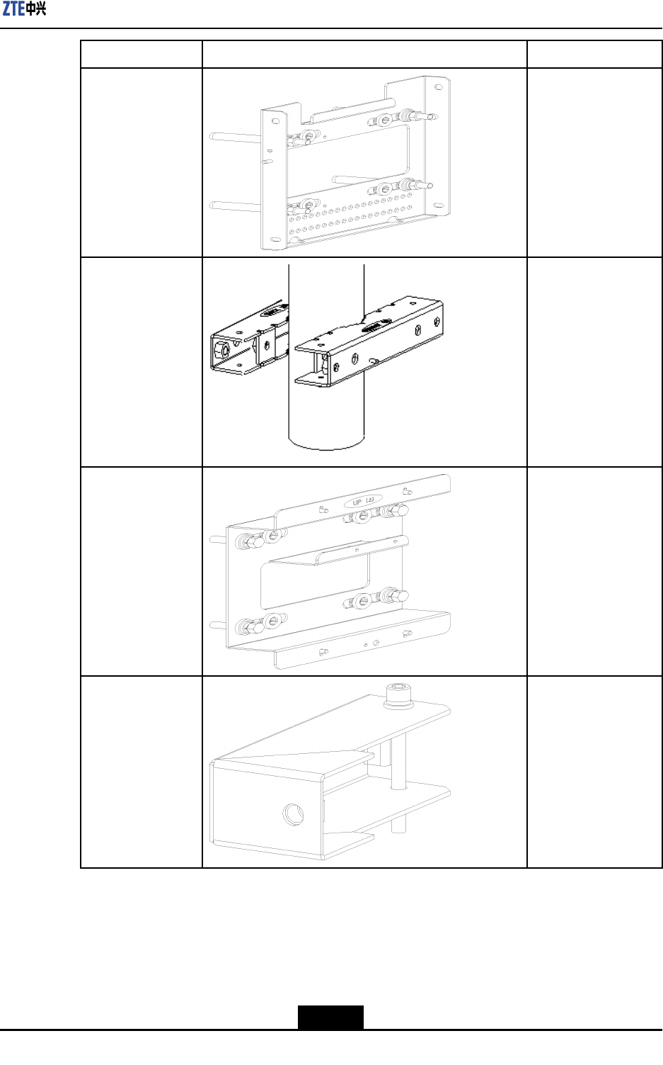
NameShapeFunction
ProtectionshadeToshieldR8860E
GU198fromdirect
sunlight
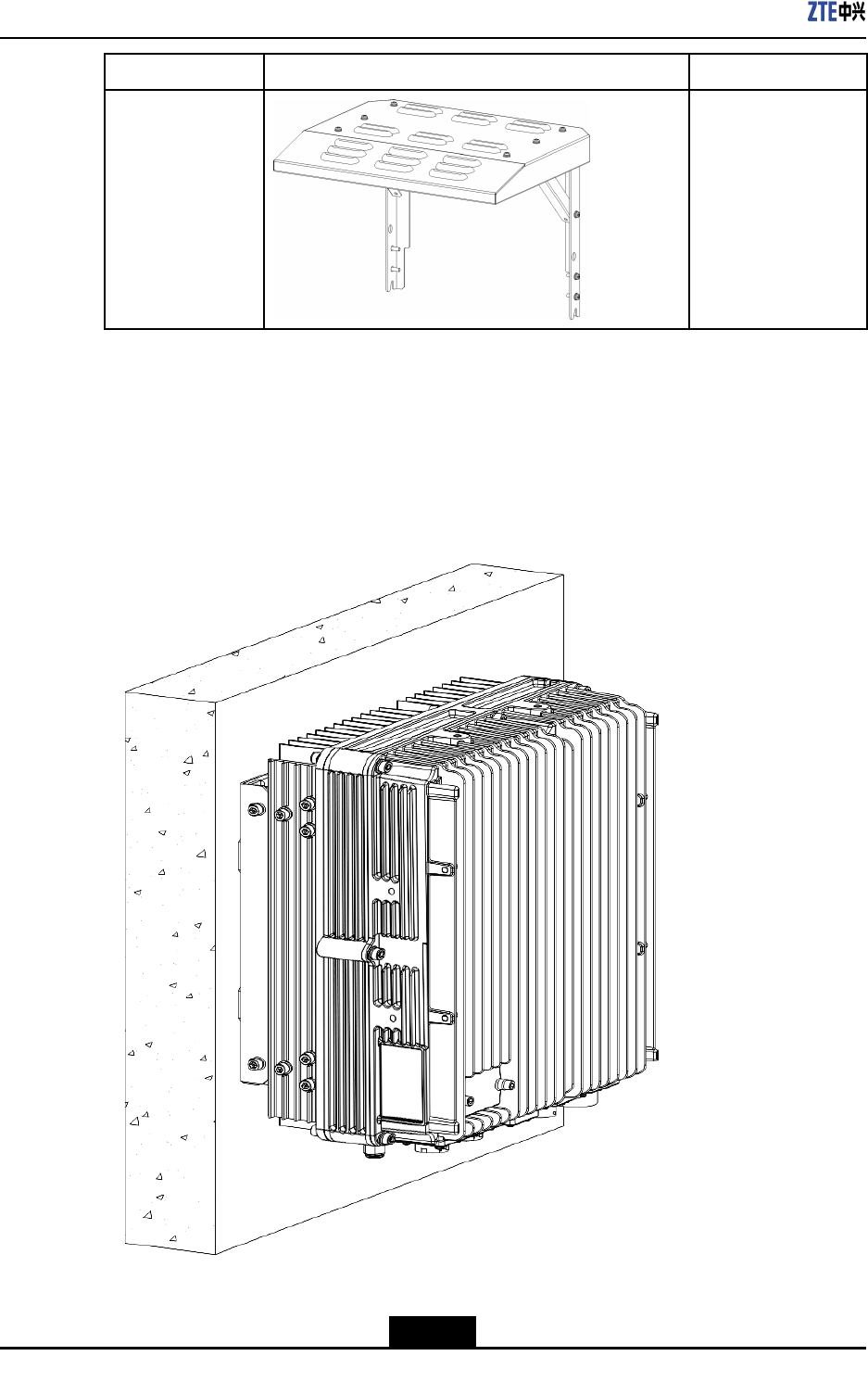
4.5.2.2WallMountedInstallation
Fixtheassemblyforwallmountedinstallationonthewall,andthenxR8860EGU198on
theassemblywithbolts,asshowninFigure4-7.
Figure4-7WALLMOUNTEDINSTALLATIONFORR8860EGU198
4-24
SJ-20101210110401-002|2011-05-31ZTEProprietaryandCondential
Chapter4Installation
4.5.2.3PoleMountedInstallation(PoleMountingKit)
Ifthereareonly1or2R8860EGU198s,usetheclampassemblytoxit/themonthepole,
asshowninFigure4-8.
Figure4-8POLEMOUNTEDINSTALLATIONFOR1OR2R8860EGU198s
Ifthereare3R8860EGU198s,usethemountingbracketassemblytoxthemonthepole,
asshowninFigure4-9.
Figure4-9POLEMOUNTEDINSTALLATIONFOR3R8860EGU198s
4.5.2.4PoleMounting(UniversalSheet-MetalKit)
InthesingleR8860EGU198solutiontheunitisxedonthepolebyanuniversalmounting
kit,asshowninFigure4-10.
4-25
SJ-20101210110401-002|2011-05-31ZTEProprietaryandCondential
ZXSDRR8860EGU198UserManual
Figure4-10TheSingleR8860EGU198MountingSolution
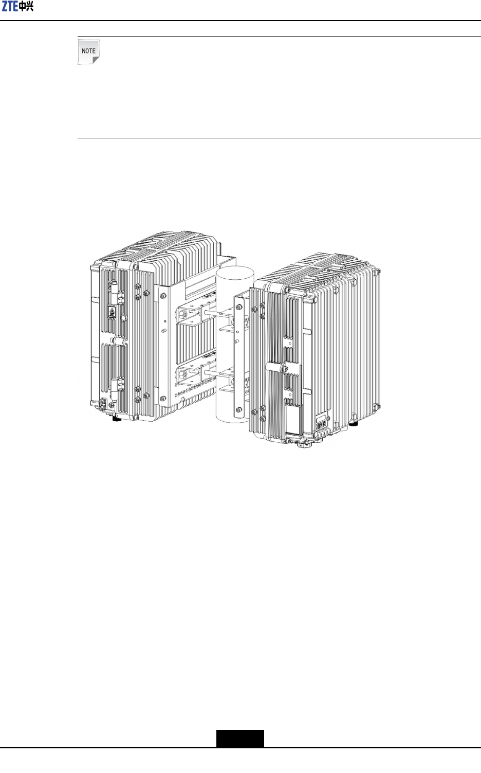
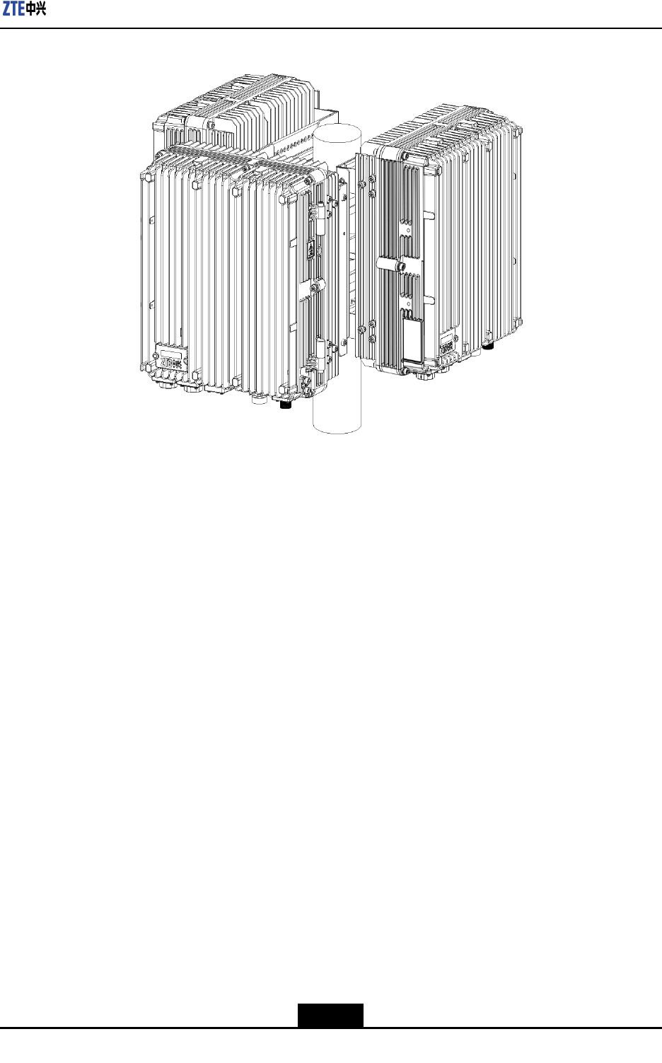
InthedoubleR8860EGU198solutiontheunitisxedonthepolebyanuniversalmounting
kit,asshowninFigure4-11.
Figure4-11TheDoubleR8860EGU198MountingSolution
InthetripleR8860EGU198solutiontheunitisxedonthepolebyanuniversalmounting
kit,asshowninFigure4-12.
4-26
SJ-20101210110401-002|2011-05-31ZTEProprietaryandCondential
ZXSDRR8860EGU198UserManual
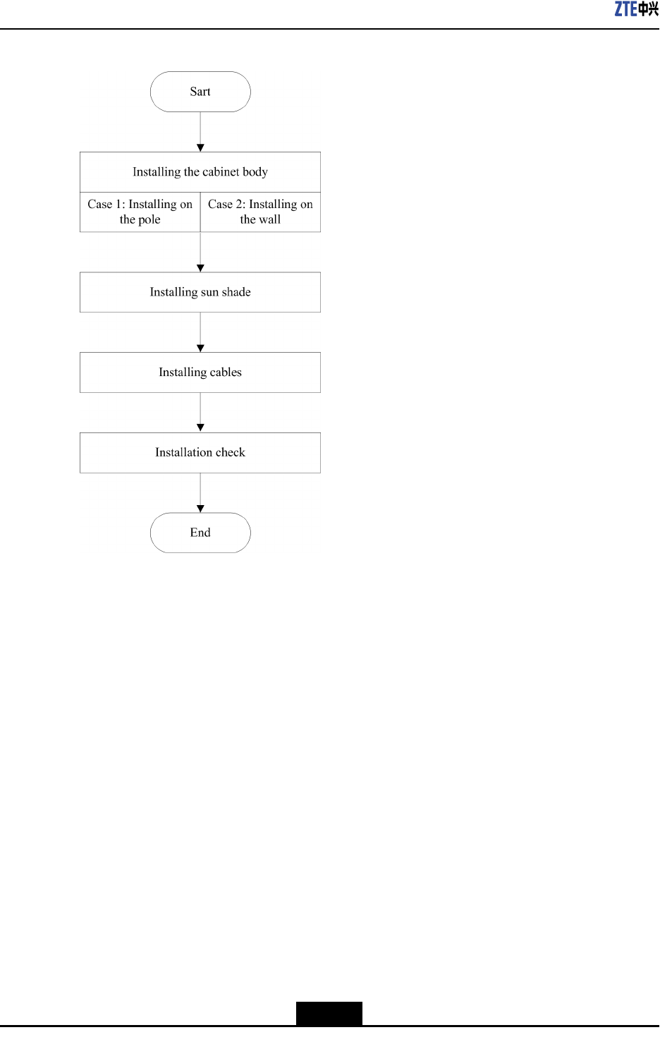
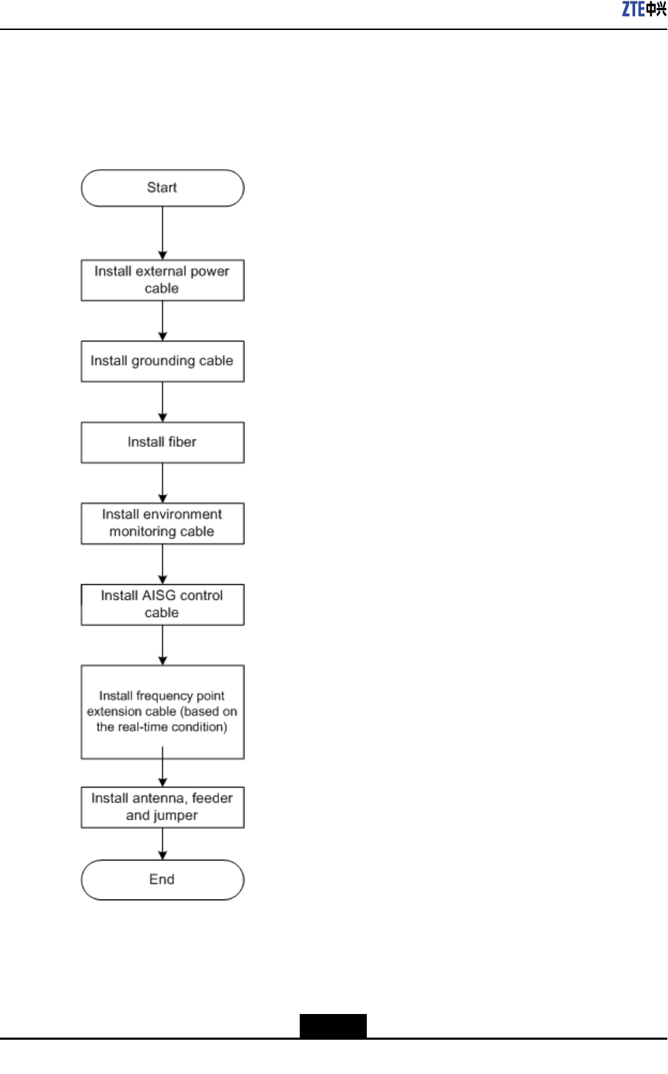
Figure4-13R8860EGU198INSTALLATIONFLOW
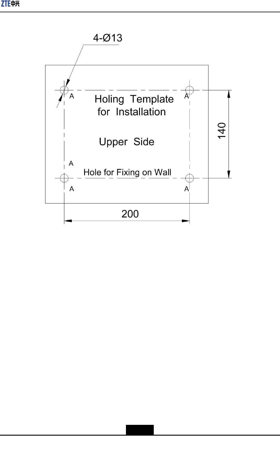
4.5.3.1WallMountedInstallationforR8860EGU198
Steps
1.DrillholesonthewallwithholingtemplateaccordingtotheR8860EGU198installation
positionspeciedintheengineeringdesigndocuments,andinstalltheexpansion
bolts.Thedepthoftheholeshouldbeabout60mm.Theholingtemplateisshownin
Figure4-14.
4-28
SJ-20101210110401-002|2011-05-31ZTEProprietaryandCondential
ZXSDRR8860EGU198UserManual
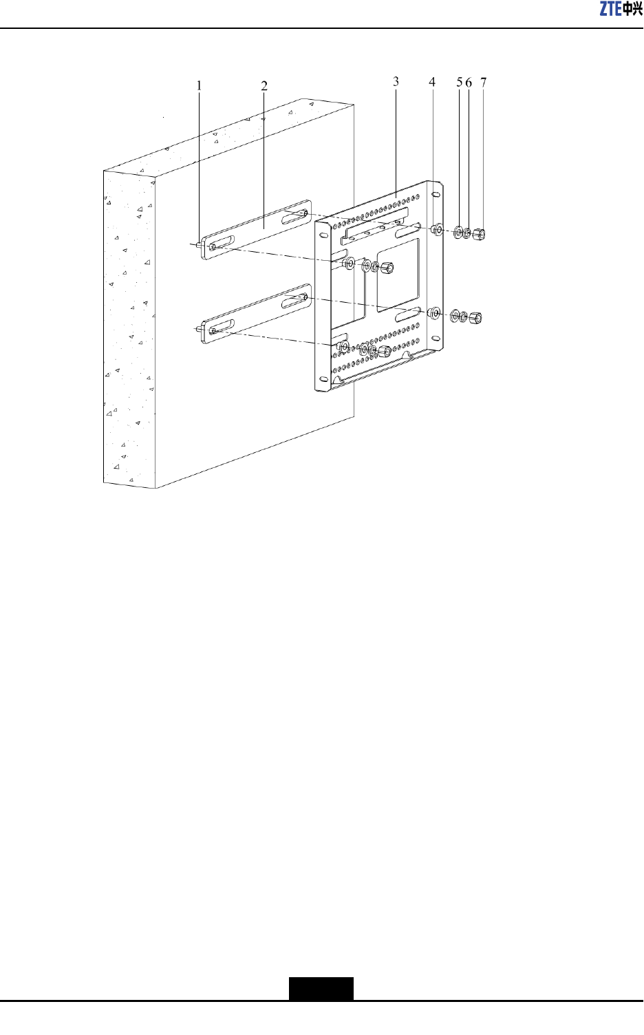
Figure4-15ASSEMBLINGWALL-MOUNTEDINSTALLATIONASSEMBLY
1.Expansionbolt
2.Insulationplate
3.Wall-mountingplate
4.Insulationflange
5.Flatwasher
6.Springwasher
7.Nut
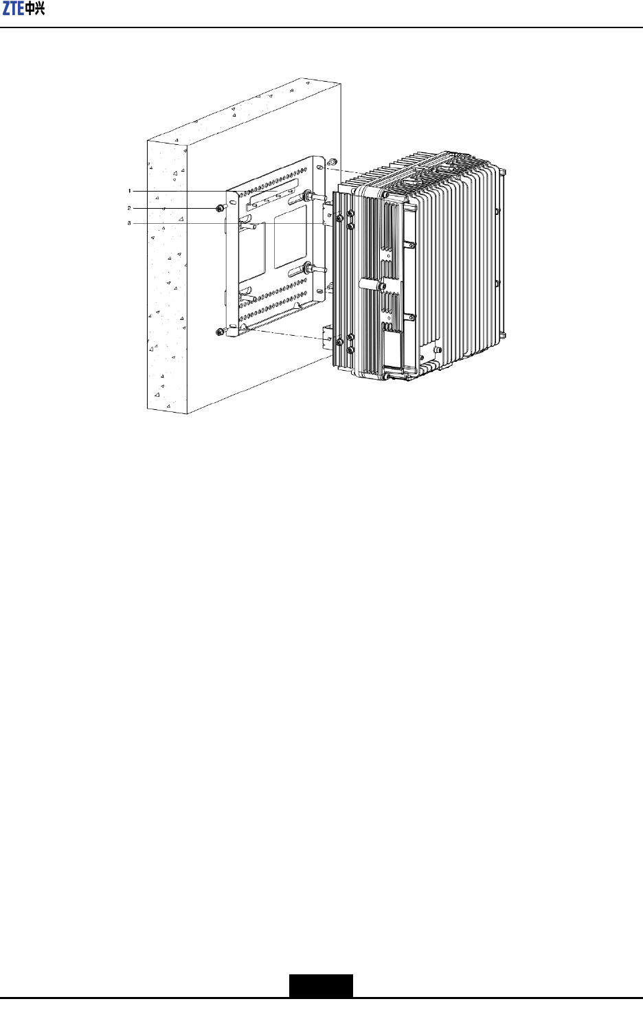
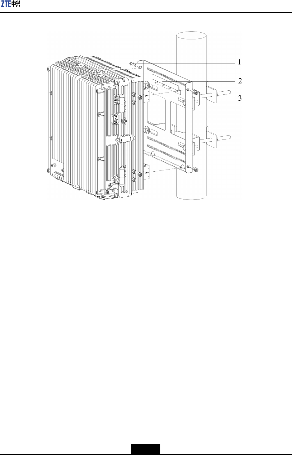
3.HangtheR8860EGU198cabinetonthewallmountedinstallationassembly(alignit
withtheclamps),andxthecabinettotheassemblywith2M6bolts,asshownin
Figure4-16.
4-30
SJ-20101210110401-002|2011-05-31ZTEProprietaryandCondential
Chapter4Installation
Figure4-16FIXINGTHECABINET
1.Wall-mountinginstallat
ioncomponentsclamp
2.Screw
3.Fixationboard
–EndofSteps–
4.5.3.2PoleMountedInstallationforR8860PoleMountingKit
4.5.3.2.1Installing1R8860EGU198
Steps
1.Install2setsofclampassembliesonthepole,andfastenthemjustalittle.Adjustthe
distancebetweenthepoleclampassembliesaccordingtothescrewholesandthen
fastenM8bolts.Finally,fastenthescrewsonthepoleclampassemblies,asshown
inFigure4-17.
4-31
SJ-20101210110401-002|2011-05-31ZTEProprietaryandCondential
ZXSDRR8860EGU198UserManual
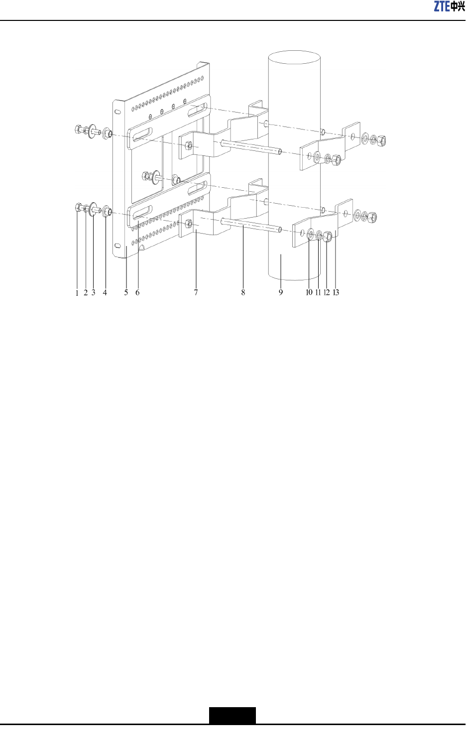
Figure4-17INSTALLINGCLAMPASSEMBLY
1.M8nut
2.Springwasher
3.Flatwasher
4.Insulationflange
5.Wall-mounting
installationassemblies
6.Insulationboard
7.Hoop
8.Bolt
9.Pole
10.Plainwasher
11.Springwasher
12.NutHoop
13.Hoop
2.HangtheR8860EGU198cabinetonthewallmountedinstallationassembly(alignit
withtheclamps),andxthecabinettotheassemblywith2M6bolts,asshownin
Figure4-18.
4-32
SJ-20101210110401-002|2011-05-31ZTEProprietaryandCondential
ZXSDRR8860EGU198UserManual
Figure4-19INSTALLINGCLAMPASSEMBLY
1.Nut
2.Springwasher
3.Plainwasher
4.Hoop
5.Bolt
Note:
Wheninstalling2R8860EGU198s,decidethelengthofclampassemblybolts
accordingtotheresultofengineeringsurvey.Ifthepolediameterisintherange60
mm~90mm,useboltswiththelength80mm.Ifthepolediameterisintherange90
mm~120mm,useboltswiththelength130mm.
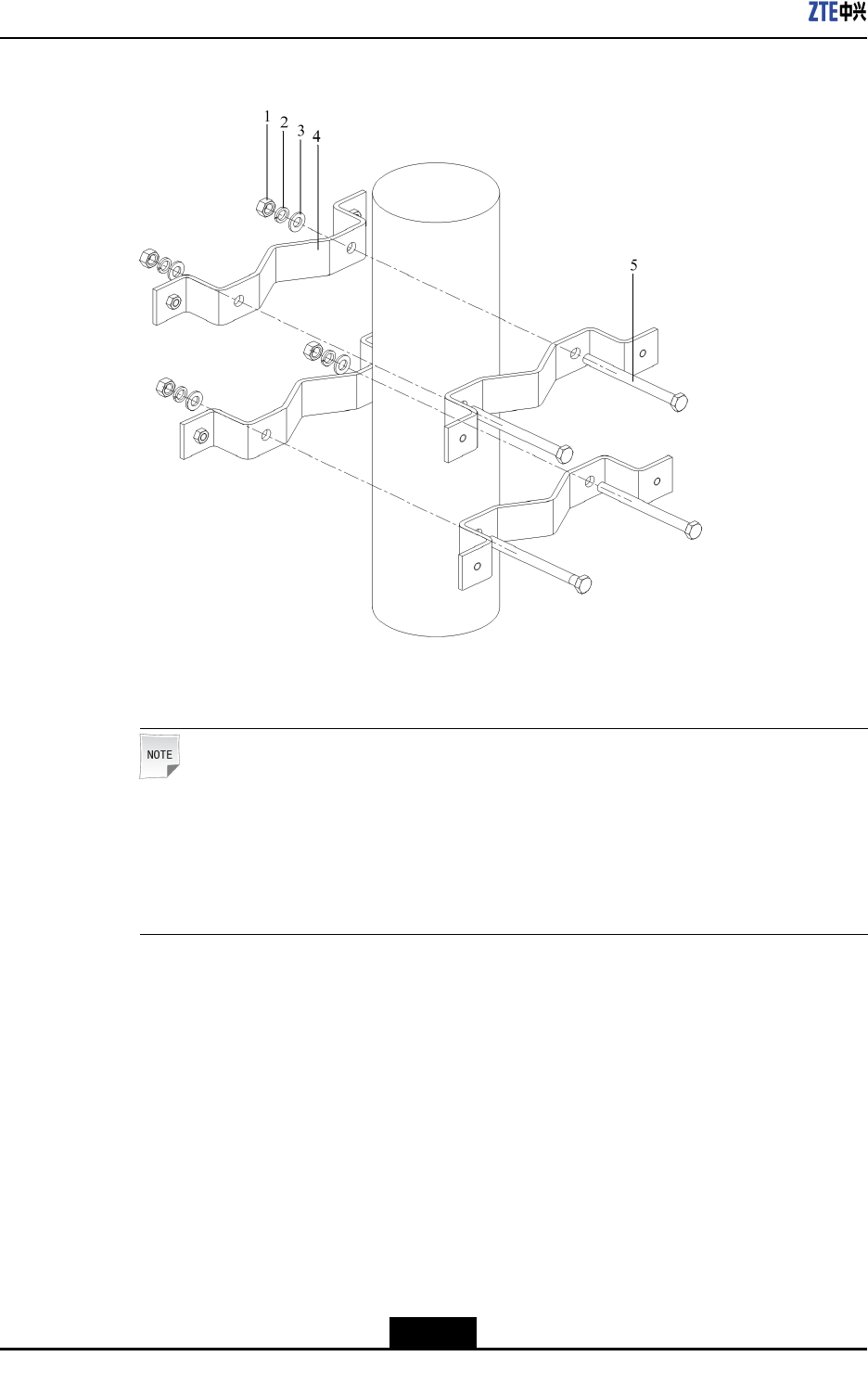
2.Assemble2setsofwallmountedinstallationassembliesandfastentheM8bolts,as
showninFigure4-20.Fastentheboltsoftheclampassemblies.
4-34
SJ-20101210110401-002|2011-05-31ZTEProprietaryandCondential
Chapter4Installation
Figure4-20ASSEMBLINGWALL-MOUNTEDINSTALLATIONASSEMBLY
1.Bolt
2.Springwasher
3.Plainwashe
4.Insulationflange
5.Wall-mounting
installationassemblies
6.Insulationwasher
7.Hoop
3.HangtheR8860EGU198cabinetonthewallmountedinstallationassembly(alignit
withtheclamps),andxthecabinettotheassemblywith2M6bolts,asshownin
Figure4-21.
Figure4-21FIXINGTHECABINET
1.Screw2.Wall-mounting
installationassemblies
4-35
SJ-20101210110401-002|2011-05-31ZTEProprietaryandCondential
ZXSDRR8860EGU198UserManual
3.Fixationboard
–EndofSteps–
4.5.3.2.3Installing3R8860EGU198s
Steps
1.Install4setsofmountingbracketassembliesonthepole,backtoback,andfasten
themjustalittle,asshowninFigure4-22.
Figure4-22INSTALLINGMOUNTINGBRACKETASSEMBLY
1.Fixationplate
2.Nut
3.Springwasher
4.Plainwasher
5.Bolt
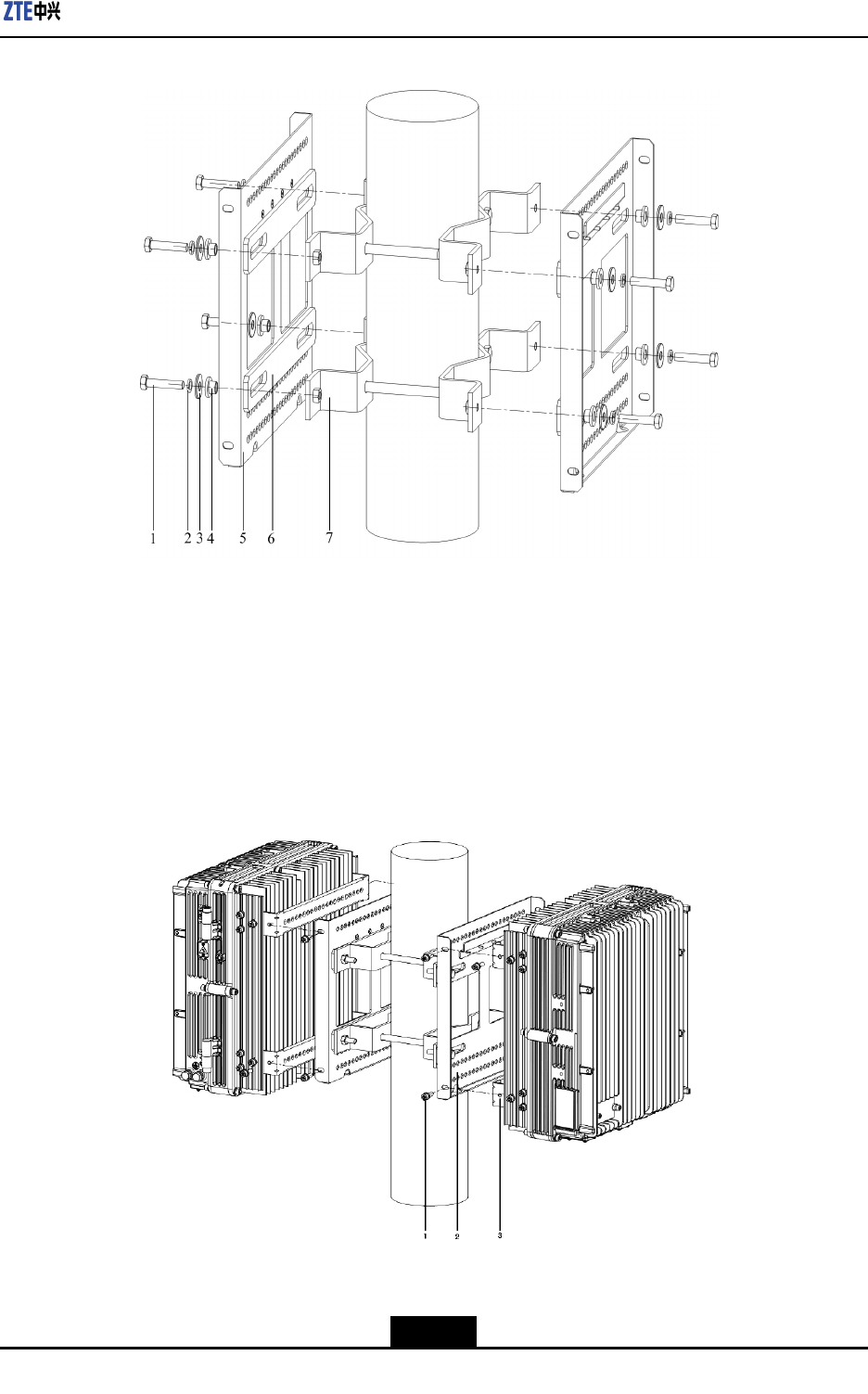
2.Assemble3setsofwallmountedinstallationassembliesandfastentheM8bolts,as
showninFigure4-23.Fastentheboltsoftheclampassemblies.
4-36
SJ-20101210110401-002|2011-05-31ZTEProprietaryandCondential
Chapter4Installation
Figure4-23ASSEMBLINGWALL-MOUNTEDINSTALLATIONASSEMBLY
1.Fixationplate
2.Largeinsulationplate
3.Wall-mounting
installationassemblies
4.Insulationflange
5.Plainwasher
6.Springwasher
7.Bolt
3.HangtheR8860EGU198cabinetonthewallmountedinstallationassembly(alignit
withtheclamps),andxthecabinettotheassemblywith2M6bolts,asshownin
Figure4-24.
Figure4-24FIXINGTHECABINET
1.Screw2.Wall-mounting
installationassemblies
3.Fixationboard
4-37
SJ-20101210110401-002|2011-05-31ZTEProprietaryandCondential
ZXSDRR8860EGU198UserManual
Note:
Theemptysideofmountingbracketcanbebesidethewallorusedtoinstalloutdoor
lightningprotectionbox.
–EndofSteps–
4.5.3.3PoleMounting(UniversalSheet-MetalKit)
4.5.3.3.1PoleMounting(SingleUnitSolution)
Steps
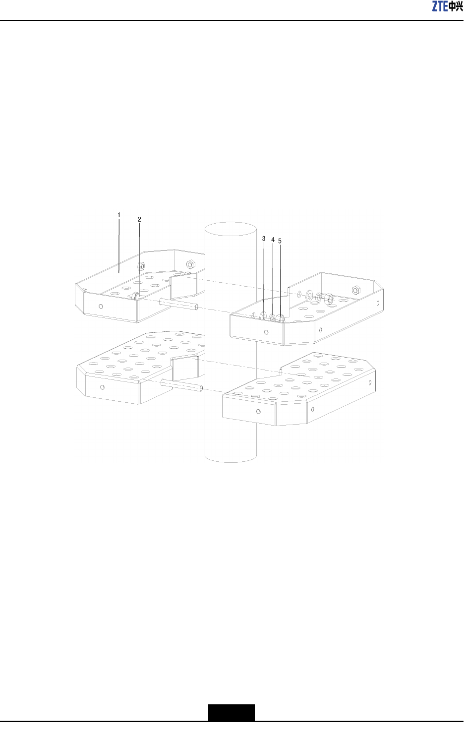
1.Fixtwosetsoffrontmountingpieces(keepthescreenprintingonthetop)onto
themountingbasebyfourM8×35bolts,andinsertfourM10×180longboltstothe
mountingbaseandattachthemountingbasetothepole,thenattachtwomounting
pieces(keepthescreenprintingonthetop)totheoppositepositionofthepoleand
connectthemtothelongboltasshowninFigure4-25.
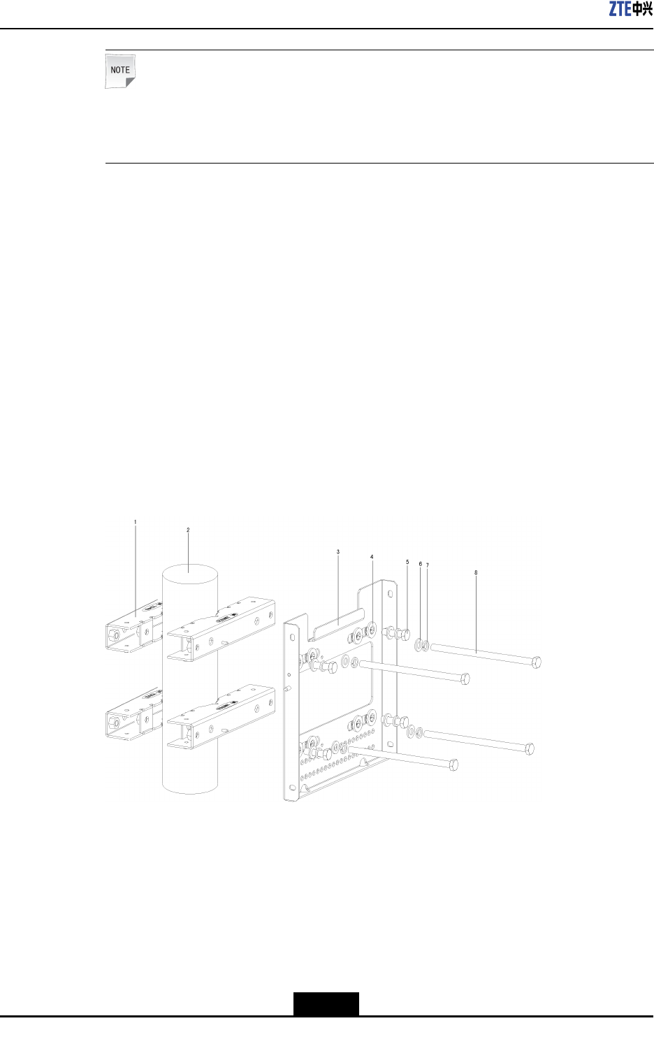
Figure4-25FixingtheMountingPiece
1.MountingPiece(the
screenprintingonthe
top)
2.Pole
3.MountingBase
4.InsulatingFlange
5.M8×35Bolt
6.FlatWasher
7.LockWasher
8.M10×180LongBolt
2.AttachtheR8860EGU198ontothehooksonthemountingbaseandfastenitwith
fourM6×20allenscrews,asshowninFigure4-26.
4-38
SJ-20101210110401-002|2011-05-31ZTEProprietaryandCondential
Chapter4Installation
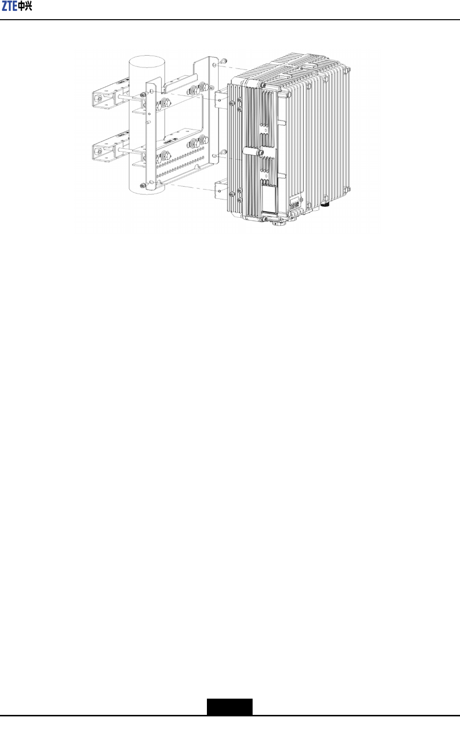
Figure4-26MountingR8860EGU198
–EndofSteps–
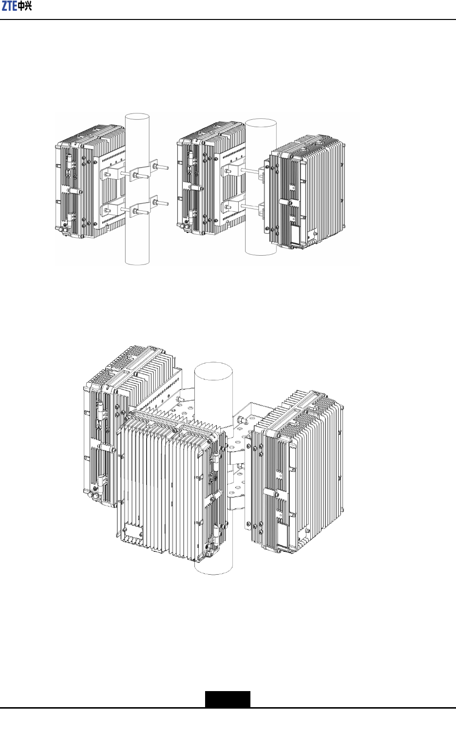
4.5.3.3.2PoleMounting(DoubleUnitSolution)
Steps
1.Fixtwosetsoffrontmountingpieces(keepthescreenprintingonthetop)ontothe
mountingbasebyfourM8×35bolts.AndInsertfourM10×180longboltstothe
mountingbase.
2.Fixtwosetsofrearmountingpieces(keepthescreenprintingonthetop)ontoanother
mountingbasebyfourM8×35bolts.
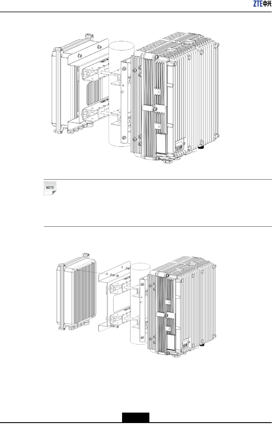
3.Attachthefront/rearmountingpiecestothepole(keepthescreenprintingonthetop).
FastentheM10×180longbolts(notetheboltsgothroughtheinsulatingange),as
showninFigure4-27andFigure4-28.
4-39
SJ-20101210110401-002|2011-05-31ZTEProprietaryandCondential
ZXSDRR8860EGU198UserManual
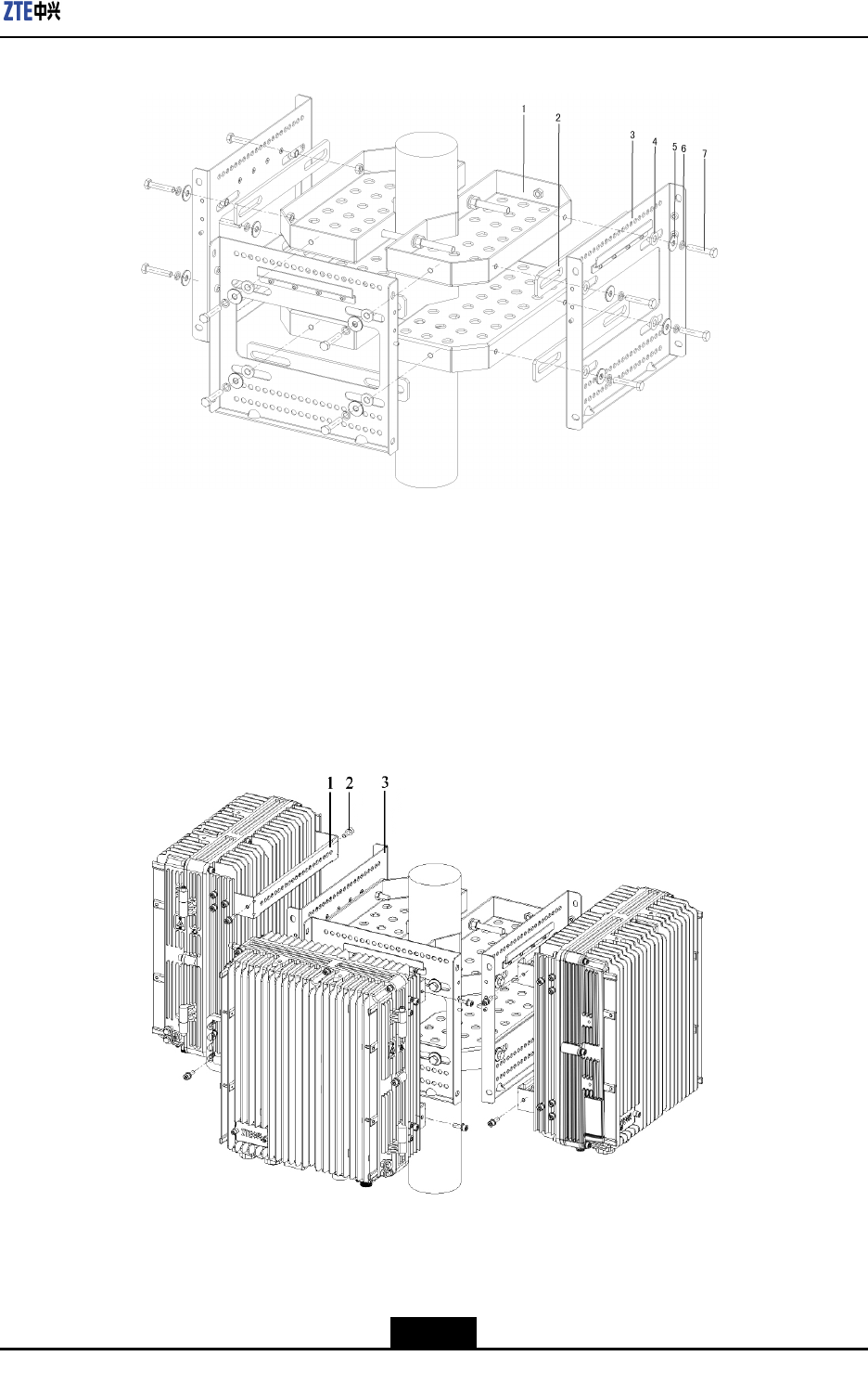
Figure4-27MountingbaseDoubleUnitSolution
Figure4-28MountingbaseSingleUnit+LightningProtectorBoxSolution
4-40
SJ-20101210110401-002|2011-05-31ZTEProprietaryandCondential
Chapter4Installation
Note:
Thefastenersareshowninthelastsectionsingleunitsolution.
ThedoubleunitmountingbasesolutionsupportstwoR8860EGU198oroneR8860E
GU198andalightarrestorunit.
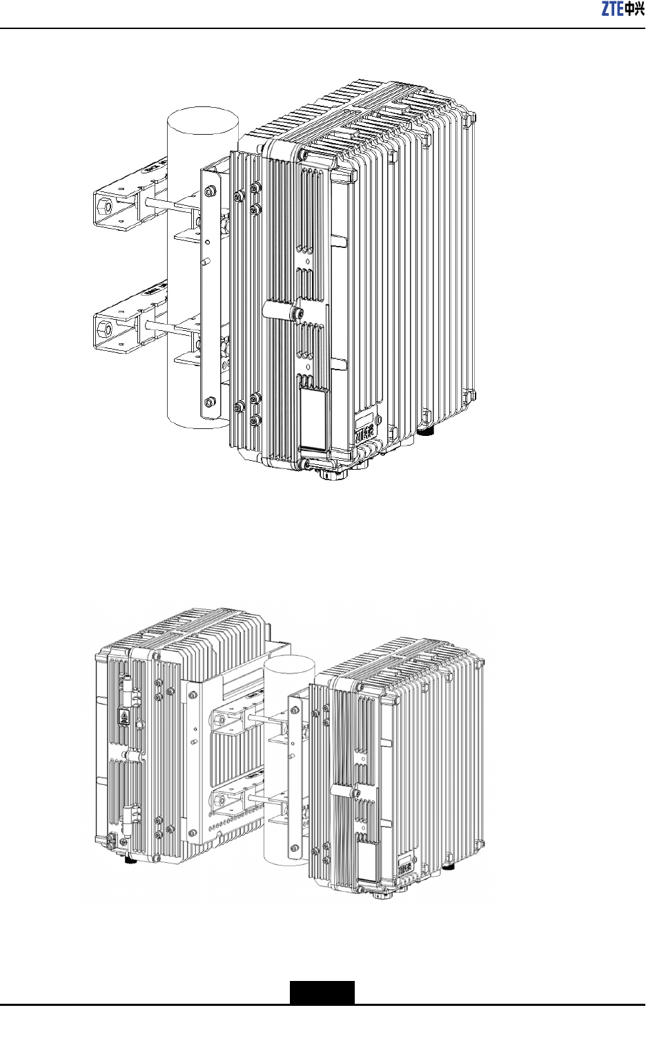
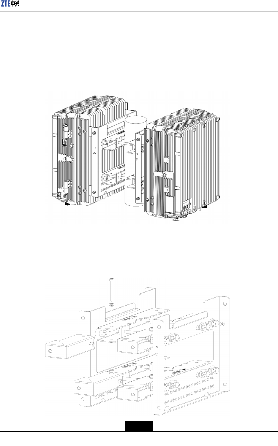
4.FastentheM10×180boltsandattachR8860EGU198tothemountingbase.Fasten
theconnectionwiththeM6×20Allenbolts,asshowninFigure4-29andFigure4-30.
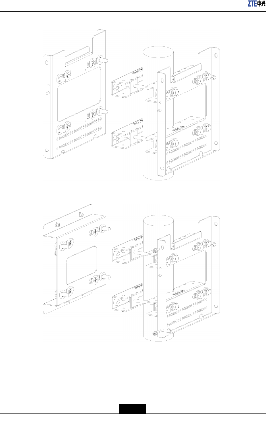
Figure4-29MountingTwoR8860EGU198
4-41
SJ-20101210110401-002|2011-05-31ZTEProprietaryandCondential
ZXSDRR8860EGU198UserManual
Figure4-30MountingoneR8860EGU198andOneLightningProtectorBox
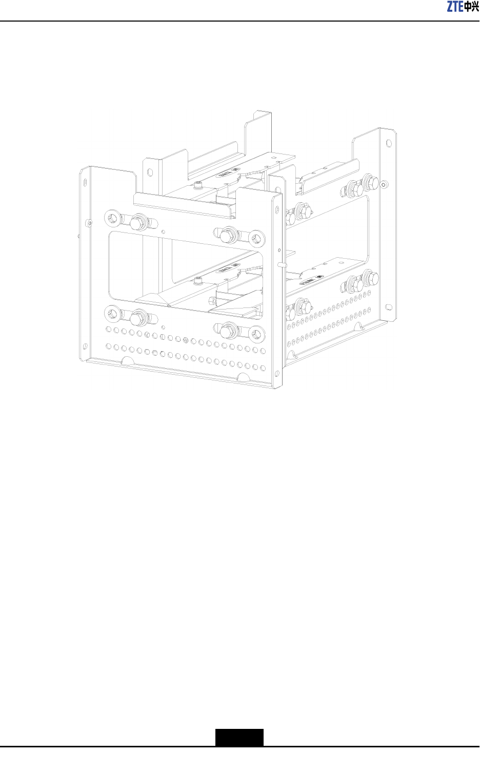
Note:
Thelightningprotectorboxisxedontothelightningprotectorboxmountingbasewith
theboltsfastened,asshowninFigure4-31.
Figure4-31FixingtheLightningProtectorBox
–EndofSteps–
4-42
SJ-20101210110401-002|2011-05-31ZTEProprietaryandCondential
Chapter4Installation
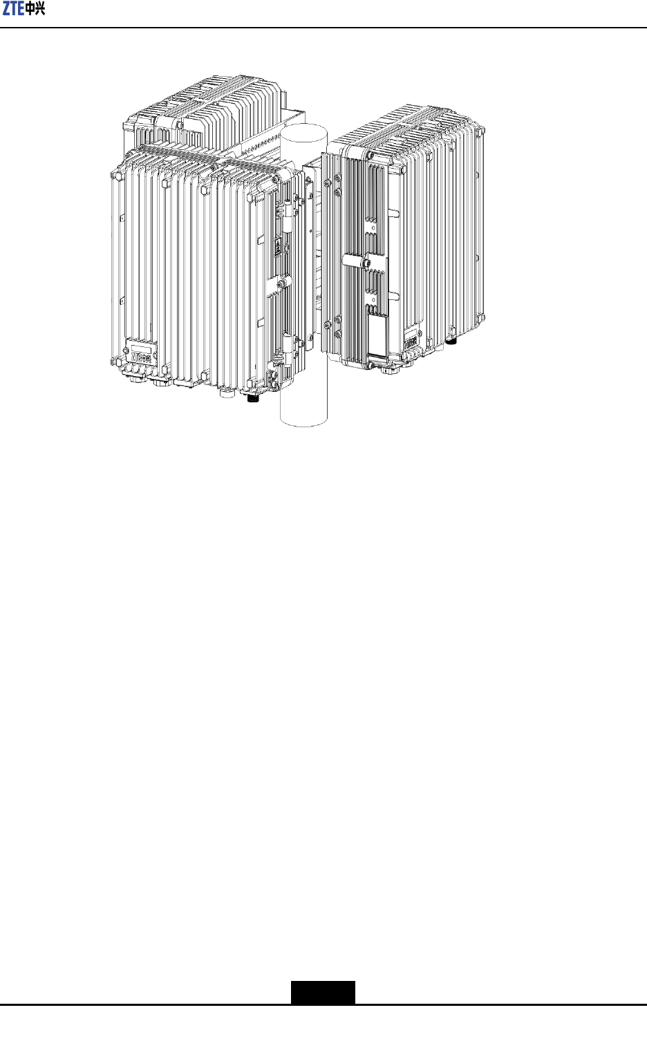
4.5.3.3.3PoleMounting(TripleUnitSolution)
Steps
1.Securetwosetsofmountingpiecesandmountingbasesonthepoleandattachtwo
R8860EGU198,asshowninFigure4-32.
Figure4-32MountingTwoR8860EGU198
2.AttachtheexpansionpiecetoasideofthepoleandfastenwithM6×60bolts.Install
thelowerpiecebeforethehigherpiece,asshowninFigure4-33.
Figure4-33MountingtheExpansionPiece
4-43
SJ-20101210110401-002|2011-05-31ZTEProprietaryandCondential
ZXSDRR8860EGU198UserManual
3.AttachthemountingbaseontotheexpansionpieceandfastenwiththeM10×35bolts,
asshowninFigure4-34.
Figure4-34AttachingtheMountingbase
4.AttachtheR8860EGU198ontothehooksonthemountingbaseandfastenitwith
fourM6×20Allenscrews,asshowninFigure4-35.
4-44
SJ-20101210110401-002|2011-05-31ZTEProprietaryandCondential
Chapter4Installation
Figure4-35AttachtheR8860EGU198totheMountingbase
–EndofSteps–
4.5.3.4InstallingProtectionShade
Steps
1.HangtheR8860EGU198cabinetonthewall.
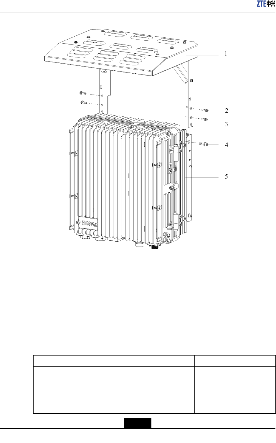
2.Fixtheprotectionshadeonthe4xingpositionsonthefrontofR8860EGU198
cabinet,andfastenitonthehandlesontopofthecabinetwith2M6bolts,asshown
inFigure4-36.
4-45
SJ-20101210110401-002|2011-05-31ZTEProprietaryandCondential
ZXSDRR8860EGU198UserManual
Figure4-36INSTALLINGPROTECTIONSHADE
1.M6screw
2.Protectionshade
3.Handle
4.Buckle
5.R8860EGU198
–EndofSteps–
4.6ExternalCableInstallation
4.6.1ExternalCableLayout
TheconnectionrelationshipofR8860EGU198externalcablesisdescribedinTable4-4.
Table4-4R8860EGU198ExternalCableConnectionRelationship
NameConnectionRelationshipDescription
PowercableConnectstheR8860EGU198
powerinterface(DCIN)to
thepowersupplyequipment
interface
Oneendistheaviationplugand
theotherendisreservedfor
powercablemadeonsite.The
lengthofcableisbasedonthe
engineeringsurvey.
4-46
SJ-20101210110401-002|2011-05-31ZTEProprietaryandCondential
Chapter4Installation
NameConnectionRelationshipDescription
GroundingcableConnectsoneR8860EGU198
groundbolttothecopperbar
Thegroundingcableismade
upofstrandsofame-retardant
wire.Thecrosssectionalarea
ofR8860EGU198grounding
cableis10mm2.Thecolorof
groundingcableisyellowand
green.Copperlugsarecrimped
atbothendsoftheR8860E
GU198groundingcable.
OpticalFiberTherearetwotypesofR8860E
GU198ber:BBUconnection/
R8860EGU198cascading.
TherearetwotypesofR8860E
GU198opticalber:oneused
inBBUconnectionandtheother
usedincascadingbetween
R8860EGU198s.
EnvironmentmonitoringcableConnectstheR8860EGU198
environmentmonitoring
interfaceMONtotheexternal
monitoringcomponentsorthe
drycontact.
Aendoftheenvironment
monitoringcableisPINdesign.
Bend,with3mlengthintotal,
needsmakingbasedonthe
on-siteengineering.
AISGcontrolcableConnectstheR8860EGU198
debugginginterface(AISG)
tothecontrolinterfaceof
electrical-adjustmentantenna.
AISGisusedforcontrolofthe
electrical-adjustmentantenna.
Frequencypointextension
cable
InterconnectstheR8860E
GU198RXin/RXoutinterfaces.
Thefrequencypointextension
cableusuallyadoptsthenished
1/2″jumperwith2mlength.
Thejumpercanbeself-made
basedonthereal-timecondition
onsite.
AandBendsofjumperareN
connectors(male).
Antenna,feederandjumperConnectstheR8860EGU198
tothemainfeeder.
TheRFjumperusuallyadopts
thenished1/2″jumperwith
2mlength.Thejumpercan
beself-madebasedonthe
real-timeconditiononsite.
TheendofjumperisN
connector(male)andtheother
endisDINconnector(female).
4-47
SJ-20101210110401-002|2011-05-31ZTEProprietaryandCondential
Chapter4Installation
4.6.3InstallingPowerCable
Context
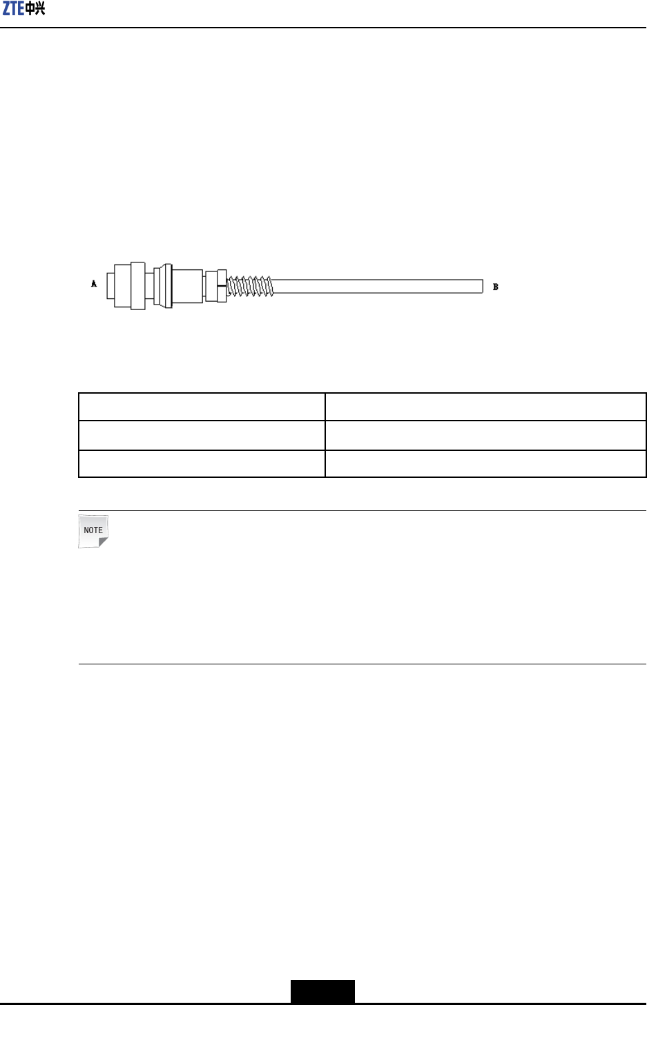
TheR8860EGU198cabinetadopts-48VDCforpowersupply.EndAistheaviationplug
andEndBisreservedforself-madepowercableonsite.Thelengthofpowercableis
accordingtotheengineeringsurvey.
R8860EGU198Figure4-38showsthestructureofpowercable.
Figure4-38PowerCablestructure
Table4-5describesthecolorsandspecicationsofinsidecorecable.
Table4-5ColorandSpecication
ColorSpecication
Blue-48V
Black-48VGND
Note:
1.Ifthetwo-corecableisadopted,thebluecorecablestandsfor-48Vandtheblack
corecablestandsfor-48VGND;
2.Ifthefour-corecableisadopted,thetwobluecorecablesconnectedinparallelstand
for-48Vandtheblackcorecablesconnectedinparallelstandfor-48VGND.
Steps
1.ConnectEndAofpowercablewithDCINinterfacelocatedatthebottomofR8860E
GU198.
2.StriptheprotectivecoatofEndBandconnectitwiththeDCinputpowersource
accordingtocolorsoftheinsidecorecable.
3.MakewaterproofprotectionofEndB.
4.Attachlabelsatbothendsofthepowercable.
5.Fixthepowercable.
–EndofSteps–
4-49
SJ-20101210110401-002|2011-05-31ZTEProprietaryandCondential
ZXSDRR8860EGU198UserManual
4.6.4InstallingGroundingCable
Context
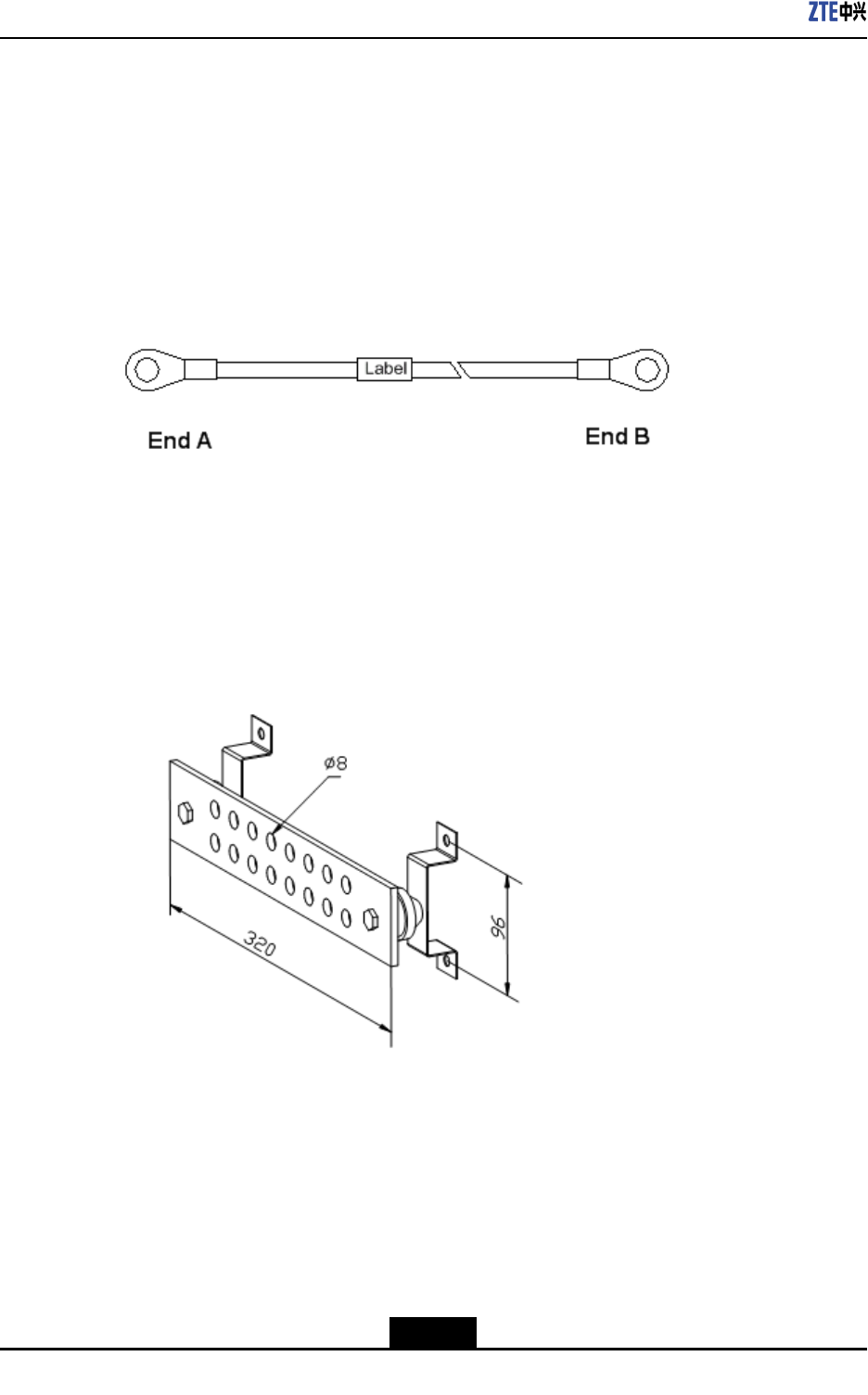
Thegroundingcableismadeupofstrandsofame-retardantwire.Thecrosssectional
areaofR8860EGU198groundingcableis10mm2.Thecolorofgroundingcableis
yellowandgreen.CopperlugsarecrimpedatbothendsoftheR8860EGU198grounding
cable,asshowninFigure4-39.
Figure4-39GroundingCableStructure
Steps
1.CoverandxacopperlugontheagroundingboltoftheR8860EGU198cabinet.
2.Connecttheothercopperlugtotheearth-networkingcopperbarandxitwithabolt,
asshowninFigure4-40.
Figure4-40Earth-networkCopperBar(Unit:mm)
3.Attachthelabelonthegroundingcable.
4.Measurethegroundingresistanceandmakesureitlessthan5Ω.
–EndofSteps–
4-50
SJ-20101210110401-002|2011-05-31ZTEProprietaryandCondential
Chapter4Installation
4.6.5InstallingFiberbetweenBBUandRRU
Prerequisites
TheR8860EGU198cabinetmustbeinstalledandxedsuccessfully.
Context
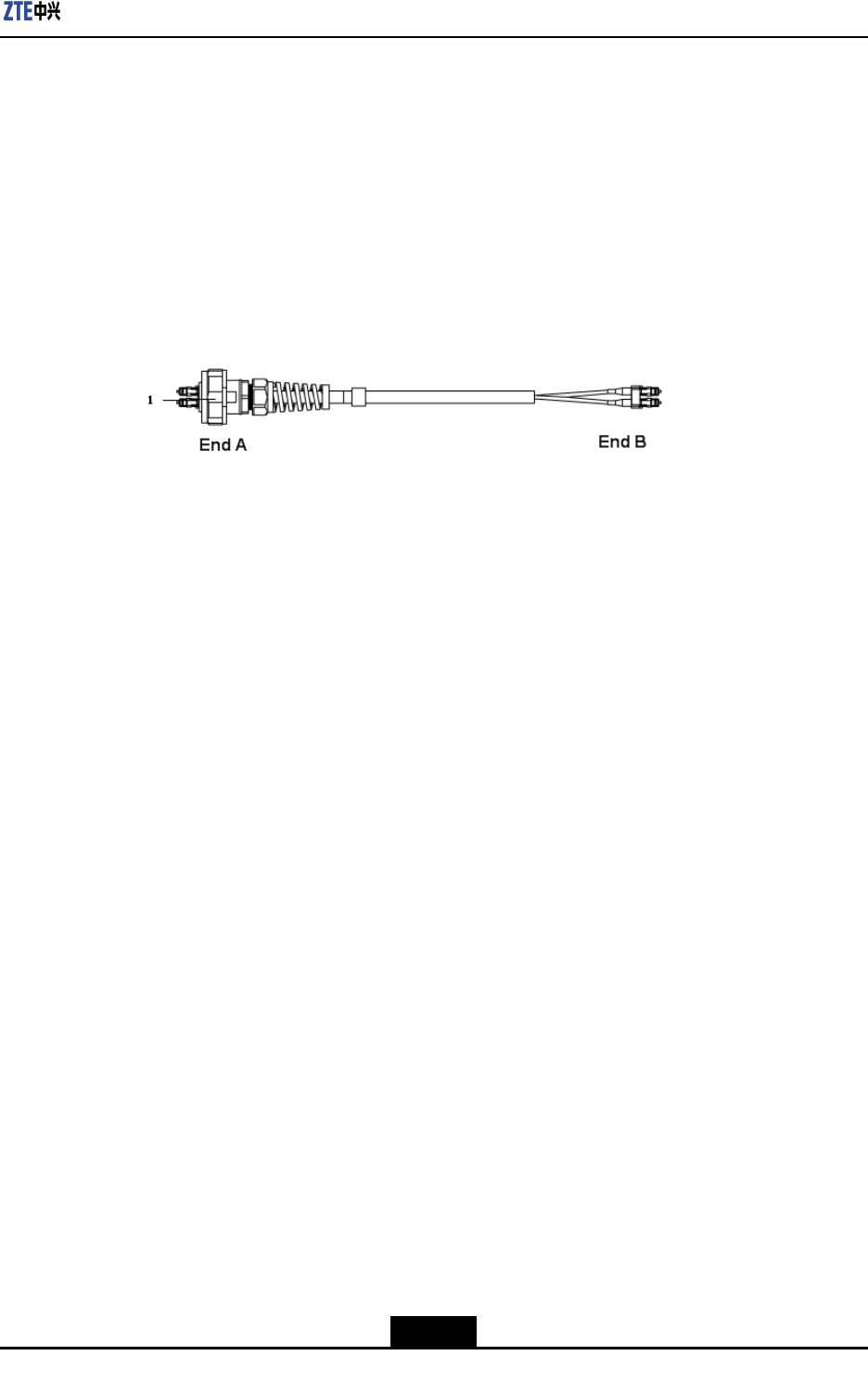
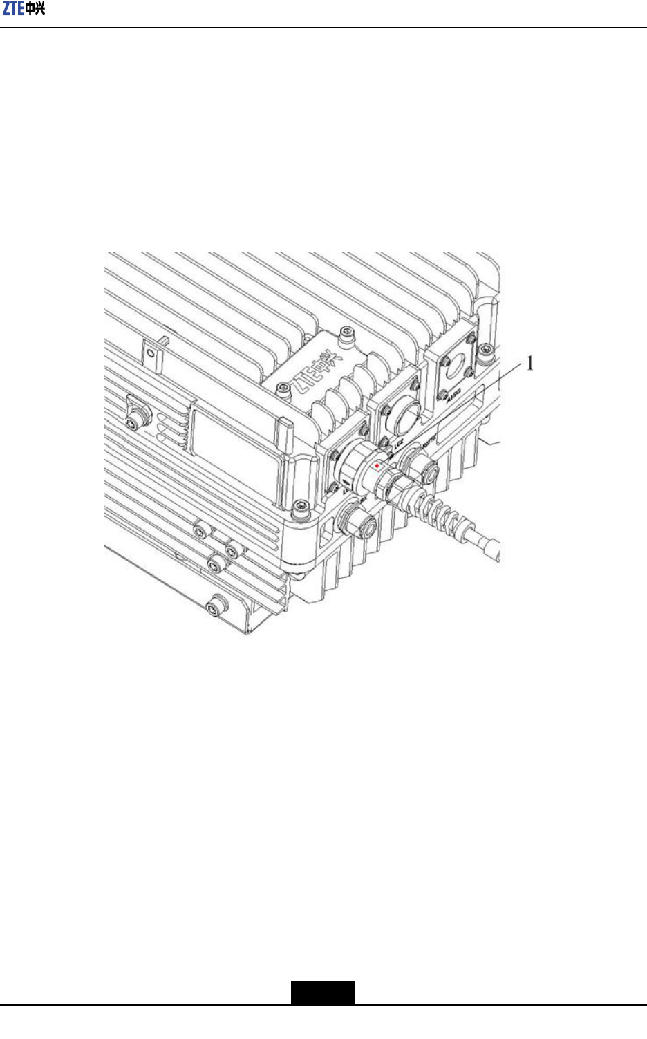
Figure4-41showsberconnectionbetweenR8860EGU198andBBU.
Figure4-41FiberConnectionbetweenR8860EGU198andBBU
1.OutdoorSealComponent
WhileconnectingaBBUtoR8860EGU198,makesurethatthebasebandRFber
interface(LC1/2)oftheR8860EGU198isconnectedtotheopticalinterfaceconnector
oftheBBU.
Steps
1.Attachlabelsatbothendsoftheber.
2.AdjustthesideofEndAwiththecolormarkandinserttheR8860EGU198ber
interface,andscrewdownthenuts,asshowninFigure4-42
4-51
SJ-20101210110401-002|2011-05-31ZTEProprietaryandCondential
ZXSDRR8860EGU198UserManual
Figure4-42OpticalFiberInstallation
1.Colormark
3.ConnectEndAofthebertothebasebandRFberinterface(LC1/2)oftheR8860E
GU198.
4.ConnectEndBoftheber,whichisaDLCconnector,totheBBUopticalconnector.
5.ScrewdowntheoutdoorsealcomponentatEndAforwaterproong.
–EndofSteps–
4.6.6InstallingFiberbetweenRRUandRRU
Prerequisites
ThecascadingR8860EGU198cabinetsmustbeinstalledandxedsuccessfully.
Context
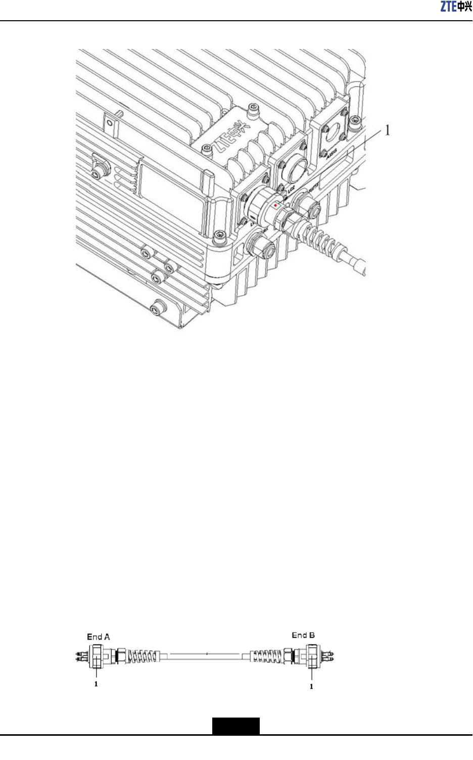
Figure4-43showsberconnectionbetweenR8860EGU198s.
Figure4-43FiberConnectionbetweenR8860EGU198s
1.OutdoorSealComponent
4-52
SJ-20101210110401-002|2011-05-31ZTEProprietaryandCondential
Chapter4Installation
WhileinterconnectingtheR8860EGU198s,makesurethatthetwobasebandRFber
interfaces(LC1/2)oftheR8860EGU198areconnected.
Steps
1.Attachlabelsatbothendsoftheopticalber.
2.AdjustthesideofEndAwiththecolormarkandinserttheR8860EGU198ber
interface,andscrewdownthenuts,asshowninFigure4-44.
Figure4-44OpticalFiberInstallation
1.Colormark
3.ConnectEndAoftheopticalbertothebasebandRFberinterface(LC1/2)ofthe
R8860EGU198.
4.ConnectEndBoftheopticalbertotheotherbasebandRFberinterface(LC1/2)of
theR8860EGU198.
5.ScrewdowntheoutdoorsealcomponentatEndAforwaterproong.
–EndofSteps–
4.6.7InstallingEnvironmentMonitoringCable
Prerequisites
TheR8860EGU198cabinetmustbeinstalledandxedsuccessfully.
4-53
SJ-20101210110401-002|2011-05-31ZTEProprietaryandCondential
ZXSDRR8860EGU198UserManual
Context
Theenvironmentmonitoringcableprovidesa485interface,usedforR8860EGU198
environmentmonitoring.Inaddition,thecablealsoprovidesfourextensionaccessesfor
externaldrycontactmonitoring.
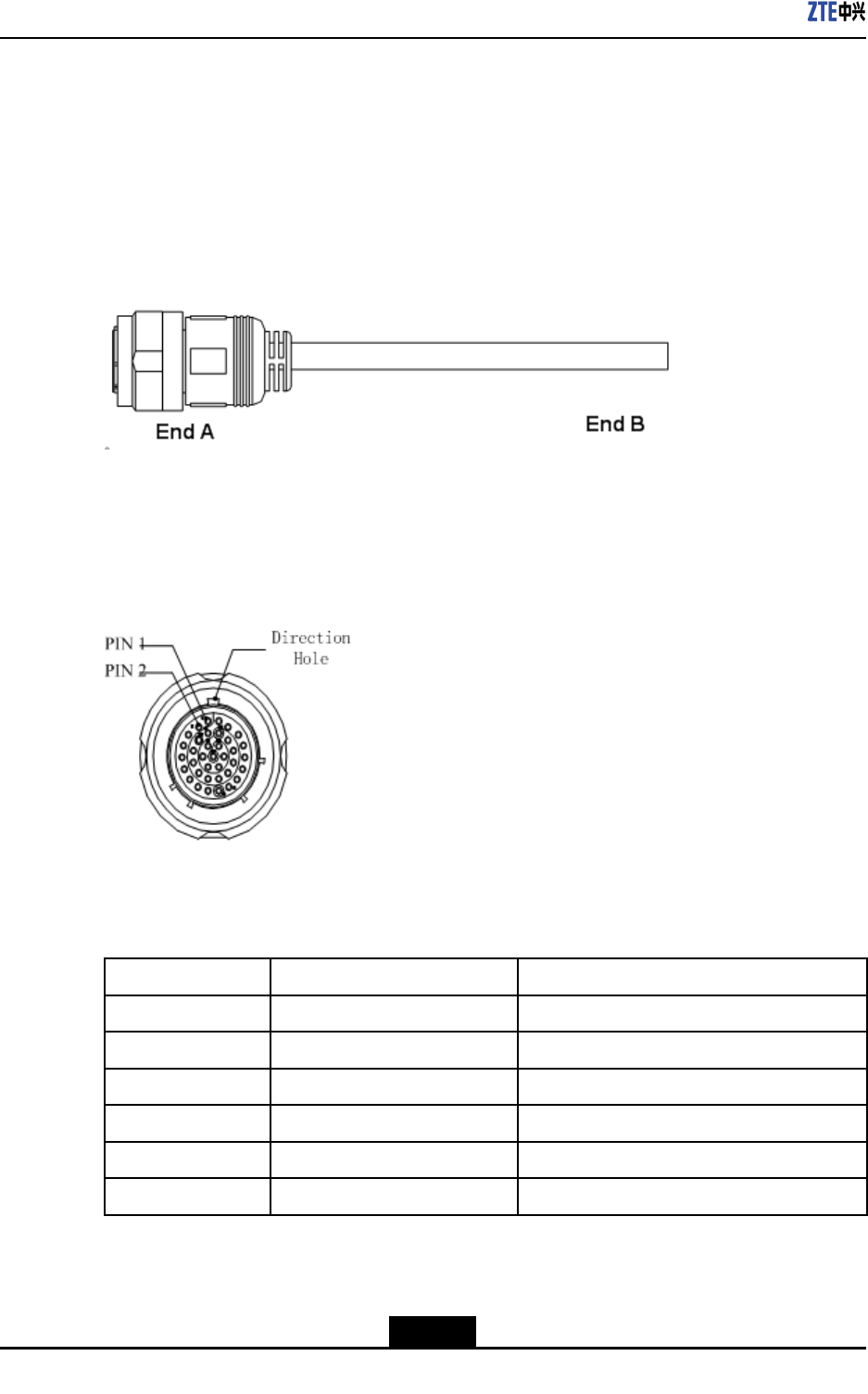
EndAisthe37PINconnector,andEndBismadebyon-siteengineering.Thetotallength
is3m.Figure4-45showstheappearanceofenvironmentmonitoringcable.
Figure4-45EnvironmentMonitoringCable
Theconnector,connectingtheenvironmentmonitoringcabletotheR8860EGU198,
adopts37–coreaviationjack.TheconnectoraccordswiththeGJB599specication.The
connectorappearanceisasshowninFigure4-46
Figure4-46AviationJackAppearance
Table4-6describestheconnectorpins.
Table4-6CablePinDescription
PinCore-CableColorSignalDescription
15/16Whiteandblue/blueDrycontact4-/+
17/18Whiteandorange/orangeDrycontact3-/+
19/20Whiteandgreen/greenDrycontact2-/+
21/22Whiteandbrown/brownDrycontact1-/+
23/24Redandblue/blueRS485receive
25/26Redandorange/orangeRS485transmit
Steps
1.ConnectEndAtotheMONinterfacelocatedatthebottomofR8860EGU198.
4-54
SJ-20101210110401-002|2011-05-31ZTEProprietaryandCondential
Chapter4Installation
2.ConnectEndBwithexternalmonitoringdevicesordrycontacts.
3.AttachthelabelatEndB.
–EndofSteps–
4.6.8InstallingAISGControlCable
Context
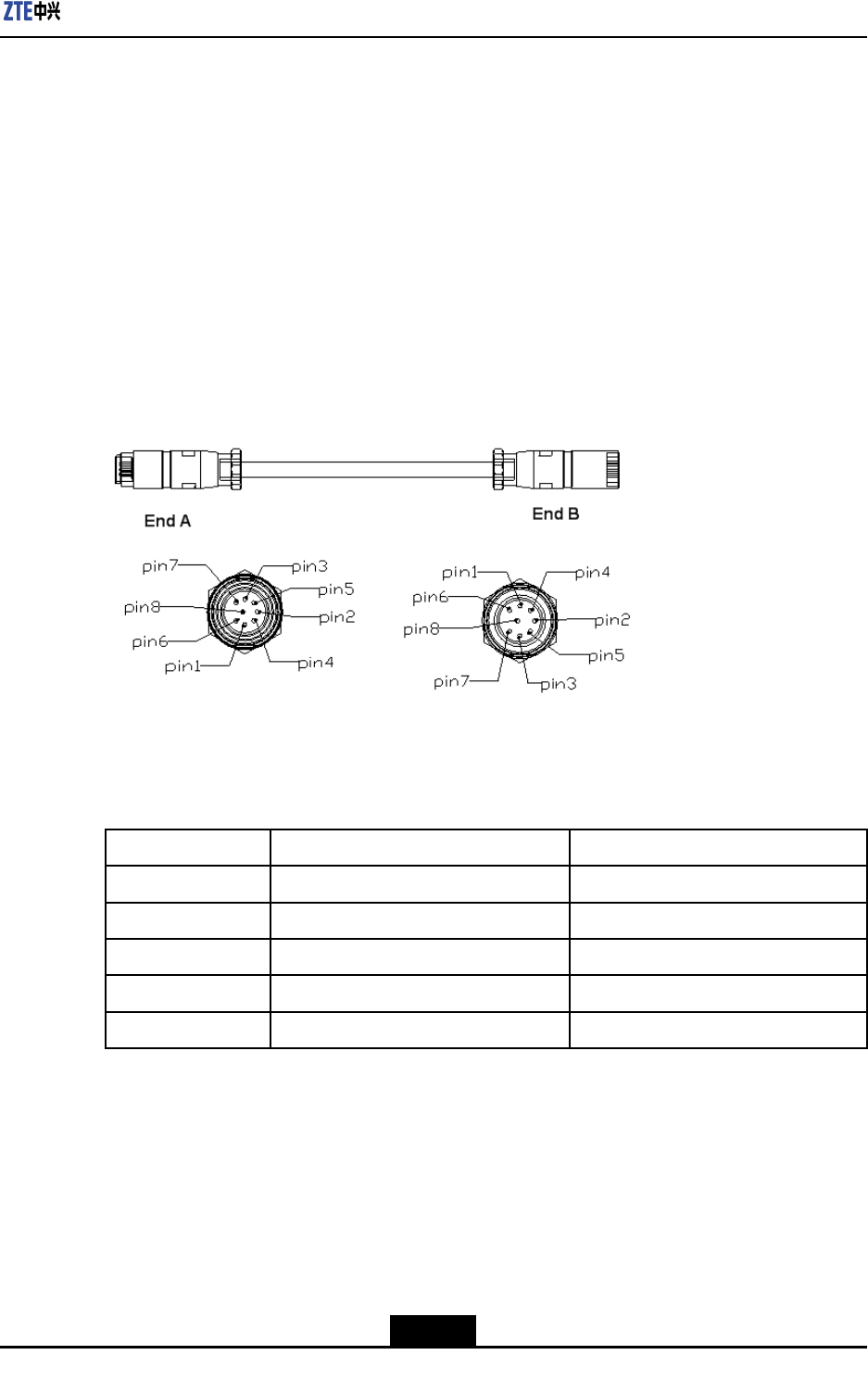
TheAISGcontrolcableisusedforcontroloftheelectricaladjustmentantenna.
Figure4-47showsthestructureoftheAISGcontrolcable.
Figure4-47AISGControlCableStructure
Table4-7describestheserialNo.meaningofAISGcontrolcable.
Table4-7AISGControlCableDescription
SerialNo.NameMeaning
1TRX_ANT_485_+RS485+
2TRX_ANT_485_-RS485-
3,4TRX_ANT_28V28V
5,6TRX_ANT_28VGND28VGND
7,8NCNull
Steps
1.ConnectEndAtotheR8860EGU198debugginginterface(AISG)andscrewdown
thebolt;
2.ConnectEndBtothecontrolinterfaceofelectricaladjustmentantennaandscrew
downthebolt.
–EndofSteps–
4-55
SJ-20101210110401-002|2011-05-31ZTEProprietaryandCondential
ZXSDRR8860EGU198UserManual
4.6.9InstallingFrequencyPointExtensionCable
Prerequisites
ThetwoR8860EGU198cabinetstobecombinedmustbeinstalledandxedsuccessfully.
Context
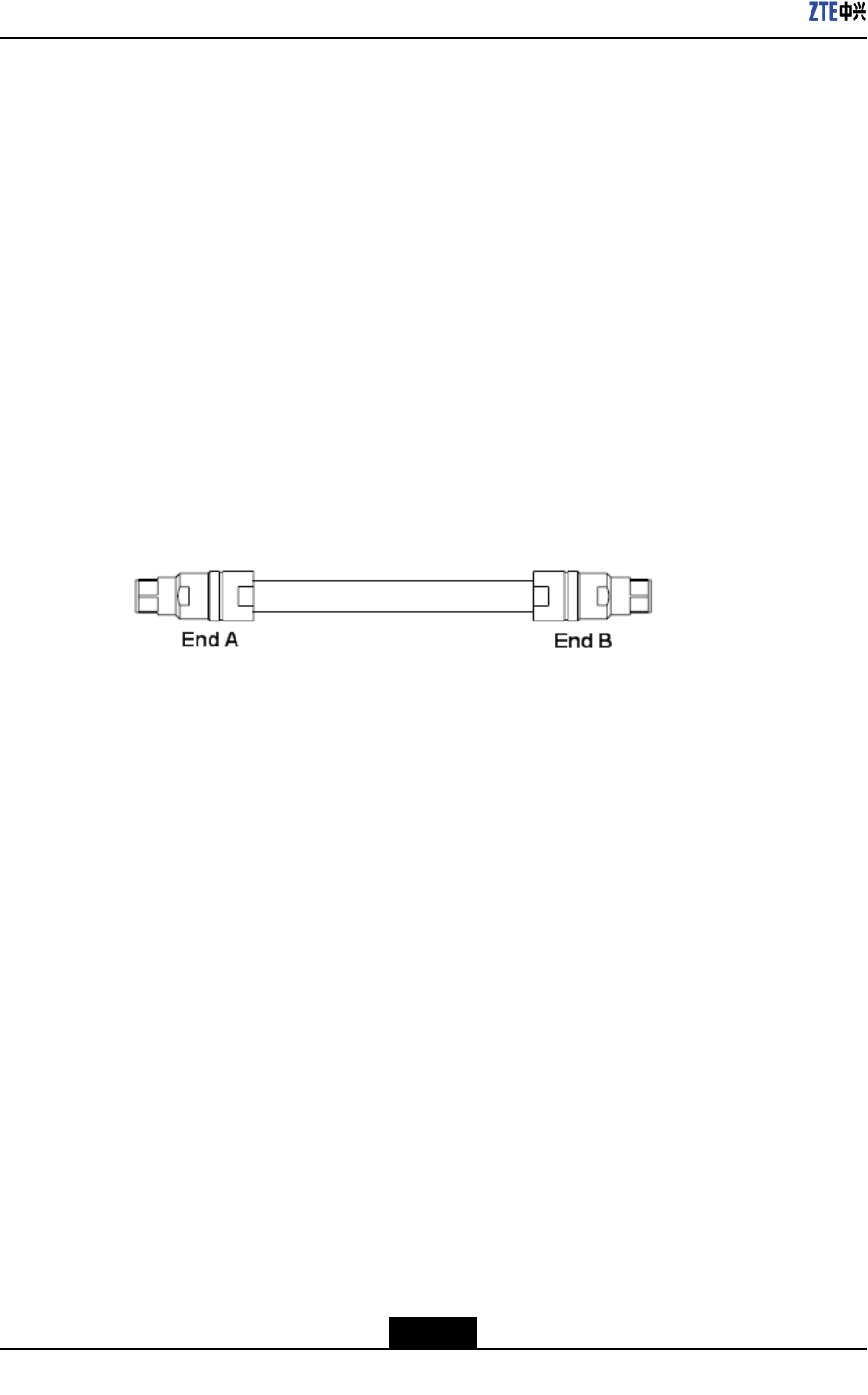
Afterthecombinationofcabinets,theR8860EGU198cansupport8carriersectorsat
most.
ThetwoR8860EGU198cabinetsareconnectedthroughtheirconnectinginterfacessuch
asRXinandRXoutbytwofrequencypointextensioncables.Figure4-48showsthe
structureofthefrequencypointcable.EndAandEndBareNconnectors(male).
The2M1/2″jumperisoftenusedforthefrequencypointextensioncable.Itmaybe
preparedonsiteifnecessary.
Figure4-48FrequencyPointExtensionCable
Steps
1.ConnectEndAofthefrequencypointextensioncabletothefrequencypointextension
interfaceRXINofoneR8860EGU198;
2.ConnectEndBtoRXoutoftheotherR8860EGU198;
3.ConnecttheremainingRXin/RXoutinterfacesofthetwocombinedcabinetswiththe
otherfrequencypointextensioncable.
–EndofSteps–
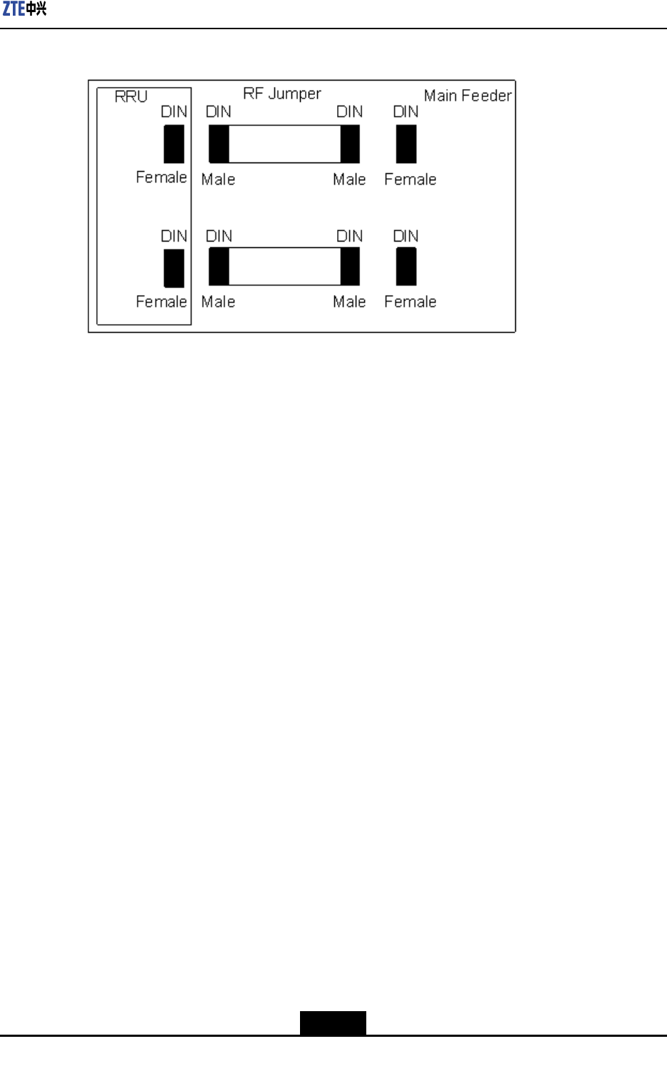
4.6.10InstallingJumper
Context
OneendofRFjumperconnectswiththemainfeederandtheotherendconnectswiththe
antennafeederinterfaceofR8860EGU198cabinet.BeforeinstallingtheRFjumper,the
mainfeederisinstalled.
TheRFjumperadoptsthe1/2″jumperwitha2mlength.Thejumpercanalsobeself-made
accordingtotheon-sitecondition.
TheinstallationpositionofRFjumperisasshowninFigure4-49.
4-56
SJ-20101210110401-002|2011-05-31ZTEProprietaryandCondential
Chapter4Installation
Figure4-49RFJumperInstallation
PerformthefollowingstepstoinstalltheRFjumper.
Steps
1.ConnecttheDINconnector(male)ofRFjumperwiththeDINconnector(female)of
mainfeeder.
2.ConnecttheDINconnector(male)ofRFjumperwiththeDINconnector(female)of
R8860EGU198cabinet.
3.SealtheconnectorswithwaterproofadhesivetapesandPVCtapes.
–EndofSteps–
4.7HardwareInstallationInspection
4.7.1CheckingCabinetInstallation
Steps
1.Ensurethatthecabinetinstallationpositioncomplieswiththeengineeringdesign
drawing.
2.Erectcabinetrmlysoastoresistanearthquakemeasuringupto7.0onRichterscale.
3.Ensurethathorizontalandverticalerrorislessthan3mm.
4.Ensurethatcabinetsurfaceiscleanandtidyandcoveredwellbyoilpaint.Allparts
ofthecabinetarecompleteandallmarkingonthecabinetarecorrect,clearand
complete.
5.Ensureallscrewsarexedtightwithatwashersorspringwashers.
–EndofSteps–
4-57
SJ-20101210110401-002|2011-05-31ZTEProprietaryandCondential
ZXSDRR8860EGU198UserManual
4.7.2CheckingCableInstallation
4.7.2.1CablesInstallationGeneralSpecification
OpticalFiber
Note:
Thelengthofopticalberisdecidedbyengineeringsurvey(1Tx,1Rx).
Thetechnicalspecicationsofopticalberareasfollows:
lTheopticalberisasinglemodewithEndBadoptingtwoDLC/PCconnectors.
lTheinsertionlossislessthat0.3dB.
lThereturnlossislessthan45dB.
lIfopticalberistobeusedoutdoor,then
1.Takewaterproofandanti-ultravioletprotectionmeasures.
2.Makesurethatworkingtemperatureisinbetween-40to80oC.
lThesheathofopticalberisblackincolorwithadiameterof7mm.Underthesheath,
therearetwocoresopticalwires(yellowandbluecolor)withsubstantialamountof
protectionpadding.
lThemaximumdistancebetweencoreopticalwires(includingbothDLC/PC
connectors)andsheathedopticalberis350mm.
lZTEsupplies15m,25m,35m.50m,70m,100m,and130mlongbercables.
lThe20mmlongblackPyrocondensationcannulashouldbeaddedinbetweenoptical
corewiresandsheathedopticalber.
lThelabelattachedatbothendsshouldsatisfytherequirementsofZTECable
DesigningCriteria–LabelDesigningandUsageRequirements.
AISGCable
ThefollowingarethetechnicalspecicationofAISGcable:
lTable4-8illustratestheconnectionrelationshipofbothends.Makesuretoenclose
EndAconnectionbyblackcannulacompletelyafterconnecting.
Table4-8ConnectionRelationship
Serial
Number
Signal
Denition
EndAPin
Number
EndBPin
Number
ConnectedCable
1485+Pin3Pin1-
2485-Pin5Pin2-
4-58
SJ-20101210110401-002|2011-05-31ZTEProprietaryandCondential
Chapter4Installation
Serial
Number
Signal
Denition
EndAPin
Number
EndBPin
Number
ConnectedCable
328VPin6Pin3,4TwocablesfromPin6
ofAendareweldedto
Pin3and4ofBend.
428VGNDPin7Pin5,6TwocablesfromPin7
ofAendareweldedto
Pin5and6ofBend.
lThePin6andPin7(SeeTable4-8)areneededtobeweldedwithtwocables.
lTheEndAconnectorshouldbeequippedwithmetaldust-proofcover
lThelabelsprintingandpastingshouldsatisfytherequirementsofQ/ZX04.113.4Cable
DesigningCriteria–LabelDesigningandUsageRequirements.
MonitoringCable
Thefollowingarethetechnicalspecicationofmonitoringcable:
lTheEndAisa37-pinfemaleconnector.
lEndBisanopenendwithoutanyconnector.TheconnectorattheEndBshouldbe
preparedon-siteaccordingtotheon-siterequirements.
lMakesurethatconnectorattheEndAisproperlywelded.
lThelabelattachedatbothendsshouldsatisfytherequirementsofZTECable
DesigningCriteria–LabelDesigningandUsageRequirements.
lTable4-9showstheconnectionrelationshipofEndA.
Table4-9ConnectionRelationship
EndA(Pins)ColorSignalDenition
15/16White/blueDrycontact4-/+
17/18White/orangeDrycontact3-/+
19/20White/greenDrycontact2-/+
21/22White/brownDrycontact1-/+
23/24Red/blue485Rx-/+
25/26Red/orange485Tx-/+
OtherPinsarefreeOthercorewiresarefree
4.7.2.2PowerandGroundingCablesInstallationCheck
Context
Ensurethepowerandgroundingcablesinstallationisdoneinaccordancewiththe
followingchecks:
4-59
SJ-20101210110401-002|2011-05-31ZTEProprietaryandCondential

ZXSDRR8860EGU198UserManual
Steps
1.Thepowerandgroundingcablesarelaidseparatelyfromothercables.Ifthepower
andgroundingcablesaretobelaidparallelwithothercables,thenatleastadistance
of20cmismaintainedbetweenthem.
2.Thecablelabelsareintactonbothsidesofpowerandgroundingcables.Thelabels
areattachedatalmost2cmfromcablecopperlug.
3.Entirepowerandgroundingcablesaremadefromonematerialwithnoconnections
inbetween.
4.Asinglegroundingpointonthegroundingbusbarjustconnectstoapieceof
equipment.
5.Copperlugsonbothendsofpowerandgroundingcablesaresolderedorpressed
rmly.
6.Theshortestroutebetweenthegroundingcablesandgroundingbusbarisadopted.
7.Powerandgroundingcablesatconnectingterminalsandlughandlesareproperly
insulatedusingeitherinsulatedtapesorheatshrinktubes.
8.Theredundantlengthofpowerandgroundingcablesiscuttoavoidwrappingeach
other.
–EndofSteps–
4.7.2.3OpticalFiberInstallationCheck
Context
Thebercableinstallationshouldmeetthefollowingspecications:
Steps
1.Donotfoldopticalberat90o.Foropticalberthatistobelaidoutdoors,minimal
twistradiusshouldbeatleastgreaterthan90mm.Whereasforopticalberthatisto
belaidindoors,minimaltwistradiusshouldbeatleastgreaterthan30mm.
2.Afterinstallation,anysurplusopticalbershouldbeputbackinthebercardfor
convenience.
3.Duringinstallation,minimizeopticalbertwistandturn,asmuchaspossible.
4.Thebindingforceshouldbepropertoensurethatbindinggapsareless0.5m.
5.Makesurethatlabelsatbothendsofopticalberareintactandclear.
–EndofSteps–
4-60
SJ-20101210110401-002|2011-05-31ZTEProprietaryandCondential
Chapter4Installation
4.7.3CheckingMainAntennaSystemInstallation
Steps
1.Ensuretheheightofantennaisconsistentwiththenetworkplanning,andthe
installationpositionisconsistentwiththeengineeringdesigndrawing.
2.Ensuretheazimuthanddown-tiltoftheantennaisconsistentwiththeengineering
designdrawing.
3.Ensuretheantennaiswithintheprotectionareaoflightningrod.
4.EnsuretheVSWRnotmorethan1.5.
5.Ensureproperconnectionbetweenantennaandjumperaswellasbetweenjumper
andmainfeedercorrect.
6.Makesurethatthejumperandantennaatthejunctionkeepstraightwithin30cmat
least.
–EndofSteps–
4.8Poweronandoff
4.8.1PoweronPreparation
Context
Makesurethatfollowingconditionsarefullledbeforepowering-onR8860EGU198:
Steps
1.Makesurethatinputpowersupplyiswithintheacceptablerange.
2.MakesurethatpowercableconnectedtoR8860EGU198cabinetisproperly
grounded.
–EndofSteps–
Result
Thepreparationtopoweronthecabinetissuccessfullycompleted.
4.8.2PowerON
Context
Performthefollowingstepstopower-ontheR8860EGU198.
4-61
SJ-20101210110401-002|2011-05-31ZTEProprietaryandCondential

ZXSDRR8860EGU198UserManual
Steps
1.ThereisnopowerswitchONtheR8860EGU198cabinet.Closetheexternalpower
switchtopoweronR8860EGU198.
2.DuringpowerON,ifsomeabnormalphenomenaoccurs,disconnecttheexternal
powerswitchortheplugimmediately,andcheckthereason.
–EndofSteps–
4.8.3PowerOFF
Context
PerformthefollowingstepstopowerOFFtheR8860EGU198.
Steps
1.ThereisnopowerswitchontheR8860EGU198cabinet.Disconnecttheexternal
powerswitchtopoweroffR8860EGU198.
–EndofSteps–
4-62
SJ-20101210110401-002|2011-05-31ZTEProprietaryandCondential

Chapter5
RRUConnectionswith
AntennaFeederSystem
TableofContents
TypicalSingle-RRUAntennaFeederSystemCongurations......................................5-1
ConguringRRUwithCommonAntennasandWithoutADTMA.................................5-1
ConguringRRUwithCommonAntennasandADTMA..............................................5-2
ConguringRRUwithElectricalAntennasandWithoutADTMA(I).............................5-3
ConguringRRUwithElectricalAntennasandWithoutADTMA(II)............................5-4
ConguringRRUwithElectricalAntennasandADTMA..............................................5-5
5.1TypicalSingle-RRUAntennaFeederSystem
Configurations
Thetypicalcongurationsofasingle-RRUfeedersystemareasfollows:
lTheRRUisconguredwithcommonantennas
lTheRRUisconguredwithcommonantennasandAISGdualT owerMounted
Amplier(ADTMA)
lTheRRUisconguredwithelectricalantennas(I)
lTheRRUisconguredwithelectricalantennas(II)
lTheRRUisconguredwithelectricalantennasandADTMA
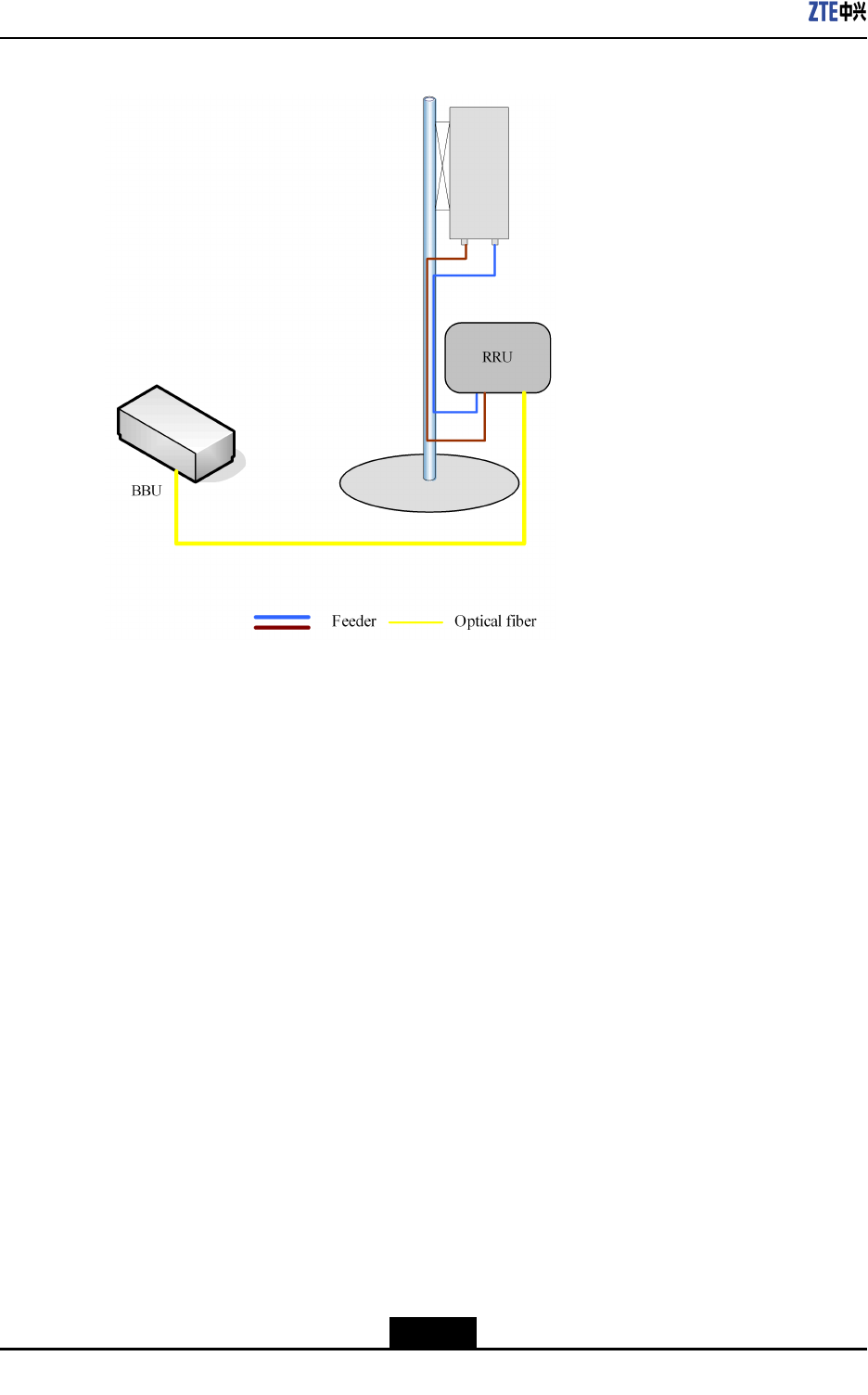
5.2ConfiguringRRUwithCommonAntennasand
WithoutADTMA
InstalltheRRUclosetotheantennaontherooftop.DirectlyconnecttheRRUtothe
antennathrough1/2”feeders,orinsomesituations,5/4”or7/8”feeders.
5-1
SJ-20101210110401-002|2011-05-31ZTEProprietaryandCondential
ZXSDRR8860EGU198UserManual
Figure5-1CONNECTINGRRUTOCOMMONANTENNASWITHOUTTWA
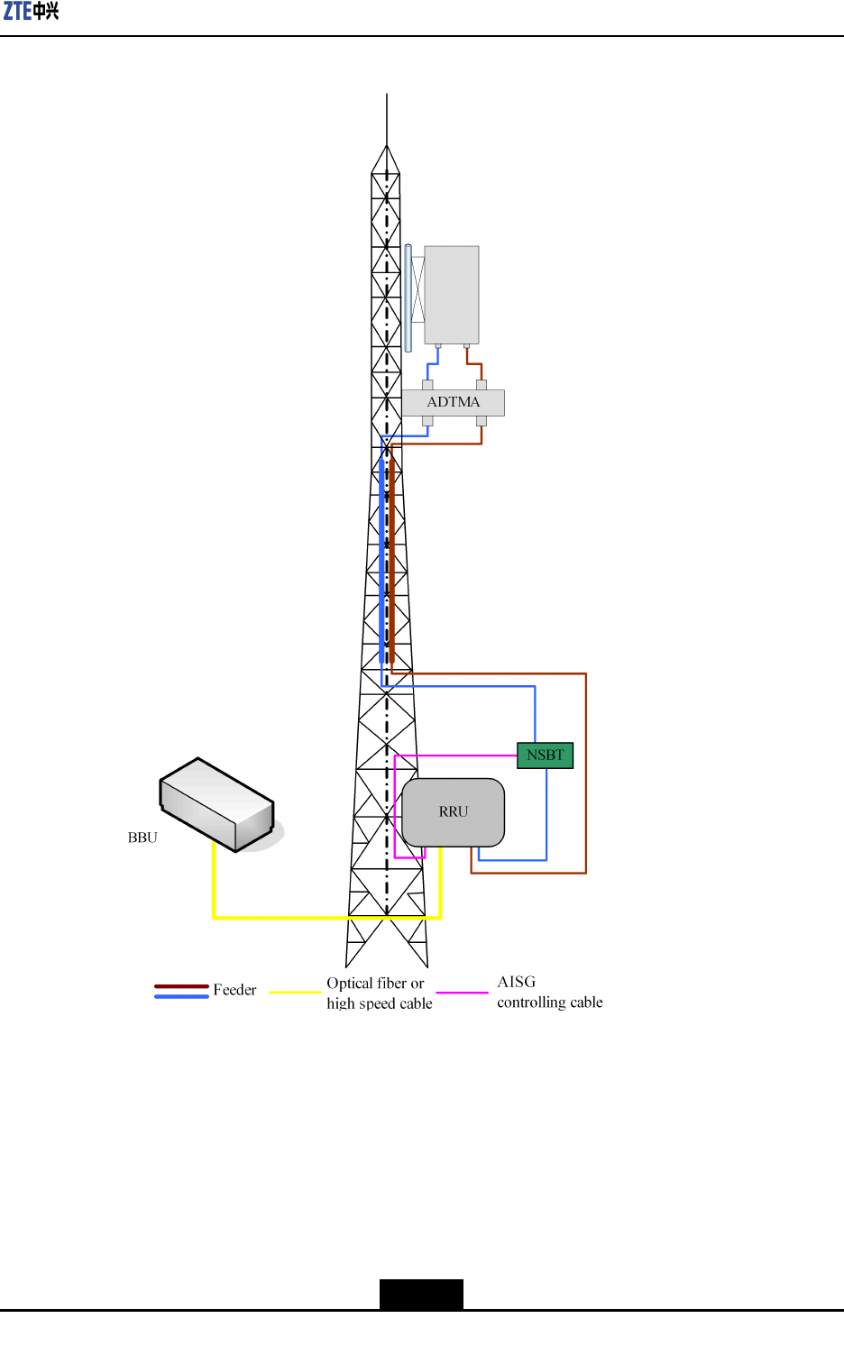
5.3ConfiguringRRUwithCommonAntennasand
ADTMA
InstalltheRRUunderthetowerandinstalltheantennaonthetower.ConnecttheRRUto
theantennathrough5/4”or7/8”feeders.
5-2
SJ-20101210110401-002|2011-05-31ZTEProprietaryandCondential
Chapter5RRUConnectionswithAntennaFeederSystem
Figure5-2CONNECTINGRRUTOCOMMONANTENNASANDADTMA
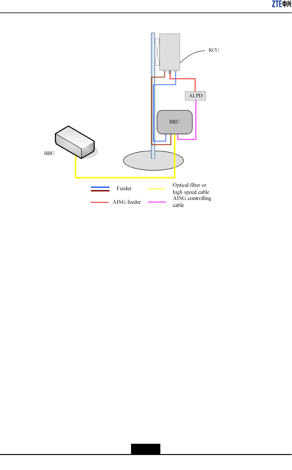
5.4ConfiguringRRUwithElectricalAntennasand
WithoutADTMA(I)
InstalltheRRUclosetotheantennaontherooftop.ConnecttheRRUtotheantenna
through1/2”feeders,orinsomesituations,5/4”or7/8”feeders.
5-3
SJ-20101210110401-002|2011-05-31ZTEProprietaryandCondential
ZXSDRR8860EGU198UserManual
Figure5-3CONNECTINGRRUWITHELECTRICALANTENNAS(I)
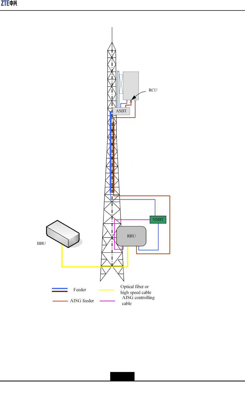
5.5ConfiguringRRUwithElectricalAntennasand
WithoutADTMA(II)
InstalltheRRUunderthetowerandinstalltheantennaonthetower.ConnecttheRRUto
theantennathrough5/4”or7/8”feeders.
5-4
SJ-20101210110401-002|2011-05-31ZTEProprietaryandCondential
Chapter5RRUConnectionswithAntennaFeederSystem
Figure5-4CONNECTINGRRUWITHELECTRICALANTENNAS(II)
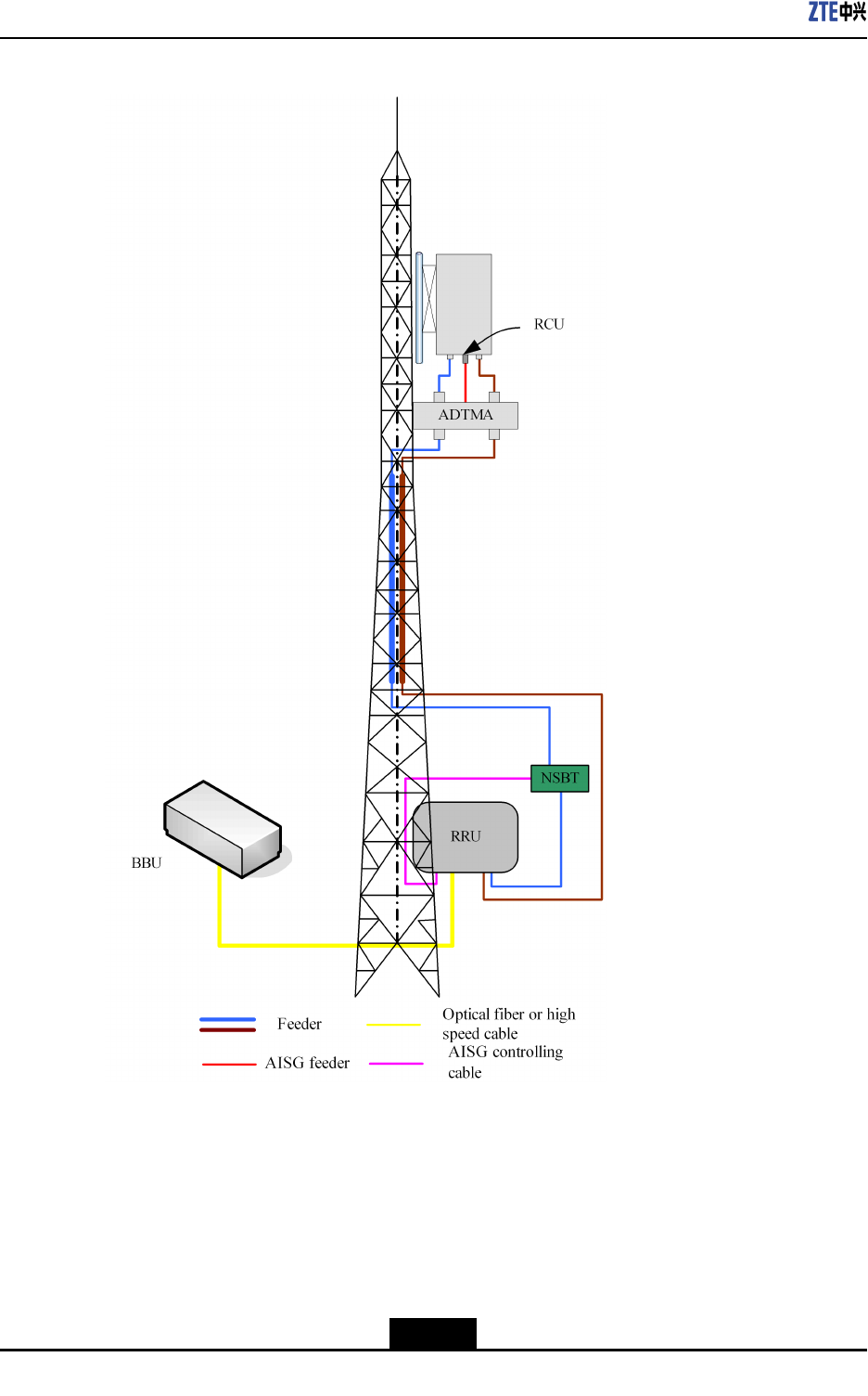
5.6ConfiguringRRUwithElectricalAntennasand
ADTMA
InstalltheRRUunderthetowerandinstalltheantennaonthetower.ConnecttheRRUto
theantennathrough5/4”or7/8”feeders.
5-5
SJ-20101210110401-002|2011-05-31ZTEProprietaryandCondential
ZXSDRR8860EGU198UserManual
Figure5-5CONNECTINGRRUTOELECTRICALANTENNASANDADTMA
5-6
SJ-20101210110401-002|2011-05-31ZTEProprietaryandCondential

Figures
Figure1-1R8860EGU198POSITIONINGSM/UMTSNETWORK..........................1-2
Figure1-2BASESTATION(BBUANDRRU)............................................................1-2
Figure1-3DISTRIBUTEDBASESTATIONSYSTEMSTRUCTURE.........................1-3
Figure1-4RUNNINGENVIRONMENTOFR8860EGU198.....................................1-4
Figure1-5R8860EGU198Appearance...................................................................1-5
Figure1-6OPERATIONANDMAINTENANCEOFR8860EGU198.........................1-9
Figure3-1ExternalInterfacesatChassisBottom.....................................................3-1
Figure3-2R8860EGU198IndicatorsandButtons....................................................3-3
Figure3-3HARDWARESYSTEM............................................................................3-4
Figure3-4R8860EGU198SOFTWAREARCHITECTURE......................................3-7
Figure4-1PACKINGOFR8860EGU198..............................................................4-16
Figure4-2FLOWOFUNPACKINGANDCHECKING.............................................4-17
Figure4-3R8860EGU198InstallationFlow...........................................................4-18
Figure4-4TakingoutCabinet.................................................................................4-19
Figure4-5BindingCabinetwithRope.....................................................................4-19
Figure4-6HoistingOperationSchematicDiagram..................................................4-20
Figure4-7WALLMOUNTEDINSTALLATIONFORR8860EGU198.......................4-24
Figure4-8POLEMOUNTEDINSTALLATIONFOR1OR2R8860E
GU198s................................................................................................4-25
Figure4-9POLEMOUNTEDINSTALLATIONFOR3R8860EGU198s..................4-25
Figure4-10TheSingleR8860EGU198MountingSolution.....................................4-26
Figure4-11TheDoubleR8860EGU198MountingSolution....................................4-26
Figure4-12TheTripleR8860EGU198MountingSolution......................................4-27
Figure4-13R8860EGU198INSTALLATIONFLOW...............................................4-28
Figure4-14HOLINGTEMPLATE...........................................................................4-29
Figure4-15ASSEMBLINGWALL-MOUNTEDINSTALLATIONASSEMBLY...........4-30
Figure4-16FIXINGTHECABINET........................................................................4-31
Figure4-17INSTALLINGCLAMPASSEMBLY.......................................................4-32
Figure4-18FIXINGTHECABINET........................................................................4-33
Figure4-19INSTALLINGCLAMPASSEMBLY.......................................................4-34
Figure4-20ASSEMBLINGWALL-MOUNTEDINSTALLATIONASSEMBLY...........4-35
Figure4-21FIXINGTHECABINET........................................................................4-35
I

ZXSDRR8860EGU198UserManual
Figure4-22INSTALLINGMOUNTINGBRACKETASSEMBLY...............................4-36
Figure4-23ASSEMBLINGWALL-MOUNTEDINSTALLATIONASSEMBLY...........4-37
Figure4-24FIXINGTHECABINET........................................................................4-37
Figure4-25FixingtheMountingPiece....................................................................4-38
Figure4-26MountingR8860EGU198....................................................................4-39
Figure4-27MountingbaseDoubleUnitSolution...............................................4-40
Figure4-28MountingbaseSingleUnit+LightningProtectorBoxSolution............4-40
Figure4-29MountingTwoR8860EGU198.............................................................4-41
Figure4-30MountingoneR8860EGU198andOneLightningProtectorBox...........4-42
Figure4-31FixingtheLightningProtectorBox........................................................4-42
Figure4-32MountingTwoR8860EGU198.............................................................4-43
Figure4-33MountingtheExpansionPiece.............................................................4-43
Figure4-34AttachingtheMountingbase................................................................4-44
Figure4-35AttachtheR8860EGU198totheMountingbase.................................4-45
Figure4-36INSTALLINGPROTECTIONSHADE...................................................4-46
Figure4-37ExternalCableInstallationFlow...........................................................4-48
Figure4-38PowerCablestructure.........................................................................4-49
Figure4-39GroundingCableStructure..................................................................4-50
Figure4-40Earth-networkCopperBar(Unit:mm)..................................................4-50
Figure4-41FiberConnectionbetweenR8860EGU198andBBU..........................4-51
Figure4-42OpticalFiberInstallation.......................................................................4-52
Figure4-43FiberConnectionbetweenR8860EGU198s.......................................4-52
Figure4-44OpticalFiberInstallation.......................................................................4-53
Figure4-45EnvironmentMonitoringCable.............................................................4-54
Figure4-46AviationJackAppearance....................................................................4-54
Figure4-47AISGControlCableStructure..............................................................4-55
Figure4-48FrequencyPointExtensionCable........................................................4-56
Figure4-49RFJumperInstallation.........................................................................4-57
Figure5-1CONNECTINGRRUTOCOMMONANTENNASWITHOUTTWA...........5-2
Figure5-2CONNECTINGRRUTOCOMMONANTENNASANDADTMA...............5-3
Figure5-3CONNECTINGRRUWITHELECTRICALANTENNAS(I).......................5-4
Figure5-4CONNECTINGRRUWITHELECTRICALANTENNAS(II)......................5-5
Figure5-5CONNECTINGRRUTOELECTRICALANTENNASANDADTMA
...............................................................................................................5-6
II

Tables
Table1-1EQUIPMENTSRELATEDTOR8860EGU198RUNNING.........................1-4
Table2-1WindSpeed@150km/h...........................................................................2-2
Table2-2WindSpeed@240km/h...........................................................................2-2
Table3-1ExternalInterfaces....................................................................................3-2
Table3-2IndicatorsandButtons...............................................................................3-3
Table3-3COMPOSITIONOFM8206CABINETHARDWARE..................................3-5
Table4-1SafetySymbolsDescription.......................................................................4-3
Table4-2ToolandMeterList..................................................................................4-10
Table4-3INSTALLATIONACCESSORIESOFR8860EGU198ANDTHEIR
FUNCTIONS..........................................................................................4-22
Table4-4R8860EGU198ExternalCableConnectionRelationship........................4-46
Table4-5ColorandSpecication...........................................................................4-49
Table4-6CablePinDescription.............................................................................4-54
Table4-7AISGControlCableDescription..............................................................4-55
Table4-8ConnectionRelationship..........................................................................4-58
Table4-9ConnectionRelationship..........................................................................4-59
III

Tables
Thispageintentionallyleftblank.

Glossary
AISG
-AntennaInterfaceStandardsGroup
Abis
-AbisInterfacebetweenBSCandBTS
BBU
-BaseBandUnit
BSC
-BaseStationController
BTS
-BaseTransceiverStation
CN
-CoreNetwork
DPD
-DigitalPre-Distortion
EDGE
-EnhancedDataratesforGSMEvolution
FP
-FrameProtocol
GPRS
-GeneralPacketRadioService
GPS
-GlobalPositioningSystem
GSM
-GlobalSystemforMobileCommunication
HSPA
-HighSpeedPacketAccess
Iub
-InterfacebetweenanRNCandaNodeB
LTE
-LongT ermEvolution
MS
-MobileStation
NodeB
-NodeB
V

ZXSDRR8860EGU198UserManual
OAM
-Operation,AdministrationandMaintenance
PA
-PowerAmplier
RF
-RadioFrequency
RNC
-RadioNetworkController
RRU
-RemoteRadioUnit
UE
-UserEquipment
UMTS
-UniversalMobileT elecommunicationSystem
Uu
-Uinterfaceinmobilenetwork
VI