ZTE R8860EGU198A Outdoor GSM/UMTS Dual Mode Remote Radio Unit User Manual
ZTE Corporation Outdoor GSM/UMTS Dual Mode Remote Radio Unit
ZTE >
Contents
- 1. User Manual
- 2. User Manual II
User Manual

ZXSDRR8860EGU198
OutdoorGSM&UMTSDualModeMacroRRU
UserManual
HV2.0
ZTECORPORATION
NO.55,Hi-techRoadSouth,ShenZhen,P .R.China
Postcode:518057
Tel:+86-755-26771900
Fax:+86-755-26770801
URL:http://ensupport.zte.com.cn
E-mail:support@zte.com.cn

LEGALINFORMATION
Copyright©2011ZTECORPORATION.
Thecontentsofthisdocumentareprotectedbycopyrightlawsandinternationaltreaties.Anyreproductionor
distributionofthisdocumentoranyportionofthisdocument,inanyformbyanymeans,withoutthepriorwritten
consentofZTECORPORATIONisprohibited.Additionally,thecontentsofthisdocumentareprotectedby
contractualcondentialityobligations.
Allcompany,brandandproductnamesaretradeorservicemarks,orregisteredtradeorservicemarks,ofZTE
CORPORATIONoroftheirrespectiveowners.
Thisdocumentisprovided“asis”,andallexpress,implied,orstatutorywarranties,representationsorconditions
aredisclaimed,includingwithoutlimitationanyimpliedwarrantyofmerchantability,tnessforaparticularpurpose,
titleornon-infringement.ZTECORPORATIONanditslicensorsshallnotbeliablefordamagesresultingfromthe
useoforrelianceontheinformationcontainedherein.
ZTECORPORATIONoritslicensorsmayhavecurrentorpendingintellectualpropertyrightsorapplications
coveringthesubjectmatterofthisdocument.ExceptasexpresslyprovidedinanywrittenlicensebetweenZTE
CORPORATIONanditslicensee,theuserofthisdocumentshallnotacquireanylicensetothesubjectmatter
herein.
ZTECORPORATIONreservestherighttoupgradeormaketechnicalchangetothisproductwithoutfurthernotice.
UsersmayvisitZTEtechnicalsupportwebsitehttp://ensupport.zte.com.cntoinquirerelatedinformation.
TheultimaterighttointerpretthisproductresidesinZTECORPORATION.
RevisionHistory
RevisionNo.RevisionDateRevisionReason
R1.02011-05-31Firstedition
SerialNumber:SJ-20101210110401-002
PublishingDate:2011-05-31

Contents
AboutThisManual.........................................................................................I
Chapter1SystemOverview......................................................................1-1
1.1SystemBackground...........................................................................................1-1
1.2SystemPositions................................................................................................1-1
1.2.1SystemPositioninNetwork.......................................................................1-1
1.2.2BBUandRRU..........................................................................................1-2
1.3SystemRunningEnvironment.............................................................................1-3
1.4RRUAppearance...............................................................................................1-5
1.5SystemFeatures................................................................................................1-5
1.6ServicesandFunctions......................................................................................1-6
1.7SystemOperationandMaintenance....................................................................1-8
Chapter2TechnicalIndices......................................................................2-1
2.1PhysicalIndices.................................................................................................2-1
2.2RadioPerformanceIndices.................................................................................2-2
2.3InterfaceandTransmissionIndices......................................................................2-3
Chapter3StructureandPrinciples..........................................................3-1
3.1StructureLayout.................................................................................................3-1
3.1.1ExternalInterfaces...................................................................................3-1
3.1.2IndicatorsandButtons..............................................................................3-2
3.2HardwarePrinciple.............................................................................................3-4
3.2.1HardwareArchitecture..............................................................................3-4
3.2.2BoardFunctions.......................................................................................3-5
3.3SoftwareSystem................................................................................................3-7
3.3.1SoftwareArchitecture...............................................................................3-7
3.3.2SoftwareFunctions...................................................................................3-7
Chapter4Installation.................................................................................4-1
4.1SafteyDescription..............................................................................................4-1
4.1.1SafetySpecicationsGuide......................................................................4-1
4.1.2SafetySymbols........................................................................................4-2
4.1.3SafetyInstructions....................................................................................4-4
4.2Preparation........................................................................................................4-7
4.2.1EngineeringConditionInspection..............................................................4-8
4.2.2RequirementstoOnsitePersonnel............................................................4-9
I

4.2.3T echnicalDocumentPreparation...............................................................4-9
4.2.4T oolsandInstrumentsPreparation..........................................................4-10
4.3UnpackingandChecking..................................................................................4-15
4.3.1ContainerofR8860EGU198...................................................................4-15
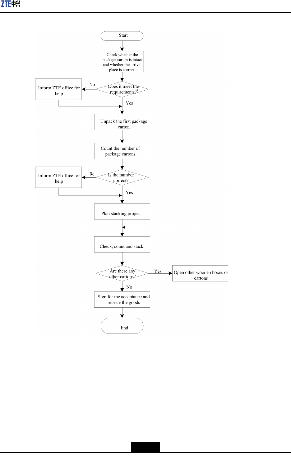
4.3.2FlowofUnpackingandChecking............................................................4-16
4.4InstallationOverview........................................................................................4-17
4.4.1InstallationFlow.....................................................................................4-17
4.4.2HoistingOperationInstructions................................................................4-18
4.5CabinetInstallation...........................................................................................4-21
4.5.1InstallationModeInstruction....................................................................4-21
4.5.2InstallationMethodsandAccessories......................................................4-21
4.5.3R8860EGU198Installation.....................................................................4-27
4.6ExternalCableInstallation................................................................................4-46
4.6.1ExternalCableLayout............................................................................4-46
4.6.2ExternalCableInstallationFlow..............................................................4-48
4.6.3InstallingPowerCable............................................................................4-49
4.6.4InstallingGroundingCable......................................................................4-50
4.6.5InstallingFiberbetweenBBUandRRU....................................................4-51
4.6.6InstallingFiberbetweenRRUandRRU...................................................4-52
4.6.7InstallingEnvironmentMonitoringCable..................................................4-53
4.6.8InstallingAISGControlCable..................................................................4-55
4.6.9InstallingFrequencyPointExtensionCable..............................................4-56
4.6.10InstallingJumper..................................................................................4-56
4.7HardwareInstallationInspection........................................................................4-57
4.7.1CheckingCabinetInstallation..................................................................4-57
4.7.2CheckingCableInstallation.....................................................................4-58
4.7.3CheckingMainAntennaSystemInstallation.............................................4-61
4.8Poweronandoff..............................................................................................4-61
4.8.1PoweronPreparation.............................................................................4-61
4.8.2PowerON..............................................................................................4-61
4.8.3PowerOFF............................................................................................4-62
Chapter5RRUConnectionswithAntennaFeederSystem...................5-1
5.1TypicalSingle-RRUAntennaFeederSystemCongurations.................................5-1
5.2ConguringRRUwithCommonAntennasandWithoutADTMA............................5-1
5.3ConguringRRUwithCommonAntennasandADTMA.........................................5-2
5.4ConguringRRUwithElectricalAntennasandWithoutADTMA(I)........................5-3
5.5ConguringRRUwithElectricalAntennasandWithoutADTMA(II).......................5-4
II

5.6ConguringRRUwithElectricalAntennasandADTMA.........................................5-5
Figures.............................................................................................................I
Tables............................................................................................................III
Glossary.........................................................................................................V
III

IV

AboutThisManual
Purpose
Thismanualintroducetheworkingprinciple,structurefeatures,networkingschemeand
installationmethodsofZXSDRR8860EGU198.
IntendedAudience
lSystemEngineer
lInstallationEngineer
lMaintenanceEngineer
WhatIsinThisManual
Thismanualcontainsthefollowingchapters.
ChapterDescription
Chapter1,ProductOverviewIntroducesthefunction,specication,featuresandtechnical
specicationsofR8860EGU198.
Chapter2,TechnicalIndicesIntroducesthetechnicalindicesofR8860EGU198
Chapter3,Structureand
Principles
IntroducesthestructureandprinciplesofR8860EGU198
Chapter4,InstallationIntroducestheinstallationmethodsandstepsofR8860EGU198in
detail.
Chapter5,RRUConnections
withAntennaFeederSystem
IntroducestheRRUConnectionswithAntennaFeederSystem.
I

II

Chapter1
SystemOverview
TableofContents
SystemBackground...................................................................................................1-1
SystemPositions........................................................................................................1-1
SystemRunningEnvironment....................................................................................1-3
RRUAppearance.......................................................................................................1-5
SystemFeatures........................................................................................................1-5
ServicesandFunctions..............................................................................................1-6
SystemOperationandMaintenance...........................................................................1-8
1.1SystemBackground
R8860EGU198istheoutdoordual-modeRFremoteunitintheZTEZXSDRseriesbase
stationproducts.
ZTECorporationhaslaunchedaseriesofbasestationproductstosatisfyvarious
requirementsofoperators.Oneofthesolutionsisdividingthebasestationintotwoparts:
BaseBandUnit(BBU)andRemoteRadioUnit(RRU).R8860EGU198istheoutdoor
RRU,anditworkswithBBUtorealizecompletelogicalfunctionsofabasestation.
R8860EGU198adoptsthemulti-carriertechnologyasitscoretechnology.Itsupportstwo
radiosystems:GSMandUMTS.R8860EGU198canbeusedasanindependentRRU
forGSMoranindependentRRUforUMTS,anditworkswithBBUtoformthedual-mode
basestation.
1.2SystemPositions
1.2.1SystemPositioninNetwork
TheGSM/UMTSsystemconsistsoffourparts:
lBasestation(BTS/NodeB)
lRadionetworkcontroller(BSC/RNC)
lCoreNetwork(CN)system
lMobilestation(MS/UE)
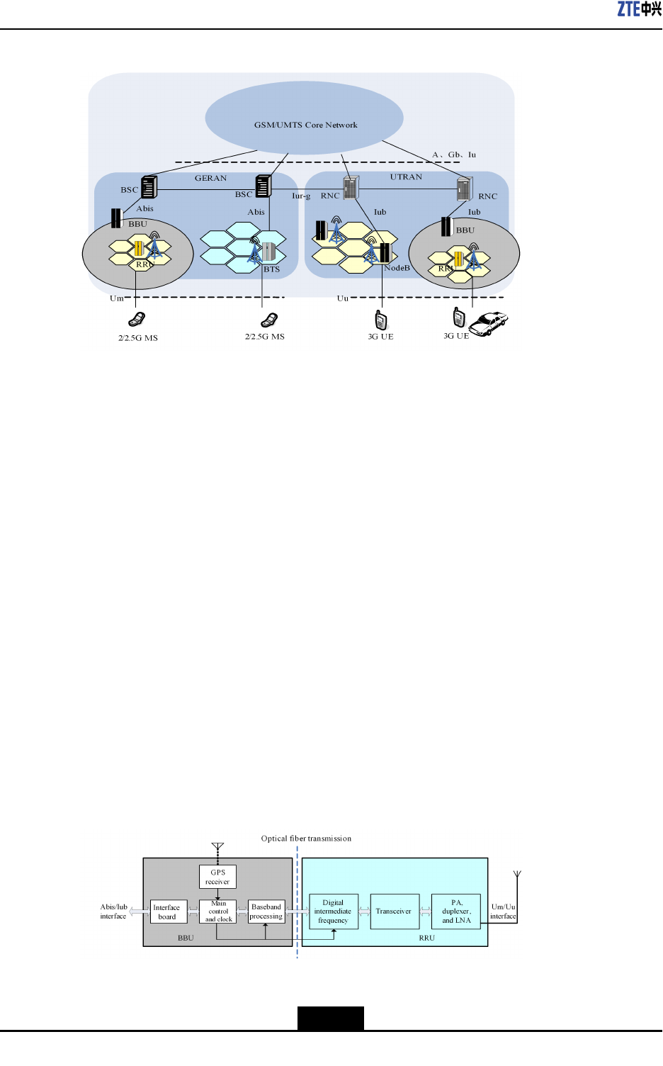
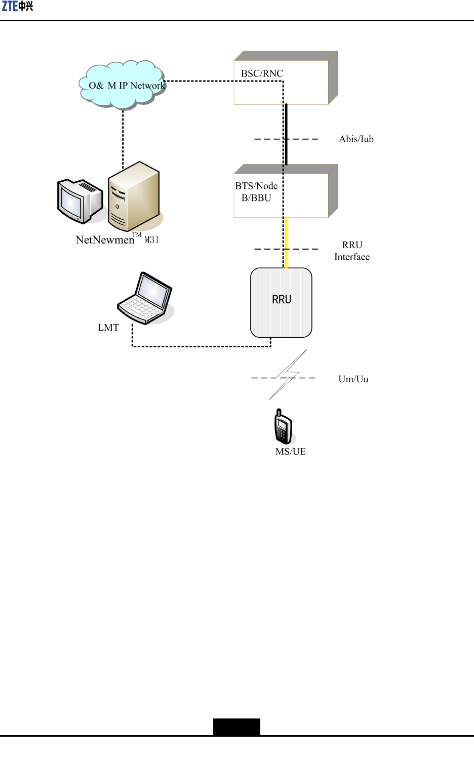
Figure1-1showsthepositionofR8860EGU198intheGSM/UMTSnetwork.
1-1
SJ-20101210110401-002|2011-05-31ZTEProprietaryandCondential
ZXSDRR8860EGU198UserManual
Figure1-1R8860EGU198POSITIONINGSM/UMTSNETWORK
BTS/NodeB,whichprovidestheradiocoverageofGSM/UMTSnetwork,performsthe
followingfunctions:
lRealizesMS/UEaccessandradiolinktransmissionthroughUm/Uuinterface.
lConnectswithBSC/RNCthroughAbis/Iubinterface,reportsBTS/NodeB
measurementinformation,broadcastssysteminformationprovidedbyBSC/RNC,
executescommandsissuedbyBSC/RNC(suchasaccesscontrol,mobility
management,andradioresourcemanagement),andperformsFPprocessingand
transmissionmanagement.
ThedistributedBTS/NodeBsystemconsistsofBBUandRRU.R8860EGU198realizes
thefunctionofRRU,andworkswiththedual-modeBBUtoformtheBTS/NodeBbase
station.
1.2.2BBUandRRU
Functions
Figure1-2showsthebasestationstructurewhichisdividedintoBBUandRRU.BBU
performsbasebandprocessing,transmission,andcontrol,whileRRUperformstheRF
processing.
Figure1-2BASESTATION(BBUANDRRU)
1-2
SJ-20101210110401-002|2011-05-31ZTEProprietaryandCondential
Chapter1SystemOverview
lThebasestationisdividedintoBBUandRRU.OneBBUprovidesthebaseband
resourceformultipleRRUs
lBBUperformsdigitalbasebandsignalprocessingandcontrolmanagement.
lRRUperformsconversionofthedigitalbasebandsignalandtheanalogRFsignal
betweenBBUandantenna.
lBBUconnectswithRRUthroughthebaseband-RFinterface(opticalinterface),and
transmitsI/QdigitalbasebandsignalandOAMsignalingdata.
lBBUconnectswithBSC/NodeBthroughAbis/Iubinterface.
lRRUrealizesMS/UEaccessthroughUm/Uuinterface.
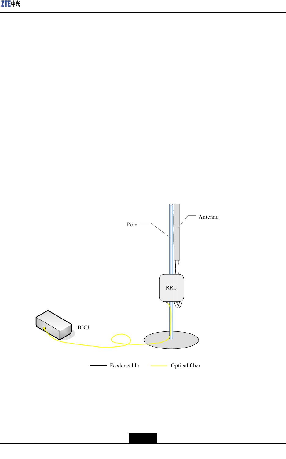
DistributedBaseStationArchitecture
BBUandRRUconstitutethedistributedbasestationsystem.OnecentralBBUmanages
agroupofRRUs,realizingrapidandexiblecongurationandnetworkingforthe
basestationsystem.TheBBU+RRUsolutionisamoreexiblemodeforbasestation
establishment.Itreducesrequirementsfortheequipmentroomandthefeedercableloss.
BBUisarrangedindoorsandconnectedwithRRU(usuallyarrangedoutdoors)through
opticalber,asshowninFigure1-3.
Figure1-3DISTRIBUTEDBASESTATIONSYSTEMSTRUCTURE
1.3SystemRunningEnvironment
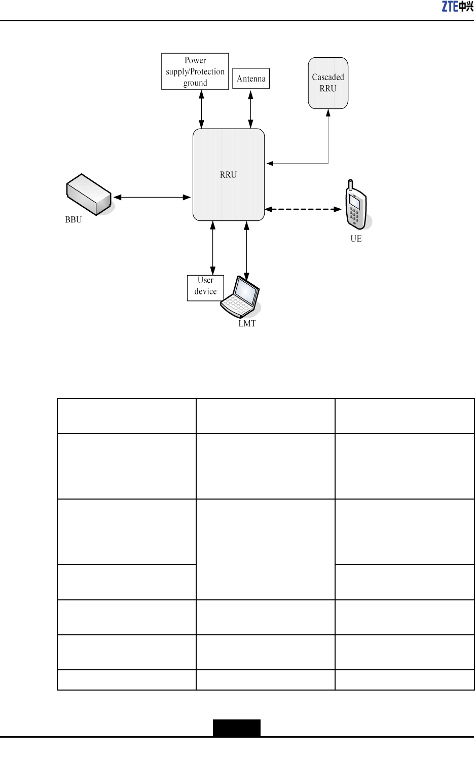
TherunningenvironmentofR8860EGU198isshowninFigure1-4.
1-3
SJ-20101210110401-002|2011-05-31ZTEProprietaryandCondential
ZXSDRR8860EGU198UserManual
Figure1-4RUNNINGENVIRONMENTOFR8860EGU198
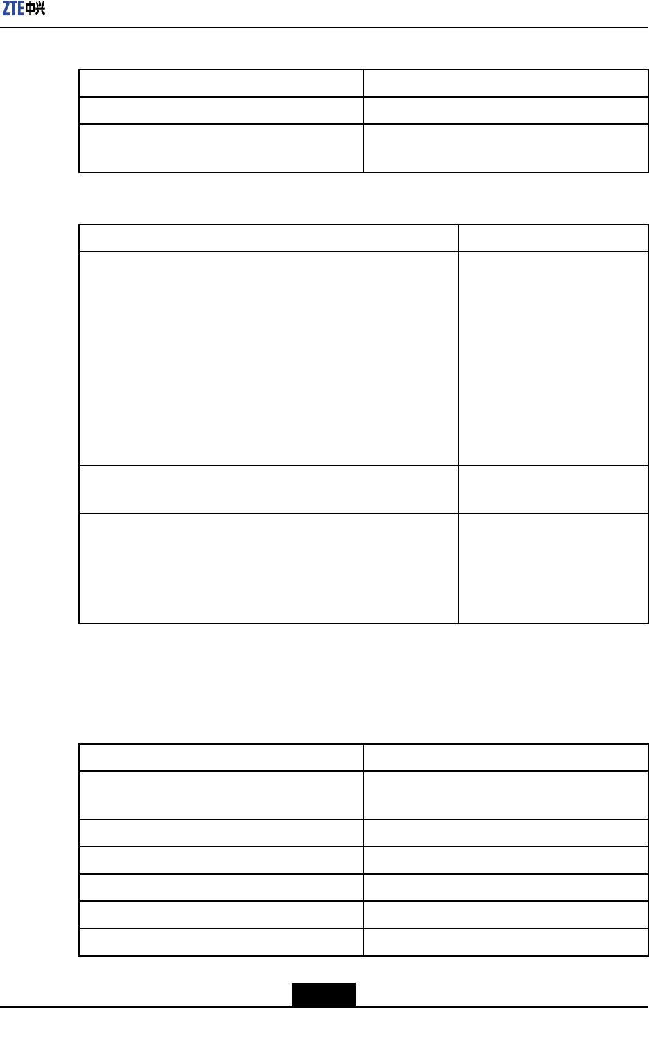
EquipmentfunctionsandinterfacesrelatedtotherunningofR8860EGU198areshown
inTable1-1.
Table1-1EQUIPMENTSRELATEDTOR8860EGU198RUNNING
ExternalSystemInterface
ExternalSystemFunction
Description
MS/UEUm/Uuinterface
Subscriberterminalequipment,
realizingvoiceanddataservice
transmissionthroughtheradio
interface.
BBU
Basebandresourcepool,
realizingGPSsynchronization,
maincontrol,andbaseband
processing.
CascadedRRU
Baseband-RFinterface(optical
interface)
RealizingRFprocessing
function
UserdeviceExternaldeviceinterface
Environmentmonitoring
devices,etc.
AntennaAntennafeederinterface
Receivingandsendingradio
signals
LMTLMTinterfaceLocalO&Mterminal
1-4
SJ-20101210110401-002|2011-05-31ZTEProprietaryandCondential
Chapter1SystemOverview
ExternalSystemInterface
ExternalSystemFunction
Description
PowersupplyPowersupplyinterface
ProvidingpowerforRRU
system
ProtectiongroundProtectiongroundinterfaceSystemgroundingprotection
ElectricalantennaElectricalantennainterface0
Antennaswithadjustable
electricalantenna
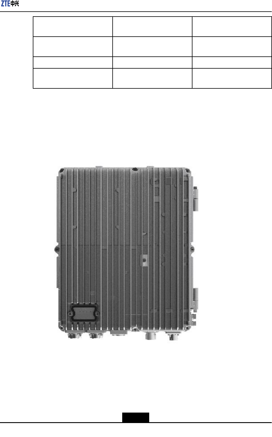
1.4RRUAppearance
Figure1-5showstheappearanceoftheR8860EGU198chassis.
Figure1-5R8860EGU198Appearance
1.5SystemFeatures
R8860EGU198hasthefollowingsystemfeatures:
lDual-modefunction
1-5
SJ-20101210110401-002|2011-05-31ZTEProprietaryandCondential

ZXSDRR8860EGU198UserManual
R8860EGU198supportstworadioaccessmodes:GSMandUMTS.itisadual-mode
RRU.
lDistributedarchitecture
BBUandRRUconstitutethedistributedbasestationsystem,providingamoreexible
modeforbasestationestablishment.
lSmoothevolution
àSmoothevolutiontowardsenhancedEDGEandHSPA+canberealizedthrough
softwareupgrade,whichhelpssaveinvestmentforoperatorstothemaximum
extent.
àR8860EGU198supportsthe25MHzbandwidth,whichenablesittosmoothly
evolveintoLTE.
lFlexiblecongurationandnetworking
àWiththemulti-carriertechnology,whenR8860EGU198worksintheGSMmode,
itsupports1~6carriersthroughmodifyingsoftwareconguration.
àWhenR8860EGU198worksintheUMTSmode,R8860EGU198supports4
CarrierandSector(CS).
àWithinthesamefrequencyband,R8860EGU198canworkinGSM/UMTSdual
modethroughmodifyingsoftwareconguration.Forexample,itcansupportthe
capacityof4GSMcarriersplusoneUMTSCS.
àStarnetwork,chainingnetworking,andringnetworkingatbaseband-RFinterface
aresupported.
lEnergysavingandenvironmentprotection
àR8860EGU198adoptsthemulti-carrierPowerAmplication(PA)andadvanced
DohertyandDPDlinearPAtechnology.
àThetypicalpowerconsumptionofR8860EGU198islessthan215W.
lEasyinstallation
R8860EGU198systemhassmallsizeandlightweight,whichfacilitatesinstallation
andmaintenance.
1.6ServicesandFunctions
R8860EGU198workswithBBUtoformthedistributedbasestationsystem.Signals
aretransferredtoBBUthroughR8860EGU198forfurtherprocessing.R8860EGU198
connectswiththebasebandprocessingunitandrealizesthefollowingservicesand
functions.
Services
R8860EGU198providesthefollowingservices:
lGSM/EDGE
1-6
SJ-20101210110401-002|2011-05-31ZTEProprietaryandCondential

Chapter1SystemOverview
àFull-ratevoiceservice
àEnhancedfull-ratevoiceservice
àHalf-ratevoiceservice
àAdaptivemulti-ratevoiceservice
à9.6KbpsCS-domaindataservice
àGPRS/EDGEservice
lLocationservice
R8860EGU198supportsCellID,CellID+RTT,andAGPSlocationservices.
lR99service
àCSdomainservice:adaptivemulti-ratevoiceservice(8codingschemes),CS64
Kbpsdataservice.
àPSdomainservice:UL/DL64Kbps,UL/DL128Kbps,andUL/DL384Kbpsdata
services.
àConcurrentservice:CSdomain(AMR12.2Kbps,CS64Kbps)+PSdomain(64
Kbps,128Kbps,384Kbps).
lHSDPAservice
à14.4Mbpsdatarate
à15codechannel
àHSDPAandR99canbeconguredatdifferentcarriers
àSupportingco-frequency/hetero-frequencyhandoverandHSDPA/R99handover
àSupportingconcurrentservice
àSupportingstreammediaservice
lHSUPAservice
5.76Mbpsdatarate
lMBMSservice
àSupportingbroadcastingandmulticastingfunctions,supportingPtPandPtm
multicastmode
àSupportingmobilitymanagement
àSupportingstream-typeandbackground-typeMBMSservice
lHSPA+service
àDownlink43.2Mbpsdatarate
àUplink11.5Mbpsdatarate
Functions
R8860EGU198performsthefollowingfunctions:
1-7
SJ-20101210110401-002|2011-05-31ZTEProprietaryandCondential

ZXSDRR8860EGU198UserManual
lPerformsterminalaccessandRFlinktransmissionfunctionthroughUm/Uuinterface,
includingRFsignalprocessing,channelcodinganddecoding,channelmultiplexing
andde-multiplexing,measurementandreport,powercontrol,transmissiondiversity,
receptiondiversity,calibration,andsynchronization.
lConnectswithBBUthroughtheopticalinterface.Functionsperformedbytheoptical
interfaceincludeIQdatatransmission,reportingmeasurementinformation,RF
functionconguration,andclocksynchronization.
lProvidessystemmanagementfunctionsthroughtheO&Minterface,including
congurationmanagement,alarmmanagement,andstatuscheckandmonitoring.
lOtherbasicfunctions
àSupportsGSMPhaseI/PhaseII/PhaseII+
àSupportsUMTSR99,R4,R5,R6,R7
àSupportsEGSM/GSM1900MHz,UMTS1900MHz.
àSupportsGPRSCS1~CS4andEDGEMCS1~MCS9codingschemes
àSupportsvariousdiversitymodes,includingspacediversity,frequencydiversity,
timediversity,andpolarizationdiversity
àSupportsViterbidemodulationalgorithmatthereceivingendtoenhancesystem
receivingsensitivityandchanneldecodingcapability
àSupportsfrequencyhoppingtechnology
àSupportsinconsecutivetransmissiontechnology
àSupportsTAcalculationandultra-distancecoverage,withthemaximumcoverage
distanceof120km
àSupportsCo-BCCHtechnology
1.7SystemOperationandMaintenance
TherearetwoOperationandMaintenance(O&M)modesforR8860EGU198:localO&
MandremoteO&MLocalO&MusestheLMTsoftware,andremoteO&Musesthe
ZTENetNumen™networkmanagementsystem,asshowninFigure1-6.
1-8
SJ-20101210110401-002|2011-05-31ZTEProprietaryandCondential
Chapter1SystemOverview
Figure1-6OPERATIONANDMAINTENANCEOFR8860EGU198
1-9
SJ-20101210110401-002|2011-05-31ZTEProprietaryandCondential

ZXSDRR8860EGU198UserManual
Thispageintentionallyleftblank.
1-10
SJ-20101210110401-002|2011-05-31ZTEProprietaryandCondential

Chapter2
TechnicalIndices
TableofContents
PhysicalIndices.........................................................................................................2-1
RadioPerformanceIndices........................................................................................2-2
InterfaceandTransmissionIndices............................................................................2-3
2.1PhysicalIndices
ThefollowinglistsphysicalindicesofR8860EGU198.
Appearance
ItemIndex
Size370mm×320mm×197mm(H×W×D)
Weight≤20kg
ColorSilvergray
PowerSupplyandPowerConsumption
ItemIndex
Peakpowerconsumption330W
Ratedinputvoltage–48V(-57VDC~-37VDC)
EnvironmentCondition
ItemIndex
Workingenvironmenttemperature-40℃~55℃
Relativeworkingenvironmenthumidity5%~100%
Storageenvironmenttemperature-45℃~70℃
Relativestorageenvironmenthumidity5%~98%
Transportationcondition
Withtheconditionof4K2/4Z5/4Z7/4B1/4C2/4S3/4
M3,thetransportationprocesslastslessthan180
days.
2-1
SJ-20101210110401-002|2011-05-31ZTEProprietaryandCondential

ZXSDRR8860EGU198UserManual
Reliability
ItemIndex
Availability99.999868%
MTBF≥380,000hours
MTTR1hour
SystemserviceinterruptiontimeThesystem'sentireserviceinterruptiontime≤
1.383minute/year
WindLoadIndicesofR8860EGU198
WindSpeedFrontalLateralRearside
150km/h439N219N439N
240km/h1137N567N1137N
WindLoadIndicesofR8860EGU198LightningProtectionBox
Table2-1WindSpeed@150km/h
LightningProtection
Box(H×W×D)
FrontalLateralRearside
OLP48-2A295mm×
220mm×86mm
178N70N178N
ZXB08.002300mm×
250mm×115mm
206N95N206N
Table2-2WindSpeed@240km/h
LightningProtection
Box(H×W×D)
FrontalLateralRearside
OLP48-2A295mm×
220mm×86mm
462N180N462N
ZXB08.002300mm×
250mm×115mm
534N245N534N
2.2RadioPerformanceIndices
Thefollowinglistsradioperformanceindices.
2-2
SJ-20101210110401-002|2011-05-31ZTEProprietaryandCondential
Chapter2TechnicalIndices
CapacityIndices
ItemIndex
Single-modecongurationGSM6TRXorUMTS4Carriers
G/Udual-modeconguration4GSMTRXand1UMTScarriersor2GSM
TRXand2UMTScarriers
RFIndices
ItemIndex
WorkingFrequency
GSM198/UMTS198Type1:
Uplinkfrequencyrange:
1850~1890MHz
Downlinkfrequencyrange:
1930~1970MHz
GSM198/UMTS198Type2:
Uplinkfrequencyrange:
1870~1910MHz
Downlinkfrequencyrange:
1950~1990MHz
MaximumtransmissionpowerGSM:GMSK80W/8PSK50W
UMTS:80W
Staticreceivingsensitivity
GSM:-113dBm@GSMsingle
antenna
UMTS:-126.5dBm@UMTS
singleantenna/-129.2
dBm@UMTSdoubleantennas
2.3InterfaceandTransmissionIndices
Thefollowinglistsinterfaceandtransmissionindices.
ItemIndex
Baseband-RFinterface2,connectingwiththebasebandunitandcascad-
ingwithotherRRUs.
RS485interface1,connectingwithexternalmonitoringequipment.
FEinterface1,usedforlocalmaintenance.
Antennaport2,connectingwithantennafeeder.
AISGinterface1,usedforelectricaldowntiltadjustableantenna
Drycontactinput4ways,externalalarm
2-3
SJ-20101210110401-002|2011-05-31ZTEProprietaryandCondential

ZXSDRR8860EGU198UserManual
Thispageintentionallyleftblank.
2-4
SJ-20101210110401-002|2011-05-31ZTEProprietaryandCondential
Chapter3
StructureandPrinciples
TableofContents
StructureLayout.........................................................................................................3-1
HardwarePrinciple.....................................................................................................3-4
SoftwareSystem........................................................................................................3-7
3.1StructureLayout
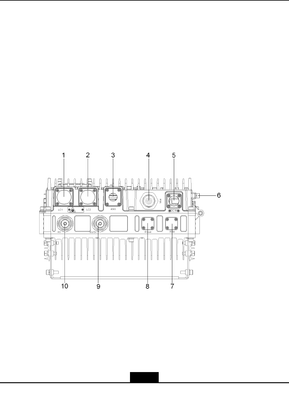
3.1.1ExternalInterfaces
TheexternalinterfacesofR8860EGU198arelocatedatthebottomofthechassis,as
showninFigure3-1.
Figure3-1ExternalInterfacesatChassisBottom
Table3-1describestheexternalinterfaces.
3-1
SJ-20101210110401-002|2011-05-31ZTEProprietaryandCondential

ZXSDRR8860EGU198UserManual
Table3-1ExternalInterfaces
SerialNumberLabelInterfaceInterface
Type/Connector
1LC1
InterfacebetweenBBU
andRRU/RRUcascad-
inginterface
LC-typeopticalinter-
face(IEC874)
2LC2
InterfacebetweenBBU
andRRU/RRUcascad-
inginterface
LC-typeopticalinter-
face(IEC874)
3AISGAISGequipmentinter-
face
8-coreaeronautical
socket(IEC60130-9-
ED)
4Mon
Externalequipmentin-
terface(monitoring,
LMT,etc.)
37-coreaeronautical
socket
DCinterface:Con-
nectorXCG18T4K1P1-
01+XC18FJJP1-10.5
5DCINPowersupplyinterface
Thecable'scross-sec-
tionalareais1.5mm2
6GNDTheequipmentis
grounded
Thecable'scross-sec-
tionalareais35mm2
7RXinFrequencypointex-
tendedinterface
N-KY(MIL-C-39012or
IEC169-16)
8RXoutFrequencypointex-
tendedinterface
N-KY(MIL-C-39012or
IEC169-16)
9RX/TX
Transmitting/Receiving
maindiversityRFcable
interface
50ΩDIN-typeconnec-
tor
10RXReceivingdiversityRF
cableinterface
50ΩDIN-typeconnec-
tor
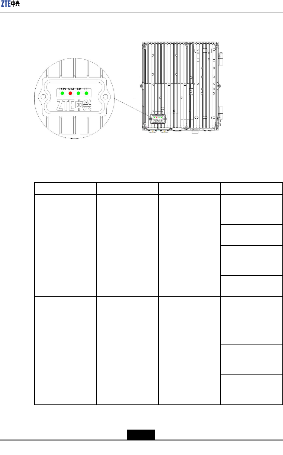
3.1.2IndicatorsandButtons
R8860EGU198indicatorsandbuttonsarelocatedinthebottom-leftofthefrontpanelof
thechassis,behindthecoverplate,asshowninFigure3-2.
3-2
SJ-20101210110401-002|2011-05-31ZTEProprietaryandCondential
Chapter3StructureandPrinciples
Figure3-2R8860EGU198IndicatorsandButtons
Table3-2describestheindicatorsandbuttons.
Table3-2IndicatorsandButtons
ColorNameMeaningWorkingMode
ConstantlyON:
R8860EGU198isbe-
ingresetandstarted.
Flashingat1Hz:Nor-
malstatus
Flashingat5Hz:Indi-
catesthatversionisbe-
ingdownloaded.
GreenRUNRunningindicator
OFF:Indicatestheself-
testfails.
OFF:Indicatesthat
thereisnofaultor
R8860EGU198isbe-
ingreset,started,or
downloadingversion.
Flashingat5Hz:In-
dicatescriticalalarmor
majoralarm.
RedALMAlarmindicator
Flashingat1Hz:In-
dicatesminoralarmor
warning.
3-3
SJ-20101210110401-002|2011-05-31ZTEProprietaryandCondential
ZXSDRR8860EGU198UserManual
ColorNameMeaningWorkingMode
ConstantlyON:Theop-
ticalberconnectionis
normal.
OFF:Theopticalberis
disconnected.
Flashingat5Hz:The
linkistakenastheclock
referencesource,and
Phase-LockedLoop
(PLL)isinthecapture
status.
GreenLNKOpticallinkindicator
Flashingat2.5Hz:The
linkistakenastheclock
referencesource,and
Phase-LockedLoop
(PLL)isinthetracing
status.
OFF:ThereisnoRF
output.
GreenRFRFworkingstatusindi-
cator
ON:ThereisRFoutput.
3.2HardwarePrinciple
3.2.1HardwareArchitecture
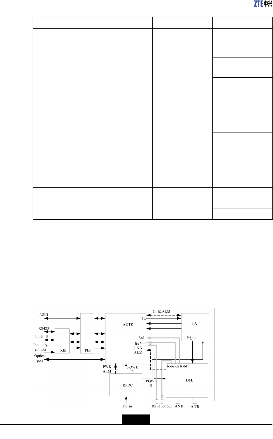
Forgeneralhardwarearchitectureblock,seeFigure3-3
Figure3-3HARDWARESYSTEM
3-4
SJ-20101210110401-002|2011-05-31ZTEProprietaryandCondential
Chapter3StructureandPrinciples
R8860EGU198iscomposedofADTR,PA,DFL,RIE,PIB,andPRDC,asshowninT able
3-3.
Table3-3COMPOSITIONOFM8206CABINETHARDWARE
NameMeaningMainfunctions
ADTR
AdvancedDual-modetransceiver
board
Completesthefunctionoftransmitterbyonepath
andreceiverbytwopaths,providinginterfaceand
control
PARRUPowerAmplyUnit
Providesamplicationfunctionduringtransmission
forRFsignal
DFLDuplexerlterline
Providesreceiving&transmittingcombinationand
divisionfunctionforRFsignal,andprovideslow
noiseamplicationfunctionforsignal.Itincludes
duplexerbyonepathandreceivinglterbyone
path.
RIERRUinterfaceexchangeboard
MainlycompletesthetransitionbetweenPIBboard
testandmonitoringinterfacesignal
PIBProtectiveinterfaceboard
Mainlycompleteselectricallytunedantennaand
toweramplierAISGinterfaceprotectionand
ADTRboardinterfacesignaltransition
RPDCRRUPowerModuleSuppliedbyDCpowerconversion
3.2.2BoardFunctions
1.ADTR
Process2pathsreceivingand1pathtransmittingsignal;
Uplink&downlinktransitionforradiolinksignal;
DownlinkIQsignalmultiplexing,uplinkIQsignaldemultiplexing;
Signalamplication,lter,anddigit/analogconversion;
Opticalandelectricsignalconversion;
Extractclockreferencesignalfrombasebandunit,provideclockfordifferentmodules;
RTWPandTSSImeasurementreport;
Standingwaveratio(SWR)measurementreport
Hardwarefailureself-testandalarm;
EnvironmentDetection;
Provide2pathsofbaseband–RFinterfaceand4pathsofexternalalarminput,anda
serialport,aFEinterface,aRS232interface,andaAISGinterface;
Provideresetfunction.
3-5
SJ-20101210110401-002|2011-05-31ZTEProprietaryandCondential

ZXSDRR8860EGU198UserManual
2.PA
AmplifydownlinkRFsignalinputbyADTR,andoutputittoDFL;
ProvidedigitalpredistortionfeedbacksignalforADTR;
Providepoweramplicationoutputcontrol;
FeedbackforwardpowercouplingsignaltoADTR,andADTRdoforwardpower
inspection;
FeedbackbackwardpowercouplingsignaltoADTR,andADTRdobackwardpower
(SWR)inspection;
ProvidePAinternaltemperaturedatatoADTRandADTRwilldotemperature
inspection.
3.DFL
Combinationandseparationofreceivingandtransmittingsignal;
Filterfunctionofreceiving&transmittingsignal;
Low-noiseamplicationfunction;
ProvideDFLalarminspectionfunction.
4.RIE
AccessfollowingthesesignalsfromPIBboard:Ethernetsignal,485drycontact,LED
indicator,singleboardresetsignal,jumper,buttonsignal,digitalground;
Transmittheaccesssignalbythesocketandnishthefunctionofinterfaceconversion.
5.PIB
AccessfollowingthesesignalsfromADTRboard:Ethernetsignal,LEDindicator,
singleboardresetsignal,jumper,buttonsignal,digitalground,power,groundand
458signalofelectricallytunedantenna;
Power,ground,and458signalofelectricallytunedantenna,outputtoelectricallytuned
antennabysocket;othersignalsareintroducedtooutsidebytestsocket,tododebug
anduseasindicativesignal;
FinishAISGinterfacepowerlteringand485lighteningprotection;
Finishinterferenceprotectionforindicators,resetsignals,buttons,andjumpers.
6.RPDC
FinishpowerconversionfromDCtoDC,andprovidepowersupplyfunction;
Inspectinputovervoltageorundervoltage,inputpowerdisconnection,output
overvoltageorundervoltage,outputover-currentalarm,andreportittoADTRboard.
3-6
SJ-20101210110401-002|2011-05-31ZTEProprietaryandCondential
Chapter3StructureandPrinciples
3.3SoftwareSystem
3.3.1SoftwareArchitecture
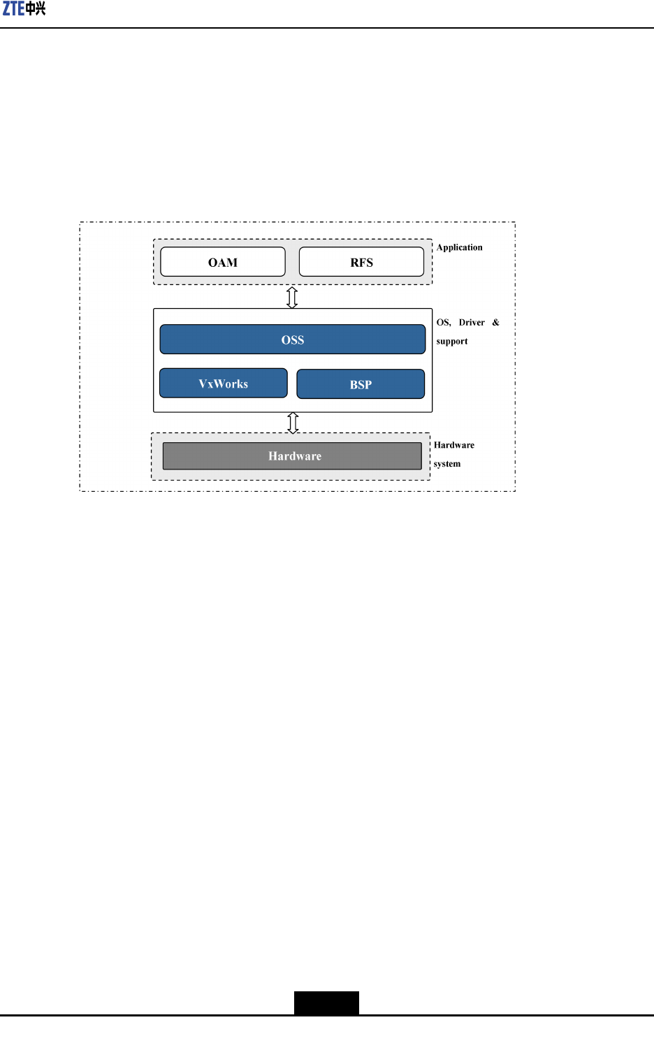
R8860EGU198softwarecanbeclassiedintodrivers,supportingsoftware,and
applicationsoftware,asshowninFigure3-4.
Figure3-4R8860EGU198SOFTWAREARCHITECTURE
3.3.2SoftwareFunctions
Applicationlayerincludesradiofrequencysubsystem(RFS)andoperationand
maintenance(OAM)subsystem,mainlyimplementingsoftwaredownload,conguration,
management,systemmaintenance,andmeasurement.
OperationSupportSub-system(OSS)isthesupportinglayerofwholesoftwareframework,
whichprovidesahardware-unrelatedplatformtorunsystemsoftwareandprovides
basicsoftwarefunction,suchasdispatching,timer,memorymanagement,inter-module
communication,sequencecontrol,monitoring,alarm,andlogfunction.
BoardSupportPackage(BSP)isresponsibleforroutingrelevantinformationanddatato
applicationlayerofGSMorUMTS.
VxWorksistheoperatingsystemofhardwareplatform.
3-7
SJ-20101210110401-002|2011-05-31ZTEProprietaryandCondential

ZXSDRR8860EGU198UserManual
Thispageintentionallyleftblank.
3-8
SJ-20101210110401-002|2011-05-31ZTEProprietaryandCondential
Chapter4
Installation
TableofContents
SafteyDescription......................................................................................................4-1
Preparation................................................................................................................4-7
UnpackingandChecking..........................................................................................4-15
InstallationOverview................................................................................................4-17
CabinetInstallation...................................................................................................4-21
ExternalCableInstallation........................................................................................4-46
HardwareInstallationInspection...............................................................................4-57
Poweronandoff......................................................................................................4-61
4.1SafteyDescription
4.1.1SafetySpecificationsGuide
Thesesafetyinstructionsmustbeconsideredassupplementaryforlocalsafety
regulations.Theprioritymustbegiventolocalsafetyregulationsifthereisanyconict
betweenthetwo.
Themaintenancepersonnelmusthavetheknowledgeofsafetyoperationsand
maintenancewithrequiredqualicationandtechnicalbackground.
Warning!
Thisdevicecomplieswithpart15oftheFCCRules.Operationissubjecttothefollowing
twoconditions:(1)Thisdevicemaynotcauseharmfulinterference,and(2)thisdevice
mustacceptanyinterferencereceived,includinginterferencethatmaycauseundesired
operation.Changesormodicationsnotexpresslyapprovedbythepartyresponsiblefor
compliancecouldvoidtheuser'sauthoritytooperatetheequipment.
Alltheoperationandmaintenancepersonnelmustfollowthesafetyprecautionsand
instructionsprovidedbyZTECorporationtoavoidanyaccident.
4-1
SJ-20101210110401-002|2011-05-31ZTEProprietaryandCondential
ZXSDRR8860EGU198UserManual
Note:
ZTECorporationdoesnotbearanyliabilitiesincurredbecauseofviolationofthe
universalsafetyoperationrequirements,orviolationofsafetystandardsfordesigning,
manufacturingandusingtheequipment.
FCCRadiationExposureStatement:
ThisequipmentcomplieswithFCCradiationexposurelimitssetforthforanuncontrolled
environment.Thisequipmentshouldbeinstalledandoperatedwithminimumdistance4
mbetweentheradiator&yourbody.
FCC&ICStatement
Warning!
Changesormodicationstothisunitnotexpresslyapprovedbythepartyresponsiblefor
compliancecouldvoidtheuser’sauthoritytooperatetheequipment.
Note:
ThisequipmenthasbeentestedandfoundtocomplywiththelimitsforaClassAdigital
device,pursuanttoPart15oftheFCCRules.Theselimitsaredesignedtoprovide
reasonableprotectionagainstharmfulinterferencewhentheequipmentisoperatedin
acommercialenvironment.Thisequipmentgenerates,uses,andcanradiateradio
frequencyenergyand,ifnotinstalledandusedinaccordancewiththeinstructionmanual,
maycauseharmfulinterferencetoradiocommunications.Operationofthisequipment
inaresidentialareaislikelytocauseharmfulinterferenceinwhichcasetheuserwillbe
requiredtocorrecttheinterferenceathisownexpense.
Operationofthisequipmentinaresidentialareaislikelytocauseharmfulinterferencein
whichcasetheuserwillberequiredtocorrecttheinterferenceathisownexpense.
4.1.2SafetySymbols
Table4-1listssafetysymbols.Theyaretoprompttheuserofthesafetyprecautionstobe
observedduringR8860EGU198operationandmaintenance.
4-2
SJ-20101210110401-002|2011-05-31ZTEProprietaryandCondential
Chapter4Installation
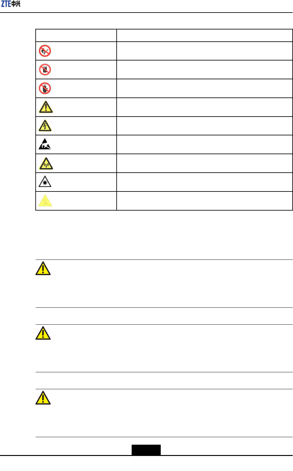
Table4-1SafetySymbolsDescription
SafetySymbolsMeaning
Nosmoking:Smokingisforbidden
Noammables:Noammablescanbestored.
Notouching:Donottouch.
Universalalertingsymbol:Generalsafetyattentions.
Electricshock:Riskofelectricshock.
Electrostatic:Thedevicemaybesensitivetostaticelectricity.
Microwave:Bewareofstrongelectromagneticeld.
Laser:Bewareofstronglaserbeam.
Scald:Bewareofscald.
Amongstthesesafetysymbols,theuniversalalarmsymbolsareclassiedintothreelevels:
danger,warning,andcaution.Theformatsandmeaningsofthethreelevelsaredescribed
asbelow:
Danger!
Indicatesapotentiallyhazardoussituationwhich,ifnotavoided,willresultindeathor
seriousinjuryofpeople,orequipmentdamagesandbreakdown.
Warning!
Indicatesapotentiallyhazardoussituationwhich,ifnotavoided,couldresultindeathor
seriousinjury.
Caution!
Indicatesapotentiallyhazardoussituationwhich,ifnotavoided,couldresultinserious
injuries,equipmentdamagesorinterruptionofpartservices.
4-3
SJ-20101210110401-002|2011-05-31ZTEProprietaryandCondential
ZXSDRR8860EGU198UserManual
4.1.3SafetyInstructions
Thissectiondescribesthesafetyinstructionsrelatedtoelectricalsafety,antistatic,heavy
objectsandmodules.
ElectricalSafetyInstructions
Thefollowingaretheelectricalsafetyinstructionsabouttools,highvoltage,powercables,
holesandlightning:
lTools
Usespecialtoolsratherthancommontoolsforhigh-voltageandACoperations.
lHighVoltage
Danger!
Highvoltageishazardous.Directorindirectcontactwithhighvoltageormainsupply
usingawetobjectcouldresultindeath.
àStrictlyfollowlocalsafetyrulestoinstallACpowerdevices.
àInstallationstaffmustbequaliedforperforminghigh-voltageandACoperations.
àDonotwearanywatch,handchain,bracelet,ringoranyotherconductiveobjects
duringsuchoperations.
àPreventmoisturefromaccumulatingontheequipmentduringoperationsina
dampenvironment.
lPowerCable
Warning!
Neverinstalloruninstallpowercableswhiletheyarelive.Otherwise,thepowercable,
whencontactingaconductor,mayresultinsparksorelectricarccausingareoreven
damagetoeyes.
àMakesureofshuttingoffpowersupplybeforeinstallingordisconnectingapower
cable.
àBeforeconnectingthepowercable,makesurethattheconnectingcableandits
labelareappropriatefortheactualinstallationrequirements.
lDrillingHoles
4-4
SJ-20101210110401-002|2011-05-31ZTEProprietaryandCondential
Chapter4Installation
Warning!
Itisnotallowedtodrillchassisholeswithoutpermission.
àUnqualieddrillingcoulddamagewiringandcablesinsidethechassis.
Additionally,metalpiecesinsidethechassiscreatedbythedrillingcouldresult
inashortcircuit.Useinsulationprotectionglovesandrstmovecablesinsidea
chassisawaywhendrillingisnecessaryonachassis.
àProtecteyesduringdrillingasdustoryingdebrismaydamageeyes.
àCleananydebrisintimeafterdrilling.
lLightning
Danger!
Donotperformhigh-voltage,AC,irontowerormastoperationsinathunderstorm.
Thunderstormswouldgiverisetoastrongelectromagneticeldintheatmosphere.
Therefore,theequipmentmustbegroundedandprotectedintimeagainstlightning
strikes.
AntistaticSafetyInstructions
Caution!
Staticelectricityproducedbyhumanbodycandamagestatic-sensitivecomponentson
circuitboard,suchaslarge-scaleintegratedcircuits.
lFrictioncausedbyhumanbodyactivitiesistherootcauseofelectrostaticcharge
accumulation.Staticvoltagecarriedbyahumanbodyinadryenvironmentcanbe
upto30kV,andcanremainthereforalongtime.Anoperatorwithstaticelectricity
maydischargeelectricitythroughacomponentwhenhe/shetouchestheconductor
andcausingdamage.
lWearanantistaticwriststrap(theotherendofwriststrapmustbewellgrounded)
beforetouchingtheequipmentorholdingaplug-inboard,circuitboard,Integrated
Circuit(IC)chiporotherdevices,topreventhumanstaticelectricityfromdamaging
sensitivecomponents.
lTheantistaticwriststrapusedmustbesubjecttoregularcheck.Donotreplacethe
cableofanantistaticwriststrapwithanyothercables.
4-5
SJ-20101210110401-002|2011-05-31ZTEProprietaryandCondential

ZXSDRR8860EGU198UserManual
lDonotcontactstatic-sensitivemoduleswithanyobjectthateasilygeneratesstatic
electricity.Forexample,frictionofpackagebag,transferboxandtransferbeltmade
frominsulationplasticmaycausestaticelectricityoncomponents.Dischargeofstatic
electricitymaydamagecomponentswhentheycontactahumanbodyortheground.
lModulesshouldonlycontactmaterialssuchasanantistaticbag.Keepmodulesin
antistaticbagsduringstorageandtransportation.
lDischargestaticelectricityofthetestdevicebeforeuse,thatis,groundthetestdevice
rst.
lDonotplacethemodulenearastrongDCmagneticeld,suchasthecathode-ray
tubeofamonitor.Keepthemoduleatleast10cmaway.
HoistingHeavyObjects
Warning!
Whenhoistingheavyobjects,ensurethatnobodyisstandingorwalkingunderthehoisted
object.
lEnsurethehoistercanmeethoistingrequirementswhendisassemblingheavy
equipment,ormovingandreplacingequipment.
lTheinstallationpersonnelmustbedulytrainedandqualiedforhoistingoperations.
lHoistingtoolsmustbeinspectedandcompletebeforeservice.
lMakesurethathoistingtoolsarexedrmlyonasufcientlysecuredobjectorwall
beforethehoistingoperation.
lGivebrieforalinstructionsduringhoistingoperationstopreventanymishap.
Unplugging/PluggingaModule
lNeverplugamodulewithexcessiveforce,toensurethatthepinsonthebackplane
donotgetdeformed.
lPlugthemodulerightintotheslotandmakesuremodulecircuitfacesdonotcontact
eachotherlestanyshortcircuitmayoccur.
lKeephandsoffthemodulecircuit,components,connectorsandcabletroughwhen
holdingamodule.
RackMountSafetyInstructions
RackMountInstructions-Thefollowingorsimilarrack-mountinstructionsareincluded
withtheinstallationinstructions:
lElevatedOperatingAmbient-Ifinstalledinaclosedormulti-unitrackassembly,the
operatingambienttemperatureoftherackenvironmentmaybegreaterthanroom
ambient.Therefore,considerationshouldbegiventoinstallingtheequipmentinan
environmentcompatiblewiththemaximumambienttemperature(Tma)speciedby
themanufacturer.
4-6
SJ-20101210110401-002|2011-05-31ZTEProprietaryandCondential

Chapter4Installation
lReducedAirFlow-Installationoftheequipmentinarackshouldbesuchthatthe
amountofairowrequiredforsafeoperationoftheequipmentisnotcompromised.
lMechanicalLoading-Mountingoftheequipmentintherackshouldbesuchthata
hazardousconditionisnotachievedduetounevenmechanicalloading.
lCircuitOverloading-Considerationshouldbegiventotheconnectionofthe
equipmenttothesupplycircuitandtheeffectthatoverloadingofthecircuitsmight
haveonovercurrentprotectionandsupplywiring.Appropriateconsiderationof
equipmentnameplateratingsshouldbeusedwhenaddressingthisconcern.
lReliableEarthing-Reliableearthingofrack-mountedequipmentshouldbe
maintained.Particularattentionshouldbegiventosupplyconnectionsotherthan
directconnectionstothebranchcircuit(e.g.useofpowerstrips).
OtherSafetyInstructions
Note:
Donotperformmaintenanceordebuggingindependently,unlessaqualiedpersonis
present.
lPerformanairtighttestbeforeRRUdelivery,andprohibitdisassemblingtheRRUon
site.
lReplacinganypartsormakinganychangestotheequipmentmightresultinan
unexpecteddanger.Therefore,besurenottoreplaceanypartsorperformany
changestotheequipmentunlessauthorizedotherwise.
lDuetothatRRUisinhightemperatureduringrunning,theRRUshouldbeinstalled
insomeregionsoutofoperators'reachorstrictlyrestricted.
lContactZTEofceifyouhaveanyquestion,toensureyoursafety.
4.2Preparation
R8860EGU198istheoutdoordual-modeRFremoteunitintheZTEZXSDRseriesbase
stationproducts.
ZTECorporationhaslaunchedaseriesofbasestationproductstosatisfyvarious
requirementsofoperators.Oneofthesolutionsisdividingthebasestationintotwoparts:
BaseBandUnit(BBU)andRemoteRadioUnit(RRU).R8860EGU198istheoutdoor
RRU,anditworkswithBBUtorealizecompletelogicalfunctionsofabasestation.
R8860EGU198adoptsthemulti-carriertechnologyasitscoretechnology.Itsupportstwo
radiosystems:GSMandUMTS.R8860EGU198canbeusedasanindependentRRU
forGSMoranindependentRRUforUMTS,anditworkswithBBUtoformthedual-mode
basestation.
4-7
SJ-20101210110401-002|2011-05-31ZTEProprietaryandCondential

ZXSDRR8860EGU198UserManual
4.2.1EngineeringConditionInspection
Beforeinstallingdevices,followtherequirementsofEnvironmentAcceptanceReportand
checkinstallationenvironment.Thefollowingcontentisjustasareference.
InstallationPositionInspection
R8860EGU198installationpositionshouldaccordwiththerequirementsofengineering
design,thespeciedrequirementsasfollows:
lAvoiddusty,harmful-gasorexplosive-goodsenvironment;
lAvoidtheplaceswithbigshockorstrongnoise;
lFarawaysubstation;
lFarawaypollutionsource;
lAvoidanindustrialboilerandheatingboiler;
lFarawayhigh-powerwirelessinterferencesource.
TemperatureandHumidityInspection
R8860EGU198temperatureandhumidityinworkenvironmentshouldmeetthe
requirements,asshownin
PowerSupplyInspection
TherequirementsofR8860EGU198powersupplyaredescribedasfollows.
1.DCpowersupply:R8860EGU198is–48VDCpowersupplyandthevoltageofpower
supplyis–40VDC~–57VDC.
2.IndirectACpowersupply:adoptanoutdoorACunit(OAU);theOAUcanprovide220V
ACpowersupplyforoneZXSDRB8200C100andoneR8860EGU198atthesame
time.
LightningInspection
TheR8860EGU198lightningrequirementsaredescribedasfollows.
lOutdoorInstallation
1.ForDCpowersupply,congureanoutdoorDClightningboxOLP48-2.Ifthe
DCpowerisexportedfromtheequipmentroom,thelengthofpowercableis
morethan10m(lessthan50m)andtheoutputendofindoorDCpowerisnot
conguredwithB-levelorabovelightningdevices,itisrequiredtocongurean
indoorDClightningboxILP48–3intheequipmentroom.
2.ForindirectACpowersupply,itisrequiredtocongureanAClightningbox
(ZXPCScombinedarrester).
lForindoorinstallation,ifthepowercableisdistributedoutdoors,congurethepower
lightningboxaccordingtotheconditionsofoutdoorinstallation.
4-8
SJ-20101210110401-002|2011-05-31ZTEProprietaryandCondential

Chapter4Installation
GroundingInspection
R8860EGU198adoptsanassociatedgroundingmode.Thevalueofgroundingresistance
isnotmorethan5ohm.
OtherInspections
1.ThecorollarydevicesorcomponentsshouldaccordwiththerequirementsofR8860E
GU198engineeringdesigndrawing.
2.ThetransmissiondevicesinterconnectedwithBBUshouldhavebeenprepared.
4.2.2RequirementstoOnsitePersonnel
Theonsiteengineeringsupervisorisinchargeofthetrainingandmanagementof
installationpersonnel,tomakesuretheinstallationisperformedcorrectlyandcontrol
installationquality.Theinstallationpersonnelperformtheinstallation.RefertoSafety
Instruction.
RequirementstoEngineeringSupervisor
lTheengineeringsupervisorshouldhavequalitycontrolability.
lTheengineeringsupervisorshouldhavereceivedcorrespondingZTEtrainingand
obtainedcertication.
lTheengineeringsupervisorshouldbefamiliarwiththematerials,toolsandoperation
methodsusedintheinstallation.
lTheengineeringsupervisorshouldbefamiliarwiththeinstallationowandinstallation
methodsofeachcomponent.
lTheengineeringsupervisorshouldfollowthe“SafetyFirst”principle,toensurethe
smoothcompletionofinstallation.
RequirementstoInstallationPersonnel
lTheinstallationpersonnelshouldhavereceivedcorrespondingZTEtrainingand
obtainedcertication.
lTheinstallationpersonnelshouldbehealthy,havenotdrunkalcohol.
lTheinstallationpersonnelshouldfollowthesafetyinstructionsoftools,andusesafety
belts.
lTheinstallationpersonnelshouldfastenthetools,topreventthemfromfalling.
lTheinstallationpersonnelshouldnotwearlooseclothesandslipperyshoes.
4.2.3TechnicalDocumentPreparation
BeforeinstallingR8860EGU198,makesurethatthefollowingtechnicaldocumentisat
hand:
lZXSDRR8860EGU198GU858OutdoorGSM&UMTSDualModeMacroRRUUser
Manual
4-9
SJ-20101210110401-002|2011-05-31ZTEProprietaryandCondential

ZXSDRR8860EGU198UserManual
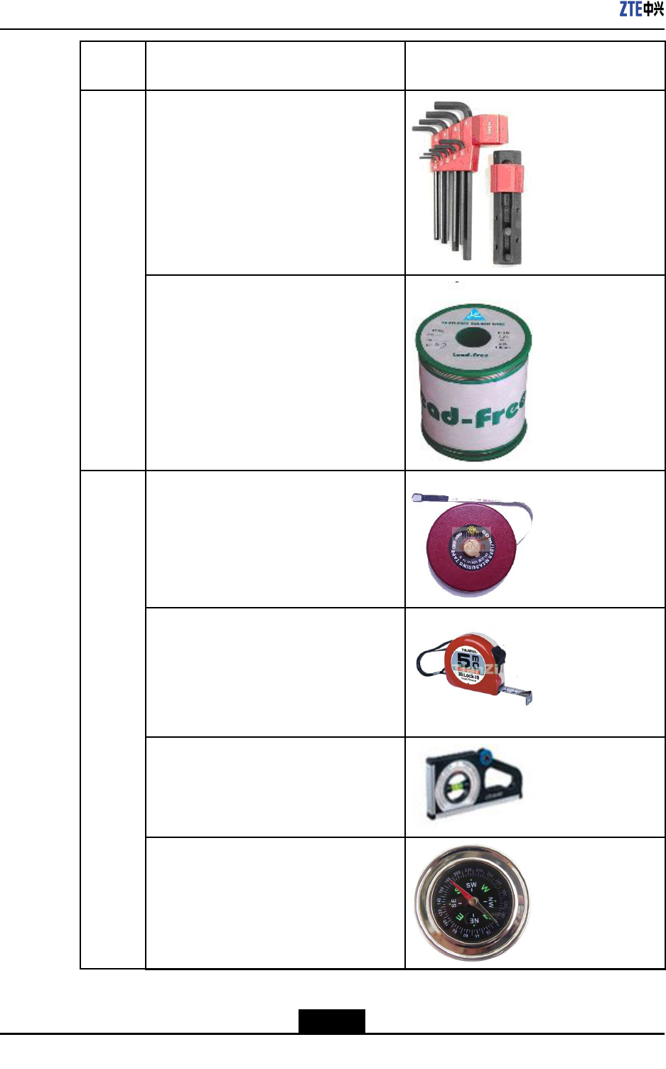
4.2.4ToolsandInstrumentsPreparation
Table4-2showstoolsandmeterslistrequiredduringinstallation.
Table4-2ToolandMeterList
Cate-
goryNameExample
Onefeederconnectorknife
One75Ωcoaxialcablestripper
Onemulti-functionalcrimpingpliers
Onemultimeter
Onestandingwaveratiotester
Special-
purpose
tools
Oneearthresistancetester
Oneelectricpercussiondrill
Severalauxiliarypercussiondrillbits
Punch-
ingtools
4-10
SJ-20101210110401-002|2011-05-31ZTEProprietaryandCondential

Chapter4Installation
Cate-
goryNameExample
Onevacuumcleaner
Powerconnectorboard(providingatleast3
two-phasesocketsand3three-phasesock-
ets,withthecurrentcapacitylargerthan15
A)
Crossscrewdrivers(4”,6”and8”each)
Flatheadscrewdrivers(4”,6”and8”each)
Adjustablewrenches(6”,8”,10”and12”
each)
Dual-purposewrenches(17”and19”each)
Onesetofsocketwrenches
Onepaperknife
5kgnailhammer
One300Wironandone40Wiron
General-
purpose
tools
4-11
SJ-20101210110401-002|2011-05-31ZTEProprietaryandCondential
ZXSDRR8860EGU198UserManual
Cate-
goryNameExample
Onesetofinner-hexagonwrench
Solderwires
One50m(164feet)tapemeasure
One5m(16feet)steeltape
Oneangleinstrument
Onecompass
Mea-
sure-
ment
tools
4-12
SJ-20101210110401-002|2011-05-31ZTEProprietaryandCondential
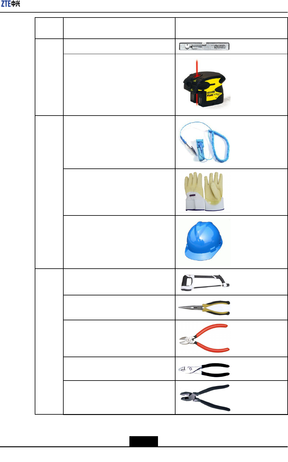
Chapter4Installation
Cate-
goryNameExample
Onelevelbar
Oneplumb
Antistaticwriststrap
slip-proofgloves
Protec-
tiontools
Safetyhelmet
Onehacksaw(withseveralsawblades)
Onepairofsharp-nosepliers(8″)
Onepairofdiagonalpliers(8″)
Onepairofround-nosepliers(8″)
Onepairofvices(8″)
Clamp
tools
4-13
SJ-20101210110401-002|2011-05-31ZTEProprietaryandCondential

ZXSDRR8860EGU198UserManual
Cate-
goryNameExample
Onesetofneedleles(medium-sized)
Nippers
Onepaintbrush
Onepairofscissors
Onehotairblower
Onesolderremovaltool
Onehydrauliccrimper
Onecrowbar
Pulleyset
Rope
Auxiliary
tools
4-14
SJ-20101210110401-002|2011-05-31ZTEProprietaryandCondential
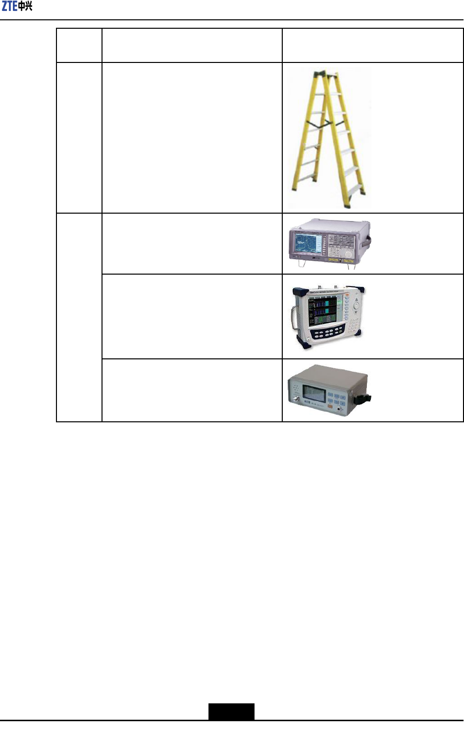
Chapter4Installation
Cate-
goryNameExample
Ladder
Spectrumanalyzer(requiredincertainspe-
cialcases)
BTStester
Meters
Fieldstrengthtester(requiredincertainspe-
cialcases)
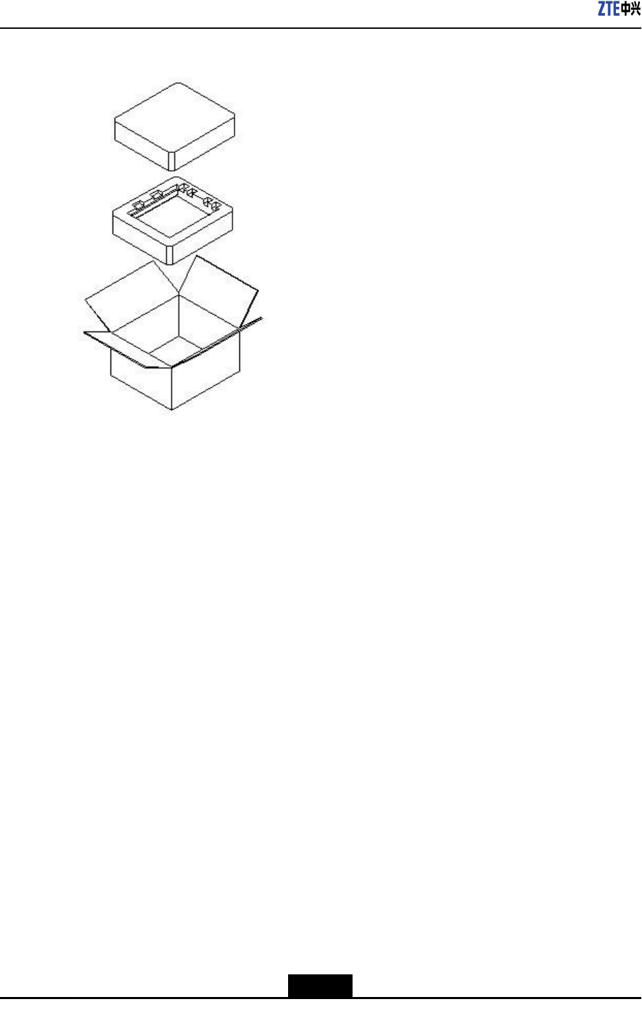
4.3UnpackingandChecking
4.3.1ContainerofR8860EGU198
R8860EGU198usescartonsforpacking.TheR8860EGU198cabinetiswrappedbyEPE
polyfoamandthenputintothecarton,asshowninFigure4-1.
4-15
SJ-20101210110401-002|2011-05-31ZTEProprietaryandCondential
ZXSDRR8860EGU198UserManual
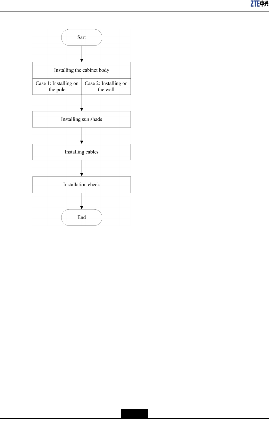
Figure4-3R8860EGU198InstallationFlow
4.4.2HoistingOperationInstructions
IfitisrequiredtohoistRRUtothetower,refertothefollowinginstructions.
Prerequisites
lNaturalconditionsforhoistingoperationaresatised,suchasnofogandhighvisibility.
Thehoistingoperationisprohibitedinwindy,snowy,orrainydays.
lToolsforhoistingoperationareavailable,suchasthehoistingrope(withabearing
capacityof100kg)andthecrownblock,andthecrownblockisrmlyinstalledin
appropriatepositiononthetower.
lOpenthepackagetocheckwhetherthecabinetisingoodcondition.Hoistthecabinet
tothetoweraftertheinspection.
Procedure
Performthefollowingstepsforhoistingoperation.
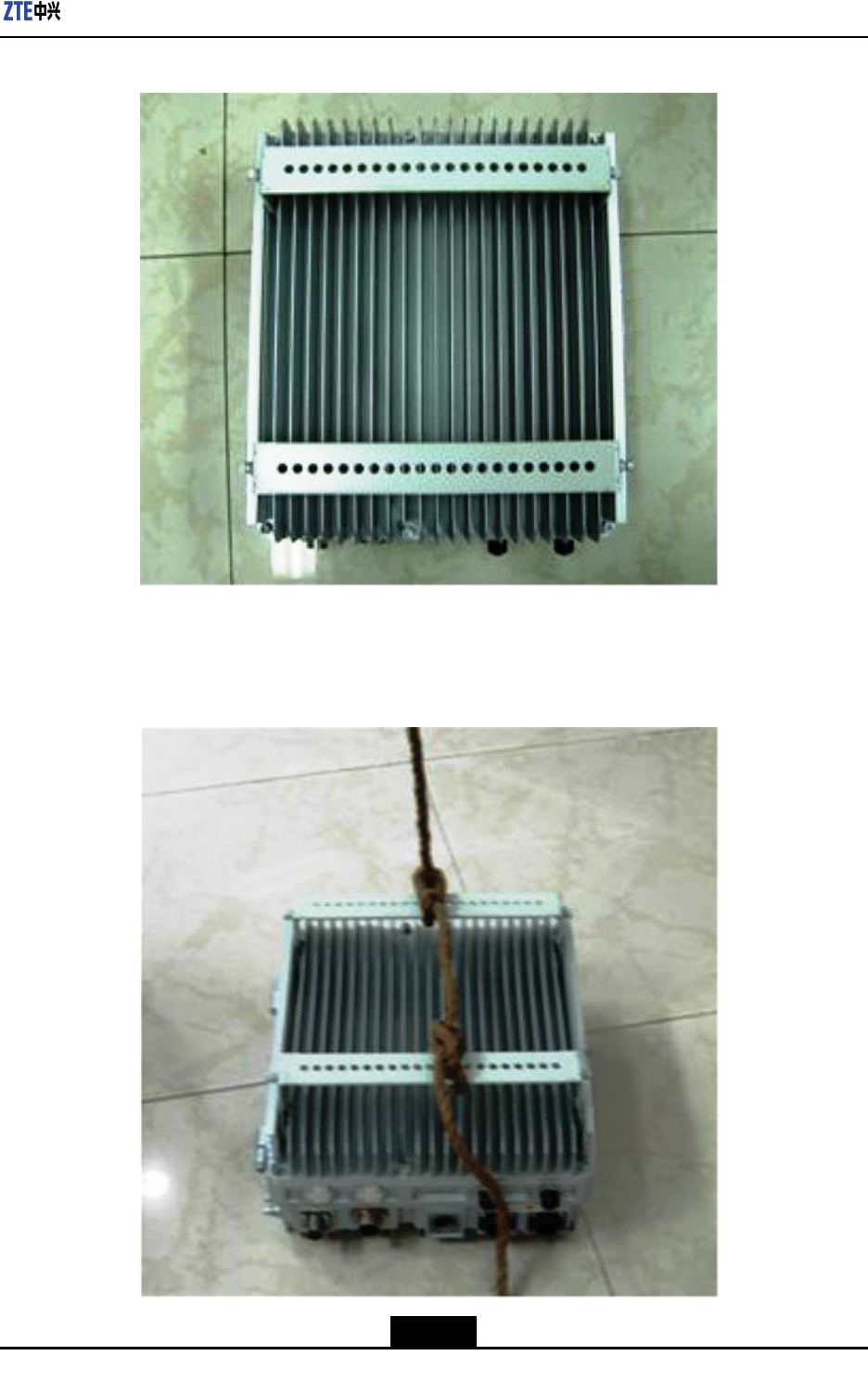
1.T akeoutthecabinet,makeitsxingboardupwards,andlayitontheoor,asshown
inFigure4-4.
4-18
SJ-20101210110401-002|2011-05-31ZTEProprietaryandCondential
ZXSDRR8860EGU198UserManual
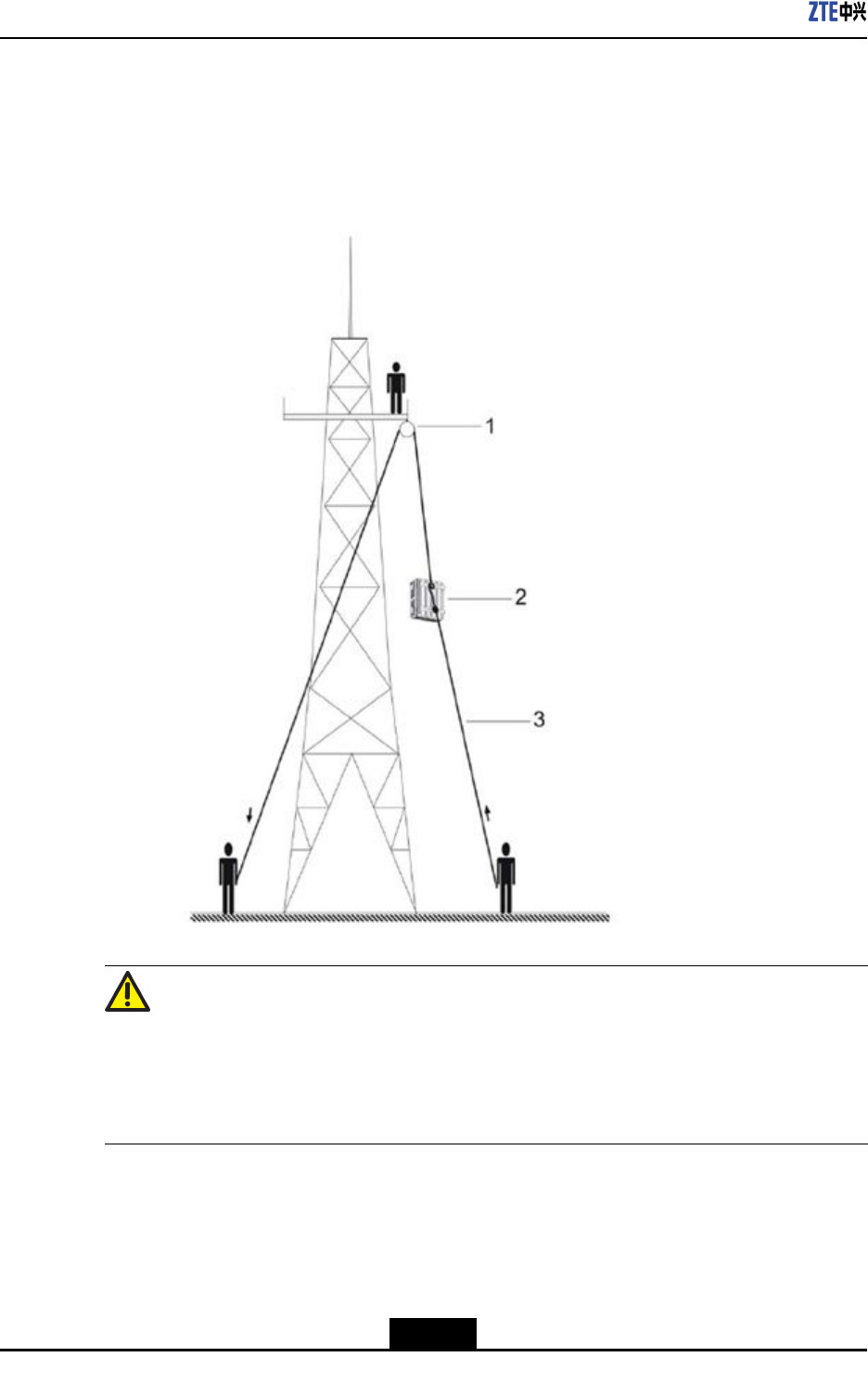
3.Whenperformingthehoistingoperation,twopersonsstandatthefootofthetower.
Onepullstheropeslowly,theotheronereleasestheropeslowlyandpreventsthe
cabinetfromtouchingthetower,protectingtheheatsinkdeviceandthecabinet,as
showninFigure4-6.
Figure4-6HoistingOperationSchematicDiagram
Warning!
lTheRRUhandlecannotbeusedforbindingthehoistingrope.
lItisstrictlyprohibitedtousesteelwireropeasthehoistingrope.
lDuringthehoistingprocedure,irrelevantpersonisprohibitedtostandsurroundingthe
tower,especiallyundertheRRU,toavoidunexpectedinjury.
4-20
SJ-20101210110401-002|2011-05-31ZTEProprietaryandCondential