ZTE R8882L718 LTE Remote Radio Unit User Manual Users manual
ZTE Corporation LTE Remote Radio Unit Users manual
ZTE >
Users manual

ZXSDRR8882L200
LTERemoteRadioFrequencyUnit
UserManual
Version:V2.00
ZTECORPORATION
No.55,Hi-techRoadSouth,ShenZhen,P .R.China
Postcode:518057
Tel:+86-755-26771900
Fax:+86-755-26770801
URL:http://support.zte.com.cn
E-mail:support@zte.com.cn
LEGALINFORMATION
Copyright©2014ZTECORPORATION.
Thecontentsofthisdocumentareprotectedbycopyrightlawsandinternationaltreaties.Anyreproductionor
distributionofthisdocumentoranyportionofthisdocument,inanyformbyanymeans,withoutthepriorwritten
consentofZTECORPORATIONisprohibited.Additionally,thecontentsofthisdocumentareprotectedby
contractualcondentialityobligations.
Allcompany,brandandproductnamesaretradeorservicemarks,orregisteredtradeorservicemarks,ofZTE
CORPORATIONoroftheirrespectiveowners.
Thisdocumentisprovided“asis”,andallexpress,implied,orstatutorywarranties,representationsorconditions
aredisclaimed,includingwithoutlimitationanyimpliedwarrantyofmerchantability,tnessforaparticularpurpose,
titleornon-infringement.ZTECORPORATIONanditslicensorsshallnotbeliablefordamagesresultingfromthe
useoforrelianceontheinformationcontainedherein.
ZTECORPORATIONoritslicensorsmayhavecurrentorpendingintellectualpropertyrightsorapplications
coveringthesubjectmatterofthisdocument.ExceptasexpresslyprovidedinanywrittenlicensebetweenZTE
CORPORATIONanditslicensee,theuserofthisdocumentshallnotacquireanylicensetothesubjectmatter
herein.
ZTECORPORATIONreservestherighttoupgradeormaketechnicalchangetothisproductwithoutfurthernotice.
UsersmayvisittheZTEtechnicalsupportwebsitehttp://support.zte.com.cntoinquireforrelatedinformation.
TheultimaterighttointerpretthisproductresidesinZTECORPORATION.
RevisionHistory
RevisionNo.RevisionDateRevisionReason
R1.02011–01–19FirstEdition
SerialNumber:SJ-20110104194923-001
PublishingDate:2011-01-19(R1.0)
SJ-20110104194923-001|2011-01-19(R1.0)ZTEProprietaryandCondential

Contents
AboutThisManual.........................................................................................I
Chapter1FCCStatement..........................................................................1-1
Chapter2ProductOverview.....................................................................
2-1
2.1DistributedeNodeBSolution...............................................................................2-1
2.2ProductPositioninNetwork................................................................................
2-3
2.3ProductFeatures................................................................................................2-4
2.4ProductFunctions..............................................................................................
2-4
2.5ProductAppearance...........................................................................................2-4
2.6InstallationScenario...........................................................................................
2-5
2.7ProductNetworking............................................................................................2-5
2.8OperationandMaintenanceIntroduction..............................................................2-6
2.9ProductExternalInterfaces.................................................................................2-7
2.10ProductIndicators............................................................................................
2-9
Chapter3ProductTechnicalSpecications............................................
3-1
3.1PhysicalIndices.................................................................................................3-1
3.2WorkingEnvironment.........................................................................................3-1
3.3Bandwidth..........................................................................................................3-2
3.4PowerRequirements..........................................................................................
3-2
3.5PowerConsumption...........................................................................................
3-2
3.6TransmissionIndex............................................................................................
3-2
3.7PerformanceIndices...........................................................................................
3-2
3.8ElectromagneticCompatibility.............................................................................
3-3
3.9Reliability...........................................................................................................
3-5
Chapter4ProductInstallation..................................................................4-1
4.1SafetyDescription..............................................................................................
4-1
4.1.1SafetySpecicationsIntroduction..............................................................4-1
4.1.2SafetySymbols........................................................................................4-1
4.1.3SafetyOperationGuidance.......................................................................4-3
4.2DeviceUnpackingandInspection........................................................................
4-5
4.2.1UnpackingandCheckingZXSDRR8882L200...........................................
4-5
4.2.2GoodsHandover......................................................................................4-6
4.3DeviceInstallation..............................................................................................
4-6
4.3.1MountingDeviceonWall..........................................................................4-6
I
SJ-20110104194923-001|2011-01-19(R1.0)ZTEProprietaryandCondential

4.3.2MountingDeviceonPole........................................................................4-10
4.3.3MountingDeviceonGantry.....................................................................4-19
4.4CablesConnection...........................................................................................4-23
4.4.1ConnectionofExternalCables................................................................
4-23
4.4.2ExternalCableInstallationFlow..............................................................4-24
4.4.3ConnectingPowerCable........................................................................
4-25
4.4.4ConnectingGroundingCable..................................................................4-28
4.4.5ConnectingFiberBetweeneBBUandeRRU............................................
4-30
4.4.6ConnectingEnvironmentMonitorCable...................................................
4-32
4.4.7ConnectingAISGControlCable..............................................................
4-33
4.4.8ConnectingtheRFJumpers....................................................................4-34
Figures.............................................................................................................I
Tables............................................................................................................III
Glossary.........................................................................................................V
II
SJ-20110104194923-001|2011-01-19(R1.0)ZTEProprietaryandCondential
AboutThisManual
Purpose
Thismanualgivesintroductionontheproductdescription,technicalindices,andproduct
installation.
IntendedAudience
lHardwareInstallationEngineer
lOperationandMaintenanceEngineer
PrerequisiteSkillandKnowledge
Tousethisdocumenteffectively,usersshouldhaveageneralunderstandingofwireless
telecommunicationstechnology.FamiliaritywithLTEwirelessnetworkanditsrelated
componentsishelpful.
WhatisinThisManual
ChapterSummary
Chapter1,FCCStatementIntroducestheFCCstatementsthatthisdevicecomplies
with
Chapter2,ProductOverviewDescribesproductcharacteristic,interfaces,indicators
Chapter3,ProductT echnicalIndicesDescribesthetechnicalindicesoftheproduct
Chapter4,ProductInstallationDescribesinstallationandcableconnectionofthe
product
I
SJ-20110104194923-001|2011-01-19(R1.0)ZTEProprietaryandCondential

Thispageintentionallyleftblank.
II
SJ-20110104194923-001|2011-01-19(R1.0)ZTEProprietaryandCondential
Chapter1
FCCStatement
FCC&ICStatement
ThisdevicecomplieswithPart15oftheFCCRules.Operationissubjecttothefollowing
twoconditions:
lThisdevicemaynotcauseharmfulinterference.
lThisdevicemustacceptanyinterferencereceived,includinginterferencethatmay
causeundesiredoperation.
Note:
ThisequipmenthasbeentestedandfoundtocomplywiththelimitsforaClassAdigital
device,pursuanttoPart15oftheFCCRules.Theselimitsaredesignedtoprovide
reasonableprotectionagainstharmfulinterferencewhentheequipmentisoperatedin
acommercialenvironment.Thisequipmentgenerates,uses,andcanradiateradio
frequencyenergyand,ifnotinstalledandusedinaccordancewiththeinstructionmanual,
maycauseharmfulinterferencetoradiocommunications.
Operationofthisequipmentinaresidentialareaislikelytocauseharmfulinterferencein
whichcasetheuserwillberequiredtocorrecttheinterferenceathisownexpense.
Caution!
Changesormodicationstothisunitnotexpresslyapprovedbythepartyresponsiblefor
compliancewillvoidtheuser’sauthoritytooperatetheequipment.Anychangetothe
equipmentwillvoidFCCandICgrant.
FCCRadiationExposureStatement
ThisequipmentcomplieswithFCCradiationexposurelimitssetforthforanuncontrolled
environment.Thisequipmentshouldbeinstalledandoperatedwithminimumdistance6.24
mbetweentheradiator&yourbody.
1-1
SJ-20110104194923-001|2011-01-19(R1.0)ZTEProprietaryandCondential

ZXSDRR8882L200UserManual
Thispageintentionallyleftblank.
1-2
SJ-20110104194923-001|2011-01-19(R1.0)ZTEProprietaryandCondential

Chapter2
ProductOverview
TableofContents
DistributedeNodeBSolution.......................................................................................2-1
ProductPositioninNetwork........................................................................................2-3
ProductFeatures........................................................................................................2-4
ProductFunctions......................................................................................................2-4
ProductAppearance...................................................................................................2-4
InstallationScenario...................................................................................................2-5
ProductNetworking....................................................................................................2-5
OperationandMaintenanceIntroduction....................................................................2-6
ProductExternalInterfaces........................................................................................2-7
ProductIndicators......................................................................................................2-9
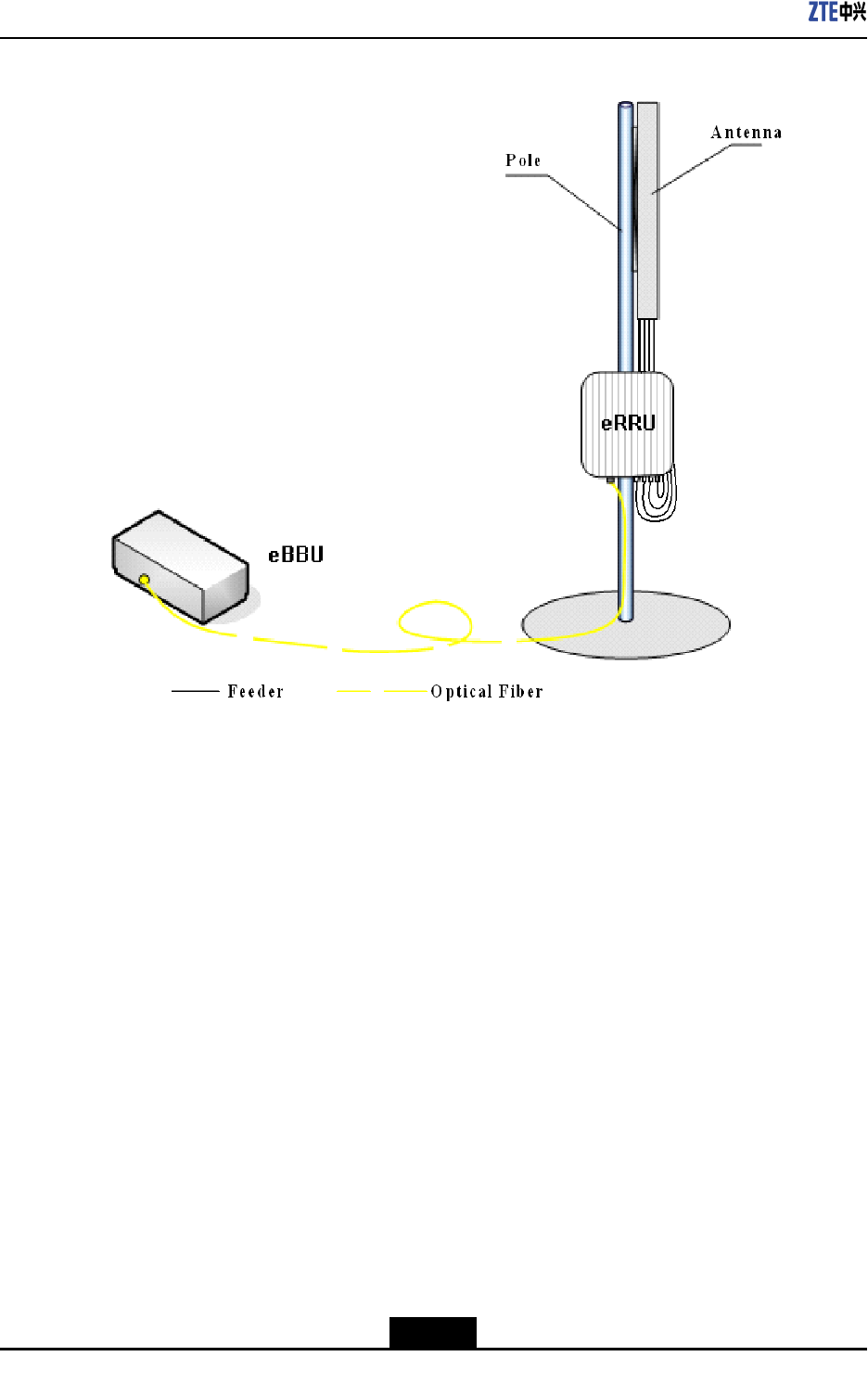
2.1DistributedeNodeBSolution
Tosupplycustomerswithmorecompetitivecommunicationequipmentandsolutioninthe
market,ZTEdevelopsandpromotesZTESDReBBU(basebandunit)andeRRU(remote
radiounit)distributedeNodeBsolutiontimely,whichjointlyperformLTEeNodeBservice.
ZTEdistributedeNodeBsolutionisshowninFigure2-1.
2-1
SJ-20110104194923-001|2011-01-19(R1.0)ZTEProprietaryandCondential
ZXSDRR8882L200UserManual
Figure2-1ZTEDistributedeNodeBSolution
ZTE'sLTEeBBU+eRRUdistributedeNodeBsolutionhasthefollowingpredominance:
1.Savinglaborcostandengineeringcostfornetworking.
eBBU+eRRUdistributedeNodeBequipmentissmallinsize,lightinweight,andeasy
fortransportationandengineeringconstruction.
2.Fastnetworking,alsosavingthefeesofrentingequipmentroom.
eBBU+eRRUdistributedeNodeBisapplicabletovarioussites,suchasmountedon
steeltower,onbuildingtop,oronwall,etc.It'smoreexibleinselectinginstallation
site,andnotrestrictedbythespaceofequipmentroom.Itcanhelpoperatorstodeploy
networkrapidly.Itcanalsosavethefeesofrentingequipmentroom,andthenetwork
operationcost.
3.Convenientinupgradeandcapacityexpansion;savingtheinitialstagecostofthe
network.
eRRUcanbemountedasclosetoantennaaspossible,tosavethecostoffeedcable
anddecreasethelossoffeedcable.ItalsocanenhancetheoutputpowerofeRRU
andincreasethecoverage.
4.Lowpowerconsumption,power-saving.
2-2
SJ-20110104194923-001|2011-01-19(R1.0)ZTEProprietaryandCondential
Chapter2ProductOverview
ComparedwithtraditionaleNodeB,eBBU+eRRUdistributedeNodeBhaslowerpower
consumption,whichcangreatlyreducetheinvestmentandcostonelectricpower,and
thussavethenetworkoperationcost.
5.Distributednetworking,makinggooduseofoperators'networkresourcessupporting
eBBU+eRRUdistributednetworking;supportingstarnetworkingmodebetweeneBBU
andeRRU.
6.AdoptingamoreperspectiveandgeneralizedeNodeBplatform.
eBBUadoptstheplatformdesignedforthefutureB3Gand4G.Onehardwareplatform
canrealizedifferentstandardmodes,andseveralstandardmodescancoexistinone
eNodeB.Inthisway,operators'managementcanbesimplied,andseveraleNodeBs
tobeinvestedcanbeintegratedintooneeNodeB(multimodeeNodeB).Theoperators
canselecttheevolutiondirectionofthefuturenetworkmoreexibly.
2.2ProductPositioninNetwork
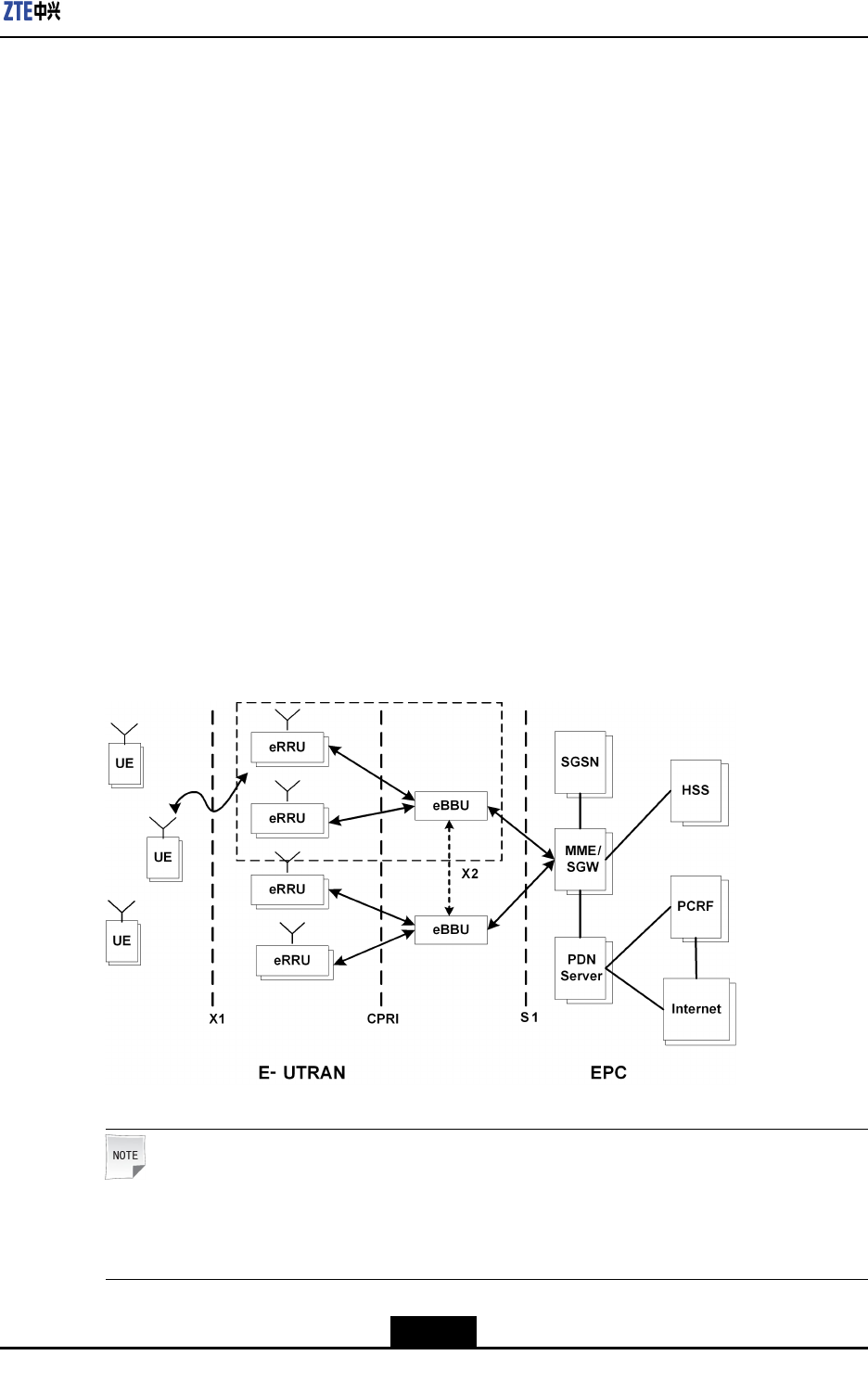
ZXSDRR8882L200isaremoteradiounit(eRRU)ofdistributedeNodeB.Thesignalis
transmittedorreceivedthroughZXSDRR8882L200toandfrombasebandprocessing
unitforfurtherprocessingthroughCPRIinterface.Byapplyingthedistributedsystem,the
feederlosswillbereducedwhentheremoteradiounitispositionedclosetotheantenna.
Thecoverageisenlargedwiththissolution.
Figure2-2ProductLocation
Note:
ZXSDRR8882L200coversR8882L188,R8882L708,R8882L808,R8882L268and
R8882L718.
2-3
SJ-20110104194923-001|2011-01-19(R1.0)ZTEProprietaryandCondential

ZXSDRR8882L200UserManual
2.3ProductFeatures
Multi-ModeeRRU
ZXSDRR8882L200isfullysoftwaredeneddevice.Itsupportsmulti-modeatthesame
frequencybandsimultaneously.Therefore,itfullysatisesoperators’requirementsof
hybridnetworkdeploymentandlongtermevolutionwiththelowestcost.
MIMOSupported,BetterPerformance
R8882L268supports2T4R(licenseneeded),R8882L188,R8882L708,R8882L808and
R8882L718support2T2R,whichcanoptimizespectrumefciencygreatlyandimprove
networkuplinkperformance.Asaresult,itbringsbettercustomerexperience.
HigherEfciency,LowerTCO
lZXSDRR8882L200’sPAefciencycanreachupto30%thankstothemostadvanced
DohertyPA,DPDlineartechnology.
lItsupportsdynamicadaptivePApowersupplyduetotheoutputpower,whichreduces
powerconsumption.
2.4ProductFunctions
ZXSDRR8882L200istheremoteradiounitofdistributedbasestation.Thesignalis
transmittedorreceivedthroughZXSDRR8882L200to/frombasebandprocessingunit
forfurtherprocessingviastandardCPRIinterface.
Theproductbasicfunctionsarelistedbelow:
lSupportsthecongurationof5MHz,10MHz,15MHzand20MHzscalable
bandwidth.
lSupports2x2MIMOondownlink.
lSupportsQPSK,16-QAM,64-QAMondownlink,QPSKand16–QAMonuplink.
lSupportstransmissionandreceivepowerdetection.
lSupportsoverloadpowerprotectionforpoweramplier.
lSupportspoweramplierswitchingon/offfunction.
lZXSDRR8882L200softwarefailurewillnotaffecttherunningofeBBUandother
ZXSDRR8882L200swhichareconnectedtoit.
lSupportseldstrengthscanning,temperaturequery,VSWRquery,drycontact,
hardware/softwareresetting.
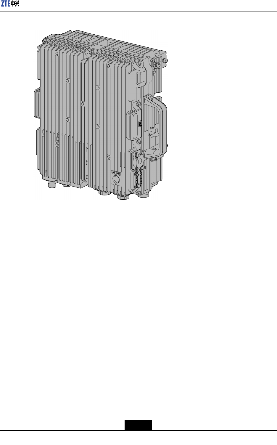
2.5ProductAppearance
TheappearanceofZXSDRR8882L200isasshowninFigure2-3.
2-4
SJ-20110104194923-001|2011-01-19(R1.0)ZTEProprietaryandCondential
ZXSDRR8882L200UserManual
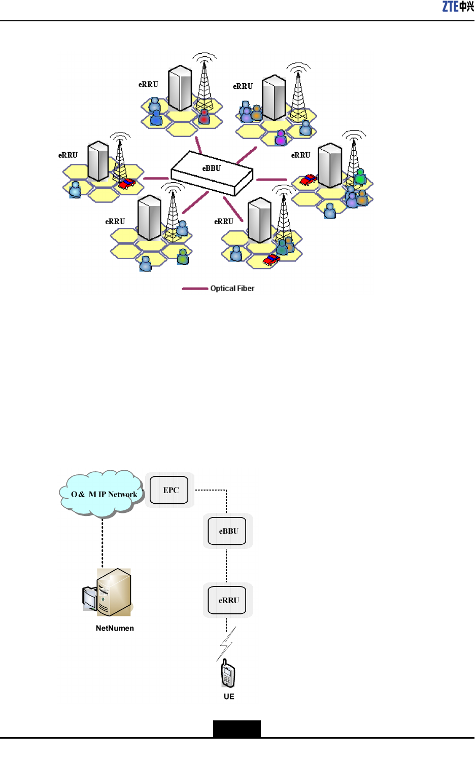
Figure2-4StarNetworkingMode
2.8OperationandMaintenanceIntroduction
ZXSDRR8882L200supportssystemoperationandmaintenanceremotelyorlocally.
OperateandMaintainSystemRemotely
RemotelyoperatesandmaintainssystembyusingNetNumenmanagementsystem,as
showninFigure2-5.
Figure2-5OperateandMaintainSystemRemotely
2-6
SJ-20110104194923-001|2011-01-19(R1.0)ZTEProprietaryandCondential
Chapter2ProductOverview
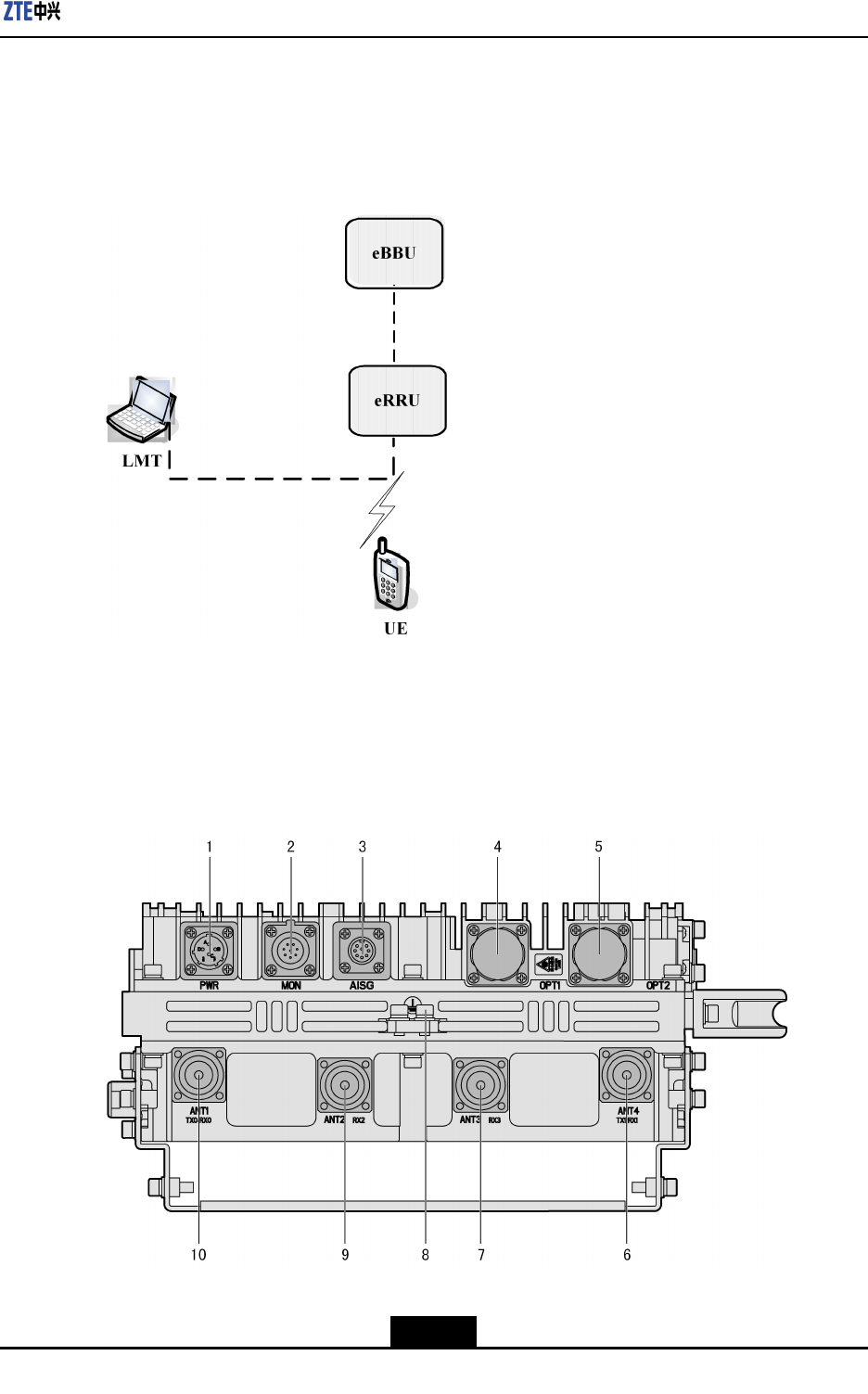
OperateandMaintainSystemLocally
locallyoperatesandmaintainssystembyusingZTE’sLocalMaintenanceTerminal(LMT)
softwarekit,asshowninFigure2-6.
Figure2-6OperateandMaintainSystemLocally
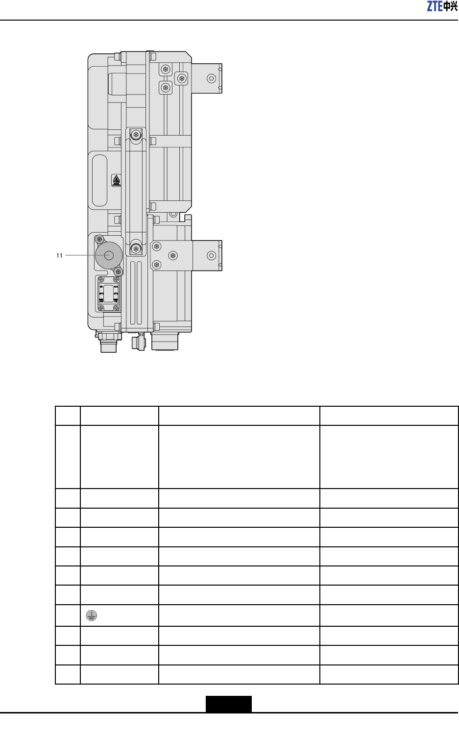
2.9ProductExternalInterfaces
TheZXSDRR8882L200externalinterfacesareshowninFigure2-7andFigure2-8.
Figure2-7ProductExternalInterfacesandGroundingTerminal
2-7
SJ-20110104194923-001|2011-01-19(R1.0)ZTEProprietaryandCondential
ZXSDRR8882L200UserManual
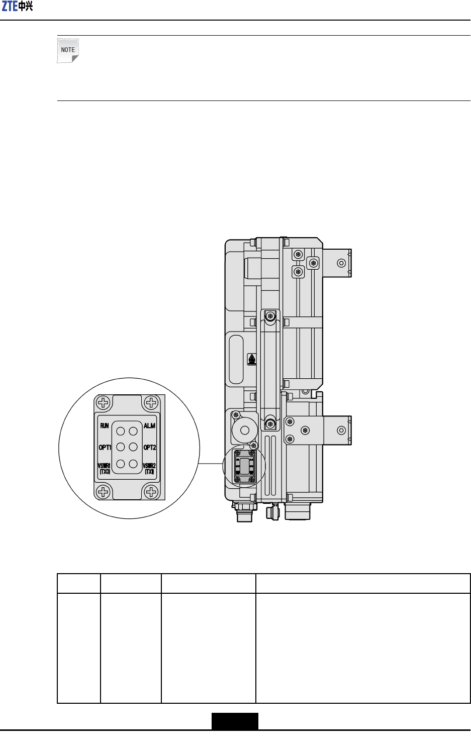
Figure2-8LMTInterface
Table2-1showsthedetaileddescriptionofalltheexternalinterfaces.
Table2-1ProductExternalInterfacesDescription
No.LabelInterface/TerminalInterfacetype/connector
1PWRPowerinterface/1drycontactDCinterface:
ConnectorXCG18T4K1P1-
01+XC18FJJP1-10.5
Sectionareaofcableis1.5mm2
2MON485Serial/2drycontacts8-coressocket(IEC60130-9-ED)
3AISGAISGdeviceinterface8-coresaviationsocket
4OPT1eBBUInterfaceLCtypeopticalinterface
5OPT2ReservedLCtypeopticalinterface
6ANT4(TX1/RX1)AntennaTX/RXinterfaceonchannel150OhmDIN-7/16Connector
7ANT3(RX3)AntennaRXinterfaceonchannel350OhmDIN-7/16Connector
8GroundingT erminal-
9ANT2(RX2)AntennaRXinterfaceonchannel250OhmDIN-7/16Connector
10ANT1(TX0/RX0)AntennaTX/RXinterfaceonchannel050OhmDIN-7/16Connector
11LMTOperationandMaintenanceInterface8P8CEthernetinterface
2-8
SJ-20110104194923-001|2011-01-19(R1.0)ZTEProprietaryandCondential
Chapter2ProductOverview
Note:
TherearenoANT2andANT3interfacesforL708andL808.
2.10ProductIndicators
ZXSDRR8882L200providessixLEDindicators,whicharelocatedattherightbottom
sideofthedevice.TheLEDindicatorsareusedtoshowproductworkingstatusandalarm
status,asshowninFigure2-9.
Figure2-9ProductIndicators
Table2-2showsthedetailedinformationoftheindicators.
Table2-2ProductIndicatorDescription
NameColorMeaningWorkingMode
RUNGreenRunningstatuslBlinkingevery1.5second:physicallinkinthe
processofinitialization
lBlinkingevery0.07second:thelinkbetween
eBBUandeRRUisintheprocessof
establishment,orthelinkisbroken
lBlinkingevery0.3second:deviceisingood
state
2-9
SJ-20110104194923-001|2011-01-19(R1.0)ZTEProprietaryandCondential

ZXSDRR8882L200UserManual
NameColorMeaningWorkingMode
ALMRedAlarmindicatorlSolidON:thereisalarm
lOFF:thereisnoalarm
OPT1GreenOpticalinterface
runningindicator
lSolidON:physicallinkisgood,logicallinkis
abnormal
lOFF:physicallinkisabnormal
lBlinkingevery0.3second:interfaceisingood
state
OPT2GreenOpticalinterface
runningindicator
lSolidON:physicallinkisgood,logicallinkis
abnormal
lOFF:physicallinkisabnormal
lBlinkingevery0.3second:interfaceisingood
state
VSWR1RedTransmission
channel1VSWR
indicator
lSolidON:thereareVSWRalarms
lOFF:thereisnoVSWRalarm
VSWR2RedTransmission
channel4VSWR
indicator
lSolidON:thereareVSWRalarms
lOFF:thereisnoVSWRalarm
2-10
SJ-20110104194923-001|2011-01-19(R1.0)ZTEProprietaryandCondential
Chapter3
ProductTechnical
Specications
TableofContents
PhysicalIndices.........................................................................................................3-1
WorkingEnvironment.................................................................................................3-1
Bandwidth..................................................................................................................3-2
PowerRequirements..................................................................................................3-2
PowerConsumption...................................................................................................3-2
TransmissionIndex....................................................................................................3-2
PerformanceIndices..................................................................................................3-2
ElectromagneticCompatibility....................................................................................3-3
Reliability....................................................................................................................3-5
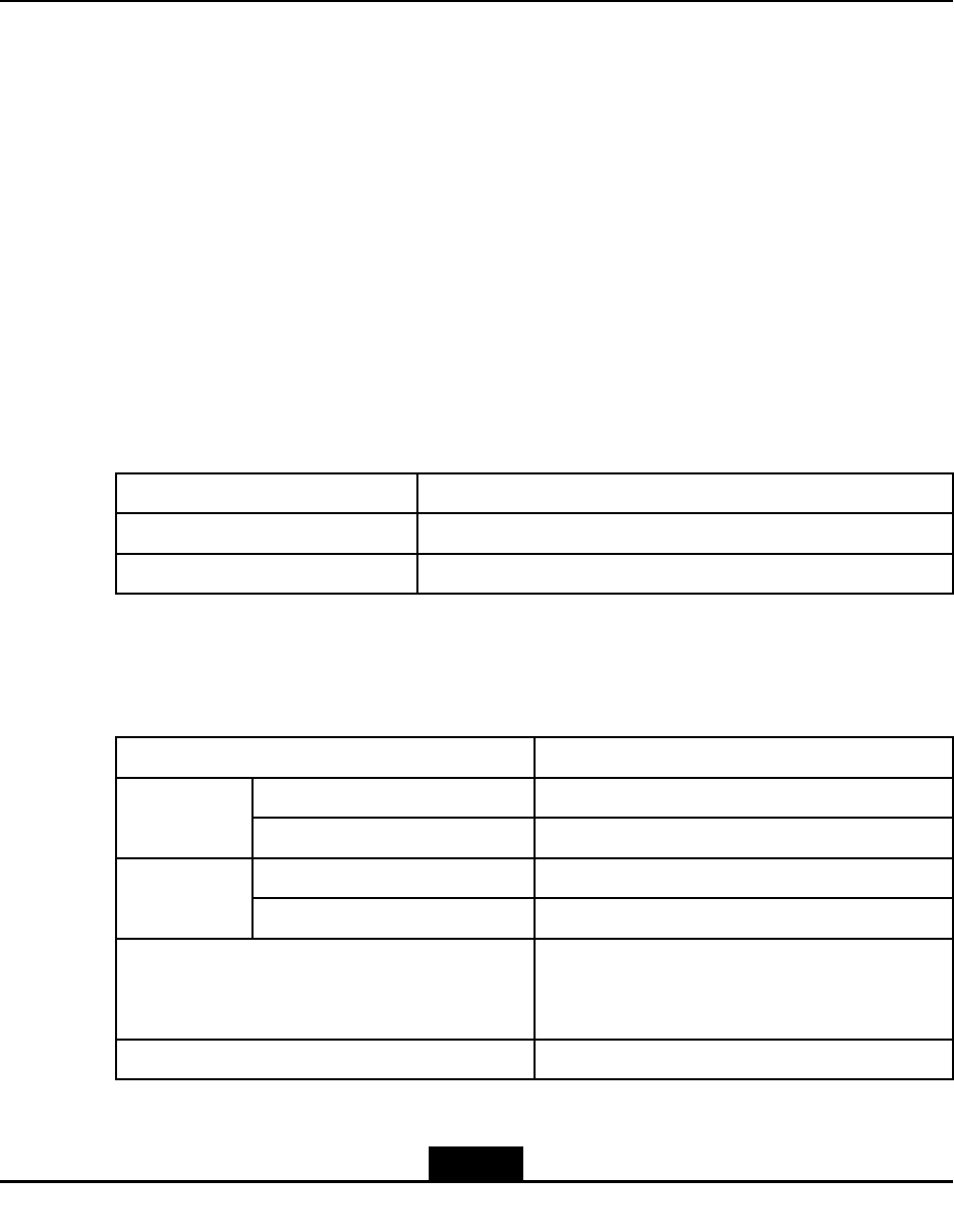
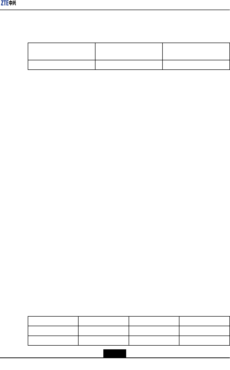
3.1PhysicalIndices
ItemIndex
Dimension380mmx320mmx140mm(HxWxD)
Weight20kg
3.2WorkingEnvironment
ItemIndex
Temperature-40℃~55℃Working
RelativeHumidity5%~100%
Temperature-55℃~70℃Storage
RelativeHumidity5%~98%
Ground≤5Ω,earthresistancecanbelessthan10Ωin
thunder-lessareawherethunderstormdaysis
lessthan20daysperyear
Waterproof/DustproofIP65
3-1
SJ-20110104194923-001|2011-01-19(R1.0)ZTEProprietaryandCondential
ZXSDRR8882L200UserManual
3.3Bandwidth
ZXSDRR8882L200supports5MHz,10MHz,15MHzand20MHz.
Note:
L708doesnotsupport20MHz.
3.4PowerRequirements
ThepowersupplyoftheZXSDRR8882L200is-48VDC(range:-37VDC~-57VDC).
3.5PowerConsumption
ThemaximumpowerconsumptionofZXSDRR8882L200is330W.
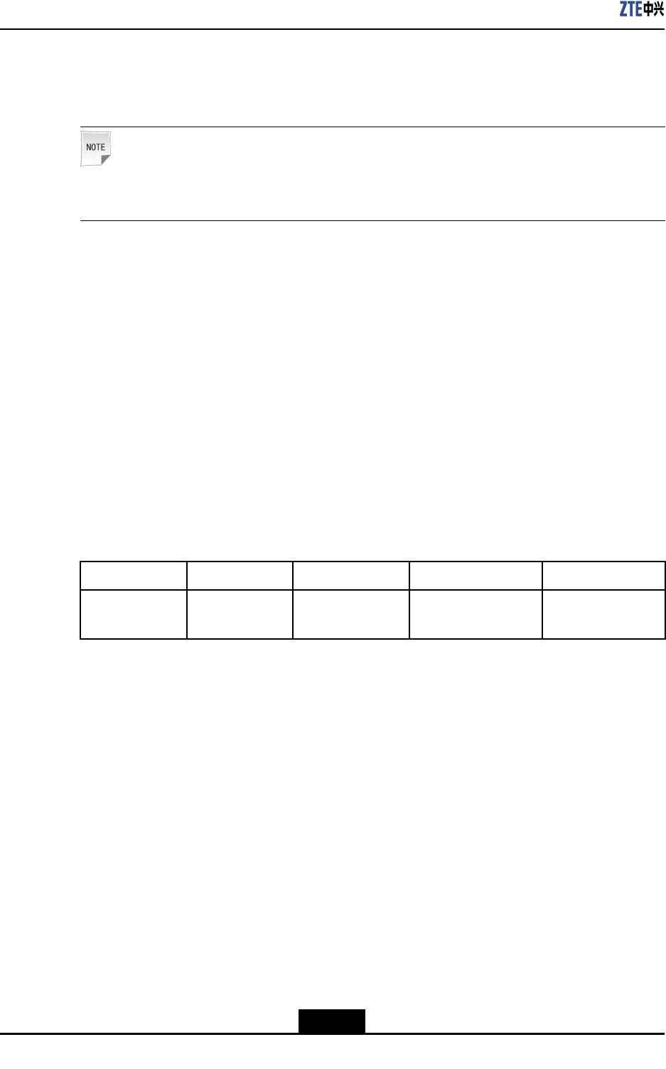
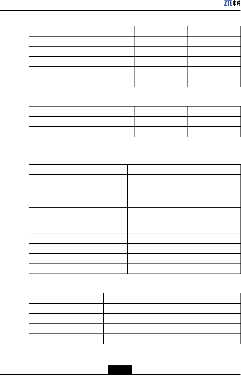
3.6TransmissionIndex
ZXSDRR8882L200connectstoeBBUthroughCPRIinterfaces.Thedetailedinformation
oftheCPRIinterfaceisshowninT able3-1.
Table3-1CPRIInterfaceIndex
ItemQuantityInterfacetypeSpeedStandard
CPRIinterface2SFP(LC)2x3.072Gbpsor
2x2.4576Gbps
CPRIV4.1
3.7PerformanceIndices
OperationFrequencyBand
lR8882L188:1730MHz~1785MHz(uplink)/1825MHz~1880MHz(downlink)or1710
MHz~1765MHz(uplink)/1805MHz~1860MHz(downlink)
lR8882L268:2500MHz~2570MHz(uplink)/2620MHz~2690MHz(downlink)
lR8882L708:698MHz~716MHz(uplink)/728MHz~746MHz(downlink)
lR8882L808:832MHz~862MHz(uplink)/791MHz~821MHz(downlink)
lR8882L718:777MHz~798MHz(uplink)/746MHz~768MHz(downlink)
OutputPower
lR8882L188,R8882L708,R8882L808,R8882L718:2x40W
lR8882L268:2x30W
3-2
SJ-20110104194923-001|2011-01-19(R1.0)ZTEProprietaryandCondential
Chapter3ProductTechnicalSpecications
ReceiverSensitivity
ThereceiversensitivityofZXSDRR8882L200isshowninT able3-2.
Table3-2ReceiverSensitivity
Channelbandwidth(MHz)Referencemeasurement
channel
Referencesensitivitypower
level(dBm)
5/10/15/20FRCA1-3-104
Transmission
lThemaximumtransmissiondistanceis10kilometers.
lSupportstwokindsofopticalberinterfacemode:2x3.072Gbpsand2x2.4576Gbps.
3.8ElectromagneticCompatibility
Thedecisionruleusedinthissectionisdescribesasfollows:
1.RuleA
lAcommunicationchannelissetupforthetest,anditisalwaysavailableduring
thetest.
lFERoftheforwardchannelandreversechannelarelessthanorequalto1during
thetest.
lWhenthetesttaskaccomplished,equipmentundertest(EUT)worksnormally
underpre-scheduledmethod,thereisnoinformationlossofusercontrolfunction
andthesaveddata,andthecommunicationchannelisstillavailable.
lIftheEUTisatransmitteronly,testshouldbedoneunderidle-mode,andthere
isnounintentionalradiationduringthetest.
2.RuleB
lAcommunicationchannelissetupforthetest,anditisalwaysavailableduring
test.
lEUTworksnormallyunderpre-scheduledmethod,thereisnoinformationlossof
usercontrolfunctionandthesaveddata,andthecommunicationchannelisstill
available.
lIftheEUTisatransmitteronly,testshouldbedoneunderidle-mode,andthere
isnounintentionalradiationduringthetest.
3.RuleR
Thereisnodevicedamageorinterference(suchassoftwaremalfunctionorprotection
devicemis-operation)duringthetest.TheEUTworksnormallyunderthedened
boundaryaftertransientelectromagneticincident.
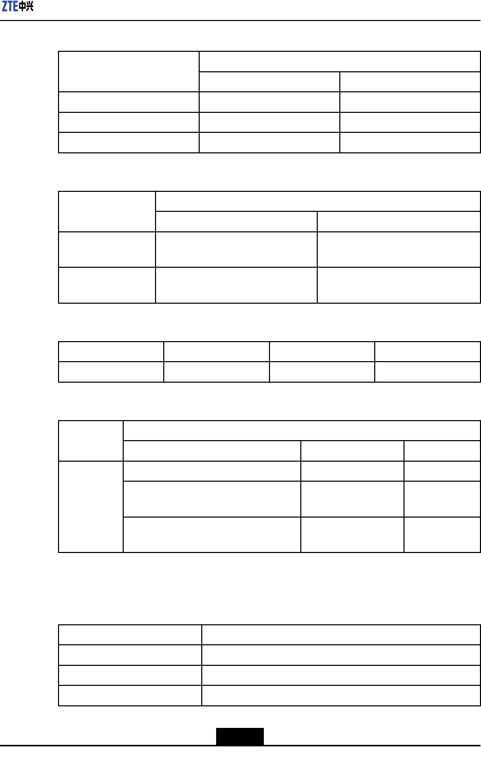
ElectronicStaticDischargeImmunity
ItemContactdischargeAirdischargeDecisionRule
Basictesting6kV8kVRuleB
Enhancedtesting8kV15kVRuleR
3-3
SJ-20110104194923-001|2011-01-19(R1.0)ZTEProprietaryandCondential
ZXSDRR8882L200UserManual
RFElectromagneticFieldRadiationImmunity
RangeFeatureFieldStrengthDecisionRule
80MHz~800MHz80%AM(1kHz)10V/mRuleA
800MHz~960MHz80%AM(1kHz)10V/mRuleA
960MHz~1400MHz80%AM(1kHz)10V/mRuleA
1400MHz~2700MHz80%AM(1kHz)10V/mRuleA
2700MHz~6000MHz80%AM(1kHz)10V/mRuleA
ElectricalFastTransientBurstImmunity
ItemVoltageRepetitionFrequencyDecisionRule
Basictest±1kV5kHzRuleB
Enhancedtest±2kV5kHzRuleB
signalgeneratorwaveform5/50ns
LightningTolerance
SignalTypeNominalRequired
Antennafeederport10kA±5times
The10KAprotectionisguaranteedbytheduplexof
theRFmodule.Anexternallightningprotectionunit
isneededforthehigherprotectionotherthan10KA
DCpowerport(externalSPD)20kA±5times,ResidualVoltageislessthan250V.
ShieldedcableisusedfortheR8882remotepower
supply
Signalport—drycontact3KA
Signalport—RS485signal3KA
AISGpower5KA
Signalport—AISG485port3KA
RadiationTransmission
Frequencyrange(MHz)Quasi-peaklimit(dBuV/m)Distance( (
(m) )
)
30~2303010
230~10003710
1G~3G5010
3G~6G5410
3-4
SJ-20110104194923-001|2011-01-19(R1.0)ZTEProprietaryandCondential
Chapter3ProductTechnicalSpecications
PowerConductedTransmission
Sumlimit(dBuV) Frequencyrange(MHz)
Quasi-peakAveragevalue
0.15~0.5056~6646~56
0.50~55646
5~306050
SignalConductedTransmission
Sumlimit Frequencyrange
Quasi-peakAveragevalue
0.15MHz~0.5MHz84dBuV~74dBuV(Voltage)or40
dBuV~30dBuA(Current)
74dBuV~64dBuV(Voltage)or30
dBuV~20dBuA(Current)
0.5MHz~30MHz74dBuV(Voltage)or30dBuA
(Current)
64dBuV(Voltage)or20dBuA
(Current)
RFElectromagneticFieldConductedImmunity
FrequencyrangeVoltageFeatureDecisionRule
0.15MHz~80MHz10V80%AM(1kHz)RuleA
SurgeImmunity
OpencircuitVoltage Site
TypeWire—WireWire—Ground
DCpower0.51
Longdistancewire(wirelengthlonger
than10meters)
11
Indoor
Shortdistancewire(wirelengthlessthan
10meters)
--
3.9Reliability
ItemCharacteristics
MTBF≥34,0000hours
MTTR1hour
Availability≥99.999842%
3-5
SJ-20110104194923-001|2011-01-19(R1.0)ZTEProprietaryandCondential

ZXSDRR8882L200UserManual
Thispageintentionallyleftblank.
3-6
SJ-20110104194923-001|2011-01-19(R1.0)ZTEProprietaryandCondential
Chapter4
ProductInstallation
TableofContents
SafetyDescription......................................................................................................4-1
DeviceUnpackingandInspection...............................................................................4-5
DeviceInstallation......................................................................................................4-6
CablesConnection...................................................................................................4-23
4.1SafetyDescription
4.1.1SafetySpecificationsIntroduction
Inordertoavoidaccidents,beforeinstallingormaintainingtheZXSDRR8882L200,please
readthismanualcarefullyforsafetyissues.Ifthereareanylocalsafetyspecications,use
thesafetyspecicationsdescribedinthismanualasasupplement.Ifthereisanyconict
betweenthem,pleasefollowthelocalsafetyspecications.
ThepersonnelwhoinstallormaintaintheZXSDRR8882L200mustbeequipped
withknowledgeofsafetyoperation,technicaltraining,correctknowledgeofequipment
operationandmaintenance,andcorrespondingqualications.
WheninstallingormaintainingtheZXSDRR8882L200,theoperatormustfollowthe
precautionsoftheequipmentandspecialinstructionsprovidedbyZTECORPORATION.
Furthermore,thesecurityissueslistedinthismanualareonlyfriendlyremindersby
ZTECORPORATIONfromsafetypointofview.ZTEisnotresponsibleforanyaccident
causedbyviolationsofgeneralsafetyoperatingrequirements,orbyviolationsofthe
design,productionanduseofequipmentsafetystandards.
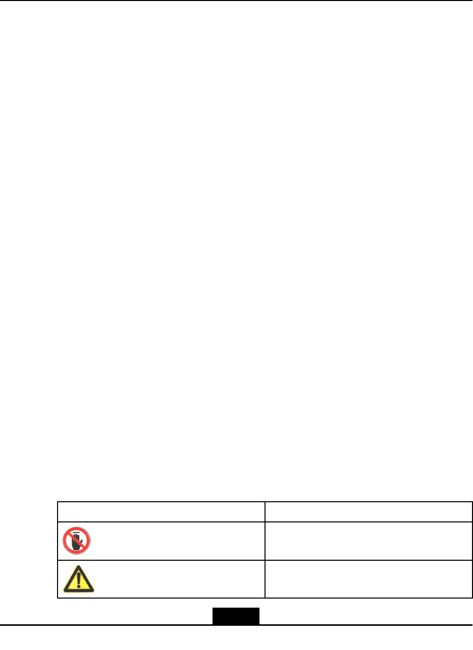
4.1.2SafetySymbols
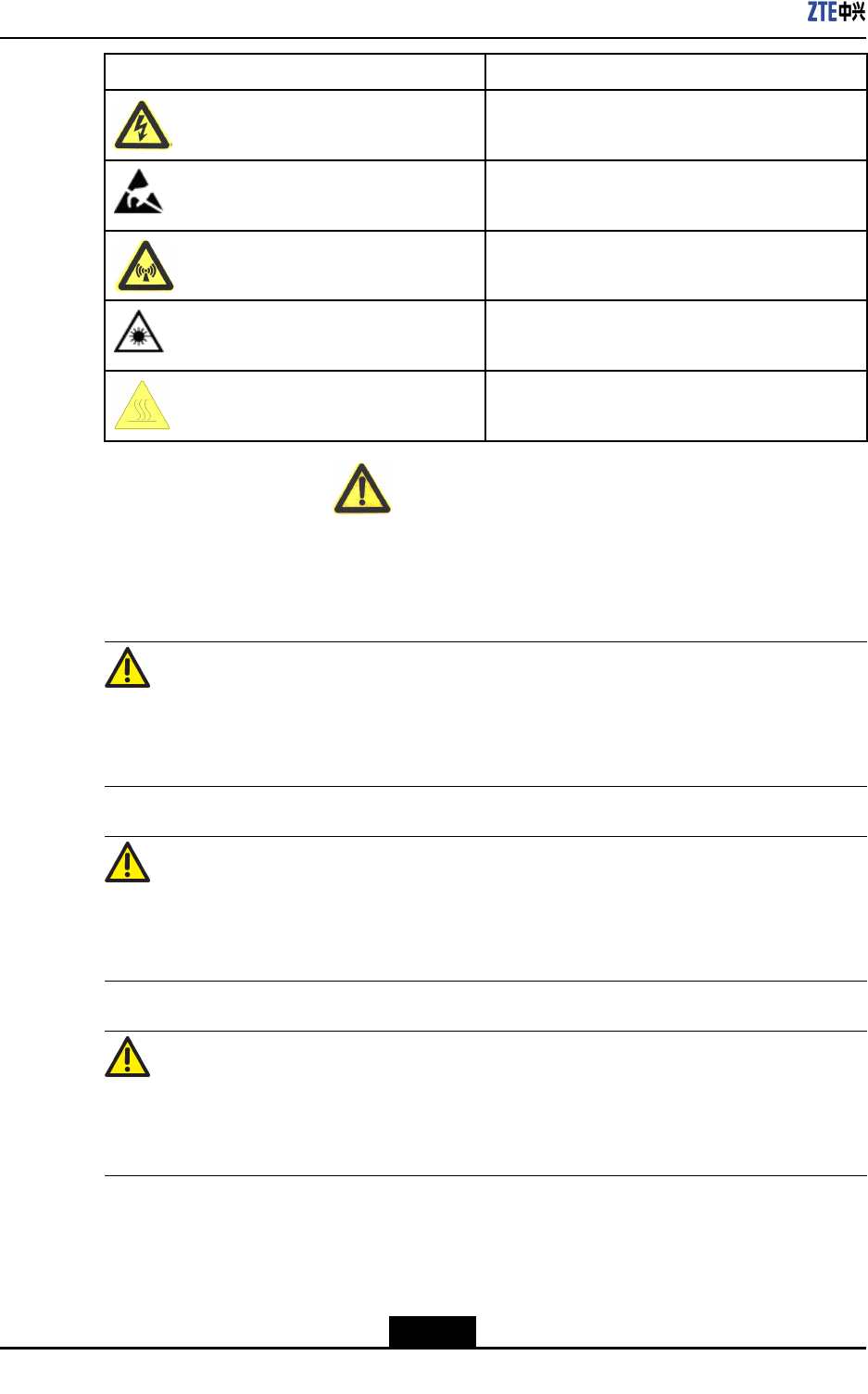
CommonsafetysymbolsareshowninT able4-1.Thesesymbolsareusedtoremindthe
userwithsafetymatterswhentheymaintaintheequipment.
Table4-1Symboltypeandmeanings
SymbolsMeanings
NoT ouchSign:DONOTtouch
GeneralWarningSign:Generalsecurityissues
4-1
SJ-20110104194923-001|2011-01-19(R1.0)ZTEProprietaryandCondential
ZXSDRR8882L200UserManual
SymbolsMeanings
ElectricShockWarningSign:Bewareofhigh
voltage
AntistaticSign:Thedeviceissensitiveto
electrostaticchargeorstaticelectricity
MicrowaveWarningSign:Becarefulofstrong
electromagneticelds
LaserWarningSign:Becarefulofintenselaser
beam
BurnWarningSign:Becarefulofhigh
temperature
Thegeneralwarningsignfallsintothreesafetyseverities:Danger,Warningand
Caution,frommajortominor.Theseverityismarkedontherightofthesymbolanddetailed
descriptionsareplacedunderthesymbol.Theirformatsanddescriptionsareshownas
below.
Danger!
Ignoringthesafetywarningmaycausedeathorseriouspersonalinjuries,orequipment
damageorbreakdown.
Warning!
Ignoringthesafetywarningmaycausemajorseriousinjuries,equipmentdamageor
serviceinterruption.
Caution!
Ignoringthesafetywarningmaycauseseriousinjuries,equipmentdamagesorinterruption
ofsomeservices.
4-2
SJ-20110104194923-001|2011-01-19(R1.0)ZTEProprietaryandCondential
Chapter4ProductInstallation
4.1.3SafetyOperationGuidance
ElectricalSafety
1.Tool
Whenoperatinginthecaseofhighvoltage,usespecialtools.Donotusegeneral
tools.
2.PowerCable
lCutoffthepowerbeforeinstallingorremovingthepowercable.
lBeforeconnectingthepowercable,makesurethecableconnectionandlabels
onthecablecomplywiththeactualinstallationsituation.
Danger!
lDonotinstallorremovethepowercablewhenthepowerisON.
lSparksorelectricarcmayhappenwhenthepowercabletouchestheconductor,
whichmaycausereoreyeinjury.
3.Drilling
lUnqualieddrillingwilldamagethelinesandcablesinthecabinet.Themetal
splashesmayenterthecabinetandcausetheshortcircuitonthecircuitboard.
lWhendrillingonthecabinetsisneeded,wearinsulatingglovesandremovethe
cablesinsidethecabinetbeforetheoperation.Takecareofyoureyeswhen
drilling,becausemetalsplashesmayhurtyoureyes.Cleanupthemetallings
oncethedrillingisdone.
Warning!
Donotdrillonthecabinetatwill.
4.Thunderstorm
Duringthunderstorm,strongelectromagneticeldwillbeproducedintheatmosphere.
Thus,toavoidlightningstrike,takelightninggroundingmeasuresontheequipment
immediately.
Danger!
Duringthunderstorm,donotperformoperationsofhighvoltage,anddonotperform
operationsontheirontowerormast.
4-3
SJ-20110104194923-001|2011-01-19(R1.0)ZTEProprietaryandCondential
ZXSDRR8882L200UserManual
Antistatic
lThefrictioncausedbyhumanactivitiesisthereasontoproducetheaccumulationof
electrostaticcharge.Indryclimates,electrostaticvoltagecarriedbythehumanbody
canbeaccumulatedupto30kV,whichwillbekeptinthebodyforcoupleofhours.
Operatorscarryingelectrostaticchargewillbedischargedthroughthedevice,causing
equipmentdamage.
lToavoiddamagingsensitivecomponentsbyhumanstaticelectricity,beforetouching
thedevices,suchasboards,circuitboards,ICchips,operatorsshouldwearantistatic
wristband,andmakesuretheotherendofwristbandtouchestheground.
lToprotectpeoplefromaccidentalelectricshock,aresistanceover1MΩshouldbe
addedbetweentheantistaticwristbandandtheground.
lTheantistaticwristbandshouldbeinspectedperiodically.Donotreplacetheelectric
wiresonthewristbandbyanyotherunqualiedones.
lThoseelectrostaticsensitiveboardsormodulesshouldnothaveanycontactwiththe
objectsofelectrostaticchargeorwhichcarriesstaticelectricityeasily.Forexample,
frictionbetweenthepackagesofinsulatingmaterialsandtransmissionbeltcouldmake
thecomponentscarryingstaticelectricity.Damagesmayhappenwhenitisdischarged
bycontactinghumanbody.
lThoseelectrostaticsensitiveboardscanbeonlycontactedwithqualieddischarged
materials,suchasantistaticbag.Equipmentcomponentsneedtobestoredor
transportedintheantistaticbags.
lBeforethetestingequipmentiswiredwithboardsormodules,itshouldbeconnected
togroundfordischarging.
lDonotplacetheboardsormodulesnearstrongDCmagneticeld.Forexample,
thosemonitorswithCathode-raytube,safetydistanceisover10cm.
Caution!
Electrostaticchargeproducedbyhumanbodywilldamagetheelectrostaticsensitive
componentsonthecircuitboard,suchasIntegratedCircuit(IC),etc.
LiftingWeights
lTheadequatefacilitieswithliftingcapacitymustbeusedforassembling,movingor
replacingtheheavyequipments.
lThestaffforliftingoperationsarerequiredtohavequaliedtraining.Liftingtoolsmust
haveperiodicinspection,andmustbeusedwhenitisacompletetoolkit.Ensurethat
theliftingtoolcanbermlyxedonthextureorload-bearingwallbeforeanylifting
operations.Usesimpliedcommandstopreventmisoperation.
4-4
SJ-20110104194923-001|2011-01-19(R1.0)ZTEProprietaryandCondential
Chapter4ProductInstallation
Warning!
Duringliftingoperations,donotwalkatthebottomofanycraneorliftingobjects.
Plugging/UnpluggingBoardsorModules
lToavoidcrookingthepinonbackplane,plugtheboardsormodulesgently.
lPlugtheboardsormodulesalongtheslottopreventanyshortcircuit.
lWhencarryingtheboardsormodules,donottouchthecircuits,aswellasthe
components,connectionheads,slotsontheboards.
Others
lReplacingthecomponentsormodifyingtheequipmentsmaycauseextradangers.
lDonotreplacethecomponentsormodifytheequipmentswithoutauthorization.
lFromsafetypointofview,pleasecontactZTECORPORATIONforanyqueries.
Caution!
Donotperformmaintenanceordebugginginsidethedevice,unlessthereisanother
qualiedengineerworkingwithyou.
4.2DeviceUnpackingandInspection
4.2.1UnpackingandCheckingZXSDRR8882L200
UnpackingtheCarton
ZXSDRR8882L200istransportedinacarton.
1.Checkthepackagingfordamage.Ifitisdamaged,makeanimmediatecomplaintto
thetransportcompany.
2.Unpacktheequipmentandcheckifitiscompleteaccordingtothepackinglist.
InspectingtheDevice
ChecktheDeviceandmakesure:
lTherearenodents,protrusions,bendings,peelings,ormarksonthesurface.
lFasteningboltsareproperlytightenedinplace.
lThettingsandaccessoriesrequiredforinstallationarematchedandcomplete.
lConnectorlinksarenotbrokenormissing.
4-5
SJ-20110104194923-001|2011-01-19(R1.0)ZTEProprietaryandCondential
ZXSDRR8882L200UserManual
Thesuppliershouldberesponsibleforinspectingthedevicesandinstrumentsthatare
easytobedamaged.
Separatetheinspectedpartsbycategory.
4.2.2GoodsHandover
AfterequipmentinspectionboththepartiesshouldsigntheUnpackingandInspection
Reportwitheachpartykeepingacopy,withthetopcopyreturnedwithinsevendaystothe
vendor.
Caution!
Ifanygoodsarefoundtobewrong,missing,ordamaged,recordthedetailsontheform
andaskforreplacements.
4.3DeviceInstallation
4.3.1MountingDeviceonWall
Context
Note:
TheeRRUinthischapterareonlyfordemonstratinginstallationscenario.
Prerequisite
BeforeinstallingR8882,youshouldatleastleavethefollowingspaceforproductfuture
maintenance.
lFrontside:600mm
lBackside:40mm
lLeftandrightside:100mm
lUPanddownside:250mm
Steps
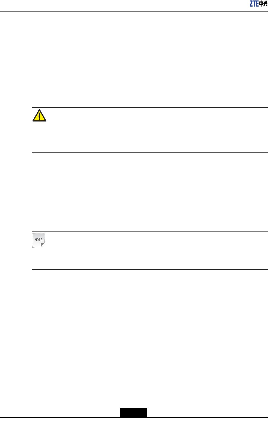
1.Markoninstallationpositionsbasedonlayoutmarkingtemplateonwall,asshownin
Figure4-1,andthendrillholes.
4-6
SJ-20110104194923-001|2011-01-19(R1.0)ZTEProprietaryandCondential
Chapter4ProductInstallation
Figure4-1TemplateHolePosition
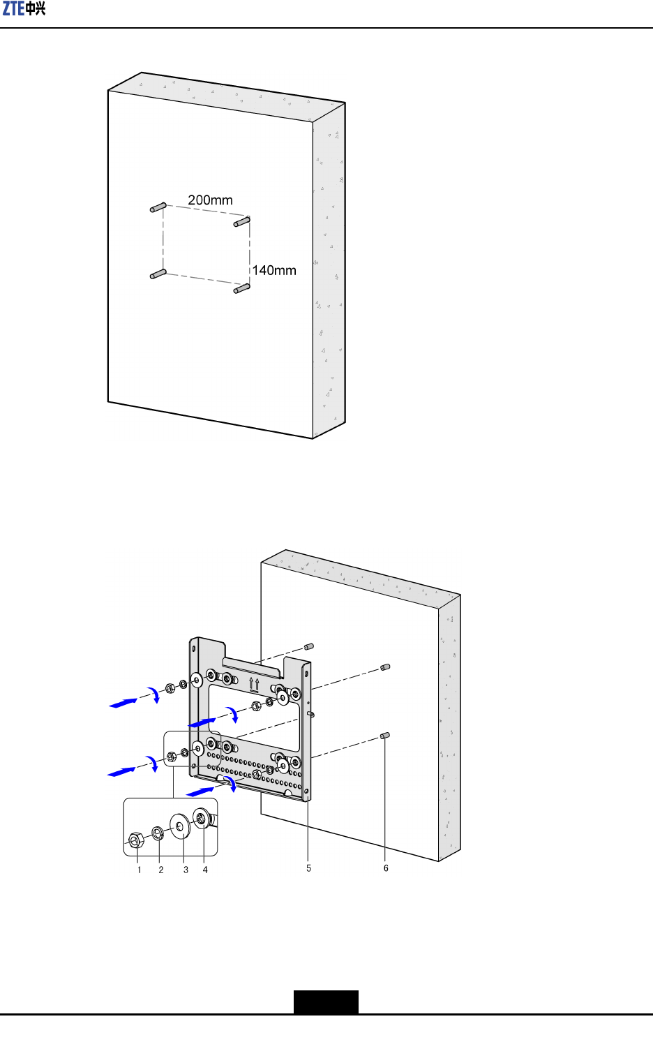
2.Fixthewall-mountingcomponentsontothewallrmlywiththebolts,asshownin
Figure4-2.
Figure4-2InstallingWall-mountingComponents
1.HexBolt
2.SpringWasher
3.FlatWasher
4.InsulationWasher
5.Wall-Mounting
components
6.ExpansionBolt
Thewall-mountingcomponentsisinstalledonthewall,asshowninFigure4-3.
4-7
SJ-20110104194923-001|2011-01-19(R1.0)ZTEProprietaryandCondential
ZXSDRR8882L200UserManual
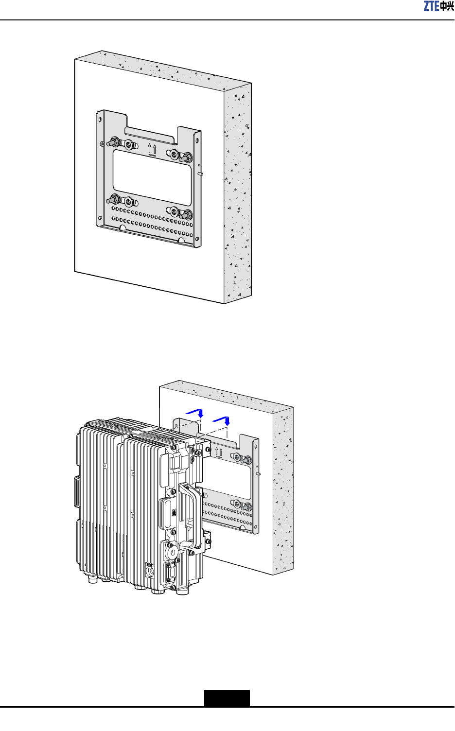
Figure4-3Wall-mountingComponentsFixedonWall
3.Hangthedeviceonthewall-mountingcomponentsonthenotchdepartment,asshown
inFigure4-4.
Figure4-4HangtheDeviceontheWall-mountingComponents
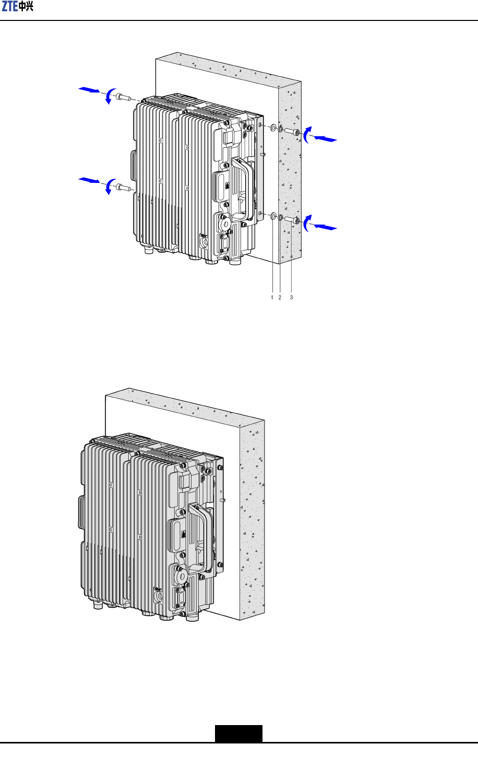
4.MounttheZXSDRR8882L200ontothewall-mountingcomponents,andthenfasten
itwiththeM6x20bolts,asshowninFigure4-5.
4-8
SJ-20110104194923-001|2011-01-19(R1.0)ZTEProprietaryandCondential
ZXSDRR8882L200UserManual
4.3.2MountingDeviceonPole
4.3.2.1MountingOneDeviceonPole
Context
Theinstallationaccessoryforthelightningprotectionboxisneededtobeattachedin
advance,asshowninFigure4-7.
Figure4-7AttachInstallationAccessoryforLightningProtectionBox
Steps
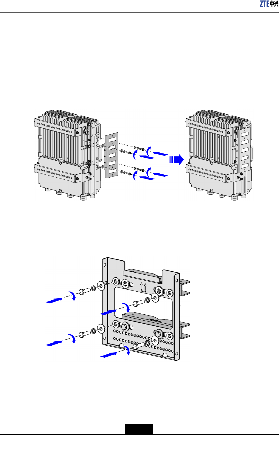
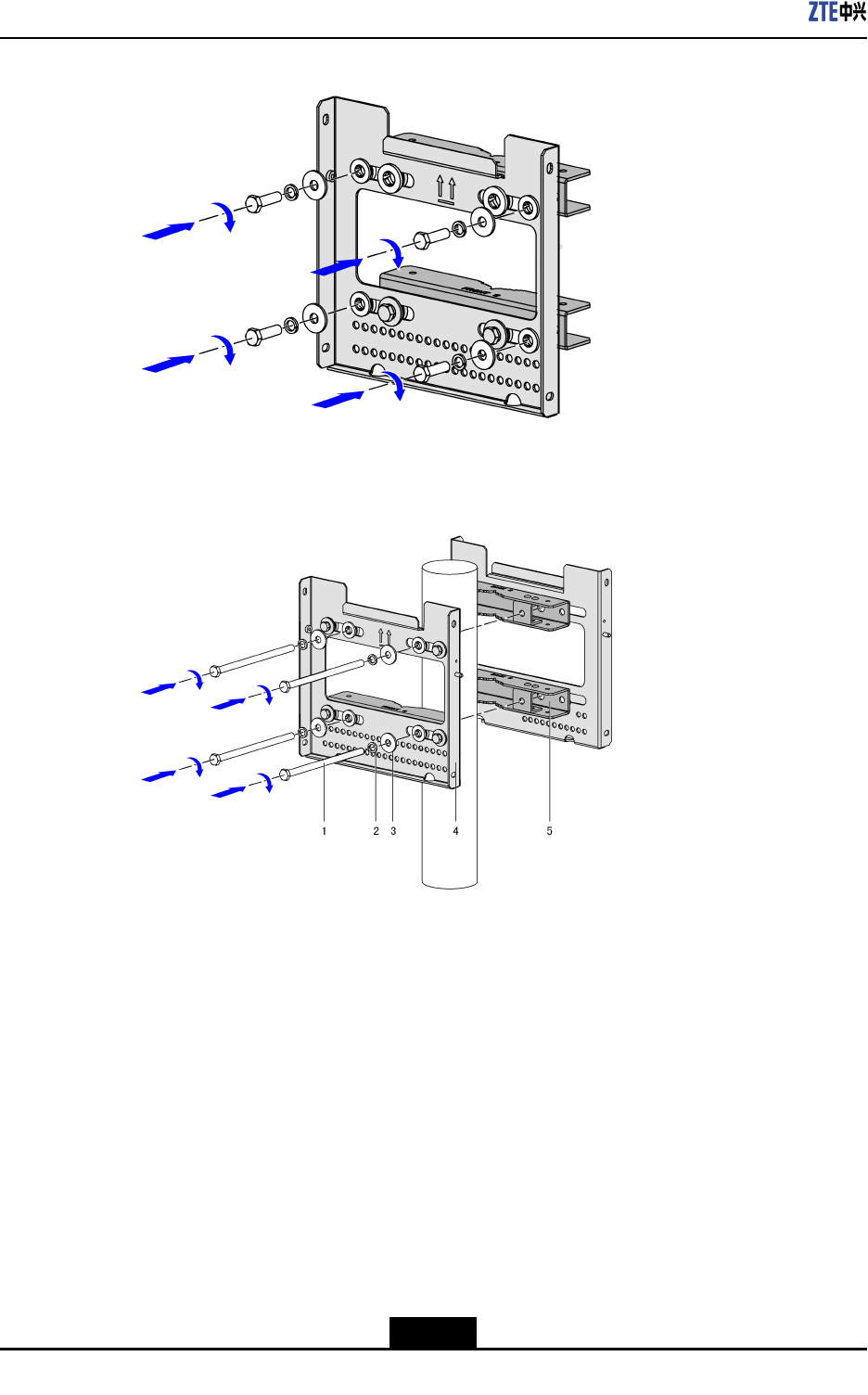
1.Fixthewall-mountingcomponentsandpolecliptogether,asshowninFigure4-8.
Figure4-8FixWall-mountingComponentsandPoleClips
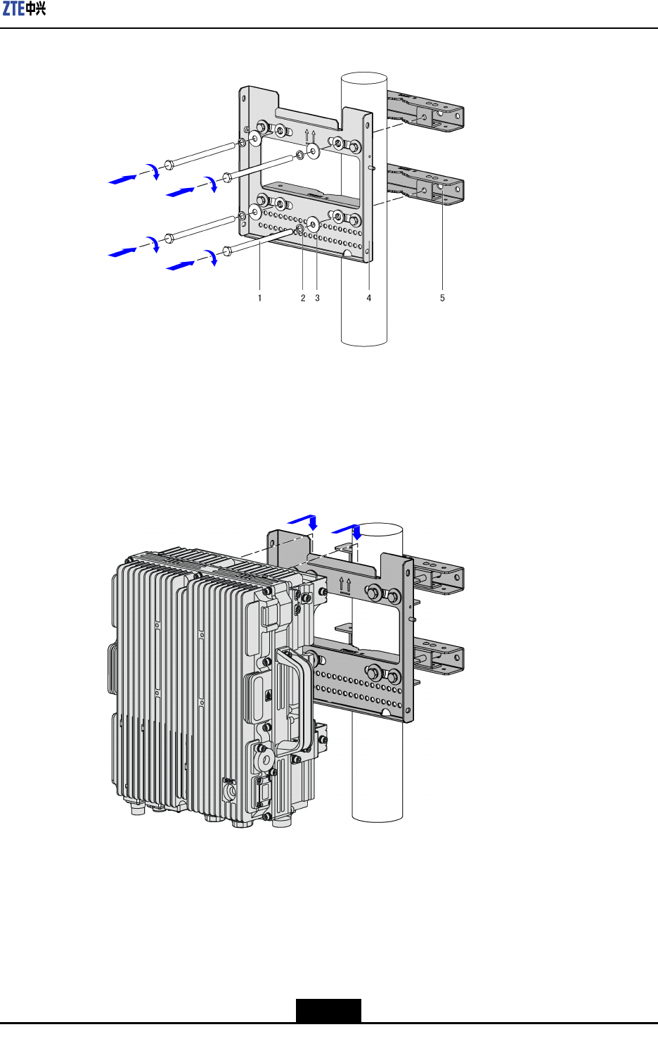
2.Fixthewall-mountingcomponentsandpoleclipsonthepole,asshowninFigure4-9.
4-10
SJ-20110104194923-001|2011-01-19(R1.0)ZTEProprietaryandCondential
Chapter4ProductInstallation
Figure4-9FixWall-mountingComponentsandPoleClipsonPole
1.Bolt
2.Springwasher
3.Flatwasher
4.Wall-mounting
components
5.PoleClips
3.Hangthedeviceonthenotchpartofthewall-mountingcomponents,asshownin
Figure4-10.
Figure4-10HangtheDeviceontheWall-mountingComponents
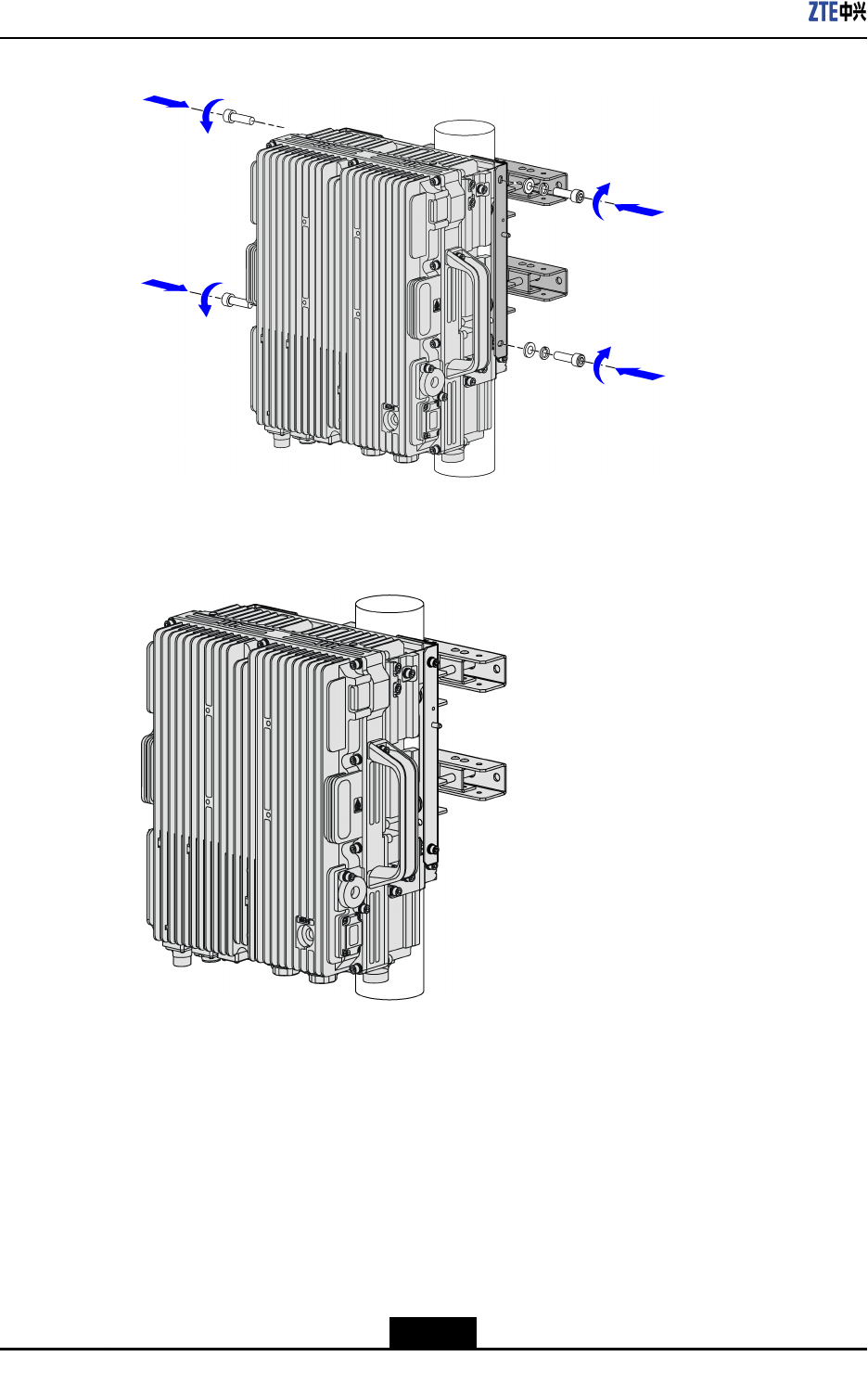
4.Fixthedeviceonthewall-mountingcomponents,asshowninFigure4-11.
4-11
SJ-20110104194923-001|2011-01-19(R1.0)ZTEProprietaryandCondential
ZXSDRR8882L200UserManual
Figure4-11FixtheDeviceontheWall-mountingComponents
ZXSDRR8882L200isinstalledrmlyonthepole,asshowninFigure4-12.
Figure4-12ZXSDRR8882L200IsInstalledonPole
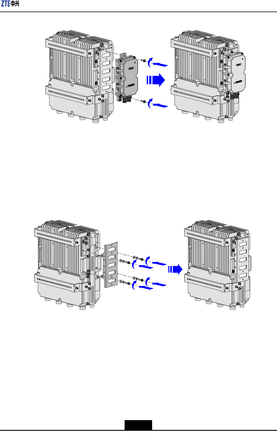
5.Alignthelightningprotectionboxtotheholeoftheinstallationaccessory,andthe
fastenthescrews,asshowninFigure4-13.
4-12
SJ-20110104194923-001|2011-01-19(R1.0)ZTEProprietaryandCondential
Chapter4ProductInstallation
Figure4-13AttachLightningProtectionBox
–EndofSteps–
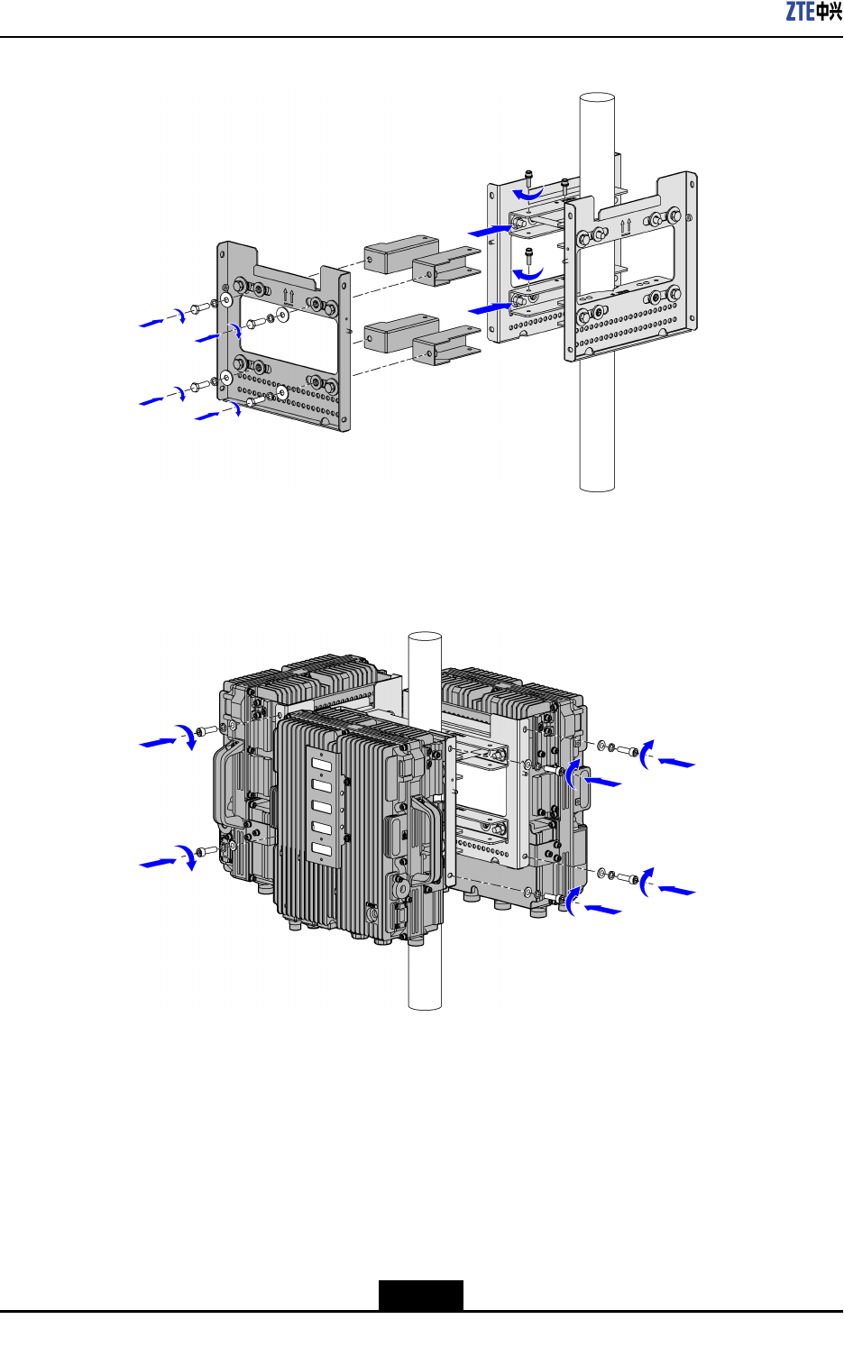
4.3.2.2MountingTwoDevicesonPole
Context
Theinstallationaccessoryforthelightningprotectionboxisneededtobeattachedin
advance,asshowninFigure4-14.
Figure4-14AttachInstallationAccessoryforLightningProtectionBox
Steps
1.Fixthewall-mountingcomponentsandpolecliptogether,asshowninFigure4-15.
4-13
SJ-20110104194923-001|2011-01-19(R1.0)ZTEProprietaryandCondential
ZXSDRR8882L200UserManual
Figure4-15FixWall-mountingComponentsandPoleClips
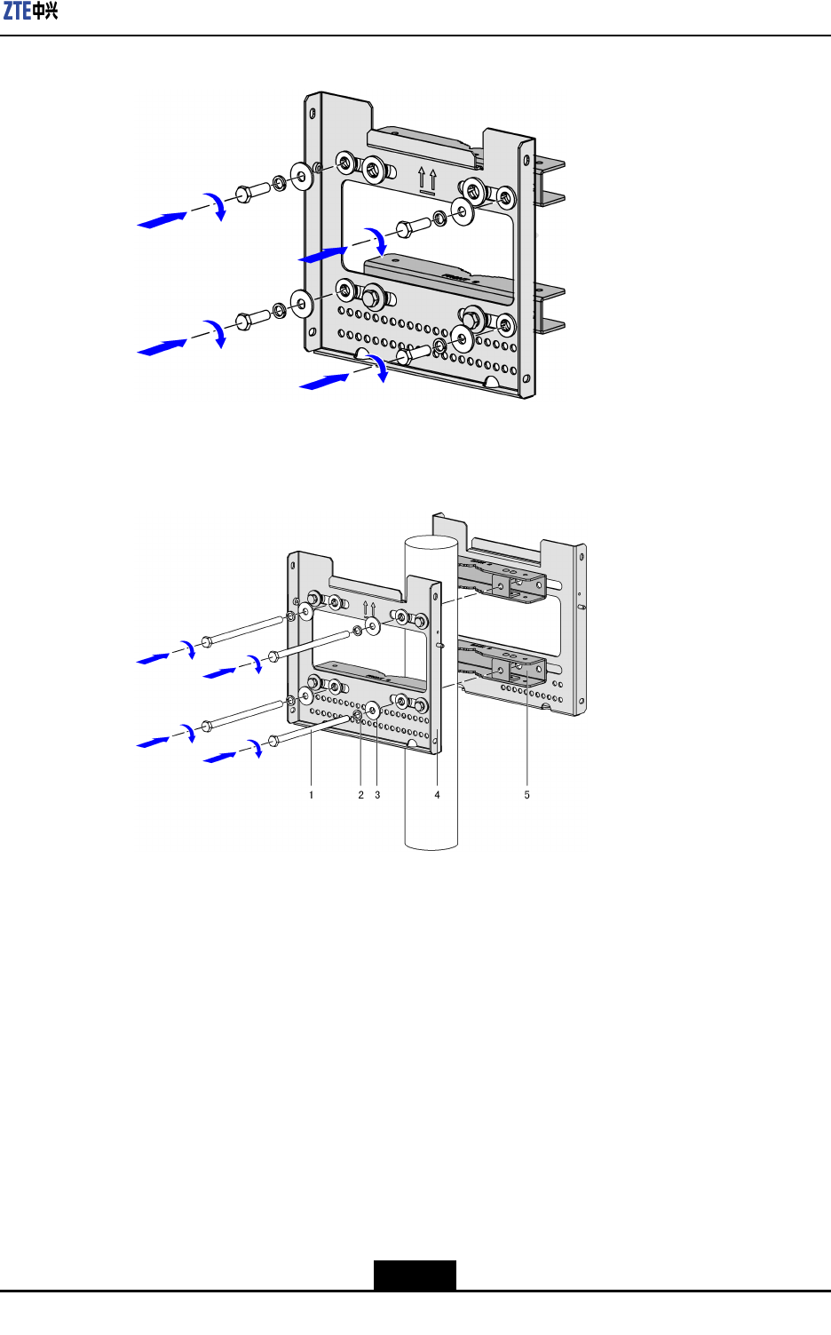
2.Fixthewall-mountingcomponentsandpoleclipsonthepole,asshowninFigure4-16.
Figure4-16FixWall-mountingComponentsandPoleClipsonPole
1.Bolt
2.Springwasher
3.Flatwasher
4.Wall-mounting
components
5.PoleClips
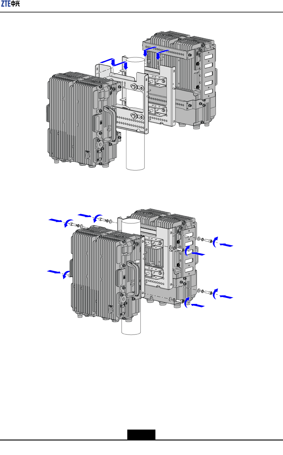
3.Hangthedevicesonthenotchpartofthewall-mountingcomponentsrespectively,as
showninFigure4-17.
4-14
SJ-20110104194923-001|2011-01-19(R1.0)ZTEProprietaryandCondential
Chapter4ProductInstallation
Figure4-17HangtheDevicesontheWall-mountingComponents
4.Fixthedevicesonthewall-mountingcomponents,asshowninFigure4-18.
Figure4-18FixtheDevicesontheWall-mountingComponents
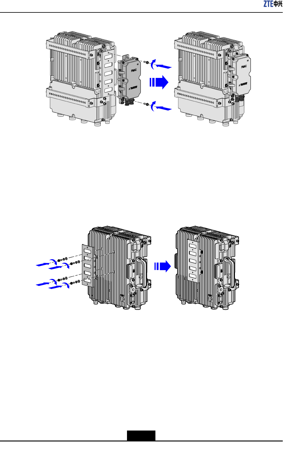
5.Alignthelightningprotectionboxtotheholeoftheinstallationaccessory,andthe
fastenthescrews,asshowninFigure4-19.
4-15
SJ-20110104194923-001|2011-01-19(R1.0)ZTEProprietaryandCondential
ZXSDRR8882L200UserManual
Figure4-19AttachLightningProtectionBox
–EndofSteps–
4.3.2.3MountingThreedevicesonPole
Context
Theinstallationaccessoryforthelightningprotectionboxisneededtobeattachedin
advance,asshowninFigure4-20.
Figure4-20AttachInstallationAccessoryforLightningProtectionBox
Steps
1.Fixthewall-mountingcomponentsandpolecliptogether,asshowninFigure4-21.
4-16
SJ-20110104194923-001|2011-01-19(R1.0)ZTEProprietaryandCondential
Chapter4ProductInstallation
Figure4-21FixWall-mountingComponentsandPoleClips
2.Fixthewall-mountingcomponentsandpoleclipsonthepole,asshowninFigure4-22.
Figure4-22FixWall-mountingComponentsandPoleClipsonPole
1.Bolt
2.Springwasher
3.Flatwasher
4.Wall-mounting
components
5.PoleClips
3.Fixthethirdwall-mountingcomponentsbyusingtheexpansioncomponentstothe
othertwoones,asshowninFigure4-23.
4-17
SJ-20110104194923-001|2011-01-19(R1.0)ZTEProprietaryandCondential
ZXSDRR8882L200UserManual
Figure4-23FixtheThirdWall-mountingComponents
4.Hangdevicesonthenotchpartofthewall-mountingcomponentsrespectively,as
showninFigure4-24.
Figure4-24HangtheDevicesontheWall-mountingComponents
5.Alignthelightningprotectionboxtotheholeoftheinstallationaccessory,andthe
fastenthescrews,asshowninFigure4-25.
4-18
SJ-20110104194923-001|2011-01-19(R1.0)ZTEProprietaryandCondential
Chapter4ProductInstallation
Figure4-25AttachLightningProtectionBox
–EndofSteps–
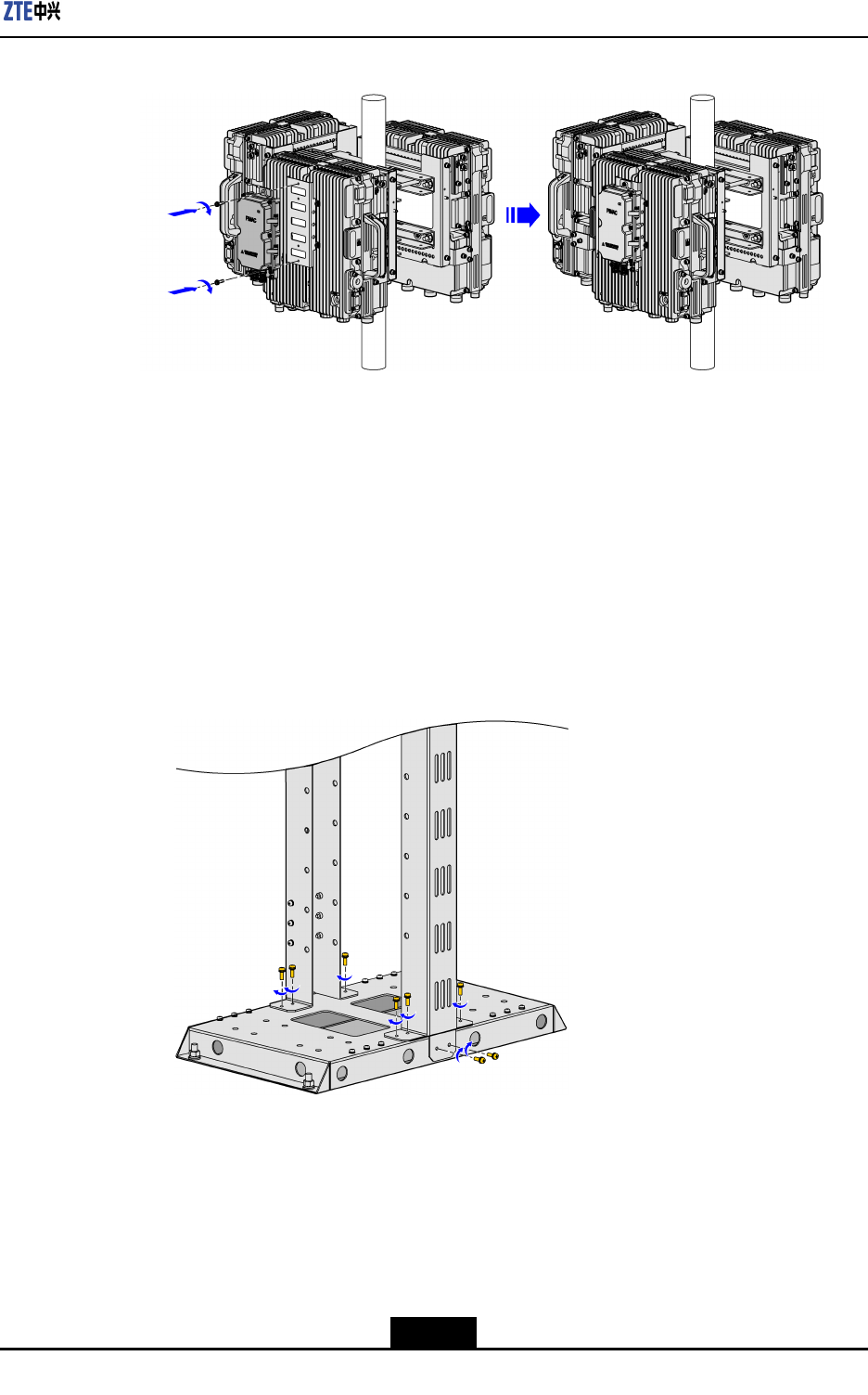
4.3.3MountingDeviceonGantry
Steps
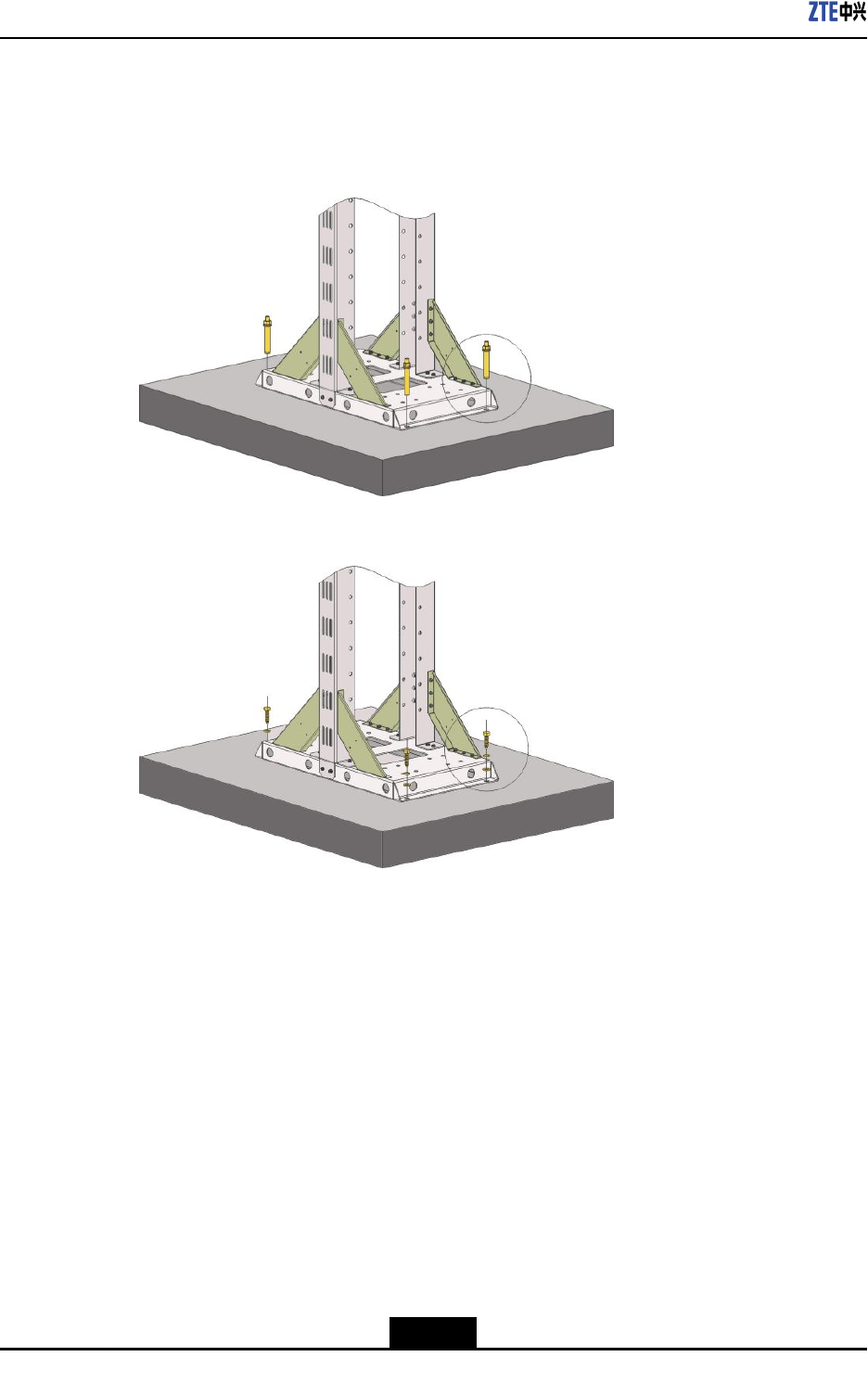
1.Assemblethegantry.
a.InstalltheverticalshaftandthebottomplatebyusingtheM5x16screw,asshown
inFigure4-26.
Figure4-26InstalltheVerticalShaftandtheBottomPlate
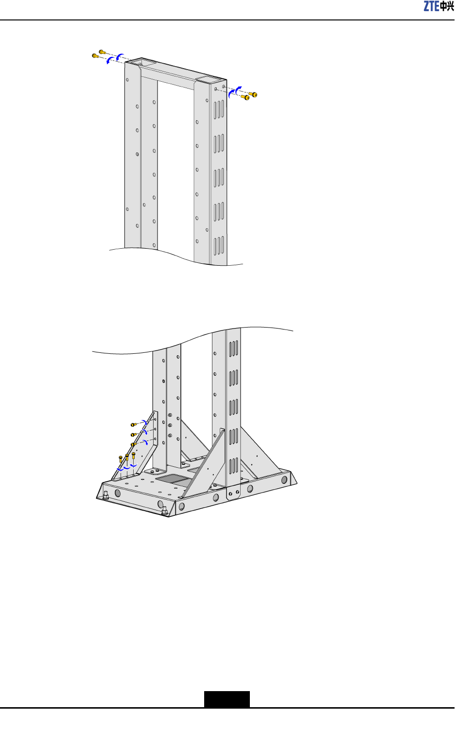
b.FastentheverticalshaftandthecoverplatebyusingtheM5x16screw,asshown
inFigure4-27.
4-19
SJ-20110104194923-001|2011-01-19(R1.0)ZTEProprietaryandCondential
ZXSDRR8882L200UserManual
Figure4-27FastentheVerticalShaftandtheCoverPlate
c.InstalltheslantedrackbyusingtheM5x16screw,asshowninFigure4-28.
Figure4-28InstalltheSlantedRack
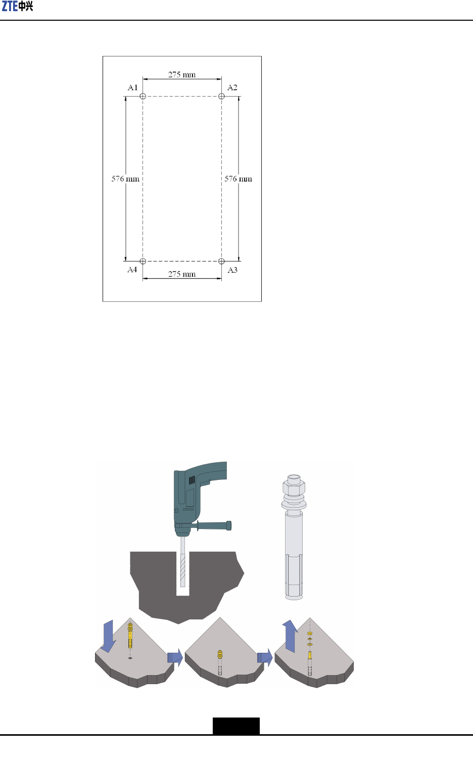
2.Drillholes
a.Accordingtotheengineeringdesigndrawing,determinetheinstallationposition
ofthegantryandmarkinstallationholesbyusingthemarkingpen.Figure4-29
showstheinstallationholesofthegantry.
4-20
SJ-20110104194923-001|2011-01-19(R1.0)ZTEProprietaryandCondential
Chapter4ProductInstallation
Figure4-29MarktheDrillingHolesPosition
b.Drillholesbyusingtheelectricpercussiondrill(drillbit:φ12)attheplaceswhere
installationholesaremarked.Atthesametime,usethevacuumcleanertoremove
thedustgeneratedduringthedrillingofholes.
c.Puttheexpansionsleeveontothemetalconeoftheexpansionbolt,fastenthe
nutslightly,striketheexpansionboltintotheinstallationholebyusingtherubber
hammer,fastenthenuttightlytomaketheboltfullyexpanded,andthenremove
thenut,asshowninFigure4-30.
Figure4-30InstalltheExpansionBolt
3.Installthegantry.
4-21
SJ-20110104194923-001|2011-01-19(R1.0)ZTEProprietaryandCondential
ZXSDRR8882L200UserManual
Ifthegantryisinstalledontheconcreteoor,usetheM10x100expansionbolt,as
showninFigure4-31;ifthegantryisinstalledonthewoodenoor,usetheM10x40
tappingscrew,asshowninFigure4-32.
Figure4-31InstalltheGantryonConcreteFloor
Figure4-32InstalltheGantryonWoodenFloor
4.Installthewall-mountingcomponentsonthegantry.
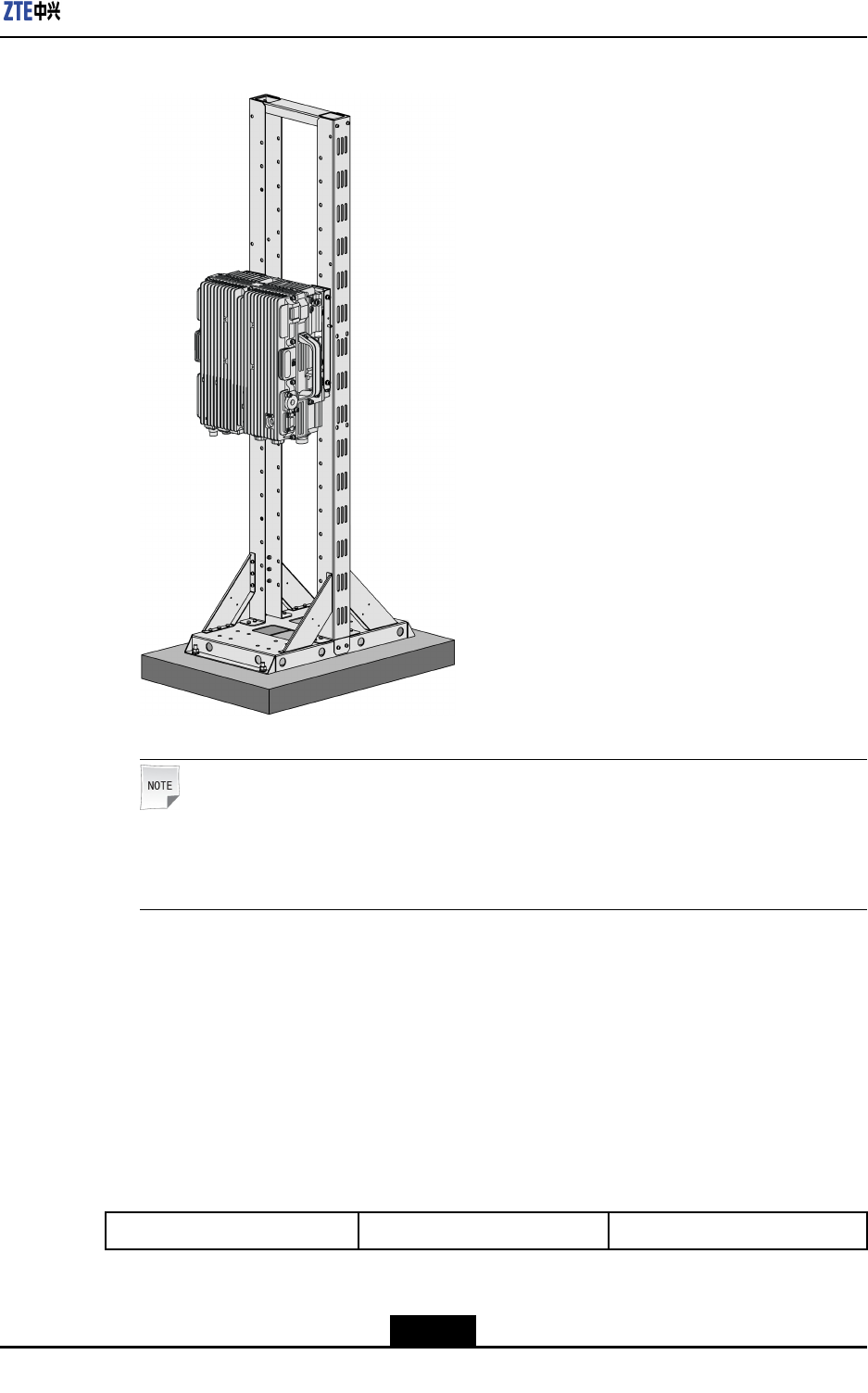
5.InstalltheZXSDRR8882L200onthewall-mountingcomponents.Thedeviceis
installedrmlyonthegantry,asshowninFigure4-33.
4-22
SJ-20110104194923-001|2011-01-19(R1.0)ZTEProprietaryandCondential
Chapter4ProductInstallation
Figure4-33ZXSDRR8882L200IsInstalledonGantry
Note:
Acopperbarisneededtoattachatthesideofthegantrytoconnecttothegrounding
bar.
–EndofSteps–
4.4CablesConnection
4.4.1ConnectionofExternalCables
Table4-2describestheconnectionofZXSDRR8882L200externalcables.
Table4-2ConnectionofZXSDRR8882L200ExternalCables
CabletypeConnectionrelationDescription
4-23
SJ-20110104194923-001|2011-01-19(R1.0)ZTEProprietaryandCondential

ZXSDRR8882L200UserManual
PowercableConnectstheZXSDRR8882
L200powerinterfacetothe
powersupplyequipment
interface
Oneendiscircular6-corecable
connector(hole)withplastic
cover,theotherendisreserved
forpowercableanddrycontact
cable.Thelengthofcable
isbasedontheengineering
survey.
GroundingcableConnectsoneZXSDRR8882
L200groundbolttothecopper
bar
Thegroundingcableismade
upofstrandsofame-retardant
wire.Thecrosssectionalareaof
ZXSDRR8882L200grounding
cableis16mm2.Copperlugs
arecrimpedatbothendsofthe
groundingcable.
FiberConnectstoeBBU-
EnvironmentmonitorcableConnectstheZXSDRR8882
L200environmentmonitor
interfacetotheexternalmonitor
componentsorthedrycontact.
Fortheenvironmentmonitor
cable,endAisPINheader.
EndB,with3mlengthintotal,
ismadedependingontheeld
engineeringconditions.
AISGcontrolcableConnectstheZXSDRR8882
L200debugginginterface
(AISG)tothecontrolinterfaceof
electrical-adjustmentantenna.
AISGisusedtocontrolthe
electrical-adjustmentantenna.
AntennajumperConnectsZXSDRR8882L200
tomainfeeder
TheRFjumperusuallyuses
thenished1/2″jumperwith
2mlength.Thejumpercan
becustomizeddependingon
actualconditions.Oneend
ofthejumperisNconnector
(male)andtheotherendisDIN
connector(female).
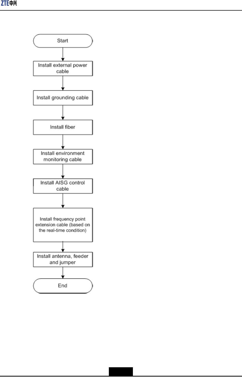
4.4.2ExternalCableInstallationFlow
Figure4-34liststheinstallationowofexternalcable.Thisowcanbeadjustedbasedon
actualconditions.
4-24
SJ-20110104194923-001|2011-01-19(R1.0)ZTEProprietaryandCondential
ZXSDRR8882L200UserManual
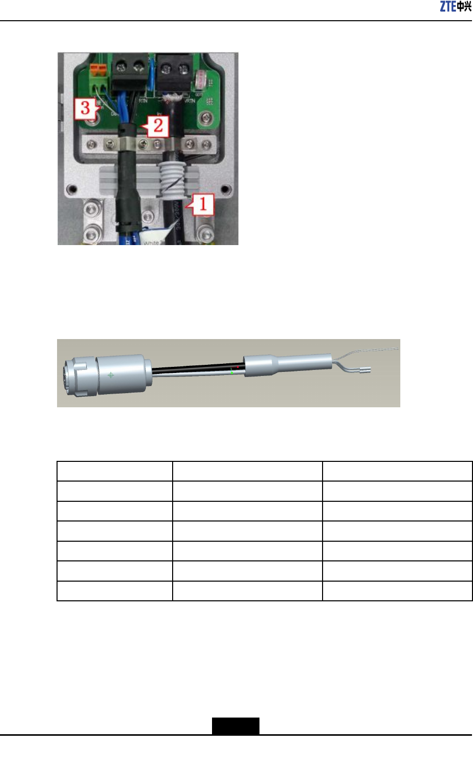
Figure4-35PIMDCPowerCableConnection
1.Powerinputcableofthe
PIMDC
2.Powerinputcableofthe
R8882
3.Drycontactcable
Figure4-36showsthepowercableofZXSDRR8882L200.
Figure4-36PowerCable
Table4-3describesthecoloranddenitionofinnercoreofthepowercable.
Table4-3ColorandDenitionofInnerCoreofthePowerCable
CorecolorDenitionSignalDescription
Blue-48V-48V
Blue-48V-48V
Black-48VGND-48Vground
Black-48VGND-48Vground
WhiteNODE_IN+Drycontact
BrownNODE_IN-Drycontact
4-26
SJ-20110104194923-001|2011-01-19(R1.0)ZTEProprietaryandCondential
Chapter4ProductInstallation
Note:
1.Ifthetwo-corecableisadopted,thebluecorecablestandsfor-48Vandtheblack
corecablestandsfor-48VGND.
2.Ifthefour-corecableisadopted,thetwobluecorecablesconnectedinparallelstand
for-48Vandtheblackcorecablesconnectedinparallelstandfor-48VGND.
Steps
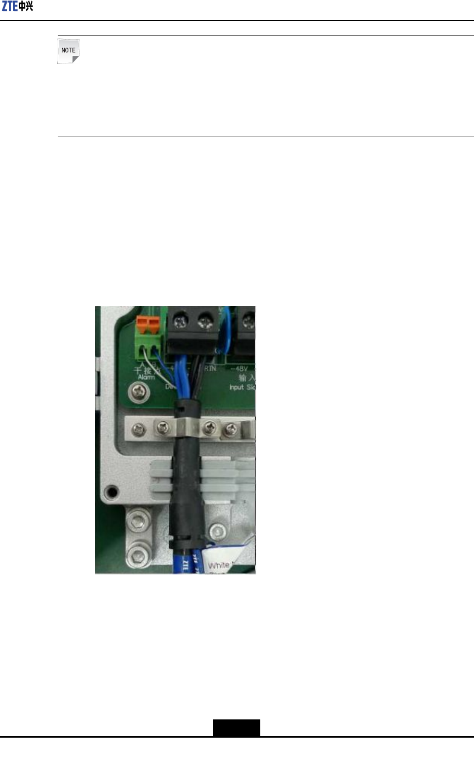
1.ConnectpowercablefromPIMDCtoZXSDRR8882L200
a.ConnectendAofpowercabletothePWRinterfaceoftheZXSDRR8882L200.
b.StriptheprotectivecoatofendB,andthenconnectthebluewiresto-48Vterminal
andtheblackwiresto-48VRTNterminal.Connectthewhiteandbluedrycontact
wirestotheAlarmterminals,asshowninFigure4-37.
Figure4-37PIMDCConnection(toR8882)
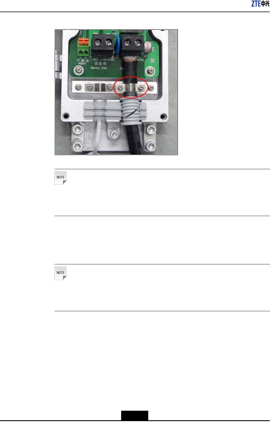
2.ConnectpowercablefromPIMDCtolightningprotectionbox
a.PeeloffanappropriatelengthofinsulatinglayerofthePIMDCpowerinputcable.
b.LeadtheendAofthecablethroughthewaterproofplasticringofthePIMDC,
andthenconnectthebluewirestothe-48Vterminalandtheblackwirestothe
-48VRTNterminal.Fastenthepowercablewithalatch,asshowninFigure4-38.
4-27
SJ-20110104194923-001|2011-01-19(R1.0)ZTEProprietaryandCondential
ZXSDRR8882L200UserManual
Figure4-38PIMDCConnection(toLightningProtectionBox)
Note:
ThislatchshouldbefullycontactedwiththeshieldedlayerofthePIMDCinput
powercable.
c.ConnecttheendBofthePIMDCinputpowercabletotheoutputportoftheindoor
DClightningprotectionbox.Connectthebluewirestothe-48Vterminalandthe
blackwirestothe-48VRTNterminal.
Note:
Powerforsectorsα,β,andγareconnectedtoSPD-1,SPD-2,andSPD-3
terminalsrespectively.
–EndofSteps–
4.4.4ConnectingGroundingCable
Context
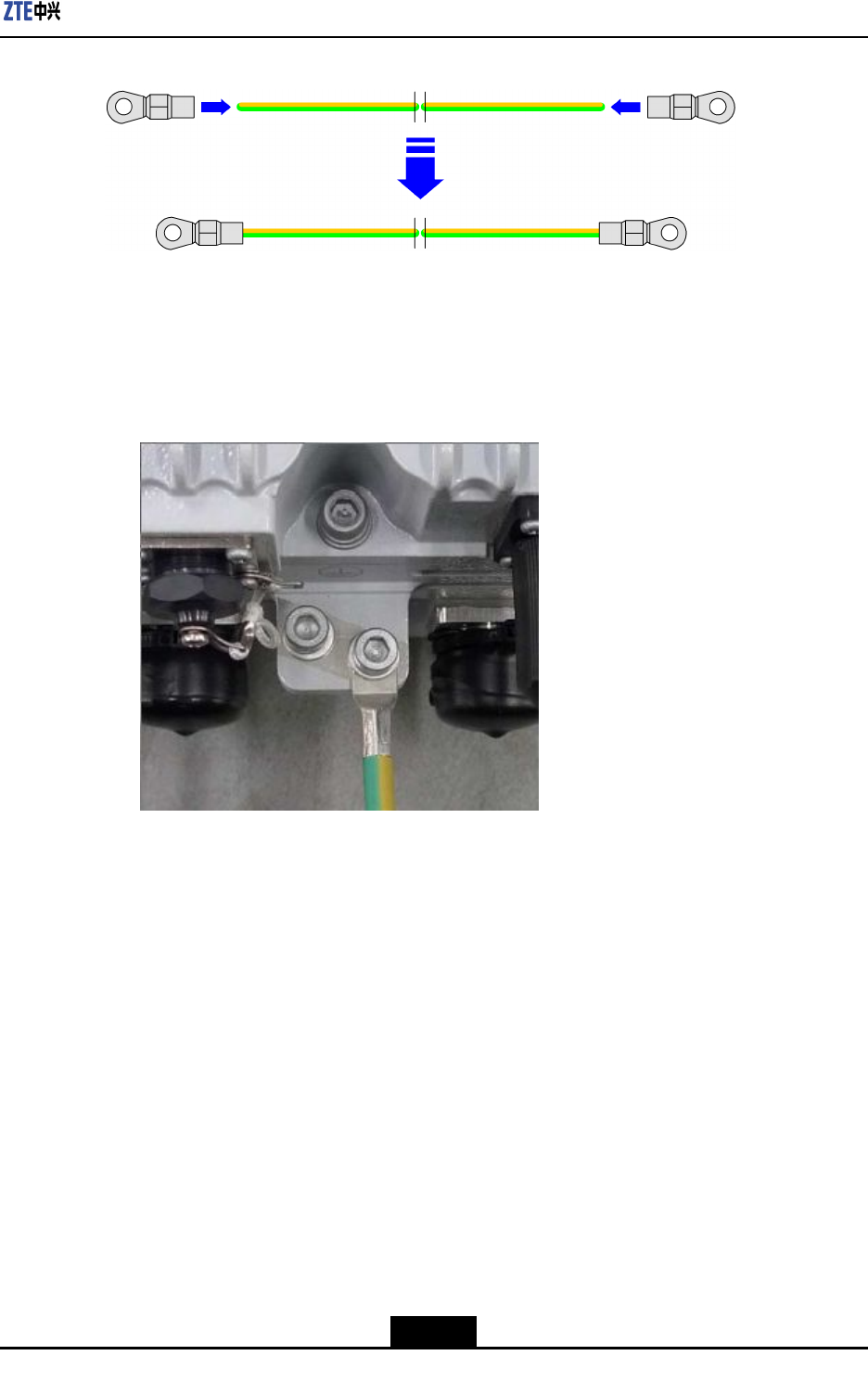
ThegroundingcableofZXSDRR8882L200ismadeupofstrandsofame-retardantwire.
Copperlugsareneededtobecrimpedatbothendsofthegroundingcableinadvance,as
showninFigure4-39.
4-28
SJ-20110104194923-001|2011-01-19(R1.0)ZTEProprietaryandCondential
Chapter4ProductInstallation
Figure4-39GroundingCable
Steps
1.Connectoneendofgroundingcabletothegroundingterminalofthedevice,asshown
inFigure4-40.
Figure4-40R8882GroundingBarConnection
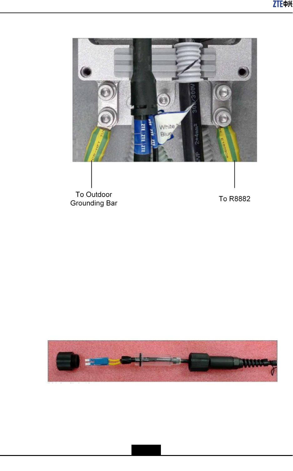
2.ConnecttheotherendofthegroundcabletoPIMDC,andthenconnectionthePIMDC
tooutdoorgroundingbar,asshowninFigure4-41.
4-29
SJ-20110104194923-001|2011-01-19(R1.0)ZTEProprietaryandCondential
ZXSDRR8882L200UserManual
Figure4-41PIMDCGroundingBarConnection
3.Attachthelabelonthegroundingcable.
4.Measurethegroundingresistanceandmakesureitislessthan5ohms.
–EndofSteps–
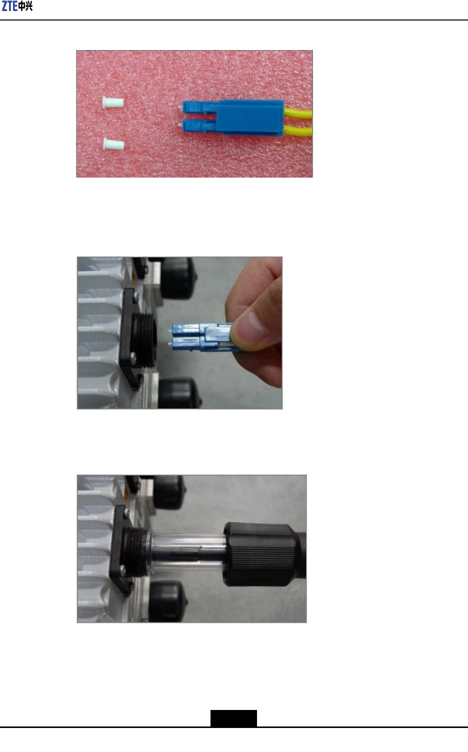
4.4.5ConnectingFiberBetweeneBBUandeRRU
Steps
1.Removetheprotectioncapfromtheopticalber,andthendetachtheouterprotection
cover,asshowninFigure4-42.
Figure4-42RemoveProtectionCap
2.Removetwowhitecovers,asshowninFigure4-43.
4-30
SJ-20110104194923-001|2011-01-19(R1.0)ZTEProprietaryandCondential
Chapter4ProductInstallation
Figure4-43RemoveCovers
3.InserttheopticalberintotheOPT1portuntilitlocksintoplacewithasnap,asshown
inFigure4-44.
Figure4-44InsertOpticalFiber
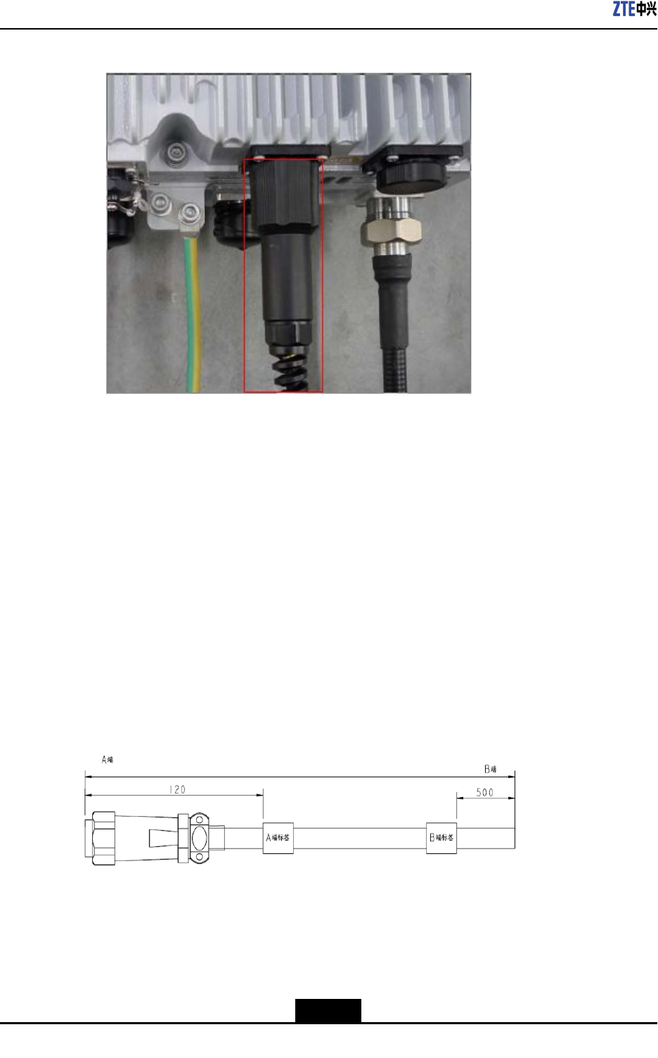
4.InsertthetransparentsleeveintotheOPTportfully,asshowninFigure4-45.
Figure4-45InsertTransparentSleeve
5.Tightentheouterprotectioncoverfully.
4-31
SJ-20110104194923-001|2011-01-19(R1.0)ZTEProprietaryandCondential
ZXSDRR8882L200UserManual
Figure4-46TightenConnection
6.Connecttheopticalbersofsectorsα,β,andγtotheTX0/RX0,TX1/RX1,and
TX2/RX2portsoftheBPLboardlocatedintheeBBU.
–EndofSteps–
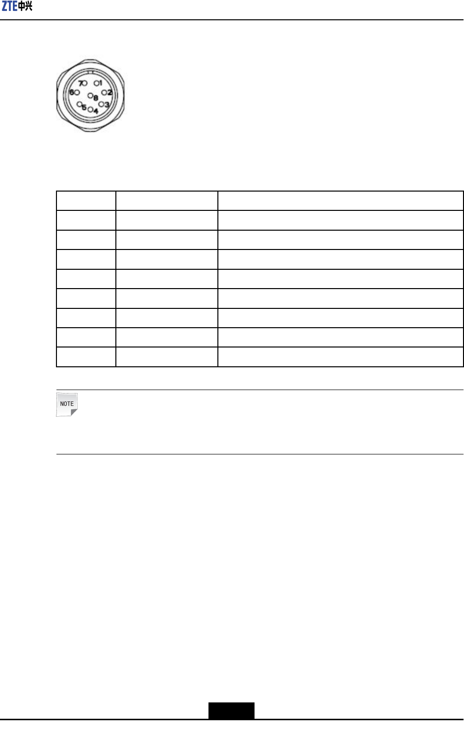
4.4.6ConnectingEnvironmentMonitorCable
Context
Theenvironmentmonitorcableprovidesa485interface,usedforZXSDRR8882L200
environmentmonitor.Italsoprovidesfourextensionaccessesforexternaldrycontact
monitor.
EndAiscircular8-coreplugandendBismadedependingonactualconditions.Thetotal
lengthis3m.Figure4-47showsthestructureofenvironmentmonitorcable.
Figure4-47EnvironmentMonitorCable
Theconnector,connectingtheenvironmentmonitoringcabletoZXSDRR8882L200,is
8-corestraightweldedconnector(pin)mountedonpanel.Theconnectorappearanceis
showninFigure4-48.
4-32
SJ-20110104194923-001|2011-01-19(R1.0)ZTEProprietaryandCondential
Chapter4ProductInstallation
Figure4-48AppearanceofEnvironmentMonitorCable
ThecableconnectorpinsandconnectionareshowninT able4-4.
Table4-4CablePinDescription
PinCorecolorSignalDescription
PIN1BrownDrycontactinput,positivepolarity
PIN2YellowDrycontactinput,negativepolarity
PIN3BlueDrycontactinput,positivepolarity
PIN4WhiteDrycontactinput,negativepolarity
PIN5GreenPositiveRS485bussignal
PIN6GreyNegativeRS485bussignal
PIN7RedPositiveRS485bussignal
PIN8BlackNegativeRS485bussignal
Note:
ConnecttherstdrycontactofeRRUtooutdoorDClightningprotectionbox.
Steps
1.ConnectendAofenvironmentmonitorcabletoenvironmentmonitorinterfaceof
ZXSDRR8882L200cabinet.
2.ConnectendBofenvironmentmonitorcabletoexternalmonitorpartordrycontact.
3.AttachthelabelsonendB.
–EndofSteps–
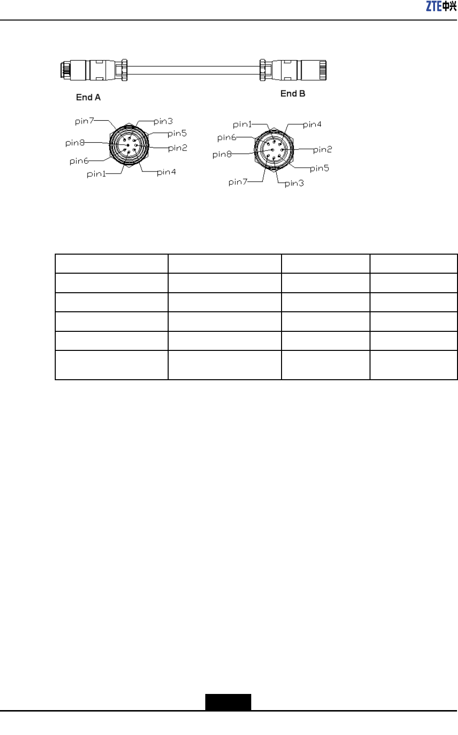
4.4.7ConnectingAISGControlCable
Context
AISGisusedtocontroltheelectrical-adjustmentantenna.
Figure4-49showsthestructureofAISGcontrolcable.
4-33
SJ-20110104194923-001|2011-01-19(R1.0)ZTEProprietaryandCondential
ZXSDRR8882L200UserManual
Figure4-49StructureofAISGControlCable
Table4-5describesthemeaningofsequencenumberofAISGcontrolcable.
Table4-5MeaningofSequenceNumberofAISGControlCable
PinsatendAPinsatEndBNameMeaning
PIN3PIN1RS485BRS485-
PIN5PIN2RS485ARS485+
PIN6PIN3,PIN4DCDCoutput
PIN7PIN5,PIN6DCRTNDCRTN
PIN1,PIN2,PIN4,PIN8NCNull
Steps
1.ConnectendAtoZXSDRR8882L200debugginginterface(AISG)andscrewdown
thebolt.
2.ConnectendBtothecontrolinterfaceofelectricaladjustmentantennaandscrew
downthebolt.
–EndofSteps–
4.4.8ConnectingtheRFJumpers
Steps
1.ConnecttheA-endsoftwoRFjumperstotheANT1andANT4portsoftheZXSDR
R8882L200.ConnecttheB-endtothecorrespondingportofthemainantenna.
2.Spiral-wraptwo-layerultraviolet-proofadhesivetapearoundtheANT2andANT3
ports,andthentightenthemfullybyusingblackultraviolet-proofcableties.
–EndofSteps–
4-34
SJ-20110104194923-001|2011-01-19(R1.0)ZTEProprietaryandCondential

Figures
Figure2-1ZTEDistributedeNodeBSolution.............................................................2-2
Figure2-2ProductLocation......................................................................................2-3
Figure2-3ProductOverallAppearance....................................................................2-5
Figure2-4StarNetworkingMode.............................................................................2-6
Figure2-5OperateandMaintainSystemRemotely..................................................2-6
Figure2-6OperateandMaintainSystemLocally......................................................2-7
Figure2-7ProductExternalInterfacesandGroundingTerminal................................2-7
Figure2-8LMTInterface..........................................................................................2-8
Figure2-9ProductIndicators....................................................................................2-9
Figure4-1TemplateHolePosition............................................................................4-7
Figure4-2InstallingWall-mountingComponents.....................................................4-7
Figure4-3Wall-mountingComponentsFixedonWall...............................................4-8
Figure4-4HangtheDeviceontheWall-mountingComponents...............................4-8
Figure4-5FastenDevice..........................................................................................4-9
Figure4-6ZXSDRR8882L200IsInstalledonWall..................................................4-9
Figure4-7AttachInstallationAccessoryforLightningProtectionBox.....................4-10
Figure4-8FixWall-mountingComponentsandPoleClips......................................4-10
Figure4-9FixWall-mountingComponentsandPoleClipsonPole.........................4-11
Figure4-10HangtheDeviceontheWall-mountingComponents............................4-11
Figure4-11FixtheDeviceontheWall-mountingComponents...............................4-12
Figure4-12ZXSDRR8882L200IsInstalledonPole..............................................4-12
Figure4-13AttachLightningProtectionBox...........................................................4-13
Figure4-14AttachInstallationAccessoryforLightningProtectionBox...................4-13
Figure4-15FixWall-mountingComponentsandPoleClips....................................4-14
Figure4-16FixWall-mountingComponentsandPoleClipsonPole.......................4-14
Figure4-17HangtheDevicesontheWall-mountingComponents..........................4-15
Figure4-18FixtheDevicesontheWall-mountingComponents.............................4-15
Figure4-19AttachLightningProtectionBox...........................................................4-16
Figure4-20AttachInstallationAccessoryforLightningProtectionBox...................4-16
Figure4-21FixWall-mountingComponentsandPoleClips....................................4-17
Figure4-22FixWall-mountingComponentsandPoleClipsonPole.......................4-17
Figure4-23FixtheThirdWall-mountingComponents.............................................4-18
I
SJ-20110104194923-001|2011-01-19(R1.0)ZTEProprietaryandCondential

ZXSDRR8882L200UserManual
Figure4-24HangtheDevicesontheWall-mountingComponents..........................4-18
Figure4-25AttachLightningProtectionBox..........................................................4-19
Figure4-26InstalltheVerticalShaftandtheBottomPlate.....................................4-19
Figure4-27FastentheVerticalShaftandtheCoverPlate.....................................4-20
Figure4-28InstalltheSlantedRack.......................................................................4-20
Figure4-29MarktheDrillingHolesPosition...........................................................4-21
Figure4-30InstalltheExpansionBolt.....................................................................4-21
Figure4-31InstalltheGantryonConcreteFloor....................................................4-22
Figure4-32InstalltheGantryonWoodenFloor......................................................4-22
Figure4-33ZXSDRR8882L200IsInstalledonGantry..........................................4-23
Figure4-34ExternalCableInstallationFlow...........................................................4-25
Figure4-35PIMDCPowerCableConnection.........................................................4-26
Figure4-36PowerCable........................................................................................4-26
Figure4-37PIMDCConnection(toR8882).............................................................4-27
Figure4-38PIMDCConnection(toLightningProtectionBox).................................4-28
Figure4-39GroundingCable..................................................................................4-29
Figure4-40R8882GroundingBarConnection.......................................................4-29
Figure4-41PIMDCGroundingBarConnection......................................................4-30
Figure4-42RemoveProtectionCap.......................................................................4-30
Figure4-43RemoveCovers...................................................................................4-31
Figure4-44InsertOpticalFiber...............................................................................4-31
Figure4-45InsertTransparentSleeve....................................................................4-31
Figure4-46TightenConnection..............................................................................4-32
Figure4-47EnvironmentMonitorCable..................................................................4-32
Figure4-48AppearanceofEnvironmentMonitorCable..........................................4-33
Figure4-49StructureofAISGControlCable..........................................................4-34
II
SJ-20110104194923-001|2011-01-19(R1.0)ZTEProprietaryandCondential

Tables
Table2-1ProductExternalInterfacesDescription.....................................................2-8
Table2-2ProductIndicatorDescription.....................................................................2-9
Table3-1CPRIInterfaceIndex.................................................................................3-2
Table3-2ReceiverSensitivity...................................................................................3-3
Table4-1Symboltypeandmeanings......................................................................4-1
Table4-2ConnectionofZXSDRR8882L200ExternalCables...............................4-23
Table4-3ColorandDenitionofInnerCoreofthePowerCable.............................4-26
Table4-4CablePinDescription..............................................................................4-33
Table4-5MeaningofSequenceNumberofAISGControlCable.............................4-34
III
SJ-20110104194923-001|2011-01-19(R1.0)ZTEProprietaryandCondential

Tables
Thispageintentionallyleftblank.
IV
SJ-20110104194923-001|2011-01-19(R1.0)ZTEProprietaryandCondential

Glossary
AISG
-AntennaInterfaceStandardsGroup
-天线接口标准组
CPRI
-CommonPublicRadioInterface
-通用公共无线接口
CRC
-CyclicRedundancyCheck
-循环冗余校验
FCC
-FederalCommunicationCommission
-联邦通信委员会(美国)
LED
-LightEmittingDiode
-发光二极管
QAM
-QuadratureAmplitudeModulation
-正交幅度调制
QPSK
-QuadraturePhaseShiftKeying
-四相移相键控/正交移相键控
SDR
-SoftwareDenedRadio
-软件定义无线电设备
VSWR
-VoltageStandingWaveRatio
-电压驻波比
eBBU
-evolvedBaseBandUnit
-演进的基带资源单元
eRRU
-evolvedRemoteRadioUnit
-演进的远端射频单元
V
SJ-20110104194923-001|2011-01-19(R1.0)ZTEProprietaryandCondential