ZTE RSU82C CDMA Remote Radio Unit User Manual users manual
ZTE Corporation CDMA Remote Radio Unit users manual
ZTE >
users manual

ZXSDRRSU82C
RadioSystemUnitofCDMAwith2T4R
UserManual
Version:1.00
ZTECORPORATION
NO.55,Hi-techRoadSouth,ShenZhen,P .R.China
Postcode:518057
Tel:+86-755-26771900
Fax:+86-755-26770801
URL:http://ensupport.zte.com.cn
E-mail:support@zte.com.cn

LEGALINFORMATION
Copyright©2011ZTECORPORATION.
Thecontentsofthisdocumentareprotectedbycopyrightlawsandinternationaltreaties.Anyreproductionor
distributionofthisdocumentoranyportionofthisdocument,inanyformbyanymeans,withoutthepriorwritten
consentofZTECORPORATIONisprohibited.Additionally,thecontentsofthisdocumentareprotectedby
contractualcondentialityobligations.
Allcompany,brandandproductnamesaretradeorservicemarks,orregisteredtradeorservicemarks,ofZTE
CORPORATIONoroftheirrespectiveowners.
Thisdocumentisprovided“asis”,andallexpress,implied,orstatutorywarranties,representationsorconditions
aredisclaimed,includingwithoutlimitationanyimpliedwarrantyofmerchantability,tnessforaparticularpurpose,
titleornon-infringement.ZTECORPORATIONanditslicensorsshallnotbeliablefordamagesresultingfromthe
useoforrelianceontheinformationcontainedherein.
ZTECORPORATIONoritslicensorsmayhavecurrentorpendingintellectualpropertyrightsorapplications
coveringthesubjectmatterofthisdocument.ExceptasexpresslyprovidedinanywrittenlicensebetweenZTE
CORPORATIONanditslicensee,theuserofthisdocumentshallnotacquireanylicensetothesubjectmatter
herein.
ZTECORPORATIONreservestherighttoupgradeormaketechnicalchangetothisproductwithoutfurthernotice.
UsersmayvisitZTEtechnicalsupportwebsitehttp://ensupport.zte.com.cntoinquirerelatedinformation.
TheultimaterighttointerpretthisproductresidesinZTECORPORATION.
RevisionHistory
RevisionNo.RevisionDateRevisionReason
R1.025/10/2010FirstEdion
R1.125/12/2010ModifyRFandPowerIndices
R1.208/08/2011AddthenotesofthetypicallossoftheRFcable
SerialNumber:SJ-20101019140047-001(R1.2)
PublishingDate:08/08/2011

FCC&ICSTATEMENT
ThisdevicecomplieswithPart15oftheFCCRules.Operationissubjecttothefollowing
twoconditions:(1)thisdevicemaynotcauseharmfulinterference,and(2)thisdevice
mustacceptanyinterferencereceived,includinginterferencethatmaycauseundesired
operation.
Note:
ThisequipmenthasbeentestedandfoundtocomplywiththelimitsforaClassAdigital
device,pursuanttoPart15oftheFCCRules.Theselimitsaredesignedtoprovide
reasonableprotectionagainstharmfulinterferencewhentheequipmentisoperatedin
acommercialenvironment.Thisequipmentgenerates,uses,andcanradiateradio
frequencyenergyand,ifnotinstalledandusedinaccordancewiththeinstructionmanual,
maycauseharmfulinterferencetoradiocommunications.
Operationofthisequipmentinaresidentialareaislikelytocauseharmfulinterferencein
whichcasetheuserwillberequiredtocorrecttheinterferenceathisownexpense.
I

II

FCCRadiationExposure
Statement
ThisequipmentcomplieswithFCCradiationexposurelimitssetforthforanuncontrolled
environment.Thisequipmentshouldbeinstalledandoperatedwithminimumdistance4m
betweentheradiator&yourbody.
I

II

DeclarationofRoHS
Compliance
Tominimizetheenvironmentalimpactandtakemoreresponsibilitytotheearthwelive,
thisdocumentshallserveasformaldeclarationthatZXSDRRSU82Cmanufacturedby
ZTECORPORATIONareincompliancewiththeDirective2002/95/ECoftheEuropean
Parliament-RoHS(RestrictionofHazardousSubstances)withrespecttothefollowing
substances:
lLead(Pb)
lMercury(Hg)
lCadmium(Cd)
lHexavalentChromium(Cr(VI))
lPolyBrominatedBiphenyls(PBB’s)
lPolyBrominatedDiphenylEthers(PBDE’s)
…
TheZXSDRRSU82CmanufacturedbyZTECORPORATIONmeettherequirementsofEU
2002/95/EC;however,someassembliesarecustomizedtoclientspecications.Additionof
specialized,customer-speciedmaterialsorprocesseswhichdonotmeettherequirementsof
EU2002/95/ECmaynegateRoHScomplianceoftheassembly.T oguaranteecomplianceofthe
assembly,theneedforcompliantproductmustbecommunicatedtoZTECORPORATIONinwritten
form.Thisdeclarationisissuedbasedonourcurrentlevelofknowledge.Sinceconditionsofuseare
outsideourcontrol,ZTECORPORATIONmakesnowarranties,expressorimplied,andassumesno
liabilityinconnectionwiththeuseofthisinformation.
I

II
Chapter1
SafetyDescription
TableofContents
SafetySpecicationsGuide........................................................................................1-1
SafetySymbols..........................................................................................................1-2
SafetyInstructions......................................................................................................1-3
1.1SafetySpecificationsGuide
Thesesafetyinstructionsmustbeconsideredassupplementaryforlocalsafety
regulations.Theprioritymustbegiventolocalsafetyregulationsifthereisanyconict
betweenthetwo.
Themaintenancepersonnelmusthavetheknowledgeofsafetyoperationsand
maintenancewithrequiredqualicationandtechnicalbackground.
Warning!
Thisdevicecomplieswithpart15oftheFCCRules.Operationissubjecttothefollowing
twoconditions:
lThisdevicemaynotcauseharmfulinterference.
lThisdevicemustacceptanyinterferencereceived,includinginterferencethatmay
causeundesiredoperation.
Changesormodicationsnotexpresslyapprovedbythepartyresponsibleforcompliance
couldvoidtheuser'sauthoritytooperatetheequipment.
TheequipmentisintendedforinstallationinRESTRICTEDACCESSLOCATIONS.
Alltheoperationandmaintenancepersonnelmustfollowthesafetyprecautionsand
instructionsprovidedbyZTECorporationtoavoidanyaccident.
Note:
ZTECorporationdoesnotbearanyliabilitiesincurredbecauseofviolationofthe
universalsafetyoperationrequirements,orviolationofsafetystandardsfordesigning,
manufacturingandusingtheequipment.
1-1
SJ-20101019140047-001(R1.2)|08/08/2011ZTEProprietaryandCondential
ZXSDRRSU82CUserManual
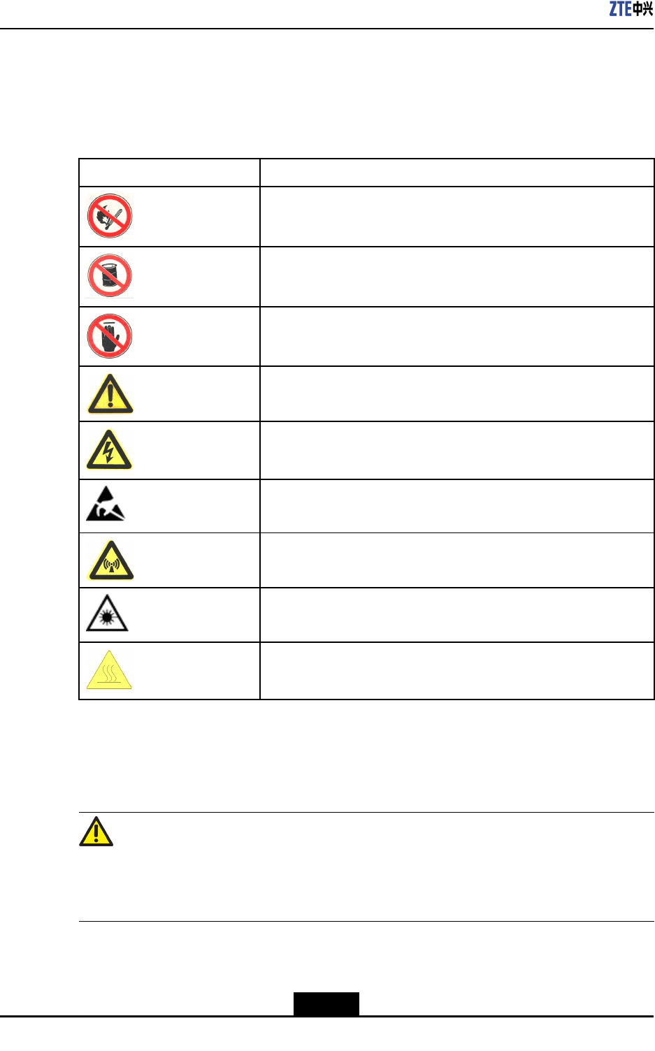
1.2SafetySymbols
Table1-1listssafetysymbols.Theyaretoprompttheuserofthesafetyprecautionstobe
observedduringZXSDRRSU82Coperationandmaintenance.
Table1-1SafetySymbolsDescription
SafetySymbolsMeaning
Nosmoking:Smokingisforbidden
Noammables:Noammablescanbestored.
Notouching:Donottouch.
Universalalertingsymbol:Generalsafetyattentions.
Electricshock:Riskofelectricshock.
Electrostatic:Thedevicemaybesensitivetostaticelectricity.
Microwave:Bewareofstrongelectromagneticeld.
Laser:Bewareofstronglaserbeam.
Scald:Bewareofscald.
Amongstthesesafetysymbols,theuniversalalarmsymbolsareclassiedintothreelevels:
danger,warning,andcaution.Theformatsandmeaningsofthethreelevelsaredescribed
asbelow:
Danger!
Indicatesapotentiallyhazardoussituationwhich,ifnotavoided,willresultindeathor
seriousinjuryofpeople,orequipmentdamagesandbreakdown.
1-2
SJ-20101019140047-001(R1.2)|08/08/2011ZTEProprietaryandCondential
Chapter1SafetyDescription
Warning!
Indicatesapotentiallyhazardoussituationwhich,ifnotavoided,couldresultindeathor
seriousinjury.
Caution!
Indicatesapotentiallyhazardoussituationwhich,ifnotavoided,couldresultinserious
injuries,equipmentdamagesorinterruptionofpartservices.
1.3SafetyInstructions
Thissectiondescribesthesafetyinstructionsrelatedtoelectricalsafety,antistatic,heavy
objectsandmodules.
ElectricalSafetyInstructions
Thefollowingaretheelectricalsafetyinstructionsabouttools,highvoltage,powercables,
holesandlightning:
lTools
Usespecialtoolsratherthancommontoolsforhigh-voltageandACoperations.
lHighVoltage
Danger!
Highvoltageishazardous.Directorindirectcontactwithhighvoltageormainsupply
usingawetobjectcouldresultindeath.
àStrictlyfollowlocalsafetyrulestoinstallACpowerdevices.
àInstallationstaffmustbequaliedforperforminghigh-voltageandACoperations.
àDonotwearanywatch,handchain,bracelet,ringoranyotherconductiveobjects
duringsuchoperations.
àPreventmoisturefromaccumulatingontheequipmentduringoperationsina
dampenvironment.
lPowerCable
1-3
SJ-20101019140047-001(R1.2)|08/08/2011ZTEProprietaryandCondential
ZXSDRRSU82CUserManual
Warning!
Neverinstalloruninstallpowercableswhiletheyarelive.Otherwise,thepowercable,
whencontactingaconductor,mayresultinsparksorelectricarccausingareoreven
damagetoeyes.
àMakesureofshuttingoffpowersupplybeforeinstallingordisconnectingapower
cable.
àBeforeconnectingthepowercable,makesurethattheconnectingcableandits
labelareappropriatefortheactualinstallationrequirements.
lDrillingHoles
Warning!
Itisnotallowedtodrillchassisholeswithoutpermission.
àUnqualieddrillingcoulddamagewiringandcablesinsidethechassis.
Additionally,metalpiecesinsidethechassiscreatedbythedrillingcouldresult
inashortcircuit.Useinsulationprotectionglovesandrstmovecablesinsidea
chassisawaywhendrillingisnecessaryonachassis.
àProtecteyesduringdrillingasdustoryingdebrismaydamageeyes.
àCleananydebrisintimeafterdrilling.
lLightning
Danger!
Donotperformhigh-voltage,AC,irontowerormastoperationsinathunderstorm.
Thunderstormswouldgiverisetoastrongelectromagneticeldintheatmosphere.
Therefore,theequipmentmustbegroundedandprotectedintimeagainstlightning
strikes.
1-4
SJ-20101019140047-001(R1.2)|08/08/2011ZTEProprietaryandCondential
Chapter1SafetyDescription
AntistaticSafetyInstructions
Caution!
Staticelectricityproducedbyhumanbodycandamagestatic-sensitivecomponentson
circuitboard,suchaslarge-scaleintegratedcircuits.
lFrictioncausedbyhumanbodyactivitiesistherootcauseofelectrostaticcharge
accumulation.Staticvoltagecarriedbyahumanbodyinadryenvironmentcanbe
upto30kV,andcanremainthereforalongtime.Anoperatorwithstaticelectricity
maydischargeelectricitythroughacomponentwhenhe/shetouchestheconductor
andcausingdamage.
lWearanantistaticwriststrap(theotherendofwriststrapmustbewellgrounded)
beforetouchingtheequipmentorholdingaplug-inboard,circuitboard,Integrated
Circuit(IC)chiporotherdevices,topreventhumanstaticelectricityfromdamaging
sensitivecomponents.
lTheantistaticwriststrapusedmustbesubjecttoregularcheck.Donotreplacethe
cableofanantistaticwriststrapwithanyothercables.
lDonotcontactstatic-sensitivemoduleswithanyobjectthateasilygeneratesstatic
electricity.Forexample,frictionofpackagebag,transferboxandtransferbeltmade
frominsulationplasticmaycausestaticelectricityoncomponents.Dischargeofstatic
electricitymaydamagecomponentswhentheycontactahumanbodyortheground.
lModulesshouldonlycontactmaterialssuchasanantistaticbag.Keepmodulesin
antistaticbagsduringstorageandtransportation.
lDischargestaticelectricityofthetestdevicebeforeuse,thatis,groundthetestdevice
rst.
lDonotplacethemodulenearastrongDCmagneticeld,suchasthecathode-ray
tubeofamonitor.Keepthemoduleatleast10cmaway.
HoistingHeavyObjects
Warning!
Whenhoistingheavyobjects,ensurethatnobodyisstandingorwalkingunderthehoisted
object.
lEnsurethehoistercanmeethoistingrequirementswhendisassemblingheavy
equipment,ormovingandreplacingequipment.
lTheinstallationpersonnelmustbedulytrainedandqualiedforhoistingoperations.
lHoistingtoolsmustbeinspectedandcompletebeforeservice.
1-5
SJ-20101019140047-001(R1.2)|08/08/2011ZTEProprietaryandCondential
ZXSDRRSU82CUserManual
lMakesurethathoistingtoolsarexedrmlyonasufcientlysecuredobjectorwall
beforethehoistingoperation.
lGivebrieforalinstructionsduringhoistingoperationstopreventanymishap.
Unplugging/PluggingaModule
lNeverplugamodulewithexcessiveforce,toensurethatthepinsonthebackplane
donotgetdeformed.
lPlugthemodulerightintotheslotandmakesuremodulecircuitfacesdonotcontact
eachotherlestanyshortcircuitmayoccur.
lKeephandsoffthemodulecircuit,components,connectorsandcabletroughwhen
holdingamodule.
RackMountSafetyInstructions
RackMountInstructions-Thefollowingorsimilarrack-mountinstructionsareincluded
withtheinstallationinstructions:
lElevatedOperatingAmbient-Ifinstalledinaclosedormulti-unitrackassembly,the
operatingambienttemperatureoftherackenvironmentmaybegreaterthanroom
ambient.Therefore,considerationshouldbegiventoinstallingtheequipmentinan
environmentcompatiblewiththemaximumambienttemperature(Tma)speciedby
themanufacturer.
lReducedAirFlow-Installationoftheequipmentinarackshouldbesuchthatthe
amountofairowrequiredforsafeoperationoftheequipmentisnotcompromised.
lMechanicalLoading-Mountingoftheequipmentintherackshouldbesuchthata
hazardousconditionisnotachievedduetounevenmechanicalloading.
lCircuitOverloading-Considerationshouldbegiventotheconnectionofthe
equipmenttothesupplycircuitandtheeffectthatoverloadingofthecircuitsmight
haveonovercurrentprotectionandsupplywiring.Appropriateconsiderationof
equipmentnameplateratingsshouldbeusedwhenaddressingthisconcern.
lReliableEarthing-Reliableearthingofrack-mountedequipmentshouldbe
maintained.Particularattentionshouldbegiventosupplyconnectionsotherthan
directconnectionstothebranchcircuit(e.g.useofpowerstrips).
OtherSafetyInstructions
Note:
Donotperformmaintenanceordebuggingindependently,unlessaqualiedpersonis
present.
lPerformanairtighttestbeforeRRUdelivery,andprohibitdisassemblingtheRRUon
site.
1-6
SJ-20101019140047-001(R1.2)|08/08/2011ZTEProprietaryandCondential
Chapter1SafetyDescription
lReplacinganypartsormakinganychangestotheequipmentmightresultinan
unexpecteddanger.Therefore,besurenottoreplaceanypartsorperformany
changestotheequipmentunlessauthorizedotherwise.
lDuetothatRRUisinhightemperatureduringrunning,theRRUshouldbeinstalled
insomeregionsoutofoperators'reachorstrictlyrestricted.
lContactZTEofceifyouhaveanyquestion,toensureyoursafety.
1-7
SJ-20101019140047-001(R1.2)|08/08/2011ZTEProprietaryandCondential

ZXSDRRSU82CUserManual
Thispageintentionallyleftblank.
1-8
SJ-20101019140047-001(R1.2)|08/08/2011ZTEProprietaryandCondential

Chapter2
ProductDescripition
TableofContents
Overview....................................................................................................................2-1
PositioninaNetwork..................................................................................................2-1
OuterView.................................................................................................................2-2
ProductionFunctions..................................................................................................2-3
ProductionFeatures...................................................................................................2-4
2.1Overview
ZTESoftwareDenedRadio(SDR)usesanarchitectureofseparatingthebaseband
partfromtheRadioFrequency(RF)part.Thisarchitecturefeatureshighintegration,
lowconsumption,exiblecongurationandconvenientinstallation&maintenance.The
newgenerationZTECDMABaseStation(BS)productsbasedontheSDRistherst
SDR-basedCDMABSintheindustry.Itisabletohelptheoperatorshavequalitative
leap.TheformofthisproductcanbedistributedBBU+RRUorBBU+RSU.Theproduct
formofZTESDRcanbedistributedBBU+RRUorBBU+RSU,macroBSormicroBS.
ZXSDRRSU82CistheRSUpartofZTECDMA2000distributedSDRCommonBTS
PlatformSolution.ItprovidesfunctionsincludingRFmodulation/demodulation,forward
poweramplication,reverselownoiseamplication,RFperformancemeasurementand
carrierpowercontroletc.
Withasmallersizeandlighterweight,theZXSDRRSU82Chassignicantadvantagesfor
savingspace,relocations,installationexibility,andpowersavings.Itdesignedforboth
indoorandoutdoorapplications.
2.2PositioninaNetwork
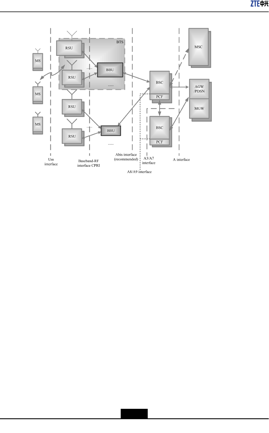
InCDMAmobilecommunicationnetwork,therelationshipbetweenZXSDRRSU82Cand
othernetworkentitiesisshowninFigure2-1.
2-1
SJ-20101019140047-001(R1.2)|08/08/2011ZTEProprietaryandCondential
ZXSDRRSU82CUserManual
Figure2-1ZXSDRRSU82CPositioninaNetwork
TheZXSDRRSU82CisanindependentRFsubsystem.TogetherwithBBU,itforms
thecompleteBTS.TheBTSimplementsradiotransmissionwiththeMSthroughthe
CDMA2000airinterface.Inaddition,theBTSimplementscontrolofradiochannelsand
communicationwiththeBSC
2.3OuterView
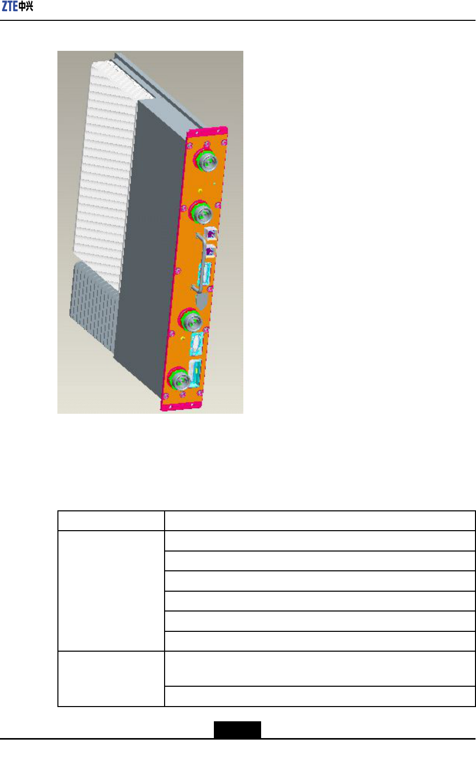
Figure2-2showstheouterviewofZXSDRRSU82C.
2-2
SJ-20101019140047-001(R1.2)|08/08/2011ZTEProprietaryandCondential
Chapter2ProductDescripition
Figure2-2OuterViewofZXSDRRSU82C
2.4ProductionFunctions
ZXSDRRSU82CprovidesprimaryfunctionsisshownasT able2-1.
Table2-1ThePrimaryFunctionsofZXSDRRSU82C
FunctionDescription
Band:800MHz/1.9GHz/2.1GHz
RFmodulation/demodulation
RFtransceiverduplexer
LownoiseamplicationforreceivedRFsignal
AmplicationfortransmittedRFsignal
RF
RFtransceiver
Baseband-RFinterface:compliantwithCommonPublicRadioInterface
(CPRI)protocol
Interface
Airinterface:compliantwithIS-2000ReleaseAandIS-856-A
2-3
SJ-20101019140047-001(R1.2)|08/08/2011ZTEProprietaryandCondential

ZXSDRRSU82CUserManual
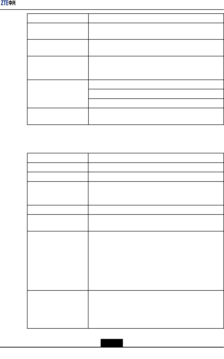
FunctionDescription
Electroniclabel
RemoteupgradeofsoftwareversionforFPGA/BOOT/DSP/CPU
Remoteresetofserviceboards
RSSIquery
Automaticcalibration
Reversespectrumquery:queryingthereversereceivedsignalspectrumof
eachcarrier
Equipment
maintenanceandtest
Poweramplicationcontrolandprotection:over-power,over-temperature,
andstandingwavealarm
ReliabilityReversevoltageprotection
ScenarioIndoorandoutdoorapplications
2.5ProductionFeatures
HerearetheproductfeaturesofZXSDRRSU82C:
lItadoptsmultiplenewtechnologiesinheatdissipationandconnectionmode;hence
itfeatureshighintegrationandcompactstructure.
lItadoptsthesingle-sideddesigninwhichdualduplexerscarrythetransceiver,power
module,andpoweramplicationmodule.
lItistherstRSUthatsupportsthe2T4Rapplicationintheindustry.
lEasytransportationandinstallationwillsavelaborandbuildingcosts
lSuitableforcomplicatedbasestationenvironments
SupportsstarandchainnetworksbetweenbasebandandRFtoprovidemore
convenientsolutionsforcomplicatedbasestationenvironments.
2-4
SJ-20101019140047-001(R1.2)|08/08/2011ZTEProprietaryandCondential
Chapter3
TechnicalDescripition
TableofContents
SystemArchitecture...................................................................................................3-1
SignalProcessingFlow..............................................................................................3-2
TechnicalSpecications.............................................................................................3-2
3.1SystemArchitecture
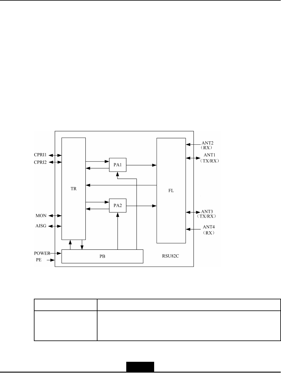
TheZXSDRRSU82Ccomprisestransceiverunit(TR),poweramplierunit(PA),duplexer
unit(FL),andpowerunit(PB).Figure3-1illustratestheZXSDRRSU82C’ssystem
architecture.
Figure3-1FrameStructureofZXSDRRSU82C
ThefunctionsofZXSDRRSU82C’ssubsystemisshownasTable3-1.
Table3-1Thefunctionsofsubsystem
PartDescription
TR
TR,theunitthatintegratestheprocessor,clock,CPRIinterface,DPD
digitalpredistortion,RFtransmittingandreceivingfunctions,isthecore
unitoftheZXSDRRSU82C.
3-1
SJ-20101019140047-001(R1.2)|08/08/2011ZTEProprietaryandCondential

ZXSDRRSU82CUserManual
PartDescription
PA
lAmpliesdownlinkRFsignalinputviatheTRandthensendsthe
signaltotheFL
lProvidesdigitalpre-distortionfeedbacksignalsfortheTR
lProvidesaPAoutputenable/disableinterface
FL
lPerformslteringandlownoiseamplicationofthereverseCDMA
signalfromtheantenna
lFilterstheforwardRFsignaltobesent
lReportsLNAalarmstotheTR
lInthecaseofmain/diversitycombinedcabinets,themainreceive
LNAoutputendoftheFLhasthepowersplitterfunctionandreserves
anexternalport(Rxout)
PB
Converts-48VDCinputpowersupplytoDCpowersupplyrequiredby
thePA,TR,orFL
3.2SignalProcessingFlow
TheinternalsignalprocessingowofZXSDRRSU82Cisasbelow:
lForwardlinkprocessing
ThebusinessdatafromBBUenterstheTR,andthenforintermediatefrequency
processing.Afterthepoweramplicationsenttotheantennafortransmission.
lReverselinkprocessing
ThereverseCDMAsignalsfromtheantennaareconvertedtobasebanddigitalsignal
byTR,thensendtoBBU.
3.3TechnicalSpecifications
3.3.1PhysicalIndices
3.3.1.1Dimension
ThedimensionsofZXSDRRSU82Cinmmare:482.6(H)×88(W)×360.0(D).
3.3.1.2Weight
WeightofaZXSDRRSU82C:<15kg(33.1pounds).
3.3.2PowerIndices
lPowerSupply
3-2
SJ-20101019140047-001(R1.2)|08/08/2011ZTEProprietaryandCondential
Chapter3TechnicalDescripition
-48VDCVoltagerange:-40V~-57V.
lPowerConsumption
Inthecaseof2S-2T ,4C/S,15W/C,thetotalpowerconsumptionoftheequipmentis
600W.
3.3.3CapacityIndices
ZXSDRRSU82CCapacityIndicesisshownasTable3-2
Table3-2ZXSDRRSU82CCapacityIndices
ItemCarrierssupported
14C1X+4C1X
24C1X+4CDO
34CDO+4CDO
4theMAX8C/2S-2T
3.3.4TemperatureandHumidity
Temperature:-40℃~+55℃.Thechangefrequencymustbelessthan0.5℃/min.
Relativehumidity:5%~95%
3.3.5EnvironmentalClasses
lGradeOfProtection:IP55
lGroundingRequirements:Jointgroundingresistanceless1W;BTSgrounding
resistanceless5W.
lNoise:Noiseofworkingenvironment:less65dBA
3.3.6ReliabilityIndices
lMeanTimeBetweenFailures(MTBF):>100,000hours
lMTTR(MeanTimeT oRepair):<0.5hour
lAvailability:>99.999%
3.3.7RFIndices
RFindicesoftheZXSDRRSU82Ccomplywith3GPP2C.S0010-C,Recommended
MinimumPerformanceStandardsforcdma2000SpreadSpectrumBaseStationand
3GPP2C.S0032-A,RecommendedMinimumPerformanceStandardsforCDMA2000
HighRatePacketDataAccessNetwork.
Table3-3illustratesthe1.9GHztransmitterindices.
3-3
SJ-20101019140047-001(R1.2)|08/08/2011ZTEProprietaryandCondential
ZXSDRRSU82CUserManual
Table3-31.9GHzTransmitterIndices
NameIndex
Operatingband1.9GHz(1930MHz~1950MHz)
Transmitteroutputfrequency
tolerance
±0.01ppm
Occupiedchannelbandwidth1.25MHz
OutputpowerattheT opof
Cabinet(TOC)
60W
TotaltransmitpowerThetotaltransmitpoweriswithin+2dBand-2dBofthe
manufacturer’sratedpower.
ModulationmodeQuadratureamplitudemodulation
Conductedspuriousemission
andradiatedspurious
emissionsuppression
<-45dBc@±885kHzoffsetCenterFreq(RBW30kHz)
<-55dBc@±1.98MHzoffsetCenterFreq(RBW30kHz)
>4MHzOFFSET:
<-36dBm(RBW1kHz)@9KHz<f<150kHz
<-36dBm(RBW10kHz)@150kHz<f<30MHz
<-36dBm(RBW100kHz)@30MHz<f<1GHz
4-16MHzOFFSET:
<-30dBm(RBW30kHz)@1GHz<f<12.5GHz
16M-19.2MOFFSET:
<-30dBm(RBW300kHz)@1GHz<f<12.5GHz
>19.2MHzOFFSET:
<-30dBm(RBW1MHz)@1GHz<f<12.5GHz
Transmitterintermodulation
performance
IfoneBTStransmitsattheratedpowerbutanotherBTS’output
poweris30dBlessthantheformer’sratedpower.Whenthepowers
oftwoBTSsarecombinedontheantennaport,thegenerated
intermodulationspuriousemissionmeetstheconductedspurious
emissionrequirement.TheIFdifferenceofthetransmitsignalsof
twoBTSsis1.25M.
PilottimetoleranceThePNtimetolerancefallswithin3usandtheinter-carriertolerance
fallswithin1us.
Timedifference:<±50ns TimeT olerance/phase
toleranceofpilotchannelto
otherchannels
Phasedifference:<0.05rad
WaveformqualityRhoisgreaterthan0.990dBmunderthecongurationofasingle
pilot.
PilotcodedomainpowerWiththestandard9CHconguration,thepilotcodedomainpoweris
intherangeof-7.0±0.5dB.
3-4
SJ-20101019140047-001(R1.2)|08/08/2011ZTEProprietaryandCondential
Chapter3TechnicalDescripition
NameIndex
Inactivechannelcodedomain
power
Withthestandard9CHconguration,theinactivechannelcode
domainpowerislessthan-27dB.
DOMACinactivechannel
codedomainpower
Withcongurationof13FLUSs,theMACinactivechannelcode
domainpowerislessthan-29.5dB(type2).
DODATAchannelcode
domainpower
Withcongurationof13FLUSsattherateof614.44kbs(test1),
theDATAchannelcodedomainpowerisintherangeof-15.5dB
to-14.5dB.
Pilotchannel:Rho>0.97
MACchannel:Rho>0.912 WavequalityofDOchannels
DATAchannel:Rho>0.97
RadiofrequencyFrontEnd
SWR
<2.0
Table3-4illustratesthe1.9GHzreceiverindices.
Table3-41.9GHzReceiverIndices
NameIndex
Operatingband1.9GHz(1850MHz~1870MHz)
Receiversensitivity<-115dBm
Receiverdynamicrange
Whenthelowerlimitisthereceiversensitivityandtheupperlimit
(noiselevel)equals-55dBm/1.23MHz(Eb/N0=10dB±1dB),the
FrameErrorRate(FER)islowerthan1%.
Noisegure<3
Adjacentchannelselection
(ACS)
BandClass6:>-53dBm(±2.5M)
Singletonedesensitization
Inthepresenceofasingletonethatis50dBabovetheCDMAsignal
level,andisatoffsetof±750kHzfromthecenterfrequency,the
outputpoweroftheMSincreasesbynomorethan3dB,andthe
FERislessthan1.5%.
Inthepresenceofasingletonethatis75dBabovetheCDMAsignal
level,andisatoffsetof±900kHzfromthecenterfrequency,the
outputpoweroftheMSincreasesbynomorethan3dB,andthe
FERislessthan1.5%.
Intermodulationspurious
responseattenuation
Inthepresenceoftwointerferingtonesthatare60dBabovethe
CDMAsignallevel,andareatoffsetsof1.25MHzand2.05MHz,
and-1.25MHzand-2.05MHzfromthecenterfrequency,theoutput
poweroftheMSincreasesbynomorethan3dB,andtheFER
islessthan1.5%.
3-5
SJ-20101019140047-001(R1.2)|08/08/2011ZTEProprietaryandCondential
ZXSDRRSU82CUserManual
NameIndex
Conductedspurious
emissionsandradiated
spuriousemissions
<-80dBm,measuredwithintheBTSreceiveband
<-60dBm,measuredwithintheBTStransmitband
RadiofrequencyFrontEnd
SWR
<2.0
3.3.8InterfaceIndices
TheinterfaceindicesofZXSDRRSU82CisshownasTable3-5.
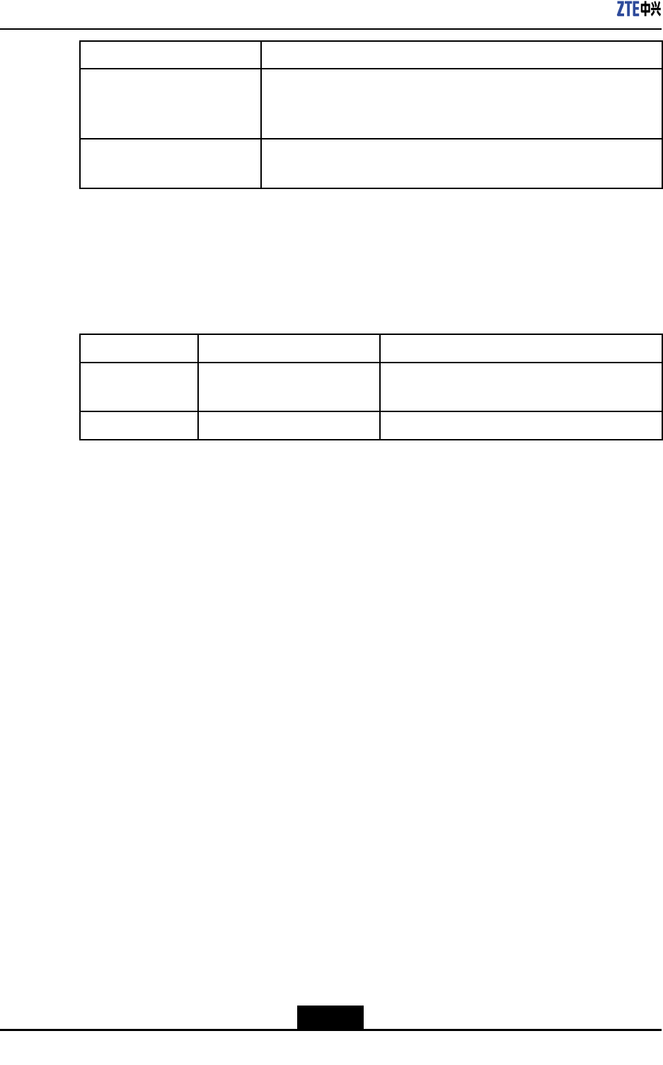
Table3-5DescriptionofZXSDRRSU82C’sinterfaces
TypeDescriptionIndex
CPRIFiber/Cable2CPRIinterfaces:1CPRIforBBUor
upper-levelRSU,1CPRIforlower-levelRSU
UEUminterface2Tx/Rx,2diversityreceivers
3-6
SJ-20101019140047-001(R1.2)|08/08/2011ZTEProprietaryandCondential

Chapter4
HardwareDecsripition
TableofContents
Function.....................................................................................................................4-1
Panel..........................................................................................................................4-1
Button........................................................................................................................4-2
Indicators...................................................................................................................4-3
PanelInterfaces.........................................................................................................4-4
4.1Function
RSUprovidesthefollowingfunctions:
lCommunicationwiththebasebandsubrack
lConversionbetweenairinterfaceRFsignalsanddigitalsignals
lRFsignalamplication,transmission,andreception
lClocksynchronization.
4.2Panel
Figure4-1illustratestheZXSDRRSU82Cpanel.
4-1
SJ-20101019140047-001(R1.2)|08/08/2011ZTEProprietaryandCondential
Chapter4HardwareDecsripition
4.4Indicators
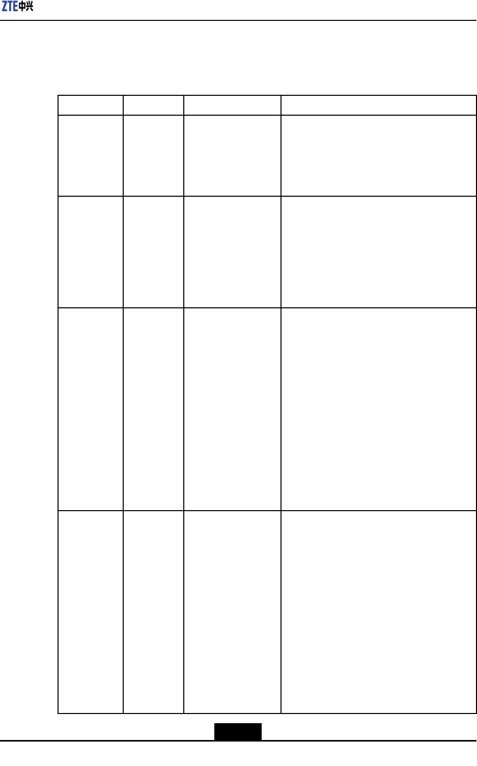
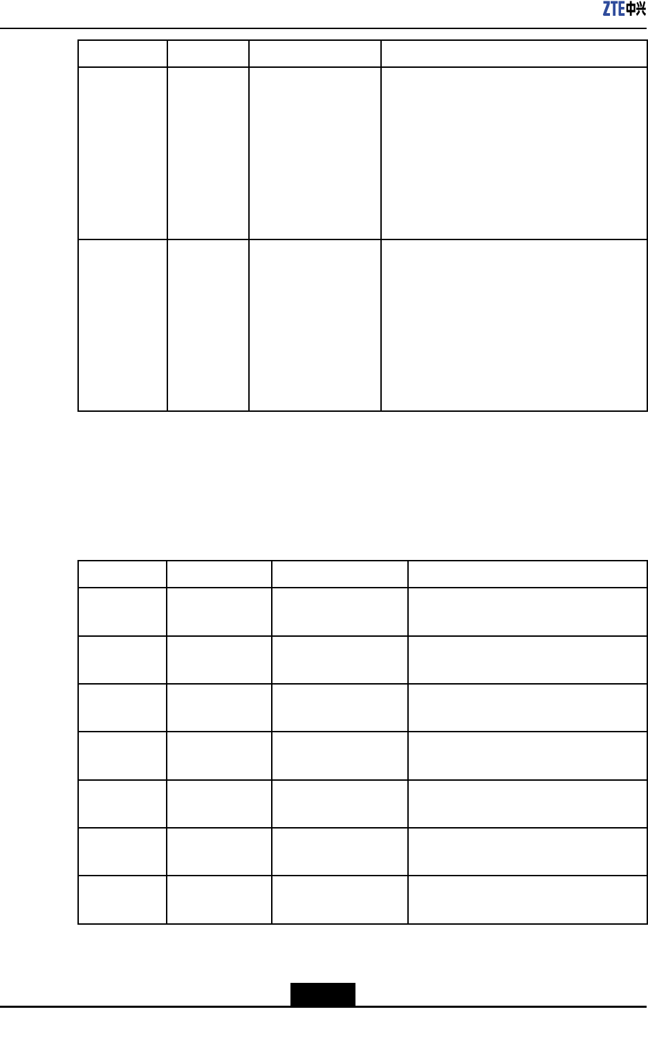
Table4-2describesZXSDRRSU82Cpanelindicators.
Table4-2ZXSDRRSU82CPanelIndicatorDescription
IndicatorColorMeaningDescription
RUNGreenRSUrunning
indicator
OnwhenRSUisbeingresetorstarted.
Blinksin1HzwhenRSUrunsnormally.
Blinksin5Hzwhentheversionisbeing
downloaded.
OffwhenSelftestfails.
ALMRedRSUalarmindicatorOffwhenRSUrunsnormallyorisbeing
resetorstarted,orRSUversionisbeing
downloaded.
Blinksin5Hzwhenacriticalalarmis
generated.
Blinksin1Hzwhenaminoralarmis
generated.
LNK1GreenIndicatoroftherst
opticalport/electrical
portconnection
A:Constantlyon.Theopticalberconnection
isnormal.
B:Flashesquickly(1Hz).Itindicatesthatthe
opticalportcommunicationisabnormal.
C:Off.Itindicatesthatthereisnooptical
moduleorthereisnoopticalsignal.(During
thepower-onprocess,theindicatorisinthis
statebydefault.)
Thisindicatorisusedmainlytocheckwhether
theopticalberlinkisconnectedontheeld.
Iftheindicatorashesortheindicatorison,it
indicatesthatthephysicalconnectionofthe
opticalberisnormal.
LNK2GreenIndicatorofthe
secondoptical
port/electricalport
connection
A:Constantlyon.Theopticalberconnection
isnormal.
B:Flashesquickly(1Hz).Itindicatesthatthe
opticalportcommunicationisabnormal.
C:Off.Itindicatesthatthereisnooptical
moduleorthereisnoopticalsignal.(During
thepower-onprocess,theindicatorisinthis
statebydefault.)
Thisindicatorisusedmainlytocheckwhether
theopticalberlinkisconnectedontheeld.
Iftheindicatorashesortheindicatorison,it
indicatesthatthephysicalconnectionofthe
opticalberisnormal.
4-3
SJ-20101019140047-001(R1.2)|08/08/2011ZTEProprietaryandCondential
ZXSDRRSU82CUserManual
IndicatorColorMeaningDescription
RF1Red/GreenRFsignalabnormal
indicatoroftherst
antennaport
A:Thegreenindicatorisconstantlyon.It
indicatesthattheRFoutputisnormal.
B:Theredindicatorisconstantlyon.It
indicatestheantennastandingwavealarm.
C:Thegreenindicatorisoff.Itindicatesthat
thereisnoRFoutput(orthepoweramplier
isshutoff.)(Duringthepower-onprocess,the
twoindicatorsareoffbydefault.)
RF2Red/GreenRFsignalabnormal
indicatorofthe
secondantennaport
A:Thegreenindicatorisconstantlyon.It
indicatesthattheRFoutputisnormal.
B:Theredindicatorisconstantlyon.It
indicatestheantennastandingwavealarm.
C:Thegreenindicatorisoff.Itindicatesthat
thereisnoRFoutput(orthepoweramplier
isshutoff.)(Duringthepower-onprocess,the
twoindicatorsareoffbydefault.)
4.5PanelInterfaces
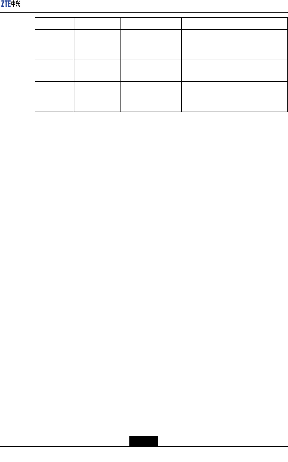
Table4-3describesZXSDRRSU82Cpanelinterfaces.
Table4-3ZXSDRRSU82CPanelInterfaceDescription
InterfaceEntityatendAEntityatendBDescription
ANT1
(TX1/RX1A)
RSUTherstTxantennaTherstTx/Rxantennafeederinterface
ANT2(RX1B)RSUTherstRxantennaTherstreceivediversityantennafeeder
interface
ANT3(TX2/
RX2A)
RSUThesecondTx
antenna
ThesecondTx/Rxantennafeeder
interface
ANT4(RX2B)RSUThesecondRx
antenna
Thesecondreceivediversityantenna
feederinterface
TX1RX1RSUBBUortheupperlevel
cascadedRSU
ConnectedtotheCPRIinterfaceofBBU
orupperlevelcascadedRSU
TX2RX2RSULowerlevelcascaded
RSU
ConnectedtotheCPRIinterfaceofthe
lowerlevelcascadedRSU
DBGRSUPCandtestdevice
(testboard)
Debuginterfaceandtestinterface
4-4
SJ-20101019140047-001(R1.2)|08/08/2011ZTEProprietaryandCondential
Chapter4HardwareDecsripition
InterfaceEntityatendAEntityatendBDescription
MONRSUPeripheralProvidesinputinterfaceforfourchannels
ofdrycontactsignalsandRS485
environmentmonitoringinterface
AISGRSUAntennafeederConnectedtoantennafeederAISG
interface
POWERRSUfrontpanelRFpowersupplyin
thepowerdistribution
subrack
-48VDCpowerinputinterface
4-5
SJ-20101019140047-001(R1.2)|08/08/2011ZTEProprietaryandCondential

ZXSDRRSU82CUserManual
Thispageintentionallyleftblank.
4-6
SJ-20101019140047-001(R1.2)|08/08/2011ZTEProprietaryandCondential

Chapter5
HardwareInstallation
TableofContents
InstallingtheRSUModule..........................................................................................5-1
ConnectingRSUMonitoringCable.............................................................................5-9
InstallingOpticalFibersBetweenBBUandRSU......................................................5-10
InstallingtheInterconnectedCableBetweenBBUandRSU.....................................5-12
InstallingtheRFJumper...........................................................................................5-15
5.1InstallingtheRSUModule
Prerequisites
lBeforeinstallingtheRFmodule,weartheESDwriststraptoavoiddamagingtheRF
module.
lTheRFcabinethasalreadybeeninstalled.
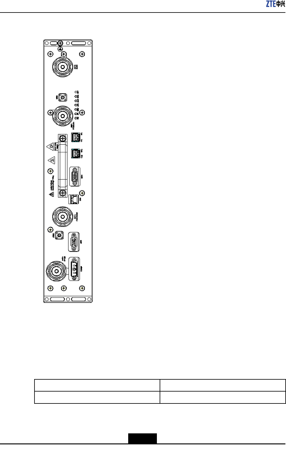
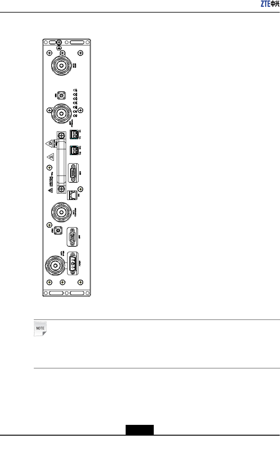
Context
Figure5-1showsthefrontpanelofaZXSDRRSU82C.
5-1
SJ-20101019140047-001(R1.2)|08/08/2011ZTEProprietaryandCondential
ZXSDRRSU82CUserManual
Figure5-1ZXSDRRSU82CPanel
Note:
WhenaZXSDRRSU82Cisusedinasingle-sectorandhigh-carrierscenario,theRF
jumperconnectsonlytotheANT1andANT3interfaces.
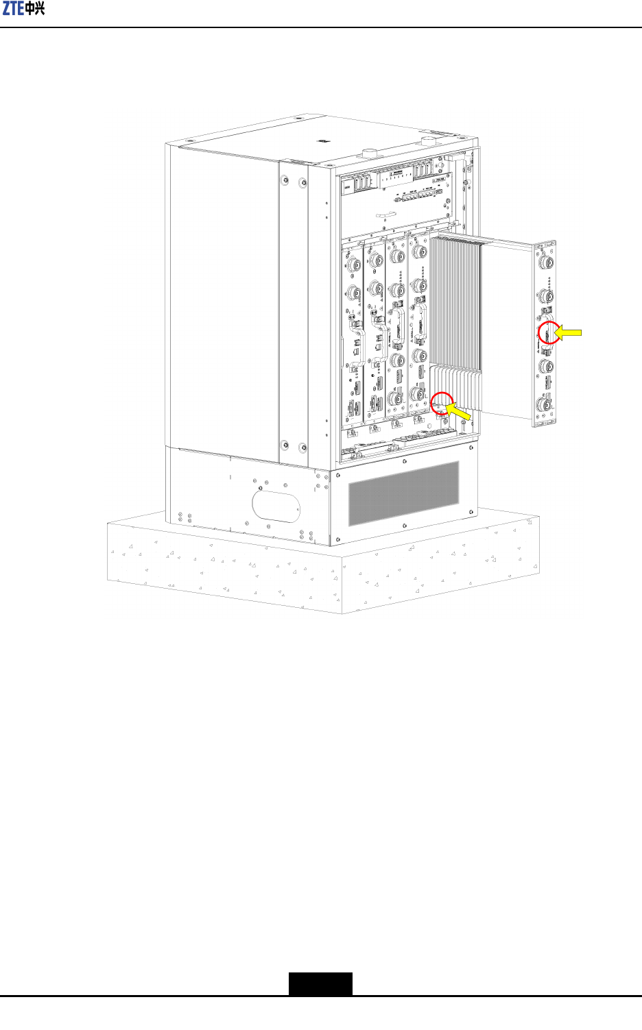
Steps
1.Determinethetargetslot,holdthehandleofthemodulewithonehand,supportthe
lowerbackofthemodulewiththeotherhand,andtrytomakeparallelthemoduleand
theguidingplane,asshowninFigure5-2.
5-2
SJ-20101019140047-001(R1.2)|08/08/2011ZTEProprietaryandCondential
Chapter5HardwareInstallation
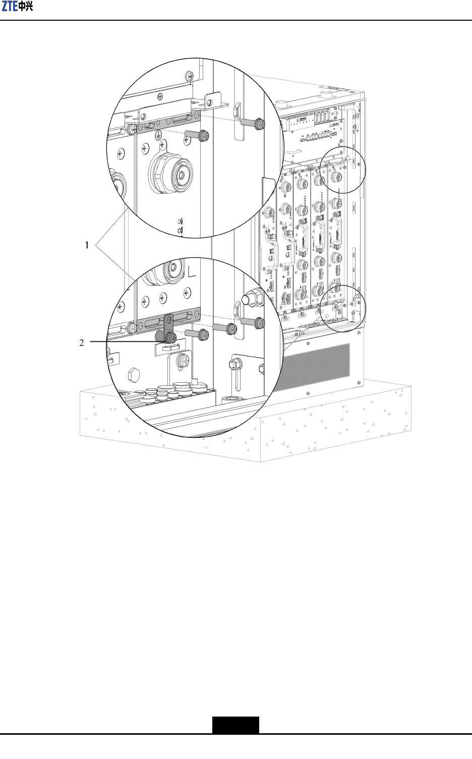
Figure5-6Step5
1.Fixingthecabinetwith
5M5x20screws
2.Fixingthegrounding
lug
6.Securethegroundlug.
AsshowninFigure5-6,theM5x20screwssecuresthegroundlugoftheRSUmodule
tothegroundpoints.
–EndofSteps–
Result
Figure5-7showsthecompletionofinstallingtheRFmodule.
5-7
SJ-20101019140047-001(R1.2)|08/08/2011ZTEProprietaryandCondential
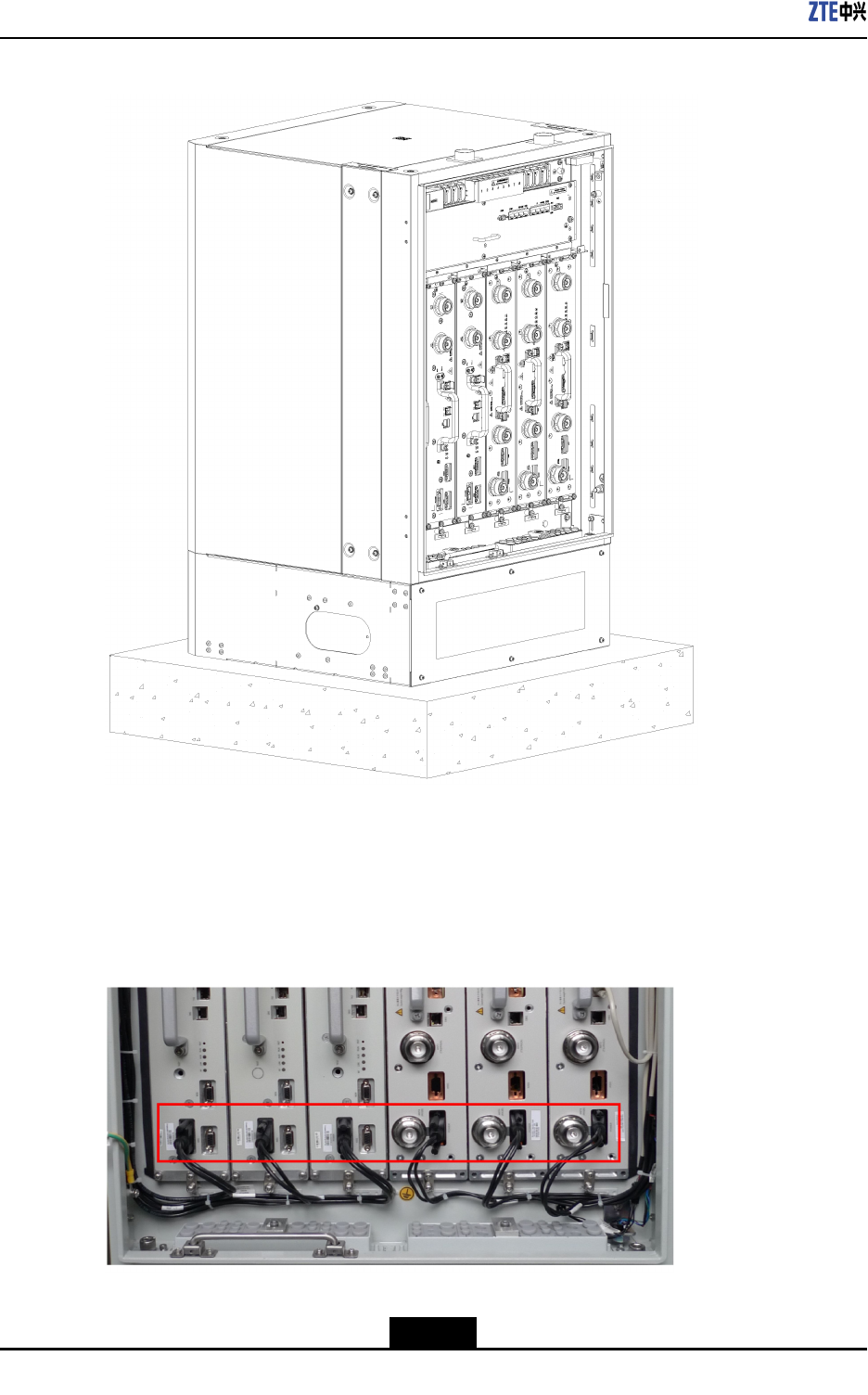
ZXSDRRSU82CUserManual
Figure5-7RSUModuleInstalledCompletely
Follow-UpAction
AfterinstallingRSUmodules,connecttheRSUpowercablestotheRSUpower
interfaces.RSUpowercableshavebeenroutedtoproperslots,asshowninFigure5-8.
Figure5-8PowerCableConnectingtheRSU
5-8
SJ-20101019140047-001(R1.2)|08/08/2011ZTEProprietaryandCondential
Chapter5HardwareInstallation
5.2ConnectingRSUMonitoringCable
Prerequisites
lZXSDRRSU82CRFcabinethasalreadybeeninstalled.
lTheRSUmodulehasalreadybeeninstalled.
Context
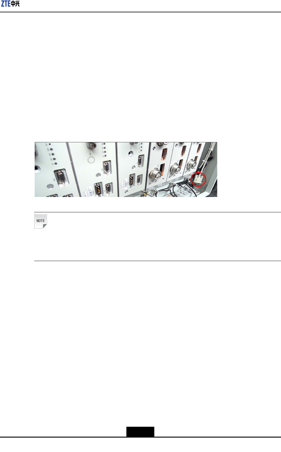
TheRSUmonitoringcableoftheRFcabinetisroutedtotherightsideoftheRFcabinet
indelivery,asshowninFigure5-9.AftertheRSUmoduleisinstalled,inserttheterminal
oftheRSUmonitoringcabletotheMON(monitoring)interfaceoftheRSUmodule.
Figure5-9RSUMonitoringCable
Note:
IfmultipleRSUmodulesneedtobemonitored,onlyoneRSUmoduleneedstobe
connectedtotheRSUmonitoringcable.
Steps
1.ConnectoneendoftheRSUmonitoringcabletotheMON(monitoring)interfaceof
theRSUmoduleandfastenthescrew.
2.BundletheRSUmonitoringcable.
Figure5-10showstheconnectedRSUmonitoringcable.
5-9
SJ-20101019140047-001(R1.2)|08/08/2011ZTEProprietaryandCondential
ZXSDRRSU82CUserManual
Figure5-10InstallingtheRSUMonitoringCable
–EndofSteps–
5.3InstallingOpticalFibersBetweenBBUandRSU
Prerequisites
lTheESDwriststrapmustbeworn.
lThebasebandpowercabinetandtheRFcabinethavebeenindependentlyinstalled.
Context
WhenthebasebandpowercabinetandtheRFcabinetareinstalledsidebysideorthey
arefarawayfromeachother,youneedtoconnectBBUandRSUusingopticalbers.
Payattentiontothefollowingpointswheninstallingopticalbers:
lDonotdamagetheopticalbercladdingduringoperations.
lProtectopticalberconnectorsandavoidcontaminatingthem.
lDonotforciblybundleopticalbers.
lCurveopticalbersattheturning.
Steps
1.Afxatemporarylabel.
5-10
SJ-20101019140047-001(R1.2)|08/08/2011ZTEProprietaryandCondential
Chapter5HardwareInstallation
Afxtemporarylabelstobothendsofthenewopticalbertosetupamapping.If
morethanoneopticalberneedstobeinstalled,usedifferentlabelstodifferentiate
opticalbers.
2.Routeopticalbers.
a.Opticalbersgooutfromthesidewaterproofmoduleofthebasebandmoduleand
gothroughtheroutingaperturesonthebase.
b.Then,opticalbersgothroughtheroutingaperturesonthebaseoftheRFcabinet,
traversethewaterproofmodules,andconnecttothesixopticalinterfacesforRF
modules.
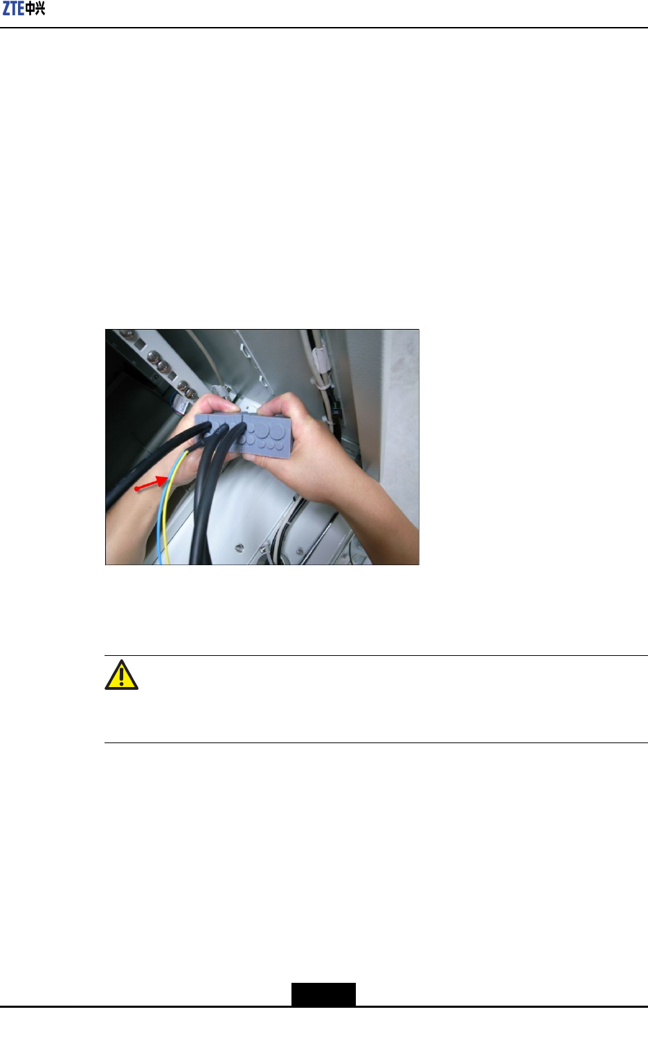
Figure5-11showshowopticalberstraversethewaterproofmodules.
Figure5-11WaterproofModulethroughWhichOpticalFibersPass
3.Insertopticalberconnectors.
Insertopticalberconnectorsaccordingtothemappingontemporarylabels.
Caution!
Insertopticalberconnectorstightly.
4.Bundleopticalbers.
Bundleandsecureopticalbersalongtheroutingtroughs,whichcomplieswith
relevantregulations.
5.Afxanengineeringlabeltoanopticalber.
Removethetemporarylabelfortheopticalberandafxanengineeringlabel.
5-11
SJ-20101019140047-001(R1.2)|08/08/2011ZTEProprietaryandCondential
ZXSDRRSU82CUserManual
Caution!
Protectanopticalberwiththewindingtubewhenroutingtheopticalberinsidethe
cabinet.Protectanopticalberwiththecorrugatedpipewhenroutingtheopticalber
outsidethecabinet.
–EndofSteps–
5.4InstallingtheInterconnectedCableBetweenBBU
andRSU
Prerequisites
lTheZXSDRRSU82Ccabinethasalreadybeeninstalled.
lTheBBUmoduleandRSUmodulehavealreadybeeninstalled.
Context
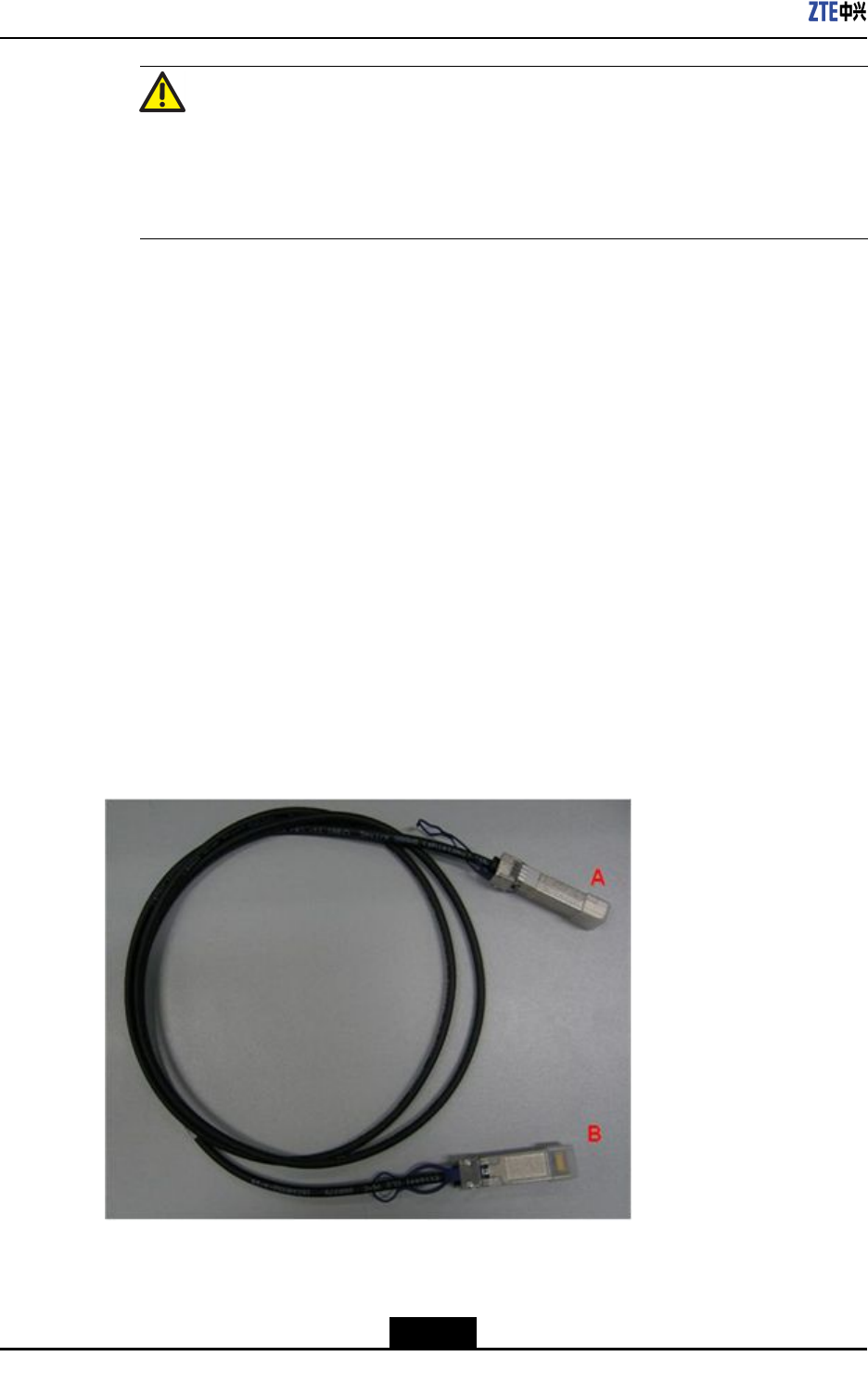
ZXSDRRSU82CInthesystem,opticalbersorSFPcablescanbeusedtoconnectBBU
andRSU.DuringthestackedinstallationoftheZXSDRRSU82C,a2mSFPhigh-speed
cableisrecommendedforinterconnectingBBUandRSU.Figure5-12showsanSFP
cable.
Figure5-12High-SpeedCable
5-12
SJ-20101019140047-001(R1.2)|08/08/2011ZTEProprietaryandCondential
Chapter5HardwareInstallation
Steps
1.AfxtemporarylabelstobothendsoftheSFRcable,withmarkings0-5tosetup
one-to-onemappingwithinterfacesTX0RX0toTX5RX5ofBBUandsixTX/RX
interfacesofRSU.
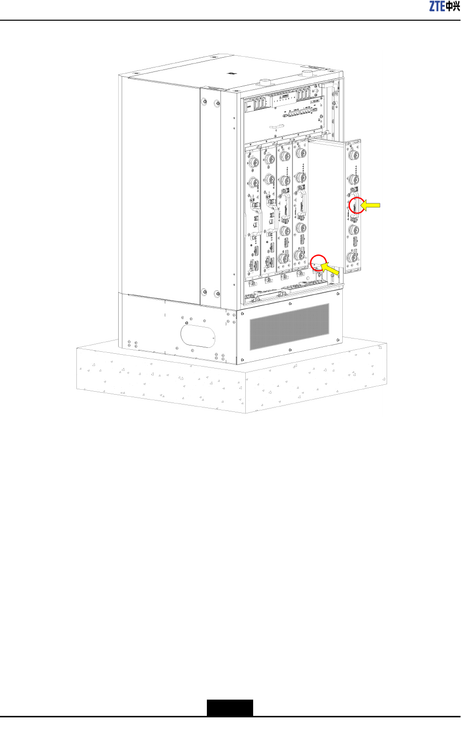
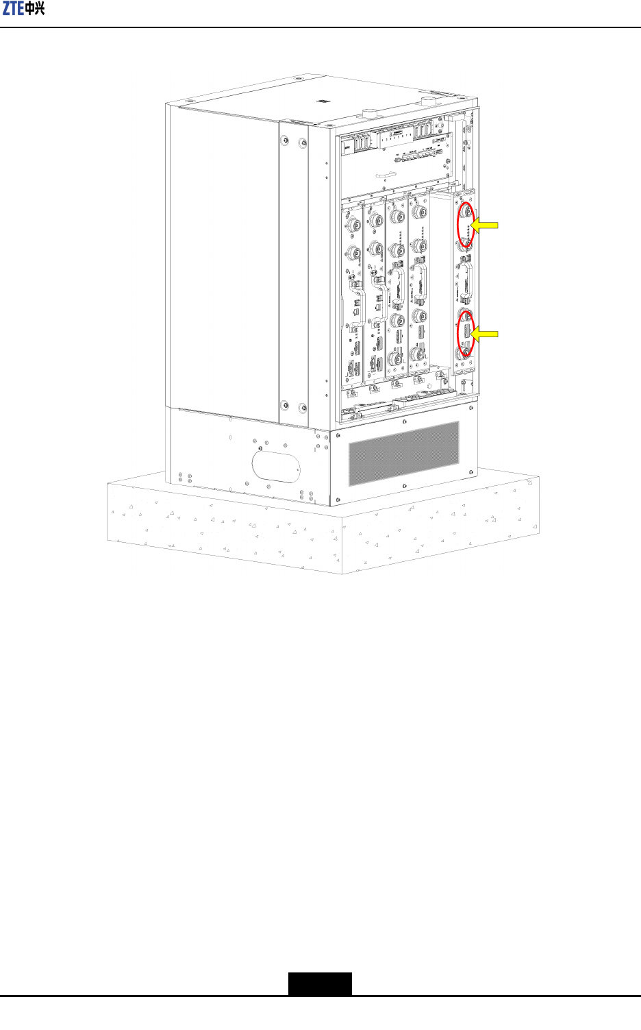
2.InsertoneendoftheSFPcabletoaTX/RXinterfaceofRSU.
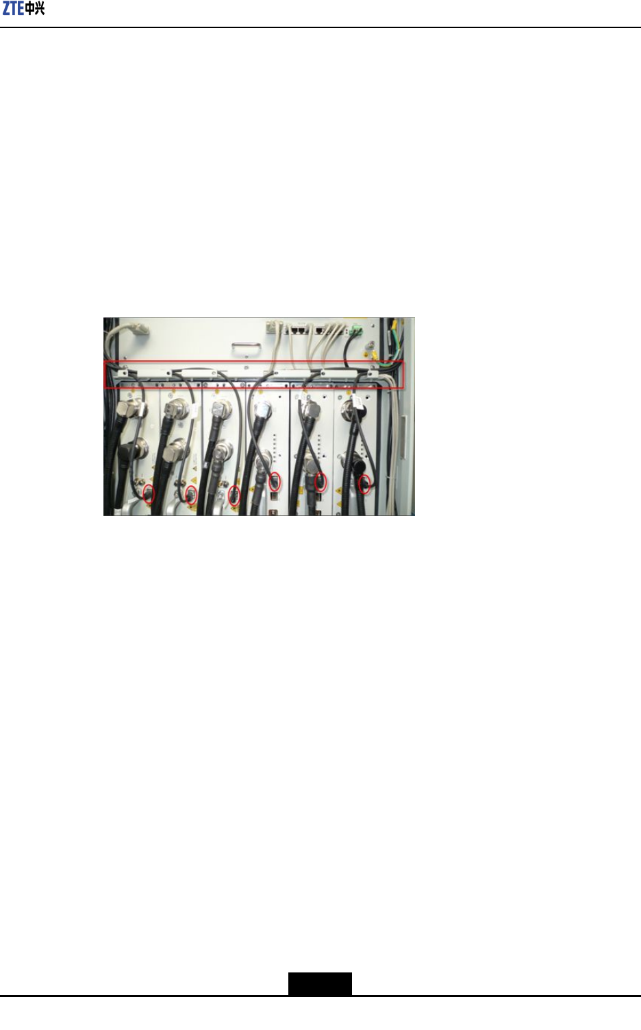
3.RoutetheSFPcablealongtheroutingtroughandcabinetsidestotheFSmoduleof
BBU.TheSFPcablesconnectingtotheRSUsinslots1to3ontheRFcabinetgo
throughtheleftroutingaperturesandthoseSFPcablesgothroughtherightapertures
ifconnectingtoslots4to6ontheRFcabinet,asshowninFigure5-13andFigure
5-14.
Figure5-13LayoutoftheSFPCablesintheRFCabinet
5-13
SJ-20101019140047-001(R1.2)|08/08/2011ZTEProprietaryandCondential
ZXSDRRSU82CUserManual
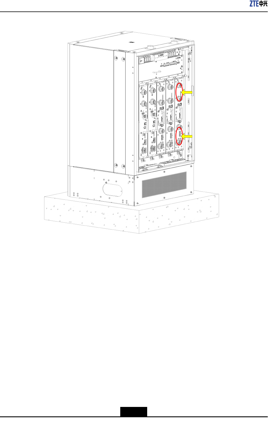
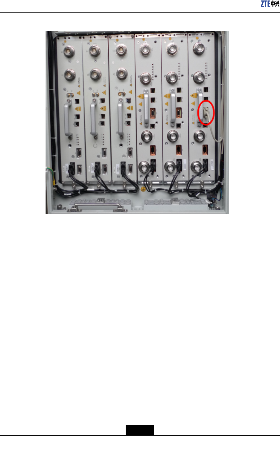
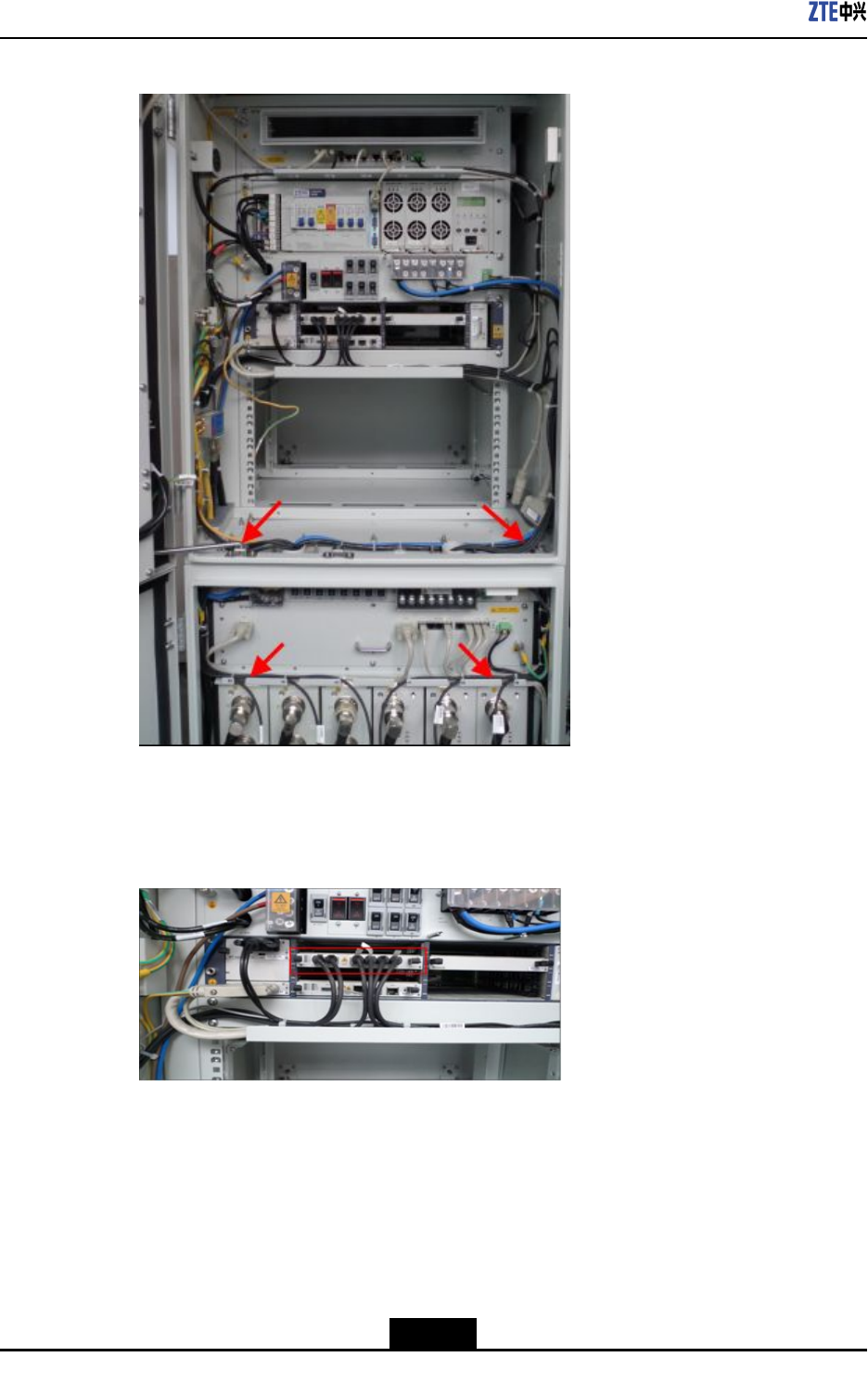
Figure5-14SFPCableLayout
4.InsertSFPcablesintotheinterfacesTX0RX0toTX5RX5oftheBBUFSboard
accordingtothemarkings0-5,asshowninFigure5-15.
Figure5-15FSBoardConnectingtotheBBU
5.BundleSFPcables.
6.Removetemporarylabelsandafxengineeringlabels.
–EndofSteps–
5-14
SJ-20101019140047-001(R1.2)|08/08/2011ZTEProprietaryandCondential
Chapter5HardwareInstallation
5.5InstallingtheRFJumper
Prerequisites
TheZXSDRRSU82CRFcabinetandothermoduleshavealreadybeeninstalled.
Context
TheRFjumpersforthethreeZXSDRRSU82Cgothroughthewaterproofmoduleonthe
right.
RemovethefrontbafeofthebasebeforeinstallingtheRFjumpersandreseatthefront
bafeafteralljumpersarecompletelyinstalled.
ThetypicallossoftheRFcable(withthefrequency1.9GHzandcablelength30m)is3.4
dB.
Steps
1.ConnecttheRFjumperstoANT1toANT4interfacesofRSUfromlefttoright.
2.WearthewaterproofrubberplugaftereverytwoRFjumpersareinstalled.
3.Insertthehorizontalandlongitudinalslideblocksandusethehexagonringwrenchto
fastenthem.
Caution!
Clampthewaterproofrubberplugtightlyandmakesurethattheunusedcabling
aperturewearstheplug.
4.RepeattheprecedingstepstoinstallotherRSU-relatedjumpers.
–EndofSteps–
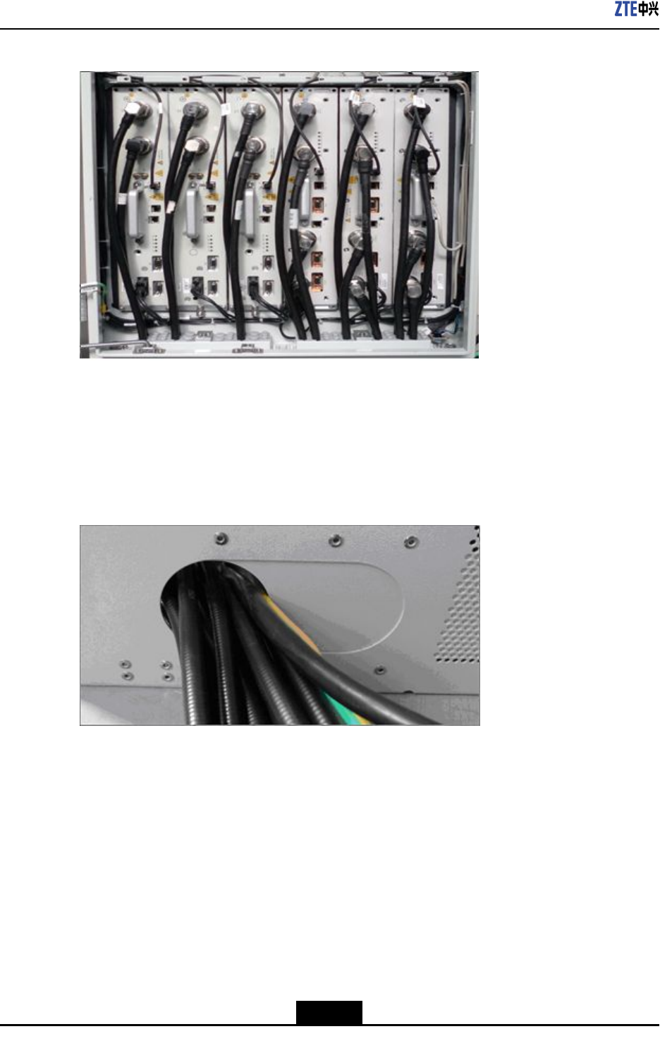
Result
Figure5-16showsthecompletionofinstallingtheRFjumpers.
5-15
SJ-20101019140047-001(R1.2)|08/08/2011ZTEProprietaryandCondential
ZXSDRRSU82CUserManual
Figure5-16AntennaFeederJumperInstalledCompletely
TheRFjumpersgooutfromthebase,asshowninFigure5-17.Thecablesbetween
cabinetsmustbeprotectedwithprotectivetubes,withoutanyexposedpartofthecables
andtheopeningsattwoendsofthesecablesmustbesealed,asshowninFigure5-18.
Figure5-17Lead-OutoftheAntennaFeederJumper
5-16
SJ-20101019140047-001(R1.2)|08/08/2011ZTEProprietaryandCondential
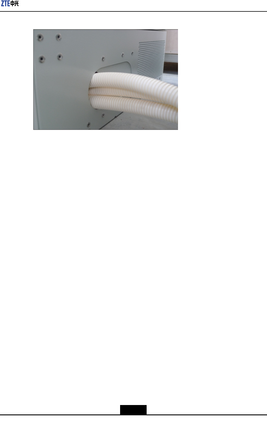
Chapter5HardwareInstallation
Figure5-18CablesinTubes
5-17
SJ-20101019140047-001(R1.2)|08/08/2011ZTEProprietaryandCondential

ZXSDRRSU82CUserManual
Thispageintentionallyleftblank.
5-18
SJ-20101019140047-001(R1.2)|08/08/2011ZTEProprietaryandCondential

Figures
Figure2-1ZXSDRRSU82CPositioninaNetwork....................................................2-2
Figure2-2OuterViewofZXSDRRSU82C...............................................................2-3
Figure3-1FrameStructureofZXSDRRSU82C.......................................................3-1
Figure4-1ZXSDRRSU82CPanel...........................................................................4-2
Figure5-1ZXSDRRSU82CPanel...........................................................................5-2
Figure5-2Step1......................................................................................................5-3
Figure5-3Step2......................................................................................................5-4
Figure5-4Step3......................................................................................................5-5
Figure5-5Step4......................................................................................................5-6
Figure5-6Step5......................................................................................................5-7
Figure5-7RSUModuleInstalledCompletely............................................................5-8
Figure5-8PowerCableConnectingtheRSU...........................................................5-8
Figure5-9RSUMonitoringCable.............................................................................5-9
Figure5-10InstallingtheRSUMonitoringCable.....................................................5-10
Figure5-11WaterproofModulethroughWhichOpticalFibersPass........................5-11
Figure5-12High-SpeedCable................................................................................5-12
Figure5-13LayoutoftheSFPCablesintheRFCabinet........................................5-13
Figure5-14SFPCableLayout................................................................................5-14
Figure5-15FSBoardConnectingtotheBBU.........................................................5-14
Figure5-16AntennaFeederJumperInstalledCompletely......................................5-16
Figure5-17Lead-OutoftheAntennaFeederJumper.............................................5-16
Figure5-18CablesinTubes...................................................................................5-17
I

Figures
Thispageintentionallyleftblank.

Tables
Table1-1SafetySymbolsDescription.......................................................................1-2
Table2-1ThePrimaryFunctionsofZXSDRRSU82C...............................................2-3
Table3-1Thefunctionsofsubsystem.......................................................................3-1
Table3-2ZXSDRRSU82CCapacityIndices............................................................3-3
Table3-31.9GHzTransmitterIndices......................................................................3-4
Table3-41.9GHzReceiverIndices..........................................................................3-5
Table3-5DescriptionofZXSDRRSU82C’sinterfaces..............................................3-6
Table4-1ZXSDRRSU82CPanelButtonDescription...............................................4-2
Table4-2ZXSDRRSU82CPanelIndicatorDescription............................................4-3
Table4-3ZXSDRRSU82CPanelInterfaceDescription............................................4-4
III

Tables
Thispageintentionallyleftblank.

Glossary
AISG
-AntennaInterfaceStandardsGroup
BBU
-BaseBandUnit
BSC
-BaseStationController
BTS
-BaseTransceiverStation
CPRI
-CommonPublicRadioInterface
MS
-MobileStation
RF
-RadioFrequency
RSSI
-ReceivedSignalStrengthIndicator
RSU
-RFSystemUnit
SDR
-SoftwareDenedRadio
V