Contents
- 1. User Manual
- 2. User Manual II
- 3. User Manual part 1
- 4. User Manual part 2
- 5. User Manual part 3
User Manual part 1

RSU82 S1900
HardwareInstallation
ZTECORPORATION
No.55,Hi-techRoadSouth,ShenZhen,P .R.China
Postcode:518057
Tel:+86-755-26771900
Fax:+86-755-26770801
URL:http://support.zte.com.cn
E-mail:800@zte.com.cn
LEGALINFORMATION
Copyright©2017ZTECORPORATION.
Thecontentsofthisdocumentareprotectedbycopyrightlawsandinternationaltreaties.Anyreproductionor
distributionofthisdocumentoranyportionofthisdocument,inanyformbyanymeans,withoutthepriorwritten
consentofZTECORPORATIONisprohibited.Additionally,thecontentsofthisdocumentareprotectedby
contractualcondentialityobligations.
Allcompany,brandandproductnamesaretradeorservicemarks,orregisteredtradeorservicemarks,ofZTE
CORPORATIONoroftheirrespectiveowners.
Thisdocumentisprovided“asis”,andallexpress,implied,orstatutorywarranties,representationsorconditions
aredisclaimed,includingwithoutlimitationanyimpliedwarrantyofmerchantability,tnessforaparticularpurpose,
titleornon-infringement.ZTECORPORATIONanditslicensorsshallnotbeliablefordamagesresultingfromthe
useoforrelianceontheinformationcontainedherein.
ZTECORPORATIONoritslicensorsmayhavecurrentorpendingintellectualpropertyrightsorapplications
coveringthesubjectmatterofthisdocument.ExceptasexpresslyprovidedinanywrittenlicensebetweenZTE
CORPORATIONanditslicensee,theuserofthisdocumentshallnotacquireanylicensetothesubjectmatter
herein.
ZTECORPORATIONreservestherighttoupgradeormaketechnicalchangetothisproductwithoutfurthernotice.
UsersmayvisittheZTEtechnicalsupportwebsitehttp://support.zte.com.cntoinquireforrelatedinformation.
TheultimaterighttointerpretthisproductresidesinZTECORPORATION.
RevisionHistory
RevisionNo.RevisionDateRevisionReason
R1.12016-03-23V4.14.10.30.P30
Thistopichasbeenmodied:
FloorMountingtheCabinet,modifythedimensionsoftheBase
andExpansionBoltPositions
R1.02015-05-22Firstedition
SerialNumber:SJ-20150203110107-011
PublishingDate:2016-03-23(R1.1)
SJ-20150203110107-011|2016-03-23(R1.1)ZTEProprietaryandCondential

Contents
AboutThisManual.........................................................................................I
Chapter1InstallationFlow........................................................................1-1
Chapter2InstallationPreparation............................................................2-1
2.1T echnicalDocuments.........................................................................................2-7
2.2Precautionsforcabinettransport.........................................................................2-7
2.3InstallationPrecautions.......................................................................................2-7
Chapter3UnpackingandInspection.......................................................3-1
Chapter4CabinetInstallation...................................................................4-1
4.1CabinetInstallationProcess................................................................................4-1
4.2FloorMountingtheCabinet.................................................................................4-3
4.3InstallingStackedCabinets...............................................................................4-16
Chapter5ComponentInstallationinaCabinet.......................................5-1
5.1InstallinganRFUnitintheRC8910ACabinet(Optional).......................................5-1
5.2InstallingBatteries..............................................................................................5-2
Chapter6InstallingtheGPSAntenna(Optional)....................................6-1
Chapter7CableInstallation......................................................................7-1
7.1CablingOverview...............................................................................................7-1
7.2Cable-ThroughHoles.........................................................................................7-6
7.3WaterproofModuleDescription...........................................................................7-9
7.3.1WaterproofModuleoftheBasebandCabinet.............................................7-9
7.3.2WaterproofModuleoftheRFCabinet.......................................................7-11
7.4GroundingCableInstallation.............................................................................7-12
7.4.1InstallingaGroundingCablefortheBC8910ACabinet............................7-13
7.4.2InstallingaGroundingCablefortheRC8910ACabinetandPC8910A
Cabinet................................................................................................7-16
7.5PowerCableInstallation...................................................................................7-18
7.5.1PowerCableInstallationintheBCCabinet..............................................7-21
7.5.2PowerCableInstallationintheRCCabinet..............................................7-25
7.5.3InstallingDCInputCablesforthePC8910ACabinet................................7-26
7.5.4InstallingaFanPowerCableforthePC8910ACabinet............................7-29
7.5.5InstallingthePowerCableoftheHeater(Optional)...................................7-32
7.5.6InstallingthePowerCableforaRemoteRRU(Optional)..........................7-34
I
SJ-20150203110107-011|2016-03-23(R1.1)ZTEProprietaryandCondential

7.6TransmissionCableInstallation.........................................................................7-35
7.6.1InstallingTransmissionFibers(Optional)..................................................7-36
7.6.2InstallingEthernetCables(Optional)........................................................7-38
7.7SignalCableInstallation...................................................................................7-40
7.7.1InstallinganInterconnectedCableBetweenBBUandRSU.......................7-40
7.7.2InstallingOutdoorFibers(Optional).........................................................7-43
7.7.3InstallingtheGPSFeeder.......................................................................7-45
7.7.4InstallingAntennaFeederJumpers.........................................................7-47
7.7.5InstallingtheAISGCable(Optional)........................................................7-49
7.8MonitoringCableInstallation.............................................................................7-50
7.8.1InstallingtheRSUMonitoringCable........................................................7-52
7.8.2InstallingDry-ContactCablesExternallyProvidedbytheBaseband
Cabinet................................................................................................7-54
7.8.3ConnectingaBatteryTemperatureMonitoringCableforthePC8910A
Cabinet...............................................................................................7-57
7.8.4InstallingaDoorAccessMonitoringCableforthePC8910ACabinet........7-59
7.8.5InstallingtheWaterLevelMonitoringCableofaPC8910ACabinet............7-61
7.9WaterproofModuleInstallation..........................................................................7-63
7.9.1InstallingtheWaterproofModulefortheBC8910ACabinet.......................7-63
7.9.2InstallingtheWaterproofModulefortheRC8910ACabinet.......................7-63
7.10InstallingtheAirFilter.....................................................................................7-64
Chapter8Post-InstallationCheck............................................................8-1
8.1CabinetInstallationCheck..................................................................................8-1
8.2ModuleInstallationCheck...................................................................................8-2
8.3CableInstallationCheck.....................................................................................8-2
8.4OtherChecks.....................................................................................................8-3
Chapter9PoweringontheCabinet..........................................................9-1
Chapter10Closure...................................................................................10-1
Figures.............................................................................................................I
Tables.............................................................................................................V
Glossary.......................................................................................................VII
II
SJ-20150203110107-011|2016-03-23(R1.1)ZTEProprietaryandCondential

AboutThisManual
Purpose
TheBS8900Aisanintegratedoutdoormacrobasestationthatconsistsofthe
BBUandRSU82 S1900.Inaddition,spaceisreservedforthebuilt-inpowersupplyand
battery inthecabinet,realizinganintegrateddevicewiththebasestation,powersupply,
and battery.Thismanualdescribeshowtoinstallthecabinet,modules,andcablesofthe
BS8900A.
IntendedAudience
Thismanualisintendedfor:
lInstallationengineers
lMaintenanceengineers
WhatIsinThisManual
Thismanualcontainsthefollowingchapters.
Chapter1,InstallationFlowDescribestheinstallationowoftheZXSDRBS8900A.
Chapter2,Installation
Preparation
Describespreparationsbeforeequipmentinstallation.
Chapter3,Unpackingand
Inspection
Describesprecautionsaboutequipmentunpackingandinspection.
Chapter4,CabinetInstallationDescribeshowtoinstallthecabinetoftheZXSDRBS8900A.
Chapter5,Component
InstallationinaCabinet
DescribeshowtoinstalltheRSUandbatteryoftheZXSDR
BS8900A.
Chapter6,InstallingtheGPS
Antenna(Optional)
DescribeshowtoinstalltheGPSantennaonthetopofthecabinet.
Chapter7,CableInstallationDescribeshowtoinstallthecablesoftheZXSDRBS8900Aon
site.
Chapter8,Post-Installation
Check
Describeshowtocheckthedeviceafterequipmentinstallation.
Chapter9,Poweringonthe
Cabinet
DescribeshowtopowerontheZXSDRBS8900A.
Chapter10,ClosureDescribestheclean-upoperationsafterequipmentinstallation.
Conventions
Thismanualusesthefollowingconventions.
I
SJ-20150203110107-011|2016-03-23(R1.1)ZTEProprietaryandCondential
ItalicsVariablesincommands.Itmayalsorefertootherrelatedmanualsanddocuments.
BoldMenus,menuoptions,functionnames,inputelds,optionbuttonnames,checkboxes,
drop-downlists,dialogboxnames,windownames,parameters,andcommands.
Constant
width
Textthatyoutype,programcodes,lenames,directorynames,andfunctionnames.
[]Optionalparameters.
{}Mandatoryparameters.
|Separatesindividualparametersinaseriesofparameters.
Danger:indicatesanimminentlyhazardoussituation.Failuretocomplywillresultin
deathorseriouspersonalinjury.
Warning:indicatesapotentiallyhazardoussituation.Failuretocomplycanresultin
deathorseriouspersonalinjury.
Caution:indicatesapotentiallyhazardoussituation.Failuretocomplycanresultin
moderateorminorpersonalinjury.
Notice:indicatesequipmentorenvironmentsafetyinformation.Failuretocomply
canresultinequipmentdamage,dataloss,equipmentperformancedegradation,
environmentalcontamination,orotherunpredictableresults.
Note:providesadditionalinformationaboutatopic.
II
SJ-20150203110107-011|2016-03-23(R1.1)ZTEProprietaryandCondential

ZXSDRBS8900AHardwareInstallation
Thispageintentionallyleftblank.
1-2
SJ-20150203110107-011|2016-03-23(R1.1)ZTEProprietaryandCondential
Chapter2
InstallationPreparation
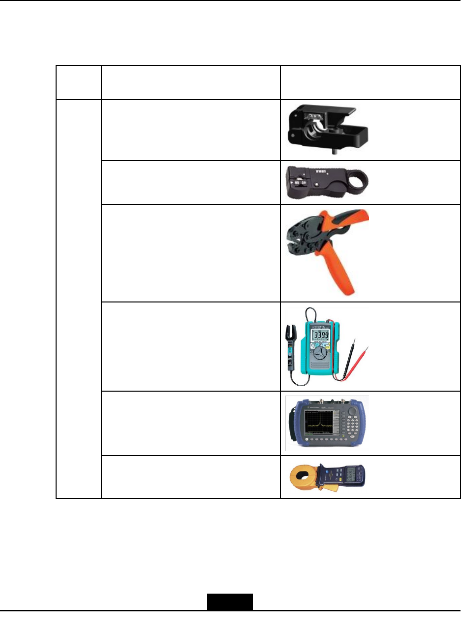
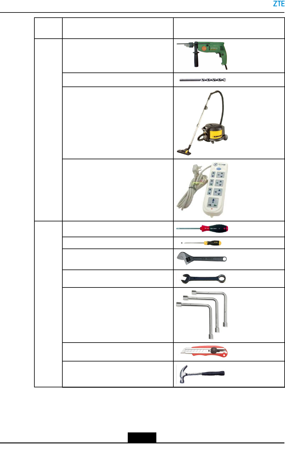
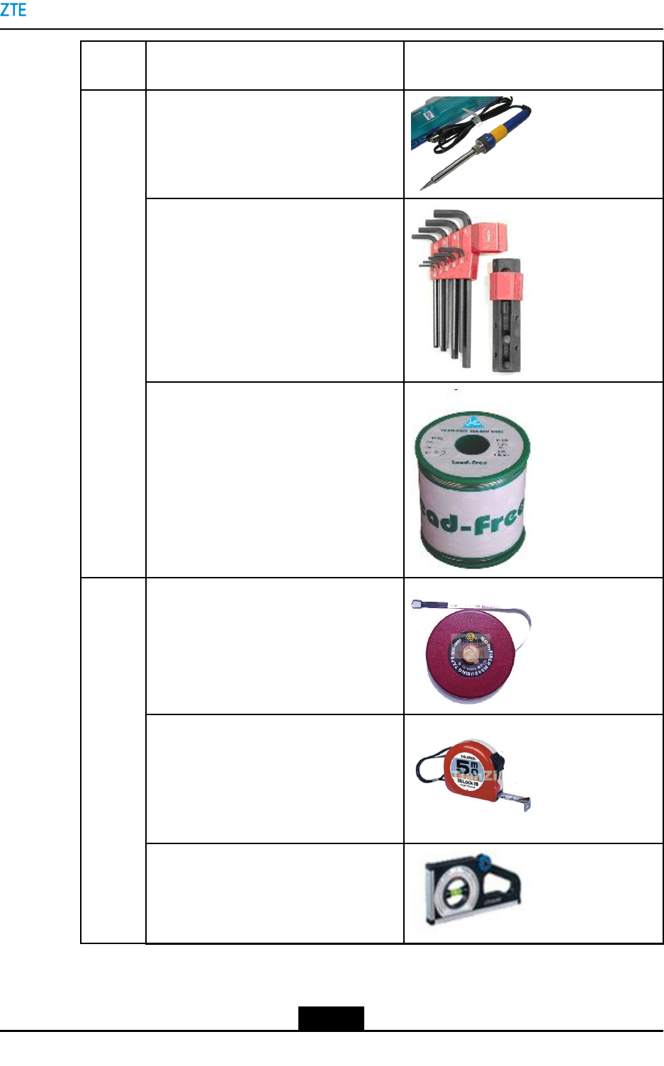
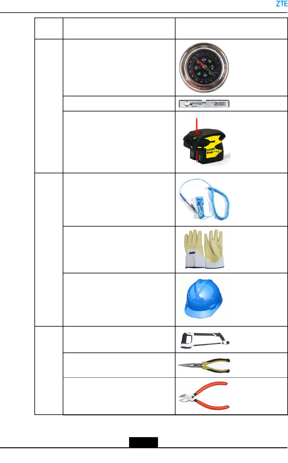
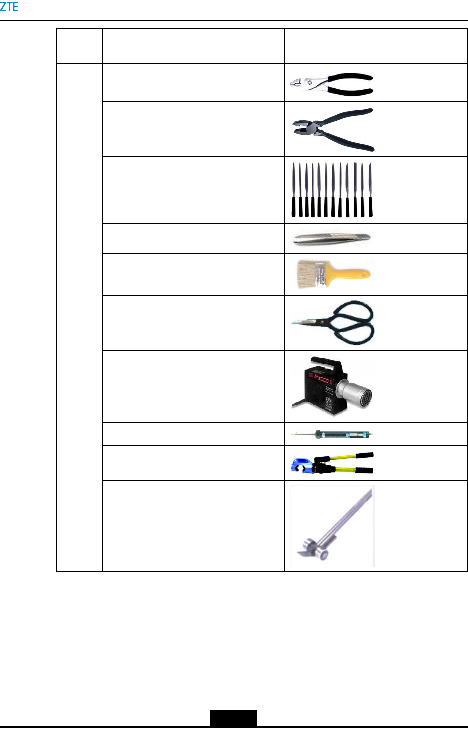
Table2-1showstoolsandmetersrequiredduringinstallation.
Table2-1ToolsandMeters
Cate-
gory
NameExample
Feederconnectorknife
75Ωcoaxialcablestripper
Multi-functionalcrimpingpliers
Multimeter
Standingwaveratiotester
Special-
purpose
tools
Earthresistancetester
2-1
SJ-20150203110107-011|2016-03-23(R1.1)ZTEProprietaryandCondential
ZXSDRBS8900AHardwareInstallation
Cate-
gory
NameExample
Hammerdrill
Auxiliarypercussiondrillbits
Vacuumcleaner
Punch-
ingtools
Powerstrip(providingatleastthree
two-phasesocketsandthreethree-phase
sockets,withthecurrentcapacitylarger
than15A)
Phillipsscrewdrivers(4",6"and8"each)
Flatheadscrewdrivers(4",6"and8"each)
Adjustablewrenches(6",8",10"and12"
each)
Dual-purposewrenches(17"and19"each)
Socketwrenches
Paperknife
5kgclawhammer
General-
purpose
tools
2-2
SJ-20150203110107-011|2016-03-23(R1.1)ZTEProprietaryandCondential
Chapter2InstallationPreparation
Cate-
gory
NameExample
Irons(300Wand40Weach)
Inner-hexagonwrench
Solderwires
50m(164feet)tapemeasure
5m(16feet)steeltape
Angleinstrument
Mea-
sure-
ment
tools
2-3
SJ-20150203110107-011|2016-03-23(R1.1)ZTEProprietaryandCondential
ZXSDRBS8900AHardwareInstallation
Cate-
gory
NameExample
Compass
Levelbar
Plumb
Antistaticwriststrap
slip-proofgloves
Protec-
tiontools
Safetyhelmet
Hacksaw(withseveralsawblades)
sharp-nosepliers(8")
diagonalpliers(8")
Clamp
tools
2-4
SJ-20150203110107-011|2016-03-23(R1.1)ZTEProprietaryandCondential
Chapter2InstallationPreparation
Cate-
gory
NameExample
round-nosepliers(8")
Pincerpliers(8")
Needleles(medium-sized)
Nippers
Paintbrush
Scissors
Airheater
Solderremovaltool
Hydrauliccrimper
Crowbar
2-5
SJ-20150203110107-011|2016-03-23(R1.1)ZTEProprietaryandCondential
ZXSDRBS8900AHardwareInstallation
Cate-
gory
NameExample
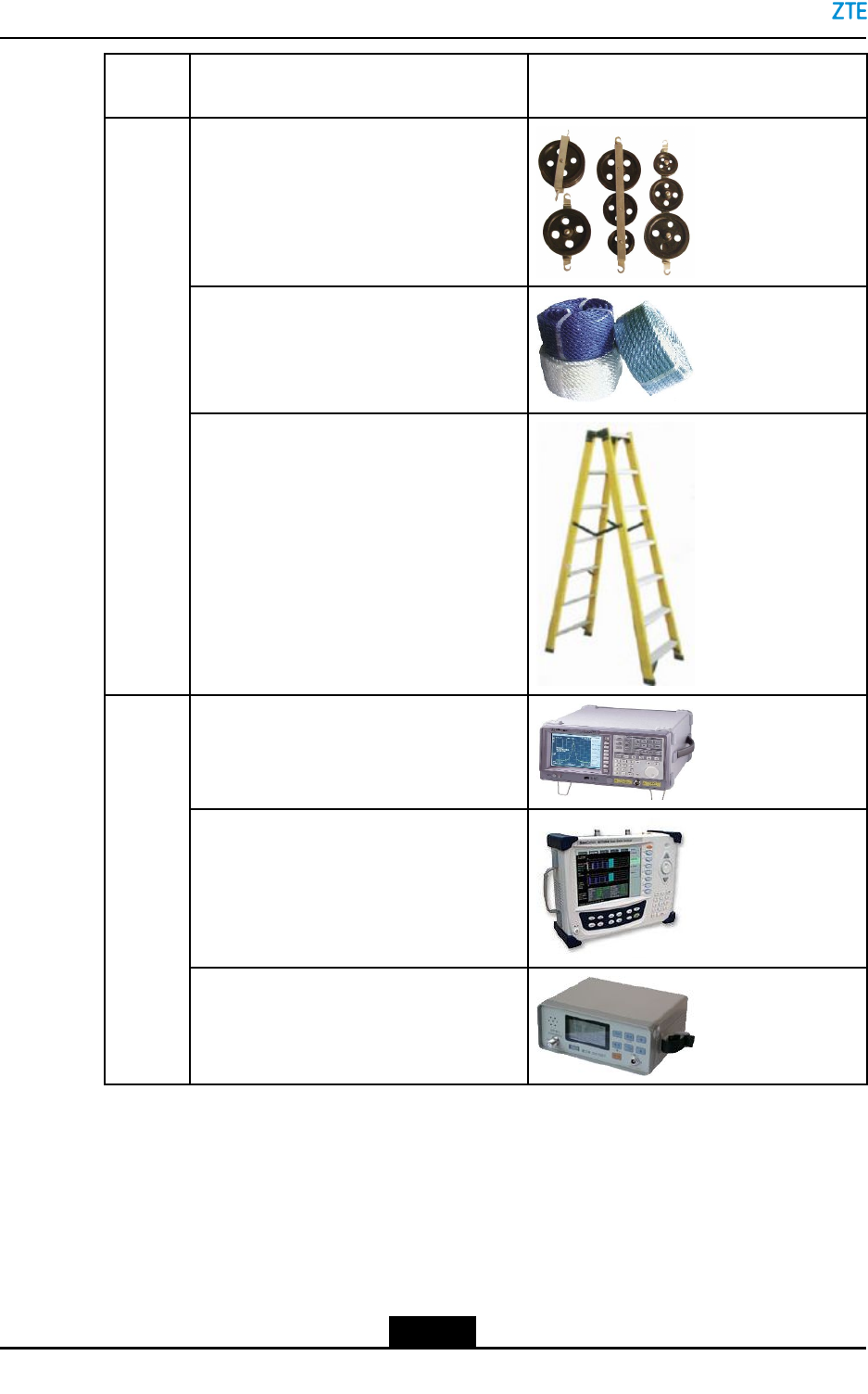
Pulleyset
Rope
Auxiliary
tools
Ladder
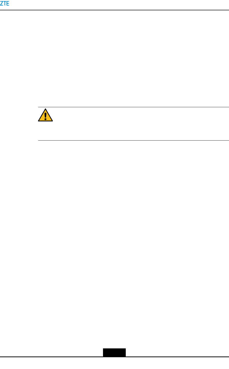
Spectrumanalyzer(requiredincertain
specialcases)
BTStester
Meters
Fieldstrengthtester(requiredincertain
specialcases)
TableofContents
TechnicalDocuments.................................................................................................2-7
Precautionsforcabinettransport................................................................................2-7
InstallationPrecautions..............................................................................................2-7
2-6
SJ-20150203110107-011|2016-03-23(R1.1)ZTEProprietaryandCondential
Chapter2InstallationPreparation
2.1TechnicalDocuments
ItisnecessarytopreparethefollowingtechnicaldocumentsforZXSDRBS8900A
installation:
lZXSDRBS8900AIntegratedOutdoorLTEMacroeNodeBProductDescription
lZXSDRBS8900AIntegratedOutdoorLTEMacroeNodeBHardwareDescription
2.2Precautionsforcabinettransport
lAcabinetmustbetransportedwiththeouterpackingcontainertoprotectthecabinet
fromscratches.
Caution!
Youmusttransportacabinetinapackingcontainer.
lAfterthepackingcontainerisremovedonsite,thecabinetmustbeprotectedwhen
youmoveorstoreit.Forexample,whenacabinetisstoredtemporarily,cushioning
materialsmustbeputunderthebottomofthecabinettoavoiddirectcontactwiththe
groundandsurroundingobjects.
lWhenyoutransportacabinet,usemachinesrst.Whenyouliftacabinetup,the
cabinetmustbedraggedproperlytoavoidcollisionwithotherobjects.
lIfacabinethastobetransportedwithoutpackingduetoenvironmentrestrictions,
cushioningmaterialssuchasfoamedplasticandpaperboardmustbeusedtoprotect
thecabinetfromscratches.
2.3InstallationPrecautions
Thefollowingprecautionsshouldbeabidedbyduringtheinstallation:
lTheZXSDRBS8900Ahardwareinstallationpersonnelmustparticipateinthetraining
relatedtocommunicationequipmentinstallationtomasterinstallationskills.
lDuringtheinstallation,ensurethepersonalsafetyandavoidaccidentssuchaselectric
shockorbruise.
lTheinstallationpersonnelshouldwearanantistaticwriststrapwheninsertingand
pullingoutboards.Ensurethattheotherendoftheantistaticwriststrapisgrounded
well.
lWhentakingaboard,takeholdoftheedgeoftheboardanddonottouchthecircuit,
components,andwires.
lInstallboardsalongslotsandavoidcontactingadjacentboardstoavoidshortcircuit.
Giveproperforcetoinstalltheboardstoavoidpindistortion.
lWheninstallingormaintaininganopticalber,donotdirectlystareatthesectionof
opticalberoranopticalsocketincasethatlaserbeamshurtyoureyes.
2-7
SJ-20150203110107-011|2016-03-23(R1.1)ZTEProprietaryandCondential

ZXSDRBS8900AHardwareInstallation
lTheequipmentmustbepoweredonwithin24hoursafterthepackageisopened.
Power-offcannotexceed24hoursinmaintenance.
2-8
SJ-20150203110107-011|2016-03-23(R1.1)ZTEProprietaryandCondential

Chapter3
UnpackingandInspection
CountingGoods
lVerifythatthepackagingboxesareintact.Ifanydamageisfound,contactthe
transportcompanyimmediately.
lUnpacktheboxesandverifythatthegoodsareconsistentwiththeinspection
checklist.
lVerifythatthechassisisingoodconditionwithoutscratches,peelingpaint,blisters,
orstains.
lVerifythattheaccessoriesrequiredfortheinstallationarecorrectandcomplete.
EquipmentHandover
Aftertheexaminationofgoods,theengineeringsupervisorandtheoperator's
representativeshouldsigntheUnpackingAcceptanceReport.TheUnpackingAcceptance
Reportismadeinduplicate,andkeptbybothparties.Theengineeringsupervisormust
sendtheUnpackingAcceptanceReportbacktotherepresentativeofcewithinseven
daysforarchiving.
3-1
SJ-20150203110107-011|2016-03-23(R1.1)ZTEProprietaryandCondential

ZXSDRBS8900AHardwareInstallation
Thispageintentionallyleftblank.
3-2
SJ-20150203110107-011|2016-03-23(R1.1)ZTEProprietaryandCondential

Chapter4
CabinetInstallation
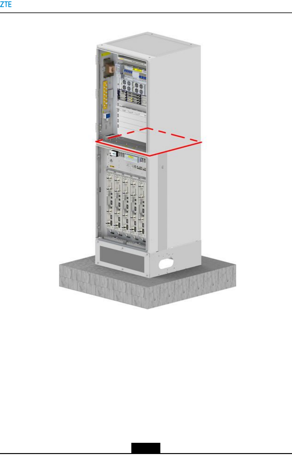
TheZXSDRBS8900Aisanoutdoordevicethatisdirectlyoor-mounted.Itcanbeinstalled
atahillorroof.Ingeneral,asimplefenceorhouseisrequiredaroundthebasestation
wheretheequipmentisinstalledinthehillorunderatower.
Aconcreteplatformneedstobesetupbeforethecabinetinstallationtoprotectthebase
stationequipmentandensurethenormalusageofthecommunicationsequipment.
TheZXSDRBS8900Ahasthreetypesofcabinets,thebasebandcabinet(BCcabinet),RF
cabinet(RCcabinet),andbatterycabinet(PCcabinet).Thesecabinetscanbestackedor
installedsidebyside.Thelower-layercabinetinthestackedcabinetinstallationmodeis
RC8910AorPC8910A.Theupper-layercabinetinthestackedcabinetinstallationmodeis
BC8910A.Thebasedoesnotaccompanythedeliveryofthesecabinets.Thebaseneeds
tobeinstalledbeforetheoor-mountedcabinetinstallation.
TableofContents
CabinetInstallationProcess.......................................................................................4-1
FloorMountingtheCabinet........................................................................................4-3
InstallingStackedCabinets......................................................................................4-16
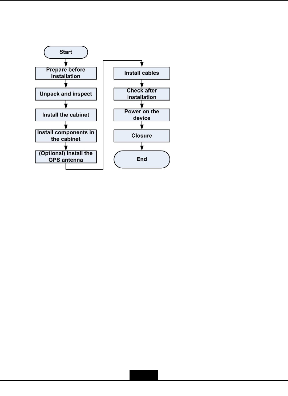
4.1CabinetInstallationProcess
FlowforFloor-MountingaCabinet
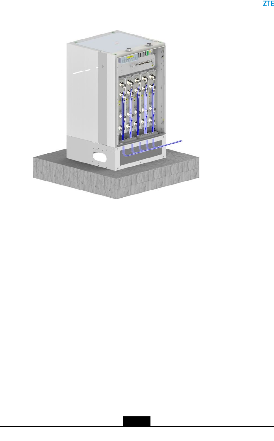
Fortheowforoor-mountingtheZXSDRBS8900Acabinet,seeFigure4-1.
4-1
SJ-20150203110107-011|2016-03-23(R1.1)ZTEProprietaryandCondential
ZXSDRBS8900AHardwareInstallation
Figure4-1FlowforFloor-MountingaCabinet
Note:
Ifaoor-mountedcabinetneednotbestackedwithanothercabinetonitstop,the
oor-mountedcabinetneedstobeinstalledwiththetopcover.
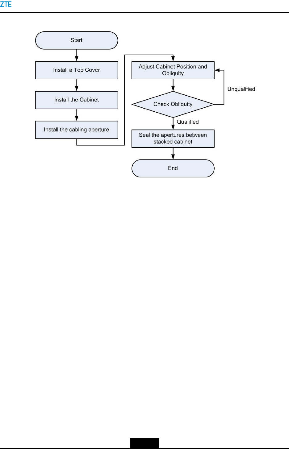
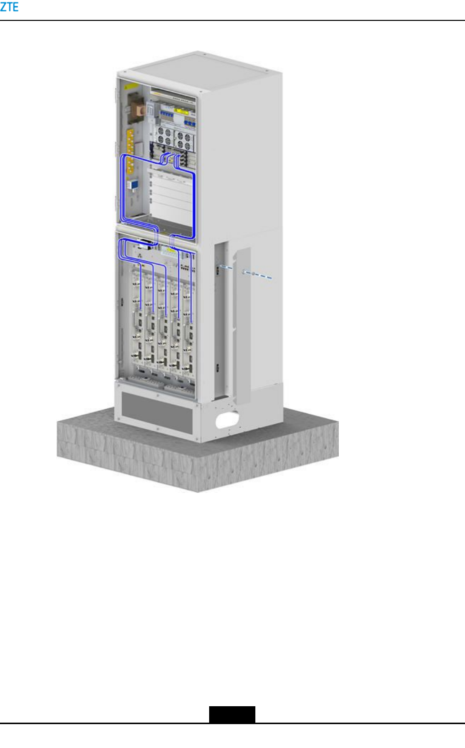
FlowforStackingCabinets
Inthestackedcabinetinstallation,youjustneedtostackanothercabinetontothetopof
theoor-mountedcabinet.Fortheinstallationow,seeFigure4-2.
4-2
SJ-20150203110107-011|2016-03-23(R1.1)ZTEProprietaryandCondential
Chapter4CabinetInstallation
Figure4-2FlowforStackingCabinets
4.2FloorMountingtheCabinet
Thisproceduredescribeshowtomountacabinetorthelowercabinetofthestacked
cabinetsontheoor.
YoucaninstalltheZXSDRBS8900Acabinetsinmultiplemodesasrequired,forexample,
stackingtheBC8910AcabinetandRC8910AcabinettogetherwiththePC8910Acabinet,
andinstallingsingleBC8910Acabinet.TheinstallationoftheBC8910Acabinetor
PC8910AcabinetontheoorisslightlydifferentfromthatofaRC8910Acabinet.No
clampingcomponentisrequiredfortheinstallationoftheBC8910AcabinetorPC8910A
cabinet.
Context
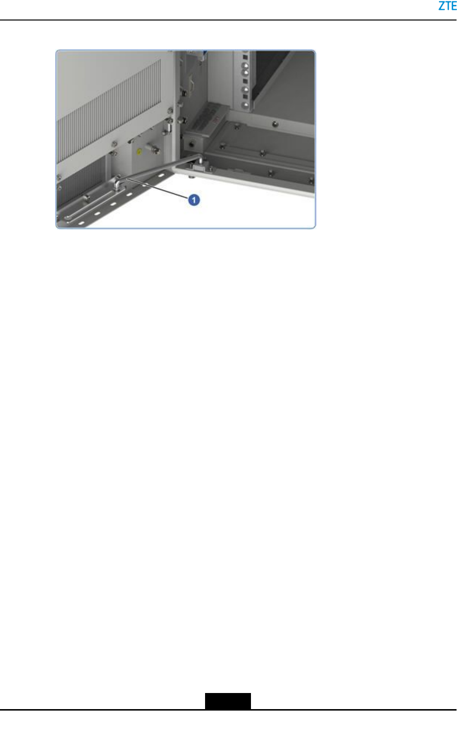
Stabilizingthewind-proofpole
Usethewind-proofpoletostabilizethecabinetdoorwheninstallingacabinetorthe
relevantcables,seeFigure4-3.
4-3
SJ-20150203110107-011|2016-03-23(R1.1)ZTEProprietaryandCondential
ZXSDRBS8900AHardwareInstallation
Figure4-3InstallingaWindproofPole
Steps
1.Determinewherethecabinetistobeinstalled.
WiththeminimuminstallationspacemeetingtherequirementsoftheZXSDRBS8900A
cabinet,selectaproperinstallationplacethatensurespropercablerouting,good
ventilationandheatdissipation,andeasyoperation.
2.ConcretePlatformDescription.
Aconcreteplatformneedstobesetupbeforethecabinetinstallation.Thecabinetis
installedontotheplatformandparticularoperationspaceisreserved.Donotdirectly
installtheexpansionboltsontheroof.Thedimensionsoftheconcreteplatformare
asfollows:
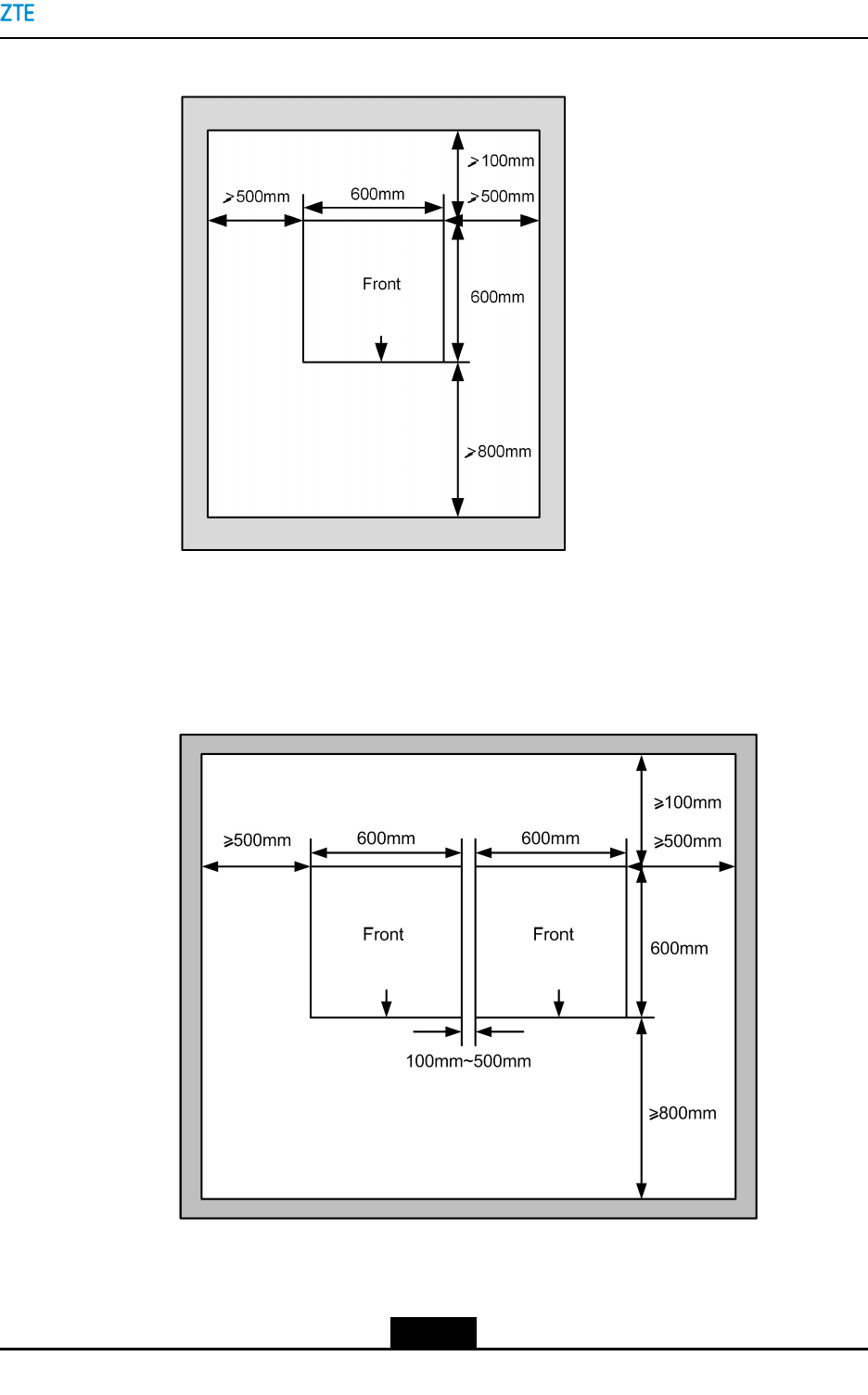
lStackedcabinets
Thespacemustbegreaterthan1600mmx1500mminsuchascenario,see
Figure4-4.
4-4
SJ-20150203110107-011|2016-03-23(R1.1)ZTEProprietaryandCondential
Chapter4CabinetInstallation
Figure4-4ConcreteBaseSizeRequirement—ForStackedCabinets
lSide-by-sideinstalledcabinets
Thespacemustbegreaterthan2200mmx1500mminsuchascenario,see
Figure4-5.
Figure4-5ConcreteBaseSizeRequirement—ForSidebySideCabinets
4-5
SJ-20150203110107-011|2016-03-23(R1.1)ZTEProprietaryandCondential
ZXSDRBS8900AHardwareInstallation
Caution!
Keepthecabinettopatleast200mmawayfromobstacles.
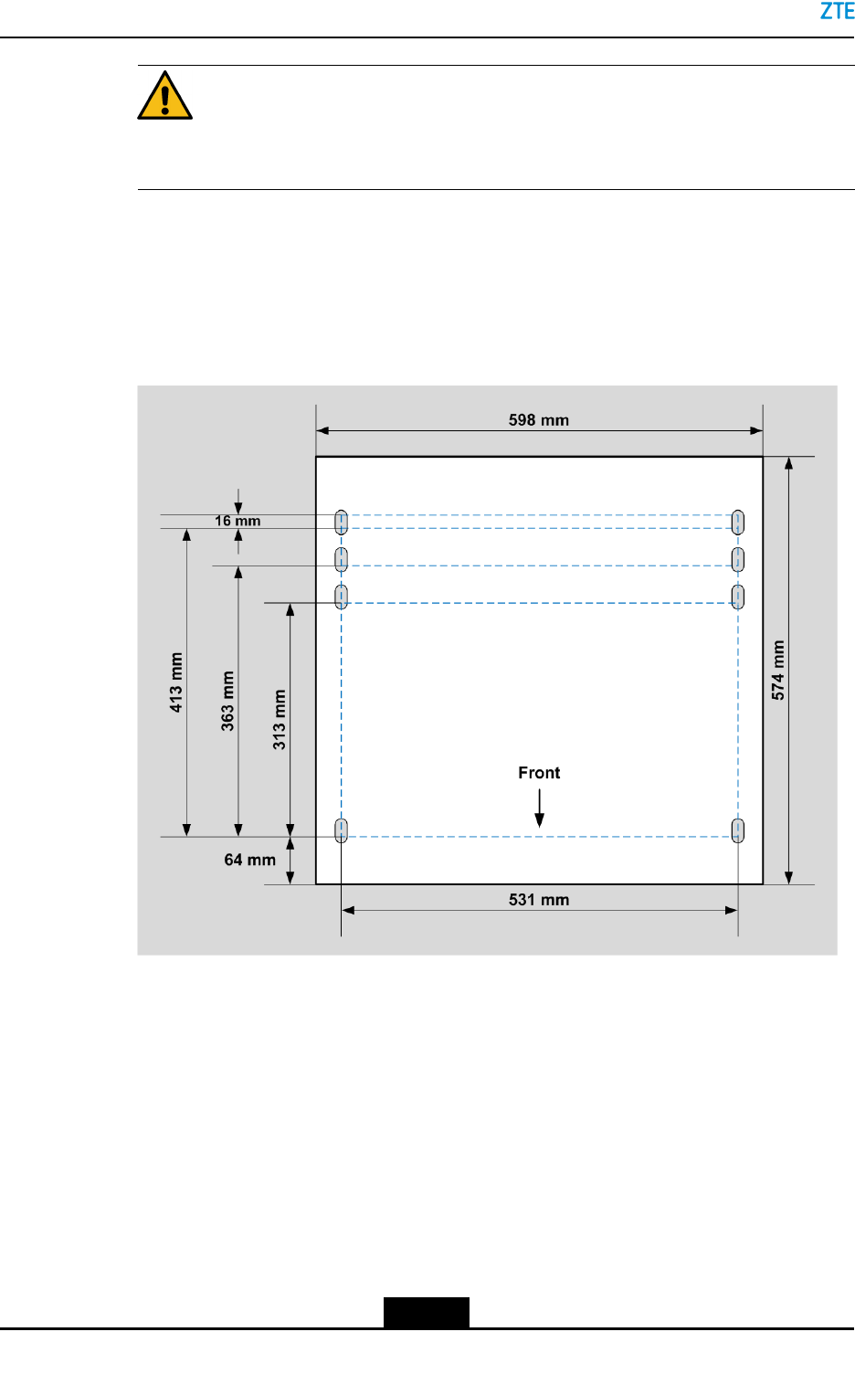
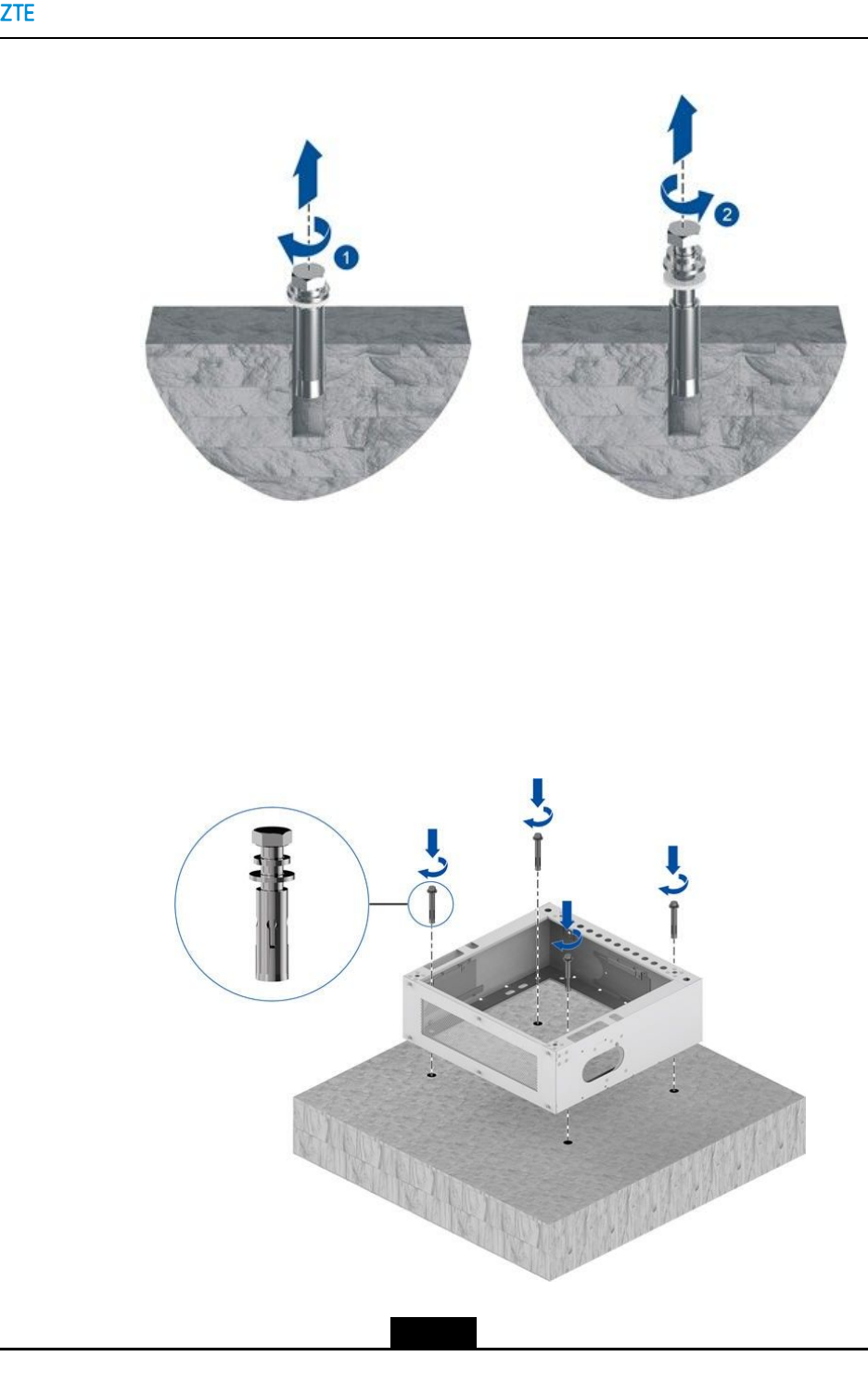
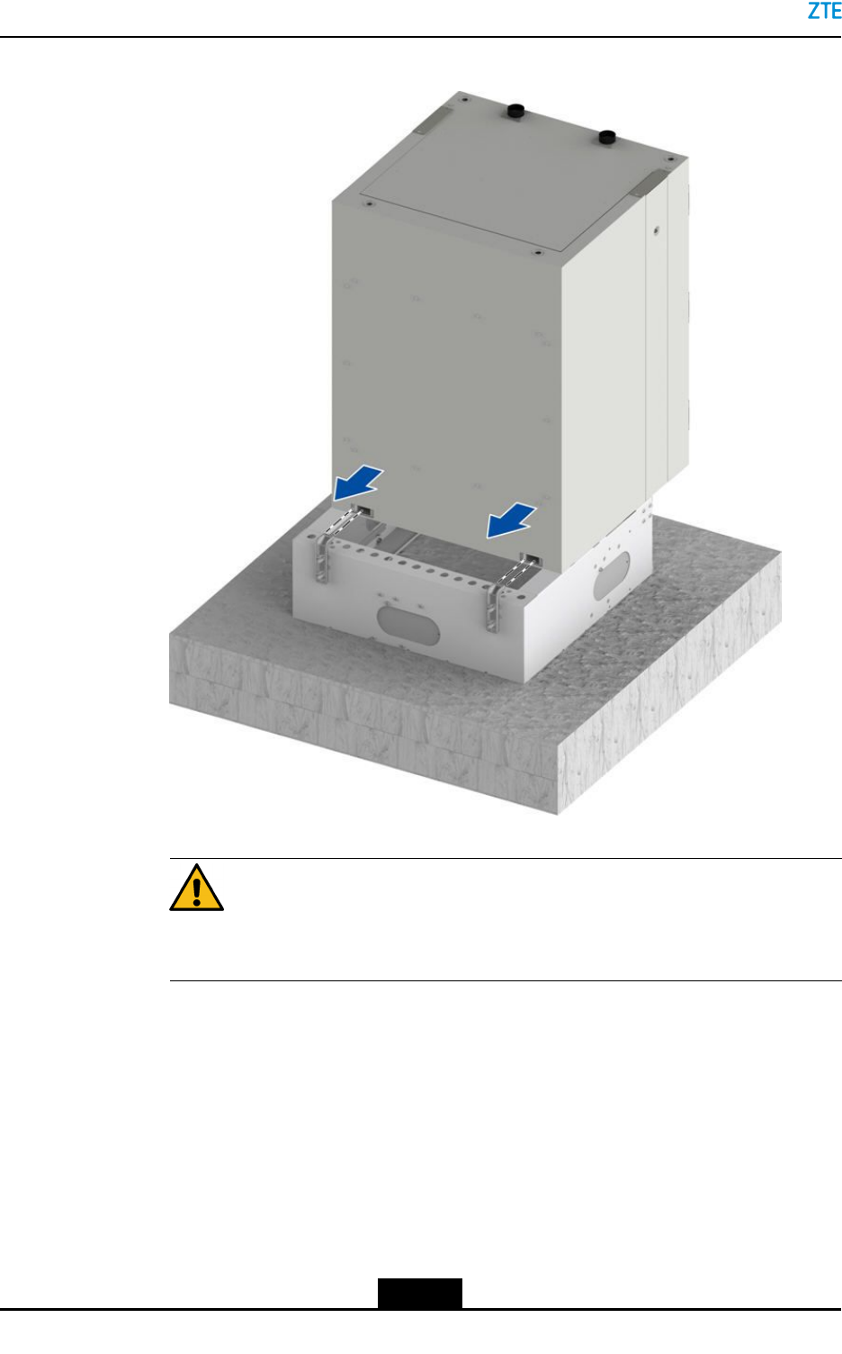
3.Determinetheholesforexpansionboltsthatfastenthecabinetbase.
InaccordancewiththeholedrillingtemplateorthedimensionsinFigure4-6,determine
theholesforexpansionboltsusedforsecuringthecabinetbase.
Figure4-6DimensionsoftheBaseandExpansionBoltPositions
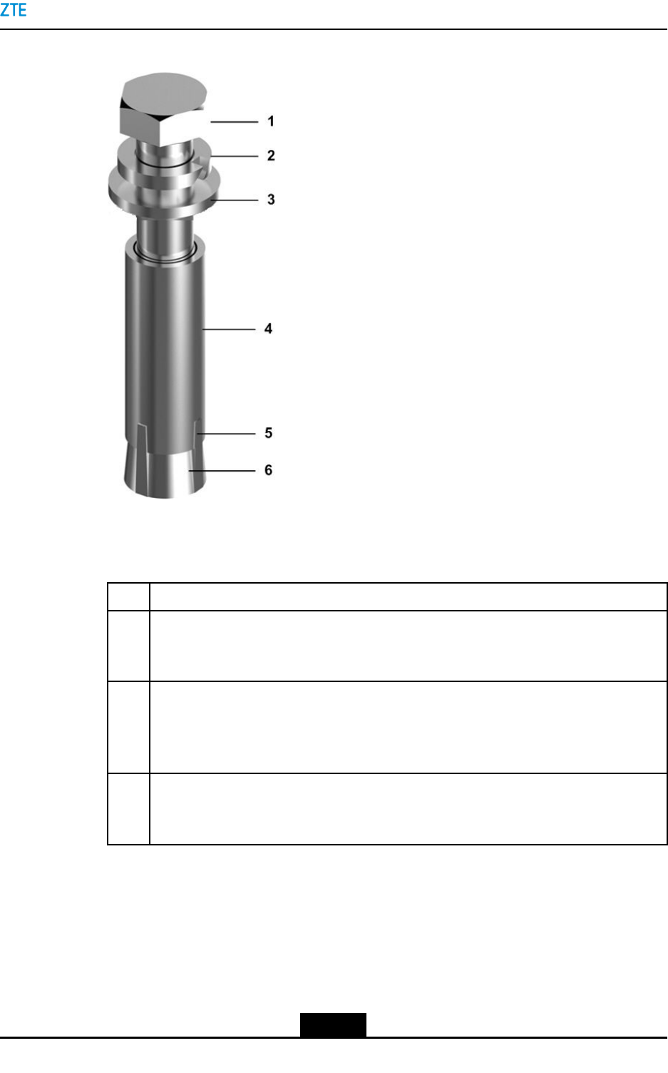
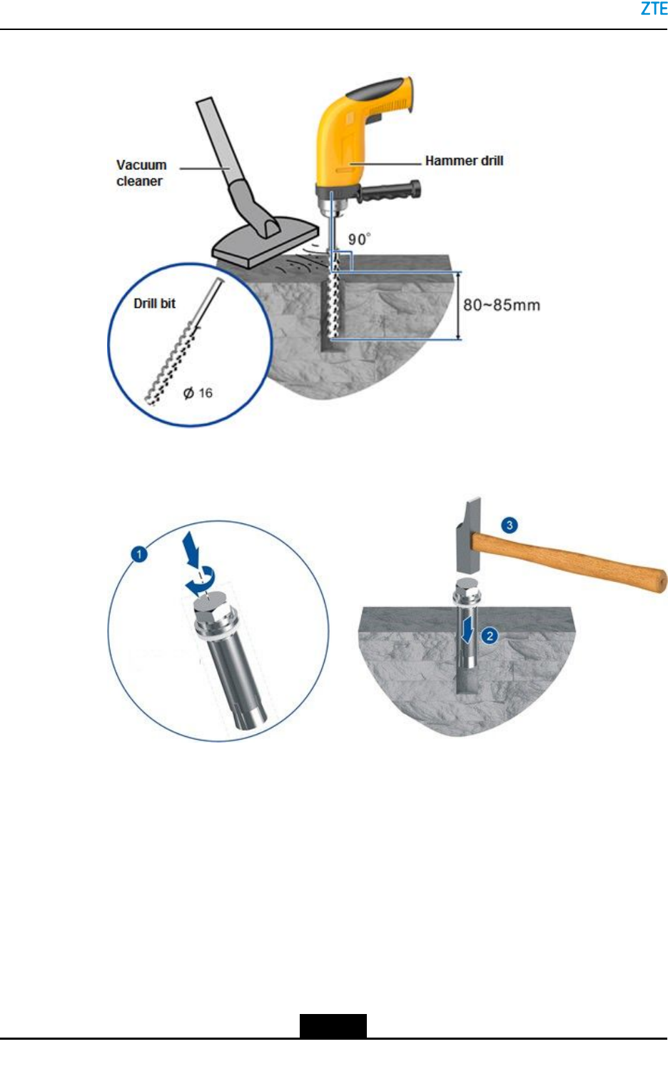
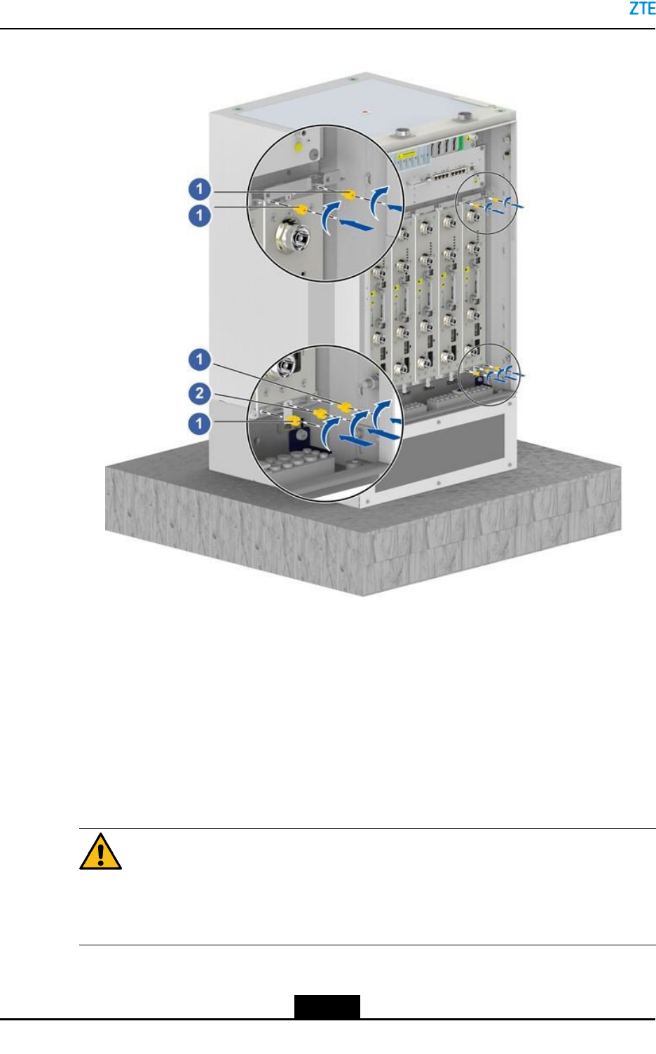
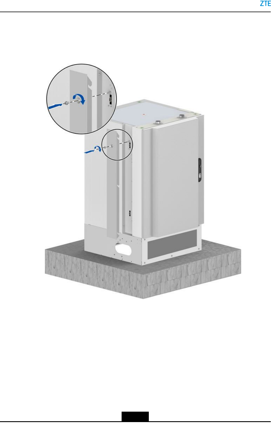
4.Drillholesandinstalltheexpansionbolts.Foranoverviewofanexpansionbolt,see
Figure4-7.Forhowtodrillholesandinstalltheexpansionbolts,refertoTable4-1.
4-6
SJ-20150203110107-011|2016-03-23(R1.1)ZTEProprietaryandCondential
Chapter4CabinetInstallation
Figure4-7OverviewofanExpansionBolt
1.Bolt
2.Springwasher
3.Flatwasher
4.Expansiontube
5.Guideslot
6.Guiderib
Table4-1DescriptionsforDrillingHolesandInstallingExpansionBolts
StepDescription
1Useaφ16drillbittodrillholesatthemarkedpositions.Thedepthoftheholesis80mm.
Useacleanertoremovedust.Keeptheholesstraightdowntothegroundduringhole
drilling,seeFigure4-8.
2Screwaboltclockwiseslightlyuntiltheguideribatthebottomoftheexpansionbolt
cannotquitfromtheguideslot.Puttheexpansionboltintotheinstallationholevertically,
andknocktheexpansionboltwithaclawhammeruntilthetopoftheboltalignswiththe
ground,seeFigure4-9.
3Fastentheexpansionboltclockwiseandensurethattheboltisxedtotheexpansion
tube.Loosenandremovethenut,springwasher,andatwasher.Theywillbeused
laterinbaseinstallation,seeFigure4-10.
4-7
SJ-20150203110107-011|2016-03-23(R1.1)ZTEProprietaryandCondential
ZXSDRBS8900AHardwareInstallation
Figure4-8InstallinganExpansionBolt1
Figure4-9InstallinganExpansionBolt2
4-8
SJ-20150203110107-011|2016-03-23(R1.1)ZTEProprietaryandCondential
Chapter4CabinetInstallation
Figure4-10InstallinganExpansionBolt3
5.Installthebase.
a.Placethebaseontotheinstallationposition.
b.Verifythattheinstallationpositionofthebaseiscorrect,passtheexpansion
boltsthroughthespringwashers,atwashers,andbaseinturn,andthenscrew
theboltsintotheexpansiontubesclockwisetomakethemfullyexpandedinthe
ground,seeFigure4-11.
Figure4-11FixingtheBase
4-9
SJ-20150203110107-011|2016-03-23(R1.1)ZTEProprietaryandCondential
ZXSDRBS8900AHardwareInstallation
6.Performthefollowingoperationsbasedonthetypeofthecabinetinstalledonthebase.
If...Then...
ItisanRFcabinetGoto7.
ItisabasebandcabinetorbatterycabinetGoto8.
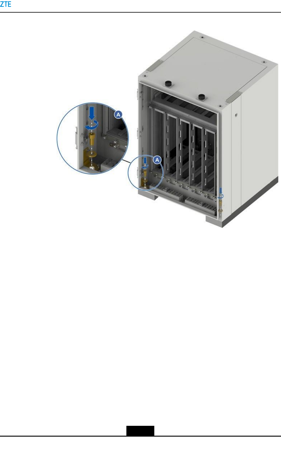
7.InstalltheRC8910Acabinetontothebase.
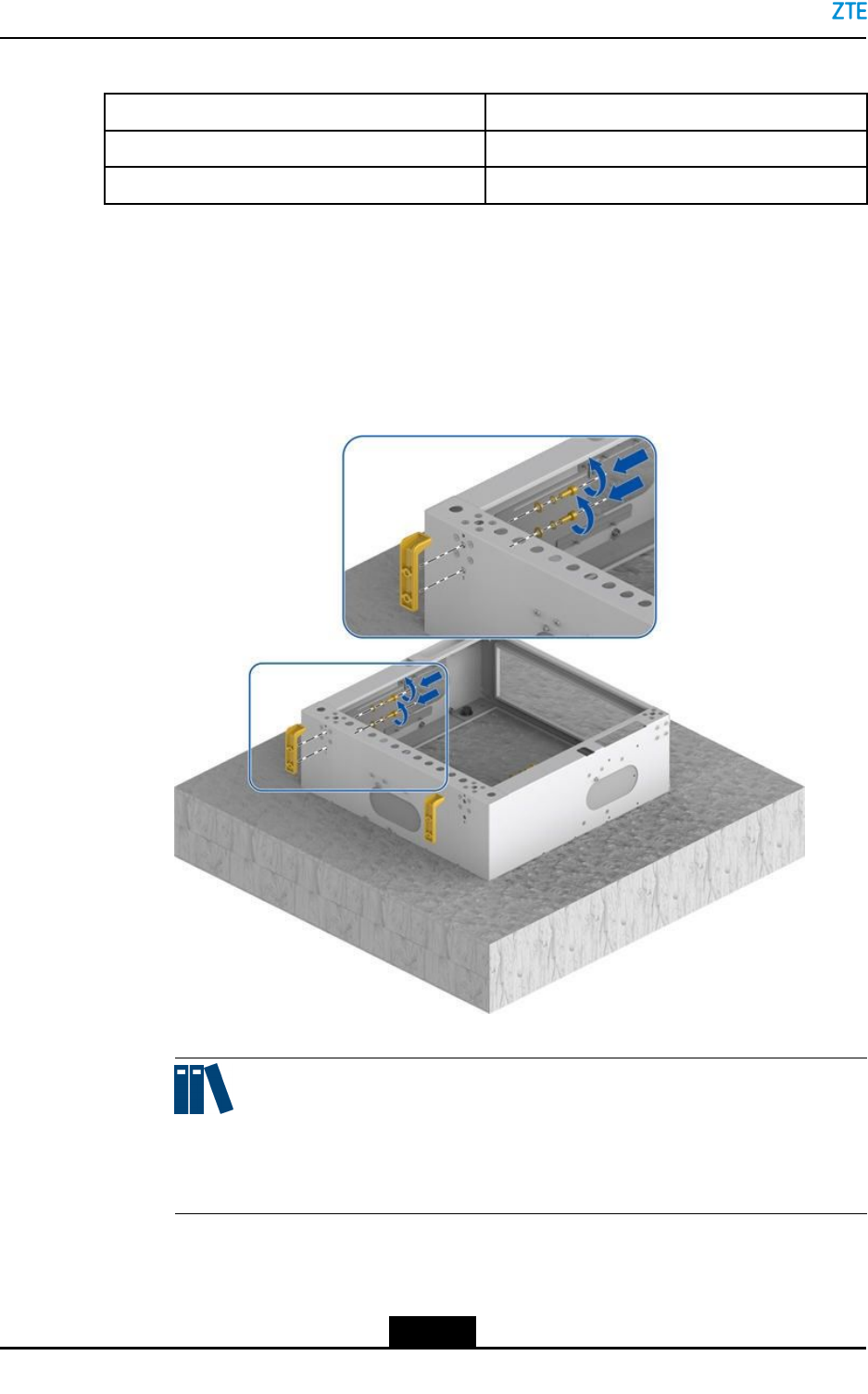
a.Installtheclampingcomponents.
UsetwoM6hexagonalscrewstofastentheclampingcomponentstothe
correspondinginstallationholesoftherearsideofthebase,seeFigure4-12.
Figure4-12InstallingtheClampingComponent
Note:
Ensurethattheclampingcomponentsareverticaltothebase.Otherwise,the
cabinetinstallationmaybedifcult.
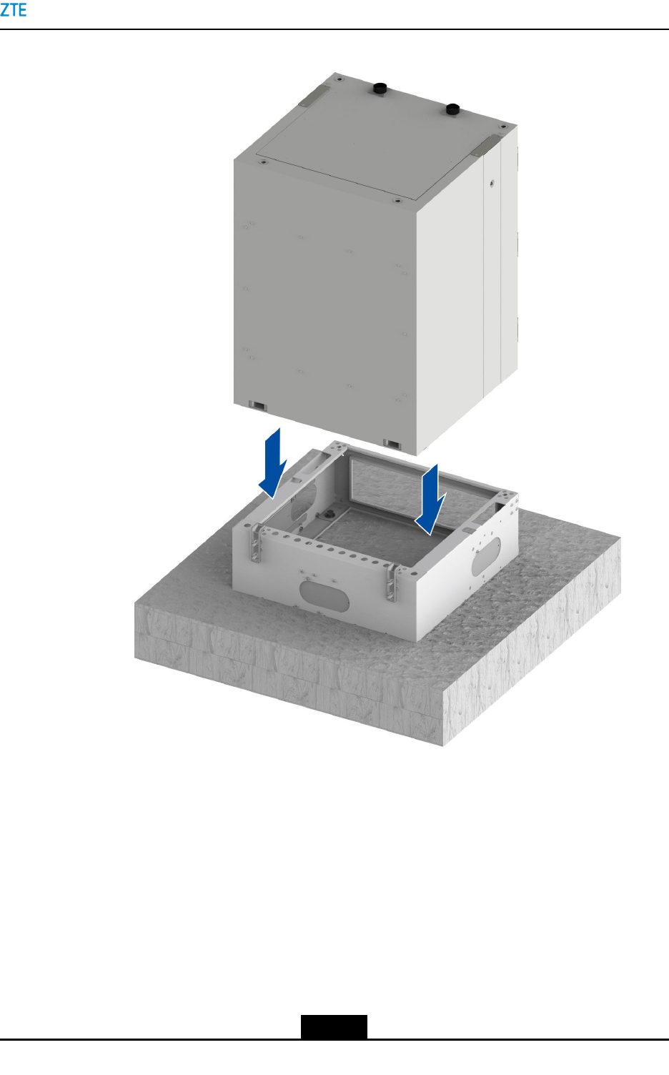
b.Placethecabinetontothebase,seeFigure4-13.
4-10
SJ-20150203110107-011|2016-03-23(R1.1)ZTEProprietaryandCondential
ZXSDRBS8900AHardwareInstallation
Figure4-14PushingtheCabinetBackward
Caution!
Pushthecabinetsteadilysoastopreventthecabinetfromfallingdown.
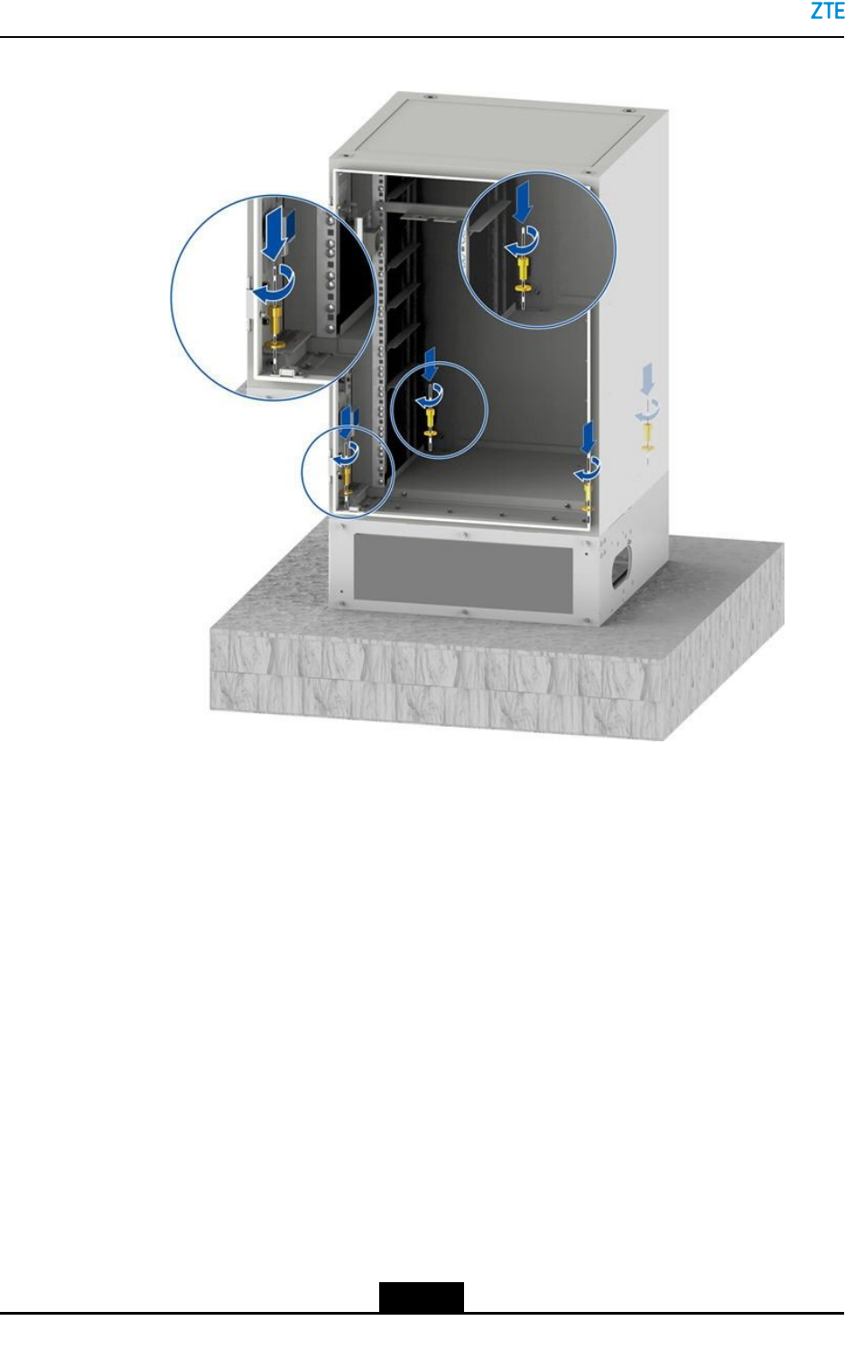
d.UsetwoM12hexagonalscrews(withrubberwashers)atthebothsidesofthe
frontofthecabinettosecurethecabinettothebase,seeFigure4-15.
4-12
SJ-20150203110107-011|2016-03-23(R1.1)ZTEProprietaryandCondential
Chapter4CabinetInstallation
Figure4-15SecuringtheRC8910ACabinet
8.InstalltheBC8910AcabinetorPC8910Acabinetonthebase.
a.Placethecabinetonthebase.
b.SecurethecabinettothebasebyusingfourM12hexagonalscrews(withrubber
washers)ateachbottomcornerofthecabinet,seeFigure4-16.
4-13
SJ-20150203110107-011|2016-03-23(R1.1)ZTEProprietaryandCondential
ZXSDRBS8900AHardwareInstallation
Figure4-16SecuringtheBC8910ACabinet
TheprocedureofsecuringaPC8910Acabinetissimilartothatofsecuringthe
BC8910Acabinet.ThedifferenceisthatwhenyousecurethePC8910Acabinet,
thecabinetbottomdoesnotneedtoberemoved.
9.Adjustthecabinetinstallationpositionandcabinettilt.
Adjustthecabinethorizontallyandvertically(usingtheironplateatthelowplaceor
adjustingthetilt)tomaketheverticaltiltofnomorethan5°.
10.Verifytheinstallation.
Checkthecabinetinstallationpositionandcabinettiltafterfasteningscrewstightly.
Theverticalgradientcannotbegreaterthan5°.
11.(Optional)Installatopcover.
Itisrequiredtoinstallatopcoveronthetopoftheoor-mountedcabinetortheupper
cabinetofthestackedcabinets.
Placethetopcoveronthetopofthecabinet,andxthetopcovertothecabinetby
usingfourM12capscrewswithsteelwashers,seeFigure4-17.
4-14
SJ-20150203110107-011|2016-03-23(R1.1)ZTEProprietaryandCondential
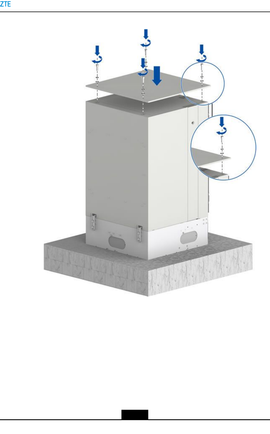
Chapter4CabinetInstallation
Figure4-17PlacingaTopCover
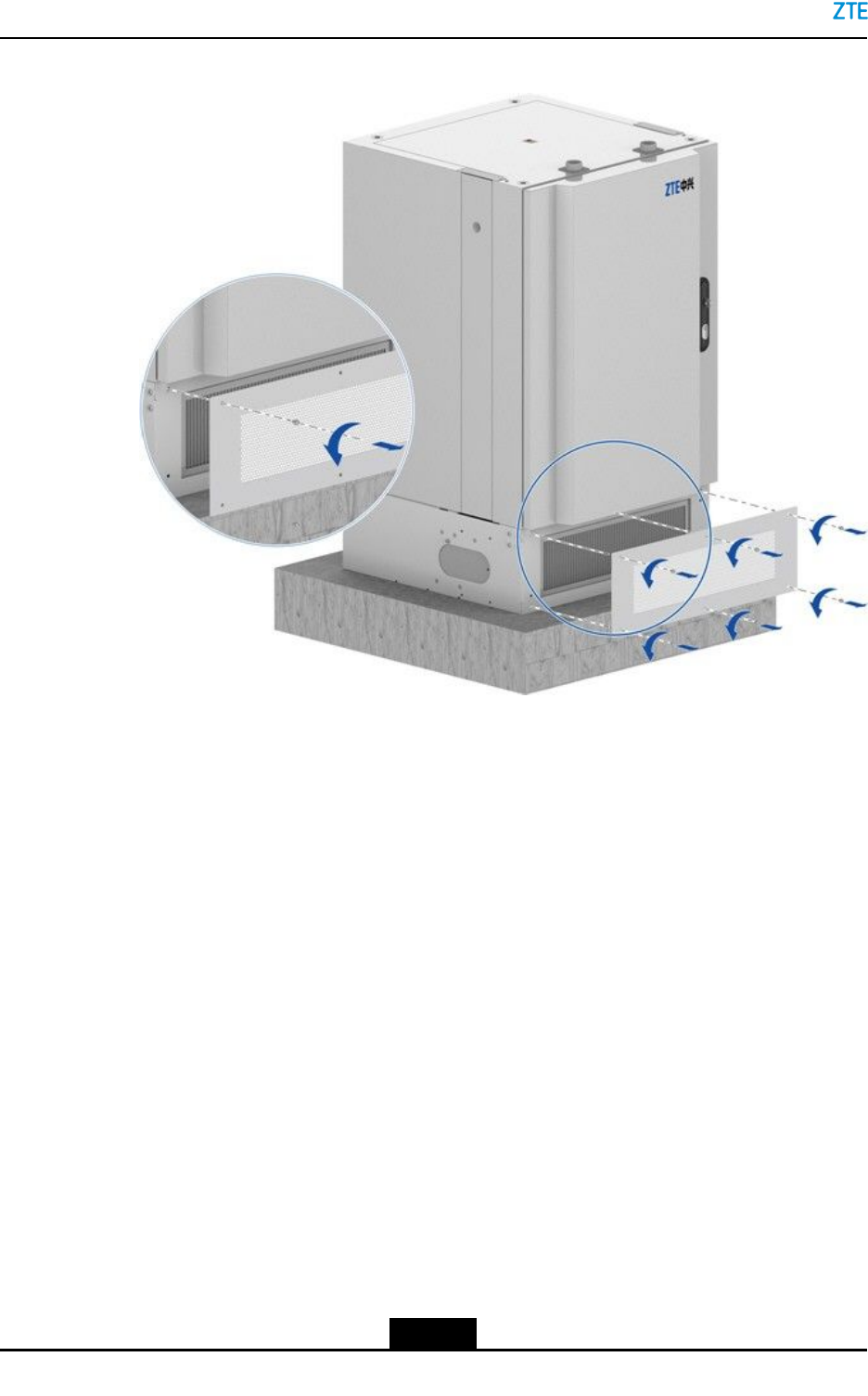
12.Removetheairlter.
Removethesixanti-theftscrewsfromthefrontpanelofthebasebyusingaspecial
wrench,andremovetheairlter,seeFigure4-18.
Toroutecables,thefrontpanelofthecabinetbottomandtheairltermustberemoved.
AfterallthecablesoftheZXSDRBS8900Aareinstalled,youmustinstalltheairlter
andthefrontpanelofthecabinetbottom.
4-15
SJ-20150203110107-011|2016-03-23(R1.1)ZTEProprietaryandCondential
ZXSDRBS8900AHardwareInstallation
Figure4-18RemovingtheAirFilter
–EndofSteps–
4.3InstallingStackedCabinets
Thisproceduredescribeshowtoinstallstackedcabinets.
Prerequisite
Thelower-layercabinetinthestackedcabinetinstallationmodeisinstalled.
Context
ThecommoncombinationmodesoftheZXSDRBS8900Acabinetsaredescribedas
follows:
lCombination1:BC8910A+RC8910A+PC8910A
lCombination2:BC8910A+RC8910A
Inthesetwocombinations,BC8910Aisthecabinetthatneedstobestacked.
Steps
1.Placethetopcoveronthetopoftheupper-layercabinet,andxittothecabinetusing
fourM12hexagonboltswithsteelgaskets.
4-16
SJ-20150203110107-011|2016-03-23(R1.1)ZTEProprietaryandCondential
Chapter4CabinetInstallation
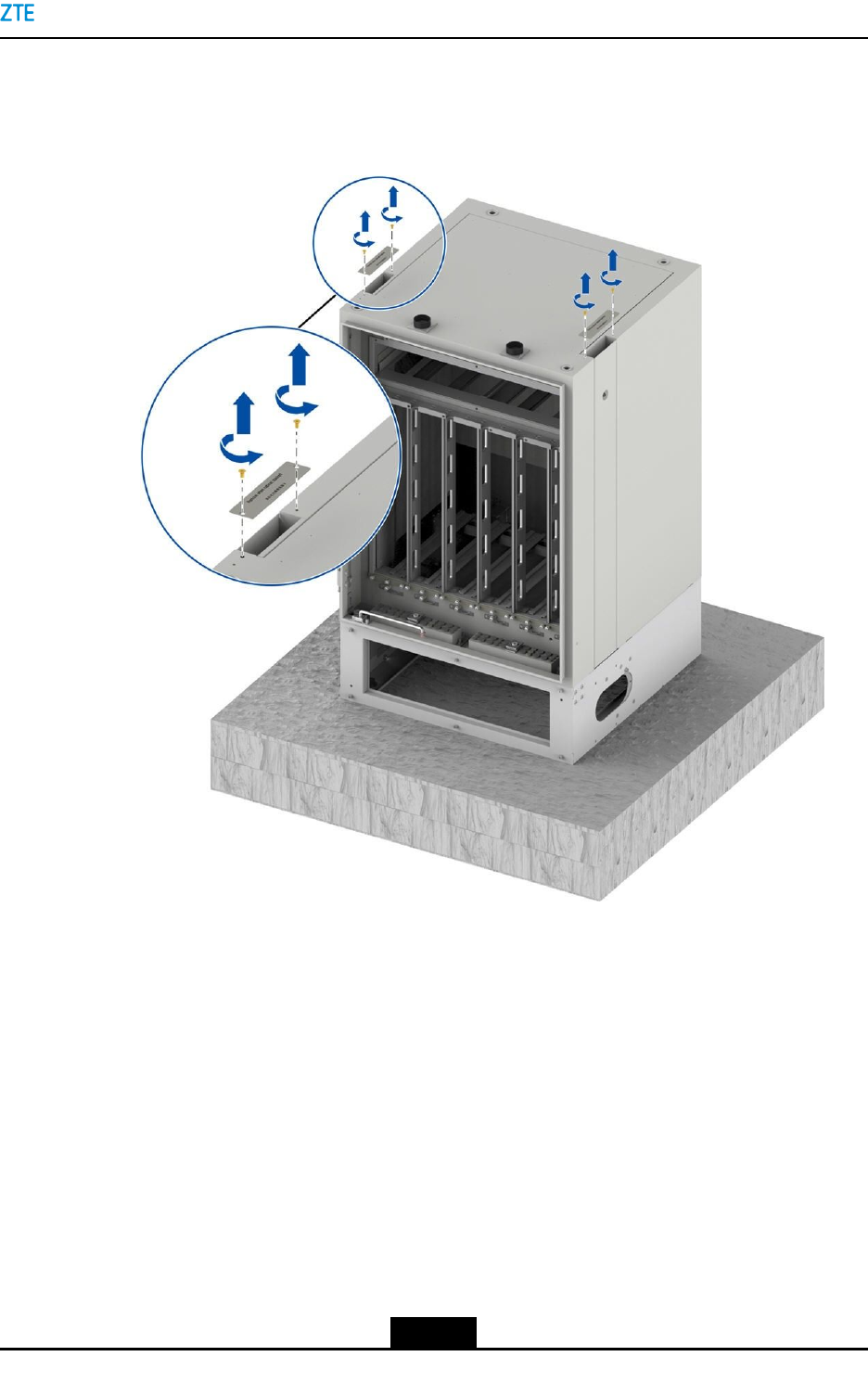
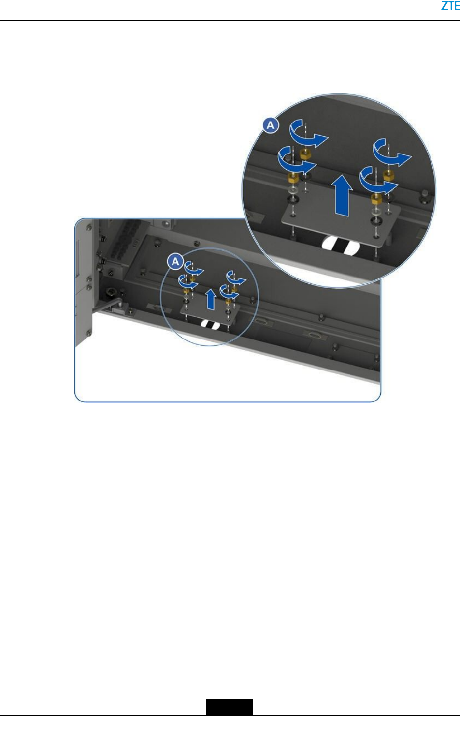
2.Removethecoverplateofthecabletroughonthelower-layercabinetbyremoving
thescrews,seeFigure4-19.
Figure4-19RemovingtheScrewsfromtheCoverPlateoftheCableTrough
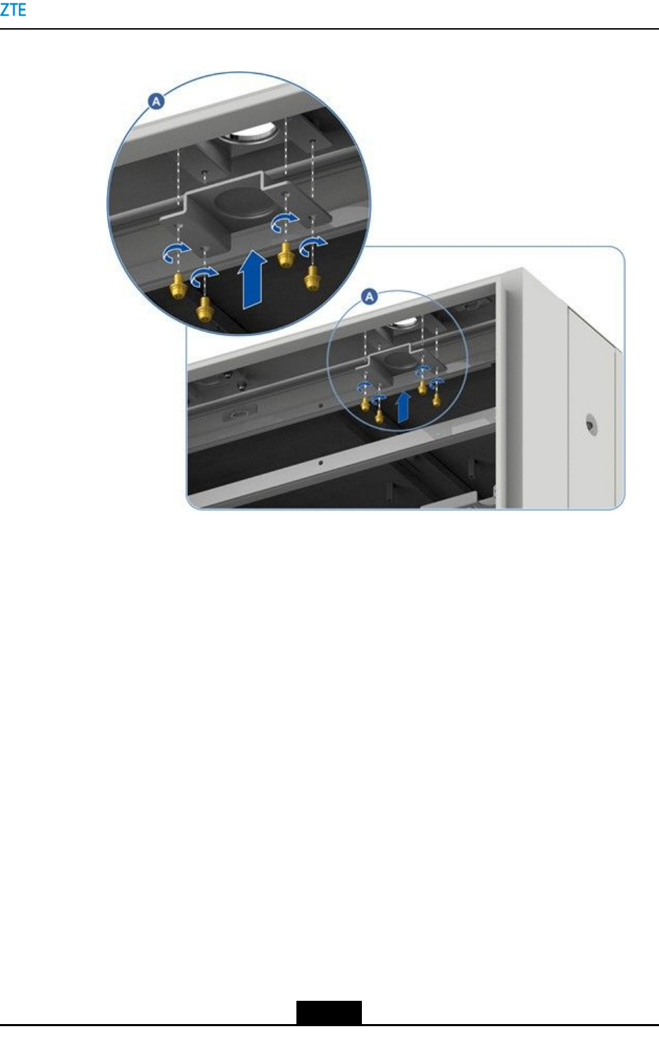
3.Removethecoverplateoftheroutingholebyremovingthefourscrewsinsidethe
lower-layercabinet,seeFigure4-20.
4-17
SJ-20150203110107-011|2016-03-23(R1.1)ZTEProprietaryandCondential
Chapter4CabinetInstallation
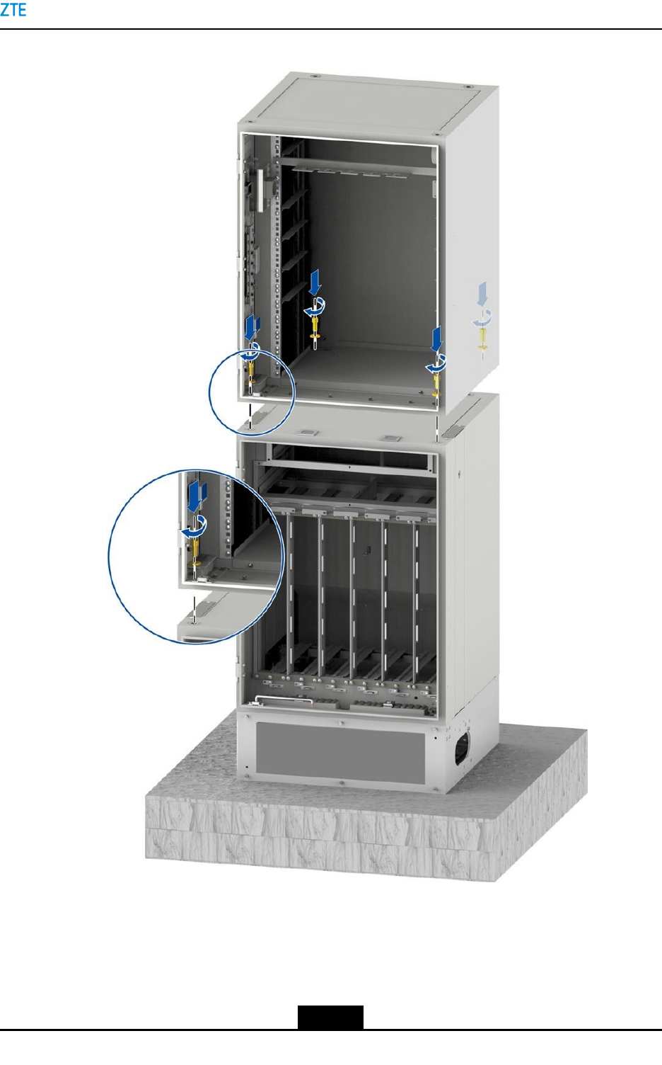
Figure4-21FixingtheUpper–LayerCabinettotheLower–LayerCabinet
IfaheaterisinstalledintheBC8910Acabinet,theheaterwillcovertheM12bolt
installationholesattherearofthecabinet.Youneedtoremovethelockingscrewsof
theheaterrstandthenpullouttheheaterpartiallybeforeinstallingM12bolts.The
powercableoftheheaterisnotrequiredtoberemoved.
4-19
SJ-20150203110107-011|2016-03-23(R1.1)ZTEProprietaryandCondential
ZXSDRBS8900AHardwareInstallation
5.Removethecoverplateoftheroutingholeatthebottomoftheupper–layercabinet,
seeFigure4-22.
Figure4-22RemovingtheCoverPlateoftheRoutingHole
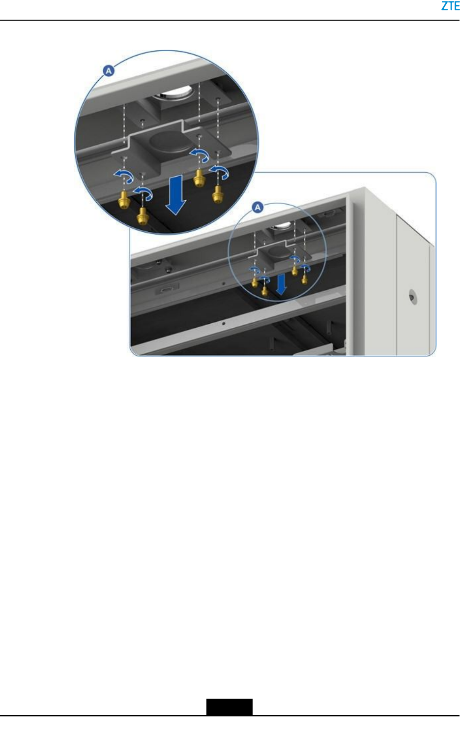
6.Securetheroutingholecomponentsbeneaththecabinetroutingholeonthetopofthe
lower-layercabinet,seeFigure4-23.
4-20
SJ-20150203110107-011|2016-03-23(R1.1)ZTEProprietaryandCondential
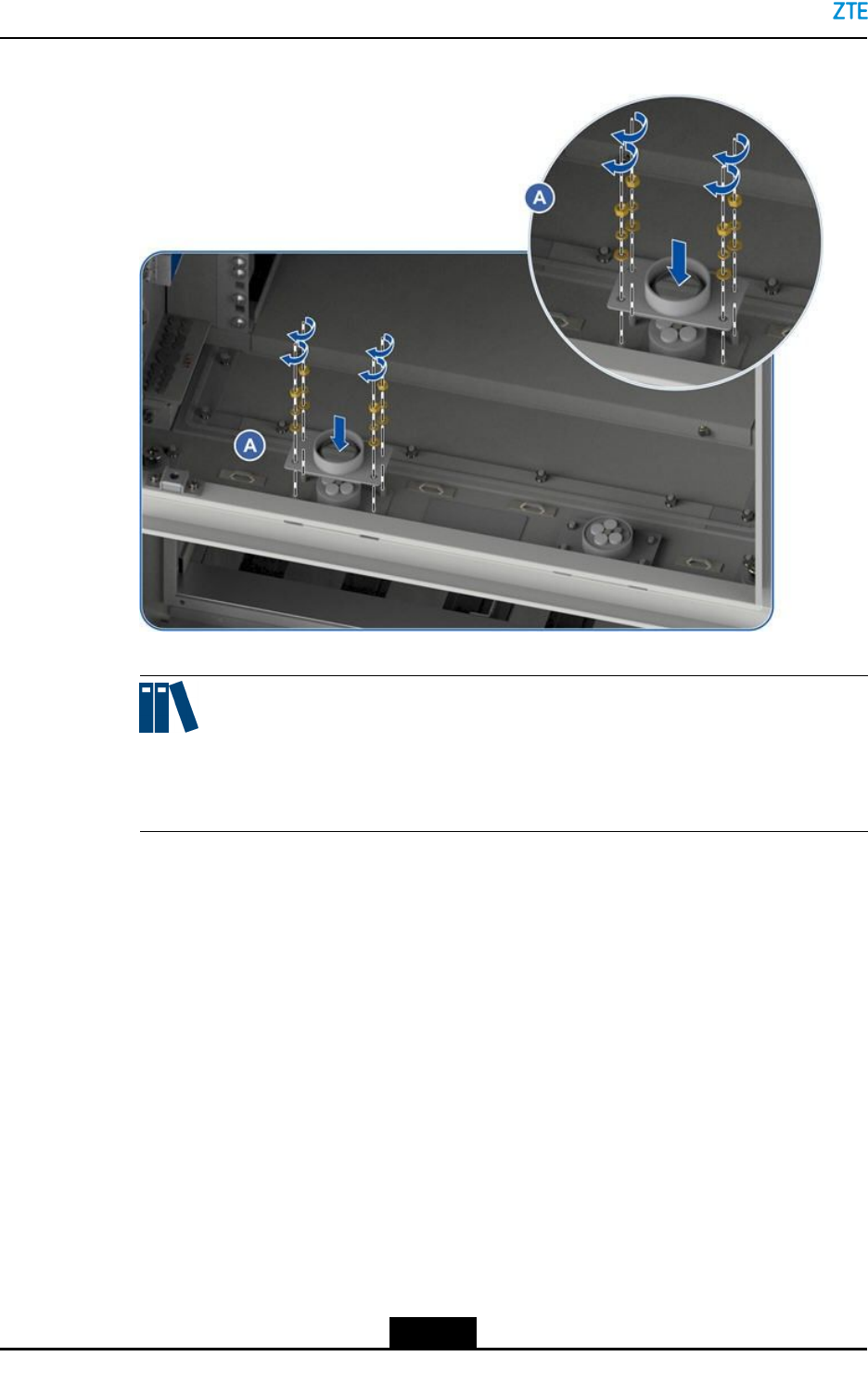
ZXSDRBS8900AHardwareInstallation
Figure4-24SecuringtheRoutingComponentsoftheUpper-LayerCabinet
Note:
Theroutingholecomponentsmustbetightenedtopreventthecabinetfromwater
leakage.
8.Toensurethatthecabinetishorizontalandproperlypositioned,adjustthecabinet
positionandgradient.
9.Sealtheaperturesbyusingseamgum.
Thereareaperturesbetweentheupperandlowercabinetsafterthecabinetsare
installedinstackmode,whichmaycausewaterloggingandequipmentcorrosion.
Youneedtosealtheaperturesbyusingseamgumafterthecabinetsareinstalledin
stackmode.
a.Sealtheaperturesevenlybyusingseamgum,seeFigure4-25.
4-22
SJ-20150203110107-011|2016-03-23(R1.1)ZTEProprietaryandCondential
Chapter4CabinetInstallation
Figure4-25SealingAperturesofStackedCabinetsbyUsingSeamgum
Thecabletroughsontheleftandrightsidesofthelowercabinetarenotrequired
tobesealed.
b.Removetheoverowingseamgumbyusingcloth.
–EndofSteps–
4-23
SJ-20150203110107-011|2016-03-23(R1.1)ZTEProprietaryandCondential

ZXSDRBS8900AHardwareInstallation
Thispageintentionallyleftblank.
4-24
SJ-20150203110107-011|2016-03-23(R1.1)ZTEProprietaryandCondential

Chapter5
ComponentInstallationina
Cabinet
TableofContents
InstallinganRFUnitintheRC8910ACabinet(Optional)............................................5-1
InstallingBatteries......................................................................................................5-2
5.1InstallinganRFUnitintheRC8910ACabinet
(Optional)
ThisproceduredescribeshowtoinstallanRFunitintheRC8910Acabinet.Inmostcases,
theRFunitisinstalled.YoufollowthisproceduretoinstalltheRFunitifrequired.
TheRC8910AcabinetsupportssixRFmodules(RSUs)installed.
WhenonlyonebootsectionoftheRSU2T4Risusedinhighcarrierfrequency(twotransmit
linksareinthesamebootsectionandusedifferentcarrierfrequencies),theantenna
jumperwirescanonlyconnecttotheANT1andANT3ports.
Prerequisite
YouworeanESDwriststrap.
Steps
1.DeterminethetargetslottoinstalltheRSU,holdthehandleoftheRSUwithonehand,
supportthebottomoftheRSUwiththeotherhand,trytomakeparallelthemodule
andtheguidingplane,andpushitslightlyintothecabinet.
Note:
YoushouldnotethedirectionoftheRSU.Thepowerinterfacemustbedownward,
andtheANTinterfacemustbeupward.
2.FixtheRSUandgroundlugwithveM5x20screws,seeFigure5-1.
5-1
SJ-20150203110107-011|2016-03-23(R1.1)ZTEProprietaryandCondential
ZXSDRBS8900AHardwareInstallation
Figure5-1FixingtheRSU
1.FixingtheRSU2.Fixingthegroundplug
3.AftertheRSUmoduleisinstalled,connecttheblackpowercablefromthePDMtothe
POWERportoftheRSUmodule.
–EndofSteps–
5.2InstallingBatteries
ThisproceduredescribeshowtoinstallbatteriesinthePC8910Acabinet.
Caution!
Ifonlyfourbatteriesareused,theunconnectedterminalsforbatteriesmustbewrapped
upwithinsulationmaterials.
5-2
SJ-20150203110107-011|2016-03-23(R1.1)ZTEProprietaryandCondential
Chapter5ComponentInstallationinaCabinet
Prerequisite
RelevantcablesshouldbedeployedbeforethePC8910Acabinetisplaced.Otherwise,it
maybedifculttodeploythecables.
Context
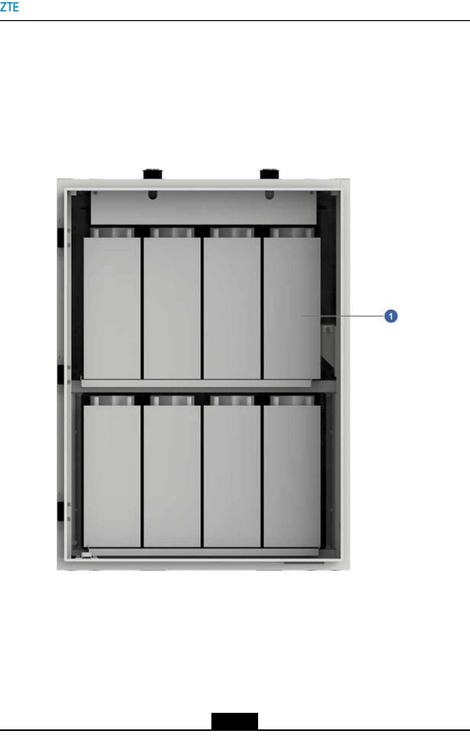
FortheinternallayoutofthePC8910Acabinet,seeFigure5-2.
Figure5-2PC8910ALayout
ThePC8910Acabinetcanbeconguredwithtwopacksofbatteriesandeachbattery
packhasfour12Vbatteriesinserialconnection.Refertothefollowingstoensurethatthe
dimensionsandweightoftheselectedbatteriesareapplicabletothePC8910Acabinet
beforethesebatteriesareinstalledintothePC8910Acabinet:
lEverybatteryracksupports260kgatmost,meaningthateachbatteryis65kgat
most.
5-3
SJ-20150203110107-011|2016-03-23(R1.1)ZTEProprietaryandCondential
ZXSDRBS8900AHardwareInstallation
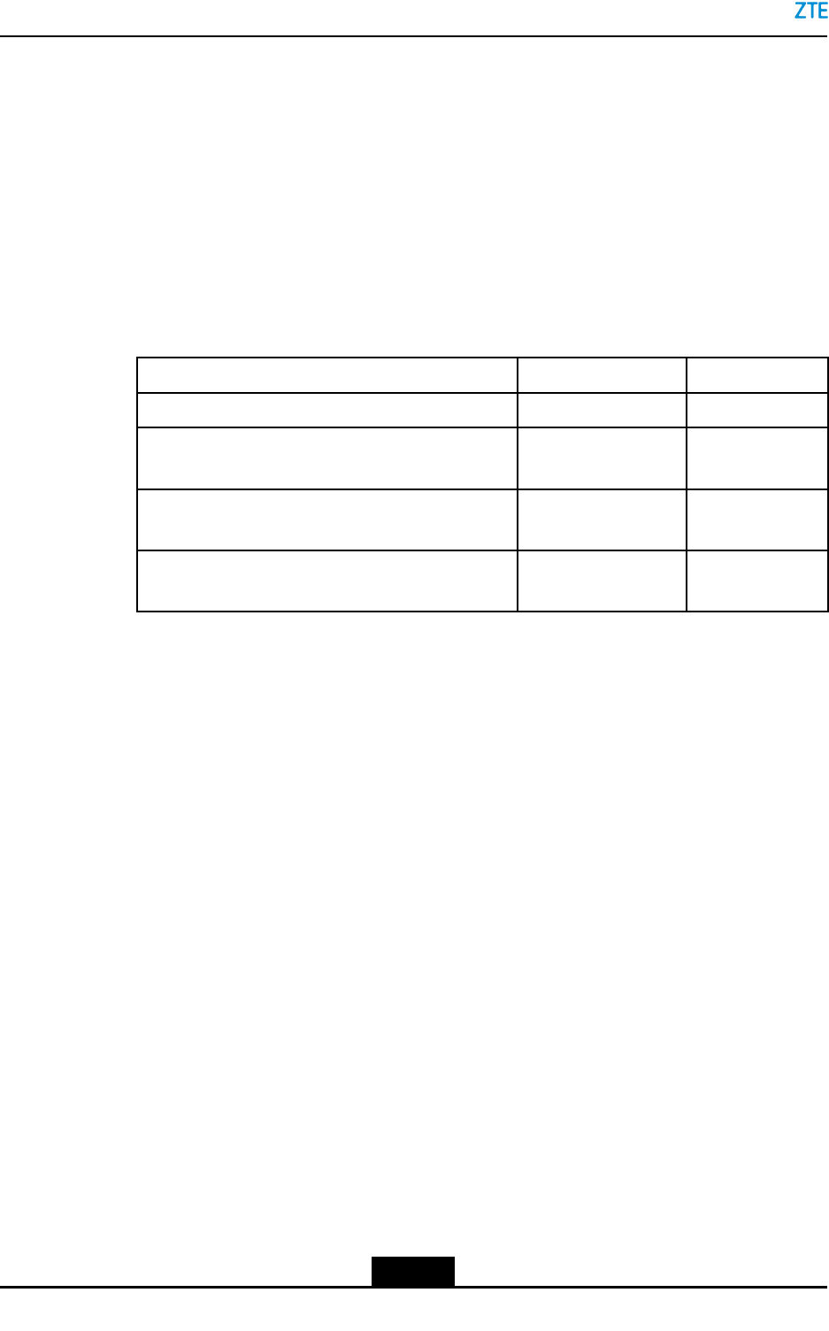
lAssumethatthebatteryspacingis2mm,atleast12mmshouldbereservedinheight
anddepth.Theleftandrightsidesofeachbatterypackshouldbeatleast9mmaway
fromtheinnerwallofthePC8910Acabinetforelectricalsafety.
lInaccordancewiththedimensionsofbatteriesandtheirspace,calculateW1(space
betweentherightandleftsidesofthebatterypackandtheinnerwallofthePC8910A
cabinet),H1(spacebetweenthetopofthebatterypackandtheinnerwallofthe
PC8910Acabinet),andD1(spacebetweentherearsideofthebatterypackandthe
innerwallofthePC8910Acabinet).MakeatableshowninT able5-1,andenter
relevantvaluesinActualSpacingcells.
Table5-1SpaceBetweentheBatteryPackandtheInnerWallofthePC8910A
Cabinet
ItemStatedSpacingActualSpacing
BatterySpacing2mm
Spacingbetweentheleftmost/rightmostbatteryand
thePC8910Acabinet(W1)
≥9mm
SpacingbetweenthebatterytopandthePC8910A
cabinet(H1)
≥12mm
SpacingbetweenthebatterybackandthePC8910A
cabinet(D1)
≥12mm
Steps
1.Usethemultimetertoverifythateachbatteryisfunctioningproperlybymeasuringthe
voltageofitsterminals.
Batteriesfromdifferentsuppliersmayhavevariousvoltageranges.Seetherelevant
batteryspecicationstolearnthevoltagerangeofabattery.Ifthedetectedvoltageof
abatteryisoutofthenormalrange,itindicatesthatthebatteryisfaulty.Replacethe
faultybatterywithafunctionaloneofthesametypeandfromthesamesupplier.
2.Placebatteriesonebyoneontothebatteryrackbythepolaritydirections.
5-4
SJ-20150203110107-011|2016-03-23(R1.1)ZTEProprietaryandCondential
Chapter5ComponentInstallationinaCabinet
Caution!
lReadthebatteryprecautionscarefully(suchassafetyrequirementsifgthe
batteriesarecarried)andlearnaboutthecorrectbatteryconnectionsbeforeany
operationsonthebatteriesareperformed.Improperoperationsonthebatteries
maycausedanger.Avoidshortcircuitsorelectrolyteoverowduringoperations
onbatteries.Electrolyteoverowposeslatentthreattotheequipmentbecauseit
corrodesmetallicobjectsorcircuitboardsanddamagestheequipment(suchas
short-circuitingthecircuitboard).
lThewiringterminalsofthebatteriesmustfaceoutwardstofacilitatewire
connection.
lPlacethebatterypacksinthemiddleandreserveatleast9mmfromtheleftand
rightsidesandtopofeachbatterypacktotheinnerwallofthePC8910Acabinet
forelectricalsafety,soastoavoidshortcircuitsorevenrecausedbywiring
terminalstouchingwiththeinnerwall.
3.Connecttheterminalsofthebatteries.
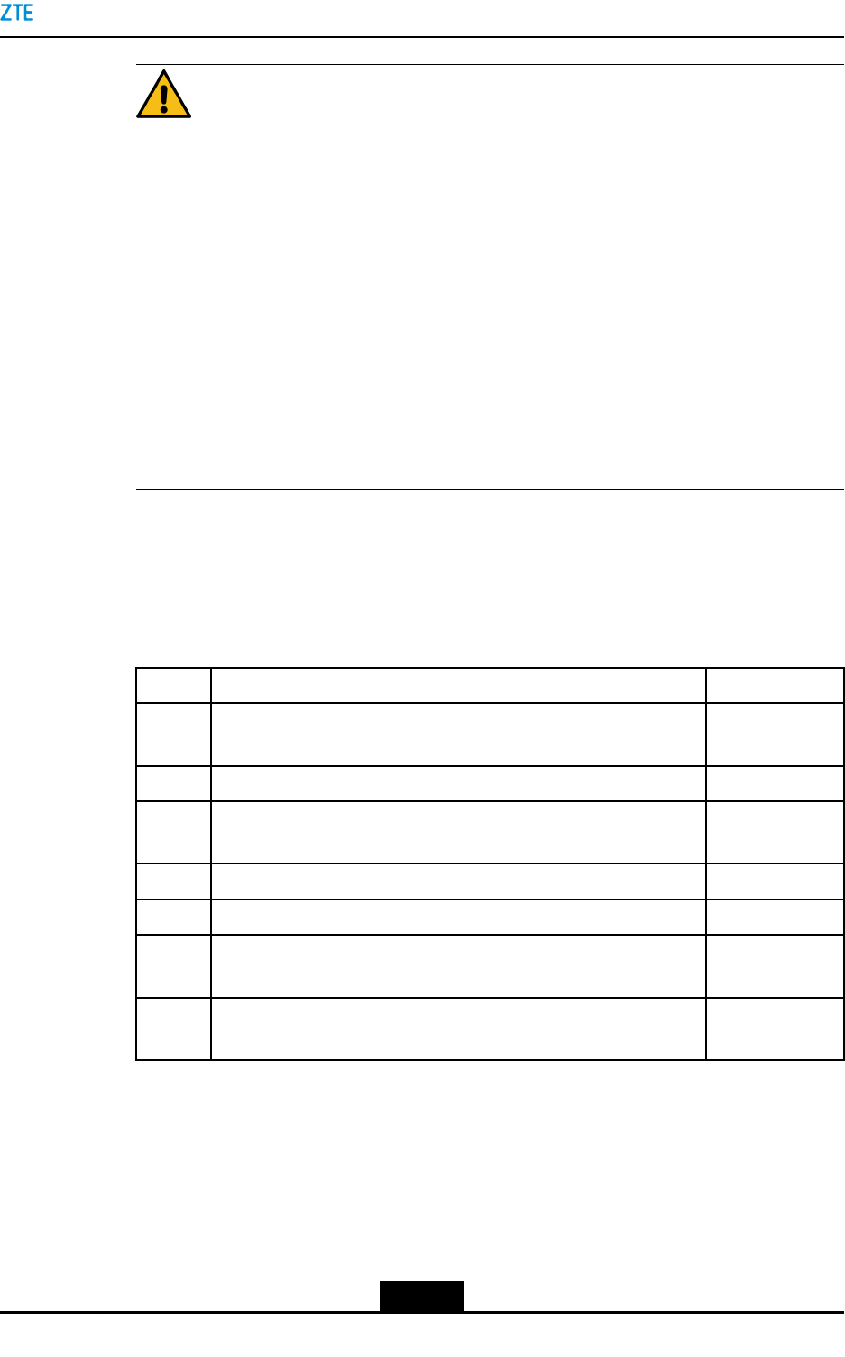
4.ChecktheinstallationagainstthechecklistshowninTable5-2andensurethatthe
answertoeachitemisYes.
Table5-2InstallationVericationChecklist
SNCheckCriterionCheckResult
1Theinstalledcabinetstandsrmlyandlookseye-pleasingand
neat.
YesNo
2Thegradientoftheinstalledcabinetissmallerthan5°.YesNo
3Allscrewsarefastenedreliably,withtheatwashersandspring
washerscorrectlyused.
YesNo
4Thecabinetisfreefromdamagesorfallenpaint.YesNo
5Thecabinetiscleanwithoutdust,pollutantorsundries.YesNo
6Thecabinetdoorcanbeopenedorclosedeasily,andthedoor
lockisfunctioningproperly.
YesNo
7Othercomponents(forexample,therectierunitandmonitoring
unit)issecure.
YesNo
–EndofSteps–
5-5
SJ-20150203110107-011|2016-03-23(R1.1)ZTEProprietaryandCondential

ZXSDRBS8900AHardwareInstallation
Thispageintentionallyleftblank.
5-6
SJ-20150203110107-011|2016-03-23(R1.1)ZTEProprietaryandCondential
Chapter6
InstallingtheGPSAntenna
(Optional)
TheZXSDRBS8900AsupportsaGPSantennainstalledonanycornetofthecabinettop.
TheGPSantennaisinstalledonthetopofthecabinettoshortenthedistancebetween
theGPSantennaandthecabinet,toreducethecomplexityofinstallingtheGPSantenna
andcables,andtosaveinstallationspaceandtime.
Context
ToinstalltheGPSantennaonthetopofthecabinet,youneedtoinstallGPSinstallation
assemblyonthehangeronthetopofthecabinet.ForGPSinstallationassemble,see
Figure6-1.
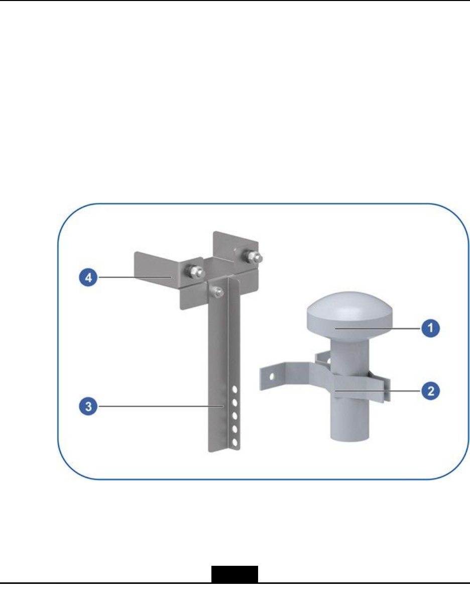
Figure6-1GPSInstallationAssembly
1.GPSantenna
2.GPSinstallationclamp
3.GPScabletrough
4.GPSinstallationaccessory
6-1
SJ-20150203110107-011|2016-03-23(R1.1)ZTEProprietaryandCondential
ZXSDRBS8900AHardwareInstallation
Steps
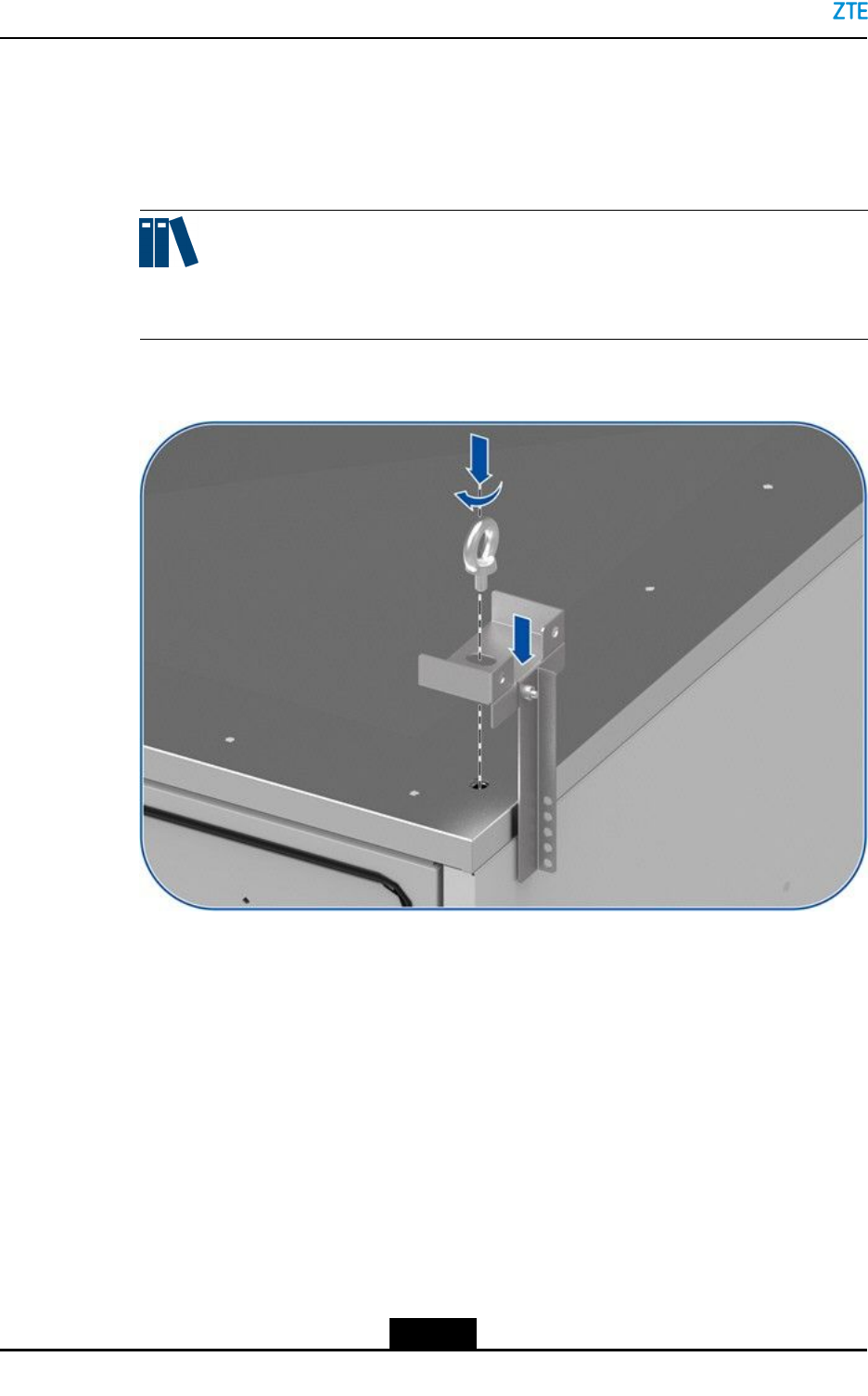
1.PlacetheGPSinstallationaccessoryattheholeonthetopofthecabinetwherethe
hangerwillbeinstalled.FastenthehangertoxtheGPSinstallationaccessory,see
Figure6-2.
Note:
TheGPScabletroughisxedtotheGPSinstallationaccessorytobindtheGPScable.
Figure6-2FixingtheGPSAccessoryontheTopoftheCabinet
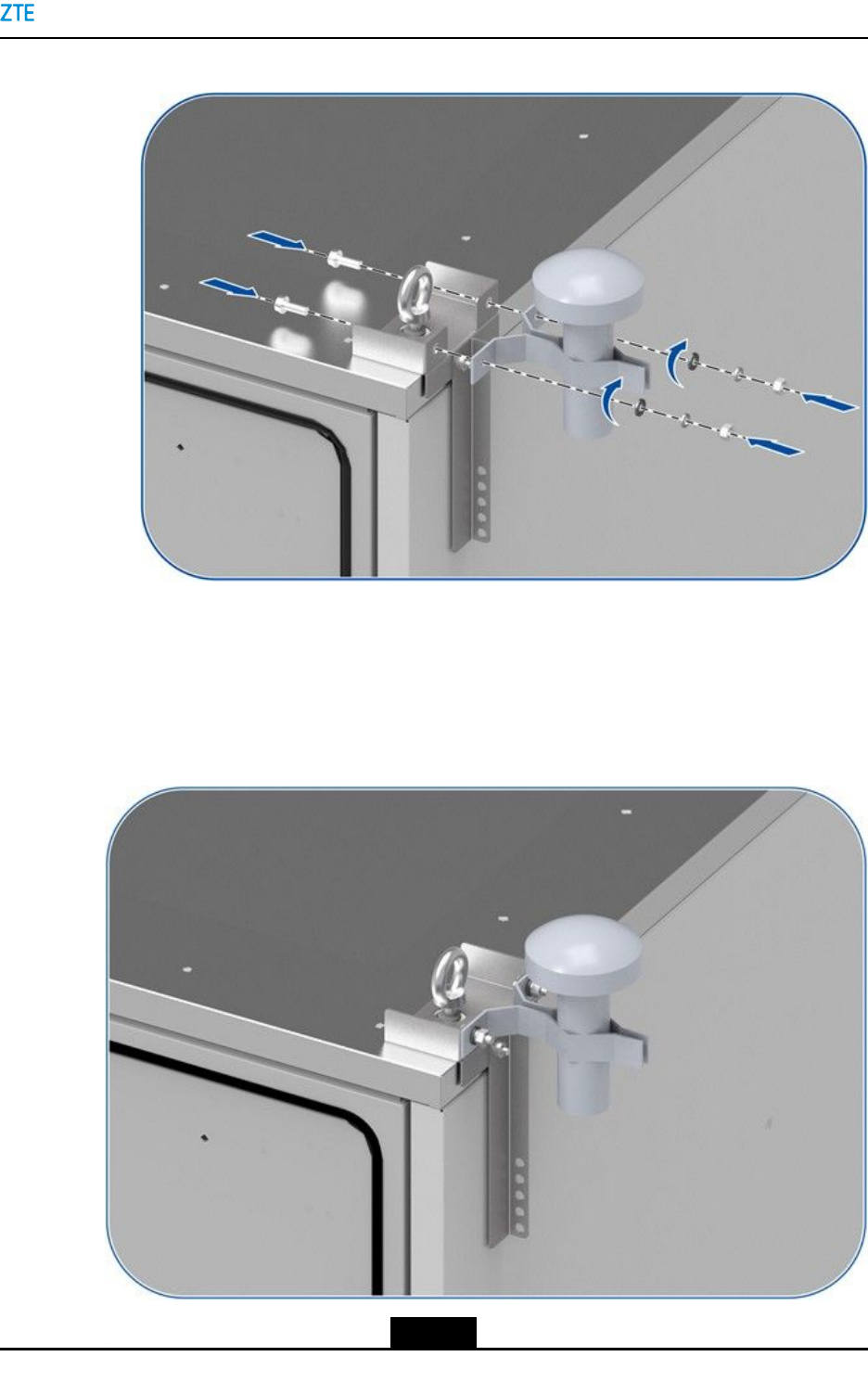
2.UseaGPSclamptoxtheGPSantenna,andusetwoboltstoxtheGPSclampon
theGPSinstallationaccessory,seeFigure6-3.
6-2
SJ-20150203110107-011|2016-03-23(R1.1)ZTEProprietaryandCondential

ZXSDRBS8900AHardwareInstallation
Thispageintentionallyleftblank.
6-4
SJ-20150203110107-011|2016-03-23(R1.1)ZTEProprietaryandCondential

Chapter7
CableInstallation
ThecablesoftheZXSDRBS8900Acabinetcanbeclassiedasgroundingcables,power
cables,transportcables,andmonitoringcables.Inaccordancewiththecableroutingin
stackedcabinets,thesecablesareclassiedasexternalcablesandinter-cabinetcables.
Thetwotypesofcablesarethreadedthroughdifferentcableholesandwaterproofmodules
duringcablerouting.
TableofContents
CablingOverview.......................................................................................................7-1
Cable-ThroughHoles.................................................................................................7-6
WaterproofModuleDescription..................................................................................7-9
GroundingCableInstallation....................................................................................7-12
PowerCableInstallation...........................................................................................7-18
TransmissionCableInstallation................................................................................7-35
SignalCableInstallation...........................................................................................7-40
MonitoringCableInstallation....................................................................................7-50
WaterproofModuleInstallation.................................................................................7-63
InstallingtheAirFilter...............................................................................................7-64
7.1CablingOverview
ExternalCablesofStackedCabinets
TheexternalcablesareusedtoconnecttheBC8910AcabinetandRC8910Acabinetto
externaldevices.
TheexternalcablesareroutedintotheBC8910AcabinetorRC8910Acabinetthroughthe
waterproofmoduleatthebottomofthecabinetandthenconnectedtothecorresponding
ports.
ExternalCablesoftheBCCabinet
TheexternalcablesoftheBC8910Acabinetinclude:
lGroundingcable
lExternalpowerinputcables
àACpowerinputcableoftheBCcabinet
àDCpowerinputcableoftheBCcabinet
àDCpowerinputcableofthePCcabinet
lTransportcables
7-1
SJ-20150203110107-011|2016-03-23(R1.1)ZTEProprietaryandCondential

ZXSDRBS8900AHardwareInstallation
àEthernetnetworkcable
àtransportbers
lSignalcables
àOutdooropticalbers
àGPSfeeder
àE1/T1cable
lMonitoringcable
ExternalCableRoutingoftheBCCabinet
Forstackedcables,theexternalcablesoftheBC8910Acablesarethreadedthroughthe
waterproofmodulesontwosidesoftheBC8910Acabinetandthenroutedalongthecable
troughsoftheRC8910Acabinet.ForexternalcableroutingoftheBC8910Acabinet,see
Figure7-1.
7-2
SJ-20150203110107-011|2016-03-23(R1.1)ZTEProprietaryandCondential
Chapter7CableInstallation
Figure7-1ExternalCableRoutingoftheBC8910ACabinet
ExternalCablesoftheRCCabinet
TheexternalcablesoftheRC8910Acabinetinclude:
lAntennajumper
lAISGcable
ExternalCableRoutingoftheRCCabinet
Thejumperwiresarethreadedthoughthewaterproofmoduleatthebottomofthecabinet,
seeFigure7-2.
7-3
SJ-20150203110107-011|2016-03-23(R1.1)ZTEProprietaryandCondential
ZXSDRBS8900AHardwareInstallation
Figure7-2ExternalCableRoutingoftheRC8910ACabinet
Inter-CabinetCables
Theinter-cabinetcablesrefertothecablesconnectingtheBCcabinettotheRCcabinet.
Theinter-cabinetcablesinclude:
lGroundingcableoftheRCcabinet
lDCpowerinputcableoftheRCcabinet
lSFPcable
Theinter-cabinetcablesarethreadedthroughthecable-throughholesontheBC8910A
cabinetandRC8910Acabinetandthenconnectedtothecorrespondingports,seeFigure
7-3.
7-4
SJ-20150203110107-011|2016-03-23(R1.1)ZTEProprietaryandCondential
Chapter7CableInstallation
Figure7-3CableRoutingforStackedCabinets
CableRoutingRequirements
lBeforepowercablesandgroundingcablesarelaidout,theconnectorsmustbe
coveredbyinsulationtape.
lThepowercables,groundingcables,andsignalcablesmustberoutedseparately.
lWhensignalcables,DCpowercables,ACpowercables,andfeedersareroutedin
parallelalongacableladder,ensurethataspacinggreaterthan100mmisreserved
betweendifferenttypesofcables.
lIfsignalcablesandpowercablesneedtobelaidoutinacrossmanner,thecross
anglemustbe90°.
lIfacableneedstobend,ensurethatthebendingradiusmeetstheminimumbending
radiusrequirement,meaningthatthebendingradiusmustbeequaltoorgreaterthan
20timesofthecable'souterdiameter.
7-5
SJ-20150203110107-011|2016-03-23(R1.1)ZTEProprietaryandCondential
ZXSDRBS8900AHardwareInstallation
lWhenthepowercableisconnectedtotheconnectorofthepowerdistributionboxin
thecabinet,thecablemustberoutedinasmoothandstraightmanner.
lTheactualinstallationpositionsofthecablesmustmeettheengineeringsurvey
requirementsandbeconsistentwithcongurations.
lThecableroutingpathsareclearandreasonablewithevenandsmoothbends,and
meetthespecicationsinengineeringdrawings.
lSignalcablesarealignedneatlyandsmoothlywithoutcross.
lCablesarelaidoutforconvenientmaintenanceandcapacityexpansion.
lYouknowclearlytheplannedrouteofeachfeeder.It'ettertodrawtheroutingina
pieceofpapertoavoidrewordduetofeedercross.
lThebendingradiusofacommonfeedermustbegreaterthan20timesoftheouter
diameter.Thebendingradiusofasoftfeedermustbegreaterthan10timesofthe
outerdiameter.
lFortherequirementsofthebendingradiusoffeeders,refertoT able7-1.
Table7-1RequirementsofBendingRadiusofFeeders
MinimumBendingRadius(Recommended) FeederType
SingleBendingContinuousBending(≤15times)
Soft1/2"feeder150mm300mm
1/2"feeder500mm1250mm
7/8"feeder900mm2500mm
5/4"feeder1500mm3800mm
CableBundleRequirements
lThecabletiesmustbeatanevenspacingwithenoughslackandfacethesame
direction.
lThesurpluspartofcableclipsshouldbetrimmedevenlyfromtheendswithoutsharp
edges.
lPowercablesandgroundingcablesshouldbeboundseparatelyfromsignalcables.
lCablesinthecabinetmustbeboundproperlywithcableties.
lCablesroutedalongcabletroughsmustbebound.Theboundcablesmustberouted
straightandorderlyclosetoeachother.
lProperredundantlengthmustbereservedforeachconnectorforinstallationand
removing.
7.2Cable-ThroughHoles
Therearetwocable-throughholesandtwowaterproofmodulesatthebottomofthe
BC8910Acabinet.Thecable-throughholesareusedtothreadtheinter-cabinetcables.
Thewaterproofmodulescommunicatewiththecabletroughsonthetwosidesofthe
RC8910AcabinetandPC8910Acabinet.
7-6
SJ-20150203110107-011|2016-03-23(R1.1)ZTEProprietaryandCondential
Chapter7CableInstallation
TherearetwocabletroughsonthetwosidesoftheRC8910AcabinetandPC8910A
cabinet.ThecabletroughsareusedforroutingtheexternalcablesoftheBC8910Acabinet
whentwocabinetsarestacked.
ThePC8910Acabinetprovidestwocable-throughholesatthebottomofthebox.The
cable-throughholesareusedforroutingthepowercableandmonitoringcableofthe
PC8910Acabinet.
Cable-ThroughHolesofBC8910A
Forthecable-throughholesoftheBC8910Aswhenbeingstalledinastackedmanner,see
Figure7-4.
Figure7-4Cable-ThroughHoleoftheBC8910A
1.Waterproofmoduleonthe
rightside
2.Waterproofmoduleonthe
leftside
3.Cable-throughhole
Cable-ThroughHolesoftheRC8910ACabinet
TofacilitatetheroutingofcableswhentheRFandbasebandcabinetsarestackedand
installed,twocable-throughholesandtworoutingtroughsaredesignedonthetopofthe
cabinet.ThetworoutingtroughsarelocatedontheleftandrightsidesoftheRFcabinet.
TheyareinteroperablewithexternalenvironmentandfacilitatetheroutingoftheBC8910A
cabinet.Thetwocable-throughholesarelocatedonthefronttopofthecabinettofacilitate
theroutingbetweenRC8910AandBC8910Acabinets.
7-7
SJ-20150203110107-011|2016-03-23(R1.1)ZTEProprietaryandCondential
ZXSDRBS8900AHardwareInstallation
lWhenroutingcablesalongatrough,removethecoverofthetroughwithahexagon
anti-theftringwrenchoftheRC8910Acabinet(specically,unscrewingthesixscrews
ontherearcover),andreseatthecoverafterallcablesarerouted,seeFigure7-5.
Figure7-5CoveroftheCableTray
lBeforethestackedinstallation,thewaterproofplatesforthetwocable-throughholes
mustberemovedandthenreseatedaftercablesarerouted.
Cable-ThroughHolesofthePC8910ACabinet
Twocable-throughholes(rightandleft)aredesignedonthebottomofthePC8910A
cabinetandthetwoholesareprotectedwithwaterproofplugs.Removetheseplugs
beforethecablesareroutedandreseatthemafterthecablesarerouted.
7-8
SJ-20150203110107-011|2016-03-23(R1.1)ZTEProprietaryandCondential
Chapter7CableInstallation
7.3WaterproofModuleDescription
7.3.1WaterproofModuleoftheBasebandCabinet
WaterproofModuleDescription
Externalcablesareroutedintotherectangularcabletroughswithwaterproofmoduleson
theleftandrightsidesoftheBC8901Acabinet.Thecablesbetweenstackedcabinetsare
routedthroughthetworoundcable-throughholesinthefrontofthecabinet.Ifbatteries
areinstalledinthelowercabinet,anacid-gas-preventionmodulemustbeinstalled.
Note:
Iftherearetooexternalcablesinthebasebandcabinettoberoutedthroughthe
cable-throughholereservedbythewaterproofmodule,thewaterproofshouldbe
removed.Youcanroutethecablesthroughthecabletraydirectly,andllthegapswith
reproofclay.
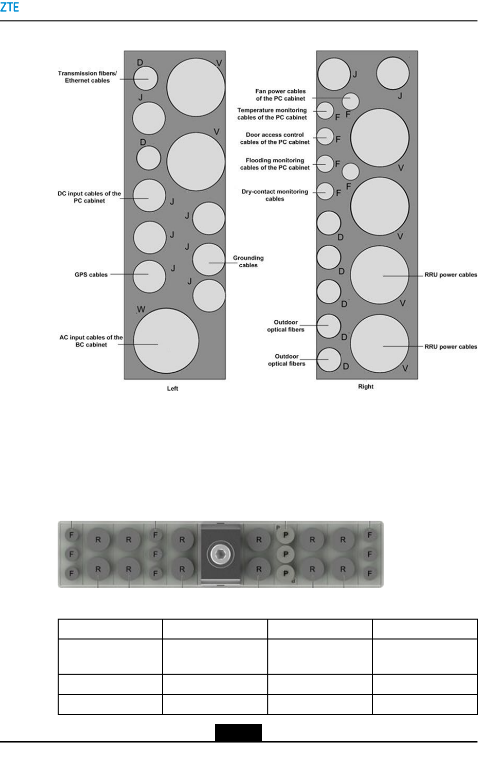
Forthestructureofthewaterproofmoduleofthebasebandcabinet,seeFigure7-6.
Figure7-6WaterproofModuleoftheBasebandCabinet
7-9
SJ-20150203110107-011|2016-03-23(R1.1)ZTEProprietaryandCondential
ZXSDRBS8900AHardwareInstallation
Table7-2ApertureDescription
Waterproof
Module
HoleQuantityAperture
(mm)
Function
D27Foroutdooropticalbersof
RRUs,Ethernetcables,andT1
cables
J79.5ForDCinputpowercables,
groundingcables,batterypower
cables,GPScables,andE1
(75/120Ω)trunkingcables
V217ForRRUpowercables
Waterproofonthe
liftside
W119ForACinputpowercables
D57Foroutdooropticalbersof
RRUs,Ethernetcables,andT1
cables
F65Formonitoringcablessuchas
temperaturemonitoringcables,
dooraccesscontrolcables,fan
powercablesofthePCcabinet,
anddry-contactcables.
J29.5ForDCinputpowercables,
groundingcables,batterypower
cables,GPScables,andE1
(75/120Ω)trunkingcables
Waterproofonthe
rightside
V417ForRRUpowercables
CableRoutingExample
Forcablesroutedthroughthewaterproofmoduleofthebasebandcabinet,seeFigure7-7.
Cablescanberoutedthroughotherholeswiththesameapertureasthecable-through
holesofthewaterproofmoduleifrequired.
Installthewaterproofmoduleafterroutingallthecables.
7-10
SJ-20150203110107-011|2016-03-23(R1.1)ZTEProprietaryandCondential
Chapter7CableInstallation
Figure7-7CableRoutingThroughtheWaterproofModuleoftheBasebandCabinet
7.3.2WaterproofModuleoftheRFCabinet
WaterproofModuleDescription
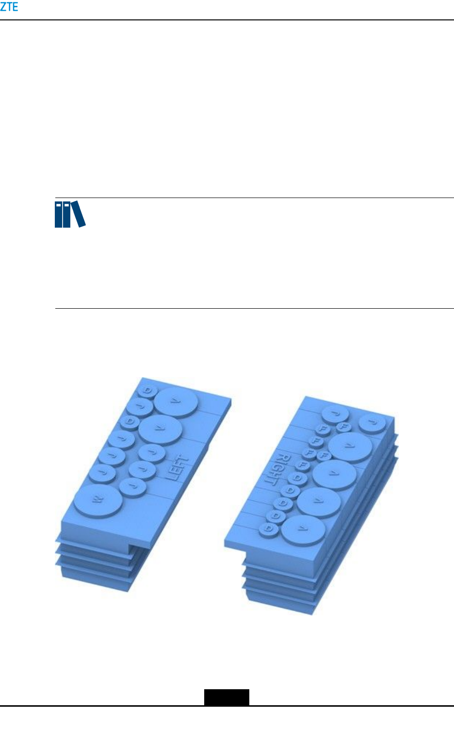
ForthestructureofthewaterproofmoduleatthebottomoftheRFcabinet,seeFigure7-8.
Figure7-8WaterproofModuleoftheRFCabinet
Table7-3DescriptionsforHolesontheWaterproofModule
HoleQuantityDiameter(mm)Function
F96.5Foropticalbersand
AISGcables
P39Forpowercables
R1212.5Forantennacables
7-11
SJ-20150203110107-011|2016-03-23(R1.1)ZTEProprietaryandCondential
ZXSDRBS8900AHardwareInstallation
Whenthescrewistightened,theverticalsliderappliesforcevertically,andthehorizontal
slidersapplyforcehorizontally.Thecableplugscontactcloselywiththecablesto
waterproofthecables.FortheoperationprincipleofwaterproofmoduleintheRC8910A
cabinet,seeFigure7-9.
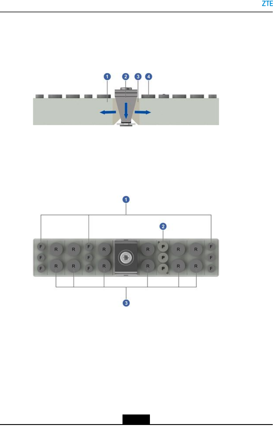
Figure7-9OperationPrincipleoftheWaterproofModuleintheRFCabinet
1.Cableplug
2.Verticalslider
3.Horizontalslider
4.Waterproofcap
CableRoutingExample
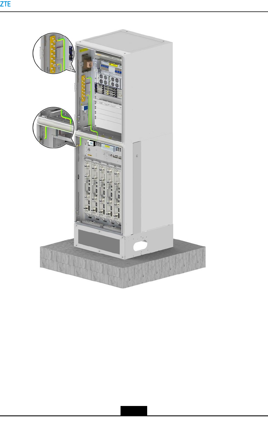
ForcablesroutedthroughthewaterproofmoduleoftheRFcabinet,seeFigure7-10.
Figure7-10CableRoutingThroughtheWaterproofModuleoftheRFCabinet
1.Opticalfibers2.Powercables3.Antennacables
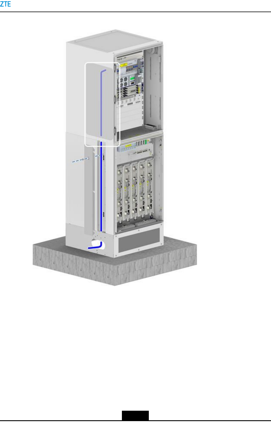
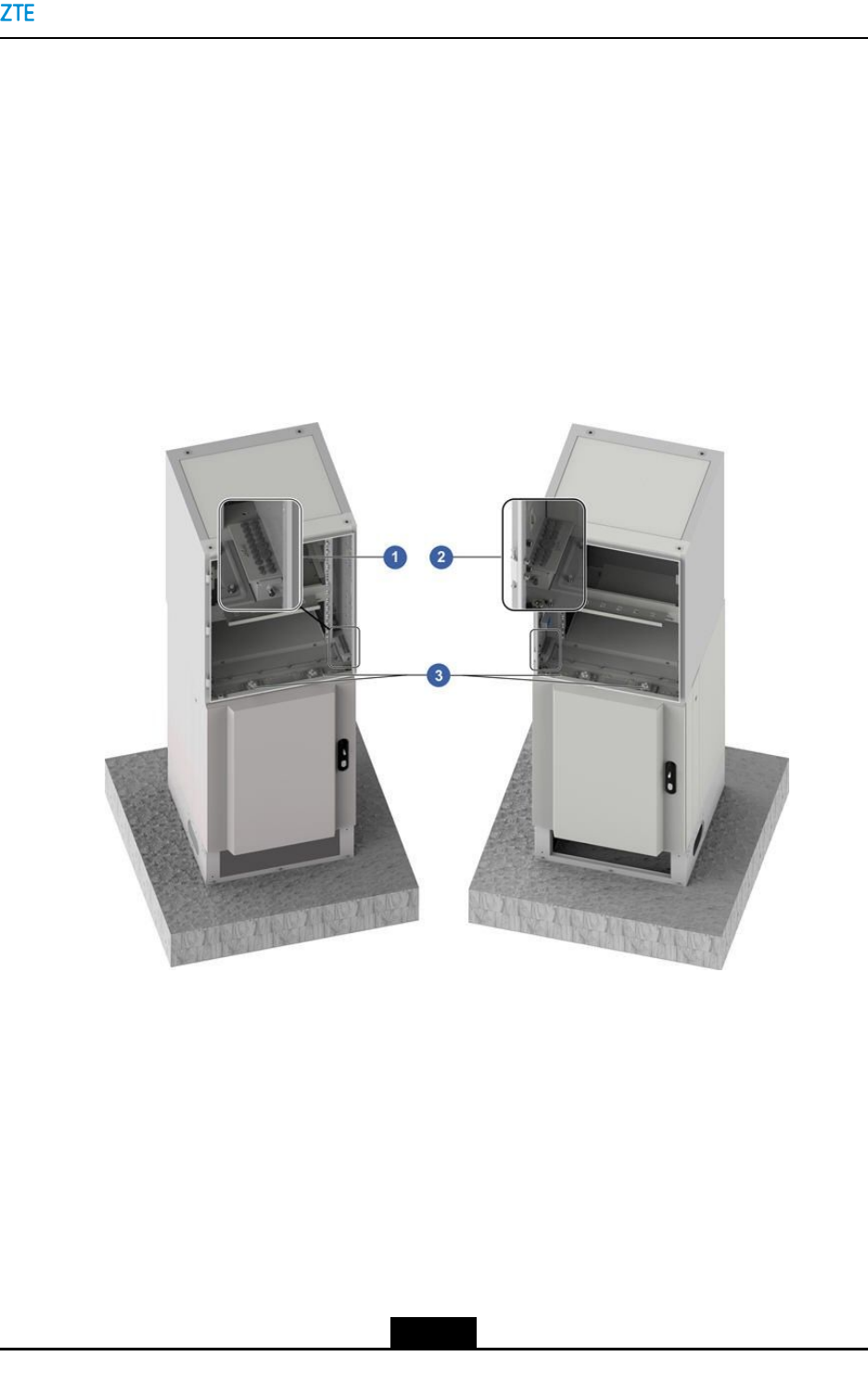
7.4GroundingCableInstallation
Thegroundingcableinstallationincludesinstallationofthegroundingcablesofstacked
cabinetsandsinglecabinet.Thisproceduredescribeshowtoinstallthegroundingcables
forstackedcabinets(BC8910AcabinetandRC8910Acabinet)andthePC8910Acabinet.
ThegroundingcablesofthestackedcabinetsincludethegroundingcablesoftheBC8910A
cabinetandRC8910Acabinet.Forthegroundingcableroutingofthestackedcabinets,
seeFigure7-11.
7-12
SJ-20150203110107-011|2016-03-23(R1.1)ZTEProprietaryandCondential
Chapter7CableInstallation
Figure7-11GroundingCableRoutingofStackedCabinets
Thegroundingcableofthesinglecabinetisconnectedtoanearbyoutdoorgrounding
busbar.
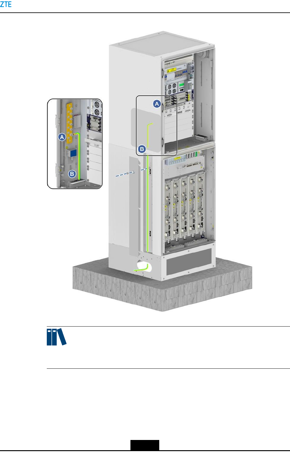
7.4.1InstallingaGroundingCablefortheBC8910ACabinet
Thisproceduredescribeshowtoinstallthebusgroundingcableofthestackedcabinets.
Thebusgroundingcableisconnectedtoanearbyoutdoorgroundingbusbar.
Prerequisite
lTheESDwriststrapmustbeworn.
lThetributaryoutputofthepowersupplyiscutoff.
7-13
SJ-20150203110107-011|2016-03-23(R1.1)ZTEProprietaryandCondential

ZXSDRBS8900AHardwareInstallation
Context
On-siteengineeringpersonnelneedtoinstallthegroundPEcablefromtheoutdoor
groundingbartothebusbarofthebasebandcabinettoprotecttheZXSDRBS8900A.
Thefansubrack,BBUsubrack,andLPUgroundingcableofthebasebandcabinetare
alreadyinstalled.Engineeringpersonnelneedtoverifythatthecablesaresecurelyxed.
Steps
1.Removethecoveroftheleft-sideroutingtroughandthefrontbafeofthebase.
2.Routethegroundingcablealongtheleft-sidewaterproofmoduleofthebaseband
cabinetandtheleft-sideroutingtroughoftheRFcabinet,andconnectthecableto
thegroundingcopperbarofthebasebandcabinet,seeFigure7-12.Preparethe
groundingcableofaparticularlengthinaccordancewiththedistancebetweenthe
basebandcabinetandthegroundingcopperbar.
7-14
SJ-20150203110107-011|2016-03-23(R1.1)ZTEProprietaryandCondential
Chapter7CableInstallation
Figure7-12FixingtheGroundingCabletotheCopperGroundingBar
Note:
Aredundantlengthmustbereservedwhenyoupreparethegroundingcable.
3.Secureoneendofthegroundingcabletothegroundcopperbaroftheleftsideofthe
BC8910Acabinet,seeFigure7-12.
4.Connecttheotherendofthegroundingcabletotheoutdoorgroundingcopperbar.
5.Bundleandfastenthegroundingcablealongthesidewallofthecabinet.
–EndofSteps–
7-15
SJ-20150203110107-011|2016-03-23(R1.1)ZTEProprietaryandCondential

ZXSDRBS8900AHardwareInstallation
7.4.2InstallingaGroundingCablefortheRC8910ACabinetand
PC8910ACabinet
Forstackedcabinets,thegroundingcableofthelowercabinetisconnectedtothe
groundingbusbaroftheBC8910Acabinet.
Thegroundingcableofthesinglecabinetisconnectedtotheoutdoorgroundingbusbar.
Forstackedcabinets(BC8910AcabinetandRC8910Acabinet),theRC8910Acabinet
isgroundedthroughthegroundingbusbaroftheBC8910Acabinet.Forastandalone
PC8910Acabinet,thePC8910Acabinetisgroundeddirectly.
Prerequisite
lTheESDwriststrapmustbeworn.
lThetributaryoutputofthepowersupplyiscutoff.
Steps
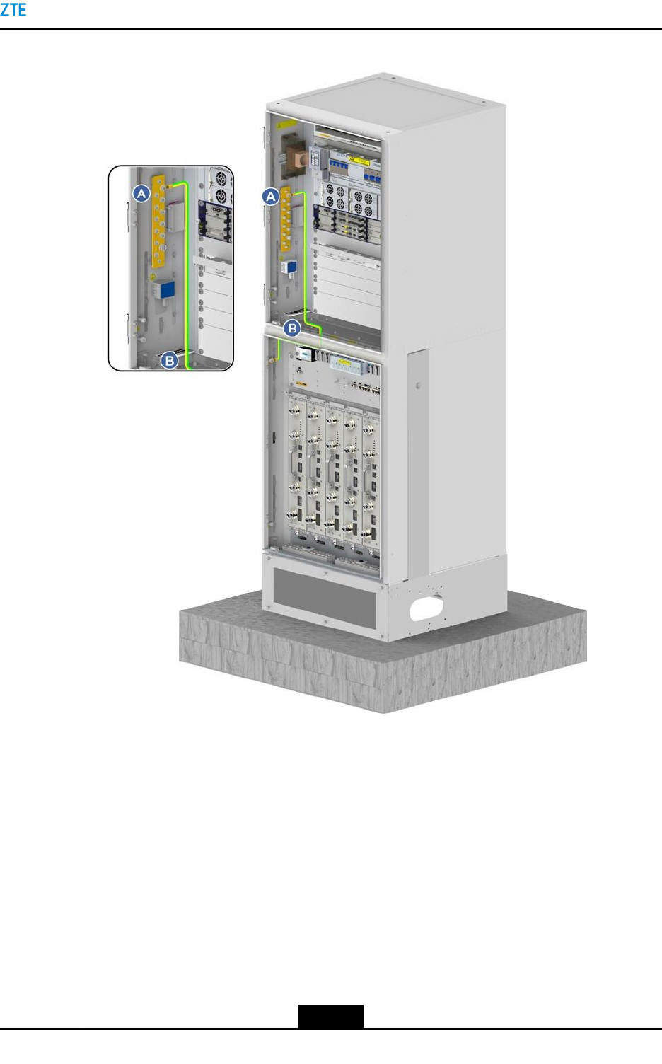
Installingthegroundingcableofstackedcabinets
1.Preparethegroundingcableofaparticularlengthinaccordancewiththedistance
betweentheBC8910Acabinetandthegroundingcopperbar.
Note:
Aredundantlengthmustbereservedwhenyoupreparethegroundingcable.
2.RemovethescrewconguredforthegroundnutonthesideoftheRC8910Acabinet
andsecureoneendofthegroundingcabletothegroundingpointatthetop-leftcorner
ofthecabinet.
3.Routethegroundingcablealongtheleft-sidecable-throughholeandtheleft-side
groundcopperbaroftheBC8910Acabinet,seeFigure7-13.
7-16
SJ-20150203110107-011|2016-03-23(R1.1)ZTEProprietaryandCondential
Chapter7CableInstallation
Figure7-13InstallingtheGroundingCableFortheRFCabinet
4.Bundleandfastenthegroundingcablealongthesidewallofthecabinet.
Installingthegroundingcableofastandalonecabinet
5.Preparethegroundingcableofaparticularlengthinaccordancewiththedistance
betweenthePC8910Acabinetandtheoutdoorgroundingcopperbusbar.
6.RemovethescrewonthegroundingnutofthePC8910Acabinetandsecureoneend
ofthegroundingcabletothecabinet.
7.Threadthegroundingcablethoughthecable-throughholeatthebottomofthecabinet,
routethecabletotheoutdoorgroundingcopperbusbar,andthensecuretheotherend
ofthecabletothebusbar.
7-17
SJ-20150203110107-011|2016-03-23(R1.1)ZTEProprietaryandCondential
ZXSDRBS8900AHardwareInstallation
8.Bindandsecurethecabletothecabinet.
–EndofSteps–
7.5PowerCableInstallation
ThepowercablesincludeACorDCinputcablesoftheBCcabinet,DCinputcablesofthe
RCcabinetsandPCcabinet.
ThepowercableconnectionsofthethreecabinetsoftheZXSDRBS8900Adependonthe
powersupplymode(ACorDC)oftheBCcabinet.
ACPowerInputfortheBCCabinet
ACpowerissuppliedtotheB201,B900,orB121PDMoftheBC8910Acabinet,converted
tobeDCpowerinthePDM,andthendistributedtoothercabinets.FortheACpower
distributionoftheZXSDRBS8900Acabinets,seeFigure7-14.
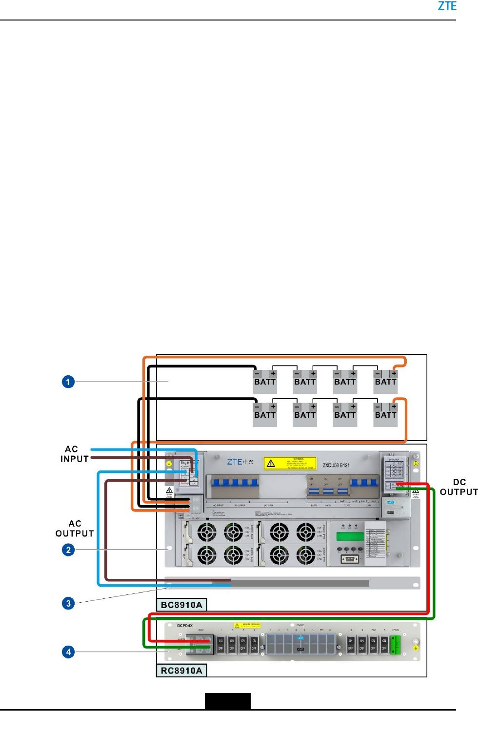
Figure7-14showsthepowerdistributionfromtheBC8910AcabinettotheRC8910Aand
PC8910AcabinetswhentheB121PDMisinstalled.WheninstallingtheZXSDRBS8900A
cabinets,youneedtoconnectthecorrespondingpowercablesinFigure7-14asrequired.
ThewaytoconnectthecableoftheB201PDMissimilartothatoftheB121PDM.
Figure7-14ACPowerDistributionoftheZXSDRBS8900ACabinets1
7-18
SJ-20150203110107-011|2016-03-23(R1.1)ZTEProprietaryandCondential
Chapter7CableInstallation
1.BatteriesofthePC8910A
cabinet
2.PDU
3.Heater
4.PDMoftheRC8910A
cabinet
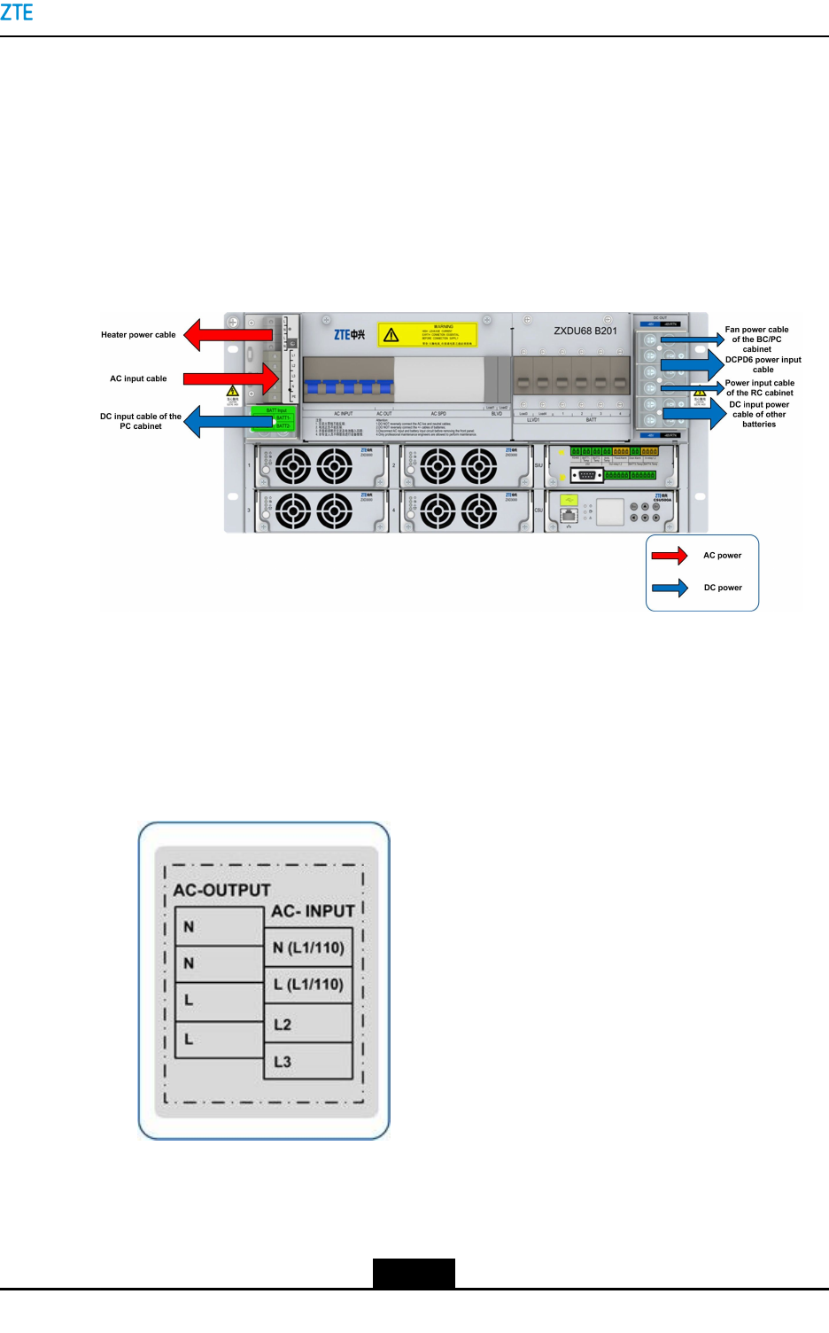
IftheZXSDRBS8900AconnectsRRUs,theDCPD6moduleisinstalledinthebaseband
cabinettoprovidepowerforRRUs.Forpowercableconnections,seeFigure7-15.The
BBUsubrackispoweredbytheDCPDmodule.Figure7-15showsthepowerdistribution
whentheB201PDMisinstalled.ThewaytoconnectthecableoftheB121PDMissimilar
tothatoftheB201PDM.
Figure7-15ACPowerDistributionoftheZXSDRBS8900ACabinets2
TheBCcabinetsupportssingle-phaseandthree-phaseACinput.Theconnectedterminals
ofsingle-phaseandthree-phaseACpoweraredifferent.
lThree-phaseACpowerinputcable
Fortheconnectorsofthethree-phaseACpowerinputcable,seeFigure7-16.
Figure7-16ConnectorsoftheThree-PhaseACPowerInputCable
7-19
SJ-20150203110107-011|2016-03-23(R1.1)ZTEProprietaryandCondential
ZXSDRBS8900AHardwareInstallation
Table7-4ChromatographDescriptionsoftheThree-phaseACPowerInputCable
PinSignal
Denition
SignalDescriptionColorEndAEndB
1L1(U)L1orUphasewireYellow
2L2(V)L2orVphasewireGreen
3L3(W)L3orWphasewireRed
4NNphasewireBlue
ACpowerinput
terminalofthe
B201/B121PDM
orADPD1
ACpowerdistri-
butiondevice
5PEProtectivegroundYel-
low/green
Groundingter-
minalofthe
B201/B121PDM
Protective
groundingbus-
barofthecabi-
net
lSingle-phaseACpowerinputcable
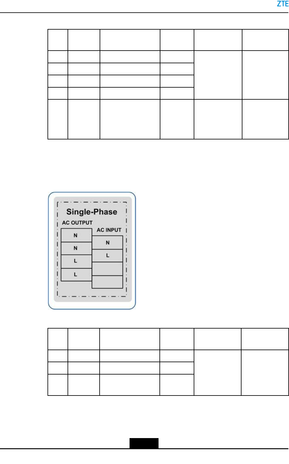
Fortheconnectorsofthesingle-phaseACpowerinputcable,seeFigure7-17.
Figure7-17ConnectorsoftheSingle-PhaseACPowerInputCable
Table7-5ChromatographDescriptionsoftheSingle-phaseACPowerInputCable
Pin
Signal
Denition
SignalDescriptionColorEndAEndB
1LLphasewireRed
2NACneutralwireBlue
3PEProtectivegroundYel-
low/green
ACpowerinput
terminalofthe
B201/B121PDM
orADPD1
ACpowerdistri-
butiondevice
DCPowerInputfortheBCCabinet
DCpowerisdistributedtotheDCPD6oftheBC8910AcabinetandtheDCPD4Xofthe
RC8910cabinet,andthendistributedtoothermodules,seeFigure7-18.
7-20
SJ-20150203110107-011|2016-03-23(R1.1)ZTEProprietaryandCondential