Contents
- 1. User Manual
- 2. User Manual II
- 3. User Manual part 1
- 4. User Manual part 2
- 5. User Manual part 3
User Manual part 2
Chapter7CableInstallation
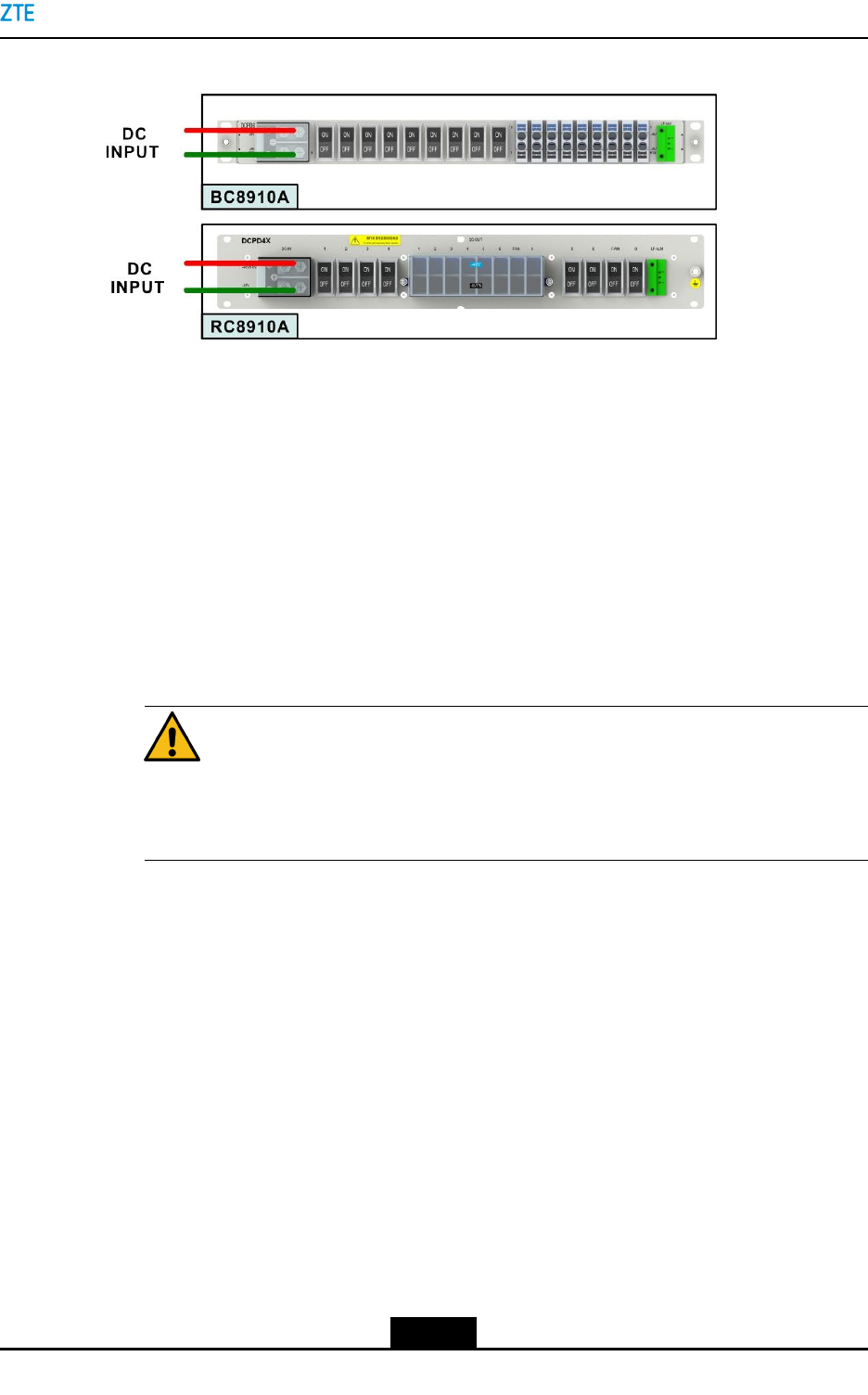
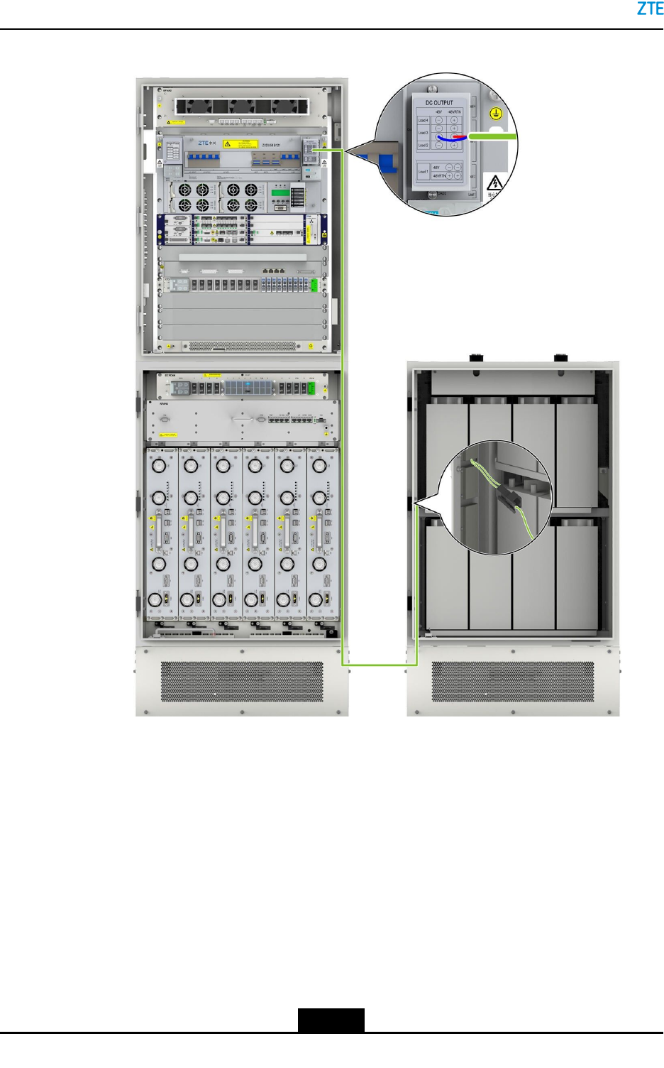
Figure7-18DCPowerDistributionoftheZXSDRBS8900ACabinets
7.5.1PowerCableInstallationintheBCCabinet
7.5.1.1InstallingaB121ACInputPowerCable
ThisproceduredescribeshowtoinstallaB121ACinputpowercableforthethree-phase
ACinputandsingle-phaseACinputrespectively.
Prerequisite
lBeforetheinstallation,youmustwearanESDwriststrap.
lThetributaryoutputofthepowersupplyhasbeencutoff.
Danger!
Ensurethatthecabinetispoweredoff.Thecableinstallationwithpoweroncanresult
inpersonalinjuryorevendeath.
Steps
1.RemovethecoverplateoftheACconnectionboxattheleftsideoftheB121power
byusingascrewdriver.
2.Cutthepowercableinaproperlength,andcrimpthebothconnectorsbyusingapair
ofcrimppliers.
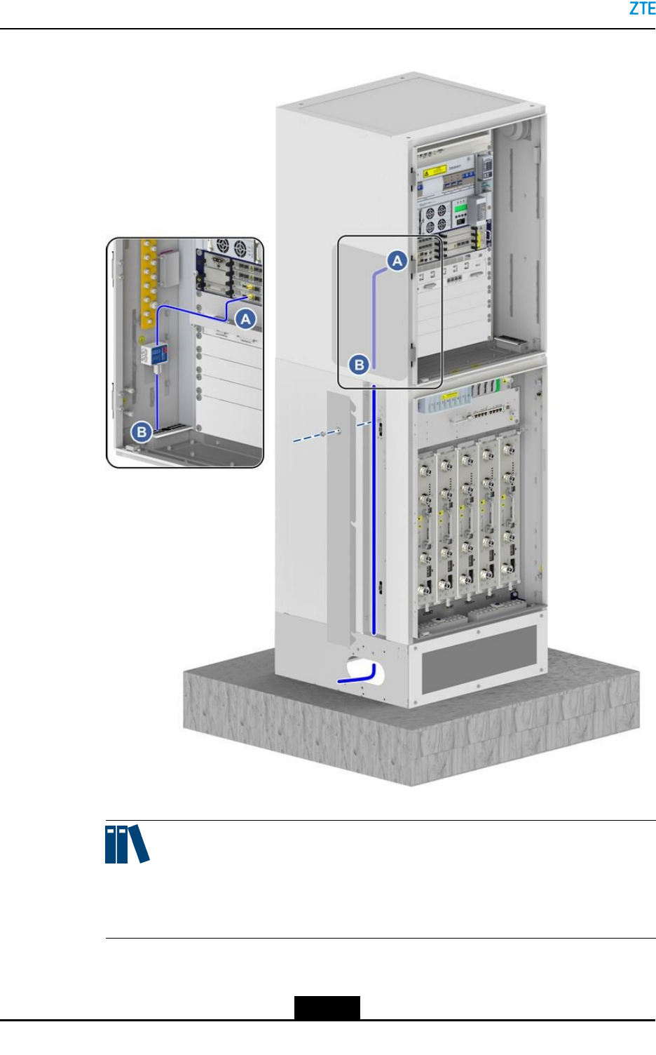
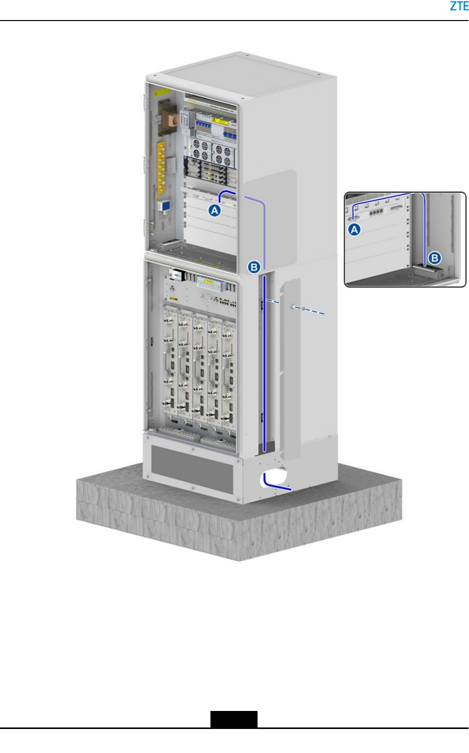
3.Layoutthepowercablealongtheleft-sidecabletray,throughthewaterproofmodule
ontheleftsideofthebasebandcabinet,andtotheinputendofthepowermodule,
seeFigure7-19.
7-21
SJ-20150203110107-011|2016-03-23(R1.1)ZTEProprietaryandCondential
ZXSDRBS8900AHardwareInstallation
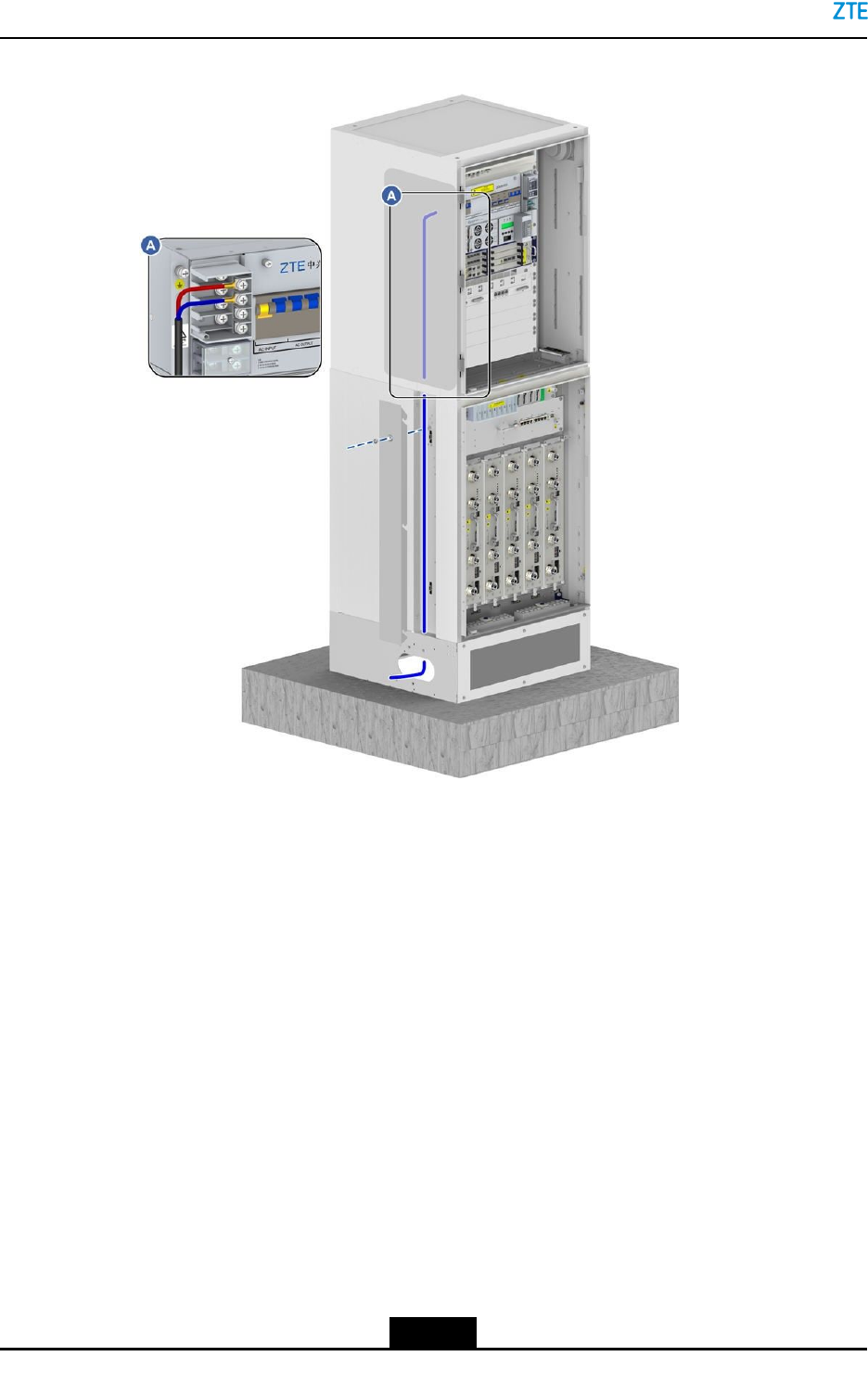
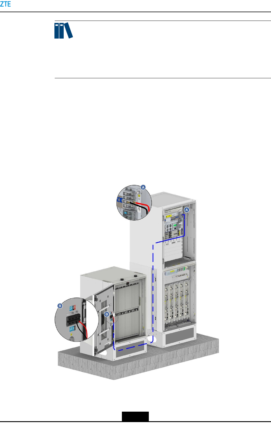
Figure7-19ExternalACInputCableConnections
4.ConnecttheACinputcabletothescrewterminaloftheB121inaccordancewiththe
ACpowermode(three-phaseorsingle-phase).ForthescrewterminaloftheB121,
seeFigure7-19.Whenusingthethree-phaseve-wiremodeforACinput,connect
L1,L2,L3andNofACinputtothecorrespondingL1,L2,L3andNoftheB121power
AC-INPUTterminals.Forthedetailedpositions,see7.5PowerCableInstallation.
lIftheACpowerinputusesthethree-phaseve-wiremode,connectL1,L2,L3,
andNoftheACinputcabletoL1,L2,L3,andNattheAC-INPUTterminalofthe
B121.
lIftheACpowerinputusesthesingle-phasemode,connectthephasewireL(red)
andneutralwireN(blue)toL1andNattheAC-INPUTterminaloftheB121.
5.ReseatthecoverplateoftheB121powerACconnectionbox,andfastentheboltsby
usingthescrewdriver.
6.ConnecttheotherendofthepowercabletotheACoutputconnectorofanexternal
powersupply.
–EndofSteps–
7-22
SJ-20150203110107-011|2016-03-23(R1.1)ZTEProprietaryandCondential
Chapter7CableInstallation
7.5.1.2InstallingaB201ACInputPowerCable
ThisproceduredescribeshowtoinstallaB201ACinputpowercableforthethree-phase
ACinputandsingle-phaseACinputrespectively.
Prerequisite
lBeforetheinstallation,youmustwearanESDwriststrap.
lThetributaryoutputofthepowersupplyhasbeencutoff.
Danger!
Ensurethatthecabinetispoweredoff.Thecableinstallationwithpoweroncanresult
inpersonalinjuryorevendeath.
Steps
lRemovethefourretainingscrewsatthefourcornersofthepowerswitchcoverplate
ofZXDU68B201,andthenremovethecoverplate.
lCutthepowercableinaproperlength,andcrimpthebothconnectorsbyusingapair
ofcrimppliers.
lLayoutthepowercablealongtheleft-sidecabletrayoftheRFcabinet,throughthe
waterproofmoduleontheleftsideofthebasebandcabinet,andtotheinputendof
thepowermodule.
lConnecttheACinputcabletothescrewterminaloftheB201inaccordancewiththe
ACpowermode(three-phaseorsingle-phase).ForthescrewterminaloftheB201,
referto7.5PowerCableInstallation.
àIftheACpowerinputusesthethree-phaseve-wiremode,connectL1,L2,L3,
andNoftheACinputcabletoL1,L2,L3,andNattheAC-INPUTterminalofthe
B201.
àIftheACpowerinputusesthesingle-phasemode,connectthephasewireL(red),
neutralwireN(blue),PEtothecorrespondingAC-INPUTterminaloftheB201.
ThePEisconnectedtothegroundingbarontheleftsideofthebasebandcabinet.
lReseatthecoverplateoftheB201powerACconnectionbox,andfastentheboltsby
usingthescrewdriver.
lConnecttheotherendofthepowercabletotheACoutputconnectorofanexternal
powersupply.
–EndofSteps–
7.5.1.3InstallingaDCInputPowerCablefortheBC8910ACabinet
ThisproceduredescribeshowtoinstallaDCinputpowercablefortheBC8910Acabinet.
7-23
SJ-20150203110107-011|2016-03-23(R1.1)ZTEProprietaryandCondential
ZXSDRBS8900AHardwareInstallation
Prerequisite
lBeforetheinstallation,youmustwearanESDwriststrap.
lThetributaryoutputofthepowersupplyhasbeencutoff.
Danger!
Ensurethatthecabinetispoweredoff.Thecableinstallationwithpoweroncanresult
inpersonalinjuryorevendeath.
Context
Whenusingthe-48VDCpowersupply,onlyconguretheDCPD6insteadofotherpowers.
ConnecttheDCinputpowercabletotheDCinputterminalofDCPD6.
Steps
1.RemovethecoverplateoftheconnectionboxofDCPD6DC-INbyusingascrew
driver.
2.Cutthepowercableinaproperlength,andcrimpthebothconnectorsbyusingapair
ofcrimppliers.
3.Layoutthepowercablealongtheleft-sidecabletrayoftheRFcabinet,throughthe
waterproofmoduleontheleftsideofthebasebandcabinet,andtotheinputendof
thepowermodule.
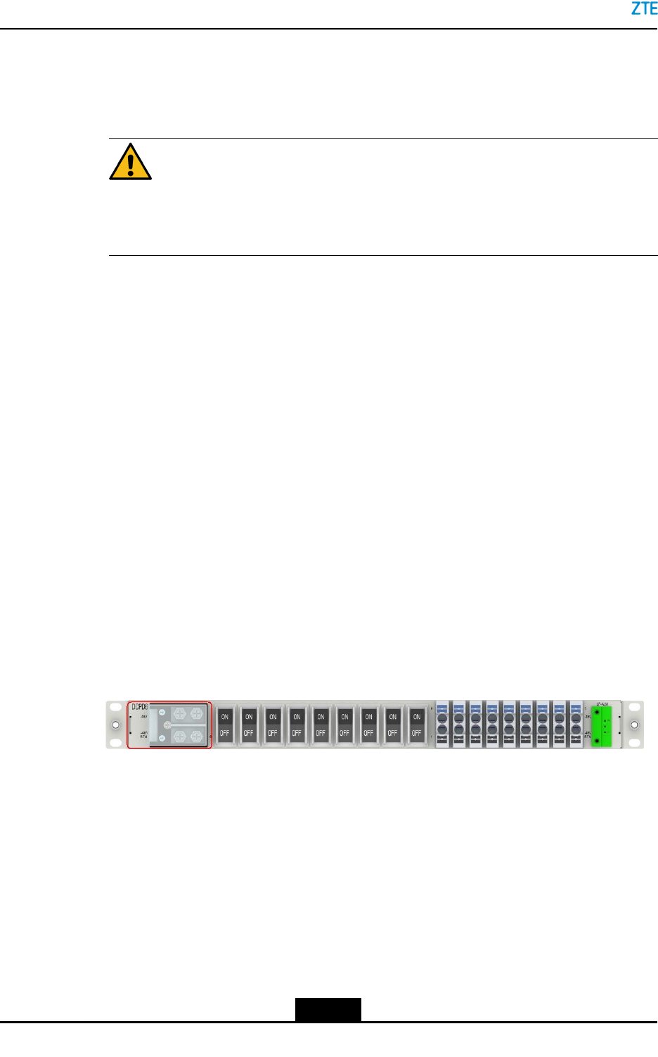
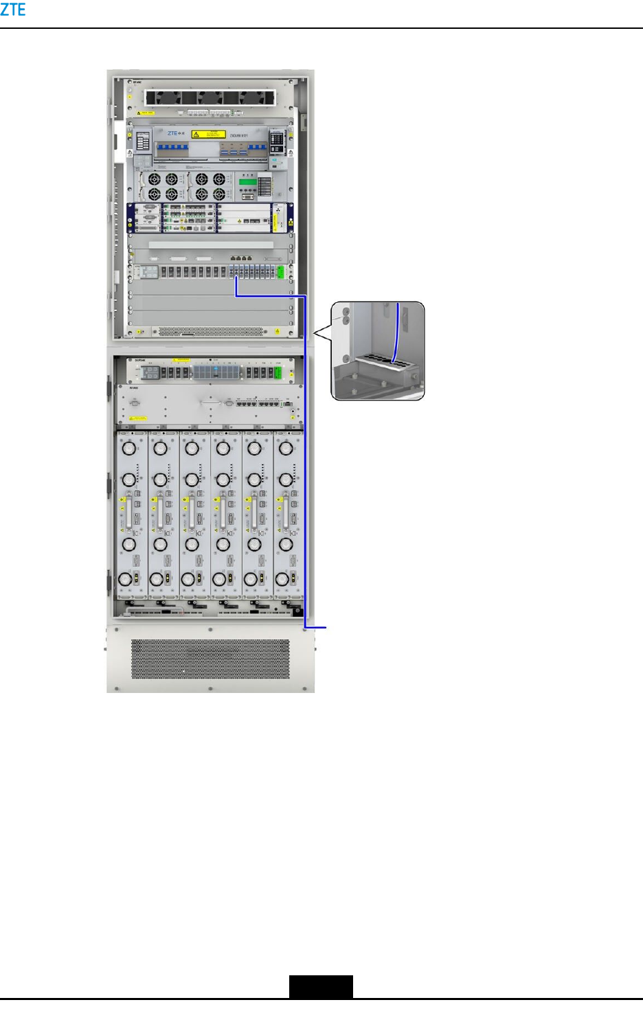
4.Connectthe–48VendoftheDCinputpowertothe–48VterminalofDCPD6DC-IN,
andconnectthe–48VRTNtothe–48VRTNterminalofDCPD6DC-IN,seeFigure
7-20.
Figure7-20CableConnectionof–48VDCInput
5.ReseatthecoverplateoftheconnectionboxofDCPD6DC-IN.,andfastenthebolts
byusingthescrewdriver.
6.ConnecttheotherendofthepowercabletotheACoutputconnectorofanexternal
powersupply.
–EndofSteps–
7-24
SJ-20150203110107-011|2016-03-23(R1.1)ZTEProprietaryandCondential
Chapter7CableInstallation
7.5.2PowerCableInstallationintheRCCabinet
7.5.2.1InstallingRC8910ADCInputPowerCables(BC8910ACabinetStackedwith
RC8910ACabinet)
ThisproceduredescribeshowtoconnecttheDCpowercablesoftheRC8910Acabinet.
Prerequisite
lTheESDwriststrapmustbeworn.
lThetributaryoutputofthepowersupplyiscutoff.
Danger!
Ensurethatthecabinetispoweredoff.Thecableinstallationwithpoweroncanresultin
personalinjuryorevendeath.
Steps
1.RemovethecoverontheconnectorsofthepowersubrackDCOUT.
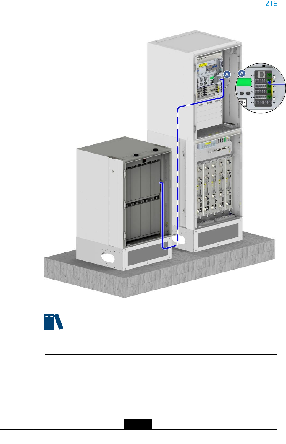
2.OntheDCoutputinterfaceDCOUTontherightsideofthepowersubrack,for
example,Load3,connectoneendoftheblue–48Vcableto-48Vconnector,and
connectoneendoftheblack–48VVRTNcabletothe-48VRTNconnector.
Forhowtoconnecttheconnectorsofthepowersubrack,referto7.5PowerCable
Installation.
Note:
Bydefault,somecablesareinstalledontheBC8910Acabinetbeforedelivery.During
theonsiteinstallation,ensurethatthesecablesarenotloosenedwheninstallingother
cables.
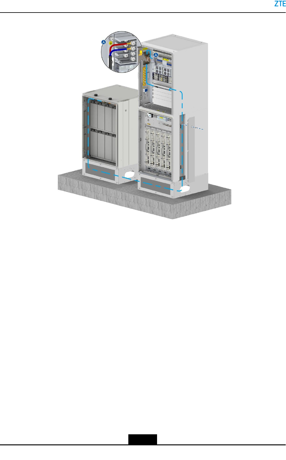
3.RoutethesecablesalongthecablerackandthesideoftheBC8910Acabinetand
thenthroughthecable-throughholesontherightsideoftheRC8910Acabinet.
4.Connectoneendofthesecablestothe-48Vand-48VRTNpowerterminalsonthe
RC8910Acabinet.
5.Bundleandsecurethesecables.
–EndofSteps–
7-25
SJ-20150203110107-011|2016-03-23(R1.1)ZTEProprietaryandCondential
ZXSDRBS8900AHardwareInstallation
7.5.2.2InstallingaRC8910ADCInputPowerCable(RC8910ACabinetPlaced
Individually)
ThisproceduredescribeshowtoconnecttheDCinputcableforasingleRC8910Acabinet.
Prerequisite
lTheESDwriststrapmustbeworn.
lThetributaryoutputofthepowersupplyiscutoff.
Steps
1.Connectoneendofthesecablestothe-48Vand-48VRTNpowerterminalsonthe
RC8910Acabinet.
2.ConnecttheotherendofthesecablestotheDCoutputterminalsoftheDCpower
supply.
3.Bundleandsecurethesecables.
4.Givewaterprooftreatmentstothecables.
–EndofSteps–
7.5.3InstallingDCInputCablesforthePC8910ACabinet
ThisproceduredescribeshowtoconnecttheDCpowercablesofaPC8910Acabinet.The
DCpowercableofthePCcabinetisusedforchargingbatteriesandpoweringtheZXSDR
BS8900A.
Danger!
Ensurethatthecabinetispoweredoff.Thecableinstallationwithpoweroncanresultin
personalinjuryorevendeath.
Context
Forhowtoconnectthepowercableofthebattery,seeFigure7-21.
7-26
SJ-20150203110107-011|2016-03-23(R1.1)ZTEProprietaryandCondential
Chapter7CableInstallation
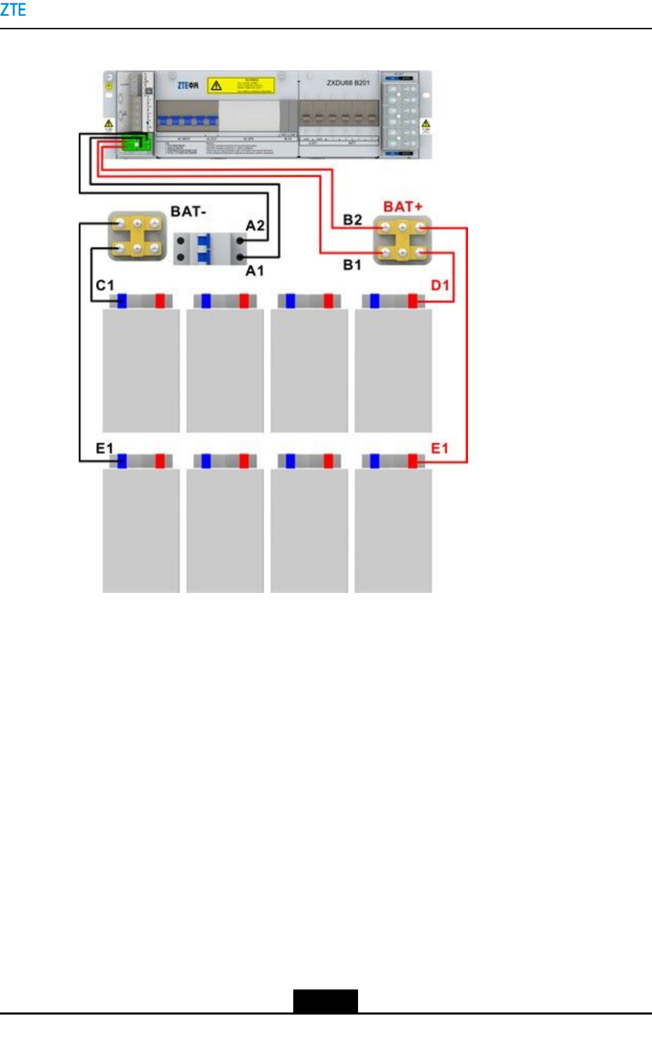
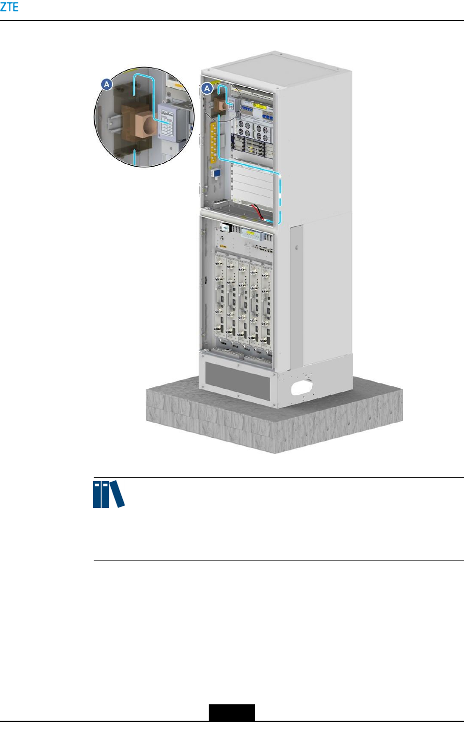
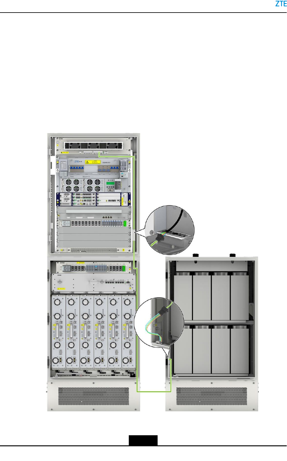
Figure7-21BatteryPowerCableConnection
Prerequisite
lTheESDwriststrapmustbeworn.
lThetributaryoutputofthepowersupplyiscutoff.
Steps
1.RemovethecoveroftheterminalsonthetopofthePC8910Acabinet.
2.Crimpthescrewterminals,andthenroutethecables,seeFigure7-22.
7-27
SJ-20150203110107-011|2016-03-23(R1.1)ZTEProprietaryandCondential
ZXSDRBS8900AHardwareInstallation
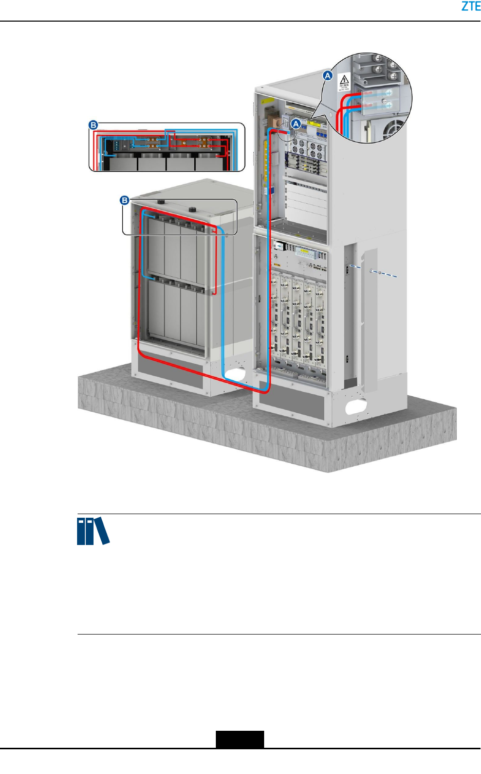
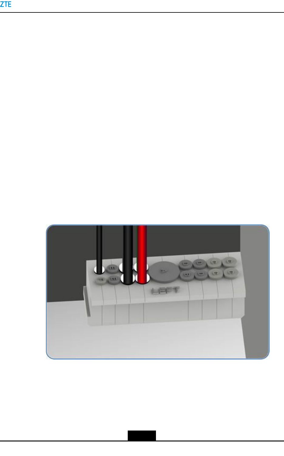
Figure7-22DCPowerCableRoutingofthePC8910ACabinet
1.-48VRTNcable(red)2.-48Vcable(blue)
Note:
lWhenthecablegoesthroughthewaterproofmodule,selectaproperholein
accordancewiththecablediameter.
lTheexposedcablesmustbeprotectedwithcorrugatedpipes.
lThecable-throughholesareprotectedwithwaterproofplugs.Removethese
plugsbeforethecablesareroutedandthenresetthem.
3.ConnectoneendofthepowercabletothepowerswitchatthetopofthePCcabinet.
Theblackcableisconnectedtothe-48Vconnector(BAT–)ontherightsideofthe
powerswitch,andtheredcableisconnectedtothe-48VRTNconnector(BAT+).
7-28
SJ-20150203110107-011|2016-03-23(R1.1)ZTEProprietaryandCondential

Chapter7CableInstallation
4.ConnectoneendofthepowercablestotheportsoftheB121orB201PDMsofthe
BC8910Acabinet.
FortheB121andB201PDMs,connectthepowercabletotheBATTInputinterface
ontheleftsideofthepowersubrack.Connecttheredwiretothe–48VRTNscrew
terminal,andconnecttheblackwiretothe–48Vscrewterminal,seeFigure7-22.
5.Bundlethecablesreliablyandneatlyalongthesideofthecabinetandthecabling
apertureonthebottomofthecabinet.
–EndofSteps–
7.5.4InstallingaFanPowerCableforthePC8910ACabinet
Thisproceduredescribeshowtoinstallthefanpowercablesforair-ventilatedand
thermoelectric-coolingPC8910Acabinets.
Prerequisite
TheESDwriststrapmustbeworn.
Steps
lConnectingthefanpowercablefortheair-ventilatedPC8910Acabinet
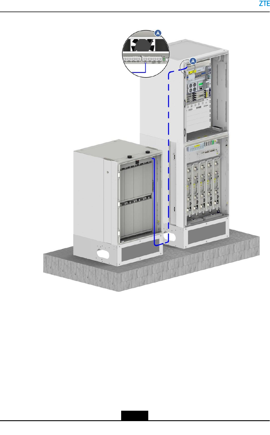
1.ConnectthefanpowercabletothefanpowerportontheleftwallofthePC8910A
cabinet,seeFigure7-23.
7-29
SJ-20150203110107-011|2016-03-23(R1.1)ZTEProprietaryandCondential
ZXSDRBS8900AHardwareInstallation
Figure7-23ConnectingtheFanPowerCable
2.Threadthefanpowercablethroughthecable-throughholeattheleftbottomof
thePC8910Acabinet,andbindthecablealongthewallofthePC8910Acabinet.
ThreadthefanpowercablethroughthebaseoftheRC8910Acabinet,androute
thecablealongthecabletroughontherightoftheRC8910Acabinetandtheright
waterproofmoduleoftheBC8910AcabinettothePDMoftheBC8910Acabinet.
3.ConnectthefanpowercabletotheDCoutputinterfaceoftheB121orB201PDM.
FortheB121andB201PDMs,connectthefanpowercabletotheDCpower
outputportofthesubrack,forexample,Load3,seeFigure7-23.
7-30
SJ-20150203110107-011|2016-03-23(R1.1)ZTEProprietaryandCondential
Chapter7CableInstallation
Note:
Bydefault,somecablesareconnectedtothepowerswitchesoftheBC8910A
cabinetbeforedelivery.Duringtheonsiteinstallation,ensurethatthesecables
arenotloosenedwheninstallingothercables.
WhenaDPCPmoduleisinstalledbutnointerfacesareleftontheDCOUTofthe
powersubrack,thefanpowercableofthePCcabinetcanbeconnectedtothe
interfaceforthefanpowercableoftheBCcabinet.TheysharethesameLoad
interface.ThefanpowercableoftheBCcabinetisinstalledbeforedelivery.
lConnectingthefanpowercableofthethermoelectric-coolingPC8910Acabinet
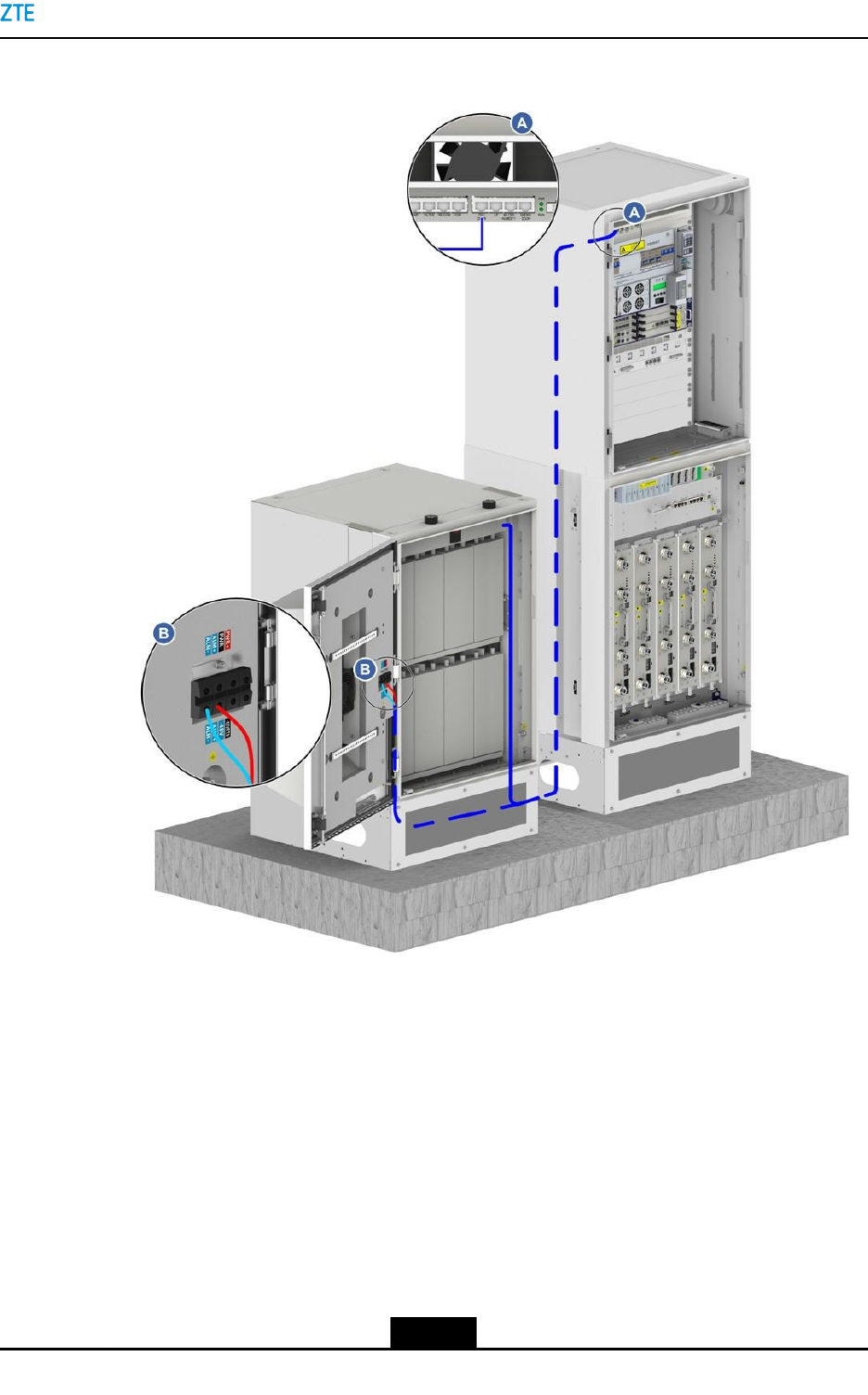
1.Figure7-24showsthefanpowercableconnectionofthermoelectric-cooling
PC8910Acabinet.
Figure7-24FanPowerCableConnectionsoftheThermoelectricCooling
batteryCabinet
2.ConnectthepowercabletotheDCpoweroutputterminalsofthePDM.
–EndofSteps–
7-31
SJ-20150203110107-011|2016-03-23(R1.1)ZTEProprietaryandCondential

ZXSDRBS8900AHardwareInstallation
7.5.5InstallingthePowerCableoftheHeater(Optional)
Theheaterisanoptionalcomponentthatcanbeinstalledinaccordancewiththedevice
operationenvironment.
ThisproceduredescribeshowtoinstallthepowercableoftheheatersfortheBC8910A
cabinetandRC8910Acabinet.ThepowercableoftheheatersintheBC8910Aandthe
RC8910AcabinetsareconnectedtotheACOUTPUTports.TheACOUTPUTportsare
besidetheACINTPUTport.
Prerequisite
lAnESDwriststrapmustbeworn.
lThepowertothecabinetsisoff.
Context
TheheateroftheBCcabinetisrequiredtobeconguredwhentheminimumtemperature
islowerthan-15°C.
ACpowerissuppliedtotheheateroftheBCcabinetwithapowerconsumptionof100W.
Theheateris3/4UhighandinstalledatthebottomlayeroftheBC8910cabinet.
ThePC8910Acabinetusestwoheatinglmswithapowerconsumptionof100W.The
heatinglmsareinstalledbelowthebatterysupportingplatebyscrews.
Whenthetemperatureislowerthanthespeciedtemperature,thetemperature-controlling
switchoftheheatinglmsisclosed,andtheheatinglmsstartheating.Theheatis
dissipatednaturallytowarmupthebatteries.
Steps
lInstallingthepowercableoftheheaterintheBCcabinet
1.ConnectthepowercableoftheheatertotheACOUTPUTscrewterminalonthe
leftsideofthePDM,seeFigure7-25.
7-32
SJ-20150203110107-011|2016-03-23(R1.1)ZTEProprietaryandCondential
Chapter7CableInstallation
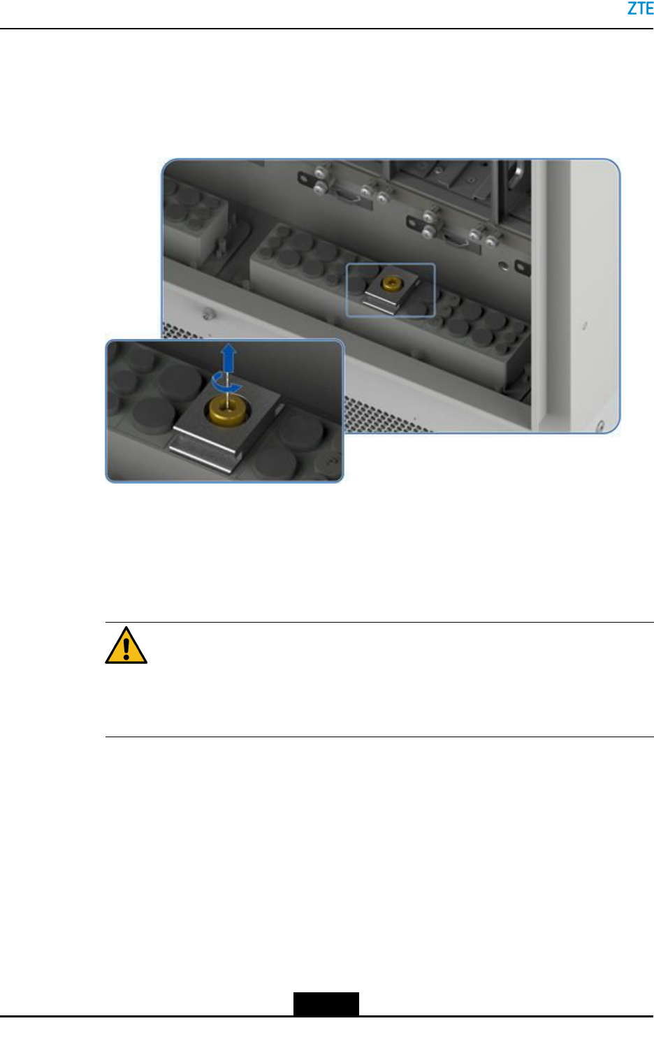
Figure7-25PowerCableRoutingoftheHeaterintheBCCabinet
Note:
Beforepoweringonthecabinet,verifythatthereisnotshortcircuitbetweenthe
ACOUTPUTterminalandthecabinetbyusingamultimeter.
lInstallingthepowercableoftheheaterinthePCcabinet
1.Threadthepowercableoftheheaterthroughtheleftwaterproofmoduleofthe
PCcabinet,routethecableintotheBCcabinetthroughthecabinetbase,and
connectthecabletotheACOUTPUTscrewterminalontheleftsideofthePDM,
seeFigure7-26.
7-33
SJ-20150203110107-011|2016-03-23(R1.1)ZTEProprietaryandCondential
ZXSDRBS8900AHardwareInstallation
Figure7-26PowerCableRoutingoftheHeaterinthePCCabinet
–EndofSteps–
7.5.6InstallingthePowerCableforaRemoteRRU(Optional)
IfremoteRRUsareconnected,theZXSDRBS8900AneedstopowertheRRUs.This
proceduredescribeshowtoconnectthepowercablefromtheZXSDRBS8900Atoa
remoteRRU.
IfRRUsareconnected,theDCPD6/DCPD7modulesareconguredinthebaseband
cabinet.TheDCPDmoduleprovidespowerforRRUs.
Prerequisite
lAnESDwriststrapmustbeworn.
lThepowertothecabinetsisoff.
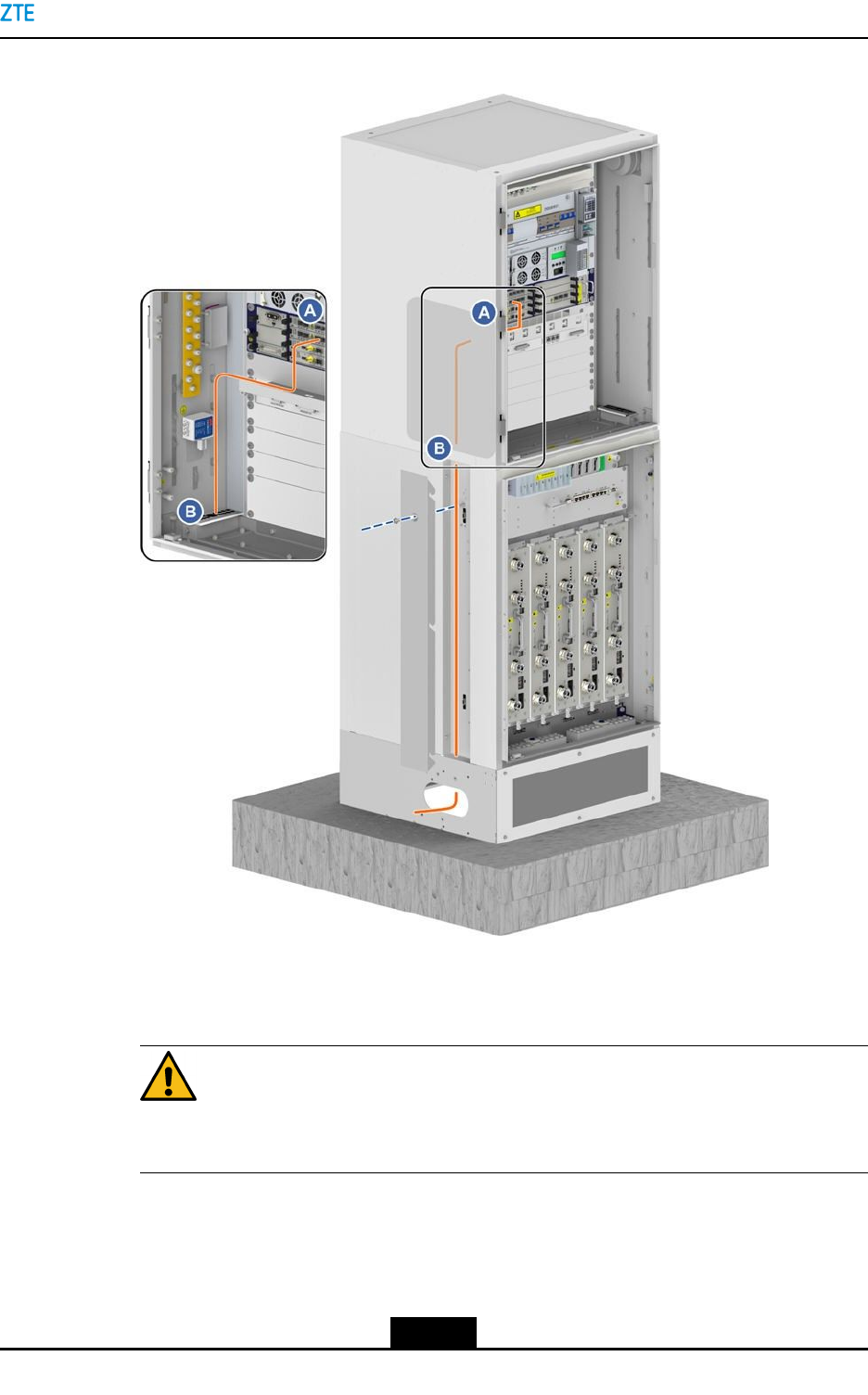
Steps
1.Layoutthepowercablealongtheright-sidecabletrayoftheRFcabinet,throughthe
waterproofmoduleontherightsideofthebasebandcabinet,andtotheoutputendof
thepowermodule,seeFigure7-27.
7-34
SJ-20150203110107-011|2016-03-23(R1.1)ZTEProprietaryandCondential
Chapter7CableInstallation
Figure7-27RRUPowerCableConnections
2.FabricatetheconnectorofthepowercableontheDCPDsidewithapairofcrimp
pliers,andconnecttheconnectortotheDCoutputinterfaceoftheDCPD.
3.FabricatetheconnectorofthepowercableontheRRUside,andconnectthe
connectortothepowerinterfaceoftheRRU.
–EndofSteps–
7.6TransmissionCableInstallation
TheZXSDRBS8900AuseseitheropticalbersorEthercablesastransmissioncables.
Transmissioncablesaredeterminedbasedonparticularsituations.
7-35
SJ-20150203110107-011|2016-03-23(R1.1)ZTEProprietaryandCondential

ZXSDRBS8900AHardwareInstallation
7.6.1InstallingTransmissionFibers(Optional)
ThisproceduredescribeshowtoinstalltheopticalbersconnectingtheBC8910Acabinet
totransmissiondevices..
ThetransmissionbersofabasestationtransmitS1-/X2-interfacesignals.
Prerequisite
TheESDwriststrapmustbeworn.
Context
Thefollowingrequirementsmustbemetwhenyouinstallopticalbers:
lDonotdamagetheopticalbercladdingduringoperations.
lProtectopticalberconnectorsandavoidcontaminatingthem.
lDonotforciblybundleopticalbers.
lCurveopticalbersattheturning.
Thefollowingrequirementsmustbemetwhenyoubindthecables:
lThecablesmustbeboundinorder.Thecablesofthesamecategorymustbeadjoined
closely.
lTobendtheboundcables,thecableclipsshouldbetiedattwosidesofthecornerto
avoidwirebreaks.
Steps
1.Pastetemporarylabels.
Pastetemporarylabelsatbothendsofthenewopticalbertosetupamapping.If
morethanoneopticalberneedstobeinstalled,usedifferentlabelstodistinguishthe
opticalbers.
2.Layoutopticalbers.
Oneendsoftheopticalbersareconnectedtotheexternaltransmissiondevice.The
otherendsoftheopticalbersarethreadedthroughthecabinetbase,androutedalong
theleftcabletroughoftheRC8910Acabinetandalongtheleftwaterproofmodule
oftheBC8910AcabinettotheopticalinterfaceTX/RXontheBBUCCboardinthe
BC8910Acabinet.Fortheroutingoftheopticalbers,seeFigure7-28.
7-36
SJ-20150203110107-011|2016-03-23(R1.1)ZTEProprietaryandCondential
Chapter7CableInstallation
Figure7-28OpticalFiberRouting
3.InsertopticalberconnectorstothecorrespondingTX/RXinterfacesinaccordance
withthelabelsontheopticalbers..
Caution!
Insertopticalberconnectorstightly.
4.Bundletheopticalbers.
Bundleandsecureopticalbersalongtheroutingtroughs,whichcomplieswith
relevantregulationsaboutopticalberbinding.
7-37
SJ-20150203110107-011|2016-03-23(R1.1)ZTEProprietaryandCondential
ZXSDRBS8900AHardwareInstallation
5.Pasteanengineeringlabelonanopticalber.
Removethetemporarylabelfortheopticalberandpasteanengineeringlabel.
Caution!
Protectanopticalberwiththewindingtubewhenroutingtheopticalberinsidethe
cabinet.Protectanopticalberwiththecorrugatedpipewhenroutingtheopticalber
outsidethecabinet.
–EndofSteps–
7.6.2InstallingEthernetCables(Optional)
ThisproceduredescribeshowtoconnecttheEthernetcablefromthebasebandcabinet
totransmissiondevices.
Prerequisite
TheESDwriststrapmustbeworn.
Steps
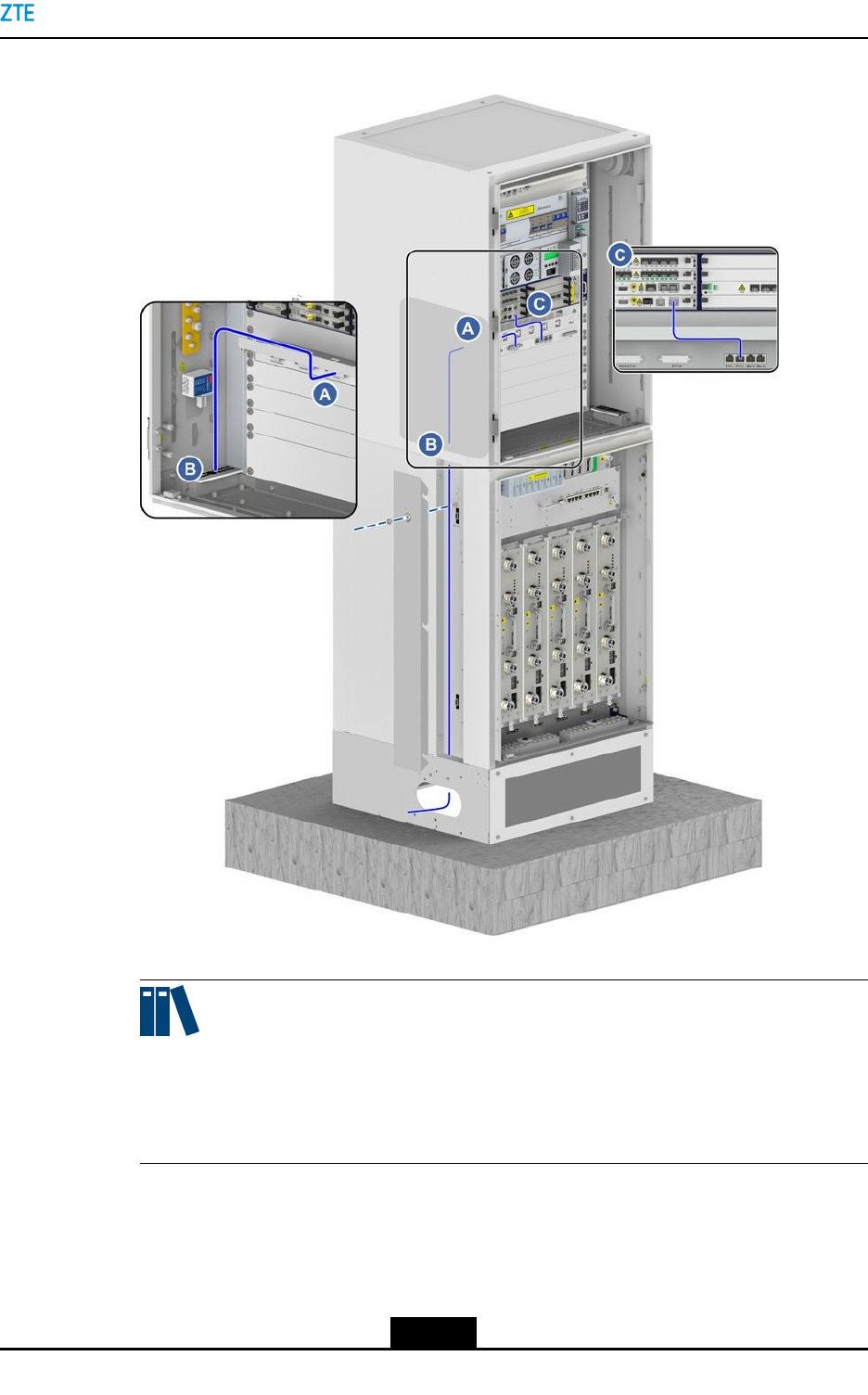
1.LeadoneendoftheEthernetcablethroughthecablehole.
2.ThreadtheEthernetcablethroughthebaseoftheoor-mountingcabinet(PC8910Aor
RC8910A),routethecablealongtheleftcabletroughoftheRC8910Acabinet,thread
thecablethroughthewaterproofmoduleattheleftbottomoftheBC8910Acabinetinto
theBC8910Acabinet,andthenconnectthecabletotheETH_0orETH_1interface
oftheLPU,seeFigure7-29.
7-38
SJ-20150203110107-011|2016-03-23(R1.1)ZTEProprietaryandCondential
Chapter7CableInstallation
Figure7-29EthernetCableRouting
Note:
TheEthernetcablebetweentheLPUandtheETHinterfaceoftheCCboardisinstalled
beforedelivery.Duringtheonsiteinstallation,ensurethatthebothendsoftheEthernet
cableareconnectedsecurely.
3.ConnecttheotherendoftheEthernetcabletoaproperinterfaceoftheswitch.
4.BundletheEthernetcableandpasteanengineeringlabeltotheEthernetcable.
–EndofSteps–
7-39
SJ-20150203110107-011|2016-03-23(R1.1)ZTEProprietaryandCondential
ZXSDRBS8900AHardwareInstallation
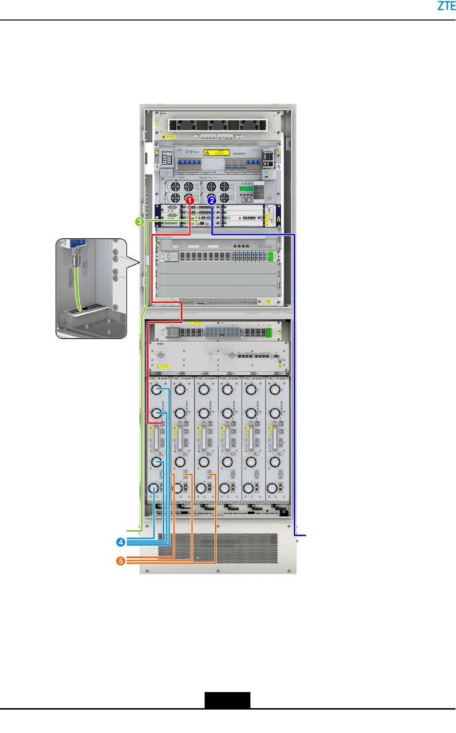
7.7SignalCableInstallation
ForthesignalcablesoftheZXSDRBS8900A,seeFigure7-30.
Figure7-30SignalCablesoftheZXSDRBS8900A
1.SFPcable
2.Outdoorfiber
3.GPScable
4.Antennafeeder
5.AISGcable
7.7.1InstallinganInterconnectedCableBetweenBBUandRSU
ThisproceduredescribeshowtoinstallSFPcables.
7-40
SJ-20150203110107-011|2016-03-23(R1.1)ZTEProprietaryandCondential

Chapter7CableInstallation
IntheZXSDRBS8900Asystem,opticalbersorSFPcablescanbeusedtoconnect
theBBUandRSU.DuringthestackedinstallationoftheZXSDRBS8900A,a2mSFP
high-speedcableisrecommendedforinterconnectingtheBBUandRSU.
Prerequisite
TheESDwriststrapmustbeworn.
Steps
1.PastetemporarylabelsatbothendsoftheSFRcable,andmark0-5tosetup
one-to-onemappingwithinterfacesTX0RX0toTX5RX5ofBBUandsixTX/RX
interfacesofRSU.
2.InsertoneendoftheSFPcabletoaTX/RXinterfaceofRSU.
3.RoutetheSFPcablealongtheroutingtroughandcabinetsidestotheFSmoduleof
BBU.TheSFPcablesconnectingtotheRSUsinslots1to3ontheRC8910Acabinet
gothroughtheleftcable-throughholesandthoseSFPcablesgothroughtheright
aperturesifconnectingtoslots4to6ontheRC8910Acabinet,seeFigure7-31.
7-41
SJ-20150203110107-011|2016-03-23(R1.1)ZTEProprietaryandCondential
ZXSDRBS8900AHardwareInstallation
Figure7-31SFPCableLayout
4.InsertSFPcablesintotheinterfacesTX0RX0toTX5RX5oftheBBUFSboardin
accordancewiththemarkings0–5.
5.BundletheSFPcables.
6.Removethetemporarylabelsandpasteengineeringlabels.
–EndofSteps–
7-42
SJ-20150203110107-011|2016-03-23(R1.1)ZTEProprietaryandCondential

Chapter7CableInstallation
7.7.2InstallingOutdoorFibers(Optional)
Thisproceduredescribeshowtoconnecttheopticalberbetweenthebasebandcabinet
andtheremoteRRU.WhentheZXSDRBS8900AconnectsRRUs,outdoorbersneedto
beinstalled.
IfthebasebandcabinetandRFcabinetareinstalledinparallelorthedistancebetween
thecabinetsislong,outdoorbersarerequiredtoconnecttheBBUandRSU.
Prerequisite
TheESDwriststrapmustbeworn.
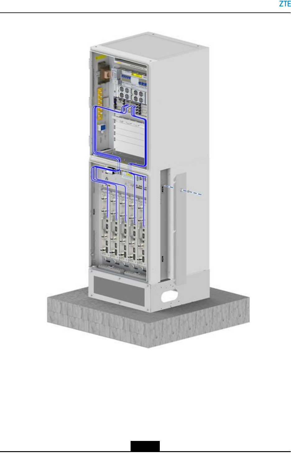
Steps
1.Pastetemporarylabels.
Pastecorrespondingtemporarylabelsatbothendsoftheopticalber.Ifthereare
morethanoneopticalbertobeinstalled,thelabelsmustbedifferent.
2.Layouttheopticalber.
Routetheoutdoorberthroughthebase,alongtheleftorrightcabletrayofthelower
cabinet,throughthewaterproofmoduleofthebasebandcabinet,andtonearthe
TX/RXinterfaceoftheBPL/FSboardintheBBU.Forthecableroute,seeFigure
7-32.
7-43
SJ-20150203110107-011|2016-03-23(R1.1)ZTEProprietaryandCondential
ZXSDRBS8900AHardwareInstallation
Figure7-32RoutingOutdoorFibers
3.InserttheberconnectorintotheopticalmoduleoftheBPL/FSboard.
4.Bundletheopticalber.
Theopticalbermustbebundledalongthecabletrayatthesideofthecabinet.You
mustfollowthespecicationswhenbundlingtheopticalber.
5.Pasteengineeringlabelsontheopticalber.
Removethetemporarylabelsandpasteengineeringlabelsontheopticalber.
7-44
SJ-20150203110107-011|2016-03-23(R1.1)ZTEProprietaryandCondential
Chapter7CableInstallation
Caution!
Protectanopticalberwiththewindingtubewhenroutingtheopticalberinsidethe
cabinet.Protectanopticalberwiththecorrugatedpipewhenroutingtheopticalber
outsidethecabinet.
–EndofSteps–
7.7.3InstallingtheGPSFeeder
ThisproceduredescribeshowtoconnecttheGPSantennatotheGPSlightningarrester
byusingaGPSfeeder.
TheGPSjumperwireconnectingtheGPSlightningarrestertotheBBUisinstalledbefore
delivery.YouneedtoconnecttheGPSantennatotheGPSlightningarresterinthe
BC8910Acabinet.
Prerequisite
TheESDwriststrapmustbeworn.
Context
OntheGPSlightningarrester,preparetheconnectorforconnectingtheGPSfeederand
theN-typeinterfaceofthelightningarresterbeforetheGPSfeederisconnected.
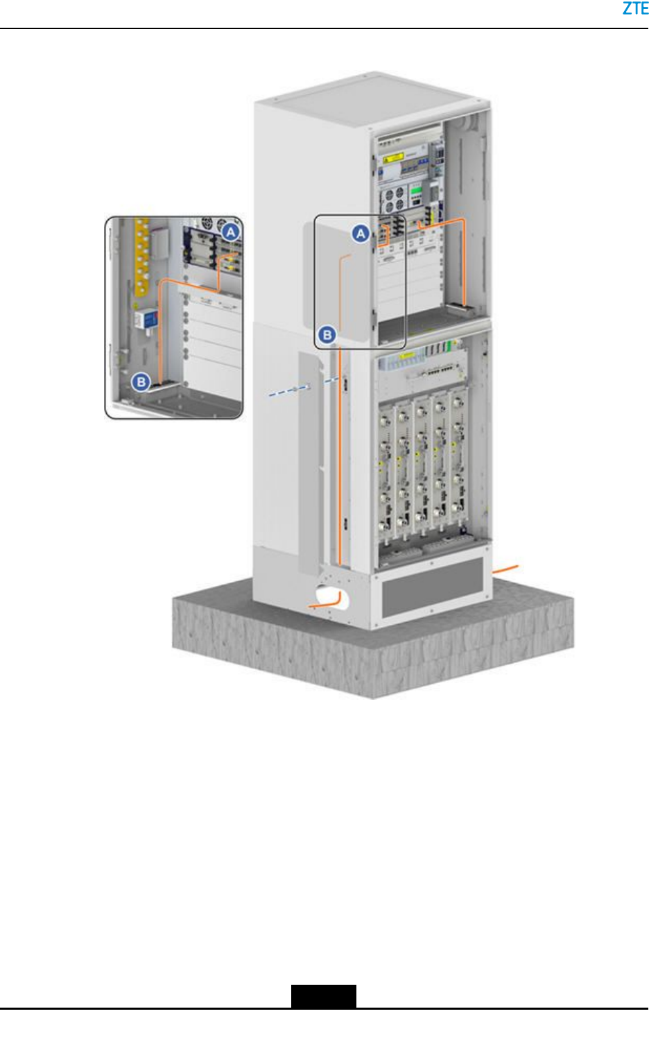
Steps
1.RoutetheGPSfeedercablealongtheleftcabletroughoftheRFcabinetandthrough
thewaterproofmoduleattheleftbottomoftheRFcabinet,andthenconnectthecable
totheGPSlightningarrester,seeFigure7-33.
7-45
SJ-20150203110107-011|2016-03-23(R1.1)ZTEProprietaryandCondential
ZXSDRBS8900AHardwareInstallation
Figure7-33RoutingtheGPSFeederCable
Note:
AproperaperturemustbeselectedbycablediameterforleadingtheGPSfeeder
throughthewaterproofmodule.
7-46
SJ-20150203110107-011|2016-03-23(R1.1)ZTEProprietaryandCondential
Chapter7CableInstallation
2.ConnecttheGPSfeedercabletotheN-typeportontheGPSlightningarrester,and
tightentheconnector.
TheGPSfeederbetweentheGPSlightningarresterandtheREFinterfaceofthe
CCboardintheBBUisinstalledbeforedelivery.Youmustensurethatthecableis
connectedsecurely.
3.ConnecttheotherendoftheGPSfeedertotheGPSantenna.
Note:
IftheGPSantennaisinstalledatthetopoftheZXSDRBS8900Acabinet,youroute
theGPSfeederalongtheedgeofthecabinetandbundlethecabletothecabletray.
Fordetails,refertoChapter6InstallingtheGPSAntenna(Optional).
–EndofSteps–
7.7.4InstallingAntennaFeederJumpers
Thisproceduredescribeshowtoinstalltheantennafeederjumperwires.
Prerequisite
TheESDwriststrapmustbeworn.
Context
TheRC8910AcabinetsupportssixRSUsinfullconguration.Amongthem,three1T2R
RSUsareinstalledinslots1to3andtheotherthree2T4RRSUsinslots4to6.
lTheantennafeederjumpersforthethree1T2RRSUsgothroughthewaterproofmod-
uleontheleft.
lTheantennafeederjumpersforthethree2T4RRSUsgothroughthewaterproof
moduleontheright.
RemovethefrontbafeofthebasebeforetheRC8910Ajumpersareinstalledandreset
thefrontbafeafteralljumpersareinstalled.
Steps
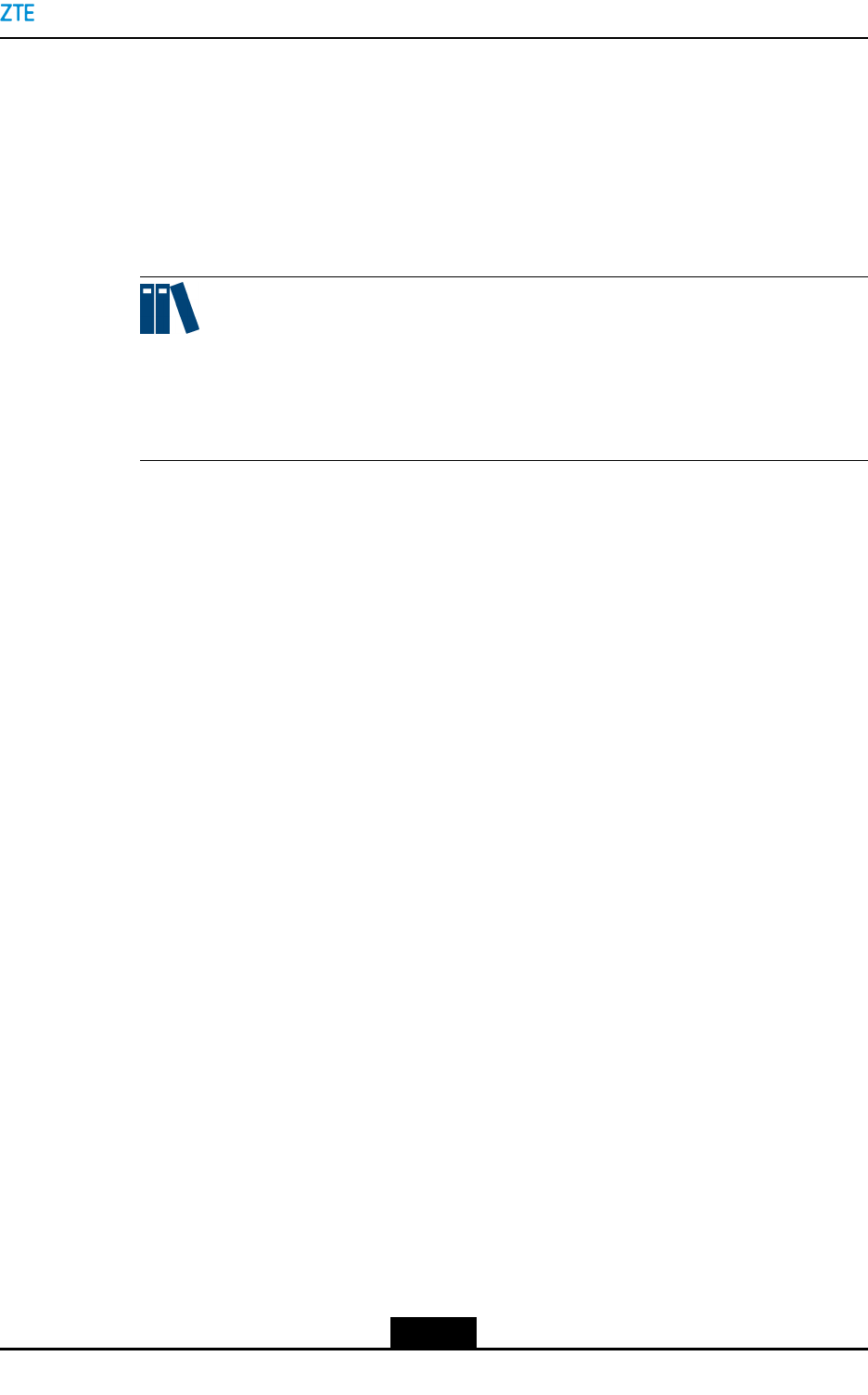
1.Routetheantennafeederjumperthroughthecable-throughandwaterproofmodule
atthebottomoftheRFcabinettotheANTinterfaceoftheRSU,seeFigure7-34.
7-47
SJ-20150203110107-011|2016-03-23(R1.1)ZTEProprietaryandCondential
ZXSDRBS8900AHardwareInstallation
Figure7-34RFJumperLayout
2.ConnecttheantennafeederjumperstoANT1toANT4interfacesoftheRSUfromright
toleft.
Ifonly1T2RRSUisused,connecttheantennafeederjumperstotheANT1
(TX1/RX1A)interfaceandANT2(RX1B)interface(high-carrierinterface).
3.Wearthewaterproofrubberplugaftereverytwoantennafeederjumpersareinstalled.
4.Insertthehorizontalandlongitudinalslideblocksandusethehexagonringwrenchto
fastenthem.
Caution!
Clampthewaterproofrubberplugtightlyandensurethattheunusedcable-through
holesweartheplug.
7-48
SJ-20150203110107-011|2016-03-23(R1.1)ZTEProprietaryandCondential

Chapter7CableInstallation
5.Theantennafeederjumpersgooutfromthebase.Thecablesbetweenthecabinets
mustbeprotectedwithprotectivetubes,withoutanyexposedpartofthecablesand
theopeningsattwoendsofthesecablesmustbesealed.
6.Connecttheotherendoftheantennafeederjumpertotheantennafeeder.
7.RepeattheprecedingstepstoinstallotherRSU-relatedjumpers.
–EndofSteps–
7.7.5InstallingtheAISGCable(Optional)
AnAISGcablebetweentheRFmoduleandanRETantennaisusedtotransmitthesignals
toorfromtheRETantenna.
Prerequisite
TheESDwriststrapmustbeworn.
Steps
1.RoutetheAISGcableoutwardthecabinetthroughthewaterproofmoduleatthebottom
ofthecabinettoneartheAISGinterfaceoftheRETantenna,seeFigure7-35.
7-49
SJ-20150203110107-011|2016-03-23(R1.1)ZTEProprietaryandCondential
ZXSDRBS8900AHardwareInstallation
Figure7-35RoutingtheAISGCable
1.AISGcable
2.ConnectoneendoftheAISGcabletotheRSU,andconnecttheotherendoftheAISG
cabletotheAISGinterfacetotheRETantenna.
–EndofSteps–
7.8MonitoringCableInstallation
Figure7-36showsthemonitoringcableroutingoftheZXSDRBS8900A.
7-50
SJ-20150203110107-011|2016-03-23(R1.1)ZTEProprietaryandCondential
Chapter7CableInstallation
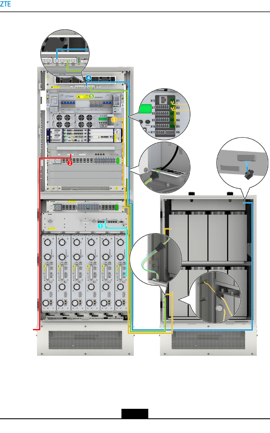
Figure7-36ZXSDRBS8900AMonitoringCableRouting
1.RSUmonitoringcable
2.Externaldrycontactcable
ofthebasebandsubrack
3.Batterytemperature
monitoringcableofthe
PC8910Acabinet
4.Dooraccessmonitoring
cableofthePC8910A
cabinet
5.Waterlevelmonitoring
cableofthePC8910A
cabinet
7-51
SJ-20150203110107-011|2016-03-23(R1.1)ZTEProprietaryandCondential

ZXSDRBS8900AHardwareInstallation
7.8.1InstallingtheRSUMonitoringCable
ThisproceduredescribeshowtoconnecttheRSUmonitoringcable.
IfmultipleRSUmodulesneedtobemonitored,theRSUmonitoringcablecanbeconnected
toanyofthem.
Prerequisite
TheESDwriststrapmustbeworn.
Context
TheRSUmonitoringcableoftheRC8910Acabinetisroutedtotherightsideofthe
RC8910Acabinetbeforedelivery.AftertheRSUmoduleisinstalled,youneedtoinsert
theterminaloftheRSUmonitoringcabletotheMON(monitoring)interfaceoftheRSU
module.
Steps
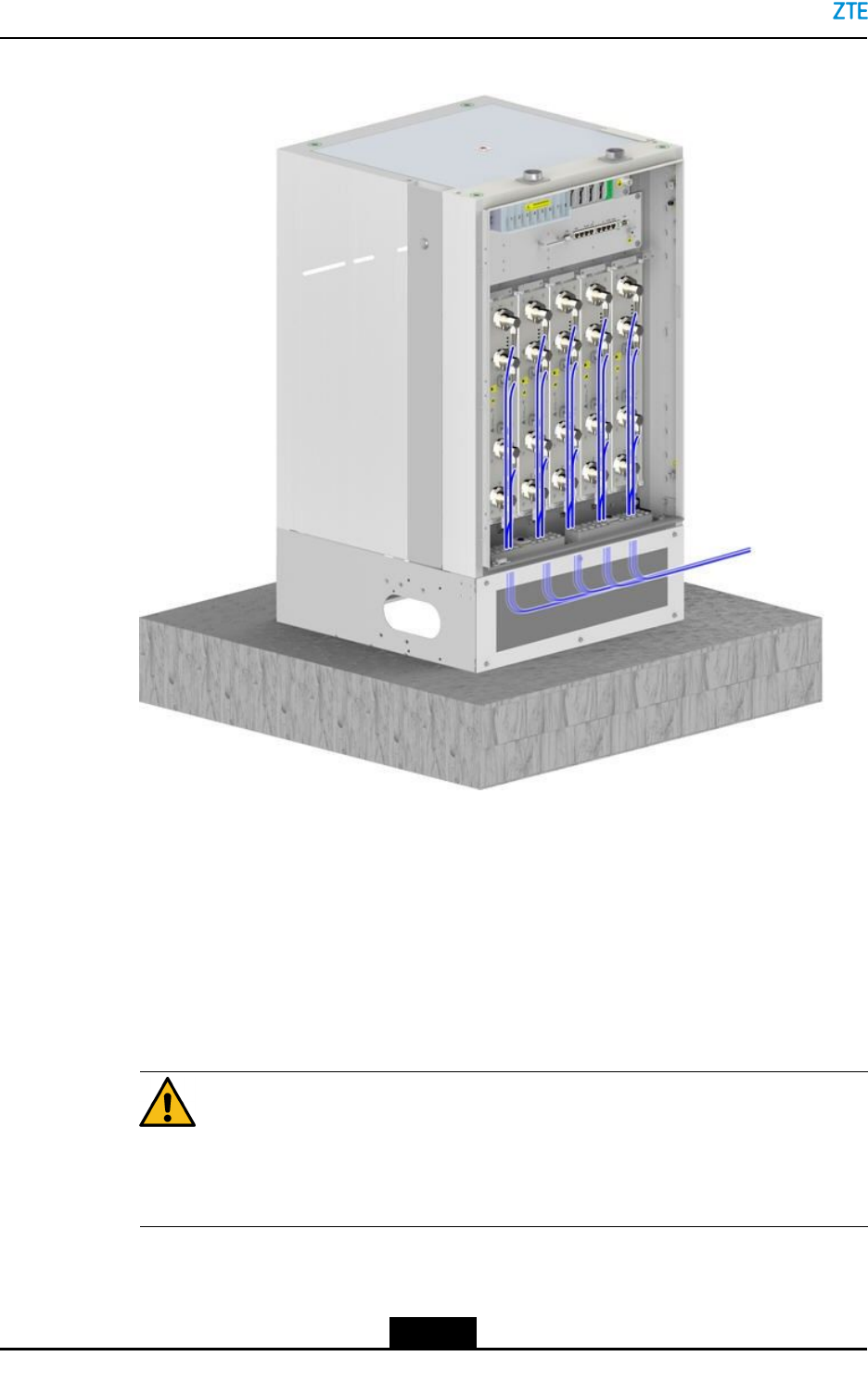
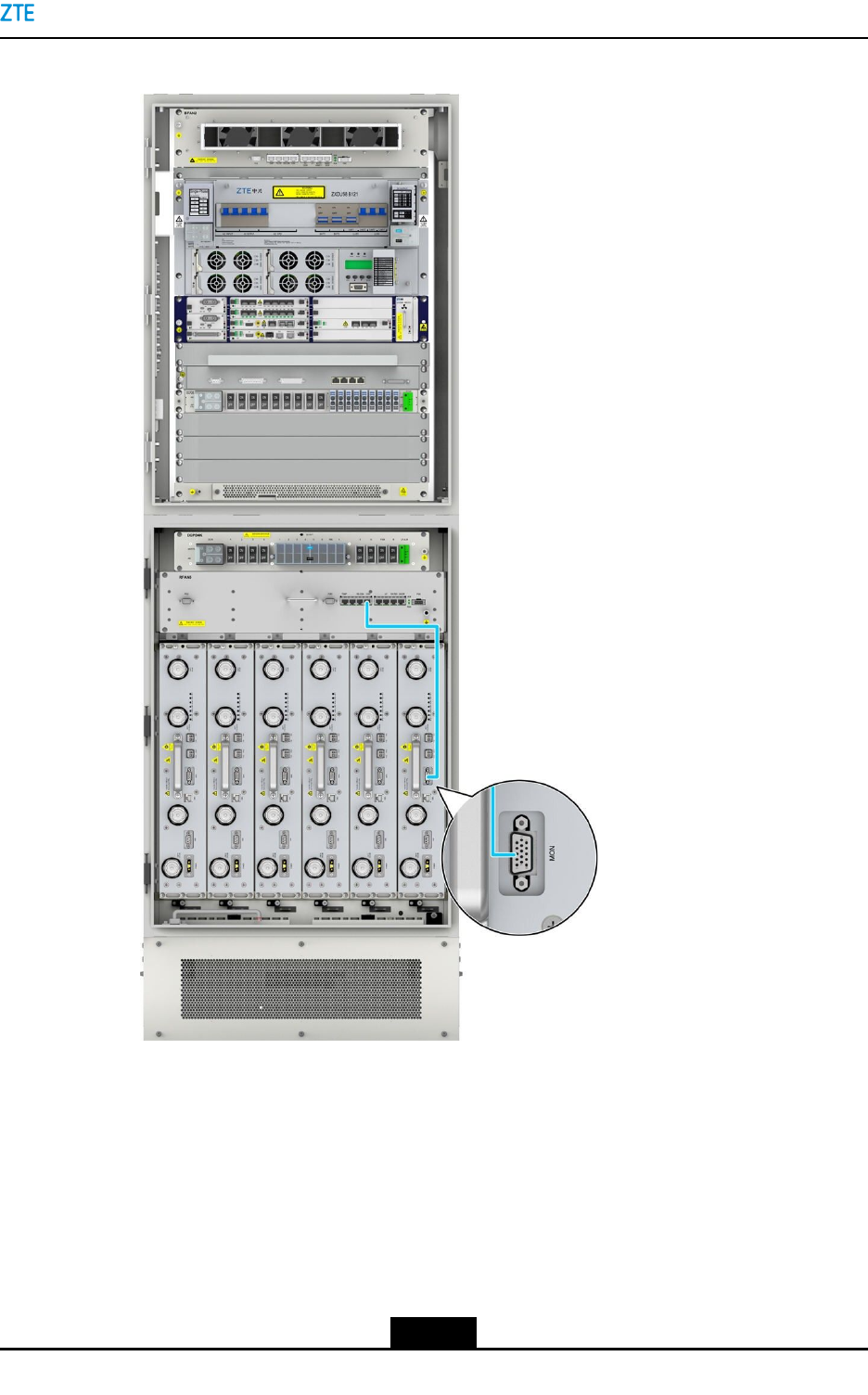
1.ConnectoneendoftheRSUmonitoringcabletotheMON(monitoring)interfaceof
theRSUmoduleandtightenthescrews,seeFigure7-37.
7-52
SJ-20150203110107-011|2016-03-23(R1.1)ZTEProprietaryandCondential
Chapter7CableInstallation
Figure7-37RSUMonitoringCableRouting
TheotherendoftheRSUmonitoringcableisconnectedtotheCOMportofthefan
subrack.Thisendisconnectedbeforedelivery.
2.BundletheRSUmonitoringcable.
–EndofSteps–
7-53
SJ-20150203110107-011|2016-03-23(R1.1)ZTEProprietaryandCondential
ZXSDRBS8900AHardwareInstallation
7.8.2InstallingDry-ContactCablesExternallyProvidedbythe
BasebandCabinet
Thisproceduredescribeshowtoconnectthedrycontactmonitoringcablefromtheexternal
monitoringdevicetotheBBU.
Theday-contactinputandoutputcableusesabalancedtwisted-paircable,connecting
theZXSDRBS8900Aandtheexternalmonitoringsystem.Thiscableinputsdry-contact
signalsfromexternaldevicesoroutputsdry-contactsignalsofthisdevice.
IftheZXSDRBS8900Aisconnectedtoexternalmonitoringdevicesthroughdry-contact
cables,anLPUsubrackmustbeinstalled.Theexternaldry-contactsignalsmustgo
throughtheLPUrst,andthentotheBBU.Furthermore,RS232andRS485monitoring
cablesarealsoconnectedtotheLPU.Theexternaldry-contactsignals,RS232monitoring
signals,andRS485monitoringsignalsaretransmittedtotheBBUthroughtheLPUand
theSAcablebetweentheLPUandBBU.
Note:
lTheRS232cableandRS485cableoftheZXSDRBS8900Aareconnectedtothe
powersubrackandfansubrackofthebasebandcabinet.NoRS232/RS485interface
isleftforexternaldevices.
lTheSAmonitoringcablebetweentheLPUandBBUisinstalledbeforedelivery.
Prerequisite
lTheESDwriststrapmustbeworn.
lRelevantmonitoringequipmentisinstalled.
Context
IftheZXSDRBS8900Adoesnotneeddry-contact/FElightningprotection,thatis;external
dry-contactcablesarenotconnectedandtheS1interfaceisnotanelectricalinterface,no
LPUsubrackisrequired.
TheRS232andRS485monitoringcablesaredirectlyconnectedtothecorresponding
interfaceoftheSAboard.ForanoverviewoftheSAmonitoringcable,seeFigure7-38.
7-54
SJ-20150203110107-011|2016-03-23(R1.1)ZTEProprietaryandCondential
Chapter7CableInstallation
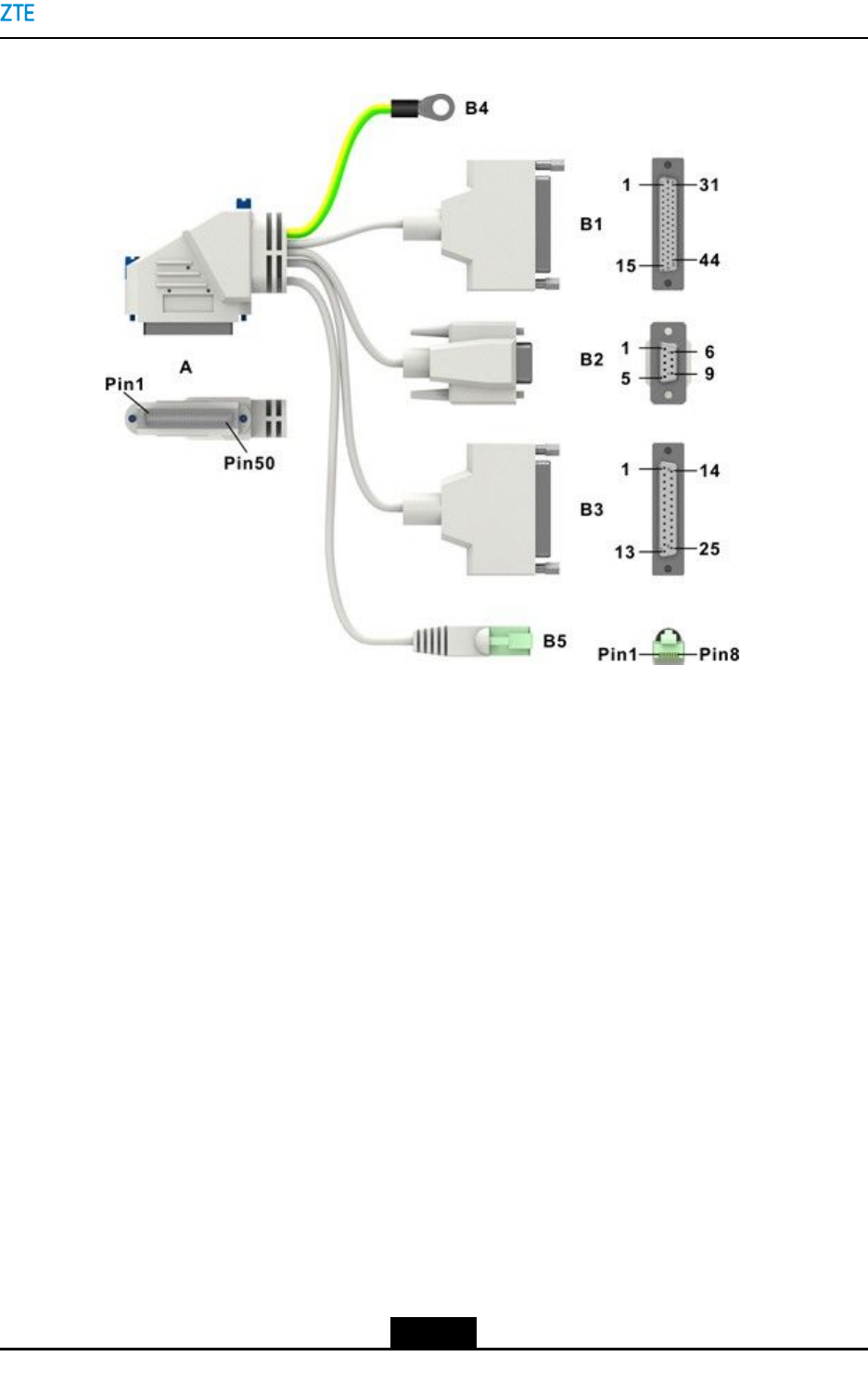
Figure7-38SAMonitoringCable
1.EndAisforconnectionto
theSAboard.
2.EndB1isforconnection
toanE1/T1cable(this
interfaceisnotusedfor
LTE)
3.EndB2isforconnectionto
anRS232cable.
4.EndB3isforconnectionto
adry-contactcable.
5.EndB4isforconnectionto
thegroundingpointofthe
BBU.
6.EndB5isforconnectionto
anRS485cable.
Steps
1.Pastelabelsinaccordancewiththeterminalsandwiresequenceofthedrycontact
cable.
2.Routethedrycontactcablefromtheexternalmonitoringdevicetotherightcable
troughoftheRC8910Acabinetthroughthebase,threadthecablethroughthe
waterproofmoduleattherightbottomoftheBC8910AcabinetintotheBC8910A
cabinet,andthentotheMON_IN/OUT_GOportoftheLPU.Fortheroutingofthe
externalMONcable,seeFigure7-39.
7-55
SJ-20150203110107-011|2016-03-23(R1.1)ZTEProprietaryandCondential
ZXSDRBS8900AHardwareInstallation
Figure7-39ExternalMONCableRouting
3.ConnectthecabletotheMON_IN/OUT_GOportoftheLPU.
7-56
SJ-20150203110107-011|2016-03-23(R1.1)ZTEProprietaryandCondential

Chapter7CableInstallation
Note:
ThefollowingthreecablesconnectingtheLPUanddevicesinthebasebandcabinet
areinstalledbeforedelivery.Youmustensurethatthecablesareconnectedsecurely.
lSAmonitoringcablefromtheBBUinterfaceoftheLPUtotheSAboardinthe
BBU
lRS232cablefromtheRS232/RS485_EMinterfaceoftheLPUtotheDB9
interfaceatthelowerrightofthepowersubrackofthebasebandcabinet
lRS485cablefromtheRS232/RS485_EMinterfaceoftheLPUtotheCOM
interfaceofthefansubrackofthebasebandcabinet
4.ConnectendBofthedrycontactcabletothemonitoringdeviceinaccordancewith
thewiresequence.
–EndofSteps–
7.8.3ConnectingaBatteryTemperatureMonitoringCableforthe
PC8910ACabinet
Thisproceduredescribeshowtoconnectthebatterytemperaturemonitoringcableforthe
B121PDM.ThetemperaturemonitoringcablesconnectionsoftheB201issimilartothat
oftheB121PDM.
Prerequisite
TheESDwriststrapmustbeworn.
Steps
1.Routeoneendofthebatterytemperaturemonitoringcabletothemonitoringunitof
theB121PDMoftheBC8910Acabinet.Threadthecablethroughtheleftbottom
waterproofmoduleoftheBC8910AcabinetandtheleftcabletroughoftheRC8910A
cabinet,andthenroutethecableintothePC8910Acabinetthroughthebase,see
Figure7-40.
7-57
SJ-20150203110107-011|2016-03-23(R1.1)ZTEProprietaryandCondential
ZXSDRBS8900AHardwareInstallation
Figure7-40PC8910ABatteryTemperatureMonitoringCableRouting
Note:
lThecable-throughholecapsshouldbekeptatoriginalpositions.
lThecableoutsidethecabinetshouldbeharnesseswithcablesheaths.
2.Removethetemperatureprobepaperonthebatterytemperaturemonitoringcableof
thePC8910Acabinetandpastethepapertotheoutsideofthebattery.
3.RemovethetwoscrewsontheprotectiveplateoftheB121monitoringports,and
connectthetemperaturemonitoringcabletotheX1andX2portsontheB121PDM,
seeFigure7-40.
7-58
SJ-20150203110107-011|2016-03-23(R1.1)ZTEProprietaryandCondential

Chapter7CableInstallation
ThetemperaturemonitoringcableconnectionsoftheB201PDMsaresimilartothatof
theB121PDM.Connectthecablesinaccordancewiththeinstructionontheprotection
plate.
4.Bundlethecables.
–EndofSteps–
7.8.4InstallingaDoorAccessMonitoringCableforthePC8910A
Cabinet
ThisproceduredescribeshowtoconnectthedooraccessmonitoringdoorforaPC8910A
cabinet.
Prerequisite
TheESDwriststrapmustbeworn.
Steps
1.Connectoneendofthedooraccessmonitoringcabletothedooraccesssensor.
2.Threadthedooraccessmonitoringcablethroughtherightcable-throughholeofthe
PC8910Acabinetandthenthreaditthroughthecabinetbase,routethecablealong
therightcabletroughoftheRC8910Acabinetandtherightwaterproofmoduleofthe
BC8910Acabinet,seeFigure7-41andFigure7-42.
7-59
SJ-20150203110107-011|2016-03-23(R1.1)ZTEProprietaryandCondential
ZXSDRBS8900AHardwareInstallation
Figure7-41DoorAccessMonitoringCableoftheAir-VentilatedPC8910ACabinet
7-60
SJ-20150203110107-011|2016-03-23(R1.1)ZTEProprietaryandCondential
Chapter7CableInstallation
Figure7-42DoorAccessMonitoringCableoftheThermoelectricCoolingPC8910A
Cabinet
3.ConnectthecabletotheTEC/DOORportonthefansubrackoftheBC8910Acabinet.
4.Bundlethiscable.
–EndofSteps–
7.8.5InstallingtheWaterLevelMonitoringCableofaPC8910A
Cabinet
ThisproceduredescribeshowtoconnectthewaterlevelmonitoringcableofaPC8910A
cabinet.
7-61
SJ-20150203110107-011|2016-03-23(R1.1)ZTEProprietaryandCondential
ZXSDRBS8900AHardwareInstallation
Steps
1.DisconnectthewaterlevelmonitoringcableoftheBC8910Acabinetfromthejointat
therightbottomcornerofthecabinet,andthenconnectthecabletotheextension
cableformonitoringwaterlevel.
ThewaterlevelmonitoringcableoftheBC8910Acabinetisthecableconnectedto
theWATER/HUMIDITYport.
2.ThreadtheextensioncablethroughtherightwaterproofmoduleoftheBC8910A
cabinet,routethecablealongtherighttroughoftheRC8910Acabinetintothecabinet
base,andthenroutethecabletothePC8910Acabinet,seeFigure7-43.
Figure7-43WaterLevelMonitoringCableofaPC8910ACabinet
3.ConnecttheextensioncabletothedetectorinthePC8910Acabinet.
7-62
SJ-20150203110107-011|2016-03-23(R1.1)ZTEProprietaryandCondential
Chapter7CableInstallation
4.Bindthecable.
–EndofSteps–
7.9WaterproofModuleInstallation
Cableshouldberoutedthroughthecorrespondingcable-throughofthewaterproofmodule.
Afterthecablesarelaidout,thewaterproofmodulemustbeinstalledtoprotectthecabinet
fromwater.
7.9.1InstallingtheWaterproofModulefortheBC8910ACabinet
TheexternalcablesareroutedintotheBCcabinetthroughthewaterproofmodule.The
waterproofmodulewaterproofsandsealsthecablesthatenterthecabinet.
Steps
1.Removethemetalbafeandwaterproofrubberplug,leadalltherequiredcables
throughthecable–throughhole,andinstallthesecablesproperly.
2.Reseatthewaterproofrubberplugafterselectingthepropercable-throughholein
accordancewiththecablediameter,seeFigure7-44.
Figure7-44FasteningThroughProperHoles
–EndofSteps–
7.9.2InstallingtheWaterproofModulefortheRC8910ACabinet
ThewaterproofmodulewaterproofsandsealsthecablesthatentertheRC8910Acabinet.
7-63
SJ-20150203110107-011|2016-03-23(R1.1)ZTEProprietaryandCondential
ZXSDRBS8900AHardwareInstallation
Steps
1.Removethescrewsonthesideofthelongitudinalslideblocktoremovethewaterproof
module,seeFigure7-45.
Figure7-45RemovingtheWaterproofModule
2.Leadalltherequiredcablesthroughthecablingapertureandinstallthemproperly.
3.Weartheproperwaterproofplugsproperlyafterselectingtheproperholediameter.
4.Insertthehorizontalandlongitudinalslideblocksandusethehexagonringwrenchto
fastenthem.
Caution!
Clampthewaterproofrubberplugtightlyandensurethattheunusedcablingaperture
wearstheplug.
–EndofSteps–
7.10InstallingtheAirFilter
AfterallthecablesoftheZXSDRBS8900Aarelaidout,theairltershouldbeinstalledin
thebaseoftheoor-mountedcabinettopreventthecabinetfromdust.
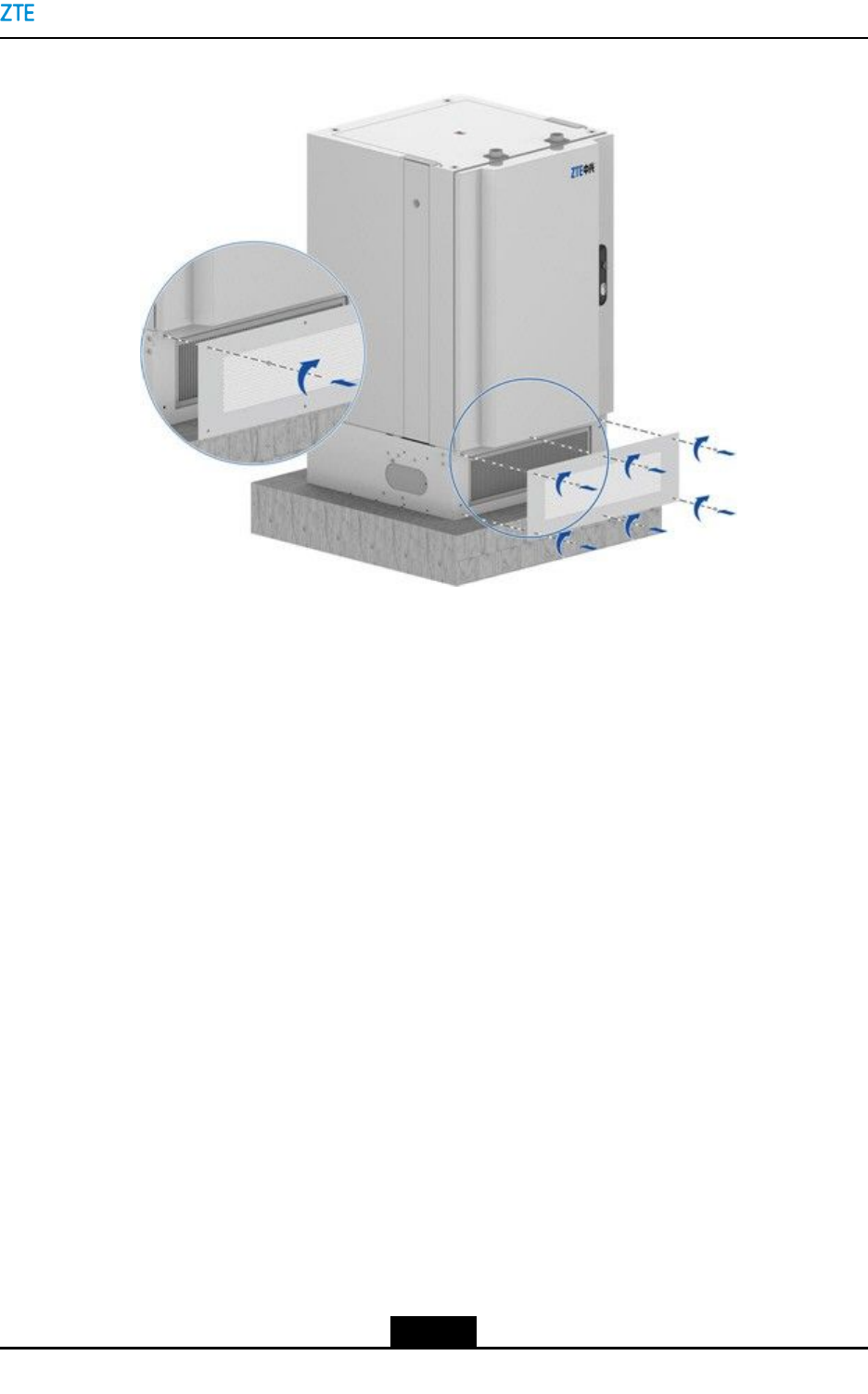
Steps
1.Inserttheairlterintothecabinetbase,useawrenchtofastenthesixanti-theftscrews
onthefrontpanelofthebase,andxthefrontpanel,seeFigure7-46.
7-64
SJ-20150203110107-011|2016-03-23(R1.1)ZTEProprietaryandCondential
Chapter7CableInstallation
Figure7-46InstallingtheAirFilter
–EndofSteps–
7-65
SJ-20150203110107-011|2016-03-23(R1.1)ZTEProprietaryandCondential

ZXSDRBS8900AHardwareInstallation
Thispageintentionallyleftblank.
7-66
SJ-20150203110107-011|2016-03-23(R1.1)ZTEProprietaryandCondential

Chapter8
Post-InstallationCheck
TableofContents
CabinetInstallationCheck..........................................................................................8-1
ModuleInstallationCheck..........................................................................................8-2
CableInstallationCheck.............................................................................................8-2
OtherChecks.............................................................................................................8-3
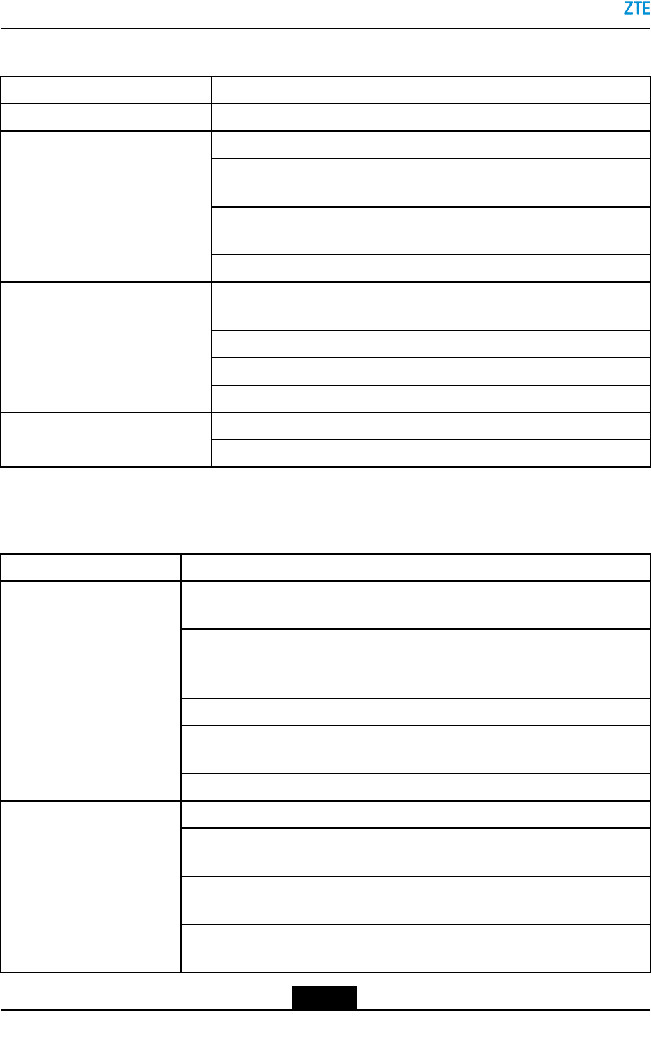
8.1CabinetInstallationCheck
ItemCheck
CabinetoverviewVerifythatthesurfaceofthecabinetisintact,forexample,thebottomofthe
cabinet,thegapbetweenstackedcabinets,andthegapbetweenthecabinet
andthebase.Ifthecabinethasdamage,scratches,orpaintstripping,the
cabinetmustberepairedtoavoidcorrosion.
Allboltsandscrewsinthecabinets,includingthebasebandcabinet,RF
cabinet,andotherauxiliarycabinet,aretightened.
Allcabinetsarehorizontallylaidandverticaltotheconcretebase.The
horizontalandverticalerrorsarewithintheallowedrange.
Thespacingbetweencabinetsandthespacereservedforcabinetmaintenance
meetthespacerequirements.
Allcabinets,includingthe(basebandcabinet,RFcabinet,andotherauxiliary
cabinet,areproperlysecuredwithoutshake.
Thetopcoverofthecabinetissecured.
Allseamsbetweentwostackedcabinets,includingtheseamsaroundfastening
screws,aresealedwithglueseals.
Theredcapofthesmokesensorisremoved.
Inthestackedcabinetinstallation,theprotectivegroundingcableisconnected
fromthebasebandcabinettotheRFcabinet,andthefasteningboltissecured.
Theinsideandoutsideofthecabinetareclean.
Cabinetinstallation
Theslidingcoversforthecableoutletsonthetopandbottomofthecabinetare
installedinproperpositions.
Insulationbetweenthecabinet
andtheearth
Thecabinets,includingthebasebandcabinet,RFcabinet,andotherauxiliary
cabinetareinsulatedfromtheearth(<3.5mA).Amultimetercanbeused
toverifytheinsulation.
8-1
SJ-20150203110107-011|2016-03-23(R1.1)ZTEProprietaryandCondential
ZXSDRBS8900AHardwareInstallation
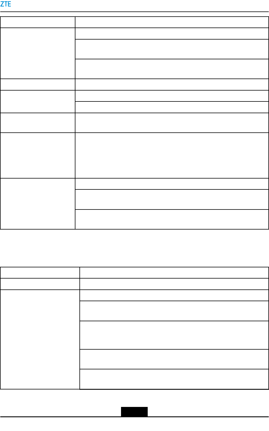
8.2ModuleInstallationCheck
ModuleCheck
PowerdistributionsubrackAllpowerdistributionsubracksareproperlyinstalled.
TheRSUisproperlyinstalledandsecuredwithfasteningscrews.
Thepowerwiresarermlyconnectedtoappropriatepowerterminalsofthe
RSU.
ThemonitoringcableisrmlyconnectedtotheMONinterfaceonthest
RSUfromrighttoleft.
RSU
ThegroundingplateisrmlyconnectedtotheRSU.
TheeBBUisinstalledina2Uslotwithventilationventsaboveorunderthe
slot.
TheeBBUissecuredwithallboltsfastened.
Thegreen-yellowgroundingwireisrmlyconnectedtothegroundterminal.
eBBU
ThespecialpowercableisrmlyconnectedtotheeBBU.
TheLPUissecuredwithallboltsfastened. LPU
Thegreen-yellowgroundingwireisrmlyconnectedtothegroundterminal.
8.3CableInstallationCheck
ItemCheck
Thepowerwiresandgroundingwiresareproperlylaidandboundattherequired
spacing.
TheexternalACpowerwires,whichareusedinthecaseofACpowersupply,are
properlyconnectedtocorrespondingpowerterminals,andsecuredwithfastened
screws.
Thepowercablesarexedandboundthroughthecabletroughinsidethecabinets.
The-48Vpowerwireand-48VGNDwire,whichareusedinthecaseofDCpower
supply,arermlyconnectedtothePM2terminalandthePM2GNDterminal.
Powerwiresandgrounding
wires
Theprotectivegroundingwireisrmlyconnectedtothegroundingstrap.
Allcablesinthecabinetareproperlyroutedandlaid.
Theredpowerwireisrmlyconnectedtothepositiveterminalofthebattery,and
thebluepowerwireisrmlyconnectedtothenegativeterminalofthebattery.
Themonitoringcableisstuckonthesurfaceofthebatterywithoneendrmly
connectedtothecorrespondinginterfaceofthepowerdistributionmodule.
BatteriesandcablesintheRF
cabinet
Theheaters(ifinstalled)areproperlyinstalledwithpowerwirescorrectly
connected.
8-2
SJ-20150203110107-011|2016-03-23(R1.1)ZTEProprietaryandCondential
Chapter8Post-InstallationCheck
ItemCheck
TheSAcableisrmlyconnectedtotheSAinterfaceoftheeBBU.
ThegroundingwireoftheSAcableisrmlyconnectedtothegroundterminal
oftheeBBU.
SAcable
TheotherendoftheSAcableisrmlyconnectedtotheeBBUinterfaceonthe
LPUmodule.
RFjumpersTheRFjumpersarermlyconnectedtocorrespondingANTinterfaces.
Allopticalbercablesareproperlyroutedandlaid. Opticalbercables
TheopticalbercablebetweentheeBBUandtheRSUisproperlyconnected.
RS232monitoringcableOneendoftheRS232cableisrmlyconnectedtotheRS232/485interfaceonthe
LPU,andtheotherendisrmlyconnectedtotheX22interface.
TransmissioncablesTheFEcables,whichareusedinthecaseofIPtransmission,areproperlyand
rmlyconnected.OneFEcableisconnectedtotheETH_0portoftheLPU.
Oneend(RJ45connector)oftheotherFEcableisconnectedtotheeBBU_A0
portontheLPU,andtheotherend(RJ45connector)isconnectedtotheETH0
portontheCCboard.
Nocableissuspendedintheair.
Thecablesareroutedproperlyandbundledwithproperintervals.Theexcesstail
ofeachcabletieiscutoffwithasmoothcuttingsurface.
Cableroutingspecication
Thesurfaceofeachcableiscleanandfreeoftheengineeringmarks.Thesheath
insulationlayerofthecableisnotdamagedorscratched.
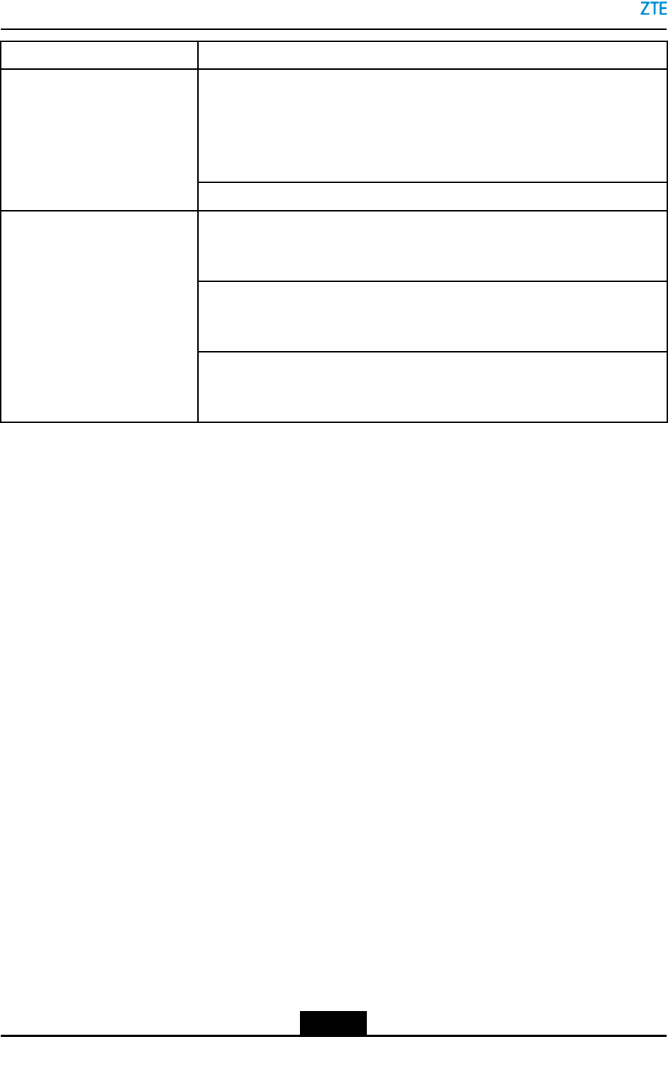
8.4OtherChecks
ItemCheck
ESDwriststrapTheESDwriststrapisconnectedtothejackontherightofthecabinet.
DedicatedZTElabelsareused.
Labelsshouldfacethesamedirection;thatis,theoutboundsideofalabelfaces
upwardsorfacestheoperationmaintenancesideforeasyreading.
Thecontentsaboutcabinetrowandcolumnonthelabelsmeettherequirements
oftheengineeringdesigndocuments.ZTEdevicesintheequipmentroomare
installedinaproperorder.
Inbatteryandpowerdistributioncabinets,thelabelsonthecircuitbreakers
forZTEdevicesareproperlypasted.
Inbatteryandpowerdistributioncabinets,thecircuitbreakersforZTEdevices
aremarkedwiththedirectionsusingnormativelabels.
Labels
8-3
SJ-20150203110107-011|2016-03-23(R1.1)ZTEProprietaryandCondential
ZXSDRBS8900AHardwareInstallation
ItemCheck
Bothendsofallthecablessuchasthepowercable,groundingcable,
transmissioncable,andjumpersarepastedwithlabels.Nolabelsarepasted
onthegroundingcablesofthecabinetdoorandsidepanel.Thelabelsare
writtenneatly,andarepastedinthesamepositions.Thelabelsarepasted
200mmawayfromtheconnectors.
Thelabels(ifrequired)onmodulesmustbewrittenneatlyandpastedproperly.
Nowastematerial,suchasscrapofcabletiesorcables,isleftinthecabinets.
Thefront,back,andsidedoorsareclean.Theinsideandoutsideofthecabinets
areclean.
Nouselessmaterialisplacedintheequipmentroom.Thematerialsinthe
equipmentroomareplacedproperly.Theoperatingoorandraisedoorare
clean.
On-Siteenvironment
Thegroundundertheraisedoornearthecabletroughandcabinetbottom
isclean.Noexcessiveengineeringmaterialsuchascabletie,thread,and
desiccantisleft.Allthecablesareproperlyrouted.
8-4
SJ-20150203110107-011|2016-03-23(R1.1)ZTEProprietaryandCondential

Chapter9
PoweringontheCabinet
ZXSDRBS8900A,throughthepowerunitinthebasebandcabinet,outputsAC/DCpower
toeachsubrack.
Prerequisite
lThepowercableandthegroundingcableareconnectedtothecabinet.
lThepowercableandthegroundingcableareinstalledinsidethecabinet.
lThesubracksandmodulesinsidethecabinetareinstalled.
lThemultimeterisavailable.
Steps
1.ProperlywearESDwriststrap,andenabletheESDwriststraptobegroundedreliably
(anti-staticsocketsonthecabinet).
2.SetallpowerswitchesofthepowerdistributionsubracktoOFF .
3.Settheswitchofthemultimetertotheresistancetype,measurethepowerinput
terminalofthepowerdistributionsubrackinthecabinetwiththemultimeter,toensure
thatthepowerisproperandnotshort-circuited.
4.Setthemultimeterswitchtothevoltagetype,andmeasuretheDCoutputterminal
withthemultimeter,toensurethattheoutputvoltageistheratedvoltage.
5.SetthepowerswitchofthefansubracktothestatusON,andensurethatthefan
operatesproperly.
6.SettheswitchofthepowersubracktothestatusON,andobservethepanelindicator
toensurethatthepowermoduleoperatesproperly.
7.Setthepowerswitchthatcorrespondstotheshelf(eBBU,RSU)onthepower
distributionsubracktothestatusON,andobservethepanelindicatortoensurethat
thepowersupplyofsubrackisproper.
8.Checkwhetherthepowercableofsubrack,moduleslot,orthemoduleitselfisfaulty
iftheindicatoronthemoduleoperatesimproperly.ContactZTEengineersforhelp
iftheindicatorofthemoduleisstillintheOFFstatusafterreplacingthemoduleand
ensuringthatthepowercableisproper.
9.Performsteps7and8again.
–EndofSteps–
9-1
SJ-20150203110107-011|2016-03-23(R1.1)ZTEProprietaryandCondential

ZXSDRBS8900AHardwareInstallation
Thispageintentionallyleftblank.
9-2
SJ-20150203110107-011|2016-03-23(R1.1)ZTEProprietaryandCondential

Chapter10
Closure
Afterinstallation,performthefollowingoperations:
lPuttoolsinorder.
Putthetoolsusedduringtheinstallationbackinrightpositions.
lCollectunexpectedmaterials.
Collectunexpectedmaterialsandhandthemovertothecustomer.
lRemovewastematerials.
Removewastematerialsandcleantheenvironment.
lCompletetheinstallationreport.
Completetheinstallationreportandsubmittheinstallationreporttothepersonin
charge.
Ifthesiteisoperatingproperly,notifytheoperationandmaintenanceengineersthat
theinstallationiscompleted.
10-1
SJ-20150203110107-011|2016-03-23(R1.1)ZTEProprietaryandCondential

ZXSDRBS8900AHardwareInstallation
Thispageintentionallyleftblank.
10-2
SJ-20150203110107-011|2016-03-23(R1.1)ZTEProprietaryandCondential

Figures
Figure1-1ZXSDRBS8900AInstallationFlow..........................................................1-1
Figure4-1FlowforFloor-MountingaCabinet...........................................................4-2
Figure4-2FlowforStackingCabinets......................................................................4-3
Figure4-3InstallingaWindproofPole......................................................................4-4
Figure4-4ConcreteBaseSizeRequirement—ForStackedCabinets.......................4-5
Figure4-5ConcreteBaseSizeRequirement—ForSidebySideCabinets................4-5
Figure4-6DimensionsoftheBaseandExpansionBoltPositions.............................4-6
Figure4-7OverviewofanExpansionBolt................................................................4-7
Figure4-8InstallinganExpansionBolt1..................................................................4-8
Figure4-9InstallinganExpansionBolt2..................................................................4-8
Figure4-10InstallinganExpansionBolt3................................................................4-9
Figure4-11FixingtheBase......................................................................................4-9
Figure4-12InstallingtheClampingComponent......................................................4-10
Figure4-13PlacingtheCabinetontheBase..........................................................4-11
Figure4-14PushingtheCabinetBackward............................................................4-12
Figure4-15SecuringtheRC8910ACabinet...........................................................4-13
Figure4-16SecuringtheBC8910ACabinet...........................................................4-14
Figure4-17PlacingaTopCover.............................................................................4-15
Figure4-18RemovingtheAirFilter.........................................................................4-16
Figure4-19RemovingtheScrewsfromtheCoverPlateoftheCableTrough...........4-17
Figure4-20RemovingtheScrewsfromtheCoverPlateoftheRoutingHole...........4-18
Figure4-21FixingtheUpper–LayerCabinettotheLower–LayerCabinet...............4-19
Figure4-22RemovingtheCoverPlateoftheRoutingHole....................................4-20
Figure4-23SecuringtheCable-ThroughComponentsoftheLower–Layer
Cabinet.................................................................................................4-21
Figure4-24SecuringtheRoutingComponentsoftheUpper-LayerCabinet...........4-22
Figure4-25SealingAperturesofStackedCabinetsbyUsingSeamgum................4-23
Figure5-1FixingtheRSU.........................................................................................5-2
Figure5-2PC8910ALayout......................................................................................5-3
Figure6-1GPSInstallationAssembly.......................................................................6-1
Figure6-2FixingtheGPSAccessoryontheTopoftheCabinet...............................6-2
Figure6-3FixingtheGPSAntenna...........................................................................6-3
I
SJ-20150203110107-011|2016-03-23(R1.1)ZTEProprietaryandCondential

ZXSDRBS8900AHardwareInstallation
Figure6-4GPSAntennaInstalledontheTopoftheCabinet.....................................6-3
Figure7-1ExternalCableRoutingoftheBC8910ACabinet.....................................7-3
Figure7-2ExternalCableRoutingoftheRC8910ACabinet....................................7-4
Figure7-3CableRoutingforStackedCabinets........................................................7-5
Figure7-4Cable-ThroughHoleoftheBC8910A.......................................................7-7
Figure7-5CoveroftheCableTray...........................................................................7-8
Figure7-6WaterproofModuleoftheBasebandCabinet...........................................7-9
Figure7-7CableRoutingThroughtheWaterproofModuleoftheBaseband
Cabinet.................................................................................................7-11
Figure7-8WaterproofModuleoftheRFCabinet....................................................7-11
Figure7-9OperationPrincipleoftheWaterproofModuleintheRFCabinet...........7-12
Figure7-10CableRoutingThroughtheWaterproofModuleoftheRF
Cabinet.................................................................................................7-12
Figure7-11GroundingCableRoutingofStackedCabinets.....................................7-13
Figure7-12FixingtheGroundingCabletotheCopperGroundingBar....................7-15
Figure7-13InstallingtheGroundingCableFortheRFCabinet..............................7-17
Figure7-14ACPowerDistributionoftheZXSDRBS8900ACabinets1..................7-18
Figure7-15ACPowerDistributionoftheZXSDRBS8900ACabinets2..................7-19
Figure7-16ConnectorsoftheThree-PhaseACPowerInputCable........................7-19
Figure7-17ConnectorsoftheSingle-PhaseACPowerInputCable.......................7-20
Figure7-18DCPowerDistributionoftheZXSDRBS8900ACabinets.....................7-21
Figure7-19ExternalACInputCableConnections..................................................7-22
Figure7-20CableConnectionof–48VDCInput...................................................7-24
Figure7-21BatteryPowerCableConnection.........................................................7-27
Figure7-22DCPowerCableRoutingofthePC8910ACabinet..............................7-28
Figure7-23ConnectingtheFanPowerCable.........................................................7-30
Figure7-24FanPowerCableConnectionsoftheThermoelectricCoolingbattery
Cabinet.................................................................................................7-31
Figure7-25PowerCableRoutingoftheHeaterintheBCCabinet.........................7-33
Figure7-26PowerCableRoutingoftheHeaterinthePCCabinet.........................7-34
Figure7-27RRUPowerCableConnections...........................................................7-35
Figure7-28OpticalFiberRouting...........................................................................7-37
Figure7-29EthernetCableRouting........................................................................7-39
Figure7-30SignalCablesoftheZXSDRBS8900A................................................7-40
Figure7-31SFPCableLayout................................................................................7-42
Figure7-32RoutingOutdoorFibers........................................................................7-44
II
SJ-20150203110107-011|2016-03-23(R1.1)ZTEProprietaryandCondential

Figures
Figure7-33RoutingtheGPSFeederCable............................................................7-46
Figure7-34RFJumperLayout...............................................................................7-48
Figure7-35RoutingtheAISGCable.......................................................................7-50
Figure7-36ZXSDRBS8900AMonitoringCableRouting........................................7-51
Figure7-37RSUMonitoringCableRouting............................................................7-53
Figure7-38SAMonitoringCable............................................................................7-55
Figure7-39ExternalMONCableRouting...............................................................7-56
Figure7-40PC8910ABatteryTemperatureMonitoringCableRouting....................7-58
Figure7-41DoorAccessMonitoringCableoftheAir-VentilatedPC8910A
Cabinet.................................................................................................7-60
Figure7-42DoorAccessMonitoringCableoftheThermoelectricCooling
PC8910ACabinet.................................................................................7-61
Figure7-43WaterLevelMonitoringCableofaPC8910ACabinet..........................7-62
Figure7-44FasteningThroughProperHoles.........................................................7-63
Figure7-45RemovingtheWaterproofModule........................................................7-64
Figure7-46InstallingtheAirFilter..........................................................................7-65
III
SJ-20150203110107-011|2016-03-23(R1.1)ZTEProprietaryandCondential

Figures
Thispageintentionallyleftblank.
IV
SJ-20150203110107-011|2016-03-23(R1.1)ZTEProprietaryandCondential

Tables
Table2-1ToolsandMeters.......................................................................................2-1
Table4-1DescriptionsforDrillingHolesandInstallingExpansionBolts....................4-7
Table5-1SpaceBetweentheBatteryPackandtheInnerWallofthePC8910A
Cabinet....................................................................................................5-4
Table5-2InstallationVericationChecklist................................................................5-5
Table7-1RequirementsofBendingRadiusofFeeders.............................................7-6
Table7-2ApertureDescription................................................................................7-10
Table7-3DescriptionsforHolesontheWaterproofModule....................................7-11
Table7-4ChromatographDescriptionsoftheThree-phaseACPowerInput
Cable.....................................................................................................7-20
Table7-5ChromatographDescriptionsoftheSingle-phaseACPowerInput
Cable.....................................................................................................7-20
V
SJ-20150203110107-011|2016-03-23(R1.1)ZTEProprietaryandCondential

Tables
Thispageintentionallyleftblank.
VI
SJ-20150203110107-011|2016-03-23(R1.1)ZTEProprietaryandCondential

Glossary
AISG
-AntennaInterfaceStandardsGroup
BBU
-BaseBandUnit
GPS
-GlobalPositioningSystem
LPU
-LineLightningProtectionUnit
PDM
-PowerDistributionModule
RF
-RadioFrequency
RRU
-RemoteRadioUnit
RSU
-RFSystemUnit
SA
-SiteAlarm
VII
SJ-20150203110107-011|2016-03-23(R1.1)ZTEProprietaryandCondential