ZTE ZXCBTS192T CDMA Micro Base Transceiver Station User Manual
ZTE Corporation CDMA Micro Base Transceiver Station Users Manual
UserManual.wiki
>
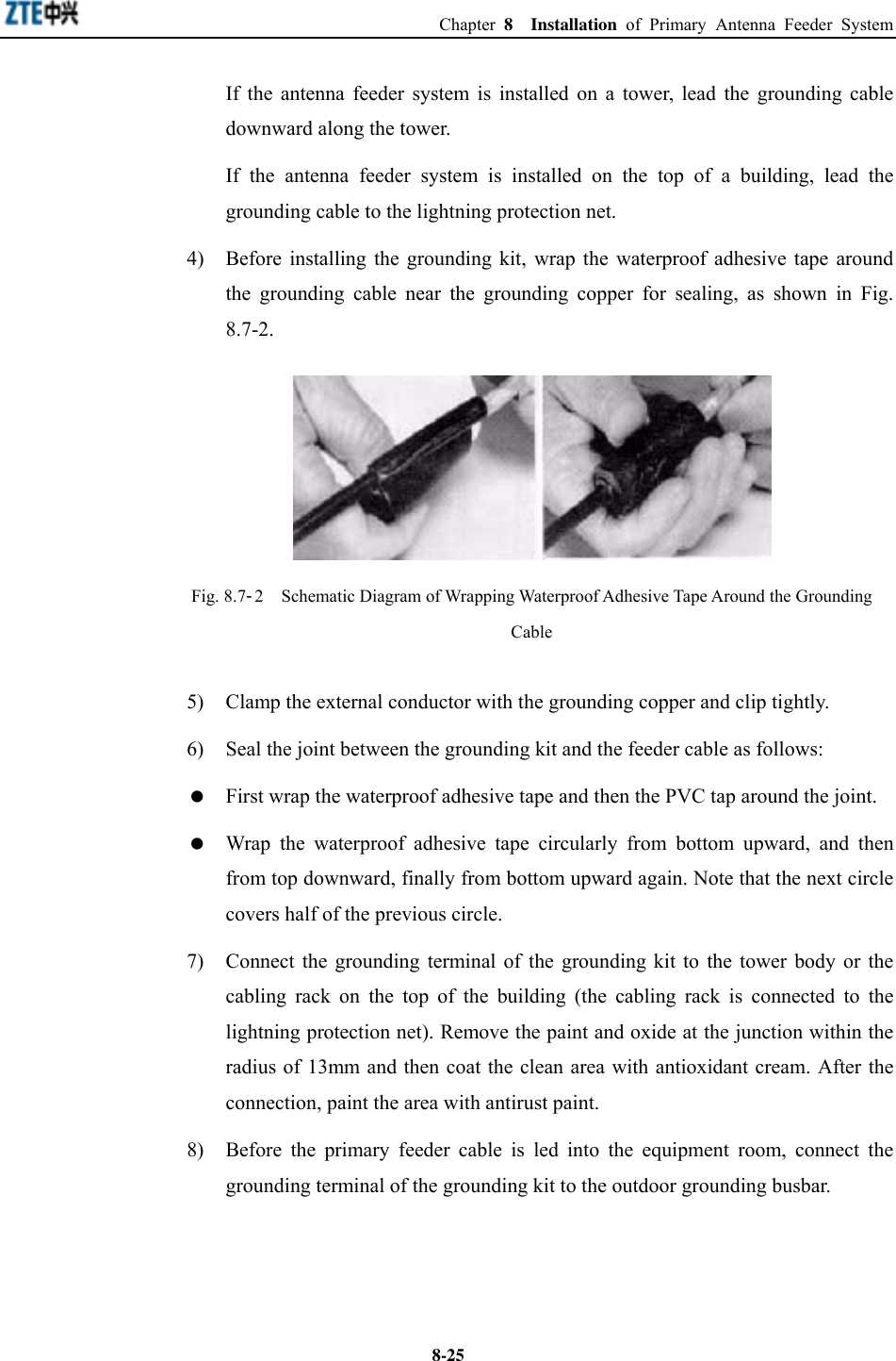
ZTE
>
ZXCBTS192T User Manual
Users Manual
Navigation menu
Upload a User Manual
Namespaces
Wiki Guide
HTML
PDF
Info
Views
User Manual
Discussion / Help
Navigation
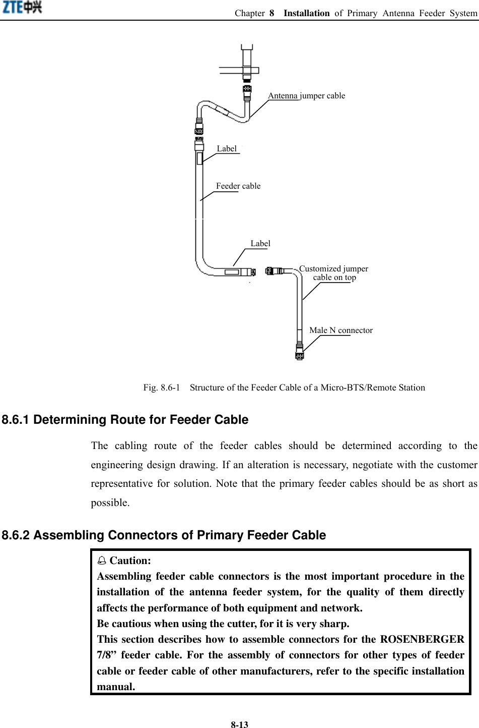
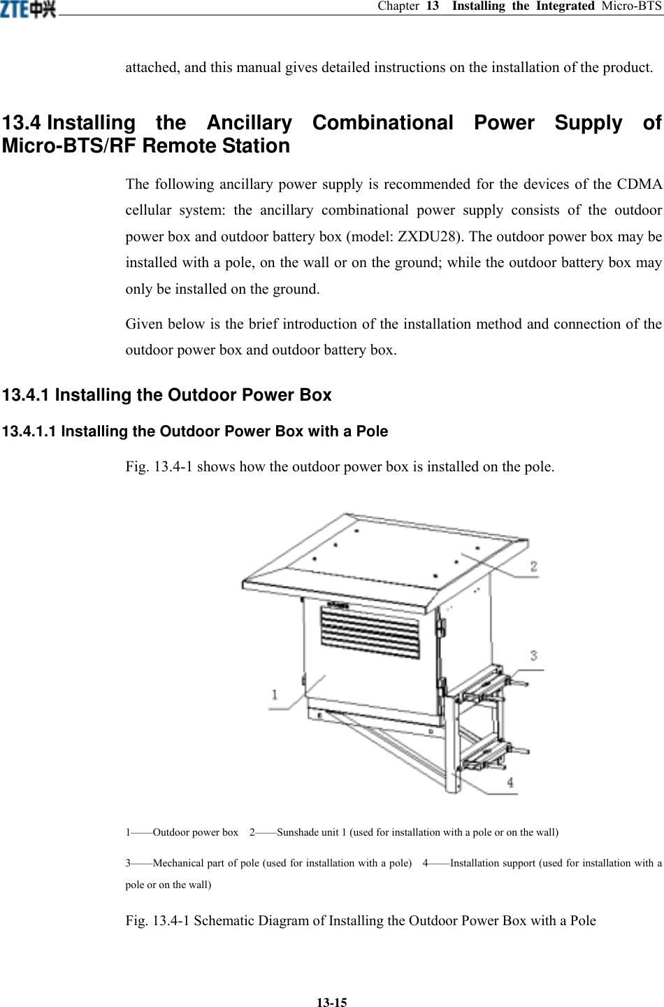
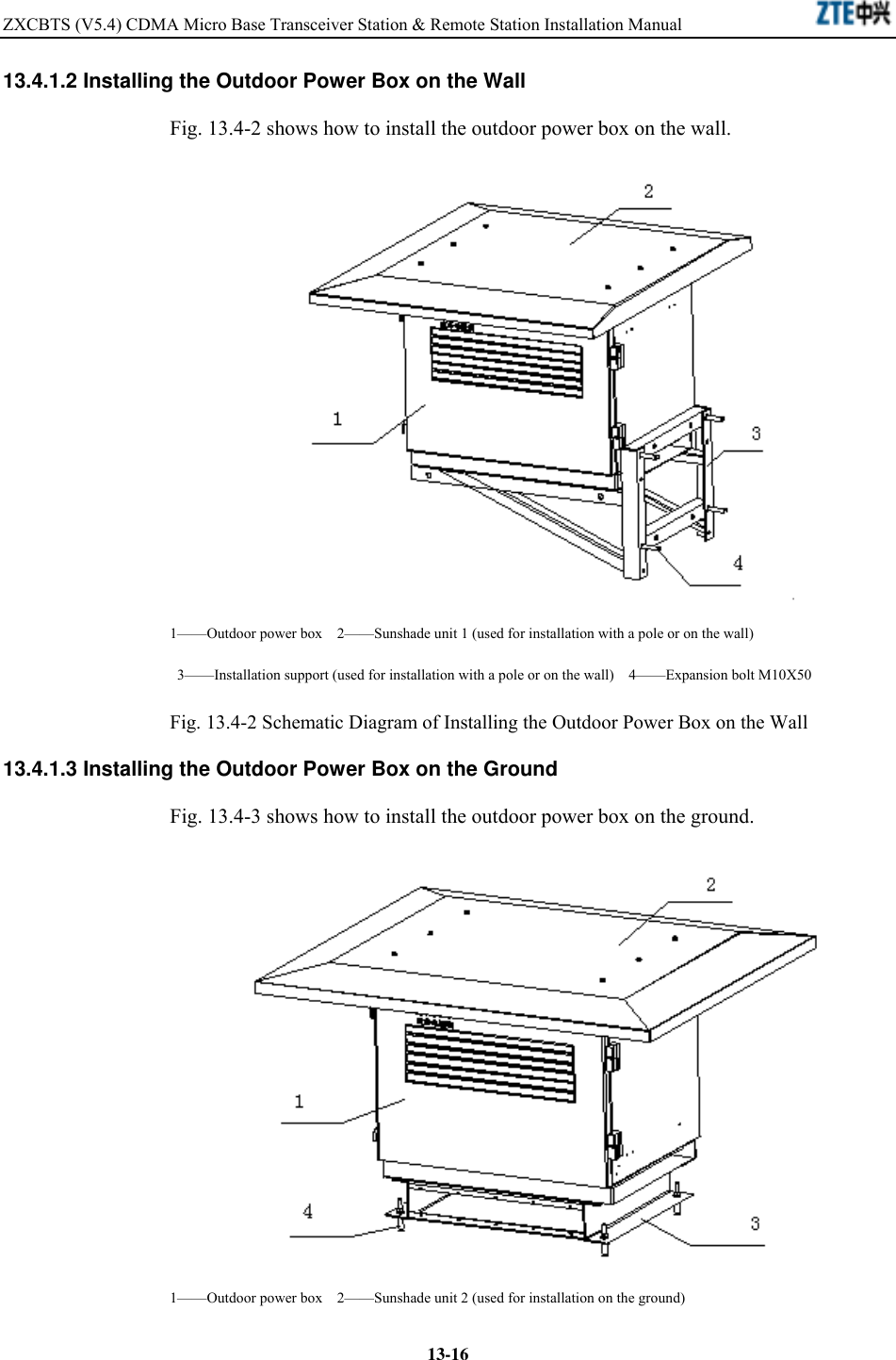
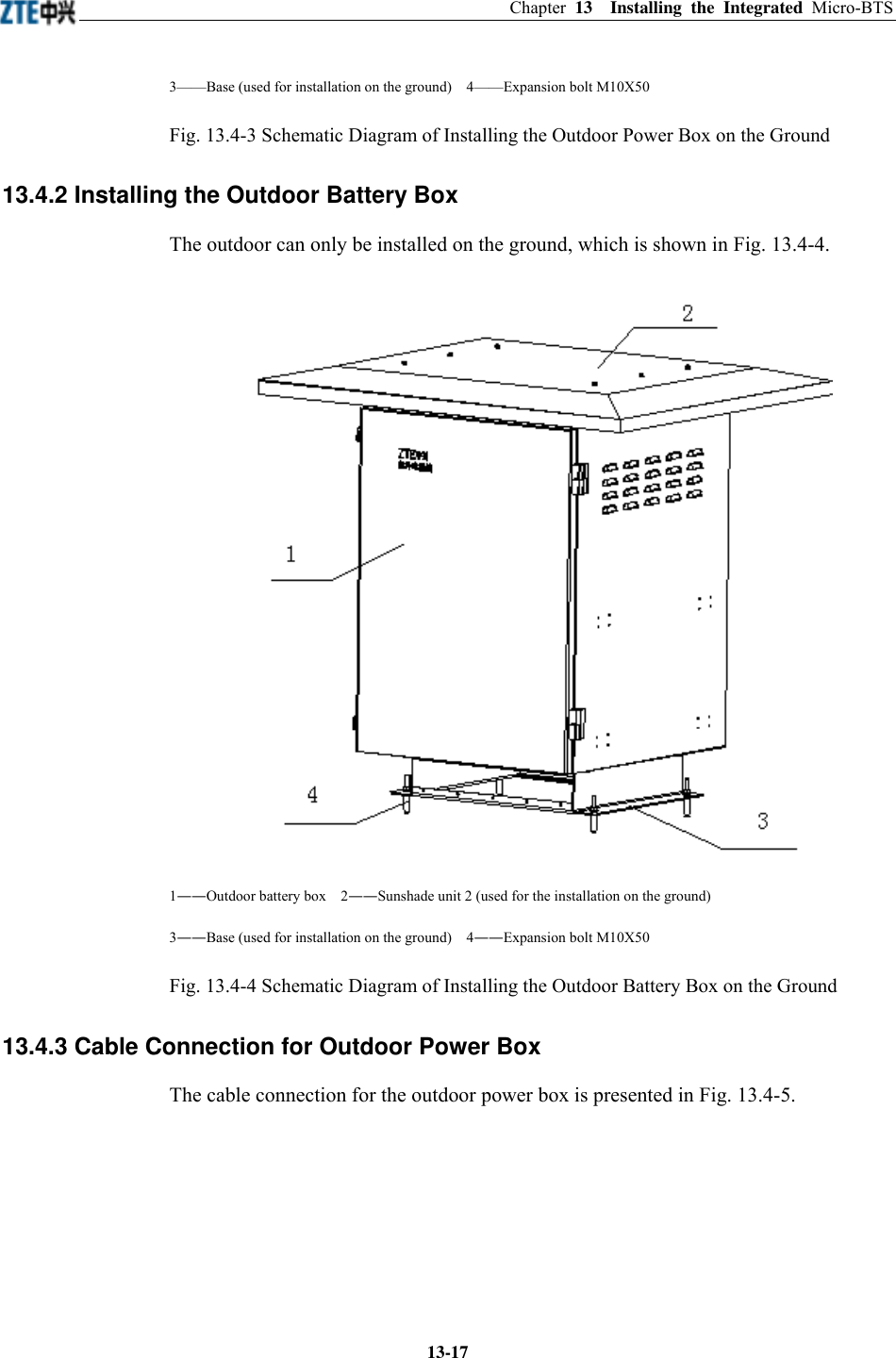
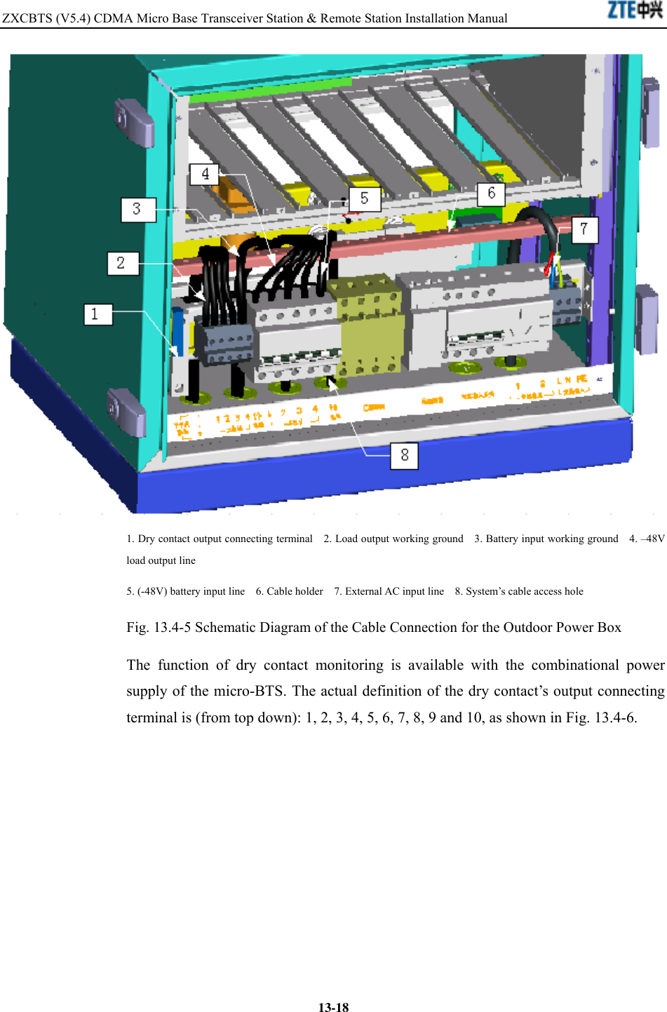
![Details the installation of the power supply system of the equipment. 6. Installation of Grounding System Details the installation of the grounding system of the equipment. 7. Connection of Cables Details the check of internal cable connections between various modules, as well as type selection and connection of external cables. 8. Installation of Primary Antenna Feeder System Details the installation of the antenna feeder system of the equipment, including the procedures of assembling feeder cable connectors, installing antenna, laying feeder cables, installing feeder cable window and grounding equipment. 9. Installation of GPS antenna feeder system Details the installation of GPS antenna feeder system for the equipment, including the procedures of assembling feeder cable connectors and installing antenna. 10. Installation of Internal Modules Details the installation of internal modules. 11. Hardware Installation Check Presents how to check the hardware installation. 12. Power-on and Power-off Presents the procedures of powering on/off the equipment. 13. Appendix Presents the equipment performance specifications, meaning of various indicators and connection of cables. Conventions 1. Notational Convention Angular brackets “< >” identify names of keys and buttons, and the information typed by an operator from a terminal. Square brackets “[ ]” indicate a man-machine interface, menu item, data list or field name. The symbol “→”](https://usermanual.wiki/ZTE/ZXCBTS192T/User-Guide-545926-Page-6.png)
![separates a multi-level menu, for example, [File→New→Folder] indicates the [Folder] menu item under the [New] submenu of the menu [File]. 2. Keyboard Operation Convention Format Description <Key> Indicate a key or button name, for example, <Enter>, <Tab>, <Backspace>, and <a>. <Key1+Key2> Press Key 1 and Key 2 at the same time. <key1, Key2> Press Key1 first. Then release Key 1 and press Key 2. 3. Mouse Operation Convention Format Description Click Refers to clicking the primary mouse button (usually the left mouse button) once Double-click Refers to quickly clicking the primary mouse button (usually the left mouse button) twice Right-click Refers to clicking the secondary mouse button (usually the right mouse button) once. Drag Refers to pressing and holding a mouse button and move the mouse 4. Danger, Warning, Caution and Note Statements Note, Caution, Warning, Danger statements are used throughout this manual to emphasize important and critical information. You must read these statements to help ensure safety and to prevent product damage. Statement: The actual product may differ from what is described in this manual due to frequent update of ZTE products and fast development of technologies. Please contact the local ZTE office for the latest updating information of the product.](https://usermanual.wiki/ZTE/ZXCBTS192T/User-Guide-545926-Page-7.png)