ZTE ZXCBTS192T CDMA Micro Base Transceiver Station User Manual
ZTE Corporation CDMA Micro Base Transceiver Station Users Manual
ZTE >
Users Manual
ZXCBTS (V5.4)
CDMA Micro Base Transceiver Station
& RF Remote Station
Installation Manual
ZTE CORPORATION
ZXCBTS (V5.4) CDMA Micro Base Transceiver Station/RF Remote
Station
Installation Manual
Manual Version 20050422-R1.1
Product Version V5.4
Copyright © 2004 ZTE Corporation
All rights reserved.
No part of this documentation may be excerpted, reproduced, translated, annotated or
duplicated, in any form or by any means without the prior written permission of ZTE
Corporation.
* * * *
ZTE CORPORATION
ZTE Plaza, Keji Road South, Hi-Tech Industrial Park, Nanshan District, Shenzhen, P.R.China
Website: http://www.zte.com.cn
Postcode: 518057
Customer Support Center: (+86755) 26771900 800-9830-9830
Fax: (+86755) 26770801
Email: support@zte.com.cn
* * * *
S.N.: sjzl20030272

FAX:+86-755-26770160
Suggestions and Feedback
To improve the quality of ZTE product documentation and offer better services to our customers, we hope
you can give us your suggestions and comments on our documentation and fax this form to
+86-755-26770160; or mail to “Marketing center 3rd floor ZTE Plaza, Keji Road South, Hi-Tech Industrial
Park, Nanshan District, Shenzhen, P. R. China”. Our postcode is 518057.
Document name ZXCBTS (V5.4) CDMA Micro Base Transceiver Station/RF Remote Stations Installation Manual
Product version V5.4 Document version 20050422-R1.1
Equipment installation time
Your information
Name Company
Postcode Company address
Telephone E-mail
Presentation: How is information presented? (Introductions, procedures, illustrations, others)
F Good F Fair F Average F Poor F Bad
Accessibility: Can you find the information you want? (Table of contents, Index, headings,
numbering, others)
F Good F Fair F Average F Poor F Bad
Your evaluation
of this
documentation
Intelligibility: Can you understand it when you find it? (Language, vocabulary, readability, others)
F Good F Fair F Average F Poor F Bad
Presentation:
Accessibility:
Your suggestions
for improvement
of this
documentation
Intelligibility:
Your other
suggestions on
ZTE product
documentation
Preface
About This Manual
This manual presents the hardware installation procedures of ZXCBTS micro base
transceiver stations (BTSs)/remote stations.
It is one of ZTE manual series for CDMA cellular mobile communications system. It
aims to providing guidance to the engineering personnel who install ZTE CDMA
micro-BTS/remote stations, as well as offering reference for the equipment
maintenance personnel.
Correct hardware installation is the basis for reliable and normal running of the base
transceiver stations, thus enjoying importance in engineering construction. To facilitate
the installation, this manual is written following the sequence of actual hardware
installation. First, it briefs the structure of the ZXCBTS products, which is helpful for
the installation personnel to get familiar with the equipment. Next, it describes the
equipment installation procedures in detail. Finally, it presents how to check the
equipment after the installation.
How to Use This Manual
1. Overview
Introduces the basic structure, basic installation procedures and points for
attention during installation of the micro-BTS/remote stations.
2. Preparations
Introduces the preparations for the installation, including listing needed tools
and checking the installation environment.
3. Open-box Inspection
Introduces the procedures and cautions for opening boxes and inspecting the
equipment.
4. Installation of Cabinet
Details the fixation and installation of the cabinet of the equipment.
5. Installation of Power Supply System
Details the installation of the power supply system of the equipment.
6. Installation of Grounding System
Details the installation of the grounding system of the equipment.
7. Connection of Cables
Details the check of internal cable connections between various modules, as well
as type selection and connection of external cables.
8. Installation of Primary Antenna Feeder System
Details the installation of the antenna feeder system of the equipment, including
the procedures of assembling feeder cable connectors, installing antenna, laying
feeder cables, installing feeder cable window and grounding equipment.
9. Installation of GPS antenna feeder system
Details the installation of GPS antenna feeder system for the equipment,
including the procedures of assembling feeder cable connectors and installing
antenna.
10. Installation of Internal Modules
Details the installation of internal modules.
11. Hardware Installation Check
Presents how to check the hardware installation.
12. Power-on and Power-off
Presents the procedures of powering on/off the equipment.
13. Appendix
Presents the equipment performance specifications, meaning of various
indicators and connection of cables.
Conventions
1. Notational Convention
Angular brackets “< >” identify names of keys and buttons, and the information
typed by an operator from a terminal. Square brackets “[ ]” indicate a
man-machine interface, menu item, data list or field name. The symbol “→”
separates a multi-level menu, for example, [File→New→Folder] indicates the
[Folder] menu item under the [New] submenu of the menu [File].
2. Keyboard Operation Convention
Format Description
<Key> Indicate a key or button name, for example, <Enter>, <Tab>,
<Backspace>, and <a>.
<Key1+Key2> Press Key 1 and Key 2 at the same time.
<key1, Key2> Press Key1 first. Then release Key 1 and press Key 2.
3. Mouse Operation Convention
Format Description
Click Refers to clicking the primary mouse button (usually the left mouse
button) once
Double-click Refers to quickly clicking the primary mouse button (usually the left
mouse button) twice
Right-click Refers to clicking the secondary mouse button (usually the right mouse
button) once.
Drag Refers to pressing and holding a mouse button and move the mouse
4. Danger, Warning, Caution and Note Statements
Note, Caution, Warning, Danger statements are
used throughout this manual to emphasize important and critical information.
You must read these statements to help ensure safety and to prevent product
damage.
Statement: The actual product may differ from what is described in this
manual due to frequent update of ZTE products and fast development of
technologies. Please contact the local ZTE office for the latest updating
information of the product.

FCC & IC STATEMENT
Before using this CDMA Micro Base Transceiver Station & RF Remote Station, read this important RF
energy awareness and control information and operational instructions to ensure compliance with the FCC
and IC RF exposure guidelines.
NOTICE: Working with the equipment while in operation, may expose the technician to RF
electromagnetic fields that exceed FCC rules for human exposure. Visit the FCC website at
www.fcc.gov/oet/rfsafety to learn more about the effects of exposure to RF electromagnetic fields.
Changes or modifications to this unit not expressly approved by the party responsible for compliance will
void the user’s authority to operate the equipment. Any change to the equipment will void FCC and IC
grant.
This equipment has been tested and found to comply with the limits for a Class A digital device, pursuant
to the FCC and IC Rules. This equipment generates, uses and can radiate radio frequency energy and, if not
installed and used in accordance with the instructions, may cause harmful interference to radio
communications. However, there is no guarantee that interference will not occur in a particular installation.
For OUTDOOR use, a PNALE Antenna with a maximum gain of 17dBi is authorized for use with this unit.
Outside antennas must be positioned to observe minimum separation of 2M (6.56 feet.) for 800MHz unit
and 1.5M (4.92 feet.) for 1900MHz unit from all users and bystanders. For the protection of personnel
working in the vicinity of outside (uplink) antennas, the following guidelines for minimum distances
between the human body and the antenna must be observed.
The installation of an OUTDOOR antenna must be such that, under normal conditions, all personnel cannot
come within 2M (6.56 feet) for 800MHz unit and 1.5M (4.92 feet) for 1900MHz unit from the outside
antenna. Exceeding this minimum separation will ensure that the worker or bystander does not receive
RF-exposure beyond the Maximum Permissible Exposure according to section 1.1310 i.e. limits for
Controlled Exposure.
-i-
Contents
1 Overview..................................................................................................................................................1-1
1.1 Introduction to Micro-BTS ............................................................................................................1-1
1.2 Installation Overview.....................................................................................................................1-4
1.3 Installation Flow ............................................................................................................................1-5
1.4 Points for Attention ........................................................................................................................ 1-7
2 Preparations ............................................................................................................................................2-1
2.1 Installation Environment Check.....................................................................................................2-1
2.1.1 Checking Equipment Building Conditions..........................................................................2-1
2.1.2 Checking Indoor Environment............................................................................................2-1
2.1.3 Checking Power Supply System .........................................................................................2-2
2.1.4 Checking Grounding System ..............................................................................................2-2
2.1.5 Checking Relative Devices .................................................................................................2-2
2.2 Tools and Instruments ....................................................................................................................2-2
2.3 Technical Documents .....................................................................................................................2-3
3 Open-box Inspection...............................................................................................................................3-1
3.1 Checking Packing List and Goods .................................................................................................3-1
3.2 Packaging.......................................................................................................................................3-2
3.3 Open-box Procedures.....................................................................................................................3-2
4 Installation of Cabinet ............................................................................................................................4-1
4.1 Installation Flow ............................................................................................................................4-1
4.2 Installation Modes..........................................................................................................................4-2
4.2.1 Installing Cabinet on Pole ...................................................................................................4-2
4.2.2 Installing Cabinet on Wall...................................................................................................4-6
-ii-
5 Installation of Power Supply System .................................................................................................... 5-1
5.1 Introduction to Power Cables ........................................................................................................ 5-1
5.1.1 -48V DC Power Cable ........................................................................................................ 5-1
5.1.2 120V AC Power Cable........................................................................................................ 5-2
5.2 Connection of Power Cables ......................................................................................................... 5-2
5.3 Assembling Power Cable Connector ............................................................................................. 5-3
5.3.1 Assembling -48V DC Power Cable Connector................................................................... 5-3
5.3.2 Assembling 120V AC Power Cable Connector .................................................................. 5-5
6 Installation of Grounding System ......................................................................................................... 6-1
6.1 Introduction to the Grounding System........................................................................................... 6-1
6.2 Installing Grounding System ......................................................................................................... 6-2
6.2.1 Installing Outdoor Grounding Copper Busbar.................................................................... 6-2
6.2.2 Installing the Grounding System of Micro-BTS................................................................. 6-3
6.2.3 Installing Feeder Cable Grounding Kit............................................................................... 6-4
7 Connection of Cables.............................................................................................................................. 7-1
7.1 Checking Internal Cable Connections ........................................................................................... 7-1
7.1.1 Type and Configuration of Internal Cables......................................................................... 7-1
7.1.2 Connection of Internal Cables ............................................................................................ 7-3
7.2 Connecting External Cables .......................................................................................................... 7-3
7.2.1 Connecting Optical Fiber.................................................................................................... 7-3
7.2.2 Connecting Multi-carrier Interconnection RF Cables......................................................... 7-7
7.2.3 Waterproof Processing of Joints ......................................................................................... 7-8
7.2.4 Connection of Trunk Cables ............................................................................................... 7-9
8 Installation of Primary Antenna Feeder System.................................................................................. 8-1
8.1 Preparations ................................................................................................................................... 8-1
8.1.1 Installation Personnel.......................................................................................................... 8-1
-iii-
8.1.2 Installation Environment.....................................................................................................8-2
8.1.3 Security Measures ...............................................................................................................8-2
8.1.4 Installation Tools .................................................................................................................8-2
8.2 Composition and Installation Requirements of Antenna Feeder System .......................................8-3
8.2.1 Composition........................................................................................................................8-3
8.2.2 Technical Parameters...........................................................................................................8-5
8.3 Installation Flow ............................................................................................................................8-5
8.4 Installation of Antenna ...................................................................................................................8-6
8.4.1 Determining Installation Location ......................................................................................8-6
8.4.2 Installing Accessories of Directional Antenna ....................................................................8-7
8.4.3 Transporting and Raising Antenna ......................................................................................8-8
8.4.4 Installing and Adjusting Directional Antenna .....................................................................8-9
8.4.5 Installing and Adjusting Omni Antenna ............................................................................8-10
8.4.6 Connecting Jumper Cable with Antenna and Sealing Their Joint ..................................... 8-10
8.5 Installation of Feeder Cable Window........................................................................................... 8-11
8.6 Connection of Feeder Cable.........................................................................................................8-12
8.6.1 Determining Route for Feeder Cable ................................................................................8-13
8.6.2 Assembling Connectors of Primary Feeder Cable ............................................................8-13
8.6.3 Cutting Feeder Cable.........................................................................................................8-16
8.6.4 Raising Primary Feeder Cable...........................................................................................8-17
8.6.5 Laying and Fastening Primary Feeder Cable ....................................................................8-18
8.6.6 Connecting Jumper Cable with Feeder Cable and Sealing Their Joint .............................8-20
8.6.7 Leading Primary Feeder Cable into Equipment Room .....................................................8-21
8.6.8 Connecting Indoor Jumper Cable......................................................................................8-23
8.7 Grounding System of Micro-BTS................................................................................................8-23
8.8 Test of Antenna Feeder System....................................................................................................8-26
-iv-
8.9 Waterproof Processing of Connectors.......................................................................................... 8-26
9 Installation of GPS Antenna Feeder System ........................................................................................ 9-1
9.1 Preparations ................................................................................................................................... 9-1
9.1.1 Installation Personnel.......................................................................................................... 9-1
9.1.2 Installation Environment..................................................................................................... 9-1
9.1.3 Security Measures............................................................................................................... 9-2
9.1.4 Installation Tools................................................................................................................. 9-2
9.2 Composition of GPS Antenna Feeder System ............................................................................... 9-3
9.3 Installation Procedures................................................................................................................... 9-3
9.4 Test of Antenna Feeder System...................................................................................................... 9-5
10 Installation of Internal Modules........................................................................................................ 10-1
10.1 Overview ................................................................................................................................... 10-1
10.1.1 Logical Positions of Equipment Modules....................................................................... 10-1
10.1.2 Layout of Internal Modules ............................................................................................ 10-2
10.1.3 Functions of the Modules ............................................................................................... 10-4
10.2 Module Installation Flow........................................................................................................... 10-7
10.3 Installation and Replacement of Modules.................................................................................. 10-8
10.3.1 Installation Sequence...................................................................................................... 10-8
10.3.2 Table of Cable Connections ............................................................................................ 10-8
10.3.3 Fastening and Bundling of Internal Cables..................................................................... 10-9
10.3.4 Installation of OIM ....................................................................................................... 10-11
10.3.5 Installation of LFM....................................................................................................... 10-12
10.4 Points for Attention.................................................................................................................. 10-12
11 Hardware Installation Check..............................................................................................................11-1
11.1 Checking Components in the Cabinet........................................................................................ 11-1
11.2 Checking the Cabinet................................................................................................................. 11-1
-v-
11.3 Checking Cables......................................................................................................................... 11-2
11.4 Checking Power Cables and Grounding Cables......................................................................... 11-2
11.5 Checking T1 Cables ................................................................................................................... 11-4
11.6 Checking Indoor 1/2” Jumper Cables ........................................................................................11-4
11.7 Checking Primary Feeder Cables and GPS Feeder Cables ........................................................11-5
11.8 Checking Water-blocking Curve for Feeder Cable Window and Primary Feeder Cables.......... 11-6
11.9 Checking Hangers ...................................................................................................................... 11-6
11.10 Checking Outdoor 1/2” Jumper Cables.................................................................................... 11-7
11.11 Checking Antenna .................................................................................................................... 11-7
11.12 Checking Standing Wave Ratio of Feeder Cables.................................................................... 11-9
11.13 Checking Indoor and Outdoor Environment ............................................................................11-9
12 Power-on and Power-off .....................................................................................................................12-1
12.1 Checking Components in the Cabinet before Power-on ............................................................12-1
12.2 Checking External Cables before Power-on ..............................................................................12-2
12.3 Powering on/off the Cabinet ......................................................................................................12-2
13 Installing the Integrated Micro-BTS.................................................................................................13-1
13.1 Introduction to the Solution of Micro-BTS Integration .............................................................13-1
13.1.1 Implementation of the Micro-BTS Integration ...............................................................13-1
13.1.2 Micro-BTS Integration Solution .....................................................................................13-2
13.1.3 Module Layout of the Integrated Micro-BTS and RF Remote Station ...........................13-4
13.1.4 Networking Modes of the Integrated SDH......................................................................13-7
13.2 Installing the Built-in SDH of Micro-BTS.................................................................................13-7
13.2.1 Position and Internal Connection of the Built-in SDH in the Micro-BTS ......................13-7
13.2.2 Connecting the External Optical Fibers and Cables During Installation.........................13-8
13.3 Installing the Integrated UPS of Micro-BTS/RF Remote Station ............................................13-10
13.3.1 Introduction to ZXUPS L010........................................................................................13-10
-vi-
13.3.2 Precautions for UPS Installation................................................................................... 13-11
13.3.3 Structural Feature and Installation Mode of UPS ......................................................... 13-12
13.3.4 Installing the Engineering Cables of L010UPS ............................................................ 13-13
13.3.5 Installing UPS............................................................................................................... 13-14
13.4 Installing the Ancillary Combinational Power Supply of Micro-BTS/RF Remote Station ..... 13-15
13.4.1 Installing the Outdoor Power Box ................................................................................ 13-15
13.4.2 Installing the Outdoor Battery Box............................................................................... 13-17
13.4.3 Cable Connection for Outdoor Power Box................................................................... 13-17
Appendix A Packaging, Storage and Transportation ............................................................................ A-1
A.1 Packaging..................................................................................................................................... A-1
A.2 Storage ......................................................................................................................................... A-1
A.3 Transportation .............................................................................................................................. A-2
Appendix B Table of Cable Connections .................................................................................................B-1
B.1 Cable Connections in M800T Single-carrier Micro-BTS .............................................................B-1
B.2 Cable Connections in M800T Double-carrier Micro-BTS............................................................B-2
B.3 Cable Connections in R800T Single-carrier Remote Stations ......................................................B-3
B.4 Cable Connections in R800T Double-carrier Remote Stations.....................................................B-5
B.5 Cable Connections in M190T Single-carrier Micro-BTS .............................................................B-6
B.6 Cable Connections in M190T Double-carrier Micro-BTS............................................................B-7
B.7 Cable Connections in R190T Single-carrier Remote Stations ......................................................B-8
B.8 Cable Connections in R190T Double-carrier Remote Stations.....................................................B-9
B.9 Cable Connections in M802T Single-carrier Micro-BTS ...........................................................B-10
B.10 Cable Connections in M802T Double-carrier Micro-BTS........................................................B-12
B.11 Cable Connections in R802 Single-carrier RF Remote Stations ...............................................B-13
B.12 Cable Connections in R802T Double-carrier Remote Stations.................................................B-14
B.13 Cable Connections in M191T Single-carrier Micro-BTS .........................................................B-15
-vii-
B.14 Cable Connections in M191T Double-carrier Micro-BTS....................................................... B-16
B.15 Cable Connections in R191T Single-carrier Remote Stations.................................................. B-18
B.16 Cable Connections in R191T Double-carrier Remote Stations ................................................ B-19
B.17 Cable Connections in M192T Single-carrier Micro-BTS......................................................... B-20
B.18 Cable Connections in M192T Double-carrier Micro-BTS....................................................... B-21
B.19 Cable Connections in R192T Single-carrier Remote Stations.................................................. B-22
B.20 Cable Connections in R192T Double-carrier Remote Stations ................................................ B-23
Appendix C Equipment Parameters .......................................................................................................C-1
C.1 Dimension .................................................................................................................................... C-1
C.2 Power Consumption ..................................................................................................................... C-1
Appendix D Indicators..............................................................................................................................D-1
D.1 BDM Indicators............................................................................................................................ D-1
D.2 Indicators on Front Panel of MGPS ............................................................................................. D-1
D.3 Indicators of LFM, RFM and OIM ..............................................................................................D-2
Appendix E Abbreviations ....................................................................................................................... E-1
-i-
A List of Figures
Fig. 1.1-1 Structure of ZXCBTS M800T Micro-BTS.......................................................................1-2
Fig. 1.1-2 Structure of Remote Stations ............................................................................................1-3
Fig. 1.1-3 Connection between Remote Station and Macro-BTS .....................................................1-3
Fig. 1.1-4 Connection between Remote Station and Macro-BTS .....................................................1-4
Fig. 1.2-1 Schematic Diagram of the Hardware Installation of Micro-BTS/Remote Station ...........1-5
Fig. 1.3-1 Hardware Installation Flow Diagram ...............................................................................1-6
Fig. 3.2-1 Packing Box for ZXCBTS Cabinet ..................................................................................3-2
Fig. 3.3-1 Schematic Diagram for Opening a Box............................................................................3-3
Fig. 4.1-1 Flow of Installing the Cabinet ..........................................................................................4-2
Fig. 4.2-1 Schematic Diagram of Fastening the Cabinet onto the Pole (step 1) ...............................4-3
Fig. 4.2-2 Schematic Diagram of Fastening the Cabinet onto the Pole (step 2) ...............................4-4
Fig. 4.2-3 Schematic Diagram of Fastening the Cabinet onto the Pole (step 3) ...............................4-4
Fig. 4.2-4 Schematic Diagram of the Cabinet Fastened onto the Pole..............................................4-5
Fig. 4.2-5 Schematic Diagram of Installing the Support onto the Wall ............................................4-6
Fig. 4.2-6 Schematic Diagram of Installing the Cabinet onto the Wall............................................. 4-7
Fig. 5.1-1 Four-pin Connector and Four-core Power Cable .............................................................5-1
Fig. 5.2-1 Connection of Power Cables and Grounding Cables at the Bottom of a Cabinet............5-3
Fig. 5.3-1 Assembling a Power Cable Connector (step 1) ................................................................5-3
Fig. 5.3-2 Assembling a Power Cable Connector (step 2) ................................................................5-4
Fig. 5.3-3 Assembling a Power Cable Connector (step 4) ................................................................5-4
Fig. 5.3-4 Assembling a Power Cable Connector (step 5) ................................................................5-5
Fig. 5.3-5 Assembling a Power Cable Connector (step 6) ................................................................5-5
Fig. 6.1-1 Schematic Diagram of Grounding Connections...............................................................6-2
-ii-
Fig. 6.2-1 Appearance of a Grounding Copper Busbar .................................................................... 6-3
Fig. 6.2-2 Connection of Power Cable and PGND Cable at the Bottom of a Cabinet...................... 6-4
Fig. 6.2-3 Structure of a Grounding Kit............................................................................................ 6-5
Fig. 6.2-4 Schematic Diagram of Wrapping Waterproof Adhesive Tape Around the Grounding Cable
............................................................................................................................................................. 6-6
Fig. 7.2-1 Structure of Optical Fiber (1) ........................................................................................... 7-3
Fig. 7.2-2 Structure of Optical Fiber (2) ........................................................................................... 7-4
Fig. 7.2-3 Structure of Optical Fiber (3) ........................................................................................... 7-5
Fig. 7.2-4 Structure of Optical Fiber (4) ........................................................................................... 7-5
Fig. 7.2-5 Schematic Diagram of Connecting Optical Fiber ............................................................ 7-6
Fig. 7.2-6 Connection of Interconnection RF Cables ....................................................................... 7-8
Fig. 7.2-7 Connection of T1 Cables.................................................................................................. 7-9
Fig. 8.2-1 Typical Structure of the Antenna Feeder System ............................................................. 8-4
Fig. 8.3-1 Antenna Installation Flow ................................................................................................ 8-6
Fig. 8.4-1 Installation of the KATHREIN Antenna .......................................................................... 8-7
Fig. 8.4-2 Schematic Diagram of Raising the Antenna to the Tower Top ........................................ 8-8
Fig. 8.4-3 Schematic Diagram of Adjusting the Pitch Angle of the Antenna ................................. 8-10
Fig. 8.5-1 Structure of a Feeder Cable Window ............................................................................. 8-12
Fig. 8.6-1 Structure of the Feeder Cable of a Micro-BTS/Remote Station..................................... 8-13
Fig. 8.6-2 Cutter for Assembling 7/8” Feeder Cable Connectors ................................................... 8-14
Fig. 8.6-3 Schematic Diagram of Cutting the Feeder Cable with the Cutter.................................. 8-14
Fig. 8.6-4 Schematic Diagram of Correct Cutting Size.................................................................. 8-14
Fig. 8.6-5 Schematic Diagram of Expanding the External Copper Conductor............................... 8-15
Fig. 8.6-6 Schematic Diagram of Connecting the Front Part with the Back Part of the Connector 8-15
Fig. 8.6-7 Schematic Diagram of Fastening the Front Part with the Back Part of the Connector .. 8-16
Fig. 8.6-8 Schematic Diagram of Pulling the Feeder Cable Up the Tower..................................... 8-18
Fig. 8.6-9 Appearance of a Hanger................................................................................................. 8-19
-iii-
Fig. 8.6-10 Schematic Diagram of Wrapping Waterproof Adhesive Tape (1)................................. 8-20
Fig. 8.6-11 Schematic Diagram of Wrapping Waterproof Adhesive Tape (2).................................8-21
Fig. 8.6-12 Schematic Diagram of Wrapping Waterproof Adhesive Tape (3)................................. 8-21
Fig. 8.6-13 Leading the Feeder Cable into the Equipment Room - Mode 1 ...................................8-22
Fig. 8.6-14 Leading the Feeder Cable into the Equipment Room - Mode 2 ...................................8-22
Fig. 8.7-1 Structure of a Grounding Kit ..........................................................................................8-24
Fig. 8.7-2 Schematic Diagram of Wrapping Waterproof Adhesive Tape Around the Grounding Cable
...........................................................................................................................................................8-25
Fig. 9.2-1 Composition of the GPS Antenna Feeder System ............................................................9-3
Fig. 9.3-1 Schematic Diagram of Length of Cable Sheath to be Stripped ........................................9-4
Fig. 9.3-2 Schematic Diagram of Soldering the Core Wire with the Pin ..........................................9-4
Fig. 9.3-3 Structure of N-J7A............................................................................................................9-4
Fig. 10.1-1 Modules and Boards in M800T/M801T/M802T/M190T/M191T/M192T Micro-BTS10-1
Fig. 10.1-2 Modules and Boards in R800T/R801T/R802T/R190T/R191T/R192T ........................10-2
Fig. 10.1-3 Layout of Modules in a ZXCBTS Micro-BTS .............................................................10-3
Fig. 10.1-4 Layout of Modules in a ZXCBTS Remote Station.......................................................10-4
Fig. 10.2-1 Module Installation Flow Diagram...............................................................................10-7
Fig. 10.3-1 Schematic Diagram of Bundling Internal Cables (1)....................................................10-9
Fig. 10.3-2 Schematic Diagram of Bundling Internal Cables (2)..................................................10-10
Fig. 10.3-3 Schematic Diagram of Bundling Internal Cables (3)..................................................10-10
Fig. 10.3-4 Corresponding Relations between OIM Expansion Slots in BDM and Sectors .........10-11
Fig. 10.3-5 Schematic Diagram of Inserting the OIM into the BDM ...........................................10-12
Fig. 12.1-1 Setting of S1 .................................................................................................................12-1
Fig. 13.1-1 Solution (I) of Micro-BTS Integration ............................................................................13-3
Fig. 13.1-2 Solution (II) of Micro-BTS Integration ...........................................................................13-4
Fig. 13.1-3 Layout of Modules in the ZXCBTS micro-BTS .............................................................13-5
Fig. 13.2-1 Cable Layout of the Built-in SDH in the CDMA Micro-BTS.........................................13-8
-iv-
Fig. 13.2-3 Connection of the Optical Fiber .................................................................................... 13-10
Fig. 13.3-1 Appearance of the ZXUPS L010 Series........................................................................ 13-11
Fig. 13.3-2 Inner Structure of the ZXUPS L010 Series................................................................... 13-11
Fig. 13.3-4 Layout of the Monitoring Cables of the CDMA Micro-BTS 485/Dry Contact ............ 13-14
Fig. 13.4-6 Output Connecting Terminal of the Dry Contact .......................................................... 13-19
Fig. C.1-1 Appearance of a ZXCBTS Cabinet .................................................................................C-1
Fig. D.1-1 Indicators of the BDM.................................................................................................... D-1
Fig. D.3-1 Location of Indicators on the OIM Panel ...................................................................... D-4
-i-
A List of Tables
Table 1.1-1 List of ZXCBTS Micro-BTS/Remote Stations (800MHz) ............................................1-1
Table 1.1-2 List of ZXCBTS Micro-BTS/Remote Stations (1900MHz) ..........................................1-1
Table 2.2-1 Tools and Instruments Needed for the Installation.........................................................2-2
Table 5.1-1 Corresponding Relationship between Core Wires and Binding Posts............................5-2
Table 5.1-2 Corresponding Relationship between Core Wires and Binding Posts............................5-2
Table 5.3-1 Corresponding Relationship between Core Wires and Binding Posts...........................5-6
Table 7.1-1 List of Types and Configurations of Internal Cables......................................................7-1
Table 13.2-1 Cable Connection of the Built-in SDH inside the CDMA Micro-BTS.........................13-7
Table 13.3-1 From-to-list of the CDMA Micro-BTS 485/dry contact supplementary cables..........13-13
Table B.1-1 Cable Connections in M800T Single-carrier Micro-BTS ............................................ B-1
Table B.2-1 Cable Connections in M800T Double-carrier Micro-BTS ........................................... B-2
Table B.3-1 Cable Connections in R800T Single-carrier Remote Stations...................................... B-3
Table B.4-1 Cable Connections in R800T Double-carrier Remote Stations .................................... B-5
Table B.5-1 Cable Connections in M190T Single-carrier Micro-BTS ............................................ B-6
Table B.6-1 Cable Connections in M190T Double-carrier Micro-BTS ........................................... B-7
Table B.7-1 Cable Connections in R190T Single-carrier Remote Stations...................................... B-8
Table B.8-1 Cable Connections in R190T Double-carrier Remote Stations .................................... B-9
Table B.9-1 Cable Connections in M802T Single-carrier Micro-BTS .......................................... B-10
Table B.10-1 Cable Connections in M802T Double-carrier Micro-BTS....................................... B-12
Table B.11-1 Cable Connections in R802T Single-carrier Remote Stations.................................. B-13
Table B.12-1 Cable Connections in R802T Double-carrier RF Remote Stations .......................... B-14
Table B.13-1 Cable Connections in M191T Single-carrier Micro-BTS......................................... B-15
Table B.14-1 Cable Connections in M191T Double-carrier Micro-BTS....................................... B-16
-ii-
Table B.15-1 Cable Connections in R191T Single-carrier Remote Stations ..................................B-18
Table B.16-1 Cable Connections in R191T Double-carrier Remote Stations.................................B-19
Table B.17-1 Cable Connections in M192T Single-carrier Micro-BTS .........................................B-20
Table B.18-1 Cable Connections in M192T Double-carrier Micro-BTS........................................B-21
Table B.19-1 Cable Connections in R192T Single-carrier Remote Stations ..................................B-22
Table B.20-1 Cable Connections in R192T Double-carrier Remote Stations.................................B-23
Table C.2-1 Power Consumption of Several Types of Micro-BTS and Remote Stations.................C-2
Table C.2-2 Power Consumption of Several Types of Micro-BTS and Remote Stations.................C-2
Table C.2-3 Power Consumption of Several Types of Micro-BTS and Remote Stations.................C-3
Table D.2-1 Indicators on the Front Panel of MGPS....................................................................... D-1
Table D.3-1 Indicators of the LFM.................................................................................................. D-2
Table D.3-2 Indicators of the RFM.................................................................................................. D-3
Table D.3-3 Indicators on the OIM Panel........................................................................................D-4

1-1
1 Overview
Summary
Listing the components to be installed.
Describing the installation flow.
Presenting points for attention during the installation
1.1 Introduction to Micro-BTS
With the development of various new technologies, Base Transceiver Station (BTS) is
oriented to be small and intelligent, with low power consumption, low cost and high
reliability. In large or medium-sized cities, common micro-BTS cannot meet the
demand of some busy-traffic areas due to the block of high buildings. In addition, it is a
waste for micro-BTS to be installed in some remote areas with less traffic. Moreover,
micro-BTS have high requirements on the equipment room environment. To avoid the
above problems, ZTE has developed ZXCBTS products.
ZXCBTS products are classified based on different frequency bands and transmitter
powers. This manual serves for the installation of the following models:
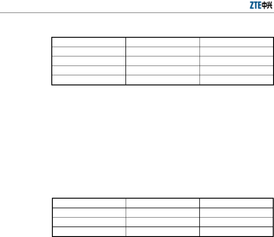
Table 1.1-1 List of ZXCBTS Micro-BTS/Remote Stations (800MHz)
Model Name Rated Transmission Power
ZXCBTS M800T CDMA micro-BTS (800MHz) 10W
ZXCBTS M802T CDMA micro-BTS (800MHz) 20W
ZXCBTS R800T CDMA remote station (800MHz) 10W
ZXCBTS R802T CDMA remote station (800MHz) 20W
Table 1.1-2 List of ZXCBTS Micro-BTS/Remote Stations (1900MHz)
Model Name Rated Transmission Power
ZXCBTS M190T CDMA micro-BTS (1900MHz) 5W
ZXCBTS M191T CDMA micro-BTS (1900MHz) 10W
ZXCBTS (V5.4) CDMA Micro Base Transceiver Station & Remote Station Installation Manual
1-2
Model Name Rated Transmission Power
ZXCBTS M192T CDMA micro-BTS (1900MHz) 20W
ZXCBTS R190T CDMA remote station (1900MHz) 5W
ZXCBTS R191T CDMA remote station (1900MHz) 10W
ZXCBTS R192T CDMA remote station (1900MHz) 20W
ZXCBTS products include micro-BTS and remote stations, working in the frequency
bands of 800MHz and 1.9GHz.
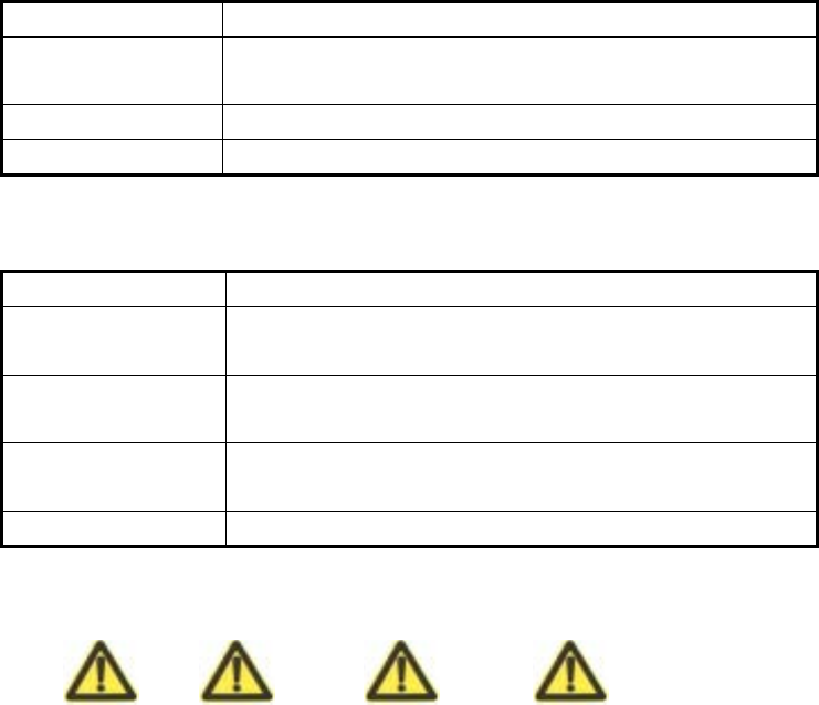
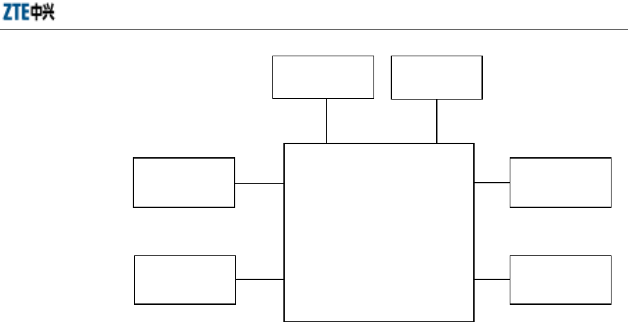
Micro-BTS system consists of Baseband Digital Subsystem (BDS), Timing &
Frequency Subsystem (TFS), power supply subsystem, lightning protection subsystem
and Radio Frequency Subsystem (RFS). The structure of
M800T/M802T//M190T/M191T/M192T micro-BTS is illustrated in the following
figure.
BSC, macro-/
micro-BTS
T1 (4) BDS
subsystem
(BDM)
RFS subsystem
(MTRX, MPA,
MLNA, MDUP
and MDIV)
TFS
subsystem
(GPSTM) Power supply
GPS, RF antenna feeder and power lightning
arrester
GPS antenna RF antenna
Micro-BTS
Fig. 1.1-1 Structure of ZXCBTS M800T Micro-BTS
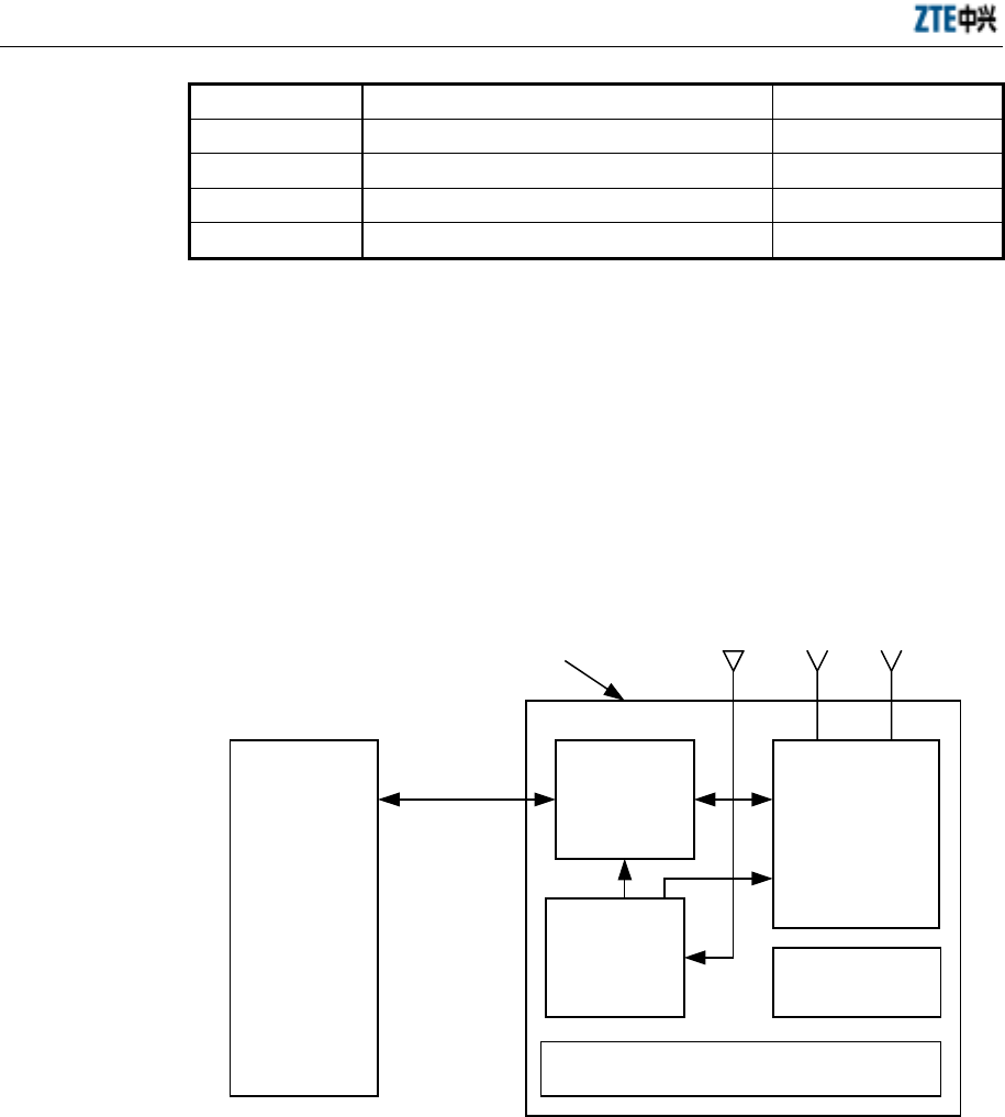
Remote stations are similar to micro-BTS in structure, but different in replacing
Baseband Digital Module (BDM) with Remote Fiber Module (RFM) and removing
GPS Timing Module (GPSTM), for the clock signals of remote stations are
demodulated from the signals sent through optical fiber. The structure of remote
stations is illustrated in the following figure.
Chapter 1 Overview
1-3
RFM RFS (MTRX,
MDUP and MDIV)
Power
supply
RF antenna feeder and power
lightning arrester
RF antenna
Optical
fiber
Fig. 1.1-2 Structure of Remote Stations
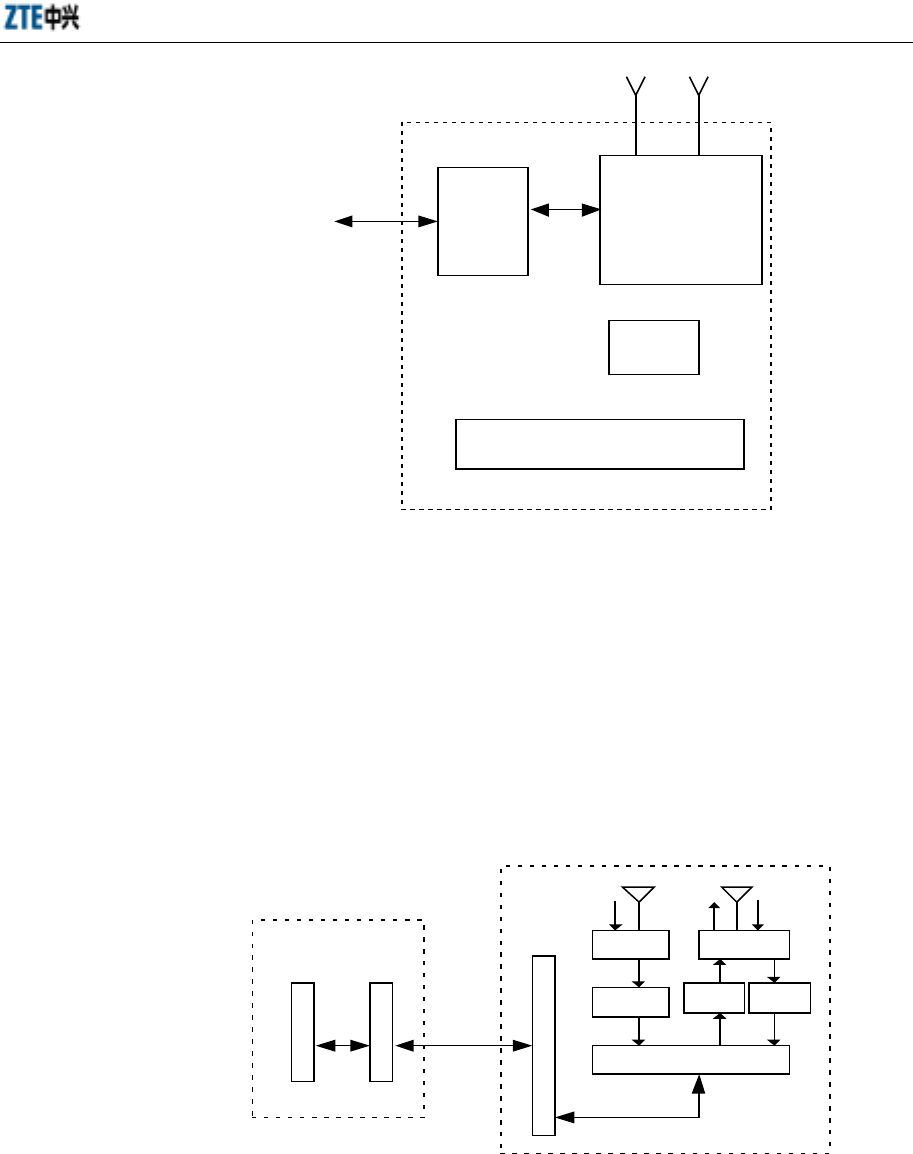
Remote stations should cooperate with the macro-/micro-BTS to achieve the BTS
functions, so you need to configure Local Fiber Module (LFM) on micro-BTS or
Optical Interface Module (OIM) on micro-BTS for interworking with the remote
stations.
If the LFM is configured in a macro-BTS, the connection between the remote station
and the macro-BTS is illustrated in the following figure.
Macro-BTS
Remote station
R
F
M
L
F
M
R
F
I
M
DIV DUP
MLNA MLNA
MTRX
TX
RX
RX RX
MPA
RX
RX RXTX
TX
Optical fiber
Fig. 1.1-3 Connection between Remote Station and Macro-BTS
If the OIM is configured in a micro-BTS, the connection between the remote station
and the micro-BTS is illustrated in the following figure.
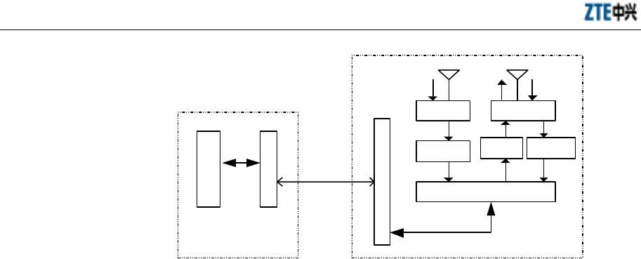
ZXCBTS (V5.4) CDMA Micro Base Transceiver Station & Remote Station Installation Manual
1-4
Remote station
R
F
M
DIV DUP
MLNA MLNA
MTRX
RX RXTX
TX
RX
RX RX
Micro-BTS
O
I
M
B
D
M
MPA
RXTX
Optical fiber
Fig. 1.1-4 Connection between Remote Station and Macro-BTS
1.2 Installation Overview
The hardware installation of micro-BTS/remote stations can be divided into the
following aspects:
1. Installing shelf and boards, connecting internal cables and setting DIP switches
2. Installing the power supply system
3. Installing the grounding system
4. Locating and installing the antenna, jumper cable and feeder cable, and testing
the antenna feeder system
5. Installing GPS and its feeder cables
6. Connecting trunk cables and assembling their connectors
7. Installing the alarm system for reporting abnormal temperature and humidity
See Fig. 1.2-1.
Chapter 1 Overview
1-5
Install the GPS
Install the shelf
Check internal
cables
Set the DIP
switches
Install the ZXCBTS cabinet
Connect trunk
cables
Install the power
supply system
Install the
grounding system
Install the
sunshade cover
Install the
antenna system
Fig. 1.2-1 Schematic Diagram of the Hardware Installation of Micro-BTS/Remote Station
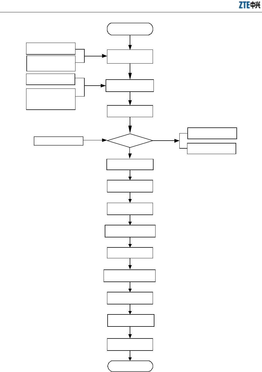
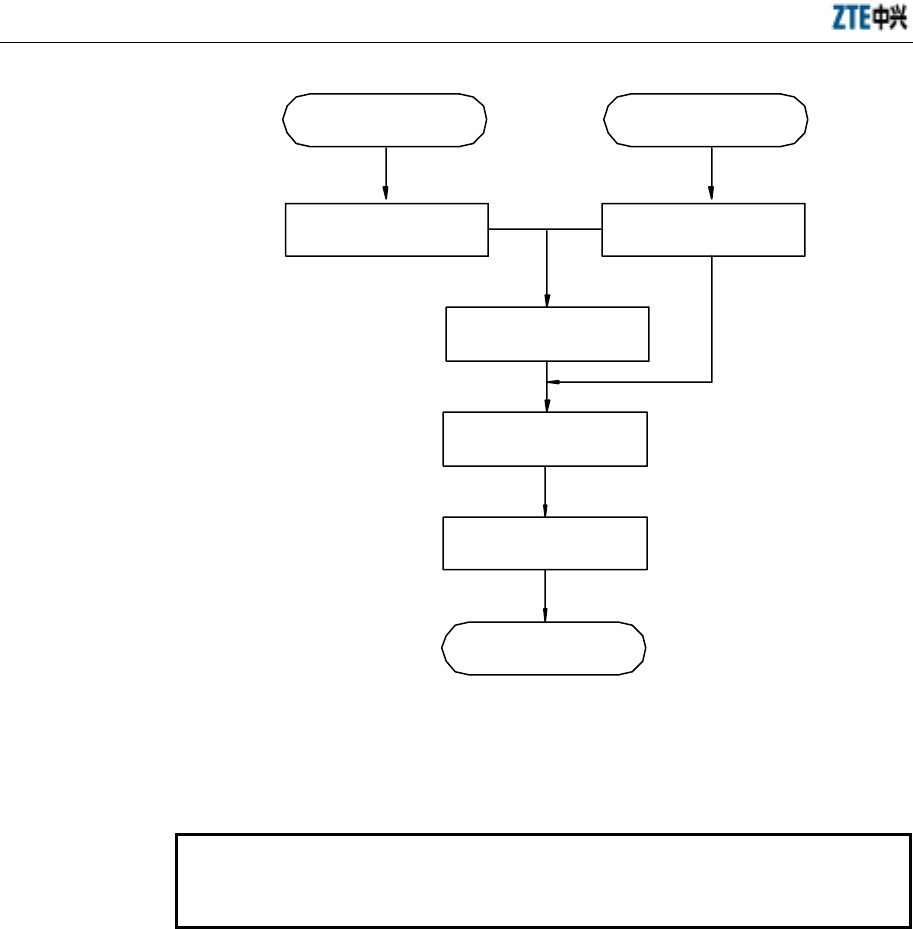
1.3 Installation Flow
Install the equipment following the specified procedures strictly:
1. Install the support;
2. Locate the cabinet on the support;
3. Secure the cabinet;
4. Install the sunshade cover (necessary for outdoor installation);
5. Connect power cables and grounding cables of the cabinet;
6. Connect T1 cables of the cabinet;
7. Install the primary antenna feeder system to connect with the RF cables;
8. Install the GPS;
9. Install and test the boards and modules, and set the DIP switches;
10. Check the installation.
See Fig. 1.3-1.
ZXCBTS (V5.4) CDMA Micro Base Transceiver Station & Remote Station Installation Manual
1-6
Engineering Survey
Report
Yes
No
Start
BTS Engineering
Design and
Construction Drawing
Environment
Acceptance Report
Cabling rack Power
supply system
Grounding system
Other accessories
Preparation for
engineering
installation
Check construction
conditions
Open-box inspection
Packing list Goods are
correct
Goods Error Feedback
List
Goods Replacement
Feedback List
Install the shelf
Install the power
supply system
Install the
grounding system
Check cable connections
in the shelf
Connect trunk cables
Check the primary
antenna feeder system
Install the GPS
Set DIP switches
Hardware installation
check
End
Fig. 1.3-1 Hardware Installation Flow Diagram

Chapter 1 Overview
1-7
1.4 Points for Attention
Pay attention to the following points during the installation: The installation personnel
should be trained to obtain the qualification entitled by ZTE and read this manual
before the installation.
1. Do not operate on the cabinet or any module when the power is on.
2. Observe the relative requirements strictly when installing the BTS.
3. Do not install the antenna feeder system in thunder weather.
4. Before the thunder storm season of each year comes, check whether the
lightning arrester is in good condition and is well contacted. If it is damaged,
replace it immediately.
5. When the installation of the cabinet completes, lock the door immediately. If the
door need be opened in case of maintenance, contact the professional personnel
for help.

2-1
2 Preparations
Summary
Describing the installation environment check.
Listing the installation tools.
Listing the technical documents needed for
installation.
2.1 Installation Environment Check
The items to check:
2.1.1 Checking Equipment Building Conditions
Check if the layout, height, bearing capability, shock-proof ability, doors and windows,
walls and troughs of the equipment building meet the requirements.
2.1.2 Checking Indoor Environment
Check the temperature, humidity, air pressure, ventilation condition, antistatic
protection measures, anti-interference measures, dustproof measures, rodent-resistant
measures, fire-protection facility, lighting condition, water supply and drainage system
of the equipment room.
To the highest priority, the equipment should be installed on the cool and dry walls
indoors with good ventilation; the fire-protection facility should be equipped; there
should be no caustic gas or smog in the room and no leakage on the roof; the
electromagnetic interference strength should be no more than 140dBµV/m
(0.01MHz~110000MHz). Or the equipment can be installed on the shady walls
outdoors with good ventilation and rain blocks. To the least priority, the equipment can
be installed on common walls, towers or high poles. The operating temperature range
of the equipment is between -40°C and +55°C, and the relative humidity range is
between 5% and 100%.

ZXCBTS (V5.4) CDMA Micro Base Transceiver Station & Remote Station Installation Manual
2-2
2.1.3 Checking Power Supply System
Check the power supply ability and quality. A group of independent and stable
85V~138V (nominal 120V) AC power should be supplied to the equipment. It is
prohibited to share the power supply with other high-power telecom equipment or the
usually powered-down equipment.
2.1.4 Checking Grounding System
The standard grounding system should be equipped and the resistance should be less
than 5 ohm.
2.1.5 Checking Relative Devices
Check if the other devices relative to the normal operation of the equipment are in good
condition, such as interface device, transmission device, Digital Distribution Frame
(DDF) and Optical Distribution Frame (ODF).
2.2 Tools and Instruments
Prepare the tools and instruments needed for the installation in advance as listed in
Table 2.2-1.
Table 2.2-1 Tools and Instruments Needed for the Installation
Type Name
Special tools
One cutter for assembling feeder cable connectors
One 75-ohm coaxial cable stripper
75-ohm coaxial crimping plier
One multi-functional crimping plier
One multimeter
One SiteMaster standing wave ratio tester
One earth resistance tester
Drilling tools
One percussive drill
Several drill bits
One cleaner
One power connector board (with at least three two-pin and three-pin
sockets respectively; the current capacity is more than 15 amp.)
General tools
Three cross screw-drivers (4”, 6” and 8”)
Three straight screw-drivers (4”, 6” and 8”)
Four adjustable wrenches (6”, 8”, 10” and 12”)

Chapter 2 Preparations
2-3
Type Name
Two spanners (17” and 19”)
One hexagon spanner
One socket wrench
One 5kg nail hammer
One 300W electric iron and one 40W electric iron
One coil of solder wires
Measurement tools
One 50m tape measure
One 5m steel tape measure
One 400mm horizontal ruler
One inclinometer
One compass
One multimeter
Ruler
One plumb
Protection tools Antistatic wrist strap
Safety helmet, slip-proof gloves
Locksmith tools
One hacksaw, several saw blades
One sharp nose plier (8”)
One diagonal plier (8”)
One slip joint plier (8”)
One vice (8”)
A set of files (middle)
One tweezers
One paint brush
One scissors
One dryer
One solder removal tool
One hydraulic pressure pliers
One crowbar
Assistant tools
Pulley group
Rope
Ladder
Forklift
2.3 Technical Documents
Prepare the following technical documents:
1. Engineering Survey Report, BTS Engineering Design and Construction Drawing,
Environment Acceptance Report

ZXCBTS (V5.4) CDMA Micro Base Transceiver Station & Remote Station Installation Manual
2-4
Engineering Survey Report should be filled by the technical engineers of the
equipment provider during site survey. If they can not carry out the survey in
time, you should survey the site, fill in the report and then send it to the
equipment provider. This report is used for the preparation of construction
materials.
BTS Engineering Design and Construction Drawing should be prepared by the
design unit you entrusted, and a copy should be provided to the equipment
provider before the delivery.
Environment Acceptance Report is used by the technical engineers of the
equipment provider to check the construction environment during site survey. If
any inconformity is found, you are required to solve the problem. Before the
construction, the second check will be implemented.
2. ZXCBTS(V5.4)CDMA Micro Base Transceiver Stations/RF Remote Stations
Installation Manual, ZXCBTS(V5.4)CDMA Micro Base Transceiver Stations/RF
Remote Stations Technical Manual, ZXCBTS(V5.4)CDMA Micro Base
Transceiver Stations/RF Remote Stations Hardware Manual,
ZXCBTS(V5.4)CDMA Micro Base Transceiver Stations/RF Remote Stations
Maintenance Manual
3. Installation Acceptance Report, Test Acceptance Report
Installation Acceptance Report and Test Acceptance Report should be offered to
you by the equipment provider during delivery. Installation Acceptance Report
is filled after the BTS installation completes. Test Acceptance Report is filled
during the BTS commissioning.

3-1
3 Open-box Inspection
Summary
Describing the inspection procedures.
Describing the open-box procedures.
3.1 Checking Packing List and Goods
Caution
Because ZXCBTS equipment is expensive, ensure that it is packed well and the
flags for avoiding water and vibrations are marked. Load and unload the
equipment gently, and avoided damage from sunshine and rain.
1. Check the “ZTE delivery sheet”.
2. Open-box inspection should be done by the engineering supervisor and your
representative. First, check if the total quantity of the goods is correct according
to the packing list, if the packing boxes are in good condition, and if the delivery
location is the right installation site.
3. Next, open the boxes and the engineering supervisor should check the goods
based on the packing list. Open-box Inspection Report is put in the packing box
numbered 1#. Open the 1# box and take out the Open-box Inspection Report to
check if the total quantity of the goods is consistent with the checklist, and then
archive the report.
4. During the inspection, if loss of goods, lack of goods, error delivery or any
damage is found, find out the cause and feedback to the ZTE headquarter for
handling.
5. The goods are packed in either cartons or wooden boxes. You need to open them
on site using different tools.
ZXCBTS (V5.4) CDMA Micro Base Transceiver Station & Remote Station Installation Manual
3-2
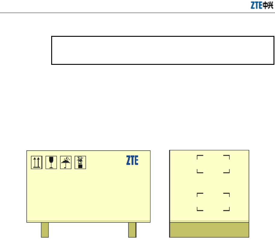
3.2 Packaging
Note
The cabinets of micro-BTS and remote stations are the same in structure, so is
the packaging method.
Put the support and other accessories of the ZXCBTS cabinet into the wooden box.
In the wooden box, the cabinet is packed with foam boards, a bubble bag and a plastic
bag. After opening the box, you need not uplift it but directly take the equipment out.
When carrying the box, be cautious to prevent the cabinet from being damaged.
The packing box for the ZXCBTS cabinet is shown in Fig. 3.2-1.
CDMA micro-BT S
ZTE CORPORATION
ZTE Plaza, Keji Road South, Hi-Tech Industrial
Park, Nanshan District, Shenzhen, P.R.China
Postcode: 518057
Tel: (+86755) 6790000
Cust omer Support Center: 8008301118
Goods:
Net Weight: (Kg)
Volume: 81x52x40 (cm)
Qty.:
Packing List:
Fig. 3.2-1 Packing Box for ZXCBTS Cabinet
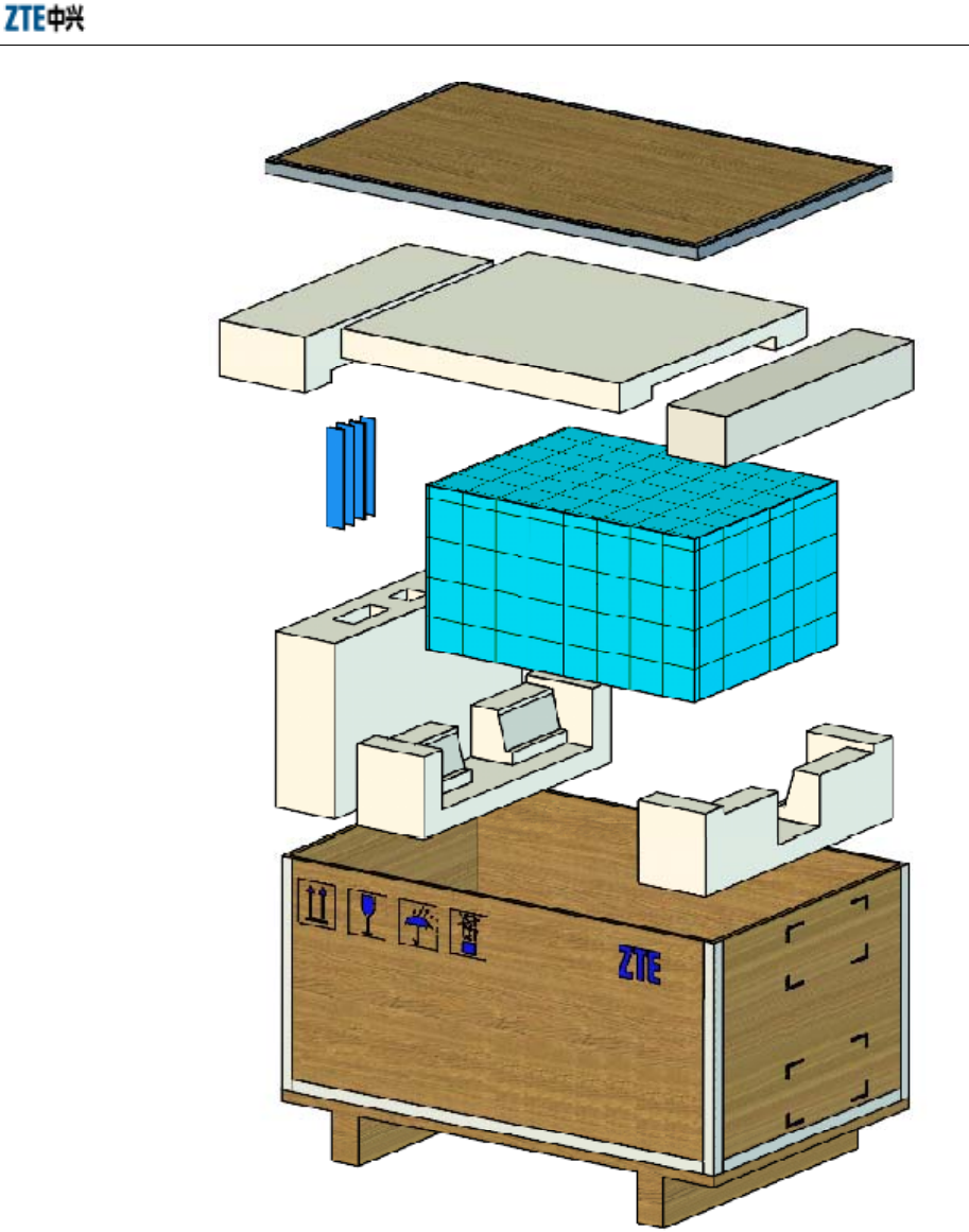
3.3 Open-box Procedures
Follow the steps below to open the box:
1. Open the cover board.
2. Remove the foam boards.
3. Take the micro-BTS out directly.
See Fig. 3.3-1.
Chapter 3 Open-box Inspection
3-3
CDMA micro-BTS
Z
TE CORPORATION
ZTE Plaza, Keji Road South, Hi-Tech Industrial
Park, Nanshan District, Shenzhe n, P.R.China
Postcode: 518057
Tel: (+86755) 6790000
Customer Support Center: 8008301118
Goods:
Net Weight: (Kg)
Volume: 81x52x40 (cm)
Qty.:
Pack
ing List:
Micro-BTS
Accessories
Fig. 3.3-1 Schematic Diagram for Opening a Box

4-1
4 Installation of Cabinet
Summary
Describing the procedures to install the
micro-BTS/remote station cabinet
Describing the possible installation modes
4.1 Installation Flow
Note
The cabinets of ZXCBTS micro-BTS/remote stations are the same in structure,
so is the installation method.
The cabinet can be installed in two modes: on pole or on wall. The installation flow is
shown in Fig. 4.1-1.
ZXCBTS (V5.4) CDMA Micro Base Transceiver Station & Remote Station Installation Manual
4-2
Install the sup p ort
Installation on pole
Installation check
Install the sunshade cover
Install the cabinet
Indoors
Install the sup p ort
Outdoors
End
Installation on wall
Fig. 4.1-1 Flow of Installing the Cabinet
4.2 Installation Modes
Note
The cabinets of ZXCBTS micro-BTS/remote stations are the same in structure,
so is the installation method.
As shown in Fig. 4.1-1, the cabinet can be installed either on pole or on wall based on
the actual environment.
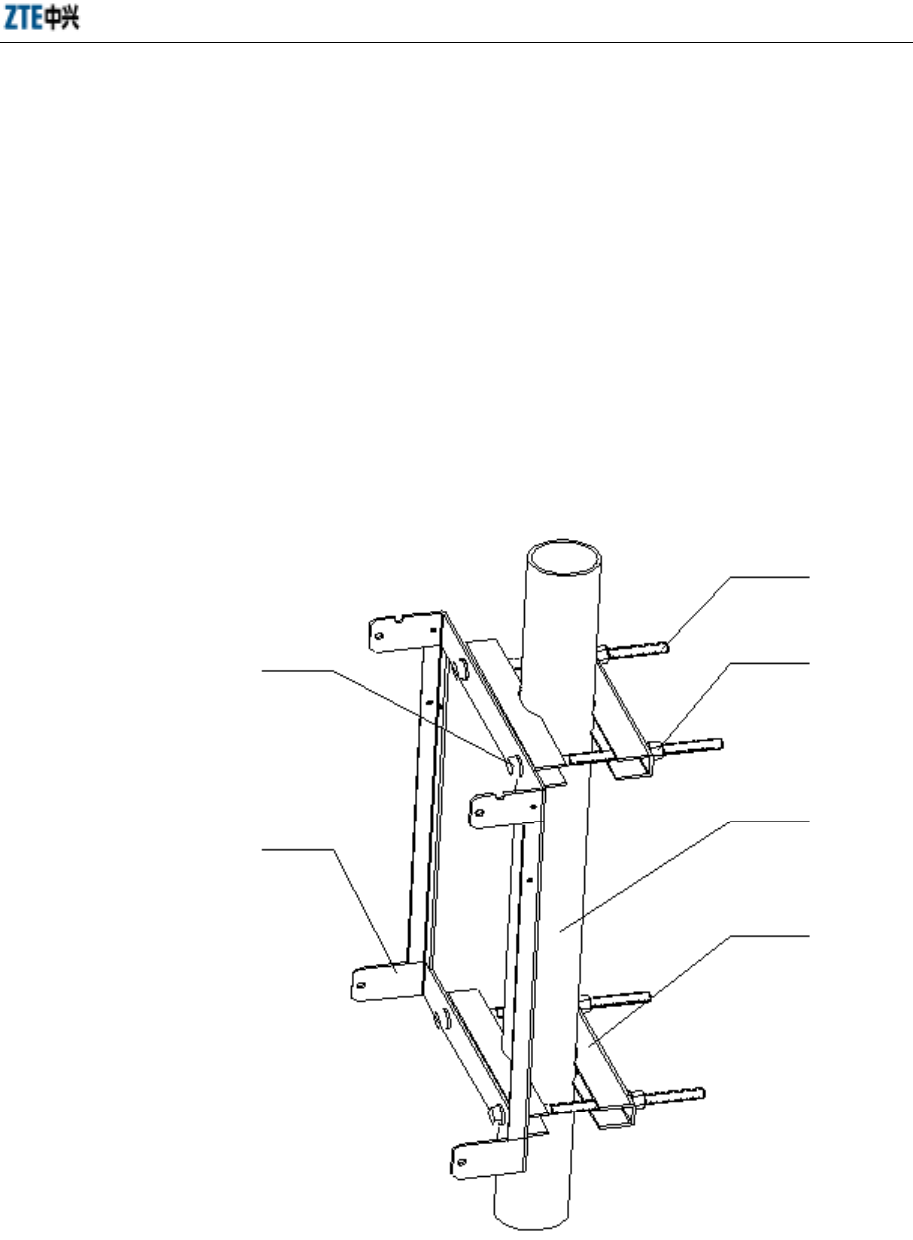
4.2.1 Installing Cabinet on Pole
1. Disassemble the support from the cabinet.
2. Secure the support onto the pole with fixing plates and 260mm-long bolts. The
diameter of the pole should be between 60mm and 90mm. 75mm is
recommended. See Fig. 4.2-1.
If the equipment is to be installed outdoors, face the front side southward and
the back side northward (This rule is applicable to the case that the equipment is
Chapter 4 Installation of Cabinet
4-3
installed in the Northern Hemisphere. If it is installed in the Southern
Hemisphere, the opposite rule should be applied).
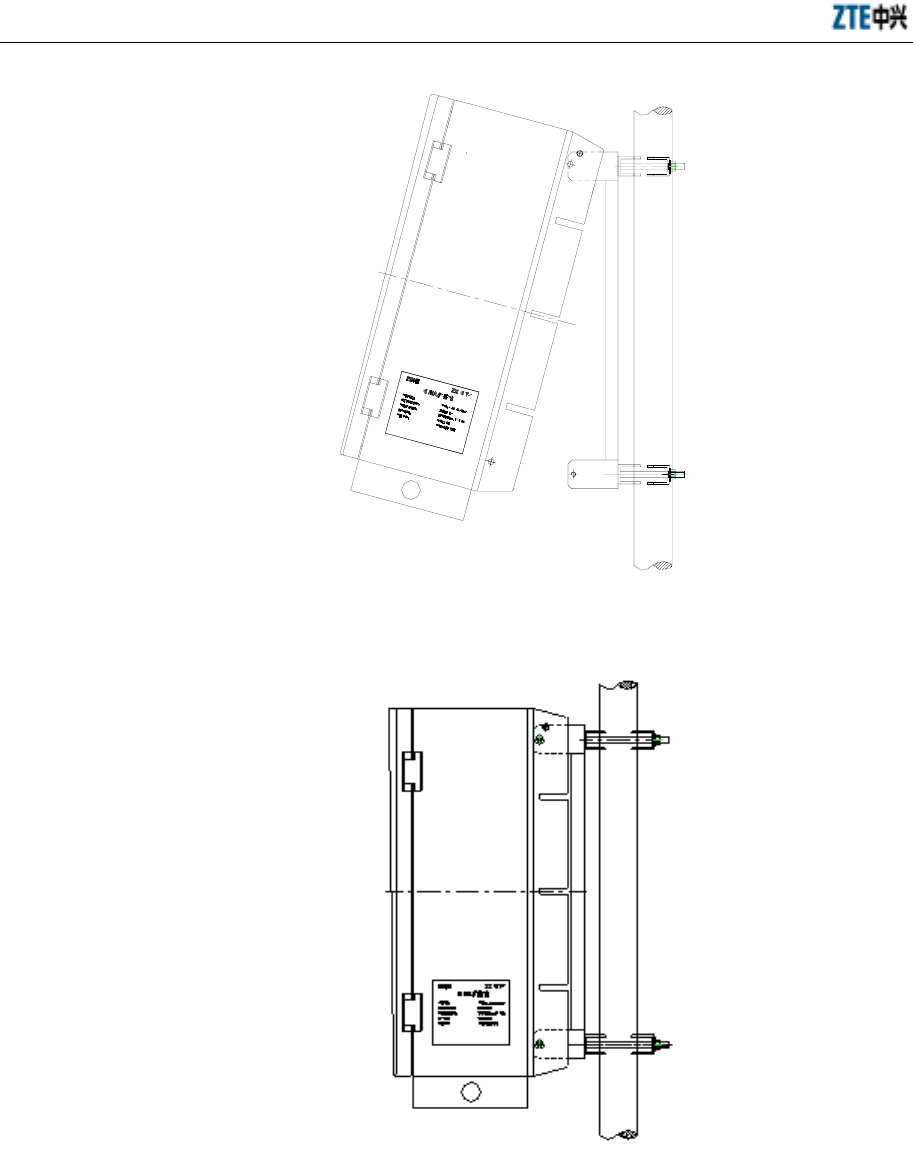
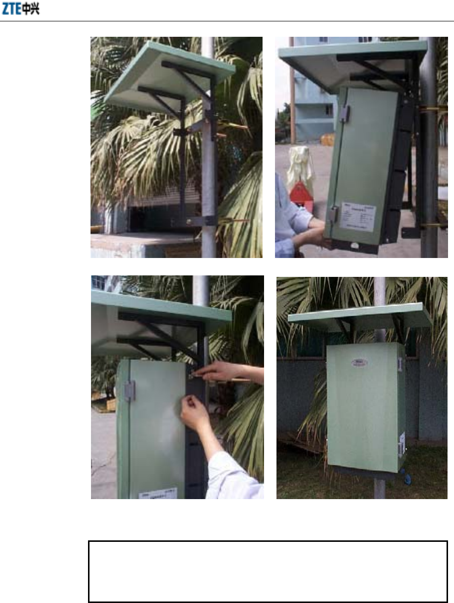
3. Install the sunshade cover onto the support with four M4 bolts. See Fig. 4.2-4.
4. Hold the cabinet to hang it onto the support, then push it into the shelf. See Fig.
4.2-2.
5. Align the bolt holes on the support with those on the cabinet, and then screw
down four M8 hexagon bolts. See Fig. 4.2-3.
6. On the cabinet base there are hangers for rope. If necessary, use the rope to hang
the cabinet onto the pole.
See Fig. 4.2-1 for the schematic diagram of cabinet fastened on pole.
Flat washer
Bolt
M12 nut,
spring washer,
flat washer
Support
Pole
Fixing plate
Fig. 4.2-1 Schematic Diagram of Fastening the Cabinet onto the Pole (step 1)
ZXCBTS (V5.4) CDMA Micro Base Transceiver Station & Remote Station Installation Manual
4-4
Fig. 4.2-2 Schematic Diagram of Fastening the Cabinet onto the Pole (step 2)
Fig. 4.2-3 Schematic Diagram of Fastening the Cabinet onto the Pole (step 3)
Chapter 4 Installation of Cabinet
4-5
Fig. 4.2-4 Schematic Diagram of the Cabinet Fastened onto the Pole
Caution
For your safety, be sure to wear the safety belt when working at heights and
the safety helmet when working at grounds. It is prohibited to work in
thunder storm weather.
ZXCBTS (V5.4) CDMA Micro Base Transceiver Station & Remote Station Installation Manual
4-6
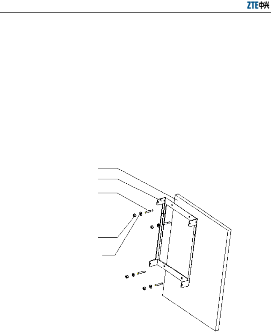
4.2.2 Installing Cabinet on Wall
1. Disassemble the support from the cabinet.
2. Mark four points on the wall based on the four holes on the support, and then
drill four holes with a percussive drill (using M12 drill bit). Secure the support
onto the wall with four M10 expansion bolts. See Fig. 4.2-5.
3. Hold the cabinet to hang it onto the support, and then push it into the shelf.
4. Align the bolt holes on the support with those on the cabinet, and then screw
down four M8 hexagon bolts.
5. Install the sunshade cover if the equipment is to be installed outdoors.
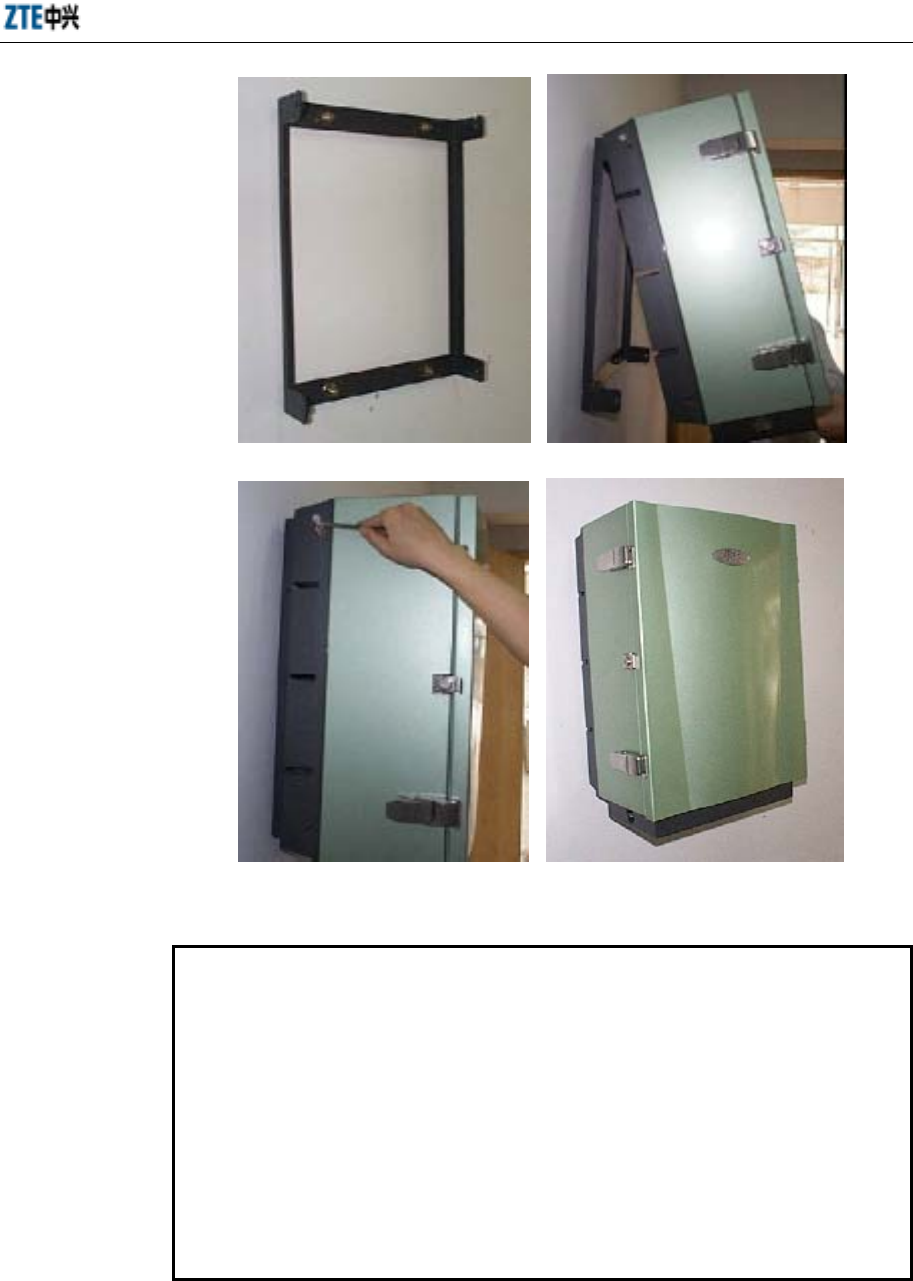
See Fig. 4.2-6 for the schematic diagram of installing cabinet on wall.
Wall
Support
Expansion bolt
Hexagon nut
Washer
Fig. 4.2-5 Schematic Diagram of Installing the Support onto the Wall
Chapter 4 Installation of Cabinet
4-7
Fig. 4.2-6 Schematic Diagram of Installing the Cabinet onto the Wall
Note
The modules and cables in micro-BTS (including ultra-wide coverage
micro-BTS) and remote stations have been installed, connected and tested
before delivery. Before commissioning, you only need to check if they are loose
due to conveyance. Refer to Chapter 7 for the connection of cables between
cabinets.
According to the configuration requirement, you might need to add optical
fiber modules or CSM5000 expansion modules in the expansion slots of the
corresponding BDM board.
If any fault occurs, the maintenance personnel can refer to this manual for
simple maintenance.
5-1
5 Installation of Power Supply System
Summary
Describing the methods for installing the power
supply system..
Describing the procedures to install the power
supply system..
5.1 Introduction to Power Cables
The micro-BTS/remote stations are supplied by 120V AC power or -48V DC power.
AC micro-BTS are supplied by 120V AC power, and DC micro-BTS are supplied by
-48V DC power.
5.1.1 -48V DC Power Cable
The ZTE -48V DC ZXCBTS equipment is equipped with a piece of 10m-long cable,
which can meet the installation requirement in most cases. If you need to assemble the
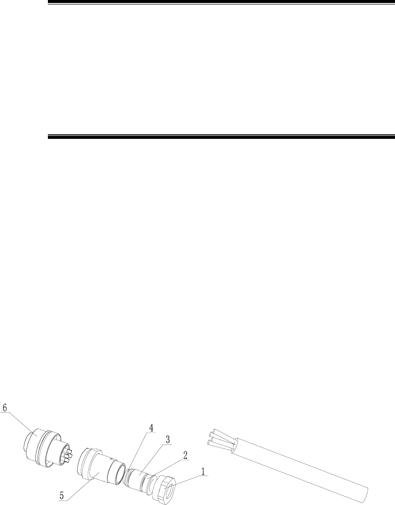
cable on site in special cases, follow the instructions in this section. The DC power
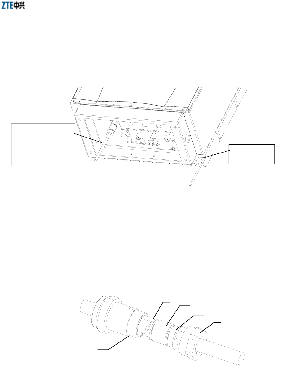
cable connector is a four-pin connector, and the power cable adopts four-core cable, as
shown in Fig. 5.1-1. The corresponding relationship between the core wires and the
binding posts are listed in Table 5.1-1.
Fig. 5.1-1 Four-pin Connector and Four-core Power Cable
ZXCBTS (V5.4) CDMA Micro Base Transceiver Station & Remote Station Installation Manual
5-2
Table 5.1-1 Corresponding Relationship between Core Wires and Binding Posts
Binding Post No. Color of Core Wire Power Polarity
1 Blue -48V
2 Red -48V
3 Black -48VGND
4 Olivine -48VGND
5.1.2 120V AC Power Cable
The ZTE 120V AC ZXCBTS equipment is equipped with a piece of 10m-long cable,
which can meet the installation requirement in most cases. If you need to assemble the
cable connector on site in special cases, follow the instructions in this section. The AC
power cable connector is a three-pin connector, and the power cable adopts three-core
cable. Refer to Table 5.1-2 for the corresponding relationship between the core wires
and the binding posts.
Table 5.1-2 Corresponding Relationship between Core Wires and Binding Posts
Binding Post No. Color of Core Wire Power Polarity
1 Yellow and green PE
2 Brown L
3 Blue N
5.2 Connection of Power Cables
120V AC power supply and -48V DC power supply are used for the micro-BTS and
remote stations. A waterproof connector is used to connect the power to the POWER
terminal at the bottom of a cabinet, as shown in Fig. 5.2-1.
1. Select a suitable type of power cable.
If the cabinet is installed outdoors, outdoor shielded power cables should be
used for power supply, which can withstand the influences of ultraviolet lights,
rains and temperature changes. If common three-core AC power cables are used
in special cases, PVC pipes should be added for protection.
If the cabinet is installed indoors, common three-core power cables can be used
for power supply.
Chapter 5 Installation of Power Supply System
5-3
2. Power cables should be laid in order. If they are laid in parallel with T1 signal
cables, an interval of 200mm is required between them.
3. Upon bundling of power cables, the space between two cable ties should be less
than 0.5m to prevent friction with the tower upon swing of cables and avoid
damage of power cable sheath.
Fig. 5.2-1 Connection of Power Cables and Grounding Cables at the Bottom of a Cabinet
5.3 Assembling Power Cable Connector
5.3.1 Assembling -48V DC Power Cable Connector
Step 1: Put the connector components 1, 2, 3, 4 and 5 onto the cable, as shown in Fig.
5.3-1.
1
2
3
5
4
Fig. 5.3-1 Assembling a Power Cable Connector (step 1)
The power cable with
a
round connector fo
r
connecting the POWE
R
terminal at the botto
m
of the cabinet
PGND terminal
of the cabinet
ZXCBTS (V5.4) CDMA Micro Base Transceiver Station & Remote Station Installation Manual
5-4
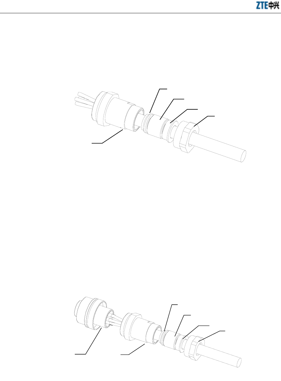
Step 2: Strip the 17mm-long sheath off the four-core cable at the end to be welded. If
the sheath of more than 17mm is stripped, the component 3 cannot press the cable tight;
if less than 17mm, inconvenience might be caused for installation. See Fig. 5.3-2.
1
2
3
5
4
Fig. 5.3-2 Assembling a Power Cable Connector (step 2)
Step 3: Strip the 5mm-long insulation layer off the four core wires respectively, twist
up the copper core wires and brush a slice layer of soldering tin on them, and then put a
10~15mm-long heat-shrink tube onto each core wire.
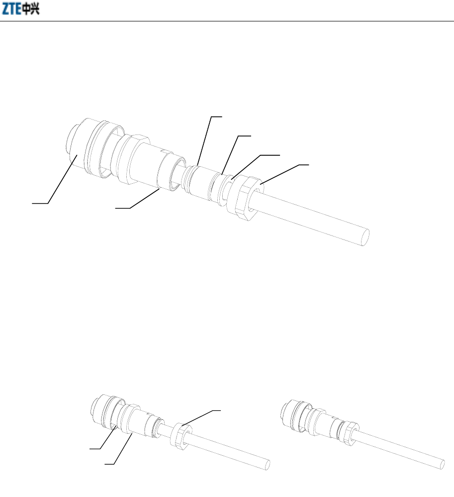
Step 4: Joint the core wires respectively with the binding posts of the component 6 by
welding them, push the heat-shrink tubes to the proper position and then make them
shrink, as shown in Fig. 5.3-3. Refer to Table 5.1-1 for the corresponding relationship
between the core wires and the binding posts.
1
2
3
5
4
6
Fig. 5.3-3 Assembling a Power Cable Connector (step 4)
Chapter 5 Installation of Power Supply System
5-5
Step 5: Screw to connect the component 5 with the component 6, as shown in Fig.
5.3-4.
1
2
3
5
4
6
Fig. 5.3-4 Assembling a Power Cable Connector (step 5)
Step 6: Push the components 2, 3 and 4 into the component 5, and then screw down the
component 1 onto the component 5. Be sure to screw the component 1 but not 5. See
Fig. 5.3-5.
1
5
6
Fig. 5.3-5 Assembling a Power Cable Connector (step 6)
5.3.2 Assembling 120V AC Power Cable Connector
The steps for assembling an AC power cable connector are the same as that for
assembling a DC power cable connector. The only difference is that the three-pin
connector and three-core power cable are used for AC power cables. Refer to the
preceding contents for the procedures and Table 5.3-1 for the corresponding
relationship between the core wires and the binding posts.

ZXCBTS (V5.4) CDMA Micro Base Transceiver Station & Remote Station Installation Manual
5-6
Table 5.3-1 Corresponding Relationship between Core Wires and Binding Posts
Binding Post No. Color of Core Wire Power Polarity
1 Yellow and green PE
2 Brown L
3 Blue N

6-1
6 Installation of Grounding System
Summary
Describing the method for installing the grounding
system
6.1 Introduction to the Grounding System
This section details the procedures to install the grounding system, including grounding
copper busbar and feeder cable grounding kit.
Grounding aims to protecting both the human being and the equipment against
lightning shock and electromagnetic interference.
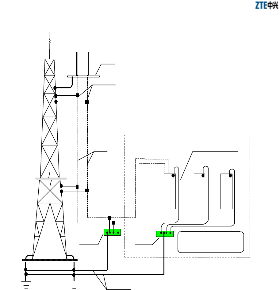
The grounding system is composed of indoor groundings, outdoor groundings and
underground grounding net.
The grounding system of a ultra-wide coverage micro-BTS includes protection
grounding on the chassis, lightning arrester for RF components in the cabinet, for GPS
antenna, for T1 cables, for 120V AC power and for feeder cable grounding kit.
The customer needs to complete the construction of the basic grounding net and the
grounding system of the tower and other buildings, and offer the points for connecting
the indoor and outdoor grounding busbars to the grounding net through different
50mm2 wires. The conductor led from the PGND terminal of the shelf is connected to
the grounding copper busbar, and the conductor led from the -48VGND of the shelf is
connected to the DC power copper busbar.
Each feeder cable should be connected to the outdoor grounding copper busbar through
the cable grounding kit before being led into the equipment room. See Fig. 6.1-1.
ZXCBTS (V5.4) CDMA Micro Base Transceiver Station & Remote Station Installation Manual
6-2
Feeder cable grounding kit
Tower platform
U
Feeder cable Grounding cable (35mm
2
)
Micro-BTS
DC power rack
Other devices
Outdoor
grounding
busbar
Indoor
grounding
busbar
PGNDs of all devices in the
equipment room (including the
cabling rack) are connected to
the indoor grounding busbar
Grounding cable (50mm
2
)
Fig. 6.1-1 Schematic Diagram of Grounding Connections
6.2 Installing Grounding System
6.2.1 Installing Outdoor Grounding Copper Busbar
The outdoor grounding copper busbar functions in lightning protection. It is usually
installed on the wall outside the equipment room, and the best position is right under
the feeder cable window or on the rain-proof wall of the feeder cable well on the top of
a building.
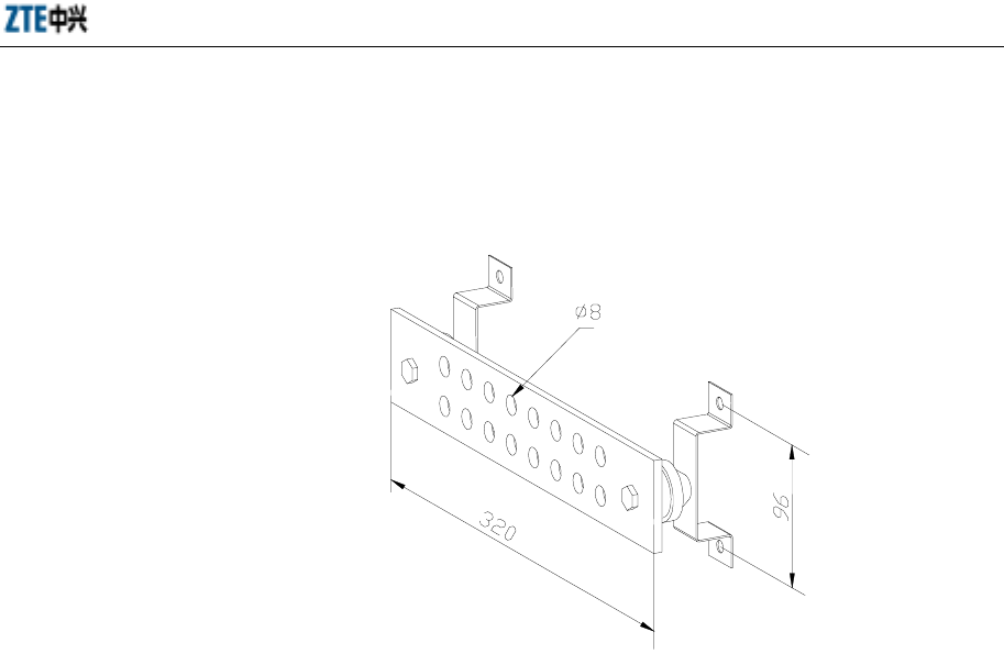
Chapter 6 Installation of Grounding System
6-3
In actual installation, first determine the position for the copper busbar based on the
engineering design drawing, and then install the busbar on the wall with expansion
bolts. See Fig. 6.2-1 for the appearance of the grounding copper busbar.
Fig. 6.2-1 Appearance of a Grounding Copper Busbar
6.2.2 Installing the Grounding System of Micro-BTS
The cabinets of ultra-wide coverage micro-BTS/remote stations are equipped with
PGND terminals, as shown in Fig. 6.2-2. The PGND terminal is connected to the
indoor grounding copper busbar via the 16mm2 yellow or olivine conducting wire. If
the equipment is installed outdoors, the PGND terminal is connected with the
grounding cable from the tower or from the top of the building in the crimping
connection mode.
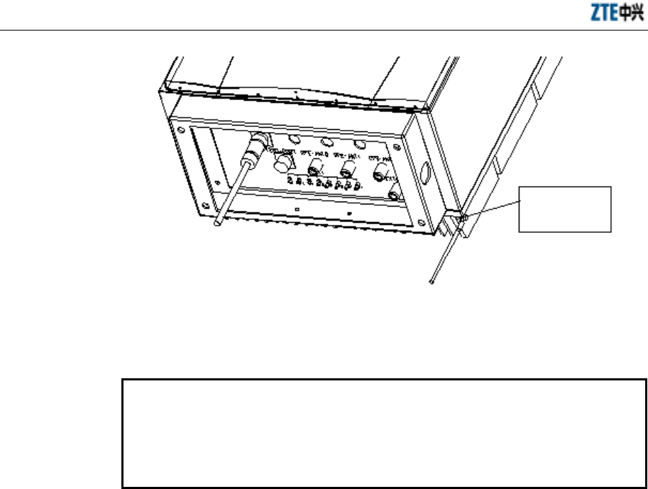
ZXCBTS (V5.4) CDMA Micro Base Transceiver Station & Remote Station Installation Manual
6-4
PGND
terminal of
the cabinet
Fig. 6.2-2 Connection of Power Cable and PGND Cable at the Bottom of a Cabinet
6.2.3 Installing Feeder Cable Grounding Kit
Caution:
It is prohibited to install the grounding kit in thunderstorm weather; otherwise,
the installation personnel might be hurt.
When installing the grounding kit, be sure to keep the feeder cable at the joint
straight.
6.2.3.1 Grounding Principles of Primary Feeder Cable
1. Generally, each primary feeder cable should be grounded at least three times for
lightning protection, that is, on the tower platform, between the tower and the
outdoor cabling rack, and on the wall before the feeder cable is led into the
equipment room. If the primary feeder cable is more than 60 meters long, a
lightning grounding kit should be installed every 20 meters.
2. The antenna feeder system, antenna mount and newly-installed cabling rack
should all be welded to the lightning protection net of the building. The feeder
cable should also be grounded at three points, that is, on the antenna pole, on the
rooftop, and on the wall before the feeder cable is led into the equipment room.
3. Before leading the primary feeder cable along the outdoor cabling ladder from
the top of the building to the equipment room, check whether the cabling ladder
is grounded. If not, request the network operator to accomplish it as soon as
possible.
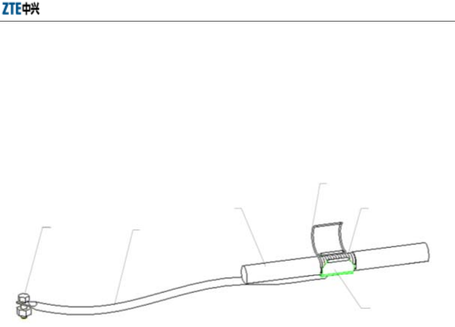
Chapter 6 Installation of Grounding System
6-5
6.2.3.2 Procedures to Install a Grounding Kit
1. Prepare such tools as paper knife, straight screwdriver, spanner and sharp nose
pliers.
2. Choose a suitable position for installing the grounding kit, and cut the sheath off
the 7/8" feeder cable based on the size of the grounding kit. The structure of a
grounding kit is shown in Fig. 6.2-3.
Grounding terminal Grounding cable
Feeder cable
Grounding wire clip
Out-layer copper
core of feeder cable
Sheet copper of
feeder cable
Fig. 6.2-3 Structure of a Grounding Kit
3. Lead the grounding cable of the lightning grounding kit to the grounding net.
Keep the angle between the grounding cable and the primary feeder cable no
more than 15°.
If the antenna feeder system is installed on a tower, lead the grounding cable
downward along the tower.
If the antenna feeder system is installed on the top of a building, lead the
grounding cable to the lightning protection net.
4. Before installing the grounding kit, wrap the waterproof adhesive tape around
the grounding cable near the grounding copper for sealing, as shown in Fig.
6.2-4.

ZXCBTS (V5.4) CDMA Micro Base Transceiver Station & Remote Station Installation Manual
6-6
Fig. 6.2-4 Schematic Diagram of Wrapping Waterproof Adhesive Tape Around the Grounding Cable
5. Clamp the external conductor with the grounding copper and clip tightly.
6. Seal the joint between the grounding kit and the feeder cable as follows:
First wrap the waterproof adhesive tape and then the PVC tape around the joint.
Wrap the waterproof adhesive tape circularly from bottom upward, and then
from top downward, finally from bottom upward again. Note that the next circle
covers 1/2 of the previous circle.
7. Connect the grounding terminal of the grounding kit to the tower body or the
cabling rack on the top of the building (the cabling rack is connected to the
lightning protection net). Remove the paint and oxide at the junction within the
radius of 13mm and then coat the clean area with antioxidant cream. After the
connection, paint the area with antirust paint.
8. Before the primary feeder cable is led into the equipment room, connect the
grounding terminal of the grounding kit to the outdoor grounding busbar.

7-1
7 Connection of Cables
Summary
Describing the connection of internal cables.
Describing the connection of external cables.
7.1 Checking Internal Cable Connections
7.1.1 Type and Configuration of Internal Cables
There are 422 or 485 internal cables totally. Refer to Table 7.1-1 for the types and
configurations of internal cables in micro-BTS/remote stations.
Table 7.1-1 List of Types and Configurations of Internal Cables
Type Name Applied Equipment
RF21 Single-carrier 800M micro-BTS/remote stations
RF22 Single-carrier and double-carrier 800M micro-BTS/remote stations
RF23 Single-carrier and double-carrier 800M micro-BTS/remote stations
RF24 Single-carrier and double-carrier 800M micro-BTS/remote stations
RF25 All micro-BTS/remote stations
RF26 Single-carrier and double-carrier 800M micro-BTS/remote stations
RF27 Single-carrier and double-carrier 800M micro-BTS/remote stations
RF28 Single-carrier and double-carrier 800M micro-BTS/remote stations
RF32 Single-carrier 1.9G micro-BTS/remote stations
RF33 Single-carrier and double-carrier 1.9G micro-BTS/remote stations
RF34 Single-carrier and double-carrier 1.9G micro-BTS/remote stations
RF35 Single-carrier 1.9G micro-BTS/remote stations
RF36 Single-carrier and double-carrier 1.9G micro-BTS/remote stations
RF37 Single-carrier 1.9G micro-BTS/remote stations
RF38 Single-carrier and double-carrier 1.9G micro-BTS/remote stations
RF cables
RF42 All double-carrier micro-BTS/remote stations

ZXCBTS (V5.4) CDMA Micro Base Transceiver Station & Remote Station Installation Manual
7-2
Type Name Applied Equipment
RF43 All double-carrier micro-BTS/remote stations
RF29 All single-carrier and double-carrier micro-BTS
RF30 Single-carrier and double-carrier 800M micro-BTS
RF31 Single-carrier and double-carrier 800M micro-BTS
RF39 Single-carrier and double-carrier 1.9G micro-BTS
RF40 All single-carrier and double-carrier remote stations
RF41 All single-carrier and double-carrier remote stations
Clock cables
BDM-GPS All single-carrier and double-carrier micro-BTS
MPA
CONTL All micro-BTS/remote stations
Communication
cables
RXTDX All micro-BTS/remote stations
DCDX01 All micro-BTS/remote stations
DCDX02 All micro-BTS/remote stations
DCDX03 All micro-BTS/remote stations
ACDX01 All AC-powered micro-BTS/remote stations
ACDX02 All AC-powered micro-BTS/remote stations
ACDX03 All micro-BTS/remote stations configured with heater
ACDX04 All AC-powered micro-BTS/remote stations
F-DC
PWR-001 All DC-powered micro-BTS/remote stations
F-DC
PWR-002 All DC-powered micro-BTS/remote stations
Power cables
F-DC
PWR-003 All DC-powered micro-BTS/remote stations
F-FAN-004 All single-carrier and double-carrier micro-BTS
F-FAN-005 Single-carrier and double-carrier 20W micro-BTS/remote stations
Fan cables
F-FAN-006 Single-carrier and double-carrier 20W micro-BTS/remote stations
DX01 All micro-BTS/remote stations
DX02 All micro-BTS/remote stations
Grounding
cables
DX03 All micro-BTS/remote stations
MONDX01 All micro-BTS/remote stations
MONDX02 All micro-BTS/remote stations
DX04 All single-carrier and double-carrier micro-BTS
DX05 All single-carrier and double-carrier remote stations
Alarm cables
DX06 All micro-BTS/remote stations
Among these cables, only ACDX04 (AC power cable) and F-DC PWR-002 (DC power
cable) are delivered with the equipment, and other cables have been connected in the
equipment before delivery.
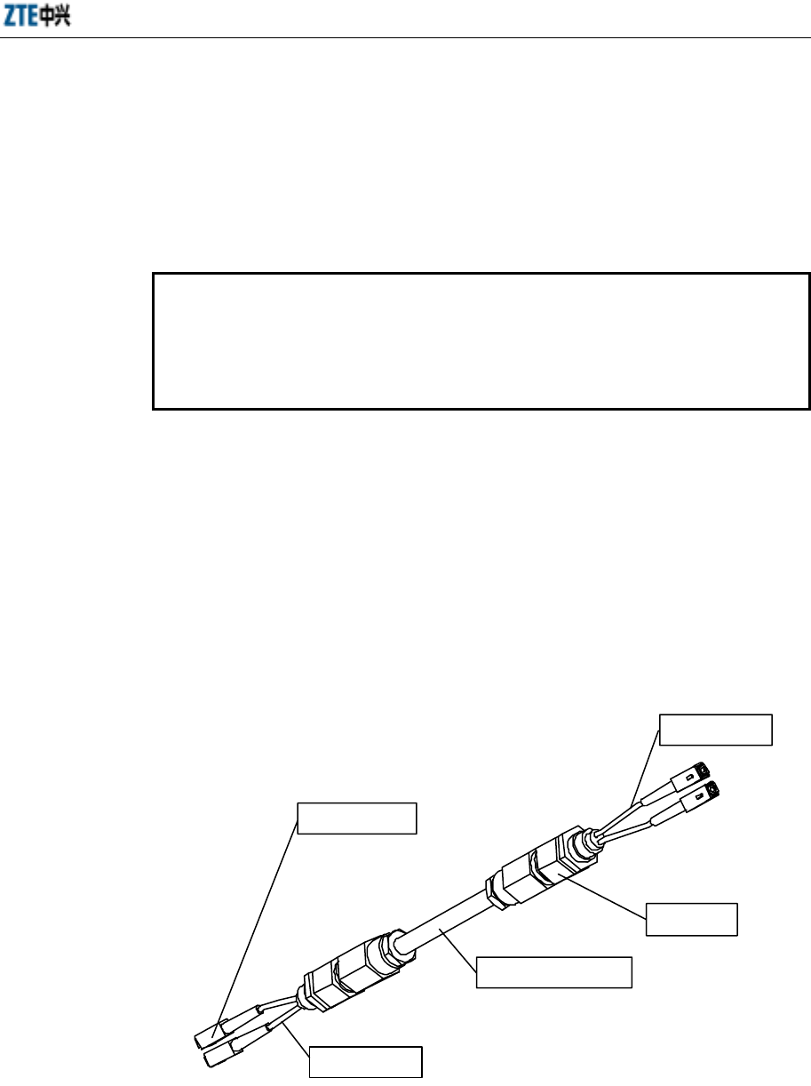
Chapter 7 Connection of Cables
7-3
7.1.2 Connection of Internal Cables
Refer to Appendix B for the connection of internal cables.
7.2 Connecting External Cables
7.2.1 Connecting Optical Fiber
Note
The optical fiber connectors of micro-BTS/remote stations are SC connectors.
The ODF or optical connection box provided is equipped with FC connectors by
default. If there are special requirements on the connectors, contact ZTE for
customization.
7.2.1.1 Selecting Optical Fiber
Different optical fibers are used for the connections between macro-/micro-BTS and
remote stations.
1. If a remote station is near to a relative micro-BTS, optical fiber is used directly.
The optical fiber adopts waterproof pigtail cable, and both ends are equipped
with waterproof blockers and SC connectors. See Fig. 7.2-1 for the structure of
the optical fiber.
SC/P C c o n n ec t o r
Optical fiber core
wire (0.7m)
Optical fiber core
wire (0.7m)
Waterproof
blocker
Single-mode waterproof
pigtail cable
Fig. 7.2-1 Structure of Optical Fiber (1)
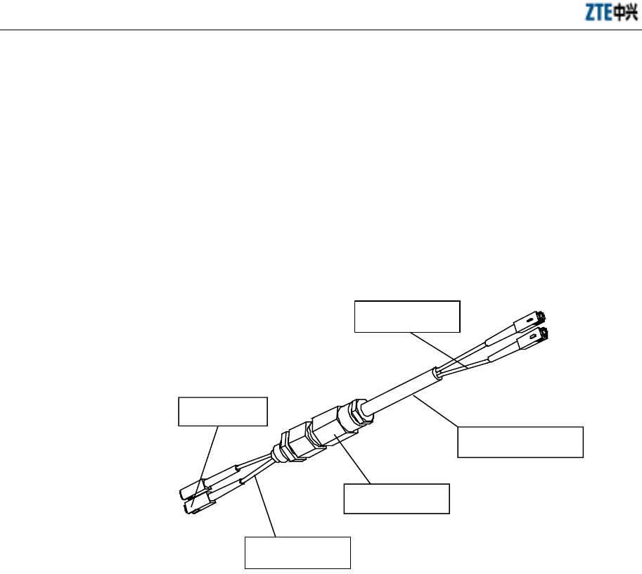
ZXCBTS (V5.4) CDMA Micro Base Transceiver Station & Remote Station Installation Manual
7-4
The core wires at both ends are 0.7m long. Both ends of the optical fiber can
connect either a micro-BTS or a remote station.
You can choose 10m/20m/50m/100m-long optical fiber for this connection
based on the actual situation.
2. If an outdoor remote station is near to a relative indoor macro-BTS, optical fiber
is used for connecting them directly. The optical fiber adopts waterproof pigtail
cable, with both ends being SC connectors. In addition, one end is equipped with
a waterproof blocker. See Fig. 7.2-2 for the structure of the optical fiber.
Optical fiber core
wire (3m)
SC/PC
connector
Optical fiber core
wire (0.7m)
Waterproof blocker
Single-mode waterproof
pigtail cable
Fig. 7.2-2 Structure of Optical Fiber (2)
The core wires of the end equipped with a waterproof blocker are 0.7m long,
and those of the other end are 3m long. The end with a waterproof blocker is to
be connected with the remote station, and other end is used to connect the
macro-BTS.
You can choose 50m/100m-long optical fiber for this connection based on the
actual situation.
3. If a remote station is far from a relative macro-BTS and an ODF or optical
connection box is required, two pieces of optical fiber should be used for
connecting the macro-BTS with the ODF and the ODF with the remote station
respectively.
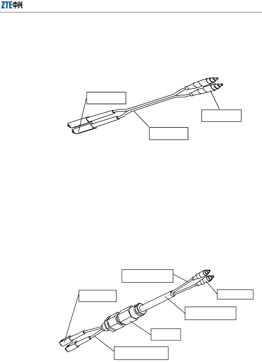
Chapter 7 Connection of Cables
7-5
1) Connection between the macro-BTS and the ODF
The indoor-type optical fiber is adopted, with one end being SC/PC connectors
and the other end being FC/PC connectors. See Fig. 7.2-3 for the structure of the
optical fiber.
FC/PC connector
SC/PC connector
Single-mode
optical fiber
Fig. 7.2-3 Structure of Optical Fiber (3)
The SC/PC connectors are used to connect the macro-BTS, and the FC/PC
connectors are used to connect the ODF.
There is only one option for this connection: 30m-long optical fiber.
2) Connection between the ODF and the remote station
The optical fiber adopts waterproof pigtail cable. The end equipped with a
waterproof blocker uses SC/PC connectors, and the other end offers FC/PC
connectors. See Fig. 7.2-4 for the structure of the optical fiber.
SC/PC connector FC/PC connector
Optical fiber core wire
(3m)
Optical fiber core wire
(0.7m)
Waterproof
blocker
Single-mode waterproof
pigtail cable
Fig. 7.2-4 Structure of Optical Fiber (4)
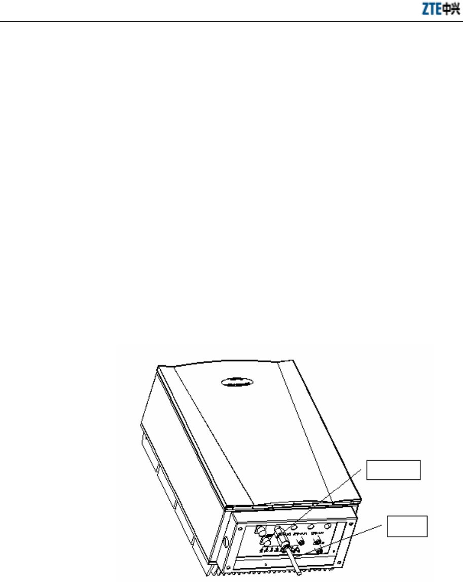
ZXCBTS (V5.4) CDMA Micro Base Transceiver Station & Remote Station Installation Manual
7-6
The core wires of the end equipped with a waterproof blocker are 0.7m long,
and those of the other end are 3m long. The end with a waterproof blocker is to
be connected with the remote station, and the other end is to be connected with
the ODF.
You can choose 50m/100m-long optical fiber for this connection based on the
actual situation.
Caution: If the ODF uses cubical connectors, contact ZTE in advance.
7.2.1.2 Laying Optical Fiber
1. Connecting optical fiber for a micro-BTS/remote station
Because the end of the optical fiber for connecting a micro-BTS/remote station
is equipped with a waterproof blocker, you need to remove the cover of the
optical interface at the bottom of a micro-BTS/remote station first, insert the
pigtail fiber into the cabinet, and then screw down the waterproof blocker into
the optical interface, as shown in Fig. 7.2-5.
Waterproof
blocker
Optical
fiber
Fig. 7.2-5 Schematic Diagram of Connecting Optical Fiber
2. Connecting optical fiber for a macro-BTS
If the optical fiber is used to connect the Local Fiber Module (LFM) of a
macro-BTS, first insert the optical fiber into an interface on the front panel of

Chapter 7 Connection of Cables
7-7
the LFM, lay the optical fiber along the horizontal cabling trough on the top of
the TRX layer, and then along the vertical cabling trough on the left of the shelf;
next, open the cover of the standby interface marked with “BTM ANT” on the
top of the macro-BTS, pull the optical fiber out of the shelf and then lay it onto
the cabling rack on top.
3. Requirements for laying optical fiber
The optical fiber should be arranged in order, with the interval for cable ties less
than 0.5m.
The minimum bending radius of the outdoor-type optical fiber is 90mm, and that
of the indoor-type optical fiber is 30mm.
7.2.2 Connecting Multi-carrier Interconnection RF Cables
If a double-carrier & single-sector micro-BTS/remote station is required, two cabinets
need be configured. These two cabinets should be connected by cables to achieve
transmission of diversity antenna signals.
When a micro-BTS cabinet and a remote station cabinet form a double-carrier &
single-sector micro-BTS system, two pieces of RF cables need be added to
cross-connect the RFE-ANT0 interface with the EXTEND interface at the bottom of
the two cabinets respectively.
Similarly, when two double-carrier remote station cabinets form a double-carrier
remote station and it is used in cooperation with a double-carrier macro-BTS, two
pieces of RF cables need be added to cross-connect the RFE-ANT0 interface with the
EXTEND interface at the bottom of the two cabinets respectively.
Refer to Appendix B for the configuration of internal cables in a double-carrier system.
The interconnection RF cable is 3m long, with both ends being RF N connectors. It is a
finished product delivered with cabinets. It is named as “F-RF05-009”. See Fig. 7.2-6
for the cable connections between two cabinets.
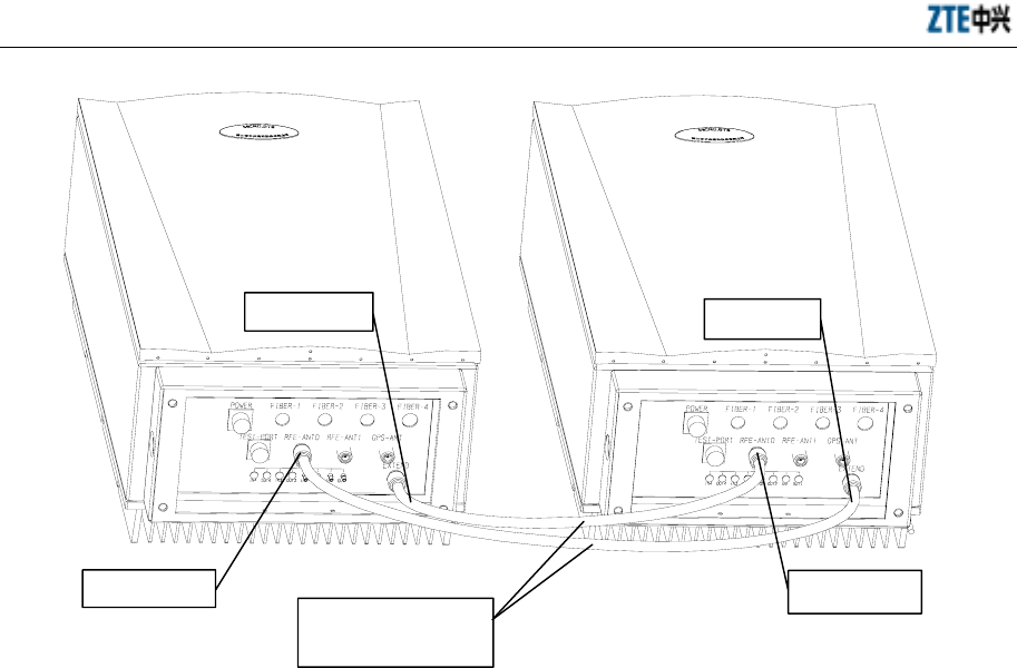
ZXCBTS (V5.4) CDMA Micro Base Transceiver Station & Remote Station Installation Manual
7-8
Fig. 7.2-6 Connection of Interconnection RF Cables
7.2.3 Waterproof Processing of Joints
In case of double-carrier configuration, the joints between the sockets at the bottom of
the cabinets and the connectors of the interconnection RF cables should be wrapped
with waterproof adhesive tape. In addition, the joint between the socket at the bottom
of a 20W micro-BTS (M802T micro-BTS) cabinet and the connector of the external
fan cable should also be wrapped with the adhesive tape. You need to do the following:
1. Secure the relative connectors and sockets.
2. Implement waterproof processing to the joints.
1) Wrap the joints with the waterproof adhesive tape from the top of the connectors.
The first layer should be wrapped in the same direction as for fastening the cable
connectors.
2) Stretch the tape with force and wrap it circularly for three layers totally. Note
that the next circle covers 1/2 of the previous circle, and the wrap stops at the
position about 10cm away from the joint.
3) Grip the joint with force to make the tape stuck firmly with the joint.
RFE-ANT0 RFE-ANT0
EXTEND EXTEND
Micro-BTS/remote
station
Remote station
Interconnection RF
cable
(
3m
)
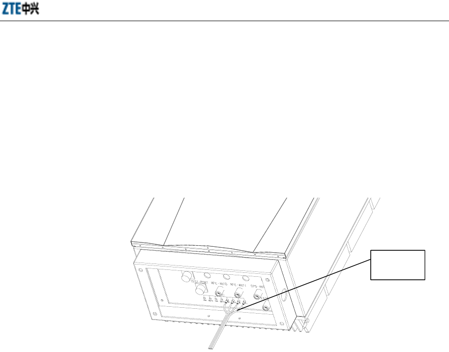
Chapter 7 Connection of Cables
7-9
4) Wrap two layers of PVC tape around the waterproof adhesive tape in the same
way as for wrapping the waterproof adhesive tape.
5) Finally wrap a layer of anti-ultraviolet tape.
7.2.4 Connection of Trunk Cables
There are T1 interfaces at the bottom of the primary cabinet of a micro-BTS for
connecting T1 cables (100-ohm coaxial cables), as shown in Fig. 7.2-7.
Fig. 7.2-7 Connection of T1 Cables
1. Select T1 cables.
Micro-BTS can be installed outdoors, so PE-sheath T1 cables are used generally.
If common T1 cables are used in an outdoor micro-BTS, PVC pipe should be
added for protection.
2. Lay the T1 cables in order. Keep T1 cables and AC power cables separate with
distance of more than 200mm.
3. When laying T1 cables on a tower, the space between two cable ties should be
less than 0.5m to prevent friction with the tower upon swing of cables and avoid
damage of T1 cable sheath.
T1 cable

8-1
8 Installation of Primary Antenna Feeder
System
Summary
Describing the composition of the primary antenna
feeder system.
Describing the procedures to install the primary
antenna feeder system.
8.1 Preparations
Before installing the primary antenna feeder system, check the qualification of the
installation personnel for working at heights, installation environment, security
measures, installation tools and system components, for the purpose of ensuring the
successful installation.
8.1.1 Installation Personnel
The antenna feeder system is installed by the professional installation personnel under
the monitoring of the installation supervisor.
The installation supervisor should be familiar with the materials, tools and operations
for the installation, who is responsible for assigning suitable work for the installation
personnel and recording the actual engineering data.
The installation personnel should be skillful and healthy. Those who work at heights
should have obtained the corresponding qualification, have no acrophobia, observe the
security regulations, and have purchased the personal accident insurance. In addition,
they are prohibited from drinking alcohol when working.

ZXCBTS (V5.4) CDMA Micro Base Transceiver Station & Remote Station Installation Manual
8-2
8.1.2 Installation Environment
Check if the outdoor lightning grounding cable is well grounded and if its cross-section
area is more than 50mm2. Check if the distance between the antenna pole and the
lightning rod/lightning grounding point/outdoor cabling rack, the firmness and
wind-resistant ability of the pole meet the design requirements. In addition, check if the
necessary tools and assisting materials are prepared, and if the route for laying the
primary feeder cables is determined through negotiation.
The equipment provider presents the requirements on the installation of the antenna
mount based on the structure and size of the antenna, and the network operator should
install the antenna mount as required.
The network operator is also responsible for the installation of the outdoor cabling rack,
lightning rod, lightning grounding point and outdoor lightning grounding cable.
Moreover, the network operator needs to drill holes on wall or rooftop for installing the
feeder cable window as one of the equipment room conditions.
8.1.3 Security Measures
Caution
The installation personnel working at heights must wear the safety belt, and
those working on ground must wear the safety helmet. They must wear working
clothes and shoes causing no slips when climbing up the tower.
1. Safety precautions should be stressed to the installation personnel.
2. The outdoor installation should be conducted in sunny days without strong wind.
3. Obvious signs should be set in the installation site to notify irrelative people to
keep away from the site. The installation personnel working on ground are
obligate to keep irrelative people, esp. children away from the site. The tools
used on the tower and some metal components might slip to cause casualties, so
they must be put in a canvas tool bag when not used, and the bag must be sealed
immediately after you open it for a tool or component.
8.1.4 Installation Tools
1. Measurement tools: A compass, multimeter, inclinometer and tape measure;
2. Communication tools: Two mobile phones;

Chapter 8 Installation of Primary Antenna Feeder System
8-3
3. Raising tools: Pulley block and rope;
4. Special tools: Cutter for cutting primary feeder cables and tools for assembling
connectors;
5. General tools: Adjustable wrench, sharp nose pliers, diagonal pliers, electrical
knife, file and hacksaw;
6. Protection tools: Safety belt, safety helmet, safety rope, thick working clothes,
RF prevention clothes, canvas tool bag, gloves, and multi-purpose sockets;
7. Other tools: Herringbone ladder and the wooden wheel axis for uplifting the
primary feeder cable (which can be borrowed locally).
8.2 Composition and Installation Requirements of Antenna Feeder
System
8.2.1 Composition
The antenna feeder system is composed of antennae, antenna jumper cables, primary
feeder cables, lightning arrester, jumper cables on top and grounding parts, as shown in
Fig. 8.2-1.
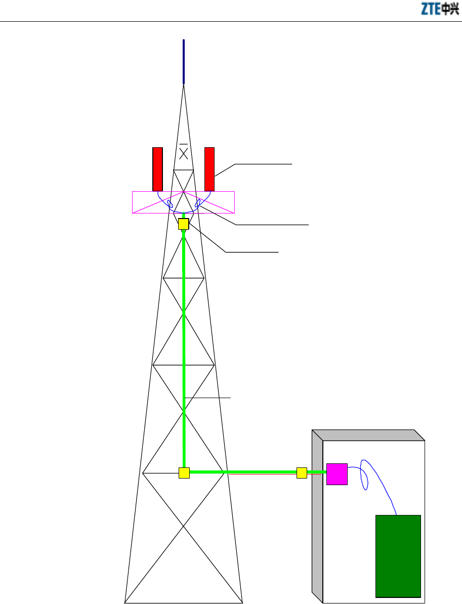
ZXCBTS (V5.4) CDMA Micro Base Transceiver Station & Remote Station Installation Manual
8-4
Lightning rod
Antenna (2 sets)
Jumper cable (1/2", 2 pieces)
Lightning grounding kit
Primary feeder cable (7/8", 2 pieces)
Jumper cable
(1/2", 2 pieces)
Lightning grounding kit
Lightning
grounding kit
Lightning arrester
Equipment room
Tower
Micro-
BTS
Cabling rack
Fig. 8.2-1 Typical Structure of the Antenna Feeder System

Chapter 8 Installation of Primary Antenna Feeder System
8-5
8.2.2 Technical Parameters
1. Height of antenna
It depends on the networking plan.
2. Azimuth angle of antenna
It depends on the networking plan.
3. Pitch angle of antenna
It depends on the networking plan. Generally, it is between 0° and 10°
(adjustable).
4. Pointing direction of antenna
It depends on the azimuth angle of the antenna. Two antennae of the same sector
must point to the same direction.
5. Distance between two diversity antennae
Two antennae of one sector are diversity reception antennae to each other. They
have the same height, but they should be distanced as much as possible. If the
following formula is met, the installation requirement is met.
d ≥ 10λ~20λ (or H/d=11)d: Distance between two diversity antennae; H: Height
from the antenna to the ground. If the carrier is 1.9GHz, the diversity distance
should be more than 1.5m. If the carrier is 800MHz, the diversity distance
should be more than 3.5m.
8.3 Installation Flow
The antenna installation flow is as shown in Fig. 8.3-1.
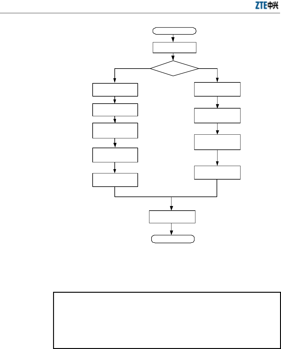
ZXCBTS (V5.4) CDMA Micro Base Transceiver Station & Remote Station Installation Manual
8-6
St a r t
Directional
antenna
Assemble
components of a
directional antenna
Fasten the antenna
End
Raise/carry the
antenna
Determine the
installation position
Omni
antenna
Adjust the direction
and pitch angle of the
directional antenna
Secure the omni
antenna
Keep the omni
antenna vertical
Se cur e t h e
directional antenna
Raise/carry the
antenna
Connect the antenna
with the jumper cable
and then seal their joint
Connect the antenna
with the jumper cable
and then seal their joint
Types of
Antenna
Fig. 8.3-1 Antenna Installation Flow
8.4 Installation of Antenna
Caution:
1. Be cautious during the installation to prevent personal injury or equipment
damage.
2. Measures should be taken to protect human body against the radiation when
adjusting the antenna, for example, the installation personnel should wear the
anti-radiation clothes.
8.4.1 Determining Installation Location
The location for installing the antenna should be determined based on the engineering
design drawing. If the actual location of the antenna mount is different from the
engineering design, the installation engineers, customer representative and design unit
should negotiate to complete the second design according to the requirements of the
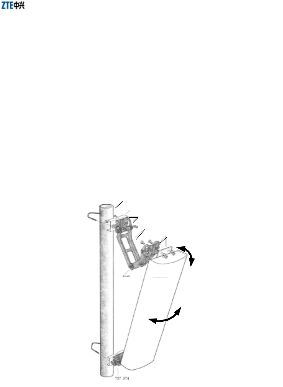
Chapter 8 Installation of Primary Antenna Feeder System
8-7
BTS on network coverage, space diversity, azimuth angle and pitch angle, thus
ensuring desirable network coverage in future.
8.4.2 Installing Accessories of Directional Antenna
Some fasteners need be installed on a directional antenna first. For example, the
KATHREIN antenna need be installed with the fasteners “738516” and “737974”.
Before fastening the antenna, first install the fastener “737974” with angle adjustment
setting onto the top and bottom of the antenna (as shown in Fig. 8.4-1), and then
connect the fastener “737974” and the pole fastener “738516” with short bolts. During
the installation, spring washers and flat washers are used. Please refer to the guide
book delivered with the equipment for the information of specific fasteners to be used.
Assemble the fasteners and angle adjustment accessories onto the antenna in advance
before installing the antenna on the tower.
φ75mm
738 51 6
737 974
0
o
~
16
o
65
o
737 974
Antenna pole
Connect them with two short bolts and nuts
Connect the antenna and the fastener with
short bolts (spring washers and flat
washers are added, and nuts are equipped
with waterproof washers)
After the connection, move the
top of the antenna up and down
to adjust the pitch angle
Scale KAT HR EIN
Directional
antenna
After the connection, move the
antenna right or left to adjust the
azimuth angle
Fig. 8.4-1 Installation of the KATHREIN Antenna
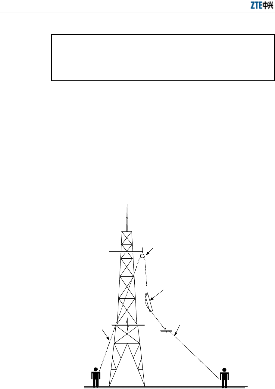
ZXCBTS (V5.4) CDMA Micro Base Transceiver Station & Remote Station Installation Manual
8-8
8.4.3 Transporting and Raising Antenna
Caution:
Both the installation personnel working on tower and those working under
tower should cooperate to raise the antenna onto the tower with rope. Note to
keep the antenna away from the tower body to prevent any damage to the
antenna when pulling it up the tower.
Use rope and pulley block to raise the antenna, 3-m antenna jumper cable and other
accessories (including tools, safety belt, adhesive tapes and cable ties) up to the tower
platform, and then put them in a safe place to avoid falling. Note that the fasteners and
other metal tools must be put in a canvas tool bag before pulling them up. When raising
a directional antenna or an omni antenna, tie a knot at each end of the antenna to
facilitate the cooperation between the installation personnel on and under the tower, as
shown in Fig. 8.4-2.
If an antenna is to be installed on the top of a building, carry the antenna and other
accessories to the installation site manually.
Pulley block
Rope for
raising the
antenna
Tie a knot with rope at
each end of the antenna
Pull the antenna away from the
antenna to avoid damaging the
antenna
Fig. 8.4-2 Schematic Diagram of Raising the Antenna to the Tower Top

Chapter 8 Installation of Primary Antenna Feeder System
8-9
8.4.4 Installing and Adjusting Directional Antenna
Note:
The antennae of different providers require different installation modes. This
section takes the installation of the KATHREIN antenna as an example. Before
the installation, read the installation manual delivered with the antenna
carefully.
Install a directional antenna by the following steps:
1. Fastening the directional antenna onto the pole
Fasten the fastener of the directional antenna with the pole. Do not screw the
screws too tight or too loosely. If they are too loose, the antenna might fall off; if
they are too tight, it is inconvenient to adjust the azimuth angle and pitch angle
of the antenna later.
2. Adjusting the azimuth angle of the antenna
1) Measure the azimuth angle of the antenna with a compass. Then check the
engineering design drawing for the antenna direction.
2) Adjust the orientation of the antenna by twisting it slightly, as shown in Fig.
8.4-1. At the same time, measure the orientation of the antenna with the compass.
Keep adjusting until the deviation is within the design requirement, that is, less
than or equal to 5° generally.
3) After the adjustment, fasten the fastener 738516 tight.
3. Adjusting the pitch angle of the antenna
1) Adjust the bubble inclinometer to the angle as required in the engineering
design.
2) Adjust the pitch angle of the antenna slightly until the bubble of the inclinometer
is located in the middle when you measure the pitch angle with it, as shown in
Fig. 8.4-3.
3) After the adjustment, fasten the fastener 737974 tight.
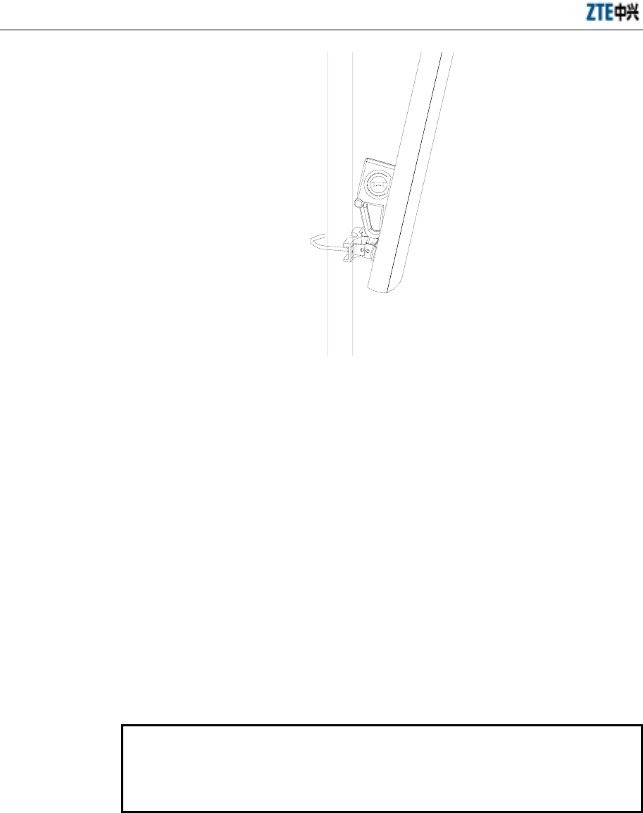
ZXCBTS (V5.4) CDMA Micro Base Transceiver Station & Remote Station Installation Manual
8-10
Fig. 8.4-3 Schematic Diagram of Adjusting the Pitch Angle of the Antenna
8.4.5 Installing and Adjusting Omni Antenna
Install an omni antenna by the following steps:
1. Fasten the antenna (the part with jacket) onto the antenna mount with two fixing
clips. Do not fasten it too tight or too loosely. If too tight, the jacket might be
damaged; if too loosely, the requirements on weight-bearing and wind-resistant
abilities cannot be met.
2. Check if the antenna is vertical. If so, fasten the antenna with the pole tight.
3. Protrude the antenna mount installed with the antenna out of the tower platform.
Adjust the mount to make the antenna vertical.
8.4.6 Connecting Jumper Cable with Antenna and Sealing Their Joint
Note:
You can connect the jumper cable with the antenna and seal their joint before
installing the antenna onto the pole, which can shorten the time for working at
heights and reinforce the connection and waterproof performance of the joint.
The operations are as follows:
1. Insert the jumper cable connector into the antenna interface and then screw them
tight.

Chapter 8 Installation of Primary Antenna Feeder System
8-11
2. Implement waterproof processing to the joint between the antenna and jumper
cable.
1) Wrap the joint with the waterproof adhesive tape from top download. The first
layer should be wrapped in the same direction as for fastening the antenna
jumper cable.
2) Wrap the waterproof tape circularly for three layers totally. Note that the next
circle covers half of the previous circle, and the wrap stops at the position 10cm
away from the joint.
3) Grip the joint with force to make the tape stuck firmly with the joint.
4) Wrap two layers of PVC tape around the waterproof adhesive tape in the same
way as for wrapping the waterproof adhesive tape.
5) Finally wrap a layer of anti-ultraviolet tape.
8.5 Installation of Feeder Cable Window
Note:
The size of the feeder cable window provided by ZTE is 400mm×400mm. It is a
four-hole window and 12 pieces of feeder cables can pass through it. A
300mm×300mm hole should be drilled on the wall for the installation of this
feeder cable window. If a special feeder cable window is used, a hole should be
drilled based on the actual size of it.
No feeder cable window is needed when a micro-BTS is installed outdoors.
The feeder cable window is usually installed on the outside wall of the equipment room,
right between the indoor and outdoor cabling racks.
If the primary feeder cable window is installed on the rooftop, you need to take
measures to make it waterproof. For example, you can seal it with asphaltum or glass
cement.
The feeder cable window has four holes and can be connected with 12 pieces of feeder
cables at most, as shown in Fig. 8.5-1. Follow the steps below to install a feeder cable
window:
1. Determine the installation location based on the engineering design drawing.
2. Drill a hole on the wall according to the size of the feeder cable window used.
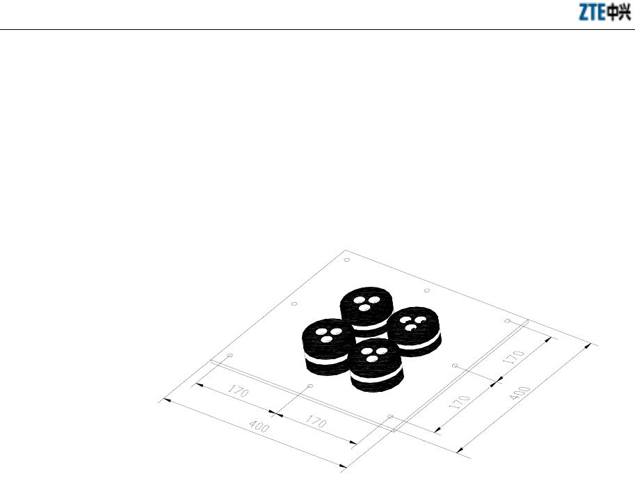
ZXCBTS (V5.4) CDMA Micro Base Transceiver Station & Remote Station Installation Manual
8-12
3. Drill holes for installing expansion bolts with a percussive drill, and then secure
the main board of the feeder cable window with the expansion bolts.
4. Install the sealing pad and gasket when leading the primary feeder cables into
the equipment room.
5. In cold and sandy places, install a wooden board in the equipment room to block
sand blown by the wind and preserve heat.
Fig. 8.5-1 Structure of a Feeder Cable Window
8.6 Connection of Feeder Cable
This section describes how to assemble the 7/8” feeder cable connectors, how to
connect the jumper cable & the primary feeder cable/antenna and seal their joint, and
how to lay and fasten the feeder cables.
The complete structure of a feeder cable of a micro-BTS/remote station is shown in Fig.
8.6-1. If a micro-BTS is installed outdoors and it is near to the antenna, the 1/2” feeder
cable can be used for the primary feeder cable.
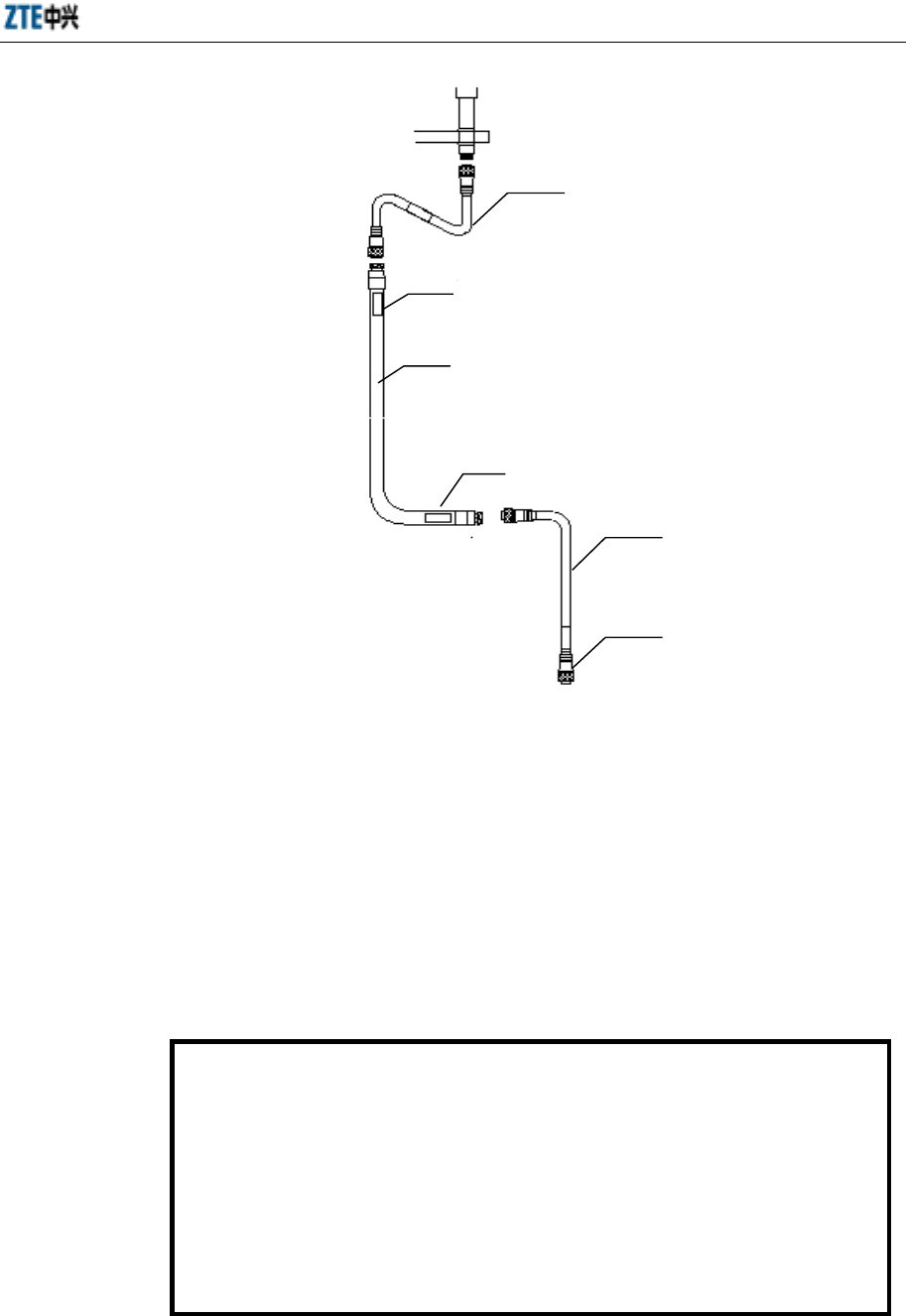
Chapter 8 Installation of Primary Antenna Feeder System
8-13
Label
Antenna jumper cable
Customized jumper
cable on top
Label
Feeder cable
Male N connector
Fig. 8.6-1 Structure of the Feeder Cable of a Micro-BTS/Remote Station
8.6.1 Determining Route for Feeder Cable
The cabling route of the feeder cables should be determined according to the
engineering design drawing. If an alteration is necessary, negotiate with the customer
representative for solution. Note that the primary feeder cables should be as short as
possible.
8.6.2 Assembling Connectors of Primary Feeder Cable
Caution:
Assembling feeder cable connectors is the most important procedure in the
installation of the antenna feeder system, for the quality of them directly
affects the performance of both equipment and network.
Be cautious when using the cutter, for it is very sharp.
This section describes how to assemble connectors for the ROSENBERGER
7/8” feeder cable. For the assembly of connectors for other types of feeder
cable or feeder cable of other manufacturers, refer to the specific installation
manual.
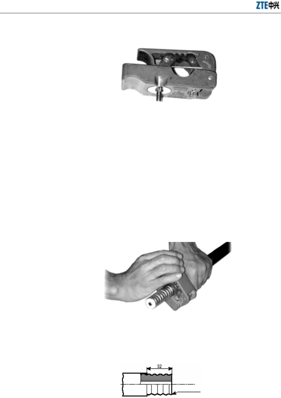
ZXCBTS (V5.4) CDMA Micro Base Transceiver Station & Remote Station Installation Manual
8-14
1. The cutter used is shown in Fig. 8.6-2.
Fig. 8.6-2 Cutter for Assembling 7/8” Feeder Cable Connectors
2. Pull the feeder cable straight (about 150mm long) at the end to be installed with
a connector, and then strip 50mm-long sheath off the cable with the cutter.
3. Put the feeder cable on the trough of the cutter EASIAX, reserve four
corrugations at the end of the blade, and then press down the handle. The main
blade should point to one wave crest.
4. Screw to shut the cutter closely. In this way, the internal and external copper
conductors of the feeder cable are severed, and at the same time the cable sheath
is severed by the assisting blade, as shown in Fig. 8.6-3.
Fig. 8.6-3 Schematic Diagram of Cutting the Feeder Cable with the Cutter
5. Check if the cutting position is correct, as shown in Fig. 8.6-4.
Wave crest
Fig. 8.6-4 Schematic Diagram of Correct Cutting Size
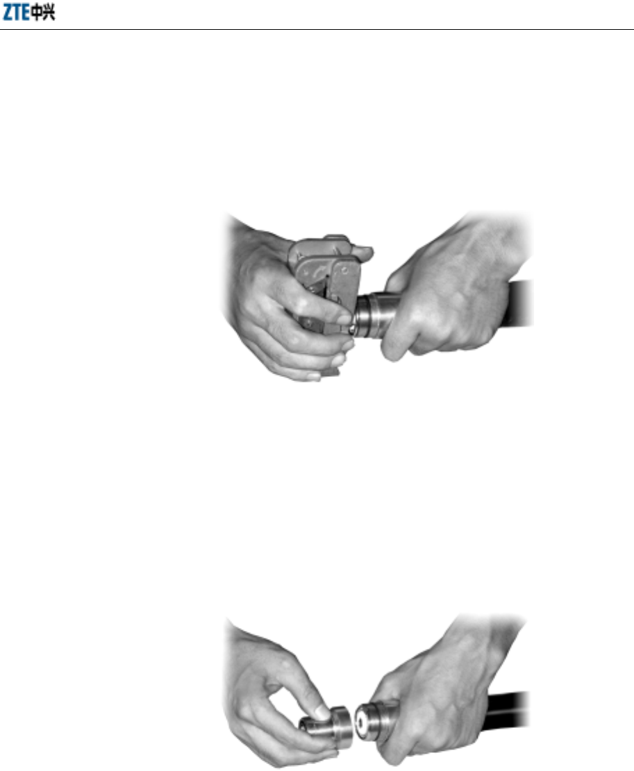
Chapter 8 Installation of Primary Antenna Feeder System
8-15
6. Disassemble the feeder cable connector into two parts: front part and back part.
And then insert the feeder cable into the back part until it contacts the first
corrugation of the cable.
7. Insert the tube expander of the cutter into the feeder cable and then screw left
and right to expand the external copper conductor, as shown in Fig. 8.6-5.
Fig. 8.6-5 Schematic Diagram of Expanding the External Copper Conductor
8. Check if there are copper bits left in the conductor and if the conductor is
expanded evenly. Pull the back part of the connector with force to check if it is
connected firmly with the cable. If any requirement cannot be met, redo the
above steps.
9. Connect the front part with the back part, as shown in Fig. 8.6-6.
Fig. 8.6-6 Schematic Diagram of Connecting the Front Part with the Back Part of the Connector
10. Clamp the front part of the connector with a wrench and use another wrench to
clamp the back part. Twist the back part but keep the front part unmoved until
they are connected firmly.
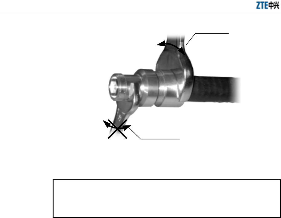
ZXCBTS (V5.4) CDMA Micro Base Transceiver Station & Remote Station Installation Manual
8-16
Twist this wrench only
Keep this wrench immovable
Fig. 8.6-7 Schematic Diagram of Fastening the Front Part with the Back Part of the Connector
8.6.3 Cutting Feeder Cable
Caution:
Stick temporary labels at both ends of the primary feeder cables after cutting
them. Labels can also be stuck in the middle part of the feeder cables but they
must be the same; otherwise, wrong connections might be caused.
On the installation site, measure the cabling route of the primary feeder cables
accurately and then cut the cables as needed. The operations are as follows:
1. When the antenna feeder system is to be installed on the top of a building:
1) Measure the cabling route with a tape measure to determine the length of the
primary feeder cables needed by each sector.
2) Add some margin (1m~2m) to the measured lengths when cutting the cables.
3) After cutting a piece of primary feeder cable, stick temporary labels at both ends
of the cable, for example, ANT1, ANT2, ANT3, ANT4, ANT5, ANT6.
4) Carry the feeder cables having been cut to the top of the building. Ensure that
the cables are not squeezed or damaged during the conveyance.
2. When the antenna feeder system is to be installed on a tower:
1) Pull one end of the feeder cable to the tower top with the roller support, pulley
block and rope. Then the installation personnel under the tower cut the cable
based on the length needed (with a certain margin). Stick a temporary label at

Chapter 8 Installation of Primary Antenna Feeder System
8-17
the lower end of the cable. Stick a formal label after the cable is led into the
equipment room.
2) Assemble the connectors before raising the primly feeder cables, thus shortening
the time for working at heights and ensuring the quality of the connectors.
8.6.4 Raising Primary Feeder Cable
When the antenna feeder system is to be installed on a tower, the pulley block will be
used to raise the primary feeder cables, as shown in Fig. 8.6-8. The operations are as
follows:
1. Check the labels at both ends of the primary feeder cable to ensure that it is the
right cable.
2. Wrap the feeder cable connector with a piece of flax cloth or an antistatic plastic
bag filled with foam, and then bundle it tight.
3. Tie a knot with the rope on the feeder cable at the place 0.4m away from the
connector and then another knot about 3.4m away from the connector, for the
purpose of facilitating the cooperation between the installation personnel on and
under the tower to raise the cable and preventing the feeder cable and its
connector from being damaged due to hit with the tower.
4. After the primary feeder cable is pulled to the tower top, fasten it tight.
Caution:
Raise the primary feeder cable with care to avoid damaging the sheath of it. If
not, the whole piece of the cable will be wasted.
Mind your own safety also when raising the cable.
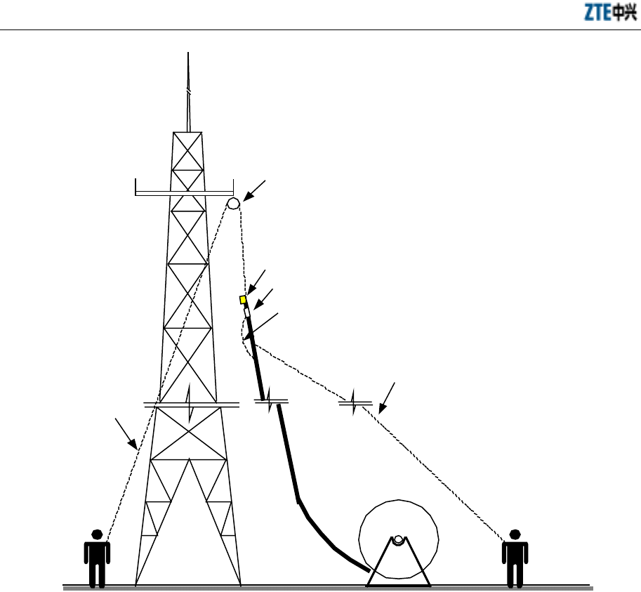
ZXCBTS (V5.4) CDMA Micro Base Transceiver Station & Remote Station Installation Manual
8-18
Pulley block
The rope for
pulling the cable
up the tower
The feeder cable
connector is wrapped
Tie a knot with the rope on the feeder cable at the
place 0.4m away from the connector and then
another knot about 3.4m away from the connector
Use this rope to pull the feeder cable away
from the tower to prevent damaging the cable
and the connector when raising the cable
Label
Fig. 8.6-8 Schematic Diagram of Pulling the Feeder Cable Up the Tower
8.6.5 Laying and Fastening Primary Feeder Cable
1. Cabling principles
1) The primary feeder cables should be laid in order on the cabling rack after being
led into the equipment room through the feeder cable window.
2) The primary feeder cables should be laid without crossings along the outdoor
cabling rack and the cabling ladder of the tower.
3) Be familiar with the cabling route of the primary feeder cables and draw it on
paper in advance to ensure there are no crossings during the actual cabling.
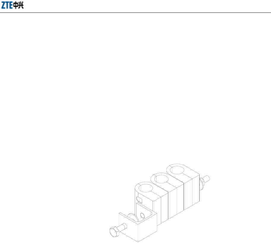
Chapter 8 Installation of Primary Antenna Feeder System
8-19
4) The minimum bending radius of the primary feeder cable should be no less than
20 times of its semi-diameter. The minimum one-time bending radius is 90mm,
and the minimum repeated bending radius is 200mm.
5) The maximum interval between hangers is 1.65m.
2. Cabling procedures:
1) In principle, a hanger should be installed on the tower or cabling rack every
about 1.5m. For onsite installation, the interval can be lengthened or shortened
depending on the actual situation, but the maximum interval cannot exceed
1.65m. Install the hangers with even distance in the same direction. If two rows
of hangers are installed on one cabling ladder, keep them in parallel and in order.
See Fig. 8.6-9 for the appearance of a hanger.
Fig. 8.6-9 Appearance of a Hanger
2) Arrange the primary feeder cables before leading them into the equipment room.
3) Fasten the primary feeder cables from top downward with hangers. Keep the
cables straight all the way. Do not fasten the feeder cables at both ends
simultaneously.
4) If the antenna feeder system is installed on the top of a building, the network
operator should install the cabling ladder on the wall. In this case, fasten the
primary feeder cables with hangers along the ladder before leading them into the
equipment room.
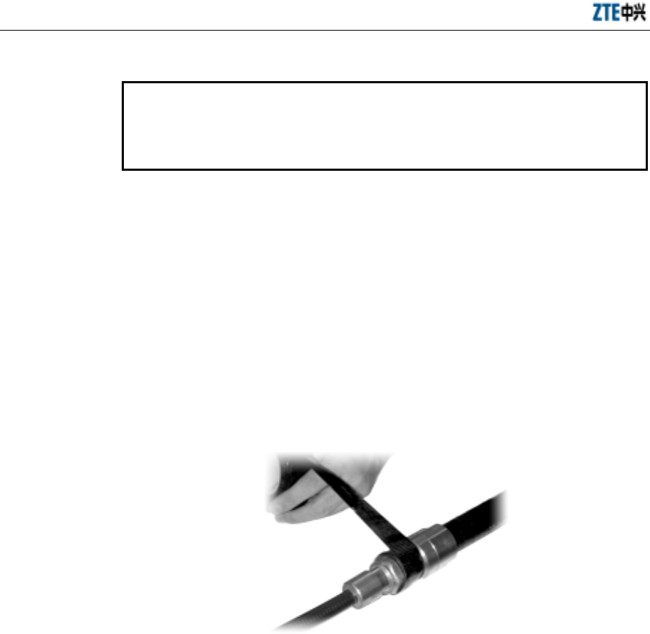
ZXCBTS (V5.4) CDMA Micro Base Transceiver Station & Remote Station Installation Manual
8-20
8.6.6 Connecting Jumper Cable with Feeder Cable and Sealing Their Joint
Caution:
Pay attention to the sealing of the joint between the feeder cable and the jumper
cable, which is critical in the installation of the antenna feeder system. Use
waterproof adhesive tape for the sealing.
Generally, the 3m-long 1/2” jumper cable is used to connect the antenna and the
primary feeder cable. Connect the 1/2” jumper cable with the primary feeder cable and
then seal their joint as follows:
1. Connect the antenna jumper cable with the connector of the primary feeder cable
and then screw down the connector.
2. Treat connectors with waterproof measures. The procedures are as follows:
1) Wrap the waterproof adhesive tape around the joint from the sunk area upward
(fill the area with the tape), as shown in Fig. 8.6-10.
Fig. 8.6-10 Schematic Diagram of Wrapping Waterproof Adhesive Tape (1)
2) Stretch the tape with force and wrap it in the same direction as for fastening the
cable connector.
3) Wrap circularly in the reverse direction for the second layer, as shown in Fig.
8.6-11. Note that the next circle covers 1/3 of the previous circle for the purpose
of preventing inleakage of rain. Wrap the joint for three layers totally. Do not cut
the adhesive tape during the wrapping. The length of the cable wrapped with the
tape should be 20mm longer than that of the connector.
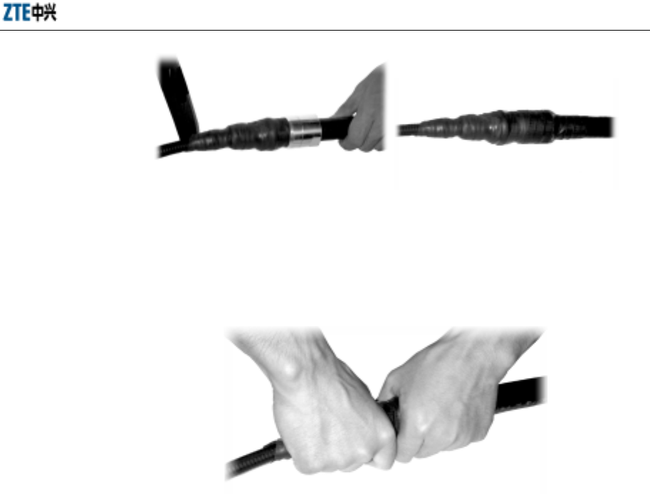
Chapter 8 Installation of Primary Antenna Feeder System
8-21
Fig. 8.6-11 Schematic Diagram of Wrapping Waterproof Adhesive Tape (2)
4) After the wrapping, grip the joint with both hands to make the tape stuck tight
with the joint, as shown in Fig. 8.6-12.
Fig. 8.6-12 Schematic Diagram of Wrapping Waterproof Adhesive Tape (3)
5) Wrap two layers of PVC tape around the waterproof adhesive tape. Note that the
next circle covers half of the previous circle.
6) Grip the joint again.
7) Use ties to fasten the wrapped part at both ends to prevent the tape from falling
off due to aging.
8.6.7 Leading Primary Feeder Cable into Equipment Room
1. Precautions
1) See Fig. 8.6-13 and Fig. 8.6-14 for the modes of leading the primary feeder
cables into the equipment room. It must be ensured that no rainwater will be led
in along the feeder cable. If necessary, the water-blocking curve can be made.
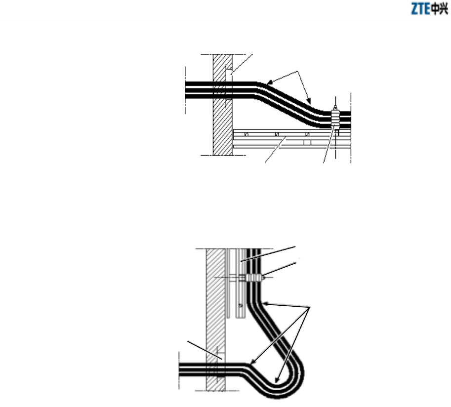
ZXCBTS (V5.4) CDMA Micro Base Transceiver Station & Remote Station Installation Manual
8-22
Feeder cable window One-time bending,
with the min. radius
of more than 90mm
Cabling rack Hanger
OutdoorsIndoors
Fig. 8.6-13 Leading the Feeder Cable into the Equipment Room - Mode 1
Feeder cable
window
One-time bending,
with the min. radius
of more than 90mm
Hanger
Cabling rack
Indoors
Outdoors
Fig. 8.6-14 Leading the Feeder Cable into the Equipment Room - Mode 2
2) The feeder cables are led into the equipment room through the feeder cable
window. The outdoor and indoor cabling racks are used for leading them.
2. Procedures
1) Loosen the fasteners on the feeder cable window and remove the cover from the
holes.
2) Lead the feeder cables into the equipment room. Two people in and out of the
room respectively should cooperate when leading the cables to prevent
damaging both the equipment and the cable. Screw down the fastening hoop
after the feeder cables are pulled in position.
3) Cut the feeder cables. The following should be done before cutting them:

Chapter 8 Installation of Primary Antenna Feeder System
8-23
Checking labels
Check if the temporary labels are stuck on the cables. Without the labels, you
might misconnect the cables.
Determining the cutting position
Determine the cutting position based on the installation position of the shelf and
the lightning arrester, length of jumper cable on top, and the bending radius of
the feeder cables.
4) Assemble the indoor connectors of the primary feeder cables.
8.6.8 Connecting Indoor Jumper Cable
The indoor jumper cable on top is connected between the primary feeder cable and the
antenna interface at the bottom of a micro-BTS. Customize a jumper cable on site
based on the actual situation. One end of the jumper cable is a male N connector, which
is directly connected to the bottom of the cabinet. The other end is a female DIN
connector, which is connected to the 7/8” primary feeder cable. See Fig. 8.6-1.
8.7 Grounding System of Micro-BTS
Grounding aims to protecting both the human being and the equipment against
lightning shock and electromagnetic interference.
The grounding system of a micro-BTS includes protection grounding on the chassis,
lightning arrester for RF components in the cabinet, for GPS antenna, for T1 cables, for
120V AC power and for feeder cable grounding kit.
1. Grounding principles of primary feeder cables
1) Generally, each primary feeder cable should be grounded at least three times for
lightning protection, that is, on the tower platform, between the tower and the
outdoor cabling rack, and on the wall before the feeder cable is led into the
equipment room. If the primary feeder cable is more than 60 meters long, a
lightning grounding kit should be installed every 20 meters. If the primary
feeder cable is shorter than 5m, one grounding point is enough. If the feeder
cable is shorter than 20m but longer than 5m, it can be grounded at two points.
2) The antenna feeder system, antenna mount and newly-installed cabling rack
should all be welded to the lightning protection net of the building. The feeder
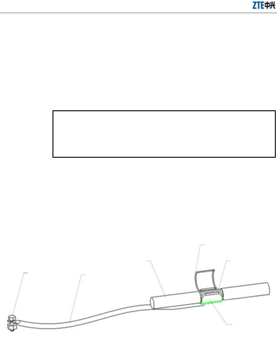
ZXCBTS (V5.4) CDMA Micro Base Transceiver Station & Remote Station Installation Manual
8-24
cables should also be grounded at three points, that is, on the antenna pole, on
the rooftop, and on the wall before the cables are led into the equipment room.
3) Before leading the primary feeder cable along the outdoor cabling ladder from
the top of the building to the equipment room, check whether the cabling ladder
is grounded. If not, request the network operator to accomplish it as soon as
possible.
2. Procedures to install the grounding kit
Caution:
It is prohibited to install the grounding kit in thunderstorm weather;
otherwise, the installation personnel might be hurt.
When installing the grounding kit, be sure to keep the feeder cable at the joint
straight.
1) Prepare such tools as paper knife, straight screwdriver, spanner and sharp nose
pliers.
2) Choose a suitable position for installing the grounding kit, and cut the sheath off
the 7/8" feeder cable based on the size of the grounding kit. The structure of a
grounding kit is shown in Fig. 8.7-1.
Grounding terminal Grounding cable
Feeder cable
Grounding wire clip
Out-layer copper
core of feeder cable
Sheet copper of
feeder cable
Fig. 8.7-1 Structure of a Grounding Kit
3) Lead the grounding cable of the lightning grounding kit to the grounding net.
Keep the angle between the grounding cable and the primary feeder cable no
more than 15°.
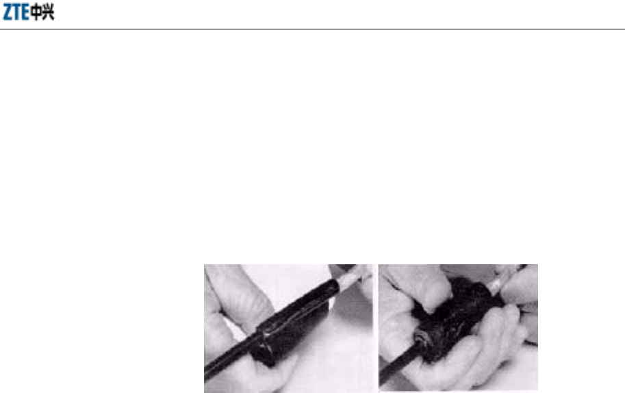
Chapter 8 Installation of Primary Antenna Feeder System
8-25
If the antenna feeder system is installed on a tower, lead the grounding cable
downward along the tower.
If the antenna feeder system is installed on the top of a building, lead the
grounding cable to the lightning protection net.
4) Before installing the grounding kit, wrap the waterproof adhesive tape around
the grounding cable near the grounding copper for sealing, as shown in Fig.
8.7-2.
Fig. 8.7-2 Schematic Diagram of Wrapping Waterproof Adhesive Tape Around the Grounding
Cable
5) Clamp the external conductor with the grounding copper and clip tightly.
6) Seal the joint between the grounding kit and the feeder cable as follows:
First wrap the waterproof adhesive tape and then the PVC tap around the joint.
Wrap the waterproof adhesive tape circularly from bottom upward, and then
from top downward, finally from bottom upward again. Note that the next circle
covers half of the previous circle.
7) Connect the grounding terminal of the grounding kit to the tower body or the
cabling rack on the top of the building (the cabling rack is connected to the
lightning protection net). Remove the paint and oxide at the junction within the
radius of 13mm and then coat the clean area with antioxidant cream. After the
connection, paint the area with antirust paint.
8) Before the primary feeder cable is led into the equipment room, connect the
grounding terminal of the grounding kit to the outdoor grounding busbar.

ZXCBTS (V5.4) CDMA Micro Base Transceiver Station & Remote Station Installation Manual
8-26
8.8 Test of Antenna Feeder System
1. After the antennae are installed and all feeder cables are connected, measure the
standing wave ratio of them.
2. Measure one end of the indoor 1/2” jumper cable, which is to be connected with
the cabinet, with the tester. The standing wave ratio should be lower than 1.5. It
is best to be lower than 1.3.
3. Record the Voltage Standing Wave Ratio (VSWR) value and provide the VSWR
testing diagram.
8.9 Waterproof Processing of Connectors
Follow the steps below to seal the joints between two cables:
1. Fasten the relative joints.
2. Implement waterproof processing to the joints.
1) Wrap the joints with the waterproof adhesive tape from the top of the connectors.
The first layer should be wrapped in the same direction as for fastening the cable
connectors.
2) Stretch the tape with force and wrap it circularly for three layers totally. Note
that the next circle covers half of the previous circle, and the wrap stops at the
position about 10cm away from the joint.
3) Grip the joint with force to make the tape stuck firmly with the joint.
4) Wrap two layers of PVC tape around the waterproof adhesive tape in the same
way as for wrapping the waterproof adhesive tape.
5) Finally wrap a layer of anti-ultraviolet tape.

9-1
9 Installation of GPS Antenna Feeder
System
Summary
Describing the composition of the GPS antenna
feeder system.
Describing the procedures to install the GPS antenna
feeder system.
9.1 Preparations
9.1.1 Installation Personnel
Before installing the GPS antenna feeder system, check the qualification of the
installation personnel for working at heights, installation environment, security
measures, installation tools and system components.
The antenna feeder system is installed by the professional installation personnel under
the monitoring of the installation supervisor.
The installation supervisor should be familiar with the materials, tools and operations
for the installation, who is responsible for assigning suitable work for the installation
personnel and recording the actual engineering data.
The installation personnel should be skillful and healthy. Those who work at heights
should have obtained the corresponding qualification, have no acrophobia, observe the
security regulations, and have purchased the personal accident insurance. In addition,
they are prohibited from drinking alcohol when working.
9.1.2 Installation Environment
Check if the outdoor lightning grounding cable is well grounded and if its cross-section
area is more than 50mm2. Check if the distance between the antenna pole and the

ZXCBTS (V5.4) CDMA Micro Base Transceiver Station & Remote Station Installation Manual
9-2
lightning rod/lightning grounding point/outdoor cabling rack, the firmness and
wind-resistant ability of the pole meet the design requirements. In addition, check if the
necessary tools and assisting materials are prepared, and if the route for laying the
primary feeder cable are determined through negotiation.
The equipment provider presents the requirements on the installation of the antenna
mount based on the structure and size of the antenna, and the network operator should
install the antenna mount as required.
The network operator is also responsible for the installation of the outdoor cabling rack,
lightning rod, lightning grounding point and outdoor lightning grounding cable.
Moreover, the network operator needs to drill holes on wall or rooftop for installing the
feeder cable window as one of the equipment room conditions.
9.1.3 Security Measures
Caution:
The installation personnel working at heights must wear the safety belt, and
those working on ground must wear the safety helmet. They must wear
working clothes and shoes causing no slips when climbing up the tower.
1. Safety precautions should be stressed to the installation personnel.
2. The outdoor installation should be conducted in sunny days without strong wind.
3. Obvious signs should be set in the installation site to notify irrelative people to
keep away from the site. The installation personnel working on ground are
obligate to keep irrelative people, esp. children away from the site. The tools
used on the tower and some metal components might slip to cause casualties, so
they must be put in a canvas tool bag when not used, and the bag must be sealed
immediately after you open it for a tool or component.
9.1.4 Installation Tools
1. Measurement tools: A compass, multimeter, inclinometer and tape measure;
2. Communication tools: Two mobile phones;
3. Raising tools: Pulley and rope;
4. Special tools: Cutter for cutting primary feeder cables and tools for assembling
connectors;
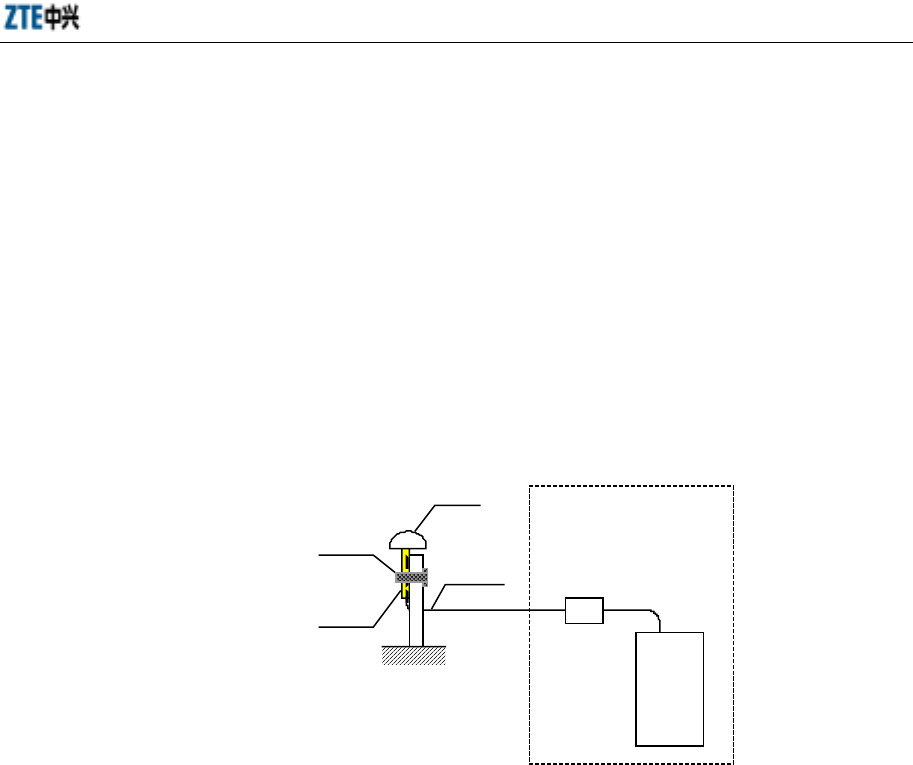
Chapter 9 Installation of GPS Antenna Feeder System
9-3
5. General tools: Adjustable wrench, sharp nose pliers, diagonal pliers, electrical
knife, file and hacksaw;
6. Protection tools: Safety belt, safety helmet, safety rope, thick working clothes,
RF prevention clothes, canvas tool bag, gloves, and multi-purpose sockets;
7. Other tools: Herringbone ladder and the wooden wheel axis for uplifting the
primary feeder cable (which can be borrowed locally).
9.2 Composition of GPS Antenna Feeder System
See Fig. 9.2-1 for the composition of the GPS antenna feeder system.
Sleeve
Fixing clip
Micro-
BTS
GPS antenna
Coaxial cable
Fig. 9.2-1 Composition of the GPS Antenna Feeder System
9.3 Installation Procedures
As the CDMA clock and frequency reference, GPS plays a very important role. The
GPS antenna receives navigation and position signals of GPS satellites, demodulates
frequency and clock signals through a GPS signal receiver and provides these signals
to related elements of CDMA BTSs.
1. Requirements on GPS antenna installation
The GPS antenna should be installed in an open and high place, so that it can
trace more satellites, for example, on the top of a building or on a tower. Make
the GPS feeder cable as short as possible to minimize the attenuation.
The GPS antenna should be installed in the lightning protection area of the
tower; otherwise, a lightning rod should be customized and installed for the GPS
antenna.
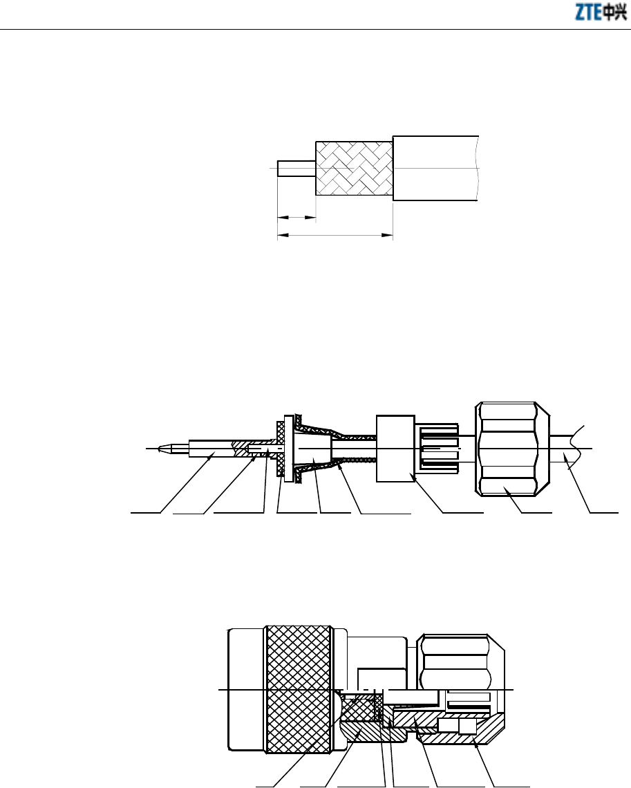
ZXCBTS (V5.4) CDMA Micro Base Transceiver Station & Remote Station Installation Manual
9-4
2. Assembly of a GPS coaxial cable connector
1) Strip the a segment of sheath off the GPS coaxial cable as required in Fig. 9.3-1.
6.2 16.7
Fig. 9.3-1 Schematic Diagram of Length of Cable Sheath to be Stripped
2) Assemble the components onto the cable as shown in Fig. 9.3-2. And then solder
the core wire with the pin. Unfold the shielding layer and wrap it around the
bushing.
Pin Insulating
washer Cable shielding
Bushing Crimping tube Nut Cable
Cable core
wire
Soldering
tin
Fig. 9.3-2 Schematic Diagram of Soldering the Core Wire with the Pin
3) Assemble the components into the shell, as shown in Fig. 9.3-3.
Insulating
washer Bushing Crimping
tube
Shell Nut
Pin
Fig. 9.3-3 Structure of N-J7A
3. Procedures to install the GPS antenna feeder system
1) Assemble an outdoor coaxial cable connector following the same steps
mentioned above.

Chapter 9 Installation of GPS Antenna Feeder System
9-5
2) Insert the connector through the sleeve (a GPS accessory), and then lay the
coaxial cable from the GPS antenna to the GPS lightning arrester.
3) Screw to connect the outdoor coaxial cable connector with the GPS antenna
connector.
4) Screw the sleeve onto the GPS antenna, keeping the GPS antenna unmoved.
5) Secure the tube on the antenna pole with a fixing clip.
6) Cut the coaxial cable based on the installation position of the GPS lightning
arrester. Assemble the indoor cable connector and then connect it with the
lightning arrester. Do not wrongly connect the equipment terminal and antenna
feeder terminal of the GPS lightning arrester.
7) Lay the coaxial cable from the GPS lightning arrester to the GPS port of a
micro-BTS.
9.4 Test of Antenna Feeder System
1. After the antennae are installed and all feeder cables are connected, measure the
standing wave ratio of them.
2. Measure one end of the indoor 1/2” jumper cable, which is to be connected with
the cabinet, with the tester. The standing wave ratio should be lower than 1.5. It
is best to be lower than 1.3.
3. Record the VSWR value and provide the VSWR test diagram.
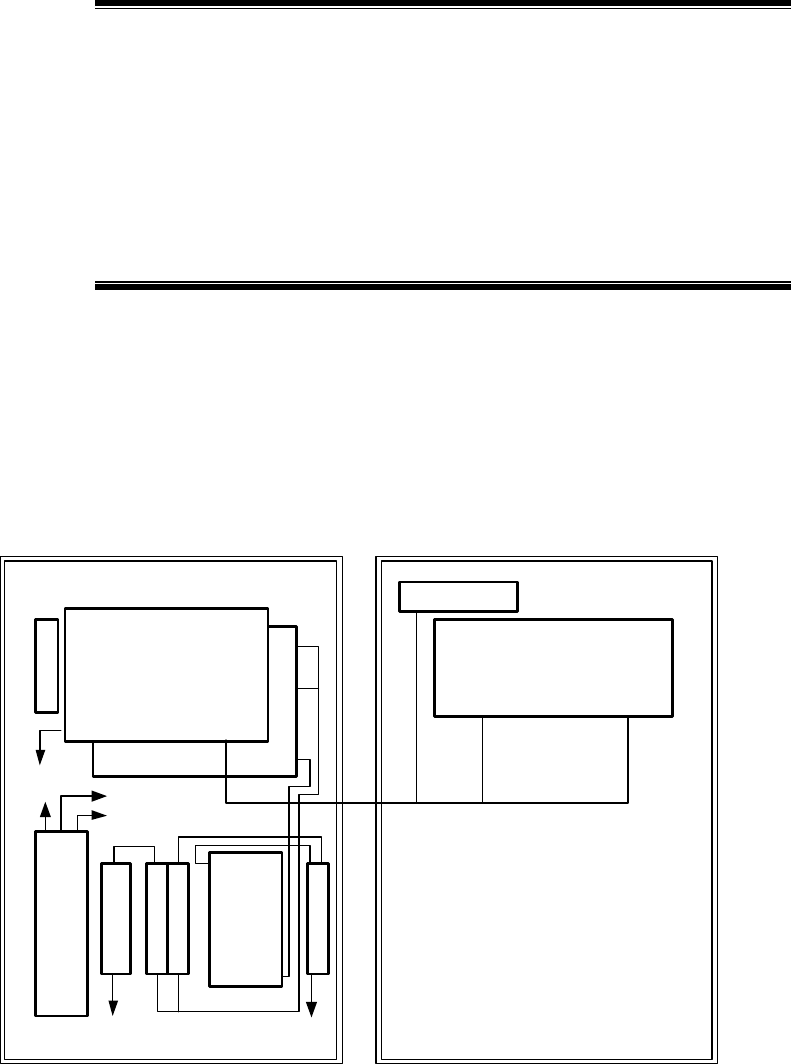
10-1
10 Installation of Internal Modules
Summary
Describing the modules in a micro-BTS/remote
station.
Describing the functions of the modules.
Describing the flow of installing the modules.
10.1 Overview
10.1.1 Logical Positions of Equipment Modules
The modules and boards in M800T/M801T/M802T/M190T/M191T/M192T
micro-BTS are positioned as shown in Fig. 10.1-1.
BDM
B
R
F
S
M
P
D
M
D
I
V
M
L
N
A
1
M
L
N
A
2
M
P
A
M
D
U
P
MGPS
BGPS
MLNA
MPABRFS
E1
MTRX
RFE-ANT0
TX
RX0
RX1
10M/12M ANT
RFE-ANT1
Door
Fig. 10.1-1 Modules and Boards in M800T/M801T/M802T/M190T/M191T/M192T Micro-BTS
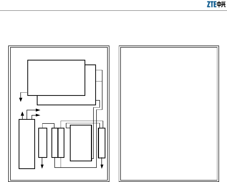
ZXCBTS (V5.4) CDMA Micro Base Transceiver Station & Remote Station Installation Manual
10-2
The modules and boards in R800T/R801T/R802T/R190T/R191T/R192T remote
stations are positioned as shown in Fig. 10.1-2.
RFM
M
P
D
M
D
I
V
M
L
N
A
1
M
L
N
A
2
M
P
A
M
D
U
P
MLNA
MPA
MTRX
RFE-ANT1
TX
RX0
RX1
RFE-ANT0
Door
BRFS
Optical fiber
Fig. 10.1-2 Modules and Boards in R800T/R801T/R802T/R190T/R191T/R192T
10.1.2 Layout of Internal Modules
A ZXCBTS micro-BTS is composed of Micro Transmitter & Receiver (MTRX)
module, Micro Low Noise Amplifier (MLNA) module, Baseband Digital Module
(BDM) module, Micro GPS (MGPS) module, Micro-BTS Power Distribution (MPD)
400W module, DIVersity (DIV) module, DUPlexer (DUP) module and Micro Power
Amplifier (MPA) module, as shown in Fig. 10.1-3.
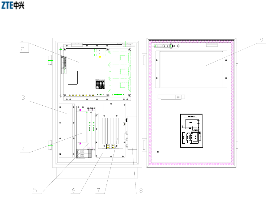
Chapter 10 Installation of Internal Modules
10-3
1 MTRX 2 BDM 3 MPD400W 4 DIV
5 MLNA 6 MPA 7 Heater 8 DUP 9 MGPS
Fig. 10.1-3 Layout of Modules in a ZXCBTS Micro-BTS
A ZXCBTS remote station is composed of MTRX module, MLNA module, Remote
Fiber Module (RFM), MPD 400W module, DIV module, DUP module and MPA
module, as shown in Fig. 10.1-4.
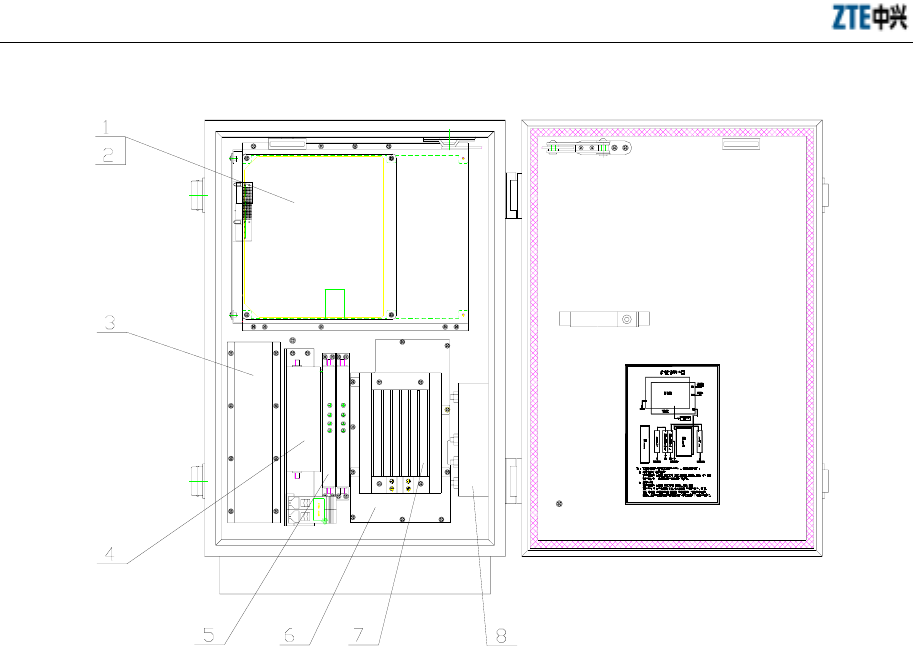
ZXCBTS (V5.4) CDMA Micro Base Transceiver Station & Remote Station Installation Manual
10-4
1 MTRX 2 RFM 3 MPD400W 4 DIV
5 MLNA 6 MPA 7 Heater 8 DUP
Fig. 10.1-4 Layout of Modules in a ZXCBTS Remote Station
10.1.3 Functions of the Modules
The following modules and accessories need be installed:
1. BDM
BDM is the core module of a ZXCBTS micro-BTS, which completes the
modulation & demodulation of baseband data, signaling processing, resources
management and operation & maintenance functions.
2. MTRX
MTRX provides interfaces to BDM and sends transmitted or received basedband
data as well as the information on configuration, control, status and alarms. It
achieves up conversion, intermediate frequency bandpass filter, transmit link
gain control and signal amplification on forward links. Moreover, it

Chapter 10 Installation of Internal Modules
10-5
accomplishes down conversion, signal amplification and bandpass filter on
reverse links.
MTRX800 is used in M800T/M802T micro-BTS/remote stations, whereas
M190T/M191T/M192T micro-BTS/remote stations adopt MTRX190.
3. MPA
MPA receives CDMA signals transmitted by MTRX and then amplifies the
power of the signals, which are finally emitted to a cell through the antenna after
being processed by a duplexer filter.
M800T micro-BTS/remote stations adopt MPA800; M802T micro-BTS/remote
stations adopt MPA802; M190T/M191T micro-BTS/remote stations adopt
MPA190T; M192T micro-BTS/remote stations adopt MPA192.
4. RFE
Receive Front Element (RFE) consists of MDUP (Duplex), MDIV (Diversity)
and MLNA.
On reverse links, the signals received by the antenna are filtered by the duplexer
filter and then amplified.
On forward links, the signals outputted by MPA are filtered by the duplexer
filter and then emitted to the cell through the antenna.
5. MPD
MPD directly converts the 120V AC power into the power with suitable voltage
and supply the power to all modules in a micro-BTS/remote station. Moreover,
it controls the heater in a micro-BTS/remote station to maintain the internal
environment stable. It also supports the monitoring of the power supply status.
6. Optical interface module
There are two kinds of optical interface modules used: OIM and RFM, which
are respectively installed in a micro-BTS and a remote station. They accomplish
the following functions:
1) Connecting BDS and RFS, providing channel for multiplexing and
demultiplexing forward/reverse data and signaling, and carrying out
optical-electrical conversion.

ZXCBTS (V5.4) CDMA Micro Base Transceiver Station & Remote Station Installation Manual
10-6
2) Multiplexing and demultiplexing LVDS signals.
3) Providing 12MHz (800MHz) or 10MHz (1.9GHz) analog signals to the RF
subsystem.
4) Measuring the transmission delay of LFM (OIM) and RFM, and reporting the
signal to RF Control Module (RFCM) through Integrated Circuit Interface
Circuit (IIC) bus CM to compensate the transmission delay on Channel
Processing Module (CHM).
5) Reporting the alarm signals about temperature, humidity, and access control
generated in a remote station to RFCM.
6) Offering communication links between MPA and RFCM.
7) Monitoring important signal, for example, 16chip.
7. GPSTM
GPSTM functions in providing 16chip or pp2s clock signal, 10MHz reference
signal and TOD messages.
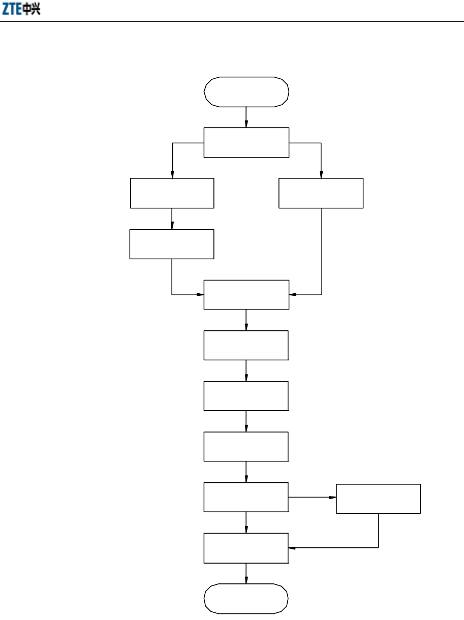
Chapter 10 Installation of Internal Modules
10-7
10.2 Module Installation Flow
Start
Install MTRX
Ins tall RFM
Remote s tatio n
Ins tall BDM
Install MGPS
Micro-BTS
Install MPA
Install DUP
Install DIV
Install MPD400W
Ins tall MLAN
Installation check
End
Install the heater
Based on t he
configuration
Fig. 10.2-1 Module Installation Flow Diagram

ZXCBTS (V5.4) CDMA Micro Base Transceiver Station & Remote Station Installation Manual
10-8
10.3 Installation and Replacement of Modules
Note
The modules and cables in Micro-BTS/remote stations have been installed,
connected and tested before delivery. Before commissioning, you only need to
check if they are loose due to conveyance.
According to the configuration requirement, you might need to add optical
fiber modules or CSM5000 expansion modules in the expansion slots of the
corresponding BDM board.
If any fault occurs, the maintenance personnel can refer to this manual for
simple maintenance.
10.3.1 Installation Sequence
Note
This section describes the sequence of module installation and cable connection
in an M800 micro-BTS. Refer to this sequence for the installation in
M801T/M802T/M190T/M191T/M192T/R800T/R190T/R191T/R192T
micro-BTS.
1. Install MTRX, BDM and BRFS.
2. Install T1 lightning arrester and lay T1 cables.
3. Connect Terminal B of DCDX02 and RSTDX to MPA and BRFS respectively,
and bundle the cables with cable ties on the cable tie bases.
4. Install MPD, BGPS, MGPS, MDIV, MLNA, MPA, RF and GPS lightning
arrester.
5. Lay interconnection cables between modules, access control cable and door
grounding cable, and connect the antistatic wrist strap.
6. Connect Terminal B of the RF cable RF27 to MDUP_ANT loosely. Next, install
MDUP in the cabinet and then fasten it. Finally, connect the other two RF
connectors on MDUP.
7. Install the heater, power lightning arrester and connect the relative cables
(including ACDX01).
10.3.2 Table of Cable Connections
Refer to Appendix B.
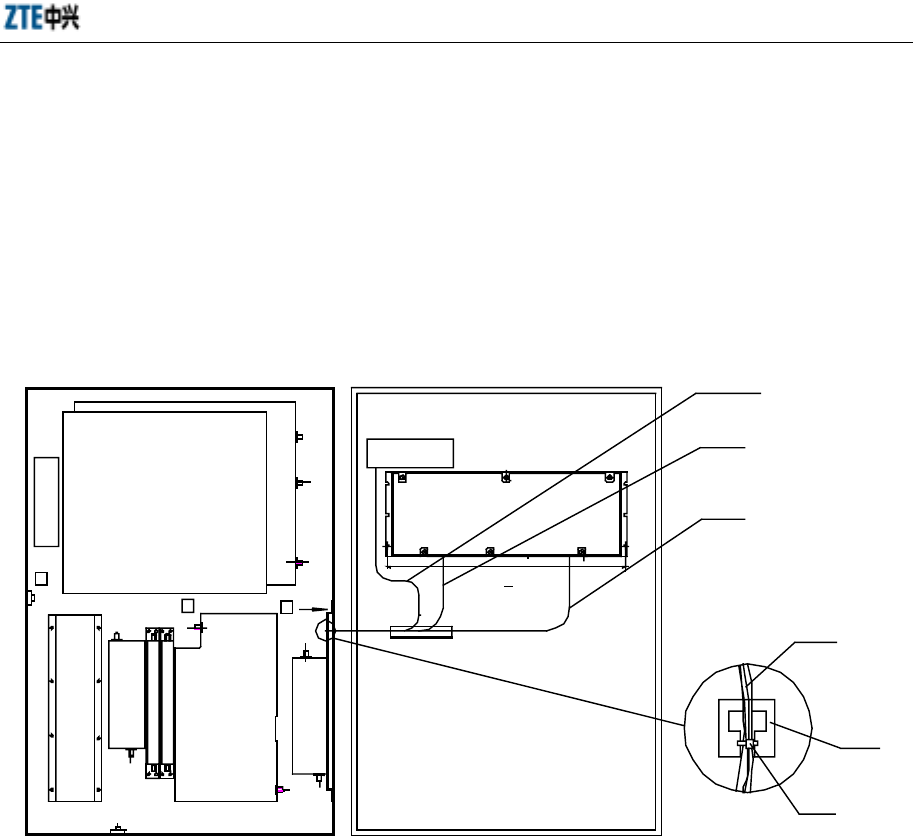
Chapter 10 Installation of Internal Modules
10-9
10.3.3 Fastening and Bundling of Internal Cables
1. Fastening coaxial cables
For semi-rigid coaxial cables, connect both ends to the corresponding terminals
firmly.
2. Bundling of GPS-BDM conductive wires and RF cables RF29/RF30
See Fig. 10.3-1.
BDM
B
R
F
S
BGPS
M
T
R
X
M
P
D
M
D
I
V
M
L
N
A
|
1
M
L
N
A
|
2
M
P
A
M
D
U
P
A
GPSTM
307.5+0.1
GPS-BDM
RF30
RF29
To Terminal A
Bundle of
cables
T-shape
hole
Cable tie
Fig. 10.3-1 Schematic Diagram of Bundling Internal Cables (1)
Bundle the cables RF29 and RF30 on the door and the grounding cable of the
antistatic wrist strap in the inner side of the bundling plank, while bundle the
GPS-BDM cables in the outer side of it, as shown in Fig. 10.3-2.
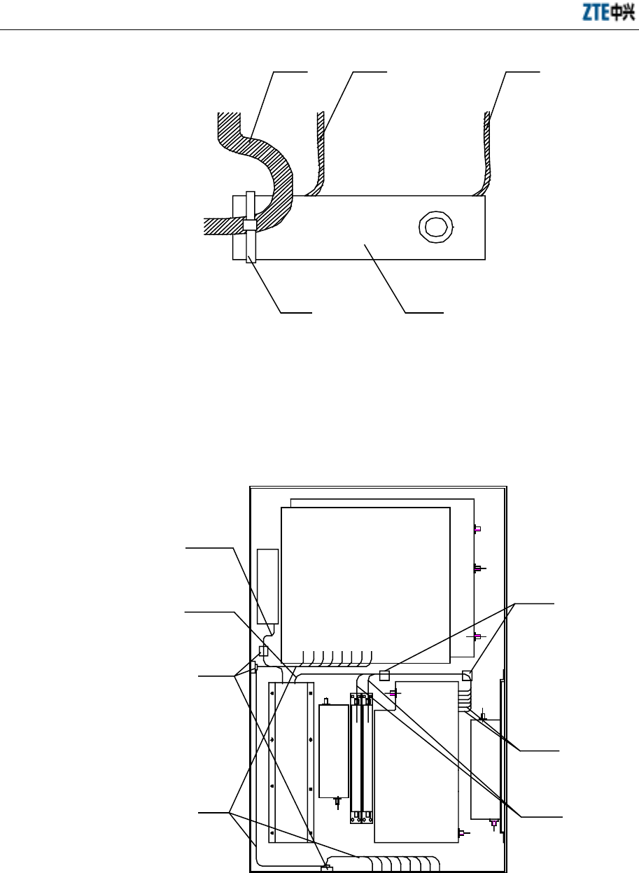
ZXCBTS (V5.4) CDMA Micro Base Transceiver Station & Remote Station Installation Manual
10-10
GPS-BDM cable RF30 RF29
Cable tie Bundling plank
Fig. 10.3-2 Schematic Diagram of Bundling Internal Cables (2)
3. Bundling of DCDX01, DCDX02, RSTDX, MONDX01 and MONDX02 cables
Bundle the cables DCDX01, DCDX02, RSTDX, MONDX01 and MONDX02
with cable ties on the cable tie bases, as shown in Fig. 10.3-3.
BDM
M
T
R
X
M
P
D
M
D
I
V
M
L
N
A
|
1
M
L
N
A
|
2
M
P
A
M
D
U
P
Cable
tie base
MONDX02
MONDX01
DCDX01
RSTDX
DCDX02
E1
cable
B
R
F
S
Cable
tie base
Fig. 10.3-3 Schematic Diagram of Bundling Internal Cables (3)
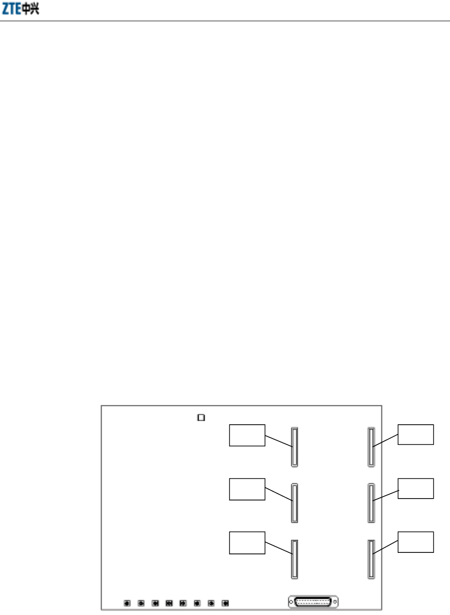
Chapter 10 Installation of Internal Modules
10-11
4. Cabling of T1 cables in the cabinet
The T1 lightning arrester is equipped with two T1 cables. Before connecting the
T1 lightning arrester with the cabinet, label the T1 cables at the position near the
connectors with “OUT#” or “IN#” (#=1, 2, 3 or 4”).
“OUT#” and “IN#” should be the same as “OUT” or “IN” marked on the cable
outlets at the back of the lightning arrester. When installing the T1 lightning
arrester, ensure that the serial number “#” marked on the T1 cables is consistent
with the silk-screen at the bottom of the BDM and the cabinet.
To facilitate recabling the T1 cables connected with the lightning arrester, these
T1 cables should be laid along the upper edge inside the cabinet, and the cable
tie bases should be installed at the positions convenient for uninstallation. See
Fig. 11-8. It is suggested to bundle the T1 cables with cable ties every 150mm.
10.3.4 Installation of OIM
If a micro-BTS need be configured as a remote station, an OIM should be added on the
BDM of the micro-BTS.
See Fig. 10.3-4 for the corresponding relations between the OIM expansion slots in
BDM and the sectors.
αsector
β
γ
X26
X15
X16
X27
X17
X18
sector
sector
Fig. 10.3-4 Corresponding Relations between OIM Expansion Slots in BDM and Sectors
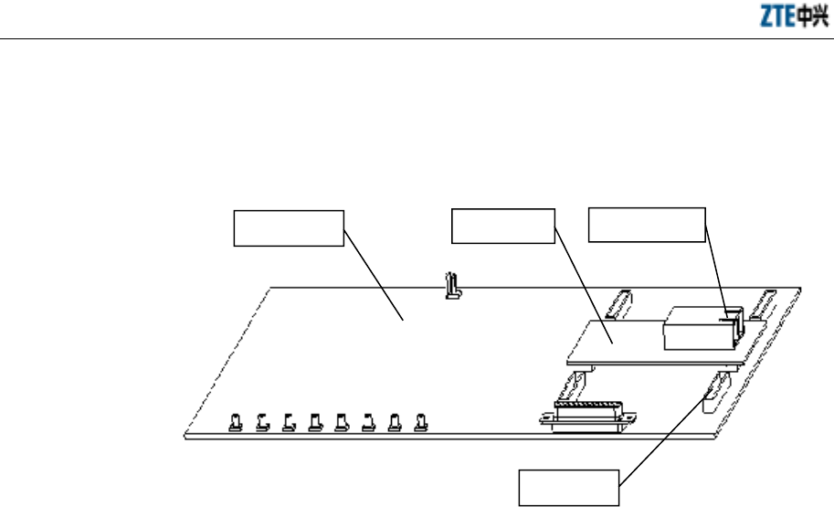
ZXCBTS (V5.4) CDMA Micro Base Transceiver Station & Remote Station Installation Manual
10-12
When inserting the OIM into the BDM, make the interface of the optical module on the
OIM face outward to ensure that optical fibers can be inserted into the optical module
of the OIM from the right side of the BDM, as shown in Fig. 10.3-5.
BDM
OIM slot
OIM Optical interface
facing outward
Fig. 10.3-5 Schematic Diagram of Inserting the OIM into the BDM
10.3.5 Installation of LFM
If a remote station need be configured for a macro-BTS, it is only necessary to replace
TRX of a sector with LFM by just inserting LFM into the TRX slot in the TRX layer of
the macro-BTS without changing any cable connections on the backplane. The RF
modules such as TRX, HPA and RFE need not be installed in the macro-BTS.
Refer to “7.2.1 Connecting Optical Fiber” for the connection with LFM and the
cabling of optical fibers in a macro-BTS.
10.4 Points for Attention
1. Main tool: Philips screwdriver.
2. When installing MPA and MPD400W, cover the place between the
MPA/MPD400W and the main radiator with silicon.
3. The modules should be installed firmly and reliably.

11-1
11 Hardware Installation Check
Summary
Describing the hardware installation check items
11.1 Checking Components in the Cabinet
Check if:
1. The RF cables between the modules are connected correctly and firmly.
2. The bolts of all modules are screwed down to ensure reliable connections
between the modules and the backplane.
3. The unused connectors are screwed with matching terminals.
4. The RF cables are not cross-connected or pulled too tight. Some margin is
reserved at the turning corner and the connectors are connected firmly.
11.2 Checking the Cabinet
Check if:
1. The installation position of the cabinet complies with the design requirement.
2. After the shelf is fixed, it is stable enough to resist earthquake of 7 in Richter
scale.
3. No part of the shelf is loose or damaged. The shelf is well painted and the
indications on the shelf are complete, correct and clear.
4. No metal scraps or useless wires are left in the cabinet.
5. All bolts are screwed down, and flat washers and spring washers are installed
without inversion.

ZXCBTS (V5.4) CDMA Micro Base Transceiver Station & Remote Station Installation Manual
11-2
6. The cable outlet at the bottom of the cabinet has been covered with the cover
plate after the cables are connected.
7. The combined cabinets are arranged in order and the connecting pieces on the
top of the cabinets are fastened firmly.
8. The surface of the cabinet is clean, the paint has no blemishes, and various
indications on the surface are correct, clear and complete.
9. The front door can be opened or closed flexibly.
11.3 Checking Cables
Check if:
1. All cables are laid straight and there are no cross-connections. Surplus cables are
coiled, bundled and put in the cabling trough.
2. The cables are turned smoothly.
3. Power cables and signal cables are laid separately with a distance of more than
150mm.
4. All cables are labeled clearly at both ends to avoid wrong or missed connections.
5. The joints are reliable and well contacted without breaks or bends.
6. The cables are tied with proper tightness, and the cable ties are distanced evenly.
7. Surplus part of the cable ties for indoor cables has been cut.
8. Some margin is reserved when the cable ties used on outdoor cables are cut.
9. No cable tie has spininess part after being cut.
10. All cables are stuck with labels indicating the usage, and the contents in the
labels at both ends are the same.
11. Stick the labels with transparent adhesive tape to prevent them from falling off.
11.4 Checking Power Cables and Grounding Cables
Check if:
1. The cabling of power cables and grounding cables conforms to the design
requirements.

Chapter 11 Hardware Installation Check
11-3
2. The PGND cable of the micro-BTS adopts the olivine or yellow copper-core
cable with the cross-section area of 35mm2, which is connected to the indoor
PGND copper busbar reliably. The GND/BGND cable adopts the black
copper-core cable with the cross-section area of 25mm2. The -48V power cable
adopts the blue copper-core cable with the cross-section area of 25mm2. All
these cables are laid straight and connected reliably.
3. The grounding bus wire is directly connected to the indoor grounding busbar.
The cross-section area of the grounding bus wire is more than 50mm2.
4. Each terminal of the grounding copper busbar is connected with only one
device.
5. PGND cables and AC neutral cables are laid separately.
6. AC neutral cables are grounded independently in the power room.
7. The indoor grounding resistance is less than 5 ohm.
8. Each cable is marked correctly and clearly.
9. Power cables are not bundled with other cables but separately.
10. The surplus part of the grounding and power cables are cut.
11. The copper lugs at both ends of power cables and grounding cables are welded
or crimped well.
12. There is no joint (between two pieces of cables) for a piece of power cable or
grounding cable.
13. The grounding copper busbar is insulated from the wall, and the grounding path
is as short as possible.
14. The primary power supply is connected to the power terminal on the shelf
correctly.
15. The opening lug of power cables are welded or crimped firmly.
16. Power cables are well contacted with the copper lugs and sealed with adhesive
tape. The copper lugs are reliably connected with the power cabinet or BTS
shelf.
17. The power terminals on the top of the shelf are equipped with insulation tubes.
18. No power cable, grounding cable, trunk cable or RF cable is broken.

ZXCBTS (V5.4) CDMA Micro Base Transceiver Station & Remote Station Installation Manual
11-4
19. The labels at both ends of the power cable and ground cable should be clear and
correct.
20. The naked wires at the wiring terminals and the handles of cable lugs are
wrapped with insulation adhesive tape or heat-shrink tube.
21. Each wiring terminal is installed with a flat washer and a spring washer.
11.5 Checking T1 Cables
Check if:
1. T1 cables are not short-circuited and the connectors are not damaged.
2. T1 cables are connected correctly and stuck with clear labels.
3. T1 cable connectors are firmly connected. Use the multimeter to test if the
connectors are well connected with the grounding system. If the test result is
negative, it might be caused by the poor contact between the flange of the
connectors and the chassis.
4. T1 cables are laid loosely to ensure firm connection with the connectors of the
shelf when the cabling rack moves up and down.
5. T1 cables are connected firmly and reliably.
11.6 Checking Indoor 1/2” Jumper Cables
Check if:
1. The primary feeder cable is connected with the 1/2” jumper cable, which is then
connected to the wiring terminal on the top of the shelf.
2. The indoor 1/2” jumper cables are stuck with labels indicating the corresponding
sector and the length of the primary feeder cable.
3. The indoor jumper cables are cabled and bundled neatly.
4. The cabling is convenient for future maintenance and expansion.
5. The jumper cables are laid in different layers and sectors.
6. The jumper cable at the joint with the lightning arrester keeps straight for 30cm
long.

Chapter 11 Hardware Installation Check
11-5
11.7 Checking Primary Feeder Cables and GPS Feeder Cables
Check if:
1. The primary feeder cables are cut by a dedicated cutter. The cross-section is
smooth and no copper scraps are left in the copper pipe of the primary feeder
cable. The connectors of the primary feeder cables are installed firmly.
2. The 7/8” feeder cable connectors are installed firmly to ensure normal standing
wave ratio.
3. The feeder cables are grounded at least three times as required (Refer to 6.2.3.1).
The grounding points are connected firmly and sealed well. The end of the cable
grounding kit for connecting the grounding cable is downward so that rainwater
will not flow into the feeder cable along the grounding cable.
4. One feeder cable grounding kit is installed in the middle of the tower if the
tower is more than 60m high.
5. One lightning grounding kit is installed on the top of a building or on the cabling
rack if the length of the feeder cable after leaving the tower before entering the
equipment room is more than 20m.
6. The terminals of the feeder cable grounding kit are fixed separately onto the
tower.
7. The outdoor grounding copper busbar is connected with the underground
grounding net by the dedicated cable whose cross-section area is more than
50mm2.
8. The antenna feeder system on the top of a building is connected to the nearby
lightning grounding net.
9. The cabling ladder for leading the feeder cable from the building top along the
wall to the equipment room is grounded.
10. The inclination between the feeder cable and its grounding cable is less than 15°.
11. The feeder cables are laid neatly, neither cross-connected nor broken or twisted.
The connections with the sectors are correct.
12. The minimum bending radius of feeder cables is 20 times of the semi-diameter
of feeder cables or more. The bending radius of the primary feeder cables is
larger than 0.3m.

ZXCBTS (V5.4) CDMA Micro Base Transceiver Station & Remote Station Installation Manual
11-6
13. The primary feeder cables of one sector are arranged in one row and they are
queued the same in each row.
14. No copper part of the feeder cable connectors is exposed. Same labels are stuck
at both ends of a feeder cable with the cable length recorded.
15. The GPS core wire is not falsely soldered.
16. The GPS copper core is not short-circuited with the outer layer, and the core
pins of the GPS feeder cable connectors are not exposed.
17. The GPS feeder cable connectors are fastened tight.
11.8 Checking Water-blocking Curve for Feeder Cable Window and
Primary Feeder Cables
Check if:
1. The feeder cable window is fixed on the wall in the equipment room, and the
protruding holes of the feeder cable window are outward faced.
2. The glue-injecting hole on sealing gasket of the feeder cable window is sealed
upward. The window boards are installed in the indoor side of the window.
3. The feeder cable window installed on the top of a building is well sealed.
4. The lowest point of the water-blocking curve is at the place 10cm-20cm under
the feeder cable window.
5. The minimum bending radius of feeder cables is 20 times of the semi-diameter
of feeder cables or more. The bending radius of the primary feeder cables is
more than 0.3m.
6. Keep a minimum length of 0.5m of straight feeder cable both in and out of the
equipment room. There should be at least 0.3m of straight feeder cable in length
through the lightning arrester.
11.9 Checking Hangers
Check if:
1. The hangers are fastened firmly on the outdoor cabling rack.
2. The fixing clips installed are evenly distanced.

Chapter 11 Hardware Installation Check
11-7
3. The hangers are installed on the primary feeder cables every 1.5m..
11.10 Checking Outdoor 1/2” Jumper Cables
Check if:
1. The connections between the antenna and the 1/2” jumper cable as well as the
1/2” jumper cable and the primary feeder cable are correct. Their joints are
tightened.
2. The jumper cable connected with the antenna is laid along the beam of the
antenna mount and bound to the tower.
3. The joints between the antenna and the 1/2” jumper cable as well as the 1/2”
jumper cable and the primary feeder are sealed as required (Refer to 9.4.6 and
9.6.6).
4. The jumper cable keeps straight with the antenna for 30cm long at their joint.
5. All the connectors of outdoor jumper cables are sealed and water-blocking curve
is made for jumper cables.
11.11 Checking Antenna
Check if:
1. The antenna mount is connected firmly with the tower.
2. The type of the antenna installed meets the requirement of the networking plan.
3. The height from the center of the antenna to the ground and the installation
position of the antenna comply with the networking plan.
4. The RF antenna and the GPS antenna are installed in the area protected by the
lightning rod.
5. The azimuth angle of each single-polarized directional antenna conforms to the
networking plan. Two antennae of one sector are oriented to the same direction.
The deviation of the azimuth angle of a directional antenna is within +/-5°.
6. The pitch angle of each single-polarized antenna conforms to the networking
plan. The deviation of the pitch angle of a directional antenna is within +/-0.5°.
The pitch angle of two single-polarized antennae is the same.

ZXCBTS (V5.4) CDMA Micro Base Transceiver Station & Remote Station Installation Manual
11-8
7. There are two types of antenna: the pointer-modulated antenna and
digital-modulated antenna. Adjust the former with a spanner and modulate the
latter by setting the exact value in the equipment room. When the control line
connecting the antenna is broken, you must adjust the antenna with a spanner.
You must measure every single-polarized antenna. For digital-modulated
antenna, keep the lower obliquity the same as planned, and keep consistency
between the two single-polarized antennae.
8. All antenna poles are installed stably and grounded well. They are vertical to the
ground, with the deviation within 2°.
9. The transceiving distance of omni antennae is no less than 3.5m.
10. The distance between an omni antenna and the tower is more than 1.5m, and that
between a directional antenna and the tower is more than 1m.
11. The top of the jacket of an omni antennae is level with or higher than the
antenna mount.
12. The distance between an omni antenna and the antenna lightning rod is no less
than 2.5m when the antenna situates on the rooftop.
13. An omni antenna can cover all areas when it is installed on the rooftop.
14. The diversity antenna of each sector corresponds with the jumper cables on top
of the shelf.
15. The diversity distance between two antennae of one sector refers to the vertical
distance between two antennae. The diversity distance is more than 3.5m for a
800M micro-BTS/remote station; the diversity distance for a 1.9G
micro-BTS/remote station is more than 1.5m; the diversity distance is more than
6.7m for a 450M micro-BTS/remote station.
16. The vertical distance between two directional antennae of different sectors
installed on the same antenna mount is more than 0.6m.
17. The antennae are separated from G-network antennae, distancing more than 1m
vertically and more than 2m horizontally.
18. The GPS antenna is installed in an open, low and safe place. It is vertical and its
solid angle is bigger than 90°.
19. A lightning rod is installed specially for the GPS antenna situated on rooftop.

Chapter 11 Hardware Installation Check
11-9
11.12 Checking Standing Wave Ratio of Feeder Cables
1. After the antennae are installed and all feeder cables are connected, measure the
standing wave ratio of them.
2. Measure one end of the indoor 1/2” jumper cable, which is connected with the
cabinet, with the tester. The standing wave ratio should be lower than 1.5. It is
best to be lower than 1.3.
3. Record the VSWR value and provide the VSWR test diagram.
11.13 Checking Indoor and Outdoor Environment
Check if:
1. All waste materials are cleared, and the outdoor environment is clean.
2. The equipment room is clean and neat, and all things needed are arranged in
order.
3. No waste materials such as cable ties, cables and desiccant bags are left
around/under the shelf and under the raised floor.
4. The front door, rear door and side panels are cleaned so that no touch prints can
be seen. There is no dust or scrap in the cabinet.
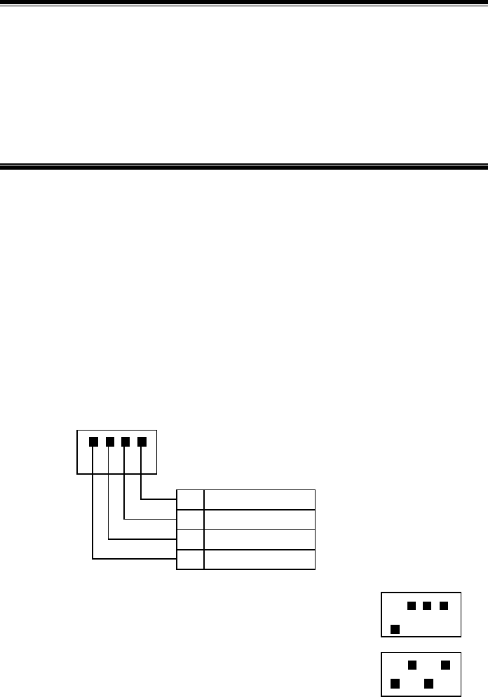
12-1
12 Power-on and Power-off
Summary
Describing the power-on check items
Describing the procedures to power on/off a
micro-BTS/remote station
12.1 Checking Components in the Cabinet before Power-on
Open the cabinet to check if the modules are installed firmly and the cables are
connected reliably.
Insert the OIM and the CSM5000 into the cabinet.
Set the PATH ID by setting the DIP switch on the BDM based on the T1 cable
connections with the CDSU of the BSC. See Fig. 12.1-1 for the setting of the DIP
switch.
PATH_ID1
2
PATH_ID2
PATH_ID3
PATH_ID0
4
ON
OFF
When PATH_ID=1, the DIP switch is set as:
When PATH_ID=5, the DIP switch is set as:
ON
OFF
ON
OFF
3
1
Fig. 12.1-1 Setting of S1

ZXCBTS (V5.4) CDMA Micro Base Transceiver Station & Remote Station Installation Manual
12-2
12.2 Checking External Cables before Power-on
1. Use the multimeter to measure if the 120V AC power meets the requirement.
2. Check if the connector of the 120V AC power cable is connected firmly.
3. Check if T1 cable connectors are connected tight.
4. Check if the optical fibers are connected correctly.
5. Use the tester to check if the standing wave ratio of the antenna feeder system is
lower than 1.5. It should be lower than 1.3 generally. Check if feeder cable
connectors are assembled correctly, and if the feeder cables and antennae are in
good condition.
6. Check if correct labels are stuck on the cables firmly.
12.3 Powering on/off the Cabinet
No power switch is configured in micro-BTS or remote stations, so you need to power
on/off them by plugging/unplugging the power connector or powering on/off the power
supply equipment.
After power-on, debug the BTS through the BSC.

13-1
13 Installing the Integrated Micro-BTS
Summary
Describing the installation of the integrated built-in
SDH of the micro-BTS
Describing the installation of the integrated UPS of
the micro-BTS
13.1 Introduction to the Solution of Micro-BTS Integration
13.1.1 Implementation of the Micro-BTS Integration
The micro-BTS integration solution integrates the transmission, power and micro-BTS
technologies and devices to provide users with an integrated networking solution. The
core of the CDMA micro-BTS integration of ZTE Corporation lies in the built-in SDH.
Through improvement on the structure and cabling process of the micro-BTS and
change of related boards, the SDH board is built into the micro-BTS. In addition, the
integrated UPS is added to the micro-BTS to provide the micro-BTS with the
interfacing and monitoring functions over the backup power supply (UPS power supply
and combinational power supply) and other devices. Meanwhile, the functions of
secondary power-off and dry contact monitoring are added to address new
requirements. The built-in SDH and integrated UPS are optional for micro-BTS
configuration. The following modifications to the micro-BTS are required if this
function is to be added to the micro-BTS:
1. BDM modification: Add the half-duplex RS485 monitoring interface and three
dry contacts (input), no longer support the RS232 monitoring interface;
2. RFM modification: Add six dry contacts (input), not to support the RS485 and
RS232 monitoring interface;
3. SDH selection: For the consistency of internal cabling, the CC4 connector is to
be used for the T1 interface on the built-in SDH board, corresponding to the

ZXCBTS (V5.4) CDMA Micro Base Transceiver Station & Remote Station Installation Manual
13-2
indoor T150 board for the transmission of this part. The indoor and outdoor
T150 boards are the same except for the interface connector, that is to say, they
are basically the same in terms of performance and reliability. Support of power
supply: 24V and –48V input;
4. Improvement on cabling process: Consistent internal T1 cabling, that is, the
same cabling can be inserted either to the BDM or the to built-in SDH to make
upgrade and networking configuration more more convenient and flexible;
internal cabling for the monitoring part;
5. Improvement on pinboard (bottom plate): Add a standalone built-in SDH power
connector interface. The type of pinboard is settled on the 10W and 20W
micro-BTS pinboard, 40W micro-BTS main cabient pinboard and 450M
micro-BTS pinboard;
6. Add the lightning protection (class II) function for the monitoring part inside
the cabinet with some lightning protection design on the board; furthermore,
install an additional RS485/dry contact lightning protection board at the
monitoring interface of the cabinet;
7. Modification of T1 lightning arrester: Because of the changed T1 cabling inside
the cabinet, a longer coaxial cable may be needed for the T1 lightning arrester;
in addition, codes of the T1 lightning arrester needs changing;
8. Improve the door panel structure of the micro-BTS, to build the SDH into the
door panel of the micro-BTS.
13.1.2 Micro-BTS Integration Solution
Thanks to above improvements on the micro-BTS, the integration solution now poses
as an even simpler one with more flexible configuration available. With the solution of
the micro-BTS integrated with the backup power supply and transmission, the user’s
requirements are taken as the first priority. There comes two basic integration solutions
for selection:
1. AC micro-BTS+UPS+built-in SDH, as shown in Fig. 13.1-1.
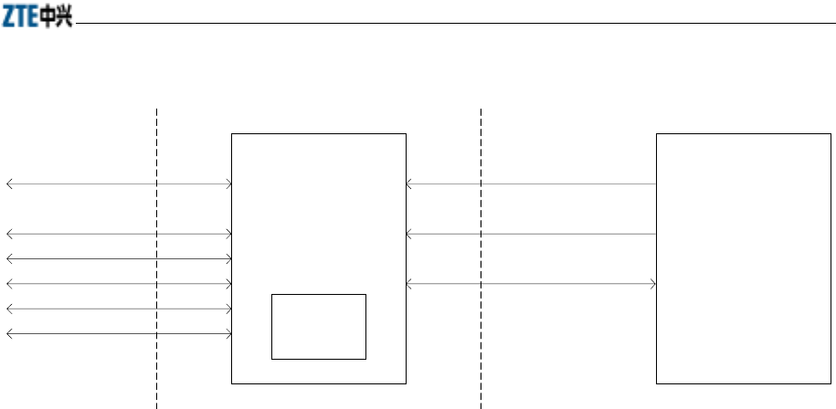
Chapter 13 Installing the Integrated Micro-BTS
13-3
AC micro-BTS UPS
220V
-48V
485/dry contact
Fiber 1 (SDH)
Fiber 2 (SDH)
E1(1)
E1(2)
E1(3)
E1(4)
Transmission
interface
Power supply
interface
Built-in
SDH
Fig. 13.1-1 Solution (I) of Micro-BTS Integration
In this solution, a ZTE ZXSM T150 transmission system serves as the built-in SDH
system, and a ZTE ZXUPS L010 UPS power system serves as the UPS power
supply.On the power interface, the UPS provides 120V and -48V power outputs to
supply power for the micro-BTS and built-in SDH. Furthermore, the UPS provides
secondary power-off function to guarantee the power supply of the built-in SDH in
precedence.485 or dry contact are supported for the monitoring. There is only one
monitoring interface at the micro-BTS side and this interface is compatible with the
485 and dry contact input, that is, it supports either the 485 or dry contact for the
monitoring part. On the transmission interface side, two STM-1 optical interfaces are
supported and a maximum of four T1 interfaces can be provided. In addition, the
built-in SDH or BDM board can be selected according to the actual requirements.
2. DC micro-BTS+combinational power+built-in SDH, as shown in Fig. 13.1-2.
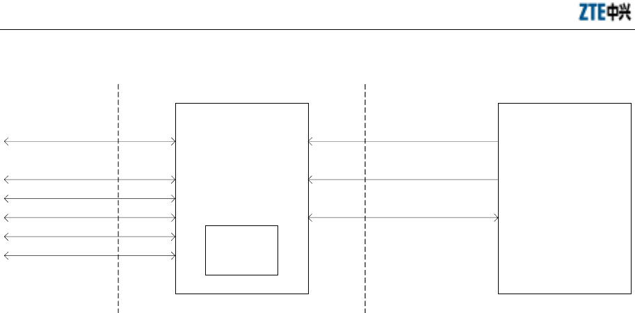
ZXCBTS (V5.4) CDMA Micro Base Transceiver Station & Remote Station Installation Manual
13-4
DC micro-BTS
Combinational
power supply
-48V(1)
-48V(2)
485/dry contact
Fiber 1 (SDH)
Fiber 2 (SDH)
E1(1)
E1(2)
E1(3)
E1(4)
Transmission
interface
Power supply
interface
Built-in
SDH
Fig. 13.1-2 Solution (II) of Micro-BTS Integration
In this solution, a ZTE ZXSM T150 transmission system serves as the built-in SDH
system, and a suitable ZTE power system model may serve as the outdoor
combinational power supply. On the power interface side, the combinational power
provides two -48V power outputs to supply power for the micro-BTS and the built-in
SDH, Furthermore, the combinational power system provides the secondary power-off
function to guarantee power supply for the built-in SDH in precedence. The monitor
part and the transmission interface part are the same as those in Solution I.
If the backup power is not available, the built-in SDH is also supported. However, the
secondary power-off function cannot be implemented. To reduce power interfaces, the
power of the built-in SDH can be supplied by the micro-BTS. In this case, a built-in
24V power and an SDH board are needed. Without the support of the backup power, if
the electric power network is of poor quality, to reduce the influence of transmission
interruption on the network due to power failure, it is recommended the configuration
be used in a single station application only to avoid complicated SDH transmission
networking.
13.1.3 Module Layout of the Integrated Micro-BTS and RF Remote Station
Fig. 13.1-3 shows the module layout inside the ZXCBTS integrated micro-BTS:
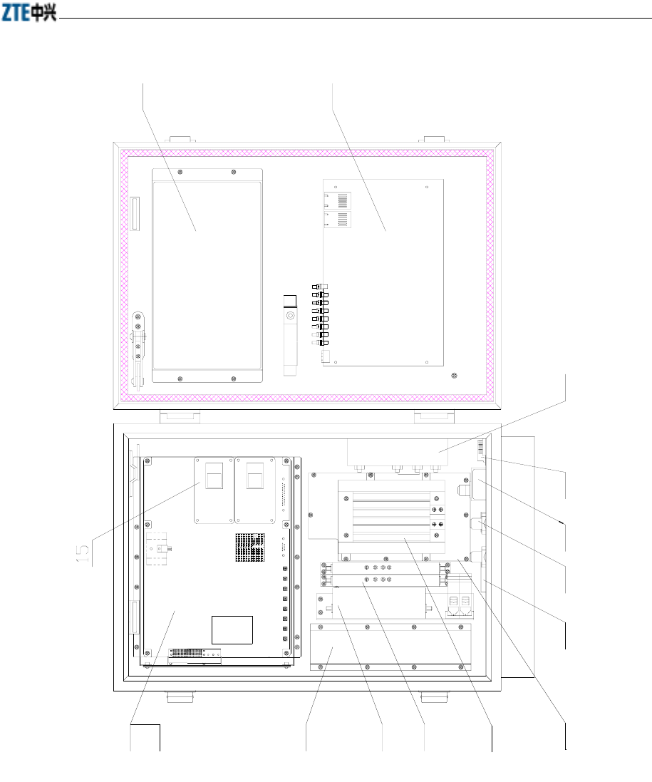
Chapter 13 Installing the Integrated Micro-BTS
13-5
14
13
12
11
10987
6
5
4
3
2
1
1 BDM module (top layer) 2 MTRX module (bottom layer) 3 power module 4 MDIV module 5 MLNA module 6. Heater
7 MPA module 8 T1 arrester 9 RF lightning arrester 10 MGPSTM lightning arrester 11 MTPB1
lightning-protection plate (the external 48VUPS should be built internally)
12 MDUP module 13 SDH board (if built-in SDH is necessary) 14 MGPSTM module 15 OIM board
Fig. 13.1-3 Layout of Modules in the ZXCBTS micro-BTS
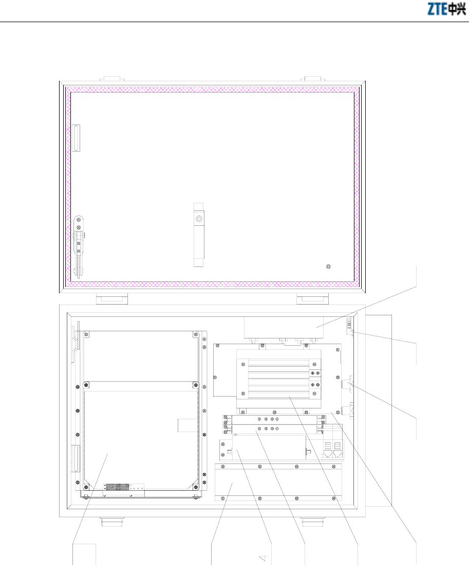
ZXCBTS (V5.4) CDMA Micro Base Transceiver Station & Remote Station Installation Manual
13-6
Fig. 13.1-4 shows the module layout inside the ZXCBTS integrated RF remote station:
10
9
87
6
5
3
2
1
1 RFM module (top layer) 2 MTRX module (bottom layer) 3 power module 4 MDIV module 5 MLNA module
6 Heater 7 MPA module 8 RF arrester 9 MTPB1 lightning protection plate (the external 48VUPS should be built internally)
10 MDUP module
Fig. 13.1-4 Layout of Internal Modules of the ZXCBTS RF Remote Station

Chapter 13 Installing the Integrated Micro-BTS
13-7
13.1.4 Networking Modes of the Integrated SDH
The built-in SDH technology is employed to make even more flexible networking of
the micro-BTS and to address basically various networking requirements. The built-in
SDH is a standard SDH STM-1 optical interface, which supports independent
networking or networking with cooperation of an SDH device. The built-in SDH also
supports directly fiber networking and has ring network protection capability. The
built-in SDH cooperates with the SDH transmission equipment via standard T1
interfaces to flexibly support different networking modes such as point-to-point, chain,
T-type, cross and ring modes and other hybrid networking modes. The built-in SDH
micro-BTS supports independent networking or networking with cooperation of a
standard SDH device.
13.2 Installing the Built-in SDH of Micro-BTS
13.2.1 Position and Internal Connection of the Built-in SDH in the Micro-BTS
13.2.1.1 Connections of the Built-in SDH
Table 13.2-1 gives the cable connections of the built-in SDH in the CDMA micro-BTS.
Table 13.2-1 Cable Connection of the Built-in SDH inside the CDMA Micro-BTS
No. Cable Name Length (mm) To End A To End B
1 Power cables 950 SDH-POWER (at the
bottom of the cabinet) SDH-X22
850 BDM_OUT1
SDH-R1
850 BDM_IN1
SDH-T1
850 BDM_OUT2
SDH-R2
2 RF cable
850 BDM_IN2
SDH-T2
3 F-DC PWR-002 5000 SDH-POWER (at the
bottom of the cabinet)
UPS power
supply
FIBER-3 (at the bottom
of the cabinet) SDH-D43
4 Fiber cable As required on site FIBER-4 (at the bottom
of the cabinet) SDH-D44
13.2.1.2 Schematic Diagram of Internal Cable Connection
Fig. 13.2-1 gives the cable layout of the built-in SDH in the CDMA micro-BTS.
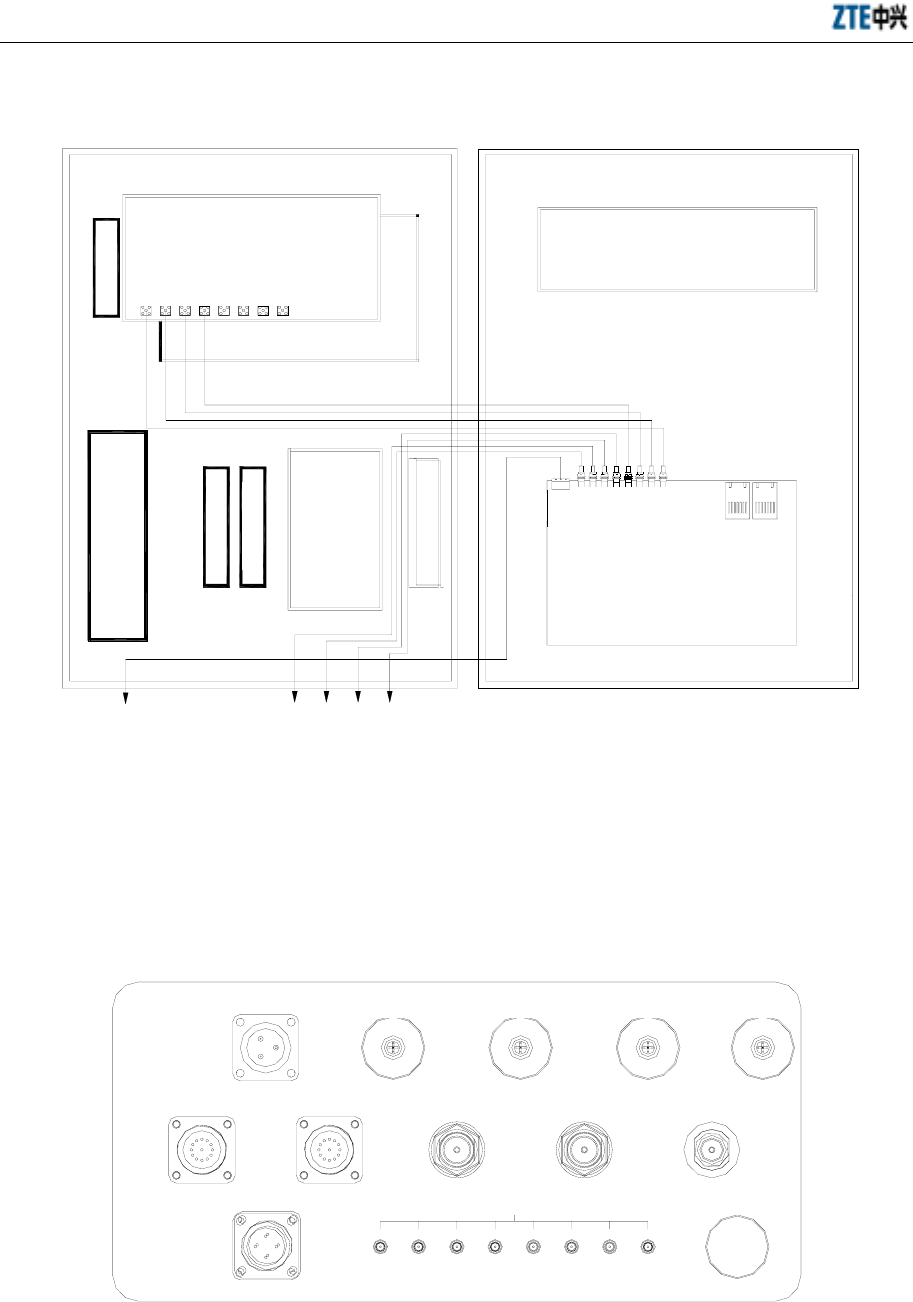
ZXCBTS (V5.4) CDMA Micro Base Transceiver Station & Remote Station Installation Manual
13-8
Door panel
GPS
BDM
Bottom SDH-POWER
SDH
M
P
D
L
N
A
L
N
A
M
P
A
D
U
P
IN2 OUT2 IN1 OUT1
ANT
10M
B
R
F
S
MTRX TX
RX0
RX1
D43 D44
T4R4T3R3T2R1T1R1
X22
OUT1IN1OUT2IN2OUT3IN3OUT4IN4
Fig. 13.2-1 Cable Layout of the Built-in SDH in the CDMA Micro-BTS
13.2.2 Connecting the External Optical Fibers and Cables During Installation
13.2.2.1 Description of the Cabinet-Bottom Interfaces
Fig. 13.2-2 shows all the cabinet-bottom interfaces of the micro-BTS:
POWER FIBER-1 FIBER-2 FIBER-3 FIBER-4
MONITOR FAN RFE-ANT0 RFE-ANT1 GPS-ANT
EXTEND
T1
SDH-POWER
IN4 OUT4 IN3 OUT3 IN2 OUT2 IN1 OUT1
Fig. 13.2-2 Cabinet-bottom Interfaces of the CDMA Micro-BTS

Chapter 13 Installing the Integrated Micro-BTS
13-9
See below for the meaning of each connector:
POWER——Power input of the micro-BTS;
FIBER-1\-2——Extension fiber interface of the RF remote station;
FIBER-3\-4——Input/output of the built-in SDH fiber interface of the micro-BTS;
MONITOR——Communication interface of the external UPS of the micro-BTS;
FAN——Fan interface for external heat dissipation of the high-power (over 20W)
micro-BTS;
RFE-ANT0——Diversity reception antenna interface of the micro-BTS;
RFE-ANT1——Main reception / transmission antenna interface of the micro-BTS;
GPS-ANT——GPS antenna interface;
SDH-POWER——Built-in SDH power supply interface of the micro-BTS;
T1——Four 2M signal interfaces;
EXTEND——RF extension interface of the multi-carrier micro-BTS.
13.2.2.2 Description of the Fiber Installation
Here the interfaces related with the built-in SDH are FIBER-3 and FIBER-4. FIBER-3
is the optical transmission input interface and FIBER-4 is the fiber transmission output
interface used for networking with the adjacent BTS.
Fig. 13.2-3 shows the position for installing the water-proof fiber at the bottom of the
micro-BTS cabinet and that for connecting and laying out the water-proof fiber inside
the cabinet.
The water-proof connector of the fiber is connected with the cabinet body in the similar
way to the fiber connection when the micro-BTS connects with the RF remote station.
The fiber is laid out in a naturally way after it goes into the cabinet and is connected
with the optical module on the SDH.
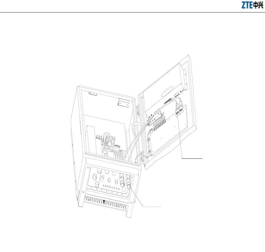
ZXCBTS (V5.4) CDMA Micro Base Transceiver Station & Remote Station Installation Manual
13-10
??????
SDH?????
Fiber water-proof
connector
SDH fiber
connector
Fig. 13.2-3 Connection of the Optical Fiber
13.3 Installing the Integrated UPS of Micro-BTS/RF Remote Station
13.3.1 Introduction to ZXUPS L010
Currently, the integrated CDMA micro-BTS employs the ZXUPS L010 as its UPS. Fig.
13.3-1 shows the appearance of the ZXUPS L010 series products.
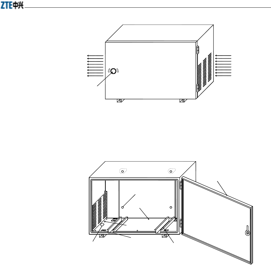
Chapter 13 Installing the Integrated Micro-BTS
13-11
DANGER OF HIGH VOLTAGE
Shutter for
air discharge
a
CLOSE
Key
OPEN
Front side of
enclosure
Rear side of
enclosure
Shutter for air
admittance
Fig. 13.3-1 Appearance of the ZXUPS L010 Series
Fig. 13.3-2 shows the inner structure of the ZXUPS L010 series.
外箱底部安装孔
外箱底部出水孔
外箱底部接地孔
外箱底部出线孔
外箱门
外箱底部导槽
外箱背部安装孔
Door panel
Rear-side
installation hole
Water outlet at
the bottom
Grounding hole
at the bottom
Leading-out hole
at the bottom
Installation hole
at the bottom
Bottom slide
Fig. 13.3-2 Inner Structure of the ZXUPS L010 Series
13.3.2 Precautions for UPS Installation
The following rules should be followed if the micro-BTS (800M or 1.9G) is to be
configured with an additional UPS:
1. The UPS must be kept within two meters away from the micro-BTS. Because
current micro-BTS uses the BDM for monitoring the UPS and the RS-232
specification for communication, the communication distance is limited to 10
meters generally. To ensure correct communication, no more than two meters
should better be kept between two cabinets. As the UPS is relatively close to
the micro-BTS, lightning-protection may be ignored for between them.

ZXCBTS (V5.4) CDMA Micro Base Transceiver Station & Remote Station Installation Manual
13-12
2. Improvement on the power connector of the micro-BTS. As the output of UPS
is screwed with the bolt, the power supply of the current micro-BTS cannot be
plugged. To improve this situation, a connector board may be used. Cut off the
input 3-core connector on the connector board, divide by L-N-PE and connect
respectively to the L-N-PE of the UPS’ output end. Be careful not to make any
mistakes in this operation. In most cases, the brown line is for the live line (L),
the blue line for neutral line (N) and the yellow-green line for protection
grounding line (PE).
3. At present, the UPS employs the 232 communication mode and its RS232
interface differs from other standards. There are six pins in total — Pin 6: RXD
(blue); Pin 7: GND (green); Pin 9: TXD (black), useful signal. The backup 232
interface of the BDM board is defined as: Pin 2: RXD; Pin 3: TXD; Pin 4:
GND. Therefore, the 232 connector of UPS has to be changed, that is: Connect
RXD (blue) to Pin 3 of DB9, TXD (black) to Pin 2 of DB9, and GND (green)
to Pin 4 of DB9. Remember that the DB9 connector must be a “male” one.
4. Precautions for installation
1) Good ventilation for heat dissipation;
2) Keep from the place with corrosive gas;
3) The top of UPS must not be occupied by any objects, nor could it be taken by a
sitting person, lest the air vent might be blocked;.
13.3.3 Structural Feature and Installation Mode of UPS
The ZXUPS L010UPS features a compact structure and boasts functions of dust-proof,
water-proof, thermal insulation, anti-burglary, damp-proof, mildew-proof and corrosion
protection. It is suitable for the outdoor environment in a remote area with formidable
natural conditions. With the modular design, the enclosure is not only neat-looking but
also rust-proof with excellent performance. This device can be installed easily and if it
is for outdoor use, it can be set up on the flat ground along with other delivery-attached
fittings, that is, the floor-type installation.
Fig. 13.3-3 shows the floor-type installation of ZXUPS L010UPS.
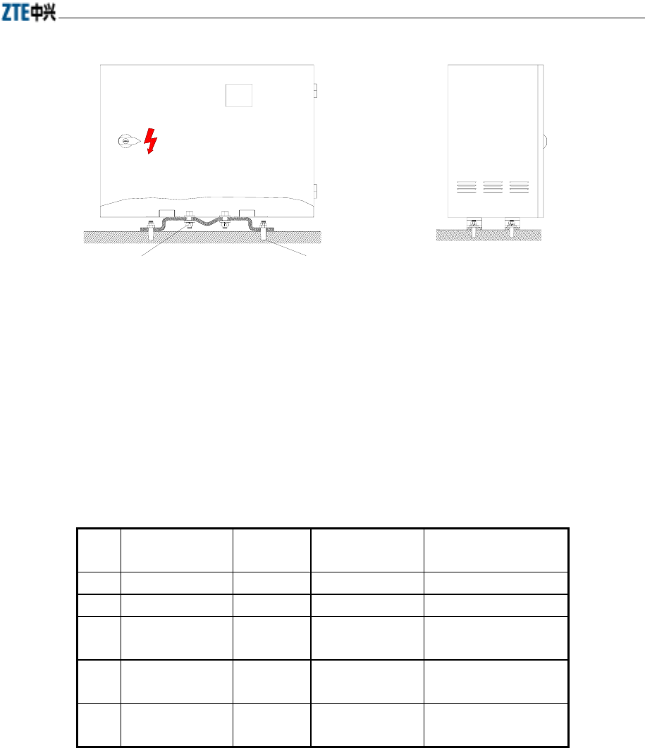
Chapter 13 Installing the Integrated Micro-BTS
13-13
M10×30内六角螺栓(4个)
弹簧垫 (4个)
平垫 (8个) M8膨胀螺丝(4个)
M8螺母 (4个)
地
Ground
Spring cushion
Plain cushion
M10x30 inner hexagon bolt
M8 nut
M8 expansion screw
(4pcs)
(8pcs)
(4pcs)
(4pcs)
(4pcs)
Fig. 13.3-3 Frontal and Lateral Faces of the UPS’s Floor-type Installation
13.3.4 Installing the Engineering Cables of L010UPS
13.3.4.1 From-to-list
Table 13.3-1 shows the connections of the CDMA micro-BTS 485 / dry contact
supplementary cables.
Table 13.3-1 From-to-list of the CDMA Micro-BTS 485/dry contact supplementary cables
No. Cable Name Length
(mm)
To End A To End B
1 Monitoring cable 800 BDM-RS485 MTPB1-X2
2 Monitoring cable 800 BDM-JOINT MTPB1-X1
3 Monitoring cable 470 MTPB1-X3 MONITOR at the
cabinet bottom
4 Monitoring
grounding cable
170 MTPB1 Grounding hole at the
right side of the cabinet
5 Monitoring cable 3000 MONITOR at the
cabinet bottom
DB9 socket of UPS
13.3.4.2 Layout of Cabling
Fig. 13.3-4 shows the layout of the monitoring cables of the CDMA micro-BTS
485/dry contact:
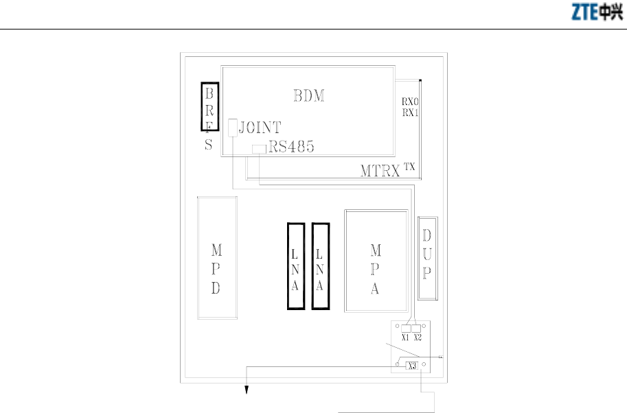
ZXCBTS (V5.4) CDMA Micro Base Transceiver Station & Remote Station Installation Manual
13-14
Connected together with the
front-door grounding cable
MTPB1 lightning-
protection board
Bottom MONOTOR
Fig. 13.3-4 Layout of the Monitoring Cables of the CDMA Micro-BTS 485/Dry Contact
Here three interfaces, namely POWER, MONITOR and SDH-POWER are related to
the external UPS.
Where,
One cable end of POWER interface is connected with the POWER interface, and the
other end is a standard 3-core power plug. To connect with the UPS, the 3-pin plug
should be cut off first, then the three core wires (yellow-green, blue and brown,
corresponding respectively to the ground line, neutral line and live line) should be
connected with the output terminal of UPS properly;
For the cable connection of the MONITOR interface, refer to the above-mentioned
from-to-list.
One end of the cable for the SDH-POWER interface is connected with this interface,
and the other with the secondary power-off output connecting terminal of UPS, with
the red and blue core wires connecting with the -48V, and the black and yellow-green
ones with the ground.
13.3.5 Installing UPS
As a product of ZTE, the ZXUPSL010 is delivered with the proper user’s manual
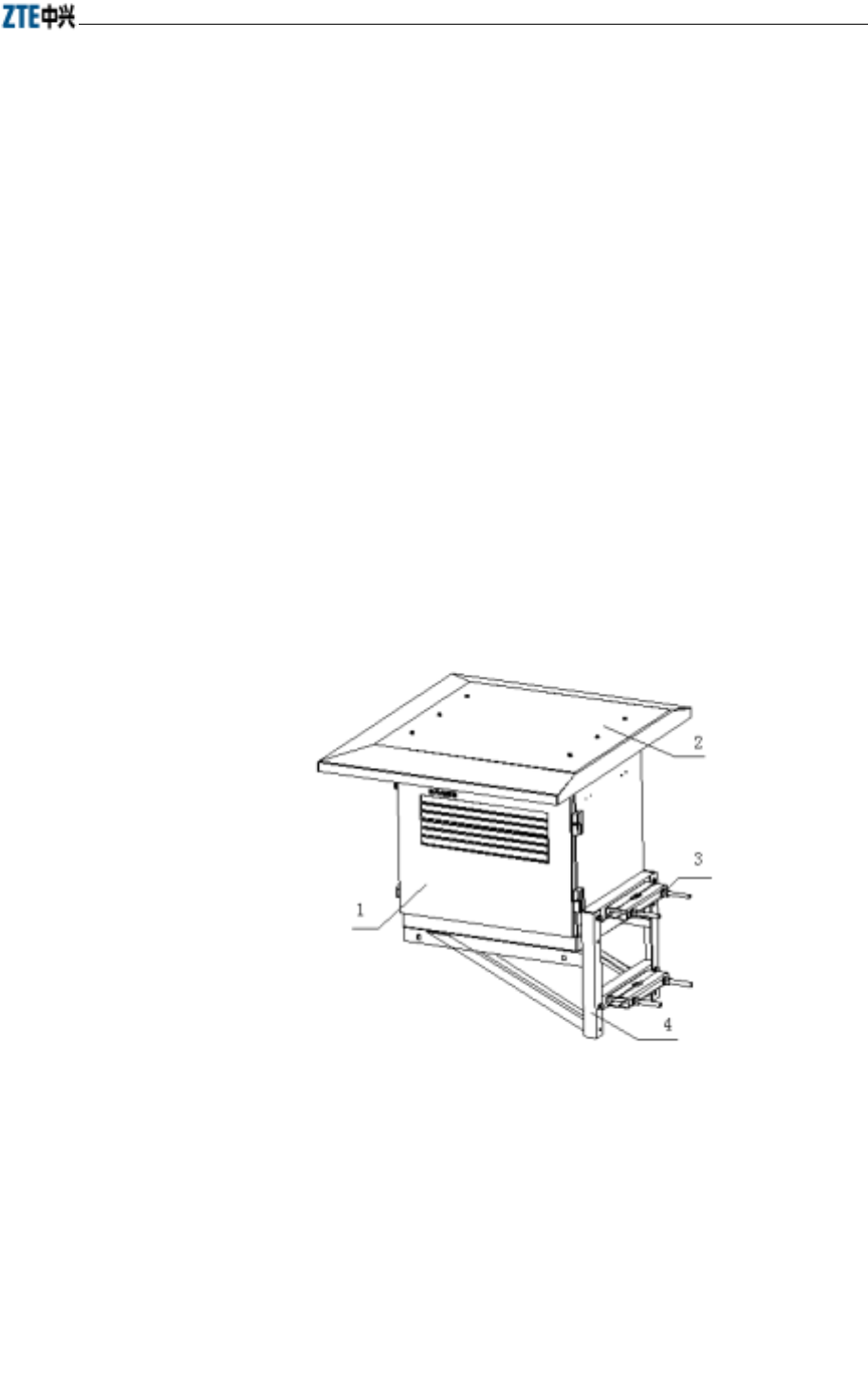
Chapter 13 Installing the Integrated Micro-BTS
13-15
attached, and this manual gives detailed instructions on the installation of the product.
13.4 Installing the Ancillary Combinational Power Supply of
Micro-BTS/RF Remote Station
The following ancillary power supply is recommended for the devices of the CDMA
cellular system: the ancillary combinational power supply consists of the outdoor
power box and outdoor battery box (model: ZXDU28). The outdoor power box may be
installed with a pole, on the wall or on the ground; while the outdoor battery box may
only be installed on the ground.
Given below is the brief introduction of the installation method and connection of the
outdoor power box and outdoor battery box.
13.4.1 Installing the Outdoor Power Box
13.4.1.1 Installing the Outdoor Power Box with a Pole
Fig. 13.4-1 shows how the outdoor power box is installed on the pole.
1——Outdoor power box 2——Sunshade unit 1 (used for installation with a pole or on the wall)
3——Mechanical part of pole (used for installation with a pole) 4——Installation support (used for installation with a
pole or on the wall)
Fig. 13.4-1 Schematic Diagram of Installing the Outdoor Power Box with a Pole
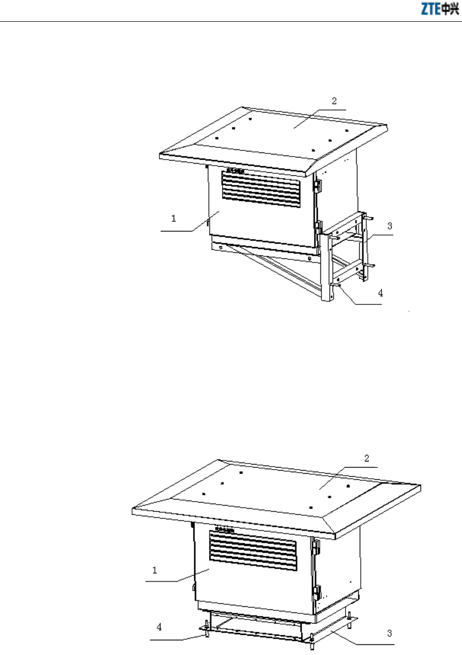
ZXCBTS (V5.4) CDMA Micro Base Transceiver Station & Remote Station Installation Manual
13-16
13.4.1.2 Installing the Outdoor Power Box on the Wall
Fig. 13.4-2 shows how to install the outdoor power box on the wall.
1——Outdoor power box 2——Sunshade unit 1 (used for installation with a pole or on the wall)
3——Installation support (used for installation with a pole or on the wall) 4——Expansion bolt M10X50
Fig. 13.4-2 Schematic Diagram of Installing the Outdoor Power Box on the Wall
13.4.1.3 Installing the Outdoor Power Box on the Ground
Fig. 13.4-3 shows how to install the outdoor power box on the ground.
1——Outdoor power box 2——Sunshade unit 2 (used for installation on the ground)
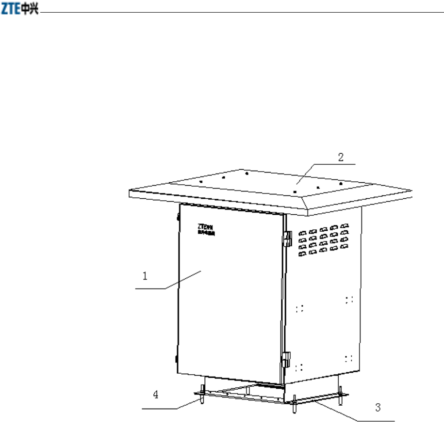
Chapter 13 Installing the Integrated Micro-BTS
13-17
3——Base (used for installation on the ground) 4——Expansion bolt M10X50
Fig. 13.4-3 Schematic Diagram of Installing the Outdoor Power Box on the Ground
13.4.2 Installing the Outdoor Battery Box
The outdoor can only be installed on the ground, which is shown in Fig. 13.4-4.
1——Outdoor battery box 2——Sunshade unit 2 (used for the installation on the ground)
3——Base (used for installation on the ground) 4——Expansion bolt M10X50
Fig. 13.4-4 Schematic Diagram of Installing the Outdoor Battery Box on the Ground
13.4.3 Cable Connection for Outdoor Power Box
The cable connection for the outdoor power box is presented in Fig. 13.4-5.
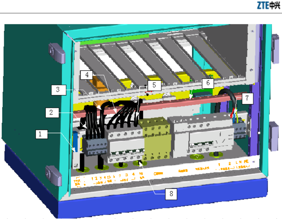
ZXCBTS (V5.4) CDMA Micro Base Transceiver Station & Remote Station Installation Manual
13-18
1. Dry contact output connecting terminal 2. Load output working ground 3. Battery input working ground 4. –48V
load output line
5. (-48V) battery input line 6. Cable holder 7. External AC input line 8. System’s cable access hole
Fig. 13.4-5 Schematic Diagram of the Cable Connection for the Outdoor Power Box
The function of dry contact monitoring is available with the combinational power
supply of the micro-BTS. The actual definition of the dry contact’s output connecting
terminal is (from top down): 1, 2, 3, 4, 5, 6, 7, 8, 9 and 10, as shown in Fig. 13.4-6.
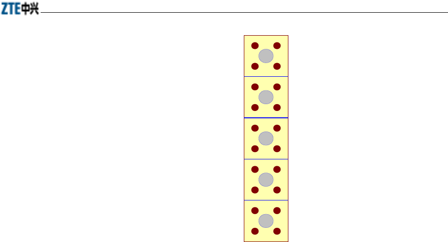
Chapter 13 Installing the Integrated Micro-BTS
13-19
1
2
3
4
5
6
7
8
9
10
Fig. 13.4-6 Output Connecting Terminal of the Dry Contact
Precautions for the cable connection of the combinational power supply:
1. Description of dry contact pairs: As shown in the above figure, 1 and 2 are a
pair of dry contacts (for the mains status alarm); 3 and 4 are a pair of dry
contacts (for the battery under-voltage alarm); 5 and 6 are a pair of dry contacts
(for the rectifier fault alarm); 7 and 8 are a pair of dry contacts (for the access
control alarm). The micro-BTS monitors only the first three, that is, the access
control monitoring is excluded. Between the dry contacts of the micro-BTS and
the combinational power supply, a 7-core monitoring cable attached with
delivery is used for the connection.
2. The cross-section area of the system’s AC input cable should be no smaller than
6mm2.
3. The cross-section area of the battery’s input cable should be no smaller than
16mm2.
4. The cross-section area of the DC load output cable should be no smaller than
10mm2.
5. There are clear silk-screen prints for the connecting terminals and the switch
definitions under the corresponding devices. Please check them out before you
go on with the connection or operation.
As the outdoor power box and outdoor battery box of the ancillary combinational

ZXCBTS (V5.4) CDMA Micro Base Transceiver Station & Remote Station Installation Manual
13-20
power supply are products of ZTE, proper user’s manual will be attached with the
product delivery. Detailed instructions are covered in these manuals for user’s
reference during the installation.

A-1
Appendix A Packaging, Storage and
Transportation
Summary
Describing how a micro-BTS/remote station is
packed.
Describing how a micro-BTS/remote station should
be stored.
Describing how a micro-BTS/remote station should
be transported.
A.1 Packaging
The packaging of all components of micro-BTS, ultra-wide micro-BTS, and remote
station are properly proofed against quakes during transportation. They are divided into
two groups in packaging:
1. Cabinets
2. Cables and delivery-attached document
Each item has been identified with model, name, placement direction, number of layers,
together with signs of “No damping”, and “Fragile” etc.
A.2 Storage
Keep all components in the original package. Keep the storeroom in order, and mark
the number of equipment sets in stock. The range of temperature is -40°C ~+75°C, and
the range of relative humidity is 5%~100%. Adopt measures of anti-moisture, anti-dust,
quake-proof, and anti-erosion. It is recommended to equip air-conditioner and lighting
equipment. The stock duration should be less than six months.

ZXCBTS (V5.4) CDMA Micro Base Transceiver Station & Remote Station Installation Manual
A-2
A.3 Transportation
Use designated containers.
All items should be placed closely, neatly, orderly and safely in the container to avoid
any possible damage during transportation. There should be three layers of wooden box
or four layers of cartons at maximum. Cables and delivery-attached document should
be placed in the lower half and the cabinet should be placed in the upper half.
Never put the equipment in open freight cars or ships. Never leave the equipment in
open warehouses. Never transport the equipment with flammable, explosive or erosive
chemicals. Keep the equipment away from being washed by rains and snow, or any
physical damage.
Keep the equipment away from electromagnetic or radiant substance during
transportation.
Ensure that all items are in the correct placement direction before being lifted during
transportation.

B-1
Appendix B Table of Cable Connections
Summary
Refer to the following tables for the cable
connections in micro-BTS and remote stations.
B.1 Cable Connections in M800T Single-carrier Micro-BTS
Table B.1-1 Cable Connections in M800T Single-carrier Micro-BTS
Serial
No. Cable Name Connection of Terminal A Connection of Terminal B Remarks
1 DCDX01 BRFS_X5 MPD_X11
2 DCDX02 MPD_X6 MPA800
3 DCDX03 MPD_X7 MLNA800
4 RSTDX MPD_X5 BRFS_X6
5 MONDX01 MPA800 MONDX02_B
6 MONDX02 MLNA800-1,-2 MONDX01_B
7 MPA CONTL MPA800 MTRX800
8 DX01 Door grounding point Cabinet grounding point
Cabinet Lightning arrester
9 DX02
Cabinet BDM
10 DX03 Cabinet Door
11 DX04 BDM800_X39 Door status switch
12 DX06 MPD_X4 Power lightning arrester
13 ACDX03 MPD_HP Heater
Power lightning arrester (blue,
brown)
14 ACDX01 POWER (at the bottom of the
cabinet)
Grounding point (black)
15 ACDX02 MPD_X1 Power lightning arrester
16 ACDX04 ACDX01_A External AC power
The configuration in
case that AC power
is supplied
17 F-DC PWR-001
POWER (at the bottom of the
cabinet) Power lightning arrester The configuration in
case that DC
p
ower

ZXCBTS (V5.4) CDMA Micro Base Transceiver Station & Remote Station Installation Manual
B-2
Serial
No. Cable Name Connection of Terminal A Connection of Terminal B Remarks
18 F-DC PWR-002 F-DC PWR-001_A External -48V power
19 F-DC PWR-003
(Blue) MPD_V-
(Black) MPD_V+ Power lightning arrester
is supplied
20 RF21 MDIV800_RX MLNA800-1_IN
21 RF22 MLNA800-2_IN MDUP800_RX
22 RF23 MTRX800_RX0 MLNA800-1_RFOUT1
23 RF24 MTRX800_RX1 MLNA800-2_RFOUT1
24 RF25 MTRX800_TX MPA800_IN
25 RF26 MDIV800_ANT RFE-ANT0 (at the bottom of the
cabinet)
26 RF27 RFE-ANT1 (at the bottom of the
cabinet) MDUP800_ANT
27 RF28 MPA800_OUT MDUP800_TX
28 RF29 GPS-ANT at the bottom of the
cabinet MGPS_ANT
29 RF30 MGPS_10M BDM800_X7
30 RF31 BDM800_X8 Middle hole of BRFS_X1
31 GPS-BDM BDM800_X3 BGPS_X2
B.2 Cable Connections in M800T Double-carrier Micro-BTS
Table B.2-1 Cable Connections in M800T Double-carrier Micro-BTS
Serial
No. Cable Name Connection of Terminal A Connection of Terminal B Remarks
1 DCDX01 BRFS_X5 MPD_X11
2 DCDX02 MPD_X6 MPA800
3 DCDX03 MPD_X7 MLNA800
4 RSTDX MPD_X5 BRFS_X6
5 MONDX01 MPA800 MONDX02_B
6 MONDX02 MLNA800-2 MONDX01_B
7 MPA CONTL MPA800 MTRX800
8 DX01 Door grounding point Cabinet grounding point
Cabinet Lightning arrester
9 DX02
Cabinet BDM
10 DX03 Cabinet Door
11 DX04 BDM800_X39 Door status switch

Appendix B Table of Cable Connections
B-3
Serial
No. Cable Name Connection of Terminal A Connection of Terminal B Remarks
12 DX06 MPD_X4 Power lightning arrester
13 ACDX03 MPD_HP Heater
Power lightning arrester (blue,
brown)
14 ACDX01 POWER (at the bottom of the
cabinet)
Grounding point (black)
15 ACDX02 MPD_X1 Power lightning arrester
16 ACDX04 ACDX01_A External AC power
The configuration in
case that AC power
is supplied
17 F-DC PWR-001
POWER (at the bottom of the
cabinet) Power lightning arrester
18 F-DC PWR-002 F-DC PWR-001_A External -48V power
19 F-DC PWR-003
(Blue) MPD_V-
(Black) MPD_V+ Power lightning arrester
The configuration in
case that DC power
is supplied
20 RF22 (Black) MPD_V+ MDUP800_RX
21 RF24 MTRX800_RX1 MLNA800-2_RFOUT1
22 RF25 MTRX800_TX MPA800_IN
23 RF27 RFE-ANT1 (at the bottom of the
cabinet) MDUP800_ANT
24 RF28 MPA800_OUT MDUP800_TX
25 RF29 GPS-ANT (at the bottom of the
cabinet) MGPS_ANT
26 RF30 MGPS_10M BDM800_X7
27 RF31 BDM800_X8 Middle hole of BRFS_X1
28 RF42 MLNA800-2_RFOUT2 RFE-ANT0 (at the bottom of the
cabinet)
29 RF43 MTRX800_RX0 EXTEND (at the bottom of the
cabinet)
30 GPS-BDM BDM800_X3 BGPS_X2
Note: Please refer to precautions listed in Table B-1.
B.3 Cable Connections in R800T Single-carrier Remote Stations
Table B.3-1 Cable Connections in R800T Single-carrier Remote Stations
Serial
No. Cable Name Connection of Terminal A Connection of Terminal B Remarks
1 DCDX01 BRFS_X5 MPD_X11
2 DCDX02 MPD_X6 MPA800
3 DCDX03 MPD_X7 MLNA800

ZXCBTS (V5.4) CDMA Micro Base Transceiver Station & Remote Station Installation Manual
B-4
Serial
No. Cable Name Connection of Terminal A Connection of Terminal B Remarks
4 RSTDX MPD_X5 BRFS_X6
5 MONDX01 MPA800 MONDX02_B
6 MONDX02 MLNA800-1, -2 MONDX01_B
7 MPA CONTL MPA800 MTRX800
8 DX01 Door grounding point Cabinet grounding point
Cabinet Lightning arrester
9 DX02
Cabinet BDM
10 DX03 Cabinet Door
11 DX05 RFM_X24 Door status switch
12 DX06 MPD_X4 Power lightning arrester
13 ACDX03 MPD_HP Heater
Power lightning arrester (blue,
brown)
14 ACDX01 POWER (at the bottom of
the cabinet)
Grounding point (black)
15 ACDX02 MPD_X1 Power lightning arrester
16 ACDX04 ACDX01_A External AC power
The configuration in
case that AC power
is supplied
17 F-DC PWR-001 POWER (at the bottom of
the cabinet) Power lightning arrester
18 F-DC PWR-002 F-DC PWR-001_A External -48V power
19 F-DC PWR-003 (Blue) MPD_V-
(Black) MPD_V+ Power lightning arrester
The configuration in
case that DC power
is supplied
20 RF21 MDIV800_RX MLNA800-1_IN
21 RF22 MLNA800-2_IN MDUP800_RX
22 RF23 MTRX800_RX0 MLNA800-1_RFOUT1
23 RF24 MTRX800_RX1 MLNA800-2_RFOUT1
24 RF25 MTRX800_TX MPA800_IN
25 RF26 MDIV800_ANT RFE-ANT0 (at the bottom of the
cabinet)
26 RF27 RFE-ANT1 (at the bottom of
the cabinet) MDUP800_ANT
27 RF28 MPA800_OUT MDUP800_TX
28 RF40 Middle hole of BRFS_X1 Middle hole of BRFS_X3
29 RF41 RFM_X7 Middle hole of RFM_X3

Appendix B Table of Cable Connections
B-5
B.4 Cable Connections in R800T Double-carrier Remote Stations
Table B.4-1 Cable Connections in R800T Double-carrier Remote Stations
Serial
No. Cable Name Connection of Terminal A Connection of Terminal B Remarks
1 DCDX01 BRFS_X5 MPD_X11
2 DCDX02 MPD_X6 MPA800
3 DCDX03 MPD_X7 MLNA800
4 RSTDX MPD_X5 BRFS_X6
5 MONDX01 MPA800 MONDX02_B
6 MONDX02 MLNA800-2 MONDX01_B
7 MPA CONTL MPA800 MTRX800
8 DX01 Door grounding point Cabinet grounding point
Cabinet Lightning arrester
9 DX02
Cabinet BDM
10 DX03 Cabinet Door
11 DX05 RFM_X24 Door status switch
12 DX06 MPD_X4 Power lightning arrester
13 ACDX03 MPD_HP Heater
Power lightning arrester (blue,
brown)
14 ACDX01 POWER (at the bottom of
the cabinet)
Grounding point (black)
15 ACDX02 MPD_X1 Power lightning arrester
16 ACDX04 ACDX01_A External AC power
The configuration in
case that AC power
is supplied
17 F-DC PWR-001 POWER (at the bottom of
the cabinet) Power lightning arrester
18 F-DC PWR-002 F-DC PWR-001_A External -48V power
19 F-DC PWR-003 (Blue) MPD_V-
(Black) MPD_V+ Power lightning arrester
The configuration in
case that DC power
is supplied
20 RF22 MLNA800-2_IN MDUP800_RX
21 RF24 MTRX800_RX1 MLNA800-2_RFOUT1
22 RF25 MTRX800_TX MPA800_IN
23 RF27 RFE-ANT1 (at the bottom
of the cabinet) MDUP800_ANT
24 RF28 MPA800_OUT MDUP800_TX
25 RF40 Middle hole of BRFS_X1 Middle hole of BRFS_X3
26 RF41 RFM_X7 Middle hole of RFM_X3
27 RF42 MLNA800-2_RFOUT2
RFE-ANT0 (at the bottom of the
cabinet)

ZXCBTS (V5.4) CDMA Micro Base Transceiver Station & Remote Station Installation Manual
B-6
Serial
No. Cable Name Connection of Terminal A Connection of Terminal B Remarks
28 RF43 MTRX800_RX0 EXTEND (at the bottom of the
cabinet)
B.5 Cable Connections in M190T Single-carrier Micro-BTS
Table B.5-1 Cable Connections in M190T Single-carrier Micro-BTS
Serial
No. Cable Name Connection of Terminal A Connection of Terminal B Remarks
1 DCDX01 BRFS_X5 MPD_X11
2 DCDX02 MPD_X6 MPA800
3 DCDX03 MPD_X7 MLNA800
4 RSTDX MPD_X5 BRFS_X6
5 MONDX01 MPA800 MONDX02_B
6 MONDX02 MLNA800-1, -2 MONDX01_B
7 MPA CONTL MPA800 MTRX800
8 DX01 Door grounding point Cabinet grounding point
Cabinet Lightning arrester
9 DX02 Cabinet BDM
10 DX03 Cabinet Door
11 DX05 RFM_X24 Door status switch
12 DX06 MPD_X4 Power lightning arrester
13 ACDX03 MPD_HP Heater
Power lightning arrester (blue, brown)
14 ACDX01 POWER (at the bottom of
the cabinet) Grounding point (black)
15 ACDX02 MPD_X1 Power lightning arrester
16 ACDX04 ACDX01_A External AC power
The configuration in
case that AC power
is supplied
17 F-DC PWR-001
POWER (at the bottom of
the cabinet) Power lightning arrester
18 F-DC PWR-002 F-DC PWR-001_A External -48V power
19 F-DC PWR-003
(Blue) MPD_V-
(Black) MPD_V+ Power lightning arrester
The configuration in
case that DC power
is supplied
20 RF21 MDIV800_RX MLNA800-1_IN
21 RF22 MLNA800-2_IN MDUP800_RX
22 RF23 MTRX800_RX0 MLNA800-1_RFOUT1
23 RF24 MTRX800_RX1 MLNA800-2_RFOUT1
24 RF25 MTRX800_TX MPA800_IN

Appendix B Table of Cable Connections
B-7
Serial
No. Cable Name Connection of Terminal A Connection of Terminal B Remarks
25 RF26 MDIV800_ANT RFE-ANT0 (at the bottom of the
cabinet)
26 RF27 RFE-ANT1 (at the bottom
of the cabinet) MDUP800_ANT
27 RF28 MPA800_OUT MDUP800_TX
28 RF40 Middle hole of BRFS_X1 Middle hole of BRFS_X3
29 R41 RFM_X7 Middle hole of RFM_X3
B.6 Cable Connections in M190T Double-carrier Micro-BTS
Table B.6-1 Cable Connections in M190T Double-carrier Micro-BTS
Serial
No. Cable Name Connection of Terminal A Connection of Terminal B Remarks
1 DCDX01 BRFS_X5 MPD_X11
2 DCDX02 MPD_X6 MPA800
3 DCDX03 MPD_X7 MLNA800
4 RSTDX MPD_X5 BRFS_X6
5 MONDX01 MPA800 MONDX02_B
6 MONDX02 MLNA800-2 MONDX01_B
7 MPA CONTL MPA800 MTRX800
8 DX01 Door grounding point Cabinet grounding point
Cabinet Lightning arrester
9 DX02
Cabinet BDM
10 DX03 Cabinet Door
11 DX05 RFM_X24 Door status switch
12 DX06 MPD_X4 Power lightning arrester
13 ACDX03 MPD_HP Heater
Power lightning arrester (blue, brown)
14 ACDX01 POWER (at the bottom of
the cabinet) Grounding point (black)
15 ACDX02 MPD_X1 Power lightning arrester
16 ACDX04 ACDX01_A External AC power
The configuration in
case that AC power
is supplied
17 F-DC PWR-001 POWER (at the bottom of
the cabinet) Power lightning arrester
18 F-DC PWR-002 F-DC PWR-001_A External -48V power
19 F-DC PWR-003 (Blue) MPD_V-
(Black) MPD_V+ Power lightning arrester
The configuration in
case that DC power
is supplied

ZXCBTS (V5.4) CDMA Micro Base Transceiver Station & Remote Station Installation Manual
B-8
Serial
No. Cable Name Connection of Terminal A Connection of Terminal B Remarks
20 RF22 MLNA800-2_IN MDUP800_RX
21 RF24 MTRX800_RX1 MLNA800-2_RFOUT1
22 RF25 MTRX800_TX MPA800_IN
23 RF27 RFE-ANT1 (at the bottom of
the cabinet) MDUP800_ANT
24 RF28 MPA800_OUT MDUP800_TX
25 RF40 Middle hole of BRFS_X1 Middle hole of BRFS_X3
26 RF41 RFM_X7 Middle hole of RFM_X3
27 RF42 MLNA800-2_RFOUT2 RFE-ANT0 (at the bottom of the
cabinet)
28 RF43 MTRX800_RX0 EXTEND (at the bottom of the cabinet)
B.7 Cable Connections in R190T Single-carrier Remote Stations
Table B.7-1 Cable Connections in R190T Single-carrier Remote Stations
Serial
No. Cable Name Connection of Terminal A Connection of Terminal B Remarks
1 DCDX01 BRFS_X5 MPD_X11
2 DCDX02 MPD_X6 MPA800
3 DCDX03 MPD_X7 MLNA800
4 RSTDX MPD_X5 BRFS_X6
5 MONDX01 MPA800 MONDX02_B
6 MONDX02 MLNA800-2 MONDX01_B
7 MPA CONTL MPA800 MTRX800
8 DX01 Door grounding point Cabinet grounding point
Cabinet Lightning arrester
9 DX02
Cabinet BDM
10 DX03 Cabinet Door
11 DX05 RFM_X24 Door status switch
12 DX06 MPD_X4 Power lightning arrester
13 ACDX03 MPD_HP Heater
Power lightning arrester (blue, brown)
14 ACDX01 POWER (at the bottom of
the cabinet) Grounding point (black)
15 ACDX02 MPD_X1 Power lightning arrester
16 ACDX04 ACDX01_A External AC power
The configuration
in case that AC
power is supplied

Appendix B Table of Cable Connections
B-9
Serial
No. Cable Name Connection of Terminal A Connection of Terminal B Remarks
17 F-DC PWR-001 POWER (at the bottom of
the cabinet) Power lightning arrester
18 F-DC PWR-002 F-DC PWR-001_A External -48V power
19 F-DC PWR-003 (Blue) MPD_V-
(Black) MPD_V+ Power lightning arrester
The configuration
in case that DC
power is supplied
20 RF22 MLNA800-2_IN MDUP800_RX
21 RF24 MTRX800_RX1 MLNA800-2_RFOUT1
22 RF25 MTRX800_TX MPA800_IN
23 RF27 RFE-ANT1 (at the bottom of
the cabinet) MDUP800_ANT
24 RF28 MPA800_OUT MDUP800_TX
25 RF40 Middle hole of BRFS_X1 Middle hole of BRFS_X3
26 RF41 RFM_X7 Middle hole of RFM_X3
27 RF42 MLNA800-2_RFOUT2 RFE-ANT0 (at the bottom of the
cabinet)
28 RF43 MTRX800_RX0 EXTEND (at the bottom of the cabinet)
B.8 Cable Connections in R190T Double-carrier Remote Stations
Table B.8-1 Cable Connections in R190T Double-carrier Remote Stations
Serial
No. Cable Name Connection of Terminal A Connection of Terminal B Remarks
1 DCDX01 BRFS_X5 MPD_X11
2 DCDX02 MPD_X6 MPA1900
3 DCDX03 MPD_X7 MLNA1900
4 RSTDX MPD_X5 BRFS_X6
5 MONDX01 MPA1900 MONDX02_B
6 MONDX02 MLNA1900-2 MONDX01_B
7 MPA CONTL MPA1900 MTRX1900
8 DX01 Door grounding point Cabinet grounding point
Cabinet Lightning arrester
9 DX02
Cabinet BDM
10 DX03 Cabinet Door
11 DX05 RFM_X24 Door status switch
12 DX06 MPD_X4 Power lightning arrester
13 ACDX03 MPD_HP Heater

ZXCBTS (V5.4) CDMA Micro Base Transceiver Station & Remote Station Installation Manual
B-10
Serial
No. Cable Name Connection of Terminal A Connection of Terminal B Remarks
Power lightning arrester (blue, brown)
14 ACDX01 POWER (at the bottom of
the cabinet) Grounding point (black)
15 ACDX02 MPD_X1 Power lightning arrester
16 ACDX04 ACDX01_A External AC power
The configuration in
case that AC power
is supplied
17 F-DC PWR-001 POWER (at the bottom of
the cabinet) Power lightning arrester
18 F-DC PWR-002 F-DC PWR-001_A External -48V power
19 F-DC PWR-003 (Blue) MPD_V-
(Black) MPD_V+ Power lightning arrester
The configuration in
case that DC power
is supplied
20 RF25 MTRX1900_TX MPA1900_IN
21 RF33 MLNA1900-2_IN MDUP1900_RX
22 RF34 MPA1900_OUT MDUP1900_TX
23 RF36 MTRX1900_RX1 MLNA1900-2_RFOUT1
24 RF38 RFE-ANT1 (at the bottom of
the cabinet) MDUP1900_ANT
25 RF40 Middle hole of BRFS_X1 Middle hole of BRFS_X3
26 RF41 RFM_X7 Middle hole of RFM_X3
27 RF42 MLNA1900-2_RFOUT2
RFE-ANT0 (at the bottom of the
cabinet)
28 RF43 MTRX1900_RX0 EXTEND (at the bottom of the cabinet)
B.9 Cable Connections in M802T Single-carrier Micro-BTS
Table B.9-1 Cable Connections in M802T Single-carrier Micro-BTS
Serial
No. Cable Name Connection of Terminal A Connection of Terminal B Remarks
1 DCDX01 BRFS_X5 MPD_X11
2 DCDX02 MPD_X6 MPA
3 DCDX03 MPD_X7 MLNA800
4 RSTDX MPD_X5 BRFS_X6
5 MONDX01 MPA MONDX02_B
6 MONDX02 MLNA800-1, -2 MONDX01_B
7 MPA CONTL MPA MTRX800
8 DX01 Door grounding point Cabinet grounding point
Cabinet Lightning arrester
9 DX02
Cabinet BDM

Appendix B Table of Cable Connections
B-11
Serial
No. Cable Name Connection of Terminal A Connection of Terminal B Remarks
10 DX03 Cabinet Door
11 DX04 BDM802_X39 Door status switch
12 DX06 MPD_X4 Power lightning arrester
13 ACDX03 MPD_HP Heater
Power lightning arrester (blue, brown)
14 ACDX01 POWER (at the bottom of
the cabinet) Grounding point (black)
15 ACDX02 MPD_X1 Power lightning arrester
16 ACDX04 ACDX01_A External AC power
The configuration in
case that AC power
is supplied
17 F-DC PWR-001 POWER (at the bottom of
the cabinet) Power lightning arrester
18 F-DC PWR-002 F-DC PWR-001_A External -48V power
19 F-DC PWR-003 (Blue) MPD_V-
(Black) MPD_V+ Power lightning arrester
The configuration in
case that DC power
is supplied
20 F-FAN-004 MPD Internal fan rack
21 F-FAN-005 COMMAN (at the bottom of
the cabinet) MPD
22 F-FAN-006 COMMAN (at the bottom of
the cabinet) External fan rack
23 RF21 MDIV800_RX MLNA800-1_IN
24 RF22 MLNA800-2_IN MDUP800_RX
25 RF23 MTRX800_RX0 MLNA800-1_RFOUT1
26 RF24 MTRX800_RX1 MLNA800-2_RFOUT1
27 R25 MTRX800_TX MPA_IN
28 RF26 MDIV800_ANT RFE-ANT0 (at the bottom of the
cabinet)
29 RF27 RFE-ANT1 (at the bottom of
the cabinet) MDUP800_ANT
30 RF28 MPA_OUT MDUP800_TX
31 RF29 GPS-ANT at the bottom of
the cabinet MGPS_ANT
32 RF30 MGPS_10M BDM802_X7
33 RF31 BDM802_X8 Middle hole of BRFS_X1
34 GPS-BDM BDM802_X3 BGPS_X2

ZXCBTS (V5.4) CDMA Micro Base Transceiver Station & Remote Station Installation Manual
B-12
B.10 Cable Connections in M802T Double-carrier Micro-BTS
Table B.10-1 Cable Connections in M802T Double-carrier Micro-BTS
Serial
No. Cable Name Connection of Terminal A Connection of Terminal B Remarks
1 DCDX01 BRFS_X5 MPD_X11
2 DCDX02 MPD_X6 MPA
3 DCDX03 MPD_X7 MLNA800
4 RSTDX MPD_X5 BRFS_X6
5 MONDX01 MPA MONDX02_B
6 MONDX02 MLNA800-2 MONDX01_B
7 MPA CONTL MPA MTRX800
8 DX01 Door grounding point Cabinet grounding point
Cabinet Lightning arrester
9 DX02
Cabinet BDM
10 DX03 Cabinet Door
11 DX04 BDM802_X39 Door status switch
12 DX06 MPD_X4 Power lightning arrester
13 ACDX03 MPD_HP Heater
Power lightning arrester (blue, brown)
14 ACDX01 POWER (at the bottom of the
cabinet) Grounding point (black)
15 ACDX02 MPD_X1 Power lightning arrester
16 ACDX04 ACDX01_A External AC power
The configuration in
case that AC power
is supplied
17 F-DC PWR-001
POWER (at the bottom of the
cabinet) Power lightning arrester
18 F-DC PWR-002 F-DC PWR-001_A External -48V power
19 F-DC PWR-003
(Blue) MPD_V-
(Black) MPD_V+ Power lightning arrester
The configuration in
case that DC power
is supplied
20 F-FAN-004 MPD Internal fan rack
21 F-FAN-005 COMMAN (at the bottom of
the cabinet) MPD
22 F-FAN-006 COMMAN (at the bottom of
the cabinet) External fan
23 RF22 (Black) MPD_V+ MDUP800_RX
24 RF24 MTRX800_RX1 MLNA800-2_RFOUT1
25 RF25 MTRX800_TX MPA_IN
26 RF27 RFE-ANT1 (at the bottom of
the cabinet) MDUP800_ANT
27 RF28 MPA_OUT MDUP800_TX

Appendix B Table of Cable Connections
B-13
Serial
No. Cable Name Connection of Terminal A Connection of Terminal B Remarks
28 RF29 GPS-ANT at the bottom of
the cabinet MGPS_ANT
29 RF30 MGPS_10M BDM802_X7
30 RF31 BDM802_X8 Middle hole of BRFS_X1
31 RF42 MLNA800-2_RFOUT2 RFE-ANT0 (at the bottom of the
cabinet)
32 RF43 MTRX800_RX0 EXTEND (at the bottom of the cabinet)
33 GPS-BDM BDM802_X3 BGPS_X2
B.11 Cable Connections in R802 Single-carrier RF Remote Stations
Table B.11-1 Cable Connections in R802T Single-carrier Remote Stations
Serial
No. Cable Name Connection of Terminal A Connection of Terminal B Remarks
1 DCDX01 BRFS_X5 MPD_X11
2 DCDX02 MPD_X6 MPA
3 DCDX03 MPD_X7 MLNA800
4 RSTDX MPD_X5 BRFS_X6
5 MONDX01 MPA MONDX02_B
6 MONDX02 MLNA800-1, -2 MONDX01_B
7 MPA CONTL MPA MTRX800
8 DX01 Door grounding point Cabinet grounding point
9 DX02 Cabinet Lightning arrester
10 DX03 Cabinet Door
11 DX05 RFM_X24 Door status switch
12 DX06 MPD_X4 Power lightning arrester
13 ACDX03 MPD_HP Heater
Power lightning arrester (blue, brown)
14 ACDX01 POWER (at the bottom of the
cabinet) Grounding point (black)
15 ACDX02 MPD_X1 Power lightning arrester
16 ACDX04 ACDX01_A External AC power
The configuration in
case that AC power
is supplied
17 F-DC PWR-001
POWER (at the bottom of the
cabinet) Power lightning arrester
18 F-DC PWR-002 F-DC PWR-001_A External -48V power
19 F-DC PWR-003
(Blue) MPD_V-
(Black) MPD_V+ Power lightning arrester
The configuration in
case that DC power
is supplied

ZXCBTS (V5.4) CDMA Micro Base Transceiver Station & Remote Station Installation Manual
B-14
Serial
No. Cable Name Connection of Terminal A Connection of Terminal B Remarks
20 RF21 MDIV800_RX MLNA800-1_IN
21 RF22 MLNA800-2_IN MDUP800_RX
22 RF23 MTRX800_RX0 MLNA800-1_RFOUT1
23 RF24 MTRX800_RX1 MLNA800-2_RFOUT1
24 RF25 MTRX800_TX MPA_IN
25 RF26 MDIV800_ANT RFE-ANT0 (at the bottom of the cabinet)
26 RF27 RFE-ANT1 (at the bottom of
the cabinet) MDUP800_ANT
27 RF28 MPA_OUT MDUP800_TX
28 RF40 Middle hole of BRFS_X1 Middle hole of BRFS_X3
29 RF41 RFM_X7 Middle hole of RFM_X3
30 F-FAN-005 COMMAN (at the bottom of
the cabinet) MPD
31 F-FAN-006 COMMAN (at the bottom of
the cabinet) External fan
B.12 Cable Connections in R802T Double-carrier Remote Stations
Table B.12-1 Cable Connections in R802T Double-carrier RF Remote Stations
Serial
No. Cable Name Connection of Terminal A Connection of Terminal B Remarks
1 DCDX01 BRFS_X5 MPD_X11
2 DCDX02 MPD_X6 MPA
3 DCDX03 MPD_X7 MLNA800
4 RSTDX MPD_X5 BRFS_X6
5 MONDX01 MPA MONDX02_B
6 MONDX02 MLNA800-2 MONDX01_B
7 MPA CONTL MPA MTRX800
8 DX01 Door grounding point Cabinet grounding point
9 DX02 Cabinet Lightning arrester
10 DX03 Cabinet Door
11 DX05 RFM_X24 Door status switch
12 DX06 MPD_X4 Power lightning arrester
13 ACDX03 MPD_HP Heater
Power lightning arrester (blue, brown)
14 ACDX01 POWER (at the bottom of the
cabinet) Grounding point (black)
The configuration in
case that AC power

Appendix B Table of Cable Connections
B-15
Serial
No. Cable Name Connection of Terminal A Connection of Terminal B Remarks
15 ACDX02 MPD_X1 Power lightning arrester
16 ACDX04 ACDX01_A External AC power
is supplied
17 F-DC PWR-001
POWER (at the bottom of the
cabinet) Power lightning arrester
18 F-DC PWR-002 F-DC PWR-001_A External -48V power
19 F-DC PWR-003
(Blue) MPD_V-
(Black) MPD_V+ Power lightning arrester
The configuration in
case that DC power
is supplied
20 RF22 MLNA800-2_IN MDUP800_RX
21 RF24 MTRX800_RX1 MLNA800-2_RFOUT1
22 RF25 MTRX800_TX MPA_IN
23 RF27 RFE-ANT1 (at the bottom of
the cabinet) MDUP800_ANT
24 RF28 MPA_OUT MDUP800_TX
25 RF40 Middle hole of BRFS_X1 Middle hole of BRFS_X3
26 RF41 RFM_X7 Middle hole of RFM_X3
27 RF42 MLNA800-2_RFOUT2 RFE-ANT0 (at the bottom of the
cabinet)
28 RF43 MTRX800_RX0 EXTEND (at the bottom of the cabinet)
29 F-FAN-005 COMMAN (at the bottom of
the cabinet) MPD
30 F-FAN-006 COMMAN (at the bottom of
the cabinet) External fan
B.13 Cable Connections in M191T Single-carrier Micro-BTS
Table B.13-1 Cable Connections in M191T Single-carrier Micro-BTS
Serial
No. Cable Name Connection of Terminal A Connection of Terminal B Remarks
1 DCDX01 BRFS_X5 MPD_X11
2 DCDX02 MPD_X6 MPA
3 DCDX03 MPD_X7 LNA
4 RSTDX MPD_X5 BRFS_X6
5 MONDX01 MPA MONDX02_B
6 MONDX02 LNA-1, -2 MONDX01_B
7 MPA CONTL MPA TRX
8 DX01 Door grounding point Cabinet grounding point

ZXCBTS (V5.4) CDMA Micro Base Transceiver Station & Remote Station Installation Manual
B-16
Serial
No. Cable Name Connection of Terminal A Connection of Terminal B Remarks
Cabinet Lightning arrester
9 DX02
Cabinet BDM
10 DX03 Cabinet Door
11 DX04 BDM_X39 Door status switch
12 DX06 MPD_X4 Power lightning arrester
13 ACDX03 MPD_HP Heater
Power lightning arrester (blue, brown)
14 ACDX01 POWER (at the bottom of the
cabinet) Grounding point (black)
15 ACDX02 MPD_X1 Power lightning arrester
16 ACDX04 ACDX01_A External AC power
The configuration in
case that AC power
is supplied
17 F-DC PWR-001
POWER (at the bottom of the
cabinet) Power lightning arrester
18 F-DC PWR-002 F-DC PWR-001_A External -48V power
19 F-DC PWR-003
(Blue) MPD_V-
(Black) MPD_V+ Power lightning arrester
The configuration in
case that DC power
is supplied
20 RF25 TRX_TX MPA_IN
21 RF29 GPS-ANT at the bottom of
the cabinet MGPS_ANT
22 RF32 DIV_RX LNA-1_IN
23 RF33 LNA-2_IN DUP_RX
24 RF34 MPA_OUT DUP_TX
25 RF35 TRX_RX0 LNA-1_RFOUT1
26 RF36 TRX_RX1 LNA-2_RFOUT1
27 RF37 DIV_ANT RFE-ANT0 (at the bottom of the
cabinet)
28 RF38 RFE-ANT1 (at the bottom of
the cabinet) DUP_ANT
29 RF39 MGPS_10M Middle hole of BRFS_X1
30 GPS-BDM BDM_X3 BGPS_X2
B.14 Cable Connections in M191T Double-carrier Micro-BTS
Table B.14-1 Cable Connections in M191T Double-carrier Micro-BTS
Serial
No. Cable Name Connection of Terminal A Connection of Terminal B Remarks
1 DCDX01 BRFS_X5 MPD_X11

Appendix B Table of Cable Connections
B-17
Serial
No. Cable Name Connection of Terminal A Connection of Terminal B Remarks
2 DCDX02 MPD_X6 MPA
3 DCDX03 MPD_X7 LNA
4 RSTDX MPD_X5 BRFS_X6
5 MONDX01 MPA MONDX02_B
6 MONDX02 LNA-2 MONDX01_B
7 MPA CONTL MPA TRX
8 DX01 Door grounding point Cabinet grounding point
Cabinet Lightning arrester
9 DX02
Cabinet BDM
10 DX03 Cabinet Door
11 DX04 BDM_X39 Door status switch
12 DX06 MPD_X4 Power lightning arrester
13 ACDX03 MPD_HP Heater
Power lightning arrester (blue, brown)
14 ACDX01 POWER (at the bottom of the
cabinet) Grounding point (black)
15 ACDX02 MPD_X1 Power lightning arrester
16 ACDX04 ACDX01_A External AC power
The configuration in
case that AC power
is supplied
17 F-DC PWR-001
POWER (at the bottom of the
cabinet) Power lightning arrester
18 F-DC PWR-002 F-DC PWR-001_A External -48V power
19 F-DC PWR-003
(Blue) MPD_V-
(Black) MPD_V+ Power lightning arrester
The configuration in
case that DC power
is supplied
20 RF25 TRX_TX MPA_IN
21 RF29 GPS-ANT at the bottom of
the cabinet MGPS_ANT
22 RF33 LNA-2_IN DUP_RX
23 RF34 MPA_OUT DUP_TX
24 RF36 TRX_RX1 LNA-2_RFOUT1
25 RF38 RFE-ANT1 (at the bottom of
the cabinet) DUP_ANT
26 RF39 MGPS_10M Middle hole of BRFS_X1
27 RF42 LNA-2_RFOUT2 RFE-ANT0 (at the bottom of the
cabinet)
28 RF43 TRX_RX0 EXTEND (at the bottom of the cabinet)
29 GPS-BDM BDM_X3 BGPS_X2

ZXCBTS (V5.4) CDMA Micro Base Transceiver Station & Remote Station Installation Manual
B-18
B.15 Cable Connections in R191T Single-carrier Remote Stations
Table B.15-1 Cable Connections in R191T Single-carrier Remote Stations
Serial
No. Cable Name Connection of Terminal A Connection of Terminal B Remarks
1 DCDX01 BRFS_X5 MPD_X11
2 DCDX02 MPD_X6 MPA
3 DCDX03 MPD_X7 LNA
4 RSTDX MPD_X5 BRFS_X6
5 MONDX01 MPA MONDX02_B
6 MONDX02 LNA-1, -2 MONDX01_B
7 MPA CONTL MPA TRX
8 DX01 Door grounding point Cabinet grounding point
Cabinet Lightning arrester
9 DX02
Cabinet BDM
10 DX03 Cabinet Door
11 DX05 RFM_X24 Door status switch
12 DX06 MPD_X4 Power lightning arrester
13 ACDX03 MPD_HP Heater
Power lightning arrester (blue, brown)
14 ACDX01 POWER (at the bottom of
the cabinet) Grounding point (black)
15 ACDX02 MPD_X1 Power lightning arrester
16 ACDX04 ACDX01_A External AC power
The configuration in
case that AC power
is supplied
17 F-DC PWR-001
POWER (at the bottom of
the cabinet) Power lightning arrester
18 F-DC PWR-002 F-DC PWR-001_A External -48V power
19 F-DC PWR-003
(Blue) MPD_V-
(Black) MPD_V+ Power lightning arrester
The configuration in
case that DC power
is supplied
20 RF25 TRX_TX MPA_IN
21 RF32 DIV_RX LNA-1_IN
22 RF33 LNA-2_IN MDUP1900_RX
23 RF34 MPA_OUT MDUP1900_TX
24 RF35 TRX_RX0 LNA-1_RFOUT1
25 RF36 TRX_RX1 LNA-2_RFOUT1
26 RF37 DIV_ANT RFE-ANT0 (at the bottom of the
cabinet)
27 RF38 RFE-ANT1 (at the bottom of
the cabinet) MDUP1900_ANT
28 RF40 Middle hole of BRFS_X1 Middle hole of BRFS_X3
29 RF41 RFM_X7 Middle hole of RFM_X3

Appendix B Table of Cable Connections
B-19
B.16 Cable Connections in R191T Double-carrier Remote Stations
Table B.16-1 Cable Connections in R191T Double-carrier Remote Stations
Serial
No. Cable Name Connection of Terminal A Connection of Terminal B Remarks
1 DCDX01 BRFS_X5 MPD_X11
2 DCDX02 MPD_X6 MPA
3 DCDX03 MPD_X7 LNA
4 RSTDX MPD_X5 BRFS_X6
5 MONDX01 MPA MONDX02_B
6 MONDX02 LNA-2 MONDX01_B
7 MPA CONTL MPA TRX
8 DX01 Door grounding point Cabinet grounding point
Cabinet Lightning arrester
9 DX02
Cabinet BDM
10 DX03 Cabinet Door
11 DX05 RFM_X24 Door status switch
12 DX06 MPD_X4 Power lightning arrester
13 ACDX03 MPD_HP Heater
Power lightning arrester (blue, brown)
14 ACDX01 POWER (at the bottom of
the cabinet) Grounding point (black)
15 ACDX02 MPD_X1 Power lightning arrester
16 ACDX04 ACDX01_A External AC power
The configuration in
case that AC power
is supplied
17 F-DC PWR-001
POWER (at the bottom of
the cabinet) Power lightning arrester
18 F-DC PWR-002 F-DC PWR-001_A External -48V power
19 F-DC PWR-003
(Blue) MPD_V-
(Black) MPD_V+ Power lightning arrester
The configuration in
case that DC power
is supplied
20 RF25 TRX_TX MPA_IN
21 RF33 LNA-2_IN MDUP1900_RX
22 RF34 MPA_OUT MDUP1900_TX
23 RF36 TRX_RX1 LNA-2_RFOUT1
24 RF38 RFE-ANT1 (at the bottom of
the cabinet) MDUP1900_ANT
25 RF40 Middle hole of BRFS_X1 Middle hole of BRFS_X3
26 RF41 RFM_X7 Middle hole of RFM_X3
27 RF42 LNA-2_RFOUT2 RFE-ANT0 (at the bottom of the
cabinet)
28 RF43 TRX_RX0 EXTEND (at the bottom of the cabinet)

ZXCBTS (V5.4) CDMA Micro Base Transceiver Station & Remote Station Installation Manual
B-20
B.17 Cable Connections in M192T Single-carrier Micro-BTS
Table B.17-1 Cable Connections in M192T Single-carrier Micro-BTS
Serial
No. Cable Name Connection of Terminal A Connection of Terminal B Remarks
1 DCDX01 BRFS_X5 MPD_X11
2 DCDX02 MPD_X6 MPA
3 DCDX03 MPD_X7 MLNA
4 RSTDX MPD_X5 BRFS_X6
5 MONDX01 MPA MONDX02_B
6 MONDX02 MLNA-1, -2 MONDX01_B
7 MPA CONTL MPA TRX
8 DX01 Door grounding point Cabinet grounding point
Cabinet Lightning arrester
9 DX02
Cabinet BDM
10 DX03 Cabinet Door
11 DX04 BDM_X39 Door status switch
12 DX06 MPD_X4 Power lightning arrester
13 ACDX03 MPD_HP Heater
Power lightning arrester (blue, brown)
14 ACDX01 POWER (at the bottom of
the cabinet) Grounding point (black)
15 ACDX02 MPD_X1 Power lightning arrester
16 ACDX04 ACDX01_A External AC power
The configuration in
case that AC power
is supplied
17 F-DC PWR-001
POWER (at the bottom of
the cabinet) Power lightning arrester
18 F-DC PWR-002 F-DC PWR-001_A External -48V power
19 F-DC PWR-003
(Blue) MPD_V-
(Black) MPD_V+ Power lightning arrester
The configuration in
case that DC power
is supplied
20 F-FAN-004 MPD Internal fan rack
21 F-FAN-005 COMMAN (at the bottom of
the cabinet) MPD
22 F-FAN-006 COMMAN (at the bottom of
the cabinet) External fan rack
23 RF25 TRX_TX MPA_IN
24 RF29 GPS-ANT at the bottom of
the cabinet MGPS_ANT
25 RF32 DIV_RX LNA-1_IN
26 RF33 LNA-2_IN DUP_RX
27 RF34 MPA_OUT DUP_TX
28 RF35 TRX_RX0 LNA-1_RFOUT1

Appendix B Table of Cable Connections
B-21
Serial
No. Cable Name Connection of Terminal A Connection of Terminal B Remarks
29 RF36 TRX_RX1 LNA-2_RFOUT1
30 RF37 DIV_ANT RFE-ANT0 (at the bottom of the
cabinet)
31 RF38 RFE-ANT1 (at the bottom of
the cabinet) DUP_ANT
32 RF39 MGPS_10M Middle hole of BRFS_X1
33 GPS-BDM BDM_X3 BGPS_X2
B.18 Cable Connections in M192T Double-carrier Micro-BTS
Table B.18-1 Cable Connections in M192T Double-carrier Micro-BTS
Serial
No. Cable Name Connection of Terminal A Connection of Terminal B Remarks
1 DCDX01 BRFS_X5 MPD_X11
2 DCDX02 MPD_X6 MPA
3 DCDX03 MPD_X7 MLNA
4 RSTDX MPD_X5 BRFS_X6
5 MONDX01 MPA MONDX02_B
6 MONDX02 MLNA-2 MONDX01_B
7 MPA CONTL MPA TRX
8 DX01 Door grounding point Cabinet grounding point
Cabinet Lightning arrester
9 DX02 Cabinet BDM
10 DX03 Cabinet Door
11 DX04 BDM_X39 Door status switch
12 DX06 MPD_X4 Power lightning arrester
13 ACDX03 MPD_HP Heater
Power lightning arrester (blue, brown)
14 ACDX01 POWER (at the bottom of
the cabinet) Grounding point (black)
15 ACDX02 MPD_X1 Power lightning arrester
16 ACDX04 ACDX01_A External AC power
The configuration in
case that AC power
is supplied
17 F-DC PWR-001 POWER (at the bottom of
the cabinet) Power lightning arrester
18 F-DC PWR-002 F-DC PWR-001_A External -48V power
19 F-DC PWR-003 (Blue) MPD_V-
(Black) MPD_V+ Power lightning arrester
The configuration in
case that DC power
is supplied

ZXCBTS (V5.4) CDMA Micro Base Transceiver Station & Remote Station Installation Manual
B-22
Serial
No. Cable Name Connection of Terminal A Connection of Terminal B Remarks
20 F-FAN-004 MPD Internal fan rack
21 F-FAN-005 COMMAN (at the bottom of
the cabinet) MPD
22 F-FAN-006 COMMAN (at the bottom of
the cabinet) External fan
23 RF25 TRX_TX MPA_IN
24 RF29 GPS-ANT at the bottom of
the cabinet MGPS_ANT
25 RF33 LNA-2_IN DUP_RX
26 RF34 MPA_OUT DUP_TX
27 RF36 TRX_RX1 LNA-2_RFOUT1
28 RF38 RFE-ANT1 (at the bottom
of the cabinet) DUP_ANT
29 RF39 MGPS_10M Middle hole of BRFS_X1
30 RF42 LNA-2_RFOUT2 RFE-ANT0 (at the bottom of the
cabinet)
31 RF43 TRX_RX0 EXTEND (at the bottom of the cabinet)
32 GPS-BDM BDM_X3 BGPS_X2
B.19 Cable Connections in R192T Single-carrier Remote Stations
Table B.19-1 Cable Connections in R192T Single-carrier Remote Stations
Serial
No. Cable Name Connection of Terminal A Connection of Terminal B Remarks
1 DCDX01 BRFS_X5 MPD_X11
2 DCDX02 MPD_X6 MPA
3 DCDX03 MPD_X7 LNA
4 RSTDX MPD_X5 BRFS_X6
5 MONDX01 MPA MONDX02_B
6 MONDX02 LNA-1, -2 MONDX01_B
7 MPA CONTL MPA TRX
8 DX01 Door grounding point Cabinet grounding point
9 DX02 Cabinet Lightning arrester
10 DX03 Cabinet Door
11 DX05 RFM_X24 Door status switch
12 DX06 MPD_X4 Power lightning arrester

Appendix B Table of Cable Connections
B-23
Serial
No. Cable Name Connection of Terminal A Connection of Terminal B Remarks
13 ACDX03 MPD_HP Heater
Power lightning arrester (blue, brown)
14 ACDX01 POWER (at the bottom of
the cabinet) Grounding point (black)
15 ACDX02 MPD_X1 Power lightning arrester
16 ACDX04 ACDX01_A External AC power
The configuration in
case that AC power is
supplied
17 F-DC PWR-001
POWER (at the bottom of
the cabinet) Power lightning arrester
18 F-DC PWR-002 F-DC PWR-001_A External -48V power
19 F-DC PWR-003
(Blue) MPD_V-
(Black) MPD_V+ Power lightning arrester
The configuration in
case that DC power
is supplied
20 RF25 TRX_TX MPA_IN
21 RF32 DIV_RX LNA-1_IN
22 RF33 LNA-2_IN MDUP1900_RX
23 RF34 MPA_OUT MDUP1900_TX
24 RF35 TRX_RX0 LNA-1_RFOUT1
25 RF36 TRX_RX1 LNA-2_RFOUT1
26 RF37 DIV_ANT RFE-ANT0 (at the bottom of the
cabinet)
27 RF38 RFE-ANT1 (at the bottom
of the cabinet) MDUP1900_ANT
28 RF40 Middle hole of BRFS_X1 Middle hole of BRFS_X3
29 RF41 RFM_X7 Middle hole of RFM_X3
30 F-FAN-005 COMMAN (at the bottom of
the cabinet) MPD
31 F-FAN-006 COMMAN (at the bottom of
the cabinet) External fan
B.20 Cable Connections in R192T Double-carrier Remote Stations
Table B.20-1 Cable Connections in R192T Double-carrier Remote Stations
Serial
No. Cable Name Connection of Terminal A Connection of Terminal B Remarks
1 DCDX01 BRFS_X5 MPD_X11
2 DCDX02 MPD_X6 MPA
3 DCDX03 MPD_X7 LNA
4 RSTDX MPD_X5 BRFS_X6

ZXCBTS (V5.4) CDMA Micro Base Transceiver Station & Remote Station Installation Manual
B-24
Serial
No. Cable Name Connection of Terminal A Connection of Terminal B Remarks
5 MONDX01 MPA MONDX02_B
6 MONDX02 LNA-2 MONDX01_B
7 MPA CONTL MPA TRX
8 DX01 Door grounding point Cabinet grounding point
9 DX02 Cabinet Lightning arrester
10 DX03 Cabinet Door
11 DX05 RFM_X24 Door status switch
12 DX06 MPD_X4 Power lightning arrester
13 ACDX03 MPD_HP Heater
Power lightning arrester (blue, brown)
14 ACDX01 POWER (at the bottom of
the cabinet) Grounding point (black)
15 ACDX02 MPD_X1 Power lightning arrester
16 ACDX04 ACDX01_A External AC power
The configuration in
case that AC power
is supplied
17 F-DC PWR-001
POWER (at the bottom of
the cabinet) Power lightning arrester
18 F-DC PWR-002 F-DC PWR-001_A External -48V power
19 F-DC PWR-003
(Blue) MPD_V-
(Black) MPD_V+ Power lightning arrester
The configuration in
case that DC power
is supplied
20 RF25 TRX_TX MPA_IN
21 RF33 LNA-2_IN MDUP1900_RX
22 RF34 MPA_OUT MDUP1900_TX
23 RF36 TRX_RX1 LNA-2_RFOUT1
24 RF38 RFE-ANT1 (at the bottom
of the cabinet) MDUP1900_ANT
25 RF40 Middle hole of BRFS_X1 Middle hole of BRFS_X3
26 RF41 RFM_X7 Middle hole of RFM_X3
27 RF42 LNA-2_RFOUT2 RFE-ANT0 (at the bottom of the
cabinet)
28 RF43 TRX_RX0 EXTEND (at the bottom of the cabinet)
29 F-FAN-005 COMMAN (at the bottom of
the cabinet) MPD
30 F-FAN-006 COMMAN (at the bottom of
the cabinet) External fan

C-1
Appendix C Equipment Parameters
C.1 Dimension
See Fig. C.1-1 for the appearance of a micro-BTS/remote station cabinet.
Fig. C.1-1 Appearance of a ZXCBTS Cabinet
The dimension of the cabinet is 630mm (height)×400mm (width)×285mm (depth). The
weight of one cabinet is 45kg.
C.2 Power Consumption
Refer to the following table for the power consumption of several types of micro-BTS
and remote stations supplied with the 120V AC power in case of full load.

ZXCBTS (V5.4) CDMA Micro Base Transceiver Station & Remote Station Installation Manual
C-2
Table C.2-1 Power Consumption of Several Types of Micro-BTS and Remote Stations
Model Power Consumption
M190T 180W
M191T 195W
M192T 290W
M800T 195W
M802T 290W
R190T 180W
R191T 195W
R192T 290W
R800T 195W
R802T 290W
Power factor: 0.5
Refer to the following table for the power consumption of several types of micro-BTS
and remote stations supplied with the 120V AC power in case of full load when they
are configured with heaters.
Table C.2-2 Power Consumption of Several Types of Micro-BTS and Remote Stations
Model Power Consumption (Watt)
M190T 280W
M191T 295W
M192T 390W
M800T 295W
M802T 390W
R190T 280W
R191T 295W
R192T 390W
R800T 295W
R802T 390W
Power factor: 0.5
Note: When the temperature is lower than -10°C, a heater can be added. Currently, only the equipment supplied with 120V
AC power support this function.
DC equipment does not support this function.

Appendix C Equipment Parameters
C-3
Refer to the following table for the power consumption of several types of micro-BTS
and remote stations supplied with the -48V DC power in case of full load.
Table C.2-3 Power Consumption of Several Types of Micro-BTS and Remote Stations
Model Power Consumption (Watt)
M190T 180W
M191T 195W
M192T 290W
M800T 195W
M802T 290W
R190T 180W
R191T 195W
R192T 290W
R800T 195W
R802T 290W
D-1
Appendix D Indicators
D.1 BDM Indicators
See Fig. D.1-1 for the BDM indicators and their meanings.
HL4
HL7
HL8
HL5
HL6
HL16
HL11
HL10
HL3
HL9
HL17
HL18
HL12
HL13
HL14
HL15
HL2
HL1
HL4: 3.3V power indicator
HL7: 5V power indicator
HL8: 12V power indicator
HL3: Synchronization indicator for the first channel of E1.
On: asynchronized; Off: synchronized.
HL9: Synchronization indicator for the second channel of
E1. On: asynchronized; Off: synchronized.
HL17: Synchronization indicator for the third channel of E1.
On: asynchronized; Off: synchronized.
HL18: Synchronization indicator for the fourth channel of
E1. On: asynchronized; Off: synchronized.
HL2: EPLD running indicator. On: Normal; Off: Not written
HL1: FPGA running indicator. On: Not downloaded; Off:
Downloaded.
HL5: System running indicator. On: Not started; Flash
slowly: Loading data; Flash fast: Running normally.
HL10: Alarm indicator. Off: No alarm is generated; Flash
quickly: An alarm is generated.
HL6, HL16 and HL11: Reserved.
HL12 ~ HL15: 10M Ethernet network running indicator.
Used for debugging.
Fig. D.1-1 Indicators of the BDM
D.2 Indicators on Front Panel of MGPS
Refer to Table D.2-1 for the indicators on the front panel of MGPS and their meanings.
Table D.2-1 Indicators on the Front Panel of MGPS
Meaning
Indicator
On Off
RUN (Green) Indicates that the equipment is working
normally.
Indicates that the equipment is
abnormal.
ZXCBTS (V5.4) CDMA Micro Base Transceiver Station & Remote Station Installation Manual
D-2
Meaning
Indicator
On Off
WARM UP (Green) Indicates that the equipment is warming up. Indicates that the equipment is
working normally.
GPS ALM (Green)
Indicates that the equipment is in
initialization status, unlocked status or in
status in which satellite signals cannot be
received.
If it flashes, it indicates that the GPS
antenna is disconnected.
Other causes
1PPS ALM (Green) Indicates that the 1PPS detection accuracy
exceeds the required range (800ns).
Indicates that the 1PPS
detection accuracy meets the
requirement (800ns).
FAULT (Red) Indicates that the equipment is faulty.
Check TOD messages for the cause.
Indicates that the equipment is
working normally.
10MHz (Red) No output Output of 10MHz
19.6608MHz (Red) No output Output of 19.6608MHz
PP2S (Red) No output Output of PP2S
D.3 Indicators of LFM, RFM and OIM
1. Refer to the following table for the LFM indicators and their meanings.
Table D.3-1 Indicators of the LFM
Indicator Meaning
POWER (Red) Power indicator. When it is on, it indicates that power is being
supplied.
CLKER (Red) Clock alarm indicator. When it is on, it indicates that no clock
signal is recovered in the LFM.
TXCLK (Green) Tx clock indicator. When it is on, it indicates that the
multiplexing chip in the LFM locks the Tx clock.
FIBIN (Green) Optical signal indicator. When it is on, it indicates that optical
signal is entering the optical interface.
RXREADY (Green) Data receiving indicator. When it is on, it indicates that the LFM
is recovering the data from the optical links correctly.

Appendix D Indicators
D-3
2. Refer to the following table for the RFM indicators and their meanings.
Table D.3-2 Indicators of the RFM
Indicator Meaning
HL7 ALARMCLK (Red)
Clock alarm indicator. When it is on, it indicates that the RFM
cannot recover the 16chip clock signal from the optical links
correctly.
HL2 PLLLOST (Red) Phase-locked loop indicator. When it is on, it indicates that the
phase-locked loop of the RFM is unlocked.
HL12 TEMP_INT (Red) Temperature alarm indicator. When it is on, it indicates that the
temperature is too high.
HL11 OPT_DETECT (Green) PP2S indicator. When it flashes every 2 seconds, it indicates that
the links are normal.
HL10 DOOR (Green) Door control indicator. When it is on, it indicates that the door is
opened.
HL9 SD_ALARM (Green) Optical signal alarm indicator. When it is on, it indicates that no
optical signal enters the optical interface.
HL3 3.3V (Green) 3.3V power indicator. When it is on, it indicates that the 3.3V
power is supplied normally.
HL1 5V (Green) 5V power indicator. When it is on, it indicates that the 5V power
is supplied normally.
HL4 12V (Green) 12V power indicator. When it is on, it indicates that the 12V
power is supplied normally.
HL6 1032LOCK (Green) Tx clock indicator. When it is on, it indicates that the
multiplexing chip in the RFM locks the Tx clock.
HL17 1034RDY (Green) Data receiving indicator. When it is on, it indicates that the RFM
is recovering the data from the optical links correctly.
HL8 LVDS_TEST Test indicator. It is always off.
ZXCBTS (V5.4) CDMA Micro Base Transceiver Station & Remote Station Installation Manual
D-4
3. See Fig. D.3-1 for the location of the indicators on the OIM panel.
HL2
HL5 HL4HL3HL1 HL6
ZX3G1X-OIM
Fig. D.3-1 Location of Indicators on the OIM Panel
Table D.3-3 Indicators on the OIM Panel
Indicator Meaning
HL1 3.3V power indicator. When it is on, it indicates that the 3.3V power is being
supplied normally; when it is off, it indicates that the 3.3V power is not available.
HL2 Tx clock lock indicator. When it is on, it indicates that the Tx clock has been
locked; when it is off, it indicates that the Tx clock has not been locked yet.
HL3
Data receiving preparation indicator. When it is on, it indicates that the receiving
p
reparation has been completed; when it is off, it indicates that the receiving
preparation has not been completed yet.
HL4 Optical signal indicator. When it is on, it indicates that optical signals are available;
when it is off, it indicates that no optical signals are available.
HL5 5V power indicator. When it is on, it indicates that the 5V power is supplied
normally; when it is off, it indicates that the 5V power is not available.
HL6
Data receiving error indicator. When it is on, it indicates that errors exist in the
currently received data; when it is off, it indicates that the currently received data is
correct.

E-1
Appendix E Abbreviations
Abbreviation Full Name
1X EV 1X Evolution
1X EV-DO 1X Evolution Data Only
1X EV-DV 1X Evolution Data & Voice
1X EV-DO 1X Evolution Data Optimized
24PB 24V Power Board
2G BTS 2G Base Transceiver Station
3G BTS 3G Base Transceiver Station
A
AAA Authentication Authorization Accounting
AAL ATM Adaptation Layer
AAL2 ATM Adaptation Layer type 2
AAL5 ATM Adaptation Layer type 5
Abis Interface Abis Interface—the interface of BSC--BTS
ABS Air Break Switch
AC Asynchronous Capsule
ACB Amplifier Control Board
ACCH Associated Control Channel
ACCM Asynchronous Control Character Map
ACIR Adjacent Channel Interference Ratio
ACK Acknowledgement
ACLR Adjacent Channel Leakage Power Ratio
ACS Adjacent Channel Selectivity
AGC Automatic Gain Control
AH Authentication Header
AI Acquisition Indicator
AICH Acquisition Indicator Channel
AID Application Identifier
AIUR Air Interface User Rate
AK Anonymity key
ALC Automatic Level Control
ALCAP Access Link Control Application Protocol
AM Acknowledged Mode
AMB Attenuation Matching Board

ZXCBTS (V5.4) CDMA Micro Base Transceiver Station & Remote Station Installation Manual
E-2
Abbreviation Full Name
AMF Authentication Management Field
AMP Address Management Protocol
AMR Adaptive Multi Rate
AN Access Network
ANID Access Network Identifiers
AP Access preamble
APD AC Power Distribution Module
APDU Application Protocol Data Unit
API Application Programming Interface
ARM ARM processor
ARP Address Resolution Protocol
ARQ Automatic Repeat Request
AS Access Stratum
ASC Access Service Class
A-SGW Access Signaling Gateway
ASN.1 Abstract Syntax Notation One
AT Access Terminal
ATM Asynchronous Transfer Mode
ATR Answer To Reset
ATT Attenuator
AUC Authentication Center
AUTN Authentication token
AWGN Additive White Gaussian Noise
A Interface A Interface - the interface between BSC and MSC
B
B-BDS Backplane of Baseband Digital Subsystem
BBDS Backplane of BDS
BBS BTS Baseband Subsystem
BCC Bear Channel Connect
BCCH Broadcast Control Channel
BCFE Broadcast Control Functional Entity
BCH Broadcast Channel
BCS BTS Communication Subsystem
BCSN Backplane of Circuit Switch Network
BCTC Backplane of Control Center
BDM Baseband Digital Module
BDM1900 1.9G Baseband Digital Module
BDM800 800M Baseband Digital Module

Appendix E Abbreviations
E-3
Abbreviation Full Name
BDS Baseband Digital System
BER Bit Error Ratio
BGPS Backplane of GPS
BGT Block Guard Time
BIM BDS Interface Module
B-ISDN Broadband ISDN
BLPA Backplane of LPA
BMC Broadcast/Multicast Control
BPD BDS Power Distribute
BPSK Binary Phase Shift Keying
BPSN Backplane of Packet Switching Network
BPWS Backplane of PWS
BRFE Backplane of RFE
BRFS Backplane of TRX and BDM/RFM
BS Base Station
BSC Base Station Controller
BSM Base Station Management
BSP Board Support Package
BSS Base Station Subsystem
BSSAP Base Station Subsystem Application Part
BTM BTS Test Module
BTRX Backplane of TRX
BTS Base Transceiver Station
BUSN Backplane of Universal Switching Network
BWT Block Waiting Time
C
CA Certificate Authentication
CAMEL Customized Application for Mobile network Enhanced Logic
CB Cell Broadcast
CBR Constant Bit Rate
CBS Cell Broadcast Service
CC Control Channel
CC/PP Composite Capability/Preference Profiles
CCCH Common Control Channel
CCF Call Control Function
CCH Control Channel
CCK Corporate Control Key
CCM Communication Control Module

ZXCBTS (V5.4) CDMA Micro Base Transceiver Station & Remote Station Installation Manual
E-4
Abbreviation Full Name
CCP Compression Control Protocol
CCPCH Common Control Physical Channel
CDF Command Dispatch Functions
CDMA Code Division Multiple Access
CDR Call Detail Record
CDSU Channel/Data Service Unit
CE Channel Element
CEB Channel Element Board
CES Channel Element Subsystem
CFN Connection Frame Number
CGI Common Gateway Interface
CHAP Challenge Handshake Authentication Protocol
CHM Channel Processing Module
CHM-1X Channel Processing Module for CDMA2000
CHM-95 Channel Processing Module for IS-95
CIB Circuit-bearer Interface Board
CIC Circuit Identification Code
CLK Clock
CLKD Clock Distributor
CLKG Clock Generator
CLNP Connectionless Network Protocol
CLNS Connectionless Network Service
CM Configuration Management
CMB Combiner
CMF Connection Monitor Function
CMIP Common Management Information Protocol
CMIS Common Management Information Service
CMM Capability Maturity Model
CN Core Network
CNAP Calling Name Presentation
CPCH Common Packet Channel
CPCS Common Part Convergence Sublayer
CPICH Common Pilot Channel
CPM Calling Processing Module
CPP Core Processor Part
CPU Central Processing Unit
CR Change Request
CRC Cyclic Redundancy Check

Appendix E Abbreviations
E-5
Abbreviation Full Name
CRF Command Resolution Function
CRNC Controlling Radio Network Controller
C-RNTI Cell Radio Network Temporary Identity
CS Circuit Switched
CSCF Call Server Control Function
CS-GW Circuit Switched Gateway
CSM Cell Site Modem
CSM5000 Cell Site Modem ASIC 5000
CSU/DSU Channel Service Unit/ Digital Service Unit
CTCH Common Traffic Channel
CTDMA Code Time Division Multiple Access
CTML Common Trunking Message Link
C-TPDU Command TPDU
D
D_K DBS Kernel Module
D_M D_Method
D_S D_Service
D_V D_View
DAC Digital-to-Analog Converter
DAD Destination Address
DBS Database Subsystem
DC Dedicated Control (SAP)
DCA Dynamic Channel Allocation
DCCH Dedicated Control Channel
DCH Dedicated Channel
DCM Dispatching Client Module
DCS Dispatching Client Subsystem
DDI Direct Dial In
DECT Digital Enhanced Cordless Telecommunication
DFSM Dispatching Frame Selector Module
DHCP Dynamic Host Configuration Protocol
DHO Diversity Handover
DIF Data Intermediate Frequency Module
DIU Digital Interface Module
DL Downlink (Forward Link)
DLC Data Link Control
DN Destination Network
DNS Directory Name Service

ZXCBTS (V5.4) CDMA Micro Base Transceiver Station & Remote Station Installation Manual
E-6
Abbreviation Full Name
DO Data Object
DOI Domain of Interpretation
DPC Destination Point Code
DPCCH Dedicated Physical Control Channel
DPCH Dedicated Physical Channel
DPDCH Dedicated Physical Data Channel
DRAC Dynamic Resource Allocation Control
DRC Data Rate Control
DRNC Drift Radio Network Controller
DRNS Drift RNS
DRX Discontinuous Reception
DSA Digital Signature Algorithm
DS-CDMA Direct Sequence-Code Division Multiple Access
DSCH Downlink Shared Channel
DSM Data Service Module
DSS Dispatching SubSystem
D-CN Dispatching Control Node
D-SN Dispatching Serving Node
DTB Digital Trunk Board
DTCH Dedicated Traffic Channel
DTI Digital Trunk Interface Element
DTMF Dual Tone Multiple Frequency
DTX Discontinuous Transmission
DUP Duplexer
E
EDC Error Detection Code byte
EF Elementary File
EHB Ethernet HUB Board
E-HLR Enhanced HLR
EIRP Equivalent Isotropic Radiated Power
EJB Enterprise Java Beans
EMC Electromagnetic Compatibility
EMI Electromagnetic Interference
EMS Electromagnetic Susceptibility
ESB Ethernet Switch Board
ESD Electrostatic discharge
ESP Encapsulating Security Payload
ESU Extended Subscriber Unit

Appendix E Abbreviations
E-7
Abbreviation Full Name
ETSI European Telecommunications Standards Institute
ETU Elementary Time Unit
F
F/R-CCCH Forward / Reverse Common Control Channel
F/R-DSCH Forward/Reverse Dedicated Signaling Channel
F/R-DCCH Forward / Reverse Dedicated Control Channel
F/R-FCH Forward / Reverse Fundamental Channel
F/R-PICH Forward / Reverse Pilot Channel
F/R-SCCH Forward / Reverse Supplemental Code Channel
F/R-SCH Forward / Reverse Supplemental Channel
FA Foreign Agent
FAC Foreign Agent Challenge
FACH Forward Access Channel
F-APICH Forward-Dedicated Auxiliary Pilot Channel
F-ATDPICH Forward-Auxiliary Transmit Diversity Pilot Channel
FAUSCH Fast Uplink Signaling Channel
FAX Facsimile
F-BCCH Broadcast Control Channel
FBI Feedback Information
F-CACH Forward-Common Assignment Channel
FCI File Control Information
FCP Flow Control Protocol
F-CPCCH Forward-Common Power Control Channel
FCS Frame Check Sequence
FD Full Duplex
FDD Frequency Division Duplex
FDMA Frequency Division Multiple Access
FE Front End
FEC Forward Error Correction
FER Frame Erasure Rate/Frame Error Rate
Flexible-Rate Flexible Data Rate
FLPC Forward Link Power Control
FM Fault Management
FN Frame Number
FNUR Fixed Network User Rate
FP Function Point
F-PCH Forward-Paging Channel
F-QPCH Forward-Quick Paging Channel

ZXCBTS (V5.4) CDMA Micro Base Transceiver Station & Remote Station Installation Manual
E-8
Abbreviation Full Name
FS Frequency Synthesizer
FSB Frequency Synthesizer Board
F-SYNCH Forward-Synchronous Channel
FTB Fiber Transceiver Board
FTC Forward Traffic Channel
F-TDPICH Forward-Transmit Diversity Pilot Channel
FTP File Transfer Protocol
G
GCM GPS Control Module
GID1 Group Identifier (level 1)
GID2 Group Identifier (level 2)
GMSC Gateway MSC
GMSK Gaussian Minimum Shift Keying
GoTa Global open Trunking Architecture
GP Guard Period
GPCM General Purpose Chip-select Machine
GPRS General Packet Radio Service
GPS Global Position System
GPSR Global Position System Receiver
GPSTM GPS Timing Module
GRE Generic Routing Encapsulation
GSM Globe System of Mobile Communication
GSN GPRS Support Nodes
GTP GPRS Tunneling Protocol
H
HA Home Agent
HCS Hierarchical Cell Structure
HDLC High-level Data Link Control
HDR High Data Rate
HHO Hard Handover
HIRS High-speed Interconnect Router Subsystem
HLR Home Location Register
HN Home Network
HO Handover
HPA High Power Amplifier
HPS Handover Path Switching
HRPD High Rate Packet Data
HRR Handover Resource Reservation

Appendix E Abbreviations
E-9
Abbreviation Full Name
HSCSD High Speed Circuit Switched Data
HSS Home Subscriber Server
HWB HW-signal process Board
I
I/O Input/Output
I-Block Information Block
IC Intergroup Coordination
ICC Integrated Circuit Card
ICGW Incoming Call Gateway
ID Identifier
IEC International Electrical Commission
IETF Internet Engineering Task Force
IF Intermediate Frequency
IFS Information Field Sizes
IFSC Information Field Size for the UICC
IFSD Information Field Size for the Terminal
IIC Integrated Circuit Interface Circuit
IKE Internet Key Exchange
IM Intermodulation
IMA Inverse Multiplexing on ATM
IMAB IMA Board
IMEI International Mobile Equipment Identity
IMGI International mobile group identity
IMSI International Mobile Subscriber Identity
IMT-2000 International Mobile Telecommunications 2000
IMUN International Mobile User Number
IN Intelligent Network
INAP Intelligent Network Application Part
INF Information Field
IP Internet Protocol
IPB IP Process Board
IPCP IP Control Protocol
IP-M IP-Multicast
IPSec IP Security
ISAKMP Internet Security Association and Key Management Protocol
ISCP Interference Signal Code Power
ISDN Integrated Services Digital Network
ISO International Standardization Organization

ZXCBTS (V5.4) CDMA Micro Base Transceiver Station & Remote Station Installation Manual
E-10
Abbreviation Full Name
ISP Internet Service Provider
ISUP ISDN User Part
ITU International Telecommunications Union
IUI International USIM Identifier
IWFB InterWorking Function Board
J
J2EE Java 2 Platform Enterprise Edition
JAR file Java Archive File
JD Joint Detection
JDMK Java Dynamic Management Kit
JMS Java Message Service
JNDI Java Naming Directory Interface
JP Joint Predistortion
JTAPI Java Telephony Application Programming Interface
JTS Java Transaction Service
JVM Java Virtual Machine
K
kbps kilo-bits per second
ksps kilo-symbols per second
L
L1 Layer 1 (physical layer)
L2 Layer 2 (data link layer)
L3 Layer 3 (network layer)
L3Addr Layer 3 Address
LAC Link Access Control
LAI Location Area Identity
LAN Local Area Network
LATA Local Access and Transport Area
LCD Low Constrained Delay
LCF Link Control Function
LCP Link Control Protocol
LCS Location Services
LFM Local Fibre Module
LLC Logical Link Control
LMF Local Management Function
LMT Local Management Terminal
LN Logical Name
LNA Low Noise Amplifier

Appendix E Abbreviations
E-11
Abbreviation Full Name
LOMC Local OMC
LPA Linear Power Amplifier
LPF Low Pass Filter
LSB Least Significant Bit
M
M&C Monitor and Control
MA Multiple Access
MAC Message Authentication Code (encryption context)
MAF Management Application Features
MAHO Mobile Assisted Handover
MAP Mobile Application Part
MCC Mobile Country Code
MCE Module Control Element
Mcps Mega-chips per second
MCU Media Control Unit
MDIV Micro Diversity
MDIV800 800M Micro Diversity
MDN Mobile Directory Number
MDS Multimedia Distribution Service
MDUP Micro Duplex
MDUP800 800M Micro Duplex
ME Mobile Equipment
MEHO Mobile Evaluated Handover
MER Message Error Rate
MF Mediation Function
MGCF Media Gateway Control Function
MGCP Media Gateway Control Part
MGPS Micro GPS
MGW Media GateWay
MHEG Multimedia and Hypermedia Information Coding Expert Group
MHz Mega Hertz
MIB Management Information Base
MIF Management Information Function
MIN Mobile Identification Number
MIP Mobil IP
MIPS Million Instructions Per Second
MIT MO Instance Tree
MLNA Micro Low Noise Amplifier

ZXCBTS (V5.4) CDMA Micro Base Transceiver Station & Remote Station Installation Manual
E-12
Abbreviation Full Name
MLNA800 800M Micro Low Noise Amplifier
MM Mobility Management
MMI Man Machine Interface
MML Man Machine Language
MNC Mobile Network Code
MNIC Multi-service Network Interface Card
MNP Mobile Number Portability
MO Mobile Originated
MOF MO administration Function
MOHO Mobile Originated Handover
MONB Monitor Board
MOS Mean Opinion Score
MPA Micro Power Amplifier
MPA800 800M Micro Power Amplifier
MPB Main Process Board
MPC8260 Motorola Power PC 8260
MPC860 Motorola Power PC 860
MPD Micro-BTS Power Distribution
MPM MSC Processing Module
MRB Media Resource Board
MRF Media Resource Function
MS Mobile Station
MSB Most Significant Bit
MSC Mobile Switching Center
MSG Management Steering Group
MSID Mobile Station Identifier
MSIN Mobile Station Identification Number
MSM Message Switching Module
MSP Multiple Subscriber Profile
MSU Main Subscriber Unit
MT Mobile Termination
MTBF Mean Time Between Failures
MTP Message Transfer Part
MTP3-B Message Transfer Part level 3
MTRX800 800M Micro Transmitter & Receiver
MTSI Master To Slave Interface
MUI Mobile User Identifier
N

Appendix E Abbreviations
E-13
Abbreviation Full Name
NAD Node Address byte
NAI Network Access Identifier
NAS Non-Access Stratum
NBAP Node B Application Part
NCK Network Control Key
NCM Network Control Module
NDC National Destination Code
NDUB Network Determined User Busy
NE Network Element
NEF Network Element Function
NEHO Network Evaluated Handover
NEMF Network Element Mediation Function
NIM Network Interface Module
NITZ Network Identity and Time Zone
NMC Network Management Center
NMSI National Mobile Station Identifier
NNI Network-Node Interface
NO Network Operator
NP Network Performance
NPA Numbering Plan Area
NPI Numbering Plan Identifier
NRT Non-Real Time
NSAP Network Service Access Point
NSCK Network Subset Control Key
NSDU Network Service Data Unit
NSS Network Subsystem
NW Network
O
O&M Operations and Maintenance
O_AMP O&M _Alarm Management Part
O_CMP O&M _Configuration Management Part
O_PMP O&M _Performance Management Part
O_RMP O&M _Right Management Part
O_TMP O&M _Test Management Part
OCCCH ODMA Common Control Channel
ODCCH ODMA Dedicated Control Channel
ODCH ODMA Dedicated Channel
ODMA Opportunity Driven Multiple Access

ZXCBTS (V5.4) CDMA Micro Base Transceiver Station & Remote Station Installation Manual
E-14
Abbreviation Full Name
ODTCH ODMA Dedicated Traffic Channel
OIB Optical Interface Board
OIM Optical Interface Module
OMC Operation Maintenance Centre
OMF Operation Maintenance Function
OMI Operation Maintenance Interface
OMM Operation Maintenance Module
OMS Operation & Maintenance Subsystem
OO Object-Oriented
OOF Operation Outputting Function
OPD Organization Process Definition
OPF Organization Process Focus
OPRM Optical Receiver Module
OPTM Optical Transmitter Module
OSA Open Service Architecture
OSF Operations Systems Function
OSS Operating Systems Subsystem
OSS_CLP OSS_Communicating Link Part
OSS_FMP OSS_File Management Part
OSS_RSP OSS_Running Support Part
OSS_SCP OSS_Status Control Part
OSS_SWD OSS_Software Download
OVSF Orthogonal Variable Spreading Factor
OWB Order Wire Board
P
PA Power Amplifier
PAB Power Amplify Board
PACA Priority Access and Channel Assignment
PAM Power Alarm Module
PAP Password Authentication Protocol
PBP Paging Block Periodicity
PC Power Control
PCB Protocol Control Byte
PCCC Parallel Concatenated Convolution Code
PCCH Paging Control Channel
PCCPCH Primary Common Control Physical Channel
PCF Packet Control Function
PCH Paging Channel

Appendix E Abbreviations
E-15
Abbreviation Full Name
PCMCIA Personal Computer Memory Card International Association
PCP Packet Consolidation Protocol
PCPCH Physical Common Packet Channel
PCS Personal Communication System
PCU Packet Control Unit
PD Power Divider
PDB Process Database
PDC PTT Dispatching Client
PDCP Packet Data Convergence Protocol
PDF Detecting of Power Direction Forward
PDN Public Data Network
PDP Packet Data Protocol
PDR Detecting of Power Direction Reverse
PDS PTT Dispatching Server
PDSCH Physical Downlink Shared Channel
PDSN Packet Data Serving Node
PDU Protocol Data Unit
PERT Program Evaluation and Review Technique
PG Processing Gain
PHB Per Hop Behavior
PHR PTT Home Register
PHS Personal Handy phone System
PHY Physical layer
PhyCH Physical Channel
PI Page Indicator
PICH Pilot Channel
PID Packet Identification
PIM Power Amplifier Interface Module
PIN Personal Identifying Number
PL Physical Layer
PLMN Public Land Mobile Network
PM Project Manager
PMD Physical Layer Medium Dependent
PMM Power Monitor Module
PN Pseudo Noise
PNP Private Numbering Plan
POMC Province OMC
POTS Plain Old Telephone Service

ZXCBTS (V5.4) CDMA Micro Base Transceiver Station & Remote Station Installation Manual
E-16
Abbreviation Full Name
PP2S
PPM Protocol Process Module
PPP Point-to-Point Protocol
PPS Protocol and Parameter Select (response to the ATR)
PR Peer Reviews
PRACH Physical Random Access Channel
PRE Pre-amplifying Board
PRM Power Rectifier Module
PS Packet Switched
PSB Power Splitter Board
PSC Primary Synchronization Code
PSCH Physical Shared Channel
PSE Personal Service Environment
PSI PCF Session ID
PSM Power Supplier Module
PSN Packet Switched Network
PSOS
PSPDN Public Switched Packet Data Network
PSTN Public Switched Telephone Network
PTM Power Transition Module
PTM-G PTM Group Call
PTM-M PTM Multicast
PTP Point to point
PTT Push to Talk
PUSCH Physical Uplink Shared Channel
PVD Power VSWR Detect Board
PWRD POWER Distributor
PWS Power System
Q
QA Quality Assurance
QAF Q3 Adaptor Function
QC Quality Control
QoS Quality of Service
QPM Quantitative Process Management
QPSK Quadrature Phase Shift Keying
QXF Qx Interface Function
R
R_CLP R_Communication Link Part

Appendix E Abbreviations
E-17
Abbreviation Full Name
R_CLP_InSubsystem
R_CLP_InterSubsystem
R_CLP_MasterSlave
R_CLP_TrafficData
R_FMP R_File Management Part
R_FMP_Background
R_FMP_Foreground
R_RSP R_Running Support Part
R_RSP_AbnormityProcess
R_RSP_MemoryManagement
R_RSP_ProcessCommunication
R_RSP_ProcessDispatch
R_RSP_StartupConfigration
R_RSP_SystemObservation
R_RSP_Timer Management
R_SCP R_System Control Part
R_SCP_Boot
R_SCP_MainControl
R_SCP_StatusControlManagement
RA Routing Area
RAB Reverse Activity Bit
RAC Reverse Access Channel
R-ACH Access Channel
RACH Random Access Channel
RADIUS Remote Authentication Dial-In User Service
RAI Routing Area Identity
RAN Radio Access Network
RANAP Radio Access Network Application Part
RB Radio Bearer
R-Block Receive-ready Block
RC Radio Configuration
RDF Resource Description Format
R-EACH Enhanced Access Channel
RF Radio Frequency
RFCM RF Control Module
RFE Routing Functional Identity
RFF RF Filter
RFIM RF Interface Module

ZXCBTS (V5.4) CDMA Micro Base Transceiver Station & Remote Station Installation Manual
E-18
Abbreviation Full Name
RFM Remote Fiber Module
RFM1900 1.9G Remote Fiber Module
RFM800 800M Remote Fiber Module
RFS Radio Frequency Subsystem
RIM RF Interface Module
RL Radio Link
RLC Radio Link Control
RLCP Radio Link Control Protocol
RLP Radio Link Protocol
RMI Remote Method Invocation
RMM RF Management Module
RN Radio Network
RNC Radio Network Controller
RNS Radio Network Subsystem
RNSAP Radio Network Subsystem Application Part
RNTI Radio Network Temporary Identity
ROI Return On Investment
RPB Router Protocol Process Board
RPC Reverse Power Control
RPD RFS Power Distribute
RPT Repeater
RRC Radio Resource Control
RRI Reverse Rate Indication
RRM Radio Resource Management
RRP Mobile IP Registration Reply
RRQ Mobile IP Registration Request
RSA Rivest-Shamir-Adleman public key algorithm
RSCP Received Signal Code Power
R-SGW Roaming Signaling Gateway
RSM Reverse Switch Module
RSSI Received Signal Strength Indicator
RST Reset
RSVP Resource Reservation Protocol
RT Real Time
RTC Reverse Traffic Channel
RTOS Real Time Operate System
RTP Real Time Protocol
R-TPDU Response TPDU

Appendix E Abbreviations
E-19
Abbreviation Full Name
RU Resource Unit
RUM Route Update Message
RUP Route Update Protocol
RX Receiver
RXB Receiver Board
S
S/N Signal/Noise
S_BSSAP SPS Base Station System Application Part
S_CCHSP SPS Control Channel Signaling Process
S_CEC SPS Channel Element Controller
S_CEM SPS Channel Element Modem
S_MTP SPS Message Transfer Part
S_MTP3 SPS Message Transfer Part3
S_RCM SPS Radio Channel Control Management
S_SCCP SPS Signaling Connection Control Part
S_SVLP SPS Selector Vocoder Low-Layer Process
S_TCHL2P SPS Traffic Channel Layer2 Process
S_TCHL3P SPS Traffic Channel Layer3 Process
S_TLH SPS Traffic Link Handler
S_VIM SPS Vocoder Interface Module
SA Security Association
SAAL Signaling ATM Adaptation Layer
SACCH Slow Associated Control Channel
SAD Source Address
SAM Site Alarm Module
SAP Service Access Point
SAPI Service Access Point Identifier
SAR Segmentation and Reassembly
SB Storage Battery
S-Block Supervisory Block
SC Synchronous Capsule
SCC Serial Communication Controller
SCCB Software Configuration Control Board
SCCH Synchronization Control Channel
SCCP Signaling Connection Control Part
SCCPCH Secondary Common Control Physical Channel
SCE Software Capability Evaluation
SCH Synchronization Channel

ZXCBTS (V5.4) CDMA Micro Base Transceiver Station & Remote Station Installation Manual
E-20
Abbreviation Full Name
SCI Subscriber Controlled Input
SCM Sub-BDS Control Module
SCP Session Configuration Protocol
SCS System Control Subsystem
SCWLL Super CDMA Wireless Local Loop
SDCCH Stand-Alone Dedicated Control Channel
SDF Service Discovery Function
SDH Synchronous Digital Hierarchy
SDHB SDH Board
SDL Specification & Description Language
SDP Software Development Plan
SDTB Sonet Digital Trunk Board
SDU Service Data Unit
SF Spreading Factor
SHA Secure Hash Algorithm
SHCCH Shared Control Channel
SIE Sector Interface Element
SIM GSM Subscriber Identity Module
SINR Signal-to-Interface plus Noise ratio
SIP Session Initiated Protocol
SIR Signal-to-Interference Ratio
SLA Service Level Agreement
SLP Signaling Link Protocol
SMC Serial Management Controller
SME Short Message Entity
SMF Session Management Function
SMP Session Management Protocol
SMS Short Message Service
SMS-CB SMS Cell Broadcast
SN Serving Network
SNM Switching Network Module
SNP Signaling Network protocol
SPB Signaling Process Board
SPLL System Phase Locked Loop
SPS Signaling Process Subsystem
SQN Sequence Number
SR1 Spreading Rate 1
SS7 Signaling System No.7

Appendix E Abbreviations
E-21
Abbreviation Full Name
STC Signaling Transport Converter
STDL Shared Trunking Data Link
STTD Space Time Transmit Diversity
SVBS Selector & Vocoder Bank Subsystem
SVC Switched virtual circuit
SVE Selector & Vocoder Element
SVICM Selector & Vocoder Interface Control Module
SVM Selector & Vocoder Module
SVP Selector & Vocoder Processor
SVPM Selector & Vocoder & PCF Module
SVPP Selector & Vocoder & PCF Processor
T
TCH Traffic Channel
TCM Technology Change Management
TCP Transmission Control Protocol
TCP/IP
TD-CDMA Time Division-Code Division Multiple Access
TDD Time Division Duplex
TDMA Time Division Multiple Access
TE Terminal Equipment
TFM Timing Frequency Module
TFS Timing & Frequency Subsystem
TLLI Temporary Link Level Identity
TLS Transport Layer Security
TMB Traffic Manage Board
TMN Telecommunication Management Network
TMSI Temporary Mobile Subscriber Identity
TN Termination Node
TOD Time of Date
TPC Transmit Power Control
TPDU Transfer Protocol Data Unit
TPTL Transmission Power Track Loop
TrCH Transport Channel
TRX Transmitter and Receiver
T-SGW Transport Signaling Gateway
TSM Transmit Switch Module
TSNB TDM Switch Network Board
TSTD Time Switched Transmit Diversity

ZXCBTS (V5.4) CDMA Micro Base Transceiver Station & Remote Station Installation Manual
E-22
Abbreviation Full Name
TTI Transmission Timing Interval
TX Transmitter
TXB Transmitter Board
U
UDP User Datagram Protocol
UDR User Data Record
UE User Equipment
UI User Interface
UICC Universal Integrated Circuit Card
UIM Universal Interface Module
UL Uplink (Reverse Link)
ULB Universal LED Board
UM Unacknowledged Mode
UMS User Mobility Server
UMTS Universal Mobile Telecommunications System
Um Interface Um Interface-the interface between MS and BTS
UNI User-Network Interface
UPT Universal Personal Telecommunication
URI Uniform Resource Identifier
URL Uniform Resource Locator
USCH Uplink Shared Channel
UT Universal Time
UTRA Universal Terrestrial Radio Access
UTRAN Universal Terrestrial Radio Access Network
V
VA Voice Activity factor
Variable-Rate Variable Data Rate
VASP Value Added Service Provider
VBR Variable Bit Rate
VBS Voice Broadcast Service
VC Virtual Circuit
VCO Voltage Control Oscillator
VGCS Voice Group Call Service
VHE Virtual Home Environment
VLR Visitor Location Register
VMS Voice Mail Server
VoIP Voice Over IP
VPLMN Visited Public Land Mobile Network

Appendix E Abbreviations
E-23
Abbreviation Full Name
VPM VLR Processing Module
VPN Virtual Private Network
VSWR Voltage Standing Wave Ratio
VTC Voice Transcoder Card
W
WAE Wireless Application Environment
WAP Wireless Application Protocol
WCDMA Wideband Code Division Multiple Access
WCF Workstation Control Function
WDP Wireless Datagram Protocol
WIN Wireless Intelligent Network
WPB Wireless Protocol Process Board
WSF Workstation Function
WSP Wireless Session Protocol
WTA Wireless Telephony Applications
WTAI Wireless Telephony Applications Interface
WTLS Wireless Transport Layer Security
WTP Wireless Transaction Protocol
X
XRES Expected user Response
Z
ZXCBTS M800T ZTE CDMA 800M micro base station (10W)
ZXCBTS M802T ZTE CDMA 800M micro base station (20W)
ZXCBTS M190T ZTE CDMA 1900M micro base station (5W)
ZXCBTS M191T ZTE CDMA 1900M micro base station (10W)
ZXCBTS M192T ZTE CDMA 1900M micro base station (20W)
ZXCBTS R800T ZTE CDMA 800M RF remote base station (10W)
ZXCBTS R802T ZTE CDMA 800M RF remote base station (20W)
ZXCBTS R190T ZTE CDMA 1900M RF remote base station (5W)
ZXCBTS R191T ZTE CDMA 1900M RF remote base station (10W)
ZXCBTS R192T ZTE CDMA 1900M RF remote base station (20W)