ZTE ZXG-OB06 GSM Base Transceiver Station User Manual
ZTE Corporation GSM Base Transceiver Station
UserManual.wiki
>
ZTE
>
ZXG OB06 User Manual
User Manual
Navigation menu
Upload a User Manual
Namespaces
Wiki Guide
HTML
PDF
Info
Views
User Manual
Discussion / Help
Navigation
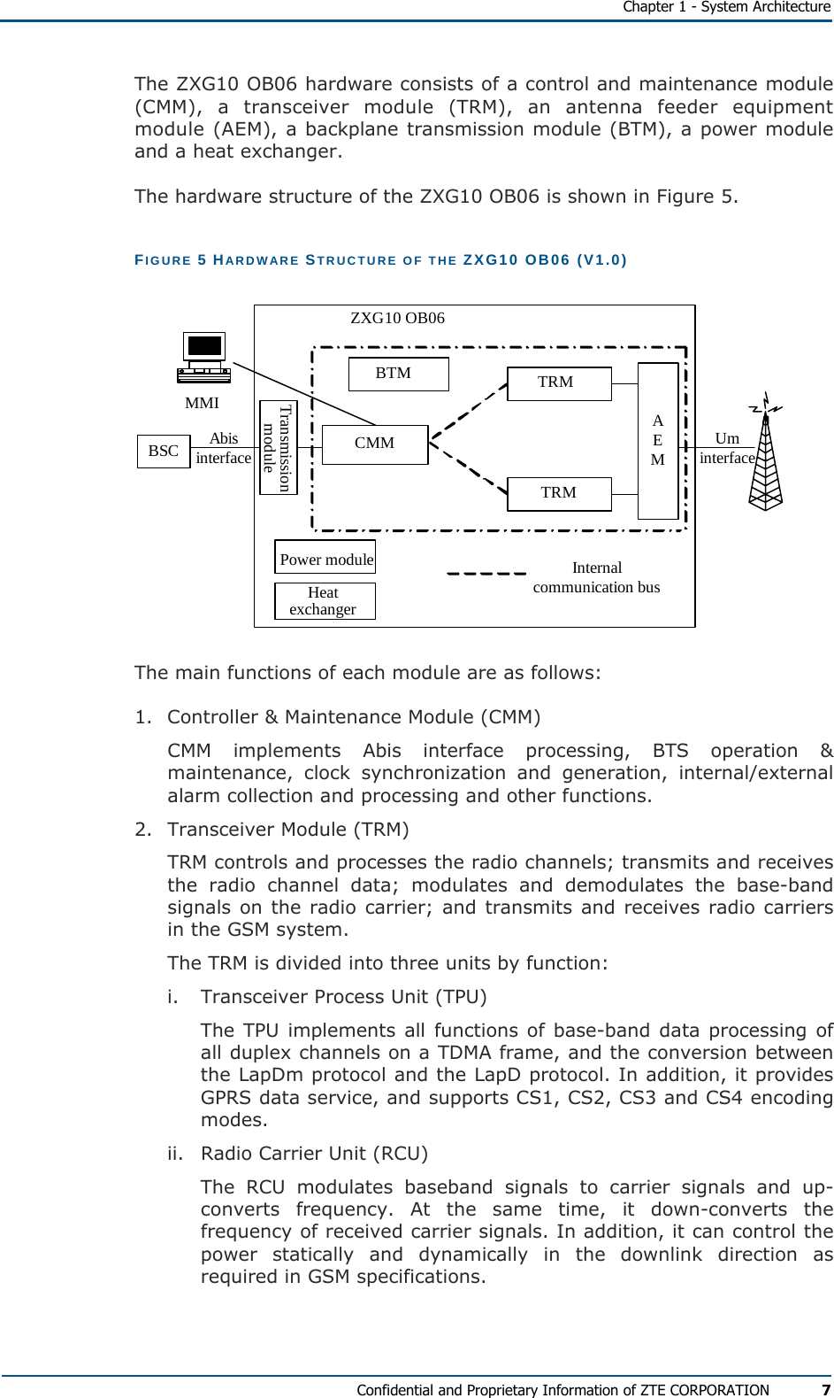
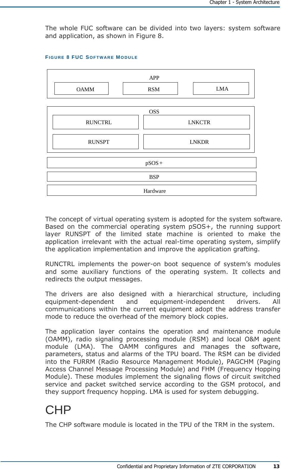
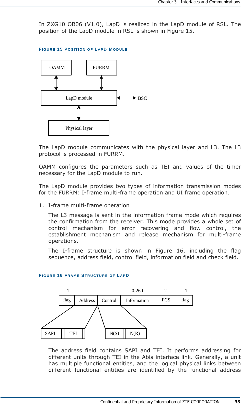
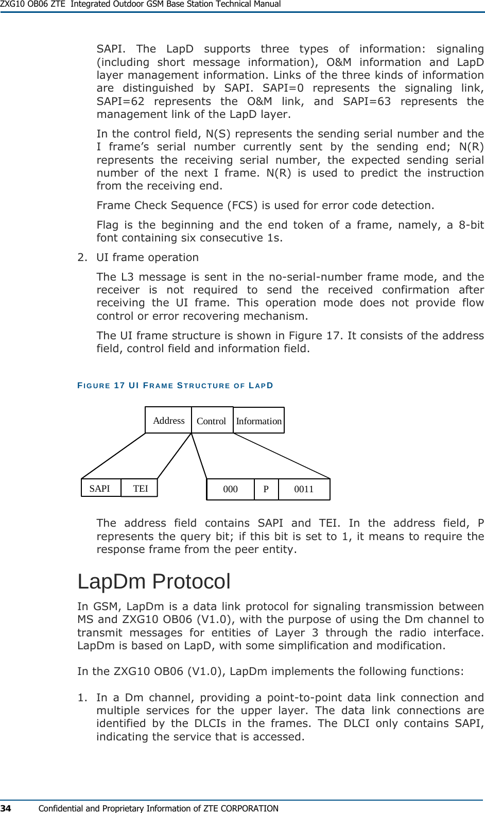
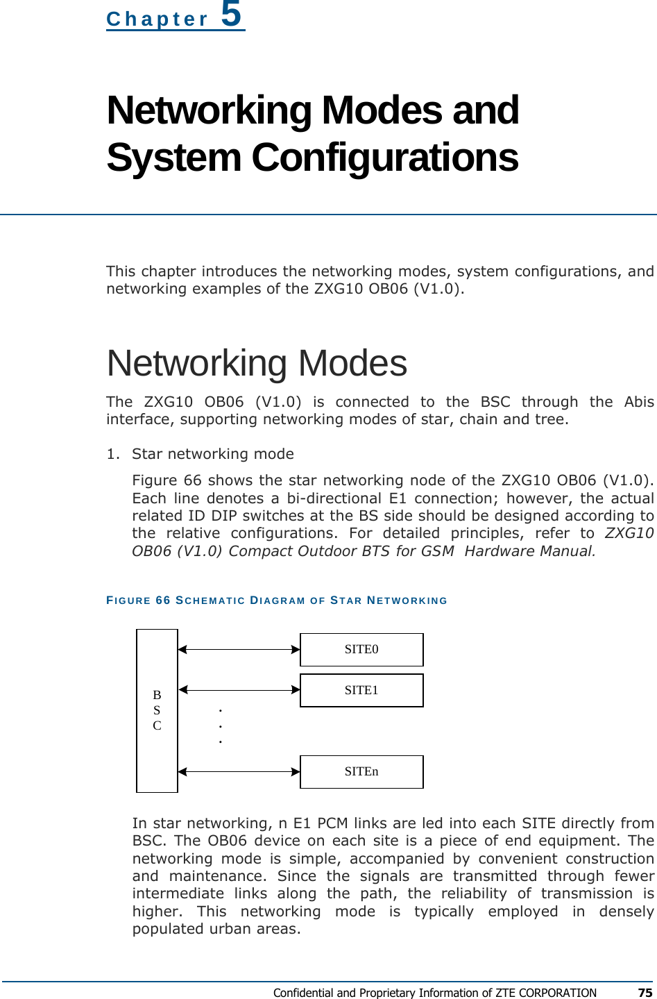
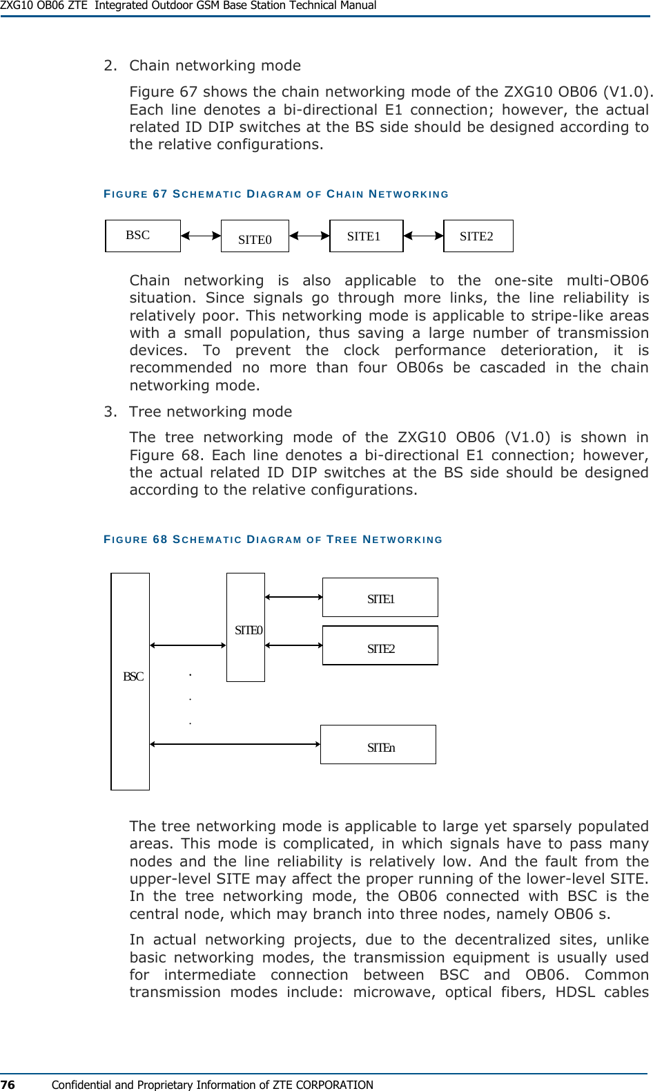
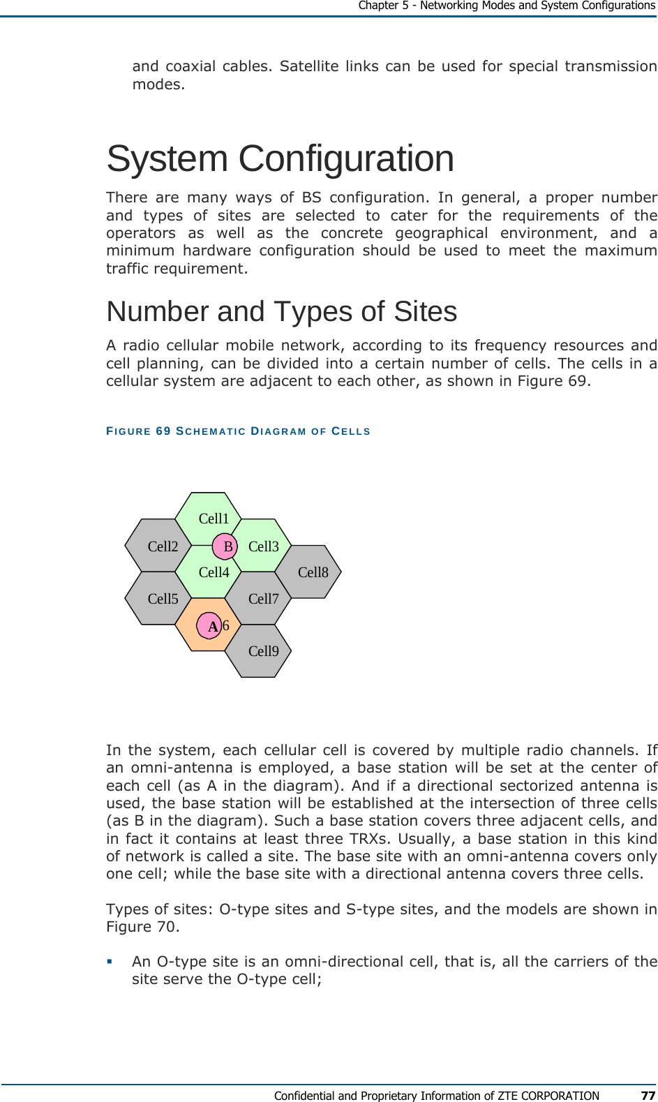
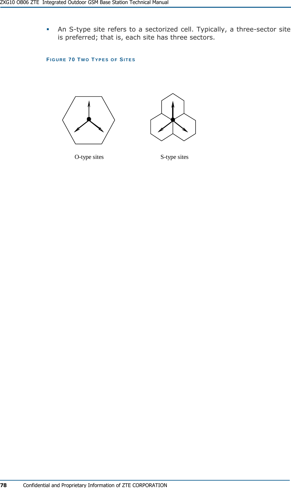
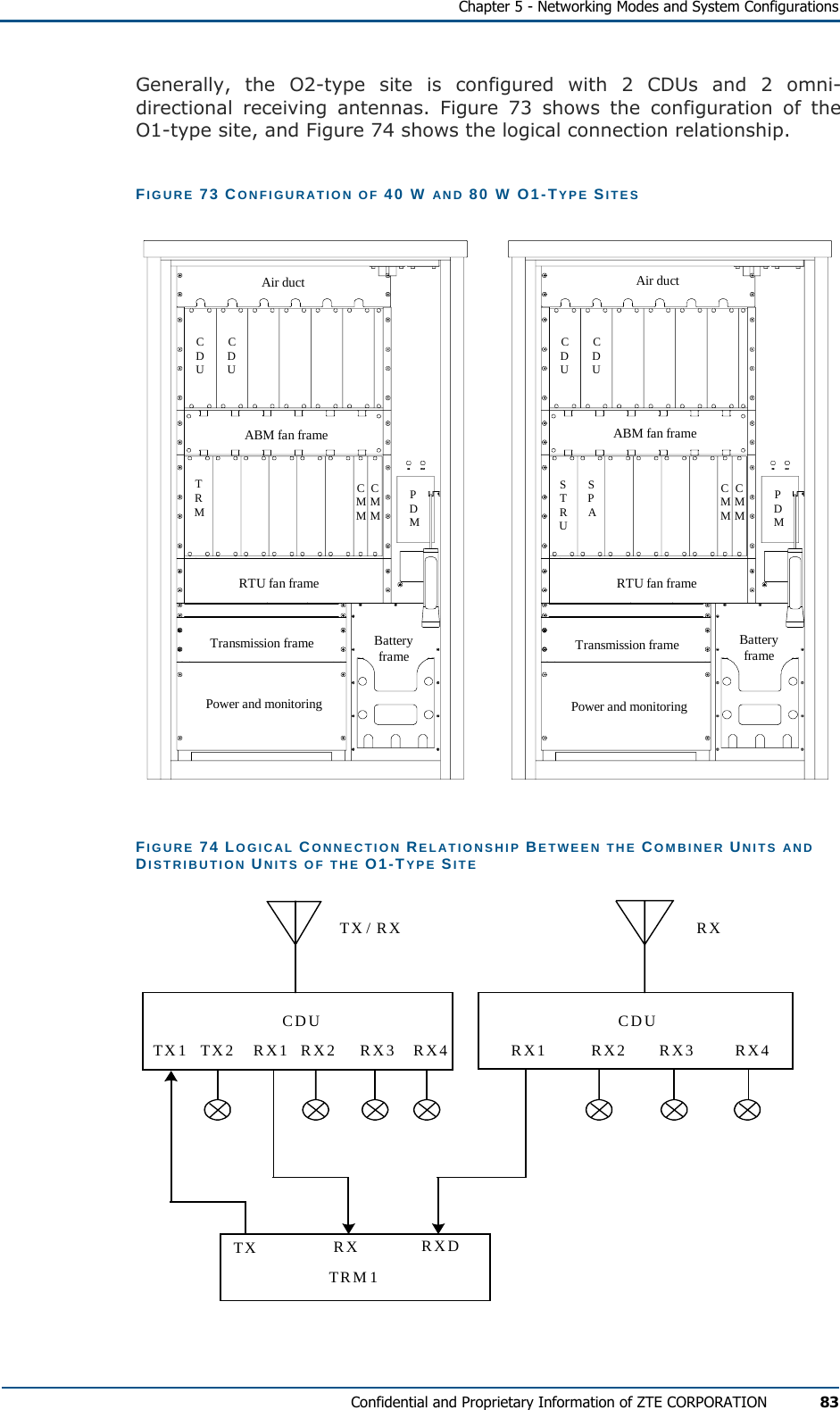
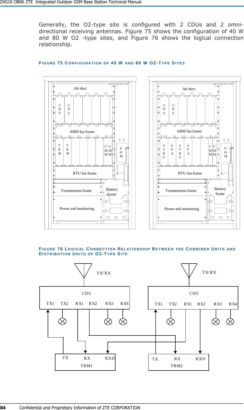
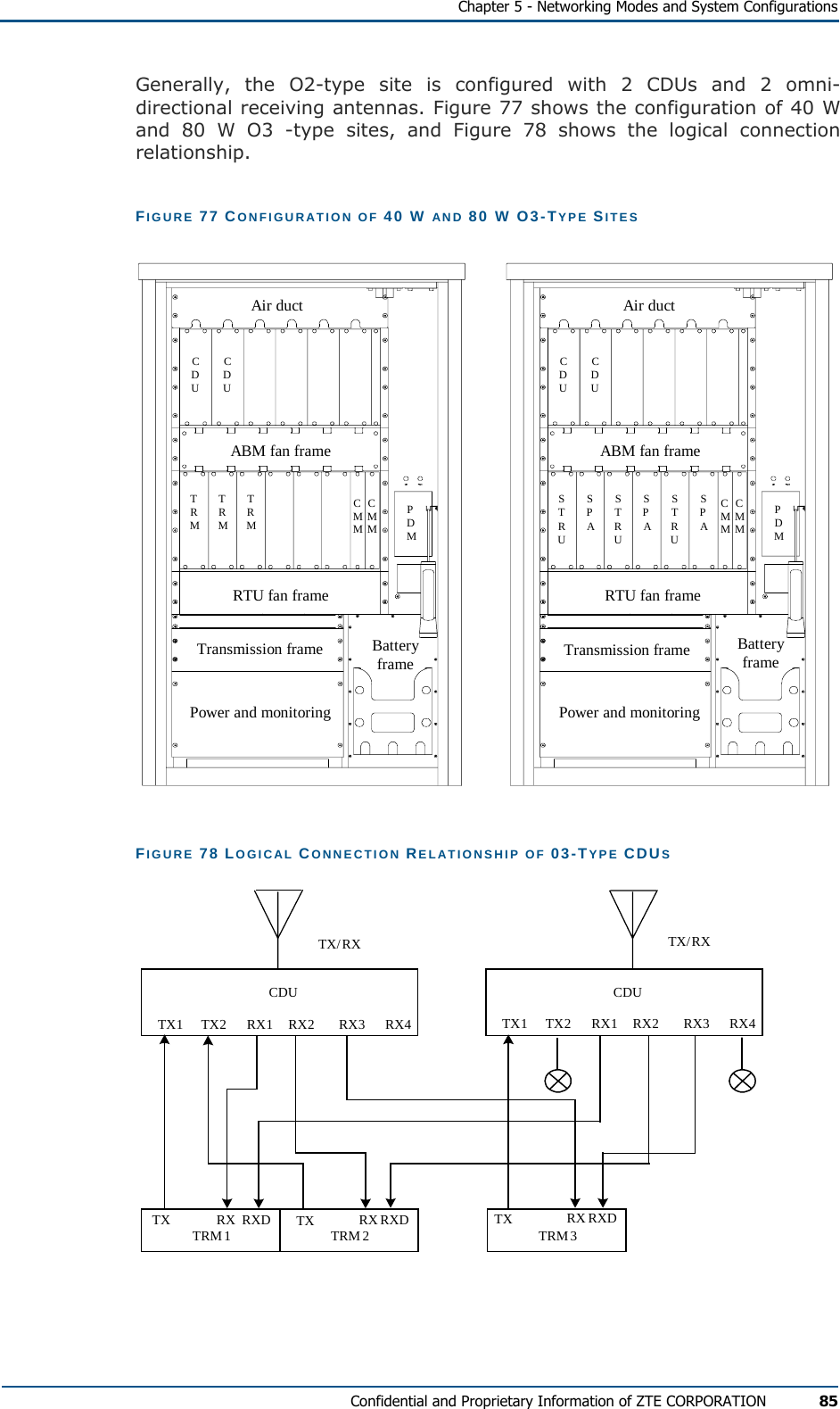
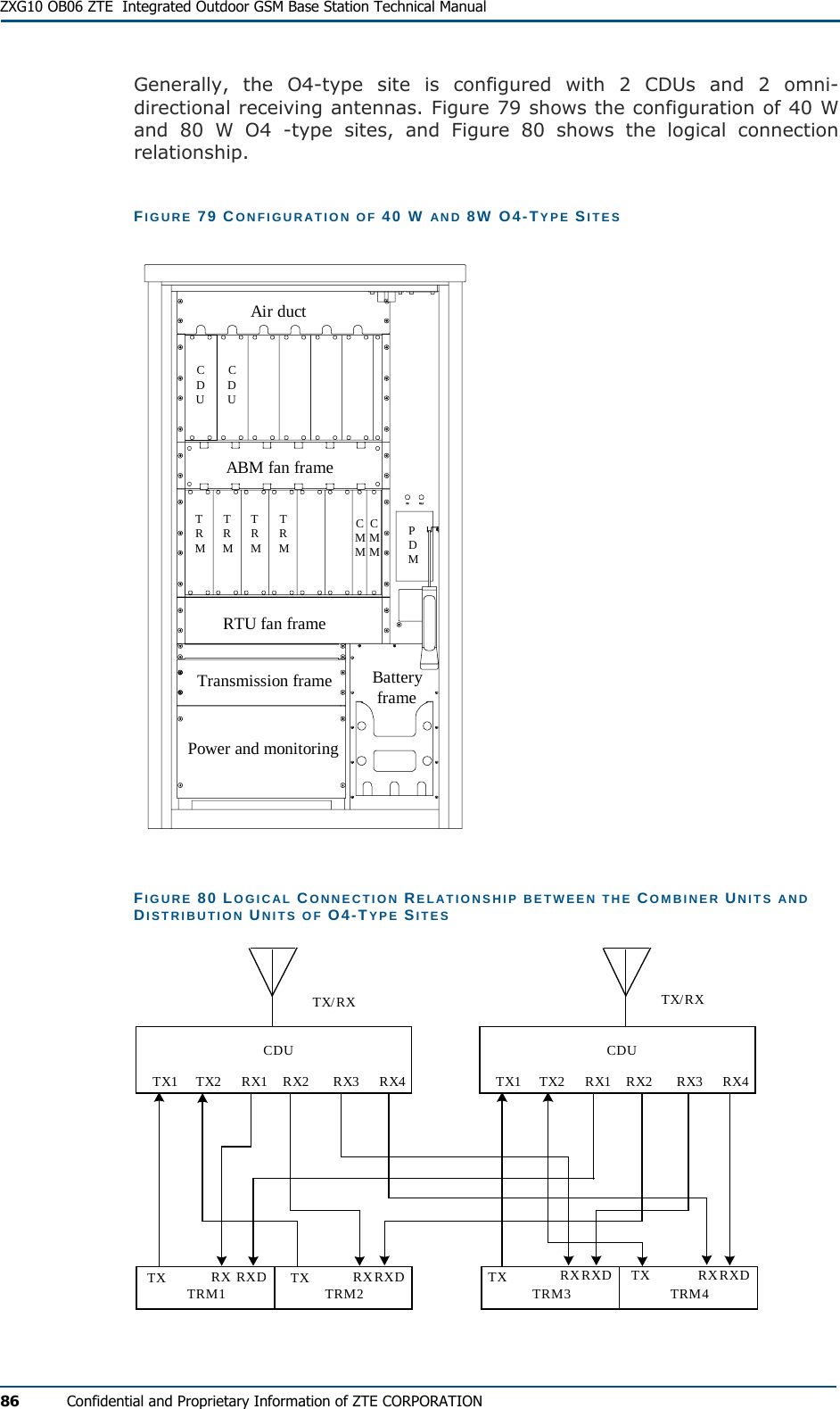
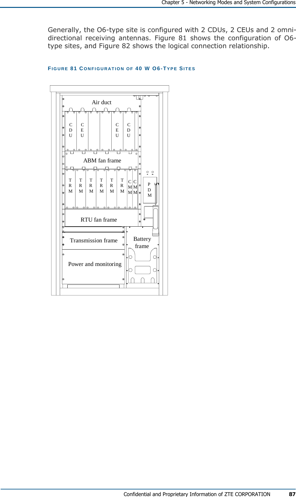
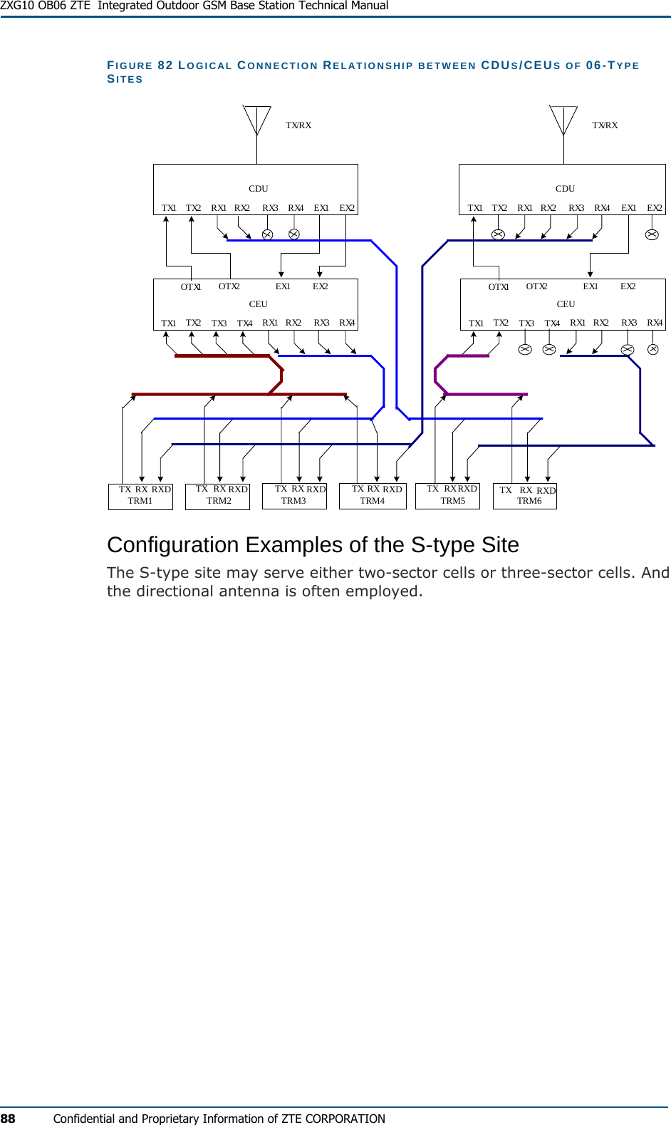
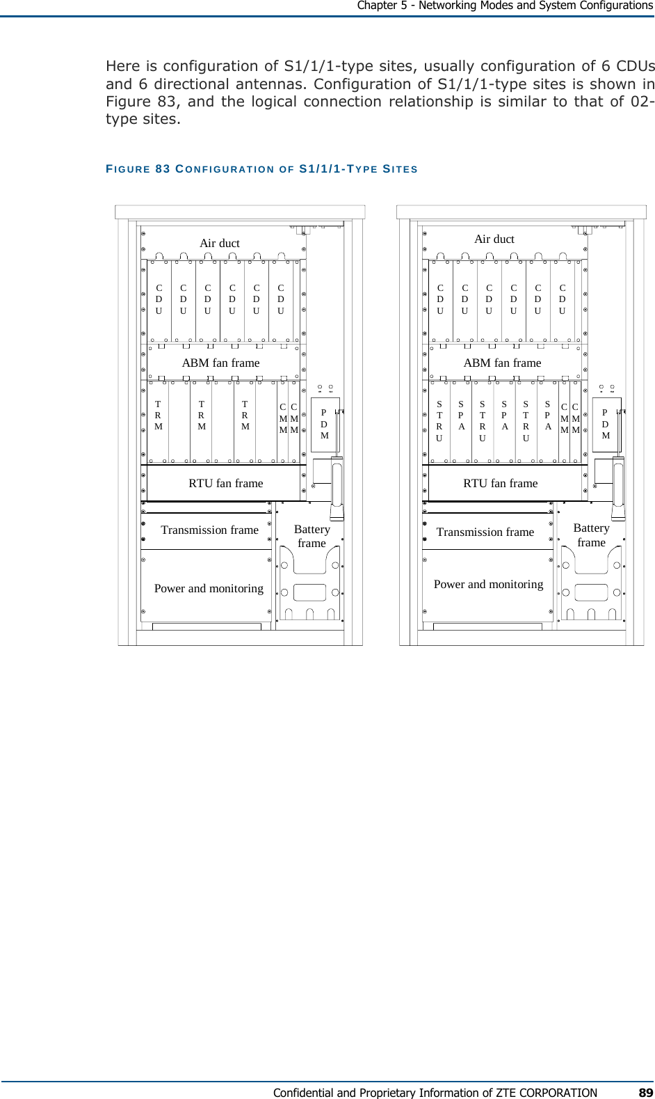
![ZXG10 OB06 ZTE Integrated Outdoor GSM Base Station Technical Manual xii Confidential and Proprietary Information of ZTE CORPORATION Chapter 1 System Architecture introduces the background, major functions, architecture of the software and hardware of ZXG10 OB06 (V1.0), and standards it complies with. It gives the user a general idea of the system. Chapter 2 Technical Indexes specifies the performance indexes of ZXG10 OB06 (V1.0). Chapter 3 Interfaces and Communications outlines the external interfaces and main interface protocols for ZXG10 OB06 (V1.0) Chapter 4 System Functions details the functions of the ZXG10 OB06 (V1.0). Chapter 5 Networking Modes and System Configuration gives a detailed description of various networking modes, connection and configuration of the ZXG10 OB06 (V1.0). Appendix A introduces the specifications cited in the manual. Appendix B,FCC STATEMENT. Appendix C, CE STATEMENT. Abbreviations list all the abbreviations used in the manual. Typographical Conventions ZTE documents employ with the following typographical conventions. TABLE 1 TYPOGRAPHICAL CONVENTIONS Typeface Meaning Italics References to other guides and documents. “Quotes” Links on screens. Bold Menus, menu options, function names, input fields, radio button names, check boxes, drop-down lists, dialog box names, window names. CAPS Keys on the keyboard and buttons on screens and company name. Constant width Text that you type, program code, files and directory names, and function names. [ ] Optional parameters { } Mandatory parameters | Select one of the parameters that are delimited by it Note: Provides additional information about a certain topic.](https://usermanual.wiki/ZTE/ZXG-OB06/User-Guide-710568-Page-12.png)