ZTE ZXG-OB06 GSM Base Transceiver Station User Manual
ZTE Corporation GSM Base Transceiver Station
ZTE >
User Manual

ZXG10 OB06
Integrated Outdoor GSM Base Station
Technical Manual
Version 1.0
ZTE CORPORATION
ZTE Plaza, Keji Road South,
Hi-Tech Industrial Park,
Nanshan District, Shenzhen,
P. R. China
518057
Tel: (86) 755 26771900 800-9830-9830
Fax: (86) 755 26772236
URL: http://support.zte.com.cn
E-mail: doc@zte.com.cn

LEGAL INFORMATION
Copyright © 2005 ZTE CORPORATION.
The contents of this document are protected by copyright laws and international treaties. Any reproduction or distribution of
this document or any portion of this document, in any form by any means, without the prior written consent of ZTE
CORPORATION is prohibited. Additionally, the contents of this document are protected by contractual confidentiality
obligations.
All company, brand and product names are trade or service marks, or registered trade or service marks, of ZTE
CORPORATION or of their respective owners.
This document is provided “as is”, and all express, implied, or statutory warranties, representations or conditions are
disclaimed, including without limitation any implied warranty of merchantability, fitness for a particular purpose, title or non-
infringement. ZTE CORPORATION and its licensors shall not be liable for damages resulting from the use of or reliance on
the information contained herein.
ZTE CORPORATION or its licensors may have current or pending intellectual property rights or applications covering the
subject matter of this document. Except as expressly provided in any written license between ZTE CORPORATION and its
licensee, the user of this document shall not acquire any license to the subject matter herein.
The contents of this document and all policies of ZTE CORPORATION, including without limitation policies related to support
or training are subject to change without notice.
Revision History
Date Revision No. Serial No. Description
2006/07/11 R1.1 sjzl20060069 English - For customers

ZTE CORPORATION
Values Your Comments & Suggestions!
Your opinion is of great value and will help us improve the quality of our product
documentation and offer better services to our customers.
Please fax to: (86) 755-26772236; or mail to Publications R&D Department, ZTE
CORPORATION, ZTE Plaza, A Wing, Keji Road South, Hi-Tech Industrial Park,
Shenzhen, P. R. China 518057.
Thank you for your cooperation!
Document
Name ZXG10 OB06 Integrated Outdoor GSM Base Station Technical Manual
Product
Version V1.0 Document
Revision Number R1.1
Equipment Installation Date
Presentation:
(Introductions, Procedures, Illustrations, Completeness, Level of Detail, Organization,
Appearance)
Good Fair Average Poor Bad N/A
Accessibility:
(Contents, Index, Headings, Numbering, Glossary)
Good Fair Average Poor Bad N/A
Your
evaluation of
this
documentation
Intelligibility:
(Language, Vocabulary, Readability & Clarity, Technical Accuracy, Content)
Good Fair Average Poor Bad N/A
Your
suggestions for
improvement
of this
documentation
Please check the suggestions which you feel can improve this documentation:
Improve the overview/introduction Make it more concise/brief
Improve the Contents Add more step-by-step procedures/tutorials
Improve the organization Add more troubleshooting information
Include more figures Make it less technical
Add more examples Add more/better quick reference aids
Add more detail Improve the index
Other suggestions
__________________________________________________________________________
__________________________________________________________________________
__________________________________________________________________________
__________________________________________________________________________
__________________________________________________________________________
# Please feel free to write any comments on an attached sheet.
If you wish to be contacted regarding your comments, please complete the following:
Name Company
Postcode Address
Telephone E-mail

Contents
About this Technical Manual.....................................................................xi
Purpose of this Technical Manual............................................................................. xi
Typographical Conventions.....................................................................................xii
Mouse Operation Conventions................................................................................xiii
Safety Signs.........................................................................................................xiii
How to Get in Touch .............................................................................................xiv
Customer Support ................................................................................................................xiv
Documentation Support........................................................................................................ xiv
Chapter 1..................................................................................... 1
System Architecture...................................................................................1
System Introduction ............................................................................................... 1
System Background ................................................................................................................1
Applicable Standards ...............................................................................................................3
Major Functions.......................................................................................................................3
System Working Principle ........................................................................................ 5
Hardware Structure ................................................................................................ 6
Software Architecture.............................................................................................. 8
CMM .......................................................................................................................................9
FUC ......................................................................................................................................12
CHP ......................................................................................................................................13
CIP .......................................................................................................................................14
System Features .................................................................................................. 14
Chapter 2...................................................................................17
Technical Indexes ................................................................................... 17
Physical Performance ............................................................................................ 17
Dimensions, Color and Structure ............................................................................................ 17
Weight of Integrated Equipment and Weight Bearing Requirements of Equipment Room Ground
............................................................................................................................................17
Power Supply ....................................................................................................... 18
Power Supply Range of Power Supply System ........................................................................ 18
Power Consumption Indexes.................................................................................................. 18
Ambient Conditions............................................................................................... 18
Requirements for Grounding and Lightning Protection ............................................................. 18
Requirements for Temperature and Humidity: ........................................................................ 19
Requirements for Cleanness .................................................................................................. 19
Requirements for Atmospheric Pressure ................................................................................. 20
Interface Indexes ................................................................................................. 20
Abis Interface Indexes ........................................................................................................... 20
Um Interface Indexes ............................................................................................................21
Capacity Indexes .................................................................................................. 23
Clock Indexes....................................................................................................... 23
Reliability Indexes................................................................................................. 23
Chapter 3...................................................................................25
Interfaces and Communications............................................................. 25
Overview ............................................................................................................. 25
Interfaces ............................................................................................................ 26
Abis Interface........................................................................................................................ 26
Um Interface......................................................................................................................... 28
Inter-Cabinet Cascaded Interface of Same Site ....................................................................... 30
Interfaces of the Tower Amplifier System ............................................................................... 31
Man-Machine Interface (MMI) ................................................................................................31
Protocol Introduction............................................................................................. 32
LapD Protocol........................................................................................................................ 32
LapDm Protocol..................................................................................................................... 34
RR/MM/CM Protocol...............................................................................................................37
Chapter 4...................................................................................39
System Functions.................................................................................... 39
Overview ............................................................................................................. 39
Major RF Functions ............................................................................................... 39
High Receiving Sensitivity ......................................................................................................40
Flexible Configuration ............................................................................................................40
Easy O&M ............................................................................................................................. 40
Diversity Receiving ................................................................................................................40
Frequency Hopping ...............................................................................................................40
Power Control .......................................................................................................................40
Baseband Processing ............................................................................................ 41
Signaling Processing ............................................................................................. 41
Wireless Link Management Function....................................................................................... 41
Dedicated Channel Management Function ..............................................................................47
Public Channel Management Function..................................................................................... 60
TRX Management Function ....................................................................................................65
O&M.................................................................................................................... 68
Parameter Configuration........................................................................................................ 69
Alarm and Status Reporting ...................................................................................................69
Online Software Loading ........................................................................................................70
Ultra-Distance Coverage........................................................................................ 71
Chapter 5...................................................................................75
Networking Modes and System Configurations..................................... 75
Networking Modes ................................................................................................ 75
System Configuration............................................................................................ 77
Number and Types of Sites .................................................................................................... 77
BS Configuration Principles ....................................................................................................79
Expansion Configuration ........................................................................................................82
Configuration Examples ......................................................................................................... 82
Appendix A................................................................................91
Pertinent Standards ................................................................................ 91
Appendix B................................................................................93
FCC STATEMENT ...................................................................................... 93
Appendix C................................................................................95
CE STATEMENT ........................................................................................ 95
Abbreviations ............................................................................... 97
Figures........................................................................................101
Tables .........................................................................................103

Confidential and Proprietary Information of ZTE CORPORATION xi
About this Technical Manual
The ZXG10 is a GSM mobile communication system independently
developed by ZTE Corporation. It is composed of the ZXG10-MSS mobile
switching subsystem and the ZXG10-BSS base station subsystem. The
ZXG10-BSS Base Station Subsystem provides and manages radio
transmission in GSM, and it is composed of the ZXG10-BSC Base Station
Controller and the ZXG10-BTS Base Transceiver Station.
ZXG10 OB06 is one of the ZXG10-BTS series of base transceiver stations,
and is an integrated outdoor BTS for GSM. Installed outdoors, the ZXG10
OB06 features high capacity, compactness, high reliability, high
performance/cost ratio, complete functions, and powerful capability of
service supporting.
Purpose of this Technical Manual
The ZXG10 OB06 (V1.0) Compact Outdoor BTS for GSM—Technical Manual
introduces the working principle, functions and technical features of the
ZXG10 OB06 (V1.0) compact outdoor BTS for GSM, enabling the user to
have an all-around understanding of the technical features of the ZXG10
OB06 (V1.0).
The whole set of documents also include:
ZXG10 OB06 (V1.0) Compact Outdoor BTS for GSM Guide to
Documentation
ZXG10 OB06 (V1.0) Compact Outdoor BTS for GSM Hardware Manual
ZXG10 OB06 (V1.0) Compact Outdoor BTS for GSM Installation Manual
ZXG10 OB06 (V1.0) Compact Outdoor BTS for GSM Maintenance
Manual—Routine Maintenance
ZXG10 OB06 (V1.0) Compact Outdoor BTS for GSM Maintenance
Manual—Emergency Handling
ZXG10 OB06 (V1.0) Compact Outdoor BTS for GSM Maintenance
Manual—Troubleshooting
This manual includes five chapters.

ZXG10 OB06 ZTE Integrated Outdoor GSM Base Station Technical Manual
xii Confidential and Proprietary Information of ZTE CORPORATION
Chapter 1 System Architecture introduces the background, major
functions, architecture of the software and hardware of ZXG10 OB06
(V1.0), and standards it complies with. It gives the user a general idea of
the system.
Chapter 2 Technical Indexes specifies the performance indexes of
ZXG10 OB06 (V1.0).
Chapter 3 Interfaces and Communications outlines the external
interfaces and main interface protocols for ZXG10 OB06 (V1.0)
Chapter 4 System Functions details the functions of the ZXG10 OB06
(V1.0).
Chapter 5 Networking Modes and System Configuration gives a
detailed description of various networking modes, connection and
configuration of the ZXG10 OB06 (V1.0).
Appendix A introduces the specifications cited in the manual.
Appendix B,FCC STATEMENT.
Appendix C, CE STATEMENT.
Abbreviations list all the abbreviations used in the manual.
Typographical Conventions
ZTE documents employ with the following typographical conventions.
TABLE 1 TYPOGRAPHICAL CONVENTIONS
Typeface Meaning
Italics
References to other guides and documents.
“Quotes” Links on screens.
Bold Menus, menu options, function names, input fields, radio
button names, check boxes, drop-down lists, dialog box
names, window names.
CAPS Keys on the keyboard and buttons on screens and company
name.
Constant width Text that you type, program code, files and directory names,
and function names.
[ ] Optional parameters
{ } Mandatory parameters
| Select one of the parameters that are delimited by it
Note: Provides additional information about a certain topic.
About this Technical Manual
Confidential and Proprietary Information of ZTE CORPORATION xiii
Typeface Meaning
Checkpoint: Indicates that a particular step needs to be
checked before proceeding further.
Tip: Indicates a suggestion or hint to make things easier or
more productive for the reader.
Mouse Operation Conventions
TABLE 2 MOUSE OPERATION CONVENTIONS
Typeface Meaning
Click Refers to clicking the primary mouse button (usually the left
mouse button) once.
Double-click Refers to quickly clicking the primary mouse button (usually
the left mouse button) twice.
Right-click Refers to clicking the secondary mouse button (usually the
right mouse button) once.
Drag Refers to pressing and holding a mouse button and moving
the mouse.
Safety Signs
TABLE 3 SAFETY SIGNS
Safety Signs Meaning
Danger: Indicates an imminently hazardous situation, which if
not avoided, will result in death or serious injury. This signal
word should be limited to only extreme situations.
Warning: Indicates a potentially hazardous situation, which if
not avoided, could result in death or serious injury.
Caution: Indicates a potentially hazardous situation, which if not
avoided, could result in minor or moderate injury. It may also
be used to alert against unsafe practices.
Erosion: Beware of erosion.
Electric shock: There is a risk of electric shock.
Electrostatic: The device may be sensitive to static electricity.

ZXG10 OB06 ZTE Integrated Outdoor GSM Base Station Technical Manual
xiv Confidential and Proprietary Information of ZTE CORPORATION
Safety Signs Meaning
Microwave: Beware of strong electromagnetic field.
Laser: Beware of strong laser beam.
No flammables: No flammables can be stored.
No touching: Do not touch.
No smoking: Smoking is forbidden.
How to Get in Touch
The following sections provide information on how to obtain support for
the documentation and the software.
Customer Support
If you have problems, questions, comments, or suggestions regarding
your product, contact us by e-mail at support@zte.com.cn. You can also
call our customer support center at (86) 755 26771900 and (86) 800-
9830-9830.
Documentation Support
ZTE welcomes your comments and suggestions on the quality and
usefulness of this document. For further questions, comments, or
suggestions on the documentation, you can contact us by e-mail at
doc@zte.com.cn; or you can fax your comments and suggestions to (86)
755 26772236. You can also explore our website at
http://support.zte.com.cn, which contains various interesting subjects like
documentation, knowledge base, forum and service request.

Confidential and Proprietary Information of ZTE CORPORATION 1
Chapter 1
System Architecture
This chapter describes the background, the standards followed, major
functions, system features, working principles and the general structure of
both the software and hardware of the ZXG10 OB06 (V1.0).
System Introduction
System Background
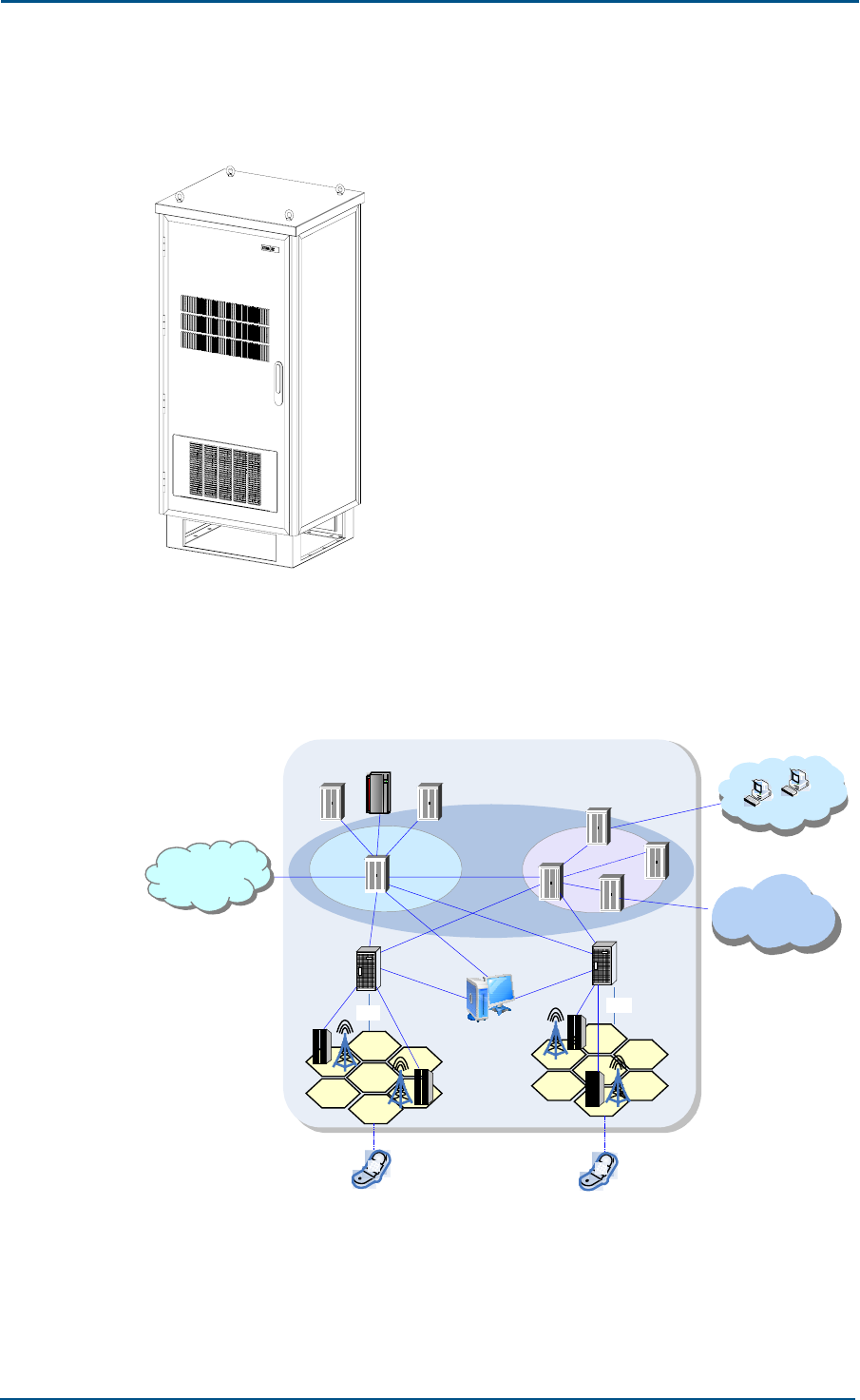
ZXG10 OB06 is a high-capacity outdoor BTS for GSM, with a single cabinet
supporting six carriers at the maximum. It is to be installed outdoors,
integrating functions of transmission, power supply, environment
monitoring and temperature control in one system. It is applicable to the
following cases: The cost of a standard equipment room would be too high
in the site selected for it, for example, in the center of a city; there is no
equipment room in the site selected for it, for example, in the countryside
or in the remote areas of a city.
The availability of ZXG10 OB06 adds another product to the ZXG10-BTS
series and makes the ZXG10 system offer more flexible networking modes,
hence more powerful market competition edge.
ZXG10 OB06 ZTE Integrated Outdoor GSM Base Station Technical Manual
2 Confidential and Proprietary Information of ZTE CORPORATION
The appearance of the whole ZXG10 OB06 is shown in Figure 1
FIGURE 1 APPEARANCE OF THE ZXG10 OB06
Figure 2 shows the position of ZXG10 OB06 (V1.0) in a GSM/GPRS
network.
FIGURE 2 POSITION OF ZXG10 OB06 IN GSM/GPRS NETWORK
SGSN
GGSN PLMN
GGSN
SGSN
MSC
Internet
HLR
AUC
MSC/VLR
Gb
OMC
AA
OB06
Gb
Um
BSC
ZTE
Abis
BTS
MS
BSC
OB06
ZTE
Abis
Um
MS
PDN
PSTN
ISDN
PSPDN
PLMN
In the GSM/GPRS system, the ZXG10 OB06 is located between the BSC
and MS, connected to the BSC through an Abis interface, and connected to
the MS through an Um interface. The ZXG10 OB06 provides functions of

Chapter 1 - System Architecture
Confidential and Proprietary Information of ZTE CORPORATION 3
serving as a radio transceiver for a cell, converting between the BSC and a
radio channel, wireless transmission with the MS and the related
controlling function.
Applicable Standards
It supports GSM Phase I/ GSM Phase II/GSM Phase II + standards.
Its radio frequency (RF) interface complies with ETSI TS 101 087 Version
5.0.0 GSM05.05 and GSM11.21.
Its Abis interface complies with the ITU-T G.703/ITU-T G.704 interface
standards.
Its high/low temperature indexes comply with the specifications in
GSM11.21.
In terms of radio services, it complies with the following protocols and
specifications.
GSM03.60 General Packet Radio Service (GPRS) Service description
GSM03.64 General Packet Radio Service (GPRS) Overall description of the
GPRS radio interface
GSM04.04 Technical Specification Group GSM/EDGE Radio Access Net
Work Layer 1 General requirements
GSM04.06 Mobile Station - Base Station System (MS - BSS) interface Data
Link (DL) layer specification
GSM04.08 Mobile radio interface layer 3 specification
GSM04.60 General Packet Radio Service (GPRS) Mobile Station (MS) -
Base Station System (BSS) interface Radio Link Control/ Medium Access
Control (RLC/MAC) protocol
GSM05.02 Multiplexing and multiple access on the radio path
GSM05.08 Radio subsystem link control
GSM08.58 Base Station Controller - Base Transceiver Station (BSC - BTS)
interface Layer 3 specification
The EMC complies with the ETSI 301489-8 specifications
R&TTE Directive 1999/5/EC
Major Functions
The ZXG10 OB06 (V1.0) has the following functions:
1. It supports GSM Phase I/ GSM Phase II/GSM Phase II + standards.

ZXG10 OB06 ZTE Integrated Outdoor GSM Base Station Technical Manual
4 Confidential and Proprietary Information of ZTE CORPORATION
2. It supports GSM900, EGSM900, GSM850, GSM1800 and GSM1900
systems; it also supports modules of different frequency bands
inserted in the same cabinet.
3. It provides the following TCH services:
TCH/FS: Full-rate voice traffic channel
TCH/HS: Half-rate voice traffic channel
TCH/EFS: Enhanced full-rate voice traffic channel
TCH/F9.6: 9.6 kbit/s full-rate data traffic channel
TCH/F4.8: 4.8 kbit/s full-rate data traffic channel
TCH/F2.4: 2.4 kbit/s full-rate data traffic channel
It supports service channels related with GPRS service
4. It provides a diversity receiving function. Main diversity technologies
are space diversity, frequency diversity, time diversity and polarization
diversity.
5. The receiving end adopts the Viterbi soft decision algorithm, improving
the channel decoding performance and increasing the system receiving
sensitivity and anti-interference capability.
6. It supports frequency hopping, improving the system capability against
Rayleigh fading.
7. It supports the discontinuous transmission (DTX) mode, only
transmitting comfort noise in the voice non-activated period, and
reducing the transmitter power and general interference level in the air
signaling.
8. It can calculate the time advance.
9. For GSM 900 and EGSM 900 systems, it supports configurations with
power consumption of 40 W or 80 W. For GSM1800, GSM1900 and
GSM850 systems, it supports 40 W configuration.
10. One OB06 (40 W configuration, in this document, 40 W for the GMSK
mode, and 25 W for the 8PSK mode) supports 6 TRXs, supports
extension of 18 TRXs at the same site, and one site supports extension
of S6/6/6.
11. One OB06 (80 W configuration, in this document, 80 W for the GMSK
mode, and 50 W for the 8PSK mode) supports 3 TRXs, supports
extension of 9 TRXs at the same site, and one site supports extension
of S3/3/3.
12. It supports star, chain and tree configuration of Abis interfaces.
13. It supports satellite transmission links of Abis interfaces, with the
unidirectional transmission delay of Abis interfaces being 260 ms.
14. It supports LapD signaling 1: 4 TEI multiplex of Abis interfaces, that is,
having 4 pieces of LapD signaling multiplexed into one 64 Kb/s
signaling timeslot through TEI.
15. When multiple OB06s are cascaded, the automatic crossover protection
function is provided for the Abis interface link when any OB06 is
powered off.
Chapter 1 - System Architecture
Confidential and Proprietary Information of ZTE CORPORATION 5
16. It supports preprocessing of the measurement reports on the OB06.
17. It supports BS power control: statically 6 levels and dynamically 15
levels.
18. It supports all paging modes defined in GSM specifications.
19. It supports synchronous handover, asynchronous handover, pseudo-
synchronous handover, and pre-synchronous handover.
20. It has an overall timely alarm system.
i. Available for implementing unattended BS and automatic alarming.
ii. Providing power supply and alarm for the built-in tower amplifier
system.
21. It supports EDGE service, realizing a higher data transmission rate by
means of 8PSK modulation.
22. It supports GPRS and CS1 ~ CS2 channel encoding modes. It supports
CS3 and CS4 through software upgrading, and it can adjust the
channel encoding mode dynamically according to the monitoring and
measurement results.
23. The Um interface supports A51/A52 encryption algorithm.
24. It supports ultra-distance coverage with a radius of 35 km~120 km.
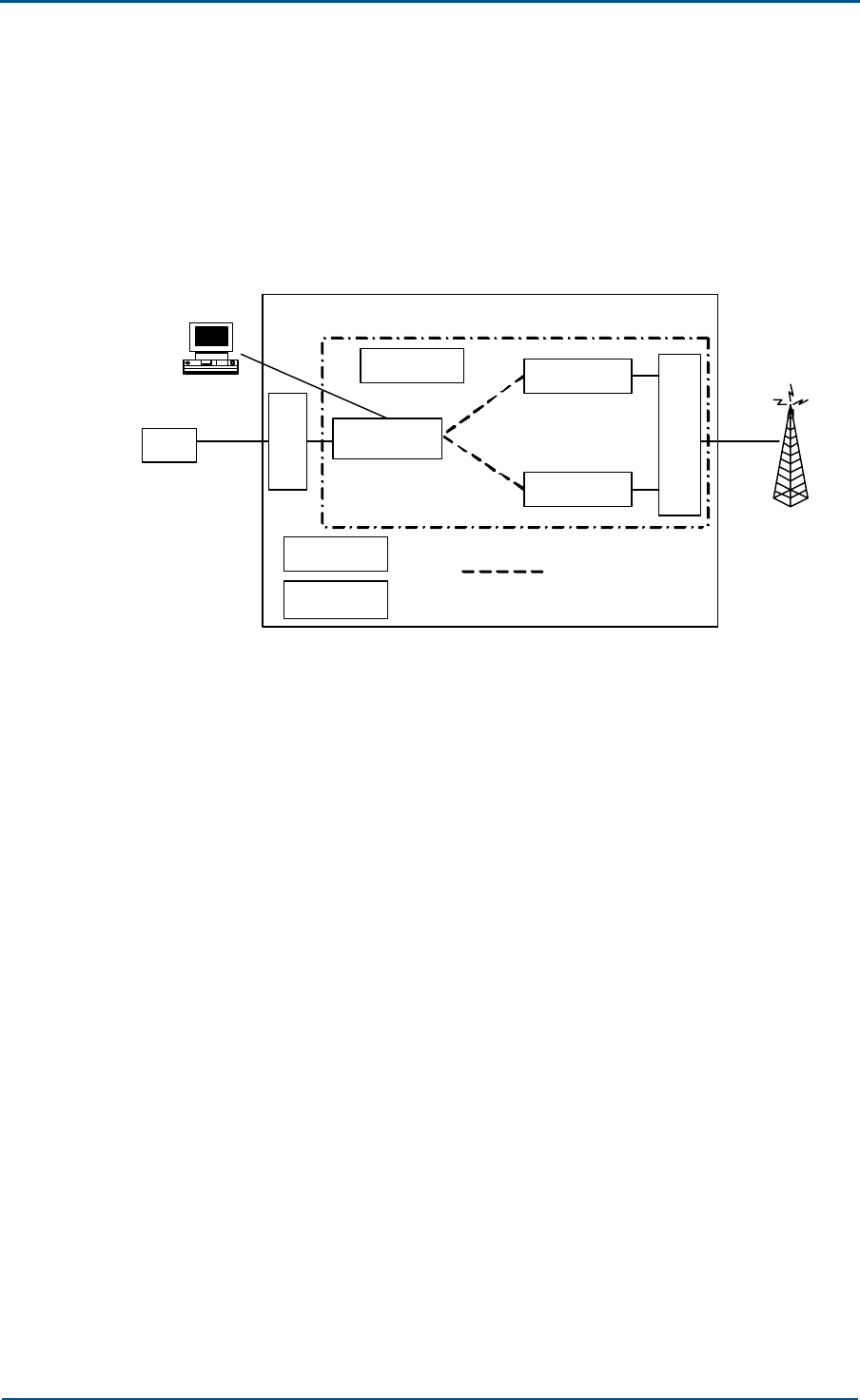
System Working Principle
The working principle of ZXG10 OB06 (V1.0) is shown in Figure 3.
FIGURE 3 WORKING PRINCIPLE OF THE ZXG10 0B06 (V1.0)
ZXG10-OB06
Operation &
maintenance unit
Baseband
processing unit
RF unit
Antenna
processing unit
Power unit
Heat exchanger
AC input
Data link
System
clock
RF demodulation
signal
Baseband
modulation signal
System clock
Control signal
RF signal
Um interface
Transmission unit
BSC
Abis
The ZXG10 OB06 (V1.0) system is composed of an operation and
maintenance unit, a baseband processor, an RF unit, an antenna feeder
ZXG10 OB06 ZTE Integrated Outdoor GSM Base Station Technical Manual
6 Confidential and Proprietary Information of ZTE CORPORATION
processor, a transmission unit, a power unit and a heat exchanger. The
working principle of the system is as follows:
In the downlink direction, the ZXG10 OB06 (V1.0) receives data from BSC,
including voice and signaling data. Here, the signaling data are sent to the
control, operation & maintenance unit for processing. The voice data are
first sent to the base band processor for processing such as rate
conversion, encryption and interleaving, sent to the RF unit to be
modulated to high-frequency signals, and then finally transmitted through
the antenna feeder processor.
In the uplink direction, the antenna feeder processor receives the RF
signals from the MS, and sends them to the RF unit to convert them into
digital signals. Then, the signals are sent to the baseband processor for
rate conversion, decryption and de-interleaving. Finally, after being
converted to the code pattern suitable for long-distance transmission, the
signals are sent to the BSC through the Abis interface.
Hardware Structure
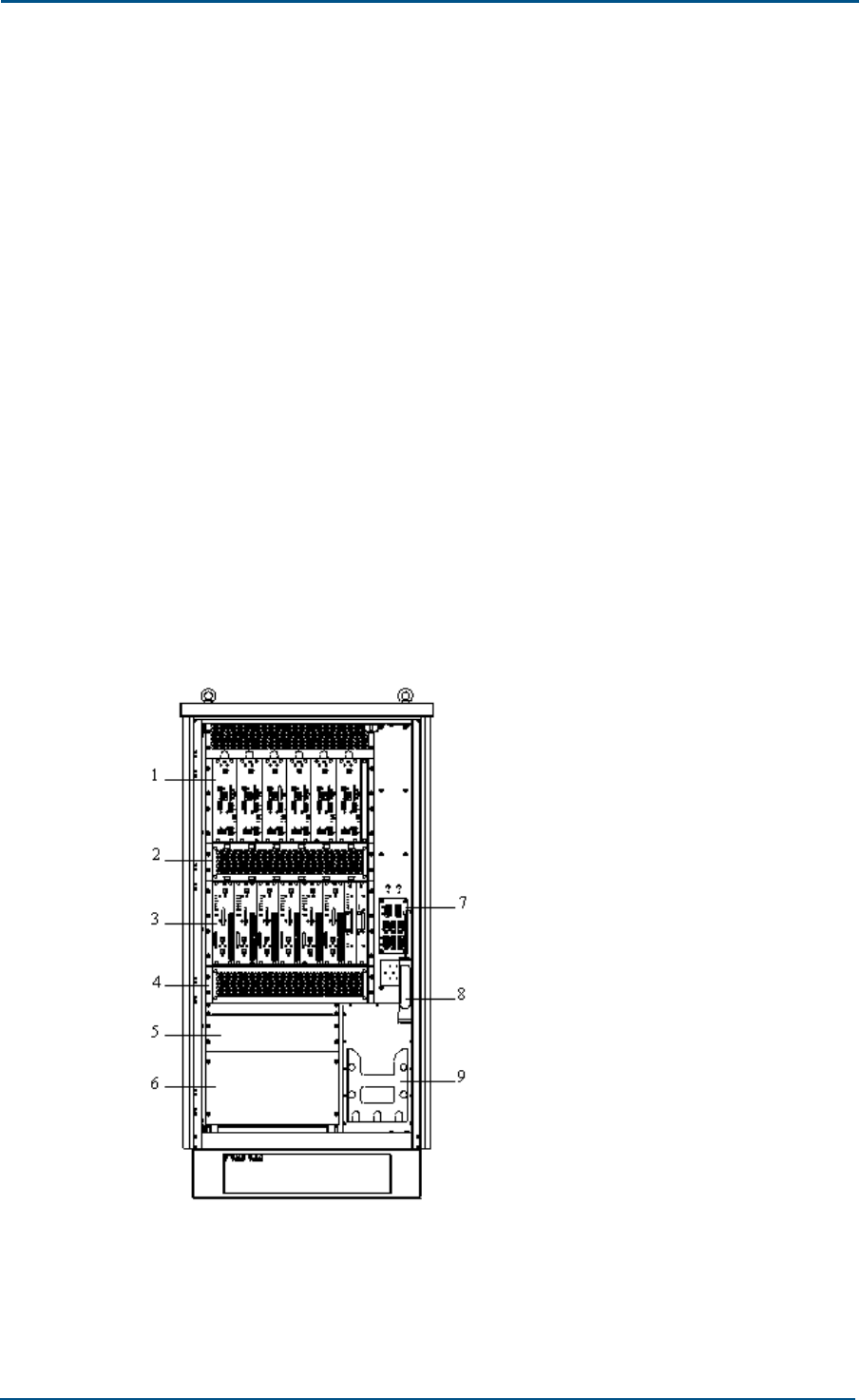
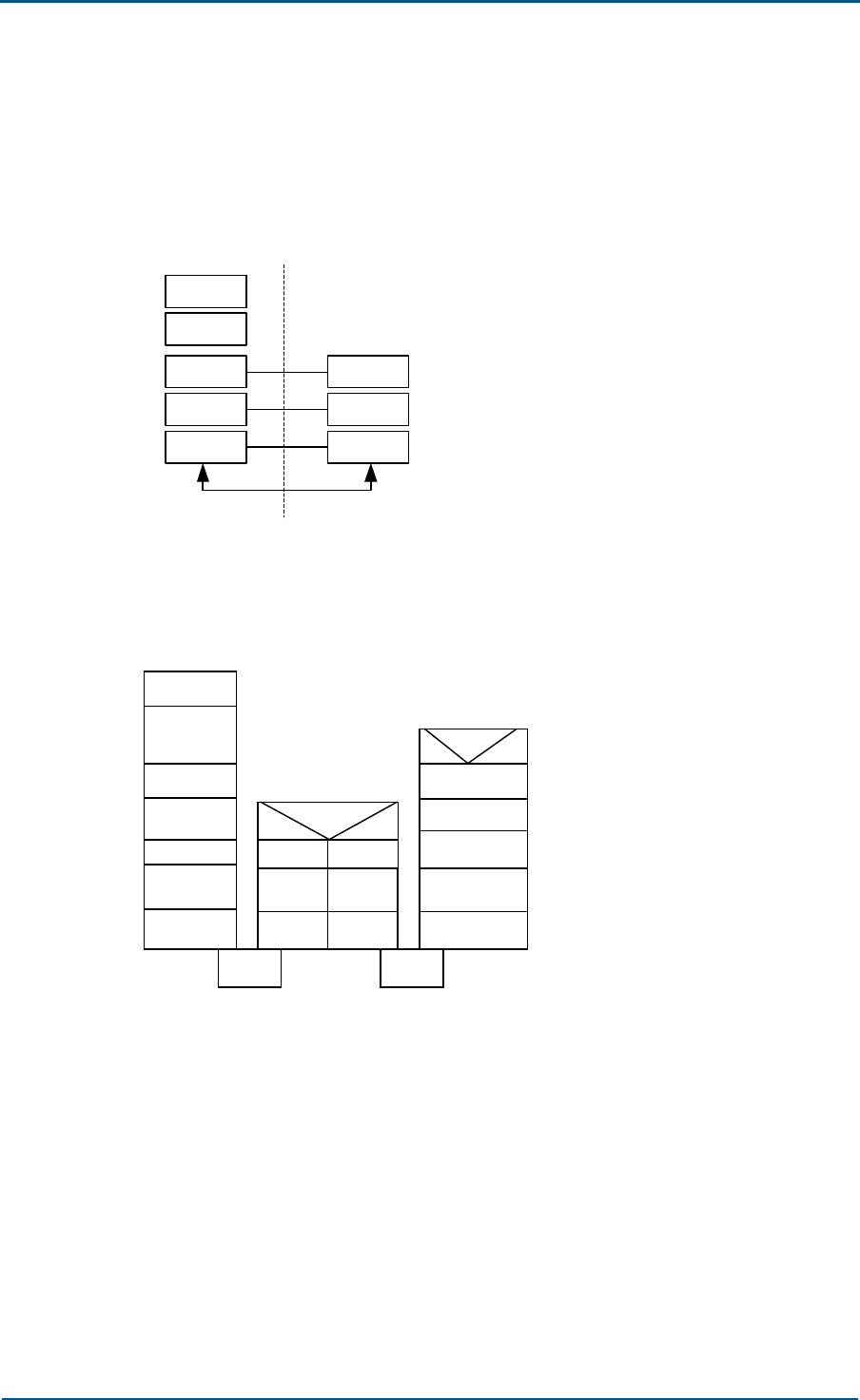
The layout of the ZXG10 OB06 system is shown in Figure 4.
FIGURE 4 LAYOUT OF THE ZXG10 OB06 SYSTEM
Promulgation frame
Power frame
1. AEM module 2. AEM fan frame 3. Transceiver module
4. RTU fan frame 5. Transmission frame 6. Power frame 7. PDM panel
8. Emergency lamp 9. Battery frame
Chapter 1 - System Architecture
Confidential and Proprietary Information of ZTE CORPORATION 7
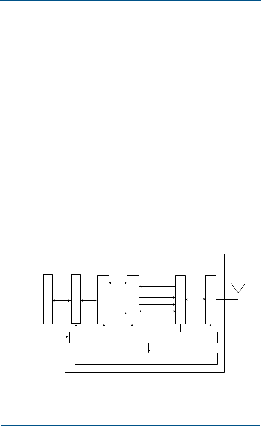
The ZXG10 OB06 hardware consists of a control and maintenance module
(CMM), a transceiver module (TRM), an antenna feeder equipment
module (AEM), a backplane transmission module (BTM), a power module
and a heat exchanger.
The hardware structure of the ZXG10 OB06 is shown in Figure 5.
FIGURE 5 HARDWARE STRUCTURE OF THE ZXG10 OB06 (V1.0)
CMM
Power module
TRM
TRM
A
E
M
Um
interface
Internal
communication bus
ZXG10 OB06
BSC Abis
interface
Heat
exchanger
Transmission
module
MMI
BTM
The main functions of each module are as follows:
1. Controller & Maintenance Module (CMM)
CMM implements Abis interface processing, BTS operation &
maintenance, clock synchronization and generation, internal/external
alarm collection and processing and other functions.
2. Transceiver Module (TRM)
TRM controls and processes the radio channels; transmits and receives
the radio channel data; modulates and demodulates the base-band
signals on the radio carrier; and transmits and receives radio carriers
in the GSM system.
The TRM is divided into three units by function:
i. Transceiver Process Unit (TPU)
The TPU implements all functions of base-band data processing of
all duplex channels on a TDMA frame, and the conversion between
the LapDm protocol and the LapD protocol. In addition, it provides
GPRS data service, and supports CS1, CS2, CS3 and CS4 encoding
modes.
ii. Radio Carrier Unit (RCU)
The RCU modulates baseband signals to carrier signals and up-
converts frequency. At the same time, it down-converts the
frequency of received carrier signals. In addition, it can control the
power statically and dynamically in the downlink direction as
required in GSM specifications.

ZXG10 OB06 ZTE Integrated Outdoor GSM Base Station Technical Manual
8 Confidential and Proprietary Information of ZTE CORPORATION
iii. Power Amplifier Unit (PAU)
The PAU amplifies the power of the radio carrier to provide the BS
equipment with sufficient transmission power.
In band GSM900 or EGSM900, ZXG10 OB06 features a transceiver
unit with an output power of 80 W. The unit consists of two
modules: STRG and SPAG: The former fulfills the functions of the
TPU and RCU parts, while the latter accomplishes the functions of
the PAU. The SPAG and STRG form the TRM of the GSM900 system
or the EGSM900 system.
3. Antenna Equipment Module (AEM)
The AEM accomplishes functions of duplex and distribution of air
signals. ZXG10 OB06 provides a Combiner Distribution Unit (CDU) and
a Combiner Extension Unit (CEU):
i. The CDU supports one 2-in-1 combiner unit and one 1-to-4
distribution unit. It has two low noise amplifiers with extended
receiving output and one built-in duplexer.
ii. The CEU supports two 1-to-2 power distribution units and two 2-in-
1 combiner units.
The AEM can provide the ZXG10 OB06 (V1.0) with different
configurations through combinations.
4. Backplane Transmission Module (BTM)
The BTM is responsible for transmitting messages between the CMM,
TRM and AEM and at the same time provides interfaces for inputting
and outputting external signals.
5. Transmission Management Module (TMM)
The TMM can be a product manufactured by a third party. In ZXG10
OB06 there is a standard 19-inch 3U-high shelf for accommodating
transmission devices such as SDH and microwave.
6. Heat Exchanger (HEX)
The HEX is composed of four key components, namely, internal
circulation fan, external fan, heat exchanging chip and heater. The HEX
provides a function of dissipating heat in case of high temperature and
heating in case of low temperature, so that suitable temperature will
be ensured in the cabinet for normal operation of the system.
7. Power Module (PWM)
The PWM accomplishes lightning protection and rectification/filtration
of AC power: It outputs AC 220 V power to the heat exchanger and the
maintenance socket; converts AC power to DC –48 V power for the
CMM, TRM, TMM and heat exchanger, and provides a function of
overload/short circuit protection.
Software Architecture
In software design, the ZXG10 OB06 (V1.0) adopts modular and
hierarchical concepts to facilitate development and maintenance.
Chapter 1 - System Architecture
Confidential and Proprietary Information of ZTE CORPORATION 9
The software is distributed on boards. There is little correlation between
pieces of software. The board software is independent in function and
associates with each other through the internal interfaces.
The core software can be downloaded from the background, facilitating
service upgrade and version maintenance. It also provides external
interfaces, through which the software can be maintained, OB06
information can be collected, and OB06 local tests can be performed.
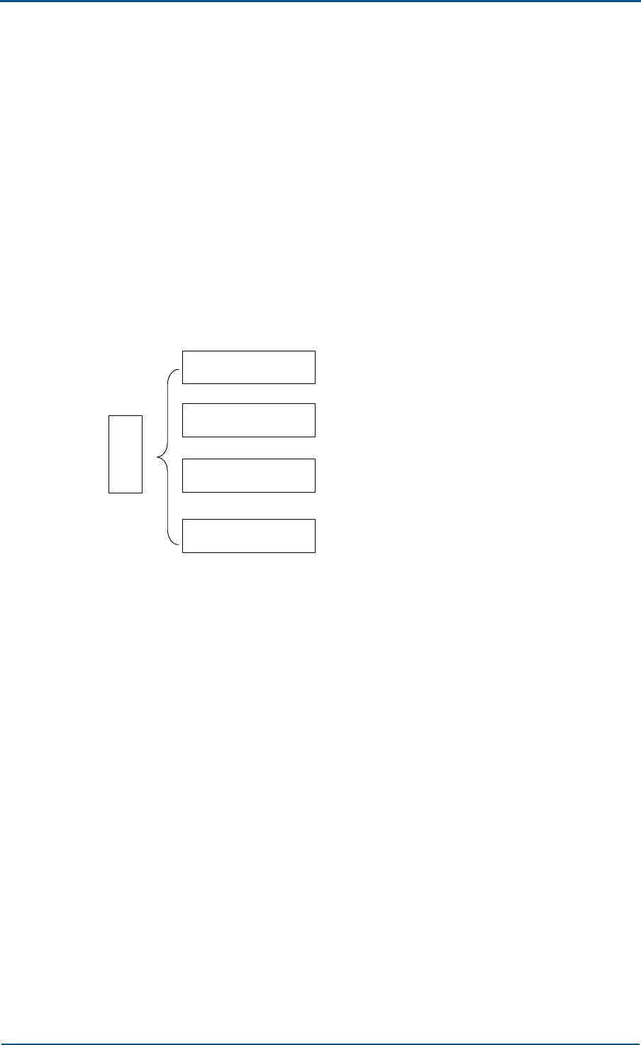
The internal software of ZXG10 OB06 (V1.0) is composed of four parts:
Controller & Maintenance Module (CMM), Frame Unit Controller (FUC),
Channel Codec Module (CHP) and Carrier Interface Processor (CIP).
Different software platforms are adopted for the software according to
their functions, as shown in Figure 6.
FIGURE 6 SOFTWARE MODULES OF THE ZXG10 OB06 (V1.0)
System
software
CMM software module
FUC software module
CHP software module
CIP software module
CMM
The CMM of ZXG10 OB06 (V1.0) provides the following functions:
Status management;
Configuration management
Device management;
Monitoring management
Test management
Database management
Supporting local O&M function, including local parameter configurations
and alarm query

ZXG10 OB06 ZTE Integrated Outdoor GSM Base Station Technical Manual
10 Confidential and Proprietary Information of ZTE CORPORATION
The CMM software is designed in layers, as shown in Figure 7.
FIGURE 7 CMM SOFTWARE MODULE STRUCTURE
APP
pSOS+
Hardware
BSP
LMU O&M
DBS
RUNCTRL
LNKDRV
LNKCTRL
RUNSPT
OSS
The five layers from the top downward are as follows:
1. Hardware
The physical platform on which the CMM software is running.
2. BSP (board-level support package)
BSP initializes CMM boards and provides drivers for the relevant parts
of the equipment. It provides consistent operation interfaces for the
specific details of the upper-level encapsulated hardware equipment
and simplifies the OSS design.
3. pSOS + operating system
It is a real-time multi-task operating system for commercial purposes
and with superior performance. The operating system has been
successfully applied to the next-generation BTS.
4. Operation support system (OSS) layer
This layer consists of the following parts:
i. RUNSPT
It is the core layer of the OSS.
It is a dispatch system of the state machine, providing process
dispatch, process communication, memory management, timer
management, process monitoring and abnormality capture.

Chapter 1 - System Architecture
Confidential and Proprietary Information of ZTE CORPORATION 11
ii. RUNCTRL
It is the operation control layer of the system.
It includes the system control module and implements the power-
on sequence for application processes. In addition, this layer
includes some miscellaneous functions of the operating system
such as redirection of the printing messages.
iii. LNKDRV
It is the device driver.
Working with BSP, LNKDRV provides equipment-independent
drivers for LNKCTR. At the same time, this part also includes a
frame number synchronization module, implementing the frame
number synchronization between active/standby CMMs, active
CMMs of the base cabinet and the extension cabinet, and master
CMM and TRMs.
iv. LNKCTRL
It is the communication link control layer module.
It consists of multiple communication link control modules, like
LapD, HDLC, LMComm.
LapD communication link control module
LapD is the communication link control module of the Abis interface.
HDLC communication link control module
HDLC is the communication link control module inside the cabinet.
They all communicate in a point-to-point way.
Currently, there are three types of communication links:
CCComm: It is the auxiliary communication link between the
master CMM of the base cabinet and that of the extension cabinet.
Physically, it is a 2 M PCM line, which facilitates the centralized data
collection of LMU.
CMComm: The communication link between the active and standby
CMMs, implementing the data synchronization between them.
Physically, it is a 1M HW.
CTComm: As the communication link between the active CMM and
1 ~ 12 TRMs of its cabinets, the CTComm implements the
parameter configuration of TRM and alarm collection. Physically, it
uses a 64 Kbit/s timeslot in 4 M HW.
LMComm
Foreground/background link control module with RS232 as its
physical interface. It is a self-defined point-to-point link control
protocol and character-oriented single-bit stop and wait protocol.
5. APP layer
It is the application layer. It consists of three parts:
i. O&M
As the core of the application layer, it receives the O&M messages
of the Abis interface and implements parameter configuration,

ZXG10 OB06 ZTE Integrated Outdoor GSM Base Station Technical Manual
12 Confidential and Proprietary Information of ZTE CORPORATION
status and alarm management, software version management,
device test and external alarm collection.
ii. DBS
The whole application layer is designed with the database as a core.
The database coordinates to assign configuration parameters. It
also synchronizes data between the active and standby CMMs and
between the foreground and the background.
iii. LMU
It is the local O&M unit, including two parts: foreground agent and
background operation interface.
It works with the database synchronization module to complete the
local parameter configuration, equipment status and alarm
collection. It also includes operating interface of equipment test to
implement test functions of the local BTS.
The system tool part is a series of developer-oriented tools for
system diagnosis and test to rapidly locate faults.
FUC
The FUC software module is located in the TPU of the TRM module. It
processes the radio signaling over every radio carrier and signaling on the
BSC interface and manages all channels. Its major functions are as follows:
1. It processes and converts GSM signaling protocols, including the layer-
2 protocol LAPD with BSC, the layer-2 protocol HDLC with CMM, the
layer-2 protocol LAPDm with the Um interface and the layer-3 radio
resources management protocol of GSM.
2. It is responsible for the TDMA multi-frame framing on the Um interface,
frame number (FN) receiving, frequency hopping calculation and
management & control over CHP.
3. It manages OB06 and loads the FUC software and DSP program. It
supports packet switching services (GPRS or PS for short).

Chapter 1 - System Architecture
Confidential and Proprietary Information of ZTE CORPORATION 13
The whole FUC software can be divided into two layers: system software
and application, as shown in Figure 8.
FIGURE 8 FUC SOFTWARE MODULE
OSS
APP
pSOS+
Hardware
BSP
LMA
OAMM
RUNCTRL
RUNSPT
LNKCTR
LNKDR
RSM
The concept of virtual operating system is adopted for the system software.
Based on the commercial operating system pSOS+, the running support
layer RUNSPT of the limited state machine is oriented to make the
application irrelevant with the actual real-time operating system, simplify
the application implementation and improve the application grafting.
RUNCTRL implements the power-on boot sequence of system’s modules
and some auxiliary functions of the operating system. It collects and
redirects the output messages.
The drivers are also designed with a hierarchical structure, including
equipment-dependent and equipment-independent drivers. All
communications within the current equipment adopt the address transfer
mode to reduce the overhead of the memory block copies.
The application layer contains the operation and maintenance module
(OAMM), radio signaling processing module (RSM) and local O&M agent
module (LMA). The OAMM configures and manages the software,
parameters, status and alarms of the TPU board. The RSM can be divided
into the FURRM (Radio Resource Management Module), PAGCHM (Paging
Access Channel Message Processing Module) and FHM (Frequency Hopping
Module). These modules implement the signaling flows of circuit switched
service and packet switched service according to the GSM protocol, and
they support frequency hopping. LMA is used for system debugging.
CHP
The CHP software module is located in the TPU of the TRM in the system.

ZXG10 OB06 ZTE Integrated Outdoor GSM Base Station Technical Manual
14 Confidential and Proprietary Information of ZTE CORPORATION
It implements all baseband channel processing and some corresponding
control functions, including channel encoding, channel decoding and
demodulation.
CIP
The CIP software module is located in the TPU of the TRM in the system.
The functions of CIP software are GMSK (GSM modulation mode), 8PSK
(EGPRS modulation mode), software modulation, power control and the
collection and handling of AEM, amplifier, RCU and fan alarm information.
System Features
The ZXG10 OB06 (V1.0) is a compact outdoor BTS with a high capacity; a
single cabinet may support 6 carriers at the maximum; customer
requirements in terms of capacity, configuration, arrangement and
maintenance are all taken into consideration in its design.
The main features of the ZXG10 BS21 are as follows:
1. High jumping-off point in technology
The ZXG10 OB06 (V1.0) starts from the new generation of GSM
technology, and the standards of GSM Phase II are adopted. It can be
upgraded to GSM Phase II+ smoothly.
2. Advanced functions, covering all frequency bands and supporting
flexible configurations
The ZXG10 OB06 (V1.0) supports functions defined in GSM
specifications and flexible configurations according to the customer’s
requirements. It also supports mixed insertion of modules of different
frequency bands, such as GSM1900/1800, GSM900/1900.
GSM850/1800, and GSM850/1900; it supports star, chain and tree
connections of PCM links; it supports FH; it supports configurations
with 40 W and 80 W power.
3. Strong environmental adaptability
The ZXG10 OB06 (V1.0) allows normal operation in an adverse outdoor
environment.
The cabinet features a framework of double-layer section aluminum
and a base of bended aluminum alloy plate, which are good in erosion
resistance and electric conduction.
Thanks to the sealing strips between the cabinet door and the racks,
and between the HEX and the door plate, the cabinet is well sealed,
and becomes a consecutive conductor as well, thus satisfying the
requirements by the EMC.
The integrated equipment permits protection of IP55 level.
4. Beautiful appearance and compact structure

Chapter 1 - System Architecture
Confidential and Proprietary Information of ZTE CORPORATION 15
ZXG10 OB06 (V1.0) looks concise, features compact structure, high
performance of electromagnetic shielding and good heat dissipation.
Both the front door and back door of the cabinet can be opened to
facilitate maintenance.
5. Modular design in software/hardware.
The software/hardware of the ZXG10 OB06 (V1.0) is of a modular
design to reduce the types of its boards and modules, enhance the
integration of the boards, facilitate installation and maintenance for the
projects, and improve the reliability of the system.
6. Advanced software radio technology.
With the advanced software radio technology, the ZXG10 OB06 (V1.0)
ensures that the RF components would work stably and reliably. It
improves the consistency of the equipment in batches and the massive
production of the equipment.
7. Flexible and reliable Abis interface
Advanced flow control algorithms and variable rate signaling link
technology are used so that multiple logical signaling links can be
configured on the 64 Kbit/s physical link to fully share the bandwidth.
In case of ZXG10 OB06 (V1.0) cascading, if one ZXG10 OB06 (V1.0) is
powered off, the Abis interface link can provide auto-bridging
protection.
8. Secure and reliable power supply system.
The power supply module of the ZXG10 OB06 (V1.0) provides such
functions as lightning protection and electromagnetic filtration. The
PSM provides AC input protection (overvoltage/undervoltage protection)
and DC output protection (overvoltage/undervoltage protection),
lightening/surge prevention, burst interference resistance, cycle drop
prevention, conduction interference resistance and anti-
electromagnetic radiation functions.
Since there will be nobody on duty for an outdoor BTS, the power
system is configured with an intelligent control function for equipment
start to protect the system, that is, when the temperature is lower
than -20˚C, the DC output will be automatically cut off, and when the
temperature is higher than -20˚C, the DC output will be automatically
restored.
The power system accommodates external high-capacity batteries, and
provides a function for management of secondary power down and
batteries.
9. Perfect environment monitoring capability
Internal smog, flood and over-high/over-low temperature can be
detected automatically.
10. Good heat design
The system features direct heat dissipation by wind. Fans of high wind
pressure and large wind capacity are used, thus ensuring quick and
effective heat dissipation for the modules.
Independent air ducts are designed for the AEM and TRM, so that the
distance of heat dissipation is shortened for higher efficiency.

ZXG10 OB06 ZTE Integrated Outdoor GSM Base Station Technical Manual
16 Confidential and Proprietary Information of ZTE CORPORATION
High-capacity heat exchangers are used for more powerful heat
dissipation capability of the system.
The cabinet features a double-layer top, thus effectively alleviating the
influence of direct sunshine. The cabinet surface is covered with
painting resisting infrared radiation.
11. Convenient local operation and maintenance
Standard RS232 interface is used for connection with the local
operation and maintenance terminal.
The local operation and maintenance terminal is easy to learn and use
since it is consistent with the OMCR interface.
Perfect local operation and maintenance
Rapid and reliable online software upgrade.
12. Abundant services
The ZXG10 OB06 (V1.0) supports GPRS data services, HLR services,
large area coverage and satellite Abis links.

Confidential and Proprietary Information of ZTE CORPORATION 17
Chapter 2
Technical Indexes
This chapter introduces the indexes of the ZXG10 OB06 (V1.0) system and
indexes of the modules and components of the system.
Physical Performance
Dimensions, Color and Structure
The framework of the equipment is of section aluminum; the door plates
are made of aluminum; the enclosure frame is in light grey, the 4 doors
are in blue and the base is in black.
Overall dimensions of the equipment: 1800 mm×900 mm×780 mm
(H×W×D).
Weight of Integrated Equipment and
Weight Bearing Requirements of
Equipment Room Ground
Weight of the equipment: <450 kg.
Weights of parts of the cabinet:
The main body of the cabinet (including the heat exchange and base): 230
kg
AEMs (6 in full configuration): 42 kg
Carrier module (6 in full configuration): 36 kg
CMM (2 in full configuration): 3 kg
Fiber slice tray: 1.5 kg
Transmission frame: 8 kg

ZXG10 OB06 ZTE Integrated Outdoor GSM Base Station Technical Manual
18 Confidential and Proprietary Information of ZTE CORPORATION
Power subrack
Batteries (4): 75 kg
Bearing capacity of a single concrete platform: >800 kg
Power Supply
Power Supply Range of Power Supply
System
Input voltage: 88 VAC~300 VAC, optional.
Power Consumption Indexes
The maximal power consumption of each module is as follows:
TRM (×6): 200 W per TRM
CMM (2 pieces): 15 W per CMM;
AEM (×6): 15 W per AEM
Internal mixed-flow fan (×3): 40 W per fan
Internal axial flow fan (×3): 20 W per fan
Fan for HEX: 60 W
Transmission: 100 W
Battery charging: 1500 W
Heater: 2500 W
Maintenance socket: 500 W
When fully configured, the power consumption of the whole system is <
6511W.
Ambient Conditions
Requirements for Grounding and Lightning
Protection
OB06 outdoor BTS features a lightning-protection capability of B+C level.

Chapter 2 - Technical Indexes
Confidential and Proprietary Information of ZTE CORPORATION 19
There is a built-in induction-free lightning protector of B+C level in the AC
input part of the ZXG10 OB06 system, while the internal modules of the
power system provides a lightning-protection function of D level, thus
preventing faults in most cases of lightning.
A 1/4 wavelength lightning-protector is used for the antenna system,
installed at outlet of the antenna feeder in a position near the cabinet. The
lightning protector is effective in preventing the antenna from suffering
damage by lightning.
ZXG10 OB06 supports E1 transmission access. At the access interface of
E1 there is a B-level signal lightning protector, and the internal E1
interface boards all support a D-level lightning-protection function, thus
capable of preventing damage by lightning and surge.
All components inside the cabinet are well connected through metal screws;
good grounding terminals are available and protection ground cables are
well installed.
Requirements for Temperature and
Humidity:
Temperature range: -40˚C~+50˚C
Humidity of the ambient environment: 5%~98%
Maximum wind speed: 54.68 yd/s
Requirements for Cleanness
For internal cabinet environment requirements, see Table 4.
TABLE 4 LIMIT TO INVASION OF DETRIMENTAL GASES
Name Average (mg/m3 ) Maximum (mg/m3 )
SO2 0.2 1.5
H2S 0.006 0.03
NO2 0.04 0.15
NH3 0.05 0.15
Cl2 0.01 0.3
HCL 0.2 1.5
CO 5.0 30.0
HF 0.01 0.5
O3 0.005 0.1
It can endure rain, water, salt fog, dust and provides the anti-theft
function. The IP protection level reaches IP55.

ZXG10 OB06 ZTE Integrated Outdoor GSM Base Station Technical Manual
20 Confidential and Proprietary Information of ZTE CORPORATION
Requirements for Atmospheric Pressure
70×103~106×103 pa.
Interface Indexes
Abis Interface Indexes
The Abis interface adopts the standard E1 interface.
The performance of the Abis interface meets the requirements specified by
ITU-T G.703 and ITU-T G.704. Details are as follows:
1. Prerequisites
i. Nominal bit rate: 2048 kb/s
ii. Bit rate error tolerance: ±50×10-6
iii. Signal code pattern: HDB3
2. Electrical features:
i. Pulse shape: rectangle
ii. Nominal peak voltage of pulse (mark):
2.37V (75 ohm, a pair of coaxial cables).
3 V (120 ohm, a pair of symmetrical cables).
iii. Peak voltage when without pulse (vacant number):
0±0.237V (75 ohm, one pair of coaxial cables).
3 V (120 ohm, one pair of symmetrical cables).
iv. Nominal pulse width: 244 ns
v. The amplitude ratio between the positive pulse and the negative
pulse
The amplitude ratio of the positive pulse to the negative one at the
midpoint of the pulse width is superior to 0.955–1.05.
The amplitude ratio of the positive pulse to the negative pulse at
the half of the nominal pulse amplitude is superior to 0.95–1.05.
vi. Digital signal jittering features (1UI = 488 ns):
1.5UI (peak-peak value, 20 Hz~100 kHz).
0.2UI (peak-peak value, 18 kHz~100 kHz).
vii. Input impedance features
Corresponding to the nominal bit rate (2048 kb/s) 2.5% ~ 5%,
that is, when it is 51.2 kb/s~102.4 kb/s, echo attenuation ≥12 dB.
Corresponding to the nominal bit rate (2048 kb/s) 5% ~ 100%,
that is, when it is 102.4 kb/s~2048 kb/s, echo attenuation ≥18 dB.

Chapter 2 - Technical Indexes
Confidential and Proprietary Information of ZTE CORPORATION 21
Corresponding to the nominal bit rate (2048 kb/s) 100%~150%,
that is, when it is 2048 kb/s~3072 kb/s, echo attenuation ≥14 dB.
Um Interface Indexes
Main indexes are as follows:
1. Wireless channel
Co-channel interference protection ratio C/I≥9 dB (static).
Interference protection ratio of the adjacent channels ≥ - 9 dB
Interference protection ratio the second adjacent channel ≥ -43 dB
The wireless channel selection adopts the shared signaling channel
mode.
2. Wireless RF modulation mode
OB06 supports EDGE service. There are 9 modulation and coding
modes, namely, MCS1~9. MCS1~4 retain the GMSK modulation mode,
while MCS5~9 use the 8PSK modulation mode. 8PSK allows 3-bit data
over each modulation signal on a wireless path, whereas GMSK allows
only 1-bit data under the same conditions. So, 8PSK realizes a higher
rate in data transmission; its transmission rate at the maximum is as
high as three time that of GPRS.
Different coding modes define different sizes of data blocks and
channel redundancy codes. In comparison with GPRS that features a
mono modulation technique, EDGE is capable of adapting to a more
adverse and wider wireless propagation environment.
3. The performance of the transmitter
i. The phase error of the transmitter
The phase error of the transmitter is the error between the actual
phase and the theoretical one.
The Root Mean Square of the BS phase error is not greater than
5°and the peak value is not over 20°.
ii. The frequency error of the transmitter
The frequency error of the transmitter is the error between the
actual frequency and the theoretical one.
The BS frequency error is not over 0.05 ppm.
iii. Average transmitted carrier power (requirement for the power
amplifier output)
40 W or 80 W.
It is provided with the 6-level static power control function. Based
on the maximum output power, it can adjust downwards 6 power
levels with the step of 2 dB ± 1.0 dB. At the same time, BS has the
downlink power control function. Based on the set power level, it
can decrease the power from level zero to level-15 with the step of
2dB ± 1.5dB.
iv. Transmitted RF carrier power/time envelop

ZXG10 OB06 ZTE Integrated Outdoor GSM Base Station Technical Manual
22 Confidential and Proprietary Information of ZTE CORPORATION
Compliant with GSM 11.21 and GSM 05.05.
v. The inter-modulation attenuation of the transmitter
Compliant with GSM 11.21 and GSM 05.05.
vi. The inter-modulation attenuation in BSS
Compliant with GSM 11.21 and GSM 05.05.
vii. Transmitted adjacent channel power
Compliant with GSM 11.21 and GSM 05.05.
viii. The spurious emission of the transmitter
Compliant with GSM 11.21 and GSM 05.05.
4. The performance of the transmitter
i. The static layer-1 function of the transmitter (nominal error rate)
The static first layer functions of the receiver are the floorboard of
such functions of RF part, multiplexing and multi-addressing,
equalizer de-encryption, de-interleaving and the channel encoding.
The static layer-1 function is signified by the nominal error rate
(BER) before channel decoding.
Compliant with GSM 11.21 and GSM 05.05.
ii. Static referential sensitivity level
The static referential sensitivity level means that when inputting a
standard test signal under the static environment, the FER, RBER
or BER performance of the data, generated after modulation and
channel decoding, meets the specified requirements when the level
is configured as the referential sensitivity level.
Compliant with GSM 11.21 and GSM 05.05.
GMSK: Static sensibility level for reference ≤ -108 dBm
8PSK: Static sensibility level for reference ≤ -104 dBm
iii. Multi-path referential sensitivity
Input a standard test signal under the multi-path environment, the
FER, RBER or BER performance of the data, generated after
modulation and channel decoding, meets the specified
requirements when the level is configured as the referential
sensitivity level.
Compliant with GSM 11.21 and GSM 05.05.
iv. Referential interference level (interference and suppression of the
same frequency and adjacent channels).
The referential interference level means the capability that the
transmitter receives the expected modulation signal not over the
given degraded quantity, which is caused by the unexpected
modulation signal on the same carrier frequency (inference of the
same channel) or any adjacent carrier frequency (inference of the
adjacent channel).
Compliant with GSM 11.21 and GSM 05.05.

Chapter 2 - Technical Indexes
Confidential and Proprietary Information of ZTE CORPORATION 23
v. Block and spurious response suppression
The block and spurious response suppression is to test the
capability that the BSS transmitter receives the GSM modulation
signal when interferential signal exists.
Compliant with GSM 11.21 and GSM 05.05.
vi. Inter-modulation suppression
This index is for measuring the linear degree of the RF part of the
transmitter. It indicates, when two or multiple unexpected signals
which are relative to the expected signal in frequency exist, the
transmitter’s capability of receiving the respected modulation signal
is not over the given degraded quantity.
Compliant with GSM 11.21 and GSM 05.05.
vii. AM suppression
AM suppression means the transmitter’s capability of receiving the
expected modulation signals is not over the given degraded
quantity when an unexpected modulation signal exists.
Compliant with GSM 11.21 and GSM 05.05.
viii. Spurious emission
The spurious emission is the emission on the frequencies except
that of the RF channel of the transmitter and adjacent frequencies.
Compliant with GSM 11.21 and GSM 05.05.
Capacity Indexes
A single cabinet of ZXG10 OB06 can be configured with 6 carriers at the
maximum. One site supports 3 cabinets and 18 carriers at the maximum.
Clock Indexes
It provides a two-level clock, whose indexes are as follows:
Clock accuracy: ±1.0×10⁻⁹
Pull-in range: ±1.0×10⁻⁹
The maximum frequency offset: 1 × 10⁻⁹/day.
The maximum initial frequency offset: 1×10⁻⁷
Reliability Indexes
Mean Time Between Failures (MTBF): 63000 hours

ZXG10 OB06 ZTE Integrated Outdoor GSM Base Station Technical Manual
24 Confidential and Proprietary Information of ZTE CORPORATION
Mean Time To Repair (MTTR):
Availability ratio A (%): 99.999%
Average time of suspensions per year: 4.2 minutes
The product successfully passed the CE certification. The personal safety,
electromagnetic security, EMC and wireless frequency spectrum comply
with international standards.
Confidential and Proprietary Information of ZTE CORPORATION 25
Chapter 3
Interfaces and
Communications
This chapter details different external interfaces of the ZXG10 OB06 (V1.0)
and different interface protocols.
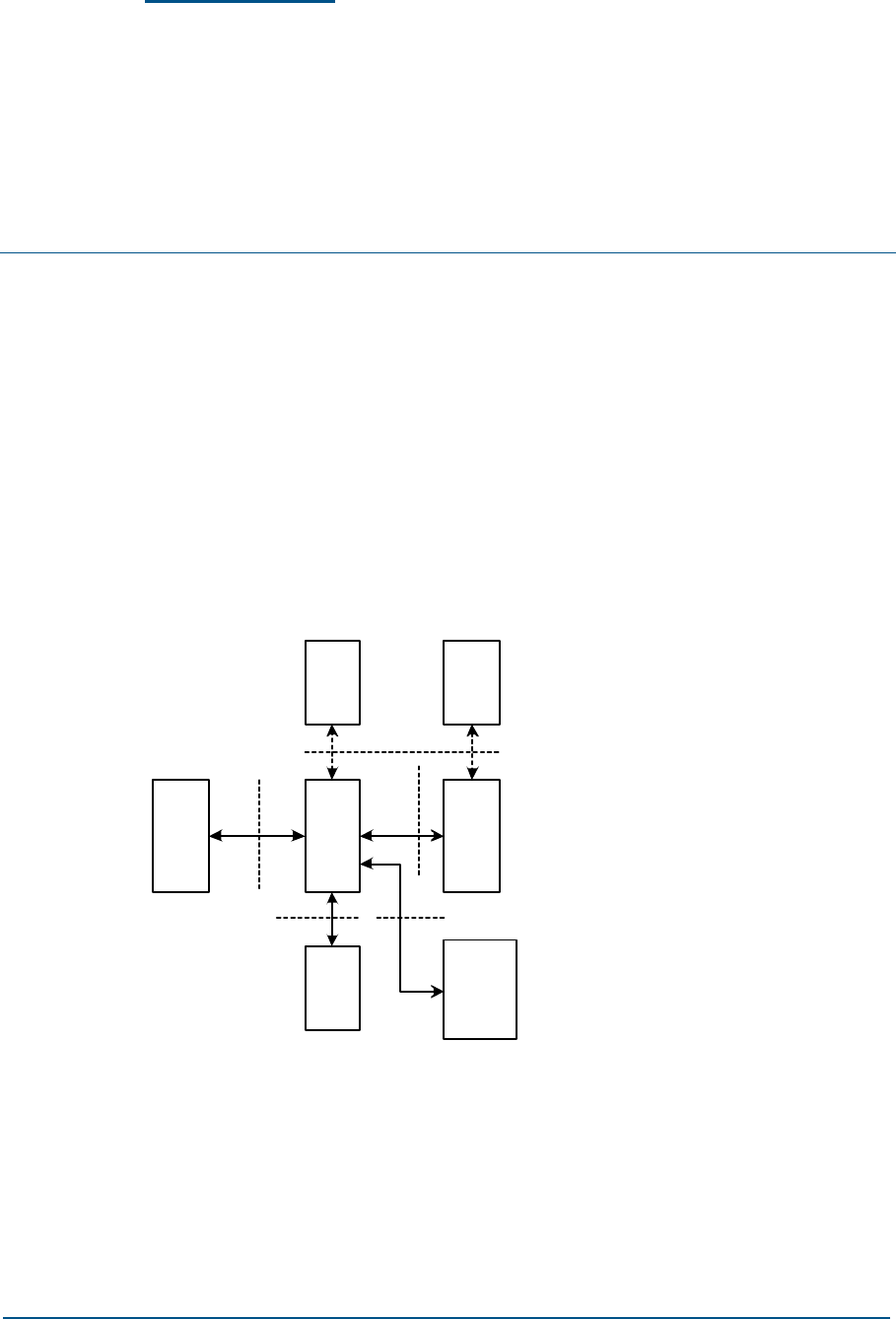
Overview
Figure 9 shows the positions of the main interfaces of the ZXG10 OB06
(V1.0) in the system.
FIGURE 9 POSITIONS OF ZXG10 OB06 (V1.0) EXTERNAL INTERFACES
OB06 OB06BSC
LMT
MS MS
Um interface
Abis interface
MMI interface
Tower
amplificatio
n system
Tower amplification
system interface
B
interface
The ZXG10 OB06 (V1.0) provides Abis interfaces and Um interfaces, as
well the cascade interface (defined as B interface) between OB06s,
interfaces of the tower amplification and local O&M interfaces.
The Abis interface is a communication interface between OB06 and BSC.
The Um interface is the interface between OB06 and MS. The B interface is
actually an extension of the Abis interface. The tower amplifier system
ZXG10 OB06 ZTE Integrated Outdoor GSM Base Station Technical Manual
26 Confidential and Proprietary Information of ZTE CORPORATION
provides the power supply and the alarm interfaces. The man-machine
interface (MMI) is an interface between the local O&M terminal (LMT) and
OB06.
Interfaces
Abis Interface
The Abis interface is defined as an interface between OB06 and BSC.
The Abis interface sends the signal from the BSC to the OB06, usually the
standard E1 signal of PCM 2M. The signals are generally the standard PCM
2M E1 signals, transmitted physically over the 75ohm coaxial cable in the
unbalanced mode or the 120 ohm cable in the balanced mode or through
digital microwave, fiber transmission (SDH/PDH) or satellite link.
Physically, the Abis interface is an E1 interface and uses thin coaxial cables
for connection.
Protocols on the Abis interface are hierarchical, and the protocol hierarchy
of circuit service is shown in Figure 10. The Abis interface does not process
the packet service protocol, and it is transparent for the packet signaling.
FIGURE 10 CIRCUIT SERVICE PROTOCOL LAYERED STRUCTURE OF ABIS INTERFACE
OB06
BTSM
LAPD
Sig.L1
BSC
Sig.L2
LAPD
BTSM
RR
Abis interface
On the Abis interface, the circuit service protocols fall into three layers:
1. Layer-1 (physical layer) is the PCM digital link at the rate of 2,048
Kbit/s.
2. Layer-2 (data link layer) is based on the LAPD.
3. Layer-3 transparently transmits the layer-3 messages on the A
interface and manages radio resources.
The protocols related to the Abis interface are as follows:

Chapter 3 - Interfaces and Communications
Confidential and Proprietary Information of ZTE CORPORATION 27
GSM 08.52 presents the basic principles and rules of the other
specifications for the Abis interface and how the service functions are
divided between BSC and OB06.
GSM 08.54 specifies the physical structure of the Abis interface.
GSM 08.56 specifies the data link layer protocol for the Abis interface.
GSM08.58 stipulates the layer-3 protocols of the Abis interface.
GSM 12.21 specifies the O&M message transmission mechanism on the
Abis interface.
The data format of Abis interface can be flexibly configured. Configuration
examples of the Abis interface are shown in Figure 11.
FIGURE 11 EXAMPLE OF ABIS INTERFACE TIMESLOT CONFIGURATION
0 1 2 3 4 5 6 7
TCH0 TCH1 TCH2 TCH3
TCH4 TCH5 TCH6 TCH7
TCH0 TCH1 TCH2 TCH3
TCH4 TCH5 TCH6 TCH7
TCH0 TCH1 TCH2 TCH3
TCH4 TCH5 TCH6 TCH7
TCH0 TCH1 TCH2 TCH3
TCH4 TCH5 TCH6 TCH7
TCH0 TCH1 TCH2 TCH3
TCH4 TCH5 TCH6 TCH7
TCH0 TCH1 TCH2 TCH3
TCH4 TCH5 TCH6 TCH7
TCH0 TCH1 TCH2 TCH3
TCH4 TCH5 TCH6 TCH7
TCH0 TCH1 TCH2 TCH3
TCH4 TCH5 TCH6 TCH7
TCH0 TCH1 TCH2 TCH3
TCH4 TCH5 TCH6 TCH7
TCH0 TCH1 TCH2 TCH3
TCH4 TCH5 TCH6 TCH7
TCH0 TCH1 TCH2 TCH3
TCH4 TCH5 TCH6 TCH7
TCH0 TCH1 TCH2 TCH3
TCH4 TCH5 TCH6 TCH7
FUL
FUL
FUL
FUL
FUL
FUL
FUL
SYNC
FUL
FUL
FUL
FUL
FUL
EAM3
EAM2
EAM1
EAM0
O&M3
O&M2
O&M1
O&M0
0 1 2 3 4 5 6 7
TCH0 TCH1 TCH2 TCH3
TCH4 TCH5 TCH6 TCH7
TCH0 TCH1 TCH2 TCH3
TCH4 TCH5 TCH6 TCH7
TCH0 TCH1 TCH2 TCH3
TCH4 TCH5 TCH6 TCH7
TCH0 TCH1 TCH2 TCH3
TCH4 TCH5 TCH6 TCH7
TCH0 TCH1 TCH2 TCH3
TCH4 TCH5 TCH6 TCH7
TCH0 TCH1 TCH2 TCH3
TCH4 TCH5 TCH6 TCH7
TCH0 TCH1 TCH2 TCH3
TCH4 TCH5 TCH6 TCH7
TCH0 TCH1 TCH2 TCH3
TCH4 TCH5 TCH6 TCH7
TCH0 TCH1 TCH2 TCH3
TCH4 TCH5 TCH6 TCH7
TS0
TS1
TS2
TS3
TS4
TS5
TS6
TS7
TS8
TS9
TS10
TS11
TS12
TS13
TS14
TS15
TS16
TS17
TS18
TS19
TS20
TS21
TS22
TS23
TS24
TS25
TS26
TS27
TS28
TS29
TS30
TS31
TS0
TS1
TS2
TS3
TS4
TS5
TS6
TS7
TS8
TS9
TS10
TS11
TS12
TS13
TS14
TS15
TS16
TS17
TS18
TS19
TS20
TS21
TS22
TS23
TS24
TS25
TS26
TS27
TS28
TS29
TS30
TS31

ZXG10 OB06 ZTE Integrated Outdoor GSM Base Station Technical Manual
28 Confidential and Proprietary Information of ZTE CORPORATION
An O&M timeslot on the Abis interface is multiplexed in each site, and the
O&M signaling at different sites occupies the fixed timeslot on the Abis
interface. During the CMM initialization, the CMM reads the ID signal from
the cabinet top to locate the TS of the O&M signaling on the Abis interface.
For detailed description of ID, refer to ZXG10 OB06 (V1.0) Compact
Outdoor BTS for GSM Hardware Manual.
For example, the site that is directly connected to BSC occupies the TS 30
Link A for O&M signaling, while the level-1 cascaded site occupies the TS
28 Link A for O&M signaling. The rest may be deduced by analogy. If the
previous-level faulty E1 interface is bridged, the next-level site can identify
the O&M channel corresponding to the site. The level of the site can be
read out on the DIP switch on the CMM board.
The Abis interface has four types of TSs: TCH TS for TRM service, FUL TS
for TRM signaling, O&M TS and EAM TS for transparent environment
monitoring channel.
The Abis interface processing is as follows:
1. Transparently transmit the TCH, FUL, O&M and EAM between cascaded
sites.
2. Downlink direction inside a site: The TCH and FUL signaling are
transparently transmitted to each TRM. The Q&M will be transparently
switched to the QMC interface of CMM in each cabinet. The CMM will
identify the O&M signaling according to TEI. EAM will be transparently
transmitted by the base cabinet.
3. Uplink direction inside a site: The TCH signaling is transmitted
transparently. The FUL signaling in the same cabinet is compressed
and packed in the CMM. The O&M signaling is multiplexed based on TEI,
and the EAM signaling is transmitted transparently in the base cabinet.
Um Interface
The Um interface is the interface between OB06 to MS, an important
external interface of the OB06.
In the PLMN, MS connects the fixed part of the network through a radio
channel to enable subscribers to access communication services.
To interconnect the MS and OB06, a series of stipulations are provided for
signal transmission over the radio channel, and a set of standards is set up.
This set of specifications about signal transmission over radio channel is
the Um interface.
Chapter 3 - Interfaces and Communications
Confidential and Proprietary Information of ZTE CORPORATION 29
The Ums interface is designed with a hierarchical model. The circuit
service protocol hierarchy is shown in Figure 12, and the packet service
protocol hierarchy is shown in Figure 13. The packet service protocol is
implemented in the BSC, so it is not introduced here.
FIGURE 12 CIRCUIT SERVICE PROTOCOL HIERARCHY OF THE UM INTERFACE
CM
MM
RR
LAPDm
Sig.L1 Sig.L1
LAPDm
RR
MS OB06
Um interface
FIGURE 13 PACKET SERVICE PROTOCOL STACK STRUCTURE OF THE UM INTERFACE
MS
Um Gb
BSS SGSN
BSSGP
LLC
SNDCP
Network
Service
L1bis
relay
BSSGP
L1bis
RLC
MAC
GSM RF
relay
RLC
MAC
GSM RF
SNDCP
IP/X.25
application
LLC
Network
Service
On the Um interface, the circuit service protocols fall into three layers:
1. The first layer is the physical layer and also the bottom layer. It
consists of various channels and provides the basic wireless channels
for upper-level message transmission.
2. The second layer is the data link layer and also the medium layer, with
the LapDm adopted. It comprises various data transmission structures
and controls data transmission.
3. The third layer (L3) is the highest layer. It comprises various messages
and programs and provides service control. L3 consists of three sub-
layers: radio resource management (RR), mobility management (MM)
and connection management (CM).

ZXG10 OB06 ZTE Integrated Outdoor GSM Base Station Technical Manual
30 Confidential and Proprietary Information of ZTE CORPORATION
The relevant protocols of the Um interface are as follows:
GSM 04.03 describes the channel structure and access capability of the
Um interface.
GSM 04.04 specifies the physical layer structure of the Um interface.
GSM 04.05 specifies the data link layer protocol for the Um interface.
GSM 04.08 stipulates the layer-3 protocols of the Um interface.
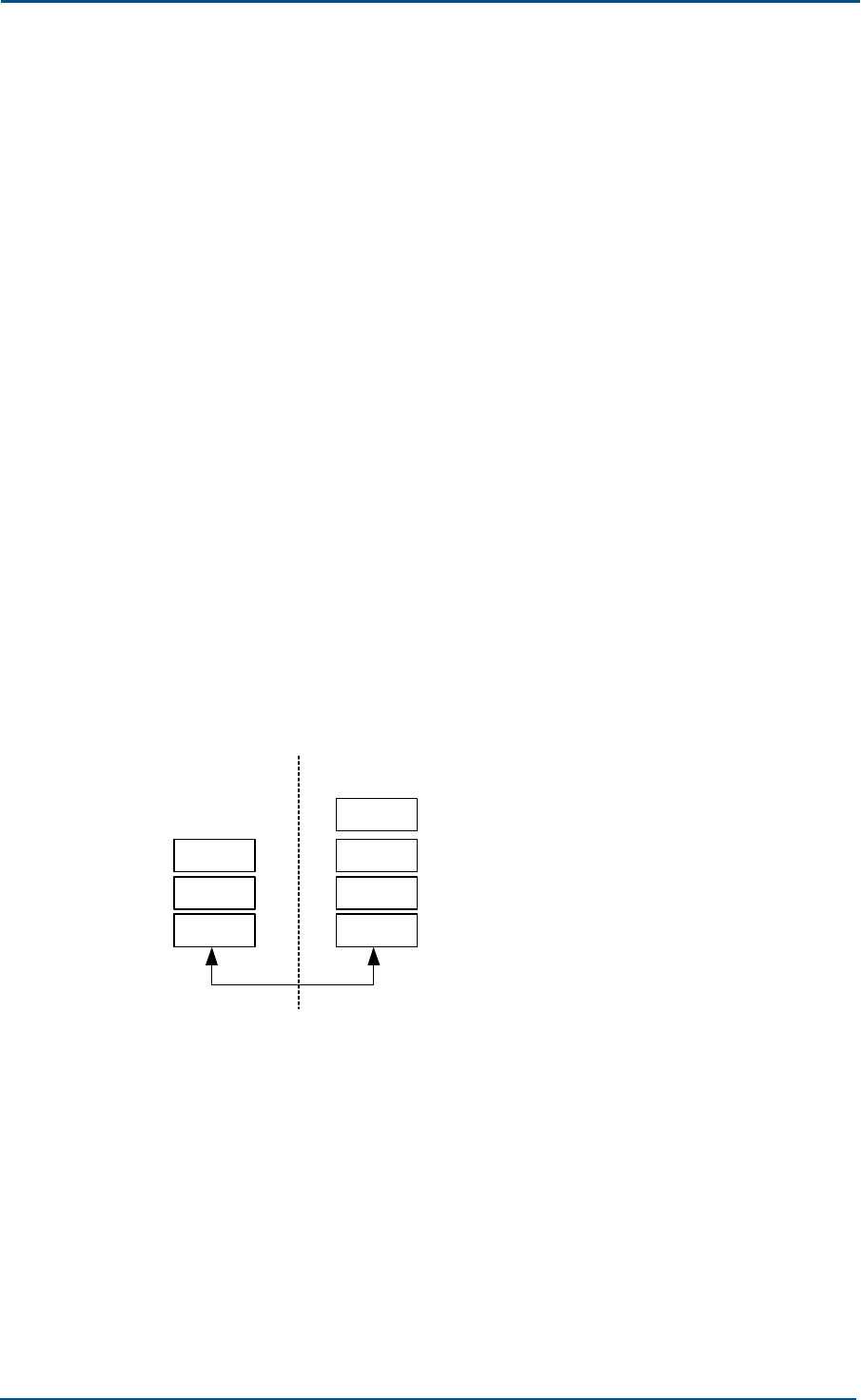
Inter-Cabinet Cascaded Interface of Same
Site
Inter-cabinet star connection is supported at the same site (one site
supports three OB06 cabinets at most).
The data interface between cabinets also employs the standard PCM 2M E1
signal to transfer service, TRM signaling, inter-cabinet O&M signaling and
FN (Frame Number). Service signaling and TRM signaling will be
transparently transmitted, while O&M and FN will be transmitted through
the time division HDLC link.
The inter-cabinet data interface format is shown in Figure 14.
FIGURE 14 DATA INTERFACES BETWEEN IN-SITE CABINETS
TS0
TS1
TS2
TS3
TS4
TS5
TS6
TS7
TS15
TS16
TS17
TS18
TS31
Downlink interface
between cabinets
0 1 2 3 4 5 6 7
SYNC
CC_COM
Frame No.
O&M operation and
maintenance timeslot
0 1 2 3 4 5 6 7
SYNC
CC_COM
TS0
TS1
TS2
TS14
TS15
TS16
TS17
TS18
TS31
.
.
.
.
.
.
.
.
.
.
.
.
.
.
.
Uplink interface
between cabinets
Frame No.
Same as Abis interface
O&M operation and
maintenance timeslot
Same as Abis interface
Same as Abis interface
Same as Abis interface
Same as Abis interface
Same as Abis interface
Same as Abis interface
Same as Abis interface
Same as Abis interface
Same as Abis interface
Same as Abis interface
Same as Abis interface
Same as Abis interface
Same as Abis interface

Chapter 3 - Interfaces and Communications
Confidential and Proprietary Information of ZTE CORPORATION 31
After CMM is powered on, it reads the ID signal to locate the position of
the O&M TS. The base cabinet generates and outputs FN and SYNCLK
while the extension cabinet receives them. The cabinet category is read by
the CMM from the cabinet top ID signal.
The inter-cabinet FN will be transmitted and broadcasted through the
HDLC protocol, the inter-cabinet O&M TS through the HDLC protocol and
inter-cabinet communication (CC_COM) through the HDLC protocol.
Details are introduced as follows:
In the downlink direction, the CMM will transparently switch the O&M
timeslot of the Abis interface to the processor of this board and other
cabinets of the same site. The CMM will identify the O&M according to TEI.
Upstream, CMM compresses the O&M TSs of this cabinet and the next
cabinet to send to the upper-level CMM. Thus, the base cabinet
compresses the O&M messages of three cabinets into one O&M message
to report to BSC.
Interfaces of the Tower Amplifier System
The interfaces of the tower amplifier system must be reserved during
installation of the tower amplifier for OB06, including the power interface
and the alarm interface of the tower amplifier. In general, they are
interfaces for providing the DC feed and alarm monitoring, and the alarm
is detected from the DC current.
OB06 can provide +12 V power supply and up to 300 mA current for the
tower amplifier system through the power interface.
The tower amplifier alarm is accessed to the backbone node in the OB06
through the backbone node alarm mode, and it is monitored by the OB06.
When two lines of the backbone node in OB06 are connected or connected
at a low resistance, it indicates there is alarm output for the tower
amplifier, and Alarm is ON. When two lines of the backbone node in OB06
are not connected or connected at a high resistance, it indicates there is
no alarm output for the tower amplifier, and Alarm is OFF.
The tower amplifier power interface is located on the cabinet top, and one
OB06 cabinet can provide 3 tower amplifier power interfaces.
Man-Machine Interface (MMI)
The MMI is a serial communication interface between the OB06 and local
O&M terminal.
It is realized by the 10-BaseT network interface or RS 232 interface
between the CMM and local O&M terminal.
It can be connected to the serial interface of a local O&M terminal
computer or network interface through the ETP interface of the CMM panel.

ZXG10 OB06 ZTE Integrated Outdoor GSM Base Station Technical Manual
32 Confidential and Proprietary Information of ZTE CORPORATION
Protocol Introduction
Two important external interfaces for the ZXG10 OB06 (V1.0) are the Abis
and the Um interface.
On the Abis and the Um interface, the ZXG10 OB06 (V1.0) processes the
LapD protocol, LapDm protocol and RR/MM/CM protocol. The following are
descriptions of the three protocols in combination with the actual system
circumstance.
LapD Protocol
LapD (link access procedure of “D” channel) is a data link procedure for
signaling transmission between ZXG10 OB06 (V1.0) and BSC, with the
purpose of using the D channel to transmit messages between Layer-3
entities.
LapD is a point-to-multipoint communication protocol that employs the
frame structure.
In the ZXG10 OB06 (V1.0), LapD implements the following functions:
1. Providing one or multiple data connections in the D channel
The data link connections are identified by the DLCIs in the frames.
DLCI consists of the Terminal Equipment Identifier (TEI) and Service
Access Point Identifier (SAPI), indicating the service and entity that are
accessed.
2. Delimitation, location and transparency of the frame
3. Sequence control, ensuring sequential transmission of the frames
4. Error detection
5. Error recovering
6. Notifying the management entity of the un-recoverable error
7. Traffic control
Functions 1, 2 and 4 hereof are implemented automatically by the
hardware, while functions 3, 5, 6 and 7 are implemented through the
software.
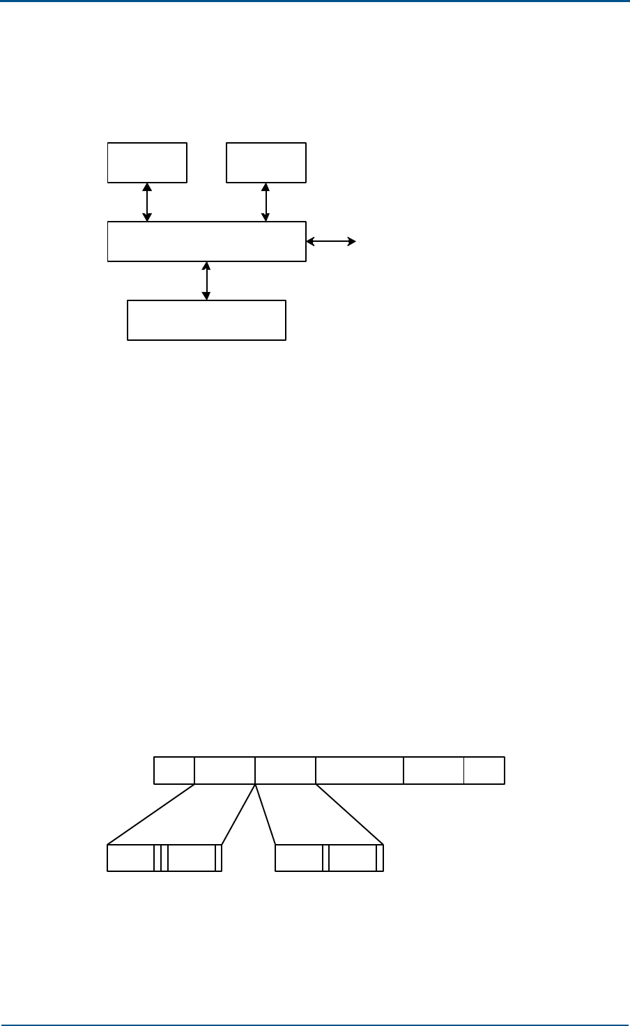
Chapter 3 - Interfaces and Communications
Confidential and Proprietary Information of ZTE CORPORATION 33
In ZXG10 OB06 (V1.0), LapD is realized in the LapD module of RSL. The
position of the LapD module in RSL is shown in Figure 15.
FIGURE 15 POSITION OF LAPD MODULE
LapD module
OAMM FURRM
Physical layer
BSC
The LapD module communicates with the physical layer and L3. The L3
protocol is processed in FURRM.
OAMM configures the parameters such as TEI and values of the timer
necessary for the LapD module to run.
The LapD module provides two types of information transmission modes
for the FURRM: I-frame multi-frame operation and UI frame operation.
1. I-frame multi-frame operation
The L3 message is sent in the information frame mode which requires
the confirmation from the receiver. This mode provides a whole set of
control mechanism for error recovering and flow control, the
establishment mechanism and release mechanism for multi-frame
operations.
The I-frame structure is shown in Figure 16, including the flag
sequence, address field, control field, information field and check field.
FIGURE 16 FRAME STRUCTURE OF LAPD
flag Address Control Information FCS flag
SAPI TEI N(S) N(R)
1 0-260 2 1
The address field contains SAPI and TEI. It performs addressing for
different units through TEI in the Abis interface link. Generally, a unit
has multiple functional entities, and the logical physical links between
different functional entities are identified by the functional address
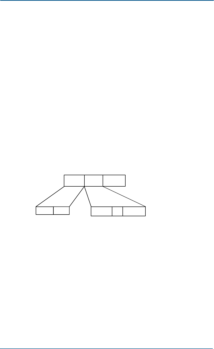
ZXG10 OB06 ZTE Integrated Outdoor GSM Base Station Technical Manual
34 Confidential and Proprietary Information of ZTE CORPORATION
SAPI. The LapD supports three types of information: signaling
(including short message information), O&M information and LapD
layer management information. Links of the three kinds of information
are distinguished by SAPI. SAPI=0 represents the signaling link,
SAPI=62 represents the O&M link, and SAPI=63 represents the
management link of the LapD layer.
In the control field, N(S) represents the sending serial number and the
I frame’s serial number currently sent by the sending end; N(R)
represents the receiving serial number, the expected sending serial
number of the next I frame. N(R) is used to predict the instruction
from the receiving end.
Frame Check Sequence (FCS) is used for error code detection.
Flag is the beginning and the end token of a frame, namely, a 8-bit
font containing six consecutive 1s.
2. UI frame operation
The L3 message is sent in the no-serial-number frame mode, and the
receiver is not required to send the received confirmation after
receiving the UI frame. This operation mode does not provide flow
control or error recovering mechanism.
The UI frame structure is shown in Figure 17. It consists of the address
field, control field and information field.
FIGURE 17 UI FRAME STRUCTURE OF LAPD
000 P0011
TEISAPI
Address Control Information
The address field contains SAPI and TEI. In the address field, P
represents the query bit; if this bit is set to 1, it means to require the
response frame from the peer entity.
LapDm Protocol
In GSM, LapDm is a data link protocol for signaling transmission between
MS and ZXG10 OB06 (V1.0), with the purpose of using the Dm channel to
transmit messages for entities of Layer 3 through the radio interface.
LapDm is based on LapD, with some simplification and modification.
In the ZXG10 OB06 (V1.0), LapDm implements the following functions:
1. In a Dm channel, providing a point-to-point data link connection and
multiple services for the upper layer. The data link connections are
identified by the DLCIs in the frames. The DLCI only contains SAPI,
indicating the service that is accessed.
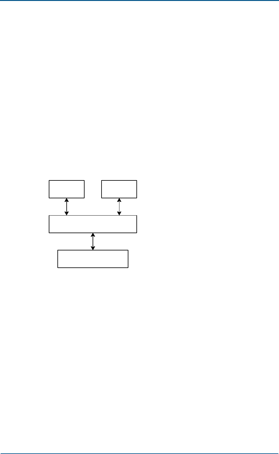
Chapter 3 - Interfaces and Communications
Confidential and Proprietary Information of ZTE CORPORATION 35
2. Supporting the identification of diversified frame types.
3. Supporting the transparent transmission of the L3 message between
L3 entities.
4. Sequence control, to maintain the sequence of frames connected
through data link.
5. Checking the format and operation errors in the data link layer.
6. Notifying the L3 entities to process the unrecoverable errors.
7. Flow control.
8. Supporting access of the burst solution mode after the RACH channel
access is instantly assigned.
In the ZXG10 OB06 (V1.0), LapDm is implemented in the LapDm module
of RSL.
The position of LapDm module in RSL is shown in Figure 18.
FIGURE 18 LAPDM MODULES
LapDm module
OAMM FURRM
Physical layer
The LapDm module communicates with the physical layer and L3. The L3
protocol is processed in FURRM. OAMM configures the value of the timer
necessary for LapDm module to run.
The LapDm module provides two types of message transmission modes for
FURRM: I-frame multi-frame operation and UI frame operation. In terms
of frame structure, LapDm cancels the frame delimiter flag (FLAG) and the
FCS. In LapDm, the synchronization scheme of the radio interface can be
used to transmit the boundary message without the corresponding start
frame or end frame flags. The transmission scheme provided by the
physical layer of the Um interface boasts the error check function, so FCS
is not used for LapDm.
1. I-frame multi-frame operation
The L3 message is sent in the information frame mode which requires
the confirmation from the receiver. This mode provides a whole set of
control mechanism for error recovering and flow control, the
establishment mechanism and release mechanism for multi-frame
operations.

ZXG10 OB06 ZTE Integrated Outdoor GSM Base Station Technical Manual
36 Confidential and Proprietary Information of ZTE CORPORATION
The I frame structure of LapDm is shown in Figure 19.
FIGURE 19 I FRAME STRUCTURE OF LAPDM
SAPI N(S) N(R)
Address Control Information
The I-frame in LapDm consists of the address field, control field and
information field.
The address field contains the SAPI. On the radio interface, LapDm
supports two types of messages: signaling and short message service,
distinguished by the SAPI. SAPI=0 represents the signaling link, and
SAPI=3 represents the short message link.
The maximum length of a LapDm frame on the TCH is 23 bytes, and
21 bytes on the SACCH. The reason for this difference is that there are
two special-purpose bytes in each SACCH block: Since the maximal
length of the frame on the radio interface is of 21 or 23 bytes which
cannot meet the need of most pieces of signaling, segmentation and
regrouping are required to be defined in LapDm. Thus an “additional”
bit is used to distinguish the last packet frame from other frames.
Thanks to this mechanism, there will be no restriction to fix the packet
length on the radio path, with the only exception when these messages
must be transmitted on other interfaces, namely, 260 bytes mentioned
in the radio interface specification.
In the control field, N(S) represents the sending serial number and the
I frame’s serial number currently sent by the sending end; N(R)
represents the receiving serial number, the expected sending serial
number of the next I frame. N(R) is used to predict the instruction
from the receiving end.
2. UI frame operation
The L3 message is sent in the no-serial-number frame mode, and the
receiver is not required to send the received confirmation after
receiving the UI frame. This operation mode does not provide flow
control or error recovering mechanism.

Chapter 3 - Interfaces and Communications
Confidential and Proprietary Information of ZTE CORPORATION 37
The UI frame structure of LapDm is shown in Figure 20.
FIGURE 20 UI FRAME STRUCTURE OF LAPDM
000 P 0011
SAPI
Address Control Information
The UI frame in LapDm consists of the address field, control field and
information field. The address field contains the SAPI. In the address
field, P represents the query bit; if this bit is set to 1, it means to
require the response frame from the opposite-end peer entity.
RR/MM/CM Protocol
The RR/MM/CM protocol, including three sub-layers of CM, MM and RR, is
responsible for control and management; it groups and arranges the
information of the subscriber and system control process into the
designated logical channels according to certain protocol packets.
1. CM Layer: It is responsible for communication management. It
establishes connections between subscribers, and holds and releases
calls. This layer provides call control (CC), supplementary service
management (SSM) and short message service (SMS).
2. MM layer: It is responsible for mobility and security management,
namely, the necessary processing when the MS initiates location
updating.
3. RR layer: It is responsible for radio resource management. It
establishes and releases connections between the MS and MSC during
the call process.
In ZXG10 OB06 (V1.0), the radio resource management module and
paging module of RSL are used to implement the RR/MM/CM protocol, and
perform the processing of transparent and non-transparent messages in
L3.
Transparent messages: ZXG10 OB06 (V1.0) is responsible for transferring
that kind of messages, without any analysis or change.
Non-transparent messages: They are only transmitted between the BSC
and ZXG10 OB06 (V1.0), and are processed by the ZXG10 OB06 (V1.0)
according to the specific message contents.
1. Um interface
The signaling on the Um interface includes all messages of RR, MM and
CM, and most of the messages are transparent to the ZXG10 OB06
(V1.0).

ZXG10 OB06 ZTE Integrated Outdoor GSM Base Station Technical Manual
38 Confidential and Proprietary Information of ZTE CORPORATION
The L3 message structure on the Um interface is shown in Figure 21.
The protocol indicator is used to indicate the protocol type (RR, CM or
SMS).
TI, a transaction identifier, is used to distinguish multiple concurrent
CM connections.
The message type indicates the function of the L3 message.
FIGURE 21 MESSAGE STRUCTURE ON THE UM INTERFACE
T1 flag TI Protocol Indicator
0Message type
Information cell (compulsory)
Information cell (optional)
2. Abis interface
On the Abis interface, most of the radio interface signaling messages
are transmitted transparently in L3. It performs management over the
physical and logical equipment of ZXG10 OB06 (V1.0), including
equipment start, release, parameter control and performance
monitoring, thus ensuring normal communication services. It divides
the managed objects into four types: radio link layer, dedicated
channel, control channel and transceiver.
The message structure of L3 on the Abis interface is shown in Figure
22
The message discriminator indicates the message type (management
message of the radio link layer, management message of the
dedicated channel, management message of the common channel or
management message of TRX).
T indicates whether it is a transparent message.
The message type indicates the function of the L3 message.
The channel number indicates the channel combination type as well as
marks the timeslot number.
The link flag contains the contents such as SAPI and so on.
FIGURE 22 MESSAGE STRUCTURE OF L3 ON THE ABIS INTERFACE
Message identifier T
Message type
Channel No.
Link ID
Other information cells

Confidential and Proprietary Information of ZTE CORPORATION 39
Chapter 4
System Functions
This chapter discusses the functions of the ZXG10 OB06 (V1.0), including
RF, baseband processing, signaling processing, O&M, and ultra-distance
coverage.
Overview
The OB06 receives the management and controls from BSC. It works with
the BSC to manage radio resources and radio network, control the
establishment, connection and disconnection of the radio connections
between MS and OB06, control the access, handover and paging of MS,
provide voice coding, transcoding and rate adaptation functions, provide
the adaptation and interconnection functions of GPRS services, and
implement the operation and maintenance functions of the BSS.
OB06 has the following four major functions to implement the above
service functions:
1. RF function: Implementing the radio connections between the MS and
BTS.
2. Baseband processing function: Providing voice coding, transcoding and
rate adaptation functions, including the processing of the GPRS part.
3. Based on the BSC instructions, controlling the establishment,
connection and disconnection of the radio connections between MS and
BTS, and controlling the access, handover and paging of MS, including
the processing of the GPRS part.
4. Operation and maintenance (O&M) function: Providing an O&M agent
for the BSC, managing radio resources and radio network and
implementing the O&M functions for OB06 subsystems.
Major RF Functions
The RF function of the OB06 meets the requirements of the GSM 05.05
protocol, featuring the advantages of high sensitivity, flexible configuration
and easy O&M, as briefed below.

ZXG10 OB06 ZTE Integrated Outdoor GSM Base Station Technical Manual
40 Confidential and Proprietary Information of ZTE CORPORATION
High Receiving Sensitivity
The static receiving sensitivity of the OB06 reaches up to -112dBm. The
high sensitivity guarantees the uplink channel performance of the OB06,
and is one of the prerequisites for a wide coverage of the OB06.
Flexible Configuration
The OB06 supports 1~6 carriers per site in omni-directional or directional
coverage. It can support 1 ~ 3 sector configuration mode, which can be
selected by the user as required. Through the adjustment of front-end
gain (such as tower amplifier and low-noise amplifier), the loss in different
length of feeder of the OB06 can be compensated to guarantee consistent
receiving system gain.
Easy O&M
The RF part of the OB06 can be controlled remotely through OMCR, to
change the transmitting power, transmitting/receiving frequency and more.
The alarm signals generated from the RF part are reported to OMCR, so
that the operators at the background can control the operation of the RF
part and know about the operation statuses.
Diversity Receiving
The OB06 provides the diversity receiving function, which is implemented
by two sets of independent receiving equipment at the same time,
including antenna, tower top amplifier (optional), feeder, divider and
receiver. The application of the diversity receiving function enhances the
anti-fading capability of the BTS receiver, enabling excellent receiving
performance of the BTS even in complex radio transmission environment.
Frequency Hopping
Frequency hopping is another important measure to enhance OB06
performance, which not only improves the anti-fading capability in the
downlink channels, but strengthens the communication security. The OB06
supports two working mode: hopping or no hopping. With hopping on, the
transceiver changes working frequencies according to a certain hopping
sequence, while with hopping off, the transceiver locks a specified working
frequency.
Power Control
The OB06 can provide static power control, dynamic power control and idle
timeslot transmitting shutoff functions. The static power control range is
up to 12 dB, 2 dB per step. The static power control enables the user to
adjust the OB06 coverage. The dynamic power control range is up to 30
dB, 2 dB per step. The BSC can adjust the OB06 transmitting power
according to the distance between MS and OB06. In case of idle timeslot,
since there is no downlink signal, the BSC commands the OB06 to shut off
the transmitting power of that timeslot. These power control functions

Chapter 4 - System Functions
Confidential and Proprietary Information of ZTE CORPORATION 41
increase the efficiency of the transmitter and the reliability of the power
amplifier, and minimize the transmitter interference.
Baseband Processing
The baseband processing implements the function of the physical layer on
the Um interface, processing all full-duplex channel baseband data on one
TDMA frame. In the downlink direction, the functions are rate adaptation,
channel encoding and interleaving, encryption, and TDMA burst generation.
In the uplink direction, they are digital demodulation, decryption,
deinterleaving, channel decoding and rate adaptation.
Signaling Processing
The OB06 signaling processing implements the following two functions:
1. Interconnection between the MS and BSS/NSS on the Um interface
layer
2. Management of some radio resources under the control of the BSC
Specifically, the OB06 signaling processing functions are wireless link layer
management function, dedicated channel management function, common
channel management function and TRX management function.
Wireless Link Management Function
This function supports the following procedures:
1. Link establishment indication procedure: This procedure allows the
OB06 to give the BSC an indication that an MS-originated link in multi-
frame mode has been established successfully. Through this indication,
the BSC establishes an SCCP link to the MSC.
2. Link establishment request procedure: This procedure allows the BSC
to request to establish a link in multi-frame mode on a radio channel.
3. Link release request procedure: This procedure allows the BSC to
request the OB06 to release a radio link.
4. Link release indication procedure: This procedure allows the OB06 to
give the BSC an indication that the MS-originated radio link has been
released.
5. Um L3 message transparent forwarding procedure in acknowledgement
mode: This procedure allows the BSC to request the OB06 to
transparently forward a Um interface L3 message in the
acknowledgement mode.
6. Um L3 message transparent receiving procedure in acknowledgement
mode: This procedure allows the OB06 to give the BSC an indication
that a Um interface L3 message is received transparently in the
acknowledgement mode.
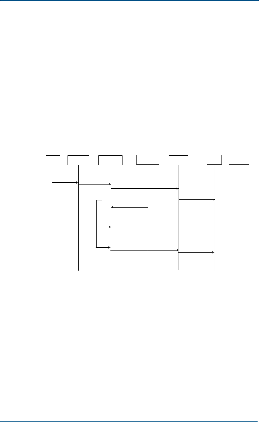
ZXG10 OB06 ZTE Integrated Outdoor GSM Base Station Technical Manual
42 Confidential and Proprietary Information of ZTE CORPORATION
7. Um L3 message transparent forwarding procedure in non-
acknowledgement-mode: This procedure allows the BSC to request the
OB06 to transparently forward a Um interface L3 message in the non-
acknowledgement mode.
8. Um L3 message transparent receiving procedure in non-
acknowledgement mode: This procedure allows the OB06 to give the
BSC an indication that a Um interface L3 message is received
transparently in the non-acknowledgement mode.
9. Link error indication procedure: This procedure allows the OB06 to give
the BSC an indication about the abnormity of a radio link layer.
Link Establishment
The procedure of the link establishment originated by MS is shown in
Figure 23.
FIGURE 23 MS-ORIGINATED LINK ESTABLISHMENT
MS LAPDm FURRM HPIMan LAPD BSC OAMM
D m_DL_EST_IND DL_DATA_REQ (EST IND) DL_DATA_IND
(EST IND)
(SABM)
Set Timer
MPH_CHPIndToRR
(CHP
SYNCHRONIZED)
DL_DATA_REQ(CONN FAIL IND ) (CONN FAIL IND)
kill Timer
The OB06 gives the BSC an indication that one multi-frame-mode L2 link
has been established on the wireless path.
During the paging, the GSM04.08 message PAGING RESPONSE will be
contained in DL_EST_IND and sent to the FURRM module.
After the FURRM module sends the EST IND message, if the current
channel is the TCH activated in the service mode, the synchronization
timer will be enabled to wait for the synchronization between CHP and TC.
If the synchronization is not implemented till the timer expires, the FURRM
sends the CONN FAIL IND message to the BSC, to wait for the BSC to
release the channel where the conversation cannot be established
normally.
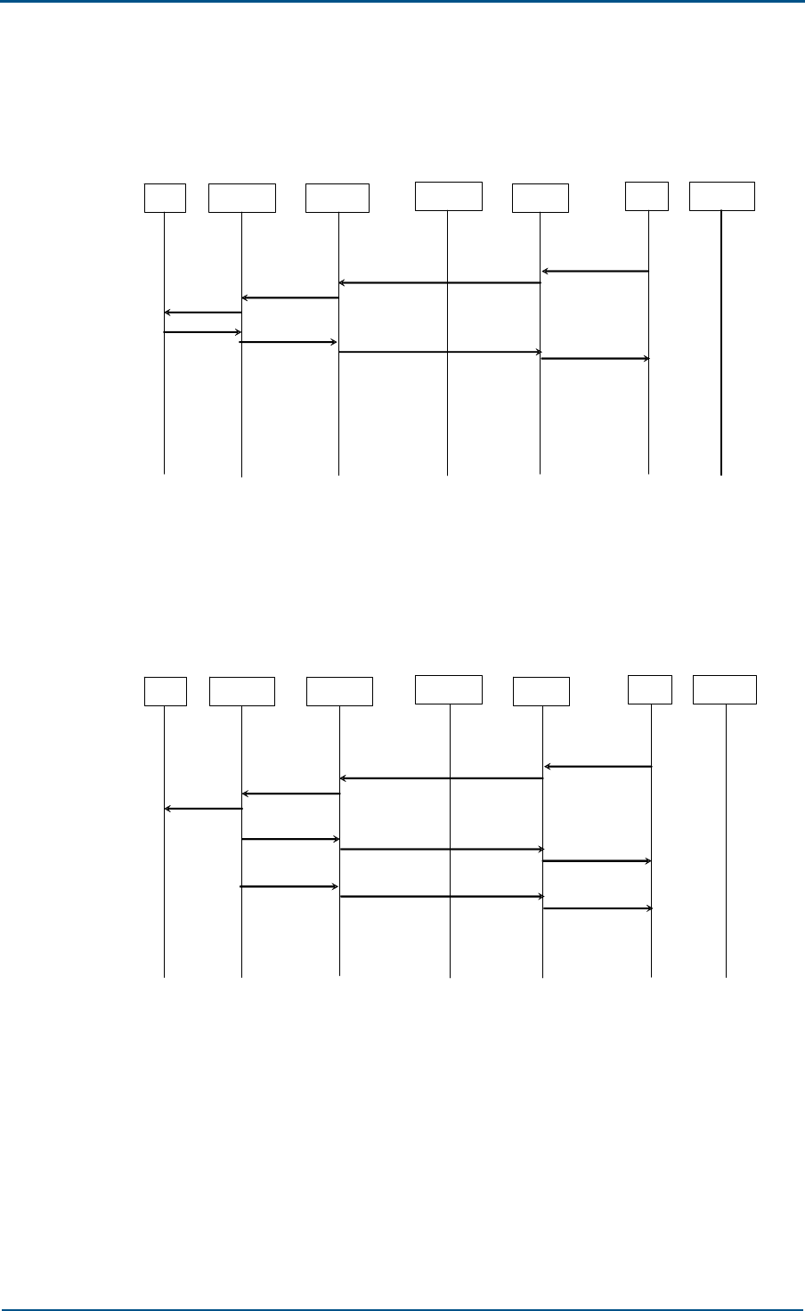
Chapter 4 - System Functions
Confidential and Proprietary Information of ZTE CORPORATION 43
The procedure of the link establishment originated by the BSC is shown in
Figure 24.
FIGURE 24 BSC-ORIGINATED LINK ESTABLISHMENT
MS LAPDm FURRM HPIMan LAPD BSC OAMM
Dm_DL_EST_
REQ DL_DATA_IND (EST REQ) (EST REQ)
(SABM)
(UA) Dm_DL_EST_
CONF DL_DATA_REQ (EST_CONF) (EST CONF)
The BSC requests the OB06 to establish a link for point-to-point
transmission (SAPI=3) on the wireless path.
A link establishment failure is shown in Figure 25.
FIGURE 25 FAILURE OF LINK ESTABLISHMENT
MS LAPDm FURRM HPIMan LAPD BSC OAMM
Dm_DL_EST_
REQ
DL_DATA_IND (EST REQ) (EST REQ)
(SABM)
Dm_DL_REL_IND DL_DATA_REQ (REL IND) (REL IND)
Dm_MDL_ERR_
IND (ERR IND)
DL_DATA_REQ (ERR IND)
When the link connection fails, the FURRM receives the Dm_DL_REL_IND
and Dm_MDL_ERROR_IND primitives from the data link layer. The latter
primitive records the failure cause: "Timer T200 expires for N200 + 1
times: Execution is released abnormally" The FURRM attaches this cause
in the ERROR REPORT message and reports it to the BSC.
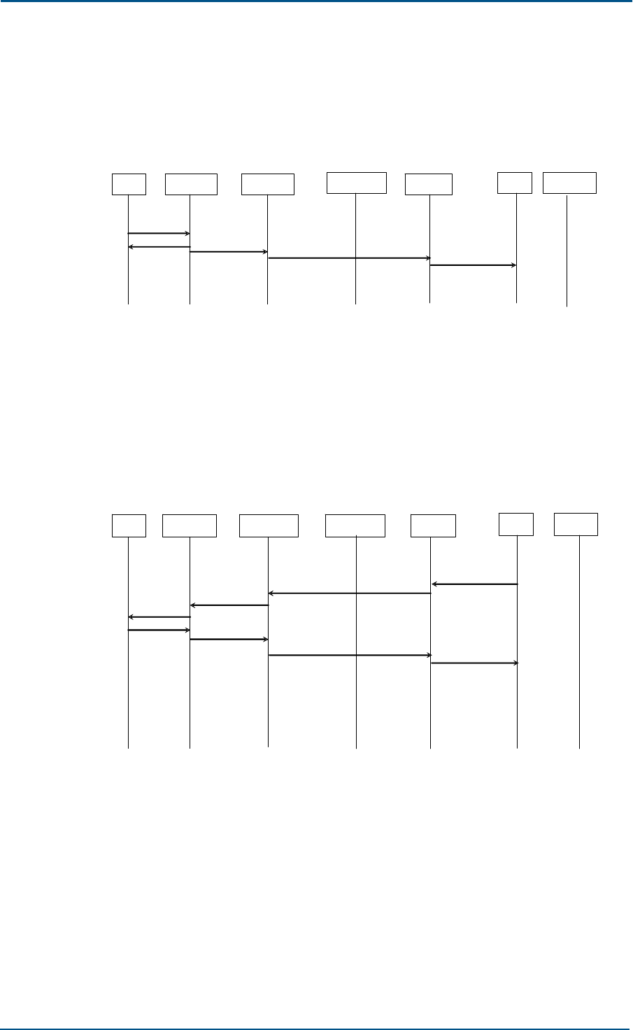
ZXG10 OB06 ZTE Integrated Outdoor GSM Base Station Technical Manual
44 Confidential and Proprietary Information of ZTE CORPORATION
Link Release
The procedure of the link release originated by an MS is shown in Figure
26.
FIGURE 26 MS-ORIGINATED LINK RELEASE
MS LAPDm FURRM HPIMan LAPD BSC OAMM
D m_DL_REL_IND DL_DATA_REQ (REL IND) (REL I ND )
(DISC)
(UA )
The OB06 gives the BSC an indication that the link-layer connection has
been released on the wireless path.
If the link layer is in idle mode, the OB06 returns DM frame to MS but not
notifies the BSC.
The procedure of the link release required by a BSC is shown in Figure 27.
FIGURE 27 BSC-REQUESTED LINK RELEASE
MS LAPDm FURRM HPIMan LAPD BSC OAM
M
Dm_DL_REL_REQ DL_DATA_IND (REL REQ)
(REL REQ)
(DISC)
( UA or DM) Dm_DL_REL_CO
NF DL_DATA_REQ (REL CONF) (REL CONF)
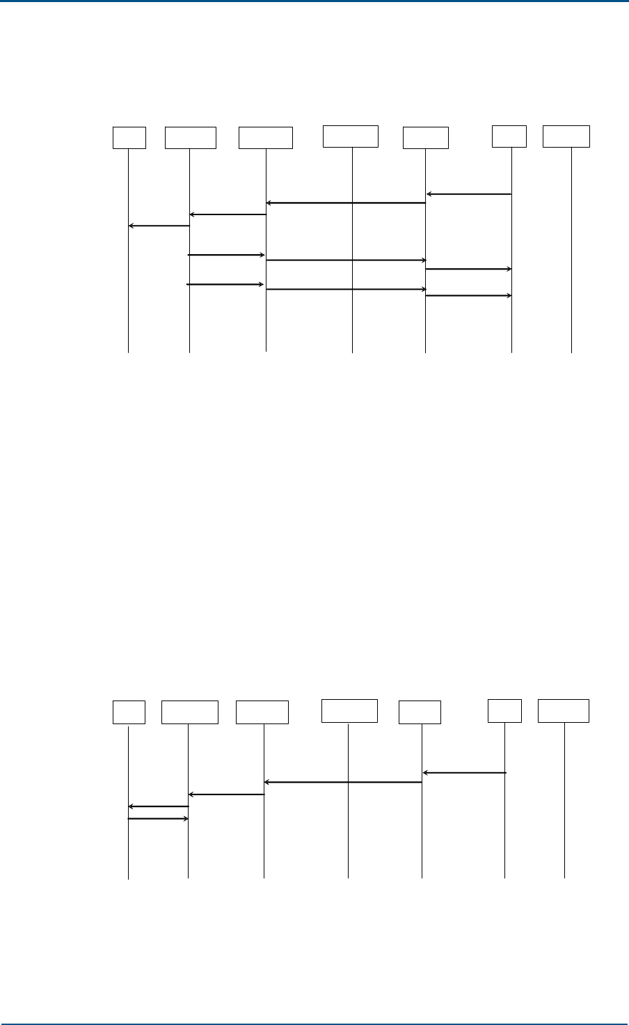
Chapter 4 - System Functions
Confidential and Proprietary Information of ZTE CORPORATION 45
A link release failure is shown in Figure 28.
FIGURE 28 FAILURE OF LINK RELEASE
MS LAPDm FURRM HPIMan LAPD BSC OAMM
Dm_DL_REL_R
EQ
DL_DATA_IND (REL REQ) (REL REQ)
(DISC)
Dm_DL_REL_I
ND DL_DATA_REQ (REL IND) (REL IND )
Dm_MDL_ERR_IN
DDL_DATA_REQ (ERR IND) (ERR IND)
The BSC requests the release of one multi-frame-mode link layer
connection (SAPI=3) on the wireless path.
The OB06 sends a DISC frame and starts the timer T200 at the same time.
If the UA or DM frame is not received until T200 expires, the DISC will be
resent and the resend times will increase by one. If the failure continues,
the Dm_DL_RELEASE_INDICATION and MDL_ERROR_INDICATION
primitives from the data link layer will be received in L3. The latter
primitive records the failure cause: "Timer T200 expires for N200 + 1
times: Execution is released abnormally".
Sending and Receiving of Transparent L3 Message in
Acknowledgment Mode
The transmitting is shown in Figure 29.
FIGURE 29 SENDING A TRANSPARENT L3 MESSAGE IN THE ACKNOWLEDGMENT MODE
MS LAPDm FURRM HPIMan LAPD BSC OAMM
Dm_DL_DATA_R
EQ
(DATA REQ)
(I frames )
(RR frames)
DL_DATA_IND (DATAREQ)
The BSC requests to send an acknowledgment mode L3 transparent
message to the MS.
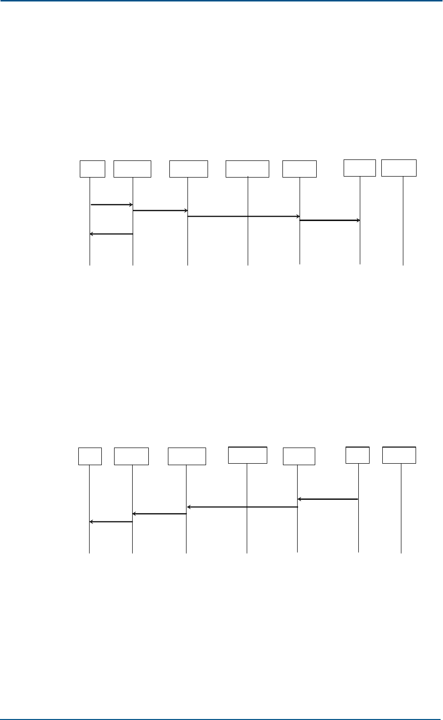
ZXG10 OB06 ZTE Integrated Outdoor GSM Base Station Technical Manual
46 Confidential and Proprietary Information of ZTE CORPORATION
The DATA REQ message contains the complete acknowledgment mode L3
transparent message. At the time when the OB06 sends the I frame, the
OB06 starts timer T200 and records the I frame resend times N200. When
T200 expires for N200 times or the REJ frame is received, the OB06 sends
the ERROR IND message to the BSC.
The receiving is shown in Figure 30.
FIGURE 30 RECEIVING A TRANSPARENT L3 MESSAGE IN THE ACKNOWLEDGMENT MODE
MS LAPDm FURRM HPIMan LAPD BSC OAMM
D m_DL_DATA_I
ND DL_DATA_REQ (DATA IND) (DATA IND)
(I frames)
(RR frames)
The BSC transfers to the BSC the acknowledgment mode L3 transparent
message that is received from MS. The DATA IND message contains the
complete transparent message.
Transmission and Receiving of Transparent L3 Message
in Non-Acknowledgment Mode
The procedure of transmitting a L3 transparent message from the BSC is
shown in Figure 31.
FIGURE 31 TRANSMITTING A L3 TRANSPARENT MESSAGE IN THE NON-ACKNOWLEDGMENT
MODE
MS LAPDm FURRM HPIman LAPD BSC OAMM
Dm_DL_UNIT
DATA _REQ
DL_DATA_IND
(UNIT DATA REQ) (UNIT DATA REQ)
(UI frames)
The BSC requests to send a transparent L3 message in the non-
acknowledgment mode to the MS.
UNIT DATA REQ message contains the complete non-acknowledgment
mode L3 transparent message.

Chapter 4 - System Functions
Confidential and Proprietary Information of ZTE CORPORATION 47
The procedure of transmitting a L3 transparent message from the MS is
shown in Figure 32.
FIGURE 32 RECEIVING A L3 TRANSPARENT MESSAGE IN THE NON-ACKNOWLEDGMENT
MODE
MS LAPDm FURRM HPIMan LAPD BSC OAMM
(UI frames)
Dm_DL_UNIT
DATA_IND DL_DATA_REQ
(UNIT DATA IND) (UNIT DATA IND)
The OB06 transfers to the BSC with the non-acknowledgment mode L3
transparent message that is received from MS.
UNIT DATA IND message contains the complete non-acknowledgment
mode L3 transparent message.
Dedicated Channel Management Function
This function supports the following procedures:
1. Channel activation procedure: This procedure allows the BSC to make
the OB06 activate a dedicated channel for an MS. When the channel is
activated successfully, the MS is handed over to this channel through
an assignment command or handover command.
2. Channel mode change procedure: This procedure allows the BSC to
request the OB06 to change the mode of an activated channel.
3. Handover detection procedure: This procedure is used to check the
access of a handed-over MS between the target OB06 and target BSC.
4. Encryption start procedure: This procedure is used to start the
encryption procedure specified in TS GSM 04.08.
5. Measurement report procedure: It includes the mandatory basic
measurement report procedure and the optional preprocessed
measurement report procedure. These two procedures are used by the
OB06 to report all the parameters related to the handover decisions to
the BSC.
6. SACCH deactivation procedure: This procedure allows the BSC to
deactivate SACCH channels of the TRX according to the requirements
of the channel release procedure in TS GSM 04.08.
7. Radio channel release procedure: This procedure allows the BSC to
instruct the OB06 to release a radio channel that will not be used any
longer.
8. MS power control procedure: This procedure allows the BSS to control
the transmitting power of the MS related to a specific activated channel.
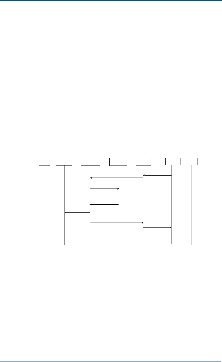
ZXG10 OB06 ZTE Integrated Outdoor GSM Base Station Technical Manual
48 Confidential and Proprietary Information of ZTE CORPORATION
9. BS power control procedure: This procedure allows the BSS to control
the transmitting power of an activated channel in the TRX.
10. Connection failure procedure: This procedure allows the OB06 to give
the BSC an indication that an activated dedicated channel has been
disconnected.
11. Physical environment content request/confirmation procedure: This
procedure allows the BSC to obtain physical parameters of a specific
channel, which generally happens before a change to the channel. This
procedure is optional.
12. SACCH fill-in information change procedure: This procedure allows the
BSC to instruct the OB06 to change the fill-in information (system
message) on a specific SACCH.
Channel Establishment
1. Channel activation
The procedure of activating a channel successfully is shown in Figure
33.
FIGURE 33 SUCCESS OF CHANNEL ACTIVATION
MS
LAPDm FURRM HPIMan LAPD BSC OAMM
(CHAN ACTIV)
MPH_RRCmdTo
CHP (CHP
CHAN ACTIV)
(CHAN ACTIV
ACK)
DL_DATA_REQ (CHAN ACTIV
ACK)
M PH_CHPIndToRR
(CHP CHAN ACTIV
RESPONSE(ACK)
DL_DATA_IND(CHAN ACTIV)
Dm_PH_CONN_IND
(if chan activated)
MS

Chapter 4 - System Functions
Confidential and Proprietary Information of ZTE CORPORATION 49
A channel activation failure is shown in Figure 34.
FIGURE 34 FAILURE OF CHANNEL ACTIVATION
MS LAPDm FURRM HPIMan LAPD BSC OAMM
(CHAN ACTIV)
MPH_RRCmdTo
CHP (CHP
CHAN ACTIV)
(CHAN ACTIV
NACK)
DL_DATA_REQ (CHAN
ACTIV NACK)
MPH_CHPIndToRR(CHP
CHAN ACTIV RESP
(NACK))
DL_DATA_IND(CHAN ACTIV)
The TRX detects the MS random access request on the RACH, and
activates a channel for the MS.
The BSC decides the channel to be used, and sends the CHAN ACTIV
message to the TRX to enable that channel. This message contains the
activation reason (immediate assignment, allocation, asynchronous
/synchronous and additional allocation), channel ID and complete
channel description (full/half rate, voice/data, code/rate adaptation,
frequency hopping sequence, key, and so on). If there is encrypted
information, it uses the encryption activation mode.
When the FURRM module receives the CHAN ACTIV message, it sends
related information unit (activation reason, and so on) contents to the
CHP for processing through the HPIMan module, and reports the
results to the BSC when the response arrives.
When the channel is activated, the TRX responds with the CHAN ACTIV
ACK message that contains the number of the current frame with the
OB06. The BSC uses this frame number to decide the Starting Time
parameter in the immediate assignment message that will be then sent
to the MS side.
If the TRX cannot activate the channel, it will return the CHAN ACTIV
NACK message that contains the failure cause. Possible failure causes
are O&M interference (channel blocked, for example), resource
unavailability (without voice encoder, for example), equipment error,
and channel activated.
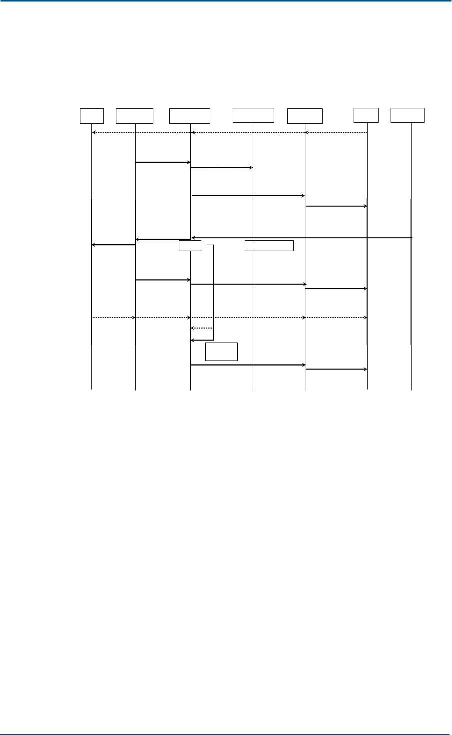
ZXG10 OB06 ZTE Integrated Outdoor GSM Base Station Technical Manual
50 Confidential and Proprietary Information of ZTE CORPORATION
2. Handover
The handover procedure is shown in Figure 35.
FIGURE 35 HANDOVER
MS LAPDm FURRM HPIMan LAPD BSC OAMM
(PHY INFO)
Dm_DL_DATA_I
ND (HANDO
COM)
(HANDO DET )
DL_DATA_REQ (DATA
IND (HANDO COM))
DL_DATA_IND (DATA REQ
(RR HANDO CMD))
Dm_DL_DATA_
REQ ( HANDO
CMD)
(DATA REQ (RR
HANDO CMD))
( HANDO
CMD)
Dm_DL_RANDO
M ACCESS_IND
(HANDO
ACCESS)
DL_DATA_REQ (HANDO DET )
Dm_DL_UNIT
DA TA_REQ
(PHY INFO)
T3105
(HANDO
COM) (DATA IND
(HANDO COM))
Repeat
Ny1 times
DL_DATA_REQ (CONN FAIL IND) (CONN FAIL IND)
T3105, Ny1
(end)
CHP RET NORM
ACTIV
Dm_DL_EST_IND
(correct L2 frame) DL_DATA_REQ (EST IND) (EST IND)
remark
The handover enables an MS in the dedicated mode to move into another
channel of another cell.
When the BSC receives the HANDO REQ message from the MSC, the BSC
enables the new channel activation procedure. The CHAN ACTIV message
sent to the TRX contains Handover Reference, which will be used to detect
the Handover Access message from MS.
When the channel for handover is activated, the FURRM uses the CHP RET
NORM ACTIV message to notify the CHP to resume the normal mode.
The FURRM should save the Handover Reference in the CHAN ACTIV
message, to compare it with the Handover Reference in the Handover
Access message that is sent by the LAPDm.
The (RR) HANDOVER COMMAND message is sent on the active DCCH. This
transparent message contains new channel characteristics, power
command, physical channel establish procedure indication, handover
reference, time lead (optional) and encryption mode setting (optional). It
also controls whether to connect MS first in synchronous activation mode.
About the physical channel establishment, in case of synchronous
handover, when MS is to be connected on the allocated channel, it will
send four (RR) HANDOVER ACCESS messages on the active DCCH in one

Chapter 4 - System Functions
Confidential and Proprietary Information of ZTE CORPORATION 51
access burst, whose content is the handover reference information unit.
The OB06 starts immediately the send on the active channel in specified
mode, with encryption if there is any encryption indication. If there are MS
power and time lead, or only MS power, the OB06 will use the parameter
to start the send on SACCH. When the OB06 receives one access burst
with correct handover reference or one correct decoding frame, the OB06
starts the normal receiving procedure on the active channel and SACCH,
and starts the handover detection procedure that is sent to the BSC. The
measured access burst delay is contained in the HANDO DET message.
In asynchronous handover, when MS is connected to the allocated channel,
the first half procedure is the same as that in the synchronous handover
(see above). When the HANDO DET message is sent, the OB06 sends the
(RR) PHY INFO message to MS in non-acknowledgement mode on the
active signaling channel, and starts T3105 at the same time. If T3105
expires before a correct decoding frame is received, the message will be
resent. If no correct decoding frame is received when the message has
been resent for Ny1 times, the OB06 will send to the BSC a CONNECTION
FAILURE message with the cause “Handover access failed”. When the
message is received, the network side will disconnect the new channel. At
this stage, the RR session release procedure begins: Channel release and
link release.
Pseudo-synchronous cell: The procedure is the same as that in a
synchronous cell. When the bottom connection is established, the MS
returns a (RR) HANDOVER COMPLETE message (transparent) on the active
DCCH. If the bottom connection fails, the MS returns a HANDOVER
FAILURE message. When the message is received, the network side will
disconnect the new channel and enter the RR session release procedure.
The parameters T3105 and Ny1 are sent by the OAMM module to the
FURRM during the system initialization.
Remarks: Similar to the link establishment procedure, when a TCH
channel in the service mode is set up, it waits for a synchronization
message.
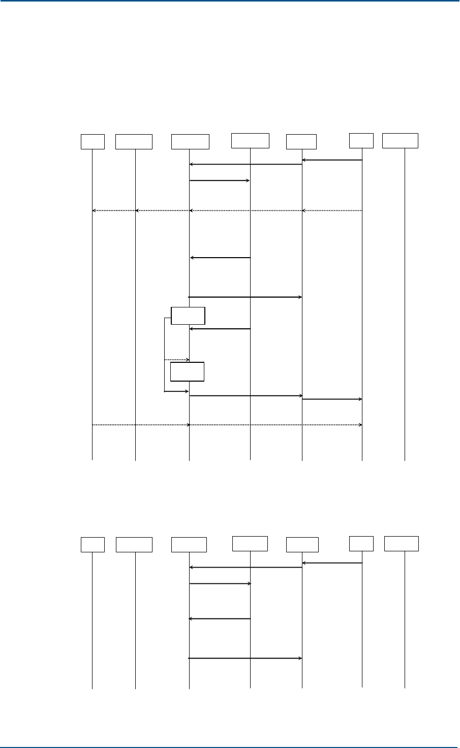
ZXG10 OB06 ZTE Integrated Outdoor GSM Base Station Technical Manual
52 Confidential and Proprietary Information of ZTE CORPORATION
Channel Mode Change
1. Mode change
The successful mode change is shown in Figure 36.
FIGURE 36 SUCCESS OF MODE CHANGE
MS LAPDm FURRM HPIMan LAPD BSC OAMM
(MODE MODIFY)
DL_DATA_IND (MODE MODIFY)
MPH_RRC mdToCHP
(CHP MODE
MODIFY)
MPH_CHPIndToRR
(CHP MODE
MODIFY RESP)
DL_DATA_REQ (MODE
MODIFY ACK)
DATA REQ (CHAN
MODE MODIFY)
DL_DATA_IND (DATA REQ
(CHAN MODE MODIFY))
Dm_DL_
DATA_REQ
(CHAN MODE
MODIFY)
(CHAN
MODE
MODIFY)
DL_DATA_REQ (DATA REQ
(CHAN MODE MODIFY ACK))
DL_ DATA_IND
(CHAN MODE
MODIFY ACK)
DATA REQ (CHAN
M ODE MODIFY
ACK)
Set Timer
MPH_CHPIndToRR
(CHP
SYNCHRONIZED)
DL_DATA_REQ (CONN FAIL IND)
kill Timer
(CONN FAIL IND)
The mode change failure is shown in Figure 37.
FIGURE 37 FAILURE OF MODE CHANGE
MS LAPDm FURRM HPIMan LAPD BSC OAMM
(MODE MODIFY)
DL_DATA_IND (MODE MODIFY)
MPH_RRC mdToCHP
(CHP MODE
MODIFY)
MPH_CHPIndToRR
(CHP MODE
MODIFY RESP)
DL_DATA_REQ (MODE
MODIFY NACK)
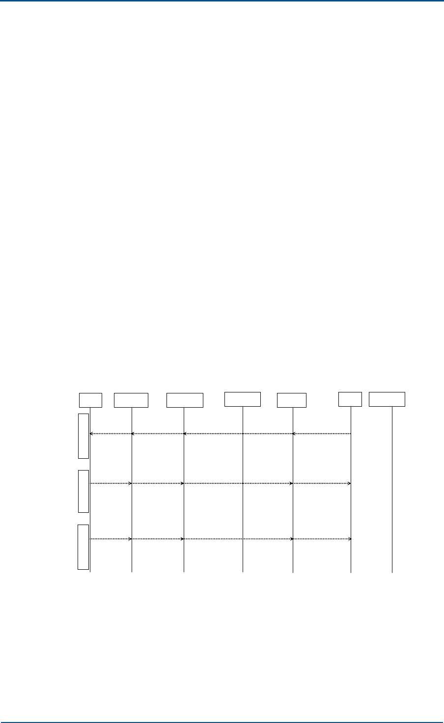
Chapter 4 - System Functions
Confidential and Proprietary Information of ZTE CORPORATION 53
The BSC requests to change the channel mode of an activated channel.
The BSC sends a MODE MODIFY to the OB06 to trigger the
reconfiguration of the OB06. When the OB06 receives the message, it
modifies the encoding and decoding algorithms (the CHP module
implements this operation), and modifies the inband mode of the
OB06-TRAU frame. After it changes into the new mode, the OB06
returns a MODE MODIFY ACK message. If the TRX cannot change the
mode for some reasons, it returns a MODE MODIFY NACK message.
If the response message indicates the successful mode change and the
TCH channel changes into the service mode, the FURRM starts the
timer to wait for the CHP SYNCHRONIZED message for the
synchronization between CHP and TC. If the message is not received
when the timer expires, it sends the CONN FAIL IND message to the
BSC.
At the same time, the BSC sends a (RR) CHANNEL MODE MODIFY
message that contains the new mode to be used to trigger the
reconfiguration of the MS. When it is implemented, the MS responds
with the (RR) CHANNEL MODE MODIFY ACKNOWLEDGE message to the
BSC through the OB06. If the MS does not support the channel to be
modified, it will keep its original mode, and place related information in
the CHANNEL MODE MODIFY ACKNOWLEDGE message. These two are
transparent messages.
2. Connection allocation
The procedure of connection allocation is shown in Figure 38.
FIGURE 38 CONNECTION ALLOCATION
MS LAPDm FURRM HPIMan LAPD BSC OAMM
DATA REQ
( ASSIGN CMD)
DL_DATA_IND (DATA REQ
( ASSIGN CMD))
Dm_DL_DATA_R
EQ ( ASSIGN
CMD)
( ASSIGN
CMD)
Old channel
DATA IND
( ASSIGN FAIL)
DL_DATA_REQ (DATA IND
( ASSIGN FAIL))
Dm_DL_DATA_IN
D ( ASSIGN FAIL)
( ASSIGN
FAIL)
DATA IND
( ASSIGN C OMP)
DL_DATA_REQ (DATA IND
( ASSIGN COM P))
Dm_DL_DATA_IN
D ( ASSIGN
COMP)
( ASSIGN
COMP)
Old channel New channel
The wireless link is changed in the same cell.
The BSC commands the OB06 activation through a simple
request/acknowledgement procedure (see the CHAN ACTIV and CHAN
ACTIV ACK of the “access” procedure). Once the OB06 is activated, the
BSC commands the MS to perform channel change through the (RR)
ASSIGNMENT COMMAND message. When the MS changes its settings
according to the new information and establishes a new signaling link,

ZXG10 OB06 ZTE Integrated Outdoor GSM Base Station Technical Manual
54 Confidential and Proprietary Information of ZTE CORPORATION
the MS sends an (RR) ASSIGNMENT COMPLETE message to the BSC. If
the MS cannot implement the connection allocation for some reasons,
it will send the (RR) ASSIGNMENT FAILURE message on the original
channel.
The FURRM transfers transparently the (RR) ASSIGNMENT COMMAND,
(RR) ASSIGNMENT COMPLETE and (RR) ASSIGNMENT FAILURE
messages.
Encryption
The encryption is shown in Figure 39.
FIGURE 39 ENCRYPTION
MS LAPDm FURRM HPIMan LAPD BSC OAMM
(ENCR CMD)
DL_DATA_IND (ENCR CMD)
MPH_ RRCmdToCHP
(CHP START
DECRYPTION)
MPH_CHPIndToRR
(CHP CRYPTION
RESP (ACK))
Dm_DL_DATA_
REQ (CIPH
MODE CMD)
(CIPH MODE
CMD)
DL_DATA_REQ (DATA REQ
(CIPH MODE COM))
Dm_DL_DATA_
IND (CIPH
MODE COM)
DATA REQ (CIPH
MODE COM)
(CIPH MODE
COM)
MPH_RRCmdToCHP
(CHP START
ENCRYPTION)
To set an encryption mode for the network means specifying whether the
transmission needs to be encrypted and which algorithm should be used.
This procedure is initiated after the BSC receives the CIPHER MODE
COMMAND message from the MSC. The ENCR CMD message that is sent
by the BSC to the TRX and related channel contains all information to be
selected, loading user data, encryption equipment and the complete (RR)
CIPH MODE CMD message that is sent to the MS.
When the ENCR CMD is received, the TRX sends the (RR) CIPH MODE CMD
to the MS in the non-encryption mode, and begins the decryption at the
same time (the CHP implements this operation). The OB06, in fact here,
sends configurations in old mode, and receives configurations in new mode.
Upon receiving the (RR) CIPH MODE CMD, the MS is set to the new mode,
and sends the (RR) CIPH MOD COM to the OB06. Whenever the OB06
receives a correct decoded message (in new mode), it indicates that the
MS has been correctly changed into the new mode. Only after that, the
OB06 changes into the new mode, and the sending is also in new mode
(the CHP implement this operation).
If the TRX cannot implement encryption according to the ENCR CMD
requirement for some reasons, the CHP sends the CHP CYPTION
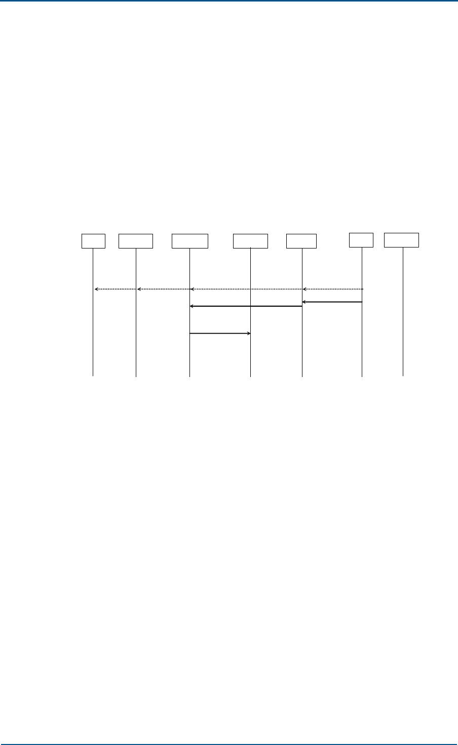
Chapter 4 - System Functions
Confidential and Proprietary Information of ZTE CORPORATION 55
RESPONSE (NACK) message to the FURRM, and then the FURRM returns
an ERROR REPORT message, with the cause “Encryption algorithm cannot
be executed” for example.
If the (RR) CIPH MODE CMD message is considered wrong, the MS returns
a (RR) RR STATUS message with the cause “Protocol error unspecified”
and performs no operation after that.
Channel Release
1. SACCH deactivation
The procedure of SACCH deactivation is shown in Figure 40.
FIGURE 40 SACCH DEACTIVATION
MS LAPDm FURRM HPIMan LAPD BSC OAMM
D m_DL_DATA_
REQ
(CHAN REL)
DL_DATA_IND (DATA
REQ(CHAN REL))
DATA REQ
(CHAN REL)
(CHAN REL)
(DEACT SACCH)
DL_DATA_IND (DEACT SACCH)
MPH_RRCmdTo
CHP (CHP
DEACT SACCH)
The BSC releases the SACCH in the OB06 according to the (RR)
CHANNEL RELEASE procedure.
When the BSC sends the (RR) CHANNEL RELEASE, it sends the DEACT
SACCH message to the OB06, to command the OB06 to stop
transmitting downlink SACCH frame.
The FURRM module sends the related information in the DEACT SACCH
message to the CHP for processing.

ZXG10 OB06 ZTE Integrated Outdoor GSM Base Station Technical Manual
56 Confidential and Proprietary Information of ZTE CORPORATION
2. Wireless channel release
The wireless channel release procedure is shown in Figure 41.
FIGURE 41 WIRELESS CHANNEL RELEASE
MS LAPDm FURRM HPIMan LAPD BSC OAMM
( RF CHAN REL)
DL_DATA_IND (RF CHAN REL)
MPH_RRCmdTo
CHP (CHP RF
CHAN REL)
MPH_CHPIndToRR
( CHP RF CHAN
REL ACK)
DL _DATA_REQ
( RF CHAN REL ACK)( RF CHAN
REL ACK)
The BSC releases a wireless link that is not used any longer.
When an activated wireless channel is not used any longer, the BSC
will send a RF channel release message (RF CHAN REL) to the related
TRX and channel. The CHP module processes the channel release.
When the related resources are released, the OB06 returns a RF
channel release acknowledgement message (RF CHAN REL ACK) to the
BSC. If the CHP cannot release the channel successfully, the FURRM
will send the ERROR REPORT message to the BSC.
SACCH Procedure
1. Measurement report
The data from the MS and OB06 measurement results are processed
by the BSC and will be used for the transmission power control and
handover preparation.
The MS measurement result is in the (RR) MEASurement REPort
message and will be reported once every SACCH block (480 ms), or if
the SACCH is being used by other signaling, reported once every two
SACCH blocks (960 ms). The TRX measures the level and quality of the
received signals in the current uplink channel. The average time is the
period of one SACCH block. The (RR) MEASurement REPort message
that is sent by the MS to the OB06 contains the measurement results
for the dedicated channel and adjacent cells.
The OB06 and MS measurement results form basic original data that
must be transmitted on the Abis interface. See “Basic measurement
report” for details. In addition, the OB06 and BSC also support
preprocessing for these basic measurement data in OB06, to lessen the
signaling load on the Abis interface. See “Measurement report
preprocessing” for details.
The FURRM receives the CHP measurement report ahead of the MS
measurement report. As a result, when the FURRM triggers group
sending of the Abis MEAS RESULT according to the CHP measurement
report, the problem of timing adjustment arises.
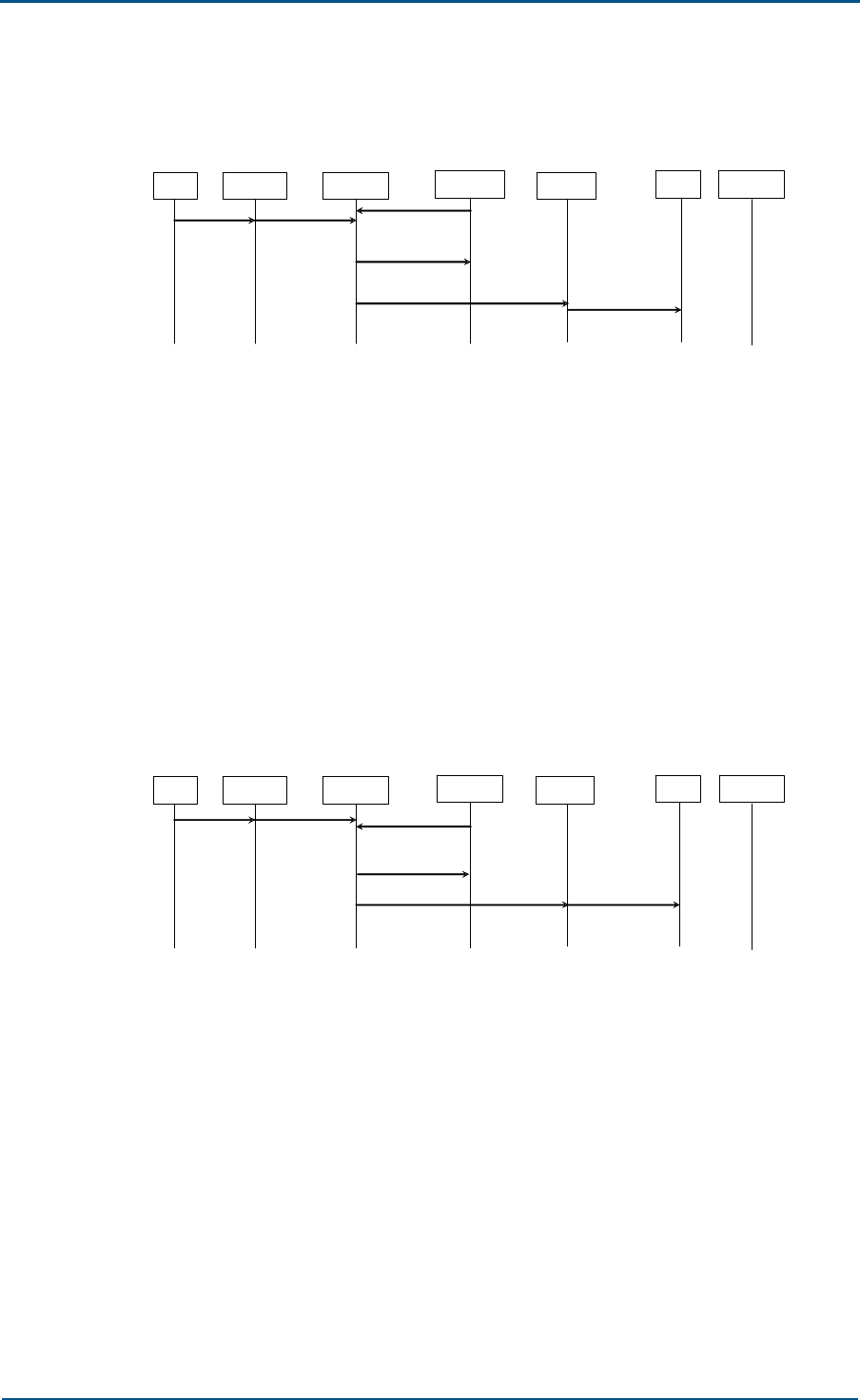
Chapter 4 - System Functions
Confidential and Proprietary Information of ZTE CORPORATION 57
The basic measurement report is shown in Figure 42.
FIGURE 42 BASIC MEASUREMENT REPORT
MS LAPDm FURRM HPIMan LAPD BSC OAMM
Dm_DL_UNIT
DATA_REQ
(MEAS REP)
(MEAS REP)
DL_DATA_REQ (MEAS RES) (MEAS RES)
MPH_CHPIndToRR
(CHP MEAS IND)
MPH_RRCmdToCHP
(C HP S ET TA)
The OB06 reports the basic wireless measurement results (GSM 05.08
and GSM 05.05) that are generated by the MS and TRX.
This procedure is a default procedure, unless another plan
(preprocessing, as described below) is used.
The TRS places these results in the MEAS RES message and reports to
the BSC. The sending of this message is synchronous with the
receiving of the SACCH block from the MS. If this uplink SACCH block
does not contain the measurement report that is from the MS (in case
of short messages, for example), the MEAS RES that is sent by the
OB06 will indicate this.
The procedure of measurement report preprocessing is shown in Figure
43.
FIGURE 43 MEASUREMENT REPORT PREPROCESSING
MS LAPDm FURRM HPIMan LAPD BSC OAMM
Dm_DL_UNIT
DATA_REQ
(MEAS REP)
(MEAS REP)
DL_DATA_REQ (PREPROC
MEAS RES) (PREPROC
MEAS RES)
MPH_CHPIndToRR
(CHP MEAS IND)
(CHP SET TA)
The OB06 first preprocesses the MS measurement report, and then
sends it together with the OB06 measurement result to the BSC
through the PREPROC MEAS RES message.
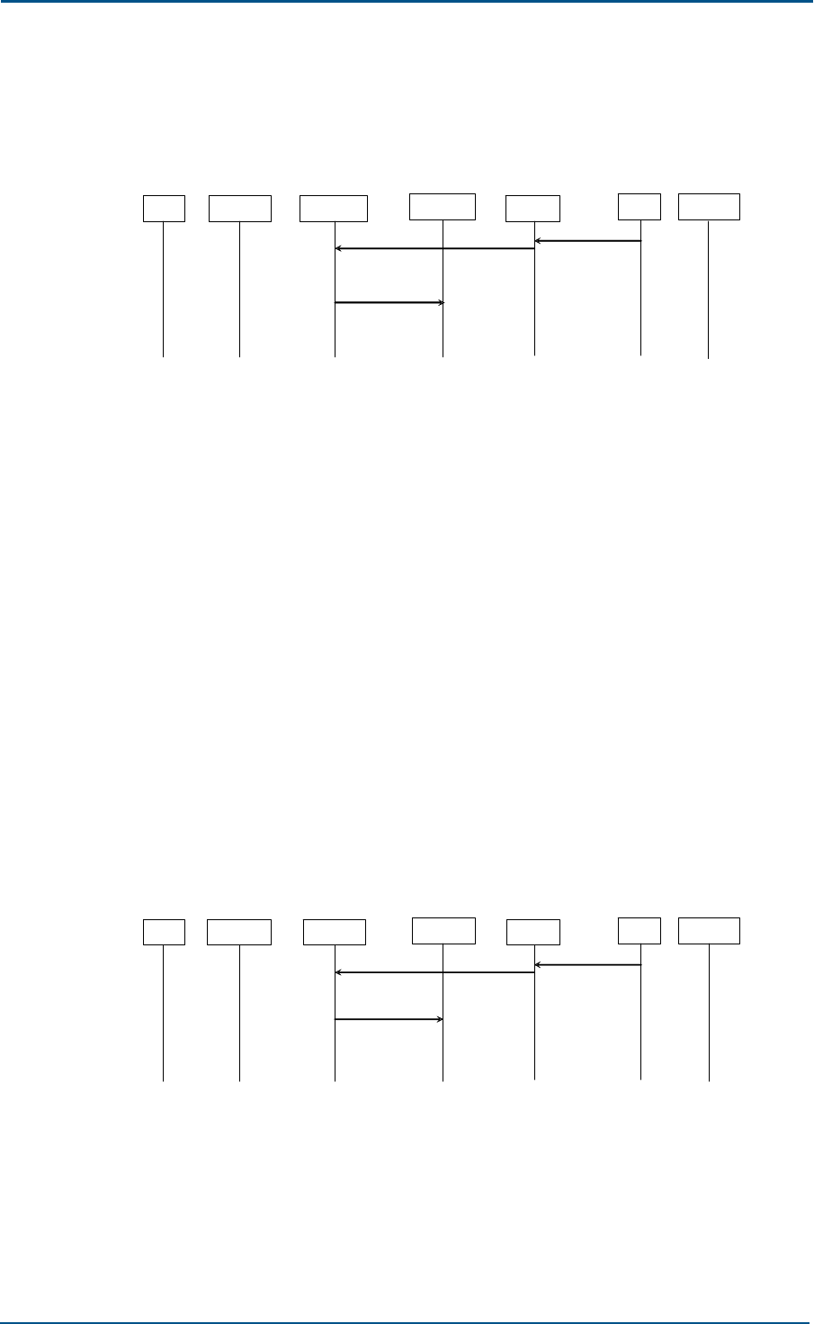
ZXG10 OB06 ZTE Integrated Outdoor GSM Base Station Technical Manual
58 Confidential and Proprietary Information of ZTE CORPORATION
2. Power control
The MS power control is shown in Figure 44.
FIGURE 44 MS POWER CONTROL
MS LAPDm FURRM HPIMan LAPD BSC OAMM
(MS POWER
CONTROL)
DL_DATA_IND (MS
POWER CONTROL)
MPH _RRCmdToCHP
(C HP S ET M S
POWER)
The BSC sets the MS power control parameters according to the TRX
requirement.
The initial parameters are set in the CHAN ACTIV message by the BSC.
If these parameters are to be changed, the BSC will send the MS
POWER CONTROL message to the TRX.
The OB06 power control is optional, which is indicated by the
parameters in the MS POWER CONTROL or CHAN ACTIV message. By
changing the frame header of the power level L1 that is sent to the MS,
the TRX tries to control the power control parameter within certain
range according to the message requirement (the CHP module
implements this operation).
When the OB06 executes the MS power control, the BSC can change
the MS power parameter during the connection (change by levels, for
example).
The MS POWER CONTROL and CHAN ACTIV messages must contain an
MS-allowed maximum power value.
The procedure of BS power control executed by the BSC is shown in
Figure 45.
FIGURE 45 BS POWER CONTROL
MS LAPDm FURRM HPIMan LAPD BSC OAMM
(B S P OWER
CONTROL)
DL_DATA_IND (BS
POWER CONTROL)
MPH_RRCmdTo
CHP(CHP SET
BS POWER)
This optional procedure can have the BSC set the TRX transmission
power level or the parameter that the TRX uses to control the TRX
transmission power.
The initial parameters are set in the CHAN ACTIV message by the BSC.
If these parameters are to be changed, the BSC will send the BS
POWER CONTROL message to the TRX.
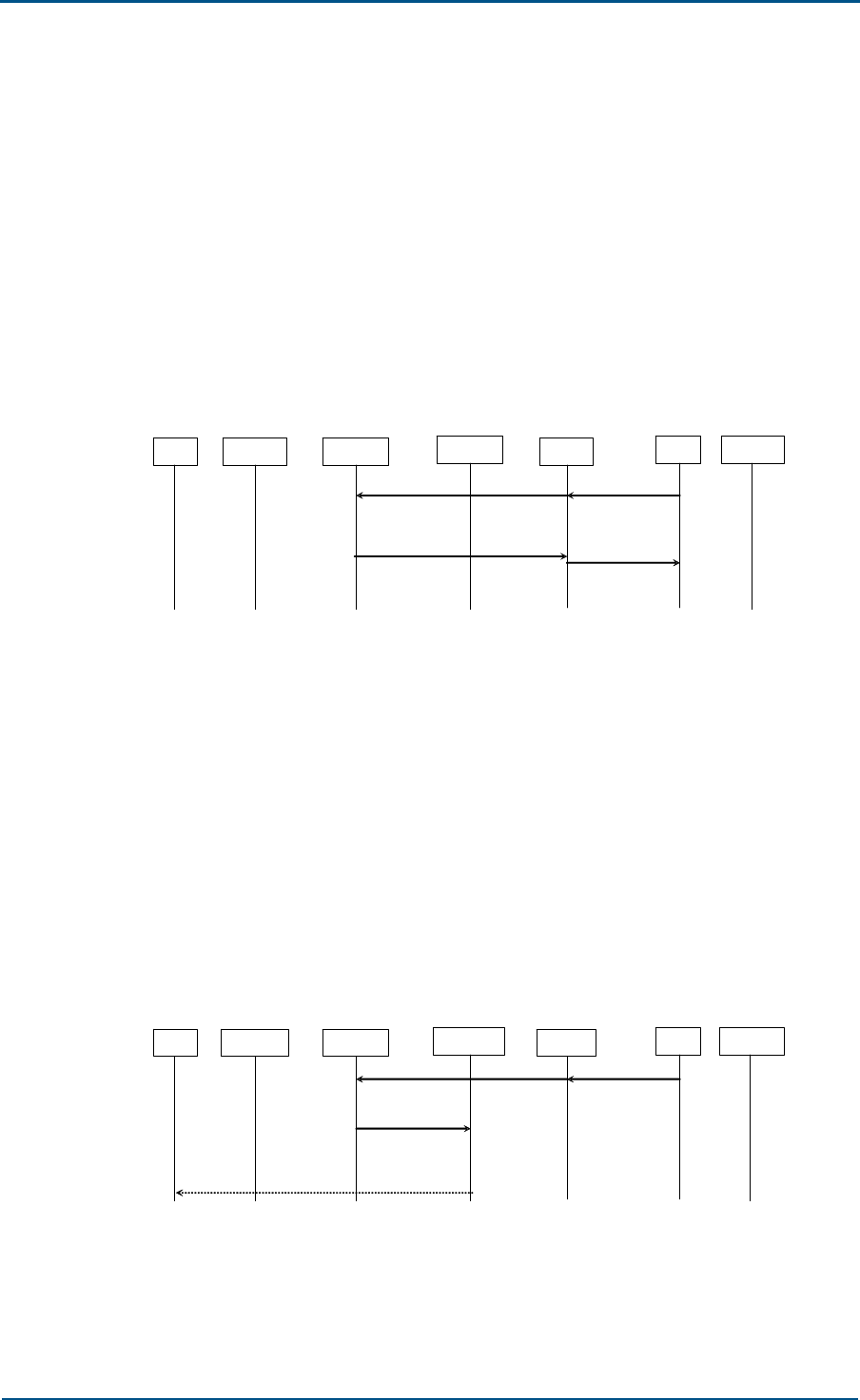
Chapter 4 - System Functions
Confidential and Proprietary Information of ZTE CORPORATION 59
The OB06 power control is optional, which is indicated by the
parameters in the BS POWER CONTROL or CHAN ACTIV message. By
changing the transmission power, the TRX tries to control the power
control parameter within a certain range according to the message
requirement (the CHP module implements this operation).
The maximum power of the TRX is determined by the network design
specifications, but the BSC can specify a smaller maximum power
value in the BS POWER CONTROL and CHAN ACTIV messages.
3. Physical environment request/acknowledgement
The procedure of physical environment request/acknowledgement is
shown in Figure 46.
FIGURE 46 PHYSICAL ENVIRONMENT REQUEST/ACKNOWLEDGEMENT
MS LAPDm FURRM HPIMan LAPD BSC OAMM
DL_ DATA_IND (PHYS
CONTEXT REQ) (PHYS
CON- TEXT
REQ)
DL_DATA_REQ (PHYS
CONTEXT CONF)
(PHYS
CON- TEXT
CONF)
This optional procedure enables the BSC to obtain the physical
environment information before the channel change.
The physical environment information can be sent to a new TRX (which
may be in another cell).
The PHY CONTEXT CONF message to be returned by the OB06 to the
BSC contains the MS/BS power and TA that are obtained from the
channel, and the OB06 does not process the physical environment
information temporarily.
4. SACCH fill-in information change
The procedure of modifying the SACCH fill-in information is shown in
Figure 47.
FIGURE 47 SACCH FILL-IN INFORMATION CHANGE
MS LAPDm FURRM HPIMan LAPD BSC OAMM
DL_ DATA_IND (SACCH
INFO MODIFY) (SACCH INFO
MODIFY)
MPH_RRCmdToCHP
(CHP SET/STOP
SACCH INFO )
(SYS INFO TYPE
5/6/5bis/5ter)
The BSC instructs the OB06 that the new system message ((RR)
System Information Type 5/5bis/5ter/6) will change the original
system message that is filled in the SACCH.

ZXG10 OB06 ZTE Integrated Outdoor GSM Base Station Technical Manual
60 Confidential and Proprietary Information of ZTE CORPORATION
The SACCH fill-in information in the SACCH INFO MODIFY message will
be sent in the specified channel, till the channel is released or changed
by another SACCH INFO MODIFY message.
When the OB06 receives the SACCH INFO MODIFY message, it extracts
the system message ((RR) System Information Type 5/5bis/5ter/6)
and sends it to the CHP module to change the original system
information. If there is no system message content, it indicates that
such system messages will no longer be sent on this channel.
Public Channel Management Function
This function supports the following procedures:
1. MS channel request procedure: This procedure is triggered when the
TRX detects the random access of an MS.
2. Paging procedure: This procedure is used to page an MS on the
specified paging sub-channel. It is used for the mobile called, and is
started by the MSC through the BSC. The BSC determines the paging
team according to the IMSI of the called MS. The value of the paging
team and the MS IMSI are sent to the OB06.
3. Immediate assignment procedure: This procedure allows the BSC to
immediately assign a dedicated channel to the MS that accesses the
OB06.
4. Indication deletion procedure: This procedure allows the OB06 to give
the BSC an indication that an immediate assignment message is
deleted due to the overload on the AGCH channel. CCCH load
indication procedure:
5. This procedure allows the OB06 to give the BSC an indication about the
load on the specified CCCH channel.
6. Broadcast information change procedure: With this procedure, the BSC
instructs the OB06 to broadcast new system messages on the BCCH
channel.
7. Short message cell broadcast procedure: With this procedure, the BSC
requests the OB06 to send a cell broadcast short message.
Access Request
The procedure of access request is shown in Figure 48.
FIGURE 48 ACCESS REQUEST
MS LAPDm FURRM HPIMan LAPD BSC OAMM
(CHAN RQD)
D m_DL_RANDO
M ACCESS_IND
( CHAN REQ)
DL_DATA_REQ(CHAN RQD)

Chapter 4 - System Functions
Confidential and Proprietary Information of ZTE CORPORATION 61
When the TRX receives the MS random access request, it sends the
channel request message to the BSC.
The CHAN RQD message contains the Request Reference parameter (MS-
selected random number, low-order bit of the TDMA frame number) and
access burst pulse sequence measurement delay.
Immediate Assignment
The procedure of immediate assignment is shown in Figure 49.
FIGURE 49 IMMEDIATE ASSIGMENT
MS LAPDm FURRM PAGCHM LAPD BSC OAMM
(RR) imm ass PAG_ DATA_REQ
(PAG IMM ASS)
(IMM ASS CMD)
DL_DATA_IND (IMM ASS CMD)
The immediate assignment message is transmitted in the downlink CCCH
(AGCH) channel.
The immediate assignment message that is from the network side may be
(RR) IMMEDIATE ASSIGNMENT, (RR) IMMEDIATE ASSIGNMENT
EXTENDED or (RR) IMMEDIATE ASSIGNMENT REJECT. On the Abis
interface, it is contained in the IMM ASS CMD message, which contains
complete the “immediate assignment” message and where the “paging
mode” unit is set as “unchanged”. When this message is received, the
FURRM sends it to the PAGCHMan sub-module of the PAGCHM module.
That sub-module places the message in the buffer. When the trigger is
received from the ISR, the PAGCHDaemon sub-module of the PAGCHM
module forms the messages in the waiting queue into the (RR) IMMEDIATE
ASSIGNMENT EXTENDED or (RR) IMMEDIATE ASSIGNMENT REJECT
message and sends to the CHP. Before the send, the OB06 changes the
“paging mode”
If no channel can be assigned, the BSC sends the (RR) IMMEDIATE
ASSIGNMENT REJECT on the same CCCH timeslot where the channel
request message is received.
If the downlink CCCH is overloaded, the FURRM sends the DELETE IND
message to the BSC, notifying that an IMM ASS CMD command is deleted.
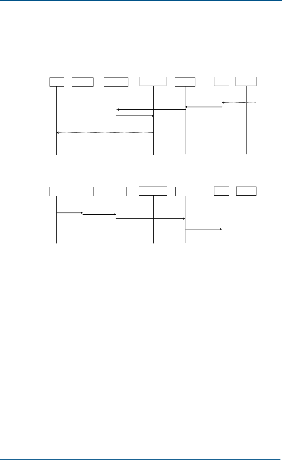
ZXG10 OB06 ZTE Integrated Outdoor GSM Base Station Technical Manual
62 Confidential and Proprietary Information of ZTE CORPORATION
Paging
The paging procedure is shown in Figure 50, and the MS paging response
is shown in Figure 51.
FIGURE 50 PAGING
MS LAPDm FURRM PAGCHM LAPD BSC OAMM
DL_DATA_IND (PAG CMD) (PAG CMD)
PAG REQ) TYPE 1/2/3
PAGING
PAG_DATA_REQ
(PAG PAG CMD)
FIGURE 51 PAGING RESPONSE
MS LAPDm FURRM PAGCHM LAPD BSC OAMM
Dm_DL_EST_IND
(RR PAG RES) DL_DATA_REQ (EST IND)
(EST IND)
(SABM)
(PAG RES)
Page an MS in the specified paging sub-channel.
The PAG CMD message contains the MS ID (TMSI or IMSI) and paging
sub-channel number, or additional call-related channel combination that is
indicated to the MS and will be used for follow-up processing.
The (RR) PAGing REQuest type 1/2/3 messages are buffered by the
PAGCHMan sub-module of the PAGCHM module. The PAGCHDaemon sub-
module combines and sends them, and calculates the correct DRX (paging
message arrangement) paging block to correctly transmit them.
When the MS receives the (RR) PAGing REQuest message and is allowed
to access the network, it triggers the immediate assignment procedure.
The establishment of the main signaling link is triggered by SABM, and the
SABM’s information field contains the (RR) PAGing RESponse message.
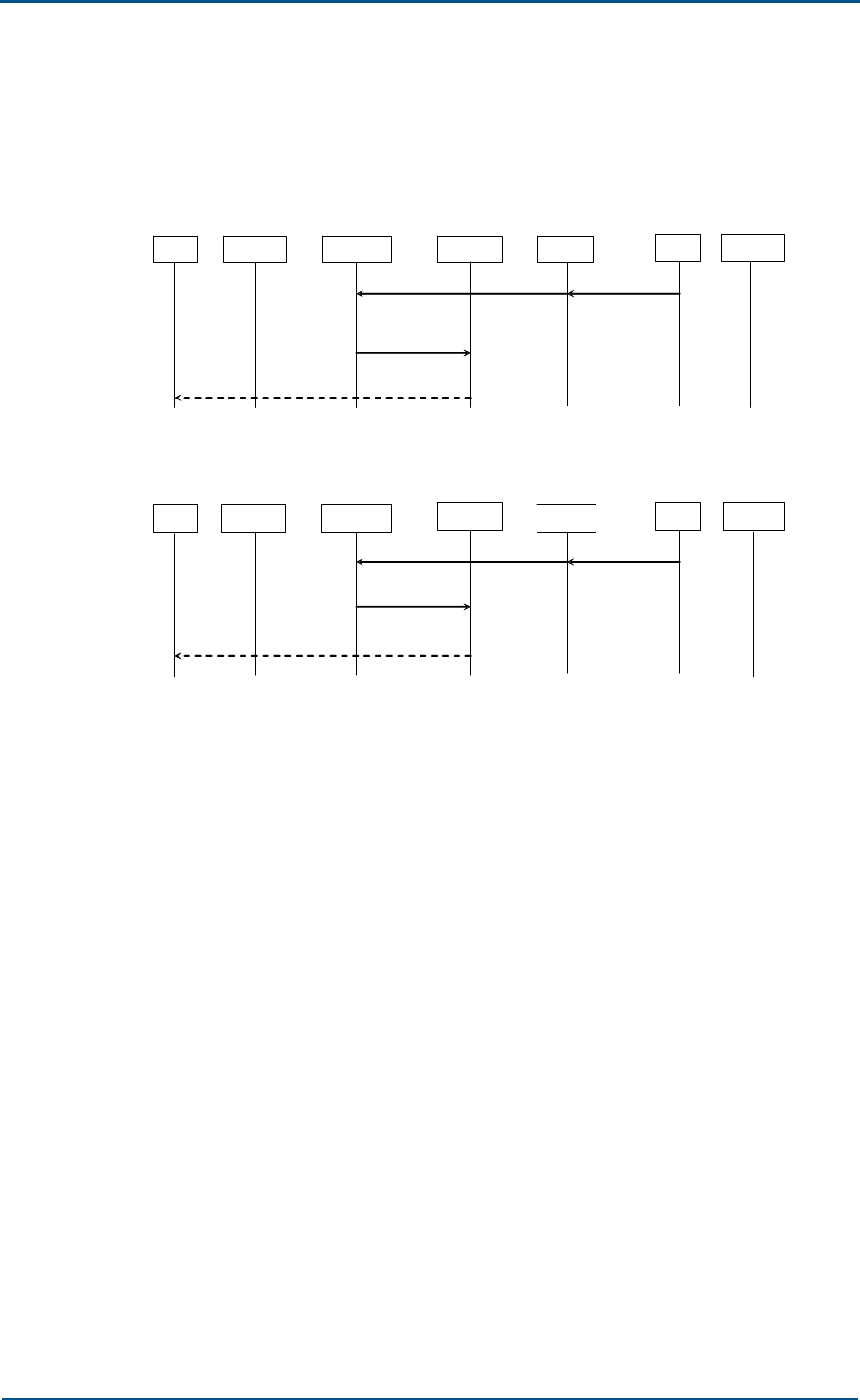
Chapter 4 - System Functions
Confidential and Proprietary Information of ZTE CORPORATION 63
Short Message Cell Broadcast
The short message cell broadcast procedure is shown in Figure 52 and
Figure 53.
FIGURE 52 REQUEST FOR SHORT MESSAGE CELL BROADCAST
MS LAPDm FURRM HPIMan LAPD BSC OAMM
DL_ DATA_IND (SMS
BROADCAST REQ)(SMS
BROAD-CAST
REQ)
CBCH block n
MPH_CBCHMsg
ToCHP
FIGURE 53 SHORT MESSAGE CELL BROADCAST COMMAND
MS LAPDm FURRM HPIMan LAPD BSC OAMM
DL_ DATA_IND (SMS
BROADCAST CMD) ( SMS BROAD-CAST
CMD)
MPH_CBCHMsg
BlkToCHP
CBCH page
The BSC sends the Short Message Service Cell Broadcast messages to the
OB06.
These messages are sent by the BSC to the OB06 with the SMS
BROADCAST REQ or SMS BROADCAST CMD message. In these two
messages, the BSC considers the CBCH capacity and then queues, repeats
and transmits the messages. The BSC also splits the SMS Cell Broadcast
message on the air interface. The difference between the two messages is
that, the SMS BROADCAST CMD message can request broadcasting of a
complete cell broadcast message (sent in every message by pages) and
the OB06 splits it into blocks. For the SMS BROADCAST REQ message, it
has been split by the BSC, 23 bytes per block.
With the SMS BROADCAST CMD message, the BSC can set the OB06
broadcast to the default mode. When there are no other messages to be
broadcast in this mode, the OB06 will send a default message.

ZXG10 OB06 ZTE Integrated Outdoor GSM Base Station Technical Manual
64 Confidential and Proprietary Information of ZTE CORPORATION
Broadcast Information 1 Change Procedure
The procedure of broadcast information 1 change is shown in Figure 54.
FIGURE 54 BROADCAST INFORMATION 1 CHANGE PROCEDURE
MS LAPDm FURRM HPIMan LAPD BSC PAGCH
M
DL_ DATA_IND (BCCH INFO) (BCCH INFO)
MPH_
RRC mdToCHP (CHP
SET/STOP BCCH
INFO)
(CHP SET CCCH
Para.)
(SYS INFOTYPE
1/2/ 2bis /2ter/3/4/7/8 )
(PAG SET CCCH Para.)
The BSC indicates to the OB06 that the new system messages (like (RR)
System Information Type 1/2/2bis/2ter 3/4/7/8) will be broadcast on the
BCCH.
When the OB06 receives the BCCH INFO message, the FURRM module will
send the CHP SET BCCH INFORMATION message to the CHP if there is any
system message. Then, the CHP sends it to the MS. If there is no system
message, the FURRM module will send the CHP STOP BCCH INFORMATION
message to the CHP, indicating to stop sending these system messages to
the MS.
For easy observation of the system message sending, the TRU panel of the
OB06 has a signal indicator marked as “MOD”.
System Information Type 1 contains RACH control parameters and cell
configuration; System Information Type 2 contains RACH control
parameters and BCCH configuration of an adjacent cell; System
Information Type 2bis and System Information Type 2ter are optional
messages, containing BCCH extension configuration of an adjacent cell;
System Information Type 3 contains information of other cells, such as
identifier of a location area and cell identity; System Information Type 4
contains information of control over RACH, identifier of a location area and
cell identity; System Information Type 7 and System Information Type 8
contain parameters of cell reselection.
The FURRM extracts three parameters (BS_PA_MFRMS, BS_AG_BLKS_RES
and CCCH_CONF) from the Control Channel Description information unit of
the System Information Type 3 message, and sends them to the CHP and
PAGCHM modules.

Chapter 4 - System Functions
Confidential and Proprietary Information of ZTE CORPORATION 65
Broadcast Information 2 (SACCH FILL) Change
Procedure
The broadcast information 2 (SACCH FILL) change procedure is shown in
Figure 55.
FIGURE 55 BROADCAST INFORMATION 2 (SACCH FILL) CHANGE PROCEDURE
MS LAPDm FURRM HPIMan LAPD BSC OAMM
DL_ DATA_IND (SACCH FILL) (SACCH FILL)
MPH_
RRCmdToCHP (CHP
SET/STOP SACCH
FILL )
(SYS INFO TYPE 5/6/5bis)
The BSC indicates to the OB06 that the new system information ((RR)
System Information Type 5/6/5bis/5ter) will be sent in the downlink
SACCH as fill-in information, generally when channel connection starts
(especially after a handover) and the channel changes.
When the FURRM receives the SACCH FILL message, it extracts the
information unit and sends it to the CHP module for the system message
transmission. If it does not receive the message, it indicates that the
system message sending will stop.
The System Information Type 5 contains the adjacent cell BCCH frequency
table. The System Information Type 5bis and System Information Type
5ter contain adjacent cell BCCH extended configuration information. The
System Information Type 6 contains the location area ID and cell ID.
When the fill-in information uploaded in the SACCH needs to be changed,
the BSC will send a SACCH INFO MODIFY message to the OB06. The
SACCH fill-in information in this message will be transmitted in the
specified channel, till the channel is released or changed by another
SACCH INFO MODIFY message.
TRX Management Function
This function supports the following procedures:
1. Radio resource indication procedure: With this procedure, the OB06
gives the BSC an indication of interference level on the idle dedicated
channel of each TRX.
2. Traffic control procedure: With this procedure, the FUC gives the BSC
an indication about the overload of this TRX. The overload cause may
be CCCH overload, ACCCH overload or processor overload.
3. Error report procedure: With this procedure, the OB06 reports to the
BSC the detected downlink message error that cannot be reported with
other procedures.
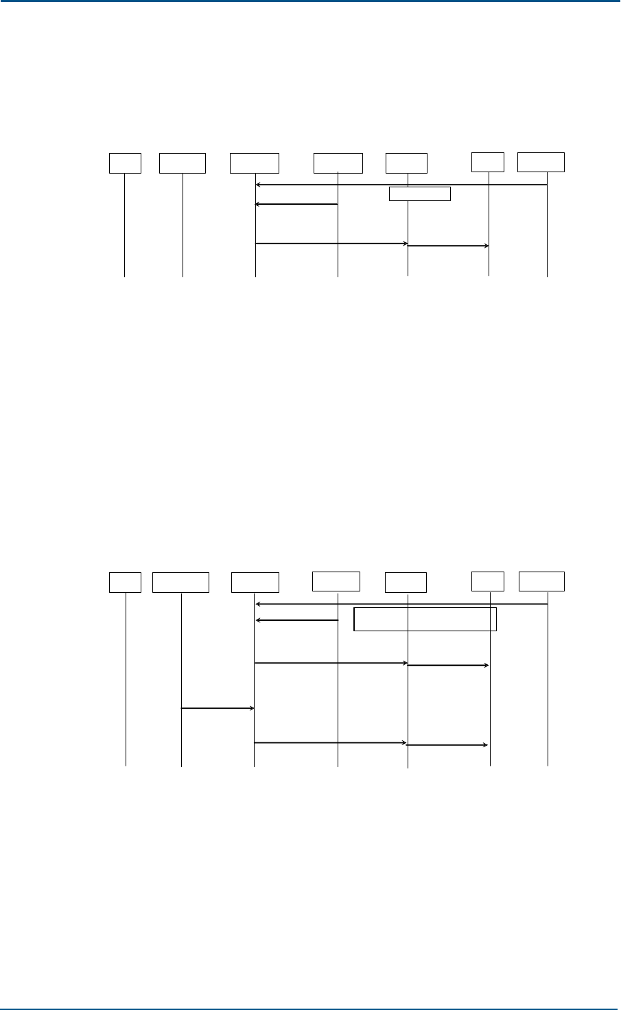
ZXG10 OB06 ZTE Integrated Outdoor GSM Base Station Technical Manual
66 Confidential and Proprietary Information of ZTE CORPORATION
Radio Resource Indication
The radio resource indication is shown in Figure 56.
FIGURE 56 RADIO RESOURCE INDICATION
MS LAPDm FURRM HPIMan LAPD BSC OAMM
DL_ DATA_REQ (RF RES IND)
MPH_CHPI ndToRR
(CHP MEAS IND)
(RF RES IND)
Period value
It notifies the BSC the interference level of the idle channel of one TRX.
The interference level value of the idle channel is provided by the CHP,
and reported in the CHP MEASUREMENT INDICATION message, just like
the measurement report. This message is reported once every 102 frames
(51 multiframes) or 104 frames (26 multiframes).
Load Management
1. Load indication
The procedure of load indication on the common channel is shown in
Figure 57.
FIGURE 57 PUBLIC CHANNEL LOAD INDICATION
MS PAGCHM FURRM HPIMan LAPD BSC OAMM
DL_ DATA_REQ (CCCH LOAD IND)
MPH _CHPIndTo
RR (CHP RACH
LOAD IND)
(CCCH LOAD IND)
PAG_DATA_IND
(PAG PC H LOAD
IND)
DL_ DATA_REQ (CCCH LOAD IND) (CCCH LOAD IND)
Period value & threshold
The OB06 gives the BSC the load information in a specific CCCH
timeslot, involving RACH and PCH loads.
The CHP calculates the exact load on the RACH. The PAGCHM
calculates the load on the PCH. The thresholds and sending period are
configured in the OAMM.
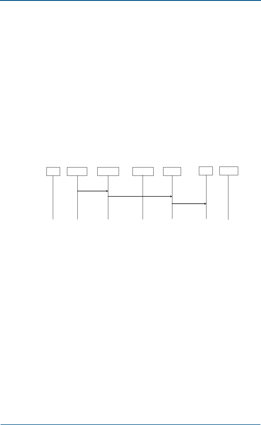
Chapter 4 - System Functions
Confidential and Proprietary Information of ZTE CORPORATION 67
2. General overload
The OB06 instructs the BSC that the receiver must reduce the traffic.
According to the protocol, it can be used to indicate the TRX overload,
downlink CCCH overload and ACCH overload.
The TRX processor provides data from the bottom running operating
system. The downlink CCCH load calculation is just the same as the
above-mentioned CCCH LOAD IND, the CHP provides the RACH load,
and the PAGCHM provides the PCH load. The ACCH load calculation is
not determined.
According to the negotiation with the BSC, the current general
overload (OVER LOAD) is only used to report the RACH load that is
provided by the CHP.
Error Indication
The procedure of error indication is shown in Figure 58.
FIGURE 58 ERROR INDICATION
MS LAPDm FURRM HPIMan LAPD BSC OAMM
Dm_MDL_ERR
OR_IND DL_DATA_REQ (ERROR IND)
(ERROR IND)
The ERROR IND message that is sent from the OB06 to the BSC indicates
to the BSC that the following abnormities happen in the radio data link
layer.
The ERROR IND message contains the related error cause information,
including the following causes:
1. Protocol errors, as listed in Sections 5.6.4, 5.7.3 and Appendix G in TS
GSM 04.06;
2. Error with one link layer. In other words, the I frame is repeated for
N200 times but is not acknowledged.
3. The SABM or DISC frame is repeated for N200 times but is not
acknowledged.
4. The SABM frame received in the multiframe establishment status

ZXG10 OB06 ZTE Integrated Outdoor GSM Base Station Technical Manual
68 Confidential and Proprietary Information of ZTE CORPORATION
Connection Failure
The procedure of connection failure is shown in Figure 59.
FIGURE 59 CONNECTION FAILURE
MS LAPDm FURRM HPIMan LAPD BSC OAMM
M PH_CHPIndToRR
(CHP CONN FAIL
IND)
(CONN FAIL IND)
DL_DATA_REQ (CONN FAIL IND)
The CONN FAIL IND message that is sent from the OB06 to the BSC
indicates the BSC that one activated channel cannot be used as more for
some reasons.
When this message is received, the network side will release the channel.
The message contains the cause parameter, including the following causes:
1. Radio link fault (Section 5 in GSM 05.08). The OB06 judges whether
there is any fault according to the uplink SACCH error rate or
RXLEV/RXQUAL test.
2. Hardware error (decoder fault, for example).
3. Others
The CHP module will report the error to the FURRM module. In addition, in
case of failed handover or mis-synchronization between CHP and TC, the
FURRM also sends this message to the BSC.
Error Report
The OB06 sends the ERROR REPORT message to the BSC, notifying the
following errors that cannot be reported with other procedures.
When the OB06 receives an error message, it ignores the message and
reports to the BSC. Here, the ERROR REPORT is the message involving all
error causes other than the CHAN ACTIV NACK for channel activation and
the MODE MODIFY NACK for channel mode modification.
The error causes include message ID error, message type error, message
sequence error, information unit error, and channel status mismatch.
O&M
The OB06 provides powerful O&M functions to implement management
and maintenance of the OB06 equipment. The functions fall into three
parts: parameter configuration, alarm and status reporting, and online
software loading.
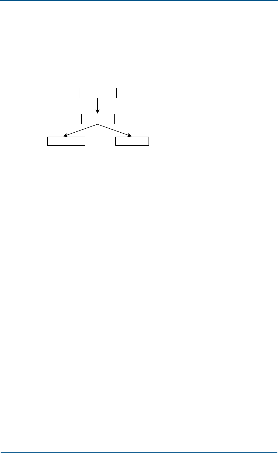
Chapter 4 - System Functions
Confidential and Proprietary Information of ZTE CORPORATION 69
Parameter Configuration
It supports the OB06 parameter configuration by the BSC.
The parameter configuration process is shown in Figure 60.
FIGURE 60 PARAMETER CONFIGURATION PROCESS
CMM software
FUC software
CHP software CIP software
The messages from the BSC are sent to the CMM board through the BIE
board through the LapD link, and then forwarded to application processes
through the message distribution process of the Abis interface of the CMM
software. The CMM configuration process processes the configuration
messages and implements the OB06 static data configuration by the BSC.
The CMM software distributes the BSC parameters, and through the HDLC,
configures the data to the TRM board FUC software that is managed by the
CMM software. After receiving the configuration message from the CMM
software, the FUC software configures the board attributes, notifies the
CMM software of the successful configuration message at the same time,
and configures the CHP and CIP.
Alarm and Status Reporting
The ZXG10 OB06 (V1.0) supports reporting the alarms and status of the
OB06 to the BSC.
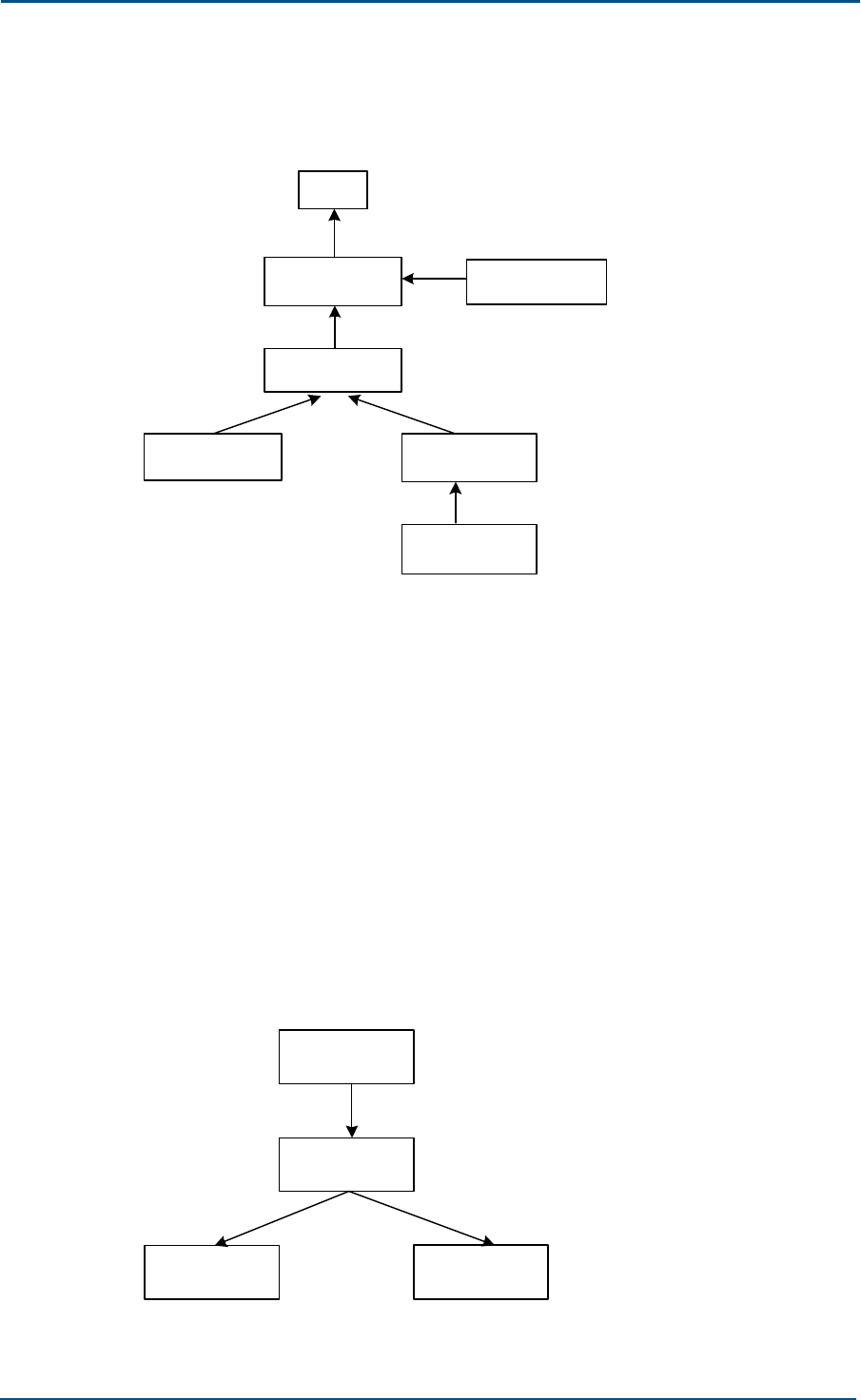
ZXG10 OB06 ZTE Integrated Outdoor GSM Base Station Technical Manual
70 Confidential and Proprietary Information of ZTE CORPORATION
The alarm reporting process is shown in Figure 61.
FIGURE 61 ALARM REPORTING PROCESS
BSC
AEM/PA alarm
Backbone
node alarm
CMM software
FUC software
CHP software CIP software
The CIP software collects the alarms of itself and the fan/AEM/PA alarms,
and then reports them to the FUC software. while the CHP software
collects the alarms of itself and reports them to the FUC software. The FUC
software reports the collected alarms and its own alarms to the CMM
software. The alarms of the backbone nodes are collected by the CMM
software, which reports all alarms of this site to BSC through LapD, and
implements some relevant alarm processing, such as power amplification
shut-down.
Online Software Loading
It supports the OB06 software online loading by the BSC.
The software loading process is shown in Figure 62.
FIGURE 62 SOFTWARE LOADING PROCESS
CMM software
FUC software
CHP software CIP software

Chapter 4 - System Functions
Confidential and Proprietary Information of ZTE CORPORATION 71
All software versions are downloaded into the CMM’s FLASH memory
through the BSC. The CMM validates the versions, and loads the software
to the FUC when it finds any difference with the TRM software.
The TRM software is stored in the FLASH memory on the FUC board. After
DSP is restarted, the FUC software loads the CHP software to the CHP and
CIP through the HPI interface.
The software loading procedure is described as follows:
1. The CMM sends to the FUC the “software loading initialization”
message.
2. The FUC returns the CMM the “software loading initialization finished”
message.
3. CMM divides the software versions into message segments and sends
to FUC segment by segment.
4. When all software data are sent, the CMM sends to the FUC the
“software loading finished” message.
5. The FUC returns the CMM the “software loading finished
acknowledgement” message.
Ultra-Distance Coverage
Ultra-distance coverage refers to coverage by a BTS with a cell radius
greater than 35 km, which is stipulated by the GSM standard.
According to the GSM protocol, the maximum access radius of the GSM
system is 35 km, and the corresponding time advance (TA) is 63. This
limit is made because, under normal conditions, and in a 900 M
propagation environment, it is difficult to offer a coverage with a radius
greater than 35 km. But, in some special propagation conditions, such as
low propagation loss areas like coasts, deserts and grasslands, with the
help of BTS of high-power output and high-gain antenna, it will be possible
to offer coverage with a radius greater than 35 km.
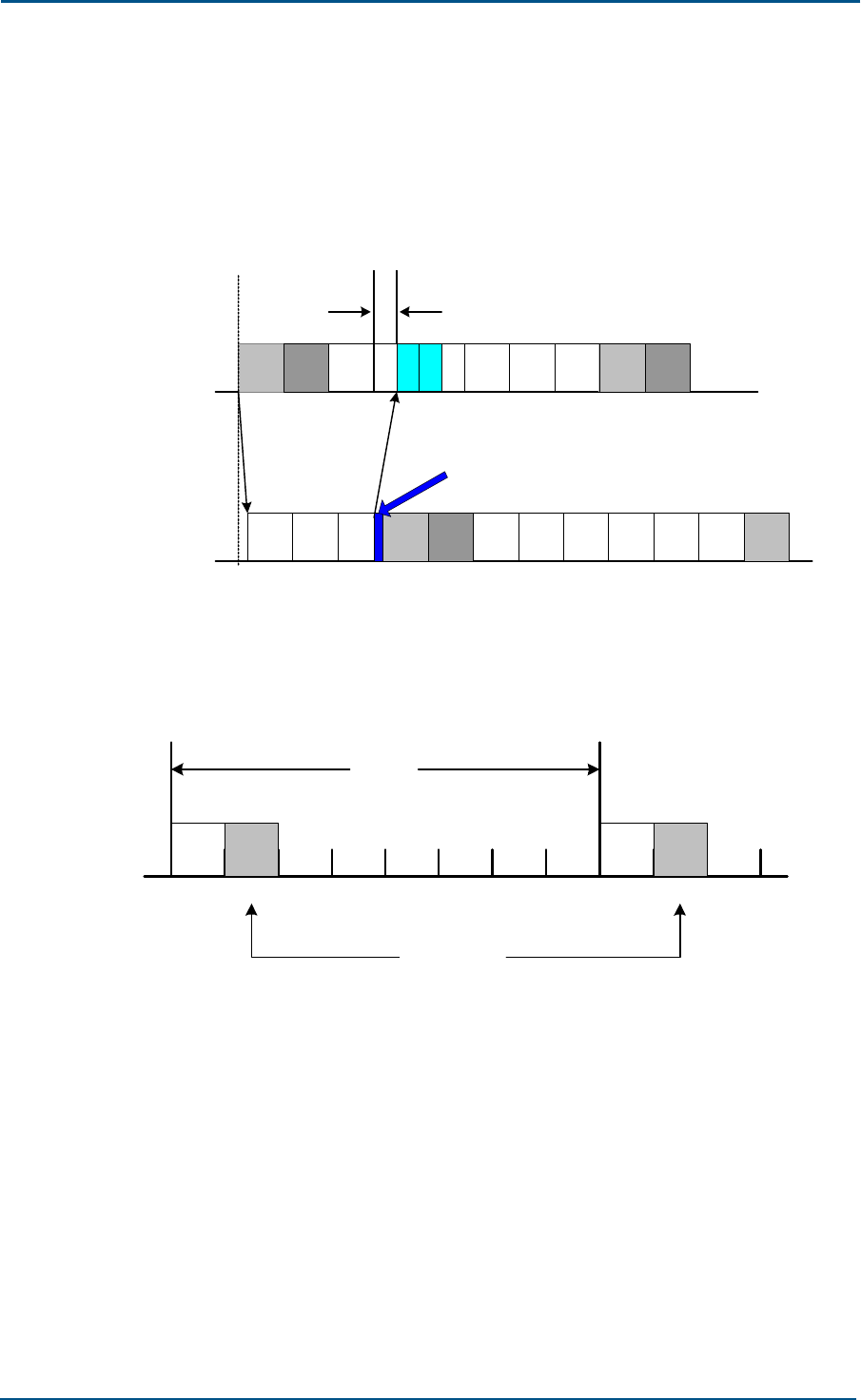
ZXG10 OB06 ZTE Integrated Outdoor GSM Base Station Technical Manual
72 Confidential and Proprietary Information of ZTE CORPORATION
When the coverage distance is greater than 35 km, that is, when the air
time delay is greater than 63, the time of arrival of a signal at the BTS will
span two time slots, as shown in Figure 63, so a dedicated control channel
and a service channel can be two physical channels, namely, two
consecutive time slots.
FIGURE 63 TIME DELAY RELATIONSHIP
0 0 11
General air delay-63
0 6 71 2
2 3 4 5 6 7
3 4 5 0765
OB06
transmitting
63-bit transmitting in advance
MS
transmitting
When the BTS uses two timeslots to process the data of one subscriber,
the second timeslot is called the extended channel, a shown in Figure 64.
FIGURE 64 OB06 SIGNAL PROCESSING
23 4 5 6 7 2
0 0 11
Frame
Extended
channels

Chapter 4 - System Functions
Confidential and Proprietary Information of ZTE CORPORATION 73
The carrier frequency after channel expansion is shown in Figure 65:
Originally a TRX may provide 8 physical channels; after channel expansion,
one carrier frequency has 4 physical channels, while the carrier frequency
capacity is reduced by half.
FIGURE 65 ACTUAL NUMBER OF PHYSICAL CHANNELS IN A CARRIER
0
0
321
1234567
The original
TRXs
Extended
channel TRXs
With extended channels, the coverage of the OB06 is theoretically up to a
radius of 120 km, and the maximum time advance is 219. Since the actual
propagation loss of GSM900 is high, and due to the balance between
upper and lower links, the actual coverage radius may be less than the
theoretical value.

74 Confidential and Proprietary Information of ZTE CORPORATION
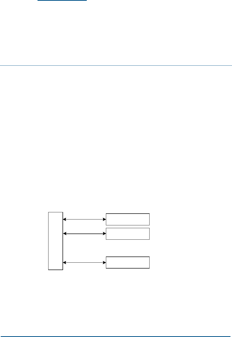
Confidential and Proprietary Information of ZTE CORPORATION 75
Chapter 5
Networking Modes and
System Configurations
This chapter introduces the networking modes, system configurations, and
networking examples of the ZXG10 OB06 (V1.0).
Networking Modes
The ZXG10 OB06 (V1.0) is connected to the BSC through the Abis
interface, supporting networking modes of star, chain and tree.
1. Star networking mode
Figure 66 shows the star networking node of the ZXG10 OB06 (V1.0).
Each line denotes a bi-directional E1 connection; however, the actual
related ID DIP switches at the BS side should be designed according to
the relative configurations. For detailed principles, refer to ZXG10
OB06 (V1.0) Compact Outdoor BTS for GSM Hardware Manual.
FIGURE 66 SCHEMATIC DIAGRAM OF STAR NETWORKING
B
S
C
SITE0
SITE1
SITEn
.
.
.
In star networking, n E1 PCM links are led into each SITE directly from
BSC. The OB06 device on each site is a piece of end equipment. The
networking mode is simple, accompanied by convenient construction
and maintenance. Since the signals are transmitted through fewer
intermediate links along the path, the reliability of transmission is
higher. This networking mode is typically employed in densely
populated urban areas.
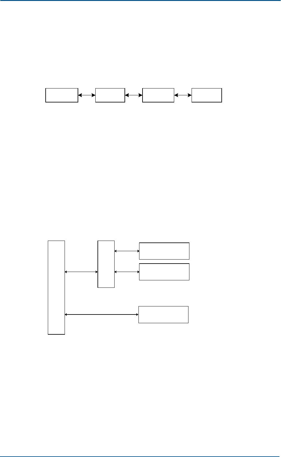
ZXG10 OB06 ZTE Integrated Outdoor GSM Base Station Technical Manual
76 Confidential and Proprietary Information of ZTE CORPORATION
2. Chain networking mode
Figure 67 shows the chain networking mode of the ZXG10 OB06 (V1.0).
Each line denotes a bi-directional E1 connection; however, the actual
related ID DIP switches at the BS side should be designed according to
the relative configurations.
FIGURE 67 SCHEMATIC DIAGRAM OF CHAIN NETWORKING
SITE0
BSC SITE1 SITE2
Chain networking is also applicable to the one-site multi-OB06
situation. Since signals go through more links, the line reliability is
relatively poor. This networking mode is applicable to stripe-like areas
with a small population, thus saving a large number of transmission
devices. To prevent the clock performance deterioration, it is
recommended no more than four OB06s be cascaded in the chain
networking mode.
3. Tree networking mode
The tree networking mode of the ZXG10 OB06 (V1.0) is shown in
Figure 68. Each line denotes a bi-directional E1 connection; however,
the actual related ID DIP switches at the BS side should be designed
according to the relative configurations.
FIGURE 68 SCHEMATIC DIAGRAM OF TREE NETWORKING
.
.
.
BSC
SITE0
SITE1
SITE2
SITEn
The tree networking mode is applicable to large yet sparsely populated
areas. This mode is complicated, in which signals have to pass many
nodes and the line reliability is relatively low. And the fault from the
upper-level SITE may affect the proper running of the lower-level SITE.
In the tree networking mode, the OB06 connected with BSC is the
central node, which may branch into three nodes, namely OB06 s.
In actual networking projects, due to the decentralized sites, unlike
basic networking modes, the transmission equipment is usually used
for intermediate connection between BSC and OB06. Common
transmission modes include: microwave, optical fibers, HDSL cables
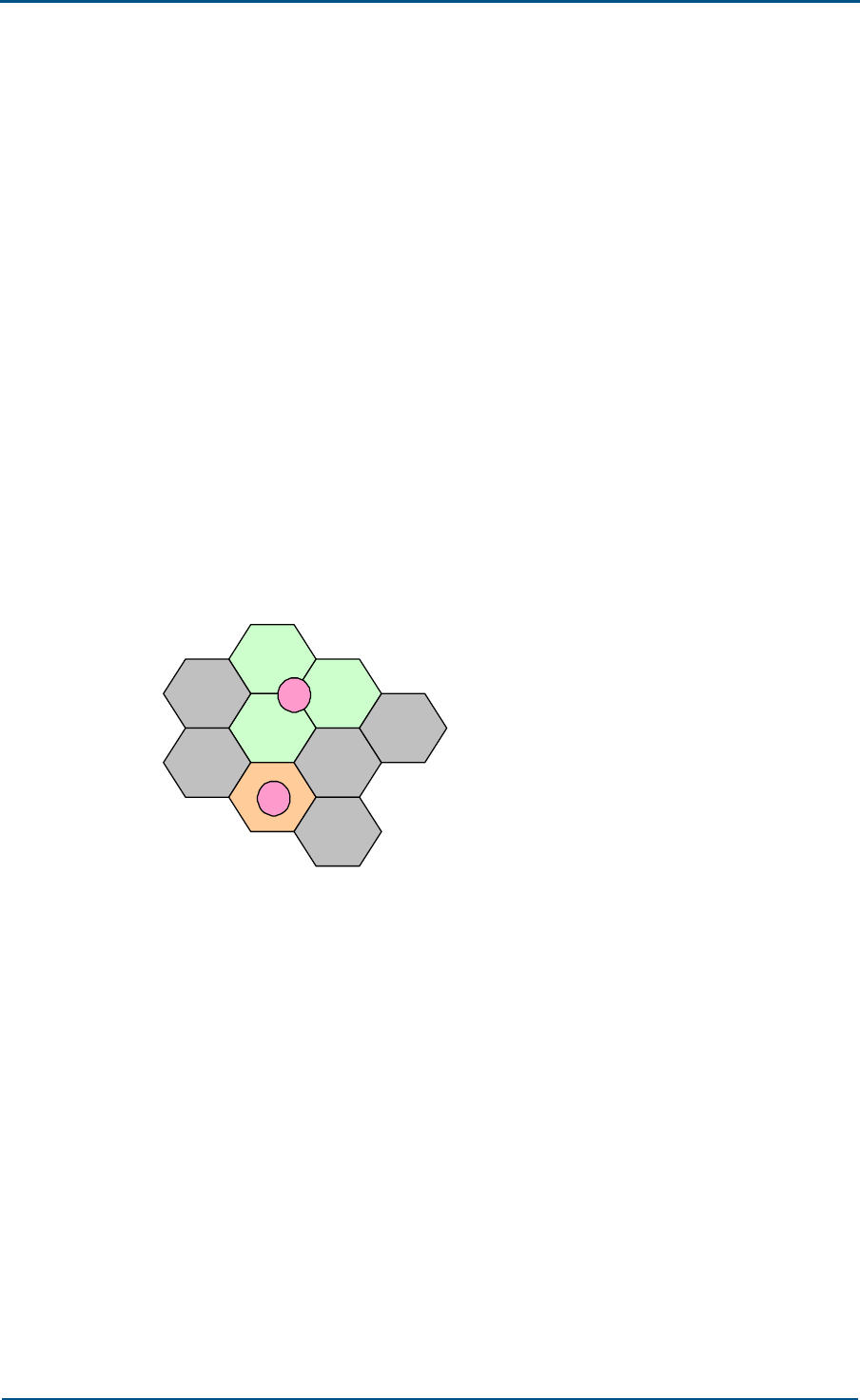
Chapter 5 - Networking Modes and System Configurations
Confidential and Proprietary Information of ZTE CORPORATION 77
and coaxial cables. Satellite links can be used for special transmission
modes.
System Configuration
There are many ways of BS configuration. In general, a proper number
and types of sites are selected to cater for the requirements of the
operators as well as the concrete geographical environment, and a
minimum hardware configuration should be used to meet the maximum
traffic requirement.
Number and Types of Sites
A radio cellular mobile network, according to its frequency resources and
cell planning, can be divided into a certain number of cells. The cells in a
cellular system are adjacent to each other, as shown in Figure 69.
FIGURE 69 SCHEMATIC DIAGRAM OF CELLS
Cell1
Cell3
Cell4
Cell2
Cell5
Cell6
Cell7
Cell9
Cell8
A
B
In the system, each cellular cell is covered by multiple radio channels. If
an omni-antenna is employed, a base station will be set at the center of
each cell (as A in the diagram). And if a directional sectorized antenna is
used, the base station will be established at the intersection of three cells
(as B in the diagram). Such a base station covers three adjacent cells, and
in fact it contains at least three TRXs. Usually, a base station in this kind
of network is called a site. The base site with an omni-antenna covers only
one cell; while the base site with a directional antenna covers three cells.
Types of sites: O-type sites and S-type sites, and the models are shown in
Figure 70.
An O-type site is an omni-directional cell, that is, all the carriers of the
site serve the O-type cell;

ZXG10 OB06 ZTE Integrated Outdoor GSM Base Station Technical Manual
78 Confidential and Proprietary Information of ZTE CORPORATION
An S-type site refers to a sectorized cell. Typically, a three-sector site
is preferred; that is, each site has three sectors.
FIGURE 70 TWO TYPES OF SITES
O-type sites S-type sites
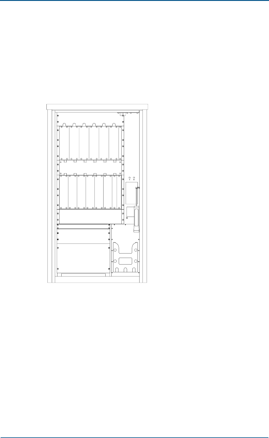
Chapter 5 - Networking Modes and System Configurations
Confidential and Proprietary Information of ZTE CORPORATION 79
BS Configuration Principles
Configuration of Standard Cabinet
For 40 W configuration, the installation positions of functional modules of
the ZXG10 OB06 (V1.0) in the cabinet are shown in Figure 71.
FIGURE 71 BOARD LAYOUT OF 40 W STANDARD FULLY-CONFIGURED ZXG10 OB06 (V1.0)
CARRIER FRAME
P
D
M
Battery
frame
Power and monitoring
Transmission frame
RTU fan frame
C
M
M
C
M
M
T
R
M
T
R
M
T
R
M
T
R
M
T
R
M
T
R
M
ABM fan frame
Air duct
A
E
M
A
E
M
A
E
M
A
E
M
A
E
M
A
E
M
For 40 W configuration, a single cabinet of OB06 can be configured with a
maximum of 6 TRMs.
For 80 W configuration, the installation positions of functional modules of
the ZXG10 OB06 (V1.0) in the cabinets are shown in Figure 72.
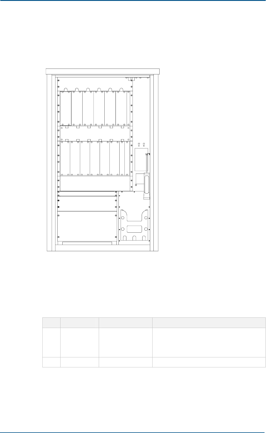
ZXG10 OB06 ZTE Integrated Outdoor GSM Base Station Technical Manual
80 Confidential and Proprietary Information of ZTE CORPORATION
For 80 W configuration, a single cabinet of OB06 can be configured with a
maximum of 3 TRMs.
FIGURE 72 BOARD POSITION OF 80 W STANDARD FULLY-CONFIGURED ZXG10 OB06
(V1.0) CARRIER FRAME
S
T
R
U
S
P
A
S
P
A
S
T
R
U
A
E
M
A
E
M
A
E
M
A
E
M
A
E
M
A
E
M
S
T
R
U
S
P
A
C
M
M
C
M
M
P
D
M
Battery
frame
Power and monitoring
Transmission frame
RTU fan frame
ABM fan frame
Air duct
Configuration of Carrier Frames and Antenna Interface
Frames
Configuration of the carrier frame is listed in Table 5.
TABLE 5 CONFIGURATION OF CARRIER FRAMES
S.N. Unit Name Configurations Description
1 TRM Ntrx (total number
of carriers)
A single cabinet is configured with 6 carriers
at the maximum (namely, Ntrx≤6). TRMs fall
into these types: 900 M, extended 900 M,
1800 M, 1900 M and 850 M.
2 CMM 2 Controller & Maintenance Module
For the carrier configuration, TRM in one cell should in principle be
configured inside one ZXG10 OB06 (V1.0) cabinet to minimize the length
of the cabinet-crossing RF connection cable and reduce the loss over

Chapter 5 - Networking Modes and System Configurations
Confidential and Proprietary Information of ZTE CORPORATION 81
cables. The cabinet-crossing cables should be as short as possible in
configuration.
Configuration of antenna feeder interface frame is shown in Table 6.
TABLE 6 CONFIGURATION OF ANTENNA FEEDER INTERFACE FRAME
S.N. Unit Name Configurations Description
1
Combiner
Distribution
Unit (CDU)
2 × Number of sectors Each sector is configured with 2 CDUs
2
Combiner
Extension Unit
(CEU)
2 ×Number of sectors
whose numbers of
carriers is greater than
4
Each sector whose numbers of carriers is
greater than 4 is configured with 4 CDUs
Configuration Principle of AEM
Two types of AEM units are available: CDU and CEU. The ZXG10 OB06
(V1.0) allows configuration of various types of sites by means of different
combinations of Combiner Distribution Units and Combiner Extension Units.
For GSM900 cells, GSM900 units are configured; for GSM1800 cells,
GSM1800 units are configured; and so on and so forth for other GSM
systems.
Each site may be configured as either an omni-directional cell or a multiple
directional cell. Based on different field strength coverage modes, there
are two types of base station antenna: omni-antenna and directional
antenna. An omni-antenna can provide omni-directional coverage, thus
saving site construction costs. However, the omni-antenna has low gain
and poor anti-interference capability. The directional antenna is of
directivity with high gain and strong anti-interference capability. To ensure
the complete coverage of a service area, combination of multiple antennas
is required.
Table 7 shows the number of configured carriers for all 40 W TRXs and the
correspondence between CDUs/CEUs and antennas configured in one cell.
TABLE 7 NUMBER OF CONFIGURED CARRIERS FOR ALL 40 W TRXS AND THE
CORRESPONDENCE BETWEEN CDUS/CEUS AND ANTENNAS CONFIGURED IN ONE CELL
TRX
Quantity Antenna Quantity and
Configuration CDU Quantity CEU Quantity
1 2, TX/RX, RX 2 -
2 2, TX/RX, TX/RX 2 -
3~4 2, TX/RX, TX/RX 2 0 or 2
5~6 2, TX/RX, TX/RX 2 2

ZXG10 OB06 ZTE Integrated Outdoor GSM Base Station Technical Manual
82 Confidential and Proprietary Information of ZTE CORPORATION
Table 8 shows the number of configured carriers for all 80 W TRXs and the
correspondence between CDUs/CEUs and antennas configured in one cell.
TABLE 8 NUMBER OF CONFIGURED CARRIERS FOR ALL 80 W TRXS AND THE
CORRESPONDENCE BETWEEN CDUS/CEUS AND ANTENNAS CONFIGURED IN ONE CELL
TRX
Quantity Antenna Quantity and
Configuration CDU Quantity CEU Quantity
1 2, TX/RX, RX 2 -
2 2, TX/RX, TX/RX 2 -
3 2, TX/RX, TX/RX 2 -
For different configuration requirements of different site types, the
combinations listed above can be used.
Expansion Configuration
In general, 1 to 3 cabinets may be configured in a site to enlarge
subscriber quantity, and it is recommended to configure cabinets as few as
possible. In case of 40 W configuration, the ZXG10 OB06 (V1.0) can be
configured as S2/S/S at most. In case of 80 W configuration, the ZXG10
OB06 (V1.0) can be configured as S1/3/3 at most.
Configuration Examples
The ZXG10 OB06 (V1.0) has multiple configuration modes with different
combinations, and all configurations are based on the user requirements
and network planning. Therefore, system configuration modes vary with
different application sites. A site is typically configured as an omni-
directional site, 2-sector site or 3-sector site.
Configuration Examples of O-type Sites
Here is the configuration of 40 W and 80 W O1/O2/O4/O6-type sites.
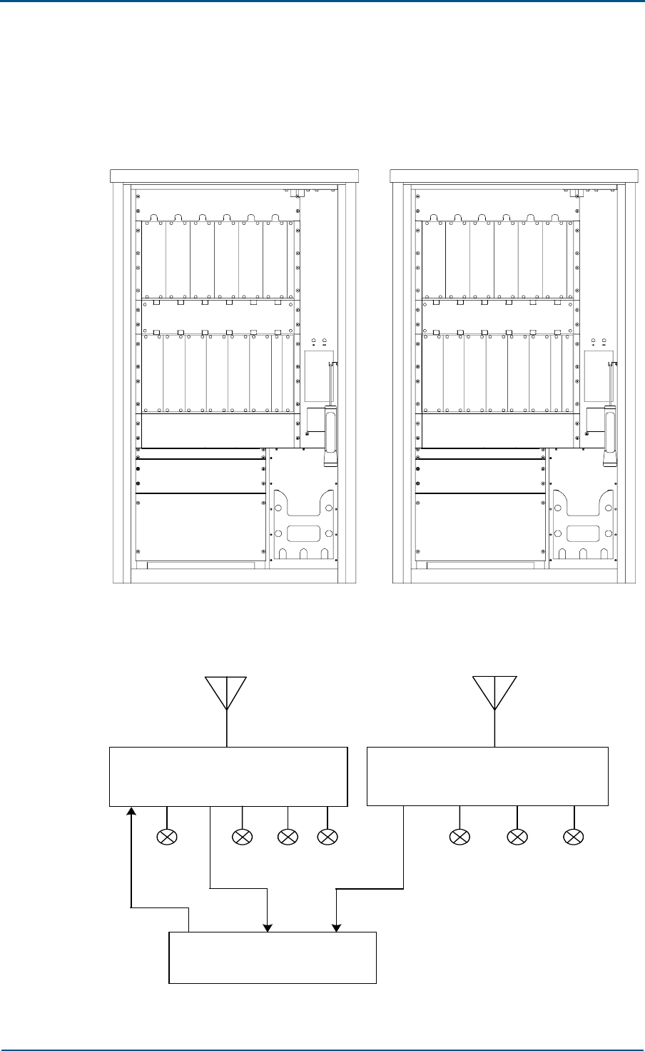
Chapter 5 - Networking Modes and System Configurations
Confidential and Proprietary Information of ZTE CORPORATION 83
Generally, the O2-type site is configured with 2 CDUs and 2 omni-
directional receiving antennas. Figure 73 shows the configuration of the
O1-type site, and Figure 74 shows the logical connection relationship.
FIGURE 73 CONFIGURATION OF 40 W AND 80 W O1-TYPE SITES
C
D
U
S
T
R
U
S
P
A
C
M
M
C
M
M
P
D
M
C
D
U
C
D
U
P
D
M
C
M
M
C
M
M
T
R
M
C
D
U
Air duct Air duct
ABM fan frame ABM fan frame
RTU fan frame RTU fan frame
Battery
frame
Power and monitoring
Transmission frame Battery
frame
Power and monitoring
Transmission frame
FIGURE 74 LOGICAL CONNECTION RELATIONSHIP BETWEEN THE COMBINER UNITS AND
DISTRIBUTION UNITS OF THE O1-TYPE SITE
CDU
TX/ RX
TRM1
CDU
RX
TX1 TX2 RX1 RX2 RX3 RX4 RX1 RX2 RX3 RX4
TX RX RXD
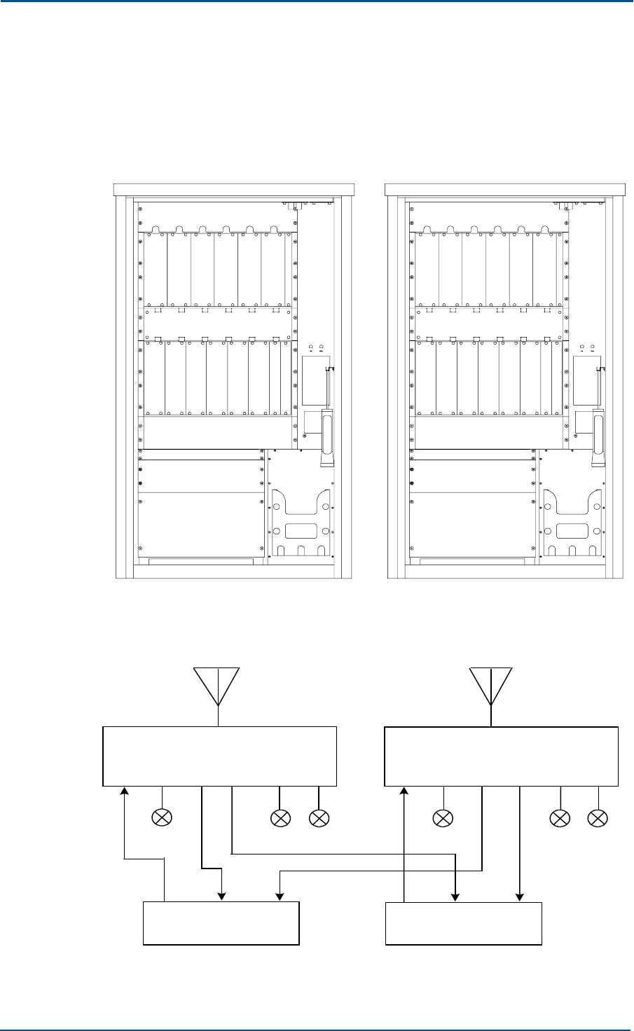
ZXG10 OB06 ZTE Integrated Outdoor GSM Base Station Technical Manual
84 Confidential and Proprietary Information of ZTE CORPORATION
Generally, the O2-type site is configured with 2 CDUs and 2 omni-
directional receiving antennas. Figure 75 shows the configuration of 40 W
and 80 W O2 -type sites, and Figure 76 shows the logical connection
relationship.
FIGURE 75 CONFIGURATION OF 40 W AND 80 W O2-TYPE SITES
S
P
A
S
T
R
U
T
R
M
C
D
U
T
R
M
C
M
M
C
M
M
P
D
M
C
D
U
C
D
U
P
D
M
C
M
M
C
M
M
S
P
A
S
T
R
U
C
D
U
Air duct Air duct
ABM fan frame ABM fan frame
RTU fan frame RTU fan frame
Battery
frame
Power and monitoring
Transmission frame Battery
frame
Power and monitoring
Transmission frame
FIGURE 76 LOGICAL CONNECTION RELATIONSHIP BETWEEN THE COMBINER UNITS AND
DISTRIBUTION UNITS OF O2-TYPE SITE
TX/RX
TRM1
TX RX RXD
TRM2
TX RX RXD
CDU
TX1 TX2 RX1 RX2 RX3 RX4
CDU
TX1 TX2 RX1 RX2 RX3 RX4
TX/RX
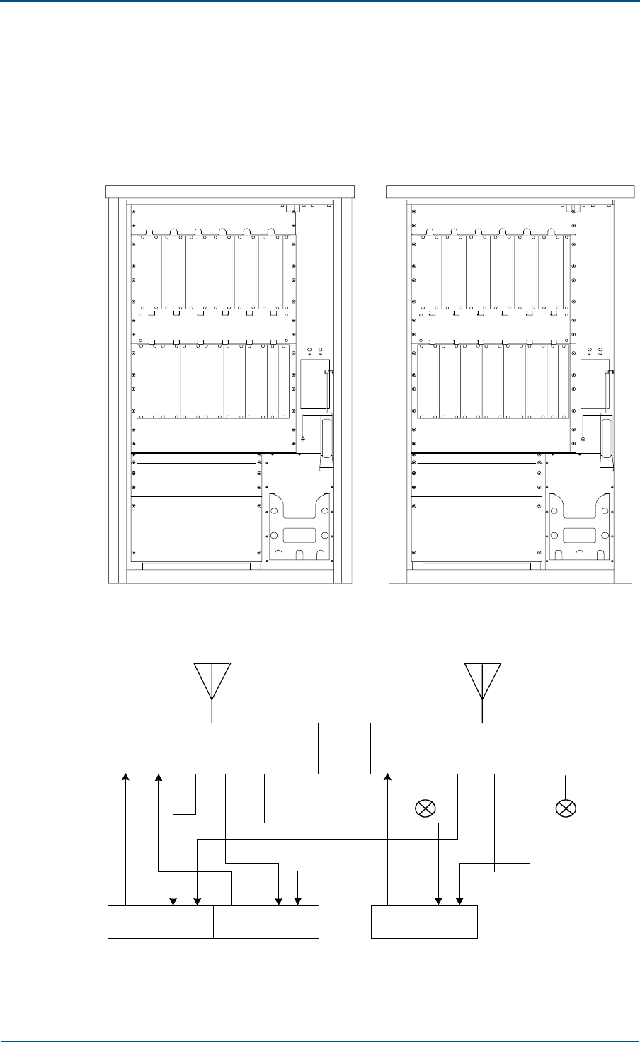
Chapter 5 - Networking Modes and System Configurations
Confidential and Proprietary Information of ZTE CORPORATION 85
Generally, the O2-type site is configured with 2 CDUs and 2 omni-
directional receiving antennas. Figure 77 shows the configuration of 40 W
and 80 W O3 -type sites, and Figure 78 shows the logical connection
relationship.
FIGURE 77 CONFIGURATION OF 40 W AND 80 W O3-TYPE SITES
S
P
A
S
T
R
U
T
R
M
C
D
U
Air duct
S
T
R
U
S
P
A
C
M
M
C
M
M
RTU fan frame
Transmission frame
Power and monitoring
Battery
frame
P
D
M
C
D
U
C
D
U
P
D
M
Battery
frame
Power and monitoring
Transmission frame
RTU fan frame
C
M
M
C
M
M
T
R
M
Air duct
C
D
U
T
R
M
S
T
R
U
S
P
A
ABM fan frame ABM fan frame
FIGURE 78 LOGICAL CONNECTION RELATIONSHIP OF 03-TYPE CDUS
TX/RX TX/RX
TRM1
TX RX RXD TRM 2
TX RX RXD
CDU
TX1 TX2 RX1 RX2 RX3 RX4
CDU
TX1 TX2 RX1 RX2 RX3 RX4
TRM3
TX RX RXD
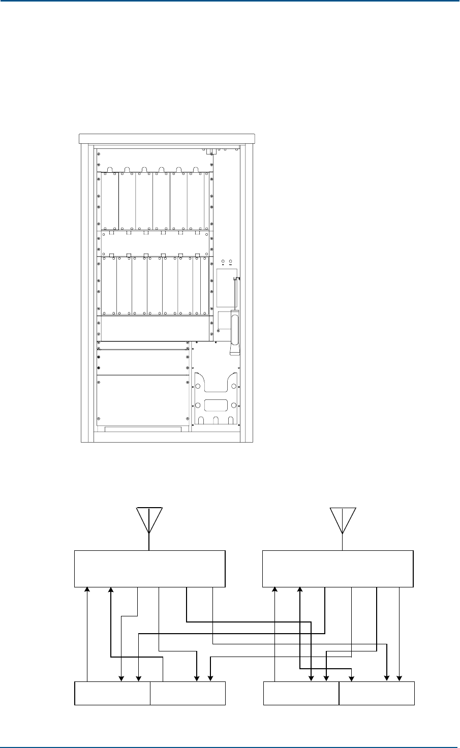
ZXG10 OB06 ZTE Integrated Outdoor GSM Base Station Technical Manual
86 Confidential and Proprietary Information of ZTE CORPORATION
Generally, the O4-type site is configured with 2 CDUs and 2 omni-
directional receiving antennas. Figure 79 shows the configuration of 40 W
and 80 W O4 -type sites, and Figure 80 shows the logical connection
relationship.
FIGURE 79 CONFIGURATION OF 40 W AND 8W O4-TYPE SITES
T
R
M
T
R
M
C
D
U
T
R
M
C
M
M
C
M
M
P
D
M
C
D
U
T
R
M
Battery
frame
Power and monitoring
Transmission frame
RTU fan frame
Air duct
ABM fan frame
FIGURE 80 LOGICAL CONNECTION RELATIONSHIP BETWEEN THE COMBINER UNITS AND
DISTRIBUTION UNITS OF O4-TYPE SITES
TX/RX TX/RX
TRM1
TX RX RXD TRM2
TX RXRXD TRM4
TX RXRXD
CDU
TX1 TX2 RX1 RX2 RX3 RX4
CDU
TX1 TX2 RX1 RX2 RX3 RX4
TRM3
TX RXRXD
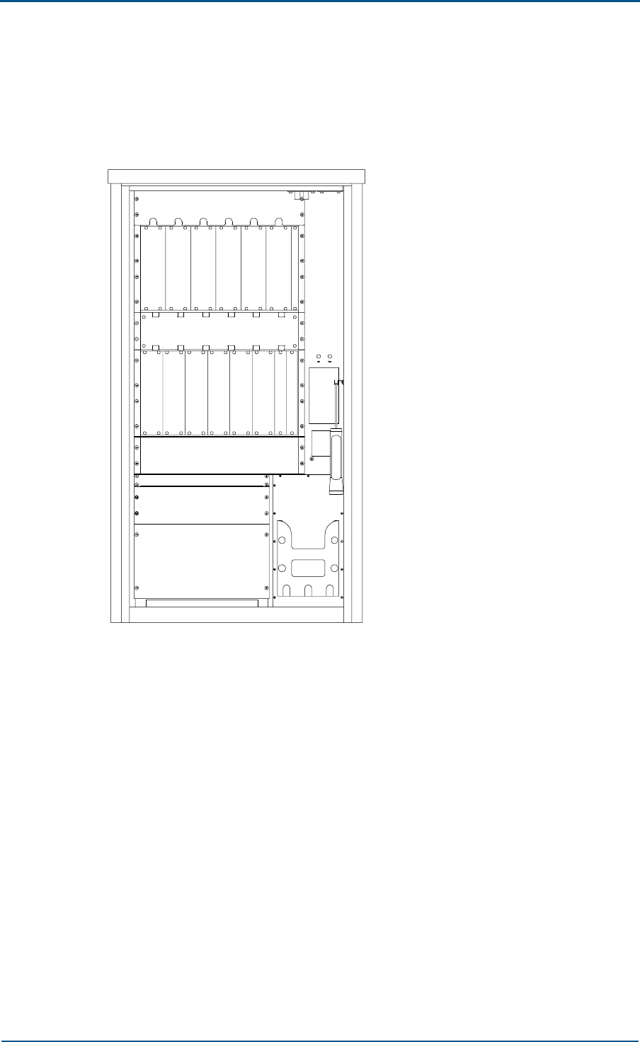
Chapter 5 - Networking Modes and System Configurations
Confidential and Proprietary Information of ZTE CORPORATION 87
Generally, the O6-type site is configured with 2 CDUs, 2 CEUs and 2 omni-
directional receiving antennas. Figure 81 shows the configuration of O6-
type sites, and Figure 82 shows the logical connection relationship.
FIGURE 81 CONFIGURATION OF 40 W O6-TYPE SITES
T
R
M
T
R
M
C
E
U
C
E
U
T
R
M
C
D
U
P
D
M
C
M
M
C
M
M
T
R
M
C
D
U
T
R
M
T
R
M
Battery
frame
Power and monitoring
Transmission frame
RTU fan frame
Air duct
ABM fan frame
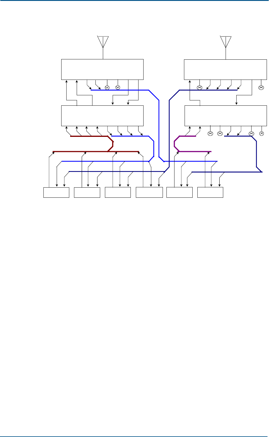
ZXG10 OB06 ZTE Integrated Outdoor GSM Base Station Technical Manual
88 Confidential and Proprietary Information of ZTE CORPORATION
FIGURE 82 LOGICAL CONNECTION RELATIONSHIP BETWEEN CDUS/CEUS OF 06-TYPE
SITES
TX/RX
TRM2TRM1 TRM3 TRM4
TX/RX
TRM5 TRM6
CEU
TX1 TX2 RX1 RX2 RX3 RX4
TX3 TX4
OTX1OTX2EX1EX2
CDU
T X1 T X2 R X1 R X2 R X3 R X4 E X1 E X2
CDU
TX1 TX2 RX1 RX2 RX3 RX4 EX1 EX2
CEU
TX1 TX2 RX1 RX2 RX3 RX4
TX3 TX4
OTX1OTX2EX1EX2
TX RX RXD TX RX RXD TX RX RXD TX RX RXD TX RXRXD TX RX RXD
Configuration Examples of the S-type Site
The S-type site may serve either two-sector cells or three-sector cells. And
the directional antenna is often employed.
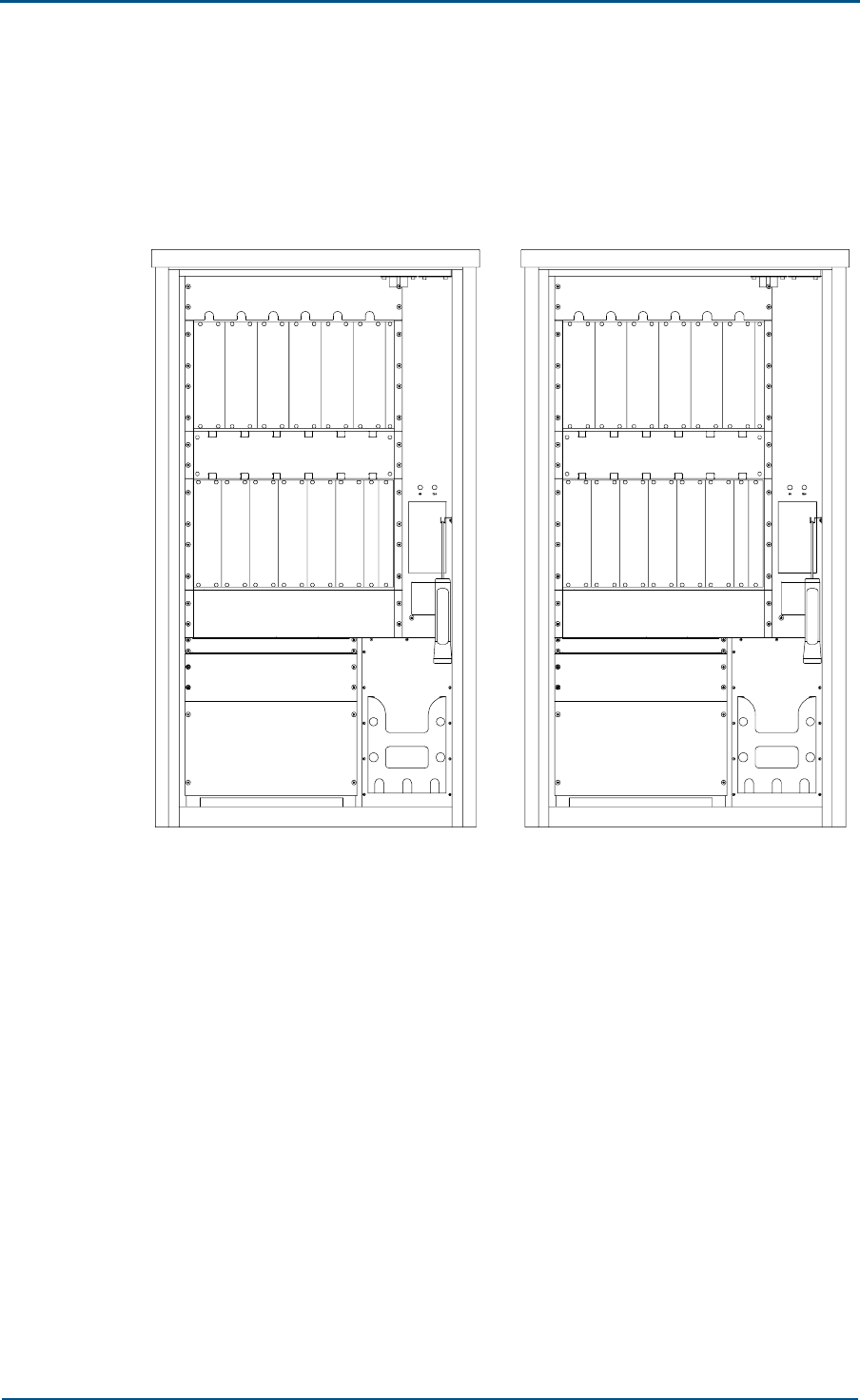
Chapter 5 - Networking Modes and System Configurations
Confidential and Proprietary Information of ZTE CORPORATION 89
Here is configuration of S1/1/1-type sites, usually configuration of 6 CDUs
and 6 directional antennas. Configuration of S1/1/1-type sites is shown in
Figure 83, and the logical connection relationship is similar to that of 02-
type sites.
FIGURE 83 CONFIGURATION OF S1/1/1-TYPE SITES
C
D
U
C
D
U
C
D
U
C
D
U
T
R
M
C
D
U
C
D
U
C
D
U
C
D
U
S
P
A
S
T
R
U
C
D
U
T
R
M
C
M
M
C
M
M
P
D
M
C
D
U
C
D
U
P
D
M
C
M
M
C
M
M
S
P
A
S
T
R
U
C
D
U
T
R
M
S
T
R
U
S
P
A
Battery
frame
Power and monitoring
Transmission frame
RTU fan frame
Air duct
ABM fan frame
Battery
frame
Power and monitoring
Transmission frame
RTU fan frame
Air duct
ABM fan frame

90 Confidential and Proprietary Information of ZTE CORPORATION
This page is intentionally blank

Confidential and Proprietary Information of ZTE CORPORATION 91
Appendix A
Pertinent Standards
The numbers and names of standards quoted in this manual are listed
below.
ETSI TS 100 910 Version 3.16.0 European Digital Cellular Communication
System (Phase One); Radio Transmitting and Receiving (GSM 05.05)
ETSI I-ETS 300 609 European Digital Cellular Communication System
(Phase II); Equipment Specifications of BS; Part I: Wireless (GSM 11.21)
ITU-T G.703 Physical/Electrical Characteristics of System Digital Interfaces
ITU-T G.704 Synchronous Frame Structure used for the Rate Series of
1544, 6312, 2048, 8448 and 44736 kbit/s
GSM03.60 General Packet Radio Service (GPRS) Service description
GSM03.64 General Packet Radio Service (GPRS) Overall description of the
GPRS radio interface
GSM04.04 Technical Specification Group GSM/EDGE Radio Access Network
Layer 1 General requirements
GSM04.06 Mobile Station - Base Station System (MS - BSS) interface Data
Link (DL) layer specification
GSM04.08 Mobile radio interface layer 3 specification
GSM04.60 General Packet Radio Service (GPRS) Mobile Station (MS) -
Base Station System (BSS) interface Radio Link Control/ Medium Access
Control (RLC/MAC) protocol
GSM05.02 Multiplexing and multiple access on the radio path
GSM05.08 Radio subsystem link control
GSM08.58 Base Station Controller - Base Transceiver Station (BSC - BTS)
interface Layer 3 specification

ZXG10 OB06 ZTE Integrated Outdoor GSM Base Station Technical Manual
92 Confidential and Proprietary Information of ZTE CORPORATION
This page is intentionally blank

Confidential and Proprietary Information of ZTE CORPORATION 93
Appendix B
FCC STATEMENT
Before using this GSM Macro Base Transceiver Station, read this important
RF energy awareness and control information and operational instructions
to ensure compliance with the FCC RF exposure guidelines.
NOTICE: Working with the equipment while in operation, may expose the
technician to RF electromagnetic fields that exceed FCC rules for human
exposure. Visit the FCC website at www.fcc.gov/oet/rfsafety to learn more
about the effects of exposure to RF electromagnetic fields.
Changes or modifications to this unit not expressly approved by the party
responsible for compliance will void the user’s authority to operate the
equipment. Any change to the equipment will void FCC grant.
This equipment has been tested and found to comply with the limits for a
Class B digital device, pursuant to the FCC Rules. This equipment
generates, uses and can radiate radio frequency energy and, if not
installed and used in accordance with the instructions, may cause harmful
interference to radio communications. However, there is no guarantee that
interference will not occur in a particular installation.
For OUTDOOR use, a Directional Antenna with a maximum gain of 17dBi is
authorized for use with this unit. Outside antennas must be positioned to
observe minimum separation of 4M (13.12 feet) for 850MHz unit and 3M
(9.84 feet) for 1900MHz unit from all users and bystanders. For the
protection of personnel working in the vicinity of outside antennas, the
following guidelines for minimum distances between the human body and
the antenna must be observed.
The installation of an OUTDOOR antenna must be such that, under normal
conditions, all personnel cannot come within 4M (13.12 feet) for 850MHz
unit and 3M (9.84 feet) for 1900MHz unit from the outside antenna.
Exceeding this minimum separation will ensure that the worker or
bystander does not receive RF-exposure beyond the Maximum Permissible
Exposure according to section 1.1310 i.e. limits for Controlled Exposure.

94 Confidential and Proprietary Information of ZTE CORPORATION
This page is intentionally blank

Confidential and Proprietary Information of ZTE CORPORATION 95
Appendix C
CE STATEMENT
Before using this GSM Macro Base Transceiver Station, read this important
RF energy awareness and control information and operational instructions
to ensure compliance with the CE RF exposure guidelines.
The assessment of compliance boundary is performed by calculation in
accordance with EN50383:2002.
Changes or modifications to this unit not expressly approved by the party
responsible for compliance will void the user’s authority to operate the
equipment.
This equipment has been tested and found to comply with the limits for a
Class B digital device, pursuant to the CE Rules. This equipment generates,
uses and can radiate radio frequency energy and, if not installed and used
in accordance with the instructions, may cause harmful interference to
radio communications. However, there is no guarantee that interference
will not occur in a particular installation.
For OUTDOOR use, a Directional Antenna with a maximum gain of 11dBi is
authorized for use with this unit. Outside antennas must be positioned to
observe minimum separation of 4.2M (13.78 feet) for 900MHz unit and 3M
(9.84 feet) for 1800MHz unit from all users and bystanders. For the
protection of personnel working in the vicinity of outside antennas, the
following guidelines for minimum distances between the human body and
the antenna must be observed.
The installation of an OUTDOOR antenna must be such that, under normal
conditions, all personnel cannot come within 4.2M (13.78 feet) for 900MHz
unit and 3M (9.84 feet) for 1800MHz unit from the outside antenna.
Exceeding this minimum separation will ensure that the worker or
bystander does not receive RF-exposure beyond the Maximum Permissible
Exposure according to section EN50383:2002 limits for Controlled
Exposure.

ZXG10 OB06 ZTE Integrated Outdoor GSM Base Station Technical Manual
96 Confidential and Proprietary Information of ZTE CORPORATION
This page is intentionally blank

Confidential and Proprietary Information of ZTE CORPORATION 97
Abbreviations
Abbreviation Full Name
A
Abis Abis
AEM Antenna Equipment Module
AGCH Access Granted Channel
ARFCN Absolute Radio Frequency Channel No.
ATM Asynchronous Transfer Mode
AUC Authentication Center
B
BBP Base Band Processor
BCCH Broadcast Control Channel
BER Bit Error Rate
BFI Bad Frame Indication
BIE Base station Interface Equipment
BP Burst Period (pulse)
BSC Base Station Controller
BSIC Base Station Identify Code
BSS Base Station Subsystem
BTM Backboard Transmission Module
BTS Base Transceiver Station
C
CCCH Calling Control Channel
CCH Common Channel
CDU Combiner Distribution Unit
CELL Cellular
CELP Code Excited Linear Prediction Coding
CEU Combiner Extension Unit
CHP Channel Processor
C/I Carrier to Interference Ratio
CIP Carrier Interface Part
CLK Clock

ZXG10 OB06 ZTE Integrated Outdoor GSM Base Station Technical Manual
98 Confidential and Proprietary Information of ZTE CORPORATION
Abbreviation Full Name
CM Communication Management
CMM Controller & Maintenance Module
CS Circuit Switched
CU Carrier Unit
D
DB Data Base
DBS Data Base Subsystem
DLCI Data Link Connection Identifier
DRX Discontinuous Receiving
DSP Digital Signal Processor
DTX Discontinuous Transmission
E
E1 E1
EAM External Alarm Module
ECDU “E”Combiner Distribution Unit
EDGE Enhanced Data rates for GSM Evolution
EIR Equipment Identity Register
EPLD Erasable Programmable Logic Device
ETP Extend Test Port
F
FACCH Fast Associated Control Channel
FB Frequency correction Burst
FCCH Frequency Correction Channel
FCLK Frame Clock
FCS Frame Check Sequence
FDMA Frequency Division Multiplex Access
FN Frame Number
FU Frame Unit
FUC Frame Unit Controller
G
GGSN Gate Way GPRS Support Node
GMSK Gaussian Minimum Shift Keying
GPRS General Packet Radio Service
GSM Global System for Mobile communication
H
HDB3 High Degree Bipolar coding
HDLC High Level Data Link Controller

Abbreviations
Confidential and Proprietary Information of ZTE CORPORATION 99
Abbreviation Full Name
HEX Heat Exchanger
HLR Home Location Register
HPI Host Processor Interface
HW High Way
I
ID IDentification/IDentity
I/Q In phase/quadrature
ISDN Integrated Services Digital Network
L
LapD Link Access Procedure “D” Channel
LapDm Link Access Procedure “Dm” (mobile “D”) Channel
M
MMI Man-Machine Interface
MS Mobile Station
MSC Mobile Switch Center
MSS Mobile Switch System
O
OMC Operation and Maintenance Center
P
PAU Power Amplifier Unit
PCM Pulse Code Modulation
PLMN Public Land Mobile Network
PSTN Public Switched Telephone Network
PWM PoWer Module
R
RCU Radio Carrier Unit
S
SACCH Slow Associated Control Channel
SMC Short Message Center
SPA Super Power Amplifier
STRU Super Transceiver Unit
Synclk Synchronous Clock
T
TA Time Advance
TCH Traffic Channel
TDMA Time Division Multiple Access
TMM Transmission Management Module

ZXG10 OB06 ZTE Integrated Outdoor GSM Base Station Technical Manual
100 Confidential and Proprietary Information of ZTE CORPORATION
Abbreviation Full Name
TPU Transceiver Process Unit
TRM Transceiver Module
TRX Transceivers
TX Transmitter
U
Um Um
V
VLR Visitor Location Register
8PSK 8-Phase Shift Keying

Confidential and Proprietary Information of ZTE CORPORATION 101
Figures
Figure 1 Appearance of the ZXG10 OB06 ........................................................ 2
Figure 2 Position of ZXG10 OB06 in GSM/GPRS Network ................................... 2
Figure 3 Working Principle of the ZXG10 0B06 (V1.0) ....................................... 5
Figure 4 Layout of the ZXG10 OB06 System.................................................... 6
Figure 5 Hardware Structure of the ZXG10 OB06 (V1.0) ................................... 7
Figure 6 Software Modules of the ZXG10 OB06 (V1.0) ...................................... 9
Figure 7 CMM Software Module Structure.......................................................10
Figure 8 FUC Software Module .....................................................................13
Figure 9 Positions of ZXG10 OB06 (V1.0) External Interfaces............................25
Figure 10 Circuit Service Protocol Layered Structure of Abis Interface ................26
Figure 11 Example of Abis Interface Timeslot Configuration..............................27
Figure 12 Circuit Service Protocol Hierarchy of the Um Interface .......................29
Figure 13 Packet Service Protocol Stack Structure of the Um Interface...............29
Figure 14 Data Interfaces between In-site Cabinets ........................................30
Figure 15 Position of LapD Module ................................................................33
Figure 16 Frame Structure of LapD ...............................................................33
Figure 17 UI Frame Structure of LapD ...........................................................34
Figure 18 LapDm Modules ...........................................................................35
Figure 19 I Frame Structure of LapDm ..........................................................36
Figure 20 UI Frame Structure of LapDm ........................................................37
Figure 21 Message Structure on the Um Interface...........................................38
Figure 22 Message Structure of L3 on the Abis Interface ..................................38
Figure 23 MS-Originated Link Establishment ..................................................42
Figure 24 BSC-Originated Link Establishment .................................................43
Figure 25 Failure of Link Establishment .........................................................43
Figure 26 MS-Originated Link Release ...........................................................44
Figure 27 BSC-Requested Link Release..........................................................44
Figure 28 Failure of Link Release ..................................................................45
Figure 29 Sending a Transparent L3 Message in the Acknowledgment Mode........45
Figure 30 Receiving a Transparent L3 Message in the Acknowledgment Mode .....46
Figure 31 Transmitting a L3 Transparent Message in the Non-Acknowledgment
Mode ................................................................................................46
Figure 32 Receiving a L3 Transparent Message in the Non-Acknowledgment Mode
........................................................................................................47
Figure 33 Success of Channel Activation ........................................................48
Figure 34 Failure of Channel Activation..........................................................49
Figure 35 Handover....................................................................................50
Figure 36 Success of Mode Change ...............................................................52
Figure 37 Failure of Mode Change.................................................................52
Figure 38 Connection Allocation ...................................................................53
Figure 39 Encryption ..................................................................................54
Figure 40 SACCH Deactivation .....................................................................55
Figure 41 Wireless Channel Release ..............................................................56
Figure 42 Basic Measurement Report ............................................................57
Figure 43 Measurement Report Preprocessing ................................................57
Figure 44 MS Power Control.........................................................................58
Figure 45 BS Power Control .........................................................................58
Figure 46 Physical Environment Request/Acknowledgement .............................59
Figure 47 SACCH Fill-in Information Change...................................................59
Figure 48 Access Request............................................................................60

ZXG10 OB06 ZTE Integrated Outdoor GSM Base Station Technical Manual
102 Confidential and Proprietary Information of ZTE CORPORATION
Figure 49 Immediate Assigment ...................................................................61
Figure 50 Paging........................................................................................62
Figure 51 Paging Response..........................................................................62
Figure 52 Request for Short Message Cell Broadcast........................................63
Figure 53 Short Message Cell Broadcast Command .........................................63
Figure 54 Broadcast Information 1 Change Procedure......................................64
Figure 55 Broadcast Information 2 (SACCH FILL) Change Procedure ..................65
Figure 56 Radio Resource Indication .............................................................66
Figure 57 Public Channel Load Indication .......................................................66
Figure 58 Error Indication............................................................................67
Figure 59 Connection Failure........................................................................68
Figure 60 Parameter Configuration Process ....................................................69
Figure 61 Alarm Reporting Process ...............................................................70
Figure 62 Software Loading Process..............................................................70
Figure 63 Time Delay Relationship ................................................................72
Figure 64 OB06 Signal Processing.................................................................72
Figure 65 Actual Number of Physical Channels in a Carrier ...............................73
Figure 66 Schematic Diagram of Star Networking ...........................................75
Figure 67 Schematic Diagram of Chain Networking .........................................76
Figure 68 Schematic Diagram of Tree Networking ...........................................76
Figure 69 Schematic Diagram of Cells ...........................................................77
Figure 70 Two Types of Sites .......................................................................78
Figure 71 Board Layout of 40 W Standard Fully-configured ZXG10 OB06 (V1.0)
Carrier Frame.....................................................................................79
Figure 72 Board Position of 80 W Standard Fully-configured ZXG10 OB06 (V1.0)
Carrier Frame.....................................................................................80
Figure 73 Configuration of 40 W and 80 W O1-Type Sites ................................83
Figure 74 Logical Connection Relationship Between the Combiner Units and
Distribution Units of the O1-Type Site ....................................................83
Figure 75 Configuration of 40 W and 80 W O2-Type Sites ................................84
Figure 76 Logical Connection Relationship Between the Combiner Units and
Distribution Units of O2-Type Site .........................................................84
Figure 77 Configuration of 40 W and 80 W O3-Type Sites ................................85
Figure 78 Logical Connection Relationship of 03-Type CDUs .............................85
Figure 79 Configuration of 40 W and 8W O4-Type Sites ...................................86
Figure 80 Logical Connection Relationship between the Combiner Units and
Distribution Units of O4-Type Sites........................................................86
Figure 81 Configuration of 40 W O6-Type Sites ..............................................87
Figure 82 Logical Connection Relationship between CDUs/CEUs of 06-Type Sites .88
Figure 83 Configuration of S1/1/1-Type Sites .................................................89

Confidential and Proprietary Information of ZTE CORPORATION 103
Tables
Table 1 Typographical Conventions............................................................... xii
Table 2 Mouse Operation Conventions.......................................................... xiii
Table 3 Safety Signs.................................................................................. xiii
Table 4 Limit to Invasion of Detrimental Gases...............................................19
Table 5 Configuration of Carrier Frames ........................................................80
Table 6 Configuration of Antenna Feeder Interface Frame ................................81
Table 7 Number of Configured Carriers for All 40 W TRXs and the Correspondence
between CDUs/CEUs and Antennas Configured in One Cell........................81
Table 8 Number of Configured Carriers for All 80 W TRXs and the Correspondence
between CDUs/CEUs and Antennas Configured in One Cell........................82