ZTE ZXMBW-E9200 Indoor PICO Base Station User Manual Manual
ZTE Corporation Indoor PICO Base Station Manual
UserManual.wiki
>
ZTE
>
ZXMBW E9200 User Manual
Manual
Navigation menu
Upload a User Manual
Namespaces
Wiki Guide
HTML
PDF
Info
Views
User Manual
Discussion / Help
Navigation
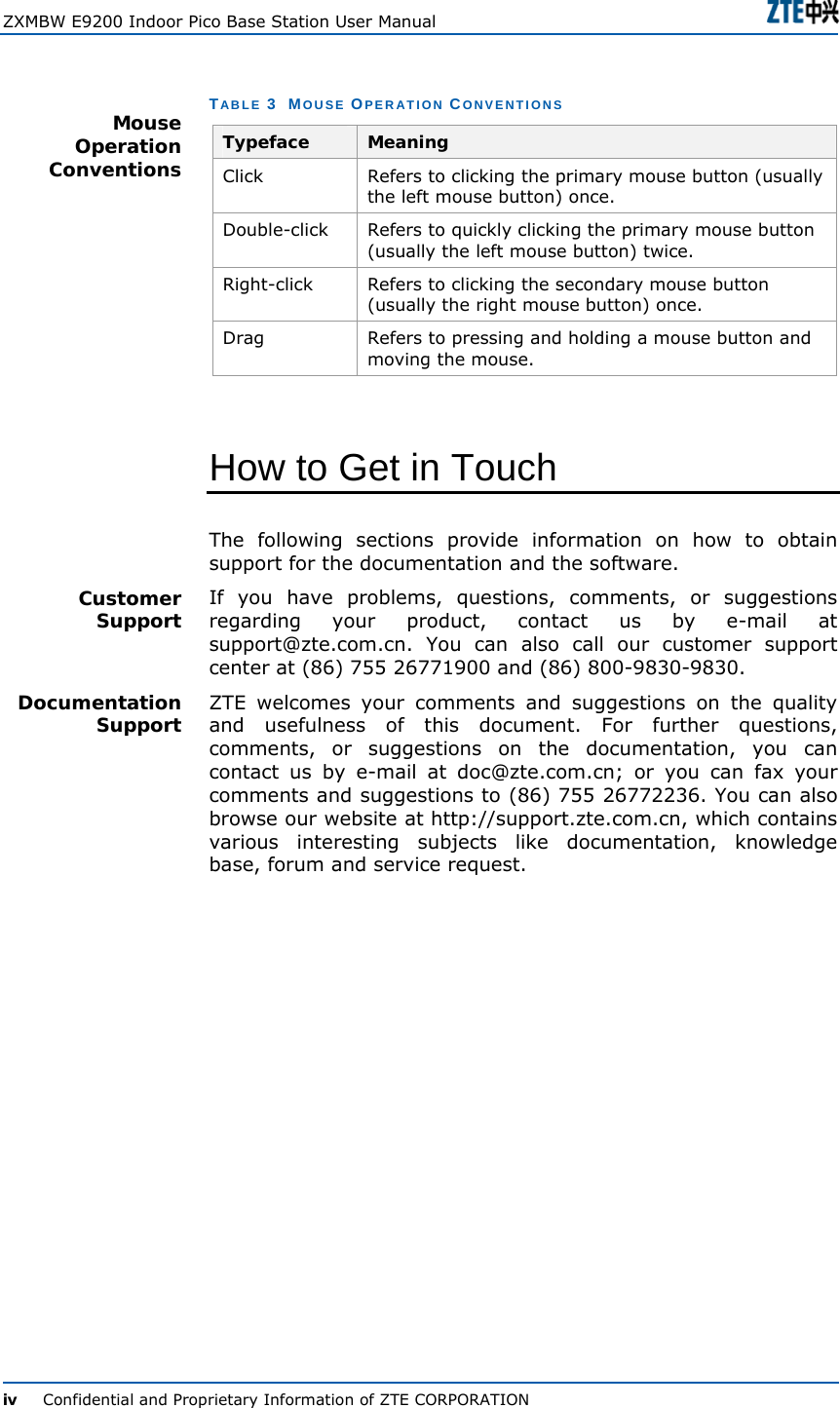
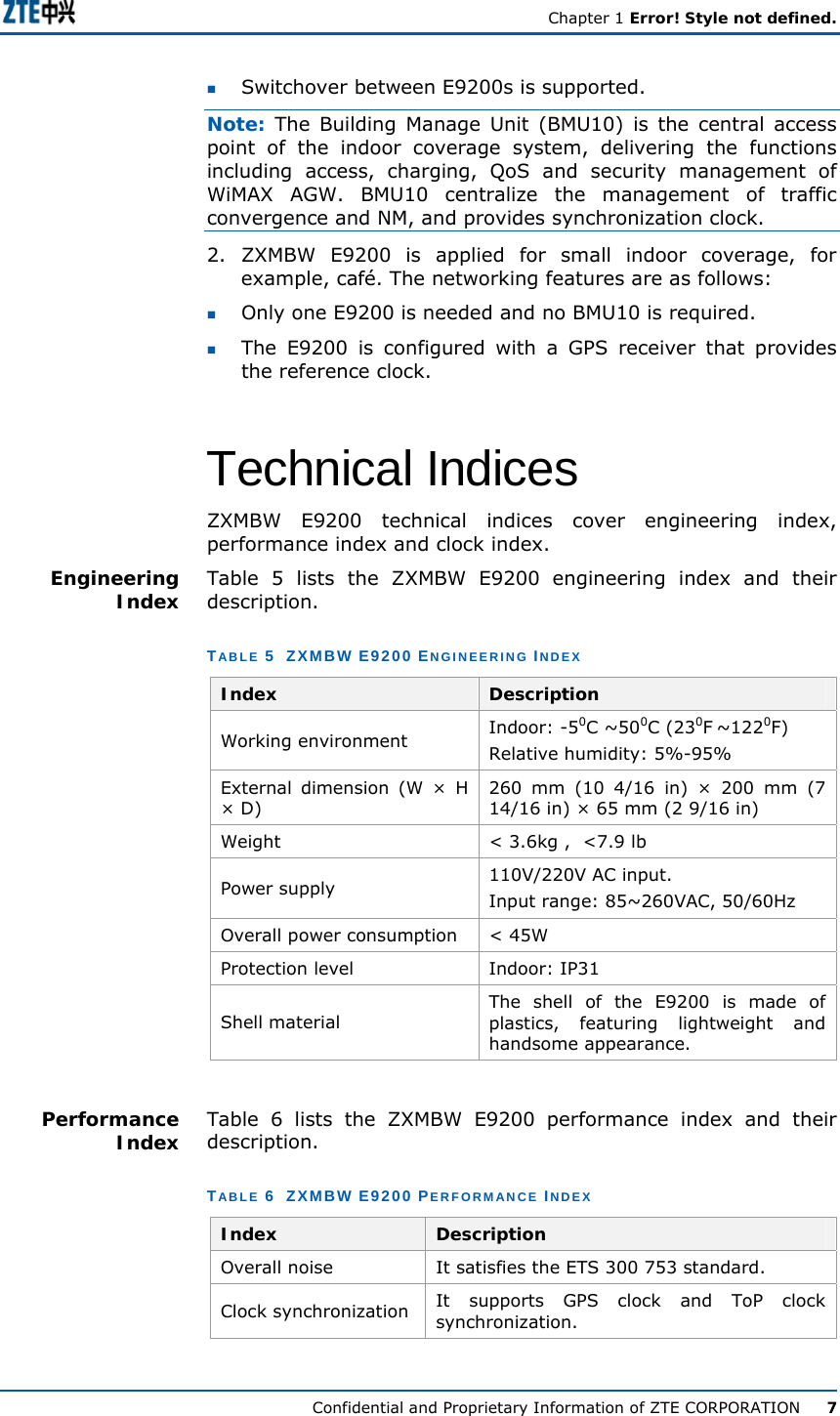
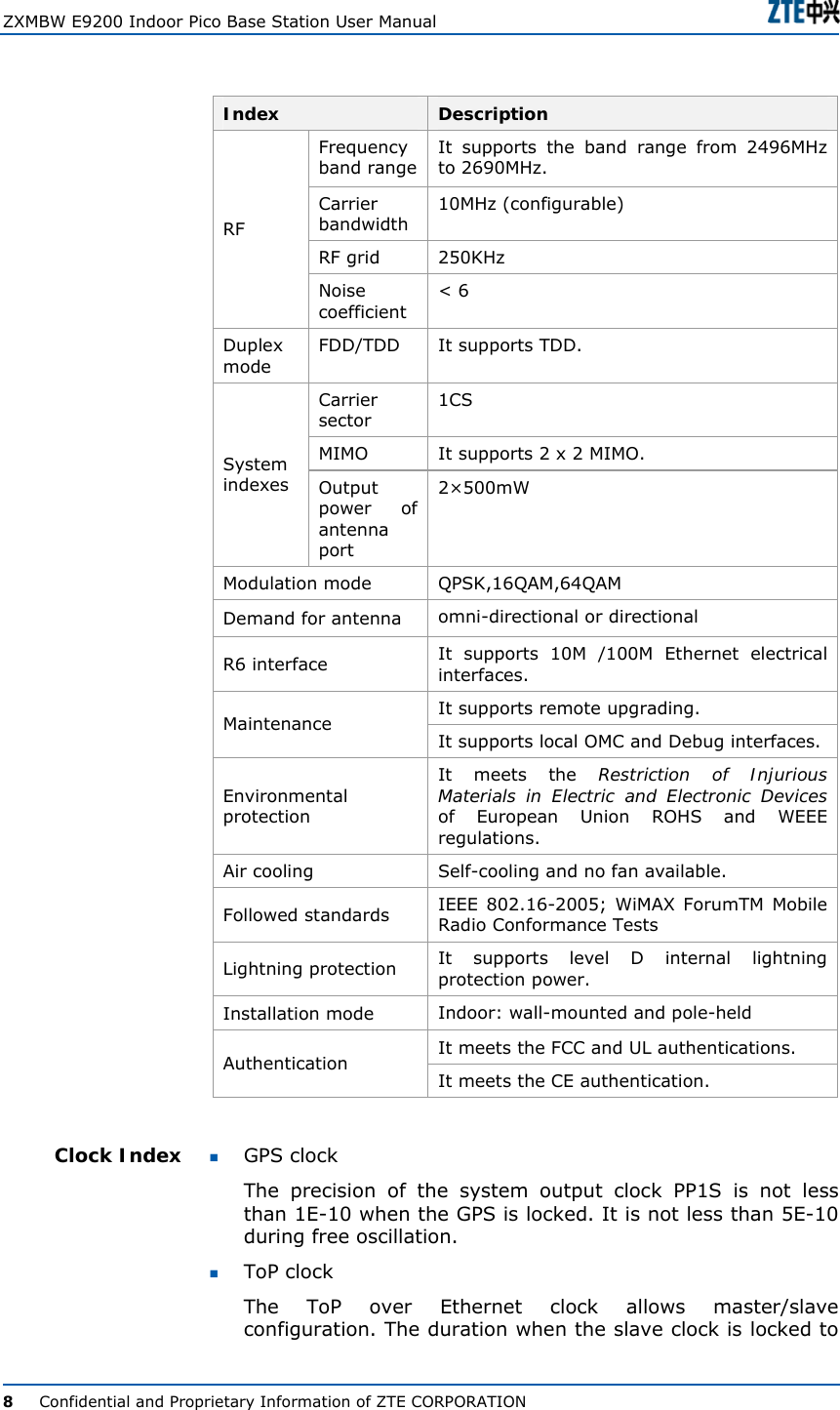
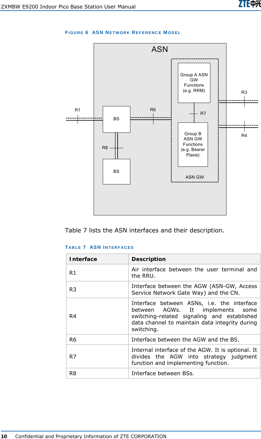
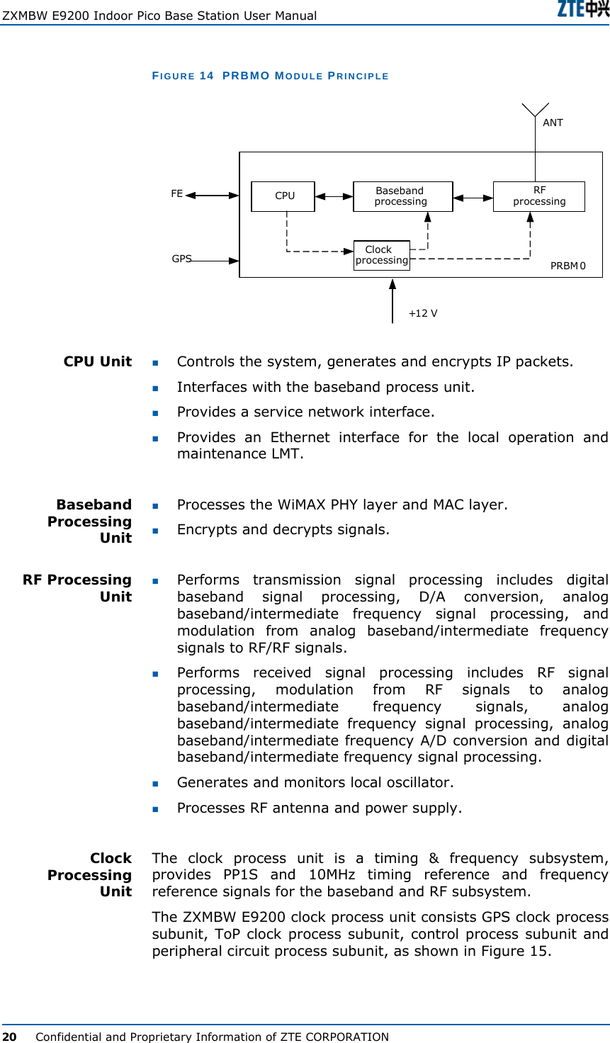
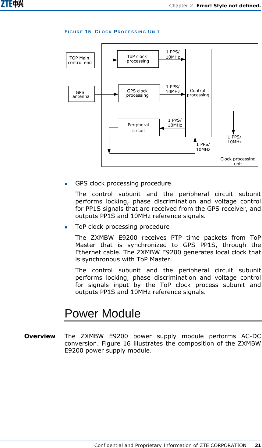
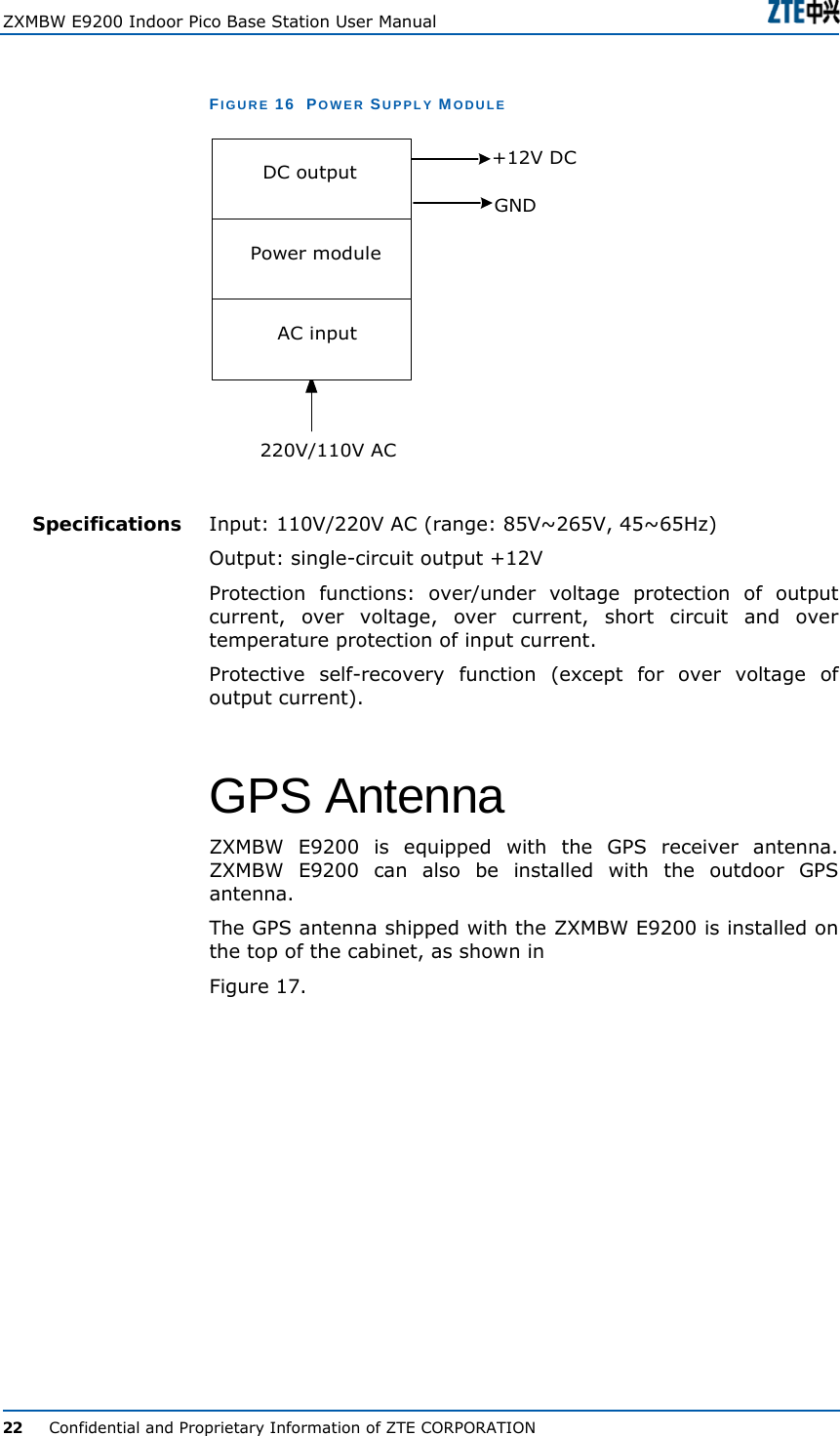
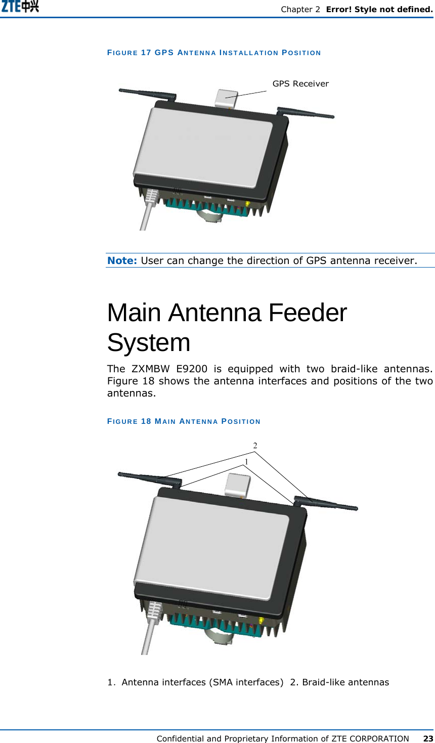
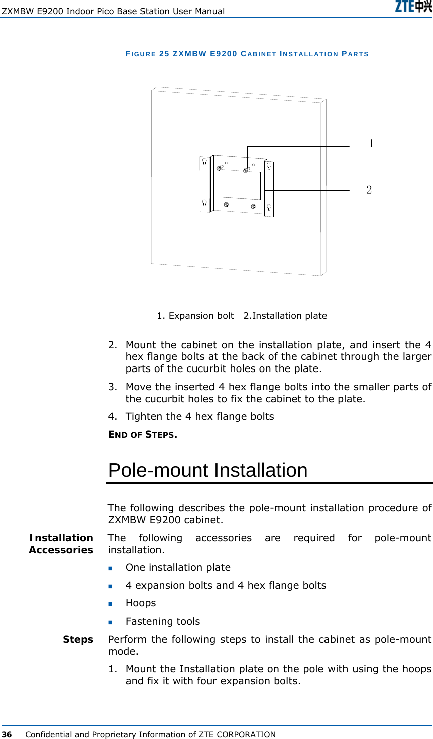
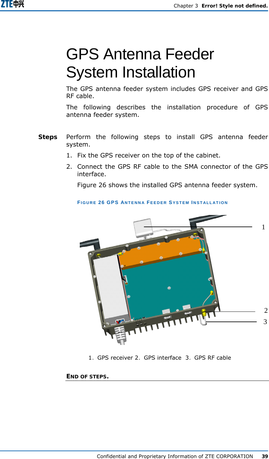
![Error! Style not defined. Confidential and Proprietary Information of ZTE CORPORATION iii TABLE 1 CHAPTER SUMMARY Chapter Summary Chapter 1 System Overview Introduces the ZXMBW E9200’s position, Functions, Principles, External and Internal interfaces, Applications and technical indices. Chapter 2 Hardware Description Describes Cabinet structure, Hardware modules, Main antenna feeder system and External cables. Chapter 3 Hardware Installation Describes detailed installation procedures of ZXMBW E9200’s cabinet, cables, main antenna feeder system, GPS antenna feeder system, and Hardware installation checking, Power-on and Power-off procedures. Conventions ZTE documents employ the following typographical conventions. TABLE 2 TYPOGRAPHICAL CONVENTIONS Typeface Meaning Italics References to other Manuals and documents. “Quotes” Links on screens. Bold Menus, menu options, function names, input fields, radio button names, check boxes, drop-down lists, dialog box names, window names. CAPS Keys on the keyboard and buttons on screens and company name. Constant width Text that you type, program code, files and directory names, and function names. [ ] Optional parameters. { } Mandatory parameters. | Select one of the parameters that are delimited by it. Note: Provides additional information about a certain topic. Checkpoint: Indicates that a particular step needs to be checked before proceeding further. Tip: Indicates a suggestion or hint to make things easier or more productive for the reader. Typographical Conventions](https://usermanual.wiki/ZTE/ZXMBW-E9200/User-Guide-1096778-Page-11.png)