ZTE ZXMBW-E9200 Indoor PICO Base Station User Manual Manual
ZTE Corporation Indoor PICO Base Station Manual
ZTE >
Manual

ZXMBW E9200
Indoor PICO Base Station
User Manual
Version 3.20.01.00
ZTE CORPORATION
ZTE Plaza, Keji Road South,
Hi-Tech Industrial Park,
Nanshan District, Shenzhen,
P. R. China
518057
Tel: (86) 755 26771900 800-9830-9830
Fax: (86) 755 26772236
URL: http://support.zte.com.cn
E-mail: doc@zte.com.cn

LEGAL INFORMATION
Copyright © 2006 ZTE CORPORATION.
The contents of this document are protected by copyright laws and international treaties. Any reproduction or
distribution of this document or any portion of this document, in any form by any means, without the prior written
consent of ZTE CORPORATION is prohibited. Additionally, the contents of this document are protected by
contractual confidentiality obligations.
All company, brand and product names are trade or service marks, or registered trade or service marks, of ZTE
CORPORATION or of their respective owners.
This document is provided “as is”, and all express, implied, or statutory warranties, representations or conditions
are disclaimed, including without limitation any implied warranty of merchantability, fitness for a particular purpose,
title or non-infringement. ZTE CORPORATION and its licensors shall not be liable for damages resulting from the
use of or reliance on the information contained herein.
ZTE CORPORATION or its licensors may have current or pending intellectual property rights or applications
covering the subject matter of this document. Except as expressly provided in any written license between ZTE
CORPORATION and its licensee, the user of this document shall not acquire any license to the subject matter
herein.
The contents of this document and all policies of ZTE CORPORATION, including without limitation policies related to
support or training are subject to change without notice.
Revision History
Date Revision No. Serial No. Reason for Revision
04/23/2008 R1.0 Sjzl20081067 First edition

ZTE CORPORATION
Values Your Comments & Suggestions!
Your opinion is of great value and will help us improve the quality of our product
documentation and offer better services to our customers.
Please fax to: (86) 755-26772236; or mail to Documentation R&D Department,
ZTE CORPORATION, ZTE Plaza, A Wing, Keji Road South, Hi-Tech Industrial Park,
Shenzhen, P. R. China 518057.
Thank you for your cooperation!
Document
Name ZXMBW E9200 Indoor Pico Base Station User Manual
Product Version V3.20.01.00 Document Revision
Number R1.0
Equipment Installation Date
Presentation:
(Introductions, Procedures, Illustrations, Completeness, Level of Detail, Organization,
Appearance)
Good Fair Average Poor Bad N/A
Accessibility:
(Contents, Index, Headings, Numbering, Glossary)
Good Fair Average Poor Bad N/A
Your evaluation
of this
documentation
Intelligibility:
(Language, Vocabulary, Readability & Clarity, Technical Accuracy, Content)
Good Fair Average Poor Bad N/A
Your
suggestions for
improvement of
this
documentation
Please check the suggestions which you feel can improve this documentation:
Improve the overview/introduction Make it more concise/brief
Improve the Contents Add more step-by-step procedures/tutorials
Improve the organization Add more troubleshooting information
Include more figures Make it less technical
Add more examples Add more/better quick reference aids
Add more detail Improve the index
Other suggestions
__________________________________________________________________________
__________________________________________________________________________
__________________________________________________________________________
__________________________________________________________________________
__________________________________________________________________________
# Please feel free to write any comments on an attached sheet.
If you wish to be contacted regarding your comments, please complete the following:
Name Company
Postcode Address
Telephone E-mail
This page is intentionally blank.

Contents
About this Manual............................................................. i
Purpose .................................................................................i
Notice ....................................................................................i
Intended Audience ................................................................. ii
Prerequisite Skill and Knowledge .............................................. ii
What is in This Manual ............................................................ ii
Conventions ......................................................................... iii
How to Get in Touch .............................................................. iv
Chapter 1..........................................................................1
System Overview.............................................................1
ZXMBW E9200 Position in WiMAX Network..........................2
ZXMBW E9200 Functions..................................................2
ZXMBW E9200 Appearance...............................................3
Fundamental Principle......................................................3
ZXMBW E9200 External Interfaces.....................................5
ZXMBW E9200 Application and Networking Scenario ............6
Technical Indices ............................................................7
Standards ......................................................................9
Interface Description .......................................................9
ASN Network Reference Model .................................................9
ZXMBW E9200 Interfaces ...................................................... 11
R1 Interface Description........................................................ 12
R6 Interface Description........................................................ 13
Chapter 2........................................................................17
Hardware Description....................................................17
ZXMBW E9200 Cabinet Structure..................................... 18
ZXMBW E9200 Hardware Modules ................................... 19
PRBMO Module..................................................................... 19
Power Module ...................................................................... 21
GPS Antenna ................................................................ 22
Main Antenna Feeder System.......................................... 23
External Cables............................................................. 25
Power Cable ........................................................................ 25
Grounding Cable.................................................................. 25
Ethernet Cable .................................................................... 26
GPS RF Cable ...................................................................... 26
Chapter 3........................................................................27
Hardware Installation....................................................27
Installation Components ................................................ 28
Installation Flow ........................................................... 28
Installation Precautions.................................................. 29
Installation Preparation.................................................. 30
Checking Installation Environment ......................................... 30
Checking Installation Position ................................................ 30
Checking Temperature and Humidity...................................... 30
Checking Power Supply ........................................................ 31
Checking Grounding Mode .................................................... 31
Other Checks ...................................................................... 31
Tools and Instruments Preparation......................................... 31
Unpacking Inspection ........................................................... 33
Acceptance and Handover..................................................... 33
Cabinet Installation ....................................................... 34
ZXMBW E9200 Cabinet Installation Introduction ...................... 34
Wall-mount Installation ........................................................ 35
Pole-mount Installation ........................................................ 36
External Cables Installation ............................................ 37
Grounding Cable Installation ................................................. 37
Ethernet Cable Installation.................................................... 38
Power Cable Installation ....................................................... 38
GPS RF Cable Installation ..................................................... 38
GPS Antenna Feeder System Installation .......................... 39
Main Antenna Feeder System Installation ......................... 40
Hardware Installation Check ........................................... 40
Cabinet Installation Check .................................................... 40
Cable Installation Check ....................................................... 41
Power and Grounding Cable Installation Check ........................ 41
Running Environment Check ..................................................42
Other Environment Check...................................................... 42
Power-on and Power-off Test .......................................... 42
Power-On Procedure ............................................................. 42
Power-Off Procedure............................................................. 42
Abbreviations.................................................................43
Figures............................................................................45
Tables.............................................................................47
Index..............................................................................49
This page is intentionally blank.

Confidential and Proprietary Information of ZTE CORPORATION i
About this Manual
Purpose
This Manual provides procedures and guidelines that support the
operation of the ZXMBW E9200 Indoor Pico Base Station.
This device complies with Part 15 of the FCC Rules. Operation is
subject to the following two conditions:
This device may not cause harmful interference.
This device must accept any interference received, including
interference that may cause undesired operation.
Notice
This equipment has been tested and found to comply with
the limits for a Class A digital device, pursuant to part 15 of
the FCC Rules. These limits are designed to provide
reasonable protection against harmful interference when the
equipment is operated in a commercial environment. This
equipment generates, uses, and can radiate radio frequency
energy and, if not installed and used in accordance with the
instruction manual, may cause harmful interference to radio
communications. Operation of this equipment in a residential
area is likely to cause harmful interference in which case the
user will be required to correct the interference at his own
expense.
Changes or modifications not expressly approved by the
party responsible for compliance could void the user’s
authority to operate the equipment.
Receivers associated with the operation of a licensed radio
service, e.g., FM broadcast under part 73 of this chapter,
land mobile operation under part 90, etc., shall bear the
following statement in a conspicuous location on the device:
This device complies with part 15 of the FCC Rules. Operation
is subject to the condition that this device does not cause
harmful interference.
ZXMBW E9200 Indoor Pico Base Station User Manual
ii Confidential and Proprietary Information of ZTE CORPORATION
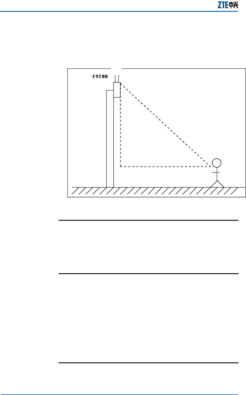
The installation methods of E9200 with two Braid-like
antennas are wall-mount installation and pole-mount installation,
about 2~3 meters height.
The safe distance between subscriber and E9200 is at least
20cm.
Intended Audience
This document is intended for engineers and technicians who
perform operation activities on the ZXMBW E9200 Indoor Pico
Base Station.
Prerequisite Skill and Knowledge
To use this document effectively, users should have a general
understanding of wireless telecommunications technology.
Familiarity with the following is helpful:
the ZXMBW E9200 system and its various components
user interfaces on the ZXMBW E9200 Indoor Pico Base
Station.
local operating procedures
What is in This Manual
This Manual contains the following chapters:
Error! Style not defined.
Confidential and Proprietary Information of ZTE CORPORATION iii
TABLE 1 CHAPTER SUMMARY
Chapter Summary
Chapter 1 System
Overview
Introduces the ZXMBW E9200’s position,
Functions, Principles, External and Internal
interfaces, Applications and technical
indices.
Chapter 2 Hardware
Description
Describes Cabinet structure, Hardware
modules, Main antenna feeder system and
External cables.
Chapter 3 Hardware
Installation
Describes detailed installation procedures
of ZXMBW E9200’s cabinet, cables, main
antenna feeder system, GPS antenna
feeder system, and Hardware installation
checking, Power-on and Power-off
procedures.
Conventions
ZTE documents employ the following typographical conventions.
TABLE 2 TYPOGRAPHICAL CONVENTIONS
Typeface Meaning
Italics References to other Manuals and documents.
“Quotes” Links on screens.
Bold Menus, menu options, function names, input
fields, radio button names, check boxes, drop-
down lists, dialog box names, window names.
CAPS Keys on the keyboard and buttons on screens
and company name.
Constant width Text that you type, program code, files and
directory names, and function names.
[ ] Optional parameters.
{ } Mandatory parameters.
| Select one of the parameters that are delimited
by it.
Note: Provides additional information about a
certain topic.
Checkpoint: Indicates that a particular step needs
to be checked before proceeding further.
Tip: Indicates a suggestion or hint to make things
easier or more productive for the reader.
Typographical
Conventions

ZXMBW E9200 Indoor Pico Base Station User Manual
iv Confidential and Proprietary Information of ZTE CORPORATION
TABLE 3 MOUSE OPERATION CONVENTIONS
Typeface Meaning
Click Refers to clicking the primary mouse button (usually
the left mouse button) once.
Double-click Refers to quickly clicking the primary mouse button
(usually the left mouse button) twice.
Right-click Refers to clicking the secondary mouse button
(usually the right mouse button) once.
Drag Refers to pressing and holding a mouse button and
moving the mouse.
How to Get in Touch
The following sections provide information on how to obtain
support for the documentation and the software.
If you have problems, questions, comments, or suggestions
regarding your product, contact us by e-mail at
support@zte.com.cn. You can also call our customer support
center at (86) 755 26771900 and (86) 800-9830-9830.
ZTE welcomes your comments and suggestions on the quality
and usefulness of this document. For further questions,
comments, or suggestions on the documentation, you can
contact us by e-mail at doc@zte.com.cn; or you can fax your
comments and suggestions to (86) 755 26772236. You can also
browse our website at http://support.zte.com.cn, which contains
various interesting subjects like documentation, knowledge
base, forum and service request.
Mouse
Operation
Conventions
Customer
Support
Documentation
Support

Error! Style not defined.
Confidential and Proprietary Information of ZTE CORPORATION v
This page is intentionally blank.

Confidential and Proprietary Information of ZTE CORPORATION 1
Chapter 1
System Overview
This chapter describes:
ZXMBW E9200 position in WiMAX network
ZXMBW E9200 functions
ZXMBW E9200 appearance
Fundamental principle
ZXMBW E9200 application and networking scenario
Technical indices
Standards
Interface description
ZXMBW E9200 Indoor Pico Base Station User Manual
2 Confidential and Proprietary Information of ZTE CORPORATION
ZXMBW E9200 Position in
WiMAX Network
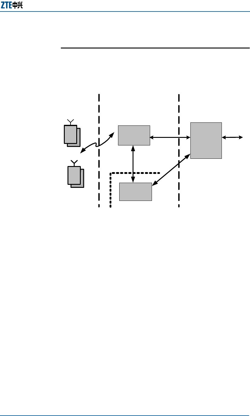
The ZXMBW E9200 is located at the radio access layer of the
WIMAX network, delivering broadband radio access services for
terminal users. The ZXMBW E9200, as a supplement for blind
points and hotspots of macro coverage, is mainly applied for
middle-scale and small-scale indoor coverage, such as airport,
shopping mall and conference center and so on.
Figure 1 illustrates the position of the ZXMBW E9200 in the
WIMAX network.
FIGURE 1 ZXMBW E9200 IN WIMAX NETWORK
ZXMBW E9200 Functions
The ZXMBW E9200 receives IP packets from the core
network, decrypts these packets and then sends them to the
baseband module to encode and modulate.
The modulated signals are sent to the TX link for up
conversion afterwards, power amplifier (PA) amplifies the
signal, and then transmitted by the antenna.
The ZXMBW E9200 supports forward auto-scale and manual
scale.
The ZXMBW E9200 receives signals from terminals, sends
them to the RX link for down conversion and then transmits
them to the baseband module for channel demodulation.
The baseband module demodulates the encrypted signals,
and converts as IP packets, and then the IP packets are
transmitted to the core network through the R6 interface.
Reverse RSSI function.
Reverse automatic gain control function.
Overview
Position in
WiMAX
Network
Forward Signal
Processing
Reverse Signal
Processing
Chapter 1 Error! Style not defined.
Confidential and Proprietary Information of ZTE CORPORATION 3
The ZXMBW E9200 generates PP1S synchronization signals.
The ZXMBW E9200 generates TDD sequential control signals.
The ZXMBW E9200 supports power supply and temperature
monitoring.
The ZXMBW E9200 delivers version monitoring and version
management functions.
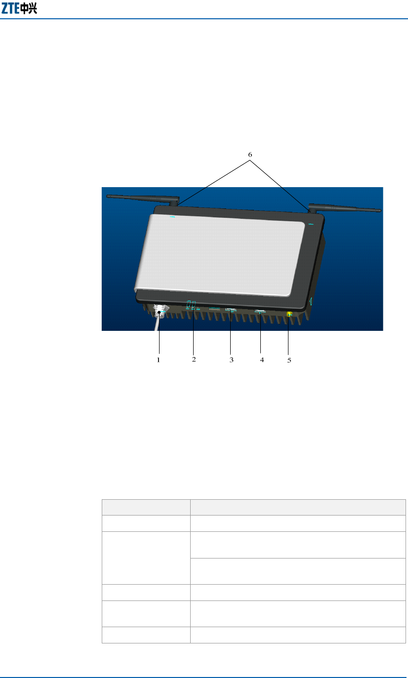
ZXMBW E9200 Appearance
The ZXMBW E9200 contains only one cabinet. The external
dimension of the cabinet is (W x H x D):260mm (10 4/16 in) x
200mm (7 14/16 in) x 65mm (2 9/16 in). The internal
dimension of the cabinet is (W x H x D): 246mm (9 11/16 in) ×
184mm (7 4/16 in) × 23.5mm (1/16 in).
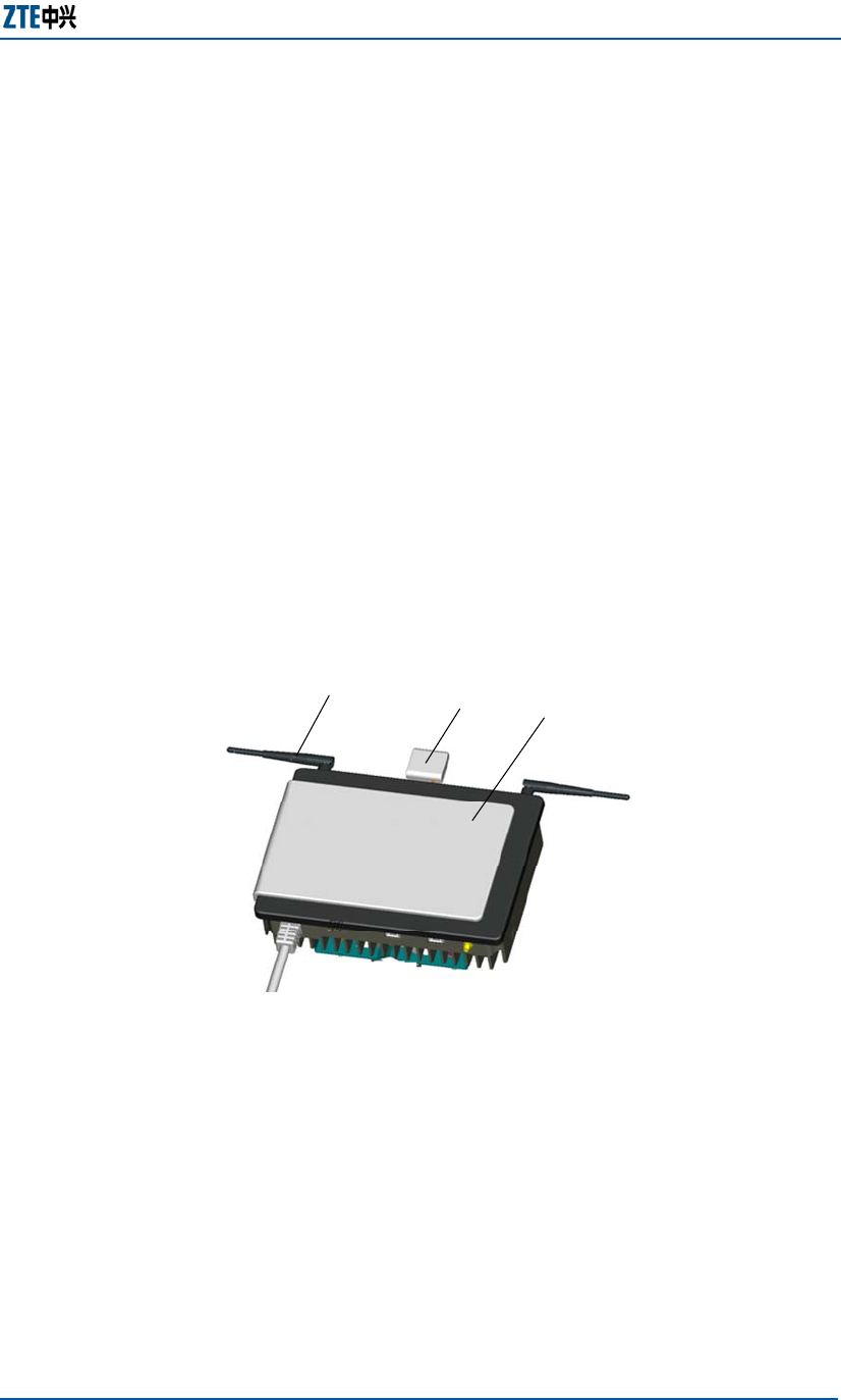
The ZXMBW E9200 comprises two braid-like antennas, one GPS
receiver (GPS receiver does not need to be configured when ToP
clock reference is adopted) and one cabinet. Figure 2 shows the
appearance of the ZXMBW E9200.
FIGURE 2 ZXMBW E9200 APPEARANCE
123
1. Braid-like antenna 2. GPS receiver (optional) 3. Cabinet.
Fundamental Principle
The ZXMBW E9200 is located at the radio access layer of the
WIMAX network, as a radio network base station lying between
terminal users and AGW. Functionally E9200 is composed of
baseband processing unit, radio frequency (RF) processing unit,
CPU control center and clock processing unit.
Other
Functions
Dimensions
Components
ZXMBW E9200 Indoor Pico Base Station User Manual
4 Confidential and Proprietary Information of ZTE CORPORATION
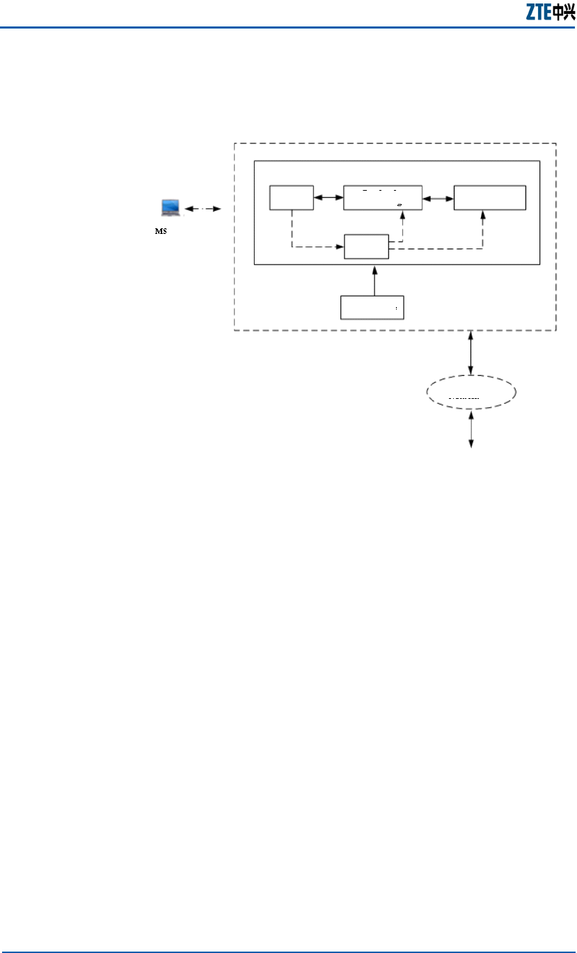
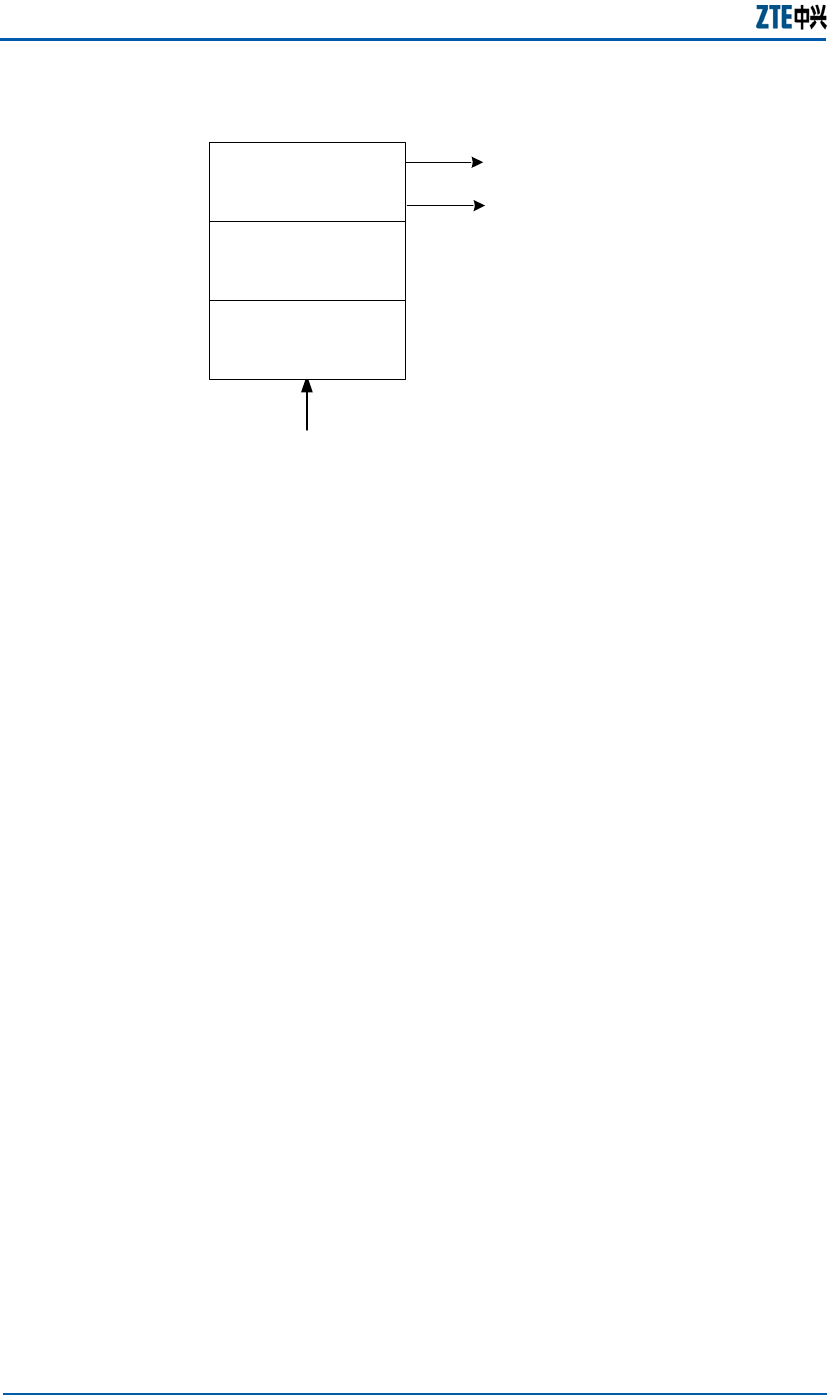
Figure 3 illustrates the functional components of ZXMBW E9200
FIGURE 3 ZXMBW E9200 FUNCTIONAL COMPONENTS
CPU Baseband
Processing
KP
Processing
Timing
Power
Module
Transmission
Network
Baseband RF Module
E9200
AGW
The ZXMBW E9200 processes the following basic traffics:
Forward traffic: The forward traffic from the core network
sends IP packets to the ZXMBW E9200. After decrypting and
unpacking these IP packets, the ZXMBW E9200 CPU control unit
transmits them to the baseband processing unit for encoding
and modulation. The modulated signals are sent to the RF
processing unit for up conversion. After being processed for
power amplification, these signals are transmitted through the
antenna to user terminals.
Reverse traffic: the antenna of the ZXMBW E9200 receives the
signals from user terminals. The RF processing unit performs
down conversion for these signals and then sends them to the
baseband processing unit for channel demodulation. Afterwards,
the CPU control unit converts these signals into IP packets and
encrypts them, and then sends them to the core network
through the transmission network.
Functional
Components
Functional
Process
Chapter 1 Error! Style not defined.
Confidential and Proprietary Information of ZTE CORPORATION 5
ZXMBW E9200 External
Interfaces
Figure 4 shows the external interfaces of ZXMBW E9200.
FIGURE 4 ZXMBW E9200 EXTERNAL INTERFACES
1.Power interface 2.Indicators and Reset 3.NM interface
4.R6 interface 5. GPS interface 6. RF interfaces
Table 4 lists the ZXMBW E9200 external interfaces and their
descriptions.
TABLE 4 EXTERNAL INTERFACES AND DESCRIPTIONS
Interface Description
Power interface 110V/220V AC power input interface
The power indicator indicates whether the
system is powered on normally.
Indicators The system operation indicator indicates
whether the system runs normally.
Reset Resets the cabinet
NM interface It is an Ethernet interface, serving to connect
the local network management LMT.
R6 interface It is an Ethernet interface, serving to connect an
Interfaces
Description
ZXMBW E9200 Indoor Pico Base Station User Manual
6 Confidential and Proprietary Information of ZTE CORPORATION
Interface Description
AGW or a BMU10.
GPS interface It is an SMA interface, serving to connect a GPS
receiver.
RF interfaces
They are SMA interfaces, serving to connect the
two braid-like antennas that the ZXMBW E9200
is equipped or external antennas.
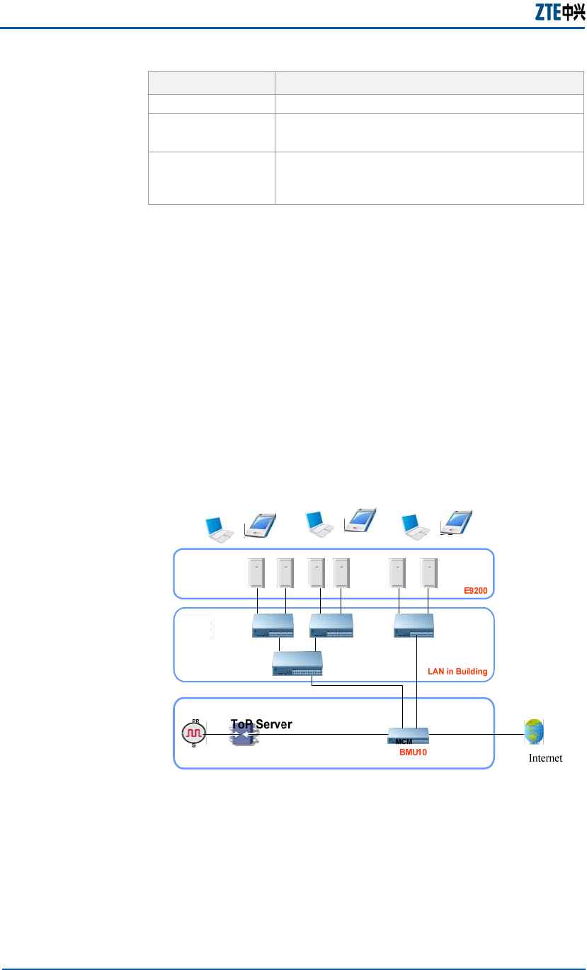
ZXMBW E9200 Application
and Networking Scenario
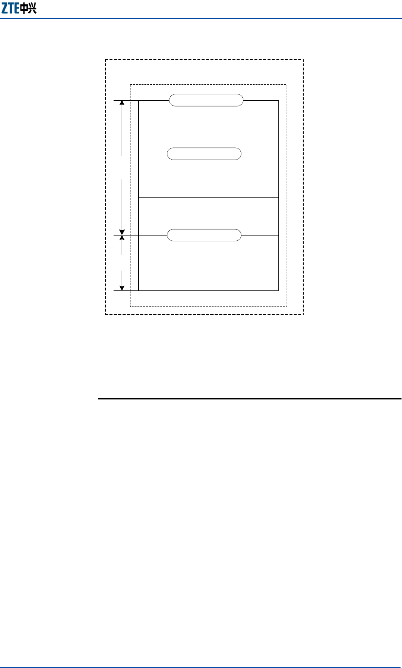
As an indoor product, the ZXMBW E9200 is often used in two
scenarios.
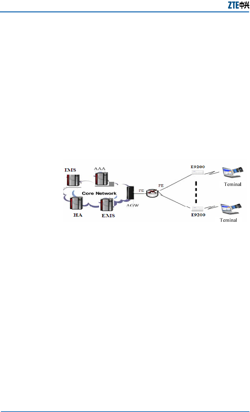
1. ZXMBW E9200 is applied for indoor or hot spot coverage, for
example, airport and conference center. This scenario
requires large capacity and extensive coverage. More than
one ZXMBW E9200s are required. Figure 5 shows the
networking structure.
FIGURE 5 ZXMBW E9200 EXTERNAL INTERFACES
The networking features are as follows:
Only the BMU10 is configured with the GPS receiver that is
provided for the E9200 in the ToP (Timing Over Packet)
mode.
Generally the BMU10 and E9200 are in the same building or
same campus.
The number of cascading levels between BMU10 and E9200
must be 5 at most.

Chapter 1 Error! Style not defined.
Confidential and Proprietary Information of ZTE CORPORATION 7
Switchover between E9200s is supported.
Note: The Building Manage Unit (BMU10) is the central access
point of the indoor coverage system, delivering the functions
including access, charging, QoS and security management of
WiMAX AGW. BMU10 centralize the management of traffic
convergence and NM, and provides synchronization clock.
2. ZXMBW E9200 is applied for small indoor coverage, for
example, café. The networking features are as follows:
Only one E9200 is needed and no BMU10 is required.
The E9200 is configured with a GPS receiver that provides
the reference clock.
Technical Indices
ZXMBW E9200 technical indices cover engineering index,
performance index and clock index.
Table 5 lists the ZXMBW E9200 engineering index and their
description.
TABLE 5 ZXMBW E9200 ENGINEERING INDEX
Index Description
Working environment Indoor: -50C ~500C (230F ~1220F)
Relative humidity: 5%-95%
External dimension (W × H
× D)
260 mm (10 4/16 in) × 200 mm (7
14/16 in) × 65 mm (2 9/16 in)
Weight < 3.6kg , <7.9 lb
Power supply 110V/220V AC input.
Input range: 85~260VAC, 50/60Hz
Overall power consumption < 45W
Protection level Indoor: IP31
Shell material
The shell of the E9200 is made of
plastics, featuring lightweight and
handsome appearance.
Table 6 lists the ZXMBW E9200 performance index and their
description.
TABLE 6 ZXMBW E9200 PERFORMANCE INDEX
Index Description
Overall noise It satisfies the ETS 300 753 standard.
Clock synchronization It supports GPS clock and ToP clock
synchronization.
Engineering
Index
Performance
Index

ZXMBW E9200 Indoor Pico Base Station User Manual
8 Confidential and Proprietary Information of ZTE CORPORATION
Index Description
Frequency
band range
It supports the band range from 2496MHz
to 2690MHz.
Carrier
bandwidth
10MHz (configurable)
RF grid 250KHz
RF
Noise
coefficient
< 6
Duplex
mode
FDD/TDD It supports TDD.
Carrier
sector
1CS
MIMO It supports 2 x 2 MIMO.
System
indexes Output
power of
antenna
port
2×500mW
Modulation mode QPSK,16QAM,64QAM
Demand for antenna omni-directional or directional
R6 interface It supports 10M /100M Ethernet electrical
interfaces.
It supports remote upgrading.
Maintenance It supports local OMC and Debug interfaces.
Environmental
protection
It meets the Restriction of Injurious
Materials in Electric and Electronic Devices
of European Union ROHS and WEEE
regulations.
Air cooling Self-cooling and no fan available.
Followed standards IEEE 802.16-2005; WiMAX ForumTM Mobile
Radio Conformance Tests
Lightning protection It supports level D internal lightning
protection power.
Installation mode Indoor: wall-mounted and pole-held
It meets the FCC and UL authentications.
Authentication It meets the CE authentication.
GPS clock
The precision of the system output clock PP1S is not less
than 1E-10 when the GPS is locked. It is not less than 5E-10
during free oscillation.
ToP clock
The ToP over Ethernet clock allows master/slave
configuration. The duration when the slave clock is locked to
Clock Index

Chapter 1 Error! Style not defined.
Confidential and Proprietary Information of ZTE CORPORATION 9
the master clock is shorter than 10min. The phase difference
between the master and slave PP1Ss is less than 5us and
jittering is less than 20ns.
Standards
The ZXMBW-E9200 complies with the following standards:
IEEE Standard 802.16-2005,Part 16: Air Interface for Fixed
and Mobile Broadband Wireless Access Systems.
WiMAX ForumTM Mobile Radio Conformance Tests (MRCT).
WiMAX ForumTM Mobile Protocol Implementation
Conformance Statement (PICS).
WiMAX ForumTM Mobile System Profile
IEE1588 Standard for a Precision Clock Synchronization
Protocol for Networked Measurement and Control Systems.
In addition, the ZXMBW-E9200 complies with Part 15 of the FCC
Rules. Operation is subject to the following two conditions:
The ZXMBW-E9200 may not cause harmful interference.
The ZXMBW-E9200 must accept any interference received,
including interference that may cause undesired operation.
Interface Description
The ZXMBW E9200 supports R1 interface, R6 interface and R8
interface. Hereafter gives the detailed description of these
interfaces.
ASN Network Reference Model
Figure 6 illustrates the ASN network reference model developed
by the WiMAX (Worldwide Interoperability for Microwave Access)
NWG (NetWork Group).
ZXMBW E9200 Indoor Pico Base Station User Manual
10 Confidential and Proprietary Information of ZTE CORPORATION
FIGURE 6 ASN NETWORK REFERENCE MODEL
ASN
Group A ASN
GW
Functions
(e.g. RRM)
R6
BS
BS
R8
R1
Group B
ASN GW
Functions
(e.g. Bearer
Plane)
R7
R3
R4
ASN GW
Table 7 lists the ASN interfaces and their description.
TABLE 7 ASN INTERFACES
Interface Description
R1 Air interface between the user terminal and
the RRU.
R3 Interface between the AGW (ASN-GW, Access
Service Network Gate Way) and the CN.
R4
Interface between ASNs, i.e. the interface
between AGWs. It implements some
switching-related signaling and established
data channel to maintain data integrity during
switching.
R6 Interface between the AGW and the BS.
R7
Internal interface of the AGW. It is optional. It
divides the AGW into strategy judgment
function and implementing function.
R8 Interface between BSs.
Chapter 1 Error! Style not defined.
Confidential and Proprietary Information of ZTE CORPORATION 11
ZXMBW E9200 Interfaces
The ZXMBW E9200 reference network is illustrated in Figure 7.
FIGURE 7 ZXMBW E9200 NETWORK REFERENCE MODEL
MS
MS E 9200
MS
MS AGW
E 9200
R1
R8
R6
R1 interface
R1 interface is the air interface between the BS and the MS,
including MAC layer, physical layer and relevant
management plane. It complies with the 802.16e protocol.
R6 interface
R6 interface is between the BS and the AGW. It includes:
Data plane
Data plane is the IP tunnel between the AGW and the BS,
used to differentiate traffic flows required by different
Quality of Service (QoS).
Control plane
Control plane delivers tunnel management,
Authentication, Authorization, Accounting (AAA) and
Radio Resource Management (RRM).
R8 interface
R8 interface is between BSs to deliver quick and seamless
switch-over.
Overview
Interfaces and
description

ZXMBW E9200 Indoor Pico Base Station User Manual
12 Confidential and Proprietary Information of ZTE CORPORATION
R1 Interface Description
The following describes the R1 interface, including R1 message
format, protocol stack and physical layer.
Table 8 describes the MAC management message format of the
R1 interface.
TABLE 8 R1 MESSAGE FORMAT
Content Description
Message Type
The first field of every management message is
Message Type. To know the value of this field, see
the content of MAC management message in the
protocol.
Non-TLV field
This field is sequenced strictly according to the
definition of message format. The corresponding
values of various fields are sorted strictly
according to the sequence defined by the message
format.
TLV field
This field is a triple field, i.e. type-length-value.
The message sorts the triple of such field
according to the actual situation.
The R1 interface contains MAC layer and physical layer.
The MAC layer includes three sub-layers, that is, service-specific
Convergence Sub-layer (CS), MAC Common Part Sub-layer (MAC
CPS) and security sub-layer in the top-down sequence.
The CS sub-layer converts/maps the external data received
by CS-SAP into MAC SDU and transmits the data to MAC CPS
through MAC SAP. The sub-layer classifies external Service
Data Units (SDUs) and associates them with proper SFIDs
and CIDs. It supports the payload head compression function
and provides various service-specific convergence sub-layer
specifications for different external protocol interfaces.
The MAC CPS sub-layer does not resolve the payload at the
CS sub-layer. The MAC CPS subl-ayer delivers the core
functions of the MAC layer, including bandwidth request,
connection setup and maintenance. It receives data of
various CS sub-layers through the MAC SAP and classifies
these data by different MAC connections. Its QoS is applied
to transmission and schedule above the physical layer.
The MAC layer contains an independent security sub-layer
that serves for authentication, safe key exchange and
encryption.
The physical layer is defined by multiple specifications, each of
which corresponds to a specific frequency range and application.
Figure 8 illustrates the R1 interface protocol stack.
R1 Message
Format
Protocol Stack
Chapter 1 Error! Style not defined.
Confidential and Proprietary Information of ZTE CORPORATION 13
FIGURE 8 R1 INTERFACE PROTOCOL STACK
CS SAP
MAC SAP
PHY SAP
Service Specifice
convergence Sub-layer
(CS)
MAC Common Part
Sub-layer (MAC CPS)
Security Sub-layer
Physical Layer
(PHY)
Scope of Standard
Data/Control Plane
PHY MAC
The R1 interface physical layer adopts Orthogonal Frequency
Division Multiplexing (OFDM) mode.
R6 Interface Description
This following describes the R6 interface including signaling
transmission mode and message format of the control plane.
The signaling between the BS and the ASN-GW is transmitted
through the R6 tunnel in the format of User Datagram Protocol
(UDP) plus the signaling format defined by NWG stage 3. The
media plane data is over the encapsulation tunnel protocol, in
which the UDP bears R6 signaling. Generic Routing
Encapsulation (GRE), Multiple Protocol Label Switching (MPLS)
and Virtual Local Area Network (VLAN) can be the bearer of R6
data.
The ASN-GW terminates the R6 tunnel from the BS. Various
encapsulation technologies such as GRE, MPLS and VLAN can be
adopted to implement the R6 tunnel. Different tunnel
granularities are allowable. The R6 data path supports
encapsulation protocol and tunnel granularity negotiation.
Figure 9 illustrates control plane message format of R6 interface.
Physical Layer
Signaling
Transmission
Mode
Control Plane
Message
Format
ZXMBW E9200 Indoor Pico Base Station User Manual
14 Confidential and Proprietary Information of ZTE CORPORATION
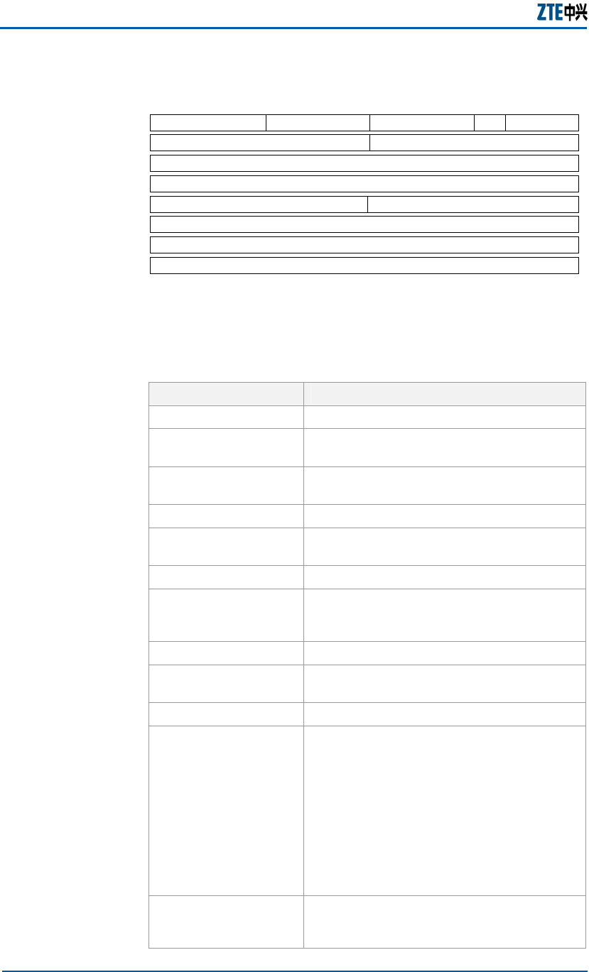
FIGURE 9 CONTROL PLANE MESSAGE FORMAT
Version
MSID
Flags Function Type Message Type
MSIDLength
Reserved
Transaction ID Reserved
TLVs
Source Identifier TLV
Destination Identifier TLV
08
16 24 31
OP ID
27
Table 9 lists description of the field in R6 control plane message
(ordered by byte).
TABLE 9 R6 CONTROL PLANE MESSAGE FIELDS AND DESCRIPTION
Field Description
Version Protocol version Number.
Flags Byte length with detailed format is given in
Figure 10.
Function Type Indicates functions, for example, HO
Control.
OP ID Indicates operation type.
Message Type: Message type corresponding to Function
Type, for example, HO_Req
Length Message length, including message head
MSID
MAC address of the message-related to MS.
If it is not related with any specific MS, all
bits of this field are set to 0.
Reserved 32 reserved bits set to 0.
Transaction ID Transaction ID. If it is 0, the message
should be discarded.
Reserved Reserved bit set to 0.
Destination Identifier
TLV
(Type/Length/Value)
Length-variable destination entity identifier.
For example, the destination to which the
message is to be sent is the network node
ID of a functional entity. The message
receiver checks whether the Destination
Identifier in the message head is the same
as its own identifier before accepting the
message. If yes, the receiver will process
this message. If no, the receiver will transit
the message to the destination identifier
without changing it.
Source Identifier TLV
Length-variable source entity identifier, for
example, the network ID of a functional
entity originating the message.
Chapter 1 Error! Style not defined.
Confidential and Proprietary Information of ZTE CORPORATION 15
Field Description
TLVs A triplet following the message head.
Figure 10 illustrates the detailed format of the flag field.
FIGURE 10 FLAG FIELDS FORMAT
Trrrrrr R
Table 10 Flag Fields and Description lists the flag fields and
their description.
TABLE 10 FLAG FIELDS AND DESCRIPTION
Bit Description
r Reserved bit that must be set to 0. The receiver
should ignore the reserved bit.
T If this bit is configured, the message should contain
Source Identifier TLV and Destination Identifier TLV.
R Used to reset the next expected Transaction ID.
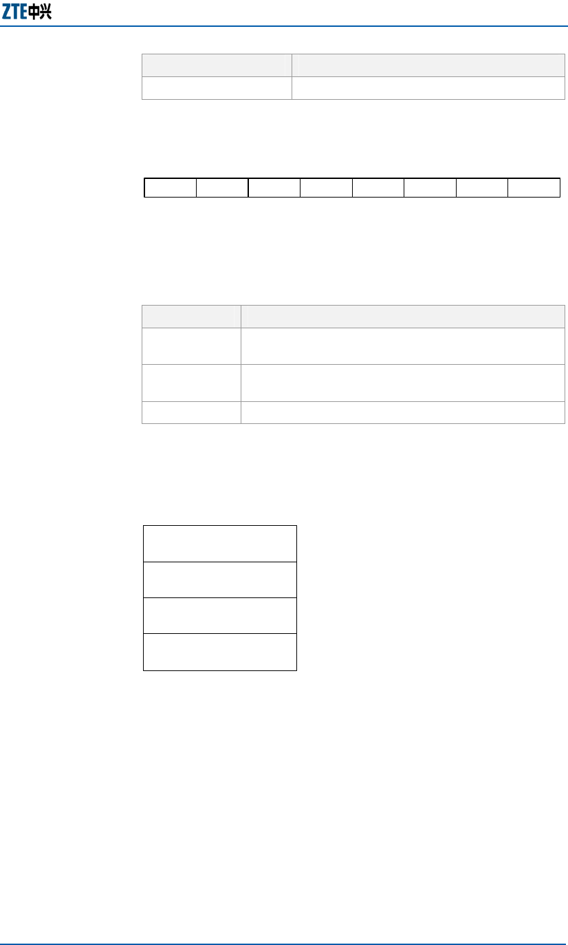
Figure 11 illustrates the structure control plane protocol stack.
FIGURE 11 CONTROL PLANE PROTOCOL STACK
IP
UDP
Control
Message
L2 Connectivity
A logical connectivity between L2 of two control plane protocol
stack enables communications between the two functional
entities. The encapsulation of IP packets between the two
functional entities relies on the connectivity type, e.g. GRE
tunnel. The seal of the encapsulated packet contains address
information, which ensures that the packet can be sent to the
correct physical entity.
The physical layer of the R6 interface supports packet access
and Time Division Multiplexing (TDM) access.
Packet access: 100MBps FE electrical port
TDM access: E1/T1, E3/T3 electrical port, OC-3 optical port.
Control Plane
Protocol Stack
Physical Layer

ZXMBW E9200 Indoor Pico Base Station User Manual
16 Confidential and Proprietary Information of ZTE CORPORATION
This page is intentionally blank.

Confidential and Proprietary Information of ZTE CORPORATION 17
Chapter 2
Hardware Description
This chapter describes:
ZXMBW E9200 cabinet structure
ZXMBW E9200 hardware modules
Main antenna feeder system
External cables
ZXMBW E9200 Indoor Pico Base Station User Manual
18 Confidential and Proprietary Information of ZTE CORPORATION
ZXMBW E9200 Cabinet
Structure
The ZXMBW E9200 is composed of one cabinet, two braid-like
antennas and one GPS receiver (optional) is shown in Figure 2.
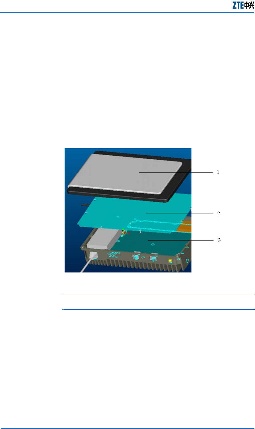
The ZXMBW E9200 cabinet comprises a top, a shield cover plate
and a bottom shell.
Figure 12 shows the structure of ZXMBW E9200 cabinet.
FIGURE 12 ZXMBW E9200 CABINET STRUCTURE
1. Top 2. Shield cover plate 3. Bottom shell
Caution: Do not open the ZXMBW E9200 cabinet. Contact ZTE
engineers to open it for maintenance.
Chapter 2 Error! Style not defined.
Confidential and Proprietary Information of ZTE CORPORATION 19
ZXMBW E9200 Hardware
Modules
The ZXMBW E9200 is composed of one cabinet, two braid-like
antennas and one GPS receiver (optional) is shown in Figure 2.
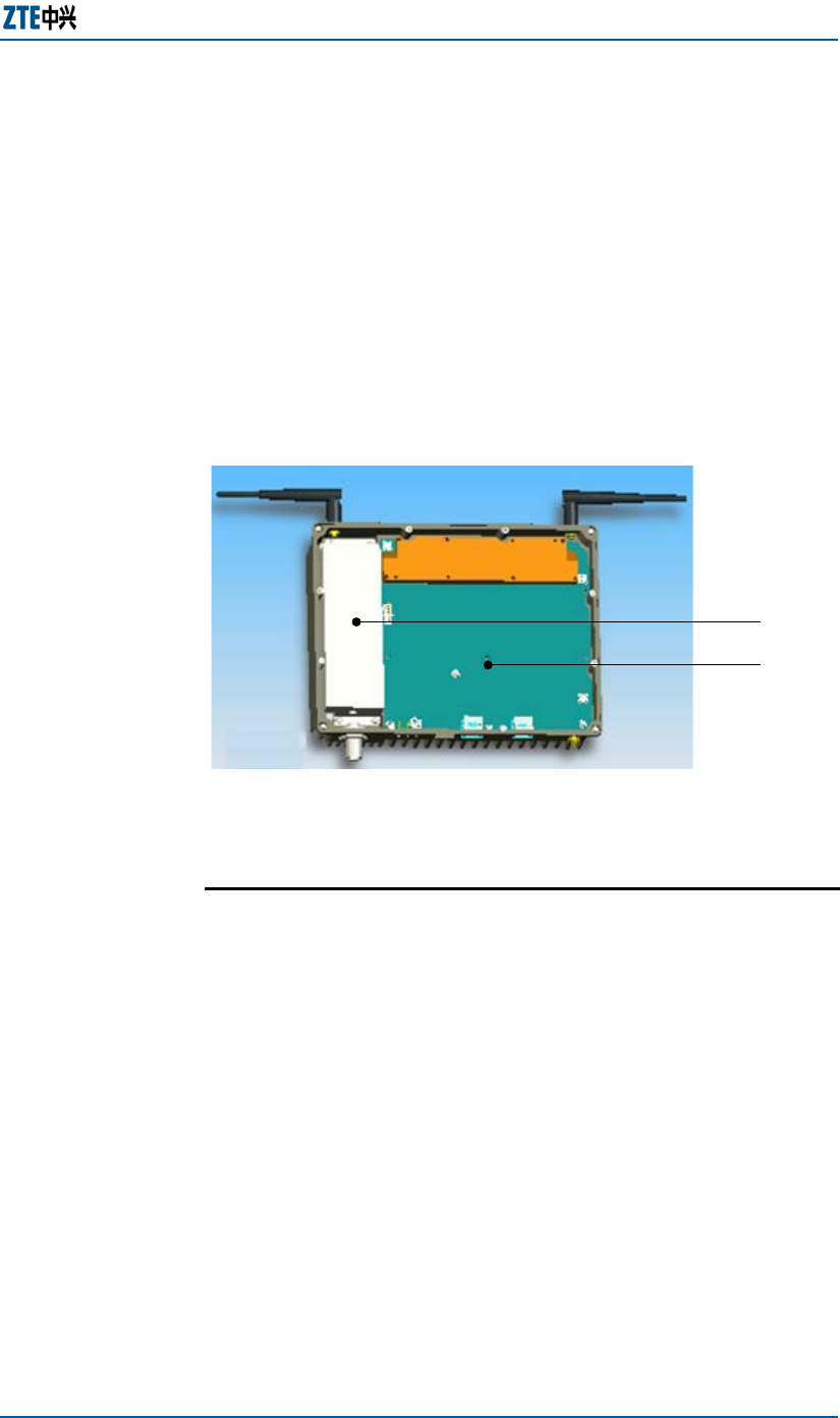
The ZXMBW E9200 bottom shell contains two functional
modules, power module and PICO RF Baseband Module
(PRBMO), as shown in Figure 13.
FIGURE 13 ZXMBW E9200 FUNCTIONAL MODULES
1
2
1. Power module 2. PRBMO Module
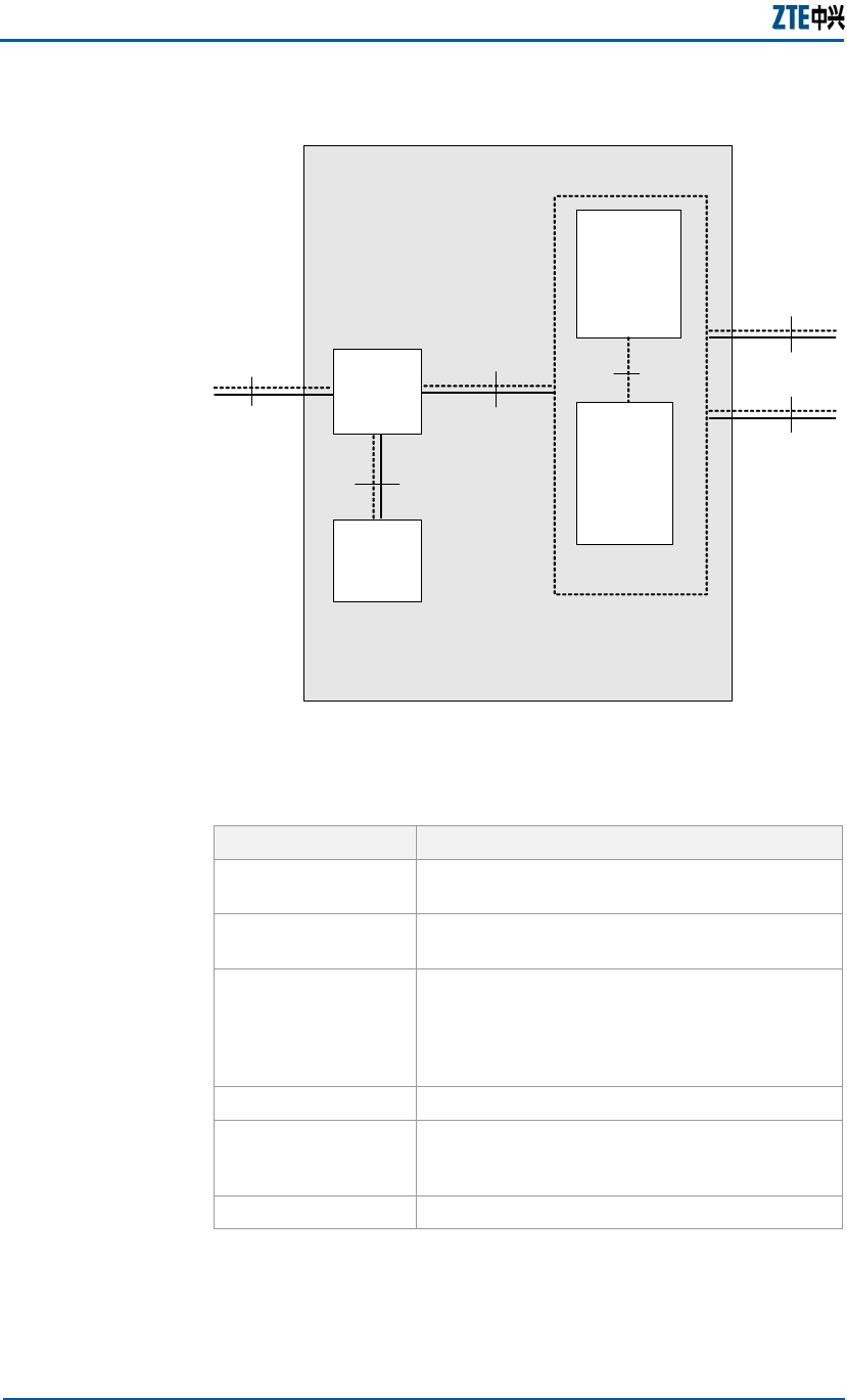
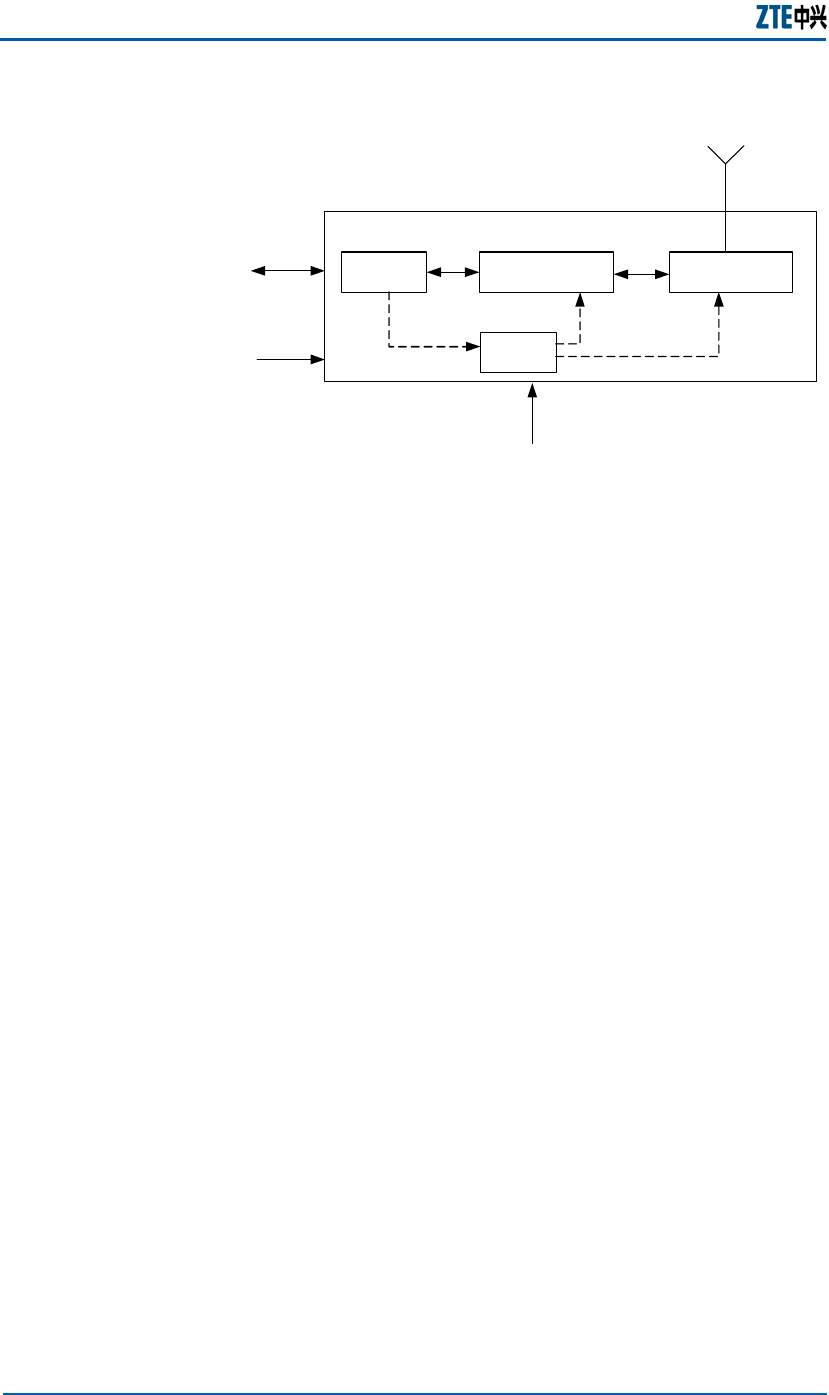
PRBMO Module
The PRBMO module integrates RF processing, baseband
processing, CPU control and clock (GPS clock and ToP clock)
processing functions. Figure 14 illustrates the principle of the
PRBMO module.
Overview
ZXMBW E9200 Indoor Pico Base Station User Manual
20 Confidential and Proprietary Information of ZTE CORPORATION
FIGURE 14 PRBMO MODULE PRINCIPLE
CPU Baseband
processing
RF
processing
Clock
processing PRBM 0
+12 V
GPS
FE
ANT
Controls the system, generates and encrypts IP packets.
Interfaces with the baseband process unit.
Provides a service network interface.
Provides an Ethernet interface for the local operation and
maintenance LMT.
Processes the WiMAX PHY layer and MAC layer.
Encrypts and decrypts signals.
Performs transmission signal processing includes digital
baseband signal processing, D/A conversion, analog
baseband/intermediate frequency signal processing, and
modulation from analog baseband/intermediate frequency
signals to RF/RF signals.
Performs received signal processing includes RF signal
processing, modulation from RF signals to analog
baseband/intermediate frequency signals, analog
baseband/intermediate frequency signal processing, analog
baseband/intermediate frequency A/D conversion and digital
baseband/intermediate frequency signal processing.
Generates and monitors local oscillator.
Processes RF antenna and power supply.
The clock process unit is a timing & frequency subsystem,
provides PP1S and 10MHz timing reference and frequency
reference signals for the baseband and RF subsystem.
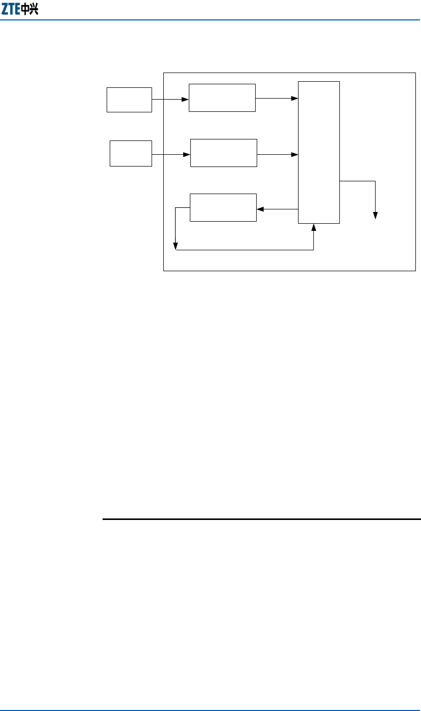
The ZXMBW E9200 clock process unit consists GPS clock process
subunit, ToP clock process subunit, control process subunit and
peripheral circuit process subunit, as shown in Figure 15.
CPU Unit
Baseband
Processing
Unit
RF Processing
Unit
Clock
Processing
Unit
Chapter 2 Error! Style not defined.
Confidential and Proprietary Information of ZTE CORPORATION 21
FIGURE 15 CLOCK PROCESSING UNIT
ToP clock
processing
GPS clock
processing
Control
processing
Peripheral
circuit
GPS
antenna
TOP Main
control end
Clock processing
unit
1 PPS/
10MHz
1 PPS/
10MHz
1 PPS/
10MHz
1 PPS/
10MHz
1 PPS/
10MHz
GPS clock processing procedure
The control subunit and the peripheral circuit subunit
performs locking, phase discrimination and voltage control
for PP1S signals that are received from the GPS receiver, and
outputs PP1S and 10MHz reference signals.
ToP clock processing procedure
The ZXMBW E9200 receives PTP time packets from ToP
Master that is synchronized to GPS PP1S, through the
Ethernet cable. The ZXMBW E9200 generates local clock that
is synchronous with ToP Master.
The control subunit and the peripheral circuit subunit
performs locking, phase discrimination and voltage control
for signals input by the ToP clock process subunit and
outputs PP1S and 10MHz reference signals.
Power Module
The ZXMBW E9200 power supply module performs AC-DC
conversion. Figure 16 illustrates the composition of the ZXMBW
E9200 power supply module.
Overview
ZXMBW E9200 Indoor Pico Base Station User Manual
22 Confidential and Proprietary Information of ZTE CORPORATION
FIGURE 16 POWER SUPPLY MODULE
DC output
Power module
AC input
+12V DC
GND
220V/110V AC
Input: 110V/220V AC (range: 85V~265V, 45~65Hz)
Output: single-circuit output +12V
Protection functions: over/under voltage protection of output
current, over voltage, over current, short circuit and over
temperature protection of input current.
Protective self-recovery function (except for over voltage of
output current).
GPS Antenna
ZXMBW E9200 is equipped with the GPS receiver antenna.
ZXMBW E9200 can also be installed with the outdoor GPS
antenna.
The GPS antenna shipped with the ZXMBW E9200 is installed on
the top of the cabinet, as shown in
Figure 17.
Specifications
Chapter 2 Error! Style not defined.
Confidential and Proprietary Information of ZTE CORPORATION 23
FIGURE 17 GPS ANTENNA INSTALLATION POSITION
1
GPS Receiver
Note: User can change the direction of GPS antenna receiver.
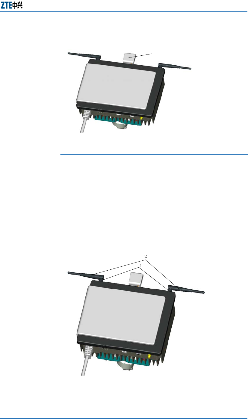
Main Antenna Feeder
System
The ZXMBW E9200 is equipped with two braid-like antennas.
Figure 18 shows the antenna interfaces and positions of the two
antennas.
FIGURE 18 MAIN ANTENNA POSITION
1.Antenna interfaces (SMA interfaces) 2. Braid-like antennas

ZXMBW E9200 Indoor Pico Base Station User Manual
24 Confidential and Proprietary Information of ZTE CORPORATION
The ZXMBW E9200 antenna is close to the cabinet because the
ZXMBW E9200 is low power equipment. Generally, the two
braid-like antennas can meet the requirement. They are
removable. The ZXMBW E9200 provides two SMA antenna
interfaces to connect the external antenna.
In the case that the external antenna feeder system is adopted,
the feeder must be made on site according to the actual
situation, and the common indoor ceiling antenna or wall-
mounted antenna is often used as the external antenna. For
details of the external antenna feeder system, refer to the
relevant information of other base stations.
Chapter 2 Error! Style not defined.
Confidential and Proprietary Information of ZTE CORPORATION 25
External Cables
The external cables of the ZXMBW E9200 are:
Power cable
Grounding cable
Ethernet cable
GPS RF cable.
Power Cable
The ZXMBW E9200 adopts 220 V/110 V AC power.
The wall-through 3-core power cable serves as the ZXMBW
E9200 AC power cable. Figure 19 shows the appearance of the
power cable.
FIGURE 19 AC POWER CABLE APPEARANCE
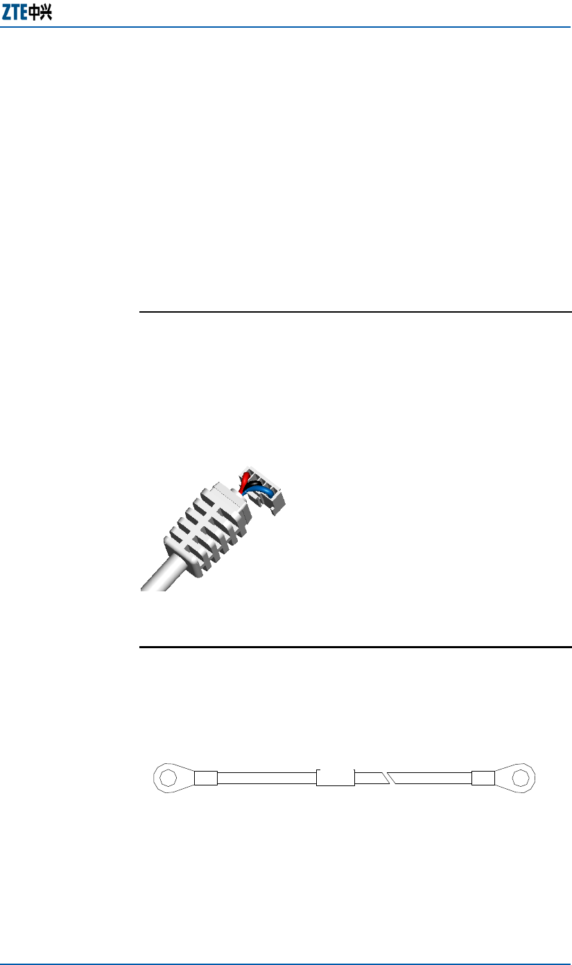
Grounding Cable
Figure 20 illustrates the structure of the grounding cable.
FIGURE 20 GROUNDING CABLE STRUCTURE
B
Label
A
The grounding cable is made of 16mm2 (6 AWG) olivine copper
cable, with two bare round metal terminals (also called lug)
crimped at both ends of the cable.
ZXMBW E9200 Indoor Pico Base Station User Manual
26 Confidential and Proprietary Information of ZTE CORPORATION
Ethernet Cable
The ZXMBW E9200 is connected with the AGW and the LMT by
Ethernet cables. Figure 21 illustrates the structure of Ethernet
cable.
FIGURE 21 ETHERNET CABLE STRUCTURE
??
??
label label
GPS RF Cable
The ZXMBW E9200 GPS receiver is shipped with a GPS RF cable.
Figure 22 shows the connection points of GPS RF cable.
End A of the cable connects the GPS receiver while end B
connects the GPS interface on the ZXMBW E9200 cabinet. End B
is an SMA interface.
FIGURE 22 GPS RF CABLE
End B
End A

Confidential and Proprietary Information of ZTE CORPORATION 27
Chapter 3
Hardware Installation
This chapter describes:
Installation components
Installation flow
Installation precautions
Installation preparation
Cabinet installation
External cables installation
GPS antenna feeder system installation
Main antenna feeder system installation
Hardware installation check
Power-on and Power-off test

ZXMBW E9200 Indoor Pico Base Station User Manual
28 Confidential and Proprietary Information of ZTE CORPORATION
Installation Components
The ZXMBW E9200 cabinet includes fixing clips and enclosure.
Note: The internal cables and functional modules are installed
before delivery.
Cables: power cable, grounding cable, Ethernet cable and
GPS RF cable
GPS antenna feeder system: optional. The system needs to
be installed when GPS is used to provide time reference. GPS
antenna need not be installed when ToP clock reference is
used.
Main antenna feeder system includes antenna and main
feeder.
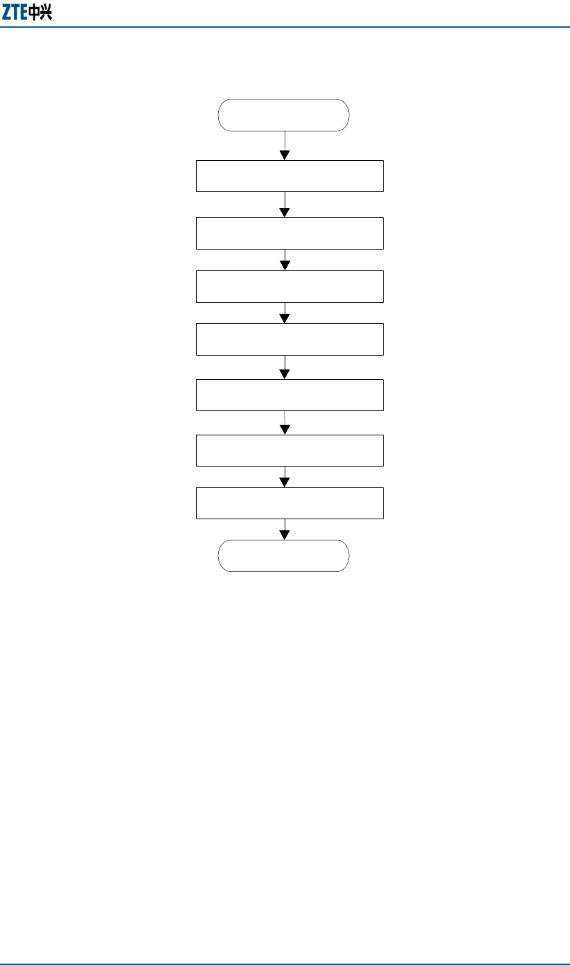
Installation Flow
Figure 23 illustrates the general installation flow of ZXMBW
E9200.
Note: The on-site installation flow may differ depending on the
actual situation.
Chapter 3 Error! Style not defined.
Confidential and Proprietary Information of ZTE CORPORATION 29
FIGURE 23 ZXMBW E9200 INSTALLATION FLOW
Begin
End
Cabinet
Installation
Hardware installation
check
-
Power-up and
Power-down Test
-
Cables
Installation
Installation
preparation
Main antenna system
Installation
GPS antenna system
Installattion
Installation Precautions
The installation engineer should check the working environment
before starting the installation. The installation engineer must be
familiar with the installation position, networking, data
configuration and cables of ZXMBW E9200.
Besides, pay attention to the following:
Operations on the ZXMBW E9200 are forbidden if the cabinet
is powered on.
Installing the outdoor antenna feeder system is forbidden
during rainy and lightning situations.

ZXMBW E9200 Indoor Pico Base Station User Manual
30 Confidential and Proprietary Information of ZTE CORPORATION
Installation Preparation
Check the installation environment, installation position,
temperature, humidity and power supply before installing the
ZXMBW E9200.
Checking Installation Environment
Check the installation environment according to the
requirements of ZTE Environment Acceptance Report before the
installation.
Checking Installation Position
Check whether the installation position of ZXMBW E9200 meets
the engineering requirements are as given below.
The ZXMBW E9200 installation position must be clean, and
away from the places of injurious gases or explosive articles.
The ZXMBW E9200 must be away from the places with
strong shocks or loud noise.
The ZXMBW E9200 is away from transformer substations.
The ZXMBW E9200 away from industrial boilers and heating
boilers and contamination resources.
The ZXMBW E9200 away from high power wireless
interfering resources.
Checking Temperature and Humidity
Check whether the working temperature and humidity of ZXMBW
E9200 meets the requirements as described in Table 11.
TABLE 11 ZXMBW E9200 WORKING TEMPERATURE AND HUMIDITY
Name Working condition
Temperature Indoor: -50C ~500C (230F ~1220F)
Humidity Relative humidity: 5%-95%

Chapter 3 Error! Style not defined.
Confidential and Proprietary Information of ZTE CORPORATION 31
Checking Power Supply
Check whether the power supply of ZXMBW E9200 meets the
requirement as described in Table 12.
TABLE 12 ZXMBW E9200 POWER SUPPLY REQUIREMENT
Type Nominal value Voltage range
AC 110 V /220V AC 85 V AC~265V AC, 50/60Hz
Checking Grounding Mode
The ZXMBW E9200 applies the joint grounding mode. The
grounding resistance must be less than 5 Ω.
Other Checks
Make sure that accessories or parts (e.g. antenna pole,
grounding copper bus-bar) are in accordance with the
ZXMBW E9200 engineering design.
Make sure that interconnection devices such as AGW, and
power supply are available.
Tools and Instruments Preparation
Prepare installation tools and test instruments according to the
actual situation. Table 13 and Table 14 list the common tools
and instruments.
TABLE 13 TOOLS LIST
Type Tool
Special-purpose
tools
Knife for cutting feeder ends
Wire stripper for coaxial cables
One crimping pliers for coaxial cables
Multi-functional crimping pliers
Concrete
drilling tools
Electric percussion drill
Auxiliary bits
Vacuum cleaner
Power socket (two-phase and three-phase socket)

ZXMBW E9200 Indoor Pico Base Station User Manual
32 Confidential and Proprietary Information of ZTE CORPORATION
Type Tool
General-
purpose tools
Cross screwdrivers (4", 6" and 8" each)
Flathead screwdrivers (4", 6" and 8" each)
Monkey wrenches (6", 8", 10" and 12")
Dual-purpose spanners (17" and 19" each)
Socket wrench
5 kg (11 lb) nail hammer
Electric iron, 300 W
Electric iron, 40 W
Solder wires
Hot wind blower
Tin sucker
Tweezers
Paint brush
Electrical knife
Paper knife
Scissors
Measurement
tools
50 m (164 ft) cloth tape
5 m (16.4 ft) copper tape
400 mm (15.6 in) horizontal ruler
Angle instrument
Plumb
Protection tools
Antistatic wrist strap
Safety helmet
Slip-proof glove
Pliers
Hacksaw (with several saw blades)
Sharp-nose pliers (8”)
Diagonal pliers (8”)
Slip joint pliers (8")
Vices (8”)
Needle file set (medium sized)
Hydraulic crimper
Crowbar
Auxiliary tools
Pulley block
Rope
Ladder
TABLE 14 INSTRUMENTS LIST
Instrument Manufactory
Voltage Standing Wave
Ratio (VSWR) tester
SITE MASTER
Fiber tester -
Compass -
Multi-meter -

Chapter 3 Error! Style not defined.
Confidential and Proprietary Information of ZTE CORPORATION 33
Instrument Manufactory
Grounding resistance tester -
Unpacking Inspection
The project supervisor and the representative of customer must
be present on site during unpacking.
The following describes the procedure for unpacking inspection
ZXMBW E9200 boxes.
Perform the following steps to unpack ZXMBW E9200.
1. Count the number of packing boxes. Check whether the
packing boxes are intact and whether the actual arrival place
is the correct place. If yes, unpack the goods for inspection.
2. Check whether the goods are consistent with the goods in
the Equipment Acceptance List and archive the report.
3. If any shortage of goods, wrong goods, superfluous goods or
goods damage found, note it and inform ZTE office.
4. The project supervisor should fill Unpacking for Inspection
Feedback Table and send it back to ZTE office.
Caution
When the equipment is moved from a colder and drier place
to a hotter and damper place, wait for 30 minutes before
unpacking the equipment. Otherwise, moisture may
condense on the surface of the equipment and cause damage.
Properly recycle the desiccant lest.
END OF STEPS.
Acceptance and Handover
Check the goods one by one according to the name, type and
amount on the shipping list.
There should be no dents, bulges, scratches, peels, blithers,
blisters or smudges on the outer surface of the cabinets.
The surface paint on the cabinets should not fall off or be
scratched.
The fastening screws should not be loosened, disconnected,
or mistakenly placed.
The accessories and fittings needed for cabinet installation
should be complete.
Arrange the checked goods by type.
Prerequisite
Steps
Acceptance

ZXMBW E9200 Indoor Pico Base Station User Manual
34 Confidential and Proprietary Information of ZTE CORPORATION
Upon completion of unpacking for acceptance, the representative
of user and the project supervisor sign on the Unpacking
Acceptance Report to acknowledge the acceptance. If goods are
to be kept by the user after acceptance, both parties sign on the
Unpacking Acceptance Report for confirmation, and then goods
will be handed over to the user.
Note: Both parties must hold a copy of Unpacking Acceptance
Report and the project supervisor should give feed back for the
Acceptance Conclusion of this report to ZTE office for archiving
within seven days.
Cabinet Installation
The following introduces ZXMBW E9220 cabinet installation, and
installation modes such as wall-mount installation and pole-
mount installation.
ZXMBW E9200 Cabinet Installation
Introduction
The ZXMBW E9200 cabinet can be installed in two modes
depending on the installation environment.
The installation modes are:
Wall-mount installation
Pole-mount installation
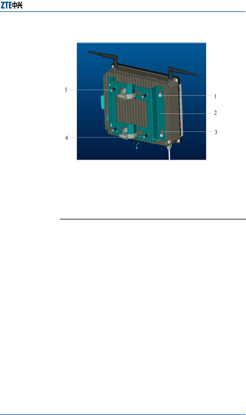
Figure 24 shows the installation supporting parts of ZXMBW
E9200 cabinet.
Handover
Installation
Modes
Cabinet
Installation
Supporting
Parts
Chapter 3 Error! Style not defined.
Confidential and Proprietary Information of ZTE CORPORATION 35
FIGURE 24 ZXMBW E9200 CABINET INSTALLATION PARTS
1.Hex flange bolt 2.Installation plate
3.Cucurbit hole 4.Hoop (used for pole-held installationz0)
5. Expansion bolt
Wall-mount Installation
The following describes the wall-mount installation procedure of
ZXMBW E9200 cabinet.
The following accessories are required for wall-mount
installation.
One installation plate
4 expansion bolts and 4 hex flange bolts
Fastening tools
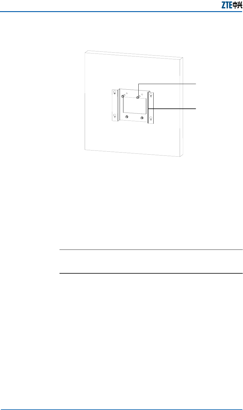
Perform the following steps to install the cabinet as wall-mount
mode.
1. Fix the installation plate on the wall using 4 expansion bolts,
as shown in Figure 25.
Installation
Accessories
Steps
ZXMBW E9200 Indoor Pico Base Station User Manual
36 Confidential and Proprietary Information of ZTE CORPORATION
FIGURE 25 ZXMBW E9200 CABINET INSTALLATION PARTS
1
2
1. Expansion bolt 2.Installation plate
2. Mount the cabinet on the installation plate, and insert the 4
hex flange bolts at the back of the cabinet through the larger
parts of the cucurbit holes on the plate.
3. Move the inserted 4 hex flange bolts into the smaller parts of
the cucurbit holes to fix the cabinet to the plate.
4. Tighten the 4 hex flange bolts
END OF STEPS.
Pole-mount Installation
The following describes the pole-mount installation procedure of
ZXMBW E9200 cabinet.
The following accessories are required for pole-mount
installation.
One installation plate
4 expansion bolts and 4 hex flange bolts
Hoops
Fastening tools
Perform the following steps to install the cabinet as pole-mount
mode.
1. Mount the Installation plate on the pole with using the hoops
and fix it with four expansion bolts.
Installation
Accessories
Steps

Chapter 3 Error! Style not defined.
Confidential and Proprietary Information of ZTE CORPORATION 37
2. Mount the cabinet on the installation plate, and insert the 4
hex flange bolts at the back of the cabinet through the larger
parts of the cucurbit holes on the plate.
3. Move the inserted 4 hex flange bolts into the smaller parts of
the cucurbit holes to fix the cabinet to the plate.
4. Tighten the 4 hex flange bolts.
Note: The diameter of the pole should be within the range of 30
mm (1 3/16 in) to 60 mm (2 6/16 in).
END OF STEPS.
External Cables Installation
The external cable installation includes:
Grounding cable installation
Ethernet cable installation
Power cable installation
GPS RF cable installation
Grounding Cable Installation
The following describes prerequisites and procedure of
grounding cable installation.
The connection point for the indoor grounding copper bus-bar is
available.
Prepare a length-proper grounding cable according to the actual
situation. Use a 16mm2 (6 AWG) olivine copper cable to make
the grounding cable.
Crimp a bare round metal terminal (also called lug) at both ends
of the cable respectively.
Perform the following steps to install the grounding cable.
1. Connect one bare terminal of the grounding cable to the
protective grounding terminal that is located at the M5 bolt
of the power cable interface on the ZXMBW E9200 cabinet.
2. Connect the other end of the grounding cable to the specified
indoor grounding copper bus-bar.
Note: To ensure reliable connection, press the lugs of grounding
cable to make the cable in good contact with the other parts.
END OF STEPS.
Prerequisites
Steps

ZXMBW E9200 Indoor Pico Base Station User Manual
38 Confidential and Proprietary Information of ZTE CORPORATION
Ethernet Cable Installation
The following describes prerequisite and procedure of Ethernet
cable installation.
Prepare a length-proper Ethernet cable and make RJ45
connectors at the both ends of the cable before the installation.
Perform the following steps to install the Ethernet cable.
1. Connect one end of the Ethernet cable to the Ethernet
interface on the ZXMBW E9200 plane.
2. Connect the other end to the Ethernet interface of the
network equipment.
END OF STEPS.
Power Cable Installation
The following describes installation procedure of power cable.
Note: The wall-through connector of the power cable is
connected to the ZXMBW E9200 cabinet before delivery.
Insert the other end to the GPS interface on the ZXMBW E9200
cabinet.
GPS RF Cable Installation
The following describes installation procedure of GPS RF cable.
Note: One end of the GPS RF cable is fixed on the shell of the
GPS receiver before ZXMBW E9200 delivery.
Insert the other end to the GPS interface on the ZXMBW E9200
cabinet.
Prerequisite
Steps
Chapter 3 Error! Style not defined.
Confidential and Proprietary Information of ZTE CORPORATION 39
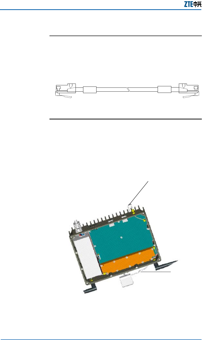
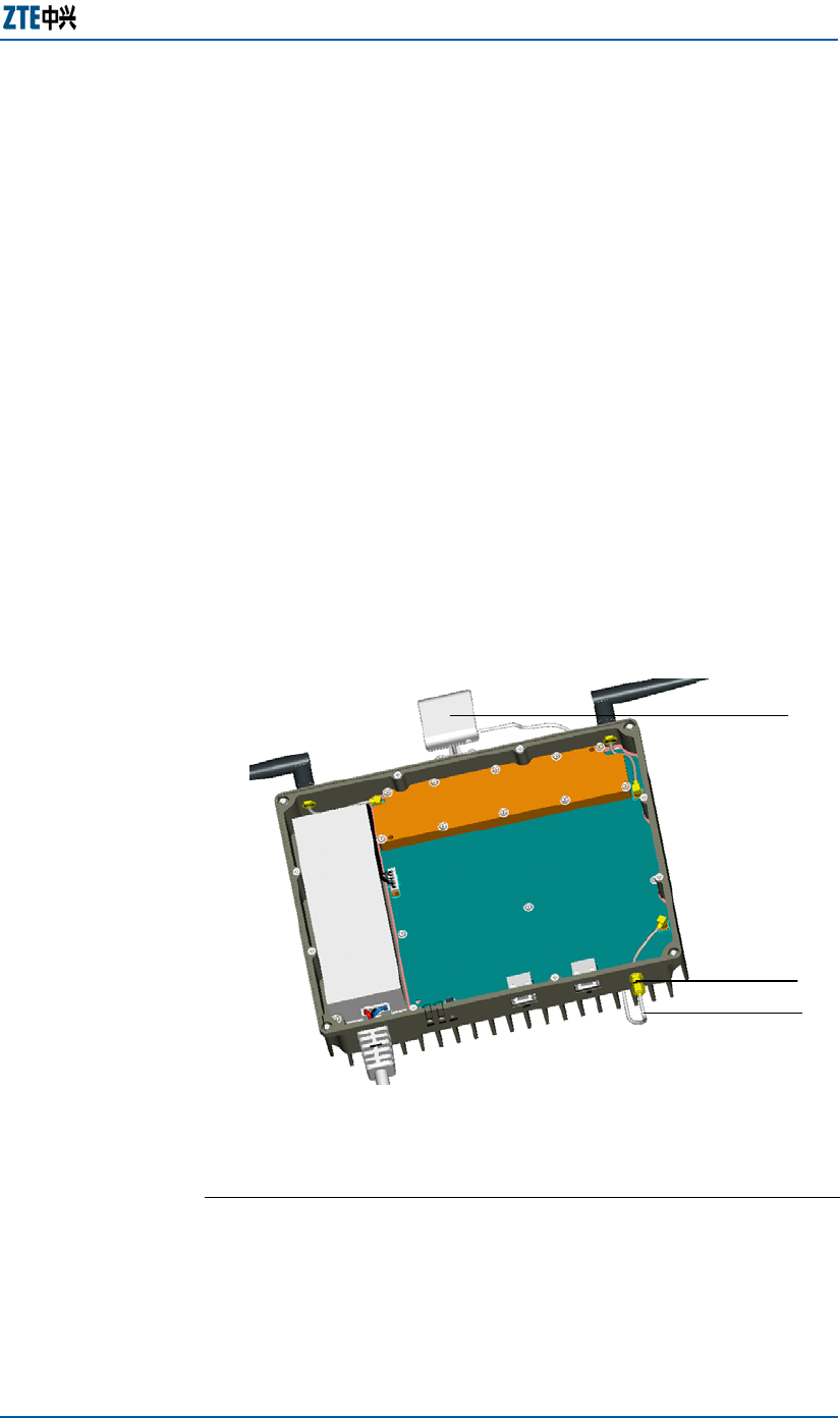
GPS Antenna Feeder
System Installation
The GPS antenna feeder system includes GPS receiver and GPS
RF cable.
The following describes the installation procedure of GPS
antenna feeder system.
Perform the following steps to install GPS antenna feeder
system.
1. Fix the GPS receiver on the top of the cabinet.
2. Connect the GPS RF cable to the SMA connector of the GPS
interface.
Figure 26 shows the installed GPS antenna feeder system.
FIGURE 26 GPS ANTENNA FEEDER SYSTEM INSTALLATION
1
3
2
1.GPS receiver 2.GPS interface 3.GPS RF cable
END OF STEPS.
Steps

ZXMBW E9200 Indoor Pico Base Station User Manual
40 Confidential and Proprietary Information of ZTE CORPORATION
Main Antenna Feeder
System Installation
The ZXMBW E9200 provides external SMA antenna interfaces.
Generally two braid-like antennas are to be installed before
ZXMBW E9200 delivery.
To install an external antenna feeder system, perform the
following steps.
1. Remove the two braid-like antenna from cabinet.
2. Install the external antenna jumper or antenna feeder.
END OF STEP.
For details, refer to the relevant information of other base
stations.
Hardware Installation Check
This section describes the over all check on the installed cabinet,
cables and running environment.
Cabinet Installation Check
The following describes the checking procedure of installed
cabinet.
Perform the following steps to check the installed cabinet.
1. Check whether the cabinet is installed in the right position
that is complies with the design drawing.
2. Check whether the cabinet is fixedly installed and able to
resist level 7 earthquakes.
3. Confirm the horizontal and vertical deviations of the cabinet
are less than 3 mm (2/16 in).
4. Check whether the overall equipment is clean and painted
well. The parts on the cabinets are intact and well installed.
The labels on the cabinet are correct, clear and complete.
5. Make sure all screws are tightened with flat washers and
spring washers placed correctly.
END OF STEPS.
Steps
Steps

Chapter 3 Error! Style not defined.
Confidential and Proprietary Information of ZTE CORPORATION 41
Cable Installation Check
The following describes the checking procedure of installed
cables includes Ethernet cable and GPS RF cable.
Perform the following steps to check the installed cabinet.
1. Check whether the cables are laid flat and straight without
any apparent fluctuation, crossing or jump-wire in air.
2. Check whether the bends of the cable are smooth.
3. Check whether both ends of each cable are clearly labeled
and marked with its usage. The labels on both ends of a
cable should have the same contents.
4. Check the joint parts are firmly and correctly connected and
in good contact without breaking or bending.
END OF STEPS.
Power and Grounding Cable
Installation Check
The following describes the checking procedure of installed
cables includes power cable and grounding cable.
Perform the following steps to check the installed cabinet.
1. Check whether the power cable and the grounding cable are
laid away from other cables. They must be horizontally 200
mm (7 14/16 in) away from the signal cable upon parallel
laying.
2. Check whether the power cable and the grounding cable are
whole material without connector is in middle.
3. Confirm that each grounding point on the grounding copper
bus-bar only connected with one device.
4. Confirm the power cable and grounding cable redundant in
length is cut and there is no winding.
5. Make sure that the copper lugs on both ends of the power
cable and the grounding cable are soldered or pressed firmly.
6. Make sure that the grounding path is short as possible.
7. Check whether the bare wires at the connecting terminals
and lug handle are tightly wrapped with the insulating tape
or the heat-shrink tube instead of being exposed
END OF STEPS.
Steps
Steps

ZXMBW E9200 Indoor Pico Base Station User Manual
42 Confidential and Proprietary Information of ZTE CORPORATION
Running Environment Check
Engineering wastes must be cleaned. After the installation is
finished, the work site should be recovered to what it was,
without any cable strap, stub, waste paper box, waste cable or
waste plastic bag. The whole site must be clean and tidy.
Other Environment Check
During the installation, record the relevant information according
to the base station information table in the installation
acceptance report.
Power-on and Power-off Test
This section describes the Power-on and Power-off procedures at
first time.
Power-On Procedure
The following describes prerequisites and procedure of power-on
ZXMBW E9200 equipment.
The voltage of the power supply meets the requirement of
the ZXMBW E9200
The cabinet power and the grounding cable are correctly
connected.
The cabinet power plug is disconnected from the power
socket.
1. The ZXMBW E9200 cabinet has no power switch. Enable the
external power switch to power on the cabinet.
2. If any exception occurs during the power-on, disconnect the
switch or remove the power plug. Find out the cause.
END OF STEPS.
Power-Off Procedure
Disconnect the external power switch.
Prerequisites
Steps

Confidential and Proprietary Information of ZTE CORPORATION 43
Abbreviations
Abbreviation Full name
AGW Access Service Network GateWay
AAA Authentication, Authorization, Accounting
BMU Building Manager Unit
E9200 Pico Base Station(indoor)
EMS Element Management System
FDD Frequency Division Duplex
HA Home Agent
IMS IP Multimedia Subsystem
MAC Media Access Control
MIMO Multiple-Input multiple-Out-put
OFDM Orthogonal Frequency Division Multiplexing.
QoS Quality of Service
QPSK Quadrature Phase-Shift Keying
QAM Quadrature Amplitude Modulation
RSSI Receive Signal Strength Indicator
RRM Radio Resource Management
TDD Time Division Duplex
ToP Timing Over Packet
WIMAX Worldwide Interoperability for Microwave
Access
WiFi Wireless Fidelity 802.11
ZXMBW ZTE Mobile Broadband Wireless

ZXMBW E9200 Indoor Pico Base Station User Manual
44 Confidential and Proprietary Information of ZTE CORPORATION
This page is intentionally blank.

Confidential and Proprietary Information of ZTE CORPORATION 45
Figures
Figure 1 ZXMBW E9200 in WIMAX Network ............................2
Figure 2 ZXMBW E9200 Appearance.....................................3
Figure 3 ZXMBW E9200 Functional Components.....................4
Figure 4 ZXMBW E9200 External Interfaces...........................5
Figure 5 ZXMBW E9200 External Interfaces...........................6
Figure 6 ASN Network Reference Model .............................. 10
Figure 7 ZXMBW E9200 Network Reference Model ................ 11
Figure 8 R1 Interface Protocol Stack................................... 13
Figure 9 Control Plane Message Format .............................. 14
Figure 10 Flag Fields Format ............................................. 15
Figure 11 Control Plane Protocol Stack................................ 15
Figure 12 ZXMBW E9200 cabinet Structure ......................... 18
Figure 13 ZXMBW E9200 Functional Modules ....................... 19
Figure 14 PRBMO Module Principle ..................................... 20
Figure 15 Clock Processing Unit ......................................... 21
Figure 16 Power Supply Module ......................................... 22
Figure 17 GPS Antenna Installation Position ......................... 23
Figure 18 Main Antenna Position ......................................... 23
Figure 19 AC Power Cable Appearance................................. 25
Figure 20 Grounding Cable Structure................................... 25
Figure 21 Ethernet Cable Structure ..................................... 26
Figure 22 GPS RF Cable..................................................... 26
Figure 23 ZXMBW E9200 Installation Flow............................ 29
Figure 24 ZXMBW E9200 Cabinet Installation Parts ............... 35
Figure 25 ZXMBW E9200 Cabinet Installation Parts ............... 36
Figure 26 GPS Antenna Feeder System Installation................ 39

ZXMBW E9200 Indoor Pico Base Station User Manual
46 Confidential and Proprietary Information of ZTE CORPORATION
This page is intentionally blank.

Confidential and Proprietary Information of ZTE CORPORATION 47
Tables
Table 1 Chapter Summary ................................................. iii
Table 2 Typographical Conventions ..................................... iii
Table 3 Mouse Operation Conventions ................................. iv
Table 4 External Interfaces and Descriptions .........................5
Table 5 ZXMBW E9200 Engineering Index .............................7
Table 6 ZXMBW E9200 Performance Index ............................7
Table 7 ASN Interfaces..................................................... 10
Table 8 R1 Message Format .............................................. 12
Table 9 R6 Control Plane Message Fields and Description....... 14
Table 10 Flag Fields and Description................................... 15
Table 11 ZXMBW E9200 Working Temperature and Humidity . 30
Table 12 ZXMBW E9200 Power supply Requirement.............. 31
Table 13 Tools List........................................................... 31
Table 14 Instruments List ................................................. 32

ZXMBW E9200 Indoor Pico Base Station User Manual
48 Confidential and Proprietary Information of ZTE CORPORATION
This page is intentionally blank.

Confidential and Proprietary Information of ZTE CORPORATION 49
Index
A/D ....................................20
AAA .............................. 11, 43
AC 5, 7, 21, 22, 25, 31
B 26
BS 10, 11, 13
CAPS ....................................ii
CE 8
CN 10
CPU .......................3, 4, 19, 20
DC 21
E 1, 3
E1 15
E1/T1.................................15
E3/T3.................................15
ETS ..................................... 7
FE 15
GPS . ii, 3, 5, 6, 7, 8, 18, 19, 20,
21, 22, 23, 25, 26, 27, 28,
37, 38, 39, 41
HA 43
INFORMATION........................ 2
IP 2, 4, 11, 15, 20, 43
LEGAL.................................. 2
LMT .......................... 5, 20, 26
MAC ..............11, 12, 14, 20, 43
MASTER ...............................32
MS 11, 14
N/A......................................3
NM 5, 7
OMC......................................8
P 1, 3
PA 2
R&D......................................3
R1 2, 3, 9, 10, 11, 12, 13
R3 10
R4 10
R6 2, 5, 8, 9, 10, 11, 13, 14, 15
R7 10
RF 3, 4, 5, 6, 8, 19, 20, 25, 26,
28, 37, 38, 39, 41
RJ45 .................................. 38
RSSI .............................. 2, 43
RX 2
SITE .................................. 32
SMA.......... 6, 23, 24, 26, 39, 40
TOP................. 3, 7, 19, 20, 28
TX 2
URL......................................1
V 25, 31
V1 3
VSWR .................................. 32