ZTE ZXMBW-RA25 Agile 2.5G Remote Radio Frequency Unit User Manual Installation Manual
ZTE Corporation Agile 2.5G Remote Radio Frequency Unit Installation Manual
UserManual.wiki
>
ZTE
>
ZXMBW RA25 User Manual
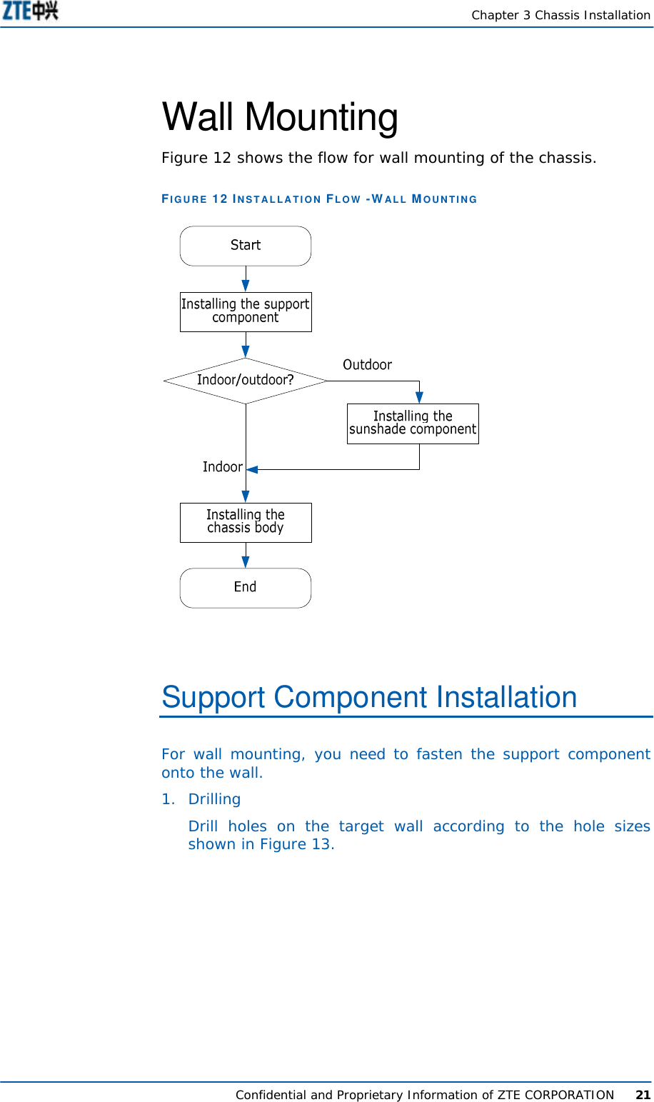
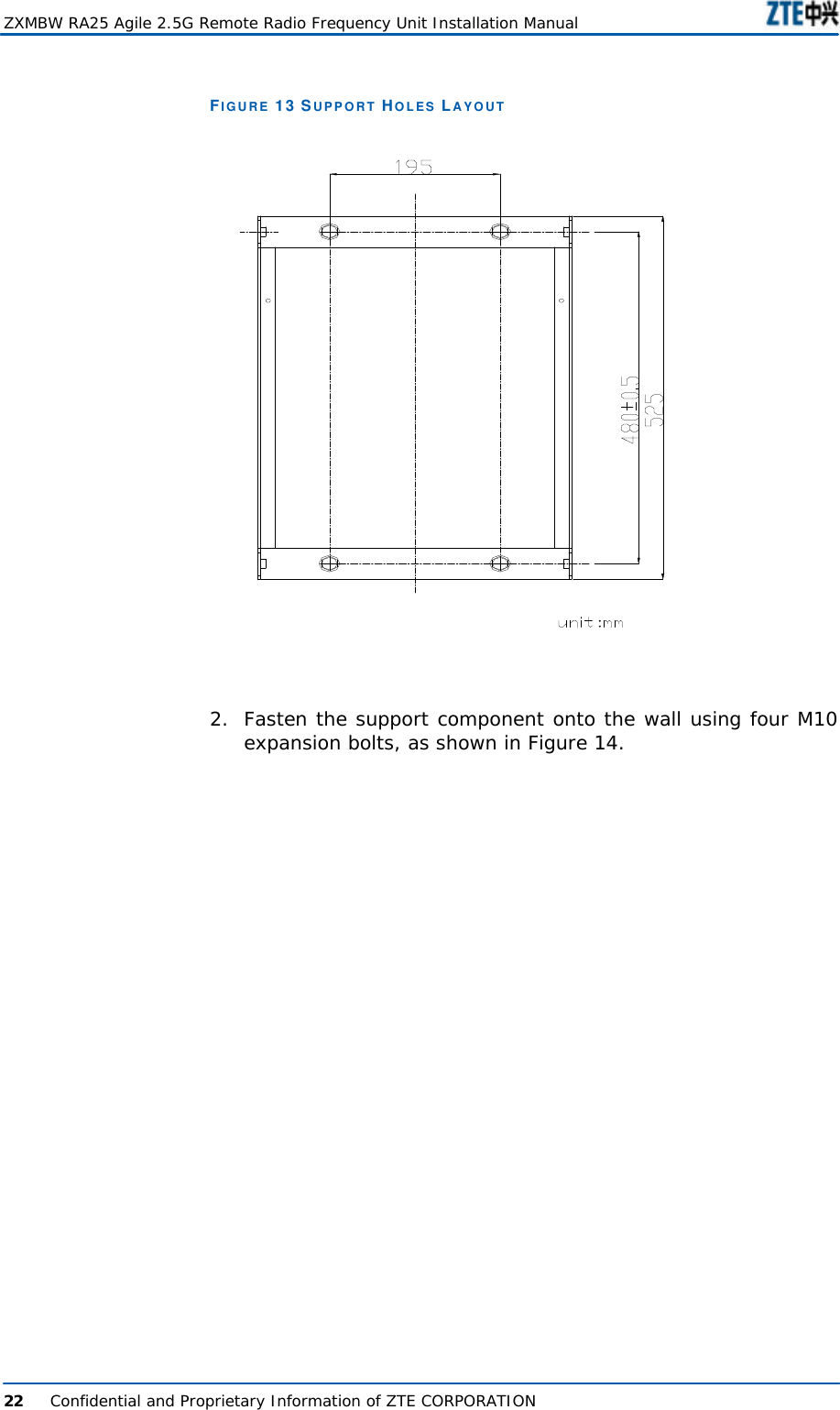
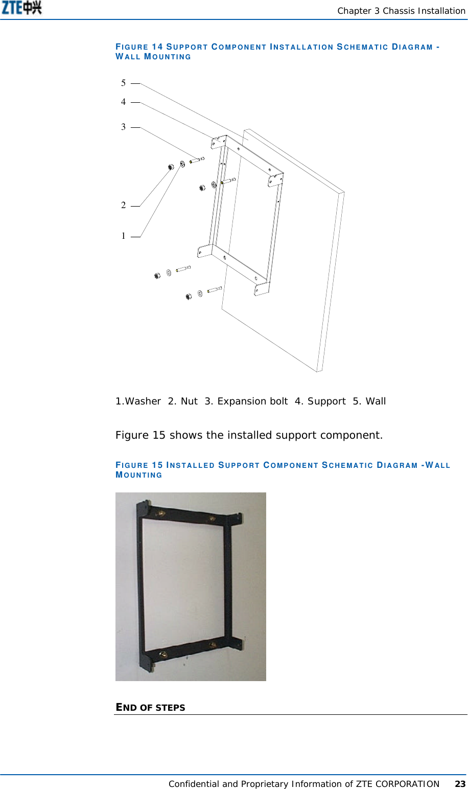
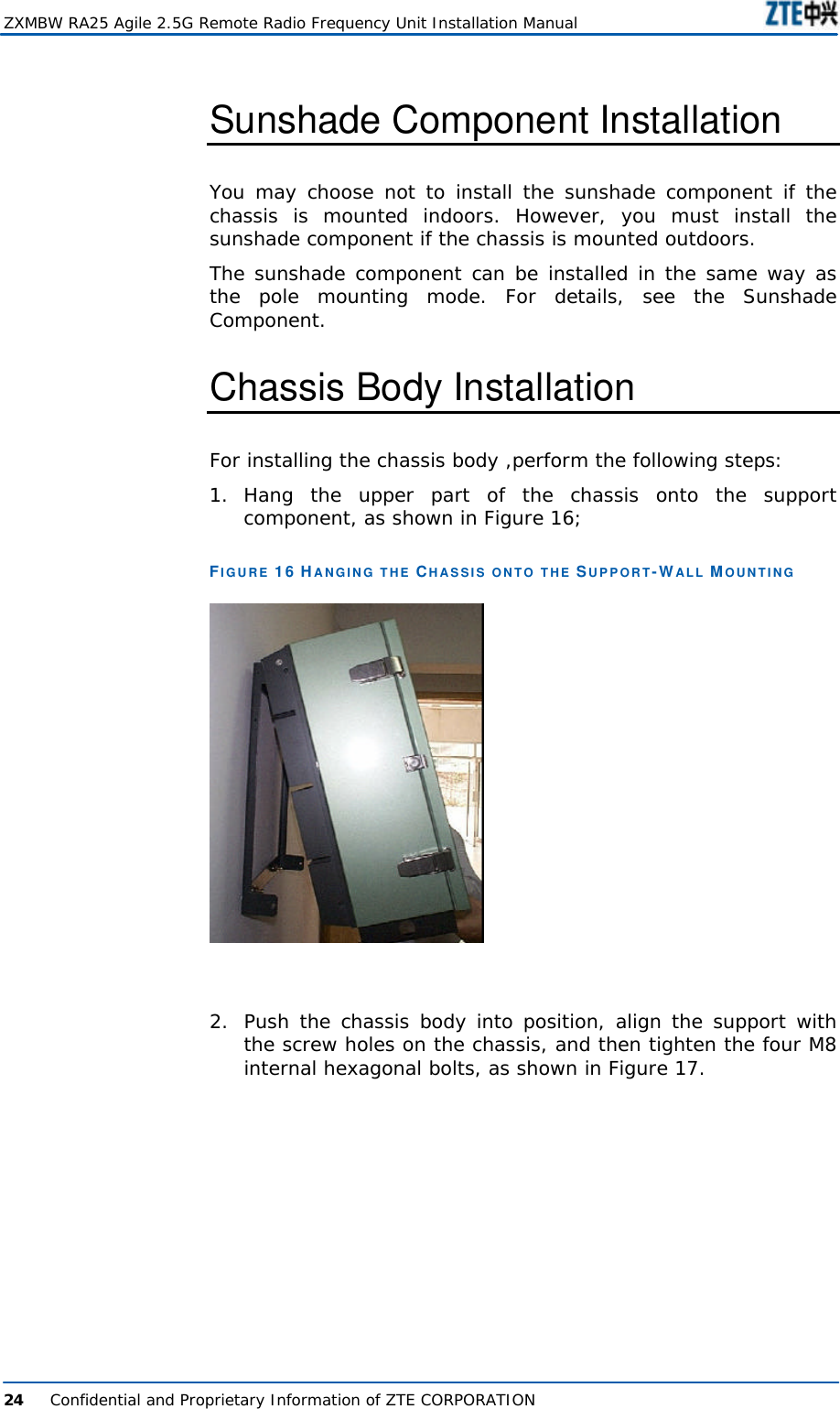
Installation Manual
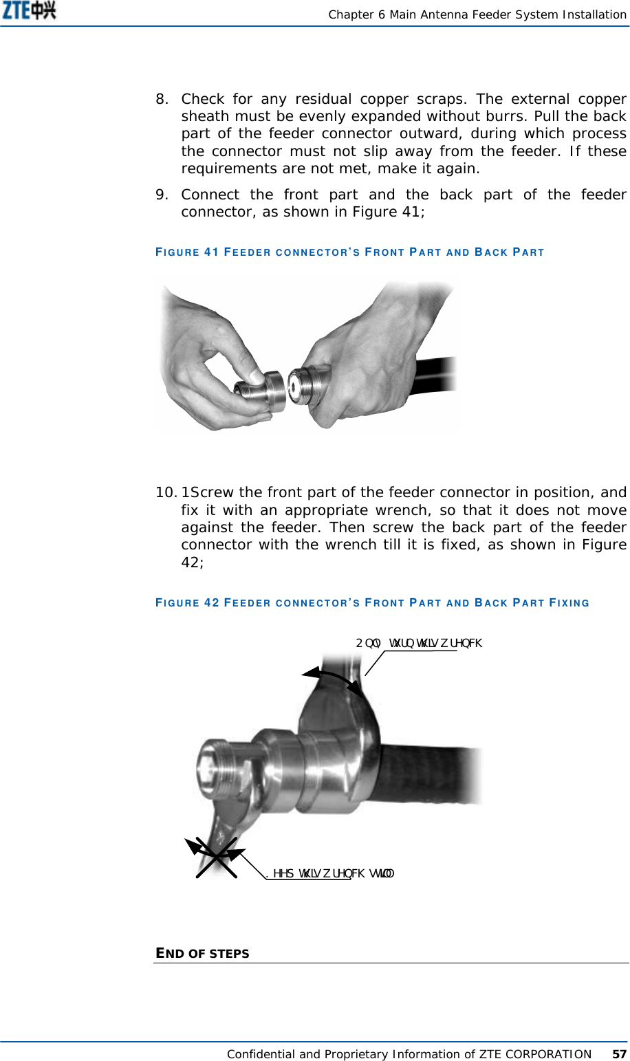
Navigation menu
Upload a User Manual
Namespaces
Wiki Guide
HTML
PDF
Info
Views
User Manual
Discussion / Help
Navigation
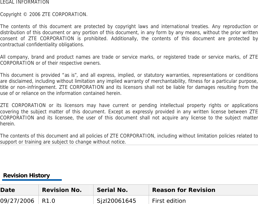
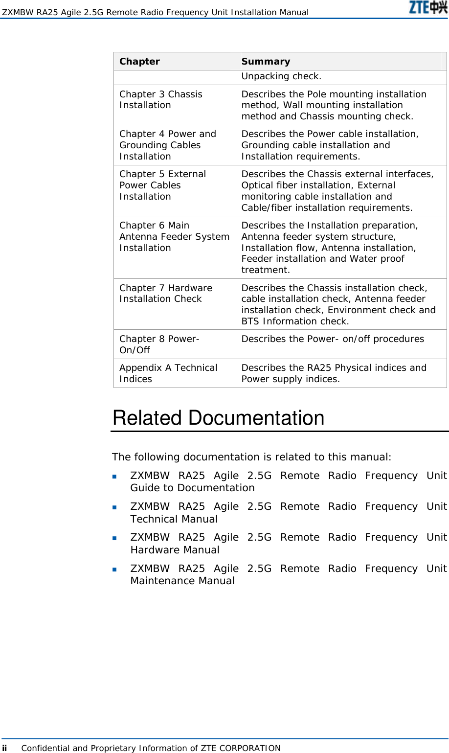
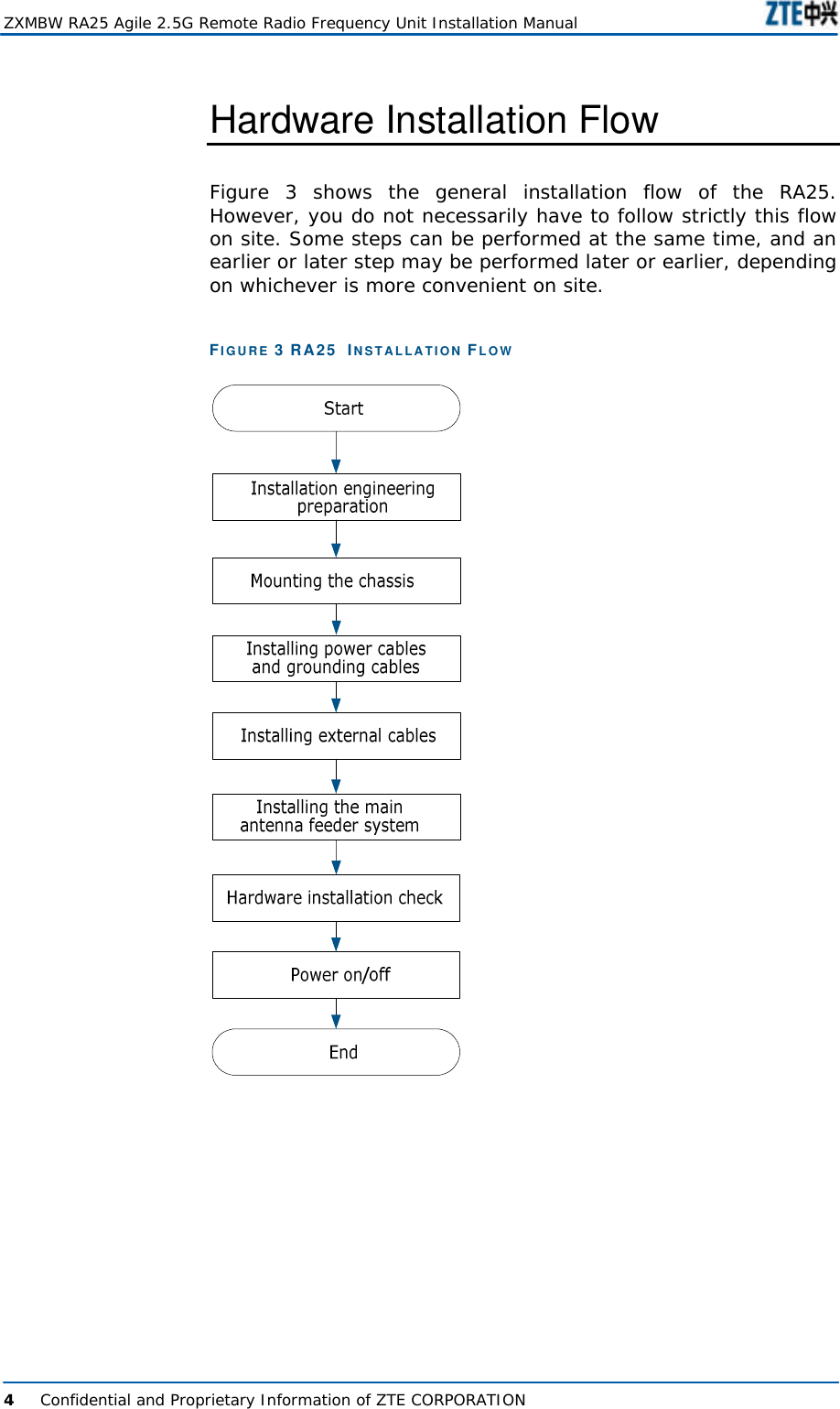
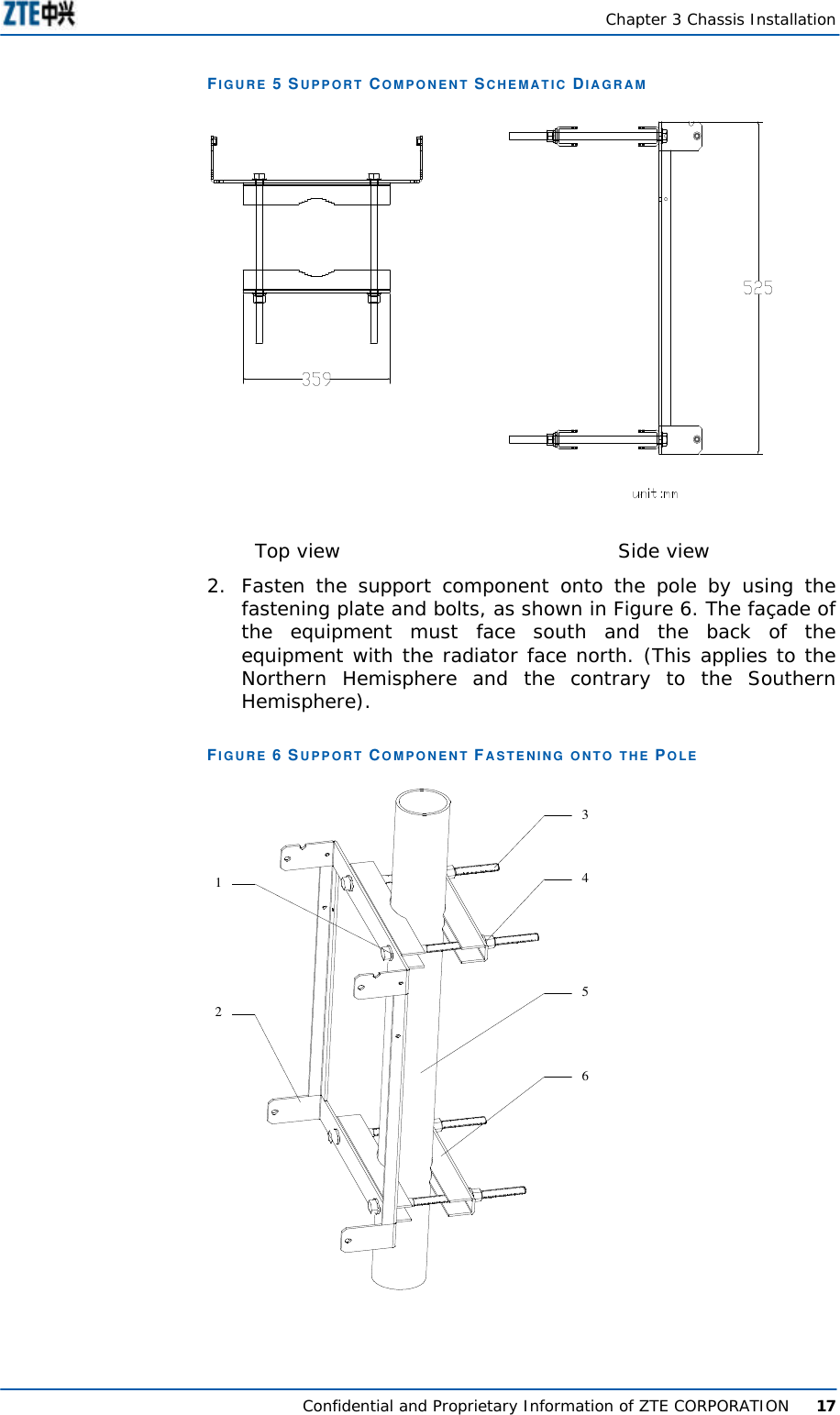
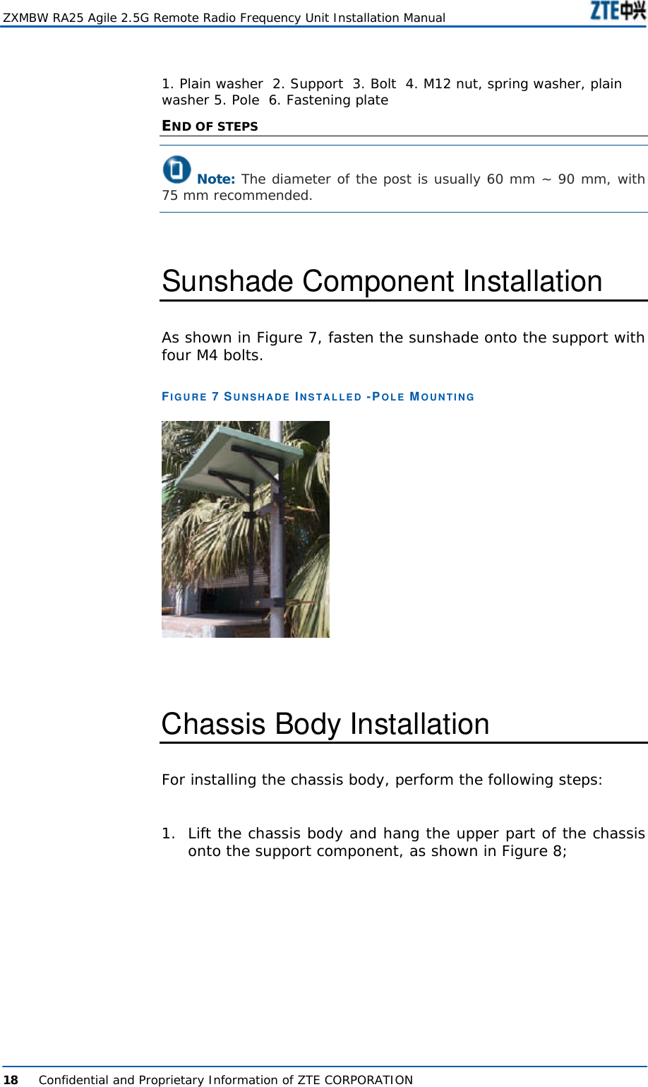
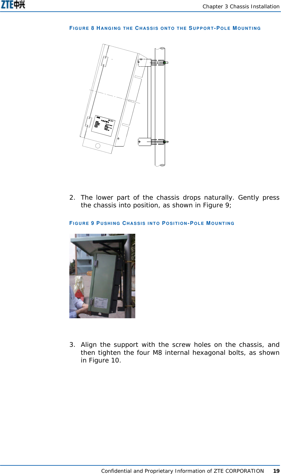
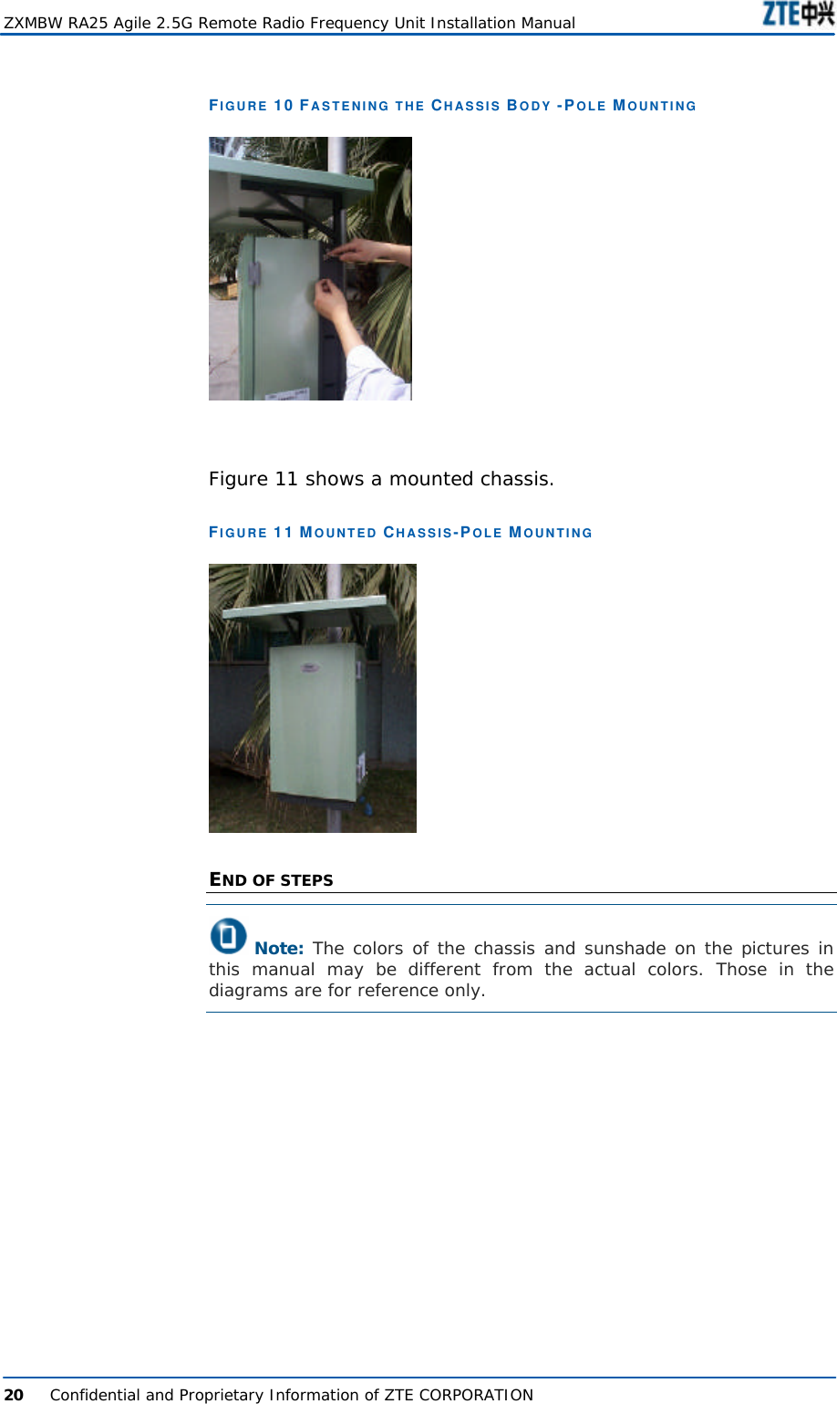
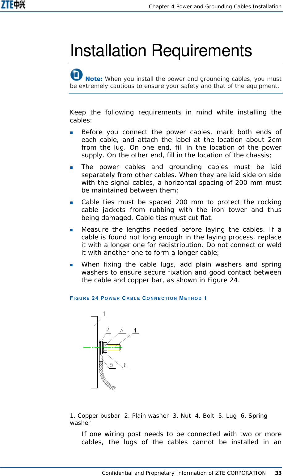
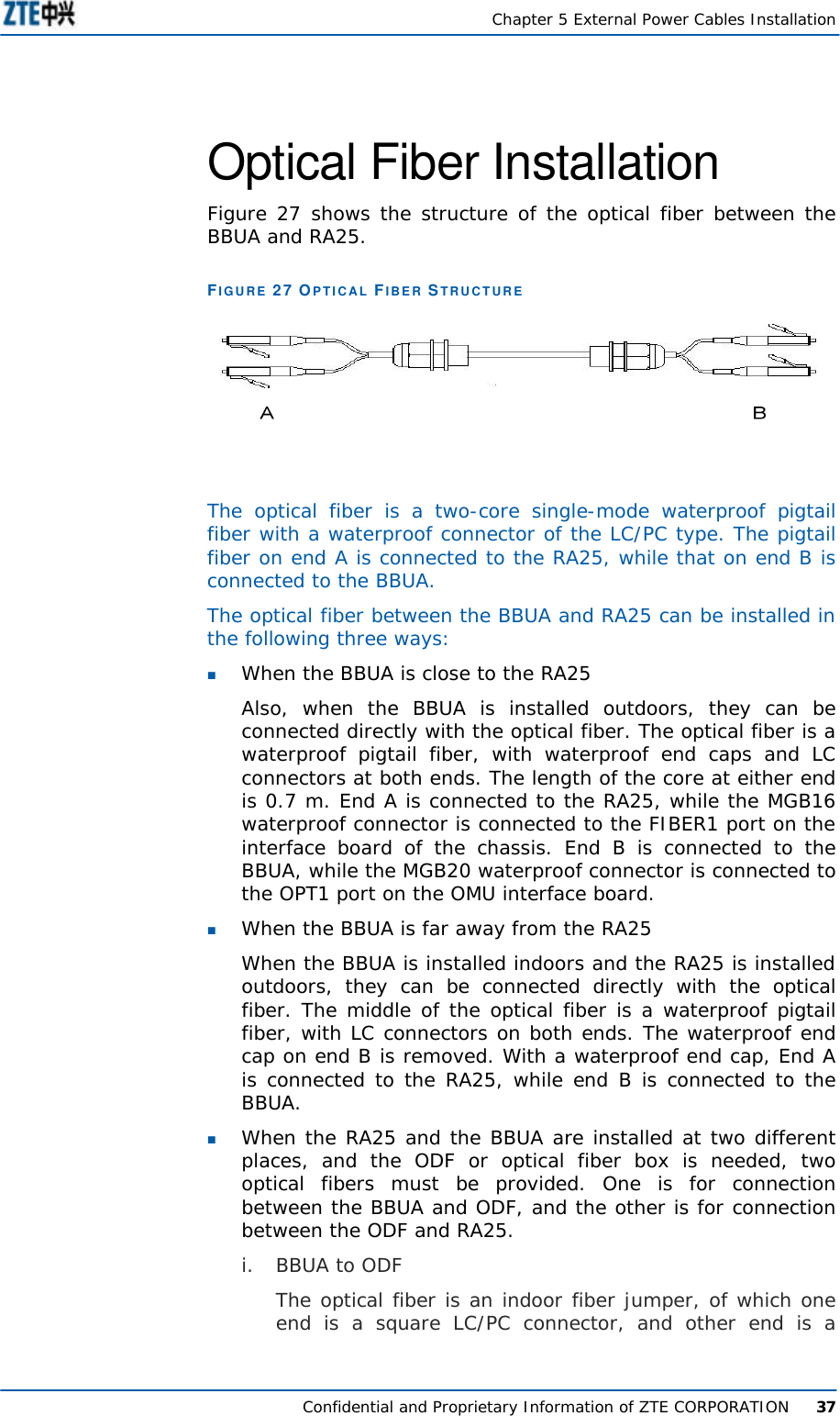
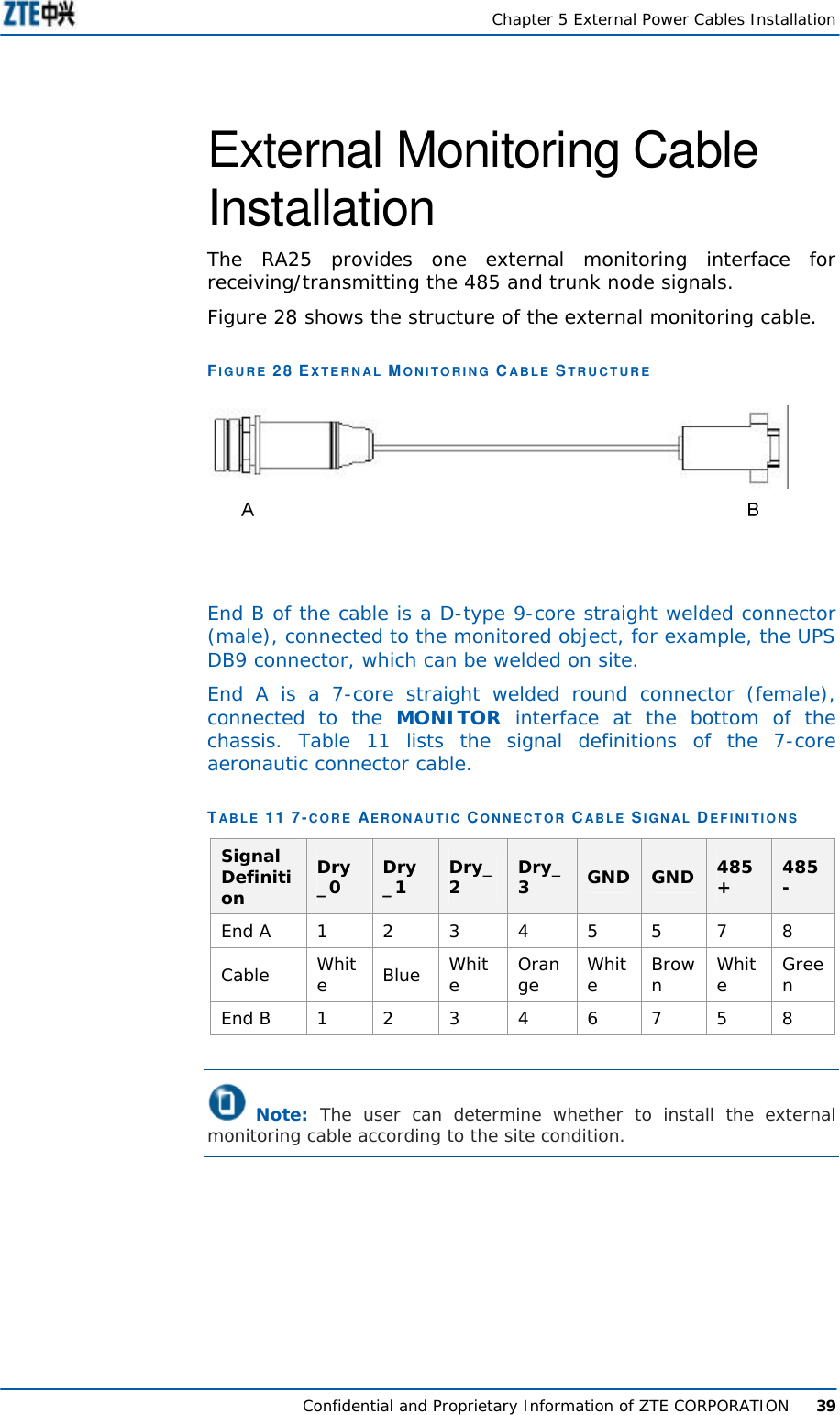
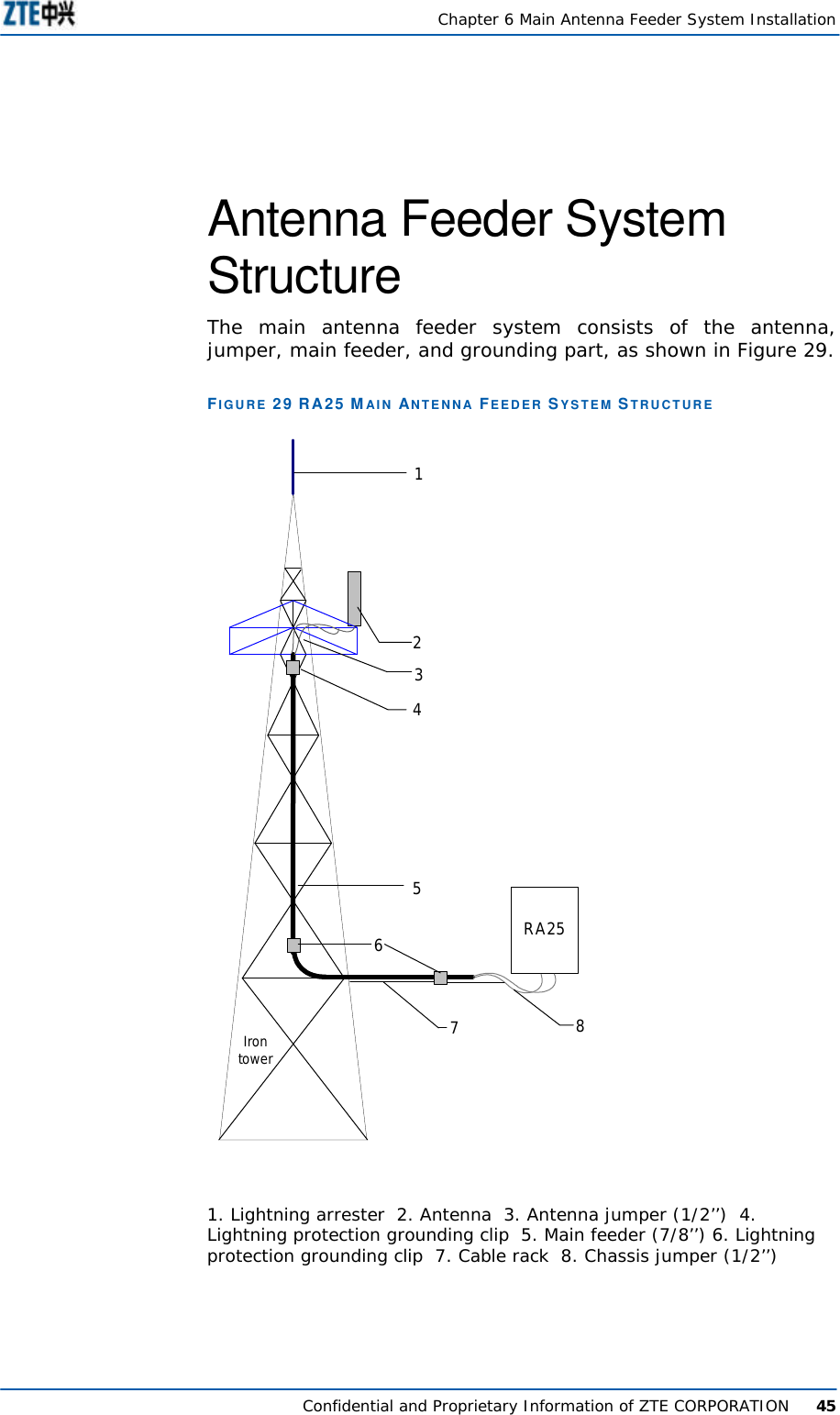
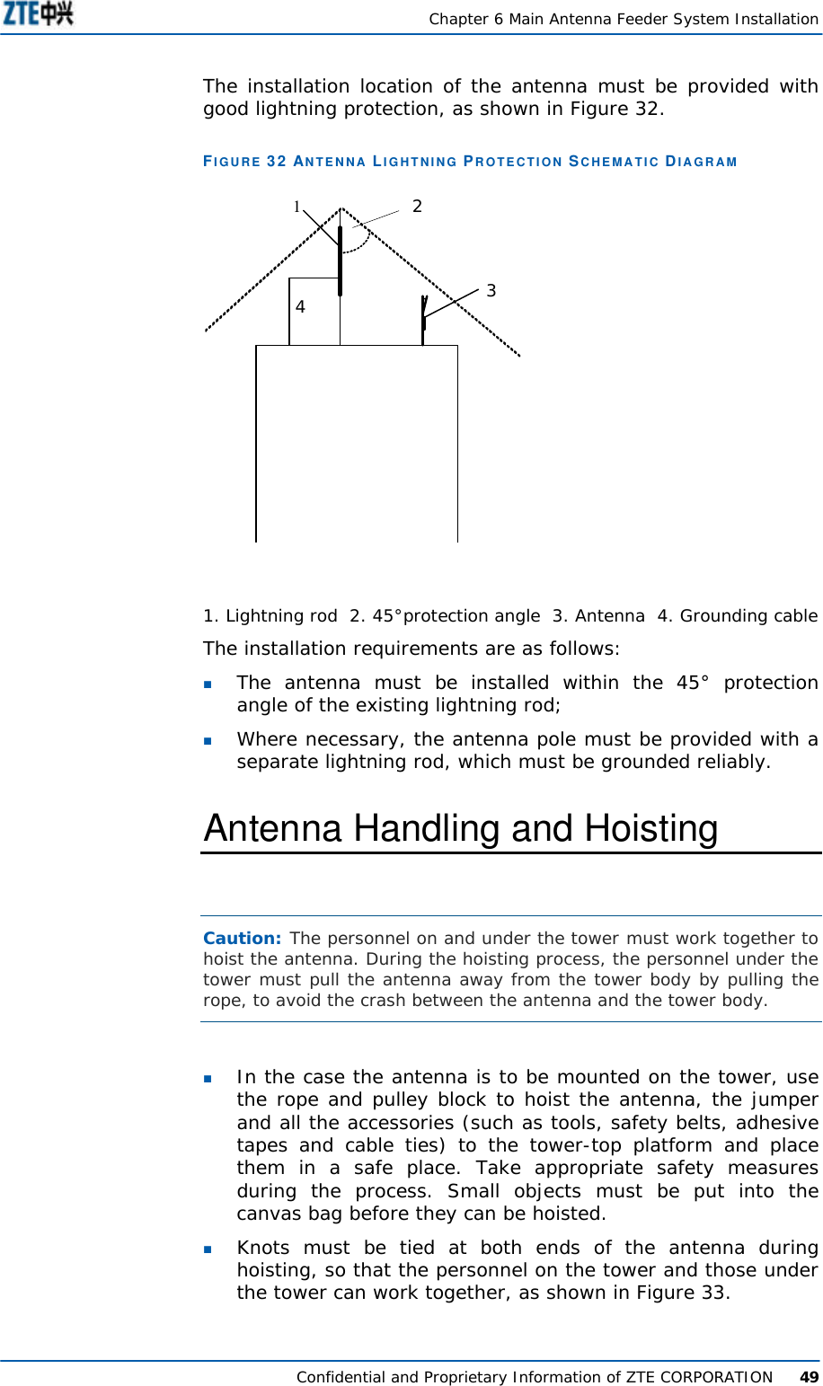
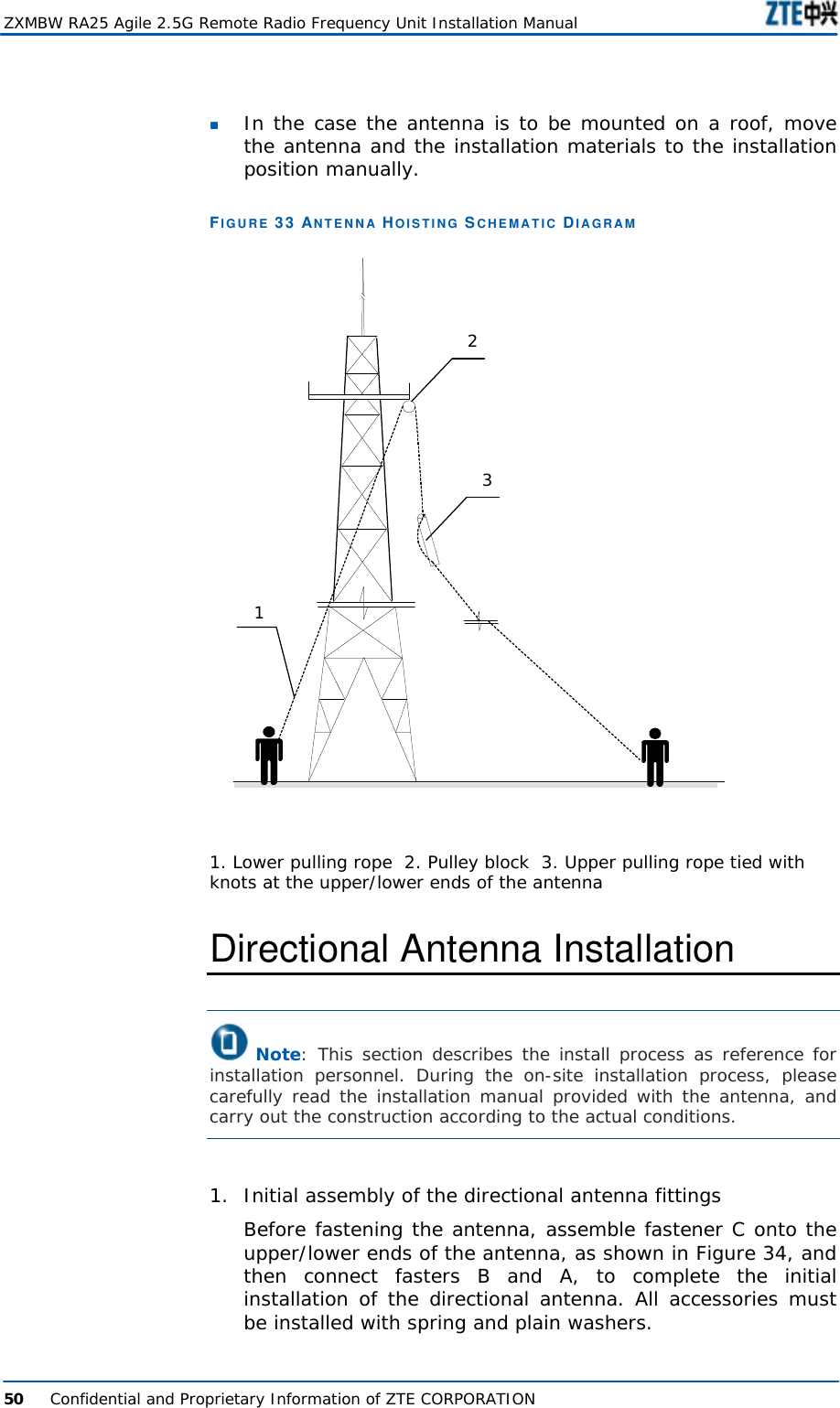
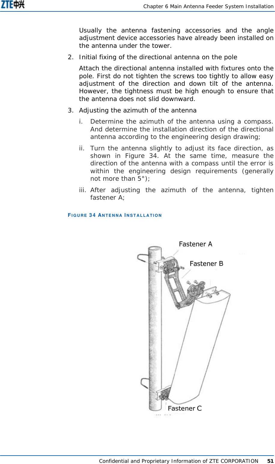
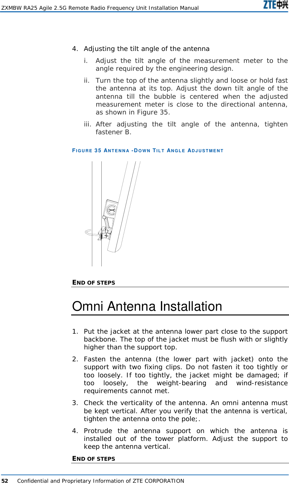
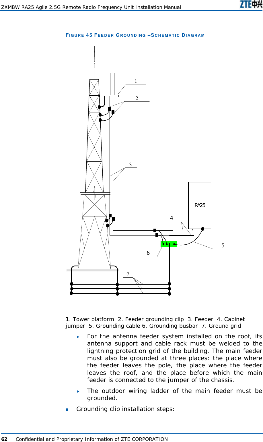
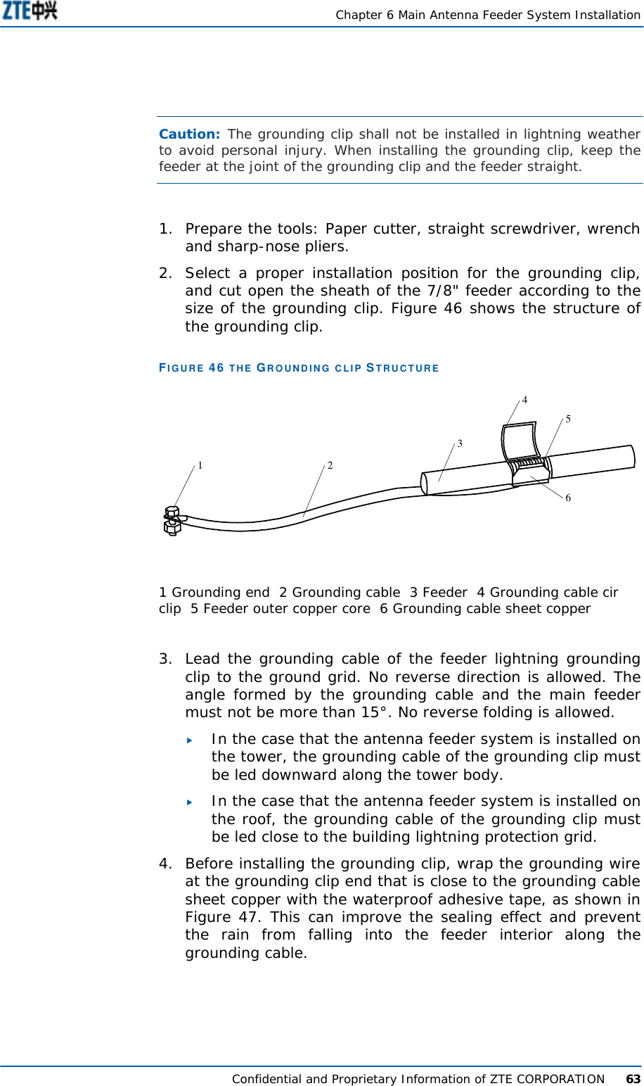
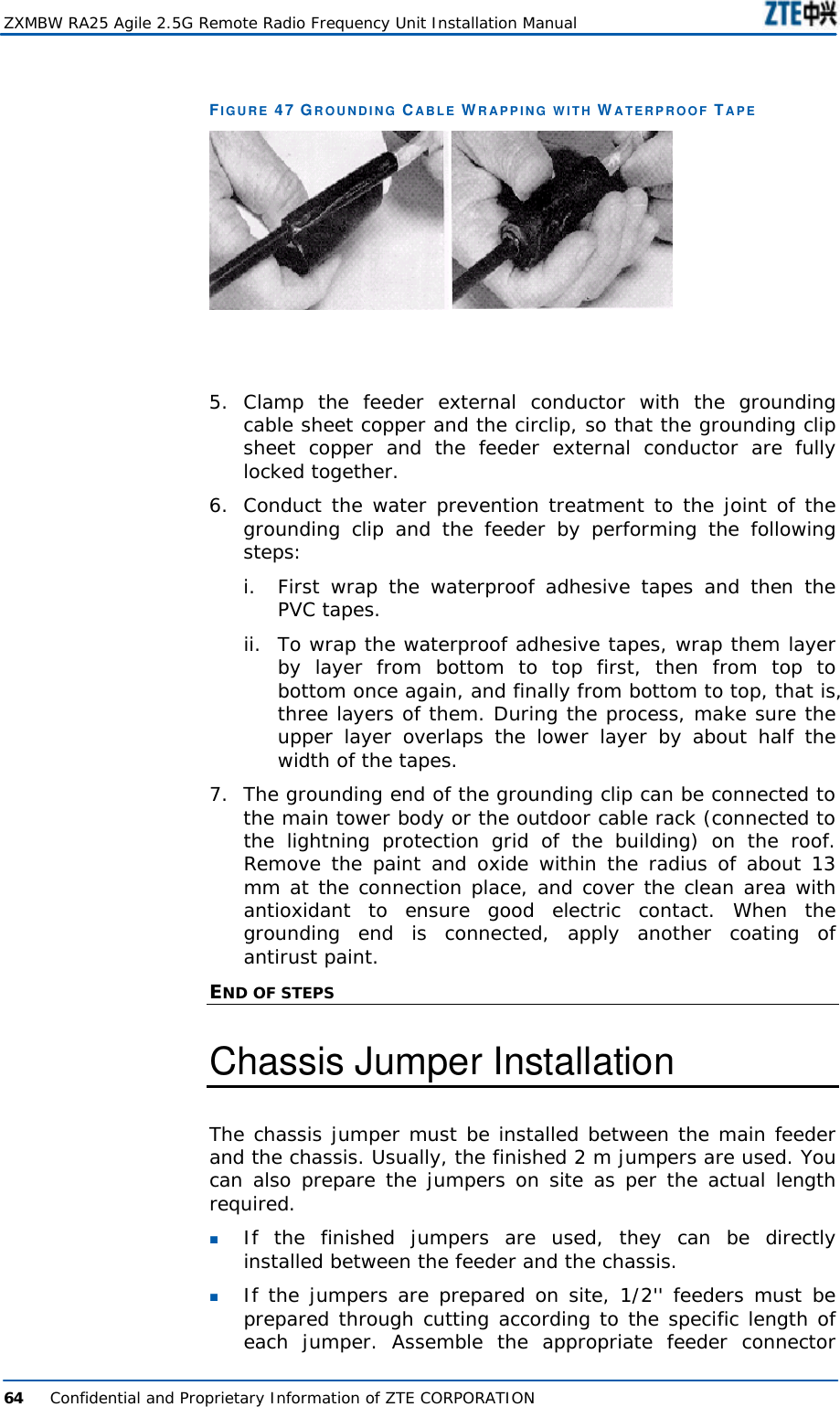
![About this Manual Confidential and Proprietary Information of ZTE CORPORATION iii Conventions ZTE documents employ the following typographical conventions. Typographical Conventions TABLE 2 TYPOGRAPHICAL CONVENTIONS Typeface Meaning Italics References to other Manuals and documents. “Quotes” Links on screens. Bold Menus, menu options, function names, input fields, radio button names, check boxes, drop-down lists, dialog box names, window names. CAPS Keys on the keyboard and buttons on screens and company name. Constant width Text that you type, program code, files and directory names, and function names. [ ] Optional parameters. { } Mandatory parameters. | Select one of the parameters that are delimited by it. Note: Provides additional information about a certain topic. Checkpoint: Indicates that a particular step needs to be checked before proceeding further. Tip: Indicates a suggestion or hint to make things easier or more productive for the reader. Mouse Operation Conventions TABLE 3 MOUSE OPERATION CONVENTIONS Typeface Meaning Click Refers to clicking the primary mouse button (usually the left mouse button) once. Double-click Refers to quickly clicking the primary mouse button (usually the left mouse button) twice. Right-click Refers to clicking the secondary mouse button (usually the right mouse button) once. Drag Refers to pressing and holding a mouse button and moving the mouse.](https://usermanual.wiki/ZTE/ZXMBW-RA25/User-Guide-736604-Page-11.png)