ZTE ZXR10W140A W140A Wireless Access Point User Manual Professional Installation Manual
ZTE Corporation W140A Wireless Access Point Professional Installation Manual
ZTE >
Contents
- 1. Professional Installation Manual
- 2. Users Manual
Professional Installation Manual
ZXR10 WAS (V1.0) IP Wireless Access System
W140A Outdoor Wireless Access
Point/Bridge
Professional Installation
Instruction Manual
ZTE CORPORATION
ZXR10 WAS (V1.0) IP Wireless Access System
W140A Outdoor Wireless Access Point/Bridge
Professional Installation Instruction Manual
Manual Version 20040325-R1.0
Product Version V1.0
Copyright © 2003 ZTE Corporation
All rights reserved.
No part of this documentation may be excerpted, reproduced, translated, annotated or
duplicated, in any form or by any means without the prior written permission of ZTE
Corporation.
ZTE CORPORATION
ZTE Plaza, Keji Road South, Hi-Tech Industrial Park, Nanshan District, Shenzhen, P.R.China
Website: http://www.zte.com.cn
Postcode: 518057
Customer Support Center: (+86755) 26771900 800-9830-9830
Fax: (+86755) 26770801
Email: support@zte.com.cn
* * * *
S.N.: sjzl20040367

Conventions
Four striking symbols are used throughout this manual to emphasize important and
critical information during operation:
Danger, Warning, Caution and Note statements are
used throughout this manual to emphasize important and critical information. You must
read these statements to help ensure safety and to prevent product damage. The
statements are defined below.
Statement: The actual product may differ from what is described in this
manual due to frequent update of ZTE products and fast development of
technologies. Please contact the local ZTE office for the latest updating
information of the product.
-i-
Contents
1 Safety Precautions...................................................................................................................................1-1
1.1 Safety Precautions..........................................................................................................................1-1
1.2 Symbol Description........................................................................................................................ 1-1
2 Installation and Debugging ....................................................................................................................2-1
2.1 Equipment Configurations and Fittings .........................................................................................2-1
2.1.1 Equipment Configurations ..................................................................................................2-1
2.1.2 Mechanical Parts .................................................................................................................2-2
2.1.3 Antenna ............................................................................................................................... 2-4
2.2 Installation Preparations................................................................................................................. 2-7
2.2.1 Channel Planning ................................................................................................................2-8
2.2.2 Configurations Before Installation ......................................................................................2-9
2.2.3 Tools, Instruments and Documentations ...........................................................................2-10
2.2.4 Installation Environment Inspection .................................................................................2-10
2.2.5 Unpacking Inspection........................................................................................................ 2-11
2.3 Installation.................................................................................................................................... 2-11
2.3.1 Installation Process............................................................................................................ 2-11
2.3.2 Installation Method ...........................................................................................................2-12
2.3.3 Installing Antenna .............................................................................................................2-21
2.3.4 Connecting Antenna Feeder ..............................................................................................2-22
2.3.5 Connecting PoE Cable ......................................................................................................2-22
2.3.6 Lightning Protection System.............................................................................................2-23
2.4 Power-on and Power-off ..............................................................................................................2-24
2.5 Debugging....................................................................................................................................2-25
-ii-
3 Command Line Configuration .............................................................................................................. 3-1
3.1 Overview ....................................................................................................................................... 3-1
3.2 User Mode ..................................................................................................................................... 3-3
3.3 Privileged Mode ............................................................................................................................ 3-4
3.3.1 Command to Test Network Connectivity............................................................................ 3-4
3.3.2 Command to Save Configurations to Flash ........................................................................ 3-4
3.3.3 Command to Reset Software .............................................................................................. 3-4
3.3.4 Command to Enter Configure Mode................................................................................... 3-5
3.3.5 Command to Exit Privileged Mode .................................................................................... 3-5
3.3.6 Command to Exit TELNET Configuration......................................................................... 3-5
3.4 Configure Mode............................................................................................................................. 3-5
3.4.1 Commands to Configure Wireless Access-Bridge .............................................................. 3-5
3.4.2 Command to Configure Bridge Information....................................................................... 3-6
3.4.3 Commands to Configure DHCP Server .............................................................................. 3-7
3.4.4 Discover commands............................................................................................................ 3-8
3.4.5 Commands to Configure 802.1X Parameters ..................................................................... 3-9
3.4.6 Command to Set User Password in Privileged Mode ....................................................... 3-12
3.4.7 Command to Delete Filtration Rules ................................................................................ 3-12
3.4.8 Command to Exit Configuration Mode ............................................................................ 3-13
3.4.9 Commands to Configure IAPP (Load-balance) ................................................................ 3-13
3.4.10 Interface Skip.................................................................................................................. 3-14
3.4.11 Commands to Configure Layer 2 Isolation..................................................................... 3-15
3.4.12 Commands to Configure IP network Parameters............................................................ 3-15
3.4.13 Command to Configure Log Print Information .............................................................. 3-16
3.4.14 Command to Configure MAC Filter............................................................................... 3-17
3.4.15 Command to Configure MAC Address Authentication .................................................. 3-18
-iii-
3.4.16 Command to Configure Users.........................................................................................3-18
3.4.17 Commands to Configure Radius Server..........................................................................3-19
3.4.18 Command to Configure SNMP Module..........................................................................3-21
3.4.19 Command to Manage Telnet Idle Timeout......................................................................3-25
3.4.20 Commands to Upload/download TFTP Files ..................................................................3-25
3.4.21 Commands to Configure VLAN ..................................................................................... 3-26
3.4.22 Show Commands ............................................................................................................3-27
3.5 Ethernet Interface Configuration Mode .......................................................................................3-33
3.5.1 Configurations in the Ethernet Interface Mode.................................................................3-33
3.5.2 Command to Exit the Ethernet Interface Configuration Mode .........................................3-33
3.5.3 Command to Configure Ethernet interface IP addresses...................................................3-33
3.5.4 Command to Configure MAC filter for the Ethernet Interface .........................................3-34
3.6 Wireless Interface Configuration Mode .......................................................................................3-34
3.6.1 Command to Configure 80211b-related Parameters for the Wireless Interface................ 3-34
3.6.2 Command to Exit Wireless Interface Configuration Mode...............................................3-36
3.6.3 Command to Enable Link Integrity Detection ..................................................................3-37
3.6.4 WEP Configuration of the Wireless Interface ...................................................................3-37
3.6.5 Command to Configure MAC Filter in Wireless Interface Configuration ........................3-38
3.6.6 Command to Configure Authentication Mode in Wireless Interface Configuration.........3-39
Appendix A Making of Ethernet Cable...................................................................................................A-1
A.1 Making of Ethernet Cables........................................................................................................... A-1
A.1.1 Making of Straight Through Ethernet Cables (RJ45)........................................................ A-1
A.1.2 Making of Straight Through Power Supply Ethernet Cables (C-RJ45-001) ..................... A-1
A.1.3 Making of Crossover Ethernet Cables (RJ45J) ................................................................. A-2
A.1.4 Ethernet Cable Label......................................................................................................... A-3
-iv-
-i-
A List of Figures
Fig. 2.1-1 W140A Structure ..............................................................................................................2-3
Fig. 2.1-2 The Structure of W140A Backplane................................................................................. 2-3
Fig. 2.1-3 The Structure of W140A Mounting Panel ........................................................................ 2-4
Fig. 2.1-4 Physical Appearance of an Omni Antenna ....................................................................... 2-5
Fig. 2.1-5 Physical Appearance of an Indoor (Outdoor) Directional Antenna ..................................2-5
Fig. 2.1-6 Physical Appearance of a 14 dBi Directional Antenna.....................................................2-6
Fig. 2.2-1 Sub-channel Allocations...................................................................................................2-8
Fig. 2.2-2 Channel Allocations between the Adjacent APs in Actual Networking ...........................2-9
Fig. 2.3-1 The Process of Installing the W140A.............................................................................2-12
Fig. 2.3-2 The Necessary Components in the Wall-Mounted Mode...............................................2-13
Fig. 2.3-3 The W140A Backplane...................................................................................................2-14
Fig. 2.3-4 The Necessary Components in the Pole-Mounted Mode ...............................................2-15
Fig. 2.3-5 The Necessary Components in the Roof-Mounted Mode with an Installing support C .2-17
Fig. 2.3-6 The Necessary Components in the Roof-Mounted Mode with an Installing support A .2-18
Fig. 2.3-7 The Necessary Components in the Side Wall-Mounted Mode .......................................2-20
Fig. 2.3-8 The Grounding System of the W140A ...........................................................................2-24
Fig. 3.1-1 Telnet to W140A ..............................................................................................................3-3
Figure B.2-1 Straight through Ethernet label ...................................................................................A-3
Figure B.2-2 Label of the Straight Through Power Supply Ethernet Cable..................................... A-3
Figure B.2-3 Crossover Ethernet Cable Label ................................................................................. A-4
-i-
A list of Tables
Table 1.2-1 Safety Symbols and Descriptions...................................................................................1-2
Table 2.1-1 A List of the W140A Kit ................................................................................................ 2-1
Table 2.1-2 A List of Optional Fittings of the W140A...................................................................... 2-2
Table 2.1-3 Technical Indices of an Outdoor Omni Antenna ............................................................ 2-5
Table 2.1-4 Technical Indices of an Indoor (Outdoor) Directional Antenna.....................................2-6
Table 2.1-5 Technical Indices of a 14 dBi Directional Antenna........................................................2-7
Table 2.2-1 Channel IDs and Frequencies.........................................................................................2-8
Table B.2-1 Connections of Straight Through Ethernet Cables (RJ45) ........................................... A-1
Table B.2-2 Connections of Straight Through Power Supply Ethernet Cables (C-RJ45-001)......... A-1
Table B.2-3 Connections of Crossover Ethernet Cables (RJ45J)..................................................... A-2
1-1
1 Safety Precautions
This chapter introduces the safety precautions of this product and safety symbols used
in this manual.
1.1 Safety Precautions
High voltage and high temperature exist in this equipment, so only trained professional
personnel can install, operate and maintain it.
During the installation, operation and maintenance of the equipment, all the safety
rules and related operation procedures on the site must be strictly abided by, to avoid
body injuries or equipment damages. The safety precautions in this manual can only be
used as a supplement to site safety regulations.
ZTE assumes no responsibility for consequences resulting from violation of general
specifications for safety operations or of safety rules for design, production and use of
the equipment.
1.2 Symbol Description
See Table 1.2-1 for the safety symbols used in this manual, which serves to remind the
readers of the safety precautions to be taken when the equipment is installed, operated
and maintained.
ZXR10 WAS (V1.0) W140A Outdoor Wireless Access Point / Bridge
Professional Installation Instruction Manual
1-2
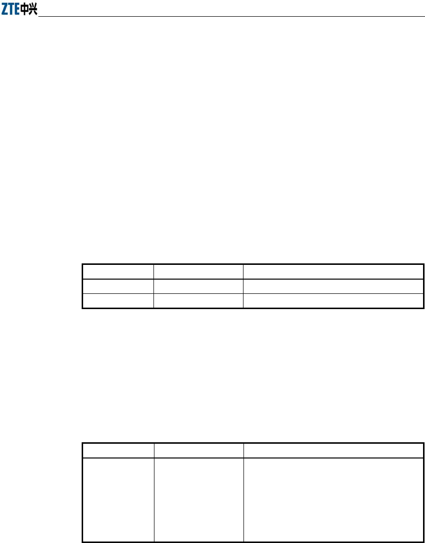
Table 1.2-1 Safety Symbols and Descriptions
Safety Symbol Meaning
Call for notice
Call for antistatic measures
Warn against electric shock
Caution against scald
Warn against laser
Caution against microwave
Four types of safety levels are available: danger, warning, caution and note. To the
right of a safety symbol is the text description of its safety level. Under the symbol is
the detailed description about its contents. The formats are as follows.
Danger:
Indicates an imminently hazardous situation which, if not avoided, will result in death
or serious injury. This signal word is to be limited to the most extreme situations.
Warning:
Indicates a potentially hazardous situation which, if not avoided, could result in death
or serious injury.
Caution:
Indicates a potentially hazardous situation which, if not avoided, could result in minor
or moderate injury. It may also be used to alert against unsafe practices.

Chapter Error! Style not defined. Error! Style not defined.
1-3
Note:
A Note statement is used to notify people of installation, operation, or maintenance
information that is important, but not hazard-related.
Tips:
Indicates a suggestion or hint to make things easier or more productive for the reader

2-1
2 Installation and Debugging
W140A require installation by professional installer. This chapter introduces the
W140A fittings, installation methods and steps, debugging methods and steps for your
reference.
2.1 Equipment Configurations and Fittings
2.1.1 Equipment Configurations
The W140A is composed of a kit and optional fittings. Items in the kit are not to be
changed randomly, but items in the fittings are dispensable depending on the user
demands.
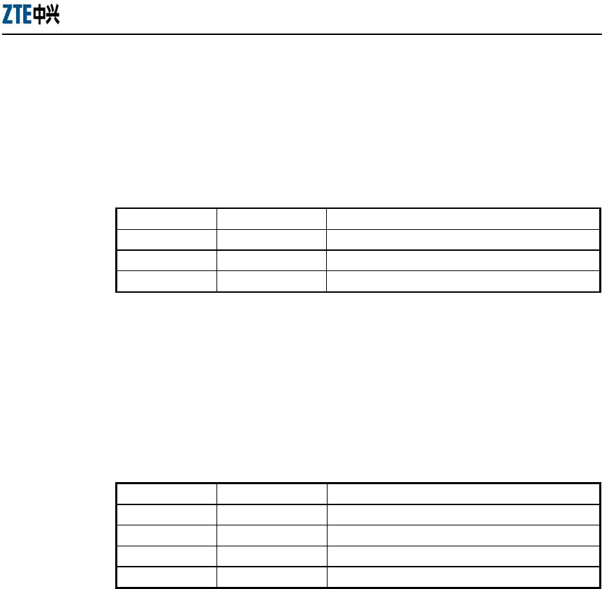
Please refer to Table 2.1-1 for a list of the W140A kit.
Table 2.1-1 A List of the W140A Kit
Name Unit Quantity Remarks
W140A Set 1
Backplane PCS 1
With seven M8×10 inner hex head
screws and four expansion screws
Mounting panel PCS 1
Power over Ethernet (PoE)
product Set 1
Power cord of PoE product pc 1 1.5m
PoE cable pc 1 30m
Grounding cable pc 1 10m
Antenna feeder pc 1 1.2m

ZXR10 WAS (V1.0) W140A Outdoor Wireless Access Point / Bridge
Professional Installation Instruction Manual
2-2
Please refer to Table 2.1-2 for a list of optional fittings of the W140A.
Table 2.1-2 A List of Optional Fittings of the W140A
Name Unit Quantity Remarks
Omni antenna pc 1 8 dBi omni antenna
Directional antenna pc 1 8.5 dBi directional antenna
Directional antenna pc 1 14 dBi directional antenna
Directional antenna pc 1 21 dBi directional antenna
Antenna kit Set 1 Used for installing and fixing an omni antenna.
Installing support A Set 1
Used for roof-mounted mode (comprising a vertical
pole), applicable to install all types of antennae, and
providing an installation position for a lightning
arrester.
Installing support B Set 1
Used for pole-mounted mode (excluding a vertical
pole), inapplicable to install a directional antenna,
and an installation position for a lightning arrester
not available.
Installing support C Set 1
Used for side wall-mounted mode (comprising a
vertical pole), applicable to install all types of
antennae, but an installation position for a lightning
arrester not available. You can choose roof-mounted
mode or side wall-mounted mode as required.
Lightning arrester pc 1
If a lightning arrester is not available on the roof,
you must install a lightning arrester in an installing
support A.
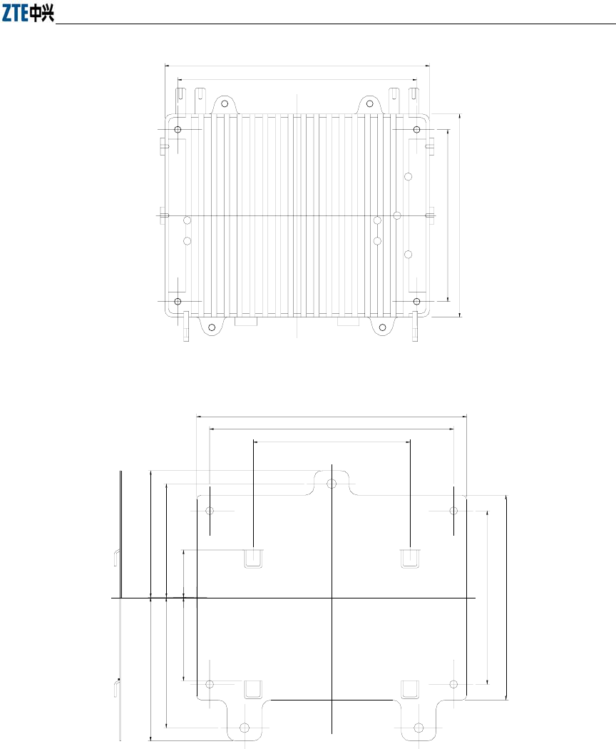
2.1.2 Mechanical Parts
Mechanical parts of the W140A consist of the W140A, backplane, mounting panel and
installation fittings. Fig. 2.1-1, Fig. 2.1-2 and Fig. 2.1-3 show the mechanical structures
of W140A, backplane and mounting panel in turn.
Chapter Error! Style not defined. Error! Style not defined.
2-3
310
280
199
235
Fig. 2.1-1 W140A Structure
310
280
180
199
235
145.5
130.5
54.5
95.5
164.5
149.5
Fig. 2.1-2 The Structure of W140A Backplane
ZXR10 WAS (V1.0) W140A Outdoor Wireless Access Point / Bridge
Professional Installation Instruction Manual
2-4
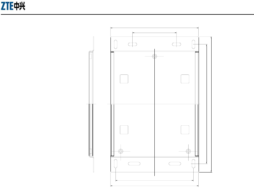
260
130
352
400
230
260
Fig. 2.1-3 The Structure of W140A Mounting Panel
2.1.3 Antenna
An antenna works effectively to convert high-frequency oscillating currents (energy)
into radio waves which are transmitted to the air; or, convert the radio waves received
from the air into high-frequency voltage (energy). It serves to implement energy
conversion.
The W140A adopts an outdoor antenna: Omni antenna or directional antenna.
Following are introductions to the common types of antennae.
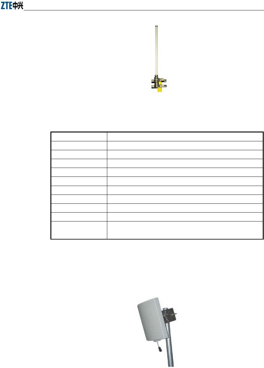
1. Outdoor omni antenna
Fig. 2.1-4 shows the physical appearance of an outdoor omni antenna, and Table
2.1-3 lists the technical indices.
Chapter Error! Style not defined. Error! Style not defined.
2-5
Fig. 2.1-4 Physical Appearance of an Omni Antenna
Table 2.1-3 Technical Indices of an Outdoor Omni Antenna
Items Technical Indices
Frequency range 2.4 GHz ~ 2.5 GHz
Gain 8 dBi
VSWR 1.5: 1 Max
Polarization Vertical polarization
Horizontal beam width 360°
Vertical beam width 15°
Connector type N-K
Input impedance 50 Ω
Outer dimensions φ 22 mm × 800 mm
Installation mode The antenna is fixed to a pole through a fixture, and connected to the
antenna interface in the AP through a cable.
2. Indoor (outdoor) directional antenna
Fig. 2.1-5 shows the physical appearance of an indoor (outdoor) directional
antenna, and Table 2.1-4 lists the technical indices.
Fig. 2.1-5 Physical Appearance of an Indoor (Outdoor) Directional Antenna
ZXR10 WAS (V1.0) W140A Outdoor Wireless Access Point / Bridge
Professional Installation Instruction Manual
2-6
Table 2.1-4 Technical Indices of an Indoor (Outdoor) Directional Antenna
Items Technical Indices
Frequency range 2.4 GHz ~ 2.5 GHz
Gain 8.5 dBi
VSWR 1.5: 1 Max
Polarization Vertical polarization
Horizontal beam width 70°
Vertical beam width 65°
Connector type N-K
Input impedance 50 Ω
Outer dimensions 120 mm × 120 mm × 44 mm
Installation mode
The indoor or outdoor antenna is fixed to a wall or a pole through the
installation parts, and connected to the antenna interface in the AP
through a cable.
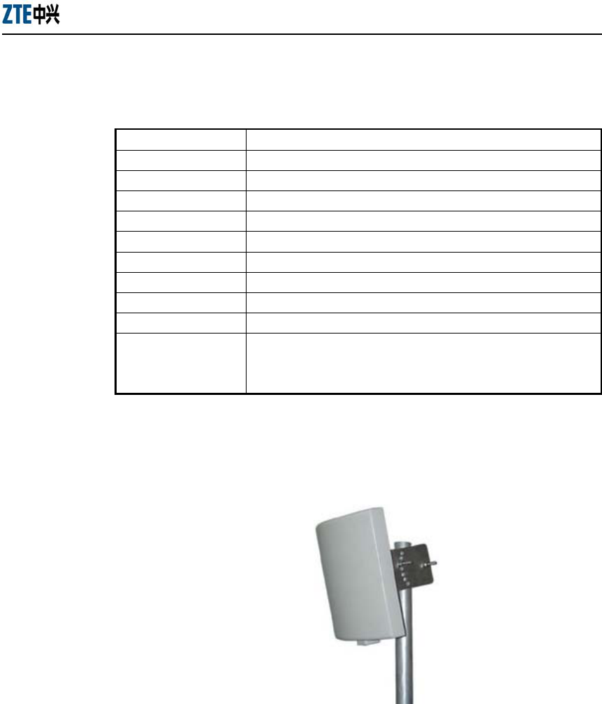
3. 14 dBi directional antenna
Fig. 2.1-6 shows the physical appearance of a 14 dBi directional antenna, and
Table 2.1-5 lists the technical indices.
Fig. 2.1-6 Physical Appearance of a 14 dBi Directional Antenna

Chapter Error! Style not defined. Error! Style not defined.
2-7
Table 2.1-5 Technical Indices of a 14 dBi Directional Antenna
Items Technical Indices
Frequency range 2.4 GHz ~ 2.5 GHz
Gain 14 dBi
VSWR 1.5: 1 Max
Polarization Vertical polarization
Horizontal beam width 30°
Vertical beam width 30°
Connector type N-K
Input impedance: 50 Ω
Outer dimensions 240 mm × 240 mm × 60 mm
Installation mode The antenna is fixed to a support, and connected to the antenna interface
in the AP through a cable.
2.2 Installation Preparations
Whether the W140A is properly installed has a direct impact on the QoS of the system.
Due to the huge amount of installation work, it is necessary to work out a practicable
installation scheme to effectively ensure the progress and quality of the installation
work.
Complete the following issues before installing the W140A:
1. Network planning: Defining the installation location, installation mode and
connection method of the working ground.
2. Obtaining installation approval documents: To install the W140A in any public
building or the building of any group or individual, you should ask for
permission in advance.
3. Line resource: The W140A must be connected with the upper layer network
equipment via an RJ45 Ethernet interface. You should make sure beforehand
that whether the necessary line resource is available.
4. Lightning protection measures: Determining the lightning protection measures.
If a lightning arrester is to be installed, determining the grounding method of the
lightning protection grounding wire.
5. Installation personnel: Only the trained personnel should be allowed to install
the W140A, and supervision personnel should be present.
ZXR10 WAS (V1.0) W140A Outdoor Wireless Access Point / Bridge
Professional Installation Instruction Manual
2-8
6. Installation materials: Before the W140A is installed, making sure that all the
installation materials are ready.
7. The installation tools, instruments and documentations should be in place.
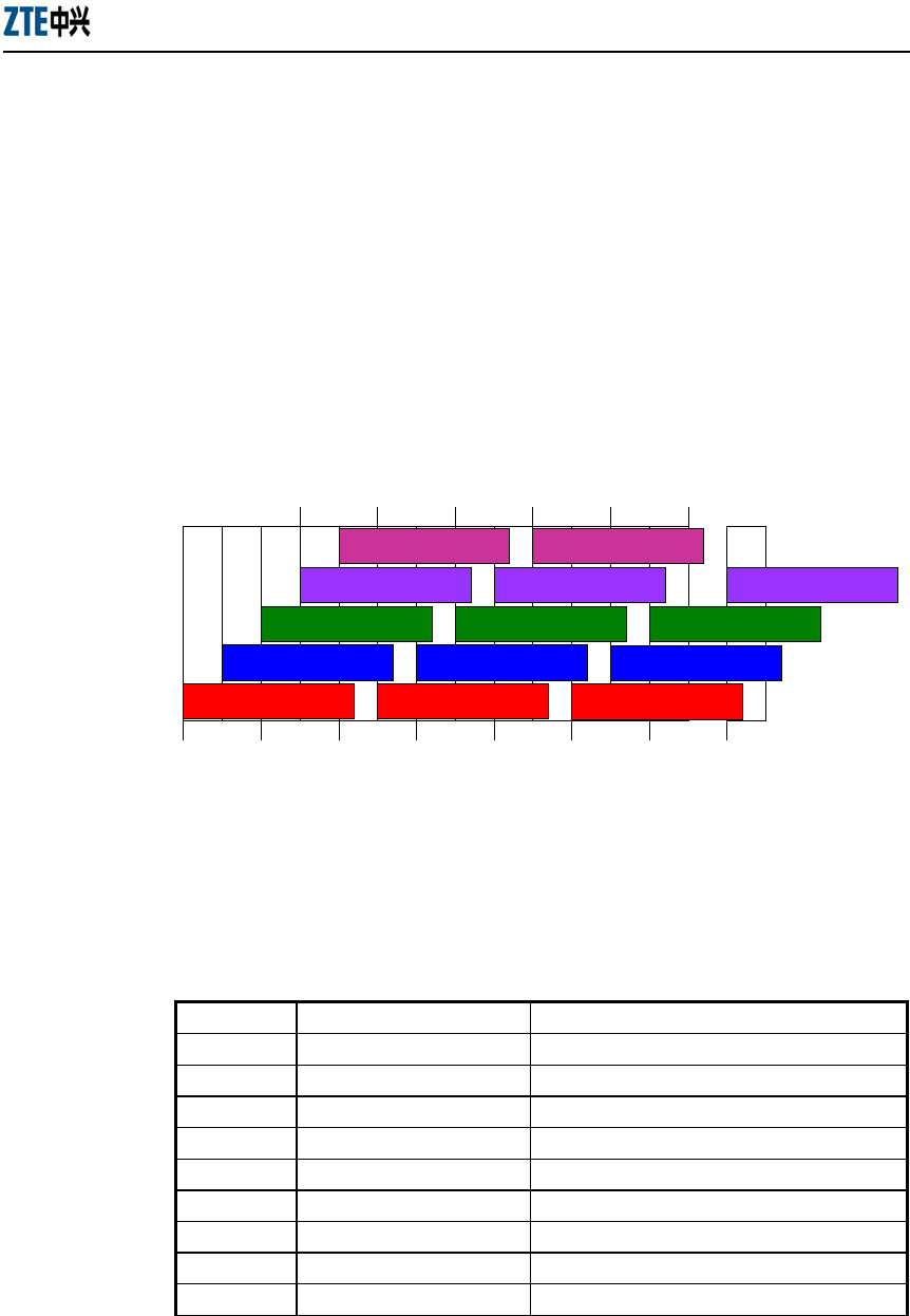
2.2.1 Channel Planning
According to the wireless LAN technology standard 802.11b and the standard of state
radio management committee, a wireless device in the wireless LAN operates at 2400
MHz ~ 2483.5 MHz, and the working frequency bandwidth is 83.5 MHz. The working
frequency is divided into 14 sub-channels, and the bandwidth of each sub-channel is 22
MHz. Fig. 2.2-1 shows the sub-channel allocations.
1 6 11
2 7 12
3
4
510
9
8
14
13
2.417 2.427 2.437 2.447 2.457
2.412 2.422 2.432 2.442 2.452 2.462 2.472 2.484
2.467
Fig. 2.2-1 Sub-channel Allocations
The above figure reveals that up to 13 channels are available. The IDs and central
frequencies of these 13 channels are described in Table 2.2-1.
Table 2.2-1 Channel IDs and Frequencies
Channel ID Central Frequency Low End/High End Frequency of the Channel
1 2,412 MHz 2401/2423 MHz
2 2,417 MHz 2411/2433 MHz
3 2,422 MHz 2416/2438 MHz
4 2,427 MHz 2421/2443 MHz
5 2,432 MHz 2426/2448 MHz
6 2,437 MHz 2431/2453 MHz
7 2,442 MHz 2431/2453 MHz
8 2,447 MHz 2436/2458 MHz
9 2,452 MHz 2441/2463 MHz
Chapter Error! Style not defined. Error! Style not defined.
2-9
10 2,457 MHz 2446/2468 MHz
11 2,462 MHz 2451/2473 MHz
12 2,467 MHz 2456/2478 MHz
13 2,472 MHz 2461/2483 MHz
When multiple channels are working at the same time, the central frequency intervals
between two channels should not be less than 25 MHz to avoid mutual interference. As
shown in Fig. 2.2-1, the technology of direct sequence spread spectrum can support
three un-overlapped channels working simultaneously in a cell.
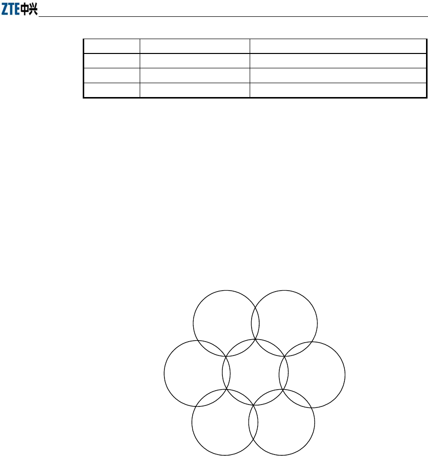
In the wireless LAN planning, the cellular coverage principle applied in the BTS
system is introduced in the channel allocation to ensure efficient coverage of the APs
and avoid inter-carrier interference. This principle supports three un-overlapped
channels (for example, channels 1, 6 and 11) working simultaneously in the same area,
as shown in Fig. 2.2-2.
AP
channel 6
AP
channel 6
AP
channel 6
AP
channel 1
AP
channel 11
AP
channel 11
AP
channel 11
Fig. 2.2-2 Channel Allocations between the Adjacent APs in Actual Networking
You should choose the working channels (generally channels 1, 6 and 11) for the
adjacent APs following the principle illustrated in Fig. 2.2-2, to guarantee normal
operation of the equipment in the wireless LAN.
2.2.2 Configurations Before Installation
Prior to install the W140A, power on the APs in turn and check whether they work
normally. If they fail to work normally, please check whether the versions are loaded
correctly. Refer to Section Error! Reference source not found. for details of loading a

ZXR10 WAS (V1.0) W140A Outdoor Wireless Access Point / Bridge
Professional Installation Instruction Manual
2-10
version.
When you are sure that the APs work normally, you should proceed with the following
basic configurations:
1. Configuring IP addresses of the Ethernet interfaces, that is, the management
addresses. At least one management address should be configured for each AP
for the end of management configuration. This management address may be a
private address or a public address.
2. Configuring SSIDs and working channels of the wireless interfaces.
3. Configuring the working mode of the W140A.
The configuration methods will be elaborated in the subsequent sections.
2.2.3 Tools, Instruments and Documentations
1. Tools
A ladder, electric drill, wrench, diagonal pliers, scissors, 8-core cable clamp and
common toolkit.
2. Instrument
Multimeter
3. Documentations
W140A Installation Data Sheet
ZXR10 WAS (V1.0) IP Wireless Access System W140A Outdoor Wireless Access
Point / Bridge User’s Manual
2.2.4 Installation Environment Inspection
As the W140A is located outdoors, you should make sure that the lightning protection
measures are in place.
Generally, the W140A uses W201P as the PoE product, which must be located indoors.
To guarantee the normal work of the W201P and prolong its service lifetime, the indoor
temperature should be in the range of -5°C ~ 45°C, and the relative humidity in the
range of 5% ~ 95%. The equipment room should be dry and ventilated.

Chapter Error! Style not defined. Error! Style not defined.
2-11
2.2.5 Unpacking Inspection
Follow the steps below to perform unpacking inspection.
1. Checking outer packing conditions
If a package is obviously damaged, the technical personnel should mark the
damage distinctly and check the performance of the equipment in the package
afterwards.
2. Checking the amount of the packages
Check the amount of the packages against the packing list. For any discrepancy,
make a memo and report to the department concerned.
3. Unpacking
During the unpacking, handle the packages with care and protect the surface
coating in the parts. For any damage to the inner package materials, a detailed
record must be made.
All the part lists and technical documents of the W140A can be found in the
packing boxes. The installation personnel should check against the lists and read
the technical documents carefully.
4. Counting the articles
After unpacking, check the articles against the configuration list and packing list.
Make sure that the articles are all complete.
Note:
Unpacking inspection should be based on the packing list in the package. If there is any
missing part, please contact ZTE Cooperation.
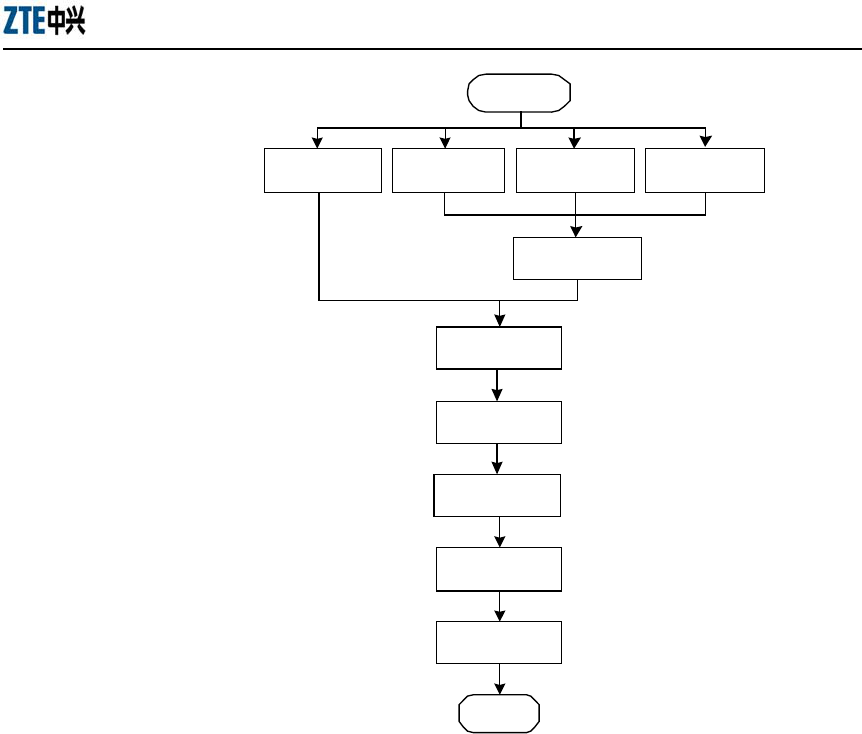
2.3 Installation
2.3.1 Installation Process
Fig. 2.3-1 shows the process of installing the W140A.
ZXR10 WAS (V1.0) W140A Outdoor Wireless Access Point / Bridge
Professional Installation Instruction Manual
2-12
End
Installing
antenna
Installing
mounting panel
Installing
backplane
Installing
W140A
Connecting
cable
Installing
support
Start
Wall-mounted
mode
Pole-mounted
mode
Roof-mounted
mode
Side wall-
mounted mode
Fig. 2.3-1 The Process of Installing the W140A
2.3.2 Installation Method
The W140A can be installed in four modes: Wall-mounted mode, pole-mounted mode,
roof-mounted mode and side wall-mounted mode. You should choose a proper mode
based on the actual requirement.
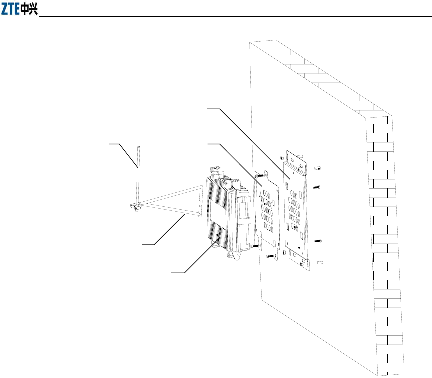
2.3.2.1 Wall-Mounted Mode
The wall-mounted mode is suitable for installing an omni antenna or a directional
antenna. Following is an example of how to install the W140A with an omni antenna in
the wall-mounted mode. You may install the W140A with a directional antenna in the
similar way.
Fig. 2.3-2 shows the necessary components in the wall-mounted mode.
Chapter Error! Style not defined. Error! Style not defined.
2-13
1
23
4
5
1. Backplane 2. Mounting panel 3. Omni antenna 4. Antenna kit 5. W140A
Fig. 2.3-2 The Necessary Components in the Wall-Mounted Mode
To install the W140A in the wall-mounted mode, follow the steps below:
1. Installing the mounting panel: Drill four holes (8 mm in diameter) in the wall
with an impact drill. Clear the dusts and mount the expansion screws, making
the four holes in a rectangular (measuring 230 mm horizontally by 352 mm
vertically) perpendicular to the ground. Fasten the mounting panel to the wall
using the expansion screw kit.
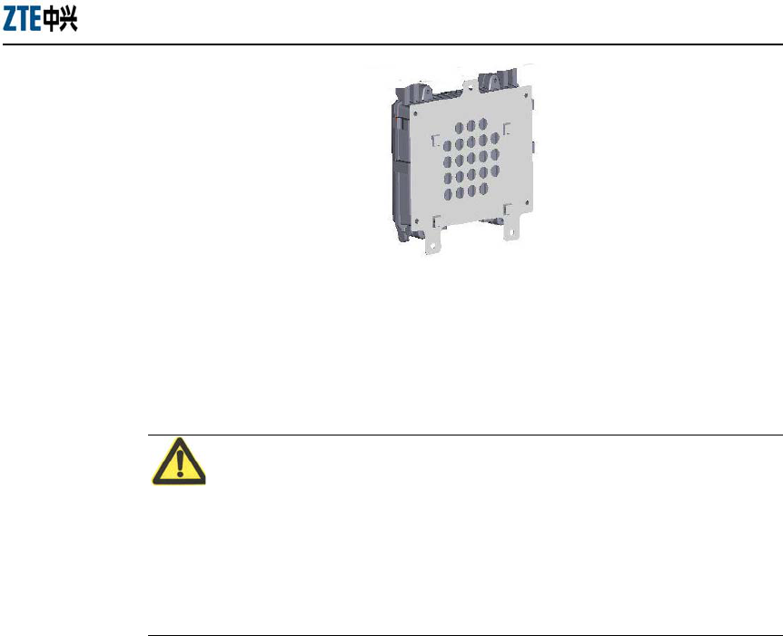
2. Installing the backplane: There are four fastening holes in the backplane of the
W140A, as shown in Fig. 2.3-3. Fix the backplane to the wall using four
matched screws.
ZXR10 WAS (V1.0) W140A Outdoor Wireless Access Point / Bridge
Professional Installation Instruction Manual
2-14
Fig. 2.3-3 The W140A Backplane
3. Installing the antenna: Fix the antenna stand to the left and right locks in the
W140A using a U-shape fixture. Do not screw it too tight. Then fix the omni
antenna to the antenna stand using a U-shape clamp.
Note:
● All the antennas must be clamped on the metallic casings, to ensure that all the
other parts in the antennas do not bear any weight.
● The antenna feeder shall go through the left and right locks of the W140A to make
it look nicer.
4. Installing the W140A: Securing the W140A with a backplane to the mounting
plane on the wall with reference to the three fastening holes in the backplane and
by using the fastening screws.
5. Fixing the antenna: Turn the antenna stand to place the antenna in an optimum
position. Then tighten the U-shape fixture to fix the antenna stand firmly.
6. Connecting the cable: Interconnect the U-interface cable led out from the
distribution box with the twisted pairs of the W140A, and carry out water-proof
and anti-aging treatment. Connect and tighten the cable connectors of the
antenna with the antenna interface of the W140A, and make sure that they are
waterproof.
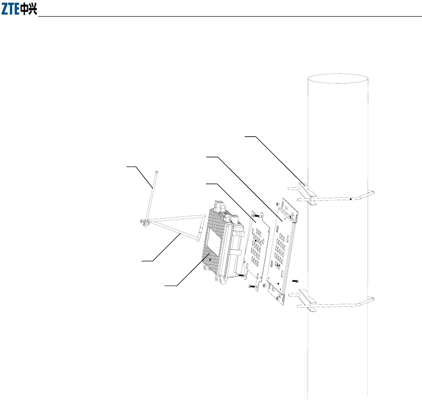
2.3.2.2 Pole-Mounted Mode
The pole-mounted mode is suitable for installing an omni antenna in an installing
support B. Two models of installing support are available: 150 mm-gauge and 230
mm-gauge.
Chapter Error! Style not defined. Error! Style not defined.
2-15
Fig. 2.3-4 shows the components in the pole-mounted mode.
2
3
4
5
6
1
1. Installing support B 2. Backplane 3. Mounting plane 4. Omni antenna 5. Antenna stand kit 6. W140A
Fig. 2.3-4 The Necessary Components in the Pole-Mounted Mode
To install the W140A in the pole-mounted mode, follow the steps below:
1. Installing the mounting panel: Fix the mounting panel to the concrete pole using
a lock ring.
2. Installing the backplane: There are four fastening holes in the backplane of the
W140A, as shown in Fig. 2.3-3. Fix the backplane to the wall using four
matched screws.
3. Installing the antenna: Fix the antenna stand to the left and right locks in the
W140A using a U-shape fixture. Do not screw it too tight. Then fix the omni
antenna to the antenna stand using a U-shape clamp.

ZXR10 WAS (V1.0) W140A Outdoor Wireless Access Point / Bridge
Professional Installation Instruction Manual
2-16
Note:
● All the antennas must be clamped on the metallic casings, to ensure that all the
other parts in the antennas do not bear any weight.
● The antenna feeder shall go through the left and right locks of the W140A to make
it look nicer.
4. Installing the W140A: Securing the W140A with a backplane to the mounting
plane on the wall with reference to the three fastening holes in the backplane and
by using the fastening screws.
5. Fixing the antenna: Turn the antenna stand to place the antenna in an optimum
position. Then tighten the U-shape fixture to fix the antenna stand firmly.
6. Connecting the cable: Interconnect the U-interface cable led out from the
distribution box with the twisted pairs of the W140A, and carry out water-proof
and anti-aging treatment. Connect and tighten the cable connectors of the
antenna with the antenna interface of the W140A, and make sure that they are
waterproof.
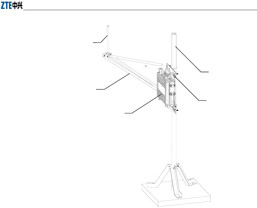
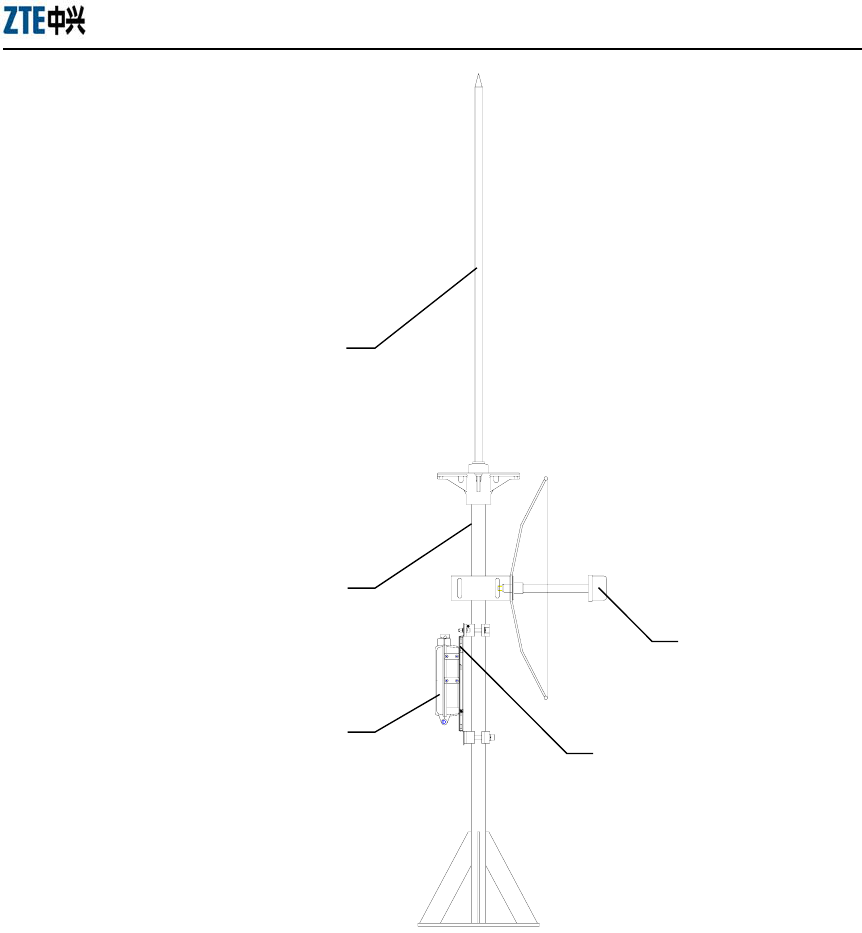
2.3.2.3 Roof-Mounted Mode
The roof-mounted mode is suitable for installing an omni antenna or a directional
antenna. When the W140A is not within the 45° protection area of other lightning
arresters, a lightning arrester should be installed in an installing support A or C.
Fig. 2.3-5 shows the components in the roof-mounted mode with an installing support
C, and Fig. 2.3-6 shows the components in the roof-mounted mode with an installing
support A.
Chapter Error! Style not defined. Error! Style not defined.
2-17
1
2
3
4
5
1. Omni antenna 2. Installing support kit 3. W140A 4. Installing support C 5. Backplane and moutning panel
Fig. 2.3-5 The Necessary Components in the Roof-Mounted Mode with an Installing support C
ZXR10 WAS (V1.0) W140A Outdoor Wireless Access Point / Bridge
Professional Installation Instruction Manual
2-18
1
2
3
4
5
1. Lightning arrester 2. Installing support A 3. W140A 4. Omni antenna 5. Backplane and mounting panel
Fig. 2.3-6 The Necessary Components in the Roof-Mounted Mode with an Installing support A
Following are steps of installing an omni antenna in the roof-mounted mode.
1. Installing the antenna stand: Fix the three pole supports to the installing support
using fixing gaskets and screws. Put the installing supports fixed with three
supports on the mounting base (a concrete base or flat roof). Mark the
installation holes in the pole supports, and remove the installing support. Then
drill the holes in the marked places, and secure the installing support to the

Chapter Error! Style not defined. Error! Style not defined.
2-19
mounting base by the expansion bolts.
2. Installing the antenna: Fix the antenna stand to the left and right locks in the
W140A using a U-shape fixture. Do not screw it too tight. Then fix the omni
antenna to the antenna stand using a U-shape clamp.
Note:
● All the antennas must be clamped on the metallic casings, to ensure that all the
other parts in the antennas do not bear any weight.
● The antenna feeder shall go through the left and right locks of the W140A to make
it look nicer.
● The omni antenna should be secured to the pole.
3. Installing the mounting panel: Secure the mounting panel to the installing
support by using a fixture.
4. Installing the backplane: There are four fastening holes in the backplane of the
W140A, as shown in Fig. 2.3-3. Fix the backplane to the wall using four
matched screws.
5. Installing the W140A: Securing the W140A with a backplane to the mounting
plane on the wall with reference to the three fastening holes in the backplane and
by using the fastening screws.
6. Fixing the antenna: Turn the antenna stand to place the antenna in an optimum
position. Then tighten the U-shape fixture to fix the antenna stand firmly.
7. Connecting the cable: Interconnect the U-interface cable led out from the
distribution box with the twisted pairs of the W140A, and carry out water-proof
and anti-aging treatment. Connect and tighten the cable connectors of the
antenna with the antenna interface of the W140A, and make sure that they are
waterproof.
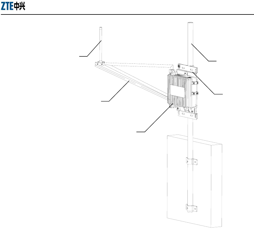
2.3.2.4 Side Wall-Mounted Mode
The side wall-mounted mode is suitable for installing an omni antenna or a directional
antenna. Fig. 2.3-7 shows the components in the side wall-mounted mode with an
installing support C.
ZXR10 WAS (V1.0) W140A Outdoor Wireless Access Point / Bridge
Professional Installation Instruction Manual
2-20
1
2
3
4
5
1. Omni antenna 2. Antenna stand kit 3. W140A 4. Installing support C 5. Backplane and mounting plane
Fig. 2.3-7 The Necessary Components in the Side Wall-Mounted Mode
To install an omni antenna in the side wall-mounted mode, follow the steps below:
1. Installing the antenna stand: Determine the installation location, and draw lines
at the two fastening holes in the wall fixture which is to used along with the
installing support. Then remove the wall fixture and drill holes (12 in diameter,
50 mm deep) at the marked places with an impact drill. After that, insert the
expansion bolts into the installation holes and fix the installing support to the
wall using the matched nuts. The installation spacing depends on the actual
situation.
2. Installing the antenna: Fix the antenna stand to the left and right locks in the
W140A using a U-shape fixture. Do not screw it too tight. Then fix the omni

Chapter Error! Style not defined. Error! Style not defined.
2-21
antenna to the antenna stand using a U-shape clamp.
Note:
● All the antennas must be clamped on the metallic casings, to ensure that all the
other parts in the antennas do not bear any weight.
● The antenna feeder shall go through the left and right locks of the W140A to make
it look nicer.
● The omni antenna should be secured to the pole.
3. Installing the mounting panel: Secure the mounting panel to the installing
support by using a fixture.
4. Installing the backplane: There are four fastening holes in the backplane of the
W140A, as shown in Fig. 2.3-3. Fix the backplane to the wall using four
matched screws.
5. Installing the W140A: Securing the W140A with a backplane to the mounting
plane on the wall with reference to the three fastening holes in the backplane and
by using the fastening screws.
6. Fixing the antenna: Turn the antenna stand to place the antenna in an optimum
position. Then tighten the U-shape fixture to fix the antenna stand firmly.
7. Connecting the cable: Interconnect the U-interface cable led out from the
distribution box with the twisted pairs of the W140A, and carry out water-proof
and anti-aging treatment. Connect and tighten the cable connectors of the
antenna with the antenna interface of the W140A, and make sure that they are
waterproof.
2.3.3 Installing Antenna
The omni antenna of the W140A can be installed directly on a wall or a pole. It gets
connected to the antenna arms which is installed in the W140A backplane.
ZXR10 WAS (V1.0) W140A Outdoor Wireless Access Point / Bridge
Professional Installation Instruction Manual
2-22
2.3.4 Connecting Antenna Feeder
To connect an antenna feeder cable, complete the following steps:
1. Attaching a shrinkable sleeve (for normal temperature) to the feeder cable.
2. Taking off the plastic dust-proof cover mounted on the W140A socket to the
feeder cable.
3. Plugging the feeder cable into the socket.
4. Fastening the feeder cable plug with the specified torque force (7 kgf/cm ~ 11.5
kgf/cm).
5. Attaching the shrinkable sleeve (for normal temperature) to the antenna
connector, and adjusting the sleeve.
When using the waterproof tape, you should bind the tape around the joints carefully,
wrap the outer cover with the insulting tape, and then apply the silica gel carefully.
Note:
● Never use the hot shrinkable sleeve.
● Observe the installation direction of the shrinkable sleeve (for normal
temperature). Make sure that it reaches the root of the connector post. Guidance is
required on how to use a shrinkable sleeve (for normal temperature).
● To fasten a feeder cable, you must use a torque wrench. Also, you must fasten the
cable with the specified torque, to make the feeder cable connector to be
waterproof.
2.3.5 Connecting PoE Cable
The W140A accepts power over Ethernet. The following steps describe how to connect
a PoE cable.
1. Making the Ethernet cable according to the engineering requirements
The W140A is accompanied with a 30m Ethernet cable. If a longer cable is
needed, you should make an Ethernet cable following the instructions for
making a standard straight-through cable. Please refer to Appendix A for details
of making an Ethernet cable.
Connect the manufactured Ethernet cable to the Ethernet cable originally in the

Chapter Error! Style not defined. Error! Style not defined.
2-23
W140A through a bi-directional Ethernet connector.
2. Protecting the Ethernet cable
As part of the Ethernet cable is exposed outdoor, the said segment of the
Ethernet cable must be covered by a shrinkable sleeve (for normal temperature)
or a PVC tube.
Note:
Observe the installation direction of the shrinkable sleeve (for normal temperature).
When using the waterproof tape, you should bind the tape around the joints carefully,
wrap the outer cover with the insulting tape, and then apply the silica gel carefully.
3. Installing the Ethernet cable
4. Fixing the Ethernet cable
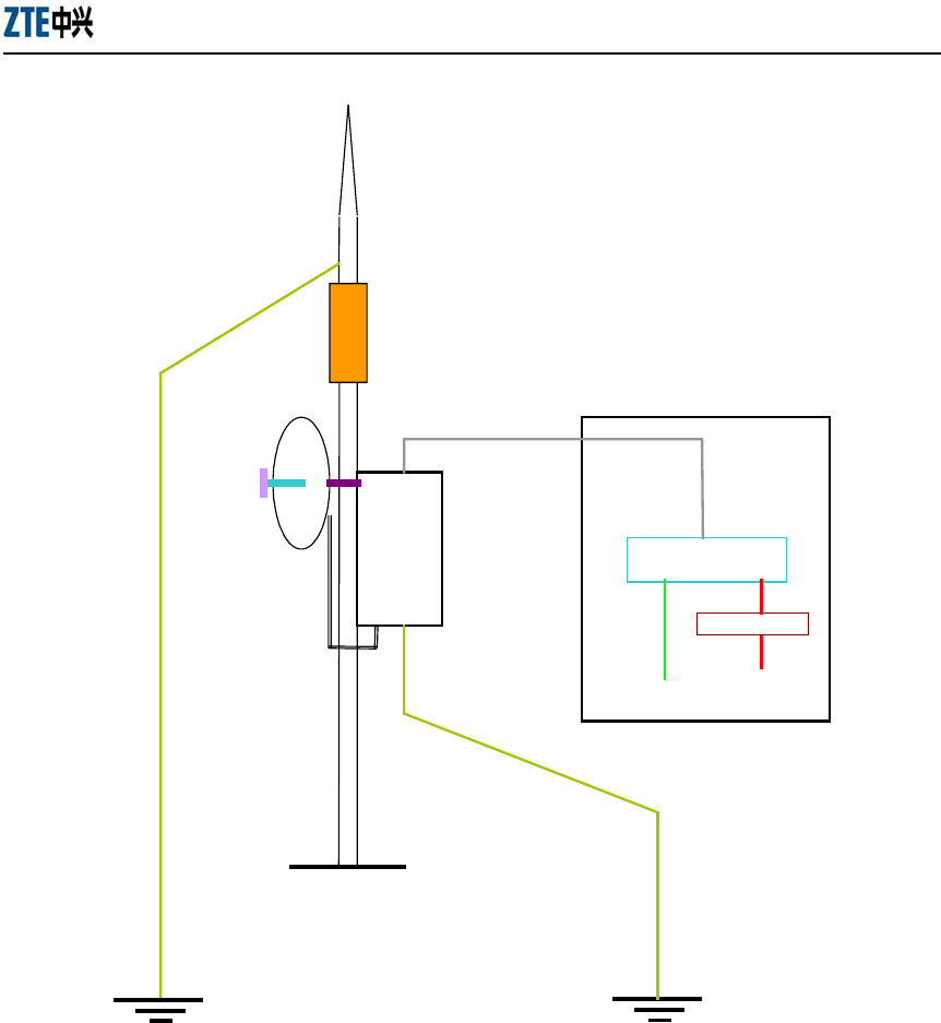
2.3.6 Lightning Protection System
A safe grounding system should be able to protect the outdoor equipment from direct
lightning strike and inductive lightning strike. The W140A can withstand a 2200 kV
inductive lightning strike within 10m, 5m, 3m and 1m from the discharge electrode. It
can also withstand a 2200 kV simulated direct lightning strike (the discharge electrode
discharges to the lightning arrester of the W140A directly).
Fig. 2.3-8 shows how to install the lightning protection system of the W140A.
ZXR10 WAS (V1.0) W140A Outdoor Wireless Access Point / Bridge
Professional Installation Instruction Manual
2-24
Antenna
Antenna
feeder
Insulation
Lightning arrestor
Lightning
protection ground
Shared by working
ground and surge
protection ground
Work ground and
surge ground
combined at the case
Control
room
AC power network
W201P
Insulating transformer
W140A
Fig. 2.3-8 The Grounding System of the W140A
2.4 Power-on and Power-off
The W140A accepts power supply over Ethernet. The W140A is equipped with a
built-in PoE module. It is connected to the PoE interface in the W201P, the PoE
terminal, through the PoE cable attached with the W140A.
To power on the W140A, follow the steps below:

Chapter Error! Style not defined. Error! Style not defined.
2-25
1. Making sure that the W140A is installed correctly, the cable connections are
correct, and the water-proof and lightning protection measures are in place.
2. Checking the W201P power supply, to ensure that the power connections are
correct and the W201P works normally.
3. Connecting the PoE cable to the W201P.
To power off the W140A, you just need to disconnect the PoE cable.
After power on, the W140A will start automatically, without any manual operation at
the management console.
2.5 Debugging
After the W140A is powered on and started, you should perform service debugging.
Service debugging serves the following three purposes:
1. Ensuring that the routes between the W140A and Internet/customer server are
smooth.
2. Ensuring that each client in the W140A coverage area can access the Internet
normally.
3. Ensuring that in the whole engineering coverage area, the clients can roam and
be handed over between the APs in different cells.
3-1
3 Command Line Configuration
This chapter describes the operation methods and configuration commands of the
W140A command line configuration.
3.1 Overview
The W140A provides the Command Line Interface (CLI) for configuring the W140A
data.
The CLI configuration of the W140A has the following features:
1. The CLI configuration of the W140A allows users to perform configuration
through the Ethernet interface and wireless network card in the Telnet mode.
2. The CLI provides five command modes: User, privileged, configure, Ethernet
interface configuration and wireless interface configuration modes One mode is
the execution environment of a group of related commands, and one command
can be executed only in the corresponding command mode. To obtain the valid
commands in the current command mode, just input “?” in the current mode.
3. Commands are divided into information query command and function command.
The information query command serves to obtain some information to be
queried. The function command serves to change the function configuration of
the W140A. The changed configuration is saved in the running configuration
information library. To cancel the function configuration, execute the reverse
command of the former command (that is, no + key word + original command)
4. The CLI provides perfect help system: At any time, you can input “?” to obtain
the related help information.
5. The command inputting provides the fuzzy match function: Once the
information input by the user is enough for determining a command, it is not
necessary to input the full spell.
6. The CLI provides the command history function: You can select a historical
command for executing through “↑” or “↓” of the keyboard.

ZXR10 WAS (V1.0) W140A Outdoor Wireless Access Point / Bridge
Professional Installation Instruction Manual
3-2
7. The CLI provides two layers of password protection to reject illegal users. The
first layer password authentication appears on the Telnet welcome interface, then
the safety authentication for accessing the user mode is required. The default
user name is “root” and default password is “public”. In the user mode, input the
enable command and correct password to enter the privileged mode, the default
password is “zte”.
8. The CLI can automatically page the output commands on the terminal:
“—More—” at the lower left corner of the command output window indicates
more output commands. At this time, you can press CTRL to display the next
page, press ENTER to output the next line and press other keys to exit.
9. The W140A CLI provides the basic command line editing function. The
short-cut keys for editing command lines are described as follows:
Ctrl + U: Delete the whole command being input.
Ctrl + A: Move the cursor to the first character of the command line.
Ctrl + E: Move the cursor to the last character of the command line.
Ctrl + X: Delete all the characters before the cursor.
Ctrl + K: Delete all the characters after the cursor (containing the character at
the cursor)
Ctrl + C: Give up all the input contents. Enter the new line and the prompt
character will appear.
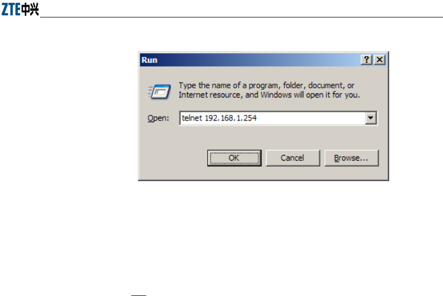
When the Telnet mode is used for configuring the W140A, you just need to input
“telnet working IP address of W140A”, as shown in Fig. 3.1-1. By default, the W140A
working IP address is 192.168.1.254 and the sub-network mask is 255.255.255.0.
Chapter Error! Style not defined. Error! Style not defined.
3-3
Fig. 3.1-1 Telnet to W140A
These five configuration modes of the W140A and all the available commands under
each mode are described in detail as follows: The stipulation of command format is as
follows:
1. The abc refers to the contents to be input by the user.
2. The {abc | def} means that the user should input either of the two items.
3. [A ~ B] indicates the digital range of the configuration parameters that the user
can input.
4. For the contents included in [ ], the user can choose to input or not input them..
3.2 User Mode
Mode of entry: Telnet
Exit mode: exit
Default prompt: wlan>
Note: When an ordinary user logs in to the W140A via Telnet, he/she will not be able to
enter the user mode unless he/she passes the username and password authentication. By
default, the username and password are "root" and "public". To prevent illegal users
from attempting the password frequently, the system will cut the Telnet connections of
a user automatically if incorrect passwords have been entered 3 times continuously.

ZXR10 WAS (V1.0) W140A Outdoor Wireless Access Point / Bridge
Professional Installation Instruction Manual
3-4
3.3 Privileged Mode
Mode of entry: Type in the enable command in the in use mode and enter the correct
password.
Exit mode: disable for entering the user mode; exit for exiting the privileged mode and
go back to the system.
Default prompt: wlan#
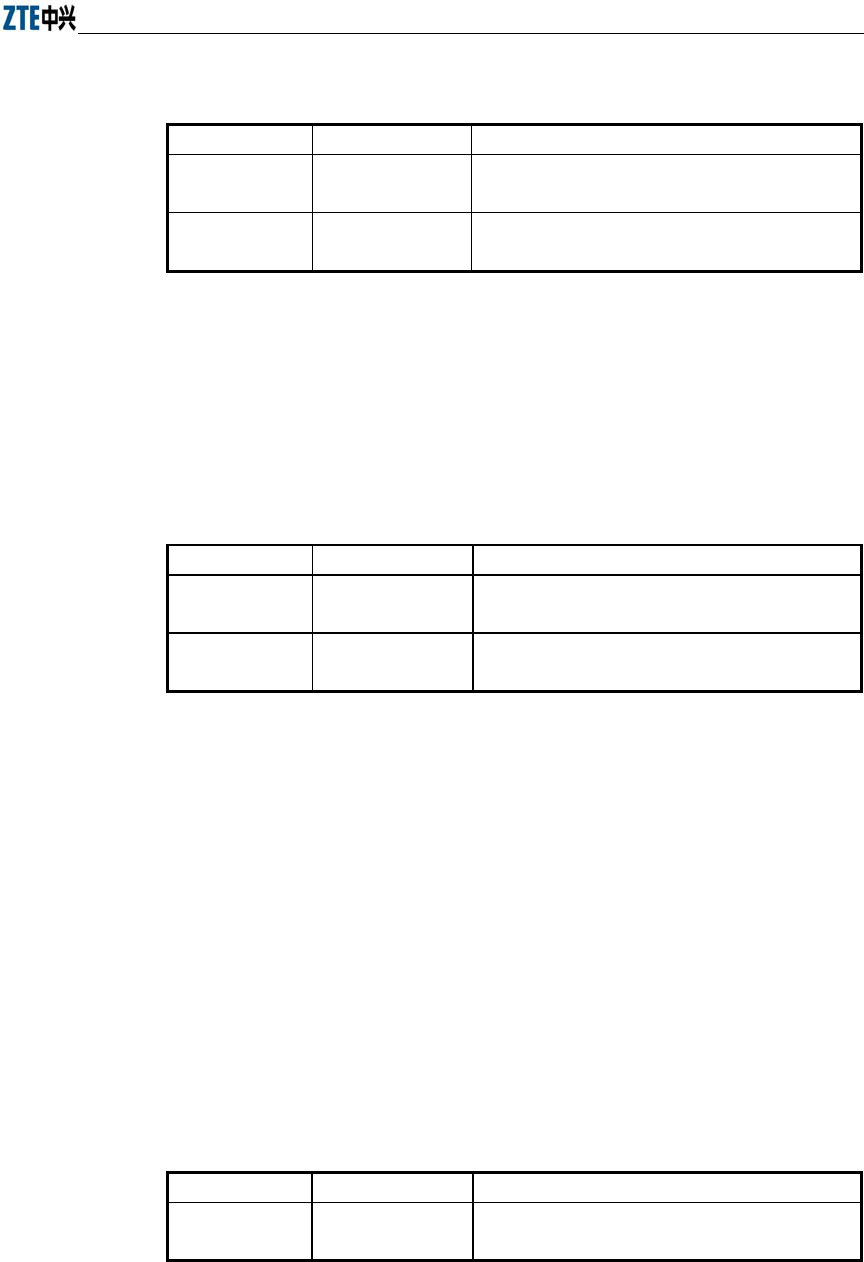
3.3.1 Command to Test Network Connectivity
Command mode: privileged mode
Function: Test the network connectivity
Command format: ping A.B.C.D [-n echo-number] [-w timeout] [-l packet-size]
Parameter description:
Name Range Description
A.B.C.D IP address Destination IP address
-n Null Sets the flag bits for the number of PING packets
echo-number 1~40 The number of PING packets
-w Null Sets the flag bits for the maximum timeout interval
Timeout 1~2 Maximum timeout interval (unit: s)
-l Null Sets the flag bits for the capacity of buffer area
packet-size 0~1504 Capacity of buffer area
3.3.2 Command to Save Configurations to Flash
Command mode: privileged mode
Function: Save configurations to flash
Command format: wlan#write flash
3.3.3 Command to Reset Software
Command mode: privileged mode
Function: Reset W140A
Command format: wlan#reboot

Chapter Error! Style not defined. Error! Style not defined.
3-5
3.3.4 Command to Enter Configure Mode
Command mode: privileged mode
Function: Enter configuration modes
Command format: wlan#configure terminal
3.3.5 Command to Exit Privileged Mode
Command mode: privileged mode
Function: Exit Privileged Mode and enter User Mode
Command format: wlan#disable
3.3.6 Command to Exit TELNET Configuration
Command mode: privileged mode
Function: Exit Telnet and go back to the system
Command format: wlan#exit
Note: This command can only be used via Telnet. If you log in by using a
hyperterminal mode via the serial port, this command will not be available.
3.4 Configure Mode
Mode of entry: Enter the configure terminal command in Privileged Mode
Exit mode: Exit and enter privileged mode
Default prompt: wlan (config) #
Note: In this mode (including the sub-mode), all the configuration commands can be
executed.
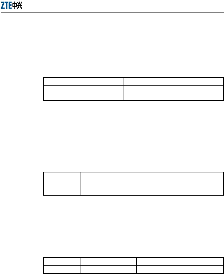
3.4.1 Commands to Configure Wireless Access-Bridge
1. access-bridge client connect-server
Command mode: Configure mode
Function: Configure the MAC address of the access bridge connecting the server
Command format: wlan (config) #access-bridge client connect-server mac

ZXR10 WAS (V1.0) W140A Outdoor Wireless Access Point / Bridge
Professional Installation Instruction Manual
3-6
Parameter description:
Name Range Description
mac MAC address in the
xx-xx-xx-xx-xx-xx format
MAC address of the access bridge connecting
the server
2. access-bridge client enable
Command mode: Configure mode
Function: Enable/disable the wireless bridge client
Command format: wlan( config) #[no] access-bridge client enable
3. access-bridge server connect-client
Command mode: Configure mode
Function: Configure the MAC address of the access bridge connecting clients
Command format: wlan(config)#[no] access-bridge server connect-client mac
Parameter description:
Name Range Description
mac
MAC address in the
xx-xx-xx-xx-xx-xx format
MAC address of the access bridge connecting
clients
4. access-bridge server enable
Command mode: Configure mode
Function: Enable/disable the wireless bridge server
Command format: wlan (config) #[no] access-bridge server enable
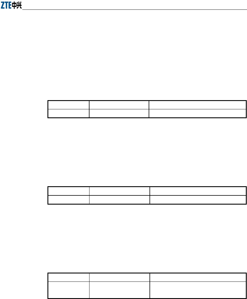
3.4.2 Command to Configure Bridge Information
bridge filterdb
Command mode: Configure mode
Function: Configure bridge filtration or cancel the configuration
Command format: wlan (config) #[no] bridge filterdb max-user aging-time
alarm-percent

Chapter Error! Style not defined. Error! Style not defined.
3-7
Parameter description:
Name Range Description
max-user
512~1024 Maximum capacity of the MAC address list
aging-time 10~100,000 Aging time of the MAC address list entries
alarm-percent 1~10 Percent of alarms
3.4.3 Commands to Configure DHCP Server
1. dhcp server dns
Command mode: Configure mode
Function: Configure the IP addresses of the master/slave DNS server in the
DHCP server
Command format: wlan (config) # dhcp server dns A.B.C.D [A.B.C.D]
Parameter description:
Name Range Description
A.B.C.D
IP address IP address of the master DNS server
[A.B.C.D] IP address IP address of the slave DNS server (optional)
2. dhcp server gateway
Command mode: Configure mode
Function: Configure the IP address of the default gateway of the DHCP server
Command format: wlan (config) # dhcp server gateway A.B.C.D
Parameter description:
Name Range Description
A.B.C.D
IP address IP address of the gateway
3. dhcp server leasetime
Command mode: Configure mode
Function: Configure the address lease time of the DHCP server
Command format: wlan (config) # dhcp server leasetime time-value

ZXR10 WAS (V1.0) W140A Outdoor Wireless Access Point / Bridge
Professional Installation Instruction Manual
3-8
Parameter description:
Name Range Description
time-value
60~3600 DHCP server address lease time (unit: s), 60s by
default
4. dhcp server run
Command mode: Configure mode
Function: Start, stop or restart the DHCP server
Command format: wlan (config) # dhcp server run run-flag
Parameter description:
Name Range Description
run-flag
start, stop, restart
start: Start the DHCP server
stop: Stop the DHCP server
restart: Restart the DHCH server
5. dhcp server start-flag
Command mode: Configure mode
Function: Configure the start flag of the DHCP server for the restart of the
system
Command format: wlan (config) # dhcp server start-flag {true|false}
Parameter description:
Name Range Description
{true|false} True, false
Start flag of the DHCP server. If it is set to true, it
will be started when the system is restarted. If false,
the DHCP server will not be started.
3.4.4 Discover commands
1. discover device
Command mode: Configure mode
Function: Configure the multicasting address for the integrated management and
the port number of the equipment
Command format: wlan (config) #discover device A.B.C.D [0~65535]
Chapter Error! Style not defined. Error! Style not defined.
3-9
Parameter description:
Name Range Description
A.B.C.D
IP address Multicasting address for the integrated management
of the equipment
[0~65535] 0~65535 Snooping port number for the integrated management
of the equipment
2. discover manager
Command mode: Configure mode
Function: Configure the multicasting address and port number for the integrated
management server
Command format: wlan (config) #discover manager A.B.C.D [0~65535]
Parameter description:
Name Range Description
A.B.C.D
IP address Multicasting address for the integrated management
server
[0~65535] 0~65535 Snooping port number for the integrated management
server
3.4.5 Commands to Configure 802.1X Parameters
1. dot1x enable
Command mode: Configure mode
Function: Enable or disable 802.1x
Command format: wlan (config) #[no] dot1x enable
2. dot1x max-reauth
Command mode: Configure mode
Function: Configure the maximum number of attempts for 802.1x authentication
Command format: wlan (config)# dot1x max-reauth max-reauth-times
Parameter description:
Name Range Description
max-reauth-times 0~10 the maximum number of attempts for 802.1x
authentication
ZXR10 WAS (V1.0) W140A Outdoor Wireless Access Point / Bridge
Professional Installation Instruction Manual
3-10
3. dot1x max-request
Command mode: Configure mode
Function: Configure the maximum number of requests for 802.1x authentication
Command format: wlan (config) # dot1x max-request max-request-times
Parameter description:
Name Range Description
max-request-times
1~10 Maximum number of requests for 802.1x
authentication
4. dot1x md5-domain
Command mode: Configure mode
Function: Configure the domain name in the EAP-MD5 authentication mode
命令格式:wlan(config)Command format: wlan (config) # dot1x md5-domain
string
Parameter description:
Name Range Description
String No more than 32 characters Domain name in the EAP-MD5
authentication mode
5. dot1x nas-id
Command mode: Configure mode
Function: Configure the NAS-ID field for 802.1x
Command format: wlan (config) # dot1x nas-id string
Parameter description:
Name Range Description
String
No more than 64 characters NAS-ID character string
6. dot1x portenable
Command mode: Configure mode
Function: Enable or disable 802.1x port control
Command format: wlan (config) # [no] dot1x portenable
Chapter Error! Style not defined. Error! Style not defined.
3-11
7. dot1x quiet-period
Command mode: Configure mode
Function: Configure the quiet-period for 802.1x
Command format: wlan (config) # dot1x quiet-period value
Parameter description:
Name Range Description
Value
1~255 802.1x quiet-period (unit: s)
8. dot1x server-timeout
Command mode: Configure mode
Function: Configure the hold time for the 802.1x authentication server
Command format: wlan (config) # dot1x server-timeout value
Parameter description:
Name Range Description
value
1~255 Hold time of the authentication server (unit: s)
9. dot1x sim-domain
Command mode: Configure mode
Function: Configure the domain name in the EAP-SIM authentication mode
Command format: wlan (config) # dot1x sim-domain string
Parameter description:
Name Range Description
string
No more than 32 characters the domain name in the EAP-SIM
authentication mode
10. dot1x supp-timeout
Command mode: Configure mode
Function: Configure the supp hold time for 802.1x
Command format: wlan (config) # dot1x supp-timeout value

ZXR10 WAS (V1.0) W140A Outdoor Wireless Access Point / Bridge
Professional Installation Instruction Manual
3-12
Parameter description:
Name Range Description
value
1~255 Hold time of the 802.1x client (unit: s)
11. dot1x tx-period
Command mode: Configure mode
Function: Configure the transmission period for 802.1x
Command format: wlan (config) # dot1x tx-period value
Parameter description:
Name Range Description
value
1~255 802.1x transmission-period (unit: s)
3.4.6 Command to Set User Password in Privileged Mode
Command mode: Configure mode
Function: Set user passwords in privileged mode
Command format: wlan(config)#enable-password password
Parameter description:
Name Range Description
password
No more than 30 characters User password in privileged mode
3.4.7 Command to Delete Filtration Rules
erase mac-access-rule
Command mode: Configure mode
Function: Delete MAC rules according to global rule numbers
Command format: wlan(config)#erase mac-access-rule {static} acl-rule-number
Parameter description:
Name Range Description
{static} static Static mac-access-rule flag
acl-rule-number 0~1023 Filtration rule number
Chapter Error! Style not defined. Error! Style not defined.
3-13
3.4.8 Command to Exit Configuration Mode
Command mode: Configure mode
Function: Exit configure mode and enter privileged Mode
Command format: wlan (config) #exit
3.4.9 Commands to Configure IAPP (Load-balance)
1. iapp balance
Command mode: Configure mode
Function: Set the load-balance group ID and nominal capacity
Command format: wlan (config) #iapp balance group-id capability
Parameter description:
Name Range Description
group-id
1~65535 Load-balance group ID
capability
1~30 Nominal capacity
2. iapp enable-flag
Command mode: Configure mode
Function: Enable or disable load balance and the restriction to the maximum
number of users allowed
Command format: wlan (config) #iapp enable-flag {disable|balance|max-user}
Parameter description:
Name Range Description
{disable|balance|
max-user}
disable, balance,
max-user
disable: Disable the IAPP function. Neither
load-balance nor the restriction to the maximum
number of users will be enabled.
balance: Enable load-balance
Max-user: Enable the restriction to the maximum
number of users

ZXR10 WAS (V1.0) W140A Outdoor Wireless Access Point / Bridge
Professional Installation Instruction Manual
3-14
Tips:
The iapp balance and iapp max-user configurations cannot take effect at the same
time.
3. iapp max-user
Command mode: Configure mode
Function: Set the number of users allowed
Command format: wlan (config) #iapp max-user value
Parameter description:
Name Range Description
Value
1~150 Sets the number of users allowed
3.4.10 Interface Skip
1. interface ethernet
Command mode: Configure mode
Function: Skip to the Ethernet interface configuration mode. This command
ends with the unit number of the Ethernet interface. For equipment, multiple
Ethernet interfaces are available.
Command format: wlan (config) #interface ethernet {0}
Parameter description:
Name Range Description
{0} 0 Unit number of the Ethernet interface. W140A has only
one Ethernet interface with the unchangeable value of 0.
2. interface wlan
Command mode: Configure mode
Function: Skip to the wireless interface configuration mode. This command ends
with the unit number of the wireless interface. For equipment, multiple wireless
interfaces are available.
Command format: wlan (config) #interface wlan {0}

Chapter Error! Style not defined. Error! Style not defined.
3-15
Parameter description:
Name Range Description
{0} 0 Unit number of the wireless interface. W140A has only
one wireless interface with the unchangeable value of 0.
3.4.11 Commands to Configure Layer 2 Isolation
1. intra-security enable
Command mode: Configure mode
Function: Enable or disable Layer 2 Isolation
Command format: wlan (config) #[no] intra-security enable
2. intra-security gateway
Command mode: Configure mode
Function: Configure the IP address or MAC address of the gateway
Command format: wlan (config) # intra-security gateway {ip A.B.C.D | mac
xx-xx-xx-xx-xx-xx}
Parameter description:
Name Range Description
A.B.C.D
IP address IP address of the gateway
xx-xx-xx-xx-xx-xx MAC address MAC address of the gateway
3.4.12 Commands to Configure IP network Parameters
1. ip arp
Command mode: Configure mode
Function: Add/delete ARP list entries
Command format: wlan (config) #[no] ip arp A.B.C.D xx-xx-xx-xx-xx-xx
Parameter description:
Name Range Description
A.B.C.D
IP address IP address of the host
xx-xx-xx-xx-xx-xx MAC address Hardware address of the host
ZXR10 WAS (V1.0) W140A Outdoor Wireless Access Point / Bridge
Professional Installation Instruction Manual
3-16
2. ip route
Command mode: Configure mode
Function: Configure the default routing address for the system
Command format: wlan (config) #[no] ip route A.B.C.D1 A.B.C.D2 A.B.C.D3
Parameter description:
Name Range Description
A.B.C.D1
IP address IP address of the host
A.B.C.D2 Subnet mask IP address mask of the host
A.B.C.D3 IP address IP address of the next-hop router
3. ip pool
Command mode: Configure mode
Function: Configure the IP address pool for the system
Command format: wlan (config) #[no] ip pool index A.B.C.D1 A.B.C.D2
A.B.C.D3
Parameter description:
Name Range Description
index 0~9 Group number of the IP address pools
A.B.C.D1
IP address Starting IP address of the host address pool
A.B.C.D2 IP address Ending IP address of the host address pool
A.B.C.D3 Subnet mask Subnet mask of the addresses in an address pool
3.4.13 Command to Configure Log Print Information
1. logmsg all-enable
Command mode: Configure mode
Function: Open or close the log print information in all modules
Command format: wlan (config) #[no] logmsg all-enable
2. logmsg level
Command mode: Configure mode
Function: Configure the level of log print information to be output
Command format: wlan (config) # logmsg level level-num

Chapter Error! Style not defined. Error! Style not defined.
3-17
Parameter description:
Name Range Description
level-num
Lowest (Flood)
Lower (Info)
Higher (Error)
Highest (Fatal)
Level of the log print information to be output.
Only the information with a higher level will be
output.
3. logmsg mod-enable
Command mode: Configure mode
Function: Determine the module whose log print information should be output
Command format: wlan (config) # [no] logmsg mod-enable module
Parameter description:
Name Range Description
module
A specified module name Module whose log print information should be
output
4. logmsg telnet-log
Command mode: Configure mode
Function: Set the log print information output window to the active Telnet
window.
Command format: wlan (config) #[no] logmsg telnet-log
3.4.14 Command to Configure MAC Filter
Command mode: Configure mode
Function: Add/delete an access list by serial number
Command format: wlan(config)#[no] mac-access-list acl-list-number {deny|permit}
{macaddr|any}
Parameter description:
Name Range Description
acl-list-number
1~99 MAC filter group number
{ deny|permit } Deny, permit
Deny: If the conditions meet the requirements, the
MAC communication is denied.
Permit: If the conditions meet the requirements, the
MAC communication is allowed.

ZXR10 WAS (V1.0) W140A Outdoor Wireless Access Point / Bridge
Professional Installation Instruction Manual
3-18
Name Range Description
{macaddr|any}
MAC address in the
xx-xx-xx-xx-xx-xx
format or any
MAC address from which MAC packets are sent. The
source address can be specified in two ways:
One is to use six 48-bit hexadecimal numbers with
dashes between them (HYPHEN), e.g.
00-d0-d0-f1-c4-ef
Another is to use the any keyword as the abbreviation
of source 00-00-00-00-00-00. It is not recommended
to use this keyword.
3.4.15 Command to Configure MAC Address Authentication
Command mode: Configure mode
Function: Configure MAC address authentication
Command format: wlan (config) #[no] mac-authen {deny|permit} {macaddr|any}
Parameter description:
Name Range Description
{deny|permit} Deny, permit
deny: If the conditions meet the requirements, the
MAC communication is denied.
permit: If the conditions meet the requirements, the
MAC communication is allowed.
{macaddr|any}
MAC address in the
xx-xx-xx-xx-xx-xx
format or any
MAC address from which MAC packets are sent. The
source address can be specified in two ways:
One is to use six 48-bit hexadecimal numbers with
dashes between them (HYPHEN), e.g.
00-d0-d0-f1-c4-ef
Another is to use the any keyword as the abbreviation
of source 00-00-00-00-00-00. It is not recommended
to use this keyword.
3.4.16 Command to Configure Users
Command mode: Configure mode
Function: Add/delete usernames
Command format: wlan (config) #[no] manage-user username password

Chapter Error! Style not defined. Error! Style not defined.
3-19
Parameter description:
Name Range Description
username
1~32 characters Username
password
1~32 characters User password
3.4.17 Commands to Configure Radius Server
1. radius-server account
Command mode: Configure mode
Function: Add/delete the accounting server of an ISP
Command format: wlan (config) #[no] radius-server account isp-name
master-flag A.B.C.D key-string
Parameter description:
Name Range Description
isp-name
1~255 characters ISP name
master-flag
master, slave Master/slave flag of the accounting server
A.B.C.D IP address IP address of the accounting server
key-string 1~255 characters Shared key string for accounting
2. radius-server authen
Command mode: Configure mode
Function: Add/delete the authentication server of an ISP
Command format: wlan (config) wlan(config)#[no] radius-server authen
isp-name master-flag A.B.C.D key-string
Parameter description:
Name Range Description
isp-name
1-255 characters ISP name
master-flag
master, slave Master or slave authentication server. Only one
master server can be set.
A.B.C.D IP address IP address of the authentication server
key-string 1-255 characters Shared key string for authentication

ZXR10 WAS (V1.0) W140A Outdoor Wireless Access Point / Bridge
Professional Installation Instruction Manual
3-20
3. radius-server dns
Command mode: Configure mode
Function: Add/delete the DNS server of an ISP
Command format: wlan (config) #[no] radius-server dns isp-name A.B.C.D
[A.B.C.D]
Parameter description:
Name Range Description
isp-name
1~255 characters ISP name
A.B.C.D IP address IP address of the master DNS server
[A.B.C.D] IP address IP address of the slave DNS server
4. radius-server isp-name
Command mode: Configure mode
Function: Add/delete an ISP
Command format: wlan (config) #[no] radius-server isp-name isp-name
Parameter description:
Name Range Description
isp-name 1~255 character ISP name
5. radius-server retry-times
Command mode: Configure mode
Function: Set the number of retries of RADIUS authentication of an ISP
Command format: wlan (config) #radius-server retry-times isp-name retry-time
Parameter description:
Name Range Description
isp-name
1~255 characters Name of an ISP which has been created.
retry-time 1~10 Number of retries of RADIUS authentication
6. radius-server timeout
Command mode: Configure mode
Function: Set the hold time of the RADIUS authentication of an ISP
Command format: wlan (config) #radius-server timeout isp-name timeout

Chapter Error! Style not defined. Error! Style not defined.
3-21
Parameter description:
Name Range Description
isp-name
1~255 characters Name of an ISP which has been created.
timeout 1~65535 Hold time of the RADIUS authentication (unit: s)
3.4.18 Command to Configure SNMP Module
1. snmp access-host
Command mode: Configure mode
Function: Add and delete host IP addresses allowed to access
Command format: wlan (config) #[no] snmp access-host A.B.C.D
Parameter description:
Name Range Description
A.B.C.D
IP address Host IP addresses (up to 10) in dotted decimal
format (A.B.C.D)
2. snmp access-mode
Command mode: Configure mode
Function: Allow all hosts or hosts in the server-list to access this agent
Command format: wlan (config) #snmp access-mode {all|list}
Parameter description:
Name Range Description
{all|list} all, list all: All users are allow to access
list: Users in server-list are allowed to access
3. snmp community
Command mode: Configure mode
Function: Configure the SNMP access community string and its access right
Command format: wlan (config) #snmp community comstr {read-only|
read-write}
wlan(config)#no snmp community comstr

ZXR10 WAS (V1.0) W140A Outdoor Wireless Access Point / Bridge
Professional Installation Instruction Manual
3-22
Parameter description:
Name Range Description
comstr
1~32 characters
Names of the SNMP access community strings
(up to 10). comstr is a string with up to 32
characters
{read-only|read-write} read-only, read-write read-only: read-only access
read-write: Read-write access
4. snmp contact
Command mode: Configure mode
Function: Set the name and contact information of the equipment administrator
Command format: wlan (config) #snmp contact sysContact
Parameter description:
Name Range Description
sysContact
1~255 characters
A management variable of the system group in
MIB II, denotes the name and contact
information of the equipment administrator
5. snmp location
Command mode: Configure mode
Function: Configure the geographical location of the managed equipment
Command format: wlan (config) #snmp location sysLocation
Parameter description:
Name Range Description
sysLocation
1~255 characters
A management variable of the system group in
MIB, used to define the geographic location of
the managed equipment
6. snmp nodecode
Command mode: Configure mode
Function: Configure the network element (NE) codes of the managed equipment
Command format: wlan (config) #snmp nodecode node-code

Chapter Error! Style not defined. Error! Style not defined.
3-23
Parameter description:
Name Range Description
node-code
>= 0 (integer)
A management variable of the system group in
MIB, used to define the NE code of the managed
equipment
7. snmp nodeid
Command mode: Configure mode
Function: Configure the NE ID of the managed equipment
Command format: wlan (config) #snmp nodeid node-id
Parameter description:
Name Range Description
node-code
1~31 characters
A management variable of the system group in
MIB, used to define the NE ID of the managed
equipment
8. snmp nodecreatdate
Command mode: Configure mode
Function: Configure the NE creation date of the managed equipment
Command format: wlan (config) #snmp nodecreatdate hh:mm:ss month day year
Parameter description:
Name Range Description
hh:mm:ss
Time hh (hour): mm (minute): ss (second)
month 1~12 Month
day 1~31 Day
year 2002~2130 Year: 4 bits
hh:mm:ss month day year: A management variable of the system group in MIB,
used to define the NE creation date of the managed equipment
9. snmp proxytraphost
Command mode: Configure mode
Function: Add the address information of a proxy Trap destination host
Command format: wlan (config) #[no] snmp proxytraphost A.B.C.D

ZXR10 WAS (V1.0) W140A Outdoor Wireless Access Point / Bridge
Professional Installation Instruction Manual
3-24
Parameter description:
Name Range Description
A.B.C.D
IP address Addresses of the proxy Trap destination hosts (up
to 10)
10. snmp sysname
Command mode: Configure mode
Function: Set the name of the managed equipment
Command format: wlan (config) #snmp sysname sysName
Parameter description:
Name Range Description
sysName
1~255 characters
A management variable of the system group in
RFC1213 MIB, used as the name of the managed
equipment
11. snmp trap enable
Command mode: Configure mode
Function: Configure if the SNMP Agent is allowed to send Trap
Command format: wlan (config) #[no] snmp trap enable
12. snmp authtrap enable
Command mode: Configure mode
Function: Configure if the SNMP Agent is allowed to send the authentication
failed Trap
Command format: wlan (config) #[no] snmp authtrap enable
13. snmp traphost
Command mode: Configure mode
Function: Add the address of a trap destination host and the trap version number
Command format: wlan (config) #snmp traphost A.B.C.D [version version]
wlan(config)#no snmp traphost A.B.C.D

Chapter Error! Style not defined. Error! Style not defined.
3-25
Parameter description:
Name Range Description
A.B.C.D
IP address Addresses of Trap destination hosts
version 1~2 Trap version number
3.4.19 Command to Manage Telnet Idle Timeout
Command mode: Configure mode
Function: Set the automatic exit time when the Telnet window is idle
Command format: wlan (config) #telnet idle-timeout time-value
Parameter description:
Name Range Description
time-value
300~3600 (unit: s) The automatic exit time when the Telnet window is
idle (300s by default)
3.4.20 Commands to Upload/download TFTP Files
1. tftp dir
Command mode: Configure mode
Function: Check the free space of a flash disk (unit: byte)
Command format: wlan (config) #tftp dir
2. tftp pic
Command mode: Configure mode
Function: Download graphics files from the Web configuration pages on the
TFTP server and save them to a flash disk.
Command format: wlan (config) #tftp pic A.B.C.D
Parameter description:
Name Range Description
A.B.C.D
IP address IP Address of a TFTP server in dotted decimal format
3. Download files using tftp get
Command mode: Configure mode
Function: Download files from the TFTP server using TFTP and save them to

ZXR10 WAS (V1.0) W140A Outdoor Wireless Access Point / Bridge
Professional Installation Instruction Manual
3-26
the flash disk.
Command format: wlan (config) #tftp get A.B.C.D flash-file-name
Parameter description:
Name Range Description
A.B.C.D
IP address IP Address of a TFTP server in dotted decimal
format
flash-file-name Filename of a version Full name (including the extension name) of the file
to be transmitted from the TFTP server
4. Upload files using tftp put
Command mode: Configure mode
Function: Upload files from the flash disk to the TFTP server using TFTP
Command format: wlan (config) #tftp put A.B.C.D flash-file-name
Parameter description:
Name Range Description
A.B.C.D
IP address IP Address of a TFTP server in dotted decimal
format
flash-file-name Filename of a version Full name (including the extension name) of the
file to be transmitted from the flash disk
3.4.21 Commands to Configure VLAN
1. vlan ap-vid
Command mode: Configure mode
Function: Configure the VLAN ID of AP
Command format: wlan (config) #vlan ap-vid value
Parameter description:
Name Range Description
value
0~4094 VLAN ID
2. vlan enable
Command mode: Configure mode
Function: Enable VLAN

Chapter Error! Style not defined. Error! Style not defined.
3-27
Command format: wlan (config) #vlan enable
3. vlan keep-vid
Command mode: Configure mode
Function: Allow a terminal to switch over with the same VLAN ID between
different APs
Command format: wlan (config) #vlan keep-vid
4. vlan sta-default-vid
Command mode: Configure mode
Function: Configure the default VLAN ID of the STA accessed from the AP
Command format: wlan (config) #vlan sta-default-vid value
Parameter description:
Name Range Description
value
1~4094 Default VLAN ID when the STA is accessed
5. vlan sta-vid
Command mode: Configure mode
Function: Configure the specified VLAN ID of the STA accessed from the AP
Command format: wlan (config) #vlan sta-vid xx-xx-xx-xx-xx-xx vlan value
Parameter description:
Name Range Description
value
1~4094 Default VLAN ID when the STA is accessed
xx-xx-xx-xx-xx-xx
MAC address MAC address of the accessed STA
3.4.22 Show Commands
1. show access-bridge
Command mode: Configure mode
Function: Display configured parameters of a wireless bridge
Command format: wlan (config) #show access-bridge
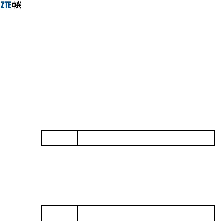
ZXR10 WAS (V1.0) W140A Outdoor Wireless Access Point / Bridge
Professional Installation Instruction Manual
3-28
2. show alarm
1) show alarm all
Command mode: Configure mode
Function: Display all alarm information
Command format: wlan (config) #show alarm all
2) show alarm bycode
Command mode: Configure mode
Function: Display alarm Information by alarm code
Command format: wlan (config) #show alarm bycode code
Parameter description:
Name Range Description
code
1001~3999 Code of an alarm
3) show alarm bylevel
Command mode: Configure mode
Function: Display alarm information by alarm level
Command format: wlan (config) #show alarm bylevel level
Parameter description:
Name Range Description
level
1~3 Alarm level
3. show bridge configure
Command mode: Configure mode
Function: Display configured bridge parameters
Command format: wlan (config) #show bridge configure
4. show dhcp server
Command mode: Configure mode
Function: Display DHCP server parameters
Command format: wlan (config) #show dhcp server

Chapter Error! Style not defined. Error! Style not defined.
3-29
5. show discover
Command mode: Configure mode
Function: Display configured discover parameters of the equipment
Command format: wlan (config) #show discover
6. show dot1x-cfg
Command mode: Configure mode
Function: Display 802.1x parameters
Command format: wlan (config) #show dot1x-cfg
7. show dynamic-key
Command mode: Configure mode
Function: Display dynamic WEP key parameters
Command format: wlan (config) #show dynamic-key
8. show iapp
Command mode: Configure mode
Function: Display configured load-balance parameters
Command format: wlan (config) #show iapp
9. show interface
Command mode: Configure mode
Function: Display configured interface parameters
Command format: wlan (config) #show interface {ethernet|wlan} Function:
Display configured Layer 2 isolation parameters
Command format: wlan (config) #show intra-security
11. show ip
1) show ip arp
Command mode: Configure mode
Function: Display ARP address resolution information
Command format: wlan (config) #show ip arp

ZXR10 WAS (V1.0) W140A Outdoor Wireless Access Point / Bridge
Professional Installation Instruction Manual
3-30
2) show ip if-stat
Command mode: Configure mode
Function: Display IP interface status information
Command format: wlan (config) #show ip if-stat
3) show ip pool
● show ip pool config
Command mode: Configure mode
Function: Display information of all IP address pools
Command format: wlan (config) #show ip pool config
● show ip pool used
Command mode: Configure mode
Function: Display information of allocated IP addresses in the specified IP
address pool
Command format: wlan (config) #show ip pool used index
Parameter description:
Name Range Description
Index 0~9 Serial number of an IP address pool
4) show ip route
Command mode: Configure mode
Function: Display configured IP route parameters
Command format: wlan (config) #show ip route
12. show logmsg
Command mode: Configure mode
Function: Display all configured log print information
Command format: wlan (config) #show logmsg

Chapter Error! Style not defined. Error! Style not defined.
3-31
13. show mac-access-list
Command mode: Configure mode
Function: Display configured mac-access-list information
Command format: wlan (config) #show mac-access-list {static} [1~99]
14. show mac-authen
Command mode: Configure mode
Function: Display configured mac-authen parameters
Command format: wlan (config) #show mac-authen
15. show manage-user
Command mode: Configure mode
Function: Display configured manage-user parameters
Command format: wlan (config) #show manage-user
16. show radius
Command mode: Configure mode
Function: Display configured radius parameters
Command format: wlan (config) #show radius
17. show snmp
1) show snmp access-host
Command mode: Configure mode
Function: Display configured snmp access-host parameters
Command format: wlan (config) #show snmp access-host
2) show snmp community
Command mode: Configure mode
Function: Display configured snmp community parameters
Command format: wlan (config) #show snmp community

ZXR10 WAS (V1.0) W140A Outdoor Wireless Access Point / Bridge
Professional Installation Instruction Manual
3-32
3) show snmp nodeinfo
Command mode: Configure mode
Function: Display configured snmp nodeinfo parameters
Command format: wlan(config)#show snmp nodeinfo
4) show snmp sysinfo
Command mode: Configure mode
Function: Display configured snmp sysInfo parameters
Command format: wlan (config) #show snmp sysinfo
5) show snmp traphost
Command mode: Configure mode
Function: Display configured snmp traphost parameters
Command format: wlan (config) #show snmp traphost
18. show telnet idle-timeout
Command mode: Configure mode
Function: Display the configured interval for telnet idle time-out
Command format: wlan (config) #show telnet idle-timeout
19. show version
Command mode: Configure mode
Function: Display the software version number
Command format: wlan (config) #show version
20. show vlan
Command mode: Configure mode
Function: Display configured VLAN information
Command format: wlan (config) #show vlan
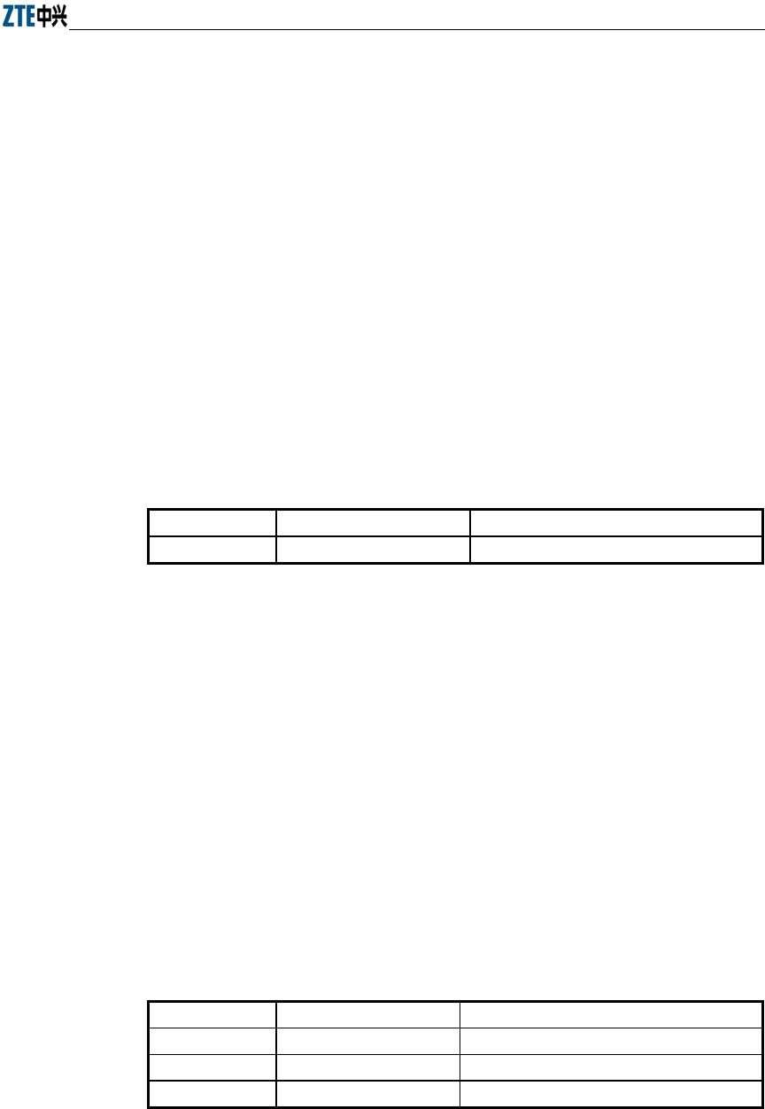
Chapter Error! Style not defined. Error! Style not defined.
3-33
3.5 Ethernet Interface Configuration Mode
Mode of entry: Enter the interface ethernet command in configure mode
Exit mode: Exit and enter configure mode
Default prompt: wlan (config-int-ethernet)#
Note: In this mode (including the sub-mode), all information can be configured for
relevant interfaces.
3.5.1 Configurations in the Ethernet Interface Mode
Command mode: Ethernet Interface Configuration Mode
Function: Set the mode of rate negotiation for the Ethernet interface
Command format: wlan (config-int-ethernet)# ethernet-mode mode
Parameter description:
Name Range Description
mode
10M, autoNeg (100M/10M) Mode of the Ethernet Interface
3.5.2 Command to Exit the Ethernet Interface Configuration Mode
Command mode: Ethernet Interface Configuration Mode
Function: Exit Ethernet interface configuration mode and enter configure Mode
Command format: wlan (config-int-ethernet)# #exit
3.5.3 Command to Configure Ethernet interface IP addresses
Command mode: Ethernet Interface Configuration Mode
Function: Set the IP address of the Ethernet interface
Command format: wlan(config-int-ethernet)#ipaddr A.B.C.D1 A.B.C.D2 [second]
wlan(config-int-ethernet)#no ipaddr A.B.C.D1 [A.B.C.D2]
Parameter description:
Name Range Description
A.B.C.D1
IP address IP address of an interface
A.B.C.D2 IP address IP address mask of an interface
[second] Optional The additional IP address flag of an interface

ZXR10 WAS (V1.0) W140A Outdoor Wireless Access Point / Bridge
Professional Installation Instruction Manual
3-34
3.5.4 Command to Configure MAC filter for the Ethernet Interface
Command mode: Ethernet Interface Configuration Mode
Function: Configure MAC filter for the Ethernet interface
Command format: wlan(config-int-ethernet)#[no] mac-access-group acl-number
direction
Parameter description:
Name Range Description
acl-num
1~99 MAC filter entry number bound to the interface
direction in Bind to the "in" direction of the interface
3.6 Wireless Interface Configuration Mode
Mode of entry: Enter the interface wlan command in configure mode
Exit mode: Exit and enter configure mode
Default prompt: wlan (config-int-wlan)#
Note: In this mode (including the sub-mode), all information can be configured for
relevant interfaces.
3.6.1 Command to Configure 80211b-related Parameters for the Wireless
Interface
1. 80211b channel
Command mode: Wireless interface configuration mode
Function: Set the current operating channel
Command format: wlan (config-int-wlan) #80211b channel channel-num
Parameter description:
Name Range Description
channel-num
1~13 Wireless channel number: 6 by default
2. 80211b dynamic-key
Command mode: Wireless interface configuration mode
Function: Set the dynamic key of the wireless network
Command format: wlan (config-int-wlan) #80211b dynamic-key key

Chapter Error! Style not defined. Error! Style not defined.
3-35
xx-xx-xx-xx-xx-xx key1-string key2-string used-key
wlan(config-int-wlan)#no 80211b dynamic-key xx-xx-xx-xx-xx-xx
wlan(config-int-wlan)#80211b dynamic-key enable xx-xx-xx-xx-xx-xx
wlan(config-int-wlan)#no 80211b dynamic-key enable xx-xx-xx-xx-xx-xx
Note: The 80211b dynamic-key key command is used to set the dynamic key
for a specified MAC address. The 80211b dynamic-key enable command is
used to enable this dynamic key.
Parameter description:
Name Range Description
xx-xx-xx-xx-xx-xx MAC address MAC address of the wireless user using the dynamic
key
key1-string 5 or 13 characters First dynamic key (the key length can only be 5 or
13 characters)
key2-string 5 or 13 characters Second dynamic key (the key length can only be 5
or 13 characters)
used-key key1, key2 Key number that is used
3. 80211b enh-security enable
Command mode: Wireless interface configuration mode
Function: Set to enable or disable the enhanced security function of AP
Command format: wlan (config) #[no] 80211b enh-security enable
Note: If the enhanced security function is enabled, the wireless terminal will not
be able to scan the AP. If this function is disabled, the AP can be scanned.
4. 80211b essid
Command mode: Wireless interface configuration mode
Function: Set ESSID of the wireless network
Command format: wlan (config-int-wlan) #80211b essid essid-string
Parameter description:
Name Range Description
essid-string
1~31 characters ESSID of the wireless network. By default, it is
zxwlan.
ZXR10 WAS (V1.0) W140A Outdoor Wireless Access Point / Bridge
Professional Installation Instruction Manual
3-36
5. 80211b frg-threshold
Command mode: Wireless interface configuration mode
Function: Set fragment threshold
Command format: wlan (config-int-wlan) #80211b frg-threshold value
Parameter description:
Name Range Description
value
256~2346 (even) Threshold of fragments, 2346 by default
6. 80211b power
Command mode: Wireless interface configuration mode
Function: Set the transmission power of the wireless network card
Command format: wlan (config-int-wlan) #80211b power value
Parameter description:
Name Range Description
value
auto,
10/20/30/40/50/60/70/80/90/100
(unit: mW)
max
auto: automatic power control (default)
10/20/30/40/50/60/70/80/90/100: fixed
transmission power
max: maximal transmission power
7. 80211b rts-threshold
Command mode: Wireless interface configuration mode
Function: Set RTS threshold
Command format: wlan (config-int-wlan) #80211b rts-threshold value
Parameter description:
Name Range Description
value
0~2347 RTS threshold, 2347 by default
3.6.2 Command to Exit Wireless Interface Configuration Mode
Command mode: Wireless interface configuration mode
Function: Exit wireless interface configuration mode and enter configure mode
Command format: wlan (config-int-wlan)# exit

Chapter Error! Style not defined. Error! Style not defined.
3-37
3.6.3 Command to Enable Link Integrity Detection
Command mode: Wireless interface configuration mode
Function: Set to enable or disable link integrity detection
Command format: wlan (config-int-wlan)#[no] link-integrity enable
Note: the link integrity detection function of AP means that when the Ethernet link of
the AP is disconnected, the AP will release all connected wireless users, close the
wireless port, and deny the connection requests of other wireless terminals. When the
link is recovered, the AP will open the wireless port and accept connections of wireless
users.
3.6.4 WEP Configuration of the Wireless Interface
1. wep mode
Command mode: Wireless interface configuration mode
Function: Set WEP encryption mode and WEP key format
Command format: wlan (config-int-wlan) #wep mode {disable | wep64 | wep128
| mix-wep64 | mix-wep128} {Alphanumeric|Hexadecimal}
Parameter description:
Name Range Description
{disable|wep64|wep128|
mix-wep64|mix-wep128}
disable
wep64
wep128
mix-wep64
mix-wep128
Disable: disable the WEP encryption
function
wep64: Use the 64-bit WEP encryption
wep128: Use the 128-bite WEP encryption
mix-wep64: Use a mixed 64-bit WEP
encryption. In this mode, the clients can
communicate normally with a correct 64-bit
encryption key or without encryption.
Mix-wep128: Use a mixed 128-bite WEP
encryption. In this mode, the clients can
communicate normally with a correct
128-bite encryption key or without
encryption.
{Alphanumeric|
Hexadecimal}
Alphanumeric
Hexadecimal
Alphanumeric: WEP key in string format
Alphanumeric: WEP key in sexadecimal
format

ZXR10 WAS (V1.0) W140A Outdoor Wireless Access Point / Bridge
Professional Installation Instruction Manual
3-38
2. wep set-key
Command mode: Wireless interface configuration mode
Function: Set the key of WEP encryption
Command format: wlan (config-int-wlan) #wep set-key key-id key-text
Parameter description:
Name Range Description
key-id
key1, key2, key3, key4 Entry number of the key to be set
key-text
5 or 13 characters, or a
combination of 10 or 26
sexadecimal digits
If it is set to 64-bit encryption, the key_text
argument can be 5 case sensitive characters (in
alphanumeric format), e.g. MyKey, or 10
sexadecimal digits (in hexadecimal format), e.g.
11AA22BB33
If it is set to 128-bit encryption, the key_text
argument can be 13 case sensitive characters (in
alphanumeric format), e.g. MyKey12345678, or
26 sexadecimal digits (in hexadecimal format),
e.g. 00112233445566778899AABBCC
3. wep use-key
Command mode: Wireless interface configuration mode
Function: Set the WEP encryption key to be used
Command format: wlan (config-int-wlan) #wep use-key key-id
Parameter description:
Name Range Description
Key-id key1, key2, key3, key4 Entry number of the key to be used
3.6.5 Command to Configure MAC Filter in Wireless Interface Configuration
Command mode: Wireless interface configuration mode
Function: Configure MAC filter for the wireless interface
Command format: wlan (config-int-wlan) #[no] mac-access-group acl-list-number
direction

Chapter Error! Style not defined. Error! Style not defined.
3-39
Parameter description:
Name Range Description
Acl-list-number 1~99 MAC filter entry number bound to the interface
direction in Bind to the "in" direction of the interface
3.6.6 Command to Configure Authentication Mode in Wireless Interface
Configuration
Command mode: Wireless interface configuration mode
Function: Configure authentication mode for the wireless interface
Command format: wlan (config-int-ethernet) #authmode auth mode
Parameter description:
Name Range Description
Authmode
OpenSystem
SharedKey
Both
OpenSystem: Authentication using Opensystem
SharedKey: Authentication using Sharedkey
Both: Both authentication modes are supported
A-1

A-1
Appendix A Making of Ethernet Cable
A.1 Making of Ethernet Cables
A.1.1 Making of Straight Through Ethernet Cables (RJ45)
In IP wireless access system, the following network cables must adopt the straight
through Ethernet cables:
1. The Ethernet cable between the Ethernet switch (end A) and W201P (end B).
2. If no switch is used, the AC downlink port is directly connected to W201P, and
the Ethernet cable between AC (end A) and W201P (end B) is a straight through
Ethernet cable.
The connections of the straight through Ethernet cables are shown in Table
A.1-1.
Table A.1-1 Connections of Straight Through Ethernet Cables (RJ45)
End A Signal Name Conductor Color End B Signal Name Conductor Color
1 Data receiving Rx+ White/orange 1 Data transmitting Tx+ White/orange
2 Data receiving Rx- Orange 2 Data transmitting Tx- Orange
3 Data transmitting Tx+ White/green 3 Data receiving Rx+ White/green
4 MATCH1 Blue 4 MATCH1 Blue
5 MATCH2 White/blue 5 MATCH2 White/blue
6 Data transmitting Tx- Green 6 Data receiving Rx- Green
7 MATCH3 White/brown 7 MATCH3 White/brown
8 MATCH4 Brown 8 MATCH4 Brown
A.1.2 Making of Straight Through Power Supply Ethernet Cables (C-RJ45-001)
The Ethernet cable between the W201P (end A) and AP (end B) not only serves as the
Ethernet data signal cable, but also provides -48V DC power for two twisted pairs 4&5
and 7&8 on the load balance, to power AP remotely.
The connection method of this cable is the same as that of the straight through cable
without power supply, and the connection table is shown in Table A.1-2.
Table A.1-2 Connections of Straight Through Power Supply Ethernet Cables (C-RJ45-001)
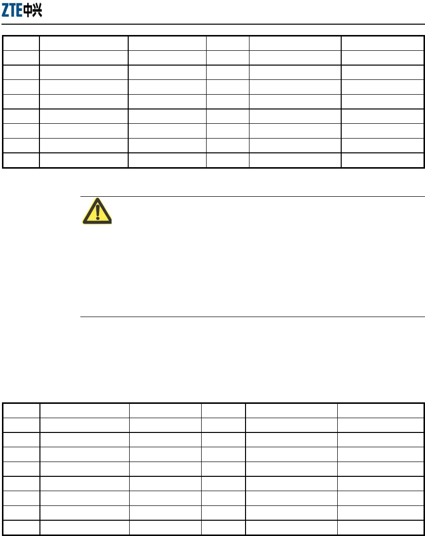
ZXR10 WAS (V1.0) W140A Outdoor Wireless Access Point / Bridge
Professional Installation Instruction Manual
A-2
End A Signal Name Conductor Color End B Signal Name Conductor Color
1 Data receiving Rx+ White/orange 1 Data transmitting Tx+ White/orange
2 Data receiving Rx- Orange 2 Data transmitting Tx- Orange
3 Data transmitting Tx+ White/green 3 Data receiving Rx+ White/green
4 GND Blue 4 GND Blue
5 GND White/blue 5 GND White/blue
6 Data transmitting Tx- Green 6 Data receiving Rx- Green
7 -48V White/brown 7 -48V White/brown
8 -48V Brown 8 -48V Brown
Note:
These cables are with -48 V DC power supply, so make sure to prevent short circuits,
otherwise, the signal will be interrupted and the equipment may not work normally, and
even the equipment protection action will be activated. GND and -48 V each occupy
one twisted pair. These twisted pairs should be separate, otherwise short circuit may
occur.
A.1.3 Making of Crossover Ethernet Cables (RJ45J)
The connections of the crossover Ethernet cables are shown in Table A.1-3.
Table A.1-3 Connections of Crossover Ethernet Cables (RJ45J)
End A Signal Name Conductor Color End B Signal Name Conductor Color
1 Data receiving Rx+ White/orange 3 Data transmitting Tx+ White/green
2 Data receiving Rx- Orange 6 Data transmitting Tx- Green
3 Data transmitting Tx+ White/green 1 Data receiving Rx+ White/orange
4 MATCH1 Blue 4 MATCH1 Blue
5 MATCH2 White/blue 5 MATCH2 White/blue
6 Data transmitting Tx- Green 2 Data receiving Rx- Orange
7 MATCH3 White/brown 7 MATCH3 White/brown
8 MATCH4 Brown 8 MATCH4 Brown
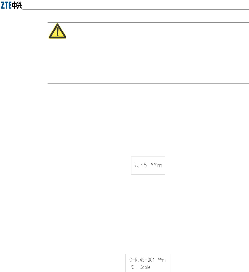
Error! Style not defined. Error! Style not defined.
A-3
Note:
The signals and connection methods mentioned here are designed according to the
signal definitions of the ZTE AC equipment interface. If the AC in the actual
engineering is not from ZTE, modify the cable making methods according to the actual
conditions.
A.1.4 Ethernet Cable Label
After the Ethernet cable is crimped, paste labels on ends A and B of the network cable,
indicating name and length of this cable.
1. Label of the straight through Ethernet cable
The label of the straight through Ethernet cable (RJ45) is shown in Figure A.1-1.
Figure A.1-1 Straight through Ethernet label
In the diagram, “**m” indicates the actual length of the cable.
2. Label of the straight through power supply Ethernet cable
The label of the straight through power supply Ethernet cable (C-RJ45-001) is
shown in Figure A.1-2.
Figure A.1-2 Label of the Straight Through Power Supply Ethernet Cable
In the diagram, “**m” indicates the actual length of the cable; “PoE Cable”
indicates that this is the Ethernet power cable.
3. Label of the Crossover Ethernet Cable
The label of the crossover Ethernet cable (RJ45J) is shown in Figure A.1-3.

ZXR10 WAS (V1.0) W140A Outdoor Wireless Access Point / Bridge
Professional Installation Instruction Manual
A-4
RJ45J * * m
Figure A.1-3 Crossover Ethernet Cable Label
In the diagram, “**m” indicates the actual length of the cable; “J” after “RJ45”
indicates that this is the crossover Ethernet cable.