ZTE ZXR10W140A W140A Wireless Access Point User Manual W140A 0702
ZTE Corporation W140A Wireless Access Point W140A 0702
UserManual.wiki
>
ZTE
>
ZXR10W140A User Manual
>
Users Manual
Contents
1.
Professional Installation Manual
2.
Users Manual
Users Manual
Navigation menu
Upload a User Manual
Namespaces
Wiki Guide
HTML
PDF
Info
Views
User Manual
Discussion / Help
Navigation
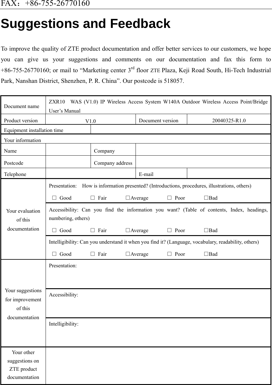
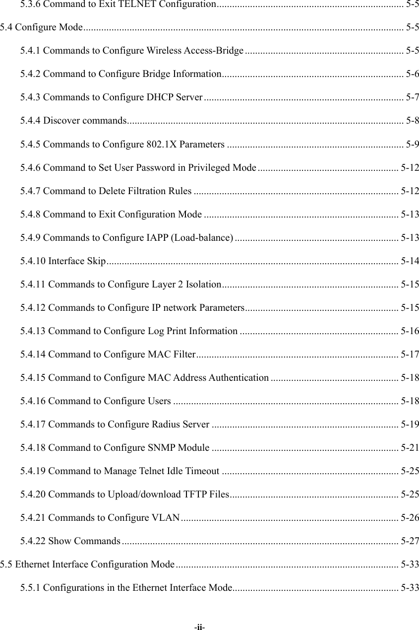
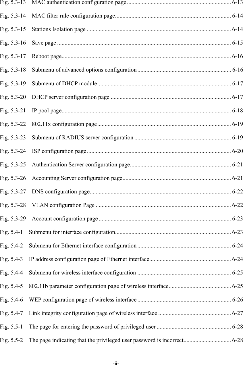
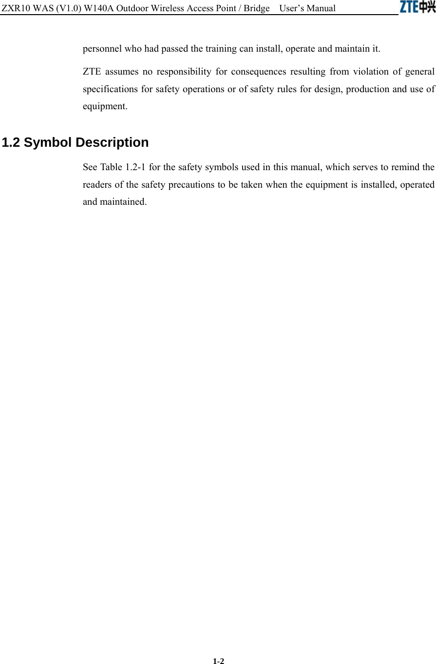

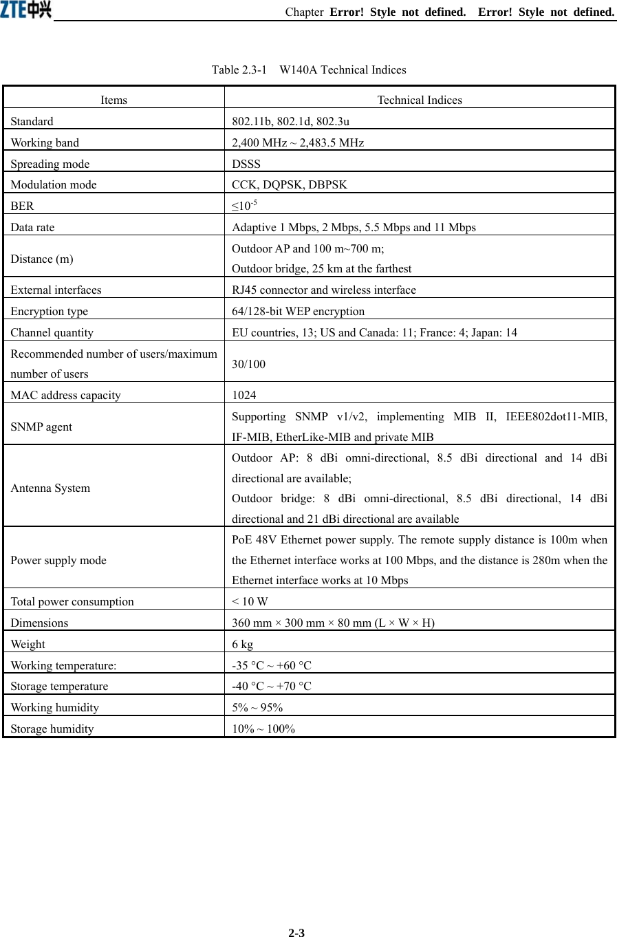
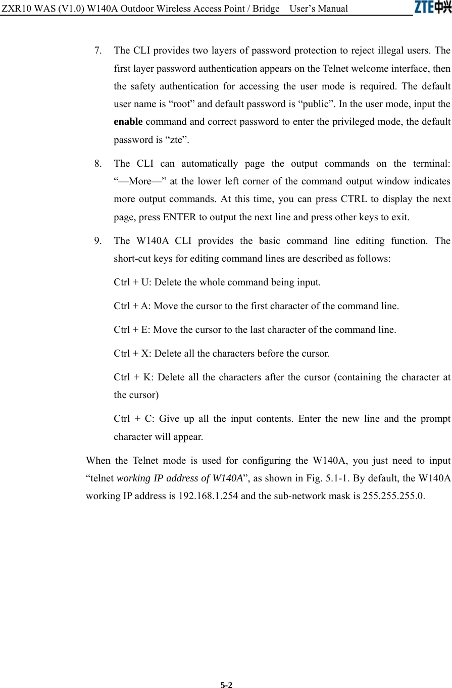
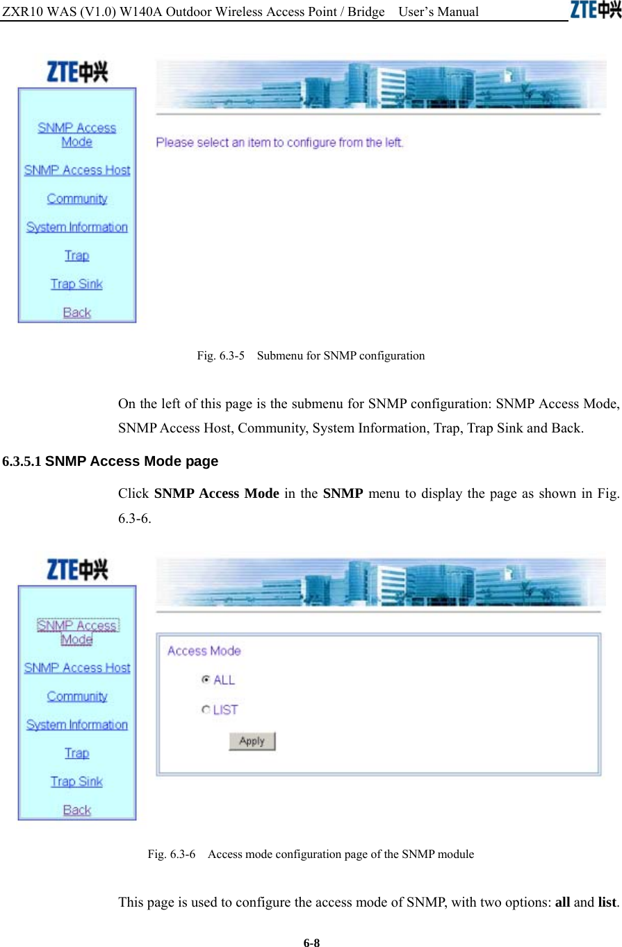
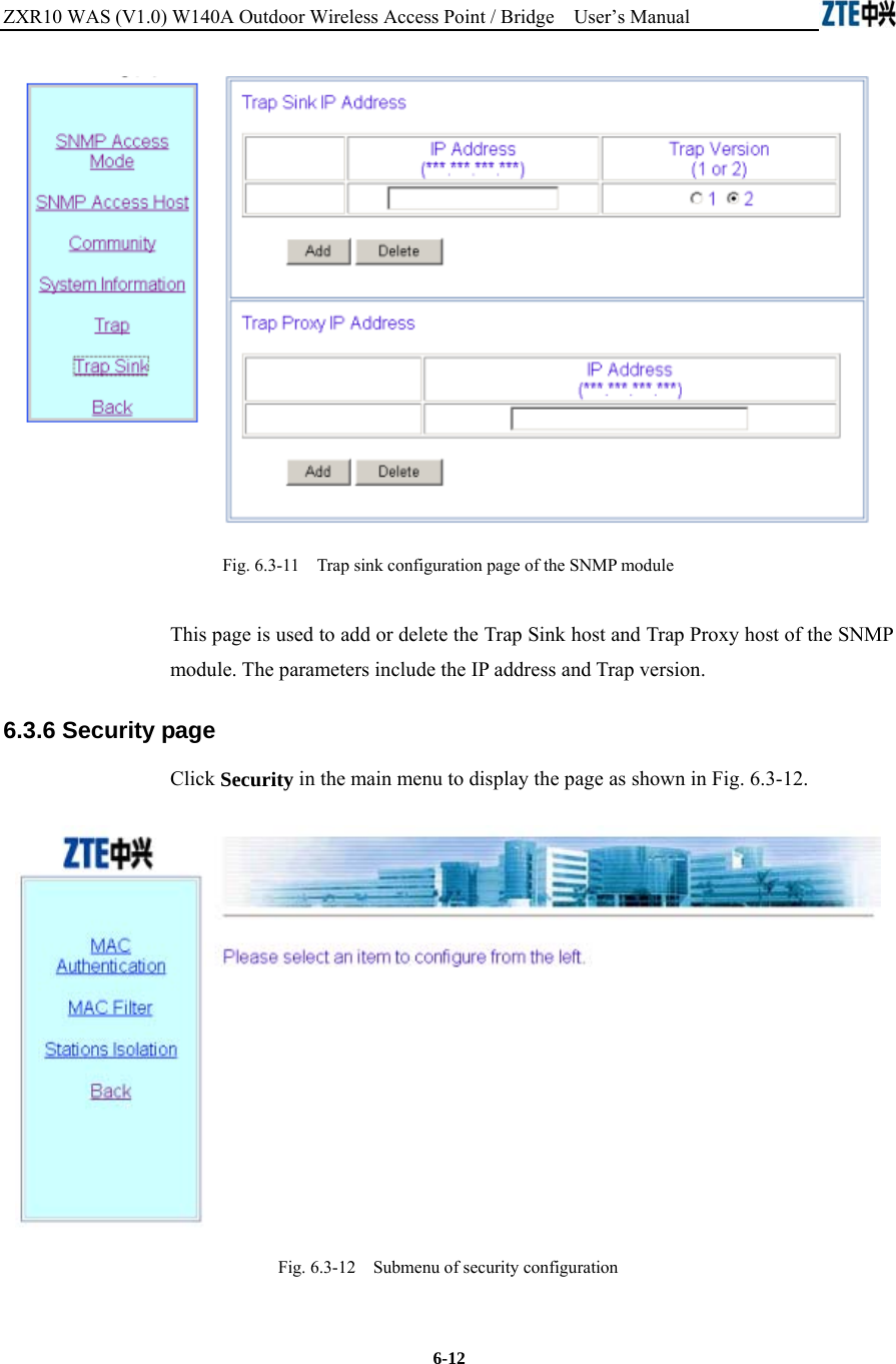
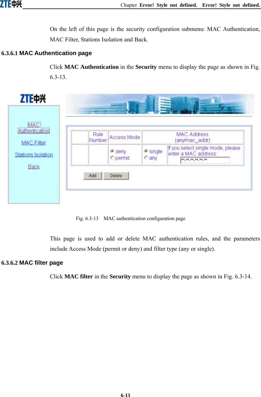
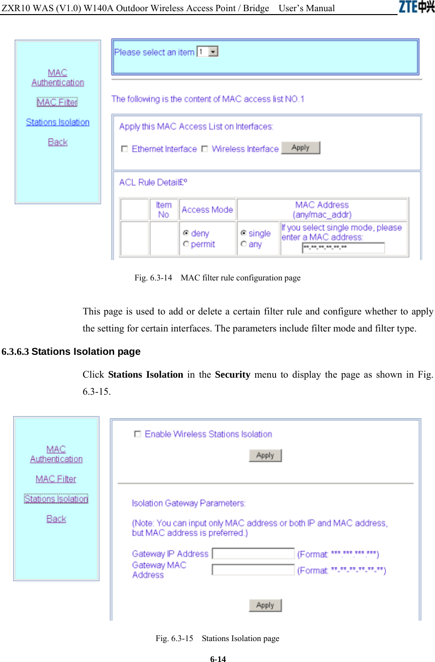
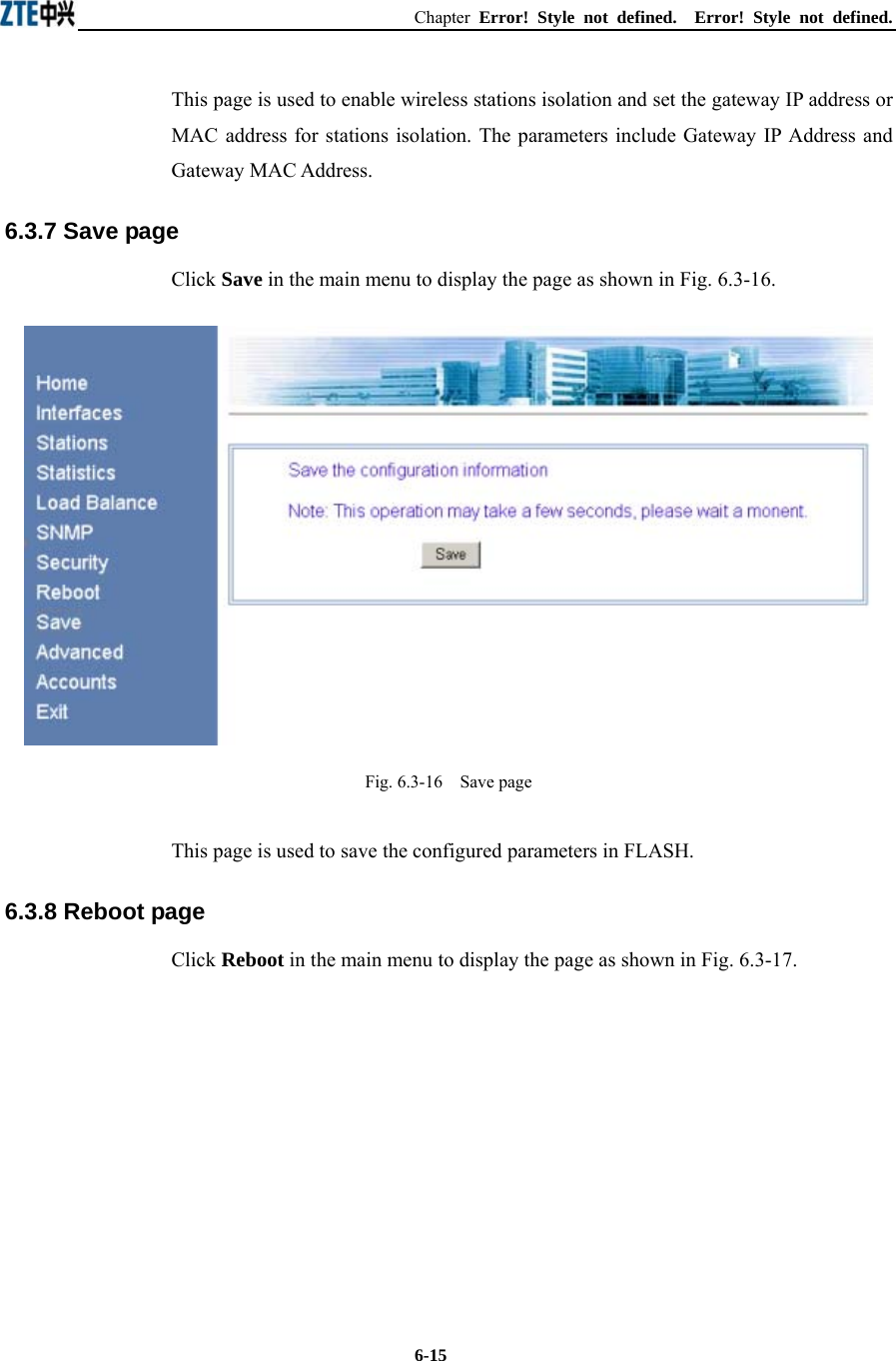
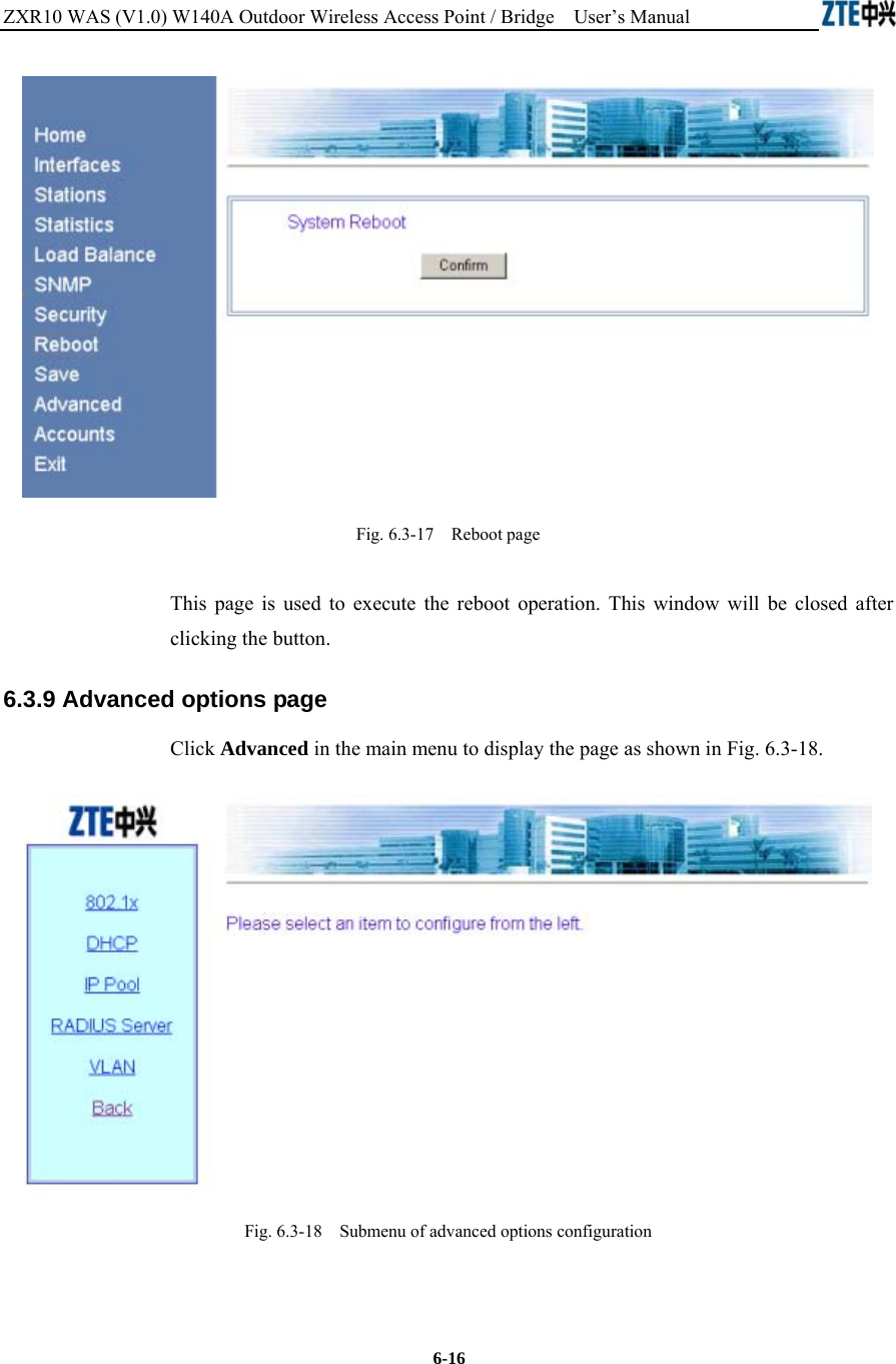
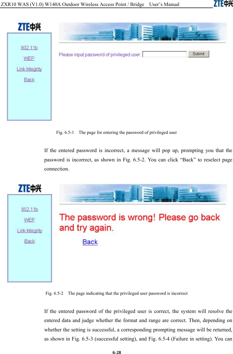
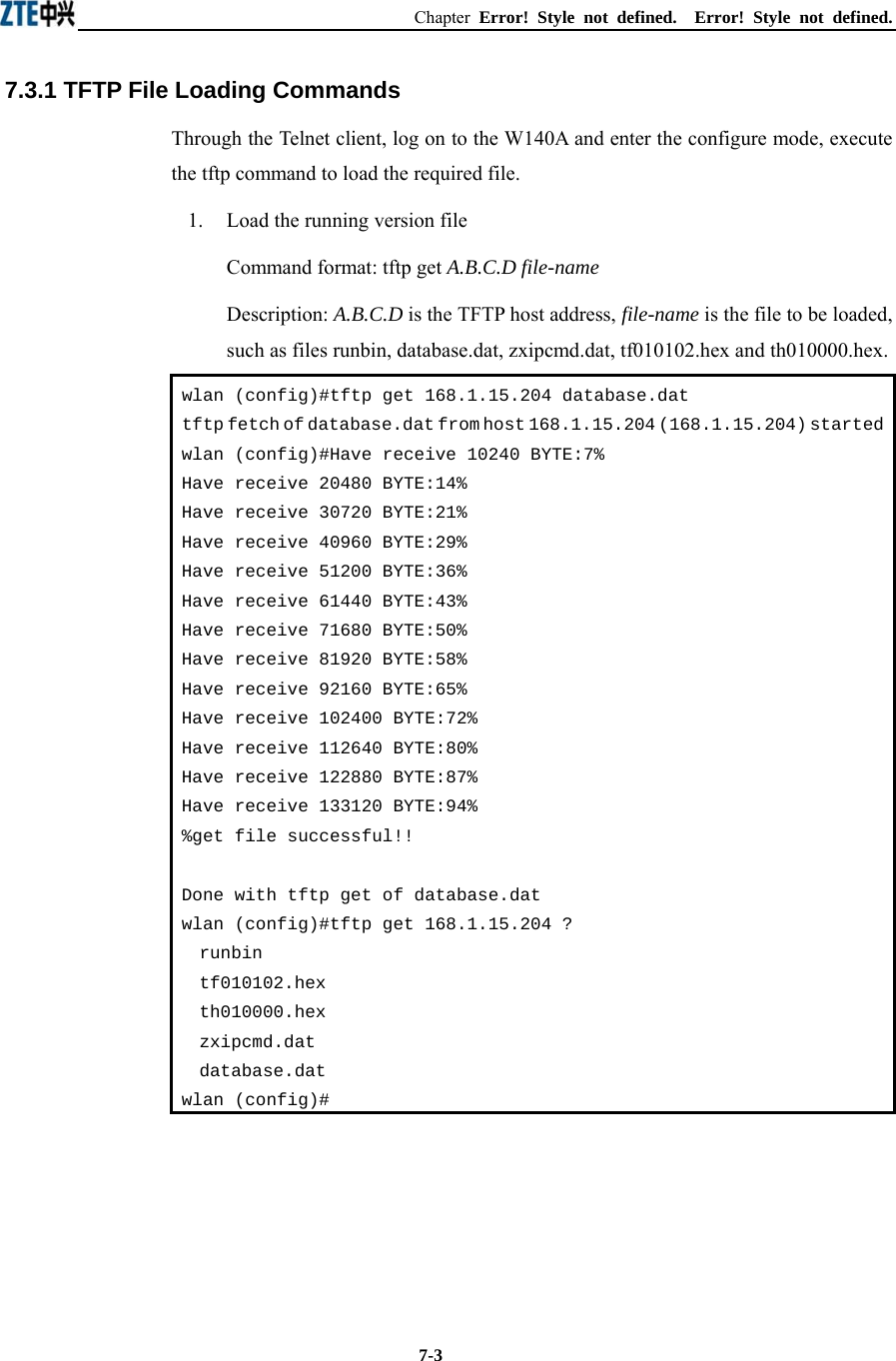
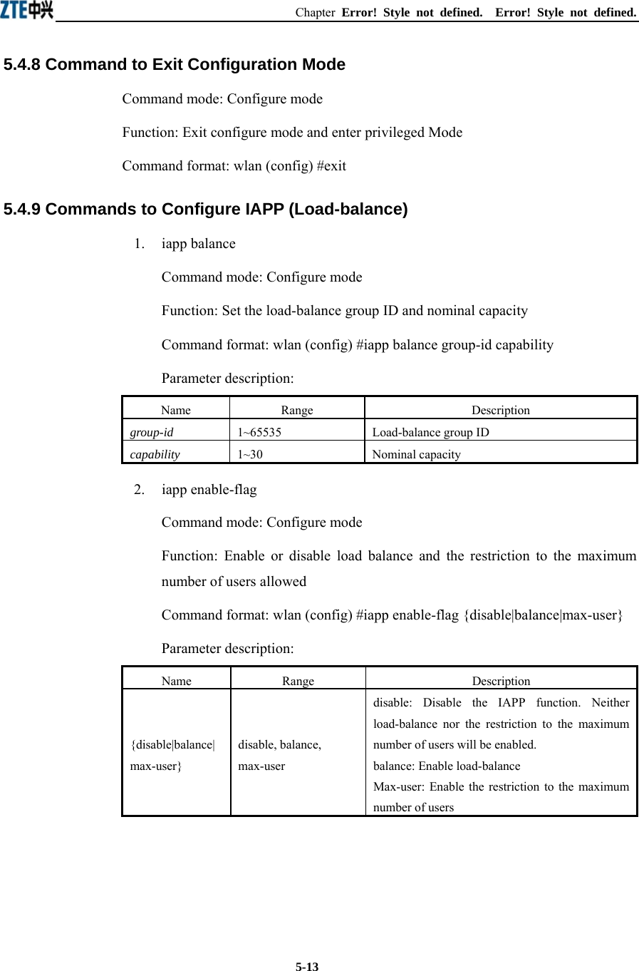
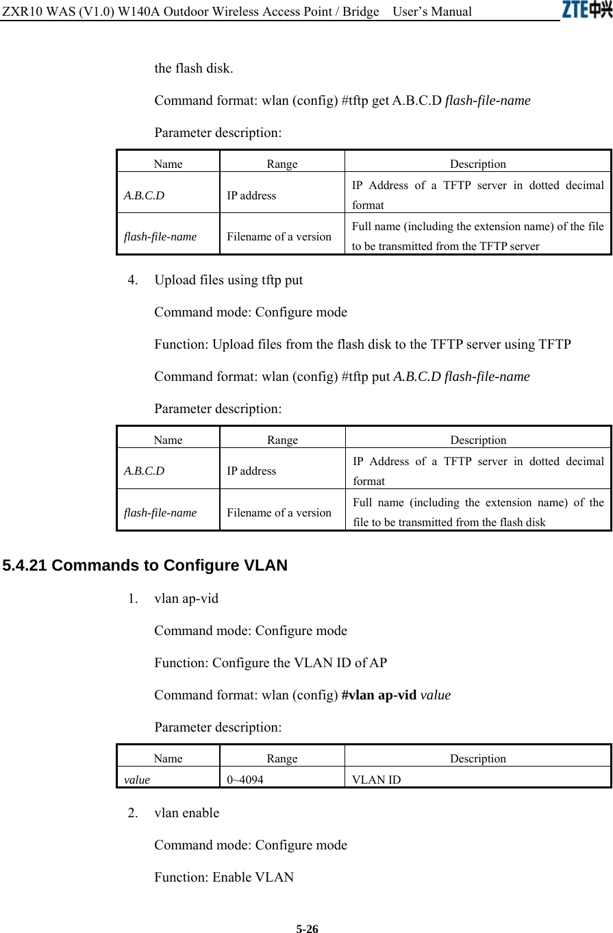
![Chapter Error! Style not defined. Error! Style not defined. 5-3 Fig. 5.1-1 Telnet to W140A These five configuration modes of the W140A and all the available commands under each mode are described in detail as follows: The stipulation of command format is as follows: 1. The abc refers to the contents to be input by the user. 2. The {abc | def} means that the user should input either of the two items. 3. [A ~ B] indicates the digital range of the configuration parameters that the user can input. 4. For the contents included in [ ], the user can choose to input or not input them.. 5.2 User Mode Mode of entry: Telnet Exit mode: exit Default prompt: wlan> Note: When an ordinary user logs in to the W140A via Telnet, he/she will not be able to enter the user mode unless he/she passes the username and password authentication. By default, the username and password are "root" and "public". To prevent illegal users from attempting the password frequently, the system will cut the Telnet connections of a user automatically if incorrect passwords have been entered 3 times continuously.](https://usermanual.wiki/ZTE/ZXR10W140A.Users-Manual/User-Guide-446187-Page-35.png)
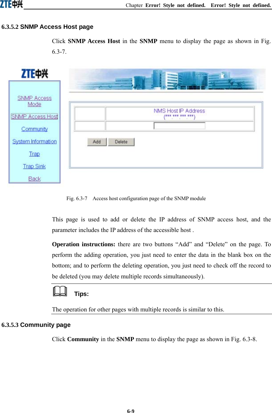
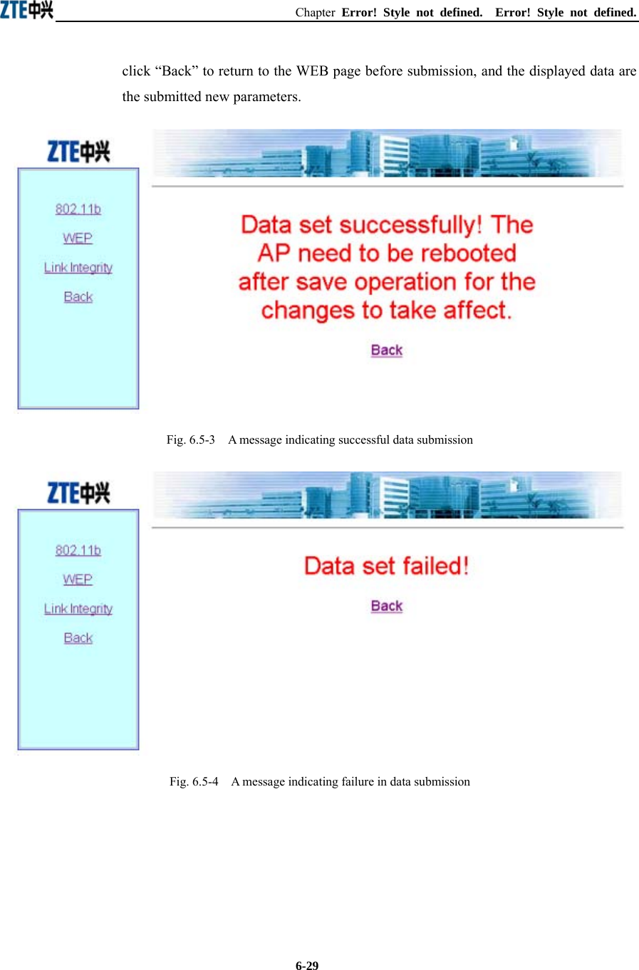
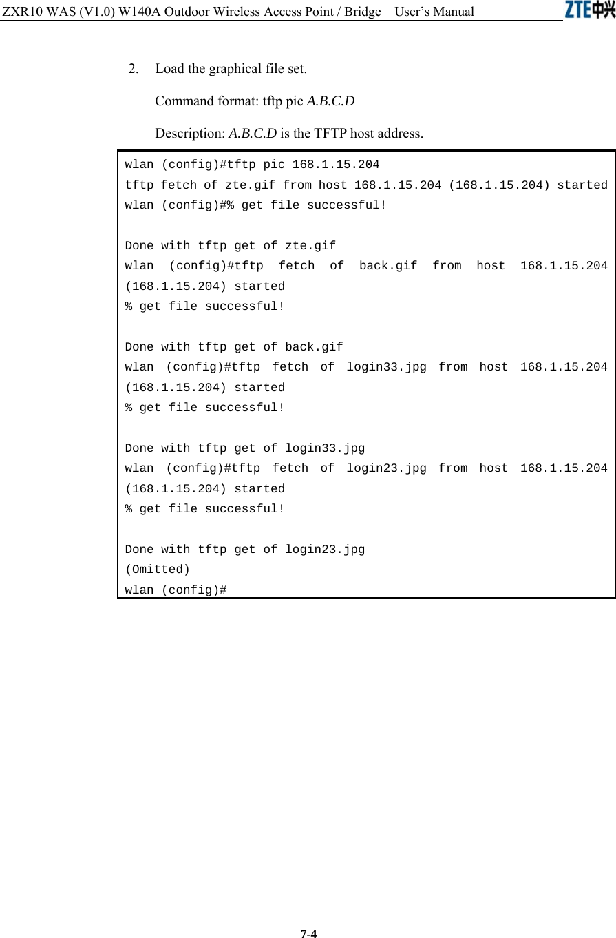
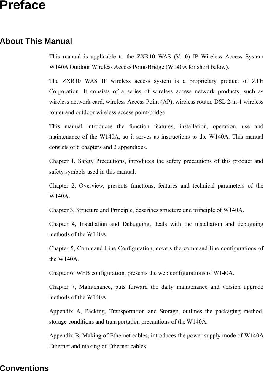
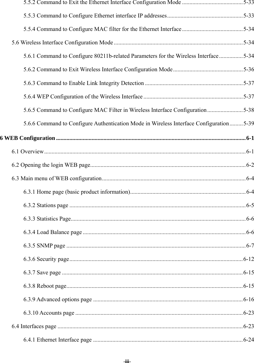
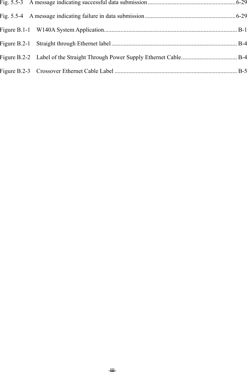
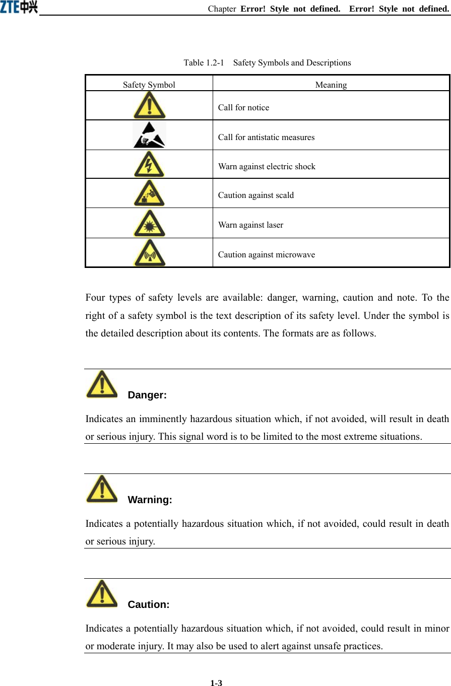
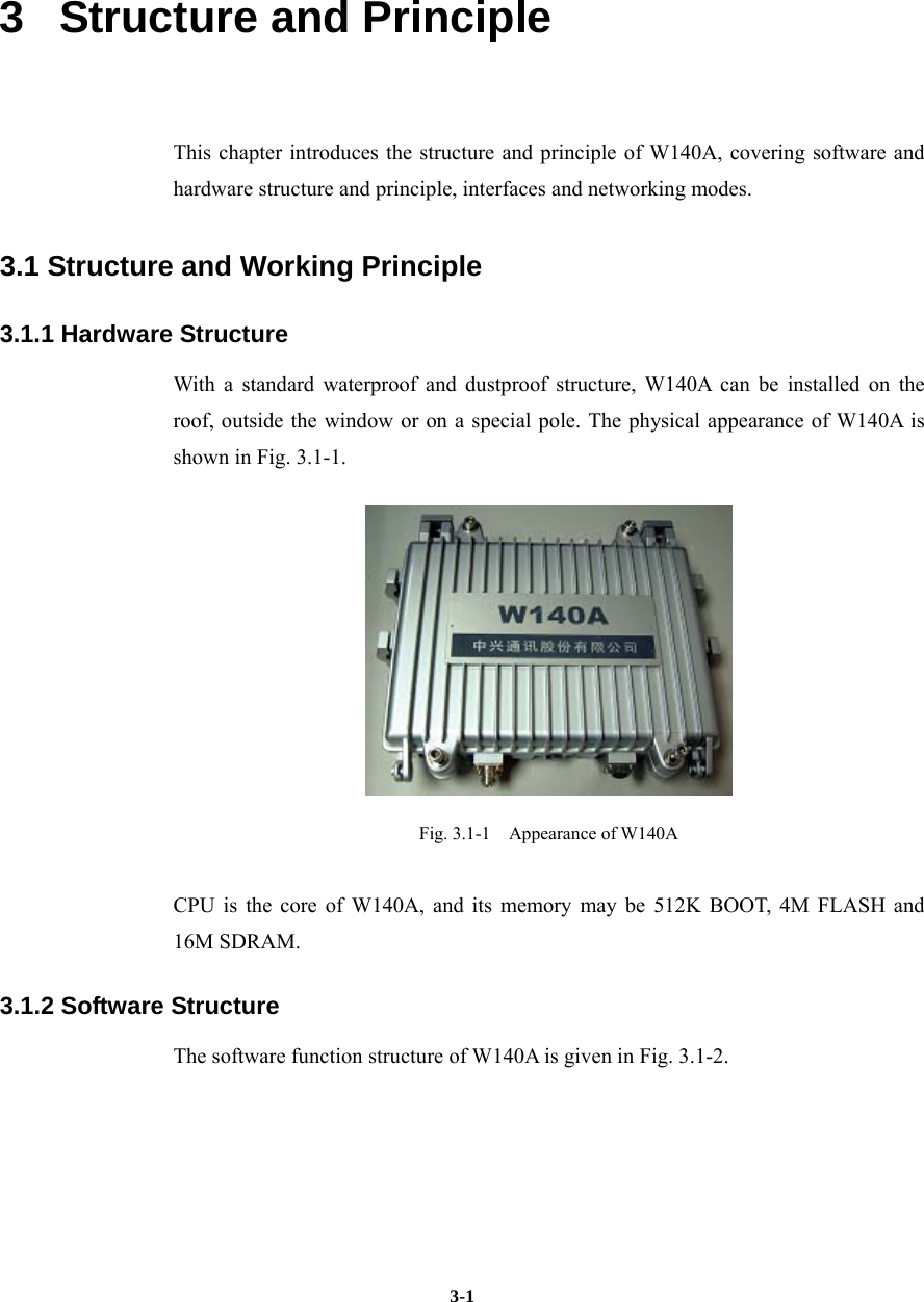
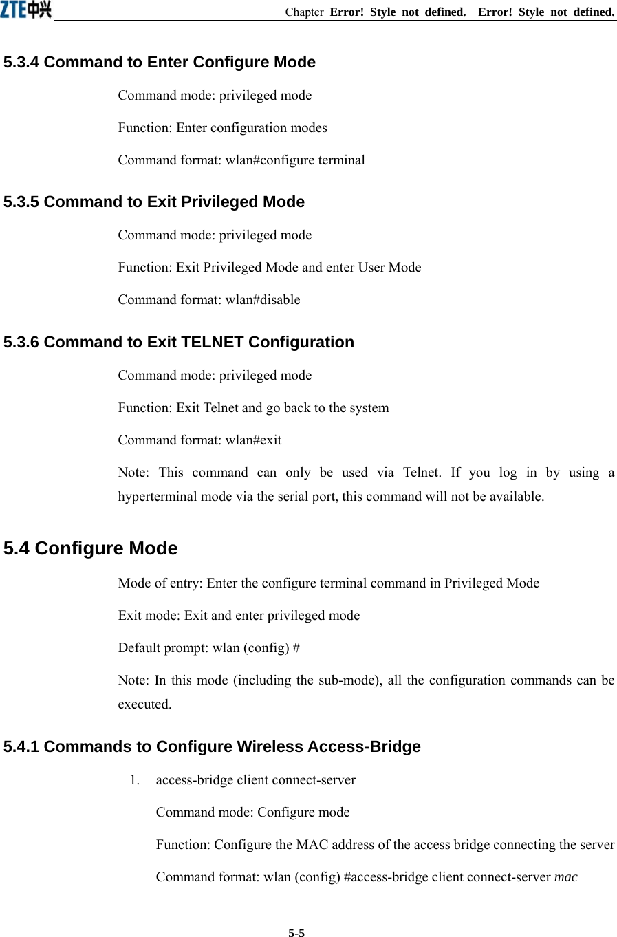
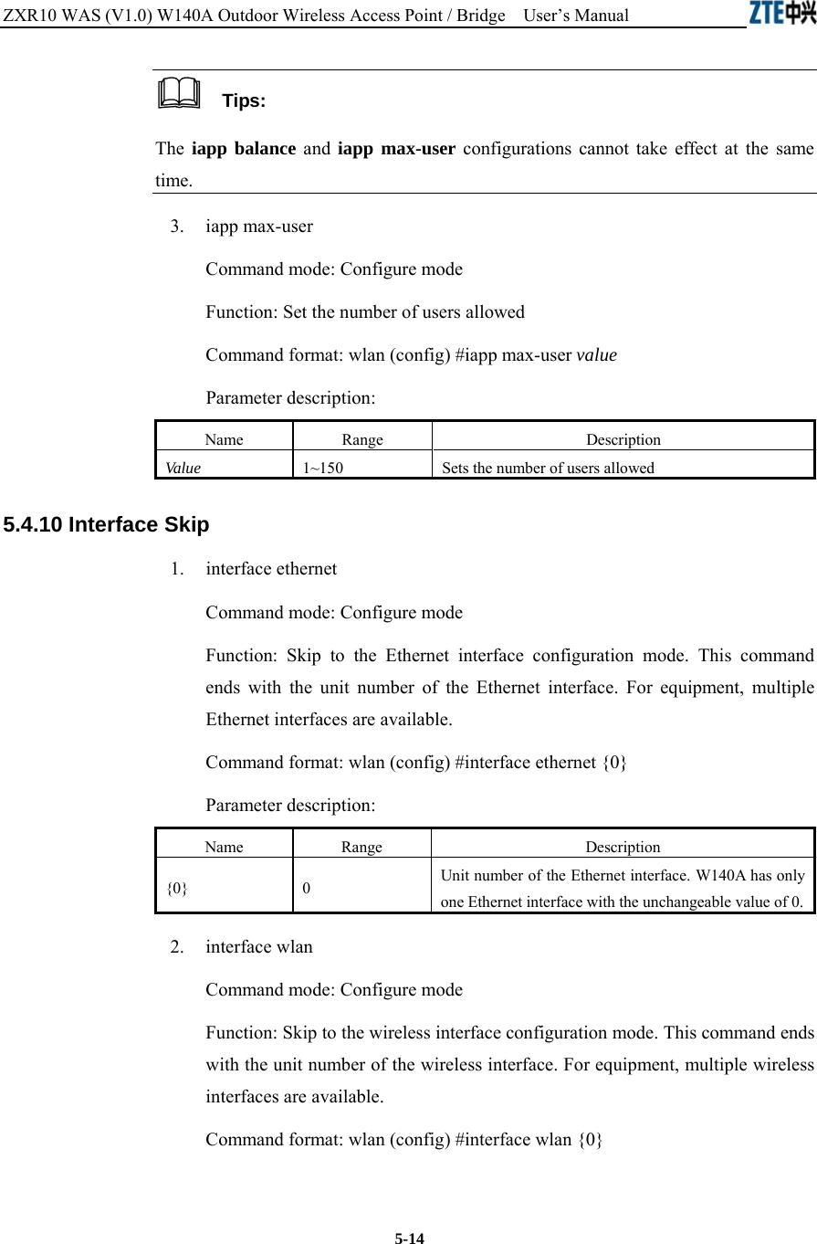
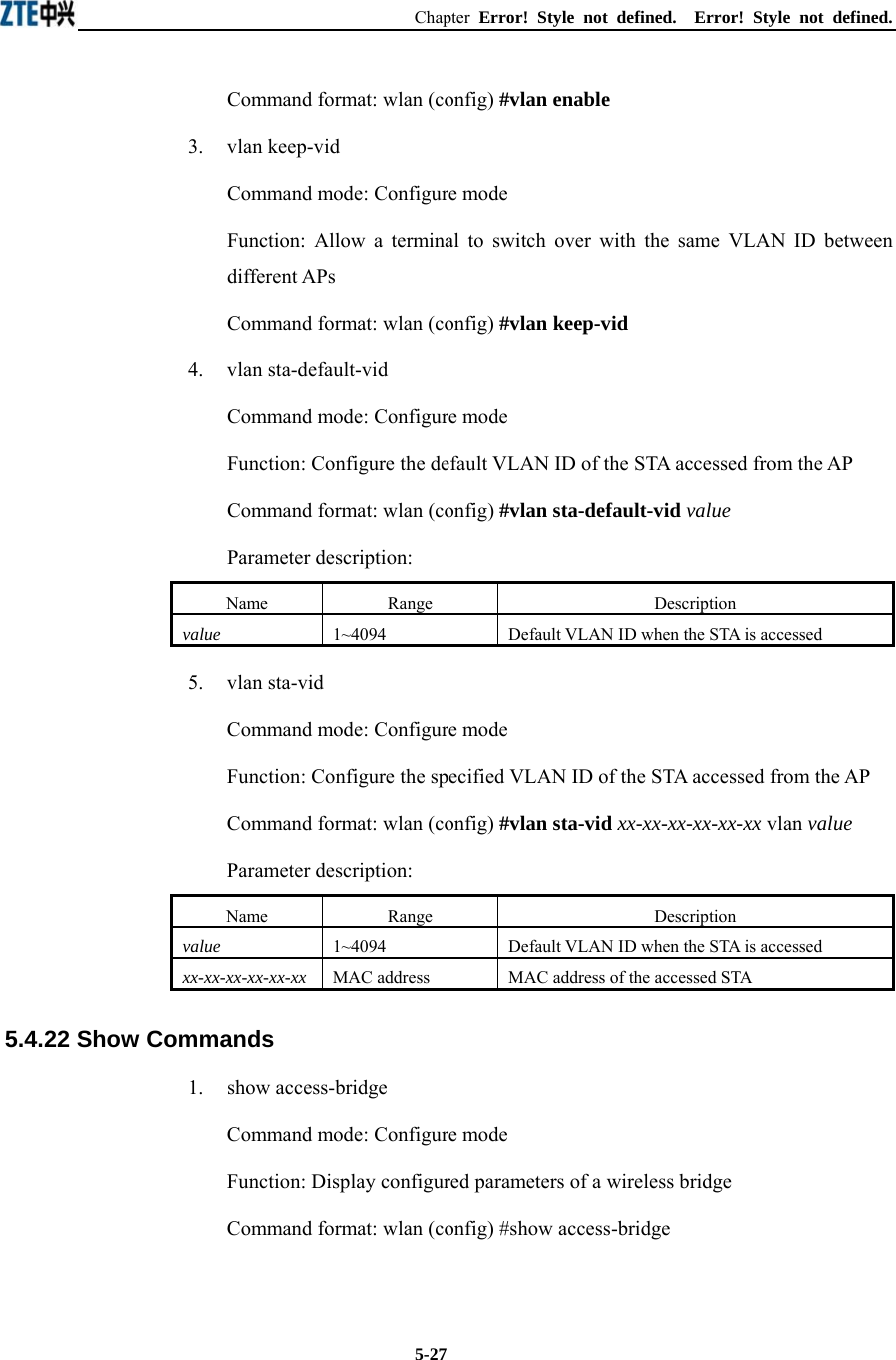
![ZXR10 WAS (V1.0) W140A Outdoor Wireless Access Point / Bridge User’s Manual 5-4 5.3 Privileged Mode Mode of entry: Type in the enable command in the in use mode and enter the correct password. Exit mode: disable for entering the user mode; exit for exiting the privileged mode and go back to the system. Default prompt: wlan# 5.3.1 Command to Test Network Connectivity Command mode: privileged mode Function: Test the network connectivity Command format: ping A.B.C.D [-n echo-number] [-w timeout] [-l packet-size] Parameter description: Name Range Description A.B.C.D IP address Destination IP address -n Null Sets the flag bits for the number of PING packets echo-number 1~40 The number of PING packets -w Null Sets the flag bits for the maximum timeout interval Timeout 1~2 Maximum timeout interval (unit: s) -l Null Sets the flag bits for the capacity of buffer area packet-size 0~1504 Capacity of buffer area 5.3.2 Command to Save Configurations to Flash Command mode: privileged mode Function: Save configurations to flash Command format: wlan#write flash 5.3.3 Command to Reset Software Command mode: privileged mode Function: Reset W140A Command format: wlan#reboot](https://usermanual.wiki/ZTE/ZXR10W140A.Users-Manual/User-Guide-446187-Page-36.png)
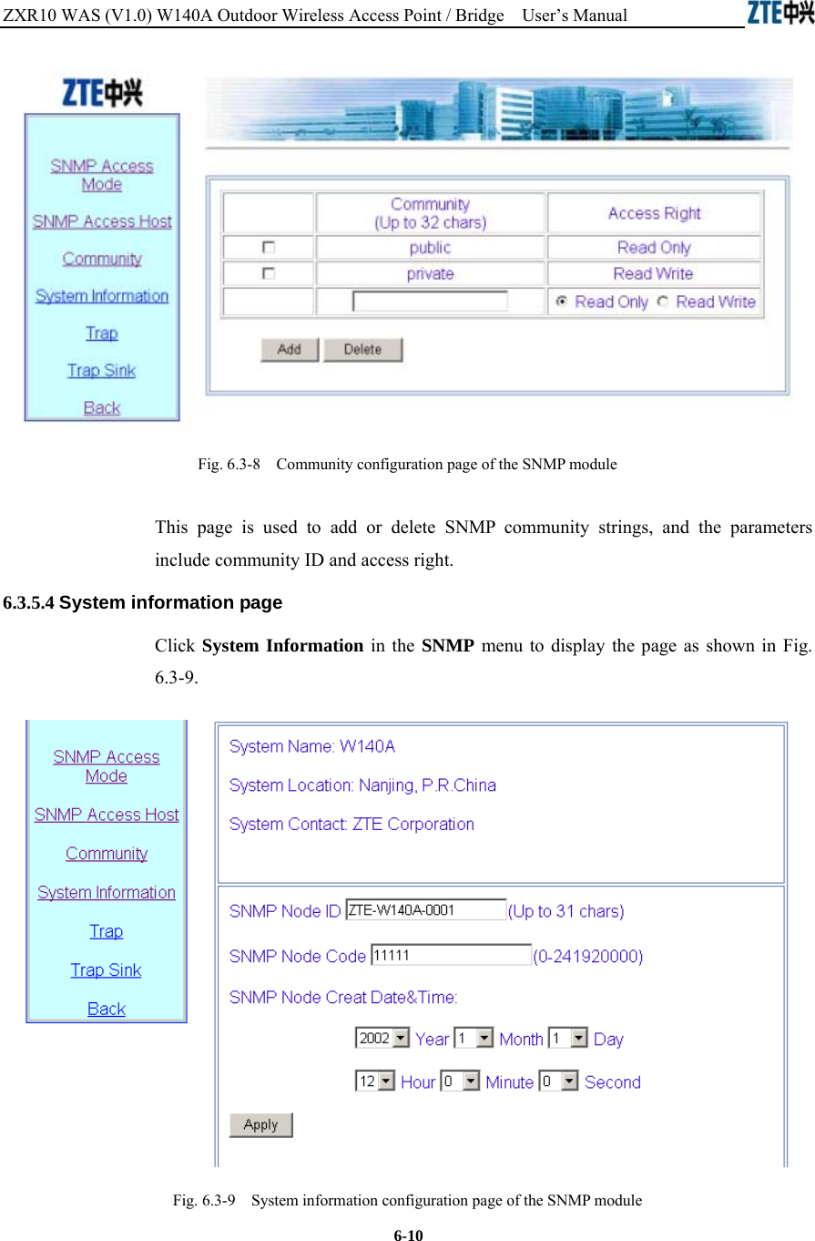
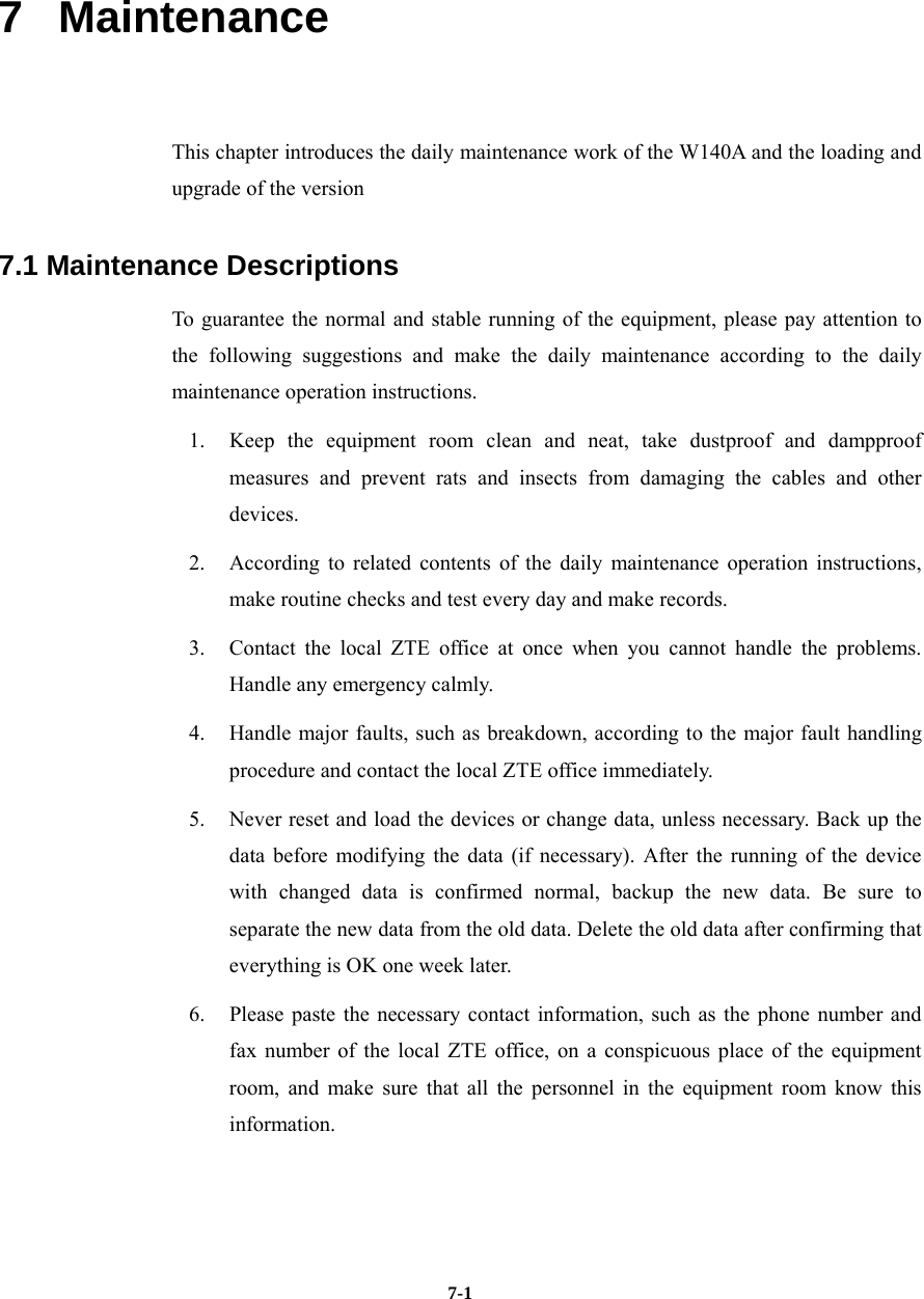
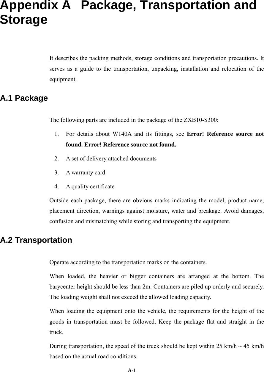
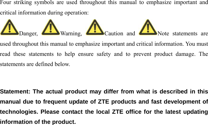
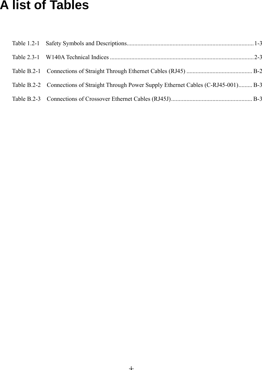
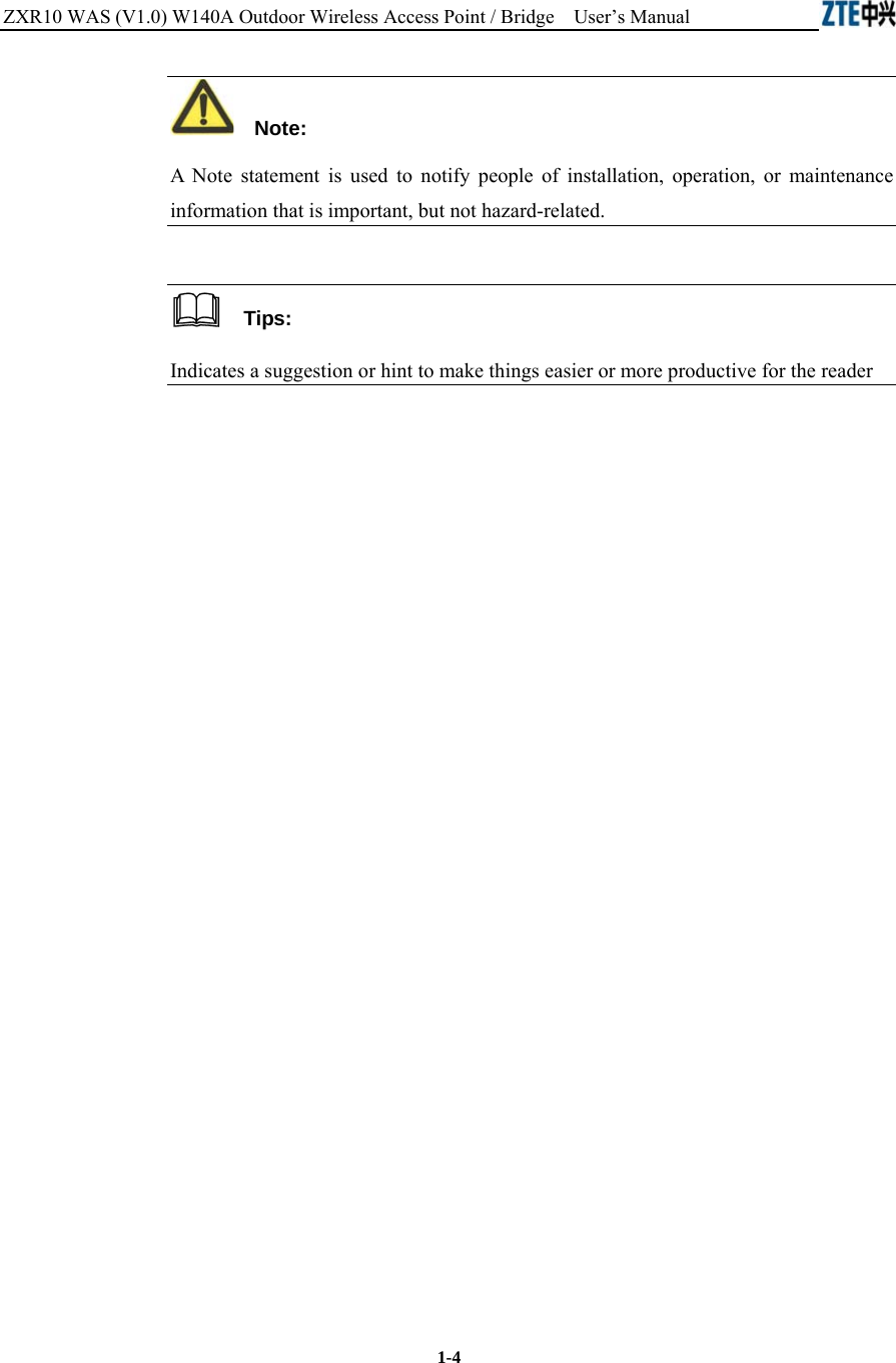
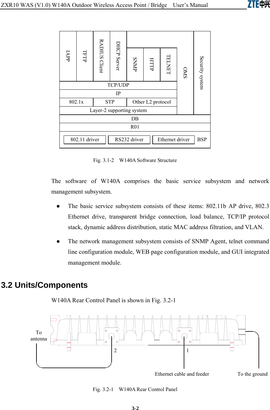
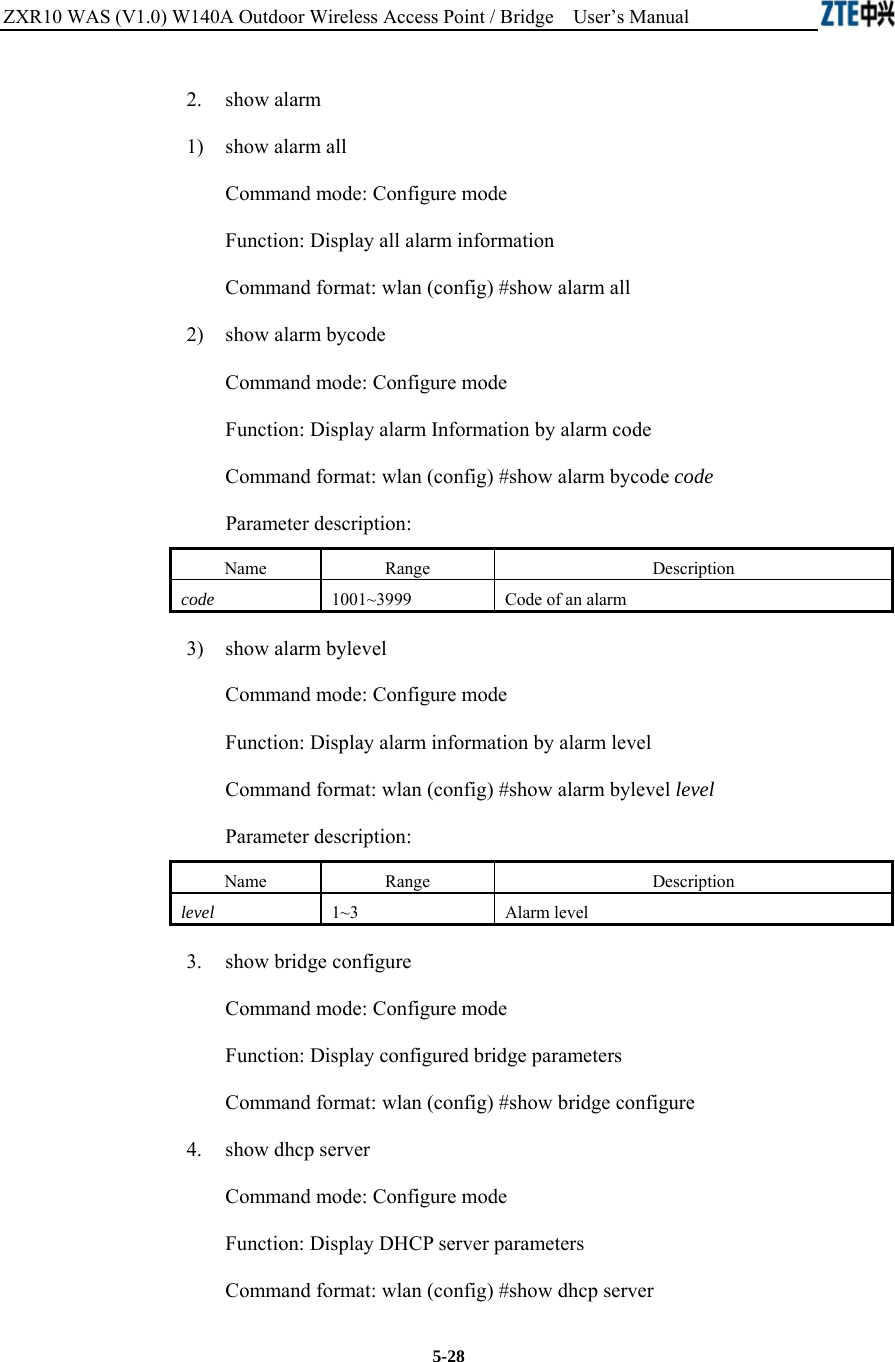
![ZXR10 WAS (V1.0) W140A Outdoor Wireless Access Point / Bridge User’s Manual 5-6 Parameter description: Name Range Description mac MAC address in the xx-xx-xx-xx-xx-xx format MAC address of the access bridge connecting the server 2. access-bridge client enable Command mode: Configure mode Function: Enable/disable the wireless bridge client Command format: wlan( config) #[no] access-bridge client enable 3. access-bridge server connect-client Command mode: Configure mode Function: Configure the MAC address of the access bridge connecting clients Command format: wlan(config)#[no] access-bridge server connect-client mac Parameter description: Name Range Description mac MAC address in the xx-xx-xx-xx-xx-xx format MAC address of the access bridge connecting clients 4. access-bridge server enable Command mode: Configure mode Function: Enable/disable the wireless bridge server Command format: wlan (config) #[no] access-bridge server enable 5.4.2 Command to Configure Bridge Information bridge filterdb Command mode: Configure mode Function: Configure bridge filtration or cancel the configuration Command format: wlan (config) #[no] bridge filterdb max-user aging-time alarm-percent](https://usermanual.wiki/ZTE/ZXR10W140A.Users-Manual/User-Guide-446187-Page-38.png)
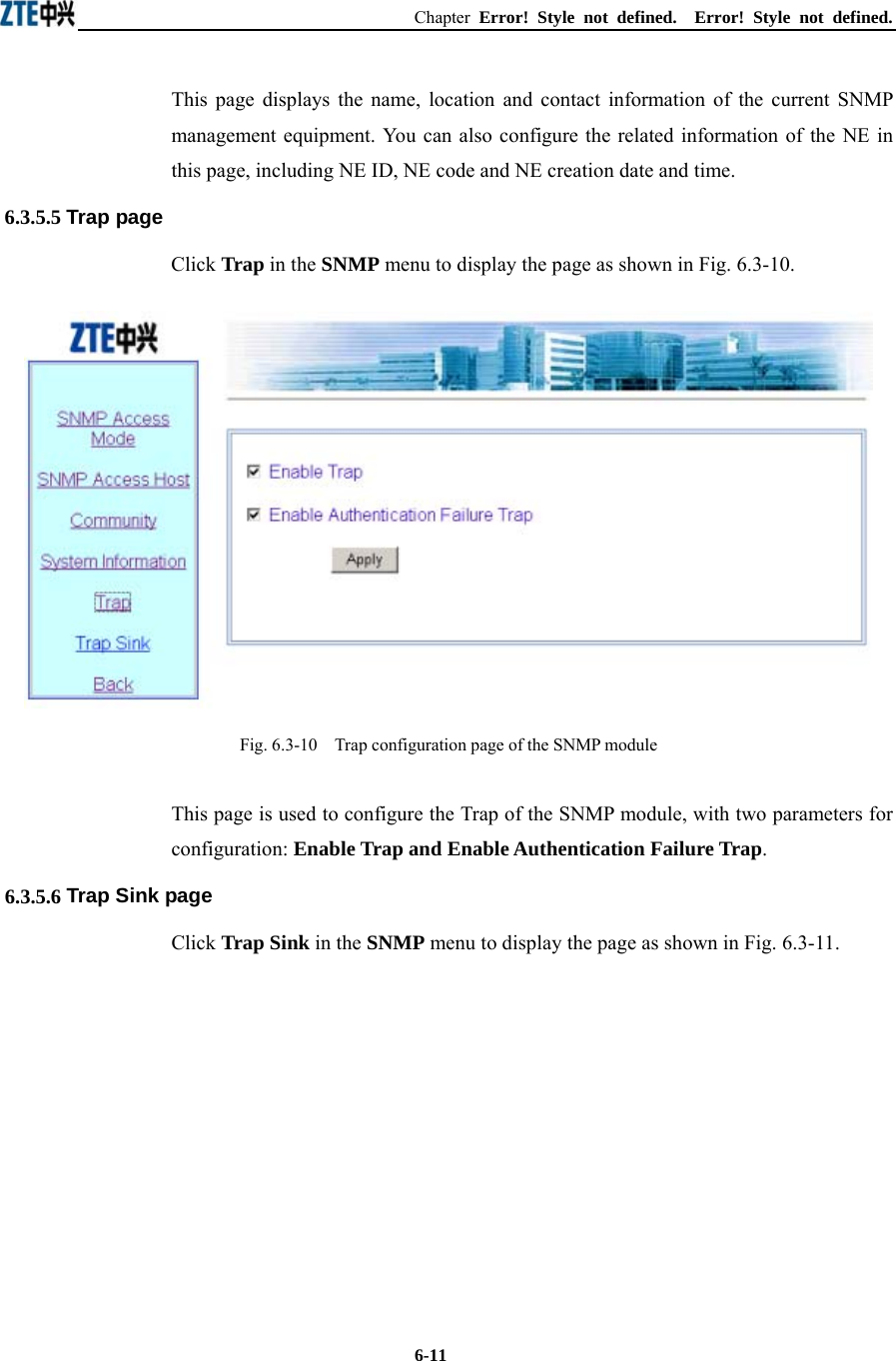
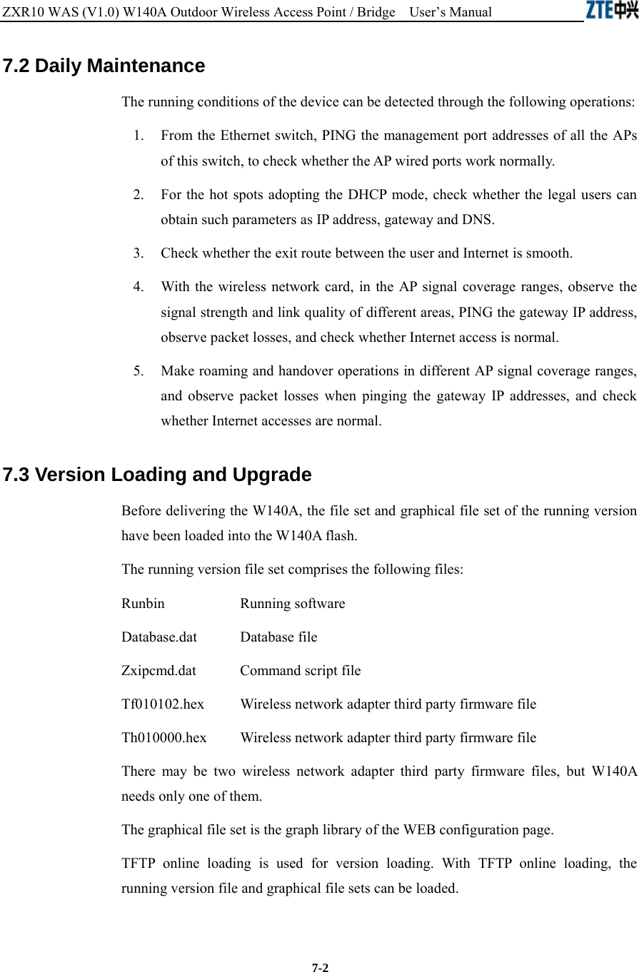
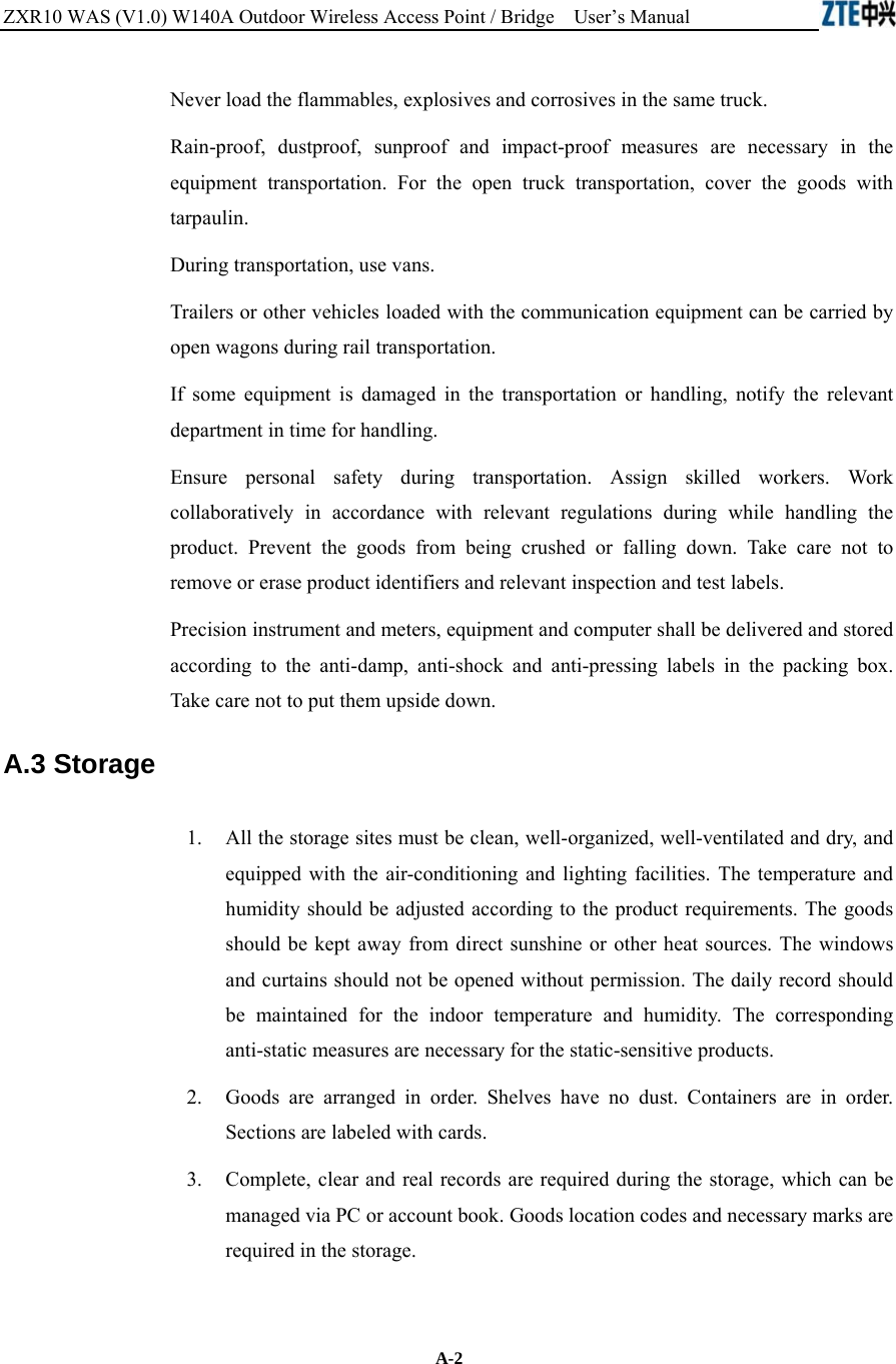
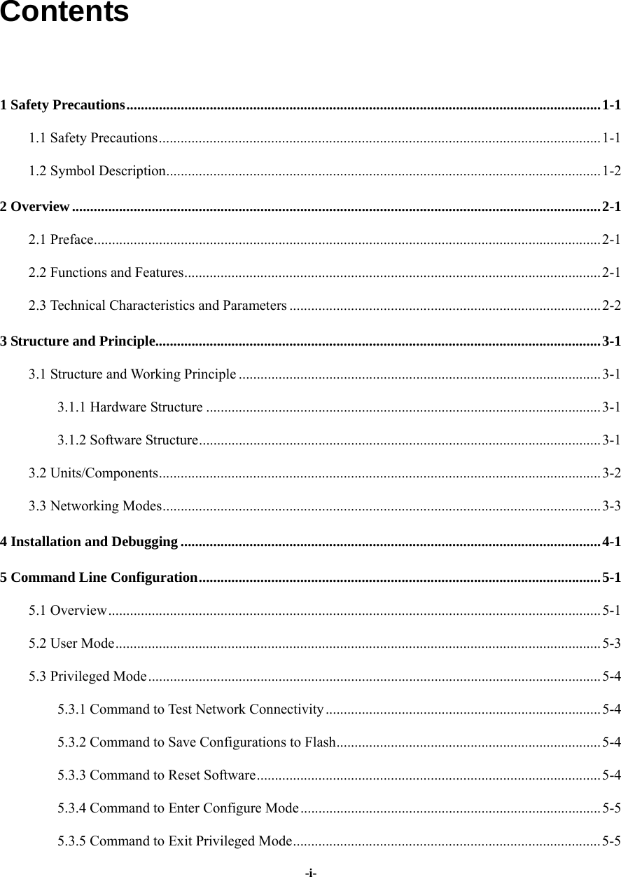
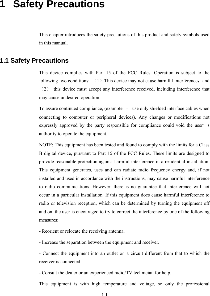
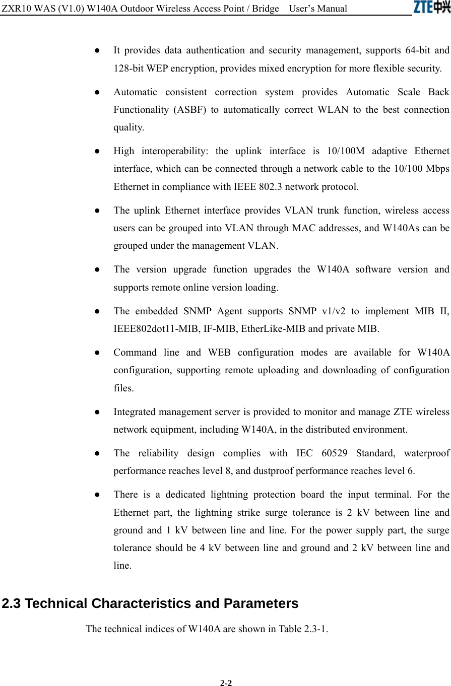
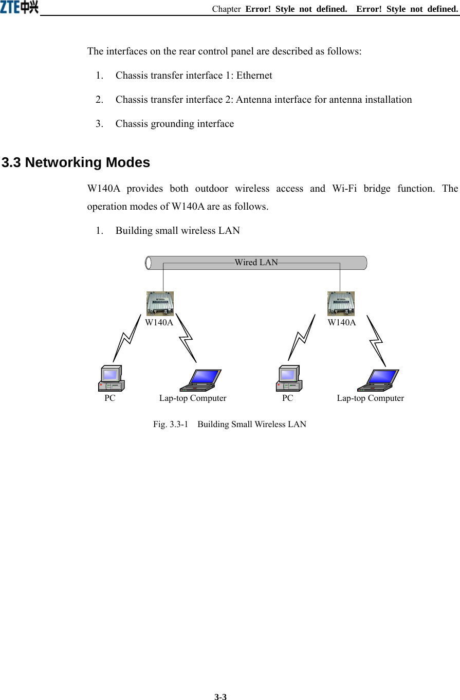
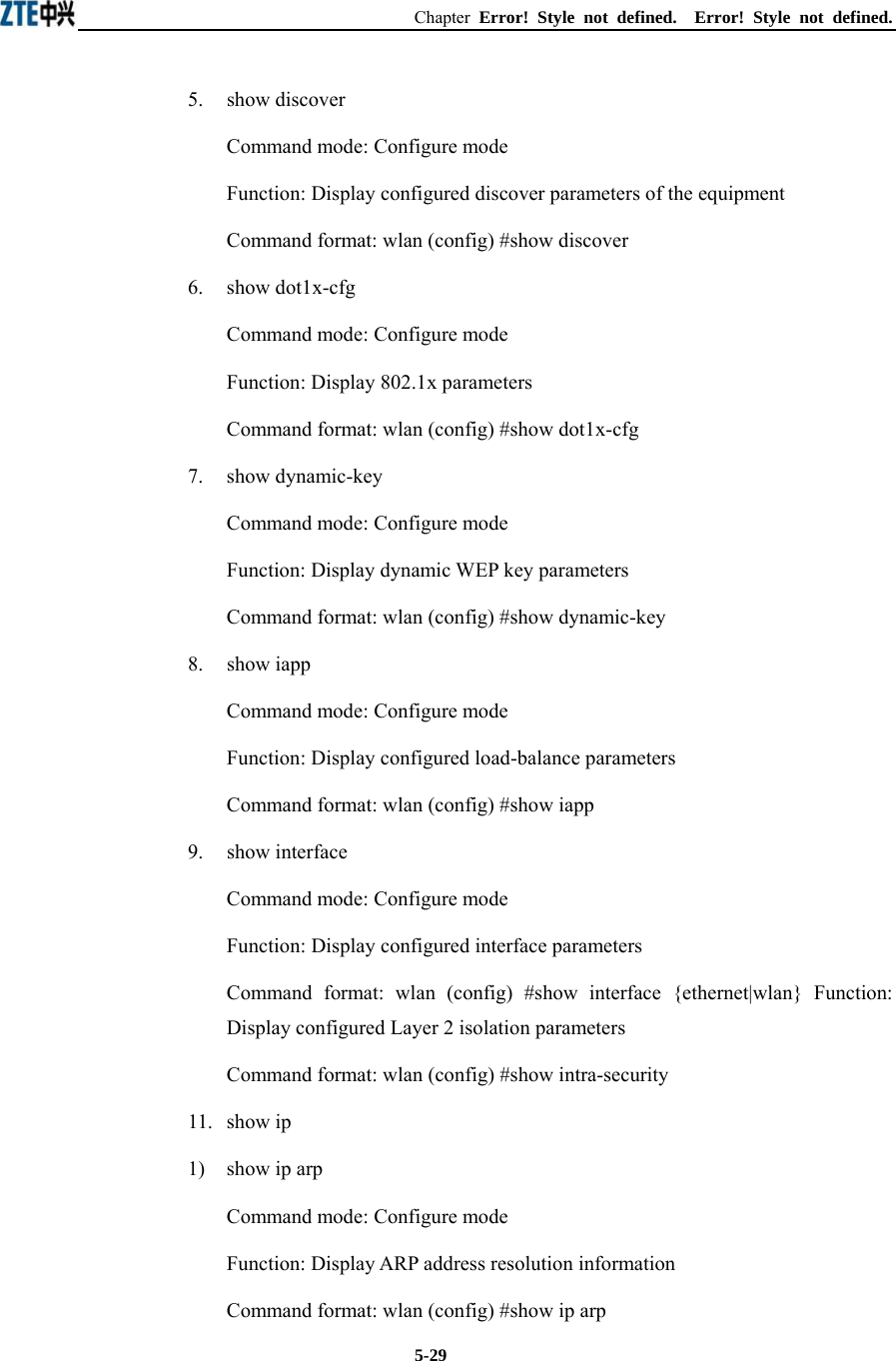
![Chapter Error! Style not defined. Error! Style not defined. 5-7 Parameter description: Name Range Description max-user 512~1024 Maximum capacity of the MAC address list aging-time 10~100,000 Aging time of the MAC address list entries alarm-percent 1~10 Percent of alarms 5.4.3 Commands to Configure DHCP Server 1. dhcp server dns Command mode: Configure mode Function: Configure the IP addresses of the master/slave DNS server in the DHCP server Command format: wlan (config) # dhcp server dns A.B.C.D [A.B.C.D] Parameter description: Name Range Description A.B.C.D IP address IP address of the master DNS server [A.B.C.D] IP address IP address of the slave DNS server (optional) 2. dhcp server gateway Command mode: Configure mode Function: Configure the IP address of the default gateway of the DHCP server Command format: wlan (config) # dhcp server gateway A.B.C.D Parameter description: Name Range Description A.B.C.D IP address IP address of the gateway 3. dhcp server leasetime Command mode: Configure mode Function: Configure the address lease time of the DHCP server Command format: wlan (config) # dhcp server leasetime time-value](https://usermanual.wiki/ZTE/ZXR10W140A.Users-Manual/User-Guide-446187-Page-39.png)
![ZXR10 WAS (V1.0) W140A Outdoor Wireless Access Point / Bridge User’s Manual 5-8 Parameter description: Name Range Description time-value 60~3600 DHCP server address lease time (unit: s), 60s by default 4. dhcp server run Command mode: Configure mode Function: Start, stop or restart the DHCP server Command format: wlan (config) # dhcp server run run-flag Parameter description: Name Range Description run-flag start, stop, restart start: Start the DHCP server stop: Stop the DHCP server restart: Restart the DHCH server 5. dhcp server start-flag Command mode: Configure mode Function: Configure the start flag of the DHCP server for the restart of the system Command format: wlan (config) # dhcp server start-flag {true|false} Parameter description: Name Range Description {true|false} True, false Start flag of the DHCP server. If it is set to true, it will be started when the system is restarted. If false, the DHCP server will not be started. 5.4.4 Discover commands 1. discover device Command mode: Configure mode Function: Configure the multicasting address for the integrated management and the port number of the equipment Command format: wlan (config) #discover device A.B.C.D [0~65535]](https://usermanual.wiki/ZTE/ZXR10W140A.Users-Manual/User-Guide-446187-Page-40.png)
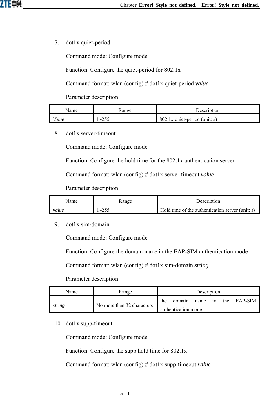
![Chapter Error! Style not defined. Error! Style not defined. 5-9 Parameter description: Name Range Description A.B.C.D IP address Multicasting address for the integrated management of the equipment [0~65535] 0~65535 Snooping port number for the integrated management of the equipment 2. discover manager Command mode: Configure mode Function: Configure the multicasting address and port number for the integrated management server Command format: wlan (config) #discover manager A.B.C.D [0~65535] Parameter description: Name Range Description A.B.C.D IP address Multicasting address for the integrated management server [0~65535] 0~65535 Snooping port number for the integrated management server 5.4.5 Commands to Configure 802.1X Parameters 1. dot1x enable Command mode: Configure mode Function: Enable or disable 802.1x Command format: wlan (config) #[no] dot1x enable 2. dot1x max-reauth Command mode: Configure mode Function: Configure the maximum number of attempts for 802.1x authentication Command format: wlan (config)# dot1x max-reauth max-reauth-times Parameter description: Name Range Description max-reauth-times 0~10 the maximum number of attempts for 802.1x authentication](https://usermanual.wiki/ZTE/ZXR10W140A.Users-Manual/User-Guide-446187-Page-41.png)
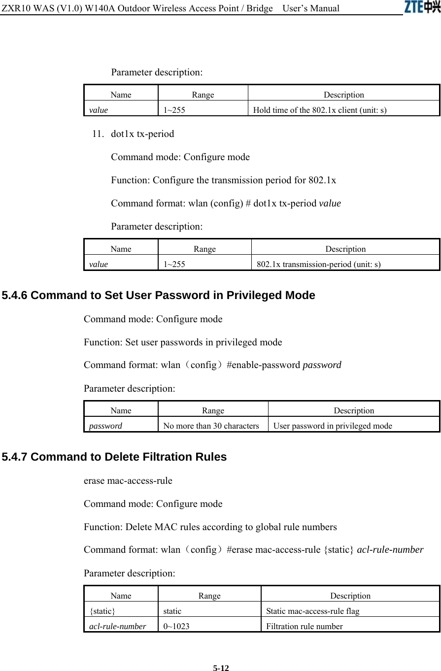
![ZXR10 WAS (V1.0) W140A Outdoor Wireless Access Point / Bridge User’s Manual 5-10 3. dot1x max-request Command mode: Configure mode Function: Configure the maximum number of requests for 802.1x authentication Command format: wlan (config) # dot1x max-request max-request-times Parameter description: Name Range Description max-request-times 1~10 Maximum number of requests for 802.1x authentication 4. dot1x md5-domain Command mode: Configure mode Function: Configure the domain name in the EAP-MD5 authentication mode 命令格式:wlan(config)Command format: wlan (config) # dot1x md5-domain string Parameter description: Name Range Description String No more than 32 characters Domain name in the EAP-MD5 authentication mode 5. dot1x nas-id Command mode: Configure mode Function: Configure the NAS-ID field for 802.1x Command format: wlan (config) # dot1x nas-id string Parameter description: Name Range Description String No more than 64 characters NAS-ID character string 6. dot1x portenable Command mode: Configure mode Function: Enable or disable 802.1x port control Command format: wlan (config) # [no] dot1x portenable](https://usermanual.wiki/ZTE/ZXR10W140A.Users-Manual/User-Guide-446187-Page-42.png)
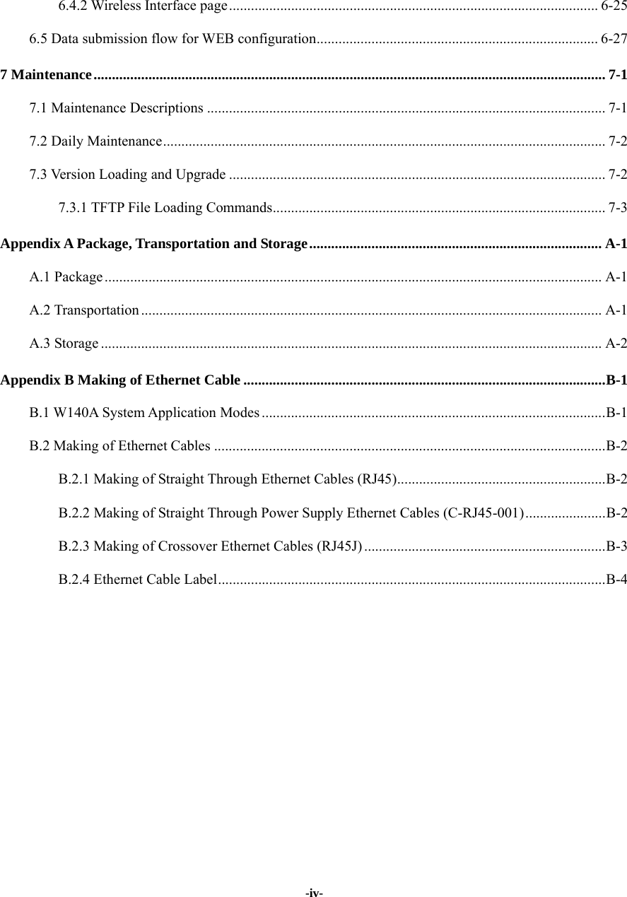
![Chapter Error! Style not defined. Error! Style not defined. 5-15Parameter description: Name Range Description {0} 0 Unit number of the wireless interface. W140A has only one wireless interface with the unchangeable value of 0. 5.4.11 Commands to Configure Layer 2 Isolation 1. intra-security enable Command mode: Configure mode Function: Enable or disable Layer 2 Isolation Command format: wlan (config) #[no] intra-security enable 2. intra-security gateway Command mode: Configure mode Function: Configure the IP address or MAC address of the gateway Command format: wlan (config) # intra-security gateway {ip A.B.C.D | mac xx-xx-xx-xx-xx-xx} Parameter description: Name Range Description A.B.C.D IP address IP address of the gateway xx-xx-xx-xx-xx-xx MAC address MAC address of the gateway 5.4.12 Commands to Configure IP network Parameters 1. ip arp Command mode: Configure mode Function: Add/delete ARP list entries Command format: wlan (config) #[no] ip arp A.B.C.D xx-xx-xx-xx-xx-xx Parameter description: Name Range Description A.B.C.D IP address IP address of the host xx-xx-xx-xx-xx-xx MAC address Hardware address of the host](https://usermanual.wiki/ZTE/ZXR10W140A.Users-Manual/User-Guide-446187-Page-47.png)
![ZXR10 WAS (V1.0) W140A Outdoor Wireless Access Point / Bridge User’s Manual 5-16 2. ip route Command mode: Configure mode Function: Configure the default routing address for the system Command format: wlan (config) #[no] ip route A.B.C.D1 A.B.C.D2 A.B.C.D3 Parameter description: Name Range Description A.B.C.D1 IP address IP address of the host A.B.C.D2 Subnet mask IP address mask of the host A.B.C.D3 IP address IP address of the next-hop router 3. ip pool Command mode: Configure mode Function: Configure the IP address pool for the system Command format: wlan (config) #[no] ip pool index A.B.C.D1 A.B.C.D2 A.B.C.D3 Parameter description: Name Range Description index 0~9 Group number of the IP address pools A.B.C.D1 IP address Starting IP address of the host address pool A.B.C.D2 IP address Ending IP address of the host address pool A.B.C.D3 Subnet mask Subnet mask of the addresses in an address pool 5.4.13 Command to Configure Log Print Information 1. logmsg all-enable Command mode: Configure mode Function: Open or close the log print information in all modules Command format: wlan (config) #[no] logmsg all-enable 2. logmsg level Command mode: Configure mode Function: Configure the level of log print information to be output Command format: wlan (config) # logmsg level level-num](https://usermanual.wiki/ZTE/ZXR10W140A.Users-Manual/User-Guide-446187-Page-48.png)
![Chapter Error! Style not defined. Error! Style not defined. 5-17Parameter description: Name Range Description level-num Lowest (Flood) Lower (Info) Higher (Error) Highest (Fatal) Level of the log print information to be output. Only the information with a higher level will be output. 3. logmsg mod-enable Command mode: Configure mode Function: Determine the module whose log print information should be output Command format: wlan (config) # [no] logmsg mod-enable module Parameter description: Name Range Description module A specified module name Module whose log print information should be output 4. logmsg telnet-log Command mode: Configure mode Function: Set the log print information output window to the active Telnet window. Command format: wlan (config) #[no] logmsg telnet-log 5.4.14 Command to Configure MAC Filter Command mode: Configure mode Function: Add/delete an access list by serial number Command format: wlan(config)#[no] mac-access-list acl-list-number {deny|permit} {macaddr|any} Parameter description: Name Range Description acl-list-number 1~99 MAC filter group number { deny|permit } Deny, permit Deny: If the conditions meet the requirements, the MAC communication is denied. Permit: If the conditions meet the requirements, the MAC communication is allowed.](https://usermanual.wiki/ZTE/ZXR10W140A.Users-Manual/User-Guide-446187-Page-49.png)
![ZXR10 WAS (V1.0) W140A Outdoor Wireless Access Point / Bridge User’s Manual 5-18 Name Range Description {macaddr|any} MAC address in the xx-xx-xx-xx-xx-xx format or any MAC address from which MAC packets are sent. The source address can be specified in two ways: One is to use six 48-bit hexadecimal numbers with dashes between them (HYPHEN), e.g. 00-d0-d0-f1-c4-ef Another is to use the any keyword as the abbreviation of source 00-00-00-00-00-00. It is not recommended to use this keyword. 5.4.15 Command to Configure MAC Address Authentication Command mode: Configure mode Function: Configure MAC address authentication Command format: wlan (config) #[no] mac-authen {deny|permit} {macaddr|any} Parameter description: Name Range Description {deny|permit} Deny, permit deny: If the conditions meet the requirements, the MAC communication is denied. permit: If the conditions meet the requirements, the MAC communication is allowed. {macaddr|any} MAC address in the xx-xx-xx-xx-xx-xx format or any MAC address from which MAC packets are sent. The source address can be specified in two ways: One is to use six 48-bit hexadecimal numbers with dashes between them (HYPHEN), e.g. 00-d0-d0-f1-c4-ef Another is to use the any keyword as the abbreviation of source 00-00-00-00-00-00. It is not recommended to use this keyword. 5.4.16 Command to Configure Users Command mode: Configure mode Function: Add/delete usernames Command format: wlan (config) #[no] manage-user username password](https://usermanual.wiki/ZTE/ZXR10W140A.Users-Manual/User-Guide-446187-Page-50.png)
![Chapter Error! Style not defined. Error! Style not defined. 5-19Parameter description: Name Range Description username 1~32 characters Username password 1~32 characters User password 5.4.17 Commands to Configure Radius Server 1. radius-server account Command mode: Configure mode Function: Add/delete the accounting server of an ISP Command format: wlan (config) #[no] radius-server account isp-name master-flag A.B.C.D key-string Parameter description: Name Range Description isp-name 1~255 characters ISP name master-flag master, slave Master/slave flag of the accounting server A.B.C.D IP address IP address of the accounting server key-string 1~255 characters Shared key string for accounting 2. radius-server authen Command mode: Configure mode Function: Add/delete the authentication server of an ISP Command format: wlan (config) wlan(config)#[no] radius-server authen isp-name master-flag A.B.C.D key-string Parameter description: Name Range Description isp-name 1-255 characters ISP name master-flag master, slave Master or slave authentication server. Only one master server can be set. A.B.C.D IP address IP address of the authentication server key-string 1-255 characters Shared key string for authentication](https://usermanual.wiki/ZTE/ZXR10W140A.Users-Manual/User-Guide-446187-Page-51.png)
![ZXR10 WAS (V1.0) W140A Outdoor Wireless Access Point / Bridge User’s Manual 5-20 3. radius-server dns Command mode: Configure mode Function: Add/delete the DNS server of an ISP Command format: wlan (config) #[no] radius-server dns isp-name A.B.C.D [A.B.C.D] Parameter description: Name Range Description isp-name 1~255 characters ISP name A.B.C.D IP address IP address of the master DNS server [A.B.C.D] IP address IP address of the slave DNS server 4. radius-server isp-name Command mode: Configure mode Function: Add/delete an ISP Command format: wlan (config) #[no] radius-server isp-name isp-name Parameter description: Name Range Description isp-name 1~255 character ISP name 5. radius-server retry-times Command mode: Configure mode Function: Set the number of retries of RADIUS authentication of an ISP Command format: wlan (config) #radius-server retry-times isp-name retry-time Parameter description: Name Range Description isp-name 1~255 characters Name of an ISP which has been created. retry-time 1~10 Number of retries of RADIUS authentication 6. radius-server timeout Command mode: Configure mode Function: Set the hold time of the RADIUS authentication of an ISP Command format: wlan (config) #radius-server timeout isp-name timeout](https://usermanual.wiki/ZTE/ZXR10W140A.Users-Manual/User-Guide-446187-Page-52.png)
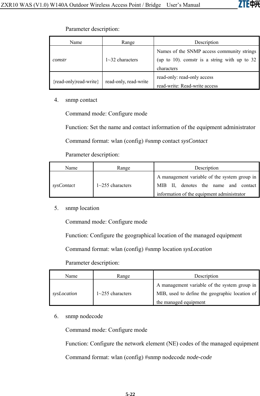
![Chapter Error! Style not defined. Error! Style not defined. 5-21Parameter description: Name Range Description isp-name 1~255 characters Name of an ISP which has been created. timeout 1~65535 Hold time of the RADIUS authentication (unit: s) 5.4.18 Command to Configure SNMP Module 1. snmp access-host Command mode: Configure mode Function: Add and delete host IP addresses allowed to access Command format: wlan (config) #[no] snmp access-host A.B.C.D Parameter description: Name Range Description A.B.C.D IP address Host IP addresses (up to 10) in dotted decimal format (A.B.C.D) 2. snmp access-mode Command mode: Configure mode Function: Allow all hosts or hosts in the server-list to access this agent Command format: wlan (config) #snmp access-mode {all|list} Parameter description: Name Range Description {all|list} all, list all: All users are allow to access list: Users in server-list are allowed to access 3. snmp community Command mode: Configure mode Function: Configure the SNMP access community string and its access right Command format: wlan (config) #snmp community comstr {read-only| read-write} wlan(config)#no snmp community comstr](https://usermanual.wiki/ZTE/ZXR10W140A.Users-Manual/User-Guide-446187-Page-53.png)
![Chapter Error! Style not defined. Error! Style not defined. 5-23Parameter description: Name Range Description node-code >= 0 (integer) A management variable of the system group in MIB, used to define the NE code of the managed equipment 7. snmp nodeid Command mode: Configure mode Function: Configure the NE ID of the managed equipment Command format: wlan (config) #snmp nodeid node-id Parameter description: Name Range Description node-code 1~31 characters A management variable of the system group in MIB, used to define the NE ID of the managed equipment 8. snmp nodecreatdate Command mode: Configure mode Function: Configure the NE creation date of the managed equipment Command format: wlan (config) #snmp nodecreatdate hh:mm:ss month day year Parameter description: Name Range Description hh:mm:ss Time hh (hour): mm (minute): ss (second) month 1~12 Month day 1~31 Day year 2002~2130 Year: 4 bits hh:mm:ss month day year: A management variable of the system group in MIB, used to define the NE creation date of the managed equipment 9. snmp proxytraphost Command mode: Configure mode Function: Add the address information of a proxy Trap destination host Command format: wlan (config) #[no] snmp proxytraphost A.B.C.D](https://usermanual.wiki/ZTE/ZXR10W140A.Users-Manual/User-Guide-446187-Page-55.png)
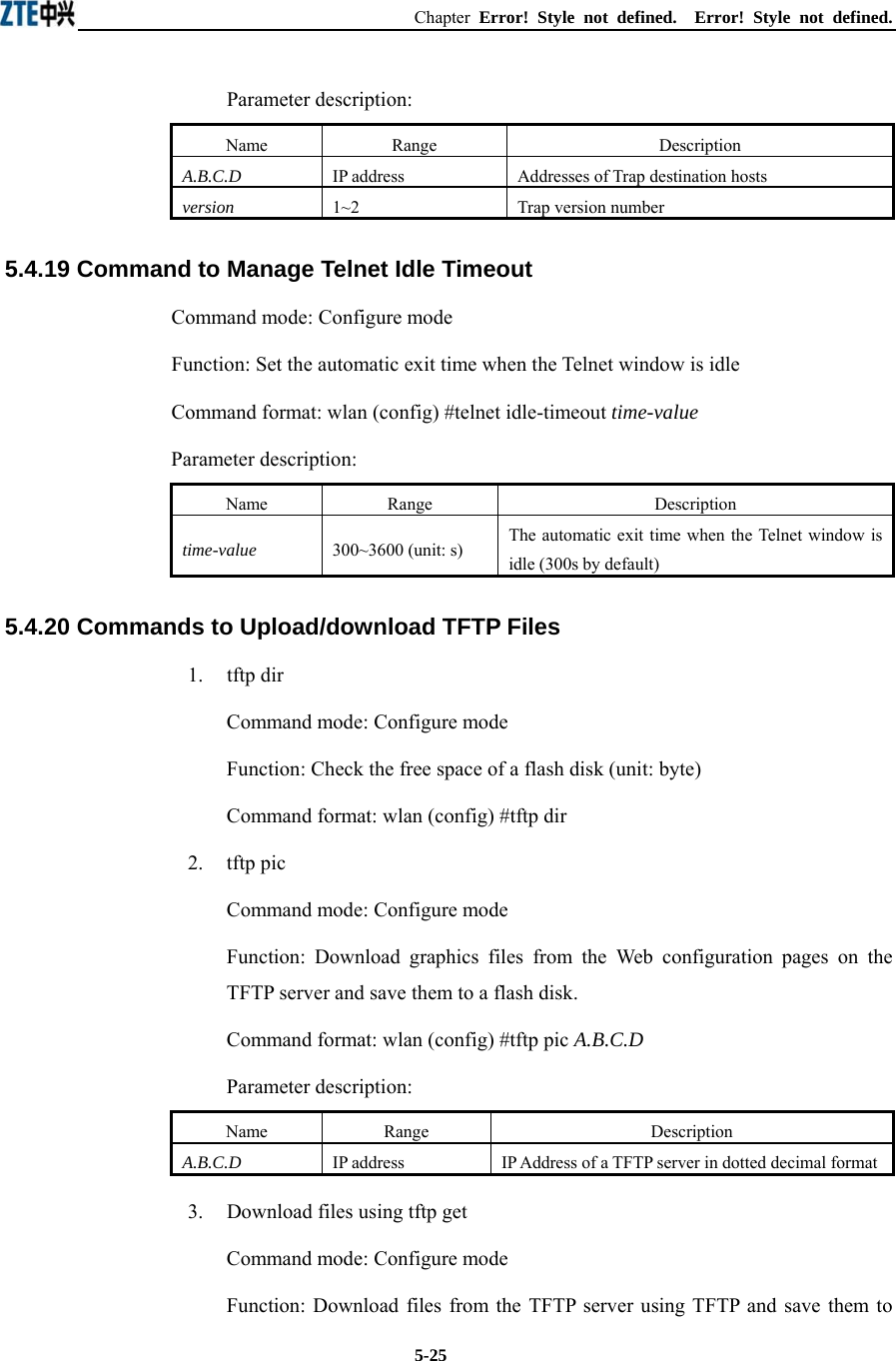
![ZXR10 WAS (V1.0) W140A Outdoor Wireless Access Point / Bridge User’s Manual 5-24 Parameter description: Name Range Description A.B.C.D IP address Addresses of the proxy Trap destination hosts (up to 10) 10. snmp sysname Command mode: Configure mode Function: Set the name of the managed equipment Command format: wlan (config) #snmp sysname sysName Parameter description: Name Range Description sysName 1~255 characters A management variable of the system group in RFC1213 MIB, used as the name of the managed equipment 11. snmp trap enable Command mode: Configure mode Function: Configure if the SNMP Agent is allowed to send Trap Command format: wlan (config) #[no] snmp trap enable 12. snmp authtrap enable Command mode: Configure mode Function: Configure if the SNMP Agent is allowed to send the authentication failed Trap Command format: wlan (config) #[no] snmp authtrap enable 13. snmp traphost Command mode: Configure mode Function: Add the address of a trap destination host and the trap version number Command format: wlan (config) #snmp traphost A.B.C.D [version version] wlan(config)#no snmp traphost A.B.C.D](https://usermanual.wiki/ZTE/ZXR10W140A.Users-Manual/User-Guide-446187-Page-56.png)

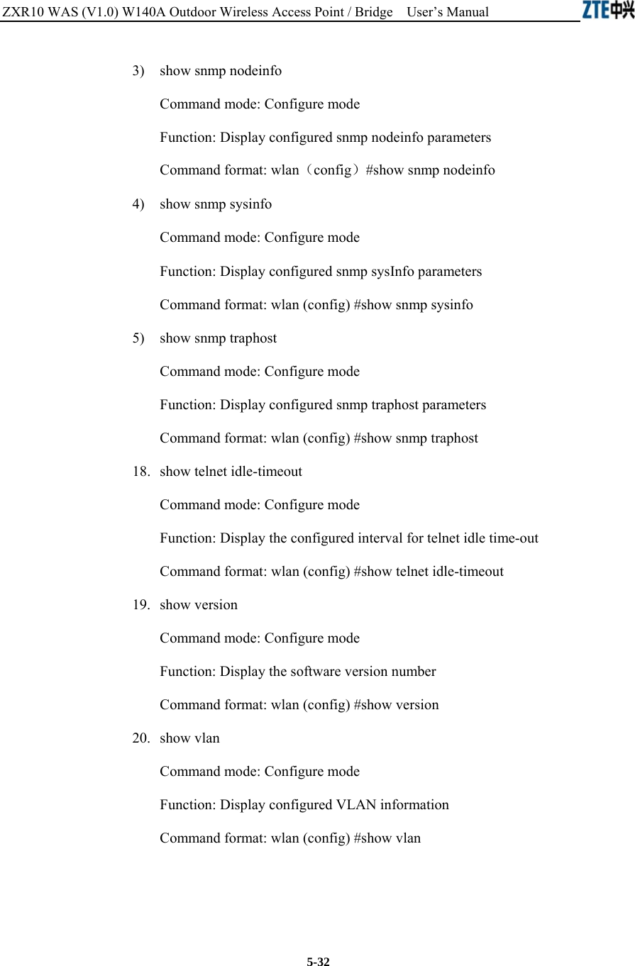
![Chapter Error! Style not defined. Error! Style not defined. 5-3113. show mac-access-list Command mode: Configure mode Function: Display configured mac-access-list information Command format: wlan (config) #show mac-access-list {static} [1~99] 14. show mac-authen Command mode: Configure mode Function: Display configured mac-authen parameters Command format: wlan (config) #show mac-authen 15. show manage-user Command mode: Configure mode Function: Display configured manage-user parameters Command format: wlan (config) #show manage-user 16. show radius Command mode: Configure mode Function: Display configured radius parameters Command format: wlan (config) #show radius 17. show snmp 1) show snmp access-host Command mode: Configure mode Function: Display configured snmp access-host parameters Command format: wlan (config) #show snmp access-host 2) show snmp community Command mode: Configure mode Function: Display configured snmp community parameters Command format: wlan (config) #show snmp community](https://usermanual.wiki/ZTE/ZXR10W140A.Users-Manual/User-Guide-446187-Page-63.png)
![Chapter Error! Style not defined. Error! Style not defined. 5-335.5 Ethernet Interface Configuration Mode Mode of entry: Enter the interface ethernet command in configure mode Exit mode: Exit and enter configure mode Default prompt: wlan (config-int-ethernet)# Note: In this mode (including the sub-mode), all information can be configured for relevant interfaces. 5.5.1 Configurations in the Ethernet Interface Mode Command mode: Ethernet Interface Configuration Mode Function: Set the mode of rate negotiation for the Ethernet interface Command format: wlan (config-int-ethernet)# ethernet-mode mode Parameter description: Name Range Description mode 10M, autoNeg (100M/10M) Mode of the Ethernet Interface 5.5.2 Command to Exit the Ethernet Interface Configuration Mode Command mode: Ethernet Interface Configuration Mode Function: Exit Ethernet interface configuration mode and enter configure Mode Command format: wlan (config-int-ethernet)# #exit 5.5.3 Command to Configure Ethernet interface IP addresses Command mode: Ethernet Interface Configuration Mode Function: Set the IP address of the Ethernet interface Command format: wlan(config-int-ethernet)#ipaddr A.B.C.D1 A.B.C.D2 [second] wlan(config-int-ethernet)#no ipaddr A.B.C.D1 [A.B.C.D2] Parameter description: Name Range Description A.B.C.D1 IP address IP address of an interface A.B.C.D2 IP address IP address mask of an interface [second] Optional The additional IP address flag of an interface](https://usermanual.wiki/ZTE/ZXR10W140A.Users-Manual/User-Guide-446187-Page-65.png)
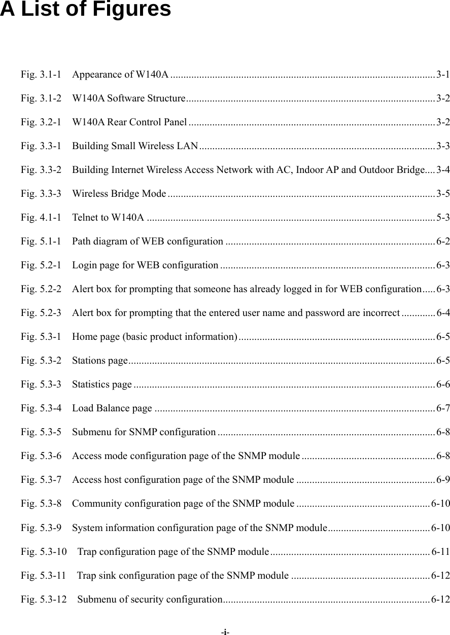
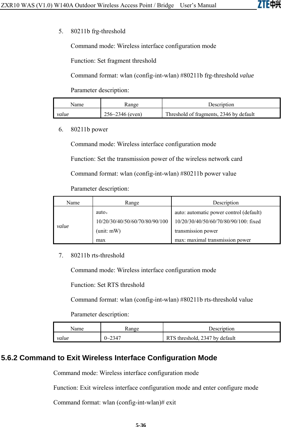
![ZXR10 WAS (V1.0) W140A Outdoor Wireless Access Point / Bridge User’s Manual 5-34 5.5.4 Command to Configure MAC filter for the Ethernet Interface Command mode: Ethernet Interface Configuration Mode Function: Configure MAC filter for the Ethernet interface Command format: wlan(config-int-ethernet)#[no] mac-access-group acl-number direction Parameter description: Name Range Description acl-num 1~99 MAC filter entry number bound to the interface direction in Bind to the "in" direction of the interface 5.6 Wireless Interface Configuration Mode Mode of entry: Enter the interface wlan command in configure mode Exit mode: Exit and enter configure mode Default prompt: wlan (config-int-wlan)# Note: In this mode (including the sub-mode), all information can be configured for relevant interfaces. 5.6.1 Command to Configure 80211b-related Parameters for the Wireless Interface 1. 80211b channel Command mode: Wireless interface configuration mode Function: Set the current operating channel Command format: wlan (config-int-wlan) #80211b channel channel-num Parameter description: Name Range Description channel-num 1~13 Wireless channel number: 6 by default 2. 80211b dynamic-key Command mode: Wireless interface configuration mode Function: Set the dynamic key of the wireless network Command format: wlan (config-int-wlan) #80211b dynamic-key key](https://usermanual.wiki/ZTE/ZXR10W140A.Users-Manual/User-Guide-446187-Page-66.png)
![Chapter Error! Style not defined. Error! Style not defined. 5-35xx-xx-xx-xx-xx-xx key1-string key2-string used-key wlan(config-int-wlan)#no 80211b dynamic-key xx-xx-xx-xx-xx-xx wlan(config-int-wlan)#80211b dynamic-key enable xx-xx-xx-xx-xx-xx wlan(config-int-wlan)#no 80211b dynamic-key enable xx-xx-xx-xx-xx-xx Note: The 80211b dynamic-key key command is used to set the dynamic key for a specified MAC address. The 80211b dynamic-key enable command is used to enable this dynamic key. Parameter description: Name Range Description xx-xx-xx-xx-xx-xx MAC address MAC address of the wireless user using the dynamic key key1-string 5 or 13 characters First dynamic key (the key length can only be 5 or 13 characters) key2-string 5 or 13 characters Second dynamic key (the key length can only be 5 or 13 characters) used-key key1, key2 Key number that is used 3. 80211b enh-security enable Command mode: Wireless interface configuration mode Function: Set to enable or disable the enhanced security function of AP Command format: wlan (config) #[no] 80211b enh-security enable Note: If the enhanced security function is enabled, the wireless terminal will not be able to scan the AP. If this function is disabled, the AP can be scanned. 4. 80211b essid Command mode: Wireless interface configuration mode Function: Set ESSID of the wireless network Command format: wlan (config-int-wlan) #80211b essid essid-string Parameter description: Name Range Description essid-string 1~31 characters ESSID of the wireless network. By default, it is zxwlan.](https://usermanual.wiki/ZTE/ZXR10W140A.Users-Manual/User-Guide-446187-Page-67.png)
![Chapter Error! Style not defined. Error! Style not defined. 5-375.6.3 Command to Enable Link Integrity Detection Command mode: Wireless interface configuration mode Function: Set to enable or disable link integrity detection Command format: wlan (config-int-wlan)#[no] link-integrity enable Note: the link integrity detection function of AP means that when the Ethernet link of the AP is disconnected, the AP will release all connected wireless users, close the wireless port, and deny the connection requests of other wireless terminals. When the link is recovered, the AP will open the wireless port and accept connections of wireless users. 5.6.4 WEP Configuration of the Wireless Interface 1. wep mode Command mode: Wireless interface configuration mode Function: Set WEP encryption mode and WEP key format Command format: wlan (config-int-wlan) #wep mode {disable | wep64 | wep128 | mix-wep64 | mix-wep128} {Alphanumeric|Hexadecimal} Parameter description: Name Range Description {disable|wep64|wep128| mix-wep64|mix-wep128}disable wep64 wep128 mix-wep64 mix-wep128 Disable: disable the WEP encryption function wep64: Use the 64-bit WEP encryption wep128: Use the 128-bite WEP encryption mix-wep64: Use a mixed 64-bit WEP encryption. In this mode, the clients can communicate normally with a correct 64-bit encryption key or without encryption. Mix-wep128: Use a mixed 128-bite WEP encryption. In this mode, the clients can communicate normally with a correct 128-bite encryption key or without encryption. {Alphanumeric| Hexadecimal} Alphanumeric Hexadecimal Alphanumeric: WEP key in string format Alphanumeric: WEP key in sexadecimal format](https://usermanual.wiki/ZTE/ZXR10W140A.Users-Manual/User-Guide-446187-Page-69.png)
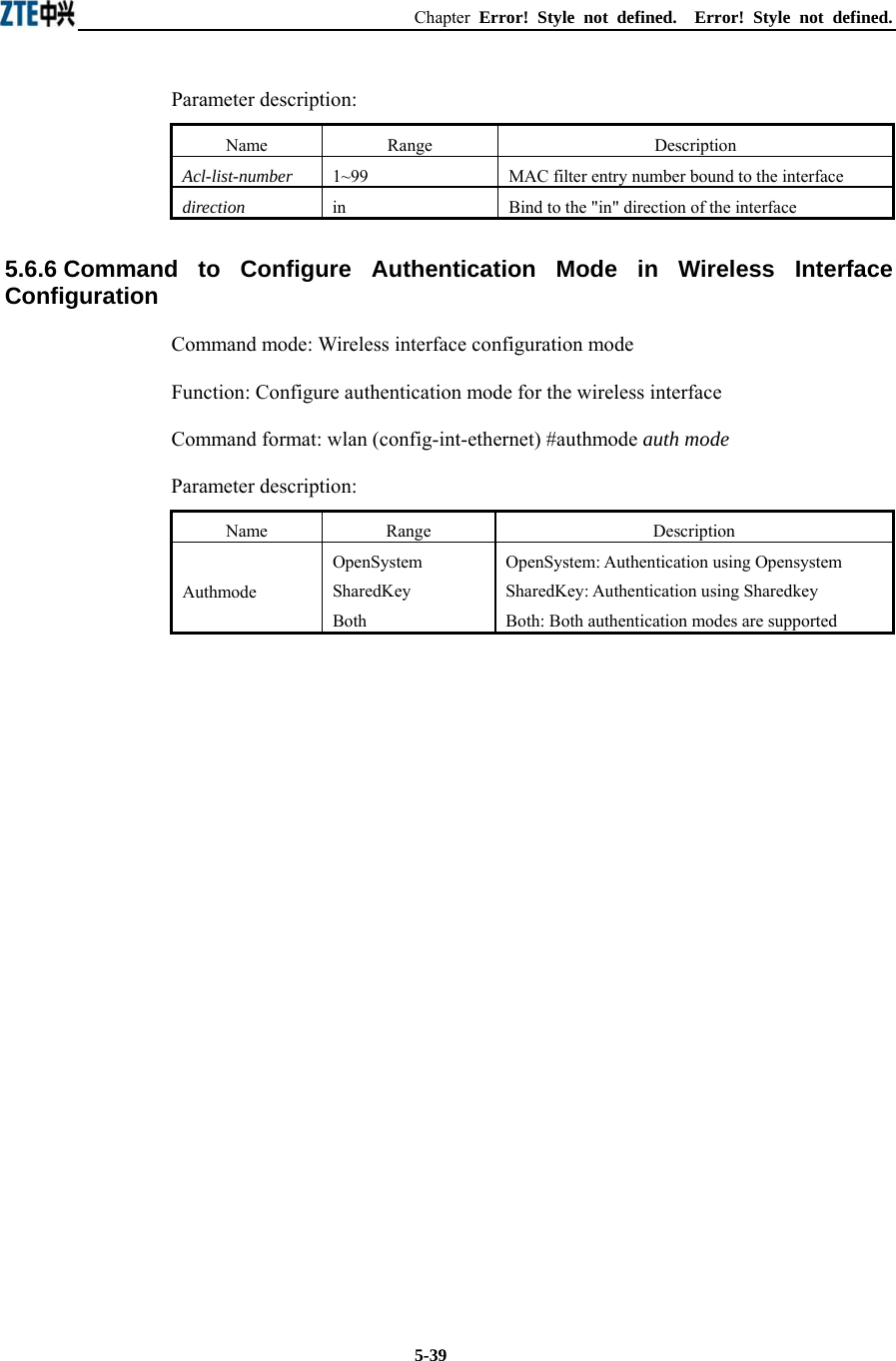
![ZXR10 WAS (V1.0) W140A Outdoor Wireless Access Point / Bridge User’s Manual 5-38 2. wep set-key Command mode: Wireless interface configuration mode Function: Set the key of WEP encryption Command format: wlan (config-int-wlan) #wep set-key key-id key-text Parameter description: Name Range Description key-id key1, key2, key3, key4 Entry number of the key to be set key-text 5 or 13 characters, or a combination of 10 or 26 sexadecimal digits If it is set to 64-bit encryption, the key_text argument can be 5 case sensitive characters (in alphanumeric format), e.g. MyKey, or 10 sexadecimal digits (in hexadecimal format), e.g. 11AA22BB33 If it is set to 128-bit encryption, the key_text argument can be 13 case sensitive characters (in alphanumeric format), e.g. MyKey12345678, or 26 sexadecimal digits (in hexadecimal format), e.g. 00112233445566778899AABBCC 3. wep use-key Command mode: Wireless interface configuration mode Function: Set the WEP encryption key to be used Command format: wlan (config-int-wlan) #wep use-key key-id Parameter description: Name Range Description Key-id key1, key2, key3, key4 Entry number of the key to be used 5.6.5 Command to Configure MAC Filter in Wireless Interface Configuration Command mode: Wireless interface configuration mode Function: Configure MAC filter for the wireless interface Command format: wlan (config-int-wlan) #[no] mac-access-group acl-list-number direction](https://usermanual.wiki/ZTE/ZXR10W140A.Users-Manual/User-Guide-446187-Page-70.png)