ZTE ZXR10W200A W200A Wireless Access Point User Manual
ZTE Corporation W200A Wireless Access Point Users Manual
UserManual.wiki
>
ZTE
>
ZXR10W200A User Manual
Users Manual
Navigation menu
Upload a User Manual
Namespaces
Wiki Guide
HTML
PDF
Info
Views
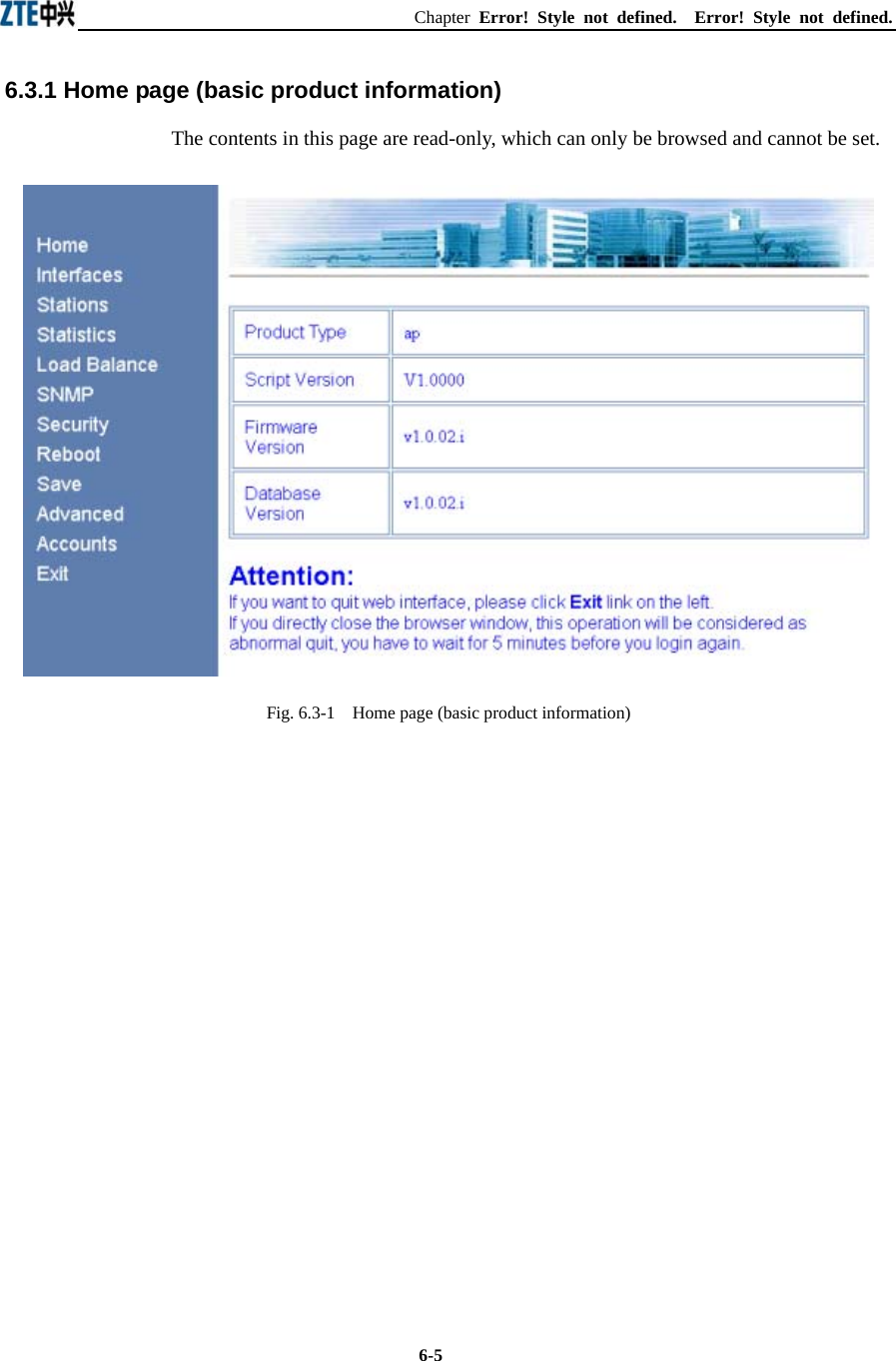
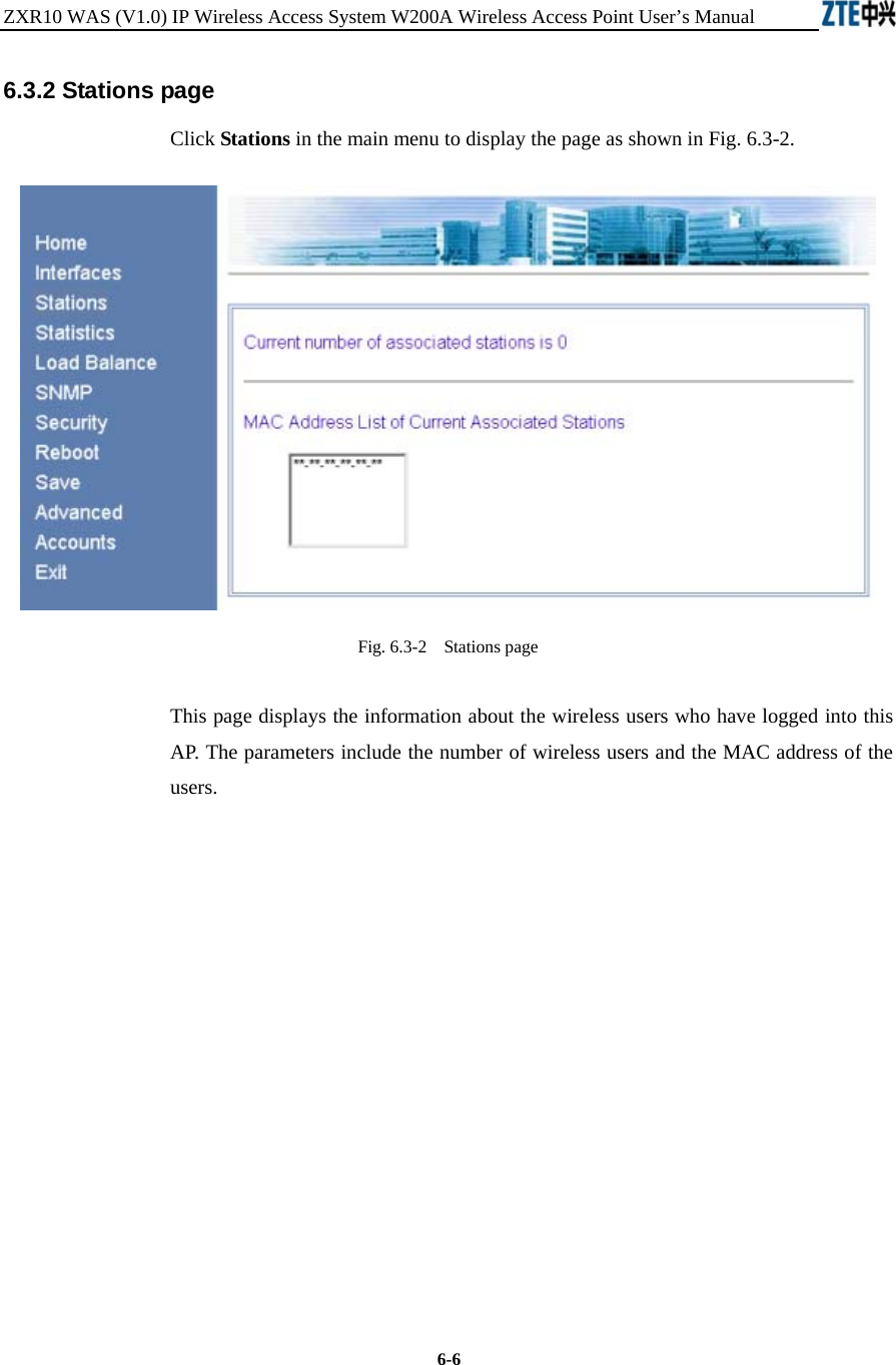
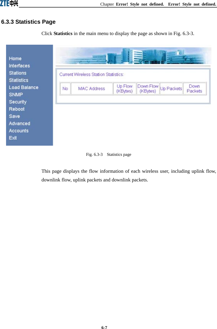
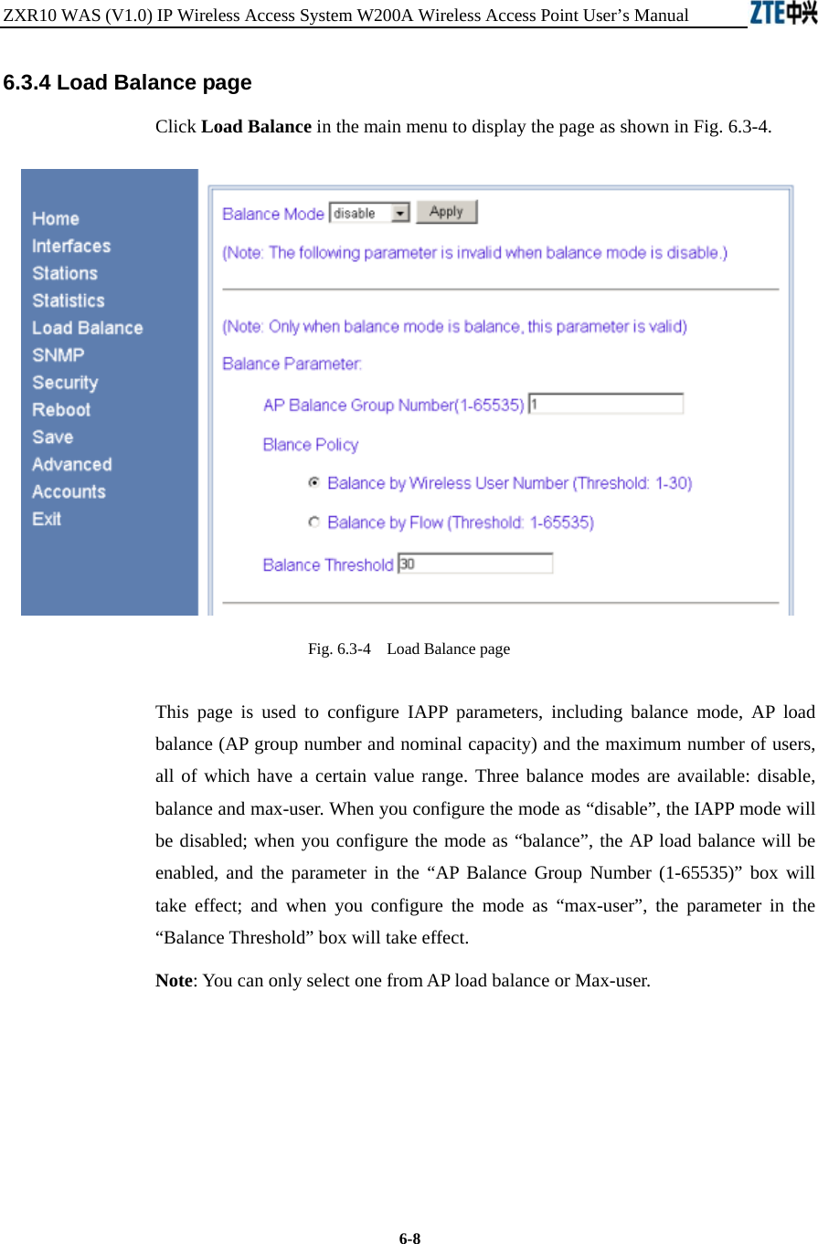
User Manual
Discussion / Help
Navigation
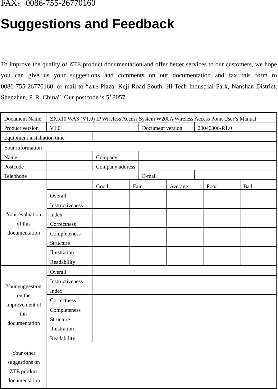
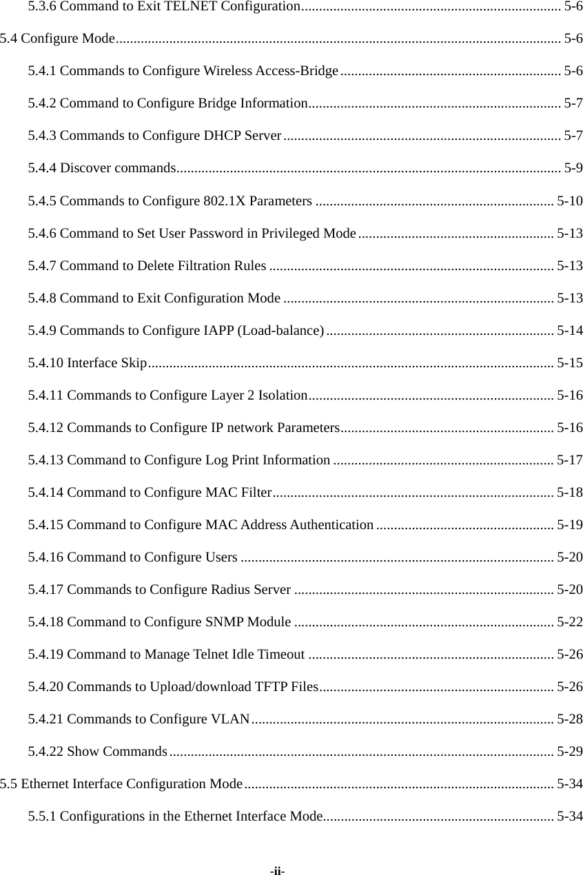
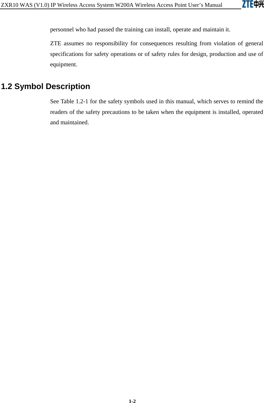
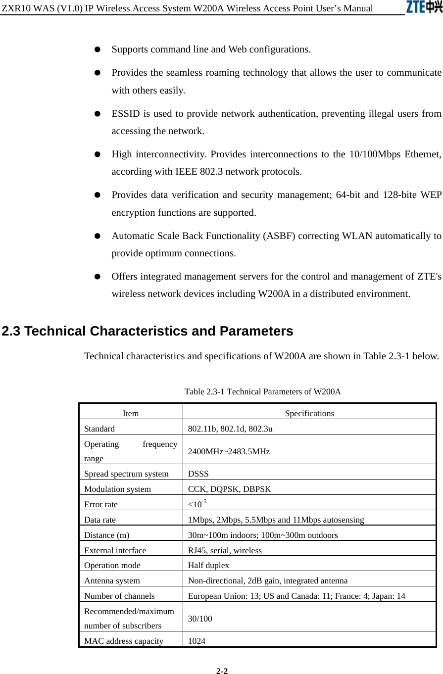
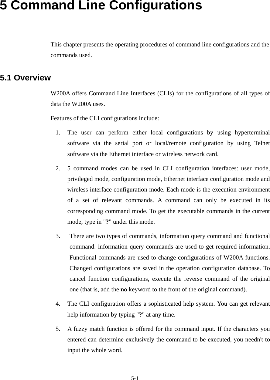
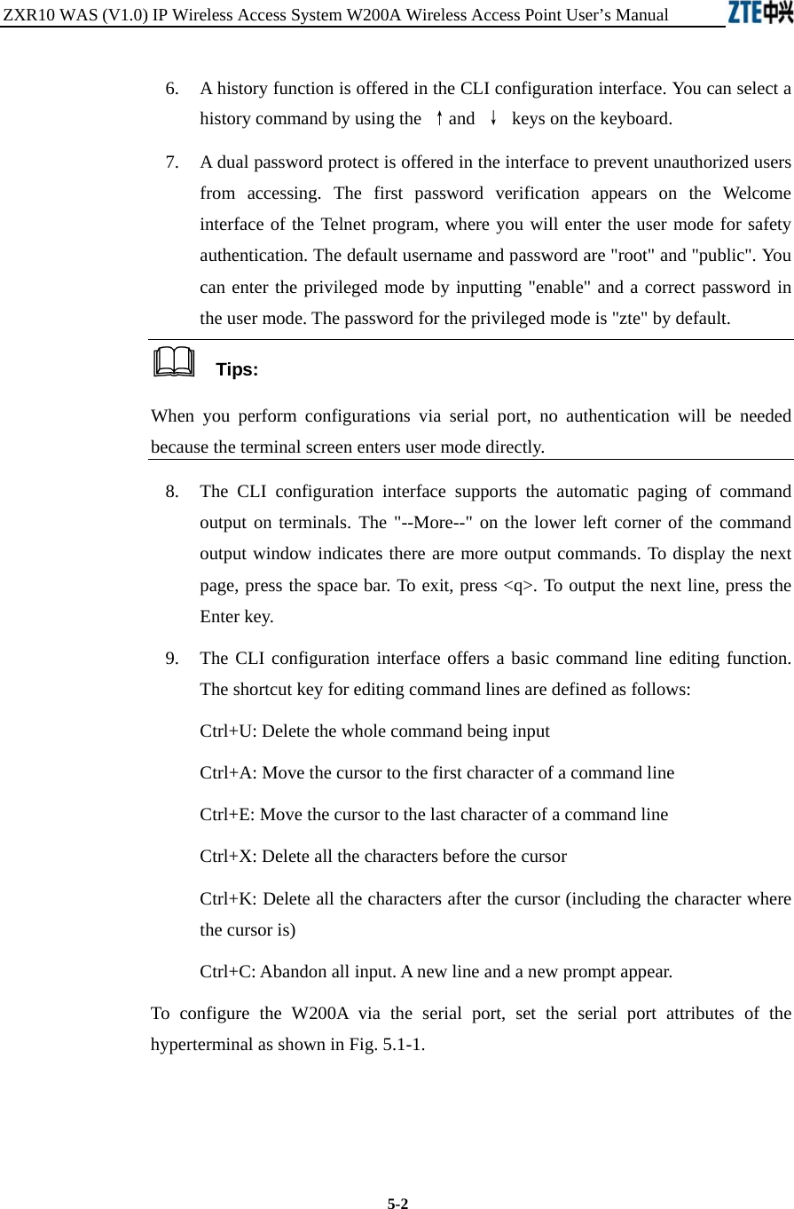
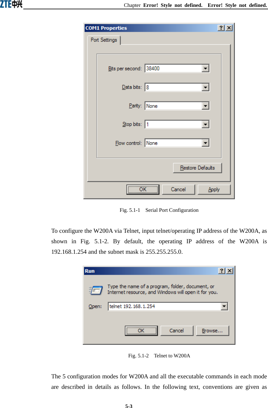
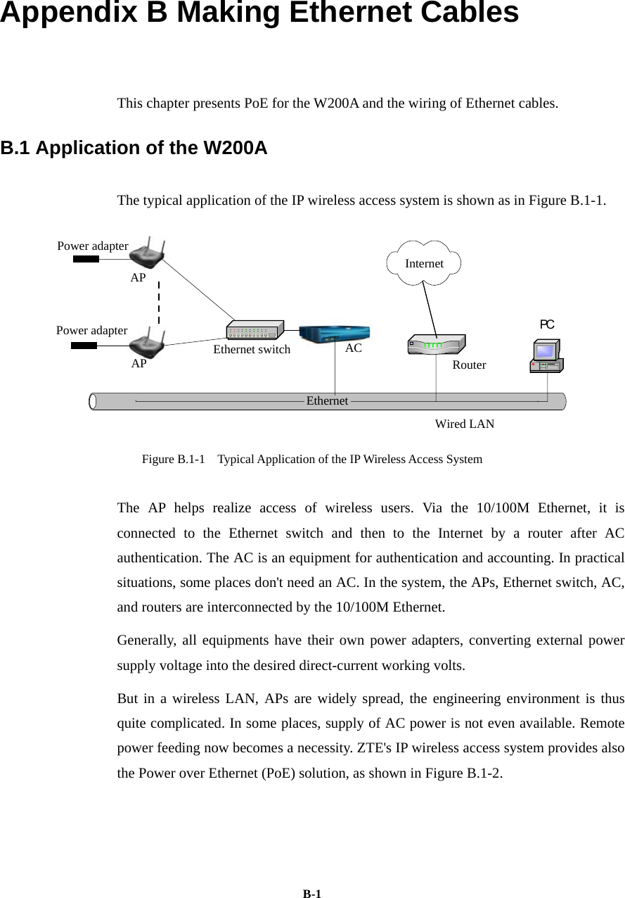
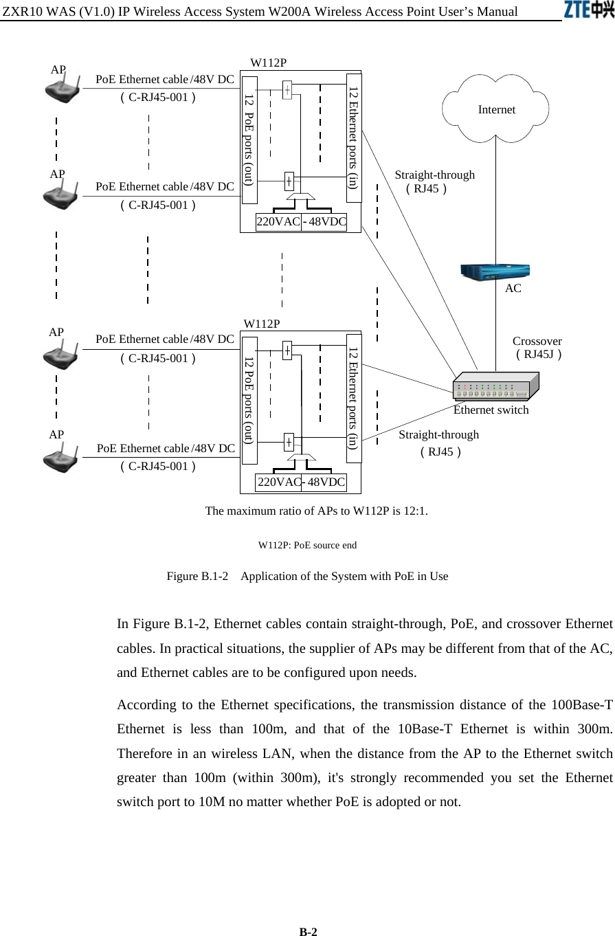
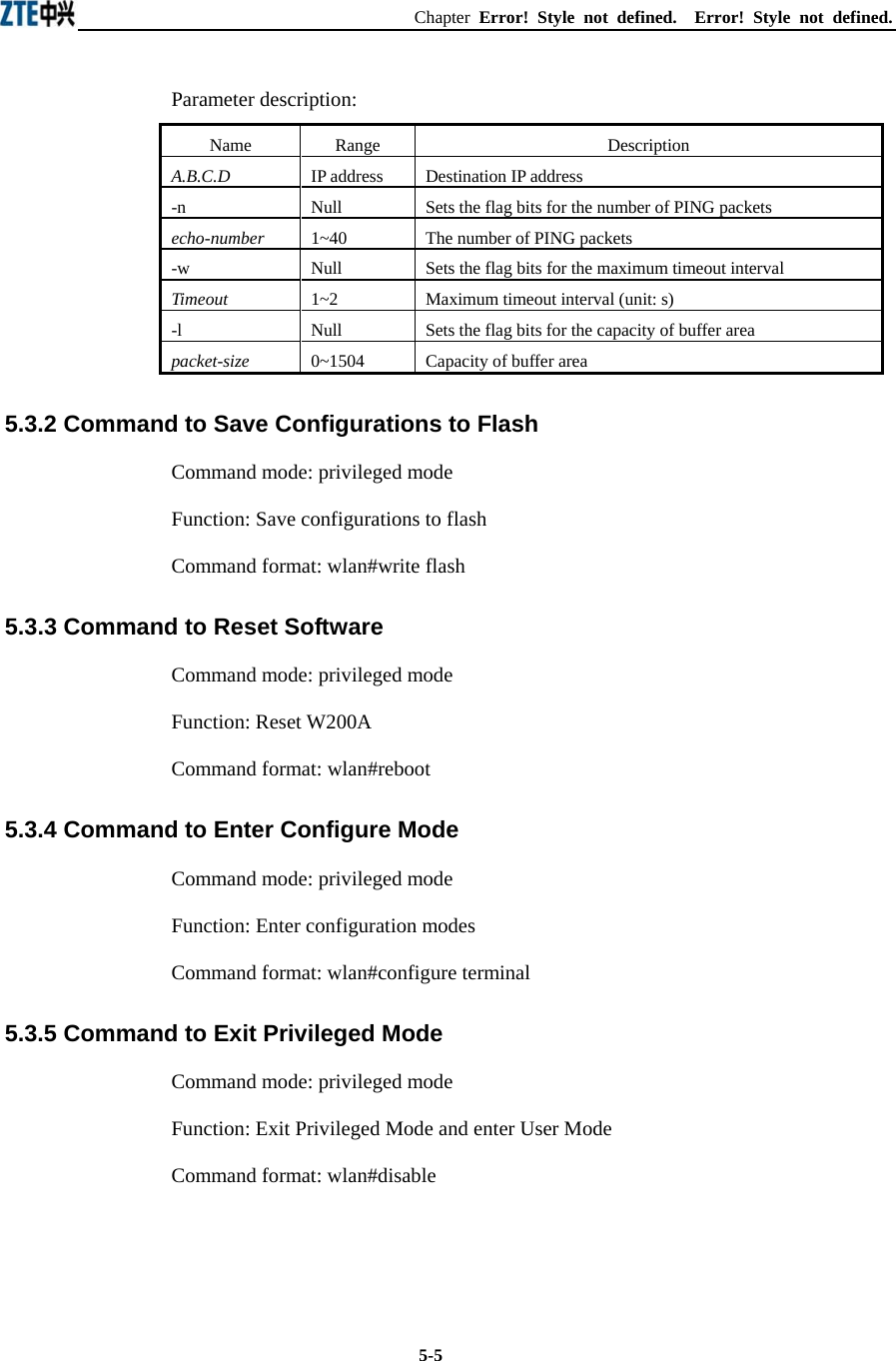
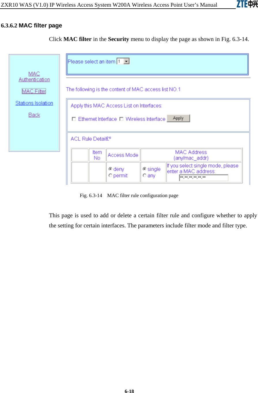
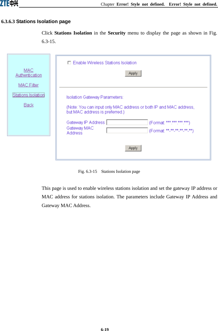
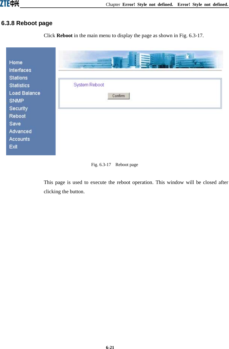
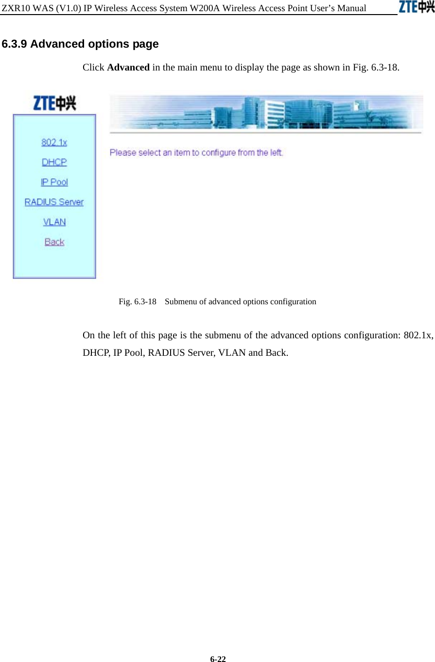
![ZXR10 WAS (V1.0) IP Wireless Access System W200A Wireless Access Point User’s Manual 5-4 follows to the expression of commands: 1. abc denotes the contents that you should enter. 2. {abc|def} denotes that you must type in one of the two options. 3. The number range with [A~B] denotes you can type in a configuration parameter within this range. 4. [ ] denotes that you can either enter the contents in [ ] or not. 5.2 User Mode Mode of entry: Telnet Exit mode: exit Default prompt: wlan> Note: When an ordinary user logs in to the W200A via Telnet, he/she will not be able to enter the user mode unless he/she passes the username and password authentication. By default, the username and password are "root" and "public". To prevent illegal users from attempting the password frequently, the system will cut the Telnet connections of a user automatically if incorrect passwords has been entered 3 times continuously. 5.3 Privileged Mode Mode of entry: Type in the enable command in the in use mode and enter the correct password. Exit mode: disable for entering the user mode; exit for exiting the privileged mode and go back to the system. Default prompt: wlan# 5.3.1 Command to Test Network Connectivity Command mode: privileged mode Function: Test the network connectivity Command format: wlan#ping A.B.C.D [-n echo-number] [-w timeout] [-l packet-size]](https://usermanual.wiki/ZTE/ZXR10W200A/User-Guide-446304-Page-30.png)
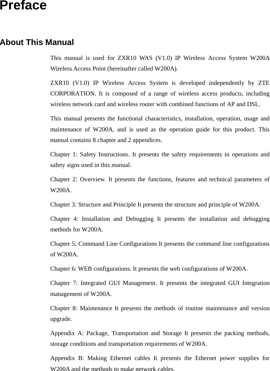
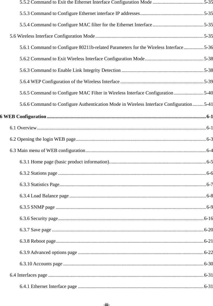
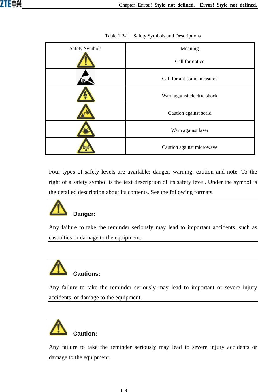
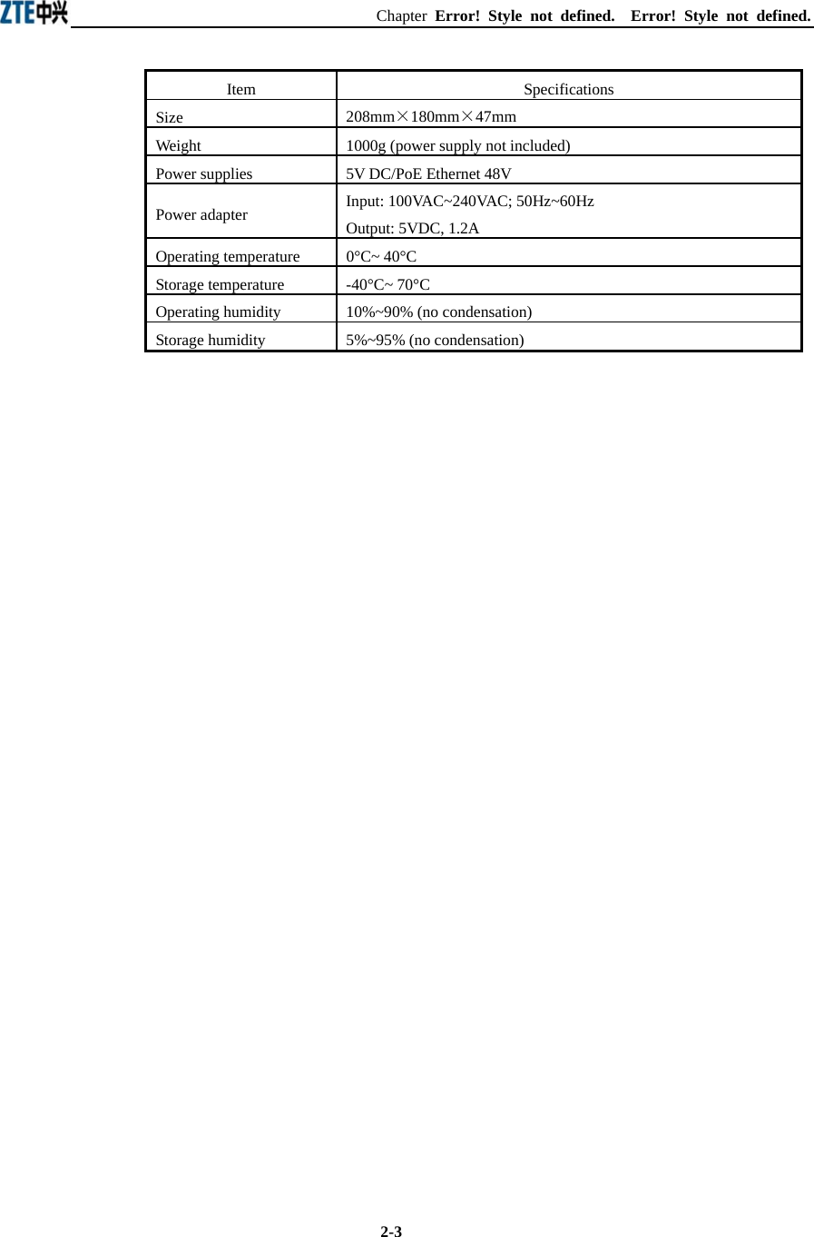
![ZXR10 WAS (V1.0) IP Wireless Access System W200A Wireless Access Point User’s Manual 5-6 5.3.6 Command to Exit TELNET Configuration Command mode: privileged mode Function: Exit Telnet and go back to the system Command format: wlan#exit Note: This command can only be used via Telnet. If you log in by using a hyperterminal mode via the serial port, this command will not be available. 5.4 Configure Mode Mode of entry: Enter the configure terminal command in Privileged Mode Exit mode: Exit and enter privileged mode Default prompt: wlan (config) # Note: In this mode (including the sub-mode), all the configuration commands can be executed. 5.4.1 Commands to Configure Wireless Access-Bridge Mode of entry: Enter the access-bridge command in configure mode 1. access-bridge client connect-server Command mode: Configure mode Function: Configure the MAC address of the access bridge connecting the server Command format: wlan (config) #access-bridge client connect-server mac Parameter description: Name Range Description mac MAC address in the xx-xx-xx-xx-xx-xx format MAC address of the access bridge connecting the server 2. access-bridge client enable Command mode: Configure mode Function: Enable/disable the wireless bridge client Command format: wlan( config) #[no] access-bridge client enable](https://usermanual.wiki/ZTE/ZXR10W200A/User-Guide-446304-Page-32.png)
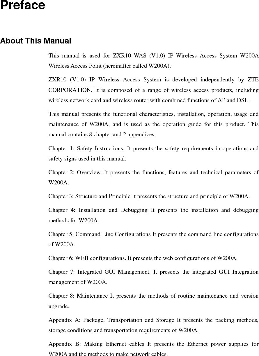
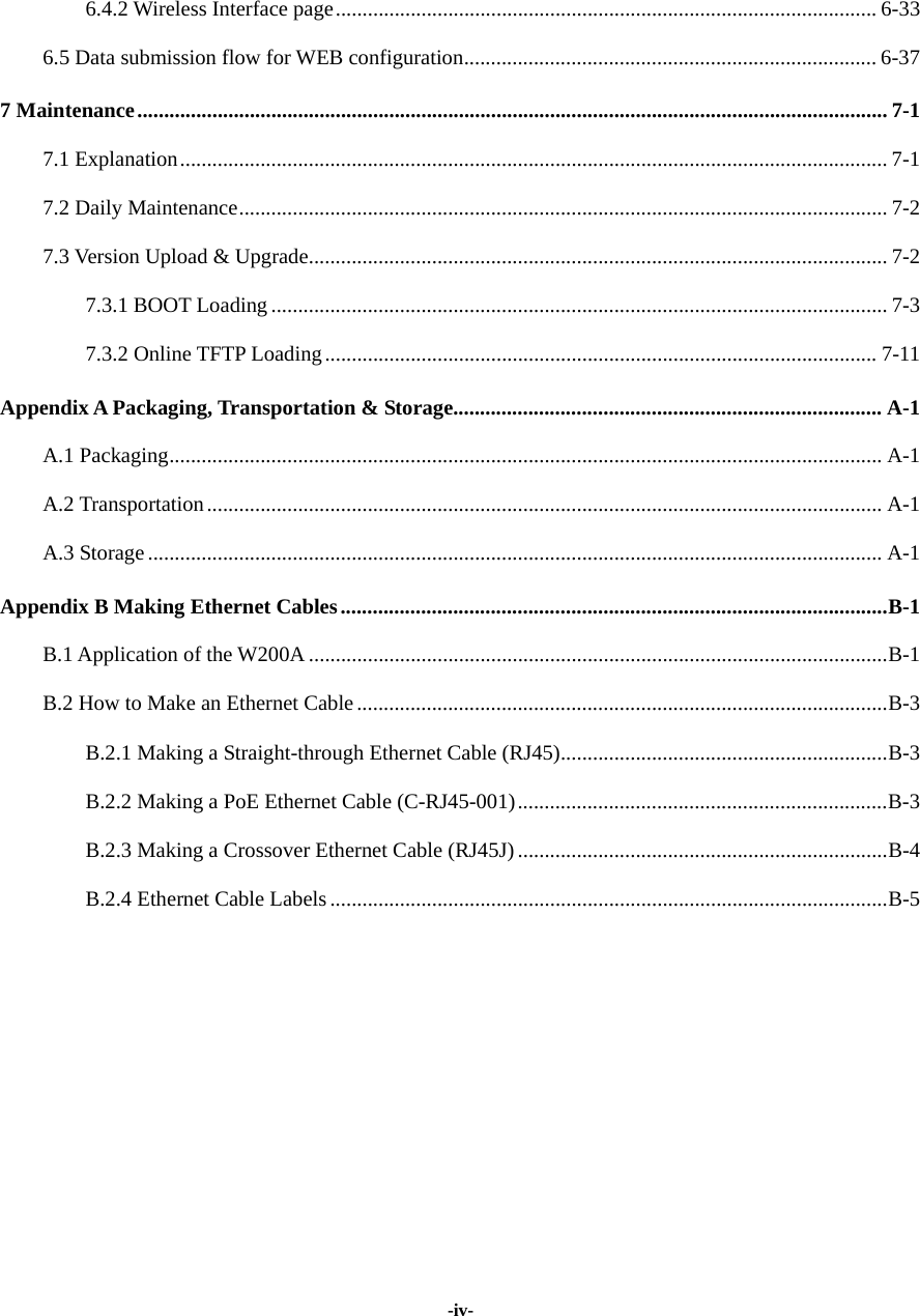
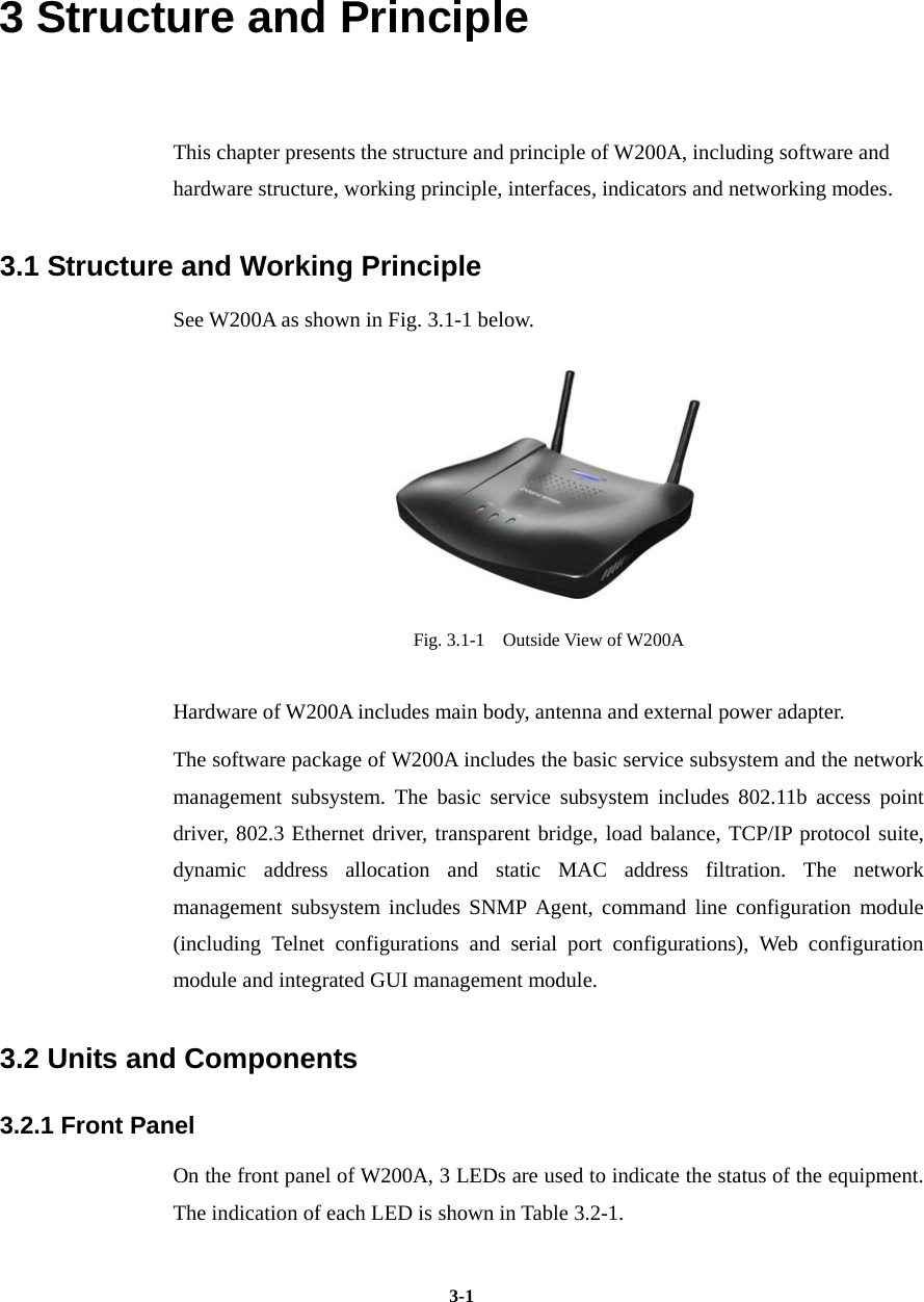
![Chapter Error! Style not defined. Error! Style not defined. 5-7 3. access-bridge server connect-client Command mode: Configure mode Function: Configure the MAC address of the access bridge connecting clients Command format: wlan(config)#[no] access-bridge server connect-client mac Parameter description: Name Range Description mac MAC address in the xx-xx-xx-xx-xx-xx format MAC address of the access bridge connecting clients 4. access-bridge server enable Command mode: Configure mode Function: Enable/disable the wireless bridge server Command format: wlan (config) #[no] access-bridge server enable 5.4.2 Command to Configure Bridge Information Mode of entry: Enter the bridge command in configure mode bridge filterdb Command mode: Configure mode Function: Configure bridge filtration or cancel the configuration Command format: wlan (config) #[no] bridge filterdb max-user aging-time alarm-percent Parameter description: Name Range Description max-user 512~1024 Maximum capacity of the MAC address list aging-time 10~100,000 Aging time of the MAC address list entries alarm-percent 1~10 Percent of alarms 5.4.3 Commands to Configure DHCP Server Mode of entry: Enter the dhcp server command in configure mode](https://usermanual.wiki/ZTE/ZXR10W200A/User-Guide-446304-Page-33.png)
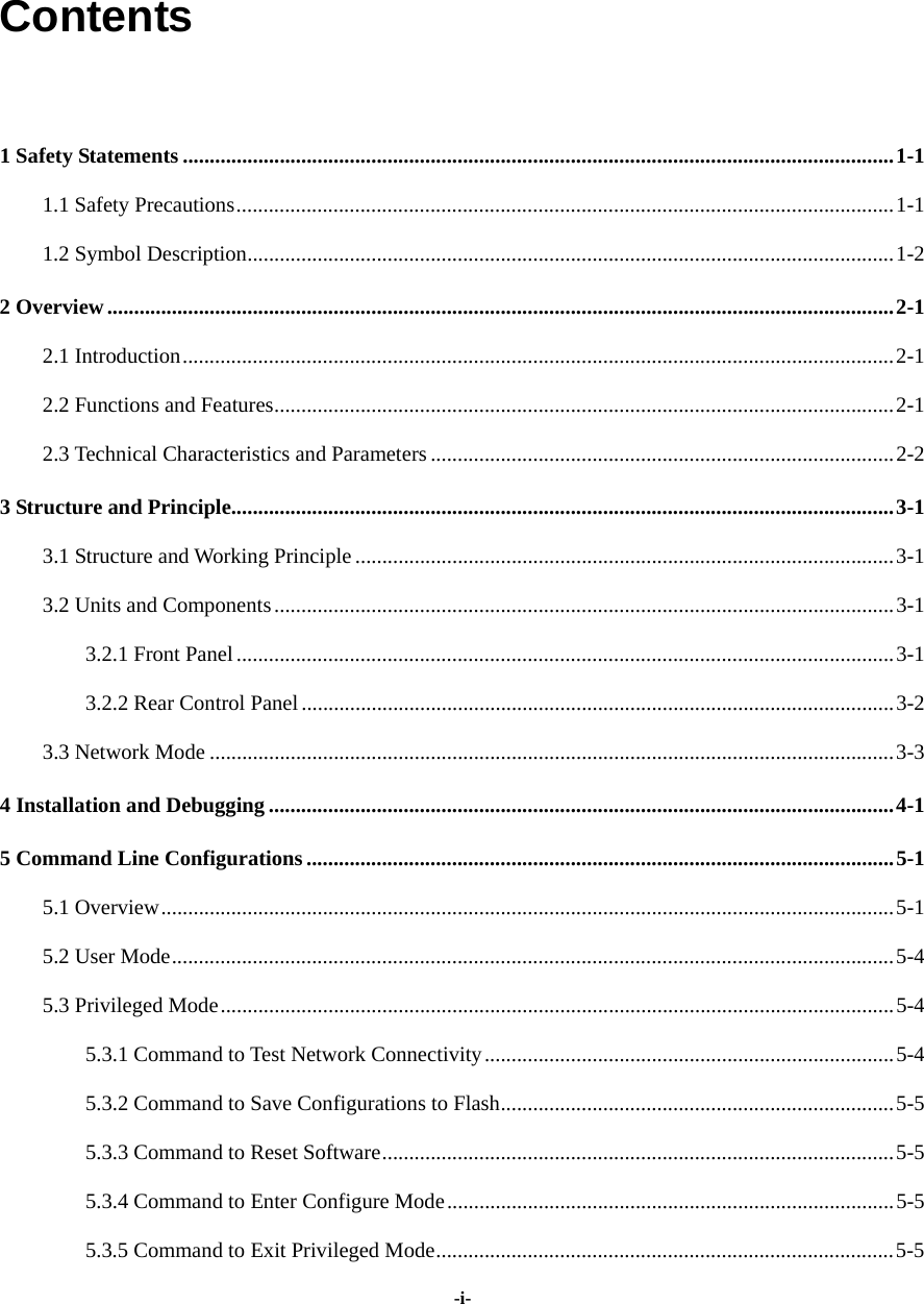
![ZXR10 WAS (V1.0) IP Wireless Access System W200A Wireless Access Point User’s Manual 5-8 1. dhcp server dns Command mode: Configure mode Function: Configure the IP addresses of the master/slave DNS server in the DHCP server Command format: wlan (config) # dhcp server dns A.B.C.D [A.B.C.D] Parameter description: Name Range Description A.B.C.D IP address IP address of the master DNS server [A.B.C.D] IP address IP address of the slave DNS server (optional) 2. dhcp server gateway Command mode: Configure mode Function: Configure the IP address of the default gateway of the DHCP server Command format: wlan (config) # dhcp server gateway A.B.C.D Parameter description: Name Range Description A.B.C.D IP address IP address of the gateway 3. dhcp server leasetime Command mode: Configure mode Function: Configure the address lease time of the DHCP server Command format: wlan (config) # dhcp server leasetime time-value Parameter description: Name Range Description time-value 60~3600 DHCP server address lease time (unit: s), 60s by default 4. dhcp server run Command mode: Configure mode Function: Start, stop or restart the DHCP server Command format: wlan (config) # dhcp server run run-flag](https://usermanual.wiki/ZTE/ZXR10W200A/User-Guide-446304-Page-34.png)
![Chapter Error! Style not defined. Error! Style not defined. 5-9 Parameter description: Name Range Description run-flag start, stop, restart start: Start the DHCP server stop: Stop the DHCP server restart: Restart the DHCH server 5. dhcp server start-flag Command mode: Configure mode Function: Configure the start flag of the DHCP server for the restart of the system Command format: wlan (config) # dhcp server start-flag {true|false} Parameter description: Name Range Description {true|false} True, false Start flag of the DHCP server. If it is set to true, it will be started when the system is restarted. If false, the DHCP server will not be started. 5.4.4 Discover commands Mode of entry: Enter the discover command in configure mode 1. discover device Command mode: Configure mode Function: Configure the multicasting address for the integrated management and the port number of the equipment Command format: wlan (config) #discover device A.B.C.D [0~65535] Parameter description: Name Range Description A.B.C.D IP address Multicasting address for the integrated management of the equipment [0~65535] 0~65535 Snooping port number for the integrated management of the equipment 2. discover manager Command mode: Configure mode](https://usermanual.wiki/ZTE/ZXR10W200A/User-Guide-446304-Page-35.png)
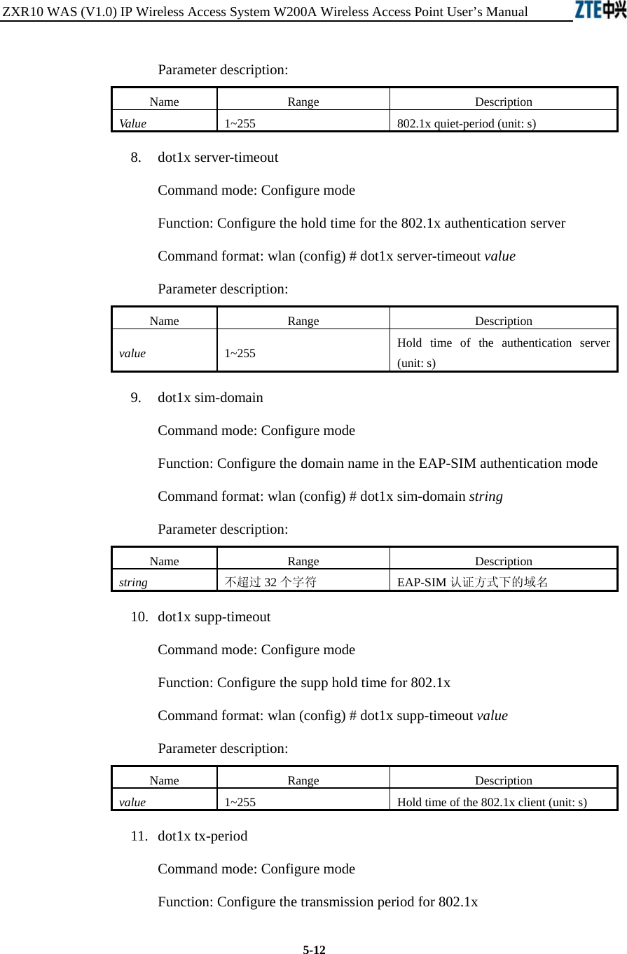
![ZXR10 WAS (V1.0) IP Wireless Access System W200A Wireless Access Point User’s Manual 5-10 Function: Configure the multicasting address and port number for the integrated management server Command format: wlan (config) #discover manager A.B.C.D [0~65535] Parameter description: Name Range Description A.B.C.D IP address Multicasting address for the integrated management server [0~65535] 0~65535 Snooping port number for the integrated management server 5.4.5 Commands to Configure 802.1X Parameters Mode of entry: Enter the dot1x command in configure mode 1. dot1x enable Command mode: Configure mode Function: Enable or disable 802.1x Command format: wlan (config) #[no] dot1x enable 2. dot1x max-reauth Command mode: Configure mode Function: Configure the maximum number of attempts for 802.1x authentication Command format: wlan (config)# dot1x max-reauth max-reauth-times Parameter description: Name Range Description max-reauth-times 0~10 802.1x 重复认证的最大尝试次数 3. dot1x max-request Command mode: Configure mode Function: Configure the maximum number requests for 802.1x authentication Command format: wlan (config) # dot1x max-request max-request-times](https://usermanual.wiki/ZTE/ZXR10W200A/User-Guide-446304-Page-36.png)
![Chapter Error! Style not defined. Error! Style not defined. 5-11Parameter description: Name Range Description max-request-times 1~10 Maximum number requests for 802.1x authentication 4. dot1x md5-domain Command mode: Configure mode Function: Configure the domain name in the EAP-MD5 authentication mode 命令格式:wlan(config)Command format: wlan (config) # dot1x md5-domain string Parameter description: Name Range Description String No more than 32 characters Domain name in the EAP-MD5 authentication mode 5. dot1x nas-id Command mode: Configure mode Function: Configure the NAS-ID field for 802.1x Command format: wlan (config) # dot1x nas-id string Parameter description: Name Range Description String No more than 64 characters NAS-ID character string 6. dot1x portenable Command mode: Configure mode Function: Enable or disable 802.1x port control Command format: wlan (config) # [no] dot1x portenable 7. dot1x quiet-period Command mode: Configure mode Function: Configure the quiet-period for 802.1x Command format: wlan (config) # dot1x quiet-period value](https://usermanual.wiki/ZTE/ZXR10W200A/User-Guide-446304-Page-37.png)
![ZXR10 WAS (V1.0) IP Wireless Access System W200A Wireless Access Point User’s Manual 5-16 5.4.11 Commands to Configure Layer 2 Isolation Mode of entry: Enter the intra-security command in configure mode 1. intra-security enable Command mode: Configure mode Function: Enable or disable Layer 2 Isolation Command format: wlan (config) #[no] intra-security enable 2. intra-security gateway Command mode: Configure mode Function: Configure the IP address or MAC address of the gateway Command format: wlan (config) # intra-security gateway {ip A.B.C.D | mac xx-xx-xx-xx-xx-xx} Parameter description: Name Range Description A.B.C.D IP address IP address of the gateway xx-xx-xx-xx-xx-xx MAC address MAC address of the gateway 5.4.12 Commands to Configure IP network Parameters Mode of entry: Enter the ip command in configure mode 1. ip arp Command mode: Configure mode Function: Add/delete ARP list entries Command format: wlan (config) #[no] ip arp A.B.C.D xx-xx-xx-xx-xx-xx Parameter description: Name Range Description A.B.C.D IP address IP address of the host xx-xx-xx-xx-xx-xx MAC address Hardware address of the host 2. ip route Command mode: Configure mode Function: Configure the default routing address for the system](https://usermanual.wiki/ZTE/ZXR10W200A/User-Guide-446304-Page-42.png)
![Chapter Error! Style not defined. Error! Style not defined. 5-17Command format: wlan (config) #[no] ip route A.B.C.D1 A.B.C.D2 A.B.C.D3 Parameter description: Name Range Description A.B.C.D1 IP address IP address of the host A.B.C.D2 Subnet mask IP address mask of the host A.B.C.D3 IP address IP address of the next-hop router 3. ip pool Command mode: Configure mode Function: Configure the IP address pool for the system Command format: wlan (config) #[no] ip pool index A.B.C.D1 A.B.C.D2 A.B.C.D3 Parameter description: Name Range Description index 0~9 Group number of the IP address pools A.B.C.D1 IP address Starting IP address of the host address pool A.B.C.D2 IP address Ending IP address of the host address pool A.B.C.D3 Subnet mask Subnet mask of the addresses in an address pool 5.4.13 Command to Configure Log Print Information Mode of entry: Enter the logmsg command in configure mode 1. logmsg all-enable Command mode: Configure mode Function: Open or close the log print information in all modules Command format: wlan (config) #[no] logmsg all-enable 2. logmsg level Command mode: Configure mode Function: Configure the level of log print information to be output Command format: wlan (config) # logmsg level level-num](https://usermanual.wiki/ZTE/ZXR10W200A/User-Guide-446304-Page-43.png)
![ZXR10 WAS (V1.0) IP Wireless Access System W200A Wireless Access Point User’s Manual 5-18 Parameter description: Name Range Description level-num Lowest (Flood) Lower (Info) Higher (Error) Highest (Fatal) Level of the log print information to be output. Only the information with a higher level will be output. 3. logmsg mod-enable Command mode: Configure mode Function: Determine the module whose log print information should be output Command format: wlan (config) # [no] logmsg mod-enable module Parameter description: Name Range Description module A specified module name Module whose log print information should be output 4. logmsg telnet-log Command mode: Configure mode Function: Set the log print information output window to the active Telnet window. Command format: wlan (config) #[no] logmsg telnet-log 5.4.14 Command to Configure MAC Filter Mode of entry: Enter the mac-access-list command in configure mode Command mode: Configure mode Function: Add/delete an access list by serial number Command format: wlan(config)#[no] mac-access-list acl-list-number {deny|permit} {macaddr|any}](https://usermanual.wiki/ZTE/ZXR10W200A/User-Guide-446304-Page-44.png)
![Chapter Error! Style not defined. Error! Style not defined. 5-19Parameter description: Name Range Description acl-list-number 1~99 MAC filter group number { deny|permit } Deny, permit Deny: If the conditions meet the requirements, the MAC communication is denied. Permit: If the conditions meet the requirements, the MAC communication is allowed. {macaddr|any} MAC address in the xx-xx-xx-xx-xx-xx format or any MAC address from which MAC packets are sent. The source address can be specified in two ways: One is to use six 48-bit hexadecimal numbers with dashes between them (HYPHEN), e.g. 00-d0-d0-f1-c4-ef Another is to use the any keyword as the abbreviation of source 00-00-00-00-00-00. It is not recommended to use this keyword. 5.4.15 Command to Configure MAC Address Authentication Mode of entry: Enter the mac-authen command in configure mode Command mode: Configure mode Function: Configure MAC address authentication Command format: wlan (config) #[no] mac-authen {deny|permit} {macaddr|any} Parameter description: Name Range Description {deny|permit} Deny, permit deny: If the conditions meet the requirements, the MAC communication is denied. permit: If the conditions meet the requirements, the MAC communication is allowed. {macaddr|any} MAC address in the xx-xx-xx-xx-xx-xx format or any MAC address from which MAC packets are sent. The source address can be specified in two ways: One is to use six 48-bit hexadecimal numbers with dashes between them (HYPHEN), e.g. 00-d0-d0-f1-c4-ef Another is to use the any keyword as the abbreviation of source 00-00-00-00-00-00. It is not recommended to use this keyword.](https://usermanual.wiki/ZTE/ZXR10W200A/User-Guide-446304-Page-45.png)
![ZXR10 WAS (V1.0) IP Wireless Access System W200A Wireless Access Point User’s Manual 5-20 5.4.16 Command to Configure Users Mode of entry: Enter the manage-user command in configure mode Command mode: Configure mode Function: Add/delete usernames Command format: wlan (config) #[no] manage-user username password Parameter description: Name Range Description username 1~32 characters Username password 1~32 characters User password 5.4.17 Commands to Configure Radius Server Mode of entry: Enter the radius-server command in configure mode 1. radius-server account Command mode: Configure mode Function: Add/delete the accounting server of an ISP Command format: wlan (config) #[no] radius-server account isp-name master-flag A.B.C.D key-string Parameter description: Name Range Description isp-name 1~255 characters ISP name master-flag master, slave Master/slave flag of the accounting server A.B.C.D IP address IP address of the accounting server key-string 1~255 characters Shared key string for accounting 2. radius-server authen Command mode: Configure mode Function: Add/delete the authentication server of an ISP Command format: wlan (config) wlan(config)#[no] radius-server authen isp-name master-flag A.B.C.D key-string](https://usermanual.wiki/ZTE/ZXR10W200A/User-Guide-446304-Page-46.png)
![Chapter Error! Style not defined. Error! Style not defined. 5-21Parameter description: Name Range Description isp-name 1~255 个字符 ISP name master-flag master, slave Master or slave authentication server. Only one master server can be set. A.B.C.D IP address IP address of the authentication server key-string 1-255 characters Shared key string for authentication 3. radius-server dns Command mode: Configure mode Function: Add/delete the DNS server of an ISP Command format: wlan (config) #[no] radius-server dns isp-name A.B.C.D [A.B.C.D] Parameter description: Name Range Description isp-name 1~255 characters ISP name A.B.C.D IP address IP address of the master DNS server [A.B.C.D] IP address IP address of the slave DNS server 4. radius-server isp-name Command mode: Configure mode Function: Add/delete an ISP Command format: wlan (config) #[no] radius-server isp-name isp-name Parameter description: Name Range Description isp-name 1~255 character ISP name 5. radius-server retry-times Command mode: Configure mode Function: Set the number of retries of RADIUS authentication of an ISP Command format: wlan (config) #radius-server retry-times isp-name retry-time](https://usermanual.wiki/ZTE/ZXR10W200A/User-Guide-446304-Page-47.png)
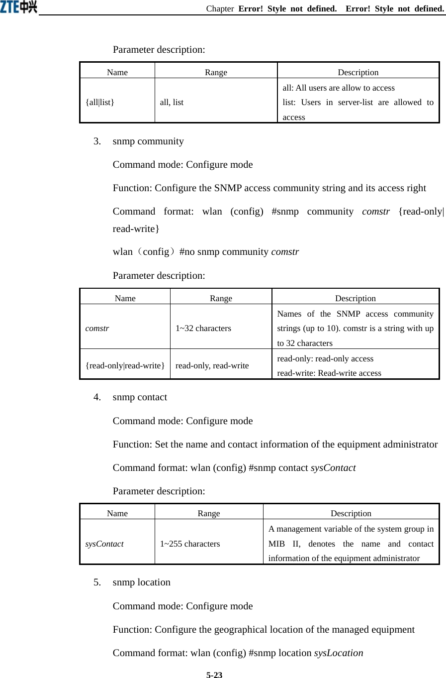
![ZXR10 WAS (V1.0) IP Wireless Access System W200A Wireless Access Point User’s Manual 5-22 Parameter description: Name Range Description isp-name 1~255 characters Name of an ISP which has been created. retry-time 1~10 Number of retries of RADIUS authentication 6. radius-server timeout Command mode: Configure mode Function: Set the hold time of the RADIUS authentication of an ISP Command format: wlan (config) #radius-server timeout isp-name timeout Parameter description: Name Range Description isp-name 1~255 characters Name of an ISP which has been created. timeout 1~65535 Hold time of the RADIUS authentication (unit: s) 5.4.18 Command to Configure SNMP Module Mode of entry: Enter the snmp command in configure mode 1. snmp access-host Command mode: Configure mode Function: Add and delete host IP addresses allowed to access Command format: wlan (config) #[no] snmp access-host A.B.C.D Parameter description: Name Range Description A.B.C.D IP address Host IP addresses (up to 10) in dotted decimal format (A.B.C.D) 2. snmp access-mode Command mode: Configure mode Function: Allow all hosts or hosts in the server-list to access this agent Command format: wlan (config) #snmp access-mode {all|list}](https://usermanual.wiki/ZTE/ZXR10W200A/User-Guide-446304-Page-48.png)
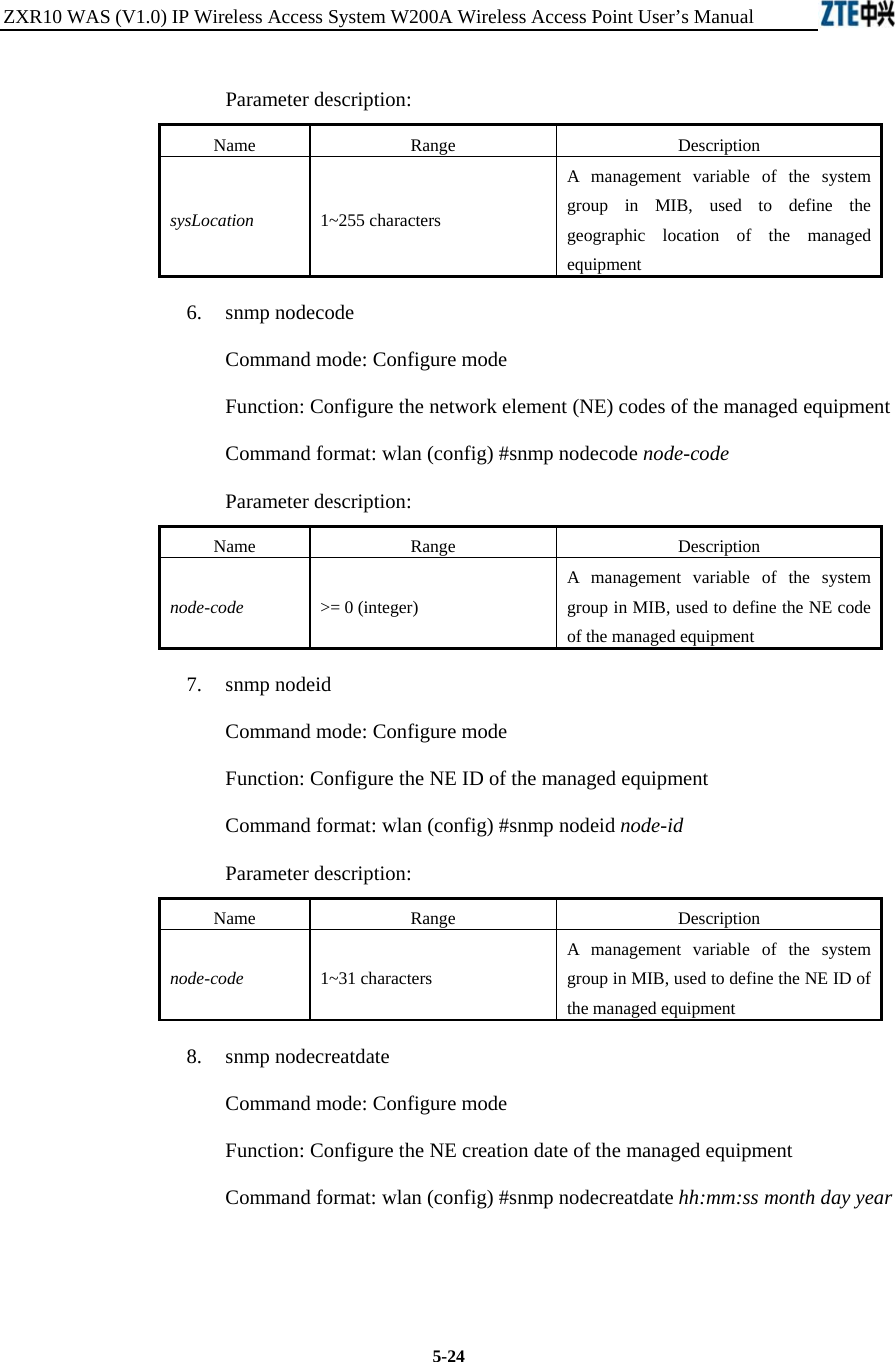
![Chapter Error! Style not defined. Error! Style not defined. 5-25Parameter description: Name Range Description hh:mm:ss Time hh (hour): mm (minute): ss (second) month 1~12 Month day 1~31 Day year 2002~2130 Year: 4 bits hh:mm:ss month day year: A management variable of the system group in MIB, used to define the NE creation date of the managed equipment 9. snmp proxytraphost Command mode: Configure mode Function: Add the address information of a proxy Trap destination host Command format: wlan (config) #[no] snmp proxytraphost A.B.C.D Parameter description: Name Range Description A.B.C.D IP address Addresses of the proxy Trap destination hosts (up to 10) 10. snmp sysname Command mode: Configure mode Function: Set the name of the managed equipment Command format: wlan (config) #snmp sysname sysName Parameter description: Name Range Description sysName 1~255 characters A management variable of the system group in RFC1213 MIB, used as the name of the managed equipment 11. snmp trap enable Command mode: Configure mode Function: Configure if the SNMP Agent is allowed to send Trap Command format: wlan (config) #[no] snmp trap enable](https://usermanual.wiki/ZTE/ZXR10W200A/User-Guide-446304-Page-51.png)
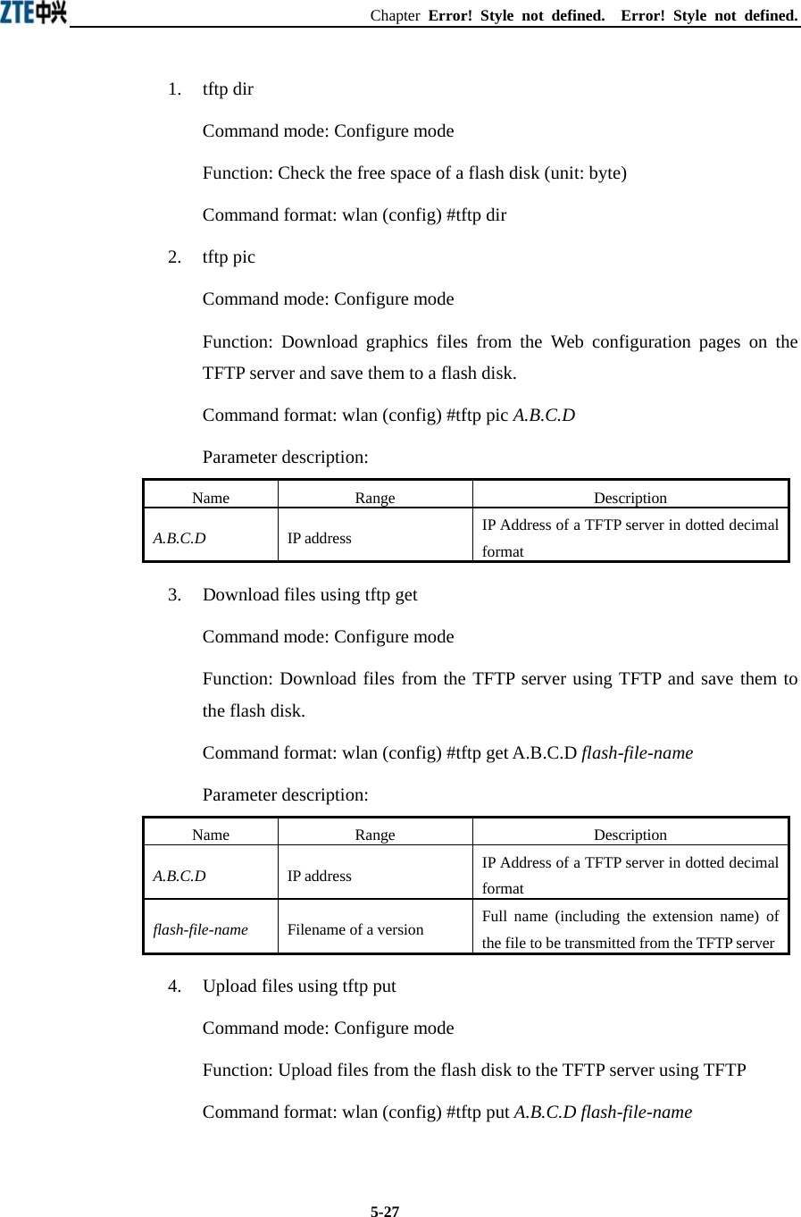
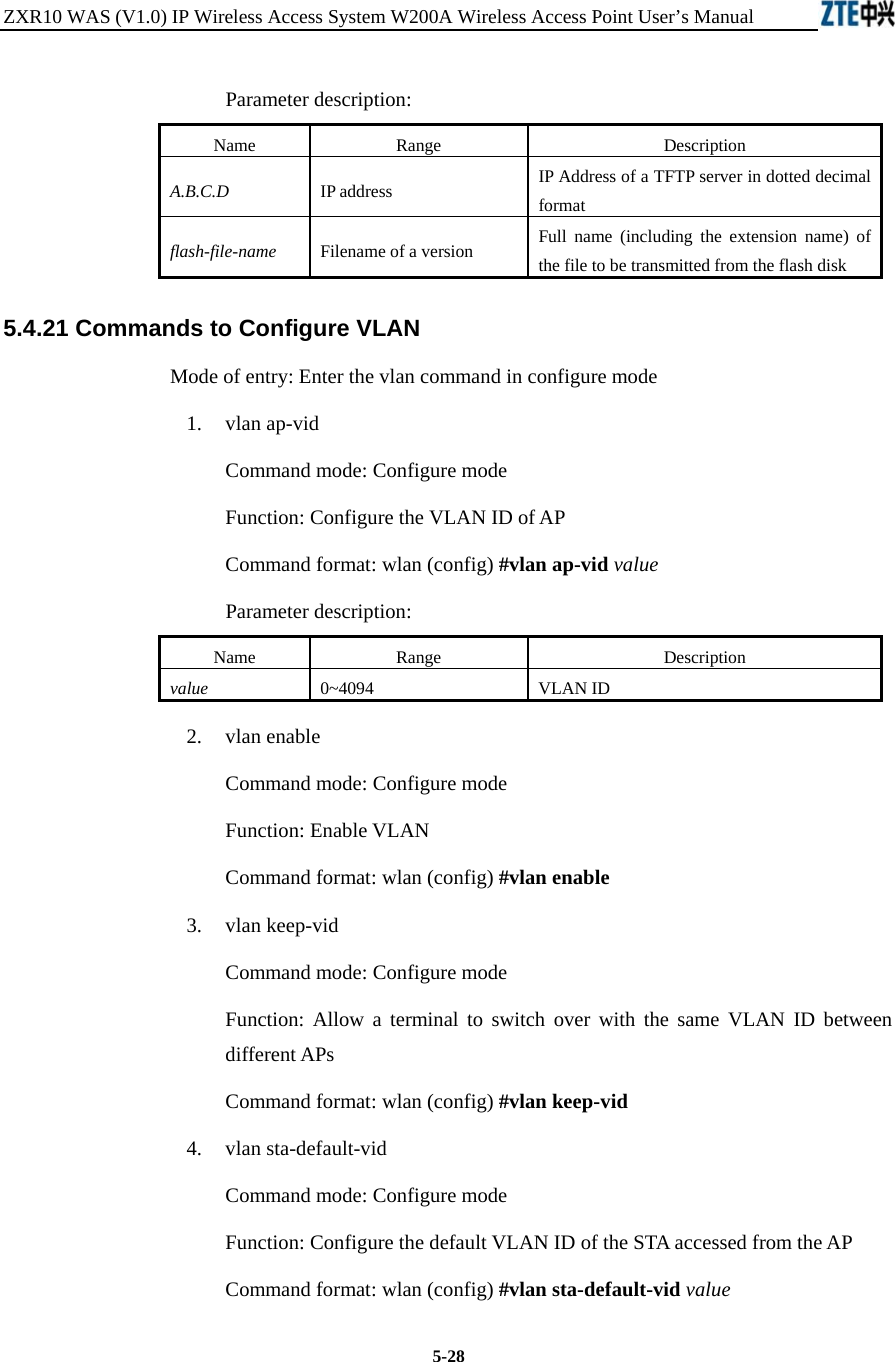
![ZXR10 WAS (V1.0) IP Wireless Access System W200A Wireless Access Point User’s Manual 5-26 12. snmp authtrap enable Command mode: Configure mode Function: Configure if the SNMP Agent is allowed to send the authentication failed Trap Command format: wlan (config) #[no] snmp authtrap enable 13. snmp traphost Command mode: Configure mode Function: Add the address of a trap destination host and the trap version number Command format: wlan (config) #snmp traphost A.B.C.D [version version] wlan(config)#no snmp traphost A.B.C.D Parameter description: Name Range Description A.B.C.D IP address Addresses of Trap destination hosts version 1~2 Trap version number 5.4.19 Command to Manage Telnet Idle Timeout Mode of entry: Enter the Telnet idle-timeout command in configure mode Command mode: Configure mode Function: Set the automatic exit time when the Telnet window is idle Command format: wlan (config) #telnet idle-timeout time-value Parameter description: Name Range Description time-value 300~3600 (unit: s) The automatic exit time when the Telnet window is idle (300s by default) 5.4.20 Commands to Upload/download TFTP Files Mode of entry: Enter the tftp command in configure mode](https://usermanual.wiki/ZTE/ZXR10W200A/User-Guide-446304-Page-52.png)
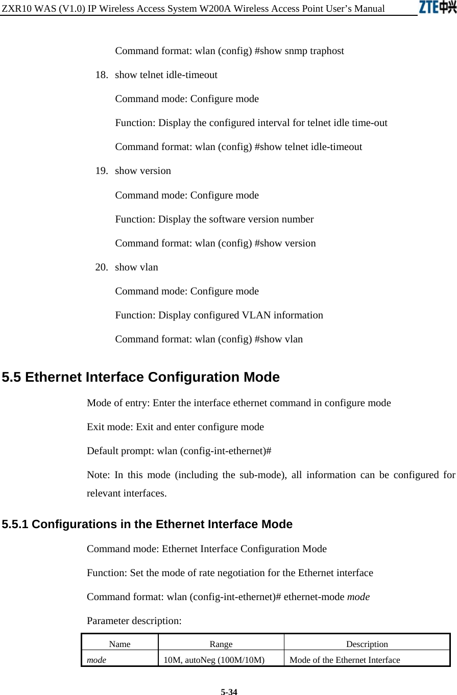
![ZXR10 WAS (V1.0) IP Wireless Access System W200A Wireless Access Point User’s Manual 5-32 Command format: wlan (config) #show ip pool config show ip pool used Command mode: Configure mode Function: Display information of allocated IP addresses in the specified IP address pool Command format: wlan (config) #show ip pool used index Parameter description: Name Range Description Index 0~9 Serial number of an IP address pool 4) show ip route Command mode: Configure mode Function: Display configured IP route parameters Command format: wlan (config) #show ip route 12. show logmsg Command mode: Configure mode Function: Display all configured log print information Command format: wlan (config) #show logmsg 13. show mac-access-list Command mode: Configure mode Function: Display configured mac-access-list information Command format: wlan (config) #show mac-access-list {static} [1~99] 14. show mac-authen Command mode: Configure mode Function: Display configured mac-authen parameters Command format: wlan (config) #show mac-authen 15. show manage-user Command mode: Configure mode](https://usermanual.wiki/ZTE/ZXR10W200A/User-Guide-446304-Page-58.png)
![Chapter Error! Style not defined. Error! Style not defined. 5-355.5.2 Command to Exit the Ethernet Interface Configuration Mode Command mode: Ethernet Interface Configuration Mode Function: Exit Ethernet interface configuration mode and enter configure Mode Command format: wlan (config-int-ethernet)# #exit 5.5.3 Command to Configure Ethernet interface IP addresses Command mode: Ethernet Interface Configuration Mode Function: Set the IP address of the Ethernet interface Command format: wlan(config-int-ethernet)#ipaddr A.B.C.D1 A.B.C.D2 [second] wlan(config-int-ethernet)#no ipaddr A.B.C.D1 [A.B.C.D2] Parameter description: Name Range Description A.B.C.D1 IP address IP address of an interface A.B.C.D2 IP address IP address mask of an interface [second] Optional The additional IP address flag of an interface 5.5.4 Command to Configure MAC filter for the Ethernet Interface Command mode: Ethernet Interface Configuration Mode Function: Configure MAC filter for the Ethernet interface Command format: wlan(config-int-ethernet)#[no] mac-access-group acl-number direction Parameter description: Name Range Description acl-num 1~99 MAC filter entry number bound to the interface direction in Bind to the "in" direction of the interface 5.6 Wireless Interface Configuration Mode Mode of entry: Enter the interface wlan command in configure mode Exit mode: Exit and enter configure mode](https://usermanual.wiki/ZTE/ZXR10W200A/User-Guide-446304-Page-61.png)
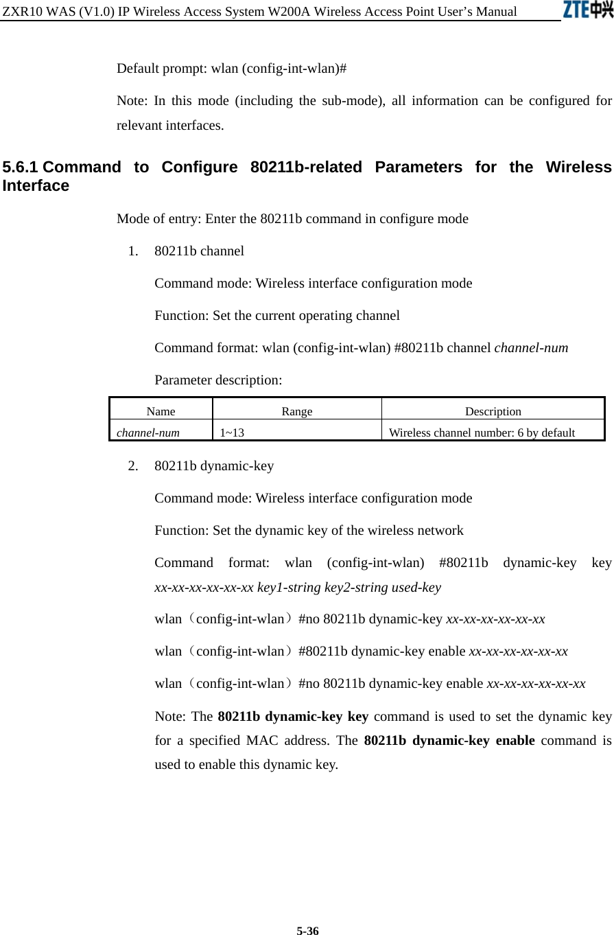
![Chapter Error! Style not defined. Error! Style not defined. 5-37Parameter description: Name Range Description xx-xx-xx-xx-xx-xx MAC address MAC address of the wireless user using the dynamic key key1-string 5 or 13 characters First dynamic key (the key length can only be 5 or 13 characters) key2-string 5 or 13 characters Second dynamic key (the key length can only be 5 or 13 characters) used-key key1, key2 Key number that is used 3. 80211b enh-security enable Command mode: Wireless interface configuration mode Function: Set to enable or disable the enhanced security function of AP Command format: wlan (config) #[no] 80211b enh-security enable Note: If the enhanced security function is enabled, the wireless terminal will not be able to scan the AP. If this function is disabled, the AP can be scanned. 4. 80211b essid Command mode: Wireless interface configuration mode Function: Set ESSID of the wireless network Command format: wlan (config-int-wlan) #80211b essid essid-string Parameter description: Name Range Description essid-string 1~31 characters ESSID of the wireless network. By default, it is zxwlan. 5. 80211b frg-threshold Command mode: Wireless interface configuration mode Function: Set fragment threshold Command format: wlan (config-int-wlan) #80211b frg-threshold value Parameter description: Name Range Description value 256~2346 (even) Threshold of fragments, 2346 by default](https://usermanual.wiki/ZTE/ZXR10W200A/User-Guide-446304-Page-63.png)
![ZXR10 WAS (V1.0) IP Wireless Access System W200A Wireless Access Point User’s Manual 5-38 6. 80211b power Command mode: Wireless interface configuration mode Function: Set the transmission power of the wireless network card Command format: wlan (config-int-wlan) #80211b power value Parameter description: Name Range Description value auto, 10/20/30/40/50/60/70/80/90/100(unit: mW) max auto: automatic power control (default) 10/20/30/40/50/60/70/80/90/100: fixed transmission power max: maximal transmission power 7. 80211b rts-threshold Command mode: Wireless interface configuration mode Function: Set RTS threshold Command format: wlan (config-int-wlan) #80211b rts-threshold value Parameter description: Name Range Description value 0~2347 RTS threshold, 2347 by default 5.6.2 Command to Exit Wireless Interface Configuration Mode Command mode: Wireless interface configuration mode Function: Exit wireless interface configuration mode and enter configure mode Command format: wlan (config-int-wlan)# exit 5.6.3 Command to Enable Link Integrity Detection Command mode: Wireless interface configuration mode Function: Set to enable or disable link integrity detection Command format: wlan (config-int-wlan)#[no] link-integrity enable Note: the link integrity detection function of AP means that when the Ethernet link of the AP is disconnected, the AP will release all connected wireless users, close the wireless port, and deny the connection requests of other wireless terminals. When the](https://usermanual.wiki/ZTE/ZXR10W200A/User-Guide-446304-Page-64.png)
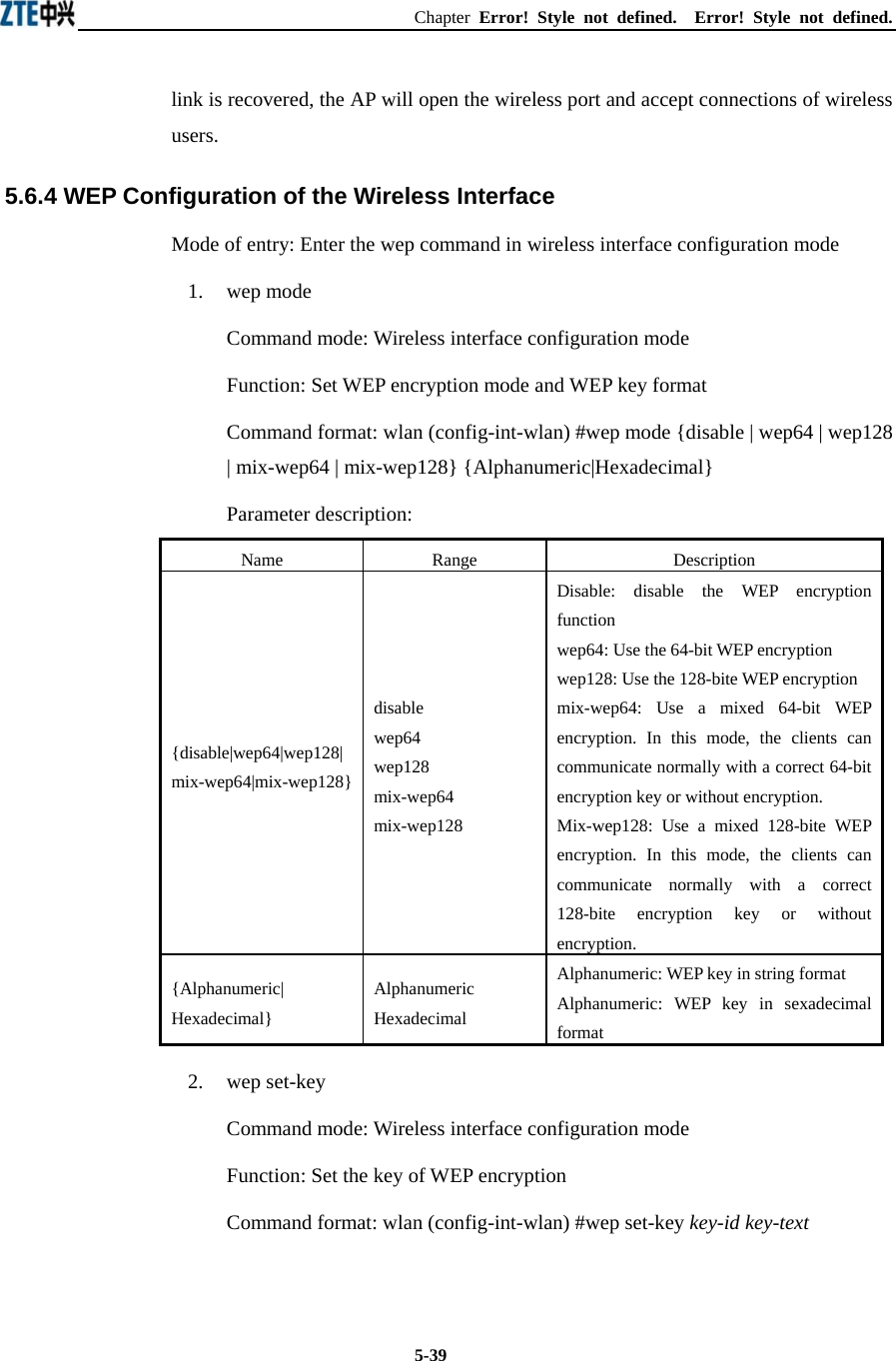
![ZXR10 WAS (V1.0) IP Wireless Access System W200A Wireless Access Point User’s Manual 5-40 Parameter description: Name Range Description key-id key1, key2, key3, key4 Entry number of the key to be set key-text 5 or 13 characters, or a combination of 10 or 26 sexadecimal digits If it is set to 64-bit encryption, the key_text argument can be 5 case sensitive characters (in alphanumeric format), e.g. MyKey, or 10 sexadecimal digits (in hexadecimal format), e.g. 11AA22BB33 If it is set to 128-bit encryption, the key_text argument can be 13 case sensitive characters (in alphanumeric format), e.g. MyKey12345678, or 26 sexadecimal digits (in hexadecimal format), e.g. 00112233445566778899AABBCC 3. wep use-key Command mode: Wireless interface configuration mode Function: Set the WEP encryption key to be used Command format: wlan (config-int-wlan) #wep use-key key-id Parameter description: Name Range Description Key-id key1, key2, key3, key4 Entry number of the key to be used 5.6.5 Command to Configure MAC Filter in Wireless Interface Configuration Command mode: Wireless interface configuration mode Function: Configure MAC filter for the wireless interface Command format: wlan (config-int-wlan) #[no] mac-access-group acl-list-number direction Parameter description: Name Range Description Acl-list-number 1~99 MAC filter entry number bound to the interface direction in Bind to the "in" direction of the interface](https://usermanual.wiki/ZTE/ZXR10W200A/User-Guide-446304-Page-66.png)


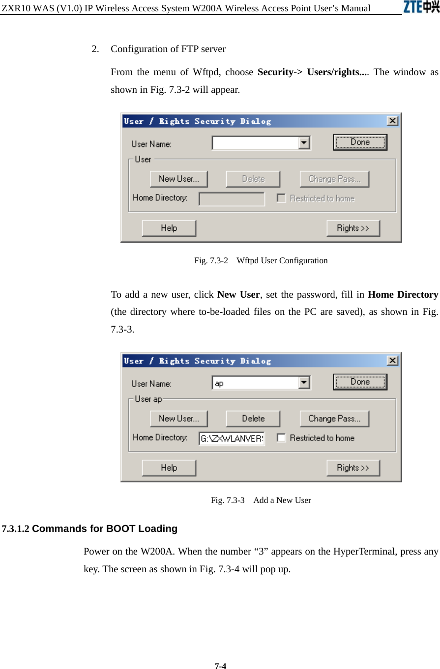
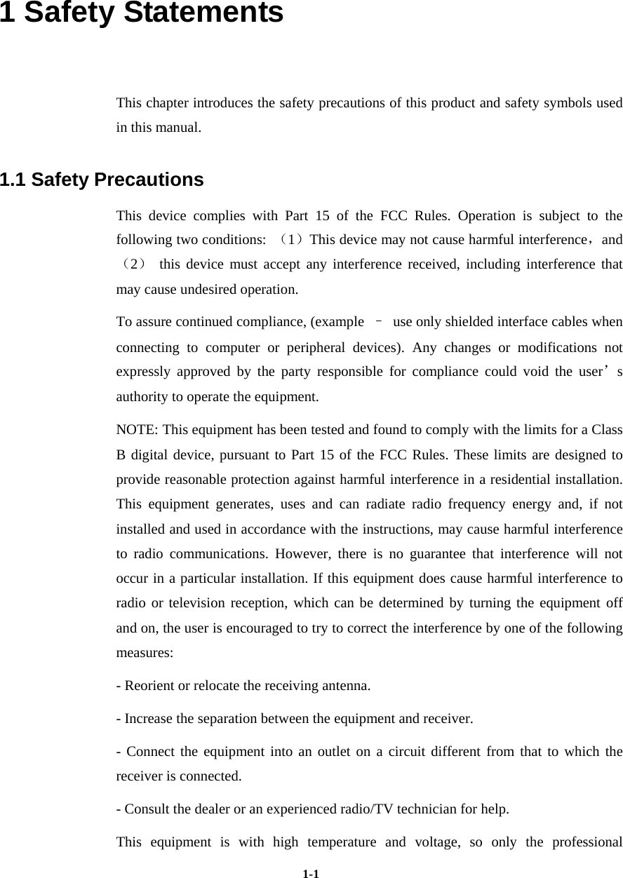
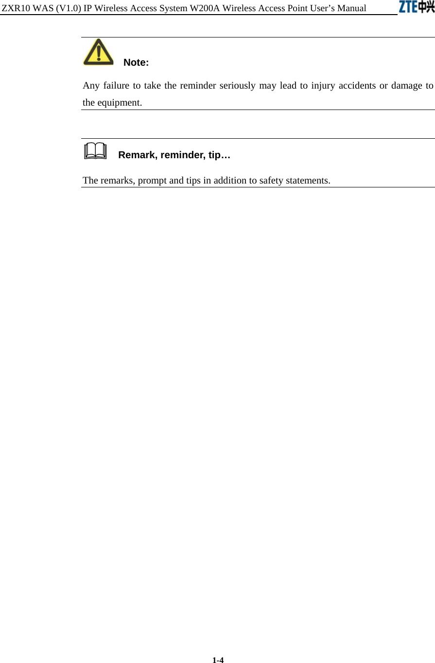
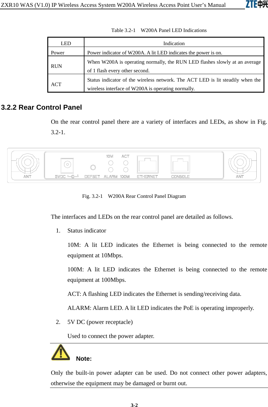
![Chapter Error! Style not defined. Error! Style not defined. 7-5 Fig. 7.3-4 Initial Window 1. Command: p Function: Show BOOT parameters Command format: [VxWorks Boot]: p Example: See Fig. 7.3-5. Fig. 7.3-5 Execution of “p” Command 2. Command: c Function: Modify BOOT parameters Command format: [VxWorks Boot]: c The following parameters are subject to modification:](https://usermanual.wiki/ZTE/ZXR10W200A/User-Guide-446304-Page-113.png)
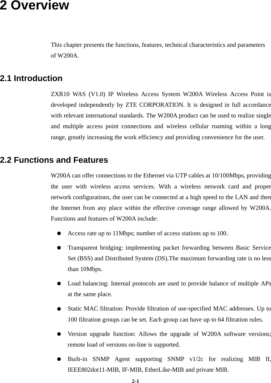
![ZXR10 WAS (V1.0) IP Wireless Access System W200A Wireless Access Point User’s Manual 7-6 file name Filename inet on Ethernet (e) IP address of the W200A (used for communication with the host during version loading) host inet (h) IP address of the host user(u) User name ftp password(pw) Password Example: As shown in Fig. 7.3-6, change inet on Ethernet (e) to 168.1.100.100, host inet (h) to 168.1.15.204, user (u) to ap, ftp password (pw) to ap. Corresponding settings should be set in the FTP server when user (u) and ftp password (pw) have been changed. Fig. 7.3-6 Execution of “c” Command 3. Command: % Function: Format the flash memory Command format: [VxWorks Boot]: % Explanation: Formatting of the Flash card is generally required before the version loading in order to ensure there is enough space for the files to be loaded. Example: As shown in Fig. 7.3-7, prompts are given asking for confirming of the Flash formatting. Enter “y” within 3 seconds; otherwise, the operation will](https://usermanual.wiki/ZTE/ZXR10W200A/User-Guide-446304-Page-114.png)
![Chapter Error! Style not defined. Error! Style not defined. 7-7 be aborted. Fig. 7.3-7 Execution of “%” Command 4. Command: & Function: Load the file "runbin" to the Flash memory Command format: [VxWorks Boot]: & Example: See Fig. 7.3-8. Fig. 7.3-8 Execution of “&” Command](https://usermanual.wiki/ZTE/ZXR10W200A/User-Guide-446304-Page-115.png)
![ZXR10 WAS (V1.0) IP Wireless Access System W200A Wireless Access Point User’s Manual 7-8 5. Command: # Function: Load database.dat, zxipcmd.dat, tf010102.hex, th010000.hex, tf010302.hex to the Flash memory Command format: [VxWorks Boot]: # Example: See Fig. 7.3-9. Fig. 7.3-9 Execution of “#” Command 6. Command: + Function: Load a specified file to the Flash memory Command format: [VxWorks Boot]: + Example: Modify BOOT parameters using the C command and then type in](https://usermanual.wiki/ZTE/ZXR10W200A/User-Guide-446304-Page-116.png)
![Chapter Error! Style not defined. Error! Style not defined. 7-9 "+".As shown in Fig. 7.3-10, modify file name by means of the C command, change vxworks to “b.hex”, input “+” to load b.hex to the Flash memory. Fig. 7.3-10 Execution of “+” Command 7. Command: s Function: Display files and free space of the Flash memory Command format: [VxWorks Boot]: s Example: See Fig. 7.3-11.](https://usermanual.wiki/ZTE/ZXR10W200A/User-Guide-446304-Page-117.png)
![ZXR10 WAS (V1.0) IP Wireless Access System W200A Wireless Access Point User’s Manual 7-10 Fig. 7.3-11 Execution of “s” Command 8. Command: - Function: Delete a file from the Flash memory Command format: [VxWorks Boot]: - filename Example: See Fig. 7.3-12. Fig. 7.3-12 Execution of “-“ Command 9. Command: v Function: Show version information of runbin Command format: [VxWorks Boot]: v Example: See Fig. 7.3-13. Fig. 7.3-13 Execution of “v” Command](https://usermanual.wiki/ZTE/ZXR10W200A/User-Guide-446304-Page-118.png)
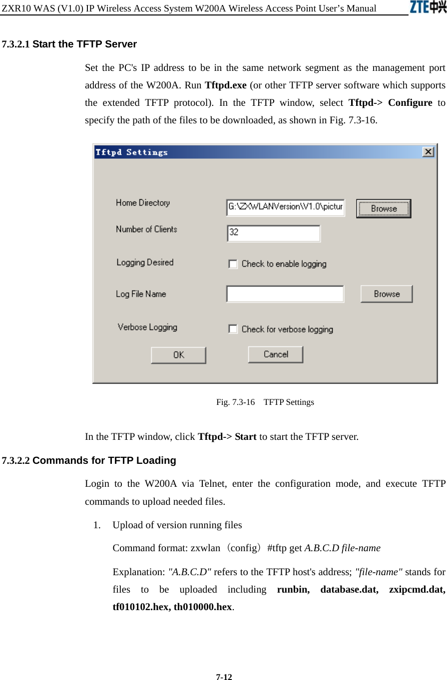
![Chapter Error! Style not defined. Error! Style not defined. 7-1110. Command: r Function: Show version information of boot Command format: [VxWorks Boot]: r Example: See Fig. 7.3-14. Fig. 7.3-14 Execution of “r” Command 11. Command: * Function: Run runbin, start the W200A. Command format: [VxWorks Boot]: * Example: See Fig. 7.3-15. Fig. 7.3-15 Execution of “*” Command 7.3.2 Online TFTP Loading When the W200A functions properly, file downloading from the host to the Flash memory of the device via TFTP is available. The size of the Flash is only 4M, therefore there are some restrictions to the files to be loaded online. Generally via TFTP, version running files and graphics files can be loaded. No support for other files is provided temporarily.](https://usermanual.wiki/ZTE/ZXR10W200A/User-Guide-446304-Page-119.png)