ZTE ZXR10W200A W200A Wireless Access Point User Manual
ZTE Corporation W200A Wireless Access Point Users Manual
ZTE >
Users Manual
ZXR10 WAS (V1.0) IP Wireless Access
System
W200A Wireless Access Point
User’s Manual
ZTE CORPORATION
ZXR10 WAS (V1.0) IP Wireless Access System
W200A Wireless Access Point
User’s Manual
Manual Version 20040306-R1.0
Product Version V1.0
BOM ××××××××
Copyright © 2003 ZTE Corporation
All rights reserved.
No part of this documentation may be excerpted, reproduced, translated, annotated or
duplicated, in any form or by any means without the prior written permission of ZTE
Corporation.
ZTE CORPORATION
ZTE Plaza, Keji Road South, Hi-Tech Industrial Park, Nanshan District, Shenzhen, P. R. China
Website: http://www.zte.com.cn
Post code: 518057
Customer Support Center: (+86755) 26770800 800-830-1118
Fax: (+86755) 26770801
E-mail: 800@zte.com.cn
* * * *
S.N.: DDDDDDDDD

FAX:0086-755-26770160
Suggestions and Feedback
To improve the quality of ZTE product documentation and offer better services to our customers, we hope
you can give us your suggestions and comments on our documentation and fax this form to
0086-755-26770160; or mail to “ZTE Plaza, Keji Road South, Hi-Tech Industrial Park, Nanshan District,
Shenzhen, P. R. China”. Our postcode is 518057.
Document Name ZXR10 WAS (V1.0) IP Wireless Access System W200A Wireless Access Point User’s Manual
Product version V1.0 Document version 20040306-R1.0
Equipment installation time
Your information
Name Company
Postcode Company address
Telephone E-mail
Good Fair Average Poor Bad
Overall
Instructiveness
Index
Correctness
Completeness
Structure
Illustration
Your evaluation
of this
documentation
Readability
Overall
Instructiveness
Index
Correctness
Completeness
Structure
Illustration
Your suggestion
on the
improvement of
this
documentation
Readability
Your other
suggestions on
ZTE product
documentation
Preface
About This Manual
This manual is used for ZXR10 WAS (V1.0) IP Wireless Access System W200A
Wireless Access Point (hereinafter called W200A).
ZXR10 (V1.0) IP Wireless Access System is developed independently by ZTE
CORPORATION. It is composed of a range of wireless access products, including
wireless network card and wireless router with combined functions of AP and DSL.
This manual presents the functional characteristics, installation, operation, usage and
maintenance of W200A, and is used as the operation guide for this product. This
manual contains 8 chapter and 2 appendices.
Chapter 1: Safety Instructions. It presents the safety requirements in operations and
safety signs used in this manual.
Chapter 2: Overview. It presents the functions, features and technical parameters of
W200A.
Chapter 3: Structure and Principle It presents the structure and principle of W200A.
Chapter 4: Installation and Debugging It presents the installation and debugging
methods for W200A.
Chapter 5: Command Line Configurations It presents the command line configurations
of W200A.
Chapter 6: WEB configurations. It presents the web configurations of W200A.
Chapter 7: Integrated GUI Management. It presents the integrated GUI Integration
management of W200A.
Chapter 8: Maintenance It presents the methods of routine maintenance and version
upgrade.
Appendix A: Package, Transportation and Storage It presents the packing methods,
storage conditions and transportation requirements of W200A.
Appendix B: Making Ethernet cables It presents the Ethernet power supplies for
W200A and the methods to make network cables.
Statement: The actual product may differ from what is described in this
manual due to frequent update of ZTE products and fast development of
technologies. Please contact the local ZTE office for the latest updating
information of the product.
-i-
Contents
1 Safety Statements ....................................................................................................................................1-1
1.1 Safety Precautions..........................................................................................................................1-1
1.2 Symbol Description........................................................................................................................1-2
2 Overview..................................................................................................................................................2-1
2.1 Introduction....................................................................................................................................2-1
2.2 Functions and Features...................................................................................................................2-1
2.3 Technical Characteristics and Parameters......................................................................................2-2
3 Structure and Principle...........................................................................................................................3-1
3.1 Structure and Working Principle ....................................................................................................3-1
3.2 Units and Components...................................................................................................................3-1
3.2.1 Front Panel..........................................................................................................................3-1
3.2.2 Rear Control Panel ..............................................................................................................3-2
3.3 Network Mode ...............................................................................................................................3-3
4 Installation and Debugging ....................................................................................................................4-1
5 Command Line Configurations .............................................................................................................5-1
5.1 Overview........................................................................................................................................5-1
5.2 User Mode......................................................................................................................................5-4
5.3 Privileged Mode.............................................................................................................................5-4
5.3.1 Command to Test Network Connectivity............................................................................5-4
5.3.2 Command to Save Configurations to Flash.........................................................................5-5
5.3.3 Command to Reset Software...............................................................................................5-5
5.3.4 Command to Enter Configure Mode...................................................................................5-5
5.3.5 Command to Exit Privileged Mode.....................................................................................5-5
-ii-
5.3.6 Command to Exit TELNET Configuration......................................................................... 5-6
5.4 Configure Mode............................................................................................................................. 5-6
5.4.1 Commands to Configure Wireless Access-Bridge.............................................................. 5-6
5.4.2 Command to Configure Bridge Information....................................................................... 5-7
5.4.3 Commands to Configure DHCP Server.............................................................................. 5-7
5.4.4 Discover commands............................................................................................................ 5-9
5.4.5 Commands to Configure 802.1X Parameters ................................................................... 5-10
5.4.6 Command to Set User Password in Privileged Mode....................................................... 5-13
5.4.7 Command to Delete Filtration Rules ................................................................................ 5-13
5.4.8 Command to Exit Configuration Mode ............................................................................ 5-13
5.4.9 Commands to Configure IAPP (Load-balance)................................................................ 5-14
5.4.10 Interface Skip.................................................................................................................. 5-15
5.4.11 Commands to Configure Layer 2 Isolation..................................................................... 5-16
5.4.12 Commands to Configure IP network Parameters............................................................ 5-16
5.4.13 Command to Configure Log Print Information .............................................................. 5-17
5.4.14 Command to Configure MAC Filter............................................................................... 5-18
5.4.15 Command to Configure MAC Address Authentication .................................................. 5-19
5.4.16 Command to Configure Users ........................................................................................ 5-20
5.4.17 Commands to Configure Radius Server ......................................................................... 5-20
5.4.18 Command to Configure SNMP Module ......................................................................... 5-22
5.4.19 Command to Manage Telnet Idle Timeout ..................................................................... 5-26
5.4.20 Commands to Upload/download TFTP Files.................................................................. 5-26
5.4.21 Commands to Configure VLAN..................................................................................... 5-28
5.4.22 Show Commands............................................................................................................5-29
5.5 Ethernet Interface Configuration Mode.......................................................................................5-34
5.5.1 Configurations in the Ethernet Interface Mode................................................................. 5-34
-iii-
5.5.2 Command to Exit the Ethernet Interface Configuration Mode .........................................5-35
5.5.3 Command to Configure Ethernet interface IP addresses...................................................5-35
5.5.4 Command to Configure MAC filter for the Ethernet Interface.........................................5-35
5.6 Wireless Interface Configuration Mode.......................................................................................5-35
5.6.1 Command to Configure 80211b-related Parameters for the Wireless Interface................5-36
5.6.2 Command to Exit Wireless Interface Configuration Mode...............................................5-38
5.6.3 Command to Enable Link Integrity Detection ..................................................................5-38
5.6.4 WEP Configuration of the Wireless Interface ...................................................................5-39
5.6.5 Command to Configure MAC Filter in Wireless Interface Configuration........................5-40
5.6.6 Command to Configure Authentication Mode in Wireless Interface Configuration.........5-41
6 WEB Configuration................................................................................................................................6-1
6.1 Overview........................................................................................................................................6-1
6.2 Opening the login WEB page.........................................................................................................6-3
6.3 Main menu of WEB configuration.................................................................................................6-4
6.3.1 Home page (basic product information)..............................................................................6-5
6.3.2 Stations page .......................................................................................................................6-6
6.3.3 Statistics Page......................................................................................................................6-7
6.3.4 Load Balance page ..............................................................................................................6-8
6.3.5 SNMP page .........................................................................................................................6-9
6.3.6 Security page.....................................................................................................................6-16
6.3.7 Save page ..........................................................................................................................6-20
6.3.8 Reboot page.......................................................................................................................6-21
6.3.9 Advanced options page .....................................................................................................6-22
6.3.10 Accounts page .................................................................................................................6-30
6.4 Interfaces page .............................................................................................................................6-31
6.4.1 Ethernet Interface page .....................................................................................................6-31
-iv-
6.4.2 Wireless Interface page..................................................................................................... 6-33
6.5 Data submission flow for WEB configuration............................................................................. 6-37
7 Maintenance............................................................................................................................................ 7-1
7.1 Explanation.................................................................................................................................... 7-1
7.2 Daily Maintenance......................................................................................................................... 7-2
7.3 Version Upload & Upgrade............................................................................................................ 7-2
7.3.1 BOOT Loading ................................................................................................................... 7-3
7.3.2 Online TFTP Loading.......................................................................................................7-11
Appendix A Packaging, Transportation & Storage................................................................................ A-1
A.1 Packaging..................................................................................................................................... A-1
A.2 Transportation.............................................................................................................................. A-1
A.3 Storage ......................................................................................................................................... A-1
Appendix B Making Ethernet Cables......................................................................................................B-1
B.1 Application of the W200A ............................................................................................................B-1
B.2 How to Make an Ethernet Cable ...................................................................................................B-3
B.2.1 Making a Straight-through Ethernet Cable (RJ45).............................................................B-3
B.2.2 Making a PoE Ethernet Cable (C-RJ45-001).....................................................................B-3
B.2.3 Making a Crossover Ethernet Cable (RJ45J) .....................................................................B-4
B.2.4 Ethernet Cable Labels........................................................................................................B-5
1-1
1 Safety Statements
This chapter introduces the safety precautions of this product and safety symbols used
in this manual.
1.1 Safety Precautions
This device complies with Part 15 of the FCC Rules. Operation is subject to the
following two conditions: (1)This device may not cause harmful interference,and
(2) this device must accept any interference received, including interference that
may cause undesired operation.
To assure continued compliance, (example – use only shielded interface cables when
connecting to computer or peripheral devices). Any changes or modifications not
expressly approved by the party responsible for compliance could void the user’s
authority to operate the equipment.
NOTE: This equipment has been tested and found to comply with the limits for a Class
B digital device, pursuant to Part 15 of the FCC Rules. These limits are designed to
provide reasonable protection against harmful interference in a residential installation.
This equipment generates, uses and can radiate radio frequency energy and, if not
installed and used in accordance with the instructions, may cause harmful interference
to radio communications. However, there is no guarantee that interference will not
occur in a particular installation. If this equipment does cause harmful interference to
radio or television reception, which can be determined by turning the equipment off
and on, the user is encouraged to try to correct the interference by one of the following
measures:
- Reorient or relocate the receiving antenna.
- Increase the separation between the equipment and receiver.
- Connect the equipment into an outlet on a circuit different from that to which the
receiver is connected.
- Consult the dealer or an experienced radio/TV technician for help.
This equipment is with high temperature and voltage, so only the professional

ZXR10 WAS (V1.0) IP Wireless Access System W200A Wireless Access Point User’s Manual
1-2
personnel who had passed the training can install, operate and maintain it.
ZTE assumes no responsibility for consequences resulting from violation of general
specifications for safety operations or of safety rules for design, production and use of
equipment.
1.2 Symbol Description
See Table 1.2-1 for the safety symbols used in this manual, which serves to remind the
readers of the safety precautions to be taken when the equipment is installed, operated
and maintained.
Chapter Error! Style not defined. Error! Style not defined.
1-3
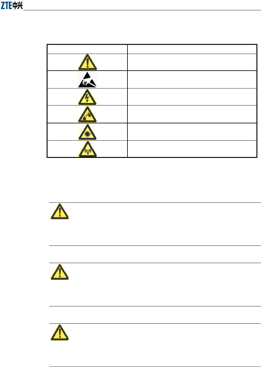
Table 1.2-1 Safety Symbols and Descriptions
Safety Symbols Meaning
Call for notice
Call for antistatic measures
Warn against electric shock
Caution against scald
Warn against laser
Caution against microwave
Four types of safety levels are available: danger, warning, caution and note. To the
right of a safety symbol is the text description of its safety level. Under the symbol is
the detailed description about its contents. See the following formats.
Danger:
Any failure to take the reminder seriously may lead to important accidents, such as
casualties or damage to the equipment.
Cautions:
Any failure to take the reminder seriously may lead to important or severe injury
accidents, or damage to the equipment.
Caution:
Any failure to take the reminder seriously may lead to severe injury accidents or
damage to the equipment.

ZXR10 WAS (V1.0) IP Wireless Access System W200A Wireless Access Point User’s Manual
1-4
Note:
Any failure to take the reminder seriously may lead to injury accidents or damage to
the equipment.
Remark, reminder, tip…
The remarks, prompt and tips in addition to safety statements.
2-1
2 Overview
This chapter presents the functions, features, technical characteristics and parameters
of W200A.
2.1 Introduction
ZXR10 WAS (V1.0) IP Wireless Access System W200A Wireless Access Point is
developed independently by ZTE CORPORATION. It is designed in full accordance
with relevant international standards. The W200A product can be used to realize single
and multiple access point connections and wireless cellular roaming within a long
range, greatly increasing the work efficiency and providing convenience for the user.
2.2 Functions and Features
W200A can offer connections to the Ethernet via UTP cables at 10/100Mbps, providing
the user with wireless access services. With a wireless network card and proper
network configurations, the user can be connected at a high speed to the LAN and then
the Internet from any place within the effective coverage range allowed by W200A.
Functions and features of W200A include:
Access rate up to 11Mbps; number of access stations up to 100.
Transparent bridging: implementing packet forwarding between Basic Service
Set (BSS) and Distributed System (DS).The maximum forwarding rate is no less
than 10Mbps.
Load balancing: Internal protocols are used to provide balance of multiple APs
at the same place.
Static MAC filtration: Provide filtration of use-specified MAC addresses. Up to
100 filtration groups can be set. Each group can have up to 64 filtration rules.
Version upgrade function: Allows the upgrade of W200A software versions;
remote load of versions on-line is supported.
Built-in SNMP Agent supporting SNMP v1/2c for realizing MIB II,
IEEE802dot11-MIB, IF-MIB, EtherLike-MIB and private MIB.

ZXR10 WAS (V1.0) IP Wireless Access System W200A Wireless Access Point User’s Manual
2-2
Supports command line and Web configurations.
Provides the seamless roaming technology that allows the user to communicate
with others easily.
ESSID is used to provide network authentication, preventing illegal users from
accessing the network.
High interconnectivity. Provides interconnections to the 10/100Mbps Ethernet,
according with IEEE 802.3 network protocols.
Provides data verification and security management; 64-bit and 128-bite WEP
encryption functions are supported.
Automatic Scale Back Functionality (ASBF) correcting WLAN automatically to
provide optimum connections.
Offers integrated management servers for the control and management of ZTE's
wireless network devices including W200A in a distributed environment.
2.3 Technical Characteristics and Parameters
Technical characteristics and specifications of W200A are shown in Table 2.3-1 below.
Table 2.3-1 Technical Parameters of W200A
Item Specifications
Standard 802.11b, 802.1d, 802.3u
Operating frequency
range 2400MHz~2483.5MHz
Spread spectrum system DSSS
Modulation system CCK, DQPSK, DBPSK
Error rate <10-5
Data rate 1Mbps, 2Mbps, 5.5Mbps and 11Mbps autosensing
Distance (m) 30m~100m indoors; 100m~300m outdoors
External interface RJ45, serial, wireless
Operation mode Half duplex
Antenna system Non-directional, 2dB gain, integrated antenna
Number of channels European Union: 13; US and Canada: 11; France: 4; Japan: 14
Recommended/maximum
number of subscribers 30/100
MAC address capacity 1024

Chapter Error! Style not defined. Error! Style not defined.
2-3
Item Specifications
Size 208mm×180mm×47mm
Weight 1000g (power supply not included)
Power supplies 5V DC/PoE Ethernet 48V
Power adapter Input: 100VAC~240VAC; 50Hz~60Hz
Output: 5VDC, 1.2A
Operating temperature 0°C~ 40°C
Storage temperature -40°C~ 70°C
Operating humidity 10%~90% (no condensation)
Storage humidity 5%~95% (no condensation)
3-1
3 Structure and Principle
This chapter presents the structure and principle of W200A, including software and
hardware structure, working principle, interfaces, indicators and networking modes.
3.1 Structure and Working Principle
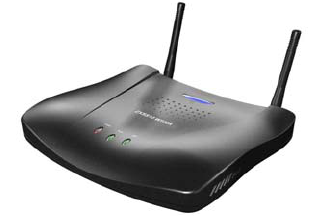
See W200A as shown in Fig. 3.1-1 below.
Fig. 3.1-1 Outside View of W200A
Hardware of W200A includes main body, antenna and external power adapter.
The software package of W200A includes the basic service subsystem and the network
management subsystem. The basic service subsystem includes 802.11b access point
driver, 802.3 Ethernet driver, transparent bridge, load balance, TCP/IP protocol suite,
dynamic address allocation and static MAC address filtration. The network
management subsystem includes SNMP Agent, command line configuration module
(including Telnet configurations and serial port configurations), Web configuration
module and integrated GUI management module.
3.2 Units and Components
3.2.1 Front Panel
On the front panel of W200A, 3 LEDs are used to indicate the status of the equipment.
The indication of each LED is shown in Table 3.2-1.
ZXR10 WAS (V1.0) IP Wireless Access System W200A Wireless Access Point User’s Manual
3-2
Table 3.2-1 W200A Panel LED Indications
LED Indication
Power Power indicator of W200A. A lit LED indicates the power is on.
RUN When W200A is operating normally, the RUN LED flashes slowly at an average
of 1 flash every other second.
ACT Status indicator of the wireless network. The ACT LED is lit steadily when the
wireless interface of W200A is operating normally.
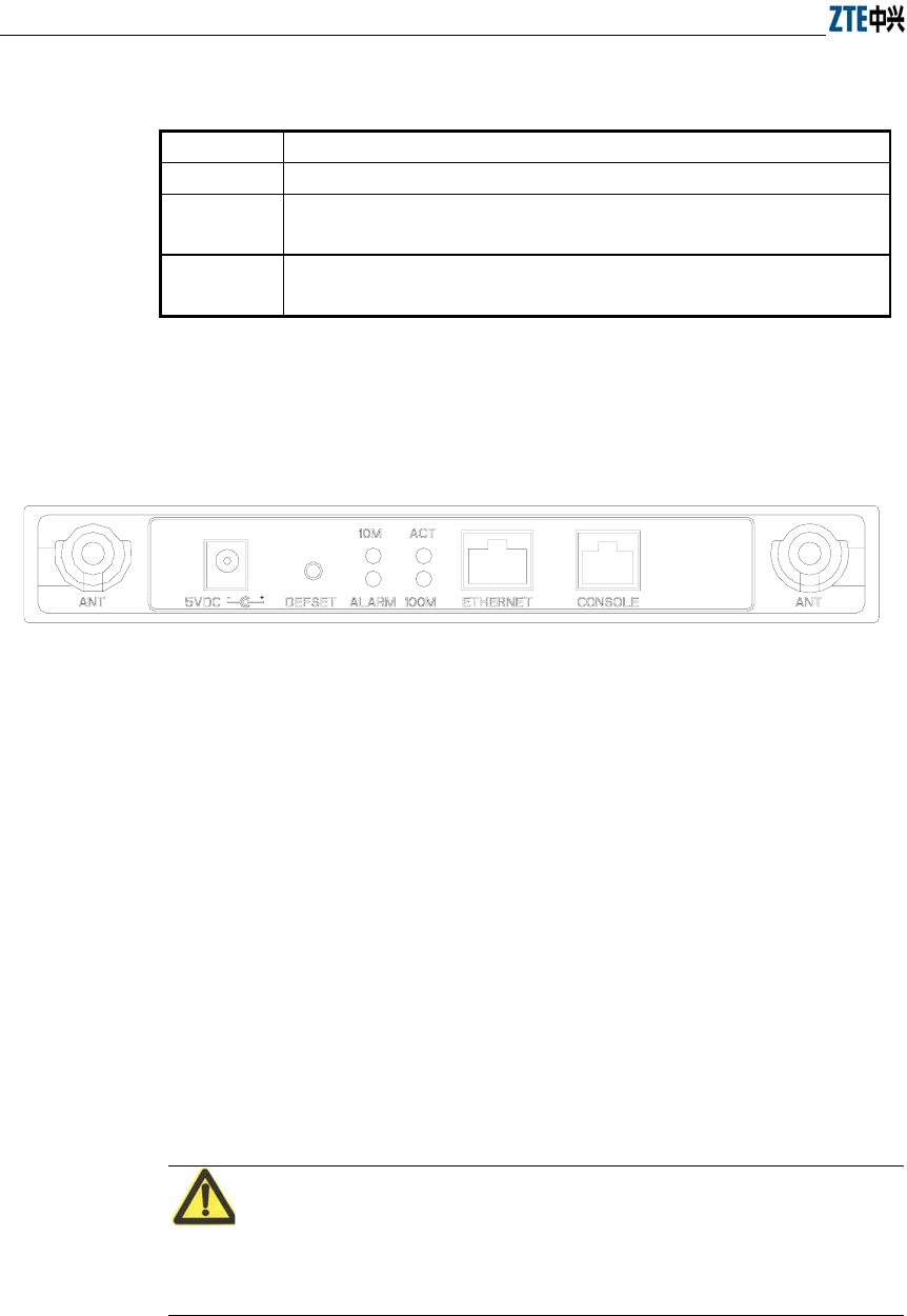
3.2.2 Rear Control Panel
On the rear control panel there are a variety of interfaces and LEDs, as show in Fig.
3.2-1.
Fig. 3.2-1 W200A Rear Control Panel Diagram
The interfaces and LEDs on the rear control panel are detailed as follows.
1. Status indicator
10M: A lit LED indicates the Ethernet is being connected to the remote
equipment at 10Mbps.
100M: A lit LED indicates the Ethernet is being connected to the remote
equipment at 100Mbps.
ACT: A flashing LED indicates the Ethernet is sending/receiving data.
ALARM: Alarm LED. A lit LED indicates the PoE is operating improperly.
2. 5V DC (power receptacle)
Used to connect the power adapter.
Note:
Only the built-in power adapter can be used. Do not connect other power adapters,
otherwise the equipment may be damaged or burnt out.

Chapter Error! Style not defined. Error! Style not defined.
3-3
3. Defset (default button)
This button is used to reset the W200A configurations to the factory presets. For
example, reset the management interface IP address of W200A to default
192.168.1.254, and subnet mask to 255.255.255.0; reset SSID (service ID) to
default zxwlan; reset the login username and password to default root and public,
and reset the privileged user password to default zte.
4. Ethernet (Ethernet RJ45 interface)
This interface has 3 functions:
1) When W200A is operating normally in a network, this interface is used as an
up-link interface and connected to W112P (AP remote power feeding mode) via
a directly powered Ethernet cable or connected (using a power adapter to supply
the AP in a near-end power mode)to the down-link interface of an Ethernet
switch via a directly connected Ethernet cable.
2) Before W200A is installed, you can connect to the wired network interface of a
computer via a cross network cable, log in to W200A via Web or Telnet and
configure parameters of W200A.
3) To load a version to W200A via a hyperterminal, you can connect this interface
with the wired network interface of the computer via a cross network cable, and
run FTP/TFTP server program on the computer to load the version file to the
flash of W200A.
5. CONSOLE (RJ11 interface for configurations)
Connect to the serial port of the computer using a serial cable so that you can
load, configure and debug the version for the equipment via the hyperterminal.
6. ANT (antenna port)
Used to install the antenna.
3.3 Network Mode
W200A is designed to provide wire access for indoor and outdoor wireless users. It can
be installed in offices, hotel halls and corridors, top of buildings, and residential yards.
The major operation modes are described as follows.
ZXR10 WAS (V1.0) IP Wireless Access System W200A Wireless Access Point User’s Manual
3-4
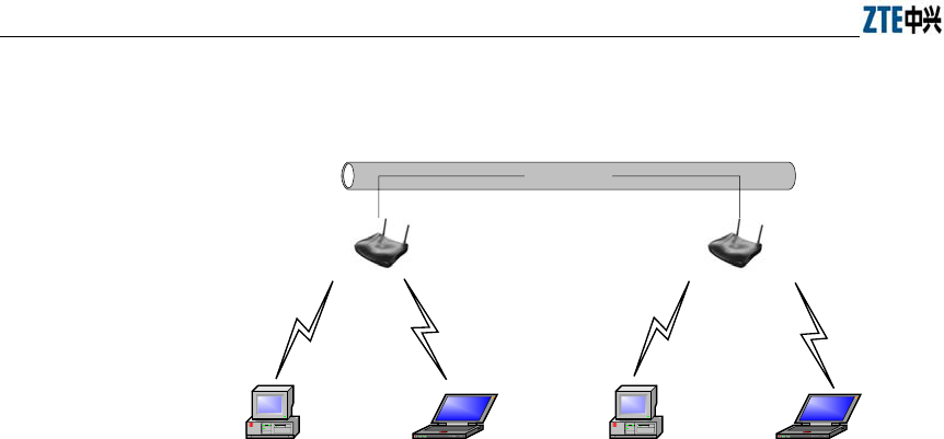
1. Establishing a small-scale wireless LAN
Wired LAN
W200A W200A
PC Lop-top computer PC Lop-top computer
Fig. 3.3-1 Establishing a Small-scale Wireless LAN
Chapter Error! Style not defined. Error! Style not defined.
3-5
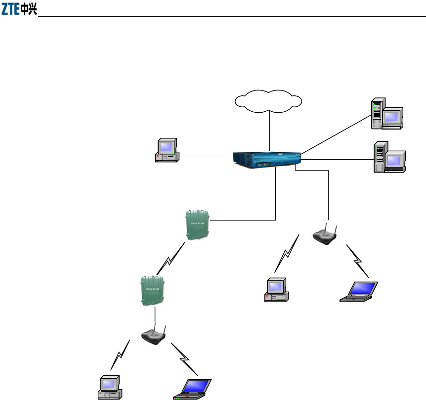
2. Comprising a wireless access network to the Internet together with other
equipment including ACs and bridges.
W110B
AAA
File server
W200A
W200A
Ethernet
Internet
W110B
UAS2500E
PC Lop-top computer
PC Lop-top computer
PC
Fig. 3.3-2 Comprising a Wireless Access Network to the Internet together with ACs, bridges and
other APs.
4-1
4 Installation and Debugging
See document “ZXR10 WAS (V1.0) IP Wireless Access System W200A Wireless
Access Point Professional Installation Instruction manual”
5-1
5 Command Line Configurations
This chapter presents the operating procedures of command line configurations and the
commands used.
5.1 Overview
W200A offers Command Line Interfaces (CLIs) for the configurations of all types of
data the W200A uses.
Features of the CLI configurations include:
1. The user can perform either local configurations by using hyperterminal
software via the serial port or local/remote configuration by using Telnet
software via the Ethernet interface or wireless network card.
2. 5 command modes can be used in CLI configuration interfaces: user mode,
privileged mode, configuration mode, Ethernet interface configuration mode and
wireless interface configuration mode. Each mode is the execution environment
of a set of relevant commands. A command can only be executed in its
corresponding command mode. To get the executable commands in the current
mode, type in "?" under this mode.
3. There are two types of commands, information query command and functional
command. information query commands are used to get required information.
Functional commands are used to change configurations of W200A functions.
Changed configurations are saved in the operation configuration database. To
cancel function configurations, execute the reverse command of the original
one (that is, add the no keyword to the front of the original command).
4. The CLI configuration offers a sophisticated help system. You can get relevant
help information by typing "?" at any time.
5. A fuzzy match function is offered for the command input. If the characters you
entered can determine exclusively the command to be executed, you needn't to
input the whole word.

ZXR10 WAS (V1.0) IP Wireless Access System W200A Wireless Access Point User’s Manual
5-2
6. A history function is offered in the CLI configuration interface. You can select a
history command by using the ↑and ↓ keys on the keyboard.
7. A dual password protect is offered in the interface to prevent unauthorized users
from accessing. The first password verification appears on the Welcome
interface of the Telnet program, where you will enter the user mode for safety
authentication. The default username and password are "root" and "public". You
can enter the privileged mode by inputting "enable" and a correct password in
the user mode. The password for the privileged mode is "zte" by default.
Tips:
When you perform configurations via serial port, no authentication will be needed
because the terminal screen enters user mode directly.
8. The CLI configuration interface supports the automatic paging of command
output on terminals. The "--More--" on the lower left corner of the command
output window indicates there are more output commands. To display the next
page, press the space bar. To exit, press <q>. To output the next line, press the
Enter key.
9. The CLI configuration interface offers a basic command line editing function.
The shortcut key for editing command lines are defined as follows:
Ctrl+U: Delete the whole command being input
Ctrl+A: Move the cursor to the first character of a command line
Ctrl+E: Move the cursor to the last character of a command line
Ctrl+X: Delete all the characters before the cursor
Ctrl+K: Delete all the characters after the cursor (including the character where
the cursor is)
Ctrl+C: Abandon all input. A new line and a new prompt appear.
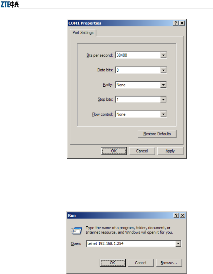
To configure the W200A via the serial port, set the serial port attributes of the
hyperterminal as shown in Fig. 5.1-1.
Chapter Error! Style not defined. Error! Style not defined.
5-3
Fig. 5.1-1 Serial Port Configuration
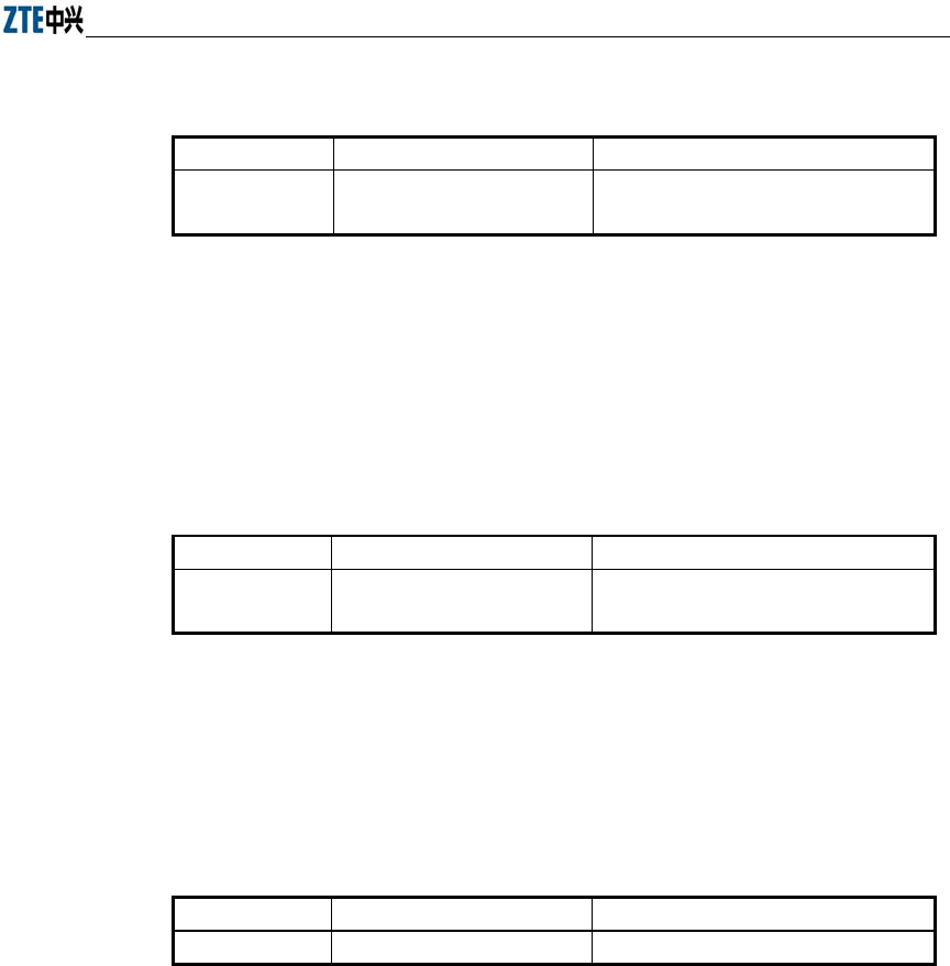
To configure the W200A via Telnet, input telnet/operating IP address of the W200A, as
shown in Fig. 5.1-2. By default, the operating IP address of the W200A is
192.168.1.254 and the subnet mask is 255.255.255.0.
Fig. 5.1-2 Telnet to W200A
The 5 configuration modes for W200A and all the executable commands in each mode
are described in details as follows. In the following text, conventions are given as

ZXR10 WAS (V1.0) IP Wireless Access System W200A Wireless Access Point User’s Manual
5-4
follows to the expression of commands:
1. abc denotes the contents that you should enter.
2. {abc|def} denotes that you must type in one of the two options.
3. The number range with [A~B] denotes you can type in a configuration
parameter within this range.
4. [ ] denotes that you can either enter the contents in [ ] or not.
5.2 User Mode
Mode of entry: Telnet
Exit mode: exit
Default prompt: wlan>
Note: When an ordinary user logs in to the W200A via Telnet, he/she will not be able to
enter the user mode unless he/she passes the username and password authentication. By
default, the username and password are "root" and "public". To prevent illegal users
from attempting the password frequently, the system will cut the Telnet connections of
a user automatically if incorrect passwords has been entered 3 times continuously.
5.3 Privileged Mode
Mode of entry: Type in the enable command in the in use mode and enter the correct
password.
Exit mode: disable for entering the user mode; exit for exiting the privileged mode and
go back to the system.
Default prompt: wlan#
5.3.1 Command to Test Network Connectivity
Command mode: privileged mode
Function: Test the network connectivity
Command format: wlan#ping A.B.C.D [-n echo-number] [-w timeout] [-l packet-size]

Chapter Error! Style not defined. Error! Style not defined.
5-5
Parameter description:
Name Range Description
A.B.C.D IP address Destination IP address
-n Null Sets the flag bits for the number of PING packets
echo-number 1~40 The number of PING packets
-w Null Sets the flag bits for the maximum timeout interval
Timeout 1~2 Maximum timeout interval (unit: s)
-l Null Sets the flag bits for the capacity of buffer area
packet-size 0~1504 Capacity of buffer area
5.3.2 Command to Save Configurations to Flash
Command mode: privileged mode
Function: Save configurations to flash
Command format: wlan#write flash
5.3.3 Command to Reset Software
Command mode: privileged mode
Function: Reset W200A
Command format: wlan#reboot
5.3.4 Command to Enter Configure Mode
Command mode: privileged mode
Function: Enter configuration modes
Command format: wlan#configure terminal
5.3.5 Command to Exit Privileged Mode
Command mode: privileged mode
Function: Exit Privileged Mode and enter User Mode
Command format: wlan#disable

ZXR10 WAS (V1.0) IP Wireless Access System W200A Wireless Access Point User’s Manual
5-6
5.3.6 Command to Exit TELNET Configuration
Command mode: privileged mode
Function: Exit Telnet and go back to the system
Command format: wlan#exit
Note: This command can only be used via Telnet. If you log in by using a
hyperterminal mode via the serial port, this command will not be available.
5.4 Configure Mode
Mode of entry: Enter the configure terminal command in Privileged Mode
Exit mode: Exit and enter privileged mode
Default prompt: wlan (config) #
Note: In this mode (including the sub-mode), all the configuration commands can be
executed.
5.4.1 Commands to Configure Wireless Access-Bridge
Mode of entry: Enter the access-bridge command in configure mode
1. access-bridge client connect-server
Command mode: Configure mode
Function: Configure the MAC address of the access bridge connecting the server
Command format: wlan (config) #access-bridge client connect-server mac
Parameter description:
Name Range Description
mac MAC address in the
xx-xx-xx-xx-xx-xx format
MAC address of the access bridge connecting
the server
2. access-bridge client enable
Command mode: Configure mode
Function: Enable/disable the wireless bridge client
Command format: wlan( config) #[no] access-bridge client enable

Chapter Error! Style not defined. Error! Style not defined.
5-7
3. access-bridge server connect-client
Command mode: Configure mode
Function: Configure the MAC address of the access bridge connecting clients
Command format: wlan(config)#[no] access-bridge server connect-client mac
Parameter description:
Name Range Description
mac
MAC address in the
xx-xx-xx-xx-xx-xx format
MAC address of the access bridge connecting
clients
4. access-bridge server enable
Command mode: Configure mode
Function: Enable/disable the wireless bridge server
Command format: wlan (config) #[no] access-bridge server enable
5.4.2 Command to Configure Bridge Information
Mode of entry: Enter the bridge command in configure mode
bridge filterdb
Command mode: Configure mode
Function: Configure bridge filtration or cancel the configuration
Command format: wlan (config) #[no] bridge filterdb max-user aging-time
alarm-percent
Parameter description:
Name Range Description
max-user
512~1024 Maximum capacity of the MAC address
list
aging-time 10~100,000 Aging time of the MAC address list
entries
alarm-percent 1~10 Percent of alarms
5.4.3 Commands to Configure DHCP Server
Mode of entry: Enter the dhcp server command in configure mode

ZXR10 WAS (V1.0) IP Wireless Access System W200A Wireless Access Point User’s Manual
5-8
1. dhcp server dns
Command mode: Configure mode
Function: Configure the IP addresses of the master/slave DNS server in the
DHCP server
Command format: wlan (config) # dhcp server dns A.B.C.D [A.B.C.D]
Parameter description:
Name Range Description
A.B.C.D
IP address IP address of the master DNS server
[A.B.C.D] IP address IP address of the slave DNS server
(optional)
2. dhcp server gateway
Command mode: Configure mode
Function: Configure the IP address of the default gateway of the DHCP server
Command format: wlan (config) # dhcp server gateway A.B.C.D
Parameter description:
Name Range Description
A.B.C.D
IP address IP address of the gateway
3. dhcp server leasetime
Command mode: Configure mode
Function: Configure the address lease time of the DHCP server
Command format: wlan (config) # dhcp server leasetime time-value
Parameter description:
Name Range Description
time-value
60~3600 DHCP server address lease time (unit: s),
60s by default
4. dhcp server run
Command mode: Configure mode
Function: Start, stop or restart the DHCP server
Command format: wlan (config) # dhcp server run run-flag

Chapter Error! Style not defined. Error! Style not defined.
5-9
Parameter description:
Name Range Description
run-flag
start, stop, restart
start: Start the DHCP server
stop: Stop the DHCP server
restart: Restart the DHCH server
5. dhcp server start-flag
Command mode: Configure mode
Function: Configure the start flag of the DHCP server for the restart of the
system
Command format: wlan (config) # dhcp server start-flag {true|false}
Parameter description:
Name Range Description
{true|false} True, false
Start flag of the DHCP server. If it is set to true, it
will be started when the system is restarted. If false,
the DHCP server will not be started.
5.4.4 Discover commands
Mode of entry: Enter the discover command in configure mode
1. discover device
Command mode: Configure mode
Function: Configure the multicasting address for the integrated management and
the port number of the equipment
Command format: wlan (config) #discover device A.B.C.D [0~65535]
Parameter description:
Name Range Description
A.B.C.D
IP address Multicasting address for the integrated
management of the equipment
[0~65535] 0~65535 Snooping port number for the integrated
management of the equipment
2. discover manager
Command mode: Configure mode

ZXR10 WAS (V1.0) IP Wireless Access System W200A Wireless Access Point User’s Manual
5-10
Function: Configure the multicasting address and port number for the integrated
management server
Command format: wlan (config) #discover manager A.B.C.D [0~65535]
Parameter description:
Name Range Description
A.B.C.D
IP address Multicasting address for the integrated
management server
[0~65535] 0~65535 Snooping port number for the integrated
management server
5.4.5 Commands to Configure 802.1X Parameters
Mode of entry: Enter the dot1x command in configure mode
1. dot1x enable
Command mode: Configure mode
Function: Enable or disable 802.1x
Command format: wlan (config) #[no] dot1x enable
2. dot1x max-reauth
Command mode: Configure mode
Function: Configure the maximum number of attempts for 802.1x authentication
Command format: wlan (config)# dot1x max-reauth max-reauth-times
Parameter description:
Name Range Description
max-reauth-times 0~10 802.1x 重复认证的最大尝试次数
3. dot1x max-request
Command mode: Configure mode
Function: Configure the maximum number requests for 802.1x authentication
Command format: wlan (config) # dot1x max-request max-request-times
Chapter Error! Style not defined. Error! Style not defined.
5-11
Parameter description:
Name Range Description
max-request-times
1~10 Maximum number requests for 802.1x
authentication
4. dot1x md5-domain
Command mode: Configure mode
Function: Configure the domain name in the EAP-MD5 authentication mode
命令格式:
wlan
(config)
Command format: wlan (config) # dot1x md5-domain
string
Parameter description:
Name Range Description
String No more than 32 characters Domain name in the EAP-MD5
authentication mode
5. dot1x nas-id
Command mode: Configure mode
Function: Configure the NAS-ID field for 802.1x
Command format: wlan (config) # dot1x nas-id string
Parameter description:
Name Range Description
String
No more than 64 characters NAS-ID character string
6. dot1x portenable
Command mode: Configure mode
Function: Enable or disable 802.1x port control
Command format: wlan (config) # [no] dot1x portenable
7. dot1x quiet-period
Command mode: Configure mode
Function: Configure the quiet-period for 802.1x
Command format: wlan (config) # dot1x quiet-period value

ZXR10 WAS (V1.0) IP Wireless Access System W200A Wireless Access Point User’s Manual
5-12
Parameter description:
Name Range Description
Value
1~255 802.1x quiet-period (unit: s)
8. dot1x server-timeout
Command mode: Configure mode
Function: Configure the hold time for the 802.1x authentication server
Command format: wlan (config) # dot1x server-timeout value
Parameter description:
Name Range Description
value
1~255 Hold time of the authentication server
(unit: s)
9. dot1x sim-domain
Command mode: Configure mode
Function: Configure the domain name in the EAP-SIM authentication mode
Command format: wlan (config) # dot1x sim-domain string
Parameter description:
Name Range Description
string
不超过 32 个字符 EAP-SIM 认证方式下的域名
10. dot1x supp-timeout
Command mode: Configure mode
Function: Configure the supp hold time for 802.1x
Command format: wlan (config) # dot1x supp-timeout value
Parameter description:
Name Range Description
value
1~255 Hold time of the 802.1x client (unit: s)
11. dot1x tx-period
Command mode: Configure mode
Function: Configure the transmission period for 802.1x

Chapter Error! Style not defined. Error! Style not defined.
5-13
Command format: wlan (config) # dot1x tx-period value
Parameter description:
Name Range Description
value
1~255 802.1x transmission-period (unit: s)
5.4.6 Command to Set User Password in Privileged Mode
Mode of entry: Enter the enable-password command in configure mode
Command mode: Configure mode
Function: Set user passwords in privileged mode
Command format: wlan(config)#enable-password password
Parameter description:
Name Range Description
password
No more than 30 characters User password in privileged mode
5.4.7 Command to Delete Filtration Rules
Mode of entry: Enter the erase command in configure mode
erase mac-access-rule
Command mode: Configure mode
Function: Delete MAC rules according to global rule numbers
Command format: wlan(config)#erase mac-access-rule {static} acl-rule-number
Parameter description:
Name Range Description
{static} static Static mac-access-rule flag
acl-rule-number 0~1023 Filtration rule number
5.4.8 Command to Exit Configuration Mode
Mode of entry: Enter the exit command in configure mode
Command mode: Configure mode
Function: Exit configure mode and enter privileged Mode
Command format: wlan (config) #exit

ZXR10 WAS (V1.0) IP Wireless Access System W200A Wireless Access Point User’s Manual
5-14
5.4.9 Commands to Configure IAPP (Load-balance)
Mode of entry: Enter the iapp command in configure mode
1. iapp balance
Command mode: Configure mode
Function: Set the load-balance group ID and nominal capacity
Command format: wlan (config) #iapp balance group-id capability
Parameter description:
Name Range Description
group-id
1~65535 Load-balance group ID
capability
1~30 Nominal capacity
2. iapp enable-flag
Command mode: Configure mode
Function: Enable or disable load balance and the restriction to the maximum
number of users allowed
Command format: wlan (config) #iapp enable-flag {disable|balance|max-user}
Parameter description:
Name Range Description
{disable|balance|max-user} disable, balance, max-user
disable: Disable the IAPP function.
Neither load-balance nor the
restriction to the maximum number of
users will be enabled.
balance: Enable load-balance
Max-user: Enable the restriction to
the maximum number of users
Tips:
The iapp balance and iapp max-user configurations cannot take effect at the same
time.
3. iapp max-user
Command mode: Configure mode

Chapter Error! Style not defined. Error! Style not defined.
5-15
Function: Set the number of users allowed
Command format: wlan (config) #iapp max-user value
Parameter description:
Name Range Description
Value
1~150 Sets the number of users allowed
5.4.10 Interface Skip
Mode of entry: Enter the interface command in configure mode
1. interface ethernet
Command mode: Configure mode
Function: Skip to the Ethernet interface configuration mode. This command
ends with the unit number of the Ethernet interface. For equipment, multiple
Ethernet interfaces are available.
Command format: wlan (config) #interface ethernet {0}
Parameter description:
Name Range Description
{0} 0
Unit number of the Ethernet interface. W200A has
only one Ethernet interface with the unchangeable
value of 0.
2. interface wlan
Command mode: Configure mode
Function: Skip to the wireless interface configuration mode. This command ends
with the unit number of the wireless interface. For equipment, multiple wireless
interfaces are available.
Command format: wlan (config) #interface wlan {0}
Parameter description:
Name Range Description
{0} 0
Unit number of the wireless interface. W200A has
only one wireless interface with the unchangeable
value of 0.

ZXR10 WAS (V1.0) IP Wireless Access System W200A Wireless Access Point User’s Manual
5-16
5.4.11 Commands to Configure Layer 2 Isolation
Mode of entry: Enter the intra-security command in configure mode
1. intra-security enable
Command mode: Configure mode
Function: Enable or disable Layer 2 Isolation
Command format: wlan (config) #[no] intra-security enable
2. intra-security gateway
Command mode: Configure mode
Function: Configure the IP address or MAC address of the gateway
Command format: wlan (config) # intra-security gateway {ip A.B.C.D | mac
xx-xx-xx-xx-xx-xx}
Parameter description:
Name Range Description
A.B.C.D
IP address IP address of the gateway
xx-xx-xx-xx-xx-xx MAC address MAC address of the gateway
5.4.12 Commands to Configure IP network Parameters
Mode of entry: Enter the ip command in configure mode
1. ip arp
Command mode: Configure mode
Function: Add/delete ARP list entries
Command format: wlan (config) #[no] ip arp A.B.C.D xx-xx-xx-xx-xx-xx
Parameter description:
Name Range Description
A.B.C.D
IP address IP address of the host
xx-xx-xx-xx-xx-xx MAC address Hardware address of the host
2. ip route
Command mode: Configure mode
Function: Configure the default routing address for the system

Chapter Error! Style not defined. Error! Style not defined.
5-17
Command format: wlan (config) #[no] ip route A.B.C.D1 A.B.C.D2 A.B.C.D3
Parameter description:
Name Range Description
A.B.C.D1
IP address IP address of the host
A.B.C.D2 Subnet mask IP address mask of the host
A.B.C.D3 IP address IP address of the next-hop router
3. ip pool
Command mode: Configure mode
Function: Configure the IP address pool for the system
Command format: wlan (config) #[no] ip pool index A.B.C.D1 A.B.C.D2
A.B.C.D3
Parameter description:
Name Range Description
index 0~9 Group number of the IP address pools
A.B.C.D1
IP address Starting IP address of the host address
pool
A.B.C.D2 IP address Ending IP address of the host address pool
A.B.C.D3 Subnet mask Subnet mask of the addresses in an
address pool
5.4.13 Command to Configure Log Print Information
Mode of entry: Enter the logmsg command in configure mode
1. logmsg all-enable
Command mode: Configure mode
Function: Open or close the log print information in all modules
Command format: wlan (config) #[no] logmsg all-enable
2. logmsg level
Command mode: Configure mode
Function: Configure the level of log print information to be output
Command format: wlan (config) # logmsg level level-num

ZXR10 WAS (V1.0) IP Wireless Access System W200A Wireless Access Point User’s Manual
5-18
Parameter description:
Name Range Description
level-num
Lowest (Flood)
Lower (Info)
Higher (Error)
Highest (Fatal)
Level of the log print information to be
output. Only the information with a higher
level will be output.
3. logmsg mod-enable
Command mode: Configure mode
Function: Determine the module whose log print information should be output
Command format: wlan (config) # [no] logmsg mod-enable module
Parameter description:
Name Range Description
module
A specified module name Module whose log print information
should be output
4. logmsg telnet-log
Command mode: Configure mode
Function: Set the log print information output window to the active Telnet
window.
Command format: wlan (config) #[no] logmsg telnet-log
5.4.14 Command to Configure MAC Filter
Mode of entry: Enter the mac-access-list command in configure mode
Command mode: Configure mode
Function: Add/delete an access list by serial number
Command format: wlan(config)#[no] mac-access-list acl-list-number {deny|permit}
{macaddr|any}

Chapter Error! Style not defined. Error! Style not defined.
5-19
Parameter description:
Name Range Description
acl-list-number
1~99 MAC filter group number
{ deny|permit } Deny, permit
Deny: If the conditions meet the requirements, the
MAC communication is denied.
Permit: If the conditions meet the requirements, the
MAC communication is allowed.
{macaddr|any}
MAC address in the
xx-xx-xx-xx-xx-xx
format or any
MAC address from which MAC packets are sent. The
source address can be specified in two ways:
One is to use six 48-bit hexadecimal numbers with
dashes between them (HYPHEN), e.g.
00-d0-d0-f1-c4-ef
Another is to use the any keyword as the abbreviation
of source 00-00-00-00-00-00. It is not recommended
to use this keyword.
5.4.15 Command to Configure MAC Address Authentication
Mode of entry: Enter the mac-authen command in configure mode
Command mode: Configure mode
Function: Configure MAC address authentication
Command format: wlan (config) #[no] mac-authen {deny|permit} {macaddr|any}
Parameter description:
Name Range Description
{deny|permit} Deny, permit
deny: If the conditions meet the requirements, the
MAC communication is denied.
permit: If the conditions meet the requirements, the
MAC communication is allowed.
{macaddr|any}
MAC address in the
xx-xx-xx-xx-xx-xx
format or any
MAC address from which MAC packets are sent. The
source address can be specified in two ways:
One is to use six 48-bit hexadecimal numbers with
dashes between them (HYPHEN), e.g.
00-d0-d0-f1-c4-ef
Another is to use the any keyword as the abbreviation
of source 00-00-00-00-00-00. It is not recommended
to use this keyword.

ZXR10 WAS (V1.0) IP Wireless Access System W200A Wireless Access Point User’s Manual
5-20
5.4.16 Command to Configure Users
Mode of entry: Enter the manage-user command in configure mode
Command mode: Configure mode
Function: Add/delete usernames
Command format: wlan (config) #[no] manage-user username password
Parameter description:
Name Range Description
username
1~32 characters Username
password
1~32 characters User password
5.4.17 Commands to Configure Radius Server
Mode of entry: Enter the radius-server command in configure mode
1. radius-server account
Command mode: Configure mode
Function: Add/delete the accounting server of an ISP
Command format: wlan (config) #[no] radius-server account isp-name
master-flag A.B.C.D key-string
Parameter description:
Name Range Description
isp-name
1~255 characters ISP name
master-flag
master, slave Master/slave flag of the accounting server
A.B.C.D IP address IP address of the accounting server
key-string 1~255 characters Shared key string for accounting
2. radius-server authen
Command mode: Configure mode
Function: Add/delete the authentication server of an ISP
Command format: wlan (config) wlan(config)#[no] radius-server authen
isp-name master-flag A.B.C.D key-string

Chapter Error! Style not defined. Error! Style not defined.
5-21
Parameter description:
Name Range Description
isp-name
1~255 个字符 ISP name
master-flag
master, slave Master or slave authentication server. Only
one master server can be set.
A.B.C.D IP address IP address of the authentication server
key-string 1-255 characters Shared key string for authentication
3. radius-server dns
Command mode: Configure mode
Function: Add/delete the DNS server of an ISP
Command format: wlan (config) #[no] radius-server dns isp-name A.B.C.D
[A.B.C.D]
Parameter description:
Name Range Description
isp-name
1~255 characters ISP name
A.B.C.D IP address IP address of the master DNS server
[A.B.C.D] IP address IP address of the slave DNS server
4. radius-server isp-name
Command mode: Configure mode
Function: Add/delete an ISP
Command format: wlan (config) #[no] radius-server isp-name isp-name
Parameter description:
Name Range Description
isp-name 1~255 character ISP name
5. radius-server retry-times
Command mode: Configure mode
Function: Set the number of retries of RADIUS authentication of an ISP
Command format: wlan (config) #radius-server retry-times isp-name retry-time

ZXR10 WAS (V1.0) IP Wireless Access System W200A Wireless Access Point User’s Manual
5-22
Parameter description:
Name Range Description
isp-name
1~255 characters Name of an ISP which has been created.
retry-time 1~10 Number of retries of RADIUS
authentication
6. radius-server timeout
Command mode: Configure mode
Function: Set the hold time of the RADIUS authentication of an ISP
Command format: wlan (config) #radius-server timeout isp-name timeout
Parameter description:
Name Range Description
isp-name
1~255 characters Name of an ISP which has been created.
timeout 1~65535 Hold time of the RADIUS authentication
(unit: s)
5.4.18 Command to Configure SNMP Module
Mode of entry: Enter the snmp command in configure mode
1. snmp access-host
Command mode: Configure mode
Function: Add and delete host IP addresses allowed to access
Command format: wlan (config) #[no] snmp access-host A.B.C.D
Parameter description:
Name Range Description
A.B.C.D
IP address Host IP addresses (up to 10) in dotted
decimal format (A.B.C.D)
2. snmp access-mode
Command mode: Configure mode
Function: Allow all hosts or hosts in the server-list to access this agent
Command format: wlan (config) #snmp access-mode {all|list}

Chapter Error! Style not defined. Error! Style not defined.
5-23
Parameter description:
Name Range Description
{all|list} all, list
all: All users are allow to access
list: Users in server-list are allowed to
access
3. snmp community
Command mode: Configure mode
Function: Configure the SNMP access community string and its access right
Command format: wlan (config) #snmp community comstr {read-only|
read-write}
wlan(config)#no snmp community comstr
Parameter description:
Name Range Description
comstr
1~32 characters
Names of the SNMP access community
strings (up to 10). comstr is a string with up
to 32 characters
{read-only|read-write} read-only, read-write read-only: read-only access
read-write: Read-write access
4. snmp contact
Command mode: Configure mode
Function: Set the name and contact information of the equipment administrator
Command format: wlan (config) #snmp contact sysContact
Parameter description:
Name Range Description
sysContact
1~255 characters
A management variable of the system group in
MIB II, denotes the name and contact
information of the equipment administrator
5. snmp location
Command mode: Configure mode
Function: Configure the geographical location of the managed equipment
Command format: wlan (config) #snmp location sysLocation

ZXR10 WAS (V1.0) IP Wireless Access System W200A Wireless Access Point User’s Manual
5-24
Parameter description:
Name Range Description
sysLocation
1~255 characters
A management variable of the system
group in MIB, used to define the
geographic location of the managed
equipment
6. snmp nodecode
Command mode: Configure mode
Function: Configure the network element (NE) codes of the managed equipment
Command format: wlan (config) #snmp nodecode node-code
Parameter description:
Name Range Description
node-code
>= 0 (integer)
A management variable of the system
group in MIB, used to define the NE code
of the managed equipment
7. snmp nodeid
Command mode: Configure mode
Function: Configure the NE ID of the managed equipment
Command format: wlan (config) #snmp nodeid node-id
Parameter description:
Name Range Description
node-code
1~31 characters
A management variable of the system
group in MIB, used to define the NE ID of
the managed equipment
8. snmp nodecreatdate
Command mode: Configure mode
Function: Configure the NE creation date of the managed equipment
Command format: wlan (config) #snmp nodecreatdate hh:mm:ss month day year

Chapter Error! Style not defined. Error! Style not defined.
5-25
Parameter description:
Name Range Description
hh:mm:ss
Time hh (hour): mm (minute): ss (second)
month 1~12 Month
day 1~31 Day
year 2002~2130 Year: 4 bits
hh:mm:ss month day year: A management variable of the system group in MIB,
used to define the NE creation date of the managed equipment
9. snmp proxytraphost
Command mode: Configure mode
Function: Add the address information of a proxy Trap destination host
Command format: wlan (config) #[no] snmp proxytraphost A.B.C.D
Parameter description:
Name Range Description
A.B.C.D
IP address Addresses of the proxy Trap destination hosts
(up to 10)
10. snmp sysname
Command mode: Configure mode
Function: Set the name of the managed equipment
Command format: wlan (config) #snmp sysname sysName
Parameter description:
Name Range Description
sysName
1~255 characters
A management variable of the system group in
RFC1213 MIB, used as the name of the
managed equipment
11. snmp trap enable
Command mode: Configure mode
Function: Configure if the SNMP Agent is allowed to send Trap
Command format: wlan (config) #[no] snmp trap enable

ZXR10 WAS (V1.0) IP Wireless Access System W200A Wireless Access Point User’s Manual
5-26
12. snmp authtrap enable
Command mode: Configure mode
Function: Configure if the SNMP Agent is allowed to send the authentication
failed Trap
Command format: wlan (config) #[no] snmp authtrap enable
13. snmp traphost
Command mode: Configure mode
Function: Add the address of a trap destination host and the trap version number
Command format: wlan (config) #snmp traphost A.B.C.D [version version]
wlan(config)#no snmp traphost A.B.C.D
Parameter description:
Name Range Description
A.B.C.D
IP address Addresses of Trap destination hosts
version 1~2 Trap version number
5.4.19 Command to Manage Telnet Idle Timeout
Mode of entry: Enter the Telnet idle-timeout command in configure mode
Command mode: Configure mode
Function: Set the automatic exit time when the Telnet window is idle
Command format: wlan (config) #telnet idle-timeout time-value
Parameter description:
Name Range Description
time-value
300~3600 (unit: s) The automatic exit time when the Telnet
window is idle (300s by default)
5.4.20 Commands to Upload/download TFTP Files
Mode of entry: Enter the tftp command in configure mode

Chapter Error! Style not defined. Error! Style not defined.
5-27
1. tftp dir
Command mode: Configure mode
Function: Check the free space of a flash disk (unit: byte)
Command format: wlan (config) #tftp dir
2. tftp pic
Command mode: Configure mode
Function: Download graphics files from the Web configuration pages on the
TFTP server and save them to a flash disk.
Command format: wlan (config) #tftp pic A.B.C.D
Parameter description:
Name Range Description
A.B.C.D
IP address IP Address of a TFTP server in dotted decimal
format
3. Download files using tftp get
Command mode: Configure mode
Function: Download files from the TFTP server using TFTP and save them to
the flash disk.
Command format: wlan (config) #tftp get A.B.C.D flash-file-name
Parameter description:
Name Range Description
A.B.C.D
IP address IP Address of a TFTP server in dotted decimal
format
flash-file-name Filename of a version Full name (including the extension name) of
the file to be transmitted from the TFTP server
4. Upload files using tftp put
Command mode: Configure mode
Function: Upload files from the flash disk to the TFTP server using TFTP
Command format: wlan (config) #tftp put A.B.C.D flash-file-name

ZXR10 WAS (V1.0) IP Wireless Access System W200A Wireless Access Point User’s Manual
5-28
Parameter description:
Name Range Description
A.B.C.D
IP address IP Address of a TFTP server in dotted decimal
format
flash-file-name Filename of a version Full name (including the extension name) of
the file to be transmitted from the flash disk
5.4.21 Commands to Configure VLAN
Mode of entry: Enter the vlan command in configure mode
1. vlan ap-vid
Command mode: Configure mode
Function: Configure the VLAN ID of AP
Command format: wlan (config) #vlan ap-vid value
Parameter description:
Name Range Description
value
0~4094 VLAN ID
2. vlan enable
Command mode: Configure mode
Function: Enable VLAN
Command format: wlan (config) #vlan enable
3. vlan keep-vid
Command mode: Configure mode
Function: Allow a terminal to switch over with the same VLAN ID between
different APs
Command format: wlan (config) #vlan keep-vid
4. vlan sta-default-vid
Command mode: Configure mode
Function: Configure the default VLAN ID of the STA accessed from the AP
Command format: wlan (config) #vlan sta-default-vid value
Chapter Error! Style not defined. Error! Style not defined.
5-29
Parameter description:
Name Range Description
value
1~4094 Default VLAN ID when the STA is accessed
5. vlan sta-vid
Command mode: Configure mode
Function: Configure the specified VLAN ID of the STA accessed from the AP
Command format: wlan (config) #vlan sta-vid xx-xx-xx-xx-xx-xx vlan value
Parameter description:
Name Range Description
value
1~4094 Default VLAN ID when the STA is accessed
xx-xx-xx-xx-xx-xx
MAC address MAC address of the accessed STA
5.4.22 Show Commands
Mode of entry: Enter show commands in configure mode
1. show access-bridge
Command mode: Configure mode
Function: Display configured parameters of a wireless bridge
Command format: wlan (config) #show access-bridge
2. show alarm
1) show alarm all
Command mode: Configure mode
Function: Display all alarm information
Command format: wlan (config) #show alarm all
2) show alarm bycode
Command mode: Configure mode
Function: Display alarm Information by alarm code
Command format: wlan (config) #show alarm bycode code
ZXR10 WAS (V1.0) IP Wireless Access System W200A Wireless Access Point User’s Manual
5-30
Parameter description:
Name Range Description
code
1001~3999 Code of an alarm
3) show alarm bylevel
Command mode: Configure mode
Function: Display alarm information by alarm level
Command format: wlan (config) #show alarm bylevel level
Parameter description:
Name Range Description
level
1~3 Alarm level
3. show bridge configure
Command mode: Configure mode
Function: Display configured bridge parameters
Command format: wlan (config) #show bridge configure
4. show dhcp server
Command mode: Configure mode
Function: Display DHCP server parameters
Command format: wlan (config) #show dhcp server
5. show discover
Command mode: Configure mode
Function: Display configured discover parameters of the equipment
Command format: wlan (config) #show discover
6. show dot1x-cfg
Command mode: Configure mode
Function: Display 802.1x parameters
Command format: wlan (config) #show dot1x-cfg

Chapter Error! Style not defined. Error! Style not defined.
5-31
7. show dynamic-key
Command mode: Configure mode
Function: Display dynamic WEP key parameters
Command format: wlan (config) #show dynamic-key
8. show iapp
Command mode: Configure mode
Function: Display configured load-balance parameters
Command format: wlan (config) #show iapp
9. show interface
Command mode: Configure mode
Function: Display configured interface parameters
Command format: wlan (config) #show interface {ethernet|wlan} Function:
Display configured Layer 2 isolation parameters
Command format: wlan (config) #show intra-security
11. show ip
1) show ip arp
Command mode: Configure mode
Function: Display ARP address resolution information
Command format: wlan (config) #show ip arp
2) show ip if-stat
Command mode: Configure mode
Function: Display IP interface status information
Command format: wlan (config) #show ip if-stat
3) show ip pool
show ip pool config
Command mode: Configure mode
Function: Display information of all IP address pools

ZXR10 WAS (V1.0) IP Wireless Access System W200A Wireless Access Point User’s Manual
5-32
Command format: wlan (config) #show ip pool config
show ip pool used
Command mode: Configure mode
Function: Display information of allocated IP addresses in the specified IP
address pool
Command format: wlan (config) #show ip pool used index
Parameter description:
Name Range Description
Index 0~9 Serial number of an IP address pool
4) show ip route
Command mode: Configure mode
Function: Display configured IP route parameters
Command format: wlan (config) #show ip route
12. show logmsg
Command mode: Configure mode
Function: Display all configured log print information
Command format: wlan (config) #show logmsg
13. show mac-access-list
Command mode: Configure mode
Function: Display configured mac-access-list information
Command format: wlan (config) #show mac-access-list {static} [1~99]
14. show mac-authen
Command mode: Configure mode
Function: Display configured mac-authen parameters
Command format: wlan (config) #show mac-authen
15. show manage-user
Command mode: Configure mode

Chapter Error! Style not defined. Error! Style not defined.
5-33
Function: Display configured manage-user parameters
Command format: wlan (config) #show manage-user
16. show radius
Command mode: Configure mode
Function: Display configured radius parameters
Command format: wlan (config) #show radius
17. show snmp
1) show snmp access-host
Command mode: Configure mode
Function: Display configured snmp access-host parameters
Command format: wlan (config) #show snmp access-host
2) show snmp community
Command mode: Configure mode
Function: Display configured snmp community parameters
Command format: wlan (config) #show snmp community
3) show snmp nodeinfo
Command mode: Configure mode
Function: Display configured snmp nodeinfo parameters
命令格式:wlan(config)#show snmp nodeinfo
4) show snmp sysinfo
Command mode: Configure mode
Function: Display configured snmp sysInfo parameters
Command format: wlan (config) #show snmp sysinfo
5) show snmp traphost
Command mode: Configure mode
Function: Display configured snmp traphost parameters

ZXR10 WAS (V1.0) IP Wireless Access System W200A Wireless Access Point User’s Manual
5-34
Command format: wlan (config) #show snmp traphost
18. show telnet idle-timeout
Command mode: Configure mode
Function: Display the configured interval for telnet idle time-out
Command format: wlan (config) #show telnet idle-timeout
19. show version
Command mode: Configure mode
Function: Display the software version number
Command format: wlan (config) #show version
20. show vlan
Command mode: Configure mode
Function: Display configured VLAN information
Command format: wlan (config) #show vlan
5.5 Ethernet Interface Configuration Mode
Mode of entry: Enter the interface ethernet command in configure mode
Exit mode: Exit and enter configure mode
Default prompt: wlan (config-int-ethernet)#
Note: In this mode (including the sub-mode), all information can be configured for
relevant interfaces.
5.5.1 Configurations in the Ethernet Interface Mode
Command mode: Ethernet Interface Configuration Mode
Function: Set the mode of rate negotiation for the Ethernet interface
Command format: wlan (config-int-ethernet)# ethernet-mode mode
Parameter description:
Name Range Description
mode
10M, autoNeg (100M/10M) Mode of the Ethernet Interface

Chapter Error! Style not defined. Error! Style not defined.
5-35
5.5.2 Command to Exit the Ethernet Interface Configuration Mode
Command mode: Ethernet Interface Configuration Mode
Function: Exit Ethernet interface configuration mode and enter configure Mode
Command format: wlan (config-int-ethernet)# #exit
5.5.3 Command to Configure Ethernet interface IP addresses
Command mode: Ethernet Interface Configuration Mode
Function: Set the IP address of the Ethernet interface
Command format: wlan(config-int-ethernet)#ipaddr A.B.C.D1 A.B.C.D2 [second]
wlan(config-int-ethernet)#no ipaddr A.B.C.D1 [A.B.C.D2]
Parameter description:
Name Range Description
A.B.C.D1
IP address IP address of an interface
A.B.C.D2 IP address IP address mask of an interface
[second] Optional The additional IP address flag of an
interface
5.5.4 Command to Configure MAC filter for the Ethernet Interface
Command mode: Ethernet Interface Configuration Mode
Function: Configure MAC filter for the Ethernet interface
Command format: wlan(config-int-ethernet)#[no] mac-access-group acl-number
direction
Parameter description:
Name Range Description
acl-num
1~99 MAC filter entry number bound to the
interface
direction in Bind to the "in" direction of the interface
5.6 Wireless Interface Configuration Mode
Mode of entry: Enter the interface wlan command in configure mode
Exit mode: Exit and enter configure mode

ZXR10 WAS (V1.0) IP Wireless Access System W200A Wireless Access Point User’s Manual
5-36
Default prompt: wlan (config-int-wlan)#
Note: In this mode (including the sub-mode), all information can be configured for
relevant interfaces.
5.6.1 Command to Configure 80211b-related Parameters for the Wireless
Interface
Mode of entry: Enter the 80211b command in configure mode
1. 80211b channel
Command mode: Wireless interface configuration mode
Function: Set the current operating channel
Command format: wlan (config-int-wlan) #80211b channel channel-num
Parameter description:
Name Range Description
channel-num
1~13 Wireless channel number: 6 by default
2. 80211b dynamic-key
Command mode: Wireless interface configuration mode
Function: Set the dynamic key of the wireless network
Command format: wlan (config-int-wlan) #80211b dynamic-key key
xx-xx-xx-xx-xx-xx key1-string key2-string used-key
wlan(config-int-wlan)#no 80211b dynamic-key xx-xx-xx-xx-xx-xx
wlan(config-int-wlan)#80211b dynamic-key enable xx-xx-xx-xx-xx-xx
wlan(config-int-wlan)#no 80211b dynamic-key enable xx-xx-xx-xx-xx-xx
Note: The 80211b dynamic-key key command is used to set the dynamic key
for a specified MAC address. The 80211b dynamic-key enable command is
used to enable this dynamic key.

Chapter Error! Style not defined. Error! Style not defined.
5-37
Parameter description:
Name Range Description
xx-xx-xx-xx-xx-xx MAC address MAC address of the wireless user using the dynamic
key
key1-string 5 or 13 characters First dynamic key (the key length can only be 5 or
13 characters)
key2-string 5 or 13 characters Second dynamic key (the key length can only be 5
or 13 characters)
used-key key1, key2 Key number that is used
3. 80211b enh-security enable
Command mode: Wireless interface configuration mode
Function: Set to enable or disable the enhanced security function of AP
Command format: wlan (config) #[no] 80211b enh-security enable
Note: If the enhanced security function is enabled, the wireless terminal will not
be able to scan the AP. If this function is disabled, the AP can be scanned.
4. 80211b essid
Command mode: Wireless interface configuration mode
Function: Set ESSID of the wireless network
Command format: wlan (config-int-wlan) #80211b essid essid-string
Parameter description:
Name Range Description
essid-string
1~31 characters ESSID of the wireless network. By
default, it is zxwlan.
5. 80211b frg-threshold
Command mode: Wireless interface configuration mode
Function: Set fragment threshold
Command format: wlan (config-int-wlan) #80211b frg-threshold value
Parameter description:
Name Range Description
value
256~2346 (even) Threshold of fragments, 2346 by default

ZXR10 WAS (V1.0) IP Wireless Access System W200A Wireless Access Point User’s Manual
5-38
6. 80211b power
Command mode: Wireless interface configuration mode
Function: Set the transmission power of the wireless network card
Command format: wlan (config-int-wlan) #80211b power value
Parameter description:
Name Range Description
value
auto,
10/20/30/40/50/60/70/80/90/100(unit:
mW)
max
auto: automatic power control (default)
10/20/30/40/50/60/70/80/90/100: fixed
transmission power
max: maximal transmission power
7. 80211b rts-threshold
Command mode: Wireless interface configuration mode
Function: Set RTS threshold
Command format: wlan (config-int-wlan) #80211b rts-threshold value
Parameter description:
Name Range Description
value
0~2347 RTS threshold, 2347 by default
5.6.2 Command to Exit Wireless Interface Configuration Mode
Command mode: Wireless interface configuration mode
Function: Exit wireless interface configuration mode and enter configure mode
Command format: wlan (config-int-wlan)# exit
5.6.3 Command to Enable Link Integrity Detection
Command mode: Wireless interface configuration mode
Function: Set to enable or disable link integrity detection
Command format: wlan (config-int-wlan)#[no] link-integrity enable
Note: the link integrity detection function of AP means that when the Ethernet link of
the AP is disconnected, the AP will release all connected wireless users, close the
wireless port, and deny the connection requests of other wireless terminals. When the

Chapter Error! Style not defined. Error! Style not defined.
5-39
link is recovered, the AP will open the wireless port and accept connections of wireless
users.
5.6.4 WEP Configuration of the Wireless Interface
Mode of entry: Enter the wep command in wireless interface configuration mode
1. wep mode
Command mode: Wireless interface configuration mode
Function: Set WEP encryption mode and WEP key format
Command format: wlan (config-int-wlan) #wep mode {disable | wep64 | wep128
| mix-wep64 | mix-wep128} {Alphanumeric|Hexadecimal}
Parameter description:
Name Range Description
{disable|wep64|wep128|
mix-wep64|mix-wep128}
disable
wep64
wep128
mix-wep64
mix-wep128
Disable: disable the WEP encryption
function
wep64: Use the 64-bit WEP encryption
wep128: Use the 128-bite WEP encryption
mix-wep64: Use a mixed 64-bit WEP
encryption. In this mode, the clients can
communicate normally with a correct 64-bit
encryption key or without encryption.
Mix-wep128: Use a mixed 128-bite WEP
encryption. In this mode, the clients can
communicate normally with a correct
128-bite encryption key or without
encryption.
{Alphanumeric|
Hexadecimal}
Alphanumeric
Hexadecimal
Alphanumeric: WEP key in string format
Alphanumeric: WEP key in sexadecimal
format
2. wep set-key
Command mode: Wireless interface configuration mode
Function: Set the key of WEP encryption
Command format: wlan (config-int-wlan) #wep set-key key-id key-text

ZXR10 WAS (V1.0) IP Wireless Access System W200A Wireless Access Point User’s Manual
5-40
Parameter description:
Name Range Description
key-id
key1, key2, key3, key4 Entry number of the key to be set
key-text
5 or 13 characters, or a
combination of 10 or 26
sexadecimal digits
If it is set to 64-bit encryption, the key_text
argument can be 5 case sensitive characters
(in alphanumeric format), e.g. MyKey, or 10
sexadecimal digits (in hexadecimal format),
e.g. 11AA22BB33
If it is set to 128-bit encryption, the
key_text argument can be 13 case sensitive
characters (in alphanumeric format), e.g.
MyKey12345678, or 26 sexadecimal digits
(in hexadecimal format), e.g.
00112233445566778899AABBCC
3. wep use-key
Command mode: Wireless interface configuration mode
Function: Set the WEP encryption key to be used
Command format: wlan (config-int-wlan) #wep use-key key-id
Parameter description:
Name Range Description
Key-id key1, key2, key3, key4 Entry number of the key to be used
5.6.5 Command to Configure MAC Filter in Wireless Interface Configuration
Command mode: Wireless interface configuration mode
Function: Configure MAC filter for the wireless interface
Command format: wlan (config-int-wlan) #[no] mac-access-group acl-list-number
direction
Parameter description:
Name Range Description
Acl-list-number 1~99 MAC filter entry number bound to the
interface
direction in Bind to the "in" direction of the interface

Chapter Error! Style not defined. Error! Style not defined.
5-41
5.6.6 Command to Configure Authentication Mode in Wireless Interface
Configuration
Command mode: Wireless interface configuration mode
Function: Configure authentication mode for the wireless interface
Command format: wlan (config-int-ethernet) #authmode auth mode
Parameter description:
Name Range Description
Authmode
OpenSystem
SharedKey
Both
OpenSystem: Authentication using
Opensystem
SharedKey: Authentication using Sharedkey
Both: Both authentication modes are
supported
6-1
6 WEB Configuration
6.1 Overview
For the W200A, we also provide a WEB configuration page to configure the various
parameters of the W200A. The configuration page is same as an ordinary Web page,
and the followings are some instructions on WEB configuration:
1. We provide a means to log into the W200A in the HTTP mode to configure
parameters. Users can open the WEB configuration login page of the W200A by
entering http://Working IP Address of W200A in the address bar of the WEB
browser (the default working IP address of the W200A is 192.168.1.254, and the
subnet is 255.255.255.0).
2. To simplify operation, only one operation mode is available at present for WEB
configuration (similar to the CONFIG mode in CLI configuration), with two
levels of password protection. The first level of password allows users to browse
the current parameters. To submit data for the first time after login, users must
enter the privileged user password, and it is unnecessary to re-enter the
privileged user password for submitting other data pages if the password is
correct. These two levels of passwords are same as those of the CLI
configuration.
3. Browsing and setting functions: After you logs in successfully, you can open a
certain WEB page to browse the current parameters. To modify a certain
parameter, you just need to enter the new value and then submit the modification.
If the setting operation is successful, you can view the new setting by returning
to the previous page. WEB configuration will resolve the newly entered value,
and a failure message will be returned if the format is incorrect.
4. At present, only one user is allowed to configure or browse parameters for WEB
configuration. If the user is idle for over 5 minutes, he will automatically exit
and another user can log in for configuration.
The path diagram of WEB configuration is as shown in Fig. 6.1-1.
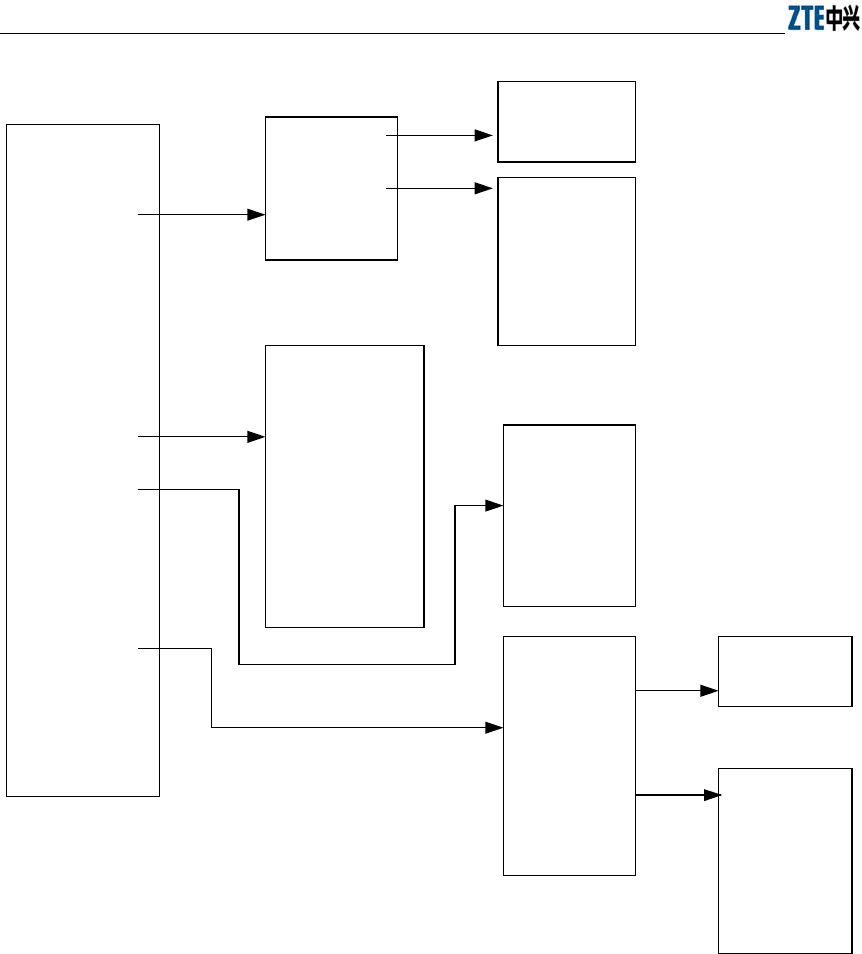
ZXR10 WAS (V1.0) IP Wireless Access System W200A Wireless Access Point User’s Manual
6-2
Home
Interfaces
Stations
Statistics
Load Balance
SNMP
Security
Reboot
Save
Advanced
Accounts
Exit
Ethernet interface
Wireless interface
Back
IP Address
Back
80211b
WEP
Link Integrity
Back
SNMP Access Mode
SNMP Access Host
Community
System Information
Trap
Trap Sink
Back
MAC
Authentication
MAC Filter
Stations Isolation
Back
802.1x
DHCP
IP Pool
RADIUS Server
Back
DHCP Server
Back
ISP
Authentication
Server
Accounting
Server
DNS Server
Back
VLAN
Fig. 6.1-1 Path diagram of WEB configuration
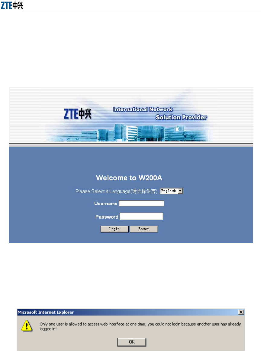
Chapter Error! Style not defined. Error! Style not defined.
6-3
6.2 Opening the login WEB page
Open the WEB browser, and enter “Http://Working IP Address of the W200A” in the
address bar of the browser to display the WEB page shown in Fig. 6.2-1. You can open
the parameter-browsing page by entering the correct user name and password in this
page.
Fig. 6.2-1 Login page for WEB configuration
If someone has already logged in for WEB configuration (or you have opened the
WEB configuration window), the following message will be given after you submit
your user name and password, as shown in Fig. 6.2-2.
Fig. 6.2-2 Alert box for prompting that someone has already logged in for WEB configuration
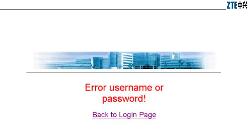
ZXR10 WAS (V1.0) IP Wireless Access System W200A Wireless Access Point User’s Manual
6-4
If the entered user name and password are incorrect, the following message will be
given after you submit your user name and password, as shown in Fig. 6.2-3.
Fig. 6.2-3 Alert box for prompting that the entered user name and password are incorrect
6.3 Main menu of WEB configuration
After you log into the system successfully, the main menu page for user browsing will
be opened. The main menu includes the following items: Home, Interfaces, Stations,
Statistics, Load Balance, SNMP, Security, Reboot, Save, Advanced, Accounts and
Exit. Among them, Interfaces, SNMP, Security and Advanced also have submenus,
while other configuration modules only have one WEB page for configuration. The
main menu is on the left of the WEB page, as shown in Fig. 6.3-1, and the right pane is
the page of the currently selected configuration module.

Chapter Error! Style not defined. Error! Style not defined.
6-5
6.3.1 Home page (basic product information)
The contents in this page are read-only, which can only be browsed and cannot be set.
Fig. 6.3-1 Home page (basic product information)
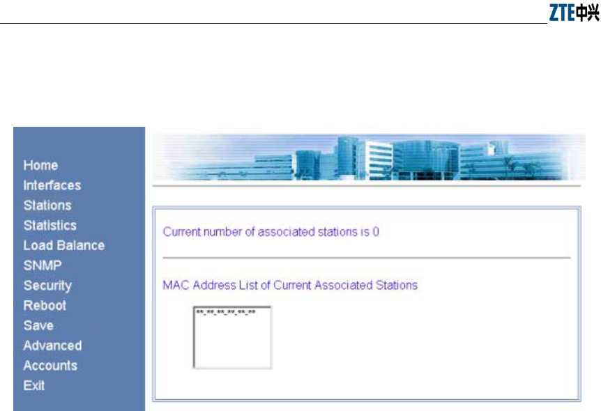
ZXR10 WAS (V1.0) IP Wireless Access System W200A Wireless Access Point User’s Manual
6-6
6.3.2 Stations page
Click Stations in the main menu to display the page as shown in Fig. 6.3-2.
Fig. 6.3-2 Stations page
This page displays the information about the wireless users who have logged into this
AP. The parameters include the number of wireless users and the MAC address of the
users.
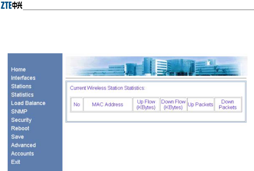
Chapter Error! Style not defined. Error! Style not defined.
6-7
6.3.3 Statistics Page
Click Statistics in the main menu to display the page as shown in Fig. 6.3-3.
Fig. 6.3-3 Statistics page
This page displays the flow information of each wireless user, including uplink flow,
downlink flow, uplink packets and downlink packets.
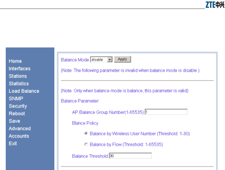
ZXR10 WAS (V1.0) IP Wireless Access System W200A Wireless Access Point User’s Manual
6-8
6.3.4 Load Balance page
Click Load Balance in the main menu to display the page as shown in Fig. 6.3-4.
Fig. 6.3-4 Load Balance page
This page is used to configure IAPP parameters, including balance mode, AP load
balance (AP group number and nominal capacity) and the maximum number of users,
all of which have a certain value range. Three balance modes are available: disable,
balance and max-user. When you configure the mode as “disable”, the IAPP mode will
be disabled; when you configure the mode as “balance”, the AP load balance will be
enabled, and the parameter in the “AP Balance Group Number (1-65535)” box will
take effect; and when you configure the mode as “max-user”, the parameter in the
“Balance Threshold” box will take effect.
Note: You can only select one from AP load balance or Max-user.
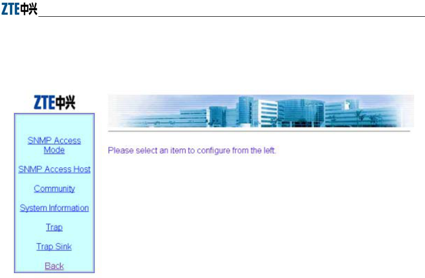
Chapter Error! Style not defined. Error! Style not defined.
6-9
6.3.5 SNMP page
Click SNMP in the main menu to display the page as shown in Fig. 6.3-5.
Fig. 6.3-5 Submenu for SNMP configuration
On the left of this page is the submenu for SNMP configuration: SNMP Access Mode,
SNMP Access Host, Community, System Information, Trap, Trap Sink and Back.
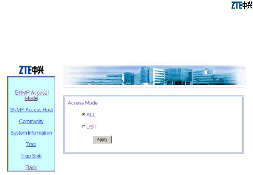
ZXR10 WAS (V1.0) IP Wireless Access System W200A Wireless Access Point User’s Manual
6-10
6.3.5.1 SNMP Access Mode page
Click SNMP Access Mode in the SNMP menu to display the page as shown in Fig.
6.3-6.
Fig. 6.3-6 Access mode configuration page of the SNMP module
This page is used to configure the access mode of SNMP, with two options: all and list.
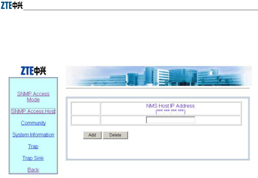
Chapter Error! Style not defined. Error! Style not defined.
6-11
6.3.5.2 SNMP Access Host page
Click SNMP Access Host in the SNMP menu to display the page as shown in Fig.
6.3-7.
Fig. 6.3-7 Access host configuration page of the SNMP module
This page is used to add or delete the IP address of SNMP access host, and the
parameter includes the IP address of the accessible host .
Operation instructions: there are two buttons “Add” and “Delete” on the page. To
perform the adding operation, you just need to enter the data in the blank box on the
bottom; and to perform the deleting operation, you just need to check off the record to
be deleted (you may delete multiple records simultaneously).
Note: the operation for other pages with multiple records is similar to this.
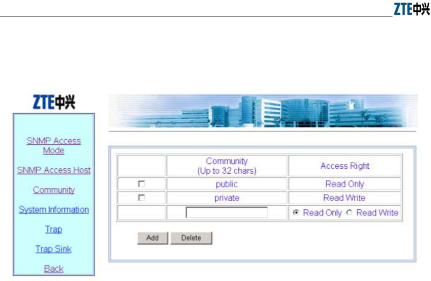
ZXR10 WAS (V1.0) IP Wireless Access System W200A Wireless Access Point User’s Manual
6-12
6.3.5.3 Community page
Click Community in the SNMP menu to display the page as shown in Fig. 6.3-8.
Fig. 6.3-8 Community configuration page of the SNMP module
This page is used to add or delete SNMP community strings, and the parameters
include community ID and access right.
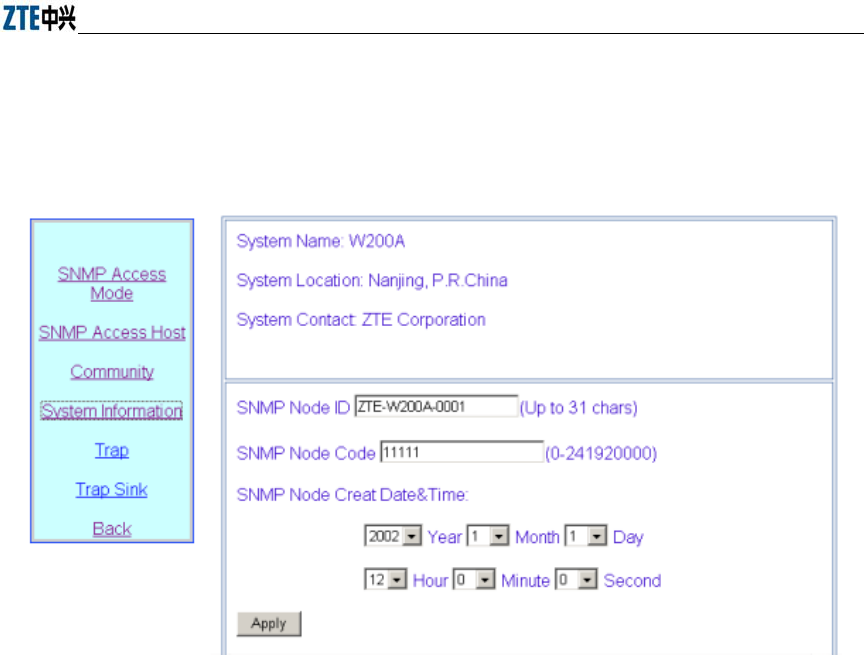
Chapter Error! Style not defined. Error! Style not defined.
6-13
6.3.5.4 System information page
Click System Information in the SNMP menu to display the page as shown in Fig.
6.3-9.
Fig. 6.3-9 System information configuration page of the SNMP module
This page displays the name, location and contact information of the current SNMP
management equipment. You can also configure the related information of the NE in
this page, including NE ID, NE code and NE creation date and time.
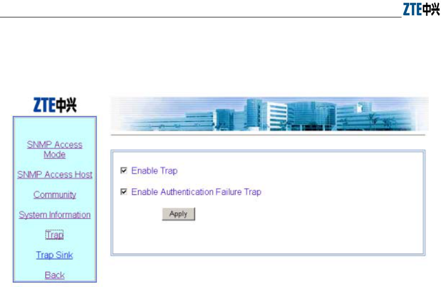
ZXR10 WAS (V1.0) IP Wireless Access System W200A Wireless Access Point User’s Manual
6-14
6.3.5.5 Trap page
Click Trap in the SNMP menu to display the page as shown in Fig. 6.3-10.
Fig. 6.3-10 Trap configuration page of the SNMP module
This page is used to configure the Trap of the SNMP module, with two parameters for
configuration: Enable Trap and Enable Authentication Failure Trap.
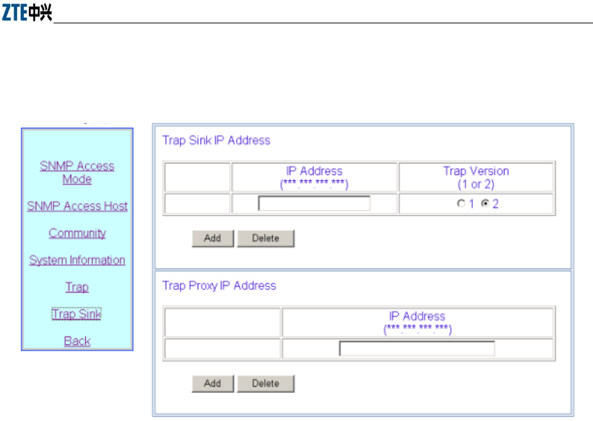
Chapter Error! Style not defined. Error! Style not defined.
6-15
6.3.5.6 Trap Sink page
Click Trap Sink in the SNMP menu to display the page as shown in Fig. 6.3-11.
Fig. 6.3-11 Trap sink configuration page of the SNMP module
This page is used to add or delete the Trap Sink host and Trap Proxy host of the SNMP
module. The parameters include the IP address and Trap version.
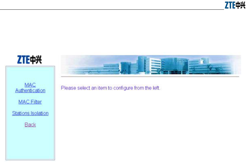
ZXR10 WAS (V1.0) IP Wireless Access System W200A Wireless Access Point User’s Manual
6-16
6.3.6 Security page
Click Security in the main menu to display the page as shown in Fig. 6.3-12.
Fig. 6.3-12 Submenu of security configuration
On the left of this page is the security configuration submenu: MAC Authentication,
MAC Filter, Stations Isolation and Back.
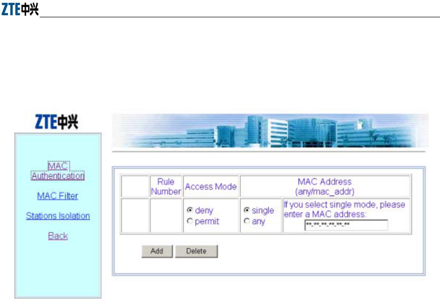
Chapter Error! Style not defined. Error! Style not defined.
6-17
6.3.6.1 MAC Authentication page
Click MAC Authentication in the Security menu to display the page as shown in Fig.
6.3-13.
Fig. 6.3-13 MAC authentication configuration page
This page is used to add or delete MAC authentication rules, and the parameters
include Access Mode (permit or deny) and filter type (any or single).
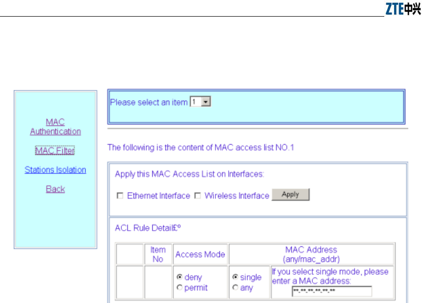
ZXR10 WAS (V1.0) IP Wireless Access System W200A Wireless Access Point User’s Manual
6-18
6.3.6.2 MAC filter page
Click MAC filter in the Security menu to display the page as shown in Fig. 6.3-14.
Fig. 6.3-14 MAC filter rule configuration page
This page is used to add or delete a certain filter rule and configure whether to apply
the setting for certain interfaces. The parameters include filter mode and filter type.
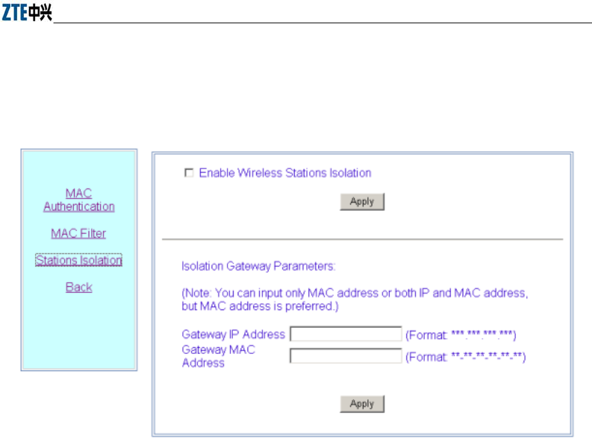
Chapter Error! Style not defined. Error! Style not defined.
6-19
6.3.6.3 Stations Isolation page
Click Stations Isolation in the Security menu to display the page as shown in Fig.
6.3-15.
Fig. 6.3-15 Stations Isolation page
This page is used to enable wireless stations isolation and set the gateway IP address or
MAC address for stations isolation. The parameters include Gateway IP Address and
Gateway MAC Address.
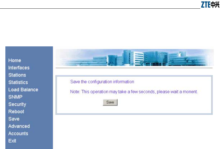
ZXR10 WAS (V1.0) IP Wireless Access System W200A Wireless Access Point User’s Manual
6-20
6.3.7 Save page
Click Save in the main menu to display the page as shown in Fig. 6.3-16.
Fig. 6.3-16 Save page
This page is used to save the configured parameters in FLASH.
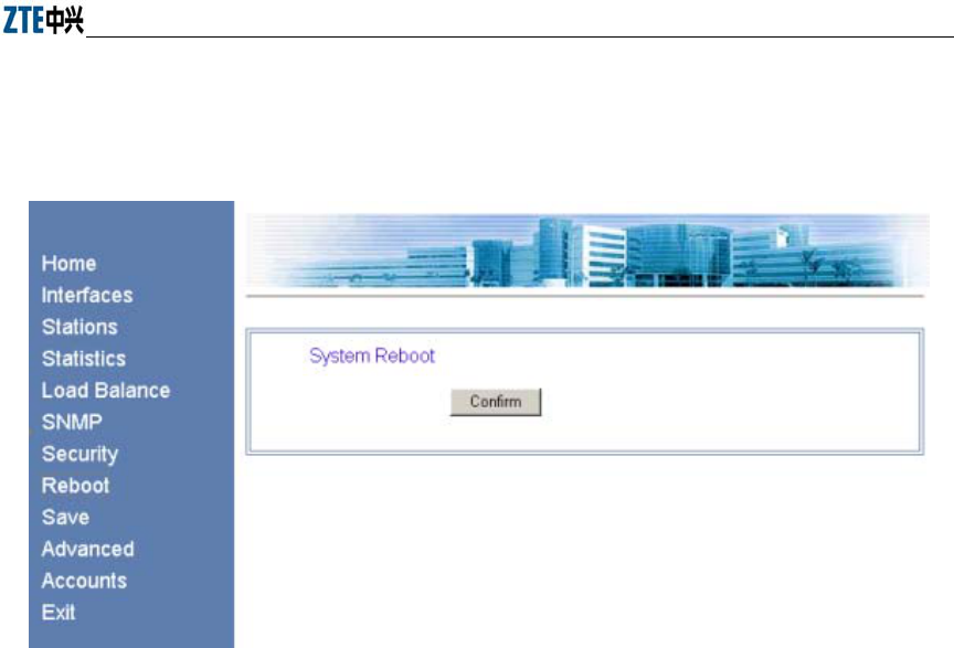
Chapter Error! Style not defined. Error! Style not defined.
6-21
6.3.8 Reboot page
Click Reboot in the main menu to display the page as shown in Fig. 6.3-17.
Fig. 6.3-17 Reboot page
This page is used to execute the reboot operation. This window will be closed after
clicking the button.
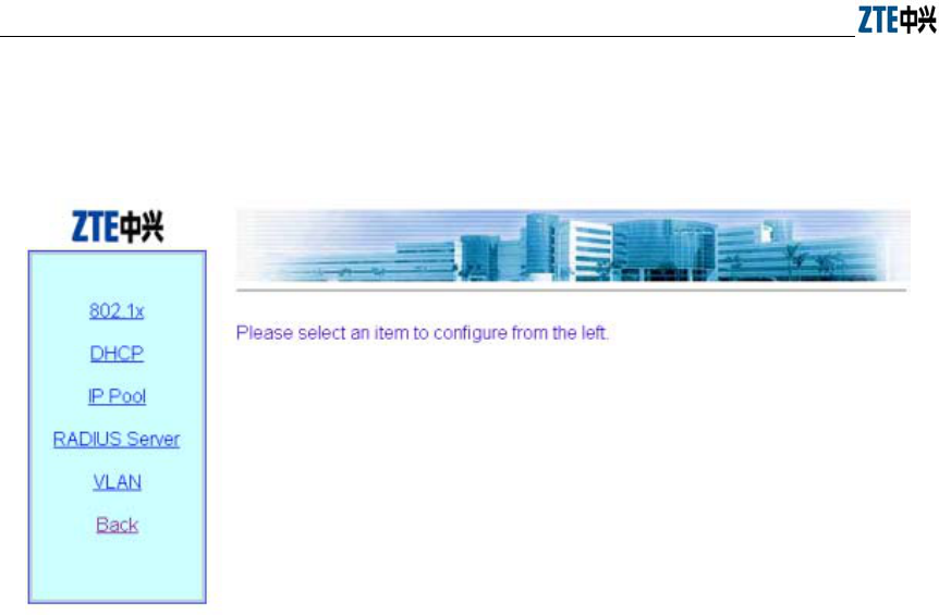
ZXR10 WAS (V1.0) IP Wireless Access System W200A Wireless Access Point User’s Manual
6-22
6.3.9 Advanced options page
Click Advanced in the main menu to display the page as shown in Fig. 6.3-18.
Fig. 6.3-18 Submenu of advanced options configuration
On the left of this page is the submenu of the advanced options configuration: 802.1x,
DHCP, IP Pool, RADIUS Server, VLAN and Back.
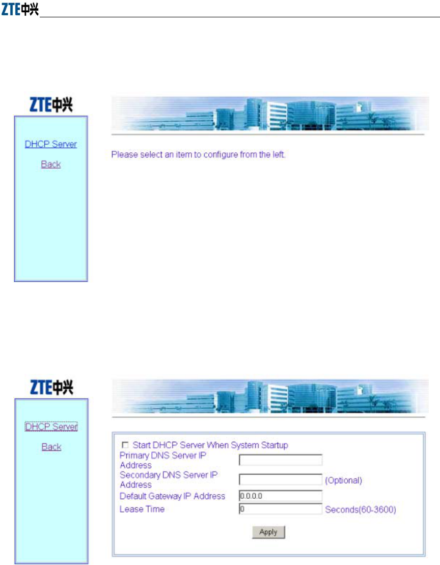
Chapter Error! Style not defined. Error! Style not defined.
6-23
6.3.9.1 DHCP page
Click DHCP in the Advanced menu to display the page as shown in Fig. 6.3-19.
Fig. 6.3-19 Submenu of DHCP module
Click DHCP Server in the DHCP submenu to display the page as shown in Fig.
6.3-20.
Fig. 6.3-20 DHCP server configuration page
This page is used to configure the related parameters of the DHCP server: Primary
DNS Server IP address, Secondary DNS Server IP Address, Default Gateway IP
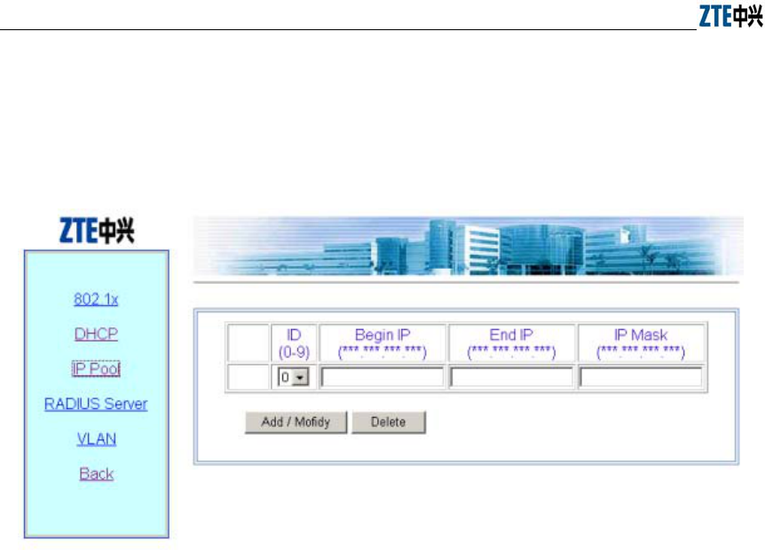
ZXR10 WAS (V1.0) IP Wireless Access System W200A Wireless Access Point User’s Manual
6-24
Address, and Lease time.
6.3.9.2 IP Pool page
Click IP Pool in the Advanced menu to display the page as shown in Fig. 6.3-21.
Fig. 6.3-21 IP pool page
This page is used to add, modify and delete IP pools. The parameters include ID, Begin
IP, End Ip and IP Mask.
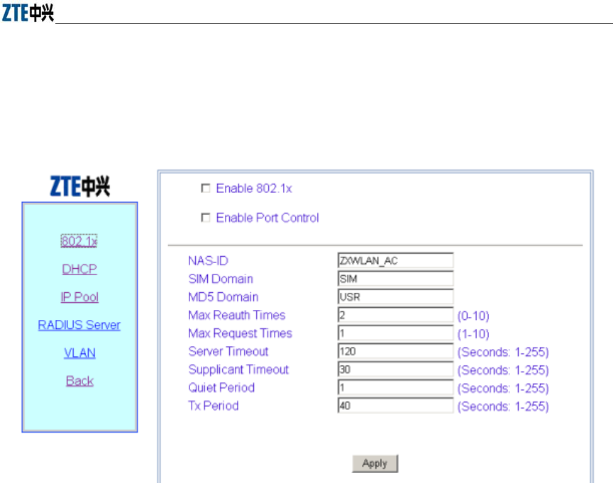
Chapter Error! Style not defined. Error! Style not defined.
6-25
6.3.9.3 802.1x page
Click 802.1x in the Advanced menu to display the page as shown in Fig. 6.3-22.
Fig. 6.3-22 802.11x configuration page
This page is used to configure 802.1x authentication parameters, including two check
boxes: Enable 802.1x and Enable Port Control, and some other parameters: NAS-ID,
SIM Domain, MD5 Domain, Max Reauth Times, Max Request Times, Server Timeout,
Supplicant Timeout, Quiet Period and Tx Period.
ZXR10 WAS (V1.0) IP Wireless Access System W200A Wireless Access Point User’s Manual
6-26
6.3.9.4 RADIUS Server page
Click RADIUS Server in the Advanced menu to display the page as shown in Fig.
6.3-23.
Fig. 6.3-23 Submenu of RADIUS server configuration
The RADIUS configuration submenu includes: ISP, Authentication Server, Accounting
Server, DNS Server and Back.
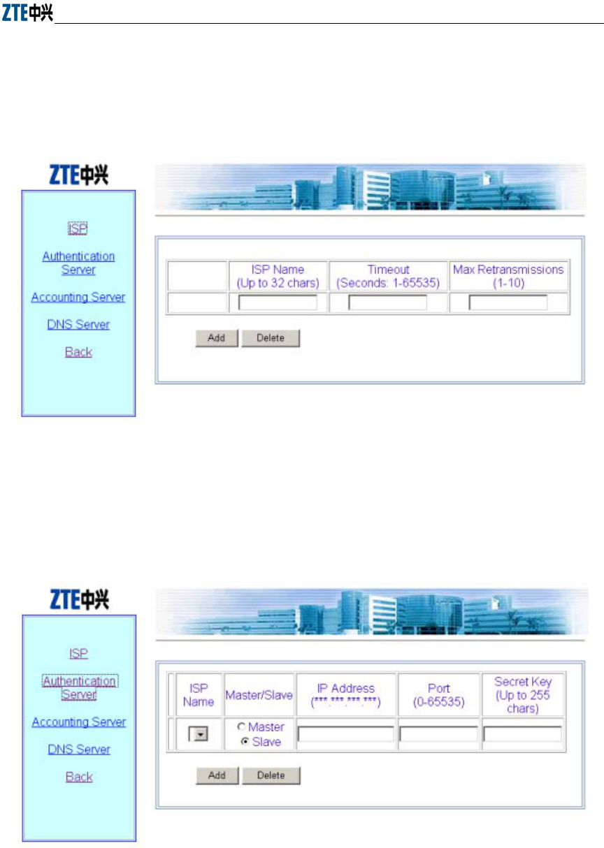
Chapter Error! Style not defined. Error! Style not defined.
6-27
ISP Page
Click ISP in the RADIUS Server menu to display the page as shown in Fig.
6.3-24.
Fig. 6.3-24 ISP configuration page
Authentication Server page
Click
Authentication Server in the RADIUS Server menu to display the page
as shown in Fig. 6.3-25.
Fig. 6.3-25 Authentication Server configuration page
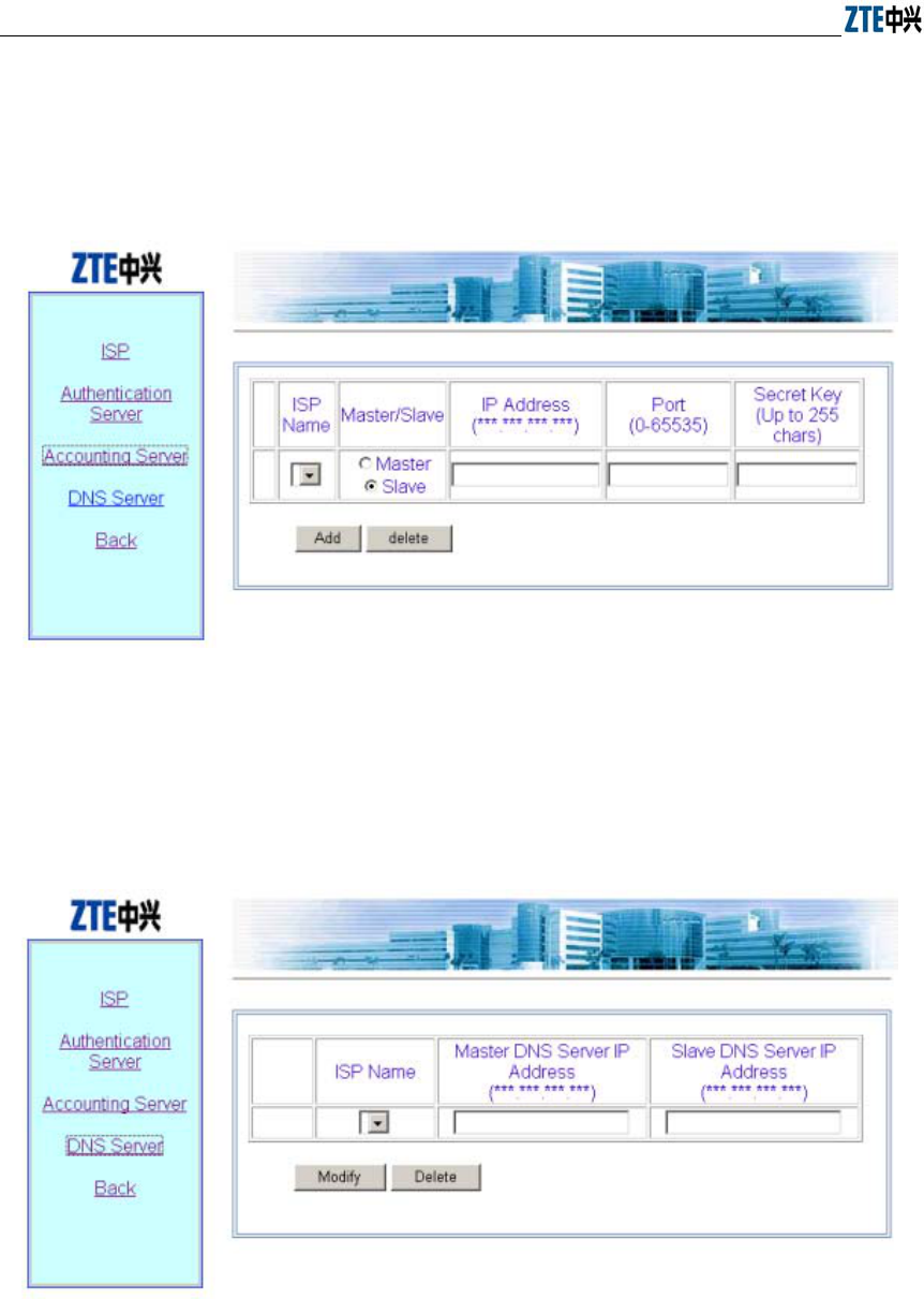
ZXR10 WAS (V1.0) IP Wireless Access System W200A Wireless Access Point User’s Manual
6-28
Accounting Server page
Click Accounting Server in the RADIUS Server menu to display the page as
shown in Fig. 6.3-26.
Fig. 6.3-26 Accounting Server configuration page
DNS Server page
Click DNS Server in the RADIUS Server menu to display the page as shown in
Fig. 6.3-27.
Fig. 6.3-27 DNS configuration page
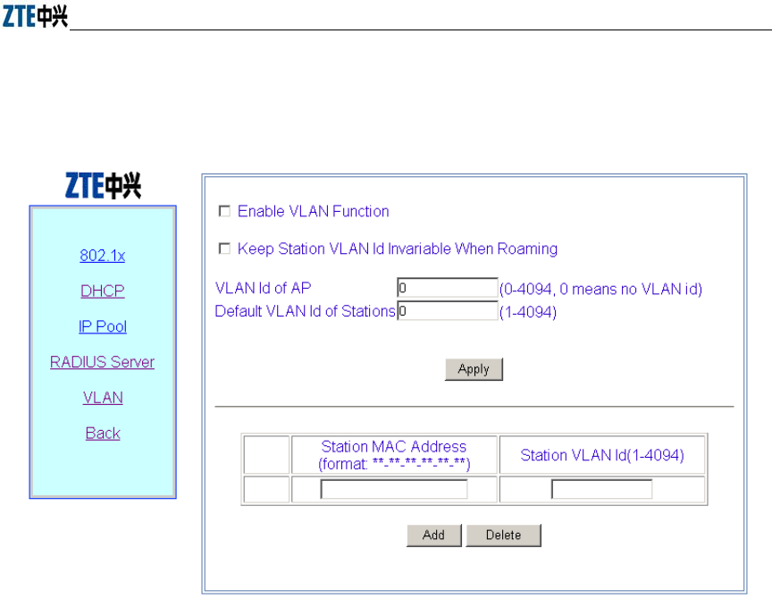
Chapter Error! Style not defined. Error! Style not defined.
6-29
6.3.9.5 VLAN page
Click VLAN in the Advanced menu to display the page as shown in Fig. 6.3-28.
Fig. 6.3-28 VLAN configuration Page
This page serves to enable/disable the VLAN and configure its parameter.
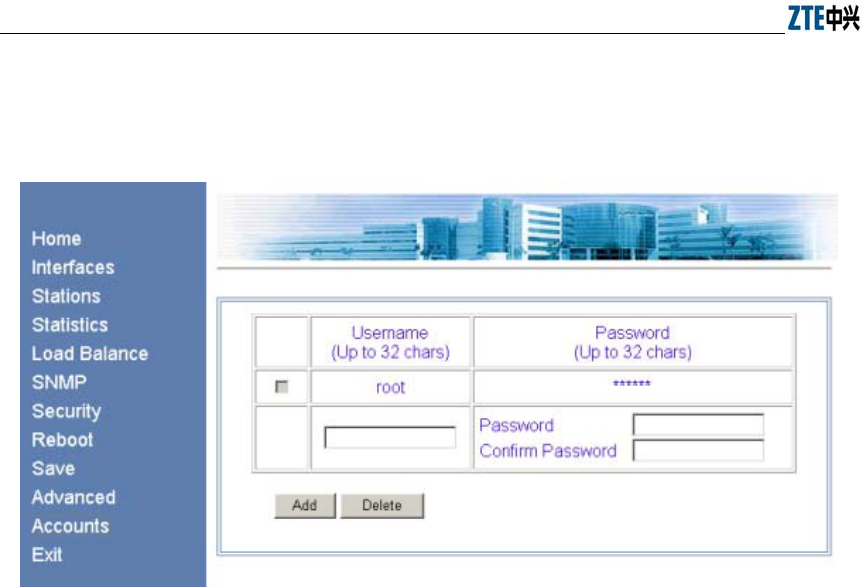
ZXR10 WAS (V1.0) IP Wireless Access System W200A Wireless Access Point User’s Manual
6-30
6.3.10 Accounts page
Click Accounts in the main menu to display the page as shown in Fig. 6.3-29.
Fig. 6.3-29 Account configuration page
This page is used to add, delete or modify an ordinary user name and password.
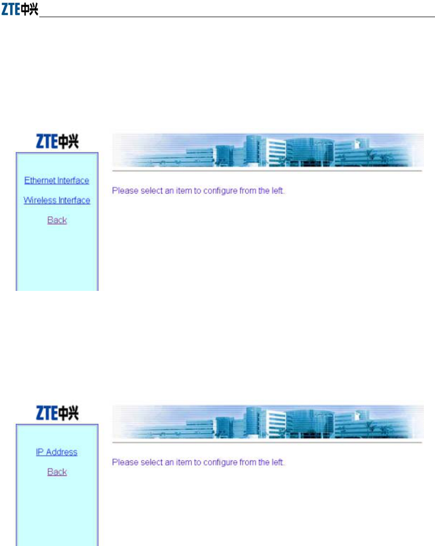
Chapter Error! Style not defined. Error! Style not defined.
6-31
6.4 Interfaces page
Open the submenu page of interface configuration by clicking Interfaces in the main
menu. The W200A product involves the configuration of Ethernet interface and
Wireless interface.
Fig. 6.4-1 Submenu for interface configuration
6.4.1 Ethernet Interface page
Click Ethernet Interface in Fig. 6.4-1 to open the submenu for Ethernet interface
configuration, as shown in Fig. 6.4-2.
Fig. 6.4-2 Submenu for Ethernet interface configuration
On the left of this page is the submenu for Ethernet interface configuration: IP Address.
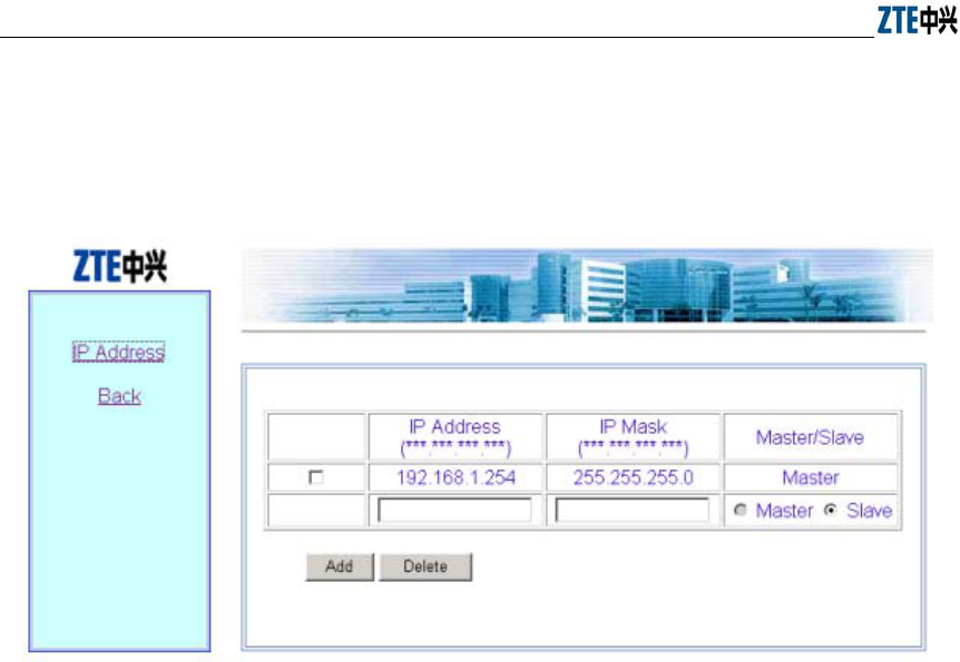
ZXR10 WAS (V1.0) IP Wireless Access System W200A Wireless Access Point User’s Manual
6-32
6.4.1.1 IP Address page
Click IP Address in the Ethernet Interface submenu to display the page as shown in
Fig. 6.4-3.
Fig. 6.4-3 IP address configuration page of Ethernet interface
This page is used to add or delete the IP address of the Ethernet interface module. The
parameters include IP Address, IP Mask and Master/Slave.
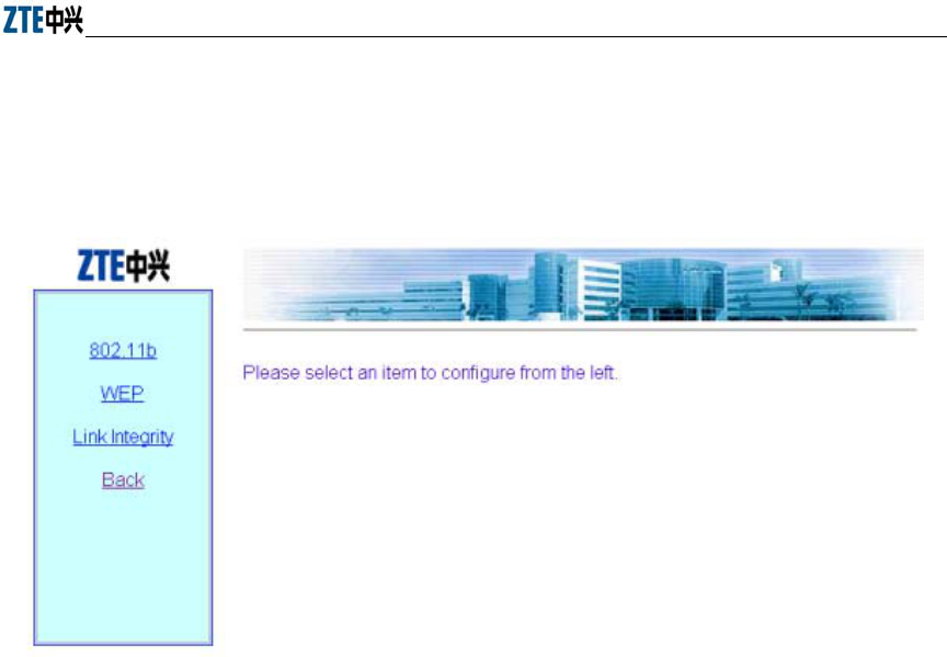
Chapter Error! Style not defined. Error! Style not defined.
6-33
6.4.2 Wireless Interface page
Click Wireless Interface in Fig. 6.4-1 to open the submenu for wireless interface
configuration, as shown in Fig. 6.4-4.
Fig. 6.4-4 Submenu for wireless interface configuration
On the left is the submenu for wireless interface configuration: 802.11b, WEP, Link
Integrity and Back.
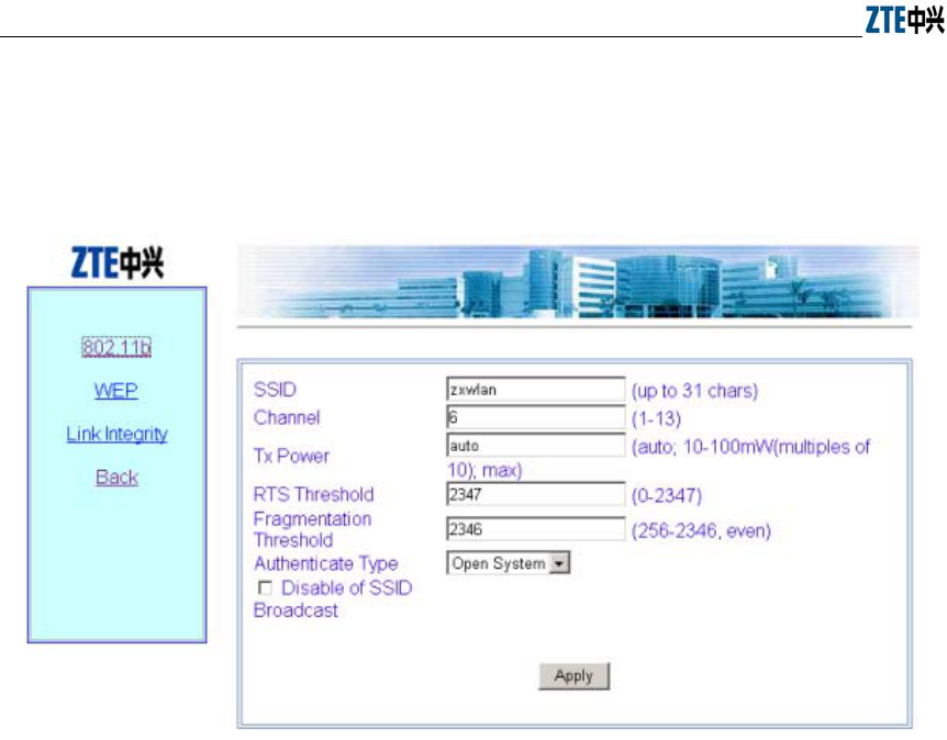
ZXR10 WAS (V1.0) IP Wireless Access System W200A Wireless Access Point User’s Manual
6-34
6.4.2.1 802.11b page
Click 802.11b in the Wireless Interface submenu to display the page as shown in Fig.
6.4-5.
Fig. 6.4-5 802.11b parameter configuration page of wireless interface
This page is used to configure the 802.11b parameters of the wireless interface module.
The parameters include SSID, Channel, Tx Power, RTS Threshold, Fragmentation
Threshold, Authentication Type, and the check box “Disable SSID Broadcast”.
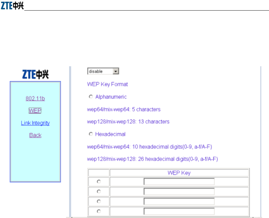
Chapter Error! Style not defined. Error! Style not defined.
6-35
6.4.2.2 WEP page
Click WEP in the Wireless Interface submenu to display the page as shown in Fig.
6.4-6.
Fig. 6.4-6 WEP configuration page of wireless interface
This page is used to configure the WEP parameters of the wireless interface module.
The parameters include WEP mode, WEP value and WEP keyword.
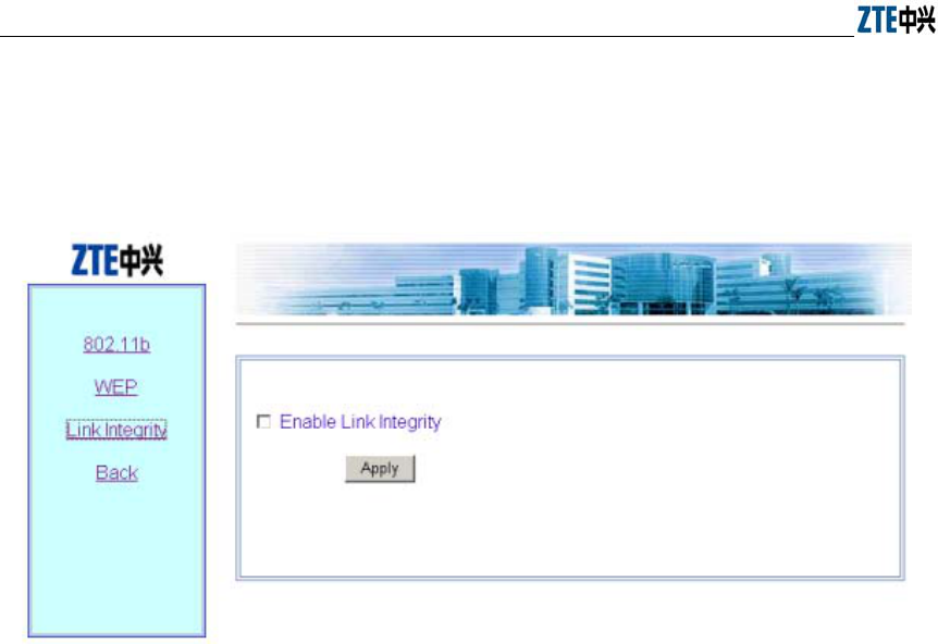
ZXR10 WAS (V1.0) IP Wireless Access System W200A Wireless Access Point User’s Manual
6-36
6.4.2.3 Link Integrity page
Click Link Integrity in the Wireless Interface submenu to display the page as shown
in Fig. 6.4-7.
Fig. 6.4-7 Link integrity configuration page of wireless interface
This page is used to configure the link integrity parameters of the wireless interface
module. The parameter includes the check box “Enable Link Integrity”.
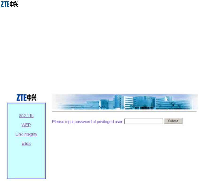
Chapter Error! Style not defined. Error! Style not defined.
6-37
6.5 Data submission flow for WEB configuration
When you open a certain WEB configuration page and enter parameters in the
corresponding text boxes, you can click “Submit” to immediately proceed to the next
page. If you submit data for the first time after login, a page will pop up for you to
enter the password of privileged user, as shown in Fig. 6.5-1. If you have already
submitted data with correct password, the system will skip this page and directly
proceed to the next page to prompt you whether the data have been submitted
successfully when you submit dada again.
Fig. 6.5-1 The page for entering the password of privileged user
If the entered password is incorrect, a message will pop up, prompting you that the
password is incorrect, as shown in Fig. 6.5-2. You can click “Back” to reselect page
connection.
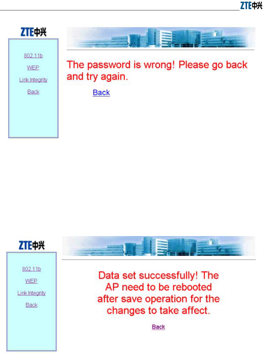
ZXR10 WAS (V1.0) IP Wireless Access System W200A Wireless Access Point User’s Manual
6-38
Fig. 6.5-2 The page indicating that the privileged user password is incorrect
If the entered password of the privileged user is correct, the system will resolve the
entered data and judge whether the format and range are correct. Then, depending on
whether the setting is successful, a corresponding prompting message will be returned,
as shown in Fig. 6.5-3 (successful setting), and Fig. 6.5-4 (Failure in setting). You can
click “Back” to return to the WEB page before submission, and the displayed data are
the submitted new parameters.
Fig. 6.5-3 A message indicating successful data submission
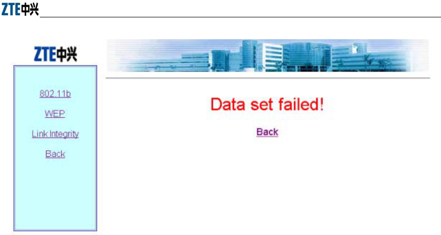
Chapter Error! Style not defined. Error! Style not defined.
6-39
Fig. 6.5-4 A message indicating failure in data submission
7-1
7 Maintenance
This chapter details the daily maintenance of the W200A and version upload &
upgrade.
7.1 Explanation
To ensure proper, stable functioning of the equipment, please pay close attention to the
suggestions below and perform necessary routine maintenance following the daily
operation & maintenance instructions.
1. Always keep the equipment room clean, tidy, dust-proof and moisture-proof.
Protect wires & cables from being damaged by rats and insects.
2. Perform a routine inspection and test everyday following the daily operation &
maintenance instructions and take the records down.
3. Troubleshoot problems in a timely manner. For those beyond your control,
please contact the local ZTE office for help. Don't get nervous when
emergencies occur so as to avoid exacerbating the failures.
4. Follow the Disaster Handling sequence when major accidents like crashdown
happen and contact the local ZTE office immediately.
5. Do not reset, load or modify the equipment data in a hurry. If data modification
is necessary, make sure to backup the data before you change it. After the
modification, backup of new data is also required. Save the new and old data
respectively. Deletion of old data is allowed one week after confirming that the
equipment functions properly with the new data.
6. Please have the contact information of the local ZTE office such as phone
number, fax number posted in a conspicuous place in the equipment room so
that each maintenance staff member knows it clearly.

ZXR10 WAS (V1.0) IP Wireless Access System W200A Wireless Access Point User’s Manual
7-2
7.2 Daily Maintenance
To check the operating condition of the W200A, perform the following:
1. Ping the management port address of all APs from an Ethernet switch, and check
if the APs' wired ports function properly.
2. For hotspots adopting DHCP, check if validated users are able to obtain
parameters such as IP Address, Gateway, DNS and so on correctly.
3. Check if access to the Internet is free from obstruction.
4. Check signal intensity and link quality in different places within the coverage of
each AP using a wireless Ethernet card. Ping the gateway's IP address, view
packet loss, and check if access to the Internet is normal.
5. Roaming between different APs. Ping the gateway's IP address, view packet loss,
and check if access to the Internet is normal.
7.3 Version Upload & Upgrade
Version running files and graphics files have been loaded to the flash memory of the
W200A prior to the shipment.
Version running files include:
Runbin Running file
Database.dat Database file
Zxipcmd.dat Command script file
Tf010102.hex Wireless Ethernet card 3rd-party firmware file
Th010000.hex Wireless Ethernet card 3rd-party firmware file
There may be many wireless Ethernet card 3rd-party firmware files, but only one is
needed during the operation of the W200A.
Graphics files form a graphics library for the web configuration page.
Version upload includes BOOT loading and online TFTP loading. The BOOT loading
is mostly used to load the version running files; while via TFTP, both version running
files and graphics files can be loaded. Wftpd and Tftpd are two tools needed for version
loading.
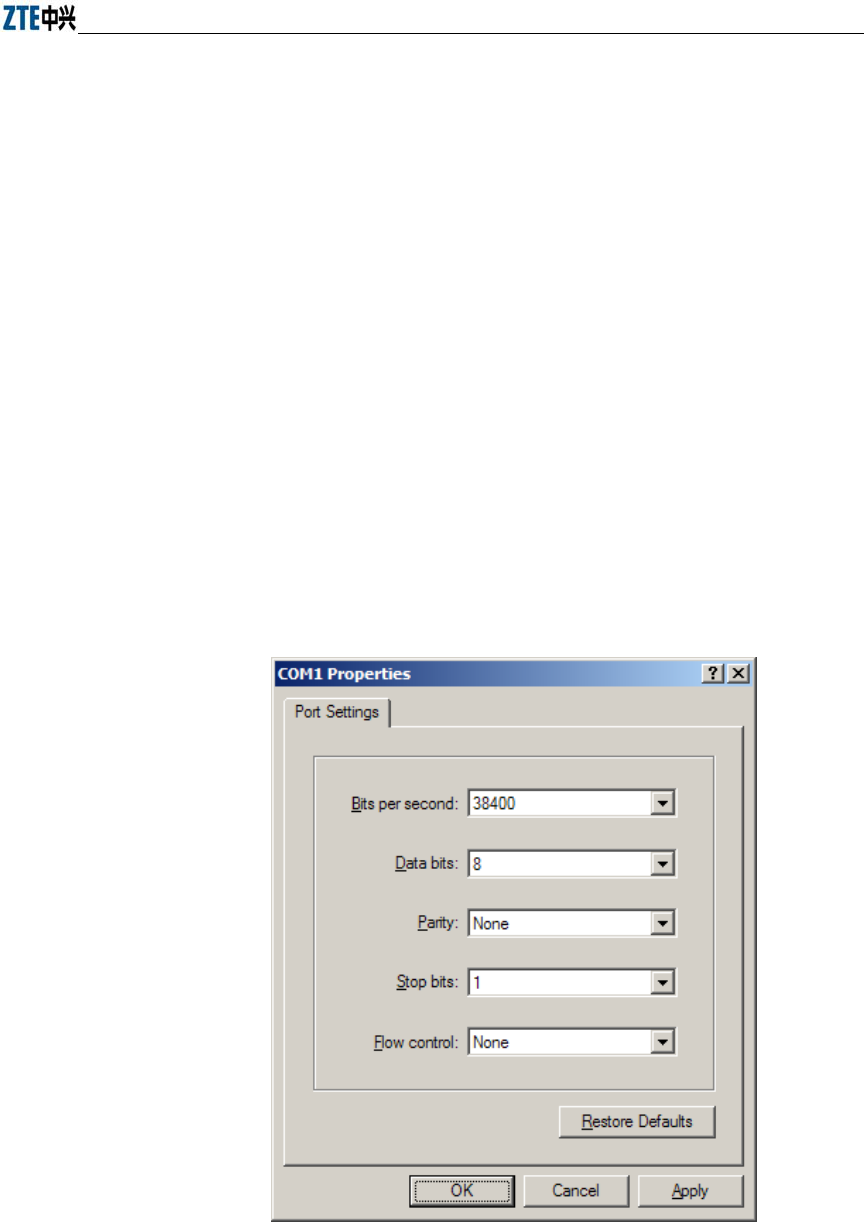
Chapter Error! Style not defined. Error! Style not defined.
7-3
7.3.1 BOOT Loading
The BOOT loading is mostly used to load the version running files. Prior to the loading,
please prepare a serial port line and a crossover Ethernet cable and follow the steps
below:
1. Connect the W200A's CONSOLE port to the serial port of a PC via the serial
port line; connect the W200A's Ethernet port to the wired Ethernet port of the
PC via the crossover cable.
2. Start HyperTerminal on the PC, execute Wftpd.exe to start the FTP server. For
configurations of the serial port and FTP server, Refer to 7.3.1.1 for details.
Power on the W200A. Perform version installation or upgrade using commands listed
in 7.3.1.2.
7.3.1.1 Configuration of Serial Port and FTP Server
1. Configuration of serial port
For the W200A, the configuration of the serial port is shown as in Fig. 7.3-1.
Fig. 7.3-1 Configuration of Serial Port
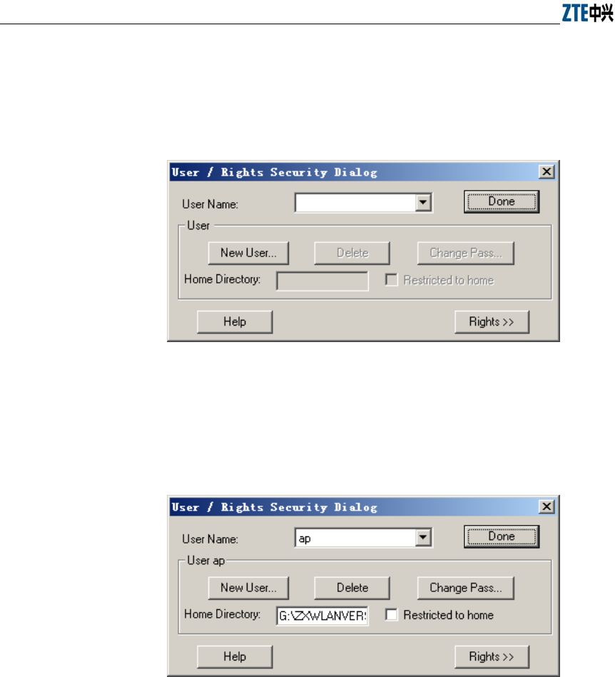
ZXR10 WAS (V1.0) IP Wireless Access System W200A Wireless Access Point User’s Manual
7-4
2. Configuration of FTP server
From the menu of Wftpd, choose Security-> Users/rights.... The window as
shown in Fig. 7.3-2 will appear.
Fig. 7.3-2 Wftpd User Configuration
To add a new user, click New User, set the password, fill in Home Directory
(the directory where to-be-loaded files on the PC are saved), as shown in Fig.
7.3-3.
Fig. 7.3-3 Add a New User
7.3.1.2 Commands for BOOT Loading
Power on the W200A. When the number “3” appears on the HyperTerminal, press any
key. The screen as shown in Fig. 7.3-4 will pop up.
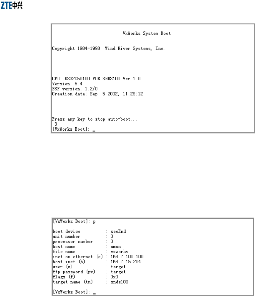
Chapter Error! Style not defined. Error! Style not defined.
7-5
Fig. 7.3-4 Initial Window
1. Command: p
Function: Show BOOT parameters
Command format: [VxWorks Boot]: p
Example: See Fig. 7.3-5.
Fig. 7.3-5 Execution of “p” Command
2. Command: c
Function: Modify BOOT parameters
Command format: [VxWorks Boot]: c
The following parameters are subject to modification:
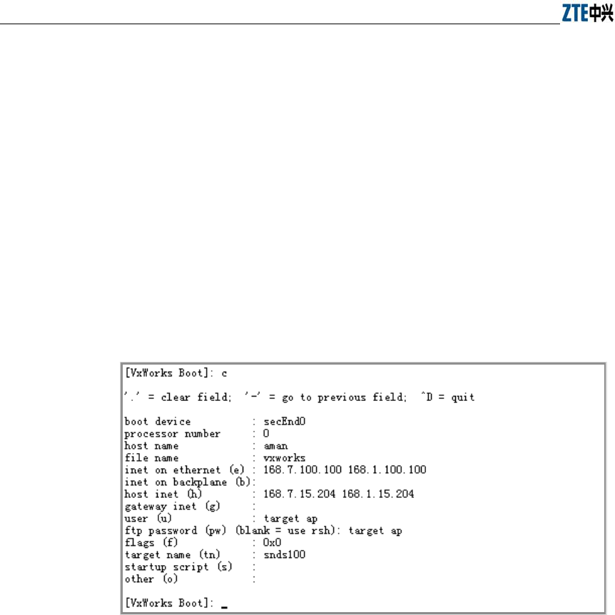
ZXR10 WAS (V1.0) IP Wireless Access System W200A Wireless Access Point User’s Manual
7-6
file name Filename
inet on Ethernet (e) IP address of the W200A (used for communication with
the host during version loading)
host inet (h) IP address of the host
user(u) User name
ftp password(pw) Password
Example: As shown in Fig. 7.3-6, change inet on Ethernet (e) to 168.1.100.100,
host inet (h) to 168.1.15.204, user (u) to ap, ftp password (pw) to ap.
Corresponding settings should be set in the FTP server when user (u) and ftp
password (pw) have been changed.
Fig. 7.3-6 Execution of “c” Command
3. Command: %
Function: Format the flash memory
Command format: [VxWorks Boot]: %
Explanation: Formatting of the Flash card is generally required before the
version loading in order to ensure there is enough space for the files to be
loaded.
Example: As shown in Fig. 7.3-7, prompts are given asking for confirming of
the Flash formatting. Enter “y” within 3 seconds; otherwise, the operation will
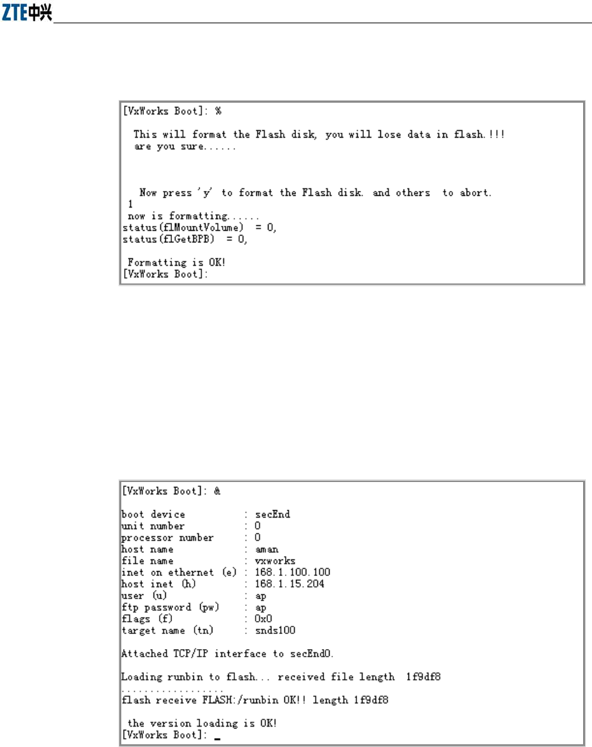
Chapter Error! Style not defined. Error! Style not defined.
7-7
be aborted.
Fig. 7.3-7 Execution of “%” Command
4. Command: &
Function: Load the file "runbin" to the Flash memory
Command format: [VxWorks Boot]: &
Example: See Fig. 7.3-8.
Fig. 7.3-8 Execution of “&” Command
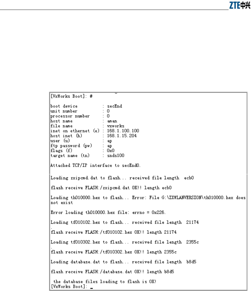
ZXR10 WAS (V1.0) IP Wireless Access System W200A Wireless Access Point User’s Manual
7-8
5. Command: #
Function: Load database.dat, zxipcmd.dat, tf010102.hex, th010000.hex,
tf010302.hex to the Flash memory
Command format: [VxWorks Boot]: #
Example: See Fig. 7.3-9.
Fig. 7.3-9 Execution of “#” Command
6. Command: +
Function: Load a specified file to the Flash memory
Command format: [VxWorks Boot]: +
Example: Modify BOOT parameters using the C command and then type in
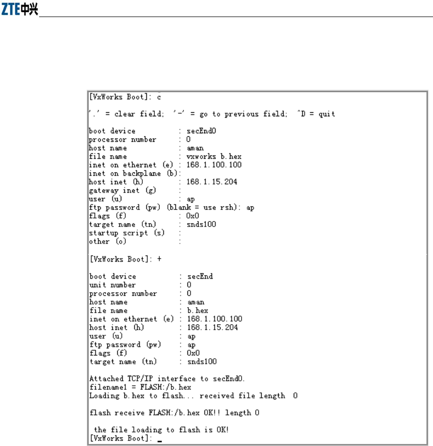
Chapter Error! Style not defined. Error! Style not defined.
7-9
"+".As shown in Fig. 7.3-10, modify file name by means of the C command,
change vxworks to “b.hex”, input “+” to load b.hex to the Flash memory.
Fig. 7.3-10 Execution of “+” Command
7. Command: s
Function: Display files and free space of the Flash memory
Command format: [VxWorks Boot]: s
Example: See Fig. 7.3-11.
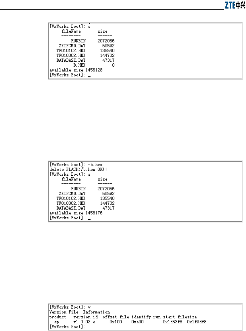
ZXR10 WAS (V1.0) IP Wireless Access System W200A Wireless Access Point User’s Manual
7-10
Fig. 7.3-11 Execution of “s” Command
8. Command: -
Function: Delete a file from the Flash memory
Command format: [VxWorks Boot]: - filename
Example: See Fig. 7.3-12.
Fig. 7.3-12 Execution of “-“ Command
9. Command: v
Function: Show version information of runbin
Command format: [VxWorks Boot]: v
Example: See Fig. 7.3-13.
Fig. 7.3-13 Execution of “v” Command
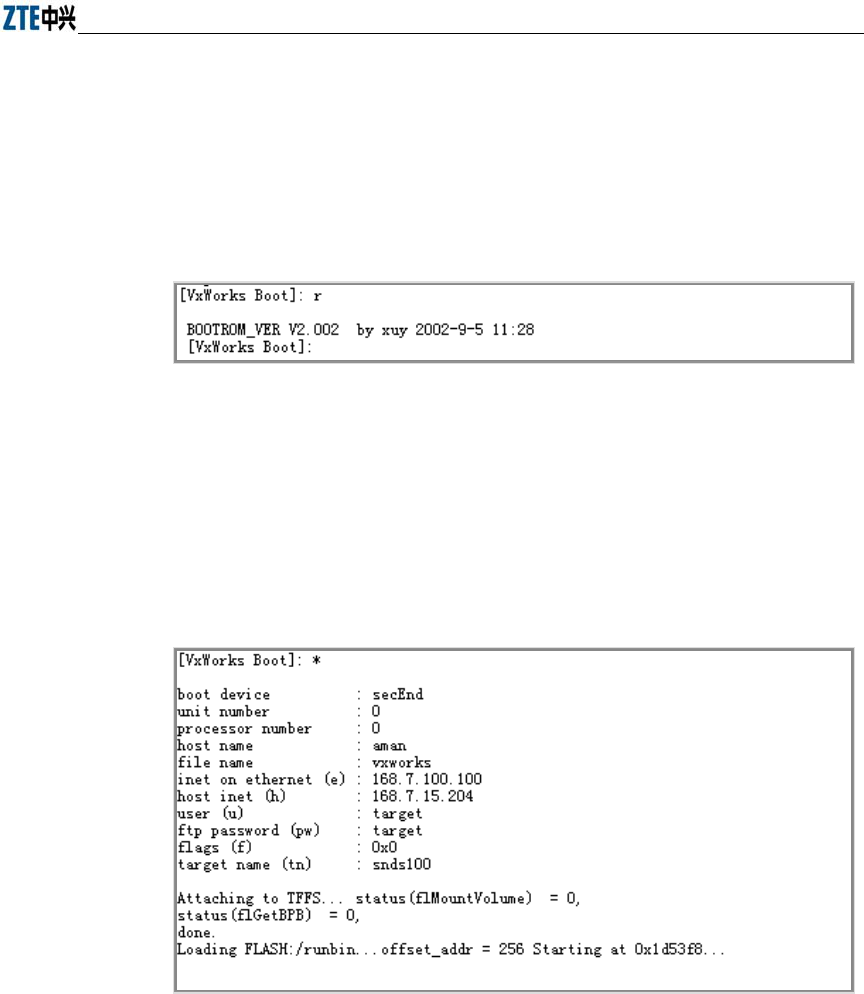
Chapter Error! Style not defined. Error! Style not defined.
7-11
10. Command: r
Function: Show version information of boot
Command format: [VxWorks Boot]: r
Example: See Fig. 7.3-14.
Fig. 7.3-14 Execution of “r” Command
11. Command: *
Function: Run runbin, start the W200A.
Command format: [VxWorks Boot]: *
Example: See Fig. 7.3-15.
Fig. 7.3-15 Execution of “*” Command
7.3.2 Online TFTP Loading
When the W200A functions properly, file downloading from the host to the Flash
memory of the device via TFTP is available. The size of the Flash is only 4M, therefore
there are some restrictions to the files to be loaded online. Generally via TFTP, version
running files and graphics files can be loaded. No support for other files is provided
temporarily.
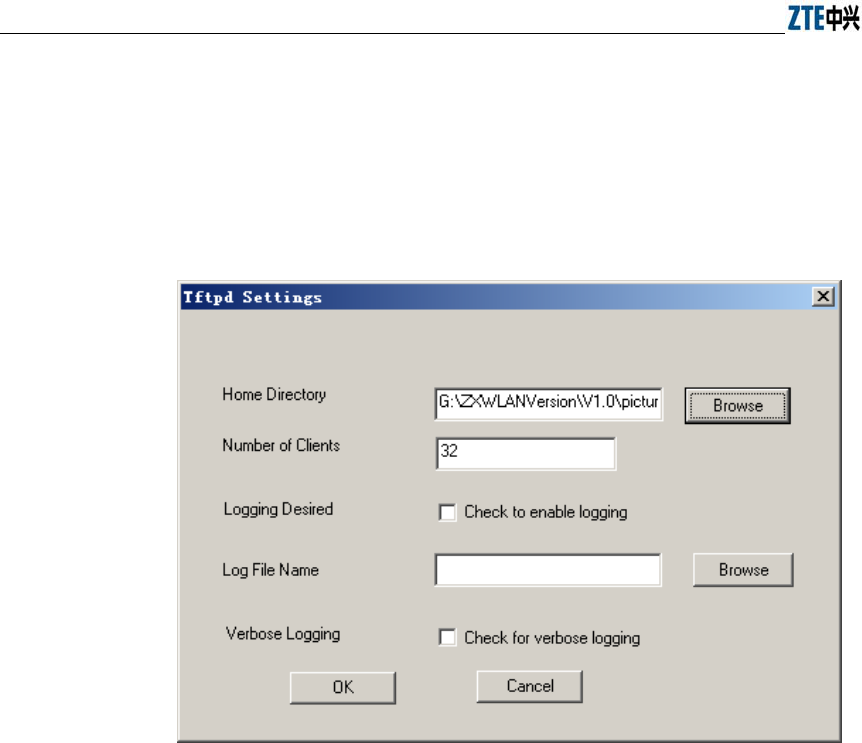
ZXR10 WAS (V1.0) IP Wireless Access System W200A Wireless Access Point User’s Manual
7-12
7.3.2.1 Start the TFTP Server
Set the PC's IP address to be in the same network segment as the management port
address of the W200A. Run Tftpd.exe (or other TFTP server software which supports
the extended TFTP protocol). In the TFTP window, select Tftpd-> Configure to
specify the path of the files to be downloaded, as shown in Fig. 7.3-16.
Fig. 7.3-16 TFTP Settings
In the TFTP window, click Tftpd-> Start to start the TFTP server.
7.3.2.2 Commands for TFTP Loading
Login to the W200A via Telnet, enter the configuration mode, and execute TFTP
commands to upload needed files.
1. Upload of version running files
Command format: zxwlan (config) #tftp get A.B.C.D file-name
Explanation: "A.B.C.D" refers to the TFTP host's address; "file-name" stands for
files to be uploaded including runbin, database.dat, zxipcmd.dat,
tf010102.hex, th010000.hex.

Chapter Error! Style not defined. Error! Style not defined.
7-13
wlan(config)#tftp get 168.1.15.204 database.dat
tftp fetch of database.dat from host 168.1.15.204 (168.1.15.204) started
wlan(config)#Have receive 10240 BYTE: 7%
Have receive 20480 BYTE: 14%
Have receive 30720 BYTE: 21%
Have receive 40960 BYTE: 29%
Have receive 51200 BYTE: 36%
Have receive 61440 BYTE: 43%
Have receive 71680 BYTE: 50%
Have receive 81920 BYTE: 58%
Have receive 92160 BYTE: 65%
Have receive 102400 BYTE: 72%
Have receive 112640 BYTE: 80%
Have receive 122880 BYTE: 87%
Have receive 133120 BYTE: 94%
%get file successful!!
Done with tftp get of database.dat
wlan(config)#tftp get 168.1.15.204 ?
runbin
tf010102.hex
th010000.hex
zxipcmd.dat
database.dat
wlan(config)#
2. Upload of graphics files
Command format: zxwlan (config) #tftp pic A.B.C.D
Explanation: A.B.C.D refers to the host's address.
wlan(config)#tftp pic 168.1.15.204
tftp fetch of zte.gif from host 168.1.15.204 (168.1.15.204) started
wlan(config)#% get file successful!
Done with tftp get of zte.gif
wlan(config)#tftp fetch of back.gif from host 168.1.15.204
(168.1.15.204) started
% get file successful!
Done with tftp get of back.gif
wlan(config)#tftp fetch of login33.jpg from host 168.1.15.204
(168.1.15.204) started

ZXR10 WAS (V1.0) IP Wireless Access System W200A Wireless Access Point User’s Manual
7-14
% get file successful!
Done with tftp get of login33.jpg
wlan(config)#tftp fetch of login23.jpg from host 168.1.15.204
(168.1.15.204) started
% get file successful!
Done with tftp get of login23.jpg
...
wlan(config)#

A-1
Appendix A Packaging, Transportation &
Storage
This chapter describes precautions about packaging, storage and transportation of the
W200A, as a guide for the equipment transportation, unpacking, installation and
moving.
A.1 Packaging
Table A.1-1 Packing List of W200A
Item Name Dimension Quantity Remarks
W200A 208mm×180mm×47mm 1
Power adapter 1
Console configuration line 1
CD of documents that accompanied
the device 1
Warranty card 32K 1
Certificate of Quality 32K 1
A.2 Transportation
Handle with care. Always keep the device upright.
A.3 Storage
Keep the device in the package. The temperature/humidity requirements are:
Temperature: - 40℃~ 70℃
Relative humidity: 5%~95%
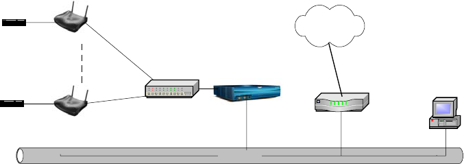
B-1
Appendix B Making Ethernet Cables
This chapter presents PoE for the W200A and the wiring of Ethernet cables.
B.1 Application of the W200A
The typical application of the IP wireless access system is shown as in Figure B.1-1.
Ethernet
Router
PC
Wired LAN
AP
AP
AC
Power adapter
Power adapter
Internet
Ethernet switch
Figure B.1-1 Typical Application of the IP Wireless Access System
The AP helps realize access of wireless users. Via the 10/100M Ethernet, it is
connected to the Ethernet switch and then to the Internet by a router after AC
authentication. The AC is an equipment for authentication and accounting. In practical
situations, some places don't need an AC. In the system, the APs, Ethernet switch, AC,
and routers are interconnected by the 10/100M Ethernet.
Generally, all equipments have their own power adapters, converting external power
supply voltage into the desired direct-current working volts.
But in a wireless LAN, APs are widely spread, the engineering environment is thus
quite complicated. In some places, supply of AC power is not even available. Remote
power feeding now becomes a necessity. ZTE's IP wireless access system provides also
the Power over Ethernet (PoE) solution, as shown in Figure B.1-2.
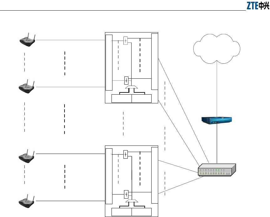
ZXR10 WAS (V1.0) IP Wireless Access System W200A Wireless Access Point User’s Manual
B-2
12 PoE ports (out)
12 Ethernet ports (in)
W112P
220VAC -48VDC
PoE Ethernet cable /48V DC
AC
AP
AP PoE Ethernet cable /48V DC Straight-through
Crossover
(RJ45J)
(C-RJ45-001)
(C-RJ45-001)
Straight-through
12 PoE ports (out)
12 Ethernet ports (in)
W112P
220VAC-48VDC
PoE Ethernet cable /48V DC
AP
AP PoE Ethernet cable /48V DC
(C-RJ45-001)
(C-RJ45-001)
The maximum ratio of APs to W112P is 12:1.
Internet
Ethernet switch
(RJ45)
(RJ45)
W112P: PoE source end
Figure B.1-2 Application of the System with PoE in Use
In Figure B.1-2, Ethernet cables contain straight-through, PoE, and crossover Ethernet
cables. In practical situations, the supplier of APs may be different from that of the AC,
and Ethernet cables are to be configured upon needs.
According to the Ethernet specifications, the transmission distance of the 100Base-T
Ethernet is less than 100m, and that of the 10Base-T Ethernet is within 300m.
Therefore in an wireless LAN, when the distance from the AP to the Ethernet switch
greater than 100m (within 300m), it's strongly recommended you set the Ethernet
switch port to 10M no matter whether PoE is adopted or not.

Error! Style not defined. Error! Style not defined.
B-3
B.2 How to Make an Ethernet Cable
B.2.1 Making a Straight-through Ethernet Cable (RJ45)
In the IP wireless access system, the following Ethernet cables should be
straight-through:
1. Ethernet cables from the Ethernet switch (End A) to the W112P (End B);
2. When the Ethernet switch is not used, the AP is connected directly to the
downstream port of the AC. In this case, Ethernet cables from the AC (End A) to
the AP (End B) must be straight through;
3. When the Ethernet switch is not used, the downstream port of the AC is directly
connected to the W112P if PoE is adopted. Now Ethernet cables from the AC
(End A) to the W112P (End B) must be straight through.
The wiring of straight-through Ethernet cables is shown as in Table B.2-1.
Table B.2-1 Wiring of a Straight-through Ethernet Cable (RJ45)
End A Signal Line Color End B Signal Line Color
1 Rx+ White/orange 1 Tx+ White/orange
2 Rx- Orange 2 Tx- Orange
3 Tx+ White/green 3 Rx+ White/green
4 MATCH1 Blue 4 MATCH1 Blue
5 MATCH2 White/blue 5 MATCH2 White/blue
6 Tx- Green 6 Rx- Green
7 MATCH3 White/brown 7 MATCH3 White/brown
8 MATCH4 Brown 8 MATCH4 Brown
B.2.2 Making a PoE Ethernet Cable (C-RJ45-001)
The Ethernet cable from the W112P (End A) and AP (End B) is used to not only
transmit signals, but also provide -48V DC via the load-matched 4&5, 7&8
twisted-pair cables, furnishing power to the AP.
The wiring of PoE Ethernet cables is the same as the straight-through Ethernet cables.
For details, please refer to Table B.2-2.

ZXR10 WAS (V1.0) IP Wireless Access System W200A Wireless Access Point User’s Manual
B-4
Table B.2-2 Wiring of a PoE Ethernet Cable (C-RJ45-001)
End A Signal Line Color End B Signal Line Color
1 Rx+ White/orange 1 Tx+ White/orange
2 Rx- Orange 2 Tx- Orange
3 Tx+ White/green 3 Rx+ White/green
4 GND Blue 4 GND Blue
5 GND White/blue 5 GND White/blue
6 Tx- Green 6 Rx- Green
7 -48V White/brown 7 -48V White/brown
8 -48V Brown 8 -48V Brown
Tips:
The PoE Ethernet cable carries -48V DC power. Short circuit is prohibited; otherwise,
transmission of signals won't be available, which will cause malfunction or even
protection measures of the equipment. The GND or -48V line should use a separate
twisted-pair cable. No mixture of them is allowed, or it will result in short-circuit
failures.
B.2.3 Making a Crossover Ethernet Cable (RJ45J)
The wiring of crossover Ethernet cables is shown as in Table B.2-3.
Table B.2-3 Wiring of a Crossover Ethernet Cable (RJ45J)
End A Signal Line Color End B Signal Line Color
1 Rx+ White/orange 3 Tx+ White/green
2 Rx- Orange 6 Tx- Green
3 Tx+ White/green 1 Rx+ White/orange
4 MATCH1 Blue 4 MATCH1 Blue
5 MATCH2 White/blue 5 MATCH2 White/blue
6 Tx- Green 2 Rx- Orange
7 MATCH3 White/brown 7 MATCH3 White/brown
8 MATCH4 Brown 8 MATCH4 Brown
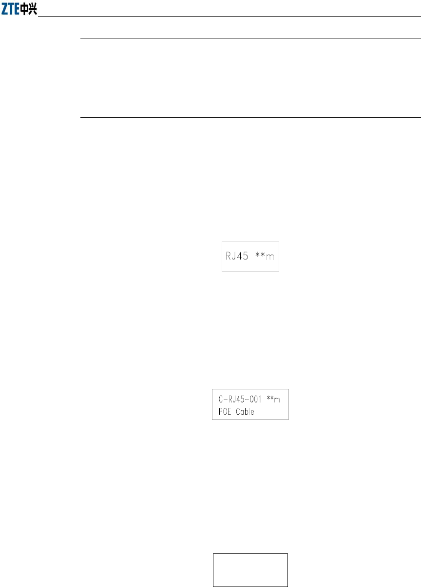
Error! Style not defined. Error! Style not defined.
B-5
Tips:
Signals and Ethernet cable wiring are defined & designed based on the interface signals
of ZTE's AC. If a 3rd-party AC is employed, the wiring of Ethernet cables should be
decided according to the practical situations.
B.2.4 Ethernet Cable Labels
After the crimping of an Ethernet cable, a label should be attached to End A and B,
labeling the name and length of the Ethernet cable.
1. Label of straight-through Ethernet cables
The label of straight-through Ethernet cables (RJ45) is shown as in Figure B.2-1.
Figure B.2-1 Label of Straight-through Ethernet Cables
"**m" in the above figure indicates the physical length of the Ethernet cable.
2. Label of PoE Ethernet Cables
The label of PoE Ethernet cables (C-RJ45-001) is shown as in Figure B.2-2.
Figure B.2-2 Label of PoE Ethernet Cables
"**m" in the above figure indicates the physical length of the Ethernet cable.
"PoE Cable" tells that this cable is a PoE Ethernet cable.
3. Label of crossover Ethernet cables
The label of crossover Ethernet cables (RJ45) is shown as in Figure B.2-3.
RJ45J * * m
Figure B.2-3 Label of Crossover Ethernet Cables

ZXR10 WAS (V1.0) IP Wireless Access System W200A Wireless Access Point User’s Manual
B-6
"**m" in the above figure indicates the physical length of the Ethernet cable. "J"
tells this cable is a crossover Ethernet cable.
Warning:
Changes or modifications to this unit not expressly approved by the party responsible
for compliance could void the user’s authority to operate the equipment. Any change to
the equipment will void FCC grant.
This equipment has been tested and found to comply with the limits for a Class B digital device, pursuant
to part 15 of the FCC Rules. These limits are designed to provide reasonable protection against harmful
interference in a residential installation. This equipment generates, uses and can radiate radio frequency
energy and, if not installed and used in accordance with the instructions, may cause harmful interference to
radio communications. However, there is no guarantee that interference will not occur in a particular
installation. If this equipment does cause harmful interference to radio or television reception, which can be
determined by turning the equipment off and on, the user is encouraged to try to correct the interference by
one or more of the following measures:
--Reorient or relocate the receiving antenna.
--Increase the separation between the equipment and receiver.
--Connect the equipment into an outlet on a circuit different from that to which the receiver is connected.
--Consult the dealer or an experienced radio/TV technician for help.