ZTE ZXR10W800A Wireless Access Point User Manual Professional Installation Manual
ZTE Corporation Wireless Access Point Professional Installation Manual
ZTE >
Contents
- 1. Usera Manal
- 2. Professional Installation Manual
- 3. Users Manual
Professional Installation Manual
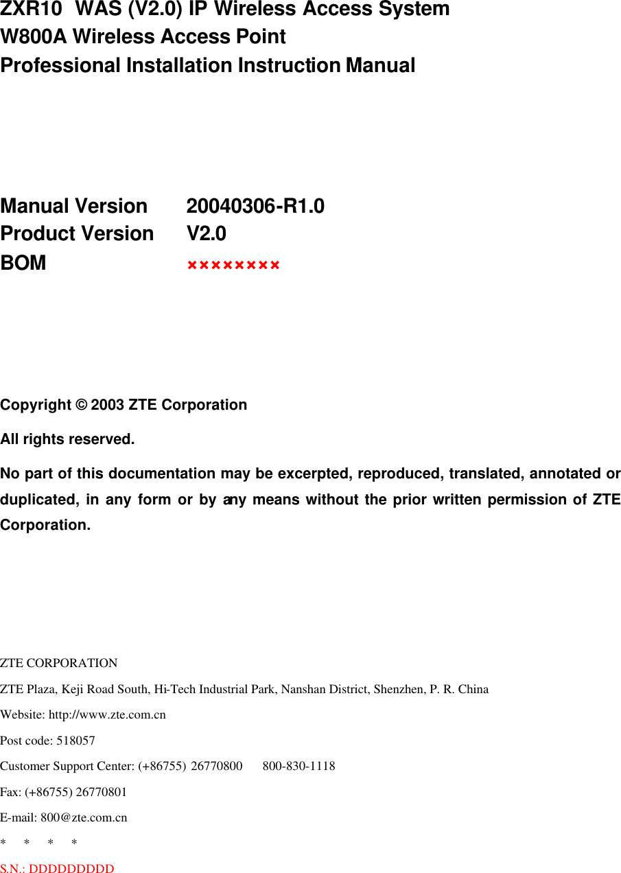
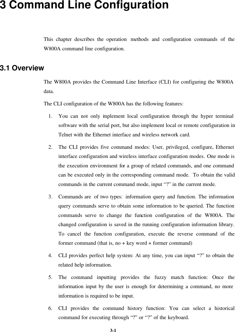
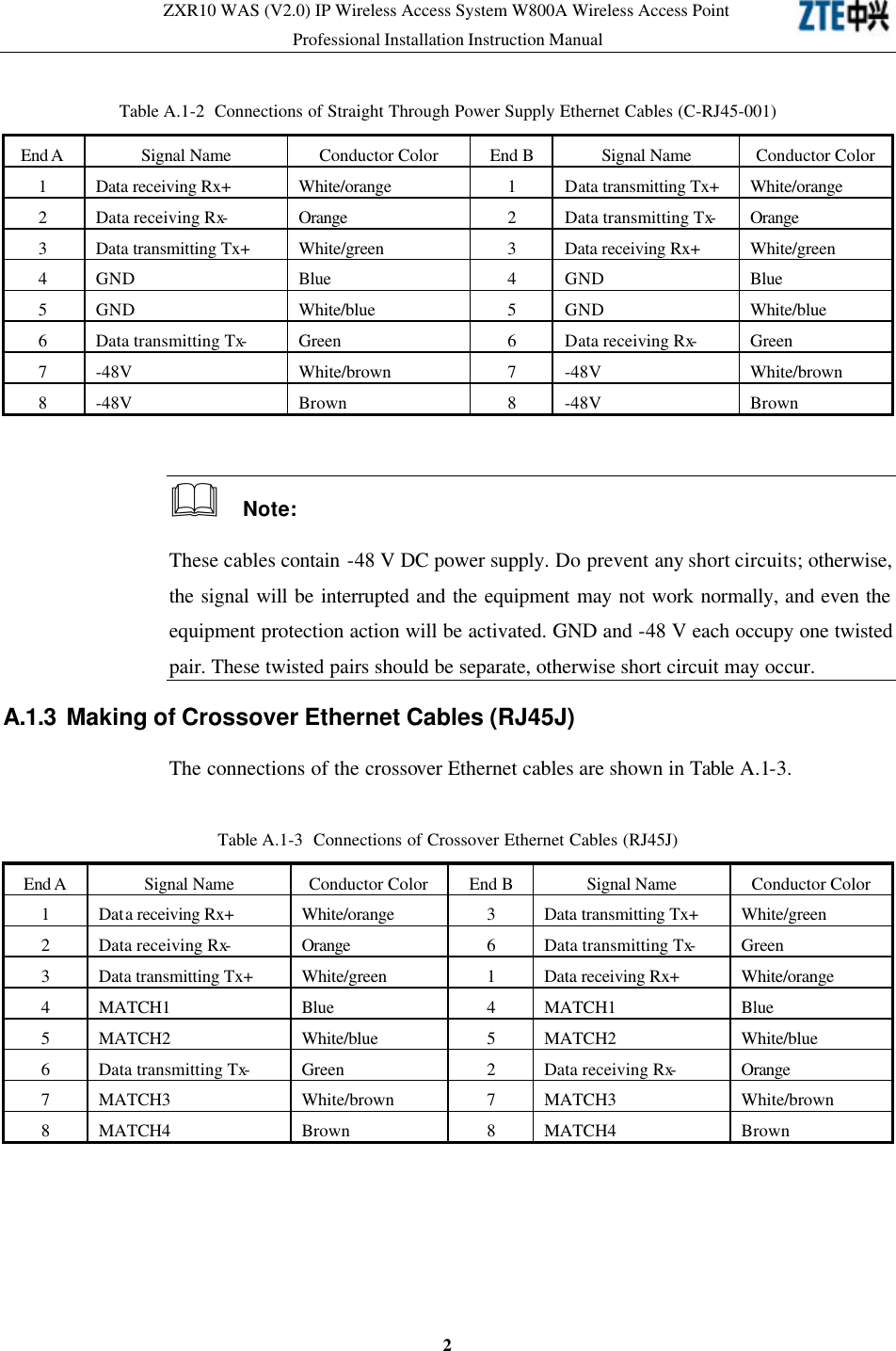
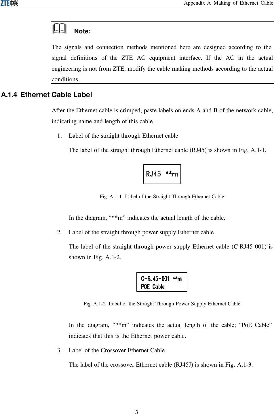
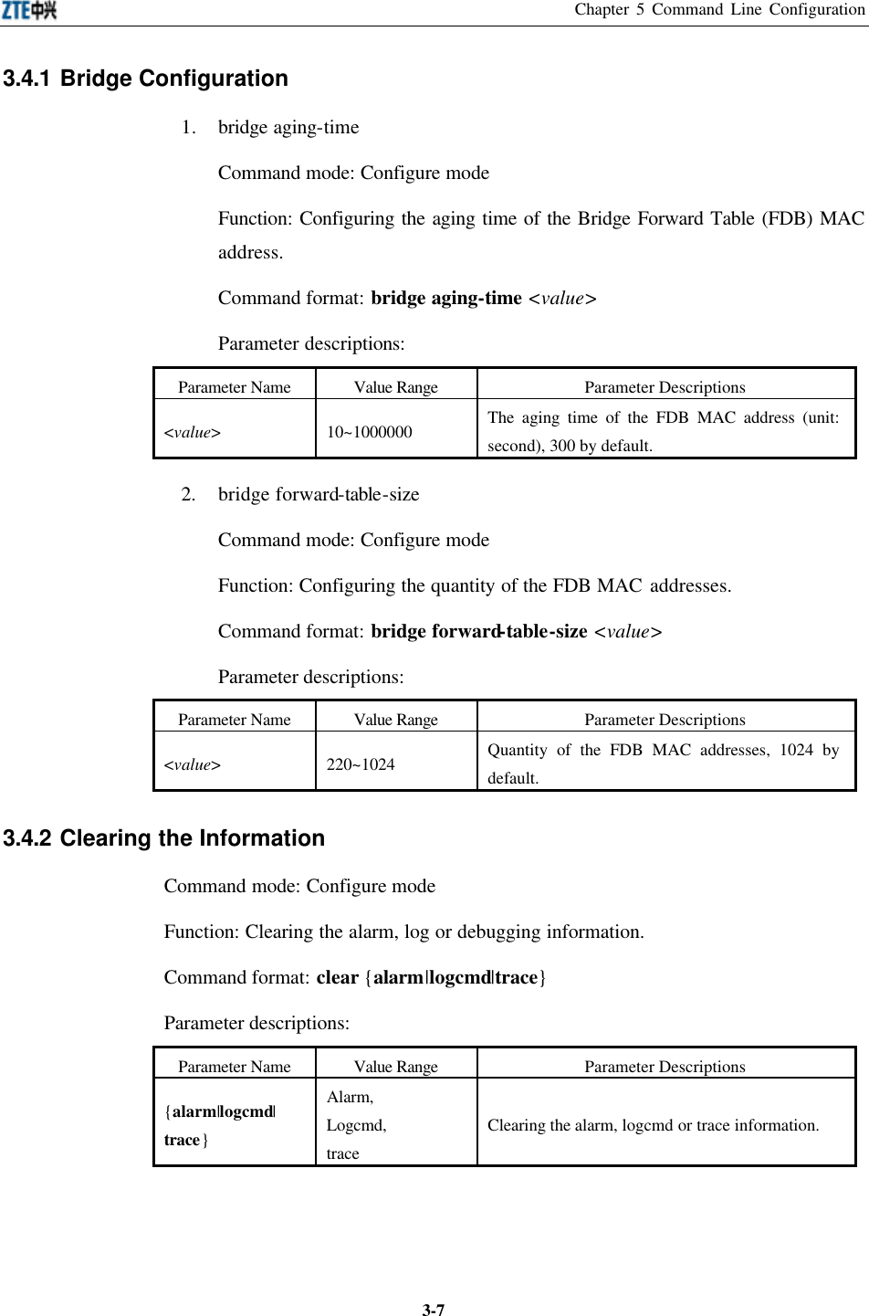
![ZXR10 WAS (V2.0) IP Wireless Access System W800A Wireless Access Point Professional Installation Instruction Manual 3-4follows: 1. abc refers to the command or keyword. 2. <abc> refers to the contents to be input by the user. 3. abc|def indicates that one of the two will be selected. 4. For the contents included in [ ], the user can choose to input or not input them.. 5. For the contents included in { }, the user must input them. 3.2 User Mode Entering mode: Telnet Exiting mode: exit Default prompt character: wlan> Note: After logging on to the W800A in Telnet, the common user can enter the user mode only once the user name and password authentications are passed. The default user name is “root” and default password is “public”. To avoid the case in which the illegal user tries with different passwords, the system will automatically disconnect from the Telnet of a user, after this user inputs wrong password for consecutive three times. 3.2.1 Entering the Privileged Mode Command mode: User mode Function: Input the correct password to enter the privileged mode. Command format: enable Note: After the user inputs the enable command and press ENTER, the system will prompt that password need be input. The default password of privileged mode is “zte”. 3.2.2 Exiting the Telnet Configuration Command mode: User mode. Function: Exiting the user mode and returning to the system. Command format: exit.](https://usermanual.wiki/ZTE/ZXR10W800A.Professional-Installation-Manual/User-Guide-455794-Page-30.png)
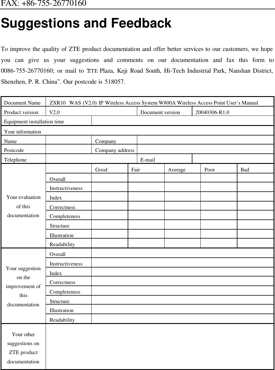
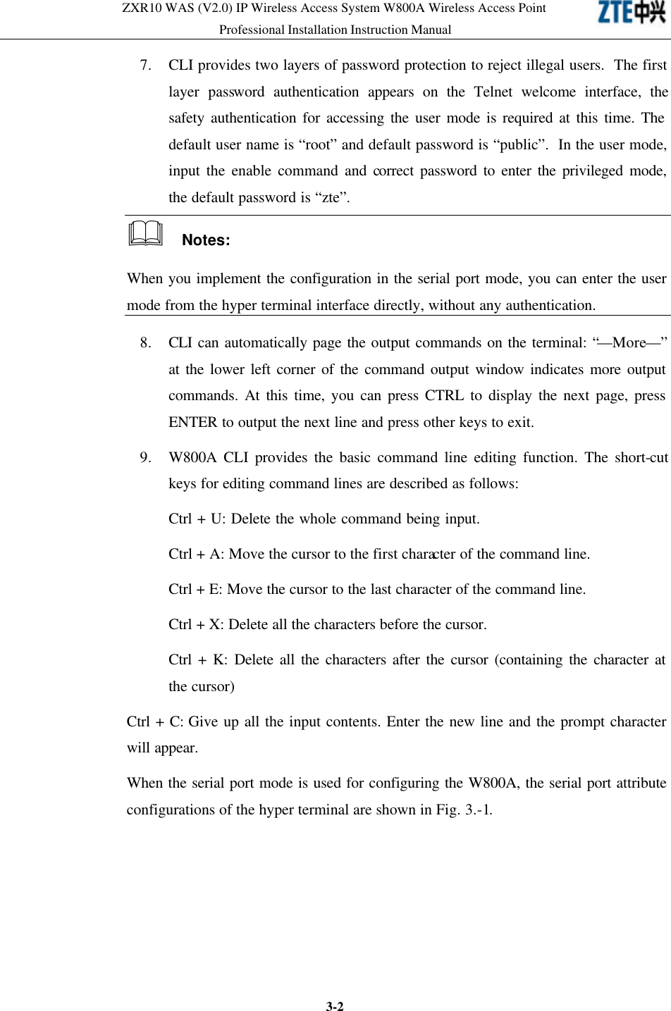
![Chapter 5 Command Line Configuration 3-53.3 Privileged Mode Entering mode: Input the enable command in the user mode and input correct password. Exiting mode: disable, entering the user mode; exit, exiting the privileged mode and returning to the system. Default prompt character: wlan # 3.3.1 Network Connectivity Check Command mode: Privileged mode Function: Checking the network connectivity. Command format: ping <A.B.C.D> [-n <echo-number>] [-w <timeout>] [-l <packet-size>] [-t] Parameter descriptions: Parameter Name Value Range Parameter Descriptions <A.B.C.D> IP address Destination IP address -n None Setting the flag bit of ping packet quantity. <echo-number> 1~40 Quantity of ping packets. -w None Setting the flag bit of the maximum time-out interval. <timeout> 1~2 Maximum time-out interval (unit: second). -l None Setting the flag bit of the buffer area capacity . <packet-size> 0~1504 Buffer area capacity -t None Setting the consecutive ping packets (complete it by <Ctrl + C>) 3.3.2 Saving the Configuration Data to FLASH Command mode: Privileged mode. Function: Saving the configuration data to FLASH. Command format: write flash. 3.3.3 Restoring the Default Configuration Command mode: Privileged mode Function: Deleting the database, recovering the default configuration of the W800A](https://usermanual.wiki/ZTE/ZXR10W800A.Professional-Installation-Manual/User-Guide-455794-Page-31.png)
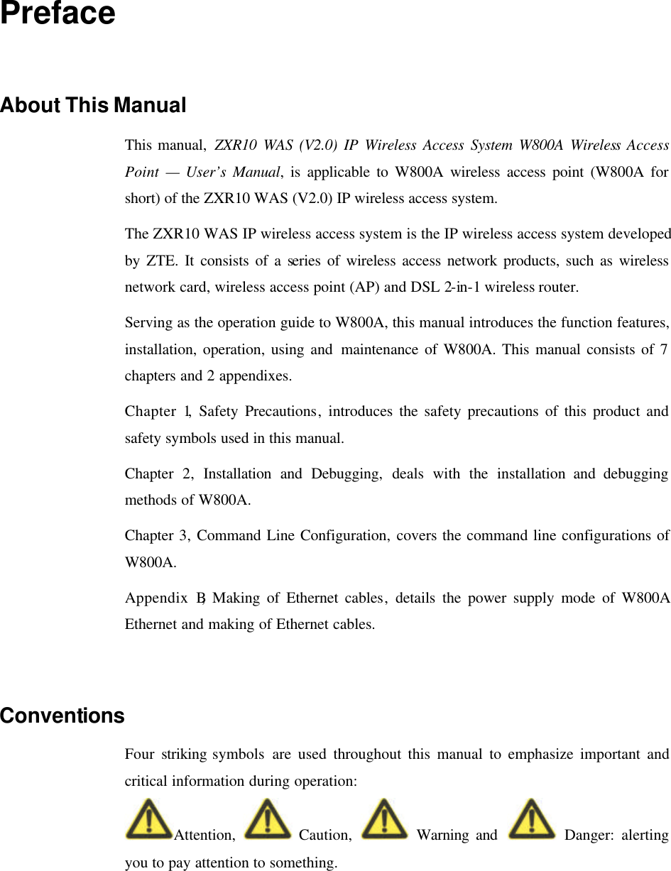
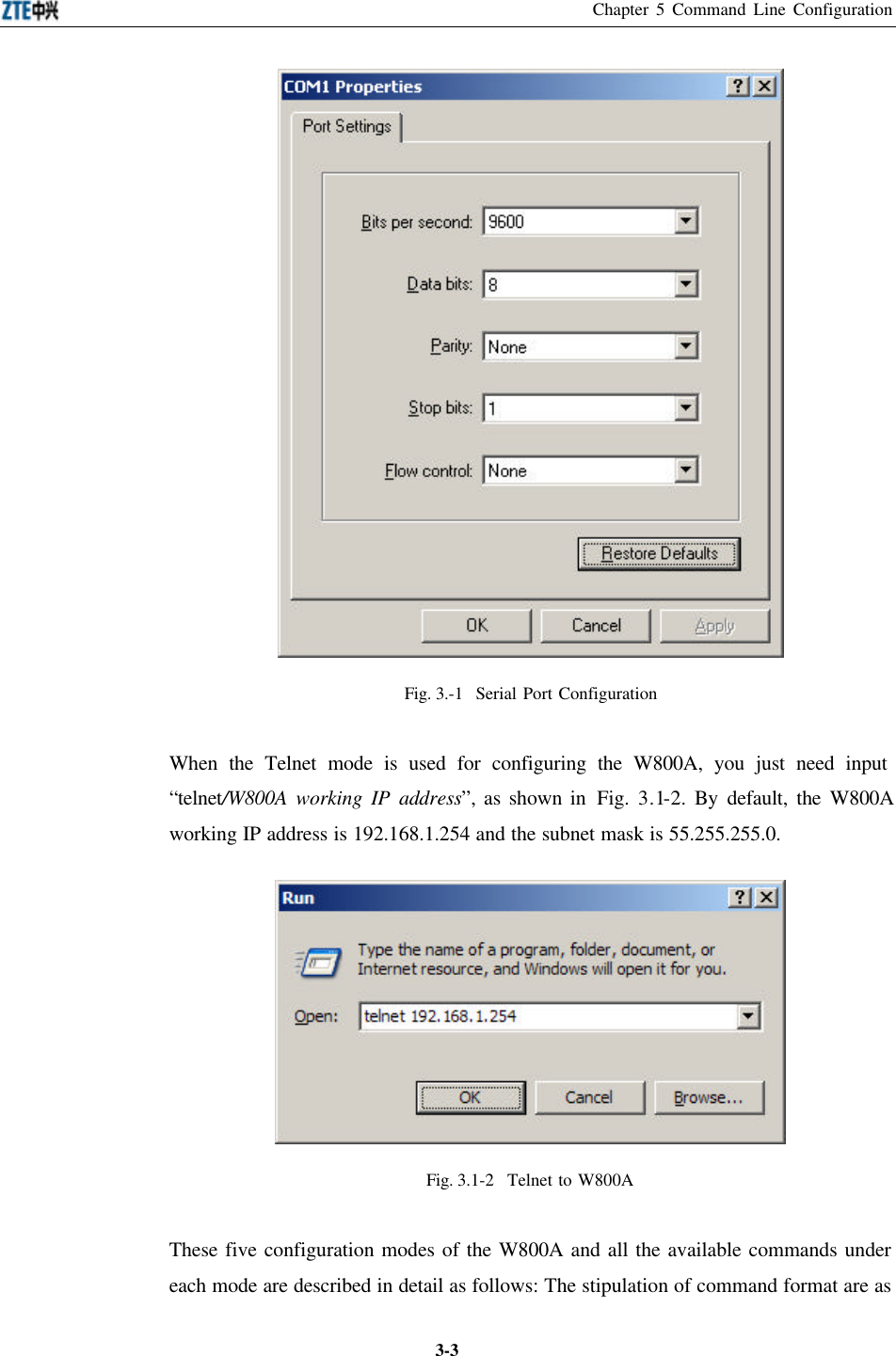
![ZXR10 WAS (V2.0) IP Wireless Access System W800A Wireless Access Point Professional Installation Instruction Manual 3-83.4.3 Configuring the Configuration Server Command mode: Configure mode Function: Configuring the parameters of configuration server: IP address, interception port number of the TCP and the interception port number of UDP. Command format: config-server {ipaddress <A.B.C.D> [tcp-port <value1> [udp-port <value2>] | udp-port <value2> [tcp-port <value1>]] | tcp-port <value1> [ipaddress <A.B.C.D> [udp-port <value2>] | udp-port <value2> [ipaddress <A.B.C.D>]] | udp-port <value2> [ipaddress <A.B.C.D> [tcp-port <value1>] | tcp-port <value1> [ipaddress <A.B.C.D>]]} Parameter descriptions: Parameter Name Value Range Parameter Descriptions <A.B.C.D> IP address IP address of the configuration server <value1> 3000~65535 The interception port number of tcp, 3601 by default. <value2> 3000~65535 The interception port number of udp, 3600 by default. Note: One or multiple parameters can be configured randomly. The un-configured parameters will keep unchanged. 3.4.4 DHCP Server Configuration 1. dhcp server dns Command mode: Configure mode Function: Configuring the IP address parameters of the master and slave DNS servers of the DHCP server. Command format: dhcp server dns <A.B.C.D1> [<A.B.C.D2>] Parameter descriptions: Parameter Name Value Range Parameter Descriptions <A.B.C.D1> IP address IP address of the master DNS server. <A.B.C.D2> IP address IP address of the slave DNS server (optional). 2. dhcp server gateway](https://usermanual.wiki/ZTE/ZXR10W800A.Professional-Installation-Manual/User-Guide-455794-Page-34.png)
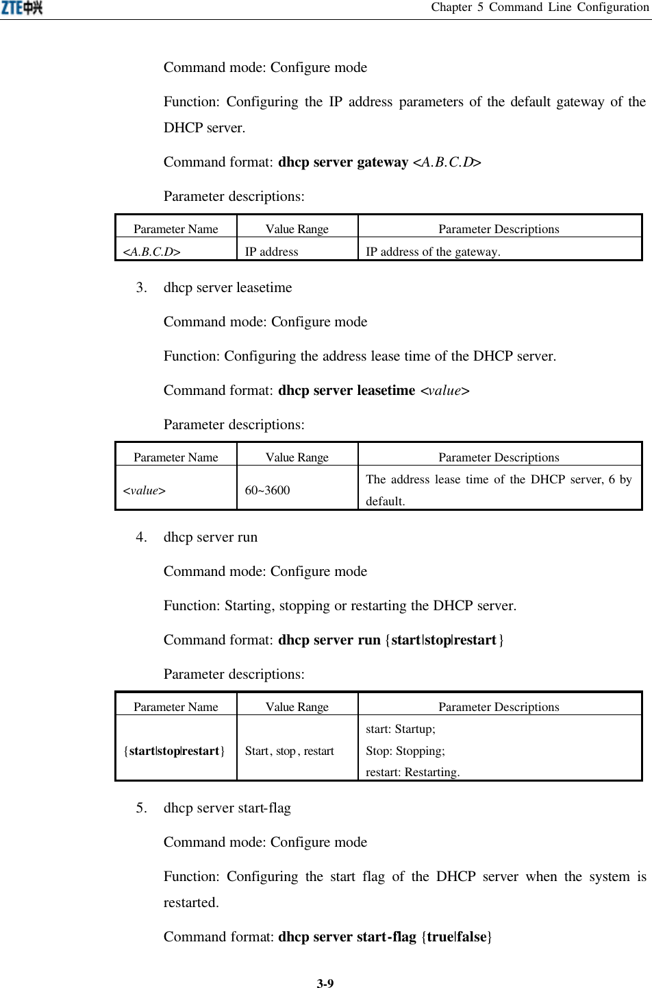
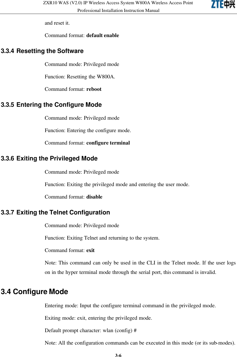
![ZXR10 WAS (V2.0) IP Wireless Access System W800A Wireless Access Point Professional Installation Instruction Manual 3-10Parameter descriptions: Parameter Name Value Range Parameter Descriptions {true|false} True, false The start flag of the DHCP server. If it is “true”, the DHCP server will be started when the system is restarted. If it is “false”, the DHCP server will not be started when the system is restarted. 3.4.5 DISCOVER Configuration 1. discover device Command mode: Configure mode Function: Configuring the integrated management multicast address and port number of the equipment. Command format: discover device <A.B.C.D> [<value>] Parameter descriptions: Parameter Name Value Range Parameter Descriptions <A.B.C.D> IP address with a range of 224.0.0.1 ~ 239.255.255.254. The integrated management multicast address of the equipment, 224.1.88.89 by default. <value> 0~65535 The interception port number of the integrated management multicast of the equipment, 2801 by default. 2. discover manager Command mode: Configure mode Function: Configuring the management multicast address and port number of the integrated management server. Command format: discover manager <A.B.C.D> [<value>] Parameter descriptions:](https://usermanual.wiki/ZTE/ZXR10W800A.Professional-Installation-Manual/User-Guide-455794-Page-36.png)
![Chapter 5 Command Line Configuration 3-11Parameter Name Value Range Parameter Descriptions <A.B.C.D> IP address with a range of 224.0.0.1 ~ 239.255.255.254. The management multicast address of the integrated management server, 224.1.88.88 by default. <value> 0~65535 The management interception port number of the integrated management server, 2800 by default. 3.4.6 802.1X Parameter Configuration 1. dot1x enable Command mode: Configure mode Function: Enabling or disabling the 802.1x function. Command format: [no] dot1x enable 2. dot1x max-reauth Command mode: Configure mode Function: Configuring the maximum times of 802.1x re-authenticating. Command format: dot1x max-reauth <value> Parameter descriptions: Parameter Name Value Range Parameter Descriptions <value> 0~10 The maximum times of 802.1x re-authenticating, 5 by default. 3. dot1x max-request Command mode: Configure mode Function: Configuring the maximum times of 802.1x authentication request. Command format: dot1x max-request <value> Parameter descriptions: Parameter Name Value Range Parameter Descriptions <value> 1~10 The maximum times of 802.1x authentication request, 2 by default. 4. dot1x md5-domain](https://usermanual.wiki/ZTE/ZXR10W800A.Professional-Installation-Manual/User-Guide-455794-Page-37.png)
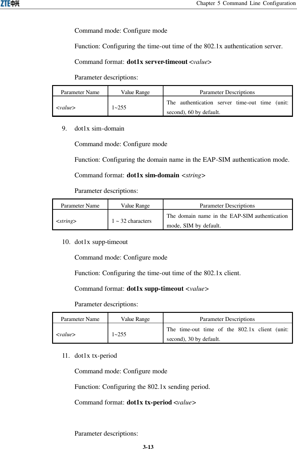
![ZXR10 WAS (V2.0) IP Wireless Access System W800A Wireless Access Point Professional Installation Instruction Manual 3-12Command mode: Configure mode Function: Configuring the domain name in the EAP-MD5 authentication mode. Command format: dot1x md5-domain <string> Parameter descriptions: Parameter Name Value Range Parameter Descriptions <string> 1 ~ 32 characters The domain name in the EAP-MD5 authentication mode, USR by default. 5. dot1x nas-id Command mode: Configure mode Function: Configuring the 802.1x NAS-ID field information. Command format: dot1x nas-id <string> Parameter descriptions: Parameter Name Value Range Parameter Descriptions <string> 1 ~ 64 characters NAS-ID character string, W800A by default. 6. dot1x portenable Command mode: Configure mode Function: Enabling or disabling the 802.1x port control function. Command format: [no] dot1x portenable 7. dot1x quiet-period Command mode: Configure mode Function: Configuring the 802.1x quiet period. Command format: dot1x quiet-period <value> Parameter descriptions: Parameter Name Value Range Parameter Descriptions <value> 1~255 The 802.1x quiet period (unit: second), 30 by default. 8. dot1x server-timeout](https://usermanual.wiki/ZTE/ZXR10W800A.Professional-Installation-Manual/User-Guide-455794-Page-38.png)
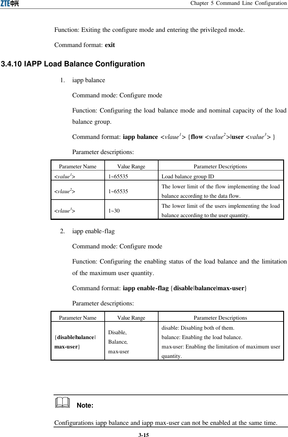
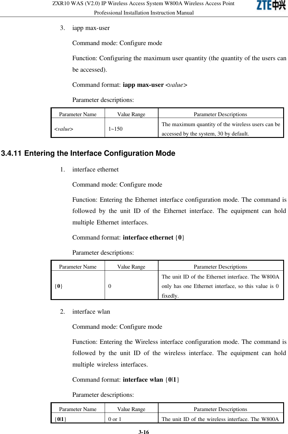
![Chapter 5 Command Line Configuration 3-17has two wireless interfaces, so this value is 0 or 1. 3.4.12 IP Network Parameter Configuration 1. ip address Command mode: Configure mode Function: Adding the IP address of the W800A management interface. Command format: [no] ip address <A.B.C.D1> <A.B.C.D2> [second] Parameter descriptions: Parameter Name Value Range Parameter Descriptions <A.B.C.D1> IP address IP address of the host. <A.B.C.D2> Subnet mask Subnet mask of the host. second second The main address is without “second” and the standby address is with “second”. The main address quantity can only be one and the standby address quantity can be up to nine. 2. ip route Command mode: Configure mode Function: Configuring the default route address of the system. Command format: [no] ip route <A.B.C.D1> <A.B.C.D2> <A.B.C.D3> Parameter descriptions: Parameter Name Value Range Parameter Descriptions <A.B.C.D1> IP address IP address of the host. <A.B.C.D2> Subnet mask Subnet mask of the host. <A.B.C.D3> IP address IP address of the router of the next hop. 3. ip pool Command mode: Configure mode Function: Configuring the IP address pool of the system. Command format: [no] ip pool <index> <A.B.C.D1> <A.B.C.D2> <A.B.C.D3> Parameter descriptions: Parameter Name Value Range Parameter Descriptions <index> 0~9 IP address pool group ID](https://usermanual.wiki/ZTE/ZXR10W800A.Professional-Installation-Manual/User-Guide-455794-Page-43.png)
![ZXR10 WAS (V2.0) IP Wireless Access System W800A Wireless Access Point Professional Installation Instruction Manual 3-18<A.B.C.D1> IP address Initial IP address of the host address pool. <A.B.C.D2> IP address End IP address of the host address pool. <A.B.C.D3> Subnet mask Subnet mask of the address pool address. 3.4.13 Kicking Users 1. kick all Command mode: Configure mode Function: Kicking all the users. Command format: kick all 2. kick station Command mode: Configure mode Function: Kicking the user with the specified MAC address. Command format: kick station <xx-xx-xx-xx-xx-xx> Parameter descriptions: Parameter Name Value Range Parameter Descriptions <xx-xx-xx-xx-xx-xx> MAC address User MAC address 3.4.14 Two-Layer Separation Configuration 1. l2-separate enable Command mode: Configure mode Function: Enabling or disabling the two-layer separation function. Command format: [no] l2-separate enable 2. l2-separate gateway Command mode: Configure mode Function: Configuring the gateway MAC address . Command format: l2-separate gateway mac <xx-xx-xx-xx-xx-xx> Parameter descriptions: Parameter Name Value Range Parameter Descriptions <xx-xx-xx-xx-xx-xx> MAC address Gateway MAC address](https://usermanual.wiki/ZTE/ZXR10W800A.Professional-Installation-Manual/User-Guide-455794-Page-44.png)
![Chapter 5 Command Line Configuration 3-193. l2-separate mode Command mode: Configure mode Function: Configuring the two-layer separation working mode. Command format: l2-separate mode {simple_mode| gateway_mode } Parameter descriptions: Parameter Name Value Range Parameter Descriptions {simple_mode| gateway_mode } simple_mode, gateway_mode Selecting the simple mode or gateway mode for the two-layer separation. 3.4.15 Log Printing Message Configuration 1. logmsg all-enable Command mode: Configure mode Function: Enabling or disabling the log printing messages of all the modules. Command format: [no] logmsg all-enable 2. logmsg level Command mode: Configure mode Function: Configuring the levels of the log printing messages to be output. Command format: logmsg level {Lowest|Lower|Higher|Highest} Parameter descriptions: Parameter Name Value Range Parameter Descriptions {Lowest|Lower| Higher|Highest} Lowest (Flood), Lower (Info), Higher (Error), Highest (Fatal) Level of the log printing messages to be output. Only the printing messages higher than this level can be output. 3. logmsg mod-enable Command mode: Configure mode Function: Determining the module containing the log printing messages. Command format: [no] logmsg mod-enable <module> Parameter descriptions:](https://usermanual.wiki/ZTE/ZXR10W800A.Professional-Installation-Manual/User-Guide-455794-Page-45.png)
![ZXR10 WAS (V2.0) IP Wireless Access System W800A Wireless Access Point Professional Installation Instruction Manual 3-20Parameter Name Value Range Parameter Descriptions <module> Specified module names: BSP, DATABASE, 80211, BRIDGE, IAPP, DHCP, IPPOOL, DOT1X, RADIUS, ACL, SVCMANAGE, TELNET, WEB, CONSOLE, SNMP, ALARM, R01, TFTP, DISCOVER, QOS The module containing the log printing messages. 4. logmsg telnet-log Command mode: Configure mode Function: Configuring the current Telnet window as the output window of the log printing messages Command format: [no] logmsg telnet-log 3.4.16 MAC Filtration Configuration Command mode: Configure mode Function: Adding or deleting a number accessing list. Command format: [no] mac-access-list <value> {deny|permit} {<xx-xx-xx-xx-xx-xx>|any} Parameter descriptions: Parameter Name Value Range Parameter Descriptions <value> 1~99 MAC filtration group ID {deny|permit} deny, permit deny: If the condition is satisfied, the MAC communication will be denied. permit: If the condition is satisfied, the MAC communication will be permitted.](https://usermanual.wiki/ZTE/ZXR10W800A.Professional-Installation-Manual/User-Guide-455794-Page-46.png)
![Chapter 5 Command Line Configuration 3-21Parameter Name Value Range Parameter Descriptions {<xx-xx-xx-xx-xx-xx> |any} MAC address or any The MAC address sending the MAC packet. Two methods can be used for specifying the source address: One is to use the format of 48-bit 6 hexadecimal hyphens, for example: 00-d0-d0-f1-c4-ef. The other is to use the keyword any as the abbreviation of the source 00-00-00-00-00-00. This keyword is not recommended. 3.4.17 MAC Address Authentication Configuration Command mode: Configure mode Function: Configuring the MAC address authentication function. Command format: [no] mac-authen {deny|permit} {<xx-xx-xx-xx-xx-xx>|any} Parameter descriptions: Parameter Name Value Range Parameter Descriptions {deny|permit} Deny, permit deny: If the condition is satisfied, the MAC communication will be denied. permit: If the condition is satisfied, the MAC communication will be permitted. {<xx-xx-xx-xx-xx-xx> |any} MAC address or any The MAC address sending the MAC packet. Two methods can be used for specifying the source address: One is to use the format of 48-bit 6 hexadecimal hyphens, for example: 00-d0-d0-f1-c4-ef; The other is to use the keyword any as the abbreviation of the source 00-00-00-00-00-00, and this keyword is not recommended. 3.4.18 Manager Configuration Command mode: Configure mode Function: Adding or deleting the manager account. Command format: [no] manage-user <string1> <string2>](https://usermanual.wiki/ZTE/ZXR10W800A.Professional-Installation-Manual/User-Guide-455794-Page-47.png)
![ZXR10 WAS (V2.0) IP Wireless Access System W800A Wireless Access Point Professional Installation Instruction Manual 3-22Parameter descriptions: Parameter Name Value Range Parameter Descriptions <string1> 1 ~ 32 characters User name <string2> 1 ~ 32 characters User password. 3.4.19 QoS Configuration 1. qos enable Command mode: Configure mode Function: Enabling or disabling QoS function. Command format: [no] qos enable 2. qos policy Command mode: Configure mode Function: Configuring QoS policy. Command format: qos policy {ESSID|802.1p} Parameter descriptions: Parameter Name Value Range Parameter Descriptions {ESSID|802.1p} ESSID, 802.1p Indicating the priority policy which is the base of QoS, ESSID by default. 3.4.20 RADIUS Server Configuration 1. radius-server account Command mode: Configure mode Function: Adding or deleting the accounting server of an ISP. Command format: [no] radius-server account <string1> {master|slave} <A.B.C.D> <value> <string2> Parameter descriptions: Parameter Name Value Range Parameter Descriptions <string1> 1 ~ 32 characters ISP name, and only the created ISP can be input. {master|slave } Master, slave Master or slave flag of the accounting server. <A.B.C.D> IP address IP address of the accounting server <value> 0~65535 Port number of the accounting server](https://usermanual.wiki/ZTE/ZXR10W800A.Professional-Installation-Manual/User-Guide-455794-Page-48.png)
![Chapter 5 Command Line Configuration 3-23Parameter Name Value Range Parameter Descriptions <string2> 1 ~ 255 characters Character string of the accounting shared secret key 2. radius-server authen Command mode: Configure mode Function: Adding or deleting the authentication server of an ISP. Command format: [no] radius-server authen <string1> {master|slave} <A.B.C.D> <value> <string2> Parameter descriptions: Parameter Name Value Range Parameter Descriptions <string1> 1 ~ 32 characters ISP name, and only the created ISP can be input. {master|slave } Master, slave Master/slave authentication server. The master authentication server can only be one. <A.B.C.D> IP address IP address of the authentication server <value> 0~65535 Port number of the authentication server <string2> 1 ~ 255 characters Character string of the authentication shared secret key 3. radius-server dns Command mode: Configure mode Function: Adding or deleting the DNS server of an ISP. Command format: [no] radius-server dns <string> Parameter descriptions: Parameter Name Value Range Parameter Descriptions <string> 1 ~ 32 characters ISP name, and only the created ISP can be input. 4. radius-server isp-name Command mode: Configure mode Function: Adding or deleting an ISP. Command format: [no] radius-server isp-name <string> Parameter descriptions: Parameter Name Value Range Parameter Descriptions <string> 1 ~ 32 characters ISP name.](https://usermanual.wiki/ZTE/ZXR10W800A.Professional-Installation-Manual/User-Guide-455794-Page-49.png)
![ZXR10 WAS (V2.0) IP Wireless Access System W800A Wireless Access Point Professional Installation Instruction Manual 3-245. radius-server retry-times Command mode: Configure mode Function: Configuring the retrying times of the RADIUS authentication of an ISP. Command format: radius-server retry-times <string> <value> Parameter descriptions: Parameter Name Value Range Parameter Descriptions <string> 1 ~ 32 characters ISP name, and only the created ISP can be input. <value> 1~10 The retrying times of the RADIUS authentication, 3 by default. 6. radius-server timeout Command mode: Configure mode Function: Configuring the time-out time of the RADIUS authentication of an ISP. Command format: radius-server timeout <string> <value> Parameter descriptions: Parameter Name Value Range Parameter Descriptions <string> 1 ~ 32 characters ISP name, and only the created ISP can be input. <value> 1~65535 The time-out time of the RADIUS authentication (unit: second), 2 by default. 3.4.21 SNMP Module Configuration 1. snmp access-host Command mode: Configure mode Function: Adding or deleting the IP address of the host which can be accessed. Command format: [no] snmp access-host <A.B.C.D> Parameter descriptions: Parameter Name Value Range Parameter Descriptions <A.B.C.D> IP address The host IP address represented by dotted decimal (A.B.C.D) (at most 10).](https://usermanual.wiki/ZTE/ZXR10W800A.Professional-Installation-Manual/User-Guide-455794-Page-50.png)
![Chapter 5 Command Line Configuration 3-252. snmp access-mode Command mode: Configure mode Function: Configuring the local agent can be accessed by all the hosts or the host in access-host. Command format: snmp access-mode {all|list} Parameter descriptions: Parameter Name Value Range Parameter Descriptions {all|list} All, list all: All the users can access it. list: The users in access-host can access it. 3. snmp authtrap Command mode: Configure mode Function: Enabling or disabling the community string authentication. Command format: [no] snmp authtrap enable 4. snmp community Command mode: Configure mode Function: Configuring the SNMP access community string and its accessing authority. Command format: snmp community <string> {read-only| read-write} no snmp community <string> Parameter descriptions: Parameter Name Value Range Parameter Descriptions <string> 1 ~ 32 characters SNMP access community string name (at most 10). <string> is a character string with at most 32 characters. {read-only| read-write} read-only, read-write read-only: Read-only authority. read-write: Read-write authority. 5. snmp contact Command mode: Configure mode Function: Configuring the name and contact method of the equipment manager. Command format: snmp contact <End-Mark> <string>](https://usermanual.wiki/ZTE/ZXR10W800A.Professional-Installation-Manual/User-Guide-455794-Page-51.png)
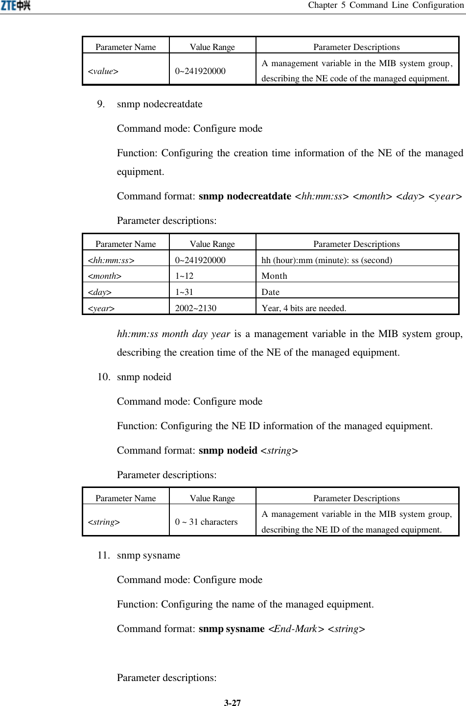
![ZXR10 WAS (V2.0) IP Wireless Access System W800A Wireless Access Point Professional Installation Instruction Manual 3-26Parameter descriptions: Parameter Name Value Range Parameter Descriptions <End-Mark> Any character. Serving as the end mark of inputting character string. <string> 1 ~ 255 characters A management variable content in the MIB II system group, containing the name and contact method of the equipment manager. 6. snmp enable Command mode: Configure mode Function: Enabling or disabling the SNMP management function. Command format: [no] snmp enable 7. snmp location Command mode: Configure mode Function: Configuring the geographic location information of the managed equipment. Command format: snmp location <End-Mark> <string> Parameter descriptions: Parameter Name Value Range Parameter Descriptions <End-Mark> Any character. Serving as the end mark of inputting character string. <string> 1 ~ 255 characters sysLocation, a management variable in the MIB system group, describing the geographic location of the managed equipment. 8. snmp nodecode Command mode: Configure mode Function: Configuring the NE code information of the managed equipment. Command format: snmp nodecode <value> Parameter descriptions:](https://usermanual.wiki/ZTE/ZXR10W800A.Professional-Installation-Manual/User-Guide-455794-Page-52.png)
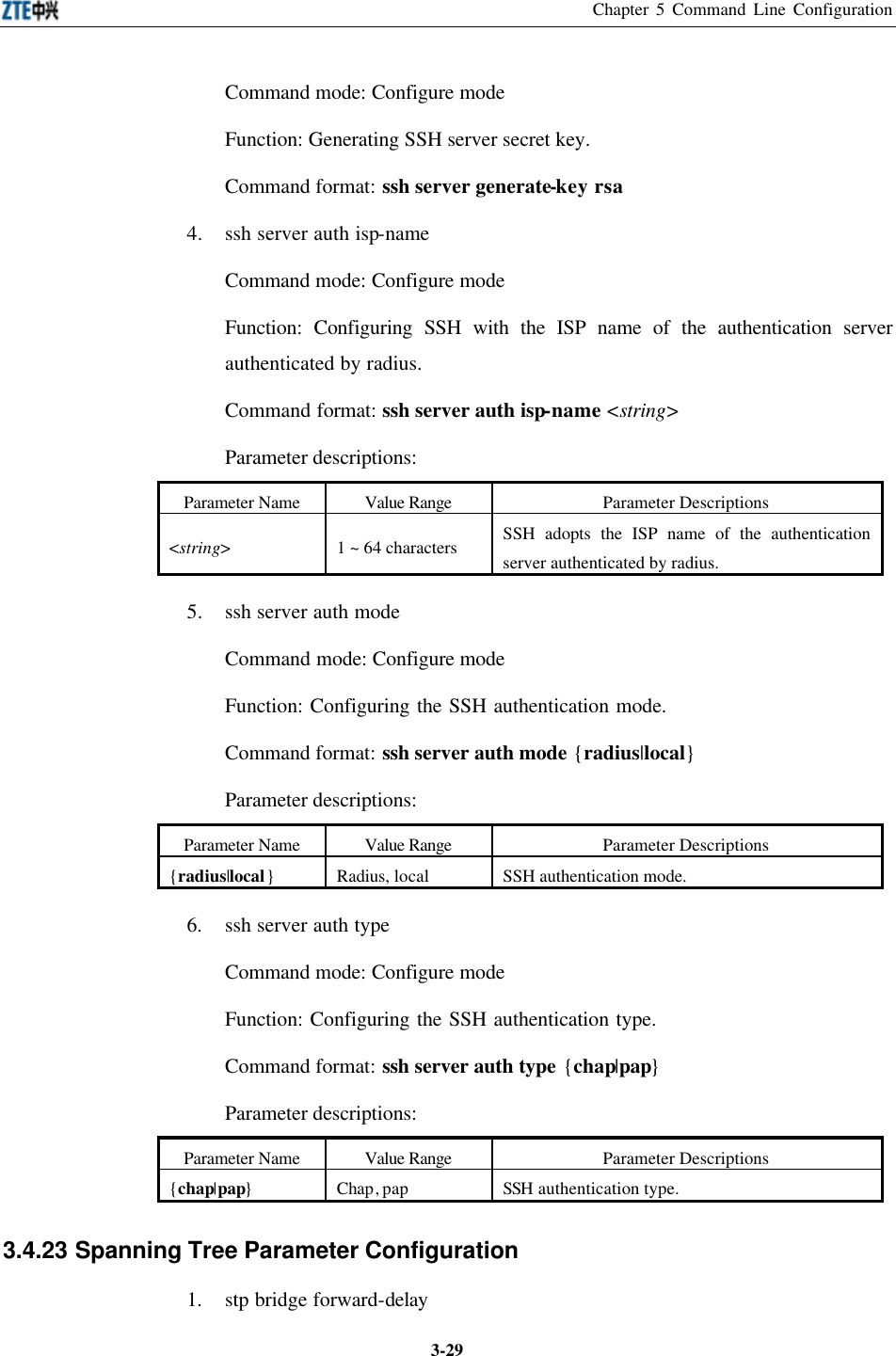
![ZXR10 WAS (V2.0) IP Wireless Access System W800A Wireless Access Point Professional Installation Instruction Manual 3-28Parameter Name Value Range Parameter Descriptions <End-Mark> Any character. Serving as the end mark of inputting character string. <string> 1 ~ 255 characters RFC1213, a management variable in the MIB system group, and it is the name of the managed equipment. 12. snmp trap enable Command mode: Configure mode Function: Enabling or disabling SNMP Agent to send trap. Command format: [no] snmp trap enable 13. snmp traphost Command mode: Configure mode Function: Adding a trap target host address and trap version number information. Command format: [no] snmp traphost <A.B.C.D> [version <value>] Parameter descriptions: Parameter Name Value Range Parameter Descriptions <A.B.C.D> IP address trap target host address. <value> 1~2 trap version number. 3.4.22 SSH Parameter Configuration 1. ssh server enable Command mode: Configure mode Function: Enabling or disabling SSH function. Command format: [no] ssh server enable 2. ssh server only Command mode: Configure mode Function: Enabling or disabling SSH function, and disabling Telnet function. Command format: [no] ssh server only 3. ssh server generate-key rsa](https://usermanual.wiki/ZTE/ZXR10W800A.Professional-Installation-Manual/User-Guide-455794-Page-54.png)
![Chapter 5 Command Line Configuration 3-31Parameter Name Value Range Parameter Descriptions <value> 0~65535 The priority of the spanning tree protocol bridge, 32768 by default. 5. stp enable Command mode: Configure mode Function: Enabling or disabling the spanning tree protocol function. Command format: [no] stp enable 6. stp interface path-cost Command mode: Configure mode Function: Configuring the path cost of the spanning tree protocol interface. Command format: stp interface path-cost {eth0|wlan0|wlan1} <value> Parameter descriptions: Parameter Name Value Range Parameter Descriptions {eth0|wlan0|wlan1} eth0, wlan0, wlan1 Configured interface. <value> 1~65535 The path cost of the spanning tree protocol interface . 7. stp interface priority Command mode: Configure mode Function: Configuring the priority of the spanning tree protocol interface. Command format: stp interface priority {eth0|wlan0|wlan1} <value> Parameter descriptions: Parameter Name Value Range Parameter Descriptions {eth0|wlan0|wlan1} eth0, wlan0, wlan1 Configured interface. <value> 0~255 The priority of the spanning tree protocol interface, 128 by default. 8. stp interface state Command mode: Configure mode Function: Configuring the state of the spanning tree protocol interface. Command format: stp interface state {eth0|wlan0|wlan1} {enable|disable}](https://usermanual.wiki/ZTE/ZXR10W800A.Professional-Installation-Manual/User-Guide-455794-Page-57.png)
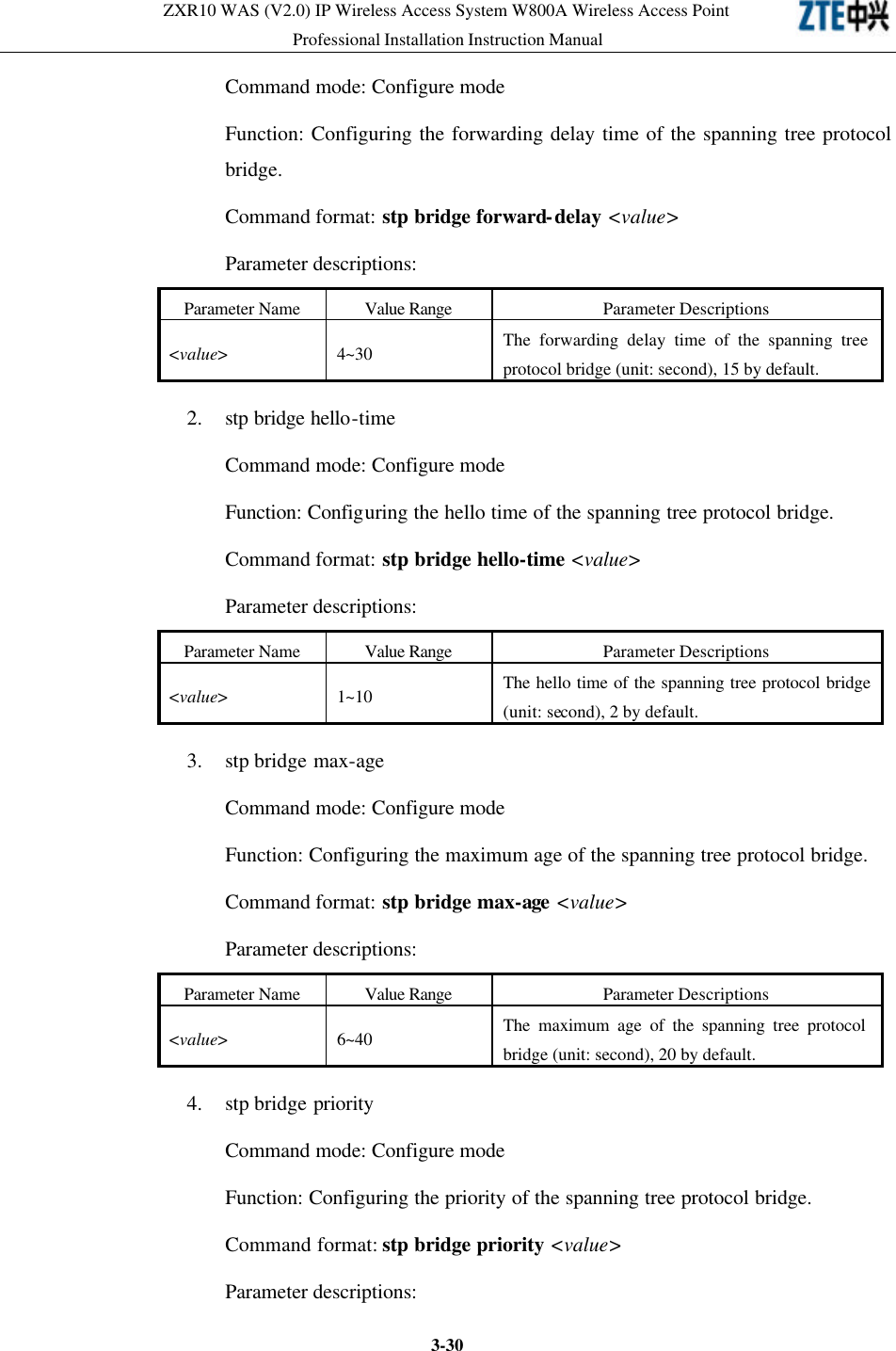
![ZXR10 WAS (V2.0) IP Wireless Access System W800A Wireless Access Point Professional Installation Instruction Manual 3-32Parameter descriptions: Parameter Name Value Range Parameter Descriptions {eth0|wlan0|wlan1} eth0, wlan0, wlan1 Configured interface. {enable|disable} Enable, disable The state of the spanning tree protocol interface, enable by default. 3.4.24 TELNET Configuration 1. telnet enable Command mode: Configure mode Function: Enabling or disabling Telnet function. Command format: [no] telnet enable 2. telnet idletime Command mode: Configure mode Function: Configuring the automatic exiting time when the Telnet window is idle. Command format: telnet idletime <value> Parameter descriptions: Parameter Name Value Range Parameter Descriptions <value> 300~3600 The automatic exiting time when the Telnet window is idle (unit: second), 300 by default. 3.4.25 Uploading/Downloading TFTP Files 1. tftp dir Command mode: Configure mode Function: Observing the spare space of the flash disk (unit: byte) Command format: tftp dir 2. tftp get: downloading files Command mode: Configure mode Function: With TFTP transmission protocol, downloading files from the TFTP server and save them to the flash disk](https://usermanual.wiki/ZTE/ZXR10W800A.Professional-Installation-Manual/User-Guide-455794-Page-58.png)
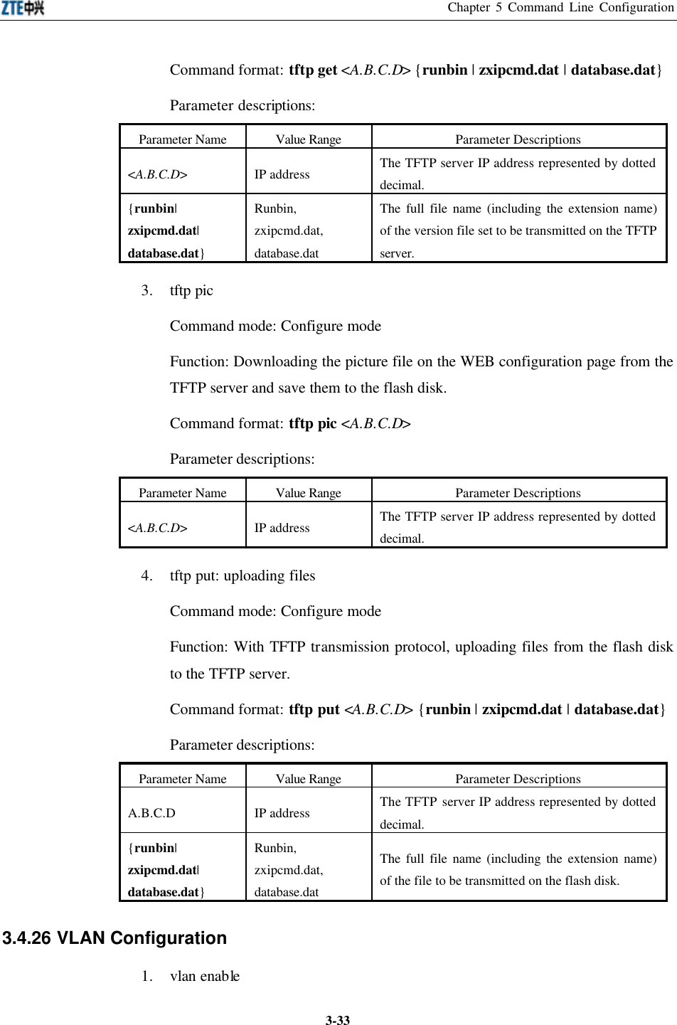
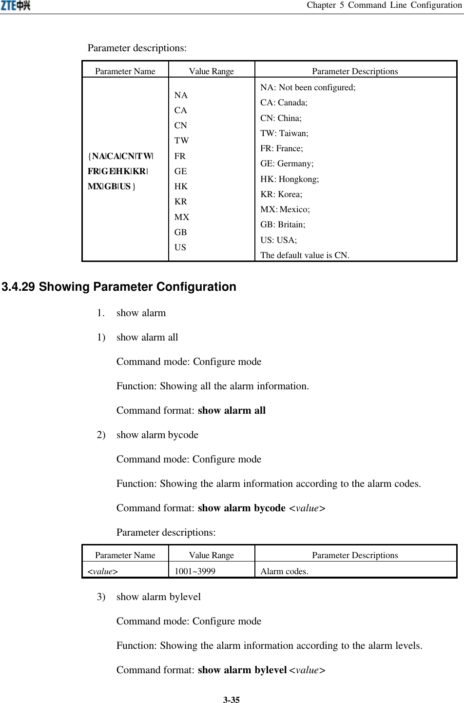
![ZXR10 WAS (V2.0) IP Wireless Access System W800A Wireless Access Point Professional Installation Instruction Manual 3-34Command mode: Configure mode Function: Enabling or disabling VLAN function. Command format: [no] vlan enable 2. vlan manager-vlanid Command mode: Configure mode Function: Configuring the VLAN of the management interface. Command format: vlan manager-vlanid <value> Parameter descriptions: Parameter Name Value Range Parameter Descriptions <value> 0~4094 0: The management interface is without VLAN. 1 ~ 4094: The VLAN domain flag of the management interface. The default value is 0. 3.4.27 Web Configuration Command mode: Configure mode Function: Enabling or disabling web function. Command format: [no] web enable 3.4.28 Nation Zone Configuration Command mode: Configure mode Function: Configuring the nation and zone whether the equipment is located, for setting the corresponding channel and frequency band. Command format: zone {NA|CA|CN|TW|FR|GE|HK|KR|MX|GB|US}](https://usermanual.wiki/ZTE/ZXR10W800A.Professional-Installation-Manual/User-Guide-455794-Page-60.png)
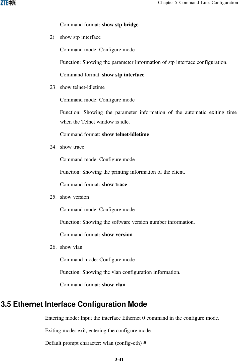
![ZXR10 WAS (V2.0) IP Wireless Access System W800A Wireless Access Point Professional Installation Instruction Manual 3-42Note: All the information of the corresponding interface can be configured in this mode. 3.5.1 Exiting the Ethernet Interface Configuration Mode Command mode: Ethernet interface configure mode Function: Exiting the Ethernet interface configuration mode and entering the configure mode. Command format: exit 3.5.2 Ethernet Interface MAC Filtration Configuration Command mode: Ethernet interface configure mode Function: Configuring the Ethernet interface MAC filtration. Command format: [no] macl-bind <value> {in} Parameter descriptions: Parameter Name Value Range Parameter Descriptions <value> 1~99 The article number of the MAC filtration bound to the interface. {in} in The in direction bound to the interface. 3.6 Wireless Interface Configuration Mode Entering mode: Input the interface wlan {0|1} command in the configure mode. Exiting mode: exit, entering the configure mode. Default prompt character: wlan (config-wlan) # Note: All the information of the corresponding interface can be configured in this mode. 3.6.1 802.11-Related Parameter Configuration of the Wireless Interface 1. 80211 authmode Command mode: Wireless interface configure mode Function: Configuring the wireless authentication mode of the AP. Command format: 80211 authmode {OpenSystem | ShareKey}](https://usermanual.wiki/ZTE/ZXR10W800A.Professional-Installation-Manual/User-Guide-455794-Page-68.png)
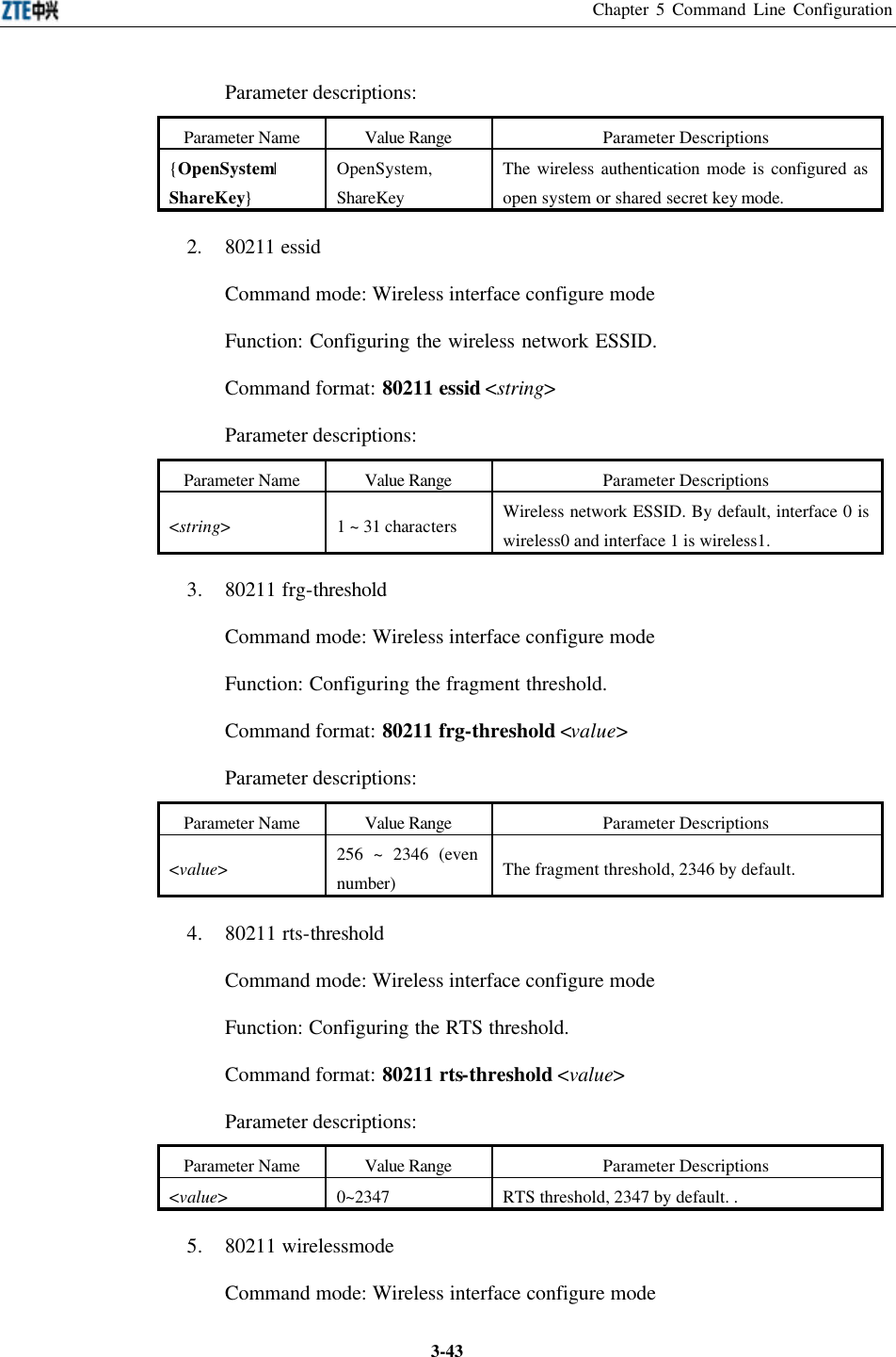
![ZXR10 WAS (V2.0) IP Wireless Access System W800A Wireless Access Point Professional Installation Instruction Manual 3-44Function: Configuring the wireless standard working mode of the wireless interface. Command format: 80211 wirelessmode {11a|11b|11g|help} [channel <num>] [rate <value>] Parameter descriptions: Parameter Name Value Range Parameter Descriptions {11a|11 b|11g|help} 11a, 11b, 11g, help 11a: Configuring 800A as the 802.11a working mode. 11b: Configuring 800A as the 802.11b working mode. 11g: Configuring 800A as the 802.11g working mode. help: Listing the configurable channels in the current working mode, according to the configured country code. <num> Configure the 800A working channel. Select the proper channel according to the country code. See Table 3.6-1 for the corresponding relationship of the nation code and selectable channel. <value> 11a: auto, 6Mbps, 9Mbps, 12Mbps, 18Mbps, 24Mbps, 36Mbps, 48Mbps, 54Mbps; 11b: auto, 1Mbps, 2Mbps, 5.5Mbps, 11Mbps; 11g: auto, 6Mbps, 9Mbps, 12Mbps, 18Mbps, 24Mbps, 36Mbps, 48Mbps, 54Mbps Configuring the 800A working rate.](https://usermanual.wiki/ZTE/ZXR10W800A.Professional-Installation-Manual/User-Guide-455794-Page-70.png)
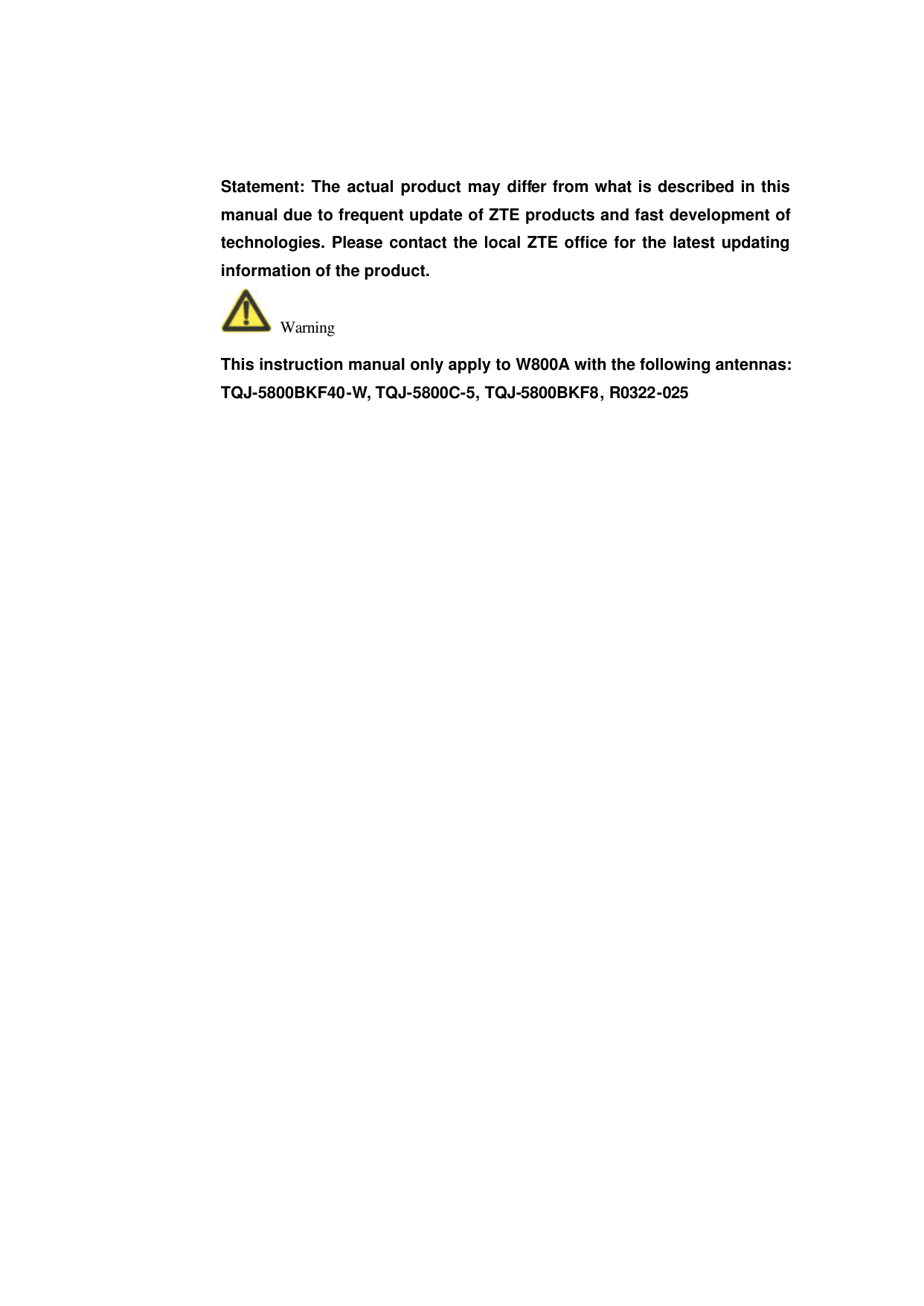
![Chapter 5 Command Line Configuration 3-45Table 3.6-1 W800A Working Channels Abbreviations of Nations and Zones Full Names of Nations and Zones 11a Available Channel Numbers 11b Available Channel Numbers 11g Available Channel Numbers CN CHINA 0 (Auto), 149, 153, 157, 161, 165 0 (Auto), 1, 2, 3, 4, 5, 6, 7, 8, 9, 10, 11, 12, 13 0 (Auto), 1, 2, 3, 4, 5, 6, 7, 8, 9, 10, 11, 12, 13 CA CANADA 0 (Auto), 36, 40, 44, 48, 52, 56, 60, 64, 149, 153, 157, 161, 165 0 (Auto), 1, 2, 3, 4, 5, 6, 7, 8, 9, 10, 11 0 (Auto), 1, 2, 3, 4, 5, 6, 7, 8, 9, 10, 11 TW TAIWAN 0 (Auto), 56, 60, 64, 149, 153, 157, 161 0 (Auto), 1, 2, 3, 4, 5, 6, 7, 8, 9, 10, 11, 12, 13 0 (Auto), 1, 2, 3, 4, 5, 6, 7, 8, 9, 10, 11, 12, 13 FR FRANCE 0 (Auto), 36, 40, 44, 48, 52, 56, 60, 64 0 (Auto), 1, 2, 3, 4, 5, 6, 7, 8, 9, 10, 11, 12, 13 0 (Auto), 1, 2, 3, 4, 5, 6, 7, 8, 9, 10, 11, 12, 13 GE GERMANY 0 (Auto), 36, 40, 44, 48, 52, 56, 60, 64, 100, 104, 108, 112, 116, 120, 124, 128, 132, 136, 140 0 (Auto), 1, 2, 3, 4, 5, 6, 7, 8, 9, 10, 11, 12, 13 0 (Auto), 1, 2, 3, 4, 5, 6, 7, 8, 9, 10, 11, 12, 13 HK HONG KONG 0 (Auto), 36, 40, 44, 48, 52, 56, 60, 64, 149, 153, 157, 161, 165 0 (Auto), 1, 2, 3, 4, 5, 6, 7, 8, 9, 10, 11, 12, 13 0 (Auto), 1, 2, 3, 4, 5, 6, 7, 8, 9, 10, 11, 12, 13 KR KOREA REPULIC 0 (Auto), 149, 153, 157, 161 0 (Auto), 1, 2, 3, 4, 5, 6, 7, 8, 9, 10, 11, 12, 13 0 (Auto), 1, 2, 3, 4, 5, 6, 7, 8, 9, 10, 11, 12, 13 MX MEXICO 0 (Auto), 52, 56, 60, 64, 36, 40, 44, 48, 149, 153, 157, 161, 165 0 (Auto), 1, 2, 3, 4, 5, 6, 7, 8, 9, 10, 11 0 (Auto), 1, 2, 3, 4, 5, 6, 7, 8, 9, 10, 11 GB the UNITED KINGDOM 0 (Auto), 36, 40, 44, 48, 52, 56, 60, 64, 100, 104, 108, 112, 116, 120, 124, 128, 132, 136, 140 0 (Auto), 1, 2, 3, 4, 5, 6, 7, 8, 9, 10, 11, 12, 13 0 (Auto), 1, 2, 3, 4, 5, 6, 7, 8, 9, 10, 11, 12, 13 US the UNITED STATES 0 (Auto), 52, 56, 60, 64, 36, 40, 44, 48, 149, 153, 157, 161, 165 0 (Auto), 1, 2, 3, 4, 5, 6, 7, 8, 9, 10, 11 0 (Auto), 1, 2, 3, 4, 5, 6, 7, 8, 9, 10, 11 3.6.2 ESSID Hiding Configuration Command mode: Wireless interface configure mode Function: Enabling or disabling the ESSID. Command format: [no] essid-hide enable](https://usermanual.wiki/ZTE/ZXR10W800A.Professional-Installation-Manual/User-Guide-455794-Page-71.png)
![ZXR10 WAS (V2.0) IP Wireless Access System W800A Wireless Access Point Professional Installation Instruction Manual 3-463.6.3 Exiting the Wireless Interface Configuration Mode Command mode: Wireless interface configure mode Function: Exiting the wireless interface configuration mode and entering the configure mode. Command format: exit 3.6.4 Enabling the Link Integrity Detection Function Command mode: Wireless interface configure mode Function: Enabling or disabling the AP link integrity detection function. Command format: [no] link-integrity enable Note: AP link integrity detection function is: when AP Ethernet links are disconnected, AP will release all the created wireless users and close the wireless interface, denying the connection requests from other wireless terminals; when AP Ethernet links are restored normally, AP will open the wireless interface and receive the wireless user connections. If the AP placement position is difficult to be reached, please be cautious to use this function. 3.6.5 Wireless Interface MAC Filtration Configuration Command mode: Wireless interface configure mode Function: Configuring the wireless interface MAC filtration. Command format: [no] macl-bind <value> {in} Parameter descriptions: Parameter Name Value Range Parameter Descriptions <value> 1~99 The article number of the MAC filtration bound by the interface. {in} in The in direction bound to the interface. 3.6.6 Multi-ESSID Configuration Command mode: Wireless interface configure mode Function: Configuring the VLAN ID, maximum user quantity and priority corresponding to the ESSID. Command format: multi-essid <string> [vlan-id <value1>] [max-user <value2>]](https://usermanual.wiki/ZTE/ZXR10W800A.Professional-Installation-Manual/User-Guide-455794-Page-72.png)
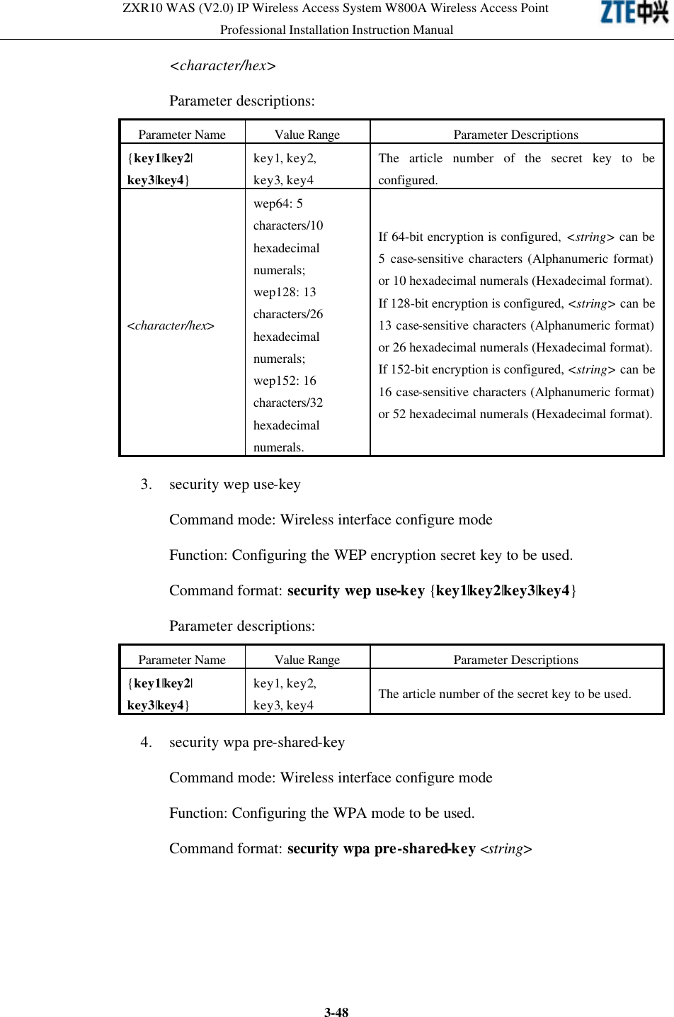
![Chapter 5 Command Line Configuration 3-47[priority <value3>] Parameter descriptions: Parameter Name Value Range Parameter Descriptions <string> 1 ~ 32 characters ESSID name. <value1> 1~4094 The VLAN ID corresponding to the ESSID. <value2> 1~30 The maximum user quantity corresponding to the ESSID. <value3> 0~7 The priority corresponding to the ESSID. 3.6.7 Security Parameter Configuration 1. security mode Command mode: Wireless interface configure mode Function: Configuring the security mode. Command format: security mode {none|wep64|wep128|wep152|wpa-eap-tls| wpa-psk} {Alphanumeric|Hexadecimal} {TKIP|AES} Parameter descriptions: Parameter Name Value Range Parameter Descriptions {none|wep64| wep128|wep152| wpa-eap-tls| wpa-psk} none, wep64, wep128, wep152, wpa-eap-tls, wpa-psk none: No encryption wep64: Encryption of WEP 64-bit secret key mode. wep128: Encryption of WEP 128-bit secret key mode. wep152: Encryption of WEP 152-bit secret key mode. wpa-eap-tls: Encryption of wpa mode. wpa-psk: Encryption of wpa-psk mode. {Alphanumeric| Hexadecimal} Alphanumeric, Hexadecimal Alphanumeric: WEP secret key is in the character string format. Hexadecimal: WEP secret key is in the hexadecimal format. {TKIP|AES } TKIP, AES Configuring the WPA encryption mode. 2. security wep set-key Command mode: Wireless interface configure mode Function: Configuring the WEP encryption secret key. Command format: security wep set-key {key1|key2|key3|key4}](https://usermanual.wiki/ZTE/ZXR10W800A.Professional-Installation-Manual/User-Guide-455794-Page-73.png)