ZTE ZXR10W800A Wireless Access Point User Manual W800A
ZTE Corporation Wireless Access Point W800A
ZTE >
Contents
- 1. Usera Manal
- 2. Professional Installation Manual
- 3. Users Manual
Usera Manal
ZXR10 WAS (V2.0) IP Wireless
Access System
W800A Wireless Access Point
User’s Manual
ZTE CORPORATION
ZXR10 WAS (V2.0) IP Wireless Access System
W800A Wireless Access Point
User’s Manual
Manual Version 20040306-R1.0
Product Version V2.0
BOM ××××××××
Copyright © 2003 ZTE Corporation
All rights reserved.
No part of this documentation may be excerpted, reproduced, translated, annotated or
duplicated, in any form or by any means without the prior written permission of ZTE
Corporation.
ZTE CORPORATION
ZTE Plaza, Keji Road South, Hi-Tech Industrial Park, Nanshan District, Shenzhen, P. R. China
Website: http://www.zte.com.cn
Post code: 518057
Customer Support Center: (+86755) 26770800 800-830-1118
Fax: (+86755) 26770801
E-mail: 800@zte.com.cn
* * * *
S.N.: DDDDDDDDD

FAX: +86-755-26770160
Suggestions and Feedback
To improve the quality of ZTE product documentation and offer better services to our customers, we hope
you can give us your suggestions and comments on our documentation and fax this form to
0086-755-26770160; or mail to “ZTE Plaza, Keji Road South, Hi-Tech Industrial Park, Nanshan District,
Shenzhen, P. R. China”. Our postcode is 518057.
Document Name ZXR10 WAS (V2.0) IP Wireless Access System W800A Wireless Access Point User’s Manual
Product version V2.0 Document version 20040306-R1.0
Equipment installation time
Your information
Name Company
Postcode Company address
Telephone E-mail
Good Fair Average Poor Bad
Overall
Instructiveness
Index
Correctness
Completeness
Structure
Illustration
Your evaluation
of this
documentation
Readability
Overall
Instructiveness
Index
Correctness
Completeness
Structure
Illustration
Your suggestion
on the
improvement of
this
documentation
Readability
Your other
suggestions on
ZTE product
documentation
Preface
About This Manual
This manual, ZXR10 WAS (V2.0) IP Wireless Access System W800A Wireless Access
Point — User’s Manual, is applicable to W800A wireless access point (W800A for
short) of the ZXR10 WAS (V2.0) IP wireless access system.
The ZXR10 WAS IP wireless access system is the IP wireless access system developed
by ZTE. It consists of a series of wireless access network products, such as wireless
network card, wireless access point (AP) and DSL 2-in-1 wireless router.
Serving as the operation guide to W800A, this manual introduces the function features,
installation, operation, using and maintenance of W800A. This manual consists of 7
chapters and 2 appendixes.
Chapter 1, Safety Precautions, introduces the safety precautions of this product and
safety symbols used in this manual.
Chapter 2, Overview, presents functions, features and technical parameters of W800A.
Chapter 3, Structure and Principle, describes structure and principle of W800A.
Chapter 4, Installation and Debugging, deals with the installation and debugging
methods of W800A.
Chapter 5, Command Line Configuration, covers the command line configurations of
W800A.
Chapter 6, WEB Configuration, examines WEB configurations of W800A.
Chapter 7, Maintenance, puts forward the daily maintenance and version upgrade
methods of W800A.
Appendix A, Packing, Transportation and Storage, outlines the packaging method,
storage conditions and transportation precautions of W800A.
Appendix B, Making of Ethernet cables, details the power supply mode of W800A
Ethernet and making of Ethernet cables.

Conventions
Four striking symbols are used throughout this manual to emphasize important and
critical information during operation:
Attention, Caution, Warning and Danger: alerting
you to pay attention to something.
Statement: The actual product may differ from what is described in this
manual due to frequent update of ZTE products and fast development of
technologies. Please contact the local ZTE office for the latest updating
information of the product.
-i-
Contents
1 Safety Precautions................................................................................................................... 1-1
1.1 Safety Precautions ............................................................................................................ 1-1
1.2 Symbol Description........................................................................................................... 1-2
2 Overview................................................................................................................................ 2-1
2.1 Preface............................................................................................................................ 2-1
2.2 Functions and Features...................................................................................................... 2-1
2.3 Technical Characteristics and Parameters............................................................................. 2-3
3 Structure and Principle ........................................................................................................... 3-1
3.1 Structure and Working Principle ......................................................................................... 3-1
3.2 Units/Components ............................................................................................................ 3-2
3.2.1 Front Panel............................................................................................................... 3-2
3.2.2 Rear Control Panel.................................................................................................... 3-3
3.3 Networking Modes ........................................................................................................... 3-4
3.3.1 AP Mode Application ................................................................................................ 3-5
3.3.2 Bridge Connection Mode Application.......................................................................... 3-6
3.3.3 Wireless Repeater Mode Application ........................................................................... 3-7
4 Installation and Debugging...................................................................................................... 4-1
4.1 Installation Preparations .................................................................................................... 4-1
4.1.1 Installation Preparation Flow...................................................................................... 4-1
4.1.2 Tool, Instrument and Document.................................................................................. 4-4
4.1.3 Installation Environment Inspection ............................................................................ 4-4
4.1.4 Unpacking Inspection................................................................................................ 4-4
4.2 Installation....................................................................................................................... 4-4
-ii
-
4.3 Power-on and Power-off.....................................................................................................4-5
4.4 Debugging........................................................................................................................4-6
5 Command Line Configuration.................................................................................................5-1
5.1 Overview .........................................................................................................................5-1
5.2 User Mode .......................................................................................................................5-4
5.2.1 Entering the Privileged Mode......................................................................................5-4
5.2.2 Exiting the Telnet Configuration..................................................................................5-4
5.3 Privileged Mode................................................................................................................5-5
5.3.1 Network Connectivity Check......................................................................................5-5
5.3.2 Saving the Configuration Data to FLASH.....................................................................5-5
5.3.3 Restoring the Default Configuration.............................................................................5-5
5.3.4 Resetting the Software...............................................................................................5-6
5.3.5 Entering the Configure Mode......................................................................................5-6
5.3.6 Exiting the Privileged Mode .......................................................................................5-6
5.3.7 Exiting the Telnet Configuration..................................................................................5-6
5.4 Configure Mode................................................................................................................5-6
5.4.1 Bridge Configuration .................................................................................................5-7
5.4.2 Clearing the Information ............................................................................................5-7
5.4.3 Configuring the Configuration Server ..........................................................................5-8
5.4.4 DHCP Server Configuration .......................................................................................5-8
5.4.5 DISCOVER Configuration .......................................................................................5-10
5.4.6 802.1X Parameter Configuration ............................................................................... 5-11
5.4.7 Password Configuration in the Privileged Mode..........................................................5-14
5.4.8 Erasing the Filtration Rules.......................................................................................5-14
5.4.9 Exiting the Configure Mode......................................................................................5-14
5.4.10 IAPP Load Balance Configuration ........................................................................... 5-15
-iii-
5.4.11 Entering the Interface Configuration Mode................................................................5-16
5.4.12 IP Network Parameter Configuration ........................................................................5-17
5.4.13 Kicking Users........................................................................................................5-18
5.4.14 Two-Layer Separation Configuration........................................................................5-18
5.4.15 Log Printing Message Configuration.........................................................................5-19
5.4.16 MAC Filtration Configuration..................................................................................5-20
5.4.17 MAC Address Authentication Configuration..............................................................5-21
5.4.18 Manager Configuration...........................................................................................5-21
5.4.19 QoS Configuration .................................................................................................5-22
5.4.20 RADIUS Server Configuration ................................................................................5-22
5.4.21 SNMP Module Configuration ..................................................................................5-24
5.4.22 SSH Parameter Configuration..................................................................................5-28
5.4.23 Spanning Tree Parameter Configuration....................................................................5-29
5.4.24 TELNET Configuration ..........................................................................................5-32
5.4.25 Uploading/Downloading TFTP Files.........................................................................5-32
5.4.26 VLAN Configuration..............................................................................................5-33
5.4.27 Web Configuration .................................................................................................5-34
5.4.28 Nation Zone Configuration......................................................................................5-34
5.4.29 Showing Parameter Configuration............................................................................5-35
5.5 Ethernet Interface Configuration Mode...............................................................................5-41
5.5.1 Exiting the Ethernet Interface Configuration Mode.......................................................5-42
5.5.2 Ethernet Interface MAC Filtration Configuration .........................................................5-42
5.6 Wireless Interface Configuration Mode...............................................................................5-42
5.6.1 802.11-Related Parameter Configuration of the Wireless Interface..................................5-42
5.6.2 ESSID Hiding Configuration.....................................................................................5-45
5.6.3 Exiting the Wireless Interface Configuration Mode ......................................................5-46
-iv-
5.6.4 Enabling the Link Integrity Detection Function...........................................................5-46
5.6.5 Wireless Interface MAC Filtration Configuration.........................................................5-46
5.6.6 Multi-ESSID Configuration ......................................................................................5-46
5.6.7 Security Parameter Configuration..............................................................................5-47
5.6.8 Transmission Power Configuration ............................................................................5-49
5.6.9 Working Mode Configuration....................................................................................5-49
6 WEB Configuration.................................................................................................................6-1
6.1 Overview .........................................................................................................................6-1
6.2 Login...............................................................................................................................6-3
6.3 Main Menu.......................................................................................................................6-4
6.3.1 Home.......................................................................................................................6-4
6.3.2 Interface...................................................................................................................6-5
6.3.3 Stations....................................................................................................................6-9
6.3.4 Load Balance..........................................................................................................6-10
6.3.5 SNMP.................................................................................................................... 6-11
6.3.6 Security..................................................................................................................6-15
6.3.7 Reboot...................................................................................................................6-19
6.3.8 Save ......................................................................................................................6-20
6.3.9 Advanced...............................................................................................................6-20
6.3.10 Management.........................................................................................................6-29
6.4 Data Submitting Flow of WEB Configuration .....................................................................6-32
7 Maintenance............................................................................................................................7-1
7.1 Maintenance Descriptions ..................................................................................................7-1
7.2 Daily Maintenance............................................................................................................7-2
7.3 Version Loading and Upgrade .............................................................................................7-2
7.3.1 BOOT Loading .........................................................................................................7-2
-v-
7.3.2 TFTP Online Loading...............................................................................................7-11
7.4 Alarms and Handling........................................................................................................7-13
Appendix A Package, Transportation and Storage.......................................................................A-1
A.1 Package..........................................................................................................................A-1
A.2 Transportation .................................................................................................................A-1
A.3 Storage...........................................................................................................................A-1
Appendix B Making of Ethernet Cable .......................................................................................B-1
B.1 W800A System Application Modes ....................................................................................B-1
B.2 Making of Ethernet Cables ................................................................................................B-3
B.2.1 Making of Straight Through Ethernet Cables (RJ45).....................................................B-3
B.2.2 Making of Straight Through Power Supply Ethernet Cables (C-RJ45-001).......................B-3
B.2.3 Making of Crossover Ethernet Cables (RJ45J).............................................................B-4
B.2.4 Ethernet Cable Label................................................................................................B-5
-i-
A List of Figures
Fig. 3.1-1 W800A Appearance............................................................................................... 3-1
Fig. 3.2-1 Schematic Diagram of the Rear Control Panel of W800A........................................... 3-3
Fig. 3.3-1 Application of the W800A Single Frequency Mode ................................................... 3-5
Fig. 3.3-2 Application of the W800A Double Frequency Mode.................................................. 3-6
Fig. 3.3-3 Wireless Bridge Connection Mode .......................................................................... 3-7
Fig. 3.3-4 Wireless Repeater Mode......................................................................................... 3-8
Fig. 4.1-1 Sub-Channel Distribution....................................................................................... 4-2
Fig. 4.1-2 Channel Distribution Principle of Adjacent APs ........................................................ 4-3
Fig. 5.1-1 Serial Port Configuration........................................................................................ 5-3
Fig. 5.1-2 Telnet to W800A................................................................................................... 5-3
Fig. 6.1-1 Route Map of the WEB Configuration ..................................................................... 6-2
Fig. 6.2-1 Login Page........................................................................................................... 6-3
Fig. 6.2-2 Dialog Box for a User Who Has Logged on.............................................................. 6-3
Fig. 6.2-3 Prompt Page for Wrong User Name or Password....................................................... 6-4
Fig. 6.3-1 Home Page........................................................................................................... 6-4
Fig. 6.3-2 Interface Configuration Menu Page ......................................................................... 6-5
Fig. 6.3-3 Wireless Interface Configuration Menu Page ............................................................ 6-6
Fig. 6.3-4 802.11 Parameter Configuration Page ...................................................................... 6-6
Fig. 6.3-5 Security Configuration Page ................................................................................... 6-7
Fig. 6.3-6 Multi-ESSID Configuration Page ............................................................................ 6-8
Fig. 6.3-7 Advanced Configuration Page................................................................................. 6-8
Fig. 6.3-8 Device IP Address Configuration Page..................................................................... 6-9
Fig. 6.3-9 Stations Page.......................................................................................................6-10
-ii-
Fig. 6.3-10 Load Balance Configuration Page ........................................................................ 6-11
Fig. 6.3-11 SNMP Configuration Menu Page ......................................................................... 6-11
Fig. 6.3-12 SNMP Access Mode Configuration Page...............................................................6-12
Fig. 6.3-13 SNMP Access Host Configuration Page................................................................6-12
Fig. 6.3-14 Community Configuration Page...........................................................................6-13
Fig. 6.3-15 System Information Page....................................................................................6-14
Fig. 6.3-16 Trap Configuration Page.....................................................................................6-15
Fig. 6.3-17 Trap Host Configuration Page..............................................................................6-15
Fig. 6.3-18 Security Configuration Menu Page.......................................................................6-16
Fig. 6.3-19 MAC Authentication Configuration Page ..............................................................6-16
Fig. 6.3-20 MAC Filter Configuration Page ...........................................................................6-17
Fig. 6.3-21 Stations Isolation Configuration Page ...................................................................6-18
Fig. 6.3-22 SSH Configuration Page .....................................................................................6-18
Fig. 6.3-23 Reboot Page......................................................................................................6-19
Fig. 6.3-24 Page of Inputting the Privileged Password.............................................................6-19
Fig. 6.3-25 Page of Closing the Window................................................................................6-20
Fig. 6.3-26 Save Page.........................................................................................................6-20
Fig. 6.3-27 Advanced Option Configuration Menu Page..........................................................6-21
Fig. 6.3-28 802.1x Configuration Page..................................................................................6-22
Fig. 6.3-29 DHCP Configuration Menu Page .........................................................................6-22
Fig. 6.3-30 DHCP Server Configuration Page ........................................................................6-23
Fig. 6.3-31 IP Pool Configuration Page .................................................................................6-23
Fig. 6.3-32 RADIUS Server Configuration Menu Page............................................................6-24
Fig. 6.3-33 ISP Configuration Page.......................................................................................6-24
Fig. 6.3-34 Authentication Server Configuration Page.............................................................6-25
Fig. 6.3-35 Accounting Server Configuration Page .................................................................6-26
-iii-
Fig. 6.3-36 DNS Server Configuration Page...........................................................................6-26
Fig. 6.3-37 Bridge Configuration Page...................................................................................6-27
Fig. 6.3-38 STP Configuration Page ......................................................................................6-28
Fig. 6.3-39 VLAN Configuration Page ..................................................................................6-29
Fig. 6.3-40 QoS Configuration Page......................................................................................6-29
Fig. 6.3-41 Management Configuration Menu Page.................................................................6-30
Fig. 6.3-42 Management Accounts Configuration Page............................................................6-30
Fig. 6.3-43 Management Control Page...................................................................................6-31
Fig. 6.3-44 Configure Server Configuration Page....................................................................6-31
Fig. 6.4-1 Prompt of Wrong Data Input..................................................................................6-32
Fig. 6.4-2 Prompt Page of Inputting Superuser Password.........................................................6-32
Fig. 6.4-3 Prompt Page of Wrong Superuser Password.............................................................6-33
Fig. 6.4-4 Prompt Page of Successful Data Submission............................................................6-33
Fig. 7.3-1 Serial Port Configuration........................................................................................ 7-3
Fig. 7.3-2 Wftpd User Configuration Interface......................................................................... 7-4
Fig. 7.3-3 Interface of Adding a New Wftpd User .................................................................... 7-4
Fig. 7.3-4 TFTP Configuration Interface................................................................................7-11
Fig. B.1-1 Common Application Networking Mode of the IP Wireless Access System..................B-1
Fig. B.1-2 Application of the System with Ethernet Power Supply ............................................. B-2
Fig. B.2-1 Label of the Straight Through Ethernet Cable ...........................................................B-5
Fig. B.2-2 Label of the Straight Through Power Supply Ethernet Cable ......................................B-5
Fig. B.2-3 Label of the Crossover Ethernet cable ..................................................................... B-6
-i-
A list of Tables
Table 1.2-1 Safety Symbols and Descriptions .......................................................................... 1-3
Table 2.3-1 W800A Technical Indices..................................................................................... 2-3
Table 3.1-1 Configuration Table of MiniPci Wireless Network Card for W800A.......................... 3-2
Table 3.2-1 Description of Indicators on W800A Panel............................................................. 3-3
Table 4.1-1 IDs and Frequencies of Channels .......................................................................... 4-2
Table 5.6-1 W800A Working Channels ..................................................................................5-45
Table 7.4-1 Summary of the Alarm Information ........................................................................7-13
Table A.1-1 W800A Packing List...........................................................................................A-1
Table B.2-1 Connections of Straight Through Ethernet Cables (RJ45).........................................B-3
Table B.2-2 Connections of Straight Through Power Supply Ethernet Cables (C-RJ45-001)..........B-4
Table B.2-3 Connections of Crossover Ethernet Cables (RJ45J).................................................B-4
1-1
1 Safety Precautions
This chapter introduces the safety precautions of this product and safety symbols used
in this manual.
1.1 Safety Precautions
This device complies with Part 15 of the FCC Rules. Operation is subject to the
following two conditions: (1)This device may not cause harmful interference,and(2)
this device must accept any interference received, including interference that may
cause undesired operation.
To assure continued compliance, (example – use only shielded interface cables when
connecting to computer or peripheral devices). Any changes or modifications not
expressly approved by the party responsible for compliance could void the user’s
authority to operate the equipment.
NOTE: This equipment has been tested and found to comply with the limits for a Class
B digital device, pursuant to Part 15 of the FCC Rules. These limits are designed to
provide reasonable protection against harmful interference in a residential installation.
This equipment generates, uses and can radiate radio frequency energy and, if not
installed and used in accordance with the instructions, may cause harmful interference
to radio communications. However, there is no guarantee that interference will not
occur in a particular installation. If this equipment does cause harmful interference to
radio or television reception, which can be determined by turning the equipment off
and on, the user is encouraged to try to correct the interference by one of the following
measures:
- Reorient or relocate the receiving antenna.
- Increase the separation between the equipment and receiver.
- Connect the equipment into an outlet on a circuit different from that to which the
receiver is connected.
- Consult the dealer or an experienced radio/TV technician for help.
This equipment is with high temperature and voltage, so only the professional

ZXR10 WAS (V2.0) IP Wireless Access System W800A Wireless Access Point User’s Manual
1-2
personnel who had passed the training can install, operate and maintain it.
ZTE assumes no responsibility for consequences resulting from violation of general
specifications for safety operations or of safety rules for design, production and use of
equipment.
1.2 Symbol Description
See Table 1.2-1 for the safety symbols used in this manual, which serves to remind the
readers of the safety precautions to be taken when the equipment is installed, operated
and maintained.
Chapter 1 Safety Precautions
1-3
Table 1.2-1 Safety Symbols and Descriptions
Safety Symbols Meaning
Call for notice
Call for antistatic measures
Warn against electric shock
Caution against scald
Warn against laser
Caution against microwave
Four types of safety levels are available: danger, warning, caution and note. To the
right of a safety symbol is the text description of its safety level. Under the symbol is
the detailed description about its contents. See the following formats.
Danger:
Any failure to take the reminder seriously may lead to important accidents, such as
casualties or damage to the equipment.
Cautions:
Any failure to take the reminder seriously may lead to important or severe injury
accidents, or damage to the equipment.
Caution:
Any failure to take the reminder seriously may lead to severe injury accidents or
damage to the equipment.

ZXR10 WAS (V2.0) IP Wireless Access System W800A Wireless Access Point User’s Manual
1-4
Note:
Any failure to take the reminder seriously may lead to injury accidents or damage to
the equipment.
& Remark, reminder, tip…
The remarks, prompt and tips in addition to safety statements.
2-1
2 Overview
This chapter presents functions, features, technical characteristics and parameters of
W800A.
2.1 Preface
W800A is a wireless AP product developed by ZTE and is designed totally compliant
with the international standards. With it, single-AP connection, multi-AP connection
and wireless cellular roaming in large scope are available, greatly improving work
efficiency and living quality.
2.2 Functions and Features
Through UTP (RJ45 interface) cable, the W800A can be connected to Ethernet at
10/100 Mbps to provide wireless access service. Once the wireless network card is
used and required network parameters are configured correctly, a client which is in the
valid coverage range of W800A can be connected to the local LAN through W800A,
and then be connected to Internet.
The function features of the W800A are as follows:
= The maximum access rate is 108 Mbps. At most 100 Stations can be accessed.
= MAC layer bridge connection function: 802.3 frame from Ethernet can be
received and be converted into 802.11 frame, and then be transmitted to the
wireless transceiver; or 802.11 frame from the wireless transceiver can be
received and be converted into 802.3 frames, and then be transmitted to
Ethernet.
= Transparent bridge connection provides packet transfer between Basic Service
Set (BSS) and Distributed System (DS). The maximum transmitting rate is not
less than 20 Mbps.
= The load balance adopts the access balance with multiple APs in the same area
provided by the internal protocol.

ZXR10 WAS (V2.0) IP Wireless Access System W800A Wireless Access Point User’s Manual
2-2
= Static MAC filtration can filter MAC addresses set by users. Up to 99 filtration
groups can be set and each of them can be set with 64 MAC address filtration
rules.
= It provides two configuration modes: WEB and command line, to configure
W800A.
= It provides seamless roaming to enable users to access network easily.
= ESSID provides network authentication to prevent illegal users from accessing
the network.
= High capability of interconnection enables it to interconnect with 10/100 Mbps
Ethernet, complying with IEEE 802.3 network convention.
= QoS function, compliant with 802.11e, to implement QoS control based on
SSID and maps QoS into 802.1p at the uplink port.
= VLAN function,W800A can divide VLAN based on SSID,W800A uplink port
supports 802.1q VLAN Trunk.
= It provides SSH information safety function.
= Security, supports 64-bit, 128-bit or 152-bit WEP encryption, 802.1x and
extended Athentication ,and also supports Wi-Fi Protected Access (WPA)
WLAN security standard, TKIP and AES encryption to further protect data
transmission.
= Automatic consistent correction system provides Automatic Scale Back
Functionality (ASBF) to automatically correct WLAN to the best connection
quality.
= It provides integrated management server to monitor and manage ZTE wireless
network equipment, including W800A, in the distributive environment.
= Its configuration server can manage all the APs and download versions through
the configuration server.
= The version upgrade function upgrades the W800A software version,supports
Remote and Local online version loading.
= The embedded SNMP Agent supports SNMP v1/2c to implement MIB II,
IEEE802.11 MIB, IF-MIB, EtherLike-MIB and private MIB.

Chapter 2 Overview
2-3
2.3 Technical Characteristics and Parameters
The technical indices of W800A are shown in Table 2.3-1.
Table 2.3-1 W800A Technical Indices
Items Technical Indices
Standard 802.11a, 802.11b, 802.11g, 802.1d and 802.3u
Working band
802.11a: 5.15GHz~5.25GHz, 5.25GHz~5.35GHz and 5.725~5.825GHz
802.11b: 2400MHz~2483.5MHz
802.11g: 2400MHz~2483.5MHz
Can flexibility chose the frequency band of the different contry
Modulation mode
802.11a: OFDM (64-QAM, 16-QAM and QPSK, BPSK)
802.11b: DSSS (DBPSK, DQPSK and CCK)
802.11g: OFDM (64-QAM, 16-QAM, QPSK and BPSK)
Data rate
802.11a: 6Mbps, 9Mbps, 12Mbps, 18Mbps, 24Mbps, 36Mbps, 48Mbps
and 54Mbps
802.11b: Adaptive 1Mbps, 2Mbps, 5.5Mbps and 11Mbps
802.11g: 6Mbps, 9Mbps, 12Mbps, 18Mbps, 24Mbps, 36Mbps, 48Mbps
and 54Mbps
Distance (m) Indoor: 20m ~ 100m; outdoor: 100m ~ 300m
External interfaces RJ45 interface, serial interface and wireless interface
Channel quantity
802.11b: EU: 13; USA and Canada: 11; France: 4; Japan: 14
802.11a: Up to 24 channels are provides according to different national
standards
802.11g: EU: 13; USA and Canada: 11; France: 4
Recommended number
of users/maximum
number of users
30/100
MAC address capacity 1024
Encryption type
64/128/152-bit WEP encryption
802.1x Authentication
TKIP & AES encryption
Dimensions 208mm × 180mm × 47mm (W × L × H)
Weight 1kg (without power supply)
Power supply mode DC 12V power supply and 48V Ethernet power supply
Specification of power
adapter
Input: 100VAC~240VAC, 50Hz~60Hz
Output: 12VDC, 1.2A
Working temperature: -5 ºC ~ 45 ºC
Storage temperature -40 ºC ~ 70 ºC
Working humidity 5% ~ 95%
Storage humidity 10% ~ 100%

ZXR10 WAS (V2.0) IP Wireless Access System W800A Wireless Access Point User’s Manual
2-4
3-1
3 Structure and Principle
This chapter introduces W800A structure and principle: hardware structure, working
principle, interfaces, indicators and networking mode.
3.1 Structure and Working Principle
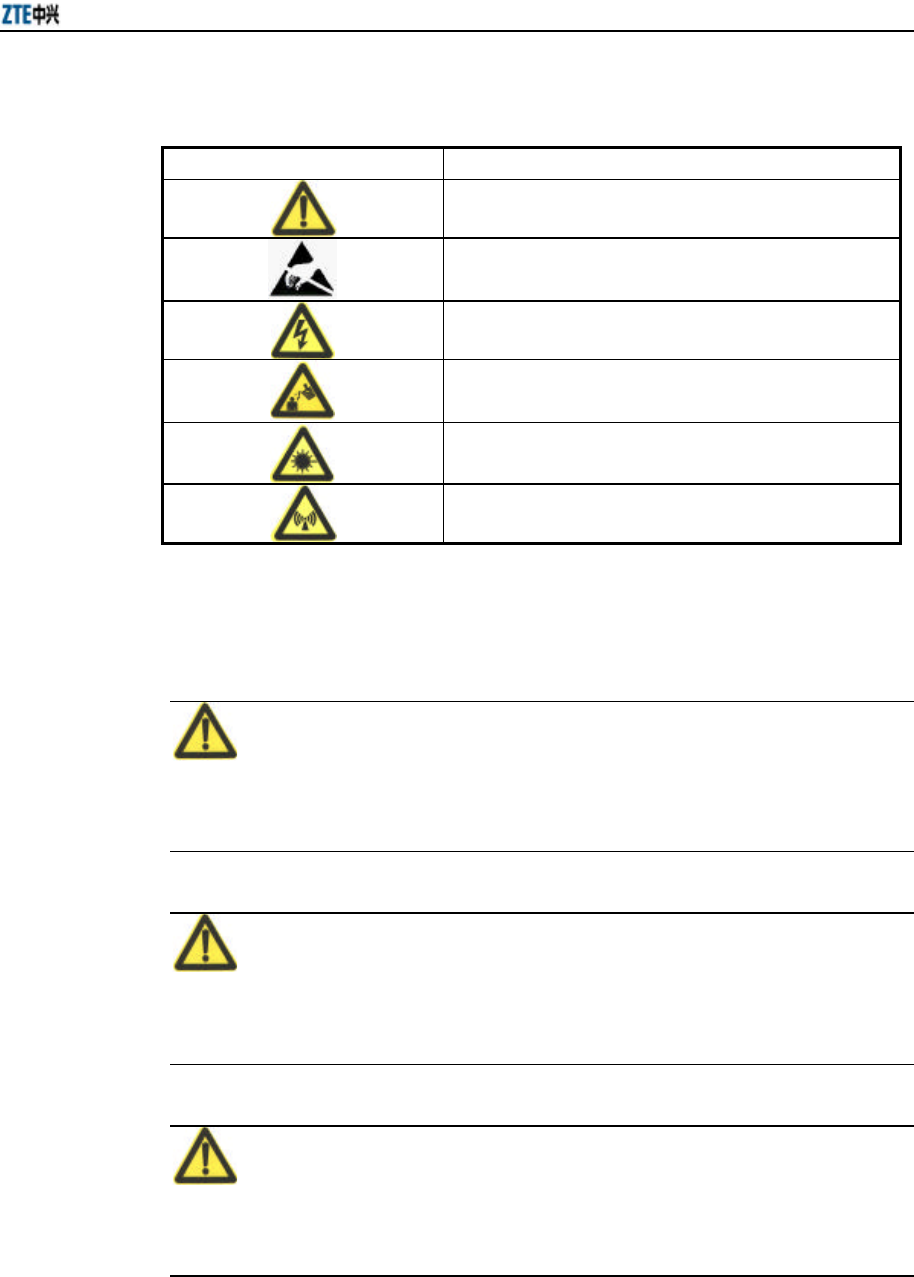
W800A appearance is shown in Fig. 3.1-1.
Fig. 3.1-1 W800A Appearance
The hardware of W800A comprises the main body, antenna and external power adapter.
The software of W800A comprises the basic service subsystem and network
management subsystem.
= The basic service subsystem consists of these items: 802.11a/b/g AP driving,
802.3 Ethernet driving, transparent bridge connection, load balance, TCP/IP
protocol stack, dynamic address distribution, static MAC address filtration, SSH,
QoS control and VLAN.
= The network management subsystem consists of these items: SNMP Agent,
command line configuration module (Telnet configuration and serial interface
configuration), WEB page configuration module.
The main board of W800A has two MiniPci wireless network card slots, one or both of
them can be used as required. Through software mode, different MiniPci wireless

ZXR10 WAS (V2.0) IP Wireless Access System W800A Wireless Access Point User’s Manual
3-2
network cards can be set as different working modes: 802.11a, 802.11b, 802.11g and
802.11b/g. So, W800A can satisfy 5 GHz based on 802.11a standard or 2.4 GHz single
frequency wireless access function based on 802.11 b/g standard, to provide 54 Mbps
access capacity, and it can also satisfy 2.4 GHz and 5 GHz double frequency wireless
access functions based on 802.11 a/b/g, to provide 2 × 54 Mbps access capacity.
The configuration mode of the W800A wireless network card is shown in Table 3.1-1.
Table 3.1-1 Configuration Table of MiniPci Wireless Network Card for W800A
Network Card
Quantity Network Card Types Function Descriptions
1 2.4 GHz (802.11 b/g standard working mode) 802.11 b/g standard single frequency wireless
access, with the maximum capacity of 54Mbps.
1 5 GHz (802.11a standard working mode) 802.11a standard single frequency wireless
access, with the maximum capacity of 54Mbps.
2 2.4 GHz (802.11 b/g
standard working mode)
2.4 GHz (802.11 b/g
standard working
mode)
802.11 b/g standard single frequency wireless
access, with the maximum capacity of 2 ×
54Mbps.
2 2.4 GHz (802.11 b/g
standard working mode)
5 GHz (802.11a
standard working
mode)
802.11 a/b/g standard double frequency wireless
access, with the maximum capacity of 2 ×
54Mbps.
2 5 GHz (802.11a standard
working mode)
5 GHz (802.11a
standard working
mode)
802.11a standard single frequency wireless
access, with the maximum capacity of 2 ×
54Mbps.
& Note:
Considering the interference owing to close distance between two network cards in one
AP , it is not recommended that two network cards are configured with the same
frequency mode, when two network cards are used.
3.2 Units/Components
3.2.1 Front Panel
There are three LED indicators on the front panel of the W800A, indicating the
equipment status. The meanings of LED indicators are shown in Table 3.2-1.
Chapter 3 Structure and Principle
3-3
Table 3.2-1 Description of Indicators on W800A Panel
Indicators Descriptions
Power It is W800A power indicator. On: Indicating that the power supply is on.
RUN During normal operation, the RUN indicator flashes slowly once per second.
ACT It is the wireless network status indicator. When W800A wireless interface works
normally, this indicator is always on.
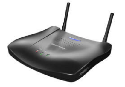
3.2.2 Rear Control Panel
There are many interfaces and indicators on the rear control panel of W800A, as shown
in Fig. 3.2-1.
Ethernet CONSOLEANT ANT12V DC DEFSET Status indicators
Fig. 3.2-1 Schematic Diagram of the Rear Control Panel of W800A
The indicators and interfaces on the rear control panel are described as follows:
1. 12V DC (Power supply jack)
Connecting the power adapter.
Note:
Only the accessory power adapter can be used. Never use other power adapters,
otherwise, equipment may be damaged.
2. DEFSET (Default button)
This button serves to reset the W800A and recover the ex-factory default
parameter configuration.
3. Status indicator
10M: ON indicates that Ethernet is connected to the opposite device at the rate
of 10 Mbps.
100M: ON indicates that Ethernet is connected to the opposite device at the rate
of 100 Mbps.
ACT: Flash indicates that Ethernet is receiving or transmitting data.

ZXR10 WAS (V2.0) IP Wireless Access System W800A Wireless Access Point User’s Manual
3-4
ALARM: It is the alarm indicator. ON indicates that the device works
abnormally.
4. Ethernet (Ethernet RJ45 interface)
The interface features three functions:
1) When the W800A works normally in the network, this interface serves as the
W800A uplink interface, to connect W112P/W105P through the straight through
power supply Ethernet cable (AP remote power supply mode), or connect the
Ethernet switch downlink interface through the straight through Ethernet cable
(using power adapter to power local AP).
2) Before the W800A is installed, this interface can connect with PC wired network
interface through the crossed network cable, and then you can log on to the
W800A in the WEB or Telnet mode to configure W800A parameters.
3) When a version is loaded to the W800A through the hyper terminal, connect this
interface to the PC wired network interface through a crossed network cable and
run FTP/TFTP server application software on the PC, to load the running
version file to the W800A system.
5. CONSOLE (RJ11 interface for configuration)
It is connected to the PC serial interface through a serial interface cable, to
implement version loading, configuration and debugging to the device through
the hyper terminal.
6. ANT (Antenna interface)
It serves for installing the antenna.
3.3 Networking Modes
The W800A provides wireless access for the indoor wireless users. It can be placed in
such positions as office area, lobby or corridor of a hotel.
As the access equipment of wireless and wired network, the W800A provides users
with wireless access to Ethernet and data service access. Through different hardware
and software configurations, the W800A can construct different modes.
1. AP mode: The W800A implements BSS access to connect BSS to DS, and
supports wireless STA access.
Chapter 3 Structure and Principle
3-5
2. Bridge connection mode: The W800A serves as both Bridge Server and Bridge
Client. Client and Server work together to implement wireless bridge
connection.
3. Repeater mode: The W800A serves as the wireless repeater. Serving as wireless
AP, The W800A connect the terminal user in wireless mode, also serving as
wireless Client,The W800A connect to AP in wireless mode.
The network modes of the W800A are described in detail below:
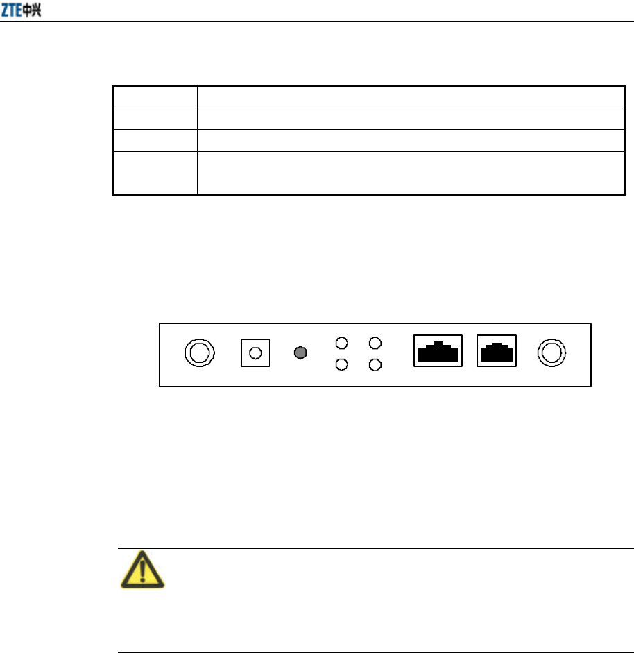
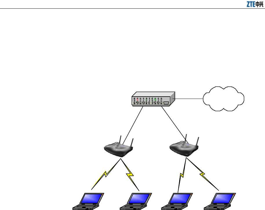
3.3.1 AP Mode Application
As shown in Fig. 3.3-1, AP1 works under 5 GHz frequency band and supports 802.11a
standard, mobile terminals 1 and 2 adopt the network cards in 802.11a mode; AP2
works under 2.4 GHz frequency band and supports 802.11 b/g standard, mobile
terminals 3 and 4 adopts the network cards in 802.11b mode. These four terminals can
communicate with each other and visit PCs of the external wired LAN through the
Ethernet switch or HUB. Mobile terminals 1 and 2 can not be switched to AP2 and
mobile terminals 3 and 4 can not be switched to AP1.
Ethernet switch/HUB
Mobile terminal 3
AP1
W800A AP2
W800A
LAN
802.11a
802.11a
802.11b
802.11b
Mobile terminal 1 Mobile terminal 2 Mobile terminal 4
Fig. 3.3-1 Application of the W800A Single Frequency Mode
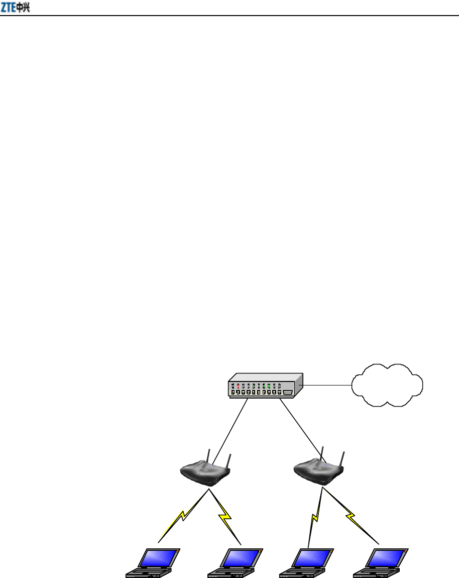
As shown in Fig. 3.3-2, both AP1 and AP2 simultaneously work under 2.4 GHz and 5
GHz frequency band and support 802.11a/b/g standard. Mobile terminals 1 and 3 adopt
ZXR10 WAS (V2.0) IP Wireless Access System W800A Wireless Access Point User’s Manual
3-6
the network cards in 802.11a mode, mobile terminal 2 adopts the network card in
802.11b mode and mobile terminal 4 adopts the network card in 802.11g mode. These
four terminals can communicate with each other and visit PCs of the external wired
LAN through the Ethernet switch or HUB, and they can be switched between AP1 and
AP2 randomly.
Ethernet switch/HUB
AP1
W800A AP2
W800A
LAN
802.11a
802.11b
802.11a
802.11g
Mobile terminal 1 Mobile terminal 2 Mobile terminal 3 Mobile terminal 4
Fig. 3.3-2 Application of the W800A Double Frequency Mode
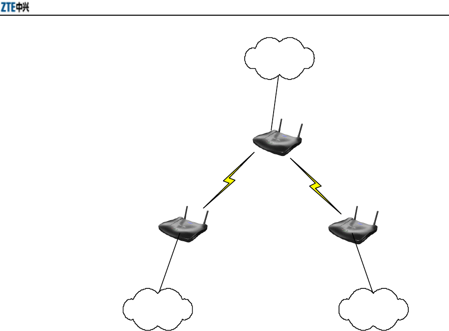
3.3.2 Bridge Connection Mode Application
As shown in Fig. 3.3-3, two W800As work in Bridge Server and Bridge Client modes
separately to implement the bridge connection of wired LAN1 and LAN2. The
bandwidth of bridge connection depends on the working mode of the W800A. Bridge
Server can serve multiple Bridge Clients at the same time, and it is suggested that the
Bridge Client quantity should not more than 4.
Chapter 3 Structure and Principle
3-7
Bridge
Client Bridge
Client
LAN1 LAN2
Internet
Bridge
Server
Fig. 3.3-3 Wireless Bridge Connection Mode
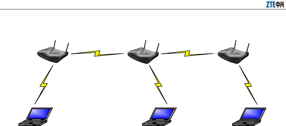
3.3.3 Wireless Repeater Mode Application
When two W800As are far from each other or their visual path is blocked, another
W800A can be used to implement the wireless repeater function, as shown in Fig. 3.3-4.
At this time, two W800As which are far from each other work in Repeater working
mode, the middle W800A works in normal AP mode and serves as the interface for
connecting the wired network. Three APs can implement mobile STA accesses and
work together as the wireless repeater, to guarantee the communication between mobile
terminals 1, 2 and 3.
ZXR10 WAS (V2.0) IP Wireless Access System W800A Wireless Access Point User’s Manual
3-8
W800A
Repeater
W800A
AP
802.11b
802.11a/b/g
802.11a/b/g
W800A
Repeater
802.11a
802.11a/b/g
Mobile terminal 1 Mobile terminal 3 Mobile terminal 2
Fig. 3.3-4 Wireless Repeater Mode

4-1
4 Installation and Debugging
Warning
This chapter do not apply to W800A with the following antennas:
TQJ-5800BKF40-W, TQJ-5800C-5, TQJ-5800BKF8, R0322-025, which must
be professionally installed.
This chapter details the methods and procedure of installation and debugging of the
W800A for your reference.
4.1 Installation Preparations
4.1.1 Installation Preparation Flow
Before installing the W800A, the engineering personnel should confirm that such work
as solution design, project survey and W800A basic configurations have been
completed. Brief introductions to the preparations required for installation are as
follows.
4.1.1.1 Channel Planning
According to 802.11b wireless LAN international standard and the standard of state
radio management committee, the working frequency band of a wireless device in the
wireless LAN is 2400 MHz ~ 2483.5 MHz, and the working frequency bandwidth is
83.5 MHz, divided into 14 sub-channels with 22 MHz as the bandwidth for each one.
The sub-channel distribution is shown in Fig. 4.1-1.
1 6 11
2 7 12
3
4
5 10
9
8
14
13
2.417 2.427 2.437 2.447 2.457
2.412 2.422 2.432 2.442 2.452 2.462 2.472 2.484
2.467
ZXR10 WAS (V2.0) IP Wireless Access System W800A Wireless Access Point User’s Manual
4-2
Fig. 4.1-1 Sub-Channel Distribution
Viewed from the above diagram, up to 13 channels are available. The IDs and central
frequencies of these 13 channels are described in Table 4.1-1.
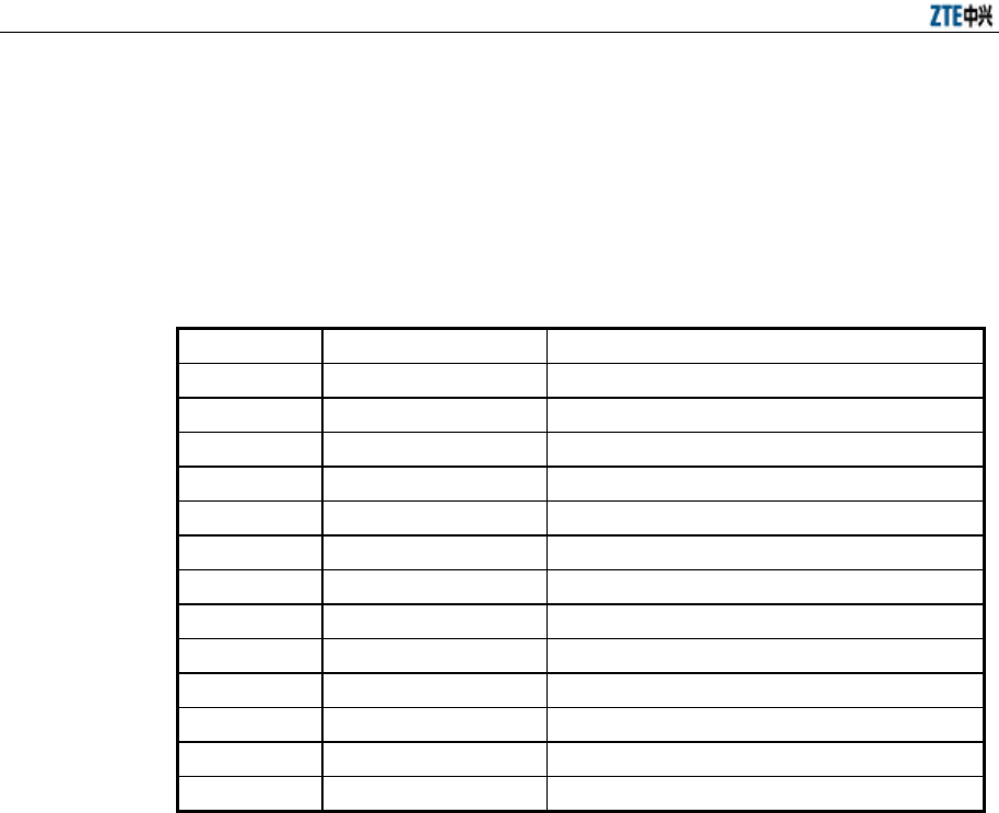
Table 4.1-1 IDs and Frequencies of Channels
Channel ID Central Frequency Low End/High End Frequency of the Channel
1 2412MHz 2401/2423MHz
2 2417MHz 2411/2433MHz
3 2422MHz 2416/2438MHz
4 2427MHz 2421/2443MHz
5 2432MHz 2426/2448MHz
6 2437MHz 2431/2453MHz
7 2442MHz 2431/2453MHz
8 2447MHz 2436/2458MHz
9 2452MHz 2441/2463MHz
10 2457MHz 2446/2468MHz
11 2462MHz 2451/2473MHz
12 2467MHz 2456/2478MHz
13 2472MHz 2461/2483MHz
When multiple channels work at the same time, the central frequency intervals between
two channels should not be less than 25 MHz to avoid mutual interference. As shown
in Fig. 4.1-1, in a cell, direct spread spectrum technology can support simultaneous
work of up to 3 un-overlapped channels.
In the wireless LAN planning, to realize efficient coverage of APs and avoid mutual
interference between channels, the cellular coverage principle of BTS is adopted in the
channel distribution. 3 un-overlapped channels (for example, channels 1, 6 and 11) can
be used in the same area at the same time, as shown in Fig. 4.1-1.

Chapter 4 Installation and Debugging
4-3
AP
channel 6
AP
channel 6
AP
channel 6
AP
channel 1
AP
channel 11
AP
channel 11
AP
channel 11
Fig. 4.1-2 Channel Distribution Principle of Adjacent APs
When using APs, for the adjacent APs, we will select their working channels (channels
1, 6 and 11 are usually used) according to the principle shown in Fig. 4.1-1, to
guarantee the normal work of the wireless LAN.
The channel distribution principle of 802.11g standard is the same as that of 802.11b.
802.11a standard channels feature anti-interference performance, so no special
configuration is required. In the actual networking, you only need make sure that the
channels between adjacent APs are different.
4.1.1.2 Configuration before Installation
Before the installation, power on W800As in turn and check whether they can work
normally. In the normal case, the Power indicator and ACT indicator on the W800A
panel should be always on, and the RUN indicator should flash slowly (about once per
second). If the indicator is not in the normal status, you can log on to the W800A in the
hyper terminal mode and check whether the version is loaded normally. If necessary,
you can reload the version (refer to Section 7.3 Version Loading and Upgrade for
detailed procedure).
When you make sure that the W800A works normally, it is required to implement basic
configurations for it. The configuration contents are as follows:
1. Configuring the W800A IP addresses, that is, management addresses. At least
one management address should be configured for each W800A, for the
management configuration of W800A.

ZXR10 WAS (V2.0) IP Wireless Access System W800A Wireless Access Point User’s Manual
4-4
2. Configuring the wireless working mode of the W800A wireless interface and the
SSID (Service ID), using channel and rate of the corresponding wireless
interface.
The detailed configuration methods will be introduced in the subsequent sections.
4.1.2 Tool, Instrument and Document
= One wireless network card.
= One PC for configuration management
= ZXR10 WAS (V2.0) IP Wireless Access System W800A Wireless Access Point —
User’s Manual
4.1.3 Installation Environment Inspection
The W800A can only be used indoors. To guarantee the normal work and longer useful
life of the equipment, the indoor temperature range should be -5 °C ~ 45 °C, you
should maintain good ventilation and dry air indoors, and the relative humidity range is
5% ~ 95%.
4.1.4 Unpacking Inspection
Generally, the following equipment and accessories are contained in the package of this
product.
W800A 1
Power adapter 1
Console configuration cable 1
Delivery attached document CD 1
& Note:
Please refer to the packing list in the package. If there is any missing part, please
contact ZTE Cooperation.
4.2 Installation
W800A shell is made in plastic with certain mechanical intensity, and can satisfy the
using requirement. The material is fire-resistant and satisfies the environment

Chapter 4 Installation and Debugging
4-5
protection requirement. The ground bolt can be installed on the interface board of the
shell, for grounding. The W800A can be used not only on the desktop or ceiling but
also on the wall, so it is easily to be used.
The W800A installation process is described in detail as follows:
1. Place the W800A to the proper position according to the engineering planning,
for example, evenly place it on the desktop, ceiling or wall.
2. Determine the angle of the antenna.
3. Connect the power cable to the power socket on the W800A backplane.
4. Connect the Ethernet cable to the Ethernet interface on the W800A backplane.
When the W800A is installed on the ceiling, for the ceiling in plaster or floor, the
W800A antenna can be directly installed on the ceiling; for the ceiling in metal, if the
antenna is directly installed on the ceiling, the antenna signal will be shielded and
W800A can not work normally, so you should lead the antenna to the place under the
ceiling, through correct antenna feeder. If the W800A is hanged on the wall, reliable
fixing method is necessary. If the W800A is placed on the desktop, reliable fixing
method is required to ensure the safety of the equipment.
4.3 Power-on and Power-off
The following two power methods are used for the W800A system.
1. Use the in-house power adapter of the W800A.
2. Use PoE.
The terminal PoE module is embedded in the W800A. When PoE power supply is
adopted, a standard straight-through cable is used to connect the PoE interface of the
PoE source end device W112P or W105P. For the detailed description, refer to
Appendix B.
To power on the W800A, connect the power adapter or Ethernet cable for powering the
Ethernet for the W800A. After being powered on, the W800A will start automatically,
without any operation by users.
To power off the W800A, directly disconnect the W800A power adapter or the cable
for powering Ethernet.

ZXR10 WAS (V2.0) IP Wireless Access System W800A Wireless Access Point User’s Manual
4-6
4.4 Debugging
After W800A is powered on and started, it is required to implement service debugging.
There are three purposes for debugging:
1. Ensure that the route between W800A and Internet/customer server is smooth.
2. Ensure that each client in the W800A coverage area can access Internet
normally.
3. Ensure that in the whole engineering coverage area, the clients can be roaming
switched between the cells containing APs.
5-1
5 Command Line Configuration
This chapter describes the operation methods and configuration commands of the
W800A command line configuration.
5.1 Overview
The W800A provides the Command Line Interface (CLI) for configuring the W800A
data.
The CLI configuration of the W800A has the following features:
1. You can not only implement local configuration through the hyper terminal
software with the serial port, but also implement local or remote configuration in
Telnet with the Ethernet interface and wireless network card.
2. The CLI provides five command modes: User, privileged, configure, Ethernet
interface configuration and wireless interface configuration modes. One mode is
the execution environment for a group of related commands, and one command
can be executed only in the corresponding command mode. To obtain the valid
commands in the current command mode, input “?” in the current mode.
3. Commands are of two types: information query and function. The information
query commands serve to obtain some information to be queried. The function
commands serve to change the function configuration of the W800A. The
changed configuration is saved in the running configuration information library.
To cancel the function configuration, execute the reverse command of the
former command (that is, no + key word + former command)
4. CLI provides perfect help system: At any time, you can input “?” to obtain the
related help information.
5. The command inputting provides the fuzzy match function: Once the
information input by the user is enough for determining a command, no more
information is required to be input.
6. CLI provides the command history function: You can select a historical
command for executing through “?” or “?” of the keyboard.

ZXR10 WAS (V2.0) IP Wireless Access System W800A Wireless Access Point User’s Manual
5-2
7. CLI provides two layers of password protection to reject illegal users. The first
layer password authentication appears on the Telnet welcome interface, the
safety authentication for accessing the user mode is required at this time. The
default user name is “root” and default password is “public”. In the user mode,
input the enable command and correct password to enter the privileged mode,
the default password is “zte”.
& Notes:
When you implement the configuration in the serial port mode, you can enter the user
mode from the hyper terminal interface directly, without any authentication.
8. CLI can automatically page the output commands on the terminal: “—More—”
at the lower left corner of the command output window indicates more output
commands. At this time, you can press CTRL to display the next page, press
ENTER to output the next line and press other keys to exit.
9. W800A CLI provides the basic command line editing function. The short-cut
keys for editing command lines are described as follows:
Ctrl + U: Delete the whole command being input.
Ctrl + A: Move the cursor to the first character of the command line.
Ctrl + E: Move the cursor to the last character of the command line.
Ctrl + X: Delete all the characters before the cursor.
Ctrl + K: Delete all the characters after the cursor (containing the character at
the cursor)
Ctrl + C: Give up all the input contents. Enter the new line and the prompt character
will appear.
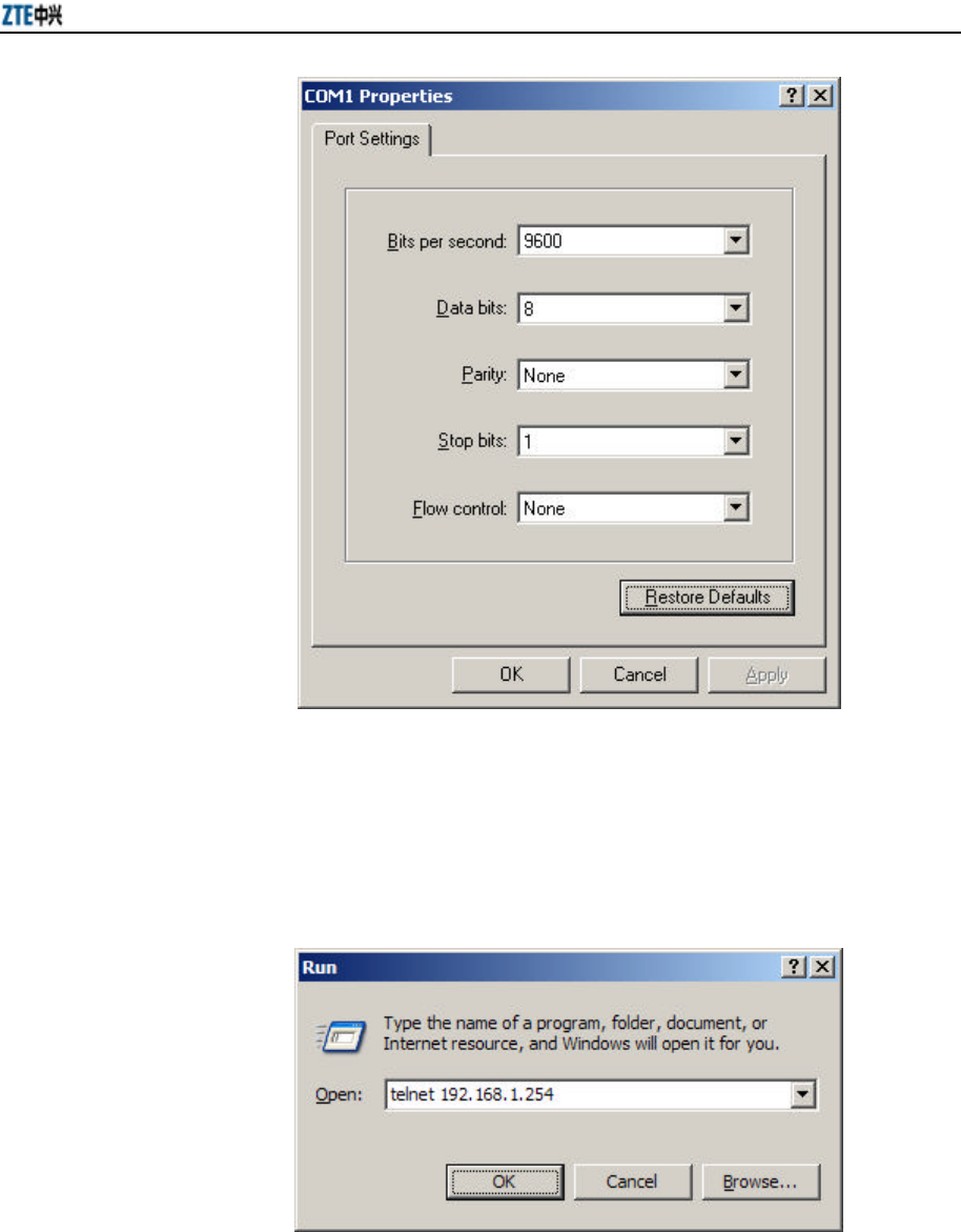
When the serial port mode is used for configuring the W800A, the serial port attribute
configurations of the hyper terminal are shown in Fig. 5.1-1.
Chapter 5 Command Line Configuration
5-3
Fig. 5.1-1 Serial Port Configuration
When the Telnet mode is used for configuring the W800A, you just need input
“telnet/W800A working IP address”, as shown in Fig. 5.1-2. By default, the W800A
working IP address is 192.168.1.254 and the subnet mask is 55.255.255.0.
Fig. 5.1-2 Telnet to W800A
These five configuration modes of the W800A and all the available commands under
each mode are described in detail as follows: The stipulation of command format are as

ZXR10 WAS (V2.0) IP Wireless Access System W800A Wireless Access Point User’s Manual
5-4
follows:
1. abc refers to the command or keyword.
2. <abc> refers to the contents to be input by the user.
3. abc|def indicates that one of the two will be selected.
4. For the contents included in [ ], the user can choose to input or not input them..
5. For the contents included in { }, the user must input them.
5.2 User Mode
Entering mode: Telnet
Exiting mode: exit
Default prompt character: wlan>
Note: After logging on to the W800A in Telnet, the common user can enter the user
mode only once the user name and password authentications are passed. The default
user name is “root” and default password is “public”. To avoid the case in which the
illegal user tries with different passwords, the system will automatically disconnect
from the Telnet of a user, after this user inputs wrong password for consecutive three
times.
5.2.1 Entering the Privileged Mode
Command mode: User mode
Function: Input the correct password to enter the privileged mode.
Command format: enable
Note: After the user inputs the enable command and press ENTER, the system will
prompt that password need be input. The default password of privileged mode is “zte”.
5.2.2 Exiting the Telnet Configuration
Command mode: User mode.
Function: Exiting the user mode and returning to the system.
Command format: exit.

Chapter 5 Command Line Configuration
5-5
5.3 Privileged Mode
Entering mode: Input the enable command in the user mode and input correct
password.
Exiting mode: disable, entering the user mode; exit, exiting the privileged mode and
returning to the system.
Default prompt character: wlan #
5.3.1 Network Connectivity Check
Command mode: Privileged mode
Function: Checking the network connectivity.
Command format: ping <A.B.C.D> [-n <echo-number>] [-w <timeout>] [-l
<packet-size>] [-t]
Parameter descriptions:
Parameter Name Value Range Parameter Descriptions
<A.B.C.D> IP address Destination IP address
-n None Setting the flag bit of ping packet quantity.
<echo-number> 1~40 Quantity of ping packets.
-w None Setting the flag bit of the maximum time-out
interval.
<timeout> 1~2 Maximum time-out interval (unit: second).
-l None Setting the flag bit of the buffer area capacity .
<packet-size> 0~1504 Buffer area capacity
-t None Setting the consecutive ping packets (complete it
by <Ctrl + C>)
5.3.2 Saving the Configuration Data to FLASH
Command mode: Privileged mode.
Function: Saving the configuration data to FLASH.
Command format: write flash.
5.3.3 Restoring the Default Configuration
Command mode: Privileged mode
Function: Deleting the database, recovering the default configuration of the W800A

ZXR10 WAS (V2.0) IP Wireless Access System W800A Wireless Access Point User’s Manual
5-6
and reset it.
Command format: default enable
5.3.4 Resetting the Software
Command mode: Privileged mode
Function: Resetting the W800A.
Command format: reboot
5.3.5 Entering the Configure Mode
Command mode: Privileged mode
Function: Entering the configure mode.
Command format: configure terminal
5.3.6 Exiting the Privileged Mode
Command mode: Privileged mode
Function: Exiting the privileged mode and entering the user mode.
Command format: disable
5.3.7 Exiting the Telnet Configuration
Command mode: Privileged mode
Function: Exiting Telnet and returning to the system.
Command format: exit
Note: This command can only be used in the CLI in the Telnet mode. If the user logs
on in the hyper terminal mode through the serial port, this command is invalid.
5.4 Configure Mode
Entering mode: Input the configure terminal command in the privileged mode.
Exiting mode: exit, entering the privileged mode.
Default prompt character: wlan (config) #
Note: All the configuration commands can be executed in this mode (or its sub-modes).

Chapter 5 Command Line Configuration
5-7
5.4.1 Bridge Configuration
1. bridge aging-time
Command mode: Configure mode
Function: Configuring the aging time of the Bridge Forward Table (FDB) MAC
address.
Command format: bridge aging-time <value>
Parameter descriptions:
Parameter Name Value Range Parameter Descriptions
<value> 10~1000000 The aging time of the FDB MAC address (unit:
second), 300 by default.
2. bridge forward-table-size
Command mode: Configure mode
Function: Configuring the quantity of the FDB MAC addresses.
Command format: bridge forward-table-size <value>
Parameter descriptions:
Parameter Name Value Range Parameter Descriptions
<value> 220~1024 Quantity of the FDB MAC addresses, 1024 by
default.
5.4.2 Clearing the Information
Command mode: Configure mode
Function: Clearing the alarm, log or debugging information.
Command format: clear {alarm|logcmd|trace}
Parameter descriptions:
Parameter Name Value Range Parameter Descriptions
{alarm|logcmd|
trace}
Alarm,
Logcmd,
trace
Clearing the alarm, logcmd or trace information.

ZXR10 WAS (V2.0) IP Wireless Access System W800A Wireless Access Point User’s Manual
5-8
5.4.3 Configuring the Configuration Server
Command mode: Configure mode
Function: Configuring the parameters of configuration server: IP address, interception
port number of the TCP and the interception port number of UDP.
Command format: config-server {ipaddress <A.B.C.D> [tcp-port <value1>
[udp-port <value2>] | udp-port <value2> [tcp-port <value1>]] | tcp-port <value1>
[ipaddress <A.B.C.D> [udp-port <value2>] | udp-port <value2> [ipaddress
<A.B.C.D>]] | udp-port <value2> [ipaddress <A.B.C.D> [tcp-port <value1>] |
tcp-port <value1> [ipaddress <A.B.C.D>]]}
Parameter descriptions:
Parameter Name Value Range Parameter Descriptions
<A.B.C.D> IP address IP address of the configuration server
<value1> 3000~65535 The interception port number of tcp, 3601 by
default.
<value2> 3000~65535 The interception port number of udp, 3600 by
default.
Note: One or multiple parameters can be configured randomly. The un-configured
parameters will keep unchanged.
5.4.4 DHCP Server Configuration
1. dhcp server dns
Command mode: Configure mode
Function: Configuring the IP address parameters of the master and slave DNS
servers of the DHCP server.
Command format: dhcp server dns <A.B.C.D1> [<A.B.C.D2>]
Parameter descriptions:
Parameter Name Value Range Parameter Descriptions
<A.B.C.D1> IP address IP address of the master DNS server.
<A.B.C.D2> IP address IP address of the slave DNS server (optional).
2. dhcp server gateway

Chapter 5 Command Line Configuration
5-9
Command mode: Configure mode
Function: Configuring the IP address parameters of the default gateway of the
DHCP server.
Command format: dhcp server gateway <A.B.C.D>
Parameter descriptions:
Parameter Name Value Range Parameter Descriptions
<A.B.C.D> IP address IP address of the gateway.
3. dhcp server leasetime
Command mode: Configure mode
Function: Configuring the address lease time of the DHCP server.
Command format: dhcp server leasetime <value>
Parameter descriptions:
Parameter Name Value Range Parameter Descriptions
<value> 60~3600 The address lease time of the DHCP server, 6 by
default.
4. dhcp server run
Command mode: Configure mode
Function: Starting, stopping or restarting the DHCP server.
Command format: dhcp server run {start|stop|restart}
Parameter descriptions:
Parameter Name Value Range Parameter Descriptions
{start|stop|restart} Start, stop , restart
start: Startup;
Stop: Stopping;
restart: Restarting.
5. dhcp server start-flag
Command mode: Configure mode
Function: Configuring the start flag of the DHCP server when the system is
restarted.
Command format: dhcp server start-flag {true|false}

ZXR10 WAS (V2.0) IP Wireless Access System W800A Wireless Access Point User’s Manual
5-10
Parameter descriptions:
Parameter Name Value Range Parameter Descriptions
{true|false} True, false
The start flag of the DHCP server.
If it is “true”, the DHCP server will be started when
the system is restarted.
If it is “false”, the DHCP server will not be started
when the system is restarted.
5.4.5 DISCOVER Configuration
1. discover device
Command mode: Configure mode
Function: Configuring the integrated management multicast address and port
number of the equipment.
Command format: discover device <A.B.C.D> [<value>]
Parameter descriptions:
Parameter Name Value Range Parameter Descriptions
<A.B.C.D>
IP address with a
range of 224.0.0.1 ~
239.255.255.254.
The integrated management multicast address of
the equipment, 224.1.88.89 by default.
<value> 0~65535
The interception port number of the integrated
management multicast of the equipment, 2801 by
default.
2. discover manager
Command mode: Configure mode
Function: Configuring the management multicast address and port number of the
integrated management server.
Command format: discover manager <A.B.C.D> [<value>]
Parameter descriptions:

Chapter 5 Command Line Configuration
5-11
Parameter Name Value Range Parameter Descriptions
<A.B.C.D>
IP address with a
range of 224.0.0.1 ~
239.255.255.254.
The management multicast address of the
integrated management server, 224.1.88.88 by
default.
<value> 0~65535 The management interception port number of the
integrated management server, 2800 by default.
5.4.6 802.1X Parameter Configuration
1. dot1x enable
Command mode: Configure mode
Function: Enabling or disabling the 802.1x function.
Command format: [no] dot1x enable
2. dot1x max-reauth
Command mode: Configure mode
Function: Configuring the maximum times of 802.1x re-authenticating.
Command format: dot1x max-reauth <value>
Parameter descriptions:
Parameter Name Value Range Parameter Descriptions
<value> 0~10 The maximum times of 802.1x re-authenticating, 5
by default.
3. dot1x max-request
Command mode: Configure mode
Function: Configuring the maximum times of 802.1x authentication request.
Command format: dot1x max-request <value>
Parameter descriptions:
Parameter Name Value Range Parameter Descriptions
<value> 1~10 The maximum times of 802.1x authentication
request, 2 by default.
4. dot1x md5-domain

ZXR10 WAS (V2.0) IP Wireless Access System W800A Wireless Access Point User’s Manual
5-12
Command mode: Configure mode
Function: Configuring the domain name in the EAP-MD5 authentication mode.
Command format: dot1x md5-domain <string>
Parameter descriptions:
Parameter Name Value Range Parameter Descriptions
<string> 1 ~ 32 characters The domain name in the EAP-MD5 authentication
mode, USR by default.
5. dot1x nas-id
Command mode: Configure mode
Function: Configuring the 802.1x NAS-ID field information.
Command format: dot1x nas-id <string>
Parameter descriptions:
Parameter Name Value Range Parameter Descriptions
<string> 1 ~ 64 characters NAS-ID character string, W800A by default.
6. dot1x portenable
Command mode: Configure mode
Function: Enabling or disabling the 802.1x port control function.
Command format: [no] dot1x portenable
7. dot1x quiet-period
Command mode: Configure mode
Function: Configuring the 802.1x quiet period.
Command format: dot1x quiet-period <value>
Parameter descriptions:
Parameter Name Value Range Parameter Descriptions
<value> 1~255 The 802.1x quiet period (unit: second), 30 by
default.
8. dot1x server-timeout

Chapter 5 Command Line Configuration
5-13
Command mode: Configure mode
Function: Configuring the time-out time of the 802.1x authentication server.
Command format: dot1x server-timeout <value>
Parameter descriptions:
Parameter Name Value Range Parameter Descriptions
<value> 1~255 The authentication server time-out time (unit:
second), 60 by default.
9. dot1x sim-domain
Command mode: Configure mode
Function: Configuring the domain name in the EAP-SIM authentication mode.
Command format: dot1x sim-domain <string>
Parameter descriptions:
Parameter Name Value Range Parameter Descriptions
<string> 1 ~ 32 characters The domain name in the EAP-SIM authentication
mode, SIM by default.
10. dot1x supp-timeout
Command mode: Configure mode
Function: Configuring the time-out time of the 802.1x client.
Command format: dot1x supp-timeout <value>
Parameter descriptions:
Parameter Name Value Range Parameter Descriptions
<value> 1~255 The time-out time of the 802.1x client (unit:
second), 30 by default.
11. dot1x tx-period
Command mode: Configure mode
Function: Configuring the 802.1x sending period.
Command format: dot1x tx-period <value>
Parameter descriptions:

ZXR10 WAS (V2.0) IP Wireless Access System W800A Wireless Access Point User’s Manual
5-14
Parameter Name Value Range Parameter Descriptions
<value> 1~255 The 802.1x sending period (unit: second), 3 by
default.
12. dot1x wpa-domain
Command mode: Configure mode
Function: Configuring the domain name in the WPA authentication mode.
Command format: dot1x wpa-domain <string>
Parameter descriptions:
Parameter Name Value Range Parameter Descriptions
<string> 1 ~ 32 characters WPA domain name, WPA by default.
5.4.7 Password Configuration in the Privileged Mode
Command mode: Configure mode
Function: Configuring the password for enabling the privileged mode.
Command format: enable-password <string>
Parameter descriptions:
Parameter Name Value Range Parameter Descriptions
<string> 1 ~ 30 characters The password for enabling the privileged mode, zte
by default.
5.4.8 Erasing the Filtration Rules
Command mode: Configure mode
Function: Erasing the ACL rule according to the global regular numbers.
Command format: erase mac-access-rule <value>
Parameter descriptions:
Parameter Name Value Range Parameter Descriptions
<value> 0~1023 Numbers of the filtration rules.
5.4.9 Exiting the Configure Mode
Command mode: Configure mode

Chapter 5 Command Line Configuration
5-15
Function: Exiting the configure mode and entering the privileged mode.
Command format: exit
5.4.10 IAPP Load Balance Configuration
1. iapp balance
Command mode: Configure mode
Function: Configuring the load balance mode and nominal capacity of the load
balance group.
Command format: iapp balance <vlaue1> {flow <value2>|user <value3> }
Parameter descriptions:
Parameter Name Value Range Parameter Descriptions
<value1> 1~65535 Load balance group ID
<vlaue2> 1~65535 The lower limit of the flow implementing the load
balance according to the data flow.
<vlaue3> 1~30 The lower limit of the users implementing the load
balance according to the user quantity.
2. iapp enable-flag
Command mode: Configure mode
Function: Configuring the enabling status of the load balance and the limitation
of the maximum user quantity.
Command format: iapp enable-flag {disable|balance|max-user}
Parameter descriptions:
Parameter Name Value Range Parameter Descriptions
{disable|balance|
max-user}
Disable,
Balance,
max-user
disable: Disabling both of them.
balance: Enabling the load balance.
max-user: Enabling the limitation of maximum user
quantity.
& Note:
Configurations iapp balance and iapp max-user can not be enabled at the same time.

ZXR10 WAS (V2.0) IP Wireless Access System W800A Wireless Access Point User’s Manual
5-16
3. iapp max-user
Command mode: Configure mode
Function: Configuring the maximum user quantity (the quantity of the users can
be accessed).
Command format: iapp max-user <value>
Parameter descriptions:
Parameter Name Value Range Parameter Descriptions
<value> 1~150 The maximum quantity of the wireless users can be
accessed by the system, 30 by default.
5.4.11 Entering the Interface Configuration Mode
1. interface ethernet
Command mode: Configure mode
Function: Entering the Ethernet interface configuration mode. The command is
followed by the unit ID of the Ethernet interface. The equipment can hold
multiple Ethernet interfaces.
Command format: interface ethernet {0}
Parameter descriptions:
Parameter Name Value Range Parameter Descriptions
{0} 0
The unit ID of the Ethernet interface. The W800A
only has one Ethernet interface, so this value is 0
fixedly.
2. interface wlan
Command mode: Configure mode
Function: Entering the Wireless interface configuration mode. The command is
followed by the unit ID of the wireless interface. The equipment can hold
multiple wireless interfaces.
Command format: interface wlan {0|1}
Parameter descriptions:
Parameter Name Value Range Parameter Descriptions
{0|1} 0 or 1 The unit ID of the wireless interface. The W800A

Chapter 5 Command Line Configuration
5-17
has two wireless interfaces, so this value is 0 or 1.
5.4.12 IP Network Parameter Configuration
1. ip address
Command mode: Configure mode
Function: Adding the IP address of the W800A management interface.
Command format: [no] ip address <A.B.C.D1> <A.B.C.D2> [second]
Parameter descriptions:
Parameter Name Value Range Parameter Descriptions
<A.B.C.D1> IP address IP address of the host.
<A.B.C.D2> Subnet mask Subnet mask of the host.
second second
The main address is without “second” and the
standby address is with “second”. The main address
quantity can only be one and the standby address
quantity can be up to nine.
2. ip route
Command mode: Configure mode
Function: Configuring the default route address of the system.
Command format: [no] ip route <A.B.C.D1> <A.B.C.D2> <A.B.C.D3>
Parameter descriptions:
Parameter Name Value Range Parameter Descriptions
<A.B.C.D1> IP address IP address of the host.
<A.B.C.D2> Subnet mask Subnet mask of the host.
<A.B.C.D3> IP address IP address of the router of the next hop.
3. ip pool
Command mode: Configure mode
Function: Configuring the IP address pool of the system.
Command format: [no] ip pool <index> <A.B.C.D1> <A.B.C.D2> <A.B.C.D3>
Parameter descriptions:
Parameter Name Value Range Parameter Descriptions
<index> 0~9 IP address pool group ID

ZXR10 WAS (V2.0) IP Wireless Access System W800A Wireless Access Point User’s Manual
5-18
<A.B.C.D1> IP address Initial IP address of the host address pool.
<A.B.C.D2> IP address End IP address of the host address pool.
<A.B.C.D3> Subnet mask Subnet mask of the address pool address.
5.4.13 Kicking Users
1. kick all
Command mode: Configure mode
Function: Kicking all the users.
Command format: kick all
2. kick station
Command mode: Configure mode
Function: Kicking the user with the specified MAC address.
Command format: kick station <xx-xx-xx-xx-xx-xx>
Parameter descriptions:
Parameter Name Value Range Parameter Descriptions
<xx-xx-xx-xx-xx-xx> MAC address User MAC address
5.4.14 Two-Layer Separation Configuration
1. l2-separate enable
Command mode: Configure mode
Function: Enabling or disabling the two-layer separation function.
Command format: [no] l2-separate enable
2. l2-separate gateway
Command mode: Configure mode
Function: Configuring the gateway MAC address .
Command format: l2-separate gateway mac <xx-xx-xx-xx-xx-xx>
Parameter descriptions:
Parameter Name Value Range Parameter Descriptions
<xx-xx-xx-xx-xx-xx> MAC address Gateway MAC address

Chapter 5 Command Line Configuration
5-19
3. l2-separate mode
Command mode: Configure mode
Function: Configuring the two-layer separation working mode.
Command format: l2-separate mode {simple_mode| gateway_mode }
Parameter descriptions:
Parameter Name Value Range Parameter Descriptions
{simple_mode|
gateway_mode }
simple_mode,
gateway_mode
Selecting the simple mode or gateway mode for the
two-layer separation.
5.4.15 Log Printing Message Configuration
1. logmsg all-enable
Command mode: Configure mode
Function: Enabling or disabling the log printing messages of all the modules.
Command format: [no] logmsg all-enable
2. logmsg level
Command mode: Configure mode
Function: Configuring the levels of the log printing messages to be output.
Command format: logmsg level {Lowest|Lower|Higher|Highest}
Parameter descriptions:
Parameter Name Value Range Parameter Descriptions
{Lowest|Lower|
Higher|Highest}
Lowest (Flood),
Lower (Info),
Higher (Error),
Highest (Fatal)
Level of the log printing messages to be output.
Only the printing messages higher than this level
can be output.
3. logmsg mod-enable
Command mode: Configure mode
Function: Determining the module containing the log printing messages.
Command format: [no] logmsg mod-enable <module>
Parameter descriptions:

ZXR10 WAS (V2.0) IP Wireless Access System W800A Wireless Access Point User’s Manual
5-20
Parameter Name Value Range Parameter Descriptions
<module>
Specified module
names:
BSP, DATABASE,
80211, BRIDGE,
IAPP, DHCP,
IPPOOL, DOT1X,
RADIUS, ACL,
SVCMANAGE,
TELNET, WEB,
CONSOLE, SNMP,
ALARM, R01,
TFTP, DISCOVER,
QOS
The module containing the log printing messages.
4. logmsg telnet-log
Command mode: Configure mode
Function: Configuring the current Telnet window as the output window of the
log printing messages
Command format: [no] logmsg telnet-log
5.4.16 MAC Filtration Configuration
Command mode: Configure mode
Function: Adding or deleting a number accessing list.
Command format: [no] mac-access-list <value> {deny|permit}
{<xx-xx-xx-xx-xx-xx>|any}
Parameter descriptions:
Parameter Name Value Range Parameter Descriptions
<value> 1~99 MAC filtration group ID
{deny|permit} deny, permit
deny: If the condition is satisfied, the MAC
communication will be denied.
permit: If the condition is satisfied, the MAC
communication will be permitted.

Chapter 5 Command Line Configuration
5-21
Parameter Name Value Range Parameter Descriptions
{<xx-xx-xx-xx-xx-xx
> |any}
MAC address or
any
The MAC address sending the MAC packet. Two
methods can be used for specifying the source
address:
One is to use the format of 48-bit 6 hexadecimal
hyphens, for example: 00-d0-d0-f1-c4-ef.
The other is to use the keyword any as the
abbreviation of the source 00-00-00-00-00-00. This
keyword is not recommended.
5.4.17 MAC Address Authentication Configuration
Command mode: Configure mode
Function: Configuring the MAC address authentication function.
Command format: [no] mac-authen {deny|permit} {<xx-xx-xx-xx-xx-xx>|any}
Parameter descriptions:
Parameter Name Value Range Parameter Descriptions
{deny|permit} Deny, permit
deny: If the condition is satisfied, the MAC
communication will be denied.
permit: If the condition is satisfied, the MAC
communication will be permitted.
{<xx-xx-xx-xx-xx-xx>
|any}
MAC address or
any
The MAC address sending the MAC packet. Two
methods can be used for specifying the source
address:
One is to use the format of 48-bit 6 hexadecimal
hyphens, for example: 00-d0-d0-f1-c4-ef;
The other is to use the keyword any as the
abbreviation of the source 00-00-00-00-00-00, and
this keyword is not recommended.
5.4.18 Manager Configuration
Command mode: Configure mode
Function: Adding or deleting the manager account.
Command format: [no] manage-user <string1> <string2>

ZXR10 WAS (V2.0) IP Wireless Access System W800A Wireless Access Point User’s Manual
5-22
Parameter descriptions:
Parameter Name Value Range Parameter Descriptions
<string1> 1 ~ 32 characters User name
<string2> 1 ~ 32 characters User password.
5.4.19 QoS Configuration
1. qos enable
Command mode: Configure mode
Function: Enabling or disabling QoS function.
Command format: [no] qos enable
2. qos policy
Command mode: Configure mode
Function: Configuring QoS policy.
Command format: qos policy {ESSID|802.1p}
Parameter descriptions:
Parameter Name Value Range Parameter Descriptions
{ESSID|802.1p} ESSID, 802.1p Indicating the priority policy which is the base of
QoS, ESSID by default.
5.4.20 RADIUS Server Configuration
1. radius-server account
Command mode: Configure mode
Function: Adding or deleting the accounting server of an ISP.
Command format: [no] radius-server account <string1> {master|slave}
<A.B.C.D> <value> <string2>
Parameter descriptions:
Parameter Name Value Range Parameter Descriptions
<string1> 1 ~ 32 characters ISP name, and only the created ISP can be input.
{master|slave } Master, slave Master or slave flag of the accounting server.
<A.B.C.D> IP address IP address of the accounting server
<value> 0~65535 Port number of the accounting server

Chapter 5 Command Line Configuration
5-23
Parameter Name Value Range Parameter Descriptions
<string2> 1 ~ 255 characters Character string of the accounting shared secret key
2. radius-server authen
Command mode: Configure mode
Function: Adding or deleting the authentication server of an ISP.
Command format: [no] radius-server authen <string1> {master|slave}
<A.B.C.D> <value> <string2>
Parameter descriptions:
Parameter Name Value Range Parameter Descriptions
<string1> 1 ~ 32 characters ISP name, and only the created ISP can be input.
{master|slave } Master, slave Master/slave authentication server. The master
authentication server can only be one.
<A.B.C.D> IP address IP address of the authentication server
<value> 0~65535 Port number of the authentication server
<string2> 1 ~ 255 characters Character string of the authentication shared secret
key
3. radius-server dns
Command mode: Configure mode
Function: Adding or deleting the DNS server of an ISP.
Command format: [no] radius-server dns <string>
Parameter descriptions:
Parameter Name Value Range Parameter Descriptions
<string> 1 ~ 32 characters ISP name, and only the created ISP can be input.
4. radius-server isp-name
Command mode: Configure mode
Function: Adding or deleting an ISP.
Command format: [no] radius-server isp-name <string>
Parameter descriptions:
Parameter Name Value Range Parameter Descriptions
<string> 1 ~ 32 characters ISP name.

ZXR10 WAS (V2.0) IP Wireless Access System W800A Wireless Access Point User’s Manual
5-24
5. radius-server retry-times
Command mode: Configure mode
Function: Configuring the retrying times of the RADIUS authentication of an
ISP.
Command format: radius-server retry-times <string> <value>
Parameter descriptions:
Parameter Name Value Range Parameter Descriptions
<string> 1 ~ 32 characters ISP name, and only the created ISP can be input.
<value> 1~10 The retrying times of the RADIUS authentication, 3
by default.
6. radius-server timeout
Command mode: Configure mode
Function: Configuring the time-out time of the RADIUS authentication of an
ISP.
Command format: radius-server timeout <string> <value>
Parameter descriptions:
Parameter Name Value Range Parameter Descriptions
<string> 1 ~ 32 characters ISP name, and only the created ISP can be input.
<value> 1~65535 The time-out time of the RADIUS authentication
(unit: second), 2 by default.
5.4.21 SNMP Module Configuration
1. snmp access-host
Command mode: Configure mode
Function: Adding or deleting the IP address of the host which can be accessed.
Command format: [no] snmp access-host <A.B.C.D>
Parameter descriptions:
Parameter Name Value Range Parameter Descriptions
<A.B.C.D> IP address The host IP address represented by dotted decimal
(A.B.C.D) (at most 10).

Chapter 5 Command Line Configuration
5-25
2. snmp access-mode
Command mode: Configure mode
Function: Configuring the local agent can be accessed by all the hosts or the host
in access-host.
Command format: snmp access-mode {all|list}
Parameter descriptions:
Parameter Name Value Range Parameter Descriptions
{all|list} All, list all: All the users can access it.
list: The users in access-host can access it.
3. snmp authtrap
Command mode: Configure mode
Function: Enabling or disabling the community string authentication.
Command format: [no] snmp authtrap enable
4. snmp community
Command mode: Configure mode
Function: Configuring the SNMP access community string and its accessing
authority.
Command format: snmp community <string> {read-only| read-write}
no snmp community <string>
Parameter descriptions:
Parameter Name Value Range Parameter Descriptions
<string> 1 ~ 32 characters
SNMP access community string name (at most 10).
<string> is a character string with at most 32
characters.
{read-only|
read-write}
read-only,
read-write
read-only: Read-only authority.
read-write: Read-write authority.
5. snmp contact
Command mode: Configure mode
Function: Configuring the name and contact method of the equipment manager.
Command format: snmp contact <End-Mark> <string>

ZXR10 WAS (V2.0) IP Wireless Access System W800A Wireless Access Point User’s Manual
5-26
Parameter descriptions:
Parameter Name Value Range Parameter Descriptions
<End-Mark> Any character. Serving as the end mark of inputting character
string.
<string> 1 ~ 255 characters
A management variable content in the MIB II
system group, containing the name and contact
method of the equipment manager.
6. snmp enable
Command mode: Configure mode
Function: Enabling or disabling the SNMP management function.
Command format: [no] snmp enable
7. snmp location
Command mode: Configure mode
Function: Configuring the geographic location information of the managed
equipment.
Command format: snmp location <End-Mark> <string>
Parameter descriptions:
Parameter Name Value Range Parameter Descriptions
<End-Mark> Any character. Serving as the end mark of inputting character
string.
<string> 1 ~ 255 characters
sysLocation, a management variable in the MIB
system group, describing the geographic location of
the managed equipment.
8. snmp nodecode
Command mode: Configure mode
Function: Configuring the NE code information of the managed equipment.
Command format: snmp nodecode <value>
Parameter descriptions:

Chapter 5 Command Line Configuration
5-27
Parameter Name Value Range Parameter Descriptions
<value> 0~241920000 A management variable in the MIB system group,
describing the NE code of the managed equipment.
9. snmp nodecreatdate
Command mode: Configure mode
Function: Configuring the creation time information of the NE of the managed
equipment.
Command format: snmp nodecreatdate <hh:mm:ss> <month> <day> <year>
Parameter descriptions:
Parameter Name Value Range Parameter Descriptions
<hh:mm:ss> 0~241920000 hh (hour):mm (minute): ss (second)
<month> 1~12 Month
<day> 1~31 Date
<year> 2002~2130 Year, 4 bits are needed.
hh:mm:ss month day year is a management variable in the MIB system group,
describing the creation time of the NE of the managed equipment.
10. snmp nodeid
Command mode: Configure mode
Function: Configuring the NE ID information of the managed equipment.
Command format: snmp nodeid <string>
Parameter descriptions:
Parameter Name Value Range Parameter Descriptions
<string> 0 ~ 31 characters A management variable in the MIB system group,
describing the NE ID of the managed equipment.
11. snmp sysname
Command mode: Configure mode
Function: Configuring the name of the managed equipment.
Command format: snmp sysname <End-Mark> <string>
Parameter descriptions:
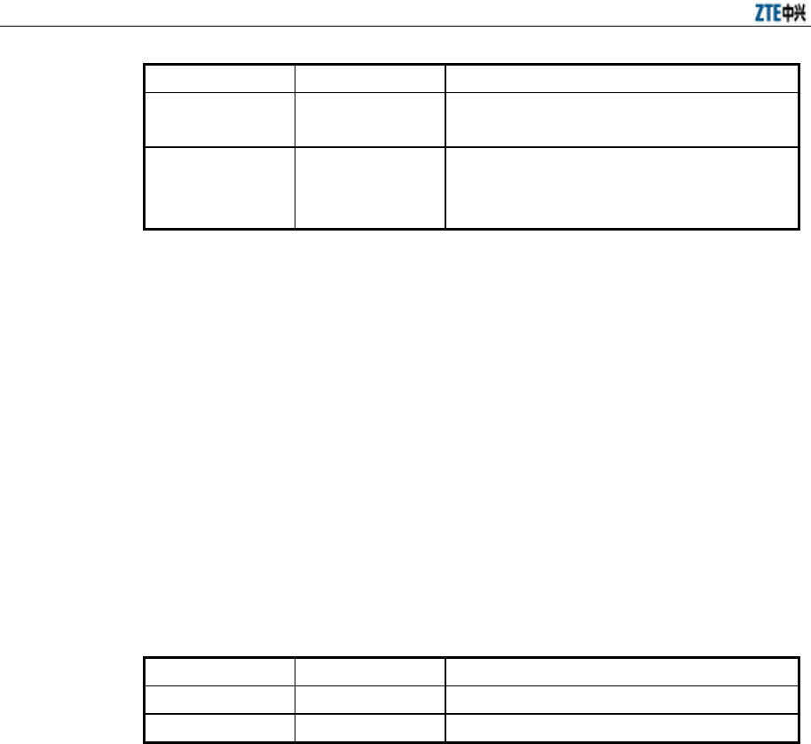
ZXR10 WAS (V2.0) IP Wireless Access System W800A Wireless Access Point User’s Manual
5-28
Parameter Name Value Range Parameter Descriptions
<End-Mark> Any character. Serving as the end mark of inputting character
string.
<string> 1 ~ 255 characters
RFC1213, a management variable in the MIB
system group, and it is the name of the managed
equipment.
12. snmp trap enable
Command mode: Configure mode
Function: Enabling or disabling SNMP Agent to send trap.
Command format: [no] snmp trap enable
13. snmp traphost
Command mode: Configure mode
Function: Adding a trap target host address and trap version number
information.
Command format: [no] snmp traphost <A.B.C.D> [version <value>]
Parameter descriptions:
Parameter Name Value Range Parameter Descriptions
<A.B.C.D> IP address trap target host address.
<value> 1~2 trap version number.
5.4.22 SSH Parameter Configuration
1. ssh server enable
Command mode: Configure mode
Function: Enabling or disabling SSH function.
Command format: [no] ssh server enable
2. ssh server only
Command mode: Configure mode
Function: Enabling or disabling SSH function, and disabling Telnet function.
Command format: [no] ssh server only
3. ssh server generate-key rsa

Chapter 5 Command Line Configuration
5-29
Command mode: Configure mode
Function: Generating SSH server secret key.
Command format: ssh server generate-key rsa
4. ssh server auth isp-name
Command mode: Configure mode
Function: Configuring SSH with the ISP name of the authentication server
authenticated by radius.
Command format: ssh server auth isp-name <string>
Parameter descriptions:
Parameter Name Value Range Parameter Descriptions
<string> 1 ~ 64 characters SSH adopts the ISP name of the authentication
server authenticated by radius.
5. ssh server auth mode
Command mode: Configure mode
Function: Configuring the SSH authentication mode.
Command format: ssh server auth mode {radius|local}
Parameter descriptions:
Parameter Name Value Range Parameter Descriptions
{radius|local} Radius, local SSH authentication mode.
6. ssh server auth type
Command mode: Configure mode
Function: Configuring the SSH authentication type.
Command format: ssh server auth type {chap|pap}
Parameter descriptions:
Parameter Name Value Range Parameter Descriptions
{chap|pap} Chap, pap SSH authentication type.
5.4.23 Spanning Tree Parameter Configuration
1. stp bridge forward-delay

ZXR10 WAS (V2.0) IP Wireless Access System W800A Wireless Access Point User’s Manual
5-30
Command mode: Configure mode
Function: Configuring the forwarding delay time of the spanning tree protocol
bridge.
Command format: stp bridge forward-delay <value>
Parameter descriptions:
Parameter Name Value Range Parameter Descriptions
<value> 4~30 The forwarding delay time of the spanning tree
protocol bridge (unit: second), 15 by default.
2. stp bridge hello-time
Command mode: Configure mode
Function: Configuring the hello time of the spanning tree protocol bridge.
Command format: stp bridge hello-time <value>
Parameter descriptions:
Parameter Name Value Range Parameter Descriptions
<value> 1~10 The hello time of the spanning tree protocol bridge
(unit: second), 2 by default.
3. stp bridge max-age
Command mode: Configure mode
Function: Configuring the maximum age of the spanning tree protocol bridge.
Command format: stp bridge max-age <value>
Parameter descriptions:
Parameter Name Value Range Parameter Descriptions
<value> 6~40 The maximum age of the spanning tree protocol
bridge (unit: second), 20 by default.
4. stp bridge priority
Command mode: Configure mode
Function: Configuring the priority of the spanning tree protocol bridge.
Command format: stp bridge priority <value>
Parameter descriptions:

Chapter 5 Command Line Configuration
5-31
Parameter Name Value Range Parameter Descriptions
<value> 0~65535 The priority of the spanning tree protocol bridge,
32768 by default.
5. stp enable
Command mode: Configure mode
Function: Enabling or disabling the spanning tree protocol function.
Command format: [no] stp enable
6. stp interface path-cost
Command mode: Configure mode
Function: Configuring the path cost of the spanning tree protocol interface.
Command format: stp interface path-cost {eth0|wlan0|wlan1} <value>
Parameter descriptions:
Parameter Name Value Range Parameter Descriptions
{eth0|wlan0|wlan1} eth0, wlan0, wlan1 Configured interface.
<value> 1~65535 The path cost of the spanning tree protocol
interface .
7. stp interface priority
Command mode: Configure mode
Function: Configuring the priority of the spanning tree protocol interface.
Command format: stp interface priority {eth0|wlan0|wlan1} <value>
Parameter descriptions:
Parameter Name Value Range Parameter Descriptions
{eth0|wlan0|wlan1} eth0, wlan0, wlan1 Configured interface.
<value> 0~255 The priority of the spanning tree protocol interface,
128 by default.
8. stp interface state
Command mode: Configure mode
Function: Configuring the state of the spanning tree protocol interface.
Command format: stp interface state {eth0|wlan0|wlan1} {enable|disable}
ZXR10 WAS (V2.0) IP Wireless Access System W800A Wireless Access Point User’s Manual
5-32
Parameter descriptions:
Parameter Name Value Range Parameter Descriptions
{eth0|wlan0|wlan1} eth0, wlan0, wlan1 Configured interface.
{enable|disable} Enable, disable The state of the spanning tree protocol interface,
enable by default.
5.4.24 TELNET Configuration
1. telnet enable
Command mode: Configure mode
Function: Enabling or disabling Telnet function.
Command format: [no] telnet enable
2. telnet idletime
Command mode: Configure mode
Function: Configuring the automatic exiting time when the Telnet window is
idle.
Command format: telnet idletime <value>
Parameter descriptions:
Parameter Name Value Range Parameter Descriptions
<value> 300~3600 The automatic exiting time when the Telnet
window is idle (unit: second), 300 by default.
5.4.25 Uploading/Downloading TFTP Files
1. tftp dir
Command mode: Configure mode
Function: Observing the spare space of the flash disk (unit: byte)
Command format: tftp dir
2. tftp get: downloading files
Command mode: Configure mode
Function: With TFTP transmission protocol, downloading files from the TFTP
server and save them to the flash disk

Chapter 5 Command Line Configuration
5-33
Command format: tftp get <A.B.C.D> {runbin | zxipcmd.dat | database.dat}
Parameter descriptions:
Parameter Name Value Range Parameter Descriptions
<A.B.C.D> IP address The TFTP server IP address represented by dotted
decimal.
{runbin|
zxipcmd.dat|
database.dat}
Runbin,
zxipcmd.dat,
database.dat
The full file name (including the extension name)
of the version file set to be transmitted on the TFTP
server.
3. tftp pic
Command mode: Configure mode
Function: Downloading the picture file on the WEB configuration page from the
TFTP server and save them to the flash disk.
Command format: tftp pic <A.B.C.D>
Parameter descriptions:
Parameter Name Value Range Parameter Descriptions
<A.B.C.D> IP address The TFTP server IP address represented by dotted
decimal.
4. tftp put: uploading files
Command mode: Configure mode
Function: With TFTP transmission protocol, uploading files from the flash disk
to the TFTP server.
Command format: tftp put <A.B.C.D> {runbin | zxipcmd.dat | database.dat}
Parameter descriptions:
Parameter Name Value Range Parameter Descriptions
A.B.C.D IP address The TFTP server IP address represented by dotted
decimal.
{runbin|
zxipcmd.dat|
database.dat}
Runbin,
zxipcmd.dat,
database.dat
The full file name (including the extension name)
of the file to be transmitted on the flash disk.
5.4.26 VLAN Configuration
1. vlan enable

ZXR10 WAS (V2.0) IP Wireless Access System W800A Wireless Access Point User’s Manual
5-34
Command mode: Configure mode
Function: Enabling or disabling VLAN function.
Command format: [no] vlan enable
2. vlan manager-vlanid
Command mode: Configure mode
Function: Configuring the VLAN of the management interface.
Command format: vlan manager-vlanid <value>
Parameter descriptions:
Parameter Name Value Range Parameter Descriptions
<value> 0~4094
0: The management interface is without VLAN. 1 ~
4094: The VLAN domain flag of the management
interface. The default value is 0.
5.4.27 Web Configuration
Command mode: Configure mode
Function: Enabling or disabling web function.
Command format: [no] web enable
5.4.28 Nation Zone Configuration
Command mode: Configure mode
Function: Configuring the nation and zone whether the equipment is located, for setting
the corresponding channel and frequency band.
Command format: zone {NA|CA|CN|TW|FR|GE|HK|KR|MX|GB|US}

Chapter 5 Command Line Configuration
5-35
Parameter descriptions:
Parameter Name Value Range Parameter Descriptions
{NA|CA|CN|TW|
FR|GE|HK|KR|
MX|GB|US }
NA
CA
CN
TW
FR
GE
HK
KR
MX
GB
US
NA: Not been configured;
CA: Canada;
CN: China;
TW: Taiwan;
FR: France;
GE: Germany;
HK: Hongkong;
KR: Korea;
MX: Mexico;
GB: Britain;
US: USA;
The default value is CN.
5.4.29 Showing Parameter Configuration
1. show alarm
1) show alarm all
Command mode: Configure mode
Function: Showing all the alarm information.
Command format: show alarm all
2) show alarm bycode
Command mode: Configure mode
Function: Showing the alarm information according to the alarm codes.
Command format: show alarm bycode <value>
Parameter descriptions:
Parameter Name Value Range Parameter Descriptions
<value> 1001~3999 Alarm codes.
3) show alarm bylevel
Command mode: Configure mode
Function: Showing the alarm information according to the alarm levels.
Command format: show alarm bylevel <value>

ZXR10 WAS (V2.0) IP Wireless Access System W800A Wireless Access Point User’s Manual
5-36
Parameter descriptions:
Parameter Name Value Range Parameter Descriptions
<value> 1~3 Alarm levels.
2. show bridge
Command mode: Configure mode
Function: Showing the bridge configuration parameter information.
Command format: show bridge
3. show config-server
Command mode: Configure mode
Function: Showing the parameter information of the configuration server.
Command format: show config-server
4. show dhcp server
Command mode: Configure mode
Function: Showing the parameter information of the DHCP server.
Command format: show dhcp server
5. show discover
Command mode: Configure mode
Function: Showing the parameter information of the equipment discovering
configuration.
Command format: show discover
6. show dot1x-cfg
Command mode: Configure mode
Function: Showing 802.1x parameter information.
Command format: show dot1x-cfg
7. show iapp
Command mode: Configure mode
Function: Showing the parameter information of the load balance configuration.

Chapter 5 Command Line Configuration
5-37
Command format: show iapp
8. show interface
Command mode: Configure mode
Function: Showing the parameter information of the interface configuration.
Command format: show interface {ethernet|wlan} {0|1}
9. show ip
1) show ip address
Command mode: Configure mode
Function: Showing IP address information.
Command format: show ip address
2) show ip pool
= show ip pool config
Command mode: Configure mode
Function: Showing all the IP address pool information.
Command format: show ip pool config
= show ip pool used
Command mode: Configure mode
Function: Showing the used IP address information in the specified IP address
pool.
Command format: show ip pool used <value>
Parameter descriptions:
Parameter Name Value Range Parameter Descriptions
<value> 0~9 Serial number of the IP address pool
3) show ip route
Command mode: Configure mode
Function: Showing the parameter information of the IP route configuration.
Command format: show ip route

ZXR10 WAS (V2.0) IP Wireless Access System W800A Wireless Access Point User’s Manual
5-38
10. show l2-separate
Command mode: Configure mode
Function: Showing the parameter information of the 2-layer separation
configuration.
Command format: show l2-separate
11. show logmsg
Command mode: Configure mode
Function: Showing all the configuration information and configuration historical
commands of log printing.
Command format: show logmsg {config|logcmd}
12. show mac-access-list
Command mode: Configure mode
Function: Showing the parameter information of mac-access-list filtration
configuration.
Command format: show mac-access-list <value>
Parameter descriptions:
Parameter Name Value Range Parameter Descriptions
<value> 1~99 MAC filtration group number.
13. show mac-authen
Command mode: Configure mode
Function: Showing the parameter information of mac-authen configuration.
Command format: show mac-authen
14. show manage-mode
Command mode: Configure mode
Function: Showing the configuration information of the Telnet, snmp and web.
Command format: show manage-mode
15. show manage-user

Chapter 5 Command Line Configuration
5-39
Command mode: Configure mode
Function: Showing the parameter information of manage-user configuration.
Command format: show manage-user
16. show multi-essid
Command mode: Configure mode
Function: Showing the parameter information of multi-essid configuration.
Command format: show multi-essid <value>
Parameter descriptions:
Parameter Name Value Range Parameter Descriptions
<value> 0 or 1 Number of the wireless interface.
17. show qos
Command mode: Configure mode
Function: Showing the parameter information of qos configuration.
Command format: show qos
18. show radius
Command mode: Configure mode
Function: Showing the parameter information of radius configuration.
Command format: show radius
19. show snmp
1) show snmp access-host
Command mode: Configure mode
Function: Showing the parameter information of snmp access-host
configuration.
Command format: show snmp access-host
2) show snmp community
Command mode: Configure mode
Function: Showing the parameter information of snmp community

ZXR10 WAS (V2.0) IP Wireless Access System W800A Wireless Access Point User’s Manual
5-40
configuration.
Command format: show snmp community
3) show snmp nodeinfo
Command mode: Configure mode
Function: Showing the parameter information of snmp nodeinfo configuration.
Command format: show snmp nodeinfo
4) show snmp sysinfo
Command mode: Configure mode
Function: Showing the parameter information of snmp sysInfo configuration.
Command format: show snmp sysinfo
5) show snmp traphost
Command mode: Configure mode
Function: Showing the parameter information of snmp traphost configuration.
Command format: show snmp traphost
20. show station-info
Command mode: Configure mode
Function: Showing the information of the client connected to W800A.
Command format: show station-info
21. show ssh
Command mode: Configure mode
Function: Showing the parameter information of SSH configuration.
Command format: show ssh
22. show stp
1) show stp bridge
Command mode: Configure mode
Function: Showing the parameter information of stp bridge configuration.

Chapter 5 Command Line Configuration
5-41
Command format: show stp bridge
2) show stp interface
Command mode: Configure mode
Function: Showing the parameter information of stp interface configuration.
Command format: show stp interface
23. show telnet-idletime
Command mode: Configure mode
Function: Showing the parameter information of the automatic exiting time
when the Telnet window is idle.
Command format: show telnet-idletime
24. show trace
Command mode: Configure mode
Function: Showing the printing information of the client.
Command format: show trace
25. show version
Command mode: Configure mode
Function: Showing the software version number information.
Command format: show version
26. show vlan
Command mode: Configure mode
Function: Showing the vlan configuration information.
Command format: show vlan
5.5 Ethernet Interface Configuration Mode
Entering mode: Input the interface Ethernet 0 command in the configure mode.
Exiting mode: exit, entering the configure mode.
Default prompt character: wlan (config-eth) #

ZXR10 WAS (V2.0) IP Wireless Access System W800A Wireless Access Point User’s Manual
5-42
Note: All the information of the corresponding interface can be configured in this
mode.
5.5.1 Exiting the Ethernet Interface Configuration Mode
Command mode: Ethernet interface configure mode
Function: Exiting the Ethernet interface configuration mode and entering the configure
mode.
Command format: exit
5.5.2 Ethernet Interface MAC Filtration Configuration
Command mode: Ethernet interface configure mode
Function: Configuring the Ethernet interface MAC filtration.
Command format: [no] macl-bind <value> {in}
Parameter descriptions:
Parameter Name Value Range Parameter Descriptions
<value> 1~99 The article number of the MAC filtration bound to
the interface.
{in} in The in direction bound to the interface.
5.6 Wireless Interface Configuration Mode
Entering mode: Input the interface wlan {0|1} command in the configure mode.
Exiting mode: exit, entering the configure mode.
Default prompt character: wlan (config-wlan) #
Note: All the information of the corresponding interface can be configured in this
mode.
5.6.1 802.11-Related Parameter Configuration of the Wireless Interface
1. 80211 authmode
Command mode: Wireless interface configure mode
Function: Configuring the wireless authentication mode of the AP.
Command format: 80211 authmode {OpenSystem | ShareKey}

Chapter 5 Command Line Configuration
5-43
Parameter descriptions:
Parameter Name Value Range Parameter Descriptions
{OpenSystem|
ShareKey}
OpenSystem,
ShareKey
The wireless authentication mode is configured as
open system or shared secret key mode.
2. 80211 essid
Command mode: Wireless interface configure mode
Function: Configuring the wireless network ESSID.
Command format: 80211 essid <string>
Parameter descriptions:
Parameter Name Value Range Parameter Descriptions
<string> 1 ~ 31 characters Wireless network ESSID. By default, interface 0 is
wireless0 and interface 1 is wireless1.
3. 80211 frg-threshold
Command mode: Wireless interface configure mode
Function: Configuring the fragment threshold.
Command format: 80211 frg-threshold <value>
Parameter descriptions:
Parameter Name Value Range Parameter Descriptions
<value> 256 ~ 2346 (even
number) The fragment threshold, 2346 by default.
4. 80211 rts-threshold
Command mode: Wireless interface configure mode
Function: Configuring the RTS threshold.
Command format: 80211 rts-threshold <value>
Parameter descriptions:
Parameter Name Value Range Parameter Descriptions
<value> 0~2347 RTS threshold, 2347 by default. .
5. 80211 wirelessmode
Command mode: Wireless interface configure mode

ZXR10 WAS (V2.0) IP Wireless Access System W800A Wireless Access Point User’s Manual
5-44
Function: Configuring the wireless standard working mode of the wireless
interface.
Command format: 80211 wirelessmode {11a|11b|11g|help} [channel <num>]
[rate <value>]
Parameter descriptions:
Parameter Name Value Range Parameter Descriptions
{11a|11b|11g|help} 11a, 11b, 11g, help
11a: Configuring 800A as the 802.11a working mode.
11b: Configuring 800A as the 802.11b working mode.
11g: Configuring 800A as the 802.11g working mode.
help: Listing the configurable channels in the current
working mode, according to the configured country code.
<num>
Configure the 800A working channel.
Select the proper channel according to the country code.
See Table 5.6-1 for the corresponding relationship of the
nation code and selectable channel.
<value>
11a: auto, 6Mbps, 9Mbps, 12Mbps,
18Mbps, 24Mbps, 36Mbps,
48Mbps, 54Mbps;
11b: auto, 1Mbps, 2Mbps, 5.5Mbps,
11Mbps;
11g: auto, 6Mbps, 9Mbps, 12Mbps,
18Mbps, 24Mbps, 36Mbps,
48Mbps, 54Mbps
Configuring the 800A working rate.

Chapter 5 Command Line Configuration
5-45
Table 5.6-1 W800A Working Channels
Abbreviations
of Nations and
Zones
Full Names of
Nations and
Zones
11a Available Channel
Numbers
11b Available Channel
Numbers
11g Available Channel
Numbers
CN CHINA 0 (Auto), 149, 153, 157,
161, 165
0 (Auto), 1, 2, 3, 4, 5,
6, 7, 8, 9, 10, 11, 12, 13
0 (Auto), 1, 2, 3, 4, 5, 6,
7, 8, 9, 10, 11, 12, 13
CA CANADA 0 (Auto), 36, 40, 44, 48,
52, 56, 60, 64, 149, 153,
157, 161, 165
0 (Auto), 1, 2, 3, 4, 5,
6, 7, 8, 9, 10, 11
0 (Auto), 1, 2, 3, 4, 5, 6,
7, 8, 9, 10, 11
TW TAIWAN 0 (Auto), 56, 60, 64, 149,
153, 157, 161
0 (Auto), 1, 2, 3, 4, 5,
6, 7, 8, 9, 10, 11, 12, 13
0 (Auto), 1, 2, 3, 4, 5, 6,
7, 8, 9, 10, 11, 12, 13
FR FRANCE 0 (Auto), 36, 40, 44, 48,
52, 56, 60, 64
0 (Auto), 1, 2, 3, 4, 5,
6, 7, 8, 9, 10, 11, 12, 13
0 (Auto), 1, 2, 3, 4, 5, 6,
7, 8, 9, 10, 11, 12, 13
GE GERMANY 0 (Auto), 36, 40, 44, 48,
52, 56, 60, 64, 100, 104,
108, 112, 116, 120, 124,
128, 132, 136, 140
0 (Auto), 1, 2, 3, 4, 5,
6, 7, 8, 9, 10, 11, 12, 13
0 (Auto), 1, 2, 3, 4, 5, 6,
7, 8, 9, 10, 11, 12, 13
HK HONG KONG 0 (Auto), 36, 40, 44, 48,
52, 56, 60, 64, 149, 153,
157, 161, 165
0 (Auto), 1, 2, 3, 4, 5,
6, 7, 8, 9, 10, 11, 12, 13
0 (Auto), 1, 2, 3, 4, 5, 6,
7, 8, 9, 10, 11, 12, 13
KR KOREA
REPULIC
0 (Auto), 149, 153, 157,
161
0 (Auto), 1, 2, 3, 4, 5,
6, 7, 8, 9, 10, 11, 12, 13
0 (Auto), 1, 2, 3, 4, 5, 6,
7, 8, 9, 10, 11, 12, 13
MX MEXICO 0 (Auto), 52, 56, 60, 64,
36, 40, 44, 48, 149, 153,
157, 161, 165
0 (Auto), 1, 2, 3, 4, 5,
6, 7, 8, 9, 10, 11
0 (Auto), 1, 2, 3, 4, 5, 6,
7, 8, 9, 10, 11
GB the UNITED
KINGDOM
0 (Auto), 36, 40, 44, 48,
52, 56, 60, 64, 100, 104,
108, 112, 116, 120, 124,
128, 132, 136, 140
0 (Auto), 1, 2, 3, 4, 5,
6, 7, 8, 9, 10, 11, 12, 13
0 (Auto), 1, 2, 3, 4, 5, 6,
7, 8, 9, 10, 11, 12, 13
US the UNITED
STATES
0 (Auto), 52, 56, 60, 64,
36, 40, 44, 48, 149, 153,
157, 161, 165
0 (Auto), 1, 2, 3, 4, 5,
6, 7, 8, 9, 10, 11
0 (Auto), 1, 2, 3, 4, 5, 6,
7, 8, 9, 10, 11
5.6.2 ESSID Hiding Configuration
Command mode: Wireless interface configure mode
Function: Enabling or disabling the ESSID.
Command format: [no] essid-hide enable

ZXR10 WAS (V2.0) IP Wireless Access System W800A Wireless Access Point User’s Manual
5-46
5.6.3 Exiting the Wireless Interface Configuration Mode
Command mode: Wireless interface configure mode
Function: Exiting the wireless interface configuration mode and entering the configure
mode.
Command format: exit
5.6.4 Enabling the Link Integrity Detection Function
Command mode: Wireless interface configure mode
Function: Enabling or disabling the AP link integrity detection function.
Command format: [no] link-integrity enable
Note: AP link integrity detection function is: when AP Ethernet links are disconnected,
AP will release all the created wireless users and close the wireless interface, denying
the connection requests from other wireless terminals; when AP Ethernet links are
restored normally, AP will open the wireless interface and receive the wireless user
connections. If the AP placement position is difficult to be reached, please be cautious
to use this function.
5.6.5 Wireless Interface MAC Filtration Configuration
Command mode: Wireless interface configure mode
Function: Configuring the wireless interface MAC filtration.
Command format: [no] macl-bind <value> {in}
Parameter descriptions:
Parameter Name Value Range Parameter Descriptions
<value> 1~99 The article number of the MAC filtration bound by
the interface.
{in} in The in direction bound to the interface.
5.6.6 Multi-ESSID Configuration
Command mode: Wireless interface configure mode
Function: Configuring the VLAN ID, maximum user quantity and priority
corresponding to the ESSID.
Command format: multi-essid <string> [vlan-id <value1>] [max-user <value2>]

Chapter 5 Command Line Configuration
5-47
[priority <value3>]
Parameter descriptions:
Parameter Name Value Range Parameter Descriptions
<string> 1 ~ 32 characters ESSID name.
<value1> 1~4094 The VLAN ID corresponding to the ESSID.
<value2> 1~30 The maximum user quantity corresponding to the
ESSID.
<value3> 0~7 The priority corresponding to the ESSID.
5.6.7 Security Parameter Configuration
1. security mode
Command mode: Wireless interface configure mode
Function: Configuring the security mode.
Command format: security mode {none|wep64|wep128|wep152|wpa-eap-tls|
wpa-psk} {Alphanumeric|Hexadecimal} {TKIP|AES}
Parameter descriptions:
Parameter Name Value Range Parameter Descriptions
{none|wep64|
wep128|wep152|
wpa-eap-tls|
wpa-psk}
none,
wep64,
wep128,
wep152,
wpa-eap-tls,
wpa-psk
none: No encryption
wep64: Encryption of WEP 64-bit secret key mode.
wep128: Encryption of WEP 128-bit secret key
mode.
wep152: Encryption of WEP 152-bit secret key
mode.
wpa-eap-tls: Encryption of wpa mode.
wpa-psk: Encryption of wpa-psk mode.
{Alphanumeric|
Hexadecimal}
Alphanumeric,
Hexadecimal
Alphanumeric: WEP secret key is in the character
string format.
Hexadecimal: WEP secret key is in the
hexadecimal format.
{TKIP|AES } TKIP, AES Configuring the WPA encryption mode.
2. security wep set-key
Command mode: Wireless interface configure mode
Function: Configuring the WEP encryption secret key.
Command format: security wep set-key {key1|key2|key3|key4}

ZXR10 WAS (V2.0) IP Wireless Access System W800A Wireless Access Point User’s Manual
5-48
<character/hex>
Parameter descriptions:
Parameter Name Value Range Parameter Descriptions
{key1|key2|
key3|key4}
key1, key2,
key3, key4
The article number of the secret key to be
configured.
<character/hex>
wep64: 5
characters/10
hexadecimal
numerals;
wep128: 13
characters/26
hexadecimal
numerals;
wep152: 16
characters/32
hexadecimal
numerals.
If 64-bit encryption is configured, <string> can be
5 case-sensitive characters (Alphanumeric format)
or 10 hexadecimal numerals (Hexadecimal format).
If 128-bit encryption is configured, <string> can be
13 case-sensitive characters (Alphanumeric format)
or 26 hexadecimal numerals (Hexadecimal format).
If 152-bit encryption is configured, <string> can be
16 case-sensitive characters (Alphanumeric format)
or 52 hexadecimal numerals (Hexadecimal format).
3. security wep use-key
Command mode: Wireless interface configure mode
Function: Configuring the WEP encryption secret key to be used.
Command format: security wep use-key {key1|key2|key3|key4}
Parameter descriptions:
Parameter Name Value Range Parameter Descriptions
{key1|key2|
key3|key4}
key1, key2,
key3, key4 The article number of the secret key to be used.
4. security wpa pre-shared-key
Command mode: Wireless interface configure mode
Function: Configuring the WPA mode to be used.
Command format: security wpa pre-shared-key <string>

Chapter 5 Command Line Configuration
5-49
Parameter descriptions:
Parameter Name Value Range Parameter Descriptions
<string> 8 ~ 36 characters Configuring the shared secret key of the WPA
encryption.
5. security wpa rekey-interval
Command mode: Wireless interface configure mode
Function: Configuring the WPA mode to be used.
Command format: security wpa rekey-interval <value>
Parameter descriptions:
Parameter Name Value Range Parameter Descriptions
<value> 30~3600 Configuring the updating interval of the dynamic
secret key (unit: second).
5.6.8 Transmission Power Configuration
Command mode: Wireless interface configure mode
Function: Configuring the transmission power of the equipment.
Command format: tx-power {full|half|quarter|eighth|min}
Parameter descriptions:
Parameter Name Value Range Parameter Descriptions
{full|half|quarter|
eighth|min}
full,
half,
quarter,
eighth,
min
full: Maximum transmission power;
half: Half transmission power;
quarter: Quarter transmission power;
eight: Eighth transmission power;
min: Minimum transmission power;
5.6.9 Working Mode Configuration
Command mode: Wireless interface configure mode
Function: Configuring the working mode of the equipment.
Command format: workmode {ap|repeater}

ZXR10 WAS (V2.0) IP Wireless Access System W800A Wireless Access Point User’s Manual
5-50
Parameter descriptions:
Parameter Name Value Range Parameter Descriptions
{ap|repeater} ap, repeater The working mode of the equipment.
6-1
6 WEB Configuration
This chapter describes the operation methods and interfaces for W800A WEB
configuration in detail.
6.1 Overview
For the W800A, a WEB configuration page is provided for W800A parameter
configurations. WEB configuration page is in the normal page format, but you need
pay attention to the following points:
1. Input http://W800A working IP address in the address box of the WEB browser
to enter the logon page of the W800A WEB configuration. By default, the
W800A working IP address is 192.168.1.254 and the Subnet mask is
255.255.255.0.
2. Currently, WEB configuration only features one operation mode (similar to CLI
configuration mode), but it also provides 2-layer password protection. The
layer-1 password permits users to browse the current parameter value. When a
user logs on and then delivers data for the first time, he must input the
previleged user password, if correct, the user need not input password again for
delivering data later. The passwords of the two layers are the same as those for
entering the user mode and privileged mode in the CLI configuration.
3. After logging on successfully, you enter a WEB page to browse the current
parameters. To modify the configuration, select other options or input a new
value, and then deliver it. After successful delivery, the new value can be
browsed. The WEB configuration will analyze the new value input by the user,
if the data is wrong, configuration failure information will be returned.
4. Only one user is permitted to browse or configure the WEB configuration at a
certain time. If the user is idle for more than 5 minutes, the system will consider
that this user has exited automatically, and at this time, another user can log on
to browse or configure the WEB configuration.
The route map of the WEB configuration is shown in Fig. 6.1-1.
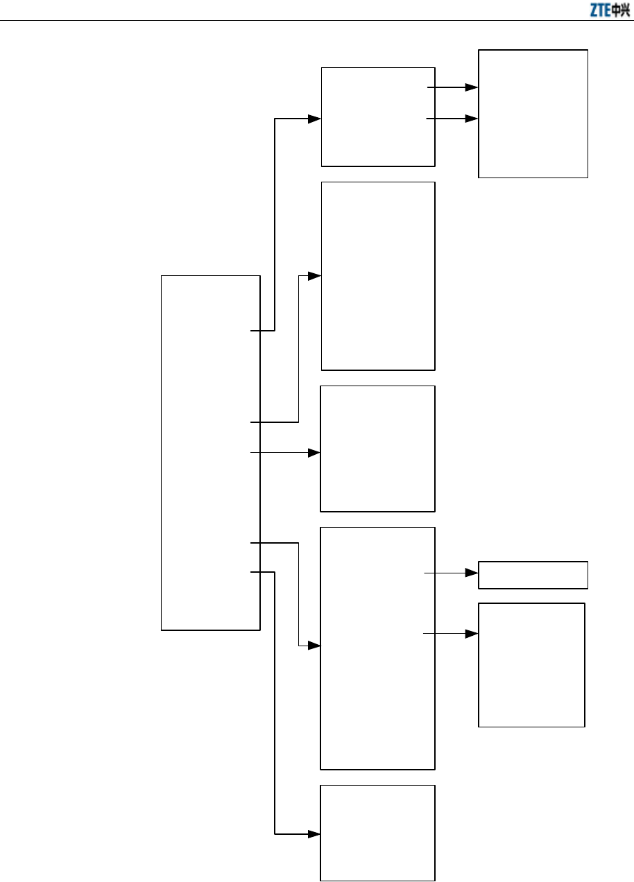
ZXR10 WAS (V2.0) IP Wireless Access System W800A Wireless Access Point User’s Manual
6-2
Home
Interface
Stations
Load Balance
SNMP
Security
Reboot
Save
Advanced
Management
Exit
SNMP Access Mode
SNMP Access Host
Community
System Information
Trap
Trap Host
Wireless Interface 0
Wireless Interface 1
Device IP Address
802.11 Parameter
Security
Multi-ESSID
Advanced
802.1x
DHCP
IP Pool
RADIUS Server
Bridge
STP
VLAN
QoS
MAC Authentication
MAC Filter
Station Isolation
SSH
DHCP Server
ISP
Authentication
Server
Accounting Server
DNS Server
Management
Accounts
Management Control
Configure Server
Fig. 6.1-1 Route Map of the WEB Configuration
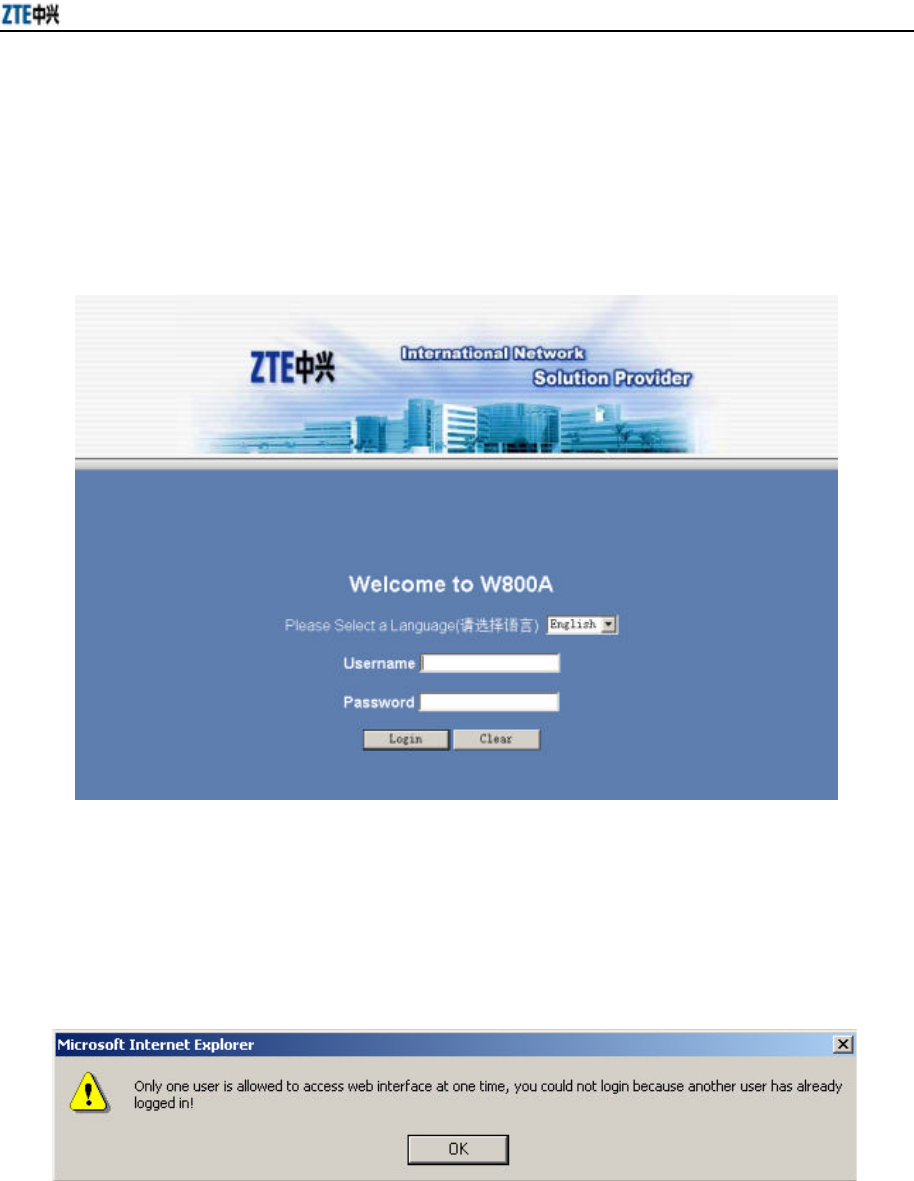
Chapter 6 WEB Configuration
6-3
6.2 Login
Open the WEB browse, input http://W800A working IP address in the address box, the
WEB configuration login page will appear, as shown in Fig. 6.2-1. In it, input the
correct user name and password (by default, the user name is “root” and the password
is “public”) to enter the parameter browsing page.
Fig. 6.2-1 Login Page
If a user has logged on the WEB configuration (or you have opened the WEB
configuration window), click <Login> and a dialog box will pop up, as shown in Fig.
6.2-2.
Fig. 6.2-2 Dialog Box for a User Who Has Logged on
If the user name or password is wrong, click <OK> and the corresponding prompt page
will appear, as shown in Fig. 6.2-3.
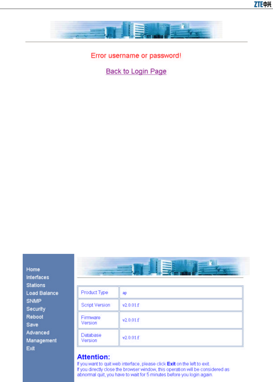
ZXR10 WAS (V2.0) IP Wireless Access System W800A Wireless Access Point User’s Manual
6-4
Fig. 6.2-3 Prompt Page for Wrong User Name or Password
6.3 Main Menu
After logging on successfully, you enter the main menu page of the WEB configuration.
The main menu comprises: Home, Interface, Stations, Load Balance, SNMP, Security,
Reboot, Save, Advanced and Management. The Interface, SNMP, Security, Advanced
and Management feature submenus, and other configuration modules only have one
WEB page for browsing or configuration. The main menu is in the left part of the WEB
page, and the current configuration module selected by the user is shown in the right
part, as shown in Fig. 6.3-1.
6.3.1 Home
The contents in this page are read-only: the contents can only be read, instead of being
configured. The top line indicates the path of the current page, as shown in Fig. 6.3-1.
Fig. 6.3-1 Home Page
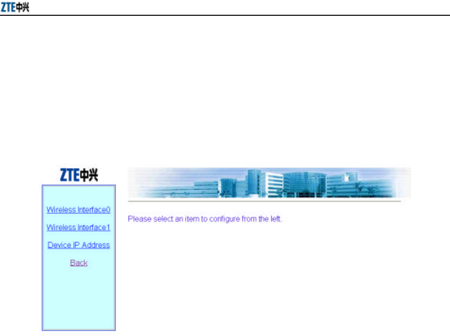
Chapter 6 WEB Configuration
6-5
This page serves to display the basic information of the product, such as product mark
and version number.
6.3.2 Interface
In the main menu, click [Interface] to enter the menu page of the interface
configuration, as shown in Fig. 6.3-2.
Fig. 6.3-2 Interface Configuration Menu Page
The W800A interface configurations are: wireless interface configuration and device IP
address configuration. Two wireless interfaces should be configured separately.
6.3.2.1 Wireless Interface
In the Interface configuration menu, click [Wireless Interface 0] or [Wireless Interface
1] to enter the menu page of the wireless interface configuration, as shown in Fig.
6.3-3.
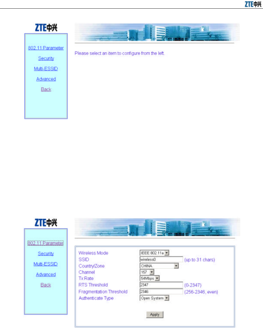
ZXR10 WAS (V2.0) IP Wireless Access System W800A Wireless Access Point User’s Manual
6-6
Fig. 6.3-3 Wireless Interface Configuration Menu Page
In the left part of this page, there are wireless interface configuration submenus: 802.11
Parameter, Security, Multi-ESSID and Advanced.
1. 802.11 Parameter
In the Wireless Interface configuration menu, click [802.11 Parameter] and the
page shown in Fig. 6.3-4 will appear.
Fig. 6.3-4 802.11 Parameter Configuration Page
This page serves to configure 802.11 parameters of the wireless interface
module, such as the Wireless Mode, SSID (service ID), Country/Zone, Channel,
Tx Rate, RTS Threshold, Fragmentation Threshold and Authentication Type.
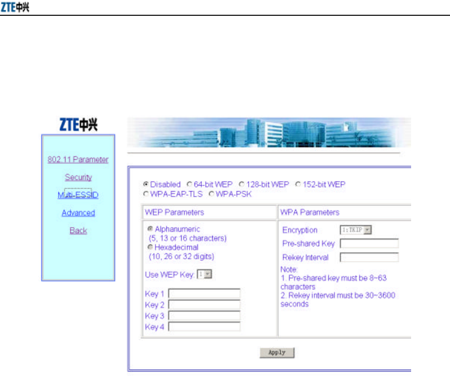
Chapter 6 WEB Configuration
6-7
2. Security
In the Wireless Interface configuration menu, click [Security] and the page
shown in Fig. 6.3-5 will appear.
Fig. 6.3-5 Security Configuration Page
This page serves to configure the security parameters of the wireless interface
module, such as the security configuration mode, WEP configuration type, WEP
key format, WEP key value, the default key used by the WEP, WPA
configuration method, WPA shared key and updating circle of the key.
3. Multi-ESSID
In the Wireless Interface configuration menu, click [Multi-ESSID] and the page
shown in Fig. 6.3-6 will appear.
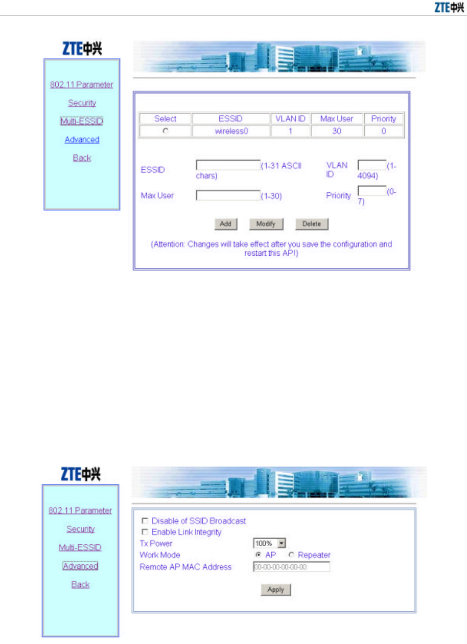
ZXR10 WAS (V2.0) IP Wireless Access System W800A Wireless Access Point User’s Manual
6-8
Fig. 6.3-6 Multi-ESSID Configuration Page
This page serves to configure multi-ESSID parameters of the wireless interface
module, such as ESSID, VLAN ID, Max User, Priority and selecting mark for
operating the selected item. The default ESSID wireless0 can not be deleted.
4. Advanced
In the Wireless Interface configuration menu, click [Advanced] and the page
shown in Fig. 6.3-7 will appear.
Fig. 6.3-7 Advanced Configuration Page
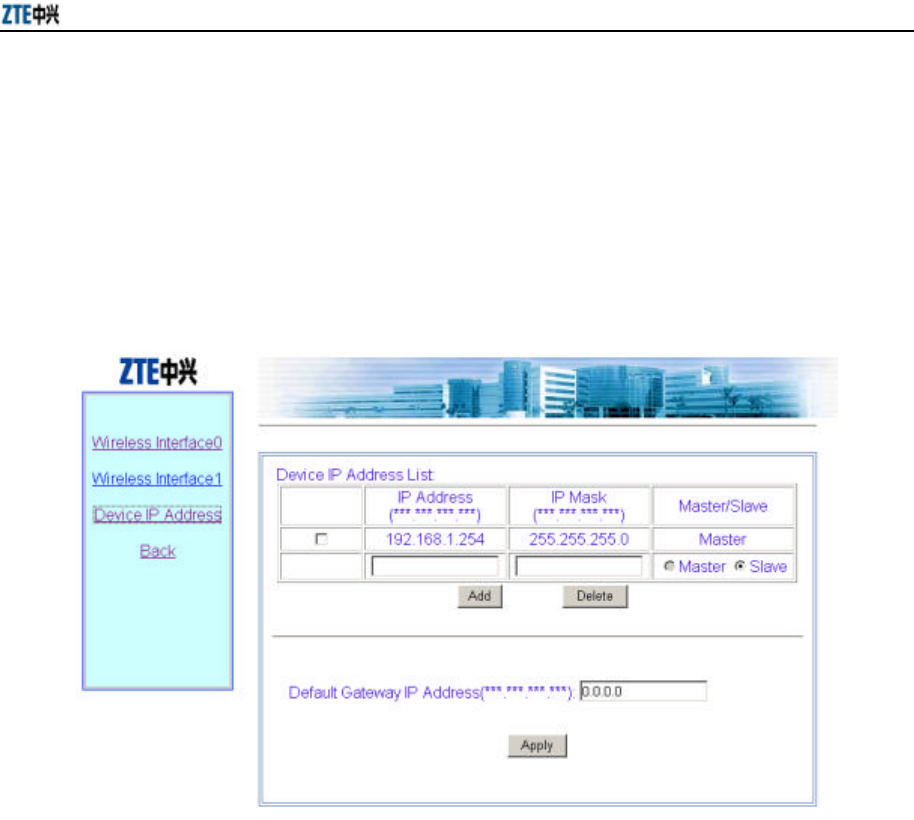
Chapter 6 WEB Configuration
6-9
This page serves to configure the advanced options of the wireless interface
module, such as enabling/disabling SSID Broadcast, enabling Link Integrity, Tx
Power, Work Mode and Remote AP MAC address in the repeater mode.
6.3.2.2 Device IP Address
In the Interface configuration menu, click [Device IP Address] and the page shown in
Fig. 6.3-8 will appear.
Fig. 6.3-8 Device IP Address Configuration Page
This page serves to configure the equipment IP addresses, such as IP address, IP mask,
Master/Slave flag of the IP address and default gateway address. The equipment has
only one active IP address and can have up to 9 standby IP addresses.
6.3.3 Stations
In the main menu, click [Stations] and the page shown in Fig. 6.3-9 will appear.
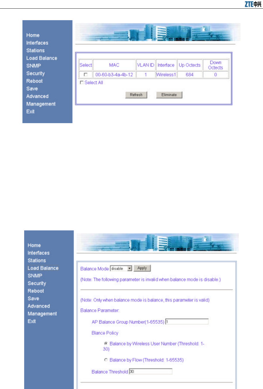
ZXR10 WAS (V2.0) IP Wireless Access System W800A Wireless Access Point User’s Manual
6-10
Fig. 6.3-9 Stations Page
This page serves to display the information of the wireless user who has logged on to
this W800A, such as the quantity, MAC address, VLAN ID, connection interface and
byte quantity of the uplink/downlink flow of the online wireless user. Use [Eliminate]
to kick out the selected user.
6.3.4 Load Balance
In the main menu, click [Load Balance] and the page shown in Fig. 6.3-10 will appear.
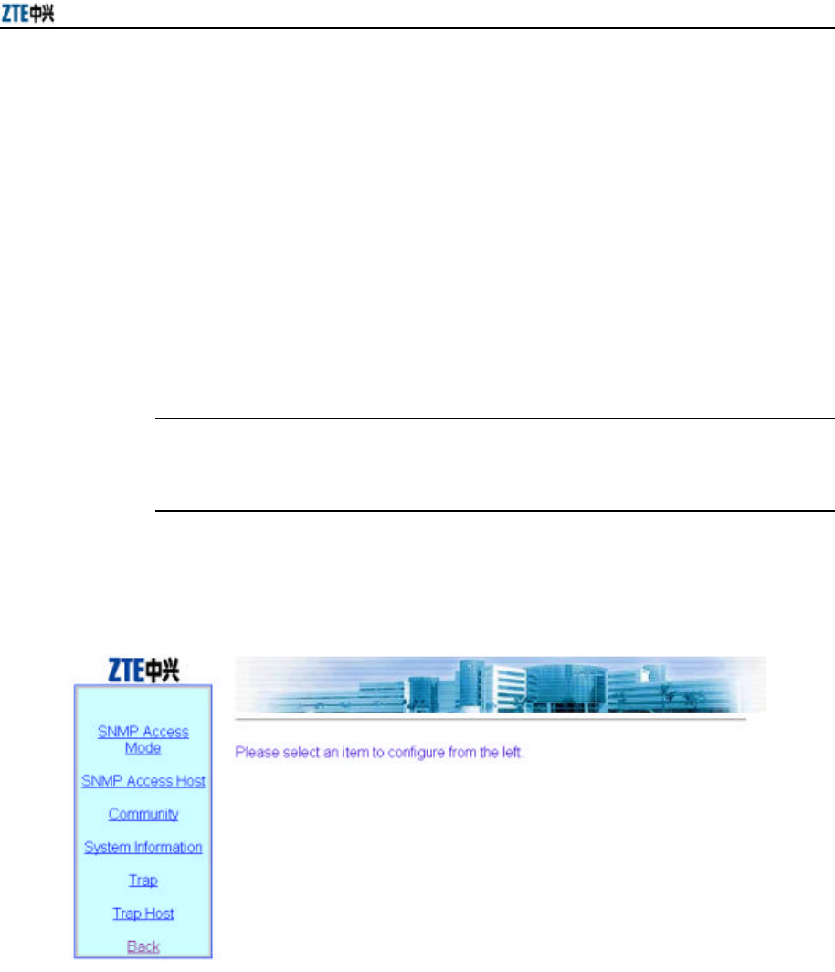
Chapter 6 WEB Configuration
6-11
Fig. 6.3-10 Load Balance Configuration Page
This page serves to configure load balance: Balance Mode, Balance Parameters (AP
Balance Group Number and Balance Threshold) and Max Wireless User, and these
values have their respective value ranges.
Balace Modes are: disable, balance and max-user. When the Balace Mode is “disable”,
the load balace is disabled; when the Balace Mode is “balance”, the AP load balance
mode is enabled, and the parameters in the Balance Parameter configuration box are
valid at this time; when the Balace Mode is “max-user”, the Max Wireless User mode
is enabled, and the parameters in the Max Wireless User configuration box are valid.
& Note:
Either AP load balance mode or Max Wireless User mode can be selected once.
6.3.5 SNMP
In the main menu, click [SNMP] and the page shown in Fig. 6.3-11 will appear.
Fig. 6.3-11 SNMP Configuration Menu Page
In the left part of this page, there are SNMP configuration submenus: SNMP Access
Mode, SNMP Access Host, Community, System Information, Trap and Trap Host.
6.3.5.1 SNMP Access Mode
In the SNMP configuration menu, click [SNMP Access Mode] and the page shown in
Fig. 6.3-12 will appear.
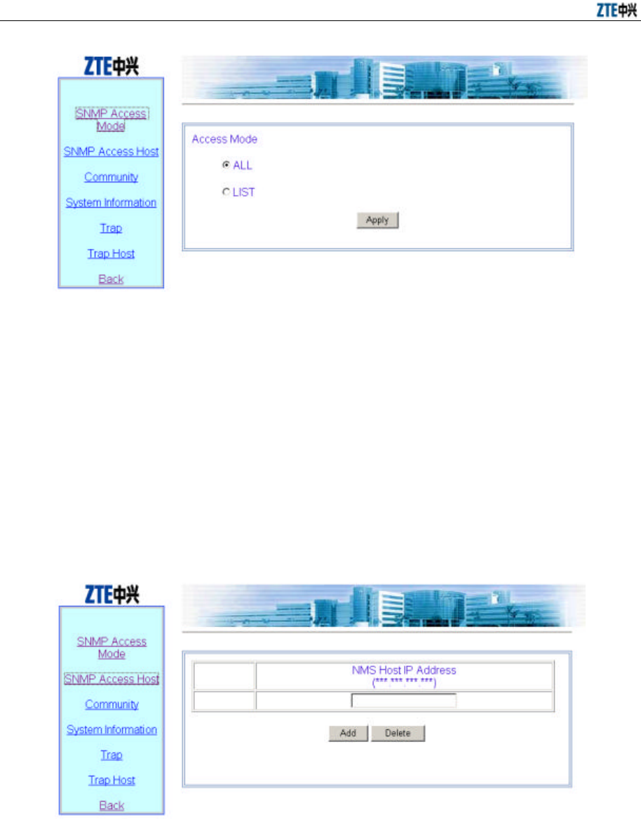
ZXR10 WAS (V2.0) IP Wireless Access System W800A Wireless Access Point User’s Manual
6-12
Fig. 6.3-12 SNMP Access Mode Configuration Page
This page serves to configure the SNMP access mode. “all” or “list” can be selected in
[Access Mode]. “all” indicates that all the users can access the SNMP. “list” indicates
that only the host whose IP address has been configured in the access host
configuration can access the SNMP.
6.3.5.2 SNMP Access Host
In the SNMP configuration menu, click [SNMP Access Host] and the page shown in
Fig. 6.3-13 will appear.
Fig. 6.3-13 SNMP Access Host Configuration Page
This page serves to add or delete the IP address of the access host of the SNMP. The
parameters include the IP address of the access host.
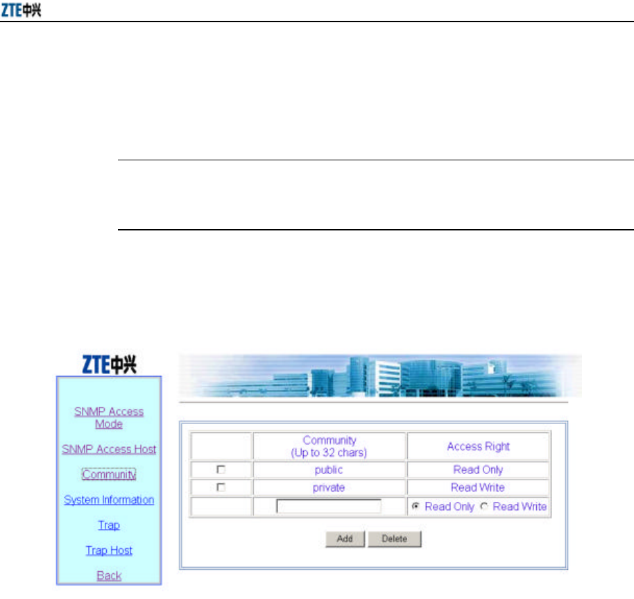
Chapter 6 WEB Configuration
6-13
This page is a multi-record data configuration page with <Add> and <Delete>. To
implement the adding operation, input data in the blank box at the bottom line and
click <Add>. To implement the deletion operation, check the record to be deleted
(multiple options can be selected) and click <Delete>.
& Note:
The other multi-record data configuration pages are similar to this one.
6.3.5.3 Community
In the SNMP configuration menu, click [Community] and the page shown in Fig.
6.3-14 will appear.
Fig. 6.3-14 Community Configuration Page
This page serves to add or delete the SNMP community strings. The parameters are
community string ID and access authority.
6.3.5.4 System information
In the SNMP configuration menu, click [System information] and the page shown in
Fig. 6.3-15 will appear.
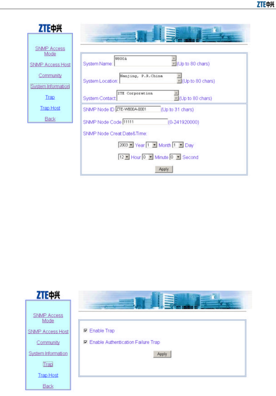
ZXR10 WAS (V2.0) IP Wireless Access System W800A Wireless Access Point User’s Manual
6-14
Fig. 6.3-15 System Information Page
This page serves to configure the information of the equipment managed by the current
SNMP: System Name, System Location and System Contact. And the related
information of the SNMP Node can be configured: ID, code and creation date&time.
6.3.5.5 Trap
In the SNMP configuration menu, click [Trap] and the page shown in Fig. 6.3-16 will
appear.
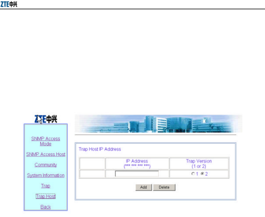
Chapter 6 WEB Configuration
6-15
Fig. 6.3-16 Trap Configuration Page
This page serves to configure the SNMP alarm enabling parameters: Whether enabling
Trap and whether enabling Authentication failure Trap.
6.3.5.6 Trap Host
In the SNMP configuration menu, click [Trap Host] and the page shown in Fig. 6.3-17
will appear.
Fig. 6.3-17 Trap Host Configuration Page
This page serves to add or delete the Trap host. The parameters are: The IP address and
version of the Trap Host and the IP address of the agent Trap Host.
6.3.6 Security
In the main menu, click [Security] and the page shown in Fig. 6.3-18 will appear.
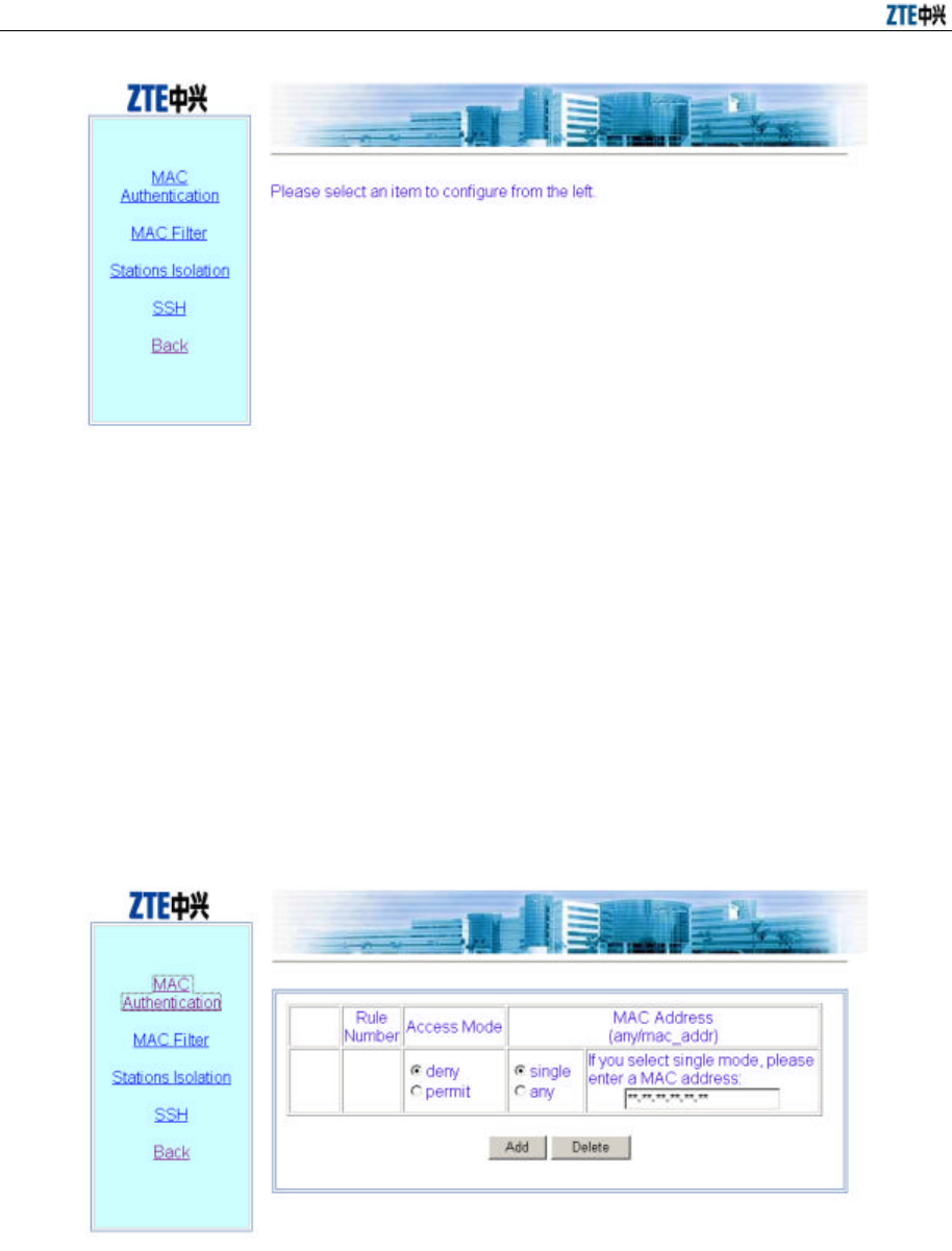
ZXR10 WAS (V2.0) IP Wireless Access System W800A Wireless Access Point User’s Manual
6-16
Fig. 6.3-18 Security Configuration Menu Page
In the left part of this page, there are security configuration submenus: MAC
Authentication, MAC filtrer, Stations Isolation and SSH.
6.3.6.1 MAC Authentication
In the Security configuration menu, click [MAC Authentication] and the page shown in
Fig. 6.3-19 will appear.
Fig. 6.3-19 MAC Authentication Configuration Page
This page serves to add or delete MAC authentication rule. The parameters are: Access
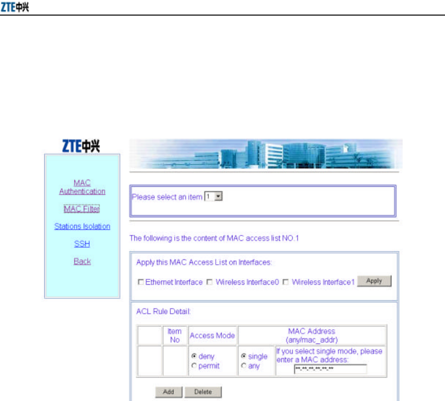
Chapter 6 WEB Configuration
6-17
Mode (“permit” or “deny”) and MAC Address (“single” MAC Address or “any”).
6.3.6.2 MAC Filter
In the Security configuration menu, click [MAC Filter] and the page shown in Fig.
6.3-20 will appear.
Fig. 6.3-20 MAC Filter Configuration Page
This page serves to enable a group of filter rules or add/delete the filter rules in the
filter rule group. The parameters are: Access Mode and MAC Address.
6.3.6.3 Stations Isolation
In the Security configuration menu, click [Stations Isolation] and the page shown in Fig.
6.3-21 will appear.
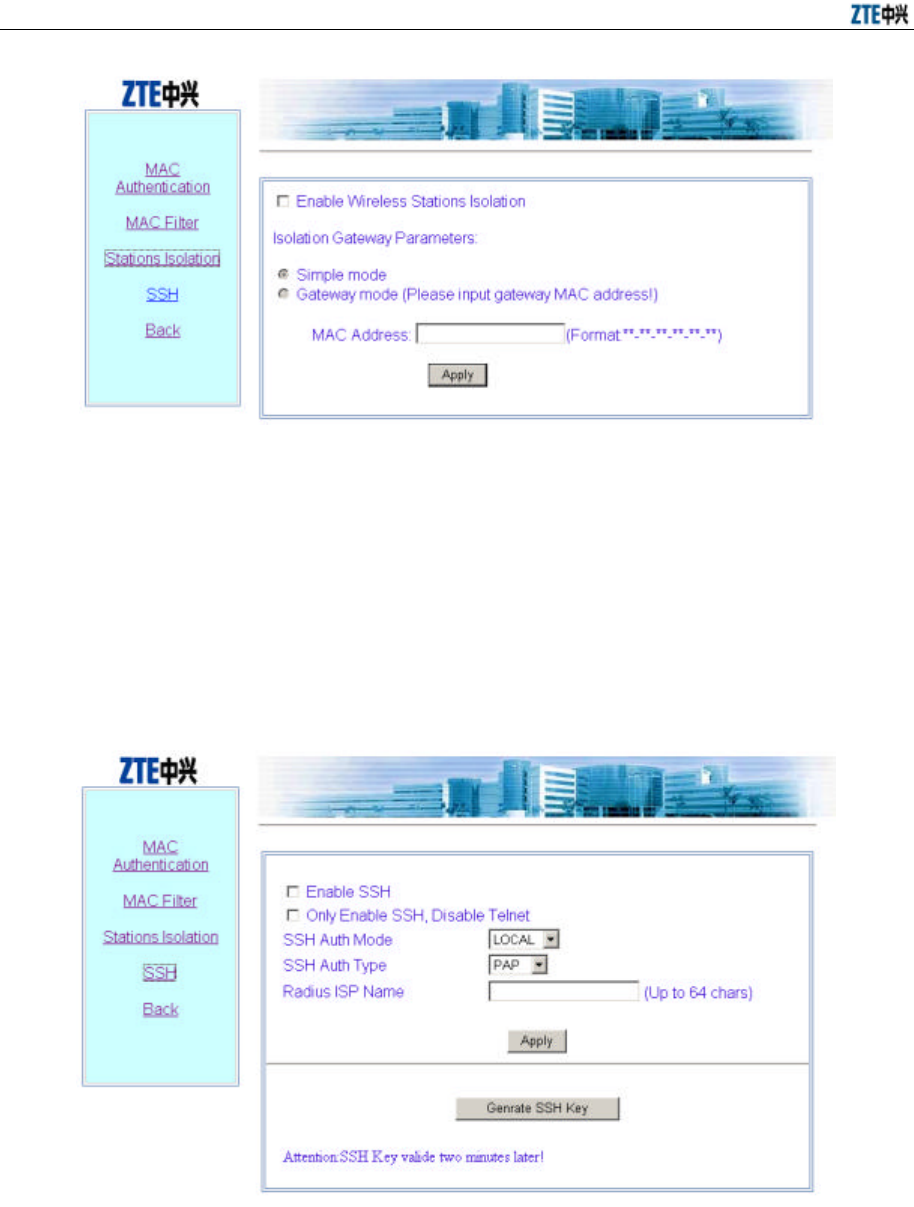
ZXR10 WAS (V2.0) IP Wireless Access System W800A Wireless Access Point User’s Manual
6-18
Fig. 6.3-21 Stations Isolation Configuration Page
This page serves to enable or disable Stations Isolation and configure the gateway
MAC address of Stations Isolation.
6.3.6.4 SSH
In the Security configuration menu, click [SSH] and the page shown in Fig. 6.3-22 will
appear.
Fig. 6.3-22 SSH Configuration Page
This page serves to enable or disable SSH function and configure SSH-related
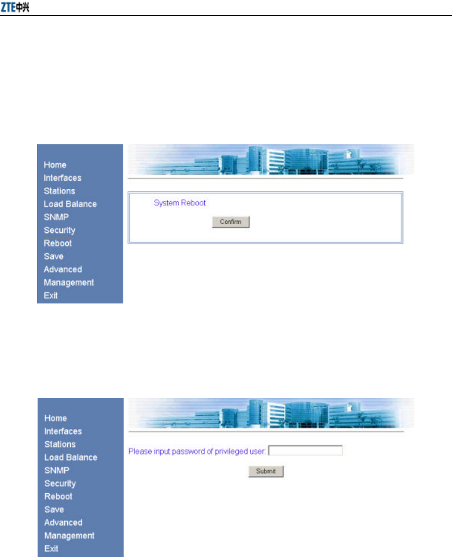
Chapter 6 WEB Configuration
6-19
parameters: Authentication mode and type of the SSH server and the ISP name of
RADIUS authentication.
6.3.7 Reboot
In the main menu, click [Reboot] and the page shown in Fig. 6.3-23 will appear.
Fig. 6.3-23 Reboot Page
This page serves to execute the reboot. Click <confirm> and the input box of the
privileged mode password will appear, as shown in Fig. 6.3-24.
Fig. 6.3-24 Page of Inputting the Privileged Password
Input the correct password and a dialog box of closing the window will pop up, as
shown in Fig. 6.3-25.
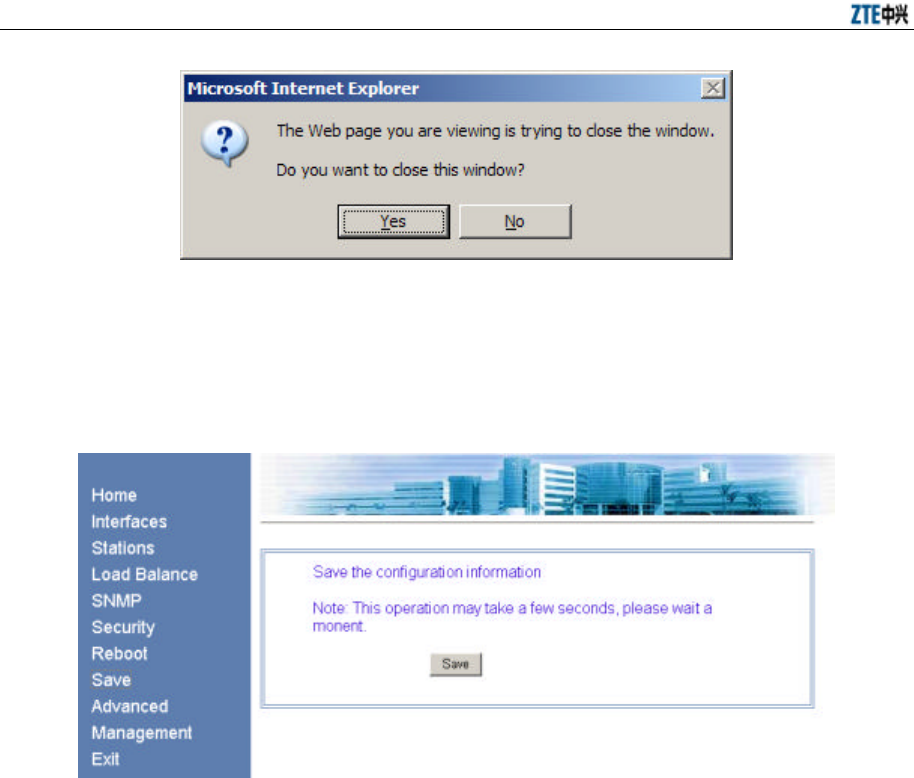
ZXR10 WAS (V2.0) IP Wireless Access System W800A Wireless Access Point User’s Manual
6-20
Fig. 6.3-25 Page of Closing the Window
6.3.8 Save
In the main menu, click [Save] and the page shown in Fig. 6.3-26 will appear.
Fig. 6.3-26 Save Page
This page serves to write the configured parameters into flash.
6.3.9 Advanced
In the main menu, click [Advanced] and the page shown in Fig. 6.3-27 will appear.
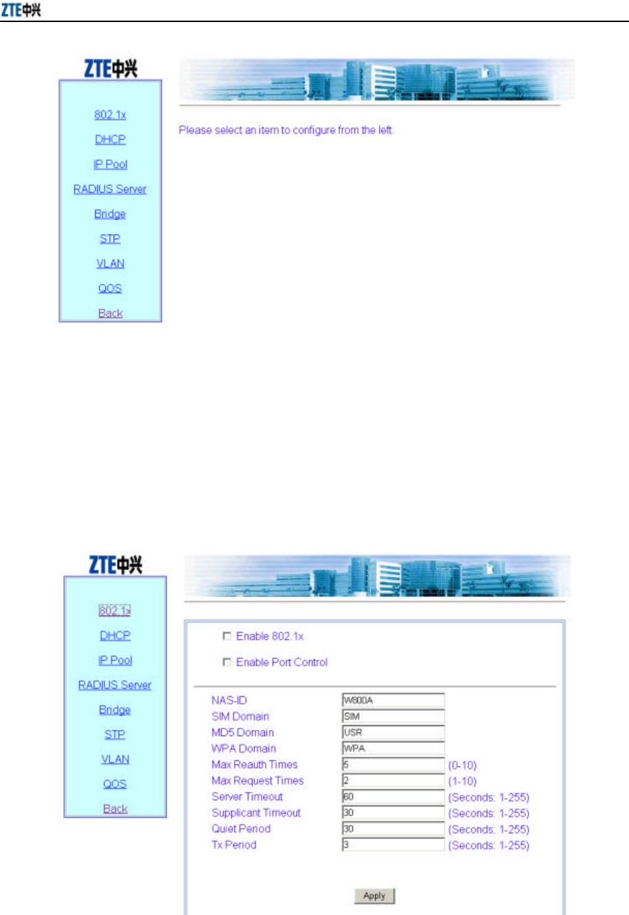
Chapter 6 WEB Configuration
6-21
Fig. 6.3-27 Advanced Option Configuration Menu Page
In the left part of this page, there are advanced option configuration submenus: 802.1x,
DHCP, IP Pool, RADIUS Server, Bridge, STP, VLAN and QoS.
6.3.9.1 802.1x
In the Advanced configuration menu, click [802.1x] and the page shown in Fig. 6.3-28
will appear.
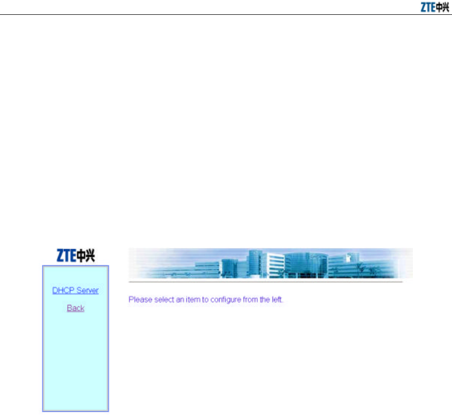
ZXR10 WAS (V2.0) IP Wireless Access System W800A Wireless Access Point User’s Manual
6-22
Fig. 6.3-28 802.1x Configuration Page
This page serves to configure 802.1x authentication parameters: Enabling 802.1x,
enabling port control, NAS-ID, SIM authentication domain name, MD5 authentication
domain name, WPA authentication domain name, maximum re-authentication times,
maximum request times, server time-out time, supplicant time-out time, quiet period
and retransmission period.
6.3.9.2 DHCP
In the Advanced configuration menu, click [DHCP] and the page shown in Fig. 6.3-29
will appear.
Fig. 6.3-29 DHCP Configuration Menu Page
In the left part of this page, there are DHCP module submenus, including DHCP Server
configuration.
1. DHCP Server
In the DHCP configuration menu, click [DHCP Server] and the page shown in
Fig. 6.3-30 will appear.
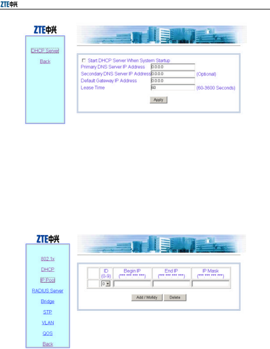
Chapter 6 WEB Configuration
6-23
Fig. 6.3-30 DHCP Server Configuration Page
This page serves to configure the related parameters of the DHCP server: The IP
address of the primary/secondary DNS server, gateway IP address, lease time and
whether the DHCP server is enabled when the system is started.
6.3.9.3 IP Pool
In the Advanced configuration menu, click [IP Pool] and the page shown in Fig. 6.3-31
will appear.
Fig. 6.3-31 IP Pool Configuration Page
This page serves to add or delete the address pool. The parameters are: IP pool ID,
begin IP address, end IP address and IP subnet mask. The IP pool can contain up to 200
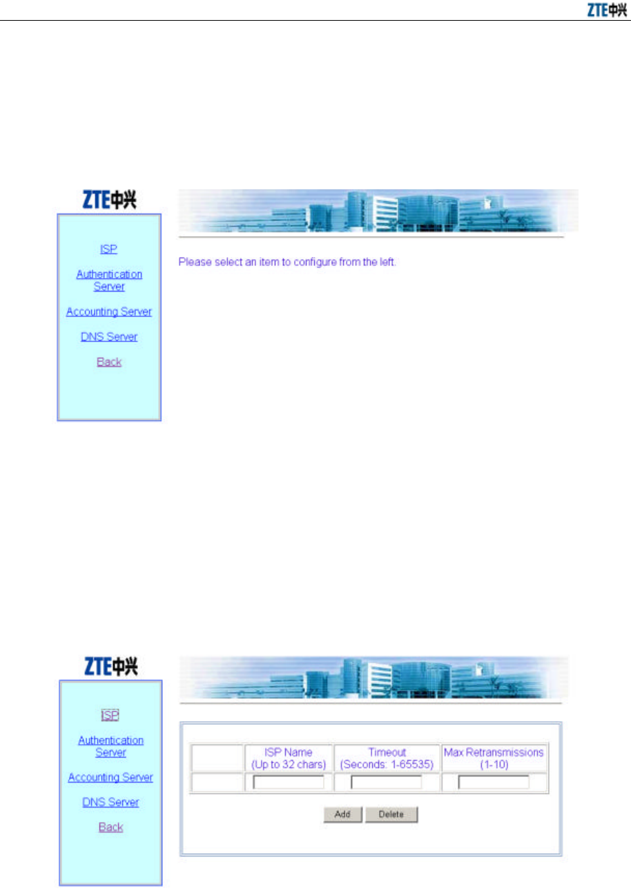
ZXR10 WAS (V2.0) IP Wireless Access System W800A Wireless Access Point User’s Manual
6-24
addresses.
6.3.9.4 RADIUS Server
In the Advanced configuration menu, click [RADIUS Server] and the page shown in
Fig. 6.3-32 will appear.
Fig. 6.3-32 RADIUS Server Configuration Menu Page
The RADIUS Server configuration menu are: ISP, Authentication Server, Accounting
Server and DNS Server.
1. ISP
In the RADIUS Server configuration menu, click [ISP] and the page shown in
Fig. 6.3-33 will appear.
Fig. 6.3-33 ISP Configuration Page
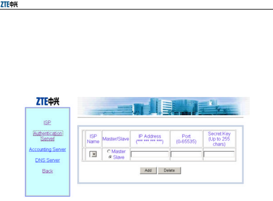
Chapter 6 WEB Configuration
6-25
This page serves to configure the ISP. The parameters are ISP name, time-out
time and max retransmission times.
2. Authentication Server
In the RADIUS Server configuration menu, click [Authentication Server] and
the page shown in Fig. 6.3-34 will appear.
Fig. 6.3-34 Authentication Server Configuration Page
This page serves to configure the authentication server. The parameters are: ISP
Name(selected from the configured ISPs), Master/Slave flag, IP Address Port ID
and Secret Key.
3. Accounting Server
In the RADIUS Server configuration menu, click [Accounting Server] and the
page shown in Fig. 6.3-35 will appear.
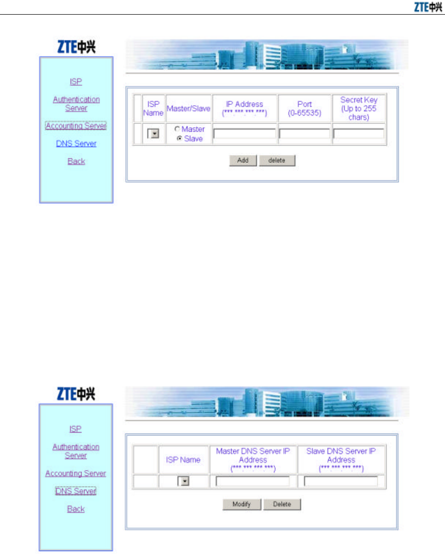
ZXR10 WAS (V2.0) IP Wireless Access System W800A Wireless Access Point User’s Manual
6-26
Fig. 6.3-35 Accounting Server Configuration Page
This page serves to configure the accounting server. The parameters are: ISP
name (selected from the configured ISPs), Master/Slave flag, IP Address Port ID
and Secret Key.
4. DNS Server
In the RADIUS Server configuration menu, click [DNS Server] and the page
shown in Fig. 6.3-36 will appear.
Fig. 6.3-36 DNS Server Configuration Page
This page serves to configure the DNS. The parameters are: ISP name (selected
from the configured ISPs), IP addresses of the master and slave DNS servers.
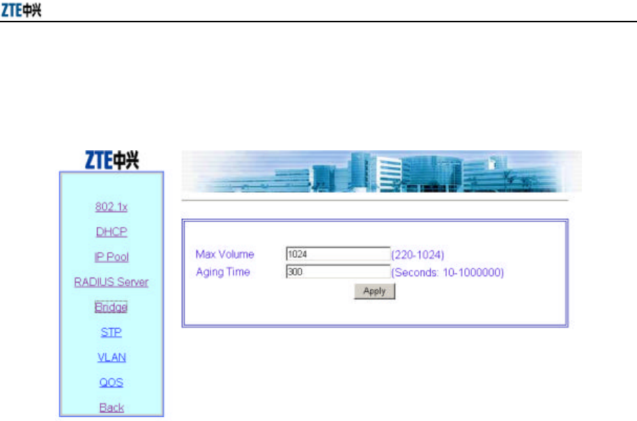
Chapter 6 WEB Configuration
6-27
6.3.9.5 Bridge
In the Advanced configuration menu, click [Bridge] and the page shown in Fig. 6.3-37
will appear.
Fig. 6.3-37 Bridge Configuration Page
This page serves to configure the bridge parameters. The parameters are Max Volume
and Aging Time.
6.3.9.6 STP
In the Advanced configuration menu, click [STP] and the page shown in Fig. 6.3-38
will appear.
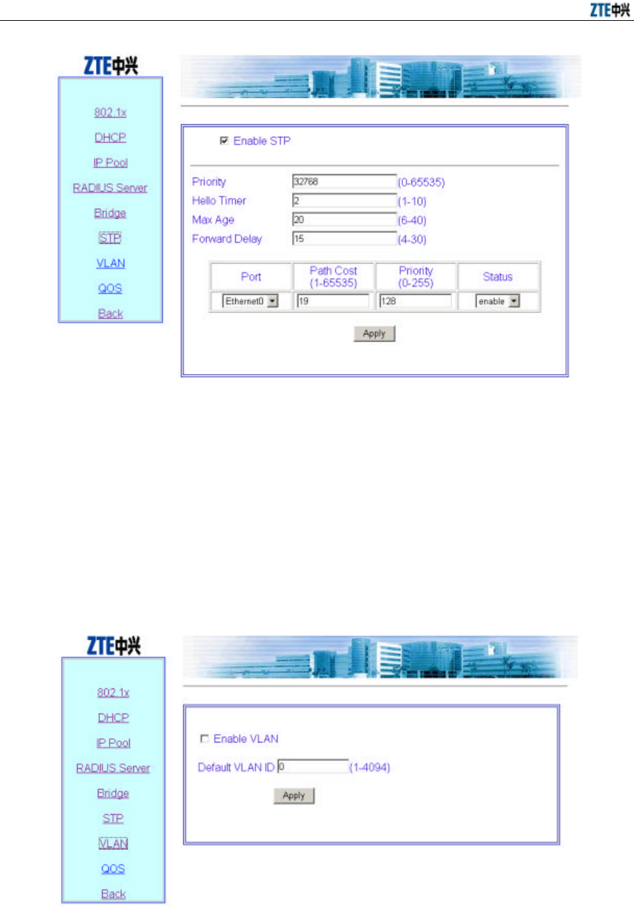
ZXR10 WAS (V2.0) IP Wireless Access System W800A Wireless Access Point User’s Manual
6-28
Fig. 6.3-38 STP Configuration Page
This page serves to configure the STP parameters: Whether the STP is enabled, bridge
priority, Hello Timer, Max Age, Forward Delay, application port, port path cost, port
priority and port status.
6.3.9.7 VLAN
In the Advanced configuration menu, click [VLAN] and the page shown in Fig. 6.3-39
will appear.
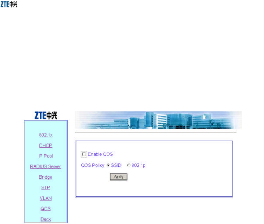
Chapter 6 WEB Configuration
6-29
Fig. 6.3-39 VLAN Configuration Page
This page serves to enable/disable the VLAN and configure its parameter. The
parameter is default VLAN ID.
6.3.9.8 QoS
In the Advanced configuration menu, click [QoS] and the page shown in Fig. 6.3-40
will appear.
Fig. 6.3-40 QoS Configuration Page
This page serves to enable/disable the QoS and configure its parameter. The parameter
is QoS configuration policy.
6.3.10 Management
In the main menu, click [Management] and the page shown in Fig. 6.3-41 will appear.
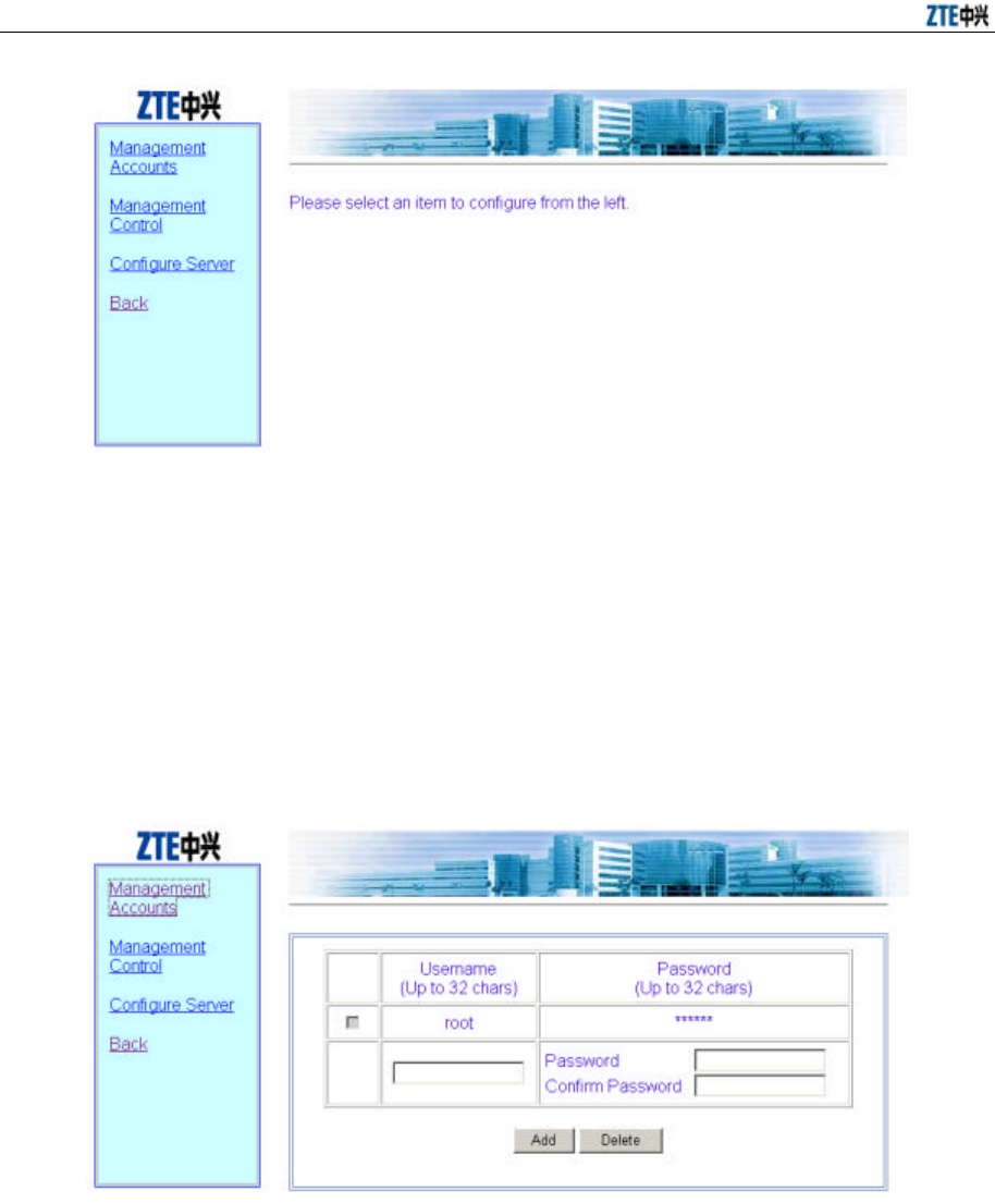
ZXR10 WAS (V2.0) IP Wireless Access System W800A Wireless Access Point User’s Manual
6-30
Fig. 6.3-41 Management Configuration Menu Page
In the left part of this page, there are management configuration submenus:
Management Accounts, Management Control and configure Server.
6.3.10.1 Management Accounts
In the Management configuration menu, click [Management Accounts] and the page
shown in Fig. 6.3-42 will appear.
Fig. 6.3-42 Management Accounts Configuration Page
This page serves to add or delete the user name and password of the administrator.
6.3.10.2 Management Control
In the Management configuration menu, click [Management Control] and the page
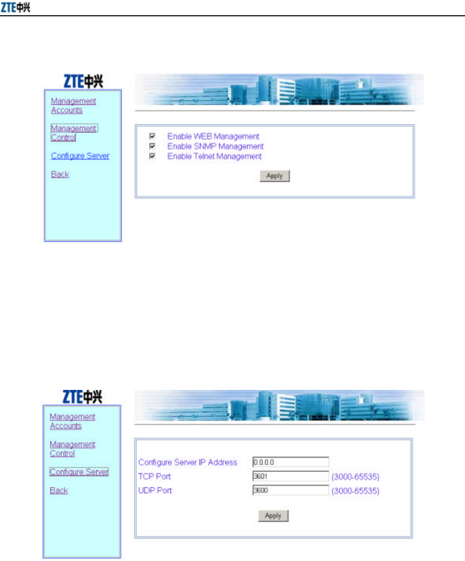
Chapter 6 WEB Configuration
6-31
shown in Fig. 6.3-43 will appear.
Fig. 6.3-43 Management Control Page
This page serves to enable or disable the WEB, SNMP and Telnet management.
6.3.10.3 Configure Server
In the Management configuration menu, click [Configure Server] and the page shown
in Fig. 6.3-44 will appear.
Fig. 6.3-44 Configure Server Configuration Page
This page serves to configure the configuration server parameters: IP address, TCP port
ID and UDP port ID.
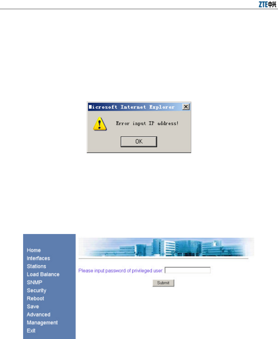
ZXR10 WAS (V2.0) IP Wireless Access System W800A Wireless Access Point User’s Manual
6-32
6.4 Data Submitting Flow of WEB Configuration
After modifying the configuration parameters in the WEB configuration page, the user
must submit the modification for confirmation. In the submitting, the system will
analyze the data input by the user, if these data are not in the specified range, the
system will prompt the wrong parameter. The user should modify it and re-submit it, as
shown in Fig. 6.4-1.
Fig. 6.4-1 Prompt of Wrong Data Input
After the data passes the analysis, if the user submits data for the first time after he logs
on, the page shown in Fig. 6.4-2 will appear, prompting the user to input superuser
password; if the user has submitted the data and the password is correct, he can directly
enter the next page to see whether the data is submitted successfully.
Fig. 6.4-2 Prompt Page of Inputting Superuser Password
If the input password is wrong, the system will enter the page shown in Fig. 6.4-3,
prompting wrong password.
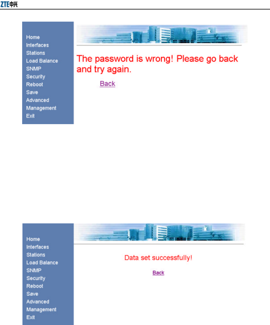
Chapter 6 WEB Configuration
6-33
Fig. 6.4-3 Prompt Page of Wrong Superuser Password
If the superuser password is input correctly, the system will re-analyze the input data to
determine whether they satisfy the requirements, and return the corresponding prompt
information page according to the success/failure of the configuration. If the
configuration is successful, the page shown in Fig. 6.4-4 will appear. Click <Back> to
return to the WEB page before submission, and the submitted new parameter values
will be displayed.
Fig. 6.4-4 Prompt Page of Successful Data Submission
7-1
7 Maintenance
This chapter introduces the daily maintenance work of the W800A and the loading and
upgrade of the version
7.1 Maintenance Descriptions
To guarantee the normal and stable running of the equipment, please pay attention to
the following suggestion and make the daily maintenance according to the daily
maintenance operation instructions.
1. Keep the equipment room clean and neat, take dustproof dampproof measures
and prevent rats and insects from damaging the cables and other devices.
2. According to related contents of the daily maintenance operation instructions,
make routine checks and test every day and make records.
3. Contact the local ZTE office at once when you cannot handle the problems.
Handle any emergency calmly.
4. Handle major faults, such as breakdown, according to the major fault handling
procedure and contact the local ZTE office immediately.
5. Never reset and load the devices or change data, unless necessary. Back up the
data before modifying the data (if necessary). After the running of the device
with changed data is confirmed normal, backup the new data. Be sure to
separate the new data from the old data. Delete the old data after confirming that
everything is OK one week later.
6. Please paste the necessary contact information, such as the phone number and
fax number of the local ZTE office, on a conspicuous place of the equipment
room, and make sure that all the personnel in the equipment room know this
information.

ZXR10 WAS (V2.0) IP Wireless Access System W800A Wireless Access Point User’s Manual
7-2
7.2 Daily Maintenance
The running conditions of the device can be detected through the following operations:
1. From the Ethernet switch, PING the management port addresses of all the APs
of this switch, to check whether the AP wired ports work normally.
2. For the hot spots adopting the DHCP mode, check whether the legal users can
obtain such parameters as IP address, gateway and DNS.
3. Check whether the exit route between the user and Internet is smooth.
4. With the wireless network card, in the AP signal coverage ranges, observe the
signal strength and link quality of different areas, PING the gateway IP address,
observe packet losses, and check whether Internet access is normal.
5. Make roaming and handover operations in different AP signal coverage ranges,
and observe packet losses when pinging the gateway IP addresses, and check
whether Internet accesses are normal.
7.3 Version Loading and Upgrade
Before delivering the W800A, the file set and graphical file set of the running version
have been loaded into the W800A flash.
The running version file set comprises the following files:
runbin Running software
database.dat Database file
zxipcmd.dat Command script file
The graphical file set is the graph library of the WEB configuration page.
Version loading comprises boot loading and tftp online loading. Boot loading serves to
load the running version. Tftp online loading serves to load the running version file and
graphical file set. The FTP server software and TFTP server software will be used in
version loading. Here, we take Wftpd and Tftpd as examples.
7.3.1 BOOT Loading
Boot loading serves to load the running version. Before loading, please prepare the
serial port cables and crossover cables and operate as follows:
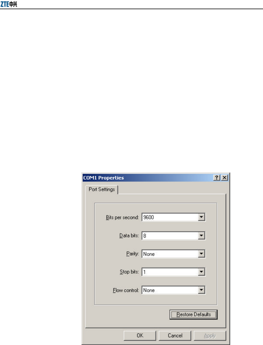
Chapter 7 Maintenance
7-3
1. Separately connect the two ends of the serial port cable to the CONSOLE port of
the W800A and the serial port of the PC. Separately connect the two ends of the
crossover cable to the Ethernet port of the W800A and the wired network port of
the PC.
2. Start the hyper terminal on the PC and run Wftpd.exe to start the FTP server.
Please refer to Section 7.3.1.1 for the configurations of the PC serial port and
FTP server.
3. Power on the W800A and install or upgrade the version, according to the related
commands in Section 7.3.1.2.
7.3.1.1 Configurations of the PC Serial Port and FTP Server
1. Serial port configuration
For the W800A, the PC serial port configuration is shown in Fig. 7.3-1.
Fig. 7.3-1 Serial Port Configuration
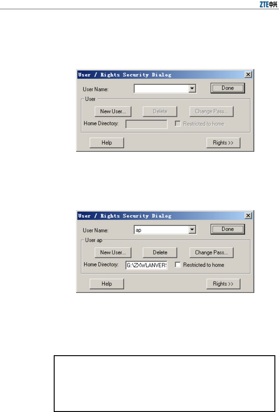
ZXR10 WAS (V2.0) IP Wireless Access System W800A Wireless Access Point User’s Manual
7-4
2. FTP server configuration
In the menu of the Wftpd window, select [Security ? Users/Rights…], the
interface shown in Fig. 7.3-2 will appear.
Fig. 7.3-2 Wftpd User Configuration Interface
Add a new user and configure the corresponding password and home directory
(the path of the loading file in the PC), as shown in Fig. 7.3-3.
Fig. 7.3-3 Interface of Adding a New Wftpd User
7.3.1.2 BOOT Loading Command
Power on the W800A. When “3” is displayed on the hyper terminal, press any key
according to the prompt, and then the prompt [WLAN Boot] will appear.
WLAN System Boot
CPU: IDT 79EB438
BSP version: 1.2/0
Creation date: Nov 7 2003, 09:43:40

Chapter 7 Maintenance
7-5
Press any key to stop auto-boot...
3
[WLAN Boot]:
1. p command
Function: Displaying the boot parameter.
Command format: p
Example:
[WLAN Boot]: p
boot device : idt
unit number : 0
processor number : 0
host name : W800A
file name : vxWorks
inet on ethernet (e) : 168.1.8.88
host inet (h) : 168.1.8.185
user (u) : target
ftp password (pw) : target
flags (f) : 0x0
[WLAN Boot]:
2. c command
Function: Modifying the boot parameter.
Command format: c
Description:
Modify the following parameters as required:
file name : File name
inet on Ethernet (e) : The W800A IP address (for communicating with the
host in the version loading).
host inet (h) : The PC IP address
user (u) : User name
ftp password (pw) : Password

ZXR10 WAS (V2.0) IP Wireless Access System W800A Wireless Access Point User’s Manual
7-6
Example: Change file name into b.hex, change inet on ethernet into
168.1.100.100, change host inet into 168.1.1.200, change user into ap, and
change ftp password into ap. The related configurations of user and ftp
password should be implemented on the FTP server.
[WLAN Boot]: c
'.' = clear field; '-' = go to previous field; ^D = quit
boot device : idt0
processor number : 0
host name : W800A
file name : vxWorks b.hex
inet on ethernet (e) : 168.1.8.88 168.1.1.100
inet on backplane (b):
host inet (h) : 168.1.8.185 168.1.1.200
gateway inet (g) :
user (u) : target ap
ftp password (pw) (blank = use rsh): target ap
flags (f) : 0x0
target name (tn) :
startup script (s) :
other (o) :
[WLAN Boot]:
3. % command
Function: Formatting the flash disk.
Command format: %
Example: The screen displays the prompt of inputting password, which is
zxwlan by default. After each reboot, you need only input the password once.
And then the system asks you to confirm flash formatting. Press <y> to begin
formatting or press any key to cancel formatting.
[WLAN Boot]: %
Please Input Password:
password is right
This operation will format the Flash disk and you will lose data!!
Now press 'y' to format the Flash disk. and others to abort.
are you sure (y/n):

Chapter 7 Maintenance
7-7
now is formatting......
Formatting is OK!
[WLAN Boot]:
4. & command
Function: Loading the running file runbin to the flash.
Command format: &
Example:
[WLAN Boot]: &
boot device : idt
unit number : 0
processor number : 0
host name : W800A
file name : vxWorks
inet on ethernet (e) : 168.1.1.100
host inet (h) : 168.1.1.200
user (u) : ap
ftp password (pw) : ap
flags (f) : 0x0
Attached TCP/IP interface to idt0.
Loading runbin to flash... received file length 124162
..........
flash receive FLASH:/runbin OK!! length 124162
the version loading is OK!
[WLAN Boot]:
5. # command
Function: Loading files database.dat and zxipcmd.dat to the flash.
Command format: #
Example:
[WLAN Boot]:#
boot device : idt
unit number : 0

ZXR10 WAS (V2.0) IP Wireless Access System W800A Wireless Access Point User’s Manual
7-8
processor number : 0
host name : W800A
file name : vxWorks
inet on ethernet (e) : 168.1.1.100
host inet (h) : 168.1.1.200
user (u) : ap
ftp password (pw) : ap
flags (f) : 0x0
Attached TCP/IP interface to idt0.
Attaching network interface lo0... done.
Loading zxipcmd.dat to flash... received file length 136a0
flash receive FLASH:/zxipcmd.dat OK!! length 136a0
Loading database.dat to flash... received file length c64a
flash receive FLASH:/database.dat OK!! length c64a
the database files loading to flash is OK!
[WLAN Boot]:
6. + command
Function: Loading a specified file to the flash.
Command format: +
Example: Through the c command, modify the file name parameter: Modify
vxworks into b.hex, and then load b.hex into the flash through the + command.
[WLAN Boot]: +
boot device : idt
unit number : 0
processor number : 0
host name : W800A
file name : b.hex
inet on ethernet (e) : 168.1.1.100
host inet (h) : 168.1.1.200
user (u) : ap
ftp password (pw) : ap
flags (f) : 0x0
Attached TCP/IP interface to idt0.
filename1 = FLASH:/b.hex
Loading w.hex to flash... received file length 6bc3

Chapter 7 Maintenance
7-9
flash receive FLASH:/b.hex OK!! length 6bc3
the file loading to flash is OK!
[WLAN Boot]:
7. s command
Function: Displaying the files and available space in the flash.
Command format: s
Example:
[WLAN Boot]: s
fileName size
-------- ------
runbin 1196386
zxipcmd.dat 79520
database.dat 79520
b.hex 27587
available size 563200
[WLAN Boot]:
8. - command
Function: Deleting a file in the flash.
Command format: - <filename>
Example:
[WLAN Boot]: - b.hex
delete FLASH:/b.hex OK!!
[WLAN Boot]: s
fileName size
-------- ------
runbin 1196386
zxipcmd.dat 79520
database.dat 79520
available size 591872
[WLAN Boot]:
9. v command
Function: Displaying the version information of the running software runbin.
Command format: v

ZXR10 WAS (V2.0) IP Wireless Access System W800A Wireless Access Point User’s Manual
7-10
Example:
[WLAN Boot]: v
Version File Information
product version_id offset file_identify run_start filesize
ap v2.0.01.a 0x100 0x7f450000 0x80010000 0x124162
[WLAN Boot]:
10. r command
Function: Displaying boot version information.
Command format: r
Example:
[WLAN Boot]:r
BOOTROM_VER V1.0 2003.11.22
[WLAN Boot]:
11. * command
Function: Running the version software and starting the W800A functions.
Command format: *
Example:
WLAN Boot]: *
boot device : idt
unit number : 0
processor number : 0
host name : W800A
file name : vxWorks
inet on ethernet (e) : 168.1.8.88
host inet (h) : 168.1.8.185
user (u) : target
ftp password (pw) : target
flags (f) : 0x0
Attaching to TFFS... done.
Loading FLASH:/runbin...HI ! offset_addr = 256 Starting at 0x80010000...
(Omitted)
[ZXWLAN]:shell restarted.
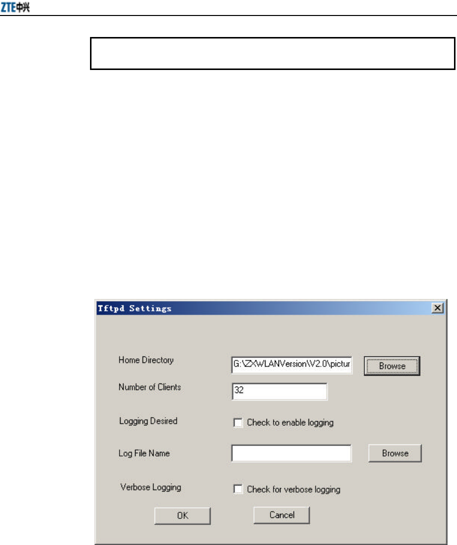
Chapter 7 Maintenance
7-11
Welcome to ZTE W800A
wlan>
7.3.2 TFTP Online Loading
When the W800A works normally, through the TFTP transmission protocol, you can
download files from the host and save them into the equipment flash. The size of the
online loaded files are limited by the flash space, which is only 2M. At present, Tftp
online loading can load the running version file and graphical file set.
7.3.2.1 Starting the TFTP Server
Set the PC IP address and W800A management interface address in the same network
section and run Tftpd.exe (or other TFTP server software supporting the extension
TFTP). In the menu of the Tftpd window, click [Tftpd ? Configure] to configure the
path of the file to be downloaded, as shown in Fig. 7.3-4.
Fig. 7.3-4 TFTP Configuration Interface
In the menu of the Tftpd window, click [Tftpd ? Start] to start the TFTP server.
7.3.2.2 TFTP File Loading Commands
Through the Telnet client, log on to the W800A and enter the configure mode, execute
the tftp command to load the required file.

ZXR10 WAS (V2.0) IP Wireless Access System W800A Wireless Access Point User’s Manual
7-12
1. Load the running version file
Command mode: Configure mode
Command format: tftp get <A.B.C.D> <file-name>
Description: <A.B.C.D> is the TFTP host address, <file-name> is the file to be
loaded, such as files runbin, database.dat and zxipcmd.dat.
Example:
wlan(config)#tftp get 192.168.1.250 database.dat
tftp store of database.dat to host 192.168.1.250 (192.168.1.250) started
% Start .....
Have send 10240 BYTE:20 %
Have send 20480 BYTE:40 %
Have send 30720 BYTE:60 %
Have send 40960 BYTE:80 %
Have send 51200 BYTE:100 %
% Put file successful!!
Done with tftp send of database.dat
wlan(config)#
2. Load the graphical file set.
Command mode: Configure mode
Command format: tftp pic <A.B.C.D>
Description: <A.B.C.D> is the TFTP host address.
Example:
wlan(config)#tftp pic 192.168.1.250
tftp fetch of zte.gif from host 192.168.1.250 (192.168.1.250) started
% Get file successful!!
Done with tftp get of zte.gif
tftp fetch of back.gif from host 192.168.1.250 (192.168.1.250) started
% Get file successful!!
Done with tftp get of back.gif
(Omitted)
tftp fetch of login41.gif from host 192.168.1.250 (192.168.1.250) started
% Get file successful!!
Done with tftp get of login41.gif

Chapter 7 Maintenance
7-13
tftp fetch of login44.jpg from host 192.168.1.250 (192.168.1.250) started
% Get file successful!!
Done with tftp get of login44.jpg
wlan(config)#
7.4 Alarms and Handling
Table 7.4-1 lists the possible alarms in the W800A running process and describes the
levels, causes and handling of the alarms.
Table 7.4-1 Summary of the Alarm Information
Alarm Name Level Possible Cause Handling Remarks
System Reboot! 1 The system is restarted.
Wireless Card Error! 1 The wireless network card
does not exist .
Make sure that the wireless network
card is inserted correctly .
System Task Suspend! 1 The system task has been
suspended.
Record the suspended task position and
contact with ZTE to solve the fault.
Ethernet Interface Link
Status! 2 Wired interface connection
is up or down.
Make sure that the wired interface is
connected correctly.
IP Address Conflicting! 3
The addresses are
configured incorrectly, so
the addresses conflict.
Re-configure the addresses.
IP Address Add! 3 An address has been added
in the system.
Make sure that the added address is
valid.
IP Address Delete! 3 An address has been
deleted in the system.
Make sure that the address is deleted
correctly.
WEP mode Changed! 3 WEP encryption mode has
been changed.
WEP key Changed! 3 WEP encryption secret key
has been changed.
ESSID Changed! 3 ESSID has been changed Inform the related users that the 800A
ESSID is changed.
Channel Changed! 3 The channel has been
changed.
Telnet Access Failed
Number Overload 3
The Telnet terminal
quantity exceeds the
maximum.
Disable the unnecessary terminals and
log on again.
Station Up! 3 A user has connected to
800A.

ZXR10 WAS (V2.0) IP Wireless Access System W800A Wireless Access Point User’s Manual
7-14
Alarm Name Level Possible Cause Handling Remarks
Station Down! 3 A user has cancelled the
connection with 800A.
Iapp Detected AP
Address Conflicting! 3 Iapp has detected the user
address conflict. Inform the user to change the address.
No Authentication
Station Try to Access
AP!
3 An un-authenticated user
has tried to access 800A.
Wireless Mode
Changed! 3 The wireless mode has
been changed. Inform the related users.

A-1
Appendix A Package, Transportation and
Storage
It describes the packing methods, storage conditions and transportation precautions. It
serves as a guide to the transportation, unpacking, installation and relocation of the
equipment.
A.1 Package
Table A.1-1 W800A Packing List
Name Dimensions Quantity Remarks
W800A 208mm × 180mm × 47mm 1
Power adapter 1
Console configuration cable 1
Delivery attached document CD 1
Warranty card 32K 1
Certificate of quality 32K 1
A.2 Transportation
Handle it with care. Never place it upside down in transportation.
A.3 Storage
Pack it before storage. The storage temperature/humidity requirements are:
Storage temperature: -40 °C ~ 70 °C
Relative humidity: 10% ~ 100%
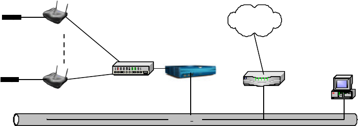
B-1
Appendix B Making of Ethernet Cable
It introduces the power supply mode of W800A Ethernet and making of Ethernet
cables.
B.1 W800A System Application Modes
The common application networking mode of the IP wireless access system is shown
in Fig. B.1-1.
Ethernet
Router
Fixed host
Wired LAN
AP
AP
AC
Power adapter
Power adapter
Internet
Ethernet switch
Fig. B.1-1 Common Application Networking Mode of the IP Wireless Access System
AP serves to access the wireless users in this way: It accesses the Ethernet switch
through 10/100 M Ethernet in the uplink way, and it is authenticated by AC and then
accesses Internet through the router. AC servers as the authentication and accounting
equipment in the system. Some areas with low requirements may be configured with
no AC according to the actual requirements. In the system, AP and Ethernet switch,
Ethernet switch and AC, and AC and router are connected through 10/100 M Ethernet.
In the common application mode, the attached power adapters of the devices convert
the external power voltage into the suitable DC working voltage.
The wireless LAN system, especially APs, features wide distribution range, the
engineering environment is rather complicated and some areas can not provide AC
power, so the remote power supply is required at this time. The IP wireless access
system provides the Ethernet power supply (PoE) solution, as shown in Fig. B.1-2.
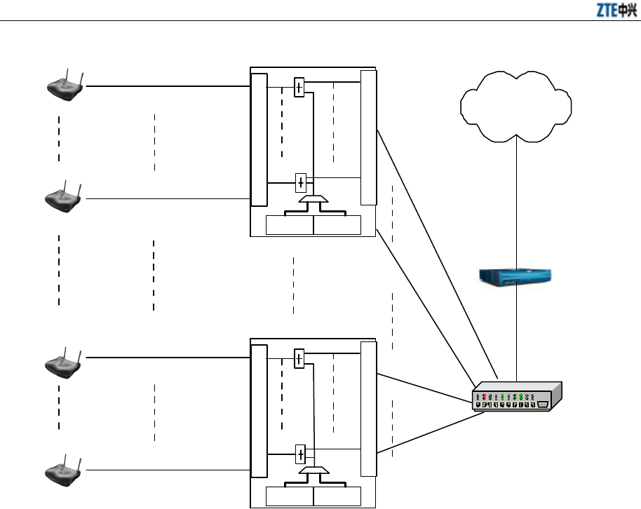
ZXR10 WAS (V2.0) IP Wireless Access System W800A Wireless Access Point User’s Manual
B-2
12 PoE egresses
12 Ethernet ingresses
W112P
220VAC -48VDC
AC
AP
AP Straight through
Ethernet cable
Crossover
Ethernet cable
£¨ RJ45J£©
£¨ C-RJ45-001£©
£¨ C-RJ45-001£©
Straight through
Ethernet cable
12 PoE engresse
12 Ethernet ingresses
W112P
220VAC-48VDC
AP
AP
£¨ C-RJ45-001£©
£¨ C-RJ45-001£©
The ratio of AP: W112P is 12:1 at most
Internet
£¨ RJ45£©
£¨ RJ45£©
Straight through power supply
Ethernet cable/48V DC
Ethernet switch
Straight through power supply
Ethernet cable/48V DC
Straight through power supply
Ethernet cable/48V DC
Straight through power supply
Ethernet cable/48V DC
W112P: Power source end of the Ethernet Power Supply (PoE)
Fig. B.1-2 Application of the System with Ethernet Power Supply
In Fig. B.1-2, Ethernet cables are: straight through Ethernet cable, straight through
Ethernet power cable and crossover Ethernet cable. In practical applications, AP and
AC may come from different producers, so the network cables should be determined
according to the detailed configurations.
According to the Ethernet specifications, 100 Base-T Ethernet features less than 100m
transmission distance and 10 Base-T Ethernet features not greater than 300m
transmission distance. So, in the wireless LAN system, no matter whether Ethernet
power supply is adopted, when the total routing length (L) between the AP and
Ethernet switch is greater than 100m (less than 300m), it is suggested to configure the
Ethernet switch port as 100 M.

Appendix B Making of Ethernet Cable
B-3
B.2 Making of Ethernet Cables
B.2.1 Making of Straight Through Ethernet Cables (RJ45)
In IP wireless access system, the following network cables must adopt the straight
through Ethernet cables:
1. The Ethernet cable between the Ethernet switch (end A) and W112P (end B).
2. When no Ethernet switch is used, AP will directly connect with the AC
downlink port, at this time, the Ethernet cable between the AC (end A) and AP
(end B) must be straight through Ethernet cable.
3. In the cases where no Ethernet switch is used, as when the system adopts the
Ethernet power supply, the AC downlink port will directly connect with W112P,
at this time, the Ethernet cable between the AC (end A) and W112P (end B)
must be straight through Ethernet cable.
The connections of the straight through Ethernet cables are shown in Table B.2-1.
Table B.2-1 Connections of Straight Through Ethernet Cables (RJ45)
End A Signal Name Conductor Color End B Signal Name Conductor Color
1 Data receiving Rx+ White/orange 1 Data transmitting Tx+ White/orange
2 Data receiving Rx- Orange 2 Data transmitting Tx- Orange
3 Data transmitting Tx+ White/green 3 Data receiving Rx+ White/green
4 MATCH1 Blue 4 MATCH1 Blue
5 MATCH2 White/blue 5 MATCH2 White/blue
6 Data transmitting Tx- Green 6 Data receiving Rx- Green
7 MATCH3 White/brown 7 MATCH3 White/brown
8 MATCH4 Brown 8 MATCH4 Brown
B.2.2 Making of Straight Through Power Supply Ethernet Cables (C-RJ45-001)
The Ethernet cable between the W112P (end A) and AP (end B) not only serves as the
Ethernet data signal cable, but also provides -48V DC power for two twisted pairs 4&5
and 7&8 on the load balance, to power AP remotely.
The connection method of this cable is the same as that of the straight through cable
without power supply, and the connection table is shown in Table B.2-2.

ZXR10 WAS (V2.0) IP Wireless Access System W800A Wireless Access Point User’s Manual
B-4
Table B.2-2 Connections of Straight Through Power Supply Ethernet Cables (C-RJ45-001)
End A Signal Name Conductor Color End B Signal Name Conductor Color
1 Data receiving Rx+ White/orange 1 Data transmitting Tx+ White/orange
2 Data receiving Rx- Orange 2 Data transmitting Tx- Orange
3 Data transmitting Tx+ White/green 3 Data receiving Rx+ White/green
4 GND Blue 4 GND Blue
5 GND White/blue 5 GND White/blue
6 Data transmitting Tx- Green 6 Data receiving Rx- Green
7 -48V White/brown 7 -48V White/brown
8 -48V Brown 8 -48V Brown
& Note:
These cables contain -48 V DC power supply. Do prevent any short circuits; otherwise,
the signal will be interrupted and the equipment may not work normally, and even the
equipment protection action will be activated. GND and -48 V each occupy one twisted
pair. These twisted pairs should be separate, otherwise short circuit may occur.
B.2.3 Making of Crossover Ethernet Cables (RJ45J)
The connections of the crossover Ethernet cables are shown in Table B.2-3.
Table B.2-3 Connections of Crossover Ethernet Cables (RJ45J)
End A Signal Name Conductor Color End B Signal Name Conductor Color
1 Data receiving Rx+ White/orange 3 Data transmitting Tx+ White/green
2 Data receiving Rx- Orange 6 Data transmitting Tx- Green
3 Data transmitting Tx+ White/green 1 Data receiving Rx+ White/orange
4 MATCH1 Blue 4 MATCH1 Blue
5 MATCH2 White/blue 5 MATCH2 White/blue
6 Data transmitting Tx- Green 2 Data receiving Rx- Orange
7 MATCH3 White/brown 7 MATCH3 White/brown
8 MATCH4 Brown 8 MATCH4 Brown
Appendix B Making of Ethernet Cable
B-5
& Note:
The signals and connection methods mentioned here are designed according to the
signal definitions of the ZTE AC equipment interface. If the AC in the actual
engineering is not from ZTE, modify the cable making methods according to the actual
conditions.
B.2.4 Ethernet Cable Label
After the Ethernet cable is crimped, paste labels on ends A and B of the network cable,
indicating name and length of this cable.
1. Label of the straight through Ethernet cable
The label of the straight through Ethernet cable (RJ45) is shown in Fig. B.2-1.
Fig. B.2-1 Label of the Straight Through Ethernet Cable
In the diagram, “**m” indicates the actual length of the cable.
2. Label of the straight through power supply Ethernet cable
The label of the straight through power supply Ethernet cable (C-RJ45-001) is
shown in Fig. B.2-2.
Fig. B.2-2 Label of the Straight Through Power Supply Ethernet Cable
In the diagram, “**m” indicates the actual length of the cable; “PoE Cable”
indicates that this is the Ethernet power cable.
3. Label of the Crossover Ethernet Cable
The label of the crossover Ethernet cable (RJ45J) is shown in Fig. B.2-3.

ZXR10 WAS (V2.0) IP Wireless Access System W800A Wireless Access Point User’s Manual
B-6
RJ45J **m
Fig. B.2-3 Label of the Crossover Ethernet cable
In the diagram, “**m” indicates the actual length of the cable; “J” after “RJ45”
indicates that this is the crossover Ethernet cable.
Warning:
Changes or modifications to this unit not expressly approved by the party responsible
for compliance could void the user’s authority to operate the equipment. Any change to
the equipment will void FCC grant.
This equipment has been tested and found to comply with the limits for a Class B digital device, pursuant
to part 15 of the FCC Rules. These limits are designed to provide reasonable protection against harmful
interference in a residential installation. This equipment generates, uses and can radiate radio frequency
energy and, if not installed and used in accordance with the instructions, may cause harmful interference to
radio communications. However, there is no guarantee that interference will not occur in a particular
installation. If this equipment does cause harmful interference to radio or television reception, which can be
determined by turning the equipment off and on, the user is encouraged to try to correct the interference by
one or more of the following measures:
--Reorient or relocate the receiving antenna.
--Increase the separation between the equipment and receiver.
--Connect the equipment into an outlet on a circuit different from that to which the receiver is connected.
--Consult the dealer or an experienced radio/TV technician for help.